EP2656639B1 - Anatomically customized ear canal hearing apparatus - Google Patents
Anatomically customized ear canal hearing apparatusDownload PDFInfo
- Publication number
- EP2656639B1 EP2656639B1EP11851438.9AEP11851438AEP2656639B1EP 2656639 B1EP2656639 B1EP 2656639B1EP 11851438 AEP11851438 AEP 11851438AEP 2656639 B1EP2656639 B1EP 2656639B1
- Authority
- EP
- European Patent Office
- Prior art keywords
- transducer
- support
- retention structure
- eardrum
- ear canal
- Prior art date
- Legal status (The legal status is an assumption and is not a legal conclusion. Google has not performed a legal analysis and makes no representation as to the accuracy of the status listed.)
- Active
Links
Images


Classifications
- H—ELECTRICITY
- H04—ELECTRIC COMMUNICATION TECHNIQUE
- H04R—LOUDSPEAKERS, MICROPHONES, GRAMOPHONE PICK-UPS OR LIKE ACOUSTIC ELECTROMECHANICAL TRANSDUCERS; DEAF-AID SETS; PUBLIC ADDRESS SYSTEMS
- H04R25/00—Deaf-aid sets, i.e. electro-acoustic or electro-mechanical hearing aids; Electric tinnitus maskers providing an auditory perception
- H04R25/65—Housing parts, e.g. shells, tips or moulds, or their manufacture
- H04R25/652—Ear tips; Ear moulds
- H—ELECTRICITY
- H04—ELECTRIC COMMUNICATION TECHNIQUE
- H04R—LOUDSPEAKERS, MICROPHONES, GRAMOPHONE PICK-UPS OR LIKE ACOUSTIC ELECTROMECHANICAL TRANSDUCERS; DEAF-AID SETS; PUBLIC ADDRESS SYSTEMS
- H04R25/00—Deaf-aid sets, i.e. electro-acoustic or electro-mechanical hearing aids; Electric tinnitus maskers providing an auditory perception
- H04R25/02—Deaf-aid sets, i.e. electro-acoustic or electro-mechanical hearing aids; Electric tinnitus maskers providing an auditory perception adapted to be supported entirely by ear
- H—ELECTRICITY
- H04—ELECTRIC COMMUNICATION TECHNIQUE
- H04R—LOUDSPEAKERS, MICROPHONES, GRAMOPHONE PICK-UPS OR LIKE ACOUSTIC ELECTROMECHANICAL TRANSDUCERS; DEAF-AID SETS; PUBLIC ADDRESS SYSTEMS
- H04R25/00—Deaf-aid sets, i.e. electro-acoustic or electro-mechanical hearing aids; Electric tinnitus maskers providing an auditory perception
- H04R25/60—Mounting or interconnection of hearing aid parts, e.g. inside tips, housings or to ossicles
- H04R25/604—Mounting or interconnection of hearing aid parts, e.g. inside tips, housings or to ossicles of acoustic or vibrational transducers
- H04R25/606—Mounting or interconnection of hearing aid parts, e.g. inside tips, housings or to ossicles of acoustic or vibrational transducers acting directly on the eardrum, the ossicles or the skull, e.g. mastoid, tooth, maxillary or mandibular bone, or mechanically stimulating the cochlea, e.g. at the oval window
- H—ELECTRICITY
- H04—ELECTRIC COMMUNICATION TECHNIQUE
- H04R—LOUDSPEAKERS, MICROPHONES, GRAMOPHONE PICK-UPS OR LIKE ACOUSTIC ELECTROMECHANICAL TRANSDUCERS; DEAF-AID SETS; PUBLIC ADDRESS SYSTEMS
- H04R2225/00—Details of deaf aids covered by H04R25/00, not provided for in any of its subgroups
- H04R2225/023—Completely in the canal [CIC] hearing aids
Definitions
- the present inventionis related to systems, devices and methods that couple to tissue such as hearing systems. Although specific reference is made to hearing aid systems, examples of the present disclosure can be used in many applications in which a signal is used to stimulate the ear.
- Natural hearingcan include spatial cues that allow a user to hear a speaker, even when background noise is present. People also like to communicate with those who are far away, such as with cellular phones.
- Hearing devicescan be used with communication systems to help the hearing impaired and to help people communicate with others who are far away. Hearing impaired subjects may need hearing aids to verbally communicate with those around them.
- the prior hearing devicescan provide less than ideal performance in at least some respects, such that users of prior hearing devices remain less than completely satisfied in at least some instances.
- Examples of deficiencies of prior hearing devicesinclude feedback, distorted sound quality, less than desirable sound localization, discomfort and autophony.
- Feedbackcan occur when a microphone picks up amplified sound and generates a whistling sound.
- Autophonyincludes the unusually loud hearing of a person's own self-generated sounds such as voice, breathing or other internally generated sound. Possible causes of autophony include occlusion of the ear canal, which may be caused by an object blocking the ear canal and reflecting sound vibration back toward the eardrum, such as an unvented hearing aid or a plug of earwax reflecting sound back toward the eardrum.
- acoustic hearing aidscan increase the volume of sound to a user, acoustic hearing aids provide sound quality that can be less than ideal and may not provide adequate speech recognition for the hearing impaired in at least some instances.
- Acoustic hearing aidscan rely on sound pressure to transmit sound from a speaker within the hearing aid to the eardrum of the user. However, the sound quality can be less than ideal and the sound pressure can cause feedback to a microphone placed near the ear canal opening.
- placement of an acoustic hearing aid along the bony portion of the ear canalmay decrease autophony and feedback, the fitting of such deep canal acoustic devices can be less than ideal such that many people are not able to use the devices. In at least some instances sound leakage around the device may result in feedback.
- the ear canalmay comprise a complex anatomy and the prior deep canal acoustic devices may be less than ideally suited for the ear canals of at least some patients. Also, the amount of time a hearing device can remain inserted in the bony portion of the ear canal can be less than ideal, and in at least some instances skin of the ear canal may adhere to the hearing device such that removal and comfort may be less than ideal.
- the clinical implementation of the prior direct mechanical coupling deviceshas been less than ideal in at least some instances. Coupling the transducer to the eardrum can provide amplified sound with decreased feedback, such that in at least some instances a microphone can be placed in or near the ear canal to provide hearing with spatial information cues.
- the eardrumis a delicate tissue structure, and in at least some instances the placement and coupling of the direct mechanical coupling devices can be less than ideal.
- the deepest portion of the ear canalcomprises the anterior sulcus
- a device extending to the anterior sulcuscan be difficult for a clinician to view in at least some instances.
- at least some prior direct coupling deviceshave inhibited viewing of the eardrum and the portion of the device near the eardrum, which may result in less than ideal placement and coupling of the transducer to the eardrum.
- direct couplingmay result in autophony in at least some instances.
- the eardrumcan move substantially in response to atmospheric pressure changes, for example about one millimeter, and at least some of the prior direct coupling devices may not be well suited to accommodate significant movement of the eardrum in at least some instances.
- the naturally occurring movement of the usersuch as chewing and eardrum movement may decouple at least some of the prior hearing devices.
- prior deviceshave been provided with a support to couple a magnet to the eardrum, the success of such coupling devices can vary among patients and the results can be less than ideal in at least some instances.
- Patents and publications that may be relevant to the present applicationinclude: 3,585,416 ; 3,764,748 ; 3,882,285 ; 5,142,186 ; 5,554,096 ; 5,624,376 ; 5,795,287 ; 5,800,336 ; 5,825,122 ; 5,857,958 ; 5,859,916 ; 5,888,187 ; 5,897,486 ; 5,913,815 ; 5,949,895 ; 6,005,955 ; 6,068,590 ; 6,093,144 ; 6,139,488 ; 6,174,278 ; 6,190,305 ; 6,208,445 ; 6,217,508 ; 6,222,302 ; 6,241,767 ; 6,422,991 ; 6,475,134 ; 6,519,376 ; 6,620,110 ; 6,626,822 ; 6,676,592 ; 6,728,024 ; 6,735,318 ; 6,900,926 ; 6,920,
- Non-U.S. patents and publicationsthat may be relevant include EP1845919 PCT Publication Nos. WO 03/063542 ; WO 2006/075175 ; U.S. Publication Nos..
- Microeng., 14(2004) 859-866Yi et al., "Piezoelectric microspeaker with compressive nitride diaphragm", IEEE, 2006 , and Zhigang Wang et al., "Preliminary Assessment of Remote Photoelectric Excitation of an Actuator for a Hearing Implant", IEEE Engineering in Medicine and Biology 27th Annual Conference, Shanghai, China, September 1-4, 2005 .
- Other publications of interestinclude: Gennum GA3280 Preliminary Data Sheet, " Voyager TDTM. Open Platform DSP System for Ultra Low Power Audio Processing " and National Semiconductor LM4673 Data Sheet, "LM4673 Filterless, 2.65W, Mono, Class D audio Power Amplifier "; Puria, S.
- US4628907describes a direct contact hearing aid apparatus adapted to be mounted deep within the ear canal including an electromechanical transducer for converting audio output signals into mechanical movement of an output coupling element without the production of discernible sound waves to prevent acoustic feedback.
- US2002/0085728describes a disposable hearing device adapted to be positioned entirely within an ear canal for extended wear.
- US6137889describes a device to be worn in the ear of a subject that provides a direct vibrational drive to the tympanic membrane through a vibrationally conductive assembly.
- US2009/0092271describes a hearing aid device for placement in an ear of a user including an elongate support and a transducer.
- the present inventionrelates to a hearing apparatus as defined in claim 1.
- Vapor deposition and polymerizationcan be used to manufacture a component of a hearing system used to transmit sound to a user.
- the output transducer assemblymay comprise a support having stiffness greater than a stiffness of the resilient retention structure, and the stiff support may comprise one or more of arms, a rigid frame, or a chassis.
- the support stiffness greater than the retention structurecan maintain alignment of the components coupled to the support, such that appropriate amounts of force can be used to urge a coupling structure against the eardrum so as to couple the transducer to the eardrum with decreased autophony.
- the stiff supportcan be coupled to at least one spring so as to provide appropriate amounts of force to the eardrum with the coupling structure and to inhibit deformation of the device when placed in the loaded configuration for the extended time.
- the deflectable retention structuremay provide a narrow profile configuration when advanced into the ear canal and a wide profile configuration when placed in the ear canal, and the stiff support can be used to deflect and advance the retention structure along the ear canal.
- a photodetector and an output transducercan be coupled to the support, such that the transducer assembly can be mechanically secure and stable when placed within the anatomy of the ear canal of the user.
- the supportcan have an elastomeric bumper structure placed thereon so as to protect the eardrum and skin when the support and retention structure are coupled to the eardrum and skin.
- the stiff supportcan be placed on the layer of vapor deposited polymer and affixed to the layer, such that the vapor deposited layer contacts the eardrum or skin.
- a second layercan be deposited on the first layer when the first layer has been placed on the first layer to situate the stiff support structure between the layers.
- the stiff supportmay comprise a part comprising arms, an intermediate portion extending between the arms, and at least one spring, such that the stiff support part can be placed an affixed to the retention structure.
- the output transducer assemblymay comprise a biasing structure coupled to the support to adjust a position of a coupling structure that engages the eardrum.
- the at least one springcan be coupled to the support and the transducer, so as to support the transducer and the coupling structure in an unloaded configuration.
- the biasing structurecan be configured to adjust the unloaded position of the coupling structure prior to placement.
- the at least one springcan be coupled to the coupling structure such that the coupling structure can move about one millimeter from the unloaded position in response to the eardrum loading the coupling structure.
- the springcan be configured to provide an appropriate force to the coupling structure engage the eardrum and to inhibit occlusion when the coupling structure comprises either the unloaded configuration or the configuration with displacement in response to eardrum movement of about one millimeter.
- the biasing structuremay comprise a dynamic biasing structure having a biasing transducer coupled to the at least one spring to urge the coupling structure into engagement with the eardrum in response to a signal to the output transducer.
- a vapor deposition and polymerization processcan be used to provide a strong and secure connection extending between the support and the resilient retention structure.
- the vapor deposition processmay comprise a poly(p-xylylene) polymer deposition process and the resilient retention structure may comprise a layer of vapor deposited poly(p-xylylene) polymer adhered to the support.
- the vapor-deposited Poly(p-xylylene) polymermay also adhere to the elastomeric bumper structure material such as a silicone material.
- the vapor deposition of the layer of material to form the retention structurecan provide a uniform accurate shape profile in a semi-automated manner that can increase reproducibility and accuracy with decreased labor so as to improve coupling and hearing for many people.
- the vapor deposition processcan be used to manufacture the output transducer assembly with a positive mold of the ear canal of the user.
- the positive moldmay comprise an optically transmissive material, and a release agent may coat an inner surface of the positive mold.
- the release agentmay comprise a hydrophilic material such that the coating can be removed from the mold with water.
- the layercan be formed with vapor deposition within the positive mold.
- the componentscan be placed on the layer.
- the positive moldmay comprise a transparent material, such that the placement of the components within the positive mold can be visualized.
- a second layercan be vapor deposited over the first layer to affix the components to the first layer and the second layer.
- the retention structuremay comprise a deflection to receive epithelium.
- the retention structuremay comprise a surface to contact a surface of an epithelial tissue.
- the epithelial tissuemay migrate under the retention structure when placed for an extended time.
- the deflection of the retention structure surfacecan be located near an edge of the retention structure and extend away from the surface of the tissue so as to inhibit accumulation of epithelial tissue near the edge of the retention structure.
- the deflected edgecan be oriented toward a source of epithelium such as the umbo when the retention structure is placed in the ear canal.
- the output transducer assemblymay comprise an oleophobic coating to inhibit autophony and accumulation of oil on components of the assembly.
- the retention structurecan be configured in many ways to permit viewing of the retention structure and the eardrum.
- the retention structuremay comprise a transparent material, which can allow a clinician to evaluate coupling of the retention structure to the tissue of the ear canal.
- the ear canalcomprises an opening, which allows a clinician to view at least a portion of the eardrum and evaluate placement of the output transducer assembly.
- the retention structureis dimensioned and shaped to avoid extending into the anterior sulcus to improve visibility when placed, and the retention structure may extend substantially around an outer portion of the eardrum such as the eardrum annulus so as to define an aperture through which the eardrum can be viewed. Alternatively, the retention structure may extend around no more than a portion of the annulus.
- he retention structureextends to a viewable location an opposite side of the ear canal, so as to limit the depth of placement in the ear canal and facilitate the clinician viewing of the retention structure.
- the visibility of the retention structurecan be increased substantially when the retention structure extends around no more than a portion of the annulus and also extends to a portion of the ear canal opposite the eardrum.
- the wall opposite the eardrumcan support the transducer with the portion opposite the annulus so as to improve coupling.
- the portions of the retention structure extending to the canal wall opposite the eardrum and around no more than a portion of the annuluscan be easily viewed and may define a viewing aperture through which the eardrum can be viewed.
- Examples of the disclosureprovide an apparatus for placement with a user, the apparatus comprises a transducer and a retention structure.
- the retention structurecomprises a layer of polymer having a shape profile corresponding to a tissue of the user to couple the transducer to the user.
- the retention structurecomprises a curved portion having an inner surface toward an eardrum when placed, and the curved portion couples to an ear canal wall oriented toward the eardrum when placed to couple a transducer to the eardrum.
- the curved portionmay couple to the ear canal on a first side of the ear canal opposite the eardrum, and a second portion of the retention structure may couple to a second side of the ear canal opposite the first side to hold the retention structure in the ear canal.
- the curved portion and the second portioncan be connected so as to define an aperture extending therebetween to view at least a portion of the eardrum when the curved portion couples to the first side of the ear canal and the second portion couples to the second side.
- the supportcomprises a first layer of a polymerizable material and a second layer of a polymerizable material and wherein components of a hearing device are situated between the first layer and the second layer.
- an oleophobic layeris coated on one or more of the first transducer or the retention structure.
- the tissuecomprises an eardrum having a first resistance to deflection and a bony portion of the ear canal having a second resistance to deflection greater than the first resistance
- the layercomprises a resistance to deflection greater than the eardrum and less than the bony portion of the ear canal.
- the layercomprises a material having a thickness to resist deflection away from the shape profile and wherein the layer comprises the shape profile in an unloaded configuration.
- the transducercouples to a tissue structure having a resistance to deflection, and the layer comprises a resistance to deflection greater than the tissue structure.
- the layercomprises a thickness within a range from about 1 um to about 100 um.
- the layermay comprise a substantially uniform thickness to provide the resistance to deflection and the shape profile in the unloaded configuration.
- the thickness of the layercan be uniform to within about +/- 25 percent of an average thickness to provide the shape profile.
- the retention structurecomprises a resilient retention structure to maintain a location of the transducer when coupled to the user.
- the resilient retention structureis sized to fit within an ear canal of the user and contact one or more of a skin of the ear canal or an eardrum annulus so as to maintain a location of the transducer when placed in the ear canal.
- the retention structurecomprises a layer composed of one or more of poly(chloro- p-xylene), poly(p-xylene), poly(dichloro-p-xylene), or fluorinated poly(p-xylene).
- the apparatuscomprises a support to couple the transducer to the retention structure.
- the supportmay comprises a stiff support having a pair of curved arms extending substantially along outer portions of the retention structure, and the curved arms can be configured to deflect inward with the retention structure when the support is advanced along an ear canal of the user.
- the transduceris supported with at least one spring extending between the support and the transducer.
- the supportmay comprise an intermediate portion extending between the arms, and the at least one spring may extends from the intermediate portion to the transducer to support the transducer.
- the at least one springcomprises a cantilever extending from the intermediate portion to the transducer to support the transducer.
- the at least one spring, the arms, and the intermediate sectionmay comprise a single part manufactured with a material.
- a projectionextends from the single part to place the retention structure in the ear canal of the user.
- the single partmay comprise one or more of a molded part, an injection molded part, or a machined part.
- the at least one springcomprises a pair of springs, a first spring of the pair coupled to a first side of the transducer, a second spring of the pair coupled to a second side of the transducer opposite the first side, so as to support the transducer with springs coupled to the support on opposing sides.
- the apparatusfurther comprises a coupling structure shaped to engage the eardrum to vibrate the eardrum, and a biasing structure to adjust an offset between the support and the coupling structure.
- the biasing structureis configured to adjust a separation distance extending between a lower surface of the retention structure and a lower surface of the coupling structure in an unloaded configuration, and the coupling structure is coupled to the support with at least one spring such that the separation distance decreases when the coupling structure contacts the eardrum.
- the biasing structure, the support, and the coupling structureare coupled to the at least one spring so as to provide about one mm or more of deflection of the coupling structure toward the support when the coupling structure engages the eardrum in a loaded configuration.
- the biasing structureis configured to adjust a position of the transducer in relation so as to the support to position the coupling structure with the offset.
- a photodetectorattached to a casing of the transducer.
- the transducercan be configured to pivot relative to the support, and the photodetector pivots with the transducer.
- the shape profilecorresponds to a shape profile of a tissue surface, and the shape profile comprises a portion having a deflection away from the shape profile of the tissue surface.
- the tissue surfacemay comprise an epithelial surface, and the deflection extends away from the epithelial surface when the support is placed.
- the deflectionmay be oriented on the support so as to receive advancing epithelium under the deflection.
- the retention structurecomprises a substantially annular retention structure and wherein the substantially annular retention structure defines an inner region, and the inner region is aligned with the aperture when the support is coupled to the retention structure such that the vibratory structure extends through the inner region and the aperture.
- the retention structurecomprises a resilient retention structure and in some examples the resilient retention structure has a first configuration comprising first dimensions so as to contact the eardrum annulus when placed, and the resilient retention structure has a second configuration when compressed.
- the second configurationcomprises second dimensions such that the retention structure is sized to move along the ear canal for placement. Upon removal of compression the retention structure returns from the second configuration substantially to the first configuration.
- the supportcomprises an elongate dimension and rigidity greater than the retention structure and wherein the retention structure comprises a first portion sized to fit an anterior sulcus of the ear canal, and the elongate dimension is aligned with the first portion such that the retention structure can be compressed when moved along the ear canal.
- the supportcomprises a rigid sheet material cut so as to define the aperture and an outer perimeter of the support.
- the transducercomprises a housing having a first end and a second end and wherein the vibratory structure extends through a first end of the housing and a pair of coil springs is coupled to the second end of the housing.
- the pairextends between the second end and the support such that transducer is supported with the springs, and the vibratory structure is urged through the aperture when the retention structure is placed within the ear canal.
- Each of the coil springsmay have a pivot axis extending through the coil and the pivot axis of said each coil can extend through the other coil such that the transducer pivots about a pivot axis extending through the coils to couple to the eardrum when the vibratory structure extends through the aperture.
- the aperturecan be sized to receive the housing of the transducer assembly such that the transducer assembly can pivot through the aperture to increase the dynamic range of the pivoting of the transducer to couple to the eardrum.
- a photo transduceris coupled to the support and the transducer.
- the term “embodiment”is used to refer to examples useful for understanding the invention, which do not necessarily fall within the scope of the present invention, unless explicitly indicated as “embodiment of the invention”.
- the scope of the present inventionis solely defined by the appended claims.
- Examples of the present disclosureare well suited to improve communication among people, for example with cellular communication and as a hearing aid with decreased invasiveness that can be readily placed by a health care provider.
- lightencompasses electromagnetic radiation having wavelengths within the visible, infrared and ultraviolet regions of the electromagnetic spectrum.
- the hearing devicecomprises a photonic hearing device, in which sound is transmitted with photons having energy, such that the signal transmitted to the ear can be encoded with transmitted light.
- an emitterencompasses a source that radiates electromagnetic radiation and a light emitter encompasses a light source that emits light.
- a surfactantencompasses a wetting agent capable of reducing the surface tension of a liquid.
- the exponential value A x 10 -Bcan be expressed as Ae-B, or AE-B, for example.
- Transducer assembliesthat couple the transducer to the eardrum so as to decrease occlusion are described in United States Patent Application Number 61/217,801, filed on 3 June 2009 , entitled “Balanced Armature Device and Methods for Hearing”; and PCT/US2009/057719, filed on September 2009 , entitled “Balanced Armature Device and Methods for Hearing”, published as WO 2010/033933 .
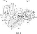
- Fig. 1shows a hearing aid system 10 configured to transmit electromagnetic energy to an output transducer assembly 1 00 positioned in the ear canal EC of the user.
- the earcomprises an external ear, a middle ear ME and an inner ear.
- the external earcomprises a Pinna P and an ear canal EC and is bounded medially by an eardrum TM.
- Ear canal ECextends medially from pinna P to eardrum TM.
- Ear canal ECis at least partially defined by a skin SK disposed along the surface of the ear canal.
- the eardrum TMcomprises an annulus TMA that extends circumferentially around a majority of the eardrum to hold the eardrum in place.
- the middle ear MEis disposed between eardrum TM of the ear and a cochlea CO of the ear.
- the middle ear MEcomprises the ossicles OS to couple the eardrum TM to cochlea CO.
- the ossicles OScomprise an incus IN, a malleus ML and a stapes ST.
- the malleus MLis connected to the eardrum TM and the stapes ST is connected to an oval window OW, with the incus IN disposed between the malleus ML and stapes ST.
- Stapes STis coupled to the oval window OW so as to conduct sound from the middle ear to the cochlea.
- the hearing system 10includes an input transducer assembly 20 and an output transducer assembly 100 to transmit sound to the user.
- Hearing system 10may comprise a behind the ear unit BTE.
- Behind the ear unit BTEmay comprise many components of system 10 such as a speech processor, battery, wireless transmission circuitry and input transducer assembly 10.
- Behind the ear unit BTEmay comprise many component as described in U.S. Pat. Pub. Nos. 2007/0100197 , entitled “Output transducers for hearing systems"; and 2006/0251278 , entitled “Hearing system having improved high frequency response".
- the input transducer assembly 20can be located at least partially behind the pinna P, although the input transducer assembly may be located at many sites.
- the input transducer assemblymay be located substantially within the ear canal, as described in U.S. Pub. No. 2006/0251278 .
- the input transducer assemblymay comprise a blue tooth connection to couple to a cell phone and my comprise, for example, components of the commercially available Sound ID 300, available from Sound ID of Palo Alto, California.
- the output transducer assembly 100may comprise components to receive the light energy and vibrate the eardrum in response to light energy.
- An example of an output transducer assembly having components suitable for combination in accordance with examples as described hereinis described in U.S. Pat. App. Nos. 61,217,801, filed June 3, 2009 , entitled “Balanced Armature Device and Methods for Hearing" and PCT/US2009/057719, filed 21 September 2009 , Balanced Armature Device and Methods for Hearing".
- the input transducer assembly 20can receive a sound input, for example an audio sound. With hearing aids for hearing impaired individuals, the input can be ambient sound.
- the input transducer assemblycomprises at least one input transducer, for example a microphone 22.
- Microphone 22can be positioned in many locations such as behind the ear, as appropriate. Microphone 22 is shown positioned to detect spatial localization cues from the ambient sound, such that the user can determine where a speaker is located based on the transmitted sound.
- the pinna P of the earcan diffract sound waves toward the ear canal opening such that sound localization cues can be detected with frequencies above at least about 4 kHz.
- the sound localization cuescan be detected when the microphone is positioned within ear canal EC and also when the microphone is positioned outside the ear canal EC and within about 5 mm of the ear canal opening.
- the at least one input transducermay comprise a second microphone located away from the ear canal and the ear canal opening, for example positioned on the behind the ear unit BTE.
- the input transducer assemblycan include a suitable amplifier or other electronic interface.
- the inputmay comprise an electronic sound signal from a sound producing or receiving device, such as a telephone, a cellular telephone, a Bluetooth connection, a radio, a digital audio unit, and the like.
- At least a first microphonecan be, positioned in an ear canal or near an opening of the ear canal to measure high frequency sound above at least about one 4 kHz comprising spatial localization cues.
- a second microphonecan be positioned away from the ear canal and the ear canal opening to measure at least low frequency sound below about 4 kHz. This configuration may decrease feedback to the user, as described in U.S. Pat. Pub. No. US 2009/0097681 .
- Input transducer assembly 20includes a signal output source 12 which may comprise a light source such as an LED or a laser diode, an electromagnet, an RF source, or the like.
- the signal output sourcecan produce an output based on the sound input.
- Output transducer assembly 100can receive the output from input transducer assembly 20 and can produce mechanical vibrations in response.
- Output transducer assembly 100comprises a sound transducer and may comprise at least one of a coil, a magnet, a magnetostrictive element, a photostrictive element, or a piezoelectric element, for example.
- the output transducer assembly 100can be coupled input transducer assembly 20 comprising an elongate flexible support having a coil supported thereon for insertion into the ear canal as described in U.S. Pat. Pub. No. 2009/0092271 , entitled "Energy Delivery and Microphone Placement Methods for Improved Comfort in an Open Canal Hearing Aid” .
- the input transducer assembly 20may comprise a light source coupled to a fiber optic, for example as described in U.S. Pat. Pub. No. 2006/0189841 entitled, "Systems and Methods for Photo-Mechanical Hearing Transduction” .
- the light source of the input transducer assembly 20may also be positioned in the ear canal, and the output transducer assembly and the BTE circuitry components may be located within the ear canal so as to fit within the ear canal.
- the mechanical vibrations caused by output transducer assembly 100can induce neural impulses in the subject which can be interpreted by the subject as the original sound input.
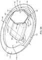
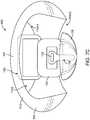
- Figs. 2A and 2Bshow isometric and top views, respectively, of the output transducer assembly 100.
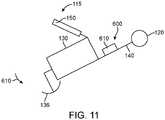
- Output transducer assembly 100comprises a retention structure 110, a support 120, a transducer 130, at least one spring 140 and a photodetector 150.
- Retention structure 110is sized to couple to the eardrum annulus TMA and at least a portion of the anterior sulcus AS of the ear canal EC.
- Retention structure 110comprises an aperture 110A.
- Aperture 110Ais sized to receive transducer 130.
- the retention structure 110can be sized to the user and may comprise one or more of an o-ring, a c-ring, a molded structure, or a structure having a shape profile so as to correspond to a mold of the ear of the user.
- retention structure 110may comprise a polymer layer 115 coated on a positive mold of a user, such as an elastomer or other polymer.
- retention structure 110may comprise a layer 115 of material formed with vapor deposition on a positive mold of the user, as described herein.
- Retention structure 110comprises a resilient retention structure and in some example the retention structure can be compressed radially inward as indicated by arrows 102 from an expanded wide profile configuration to a narrow profile configuration when passing through the ear canal and subsequently expand to the wide profile configuration when placed on one or more of the eardrum, the eardrum annulus, or the skin of the ear canal.
- the retention structure 110may comprise a shape profile corresponding to anatomical structures that define the ear canal.
- the retention structure 110may comprise a first end 112 corresponding to a shape profile of the anterior sulcus AS of the ear canal and the anterior portion of the eardrum annulus TMA.
- the first end 112may comprise an end portion having a convex shape profile, for example a nose, so as to fit the anterior sulcus and so as to facilitate advancement of the first end 112 into the anterior sulcus.
- the retention structure 110may comprise a second end 114 having a shape profile corresponding to the posterior portion of eardrum annulus TMA.
- the support 120may comprise a frame, or chassis, so as to support the components connected to support 120.
- Support 120may comprise a rigid material and can be coupled to the retention structure 110, the transducer 130, the at least one spring 140 and the photodetector 150.
- the support 120may comprise a biocompatible metal such as stainless steel so as to support the retention structure 110, the transducer 130, the at least one spring 140 and the photodetector 150.
- support 120may comprise cut sheet metal material.
- support 120may comprise injection molded biocompatible plastic.
- the support 120may comprise an elastomeric bumper structure 122 extending between the support and the retention structure, so as to couple the support to the retention structure with the elastomeric bumper.
- the elastomeric bumper structure 122can also extend between the support 120 and the eardrum, such that the elastomeric bumper structure 122 contacts the eardrum TM and protects the eardrum TM from the rigid support 120.
- the support 120may define an aperture 120A formed thereon.
- the aperture 120Acan be sized so as to receive the balanced armature transducer 130, for example such that the housing of the balanced armature transducer 130 can extend at least partially through the aperture 120A when the balanced armature transducer is coupled to the eardrum TM.
- the support 120may comprise an elongate dimension such that support 120 can be passed through the ear canal EC without substantial deformation when advanced along an axis corresponding to the elongate dimension, such that support 120 may comprise a substantially rigid material and thickness.
- the transducer 130comprises structures to couple to the eardrum when the retention structure 120 contacts one or more of the eardrum, the eardrum annulus, or the skin of the ear canal.
- the transducer 130may comprise a balanced armature transducer having a housing and a vibratory reed 132 extending through the housing of the transducer.
- the vibratory reed 132is affixed to an extension 134, for example a post, and an inner soft coupling structure 136.
- the soft coupling structure 136has a convex surface that contacts the eardrum TM and vibrates the eardrum TM.
- the soft coupling structure 136may comprise an elastomer such as silicone elastomer.
- the soft coupling structure 136can be anatomically customized to the anatomy of the ear of the user.
- the soft coupling structure 136can be customized based a shape profile of the ear of the user, such as from a mold of the ear of the user as described herein.
- At least one spring 140can be connected to the support 120 and the transducer 130, so as to support the transducer 130.
- the at least one spring 140may comprise a first spring 122 and a second spring 124, in which each spring is connected to opposing sides of a first end of transducer 130.
- the springsmay comprise coil springs having a first end attached to support 120 and a second end attached to a housing of transducer 130 or a mount affixed to the housing of the transducer 130, such that the coil springs pivot the transducer about axes 140A of the coils of the coil springs and resiliently urge the transducer toward the eardrum when the retention structure contacts one or more of the eardrum, the eardrum annulus, or the skin of the ear canal.
- the support 120may comprise a tube sized to receiving an end of the at least one spring 140, so as to couple the at least one spring to support 120.
- a photodetector 150can be coupled to the support 120.
- a bracket mount 152can extend substantially around photodetector 150.
- An arm 154extend between support 120 and bracket 152 so as to support photodetector 150 with an orientation relative to support 120 when placed in the ear canal EC.
- the arm 154may comprise a ball portion so as to couple to support 120 with a ball-joint.
- the photodetector 150can be coupled to transducer 130 so as to driven transducer 130 with electrical energy in response to the light energy signal from the output transducer assembly.
- Resilient retention structure 110can be resiliently deformed when inserted into the ear canal EC.
- the retention structure 110can be compressed radially inward along the pivot axes 140A of the coil springs such that the retention structure 110 is compressed as indicated by arrows 102 from a wide profile configuration having a first width 110W1 to an elongate narrow profile configuration having a second width 110W2 when advanced along the ear canal EC as indicated by arrow 104 and when removed from the ear canal as indicated by arrow 106.
- the elongate narrow profile configurationmay comprise an elongate dimension extending along an elongate axis corresponding to an elongate dimension of support 120 and aperture 120A.
- the elongate narrow profile configurationmay comprise a shorter dimension corresponding to a width 120W of the support 120 and aperture 120A along a shorter dimension.
- the retention structure 110 and support 120can be passed through the ear canal EC for placement.
- the reed 132 of the balanced armature transducer 130can be aligned substantially with the ear canal EC when the assembly 100 is advanced along the ear canal EC in the elongate narrow profile configuration having second width 110W2.
- the support 120may comprise a rigidity greater than the resilient retention structure 110, such that the width 120W remains substantially fixed when the resilient retention structure is compressed from the first configuration having width 11 0W1 to the second configuration having width 110W2.
- the rigidity of support 120 greater than the resilient retention structure 110can provide an intended amount of force to the eardrum TM when the inner soft coupling structure 136 couples to the eardrum, as the support 120 can maintain a substantially fixed shape with coupling of the at least one spring 140.
- the outer edges of the resilient retention structure 110can be rolled upwards toward the side of the photodetector 150 so as to compress the resilient retention structure from the first configuration having width 110W1 to the second configuration having width 110W2, such that the assembly can be easily advanced along the ear canal EC.
- Fig. 3-1 to 3-12show a method 300 of making resilient retention structure 110 to hold an output transducer assembly in an ear of the user.
- the method 300can be performed with one or more components of an apparatus 200 to make the resilient retention structure.
- the processmay comprise making an anatomically accurate mold and the vapor deposition polymerization of ParyleneTM onto the mold.
- the moldcan be constructed and prepared in such a way as to provide both the dimensional accuracy of the deposited ParyleneTM and the removal the ParyleneTM without distortion or strain.
- the ParyleneTMmay comprise an integrated structural member of the finished assembly, for example when the ParyleneTM is deposited on the support 120.
- Fig. 3-1shows an injection step 305.
- the process for creating an anatomically accurate, uniformly thick, and flexible platform of biocompatible materialcan include with the creation of a representation of the human ear canal of interest. A physician can perform this procedure in a clinical setting.
- a biocompatible, two-part silicone 205for example polyvinyl siloxane hereinafter "PVS"
- PVSpolyvinyl siloxane
- the PVSmay include mineral oil or other oil, for example.
- Fig. 3-2shows a removal step 310.
- the PVScan be allowed to fully cure, and then be removed.
- the resulting negative impression 210comprises a dimensionally accurate, customized negative representation of the ear canal (herein "PVS impression").
- the PVS impressionmay exude mineral oil, such that the impression can be easily removed from the ear canal and eardrum, and may form an anatomically accurate impression of the anterior sulcus AS.
- the positive mold of the ear canalcan be formed based on the negative impression in many ways.
- the positive moldmay have a shape profile corresponding to the ear canal and may comprise a substrate for vapor deposition so as to form the resilient retention structure 110 having the shape profile corresponding to the ear canal, for example with a release agent disposed between the substrate and the vapor deposition layer 115.
- the material used to form the positive moldmay comprise one or more of many materials such as an acrylate, an epoxy, a UV curable epoxy, a plaster, or a dental mold.
- Fig. 3-3shows a coating step 315.
- the PVS negative impression 210can be coated to create a thin rigid coating 215, for example a shell, corresponding to the retention structure 110.
- the thin coatingmay comprise a resin such as an acrylate resin, for example pattern resin comprising acrylate such as polymethylmethacrylate (hereinafter "PMMA”), or a curable epoxy such as a UV curable epoxy.
- PMMApolymethylmethacrylate
- Fig. 3-4shows an embedding step 320.
- the PVS impression and coating 215can be embedded in a small cylindrical cup 220 holding the same uncured pattern resin 222, or a UV curable epoxy or acrylate which is allowed to cure.
- the two-step molding processcan allow the use of a large cross-sectional mold for ease of handling without the dimensional changes that may result from the larger cross section when used to create the internal mold dimensions without the shell.
- the PVS impression 210can then be removed from the mold.
- the finished positive mold 225is then machined flat to provide a smooth, orthogonal surface for future handling of the ParyleneTM part as described herein.
- the pattern resincan be replaced with a low-shrinkage acrylate, for example a UV curable acrylate, such that the mold 225 can be created by embedding the PVS impression without forming the coating.
- the pattern resinmay comprise a shrinkage of about 3% when cured, for example, and the low shrinkage acrylate may have a shrinkage less than 1%, such that the low shrinkage acrylate or epoxy can be used to form the mold without forming the shell, for example when the low shrinkage acrylate comprises a UV curable acrylate having a shrinkage of less than 1 %.
- the cured pattern resinmay comprise a positive mold 225 of the user's ear canal.
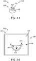
- Fig. 3-5shows a machining step 325.
- the cured pattern resincan be molded in a cylindrical mold.
- the negative impression 210can be removed leaving a channel 229 corresponding to the ear canal, and the cured surface can be machined substantially orthogonal to the axis of the cylinder.
- the flat machined surface 227can be used to handle the ParyleneTM layer 115 when deposited on the mold 225 comprising the machined surface 227 and the cured coating 215.
- Fig. 3-6shows a submersion step 330, in accordance with examples of the method of Fig. 3 ;
- the pattern resincan be porous and may also contain volatile compounds (water, air, and organic vapors), which are a result of the polymerization reaction of the pattern resin.
- the volatile compoundscan interfere with the deposition of ParyleneTM.
- the affect of the porous surface and the volatile compounds of the mold 225can be decreased substantially with treatment prior to the vapor deposition and polymerization. Gases can be released from the surface of the mold when the ParyleneTM layer is deposited in the vacuum chamber. In order to decrease this gas release, the mold material can be passivated prior to placement into the deposition chamber. This passivation process can substantially improve the quality of the ParyleneTM finished "film", as the number of pinholes formed by gas release are decreased, and the mold surface is smoothed with the release agent filling the pores near the deposition surface.
- the moldAfter removal of the PVS impression from the mold, the mold is placed into a bath of heated petroleum jelly such that the heated petroleum jelly comprises a liquid, for example heated to 100 degrees C.
- the bath of heated petroleum jellycan be provided with a container 234 comprising the heated petroleum jelly.
- the container 234 and moldcan be placed in a vacuum chamber 232 to provide low pressure and elevated temperature.
- the petroleum jellymay comprise the release agent 231.
- a pre-deposition pump down (low pressure) time period of 2-4 hourscan be used, and the mold 225 immersed in the bath can be placed in a vacuum of about 5 to 10 Torr for the 2-4 hour period, so as to inhibit formation of pinholes when the vapor is deposited and polymerized.
- the mold immersed in the bathcan be heated when placed in the vacuum for the 2-4 hour period.
- the pressureis allowed to return to atmosphere while the mold remains submerged in the heated liquefied petroleum jelly.
- Thisallows many evacuated cavities within the mold 225 to be replaced with the liquefied petroleum jelly, such that petroleum jelly substantially fills the cavities and pores.
- the mold 225can be removed, placed upside down so as to drain the liquefied petroleum jelly, and allowed to cool, so as to provide a substantially smooth surface to receive the ParyleneTM precursor vapor and form the smooth coating and so as to release the formed coating from the smooth surface.
- the petroleum jellycan be wiped at room temperature so as to provide the smooth surface for deposition of the ParyleneTM precursor monomer and formation of the ParyleneTM.
- the petroleum jellycan be referred to as petrolatum or soft paraffin, CAS number 8009-03-8, is a semi-solid mixture of hydrocarbons, with a majority carbon numbers mainly higher than 25.
- the petroleum jellymay comprise a semi-solid mixture of hydrocarbons, having a melting-point usually within a few degrees of 75°C (167°F).
- Petroleum jellycan comprise a non-polar hydrocarbon that is hydrophobic (water-repelling) and insoluble in water.
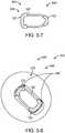
- Fig. 3-7shows a pretreatment step 335 of coating a support chassis.
- the stainless steel support chassiscan be placed into the mold.
- the chassis support 120may comprise an internal support, or "skeleton", for the placement and positioning of the transducer on the finished assembly, and the placement and orientation of the chassis can be important to the final performance and positional stability of the final activated assembly.
- the positional stability of the chassis within the moldcan be accomplished by a two-step bumperization of the support chassis using fluorosilicone.
- This thin region of fluorosiliconemay comprise a cushion between the stainless steel chassis and the sensitive skin of the ear canal.
- the supportPrior to placement in the mold 225, the support can be treated with a coating to protect the skin of the ear canal and the tympanic membrane of the user, and to improve adherence of the support 120 to the resilient retention structure 110.
- the supportmay comprise a metallic sheet material securely connected to the resilient ParyleneTM retention structure.
- each end of the support 120can be coated in many ways.
- each end of the support 120can be dipped in fluorosilicone to form an elastomeric bumper 122 on each end of support 120.
- Fig. 3-8shows a step 340 of coupling the coated support to the mold.
- a second coating of fluorosiliconecan be applied to the ends of the support and the support can be placed in the mold.
- the second application 240can be applied to each of the cured bumpers 122.
- the support 120can be inserted into the mold and aligned with positive impression of the ear, for example aligned with the eardrum and anterior sulcus, so as to correspond with an intended alignment of the ear of the user.
- This second step application 240 of fluorosiliconecan provide positional stability of the support in the mold and provide mechanical connection between the support and the ParyleneTM, for example with an increased surface area so as to improve adhesion.
- the elastomer comprising fluorosilicone disposed between the support 120 and resilient retention structure 110can improve coupling, for example when the retention structure 110 is resiliently deformed and the support 120 retains a substantially fixed and rigid configuration when the retention structure and support are advanced along the ear canal.
- the support chassisis very stable for the handling of the mold prior to and during the ParyleneTM deposition process.
- Fig. 3-9shows a step 345 of vapor deposition of monomer precursor to the mold to form a layer 115 of ParyleneTM polymer film 250.
- the vapor depositionmay occur in a chamber 245.
- the ParyleneTM precursor monomerenters the mold through an opening 229 corresponding to a cross section of the ear canal EC.
- the vaporis deposited on support 120 and bumpers 122.
- the bumpers 122contact the release agent 231 deposited on the cured coating 215.
- the vapor deposition and ParyleneTM formation processcan occur at an ambient room temperature, for example when the release agent comprising petroleum jelly is a solid.
- Fig. 3-9Ashows the structure of ParyleneTM, in accordance with examples.
- ParyleneTMis the trade name for members of a unique genus of polymers, which includes one or more of ParyleneTM N, ParyleneTM C, or ParyleneTM HT among others.
- the resilient retention structure 110 as described hereinmay comprise one or more commercially available ParyleneTM, such as one or more of Parylene TM N, ParyleneTM C, or ParyleneTM HT.
- the thickness of the retention structure 110can be within a range from about 2 um to about 100 um, for example within a range from about 5 to 50 um, so as to provide the custom resilient retention structure 110 from the custom acrylic mold substrate such that the retention structure can be resiliently folded by the skin tissue of the ear canal when advanced along the ear canal.
- a ParyleneTM thicknesswithin a range from about 10 to 25 um can be preferred.
- the modulus of the deposited layer 115 comprising ParyleneTMcan be at least about 200,000 PSI, for example at least about 300 PSI. Based on the teachings described herein, a person of ordinary skill in the art can determine the modulus and thickness so as to provide resilient structure 110 with suitable rigidity for advancement along the ear canal and placement against one or more of the eardrum or skin as described herein.
- ParyleneTMcomprises a polymer having aromatic rings connected with carbon-carbon bonds. ParyleneTM can be formed with deposition of monomer molecules having the aromatic rings, so as to form the ParyleneTM polymer having the aromatic rings.
- ParyleneTMcan be formed with deposition on a substrate corresponding to a shape profile of a tissue structure of the subject, and the formed ParyleneTM can unexpectedly be separated from the substrate so as to provide the resilient support having the shape profile of the subject.
- ParylenesTM suitable for incorporation in accordance with examples as disclosed hereinare described on the world wide web, for example on Wikipedia. (wikipedia.org/wiki/Parylene)
- ParyleneTMis the trademark for a variety of chemical vapor deposited poly(p-xylylene) based polymers and derivatives thereof that can be deposited on the substrate with a release agent to form the support.
- the ParyleneTMmay comprise one or more of ParyleneTM A, ParyleneTM C, ParyleneTM, D or ParyleneTM.
- ParyleneTM C and AF-4, SF, HTcan be used for medical devices and may comprise an FDA accepted coating devices permanently implanted into the body.
- Fig. 3-9Bshows the structure of ParyleneTM C.
- the ParyleneTMcomprises ParyleneTM C having a hydrogen atom of the benzene ring substituted with substituted chlorine, for example at the C1 location.
- ParyleneTM Nis a polymer manufactured from di-p-xylylene, a dimer synthesized from p-xylylene.
- Di-p-xylylenemore properly known as [2.2]paracyclophane, can be made from p-xylylene in several steps involving bromination, amination and elimination.
- ParyleneTM Nmay comprise an unsubstituted molecule. Heating [2.2]paracyclophane under low pressure (0.01 - 1 Torr) conditions can give rise to a diradical species which polymerizes when deposited on a surface. The monomer can be in a gaseous phase until surface contact, such that the monomer can access the entire exposed surface.
- ParyleneTM derivativesParyleneTM N (hereinafter “N Poly(p-xylylene)", hydrocarbon), ParyleneTM C (hereinafter “poly(chloro-p-xylylene)", one chlorine group per repeat unit), ParyleneTM D (hereinafter “poly(dichloro-p-xylylene)", two chlorine groups per repeat unit), ParyleneTM AF-4 (generic name, aliphatic flourination 4 atoms), ParyleneTM SF (Kisco product), ParyleneTM HT (hereinafter “fluorinated poly(p-xylylene)", AF-4, SCS product), ParyleneTM A (one amine per repeat unit, Kisco product), ParyleneTM AM (one methylene amine group per repeat unit, Kisco product), ParyleneTM VT-4 (generic name, fluorine atoms on the aromatic ring), ParyleneTM CF (VT-4, Kisco product), and ParyleneTM X (a)
- ParyleneTMcan have the following advantages: a hydrophobic, hydrophobic, chemically resistant; biostable, biocompatible coating; FDA approved, thin highly conformal, uniform, transparent coating, coating without temperature load of the substrates as coating takes place at ambient temperature in the vacuum, homogeneous surface, low intrinsic thin film stress due to its room temperature deposition, low coefficient of friction (AF-4, HT, SF).
- the ParyleneTM coatingcan have a uniformity within a range from about +/- 25 percent, for example.
- Fig. 3-10shows a top view of the mold and step 350 of cutting the layer 115 of ParyleneTM polymer film 250 to prepare the film for removal from the mold.
- the next stepcan be to remove the ParyleneTM structure (herein "film") from the mold. Due to the extremely thin cross section of the ParyleneTM and its relatively inelastic mechanical properties, the ParyleneTM layer 115 of polymer film 250 can be subject to being permanently deformed during removal, which can compromise its dimensional accuracy as it relates to the human anatomy such that the film may no longer fit in the ear. This is where the preparation of the mold can be helpful to the successful removal of the ParyleneTM film. The defect-free, smooth surface of the mold and lubricious character of the release agent comprising petroleum jelly can be helpful for a successful outcome at this step.
- the moldIn order to prepare the mold for the film release, the mold is placed into an oven so as to liquefy the thin layer of petroleum jelly that separates the ParyleneTM film from the acrylate mold substrate and so as to release the ParyleneTM film.
- the release agentmay comprise a surfactant, or polyethylene glycol (hereinafter "PEG”) and the ParyleneTM film can be separated from the mold with water so as to decouple the then film from the mold when the water contacts the surfactant.
- PEGpolyethylene glycol
- the film 250is then cut along the circumference of the machined upper surface 227 of the mold so as to provide a flat, substantially circular flange 252, which can be used as a handle with which the film can be removed from the mold.
- Fig. 3-11shows step 355 of removing the layer 115 of ParyleneTM polymer film 250 from the mold with the film comprising a 3D self supporting structure and suitable for supporting with a backing material for cutting.
- the support 120 and the ParyleneTM film comprising the resilient retention structure 110are shown removed from the mold.
- the thin filmcan benefit from a stiff backing material in order to be accurately cut with acceptable edge condition.
- the filmcan be supported with a backing material such as polyethylene glycol (hereinafter "PEG")
- PEGpolyethylene glycol
- the intact free filmis filled with heated liquid polyethylene glycol (PEG) which hardens when it cools to room temperature as described herein. Due potentially excessive shrinkage, the film can be lightly pressurized to force the outer dimensions of the film to be maintained during the PEG cooling.
- Fig. 3-12shows a step 360 of cutting the layer 115 of polymer film 250 with a backing material, in accordance with examples of the method of Fig. 3 .
- the filmcan be cut into the intended shape.
- the film 250can be fixed by the flat flange 252 to an X, Y, Z alignment device 264.
- the alignment device 264may comprise an alignment device having six degrees of freedom, three rotational and three translational, such as a goniometer coupled to an X,Y,Z, translation stage.
- a planar cutting guidecan then correctly oriented to the first desired cut.
- the outside of the PEG-filled filmis then scored with a blade to cut through the film along the plane 262 of the blade guide 260 .
- a second cutis made in the same manner, the result of which may comprise the desired shape of retention structure 110 and support 120.
- the ParyleneTM coatingcan be cut with light such as excimer laser ablation, or other laser ablation, for example.
- the PEGcan be dissolved with water.
- the resilient ParyleneTM retention structure and support 120can be suitable combination with additional components of output transducer assembly 100 as described herein.
- the vaporcomprises polyvinyl alcohol (PVA), or its hydrogel form (PVA-H).
- PVApolyvinyl alcohol
- PVA-Hpolyvinyl alcohol
- the deposited materialmay comprise one or more of a hydrogel material such as polyvinyl alcohol (hereinafter "PVA"), a sugar, cellulose, a carbon based material such as a diamond like coating or silicon based material such as SiO2.
- PVApolyvinyl alcohol
- the materialcan be deposited in many ways such as vapor deposition, thermo deposition, radiofrequency deposition, or plasma deposition.
- PVA-Hcan be blended before or after deposition with one or more other materials such as chitosan, gelatin, or starch.
- PVA-Hcan be deposited and polymerized by chemical crosslinking photocrosslinking, irradiation, or physical crosslinking, such as a freeze-thaw technique.
- the cross-linked PVA-Hcan have stable volume and material properties.
- the deposited polymercan be coagulated, for example with quenching a deposited polymer solution in an aqueous nonsolvent, resulting in solvent-nonsolvent exchange and polymer precipitation.
- a biocompatible nano composite materialcan be formed when PVA is combined with bacterial cellulose (BC) fibers. These can have the desired mechanical properties and manufacturing repeatability to make a resilient retention structure as described herein.
- BCbacterial cellulose
- the monomer moleculesare deposited and polymerized using thermal deposition methods and using Radio Frequency deposition methods, such as plasma vapor deposition.
- Radio Frequency deposition methodssuch as plasma vapor deposition.
- Carbon based materialssuch polyethylene are compatible with such techniques.
- the method 300can be performed in many ways, and one or more of the materials may be substituted or combined with one or more materials to provide one or more of the steps as described herein.
- the material to provide the coating 215 on the PVS negative impression 210can be one or more of many materials that can provide a stiff coating that retains the shape of the impression, for example with a stiff shell 215.
- the materialprovides a rigid shell 215 over the PVS negative impression when cured. Suitable materials include adhesive, UV curable adhesive, epoxy, UV curable epoxy, UV curable acrylates, PMMA, and other castable resins such as epoxy, polyester, etc..
- the material of the coating 215may comprise a substantially non-porous material, such as epoxy.
- UV curable adhesivessuch as UV curable epoxy substantially retain the shape of the negative impression 210 when cured, and that epoxies may comprises a porosity substantially less than acrylates such as PMMA.
- a UV cured epoxycan retain the shape of the negative impression 210, and has a sufficiently low porosity so as to be capable of use with one or more of many release agents.
- the use of clear mold materialscan enable visualization of components when place so as to ensure proper alignment with the tissue structures of the ear canal.
- the photodetectorcan be placed within the canal of the positive mold and visualized and aligned within the canal so as to ensure alignment, for example.
- a plurality of componentsare visualized within the canal, for example, the placement of one or more of the support 120, the transducer 130, the post 134, the coupling structure 136, the at least one spring 140, or the photodetector 150, and combinations thereof, can be visualized and aligned when placed in the canal of the positive mold.
- the coating 215 and PVS impression 210can be handled in many ways so as to protect of the fragile thin shell and to provide a base for future handling.
- the PVS impression 210 and coating 215can be embedded in a small container, for example cylindrical cup 220, holding a flowable material similar to the material of coating 215.
- the flowable materialcan harden over the coating 215 so as to protect coating 215.
- the flowable material that hardens over the coating 215may comprise one or more of resin, pattern resin, epoxy, epoxy resin, or UV curable epoxy resin, for example.
- the flowable materialcomprises a UV curable resin 222 which is cured in the container, for example cup 220.
- the positive mold 225may comprise a translucent mold to allow visualization of the components placed in the positive mold, and in many examples mold 225 is transparent.
- the coating 215may comprise a translucent material, for example a transparent material, and the material placed over the coating 215 to form mold 225 may comprise a translucent material, for example a transparent material.
- the positive mold 225can be machined in many ways, and the optically transmissive material can be machined so as to provide a smooth surface permitting visualization of the components placed in the positive mold 225.
- the release agent 231 provided on coating 215 to release the layer 115 of ParyleneTM film 250may comprise one or more of PEG, a hydrophilic coating, a surface treatment such as corona discharge, a surfactant, a wax, hydrophilic wax, or petroleum jelly, for example.
- the release agent 231may comprise a material deposited on the surface, such as a surfactant, or a surface resulting from treatment such as corona discharge such that the surface becomes hydrophilic in response to the treatment.
- the coating 215comprises a UV curable epoxy and the release agent 231 comprises a hydrophilic material, such that the coating 215 can be separated from the layer 215 with application of a solvent such as water.
- the coupling structure 136comprises layer 115 of ParyleneTM film 250.
- the release agent 231 provided on coating 215can be configured so as to release the layer 115 of ParyleneTM film 250 from positive mold 225 at a location corresponding to coupling structure 136.
- the layer 115can be removed from positive mold 225, and the layer 115 can be cut so as to permit coupling structure 136 to vibrate.
- the layer 115can be cut so as to separate the coupling structure 136 from the retention structure 110.
- the coupling structure 136 comprising layer 115can reduce the mass of the vibratory structures coupled to the umbo, can provide anatomical alignment of the coupling structure 136 to the umbo, and can be readily manufactured based on the teachings described herein, and can ensure that the coupling structure 136 remains attached to post 134.
- the method 300 of making the resilient retention structureprovides non-limiting examples in accordance with examples as described herein.
- a person of ordinary skill in the artwill recognize many variations and adaptations based on the teachings described herein.
- the steps of the methodcan be performed in any order, and the steps can be deleted, or added, and may comprise multiple steps or sub-steps based on the teachings described herein.
- the methodcan be modified so as to provide any retention structure or output transducer assembly as described herein and so as to provide one or more of the functions any one or more of the retention structures or assemblies as described herein.
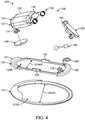
- Fig. 4shows an assembly drawing and a method of assembling output transducer assembly 100, in accordance with examples of the present disclosure.
- the resilient retention structure 110 as described hereincan be coupled to the support 120 as described herein, for example with bumpers 122 extending between the resilient retention structure 110 and the support 120.
- the resilient retention structure 110may define an aperture 110A having a width 110AW corresponding to the wide profile configuration.
- the support 120may define an aperture 120A having a width 120AW that remains substantially fixed when the resilient retention structure is compressed.
- the aperture 110A of the resilient retention structurecan be aligned with the aperture 120A of the support.
- the support 120can be affixed to resilient retention structure 110 in many ways, for example with one or more of ParyleneTM vapor deposition as described herein, or with an adhesive, or combinations thereof.
- the resilient retention structure 1 10may comprise the ParyleneTM layer 115, a fluorosilicone layer 115, an O-ring sized to the user, or a C-ring sized to the user, or combinations thereof.
- the support 120can be coupled to the photodetector 150 as described herein.
- the support 120may comprise mounts 128, and mount 128 can be coupled to couple arm 128 and bracket 152, such that the support is coupled to the photodetector 150.
- the transducer 130may comprise a housing 139 and a mount 138 attached to the housing, in which the mount 138 is shaped to receive the at least one spring 140.
- the transducer 130may comprise a reed 132 extending from the housing, in which the reed 132 is attached to a post 134.
- the post 134can be connected to the inner soft coupling structure 136.
- the support 120can be coupled to the transducer 130 with the at least one spring 140 extending between the coil and the transducer such that the inner soft coupling structure 136 is urged against the eardrum TM when the assembly 100 is placed to transmit sound to the user.
- the support 120may comprise mounts 126, for example welded tubes, and the mounts 126 can be coupled to a first end of the at least one spring 140, and a second end of the at least one spring 140 can be coupled to the transducer 130 such that the at least one spring 140 extends between the support and the transducer.
- the springhas a spring constant corresponding approximately to a mass and distance from the pivot axis of the coil spring to the inner soft coupling structure 136 such that the spring urges the inner soft coupling structure toward the eardrum TM within a range of force from about 0.5 mN to about 2.0 mN when the resilient retention structure 110 is placed against one or more of the eardrum, the eardrum annulus or the skin of the ear canal wall, for example skin of an anterior sulcus define with the ear canal wall.
- the coil springmay comprise a torsion spring, and the torsion spring constant can be within a range from range from 0.1e-5 to 2.0e-4 mN ⁇ m/rad, for example within a range from about 0.5e-5 N-m/rad to about 8e-5 N-m/rad. This range can provide sufficient force to the inner support so as to maintain coupling of the inner support to the eardrum when the head of the user is horizontal, for example supine, and when the head is upright, for example vertical.
- the resilient retention structure and the supportcan be configured in many ways so as a resistance to deflection within a range from about 1 N/m to about 10,000 N/m, for example within a range from about 250 N/m to about 10,000 N/m.
- the resistance to deflection within this rangecan provide sufficient stiffness to the retention structure 110 to support the transducer with the retention structure and so as to allow the retention structure to deflect inward when advanced into the ear canal so as to comprise the narrow profile configuration when the retention structure 110 slides along the ear canal, for example.
- the resistance to deflection of the retention structure 110 coupled to support 120is between the resistance to deflection of the ear canal and the resistance to deflection of the eardrum.
- the resistance to deflection within this rangeprovides sufficient support to displace the eardrum and enough flexibility to permit the retention structure 110 to transform from the wide profile configuration to the narrow profile configuration as described herein when advanced into the ear canal.
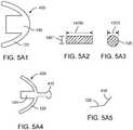
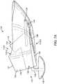
- Figs. 5A and 5Bshow top and bottom views, respectively, of an output transducer assembly 100 having a retention structure 1 10 comprising a stiff support 120 extending along a portion of the retention structure.
- the stiff support 120may comprise a pair of arms comprising a first arm 121, a second arm 123 opposite the first arm, and an intermediate portion 125 extending between the first arm and the second arm.
- the stiff support 110may comprise the resilient spring 140 coupled to the intermediate portion 125, for example.
- the resilient spring and stiff support 120comprise an integrated component such as an injection molded unitary component comprising a modulus of elasticity and dimensions so as to provide the resilient spring 140 and the stiff support 110.
- the stiff support 120 and resilient spring 140can be configured to couple the output transducer 130 to the eardrum TM when the retention structure is placed.
- the resilient spring 140can be attached to the stiff support 120, such that the resilient spring 140 directly engages the stiff support 120.
- the stiff support 120can be affixed to the resilient spring 140 so as to position the structure 136 below the retention structure 110, such that the structure 136 engages the tympanic membrane TM when the retention structure 110 is placed, for example on the eardrum annulus TMA.
- the resilient spring 140can be configured to provide an amount of force to the eardrum when placed.
- the stiff supportcan be configured in many ways so as to comprise the stiffness capable of deflection when placed and resistance to deflection to couple the output transducer 130 to the eardrum TM.
- the stiff support 120may comprise one or more of many materials such as polymer, cured epoxy, silicone elastomer having a suitable rigidity, biaxially-oriented polyethylene terephthalate (hereinafter "BoPET", commercially available under the trademark mylarTM), metal, Polyether ether ketone (hereinafter "PEEK”), thermoplastic, shape memory material, nitinol, thermoplastic PEEK, shape memory PEEK, thermoplastic polyimide, acetal, ParyleneTM, and combinations thereof, for example.
- the stiff support materialmay comprise a modulus, tensile strength and dimensions such as a cross-sectional diameter and length so as to provide the stiffness capable of deflection when placed and resistance to deflection to couple the output transducer.
- the resilient spring 140can be configured in many ways so as to comprise the resistance to deflection and force in response to displacement so as to couple the output transducer 130 to the eardrum TM.
- the resilient spring 140comprises a cantilever, in which the cantilever is fixed on a first end to the stiff support 120 and affixed to the output transducer 130 on an opposite end.
- the spring 140may comprise one or more of many materials such as polymer, cured epoxy, elastomers, MylarTM, metal, Polyether ether ketone (hereinafter "PEEK”), thermoplastic, shape memory material, nitinol, thermoplastic PEEK, shape memory PEEK, and combinations thereof, for example.
- the resilient spring materialmay comprise a modulus, tensile strength and dimensions such as a cross-sectional diameter and length so as to provide the stiffness capable of deflection when placed and resistance to deflection to couple the output transducer.
- the stiff support 120 and resilient spring 140may comprise similar materials, and may comprise substantially the same material in many examples, for example.
- the coupling structure 136may comprise one or more of many materials as described herein.
- the coupling structure 136may comprise a soft material such as an elastomer, for example.
- the coupling structure 136may comprise a stiff material, for example a layer of ParyleneTM film as described herein.
- the coupling structure 136may comprise layer 115 deposited on the positive mold, for example.
- the ParyleneTM layercan be cut as described herein so as to provide the coupling structure 136, for example.
- the coupling structuremay comprise a curable material, for example a UV curable epoxy.
- the assembly 100comprises a biasing structure 149 coupled to the stiff support 120 and the resilient spring 140 to position the structure 136 for engagement with the eardrum TM.
- the at least one spring 140may comprise a resilient cantilever beam, for example a spring having a size and thickness as described herein.
- the biasing structurecan be configured in many ways, and may comprise a shim or spacer, for example.
- the biasing structure 149can be placed between the stiff support 120 and resilient spring 140 so as to deflect the spring and position the structure 136 to engage the eardrum TM.
- the biasing structure 149can be placed on a lower surface of stiff support 120 and on an upper surface of resilient spring 140 so as to deflect the spring.
- the biasing structure coupled directly to the stiff support 120 and resilient spring 140can inhibit creep of the structure 1 36 relative to retention structure 110 so as to maintain coupling of the structure 136 to the eardrum when placed.
- the biasing structureis adjusted to deflect the resilient spring 140 prior to or subsequent to deposition of the layer 115, such that the layer 115 can lock the biasing structure in place.
- the photodetector 150can be attached to the output transducer 130 with a mount 153.
- the photodetector and output transducercan deflect together when the biasing structure 149, for example a spacer, is adjusted to couple the output transducer 130 and the structure 136 to the tympanic membrane TM.
- the componentsare assembled in the mold and coated with ParyleneTM.
- the photodetector 150can be placed in the mold and coated with one or more components of output transducer assembly 100.
- the layer 115 of film 250may comprise a translucent material that can be deposited on the light receiving surface of the photodetector 150. A substantial amount of light can be transmitted through the coating and received with the photodetector to provide the output signal to the user.
- ParyleneTMcomprises a light transmissive material such that the coating can be any desirable thickness so as to provide strength to assembly 100.
- the resilient spring 140can be coated with the layer 115, for example the layer ParyleneTM film 250 as described herein.
- Each of the components of the output transducer assembly 100can be coated with the layer 115 of ParyleneTM film, for example, so as to provide a protective coating and form the resilient retention structure 110.
- Fig. 5A1shows an integrated component 400 comprising the stiff support 120 and resilient spring 140.
- the integrated component 400can be formed in many ways.
- the integrated componentcan be formed by one or more of placing a flowable material in a mold, curing a flowable material, or an injection molding, and combinations thereof.
- the integrated component 400may comprise a modulus of elasticity and dimensions so as to provide the resilient spring 140 and the stiff support 110 based on the cross-sectional dimensions and length of the spring 140 and cross-sectional dimensions and length of stiff support 140.
- Figs. 5A2 and 5A3show cross-sectional views of the resilient spring 140 and the stiff support 120, respectively.
- the resilient spring 140may comprise a leaf spring having a thickness 140T and a width 140W, for example.
- the stiff support 120may comprise a cross-sectional dimension 120D, for example.
- the thickness 140Tmay be less than a cross-sectional dimension of the stiff support 120 and a width greater than the cross-sectional dimension of the stiff support.
- the leaf springmay have a thickness less than a cross-sectional diameter of the stiff support 120 and a width greater than the cross-sectional diameter of the stiff support.
- the stiff-supportmay have non-circular cross-sectional dimensions, such as oval, square, or rectangular, for example.
- Figs. 5A4 and 5A5show a top view and a side view, respectively, of a stiff support 120 comprising a graspable projection 410 that may be used to place the output transducer assembly in the ear canal.
- the projection 410can be affixed to the stiff support 120.
- the at least one spring 140may comprise a resilient spring having a width and thickness as described herein and can be affixed to the stiff support 120.
- the at least one spring 140may comprise a cantilever spring affixed to stiff support 120 on one end and supporting the transducer on the other end, for example.
- the projection 410may be detachable from the stiff support 120.
- the integrated component 400comprises the resilient spring 140, the stiff support 120, and the projection 410.
- the integrated component 400can be made in one or more of many ways as described herein, and may comprise substantially the same material for each of the stiff support 120, the resilient spring 140 and the projection 410.
- Fig. 5B1shows a lower surface structure 136 positioned a distance 149D beneath the lower surface of retention structure 110.
- the distance 149Dmay comprise a sufficient distance, for example about 1 mm such that structure 136 can engage the eardrum TM with movement of the eardrum, for example movement in response to pressure change. Changes in atmospheric pressure can result in displacements of the umbo of about 1 mm, for example.
- the amount of displacement for soundcan be about 1 um, for example.
- the resilient spring structure 140can be configured so as to deflect about 1 mm and provide a force to the eardrum TM, for example about 5 mN.
- the deflection of the coupling structure 136 at the umbocan be about 3 mm during placement of the device, and the at least one spring 140 can be configured to deflect at least about 3 mm, for example.
- Fig. 5B2shows a component of the output transducer assembly 100 retained between a first layer 115A and a second layer 115B.
- the layer 115may comprise the first layer 115A and the second layer 115B, for example. Any one or more of the components of the transducer assembly 100 can be placed on the first layer 115A, and the second layer 115B applied so as to affix the one or more components between the first layer 115A and the second layer 115B.
- the one or more componentscan be sandwiched between the first layer 115A and the second layer 115B so as to retain the one or more components between the first layer and the second layer, which each may comprise ParyleneTM.
- the stiff support 110can be retained between a first layer 115A and a second layer 115B of the retention structure 115B.
- the first layer 115A and the second layer 115Bmay increase the stiffness of the stiff support 120 when retained between layers, for example.
- the stiff support 120 and resilient retention structure 110can be resiliently deflected when inserted into the ear canal EC.
- the retention structure 110can be helpful, and in some instances necessary, for the retention structure to deflect from a wide profile configuration having a first width 110W1 to an elongate narrow profile configuration having a second width 110W2 when advanced along the ear canal EC as described herein.
- the stiff support 120can be configured to deflect inward to provide the narrow profile configuration, and configured with sufficient resilience so as to return to the wide profile configuration having the first width when placed.
- the stiff, deflectable support 120may also comprise sufficient stiffness so as to couple the output transducer 130 to the retention structure 110 so as to distribute force of the transducer substantially along the retention structure 110 and transmit force from the resilient spring 140 to locations away from resilient spring 140. This distribution of force to locations away from the resilient structure 140 sufficient surface area of retention structure 110 can allow the retention structure 110 to the couple the output transducer 130 to the eardrum with a surface tension of a coupling agent such as an oil, for example.
- a coupling agentsuch as an oil
- the first layer 115Amay be formed with film 250 as described herein.
- the componentscan be placed in the positive mold on the first layer 115A, which may comprise a translucent layer, for example a transparent layer, so as to allow placement within the positive mold transparent block 400 as described herein.
- the second layer 115Bcan be deposited on positive mold having the components placed on the first layer.
- Figs. 6A and 6Bshow side and top views, respectively, of a resilient retention structure comprising a stiff support extending along a portion of the resilient tubular retention structure.
- the stiff support 120may comprise a pair of arms comprising a first arm 121, a second arm 123 opposite the first arm, and an intermediate portion 125 extending between the first arm and the second arm.
- the retention structure 110comprises a curved portion, for example an arcuate portion 111, so as to engage the ear canal wall opposite the eardrum TM.
- the curved portionsuch as arcuate portion 111 can improve stability of the retention structure 110 in the ear canal, and provide improved coupling of the transducer 130 to the eardrum TM so as to decrease reliance on oil, for example.
- the curved portionsuch as arcuate portion 111 provides a structure opposite the tympanic membrane TM, and provides a second region on an opposite side of the ear canal to which the retention structure 110 and transducer 130 can couple.
- the retention structure and arcuate portion 111comprise the layer 115 of material comprising ParyleneTM film 250, such that the retention structure comprising arcuate portion 111 is shaped to the ear canal EC of the user as described herein.
- the resilient retention structure 110can engage one or more of the bony portion BP of the ear canal wall, the eardrum annulus TMA, the eardrum TM.
- the leading end opposite the stiff support 120can extend into the anterior sulcus when placed.
- the retention structure 110may comprise a substantially tubular portion of the film 250 deposited in the ear canal mold.
- the substantially tubular portionmay comprise a medial cut edge 110A1 and a lateral cut edge 110A2.
- the cut edge 110A1 and the cut edge 110A2may define ends of the substantially tubular cut portion of the film 250.
- the substantially tubular portionmay comprise an axis, and the cut edge 110A1 and the cut edge 110A2 can be cut oblique to the axis.
- Aperture 110Acan extend through the substantially tubular retention structure 110.
- Figs. 7A , 7B and 7Cshow side, top and front views, respectively, of an output transducer assembly 100 having a resilient retention structure 110 comprising curved portion such as an arcuate portion 111 and a stiff support 120 extending along a portion of the resilient retention structure.
- the retention structure 110comprises a curved portion such as an arcuate portion 111 to engage the ear canal wall opposite the eardrum TM similar to the arcuate structure of figures 6A and 6B .
- the portion extending into the anterior sulcusmay be cut away.
- the anterior sulcus AScan be difficult to view, and truncation of the medial end of the film 250 can shape the retention structure 110 such to inhibit placement of the retention structure 110 in the anterior sulcus AS.
- the curved portionsuch as arcuate portion 111 can provide substantially coupling of the transducer to the bony portion BP of the ear canal EC wall opposite the eardrum TM.
- the stiff support 120may provide provides sufficient stiffness so as to pivotally couple transducer 130 to the canal wall with the curved portion such as arcuate portion 111.
- the retention structure 110can be molded as described herein so as to comprise a thin layer 115 of material corresponding tubular portion of the ear canal.
- An aperture 110Acan extend through the tubular portion.
- the aperture 110Acan be defined with a first cut profile 110A1 and the second cut profile 110A2 of the tubular section of ParylenelTM.
- the resilient retention structure 110may comprise enough stiffness so as to couple the arcuate portion to the ear canal wall opposite tympanic membrane TM to the transducer 130.
- FIG. 6A to 7Cshow examples of retention structures, and the retention structure 110 may comprise a shape intermediate to Figures 6A-6B and Figures 7A-7C , for example.
- the layer 115comprises a tubular structure, and the shape of retention structure 110 depends upon the first cut profile 110A and the second cut profile 110B, for example.
- Fig. 8Ashows components of an output transducer assembly 100 placed in a transparent block 800 of material comprising the positive mold 225 of the ear canal and eardrum of the patient.
- the transparent block 800may comprise the cured coating 215, the flat machined surface 227 and the release agent 231.
- the components placed in the transparent block 800 comprising the transparent mold 225 of the ear canal and eardrummay comprise one or more of the transducer 130, the photodetector 150, the at least one spring 140, or the support 120, and combinations thereof.
- the transparent block 800permits the components placed in the block 800 to be viewed by an eye 810 of an assembler 810.
- the assemblermay be a person or a machine such as a robotic arm.
- the ParyleneTMcan be deposited before, or after the components have been placed, or both before and after the components have been placed so as to sandwich the components between layers of ParyleneTM film 250.
- the photodetectorcan be placed in the mold 225 such that ParyleneTM is coated on the detector and light transmitted through the ParyleneTM when the output transducer assembly 100 is placed in the ear and used.
- the sealing of the componentscan provide reliability and optical transmission through the protective coating.
- Fig. 8Bshows a transducer 130 configured to receive a layer of a coating deposited with a vapor as described herein.
- Fig. 8Cshows the transducer of Figure 8B with a deposited layer.
- the transducer 130may comprise an opening 131 formed in the casing 137 of the output transducer 130.
- the reed 132can extend through the opening 131 to couple to the post as described herein.
- the deposited layer 115may comprise the second layer 115B, for example when the components are placed on first layer 115A.
- the vaporcan pass through the opening 131 to form layer 115 on the reed.
- the opening 131can be sized so as to decrease the thickness of the layer 115B deposited on the reed 132. Work in relation to examples as described herein indicate that layer 115 can affect tuning of the reed 132. By sizing the opening 131 to decrease the thickness of the layer 115, the output transducer 130 can be used with the coating 115B, for example.
- the opening 131is sized to inhibit passage of a liquid, for example water or oil, through the opening 131.
- the opening 131can be sized based on the contact angle of the liquid, so as to inhibit passage. For layer 115 providing a steep contact angle, the opening 131 can be larger than for a layer 115 providing small contact angle.
- Fig. 8Dshows the output transducer 130 of Figure 8B with a blocking material 133 to inhibit formation of the deposited layer on the reed 132 of the transducer.
- the blocking materialmay comprise the backing material as described herein, for example PEG, such that the ParyleneTM deposited on the blocking material can be cut away.
- Fig. 8Eshows the transducer of Figure 8B with a blocking material 133 placed over a bellows 139 to inhibit formation of the deposited layer on the bellows 139 of the transducer.
- the deposited layer 115can decrease movement of the bellows, and the structure comprising blocking material 133 can be placed over the bellows to inhibit deposition of the material on the bellows.
- the structure comprising blocking material 133can be placed before the output transducer 130 is placed in the transparent block 800, for example.
- the layer 115 deposited on the structure comprising blocking material 133can be cut away, so as to expose the bellows, for example.
- a coupling agentsuch as oil can be used to couple the output transducer assembly 100 to the eardrum TM and wall of the ear canal EC.
- oilcan be helpful to maintain coupling, accumulation of excessive oil can decrease performance.
- the inhibition of oil accumulation on vibratory componentscan substantially decrease autophony when the output transducer 130 is coupled to the eardrum TM with coupling structure 136, as microactuator of the output transducer 130 can be configured to allow the eardrum move in response to the user's self-generated sounds so as to decrease autophony.
- the formation of a puddle of oil under or over the microactuatorcan inhibit movement of the microactuator and contribute to autophony, and the oleophobic coating can be configured to inhibit formation of the puddle of oil so as to inhibit the autophony.
- An oleophobic coatingcan be provided on one or more locations to decrease accumulation of oil.
- the accumulation of oilmay comprise a wetting of oil on the surfaces, and the wetting can be related to a contact angle of oil with the surface.
- the oleophobic coatingcan be provided on one or more of the microactuator, the resilient spring 140, the stiff support 120, the retention structure 110, one or more surfaces of the retention structure 1 10, or one or more surfaces of output transducer 130, and combinations thereof, so as to inhibit accumulation of oil.
- the oleophobic coatingmay comprise one or more known coatings, and can be provided over the layer 115, for example.
- the layer 115Bmay comprise an oleophobic coating.
- the oleophobic coatingcan be provided over the second layer 115B.
- Fig. 8Fshows an oleophobic layer 135 deposited on the output transducer 130.
- the oleophobic layer 135can inhibit accumulation of oil on the housing.
- the oleophobic layercan be located on one or more of many surfaces of the output transducer assembly 100.
- the bellows 139may comprise the oleophobic layer as described herein, so as to inhibit accumulation of oil on or near the bellows, for example.
- Fig. 9Ashows a retention structure 110 comprising curved portion such as an arcuate portion 111 shaped to extend along a surface of the bony portion of the ear canal opposite the eardrum TM when placed.
- the retention structure 110may comprise a stiff support 120, as described herein, in combination with layer 115 so as to stiffen the retention structure 110, for example.
- the stiff support 120may comprise a pair of arms comprising a first arm 121, a second arm 123 opposite the first arm, and an intermediate portion 125 extending between the first arm and the second arm.
- the arcuate portion 111may comprise the stiff support in combination with the layer 115.
- the arcuate portion 111can be coupled to transducer 130 with at least one structure 199 extending between the coupling structure 136 and the arcuate portion 111 so as to couple the arcuate portion 111 to the eardrum TM with transducer located in between.
- the coupling of the arcuate portion 111 to the transducer and to the eardrumcan provide the opposing surfaces of the eardrum and the arcuate portion 111 for the transducer to push against.
- the at least one structure 199may comprise the biasing structure 149 and at least one spring 140, for example, in which the distance 149D between the lower surface of coupling structure 136 and the lower surface of retention structure 110 can be adjusted prior to placement in an unloaded configuration as described herein.
- the at least one structure 199 comprising the biasing structure 149 and at least one springcan support the transducer 130 and the coupling structure 136 in the unloaded free standing configuration as described herein.
- the at least one structure 199may comprise one or more of many structures a described herein to couple the transducer 130 and the coupling structure 136 to the eardrum TM, and may comprise one or more of a biasing structure, a biasing mechanism, a spring, a coil spring, a telescopic spring, a leaf spring, a telescopic joint, a locking telescopic joint, or a transducer.
- Fig. 9Bshows a dynamic biasing system 600 coupled to the arcuate portion 111 and the coupling structure 136.
- the at least one structure 199may comprise the at least one spring 140 and the dynamic biasing system 600.
- the dynamic biasing system 600can be configured to engage the eardrum TM with coupling structure 136 when transducer 130 vibrates and configured to disengage the coupling structure 136 from the eardrum TM when transducer 130 comprises a non-vibrating configuration, for example when no substantial signal energy is transmitted to the output transducer assembly 100.
- the transducer 610 of biasing system 600as described herein and may comprise rectification or other circuitry, so as to urge the output transducer 130 toward the eardrum so as to couple the output transducer to the eardrum in response to a signal transmitted to transducer 130.
- the transducer 610 of the dynamic biasing system 600may comprise one or more transducers as described herein, for example one or more of a microactuator, a photostrictive transducer, a piezoelectric transducer, an electromagnetic transducer, a solenoid, a coil and magnet, or artificial muscle, for example.
- the transducer 610can be coupled to the photovoltaic with wires and rectification circuitry to dynamically bias the transducer 610 in response to light energy received by the photodetector 150.
- the photostrictive materialcan receive electromagnetic light energy directed toward the photodetector and bias the transducer 130 in response to the light energy signal directed toward the photodetector 150 and received by the photostrictive material.
- the arcuate portionprovides a support for the transducer to be lifted away from the eardrum TM when the transducer 130 is not active, for example, and a support for the transducer to engage and couple to the eardrum when the transducer 130 is active, for example.
- the decoupling and couplingcan decrease user perceived occlusion when the transducer 130 is not in use.
- the at least one structure 199 coupled to the curved portion 111can be combined with pivoting of the transducer 130 in relation to the stiff support 120 as described herein.
- the at least one structure 199can urge the transducer 130 toward the eardrum to couple to the eardrum, and the transducer 130 can be resiliently coupled to the support 120 with the at least one spring 140, for example a cantilever as described herein.
- the transducer 130may comprise one or more transducers as described herein, such as one or more of a microactuator, a photostrictive transducer, a piezoelectric transducer, artificial muscle, an electromagnetic transducer, a balanced armature transducer, a rod and coil transducer, a bimorph transducer, a bender, a bimorph bender, or a piezoelectric diaphragm, for example.
- a microactuatorsuch as one or more of a microactuator, a photostrictive transducer, a piezoelectric transducer, artificial muscle, an electromagnetic transducer, a balanced armature transducer, a rod and coil transducer, a bimorph transducer, a bender, a bimorph bender, or a piezoelectric diaphragm, for example.
- the at least one structure 199may comprise one or more of many structures configured to couple the transducer to the eardrum and the arcuate portion 111.
- the at least one structure 199may comprise a spring or an elastic material or a combination thereof.
- the springmay comprise a leaf spring or a coil spring.
- the at least one structure 199may comprise an elastic material, such as silicone elastomer configured to stretch and push the transducer toward the eardrum when the support is positioned on the eardrum.
- the at least one structuremay comprise a viscoelastic material.
- the post 134may comprise the at least one structure 199.
- the at least one structure 199may comprise one or more of the tuning structures, for example.
- the at least one structuremay comprise a hydraulic telescoping mechanism, for example, so as to decouple the transducer from the eardrum at low frequencies and couple the eardrum the to transducer at high frequencies.
- Additional structures suitable for use with at least one structure 199 in accordance with examplesare described in U.S. Pat. App. No. 61,217,801, filed June 3, 2009 , entitled “Balanced Armature Device and Methods for Hearing”; and PCT/US2009/057719, filed 21 September 2009 , entitled “Balanced Armature Device and Methods for Hearing", published as WO 2010/033933 .
- the transducer 130may pivot about a pivot axis to couple to the eardrum as described herein.
- Fig. 1 OAshows machining such as laser sculpting 500 of a negative mold to provide a deflection of the epithelium contacting surface of the retention structure to receive migrating epithelium.
- the laser sculptingmay comprise ablation, for example.
- a laser system 530may comprise a laser to provide a source of laser energy, and a laser delivery system comprising scanning optics, for example.
- a leaser beam 510can be directed to the negative mold 210 to remove material from the negative mold, such that the positive mold comprises the deflection.
- the laser beamcan be directed in a scan patter 520 so as to ablate a predetermined profile 540 in the surface of the negative mold.
- Fig. 10Bshows one or more deflections 550 of the epithelium contacting surface of the retention structure to receive migrating epithelium.
- the one or more deflections 550can be shaped with a curved edge such that epithelium advancing toward the edge passes under the edge.
- the retention structure 110may comprise an annular retention structure having an inner edge oriented toward the umbo and an outer edge oriented toward the canal wall.
- the inner edgemay comprise the one or more deflections 550 to receive the migrating epithelium.
- Fig. 10Cshows a epithelium 560 migrating under the one or more deflections 550 of Fig. 10B .
- the retention structuremay comprise an annular structure having an aperture positionable over the umbo.
- the epitheliumcan migrate in a direction 570 outward from the umbo along the surface of the eardrum toward the eardrum annulus and canal wall.
- the epitheliumcan migrate from the eardrum annulus to the canal wall, and subsequently in a direction 570 along the canal wall toward the opening to the ear canal.
- the deflection 550may comprise a portion of the retention structure having a thickness similar to a majority of the retention structure.
- the thickness of the retention structure 110is within a range from about 5 to about 50 um, such that the thickness of the retention structure is approximates to the thickness of the epithelium.
- the epithelium on the umbocan be about 15 um thick, for example, and can be thicker on the ear canal, for example about 50 to 100 um thick.
- the one or more deflections 550can provide sufficient clearance to pass the epithelium under the edge of the deflection 550.
- the amount of deflectionmay comprise a distance 580 corresponding to the profile of material removed from the negative mold, for example the ablation profile.
- the distance 580can be proportional to the thickness of the epithelium at the location of placement, and the distance 580 can be at least as thick as the epithelium.
- the distance 580can be at least about 15 um, for example at least about 50 um, and in many examples 100 um or more.
- a similar deflectioncan be provided by depositing material on the positive mold, for example as an alternative to removal of material
- Fig. 11shows a dynamic biasing system 600 comprising a transducer 620 configured to deflect the output transducer 130 toward the eardrum so as to couple the output transducer to the eardrum.
- the dynamic biasing system 600 comprising the transducer 620can move one or more of the transducer 130, the arm 134 or the structure 136, or combinations thereof, toward the eardrum with a movement 610.
- the at least one spring 140can be coupled to the dynamic biasing system to allow movement of the coupling structure 136.
- the biasing structure 149 of the at least one springcan be coupled to the at least one spring 140 as described herein.
- the dynamic biasing system 600 comprising the transducer 620may comprise one or more of many known transducers, such as one or more of a piezoelectric transducer, a coil and magnet transducer, a photostrictive material, artificial muscle, or combinations thereof.
- the transducer 620can be configured to couple the transducer to the eardrum when the transducer 130 transmits sound to the user.
- the dynamic biasing system 600 comprising the transducer 620is configured to couple to the eardrum in response to the signal transmitted to transducer 130.
- dynamic biasing system 600 comprising the transducer 620may comprise rectification circuitry to provide a voltage to the transducer in response to an AC signal to transducer 130.
- the transducer 620may comprise photostrictive material configured to provide movement 610 when a light beam is transmitted to photodetector 150 and a portion of the light beam is absorbed by the photostrictive material.
- the transducer 620may comprise artificial muscle, commercially available from Artificial Muscle, Inc., of Sunnyvale, CA.
- Fig. 12shows a retention structure 110 comprising layer 115 configured for placement in the middle ear supporting an acoustic hearing aid 700.
- the retention structure 110 comprising layer 115can be manufactured as described herein and configured for placement in deep in the ear canal, so as to couple to the bony portion BP of the ear canal.
- the retention structure 110may comprise a molded tubular structure having the shape of the ear canal, and can be manufactured from cut sections as described herein.
- the retention structure 110comprises one or more deflections 550 as described herein.
- the retention structure 110may comprise a thickness within a range from about 1 um to about 100 um as described herein, for example within a range from about 5 um to about 50 um.
- the thickness of the ParyleneTM retention structure within this rangecan be sufficiently resilient so as to support the retention structure 110 and to deflect when inserted or the patient chews, for example.
- the epithelium covering the bony portion of the ear canalmay comprise a thickness within a range from about 50 um to about 100 um
- the retention structure 110may comprise a thickness less than the thickness of the epithelium.
- the one or more deflections 550can be oriented toward the eardrum of retention structure 110 and shaped so as to receive epithelium migrating outward toward the ear canal opening.
- the one or more deflectionsdeflect away from the epithelium toward the source of epithelium so as to inhibit epithelial growth over an edge of the retention structure 550.
- the eardrumis located medially M to the retention structure 110 and the ear canal opening is located laterally L to the retention structure 110.
- the lateral side 110may comprise deflections similar to the one or more deflections 550 to facilitate removal of the retention structure 110.
- the retention structure 110can be configured in one or more ways as described herein so as to retain the hearing aid 700 in the ear canal.
- the retention structure 110can be place in the ear canal without lubrication and can remain in the ear canal without application of a coupling agent such as an oil.
- the usercan apply oil 750 to the ear canal, and the oil 750 can pass between the retention structure 110 and the ear canal EC.
- the presence of oil between the skin SK and the retention structure 110can couple the retention structure to the skin SK, and can reduce adhesion of the skin to the retention structure 110.
- the oilcan facilitate removal and can decrease adhesion of the skin SK to the retention structure, such that the retention structure 110 can be removed from the ear canal without tearing of the skin SK, for example.
- the retention structurecan remain placed in the ear canal EC for one or more months, for example about three or more months.
- the acoustic hearing aid 700may comprise one or more of many components to decrease occlusion and feedback, for example.
- the hearing aid 700may comprise a microphone 710 on the temporal side T of the device, such that the microphone 710 can be positioned deep in the ear canal to provide sound localization.
- the hearing aid 700may comprise and acoustic speaker 720 to vibrate the eardrum TM.
- the hearing aid 700can decrease sound transmission from the acoustic speaker 720 to the microphone 710 in one or more of many ways.
- the molded fit of the retention structure 110 to the ear canalcan inhibit the formation of sound conduction pathways such as gaps that can transmit sound from the acoustic speaker to the microphone.
- the hearing aid 700can be configured further to inhibit sound transmission from the acoustic speaker to the microphone, for example by substantially inhibiting air flow from the medial side M to the lateral side L with a casing 730 and a support material 740 to couple the retention structure 110 to the casing 730.
- the casing 730may comprise a rigid material
- support material 740may comprise one or more of a compressible or an elastic material, such as a foam or elastomer or a combination thereof.
- the deep placement on the bony portion BPcan inhibit user perceived occlusion when the hearing aid 700 occludes the ear canal and blocks sound transmission from the medial side M to the lateral side L.
- the acoustic hearing aid 700may comprise one or more components of a commercially available hearing aid, such as the LyricTM, commercially available from InSound Medical, Inc. (website www.lyrichearing.com ), or a similar known hearing aid commercially available from Starkey, for example.
- the LyricTM hearing aidcan be combined with the retention structure 110 in accordance with examples as described herein.
- the hearing aid 700can be placed deep into the bony portion of the ear canal so that the receiver resides approximately 4 mm from the eardrum, and the microphone can be 4 mm or more from the opening of the ear canal. This placement deep in the ear canal provides a number of sound quality benefits.
- the retention structure 110 comprising layer 115can be well suited to fit many complex ear anatomies, including ear canals that are one or more of narrow, or short as compared to a population of patient and combinations thereof. Additional anatomies the retention structure 110 comprising layer 110 is well suited to fit include a significant step-up in the canal floor, extreme v-shaped canal, or a large bulge in the canal, and combinations thereof. These complex ear anatomies can be fit comfortably so as to decrease the chance of discomfort to the user.
- the retention structure 115 comprising layer 1 10can provide a lateral seal of the ear canal so as to inhibit feedback and decrease occlusion.
- the placement deep in the ear canalcan provide improved directionality and localization (ability to tell where sounds are coming from).
- the hearing aid 700 placement deep in the ear canalcan allows the pinna (outer part of the ear) to interact naturally with incoming sounds.
- the acoustic transformations produced by the pinna as sound enters the ear canalcontribute to the ability to accurately determine where sounds are coming from in the environment, similar to assembly 100.
- the hearing aid 700can provide decreased user perceived occlusion and decreased feedback. As the receiver sits closer to the eardrum than with traditional hearing aids, less output can be used to accommodate hearing loss, which can decrease feedback.
- the hearing aid 700can reside substantially in the hard-walled bony portion BP of the ear canal, so as to decrease movement of the device.
- the retention structure 110can be molded, the fit between the ear canal and the device can inhibit sound transmission between the retention structure 110 and the ear canal so to inhibit feedback.
- the placement deep in the ear canalcan allow the hearing aid 700 to be configured so as to inhibit sound transmission from the receiver end toward the microphone, similar to the LyricTM.
- the hearing aid 700can be retained anchored in the ear canal so as to inhibit slippage and also in a manner that fits irregular shapes and contours of various ear canals, as the retention structure 110 can be molded.
- the retention structure 110comprises a resilient structure capable of changing shape, the fit to the ear canal can be maintained when the ear changes shape during chewing and talking. This can prevent slippage of the hearing aid 110 and inhibit sound leakage and feedback.
- Deep canal fitting of hearing aid 700can result in an increase in sound pressure level at the eardrum as compared with a conventional hearing aid. This increase can be up to 15dB in the high frequencies, and can caused by a combination of reduced residual ear canal volume between the receiver and the eardrum and the microphone location deeper in the ear canal allowing for pinna effects.
- Security of fit and retention of the molded retention structure 110can provide improved patient comfort with hearing aid 700.
- the retention structurecomprises a ParyleneTM coating having a thickness of about 20 um.
- the retention structure having this thicknesscan deform when advanced along the ear canal of the user and can expand to the wide profile configuration comprising the shape of the ear canal based on the vapor deposition to the positive mold as described herein.
- the resistance to deflectioncan be determined with concentrated loads on opposite sides of the retention structure similar to the inward deflection provided by ear canal, for example.
- the resistance to deflectioncan be determined based on material properties and dimensions of the retention structure 110 as described herein.
- Non-limiting examples of numerical calculations to determine the approximate resistance to deflectioninclude calculations for the following two examples:
- the retention structure 110comprises a flat ribbon 2mm high and 18um thick.
- the radiusis 5mm and the elastic modulus is about 1 GPa.
- the resistance to deflection of the stiff retention structureis about 5 N/m. In many examples, a lower resistance to deflection can be used, for example about 1 N/m,
- the retention structurecomprises a c channel 2mm high (with a radius of 1mm) and 18um thick.
- the overall radiusis 5mm and the elastic modulus is about I GPa.
- the resistance to deflection of the stiff retention structureis about 27,000 N/m.
- local areas of the retention structuremay absorb a substantial majority of the deflection, such that a resistance to deflection of about 10,000 N/m may be appropriate.
- the resistance to deflectioncan be within a range from about 1 N/m to about 10,000 N/m, for example.
- the eardrumcomprises a resistance to deflection of about 250 N/mm. In some examples, it can be helpful to provide the retention structure with a resistance to deflection within a range from about 250 N/m to about 10,000 N/m, for example.
Landscapes
- Health & Medical Sciences (AREA)
- General Health & Medical Sciences (AREA)
- Otolaryngology (AREA)
- Engineering & Computer Science (AREA)
- Neurosurgery (AREA)
- Physics & Mathematics (AREA)
- Acoustics & Sound (AREA)
- Signal Processing (AREA)
- Manufacturing & Machinery (AREA)
- Prostheses (AREA)
- Headphones And Earphones (AREA)
Description
- 1.Field of the Invention. The present invention is related to systems, devices and methods that couple to tissue such as hearing systems. Although specific reference is made to hearing aid systems, examples of the present disclosure can be used in many applications in which a signal is used to stimulate the ear.
- People like to hear. Hearing allows people to listen to and understand others. Natural hearing can include spatial cues that allow a user to hear a speaker, even when background noise is present. People also like to communicate with those who are far away, such as with cellular phones.
- Hearing devices can be used with communication systems to help the hearing impaired and to help people communicate with others who are far away. Hearing impaired subjects may need hearing aids to verbally communicate with those around them. Unfortunately, the prior hearing devices can provide less than ideal performance in at least some respects, such that users of prior hearing devices remain less than completely satisfied in at least some instances.
- Examples of deficiencies of prior hearing devices include feedback, distorted sound quality, less than desirable sound localization, discomfort and autophony. Feedback can occur when a microphone picks up amplified sound and generates a whistling sound. Autophony includes the unusually loud hearing of a person's own self-generated sounds such as voice, breathing or other internally generated sound. Possible causes of autophony include occlusion of the ear canal, which may be caused by an object blocking the ear canal and reflecting sound vibration back toward the eardrum, such as an unvented hearing aid or a plug of earwax reflecting sound back toward the eardrum.
- Although acoustic hearing aids can increase the volume of sound to a user, acoustic hearing aids provide sound quality that can be less than ideal and may not provide adequate speech recognition for the hearing impaired in at least some instances. Acoustic hearing aids can rely on sound pressure to transmit sound from a speaker within the hearing aid to the eardrum of the user. However, the sound quality can be less than ideal and the sound pressure can cause feedback to a microphone placed near the ear canal opening. Although placement of an acoustic hearing aid along the bony portion of the ear canal may decrease autophony and feedback, the fitting of such deep canal acoustic devices can be less than ideal such that many people are not able to use the devices. In at least some instances sound leakage around the device may result in feedback. The ear canal may comprise a complex anatomy and the prior deep canal acoustic devices may be less than ideally suited for the ear canals of at least some patients. Also, the amount of time a hearing device can remain inserted in the bony portion of the ear canal can be less than ideal, and in at least some instances skin of the ear canal may adhere to the hearing device such that removal and comfort may be less than ideal.
- Although it has been proposed to couple a transducer to the eardrum to stimulate the eardrum with direct mechanical coupling, the clinical implementation of the prior direct mechanical coupling devices has been less than ideal in at least some instances. Coupling the transducer to the eardrum can provide amplified sound with decreased feedback, such that in at least some instances a microphone can be placed in or near the ear canal to provide hearing with spatial information cues. However, the eardrum is a delicate tissue structure, and in at least some instances the placement and coupling of the direct mechanical coupling devices can be less than ideal. For example, in many patients the deepest portion of the ear canal comprises the anterior sulcus, and a device extending to the anterior sulcus can be difficult for a clinician to view in at least some instances. Further, at least some prior direct coupling devices have inhibited viewing of the eardrum and the portion of the device near the eardrum, which may result in less than ideal placement and coupling of the transducer to the eardrum. Also, direct coupling may result in autophony in at least some instances. The eardrum can move substantially in response to atmospheric pressure changes, for example about one millimeter, and at least some of the prior direct coupling devices may not be well suited to accommodate significant movement of the eardrum in at least some instances. Also, the naturally occurring movement of the user such as chewing and eardrum movement may decouple at least some of the prior hearing devices. Although prior devices have been provided with a support to couple a magnet to the eardrum, the success of such coupling devices can vary among patients and the results can be less than ideal in at least some instances.
- Although the above described prior systems can help people hear better, many people continue to have less than ideal hearing with such devices and it would be beneficial to provide improved coupling of the transducer assembly to the eardrum and ear canal. Also, it would be helpful to provide improved coupling in simplified manner such that the assemblies can be manufactured reliably for many users such that many people can enjoy the benefits of better hearing.
- For the above reasons, it would be desirable to provide hearing systems and improved manufacturing which at least decrease, or even avoid, at least some of the above mentioned limitations of the prior hearing devices. For example, there is a need to provide improved manufacturing of reliable, comfortable hearing devices which provide hearing with natural sound qualities, for example with spatial information cues, and which decrease autophony, distortion and feedback.
- Patents and publications that may be relevant to the present application include:
3,585,416 3,764,748 3,882,285 5,142,186 5,554,096 5,624,376 5,795,287 5,800,336 5,825,122 5,857,958 5,859,916 5,888,187 5,897,486 5,913,815 5,949,895 6,005,955 6,068,590 6,093,144 6,139,488 6,174,278 6,190,305 6,208,445 6,217,508 6,222,302 6,241,767 6,422,991 6,475,134 6,519,376 6,620,110 6,626,822 6,676,592 6,728,024 6,735,318 6,900,926 6,920,340 7,072,475 7,095,981 7,239,069 7,289,639 D512,979 2002/0086715 2003/0142841 2004/0234092 2005/0020873 2006/0107744 2006/0233398 2006/075175 ;2007/0083078 2007/0191673 2008/0021518 2008/0107292 5,259,032 5,276,910 5, 425, 104 5,804,109 6,084,975 6,554,761 6,629,922 U.S. Publication Nos. 2006/0023908 ;2006/0189841 ;2006/0251278 ; and2007/0100197 . Non-U.S. patents and publications that may be relevant includeEP1845919 PCT Publication Nos. WO 03/063542 WO 2006/075175 US4628907 describes a direct contact hearing aid apparatus adapted to be mounted deep within the ear canal including an electromechanical transducer for converting audio output signals into mechanical movement of an output coupling element without the production of discernible sound waves to prevent acoustic feedback.US2002/0085728 describes a disposable hearing device adapted to be positioned entirely within an ear canal for extended wear.US6137889 describes a device to be worn in the ear of a subject that provides a direct vibrational drive to the tympanic membrane through a vibrationally conductive assembly.US2009/0092271 describes a hearing aid device for placement in an ear of a user including an elongate support and a transducer.- The present invention relates to a hearing apparatus as defined in claim 1.
- Particular embodiments according to the invention are defined in the dependent claims.
- Vapor deposition and polymerization can be used to manufacture a component of a hearing system used to transmit sound to a user.
- The output transducer assembly may comprise a support having stiffness greater than a stiffness of the resilient retention structure, and the stiff support may comprise one or more of arms, a rigid frame, or a chassis. The support stiffness greater than the retention structure can maintain alignment of the components coupled to the support, such that appropriate amounts of force can be used to urge a coupling structure against the eardrum so as to couple the transducer to the eardrum with decreased autophony. The stiff support can be coupled to at least one spring so as to provide appropriate amounts of force to the eardrum with the coupling structure and to inhibit deformation of the device when placed in the loaded configuration for the extended time. The deflectable retention structure may provide a narrow profile configuration when advanced into the ear canal and a wide profile configuration when placed in the ear canal, and the stiff support can be used to deflect and advance the retention structure along the ear canal. A photodetector and an output transducer can be coupled to the support, such that the transducer assembly can be mechanically secure and stable when placed within the anatomy of the ear canal of the user. The support can have an elastomeric bumper structure placed thereon so as to protect the eardrum and skin when the support and retention structure are coupled to the eardrum and skin. Alternatively, the stiff support can be placed on the layer of vapor deposited polymer and affixed to the layer, such that the vapor deposited layer contacts the eardrum or skin. A second layer can be deposited on the first layer when the first layer has been placed on the first layer to situate the stiff support structure between the layers. The stiff support may comprise a part comprising arms, an intermediate portion extending between the arms, and at least one spring, such that the stiff support part can be placed an affixed to the retention structure.
- The output transducer assembly may comprise a biasing structure coupled to the support to adjust a position of a coupling structure that engages the eardrum. The at least one spring can be coupled to the support and the transducer, so as to support the transducer and the coupling structure in an unloaded configuration. The biasing structure can be configured to adjust the unloaded position of the coupling structure prior to placement. The at least one spring can be coupled to the coupling structure such that the coupling structure can move about one millimeter from the unloaded position in response to the eardrum loading the coupling structure. The spring can be configured to provide an appropriate force to the coupling structure engage the eardrum and to inhibit occlusion when the coupling structure comprises either the unloaded configuration or the configuration with displacement in response to eardrum movement of about one millimeter. Alternatively or in combination, the biasing structure may comprise a dynamic biasing structure having a biasing transducer coupled to the at least one spring to urge the coupling structure into engagement with the eardrum in response to a signal to the output transducer.
- A vapor deposition and polymerization process can be used to provide a strong and secure connection extending between the support and the resilient retention structure. The vapor deposition process may comprise a poly(p-xylylene) polymer deposition process and the resilient retention structure may comprise a layer of vapor deposited poly(p-xylylene) polymer adhered to the support. The vapor-deposited Poly(p-xylylene) polymer may also adhere to the elastomeric bumper structure material such as a silicone material. The vapor deposition of the layer of material to form the retention structure can provide a uniform accurate shape profile in a semi-automated manner that can increase reproducibility and accuracy with decreased labor so as to improve coupling and hearing for many people.
- The vapor deposition process can be used to manufacture the output transducer assembly with a positive mold of the ear canal of the user. The positive mold may comprise an optically transmissive material, and a release agent may coat an inner surface of the positive mold. The release agent may comprise a hydrophilic material such that the coating can be removed from the mold with water. The layer can be formed with vapor deposition within the positive mold. The components can be placed on the layer. The positive mold may comprise a transparent material, such that the placement of the components within the positive mold can be visualized. A second layer can be vapor deposited over the first layer to affix the components to the first layer and the second layer.
- The retention structure may comprise a deflection to receive epithelium. The retention structure may comprise a surface to contact a surface of an epithelial tissue. The epithelial tissue may migrate under the retention structure when placed for an extended time. The deflection of the retention structure surface can be located near an edge of the retention structure and extend away from the surface of the tissue so as to inhibit accumulation of epithelial tissue near the edge of the retention structure. The deflected edge can be oriented toward a source of epithelium such as the umbo when the retention structure is placed in the ear canal.
- The output transducer assembly may comprise an oleophobic coating to inhibit autophony and accumulation of oil on components of the assembly.
- The retention structure can be configured in many ways to permit viewing of the retention structure and the eardrum. The retention structure may comprise a transparent material, which can allow a clinician to evaluate coupling of the retention structure to the tissue of the ear canal. In many embodiments, the ear canal comprises an opening, which allows a clinician to view at least a portion of the eardrum and evaluate placement of the output transducer assembly. In many embodiments, the retention structure is dimensioned and shaped to avoid extending into the anterior sulcus to improve visibility when placed, and the retention structure may extend substantially around an outer portion of the eardrum such as the eardrum annulus so as to define an aperture through which the eardrum can be viewed. Alternatively, the retention structure may extend around no more than a portion of the annulus. In many examples, he retention structure extends to a viewable location an opposite side of the ear canal, so as to limit the depth of placement in the ear canal and facilitate the clinician viewing of the retention structure. The visibility of the retention structure can be increased substantially when the retention structure extends around no more than a portion of the annulus and also extends to a portion of the ear canal opposite the eardrum. The wall opposite the eardrum can support the transducer with the portion opposite the annulus so as to improve coupling. The portions of the retention structure extending to the canal wall opposite the eardrum and around no more than a portion of the annulus can be easily viewed and may define a viewing aperture through which the eardrum can be viewed.
- Examples of the disclosure provide an apparatus for placement with a user, the apparatus comprises a transducer and a retention structure. The retention structure comprises a layer of polymer having a shape profile corresponding to a tissue of the user to couple the transducer to the user.
- In many examples, the retention structure comprises a curved portion having an inner surface toward an eardrum when placed, and the curved portion couples to an ear canal wall oriented toward the eardrum when placed to couple a transducer to the eardrum. The curved portion may couple to the ear canal on a first side of the ear canal opposite the eardrum, and a second portion of the retention structure may couple to a second side of the ear canal opposite the first side to hold the retention structure in the ear canal. The curved portion and the second portion can be connected so as to define an aperture extending therebetween to view at least a portion of the eardrum when the curved portion couples to the first side of the ear canal and the second portion couples to the second side.
- In many examples, the support comprises a first layer of a polymerizable material and a second layer of a polymerizable material and wherein components of a hearing device are situated between the first layer and the second layer.
- In many examples, an oleophobic layer is coated on one or more of the first transducer or the retention structure.
- In many examples, the tissue comprises an eardrum having a first resistance to deflection and a bony portion of the ear canal having a second resistance to deflection greater than the first resistance, and the layer comprises a resistance to deflection greater than the eardrum and less than the bony portion of the ear canal.
- In many examples, the layer comprises a material having a thickness to resist deflection away from the shape profile and wherein the layer comprises the shape profile in an unloaded configuration.
- In many examples, the transducer couples to a tissue structure having a resistance to deflection, and the layer comprises a resistance to deflection greater than the tissue structure.
- In many examples, the layer comprises a thickness within a range from about 1 um to about 100 um. The layer may comprise a substantially uniform thickness to provide the resistance to deflection and the shape profile in the unloaded configuration. The thickness of the layer can be uniform to within about +/- 25 percent of an average thickness to provide the shape profile.
- The retention structure comprises a resilient retention structure to maintain a location of the transducer when coupled to the user.
- In many examples, wherein the resilient retention structure is sized to fit within an ear canal of the user and contact one or more of a skin of the ear canal or an eardrum annulus so as to maintain a location of the transducer when placed in the ear canal.
- In many examples, the retention structure comprises a layer composed of one or more of poly(chloro- p-xylene), poly(p-xylene), poly(dichloro-p-xylene), or fluorinated poly(p-xylene).
- In many examples, the apparatus comprises a support to couple the transducer to the retention structure. The support may comprises a stiff support having a pair of curved arms extending substantially along outer portions of the retention structure, and the curved arms can be configured to deflect inward with the retention structure when the support is advanced along an ear canal of the user.
- In many examples, the transducer is supported with at least one spring extending between the support and the transducer. The support may comprise an intermediate portion extending between the arms, and the at least one spring may extends from the intermediate portion to the transducer to support the transducer. The at least one spring comprises a cantilever extending from the intermediate portion to the transducer to support the transducer. The at least one spring, the arms, and the intermediate section may comprise a single part manufactured with a material.
- In many examples, a projection extends from the single part to place the retention structure in the ear canal of the user. The single part may comprise one or more of a molded part, an injection molded part, or a machined part.
- In many examples, the at least one spring comprises a pair of springs, a first spring of the pair coupled to a first side of the transducer, a second spring of the pair coupled to a second side of the transducer opposite the first side, so as to support the transducer with springs coupled to the support on opposing sides.
- In many examples, the apparatus further comprises a coupling structure shaped to engage the eardrum to vibrate the eardrum, and a biasing structure to adjust an offset between the support and the coupling structure.
- In many examples, the biasing structure is configured to adjust a separation distance extending between a lower surface of the retention structure and a lower surface of the coupling structure in an unloaded configuration, and the coupling structure is coupled to the support with at least one spring such that the separation distance decreases when the coupling structure contacts the eardrum.
- In many examples, the biasing structure, the support, and the coupling structure are coupled to the at least one spring so as to provide about one mm or more of deflection of the coupling structure toward the support when the coupling structure engages the eardrum in a loaded configuration.
- In many examples, the biasing structure is configured to adjust a position of the transducer in relation so as to the support to position the coupling structure with the offset.
- In many examples, a photodetector attached to a casing of the transducer. The transducer can be configured to pivot relative to the support, and the photodetector pivots with the transducer.
- In many examples, the shape profile corresponds to a shape profile of a tissue surface, and the shape profile comprises a portion having a deflection away from the shape profile of the tissue surface. The tissue surface may comprise an epithelial surface, and the deflection extends away from the epithelial surface when the support is placed. The deflection may be oriented on the support so as to receive advancing epithelium under the deflection.
- In many examples, the retention structure comprises a substantially annular retention structure and wherein the substantially annular retention structure defines an inner region, and the inner region is aligned with the aperture when the support is coupled to the retention structure such that the vibratory structure extends through the inner region and the aperture.
- The retention structure comprises a resilient retention structure and in some examples the resilient retention structure has a first configuration comprising first dimensions so as to contact the eardrum annulus when placed, and the resilient retention structure has a second configuration when compressed. The second configuration comprises second dimensions such that the retention structure is sized to move along the ear canal for placement. Upon removal of compression the retention structure returns from the second configuration substantially to the first configuration.
- In many examples, the support comprises an elongate dimension and rigidity greater than the retention structure and wherein the retention structure comprises a first portion sized to fit an anterior sulcus of the ear canal, and the elongate dimension is aligned with the first portion such that the retention structure can be compressed when moved along the ear canal.
- In many examples, the support comprises a rigid sheet material cut so as to define the aperture and an outer perimeter of the support.
- In many examples, the transducer comprises a housing having a first end and a second end and wherein the vibratory structure extends through a first end of the housing and a pair of coil springs is coupled to the second end of the housing. The pair extends between the second end and the support such that transducer is supported with the springs, and the vibratory structure is urged through the aperture when the retention structure is placed within the ear canal. Each of the coil springs may have a pivot axis extending through the coil and the pivot axis of said each coil can extend through the other coil such that the transducer pivots about a pivot axis extending through the coils to couple to the eardrum when the vibratory structure extends through the aperture. The aperture can be sized to receive the housing of the transducer assembly such that the transducer assembly can pivot through the aperture to increase the dynamic range of the pivoting of the transducer to couple to the eardrum.
- In many examples, a photo transducer is coupled to the support and the transducer. In the following, the term "embodiment" is used to refer to examples useful for understanding the invention, which do not necessarily fall within the scope of the present invention, unless explicitly indicated as "embodiment of the invention". The scope of the present invention is solely defined by the appended claims.
Fig. 1 shows a hearing aid system configured to transmit electromagnetic energy to an output transducer assembly, in accordance with embodiments of the present invention;Figs. 2A and2B show isometric and top views, respectively, of the output transducer assembly in accordance with embodiments of the present invention;Fig. 3-1 shows an injection step of a method for making a resilient retention structure;Fig. 3-2 shows a removal step of the method for making a resilient retention structure;Fig. 3-3 shows a coating step of the method for making a resilient retention structure;Fig. 3-4 shows an embedding step of the method for making a resilient retention structure;Fig. 3-5 shows a machining step of the method for making a resilient retention structure;Fig. 3-6 shows a submersion step of the method for making a resilient retention structure;Fig. 3-7 shows a pretreatment step of coating a support of the method for making a resilient retention structure;Fig. 3-8 shows a step of coupling the coated support to the mold, of the method for making a resilient structure;Fig. 3-9 shows vapor deposition of monomer to the mold to form a layer Parylene™ polymer film of the method for making a resilient retention structure;Fig. 3-9A shows the structure Parylene™;Fig. 3-9B shows the structure Parylene™ C;Fig. 3-10 shows a top view of the mold and cutting of the layer of Parylene™ polymer film to prepare the film for removal from the mold;Fig. 3-11 shows the layer of Parylene™ polymer film removed from the mold and suitable for supporting with a backing material;Fig. 3-12 shows cutting the layer with a backing material;Fig. 4 shows a method of assembling an output transducer assembly;Figs. 5A and5B show top and bottom views, respectively, of a retention structure comprising a stiff support extending along a portion of the retention structure, in accordance with examples of the present disclosure;Fig. 5A1 shows an integrated component comprising the stiff support and resilient spring, in accordance with examples of the present disclosure;Figs. 5A2 and 5A3 show cross-sectional views of the resilient spring and the stiff support, respectively, in accordance with examples of the present disclosure;Figs. 5A4 and 5A5 show a top view and a side view, respectively, of a support comprising a graspable projection to place the output transducer assembly in the ear canal, in accordance with examples of the present disclosure;Fig. 5B1 shows a lower surface support positioned a distance beneath the lower surface of retention structure, in accordance with examples of the present disclosure;Fig. 5B2 shows a component of the output transducer assembly retained between a first layer and a second layer, in accordance with examples of the present disclosure;Figs. 6A and6B show side and top views, respectively, of a resilient tubular retention structure comprising a stiff support extending along a portion of the resilient tubular retention structure, in accordance with examples of the present disclosure;Figs. 7A ,7B and7C show side, top and front views, respectively, of a resilient retention structure comprising an arcuate portion and a stiff support extending along a portion of resilient retention structure, in accordance with examples of the present disclosure;Fig. 8A shows components of an output transducer assembly placed in a transparent block of material comprising a positive mold of the ear canal and eardrum of a patient, in accordance with examples of the present disclosure;Fig. 8B shows a transducer configured to receive a vapor deposition coating, in accordance with examples of the present disclosure;Fig. 8C shows the transducer ofFigure 8B with a deposited layer, in accordance with examples of the present disclosure;Fig. 8D shows the transducer ofFigure 8B with a blocking material to inhibit formation of the deposited layer on the reed of the transducer, in accordance with examples of the present disclosure;Fig. 8E shows the transducer ofFigure 8B with a blocking material placed over a bellows to inhibit formation of the deposited layer on the bellows of the transducer, in accordance with examples of the present disclosure;Fig. 8F shows an oleophobic layer deposited on the output transducer, in accordance with examples of the present disclosure;Fig. 9A shows a retention structure comprising an curved portion shaped to extend along a surface of the bony portion of the ear canal opposite an eardrum when placed, in which the curved portion is coupled to a transducer with a structure extending from the curved portion to the transducer to couple the transducer with the eardrum, in accordance with examples of the present disclosure;Fig. 9B shows a dynamic biasing system, in accordance with examples of the present disclosure;Fig. 10A shows laser sculpting of a negative mold to provide a deflection of the epithelium contacting surface of the retention structure to receive migrating epithelium, in accordance with examples of the present disclosure;Fig. 10B shows a deflection of the epithelium contacting surface of the retention structure to receive migrating epithelium, in accordance with examples of the present disclosure;Fig. 10C shows a epithelium migrating under the deflection ofFig. 10B , in accordance with examples of the present disclosure;Fig. 11 shows a transducer to deflect the output transducer toward the eardrum and couple the output transducer to the eardrum in response to the output signal, in accordance with examples of the present disclosure; andFig. 12 shows a retention structure configured for placement in the middle ear supporting an acoustic hearing aid;- Examples of the present disclosure are well suited to improve communication among people, for example with cellular communication and as a hearing aid with decreased invasiveness that can be readily placed by a health care provider.
- As used herein, light encompasses electromagnetic radiation having wavelengths within the visible, infrared and ultraviolet regions of the electromagnetic spectrum.
- In many examples, the hearing device comprises a photonic hearing device, in which sound is transmitted with photons having energy, such that the signal transmitted to the ear can be encoded with transmitted light.
- As used herein, an emitter encompasses a source that radiates electromagnetic radiation and a light emitter encompasses a light source that emits light.
- As used herein like references numerals and letters indicate similar elements having similar structure, function and methods of use.
- As used herein a surfactant encompasses a wetting agent capable of reducing the surface tension of a liquid.
- As used herein, scientific notation may comprises known E notation known to persons of ordinary skill in the art using computer programs such as spreadsheets, for example. The exponential value A x 10-B can be expressed as Ae-B, or AE-B, for example.
- As used herein reference to a chemical structure encompasses the chemical structure and derivatives thereof.
- Transducer assemblies that couple the transducer to the eardrum so as to decrease occlusion are described in United States Patent Application Number
61/217,801, filed on 3 June 2009 PCT/US2009/057719, filed on September 2009 , entitled "Balanced Armature Device and Methods for Hearing", published asWO 2010/033933 . Fig. 1 shows ahearing aid system 10 configured to transmit electromagnetic energy to an output transducer assembly 1 00 positioned in the ear canal EC of the user. The ear comprises an external ear, a middle ear ME and an inner ear. The external ear comprises a Pinna P and an ear canal EC and is bounded medially by an eardrum TM. Ear canal EC extends medially from pinna P to eardrum TM. Ear canal EC is at least partially defined by a skin SK disposed along the surface of the ear canal. The eardrum TM comprises an annulus TMA that extends circumferentially around a majority of the eardrum to hold the eardrum in place. The middle ear ME is disposed between eardrum TM of the ear and a cochlea CO of the ear. The middle ear ME comprises the ossicles OS to couple the eardrum TM to cochlea CO. The ossicles OS comprise an incus IN, a malleus ML and a stapes ST. The malleus ML is connected to the eardrum TM and the stapes ST is connected to an oval window OW, with the incus IN disposed between the malleus ML and stapes ST. Stapes ST is coupled to the oval window OW so as to conduct sound from the middle ear to the cochlea.- The
hearing system 10 includes aninput transducer assembly 20 and anoutput transducer assembly 100 to transmit sound to the user.Hearing system 10 may comprise a behind the ear unit BTE. Behind the ear unit BTE may comprise many components ofsystem 10 such as a speech processor, battery, wireless transmission circuitry andinput transducer assembly 10. Behind the ear unit BTE may comprise many component as described inU.S. Pat. Pub. Nos. 2007/0100197 , entitled "Output transducers for hearing systems"; and2006/0251278 , entitled "Hearing system having improved high frequency response". Theinput transducer assembly 20 can be located at least partially behind the pinna P, although the input transducer assembly may be located at many sites. For example, the input transducer assembly may be located substantially within the ear canal, as described inU.S. Pub. No. 2006/0251278 . The input transducer assembly may comprise a blue tooth connection to couple to a cell phone and my comprise, for example, components of the commerciallyavailable Sound ID 300, available from Sound ID of Palo Alto, California. Theoutput transducer assembly 100 may comprise components to receive the light energy and vibrate the eardrum in response to light energy. An example of an output transducer assembly having components suitable for combination in accordance with examples as described herein is described inU.S. Pat. App. Nos. 61,217,801, filed June 3, 2009 PCT/US2009/057719, filed 21 September 2009 , Balanced Armature Device and Methods for Hearing". - The
input transducer assembly 20 can receive a sound input, for example an audio sound. With hearing aids for hearing impaired individuals, the input can be ambient sound. The input transducer assembly comprises at least one input transducer, for example amicrophone 22.Microphone 22 can be positioned in many locations such as behind the ear, as appropriate.Microphone 22 is shown positioned to detect spatial localization cues from the ambient sound, such that the user can determine where a speaker is located based on the transmitted sound. The pinna P of the ear can diffract sound waves toward the ear canal opening such that sound localization cues can be detected with frequencies above at least about 4 kHz. The sound localization cues can be detected when the microphone is positioned within ear canal EC and also when the microphone is positioned outside the ear canal EC and within about 5 mm of the ear canal opening. The at least one input transducer may comprise a second microphone located away from the ear canal and the ear canal opening, for example positioned on the behind the ear unit BTE. The input transducer assembly can include a suitable amplifier or other electronic interface. In some examples, the input may comprise an electronic sound signal from a sound producing or receiving device, such as a telephone, a cellular telephone, a Bluetooth connection, a radio, a digital audio unit, and the like. - In many examples, at least a first microphone can be, positioned in an ear canal or near an opening of the ear canal to measure high frequency sound above at least about one 4 kHz comprising spatial localization cues. A second microphone can be positioned away from the ear canal and the ear canal opening to measure at least low frequency sound below about 4 kHz. This configuration may decrease feedback to the user, as described in U.S. Pat. Pub. No.
US 2009/0097681 . Input transducer assembly 20 includes asignal output source 12 which may comprise a light source such as an LED or a laser diode, an electromagnet, an RF source, or the like. The signal output source can produce an output based on the sound input.Output transducer assembly 100 can receive the output frominput transducer assembly 20 and can produce mechanical vibrations in response.Output transducer assembly 100 comprises a sound transducer and may comprise at least one of a coil, a magnet, a magnetostrictive element, a photostrictive element, or a piezoelectric element, for example. For example, theoutput transducer assembly 100 can be coupledinput transducer assembly 20 comprising an elongate flexible support having a coil supported thereon for insertion into the ear canal as described inU.S. Pat. Pub. No. 2009/0092271 , entitled "Energy Delivery and Microphone Placement Methods for Improved Comfort in an Open Canal Hearing Aid" .- Alternatively or in combination, the
input transducer assembly 20 may comprise a light source coupled to a fiber optic, for example as described inU.S. Pat. Pub. No. 2006/0189841 entitled, "Systems and Methods for Photo-Mechanical Hearing Transduction" . - The light source of the
input transducer assembly 20 may also be positioned in the ear canal, and the output transducer assembly and the BTE circuitry components may be located within the ear canal so as to fit within the ear canal. When properly coupled to the subject's hearing transduction pathway, the mechanical vibrations caused byoutput transducer assembly 100 can induce neural impulses in the subject which can be interpreted by the subject as the original sound input. Figs. 2A and2B show isometric and top views, respectively, of theoutput transducer assembly 100.Output transducer assembly 100 comprises aretention structure 110, asupport 120, atransducer 130, at least onespring 140 and aphotodetector 150.Retention structure 110 is sized to couple to the eardrum annulus TMA and at least a portion of the anterior sulcus AS of the ear canal EC.Retention structure 110 comprises anaperture 110A.Aperture 110A is sized to receivetransducer 130.- The
retention structure 110 can be sized to the user and may comprise one or more of an o-ring, a c-ring, a molded structure, or a structure having a shape profile so as to correspond to a mold of the ear of the user. Forexample retention structure 110 may comprise apolymer layer 115 coated on a positive mold of a user, such as an elastomer or other polymer. Alternatively or in combination,retention structure 110 may comprise alayer 115 of material formed with vapor deposition on a positive mold of the user, as described herein.Retention structure 110 comprises a resilient retention structure and in some example the retention structure can be compressed radially inward as indicated byarrows 102 from an expanded wide profile configuration to a narrow profile configuration when passing through the ear canal and subsequently expand to the wide profile configuration when placed on one or more of the eardrum, the eardrum annulus, or the skin of the ear canal. - The
retention structure 110 may comprise a shape profile corresponding to anatomical structures that define the ear canal. For example, theretention structure 110 may comprise afirst end 112 corresponding to a shape profile of the anterior sulcus AS of the ear canal and the anterior portion of the eardrum annulus TMA. Thefirst end 112 may comprise an end portion having a convex shape profile, for example a nose, so as to fit the anterior sulcus and so as to facilitate advancement of thefirst end 112 into the anterior sulcus. Theretention structure 110 may comprise asecond end 114 having a shape profile corresponding to the posterior portion of eardrum annulus TMA. - The
support 120 may comprise a frame, or chassis, so as to support the components connected to support 120.Support 120 may comprise a rigid material and can be coupled to theretention structure 110, thetransducer 130, the at least onespring 140 and thephotodetector 150. Thesupport 120 may comprise a biocompatible metal such as stainless steel so as to support theretention structure 110, thetransducer 130, the at least onespring 140 and thephotodetector 150. For example,support 120 may comprise cut sheet metal material. Alternatively,support 120 may comprise injection molded biocompatible plastic. Thesupport 120 may comprise anelastomeric bumper structure 122 extending between the support and the retention structure, so as to couple the support to the retention structure with the elastomeric bumper. Theelastomeric bumper structure 122 can also extend between thesupport 120 and the eardrum, such that theelastomeric bumper structure 122 contacts the eardrum TM and protects the eardrum TM from therigid support 120. Thesupport 120 may define anaperture 120A formed thereon. Theaperture 120A can be sized so as to receive thebalanced armature transducer 130, for example such that the housing of thebalanced armature transducer 130 can extend at least partially through theaperture 120A when the balanced armature transducer is coupled to the eardrum TM. Thesupport 120 may comprise an elongate dimension such thatsupport 120 can be passed through the ear canal EC without substantial deformation when advanced along an axis corresponding to the elongate dimension, such thatsupport 120 may comprise a substantially rigid material and thickness. - The
transducer 130 comprises structures to couple to the eardrum when theretention structure 120 contacts one or more of the eardrum, the eardrum annulus, or the skin of the ear canal. Thetransducer 130 may comprise a balanced armature transducer having a housing and avibratory reed 132 extending through the housing of the transducer. Thevibratory reed 132 is affixed to anextension 134, for example a post, and an innersoft coupling structure 136. Thesoft coupling structure 136 has a convex surface that contacts the eardrum TM and vibrates the eardrum TM. Thesoft coupling structure 136 may comprise an elastomer such as silicone elastomer. Thesoft coupling structure 136 can be anatomically customized to the anatomy of the ear of the user. For example, thesoft coupling structure 136 can be customized based a shape profile of the ear of the user, such as from a mold of the ear of the user as described herein. - At least one
spring 140 can be connected to thesupport 120 and thetransducer 130, so as to support thetransducer 130. The at least onespring 140 may comprise afirst spring 122 and a second spring 124, in which each spring is connected to opposing sides of a first end oftransducer 130. The springs may comprise coil springs having a first end attached to support 120 and a second end attached to a housing oftransducer 130 or a mount affixed to the housing of thetransducer 130, such that the coil springs pivot the transducer aboutaxes 140A of the coils of the coil springs and resiliently urge the transducer toward the eardrum when the retention structure contacts one or more of the eardrum, the eardrum annulus, or the skin of the ear canal. Thesupport 120 may comprise a tube sized to receiving an end of the at least onespring 140, so as to couple the at least one spring to support 120. - A
photodetector 150 can be coupled to thesupport 120. Abracket mount 152 can extend substantially aroundphotodetector 150. Anarm 154 extend betweensupport 120 andbracket 152 so as to supportphotodetector 150 with an orientation relative to support 120 when placed in the ear canal EC. Thearm 154 may comprise a ball portion so as to couple to support 120 with a ball-joint. Thephotodetector 150 can be coupled totransducer 130 so as to driventransducer 130 with electrical energy in response to the light energy signal from the output transducer assembly. Resilient retention structure 110 can be resiliently deformed when inserted into the ear canal EC. Theretention structure 110 can be compressed radially inward along the pivot axes 140A of the coil springs such that theretention structure 110 is compressed as indicated byarrows 102 from a wide profile configuration having a first width 110W1 to an elongate narrow profile configuration having a second width 110W2 when advanced along the ear canal EC as indicated byarrow 104 and when removed from the ear canal as indicated byarrow 106. The elongate narrow profile configuration may comprise an elongate dimension extending along an elongate axis corresponding to an elongate dimension ofsupport 120 andaperture 120A. The elongate narrow profile configuration may comprise a shorter dimension corresponding to awidth 120W of thesupport 120 andaperture 120A along a shorter dimension. Theretention structure 110 andsupport 120 can be passed through the ear canal EC for placement. Thereed 132 of thebalanced armature transducer 130 can be aligned substantially with the ear canal EC when theassembly 100 is advanced along the ear canal EC in the elongate narrow profile configuration having second width 110W2.- The
support 120 may comprise a rigidity greater than theresilient retention structure 110, such that thewidth 120W remains substantially fixed when the resilient retention structure is compressed from the first configuration having width 11 0W1 to the second configuration having width 110W2. The rigidity ofsupport 120 greater than theresilient retention structure 110 can provide an intended amount of force to the eardrum TM when the innersoft coupling structure 136 couples to the eardrum, as thesupport 120 can maintain a substantially fixed shape with coupling of the at least onespring 140. In many examples, the outer edges of theresilient retention structure 110 can be rolled upwards toward the side of thephotodetector 150 so as to compress the resilient retention structure from the first configuration having width 110W1 to the second configuration having width 110W2, such that the assembly can be easily advanced along the ear canal EC. Fig. 3-1 to 3-12 show amethod 300 of makingresilient retention structure 110 to hold an output transducer assembly in an ear of the user. Themethod 300 can be performed with one or more components of anapparatus 200 to make the resilient retention structure.- The process may comprise making an anatomically accurate mold and the vapor deposition polymerization of Parylene™ onto the mold. The mold can be constructed and prepared in such a way as to provide both the dimensional accuracy of the deposited Parylene™ and the removal the Parylene™ without distortion or strain. Additionally or alternatively, the Parylene™ may comprise an integrated structural member of the finished assembly, for example when the Parylene™ is deposited on the
support 120. Fig. 3-1 shows aninjection step 305. The process for creating an anatomically accurate, uniformly thick, and flexible platform of biocompatible material can include with the creation of a representation of the human ear canal of interest. A physician can perform this procedure in a clinical setting. A biocompatible, two-part silicone 205, for example polyvinyl siloxane hereinafter "PVS", can be dispensed into the ear canal with a dispensingtube 207 such as a bent stainless steel tube. The PVS may include mineral oil or other oil, for example.Fig. 3-2 shows aremoval step 310. The PVS can be allowed to fully cure, and then be removed. The resultingnegative impression 210 comprises a dimensionally accurate, customized negative representation of the ear canal (herein "PVS impression"). The PVS impression may exude mineral oil, such that the impression can be easily removed from the ear canal and eardrum, and may form an anatomically accurate impression of the anterior sulcus AS.- The positive mold of the ear canal can be formed based on the negative impression in many ways. The positive mold may have a shape profile corresponding to the ear canal and may comprise a substrate for vapor deposition so as to form the
resilient retention structure 110 having the shape profile corresponding to the ear canal, for example with a release agent disposed between the substrate and thevapor deposition layer 115. - The material used to form the positive mold may comprise one or more of many materials such as an acrylate, an epoxy, a UV curable epoxy, a plaster, or a dental mold.
Fig. 3-3 shows acoating step 315. The PVSnegative impression 210 can be coated to create a thinrigid coating 215, for example a shell, corresponding to theretention structure 110. The thin coating may comprise a resin such as an acrylate resin, for example pattern resin comprising acrylate such as polymethylmethacrylate (hereinafter "PMMA"), or a curable epoxy such as a UV curable epoxy.- In order to provide both protection of the fragile thin shell and to provide a base for future handling, the PVS impression and
coating 215 can be embedded in a smallcylindrical cup 220 holding the sameuncured pattern resin 222, or a UV curable epoxy or acrylate which is allowed to cure. The two-step molding process can allow the use of a large cross-sectional mold for ease of handling without the dimensional changes that may result from the larger cross section when used to create the internal mold dimensions without the shell. ThePVS impression 210 can then be removed from the mold. The finishedpositive mold 225 is then machined flat to provide a smooth, orthogonal surface for future handling of the Parylene™ part as described herein. - The pattern resin can be replaced with a low-shrinkage acrylate, for example a UV curable acrylate, such that the
mold 225 can be created by embedding the PVS impression without forming the coating. The pattern resin may comprise a shrinkage of about 3% when cured, for example, and the low shrinkage acrylate may have a shrinkage less than 1%, such that the low shrinkage acrylate or epoxy can be used to form the mold without forming the shell, for example when the low shrinkage acrylate comprises a UV curable acrylate having a shrinkage of less than 1 %. - Many materials can be used to form the mold from the PVS impression, and a person of ordinary skill in the art can determine many materials based on the teachings as described herein.
- The cured pattern resin may comprise a
positive mold 225 of the user's ear canal. Fig. 3-5 shows amachining step 325. The cured pattern resin can be molded in a cylindrical mold. Thenegative impression 210 can be removed leaving achannel 229 corresponding to the ear canal, and the cured surface can be machined substantially orthogonal to the axis of the cylinder. The flatmachined surface 227 can be used to handle theParylene™ layer 115 when deposited on themold 225 comprising the machinedsurface 227 and the curedcoating 215.Fig. 3-6 shows asubmersion step 330, in accordance with examples of the method ofFig. 3 ;- The pattern resin can be porous and may also contain volatile compounds (water, air, and organic vapors), which are a result of the polymerization reaction of the pattern resin. The volatile compounds can interfere with the deposition of Parylene™. The affect of the porous surface and the volatile compounds of the
mold 225 can be decreased substantially with treatment prior to the vapor deposition and polymerization. Gases can be released from the surface of the mold when the Parylene™ layer is deposited in the vacuum chamber. In order to decrease this gas release, the mold material can be passivated prior to placement into the deposition chamber. This passivation process can substantially improve the quality of the Parylene™ finished "film", as the number of pinholes formed by gas release are decreased, and the mold surface is smoothed with the release agent filling the pores near the deposition surface. - After removal of the PVS impression from the mold, the mold is placed into a bath of heated petroleum jelly such that the heated petroleum jelly comprises a liquid, for example heated to 100 degrees C. The bath of heated petroleum jelly can be provided with a
container 234 comprising the heated petroleum jelly. Thecontainer 234 and mold can be placed in avacuum chamber 232 to provide low pressure and elevated temperature. The petroleum jelly may comprise therelease agent 231. - To remove the volatile compounds, a pre-deposition pump down (low pressure) time period of 2-4 hours can be used, and the
mold 225 immersed in the bath can be placed in a vacuum of about 5 to 10 Torr for the 2-4 hour period, so as to inhibit formation of pinholes when the vapor is deposited and polymerized. The mold immersed in the bath can be heated when placed in the vacuum for the 2-4 hour period. - After the de-gas step is complete, the pressure is allowed to return to atmosphere while the mold remains submerged in the heated liquefied petroleum jelly. This allows many evacuated cavities within the
mold 225 to be replaced with the liquefied petroleum jelly, such that petroleum jelly substantially fills the cavities and pores. Themold 225 can be removed, placed upside down so as to drain the liquefied petroleum jelly, and allowed to cool, so as to provide a substantially smooth surface to receive the Parylene™ precursor vapor and form the smooth coating and so as to release the formed coating from the smooth surface. - The petroleum jelly can be wiped at room temperature so as to provide the smooth surface for deposition of the Parylene™ precursor monomer and formation of the Parylene™.
- The petroleum jelly, can be referred to as petrolatum or soft paraffin, CAS number 8009-03-8, is a semi-solid mixture of hydrocarbons, with a majority carbon numbers mainly higher than 25. The petroleum jelly may comprise a semi-solid mixture of hydrocarbons, having a melting-point usually within a few degrees of 75°C (167°F). Petroleum jelly can comprise a non-polar hydrocarbon that is hydrophobic (water-repelling) and insoluble in water.
Fig. 3-7 shows apretreatment step 335 of coating a support chassis.- After the
mold 225 is removed from the petroleum jelly bath, the stainless steel support chassis can be placed into the mold. Thechassis support 120 may comprise an internal support, or "skeleton", for the placement and positioning of the transducer on the finished assembly, and the placement and orientation of the chassis can be important to the final performance and positional stability of the final activated assembly. - The positional stability of the chassis within the mold can be accomplished by a two-step bumperization of the support chassis using fluorosilicone. This thin region of fluorosilicone may comprise a cushion between the stainless steel chassis and the sensitive skin of the ear canal.
- Prior to placement in the
mold 225, the support can be treated with a coating to protect the skin of the ear canal and the tympanic membrane of the user, and to improve adherence of thesupport 120 to theresilient retention structure 110. For example, the support may comprise a metallic sheet material securely connected to the resilient Parylene™ retention structure. - The ends of
support 120 can be coated in many ways. For example, each end of thesupport 120 can be dipped in fluorosilicone to form anelastomeric bumper 122 on each end ofsupport 120. Fig. 3-8 shows astep 340 of coupling the coated support to the mold.- When the dip coated fluorosilicone is cured, a second coating of fluorosilicone can be applied to the ends of the support and the support can be placed in the mold. The
second application 240 can be applied to each of the curedbumpers 122. Thesupport 120 can be inserted into the mold and aligned with positive impression of the ear, for example aligned with the eardrum and anterior sulcus, so as to correspond with an intended alignment of the ear of the user. Thissecond step application 240 of fluorosilicone can provide positional stability of the support in the mold and provide mechanical connection between the support and the Parylene™, for example with an increased surface area so as to improve adhesion. The elastomer comprising fluorosilicone disposed between thesupport 120 andresilient retention structure 110 can improve coupling, for example when theretention structure 110 is resiliently deformed and thesupport 120 retains a substantially fixed and rigid configuration when the retention structure and support are advanced along the ear canal. When the fluorosilicone application is complete and fully cured, the support chassis is very stable for the handling of the mold prior to and during the Parylene™ deposition process. Fig. 3-9 shows astep 345 of vapor deposition of monomer precursor to the mold to form alayer 115 of Parylene™ polymer film 250. The vapor deposition may occur in achamber 245. The Parylene™ precursor monomer enters the mold through anopening 229 corresponding to a cross section of the ear canal EC. The vapor is deposited onsupport 120 andbumpers 122. Thebumpers 122 contact therelease agent 231 deposited on the curedcoating 215. The vapor deposition and Parylene™ formation process can occur at an ambient room temperature, for example when the release agent comprising petroleum jelly is a solid.Fig. 3-9A shows the structure of Parylene™, in accordance with examples. Parylene™ is the trade name for members of a unique genus of polymers, which includes one or more of Parylene™ N, Parylene™ C, or Parylene™ HT among others. Theresilient retention structure 110 as described herein may comprise one or more commercially available Parylene™, such as one or more of Parylene ™ N, Parylene™ C, or Parylene™ HT. The thickness of theretention structure 110 can be within a range from about 2 um to about 100 um, for example within a range from about 5 to 50 um, so as to provide the customresilient retention structure 110 from the custom acrylic mold substrate such that the retention structure can be resiliently folded by the skin tissue of the ear canal when advanced along the ear canal. Work in relation to examples suggests that a Parylene™ thickness within a range from about 10 to 25 um can be preferred. The modulus of the depositedlayer 115 comprising Parylene™ can be at least about 200,000 PSI, for example at least about 300 PSI. Based on the teachings described herein, a person of ordinary skill in the art can determine the modulus and thickness so as to provideresilient structure 110 with suitable rigidity for advancement along the ear canal and placement against one or more of the eardrum or skin as described herein.- Parylene™ comprises a polymer having aromatic rings connected with carbon-carbon bonds. Parylene™ can be formed with deposition of monomer molecules having the aromatic rings, so as to form the Parylene™ polymer having the aromatic rings.
- In accordance with examples described herein, Parylene™ can be formed with deposition on a substrate corresponding to a shape profile of a tissue structure of the subject, and the formed Parylene™ can unexpectedly be separated from the substrate so as to provide the resilient support having the shape profile of the subject. ParylenesTM suitable for incorporation in accordance with examples as disclosed herein are described on the world wide web, for example on Wikipedia. (wikipedia.org/wiki/Parylene)
- Parylene™ is the trademark for a variety of chemical vapor deposited poly(p-xylylene) based polymers and derivatives thereof that can be deposited on the substrate with a release agent to form the support. The Parylene™ may comprise one or more of Parylene™ A, Parylene™ C, Parylene™, D or Parylene™.
- Parylene™ C and AF-4, SF, HT can be used for medical devices and may comprise an FDA accepted coating devices permanently implanted into the body.
Fig. 3-9B shows the structure of Parylene™ C. In many examples, the Parylene™ comprises Parylene™ C having a hydrogen atom of the benzene ring substituted with substituted chlorine, for example at the C1 location.- Parylene™ N is a polymer manufactured from di-p-xylylene, a dimer synthesized from p-xylylene. Di-p-xylylene, more properly known as [2.2]paracyclophane, can be made from p-xylylene in several steps involving bromination, amination and elimination.
- Parylene™ N may comprise an unsubstituted molecule. Heating [2.2]paracyclophane under low pressure (0.01 - 1 Torr) conditions can give rise to a diradical species which polymerizes when deposited on a surface. The monomer can be in a gaseous phase until surface contact, such that the monomer can access the entire exposed surface.
- There are many Parylene™ derivatives, Parylene™ N (hereinafter "N Poly(p-xylylene)", hydrocarbon), Parylene™ C (hereinafter "poly(chloro-p-xylylene)", one chlorine group per repeat unit), Parylene™ D (hereinafter "poly(dichloro-p-xylylene)", two chlorine groups per repeat unit), Parylene™ AF-4 (generic name, aliphatic flourination 4 atoms), Parylene™ SF (Kisco product), Parylene™ HT (hereinafter "fluorinated poly(p-xylylene)", AF-4, SCS product), Parylene™ A (one amine per repeat unit, Kisco product), Parylene™ AM (one methylene amine group per repeat unit, Kisco product), Parylene™ VT-4 (generic name, fluorine atoms on the aromatic ring), Parylene™ CF (VT-4, Kisco product), and Parylene™ X (a cross-linkable version, not commercially available).
- Parylene™ can have the following advantages: a hydrophobic, hydrophobic, chemically resistant; biostable, biocompatible coating; FDA approved, thin highly conformal, uniform, transparent coating, coating without temperature load of the substrates as coating takes place at ambient temperature in the vacuum, homogeneous surface, low intrinsic thin film stress due to its room temperature deposition, low coefficient of friction (AF-4, HT, SF). The Parylene™ coating can have a uniformity within a range from about +/- 25 percent, for example.
Fig. 3-10 shows a top view of the mold and step 350 of cutting thelayer 115 of Parylene™ polymer film 250 to prepare the film for removal from the mold.- Once the Parylene™ has been deposited onto the mold/support/fluorosilicone assembly, the next step can be to remove the Parylene™ structure (herein "film") from the mold. Due to the extremely thin cross section of the Parylene™ and its relatively inelastic mechanical properties, the
Parylene™ layer 115 ofpolymer film 250 can be subject to being permanently deformed during removal, which can compromise its dimensional accuracy as it relates to the human anatomy such that the film may no longer fit in the ear. This is where the preparation of the mold can be helpful to the successful removal of the Parylene™ film. The defect-free, smooth surface of the mold and lubricious character of the release agent comprising petroleum jelly can be helpful for a successful outcome at this step. - In order to prepare the mold for the film release, the mold is placed into an oven so as to liquefy the thin layer of petroleum jelly that separates the Parylene™ film from the acrylate mold substrate and so as to release the Parylene™ film. Alternatively or in combination, the release agent may comprise a surfactant, or polyethylene glycol (hereinafter "PEG") and the Parylene™ film can be separated from the mold with water so as to decouple the then film from the mold when the water contacts the surfactant.
- The
film 250 is then cut along the circumference of the machinedupper surface 227 of the mold so as to provide a flat, substantiallycircular flange 252, which can be used as a handle with which the film can be removed from the mold. Fig. 3-11 shows step 355 of removing thelayer 115 of Parylene™ polymer film 250 from the mold with the film comprising a 3D self supporting structure and suitable for supporting with a backing material for cutting. Thesupport 120 and the Parylene™ film comprising theresilient retention structure 110 are shown removed from the mold. The thin film can benefit from a stiff backing material in order to be accurately cut with acceptable edge condition. The film can be supported with a backing material such as polyethylene glycol (hereinafter "PEG") In order to accomplish this, the intact free film is filled with heated liquid polyethylene glycol (PEG) which hardens when it cools to room temperature as described herein. Due potentially excessive shrinkage, the film can be lightly pressurized to force the outer dimensions of the film to be maintained during the PEG cooling.Fig. 3-12 shows astep 360 of cutting thelayer 115 ofpolymer film 250 with a backing material, in accordance with examples of the method ofFig. 3 .- The film can be cut into the intended shape. The
film 250 can be fixed by theflat flange 252 to an X, Y,Z alignment device 264. Thealignment device 264 may comprise an alignment device having six degrees of freedom, three rotational and three translational, such as a goniometer coupled to an X,Y,Z, translation stage. A planar cutting guide can then correctly oriented to the first desired cut. The outside of the PEG-filled film is then scored with a blade to cut through the film along theplane 262 of theblade guide 260 . A second cut is made in the same manner, the result of which may comprise the desired shape ofretention structure 110 andsupport 120. Alternatively to mechanical cutting, the Parylene™ coating can be cut with light such as excimer laser ablation, or other laser ablation, for example. The PEG can be dissolved with water. - The resilient Parylene™ retention structure and
support 120 can be suitable combination with additional components ofoutput transducer assembly 100 as described herein. - In some examples, the vapor comprises polyvinyl alcohol (PVA), or its hydrogel form (PVA-H).
- Alternative to Parylene™ deposition or in combination with Parylene deposition, the deposited material may comprise one or more of a hydrogel material such as polyvinyl alcohol (hereinafter "PVA"), a sugar, cellulose, a carbon based material such as a diamond like coating or silicon based material such as SiO2. The material can be deposited in many ways such as vapor deposition, thermo deposition, radiofrequency deposition, or plasma deposition. For example, PVA-H can be blended before or after deposition with one or more other materials such as chitosan, gelatin, or starch. PVA-H can be deposited and polymerized by chemical crosslinking photocrosslinking, irradiation, or physical crosslinking, such as a freeze-thaw technique. When PVA-H is crosslinked, the cross-linked PVA-H can have stable volume and material properties. The deposited polymer can be coagulated, for example with quenching a deposited polymer solution in an aqueous nonsolvent, resulting in solvent-nonsolvent exchange and polymer precipitation.
- A biocompatible nano composite material can be formed when PVA is combined with bacterial cellulose (BC) fibers. These can have the desired mechanical properties and manufacturing repeatability to make a resilient retention structure as described herein.
- In many examples, the monomer molecules are deposited and polymerized using thermal deposition methods and using Radio Frequency deposition methods, such as plasma vapor deposition. Carbon based materials such polyethylene are compatible with such techniques.
- The
method 300 can be performed in many ways, and one or more of the materials may be substituted or combined with one or more materials to provide one or more of the steps as described herein. The material to provide thecoating 215 on the PVSnegative impression 210 can be one or more of many materials that can provide a stiff coating that retains the shape of the impression, for example with astiff shell 215. In many examples, the material provides arigid shell 215 over the PVS negative impression when cured. Suitable materials include adhesive, UV curable adhesive, epoxy, UV curable epoxy, UV curable acrylates, PMMA, and other castable resins such as epoxy, polyester, etc.. The material of thecoating 215 may comprise a substantially non-porous material, such as epoxy. Work in relation to examples indicates that UV curable adhesives such as UV curable epoxy substantially retain the shape of thenegative impression 210 when cured, and that epoxies may comprises a porosity substantially less than acrylates such as PMMA. A UV cured epoxy can retain the shape of thenegative impression 210, and has a sufficiently low porosity so as to be capable of use with one or more of many release agents. - The use of clear mold materials can enable visualization of components when place so as to ensure proper alignment with the tissue structures of the ear canal. For example, the photodetector can be placed within the canal of the positive mold and visualized and aligned within the canal so as to ensure alignment, for example. In many examples, a plurality of components are visualized within the canal, for example, the placement of one or more of the
support 120, thetransducer 130, thepost 134, thecoupling structure 136, the at least onespring 140, or thephotodetector 150, and combinations thereof, can be visualized and aligned when placed in the canal of the positive mold. - In order to make the
positive mold 225, thecoating 215 andPVS impression 210 can be handled in many ways so as to protect of the fragile thin shell and to provide a base for future handling. ThePVS impression 210 andcoating 215 can be embedded in a small container, for examplecylindrical cup 220, holding a flowable material similar to the material ofcoating 215. The flowable material can harden over thecoating 215 so as to protectcoating 215. The flowable material that hardens over thecoating 215 may comprise one or more of resin, pattern resin, epoxy, epoxy resin, or UV curable epoxy resin, for example. In many examples, the flowable material comprises a UVcurable resin 222 which is cured in the container, forexample cup 220. - The
positive mold 225 may comprise a translucent mold to allow visualization of the components placed in the positive mold, and in many examples mold 225 is transparent. Thecoating 215 may comprise a translucent material, for example a transparent material, and the material placed over thecoating 215 to formmold 225 may comprise a translucent material, for example a transparent material. Thepositive mold 225 can be machined in many ways, and the optically transmissive material can be machined so as to provide a smooth surface permitting visualization of the components placed in thepositive mold 225. - The
release agent 231 provided oncoating 215 to release thelayer 115 ofParylene™ film 250 may comprise one or more of PEG, a hydrophilic coating, a surface treatment such as corona discharge, a surfactant, a wax, hydrophilic wax, or petroleum jelly, for example. Therelease agent 231 may comprise a material deposited on the surface, such as a surfactant, or a surface resulting from treatment such as corona discharge such that the surface becomes hydrophilic in response to the treatment. - In many examples, the
coating 215 comprises a UV curable epoxy and therelease agent 231 comprises a hydrophilic material, such that thecoating 215 can be separated from thelayer 215 with application of a solvent such as water. - In many examples, the
coupling structure 136 compriseslayer 115 ofParylene™ film 250. Therelease agent 231 provided oncoating 215 can be configured so as to release thelayer 115 ofParylene™ film 250 frompositive mold 225 at a location corresponding tocoupling structure 136. Thelayer 115 can be removed frompositive mold 225, and thelayer 115 can be cut so as to permitcoupling structure 136 to vibrate. For example, thelayer 115 can be cut so as to separate thecoupling structure 136 from theretention structure 110. Thecoupling structure 136 comprisinglayer 115 can reduce the mass of the vibratory structures coupled to the umbo, can provide anatomical alignment of thecoupling structure 136 to the umbo, and can be readily manufactured based on the teachings described herein, and can ensure that thecoupling structure 136 remains attached to post 134. - It should be appreciated that the
method 300 of making the resilient retention structure provides non-limiting examples in accordance with examples as described herein. A person of ordinary skill in the art will recognize many variations and adaptations based on the teachings described herein. For example, the steps of the method can be performed in any order, and the steps can be deleted, or added, and may comprise multiple steps or sub-steps based on the teachings described herein. Further the method can be modified so as to provide any retention structure or output transducer assembly as described herein and so as to provide one or more of the functions any one or more of the retention structures or assemblies as described herein. Fig. 4 shows an assembly drawing and a method of assemblingoutput transducer assembly 100, in accordance with examples of the present disclosure. Theresilient retention structure 110 as described herein can be coupled to thesupport 120 as described herein, for example withbumpers 122 extending between theresilient retention structure 110 and thesupport 120. Theresilient retention structure 110 may define anaperture 110A having a width 110AW corresponding to the wide profile configuration. Thesupport 120 may define anaperture 120A having a width 120AW that remains substantially fixed when the resilient retention structure is compressed. Theaperture 110A of the resilient retention structure can be aligned with theaperture 120A of the support. Thesupport 120 can be affixed toresilient retention structure 110 in many ways, for example with one or more of Parylene™ vapor deposition as described herein, or with an adhesive, or combinations thereof. The resilient retention structure 1 10 may comprise theParylene™ layer 115, afluorosilicone layer 115, an O-ring sized to the user, or a C-ring sized to the user, or combinations thereof.- The
support 120 can be coupled to thephotodetector 150 as described herein. Thesupport 120 may comprisemounts 128, and mount 128 can be coupled tocouple arm 128 andbracket 152, such that the support is coupled to thephotodetector 150. - The
transducer 130 may comprise ahousing 139 and amount 138 attached to the housing, in which themount 138 is shaped to receive the at least onespring 140. Thetransducer 130 may comprise areed 132 extending from the housing, in which thereed 132 is attached to apost 134. Thepost 134 can be connected to the innersoft coupling structure 136. - The
support 120 can be coupled to thetransducer 130 with the at least onespring 140 extending between the coil and the transducer such that the innersoft coupling structure 136 is urged against the eardrum TM when theassembly 100 is placed to transmit sound to the user. Thesupport 120 may comprisemounts 126, for example welded tubes, and themounts 126 can be coupled to a first end of the at least onespring 140, and a second end of the at least onespring 140 can be coupled to thetransducer 130 such that the at least onespring 140 extends between the support and the transducer. The spring has a spring constant corresponding approximately to a mass and distance from the pivot axis of the coil spring to the innersoft coupling structure 136 such that the spring urges the inner soft coupling structure toward the eardrum TM within a range of force from about 0.5 mN to about 2.0 mN when theresilient retention structure 110 is placed against one or more of the eardrum, the eardrum annulus or the skin of the ear canal wall, for example skin of an anterior sulcus define with the ear canal wall. The coil spring may comprise a torsion spring, and the torsion spring constant can be within a range from range from 0.1e-5 to 2.0e-4 mN∗m/rad, for example within a range from about 0.5e-5 N-m/rad to about 8e-5 N-m/rad. This range can provide sufficient force to the inner support so as to maintain coupling of the inner support to the eardrum when the head of the user is horizontal, for example supine, and when the head is upright, for example vertical. - The resilient retention structure and the support can be configured in many ways so as a resistance to deflection within a range from about 1 N/m to about 10,000 N/m, for example within a range from about 250 N/m to about 10,000 N/m. The resistance to deflection within this range can provide sufficient stiffness to the
retention structure 110 to support the transducer with the retention structure and so as to allow the retention structure to deflect inward when advanced into the ear canal so as to comprise the narrow profile configuration when theretention structure 110 slides along the ear canal, for example. In many examples, the resistance to deflection of theretention structure 110 coupled to support 120 is between the resistance to deflection of the ear canal and the resistance to deflection of the eardrum. The resistance to deflection within this range provides sufficient support to displace the eardrum and enough flexibility to permit theretention structure 110 to transform from the wide profile configuration to the narrow profile configuration as described herein when advanced into the ear canal. Figs. 5A and5B show top and bottom views, respectively, of anoutput transducer assembly 100 having a retention structure 1 10 comprising astiff support 120 extending along a portion of the retention structure. Thestiff support 120 may comprise a pair of arms comprising afirst arm 121, asecond arm 123 opposite the first arm, and anintermediate portion 125 extending between the first arm and the second arm. Thestiff support 110 may comprise theresilient spring 140 coupled to theintermediate portion 125, for example. In many examples, the resilient spring andstiff support 120 comprise an integrated component such as an injection molded unitary component comprising a modulus of elasticity and dimensions so as to provide theresilient spring 140 and thestiff support 110.- The
stiff support 120 andresilient spring 140 can be configured to couple theoutput transducer 130 to the eardrum TM when the retention structure is placed. Theresilient spring 140 can be attached to thestiff support 120, such that theresilient spring 140 directly engages thestiff support 120. Thestiff support 120 can be affixed to theresilient spring 140 so as to position thestructure 136 below theretention structure 110, such that thestructure 136 engages the tympanic membrane TM when theretention structure 110 is placed, for example on the eardrum annulus TMA. Theresilient spring 140 can be configured to provide an amount of force to the eardrum when placed. - The stiff support can be configured in many ways so as to comprise the stiffness capable of deflection when placed and resistance to deflection to couple the
output transducer 130 to the eardrum TM. Thestiff support 120 may comprise one or more of many materials such as polymer, cured epoxy, silicone elastomer having a suitable rigidity, biaxially-oriented polyethylene terephthalate (hereinafter "BoPET", commercially available under the trademark mylarTM), metal, Polyether ether ketone (hereinafter "PEEK"), thermoplastic, shape memory material, nitinol, thermoplastic PEEK, shape memory PEEK, thermoplastic polyimide, acetal, Parylene™, and combinations thereof, for example. These polymer materials can be crosslinked to enhance their resistance to long term creep. The stiff support material may comprise a modulus, tensile strength and dimensions such as a cross-sectional diameter and length so as to provide the stiffness capable of deflection when placed and resistance to deflection to couple the output transducer. - The
resilient spring 140 can be configured in many ways so as to comprise the resistance to deflection and force in response to displacement so as to couple theoutput transducer 130 to the eardrum TM. In many examples, theresilient spring 140 comprises a cantilever, in which the cantilever is fixed on a first end to thestiff support 120 and affixed to theoutput transducer 130 on an opposite end. Thespring 140 may comprise one or more of many materials such as polymer, cured epoxy, elastomers, MylarTM, metal, Polyether ether ketone (hereinafter "PEEK"), thermoplastic, shape memory material, nitinol, thermoplastic PEEK, shape memory PEEK, and combinations thereof, for example. The resilient spring material may comprise a modulus, tensile strength and dimensions such as a cross-sectional diameter and length so as to provide the stiffness capable of deflection when placed and resistance to deflection to couple the output transducer. - The
stiff support 120 andresilient spring 140 may comprise similar materials, and may comprise substantially the same material in many examples, for example. - The
coupling structure 136 many comprise one or more of many materials as described herein. For example thecoupling structure 136 may comprise a soft material such as an elastomer, for example. Alternatively, thecoupling structure 136 may comprise a stiff material, for example a layer of Parylene™ film as described herein. Thecoupling structure 136 may compriselayer 115 deposited on the positive mold, for example. The Parylene™ layer can be cut as described herein so as to provide thecoupling structure 136, for example. Alternatively, the coupling structure may comprise a curable material, for example a UV curable epoxy. - In many examples, the
assembly 100 comprises a biasingstructure 149 coupled to thestiff support 120 and theresilient spring 140 to position thestructure 136 for engagement with the eardrum TM. The at least onespring 140 may comprise a resilient cantilever beam, for example a spring having a size and thickness as described herein. The biasing structure can be configured in many ways, and may comprise a shim or spacer, for example. The biasingstructure 149 can be placed between thestiff support 120 andresilient spring 140 so as to deflect the spring and position thestructure 136 to engage the eardrum TM. For example, the biasingstructure 149 can be placed on a lower surface ofstiff support 120 and on an upper surface ofresilient spring 140 so as to deflect the spring. The biasing structure coupled directly to thestiff support 120 andresilient spring 140 can inhibit creep of the structure 1 36 relative toretention structure 110 so as to maintain coupling of thestructure 136 to the eardrum when placed. In many examples, the biasing structure is adjusted to deflect theresilient spring 140 prior to or subsequent to deposition of thelayer 115, such that thelayer 115 can lock the biasing structure in place. - The
photodetector 150 can be attached to theoutput transducer 130 with amount 153. The photodetector and output transducer can deflect together when the biasingstructure 149, for example a spacer, is adjusted to couple theoutput transducer 130 and thestructure 136 to the tympanic membrane TM. - In many examples, the components are assembled in the mold and coated with Parylene™. The
photodetector 150 can be placed in the mold and coated with one or more components ofoutput transducer assembly 100. Thelayer 115 offilm 250 may comprise a translucent material that can be deposited on the light receiving surface of thephotodetector 150. A substantial amount of light can be transmitted through the coating and received with the photodetector to provide the output signal to the user. Parylene™ comprises a light transmissive material such that the coating can be any desirable thickness so as to provide strength toassembly 100. Theresilient spring 140 can be coated with thelayer 115, for example the layerParylene™ film 250 as described herein. Each of the components of theoutput transducer assembly 100 can be coated with thelayer 115 of Parylene™ film, for example, so as to provide a protective coating and form theresilient retention structure 110. Fig. 5A1 shows anintegrated component 400 comprising thestiff support 120 andresilient spring 140. Theintegrated component 400 can be formed in many ways. The integrated component can be formed by one or more of placing a flowable material in a mold, curing a flowable material, or an injection molding, and combinations thereof. Theintegrated component 400 may comprise a modulus of elasticity and dimensions so as to provide theresilient spring 140 and thestiff support 110 based on the cross-sectional dimensions and length of thespring 140 and cross-sectional dimensions and length ofstiff support 140.Figs. 5A2 and 5A3 show cross-sectional views of theresilient spring 140 and thestiff support 120, respectively. Theresilient spring 140 may comprise a leaf spring having athickness 140T and awidth 140W, for example. Thestiff support 120 may comprise across-sectional dimension 120D, for example. Thethickness 140T may be less than a cross-sectional dimension of thestiff support 120 and a width greater than the cross-sectional dimension of the stiff support. For example, the leaf spring may have a thickness less than a cross-sectional diameter of thestiff support 120 and a width greater than the cross-sectional diameter of the stiff support. Alternatively, the stiff-support may have non-circular cross-sectional dimensions, such as oval, square, or rectangular, for example.Figs. 5A4 and 5A5 show a top view and a side view, respectively, of astiff support 120 comprising agraspable projection 410 that may be used to place the output transducer assembly in the ear canal. Theprojection 410 can be affixed to thestiff support 120. The at least onespring 140 may comprise a resilient spring having a width and thickness as described herein and can be affixed to thestiff support 120. The at least onespring 140 may comprise a cantilever spring affixed tostiff support 120 on one end and supporting the transducer on the other end, for example. Alternatively or in combination, theprojection 410 may be detachable from thestiff support 120. In many examples, theintegrated component 400 comprises theresilient spring 140, thestiff support 120, and theprojection 410. Theintegrated component 400 can be made in one or more of many ways as described herein, and may comprise substantially the same material for each of thestiff support 120, theresilient spring 140 and theprojection 410.Fig. 5B1 shows alower surface structure 136 positioned adistance 149D beneath the lower surface ofretention structure 110. Thedistance 149D may comprise a sufficient distance, for example about 1 mm such thatstructure 136 can engage the eardrum TM with movement of the eardrum, for example movement in response to pressure change. Changes in atmospheric pressure can result in displacements of the umbo of about 1 mm, for example. The amount of displacement for sound can be about 1 um, for example. Theresilient spring structure 140 can be configured so as to deflect about 1 mm and provide a force to the eardrum TM, for example about 5 mN. The deflection of thecoupling structure 136 at the umbo can be about 3 mm during placement of the device, and the at least onespring 140 can be configured to deflect at least about 3 mm, for example.Fig. 5B2 shows a component of theoutput transducer assembly 100 retained between afirst layer 115A and asecond layer 115B. Thelayer 115 may comprise thefirst layer 115A and thesecond layer 115B, for example. Any one or more of the components of thetransducer assembly 100 can be placed on thefirst layer 115A, and thesecond layer 115B applied so as to affix the one or more components between thefirst layer 115A and thesecond layer 115B. For example, the one or more components can be sandwiched between thefirst layer 115A and thesecond layer 115B so as to retain the one or more components between the first layer and the second layer, which each may comprise Parylene™. In many examples, thestiff support 110 can be retained between afirst layer 115A and asecond layer 115B of theretention structure 115B. Thefirst layer 115A and thesecond layer 115B may increase the stiffness of thestiff support 120 when retained between layers, for example.- In many examples, the
stiff support 120 andresilient retention structure 110 can be resiliently deflected when inserted into the ear canal EC. To place theretention structure 110 on the surface of one or more of the eardrum TM, the eardrum annulus TMA, or the bony portion BP of the ear canal, it can be helpful, and in some instances necessary, for the retention structure to deflect from a wide profile configuration having a first width 110W1 to an elongate narrow profile configuration having a second width 110W2 when advanced along the ear canal EC as described herein. Thestiff support 120 can be configured to deflect inward to provide the narrow profile configuration, and configured with sufficient resilience so as to return to the wide profile configuration having the first width when placed. The stiff,deflectable support 120 may also comprise sufficient stiffness so as to couple theoutput transducer 130 to theretention structure 110 so as to distribute force of the transducer substantially along theretention structure 110 and transmit force from theresilient spring 140 to locations away fromresilient spring 140. This distribution of force to locations away from theresilient structure 140 sufficient surface area ofretention structure 110 can allow theretention structure 110 to the couple theoutput transducer 130 to the eardrum with a surface tension of a coupling agent such as an oil, for example. - The
first layer 115A may be formed withfilm 250 as described herein. The components can be placed in the positive mold on thefirst layer 115A, which may comprise a translucent layer, for example a transparent layer, so as to allow placement within the positive moldtransparent block 400 as described herein. Thesecond layer 115B can be deposited on positive mold having the components placed on the first layer. Figs. 6A and6B show side and top views, respectively, of a resilient retention structure comprising a stiff support extending along a portion of the resilient tubular retention structure. Thestiff support 120 may comprise a pair of arms comprising afirst arm 121, asecond arm 123 opposite the first arm, and anintermediate portion 125 extending between the first arm and the second arm. Theretention structure 110 comprises a curved portion, for example anarcuate portion 111, so as to engage the ear canal wall opposite the eardrum TM. The curved portion such asarcuate portion 111 can improve stability of theretention structure 110 in the ear canal, and provide improved coupling of thetransducer 130 to the eardrum TM so as to decrease reliance on oil, for example. The curved portion such asarcuate portion 111 provides a structure opposite the tympanic membrane TM, and provides a second region on an opposite side of the ear canal to which theretention structure 110 andtransducer 130 can couple. The retention structure andarcuate portion 111 comprise thelayer 115 of material comprisingParylene™ film 250, such that the retention structure comprisingarcuate portion 111 is shaped to the ear canal EC of the user as described herein.- The
resilient retention structure 110 can engage one or more of the bony portion BP of the ear canal wall, the eardrum annulus TMA, the eardrum TM. In many examples, the leading end opposite thestiff support 120 can extend into the anterior sulcus when placed. Theretention structure 110 may comprise a substantially tubular portion of thefilm 250 deposited in the ear canal mold. The substantially tubular portion may comprise a medial cut edge 110A1 and a lateral cut edge 110A2. The cut edge 110A1 and the cut edge 110A2 may define ends of the substantially tubular cut portion of thefilm 250. The substantially tubular portion may comprise an axis, and the cut edge 110A1 and the cut edge 110A2 can be cut oblique to the axis.Aperture 110A can extend through the substantiallytubular retention structure 110. Figs. 7A ,7B and7C show side, top and front views, respectively, of anoutput transducer assembly 100 having aresilient retention structure 110 comprising curved portion such as anarcuate portion 111 and astiff support 120 extending along a portion of the resilient retention structure. Theretention structure 110 comprises a curved portion such as anarcuate portion 111 to engage the ear canal wall opposite the eardrum TM similar to the arcuate structure offigures 6A and6B . However, the portion extending into the anterior sulcus may be cut away. Work in relation to examples indicates that the anterior sulcus AS can be difficult to view, and truncation of the medial end of thefilm 250 can shape theretention structure 110 such to inhibit placement of theretention structure 110 in the anterior sulcus AS. The curved portion such asarcuate portion 111 can provide substantially coupling of the transducer to the bony portion BP of the ear canal EC wall opposite the eardrum TM. Thestiff support 120 may provide provides sufficient stiffness so as to pivotally coupletransducer 130 to the canal wall with the curved portion such asarcuate portion 111.- The
retention structure 110 can be molded as described herein so as to comprise athin layer 115 of material corresponding tubular portion of the ear canal. Anaperture 110A can extend through the tubular portion. Theaperture 110A can be defined with a first cut profile 110A1 and the second cut profile 110A2 of the tubular section of Parylenel™. - The
resilient retention structure 110 may comprise enough stiffness so as to couple the arcuate portion to the ear canal wall opposite tympanic membrane TM to thetransducer 130. - The examples illustrated in
Figures 6A to 7C show examples of retention structures, and theretention structure 110 may comprise a shape intermediate toFigures 6A-6B andFigures 7A-7C , for example. In many examples, thelayer 115 comprises a tubular structure, and the shape ofretention structure 110 depends upon thefirst cut profile 110A and the second cut profile 110B, for example. Fig. 8A shows components of anoutput transducer assembly 100 placed in atransparent block 800 of material comprising thepositive mold 225 of the ear canal and eardrum of the patient. Thetransparent block 800 may comprise the curedcoating 215, the flat machinedsurface 227 and therelease agent 231. The components placed in thetransparent block 800 comprising thetransparent mold 225 of the ear canal and eardrum may comprise one or more of thetransducer 130, thephotodetector 150, the at least onespring 140, or thesupport 120, and combinations thereof. Thetransparent block 800 permits the components placed in theblock 800 to be viewed by aneye 810 of anassembler 810. The assembler may be a person or a machine such as a robotic arm. The Parylene™ can be deposited before, or after the components have been placed, or both before and after the components have been placed so as to sandwich the components between layers ofParylene™ film 250. The photodetector can be placed in themold 225 such that Parylene™ is coated on the detector and light transmitted through the Parylene™ when theoutput transducer assembly 100 is placed in the ear and used. In addition to providing theretention structure 110, the sealing of the components can provide reliability and optical transmission through the protective coating.Fig. 8B shows atransducer 130 configured to receive a layer of a coating deposited with a vapor as described herein.Fig. 8C shows the transducer ofFigure 8B with a deposited layer.- The
transducer 130 may comprise anopening 131 formed in thecasing 137 of theoutput transducer 130. Thereed 132 can extend through theopening 131 to couple to the post as described herein. The depositedlayer 115 may comprise thesecond layer 115B, for example when the components are placed onfirst layer 115A. The vapor can pass through theopening 131 to formlayer 115 on the reed. Theopening 131 can be sized so as to decrease the thickness of thelayer 115B deposited on thereed 132. Work in relation to examples as described herein indicate thatlayer 115 can affect tuning of thereed 132. By sizing theopening 131 to decrease the thickness of thelayer 115, theoutput transducer 130 can be used with thecoating 115B, for example. - In many examples, the
opening 131 is sized to inhibit passage of a liquid, for example water or oil, through theopening 131. Theopening 131 can be sized based on the contact angle of the liquid, so as to inhibit passage. Forlayer 115 providing a steep contact angle, theopening 131 can be larger than for alayer 115 providing small contact angle. Fig. 8D shows theoutput transducer 130 ofFigure 8B with a blockingmaterial 133 to inhibit formation of the deposited layer on thereed 132 of the transducer. The blocking material may comprise the backing material as described herein, for example PEG, such that the Parylene™ deposited on the blocking material can be cut away.Fig. 8E shows the transducer ofFigure 8B with a blockingmaterial 133 placed over abellows 139 to inhibit formation of the deposited layer on thebellows 139 of the transducer. The depositedlayer 115 can decrease movement of the bellows, and the structure comprising blockingmaterial 133 can be placed over the bellows to inhibit deposition of the material on the bellows. The structure comprising blockingmaterial 133 can be placed before theoutput transducer 130 is placed in thetransparent block 800, for example. Thelayer 115 deposited on the structure comprising blockingmaterial 133 can be cut away, so as to expose the bellows, for example.- In many examples a coupling agent such as oil can be used to couple the
output transducer assembly 100 to the eardrum TM and wall of the ear canal EC. Although oil can be helpful to maintain coupling, accumulation of excessive oil can decrease performance. The inhibition of oil accumulation on vibratory components can substantially decrease autophony when theoutput transducer 130 is coupled to the eardrum TM withcoupling structure 136, as microactuator of theoutput transducer 130 can be configured to allow the eardrum move in response to the user's self-generated sounds so as to decrease autophony. The formation of a puddle of oil under or over the microactuator can inhibit movement of the microactuator and contribute to autophony, and the oleophobic coating can be configured to inhibit formation of the puddle of oil so as to inhibit the autophony. An oleophobic coating can be provided on one or more locations to decrease accumulation of oil. The accumulation of oil may comprise a wetting of oil on the surfaces, and the wetting can be related to a contact angle of oil with the surface. The oleophobic coating can be provided on one or more of the microactuator, theresilient spring 140, thestiff support 120, theretention structure 110, one or more surfaces of the retention structure 1 10, or one or more surfaces ofoutput transducer 130, and combinations thereof, so as to inhibit accumulation of oil. - The oleophobic coating may comprise one or more known coatings, and can be provided over the
layer 115, for example. In many examples, thelayer 115B may comprise an oleophobic coating. Alternatively, the oleophobic coating can be provided over thesecond layer 115B. Fig. 8F shows anoleophobic layer 135 deposited on theoutput transducer 130. Theoleophobic layer 135 can inhibit accumulation of oil on the housing. The oleophobic layer can be located on one or more of many surfaces of theoutput transducer assembly 100.- The
bellows 139 may comprise the oleophobic layer as described herein, so as to inhibit accumulation of oil on or near the bellows, for example. Fig. 9A shows aretention structure 110 comprising curved portion such as anarcuate portion 111 shaped to extend along a surface of the bony portion of the ear canal opposite the eardrum TM when placed. Theretention structure 110 may comprise astiff support 120, as described herein, in combination withlayer 115 so as to stiffen theretention structure 110, for example. Thestiff support 120 may comprise a pair of arms comprising afirst arm 121, asecond arm 123 opposite the first arm, and anintermediate portion 125 extending between the first arm and the second arm. Alternatively or in combination, thearcuate portion 111 may comprise the stiff support in combination with thelayer 115. Thearcuate portion 111 can be coupled totransducer 130 with at least onestructure 199 extending between thecoupling structure 136 and thearcuate portion 111 so as to couple thearcuate portion 111 to the eardrum TM with transducer located in between. The coupling of thearcuate portion 111 to the transducer and to the eardrum can provide the opposing surfaces of the eardrum and thearcuate portion 111 for the transducer to push against. The at least onestructure 199 may comprise the biasingstructure 149 and at least onespring 140, for example, in which thedistance 149D between the lower surface ofcoupling structure 136 and the lower surface ofretention structure 110 can be adjusted prior to placement in an unloaded configuration as described herein. The at least onestructure 199 comprising the biasingstructure 149 and at least one spring can support thetransducer 130 and thecoupling structure 136 in the unloaded free standing configuration as described herein.- The at least one
structure 199 may comprise one or more of many structures a described herein to couple thetransducer 130 and thecoupling structure 136 to the eardrum TM, and may comprise one or more of a biasing structure, a biasing mechanism, a spring, a coil spring, a telescopic spring, a leaf spring, a telescopic joint, a locking telescopic joint, or a transducer. Fig. 9B shows adynamic biasing system 600 coupled to thearcuate portion 111 and thecoupling structure 136. The at least onestructure 199 may comprise the at least onespring 140 and thedynamic biasing system 600. Thedynamic biasing system 600 can be configured to engage the eardrum TM withcoupling structure 136 whentransducer 130 vibrates and configured to disengage thecoupling structure 136 from the eardrum TM whentransducer 130 comprises a non-vibrating configuration, for example when no substantial signal energy is transmitted to theoutput transducer assembly 100. Thetransducer 610 of biasingsystem 600 as described herein and may comprise rectification or other circuitry, so as to urge theoutput transducer 130 toward the eardrum so as to couple the output transducer to the eardrum in response to a signal transmitted totransducer 130. Thetransducer 610 of thedynamic biasing system 600 may comprise one or more transducers as described herein, for example one or more of a microactuator, a photostrictive transducer, a piezoelectric transducer, an electromagnetic transducer, a solenoid, a coil and magnet, or artificial muscle, for example. Thetransducer 610 can be coupled to the photovoltaic with wires and rectification circuitry to dynamically bias thetransducer 610 in response to light energy received by thephotodetector 150. Alternatively, the photostrictive material can receive electromagnetic light energy directed toward the photodetector and bias thetransducer 130 in response to the light energy signal directed toward thephotodetector 150 and received by the photostrictive material.- The arcuate portion provides a support for the transducer to be lifted away from the eardrum TM when the
transducer 130 is not active, for example, and a support for the transducer to engage and couple to the eardrum when thetransducer 130 is active, for example. The decoupling and coupling can decrease user perceived occlusion when thetransducer 130 is not in use. - The at least one
structure 199 coupled to thecurved portion 111 can be combined with pivoting of thetransducer 130 in relation to thestiff support 120 as described herein. For example, the at least onestructure 199 can urge thetransducer 130 toward the eardrum to couple to the eardrum, and thetransducer 130 can be resiliently coupled to thesupport 120 with the at least onespring 140, for example a cantilever as described herein. - The
transducer 130 may comprise one or more transducers as described herein, such as one or more of a microactuator, a photostrictive transducer, a piezoelectric transducer, artificial muscle, an electromagnetic transducer, a balanced armature transducer, a rod and coil transducer, a bimorph transducer, a bender, a bimorph bender, or a piezoelectric diaphragm, for example. - The at least one
structure 199 may comprise one or more of many structures configured to couple the transducer to the eardrum and thearcuate portion 111. For example, the at least onestructure 199 may comprise a spring or an elastic material or a combination thereof. For example the spring may comprise a leaf spring or a coil spring. The at least onestructure 199 may comprise an elastic material, such as silicone elastomer configured to stretch and push the transducer toward the eardrum when the support is positioned on the eardrum. The at least one structure may comprise a viscoelastic material. Alternatively or in combination, thepost 134 may comprise the at least onestructure 199. The at least onestructure 199 may comprise one or more of the tuning structures, for example. The at least one structure may comprise a hydraulic telescoping mechanism, for example, so as to decouple the transducer from the eardrum at low frequencies and couple the eardrum the to transducer at high frequencies. Additional structures suitable for use with at least onestructure 199 in accordance with examples are described inU.S. Pat. App. No. 61,217,801, filed June 3, 2009 PCT/US2009/057719, filed 21 September 2009 , entitled "Balanced Armature Device and Methods for Hearing", published asWO 2010/033933 . - The
transducer 130 may pivot about a pivot axis to couple to the eardrum as described herein. Fig. 1 OA shows machining such as laser sculpting 500 of a negative mold to provide a deflection of the epithelium contacting surface of the retention structure to receive migrating epithelium. The laser sculpting may comprise ablation, for example. Alaser system 530 may comprise a laser to provide a source of laser energy, and a laser delivery system comprising scanning optics, for example. Aleaser beam 510 can be directed to thenegative mold 210 to remove material from the negative mold, such that the positive mold comprises the deflection. The laser beam can be directed in ascan patter 520 so as to ablate apredetermined profile 540 in the surface of the negative mold.Fig. 10B shows one ormore deflections 550 of the epithelium contacting surface of the retention structure to receive migrating epithelium. The one ormore deflections 550 can be shaped with a curved edge such that epithelium advancing toward the edge passes under the edge. Theretention structure 110 may comprise an annular retention structure having an inner edge oriented toward the umbo and an outer edge oriented toward the canal wall. The inner edge may comprise the one ormore deflections 550 to receive the migrating epithelium.Fig. 10C shows aepithelium 560 migrating under the one ormore deflections 550 ofFig. 10B . The retention structure may comprise an annular structure having an aperture positionable over the umbo. In many patients, the epithelium can migrate in adirection 570 outward from the umbo along the surface of the eardrum toward the eardrum annulus and canal wall. The epithelium can migrate from the eardrum annulus to the canal wall, and subsequently in adirection 570 along the canal wall toward the opening to the ear canal. Thedeflection 550 may comprise a portion of the retention structure having a thickness similar to a majority of the retention structure.- In many examples, the thickness of the
retention structure 110 is within a range from about 5 to about 50 um, such that the thickness of the retention structure is approximates to the thickness of the epithelium. The epithelium on the umbo can be about 15 um thick, for example, and can be thicker on the ear canal, for example about 50 to 100 um thick. The one ormore deflections 550 can provide sufficient clearance to pass the epithelium under the edge of thedeflection 550. The amount of deflection may comprise adistance 580 corresponding to the profile of material removed from the negative mold, for example the ablation profile. Thedistance 580 can be proportional to the thickness of the epithelium at the location of placement, and thedistance 580 can be at least as thick as the epithelium. Thedistance 580 can be at least about 15 um, for example at least about 50 um, and in many examples 100 um or more. A similar deflection can be provided by depositing material on the positive mold, for example as an alternative to removal of material from the negative mold. Fig. 11 shows adynamic biasing system 600 comprising a transducer 620 configured to deflect theoutput transducer 130 toward the eardrum so as to couple the output transducer to the eardrum. Thedynamic biasing system 600 comprising the transducer 620 can move one or more of thetransducer 130, thearm 134 or thestructure 136, or combinations thereof, toward the eardrum with amovement 610. The at least onespring 140 can be coupled to the dynamic biasing system to allow movement of thecoupling structure 136. The biasingstructure 149 of the at least one spring can be coupled to the at least onespring 140 as described herein. Thedynamic biasing system 600 comprising the transducer 620 may comprise one or more of many known transducers, such as one or more of a piezoelectric transducer, a coil and magnet transducer, a photostrictive material, artificial muscle, or combinations thereof. The transducer 620 can be configured to couple the transducer to the eardrum when thetransducer 130 transmits sound to the user. In many examples, thedynamic biasing system 600 comprising the transducer 620 is configured to couple to the eardrum in response to the signal transmitted totransducer 130. For example,dynamic biasing system 600 comprising the transducer 620 may comprise rectification circuitry to provide a voltage to the transducer in response to an AC signal totransducer 130. The transducer 620 may comprise photostrictive material configured to providemovement 610 when a light beam is transmitted tophotodetector 150 and a portion of the light beam is absorbed by the photostrictive material. The transducer 620 may comprise artificial muscle, commercially available from Artificial Muscle, Inc., of Sunnyvale, CA.Fig. 12 shows aretention structure 110 comprisinglayer 115 configured for placement in the middle ear supporting anacoustic hearing aid 700. Theretention structure 110 comprisinglayer 115 can be manufactured as described herein and configured for placement in deep in the ear canal, so as to couple to the bony portion BP of the ear canal. Theretention structure 110 may comprise a molded tubular structure having the shape of the ear canal, and can be manufactured from cut sections as described herein.- The
retention structure 110 comprises one ormore deflections 550 as described herein. Theretention structure 110 may comprise a thickness within a range from about 1 um to about 100 um as described herein, for example within a range from about 5 um to about 50 um. The thickness of the Parylene™ retention structure within this range can be sufficiently resilient so as to support theretention structure 110 and to deflect when inserted or the patient chews, for example. As the epithelium covering the bony portion of the ear canal may comprise a thickness within a range from about 50 um to about 100 um, theretention structure 110 may comprise a thickness less than the thickness of the epithelium. - The one or
more deflections 550 can be oriented toward the eardrum ofretention structure 110 and shaped so as to receive epithelium migrating outward toward the ear canal opening. The one or more deflections deflect away from the epithelium toward the source of epithelium so as to inhibit epithelial growth over an edge of theretention structure 550. The eardrum is located medially M to theretention structure 110 and the ear canal opening is located laterally L to theretention structure 110. Thelateral side 110 may comprise deflections similar to the one ormore deflections 550 to facilitate removal of theretention structure 110. - The
retention structure 110 can be configured in one or more ways as described herein so as to retain thehearing aid 700 in the ear canal. Theretention structure 110 can be place in the ear canal without lubrication and can remain in the ear canal without application of a coupling agent such as an oil. Alternatively, the user can applyoil 750 to the ear canal, and theoil 750 can pass between theretention structure 110 and the ear canal EC. The presence of oil between the skin SK and theretention structure 110 can couple the retention structure to the skin SK, and can reduce adhesion of the skin to theretention structure 110. The oil can facilitate removal and can decrease adhesion of the skin SK to the retention structure, such that theretention structure 110 can be removed from the ear canal without tearing of the skin SK, for example. In many examples, the retention structure can remain placed in the ear canal EC for one or more months, for example about three or more months. - The
acoustic hearing aid 700 may comprise one or more of many components to decrease occlusion and feedback, for example. Thehearing aid 700 may comprise amicrophone 710 on the temporal side T of the device, such that themicrophone 710 can be positioned deep in the ear canal to provide sound localization. Thehearing aid 700 may comprise andacoustic speaker 720 to vibrate the eardrum TM. Thehearing aid 700 can decrease sound transmission from theacoustic speaker 720 to themicrophone 710 in one or more of many ways. The molded fit of theretention structure 110 to the ear canal can inhibit the formation of sound conduction pathways such as gaps that can transmit sound from the acoustic speaker to the microphone. Thehearing aid 700 can be configured further to inhibit sound transmission from the acoustic speaker to the microphone, for example by substantially inhibiting air flow from the medial side M to the lateral side L with acasing 730 and asupport material 740 to couple theretention structure 110 to thecasing 730. Thecasing 730 may comprise a rigid material, andsupport material 740 may comprise one or more of a compressible or an elastic material, such as a foam or elastomer or a combination thereof. The deep placement on the bony portion BP can inhibit user perceived occlusion when thehearing aid 700 occludes the ear canal and blocks sound transmission from the medial side M to the lateral side L. - The
acoustic hearing aid 700 may comprise one or more components of a commercially available hearing aid, such as the Lyric™, commercially available from InSound Medical, Inc. (websitewww.lyrichearing.com), or a similar known hearing aid commercially available from Starkey, for example. The Lyric™ hearing aid can be combined with theretention structure 110 in accordance with examples as described herein. Thehearing aid 700 can be placed deep into the bony portion of the ear canal so that the receiver resides approximately 4 mm from the eardrum, and the microphone can be 4 mm or more from the opening of the ear canal. This placement deep in the ear canal provides a number of sound quality benefits. - The
retention structure 110 comprisinglayer 115 can be well suited to fit many complex ear anatomies, including ear canals that are one or more of narrow, or short as compared to a population of patient and combinations thereof. Additional anatomies theretention structure 110 comprisinglayer 110 is well suited to fit include a significant step-up in the canal floor, extreme v-shaped canal, or a large bulge in the canal, and combinations thereof. These complex ear anatomies can be fit comfortably so as to decrease the chance of discomfort to the user. Theretention structure 115 comprising layer 1 10 can provide a lateral seal of the ear canal so as to inhibit feedback and decrease occlusion. - The placement deep in the ear canal can provide improved directionality and localization (ability to tell where sounds are coming from). The
hearing aid 700 placement deep in the ear canal can allows the pinna (outer part of the ear) to interact naturally with incoming sounds. The acoustic transformations produced by the pinna as sound enters the ear canal contribute to the ability to accurately determine where sounds are coming from in the environment, similar toassembly 100. - The
hearing aid 700 can provide decreased user perceived occlusion and decreased feedback. As the receiver sits closer to the eardrum than with traditional hearing aids, less output can be used to accommodate hearing loss, which can decrease feedback. - The
hearing aid 700 can reside substantially in the hard-walled bony portion BP of the ear canal, so as to decrease movement of the device. As theretention structure 110 can be molded, the fit between the ear canal and the device can inhibit sound transmission between theretention structure 110 and the ear canal so to inhibit feedback. The placement deep in the ear canal can allow thehearing aid 700 to be configured so as to inhibit sound transmission from the receiver end toward the microphone, similar to the Lyric™. - The
hearing aid 700 can be retained anchored in the ear canal so as to inhibit slippage and also in a manner that fits irregular shapes and contours of various ear canals, as theretention structure 110 can be molded. As theretention structure 110 comprises a resilient structure capable of changing shape, the fit to the ear canal can be maintained when the ear changes shape during chewing and talking. This can prevent slippage of thehearing aid 110 and inhibit sound leakage and feedback. - Deep canal fitting of hearing
aid 700 can result in an increase in sound pressure level at the eardrum as compared with a conventional hearing aid. This increase can be up to 15dB in the high frequencies, and can caused by a combination of reduced residual ear canal volume between the receiver and the eardrum and the microphone location deeper in the ear canal allowing for pinna effects. - Security of fit and retention of the molded
retention structure 110 can provide improved patient comfort withhearing aid 700. - Output transducer assemblies as described herein have been placed in many ears of many users to evaluate comfort, sound quality and retention. In many examples, the retention structure comprises a Parylene™ coating having a thickness of about 20 um.
- The retention structure having this thickness can deform when advanced along the ear canal of the user and can expand to the wide profile configuration comprising the shape of the ear canal based on the vapor deposition to the positive mold as described herein. The resistance to deflection can be determined with concentrated loads on opposite sides of the retention structure similar to the inward deflection provided by ear canal, for example.
- The resistance to deflection can be determined based on material properties and dimensions of the
retention structure 110 as described herein. Non-limiting examples of numerical calculations to determine the approximate resistance to deflection include calculations for the following two examples: - Example 1. The
retention structure 110 comprises a flat ribbon 2mm high and 18um thick. The radius is 5mm and the elastic modulus is about 1 GPa. The resistance to deflection of the stiff retention structure is about 5 N/m. In many examples, a lower resistance to deflection can be used, for example about 1 N/m, - Example 2. The retention structure comprises a c channel 2mm high (with a radius of 1mm) and 18um thick. The overall radius is 5mm and the elastic modulus is about I GPa. The resistance to deflection of the stiff retention structure is about 27,000 N/m. As the asymmetric shape of the anatomy of the ear canal may result in varying resistance to deflection along the perimeter of the retention structure, local areas of the retention structure may absorb a substantial majority of the deflection, such that a resistance to deflection of about 10,000 N/m may be appropriate. The resistance to deflection can be within a range from about 1 N/m to about 10,000 N/m, for example.
- In many examples, the eardrum comprises a resistance to deflection of about 250 N/mm. In some examples, it can be helpful to provide the retention structure with a resistance to deflection within a range from about 250 N/m to about 10,000 N/m, for example.
- While the exemplary examples have been described in some detail, by way of example and for clarity of understanding, those of skill in the art will recognize that a variety of modifications, adaptations, and changes may be employed. Hence, the scope of the present invention shall be limited solely by the appended claims.
Claims (14)
- A hearing apparatus for placement with a user, the apparatus comprising:a transducer (130) for vibrating an eardrum;a retention structure (110), the retention structure (110) comprising a resilient retention structure to maintain a location of the transducer (130) when coupled to the user;characterized in that the retention structure (110) comprises a layer of polymer having a shape profile corresponding to a tissue of the user to couple the transducer (130) to the user and is sized to fit within an ear canal of the user and contact an eardrum annulus so as to maintain a location of the transducer (130) when placed in the ear canal.
- The apparatus of claim 1, wherein the retention structure (110) comprises a curved portion having a shape profile corresponding to the anterior sulcus of the ear canal and the anterior portion of the eardrum annulus, and adapted in use to couple to an ear canal wall oriented toward the eardrum to couple the transducer (130) to the eardrum, optionally(i) wherein the curved portion couples to the ear canal on a first side of the ear canal opposite the eardrum and wherein a second portion of the retention structure (110) couples to a second side of the ear canal opposite the first side to hold the retention structure (110) in the ear canal, or(ii) wherein the curved portion and the second portion are connected so as to define an aperture extending therebetween to view at least a portion of the eardrum when the curved portion couples to the first side of the ear canal and the second portion couples to the second side.
- The apparatus of claim 1, wherein the apparatus comprises a first layer of a polymerizable material and a second layer of a polymerizable material and wherein components of a hearing device are situated between the first layer and the second layer.
- The apparatus of claim 1, wherein the layer comprises a material having a thickness to resist deflection away from the shape profile and wherein the layer comprises the shape profile in an unloaded configuration, optionally wherein:(i) the transducer (130) is adapted to couple to a tissue structure having a resistance to deflection and wherein the layer comprises a resistance to deflection greater than the tissue structure;
or(ii) the layer comprises a thickness within a range from about 1 µm to about 100 µm; or(iii) the layer comprises a substantially uniform thickness to provide the resistance to deflection and the shape profile in the unloaded configuration, optionally wherein the substantially uniform thickness of the layer is uniform to within about +/- 25 percent of an average thickness to provide the shape profile. - The apparatus of claim 1, wherein the retention structure (110) comprises a layer composed of one or more of poly(chloro- p-xylylene), poly(p-xylylene), poly(dichloro- p-xylylene), or fluorinated poly(p-xylylene).
- The apparatus of claim 1, further comprising:a support (120) to couple the transducer (130) to the retention structure (110), optionally wherein:(i) the support (120) comprises a stiff support having a pair of curved arms extending substantially along outer portions of the retention structure (110) and wherein the curved arms are configured to deflect inward with the retention structure (110) when the support (120) is advanced along an ear canal of the user; or(ii) the transducer (130) is supported with at least one spring (140) extending between the support (120) and the transducer (130), optionally wherein the support (120) comprises an intermediate portion extending between the arms and wherein the at least one spring (140) extends from the intermediate portion to the transducer (130) to support the transducer (130).
- The apparatus of claim 6, wherein the transducer (130) is supported with at least one spring (140) extending between a support (120) to couple the transducer (130) to the retention structure (110) and the transducer (130), wherein the support (120) comprises a stiff support having arms and an intermediate portion extending between the arms, and the at least one spring (140) comprises a cantilever extending from the intermediate portion to the transducer to support the transducer (130).
- The apparatus of claim 6, wherein the transducer (130) is supported with at least one spring (140) extending between the support (120) and the transducer (130), and the at least one spring (140) comprises a pair of springs, a first spring of the pair coupled to a first side of the transducer (130), a second spring of the pair coupled to a second side of the transducer (130) opposite the first side, so as to support the transducer (130) with springs coupled to the support (120) on opposing sides.
- The apparatus of claim 6, further comprising:a coupling structure (136) shaped to engage the eardrum to vibrate the eardrum; anda biasing structure (149) to adjust an offset between the support (120) and the coupling structure (136).
- The apparatus of claim 9, wherein the biasing structure (149) is configured to adjust a separation distance extending between a lower surface of the retention structure (110) and a lower surface of the coupling structure (136) in an unloaded configuration and wherein the coupling structure (136) is coupled to the support (120) with at least one spring (140) such that the separation distance decreases when the coupling structure (136) contacts the eardrum.
- The apparatus of claim 10, wherein the biasing structure (149), the support (120), and the coupling structure (136) are coupled to the at least one spring (140) so as to provide about one mm or more of deflection of the coupling structure (136) toward the support (120) when the coupling structure (136) engages the eardrum in a loaded configuration.
- The apparatus of claim 11, wherein the biasing structure (149) is configured to adjust a position of the transducer (130) in relation to the support (120) to position the coupling structure (136) with the offset.
- The apparatus of claim 6, further comprising:
a photodetector (150) attached to a casing of the transducer (130), optionally wherein the transducer (130) is configured to pivot relative to the support (120) and wherein the photodetector(150) pivots with the transducer (130). - The apparatus of claim 1, wherein the shape profile corresponding to a tissue surface of the user comprises an epithelial surface and wherein the shape profile comprises a portion having a deflection which is adapted in use to extend away from the shape profile of the tissue surface.
Priority Applications (1)
| Application Number | Priority Date | Filing Date | Title |
|---|---|---|---|
| EP20165717.8AEP3758394A1 (en) | 2010-12-20 | 2011-12-20 | Anatomically customized ear canal hearing apparatus |
Applications Claiming Priority (2)
| Application Number | Priority Date | Filing Date | Title |
|---|---|---|---|
| US201061425000P | 2010-12-20 | 2010-12-20 | |
| PCT/US2011/066306WO2012088187A2 (en) | 2010-12-20 | 2011-12-20 | Anatomically customized ear canal hearing apparatus |
Related Child Applications (2)
| Application Number | Title | Priority Date | Filing Date |
|---|---|---|---|
| EP20165717.8ADivisionEP3758394A1 (en) | 2010-12-20 | 2011-12-20 | Anatomically customized ear canal hearing apparatus |
| EP20165717.8ADivision-IntoEP3758394A1 (en) | 2010-12-20 | 2011-12-20 | Anatomically customized ear canal hearing apparatus |
Publications (3)
| Publication Number | Publication Date |
|---|---|
| EP2656639A2 EP2656639A2 (en) | 2013-10-30 |
| EP2656639A4 EP2656639A4 (en) | 2016-08-10 |
| EP2656639B1true EP2656639B1 (en) | 2020-05-13 |
Family
ID=46314865
Family Applications (2)
| Application Number | Title | Priority Date | Filing Date |
|---|---|---|---|
| EP11851438.9AActiveEP2656639B1 (en) | 2010-12-20 | 2011-12-20 | Anatomically customized ear canal hearing apparatus |
| EP20165717.8AWithdrawnEP3758394A1 (en) | 2010-12-20 | 2011-12-20 | Anatomically customized ear canal hearing apparatus |
Family Applications After (1)
| Application Number | Title | Priority Date | Filing Date |
|---|---|---|---|
| EP20165717.8AWithdrawnEP3758394A1 (en) | 2010-12-20 | 2011-12-20 | Anatomically customized ear canal hearing apparatus |
Country Status (4)
| Country | Link |
|---|---|
| US (5) | US9392377B2 (en) |
| EP (2) | EP2656639B1 (en) |
| DK (1) | DK2656639T3 (en) |
| WO (1) | WO2012088187A2 (en) |
Families Citing this family (36)
| Publication number | Priority date | Publication date | Assignee | Title |
|---|---|---|---|---|
| US7668325B2 (en) | 2005-05-03 | 2010-02-23 | Earlens Corporation | Hearing system having an open chamber for housing components and reducing the occlusion effect |
| US8401212B2 (en) | 2007-10-12 | 2013-03-19 | Earlens Corporation | Multifunction system and method for integrated hearing and communication with noise cancellation and feedback management |
| WO2009155358A1 (en) | 2008-06-17 | 2009-12-23 | Earlens Corporation | Optical electro-mechanical hearing devices with separate power and signal components |
| BRPI0919266A2 (en) | 2008-09-22 | 2017-05-30 | SoundBeam LLC | device and method for transmitting an audio signal to a user, methods for manufacturing a device for transmitting an audio signal to the user, and for providing an audio device for a user, and device and method for transmitting a sound for a user. user having a tympanic membrane |
| JP2012530552A (en) | 2009-06-18 | 2012-12-06 | サウンドビーム エルエルシー | Optically coupled cochlear implant system and method |
| US10555100B2 (en) | 2009-06-22 | 2020-02-04 | Earlens Corporation | Round window coupled hearing systems and methods |
| EP2656639B1 (en) | 2010-12-20 | 2020-05-13 | Earlens Corporation | Anatomically customized ear canal hearing apparatus |
| KR101837331B1 (en)* | 2013-11-28 | 2018-04-19 | 와이덱스 에이/에스 | Method of operating a hearing aid system and a hearing aid system |
| US9544675B2 (en) | 2014-02-21 | 2017-01-10 | Earlens Corporation | Contact hearing system with wearable communication apparatus |
| US10034103B2 (en) | 2014-03-18 | 2018-07-24 | Earlens Corporation | High fidelity and reduced feedback contact hearing apparatus and methods |
| DK3169396T3 (en) | 2014-07-14 | 2021-06-28 | Earlens Corp | Sliding bias and peak limitation for optical hearing aids |
| EP2986029A1 (en)* | 2014-08-14 | 2016-02-17 | Oticon A/s | Method and system for modeling a custom fit earmold |
| US9924276B2 (en) | 2014-11-26 | 2018-03-20 | Earlens Corporation | Adjustable venting for hearing instruments |
| DK3888564T3 (en) | 2015-10-02 | 2025-07-14 | Earlens Corp | DEVICE FOR CUSTOMIZED DELIVERY OF MEDICINE IN THE EAR CANAL |
| US10178483B2 (en) | 2015-12-30 | 2019-01-08 | Earlens Corporation | Light based hearing systems, apparatus, and methods |
| US11350226B2 (en) | 2015-12-30 | 2022-05-31 | Earlens Corporation | Charging protocol for rechargeable hearing systems |
| US10492010B2 (en) | 2015-12-30 | 2019-11-26 | Earlens Corporations | Damping in contact hearing systems |
| US10244336B2 (en) | 2016-03-29 | 2019-03-26 | Med-El Elektromedizinische Geraete Gmbh | S-shaped coupling spring for middle ear implants |
| WO2018035036A1 (en) | 2016-08-15 | 2018-02-22 | Earlens Corporation | Hearing aid connector |
| EP3510796A4 (en) | 2016-09-09 | 2020-04-29 | Earlens Corporation | Contact hearing systems, apparatus and methods |
| US10798502B2 (en)* | 2016-10-21 | 2020-10-06 | Cochlear Limited | Implantable transducer system |
| WO2018093733A1 (en) | 2016-11-15 | 2018-05-24 | Earlens Corporation | Improved impression procedure |
| CA3040177A1 (en) | 2016-12-19 | 2018-06-28 | Robert J. Fei | Manufacture of inflatable membranes |
| JP6903933B2 (en)* | 2017-02-15 | 2021-07-14 | 株式会社Jvcケンウッド | Sound collecting device and sound collecting method |
| WO2019143702A1 (en) | 2018-01-22 | 2019-07-25 | Earlens Corporation | Light driven contact hearing aid |
| WO2019173470A1 (en) | 2018-03-07 | 2019-09-12 | Earlens Corporation | Contact hearing device and retention structure materials |
| WO2019199680A1 (en) | 2018-04-09 | 2019-10-17 | Earlens Corporation | Dynamic filter |
| WO2020028086A1 (en) | 2018-07-31 | 2020-02-06 | Earlens Corporation | Inductive coupling coil structure in a contact hearing system |
| US11090500B2 (en)* | 2018-09-28 | 2021-08-17 | Advanced Bionics Ag | Fixation device and methods for an implantable medical device |
| US10798498B2 (en) | 2018-10-30 | 2020-10-06 | Earlens Corporation | Rate matching algorithm and independent device synchronization |
| US10937433B2 (en) | 2018-10-30 | 2021-03-02 | Earlens Corporation | Missing data packet compensation |
| US20200302099A1 (en)* | 2019-03-22 | 2020-09-24 | Lantos Technologies, Inc. | System and method of machine learning-based design and manufacture of ear-dwelling devices |
| EP3949445A4 (en) | 2019-03-27 | 2022-12-28 | Earlens Corporation | Direct print chassis and platform for contact hearing system |
| US11558689B2 (en)* | 2021-04-23 | 2023-01-17 | Tbi Audio Systems Llc | Acoustic adapter for a loudspeaker driver |
| USD1031692S1 (en) | 2022-11-29 | 2024-06-18 | Tererazzina Robinson-Blackman | Ear bud pair |
| EP4521773A1 (en)* | 2023-09-07 | 2025-03-12 | Sonova AG | Skeleton housing and method for taking an ear impression |
Family Cites Families (616)
| Publication number | Priority date | Publication date | Assignee | Title |
|---|---|---|---|---|
| US2763334A (en)* | 1952-08-07 | 1956-09-18 | Charles H Starkey | Ear mold for hearing aids |
| US3209082A (en) | 1957-05-27 | 1965-09-28 | Beltone Electronics Corp | Hearing aid |
| US3229049A (en) | 1960-08-04 | 1966-01-11 | Goldberg Hyman | Hearing aid |
| US3440314A (en) | 1966-09-30 | 1969-04-22 | Dow Corning | Method of making custom-fitted earplugs for hearing aids |
| US3449768A (en) | 1966-12-27 | 1969-06-17 | James H Doyle | Artificial sense organ |
| US3549818A (en) | 1967-08-15 | 1970-12-22 | Message Systems Inc | Transmitting antenna for audio induction communication system |
| US3526949A (en)* | 1967-10-09 | 1970-09-08 | Ibm | Fly's eye molding technique |
| US3585416A (en) | 1969-10-07 | 1971-06-15 | Howard G Mellen | Photopiezoelectric transducer |
| US3594514A (en) | 1970-01-02 | 1971-07-20 | Medtronic Inc | Hearing aid with piezoelectric ceramic element |
| US3710399A (en) | 1970-06-23 | 1973-01-16 | H Hurst | Ossicle replacement prosthesis |
| DE2044870C3 (en) | 1970-09-10 | 1978-12-21 | Dietrich Prof. Dr.Med. 7400 Tuebingen Plester | Hearing aid arrangement for the inductive transmission of acoustic signals |
| US3712962A (en) | 1971-04-05 | 1973-01-23 | J Epley | Implantable piezoelectric hearing aid |
| US3764748A (en) | 1972-05-19 | 1973-10-09 | J Branch | Implanted hearing aids |
| US3808179A (en) | 1972-06-16 | 1974-04-30 | Polycon Laboratories | Oxygen-permeable contact lens composition,methods and article of manufacture |
| GB1440724A (en) | 1972-07-18 | 1976-06-23 | Fredrickson J M | Implantable electromagnetic hearing aid |
| US3882285A (en) | 1973-10-09 | 1975-05-06 | Vicon Instr Company | Implantable hearing aid and method of improving hearing |
| US4075042A (en) | 1973-11-16 | 1978-02-21 | Raytheon Company | Samarium-cobalt magnet with grain growth inhibited SmCo5 crystals |
| GB1489432A (en) | 1973-12-03 | 1977-10-19 | Commw Scient Ind Res Org | Communication or signalling system |
| US3965430A (en) | 1973-12-26 | 1976-06-22 | Burroughs Corporation | Electronic peak sensing digitizer for optical tachometers |
| US3985977A (en) | 1975-04-21 | 1976-10-12 | Motorola, Inc. | Receiver system for receiving audio electrical signals |
| US4002897A (en) | 1975-09-12 | 1977-01-11 | Bell Telephone Laboratories, Incorporated | Opto-acoustic telephone receiver |
| US4031318A (en) | 1975-11-21 | 1977-06-21 | Innovative Electronics, Inc. | High fidelity loudspeaker system |
| US4338929A (en) | 1976-03-18 | 1982-07-13 | Gullfiber Ab | Ear-plug |
| US4120570A (en) | 1976-06-22 | 1978-10-17 | Syntex (U.S.A.) Inc. | Method for correcting visual defects, compositions and articles of manufacture useful therein |
| US4098277A (en) | 1977-01-28 | 1978-07-04 | Sherwin Mendell | Fitted, integrally molded device for stimulating auricular acupuncture points and method of making the device |
| FR2383657A1 (en) | 1977-03-16 | 1978-10-13 | Bertin & Cie | EQUIPMENT FOR HEARING AID |
| US4109116A (en) | 1977-07-19 | 1978-08-22 | Victoreen John A | Hearing aid receiver with plural transducers |
| GB2047894B (en) | 1978-03-09 | 1982-11-03 | Nat Res Dev | Speckle interferometric measurement of small oscillatory movements |
| US4252440A (en) | 1978-12-15 | 1981-02-24 | Nasa | Photomechanical transducer |
| US4248899A (en) | 1979-02-26 | 1981-02-03 | The United States Of America As Represented By The Secretary Of Agriculture | Protected feeds for ruminants |
| JPS5850078B2 (en) | 1979-05-04 | 1983-11-08 | 株式会社 弦エンジニアリング | Vibration pickup type ear microphone transmitting device and transmitting/receiving device |
| IT1117418B (en) | 1979-08-01 | 1986-02-17 | Marcon Srl | IMPROVEMENT IN SOUND RE-PRODUCTION CAPSULES FOR HEARING AIDS |
| US4303772A (en) | 1979-09-04 | 1981-12-01 | George F. Tsuetaki | Oxygen permeable hard and semi-hard contact lens compositions methods and articles of manufacture |
| US4357497A (en) | 1979-09-24 | 1982-11-02 | Hochmair Ingeborg | System for enhancing auditory stimulation and the like |
| US4281419A (en) | 1979-12-10 | 1981-08-04 | Richards Manufacturing Company, Inc. | Middle ear ossicular replacement prosthesis having a movable joint |
| DE3008677C2 (en) | 1980-03-06 | 1983-08-25 | Siemens AG, 1000 Berlin und 8000 München | Hearing prosthesis for electrical stimulation of the auditory nerve |
| US4319359A (en) | 1980-04-10 | 1982-03-09 | Rca Corporation | Radio transmitter energy recovery system |
| US4375016A (en) | 1980-04-28 | 1983-02-22 | Qualitone Hearing Aids Inc. | Vented ear tip for hearing aid and adapter coupler therefore |
| GB2085694B (en) | 1980-10-02 | 1984-02-01 | Standard Telephones Cables Ltd | Balanced armature transducers |
| US4334321A (en) | 1981-01-19 | 1982-06-08 | Seymour Edelman | Opto-acoustic transducer and telephone receiver |
| US4556122A (en) | 1981-08-31 | 1985-12-03 | Innovative Hearing Corporation | Ear acoustical hearing aid |
| US4588867A (en) | 1982-04-27 | 1986-05-13 | Masao Konomi | Ear microphone |
| JPS5919918A (en) | 1982-07-27 | 1984-02-01 | Hoya Corp | Oxygen permeable hard contact lens |
| DE3243850A1 (en) | 1982-11-26 | 1984-05-30 | Manfred 6231 Sulzbach Koch | Induction coil for hearing aids for those with impaired hearing, for the reception of low-frequency electrical signals |
| US4592087B1 (en) | 1983-12-08 | 1996-08-13 | Knowles Electronics Inc | Class D hearing aid amplifier |
| US4689819B1 (en) | 1983-12-08 | 1996-08-13 | Knowles Electronics Inc | Class D hearing aid amplifier |
| JPS60154800A (en) | 1984-01-24 | 1985-08-14 | Eastern Electric Kk | Hearing aid |
| US4756312A (en) | 1984-03-22 | 1988-07-12 | Advanced Hearing Technology, Inc. | Magnetic attachment device for insertion and removal of hearing aid |
| US4628907A (en)* | 1984-03-22 | 1986-12-16 | Epley John M | Direct contact hearing aid apparatus |
| US4641377A (en) | 1984-04-06 | 1987-02-03 | Institute Of Gas Technology | Photoacoustic speaker and method |
| US4524294A (en) | 1984-05-07 | 1985-06-18 | The United States Of America As Represented By The Secretary Of The Army | Ferroelectric photomechanical actuators |
| DE3420244A1 (en) | 1984-05-30 | 1985-12-05 | Hortmann GmbH, 7449 Neckartenzlingen | MULTI-FREQUENCY TRANSMISSION SYSTEM FOR IMPLANTED HEARING PROSTHESES |
| DE3431584A1 (en) | 1984-08-28 | 1986-03-13 | Siemens AG, 1000 Berlin und 8000 München | HOERHILFEGERAET |
| GB2166022A (en) | 1984-09-05 | 1986-04-23 | Sawafuji Dynameca Co Ltd | Piezoelectric vibrator |
| US4741339A (en) | 1984-10-22 | 1988-05-03 | Cochlear Pty. Limited | Power transfer for implanted prostheses |
| US4729366A (en) | 1984-12-04 | 1988-03-08 | Medical Devices Group, Inc. | Implantable hearing aid and method of improving hearing |
| US4652414A (en)* | 1985-02-12 | 1987-03-24 | Innovative Hearing Corporation | Process for manufacturing an ear fitted acoustical hearing aid |
| DE3506721A1 (en) | 1985-02-26 | 1986-08-28 | Hortmann GmbH, 7449 Neckartenzlingen | TRANSMISSION SYSTEM FOR IMPLANTED HEALTH PROSTHESES |
| US4963963A (en) | 1985-02-26 | 1990-10-16 | The United States Of America As Represented By The Secretary Of The Air Force | Infrared scanner using dynamic range conserving video processing |
| DE3508830A1 (en) | 1985-03-13 | 1986-09-18 | Robert Bosch Gmbh, 7000 Stuttgart | Hearing aid |
| US4606329A (en) | 1985-05-22 | 1986-08-19 | Xomed, Inc. | Implantable electromagnetic middle-ear bone-conduction hearing aid device |
| US5015225A (en) | 1985-05-22 | 1991-05-14 | Xomed, Inc. | Implantable electromagnetic middle-ear bone-conduction hearing aid device |
| US4776322A (en) | 1985-05-22 | 1988-10-11 | Xomed, Inc. | Implantable electromagnetic middle-ear bone-conduction hearing aid device |
| US5699809A (en) | 1985-11-17 | 1997-12-23 | Mdi Instruments, Inc. | Device and process for generating and measuring the shape of an acoustic reflectance curve of an ear |
| JPS62170263A (en) | 1986-01-23 | 1987-07-27 | 森 敬 | Treatment irradiation light device |
| US4948855A (en) | 1986-02-06 | 1990-08-14 | Progressive Chemical Research, Ltd. | Comfortable, oxygen permeable contact lenses and the manufacture thereof |
| US4800884A (en) | 1986-03-07 | 1989-01-31 | Richards Medical Company | Magnetic induction hearing aid |
| US4817607A (en) | 1986-03-07 | 1989-04-04 | Richards Medical Company | Magnetic ossicular replacement prosthesis |
| US4840178A (en) | 1986-03-07 | 1989-06-20 | Richards Metal Company | Magnet for installation in the middle ear |
| US4759070A (en) | 1986-05-27 | 1988-07-19 | Voroba Technologies Associates | Patient controlled master hearing aid |
| US4870688A (en)* | 1986-05-27 | 1989-09-26 | Barry Voroba | Mass production auditory canal hearing aid |
| US4742499A (en) | 1986-06-13 | 1988-05-03 | Image Acoustics, Inc. | Flextensional transducer |
| NL8602043A (en) | 1986-08-08 | 1988-03-01 | Forelec N V | METHOD FOR PACKING AN IMPLANT, FOR example AN ELECTRONIC CIRCUIT, PACKAGING AND IMPLANT. |
| US5068902A (en) | 1986-11-13 | 1991-11-26 | Epic Corporation | Method and apparatus for reducing acoustical distortion |
| US4766607A (en) | 1987-03-30 | 1988-08-23 | Feldman Nathan W | Method of improving the sensitivity of the earphone of an optical telephone and earphone so improved |
| JPS63252174A (en) | 1987-04-07 | 1988-10-19 | 森 敬 | Light irradiation treatment device |
| US4774933A (en) | 1987-05-18 | 1988-10-04 | Xomed, Inc. | Method and apparatus for implanting hearing device |
| EP0296092A3 (en) | 1987-06-19 | 1989-08-16 | George Geladakis | Arrangement for wireless earphones without batteries and electronic circuits, applicable in audio-systems or audio-visual systems of all kinds |
| US20030021903A1 (en)* | 1987-07-17 | 2003-01-30 | Shlenker Robin Reneethill | Method of forming a membrane, especially a latex or polymer membrane, including multiple discrete layers |
| JPS6443252A (en) | 1987-08-06 | 1989-02-15 | Fuoreretsuku Nv | Stimulation system, housing, embedding, data processing circuit, ear pad ear model, electrode and coil |
| US4918745A (en) | 1987-10-09 | 1990-04-17 | Storz Instrument Company | Multi-channel cochlear implant system |
| US4800982A (en) | 1987-10-14 | 1989-01-31 | Industrial Research Products, Inc. | Cleanable in-the-ear electroacoustic transducer |
| DE8816422U1 (en) | 1988-05-06 | 1989-08-10 | Siemens AG, 1000 Berlin und 8000 München | Hearing aid with wireless remote control |
| US4944301A (en) | 1988-06-16 | 1990-07-31 | Cochlear Corporation | Method for determining absolute current density through an implanted electrode |
| US4936305A (en) | 1988-07-20 | 1990-06-26 | Richards Medical Company | Shielded magnetic assembly for use with a hearing aid |
| US5031219A (en) | 1988-09-15 | 1991-07-09 | Epic Corporation | Apparatus and method for conveying amplified sound to the ear |
| US5201007A (en) | 1988-09-15 | 1993-04-06 | Epic Corporation | Apparatus and method for conveying amplified sound to ear |
| US5015224A (en) | 1988-10-17 | 1991-05-14 | Maniglia Anthony J | Partially implantable hearing aid device |
| US4957478A (en) | 1988-10-17 | 1990-09-18 | Maniglia Anthony J | Partially implantable hearing aid device |
| US5066091A (en) | 1988-12-22 | 1991-11-19 | Kingston Technologies, Inc. | Amorphous memory polymer alignment device with access means |
| US4982434A (en) | 1989-05-30 | 1991-01-01 | Center For Innovative Technology | Supersonic bone conduction hearing aid and method |
| DE3918086C1 (en) | 1989-06-02 | 1990-09-27 | Hortmann Gmbh, 7449 Neckartenzlingen, De | |
| US5117461A (en) | 1989-08-10 | 1992-05-26 | Mnc, Inc. | Electroacoustic device for hearing needs including noise cancellation |
| US5003608A (en) | 1989-09-22 | 1991-03-26 | Resound Corporation | Apparatus and method for manipulating devices in orifices |
| US5061282A (en) | 1989-10-10 | 1991-10-29 | Jacobs Jared J | Cochlear implant auditory prosthesis |
| US4999819A (en) | 1990-04-18 | 1991-03-12 | The Pennsylvania Research Corporation | Transformed stress direction acoustic transducer |
| US5272757A (en) | 1990-09-12 | 1993-12-21 | Sonics Associates, Inc. | Multi-dimensional reproduction system |
| US5094108A (en) | 1990-09-28 | 1992-03-10 | Korea Standards Research Institute | Ultrasonic contact transducer for point-focussing surface waves |
| US5259032A (en) | 1990-11-07 | 1993-11-02 | Resound Corporation | contact transducer assembly for hearing devices |
| KR100229086B1 (en) | 1990-11-07 | 1999-11-01 | 빈센트 블루비너지 | Contact transducer assembly for hearing device |
| US5298692A (en) | 1990-11-09 | 1994-03-29 | Kabushiki Kaisha Pilot | Earpiece for insertion in an ear canal, and an earphone, microphone, and earphone/microphone combination comprising the same |
| CA2100773A1 (en) | 1991-01-17 | 1992-07-18 | Roger A. Adelman | Hearing apparatus |
| DE4104358A1 (en) | 1991-02-13 | 1992-08-20 | Implex Gmbh | IMPLANTABLE HOER DEVICE FOR EXCITING THE INNER EAR |
| US5167235A (en) | 1991-03-04 | 1992-12-01 | Pat O. Daily Revocable Trust | Fiber optic ear thermometer |
| EP0578752B1 (en) | 1991-04-01 | 1997-09-03 | Resound Corporation | Inconspicuous communication method utilizing remote electromagnetic drive |
| US5282858A (en) | 1991-06-17 | 1994-02-01 | American Cyanamid Company | Hermetically sealed implantable transducer |
| US5142186A (en) | 1991-08-05 | 1992-08-25 | United States Of America As Represented By The Secretary Of The Air Force | Single crystal domain driven bender actuator |
| US5163957A (en) | 1991-09-10 | 1992-11-17 | Smith & Nephew Richards, Inc. | Ossicular prosthesis for mounting magnet |
| US5276910A (en) | 1991-09-13 | 1994-01-04 | Resound Corporation | Energy recovering hearing system |
| US5440082A (en) | 1991-09-19 | 1995-08-08 | U.S. Philips Corporation | Method of manufacturing an in-the-ear hearing aid, auxiliary tool for use in the method, and ear mould and hearing aid manufactured in accordance with the method |
| US5220612A (en) | 1991-12-20 | 1993-06-15 | Tibbetts Industries, Inc. | Non-occludable transducers for in-the-ear applications |
| US5338287A (en) | 1991-12-23 | 1994-08-16 | Miller Gale W | Electromagnetic induction hearing aid device |
| DK0563421T3 (en) | 1992-03-31 | 1997-12-29 | Siemens Audiologische Technik | Hearing-circuit device |
| US5296797A (en) | 1992-06-02 | 1994-03-22 | Byrd Electronics Corp. | Pulse modulated battery charging system |
| US5402496A (en) | 1992-07-13 | 1995-03-28 | Minnesota Mining And Manufacturing Company | Auditory prosthesis, noise suppression apparatus and feedback suppression apparatus having focused adaptive filtering |
| US5360388A (en) | 1992-10-09 | 1994-11-01 | The University Of Virginia Patents Foundation | Round window electromagnetic implantable hearing aid |
| US5715321A (en) | 1992-10-29 | 1998-02-03 | Andrea Electronics Coporation | Noise cancellation headset for use with stand or worn on ear |
| US5455994A (en) | 1992-11-17 | 1995-10-10 | U.S. Philips Corporation | Method of manufacturing an in-the-ear hearing aid |
| US5531787A (en) | 1993-01-25 | 1996-07-02 | Lesinski; S. George | Implantable auditory system with micromachined microsensor and microactuator |
| DE69431741T2 (en) | 1993-03-12 | 2003-09-11 | Kabushiki Kaisha Toshiba, Kawasaki | Device for medical treatment with ultrasound |
| US5440237A (en) | 1993-06-01 | 1995-08-08 | Incontrol Solutions, Inc. | Electronic force sensing with sensor normalization |
| US5554096A (en) | 1993-07-01 | 1996-09-10 | Symphonix | Implantable electromagnetic hearing transducer |
| US6676592B2 (en) | 1993-07-01 | 2004-01-13 | Symphonix Devices, Inc. | Dual coil floating mass transducers |
| US20090253951A1 (en) | 1993-07-01 | 2009-10-08 | Vibrant Med-El Hearing Technology Gmbh | Bone conducting floating mass transducers |
| US5897486A (en) | 1993-07-01 | 1999-04-27 | Symphonix Devices, Inc. | Dual coil floating mass transducers |
| US5624376A (en) | 1993-07-01 | 1997-04-29 | Symphonix Devices, Inc. | Implantable and external hearing systems having a floating mass transducer |
| US5913815A (en) | 1993-07-01 | 1999-06-22 | Symphonix Devices, Inc. | Bone conducting floating mass transducers |
| US5800336A (en) | 1993-07-01 | 1998-09-01 | Symphonix Devices, Inc. | Advanced designs of floating mass transducers |
| US5456654A (en) | 1993-07-01 | 1995-10-10 | Ball; Geoffrey R. | Implantable magnetic hearing aid transducer |
| US5615229A (en) | 1993-07-02 | 1997-03-25 | Phonic Ear, Incorporated | Short range inductively coupled communication system employing time variant modulation |
| US5424698A (en) | 1993-12-06 | 1995-06-13 | Motorola, Inc. | Ferrite-semiconductor resonator and filter |
| JPH08511412A (en) | 1994-04-08 | 1996-11-26 | フィリップス エレクトロニクス ネムローゼ フェンノートシャップ | In-ear hearing aid with flexible seal |
| ITGE940067A1 (en) | 1994-05-27 | 1995-11-27 | Ernes S R L | END HEARING HEARING PROSTHESIS. |
| US8085959B2 (en) | 1994-07-08 | 2011-12-27 | Brigham Young University | Hearing compensation system incorporating signal processing techniques |
| RU2074444C1 (en) | 1994-07-26 | 1997-02-27 | Евгений Инвиевич Гиваргизов | Self-emitting cathode and device which uses it |
| US5531954A (en)* | 1994-08-05 | 1996-07-02 | Resound Corporation | Method for fabricating a hearing aid housing |
| US5571148A (en) | 1994-08-10 | 1996-11-05 | Loeb; Gerald E. | Implantable multichannel stimulator |
| US5572594A (en) | 1994-09-27 | 1996-11-05 | Devoe; Lambert | Ear canal device holder |
| US5549658A (en) | 1994-10-24 | 1996-08-27 | Advanced Bionics Corporation | Four-Channel cochlear system with a passive, non-hermetically sealed implant |
| SE503790C2 (en) | 1994-12-02 | 1996-09-02 | P & B Res Ab | Displacement device for implant connection at hearing aid |
| US5701348A (en) | 1994-12-29 | 1997-12-23 | Decibel Instruments, Inc. | Articulated hearing device |
| US5906635A (en) | 1995-01-23 | 1999-05-25 | Maniglia; Anthony J. | Electromagnetic implantable hearing device for improvement of partial and total sensoryneural hearing loss |
| US5558618A (en) | 1995-01-23 | 1996-09-24 | Maniglia; Anthony J. | Semi-implantable middle ear hearing device |
| US5868682A (en) | 1995-01-26 | 1999-02-09 | Mdi Instruments, Inc. | Device and process for generating and measuring the shape of an acoustic reflectance curve of an ear |
| DE19504478C2 (en) | 1995-02-10 | 1996-12-19 | Siemens Audiologische Technik | Ear canal insert for hearing aids |
| US5692059A (en) | 1995-02-24 | 1997-11-25 | Kruger; Frederick M. | Two active element in-the-ear microphone system |
| US5740258A (en) | 1995-06-05 | 1998-04-14 | Mcnc | Active noise supressors and methods for use in the ear canal |
| US5721783A (en) | 1995-06-07 | 1998-02-24 | Anderson; James C. | Hearing aid with wireless remote processor |
| US5606621A (en) | 1995-06-14 | 1997-02-25 | Siemens Hearing Instruments, Inc. | Hybrid behind-the-ear and completely-in-canal hearing aid |
| US6168948B1 (en)* | 1995-06-29 | 2001-01-02 | Affymetrix, Inc. | Miniaturized genetic analysis systems and methods |
| US5949895A (en) | 1995-09-07 | 1999-09-07 | Symphonix Devices, Inc. | Disposable audio processor for use with implanted hearing devices |
| US5772575A (en) | 1995-09-22 | 1998-06-30 | S. George Lesinski | Implantable hearing aid |
| JP3567028B2 (en) | 1995-09-28 | 2004-09-15 | 株式会社トプコン | Control device and control method for optical distortion element |
| US6072884A (en) | 1997-11-18 | 2000-06-06 | Audiologic Hearing Systems Lp | Feedback cancellation apparatus and methods |
| US6434246B1 (en) | 1995-10-10 | 2002-08-13 | Gn Resound As | Apparatus and methods for combining audio compression and feedback cancellation in a hearing aid |
| EP0861570B1 (en) | 1995-11-13 | 2005-08-10 | Cochlear Limited | Implantable microphone for cochlear implants |
| AU7729996A (en) | 1995-11-20 | 1997-06-11 | Resound Corporation | An apparatus and method for monitoring magnetic audio systems |
| EP0862648B1 (en) | 1995-11-22 | 2004-10-06 | Medtronic MiniMed, Inc. | Detection of biological molecules using chemical amplification and optical sensors |
| US5729077A (en) | 1995-12-15 | 1998-03-17 | The Penn State Research Foundation | Metal-electroactive ceramic composite transducer |
| US5795287A (en) | 1996-01-03 | 1998-08-18 | Symphonix Devices, Inc. | Tinnitus masker for direct drive hearing devices |
| KR19990082641A (en) | 1996-02-15 | 1999-11-25 | 알만드 피. 뉴커만스 | Improved biocensor transducer |
| US5824022A (en) | 1996-03-07 | 1998-10-20 | Advanced Bionics Corporation | Cochlear stimulation system employing behind-the-ear speech processor with remote control |
| WO1997033647A1 (en) | 1996-03-13 | 1997-09-18 | Med-El Elektromedizinische Geräte GmbH | Device and method for implants in ossified cochleas |
| KR20000005011A (en) | 1996-03-25 | 2000-01-25 | 알만드 피. 뉴커만스 | Apparatus and method for attaching an implantable hearing aid microactuator |
| AU714617B2 (en) | 1996-04-04 | 2000-01-06 | Medtronic, Inc. | Living tissue stimulation and recording techniques |
| DE19618964C2 (en) | 1996-05-10 | 1999-12-16 | Implex Hear Tech Ag | Implantable positioning and fixing system for actuator and sensory implants |
| US5797834A (en) | 1996-05-31 | 1998-08-25 | Resound Corporation | Hearing improvement device |
| JPH09327098A (en) | 1996-06-03 | 1997-12-16 | Yoshihiro Koseki | Hearing aid |
| US6978159B2 (en) | 1996-06-19 | 2005-12-20 | Board Of Trustees Of The University Of Illinois | Binaural signal processing using multiple acoustic sensors and digital filtering |
| US6222927B1 (en) | 1996-06-19 | 2001-04-24 | The University Of Illinois | Binaural signal processing system and method |
| US6493453B1 (en) | 1996-07-08 | 2002-12-10 | Douglas H. Glendon | Hearing aid apparatus |
| US5859916A (en) | 1996-07-12 | 1999-01-12 | Symphonix Devices, Inc. | Two stage implantable microphone |
| EP0912146B1 (en) | 1996-07-19 | 2009-11-18 | Armand P. Neukermans | Biocompatible, implantable hearing aid microactuator |
| US6005955A (en) | 1996-08-07 | 1999-12-21 | St. Croix Medical, Inc. | Middle ear transducer |
| US5899847A (en) | 1996-08-07 | 1999-05-04 | St. Croix Medical, Inc. | Implantable middle-ear hearing assist system using piezoelectric transducer film |
| US5707338A (en) | 1996-08-07 | 1998-01-13 | St. Croix Medical, Inc. | Stapes vibrator |
| US5836863A (en) | 1996-08-07 | 1998-11-17 | St. Croix Medical, Inc. | Hearing aid transducer support |
| US5762583A (en) | 1996-08-07 | 1998-06-09 | St. Croix Medical, Inc. | Piezoelectric film transducer |
| US6001129A (en) | 1996-08-07 | 1999-12-14 | St. Croix Medical, Inc. | Hearing aid transducer support |
| US5879283A (en) | 1996-08-07 | 1999-03-09 | St. Croix Medical, Inc. | Implantable hearing system having multiple transducers |
| US5842967A (en) | 1996-08-07 | 1998-12-01 | St. Croix Medical, Inc. | Contactless transducer stimulation and sensing of ossicular chain |
| US8526971B2 (en) | 1996-08-15 | 2013-09-03 | Snaptrack, Inc. | Method and apparatus for providing position-related information to mobile recipients |
| US5814095A (en) | 1996-09-18 | 1998-09-29 | Implex Gmbh Spezialhorgerate | Implantable microphone and implantable hearing aids utilizing same |
| US6024717A (en) | 1996-10-24 | 2000-02-15 | Vibrx, Inc. | Apparatus and method for sonically enhanced drug delivery |
| US5804109A (en) | 1996-11-08 | 1998-09-08 | Resound Corporation | Method of producing an ear canal impression |
| US5922077A (en) | 1996-11-14 | 1999-07-13 | Data General Corporation | Fail-over switching system |
| US6010532A (en) | 1996-11-25 | 2000-01-04 | St. Croix Medical, Inc. | Dual path implantable hearing assistance device |
| US5940519A (en) | 1996-12-17 | 1999-08-17 | Texas Instruments Incorporated | Active noise control system and method for on-line feedback path modeling and on-line secondary path modeling |
| DE19653582A1 (en) | 1996-12-20 | 1998-06-25 | Nokia Deutschland Gmbh | Device for the wireless optical transmission of video and / or audio information |
| DE19700813A1 (en) | 1997-01-13 | 1998-07-16 | Eberhard Prof Dr Med Stennert | Middle ear prosthesis |
| US5804907A (en) | 1997-01-28 | 1998-09-08 | The Penn State Research Foundation | High strain actuator using ferroelectric single crystal |
| US5888187A (en) | 1997-03-27 | 1999-03-30 | Symphonix Devices, Inc. | Implantable microphone |
| JPH10285690A (en) | 1997-04-01 | 1998-10-23 | Sony Corp | Acoustic transducer |
| US6181801B1 (en) | 1997-04-03 | 2001-01-30 | Resound Corporation | Wired open ear canal earpiece |
| US5987146A (en) | 1997-04-03 | 1999-11-16 | Resound Corporation | Ear canal microphone |
| US6445799B1 (en) | 1997-04-03 | 2002-09-03 | Gn Resound North America Corporation | Noise cancellation earpiece |
| US6240192B1 (en) | 1997-04-16 | 2001-05-29 | Dspfactory Ltd. | Apparatus for and method of filtering in an digital hearing aid, including an application specific integrated circuit and a programmable digital signal processor |
| US6045528A (en) | 1997-06-13 | 2000-04-04 | Intraear, Inc. | Inner ear fluid transfer and diagnostic system |
| US6408496B1 (en) | 1997-07-09 | 2002-06-25 | Ronald S. Maynard | Method of manufacturing a vibrational transducer |
| US6600930B1 (en) | 1997-07-11 | 2003-07-29 | Sony Corporation | Information provision system, information regeneration terminal, and server |
| CA2295750A1 (en) | 1997-07-18 | 1999-01-28 | Resound Corporation | Behind the ear hearing aid system |
| ES2224420T3 (en) | 1997-08-01 | 2005-03-01 | Alfred E. Mann Foundation For Scientific Research | IMPLANTABLE DEVICE WITH IMPROVED POWER AND BATTERY RECHARGE CONFIGURATION. |
| US5954628A (en) | 1997-08-07 | 1999-09-21 | St. Croix Medical, Inc. | Capacitive input transducers for middle ear sensing |
| US6264603B1 (en) | 1997-08-07 | 2001-07-24 | St. Croix Medical, Inc. | Middle ear vibration sensor using multiple transducers |
| US7014336B1 (en) | 1999-11-18 | 2006-03-21 | Color Kinetics Incorporated | Systems and methods for generating and modulating illumination conditions |
| US6139488A (en) | 1997-09-25 | 2000-10-31 | Symphonix Devices, Inc. | Biasing device for implantable hearing devices |
| JPH11168246A (en) | 1997-09-30 | 1999-06-22 | Matsushita Electric Ind Co Ltd | Piezoelectric actuator, infrared sensor and piezoelectric optical deflector |
| US5851199A (en) | 1997-10-14 | 1998-12-22 | Peerless; Sidney A. | Otological drain tube |
| US6068590A (en) | 1997-10-24 | 2000-05-30 | Hearing Innovations, Inc. | Device for diagnosing and treating hearing disorders |
| US6219427B1 (en) | 1997-11-18 | 2001-04-17 | Gn Resound As | Feedback cancellation improvements |
| US6498858B2 (en) | 1997-11-18 | 2002-12-24 | Gn Resound A/S | Feedback cancellation improvements |
| AUPP052097A0 (en) | 1997-11-24 | 1997-12-18 | Nhas National Hearing Aids Systems | Hearing aid |
| US6093144A (en) | 1997-12-16 | 2000-07-25 | Symphonix Devices, Inc. | Implantable microphone having improved sensitivity and frequency response |
| US6438244B1 (en) | 1997-12-18 | 2002-08-20 | Softear Technologies | Hearing aid construction with electronic components encapsulated in soft polymeric body |
| ATE322139T1 (en) | 1997-12-18 | 2006-04-15 | Softear Technologies L L C | APPARATUS AND METHOD FOR ADJUSTABLE SOFT HEARING AID |
| US6473512B1 (en)* | 1997-12-18 | 2002-10-29 | Softear Technologies, L.L.C. | Apparatus and method for a custom soft-solid hearing aid |
| US6695943B2 (en) | 1997-12-18 | 2004-02-24 | Softear Technologies, L.L.C. | Method of manufacturing a soft hearing aid |
| US6366863B1 (en) | 1998-01-09 | 2002-04-02 | Micro Ear Technology Inc. | Portable hearing-related analysis system |
| WO1999043185A1 (en) | 1998-02-18 | 1999-08-26 | Tøpholm & Westermann APS | A binaural digital hearing aid system |
| US5900274A (en) | 1998-05-01 | 1999-05-04 | Eastman Kodak Company | Controlled composition and crystallographic changes in forming functionally gradient piezoelectric transducers |
| US6084975A (en) | 1998-05-19 | 2000-07-04 | Resound Corporation | Promontory transmitting coil and tympanic membrane magnet for hearing devices |
| US20080063231A1 (en) | 1998-05-26 | 2008-03-13 | Softear Technologies, L.L.C. | Method of manufacturing a soft hearing aid |
| US6137889A (en) | 1998-05-27 | 2000-10-24 | Insonus Medical, Inc. | Direct tympanic membrane excitation via vibrationally conductive assembly |
| US6681022B1 (en) | 1998-07-22 | 2004-01-20 | Gn Resound North Amerca Corporation | Two-way communication earpiece |
| US6217508B1 (en) | 1998-08-14 | 2001-04-17 | Symphonix Devices, Inc. | Ultrasonic hearing system |
| US6216040B1 (en) | 1998-08-31 | 2001-04-10 | Advanced Bionics Corporation | Implantable microphone system for use with cochlear implantable hearing aids |
| US6792114B1 (en) | 1998-10-06 | 2004-09-14 | Gn Resound A/S | Integrated hearing aid performance measurement and initialization system |
| US6261223B1 (en) | 1998-10-15 | 2001-07-17 | St. Croix Medical, Inc. | Method and apparatus for fixation type feedback reduction in implantable hearing assistance system |
| AT408607B (en) | 1998-10-23 | 2002-01-25 | Vujanic Aleksandar Dipl Ing Dr | IMPLANTABLE SOUND RECEPTOR FOR HEARING AIDS |
| US6393130B1 (en) | 1998-10-26 | 2002-05-21 | Beltone Electronics Corporation | Deformable, multi-material hearing aid housing |
| US6940988B1 (en) | 1998-11-25 | 2005-09-06 | Insound Medical, Inc. | Semi-permanent canal hearing device |
| US6473513B1 (en)* | 1999-06-08 | 2002-10-29 | Insonus Medical, Inc. | Extended wear canal hearing device |
| US8197461B1 (en) | 1998-12-04 | 2012-06-12 | Durect Corporation | Controlled release system for delivering therapeutic agents into the inner ear |
| KR100282067B1 (en) | 1998-12-30 | 2001-09-29 | 조진호 | Transducer of Middle Ear Implant Hearing Aid |
| US6359993B2 (en) | 1999-01-15 | 2002-03-19 | Sonic Innovations | Conformal tip for a hearing aid with integrated vent and retrieval cord |
| DE10084133T1 (en) | 1999-02-05 | 2002-01-31 | St Croix Medical Inc | Method and device for a programmable implantable hearing aid |
| US6342035B1 (en) | 1999-02-05 | 2002-01-29 | St. Croix Medical, Inc. | Hearing assistance device sensing otovibratory or otoacoustic emissions evoked by middle ear vibrations |
| US6277148B1 (en) | 1999-02-11 | 2001-08-21 | Soundtec, Inc. | Middle ear magnet implant, attachment device and method, and test instrument and method |
| EP1035753A1 (en) | 1999-03-05 | 2000-09-13 | Nino Rosica | Implantable acoustic device |
| US6507758B1 (en) | 1999-03-24 | 2003-01-14 | Second Sight, Llc | Logarithmic light intensifier for use with photoreceptor-based implanted retinal prosthetics and those prosthetics |
| GB9907050D0 (en) | 1999-03-26 | 1999-05-19 | Sonomax Sft Inc | System for fitting a hearing device in the ear |
| US6385363B1 (en) | 1999-03-26 | 2002-05-07 | U.T. Battelle Llc | Photo-induced micro-mechanical optical switch |
| US6135612A (en) | 1999-03-29 | 2000-10-24 | Clore; William B. | Display unit |
| US6312959B1 (en) | 1999-03-30 | 2001-11-06 | U.T. Battelle, Llc | Method using photo-induced and thermal bending of MEMS sensors |
| US6724902B1 (en) | 1999-04-29 | 2004-04-20 | Insound Medical, Inc. | Canal hearing device with tubular insert |
| US6942989B2 (en) | 1999-05-03 | 2005-09-13 | Icf Technologies, Inc. | Methods, compositions and kits for biological indicator of sterilization |
| US6738485B1 (en) | 1999-05-10 | 2004-05-18 | Peter V. Boesen | Apparatus, method and system for ultra short range communication |
| US6094492A (en) | 1999-05-10 | 2000-07-25 | Boesen; Peter V. | Bone conduction voice transmission apparatus and system |
| US6879698B2 (en) | 1999-05-10 | 2005-04-12 | Peter V. Boesen | Cellular telephone, personal digital assistant with voice communication unit |
| US6259951B1 (en) | 1999-05-14 | 2001-07-10 | Advanced Bionics Corporation | Implantable cochlear stimulator system incorporating combination electrode/transducer |
| US6754537B1 (en) | 1999-05-14 | 2004-06-22 | Advanced Bionics Corporation | Hybrid implantable cochlear stimulator hearing aid system |
| DE19931788C1 (en) | 1999-07-08 | 2000-11-30 | Implex Hear Tech Ag | Implanted mechanical coupling device for auditory ossicle chain in hearing aid system has associated settling device for movement of coupling device between open and closed positions |
| US6434247B1 (en) | 1999-07-30 | 2002-08-13 | Gn Resound A/S | Feedback cancellation apparatus and methods utilizing adaptive reference filter mechanisms |
| US6374143B1 (en) | 1999-08-18 | 2002-04-16 | Epic Biosonics, Inc. | Modiolar hugging electrode array |
| DE19942707C2 (en) | 1999-09-07 | 2002-08-01 | Siemens Audiologische Technik | Hearing aid portable in the ear or hearing aid with earmold portable in the ear |
| US6480610B1 (en) | 1999-09-21 | 2002-11-12 | Sonic Innovations, Inc. | Subband acoustic feedback cancellation in hearing aids |
| US7058182B2 (en) | 1999-10-06 | 2006-06-06 | Gn Resound A/S | Apparatus and methods for hearing aid performance measurement, fitting, and initialization |
| US7058188B1 (en) | 1999-10-19 | 2006-06-06 | Texas Instruments Incorporated | Configurable digital loudness compensation system and method |
| US6629922B1 (en) | 1999-10-29 | 2003-10-07 | Soundport Corporation | Flextensional output actuators for surgically implantable hearing aids |
| US6554761B1 (en) | 1999-10-29 | 2003-04-29 | Soundport Corporation | Flextensional microphones for implantable hearing devices |
| US6726718B1 (en)* | 1999-12-13 | 2004-04-27 | St. Jude Medical, Inc. | Medical articles prepared for cell adhesion |
| US6888949B1 (en) | 1999-12-22 | 2005-05-03 | Gn Resound A/S | Hearing aid with adaptive noise canceller |
| US6436028B1 (en) | 1999-12-28 | 2002-08-20 | Soundtec, Inc. | Direct drive movement of body constituent |
| US6940989B1 (en) | 1999-12-30 | 2005-09-06 | Insound Medical, Inc. | Direct tympanic drive via a floating filament assembly |
| JP2001195901A (en) | 2000-01-14 | 2001-07-19 | Nippon Sheet Glass Co Ltd | Illumination apparatus |
| US20030208099A1 (en) | 2001-01-19 | 2003-11-06 | Geoffrey Ball | Soundbridge test system |
| US6387039B1 (en) | 2000-02-04 | 2002-05-14 | Ron L. Moses | Implantable hearing aid |
| DE10015421C2 (en) | 2000-03-28 | 2002-07-04 | Implex Ag Hearing Technology I | Partially or fully implantable hearing system |
| US7095981B1 (en) | 2000-04-04 | 2006-08-22 | Great American Technologies | Low power infrared portable communication system with wireless receiver and methods regarding same |
| US6631196B1 (en) | 2000-04-07 | 2003-10-07 | Gn Resound North America Corporation | Method and device for using an ultrasonic carrier to provide wide audio bandwidth transduction |
| DE10018334C1 (en) | 2000-04-13 | 2002-02-28 | Implex Hear Tech Ag | At least partially implantable system for the rehabilitation of a hearing impairment |
| DE10018361C2 (en) | 2000-04-13 | 2002-10-10 | Cochlear Ltd | At least partially implantable cochlear implant system for the rehabilitation of a hearing disorder |
| US6536530B2 (en) | 2000-05-04 | 2003-03-25 | Halliburton Energy Services, Inc. | Hydraulic control system for downhole tools |
| US6668062B1 (en) | 2000-05-09 | 2003-12-23 | Gn Resound As | FFT-based technique for adaptive directionality of dual microphones |
| US6432248B1 (en) | 2000-05-16 | 2002-08-13 | Kimberly-Clark Worldwide, Inc. | Process for making a garment with refastenable sides and butt seams |
| US6491622B1 (en) | 2000-05-30 | 2002-12-10 | Otologics Llc | Apparatus and method for positioning implantable hearing aid device |
| AU6814201A (en) | 2000-06-01 | 2001-12-11 | Otologics Llc | Method and apparatus for measuring the performance of an implantable middle ear hearing aid, and the response of patient wearing such a hearing aid |
| US6648813B2 (en) | 2000-06-17 | 2003-11-18 | Alfred E. Mann Foundation For Scientific Research | Hearing aid system including speaker implanted in middle ear |
| US6785394B1 (en) | 2000-06-20 | 2004-08-31 | Gn Resound A/S | Time controlled hearing aid |
| US7130437B2 (en) | 2000-06-29 | 2006-10-31 | Beltone Electronics Corporation | Compressible hearing aid |
| DE10031832C2 (en) | 2000-06-30 | 2003-04-30 | Cochlear Ltd | Hearing aid for the rehabilitation of a hearing disorder |
| US6800988B1 (en) | 2000-07-11 | 2004-10-05 | Technion Research & Development Foundation Ltd. | Voltage and light induced strains in porous crystalline materials and uses thereof |
| IT1316597B1 (en) | 2000-08-02 | 2003-04-24 | Actis S R L | OPTOACOUSTIC ULTRASONIC GENERATOR FROM LASER ENERGY POWERED THROUGH OPTICAL FIBER. |
| DE10041725B4 (en) | 2000-08-25 | 2004-04-29 | Phonak Ag | Device for electromechanical stimulation and testing of the hearing |
| US6754359B1 (en) | 2000-09-01 | 2004-06-22 | Nacre As | Ear terminal with microphone for voice pickup |
| DE10046938A1 (en) | 2000-09-21 | 2002-04-25 | Implex Ag Hearing Technology I | At least partially implantable hearing system with direct mechanical stimulation of a lymphatic space in the inner ear |
| US7394909B1 (en) | 2000-09-25 | 2008-07-01 | Phonak Ag | Hearing device with embedded channnel |
| US7050876B1 (en) | 2000-10-06 | 2006-05-23 | Phonak Ltd. | Manufacturing methods and systems for rapid production of hearing-aid shells |
| US6842647B1 (en) | 2000-10-20 | 2005-01-11 | Advanced Bionics Corporation | Implantable neural stimulator system including remote control unit for use therewith |
| US9089450B2 (en) | 2000-11-14 | 2015-07-28 | Cochlear Limited | Implantatable component having an accessible lumen and a drug release capsule for introduction into same |
| EA200300574A1 (en) | 2000-11-16 | 2004-06-24 | Кэмилийен Медикал Инновейшн Лтд. | SYSTEM FOR DIAGNOSTIC EARS |
| US7313245B1 (en) | 2000-11-22 | 2007-12-25 | Insound Medical, Inc. | Intracanal cap for canal hearing devices |
| US7050675B2 (en) | 2000-11-27 | 2006-05-23 | Advanced Interfaces, Llc | Integrated optical multiplexer and demultiplexer for wavelength division transmission of information |
| US6831986B2 (en) | 2000-12-21 | 2004-12-14 | Gn Resound A/S | Feedback cancellation in a hearing aid with reduced sensitivity to low-frequency tonal inputs |
| US6801629B2 (en) | 2000-12-22 | 2004-10-05 | Sonic Innovations, Inc. | Protective hearing devices with multi-band automatic amplitude control and active noise attenuation |
| WO2001028288A2 (en) | 2000-12-29 | 2001-04-19 | Phonak Ag | Hearing aid implant which is arranged in the ear |
| US20020086715A1 (en) | 2001-01-03 | 2002-07-04 | Sahagen Peter D. | Wireless earphone providing reduced radio frequency radiation exposure |
| US7120501B2 (en) | 2001-01-23 | 2006-10-10 | Microphonics, Inc. | Transcanal cochlear implant system |
| US6643378B2 (en) | 2001-03-02 | 2003-11-04 | Daniel R. Schumaier | Bone conduction hearing aid |
| US6726618B2 (en) | 2001-04-12 | 2004-04-27 | Otologics, Llc | Hearing aid with internal acoustic middle ear transducer |
| ES2258575T3 (en) | 2001-04-18 | 2006-09-01 | Gennum Corporation | MULTIPLE CHANNEL HEARING INSTRUMENT WITH COMMUNICATION BETWEEN CHANNELS. |
| CA2443782A1 (en) | 2001-05-07 | 2002-11-14 | Dusan Milojevic | Process for manufacturing electrically conductive components |
| US20020172350A1 (en) | 2001-05-15 | 2002-11-21 | Edwards Brent W. | Method for generating a final signal from a near-end signal and a far-end signal |
| DK1392154T3 (en) | 2001-05-17 | 2010-10-25 | Oticon As | Method and apparatus for locating foreign objects in the ear canal |
| US7057256B2 (en) | 2001-05-25 | 2006-06-06 | President & Fellows Of Harvard College | Silicon-based visible and near-infrared optoelectric devices |
| US7390689B2 (en) | 2001-05-25 | 2008-06-24 | President And Fellows Of Harvard College | Systems and methods for light absorption and field emission using microstructured silicon |
| US7354792B2 (en) | 2001-05-25 | 2008-04-08 | President And Fellows Of Harvard College | Manufacture of silicon-based devices having disordered sulfur-doped surface layers |
| US6727789B2 (en) | 2001-06-12 | 2004-04-27 | Tibbetts Industries, Inc. | Magnetic transducers of improved resistance to arbitrary mechanical shock |
| US7072475B1 (en) | 2001-06-27 | 2006-07-04 | Sprint Spectrum L.P. | Optically coupled headset and microphone |
| US6775389B2 (en) | 2001-08-10 | 2004-08-10 | Advanced Bionics Corporation | Ear auxiliary microphone for behind the ear hearing prosthetic |
| US20050036639A1 (en) | 2001-08-17 | 2005-02-17 | Herbert Bachler | Implanted hearing aids |
| US6592513B1 (en) | 2001-09-06 | 2003-07-15 | St. Croix Medical, Inc. | Method for creating a coupling between a device and an ear structure in an implantable hearing assistance device |
| US6944474B2 (en) | 2001-09-20 | 2005-09-13 | Sound Id | Sound enhancement for mobile phones and other products producing personalized audio for users |
| US6786860B2 (en) | 2001-10-03 | 2004-09-07 | Advanced Bionics Corporation | Hearing aid design |
| US20030097178A1 (en) | 2001-10-04 | 2003-05-22 | Joseph Roberson | Length-adjustable ossicular prosthesis |
| WO2003030772A2 (en) | 2001-10-05 | 2003-04-17 | Advanced Bionics Corporation | A microphone module for use with a hearing aid or cochlear implant system |
| US7245732B2 (en) | 2001-10-17 | 2007-07-17 | Oticon A/S | Hearing aid |
| US20030081803A1 (en) | 2001-10-31 | 2003-05-01 | Petilli Eugene M. | Low power, low noise, 3-level, H-bridge output coding for hearing aid applications |
| EP1468587A1 (en) | 2002-01-02 | 2004-10-20 | Advanced Bionics Corporation | Wideband low-noise implantable microphone assembly |
| DE10201068A1 (en) | 2002-01-14 | 2003-07-31 | Siemens Audiologische Technik | Selection of communication connections for hearing aids |
| GB0201574D0 (en) | 2002-01-24 | 2002-03-13 | Univ Dundee | Hearing aid |
| US7630507B2 (en) | 2002-01-28 | 2009-12-08 | Gn Resound A/S | Binaural compression system |
| US20030142841A1 (en) | 2002-01-30 | 2003-07-31 | Sensimetrics Corporation | Optical signal transmission between a hearing protector muff and an ear-plug receiver |
| US20050018859A1 (en) | 2002-03-27 | 2005-01-27 | Buchholz Jeffrey C. | Optically driven audio system |
| US6872439B2 (en) | 2002-05-13 | 2005-03-29 | The Regents Of The University Of California | Adhesive microstructure and method of forming same |
| US6829363B2 (en) | 2002-05-16 | 2004-12-07 | Starkey Laboratories, Inc. | Hearing aid with time-varying performance |
| US7179238B2 (en) | 2002-05-21 | 2007-02-20 | Medtronic Xomed, Inc. | Apparatus and methods for directly displacing the partition between the middle ear and inner ear at an infrasonic frequency |
| FR2841429B1 (en) | 2002-06-21 | 2005-11-11 | Mxm | HEARING AID DEVICE FOR THE REHABILITATION OF PATIENTS WITH PARTIAL NEUROSENSORY DEATHS |
| US6931231B1 (en) | 2002-07-12 | 2005-08-16 | Griffin Technology, Inc. | Infrared generator from audio signal source |
| JP3548805B2 (en) | 2002-07-24 | 2004-07-28 | 東北大学長 | Hearing aid system and hearing aid method |
| US6837857B2 (en) | 2002-07-29 | 2005-01-04 | Phonak Ag | Method for the recording of acoustic parameters for the customization of hearing aids |
| US7016738B1 (en) | 2002-07-31 | 2006-03-21 | Advanced Bionics Corporation | Digitally controlled RF amplifier with wide dynamic range output |
| US7444877B2 (en) | 2002-08-20 | 2008-11-04 | The Regents Of The University Of California | Optical waveguide vibration sensor for use in hearing aid |
| US7076076B2 (en) | 2002-09-10 | 2006-07-11 | Vivatone Hearing Systems, Llc | Hearing aid system |
| US8284970B2 (en) | 2002-09-16 | 2012-10-09 | Starkey Laboratories Inc. | Switching structures for hearing aid |
| KR20050074471A (en)* | 2002-10-04 | 2005-07-18 | 헨켈 코포레이션 | Room temperature curable water-based mold release agent for composite materials |
| US7349741B2 (en) | 2002-10-11 | 2008-03-25 | Advanced Bionics, Llc | Cochlear implant sound processor with permanently integrated replenishable power source |
| US6920340B2 (en) | 2002-10-29 | 2005-07-19 | Raphael Laderman | System and method for reducing exposure to electromagnetic radiation |
| US6975402B2 (en) | 2002-11-19 | 2005-12-13 | Sandia National Laboratories | Tunable light source for use in photoacoustic spectrometers |
| WO2004049757A1 (en) | 2002-11-22 | 2004-06-10 | Knowles Electronics, Llc | An apparatus for energy transfer in a balanced receiver assembly and manufacturing method thereof |
| JP4338388B2 (en) | 2002-12-10 | 2009-10-07 | 日本ビクター株式会社 | Visible light communication device |
| JP4020774B2 (en) | 2002-12-12 | 2007-12-12 | リオン株式会社 | hearing aid |
| US6994550B2 (en)* | 2002-12-23 | 2006-02-07 | Nano-Write Corporation | Vapor deposited titanium and titanium-nitride layers for dental devices |
| EP1435757A1 (en) | 2002-12-30 | 2004-07-07 | Andrzej Zarowski | Device implantable in a bony wall of the inner ear |
| US7273447B2 (en) | 2004-04-09 | 2007-09-25 | Otologics, Llc | Implantable hearing aid transducer retention apparatus |
| US20040166495A1 (en) | 2003-02-24 | 2004-08-26 | Greinwald John H. | Microarray-based diagnosis of pediatric hearing impairment-construction of a deafness gene chip |
| EP1606973A1 (en) | 2003-03-17 | 2005-12-21 | Microsound A/S | Hearing prosthesis comprising rechargeable battery information |
| CA2463206C (en) | 2003-04-03 | 2009-08-04 | Gennum Corporation | Hearing instrument vent |
| US7945064B2 (en) | 2003-04-09 | 2011-05-17 | Board Of Trustees Of The University Of Illinois | Intrabody communication with ultrasound |
| US7430299B2 (en) | 2003-04-10 | 2008-09-30 | Sound Design Technologies, Ltd. | System and method for transmitting audio via a serial data port in a hearing instrument |
| US7269452B2 (en) | 2003-04-15 | 2007-09-11 | Ipventure, Inc. | Directional wireless communication systems |
| US20050038498A1 (en) | 2003-04-17 | 2005-02-17 | Nanosys, Inc. | Medical device applications of nanostructured surfaces |
| DE10320863B3 (en) | 2003-05-09 | 2004-11-11 | Siemens Audiologische Technik Gmbh | Attaching a hearing aid or earmold in the ear |
| US7024010B2 (en) | 2003-05-19 | 2006-04-04 | Adaptive Technologies, Inc. | Electronic earplug for monitoring and reducing wideband noise at the tympanic membrane |
| US20040234089A1 (en) | 2003-05-20 | 2004-11-25 | Neat Ideas N.V. | Hearing aid |
| US20040236416A1 (en)* | 2003-05-20 | 2004-11-25 | Robert Falotico | Increased biocompatibility of implantable medical devices |
| US7809150B2 (en) | 2003-05-27 | 2010-10-05 | Starkey Laboratories, Inc. | Method and apparatus to reduce entrainment-related artifacts for hearing assistance systems |
| USD512979S1 (en) | 2003-07-07 | 2005-12-20 | Symphonix Limited | Public address system |
| US7442164B2 (en) | 2003-07-23 | 2008-10-28 | Med-El Elektro-Medizinische Gerate Gesellschaft M.B.H. | Totally implantable hearing prosthesis |
| AU2003904207A0 (en) | 2003-08-11 | 2003-08-21 | Vast Audio Pty Ltd | Enhancement of sound externalization and separation for hearing-impaired listeners: a spatial hearing-aid |
| AU2004301961B2 (en) | 2003-08-11 | 2011-03-03 | Vast Audio Pty Ltd | Sound enhancement for hearing-impaired listeners |
| US7152750B2 (en) | 2003-08-21 | 2006-12-26 | Conor Coffey | Baby bottle cover |
| JP4145323B2 (en) | 2003-09-19 | 2008-09-03 | ヴェーデクス・アクティーセルスカプ | Directivity control method for sound reception characteristics of hearing aid and signal processing apparatus for hearing aid having controllable directivity characteristics |
| US6912289B2 (en) | 2003-10-09 | 2005-06-28 | Unitron Hearing Ltd. | Hearing aid and processes for adaptively processing signals therein |
| US20050088435A1 (en) | 2003-10-23 | 2005-04-28 | Z. Jason Geng | Novel 3D ear camera for making custom-fit hearing devices for hearing aids instruments and cell phones |
| KR20050039446A (en) | 2003-10-25 | 2005-04-29 | 대한민국(경북대학교 총장) | Manufacturing method of elastic membrane of transducer for middle ear implant and a elastic membrane thereby |
| US20050101830A1 (en) | 2003-11-07 | 2005-05-12 | Easter James R. | Implantable hearing aid transducer interface |
| US7164775B2 (en) | 2003-12-01 | 2007-01-16 | Meyer John A | In the ear hearing aid utilizing annular ring acoustic seals |
| WO2006071210A1 (en) | 2003-12-24 | 2006-07-06 | Cochlear Americas | Transformable speech processor module for a hearing prosthesis |
| US7043037B2 (en) | 2004-01-16 | 2006-05-09 | George Jay Lichtblau | Hearing aid having acoustical feedback protection |
| US20070135870A1 (en) | 2004-02-04 | 2007-06-14 | Hearingmed Laser Technologies, Llc | Method for treating hearing loss |
| US8457336B2 (en) | 2004-02-05 | 2013-06-04 | Insound Medical, Inc. | Contamination resistant ports for hearing devices |
| US7162323B2 (en) | 2004-04-05 | 2007-01-09 | Hearing Aid Express, Inc. | Decentralized method for manufacturing hearing aid devices |
| US20050226446A1 (en) | 2004-04-08 | 2005-10-13 | Unitron Hearing Ltd. | Intelligent hearing aid |
| WO2005107320A1 (en) | 2004-04-22 | 2005-11-10 | Petroff Michael L | Hearing aid with electro-acoustic cancellation process |
| US7778434B2 (en) | 2004-05-28 | 2010-08-17 | General Hearing Instrument, Inc. | Self forming in-the-ear hearing aid with conical stent |
| US7225028B2 (en) | 2004-05-28 | 2007-05-29 | Advanced Bionics Corporation | Dual cochlear/vestibular stimulator with control signals derived from motion and speech signals |
| US20050271870A1 (en) | 2004-06-07 | 2005-12-08 | Jackson Warren B | Hierarchically-dimensioned-microfiber-based dry adhesive materials |
| US20050288739A1 (en) | 2004-06-24 | 2005-12-29 | Ethicon, Inc. | Medical implant having closed loop transcutaneous energy transfer (TET) power transfer regulation circuitry |
| US7668325B2 (en) | 2005-05-03 | 2010-02-23 | Earlens Corporation | Hearing system having an open chamber for housing components and reducing the occlusion effect |
| US8295523B2 (en) | 2007-10-04 | 2012-10-23 | SoundBeam LLC | Energy delivery and microphone placement methods for improved comfort in an open canal hearing aid |
| US7421087B2 (en) | 2004-07-28 | 2008-09-02 | Earlens Corporation | Transducer for electromagnetic hearing devices |
| US8401212B2 (en) | 2007-10-12 | 2013-03-19 | Earlens Corporation | Multifunction system and method for integrated hearing and communication with noise cancellation and feedback management |
| US7955249B2 (en) | 2005-10-31 | 2011-06-07 | Earlens Corporation | Output transducers for hearing systems |
| US7867160B2 (en) | 2004-10-12 | 2011-01-11 | Earlens Corporation | Systems and methods for photo-mechanical hearing transduction |
| KR100606031B1 (en) | 2004-08-23 | 2006-07-28 | 삼성전자주식회사 | Optical Communication System Capable of Analog Telephony Service |
| US7570775B2 (en) | 2004-09-16 | 2009-08-04 | Sony Corporation | Microelectromechanical speaker |
| US20060058573A1 (en) | 2004-09-16 | 2006-03-16 | Neisz Johann J | Method and apparatus for vibrational damping of implantable hearing aid components |
| US7548675B2 (en) | 2004-09-29 | 2009-06-16 | Finisar Corporation | Optical cables for consumer electronics |
| DE102004047257A1 (en) | 2004-09-29 | 2006-04-06 | Universität Konstanz | Phosphorus-containing heptazine derivatives, process for their preparation and their use |
| WO2006037156A1 (en) | 2004-10-01 | 2006-04-13 | Hear Works Pty Ltd | Acoustically transparent occlusion reduction system and method |
| US7243182B2 (en) | 2004-10-04 | 2007-07-10 | Cisco Technology, Inc. | Configurable high-speed serial links between components of a network device |
| KR100610192B1 (en) | 2004-10-27 | 2006-08-09 | 경북대학교 산학협력단 | piezoelectric oscillator |
| US7883535B2 (en) | 2004-11-09 | 2011-02-08 | Institut National D'optique | Device and method for transmitting multiple optically-encoded stimulation signals to multiple cell locations |
| US7833257B2 (en) | 2004-11-12 | 2010-11-16 | Northwestern University | Apparatus and methods for optical stimulation of the auditory nerve |
| WO2006058368A1 (en) | 2004-11-30 | 2006-06-08 | Cochlear Acoustics Ltd | Implantable actuator for hearing aid applications |
| KR100594152B1 (en) | 2004-12-28 | 2006-06-28 | 삼성전자주식회사 | Earphone jack to remove power noise and its operation method |
| US20070250119A1 (en) | 2005-01-11 | 2007-10-25 | Wicab, Inc. | Systems and methods for altering brain and body functions and for treating conditions and diseases of the same |
| GB0500616D0 (en) | 2005-01-13 | 2005-02-23 | Univ Dundee | Hearing implant |
| GB0500605D0 (en) | 2005-01-13 | 2005-02-16 | Univ Dundee | Photodetector assembly |
| US7715572B2 (en)* | 2005-02-04 | 2010-05-11 | Solomito Jr Joe A | Custom-fit hearing device kit and method of use |
| WO2006089047A2 (en) | 2005-02-16 | 2006-08-24 | Otologics, Llc | Integrated implantable hearing device, microphone and power unit |
| DE102005013833B3 (en) | 2005-03-24 | 2006-06-14 | Siemens Audiologische Technik Gmbh | Hearing aid device with microphone has several optical microphones wherein a diaphragm is scanned in each optical microphone with a suitable optics |
| US8825098B2 (en) | 2005-04-01 | 2014-09-02 | Interdigital Technology Corporation | Method and apparatus for providing multi-rate broadcast services |
| KR100624445B1 (en) | 2005-04-06 | 2006-09-20 | 이송자 | Earphones for Optical Music Therapy |
| US7479198B2 (en) | 2005-04-07 | 2009-01-20 | Timothy D'Annunzio | Methods for forming nanofiber adhesive structures |
| WO2006119069A2 (en) | 2005-04-29 | 2006-11-09 | Cochlear Americas | Focused stimulation in a medical stimulation device |
| US7893934B2 (en) | 2005-05-26 | 2011-02-22 | The Board Of Regents Of The University Of Oklahoma | Three-dimensional finite element modeling of human ear for sound transmission |
| US7822215B2 (en) | 2005-07-07 | 2010-10-26 | Face International Corp | Bone-conduction hearing-aid transducer having improved frequency response |
| DE102005034646B3 (en) | 2005-07-25 | 2007-02-01 | Siemens Audiologische Technik Gmbh | Hearing apparatus and method for reducing feedback |
| US20070036377A1 (en) | 2005-08-03 | 2007-02-15 | Alfred Stirnemann | Method of obtaining a characteristic, and hearing instrument |
| CA2620323A1 (en) | 2005-08-22 | 2007-03-01 | 3Win N.V. | A combined set comprising a vibrator actuator and an implantable device |
| US7979244B2 (en) | 2005-09-13 | 2011-07-12 | Siemens Corporation | Method and apparatus for aperture detection of 3D hearing aid shells |
| DE102005049507B4 (en) | 2005-09-19 | 2007-10-25 | Fraunhofer-Gesellschaft zur Förderung der angewandten Forschung e.V. | Device for generating a combination signal and corresponding method and computer program for carrying out the method |
| JP2007096436A (en) | 2005-09-27 | 2007-04-12 | Matsushita Electric Ind Co Ltd | Speaker |
| US20070076913A1 (en) | 2005-10-03 | 2007-04-05 | Shanz Ii, Llc | Hearing aid apparatus and method |
| US7753838B2 (en) | 2005-10-06 | 2010-07-13 | Otologics, Llc | Implantable transducer with transverse force application |
| US20080077200A1 (en) | 2006-09-21 | 2008-03-27 | Aculight Corporation | Apparatus and method for stimulation of nerves and automated control of surgical instruments |
| US7388543B2 (en) | 2005-11-15 | 2008-06-17 | Sony Ericsson Mobile Communications Ab | Multi-frequency band antenna device for radio communication terminal having wide high-band bandwidth |
| US7599362B2 (en) | 2005-11-28 | 2009-10-06 | Sony Ericsson Mobile Communications Ab | Method and device for communication channel selection |
| US20070127766A1 (en) | 2005-12-01 | 2007-06-07 | Christopher Combest | Multi-channel speaker utilizing dual-voice coils |
| WO2007133814A2 (en) | 2006-01-04 | 2007-11-22 | Moses Ron L | Implantable hearing aid |
| US8014871B2 (en) | 2006-01-09 | 2011-09-06 | Cochlear Limited | Implantable interferometer microphone |
| US20070206825A1 (en) | 2006-01-20 | 2007-09-06 | Zounds, Inc. | Noise reduction circuit for hearing aid |
| GB2434340B (en) | 2006-01-20 | 2008-01-02 | Ohm Ltd | Underwater equipment recovery |
| US8295505B2 (en) | 2006-01-30 | 2012-10-23 | Sony Ericsson Mobile Communications Ab | Earphone with controllable leakage of surrounding sound and device therefor |
| US8246532B2 (en) | 2006-02-14 | 2012-08-21 | Vibrant Med-El Hearing Technology Gmbh | Bone conductive devices for improving hearing |
| US7664281B2 (en) | 2006-03-04 | 2010-02-16 | Starkey Laboratories, Inc. | Method and apparatus for measurement of gain margin of a hearing assistance device |
| US8553899B2 (en) | 2006-03-13 | 2013-10-08 | Starkey Laboratories, Inc. | Output phase modulation entrainment containment for digital filters |
| US8116473B2 (en) | 2006-03-13 | 2012-02-14 | Starkey Laboratories, Inc. | Output phase modulation entrainment containment for digital filters |
| US8879500B2 (en) | 2006-03-21 | 2014-11-04 | Qualcomm Incorporated | Handover procedures in a wireless communications system |
| US7650194B2 (en) | 2006-03-22 | 2010-01-19 | Fritsch Michael H | Intracochlear nanotechnology and perfusion hearing aid device |
| US7315211B1 (en) | 2006-03-28 | 2008-01-01 | Rf Micro Devices, Inc. | Sliding bias controller for use with radio frequency power amplifiers |
| US7359067B2 (en) | 2006-04-07 | 2008-04-15 | Symphony Acoustics, Inc. | Optical displacement sensor comprising a wavelength-tunable optical source |
| TW200803231A (en) | 2006-04-26 | 2008-01-01 | Qualcomm Inc | Wireless device communication with multiple peripherals |
| US8684922B2 (en) | 2006-05-12 | 2014-04-01 | Bao Tran | Health monitoring system |
| DE102006024411B4 (en) | 2006-05-24 | 2010-03-25 | Siemens Audiologische Technik Gmbh | Method for generating a sound signal or for transmitting energy in an ear canal and corresponding hearing device |
| DE102006026721B4 (en) | 2006-06-08 | 2008-09-11 | Siemens Audiologische Technik Gmbh | Device for testing a hearing aid |
| CN101484102B (en) | 2006-07-17 | 2011-02-23 | Med-El电气医疗器械有限公司 | Remote sensing and actuation of inner ear fluids |
| AR062036A1 (en) | 2006-07-24 | 2008-08-10 | Med El Elektromed Geraete Gmbh | MOBILE COIL ACTUATOR FOR MIDDLE EAR IMPLANTS |
| US20100222639A1 (en)* | 2006-07-27 | 2010-09-02 | Cochlear Limited | Hearing device having a non-occluding in the canal vibrating component |
| US7826632B2 (en) | 2006-08-03 | 2010-11-02 | Phonak Ag | Method of adjusting a hearing instrument |
| US20080064727A1 (en) | 2006-08-18 | 2008-03-13 | Cephalon, Inc. | Crystalline forms of tiagabine hydrochloride |
| US9525930B2 (en) | 2006-08-31 | 2016-12-20 | Red Tail Hawk Corporation | Magnetic field antenna |
| US20080054509A1 (en)* | 2006-08-31 | 2008-03-06 | Brunswick Corporation | Visually inspectable mold release agent |
| DE102006046700A1 (en) | 2006-10-02 | 2008-04-10 | Siemens Audiologische Technik Gmbh | Behind-the-ear hearing aid with external optical microphone |
| US8681999B2 (en) | 2006-10-23 | 2014-03-25 | Starkey Laboratories, Inc. | Entrainment avoidance with an auto regressive filter |
| US20080123866A1 (en) | 2006-11-29 | 2008-05-29 | Rule Elizabeth L | Hearing instrument with acoustic blocker, in-the-ear microphone and speaker |
| DE102006057424A1 (en) | 2006-12-06 | 2008-06-12 | Robert Bosch Gmbh | Method and arrangement for warning the driver |
| US8157730B2 (en) | 2006-12-19 | 2012-04-17 | Valencell, Inc. | Physiological and environmental monitoring systems and methods |
| US8652040B2 (en) | 2006-12-19 | 2014-02-18 | Valencell, Inc. | Telemetric apparatus for health and environmental monitoring |
| US8320982B2 (en) | 2006-12-27 | 2012-11-27 | Valencell, Inc. | Multi-wavelength optical devices and methods of using same |
| CA2674136A1 (en)* | 2007-01-03 | 2008-07-10 | Widex A/S | A component for a hearing aid and a method of making a component for a hearing aid |
| DE202007003455U1 (en) | 2007-03-06 | 2007-05-16 | Big Dutchman International Gmbh | Poultry e.g. mast chicken, cage assembly, has cage units arranged in row, and droppings removing conveyor belts carrying dirt to cross sectional dunging device, where flooring of cage units consists of mesh |
| US8249700B2 (en) | 2007-04-19 | 2012-08-21 | Acclarent, Inc. | System and method for the simultaneous bilateral integrated tympanic drug delivery and guided treatment of target tissues within the ears |
| US20080298600A1 (en) | 2007-04-19 | 2008-12-04 | Michael Poe | Automated real speech hearing instrument adjustment system |
| DE102007031872B4 (en) | 2007-07-09 | 2009-11-19 | Siemens Audiologische Technik Gmbh | hearing Aid |
| JP5292396B2 (en) | 2007-07-10 | 2013-09-18 | ヴェーデクス・アクティーセルスカプ | Method for identifying a receiver in a hearing aid |
| KR100859979B1 (en) | 2007-07-20 | 2008-09-25 | 경북대학교 산학협력단 | Artificial ear of the garden drive method by tube vibration transducer |
| US8391534B2 (en) | 2008-07-23 | 2013-03-05 | Asius Technologies, Llc | Inflatable ear device |
| US8340310B2 (en) | 2007-07-23 | 2012-12-25 | Asius Technologies, Llc | Diaphonic acoustic transduction coupler and ear bud |
| US7885359B2 (en) | 2007-08-15 | 2011-02-08 | Seiko Epson Corporation | Sampling demodulator for amplitude shift keying (ASK) radio receiver |
| US8471823B2 (en) | 2007-08-16 | 2013-06-25 | Sony Corporation | Systems and methods for providing a user interface |
| DE102007041539B4 (en) | 2007-08-31 | 2009-07-30 | Heinz Kurz Gmbh Medizintechnik | Length variable auditory ossicle prosthesis |
| US8251903B2 (en) | 2007-10-25 | 2012-08-28 | Valencell, Inc. | Noninvasive physiological analysis using excitation-sensor modules and related devices and methods |
| WO2009056167A1 (en) | 2007-10-30 | 2009-05-07 | 3Win N.V. | Body-worn wireless transducer module |
| US7773200B2 (en) | 2007-11-06 | 2010-08-10 | Starkey Laboratories, Inc. | Method and apparatus for a single point scanner |
| US8579434B2 (en)* | 2007-11-07 | 2013-11-12 | University Of Washington Through Its Center For Commercialization | Free-standing two-sided device fabrication |
| AU2008323718B2 (en) | 2007-11-09 | 2011-09-22 | Med-El Elektromedizinische Geraete Gmbh | Pulsatile cochlear implant stimulation strategy |
| KR100931209B1 (en) | 2007-11-20 | 2009-12-10 | 경북대학교 산학협력단 | Easy-to-install garden-driven vibration transducer and implantable hearing aid using it |
| EP2066140B1 (en) | 2007-11-28 | 2016-01-27 | Oticon Medical A/S | Method for fitting a bone anchored hearing aid to a user and bone anchored bone conduction hearing aid system. |
| EP2072030A1 (en) | 2007-12-20 | 2009-06-24 | 3M Innovative Properties Company | Dental impression material containing rheological modifiers |
| ES2443918T5 (en) | 2007-12-27 | 2017-06-06 | Oticon A/S | Hearing device and procedure for receiving and / or sending wireless data |
| KR20090076484A (en) | 2008-01-09 | 2009-07-13 | 경북대학교 산학협력단 | Eardrum penetrating vibration device and implantable hearing aid using the same |
| US9445183B2 (en) | 2008-02-27 | 2016-09-13 | Linda D. Dahl | Sound system with ear device with improved fit and sound |
| CN102084442B (en) | 2008-03-17 | 2013-12-04 | 鲍尔马特技术有限公司 | Inductive transmission system |
| US8216287B2 (en) | 2008-03-31 | 2012-07-10 | Cochlear Limited | Tangential force resistant coupling for a prosthetic device |
| KR100933864B1 (en) | 2008-03-31 | 2009-12-24 | 삼성에스디아이 주식회사 | Battery pack |
| WO2009146151A2 (en) | 2008-04-04 | 2009-12-03 | Forsight Labs, Llc | Corneal onlay devices and methods |
| KR101683042B1 (en) | 2008-04-04 | 2016-12-06 | 포사이트 비젼4, 인크. | Therapeutic device for pain management and vision |
| KR100977525B1 (en) | 2008-04-11 | 2010-08-23 | 주식회사 뉴로바이오시스 | In-situ cochlear implant with infrared communication |
| KR101488332B1 (en) | 2008-04-11 | 2015-02-02 | 신파 티엔리 파머슈티컬 컴퍼니 리미티드 (항저우) | Pharmaceutical composition and poria extract useful for enhancing absorption of nutrients |
| JP2010004513A (en) | 2008-05-19 | 2010-01-07 | Yamaha Corp | Ear phone |
| WO2009152442A1 (en) | 2008-06-14 | 2009-12-17 | Michael Petroff | Hearing aid with anti-occlusion effect techniques and ultra-low frequency response |
| CN102138340B (en) | 2008-06-17 | 2014-10-08 | 依耳乐恩斯公司 | Optical electro-mechanical hearing devices with combined power and signal architectures |
| US8396239B2 (en) | 2008-06-17 | 2013-03-12 | Earlens Corporation | Optical electro-mechanical hearing devices with combined power and signal architectures |
| WO2009155358A1 (en) | 2008-06-17 | 2009-12-23 | Earlens Corporation | Optical electro-mechanical hearing devices with separate power and signal components |
| US8737655B2 (en) | 2008-06-20 | 2014-05-27 | Starkey Laboratories, Inc. | System for measuring maximum stable gain in hearing assistance devices |
| US8457618B2 (en) | 2008-06-20 | 2013-06-04 | Motorola Mobility Llc | Preventing random access based on outdated system information in a wireless communication system |
| US8774435B2 (en) | 2008-07-23 | 2014-07-08 | Asius Technologies, Llc | Audio device, system and method |
| US8233651B1 (en) | 2008-09-02 | 2012-07-31 | Advanced Bionics, Llc | Dual microphone EAS system that prevents feedback |
| JP2010068299A (en) | 2008-09-11 | 2010-03-25 | Yamaha Corp | Earphone |
| BRPI0919266A2 (en) | 2008-09-22 | 2017-05-30 | SoundBeam LLC | device and method for transmitting an audio signal to a user, methods for manufacturing a device for transmitting an audio signal to the user, and for providing an audio device for a user, and device and method for transmitting a sound for a user. user having a tympanic membrane |
| US20160087687A1 (en) | 2008-09-27 | 2016-03-24 | Witricity Corporation | Communication in a wireless power transmission system |
| WO2010040142A1 (en) | 2008-10-03 | 2010-04-08 | Lockheed Martin Corporation | Nerve stimulator and method using simultaneous electrical and optical signals |
| US8554350B2 (en) | 2008-10-15 | 2013-10-08 | Personics Holdings Inc. | Device and method to reduce ear wax clogging of acoustic ports, hearing aid sealing system, and feedback reduction system |
| CN104320748B (en) | 2008-12-10 | 2017-10-24 | Med-El电气医疗器械有限公司 | Skull vibrational unit |
| US8506473B2 (en) | 2008-12-16 | 2013-08-13 | SoundBeam LLC | Hearing-aid transducer having an engineered surface |
| US10327080B2 (en) | 2008-12-19 | 2019-06-18 | Sonova Ag | Method of manufacturing hearing devices |
| MY166603A (en) | 2009-01-06 | 2018-07-17 | Philips Ip Ventures B V | Comunication across an inductive link with a dynamic load |
| US8625829B2 (en) | 2009-01-21 | 2014-01-07 | Advanced Bionics Ag | Partially implantable hearing aid |
| US8545383B2 (en) | 2009-01-30 | 2013-10-01 | Medizinische Hochschule Hannover | Light activated hearing aid device |
| DE102009007233B4 (en) | 2009-02-03 | 2012-07-26 | Siemens Medical Instruments Pte. Ltd. | Hearing device with noise compensation and design method |
| US8788002B2 (en) | 2009-02-25 | 2014-07-22 | Valencell, Inc. | Light-guiding devices and monitoring devices incorporating same |
| US9750462B2 (en) | 2009-02-25 | 2017-09-05 | Valencell, Inc. | Monitoring apparatus and methods for measuring physiological and/or environmental conditions |
| EP3127476A1 (en) | 2009-02-25 | 2017-02-08 | Valencell, Inc. | Light-guiding devices and monitoring devices incorporating same |
| US8477973B2 (en) | 2009-04-01 | 2013-07-02 | Starkey Laboratories, Inc. | Hearing assistance system with own voice detection |
| US8437486B2 (en) | 2009-04-14 | 2013-05-07 | Dan Wiggins | Calibrated hearing aid tuning appliance |
| US8206181B2 (en) | 2009-04-29 | 2012-06-26 | Sony Ericsson Mobile Communications Ab | Connector arrangement |
| EP2438768B1 (en) | 2009-06-05 | 2016-03-16 | Earlens Corporation | Optically coupled acoustic middle ear implant device |
| US9544700B2 (en) | 2009-06-15 | 2017-01-10 | Earlens Corporation | Optically coupled active ossicular replacement prosthesis |
| CA2763826C (en) | 2009-06-17 | 2020-04-07 | 3Shape A/S | Focus scanning apparatus |
| JP2012530552A (en) | 2009-06-18 | 2012-12-06 | サウンドビーム エルエルシー | Optically coupled cochlear implant system and method |
| CN102598713A (en) | 2009-06-18 | 2012-07-18 | 音束有限责任公司 | Eardrum implantable devices for hearing systems and methods |
| EP2446645B1 (en) | 2009-06-22 | 2020-05-06 | Earlens Corporation | Optically coupled bone conduction systems and methods |
| US10555100B2 (en) | 2009-06-22 | 2020-02-04 | Earlens Corporation | Round window coupled hearing systems and methods |
| WO2010151636A2 (en) | 2009-06-24 | 2010-12-29 | SoundBeam LLC | Optical cochlear stimulation devices and methods |
| US20110125222A1 (en) | 2009-06-24 | 2011-05-26 | SoundBeam LLC | Transdermal Photonic Energy Transmission Devices and Methods |
| US8715154B2 (en) | 2009-06-24 | 2014-05-06 | Earlens Corporation | Optically coupled cochlear actuator systems and methods |
| WO2009115618A2 (en) | 2009-06-30 | 2009-09-24 | Phonak Ag | Hearing device with a vent extension and method for manufacturing such a hearing device |
| DE102009034826B4 (en) | 2009-07-27 | 2011-04-28 | Siemens Medical Instruments Pte. Ltd. | Hearing device and method |
| JP4926215B2 (en) | 2009-07-31 | 2012-05-09 | 本田技研工業株式会社 | Active vibration noise control device |
| US8340335B1 (en) | 2009-08-18 | 2012-12-25 | iHear Medical, Inc. | Hearing device with semipermanent canal receiver module |
| US20110069852A1 (en) | 2009-09-23 | 2011-03-24 | Georg-Erwin Arndt | Hearing Aid |
| WO2011040977A1 (en) | 2009-10-01 | 2011-04-07 | Ototronix, Llc | Improved middle ear implant and method |
| US8174234B2 (en) | 2009-10-08 | 2012-05-08 | Etymotic Research, Inc. | Magnetically coupled battery charging system |
| US8515109B2 (en) | 2009-11-19 | 2013-08-20 | Gn Resound A/S | Hearing aid with beamforming capability |
| EP2506922B1 (en) | 2009-12-01 | 2016-08-24 | MED-EL Elektromedizinische Geräte GmbH | Inductive signal and energy transfer through the external auditory canal |
| EP2629551B1 (en) | 2009-12-29 | 2014-11-19 | GN Resound A/S | Binaural hearing aid |
| WO2011088600A1 (en)* | 2010-01-25 | 2011-07-28 | 江苏贝泰福医疗科技有限公司 | Ear mold and open receiver-in-the-canal hearing aid |
| US8526651B2 (en) | 2010-01-25 | 2013-09-03 | Sonion Nederland Bv | Receiver module for inflating a membrane in an ear device |
| US8818509B2 (en) | 2010-02-11 | 2014-08-26 | Biotronik Se & Co. Kg | Implantable element and electronic implant |
| DE102010009453A1 (en) | 2010-02-26 | 2011-09-01 | Fraunhofer-Gesellschaft zur Förderung der angewandten Forschung e.V. | Sound transducer for insertion in an ear |
| KR20110103295A (en) | 2010-03-12 | 2011-09-20 | 삼성전자주식회사 | Wireless charging method using communication network |
| JP5341128B2 (en) | 2010-04-08 | 2013-11-13 | ジーエヌ リザウンド エー/エス | Improved stability in hearing aids |
| US8942398B2 (en) | 2010-04-13 | 2015-01-27 | Starkey Laboratories, Inc. | Methods and apparatus for early audio feedback cancellation for hearing assistance devices |
| US20110271965A1 (en) | 2010-05-10 | 2011-11-10 | Red Tail Hawk Corporation | Multi-Material Hearing Protection Custom Earplug |
| DE102010043413A1 (en) | 2010-11-04 | 2012-05-10 | Siemens Medical Instruments Pte. Ltd. | Method and hearing aid for detecting wetness |
| EP2656639B1 (en) | 2010-12-20 | 2020-05-13 | Earlens Corporation | Anatomically customized ear canal hearing apparatus |
| DK2661909T3 (en) | 2011-01-07 | 2019-01-14 | Widex As | HEARING SYSTEM WITH A DUAL MODE WIRELESS RADIO |
| US8888701B2 (en) | 2011-01-27 | 2014-11-18 | Valencell, Inc. | Apparatus and methods for monitoring physiological data during environmental interference |
| CN103155601B (en) | 2011-02-28 | 2015-10-21 | 唯听助听器公司 | Hearing aid and method for driving output stage |
| US9698129B2 (en) | 2011-03-18 | 2017-07-04 | Johnson & Johnson Vision Care, Inc. | Stacked integrated component devices with energization |
| WO2012149970A1 (en) | 2011-05-04 | 2012-11-08 | Phonak Ag | Adjustable vent of an open fitted ear mould of a hearing aid |
| US8696054B2 (en) | 2011-05-24 | 2014-04-15 | L & P Property Management Company | Enhanced compatibility for a linkage mechanism |
| US8885860B2 (en) | 2011-06-02 | 2014-11-11 | The Regents Of The University Of California | Direct drive micro hearing device |
| WO2013016007A2 (en) | 2011-07-25 | 2013-01-31 | Valencell, Inc. | Apparatus and methods for estimating time-state physiological parameters |
| US8737669B2 (en) | 2011-07-28 | 2014-05-27 | Bose Corporation | Earpiece passive noise attenuating |
| WO2013019494A2 (en) | 2011-08-02 | 2013-02-07 | Valencell, Inc. | Systems and methods for variable filter adjustment by heart rate metric feedback |
| US8600096B2 (en)* | 2011-08-02 | 2013-12-03 | Bose Corporation | Surface treatment for ear tips |
| US8724832B2 (en) | 2011-08-30 | 2014-05-13 | Qualcomm Mems Technologies, Inc. | Piezoelectric microphone fabricated on glass |
| CA2848730A1 (en) | 2011-09-15 | 2013-03-21 | Yoseph Yaacobi | Systems and methods for treating ear disorders |
| US8824695B2 (en) | 2011-10-03 | 2014-09-02 | Bose Corporation | Instability detection and avoidance in a feedback system |
| DK2579252T3 (en) | 2011-10-08 | 2020-06-02 | Gn Hearing As | Improvements in hearing aid stability and speech audibility |
| WO2013075255A1 (en) | 2011-11-22 | 2013-05-30 | Phonak Ag | A method of processing a signal in a hearing instrument, and hearing instrument |
| US8761423B2 (en) | 2011-11-23 | 2014-06-24 | Insound Medical, Inc. | Canal hearing devices and batteries for use with same |
| US8811636B2 (en) | 2011-11-29 | 2014-08-19 | Qualcomm Mems Technologies, Inc. | Microspeaker with piezoelectric, metal and dielectric membrane |
| US9620282B2 (en) | 2011-12-14 | 2017-04-11 | Panasonic Intellectual Property Management Co., Ltd. | Noncontact connector apparatus and system using inductive coupling between coils |
| US9211069B2 (en) | 2012-02-17 | 2015-12-15 | Honeywell International Inc. | Personal protective equipment with integrated physiological monitoring |
| EP2826263B1 (en) | 2012-03-16 | 2016-10-26 | Sonova AG | Antenna for hearing device, ear tip and hearing device provided with such an antenna |
| EP2845314B1 (en) | 2012-04-30 | 2016-06-29 | Merus Audio ApS | Class d audio amplifier with adjustable loop filter characteristics |
| US20130303835A1 (en) | 2012-05-10 | 2013-11-14 | Otokinetics Inc. | Microactuator |
| US9020173B2 (en) | 2012-05-17 | 2015-04-28 | Starkey Laboratories, Inc. | Method and apparatus for harvesting energy in a hearing assistance device |
| US9185501B2 (en) | 2012-06-20 | 2015-11-10 | Broadcom Corporation | Container-located information transfer module |
| EP2677770B1 (en) | 2012-06-21 | 2015-07-29 | Oticon A/s | Hearing aid comprising a feedback alarm |
| WO2014039026A1 (en) | 2012-09-04 | 2014-03-13 | Personics Holdings, Inc. | Occlusion device capable of occluding an ear canal |
| EP2713196A1 (en) | 2012-09-27 | 2014-04-02 | poLight AS | Deformable lens having piezoelectric actuators arranged with an interdigitated electrode configuration |
| US20140099992A1 (en) | 2012-10-09 | 2014-04-10 | Qualcomm Mems Technologies, Inc. | Ear position and gesture detection with mobile device |
| US9185504B2 (en) | 2012-11-30 | 2015-11-10 | iHear Medical, Inc. | Dynamic pressure vent for canal hearing devices |
| US9692829B2 (en) | 2012-12-03 | 2017-06-27 | Mylan Inc. | Medication delivery system and method |
| US8923543B2 (en) | 2012-12-19 | 2014-12-30 | Starkey Laboratories, Inc. | Hearing assistance device vent valve |
| US9532150B2 (en) | 2013-03-05 | 2016-12-27 | Wisconsin Alumni Research Foundation | Eardrum supported nanomembrane transducer |
| US9812774B2 (en) | 2013-03-05 | 2017-11-07 | Amosense Co., Ltd. | Composite sheet for shielding magnetic field and electromagnetic wave, and antenna module comprising same |
| US20140288356A1 (en) | 2013-03-15 | 2014-09-25 | Jurgen Van Vlem | Assessing auditory prosthesis actuator performance |
| KR20150011235A (en) | 2013-07-22 | 2015-01-30 | 삼성디스플레이 주식회사 | Organic light emitting display apparatus and method of manufacturing thereof |
| DK3089482T3 (en) | 2013-08-14 | 2018-03-19 | Oticon Medical As | HOLDER FOR A VIBRATION TRANSMITTER AND A VIBRATION TRANSMISSION SYSTEM USING IT |
| US10757516B2 (en) | 2013-10-29 | 2020-08-25 | Cochlear Limited | Electromagnetic transducer with specific interface geometries |
| KR102179043B1 (en) | 2013-11-06 | 2020-11-16 | 삼성전자 주식회사 | Apparatus and method for detecting abnormality of a hearing aid |
| DE102013114771B4 (en) | 2013-12-23 | 2018-06-28 | Eberhard Karls Universität Tübingen Medizinische Fakultät | In the auditory canal einbringbare hearing aid and hearing aid system |
| JP6060915B2 (en) | 2014-02-06 | 2017-01-18 | ソニー株式会社 | Earpiece and electroacoustic transducer |
| US9544675B2 (en) | 2014-02-21 | 2017-01-10 | Earlens Corporation | Contact hearing system with wearable communication apparatus |
| EP3146896B1 (en) | 2014-02-28 | 2020-04-01 | Valencell, Inc. | Method and apparatus for generating assessments using physical activity and biometric parameters |
| US10034103B2 (en) | 2014-03-18 | 2018-07-24 | Earlens Corporation | High fidelity and reduced feedback contact hearing apparatus and methods |
| US9524092B2 (en) | 2014-05-30 | 2016-12-20 | Snaptrack, Inc. | Display mode selection according to a user profile or a hierarchy of criteria |
| US10505640B2 (en) | 2014-06-05 | 2019-12-10 | Etymotic Research, Inc. | Sliding bias method and system for reducing idling current while maintaining maximum undistorted output capability in a single-ended pulse modulated driver |
| DK3169396T3 (en) | 2014-07-14 | 2021-06-28 | Earlens Corp | Sliding bias and peak limitation for optical hearing aids |
| US9538921B2 (en) | 2014-07-30 | 2017-01-10 | Valencell, Inc. | Physiological monitoring devices with adjustable signal analysis and interrogation power and monitoring methods using same |
| EP2986029A1 (en)* | 2014-08-14 | 2016-02-17 | Oticon A/s | Method and system for modeling a custom fit earmold |
| DE102014111904A1 (en) | 2014-08-20 | 2016-02-25 | Epcos Ag | Tunable HF filter with parallel resonators |
| EP3198890B1 (en) | 2014-09-23 | 2018-11-07 | Sonova AG | An impression-taking pad, a method of impression-taking, an impression, a method of manufacturing a custom ear canal shell |
| US9948112B2 (en) | 2014-09-26 | 2018-04-17 | Integrated Device Technology, Inc. | Apparatuses and related methods for detecting coil alignment with a wireless power receiver |
| US9794653B2 (en) | 2014-09-27 | 2017-10-17 | Valencell, Inc. | Methods and apparatus for improving signal quality in wearable biometric monitoring devices |
| US9808623B2 (en) | 2014-10-07 | 2017-11-07 | Oticon Medical A/S | Hearing system |
| US9924276B2 (en) | 2014-11-26 | 2018-03-20 | Earlens Corporation | Adjustable venting for hearing instruments |
| DK3269155T3 (en) | 2015-03-13 | 2019-04-15 | Sivantos Pte Ltd | Binaural hearing aid system |
| EP3086574A3 (en) | 2015-04-20 | 2017-03-15 | Oticon A/s | Hearing aid device and hearing aid device system |
| US10418016B2 (en) | 2015-05-29 | 2019-09-17 | Staton Techiya, Llc | Methods and devices for attenuating sound in a conduit or chamber |
| WO2017045700A1 (en) | 2015-09-15 | 2017-03-23 | Advanced Bionics Ag | Implantable vibration diaphragm |
| DK3888564T3 (en) | 2015-10-02 | 2025-07-14 | Earlens Corp | DEVICE FOR CUSTOMIZED DELIVERY OF MEDICINE IN THE EAR CANAL |
| US9794688B2 (en) | 2015-10-30 | 2017-10-17 | Guoguang Electric Company Limited | Addition of virtual bass in the frequency domain |
| US10009698B2 (en) | 2015-12-16 | 2018-06-26 | Cochlear Limited | Bone conduction device having magnets integrated with housing |
| US11350226B2 (en) | 2015-12-30 | 2022-05-31 | Earlens Corporation | Charging protocol for rechargeable hearing systems |
| US10492010B2 (en) | 2015-12-30 | 2019-11-26 | Earlens Corporations | Damping in contact hearing systems |
| US10178483B2 (en) | 2015-12-30 | 2019-01-08 | Earlens Corporation | Light based hearing systems, apparatus, and methods |
| EP3510796A4 (en) | 2016-09-09 | 2020-04-29 | Earlens Corporation | Contact hearing systems, apparatus and methods |
| WO2018081121A1 (en) | 2016-10-28 | 2018-05-03 | Earlens Corporation | Interactive hearing aid error detection |
| WO2018093733A1 (en) | 2016-11-15 | 2018-05-24 | Earlens Corporation | Improved impression procedure |
| WO2019055308A1 (en) | 2017-09-13 | 2019-03-21 | Earlens Corporation | Contact hearing protection device |
| KR102501025B1 (en) | 2017-11-21 | 2023-02-21 | 삼성전자주식회사 | Air pressure adjusting apparatus and air pressure adjusting method of the air pressure adjusting apparatus |
| US20190166438A1 (en) | 2017-11-30 | 2019-05-30 | Earlens Corporation | Ear tip designs |
| WO2019173470A1 (en) | 2018-03-07 | 2019-09-12 | Earlens Corporation | Contact hearing device and retention structure materials |
| WO2019199683A1 (en) | 2018-04-09 | 2019-10-17 | Earlens Corporation | Integrated sliding bias and output limiter |
| WO2019199680A1 (en) | 2018-04-09 | 2019-10-17 | Earlens Corporation | Dynamic filter |
| WO2020028086A1 (en) | 2018-07-31 | 2020-02-06 | Earlens Corporation | Inductive coupling coil structure in a contact hearing system |
| WO2020176086A1 (en) | 2019-02-27 | 2020-09-03 | Earlens Corporation | Improved tympanic lens for hearing device with reduced fluid ingress |
| WO2021003087A1 (en) | 2019-07-03 | 2021-01-07 | Earlens Corporation | Piezoelectric transducer for tympanic membrane |
- 2011
- 2011-12-20EPEP11851438.9Apatent/EP2656639B1/enactiveActive
- 2011-12-20WOPCT/US2011/066306patent/WO2012088187A2/enactiveApplication Filing
- 2011-12-20DKDK11851438.9Tpatent/DK2656639T3/enactive
- 2011-12-20EPEP20165717.8Apatent/EP3758394A1/ennot_activeWithdrawn
- 2013
- 2013-06-17USUS13/919,079patent/US9392377B2/enactiveActive
- 2016
- 2016-06-13USUS15/180,719patent/US10284964B2/enactiveActive
- 2019
- 2019-03-15USUS16/355,570patent/US10609492B2/enactiveActive
- 2020
- 2020-02-19USUS16/795,405patent/US11153697B2/enactiveActive
- 2021
- 2021-09-15USUS17/476,406patent/US11743663B2/enactiveActive
Non-Patent Citations (1)
| Title |
|---|
| None* |
Also Published As
| Publication number | Publication date |
|---|---|
| EP3758394A1 (en) | 2020-12-30 |
| US11153697B2 (en) | 2021-10-19 |
| EP2656639A2 (en) | 2013-10-30 |
| US11743663B2 (en) | 2023-08-29 |
| US10609492B2 (en) | 2020-03-31 |
| EP2656639A4 (en) | 2016-08-10 |
| US20160302011A1 (en) | 2016-10-13 |
| WO2012088187A2 (en) | 2012-06-28 |
| US20190215617A1 (en) | 2019-07-11 |
| US10284964B2 (en) | 2019-05-07 |
| DK2656639T3 (en) | 2020-06-29 |
| US20200186941A1 (en) | 2020-06-11 |
| US20140056453A1 (en) | 2014-02-27 |
| US9392377B2 (en) | 2016-07-12 |
| US20220007120A1 (en) | 2022-01-06 |
| WO2012088187A3 (en) | 2014-04-10 |
Similar Documents
| Publication | Publication Date | Title |
|---|---|---|
| US11743663B2 (en) | Anatomically customized ear canal hearing apparatus | |
| US12133054B2 (en) | Devices and methods for hearing | |
| US11979718B2 (en) | Contact hearing device and retention structure materials | |
| US20190230449A1 (en) | High fidelity and reduced feedback contact hearing apparatus and methods | |
| US7564988B2 (en) | Audio apparatus | |
| JPH06501599A (en) | Contact transducer assembly for hearing devices | |
| Chapagain | Design and characterization of piezoelectric actuator on flexible substrate for conductive hearing aids |
Legal Events
| Date | Code | Title | Description |
|---|---|---|---|
| PUAI | Public reference made under article 153(3) epc to a published international application that has entered the european phase | Free format text:ORIGINAL CODE: 0009012 | |
| 17P | Request for examination filed | Effective date:20130626 | |
| AK | Designated contracting states | Kind code of ref document:A2 Designated state(s):AL AT BE BG CH CY CZ DE DK EE ES FI FR GB GR HR HU IE IS IT LI LT LU LV MC MK MT NL NO PL PT RO RS SE SI SK SM TR | |
| DAX | Request for extension of the european patent (deleted) | ||
| R17D | Deferred search report published (corrected) | Effective date:20140410 | |
| RAP1 | Party data changed (applicant data changed or rights of an application transferred) | Owner name:EARLENS CORPORATION | |
| RIN1 | Information on inventor provided before grant (corrected) | Inventor name:FAY, JONATHAN, P. Inventor name:PURIA, SUNIL Inventor name:ROSEN, MICHA Inventor name:CHAZAN, DAVID Inventor name:OLSEN, JAKE, L. | |
| A4 | Supplementary search report drawn up and despatched | Effective date:20160708 | |
| RIC1 | Information provided on ipc code assigned before grant | Ipc:H04R 25/02 20060101AFI20160704BHEP Ipc:H04R 25/00 20060101ALN20160704BHEP | |
| STAA | Information on the status of an ep patent application or granted ep patent | Free format text:STATUS: EXAMINATION IS IN PROGRESS | |
| 17Q | First examination report despatched | Effective date:20170808 | |
| GRAP | Despatch of communication of intention to grant a patent | Free format text:ORIGINAL CODE: EPIDOSNIGR1 | |
| STAA | Information on the status of an ep patent application or granted ep patent | Free format text:STATUS: GRANT OF PATENT IS INTENDED | |
| RIC1 | Information provided on ipc code assigned before grant | Ipc:H04R 25/02 20060101AFI20181211BHEP Ipc:H04R 25/00 20060101ALN20181211BHEP | |
| INTG | Intention to grant announced | Effective date:20190115 | |
| GRAJ | Information related to disapproval of communication of intention to grant by the applicant or resumption of examination proceedings by the epo deleted | Free format text:ORIGINAL CODE: EPIDOSDIGR1 | |
| STAA | Information on the status of an ep patent application or granted ep patent | Free format text:STATUS: EXAMINATION IS IN PROGRESS | |
| INTC | Intention to grant announced (deleted) | ||
| GRAP | Despatch of communication of intention to grant a patent | Free format text:ORIGINAL CODE: EPIDOSNIGR1 | |
| STAA | Information on the status of an ep patent application or granted ep patent | Free format text:STATUS: GRANT OF PATENT IS INTENDED | |
| RIC1 | Information provided on ipc code assigned before grant | Ipc:H04R 25/00 20060101ALN20190531BHEP Ipc:H04R 25/02 20060101AFI20190531BHEP | |
| INTG | Intention to grant announced | Effective date:20190708 | |
| GRAJ | Information related to disapproval of communication of intention to grant by the applicant or resumption of examination proceedings by the epo deleted | Free format text:ORIGINAL CODE: EPIDOSDIGR1 | |
| STAA | Information on the status of an ep patent application or granted ep patent | Free format text:STATUS: EXAMINATION IS IN PROGRESS | |
| GRAP | Despatch of communication of intention to grant a patent | Free format text:ORIGINAL CODE: EPIDOSNIGR1 | |
| STAA | Information on the status of an ep patent application or granted ep patent | Free format text:STATUS: GRANT OF PATENT IS INTENDED | |
| INTC | Intention to grant announced (deleted) | ||
| RIC1 | Information provided on ipc code assigned before grant | Ipc:H04R 25/02 20060101AFI20191118BHEP Ipc:H04R 25/00 20060101ALN20191118BHEP | |
| INTG | Intention to grant announced | Effective date:20191202 | |
| GRAS | Grant fee paid | Free format text:ORIGINAL CODE: EPIDOSNIGR3 | |
| GRAA | (expected) grant | Free format text:ORIGINAL CODE: 0009210 | |
| STAA | Information on the status of an ep patent application or granted ep patent | Free format text:STATUS: THE PATENT HAS BEEN GRANTED | |
| AK | Designated contracting states | Kind code of ref document:B1 Designated state(s):AL AT BE BG CH CY CZ DE DK EE ES FI FR GB GR HR HU IE IS IT LI LT LU LV MC MK MT NL NO PL PT RO RS SE SI SK SM TR | |
| REG | Reference to a national code | Ref country code:GB Ref legal event code:FG4D | |
| REG | Reference to a national code | Ref country code:CH Ref legal event code:NV Representative=s name:SERVOPATENT GMBH, CH Ref country code:CH Ref legal event code:EP | |
| REG | Reference to a national code | Ref country code:DE Ref legal event code:R096 Ref document number:602011066886 Country of ref document:DE | |
| REG | Reference to a national code | Ref country code:AT Ref legal event code:REF Ref document number:1271810 Country of ref document:AT Kind code of ref document:T Effective date:20200615 Ref country code:CH Ref legal event code:PCAR Free format text:NEW ADDRESS: WANNERSTRASSE 9/1, 8045 ZUERICH (CH) | |
| REG | Reference to a national code | Ref country code:NL Ref legal event code:FP | |
| REG | Reference to a national code | Ref country code:DK Ref legal event code:T3 Effective date:20200622 | |
| REG | Reference to a national code | Ref country code:LT Ref legal event code:MG4D | |
| PG25 | Lapsed in a contracting state [announced via postgrant information from national office to epo] | Ref country code:GR Free format text:LAPSE BECAUSE OF FAILURE TO SUBMIT A TRANSLATION OF THE DESCRIPTION OR TO PAY THE FEE WITHIN THE PRESCRIBED TIME-LIMIT Effective date:20200814 Ref country code:NO Free format text:LAPSE BECAUSE OF FAILURE TO SUBMIT A TRANSLATION OF THE DESCRIPTION OR TO PAY THE FEE WITHIN THE PRESCRIBED TIME-LIMIT Effective date:20200813 Ref country code:IS Free format text:LAPSE BECAUSE OF FAILURE TO SUBMIT A TRANSLATION OF THE DESCRIPTION OR TO PAY THE FEE WITHIN THE PRESCRIBED TIME-LIMIT Effective date:20200913 Ref country code:SE Free format text:LAPSE BECAUSE OF FAILURE TO SUBMIT A TRANSLATION OF THE DESCRIPTION OR TO PAY THE FEE WITHIN THE PRESCRIBED TIME-LIMIT Effective date:20200513 Ref country code:PT Free format text:LAPSE BECAUSE OF FAILURE TO SUBMIT A TRANSLATION OF THE DESCRIPTION OR TO PAY THE FEE WITHIN THE PRESCRIBED TIME-LIMIT Effective date:20200914 Ref country code:LT Free format text:LAPSE BECAUSE OF FAILURE TO SUBMIT A TRANSLATION OF THE DESCRIPTION OR TO PAY THE FEE WITHIN THE PRESCRIBED TIME-LIMIT Effective date:20200513 Ref country code:FI Free format text:LAPSE BECAUSE OF FAILURE TO SUBMIT A TRANSLATION OF THE DESCRIPTION OR TO PAY THE FEE WITHIN THE PRESCRIBED TIME-LIMIT Effective date:20200513 | |
| PG25 | Lapsed in a contracting state [announced via postgrant information from national office to epo] | Ref country code:LV Free format text:LAPSE BECAUSE OF FAILURE TO SUBMIT A TRANSLATION OF THE DESCRIPTION OR TO PAY THE FEE WITHIN THE PRESCRIBED TIME-LIMIT Effective date:20200513 Ref country code:BG Free format text:LAPSE BECAUSE OF FAILURE TO SUBMIT A TRANSLATION OF THE DESCRIPTION OR TO PAY THE FEE WITHIN THE PRESCRIBED TIME-LIMIT Effective date:20200813 Ref country code:RS Free format text:LAPSE BECAUSE OF FAILURE TO SUBMIT A TRANSLATION OF THE DESCRIPTION OR TO PAY THE FEE WITHIN THE PRESCRIBED TIME-LIMIT Effective date:20200513 Ref country code:HR Free format text:LAPSE BECAUSE OF FAILURE TO SUBMIT A TRANSLATION OF THE DESCRIPTION OR TO PAY THE FEE WITHIN THE PRESCRIBED TIME-LIMIT Effective date:20200513 | |
| REG | Reference to a national code | Ref country code:AT Ref legal event code:MK05 Ref document number:1271810 Country of ref document:AT Kind code of ref document:T Effective date:20200513 | |
| PG25 | Lapsed in a contracting state [announced via postgrant information from national office to epo] | Ref country code:AL Free format text:LAPSE BECAUSE OF FAILURE TO SUBMIT A TRANSLATION OF THE DESCRIPTION OR TO PAY THE FEE WITHIN THE PRESCRIBED TIME-LIMIT Effective date:20200513 | |
| PG25 | Lapsed in a contracting state [announced via postgrant information from national office to epo] | Ref country code:EE Free format text:LAPSE BECAUSE OF FAILURE TO SUBMIT A TRANSLATION OF THE DESCRIPTION OR TO PAY THE FEE WITHIN THE PRESCRIBED TIME-LIMIT Effective date:20200513 Ref country code:SM Free format text:LAPSE BECAUSE OF FAILURE TO SUBMIT A TRANSLATION OF THE DESCRIPTION OR TO PAY THE FEE WITHIN THE PRESCRIBED TIME-LIMIT Effective date:20200513 Ref country code:CZ Free format text:LAPSE BECAUSE OF FAILURE TO SUBMIT A TRANSLATION OF THE DESCRIPTION OR TO PAY THE FEE WITHIN THE PRESCRIBED TIME-LIMIT Effective date:20200513 Ref country code:AT Free format text:LAPSE BECAUSE OF FAILURE TO SUBMIT A TRANSLATION OF THE DESCRIPTION OR TO PAY THE FEE WITHIN THE PRESCRIBED TIME-LIMIT Effective date:20200513 Ref country code:RO Free format text:LAPSE BECAUSE OF FAILURE TO SUBMIT A TRANSLATION OF THE DESCRIPTION OR TO PAY THE FEE WITHIN THE PRESCRIBED TIME-LIMIT Effective date:20200513 Ref country code:ES Free format text:LAPSE BECAUSE OF FAILURE TO SUBMIT A TRANSLATION OF THE DESCRIPTION OR TO PAY THE FEE WITHIN THE PRESCRIBED TIME-LIMIT Effective date:20200513 | |
| REG | Reference to a national code | Ref country code:DE Ref legal event code:R097 Ref document number:602011066886 Country of ref document:DE | |
| PG25 | Lapsed in a contracting state [announced via postgrant information from national office to epo] | Ref country code:PL Free format text:LAPSE BECAUSE OF FAILURE TO SUBMIT A TRANSLATION OF THE DESCRIPTION OR TO PAY THE FEE WITHIN THE PRESCRIBED TIME-LIMIT Effective date:20200513 Ref country code:SK Free format text:LAPSE BECAUSE OF FAILURE TO SUBMIT A TRANSLATION OF THE DESCRIPTION OR TO PAY THE FEE WITHIN THE PRESCRIBED TIME-LIMIT Effective date:20200513 | |
| PLBE | No opposition filed within time limit | Free format text:ORIGINAL CODE: 0009261 | |
| STAA | Information on the status of an ep patent application or granted ep patent | Free format text:STATUS: NO OPPOSITION FILED WITHIN TIME LIMIT | |
| 26N | No opposition filed | Effective date:20210216 | |
| PG25 | Lapsed in a contracting state [announced via postgrant information from national office to epo] | Ref country code:SI Free format text:LAPSE BECAUSE OF FAILURE TO SUBMIT A TRANSLATION OF THE DESCRIPTION OR TO PAY THE FEE WITHIN THE PRESCRIBED TIME-LIMIT Effective date:20200513 | |
| PG25 | Lapsed in a contracting state [announced via postgrant information from national office to epo] | Ref country code:MC Free format text:LAPSE BECAUSE OF FAILURE TO SUBMIT A TRANSLATION OF THE DESCRIPTION OR TO PAY THE FEE WITHIN THE PRESCRIBED TIME-LIMIT Effective date:20200513 | |
| REG | Reference to a national code | Ref country code:BE Ref legal event code:MM Effective date:20201231 | |
| PG25 | Lapsed in a contracting state [announced via postgrant information from national office to epo] | Ref country code:LU Free format text:LAPSE BECAUSE OF NON-PAYMENT OF DUE FEES Effective date:20201220 Ref country code:IE Free format text:LAPSE BECAUSE OF NON-PAYMENT OF DUE FEES Effective date:20201220 | |
| PG25 | Lapsed in a contracting state [announced via postgrant information from national office to epo] | Ref country code:TR Free format text:LAPSE BECAUSE OF FAILURE TO SUBMIT A TRANSLATION OF THE DESCRIPTION OR TO PAY THE FEE WITHIN THE PRESCRIBED TIME-LIMIT Effective date:20200513 Ref country code:MT Free format text:LAPSE BECAUSE OF FAILURE TO SUBMIT A TRANSLATION OF THE DESCRIPTION OR TO PAY THE FEE WITHIN THE PRESCRIBED TIME-LIMIT Effective date:20200513 Ref country code:CY Free format text:LAPSE BECAUSE OF FAILURE TO SUBMIT A TRANSLATION OF THE DESCRIPTION OR TO PAY THE FEE WITHIN THE PRESCRIBED TIME-LIMIT Effective date:20200513 | |
| PG25 | Lapsed in a contracting state [announced via postgrant information from national office to epo] | Ref country code:MK Free format text:LAPSE BECAUSE OF FAILURE TO SUBMIT A TRANSLATION OF THE DESCRIPTION OR TO PAY THE FEE WITHIN THE PRESCRIBED TIME-LIMIT Effective date:20200513 | |
| PG25 | Lapsed in a contracting state [announced via postgrant information from national office to epo] | Ref country code:BE Free format text:LAPSE BECAUSE OF NON-PAYMENT OF DUE FEES Effective date:20201231 | |
| P01 | Opt-out of the competence of the unified patent court (upc) registered | Effective date:20230531 | |
| PGFP | Annual fee paid to national office [announced via postgrant information from national office to epo] | Ref country code:GB Payment date:20231227 Year of fee payment:13 | |
| PGFP | Annual fee paid to national office [announced via postgrant information from national office to epo] | Ref country code:NL Payment date:20231226 Year of fee payment:13 Ref country code:IT Payment date:20231220 Year of fee payment:13 Ref country code:FR Payment date:20231227 Year of fee payment:13 Ref country code:DK Payment date:20231229 Year of fee payment:13 | |
| PGFP | Annual fee paid to national office [announced via postgrant information from national office to epo] | Ref country code:CH Payment date:20240101 Year of fee payment:13 | |
| PGFP | Annual fee paid to national office [announced via postgrant information from national office to epo] | Ref country code:DE Payment date:20250227 Year of fee payment:14 | |
| REG | Reference to a national code | Ref country code:DK Ref legal event code:EBP Effective date:20241231 | |
| REG | Reference to a national code | Ref country code:CH Ref legal event code:PL | |
| REG | Reference to a national code | Ref country code:NL Ref legal event code:MM Effective date:20250101 | |
| GBPC | Gb: european patent ceased through non-payment of renewal fee | Effective date:20241220 | |
| PG25 | Lapsed in a contracting state [announced via postgrant information from national office to epo] | Ref country code:NL Free format text:LAPSE BECAUSE OF NON-PAYMENT OF DUE FEES Effective date:20250101 |