EP2653185B1 - ballooncatheter with disruptable guidewire channel - Google Patents
ballooncatheter with disruptable guidewire channelDownload PDFInfo
- Publication number
- EP2653185B1 EP2653185B1EP13162996.6AEP13162996AEP2653185B1EP 2653185 B1EP2653185 B1EP 2653185B1EP 13162996 AEP13162996 AEP 13162996AEP 2653185 B1EP2653185 B1EP 2653185B1
- Authority
- EP
- European Patent Office
- Prior art keywords
- guidewire
- balloon
- sleeve
- catheter
- channel
- Prior art date
- Legal status (The legal status is an assumption and is not a legal conclusion. Google has not performed a legal analysis and makes no representation as to the accuracy of the status listed.)
- Expired - Lifetime
Links
- 239000000463materialSubstances0.000claimsdescription33
- 238000000926separation methodMethods0.000claimsdescription8
- 238000003780insertionMethods0.000claimsdescription5
- 230000037431insertionEffects0.000claimsdescription5
- 239000012530fluidSubstances0.000claimsdescription2
- 238000011282treatmentMethods0.000description95
- 238000000034methodMethods0.000description38
- 239000000853adhesiveSubstances0.000description8
- 230000001070adhesive effectEffects0.000description8
- 230000008901benefitEffects0.000description8
- 210000004204blood vesselAnatomy0.000description7
- 230000007547defectEffects0.000description6
- 239000004810polytetrafluoroethyleneSubstances0.000description5
- 229920001343polytetrafluoroethylenePolymers0.000description5
- 239000011324beadSubstances0.000description4
- 230000003073embolic effectEffects0.000description4
- -1poly(ethylene terephthalate)Polymers0.000description4
- 238000001356surgical procedureMethods0.000description4
- 238000002399angioplastyMethods0.000description3
- 230000003902lesionEffects0.000description3
- 238000012544monitoring processMethods0.000description3
- 239000012858resilient materialSubstances0.000description3
- 230000001225therapeutic effectEffects0.000description3
- 239000004952PolyamideSubstances0.000description2
- 239000004698PolyethyleneSubstances0.000description2
- 230000009286beneficial effectEffects0.000description2
- 239000002131composite materialSubstances0.000description2
- 238000010276constructionMethods0.000description2
- 238000006073displacement reactionMethods0.000description2
- 239000005038ethylene vinyl acetateSubstances0.000description2
- 238000002594fluoroscopyMethods0.000description2
- 238000011065in-situ storageMethods0.000description2
- 208000014674injuryDiseases0.000description2
- 229920003023plasticPolymers0.000description2
- 239000004033plasticSubstances0.000description2
- 229920002647polyamidePolymers0.000description2
- 229920000573polyethylenePolymers0.000description2
- 229920000139polyethylene terephthalatePolymers0.000description2
- 239000005020polyethylene terephthalateSubstances0.000description2
- 239000004814polyurethaneSubstances0.000description2
- 229920002635polyurethanePolymers0.000description2
- 239000004800polyvinyl chlorideSubstances0.000description2
- 230000008439repair processEffects0.000description2
- 230000000717retained effectEffects0.000description2
- 238000013151thrombectomyMethods0.000description2
- 230000008733traumaEffects0.000description2
- 238000003466weldingMethods0.000description2
- 206010002091AnaesthesiaDiseases0.000description1
- 206010002329AneurysmDiseases0.000description1
- 229920001651CyanoacrylatePolymers0.000description1
- 241001465754MetazoaSpecies0.000description1
- MWCLLHOVUTZFKS-UHFFFAOYSA-NMethyl cyanoacrylateChemical compoundCOC(=O)C(=C)C#NMWCLLHOVUTZFKS-UHFFFAOYSA-N0.000description1
- 208000031481Pathologic ConstrictionDiseases0.000description1
- 239000004721Polyphenylene oxideSubstances0.000description1
- 230000037005anaesthesiaEffects0.000description1
- 210000000709aortaAnatomy0.000description1
- 238000013459approachMethods0.000description1
- 210000000013bile ductAnatomy0.000description1
- 229920001400block copolymerPolymers0.000description1
- DQXBYHZEEUGOBF-UHFFFAOYSA-Nbut-3-enoic acid;etheneChemical compoundC=C.OC(=O)CC=CDQXBYHZEEUGOBF-UHFFFAOYSA-N0.000description1
- 229920001577copolymerPolymers0.000description1
- 210000004351coronary vesselAnatomy0.000description1
- 238000002405diagnostic procedureMethods0.000description1
- 230000001079digestive effectEffects0.000description1
- 238000012377drug deliveryMethods0.000description1
- 229920001971elastomerPolymers0.000description1
- 239000000806elastomerSubstances0.000description1
- 230000008030eliminationEffects0.000description1
- 238000003379elimination reactionMethods0.000description1
- 238000001125extrusionMethods0.000description1
- 210000001105femoral arteryAnatomy0.000description1
- 239000000835fiberSubstances0.000description1
- 208000025339heart septal defectDiseases0.000description1
- 238000007373indentationMethods0.000description1
- 238000013152interventional procedureMethods0.000description1
- 229920000126latexPolymers0.000description1
- 239000004816latexSubstances0.000description1
- 230000014759maintenance of locationEffects0.000description1
- 239000002184metalSubstances0.000description1
- 229910052751metalInorganic materials0.000description1
- 150000002739metalsChemical class0.000description1
- 238000002324minimally invasive surgeryMethods0.000description1
- 238000012986modificationMethods0.000description1
- 230000004048modificationEffects0.000description1
- 229920001200poly(ethylene-vinyl acetate)Polymers0.000description1
- 229920000570polyetherPolymers0.000description1
- 229920005644polyethylene terephthalate glycol copolymerPolymers0.000description1
- 229920001296polysiloxanePolymers0.000description1
- 229920000915polyvinyl chloridePolymers0.000description1
- 238000003825pressingMethods0.000description1
- 230000008569processEffects0.000description1
- 230000005855radiationEffects0.000description1
- 230000002787reinforcementEffects0.000description1
- 230000001850reproductive effectEffects0.000description1
- 230000000241respiratory effectEffects0.000description1
- 238000012552reviewMethods0.000description1
- 229910001220stainless steelInorganic materials0.000description1
- 230000036262stenosisEffects0.000description1
- 208000037804stenosisDiseases0.000description1
- 230000002966stenotic effectEffects0.000description1
- 238000002560therapeutic procedureMethods0.000description1
- 239000012815thermoplastic materialSubstances0.000description1
- 230000007704transitionEffects0.000description1
- 230000000472traumatic effectEffects0.000description1
- 238000002604ultrasonographyMethods0.000description1
- 238000007794visualization techniqueMethods0.000description1
Images


Classifications
- A—HUMAN NECESSITIES
- A61—MEDICAL OR VETERINARY SCIENCE; HYGIENE
- A61F—FILTERS IMPLANTABLE INTO BLOOD VESSELS; PROSTHESES; DEVICES PROVIDING PATENCY TO, OR PREVENTING COLLAPSING OF, TUBULAR STRUCTURES OF THE BODY, e.g. STENTS; ORTHOPAEDIC, NURSING OR CONTRACEPTIVE DEVICES; FOMENTATION; TREATMENT OR PROTECTION OF EYES OR EARS; BANDAGES, DRESSINGS OR ABSORBENT PADS; FIRST-AID KITS
- A61F2/00—Filters implantable into blood vessels; Prostheses, i.e. artificial substitutes or replacements for parts of the body; Appliances for connecting them with the body; Devices providing patency to, or preventing collapsing of, tubular structures of the body, e.g. stents
- A61F2/82—Devices providing patency to, or preventing collapsing of, tubular structures of the body, e.g. stents
- A61F2/856—Single tubular stent with a side portal passage
- A—HUMAN NECESSITIES
- A61—MEDICAL OR VETERINARY SCIENCE; HYGIENE
- A61F—FILTERS IMPLANTABLE INTO BLOOD VESSELS; PROSTHESES; DEVICES PROVIDING PATENCY TO, OR PREVENTING COLLAPSING OF, TUBULAR STRUCTURES OF THE BODY, e.g. STENTS; ORTHOPAEDIC, NURSING OR CONTRACEPTIVE DEVICES; FOMENTATION; TREATMENT OR PROTECTION OF EYES OR EARS; BANDAGES, DRESSINGS OR ABSORBENT PADS; FIRST-AID KITS
- A61F2/00—Filters implantable into blood vessels; Prostheses, i.e. artificial substitutes or replacements for parts of the body; Appliances for connecting them with the body; Devices providing patency to, or preventing collapsing of, tubular structures of the body, e.g. stents
- A61F2/95—Instruments specially adapted for placement or removal of stents or stent-grafts
- A61F2/954—Instruments specially adapted for placement or removal of stents or stent-grafts for placing stents or stent-grafts in a bifurcation
- A—HUMAN NECESSITIES
- A61—MEDICAL OR VETERINARY SCIENCE; HYGIENE
- A61F—FILTERS IMPLANTABLE INTO BLOOD VESSELS; PROSTHESES; DEVICES PROVIDING PATENCY TO, OR PREVENTING COLLAPSING OF, TUBULAR STRUCTURES OF THE BODY, e.g. STENTS; ORTHOPAEDIC, NURSING OR CONTRACEPTIVE DEVICES; FOMENTATION; TREATMENT OR PROTECTION OF EYES OR EARS; BANDAGES, DRESSINGS OR ABSORBENT PADS; FIRST-AID KITS
- A61F2/00—Filters implantable into blood vessels; Prostheses, i.e. artificial substitutes or replacements for parts of the body; Appliances for connecting them with the body; Devices providing patency to, or preventing collapsing of, tubular structures of the body, e.g. stents
- A61F2/95—Instruments specially adapted for placement or removal of stents or stent-grafts
- A61F2/958—Inflatable balloons for placing stents or stent-grafts
- A—HUMAN NECESSITIES
- A61—MEDICAL OR VETERINARY SCIENCE; HYGIENE
- A61M—DEVICES FOR INTRODUCING MEDIA INTO, OR ONTO, THE BODY; DEVICES FOR TRANSDUCING BODY MEDIA OR FOR TAKING MEDIA FROM THE BODY; DEVICES FOR PRODUCING OR ENDING SLEEP OR STUPOR
- A61M25/00—Catheters; Hollow probes
- A61M25/10—Balloon catheters
- A61M25/1002—Balloon catheters characterised by balloon shape
- A—HUMAN NECESSITIES
- A61—MEDICAL OR VETERINARY SCIENCE; HYGIENE
- A61M—DEVICES FOR INTRODUCING MEDIA INTO, OR ONTO, THE BODY; DEVICES FOR TRANSDUCING BODY MEDIA OR FOR TAKING MEDIA FROM THE BODY; DEVICES FOR PRODUCING OR ENDING SLEEP OR STUPOR
- A61M25/00—Catheters; Hollow probes
- A61M25/10—Balloon catheters
- A61M25/104—Balloon catheters used for angioplasty
- A—HUMAN NECESSITIES
- A61—MEDICAL OR VETERINARY SCIENCE; HYGIENE
- A61M—DEVICES FOR INTRODUCING MEDIA INTO, OR ONTO, THE BODY; DEVICES FOR TRANSDUCING BODY MEDIA OR FOR TAKING MEDIA FROM THE BODY; DEVICES FOR PRODUCING OR ENDING SLEEP OR STUPOR
- A61M29/00—Dilators with or without means for introducing media, e.g. remedies
- A61M29/02—Dilators made of swellable material
- A—HUMAN NECESSITIES
- A61—MEDICAL OR VETERINARY SCIENCE; HYGIENE
- A61F—FILTERS IMPLANTABLE INTO BLOOD VESSELS; PROSTHESES; DEVICES PROVIDING PATENCY TO, OR PREVENTING COLLAPSING OF, TUBULAR STRUCTURES OF THE BODY, e.g. STENTS; ORTHOPAEDIC, NURSING OR CONTRACEPTIVE DEVICES; FOMENTATION; TREATMENT OR PROTECTION OF EYES OR EARS; BANDAGES, DRESSINGS OR ABSORBENT PADS; FIRST-AID KITS
- A61F2250/00—Special features of prostheses classified in groups A61F2/00 - A61F2/26 or A61F2/82 or A61F9/00 or A61F11/00 or subgroups thereof
- A61F2250/0058—Additional features; Implant or prostheses properties not otherwise provided for
- A61F2250/006—Additional features; Implant or prostheses properties not otherwise provided for modular
- A—HUMAN NECESSITIES
- A61—MEDICAL OR VETERINARY SCIENCE; HYGIENE
- A61M—DEVICES FOR INTRODUCING MEDIA INTO, OR ONTO, THE BODY; DEVICES FOR TRANSDUCING BODY MEDIA OR FOR TAKING MEDIA FROM THE BODY; DEVICES FOR PRODUCING OR ENDING SLEEP OR STUPOR
- A61M25/00—Catheters; Hollow probes
- A61M25/01—Introducing, guiding, advancing, emplacing or holding catheters
- A61M2025/0183—Rapid exchange or monorail catheters
- A—HUMAN NECESSITIES
- A61—MEDICAL OR VETERINARY SCIENCE; HYGIENE
- A61M—DEVICES FOR INTRODUCING MEDIA INTO, OR ONTO, THE BODY; DEVICES FOR TRANSDUCING BODY MEDIA OR FOR TAKING MEDIA FROM THE BODY; DEVICES FOR PRODUCING OR ENDING SLEEP OR STUPOR
- A61M25/00—Catheters; Hollow probes
- A61M25/01—Introducing, guiding, advancing, emplacing or holding catheters
- A61M2025/0188—Introducing, guiding, advancing, emplacing or holding catheters having slitted or breakaway lumens
- A—HUMAN NECESSITIES
- A61—MEDICAL OR VETERINARY SCIENCE; HYGIENE
- A61M—DEVICES FOR INTRODUCING MEDIA INTO, OR ONTO, THE BODY; DEVICES FOR TRANSDUCING BODY MEDIA OR FOR TAKING MEDIA FROM THE BODY; DEVICES FOR PRODUCING OR ENDING SLEEP OR STUPOR
- A61M25/00—Catheters; Hollow probes
- A61M25/10—Balloon catheters
- A61M2025/1043—Balloon catheters with special features or adapted for special applications
- A61M2025/1056—Balloon catheters with special features or adapted for special applications having guide wire lumens outside the main shaft, i.e. the guide wire lumen is within or on the surface of the balloon
- A—HUMAN NECESSITIES
- A61—MEDICAL OR VETERINARY SCIENCE; HYGIENE
- A61M—DEVICES FOR INTRODUCING MEDIA INTO, OR ONTO, THE BODY; DEVICES FOR TRANSDUCING BODY MEDIA OR FOR TAKING MEDIA FROM THE BODY; DEVICES FOR PRODUCING OR ENDING SLEEP OR STUPOR
- A61M25/00—Catheters; Hollow probes
- A61M25/10—Balloon catheters
- A61M2025/1043—Balloon catheters with special features or adapted for special applications
- A61M2025/107—Balloon catheters with special features or adapted for special applications having a longitudinal slit in the balloon
- A—HUMAN NECESSITIES
- A61—MEDICAL OR VETERINARY SCIENCE; HYGIENE
- A61M—DEVICES FOR INTRODUCING MEDIA INTO, OR ONTO, THE BODY; DEVICES FOR TRANSDUCING BODY MEDIA OR FOR TAKING MEDIA FROM THE BODY; DEVICES FOR PRODUCING OR ENDING SLEEP OR STUPOR
- A61M25/00—Catheters; Hollow probes
- A61M25/01—Introducing, guiding, advancing, emplacing or holding catheters
- A61M25/0105—Steering means as part of the catheter or advancing means; Markers for positioning
- A61M25/0133—Tip steering devices
- A61M25/0138—Tip steering devices having flexible regions as a result of weakened outer material, e.g. slots, slits, cuts, joints or coils
Definitions
- the present inventionrelates to catheter systems for delivery of medical devices into a patient, and particularly to medical devices that are delivered to a treatment site using a guidewire.
- Minimally invasive (or "interventional") medical proceduresare commonly employed today to avoid the substantial effort and trauma inherent in traditional surgery. Instead of directly accessing a treatment site through surgical procedures, a physician will make a small incision into a remote vessel (e.g., a femoral artery) and guide the necessary tools to the treatment site using fluoroscopy or other visualization techniques. Access to the treatment site is first achieved using very low profile devices that can be "steered” through the various branches of vessels to the correct treatment location. Typically these initial small diameter devices will be a steerable guidewire or a small-diameter guiding catheter that is followed by insertion of a guidewire.
- a remote vessele.g., a femoral artery
- treatment devicescan then be attached to the guidewire and advanced to the treatment site along the guidewire like a train traveling along a track. Following treatment, each treatment device is then pulled out of the patient along the same guidewire to allow, if needed, further treatment devices to be advanced along the guidewire to the treatment site.
- OGWover the wire
- OTWover the wire
- each treatment deviceis mounted on a catheter that includes a guidewire lumen extending the entire length of the catheter.
- the physicianthreads each catheter completely over the length of the guidewire extending out of the patient and, while an assistant controls the tail end of the guidewire, the physician feeds the catheter to the treatment site.
- the entire catheteris then removed along the guidewire, again with the assistant controlling the tail end of the guidewire to keep it from moving out of position or touching the floor or other non-sterile areas.
- the OTW techniqueshave been widely practiced and provide very good trackability for the devices along the guidewire.
- these techniquesrequire that the long tail end of the guidewire be controlled at all times, requiring at least one additional assistant throughout the procedure. Further, the threading of the entire length of the catheter along the guidewire can be somewhat difficult and time consuming. Moreover, limiting the speed with which procedures can be completed and the types of procedures that can be easily performed, these techniques require each treatment device to be completely retracted along the guidewire before a further treatment device can be advanced along the same guidewire to the treatment site.
- the second common category of techniques for advancing treatment apparatus to a treatment siteis commonly referred to as "rapid exchange" techniques.
- rapid exchange proceduresa guidewire lumen is provided over only a relatively short distal length of the treatment catheter, having a guidewire port exiting the catheter shaft next to or a short distance back from the treatment device.
- a relatively short guidewirecan be employed that does not extend far from the patient's body.
- the physicianadvances the catheter over the guidewire (through the guidewire lumen) and gains control of the proximal end of the guidewire where it exits the catheter near the catheter's distal end. The physician can then guide the catheter into position without the need of an assistant controlling an extra long guidewire tail.
- the guidewireconnect to the treatment catheter only at the distal tip of the guidewire, with a tube housing a guidewire lumen extending along the outside of the treatment device.
- Examples of these devicesare described in United States Patents 5,458,639 to Tsukashima et al. and 6,371,961 to Osborne et al.
- a similar deviceis taught in United States Patent 6,394,995 to Solar et al. whereby an "advancement member" is provided attached to a treatment balloon; the advancement member includes a short tube at its far distal end forming a guidewire lumen.
- An elastic sleevemay be provided around the balloon to help keep the balloon folded prior to inflation and to help refold the balloon during and after deflation. If an elastic sleeve is provided, the guide wire may pass along the balloon inside the sleeve.
- the catheter systemincludes a receptacle (114) which has an elongate tubular shaft (115) of a substantially constant diameter that has a receptacle lumen (120) extending longitudinally therethrough from a proximal end (116) to a distal end (118), having a first diagnostic or therapeutic means mounted on the distal end (118) of the receptacle (114), and an inner catheter (100) extending through the receptacle lumen (120), having a proximal end (103) and a distal end (105), the catheter (100) and the receptacle (114) each adapted to slide longitudinally with respect to each other, the inner catheter (100) having a second diagnostic or therapeutic means mounted on the distal end (105) of the inner catheter (100).
- the present inventionis an improved catheter device that includes a disruptable guidewire channel.
- the guidewire channelis configured to provide necessary trackability of the catheter along the guidewire during introduction of the catheter to a treatment site. Once treatment is completed, the guidewire channel can then be disrupted so as to free the guidewire from the catheter in situ.
- the present inventioncomprises a balloon and catheter assembly having an enlargeable balloon mounted on a catheter shaft.
- a sleeveis attached to the balloon forming a guidewire channel along at least a portion of the balloon.
- the sleevemay be disrupted to cause a guidewire placed within the sleeve to free from the balloon.
- the sleevecan be disrupted through a variety of means, including being formed from intentionally fragile material that will separate upon inflation of the balloon, having one or more separation lines (for example, perforations) pre-formed in the sleeve, having an attachment line between the sleeve and the balloon that is formed to split at an appropriate time, and having one of a variety of slots into which the guidewire can be placed and then remotely removed.
- separation linesfor example, perforations
- the present inventionmay be further defined as a guidewire deliverable treatment implement comprising a sleeve attached to the implement forming a guidewire channel along at least a portion of the implement.
- the sleeveis disruptable to cause a guidewire placed within the sleeve to free, in whole or in part, from the implement upon disruption of the sleeve.
- Treatment implements that may be employed with the present inventionmay include: fluid-inflatable balloons; mechanically expandable balloons; catheters; catheter systems; stent delivery systems; stent-graft delivery systems; embolic filters; occluders; and other such devices.
- the present inventionmay be still further defined as a medical device having a balloon configured for insertion within a patient's body directed along a guidewire and a guidewire channel attached to the balloon.
- the guidewire channelis formed from a material that maintains the guidewire close to the balloon during insertion and alters upon inflation of the balloon to separate the guidewire from the balloon upon subsequent deflation of the balloon.
- This separation of the guidewire from the balloonmay take the form of various separation lines or other complete disruption means or may include a material that disrupts by distending away from the balloon so as to allow other devices to be advanced over the same guidewire past the balloon through the disrupted channel.
- the apparatus of the present inventionprovides distinct advantages over existing over-the-wire and rapid exchange catheter introduction methods, including the ability to achieve much faster treatment implement exchanges, the ability to rapidly deliver multiple treatment implements in series, and the ability to maintain multiple treatment implements simultaneously at a treatment site using a single guidewire.
- These advantagescan be realized by the present invention because: the catheter does not have to be axially removed prior to advancement of another catheter on the same guidewire; the catheter can remain across an initial lesion for future touch up, while another catheter is advanced to treat a distal lesion; and the catheter allows treatment of multiple stenotic lesions at a bifurcation requiring only one guidewire, thus eliminating entanglement of guidewires that can occur when utilizing multiple guidewires.
- the present inventionis an improved apparatus for delivery of an interventional device along a guidewire to a remote treatment site in a patient's body.
- interventional or minimally invasive devices or proceduresare intended to encompass any device or procedure whereby a medical treatment implement is delivered to a treatment site by use of wires and/or tubes threaded through vessels or other body passageways accessed remotely.
- Such devicesmay include those employed in: balloon angioplasty; thrombectomy; stent, graft, or stent-graft placement; embolic filter device placement; remote diagnostic procedures, such as those employing fiber optic cameras, ultrasound monitoring, MRI monitoring, x-ray monitoring, etc.; remote therapeutic procedures, such as those employing cutting blades, lasers, heat application, cold application, radiation, drug delivery, etc.; and any other similar devices or procedures now known or later developed.
- guidewireis used herein it is intended to encompass any device that provides a track for guiding medical implements to a treatment site in a minimally invasive procedure.
- Such devicesmay include straight, coiled, braided, coated, or other forms of wires, various tubular devices, such as catheter tubes and the like, or any other form of similar elongated device.
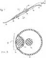
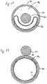
- FIGS. 1 and 2show one embodiment of a guidewire channel 30 of the present invention.
- the guidewire channel 30comprises a sleeve 32 attached to a treatment implement 34, in this case an expandable balloon 34, mounted on a catheter shaft 36.
- the catheter shaft 36includes a distal end 38 and a proximal end (not shown) extending out of the patient's body.
- the guidewire channel 30is proportioned to slidably receive a guidewire 40 therein.
- the catheter shaft 36should be stiff enough to allow the balloon 34 to be advanced along the guidewire 40 by the physician pushing on that portion of the catheter shaft 36 extending outside of the patient's body.
- a reinforcement wire 41 or similar support membermay be incorporated into the catheter shaft 36 to aid in its pushability.
- the support membercan be combined with the catheter in a variety of ways, including being attached distally to the catheter shaft distal to the balloon, being attached to the catheter shaft proximal to the balloon, or being unattached to the catheter shaft distally. In an unattached configuration, the support member can provide pushability when held by compressive forces of a stent mounted over the guidewire or similar constraining means.
- the support membercan be attached proximally, such as to the catheter shaft or the hub.
- the treatment implementtracks closely along the guidewire while the catheter is being advanced to a treatment site in a body. This is particularly important when a treatment site is in small vessels, such as coronary arteries, that may have numerous branch vessels located nearby.
- the guidewire channelshould be proportioned to keep the treatment implement closely aligned with the guidewire during device advancement through the body while not overly constricting movement of the treatment implement along the guidewire.
- the present inventorhas realized that once the treatment implement is correctly positioned within the treatment site and treatment has occurred, there is no reason why the treatment implement must remain on the guidewire for its subsequent removal from the body.
- the guidewire channel 30 of the present inventionincludes means to "disrupt" the channel at an appropriate time so as to separate the treatment implement 34 from the guidewire 40.
- such means 42comprises a separation line comprising a line of perforations formed along the length of the sleeve 32.
- the sleeve 32disrupts along the separation line, freeing the guidewire 40 from the constraint of the guidewire channel.
- the sleeve 32can occupy all or a portion of the balloon circumference.
- the guidewire channel 30provides the necessary guidance while the treatment implement is being advanced into the body, but effectively disappears when guidance is no longer required so that the treatment implement can be removed independently of the guidewire.
- in situ separation of a first treatment implement from the guidewireimmediately makes the guidewire available for the advancement of further treatment implements to the treatment site or to another adjacent or distal treatment site. This provides the physician with numerous options that are not currently available, such as allowing a second treatment implement to be advanced along the guidewire while a first treatment implement is either left in place or is being simultaneously removed, and/or allowing multiple treatment implements to be mounted in series on a single guidewire, with each advanced and used without the need to immediately and completely remove the previous treatment device.
- the sleeve 32should be formed from a relatively thin material that is selected and/or treated to disrupt at the appropriate time upon inflation of the balloon 34.
- a sleeve of the present inventionmay be constructed from a wide variety of materials, including PTFE, expanded PTFE, polyamide, polyether block copolymers and other copolymers, polyurethane, ethylene vinyl acetate (EVA), polyvinylchloride (PVC), poly(ethylene terephthalate) (PET), PETG, polyethylene, silicone, latex, etc., as well as composites or various combinations thereof.
- EVAethylene vinyl acetate
- PVCpolyvinylchloride
- PETpoly(ethylene terephthalate)
- PETGpolyethylene, silicone, latex, etc.
- the sleevecan be attached to virtually any form of balloon material, including balloons made from any of the above listed materials.
- the balloon materialmay be elastic or inelastic, and compliant, non-compliant, or semi-compliant.
- One suitable balloon material that may be used with the present inventioncomprises a composite balloon of expanded PTFE and elastomer, such as the balloons described in United States Patents 5,752,934 , 5,868,704 , 6,120,477 , all to Campbell et al.
- Attachment of the sleeve to the balloonmay take any suitable form, such as through adhesive, heat welding, ultrasonic welding, or other bonding method.
- the sleeve materialshould be thermally compatible with the balloon material if heat bonding is the means of attachment.
- the preferred sleeve materialshould have minimal thickness of less than about 0.003 inches (about 0.08 mm), and more preferably a thickness of between about 0.001 to about 0.002 inches (about 0.02 to 0.05 mm).
- a minimal thickness of the sleeveis preferred in that it is desirable that the guidewire channel not interfere with the normal operation of the treatment implements.
- a sleeve of the present inventionmay comprise one or more strips of material that is attached to a balloon or other treatment implement, or it may comprise one or more tubes of material that surrounds the balloon or other treatment implement, or it may comprise a guidewire retainer inside a balloon. Regardless of configuration, the sleeve of the present invention should provide a guidewire channel that is "disruptable.”
- Disruptable guidewire channels of the present inventionare intended to encompass any guidewire channel that breaks, separates, distends, or otherwise releases the guidewire from a treatment implement to allow another treatment implement to be advanced along the same guidewire without removal of the prior treatment implement.
- Disruptable guidewire channels of the present inventionmay include ones that are attached to the balloon material, integral with the balloon material, or folded within the balloon material.
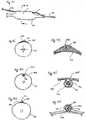
- Figures 4 and 5illustrate how the above-described device may be used to deliver a deployable device, such as a stent.
- a stent 44may be mounted over the previously described balloon 34 and guidewire channel 30 of the present invention.
- the guidewire 40passes through the guidewire channel 30 under the stent 44.
- Figure 5shows that upon inflation of the balloon 34, the stent 44 will expand to its deployed diameter while the guidewire channel 30 disrupts beneath the stent 44. Once the balloon 34 is deflated, the guidewire 40 will be separated from the balloon, allowing removal of the catheter 36 independent of the guidewire.
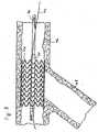
- Figures 6 through 8demonstrate the procedure for deploying the construct of Figures 4 and 5 in a blood vessel.
- Figure 6shows the balloon catheter 36 (incorporating the guidewire channel 30 of the present invention) and stent 44 of Figure 4 positioned in a patient's body at the junction of a main vessel 46 and a branch vessel 48.
- Figure 7shows the balloon 34 and stent 44 fully expanded in the main vessel 46, with the guidewire channel 30 disrupted underneath the stent 44.
- Figure 8shows the balloon 34 fully deflated and the stent 44 positioned fully expanded within the main vessel 46.
- the guidewire 40is now completely separated from the balloon 34 and catheter 36.
- Figure 9shows a second balloon 34b device of the present invention being advanced over the guidewire 40 with the original balloon device 34a left in place to accomplish further treatments.
- two stents 44a, 44bmay be deployed end-to-end (or overlapping) to address an extended defect in a vessel, with both balloons 34a, 34b kept in their original deployment positions to facilitate final "touch up" of stent placement prior to removal of the balloons.
- a second stentcan be advanced even further distal to the first stent in order to treat another defect.
- This problemcan present itself when fluoroscopy fails to detect the second distal defect prior to treatment of the first defect. Maintaining the first first implement across the first defect allows subsequent treatment (for instance, further distension of the first stent) to occur after treating the second distal defect.
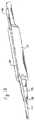
- FIG. 10A further embodiment of the present invention is shown in Figures 10 and 11 .
- the guidewire channel 30is formed from a sleeve 32 that has a separation line comprising an intentionally loose attachment line 50 to the balloon 34.
- the loose attachment line 50will separate from the balloon 34, freeing the guidewire 40.
- Loose attachment of the sleeve 32 to the balloon 34may be accomplished through a variety of means, including use of weak adhesive, discontinuously applied adhesion points, perforations, weak sleeve material along the attachment line, weak weld (e.g., weak heat bond), etc.
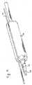
- the guidewire channel 30comprises a sleeve 32 of distensible material that expands along with the balloon 34 and then has little or no recoil to its original dimensions following balloon 34 deflation.
- a sleeve 32 of distensible materialthat expands along with the balloon 34 and then has little or no recoil to its original dimensions following balloon 34 deflation.
- Suitable distensible material for use in this embodimentmay include any material that can be distended beyond its elastic limit so as to present permanent plastic deformation.
- FIG. 15A further embodiment of the present invention is shown in Figure 15 .
- multiple separate guidewire channels 30a, 30bare attached to the treatment implement 34.
- Each of the guidewire channels 30a, 30bmay include one or more of the previously described disruption means so as to free the guidewire 40 from the treatment implement 34 at the appropriate time.
- This embodimentmay be preferable under certain circumstances where it is desirable to further limit the amount of material comprising the guidewire channel. It should be evident that this embodiment may be practiced with two, three, four, five, or more separate guidewire channels 30. Additionally, it should be understood that the separate guidewire channels of this embodiment may be of dimensions and properties identical to each other, or may differ from each other in dimensions, materials, attachment means, disruption means, and/or other properties.
- Figures 16 and 17illustrate another embodiment of the present invention that employs both a disruptable guidewire channel 30 attached to the treatment implement 34 and a unique catheter tip 56.
- the disruptable guidewire channel 30may be of any other forms described herein.
- the catheter tip 56includes a guidewire centering groove 58 therein that is adapted to receive and retain a guidewire 40 in sliding fit during device loading and advancement to a treatment site.
- the centering groove 58provides an additional anchorage for the guidewire to the treatment implement during device advancement and may be used to improve the trackability and crossability of the device.
- the centering groove 58is proportioned to release the guidewire 40 from the tip 56 when the treatment implement 34 is expanded, as is shown in Figure 17 .
- the tip 56 and centering groove 58are formed from the same or similar material as the balloon or catheter shaft material, such as thermoplastic material used in medical devices (e.g., polyamide, polyurethane, PTFE, polyethylene, EVA, PVC, etc.).
- thermoplastic material used in medical devicese.g., polyamide, polyurethane, PTFE, polyethylene, EVA, PVC, etc.
- a disruptable channel 60is formed from the external surface of the balloon 34 itself.
- a tip 56 with a centering groove 58is employed to aid in guidewire 40 attachment, trackability and crossability during device advancement.
- Figure 19when the balloon 34 is expanded, the disruptable channel 60 disappears, releasing the guidewire 40 from attachment to the balloon 34. The guidewire 40 will likewise separate from the centering groove 58.
- Figure 20illustrates how the embodiment of Figure 18 and 19 can be used to deliver a deployable device 44.
- the disruptable channel 60should be formed of sufficient dimensions and structural integrity so that the deployable device 44 can be adequately attached to the balloon 34 without hindering the proper sliding motion of the guidewire 40 through the disruptable channel 60 during device advancement.
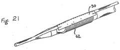
- Figure 21shows how the present invention may be adapted to be used with other treatment apparatus beyond inflatable balloons.
- a guidewire channel 30 of the present inventionis attached to a mechanical expansion device 62, adapted to expand upon mechanical actuation instead of introduction of fluid pressure.
- Other treatment implements that may benefit from use with a guidewire channel of the present inventionmay include, without limitation: other fluid-inflatable balloons; mechanically expandable balloons; catheters; catheter systems; stent delivery systems; stent-graft delivery systems; embolic filters; occluders; and other such devices.
- Figures 22 through 24illustrate embodiments of the present invention that can release from the guidewire without need for an inflation device to disrupt the sleeve.
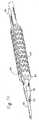
- Figure 22demonstrates that the guidewire channel 30 of the present invention may be formed from a tubular sleeve 32 that completely surrounds the treatment implement 34 and includes a tear line 42.
- the sleeveis slidable relative to a coaxial underlying catheter shaft 36 (for instance, the tubular sleeve 32 may extend along the entire length of the catheter 36 to allow the sleeve and the catheter to be moved relative to one another).
- an inflatable memberis not employed, an enlarged bulb member 63 can be mounted on the catheter shaft 36.
- the bulb member 63can disrupt the tear line 42, freeing the guidewire 40 from the guidewire channel 30. Additionally, this embodiment further demonstrates that the guidewire 40 does not have to traverse the entire length of the sleeve 32, but may be adapted to exit the sleeve 32 through a port 64 provided along its length. In this manner, the sleeve 32 does not have to tear along its entire length in order to release the guidewire 40.
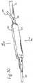
- Figure 23illustrates another disruption means for use with the present invention.
- the guidewire channel 30comprises a tubular sleeve 32 formed from a resilient material with a resealable slit 68 and an exit port 70.
- An inner membercontains a groove or passageway 66 extending from the distal tip and terminating at an outer member exit port 70.
- a guidewire 40is fed through the passageway 66 at the time of device introduction.
- the resilient material of the sleeve 32will part along the slit 68, releasing the guidewire from the passageway 66. Proximal displacement (pulling) of the outer member, or distal displacement (pushing) of the inner member, or some combination of the two, will release the guidewire.
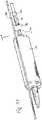
- the guidewire channel 30is formed from a sleeve 32 having a rotational slot 72 formed therein.
- the guidewire 40can be mounted into the channel by threading it through the sleeve 32 within a groove 75 of the inner member and out port 74, or by positioning the guidewire 40 along the length of the slot 72 and then pressing the guidewire 40 into the slot while the sleeve 32 is rotated to align the guidewire 40 within the sleeve 32 and exit the sleeve 32 through port 74.
- the sleeve 32 in this embodimentmay be formed from a disruptable material, as previously described, or the guidewire can be released from the guidewire channel 30 by rotating the sleeve 32 at the appropriate time to align the groove 75 with the slot 72 and allow the guidewire to "pop" free from the slot 72.
- Embodiments of the present inventionthat can be utilized without a balloon, such as those illustrated in Figures 22 through 24 , have numerous possible applications, including without limitation, use with self-expanding stents, embolic filter devices, septal defect occlusion devices, etc.
- Figures 25 through 29show the stent placement in a main vessel 46 illustrated in Figures 6 through 8 , with the balloon 34 left in place as shown in Figure 8 . If a physician would now like to likewise provide a stent in the branch vessel 48, under currently available procedures s/he would have to either remove the first balloon 34 and then direct a second deployment device down the same guidewire 40, or laboriously thread a second guidewire into the branch vessel 48.
- the guidewire 40since the guidewire 40 has been released from the balloon 34 in the procedure described in Figures 6 through 8 , the guidewire 40 is now free to be repositioned into the branch vessel 48, as is Illustrated in Figure 25 , while leaving the balloon 34 in position within the main vessel 46.
- a second deployment apparatus 76can then be advanced along the guidewire 40, as is shown in Figure 26 , and positioned into the branch vessel 48, as is shown in Figure 27 .
- a second stent 78can then be deployed, as is shown in Figure 28 . Since the first balloon 34 did not have to be removed to allow introduction of the second deployment apparatus 76, the physician then has the option of immediately reinflating the first balloon 34, as is shown in Figure 29 , in order to make sure both stents 44, 78 are fully and properly deployed in the two vessels 46, 48.
- the ability to perform simultaneous ballooning of both of these stents using a single guidewireis believed to be particularly unique to the present invention. This allows this procedure to be completed faster and more efficiently than in any previously available stent deployment method.
- Figures 30 through 34illustrate an embodiment of the present invention that improves on the embodiment illustrated in Figures 18 and 19 .
- a disruptable guidewire channel 60can be formed from the external surface of the balloon 34 itseff.
- a flexible guidewire retainer 80is contained within the balloon 34 to aid in holding the guidewire 40 within the guidewire channel 60.
- the balloon 34is inflated, as is shown in Figures 31 and 33 , the balloon 34 applies an outward force that causes the guidewire retainer 80 to flex open releasing the portion of the balloon contained within the guidewire retainer, therefore releasing the guidewire 40.
- the centering groove in the tipcould be a continuation of the guidewire retainer inside the balloon or attached thereto.
- the guidewire retainer inside the ballooncould be a continuation of the support member or attached thereto.
- the guidewire retainercould also be a continuation of the inflation lumen or attached thereto.
- the support membercould be integral to the guidewire retainer.
- An indentation 82can be formed in the catheter shaft 36 to assist in the transition of the guidewire into the guidewire channel 60.
- the guidewire retainer 80comprises a cylinder with at least a semi-circular cross section.
- the retainermay comprise any form that provides some gripping of the guidewire, including a tube having a longitudinal slice down its length to the more longitudinally slotted constructions of Figures 34 and 35 .
- One or more slits 84can be provided in the retainer 80 to aid in its flexibility and adjust the pressure necessary to release the guidewire and a portion of the balloon from the retainer.
- the guidewire retainer 80can be constructed from any suitably flexible and resilient material, including various plastics or metals.
- Figure 35illustrates that the width of the slits 84 in the guidewire retainer 80 can be altered to aid in its flexibility, adjust the release properties of the retainer relative to the particular materials used to create the retainer, as well as adjust the operating parameters of the balloon. It should be evident from this description that the shape, form, materials, and number of the guidewire retainer(s) 80 used in any given application of the present invention may take a wide variety of forms.
- This embodiment of the present inventionmay be further improved by providing releaSable retention means in the catheter proximal to the balloon, as is illustrated in Figures 36 through 39 .
- a channel 86is provided in the catheter 36 proximal to the balloon 34 that is disruptable.
- the channelcomprises a longitudinal slit 88 in the catheter shaft and an guidewire port 90.
- This proximal attachment of the guidewire 40may be beneficial in tracking the balloon into place in the body.
- the channel 86may be any suitable length, including a length of less than 5 cm to 25 cm or more from the balloon.
- a collapsible inflation lumen 92as shown in Figure 38 that will inflate when pressure is applied to the balloon.
- the collapsible lumen 92when the collapsible lumen 92 is inflated, the collapsible lumen 92 will fill the catheter shaft 36 to force the guidewire 40 out of the channel 86.
- Figure 40illustrates another embodiment of the present invention wherein the catheter shaft 36 includes a peelable sheath 94 covering the guidewire channel 96.
- the sheath 94is disruptably attached to the catheter shaft 36, such as through use of perforation lines 98a, 98b.
- An actuation cord 100is attached to one end of the sheath 94.
- the guidewire channel 96can be disrupted at any desired time simply by pulling on the actuation cord 100 to remove the sheath 94 and free the guidewire 40.
- a guidewire channel 102is formed in the wall 104 of the balloon 34.
- the guidewire channel 102may be integral with the balloon itself, with the lamina of the balloon wall 104 fully surrounding the channel 102.
- Figures 44 and 45demonstrate that the guidewire channel 102 may alternatively comprise in invagination 106 formed into the balloon wall.
- the invagination 106may include a cover 108 to assist in maintaining the guidewire 40 within the channel 102.
- Figures 46 and 47illustrate that the guidewire channel 102 may comprise a separate component 110 that is attached to the balloon 34, such as through use of an adhesive or a cover 112.
- one skilled in the artwill appreciate that similar constructs can be achieve through other means including direct extrusion of the balloon material. Likewise, one skilled in the art will further appreciate that one or more such channels 102 may be provided in any given balloon and/or a single relatively wide channel can be provided in the balloon to allow passage of multiple guidewires.
- an additional benefitmay be realized by the fact that the guidewire is positioned on the outside of the balloon. It is theorized that it can be beneficial under certain circumstances not to evenly balloon a plaque occlusion in a blood vessel. By applying a focused force at distinct areas around the circumference of the vessel during ballooning, it is believed that the plaque may more successfully be disrupted. Where focusing of expansion forces is desired, the presence of the guidewire on the outside of the balloon may provide a ready means to accomplish improved plaque treatment. In such instances it may be desirable to provide radiopaque markers on the guidewire channel to aid in positioning the balloon and guidewire and effectuating focused ballooning.
- One embodiment of the present inventioncan be constructed by modifying a commercially available balloon catheter device.
- a 4.0mm x 30mm RX GEMINI Coronary Balloon Dilatation Catheter available from Guidant/ACS of Santa Clara, CA,may be used as the starting catheter device and is modified in the following manner:
- a balloon catheter device of the present inventionis created through this above described process.
- the catheterincludes a guidewire channel attached to the exterior of the balloon that is disruptable upon inflation of the balloon so as to free the guidewire from the guidewire channel.
Landscapes
- Health & Medical Sciences (AREA)
- Engineering & Computer Science (AREA)
- Biomedical Technology (AREA)
- Heart & Thoracic Surgery (AREA)
- Life Sciences & Earth Sciences (AREA)
- Veterinary Medicine (AREA)
- General Health & Medical Sciences (AREA)
- Public Health (AREA)
- Animal Behavior & Ethology (AREA)
- Vascular Medicine (AREA)
- Cardiology (AREA)
- Oral & Maxillofacial Surgery (AREA)
- Transplantation (AREA)
- Anesthesiology (AREA)
- Hematology (AREA)
- Child & Adolescent Psychology (AREA)
- Biophysics (AREA)
- Pulmonology (AREA)
- Media Introduction/Drainage Providing Device (AREA)
Description
- The present invention relates to catheter systems for delivery of medical devices into a patient, and particularly to medical devices that are delivered to a treatment site using a guidewire.
- Minimally invasive (or "interventional") medical procedures are commonly employed today to avoid the substantial effort and trauma inherent in traditional surgery. Instead of directly accessing a treatment site through surgical procedures, a physician will make a small incision into a remote vessel (e.g., a femoral artery) and guide the necessary tools to the treatment site using fluoroscopy or other visualization techniques. Access to the treatment site is first achieved using very low profile devices that can be "steered" through the various branches of vessels to the correct treatment location. Typically these initial small diameter devices will be a steerable guidewire or a small-diameter guiding catheter that is followed by insertion of a guidewire. Once in the correct position, treatment devices can then be attached to the guidewire and advanced to the treatment site along the guidewire like a train traveling along a track. Following treatment, each treatment device is then pulled out of the patient along the same guidewire to allow, if needed, further treatment devices to be advanced along the guidewire to the treatment site.
- This basic approach is now used in a wide variety of medical procedures, including internal vessel repairs (e.g., repairing aneurysms in the aorta or other vessels using grafts or stent-graft devices) and treating blockages in vessels (e.g., performing balloon angioplasty or thrombectomy, and stent or stent-graft placements). All of these procedures tend to be much faster and far less traumatic than comparable surgical treatments. As a result, there are a host of benefits by using these procedures, including: fewer medical professionals need to attend the procedures; the procedures can be completed more rapidly; the patient may need far less extensive anesthesia and, where appropriate, can be awake and cooperative during the procedure; and since the trauma of open surgery is avoided overall hospital stays are dramatically reduced (e.g., for the repair of an abdominal aortic aneurysm hospital stays can be reduced from over a week including intensive care to only a couple of days or less).
- Two basic categories of techniques are commonly used today to advance treatment apparatus to a treatment site along a guidewire. First, "over the wire" (OTW) techniques employ a long guidewire that extends far out of the patient's body. In the OTW procedures, each treatment device is mounted on a catheter that includes a guidewire lumen extending the entire length of the catheter. The physician threads each catheter completely over the length of the guidewire extending out of the patient and, while an assistant controls the tail end of the guidewire, the physician feeds the catheter to the treatment site. Following treatment, the entire catheter is then removed along the guidewire, again with the assistant controlling the tail end of the guidewire to keep it from moving out of position or touching the floor or other non-sterile areas. The OTW techniques have been widely practiced and provide very good trackability for the devices along the guidewire. However, these techniques require that the long tail end of the guidewire be controlled at all times, requiring at least one additional assistant throughout the procedure. Further, the threading of the entire length of the catheter along the guidewire can be somewhat difficult and time consuming. Moreover, limiting the speed with which procedures can be completed and the types of procedures that can be easily performed, these techniques require each treatment device to be completely retracted along the guidewire before a further treatment device can be advanced along the same guidewire to the treatment site.
- The second common category of techniques for advancing treatment apparatus to a treatment site is commonly referred to as "rapid exchange" techniques. In rapid exchange procedures a guidewire lumen is provided over only a relatively short distal length of the treatment catheter, having a guidewire port exiting the catheter shaft next to or a short distance back from the treatment device. In this manner a relatively short guidewire can be employed that does not extend far from the patient's body. The physician advances the catheter over the guidewire (through the guidewire lumen) and gains control of the proximal end of the guidewire where it exits the catheter near the catheter's distal end. The physician can then guide the catheter into position without the need of an assistant controlling an extra long guidewire tail. Examples of such devices are described in United States Patents
4,762,129 to Bonzel and5,040,548 to Yock . Although the rapid exchange techniques may sacrifice some trackability in use, these techniques can allow for faster threading of each treatment device and cost savings in the elimination of extra long guidewires and one assistant to control the guidewire tail during the procedure. However, in practice these techniques also require each treatment device to be completely retracted along the guidewire before a further treatment implement can be advanced along the guidewire to the treatment site. - Other apparatus have been developed to provide some of the same benefits provided by the rapid exchange catheter techniques. For example, it has been suggested that the guidewire connect to the treatment catheter only at the distal tip of the guidewire, with a tube housing a guidewire lumen extending along the outside of the treatment device. Examples of these devices are described in United States Patents
5,458,639 to Tsukashima et al. and6,371,961 to Osborne et al. A similar device is taught in United States Patent6,394,995 to Solar et al. whereby an "advancement member" is provided attached to a treatment balloon; the advancement member includes a short tube at its far distal end forming a guidewire lumen. While these devices may deliver some of the same benefits of the conventional rapid exchange catheters, trackability may be a far greater problem since the guidewire is attached to the treatment catheter only at the very tip of the catheter. Additionally, depending upon the dimensions and stiffness of the tube housing the guidewire lumen (or, in the case of the Solar et al. device, of the "advancement member"), its presence on the outside of the treatment device may interfere with the proper operation of the treatment device. Finally, as was true with the other techniques discussed above, these devices would appear to require each treatment device to be completely retracted along the guidewire before a further treatment implement can be advanced along the guidewire to the treatment site. - It is accordingly a purpose of the present invention to provide an improved apparatus for advancement of a catheter along a guidewire that can be loaded and operated on a relatively short guidewire by a single operator.
- It is a further purpose of the present invention for such an apparatus to provide a guidewire lumen that affords all necessary trackability while a treatment device is being advanced to a treatment site.
- It is still a further purpose of the present invention for such an apparatus to allow other treatment devices to be advanced along the same guidewire without prior removal of the first treatment device.
- These and other purposes of the present invention will become evident from review of the following description.
- An example of rapid exchange folded balloon catheter and stent delivery system is described in
US 6,071,285 (Lashinski, Robert D, et al ), which discloses that the balloon portion of a balloon catheter for implanting a stent structure is at least initially retained laterally to a guide wire by passing the guide wire axially along the balloon inside the stent structure but not through the interior of the balloon or any permanent guide wire lumen at the location of the balloon. The initially deflated balloon may be folded laterally into a plurality of folds, and the guide wire may pass between the folds or outside the folds as desired. Guide wire lumens may be provided distally and/or proximally of the balloon. An elastic sleeve may be provided around the balloon to help keep the balloon folded prior to inflation and to help refold the balloon during and after deflation. If an elastic sleeve is provided, the guide wire may pass along the balloon inside the sleeve. - An example of a variable wire diameter angioplasty dilatation balloon catheter is described in
US 5,141,494 (Danforth, John W, et al ), which discloses a dilatation balloon catheter with an inelastic balloon wrapped about a smaller section of a guidewire. During introduction across a region of a stenosis, the balloon is wrapped around a guidewire in such a way that the guidewire contained therein can rotated freely, but cannot advance independently of the balloon. The wrapped configuration is maintained by means of a temporary bond. Inflation of the balloon, following proper positioning of the catheter breaks the bond, permitting the balloon to unwrap from the guidewire contained therein. Typically, the distal end of the guidewire is tapered and the guide wire is controllably clamped to the catheter for advancement into the patient. - An example of a sliding receptacle catheter system is described in
WO 95/16487 (Jang, G David - According to an aspect of the present invention there is described a medical device in accordance with the appended claims.
- The present invention is an improved catheter device that includes a disruptable guidewire channel. The guidewire channel is configured to provide necessary trackability of the catheter along the guidewire during introduction of the catheter to a treatment site. Once treatment is completed, the guidewire channel can then be disrupted so as to free the guidewire from the catheter in situ.
- In one embodiment of the present invention, it comprises a balloon and catheter assembly having an enlargeable balloon mounted on a catheter shaft. A sleeve is attached to the balloon forming a guidewire channel along at least a portion of the balloon. At an appropriate time, the sleeve may be disrupted to cause a guidewire placed within the sleeve to free from the balloon. The sleeve can be disrupted through a variety of means, including being formed from intentionally fragile material that will separate upon inflation of the balloon, having one or more separation lines (for example, perforations) pre-formed in the sleeve, having an attachment line between the sleeve and the balloon that is formed to split at an appropriate time, and having one of a variety of slots into which the guidewire can be placed and then remotely removed.
- The present invention may be further defined as a guidewire deliverable treatment implement comprising a sleeve attached to the implement forming a guidewire channel along at least a portion of the implement. Again, the sleeve is disruptable to cause a guidewire placed within the sleeve to free, in whole or in part, from the implement upon disruption of the sleeve. Treatment implements that may be employed with the present invention may include: fluid-inflatable balloons; mechanically expandable balloons; catheters; catheter systems; stent delivery systems; stent-graft delivery systems; embolic filters; occluders; and other such devices.
- The present invention may be still further defined as a medical device having a balloon configured for insertion within a patient's body directed along a guidewire and a guidewire channel attached to the balloon. The guidewire channel is formed from a material that maintains the guidewire close to the balloon during insertion and alters upon inflation of the balloon to separate the guidewire from the balloon upon subsequent deflation of the balloon. This separation of the guidewire from the balloon may take the form of various separation lines or other complete disruption means or may include a material that disrupts by distending away from the
balloon so as to allow other devices to be advanced over the same guidewire past the balloon through the disrupted channel. - The apparatus of the present invention provides distinct advantages over existing over-the-wire and rapid exchange catheter introduction methods, including the ability to
achieve much faster treatment implement exchanges, the ability to rapidly deliver multiple treatment implements in series, and the ability to maintain multiple treatment implements simultaneously at a treatment site using a single guidewire. These advantages can be realized by the present invention because: the catheter does not have to be axially removed prior to advancement of another catheter on the same guidewire; the catheter can remain across an initial lesion for future touch up, while another catheter is advanced to treat a distal lesion; and the catheter allows treatment of multiple stenotic lesions at a bifurcation requiring only one guidewire, thus eliminating entanglement of guidewires that can occur when utilizing multiple guidewires. - The operation of the present invention should become apparent from the following description when considered in conjunction with the accompanying drawings, in which:
Figure 1 is an isometric view of a balloon catheter incorporating one embodiment of a guidewire channel of the present invention;Figure 2 is cross-section view of the balloon catheter and a guidewire channel along line 2-2 ofFigure 1 ;Figure 3 is an isometric view of the balloon catheter ofFigure 1 , showing the balloon fully inflated and the guidewire channel disrupted;Figure 4 is an isometric view of a balloon catheter incorporating a guidewire channel of the present invention with a stent mounted over the balloon catheter and guidewire channel;Figure 5 is an isometric view of the balloon catheter and stent ofFigure 4 , showing the balloon and stent fully expanded and the guidewire channel disrupted;Figure 6 is a side view of the balloon catheter and stent ofFigure 4 positioned in a patient's body at the junction of two blood vessels shown in cross-section;Figure 7 is a side view of the balloon catheter and stent positioned in the blood vessel as shown InFigure 6 , showing the balloon and stent fully expanded;Figure 8 is a side view of the balloon catheter and stent positioned in the blood vessel as shown inFigure 7 , showing the balloon catheter deflated and the stent positioned fully expanded within the blood vessel;Figure 9 is an isometric view of a second balloon catheter and stent being advanced along a guidewire following expansion of a first stent having been deployed on the same guidewire;Figure 10 is an isometric view of a balloon catheter incorporating another embodiment of a guidewire channel of the present invention;Figure 11 is an isometric view of the balloon catheter ofFigure 10 , showing the balloon fully inflated and the guidewire channel disrupted;Figure 12 is an isometric view of a balloon catheter incorporating still another embodiment of a guidewire channel of the present invention;Figure 13 is an isometric view of the balloon catheter ofFigure 12 , showing the balloon fully inflated and the guidewire channel disrupted through distension;Figure 14 is an isometric view of the balloon catheter ofFigure 13 , showing the balloon deflated and the guidewire channel remaining disrupted through distension;Figure 15 is an isometric view of still another embodiment of the present invention comprising multiple separate guidewire channels;Figure 16 is an isometric view of another embodiment of a balloon catheter of the present invention, employing a guidewire channel along with catheter tip including a guidewire centering groove;Figure 17 is an isometric view of the balloon catheter ofFigure 16 , showing the balloon fully inflated, the guidewire channel disrupted, and the guidewire separated from the centering groove in the catheter tip;Figure 18 is an isometric view of a further embodiment of a balloon catheter of the present invention comprising a disruptable channel formed in the balloon itself and employing a catheter tip with a guidewire centering groove;Figure 19 is an isometric view of the embodiment ofFigure 18 , showing the balloon fully inflated, releasing the guidewire from the channel formed in the balloon, and the guidewire separated from the centering groove in the catheter tip;Figure 20 is an isometric view of the embodiment ofFigure 18 including a stent mounted over the balloon;Figure 21 is an isometric view of a further embodiment of the present invention employing a guidewire channel on a mechanical balloon;Figure 22 is an isometric view of a still further embodiment of the present invention employing a guidewire channel with perforated tear release;Figure 23 is an isometric view of another further embodiment of the present invention employing a guidewire channel with a slit release;Figure 24 is an isometric view of still another embodiment of the present invention employing a guidewire channel that has a slot allowing for rotational release;Figure 25 is a side view of a stent placement in a branched vessel following the procedure illustrated inFigures 6 through 8 with the guidewire repositioned into the branch vessel through the interstices of the stent;Figure 26 is a side view of the stent placement ofFigure 25 showing a second balloon catheter of the present invention being advanced along the guidewire;Figure 27 is a side view of the stent placement ofFigure 26 showing the stent and balloon catheter positioned within the branch vessel;Figure 28 is a side view of the stent placement ofFigure 27 showing the stent and balloon catheter fully inflated within the branch vessel;Figure 29 is a side view of the stent placement ofFigure 28 showing both the balloon in the main vessel and the balloon in the side vessel fully inflated;Figure 30 is an isometric view of another embodiment of the present invention comprising a further example of a disruptable channel formed from the external surface of the balloon itself, having a guidewire retainer within the balloon, and employing a catheter tip with a guidewire centering groove;Figure 31 is an isometric view of the embodiment ofFigure 18 , showing the balloon fully inflated, releasing the guidewire from the channel formed in the balloon, and the guidewire separated from the centering groove in the catheter tip;Figure 32 is a cross section view along line 32-32 ofFigure 30 ;Figure 33 is a cross section view along line 33-33 ofFigure 31 ;Figure 34 is an isometric view of one embodiment of a guidewire retainer for use in the embodiments ofFigures 30 through 33 ;Figure 35 is an isometric view of another embodiment of a guidewire retainer for use in the embodiments ofFigures 30 through 33 ;Figure 36 is an isometric view of still another embodiment of the present invention comprising another example of a disruptable channel formed in the balloon itself, having a guidewire retainer placed within the balloon, employing a catheter tip with a guidewire centering groove, and employing a disruptable channel in the catheter tube proximal to the balloon;Figure 37 is an isometric view of the embodiment ofFigure 18 , showing the balloon fully inflated, releasing the guidewire from each of the balloon, the centering groove in the catheter tip, and the disruptable channel in the catheter tube;Figure 38 is a cross section view along line 38-38 ofFigure 36 ;Figure 39 is a cross section view along line 39-39 ofFigure 37 ;Figure 40 is an isometric view of a further embodiment of a catheter including a disruptable channel of the present invention;Figure 41 is a side view of yet another guidewire channel of the present invention wherein the guidewire channel is formed in the wall of the balloon;Figure 42 is a cross section view along line A-A ofFigure 41 showing one embodiment of a guidewire channel that can be formed in the wall of the balloon;Figure 43 is an enlarged sectional view of the guidewire channel ofFigure 42 ;Figure 44 is a cross section view along line A-A ofFigure 41 showing another embodiment of a guidewire channel that can be formed in the wall of the balloon;Figure 45 is an enlarged sectional view of the guidewire channel ofFigure 44 ;Figure 46 is a cross section view along line A-A ofFigure 41 showing still another embodiment of a guidewire channel that can be formed in the wall of the balloon; andFigure 47 is an enlarged sectional view of the guidewire channel ofFigure 46 .- The present invention is an improved apparatus for delivery of an interventional device along a guidewire to a remote treatment site in a patient's body.
- As the terms "interventional" or "minimally invasive" devices or procedures are used herein they are intended to encompass any device or procedure whereby a medical treatment implement is delivered to a treatment site by use of wires and/or tubes threaded through vessels or other body passageways accessed remotely. Such devices may include those employed in: balloon angioplasty; thrombectomy; stent, graft, or stent-graft placement; embolic filter device placement; remote diagnostic procedures, such as those employing fiber optic cameras, ultrasound monitoring, MRI monitoring, x-ray monitoring, etc.; remote therapeutic procedures, such as those employing cutting blades, lasers, heat application, cold application, radiation, drug delivery, etc.; and any other similar devices or procedures now known or later developed. Currently such interventional procedures are employed in large and small blood vessels, in other vessels in the body, such as in the bile duct, as well as in the respiratory, digestive, reproductive, and other body systems. As the term "patient" is used herein it is intended to encompass both humans and animals.
- As the term "guidewire" is used herein it is intended to encompass any device that provides a track for guiding medical implements to a treatment site in a minimally invasive procedure. Such devices may include straight, coiled, braided, coated, or other forms of wires, various tubular devices, such as catheter tubes and the like, or any other form of similar elongated device.
- Referring to the illustrations,
Figures 1 and 2 show one embodiment of aguidewire channel 30 of the present invention. Theguidewire channel 30 comprises asleeve 32 attached to a treatment implement 34, in this case anexpandable balloon 34, mounted on acatheter shaft 36. Thecatheter shaft 36 includes adistal end 38 and a proximal end (not shown) extending out of the patient's body. Theguidewire channel 30 is proportioned to slidably receive aguidewire 40 therein. Thecatheter shaft 36 should be stiff enough to allow theballoon 34 to be advanced along theguidewire 40 by the physician pushing on that portion of thecatheter shaft 36 extending outside of the patient's body. - If the catheter tube alone does not provide sufficient longitudinal stiffness, a
reinforcement wire 41 or similar support member may be incorporated into thecatheter shaft 36 to aid in its pushability. The support member can be combined with the catheter in a variety of ways, including being attached distally to the catheter shaft distal to the balloon, being attached to the catheter shaft proximal to the balloon, or being unattached to the catheter shaft distally. In an unattached configuration, the support member can provide pushability when held by compressive forces of a stent mounted over the guidewire or similar constraining means. The support member can be attached proximally, such as to the catheter shaft or the hub. - It is important that the treatment implement tracks closely along the guidewire while the catheter is being advanced to a treatment site in a body. This is particularly important when a treatment site is in small vessels, such as coronary arteries, that may have numerous branch vessels located nearby. As such, the guidewire channel should be proportioned to keep the treatment implement closely aligned with the guidewire during device advancement through the body while not overly constricting movement of the treatment implement along the guidewire. However, the present inventor has realized that once the treatment implement is correctly positioned within the treatment site and treatment has occurred, there is no reason why the treatment implement must remain on the guidewire for its subsequent removal from the body.
- As such, the
guidewire channel 30 of the present invention includes means to "disrupt" the channel at an appropriate time so as to separate the treatment implement 34 from theguidewire 40. In the embodiment illustrated inFigures 1 and 2 , such means 42 comprises a separation line comprising a line of perforations formed along the length of thesleeve 32. As is shown inFigure 3 , when theballoon 34 is expanded, thesleeve 32 disrupts along the separation line, freeing theguidewire 40 from the constraint of the guidewire channel. Thesleeve 32 can occupy all or a portion of the balloon circumference. - In this manner, the
guidewire channel 30 provides the necessary guidance while the treatment implement is being advanced into the body, but effectively disappears when guidance is no longer required so that the treatment implement can be removed independently of the guidewire. Unlike previous interfaces between catheters and guidewires, in situ separation of a first treatment implement from the guidewire immediately makes the guidewire available for the advancement of further treatment implements to the treatment site or to another adjacent or distal treatment site. This provides the physician with numerous options that are not currently available, such as allowing a second treatment implement to be advanced along the guidewire while a first treatment implement is either left in place or is being simultaneously removed, and/or allowing multiple treatment implements to be mounted in series on a single guidewire, with each advanced and used without the need to immediately and completely remove the previous treatment device. - It should be evident that this construction circumvents the need for a long guidewire and extra medical personnel required with OTW catheters, while permitting far easier and quicker catheter exchanges than are possible with current so-called "rapid exchange" catheter systems.
- For most embodiments of the present invention, the
sleeve 32 should be formed from a relatively thin material that is selected and/or treated to disrupt at the appropriate time upon inflation of theballoon 34. A sleeve of the present invention may be constructed from a wide variety of materials, including PTFE, expanded PTFE, polyamide, polyether block copolymers and other copolymers, polyurethane, ethylene vinyl acetate (EVA), polyvinylchloride (PVC), poly(ethylene terephthalate) (PET), PETG, polyethylene, silicone, latex, etc., as well as composites or various combinations thereof. The sleeve can be attached to virtually any form of balloon material, including balloons made from any of the above listed materials. The balloon material may be elastic or inelastic, and compliant, non-compliant, or semi-compliant. One suitable balloon material that may be used with the present invention comprises a composite balloon of expanded PTFE and elastomer, such as the balloons described in United States Patents5,752,934 ,5,868,704 ,6,120,477 , all to Campbell et al. - Attachment of the sleeve to the balloon may take any suitable form, such as through adhesive, heat welding, ultrasonic welding, or other bonding method. The sleeve material should be thermally compatible with the balloon material if heat bonding is the means of attachment. The preferred sleeve material should have minimal thickness of less than about 0.003 inches (about 0.08 mm), and more preferably a thickness of between about 0.001 to about 0.002 inches (about 0.02 to 0.05 mm). A minimal thickness of the sleeve is preferred in that it is desirable that the guidewire channel not interfere with the normal operation of the treatment implements.
- As the term "sleeve" is used herein, It is intended to encompass any configuration of material that forms a channel through which a guidewire will be retained in close proximity to a catheter shaft during device advancement through a body while allowing the catheter shaft to slide relative to the guidewire. A sleeve of the present invention may comprise one or more strips of material that is attached to a balloon or other treatment implement, or it may comprise one or more tubes of material that surrounds the balloon or other treatment implement, or it may comprise a guidewire retainer inside a balloon. Regardless of configuration, the sleeve of the present invention should provide a guidewire channel that is "disruptable."
- As is explained and illustrated in greater detail below, as the terms "disrupt" or "disruptable" are used in reference to the guidewire channels of the present invention they are intended to encompass any guidewire channel that breaks, separates, distends, or otherwise releases the guidewire from a treatment implement to allow another treatment implement to be advanced along the same guidewire without removal of the prior treatment implement. Disruptable guidewire channels of the present invention may include ones that are attached to the balloon material, integral with the balloon material, or folded within the balloon material.
Figures 4 and 5 illustrate how the above-described device may be used to deliver a deployable device, such as a stent. As is shown inFigure 4 , astent 44 may be mounted over the previously describedballoon 34 andguidewire channel 30 of the present invention. In this embodiment the guidewire 40 passes through theguidewire channel 30 under thestent 44.Figure 5 shows that upon inflation of theballoon 34, thestent 44 will expand to its deployed diameter while theguidewire channel 30 disrupts beneath thestent 44. Once theballoon 34 is deflated, theguidewire 40 will be separated from the balloon, allowing removal of thecatheter 36 independent of the guidewire.Figures 6 through 8 demonstrate the procedure for deploying the construct ofFigures 4 and 5 in a blood vessel.Figure 6 shows the balloon catheter 36 (incorporating theguidewire channel 30 of the present invention) andstent 44 ofFigure 4 positioned in a patient's body at the junction of amain vessel 46 and abranch vessel 48.Figure 7 shows theballoon 34 andstent 44 fully expanded in themain vessel 46, with theguidewire channel 30 disrupted underneath thestent 44.Figure 8 shows theballoon 34 fully deflated and thestent 44 positioned fully expanded within themain vessel 46. Theguidewire 40 is now completely separated from theballoon 34 andcatheter 36.- Once the
guidewire 40 is separated from theballoon 34, additional devices can then be advanced on theguidewire 40 in order to accomplish further treatments. For example,Figure 9 shows a second balloon 34b device of the present invention being advanced over theguidewire 40 with the original balloon device 34a left in place to accomplish further treatments. In this instance, two stents 44a, 44b may be deployed end-to-end (or overlapping) to address an extended defect in a vessel, with both balloons 34a, 34b kept in their original deployment positions to facilitate final "touch up" of stent placement prior to removal of the balloons. - In another embodiment of the present invention, a second stent can be advanced even further distal to the first stent in order to treat another defect. This problem can present itself when fluoroscopy fails to detect the second distal defect prior to treatment of the first defect. Maintaining the first first implement across the first defect allows subsequent treatment (for instance, further distension of the first stent) to occur after treating the second distal defect.
- A further embodiment of the present invention is shown in
Figures 10 and 11 . In this embodiment theguidewire channel 30 is formed from asleeve 32 that has a separation line comprising an intentionallyloose attachment line 50 to theballoon 34. When the balloon is inflated, as is shown inFigure 11 , theloose attachment line 50 will separate from theballoon 34, freeing theguidewire 40. Loose attachment of thesleeve 32 to theballoon 34 may be accomplished through a variety of means, including use of weak adhesive, discontinuously applied adhesion points, perforations, weak sleeve material along the attachment line, weak weld (e.g., weak heat bond), etc. - A further variation on the present invention is illustrated in
Figures 12 through 14 . In this embodiment theguidewire channel 30 comprises asleeve 32 of distensible material that expands along with theballoon 34 and then has little or no recoil to its originaldimensions following balloon 34 deflation. Although this configuration does not completely separate the guidewire 40 from theguidewire channel 30 following deployment, theguidewire channel 30 is still disrupted in that other devices can be advanced past the deflatedfirst balloon 34 through the distended sleeve material. Suitable distensible material for use in this embodiment may include any material that can be distended beyond its elastic limit so as to present permanent plastic deformation. - A further embodiment of the present invention is shown in
Figure 15 . In this embodiment, multipleseparate guidewire channels 30a, 30b are attached to the treatment implement 34. Each of theguidewire channels 30a, 30b may include one or more of the previously described disruption means so as to free the guidewire 40 from the treatment implement 34 at the appropriate time. This embodiment may be preferable under certain circumstances where it is desirable to further limit the amount of material comprising the guidewire channel. It should be evident that this embodiment may be practiced with two, three, four, five, or moreseparate guidewire channels 30. Additionally, it should be understood that the separate guidewire channels of this embodiment may be of dimensions and properties identical to each other, or may differ from each other in dimensions, materials, attachment means, disruption means, and/or other properties. Figures 16 and 17 illustrate another embodiment of the present invention that employs both adisruptable guidewire channel 30 attached to the treatment implement 34 and aunique catheter tip 56. Thedisruptable guidewire channel 30 may be of any other forms described herein. Thecatheter tip 56 includes aguidewire centering groove 58 therein that is adapted to receive and retain aguidewire 40 in sliding fit during device loading and advancement to a treatment site. The centeringgroove 58 provides an additional anchorage for the guidewire to the treatment implement during device advancement and may be used to improve the trackability and crossability of the device. The centeringgroove 58 is proportioned to release the guidewire 40 from thetip 56 when the treatment implement 34 is expanded, as is shown inFigure 17 . Preferably thetip 56 and centeringgroove 58 are formed from the same or similar material as the balloon or catheter shaft material, such as thermoplastic material used in medical devices (e.g., polyamide, polyurethane, PTFE, polyethylene, EVA, PVC, etc.).- A similar application of the present invention is shown in
Figure 18 . In this embodiment, adisruptable channel 60 is formed from the external surface of theballoon 34 itself. Again, atip 56 with a centeringgroove 58 is employed to aid inguidewire 40 attachment, trackability and crossability during device advancement. As is shown inFigure 19 , when theballoon 34 is expanded, thedisruptable channel 60 disappears, releasing theguidewire 40 from attachment to theballoon 34. Theguidewire 40 will likewise separate from the centeringgroove 58. Figure 20 illustrates how the embodiment ofFigure 18 and19 can be used to deliver adeployable device 44. Thedisruptable channel 60 should be formed of sufficient dimensions and structural integrity so that thedeployable device 44 can be adequately attached to theballoon 34 without hindering the proper sliding motion of theguidewire 40 through thedisruptable channel 60 during device advancement.Figure 21 shows how the present invention may be adapted to be used with other treatment apparatus beyond inflatable balloons. In this embodiment, aguidewire channel 30 of the present invention is attached to amechanical expansion device 62, adapted to expand upon mechanical actuation instead of introduction of fluid pressure. Other treatment implements that may benefit from use with a guidewire channel of the present invention may include, without limitation: other fluid-inflatable balloons; mechanically expandable balloons; catheters; catheter systems; stent delivery systems; stent-graft delivery systems; embolic filters; occluders; and other such devices.Figures 22 through 24 illustrate embodiments of the present invention that can release from the guidewire without need for an inflation device to disrupt the sleeve.Figure 22 demonstrates that theguidewire channel 30 of the present invention may be formed from atubular sleeve 32 that completely surrounds the treatment implement 34 and includes atear line 42. In this embodiment, the sleeve is slidable relative to a coaxial underlying catheter shaft 36 (for instance, thetubular sleeve 32 may extend along the entire length of thecatheter 36 to allow the sleeve and the catheter to be moved relative to one another). If an inflatable member is not employed, anenlarged bulb member 63 can be mounted on thecatheter shaft 36. By actuating thecatheter shaft 36 relative to the tubular sleeve 32 (by either pulling the catheter or pushing the tubular sleeve, or both), thebulb member 63 can disrupt thetear line 42, freeing theguidewire 40 from theguidewire channel 30. Additionally, this embodiment further demonstrates that theguidewire 40 does not have to traverse the entire length of thesleeve 32, but may be adapted to exit thesleeve 32 through aport 64 provided along its length. In this manner, thesleeve 32 does not have to tear along its entire length in order to release theguidewire 40.Figure 23 illustrates another disruption means for use with the present invention. In this embodiment theguidewire channel 30 comprises atubular sleeve 32 formed from a resilient material with aresealable slit 68 and anexit port 70. An inner member contains a groove or passageway 66 extending from the distal tip and terminating at an outermember exit port 70. Aguidewire 40 is fed through the passageway 66 at the time of device introduction. At the time of deployment, the resilient material of thesleeve 32 will part along theslit 68, releasing the guidewire from the passageway 66. Proximal displacement (pulling) of the outer member, or distal displacement (pushing) of the inner member, or some combination of the two, will release the guidewire.- Still another embodiment of the present invention is shown in
Figure 24 . In this embodiment, theguidewire channel 30 is formed from asleeve 32 having arotational slot 72 formed therein. Theguidewire 40 can be mounted into the channel by threading it through thesleeve 32 within agroove 75 of the inner member and outport 74, or by positioning theguidewire 40 along the length of theslot 72 and then pressing the guidewire 40 into the slot while thesleeve 32 is rotated to align theguidewire 40 within thesleeve 32 and exit thesleeve 32 throughport 74. Thesleeve 32 in this embodiment may be formed from a disruptable material, as previously described, or the guidewire can be released from theguidewire channel 30 by rotating thesleeve 32 at the appropriate time to align thegroove 75 with theslot 72 and allow the guidewire to "pop" free from theslot 72. - Embodiments of the present invention that can be utilized without a balloon, such as those illustrated in
Figures 22 through 24 , have numerous possible applications, including without limitation, use with self-expanding stents, embolic filter devices, septal defect occlusion devices, etc. - As has been noted, among the advantages of the present invention is the fact that a physician is provided with unique treatment options not presently available using conventional catheter delivery devices. One such unique procedure is illustrates in
Figures 25 through 29 .Figure 25 shows the stent placement in amain vessel 46 illustrated inFigures 6 through 8 , with theballoon 34 left in place as shown inFigure 8 . If a physician would now like to likewise provide a stent in thebranch vessel 48, under currently available procedures s/he would have to either remove thefirst balloon 34 and then direct a second deployment device down thesame guidewire 40, or laboriously thread a second guidewire into thebranch vessel 48. - With the present invention, however, since the
guidewire 40 has been released from theballoon 34 in the procedure described inFigures 6 through 8 , theguidewire 40 is now free to be repositioned into thebranch vessel 48, as is Illustrated inFigure 25 , while leaving theballoon 34 in position within themain vessel 46. Asecond deployment apparatus 76 can then be advanced along theguidewire 40, as is shown inFigure 26 , and positioned into thebranch vessel 48, as is shown inFigure 27 . - Once the
deployment apparatus 76 is properly positioned in thebranch vessel 48, asecond stent 78 can then be deployed, as is shown inFigure 28 . Since thefirst balloon 34 did not have to be removed to allow introduction of thesecond deployment apparatus 76, the physician then has the option of immediately reinflating thefirst balloon 34, as is shown inFigure 29 , in order to make sure bothstents vessels - Still further embodiments of the present invention are illustrated in
Figures 30 through 47 . Figures 30 through 34 illustrate an embodiment of the present invention that improves on the embodiment illustrated inFigures 18 and19 . As was previously described, adisruptable guidewire channel 60 can be formed from the external surface of theballoon 34 itseff. In this embodiment, aflexible guidewire retainer 80 is contained within theballoon 34 to aid in holding theguidewire 40 within theguidewire channel 60. When theballoon 34 is inflated, as is shown inFigures 31 and33 , theballoon 34 applies an outward force that causes theguidewire retainer 80 to flex open releasing the portion of the balloon contained within the guidewire retainer, therefore releasing theguidewire 40. The centering groove in the tip could be a continuation of the guidewire retainer inside the balloon or attached thereto. The guidewire retainer inside the balloon could be a continuation of the support member or attached thereto. The guidewire retainer could also be a continuation of the inflation lumen or attached thereto. The support member could be integral to the guidewire retainer. Anindentation 82 can be formed in thecatheter shaft 36 to assist in the transition of the guidewire into theguidewire channel 60.- One embodiment of a
guidewire retainer 80 is shown inFigure 34 . Theguidewire retainer 80 comprises a cylinder with at least a semi-circular cross section. - The retainer may comprise any form that provides some gripping of the guidewire, including a tube having a longitudinal slice down its length to the more longitudinally slotted constructions of
Figures 34 and 35 . One ormore slits 84 can be provided in theretainer 80 to aid in its flexibility and adjust the pressure necessary to release the guidewire and a portion of the balloon from the retainer. Theguidewire retainer 80 can be constructed from any suitably flexible and resilient material, including various plastics or metals.Figure 35 illustrates that the width of theslits 84 in theguidewire retainer 80 can be altered to aid in its flexibility, adjust the release properties of the retainer relative to the particular materials used to create the retainer, as well as adjust the operating parameters of the balloon. It should be evident from this description that the shape, form, materials, and number of the guidewire retainer(s) 80 used in any given application of the present invention may take a wide variety of forms. - This embodiment of the present invention may be further improved by providing releaSable retention means in the catheter proximal to the balloon, as is illustrated in
Figures 36 through 39 . As is shown, achannel 86 is provided in thecatheter 36 proximal to theballoon 34 that is disruptable. The channel comprises alongitudinal slit 88 in the catheter shaft and anguidewire port 90. This proximal attachment of theguidewire 40 may be beneficial in tracking the balloon into place in the body. Thechannel 86 may be any suitable length, including a length of less than 5 cm to 25 cm or more from the balloon. When the balloon is inflated, as is shown inFigure 37 , theguidewire 40 will actuate out of thedisruptable channel 86 to become completely free from theballoon 34 andcatheter 36. In certain applications (e.g., when a longerdisruptable channels 86 is employed), it may be desirable to include acollapsible inflation lumen 92, as shown inFigure 38 that will inflate when pressure is applied to the balloon. As is shown inFigure 39 , when thecollapsible lumen 92 is inflated, thecollapsible lumen 92 will fill thecatheter shaft 36 to force theguidewire 40 out of thechannel 86. Figure 40 illustrates another embodiment of the present invention wherein thecatheter shaft 36 includes apeelable sheath 94 covering the guidewire channel 96. Thesheath 94 is disruptably attached to thecatheter shaft 36, such as through use ofperforation lines 98a, 98b. An actuation cord 100 is attached to one end of thesheath 94. In this embodiment the guidewire channel 96 can be disrupted at any desired time simply by pulling on the actuation cord 100 to remove thesheath 94 and free theguidewire 40.- Other versions of the present invention are shown in
Figures 41 through 47 . In these embodiments, aguidewire channel 102 is formed in thewall 104 of theballoon 34. As is shown inFigures 42 and 43 , theguidewire channel 102 may be integral with the balloon itself, with the lamina of theballoon wall 104 fully surrounding thechannel 102.Figures 44 and 45 demonstrate that theguidewire channel 102 may alternatively comprise ininvagination 106 formed into the balloon wall. Theinvagination 106 may include acover 108 to assist in maintaining theguidewire 40 within thechannel 102.Figures 46 and 47 illustrate that theguidewire channel 102 may comprise aseparate component 110 that is attached to theballoon 34, such as through use of an adhesive or acover 112. One skilled in the art will appreciate that similar constructs can be achieve through other means including direct extrusion of the balloon material. Likewise, one skilled in the art will further appreciate that one or moresuch channels 102 may be provided in any given balloon and/or a single relatively wide channel can be provided in the balloon to allow passage of multiple guidewires. - With respect to virtually all of the embodiments of the present invention, an additional benefit may be realized by the fact that the guidewire is positioned on the outside of the balloon. It is theorized that it can be beneficial under certain circumstances not to evenly balloon a plaque occlusion in a blood vessel. By applying a focused force at distinct areas around the circumference of the vessel during ballooning, it is believed that the plaque may more successfully be disrupted. Where focusing of expansion forces is desired, the presence of the guidewire on the outside of the balloon may provide a ready means to accomplish improved plaque treatment. In such instances it may be desirable to provide radiopaque markers on the guidewire channel to aid in positioning the balloon and guidewire and effectuating focused ballooning.
- Without intending to limit the scope of the present invention, the following example illustrates how the present invention may be made and used.
- One embodiment of the present invention can be constructed by modifying a commercially available balloon catheter device.
- A 4.0mm x 30mm RX GEMINI Coronary Balloon Dilatation Catheter available from Guidant/ACS of Santa Clara, CA, may be used as the starting catheter device and is modified in the following manner:
- 1. Insert a 0.36 mm diameter stainless steel wire in the tip and advance it proximally until it exits the RX port.
- 2. Measure the distance from the tip to RX port.
- 3. Remove and cut the 0.36 mm wire to the measured length.
- 4. Reinsert the 0.36 mm wire. Use the EFD dispensing tip to wick Loctite 4014 into the proximal RX channel and at the distal tip to secure the 0.36 mm wire.
- 5. A sleeve of the present invention is cut from a film or tube of expanded PTFE having the following dimensions: not longer than the balloon, but long enough to provide optimal trackability; the width should be at least as wide as the diameter of the guidewire and sufficient to attach across enough of the balloon so that the sleeve will disrupt when the balloon is inflated.
- 6. Perforations are formed in the sleeve by holes 0.64 mm in diameter on 1.02 mm centers along the entire length of the sleeve cutting using a CO2 laser.
- 7. The sleeve is permanently attached to the Guidant/ACS balloon by any suitable fashion, preferably adhesive such as Loctite 4014 cyanoacrylate.
- 8. Apply a bead of adhesive along the length of the balloon.
- 9. Place one side of the sleeve lengthwise onto the bead of adhesive, securing the sleeve to the balloon, ensuring that the other side of the sleeve is free.
- 10. Place an appropriate sized mandrel for the proper guidewire size along the balloon and under the sleeve flap.
- 11. Apply a bead of adhesive onto the balloon at an appropriate location to secure the free end of the sleeve. Wrap the sleeve over the mandrel and onto the adhesive bead, securing the sleeve to the balloon and creating a space to accommodate a future guidewire.
- A balloon catheter device of the present invention is created through this above described process. The catheter includes a guidewire channel attached to the exterior of the balloon that is disruptable upon inflation of the balloon so as to free the guidewire from the guidewire channel.
- While particular embodiments of the present invention have been illustrated and described herein, the present invention should not be limited to such illustrations and descriptions. It should be apparent that changes and modifications may be incorporated and embodied as part of the present invention within the scope of the following claims.
Claims (14)
- A medical device comprising:a balloon (34) configured for insertion within a patient's body directed along a guidewire (40);a guidewire channel (30) formed from the exterior surface of the balloon; and formed from a sleeve (32) that maintains the guidewire close to the balloon during insertion and disrupts, by separating, splitting or tearing, upon inflation of the balloon, freeing the guidewire from the balloon,the guidewire channel proportioned to slidably receive the guidewire therein.
- A medical device according to claim 1, wherein the sleeve (32) is attached to the balloon (34).
- A medical device according to claim 1 or 2, wherein the sleeve (32) extends around all, or a portion of the circumference of the balloon (34).
- The medical device of claim 1, wherein the medical device comprises a guidewire (40).
- The medical device of claim 4, wherein the sleeve (32) includes perforations (42) therein to effectuate disruption of the guidewire channel upon inflation of the balloon (34).
- The medical device of claim 1 wherein inflation of the balloon (34) causes the guidewire channel (30) to break or separate, thereby releasing a said guidewire (40) from the guidewire channel.
- The medical device of claim 1, wherein the device comprises a tip (56).
- The medical device of claim 7 wherein the tip (56) comprises a centring groove (58) for accommodating the guidewire (40).
- The medical device of claim 7 or 8, wherein the centring groove (58) aids the guidewire (40) during advancement of the medical device, and optionally wherein the guidewire separates from the centring groove upon inflation of the balloon (34).
- The medical device of claim 1 wherein the medical device supports a deployable device (44), and optionally wherein the deployable device permits sliding motion of the guidewire (40) through the guidewire channel (30).
- A medical device according to any preceding claim, wherein the balloon is a fluid inflatable balloon (34) or mechanically inflatable balloon (62).
- A medical device according to any preceding claim, wherein the sleeve (32) comprises:one or more strips of material attached to the balloon (34); orone or more tubes of material surrounding the balloon.
- A medical device according to any preceding claim, wherein the sleeve (32) comprises a separation line (42), along which the sleeve disrupts upon inflation of the balloon (34).
- A medical device according to claim 2, wherein the device comprises an attachment line (50) between the sleeve (32) and the balloon (34) that is formed to split.
Applications Claiming Priority (2)
| Application Number | Priority Date | Filing Date | Title |
|---|---|---|---|
| US10/346,599US20040143286A1 (en) | 2003-01-17 | 2003-01-17 | Catheter with disruptable guidewire channel |
| EP04702229.8AEP1583582B1 (en) | 2003-01-17 | 2004-01-14 | Catheter with disruptable guidewire channel |
Related Parent Applications (2)
| Application Number | Title | Priority Date | Filing Date |
|---|---|---|---|
| EP04702229.8Division | 2004-01-14 | ||
| EP04702229.8ADivisionEP1583582B1 (en) | 2003-01-17 | 2004-01-14 | Catheter with disruptable guidewire channel |
Publications (2)
| Publication Number | Publication Date |
|---|---|
| EP2653185A1 EP2653185A1 (en) | 2013-10-23 |
| EP2653185B1true EP2653185B1 (en) | 2018-01-03 |
Family
ID=32712188
Family Applications (2)
| Application Number | Title | Priority Date | Filing Date |
|---|---|---|---|
| EP04702229.8AExpired - LifetimeEP1583582B1 (en) | 2003-01-17 | 2004-01-14 | Catheter with disruptable guidewire channel |
| EP13162996.6AExpired - LifetimeEP2653185B1 (en) | 2003-01-17 | 2004-01-14 | ballooncatheter with disruptable guidewire channel |
Family Applications Before (1)
| Application Number | Title | Priority Date | Filing Date |
|---|---|---|---|
| EP04702229.8AExpired - LifetimeEP1583582B1 (en) | 2003-01-17 | 2004-01-14 | Catheter with disruptable guidewire channel |
Country Status (7)
| Country | Link |
|---|---|
| US (4) | US20040143286A1 (en) |
| EP (2) | EP1583582B1 (en) |
| JP (1) | JP2006515788A (en) |
| AU (3) | AU2004207462A1 (en) |
| CA (1) | CA2513368C (en) |
| ES (2) | ES2662794T3 (en) |
| WO (1) | WO2004067057A2 (en) |
Families Citing this family (119)
| Publication number | Priority date | Publication date | Assignee | Title |
|---|---|---|---|---|
| US7018401B1 (en) | 1999-02-01 | 2006-03-28 | Board Of Regents, The University Of Texas System | Woven intravascular devices and methods for making the same and apparatus for delivery of the same |
| AU2002350164A1 (en)* | 2001-11-08 | 2003-05-19 | William D. Hare | Rapid exchange catheter with stent deployment, therapeutic infusion, and lesion sampling features |
| US20040158144A1 (en)* | 2003-02-03 | 2004-08-12 | Topshooter Medical Imri Inc. | NMR probe particularly useful for intra-luminal imaging |
| JP4446091B2 (en)* | 2003-04-24 | 2010-04-07 | インヴァテック エス.アール.エル. | Balloon structure and balloon catheter |
| US20050070821A1 (en)* | 2003-07-31 | 2005-03-31 | Deal Stephen E. | System and method for introducing a prosthesis |
| US20150011834A1 (en)* | 2003-07-31 | 2015-01-08 | Cook Medical Technologies Llc | System and method for introducing multiple medical devices |
| US7998186B2 (en) | 2003-10-14 | 2011-08-16 | William A. Cook Australia Pty. Ltd. | Introducer for a side branch device |
| EP1691719B1 (en) | 2003-10-14 | 2016-09-14 | Cook Medical Technologies LLC | Introducer for an iliac side branch device |
| US7695508B2 (en)* | 2003-10-16 | 2010-04-13 | Minvasys Sa | Catheter system for stenting bifurcated vessels |
| US7766951B2 (en)* | 2004-03-04 | 2010-08-03 | Y Med, Inc. | Vessel treatment devices |
| US8267985B2 (en) | 2005-05-25 | 2012-09-18 | Tyco Healthcare Group Lp | System and method for delivering and deploying an occluding device within a vessel |
| US7891085B1 (en)* | 2005-01-11 | 2011-02-22 | Boston Scientific Neuromodulation Corporation | Electrode array assembly and method of making same |
| US20060229657A1 (en)* | 2005-03-30 | 2006-10-12 | Wasicek Lawrence D | Single operator exchange embolic protection filter |
| AU2005332044B2 (en) | 2005-05-25 | 2012-01-19 | Covidien Lp | System and method for delivering and deploying and occluding device within a vessel |
| US8273101B2 (en) | 2005-05-25 | 2012-09-25 | Tyco Healthcare Group Lp | System and method for delivering and deploying an occluding device within a vessel |
| US7670365B2 (en)* | 2005-09-23 | 2010-03-02 | BostonScientific Scimed, Inc. | Secured stent delivery system |
| US8926679B2 (en)* | 2006-03-03 | 2015-01-06 | Boston Scientific Scimed, Inc. | Bifurcated stent system balloon folds |
| US8517933B2 (en)* | 2006-06-13 | 2013-08-27 | Intuitive Surgical Operations, Inc. | Retraction of tissue for single port entry, robotically assisted medical procedures |
| US9889275B2 (en) | 2006-06-28 | 2018-02-13 | Abbott Laboratories | Expandable introducer sheath to preserve guidewire access |
| US20180140801A1 (en)* | 2006-06-28 | 2018-05-24 | Abbott Laboratories | Expandable introducer sheath to preserve guidewire access |
| US20080033476A1 (en)* | 2006-08-07 | 2008-02-07 | Greene Joel M | Catheter balloon with controlled failure sheath |
| KR101659197B1 (en) | 2006-10-22 | 2016-09-22 | 이데브 테크놀로지스, 아이엔씨. | Devices and methods for stent advancement |
| MX2009004291A (en) | 2006-10-22 | 2009-09-07 | Idev Technologies Inc | Methods for securing strand ends and the resulting devices. |
| US8029473B2 (en)* | 2007-01-29 | 2011-10-04 | Cook Medical Technologies Llc | Injection tube for catheter devices |
| US20080228139A1 (en)* | 2007-02-06 | 2008-09-18 | Cook Incorporated | Angioplasty Balloon With Concealed Wires |
| US8343181B2 (en)* | 2007-03-01 | 2013-01-01 | Medtronic Vascular, Inc. | Method and apparatus for treating stenoses at bifurcated regions |
| US8239003B2 (en)* | 2007-04-16 | 2012-08-07 | General Electric Company | System and method of integrating electromagnetic microsensors in guidewires |
| JP2010524631A (en)* | 2007-04-23 | 2010-07-22 | インターヴェンショナル アンド サージカル イノヴェイションズ リミテッド ライアビリティ カンパニー | Guidewire with adjustable stiffness |
| US9387308B2 (en) | 2007-04-23 | 2016-07-12 | Cardioguidance Biomedical, Llc | Guidewire with adjustable stiffness |
| US9358142B2 (en)* | 2007-04-24 | 2016-06-07 | W. L. Gore & Associates, Inc. | Catheter having guidewire channel |
| US20090036963A1 (en)* | 2007-08-01 | 2009-02-05 | Kirsch Daniel L | Probe electrode pad and probe electrode pad storage box |
| CA2701576C (en)* | 2007-10-17 | 2016-06-21 | Angiomed Gmbh & Co. Medizintechnik Kg | Delivery system for a self-expanding device for placement in a bodily lumen |
| US8388674B2 (en)* | 2008-02-25 | 2013-03-05 | Mayo Foundation For Medical Education And Research | Conformable stents and methods for making |
| EP2633823B1 (en) | 2008-04-21 | 2016-06-01 | Covidien LP | Braid-ball embolic devices and delivery systems |
| GB0815339D0 (en) | 2008-08-21 | 2008-10-01 | Angiomed Ag | Method of loading a stent into a sheath |
| WO2009140437A1 (en) | 2008-05-13 | 2009-11-19 | Nfocus Neuromedical, Inc. | Braid implant delivery systems |
| US20090299448A1 (en)* | 2008-05-30 | 2009-12-03 | Neurovasx, Inc. | Aneurysm treatment system |
| US9002435B2 (en)* | 2008-06-30 | 2015-04-07 | General Electric Company | System and method for integrating electromagnetic microsensors in guidewires |
| US9179918B2 (en) | 2008-07-22 | 2015-11-10 | Covidien Lp | Vascular remodeling device |
| US12076258B2 (en) | 2008-09-25 | 2024-09-03 | Advanced Bifurcation Systems Inc. | Selective stent crimping |
| US11298252B2 (en) | 2008-09-25 | 2022-04-12 | Advanced Bifurcation Systems Inc. | Stent alignment during treatment of a bifurcation |
| JP5635515B2 (en) | 2008-09-25 | 2014-12-03 | アドバンスド バイファケーション システムズ, インコーポレイテッド | Partially crimped stent |
| US8828071B2 (en) | 2008-09-25 | 2014-09-09 | Advanced Bifurcation Systems, Inc. | Methods and systems for ostial stenting of a bifurcation |
| US12324756B2 (en) | 2008-09-25 | 2025-06-10 | Advanced Bifurcation Systems Inc. | System and methods for treating a bifurcation |
| US8821562B2 (en)* | 2008-09-25 | 2014-09-02 | Advanced Bifurcation Systems, Inc. | Partially crimped stent |
| US20100087780A1 (en)* | 2008-10-03 | 2010-04-08 | Cook Incorporated | Wire Guide having Variable Flexibility and Method of Use Thereof |
| DE102008058148B4 (en)* | 2008-11-20 | 2010-07-08 | Vimecon Gmbh | laser applicator |
| US9095342B2 (en) | 2009-11-09 | 2015-08-04 | Covidien Lp | Braid ball embolic device features |
| GB0921236D0 (en) | 2009-12-03 | 2010-01-20 | Angiomed Ag | Stent device delivery system and method of making such |
| GB0921240D0 (en) | 2009-12-03 | 2010-01-20 | Angiomed Ag | Stent device delivery system and method of making such |
| GB0921237D0 (en) | 2009-12-03 | 2010-01-20 | Angiomed Ag | Stent device delivery system and method of making such |
| GB0921238D0 (en) | 2009-12-03 | 2010-01-20 | Angiomed Ag | Stent device delivery system and method of making such |
| WO2011094634A1 (en) | 2010-01-28 | 2011-08-04 | Micro Therapeutics, Inc. | Vascular remodeling device |
| WO2011094638A1 (en) | 2010-01-28 | 2011-08-04 | Micro Therapeutics, Inc. | Vascular remodeling device |
| US20110301502A1 (en)* | 2010-02-12 | 2011-12-08 | Sukhjit Gill | In-vessel positioning device |
| EP2549951B1 (en) | 2010-03-24 | 2017-05-10 | Advanced Bifurcation Systems, Inc. | Stent alignment during treatment of a bifurcation |
| CN103037815B (en) | 2010-03-24 | 2015-05-13 | 高级分支系统股份有限公司 | Method and system for treating furcations by temporarily opening side branches |
| AU2011232362B2 (en) | 2010-03-24 | 2015-12-10 | Advanced Bifurcation Systems Inc. | System and methods for treating a bifurcation |
| US9023095B2 (en) | 2010-05-27 | 2015-05-05 | Idev Technologies, Inc. | Stent delivery system with pusher assembly |
| JP2012040145A (en)* | 2010-08-18 | 2012-03-01 | Terumo Corp | Medical tube protective cover |
| GB201020373D0 (en) | 2010-12-01 | 2011-01-12 | Angiomed Ag | Device to release a self-expanding implant |
| WO2012109382A2 (en) | 2011-02-08 | 2012-08-16 | Advanced Bifurcation Systems, Inc. | Multi-stent and multi-balloon apparatus for treating bifurcations and methods of use |
| EP4424283A3 (en) | 2011-02-08 | 2024-12-25 | Advanced Bifurcation Systems Inc. | System and methods for treating a bifurcation with a fully crimped stent |
| JP5868432B2 (en) | 2011-02-11 | 2016-02-24 | コヴィディエン リミテッド パートナーシップ | Two-stage deployed aneurysm embolization device |
| US20120245674A1 (en) | 2011-03-25 | 2012-09-27 | Tyco Healthcare Group Lp | Vascular remodeling device |
| US9265920B2 (en)* | 2011-05-20 | 2016-02-23 | Boston Scientific Scimed, Inc. | Balloon catheter with improved pushability |
| US20130030406A1 (en)* | 2011-07-26 | 2013-01-31 | Medtronic Vascular, Inc. | Textured Dilatation Balloon and Methods |
| US8574283B1 (en)* | 2011-08-30 | 2013-11-05 | Suraj Govind Kamat | Deployment of stents within bifurcated vessels |
| US9060886B2 (en) | 2011-09-29 | 2015-06-23 | Covidien Lp | Vascular remodeling device |
| CN102525699B (en)* | 2012-01-12 | 2015-06-10 | 微创心脉医疗科技(上海)有限公司 | Branch type intraoperative stent conveying system and guiding catheter for same |
| US9126013B2 (en)* | 2012-04-27 | 2015-09-08 | Teleflex Medical Incorporated | Catheter with adjustable guidewire exit position |
| US9155647B2 (en) | 2012-07-18 | 2015-10-13 | Covidien Lp | Methods and apparatus for luminal stenting |
| US9763817B2 (en)* | 2012-10-29 | 2017-09-19 | Cook Medical Technologies Llc | Delivery system with curved preloaded catheter |
| US9314248B2 (en) | 2012-11-06 | 2016-04-19 | Covidien Lp | Multi-pivot thrombectomy device |
| US20140180141A1 (en)* | 2012-12-21 | 2014-06-26 | Volcano Corporation | Mounting Structures for Components of Intravascular Devices |
| US9295571B2 (en) | 2013-01-17 | 2016-03-29 | Covidien Lp | Methods and apparatus for luminal stenting |
| US9095374B2 (en)* | 2013-01-30 | 2015-08-04 | Invatec S.P.A. | Catheter with deflectable tip |
| US9398921B2 (en) | 2013-01-30 | 2016-07-26 | Invatec S.P.A. | Catheter with deflectable tip |
| US9463105B2 (en) | 2013-03-14 | 2016-10-11 | Covidien Lp | Methods and apparatus for luminal stenting |
| US10736758B2 (en) | 2013-03-15 | 2020-08-11 | Covidien | Occlusive device |
| EP2777748A1 (en)* | 2013-03-15 | 2014-09-17 | Coloplast A/S | Catheter-access sheath assembly and a security guide next to the access sheath |
| ES2633719T3 (en)* | 2013-03-15 | 2017-09-25 | Coloplast A/S | Access sheath |
| ES2677110T3 (en)* | 2013-03-15 | 2018-07-30 | Coloplast A/S | Access sheath |
| US9427378B2 (en)* | 2013-04-30 | 2016-08-30 | Avent, Inc. | Gastric jejunal tube with an enlarged jejunal lumen |
| CN203829102U (en) | 2013-10-09 | 2014-09-17 | 唐利龙 | Support for preformed guide-wire channel |
| EP2889021B1 (en)* | 2013-12-29 | 2017-12-13 | Lilong Tang | Prewire channel stent |
| USD759236S1 (en)* | 2015-01-13 | 2016-06-14 | Lumenis Ltd. | Hand piece |
| WO2016145259A1 (en)* | 2015-03-10 | 2016-09-15 | Leland Stanford Junior University | Devices and methods for analysis of tissues |
| JP6727757B2 (en)* | 2015-03-30 | 2020-07-22 | 株式会社グッドマン | catheter |
| US10478194B2 (en) | 2015-09-23 | 2019-11-19 | Covidien Lp | Occlusive devices |
| US10105519B2 (en)* | 2015-10-20 | 2018-10-23 | C.R. Bard, Inc. | Variable diameter medical balloon |
| WO2017079613A1 (en)* | 2015-11-06 | 2017-05-11 | Illuminoss Medical, Inc. | Systems and methods for anti-microbial effect for bones |
| CN106333766B (en)* | 2016-08-16 | 2018-04-10 | 董红霖 | A kind of blood vessel covered stent orthotopic fenestration positioner |
| EP4559441A3 (en) | 2016-10-14 | 2025-10-15 | The Cleveland Clinic Foundation | Method and apparatuses for accessing and/or modifying a target patient tissue site |
| JP6861281B2 (en)* | 2016-12-09 | 2021-04-21 | ボストン サイエンティフィック サイムド,インコーポレイテッドBoston Scientific Scimed,Inc. | Introducer |
| US11330994B2 (en)* | 2017-03-08 | 2022-05-17 | Medtronic Vascular, Inc. | Reduced profile FFR catheter |
| US10433852B2 (en) | 2017-05-08 | 2019-10-08 | William Z. H'Doubler | Aortic occlusion balloon apparatus, system and method of making |
| US10350395B2 (en)* | 2017-06-23 | 2019-07-16 | Cook Medical Technologies Llc | Introducer for lumen support or dilation |
| US10881838B2 (en)* | 2017-07-19 | 2021-01-05 | Hoya Corporation | Endoscopic balloon catheter |
| EP3691512B1 (en)* | 2017-10-03 | 2024-03-06 | Research Development Foundation | Systems and methods for coronary occlusion treatment |
| US11648012B2 (en)* | 2019-05-30 | 2023-05-16 | Takahiro Sato | Method and balloon catheter |
| US12402946B2 (en) | 2019-06-19 | 2025-09-02 | Boston Scientific Scimed, Inc. | Breakdown of laser pulse energy for breakup of vascular calcium |
| US12280223B2 (en) | 2019-06-26 | 2025-04-22 | Boston Scientific Scimed, Inc. | Focusing element for plasma system to disrupt vascular lesions |
| US12102384B2 (en) | 2019-11-13 | 2024-10-01 | Bolt Medical, Inc. | Dynamic intravascular lithotripsy device with movable energy guide |
| US12274497B2 (en) | 2019-12-18 | 2025-04-15 | Bolt Medical, Inc. | Multiplexer for laser-driven intravascular lithotripsy device |
| US11642178B2 (en) | 2020-02-07 | 2023-05-09 | Centerline Biomedical, Inc. | Guidewire |
| US20210290286A1 (en) | 2020-03-18 | 2021-09-23 | Bolt Medical, Inc. | Optical analyzer assembly and method for intravascular lithotripsy device |
| US12295654B2 (en) | 2020-06-03 | 2025-05-13 | Boston Scientific Scimed, Inc. | System and method for maintaining balloon integrity within intravascular lithotripsy device with plasma generator |
| US20230201533A1 (en)* | 2020-06-10 | 2023-06-29 | C.R. Bard, Inc. | Scoring balloon catheter with enhanced pushability and maneuverability |
| US12016610B2 (en) | 2020-12-11 | 2024-06-25 | Bolt Medical, Inc. | Catheter system for valvuloplasty procedure |
| EP4277548B1 (en) | 2021-01-12 | 2025-06-04 | Bolt Medical, Inc. | Balloon assembly for valvuloplasty catheter system |
| JP2024518961A (en) | 2021-06-07 | 2024-05-08 | アバンテック バスキュラー コーポレイション | Hybrid Atherectomy Device |
| WO2023028342A1 (en) | 2021-08-27 | 2023-03-02 | Illuminoss Medical, Inc. | Anti-microbial blue light systems and methods |
| CN113769243B (en) | 2021-11-09 | 2022-02-15 | 东莞天天向上医疗科技有限公司 | Multi-guide-wire balloon dilatation catheter structure, dilatation catheter mechanism and medical equipment |
| US11839391B2 (en) | 2021-12-14 | 2023-12-12 | Bolt Medical, Inc. | Optical emitter housing assembly for intravascular lithotripsy device |
| WO2023211810A1 (en)* | 2022-04-25 | 2023-11-02 | Bolt Medical, Inc. | Catheter inflation tube for use in intravascular lithotripsy |
| CN116531652A (en)* | 2023-05-08 | 2023-08-04 | 上海挚术医疗科技有限公司 | Luer connector C-type connector, assembly method and ERCP surgical robot |
| US12220140B1 (en) | 2023-08-16 | 2025-02-11 | Avantec Vascular Corporation | Thrombectomy devices with lateral and vertical bias |
| US12414785B1 (en) | 2025-03-17 | 2025-09-16 | Avantec Vascular Corporation | Cutters with pulsating vacuum control |
Citations (1)
| Publication number | Priority date | Publication date | Assignee | Title |
|---|---|---|---|---|
| US5090958A (en)* | 1988-11-23 | 1992-02-25 | Harvinder Sahota | Balloon catheters |
Family Cites Families (40)
| Publication number | Priority date | Publication date | Assignee | Title |
|---|---|---|---|---|
| US4501580A (en)* | 1980-12-12 | 1985-02-26 | Glassman Jacob A | Indwelling catheters |
| DE3442736C2 (en)* | 1984-11-23 | 1987-03-05 | Tassilo Dr.med. 7800 Freiburg Bonzel | Dilatation catheter |
| US5040548A (en)* | 1989-06-01 | 1991-08-20 | Yock Paul G | Angioplasty mehtod |
| US4881547A (en)* | 1987-08-31 | 1989-11-21 | Danforth John W | Angioplasty dilitation balloon catheter |
| US4917666A (en)* | 1988-11-14 | 1990-04-17 | Medtronic Versaflex, Inc. | Steerable thru-lumen catheter |
| US4983167A (en)* | 1988-11-23 | 1991-01-08 | Harvinder Sahota | Balloon catheters |
| US5160321A (en)* | 1988-11-23 | 1992-11-03 | Harvinder Sahota | Balloon catheters |
| US4960410A (en)* | 1989-03-31 | 1990-10-02 | Cordis Corporation | Flexible tubular member for catheter construction |
| US5049131A (en)* | 1989-05-31 | 1991-09-17 | Ashridge Ag | Balloon catheter |
| US5141494A (en)* | 1990-02-15 | 1992-08-25 | Danforth Biomedical, Inc. | Variable wire diameter angioplasty dilatation balloon catheter |
| DE4018525C2 (en)* | 1990-06-09 | 1994-05-05 | Kaltenbach Martin | Expandable area catheter |
| US5554118A (en)* | 1991-05-24 | 1996-09-10 | Jang; G. David | Universal mode vascular catheter system |
| US5324269A (en)* | 1991-09-19 | 1994-06-28 | Baxter International Inc. | Fully exchangeable dual lumen over-the-wire dilatation catheter with rip seam |
| US5263932A (en)* | 1992-04-09 | 1993-11-23 | Jang G David | Bailout catheter for fixed wire angioplasty |
| US5752932A (en)* | 1993-04-29 | 1998-05-19 | Scimed Life Systems, Inc. | Intravascular catheter with a recoverable guide wire lumen and method of use |
| US5336184A (en)* | 1993-07-15 | 1994-08-09 | Teirstein Paul S | Rapid exchange catheter |
| US5370617A (en)* | 1993-09-17 | 1994-12-06 | Sahota; Harvinder | Blood perfusion balloon catheter |
| AU1374095A (en)* | 1993-12-17 | 1995-07-03 | G. David Jang | Sliding receptacle catheter systems |
| US5458639A (en)* | 1994-08-05 | 1995-10-17 | Medtronic, Inc. | Catheter balloon distal bond |
| US5575771A (en)* | 1995-04-24 | 1996-11-19 | Walinsky; Paul | Balloon catheter with external guidewire |
| US5868704A (en)* | 1995-09-18 | 1999-02-09 | W. L. Gore & Associates, Inc. | Balloon catheter device |
| US5752934A (en)* | 1995-09-18 | 1998-05-19 | W. L. Gore & Associates, Inc. | Balloon catheter device |
| US5713854A (en)* | 1995-11-01 | 1998-02-03 | Cordis Corporation | Method and apparatus for dilatation catheterization |
| US5690642A (en)* | 1996-01-18 | 1997-11-25 | Cook Incorporated | Rapid exchange stent delivery balloon catheter |
| US6071285A (en)* | 1996-03-25 | 2000-06-06 | Lashinski; Robert D. | Rapid exchange folded balloon catheter and stent delivery system |
| US6068623A (en)* | 1997-03-06 | 2000-05-30 | Percusurge, Inc. | Hollow medical wires and methods of constructing same |
| US6007517A (en)* | 1996-08-19 | 1999-12-28 | Anderson; R. David | Rapid exchange/perfusion angioplasty catheter |
| CA2330134A1 (en)* | 1998-05-15 | 1999-11-25 | Medgination, Inc. | Enhanced balloon dilatation system |
| US6319244B2 (en)* | 1999-03-16 | 2001-11-20 | Chase Medical, L.P. | Catheter with flexible and rigid reinforcements |
| US6702269B1 (en) | 1999-04-01 | 2004-03-09 | Mitek Holdings | Truss jigging system |
| US6221042B1 (en)* | 1999-09-17 | 2001-04-24 | Scimed Life Systems, Inc. | Balloon with reversed cones |
| EP1257235A2 (en)* | 2000-02-11 | 2002-11-20 | Novo RPS ULC | Stent delivery system and method of use |
| US6648874B2 (en)* | 2000-02-28 | 2003-11-18 | Scimed Life Systems, Inc. | Guide catheter with lubricious inner liner |
| US6942680B2 (en)* | 2000-07-24 | 2005-09-13 | Jeffrey Grayzel | Stiffened balloon catheter for dilatation and stenting |
| US6749628B1 (en)* | 2001-05-17 | 2004-06-15 | Advanced Cardiovascular Systems, Inc. | Stent and catheter assembly and method for treating bifurcations |
| US6702782B2 (en)* | 2001-06-26 | 2004-03-09 | Concentric Medical, Inc. | Large lumen balloon catheter |
| ES2319621T3 (en)* | 2001-08-23 | 2009-05-11 | Darrell C. Gumm | ROTARY SYSTEM OF IMPLANT OF ENDOVASCULAR PROTESIS FOR ACCSO OF SIDE BRANCH AND PROTECTION. |
| US6878329B2 (en)* | 2002-07-30 | 2005-04-12 | Advanced Cardiovascular Systems, Inc. | Method of making a catheter balloon using a polyimide covered mandrel |
| US8016752B2 (en) | 2003-01-17 | 2011-09-13 | Gore Enterprise Holdings, Inc. | Puncturable catheter |
| US7367989B2 (en)* | 2003-02-27 | 2008-05-06 | Scimed Life Systems, Inc. | Rotating balloon expandable sheath bifurcation delivery |
- 2003
- 2003-01-17USUS10/346,599patent/US20040143286A1/ennot_activeAbandoned
- 2004
- 2004-01-14AUAU2004207462Apatent/AU2004207462A1/ennot_activeAbandoned
- 2004-01-14EPEP04702229.8Apatent/EP1583582B1/ennot_activeExpired - Lifetime
- 2004-01-14CACA002513368Apatent/CA2513368C/ennot_activeExpired - Fee Related
- 2004-01-14ESES13162996.6Tpatent/ES2662794T3/ennot_activeExpired - Lifetime
- 2004-01-14JPJP2006502844Apatent/JP2006515788A/enactivePending
- 2004-01-14WOPCT/US2004/001068patent/WO2004067057A2/enactiveApplication Filing
- 2004-01-14ESES04702229Tpatent/ES2412205T3/ennot_activeExpired - Lifetime
- 2004-01-14EPEP13162996.6Apatent/EP2653185B1/ennot_activeExpired - Lifetime
- 2006
- 2006-08-07USUS11/501,089patent/US8308749B2/enactiveActive
- 2006-09-29USUS11/540,091patent/US8216294B2/enactiveActive
- 2008
- 2008-07-17AUAU2008203188Apatent/AU2008203188A1/ennot_activeAbandoned
- 2010
- 2010-11-18AUAU2010241523Apatent/AU2010241523B2/ennot_activeCeased
- 2012
- 2012-09-14USUS13/620,062patent/US8845675B2/ennot_activeExpired - Lifetime
Patent Citations (1)
| Publication number | Priority date | Publication date | Assignee | Title |
|---|---|---|---|---|
| US5090958A (en)* | 1988-11-23 | 1992-02-25 | Harvinder Sahota | Balloon catheters |
Also Published As
| Publication number | Publication date |
|---|---|
| AU2010241523B2 (en) | 2011-08-11 |
| US8216294B2 (en) | 2012-07-10 |
| AU2010241523A1 (en) | 2010-12-09 |
| US20130041316A1 (en) | 2013-02-14 |
| CA2513368C (en) | 2010-01-12 |
| US8308749B2 (en) | 2012-11-13 |
| ES2412205T3 (en) | 2013-07-10 |
| EP1583582A2 (en) | 2005-10-12 |
| WO2004067057A2 (en) | 2004-08-12 |
| EP2653185A1 (en) | 2013-10-23 |
| EP1583582B1 (en) | 2013-04-10 |
| US20040143286A1 (en) | 2004-07-22 |
| ES2662794T3 (en) | 2018-04-09 |
| WO2004067057A3 (en) | 2005-03-24 |
| EP1583582A4 (en) | 2010-01-27 |
| CA2513368A1 (en) | 2004-08-12 |
| JP2006515788A (en) | 2006-06-08 |
| AU2008203188A1 (en) | 2008-08-14 |
| US20070021821A1 (en) | 2007-01-25 |
| US20070027524A1 (en) | 2007-02-01 |
| AU2004207462A1 (en) | 2004-08-12 |
| US8845675B2 (en) | 2014-09-30 |
Similar Documents
| Publication | Publication Date | Title |
|---|---|---|
| EP2653185B1 (en) | ballooncatheter with disruptable guidewire channel | |
| US10864355B2 (en) | Perfusion catheters and related methods | |
| EP0891171B1 (en) | Rapid exchange delivery cathether system | |
| US20100298922A1 (en) | Angioplasty Assembly | |
| JP2002505148A (en) | Expansion and stent delivery system for lesions at bifurcations | |
| JPH06197972A (en) | Rapidly exchangeable catheter system | |
| JP2003525065A (en) | Bifurcation stent delivery system | |
| HK1185575B (en) | Ballooncatheter with disruptable guidewire channel | |
| HK1185575A (en) | Ballooncatheter with disruptable guidewire channel | |
| HK1245614A1 (en) | Perfusion catheters and related methods | |
| HK1245614B (en) | Perfusion catheters and related methods | |
| HK1235648A1 (en) | Perfusion catheters and related methods | |
| IE86053B1 (en) | An angioplasty assembly |
Legal Events
| Date | Code | Title | Description |
|---|---|---|---|
| PUAI | Public reference made under article 153(3) epc to a published international application that has entered the european phase | Free format text:ORIGINAL CODE: 0009012 | |
| AC | Divisional application: reference to earlier application | Ref document number:1583582 Country of ref document:EP Kind code of ref document:P | |
| AK | Designated contracting states | Kind code of ref document:A1 Designated state(s):AT BE BG CH CY CZ DE DK EE ES FI FR GB GR HU IE IT LI LU MC NL PT RO SE SI SK TR | |
| REG | Reference to a national code | Ref country code:HK Ref legal event code:DE Ref document number:1185575 Country of ref document:HK | |
| 17P | Request for examination filed | Effective date:20140423 | |
| RBV | Designated contracting states (corrected) | Designated state(s):AT BE BG CH CY CZ DE DK EE ES FI FR GB GR HU IE IT LI LU MC NL PT RO SE SI SK TR | |
| RAP1 | Party data changed (applicant data changed or rights of an application transferred) | Owner name:W.L. GORE & ASSOCIATES, INC. | |
| 17Q | First examination report despatched | Effective date:20151001 | |
| GRAP | Despatch of communication of intention to grant a patent | Free format text:ORIGINAL CODE: EPIDOSNIGR1 | |
| STAA | Information on the status of an ep patent application or granted ep patent | Free format text:STATUS: GRANT OF PATENT IS INTENDED | |
| INTG | Intention to grant announced | Effective date:20170906 | |
| GRAS | Grant fee paid | Free format text:ORIGINAL CODE: EPIDOSNIGR3 | |
| GRAA | (expected) grant | Free format text:ORIGINAL CODE: 0009210 | |
| STAA | Information on the status of an ep patent application or granted ep patent | Free format text:STATUS: THE PATENT HAS BEEN GRANTED | |
| AC | Divisional application: reference to earlier application | Ref document number:1583582 Country of ref document:EP Kind code of ref document:P | |
| AK | Designated contracting states | Kind code of ref document:B1 Designated state(s):AT BE BG CH CY CZ DE DK EE ES FI FR GB GR HU IE IT LI LU MC NL PT RO SE SI SK TR | |
| REG | Reference to a national code | Ref country code:GB Ref legal event code:FG4D | |
| REG | Reference to a national code | Ref country code:CH Ref legal event code:EP Ref country code:AT Ref legal event code:REF Ref document number:959664 Country of ref document:AT Kind code of ref document:T Effective date:20180115 | |
| REG | Reference to a national code | Ref country code:IE Ref legal event code:FG4D | |
| REG | Reference to a national code | Ref country code:DE Ref legal event code:R096 Ref document number:602004052263 Country of ref document:DE | |
| REG | Reference to a national code | Ref country code:FR Ref legal event code:PLFP Year of fee payment:15 | |
| REG | Reference to a national code | Ref country code:ES Ref legal event code:FG2A Ref document number:2662794 Country of ref document:ES Kind code of ref document:T3 Effective date:20180409 | |
| REG | Reference to a national code | Ref country code:NL Ref legal event code:MP Effective date:20180103 | |
| REG | Reference to a national code | Ref country code:AT Ref legal event code:MK05 Ref document number:959664 Country of ref document:AT Kind code of ref document:T Effective date:20180103 | |
| PG25 | Lapsed in a contracting state [announced via postgrant information from national office to epo] | Ref country code:NL Free format text:LAPSE BECAUSE OF FAILURE TO SUBMIT A TRANSLATION OF THE DESCRIPTION OR TO PAY THE FEE WITHIN THE PRESCRIBED TIME-LIMIT Effective date:20180103 | |
| PG25 | Lapsed in a contracting state [announced via postgrant information from national office to epo] | Ref country code:FI Free format text:LAPSE BECAUSE OF FAILURE TO SUBMIT A TRANSLATION OF THE DESCRIPTION OR TO PAY THE FEE WITHIN THE PRESCRIBED TIME-LIMIT Effective date:20180103 Ref country code:CY Free format text:LAPSE BECAUSE OF FAILURE TO SUBMIT A TRANSLATION OF THE DESCRIPTION OR TO PAY THE FEE WITHIN THE PRESCRIBED TIME-LIMIT Effective date:20180103 | |
| PG25 | Lapsed in a contracting state [announced via postgrant information from national office to epo] | Ref country code:BG Free format text:LAPSE BECAUSE OF FAILURE TO SUBMIT A TRANSLATION OF THE DESCRIPTION OR TO PAY THE FEE WITHIN THE PRESCRIBED TIME-LIMIT Effective date:20180403 Ref country code:SE Free format text:LAPSE BECAUSE OF FAILURE TO SUBMIT A TRANSLATION OF THE DESCRIPTION OR TO PAY THE FEE WITHIN THE PRESCRIBED TIME-LIMIT Effective date:20180103 Ref country code:GR Free format text:LAPSE BECAUSE OF FAILURE TO SUBMIT A TRANSLATION OF THE DESCRIPTION OR TO PAY THE FEE WITHIN THE PRESCRIBED TIME-LIMIT Effective date:20180404 Ref country code:AT Free format text:LAPSE BECAUSE OF FAILURE TO SUBMIT A TRANSLATION OF THE DESCRIPTION OR TO PAY THE FEE WITHIN THE PRESCRIBED TIME-LIMIT Effective date:20180103 | |
| REG | Reference to a national code | Ref country code:CH Ref legal event code:PL | |
| REG | Reference to a national code | Ref country code:DE Ref legal event code:R097 Ref document number:602004052263 Country of ref document:DE | |
| PG25 | Lapsed in a contracting state [announced via postgrant information from national office to epo] | Ref country code:LU Free format text:LAPSE BECAUSE OF NON-PAYMENT OF DUE FEES Effective date:20180114 Ref country code:EE Free format text:LAPSE BECAUSE OF FAILURE TO SUBMIT A TRANSLATION OF THE DESCRIPTION OR TO PAY THE FEE WITHIN THE PRESCRIBED TIME-LIMIT Effective date:20180103 Ref country code:MC Free format text:LAPSE BECAUSE OF FAILURE TO SUBMIT A TRANSLATION OF THE DESCRIPTION OR TO PAY THE FEE WITHIN THE PRESCRIBED TIME-LIMIT Effective date:20180103 Ref country code:RO Free format text:LAPSE BECAUSE OF FAILURE TO SUBMIT A TRANSLATION OF THE DESCRIPTION OR TO PAY THE FEE WITHIN THE PRESCRIBED TIME-LIMIT Effective date:20180103 | |
| REG | Reference to a national code | Ref country code:BE Ref legal event code:MM Effective date:20180131 | |
| PLBE | No opposition filed within time limit | Free format text:ORIGINAL CODE: 0009261 | |
| STAA | Information on the status of an ep patent application or granted ep patent | Free format text:STATUS: NO OPPOSITION FILED WITHIN TIME LIMIT | |
| REG | Reference to a national code | Ref country code:HK Ref legal event code:GR Ref document number:1185575 Country of ref document:HK | |
| PG25 | Lapsed in a contracting state [announced via postgrant information from national office to epo] | Ref country code:CZ Free format text:LAPSE BECAUSE OF FAILURE TO SUBMIT A TRANSLATION OF THE DESCRIPTION OR TO PAY THE FEE WITHIN THE PRESCRIBED TIME-LIMIT Effective date:20180103 Ref country code:SK Free format text:LAPSE BECAUSE OF FAILURE TO SUBMIT A TRANSLATION OF THE DESCRIPTION OR TO PAY THE FEE WITHIN THE PRESCRIBED TIME-LIMIT Effective date:20180103 Ref country code:CH Free format text:LAPSE BECAUSE OF NON-PAYMENT OF DUE FEES Effective date:20180131 Ref country code:LI Free format text:LAPSE BECAUSE OF NON-PAYMENT OF DUE FEES Effective date:20180131 Ref country code:BE Free format text:LAPSE BECAUSE OF NON-PAYMENT OF DUE FEES Effective date:20180131 Ref country code:DK Free format text:LAPSE BECAUSE OF FAILURE TO SUBMIT A TRANSLATION OF THE DESCRIPTION OR TO PAY THE FEE WITHIN THE PRESCRIBED TIME-LIMIT Effective date:20180103 | |
| 26N | No opposition filed | Effective date:20181005 | |
| PGFP | Annual fee paid to national office [announced via postgrant information from national office to epo] | Ref country code:IE Payment date:20181219 Year of fee payment:16 | |
| PG25 | Lapsed in a contracting state [announced via postgrant information from national office to epo] | Ref country code:SI Free format text:LAPSE BECAUSE OF FAILURE TO SUBMIT A TRANSLATION OF THE DESCRIPTION OR TO PAY THE FEE WITHIN THE PRESCRIBED TIME-LIMIT Effective date:20180103 | |
| PGFP | Annual fee paid to national office [announced via postgrant information from national office to epo] | Ref country code:GB Payment date:20181219 Year of fee payment:16 Ref country code:FR Payment date:20181220 Year of fee payment:16 | |
| PGFP | Annual fee paid to national office [announced via postgrant information from national office to epo] | Ref country code:DE Payment date:20181218 Year of fee payment:16 Ref country code:IT Payment date:20190102 Year of fee payment:16 Ref country code:ES Payment date:20190201 Year of fee payment:16 | |
| PG25 | Lapsed in a contracting state [announced via postgrant information from national office to epo] | Ref country code:TR Free format text:LAPSE BECAUSE OF FAILURE TO SUBMIT A TRANSLATION OF THE DESCRIPTION OR TO PAY THE FEE WITHIN THE PRESCRIBED TIME-LIMIT Effective date:20180103 | |
| PG25 | Lapsed in a contracting state [announced via postgrant information from national office to epo] | Ref country code:PT Free format text:LAPSE BECAUSE OF FAILURE TO SUBMIT A TRANSLATION OF THE DESCRIPTION OR TO PAY THE FEE WITHIN THE PRESCRIBED TIME-LIMIT Effective date:20180103 Ref country code:HU Free format text:LAPSE BECAUSE OF FAILURE TO SUBMIT A TRANSLATION OF THE DESCRIPTION OR TO PAY THE FEE WITHIN THE PRESCRIBED TIME-LIMIT; INVALID AB INITIO Effective date:20040114 | |
| REG | Reference to a national code | Ref country code:DE Ref legal event code:R119 Ref document number:602004052263 Country of ref document:DE | |
| GBPC | Gb: european patent ceased through non-payment of renewal fee | Effective date:20200114 | |
| PG25 | Lapsed in a contracting state [announced via postgrant information from national office to epo] | Ref country code:GB Free format text:LAPSE BECAUSE OF NON-PAYMENT OF DUE FEES Effective date:20200114 Ref country code:DE Free format text:LAPSE BECAUSE OF NON-PAYMENT OF DUE FEES Effective date:20200801 Ref country code:FR Free format text:LAPSE BECAUSE OF NON-PAYMENT OF DUE FEES Effective date:20200131 | |
| PG25 | Lapsed in a contracting state [announced via postgrant information from national office to epo] | Ref country code:IE Free format text:LAPSE BECAUSE OF NON-PAYMENT OF DUE FEES Effective date:20200114 Ref country code:IT Free format text:LAPSE BECAUSE OF NON-PAYMENT OF DUE FEES Effective date:20200114 | |
| REG | Reference to a national code | Ref country code:ES Ref legal event code:FD2A Effective date:20210602 | |
| PG25 | Lapsed in a contracting state [announced via postgrant information from national office to epo] | Ref country code:ES Free format text:LAPSE BECAUSE OF NON-PAYMENT OF DUE FEES Effective date:20200115 |