EP2653127A1 - Systems and methods for delivering energy to passageways in a patient - Google Patents
Systems and methods for delivering energy to passageways in a patientDownload PDFInfo
- Publication number
- EP2653127A1 EP2653127A1EP13003642.9AEP13003642AEP2653127A1EP 2653127 A1EP2653127 A1EP 2653127A1EP 13003642 AEP13003642 AEP 13003642AEP 2653127 A1EP2653127 A1EP 2653127A1
- Authority
- EP
- European Patent Office
- Prior art keywords
- electrodes
- electrode assembly
- configuration
- distal
- elongated body
- Prior art date
- Legal status (The legal status is an assumption and is not a legal conclusion. Google has not performed a legal analysis and makes no representation as to the accuracy of the status listed.)
- Granted
Links
Images


Classifications
- A—HUMAN NECESSITIES
- A61—MEDICAL OR VETERINARY SCIENCE; HYGIENE
- A61B—DIAGNOSIS; SURGERY; IDENTIFICATION
- A61B18/00—Surgical instruments, devices or methods for transferring non-mechanical forms of energy to or from the body
- A61B18/04—Surgical instruments, devices or methods for transferring non-mechanical forms of energy to or from the body by heating
- A61B18/12—Surgical instruments, devices or methods for transferring non-mechanical forms of energy to or from the body by heating by passing a current through the tissue to be heated, e.g. high-frequency current
- A61B18/14—Probes or electrodes therefor
- A61B18/1492—Probes or electrodes therefor having a flexible, catheter-like structure, e.g. for heart ablation
- A—HUMAN NECESSITIES
- A61—MEDICAL OR VETERINARY SCIENCE; HYGIENE
- A61B—DIAGNOSIS; SURGERY; IDENTIFICATION
- A61B18/00—Surgical instruments, devices or methods for transferring non-mechanical forms of energy to or from the body
- A61B18/02—Surgical instruments, devices or methods for transferring non-mechanical forms of energy to or from the body by cooling, e.g. cryogenic techniques
- A61B18/0206—Surgical instruments, devices or methods for transferring non-mechanical forms of energy to or from the body by cooling, e.g. cryogenic techniques ultrasonic, e.g. for destroying tissue or enhancing freezing
- A—HUMAN NECESSITIES
- A61—MEDICAL OR VETERINARY SCIENCE; HYGIENE
- A61B—DIAGNOSIS; SURGERY; IDENTIFICATION
- A61B18/00—Surgical instruments, devices or methods for transferring non-mechanical forms of energy to or from the body
- A61B18/04—Surgical instruments, devices or methods for transferring non-mechanical forms of energy to or from the body by heating
- A61B18/08—Surgical instruments, devices or methods for transferring non-mechanical forms of energy to or from the body by heating by means of electrically-heated probes
- A61B18/082—Probes or electrodes therefor
- A—HUMAN NECESSITIES
- A61—MEDICAL OR VETERINARY SCIENCE; HYGIENE
- A61B—DIAGNOSIS; SURGERY; IDENTIFICATION
- A61B18/00—Surgical instruments, devices or methods for transferring non-mechanical forms of energy to or from the body
- A61B18/18—Surgical instruments, devices or methods for transferring non-mechanical forms of energy to or from the body by applying electromagnetic radiation, e.g. microwaves
- A61B18/1815—Surgical instruments, devices or methods for transferring non-mechanical forms of energy to or from the body by applying electromagnetic radiation, e.g. microwaves using microwaves
- A—HUMAN NECESSITIES
- A61—MEDICAL OR VETERINARY SCIENCE; HYGIENE
- A61B—DIAGNOSIS; SURGERY; IDENTIFICATION
- A61B18/00—Surgical instruments, devices or methods for transferring non-mechanical forms of energy to or from the body
- A61B18/18—Surgical instruments, devices or methods for transferring non-mechanical forms of energy to or from the body by applying electromagnetic radiation, e.g. microwaves
- A61B18/20—Surgical instruments, devices or methods for transferring non-mechanical forms of energy to or from the body by applying electromagnetic radiation, e.g. microwaves using laser
- A—HUMAN NECESSITIES
- A61—MEDICAL OR VETERINARY SCIENCE; HYGIENE
- A61B—DIAGNOSIS; SURGERY; IDENTIFICATION
- A61B17/00—Surgical instruments, devices or methods
- A61B2017/00017—Electrical control of surgical instruments
- A61B2017/00022—Sensing or detecting at the treatment site
- A61B2017/00084—Temperature
- A61B2017/00092—Temperature using thermocouples
- A—HUMAN NECESSITIES
- A61—MEDICAL OR VETERINARY SCIENCE; HYGIENE
- A61B—DIAGNOSIS; SURGERY; IDENTIFICATION
- A61B18/00—Surgical instruments, devices or methods for transferring non-mechanical forms of energy to or from the body
- A61B2018/00053—Mechanical features of the instrument of device
- A61B2018/0016—Energy applicators arranged in a two- or three dimensional array
- A—HUMAN NECESSITIES
- A61—MEDICAL OR VETERINARY SCIENCE; HYGIENE
- A61B—DIAGNOSIS; SURGERY; IDENTIFICATION
- A61B18/00—Surgical instruments, devices or methods for transferring non-mechanical forms of energy to or from the body
- A61B2018/00053—Mechanical features of the instrument of device
- A61B2018/00214—Expandable means emitting energy, e.g. by elements carried thereon
- A61B2018/00267—Expandable means emitting energy, e.g. by elements carried thereon having a basket shaped structure
- A—HUMAN NECESSITIES
- A61—MEDICAL OR VETERINARY SCIENCE; HYGIENE
- A61B—DIAGNOSIS; SURGERY; IDENTIFICATION
- A61B18/00—Surgical instruments, devices or methods for transferring non-mechanical forms of energy to or from the body
- A61B2018/00315—Surgical instruments, devices or methods for transferring non-mechanical forms of energy to or from the body for treatment of particular body parts
- A61B2018/00541—Lung or bronchi
- A—HUMAN NECESSITIES
- A61—MEDICAL OR VETERINARY SCIENCE; HYGIENE
- A61B—DIAGNOSIS; SURGERY; IDENTIFICATION
- A61B18/00—Surgical instruments, devices or methods for transferring non-mechanical forms of energy to or from the body
- A61B2018/00571—Surgical instruments, devices or methods for transferring non-mechanical forms of energy to or from the body for achieving a particular surgical effect
- A61B2018/00577—Ablation
- A—HUMAN NECESSITIES
- A61—MEDICAL OR VETERINARY SCIENCE; HYGIENE
- A61B—DIAGNOSIS; SURGERY; IDENTIFICATION
- A61B18/00—Surgical instruments, devices or methods for transferring non-mechanical forms of energy to or from the body
- A61B2018/0091—Handpieces of the surgical instrument or device
- A—HUMAN NECESSITIES
- A61—MEDICAL OR VETERINARY SCIENCE; HYGIENE
- A61B—DIAGNOSIS; SURGERY; IDENTIFICATION
- A61B18/00—Surgical instruments, devices or methods for transferring non-mechanical forms of energy to or from the body
- A61B18/04—Surgical instruments, devices or methods for transferring non-mechanical forms of energy to or from the body by heating
- A61B18/12—Surgical instruments, devices or methods for transferring non-mechanical forms of energy to or from the body by heating by passing a current through the tissue to be heated, e.g. high-frequency current
- A61B18/14—Probes or electrodes therefor
- A61B2018/1465—Deformable electrodes
- A—HUMAN NECESSITIES
- A61—MEDICAL OR VETERINARY SCIENCE; HYGIENE
- A61B—DIAGNOSIS; SURGERY; IDENTIFICATION
- A61B18/00—Surgical instruments, devices or methods for transferring non-mechanical forms of energy to or from the body
- A61B18/04—Surgical instruments, devices or methods for transferring non-mechanical forms of energy to or from the body by heating
- A61B18/12—Surgical instruments, devices or methods for transferring non-mechanical forms of energy to or from the body by heating by passing a current through the tissue to be heated, e.g. high-frequency current
- A61B18/14—Probes or electrodes therefor
- A61B2018/1467—Probes or electrodes therefor using more than two electrodes on a single probe
- A—HUMAN NECESSITIES
- A61—MEDICAL OR VETERINARY SCIENCE; HYGIENE
- A61B—DIAGNOSIS; SURGERY; IDENTIFICATION
- A61B18/00—Surgical instruments, devices or methods for transferring non-mechanical forms of energy to or from the body
- A61B18/04—Surgical instruments, devices or methods for transferring non-mechanical forms of energy to or from the body by heating
- A61B18/12—Surgical instruments, devices or methods for transferring non-mechanical forms of energy to or from the body by heating by passing a current through the tissue to be heated, e.g. high-frequency current
- A61B18/14—Probes or electrodes therefor
- A61B2018/1475—Electrodes retractable in or deployable from a housing
Definitions
- the present inventionis directed to medical systems and methods for delivering energy to passageways in a patient, such as airways in the lung of a patient to reduce the resistance to airflow.
- Asthmais a disease that makes it difficult to breathe and in many cases can be debilitating. Asthma is generally manifested by (i) bronchoconstriction, (ii) excessive mucus production, and/or (iii) inflammation and swelling of airways that cause widespread but variable airflow obstructions. Asthma can be a chronic disorder often characterized by persistent airway inflammation, but asthma can be further characterized by acute episodes of additional airway narrowing via contraction of hyper-responsive airway smooth muscle tissue.
- Conventional pharmacological approaches for managing asthmainclude: (i) administering anti-inflammatories and long-acting bronchodilators for long-term control, and/or (ii) administering short-acting bronchodilators for management of acute episodes. Both of these pharmacological approaches generally require repeated use of the prescribed drugs at regular intervals throughout long periods of time. However, high doses of corticosteroid anti-inflammatory drugs can have serious side effects that require careful management, and some patients are resistant to steroid treatment even at high doses. As such, effective patient compliance with pharmacologic management and avoiding stimulus that triggers asthma are common barriers to successfully managing asthma.
- Asthmatx, Inc.has developed new asthma treatments that involve applying energy to alter properties of the smooth muscle tissue or other tissue (e.g., nerves, mucus glands, epithelium, blood vessels, etc.) of airways in a lung of a patient.
- smooth muscle tissue or other tissuee.g., nerves, mucus glands, epithelium, blood vessels, etc.
- Several embodiments of methods and apparatus related to such treatmentsare disclosed in commonly-assigned U.S. Patent Nos. 6,411,852 , 6,634,363 , and 7,027,869 ; and U.S. Published Application No. US2005/0010270 , all of which are incorporated by reference herein in their entirety.
- FIG. 1illustrates a bronchial tree 90 in which the various bronchioles 92 decrease in size and have many branches 96 as they extend from the right and left bronchi 94. Accordingly, the treatment devices should be configured to treat airways of varying sizes as well as function properly when repeatedly deployed after navigating through the tortuous anatomy.
- a first medical practitionere.g., a bronchoscopist
- a second medical practitionere.g., a nurse or medical assistant
- the first or second practitioneruses one hand to hold the catheter in place relative to the bronchoscope while the second practitioner moves the thumb of one or the other free hand to move a slide-type actuator in a distal direction to drive an electrode array distally out of the catheter.
- the second practitionercontinues to move the slide-type actuator in the distal direction to drive a plurality of electrodes outwardly until the electrodes contact the sidewall of the airway at a first contact site.
- the first or second medical practitionerthen operates a switch that activates an energy source to deliver energy to the first contact site for a treatment period.
- the second practitionerslides the actuator in a proximal direction to contract the electrodes, (ii) the first or second practitioner repositions the catheter axially along the bronchoscope and the airway to a second contact site, and (iii) with the catheter held in place, the second practitioner slides the actuator distally to re-expand the electrodes until they contact the sidewall of the airway at the second contact site.
- the first or second practitionerthen activates the energy supply to deliver energy to the second contact site for another treatment period. This process is repeated several times at 3-30 mm increments throughout several regions of the variable sized airways in a lung of a patient. As such, this process requires good coordination and communication between the first and second practitioners to treat a patient, but even then such communication takes time.
- a typical treatment protocol for treating the full lung of a patientcan accordingly require three 30-60 minute sessions, which often results in practitioner fatigue.
- the treatment deviceshould be sufficiently flexible to follow the working lumen of a bronchoscope and help facilitate accurate steering of the bronchoscope, and the treatment device should enable accurate, reliable deployment of the electrodes at the distal end of the catheter.
- Friction losses along the cathetercan restrict expansion/contraction of the electrodes because only a portion of the force from the actuator is transmitted to the electrode array. This can inhibit the electrodes from appropriately (e.g., fully) contacting the sidewall of the airway, which may reduce the efficacy of the treatment.
- friction along the catheterincreases the load on the thumb of the second practitioner as the slide-type actuator is repeatedly moved, which may cause fatigue and also may make it difficult to sense when the electrodes engage the variable sized airways.
- FIG. 2Ais a schematic view illustrating a system 100 for delivering energy to passageways in a patient having a power/control unit 110 and an energy delivery device 120 in accordance with an embodiment of the disclosure.
- the power/control unit 110can include an energy generator 111 (e.g., power supply), a controller 112 having a processor 113, and a user interface 114.
- the energy generator 111 and controller 112can provide radio frequency (RF) energy to the energy delivery device 120, but other embodiments of the energy generator 111 and controller 112 can provide other energy modalities.
- the controller 112can contain safety algorithms and other control algorithms that control (i) the power output to the energy delivery device 120 and (ii) the indicators 118, 119, 121, 122 of the user interface 114.
- the power/control unit 110can further include one or more connections 123, 124, 125 for an optional return electrode 115 for monopolar RF configurations, an optional switch 116 (e.g., an actuation pedal) for directing the controller 112 to cause the energy generator 111 to provide energy, and a conductive line 117 and connector 126 coupled to the energy delivery device 120.
- an optional switch 116e.g., an actuation pedal
- Suitable embodiments of the power/control unitare disclosed in U.S. Patent No. 7,104,987 , U.S. Published Application No. US2006/0247746 , and commonly assigned U.S. Patent Application entitled "SYSTEM AND METHOD FOR CONTROLLING POWER BASED ON IMPEDANCE DETECTION, SUCH AS CONTROLLING POWER TO TISSUE TREATMENT DEVICES, filed on July 24, 2007, and further identified by Perkins Coie, LLP docket number 64921.8001USOO, the entirety of which are incorporated by reference herein.
- the systemmay deliver energy to target sites via the treatment device 100 in a variety of treatment patterns. Further details with respect to energy modalities and/or examples of treatment patterns may be found in commonly-assigned U.S. Patent No. 6,411,852 .
- the energy delivery device 120is an example of a treatment device for treating asthma or other indications associated with passageways in a human.
- the embodiment of the energy delivery device 120 illustrated in Figure 2Aincludes an elongated body 130 with a distal portion 132 and a proximal portion 134, an energy delivery unit 140 at the distal portion 132, and a handle 150 at the proximal portion 134.
- the length of the elongated body 130should be sufficient to access the target tissue in airways of the lung or other passageways targeted for treatment.
- the length of the elongated body 130can be from approximately 0.5-8 feet to allow passage though a bronchoscope and reach targeted airways deep within the lungs.
- the elongated body 130can also be configured to treat airways as small as 3 mm in diameter, but the elongated body 130 is not limited to treating airways of any particular size such that airways smaller or larger than 3 mm may be treated.
- the delivery unit 140expands/contracts to variable sizes to treat airways between 3-10 mm.
- the elongated body 130are flexible catheters configured to slide through the working lumen of an access device (e.g., bronchoscope).
- the elongated body 130can also include a plurality of markers 136 at the distal section 132 to position the energy delivery unit 140 relative to an access device (not shown in Figure 2A ) and a proximal marker(s) 127 so as to assist in expedient positioning of the energy delivery unit 140 out of the distal end of the access device.
- markers suitable for use in the system 100are described below with reference to Figures 8A and 8B , and in U.S. Patent Application No. 11/551,639 and in U.S. Published Application No. US2007/0106292 , which are incorporated herein by reference in their entirety.
- the energy delivery unit 140can have at least one energy delivery element, such as an electrode 142, configured to deliver energy to the tissue of an airway or other passageway in the patient.
- Figure 2Bis a partial cross-sectional view showing an embodiment of the energy delivery unit 140 in greater detail.
- the energy delivery unit 140includes four electrodes 142, a proximal sleeve 138a and a proximal alignment extrusion or retainer 144a fixed to the elongated body 130 and attached to the proximal ends of the electrodes 142, and a distal sleeve 138b and a distal alignment extrusion or retainer 144b .attached to the distal ends of the electrodes 142.
- the energy delivery device 120can also include a wire 146 attached to the distal retainer 144b at the distal sleeve 138b and configured to move through a lumen 147 of the elongated body 130 and the proximal retainer 144a.
- the example of the energy delivery unit 140 illustrated in Figure 2Bis a "basket-type" configuration in which the electrodes 142 move outwardly (arrows O) as the wire 146 moves proximally (arrow P) relative to the elongated body 130.
- the electrodes 142can move inwardly (arrows I) by releasing the wire 146 such that a spring or other resilient element in the handle 150, and/or the spring force of the electrodes 142, drives the wire 146 distally.
- the outward/inward movement of the electrodes 142is useful when the device is operated intralumena11y or in airways in the lungs because the energy delivery unit 140 can be advanced through a working lumen 181 of an access device 180 while the electrodes 142 are in a low-profile configuration, and then the electrodes 142 can repeatedly be moved outwardly according to the varying sizes of the passageways.
- the pull wire 146may also comprise a conductive wire between the electrodes 142 and the energy supply 111.
- suitable electrodes and retainers for preventing electrode inversions and limiting basket expansionsare disclosed in U.S. Publication No. US2007/0106292 .
- FIG. 2Cis an exploded view illustrating a portion of one electrode 142 in greater detail.
- the electrode 142has an outer insulating material or coating 143 at proximal and distal ends so as to define a non-insulated, active central portion 145 of the electrode 142 which delivers controlled energy to the tissue walls.
- a thermocouple 137 having thermocouple leads 139is attached and in electrical communication to the active portion 145 of the electrode 142 at separate joints 141.
- the circuitmay be triggered (e.g., open circuit) if either joint becomes detached so that the thermocouple 137 stops reading temperature.
- Specific embodiments of suitable electrode and thermocouple configurationsare disclosed in U.S. Publication No. US2007/0118184 , which is incorporated herein by reference in its entirety.
- the illustrated example of the handle 150is configured so that a single operator can hold an access device (e.g., a bronchoscope) in one hand (e.g., a first hand) and use the other hand (e.g., a second hand) to (i) advance the elongated body 130 through a working lumen of the access device until the energy delivery unit 140 projects beyond the distal end of the access device and is positioned at a desired target site, and (ii) pull the wire 146 ( Figure 2B ) to move the electrodes 142 outwardly until they contact the sidewall of an airway passage while the catheter is held in place relative to the access device with a single hand (e.g., the same second hand).
- the same operatorcan also operate the switch 116 of the power/control unit 110 such that the entire procedure can be performed by a single person.
- the handle 150has a first portion 151 and a second portion 152 rotatably coupled to the first portion 151 by a joint 153.
- the first portion 151 and/or the second portion 152are one example of an actuator for manipulating the electrodes 142.
- the first and second portions 151-152can be configured to form a grip 154 and a head 156 located at an upper portion of the grip 154.
- the head 156for example, can project outwardly from the grip such that a portion of the grip 154 is narrower than the head 156.
- the first portion 151has a first curved surface 161 with a first neck portion 163 and a first collar portion 165
- the second portion 152has a second curved surface 162 with a second neck portion 164 and a second collar portion 166.
- the first and second curved surfaces 161-162can be configured such that they are arranged to define a hyperbolic-like shaped grip when viewed from a side elevation.
- the portion of the handle 150 at the first and second neck portions 163-164provides a neck around which the thumb and forefinger of an operator can extend, and the first and second collar portions 165-166 are configured to be supported by the thumb and forefinger of the operator.
- the handle 150can also include a torsion spring (not shown) at the joint 153, or another suitable resilient element, to drive the lower ends of the first and second portions 151-152 apart from each other.
- the spring torsionmay be selected to provide a difference in sensation between handle actuation in air as opposed to a counter force of the airway wall (e.g., a less robust spring).
- a single usermoves the lower ends of the first and second portions 151-152 together (arrow R in Figure 3A ) while simultaneously controlling the position of the elongated body 130 in the airway of the patient with a single hand as explained in more detail below.
- the operatorrelaxes his/her grip and the torsion spring drives the lower ends of the first and second portions 151-152 apart from each other.
- Figures 3A and 3Bare cross-sectional views illustrating further details of an embodiment of the handle 150 with a section of the first portion 151 removed.
- the handle 150further includes a flange 170 fixed to the second portion 152 and a lever 172 pivotally attached to the first portion 151 by a pin 173.
- One end of the lever 172is in a notch in the flange 170, and an opposing end of the lever 172 is attached to the wire 146 that extends through the lumens of the elongated body 130 to the distal retainer 144b ( Figure 2B ) of the energy delivery unit 140.
- the first portion 151can also include a track element (not shown) that secures the line 117 ( Figure 2A ) to the handle 150 via a press fit or zigzag path.
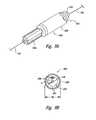
- Figure 3Cis a back view illustrating further details of an embodiment of the handle 150.
- dimensions of the gripping necks 163-164are provided such that the gripping neck 154 volume frees up two or three fingers (e.g., thumb and forefinger) of the single operator's hand to manipulate (e.g., advance, repeatedly position, hold in place relative to the bronchoscope seal) the elongated body 130 at the desired target sites within passageways of the patient.
- the first and second neck portions 163-164may have a combined width (denoted by arrows 149 in Figure 2A ) in a range from about 0.95 inches to about 1.3 inches.
- the first (or second) neck portion depth 163amay be in a range from about 0.75 inches to about 1.0 inch.
- the grip portionsare narrower than the head 156, which is dimensioned (denoted by arrows 155) in a range from about 1.3 inches to about 1.75 inches, so as to allow the head 156 to be easily cradled by the operator's thumb and forefinger.
- an opening 157 in the first portion 151can be seen for connection of the handle 150 to the conductive line 117.
- FIGS 2B-3Calso illustrate an example of operating the system 100.
- the handle 150 shown in Figure 3Ais in a first position in which the electrodes 142 are in a low-profile configuration.
- an operatoradvances the energy delivery unit 140 and the elongated body 130 through the working lumen 181 of the access device 180 until the energy delivery unit 140 projects beyond a distal end 182 of the access device 180.
- Visualization of thismay be facilitated by an imaging lumen 128 and/or light optical fiber lumens 129 of the access device 180 (or optical chip(s) or fiber(s) mounted at the distal end of the access device).
- the operatorcan control the position of the energy delivery unit 140 relative to the access device 180 using the markers 136 on the elongated body 130.
- the operatorsqueezes the handle 150 (arrow R) to move the second portion 152 about the joint 153, which causes the flange 170 to rotate the lever 172 in a manner that pulls the wire 146 proximally.
- the proximal movement of the wire 146pulls the distal retainer 144b proximally and accordingly moves the electrodes 142 outwardly (arrows O in Figure 2B ).
- the operatorcan control the elongated body 130 and rotate the second portion 152 relative to the first portion 151 with a single hand while simultaneously holding the access device 180 in the other hand and/or the same hand.
- the operatorthen actuates the switch 116 ( Figure 2A ) that activates the energy generator 111 ( Figure 2A ) to deliver energy via the electrodes 142 to the tissue of the airway until the controller 112 ( Figure 2A ) or the operator deactivates the energy generator.
- the operatorthen releases the second portion 152 of the handle to release the tension on the wire 146 so that the electrodes 142 move inwardly (arrows I).
- the operatorcan then move the elongated body 130 axially while holding the access device 180 to reposition the energy delivery unit by an increment indicated by the markers 136 and repeat the procedure at another site of the airway.
- Figure 4is an isometric view illustrating an embodiment of how an operator can hold and control both the elongated body 130 and the handle 150 with a single hand to concurrently move the electrodes 142 outwardly and/or inwardly. More specifically, the hand 400 of the operator can hold the grip 154 such that the thumb 401 and the forefinger 402 (i.e., first finger) extend around the neck portion of the grip 154. The outward projection of the head 156 of the handle 150 can be configured to rest on a portion of the thumb 401 and forefinger 402 to further control the handle 150.
- a reinforcing sheath 158 along the elongated body 130 combined with the reversible handle 150may direct the most proximal portion 134 away from the hand 400 of the operator so as to enhance single hand control at the bronchoscope seal and single operator control of both the treatment and access devices.
- the operatorcan concurrently grip the elongated body 130 with the distal phalanxes of the thumb 401 and forefinger 402 in a manner that enables the operator to hold the elongated body 130 at a precise location.
- the operatorcan also squeeze/release the handle 150 with at least one of a second-fourth (e.g., second, third, or fourth) finger of the hand 400 to move the electrodes outwardly/inwardly.
- a second-fourthe.g., second, third, or fourth
- FIG. 5is a flow chart illustrating a method 500 for treating tissue in an internal passageway of a patient in accordance with one embodiment.
- the method 500includes positioning an access device in a lung airway of a patient (block 510).
- the method 500further includes advancing an elongated body of a treatment device, such as an embodiment of the energy delivery devices described above, along the access device (block 520).
- the elongated bodyis advanced along the access device until an energy delivery unit at a distal portion of the elongated body projects from the access device and is positioned at a desired treatment site.
- the method 500further includes expanding the energy delivery unit such that electrodes or other energy delivery elements contact a sidewall of the airway while the elongated body is held in place (block 530), and activating an energy supply coupled to the treatment device such that energy is delivered to the sidewall of the airway (block 540).
- the method 500is conducted by a single person such that the single person physically operates both the access device and the treatment device while expanding the energy delivery unit and activating the energy supply.
- Figure 6is a flow chart illustrating a method 600 for treating an internal airway in a lung of a patient using an embodiment of the system 100.
- the method 600includes holding an access device in a first hand of an operator while the access device is in an airway of a lung of a patient (block 610).
- the method 600further includes holding a treatment device in a second hand of the operator such that (i) a catheter of the treatment device is positioned in the access device (block 620) and (ii) an energy delivery unit attached to the catheter is positioned beyond an end of the access device.
- the method 600also includes moving an actuator of the treatment device while holding the energy delivery unit in place using the second hand of the operator (block 630) such that at least a portion of the energy delivery unit contacts a sidewall of the airway and delivers energy to the airway while the operator's first hand holds the access device.
- FIG. 7is a flow chart of a method 700 for treating an internal airway in a lung of a patient in accordance with another embodiment.
- the method 700includes controlling a bronchoscope with a first hand of a single operator to position a distal end of a bronchoscope in a lung airway of the patient (block 710).
- the method 700further includes moving a treatment device with a second hand of the single person to slide a flexible catheter through a working lumen of the bronchoscope (block 720).
- the single personfor example, moves the treatment device until the electrode assembly of the treatment device projects beyond the distal end of the bronchoscope at a first treatment site in the lung airway.
- the method 700further includes squeezing an actuator of the treatment device with a second hand of the single person while holding the catheter and the bronchoscope with at least one of the first and second hands of the single person (block 730).
- the actuatorcauses electrodes of the electrode assembly to move outwardly to contact the airway.
- the method 700can further include applying energy to the target site via the electrodes while the single person holds the bronchoscope and the treatment device (block 740).
- the handle 150reduces thumb-fatigue associated with other devices because the handle 150 is actuated with a squeezing motion using larger muscles instead of a sliding motion using primarily muscles associated with the thumb.
- the system 100can also be operated by a single person such that it eliminates delays that can occur in systems that require both a first practitioner and a second practitioner to operate the access device and the treatment device.
- Several embodiments of the system 100may accordingly treat more patients in a fixed time period, treat patients with reduced treatment time or sessions, and/or treat more passageways within a patient in a single session. Further, a single operator procedure ensures greater accuracy of treatment device placements, and hence treatment patterns.
- Figures 8A and 8Billustrate a specific embodiment of the elongated body 130.
- the elongated body 800includes a coil 810 with a lumen 812 and an outer casing 820 over the coil 810 and fixed at distal and proximal ends.
- the coil 810can be a flexible winding of a suitable metal or polymer that can be pushed/pulled in a longitudinal direction, transmit torsional forces, and prevent kinking or collapse of the lumen 812.
- the casing 820can be a coating or thicker cover that is also flexible and configured to have an outer diameter "OD" in a range from about 0.75 mm to about 1.6 mm to enable suction and fluid irrigation through a 2 mm working lumen of the access device without catheter removal.
- the casing 820can be made from pebax, nylon, grilimide, or other polymeric materials.
- the lumen 812 of the coil 810provides a large space "S" ( Figure 8B ) through which the wire 146 and one or more thermocouple leads 830 can extend.
- the large space S between the wire 146 and the coil 810reduces friction between the wire 146 and the elongated body 130 such that the wire 146 can readily move longitudinally within the coil 810. This allows the wire 146 to move proximally/distally to move the electrodes 142 outwardly/inwardly along a significant portion of the stroke/trigger length of the actuator of the handle, which may be in a range from about 5 mm to about 40 mm. As a result, the electrodes may be more easily deployed compared to catheters with higher friction between the wire 146 and the elongated body 130.
- the tactile feedback to the operatoris also enhanced with less friction, the trigger handle design, and/or torsional spring such that it is easier for an operator to determine when the electrodes 142 sufficiently contact an airway.
- the outer diameter OD of the casing 820can also be relatively small because the elongated body 130 does not include a slideable sheath around an extrusion. Consequently, the elongated body 130 occupies less space in the working lumen of a bronchoscope such that fluids can be extracted/injected into the passageway through the working lumen.
- a solution or gascan be injected into an airway through the working lumen of a bronchoscope with the elongated body in the working lumen, and alternatively mucus and other matter can be suctioned from the airways via the working lumen of the bronchoscope with the elongated body in the working lumen.
Landscapes
- Health & Medical Sciences (AREA)
- Life Sciences & Earth Sciences (AREA)
- Surgery (AREA)
- Engineering & Computer Science (AREA)
- Plasma & Fusion (AREA)
- Medical Informatics (AREA)
- Otolaryngology (AREA)
- Physics & Mathematics (AREA)
- Cardiology (AREA)
- Biomedical Technology (AREA)
- Heart & Thoracic Surgery (AREA)
- Nuclear Medicine, Radiotherapy & Molecular Imaging (AREA)
- Molecular Biology (AREA)
- Animal Behavior & Ethology (AREA)
- General Health & Medical Sciences (AREA)
- Public Health (AREA)
- Veterinary Medicine (AREA)
- Surgical Instruments (AREA)
Abstract
Description
- The present invention is directed to medical systems and methods for delivering energy to passageways in a patient, such as airways in the lung of a patient to reduce the resistance to airflow.
- Asthma is a disease that makes it difficult to breathe and in many cases can be debilitating. Asthma is generally manifested by (i) bronchoconstriction, (ii) excessive mucus production, and/or (iii) inflammation and swelling of airways that cause widespread but variable airflow obstructions. Asthma can be a chronic disorder often characterized by persistent airway inflammation, but asthma can be further characterized by acute episodes of additional airway narrowing via contraction of hyper-responsive airway smooth muscle tissue.
- Conventional pharmacological approaches for managing asthma include: (i) administering anti-inflammatories and long-acting bronchodilators for long-term control, and/or (ii) administering short-acting bronchodilators for management of acute episodes. Both of these pharmacological approaches generally require repeated use of the prescribed drugs at regular intervals throughout long periods of time. However, high doses of corticosteroid anti-inflammatory drugs can have serious side effects that require careful management, and some patients are resistant to steroid treatment even at high doses. As such, effective patient compliance with pharmacologic management and avoiding stimulus that triggers asthma are common barriers to successfully managing asthma.
- Asthmatx, Inc. has developed new asthma treatments that involve applying energy to alter properties of the smooth muscle tissue or other tissue (e.g., nerves, mucus glands, epithelium, blood vessels, etc.) of airways in a lung of a patient. Several embodiments of methods and apparatus related to such treatments are disclosed in commonly-assigned
U.S. Patent Nos. 6,411,852 ,6,634,363 , and7,027,869 ; and U.S. Published Application No.US2005/0010270 , all of which are incorporated by reference herein in their entirety. - Many embodiments of the foregoing asthma treatments that apply energy to tissue of the airways use catheters that can be passed (e.g., navigated) through the tortuous pathways defined by the lung airways.
Figure 1 , for example, illustrates abronchial tree 90 in which thevarious bronchioles 92 decrease in size and havemany branches 96 as they extend from the right andleft bronchi 94. Accordingly, the treatment devices should be configured to treat airways of varying sizes as well as function properly when repeatedly deployed after navigating through the tortuous anatomy. - In a typical application, a first medical practitioner (e.g., a bronchoscopist) navigates a distal portion of a bronchoscope through the tortuous pathways of the lung until the distal tip of the bronchoscope is at a desired region of an airway. A second medical practitioner (e.g., a nurse or medical assistant) in addition to the first practitioner assists in advancing a catheter of a treatment device through a working lumen of the bronchoscope until a distal portion of the catheter projects out from the distal end of the bronchoscope. After positioning the distal portion of the catheter at a desired first airway site, the first or second practitioner uses one hand to hold the catheter in place relative to the bronchoscope while the second practitioner moves the thumb of one or the other free hand to move a slide-type actuator in a distal direction to drive an electrode array distally out of the catheter. The second practitioner continues to move the slide-type actuator in the distal direction to drive a plurality of electrodes outwardly until the electrodes contact the sidewall of the airway at a first contact site. The first or second medical practitioner then operates a switch that activates an energy source to deliver energy to the first contact site for a treatment period.
- After terminating the energy delivery, (i) the second practitioner slides the actuator in a proximal direction to contract the electrodes, (ii) the first or second practitioner repositions the catheter axially along the bronchoscope and the airway to a second contact site, and (iii) with the catheter held in place, the second practitioner slides the actuator distally to re-expand the electrodes until they contact the sidewall of the airway at the second contact site. The first or second practitioner then activates the energy supply to deliver energy to the second contact site for another treatment period. This process is repeated several times at 3-30 mm increments throughout several regions of the variable sized airways in a lung of a patient. As such, this process requires good coordination and communication between the first and second practitioners to treat a patient, but even then such communication takes time. A typical treatment protocol for treating the full lung of a patient can accordingly require three 30-60 minute sessions, which often results in practitioner fatigue.
- The tortuous configuration of the lung airways also presents other challenges to efficiently delivering energy to the airway tissue. For example, the treatment device should be sufficiently flexible to follow the working lumen of a bronchoscope and help facilitate accurate steering of the bronchoscope, and the treatment device should enable accurate, reliable deployment of the electrodes at the distal end of the catheter. Friction losses along the catheter, however, can restrict expansion/contraction of the electrodes because only a portion of the force from the actuator is transmitted to the electrode array. This can inhibit the electrodes from appropriately (e.g., fully) contacting the sidewall of the airway, which may reduce the efficacy of the treatment. Additionally, friction along the catheter increases the load on the thumb of the second practitioner as the slide-type actuator is repeatedly moved, which may cause fatigue and also may make it difficult to sense when the electrodes engage the variable sized airways.
- The following drawings should be read with reference to the detailed description. Like numbers in different drawings refer to like elements. The drawings, which are not necessarily to scale, illustratively depict embodiments of the disclosure and are not intended to limit the scope of the disclosure.
Figure 1 illustrates representative airways in a lung of a human patientFigure 2A is a schematic view illustrating a system for delivering energy to passageways in a patient in accordance with an embodiment of the disclosure.Figure 2B is a side view in partial cross-section of a portion of an energy delivery device for use with the system ofFigure 2A in accordance with an embodiment of the disclosure.Figure 2C is an exploded view of a portion of an electrode of the energy delivery device ofFigure 2B in accordance with an embodiment of the disclosure.Figures 3A and 3B are cross-sectional views andFigure 3C is a back view of a handle for use with an energy delivery device in accordance with an embodiment of the disclosure.Figure 4 is an isometric view illustrating an implementation of the handle illustrated inFigures 3A and 3B in accordance with an embodiment of the disclosure.Figure 5 is a flow chart of a method for treating tissue in an internal passageway of a patient in accordance with an embodiment of the disclosure.Figure 6 is a flow chart of a method of treating an internal airway in a lung of a patient in accordance with an embodiment of the disclosure.Figure 7 is a flow chart of a method of treating an internal airway in a lung of a patient in accordance with another embodiment of the disclosure.Figure 8A is an isometric view with a cutaway portion andFigure 8B is a cross-sectional view illustrating a portion of a catheter for use with an energy delivery device in accordance with an embodiment of the disclosure.- Specific details of several embodiments of the disclosure are described below with reference to systems and methods for delivering energy to passageways in a patient. Although many of the embodiments are described below with respect to delivering radio frequency energy to airways in a lung of a patient to treat asthma, other embodiments that deliver other energy modalities to lung airways or other types of passageways for treating other indications may be within the scope of the invention. For example, other types of energy modalities can include thermal (resistive and/or infrared), microwave, laser, ultrasonic (e.g., HIFU), cryo-ablation, radiation, and/or other energy modalities. Moreover, several other embodiments of the invention can have different configurations, components, or procedures than those described in this section. A person of ordinary skill in the art, therefore, will accordingly understand that the invention may have other embodiments with additional elements, or the invention may have other embodiments without several of the features shown and described below with reference to
Figures 2A-8B . It will further be appreciated that the above depictions are for illustrative purposes only and do not necessarily reflect the actual shape, size, or dimensions of the system or device. Figure 2A is a schematic view illustrating asystem 100 for delivering energy to passageways in a patient having a power/control unit 110 and anenergy delivery device 120 in accordance with an embodiment of the disclosure. The power/control unit 110 can include an energy generator 111 (e.g., power supply), acontroller 112 having aprocessor 113, and auser interface 114. Theenergy generator 111 andcontroller 112 can provide radio frequency (RF) energy to theenergy delivery device 120, but other embodiments of theenergy generator 111 andcontroller 112 can provide other energy modalities. Thecontroller 112 can contain safety algorithms and other control algorithms that control (i) the power output to theenergy delivery device 120 and (ii) theindicators user interface 114. The power/control unit 110 can further include one ormore connections optional return electrode 115 for monopolar RF configurations, an optional switch 116 (e.g., an actuation pedal) for directing thecontroller 112 to cause theenergy generator 111 to provide energy, and aconductive line 117 andconnector 126 coupled to theenergy delivery device 120.- Suitable embodiments of the power/control unit are disclosed in
U.S. Patent No. 7,104,987 , U.S. Published Application No.US2006/0247746 , and commonly assigned U.S. Patent Application entitled "SYSTEM AND METHOD FOR CONTROLLING POWER BASED ON IMPEDANCE DETECTION, SUCH AS CONTROLLING POWER TO TISSUE TREATMENT DEVICES, filed on July 24, 2007, and further identified by Perkins Coie, LLP docket number 64921.8001USOO, the entirety of which are incorporated by reference herein. The system may deliver energy to target sites via thetreatment device 100 in a variety of treatment patterns. Further details with respect to energy modalities and/or examples of treatment patterns may be found in commonly-assignedU.S. Patent No. 6,411,852 . - The
energy delivery device 120 is an example of a treatment device for treating asthma or other indications associated with passageways in a human. The embodiment of theenergy delivery device 120 illustrated inFigure 2A includes anelongated body 130 with adistal portion 132 and aproximal portion 134, anenergy delivery unit 140 at thedistal portion 132, and ahandle 150 at theproximal portion 134. The length of theelongated body 130 should be sufficient to access the target tissue in airways of the lung or other passageways targeted for treatment. For example, the length of theelongated body 130 can be from approximately 0.5-8 feet to allow passage though a bronchoscope and reach targeted airways deep within the lungs. Theelongated body 130 can also be configured to treat airways as small as 3 mm in diameter, but theelongated body 130 is not limited to treating airways of any particular size such that airways smaller or larger than 3 mm may be treated. Typically, thedelivery unit 140 expands/contracts to variable sizes to treat airways between 3-10 mm. - Several embodiments of the
elongated body 130 are flexible catheters configured to slide through the working lumen of an access device (e.g., bronchoscope). Theelongated body 130 can also include a plurality ofmarkers 136 at thedistal section 132 to position theenergy delivery unit 140 relative to an access device (not shown inFigure 2A ) and a proximal marker(s) 127 so as to assist in expedient positioning of theenergy delivery unit 140 out of the distal end of the access device. Specific embodiments of elongated bodies with markers suitable for use in thesystem 100 are described below with reference toFigures 8A and 8B , and inU.S. Patent Application No. 11/551,639 and in U.S. Published Application No.US2007/0106292 , which are incorporated herein by reference in their entirety. - The
energy delivery unit 140 can have at least one energy delivery element, such as anelectrode 142, configured to deliver energy to the tissue of an airway or other passageway in the patient.Figure 2B is a partial cross-sectional view showing an embodiment of theenergy delivery unit 140 in greater detail. In this embodiment, theenergy delivery unit 140 includes fourelectrodes 142, aproximal sleeve 138a and a proximal alignment extrusion orretainer 144a fixed to theelongated body 130 and attached to the proximal ends of theelectrodes 142, and adistal sleeve 138b and a distal alignment extrusion orretainer 144b .attached to the distal ends of theelectrodes 142. Theenergy delivery device 120 can also include awire 146 attached to thedistal retainer 144b at thedistal sleeve 138b and configured to move through alumen 147 of theelongated body 130 and theproximal retainer 144a. - The example of the
energy delivery unit 140 illustrated inFigure 2B is a "basket-type" configuration in which theelectrodes 142 move outwardly (arrows O) as thewire 146 moves proximally (arrow P) relative to theelongated body 130. Theelectrodes 142 can move inwardly (arrows I) by releasing thewire 146 such that a spring or other resilient element in thehandle 150, and/or the spring force of theelectrodes 142, drives thewire 146 distally. The outward/inward movement of theelectrodes 142 is useful when the device is operated intralumena11y or in airways in the lungs because theenergy delivery unit 140 can be advanced through a workinglumen 181 of anaccess device 180 while theelectrodes 142 are in a low-profile configuration, and then theelectrodes 142 can repeatedly be moved outwardly according to the varying sizes of the passageways. In this illustration, thepull wire 146 may also comprise a conductive wire between theelectrodes 142 and theenergy supply 111. Specific embodiments of suitable electrodes and retainers for preventing electrode inversions and limiting basket expansions are disclosed in U.S. Publication No.US2007/0106292 . Figure 2C is an exploded view illustrating a portion of oneelectrode 142 in greater detail. Theelectrode 142 has an outer insulating material orcoating 143 at proximal and distal ends so as to define a non-insulated, activecentral portion 145 of theelectrode 142 which delivers controlled energy to the tissue walls. Athermocouple 137 having thermocouple leads 139 is attached and in electrical communication to theactive portion 145 of theelectrode 142 atseparate joints 141. The circuit may be triggered (e.g., open circuit) if either joint becomes detached so that thethermocouple 137 stops reading temperature. Specific embodiments of suitable electrode and thermocouple configurations are disclosed in U.S. Publication No.US2007/0118184 , which is incorporated herein by reference in its entirety.- Referring back to
Figure 2A , the illustrated example of thehandle 150 is configured so that a single operator can hold an access device (e.g., a bronchoscope) in one hand (e.g., a first hand) and use the other hand (e.g., a second hand) to (i) advance theelongated body 130 through a working lumen of the access device until theenergy delivery unit 140 projects beyond the distal end of the access device and is positioned at a desired target site, and (ii) pull the wire 146 (Figure 2B ) to move theelectrodes 142 outwardly until they contact the sidewall of an airway passage while the catheter is held in place relative to the access device with a single hand (e.g., the same second hand). The same operator can also operate theswitch 116 of the power/control unit 110 such that the entire procedure can be performed by a single person. - In one embodiment, the
handle 150 has afirst portion 151 and asecond portion 152 rotatably coupled to thefirst portion 151 by a joint 153. Thefirst portion 151 and/or thesecond portion 152 are one example of an actuator for manipulating theelectrodes 142. The first and second portions 151-152 can be configured to form agrip 154 and ahead 156 located at an upper portion of thegrip 154. Thehead 156, for example, can project outwardly from the grip such that a portion of thegrip 154 is narrower than thehead 156. In the specific embodiment illustrated inFigure 2A , thefirst portion 151 has a firstcurved surface 161 with afirst neck portion 163 and afirst collar portion 165, and thesecond portion 152 has a secondcurved surface 162 with asecond neck portion 164 and asecond collar portion 166. The first and second curved surfaces 161-162 can be configured such that they are arranged to define a hyperbolic-like shaped grip when viewed from a side elevation. - The portion of the
handle 150 at the first and second neck portions 163-164 provides a neck around which the thumb and forefinger of an operator can extend, and the first and second collar portions 165-166 are configured to be supported by the thumb and forefinger of the operator. Thehandle 150 can also include a torsion spring (not shown) at the joint 153, or another suitable resilient element, to drive the lower ends of the first and second portions 151-152 apart from each other. In addition, the spring torsion may be selected to provide a difference in sensation between handle actuation in air as opposed to a counter force of the airway wall (e.g., a less robust spring). In operation, a single user moves the lower ends of the first and second portions 151-152 together (arrow R inFigure 3A ) while simultaneously controlling the position of theelongated body 130 in the airway of the patient with a single hand as explained in more detail below. After applying energy to the tissue for a treatment period, the operator relaxes his/her grip and the torsion spring drives the lower ends of the first and second portions 151-152 apart from each other. Figures 3A and 3B are cross-sectional views illustrating further details of an embodiment of thehandle 150 with a section of thefirst portion 151 removed. In this embodiment, thehandle 150 further includes aflange 170 fixed to thesecond portion 152 and alever 172 pivotally attached to thefirst portion 151 by apin 173. One end of thelever 172 is in a notch in theflange 170, and an opposing end of thelever 172 is attached to thewire 146 that extends through the lumens of theelongated body 130 to thedistal retainer 144b (Figure 2B ) of theenergy delivery unit 140. Thefirst portion 151 can also include a track element (not shown) that secures the line 117 (Figure 2A ) to thehandle 150 via a press fit or zigzag path.Figure 3C is a back view illustrating further details of an embodiment of thehandle 150. As described above, dimensions of the gripping necks 163-164 are provided such that thegripping neck 154 volume frees up two or three fingers (e.g., thumb and forefinger) of the single operator's hand to manipulate (e.g., advance, repeatedly position, hold in place relative to the bronchoscope seal) theelongated body 130 at the desired target sites within passageways of the patient. The first and second neck portions 163-164 may have a combined width (denoted byarrows 149 inFigure 2A ) in a range from about 0.95 inches to about 1.3 inches. The first (or second)neck portion depth 163a (denoted by arrows 148) may be in a range from about 0.75 inches to about 1.0 inch. The grip portions are narrower than thehead 156, which is dimensioned (denoted by arrows 155) in a range from about 1.3 inches to about 1.75 inches, so as to allow thehead 156 to be easily cradled by the operator's thumb and forefinger. In this view, anopening 157 in thefirst portion 151 can be seen for connection of thehandle 150 to theconductive line 117.Figures 2B-3C also illustrate an example of operating thesystem 100. Referring toFigures 2B and3A together, thehandle 150 shown inFigure 3A is in a first position in which theelectrodes 142 are in a low-profile configuration. In this configuration, an operator advances theenergy delivery unit 140 and theelongated body 130 through the workinglumen 181 of theaccess device 180 until theenergy delivery unit 140 projects beyond adistal end 182 of theaccess device 180. Visualization of this may be facilitated by animaging lumen 128 and/or lightoptical fiber lumens 129 of the access device 180 (or optical chip(s) or fiber(s) mounted at the distal end of the access device). As described in U.S. Published Application. No. 2007/0106292, the operator can control the position of theenergy delivery unit 140 relative to theaccess device 180 using themarkers 136 on theelongated body 130.- Referring to
Figures 2B and3B , the operator squeezes the handle 150 (arrow R) to move thesecond portion 152 about the joint 153, which causes theflange 170 to rotate thelever 172 in a manner that pulls thewire 146 proximally. The proximal movement of thewire 146 pulls thedistal retainer 144b proximally and accordingly moves theelectrodes 142 outwardly (arrows O inFigure 2B ). The operator can control theelongated body 130 and rotate thesecond portion 152 relative to thefirst portion 151 with a single hand while simultaneously holding theaccess device 180 in the other hand and/or the same hand. The operator then actuates the switch 116 (Figure 2A ) that activates the energy generator 111 (Figure 2A ) to deliver energy via theelectrodes 142 to the tissue of the airway until the controller 112 (Figure 2A ) or the operator deactivates the energy generator. The operator then releases thesecond portion 152 of the handle to release the tension on thewire 146 so that theelectrodes 142 move inwardly (arrows I). The operator can then move theelongated body 130 axially while holding theaccess device 180 to reposition the energy delivery unit by an increment indicated by themarkers 136 and repeat the procedure at another site of the airway. Figure 4 is an isometric view illustrating an embodiment of how an operator can hold and control both theelongated body 130 and thehandle 150 with a single hand to concurrently move theelectrodes 142 outwardly and/or inwardly. More specifically, thehand 400 of the operator can hold thegrip 154 such that thethumb 401 and the forefinger 402 (i.e., first finger) extend around the neck portion of thegrip 154. The outward projection of thehead 156 of thehandle 150 can be configured to rest on a portion of thethumb 401 andforefinger 402 to further control thehandle 150. Further, a reinforcingsheath 158 along theelongated body 130 combined with thereversible handle 150 may direct the mostproximal portion 134 away from thehand 400 of the operator so as to enhance single hand control at the bronchoscope seal and single operator control of both the treatment and access devices. In this application, the operator can concurrently grip theelongated body 130 with the distal phalanxes of thethumb 401 andforefinger 402 in a manner that enables the operator to hold theelongated body 130 at a precise location. The operator can also squeeze/release thehandle 150 with at least one of a second-fourth (e.g., second, third, or fourth) finger of thehand 400 to move the electrodes outwardly/inwardly.Figure 5 is a flow chart illustrating amethod 500 for treating tissue in an internal passageway of a patient in accordance with one embodiment. Themethod 500 includes positioning an access device in a lung airway of a patient (block 510). Themethod 500 further includes advancing an elongated body of a treatment device, such as an embodiment of the energy delivery devices described above, along the access device (block 520). The elongated body is advanced along the access device until an energy delivery unit at a distal portion of the elongated body projects from the access device and is positioned at a desired treatment site. Themethod 500 further includes expanding the energy delivery unit such that electrodes or other energy delivery elements contact a sidewall of the airway while the elongated body is held in place (block 530), and activating an energy supply coupled to the treatment device such that energy is delivered to the sidewall of the airway (block 540). Themethod 500 is conducted by a single person such that the single person physically operates both the access device and the treatment device while expanding the energy delivery unit and activating the energy supply.Figure 6 is a flow chart illustrating amethod 600 for treating an internal airway in a lung of a patient using an embodiment of thesystem 100. Themethod 600 includes holding an access device in a first hand of an operator while the access device is in an airway of a lung of a patient (block 610). Themethod 600 further includes holding a treatment device in a second hand of the operator such that (i) a catheter of the treatment device is positioned in the access device (block 620) and (ii) an energy delivery unit attached to the catheter is positioned beyond an end of the access device. Themethod 600 also includes moving an actuator of the treatment device while holding the energy delivery unit in place using the second hand of the operator (block 630) such that at least a portion of the energy delivery unit contacts a sidewall of the airway and delivers energy to the airway while the operator's first hand holds the access device.Figure 7 is a flow chart of amethod 700 for treating an internal airway in a lung of a patient in accordance with another embodiment. Themethod 700 includes controlling a bronchoscope with a first hand of a single operator to position a distal end of a bronchoscope in a lung airway of the patient (block 710). Themethod 700 further includes moving a treatment device with a second hand of the single person to slide a flexible catheter through a working lumen of the bronchoscope (block 720). The single person, for example, moves the treatment device until the electrode assembly of the treatment device projects beyond the distal end of the bronchoscope at a first treatment site in the lung airway. Themethod 700 further includes squeezing an actuator of the treatment device with a second hand of the single person while holding the catheter and the bronchoscope with at least one of the first and second hands of the single person (block 730). The actuator causes electrodes of the electrode assembly to move outwardly to contact the airway. Themethod 700 can further include applying energy to the target site via the electrodes while the single person holds the bronchoscope and the treatment device (block 740).- Several embodiments of the
system 100 provide an ergonomic and efficient treatment device. Thehandle 150, for example, reduces thumb-fatigue associated with other devices because thehandle 150 is actuated with a squeezing motion using larger muscles instead of a sliding motion using primarily muscles associated with the thumb. Thesystem 100 can also be operated by a single person such that it eliminates delays that can occur in systems that require both a first practitioner and a second practitioner to operate the access device and the treatment device. Several embodiments of thesystem 100 may accordingly treat more patients in a fixed time period, treat patients with reduced treatment time or sessions, and/or treat more passageways within a patient in a single session. Further, a single operator procedure ensures greater accuracy of treatment device placements, and hence treatment patterns. Figures 8A and 8B illustrate a specific embodiment of theelongated body 130. In this embodiment, theelongated body 800 includes acoil 810 with alumen 812 and anouter casing 820 over thecoil 810 and fixed at distal and proximal ends. Thecoil 810 can be a flexible winding of a suitable metal or polymer that can be pushed/pulled in a longitudinal direction, transmit torsional forces, and prevent kinking or collapse of thelumen 812. Thecasing 820 can be a coating or thicker cover that is also flexible and configured to have an outer diameter "OD" in a range from about 0.75 mm to about 1.6 mm to enable suction and fluid irrigation through a 2 mm working lumen of the access device without catheter removal. Thecasing 820 can be made from pebax, nylon, grilimide, or other polymeric materials.- The
lumen 812 of thecoil 810 provides a large space "S" (Figure 8B ) through which thewire 146 and one or more thermocouple leads 830 can extend. The large space S between thewire 146 and thecoil 810 reduces friction between thewire 146 and theelongated body 130 such that thewire 146 can readily move longitudinally within thecoil 810. This allows thewire 146 to move proximally/distally to move theelectrodes 142 outwardly/inwardly along a significant portion of the stroke/trigger length of the actuator of the handle, which may be in a range from about 5 mm to about 40 mm. As a result, the electrodes may be more easily deployed compared to catheters with higher friction between thewire 146 and theelongated body 130. The tactile feedback to the operator is also enhanced with less friction, the trigger handle design, and/or torsional spring such that it is easier for an operator to determine when theelectrodes 142 sufficiently contact an airway. The outer diameter OD of thecasing 820 can also be relatively small because theelongated body 130 does not include a slideable sheath around an extrusion. Consequently, theelongated body 130 occupies less space in the working lumen of a bronchoscope such that fluids can be extracted/injected into the passageway through the working lumen. For example, a solution or gas can be injected into an airway through the working lumen of a bronchoscope with the elongated body in the working lumen, and alternatively mucus and other matter can be suctioned from the airways via the working lumen of the bronchoscope with the elongated body in the working lumen. - From the foregoing, it will be appreciated that specific embodiments of the invention have been described herein for purposes of illustration, but that various modifications may be made without deviating from the inventions. For example, many of the elements of one embodiment can be combined with other embodiments in addition to, or in lieu of, the elements of the other embodiments. Where the context permits, singular or plural terms may also include the plural or singular term, respectively. Moreover, unless the word "or" is expressly limited to mean only a single item exclusive from the other items in reference to a list of two or more items, then the use of "or" in such a list is to be interpreted as including (a) any single item in the list, (b) all of the items in the list, or (c) any combination of the items in the list. Additionally, the term "comprising" is inclusive and therefore used throughout to mean including at least the recited feature(s) such that any greater number of the same feature and/or additional types of features are not precluded. Therefore, the invention is not limited except as by the appended claims.
- 1. A method of treating tissue in an internal passageway in a patient, comprising positioning an access device in a lung airway of a patient; advancing an elongated body of a treatment device along the access device until an energy delivery unit at a distal portion of the elongated body projects from the access device; expanding the energy delivery unit such that energy delivery elements contact a sidewall of the airway; and activating an energy supply coupled to the treatment device such that energy is delivered to the sidewall of the airway, wherein a single person physically operates both the access device and the treatment device while expanding the energy delivery unit and activating the energy supply.
- 2. The method of paragraph 1, wherein the single person holds both the access device and the treatment device while activating the energy supply.
- 3. The method of paragraph 1, wherein advancing the elongated body comprises holding the elongated body with a distal phalanx of a thumb and a distal phalanx of a forefinger of one hand of the single person while pushing the elongated body through a working lumen of the access device; and expanding the energy delivery unit comprises moving an actuator with one of a second-fourth finger of the one hand of the single person, wherein the actuator is operatively coupled to the energy delivery unit.
- 4. The method of paragraph 3, wherein the actuator is part of a handle having a first portion and a second portion, and wherein moving the actuator comprises squeezing the first and second portions in the one hand of the single person.
- 5. The method of paragraph 1, wherein positioning the access device comprises moving a bronchoscope through the airway of the lung with a first hand of the single person; advancing the elongated body comprises pushing the elongated body through a working lumen of the bronchoscope with a second hand of the single person; and expanding the energy delivery unit comprises moving an actuator operatively coupled to the energy delivery unit with the second hand of the single person.
- 6. The method of paragraph 5, wherein advancing the elongated body with the second hand comprises holding the elongated body with a distal phalanx of a thumb and a distal phalanx of a forefinger of the second hand of the single person while pushing the elongated body through the working lumen; and expanding the energy delivery unit comprises moving the actuator with the second hand comprises squeezing a handle with one of a second-fourth finger of the second hand of the single person.
- 7. The method of paragraph 6, wherein the handle comprises a first portion and a second portion rotatably attached to the first portion, wherein the elongated body is coupled to one of the first and second portions and a wire in the elongated body is coupled to one of the first and second portions such that relative rotation between the first and second portions moves the wire longitudinally along the elongated body, and wherein the first portion has a first curved surface and the second portion has a second curved surface arranged such that the first and second curved surfaces define a hyperbolic-like shaped grip; and squeezing the handle comprises rotating one of the first and second portions relative to each other.
- 8. The method of paragraph 6, wherein the handle comprises a grip, a head coupled to the elongated body and located at an upper portion of the grip, and an actuator mechanism coupled to a wire in the elongated body, and wherein the head projects outwardly from the grip such that a portion of the grip is narrower than the head; and squeezing the handle comprises moving the actuator mechanism.
- 9. A method of treating an internal airway in a lung of a patient, comprising holding an access device in a first hand of an operator while the access device is in an airway of a lung of a patient; holding a treatment device in a second hand of the operator such that a catheter of the treatment device is positioned in the access device and an energy delivery unit attached to the catheter is positioned beyond an end of the access device; and moving an actuator of the treatment device using the second hand of the operator such that a portion of the energy delivery unit contacts a sidewall of the airway and delivering energy to the airway while the first hand of the operator holds the access device.
- 10. The method of paragraph 9, wherein holding the treatment device comprises pinching the catheter with a distal phalanx of a thumb and a distal phalanx of a forefinger of the second hand of the operator while pushing the catheter through a working lumen of the access device; and moving the actuator comprises grasping a handle with one of a second-fourth finger of the second hand of the operator.
- 11. The method of paragraph 10, wherein the handle has a first portion and a second portion, and wherein moving the actuator comprises squeezing the first and second portions in the second hand of the operator.
- 12. The method of paragraph 9, wherein holding the access device comprises moving a bronchoscope through the airway of the lung with the first hand and/or the second hand of the operator; holding the treatment device comprises pushing the catheter through a working lumen of the bronchoscope with the second hand of the operator.
- 13. The method of paragraph 12, wherein pushing the catheter with the second hand comprises gripping the catheter with a distal phalanx of a thumb and a distal phalanx of a forefinger of the second hand of the operator; and moving the actuator with the second hand comprises squeezing a handle with one of a second- fourth finger of the second hand of the operator.
- 14. A method of treating an internal airway in a lung of a patient, comprising controlling a bronchoscope with a first hand of a single person to position a distal end of the bronchoscope in a lung airway of the patient; moving a treatment device with a second hand of the single person to slide a flexible catheter through a working lumen of the bronchoscope until an electrode assembly of the treatment device projects beyond the distal end of the bronchoscope at a first treatment site in the lung airway; squeezing an actuator of the treatment device with the second hand of the single person while holding the catheter and the bronchoscope with one of the first and second hands of the single person, wherein the actuator causes electrodes of the electrode assembly to move outwardly; and applying energy to the first treatment site via the electrodes while the single person holds the bronchoscope and the treatment device.
- 15. The method of paragraph 14, wherein moving the treatment device with the second hand comprises pinching the catheter with a distal phalanx of a thumb and a distal phalanx of a forefinger of the second hand of the single person while sliding the catheter through the working lumen; and squeezing the actuator with the second hand comprises squeezing a handle with one of a second-fourth finger of the second hand of the single person.
- 16. The method of paragraph 15, wherein the handle comprises a first portion and a second portion rotatably attached to the first portion, wherein the catheter is coupled to one of the first and second portions and a wire in the catheter is coupled to one of the first and second portions such that relative rotation between the first and second portions moves the wire longitudinally along the catheter, and wherein the first portion has a first curved surface and the second portion has a second curved surface arranged such that the first and second curved surfaces define a hyperbolic-like shaped grip; and squeezing the handle comprises rotating one of the first and second portions relative to each other.
- 17. The method of paragraph 15, wherein the handle comprises a grip, a head coupled to the catheter and located at an upper portion of the grip, and an actuator mechanism coupled to a wire in the catheter, and wherein the head projects outwardly from the grip such that a portion of the grip is narrower than the head; and squeezing the handle comprises moving the actuator mechanism.
- 18. A radio frequency energy delivery device, comprising an elongated body having a proximal portion, a distal portion, and a lumen extending along the proximal and distal portions; a wire extending through the lumen; an energy delivery element at the distal portion of the elongated body and attached to the wire; and a handle having a grip, a head coupled to the proximal portion of the elongated body and located at an upper portion of the grip, and an actuator mechanism coupled to the wire, wherein the head projects outwardly from the grip such that a portion of the grip is narrower than the head.
- 19. The energy delivery device of paragraph 18, wherein the handle comprises a first portion and a second portion rotatably attached to the first portion, and wherein the actuator is defined by one of the first portion and the second portion.
- 20. The energy delivery device of paragraph 19, wherein the second portion has a flange with a notch and the first portion has a lever pivotally attached to the first portion, and wherein the lever has a first end in the notch and a second end attached to the wire.
- 21. The energy delivery device of paragraph 18, wherein the energy delivery element comprises an electrode.
- 22. The energy delivery device of paragraph 18, wherein the elongated body comprises a catheter including a cover with an inner wall, a coil coupled to the inner wall of the cover, and a lumen in the coil, and wherein the wire extends through the lumen of the coil.
- 23. A radio frequency energy delivery device, comprising an elongated body having a proximal portion, a distal portion, and a lumen extending along the proximal and distal portions; a member extending through the lumen; an electrode unit at the distal portion of the elongated member attached to the member and having an electrode; and a handle having a first portion and a second portion rotatably attached to the first portion, wherein the proximal portion of the elongated body is coupled to one of the first and second portions and the member is coupled to one of the first and second portions such that relative rotation between the first and second portions moves the member longitudinally along the elongated body, and wherein the first portion has a first curved surface and the second portion has a second curved surface arranged such that the first and second curved surfaces define a hyperbolic-like shaped grip.
- 24. The energy delivery device of paragraph 23, wherein the second portion has a flange with a notch and the first portion has a lever pivotally attached to the first portion, and wherein the lever has a first end in the notch and a second end attached to the member.
- 25. The energy delivery device of paragraph 23, wherein the elongated body comprises a catheter including a cover with an inner wall, a coil coupled to the inner wall of the cover, and a lumen in the coil, and wherein the member extends through the lumen of the coil.
- 26. A radio frequency energy delivery device, comprising an elongated body having a cover with an inner wall, a coil coupled to the inner wall of the cover, and a lumen in the coil; a wire extending through the lumen; an energy delivery unit at the distal portion of the elongated body, the energy delivery unit having a proximal retainer fixed to the elongated body, a distal retainer attached to the wire, and a plurality of flexible electrodes having proximal ends attached to the proximal retainer and distal ends attached to the distal retainer; and a handle having a grip, a head coupled to a proximal portion of the elongated body and located at an upper portion of the grip, and an actuator mechanism coupled to the wire, wherein the head projects outwardly from the grip such that a portion of the grip is narrower than the head.
- 27. The energy delivery device of paragraph 26, wherein a stroke length of the actuator of the handle is in a range from about 5 mm to about 40 mm.
- 28. A method of treating an internal airway in a lung of a patient, comprising positioning an elongated body of a treatment device in a lung airway of a patient until an energy delivery unit at a distal portion of the elongated body is positioned at a first treatment site; expanding the energy delivery unit such that energy delivery elements contact a sidewall of the airway at the first treatment site; and delivering energy to the sidewall of the airway at the first treatment site, wherein a single hand of an operator simultaneously controls positioning of the elongated body while maintaining expansion of the energy delivery unit during energy delivery.
- 29. The method of paragraph 28, wherein positioning the elongated body comprises holding the elongated body with a distal phalanx of a thumb and a distal phalanx of a forefinger of one hand of the operator; and expanding the energy delivery unit comprises moving an actuator with one of a second-fourth finger of the one hand of the operator, wherein the actuator is operatively coupled to the energy delivery unit.
- 30. The method of paragraph 28, further comprising simultaneously controlling an access device which slidably receives the treatment device with the one or other hand of the operator during energy delivery, wherein positioning the elongated body comprises holding the elongated body relative to the access device during energy delivery.
- 31. The method of paragraph 28, further comprising contracting the energy delivery unit, positioning the elongated body at a second treatment site, expanding the energy delivery unit at the second treatment site, and delivering energy to the second treatment site.
- 32. The method of paragraph 31, further comprising repeating the contracting, positioning, expanding, and delivering steps until a desired treatment pattern is achieved.
Claims (15)
- A device for delivering energy to an airway of a lung, the device comprising:an elongate member including a proximal end, a distal end, and a lumen extending therebetween;an actuating member operably coupled to the proximal end;an electrode assembly operably coupled to the distal end, wherein the electrode assembly includes a plurality of electrodes; andan operating member extending from the actuating member, through the lumen of the elongate member, and coupled to a distal end of the electrode assembly, wherein the operating member is configured to move reciprocally relative to the elongate member via actuation of the actuating member, wherein reciprocal movement of the operating member is configured to transition the electrode assembly between a first configuration and a second configuration, and wherein the operating member is biased distally by a resilient member in the actuating member.
- The device of claim 1, wherein the electrode assembly is an expandable basket.
- The device of claim 1, wherein an external surface of the elongate member includes a plurality of visual markers.
- The device of claim 1, further comprising a proximal alignment retainer attached to proximal ends of the plurality of electrodes.
- The device of claim 4, further comprising a distal alignment retainer attached to distal ends of the plurality of electrodes.
- The device of claim 1, wherein at least one of the plurality of electrodes includes at least one insulating coating.
- The device of claim 6, wherein the at least one insulating coating is one of a proximal and a distal insulating coating disposed on the at least one of the plurality of electrodes.
- The device of claim 7, wherein the at least one of the plurality of electrodes includes an non-insulated, active region disposed between the proximal and distal insulating coatings.
- The device of claim 8, further including a thermocouple disposed on the non-insulated active region of the at least one of the plurality of electrodes, wherein the thermocouple is in electrical communication with the plurality electrodes.
- The device of claim 1, wherein the plurality of electrodes are configured to move radially outward from a longitudinal axis of the elongate member when the electrode assembly is transitioned from the first configuration to the second configuration.
- The device of claim 10, wherein the plurality of electrodes are configured to move radially inward toward the longitudinal axis of the elongate member when the electrode assembly is transitioned from the second configuration to the first configuration.
- The device of claim 1, wherein the electrode assembly is transitioned from the first configuration to the second configuration by applying a proximally directed force to the operating member.
- The device of claim 12, wherein the electrode assembly is transitioned from the second configuration to the first configuration by releasing the proximally directed force applied to the operating member.
- The device of claim 1, further including an electrical generator coupled to the operating member, wherein the electrical generator is configured to deliver electrical energy to each of the plurality of electrodes via the operating member.
- The device of claim 1, wherein:the elongate member further includes:a lumen; anda coil disposed within the lumen; andthe operating member is disposed through the coil.
Applications Claiming Priority (2)
| Application Number | Priority Date | Filing Date | Title |
|---|---|---|---|
| US11/777,225US8235983B2 (en) | 2007-07-12 | 2007-07-12 | Systems and methods for delivering energy to passageways in a patient |
| EP08756715.2AEP2170459B1 (en) | 2007-07-12 | 2008-06-05 | Systems for delivering energy to passageways in a patient |
Related Parent Applications (3)
| Application Number | Title | Priority Date | Filing Date |
|---|---|---|---|
| EP08756715.2Division | 2008-06-05 | ||
| EP08756715.2ADivision-IntoEP2170459B1 (en) | 2007-07-12 | 2008-06-05 | Systems for delivering energy to passageways in a patient |
| EP08756715.2ADivisionEP2170459B1 (en) | 2007-07-12 | 2008-06-05 | Systems for delivering energy to passageways in a patient |
Publications (2)
| Publication Number | Publication Date |
|---|---|
| EP2653127A1true EP2653127A1 (en) | 2013-10-23 |
| EP2653127B1 EP2653127B1 (en) | 2017-11-22 |
Family
ID=40228960
Family Applications (2)
| Application Number | Title | Priority Date | Filing Date |
|---|---|---|---|
| EP08756715.2AActiveEP2170459B1 (en) | 2007-07-12 | 2008-06-05 | Systems for delivering energy to passageways in a patient |
| EP13003642.9AActiveEP2653127B1 (en) | 2007-07-12 | 2008-06-05 | Systems for delivering energy to passageways in a patient |
Family Applications Before (1)
| Application Number | Title | Priority Date | Filing Date |
|---|---|---|---|
| EP08756715.2AActiveEP2170459B1 (en) | 2007-07-12 | 2008-06-05 | Systems for delivering energy to passageways in a patient |
Country Status (7)
| Country | Link |
|---|---|
| US (4) | US8235983B2 (en) |
| EP (2) | EP2170459B1 (en) |
| JP (1) | JP2010533033A (en) |
| AU (1) | AU2008275444A1 (en) |
| CA (1) | CA2693769A1 (en) |
| ES (1) | ES2453152T3 (en) |
| WO (1) | WO2009009236A1 (en) |
Families Citing this family (59)
| Publication number | Priority date | Publication date | Assignee | Title |
|---|---|---|---|---|
| US7425212B1 (en)* | 1998-06-10 | 2008-09-16 | Asthmatx, Inc. | Devices for modification of airways by transfer of energy |
| US7992572B2 (en) | 1998-06-10 | 2011-08-09 | Asthmatx, Inc. | Methods of evaluating individuals having reversible obstructive pulmonary disease |
| US6634363B1 (en)* | 1997-04-07 | 2003-10-21 | Broncus Technologies, Inc. | Methods of treating lungs having reversible obstructive pulmonary disease |
| US7027869B2 (en) | 1998-01-07 | 2006-04-11 | Asthmatx, Inc. | Method for treating an asthma attack |
| US6488673B1 (en)* | 1997-04-07 | 2002-12-03 | Broncus Technologies, Inc. | Method of increasing gas exchange of a lung |
| US7921855B2 (en) | 1998-01-07 | 2011-04-12 | Asthmatx, Inc. | Method for treating an asthma attack |
| US20070123958A1 (en)* | 1998-06-10 | 2007-05-31 | Asthmatx, Inc. | Apparatus for treating airways in the lung |
| US7198635B2 (en) | 2000-10-17 | 2007-04-03 | Asthmatx, Inc. | Modification of airways by application of energy |
| US8181656B2 (en)* | 1998-06-10 | 2012-05-22 | Asthmatx, Inc. | Methods for treating airways |
| US8251070B2 (en)* | 2000-03-27 | 2012-08-28 | Asthmatx, Inc. | Methods for treating airways |
| US7104987B2 (en) | 2000-10-17 | 2006-09-12 | Asthmatx, Inc. | Control system and process for application of energy to airway walls and other mediums |
| US20040226556A1 (en)* | 2003-05-13 | 2004-11-18 | Deem Mark E. | Apparatus for treating asthma using neurotoxin |
| US7949407B2 (en)* | 2004-11-05 | 2011-05-24 | Asthmatx, Inc. | Energy delivery devices and methods |
| WO2006052940A2 (en) | 2004-11-05 | 2006-05-18 | Asthmatx, Inc. | Medical device with procedure improvement features |
| US20070093802A1 (en)* | 2005-10-21 | 2007-04-26 | Danek Christopher J | Energy delivery devices and methods |
| EP1906923B1 (en) | 2005-07-22 | 2018-01-24 | The Foundry, LLC | Systems and methods for delivery of a therapeutic agent |
| US12433837B2 (en) | 2005-07-22 | 2025-10-07 | The Foundry, Llc | Systems and methods for delivery of a therapeutic agent |
| US7931647B2 (en)* | 2006-10-20 | 2011-04-26 | Asthmatx, Inc. | Method of delivering energy to a lung airway using markers |
| US8235983B2 (en) | 2007-07-12 | 2012-08-07 | Asthmatx, Inc. | Systems and methods for delivering energy to passageways in a patient |
| US20090043301A1 (en)* | 2007-08-09 | 2009-02-12 | Asthmatx, Inc. | Monopolar energy delivery devices and methods for controlling current density in tissue |
| US8322335B2 (en) | 2007-10-22 | 2012-12-04 | Uptake Medical Corp. | Determining patient-specific vapor treatment and delivery parameters |
| US8483831B1 (en) | 2008-02-15 | 2013-07-09 | Holaira, Inc. | System and method for bronchial dilation |
| JP2011519699A (en)* | 2008-05-09 | 2011-07-14 | インノブアトイブエ プルモナルイ ソルウトイオンス,インコーポレイティッド | Systems, assemblies and methods for treatment of bronchial trees |
| US20100160906A1 (en)* | 2008-12-23 | 2010-06-24 | Asthmatx, Inc. | Expandable energy delivery devices having flexible conductive elements and associated systems and methods |
| WO2011056684A2 (en) | 2009-10-27 | 2011-05-12 | Innovative Pulmonary Solutions, Inc. | Delivery devices with coolable energy emitting assemblies |
| US8911439B2 (en) | 2009-11-11 | 2014-12-16 | Holaira, Inc. | Non-invasive and minimally invasive denervation methods and systems for performing the same |
| WO2011060200A1 (en) | 2009-11-11 | 2011-05-19 | Innovative Pulmonary Solutions, Inc. | Systems, apparatuses, and methods for treating tissue and controlling stenosis |
| US10575893B2 (en) | 2010-04-06 | 2020-03-03 | Nuvaira, Inc. | System and method for pulmonary treatment |
| CN102905639B (en)* | 2010-04-06 | 2015-05-06 | 赫莱拉公司 | Systems and methods for lung treatment |
| US8560086B2 (en) | 2010-12-02 | 2013-10-15 | St. Jude Medical, Atrial Fibrillation Division, Inc. | Catheter electrode assemblies and methods of construction therefor |
| EP2792322B1 (en) | 2011-08-25 | 2017-10-04 | Covidien LP | Systems and devices for treatment of luminal tissue |
| WO2013184319A1 (en) | 2012-06-04 | 2013-12-12 | Boston Scientific Scimed, Inc. | Systems and methods for treating tissue of a passageway within a body |
| US9592086B2 (en) | 2012-07-24 | 2017-03-14 | Boston Scientific Scimed, Inc. | Electrodes for tissue treatment |
| WO2014071372A1 (en) | 2012-11-05 | 2014-05-08 | Boston Scientific Scimed, Inc. | Devices for delivering energy to body lumens |
| US9398933B2 (en) | 2012-12-27 | 2016-07-26 | Holaira, Inc. | Methods for improving drug efficacy including a combination of drug administration and nerve modulation |
| US20140200639A1 (en) | 2013-01-16 | 2014-07-17 | Advanced Neuromodulation Systems, Inc. | Self-expanding neurostimulation leads having broad multi-electrode arrays |
| AU2014214766B2 (en) | 2013-02-08 | 2018-04-05 | Covidien Lp | System and method for lung denervation |
| US9814618B2 (en) | 2013-06-06 | 2017-11-14 | Boston Scientific Scimed, Inc. | Devices for delivering energy and related methods of use |
| AU2014240225A1 (en) | 2013-10-01 | 2015-04-16 | Uptake Medical Technology Inc. | Preferential volume reduction of diseased segments of a heterogeneous lobe |
| US10485604B2 (en) | 2014-12-02 | 2019-11-26 | Uptake Medical Technology Inc. | Vapor treatment of lung nodules and tumors |
| CN107205774B (en) | 2015-01-28 | 2020-05-29 | 圣犹达医疗用品心脏病学部门有限公司 | Thermal mapping catheter |
| US10531906B2 (en) | 2015-02-02 | 2020-01-14 | Uptake Medical Technology Inc. | Medical vapor generator |
| WO2018005511A1 (en) | 2016-06-27 | 2018-01-04 | Gala Therapeutics, Inc. | Generator and a catheter with an electrode and a method for treating a lung passageway |
| US12403305B2 (en) | 2016-06-27 | 2025-09-02 | Galvanize Therapeutics, Inc. | Immunostimulation in the treatment of viral infection |
| EP4005500A1 (en) | 2017-04-20 | 2022-06-01 | Medtronic, Inc. | Stabilization of a transseptal delivery device |
| US11129673B2 (en) | 2017-05-05 | 2021-09-28 | Uptake Medical Technology Inc. | Extra-airway vapor ablation for treating airway constriction in patients with asthma and COPD |
| US11344364B2 (en) | 2017-09-07 | 2022-05-31 | Uptake Medical Technology Inc. | Screening method for a target nerve to ablate for the treatment of inflammatory lung disease |
| US11350988B2 (en) | 2017-09-11 | 2022-06-07 | Uptake Medical Technology Inc. | Bronchoscopic multimodality lung tumor treatment |
| USD845467S1 (en) | 2017-09-17 | 2019-04-09 | Uptake Medical Technology Inc. | Hand-piece for medical ablation catheter |
| US11419658B2 (en) | 2017-11-06 | 2022-08-23 | Uptake Medical Technology Inc. | Method for treating emphysema with condensable thermal vapor |
| US11045648B2 (en) | 2017-11-14 | 2021-06-29 | Boston Scientific Scimed, Inc. | Irreversible electroporation through a combination of substance injection and electrical field application |
| US11490946B2 (en) | 2017-12-13 | 2022-11-08 | Uptake Medical Technology Inc. | Vapor ablation handpiece |
| CN111615371B (en) | 2018-01-23 | 2024-02-27 | 波士顿科学国际有限公司 | Enhanced needle array and treatment for tumor ablation |
| EP3768185B1 (en) | 2018-05-21 | 2023-06-14 | St. Jude Medical, Cardiology Division, Inc. | Radio-frequency ablation and direct current electroporation catheters |
| US11653927B2 (en) | 2019-02-18 | 2023-05-23 | Uptake Medical Technology Inc. | Vapor ablation treatment of obstructive lung disease |
| JP7401555B2 (en) | 2019-03-15 | 2023-12-19 | ボストン サイエンティフィック サイムド,インコーポレイテッド | Time-multiplexed waveforms for selective cell ablation |
| CN114945338A (en) | 2019-10-15 | 2022-08-26 | 波士顿科学国际有限公司 | Control system and user interface for an ablation system |
| US11992260B2 (en) | 2020-03-31 | 2024-05-28 | Boston Scientific Scimed, Inc. | Smart probe identification for ablation modalities |
| WO2022038546A1 (en) | 2020-08-18 | 2022-02-24 | St. Jude Medical, Cardiology Division, Inc. | High-density electrode catheters with magnetic position tracking |
Citations (9)
| Publication number | Priority date | Publication date | Assignee | Title |
|---|---|---|---|---|
| US6411852B1 (en) | 1997-04-07 | 2002-06-25 | Broncus Technologies, Inc. | Modification of airways by application of energy |
| US6634363B1 (en) | 1997-04-07 | 2003-10-21 | Broncus Technologies, Inc. | Methods of treating lungs having reversible obstructive pulmonary disease |
| US20030233099A1 (en)* | 2000-10-17 | 2003-12-18 | Broncus Technologies, Inc. | Modification of airways by application of energy |
| WO2006007284A2 (en)* | 2004-06-21 | 2006-01-19 | Curon Medical, Inc. | Systems and methods for treating tissue regions of the body |
| US7027869B2 (en) | 1998-01-07 | 2006-04-11 | Asthmatx, Inc. | Method for treating an asthma attack |
| US7104987B2 (en) | 2000-10-17 | 2006-09-12 | Asthmatx, Inc. | Control system and process for application of energy to airway walls and other mediums |
| US20060247746A1 (en) | 2005-04-21 | 2006-11-02 | Asthmatx, Inc. | Control methods and devices for energy delivery |
| US20070021745A1 (en)* | 2005-07-22 | 2007-01-25 | Mcintyre Jon T | Bipolar radio frequency ablation device with retractable insulator |
| US20070106292A1 (en) | 2004-11-05 | 2007-05-10 | Asthmatx, Inc. | Energy delivery devices and methods |
Family Cites Families (423)
| Publication number | Priority date | Publication date | Assignee | Title |
|---|---|---|---|---|
| US1155169A (en) | 1914-11-28 | 1915-09-28 | John Starkweather | Surgical instrument. |
| US1207479A (en) | 1915-03-05 | 1916-12-05 | Holger Bisgaard | Self-retaining gatheter. |
| US2072346A (en) | 1934-10-04 | 1937-03-02 | Ward R Smith | Drainage tube |
| US3320957A (en) | 1964-05-21 | 1967-05-23 | Sokolik Edward | Surgical instrument |
| US3568659A (en) | 1968-09-24 | 1971-03-09 | James N Karnegis | Disposable percutaneous intracardiac pump and method of pumping blood |
| US3667476A (en) | 1970-04-27 | 1972-06-06 | Bio Data Corp | Apparatus for monitoring body temperature and controlling a heating device to maintain a selected temperature |
| US3692029A (en) | 1971-05-03 | 1972-09-19 | Edwin Lloyd Adair | Retention catheter and suprapubic shunt |
| US4565200A (en) | 1980-09-24 | 1986-01-21 | Cosman Eric R | Universal lesion and recording electrode system |
| JPS57168656A (en) | 1981-04-10 | 1982-10-18 | Medos Kenkyusho Kk | Endoscope laser coagulator |
| US4706688A (en) | 1981-05-18 | 1987-11-17 | Don Michael T Anthony | Non-invasive cardiac device |
| US4612934A (en) | 1981-06-30 | 1986-09-23 | Borkan William N | Non-invasive multiprogrammable tissue stimulator |
| US4584998A (en) | 1981-09-11 | 1986-04-29 | Mallinckrodt, Inc. | Multi-purpose tracheal tube |
| DE3247793C2 (en) | 1981-12-31 | 1986-01-09 | Harald 7200 Tuttlingen Maslanka | High frequency surgical loop electrode |
| US5370675A (en) | 1992-08-12 | 1994-12-06 | Vidamed, Inc. | Medical probe device and method |
| US4567882A (en) | 1982-12-06 | 1986-02-04 | Vanderbilt University | Method for locating the illuminated tip of an endotracheal tube |
| US4522212A (en) | 1983-11-14 | 1985-06-11 | Mansfield Scientific, Inc. | Endocardial electrode |
| FR2561929B1 (en) | 1984-03-27 | 1989-02-03 | Atesys | IMPLANTED AUTOMATIC APPARATUS FOR VENTRICULAR DEFIBRILLATION |
| JPS6148350A (en) | 1984-08-15 | 1986-03-10 | オリンパス光学工業株式会社 | Medical laser apparatus |
| US5019075A (en) | 1984-10-24 | 1991-05-28 | The Beth Israel Hospital | Method and apparatus for angioplasty |
| US4799479A (en) | 1984-10-24 | 1989-01-24 | The Beth Israel Hospital Association | Method and apparatus for angioplasty |
| EP0189329A3 (en) | 1985-01-25 | 1987-06-03 | Robert E. Fischell | A tunneling catheter system for transluminal arterial angioplasty |
| US4862886A (en) | 1985-05-08 | 1989-09-05 | Summit Technology Inc. | Laser angioplasty |
| US4976709A (en) | 1988-12-15 | 1990-12-11 | Sand Bruce J | Method for collagen treatment |
| US4643186A (en) | 1985-10-30 | 1987-02-17 | Rca Corporation | Percutaneous transluminal microwave catheter angioplasty |
| US4827935A (en) | 1986-04-24 | 1989-05-09 | Purdue Research Foundation | Demand electroventilator |
| US4709698A (en) | 1986-05-14 | 1987-12-01 | Thomas J. Fogarty | Heatable dilation catheter |
| US5231995A (en) | 1986-11-14 | 1993-08-03 | Desai Jawahar M | Method for catheter mapping and ablation |
| US5215103A (en) | 1986-11-14 | 1993-06-01 | Desai Jawahar M | Catheter for mapping and ablation and method therefor |
| US4802492A (en) | 1987-03-11 | 1989-02-07 | National Jewish Center For Immunology And Respiratory Medicine | Method for determining respiratory function |
| JPS6446056U (en) | 1987-09-17 | 1989-03-22 | ||
| US5588432A (en) | 1988-03-21 | 1996-12-31 | Boston Scientific Corporation | Catheters for imaging, sensing electrical potentials, and ablating tissue |
| US5010892A (en) | 1988-05-04 | 1991-04-30 | Triangle Research And Development Corp. | Body lumen measuring instrument |
| WO1989011311A1 (en) | 1988-05-18 | 1989-11-30 | Kasevich Associates, Inc. | Microwave balloon angioplasty |
| US4967765A (en) | 1988-07-28 | 1990-11-06 | Bsd Medical Corporation | Urethral inserted applicator for prostate hyperthermia |
| US4920978A (en) | 1988-08-31 | 1990-05-01 | Triangle Research And Development Corporation | Method and apparatus for the endoscopic treatment of deep tumors using RF hyperthermia |
| US5191883A (en) | 1988-10-28 | 1993-03-09 | Prutech Research And Development Partnership Ii | Device for heating tissue in a patient's body |
| US4955377A (en) | 1988-10-28 | 1990-09-11 | Lennox Charles D | Device and method for heating tissue in a patient's body |
| US4945912A (en) | 1988-11-25 | 1990-08-07 | Sensor Electronics, Inc. | Catheter with radiofrequency heating applicator |
| US5779698A (en) | 1989-01-18 | 1998-07-14 | Applied Medical Resources Corporation | Angioplasty catheter system and method for making same |
| US5433730A (en) | 1989-05-03 | 1995-07-18 | Intermedics, Inc. | Conductive pouch electrode for defibrillation |
| US5152286A (en) | 1989-05-08 | 1992-10-06 | Mezhotraslevoi Nauchnoinzhenerny Tsentr "Vidguk" | Method of microwave resonance therapy and device therefor |
| US5074860A (en) | 1989-06-09 | 1991-12-24 | Heraeus Lasersonics, Inc. | Apparatus for directing 10.6 micron laser radiation to a tissue site |
| US5084044A (en) | 1989-07-14 | 1992-01-28 | Ciron Corporation | Apparatus for endometrial ablation and method of using same |
| US5292331A (en) | 1989-08-24 | 1994-03-08 | Applied Vascular Engineering, Inc. | Endovascular support device |
| US5057105A (en) | 1989-08-28 | 1991-10-15 | The University Of Kansas Med Center | Hot tip catheter assembly |
| US5562608A (en) | 1989-08-28 | 1996-10-08 | Biopulmonics, Inc. | Apparatus for pulmonary delivery of drugs with simultaneous liquid lavage and ventilation |
| EP0490979B1 (en) | 1989-09-08 | 1996-11-13 | Boston Scientific Corporation | Physiologic low stress angioplasty |
| US5100388A (en) | 1989-09-15 | 1992-03-31 | Interventional Thermodynamics, Inc. | Method and device for thermal ablation of hollow body organs |
| US5117828A (en) | 1989-09-25 | 1992-06-02 | Arzco Medical Electronics, Inc. | Expandable esophageal catheter |
| US4927427A (en)* | 1989-09-29 | 1990-05-22 | Northgate Research, Inc. | Lithotriptor device for trapping and destroying concretions |
| US5203832A (en) | 1989-11-17 | 1993-04-20 | Long Manufacturing Ltd. | Circumferential flow heat exchanger |
| US5254088A (en)* | 1990-02-02 | 1993-10-19 | Ep Technologies, Inc. | Catheter steering mechanism |
| FR2659240B1 (en) | 1990-03-06 | 1997-07-04 | Daniel Galley | EPIDURAL ELECTRODE SYSTEM CALLED TO BE INTRODUCED INTO THE EPIDURAL SPACE. |
| US5549559A (en) | 1990-03-22 | 1996-08-27 | Argomed Ltd. | Thermal treatment apparatus |
| US5096916A (en) | 1990-05-07 | 1992-03-17 | Aegis Technology, Inc. | Treatment of chronic obstructive pulmonary disease (copd) by inhalation of an imidazoline |
| US5236413B1 (en) | 1990-05-07 | 1996-06-18 | Andrew J Feiring | Method and apparatus for inducing the permeation of medication into internal tissue |
| US5078716A (en) | 1990-05-11 | 1992-01-07 | Doll Larry F | Electrosurgical apparatus for resecting abnormal protruding growth |
| US5265604A (en) | 1990-05-14 | 1993-11-30 | Vince Dennis J | Demand - diaphragmatic pacing (skeletal muscle pressure modified) |
| US5056519A (en) | 1990-05-14 | 1991-10-15 | Vince Dennis J | Unilateral diaphragmatic pacer |
| US5103804A (en) | 1990-07-03 | 1992-04-14 | Boston Scientific Corporation | Expandable tip hemostatic probes and the like |
| US5188602A (en) | 1990-07-12 | 1993-02-23 | Interventional Thermodynamics, Inc. | Method and device for delivering heat to hollow body organs |
| US5135517A (en) | 1990-07-19 | 1992-08-04 | Catheter Research, Inc. | Expandable tube-positioning apparatus |
| US5100423A (en) | 1990-08-21 | 1992-03-31 | Medical Engineering & Development Institute, Inc. | Ablation catheter |
| JPH05506174A (en) | 1990-09-14 | 1993-09-16 | アメリカン・メディカル・システムズ・インコーポレーテッド | Combined hyperthermia and dilatation catheter |
| US5170803A (en) | 1990-09-28 | 1992-12-15 | Brunswick Biomedical Technologies, Inc. | Esophageal displacement electrode |
| US5053033A (en) | 1990-10-10 | 1991-10-01 | Boston Advanced Technologies, Inc. | Inhibition of restenosis by ultraviolet radiation |
| US5174288A (en) | 1990-11-30 | 1992-12-29 | Medtronic, Inc. | Method and apparatus for cardiac defibrillation |
| US5324255A (en) | 1991-01-11 | 1994-06-28 | Baxter International Inc. | Angioplasty and ablative devices having onboard ultrasound components and devices and methods for utilizing ultrasound to treat or prevent vasopasm |
| US5345936A (en) | 1991-02-15 | 1994-09-13 | Cardiac Pathways Corporation | Apparatus with basket assembly for endocardial mapping |
| US5409453A (en) | 1992-08-12 | 1995-04-25 | Vidamed, Inc. | Steerable medical probe with stylets |
| US5415166A (en) | 1991-02-15 | 1995-05-16 | Cardiac Pathways Corporation | Endocardial mapping apparatus and cylindrical semiconductor device mounting structure for use therewith and method |
| US5465717A (en) | 1991-02-15 | 1995-11-14 | Cardiac Pathways Corporation | Apparatus and Method for ventricular mapping and ablation |
| RU2091054C1 (en) | 1991-03-25 | 1997-09-27 | Владивостокский государственный медицинский университет | Method for treating asthmatic bronchitis in children affected with constitutional diathesis |
| US5116864A (en) | 1991-04-09 | 1992-05-26 | Indiana University Foundation | Method for preventing restenosis following reconfiguration of body vessels |
| AU669670B2 (en) | 1991-04-10 | 1996-06-20 | British Technology Group Usa, Inc. | Defibrillator and demand pacer catheter and method |
| US5255678A (en) | 1991-06-21 | 1993-10-26 | Ecole Polytechnique | Mapping electrode balloon |
| US5383917A (en) | 1991-07-05 | 1995-01-24 | Jawahar M. Desai | Device and method for multi-phase radio-frequency ablation |
| US5322503A (en)* | 1991-10-18 | 1994-06-21 | Desai Ashvin H | Endoscopic surgical instrument |
| US5366443A (en) | 1992-01-07 | 1994-11-22 | Thapliyal And Eggers Partners | Method and apparatus for advancing catheters through occluded body lumens |
| US6159194A (en) | 1992-01-07 | 2000-12-12 | Arthrocare Corporation | System and method for electrosurgical tissue contraction |
| US6053172A (en) | 1995-06-07 | 2000-04-25 | Arthrocare Corporation | Systems and methods for electrosurgical sinus surgery |
| US5699796A (en) | 1993-01-29 | 1997-12-23 | Cardima, Inc. | High resolution intravascular signal detection |
| RU2053814C1 (en) | 1992-02-11 | 1996-02-10 | Новиков Валерий Николаевич | Method for treatment of local endobronchitis |
| US5540681A (en) | 1992-04-10 | 1996-07-30 | Medtronic Cardiorhythm | Method and system for radiofrequency ablation of tissue |
| US5269758A (en) | 1992-04-29 | 1993-12-14 | Taheri Syde A | Intravascular catheter and method for treatment of hypothermia |
| US5443470A (en) | 1992-05-01 | 1995-08-22 | Vesta Medical, Inc. | Method and apparatus for endometrial ablation |
| CN1078595A (en)* | 1992-05-09 | 1993-11-24 | 沈醒迪 | Power-saving tree pruner |
| US5389098A (en)* | 1992-05-19 | 1995-02-14 | Olympus Optical Co., Ltd. | Surgical device for stapling and/or fastening body tissues |
| US5255679A (en) | 1992-06-02 | 1993-10-26 | Cardiac Pathways Corporation | Endocardial catheter for mapping and/or ablation with an expandable basket structure having means for providing selective reinforcement and pressure sensing mechanism for use therewith, and method |
| US5281218A (en) | 1992-06-05 | 1994-01-25 | Cardiac Pathways Corporation | Catheter having needle electrode for radiofrequency ablation |
| US5324284A (en) | 1992-06-05 | 1994-06-28 | Cardiac Pathways, Inc. | Endocardial mapping and ablation system utilizing a separately controlled ablation catheter and method |
| US5772590A (en) | 1992-06-30 | 1998-06-30 | Cordis Webster, Inc. | Cardiovascular catheter with laterally stable basket-shaped electrode array with puller wire |
| US5782239A (en) | 1992-06-30 | 1998-07-21 | Cordis Webster, Inc. | Unique electrode configurations for cardiovascular electrode catheter with built-in deflection method and central puller wire |
| US5411025A (en) | 1992-06-30 | 1995-05-02 | Cordis Webster, Inc. | Cardiovascular catheter with laterally stable basket-shaped electrode array |
| US5630794A (en) | 1992-08-12 | 1997-05-20 | Vidamed, Inc. | Catheter tip and method of manufacturing |
| GB9219102D0 (en) | 1992-09-09 | 1992-10-21 | Fairfax Andrew J | Flowmeters |
| US5311866A (en) | 1992-09-23 | 1994-05-17 | Endocardial Therapeutics, Inc. | Heart mapping catheter |
| US5313943A (en) | 1992-09-25 | 1994-05-24 | Ep Technologies, Inc. | Catheters and methods for performing cardiac diagnosis and treatment |
| US5293869A (en) | 1992-09-25 | 1994-03-15 | Ep Technologies, Inc. | Cardiac probe with dynamic support for maintaining constant surface contact during heart systole and diastole |
| US5309910A (en) | 1992-09-25 | 1994-05-10 | Ep Technologies, Inc. | Cardiac mapping and ablation systems |
| US6086581A (en) | 1992-09-29 | 2000-07-11 | Ep Technologies, Inc. | Large surface cardiac ablation catheter that assumes a low profile during introduction into the heart |
| US5471982A (en) | 1992-09-29 | 1995-12-05 | Ep Technologies, Inc. | Cardiac mapping and ablation systems |
| EP0669839B2 (en) | 1992-10-01 | 2001-12-19 | Cardiac Pacemakers, Inc. | Stent-type defibrillation electrode structures |
| US5431696A (en) | 1992-10-13 | 1995-07-11 | Atlee, Iii; John L. | Esophageal probe for transeophageal cardiac stimulation |
| US5807306A (en) | 1992-11-09 | 1998-09-15 | Cortrak Medical, Inc. | Polymer matrix drug delivery apparatus |
| US5348554A (en) | 1992-12-01 | 1994-09-20 | Cardiac Pathways Corporation | Catheter for RF ablation with cooled electrode |
| US5545161A (en) | 1992-12-01 | 1996-08-13 | Cardiac Pathways Corporation | Catheter for RF ablation having cooled electrode with electrically insulated sleeve |
| US5256141A (en) | 1992-12-22 | 1993-10-26 | Nelson Gencheff | Biological material deployment method and apparatus |
| US5807393A (en)* | 1992-12-22 | 1998-09-15 | Ethicon Endo-Surgery, Inc. | Surgical tissue treating device with locking mechanism |
| US5706809A (en) | 1993-01-29 | 1998-01-13 | Cardima, Inc. | Method and system for using multiple intravascular sensing devices to detect electrical activity |
| CA2158453C (en) | 1993-03-16 | 1999-11-16 | Thomas F. Kordis | Multiple electrode support structures |
| US5893847A (en) | 1993-03-16 | 1999-04-13 | Ep Technologies, Inc. | Multiple electrode support structures with slotted hub and hoop spline elements |
| US5823189A (en) | 1993-03-16 | 1998-10-20 | Ep Technologies, Inc. | Multiple electrode support structures with spline elements and over-molded hub |
| US5725525A (en) | 1993-03-16 | 1998-03-10 | Ep Technologies, Inc. | Multiple electrode support structures with integral hub and spline elements |
| WO1994021170A1 (en) | 1993-03-16 | 1994-09-29 | Ep Technologies, Inc. | Flexible circuit assemblies employing ribbon cable |
| US5417687A (en) | 1993-04-30 | 1995-05-23 | Medical Scientific, Inc. | Bipolar electrosurgical trocar |
| US6749604B1 (en) | 1993-05-10 | 2004-06-15 | Arthrocare Corporation | Electrosurgical instrument with axially-spaced electrodes |
| US5456667A (en) | 1993-05-20 | 1995-10-10 | Advanced Cardiovascular Systems, Inc. | Temporary stenting catheter with one-piece expandable segment |
| US5860974A (en) | 1993-07-01 | 1999-01-19 | Boston Scientific Corporation | Heart ablation catheter with expandable electrode and method of coupling energy to an electrode on a catheter shaft |
| EP0706345B1 (en) | 1993-07-01 | 2003-02-19 | Boston Scientific Limited | Imaging, electrical potential sensing, and ablation catheters |
| US5571088A (en) | 1993-07-01 | 1996-11-05 | Boston Scientific Corporation | Ablation catheters |
| GB9314640D0 (en) | 1993-07-15 | 1993-08-25 | Salim Aws S M | Tunnellimg catheter |
| US5562619A (en)* | 1993-08-19 | 1996-10-08 | Boston Scientific Corporation | Deflectable catheter |
| US5464404A (en) | 1993-09-20 | 1995-11-07 | Abela Laser Systems, Inc. | Cardiac ablation catheters and method |
| US5396887A (en) | 1993-09-23 | 1995-03-14 | Cardiac Pathways Corporation | Apparatus and method for detecting contact pressure |
| US5607462A (en) | 1993-09-24 | 1997-03-04 | Cardiac Pathways Corporation | Catheter assembly, catheter and multi-catheter introducer for use therewith |
| US5626618A (en) | 1993-09-24 | 1997-05-06 | The Ohio State University | Mechanical adjunct to cardiopulmonary resuscitation (CPR), and an electrical adjunct to defibrillation countershock, cardiac pacing, and cardiac monitoring |
| US5908446A (en) | 1994-07-07 | 1999-06-01 | Cardiac Pathways Corporation | Catheter assembly, catheter and multi-port introducer for use therewith |
| US5415656A (en) | 1993-09-28 | 1995-05-16 | American Medical Systems, Inc. | Electrosurgical apparatus |
| US5400783A (en) | 1993-10-12 | 1995-03-28 | Cardiac Pathways Corporation | Endocardial mapping apparatus with rotatable arm and method |
| US5582609A (en) | 1993-10-14 | 1996-12-10 | Ep Technologies, Inc. | Systems and methods for forming large lesions in body tissue using curvilinear electrode elements |
| US5881727A (en) | 1993-10-14 | 1999-03-16 | Ep Technologies, Inc. | Integrated cardiac mapping and ablation probe |
| WO1995010322A1 (en) | 1993-10-15 | 1995-04-20 | Ep Technologies, Inc. | Creating complex lesion patterns in body tissue |
| US5545193A (en) | 1993-10-15 | 1996-08-13 | Ep Technologies, Inc. | Helically wound radio-frequency emitting electrodes for creating lesions in body tissue |
| US5991650A (en) | 1993-10-15 | 1999-11-23 | Ep Technologies, Inc. | Surface coatings for catheters, direct contacting diagnostic and therapeutic devices |
| US5575810A (en)* | 1993-10-15 | 1996-11-19 | Ep Technologies, Inc. | Composite structures and methods for ablating tissue to form complex lesion patterns in the treatment of cardiac conditions and the like |
| US5409469A (en) | 1993-11-04 | 1995-04-25 | Medtronic, Inc. | Introducer system having kink resistant splittable sheath |
| US5536267A (en) | 1993-11-08 | 1996-07-16 | Zomed International | Multiple electrode ablation apparatus |
| US6071280A (en) | 1993-11-08 | 2000-06-06 | Rita Medical Systems, Inc. | Multiple electrode ablation apparatus |
| US6641580B1 (en) | 1993-11-08 | 2003-11-04 | Rita Medical Systems, Inc. | Infusion array ablation apparatus |
| US5599346A (en) | 1993-11-08 | 1997-02-04 | Zomed International, Inc. | RF treatment system |
| US5458598A (en)* | 1993-12-02 | 1995-10-17 | Cabot Technology Corporation | Cutting and coagulating forceps |
| US6438400B1 (en) | 1993-12-06 | 2002-08-20 | Heska Corporation | Electrode for evaluating cardiac functions via esophagus |
| US5423812A (en) | 1994-01-31 | 1995-06-13 | Ellman; Alan G. | Electrosurgical stripping electrode for palatopharynx tissue |
| US6216043B1 (en) | 1994-03-04 | 2001-04-10 | Ep Technologies, Inc. | Asymmetric multiple electrode support structures |
| US5394880A (en) | 1994-03-17 | 1995-03-07 | Atlee, Iii; John L. | Esophageal stethoscope |
| US5598848A (en) | 1994-03-31 | 1997-02-04 | Ep Technologies, Inc. | Systems and methods for positioning multiple electrode structures in electrical contact with the myocardium |
| SE9401267D0 (en) | 1994-04-14 | 1994-04-14 | Siemens Elema Ab | The electrode device |
| US5458596A (en) | 1994-05-06 | 1995-10-17 | Dorsal Orthopedic Corporation | Method and apparatus for controlled contraction of soft tissue |
| US5807308A (en) | 1996-02-23 | 1998-09-15 | Somnus Medical Technologies, Inc. | Method and apparatus for treatment of air way obstructions |
| US5547469A (en) | 1994-05-13 | 1996-08-20 | Boston Scientific Corporation | Apparatus for performing diagnostic and therapeutic modalities in the biliary tree |
| US5478309A (en) | 1994-05-27 | 1995-12-26 | William P. Sweezer, Jr. | Catheter system and method for providing cardiopulmonary bypass pump support during heart surgery |
| US5827277A (en) | 1994-06-24 | 1998-10-27 | Somnus Medical Technologies, Inc. | Minimally invasive apparatus for internal ablation of turbinates |
| US6009877A (en) | 1994-06-24 | 2000-01-04 | Edwards; Stuart D. | Method for treating a sphincter |
| US5681308A (en) | 1994-06-24 | 1997-10-28 | Stuart D. Edwards | Ablation apparatus for cardiac chambers |
| US6006755A (en) | 1994-06-24 | 1999-12-28 | Edwards; Stuart D. | Method to detect and treat aberrant myoelectric activity |
| US6056744A (en) | 1994-06-24 | 2000-05-02 | Conway Stuart Medical, Inc. | Sphincter treatment apparatus |
| US5505730A (en) | 1994-06-24 | 1996-04-09 | Stuart D. Edwards | Thin layer ablation apparatus |
| US6092528A (en) | 1994-06-24 | 2000-07-25 | Edwards; Stuart D. | Method to treat esophageal sphincters |
| US5843077A (en) | 1994-06-24 | 1998-12-01 | Somnus Medical Technologies, Inc. | Minimally invasive apparatus for internal ablation of turbinates with surface cooling |
| US5680860A (en) | 1994-07-07 | 1997-10-28 | Cardiac Pathways Corporation | Mapping and/or ablation catheter with coilable distal extremity and method for using same |
| US5478350A (en)* | 1994-07-14 | 1995-12-26 | Symbiosis Corporation | Rack and pinion actuator handle for endoscopic instruments |
| US5623940A (en) | 1994-08-02 | 1997-04-29 | S.L.T. Japan Co., Ltd. | Catheter apparatus with a sensor |
| US5454782A (en) | 1994-08-11 | 1995-10-03 | Perkins; Rodney C. | Translumenal circumferential energy delivery device |
| US5456684A (en)* | 1994-09-08 | 1995-10-10 | Hutchinson Technology Incorporated | Multifunctional minimally invasive surgical instrument |
| US5522862A (en) | 1994-09-21 | 1996-06-04 | Medtronic, Inc. | Method and apparatus for treating obstructive sleep apnea |
| US5549655A (en) | 1994-09-21 | 1996-08-27 | Medtronic, Inc. | Method and apparatus for synchronized treatment of obstructive sleep apnea |
| US6142994A (en) | 1994-10-07 | 2000-11-07 | Ep Technologies, Inc. | Surgical method and apparatus for positioning a diagnostic a therapeutic element within the body |
| WO1996010961A1 (en) | 1994-10-07 | 1996-04-18 | Ep Technologies, Inc. | Flexible structures for supporting electrode elements |
| US5885278A (en) | 1994-10-07 | 1999-03-23 | E.P. Technologies, Inc. | Structures for deploying movable electrode elements |
| US5836947A (en) | 1994-10-07 | 1998-11-17 | Ep Technologies, Inc. | Flexible structures having movable splines for supporting electrode elements |
| US5740808A (en) | 1996-10-28 | 1998-04-21 | Ep Technologies, Inc | Systems and methods for guilding diagnostic or therapeutic devices in interior tissue regions |
| US6032673A (en)* | 1994-10-13 | 2000-03-07 | Femrx, Inc. | Methods and devices for tissue removal |
| US5722401A (en) | 1994-10-19 | 1998-03-03 | Cardiac Pathways Corporation | Endocardial mapping and/or ablation catheter probe |
| US5899882A (en) | 1994-10-27 | 1999-05-04 | Novoste Corporation | Catheter apparatus for radiation treatment of a desired area in the vascular system of a patient |
| US5814029A (en) | 1994-11-03 | 1998-09-29 | Daig Corporation | Guiding introducer system for use in ablation and mapping procedures in the left ventricle |
| US5595183A (en) | 1995-02-17 | 1997-01-21 | Ep Technologies, Inc. | Systems and methods for examining heart tissue employing multiple electrode structures and roving electrodes |
| US5605157A (en) | 1995-02-17 | 1997-02-25 | Ep Technologies, Inc. | Systems and methods for filtering signals derived from biological events |
| CA2213133C (en) | 1995-02-17 | 2003-06-17 | Ep Technologies, Inc. | Systems and methods for making time-sequential measurements of biological events |
| US5711305A (en) | 1995-02-17 | 1998-01-27 | Ep Technologies, Inc. | Systems and methods for acquiring endocardially or epicardially paced electrocardiograms |
| US5630425A (en) | 1995-02-17 | 1997-05-20 | Ep Technologies, Inc. | Systems and methods for adaptive filtering artifacts from composite signals |
| US5722416A (en) | 1995-02-17 | 1998-03-03 | Ep Technologies, Inc. | Systems and methods for analyzing biopotential morphologies in heart tissue to locate potential ablation sites |
| US5792064A (en) | 1995-02-17 | 1998-08-11 | Panescu; Dorin | Systems and methods for analyzing cardiac biopotential morphologies by cross-correlation |
| US5601088A (en) | 1995-02-17 | 1997-02-11 | Ep Technologies, Inc. | Systems and methods for filtering artifacts from composite signals |
| US6409722B1 (en) | 1998-07-07 | 2002-06-25 | Medtronic, Inc. | Apparatus and method for creating, maintaining, and controlling a virtual electrode used for the ablation of tissue |
| DE69637107T2 (en) | 1995-02-28 | 2008-02-28 | Boston Scientific Corp., Natick | Device made of polymer for transmitting a torque |
| US5868740A (en) | 1995-03-24 | 1999-02-09 | Board Of Regents-Univ Of Nebraska | Method for volumetric tissue ablation |
| US5620438A (en) | 1995-04-20 | 1997-04-15 | Angiomedics Ii Incorporated | Method and apparatus for treating vascular tissue following angioplasty to minimize restenosis |
| US5678535A (en) | 1995-04-21 | 1997-10-21 | Dimarco; Anthony Fortunato | Method and apparatus for electrical stimulation of the respiratory muscles to achieve artificial ventilation in a patient |
| US5607419A (en) | 1995-04-24 | 1997-03-04 | Angiomedics Ii Inc. | Method and apparatus for treating vessel wall with UV radiation following angioplasty |
| DE69606845T2 (en) | 1995-04-28 | 2000-06-15 | Target Therapeutics, Inc. | High performance catheter with braided element |
| US5681280A (en) | 1995-05-02 | 1997-10-28 | Heart Rhythm Technologies, Inc. | Catheter control system |
| US5755753A (en) | 1995-05-05 | 1998-05-26 | Thermage, Inc. | Method for controlled contraction of collagen tissue |
| US6251104B1 (en) | 1995-05-10 | 2001-06-26 | Eclipse Surgical Technologies, Inc. | Guiding catheter system for ablating heart tissue |
| US6132438A (en) | 1995-06-07 | 2000-10-17 | Ep Technologies, Inc. | Devices for installing stasis reducing means in body tissue |
| US6837888B2 (en) | 1995-06-07 | 2005-01-04 | Arthrocare Corporation | Electrosurgical probe with movable return electrode and methods related thereto |
| US5697925A (en) | 1995-06-09 | 1997-12-16 | Engineering & Research Associates, Inc. | Apparatus and method for thermal ablation |
| US5868737A (en) | 1995-06-09 | 1999-02-09 | Engineering Research & Associates, Inc. | Apparatus and method for determining ablation |
| US5849011A (en)* | 1995-06-19 | 1998-12-15 | Vidamed, Inc. | Medical device with trigger actuation assembly |
| US5782795A (en) | 1995-06-30 | 1998-07-21 | Xomed Surgical Products, Inc. | Surgical suction cutting instrument with internal irrigation |
| WO1997004702A1 (en) | 1995-07-28 | 1997-02-13 | Ep Technologies, Inc. | Systems and methods for conducting electrophysiological testing using high-voltage energy pulses to stun heart tissue |
| US6023638A (en) | 1995-07-28 | 2000-02-08 | Scimed Life Systems, Inc. | System and method for conducting electrophysiological testing using high-voltage energy pulses to stun tissue |
| US5782827A (en) | 1995-08-15 | 1998-07-21 | Rita Medical Systems, Inc. | Multiple antenna ablation apparatus and method with multiple sensor feedback |
| US5624439A (en) | 1995-08-18 | 1997-04-29 | Somnus Medical Technologies, Inc. | Method and apparatus for treatment of air way obstructions |
| US6496738B2 (en) | 1995-09-06 | 2002-12-17 | Kenneth L. Carr | Dual frequency microwave heating apparatus |
| US6210367B1 (en) | 1995-09-06 | 2001-04-03 | Microwave Medical Systems, Inc. | Intracorporeal microwave warming method and apparatus |
| US5848972A (en) | 1995-09-15 | 1998-12-15 | Children's Medical Center Corporation | Method for endocardial activation mapping using a multi-electrode catheter |
| JPH0989557A (en) | 1995-09-19 | 1997-04-04 | Shunsuke Nokita | Floating structure body with wave direction follow-up ability |
| US6428538B1 (en)* | 1995-10-20 | 2002-08-06 | United States Surgical Corporation | Apparatus and method for thermal treatment of body tissue |
| US6198970B1 (en) | 1995-10-27 | 2001-03-06 | Esd Limited Liability Company | Method and apparatus for treating oropharyngeal respiratory and oral motor neuromuscular disorders with electrical stimulation |
| DE19541566A1 (en)* | 1995-11-08 | 1997-05-15 | Laser & Med Tech Gmbh | Application system for HF surgery for interstitial thermotherapy in bipolar technology (HF-ITT) |
| US5833632A (en) | 1995-12-07 | 1998-11-10 | Sarcos, Inc. | Hollow guide wire apparatus catheters |
| US5837001A (en) | 1995-12-08 | 1998-11-17 | C. R. Bard | Radio frequency energy delivery system for multipolar electrode catheters |
| US5891136A (en) | 1996-01-19 | 1999-04-06 | Ep Technologies, Inc. | Expandable-collapsible mesh electrode structures |
| US5846238A (en) | 1996-01-19 | 1998-12-08 | Ep Technologies, Inc. | Expandable-collapsible electrode structures with distal end steering or manipulation |
| US5891135A (en) | 1996-01-19 | 1999-04-06 | Ep Technologies, Inc. | Stem elements for securing tubing and electrical wires to expandable-collapsible electrode structures |
| US5904711A (en)* | 1996-02-08 | 1999-05-18 | Heartport, Inc. | Expandable thoracoscopic defibrillation catheter system and method |
| US5730726A (en) | 1996-03-04 | 1998-03-24 | Klingenstein; Ralph James | Apparatus and method for removing fecal impaction |
| US6033397A (en) | 1996-03-05 | 2000-03-07 | Vnus Medical Technologies, Inc. | Method and apparatus for treating esophageal varices |
| US6139527A (en) | 1996-03-05 | 2000-10-31 | Vnus Medical Technologies, Inc. | Method and apparatus for treating hemorrhoids |
| US6036687A (en) | 1996-03-05 | 2000-03-14 | Vnus Medical Technologies, Inc. | Method and apparatus for treating venous insufficiency |
| US6152899A (en) | 1996-03-05 | 2000-11-28 | Vnus Medical Technologies, Inc. | Expandable catheter having improved electrode design, and method for applying energy |
| WO1997032532A1 (en) | 1996-03-05 | 1997-09-12 | Vnus Medical Technologies, Inc. | Vascular catheter-based system for heating tissue |
| US5782844A (en)* | 1996-03-05 | 1998-07-21 | Inbae Yoon | Suture spring device applicator |
| US5755760A (en) | 1996-03-11 | 1998-05-26 | Medtronic, Inc. | Deflectable catheter |
| US6325795B1 (en)* | 1996-03-12 | 2001-12-04 | Sherwood Services Ag | Replaceable accessory cord and handswitch |
| NL1002598C2 (en) | 1996-03-13 | 1997-09-17 | Bootsman Holding Bv | Method and device for processing substrate. |
| US5699799A (en) | 1996-03-26 | 1997-12-23 | Siemens Corporate Research, Inc. | Automatic determination of the curved axis of a 3-D tube-shaped object in image volume |
| US6258083B1 (en)* | 1996-03-29 | 2001-07-10 | Eclipse Surgical Technologies, Inc. | Viewing surgical scope for minimally invasive procedures |
| US5863291A (en) | 1996-04-08 | 1999-01-26 | Cardima, Inc. | Linear ablation assembly |
| US5769880A (en)* | 1996-04-12 | 1998-06-23 | Novacept | Moisture transport system for contact electrocoagulation |
| US6813520B2 (en)* | 1996-04-12 | 2004-11-02 | Novacept | Method for ablating and/or coagulating tissue using moisture transport |
| US7604633B2 (en)* | 1996-04-12 | 2009-10-20 | Cytyc Corporation | Moisture transport system for contact electrocoagulation |
| US5979456A (en) | 1996-04-22 | 1999-11-09 | Magovern; George J. | Apparatus and method for reversibly reshaping a body part |
| US5810807A (en) | 1996-05-22 | 1998-09-22 | Ganz; Robert A. | Sphincterotome with deflectable cutting plane and method of using the same |
| US5824026A (en) | 1996-06-12 | 1998-10-20 | The Spectranetics Corporation | Catheter for delivery of electric energy and a process for manufacturing same |
| US6743197B1 (en) | 1996-07-10 | 2004-06-01 | Novasys Medical, Inc. | Treatment of discrete tissues in respiratory, urinary, circulatory, reproductive and digestive systems |
| US5882346A (en) | 1996-07-15 | 1999-03-16 | Cardiac Pathways Corporation | Shapable catheter using exchangeable core and method of use |
| US5980519A (en)* | 1996-07-30 | 1999-11-09 | Symbiosis Corporation | Electrocautery probe with variable morphology electrode |
| JP3165999B2 (en)* | 1996-08-14 | 2001-05-14 | 東レ・メディカル株式会社 | catheter |
| US5855577A (en) | 1996-09-17 | 1999-01-05 | Eclipse Surgical Technologies, Inc. | Bow shaped catheter |
| US5906636A (en) | 1996-09-20 | 1999-05-25 | Texas Heart Institute | Heat treatment of inflamed tissue |
| US6464697B1 (en)* | 1998-02-19 | 2002-10-15 | Curon Medical, Inc. | Stomach and adjoining tissue regions in the esophagus |
| US6016437A (en) | 1996-10-21 | 2000-01-18 | Irvine Biomedical, Inc. | Catheter probe system with inflatable soft shafts |
| DE69720495T2 (en) | 1996-10-23 | 2003-12-24 | Tdk Corp., Tokio/Tokyo | METHOD FOR PRODUCING AN ELECTRODE FOR A BATTERY |
| US5904651A (en) | 1996-10-28 | 1999-05-18 | Ep Technologies, Inc. | Systems and methods for visualizing tissue during diagnostic or therapeutic procedures |
| US5722403A (en) | 1996-10-28 | 1998-03-03 | Ep Technologies, Inc. | Systems and methods using a porous electrode for ablating and visualizing interior tissue regions |
| US5779669A (en) | 1996-10-28 | 1998-07-14 | C. R. Bard, Inc. | Steerable catheter with fixed curve |
| US5752518A (en) | 1996-10-28 | 1998-05-19 | Ep Technologies, Inc. | Systems and methods for visualizing interior regions of the body |
| US5908445A (en) | 1996-10-28 | 1999-06-01 | Ep Technologies, Inc. | Systems for visualizing interior tissue regions including an actuator to move imaging element |
| US5848969A (en) | 1996-10-28 | 1998-12-15 | Ep Technologies, Inc. | Systems and methods for visualizing interior tissue regions using expandable imaging structures |
| US5919147A (en) | 1996-11-01 | 1999-07-06 | Jain; Krishna M. | Method and apparatus for measuring the vascular diameter of a vessel |
| US5735849A (en)* | 1996-11-07 | 1998-04-07 | Everest Medical Corporation | Endoscopic forceps with thumb-slide lock release mechanism |
| US6073052A (en) | 1996-11-15 | 2000-06-06 | Zelickson; Brian D. | Device and method for treatment of gastroesophageal reflux disease |
| US6071279A (en) | 1996-12-19 | 2000-06-06 | Ep Technologies, Inc. | Branched structures for supporting multiple electrode elements |
| US5968087A (en) | 1996-12-19 | 1999-10-19 | Medtronic, Inc. | Multi-component lead body for medical electrical leads |
| US5873865A (en) | 1997-02-07 | 1999-02-23 | Eclipse Surgical Technologies, Inc. | Spiral catheter with multiple guide holes |
| US5730741A (en) | 1997-02-07 | 1998-03-24 | Eclipse Surgical Technologies, Inc. | Guided spiral catheter |
| US6056769A (en) | 1997-02-11 | 2000-05-02 | Biointerventional Corporation | Expansile device for use in blood vessels and tracts in the body and tension application device for use therewith and method |
| US5882329A (en) | 1997-02-12 | 1999-03-16 | Prolifix Medical, Inc. | Apparatus and method for removing stenotic material from stents |
| US5999855A (en) | 1997-02-28 | 1999-12-07 | Dimarco; Anthony F. | Method and apparatus for electrical activation of the expiratory muscles to restore cough |
| US5897554A (en) | 1997-03-01 | 1999-04-27 | Irvine Biomedical, Inc. | Steerable catheter having a loop electrode |
| USH1905H (en) | 1997-03-21 | 2000-10-03 | Medtronic, Inc. | Mechanism for adjusting the exposed surface area and position of an electrode along a lead body |
| US5954661A (en) | 1997-03-31 | 1999-09-21 | Thomas Jefferson University | Tissue characterization and treatment using pacing |
| US6273907B1 (en) | 1997-04-07 | 2001-08-14 | Broncus Technologies, Inc. | Bronchial stenter |
| US6083255A (en) | 1997-04-07 | 2000-07-04 | Broncus Technologies, Inc. | Bronchial stenter |
| US7425212B1 (en)* | 1998-06-10 | 2008-09-16 | Asthmatx, Inc. | Devices for modification of airways by transfer of energy |
| US6200333B1 (en) | 1997-04-07 | 2001-03-13 | Broncus Technologies, Inc. | Bronchial stenter |
| US5972026A (en) | 1997-04-07 | 1999-10-26 | Broncus Technologies, Inc. | Bronchial stenter having diametrically adjustable electrodes |
| US6488673B1 (en) | 1997-04-07 | 2002-12-03 | Broncus Technologies, Inc. | Method of increasing gas exchange of a lung |
| US6283988B1 (en) | 1997-04-07 | 2001-09-04 | Broncus Technologies, Inc. | Bronchial stenter having expandable electrodes |
| US5964756A (en)* | 1997-04-11 | 1999-10-12 | Vidamed, Inc. | Transurethral needle ablation device with replaceable stylet cartridge |
| US5876340A (en) | 1997-04-17 | 1999-03-02 | Irvine Biomedical, Inc. | Ablation apparatus with ultrasonic imaging capabilities |
| DE29707356U1 (en) | 1997-04-23 | 1997-06-19 | alfi Zitzmann GmbH Isoliergefäße und Metallwaren, 97877 Wertheim | Vacuum flask |
| US5971983A (en) | 1997-05-09 | 1999-10-26 | The Regents Of The University Of California | Tissue ablation device and method of use |
| US6024740A (en) | 1997-07-08 | 2000-02-15 | The Regents Of The University Of California | Circumferential ablation device assembly |
| US6050992A (en) | 1997-05-19 | 2000-04-18 | Radiotherapeutics Corporation | Apparatus and method for treating tissue with multiple electrodes |
| US6217576B1 (en) | 1997-05-19 | 2001-04-17 | Irvine Biomedical Inc. | Catheter probe for treating focal atrial fibrillation in pulmonary veins |
| US5876399A (en) | 1997-05-28 | 1999-03-02 | Irvine Biomedical, Inc. | Catheter system and methods thereof |
| US5921999A (en) | 1997-06-03 | 1999-07-13 | Dileo; Frank | System and method employing a pie-zoelectric crystal and transverse oscillation to perform a capsulotomy |
| JP3391466B2 (en) | 1997-06-13 | 2003-03-31 | アースロケア コーポレイション | Electrosurgical catheter system and catheter for recanalization of occluded body lumen |
| US20030109778A1 (en)* | 1997-06-20 | 2003-06-12 | Cardiac Assist Devices, Inc. | Electrophysiology/ablation catheter and remote actuator therefor |
| US6251109B1 (en) | 1997-06-27 | 2001-06-26 | Daig Corporation | Process and device for the treatment of atrial arrhythmia |
| US5824359A (en) | 1997-06-30 | 1998-10-20 | Becton Dickinson And Company | Medical device lubricant containing lecithin |
| US6500174B1 (en) | 1997-07-08 | 2002-12-31 | Atrionix, Inc. | Circumferential ablation device assembly and methods of use and manufacture providing an ablative circumferential band along an expandable member |
| US6547788B1 (en) | 1997-07-08 | 2003-04-15 | Atrionx, Inc. | Medical device with sensor cooperating with expandable member |
| DE19729459C2 (en)* | 1997-07-10 | 1999-07-29 | Winter & Ibe Olympus | Endoscopic, surgical device |
| US6010500A (en) | 1997-07-21 | 2000-01-04 | Cardiac Pathways Corporation | Telescoping apparatus and method for linear lesion ablation |
| US6014579A (en) | 1997-07-21 | 2000-01-11 | Cardiac Pathways Corp. | Endocardial mapping catheter with movable electrode |
| US6626903B2 (en) | 1997-07-24 | 2003-09-30 | Rex Medical, L.P. | Surgical biopsy device |
| US5891138A (en) | 1997-08-11 | 1999-04-06 | Irvine Biomedical, Inc. | Catheter system having parallel electrodes |
| US5916235A (en) | 1997-08-13 | 1999-06-29 | The Regents Of The University Of California | Apparatus and method for the use of detachable coils in vascular aneurysms and body cavities |
| US5964782A (en) | 1997-09-18 | 1999-10-12 | Scimed Life Systems, Inc. | Closure device and method |
| US5954717A (en) | 1997-09-25 | 1999-09-21 | Radiotherapeutics Corporation | Method and system for heating solid tissue |
| US6045549A (en) | 1997-09-30 | 2000-04-04 | Somnus Medical Technologies, Inc. | Tissue ablation apparatus and device for use therein and method |
| EP0908713A1 (en) | 1997-10-06 | 1999-04-14 | Claud S. Gordon Company | Temperature instrumented semiconductor wafer |
| US6645200B1 (en) | 1997-10-10 | 2003-11-11 | Scimed Life Systems, Inc. | Method and apparatus for positioning a diagnostic or therapeutic element within the body and tip electrode for use with same |
| US6071281A (en) | 1998-05-05 | 2000-06-06 | Ep Technologies, Inc. | Surgical method and apparatus for positioning a diagnostic or therapeutic element within the body and remote power control unit for use with same |
| US5893835A (en) | 1997-10-10 | 1999-04-13 | Ethicon Endo-Surgery, Inc. | Ultrasonic clamp coagulator apparatus having dual rotational positioning |
| US6917834B2 (en) | 1997-12-03 | 2005-07-12 | Boston Scientific Scimed, Inc. | Devices and methods for creating lesions in endocardial and surrounding tissue to isolate focal arrhythmia substrates |
| US6200311B1 (en) | 1998-01-20 | 2001-03-13 | Eclipse Surgical Technologies, Inc. | Minimally invasive TMR device |
| US7329254B2 (en)* | 1998-02-19 | 2008-02-12 | Curon Medical, Inc. | Systems and methods for treating dysfunctions in the intestines and rectum that adapt to the anatomic form and structure of different individuals |
| US6355031B1 (en)* | 1998-02-19 | 2002-03-12 | Curon Medical, Inc. | Control systems for multiple electrode arrays to create lesions in tissue regions at or near a sphincter |
| US6258087B1 (en) | 1998-02-19 | 2001-07-10 | Curon Medical, Inc. | Expandable electrode assemblies for forming lesions to treat dysfunction in sphincters and adjoining tissue regions |
| US6423058B1 (en)* | 1998-02-19 | 2002-07-23 | Curon Medical, Inc. | Assemblies to visualize and treat sphincters and adjoining tissue regions |
| US6331166B1 (en) | 1998-03-03 | 2001-12-18 | Senorx, Inc. | Breast biopsy system and method |
| US6142993A (en) | 1998-02-27 | 2000-11-07 | Ep Technologies, Inc. | Collapsible spline structure using a balloon as an expanding actuator |
| JP2002505138A (en) | 1998-03-06 | 2002-02-19 | キューロン メディカル,インコーポレイテッド | Instrument for electrosurgically treating the esophageal sphincter |
| WO1999045855A1 (en) | 1998-03-09 | 1999-09-16 | Cardiofocus, Inc. | Thermal treatment device including expansion element |
| EP1063931A2 (en) | 1998-03-19 | 2001-01-03 | Oratec Interventions, Inc. | Catheter for delivery of energy to a surgical site |
| US6338727B1 (en) | 1998-08-13 | 2002-01-15 | Alsius Corporation | Indwelling heat exchange catheter and method of using same |
| US6003517A (en) | 1998-04-30 | 1999-12-21 | Ethicon Endo-Surgery, Inc. | Method for using an electrosurgical device on lung tissue |
| US6161047A (en) | 1998-04-30 | 2000-12-12 | Medtronic Inc. | Apparatus and method for expanding a stimulation lead body in situ |
| US6045550A (en) | 1998-05-05 | 2000-04-04 | Cardiac Peacemakers, Inc. | Electrode having non-joined thermocouple for providing multiple temperature-sensitive junctions |
| US6493589B1 (en) | 1998-05-07 | 2002-12-10 | Medtronic, Inc. | Methods and apparatus for treatment of pulmonary conditions |
| US6241727B1 (en) | 1998-05-27 | 2001-06-05 | Irvine Biomedical, Inc. | Ablation catheter system having circular lesion capabilities |
| US5997534A (en) | 1998-06-08 | 1999-12-07 | Tu; Hosheng | Medical ablation device and methods thereof |
| US20070123958A1 (en) | 1998-06-10 | 2007-05-31 | Asthmatx, Inc. | Apparatus for treating airways in the lung |
| US6119030A (en) | 1998-06-22 | 2000-09-12 | Ep Technologies, Inc. | Silicone tip for multiple electrode basket assemblies |
| US6066132A (en) | 1998-06-30 | 2000-05-23 | Ethicon, Inc. | Articulating endometrial ablation device |
| US6322559B1 (en) | 1998-07-06 | 2001-11-27 | Vnus Medical Technologies, Inc. | Electrode catheter having coil structure |
| US6029091A (en) | 1998-07-09 | 2000-02-22 | Irvine Biomedical, Inc. | Catheter system having lattice electrodes |
| US6296639B1 (en) | 1999-02-12 | 2001-10-02 | Novacept | Apparatuses and methods for interstitial tissue removal |
| US6129751A (en) | 1998-07-28 | 2000-10-10 | Intermedics Inc. | Cardiac lead with active fixation and biocompatible lubricant |
| US6322584B2 (en) | 1998-07-31 | 2001-11-27 | Surx, Inc. | Temperature sensing devices and methods to shrink tissues |
| US5992419A (en) | 1998-08-20 | 1999-11-30 | Mmtc, Inc. | Method employing a tissue-heating balloon catheter to produce a "biological stent" in an orifice or vessel of a patient's body |
| US5980563A (en) | 1998-08-31 | 1999-11-09 | Tu; Lily Chen | Ablation apparatus and methods for treating atherosclerosis |
| US6183468B1 (en) | 1998-09-10 | 2001-02-06 | Scimed Life Systems, Inc. | Systems and methods for controlling power in an electrosurgical probe |
| US6123703A (en) | 1998-09-19 | 2000-09-26 | Tu; Lily Chen | Ablation catheter and methods for treating tissues |
| US6036689A (en) | 1998-09-24 | 2000-03-14 | Tu; Lily Chen | Ablation device for treating atherosclerotic tissues |
| AU1727400A (en) | 1998-11-16 | 2000-06-05 | United States Surgical Corporation | Apparatus for thermal treatment of tissue |
| US6582427B1 (en) | 1999-03-05 | 2003-06-24 | Gyrus Medical Limited | Electrosurgery system |
| US6409723B1 (en) | 1999-04-02 | 2002-06-25 | Stuart D. Edwards | Treating body tissue by applying energy and substances |
| US6325797B1 (en) | 1999-04-05 | 2001-12-04 | Medtronic, Inc. | Ablation catheter and method for isolating a pulmonary vein |
| US6149647A (en) | 1999-04-19 | 2000-11-21 | Tu; Lily Chen | Apparatus and methods for tissue treatment |
| US6270476B1 (en) | 1999-04-23 | 2001-08-07 | Cryocath Technologies, Inc. | Catheter |
| US6231571B1 (en)* | 1999-05-03 | 2001-05-15 | Alan G. Ellman | Electrosurgical handpiece for treating tissue |
| WO2000067825A1 (en)* | 1999-05-07 | 2000-11-16 | Microheart, Inc. | Apparatus and method for delivering therapeutic and diagnostic agents |
| EP1185200B1 (en) | 1999-06-05 | 2008-01-09 | Wilson-Cook Medical Inc. | Indicia for an endoscopic medical device |
| US6235024B1 (en) | 1999-06-21 | 2001-05-22 | Hosheng Tu | Catheters system having dual ablation capability |
| US6364878B1 (en) | 1999-07-07 | 2002-04-02 | Cardiac Pacemakers, Inc. | Percutaneous transluminal ablation catheter manipulation tool |
| US6200332B1 (en) | 1999-07-09 | 2001-03-13 | Ceramoptec Industries, Inc. | Device and method for underskin laser treatments |
| US6749606B2 (en) | 1999-08-05 | 2004-06-15 | Thomas Keast | Devices for creating collateral channels |
| US6419675B1 (en)* | 1999-09-03 | 2002-07-16 | Conmed Corporation | Electrosurgical coagulating and cutting instrument |
| US6338836B1 (en) | 1999-09-28 | 2002-01-15 | Siemens Aktiengesellschaft | Asthma analysis method employing hyperpolarized gas and magnetic resonance imaging |
| US20040249401A1 (en) | 1999-10-05 | 2004-12-09 | Omnisonics Medical Technologies, Inc. | Apparatus and method for an ultrasonic medical device with a non-compliant balloon |
| US6529756B1 (en) | 1999-11-22 | 2003-03-04 | Scimed Life Systems, Inc. | Apparatus for mapping and coagulating soft tissue in or around body orifices |
| US6645199B1 (en) | 1999-11-22 | 2003-11-11 | Scimed Life Systems, Inc. | Loop structures for supporting diagnostic and therapeutic elements contact with body tissue and expandable push devices for use with same |
| US6589235B2 (en) | 2000-01-21 | 2003-07-08 | The Regents Of The University Of California | Method and apparatus for cartilage reshaping by radiofrequency heating |
| US6723091B2 (en) | 2000-02-22 | 2004-04-20 | Gyrus Medical Limited | Tissue resurfacing |
| US6679264B1 (en) | 2000-03-04 | 2004-01-20 | Emphasys Medical, Inc. | Methods and devices for use in performing pulmonary procedures |
| US6544226B1 (en) | 2000-03-13 | 2003-04-08 | Curon Medical, Inc. | Operative devices that can be removably fitted on catheter bodies to treat tissue regions in the body |
| US6770070B1 (en)* | 2000-03-17 | 2004-08-03 | Rita Medical Systems, Inc. | Lung treatment apparatus and method |
| US20010031981A1 (en) | 2000-03-31 | 2001-10-18 | Evans Michael A. | Method and device for locating guidewire and treating chronic total occlusions |
| US7497844B2 (en) | 2000-03-31 | 2009-03-03 | Medtronic, Inc. | System and method for positioning implantable medical devices within coronary veins |
| US6673068B1 (en) | 2000-04-12 | 2004-01-06 | Afx, Inc. | Electrode arrangement for use in a medical instrument |
| US20020107514A1 (en)* | 2000-04-27 | 2002-08-08 | Hooven Michael D. | Transmural ablation device with parallel jaws |
| WO2002017807A1 (en)* | 2000-08-26 | 2002-03-07 | Olympus Winter & Ibe Gmbh | Monopolar and bipolar electrode for a urological resectoscope |
| US6638275B1 (en)* | 2000-10-05 | 2003-10-28 | Medironic, Inc. | Bipolar ablation apparatus and method |
| US6640120B1 (en) | 2000-10-05 | 2003-10-28 | Scimed Life Systems, Inc. | Probe assembly for mapping and ablating pulmonary vein tissue and method of using same |
| EP1326549B1 (en) | 2000-10-17 | 2005-12-21 | Asthmatx, Inc. | Modification of airways by application of energy |
| US6575623B2 (en) | 2000-11-10 | 2003-06-10 | Cardiostream, Inc. | Guide wire having extendable contact sensors for measuring temperature of vessel walls |
| US6869437B1 (en) | 2000-11-13 | 2005-03-22 | Cardica, Inc. | Method and system for performing closed-chest bypass |
| US6676657B2 (en) | 2000-12-07 | 2004-01-13 | The United States Of America As Represented By The Department Of Health And Human Services | Endoluminal radiofrequency cauterization system |
| US20020072737A1 (en) | 2000-12-08 | 2002-06-13 | Medtronic, Inc. | System and method for placing a medical electrical lead |
| US20020087151A1 (en) | 2000-12-29 | 2002-07-04 | Afx, Inc. | Tissue ablation apparatus with a sliding ablation instrument and method |
| US6699243B2 (en) | 2001-09-19 | 2004-03-02 | Curon Medical, Inc. | Devices, systems and methods for treating tissue regions of the body |
| US6647281B2 (en)* | 2001-04-06 | 2003-11-11 | Scimed Life Systems, Inc. | Expandable diagnostic or therapeutic apparatus and system for introducing the same into the body |
| US6620159B2 (en) | 2001-06-06 | 2003-09-16 | Scimed Life Systems, Inc. | Conductive expandable electrode body and method of manufacturing the same |
| US6802843B2 (en) | 2001-09-13 | 2004-10-12 | Csaba Truckai | Electrosurgical working end with resistive gradient electrodes |
| US7615049B2 (en) | 2001-09-19 | 2009-11-10 | Mederi Therapeutics, Inc. | Devices, systems and methods for treating tissue regions of the body |
| JP3607231B2 (en) | 2001-09-28 | 2005-01-05 | 有限会社日本エレクテル | High frequency heating balloon catheter |
| US6895267B2 (en) | 2001-10-24 | 2005-05-17 | Scimed Life Systems, Inc. | Systems and methods for guiding and locating functional elements on medical devices positioned in a body |
| US6669693B2 (en) | 2001-11-13 | 2003-12-30 | Mayo Foundation For Medical Education And Research | Tissue ablation device and methods of using |
| US6692492B2 (en) | 2001-11-28 | 2004-02-17 | Cardiac Pacemaker, Inc. | Dielectric-coated ablation electrode having a non-coated window with thermal sensors |
| US6893436B2 (en) | 2002-01-03 | 2005-05-17 | Afx, Inc. | Ablation instrument having a flexible distal portion |
| US6758836B2 (en)* | 2002-02-07 | 2004-07-06 | C. R. Bard, Inc. | Split tip dialysis catheter |
| US6881213B2 (en) | 2002-06-28 | 2005-04-19 | Ethicon, Inc. | Device and method to expand treatment array |
| US6866662B2 (en) | 2002-07-23 | 2005-03-15 | Biosense Webster, Inc. | Ablation catheter having stabilizing array |
| US6852110B2 (en) | 2002-08-01 | 2005-02-08 | Solarant Medical, Inc. | Needle deployment for temperature sensing from an electrode |
| US7901407B2 (en)* | 2002-08-02 | 2011-03-08 | Boston Scientific Scimed, Inc. | Media delivery device for bone structures |
| CN100377685C (en) | 2002-08-30 | 2008-04-02 | 奥林巴斯株式会社 | Medical treatment system, endoscope insertion operation program, and endoscope device |
| US20040082947A1 (en) | 2002-10-25 | 2004-04-29 | The Regents Of The University Of Michigan | Ablation catheters |
| US20040153056A1 (en) | 2002-11-11 | 2004-08-05 | Berchtold Holding Gmbh, A German Corporation | Probe |
| US7186251B2 (en) | 2003-03-27 | 2007-03-06 | Cierra, Inc. | Energy based devices and methods for treatment of patent foramen ovale |
| US7637934B2 (en) | 2003-03-31 | 2009-12-29 | Merit Medical Systems, Inc. | Medical appliance optical delivery and deployment apparatus and method |
| CA2532815A1 (en)* | 2003-07-11 | 2005-01-27 | Steven A. Daniel | Thermal ablation of biological tissue |
| US20050010138A1 (en) | 2003-07-11 | 2005-01-13 | Mangiardi Eric K. | Lumen-measuring devices and method |
| US7744587B2 (en)* | 2003-09-22 | 2010-06-29 | Boston Scientific Scimed, Inc. | Surface modified reinforcing member for medical device and method for making same |
| US20050096644A1 (en) | 2003-10-30 | 2005-05-05 | Hall Jeffrey A. | Energy delivery optimization for RF duty cycle for lesion creation |
| IL160517A0 (en)* | 2004-02-23 | 2004-07-25 | Roei Medical Technologies Ltd | A working tool for medical purposes having a rotating blade of adjustable size and a method therefor |
| US7507232B1 (en)* | 2004-08-09 | 2009-03-24 | Elliquence, Llc | Flexible electrosurgical electrode with manipulator |
| US7906124B2 (en) | 2004-09-18 | 2011-03-15 | Asthmatx, Inc. | Inactivation of smooth muscle tissue |
| US7335197B2 (en)* | 2004-10-13 | 2008-02-26 | Medtronic, Inc. | Transurethral needle ablation system with flexible catheter tip |
| WO2006044581A2 (en)* | 2004-10-13 | 2006-04-27 | Medtronic, Inc. | Single-use transurethral needle ablation device |
| US20060089637A1 (en) | 2004-10-14 | 2006-04-27 | Werneth Randell L | Ablation catheter |
| WO2006052940A2 (en) | 2004-11-05 | 2006-05-18 | Asthmatx, Inc. | Medical device with procedure improvement features |
| US7200445B1 (en) | 2005-10-21 | 2007-04-03 | Asthmatx, Inc. | Energy delivery devices and methods |
| US7479148B2 (en)* | 2004-11-08 | 2009-01-20 | Crescendo Technologies, Llc | Ultrasonic shear with asymmetrical motion |
| US20070093802A1 (en) | 2005-10-21 | 2007-04-26 | Danek Christopher J | Energy delivery devices and methods |
| US20060135953A1 (en) | 2004-12-22 | 2006-06-22 | Wlodzimierz Kania | Tissue ablation system including guidewire with sensing element |
| EP1853188B1 (en)* | 2005-01-18 | 2020-03-11 | S.D.M.H. Pty. Ltd. | Device for thermal ablation of biological tissue using spherical ablation patterns |
| JP4481922B2 (en)* | 2005-05-13 | 2010-06-16 | オリンパスメディカルシステムズ株式会社 | Medical treatment tool |
| WO2007014215A2 (en)* | 2005-07-22 | 2007-02-01 | Berg Howard K | Ultrasonic scalpel device |
| WO2007089675A2 (en)* | 2006-01-27 | 2007-08-09 | Medtronic, Inc. | Ablation device and system for guiding said ablation device into a patient's body |
| US7931647B2 (en) | 2006-10-20 | 2011-04-26 | Asthmatx, Inc. | Method of delivering energy to a lung airway using markers |
| US9924998B2 (en)* | 2007-01-12 | 2018-03-27 | Atricure, Inc. | Ablation system, clamp and method of use |
| WO2008147603A2 (en)* | 2007-04-19 | 2008-12-04 | S.D.M.H.Pty. Ltd. | Devices and methods for thermal ablation of biological tissue using geometric ablation patterns |
| US8814856B2 (en)* | 2007-04-30 | 2014-08-26 | Medtronic, Inc. | Extension and retraction mechanism for a hand-held device |
| US20080312649A1 (en)* | 2007-06-18 | 2008-12-18 | Paul Guerra | Illuminated instrument buttons |
| US8235983B2 (en)* | 2007-07-12 | 2012-08-07 | Asthmatx, Inc. | Systems and methods for delivering energy to passageways in a patient |
| US20090043301A1 (en)* | 2007-08-09 | 2009-02-12 | Asthmatx, Inc. | Monopolar energy delivery devices and methods for controlling current density in tissue |
| US8206410B2 (en)* | 2008-03-31 | 2012-06-26 | Olympus Medical Systems Corp. | Surgical operating apparatus |
| US20100023006A1 (en)* | 2008-07-23 | 2010-01-28 | Ellman Alan G | RF intervertebral disc surgical system |
| US9028491B2 (en)* | 2008-08-18 | 2015-05-12 | Alan G. Ellman | MIS electrosurgical handpiece |
| US8734444B2 (en)* | 2008-10-10 | 2014-05-27 | Covidien Lp | System and method for delivering high current to electrosurgical device |
| US20100160906A1 (en)* | 2008-12-23 | 2010-06-24 | Asthmatx, Inc. | Expandable energy delivery devices having flexible conductive elements and associated systems and methods |
| US8397971B2 (en)* | 2009-02-05 | 2013-03-19 | Ethicon Endo-Surgery, Inc. | Sterilizable surgical instrument |
| US20100292684A1 (en)* | 2009-05-15 | 2010-11-18 | Cybulski James S | Tissue modification devices and methods of the same |
| US8932282B2 (en)* | 2009-08-03 | 2015-01-13 | Covidien Lp | Power level transitioning in a surgical instrument |
| US8685015B2 (en)* | 2009-09-24 | 2014-04-01 | Covidien Lp | System and method for multi-pole phase-shifted radio frequency application |
| US9050093B2 (en)* | 2009-10-09 | 2015-06-09 | Ethicon Endo-Surgery, Inc. | Surgical generator for ultrasonic and electrosurgical devices |
| US20140350553A1 (en)* | 2011-11-21 | 2014-11-27 | Denerve Inc. | Renal artery ablation catheter and system |
- 2007
- 2007-07-12USUS11/777,225patent/US8235983B2/ennot_activeExpired - Fee Related
- 2008
- 2008-06-05ESES08756715.2Tpatent/ES2453152T3/enactiveActive
- 2008-06-05EPEP08756715.2Apatent/EP2170459B1/enactiveActive
- 2008-06-05CACA2693769Apatent/CA2693769A1/ennot_activeAbandoned
- 2008-06-05EPEP13003642.9Apatent/EP2653127B1/enactiveActive
- 2008-06-05WOPCT/US2008/065867patent/WO2009009236A1/enactiveApplication Filing
- 2008-06-05AUAU2008275444Apatent/AU2008275444A1/ennot_activeAbandoned
- 2008-06-05JPJP2010516106Apatent/JP2010533033A/enactivePending
- 2012
- 2012-07-02USUS13/540,091patent/US10368941B2/enactiveActive
- 2019
- 2019-06-24USUS16/449,952patent/US11478299B2/enactiveActive
- 2022
- 2022-09-14USUS17/932,189patent/US12029476B2/enactiveActive
Patent Citations (11)
| Publication number | Priority date | Publication date | Assignee | Title |
|---|---|---|---|---|
| US6411852B1 (en) | 1997-04-07 | 2002-06-25 | Broncus Technologies, Inc. | Modification of airways by application of energy |
| US6634363B1 (en) | 1997-04-07 | 2003-10-21 | Broncus Technologies, Inc. | Methods of treating lungs having reversible obstructive pulmonary disease |
| US7027869B2 (en) | 1998-01-07 | 2006-04-11 | Asthmatx, Inc. | Method for treating an asthma attack |
| US20050010270A1 (en) | 1998-06-10 | 2005-01-13 | Asthmatx, Inc. | Method of treating airways in the lung |
| US20070118184A1 (en) | 1998-06-10 | 2007-05-24 | Asthmatx, Inc. | Devices for modification of airways by transfer of energy |
| US20030233099A1 (en)* | 2000-10-17 | 2003-12-18 | Broncus Technologies, Inc. | Modification of airways by application of energy |
| US7104987B2 (en) | 2000-10-17 | 2006-09-12 | Asthmatx, Inc. | Control system and process for application of energy to airway walls and other mediums |
| WO2006007284A2 (en)* | 2004-06-21 | 2006-01-19 | Curon Medical, Inc. | Systems and methods for treating tissue regions of the body |
| US20070106292A1 (en) | 2004-11-05 | 2007-05-10 | Asthmatx, Inc. | Energy delivery devices and methods |
| US20060247746A1 (en) | 2005-04-21 | 2006-11-02 | Asthmatx, Inc. | Control methods and devices for energy delivery |
| US20070021745A1 (en)* | 2005-07-22 | 2007-01-25 | Mcintyre Jon T | Bipolar radio frequency ablation device with retractable insulator |
Non-Patent Citations (1)
| Title |
|---|
| SYSTEM AND METHOD FOR CONTROLLING POWER BASED ON IMPEDANCE DETECTION, SUCH AS CONTROLLING POWER TO TISSUE TREATMENT DEVICES, 24 July 2007 (2007-07-24) |
Also Published As
| Publication number | Publication date |
|---|---|
| EP2170459A1 (en) | 2010-04-07 |
| US12029476B2 (en) | 2024-07-09 |
| US8235983B2 (en) | 2012-08-07 |
| US20200008868A1 (en) | 2020-01-09 |
| EP2170459B1 (en) | 2014-02-26 |
| US20120330299A1 (en) | 2012-12-27 |
| EP2653127B1 (en) | 2017-11-22 |
| CA2693769A1 (en) | 2009-01-15 |
| US20090018538A1 (en) | 2009-01-15 |
| US20230000551A1 (en) | 2023-01-05 |
| EP2170459A4 (en) | 2010-09-29 |
| JP2010533033A (en) | 2010-10-21 |
| US11478299B2 (en) | 2022-10-25 |
| ES2453152T3 (en) | 2014-04-04 |
| WO2009009236A1 (en) | 2009-01-15 |
| US10368941B2 (en) | 2019-08-06 |
| AU2008275444A1 (en) | 2009-01-15 |
Similar Documents
| Publication | Publication Date | Title |
|---|---|---|
| US12029476B2 (en) | Systems and methods for delivering energy to passageways in a patient | |
| EP1460954B1 (en) | Radio-frequency based catheter system with improved deflection and steering mechanisms | |
| US20190216527A1 (en) | System and method for controlling power based on impedance detection, such as controlling power to tissue treatment devices | |
| US10398502B2 (en) | Energy delivery devices and methods | |
| US20190076185A1 (en) | Reconfigurable design for multiple airway treatments | |
| EP2877113B1 (en) | Electrodes for tissue treatment | |
| US20140031808A1 (en) | Medical device tracking and energy feedback | |
| US20130289562A1 (en) | Bi-Polar Ablation Devices and Methods of Use | |
| US20140200577A1 (en) | Ablation grasper | |
| WO2025128372A1 (en) | Medical systems, devices, and related methods for applying energy, delivering fluid, and/or manipulating tissue |
Legal Events
| Date | Code | Title | Description |
|---|---|---|---|
| PUAI | Public reference made under article 153(3) epc to a published international application that has entered the european phase | Free format text:ORIGINAL CODE: 0009012 | |
| AC | Divisional application: reference to earlier application | Ref document number:2170459 Country of ref document:EP Kind code of ref document:P | |
| AK | Designated contracting states | Kind code of ref document:A1 Designated state(s):AT BE BG CH CY CZ DE DK EE ES FI FR GB GR HR HU IE IS IT LI LT LU LV MC MT NL NO PL PT RO SE SI SK TR | |
| RIN1 | Information on inventor provided before grant (corrected) | Inventor name:EVANS, WILLIAM Inventor name:WIZEMAN, WILLIAM, J. Inventor name:PHAN, HUY Inventor name:DALBEC, TIMOTHY, R. Inventor name:WEBSTER, NOAH Inventor name:PRESTA, MATTHEW | |
| 17P | Request for examination filed | Effective date:20140411 | |
| RBV | Designated contracting states (corrected) | Designated state(s):AT BE BG CH CY CZ DE DK EE ES FI FR GB GR HR HU IE IS IT LI LT LU LV MC MT NL NO PL PT RO SE SI SK TR | |
| 17Q | First examination report despatched | Effective date:20140522 | |
| RIC1 | Information provided on ipc code assigned before grant | Ipc:A61B 18/00 20060101ALN20170511BHEP Ipc:A61B 18/20 20060101ALN20170511BHEP Ipc:A61B 18/18 20060101ALN20170511BHEP Ipc:A61B 18/08 20060101ALN20170511BHEP Ipc:A61B 17/00 20060101ALN20170511BHEP Ipc:A61B 18/14 20060101AFI20170511BHEP Ipc:A61B 18/02 20060101ALN20170511BHEP | |
| GRAP | Despatch of communication of intention to grant a patent | Free format text:ORIGINAL CODE: EPIDOSNIGR1 | |
| INTG | Intention to grant announced | Effective date:20170612 | |
| RAP1 | Party data changed (applicant data changed or rights of an application transferred) | Owner name:ASTHMATX, INC. | |
| GRAS | Grant fee paid | Free format text:ORIGINAL CODE: EPIDOSNIGR3 | |
| GRAA | (expected) grant | Free format text:ORIGINAL CODE: 0009210 | |
| AC | Divisional application: reference to earlier application | Ref document number:2170459 Country of ref document:EP Kind code of ref document:P | |
| AK | Designated contracting states | Kind code of ref document:B1 Designated state(s):AT BE BG CH CY CZ DE DK EE ES FI FR GB GR HR HU IE IS IT LI LT LU LV MC MT NL NO PL PT RO SE SI SK TR | |
| REG | Reference to a national code | Ref country code:GB Ref legal event code:FG4D | |
| REG | Reference to a national code | Ref country code:CH Ref legal event code:EP | |
| REG | Reference to a national code | Ref country code:IE Ref legal event code:FG4D | |
| REG | Reference to a national code | Ref country code:AT Ref legal event code:REF Ref document number:947665 Country of ref document:AT Kind code of ref document:T Effective date:20171215 | |
| REG | Reference to a national code | Ref country code:DE Ref legal event code:R096 Ref document number:602008053116 Country of ref document:DE | |
| REG | Reference to a national code | Ref country code:NL Ref legal event code:MP Effective date:20171122 | |
| REG | Reference to a national code | Ref country code:LT Ref legal event code:MG4D | |
| REG | Reference to a national code | Ref country code:AT Ref legal event code:MK05 Ref document number:947665 Country of ref document:AT Kind code of ref document:T Effective date:20171122 | |
| PG25 | Lapsed in a contracting state [announced via postgrant information from national office to epo] | Ref country code:NL Free format text:LAPSE BECAUSE OF FAILURE TO SUBMIT A TRANSLATION OF THE DESCRIPTION OR TO PAY THE FEE WITHIN THE PRESCRIBED TIME-LIMIT Effective date:20171122 Ref country code:FI Free format text:LAPSE BECAUSE OF FAILURE TO SUBMIT A TRANSLATION OF THE DESCRIPTION OR TO PAY THE FEE WITHIN THE PRESCRIBED TIME-LIMIT Effective date:20171122 Ref country code:ES Free format text:LAPSE BECAUSE OF FAILURE TO SUBMIT A TRANSLATION OF THE DESCRIPTION OR TO PAY THE FEE WITHIN THE PRESCRIBED TIME-LIMIT Effective date:20171122 Ref country code:SE Free format text:LAPSE BECAUSE OF FAILURE TO SUBMIT A TRANSLATION OF THE DESCRIPTION OR TO PAY THE FEE WITHIN THE PRESCRIBED TIME-LIMIT Effective date:20171122 Ref country code:NO Free format text:LAPSE BECAUSE OF FAILURE TO SUBMIT A TRANSLATION OF THE DESCRIPTION OR TO PAY THE FEE WITHIN THE PRESCRIBED TIME-LIMIT Effective date:20180222 Ref country code:LT Free format text:LAPSE BECAUSE OF FAILURE TO SUBMIT A TRANSLATION OF THE DESCRIPTION OR TO PAY THE FEE WITHIN THE PRESCRIBED TIME-LIMIT Effective date:20171122 | |
| PG25 | Lapsed in a contracting state [announced via postgrant information from national office to epo] | Ref country code:AT Free format text:LAPSE BECAUSE OF FAILURE TO SUBMIT A TRANSLATION OF THE DESCRIPTION OR TO PAY THE FEE WITHIN THE PRESCRIBED TIME-LIMIT Effective date:20171122 Ref country code:HR Free format text:LAPSE BECAUSE OF FAILURE TO SUBMIT A TRANSLATION OF THE DESCRIPTION OR TO PAY THE FEE WITHIN THE PRESCRIBED TIME-LIMIT Effective date:20171122 Ref country code:GR Free format text:LAPSE BECAUSE OF FAILURE TO SUBMIT A TRANSLATION OF THE DESCRIPTION OR TO PAY THE FEE WITHIN THE PRESCRIBED TIME-LIMIT Effective date:20180223 Ref country code:LV Free format text:LAPSE BECAUSE OF FAILURE TO SUBMIT A TRANSLATION OF THE DESCRIPTION OR TO PAY THE FEE WITHIN THE PRESCRIBED TIME-LIMIT Effective date:20171122 Ref country code:BG Free format text:LAPSE BECAUSE OF FAILURE TO SUBMIT A TRANSLATION OF THE DESCRIPTION OR TO PAY THE FEE WITHIN THE PRESCRIBED TIME-LIMIT Effective date:20180222 | |
| PG25 | Lapsed in a contracting state [announced via postgrant information from national office to epo] | Ref country code:SK Free format text:LAPSE BECAUSE OF FAILURE TO SUBMIT A TRANSLATION OF THE DESCRIPTION OR TO PAY THE FEE WITHIN THE PRESCRIBED TIME-LIMIT Effective date:20171122 Ref country code:CZ Free format text:LAPSE BECAUSE OF FAILURE TO SUBMIT A TRANSLATION OF THE DESCRIPTION OR TO PAY THE FEE WITHIN THE PRESCRIBED TIME-LIMIT Effective date:20171122 Ref country code:CY Free format text:LAPSE BECAUSE OF FAILURE TO SUBMIT A TRANSLATION OF THE DESCRIPTION OR TO PAY THE FEE WITHIN THE PRESCRIBED TIME-LIMIT Effective date:20171122 Ref country code:DK Free format text:LAPSE BECAUSE OF FAILURE TO SUBMIT A TRANSLATION OF THE DESCRIPTION OR TO PAY THE FEE WITHIN THE PRESCRIBED TIME-LIMIT Effective date:20171122 Ref country code:EE Free format text:LAPSE BECAUSE OF FAILURE TO SUBMIT A TRANSLATION OF THE DESCRIPTION OR TO PAY THE FEE WITHIN THE PRESCRIBED TIME-LIMIT Effective date:20171122 | |
| REG | Reference to a national code | Ref country code:DE Ref legal event code:R097 Ref document number:602008053116 Country of ref document:DE | |
| PG25 | Lapsed in a contracting state [announced via postgrant information from national office to epo] | Ref country code:PL Free format text:LAPSE BECAUSE OF FAILURE TO SUBMIT A TRANSLATION OF THE DESCRIPTION OR TO PAY THE FEE WITHIN THE PRESCRIBED TIME-LIMIT Effective date:20171122 Ref country code:RO Free format text:LAPSE BECAUSE OF FAILURE TO SUBMIT A TRANSLATION OF THE DESCRIPTION OR TO PAY THE FEE WITHIN THE PRESCRIBED TIME-LIMIT Effective date:20171122 Ref country code:IT Free format text:LAPSE BECAUSE OF FAILURE TO SUBMIT A TRANSLATION OF THE DESCRIPTION OR TO PAY THE FEE WITHIN THE PRESCRIBED TIME-LIMIT Effective date:20171122 | |
| PLBE | No opposition filed within time limit | Free format text:ORIGINAL CODE: 0009261 | |
| STAA | Information on the status of an ep patent application or granted ep patent | Free format text:STATUS: NO OPPOSITION FILED WITHIN TIME LIMIT | |
| 26N | No opposition filed | Effective date:20180823 | |
| PG25 | Lapsed in a contracting state [announced via postgrant information from national office to epo] | Ref country code:SI Free format text:LAPSE BECAUSE OF FAILURE TO SUBMIT A TRANSLATION OF THE DESCRIPTION OR TO PAY THE FEE WITHIN THE PRESCRIBED TIME-LIMIT Effective date:20171122 | |
| REG | Reference to a national code | Ref country code:CH Ref legal event code:PL | |
| REG | Reference to a national code | Ref country code:BE Ref legal event code:MM Effective date:20180630 | |
| PG25 | Lapsed in a contracting state [announced via postgrant information from national office to epo] | Ref country code:LU Free format text:LAPSE BECAUSE OF NON-PAYMENT OF DUE FEES Effective date:20180605 Ref country code:MC Free format text:LAPSE BECAUSE OF FAILURE TO SUBMIT A TRANSLATION OF THE DESCRIPTION OR TO PAY THE FEE WITHIN THE PRESCRIBED TIME-LIMIT Effective date:20171122 | |
| PG25 | Lapsed in a contracting state [announced via postgrant information from national office to epo] | Ref country code:LI Free format text:LAPSE BECAUSE OF NON-PAYMENT OF DUE FEES Effective date:20180630 Ref country code:CH Free format text:LAPSE BECAUSE OF NON-PAYMENT OF DUE FEES Effective date:20180630 Ref country code:FR Free format text:LAPSE BECAUSE OF NON-PAYMENT OF DUE FEES Effective date:20180630 | |
| PG25 | Lapsed in a contracting state [announced via postgrant information from national office to epo] | Ref country code:BE Free format text:LAPSE BECAUSE OF NON-PAYMENT OF DUE FEES Effective date:20180630 | |
| PG25 | Lapsed in a contracting state [announced via postgrant information from national office to epo] | Ref country code:MT Free format text:LAPSE BECAUSE OF NON-PAYMENT OF DUE FEES Effective date:20180605 | |
| PG25 | Lapsed in a contracting state [announced via postgrant information from national office to epo] | Ref country code:TR Free format text:LAPSE BECAUSE OF FAILURE TO SUBMIT A TRANSLATION OF THE DESCRIPTION OR TO PAY THE FEE WITHIN THE PRESCRIBED TIME-LIMIT Effective date:20171122 | |
| PG25 | Lapsed in a contracting state [announced via postgrant information from national office to epo] | Ref country code:PT Free format text:LAPSE BECAUSE OF FAILURE TO SUBMIT A TRANSLATION OF THE DESCRIPTION OR TO PAY THE FEE WITHIN THE PRESCRIBED TIME-LIMIT Effective date:20171122 Ref country code:HU Free format text:LAPSE BECAUSE OF FAILURE TO SUBMIT A TRANSLATION OF THE DESCRIPTION OR TO PAY THE FEE WITHIN THE PRESCRIBED TIME-LIMIT; INVALID AB INITIO Effective date:20080605 | |
| PG25 | Lapsed in a contracting state [announced via postgrant information from national office to epo] | Ref country code:IS Free format text:LAPSE BECAUSE OF FAILURE TO SUBMIT A TRANSLATION OF THE DESCRIPTION OR TO PAY THE FEE WITHIN THE PRESCRIBED TIME-LIMIT Effective date:20180322 | |
| PGFP | Annual fee paid to national office [announced via postgrant information from national office to epo] | Ref country code:IE Payment date:20230525 Year of fee payment:16 | |
| PGFP | Annual fee paid to national office [announced via postgrant information from national office to epo] | Ref country code:GB Payment date:20230523 Year of fee payment:16 | |
| GBPC | Gb: european patent ceased through non-payment of renewal fee | Effective date:20240605 | |
| PG25 | Lapsed in a contracting state [announced via postgrant information from national office to epo] | Ref country code:IE Free format text:LAPSE BECAUSE OF NON-PAYMENT OF DUE FEES Effective date:20240605 | |
| PG25 | Lapsed in a contracting state [announced via postgrant information from national office to epo] | Ref country code:GB Free format text:LAPSE BECAUSE OF NON-PAYMENT OF DUE FEES Effective date:20240605 | |
| PGFP | Annual fee paid to national office [announced via postgrant information from national office to epo] | Ref country code:DE Payment date:20250520 Year of fee payment:18 |