EP2650033B1 - Automatic injection device - Google Patents
Automatic injection deviceDownload PDFInfo
- Publication number
- EP2650033B1 EP2650033B1EP13175764.3AEP13175764AEP2650033B1EP 2650033 B1EP2650033 B1EP 2650033B1EP 13175764 AEP13175764 AEP 13175764AEP 2650033 B1EP2650033 B1EP 2650033B1
- Authority
- EP
- European Patent Office
- Prior art keywords
- injection device
- automatic injection
- syringe
- needle
- needle guard
- Prior art date
- Legal status (The legal status is an assumption and is not a legal conclusion. Google has not performed a legal analysis and makes no representation as to the accuracy of the status listed.)
- Expired - Lifetime
Links
Images


Classifications
- A—HUMAN NECESSITIES
- A61—MEDICAL OR VETERINARY SCIENCE; HYGIENE
- A61M—DEVICES FOR INTRODUCING MEDIA INTO, OR ONTO, THE BODY; DEVICES FOR TRANSDUCING BODY MEDIA OR FOR TAKING MEDIA FROM THE BODY; DEVICES FOR PRODUCING OR ENDING SLEEP OR STUPOR
- A61M5/00—Devices for bringing media into the body in a subcutaneous, intra-vascular or intramuscular way; Accessories therefor, e.g. filling or cleaning devices, arm-rests
- A61M5/178—Syringes
- A61M5/31—Details
- A61M5/32—Needles; Details of needles pertaining to their connection with syringe or hub; Accessories for bringing the needle into, or holding the needle on, the body; Devices for protection of needles
- A61M5/3205—Apparatus for removing or disposing of used needles or syringes, e.g. containers; Means for protection against accidental injuries from used needles
- A61M5/321—Means for protection against accidental injuries by used needles
- A61M5/3243—Means for protection against accidental injuries by used needles being axially-extensible, e.g. protective sleeves coaxially slidable on the syringe barrel
- A61M5/326—Fully automatic sleeve extension, i.e. in which triggering of the sleeve does not require a deliberate action by the user
- A—HUMAN NECESSITIES
- A61—MEDICAL OR VETERINARY SCIENCE; HYGIENE
- A61M—DEVICES FOR INTRODUCING MEDIA INTO, OR ONTO, THE BODY; DEVICES FOR TRANSDUCING BODY MEDIA OR FOR TAKING MEDIA FROM THE BODY; DEVICES FOR PRODUCING OR ENDING SLEEP OR STUPOR
- A61M5/00—Devices for bringing media into the body in a subcutaneous, intra-vascular or intramuscular way; Accessories therefor, e.g. filling or cleaning devices, arm-rests
- A61M5/178—Syringes
- A61M5/20—Automatic syringes, e.g. with automatically actuated piston rod, with automatic needle injection, filling automatically
- A61M5/2033—Spring-loaded one-shot injectors with or without automatic needle insertion
- A—HUMAN NECESSITIES
- A61—MEDICAL OR VETERINARY SCIENCE; HYGIENE
- A61M—DEVICES FOR INTRODUCING MEDIA INTO, OR ONTO, THE BODY; DEVICES FOR TRANSDUCING BODY MEDIA OR FOR TAKING MEDIA FROM THE BODY; DEVICES FOR PRODUCING OR ENDING SLEEP OR STUPOR
- A61M5/00—Devices for bringing media into the body in a subcutaneous, intra-vascular or intramuscular way; Accessories therefor, e.g. filling or cleaning devices, arm-rests
- A61M5/178—Syringes
- A61M5/20—Automatic syringes, e.g. with automatically actuated piston rod, with automatic needle injection, filling automatically
- A61M2005/206—With automatic needle insertion
- A—HUMAN NECESSITIES
- A61—MEDICAL OR VETERINARY SCIENCE; HYGIENE
- A61M—DEVICES FOR INTRODUCING MEDIA INTO, OR ONTO, THE BODY; DEVICES FOR TRANSDUCING BODY MEDIA OR FOR TAKING MEDIA FROM THE BODY; DEVICES FOR PRODUCING OR ENDING SLEEP OR STUPOR
- A61M5/00—Devices for bringing media into the body in a subcutaneous, intra-vascular or intramuscular way; Accessories therefor, e.g. filling or cleaning devices, arm-rests
- A61M5/178—Syringes
- A61M5/20—Automatic syringes, e.g. with automatically actuated piston rod, with automatic needle injection, filling automatically
- A61M2005/2073—Automatic syringes, e.g. with automatically actuated piston rod, with automatic needle injection, filling automatically preventing premature release, e.g. by making use of a safety lock
- A61M2005/208—Release is possible only when device is pushed against the skin, e.g. using a trigger which is blocked or inactive when the device is not pushed against the skin
- A—HUMAN NECESSITIES
- A61—MEDICAL OR VETERINARY SCIENCE; HYGIENE
- A61M—DEVICES FOR INTRODUCING MEDIA INTO, OR ONTO, THE BODY; DEVICES FOR TRANSDUCING BODY MEDIA OR FOR TAKING MEDIA FROM THE BODY; DEVICES FOR PRODUCING OR ENDING SLEEP OR STUPOR
- A61M5/00—Devices for bringing media into the body in a subcutaneous, intra-vascular or intramuscular way; Accessories therefor, e.g. filling or cleaning devices, arm-rests
- A61M5/178—Syringes
- A61M5/20—Automatic syringes, e.g. with automatically actuated piston rod, with automatic needle injection, filling automatically
- A61M2005/2086—Automatic syringes, e.g. with automatically actuated piston rod, with automatic needle injection, filling automatically having piston damping means, e.g. axially or rotationally acting retarders
- A—HUMAN NECESSITIES
- A61—MEDICAL OR VETERINARY SCIENCE; HYGIENE
- A61M—DEVICES FOR INTRODUCING MEDIA INTO, OR ONTO, THE BODY; DEVICES FOR TRANSDUCING BODY MEDIA OR FOR TAKING MEDIA FROM THE BODY; DEVICES FOR PRODUCING OR ENDING SLEEP OR STUPOR
- A61M5/00—Devices for bringing media into the body in a subcutaneous, intra-vascular or intramuscular way; Accessories therefor, e.g. filling or cleaning devices, arm-rests
- A61M5/178—Syringes
- A61M5/31—Details
- A61M2005/3103—Leak prevention means for distal end of syringes, i.e. syringe end for mounting a needle
- A61M2005/3107—Leak prevention means for distal end of syringes, i.e. syringe end for mounting a needle for needles
- A61M2005/3109—Caps sealing the needle bore by use of, e.g. air-hardening adhesive, elastomer or epoxy resin
- A—HUMAN NECESSITIES
- A61—MEDICAL OR VETERINARY SCIENCE; HYGIENE
- A61M—DEVICES FOR INTRODUCING MEDIA INTO, OR ONTO, THE BODY; DEVICES FOR TRANSDUCING BODY MEDIA OR FOR TAKING MEDIA FROM THE BODY; DEVICES FOR PRODUCING OR ENDING SLEEP OR STUPOR
- A61M5/00—Devices for bringing media into the body in a subcutaneous, intra-vascular or intramuscular way; Accessories therefor, e.g. filling or cleaning devices, arm-rests
- A61M5/178—Syringes
- A61M5/24—Ampoule syringes, i.e. syringes with needle for use in combination with replaceable ampoules or carpules, e.g. automatic
- A—HUMAN NECESSITIES
- A61—MEDICAL OR VETERINARY SCIENCE; HYGIENE
- A61M—DEVICES FOR INTRODUCING MEDIA INTO, OR ONTO, THE BODY; DEVICES FOR TRANSDUCING BODY MEDIA OR FOR TAKING MEDIA FROM THE BODY; DEVICES FOR PRODUCING OR ENDING SLEEP OR STUPOR
- A61M5/00—Devices for bringing media into the body in a subcutaneous, intra-vascular or intramuscular way; Accessories therefor, e.g. filling or cleaning devices, arm-rests
- A61M5/178—Syringes
- A61M5/31—Details
- A61M5/3129—Syringe barrels
- A61M5/3134—Syringe barrels characterised by constructional features of the distal end, i.e. end closest to the tip of the needle cannula
- A—HUMAN NECESSITIES
- A61—MEDICAL OR VETERINARY SCIENCE; HYGIENE
- A61M—DEVICES FOR INTRODUCING MEDIA INTO, OR ONTO, THE BODY; DEVICES FOR TRANSDUCING BODY MEDIA OR FOR TAKING MEDIA FROM THE BODY; DEVICES FOR PRODUCING OR ENDING SLEEP OR STUPOR
- A61M5/00—Devices for bringing media into the body in a subcutaneous, intra-vascular or intramuscular way; Accessories therefor, e.g. filling or cleaning devices, arm-rests
- A61M5/178—Syringes
- A61M5/31—Details
- A61M5/32—Needles; Details of needles pertaining to their connection with syringe or hub; Accessories for bringing the needle into, or holding the needle on, the body; Devices for protection of needles
- A61M5/3202—Devices for protection of the needle before use, e.g. caps
Definitions
- the present inventionrelates to automatic injection devices for hypodermic syringes generally.
- US 5 540 664discloses a reloadable automatic or manual emergency injection system having a barrel which receives a syringe subassembly.
- US 5 092 843discloses an injection device with a cocking element and a second setting element for effecting several individually-dosed injections from a single container.
- WO 03/041763discloses an intradermal delivery device which provides for penetration to a fixed depth without requiring special expertise by the user.
- the present inventionwhich is defined in independent claim 1 and the dependent claims 2-7, seeks to provide an improved automatic injection device.
- an automatic injection devicecomprising: a housing element; a syringe including at least one syringe piston; a needle guard adapted for selectable positioning with respect to said housing element; and a selectable driving element adapted, prior to being actuated, to retain said syringe in a non-penetration position, and when actuated, to be driven for displacing said syringe relative to said housing element from said non-penetration position to a penetration position, said needle guard being operative to permit displacing said syringe relative to said housing element from said non-penetration position to said penetration position, characterized in that: in a needle protected operational orientation, said needle guard is adapted for positioning with respect to said syringe in a mutually locked orientation, whereby displacement of said needle guard relative to said housing requires corresponding displacement of said syringe.
- the housing elementmay include at least one window permitting contents of said syringe to be viewed from outside said housing element.
- the needle guardmay include at least one window permitting contents of said syringe to be viewed from outside said needle guard.
- the housing elementmay include at least one transparent portion permitting contents of said syringe to be viewed from outside said housing element.
- the needle guardmay include at least one transparent portion permitting contents of said syringe to be viewed from outside said needle guard.
- the selectable driving elementmay also be operative for displacing said at least one syringe piston in said syringe to effect drug delivery.
- the selectable driving elementmay also be operative for displacing said needle guard into a needle guarding position.
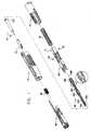
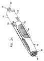
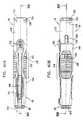
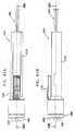
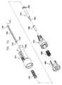
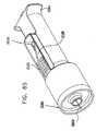
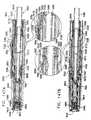
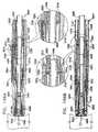
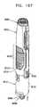
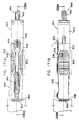
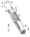
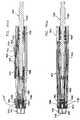
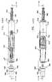
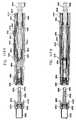
- FIG. 1 - 13Cillustrate the constituent elements of an automatic injection device constructed and operative in accordance with a preferred embodiment of the present invention.
- the automatic injection devicecomprises a rear housing element 10 in which is seated a main compression spring 20, which provides selectable forward displacement to a selectable driving assembly 30, which includes a selectable driving element 31 and a pair of elastomeric motion damping elements 32 and 34, and selectably engages a plunger 40 and a pre-filled syringe 50 having a hypodermic needle 60 which is covered by a needle protection cover 62.
- Pre-filled syringe 50may be a conventional pre-filled syringe, such as a commercially available syringe sold under the catalog designation BD-HypakTM or may be any other suitable syringe or cartridge.
- Plunger 40also operatively engages pre-filled syringe 50 and is selectably operated by selectable driving assembly 30 to inject liquid contents of pre-filled syringe 50 through hypodermic needle 60.
- forward portion of rear housing element 10 as well as spring 20, selectable driving assembly 30, plunger 40 and pre-filled syringe 50are located within a forward housing and actuator element 70.
- a needle guard element 80At a forward end of the interior of forward housing and actuator element 70 there is provided a needle guard element 80, which is positioned by a compression spring 90.
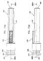
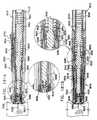
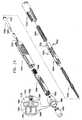
- FIG. 2is a simplified pictorial illustration of a preferred rear housing element 10 which forms part of the automatic injection device of Fig. 1, to Figs. 3A and 3B which are respective top and side view simplified planar illustrations thereof and to Figs. 4A, 4B and 4C , which are sectional illustrations taken along respective section lines and directions IVA - IVA, IVB - IVB and IVC - IVC in Figs. 3A and 3B .
- the rear housing element 10preferably is an integrally formed element, preferably injection molded of plastic and preferably has a generally cylindrical configuration including a generally tubular portion 110, which terminates in a back wall 112, defining generally symmetric side-facing tabs 114 in front of which are generally symmetric side facing recesses 116.
- Tubular portion 110is preferably side-to-side symmetric about a longitudinal axis 120.
- Tubular portion 110is formed with a pair of generally symmetric side recesses 122 at which corresponding generally elongate engagement shaft portions 124 extend forwardly parallel to longitudinal axis 120, each terminating in an outward facing protrusion 126.
- each engagement shaft portion 124there is provided an additional shaft portion 127, which extends forwardly of protrusion 126 and has a somewhat curved cross sectional configuration.
- Shaft portions 127 on the two sides of the rear housing element 10are separated from each other, as shown.
- a pair of mutually facing ribs 128extend from shaft portions 127 parallel to longitudinal axis 120, defining forward facing shoulders 129.
- a central inward facing protrusion 130is provided at a top interior surface of the rear housing element, between and rearward of ribs 128.
- a bottom interior surface 131 of the rear housing elementhas a generally uniform, slightly concave cross section and includes a plurality of generally radially inwardly directed ribs 132, which extend generally parallel to longitudinal axis 120.
- a bottom exterior surface 134 of the rear housing elementwhich is the underside of surface 131, includes a forward edge 136 and a plurality of radially outwardly directed ribs 138 which extend generally parallel to longitudinal axis 120.
- Side interior surfaces 140 of the rear housing element 10each define a forwardly pointed protrusion 142 which is engaged by an outwardly extending protrusion of a first finger of selectable driving assembly 30 and by elastomeric motion damping elements 32 and 34, forming part of selectable driving assembly 30, as described hereinbelow.
- the interior surface of back wall 112 of the rear housing element 10further comprises a rear seat 160 for spring 20.
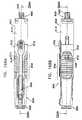
- FIG. 5is a simplified pictorial illustration of a preferred selectable driving assembly 30, which forms part of the automatic injection device of Fig. 1, to Figs. 6A and 6B , which are respective top and side view simplified planar illustrations of the selectable driving assembly and to Figs. 7A, 7B and 7C , which are sectional illustrations taken along respective section lines and directions VIIA - VIIA, VIIB - VIIB and VIIC - VIIC in Figs. 6A and 6B .
- the selectable driving element 31preferably is an integrally formed element, preferably injection molded of plastic and preferably has a generally cylindrical configuration including a generally tubular portion 310, having an open back and having a pair of side-to-side symmetric actuation arms 312 which extend forwardly of tubular portion 310 parallel to a longitudinal axis 320, which when selectable driving assembly 30 is assembled with the rear housing element 10, is coaxial with longitudinal axis 120 ( Figs. 2 - 4C ).
- a top engagement arm 322also extends forwardly of tubular portion 310.
- a narrowed tubular neck portion 324is formed forwardly of tubular portion 310. Elastomeric elements 32 and 34, seated in side recesses 326 and 328 in the selectable driving element 31, are located symmetrically at the junction of the tubular portion 310 and the neck portion 324.
- Each of actuation arms 312has a generally curved cross section and includes a rearwardly facing first finger 330 terminating in an outwardly extending protrusion 332 and an inwardly extending protrusion 333, a second rearwardly extending finger 334 terminating in an inwardly inclined protruding portion 336 and a third rearwardly extending finger 338 having formed thereon, adjacent an extreme outward end thereof, an inwardly facing generally triangular tooth 342 having a forwardly facing inclined surface 344 and a rearwardly facing engagement surface 346 extending generally perpendicular to longitudinal axis 320. Separated from tooth 342 by a notch 347 is an inwardly facing rounded tooth 348. Additionally, third finger 338 has formed thereon top and bottom protrusions 349.
- Top engagement arm 322terminates in an outwardly facing protrusion 350 having an inclined forward facing surface 351. Rearwardly of protrusion 350 and separated therefrom by an outwardly facing notch 352 is an outwardly facing protrusion 354, having an inclined outwardly facing surface 356.
- Plunger 40is a generally circularly symmetric element, which is preferably formed in an overall ribbed configuration, as shown.
- Plunger 40includes a rear portion 402 having a relatively large circular cross section which tapers forwardly to a neck portion 404, having a relatively small circular cross section.
- Forwardly of neck portion 404is an intermediate portion 406, whose circular cross section is typically the same as that of rear portion 402, and a forward portion 408, whose circular cross section is typically the same as that of neck portion 404.
- Plunger 40terminates at its forward end in a male threaded protrusion 410 adapted to fit a corresponding female threaded socket formed in a piston described hereinbelow with reference to Fig.
- Plunger 40is preferably symmetrically disposed about a longitudinal axis 420, which when assembled together with selectable driving assembly 30 and rear housing element 10, is coaxial with longitudinal axes 120 ( Figs. 2 - 4C ) and 320 ( Figs. 5 - 7C ).
- pre-filled syringe 50includes a rear flange 502 which selectably engages notches 347 formed in respective third fingers 338 of each of side-to-side symmetric actuation arms 312 of selectable driving assembly 30 ( Figs. 5 - 7C ).
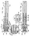
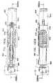
- FIG. 8is a simplified pictorial illustration of forward housing and actuator element 70 which forms part of the automatic injection device of Fig. 1, to Figs. 9A and 9B , which are respective top and side view simplified planar illustrations thereof and to Figs. 10A, 10B and 10C , which are sectional illustrations taken along respective section lines and directions XA - XA, XB - XB and XC - XC in Figs. 9A and 9B .
- the forward housing and actuator element 70preferably is an integrally formed element, preferably injection molded of plastic and preferably has a generally truncated conical configuration arranged along a longitudinal axis 720, which when the automatic injection device is assembled, is coaxial with longitudinal axes 120 ( Figs. 2 - 4C ), 320 ( Figs. 5 - 7C ) and 420 ( Fig. 1 ).
- Forward housing and actuator element 70includes a generally tubular rear portion 710, having an open back and formed with a pair of side-to-side symmetric snap fit engagement sockets 712 which receive the protrusions 126 of the rear housing element 10 during factory assembly of the automatic injection device.
- tubular rear portion 710Forward of tubular rear portion 710 are formed a pair of top-bottom symmetric windows 714, which allow the pre-filled syringe to be viewed, when the automatic injection device is assembled, including during use thereof.
- a pair of outer side surfaces 716 of forward housing and actuator element 70are each formed with ribbed grip regions 718.
- Corresponding inner side surfaces 721each define a plurality of longitudinally extending ribs 722, 724, 726 and 728 which are used to slidably guide the needle guard element 80 during axial movement thereof as well as inner facing protrusions 730, which together with ribs 722 and 724 define a forward facing spring seat for spring 90 ( Fig. 1 ).
- Inner facing protrusions 730are operative to slidably support pre-filled syringe 50 and to slidably guide actuation arms 312 of selectable driving assembly 30.
- Inner top and bottom surfaces 732 and 734define respective pairs of ribs 736 and 738 which are operative to slidably guide the needle guard 80 during axial movement thereof.
- a cantilevered rearwardly extending actuation lever 750extends from a location rearward of top window 714 and defines, at an extreme rearward top facing surface thereof, an actuation button 752.
- inner facing protrusions 730define at rearward facing portions thereof protrusions 760 and 762 which form a stopping point for flange 502, thus limiting the forward movement of the pre-filled syringe 50.
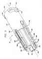
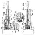
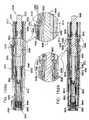
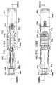
- FIG. 11is a simplified pictorial illustration of a needle guard element 80 which forms part of the automatic injection device of Fig. 1, to Figs. 12A and 12B , which are respective top and side view simplified planar illustrations thereof and to Figs. 13A, 13B and 13C , which are sectional illustrations taken along respective section lines and directions XIIIA - XIIIA, XIIIB - XIIIB and XIIIC - XIIIC in Figs. 12A and 12B .
- the needle guard element 80preferably is an integrally formed element, preferably injection molded of plastic and preferably has a generally cylindrical configuration including a generally tubular portion 810, having a forward facing body engaging surface 812 including a pair of concentric ribbed circumferential forward facing rings 814 and 816.
- Needle guard element 80has a pair of side-to-side symmetric mounting arms 818 having rearwardmost ends 819, arranged symmetrically about a longitudinal axis 820. Each of arms 818 is formed with a rectangular window 821 having a relatively wider forward portion 822 and a relatively narrower rear portion 824. Arms 818 extend along and rearwardly of tubular portion 810 parallel to longitudinal axis 820, which when the automatic injection device is assembled, is coaxial with longitudinal axes 120 ( Figs. 2 - 4C ), 320 ( Figs. 5 - 7C ), 420 ( Fig. 1 ) and 720 ( Figs. 8 - 10C ).
- a top engagement arm 832also extends rearwardly of tubular portion 810 and includes a rearwardmost axial portion 834, an inclined intermediate portion 836, an axial intermediate portion 838 and an inclined mounting portion 840, which extends from a top mounting arm 842, formed with an elongate window 844.
- Elongate windows 844 and top-bottom symmetric windows 714 of forward housing and actuator element 70are positioned in respective parallel locations, such that pre-filled syringe 50 is visible through the windows.
- Top and bottom engagement portions 846 and 848are each formed with inwardly directed teeth, here designated by reference numerals 850 and 852 respectively.
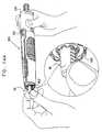
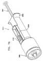
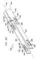
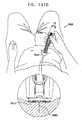
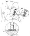
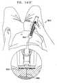
- FIGS. 14A , 14B , 14C , 14D , 14E , 14F , 14G , 14H and 141are simplified pictorial illustrations of various stages of typical use of the automatic injection device of Fig. 1 .
- the automatic injection device of Fig. 1is stored prior to use, as indicated by reference numeral 900, in a pre-use operative orientation, described hereinbelow with reference to Figs. 15 - 17B . While the automatic injection device is stored, it is preferably covered by needle protection cover 62.
- air bubbles or some of the drug contained in pre-filled syringe 50may optionally be manually expelled via the needle, as indicated by reference numeral 902.
- the operative orientation of the automatic injection device for this functionalityis described hereinbelow with reference to Figs. 18 - 20B .
- a useractuates the automatic injection device by pushing it against an injection site and depressing actuation button 752 ( Figs. 8 - 10C ), as indicated by reference numeral 904 shown in Fig. 14C and as described hereinbelow with reference to Figs. 21 - 23B .
- actuation button 752Figs. 8 - 10C
- 904shown in Fig. 14C
- Figs. 21 - 23Bneedle penetration takes place at the injection site
- reference numeral 906shown in Fig. 14D .
- the operative orientation of the automatic injection device at this stageis described hereinbelow with reference to Figs. 24 - 26B .
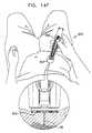
- Fig. 14Eimmediately following needle penetration, drug delivery takes place, as indicated by reference numeral 908.
- the operative orientation of the automatic injection device at this stageis described hereinbelow with reference to Figs. 27 - 29B .
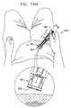
- the operative orientation of the automatic injection device immediately following completion of drug deliveryis indicated by reference numeral 910 shown in Fig. 14F , as described hereinbelow with reference to Figs. 30 - 32B .
- the automatic injection deviceis then manually disengaged from the injection site, as indicated by reference numeral 912, during which time the needle guard 80 is automatically deployed.
- the operative orientation of the automatic injection device at this stageis described hereinbelow with reference to Figs. 33 - 35B .
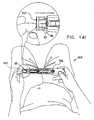
- the needleis automatically protected by the needle guard element 80, as indicated by reference numeral 914 shown in Fig. 14H .
- the operative orientation of the automatic injection device at this stageis described hereinbelow with reference to Figs. 36 -38B .
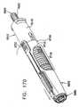
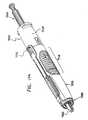
- FIG. 15is a simplified assembled view illustration of the automatic injection device of Figs. 1 and 14A in a pre-use operative orientation, to Figs. 16A and 16B , which are respective top and side view simplified planar illustrations thereof and to Figs. 17A and 17B , which are sectional illustrations taken along respective section lines and directions XVIIA - XVIIA and XVIIB - XVIIB in Figs. 16A and 16B .
- the rear housing element 10is joined to the forward housing and actuator element 70 by snap fit engagement of protrusions 126 of rear housing element 10 in the engagement sockets 712 formed in the forward housing and actuator element 70.
- Selectable driving assembly 30is retained in its axial position by engagement of inward facing protrusion 130 ( Fig. 4A ) with outwardly facing notch 352 of top engagement arm 322 ( Fig. 7A ) of selectable driving assembly 30, as shown particularly in the enlarged portion of Fig. 17A .
- spring 20is in a relatively compressed state and is held in that state by the selectable driving assembly 30.
- actuation button 752of forward housing and actuator element 70 ( Figs. 8 - 10C ). Additionally, inward displacement of actuation button 752 is limited by ribs 128 ( Figs. 2-4C ), thus ensuring that actuation button 752 does not directly engage protrusion 350 of engagement arm 322. Accordingly, in this orientation of the needle guard 80, inadvertent pressing of button 752 does not actuate the automatic injection device.
- the pre-filled syringe 50is retained in a retracted orientation by engagement of flange 502 thereof with notches 347 formed in respective third fingers 338 of each of side-to-side symmetric actuation arms 312 of selectable driving assembly 30 ( Figs. 5 - 7C ).
- Needle guard 80is retained in its axial position, and is prevented from moving forward by engagement of inwardly directed teeth 850 and 852 with the flange 502 of the pre-filled syringe 50. It is appreciated that in this operative orientation spring 90 is either at rest or in a semi-compressed state.
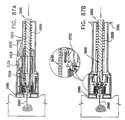
- FIG. 18is a simplified pictorial illustration of the automatic injection device of Figs. 1 and 14B in an optional titration operative orientation, to Figs. 19A and 19B , which are respective top and side view simplified planar illustrations thereof and to Figs. 20A and 20B , which are sectional illustrations taken along respective section lines and directions XXA - XXA and XXB - XXB in Figs. 19A and 19B .
- a usermay push rear portion 402 of plunger 40 forwardly as the syringe 50 is retained in place. This forces air bubbles and/or liquid out of the syringe via the needle 60.
- protrusions 349 formed on third fingers 338engage the defining walls of narrower rear portion 824 of rectangular window 821 ( Figs. 11 - 13C ), thus limiting the third fingers 338 from bending outward and therefore flange 502 continues to engage notches 347 thus inhibiting premature movement of syringe 50. It is appreciated that except for the forward movement of the plunger 40, the remainder of the operative orientation of the automatic injection device remains identical to the pre-use operative orientation.
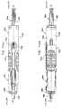
- FIG. 21is a simplified pictorial illustration of the automatic injection device of Figs. 1 and 14C in an actuated operative orientation, to Figs. 22A and 22B which are respective top and side view simplified planar illustrations thereof and to Figs. 23A and 23B which are sectional illustrations taken along respective section lines and directions XXIIIA - XXIIIA and XXIIIB - XXIIIB in Figs. 22A and 22B .
- the needle guard 80is forced to move axially in a rearward direction with respect to the remainder of the automatic injection device, thus compressing spring 90 and causing the rearwardmost axial portion 834 of the top engagement arm 832 of the needle guard 80 ( Figs. 11-13C ) to assume a relatively rearward position, generally underlying actuation button 752 of forward housing and actuator element 70 ( Figs. 8 - 10C ).
- the rearward motion of the needle guard 80is limited by engagement of rearwardmost ends 819 of arms 818 of the needle guard and the forward facing edge of outward facing protrusion 126 rear housing element 10 ( Fig. 23B ).
- pressing of button 752does actuate the automatic injection device, by causing portion 834 to engage protrusion 350, thus disengaging notch 352 from protrusion 130 ( Fig. 4A ) and thus disengaging engagement arm 322 from the rear housing element 10 and permitting forward axial movement of the selectable driving assembly 30 under the urging of spring 20.
- FIG. 24is a simplified pictorial illustration of the automatic injection device of Figs. 1 and 14D in a needle penetration, pre-drug delivery operative orientation, to Figs. 25A and 25B , which are respective top and side view simplified planar illustrations thereof and to Figs. 26A and 26B , which are sectional illustrations taken along respective section lines and directions XXVIA - XXVIA and XXVIB - XXVIB in Figs. 25A and 25B .
- Figs. 24 - 26Billustrate an initial stage in the forward motion of the selectable driving assembly 30 under the urging of spring 20 following user actuation of button 752. It is seen that the axial forward motion of the selectable driving assembly 30 produces equivalent axial forward motion of the syringe 50, due to engagement of flange 502 in notches 347 formed in respective third fingers 338 of each of side-to-side symmetric actuation arms 312 of selectable driving assembly 30 ( Figs. 5 - 7C ).
- This forward motionresults in forward motion of the needle 60 and needle penetration at the injection site as shown.
- the forward motion of syringe 50 and needle penetrationstops as flange 502 reaches protrusions 760 and 762 of forward housing and actuator element 70.
- elastomeric elements 32 and 34engage forwardly pointed protrusion 142 of side interior surface 140 causing friction therebetween, thus compensating for the force of spring 20 and resulting in damping of the needle movement and absorbance of the shock applied by protrusions 760 and 762 on the flange 502.
- the forward motion of the selectable driving assembly 30causes the outwardly extending protrusion 332 to engage forwardly pointed protrusion 142 of side interior surface 140, thus bending the first finger 330 inwards.
- drug deliveryfollows needle penetration.
- FIG. 27is a simplified pictorial illustration of the automatic injection device of Figs. 1 and 14E in drug delivery operational orientation, to Figs. 28A and 28B which are respective top and side view simplified planar illustrations thereof and to Figs. 29A and 29B , which are sectional illustrations taken along respective section lines and directions XXIXA - XXIXA and XXIXB - XXIXB in Figs. 28A and 28B .
- Figs. 27 - 29Billustrate a further stage in the forward motion of the selectable driving assembly under the urging of spring 20 following user actuation of button 752. It is seen that the axial forward motion of the selectable driving assembly 30 does not produce equivalent axial forward motion of the syringe 50, due to engagement of flange 502 of syringe 50 with protrusions 760 and 762 of ribs of the forward housing and actuator element 70 ( Fig. 10A ).
- Forward motion of piston 501forces the drug out of syringe 50 through needle 60 into the injection site.
- the forward motion of the piston 501is governed by friction between elastomeric elements 32 and 34 and forwardly pointed protrusions 142 of side interior surface 140.
- the amount of frictionmay be selected by appropriately shaping the forwardly pointed protrusion and the elastomeric elements 32 and 34.
- the forwardly pointed shape of the protrusionscauses a reduction in friction as selectable driving assembly 30 advances, which compensates for the reduction in the force applied by spring 20 as it extends. Friction between the protrusion and elastomeric elements 32 and 34 also damps shock resulting from engagement of inwardly extending protrusion 333 with intermediate portion 406 of plunger 40, which is then transferred to flange 502 of the pre-filled syringe 50, and may help control the drug injection rate.
- FIG. 30is a simplified pictorial illustration of the automatic injection device of Figs. 1 and 14F in an immediate post-drug delivery operational orientation, to Figs. 31A and 31B , which are respective top and side view simplified planar illustrations thereof and to Figs. 32A and 32B , which are sectional illustrations taken along respective section lines and directions XXXIIA - XXXIIA and XXXIIB - XXXIIB in Figs. 31A and 31B .
- FIG. 33is a simplified pictorial illustration of the automatic injection device of Figs. 1 and 14G in its operation orientation as it is being disengaged from an injection site, to Figs. 34A and 34B which are respective top and side view simplified planar illustrations thereof and to Figs. 35A and 35B which are sectional illustrations taken along respective section lines and directions XXXVA - XXXVA and XXXVB - XXXVB in Figs. 34A and 34B .
- the automatic injection deviceis being removed from the injection site and the needle guard 80 is moving axially forward under the urging of spring 90, so that the exposed portion of the needle 60 is protected by the needle guard 80.
- the first fingers 330 of each of side-to-side symmetric actuation arms 312 of the selectable driving assembly 30are released and bend outwards to their initial position, thus disengaging from the plunger 40 and engaging the rearwardmost ends 819 of arms 818 of the needle guard 80.
- spring 20applies more force than does spring 90 and thus pushes the needle guard 80 further forward. It is therefore appreciated that even if spring 90 were to be replaced by a shorter spring, for example a short plastic spring integrated with either forward housing and actuator element 70 or needle guard 80, spring 20 would guarantee that needle guard 80 would be fully deployed, such that the auto injection device would be maintained in a protected position.
- FIG. 36is a simplified pictorial illustration of the automatic injection device of Figs. 1 and 14H in a needle protected operational orientation, to Figs. 37A and 37B which are respective top and side view simplified planar illustrations thereof and to Figs. 38A and 38B which are sectional illustrations taken along respective section lines and directions XXXVIIIA - XXXVIIIA and XXXVIIIB - XXXVIIIB in Figs. 37A and 37B .
- the automatic injection deviceis fully disengaged from the injection site and the needle guard 80 is fully extended to fully enclose the needle 60.
- the needle guardWhen the needle guard is fully extended it is locked onto the syringe 50 by engagement of inwardly directed teeth 850 and 852 and flange 502 of the pre-filled syringe 50, thus inhibiting further movement outwards of the needle guard 80.
- inwardly extending protruding portions 336 of second fingers 334snap over flange 502 within the narrower rear portion 824 of rectangular window 821, thus enabling further locking of the needle guard as described hereinbelow.
- FIG. 39is a simplified pictorial illustration of the automatic injection device of Figs. 1 and 14I in a needle-guard push back misuse operational orientation, to Figs. 40A and 40B which are respective top and side view simplified planar illustrations thereof and to Figs. 41A and 41B which are sectional illustrations taken along respective section lines and directions XLIA - XLIA and XLIB - XLIB in Figs. 40A and 40B .
- Figs. 39 - 41Billustrate an important feature of the present invention provided by the locking of inwardly extending protruding portion 336 of second finger 334 of the selectable driving assembly 30 and the flange 502 of the pre-filled syringe 50.
- the selectable driving assembly 30forces the needle 60 and syringe to 50 move rearwardly together with selectable driving assembly 30, so that the needle 60 does not protrude from the needle guard 80.
- first fingers 330cannot bend inwards to cause outwardly extending protrusions 332 to disengage from rearwardmost ends 819 of arms 818, since the inwardly extending protrusions 333 of first fingers 330 are supported by intermediate portion 406 of the plunger 40.
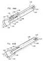
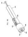
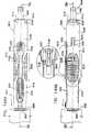
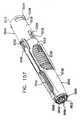
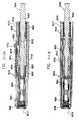
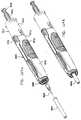
- the automatic injection devicecomprises a plunger 1002 which is partially located within a main housing element 1010 into which is seated a main compression spring 1020, which provides selectable forward displacement to a selectable driving element 1030, which selectably engages plunger 1002 and a pre-filled syringe 1050 having a hypodermic needle 1060 which is covered by a needle protection cover 1062.
- Pre-filled syringe 1050may be a conventional pre-filled syringe, such as a commercially available syringe sold under the catalog designation BD-HypakTM or may be any other suitable syringe or cartridge.
- Plunger 1002also operatively engages pre-filled syringe 1050 and is selectably operated by selectable driving element 1030 to inject the liquid contents of pre-filled syringe 1050 through hypodermic needle 1060.
- the forward portion of main housing element 1010surrounds and is engaged with a forward housing element 1070.
- a needle guard element 1080At the forward end of the interior of forward housing element 1070 there is provided a needle guard element 1080, which is positioned by a compression spring 1090.
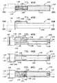
- FIGs. 43A and 43Bare simplified pictorial illustrations of a preferred main housing element 1010 which forms part of the automatic injection device of Fig. 42, to Figs. 44A and 44B which are simplified pictorial sectional illustrations of the main housing element 1010 of Figs. 43A and 43B , taken along lines XLIVA - XLIVA and XLIVB - XLIVB in Fig. 43A, to Figs. 45A and 45B , which are respective top and side view simplified planar illustrations of the main housing element of Figs. 43A - 44B and to Figs.
- 46A, 46B and 46Cwhich are sectional illustrations taken along respective section lines and directions XLVIA - XL VIA, XLVIB - XLVIB and XLVIC - XL VIC in Figs. 45A and 45B .
- the main housing element 1010preferably is an integrally formed element, preferably injection molded of plastic and preferably has a generally cylindrical configuration including a rearward generally cylindrical portion 1110, having a nearly circular cross section, which terminates in a back wall 1112, defining a rearward-facing central opening 1115 communicating with a cylindrical bore 1116.
- An interior surface of back wall 1112defines a spring seat for spring 1020, while bore 1116 slidably accommodates plunger 1002.
- Rearward generally cylindrical portion 1110is preferably side-to-side symmetric about a longitudinal axis 1120.
- Rearward generally cylindrical portion 1110is preferably formed on an interior surface thereof with a pair of generally symmetric axially extending upper interior ribs 1121 and a pair of generally symmetric axially extending lower interior ribs 1122 on each side of the interior surface. Also formed on opposite sides of an interior surface of rearward generally cylindrical portion 1110 are side-to-side symmetric axially extending guiding ribs 1123.
- actuation button portion 1124including a forward actuation button defining portion 1125 having a slightly curved finger engagement surface 1126, defining an actuation button and a selectable syringe engagement portion 1128 having a rearward facing surface 1130 which selectably engages a forward facing surface of pre-filled syringe 1050 for selectably retaining it against forward axial motion.
- Actuation button portion 1124is pivotally mounted with respect to the remainder of the main housing element 1010 about a pivot axis, transverse to longitudinal axis 1120, which lies intermediate portion 1125 and portion 1128, such that inward displacement of portion 1125 causes portion 1128 to move outwardly.
- actuation button portion 1124Formed onto upper ribs 1121 and lower ribs 1122 are forwardly facing, outwardly extending ribs 1135.
- a peripheral outwardly facing guard protrusion 1136is formed around actuation button portion 1124. Forwardly of actuation button portion 1124 and of protrusion 1136 there is formed a forwardly facing circular cylindrical portion 1140.
- Circular cylindrical portion 1140defines on an interior surface 1150 thereof a peripheral groove 1160, which is in contact with top and bottom axial grooves 1162.
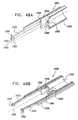
- Figs. 47A and 47Bare simplified pictorial illustrations of a selectable driving element 1030 which forms part of the automatic injection device of Fig. 42, to Figs. 48A and 48B , which are simplified pictorial sectional illustrations of the selectable driving element of Figs. 47A and 47B , taken along lines XLVIIIA - XLVIIIA and XLVIIIB - XLVIIIB in Fig. 47A, to Figs. 49A and 49B , which are respective top and side view simplified planar illustrations of the selectable driving element of Figs. 47A - 48B and to Figs. 50A and 50B , which are sectional illustrations taken along respective section lines and directions LA - LA and LB - LB in Figs. 49A and 49B .
- the selectable driving element 1030preferably is an integrally formed element, preferably injection molded of plastic and preferably has a generally cylindrical configuration including a generally tubular portion 1310, having an open back and having a pair of side-to-side symmetric actuation arms 1312 which extend forwardly of tubular portion 1310 generally parallel to a longitudinal axis 1320, which when selectable driving element 1030 is assembled with the main housing element 1010, is coaxial with longitudinal axis 1120 ( Figs. 43 - 46C ).
- a guiding slot 1324Overlying part of each actuation arm 1312 and extending axially rearwardly thereof along an outer surface of generally tubular portion 1310 is a guiding slot 1324. Guiding slots 1324 cooperate with ribs 1123 formed on main housing element 1010 for guiding axial motion of the selectable driving element 1030 with respect to the main housing element 1010.
- Each of actuation arms 1312terminates in a forwardly facing end surface 1332 having oppositely directed transversely extending protrusions 1334 and defines a shoulder along the length of each arm 1312.
- the selectable tubular portion 1310defines a forward wall 1340 having an aperture 1342 for selectable slidable engagement with plunger 1002.
- Forward of wallis formed a pair of side-to-side symmetric forward-facing tabs 1344, each defining a forward shoulder surface 1346.
- a rear facing surface of forward wall 1340defines a spring seat for spring 1020.
- Plunger 1002as seen in Fig. 42 is a generally circularly symmetric element, which is preferably formed in an overall ribbed configuration, as shown.
- Plunger 1002includes a rear wall portion 1402. Forwardly of rear wall portion 1402 by approximately two thirds of the length of plunger 1002, there are provided a pair of side-to-side symmetric, sideways extending protrusions 1404. At a forward end of plunger 1002 there is provided a peripheral protrusion 1406 forward of which is provided a threaded end 1408.
- Plunger 1002is arranged along a longitudinal axis 1420, which when the automatic injector device is assembled, is coaxial with longitudinal axes 1120 ( Figs. 43 - 46C ), and 1320 ( Figs. 47 - 50C ).
- pre-filled syringeincludes a rear flange 1502 which engages forwardly facing end surface 1332 formed in each of side-to-side symmetric actuation arms 1312 of selectable driver element 1030 ( Figs. 47 - 50C ).
- FIGs. 51A and 51Bare simplified pictorial illustrations of a forward housing element 1070 which forms part of the automatic injection device of Fig. 42, to Figs. 52A and 52B , which are simplified pictorial sectional illustrations of the forward housing element of Fig. 51A and 51B , taken along lines LIIA - LIIA and LIIB - LIIB in Fig. 51A, to Figs. 53A and 53B , which are respective top and side view simplified planar illustrations of the forward housing element of Figs. 51A - 52B and to Figs. 54A and 54B which are sectional illustrations taken along respective section lines and directions LIVA - LIVA and LIVB - LIVB in Figs. 53A and 53B .
- the forward housing element 1070preferably is an integrally formed element, preferably injection molded of plastic and preferably has a generally circular cylindrical truncated conical configuration arranged along a longitudinal axis 1720, which when the automatic injector device is assembled, is coaxial with longitudinal axes 1120 ( Figs. 43 - 46C ), 1320 ( Figs. 47 - 50C ) and 1420 ( Fig. 1 ).
- Forward housing element 1070includes a generally tubular forward portion 1710, having an open front and having formed rearward thereof a top axially extending arm 1724 and a bottom axially extending arm 1725.
- Each of arms 1724 and 1725is formed with a pair of inwardly facing protrusions, respectively designated by reference numerals 1726 and 1727 and with a pair of outwardly facing protrusions, respectively designated by reference numerals 1728 and 1729.
- Outwardly facing protrusions 1728extend rearwardly only partially along the length of arm 1724, while outwardly facing protrusions 1727 extend rearwardly along substantially the entire length of arm 1725.
- Inwardly facing protrusions 1726 and 1727are adapted to stop the forward motion of flange 1502 of pre-filled syringe 1050 following actuation as described hereinbelow with reference to Figs. 66 - 68A .
- a pair of teeth 1730are formed on top of axially extending arms 1724, which are operative to prevent premature activation of the automatic injection device as described hereinbelow with reference to Figs. 63 - 65B .
- a pair of side-to-side symmetric partial enclosures 1731are formed rearwardly of forward portion 1710, having a generally C-shaped cross section, in a plane perpendicular to longitudinal axis 1720. Interior facing surfaces of enclosures 1731 together with arms 1724 and 1725 and protrusions 1726 and 1727 guide axial sliding motion of syringe 1050 relative to the main housing element 1010 and to forward housing element 1070.
- Partially surrounded by each partial enclosure 1731is an inwardly facing cantilevered engagement element 1732 terminated in a bifurcated tooth element 1733 having an inwardly extending tooth 1734 and a forwardly axially extending tooth 1736.
- Forward portion 1710has an interior facing cylindrical surface 1740 having formed thereon four pairs of inwardly facing, axially extending protrusions 1746. Also formed interior of interior facing cylindrical surface 1740 are a plurality of spring seat defining portions 1750, each of which defines a rearwardly facing shoulder 1752. Spring 1090 sits on shoulders 1752 of spring seat defining portions 1750.
- Forward portion 1710has an outer facing cylindrical surface 1760 having formed thereon a peripheral protrusion 1770 connected with top and bottom axial protrusions 1772. Generally opposite peripheral protrusion 1770, there are formed on inner facing cylindrical surface a pair of inwardly facing protrusions 1774.
- Figs. 55A and 55Bare simplified pictorial illustrations of the needle guard element 1080 which forms part of the automatic injection device of Fig. 42, to Figs. 56A and 56B , which are simplified pictorial sectional illustrations of the needle guard element of Fig. 55A and 55B , taken along lines LVIA - LVIA and LVIB - LVIB in Fig. 55A, to Figs. 57A and 57B , which are respective top and side view simplified planar illustrations of the needle guard element of Figs. 55A and 55B and to Figs.
- 58A, 58B and 58Cwhich are sectional illustrations taken along respective section lines and directions LVIIIA - LVIIIA, LVIIIB - LVIIIB and LVIIIC - LVIIIC in Figs. 57A and 57B .
- the needle guard element 1080preferably is an integrally formed element, preferably injection molded of plastic and preferably has a generally cylindrical configuration including a generally tubular portion 1810, having a forward wall 1811 defining forward facing body engaging surface 1812 including a pair of concentric circumferential forward facing rings 1814 and 1816, and a rearward facing spring seat defining surface 1817, which defines a spring seat for spring 1090.
- Needle guard element 1080has a pair of side-to-side symmetric mounting arms 1818 having rearwardmost ends 1819, arranged symmetrically about a longitudinal axis 1820. Arms 1818 extend along and rearwardly of tubular portion 1810 parallel to longitudinal axis 1820, which when the automatic injector device is assembled, is coaxial with longitudinal axes 1120 ( Figs. 43 - 46C ), 1320 ( Figs. 47 - 50C ), 1420 ( Fig. 42 ) and 1720 ( Figs. 51 - 54C ).
- each of mounting arms 1818Formed interiorly of each of mounting arms 1818 are a pair of spaced mutually facing circumferentially directed teeth 1822, each pair of which is arranged for engagement with a corresponding axially extending tooth 1736 when the automatic injection device is in a pre-use operative orientation, as described hereinbelow with reference to Figs. 60 - 62B .
- a top engagement arm 1832also extends rearwardly of tubular portion 1810 and includes a rearwardmost axial portion 1834, an inclined intermediate portion 1836, an axial intermediate portion 1838 and an inclined mounting portion 1840, which extends from a top portion 1842. Formed at an extreme rearward end of top engagement arm 1832 are a pair of oppositely circumferentially directed protrusions 1844.
- a bottom engagement arm 1852also extends rearwardly of tubular portion 1810 and includes an inclined portion 1856, an axial intermediate portion 1858 and an inclined mounting portion 1860, which extends from a bottom portion 1862.
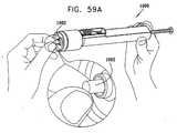
- FIGS. 59A , 59B , 59C , 59D and 59Eare simplified pictorial illustration of various stages of typical use of the automatic injection device of Fig. 42 .
- the automatic injection device of Fig. 42is stored prior to use, as indicated by reference numeral 1900, in a pre-use operative orientation, described hereinbelow with reference to Figs. 60 - 62B . While the automatic injection device is stored, it is preferably covered by needle protection cover 1062.
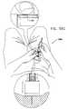
- a userenables actuation of the automatic injection device by pushing it against an injection site, as indicated by reference numeral 1902 shown in Fig. 59B and as described hereinbelow with reference to Figs. 63 - 65B .
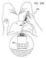
- needle penetrationtakes place at the injection site, as indicated by reference numeral 1904 shown in Fig. 59C .
- the operative orientation of the automatic injection device at this stageis described hereinbelow with reference to Figs. 66 - 68B .
- the automatic injection deviceis then manually disengaged from the injection site, as indicated by reference numeral 1908, during which time the needle guard 1080 is automatically deployed. Immediately upon disengagement, the needle is automatically protected by the needle guard element 1080.
- the operative orientation of the automatic injection device at this stageis described hereinbelow with reference to Figs. 72 - 74B .
- Fig. 60is a simplified assembled view illustration of the automatic injection device of Figs. 42 and 59A in a pre-use operative orientation
- Figs. 61A and 61Bare respective top and side view simplified planar illustrations of the automatic injection device of Fig. 60 and to Figs. 62A and 62B which are sectional illustrations taken along respective section lines and directions LXIIA - LXIIA and LXIIB - LXIIB in Figs. 61A and 61B .
- the main housing portion 1010is joined to the forward housing portion 1070 by engagement of peripheral protrusion 1770 with peripheral groove 1160, and by engagement of top and bottom axial protrusions 1772 with top and bottom axial grooves 1162 of main housing 1010 ( Figs. 43A - 46C and 51A - 54B ).
- Selectable driving element 1030is retained in a rearward axial position by engagement of forwardly facing surface 1332 ( Figs. 47 - 50B ) with a rearward facing surface of flange 1502 of pre-filled syringe 1050.
- Pre-filled syringe 1050is, in turn, retained in its retracted axial position by engagement of a forward facing surface of flange 1502 by rearward facing surface 1130 of selectable syringe engagement portion 1128 of actuation button portion 1124 ( Figs. 43A - 46C ).
- Pre-filled syringe 1050is also retained in its retracted axial position by engagement of inwardly extending teeth 1734 of bifurcated tooth elements 1733 of inwardly facing cantilevered engagement elements 1732 of forward housing element 1070 with a forward facing tapered peripheral surface of the pre-filled syringe 1050.
- Inwardly facing cantilevered engagement elements 1732cannot bend outwards to disengage inwardly extending teeth 1734 from pre-filled syringe 1050 due to engagement of forwardly axially extending teeth 1736 with respective pairs of spaced mutually facing circumferentially directed teeth 1822 formed in arms 1818 of needle guard element 1080.
- the engagement of forwardly axially extending teeth 1736 with pairs of spaced mutually facing circumferentially directed teeth 1822 formed in arms 1818 of needle guard element 1080also retains the needle guard element 1080 in its axial position and prevents it from moving outward.
- the actuation buttonis retained against inadvertent actuation by the needle guard element 1080 when in its relative forward orientation, as it is maintained in the storage orientation of the automatic injection device.
- the pair of oppositely circumferentially directed protrusions 1844 of rearwardmost axial portion 1834 of top engagement arm 1832is retained against radially inward displacement by pair of teeth 1730 of forward housing element 1070 and thus does not allow axial forward movement of selectable syringe engagement portion 1128 and of syringe 1050.
- FIG. 63is a simplified pictorial illustration of the automatic injection device of Figs. 42 and 59B in an actuatable operative orientation, to Figs. 64A and 64B which are respective top and side view simplified planar illustrations thereof and to Figs. 65A and 65B which are sectional illustrations taken along respective section lines and directions LXVA - LXVA and LXVB - LXVB in Figs. 64A and 64B .
- the needle guard element 1080is forced to move axially in a rearward direction with respect to the remainder of the automatic injection device, thus compressing spring 1090 and causing the rearwardmost axial portion 1834 of the top engagement arm 1832 of the needle guard element 1080 to assume a relatively rearward position, so that the pair of oppositely circumferentially directed protrusions 1844 does not overlie teeth 1730 of forward housing element 1070.
- Disengagement of the forward facing surface of flange 1502 from rearward facing surface 1130immediately releases the syringe 1050 to move forward under the urging of selectable driving element 1030, due to engagement of flange 1502 with forwardly facing surface 1332 of selectable driving element 1030.
- rearward movement of the needle guard element 1080causes the disengagement of the pairs of spaced mutually facing circumferentially directed teeth 1822 formed in arms 1818 of needle guard element 1080 from forwardly axially extending teeth 1736 of inwardly facing cantilevered engagement elements 1732, thus allowing outward bending of inwardly facing cantilevered engagement elements 1732.
- FIG. 66is a simplified pictorial illustration of the automatic injection device of Figs. 42 and 59C in an actuated needle penetration, pre-drug delivery operative orientation, to Figs. 67A and 67B which are respective top and side view simplified planar illustrations of the automatic injection device of Fig. 66 and to Figs. 68A and 68B which are sectional illustrations taken along respective section lines and directions LXVIIIA - LXVIIIA and LXVIIIB - LXVIIIB in Figs. 67A and 67B .
- Figs. 66is a simplified pictorial illustration of the automatic injection device of Figs. 42 and 59C in an actuated needle penetration, pre-drug delivery operative orientation
- Figs. 67A and 67Bwhich are respective top and side view simplified planar illustrations of the automatic injection device of Fig. 66 and to Figs. 68A and 68B which are sectional illustrations taken along respective section lines and directions LXVIIIA
- 66 - 68Billustrate an initial stage in the forward motion of the selectable driving element 1030 under the urging of spring 1020 following user actuation of portion 1125 of actuation button portion 1124. It is understood that the axial forward motion of the selectable driving element 1030 produces equivalent axial forward motion of the syringe 1050, due to engagement of flange 1502 by forwardly facing surface 1332 of selectable driving element 1030.
- the forward movement of pre-filled syringe 1050also ensures that selectable syringe engagement portion 1128 of actuation button portion 1124 is retained in a raised position by engagement therewith of flange 1502, which is located radially inwardly thereof.
- the raised positioning of selectable syringe engagement portion 1128maintains the downward displacement of forward actuation button defining portion 1125 of actuation button portion 1124, thus maintaining engagement thereof with rearwardmost axial portion 1834 of the top engagement arm 1832 of needle guard element 1080.
- the engagement of rearwardmost axial portion 1834 and forward actuation button defining portion 1125ensures non-interfered deployment of the needle guard element 1080 upon removal of the automatic injection device from the injection site.
- FIG. 69is a simplified pictorial illustration of the automatic injection device of Figs. 42 and 59D in a post-drug delivery operative orientation
- Figs. 70A and 70Bare respective top and side view simplified planar illustrations of the automatic injection device of Fig. 69 and to Figs. 71A and 71B which are sectional illustrations taken along respective section lines and directions LXXIA - LXXIA and LXXIB - LXXIB in Figs. 70A and 70B .
- Figs. 69 - 71Billustrate a further stage in the forward motion of the selectable driving element 1030 under the urging of spring 1020 following user actuation of forward actuation button portion 1125.
- further axial forward motion of the selectable driving element 1030does not produce equivalent axial forward motion of the syringe 1050.
- Continued urging of spring 1020 and consequent forward axial motion of the selectable driving element 1030causes engagement of forward wall 1340 of selectable driving member 1030 with corresponding protrusions 1404 located along the length of plunger 1002 thus forcing plunger 1002 forward along the interior of pre-filled syringe 1050 which results in drug delivery.
- Forward axial motion of selectable driving member 1030 and plunger 1002is stopped when a piston attached to plunger 1002 engages the forward end of syringe 1050 and is prevented from moving further.
- FIG. 72is a simplified pictorial illustration of the automatic injection device of Figs. 41 and 59E in post injection site disengagement operational orientation
- Figs. 73A and 73Bare respective top and side view simplified planar illustrations of the automatic injection device of Fig. 72 and to Figs. 74A and 74B which are sectional illustrations taken along respective section lines and directions LXXIVA - LXXIVA and LXXIVB - LXXIVB in Figs. 73A and 73B .
- the automatic injection devicehas been removed from the injection site and the needle guard 1080 has moved axially forward under the urging of spring 1090, so that the exposed portion of the needle 1060 is protected by the needle guard 1080. Due to the forward movement of the needle guard 1080, protrusion 1774 of the forward housing element 1070 engages axial intermediate portions 1838 and 1858 on the needle guard element 1080, thus locking the needle guard 1080 against retraction and further forward movement.
- all or part of any or all of the housing element 1010 and forward housing element 1070may be transparent, to enable the contents of the syringe 1050 to be viewed by a user from outside the automatic injection device.
- a usermay push rear wall portion 1402 of plunger 1040 forwardly as the syringe 1050 is retained in place. This forces air bubbles and/or liquid out of the syringe via the needle 1060. It is appreciated that except for the forward movement of the plunger 1040, the remainder of the operative orientation of the automatic injection device remains identical to the pre-use operative orientation.
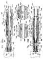
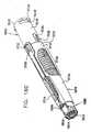
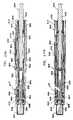
- Figs. 75 - 90Billustrate another automatic injection device.
- the automatic injection devicecomprises a plunger 2002 which is partially located within a main housing element 2010 into which is seated a main compression spring 2020, which provides selectable forward displacement to a pre-filled syringe 2050 having a hypodermic needle 2060 which is covered by a needle protection cover 2062.
- Pre-filled syringe 2050may be a conventional pre-filled syringe, such as a commercially available syringe sold under the catalog designation BD-HypakTM or may be any other suitable syringe or cartridge.
- Plunger 2002also operatively engages pre-filled syringe 2050 and is selectably operable to inject liquid contents of pre-filled syringe 2050 through hypodermic needle 2060.
- main housing element 2010surrounds and is engaged with a forward housing element 2070.
- a needle guard element 2080At the forward end of the interior of forward housing element 2070 there is provided a needle guard element 2080, which is positioned by a compression spring 2090.
- FIGs. 43A and 43Bare simplified pictorial illustrations of a preferred main housing element 1010 which forms part of the automatic injection device of Fig. 42, to Figs. 44A and 44B which are simplified pictorial sectional illustrations of the main housing element 1010 of Figs. 43A and 43B , taken along lines XLIVA - XLIVA and XLIVB - XLIVB in Fig. 43A, to Figs. 45A and 45B , which are respective top and side view simplified planar illustrations of the main housing element of Figs. 43A - 44B and to Figs.
- 46A, 46B and 46Cwhich are sectional illustrations taken along respective section lines and directions XLVIA - XL VIA, XLVIB - XLVIB and XLVIC - XLVIC in Figs. 45A and 45B .
- Main housing element 2010is similar to main housing element 1010 described hereinabove with reference to Figs. 43A - 46C , except in the following respects:
- the main housing element 2010is formed at a rearward end thereof with side-to-side symmetric outwardly extending finger-engageable retainers 2091.
- Plunger 2002as seen in Fig. 75 is a generally circularly symmetric element, which is preferably formed in an overall ribbed configuration, as shown.
- Plunger 2002includes a rear wall portion 2402.
- a peripheral protrusion 2406forward of which is provided a threaded end 2408.
- Plunger 2002is arranged along a longitudinal axis 2420, which when the automatic injector device is assembled, is coaxial with longitudinal axis 1120 ( Figs. 43 - 46C ).
- pre-filled syringe 2050includes a rear flange 2502 which is engaged by a forward end of main spring 2020.
- FIGs. 51A and 51Bare simplified pictorial illustrations of a forward housing element 1070 which forms part of the automatic injection device of Fig. 42, to Figs. 52A and 52B , which are simplified pictorial sectional illustrations of the forward housing element of Fig. 51A and 51B , taken along lines LIIA - LIIA and LIIB - LIIB in Figs. 51A, to Figs. 53A and 53B , which are respective top and side view simplified planar illustrations of the forward housing element of Figs. 51A - 52B and to Figs. 54A and 54B which are sectional illustrations taken along respective section lines and directions LIVA - LIVA and LIVB - LIVB in Figs. 53A and 53B .
- Forward housing element 2070is identical to forward housing element 1070 described hereinabove with reference to Figs. 51A - 54B .
- Figs. 55A and 55Bare simplified pictorial illustrations of the needle guard element 1080 which forms part of the automatic injection device of Fig. 42, to Figs. 56A and 56B , which are simplified pictorial sectional illustrations of the needle guard element of Fig. 55A and 55B , taken along lines LVIA - LVIA and LVIB - LVIB in Fig. 55A, to Figs. 57A and 57B , which are respective top and side view simplified planar illustrations of the needle guard element of Figs. 55A and 55B and to Figs.
- 58A, 58B and 58Cwhich are sectional illustrations taken along respective section lines and directions LVIIIA - LVIIIA, LVIIIB - LVIIIB and LVIIIC - LVIIIC in Figs. 57A and 57B .
- Needle guard element 2080is identical to needle guard element 1080 described hereinabove with reference to Figs. 55A - 58C .
- Fig. 76is a simplified assembled view illustration of the automatic injection device of Fig. 75 in a pre-use operative orientation, to Figs. 77A and 77B which are respective top and side view simplified planar illustrations of the automatic injection device of Fig. 76 and to Figs. 78A and 78B which are sectional illustrations taken along respective section lines and directions LXXVIIIA - LXXVIIIA and LXXVIIIB - LXXVIIIB in Figs. 77A and 77B .
- the main housing portion 2010is joined to the forward housing portion 2070 by engagement of peripheral protrusion 2770 with peripheral groove 2160, and by engagement of top and bottom axial protrusions formed in forward housing element 2070 with top and bottom axial grooves formed in main housing element 2010.
- Pre-filled syringe 2050is retained in its retracted axial position by engagement of a forward facing surface of flange 2502 by a rearward facing surface 2130 of a selectable syringe engagement portion 2128 of an actuation button portion 2124.
- Pre-filled syringe 2050is also retained in its retracted axial position by engagement of inwardly extending teeth 2734 of bifurcated tooth elements 2732 of inwardly facing cantilevered engagement elements 2730 of forward housing element 2070 with a forward facing tapered peripheral surface of the pre-filled syringe 2050.
- Inwardly facing cantilevered engagement elements 2730cannot bend outwards to disengage inwardly extending teeth 2734 from pre-filled syringe 2050 due to engagement of forwardly axially extending teeth 2736 with pairs of spaced mutually facing circumferentially directed teeth 2822 formed in arms 2818 of needle guard element 2080.
- the engagement of forwardly axially extending teeth 2736 with pairs of spaced mutually facing circumferentially directed teeth 2822 formed in arms 2818 of needle guard element 2080also retains the needle guard element 2080 in its axial position and prevents it from moving outward.
- the actuation buttonis retained against inadvertent actuation by the needle guard element 2080 when in its relative forward orientation, as it is maintained in the storage orientation of the automatic injection device.
- the pair of oppositely circumferentially directed protrusions 2844 of rearwardmost axial portion 2834 of top engagement arm 2832is retained against radially inward displacement by pair of teeth 2730 of forward housing element 2070 and thus does not allow axial forward movement of selectable syringe engagement portion 2128 and of syringe 2050.
- Fig. 79is a simplified pictorial illustration of the automatic injection device of Fig. 75 in an actuatable operative orientation, to Figs. 80A and 80B which are respective top and side view simplified planar illustrations thereof and to Figs. 81A and 81B which are sectional illustrations taken along respective section lines and directions LXXXIA - LXXXIA and LXXXIB - LXXXIB in Figs. 80A and 80B .
- the needle guard element 2080is forced to move axially in a rearward direction with respect to the remainder of the automatic injection device, thus compressing spring 2090 and causing the rearwardmost axial portion 2834 of the top engagement arm 2832 of the needle guard element 2080 to assume a relatively rearward position, so that the pair of oppositely circumferentially directed protrusions 2844 does not overlie teeth 2730 of forward housing element 2070.
- Disengagement of the forward facing surface of flange 2502 from rearward facing surface 2130immediately releases the syringe 2050 to move forward under the urging of main spring 2020.
- rearward movement of the needle guard element 2080causes the disengagement of the pairs of spaced mutually facing circumferentially directed teeth 2822 formed in arms 2818 of needle guard element 2080 from forwardly axially extending teeth 2736 of inwardly facing cantilevered engagement elements 2730, thus allowing outward bending of inwardly facing cantilevered engagement elements 2730.
- FIG. 82is a simplified pictorial illustration of the automatic injection device of Fig. 75 in an actuated needle penetration, pre-drug delivery operative orientation, to Figs. 83A and 83B which are respective top and side view simplified planar illustrations of the automatic injection device of Fig. 82 and to Figs. 84A and 84B which are sectional illustrations taken along respective section lines and directions LXXXIVA - LXXXIVA and LXXXIVB - LXXXIVB in Figs. 83A and 83B .
- Figs. 82 - 84Billustrate a final stage in the forward motion of the syringe 2050 under the urging of spring 2020 following user actuation of button defining portion 2125 of button portion 2124.
- the forward movement of pre-filled syringe 2050also ensures that selectable syringe engagement portion 2128 of actuation button portion 2124 is retained in a raised position by engagement therewith of flange 2502, which is located radially inwardly thereof.
- the raised positioning of selectable syringe engagement portion 2128maintains the downward displacement of forward actuation button defining portion 2125 of actuation button portion 2124, thus maintaining engagement thereof with rearwardmost axial portion 2834 of the top engagement arm 2832 of needle guard element 2080.
- the engagement of rearwardmost axial portion 2834 and forward actuation button defining portion 2125ensures non-interfered deployment of the needle guard element 2080 upon removal of the automatic injection device from the injection site.
- Fig. 85is a simplified pictorial illustration of the automatic injection device of Fig. 75 in a post-drug delivery operative orientation
- Figs. 86A and 86Bare respective top and side view simplified planar illustrations of the automatic injection device of Fig. 85 and to Figs. 87A and 87B which are sectional illustrations taken along respective section lines and directions LXXXVIIA - LXXXVIIA and LXXXVIIB - LXXXVIIB in Figs. 86A and 86B .
- Figs. 85 - 87Billustrate a further stage following user actuation of forward actuation button portion 2125.
- the usercontinues to push plunger 2002 which results in drug delivery. Forward axial motion of plunger 2002 is stopped when a piston attached to plunger 2002 engages the forward end of syringe 2050 and is prevented from moving further.
- FIG. 88is a simplified pictorial illustration of the automatic injection device of Fig. 75 in post injection site disengagement operational orientation
- Figs. 89A and 89Bwhich are respective top and side view simplified planar illustrations of the automatic injection device of Fig. 75 and to Figs. 90A and 90B which are sectional illustrations taken along respective section lines and directions XCA - XCA and XCB - XCB in Figs. 89A and 89B .
- the automatic injection devicehas been removed from the injection site and the needle guard 2080 has moved axially forward under the urging of spring 2090, so that the exposed portion of the needle 2060 is protected by the needle guard 2080. Due to the forward movement of the needle guard 2080, protrusions 2774 of the forward housing element 2070 engage sockets 2838 and 2858 on the needle guard element 2080, thus locking the needle guard 2080 against retraction and further forward movement.
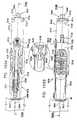
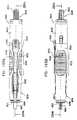
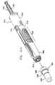
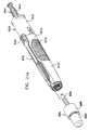
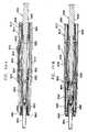
- FIG. 91illustrates the constituent elements of another automatic injection device constructed and operative in accordance with another preferred embodiment of the present invention.
- the automatic injection devicecomprises a rear housing element 4010 in which is seated a main compression spring 4020, which provides selectable forward displacement to a selectable driving assembly 4030, which includes a selectable driving element 4031 and a pair of elastomeric motion damping elements 4032 and 4034, and selectably engages a plunger 4040 and a pre-filled syringe 4050 having a hypodermic needle 4060 which is covered by a needle protection cover 4062.
- Pre-filled syringe 4050may be a conventional pre-filled syringe, such as a commercially available syringe sold under the catalog designation BD-HypakTM or may be any other suitable syringe or cartridge.
- Plunger 4040also operatively engages pre-filled syringe 4050 and is selectably operated by selectable driving assembly 4030 to inject the liquid contents of pre-filled syringe 4050 through hypodermic needle 4060.
- rear housing element 4010as well as spring 4020, selectable driving assembly 4030, plunger 4040 and pre-filled syringe 4050 are located within a forward housing and actuator element 4070.
- a needle guard element 4080At the forward end of the interior of forward housing and actuator element 4070 there is provided a needle guard element 4080, which is positioned by a compression spring 4090.
- Fig. 92is a simplified pictorial illustration of a preferred rear housing element 4010 which forms part of the automatic injection device of Fig. 91, to Figs. 93A and 93B which are respective top and side view simplified planar illustrations thereof and to Figs. 94A, 94B and 94C , which are sectional illustrations taken along respective section lines and directions XCIVA - XCIVA, XCIVB - XCIVB and XCIVC - XCIVC in Figs. 93A and 93B . As seen in Figs.
- the rear housing element 4010preferably is an integrally formed element, preferably injection molded of plastic and preferably has a generally cylindrical configuration including a generally tubular portion 4110, which terminates in a back wall 4112, defining generally symmetric side-facing tabs 4114 in front of which are generally symmetric side facing recesses 4116.
- Tubular portion 4110is preferably side-to-side symmetric about a longitudinal axis 4120.
- Tubular portion 4110is formed with a pair of generally symmetric side recesses 4122 at which corresponding generally elongate engagement shaft portions 4124 extend forwardly parallel to longitudinal axis 4120 each terminating in an outward facing protrusion 4126.
- a further shaft portion 4127which extends forwardly of protrusion 4126 and has a somewhat curved cross sectional configuration.
- Shaft portions 4127 on the two sides of the rear housing elementare separated from each other, as shown.
- a pair of mutually facing ribs 4128extend from shaft portions 4127 parallel to axis 4120, defining forward facing shoulders 4129.
- a central inward facing protrusion 4130is provided at a top interior surface of the rear housing, between and rearward of ribs 4128.
- a bottom interior surface 4131 of the rear housing elementhas a generally uniform, slightly concave cross section and includes a plurality of generally radially inwardly directed ribs 4132, which extend generally parallel to longitudinal axis 4120.
- a bottom exterior surface 4134 of the rear housing elementwhich is the underside of surface 4131, includes a forward edge 4136 from which a plurality of radially outwardly directed ribs 4138 extend generally parallel to longitudinal axis 4120.
- Side interior surfaces 4140 of the rear housing element 4010each define a forwardly pointed protrusion 4142 which is engaged by an outwardly extending protrusion of a first finger of selectable driving assembly 4030 and by elastomeric motion damping elements 4032 and 4034 forming part of selectable driving assembly 4030, as described hereinbelow.
- the interior surface of back wall 4112 of the rear housing element 4010further comprises a rear seat 4160 for the spring 4020.
- Fig. 95is a simplified pictorial illustration of a preferred selectable driving assembly 4030, which forms part of the automatic injection device of Fig. 91, to Figs. 96A and 96B , which are respective top and side view simplified planar illustrations of the selectable driving assembly and to Figs. 97A, 97B and 97C , which are sectional illustrations taken along respective section lines and directions XCVIIA - XCVIIA, XCVIIB - XCVIIB and XCVIIC - XCVIIC in Figs. 96A and 96B .
- the selectable driving element 4031preferably is an integrally formed element, preferably injection molded of plastic and preferably has a generally cylindrical configuration including a generally tubular portion 4310, having an open back and having a pair of side-to-side symmetric actuation arms 4312 which extend forwardly of tubular portion 4310 parallel to a longitudinal axis 4320, which when selectable driving assembly 4030 is assembled with the rear housing element 4010, is coaxial with longitudinal axis 4120 ( Figs. 92 - 94C ).
- a top engagement arm 4322also extends forwardly of tubular portion 4310.
- a narrowed tubular neck portion 4324is formed forwardly of tubular portion 4310.
- Elastomeric elements 4032 and 4034, seated in side recesses 4326 and 4328 in the selectable driving element 4031,are located symmetrically at the junction of the tubular portion 4310 and the neck portion 4324.
- Each of actuation arms 4312has a generally curved cross section and includes a rearwardly facing first finger 4330 terminating in an outwardly extending protrusion 4332 and an inwardly extending protrusion 4333 having a serrated edge 4334 and a second rearwardly extending finger 4338 having formed thereon, adjacent an extreme outward end thereof, an inwardly facing generally triangular tooth 4342 having a forwardly facing inclined surface 4344 and a rearwardly facing engagement surface 4346 extending generally perpendicular to longitudinal axis 4320. Separated from tooth 4342 by a notch 4347 is an inwardly facing rounded tooth 4348. Additionally, second finger 4338 has formed thereon top and bottom protrusions 4349.
- Top engagement arm 4322terminates in an outwardly facing protrusion 4350 having an inclined forward facing surface 4351.
- Rearwardly of protrusion 4350 and separated therefrom by an outwardly facing notch 4352is an outwardly facing protrusion 4354, having an inclined outwardly facing surface 4356.
- Plunger 4040as seen in Fig. 91 is a generally circularly symmetric element, which is preferably formed in an overall ribbed configuration, as shown.
- Plunger 4040includes a rear portion 4402 having a relatively large circular cross section which tapers forwardly to a neck portion 4404, having a relatively small circular cross section.
- Neck portion 4404has serrated edges herein referenced by numeral 4405.
- Serrated edges 4405 of plunger 4040are adapted to engage serrated edge 4334 of inwardly extending protrusion 4333 of first finger 4330.
- Forwardly of neck portion 4404is an intermediate portion 4406, whose circular cross section is typically the same as that of rear portion 4402, and a forward portion 4408, whose circular cross section is typically the same as that of neck portion 4404.
- Plunger 4040terminates at its forward end in a male threaded protrusion 4410 adapted to fit a corresponding female threaded socket formed in a piston described hereinbelow with reference to Fig. 106A which is movably located in pre-filled syringe 4050.
- Plunger 4040is preferably symmetrically disposed about a longitudinal axis 4420, which when assembled together with selectable driving assembly 4030 and rear housing element 4010, is coaxial with longitudinal axes 4120 ( Figs. 92 - 94C ) and 4320 ( Figs. 95 - 97C ).
- pre-filled syringe 4050includes a rear flange 4502 which engages notches 4347 formed in respective second fingers 4338 of each of side-to-side symmetric actuation arms 4312 of selectable driving assembly 4030 ( Figs. 95 - 97C ).
- Fig. 98is a simplified pictorial illustration of forward housing and actuator element 4070 which forms part of the automatic injection device of Fig. 91, to Figs. 99A and 99B , which are respective top and side view simplified planar illustrations thereof and to Figs. 100A, 100B and 100C , which are sectional illustrations taken along respective section lines and directions CA - CA, CB - CB and CC - CC in Figs. 99A and 99B .
- the forward housing and actuator element 4070preferably is an integrally formed element, preferably injection molded of plastic and preferably has a generally truncated conical configuration arranged along a longitudinal axis 4720, which when the automatic injection device is assembled, is coaxial with longitudinal axes 4120 ( Figs. 92 - 94C ), 4320 ( Figs. 95 - 97C ) and 4420 ( Fig. 91 ).
- Forward housing and actuator element 4070includes a generally tubular rear portion 4710, having an open back and formed with a pair of side-to-side symmetric snap fit engagement sockets 4712 which receive the protrusions 4126 of the rear housing element 4010 during factory assembly of the automatic injection device.
- tubular rear portion 4710Forward of tubular rear portion 4710 are formed a pair of top-bottom symmetric windows 4714, which allow the pre-filled syringe to be viewed, when the automatic injection device is assembled, including during use thereof.
- a pair of outer side surfaces 4716 of forward housing and actuator element 4070are each formed with ribbed grip regions 4718.
- Corresponding inner side surfaces 4721each define a plurality of longitudinally extending ribs 4722, 4724, 4726 and 4728 which are used to slidably guide the needle guard 4080 during axial movement thereof as well as inner facing protrusions 4730, which together with ribs 4722 and 4724 define a forward facing spring seat for spring 4090 ( Fig. 91 ).
- Inner facing protrusions 4730are operative to slidably support pre-filled syringe 4050 and to slidably guide actuation arms 4312 of selectable driving assembly 4030.
- Inner top and bottom surfaces 4732 and 4734define respective pairs of ribs 4736 and 4738 which are operative to slidably guide the needle guard 4080 during axial movement thereof.
- a cantilevered rearwardly extending actuation lever 4750extends from a location rearward of top window 4714 and defines, at an extreme rearward top facing surface thereof, an actuation button 4752.
- inner facing protrusions 4730define at rearward facing portions thereof protrusions 4760 and 4762 which form a stopping point for flange 4502, thus limiting the forward movement of the pre-filled syringe 4050.
- Fig. 101is a simplified pictorial illustration of a needle guard element 4080 which forms part of the automatic injection device of Fig. 91, to Figs. 102A and 102B , which are respective top and side view simplified planar illustrations thereof and to Figs. 103A, 103B and 103C , which are sectional illustrations taken along respective section lines and directions CIIIA - CIIIA, CIIIB - CIIIB and CIIIC - CIIIC in Figs. 102A and 102B .
- the needle guard element 4080preferably is an integrally formed element, preferably injection molded of plastic and preferably has a generally cylindrical configuration including a generally tubular portion 4810, having a forward facing body engaging surface 4812 including a pair of concentric ribbed circumferential forward facing rings 4814 and 4816.
- Needle guard element 4080has a pair of side-to-side symmetric mounting arms 4818 having rearwardmost ends 4819, arranged symmetrically about a longitudinal axis 4820. Each of arms 4818 is formed with a rectangular window 4821 having a relatively wider forward portion 4822 and a relatively narrower rear portion 4824. Arms 4818 extend along and rearwardly of tubular portion 4810 parallel to longitudinal axis 4820, which when the automatic injection device is assembled, is coaxial with longitudinal axes 4120 ( Figs. 92 - 94C ), 4320 ( Figs. 95 - 97C ), 4420 ( Fig. 91 ) and 4720 ( Figs. 98 - 100C ).
- a top engagement arm 4832also extends rearwardly of tubular portion 4810 and includes a rearwardmost axial portion 4834, an inclined intermediate portion 4836, an axial intermediate portion 4838 and an inclined mounting portion 4840, which extends from a top mounting arm 4842, formed with an elongate window 4844.
- Elongate windows 4844 and top-bottom symmetric windows 4714 of forward housing and actuator element 4070are positioned in respective parallel locations, such that pre-filled syringe 4050 is visible through the windows.
- Top and bottom engagement portions 4846 and 4848are each formed with backward inwardly directed teeth, here designated by reference numerals 4850 and 4852 respectively, and with forward inwardly directed teeth, here designated by reference numerals 4854 and 4856 respectively.
- Fig. 104is a simplified assembled view illustration of the automatic injection device of Fig. 91 in a pre-use operative orientation, to Figs. 105A and 105B , which are respective top and side view simplified planar illustrations thereof and to Figs. 106A and 106B , which are sectional illustrations taken along respective section lines and directions CVIA - CVIA and CVIB - CVIB in Figs. 105A and 105B .
- the rear housing element 4010is joined to the forward housing and actuator element 4070 by snap fit engagement of protrusions 4126 of rear housing element 4010 in the engagement sockets 4712 formed in the forward housing and actuator element 4070.
- Selectable driving assembly 4030is retained in its axial position by engagement of inward facing protrusion 4130 ( Fig. 94A ) with outwardly facing notch 4352 of top engagement arm 4322 ( Fig. 97A ) of selectable driving assembly 4030.
- spring 4020is in a relatively compressed state and is held in that state by pressure from the selectable driving assembly.
- the rearwardmost axial portion 4834 of the top engagement arm 4832 of the needle guard 4080( Figs. 91 - 93C ) is in a relatively forward position, only partially underlying actuation button 4752 of forward housing and actuator element 4070 ( Figs. 98 - 100C ). Additionally, inward displacement of actuation button 4752 is limited by ribs 4128 ( Figs. 92 - 94C ), thus ensuring that actuation button 4752 does not directly engage protrusion 4350 of engagement arm 4322. Accordingly, in this orientation of the needle guard 4080, inadvertent pressing of button 4752 does not actuate the automatic injection device.
- the pre-filled syringe 4050is retained in a retracted orientation by engagement of flange 4502 thereof with notches 4347 formed in respective second fingers 4338 of each of side-to-side symmetric actuation arms 4312 of selectable driving assembly 4030 ( Figs. 95 - 97C ).
- Needle guard 4080is retained in its axial position, and is prevented from moving forward by engagement of forward inwardly directed teeth 4854 and 4856 with the flange 4502 of the pre-filled syringe 4050.
- Forward inwardly directed teeth 4854 and 4856are supported by ribs 4132 formed on surface 4131 and ribs formed on an inner surface of shaft portion 4127 of the rear housing element ( Figs. 92 - 94C ) and thus are prevented from bending outward and disengaging from flange 4502.
- FIG. 107is a simplified pictorial illustration of the automatic injection device of Fig. 91 in an optional titration operative orientation, to Figs. 108A and 108B , which are respective top and side view simplified planar illustrations thereof and to Figs. 109A and 109B , which are sectional illustrations taken along respective section lines and directions CIXA - CIXA and CIXB - CIXB in Figs. 108A and 108B .
- a usermay push rear portion 4402 of plunger 4040 forwardly as the syringe 4050 is retained in place. This forces air bubbles and/or liquid out of the syringe via the needle 4060.
- protrusions 4349 formed on second fingers 4338engage the defining walls of narrower rear portion 4824 of rectangular window 4821, thus limiting the third fingers 4338 from bending outward and therefore flange 4502 continues to engage notches 4347 thus inhibiting premature movement of syringe 4050. It is appreciated that except for the forward movement of the plunger 4040, the remainder of the operative orientation of the automatic injection device remains identical to the pre-use operative orientation.
- Fig. 110is a simplified pictorial illustration of the automatic injection device of Fig. 91 in an actuated operative orientation, to Figs. 111A and 111B which are respective top and side view simplified planar illustrations thereof and to Figs. 112A and 112B which are sectional illustrations taken along respective section lines and directions CXIIA - CXIIA and CXIIB - CXIIB in Figs. 111A and 111B .
- the needle guard 4080is forced to move axially in a rearward direction with respect to the remainder of the automatic injection device, thus compressing spring 4090 and causing the rearwardmost axial portion 4834 of the top engagement arm 4832 of the needle guard 4080 ( Figs. 101 - 103C ) to assume a relatively rearward position, generally underlying actuation button 4752 of forward housing and actuator element 4070 ( Figs. 98 - 100C ).
- the rearward motion of the needle guard 4080is limited by engagement of rearwardmost ends 4819 of arms 4818 of the needle guard and the rear edge of the window formed in front of outward facing protrusion 4126 of rear housing element 4010 ( Fig. 112B ).
- pressing of button 4752does actuate the automatic injection device, by causing portion 4834 to engage protrusion 4350, thus disengaging notch 4352 from protrusion 4130 ( Fig. 94A ) and thus disengaging engagement arm 4322 from the rear housing element 4010 and permitting forward axial movement of the selectable driving assembly 4030 under the urging of spring 4020.
- Fig. 113is a simplified pictorial illustration of the automatic injection device of Fig. 91 in a needle penetration, pre-drug delivery operative orientation, to Figs. 114A and 114B , which are respective top and side view simplified planar illustrations thereof and to Figs. 115A and 115B , which are sectional illustrations taken along respective section lines and directions CXVA - CXVA and CXVB - CXVB in Figs. 114A and 114B .
- Figs. 113 - 115Billustrate an initial stage in the forward motion of the selectable driving assembly 4030 under the urging of spring 4020 following user actuation of button 4752.
- serrated edges 4334 of inwardly extending protrusions 4333 of first fingers 4330engage serrated edges 4405 of plunger 4040.
- the engagement point of serrated edges 4334 on serrated edges 4405is dependent on the position of plunger 4040, which in turn is dependent on the possible performance of titration prior to user actuation of the automatic injection device.
- the axial forward motion of the selectable driving assembly 4030produces equivalent axial forward motion of the syringe 4050, due to engagement of flange 4502 in notches 4347 formed in respective second fingers 4338 of each of side-to-side symmetric actuation arms 4312 of selectable driving assembly 4030 ( Figs. 95 - 97C ).
- This forward motionresults in forward motion of the needle 4060 and needle penetration at the injection site as shown.
- the forward motion of syringe 4050 and needle penetrationstops as flange 4502 reaches protrusions 4760 and 4762 of forward housing and actuator element 4070.
- the forward motion of the selectable driving assembly 4030causes the outwardly extending protrusion 4332 to engage forwardly pointed protrusion 4142 of side interior surface 140, thus bending the first finger 4330 inwards.
- elastomeric elements 4032 and 4034engage forwardly pointed protrusion 4142 causing friction therebetween, thus compensating for the force of spring 4020 and resulting in damping of the needle movement and absorbance of the shock applied by protrusions 4760 and 4762 on the flange 4502.
- drug deliveryfollows needle penetration.
- FIG. 116is a simplified pictorial illustration of the automatic injection device of Fig. 91 in drug delivery operational orientation, to Figs. 117A and 117B which are respective top and side view simplified planar illustrations thereof and to Figs. 118A and 118B , which are sectional illustrations taken along respective section lines and directions CXVIIIA - CXVIIIA and CXVIIIB - CXVIIIB in Figs. 117A and 117B .
- Figs. 116 - 118Billustrate a further stage in the forward motion of the selectable driving assembly under the urging of spring 4020 following user actuation of button 4752. It is seen that the axial forward motion of the selectable driving assembly 4030 does not produce equivalent axial forward motion of the syringe 4050, due to engagement of flange 4502 of syringe 4050 with protrusions 4760 and 4762 of ribs of the forward housing and actuator element 4070 ( Fig. 100A ).
- Forward motion of piston 4501forces the drug out of syringe 4050 through needle 4060 into the injection site.
- the forward motion of the piston 4501is governed by friction between elastomeric elements 4032 and 4034 and forwardly pointed protrusion 4142 of side interior surface 140.
- the amount of frictionmay be selected by appropriately shaping the forwardly pointed protrusion and the elastomeric elements 4032 and 4034.
- protrusions 4142causes a reduction in friction as selectable driving assembly 4030 advances, which compensates for the reduction of the force applied by spring 4020 as it extends. Friction between the protrusion and elastomeric elements 4032 and 4034 also damps shock resulting from movement of the selectable driving element 4030 which is transferred by the engagement of serrated edges 4334 of inwardly extending protrusion 4333 and serrated edges 4405 of plunger 4040, and is then transferred to flange 4502 of the pre-filled syringe 4050, and may help control the drug injection rate.
- Fig. 119is a simplified pictorial illustration of the automatic injection device of Fig. 91 in an immediate post-drug delivery operational orientation, to Figs. 120A and 120B , which are respective top and side view simplified planar illustrations thereof and to Figs. 121A and 121B , which are sectional illustrations taken along respective section lines and directions CXXIA - CXXIA and CXXIB - CXXIB in Figs. 120A and 120B .
- Fig. 122is a simplified pictorial illustration of the automatic injection device of Fig. 91 in a needle protected operational orientation, to Figs. 123A and 123B which are respective top and side view simplified planar illustrations thereof and to Figs. 124A and 124B which are sectional illustrations taken along respective section lines and directions CXXIVA - CXXIVA and CXXIVB - CXXIVB in Figs. 123A and 123B .
- the automatic injection deviceis fully disengaged from the injection site and the needle guard 4080 is fully extended to fully enclose the needle 4060, by the force of spring 4090.
- the needle guardis fully extended it is locked onto the syringe 4050 by engagement of backward inwardly directed teeth 4850 and 4852 and flange 4502 of the pre-filled syringe 4050, thus inhibiting further movement outwards of the needle guard 4080.
- inwardly directed teeth 4854 and 4856are released from the support of ribs 4132 formed on surface 4131 and ribs of shaft portions 4127 thus enabling them to bend outwardly and move forward of flange 4502.
- Fig. 125is a simplified pictorial illustration of the automatic injection device of Fig. 91 in a needle-guard push back misuse operational orientation, to Figs. 126A and 126B which are respective top and side view simplified planar illustrations thereof and to Figs. 127A and 127B which are sectional illustrations taken along respective section lines and directions CXXVIIA - CXXVIIA and CXXVIIB - CXXVIIB in Figs. 126A and 126B .
- Figs. 125 - 127Billustrate an important feature of the present invention provided by the locking of forward inwardly directed teeth 4854 and 4856 and the flange 4502 of the pre-filled syringe 4050.
- the forward inwardly directed teeth 4854 and 4856push against flange 4502 of syringe 4050, thus pushing rearwardly plunger 4040 together with syringe 4050.
- FIG. 128 - 140Cillustrate the constituent elements of yet another automatic injection device.
- the automatic injection devicecomprises a rear housing element 5010 in which is seated a main compression spring 5020, which provides selectable forward displacement to a selectable driving assembly 5030, which includes a selectable driving element 5031 and a pair of elastomeric motion damping elements 5032 and 5034, and selectably engages a plunger 5040 and a pre-filled syringe 5050 having a hypodermic needle 5060 which is covered by a needle protection cover 5062.
- Pre-filled syringe 5050may be a conventional pre-filled syringe, such as a commercially available syringe sold under the catalog designation BD-HypakTM or may be any other suitable syringe or cartridge.
- Plunger 5040also operatively engages pre-filled syringe 5050 and is selectably operated by selectable driving assembly 5030 to inject the liquid contents of pre-filled syringe 5050 through hypodermic needle 5060.
- rear housing element 5010as well as spring 5020, selectable driving assembly 5030, plunger 5040 and pre-filled syringe 5050 are located within a forward housing and actuator element 5070.
- a needle guard element 5080At the forward end of the interior of forward housing and actuator element 5070 there is provided a needle guard element 5080, which is positioned by a compression spring 5090.
- Fig. 129is a simplified pictorial illustration of a preferred rear housing element 5010 which forms part of the automatic injection device of Fig. 128, to Figs. 130A and 130B which are respective top and side view simplified planar illustrations thereof and to Figs. 131A, 131B and 131C , which are sectional illustrations taken along respective section lines and directions CXXXIA - CXXXIA, CXXXIB - CXXXIB and CXXXIC - CXXXIC in Figs. 130A and 130B .
- the rear housing element 5010preferably is an integrally formed element, preferably injection molded of plastic and preferably has a generally cylindrical configuration including a generally tubular portion 5110, which terminates in a back wall 5112, defining generally symmetric side-facing tabs 5114 in front of which are generally symmetric side facing recesses 5116.
- Tubular portion 5110is preferably side-to-side symmetric about a longitudinal axis 5120.
- Tubular portion 5110is formed with a pair of generally symmetric side recesses 5122 at which corresponding generally elongate engagement shaft portions 5124 extend forwardly parallel to longitudinal axis 5120 each terminating in an outward facing protrusion 5126.
- a further shaft portion 5127which extends forwardly of protrusion 5126 and has a somewhat curved cross sectional configuration.
- Shaft portions 5127 on the two sides of the rear housing elementare separated from each other, as shown.
- a pair of mutually facing ribs 5128extend from shaft portions 5127 parallel to axis 5120, defining forward facing shoulders 5129.
- a central inward facing protrusion 5130is provided at a top interior surface of the rear housing, between and rearward of ribs 5128.
- a bottom interior surface 5131 of the rear housing elementhas a generally uniform, slightly concave cross section and includes a plurality of generally radially inwardly directed ribs 5132, which extend generally parallel to longitudinal axis 5120.
- a bottom exterior surface 5134 of the rear housing elementwhich is the underside of surface 5131, includes a forward edge 5136 from which a plurality of radially outwardly directed ribs 5138 extend generally parallel to longitudinal axis 5120.
- Side to side parallel windows 5139having a relatively narrow forward portion and a relatively wide backward portion, are formed below shaft portions 5127 and in front of protrusion 5126.
- Side interior surfaces 5140 of the rear housing element 5010each define a forwardly pointed protrusion 5142 which is engaged by elastomeric motion damping elements 5032 and 5034 forming part of selectable driving assembly 5030, as described hereinbelow.
- the interior surface of back wall 5112 of the rear housing element 5010further comprises a rear seat 5160 for the spring 5020.
- Fig. 132is a simplified pictorial illustration of a preferred selectable driving assembly 5030, which forms part of the automatic injection device of Fig. 128, to Figs. 133A and 133B , which are respective top and side view simplified planar illustrations of the selectable driving assembly and to Figs. 134A, 134B and 134C , which are sectional illustrations taken along respective section lines and directions CXXXIVA - CXXXIVA, CXXXIVB - CXXXIVB and CXXXIVC - CXXXIVC in Figs. 133A and 133B .
- the selectable driving element 5031preferably is an integrally formed element, preferably injection molded of plastic and preferably has a generally cylindrical configuration including a generally tubular portion 5310, having an open back and having a pair of side-to-side symmetric actuation arms 5312 which extend forwardly of tubular portion 5310 parallel to a longitudinal axis 5320, which when selectable driving assembly 5030 is assembled with the rear housing element 5010, is coaxial with longitudinal axis 5120 ( Figs. 129 - 131C ).
- a top engagement arm 5322also extends forwardly of tubular portion 5310.
- a narrowed tubular neck portion 5324is formed forwardly of tubular portion 5310.
- Elastomeric elements 5032 and 5034seated in side recesses 5326 and 5328 in the selectable driving element 5031, are located symmetrically at the junction of the tubular portion 5310 and the neck portion 5324.
- Neck portion 5324is formed with an internal thread 5325.
- Each of actuation arms 5312has a generally curved cross section and includes a rearwardly extending finger 5338 having formed thereon, adjacent an extreme outward end thereof, an inwardly facing generally triangular tooth 5342 having a forwardly facing inclined surface 5344 and a rearwardly facing engagement surface 5346 extending generally perpendicular to longitudinal axis 5320. Separated from tooth 5342 by a notch 5347 is an inwardly facing rounded tooth 5348. Additionally, finger 5338 has formed thereon top and bottom protrusions 5349.
- Top engagement arm 5322terminates in an outwardly facing protrusion 5350 having an inclined forward facing surface 5351. Rearwardly of protrusion 5350 and separated therefrom by an outwardly facing notch 5352 is an outwardly facing protrusion 5354, having an inclined outwardly facing surface 5356.
- Plunger 5040as seen in Fig. 128 is a generally circularly symmetric element, which is preferably formed in a tubular configuration, as shown.
- Plunger 5040includes a rear portion 5402 having a relatively large circular cross section which continues forwardly to an externally threaded neck portion 5404 which is adapted to engage the internal thread 5325 of neck portion 5324 for advancing the plunger during titration.
- Forwardly of externally threaded neck portion 5404is an intermediate portion 5406 and a forward portion 5408.
- Plunger 5040includes a forward end 5410 adapted to engage a piston described hereinbelow with reference to Fig. 144A which is movably located in pre-filled syringe 5050.
- Plunger 5040is preferably symmetrically disposed about a longitudinal axis 5420, which when assembled together with selectable driving assembly 5030 and rear housing element 5010, is coaxial with longitudinal axes 5120 ( Figs. 129 - 131C ) and 5320 ( Figs. 132 - 134C ).
- pre-filled syringe 5050includes a rear flange 5502 which engages notches 5347 formed in respective fingers 5338 of each of side-to-side symmetric actuation arms 5312 of selectable driving assembly 5030 ( Figs. 132 - 134C ).
- Fig. 135is a simplified pictorial illustration of forward housing and actuator element 5070 which forms part of the automatic injection device of Fig. 128, to Figs. 136A and 136B , which are respective top and side view simplified planar illustrations thereof and to Figs. 137A, 137B and 137C , which are sectional illustrations taken along respective section lines and directions CXXXVIIA - CXXXVIIA, CXXXVIIB - CXXXVIIB and CXXVIIC - CXXXVIIC in Figs. 136A and 136B .
- the forward housing and actuator element 5070preferably is an integrally formed element, preferably injection molded of plastic and preferably has a generally truncated conical configuration arranged along a longitudinal axis 5720, which when the automatic injection device is assembled, is coaxial with longitudinal axes 5120 ( Figs. 129 - 131C ), 5320 ( Figs. 132 - 134C ) and 5420 ( Fig. 128 ).
- Forward housing and actuator element 5070includes a generally tubular rear portion 5710, having an open back and formed with a pair of side-to-side symmetric snap fit engagement sockets 5712 which receive the protrusions 5126 of the rear housing element 5010 during factory assembly of the automatic injection device.
- tubular rear portion 5710Forward of tubular rear portion 5710 are formed a pair of top-bottom symmetric windows 5714, which allow the pre-filled syringe to be viewed, when the automatic injection device is assembled, including during use thereof.
- a pair of outer side surfaces 5716 of forward housing and actuator element 5070are each formed with ribbed grip regions 5718.
- Corresponding inner side surfaces 5721each define a plurality of longitudinally extending ribs 5722, 5724, 5726 and 5728 which are used to slidably guide the needle guard 5080 during axial movement thereof as well as inner facing protrusions 5730, which together with ribs 5722 and 5724 define a forward facing spring seat for spring 5090 ( Fig. 128 ).
- Inner facing protrusions 5730are operative to slidably support pre-filled syringe 5050 and to slidably guide actuation arms 5312 of selectable driving assembly 5030.
- Inner top and bottom surfaces 5732 and 5734define respective pairs of ribs 5736 and 5738 which are operative to slidably guide the needle guard 5080 during axial movement thereof.
- a cantilevered rearwardly extending actuation lever 5750extends from a location rearward of top window 5714 and defines, at an extreme rearward top facing surface thereof, an actuation button 5752.
- inner facing protrusions 5730define at rearward facing portions thereof protrusions 5760 and 5762 which form a stopping point for flange 5502, thus limiting the forward movement of the pre-filled syringe 5050.
- Fig. 138is a simplified pictorial illustration of a needle guard element 5080 which forms part of the automatic injection device of Fig. 128, to Figs. 139A and 139B , which are respective top and side view simplified planar illustrations thereof and to Figs. 140A, 140B and 140C , which are sectional illustrations taken along respective section lines and directions CXLA - CXLA, CXLB - CXLB and CXLC - CXLC in Figs. 139A and 139B .
- the needle guard element 5080preferably is an integrally formed element, preferably injection molded of plastic and preferably has a generally cylindrical configuration including a generally tubular portion 5810, having a forward facing body engaging surface 5812 including a pair of concentric ribbed circumferential forward facing rings 5814 and 5816.
- Needle guard element 5080has a pair of side-to-side symmetric mounting arms 5818 arranged symmetrically about a longitudinal axis 5820. Each of arms 5818 has at a rearwardmost end thereof a pair of top and bottom facing teeth 5819, and is formed with a rectangular window 5821 having a relatively wider forward portion 5822 and a relatively narrower rear portion 5824. Arms 5818 extend along and rearwardly of tubular portion 5810 parallel to longitudinal axis 5820, which when the automatic injection device is assembled, is coaxial with longitudinal axes 5120 ( Figs. 129 - 131C ), 5320 ( Figs. 132 - 134C ), 5420 ( Fig. 128 ) and 5720 ( Figs. 135 - 137C ).
- a top engagement arm 5832also extends rearwardly of tubular portion 5810 and includes a rearwardmost axial portion 5834, an inclined intermediate portion 5836, an axial intermediate portion 5838 and an inclined mounting portion 5840, which extends from a top mounting arm 5842, formed with an elongate window 5844.
- Elongate windows 5844 and top-bottom symmetric windows 5714 of forward housing and actuator element 5070are positioned in respective parallel locations, such that pre-filled syringe 5050 is visible through the windows.
- Top and bottom engagement portions 5846 and 5848are each formed with an inwardly directed tooth, here designated by reference numerals 5850 and 5852 respectively.
- Figs. 141A , 141B , 141C , 141D , 141E , 141F and 141Gare simplified pictorial illustrations of various stages of typical use of the automatic injection device of Fig. 128 .
- the automatic injection device of Fig. 128is stored prior to use, as indicated by reference numeral 5900, in a pre-use operative orientation, described hereinbelow with reference to Figs. 142 - 144B . While the automatic injection device is stored, it is preferably covered by needle protection cover 5062.
- air bubbles or some of the drug contained in pre-filled syringe 5050may optionally be manually expelled via the needle, by rotation of rear portion 5402 of plunger 5040, as indicated by reference numeral 5902.
- the operative orientation of the automatic injection device for this functionalityis described hereinbelow with reference to Figs. 145 - 147B .
- a useractuates the automatic injection device by pushing it against an injection site and depressing actuation button 5752 ( Figs. 135 - 137C ), as indicated by reference numeral 5904 shown in Fig. 141C and as described hereinbelow with reference to Figs. 148 - 150B .
- actuation button 5752Figs. 135 - 137C
- needle penetrationtakes place at the injection site, as indicated by reference numeral 5906 shown in Fig. 141D .
- the operative orientation of the automatic injection device at this stageis described hereinbelow with reference to Figs. 151 - 153B .
- Fig. 141Eimmediately following needle penetration, drug delivery takes place, as indicated by reference numeral 5908.
- the operative orientation of the automatic injection device at this stageis described hereinbelow with reference to Figs. 154 - 156B .
- the operative orientation of the automatic injection device immediately following completion of drug deliveryis indicated by reference numeral 5910 shown in Fig. 141F , as described hereinbelow with reference to Figs. 157 - 159B .
- the automatic injection deviceis manually disengaged from the injection site and the needle is automatically protected by the needle guard element 5080, as indicated by reference numeral 5914.
- the operative orientation of the automatic injection device at this stageis described hereinbelow with reference to Figs. 160 - 162B .
- Fig. 142is a simplified assembled view illustration of the automatic injection device of Figs. 128 and 141A in a pre-use operative orientation, to Figs. 143A and 143B , which are respective top and side view simplified planar illustrations thereof and to Figs. 144A and 144B , which are sectional illustrations taken along respective section lines and directions CXLIVA - CXLIVA and CXLIVB - CXLIVB in Figs. 143A and 143B .
- the rear housing element 5010is joined to the forward housing and actuator element 5070 by snap fit engagement of protrusions 5126 of rear housing element 5010 in the engagement sockets 5712 formed in the forward housing and actuator element 5070.
- Selectable driving assembly 5030is retained in its axial position by engagement of inward facing protrusion 5130 ( Fig. 131A ) with outwardly facing notch 5352 of top engagement arm 5322 (Fig. 5134) of selectable driving assembly 5030.
- spring 5020is in a relatively compressed state and is held in that state by pressure from the selectable driving assembly.
- needle guard 5080is retained in its position by engagement of inwardly directed teeth 5850 and 5852 of top and bottom engagement portions 5846 and 5848 with flange 5502 of pre-filled syringe 5050.
- plunger 5040is retained in place by engagement of externally threaded neck portion 5404 and internal thread 5325 of neck portion 5324.
- the rearwardmost axial portion 5834 of the top engagement arm 5832 of the needle guard 5080( Figs. 138 - 140C ) is in a relatively forward position, only partially underlying actuation button 5752 of forward housing and actuator element 5070 ( Figs. 135 - 137C ). Additionally, downward displacement of actuation button 5752 is limited by ribs 5128 ( Figs. 129 - 131C ), thus ensuring that actuation button 5752 does not directly engage protrusion 5350 of engagement arm 5322. Accordingly, in this orientation of the automatic injection device, inadvertent pressing of button 5752 does not actuate the automatic injection device.
- the pre-filled syringe 5050is retained in a retracted orientation by engagement of flange 5502 thereof with notches 5347 formed in respective fingers 5338 of each of side-to-side symmetric actuation arms 5312 of selectable driving assembly 5030 ( Figs. 132 - 135C ).
- Fig. 145is a simplified pictorial illustration of the automatic injection device of Figs. 128 and 141B in an optional titration operative orientation, to Figs. 146A and 146B , which are respective top and side view simplified planar illustrations thereof and to Figs. 147A and 147B , which are sectional illustrations taken along respective section lines and directions CXLVIIA - CXLVIIA and CXLVIIB - CXLVIIB in Figs. 146A and 146B .
- a usermay rotate rear portion 5402 of plunger 5040, causing the externally threaded neck portion 5404 of the plunger to move the plunger forwardly by threading it further in the internal thread 5325 of neck portion 5324.
- the syringe 5050is retained in place, thus forcing air bubbles and/or liquid out of the syringe via the needle 5060.
- protrusions 5349 formed on fingers 5338Figs.
- Fig. 148is a simplified pictorial illustration of the automatic injection device of Figs. 128 and 141C in an actuated operative orientation, to Figs. 149A and 149B which are respective top and side view simplified planar illustrations thereof and to Figs. 150A and 150B which are sectional illustrations taken along respective section lines and directions CLA - CLA and CLB - CLB in Figs. 149A and 149B .
- the needle guard 5080is forced to move axially in a rearward direction with respect to the remainder of the automatic injection device, thus compressing spring 5090 and causing the rearwardmost axial portion 5834 of the top engagement arm 5832 of the needle guard 5080 ( Figs. 138 - 140C ) to assume a relatively rearward position, generally underlying actuation button 5752 of forward housing and actuator element 5070 ( Figs. 135 - 137C ).
- the rearward motion of the needle guard 5080is limited by engagement of rearwardmost ends of top and bottom facing teeth 5819 of arms 5818 of the needle guard and the rear edge of window 5139 formed in front of outward facing protrusion 5126 of rear housing element 5010.
- pressing of button 5752does actuate the automatic injection device, by causing portion 5834 to engage protrusion 5350, thus disengaging notch 5352 from protrusion 5130 ( Fig. 131A ) and thus disengaging engagement arm 5322 from the rear housing element 5010 and permitting forward axial movement of the selectable driving assembly 5030 under the urging of spring 5020.
- Fig. 151is a simplified pictorial illustration of the automatic injection device of Figs. 128 and 141D in a needle penetration, pre-drug delivery operative orientation, to Figs. 152A and 152B , which are respective top and side view simplified planar illustrations thereof and to Figs. 153A and 153B , which are sectional illustrations taken along respective section lines and directions CLIIIA - CLIIIA and CLIIIB - CLIIIB in Figs. 152A and 152B .
- Figs. 151 - 153Billustrate an initial stage in the forward motion of the selectable driving assembly 5030 under the urging of spring 5020 following user actuation of button 5752. It is seen that the axial forward motion of the selectable driving assembly 5030 produces equivalent axial forward motion of the syringe 5050, due to engagement of flange 5502 in notches 5347 formed in respective fingers 5338 of each of side-to-side symmetric actuation arms 5312 of selectable driving assembly 5030 ( Figs. 132 - 134C ).
- This forward motionresults in forward motion of the needle 5060 and needle penetration at the injection site as shown.
- the forward motion of syringe 5050 and needle penetrationstops as flange 5502 reaches protrusions 5760 and 5762 of forward housing and actuator element 5070.
- elastomeric elements 5032 and 5034engage forwardly pointed protrusion 5142 of side interior surface 5140 causing friction therebetween, thus compensating for the force of spring 5020 and resulting in damping of the needle movement and absorbance of the shock applied by protrusions 5760 and 5762 on the flange 5502.
- drug deliveryfollows needle penetration.
- Fig. 154is a simplified pictorial illustration of the automatic injection device of Figs. 128 and 141E in drug delivery operational orientation, to Figs. 155A and 155B which are respective top and side view simplified planar illustrations thereof and to Figs. 156A and 156B , which are sectional illustrations taken along respective section lines and directions CLVIA - CLVIA and CLVIB - CLVIB in Figs. 155A and 155B .
- Figs. 154 - 156Billustrate a further stage in the forward motion of the selectable driving assembly under the urging of spring 5020 following user actuation of button 5752. It is seen that the axial forward motion of the selectable driving assembly 5030 does not produce equivalent axial forward motion of the syringe 5050, due to engagement of flange 5502 of syringe 5050 with protrusions 5760 and 5762 of ribs of the forward housing and actuator element 5070 ( Fig. 137A ).
- Forward motion of piston 5501forces the drug out of syringe 5050 through needle 5060 into the injection site.
- the forward motion of the piston 5501is governed by friction between elastomeric elements 5032 and 5034 and forwardly pointed protrusion 5142 of side interior surfaces 5140.
- the amount of frictionmay be selected by appropriately shaping the forwardly pointed protrusion 5142 and the elastomeric elements 5032 and 5034.
- protrusions 5142causes a reduction in friction as selectable driving assembly 5030 advances, which compensates for the reduction of the force applied by spring 5020 as it extends. Friction between the protrusion and elastomeric elements 5032 and 5034 also damps shock resulting from engagement of the internal thread 5325 of neck portion 5324 and externally threaded neck portion 5404 of plunger 5040, which is then transferred to flange 5502 of the pre-filled syringe 5050, and may help control the drug injection rate.
- FIG. 157is a simplified pictorial illustration of the automatic injection device of Figs. 128 and 141F in an immediate post-drug delivery operational orientation, to Figs. 158A and 158B , which are respective top and side view simplified planar illustrations thereof and to Figs. 159A and 159B , which are sectional illustrations taken along respective section lines and directions CLIXA - CLIXA and CLIXB - CLIXB in Figs. 158A and 158B .
- Fig. 160is a simplified pictorial illustration of the automatic injection device of Figs. 128 and 141G in a needle protected operational orientation, to Figs. 161A and 161B which are respective top and side view simplified planar illustrations thereof and to Figs. 162A and 162B which are sectional illustrations taken along respective section lines and directions CLXIIA - CLXIIA and CLXIIB - CLXIIB in Figs. 161A and 161B .
- the automatic injection deviceis fully disengaged from the injection site and the needle guard 5080 is fully extended to fully enclose the needle 5060.
- the needle guardis fully extended it is locked onto the syringe 5050 by engagement of inwardly directed teeth 5850 and 5852 and flange 5502 of the pre-filled syringe 5050, thus inhibiting further movement outwards of the needle guard 5080.
- top and bottom facing teeth 5819move along the narrow portion of window 5139, until they engage forward edge 5136, thus inhibiting the needle guard 5080 from moving inwards.
- FIG. 163is a simplified exploded view illustration of an automatic injection device constructed and operative in accordance with a still further preferred embodiment of the present invention.
- the embodiment of Fig. 163is a modification of the embodiment of Figs. 1 - 41 . Accordingly, for the sake of conciseness, it is described hereinbelow in somewhat abbreviated form with reference to Figs. 164 - 190B .
- the automatic injection devicecomprises a rear housing element 6010 in which is seated a main compression spring 6020, which provides selectable forward displacement to a selectable driving assembly 6030, which includes a selectable driving element 6031 and a pair of elastomeric motion damping elements 6032 and 6034, and selectably engages a plunger 6040 and a pre-filled syringe 6050 having a hypodermic needle 6060 which is covered by a needle protection cover 6062.
- Pre-filled syringe 6050may be a conventional pre-filled syringe, such as a commercially available syringe sold under the catalog designation BD-HypakTM or may be any other suitable syringe or cartridge.
- Plunger 6040also operatively engages pre-filled syringe 6050 and is selectably operated by selectable driving assembly 6030 to inject the liquid contents of pre-filled syringe 6050 through hypodermic needle 6060.
- rear housing element 6010as well as spring 6020, selectable driving assembly 6030, plunger 6040 and pre-filled syringe 6050 are located within a forward housing and actuator element 6070.
- a needle guard element 6080At a forward end of the interior of forward housing and actuator element 6070 there is provided a needle guard element 6080, which is positioned by a compression spring 6090.
- Plunger 6040is a generally circularly symmetric element, which is preferably formed in an overall ribbed configuration, as shown.
- Plunger 6040includes a rear portion 6402 having a relatively large circular cross section which tapers forwardly to a neck portion 6404, having a relatively small circular cross section.
- Forwardly of neck portion 6404is an intermediate portion 6406, whose circular cross section is typically the same as that of rear portion 6402, and a forward portion 6408, whose circular cross section is typically the same as that of neck portion 6404.
- Plunger 6040terminates at its forward end in a male threaded protrusion 6410 adapted to fit a corresponding female threaded socket formed in a piston described hereinbelow with reference to Fig.
- Plunger 6040is preferably symmetrically disposed about a longitudinal axis 6420, which when assembled together with selectable driving assembly 6030 and rear housing element 6010, is coaxial with longitudinal axes 6120 and 6320.
- FIG. 2is a simplified pictorial illustration of a preferred rear housing element 10 which forms part of the automatic injection device of Fig. 1, to Figs. 3A and 3B which are respective top and side view simplified planar illustrations thereof and to Figs. 4A, 4B and 4C , which are sectional illustrations taken along respective section lines and directions IVA - IVA, IVB - IVB and IVC - IVC in Figs. 3A and 3B .
- Rear housing element 6010is identical to rear housing element 10 described hereinabove with reference to Figs. 2 - 4C .
- FIG. 5is a simplified pictorial illustration of a preferred selectable driving assembly 30, which forms part of the automatic injection device of Fig. 1, to Figs. 6A and 6B , which are respective top and side view simplified planar illustrations of the selectable driving assembly and to Figs. 7A, 7B and 7C , which are sectional illustrations taken along respective section lines and directions VIIA - VIIA, VIIB - VIIB and VIIC - VIIC in Figs. 6A and 6B .
- Selectable driving assembly 6030is nearly identical to selectable driving assembly 30 described hereinabove with reference to Figs. 5 - 7C except for the following differences:
- FIG. 8is a simplified pictorial illustration of forward housing and actuator element 70 which forms part of the automatic injection device of Fig. 1, to Figs. 9A and 9B , which are respective top and side view simplified planar illustrations thereof and to Figs. 10A, 10B and 10C , which are sectional illustrations taken along respective section lines and directions XA - XA, XB - XB and XC - XC in Figs. 9A and 9B .
- Forward housing and actuator element 6070is identical to forward housing and actuator element 70 described hereinabove with reference to Figs. 8 - 10B .
- FIG. 11is a simplified pictorial illustration of a needle guard element 80 which forms part of the automatic injection device of Fig. 1, to Figs. 12A and 12B , which are respective top and side view simplified planar illustrations thereof and to Figs. 13A, 13B and 13C , which are sectional illustrations taken along respective section lines and directions XIIIA - XIIIA, XIIIB - XIIIB and XIIIC - XIIIC in Figs. 12A and 12B .
- Needle guard element 6080is identical to needle guard element 80 described hereinabove with reference to Figs. 11A - 13C .
- Fig. 164is a simplified assembled view illustration of the automatic injection device of Fig. 163 in a pre-use operative orientation, to Figs. 165A and 165B , which are respective top and side view simplified planar illustrations thereof and to Figs. 166A and 166B , which are sectional illustrations taken along respective section lines and directions CLXVIA - CLXVIA and CLXVIB - CLXVIB in Figs. 165A and 165B .
- the rear housing element 6010is joined to the forward housing and actuator element 6070 by snap fit engagement of protrusions 6126 of rear housing element 6010 in the engagement sockets 6712 formed in the forward housing and actuator element 6070.
- Selectable driving assembly 6030is retained in its axial position by engagement of inward facing protrusion 6130 with outwardly facing notch 6352 of top engagement arm 6322 of selectable driving assembly 6030, as shown with particularly in the enlarged portion of Fig. 604A.
- spring 6020is in a relatively compressed state and is held in that state by the selectable driving assembly 6030.
- actuation button 6752does not directly engage protrusion 6350 of engagement arm 6322. Accordingly, in this orientation of the needle guard 6080, inadvertent pressing of button 6752 does not actuate the automatic injection device.
- the pre-filled syringe 6050is retained in a retracted orientation by engagement of flange 6502 thereof with rearwardly facing engagement surfaces 6346 of teeth 6342 formed on side-to-side symmetric actuation arms 6312 of selectable driving assembly 6030.
- Needle guard 6080is retained in its axial position, and is prevented from moving forward by engagement of inwardly directed teeth 6850 and 6852 with the flange 6502 of the pre-filled syringe 6050. It is appreciated that in this operative orientation spring 6090 either at rest or in a semi-compressed state.
- Fig. 167is a simplified pictorial illustration of the automatic injection device of Fig. 163 in an optional titration operative orientation, to Figs. 168A and 168B , which are respective top and side view simplified planar illustrations thereof and to Figs. 169A and 169B , which are sectional illustrations taken along respective section lines and directions CLIXA - CLIXA and CLIXB - CLIXB in Figs. 168A and 168B .
- a usermay push rear portion 6402 of plunger 6040 forwardly as the syringe 6050 is retained in place. This forces air bubbles and/or liquid out of the syringe via the needle 6060.
- flange 6502continues to engage rearwardly facing engagement surfaces 6346 of teeth 6342 thus inhibiting premature movement of syringe 6050. It is appreciated that except for the forward movement of the plunger 6040, the remainder of the operative orientation of the automatic injection device remains identical to the pre-use operative orientation.
- Fig. 170is a simplified pictorial illustration of the automatic injection device of Fig. 163 in an actuated operative orientation, to Figs. 171A and 171B which are respective top and side view simplified planar illustrations thereof and to Figs. 172A and 172B which are sectional illustrations taken along respective section lines and directions CLXXIIA - CLXXIIA and CLXXIIB - CLXXIIB in Figs. 609A and 609B.
- the needle guard 6080is forced to move axially in a rearward direction with respect to the remainder of the automatic injection device, thus compressing spring 6090 and causing the rearwardmost axial portion 6834 of the top engagement arm 6832 of the needle guard 6080 to assume a relatively rearward position, generally underlying actuation button 6752 of forward housing and actuator element 6070.
- the rearward motion of the needle guard 6080is limited by engagement of rearwardmost ends 6819 of arms 6818 of the needle guard with a forward facing edge of outward facing protrusion 6126 rear housing element 6010.
- pressing of button 6752does actuate the automatic injection device, by causing portion 6834 to engage protrusion 6350, thus disengaging notch 6352 from protrusion 6130 and thus disengaging engagement arm 6322 from the rear housing element 6010 and permitting forward axial movement of the selectable driving assembly 6030 under the urging of spring 6020.
- FIG. 173is a simplified pictorial illustration of the automatic injection device of Fig. 163 in a needle penetration, pre-drug delivery operative orientation, to Figs. 174A and 174B , which are respective top and side view simplified planar illustrations thereof and to Figs. 175A and 175B , which are sectional illustrations taken along respective section lines and directions CLXXVA - CLXXVA and CLXXVB - CLXXVB in Figs. 174A and 174B .
- Figs. 173 - 175Billustrate an initial stage in the forward motion of the selectable driving assembly 6030 under the urging of spring 6020 following user actuation of button 6752. It is seen that the axial forward motion of the selectable driving assembly 6030 produces equivalent axial forward motion of the syringe 6050, due to engagement between inwardly extending protrusion 6333 of the bended first finger 6330 of the selectable driving assembly 6030 and intermediate portion 6406 of plunger 6040, which, in turn, forces the syringe to move forward.
- This forward motionresults in forward motion of the needle 6060 and needle penetration at the injection site as shown.
- the forward motion of syringe 6050 and needle penetrationstops as flange 6502 reaches protrusions 6760 and 6762 of forward housing and actuator element 6070.
- elastomeric elements 6032 and 6034engage forwardly pointed protrusion 6142 causing friction therebetween, thus compensating for the force of spring 6020 and resulting in damping of the needle movement and absorbance of the shock applied by protrusions 6760 and 6762 on the flange 6502.
- the forward motion of the selectable driving assembly 6030causes the outwardly extending protrusion 6332 to engage a forwardly pointed protrusion formed on surface 6140, thus bending the first finger 6330 inwards.
- drug deliveryfollows needle penetration.
- Fig. 176is a simplified pictorial illustration of the automatic injection device of Fig. 163 in drug delivery operational orientation, to Figs. 177A and 177B which are respective top and side view simplified planar illustrations thereof and to Figs. 178A and 178B , which are sectional illustrations taken along respective section lines and directions CLXXVIIIA - CLXXVIIIA and CLXXVIIIB - CLXXVIIIB in Figs. 177A and 177B .
- Figs. 176 - 178Billustrate a further stage in the forward motion of the selectable driving assembly under the urging of spring 6020 following user actuation of button 6752. It is seen that the axial forward motion of the selectable driving assembly 6030 does not produce equivalent axial forward motion of the syringe 6050, due to engagement of flange 6502 of syringe 6050 with protrusions 6760 and 6762 of ribs of the forward housing and actuator element 6070.
- Forward motion of piston 6501forces the drug out of syringe 6050 through needle 6060 into the injection site.
- the forward motion of the piston 6501is governed by friction between elastomeric elements 6032 and 6034 and a forwardly pointed protrusion formed on surface 6140.
- the amount of frictionmay be selected by appropriately shaping the forwardly pointed protrusion and the elastomeric elements 6032 and 6034.
- the forwardly pointed shape of the protrusioncauses a reduction in friction as selectable driving assembly 6030 advances, which compensates for the reduction in the force applied by spring 6020 as it extends. Friction between the protrusion and elastomeric elements 6032 and 6034 also damps shock resulting from engagement of inwardly extending protrusion 6333 with intermediate portion 6406 of plunger 6040. may help control the drug injection rate.
- Fig. 179is a simplified pictorial illustration of the automatic injection device of Fig. 163 in an immediate post-drug delivery operational orientation, to Figs. 180A and 180B , which are respective top and side view simplified planar illustrations thereof and to Figs. 181A and 181B , which are sectional illustrations taken along respective section lines and directions LXXXIA - CLXXXIA and CLXXIIB - CLXXXIB in Figs. 180A and 180B .
- Fig. 182is a simplified pictorial illustration of the automatic injection device of Fig. 163 in its operation orientation as it is being disengaged from an injection site, to Figs. 183A and 183B which are respective top and side view simplified planar illustrations thereof and to Figs. 184A and 184B which are sectional illustrations taken along respective section lines and directions CLXXXIVA - CLXXXIVA and CLXXXIB - CLXXXIVB in Figs. 183A and 183B .
- the automatic injection deviceis being removed from the injection site and the needle guard 6080 is moving axially forward under the urging of spring 6090, so that the exposed portion of the needle 6060 is protected by the needle guard 6080.
- the first fingers 6330 of each of side-to-side symmetric actuation arms 6312 of the selectable driving assembly 6030are released and bend outwards to their initial position, thus disengaging from the plunger 6040 and engaging the rearwardmost ends 6819 of arms 6818 of the needle guard 6080.
- spring 6020applies more force than does spring 6090 and thus pushes the needle guard 6080 further forward. It is therefore appreciated that even if spring 6090 were to be replaced by a shorter spring, for example a short plastic spring integrated with either forward housing and actuator element 6070 or needle guard 6080, spring 6020 would guarantee that needle guard 6080 would be fully deployed, such that the auto injection device would be maintained in a protected position.
- Fig. 185is a simplified pictorial illustration of the automatic injection device of Fig. 163 in a needle protected operational orientation, to Figs. 186A and 186B which are respective top and side view simplified planar illustrations thereof and to Figs. 187A and 187B which are sectional illustrations taken along respective section lines and directions CLXXXVIIA - CLXXXVIIA and CLXXXVIIA - CLXXXVIIA in Figs. 186A and 186B .
- the automatic injection deviceis fully disengaged from the injection site and the needle guard 6080 is fully extended to fully enclose the needle 6060.
- the needle guardWhen the needle guard is fully extended it is locked onto the syringe 6050 by engagement of inwardly directed teeth 6850 and 6852 and flange 6502 of the pre-filled syringe 6050, thus inhibiting further movement outwards of the needle guard 6080.
- inwardly extending protruding portions 6336 of second fingers 6334snap over flange 6502 within the narrower rear portion 6824 of rectangular window 6821, thus enabling further locking of the needle guard as described hereinbelow.
- Fig. 188is a simplified pictorial illustration of the automatic injection device of Fig. 163 in a needle-guard push back misuse operational orientation, to Figs. 189A and 189B which are respective top and side view simplified planar illustrations thereof and to Figs. 190A and 190B which are sectional illustrations taken along respective section lines and directions CXCA - CXCA and CXCB - CXCB in Figs. 189A and 189B .
- Figs. 188 - 190Billustrate an important feature of the present invention provided by the locking of inwardly extending protruding portion 6336 of second finger 6334 of the selectable driving assembly 6030 and the flange 6502 of the pre-filled syringe 6050.
- the rearwardmost ends 6819 of arms 6818 of the needle guard 6080push against protrusion 6332 of the selectable driving assembly 6030.
- Selectable driving assembly 6030is therefore forced to move rearwardly together with the needle guard.
- the selectable driving assembly 6030forces the needle 6060 and syringe 6050 to move rearwardly together with selectable driving assembly 6030, so that the needle 6060 does not protrude from the needle guard 6080.
- first fingers 6330cannot bend inwards to cause outwardly extending protrusions 6332 to disengage from rearwardmost ends 6819 of arms 6818, since the inwardly extending protrusions 6333 of first fingers 6330 are supported by intermediate portion 6406 of the plunger 6040.
- Fig. 191is a simplified exploded view illustration of an automatic injection device constructed and operative in accordance with a still further preferred embodiment of the present invention.
- the embodiment of Fig. 191is a modification of the embodiment of Figs. 1 - 41 with the addition of a vial adapter and vial contents mixing functionality. Accordingly, for the sake of conciseness, it is described hereinbelow in somewhat abbreviated form with reference to Figs. 192 - 209B .
- the automatic injection devicecomprises a rear housing element 7010 into which is seated a main compression spring 7020, which provides selectable forward displacement to a selectable driving assembly 7030, which includes a selectable driving element 7031 and a pair of elastomeric motion damping elements 7032 and 7034, and selectably engages a plunger 7040 and a pre-filled syringe 7050 having a hypodermic needle 7060 which is covered by a needle protection cover 7062.
- Pre-filled syringe 7050may be a conventional pre-filled syringe, such as a commercially available syringe sold under the catalog designation BD-HypakTM or may be any other suitable syringe or cartridge.
- Plunger 7040also operatively engages pre-filled syringe 7050 and is selectably operated by selectable driving assembly 7030 to inject the liquid contents of pre-filled syringe 7050 through hypodermic needle 7060.
- the forward portion of rear housing element 7010 as well as spring 7020, selectable driving assembly 7030, plunger 7040 and pre-filled syringe 7050are located within a forward housing and actuator element 7070.
- a needle guard element 7080At the forward end of the interior of forward housing and actuator element 7070 there is provided a needle guard element 7080, which is positioned by a compression spring 7090.
- Fig. 191also includes a vial adaptor 7091 and an associated septum 7092, typically formed of rubber, which are adapted for selectable operative engagement with a conventional drug vial 7093.
- the vial adaptor 7091preferably comprises three concentric cylindrical portions including a needle engagement portion 7094 defining a rearward facing bore 7095 in which is seated septum 7092. Forward of bore 7095 is an intermediate bore 7096 which terminates in a hollow vial puncturing spike 7097. Surrounding vial puncturing spike 7097 is a forward cowl 7098 and partially surrounding needle engagement portion 7094 is a rearward cowl 7099. A radially extending wall 7100 is common to cylindrical portions 7094, 7098 and 7099.
- Fig. 192is a simplified assembled view illustration of the automatic injection device of Fig. 191 in a pre-use operative orientation, to Figs. 193A and 193B , which are respective top and side view simplified planar illustrations thereof and to Figs. 194A and 194B , which are sectional illustrations taken along respective section lines and directions CXCIVA - CXCIVA and CXCIVB - CXCIVB in Figs. 193A and 193B .
- the rear housing element 7010is joined to the forward housing and actuator element 7070 by snap fit engagement of protrusions 7126 of rear housing element 7010 in the engagement sockets 7712 formed in the forward housing and actuator element 7070.
- Selectable driving assembly 7030is retained in its axial position by engagement of inward facing protrusion 7130 with outwardly facing notch 7352 of top engagement arm 7322 of selectable driving assembly 7030.
- spring 7020is in a relatively compressed state and is held in that state by the selectable driving assembly.
- the rearwardmost axial portion 7834 of the top engagement arm 7832 of the needle guard 7080is in a relatively forward position, only partially underlying actuation button 7752 of forward housing and actuator element 7070. Additionally, inward displacement of actuation button 7752 is limited by ribs 7128, thus ensuring that actuation button 7752 does not directly engage protrusion 7350 of engagement arm 7322. Accordingly, in this orientation of the needle guard 7080, inadvertent pressing of button 7752 does not actuate the automatic injection device.
- the pre-filled syringe 7050is retained in a retracted orientation by engagement of flange 7502 thereof with notches 7347 formed in respective third fingers 7338 of each of side-to-side symmetric actuation arms 7312 of selectable driving assembly 7030.
- protrusions formed on third fingers 7338engage the defining walls of a narrower rear portion of a rectangular window formed in needle guard element 7080, thus limiting third fingers 7338 from bending outward and ensuring that flange 7502 will continue to engage notches 7347 resulting in prevention of premature movement of syringe 7050.
- Needle guard 7080is retained in its axial position and is prevented from moving forward by engagement of inwardly directed teeth 7850 and 7852 with the flange 7502 of the pre-filled syringe 7050. It is appreciated that in this operative orientation spring 7090 is either at rest or in a semi-compressed state.
- FIG. 195is a simplified pictorial illustration of the automatic injection device of Figs. 192-194B in an optional vial adaptor mounted operative orientation, to Figs. 196A and 196B , which are respective top and side view simplified planar illustrations thereof and to Figs. 197A and 197B , which are sectional illustrations taken along respective section lines and directions CXCVIIA - CXCVIIA and CXCVIIB - CXCVIIB in Figs. 196A and 196B .
- a usermay push vial adaptor 7091 onto needle 7060 so that needle 7060 extends through septum 7092 so that a forward edge of forward housing and actuator element 7070 engages a rearward facing edge of radially extending wall 7100, thus preventing premature actuation by not allowing needle guard element 7080 to be pressed rearwardly as required for firing the needle. It is appreciated that the remainder of the operative orientation of the automatic injection device remains identical to the pre-use operative orientation.
- Fig. 198is a simplified pictorial illustration of the automatic injection device of Figs. 195 - 197B in a vial communication operative orientation, to Figs. 199A and 199B which are respective top and side view simplified planar illustrations thereof and to Figs. 200A and 200B which are sectional illustrations taken along respective section lines and directions CCA - CCA and CCB - CCB in Figs. 199A and 199B .
- the interior of the vial 7093communicates with the interior of the syringe 7050 via needle 7060, septum 7092, bore 7095, bore 7096 and puncturing spike 7097. It is appreciated that as the plunger moves forwardly, the syringe 5050 is retained in place, thus forcing air bubbles or a portion of the liquid out of the syringe via the needle 5060.
- FIG. 201is a simplified pictorial illustration of the automatic injection device of Figs. 198 - 200B in a vial injection operative orientation, to Figs. 202A and 202B which are respective top and side view simplified planar illustrations thereof and to Figs. 203A and 203B which are sectional illustrations taken along respective section lines and directions CCIIIA - CCIIIA and CCIIIB - CCIIIB in Figs. 202A and 202B .
- the plunger 7040is forced axially forwardly, thus injecting at least part of the contents of the syringe 7050 into the vial 7093, via needle 7060, septum 7092, bore 7095, bore 7096 and puncturing spike 7097, thus producing mixing in the vial of the contents of the syringe 7050 with the contents of the vial 7093. It is appreciated that as the plunger 7040 moves forwardly, the syringe 7050 is retained in place.
- FIG. 204is a simplified pictorial illustration of the automatic injection device of Figs. 201 - 203B in a vial aspiration operative orientation, to Figs. 205A and 205B which are respective top and side view simplified planar illustrations thereof and to Figs. 206A and 206B which are sectional illustrations taken along respective section lines and directions CCVIA - CCVIA and CCVIB - CCVIB in Figs. 205A and 205B .
- the plunger 7040is pulled axially rearwardly, preferably to its position shown in Figs. 198-200B , thus drawing at least part of the mixed contents of the syringe 7050 and the vial 7093 from the vial 7093 into the syringe 7050, via needle 7060, septum 7092, bore 7095, bore 7096 and puncturing spike 7097. It is appreciated that as the plunger 7040 moves rearwardly, the syringe 7050 is retained in place.
- Fig. 207is a simplified pictorial illustration of the automatic injection device of Figs. 204 - 206B in a vial removed operative orientation, to Figs. 208A and 208B which are respective top and side view simplified planar illustrations thereof and to Figs. 209A and 209B which are sectional illustrations taken along respective section lines and directions CCIXA - CCIXA and CCIXB - CCIXB in Figs. 208A and 208B .
- the automatic injection devicein each of the operative orientations in which fluid is transferred between different elements prior to removal of the vial adaptor 7091, the automatic injection device is maintained in a safe orientation, ensuring that the needle guard will not be rearwardly displaced, and there will be no premature actuation of the device, as the vial adaptor covers the needle guard 7080 making it inaccessible.
- Fig. 210is a simplified exploded view illustration of an automatic injection device constructed and operative in accordance with a still further preferred embodiment of the present invention.
- the embodiment of Fig. 210is a modification of the embodiment of Figs. 1 - 41 with the addition of a vial adapter including a luer and vial contents mixing functionality. Accordingly, for the sake of conciseness, it is described hereinbelow in somewhat abbreviated form with reference to Figs. 211 - 234B .
- the automatic injection devicecomprises a rear housing element 8010 into which is seated a main compression spring 8020, which provides selectable forward displacement to a selectable driving assembly 8030, which includes a selectable driving element 8031 and a pair of elastomeric motion damping elements 8032 and 8034, and selectably engages a plunger 8040 and a needle-less syringe 8050 adapted to have attached thereto a hypodermic needle.
- Needle-less syringe 8050may be a conventional needle-less syringe, or may be any other suitable syringe or cartridge.
- Plunger 8040also operatively engages syringe 8050 and is selectably operated by selectable driving assembly 8030 to inject the liquid contents of syringe 8050 through a hypodermic needle (not shown).
- the forward portion of rear housing element 8010 as well as spring 8020, selectable driving assembly 8030, plunger 8040 and syringe 8050are located within a forward housing and actuator element 8070.
- a needle guard element 8080At the forward end of the interior of forward housing and actuator element 8070 there is provided a needle guard element 8080, which is positioned by a compression spring 8090.
- syringe 8050is a needle-less syringe and plunger 8040 is somewhat longer than plunger 40 in order to provide the vial contents mixing functionality.
- Fig. 210also includes a vial adaptor 8091 integrally formed with a vial puncturing spike 8092, which is adapted for selectable operative engagement with a conventional drug vial 8093.
- the vial adaptor 8091preferably comprises three concentric cylindrical portions including a luer engagement portion 8094 defining a rearward facing bore 8095. Forward of bore 8095 is an intermediate bore 8096 which terminates in vial puncturing spike 8092. Surrounding vial puncturing spike 8092 is a forward cowl 8098 and partially surrounding luer engagement portion 8094 is a rearward cowl 8099. A radially extending wall 8100 is common to cylindrical portions 8094, 8098 and 8099.
- FIG. 211is a simplified assembled view illustration of the automatic injection device of Fig. 210 in a pre-use operative orientation, to Figs. 212A and 212B , which are respective top and side view simplified planar illustrations thereof and to Figs. 213A and 213B , which are sectional illustrations taken along respective section lines and directions CCXIIIA - CCXIIIA and CCXIIIB - CCXIIIB in Figs. 212A and 212B .
- the rear housing element 8010is joined to the forward housing and actuator element 8070 by snap fit engagement of protrusions 8126 of rear housing element 8010 in the engagement sockets 8712 formed in the forward housing and actuator element 8070.
- Selectable driving assembly 8030is retained in its axial position by engagement of inward facing protrusion 8130 with outwardly facing notch 8352 of top engagement arm 8322 of selectable driving assembly 8030.
- spring 8020is in a relatively compressed state and is held in that state by the selectable driving assembly.
- the rearwardmost axial portion 8834 of the top engagement arm 8832 of the needle guard 8080is in a relatively forward position, only partially underlying actuation button 8752 of forward housing and actuator element 8070. Additionally, inward displacement of actuation button 8752 is limited by ribs 8128, thus ensuring that actuation button 8752 does not directly engage protrusion 8350 of engagement arm 8322. Accordingly, in this orientation of the needle guard 8080, inadvertent pressing of button 8752 does not actuate the automatic injection device.
- the syringe 8050is retained in a retracted orientation by engagement of flange 8502 thereof with notches 8347 formed in respective third fingers 8338 of each of side-to-side symmetric actuation arms 8312 of selectable driving assembly 8030.
- Needle guard 8080is retained in its axial position and is prevented from moving forward by engagement of inwardly directed teeth 8850 and 8852 with the flange 8502 of the pre-filled syringe 8050. It is appreciated that in this operative orientation spring 8090 is either at rest or in a semi-compressed state.
- Fig. 214is a simplified pictorial illustration of the automatic injection device of Figs. 211-213B in an optional vial adaptor mounted operative orientation, to Figs. 215A and 215B , which are respective top and side view simplified planar illustrations thereof and to Figs. 216A and 216B , which are sectional illustrations taken along respective section lines and directions CCXVIA - CCXVIA and CCXVIA - CCXVIB in Figs. 215A and 215B .
- a usermay push vial adaptor 8091 onto a forward tapered portion of syringe 8050 so that rearward facing bore 8095 sealingly engages the forward tapered portion of syringe 8050. It is appreciated that the remainder of the operative orientation of the automatic injection device remains identical to the pre-use operative orientation.
- FIG. 217is a simplified pictorial illustration of the automatic injection device of Figs. 214 - 216B in a vial communication operative orientation, to Figs. 218A and 218B which are respective top and side view simplified planar illustrations thereof and to Figs. 219A and 219B which are sectional illustrations taken along respective section lines and directions CCXIXA - CCXIXA and CCXIXB - CCXIXB in Figs. 218A and 218B .
- the interior of the vial 8093communicates with the interior of the syringe 8050 via spike 8092, bore 8095 and bore 8096 It is appreciated that as the plunger moves forwardly, the syringe 5050 is retained in place.
- FIG. 220is a simplified pictorial illustration of the automatic injection device of Figs. 217 - 219B in an air injection operative orientation, to Figs. 221A and 221B which are respective top and side view simplified planar illustrations thereof and to Figs. 222A and 222B which are sectional illustrations taken along respective section lines and directions CCXXIIA - CCXXIIA and CCXXIIB - CCXXIIB in Figs. 221A and 221B .
- the plunger 8040is forced axially forwardly, thus injecting air contained in the syringe 8050 into the vial 8093, via spike 8092, bore 8095 and bore 8096. It is appreciated that as the plunger 8040 moves forwardly, the syringe 8050 is retained in place.
- FIG. 223is a simplified pictorial illustration of the automatic injection device of Figs. 220 - 222B in a vial aspiration operative orientation, to Figs. 224A and 224B which are respective top and side view simplified planar illustrations thereof and to Figs. 225A and 225B which are sectional illustrations taken along respective section lines and directions CCXXVA - CCXXVA and CCXXVB - CCXXVB in Figs. 224A and 224B .
- the plunger 8040is pulled axially rearwardly, preferably to its position shown in Figs. 217 - 219B , thus drawing at least part of the content of the vial 8093 into the syringe 8050, via spike 8092, bore 8095 and bore 8096. It is appreciated that as the plunger 8040 moves rearwardly, the syringe 8050 is retained in place.
- FIG. 226is a simplified pictorial illustration of the automatic injection device of Figs. 223 - 225B in a vial removed operative orientation, to Figs. 227A and 227B which are respective top and side view simplified planar illustrations thereof and to Figs. 228A and 228B which are sectional illustrations taken along respective section lines and directions CCXXVIIIA - CCXXVIIIA and CCXXVIIIB - CCXXVIIIB in Figs. 227A and 227B .
- the vial 8093 and the vial adaptor 8091are separated from the automatic injection device.
- FIGS. 229A and 229Bare simplified pictorial illustrations of the automatic injection device of Figs. 226 - 228B in a needle connection operative orientation, to Figs. 230A and 230B which are respective top and side view simplified planar illustrations thereof and to Figs. 231A and 231B which are sectional illustrations taken along respective section lines and directions CCXXXIA - CCXXXIA and CCXXXIB - CCXXXIB in Figs. 230A and 230B .
- a needle 8902is attached to the forward tapered portion of syringe 8050, and is covered by a needle protection cover 8104.
- FIG. 232is a simplified pictorial illustration of the automatic injection device of Figs. 229 - 231B in a needle cover removed operative orientation, to Figs. 233A and 233B which are respective top and side view simplified planar illustrations thereof and to Figs. 234A and 234B which are sectional illustrations taken along respective section lines and directions CCXXXIVA - CCXXXIVA and CCXXXIB - CCXXXIVB in Figs. 233A and 233B .
- the needle protection cover 8904is removed from the automatic injection device, which is now ready for use as described hereinabove with respect to Figs. 18 - 41B .
- the automatic injection devicein each of the operative orientations in which fluid is transferred between different elements prior to removal of the vial adaptor 8091, the automatic injection device is maintained in a safe orientation, ensuring that the needle guard will not be rearwardly displaced, and there will be no premature actuation of the device, as the vial adaptor covers the needle guard 8080 making it inaccessible.
Landscapes
- Health & Medical Sciences (AREA)
- Engineering & Computer Science (AREA)
- Heart & Thoracic Surgery (AREA)
- Vascular Medicine (AREA)
- Anesthesiology (AREA)
- Biomedical Technology (AREA)
- Hematology (AREA)
- Life Sciences & Earth Sciences (AREA)
- Animal Behavior & Ethology (AREA)
- General Health & Medical Sciences (AREA)
- Public Health (AREA)
- Veterinary Medicine (AREA)
- Environmental & Geological Engineering (AREA)
- Medicines That Contain Protein Lipid Enzymes And Other Medicines (AREA)
- Infusion, Injection, And Reservoir Apparatuses (AREA)
Description
- The present invention relates to automatic injection devices for hypodermic syringes generally.
- The following U.S. Patents are believed to represent the current state of the art:
4,474,572 ;4,475,906 ;4,484,910 ;4,487,602 ;4,505,710 ;4,512,767 ;4,515,590 ;4,518,387 ;4,529,401 ;4,529,403 ;4,530,695 ;4,534,759 ;4,547,189 ;4,553,962 ;4,573,970 ;4,573,976 ;4,578,061 ;4,578,064 ;4,580,561 ;4,592,744 ;4,594,073 ;4,596,558 ;4,597,753 ;4,600,403 ;4,601,708 ;4,613,328 ;4,620,540 ;4,620,847 ;4,624,660 ;4,650,468 ;4,658,830 ;4,659,326 ;4,664,651 ;4,664,654 ;4,666,436 ;4,672,967 ;4,681,565 ;4,687,465 ;4,687,467 ;4,689,042 ;4,699,614 ;4,710,170 ;4,723,937 ;4,735,618 ;4,738,663 ;4,743,234 ;4,744,955 ;4,745,907 ;4,747,829 ;4,747,831 ;4,753,636 ;4,755,169 ;4,758,227 ;4,758,230 ;4,758,231 ;4,766,908 ;4,767,407 ;4,767,413 ;4,770,655 ;4,781,683 ;4,781,685 ;4,781,688 ;4,784,640 ;4,787,384 ;4,787,893 ;4,790,823 ;4,790,827 ;4,795,432 ;4,795,433 ;4,798,587 ;4,799,921 ;4,804,370 ;4,808,169 ;4,813,937 ;4,813,940 ;4,820,275 ;4,820,286 ;4,826,484 ;4,826,489 ;4,826,490 ;4,828,548 ;4,832,682 ;4,832,693 ;4,834,704 ;4,834,718 ;4,842,598 ;4,846,811 ;4,850,961 ;4,850,968 ;4,850,971 ;4,850,976 ;4,850,977 ;4,850,994 ;4,861,338 ;4,863,427 ;4,863,435 ;4,863,436 ;4,865,592 ;4,874,372 ;4,874,382 ;4,883,466 ;4,883,472 ;4,886,499 ;4,887,998 ;4,892,107 ;4,892,523 ;4,894,054 ;4,894,055 ;4,898,589 ;4,900,303 ;4,900,307 ;4,900,311 ;4,902,279 ;4,904,242 ;4,906,236 ;4,908,022 ;4,909,794 ;4,909,795 ;4,911,706 ;4,913,702 ;4,915,702 ;4,917,672 ;4,919,146 ;4,919,657 ;4,923,443 ;4,923,445 ;4,927,414 ;4,929,237 ;4,929,241 ;4,931,040 ;4,932,944 ;4,932,946 ;4,932,947 ;4,935,013 ;4,935,014 ;4,936,830 ;4,941,879 ;4,944,723 ;4,944,725 ;4,946,441 ;4,950,240 ;4,950,241 ;4,950,250 ;4,950,252 ;4,955,866 ;4,955,868 ;4,955,869 ;4,955,870 ;4,961,728 ;4,966,589 ;4,966,592 ;4,966,593 ;4,973,310 ;4,973,317 ;4,976,704 ;4,988,335 ;4,988,339 ;4,994,045 ;4,998,921 ;4,998,922 ;5,000,736 ;5,000,737 ;5,002,548 ;5,007,903 ;5,011,475 ;5,015,240 ;5,017,187 ;5,019,043 ;5,019,044 ;5,019,047 ;5,019,048 ;5,021,059 ;5,024,665 ;5,026,349 ;5,030,208 ;5,034,003 ;5,037,306 ;5,037,382 ;5,037,393 ;5,037,400 ;5,041,094 ;5,042,977 ;5,045,066 ;5,047,016 ;5,049,133 ;5,049,136 ;5,053,010 ;5,053,018 ;5,055,102 ;5,057,086 ;5,057,089 ;5,059,180 ;5,059,185 ;5,061,249 ;5,061,251 ;5,064,419 ;5,067,490 ;5,067,948 ;5,071,353 ;5,080,104 ;5,084,027 ;5,084,029 ;5,084,030 ;5,085,640 ;5,085,641 ;5,085,642 ;5,088,986 ;5,088,988 ;5,092,843 ;5,092,851 ;5,092,852 ;5,092,853 ;5,098,382 ;5,098,400 ;5,098,401 ;5,102,393 ;5,102,397 ;5,104,378 ;5,104,380 ;5,104,384 ;5,104,385 ;5,106,370 ;5,106,372 ;5,106,379 ;5,108,378 ;5,108,379 ;5,112,307 ;5,112,316 ;5,114,404 ;5,120,310 ;5,120,314 ;5,120,321 ;5,122,118 ;5,122,124 ;5,125,898 ;5,125,899 ;5,127,910 ;5,135,507 ;5,135,510 ;5,137,515 ;5,137,516 ;5,141,496 ;5,143,414 ;5,147,311 ;5,147,326 ;5,147,327 ;5,149,323 ;5,152,751 ;5,156,599 ;5,160,326 ;5,163,916 ;5,163,917 ;5,163,918 ;5,167,632 ;5,167,641 ;5,169,389 ;5,169,392 ;5,176,641 ;5,176,655 ;5,176,656 ;5,176,657 ;5,183,468 ;5,183,469 ;5,188,614 ;5,190,526 ;5,193,552 ;5,195,982 ;5,195,983 ;5,195,985 ;5,199,952 ;5,201,708 ;5,201,710 ;5,205,826 ;5,205,827 ;5,207,646 ;5,207,699 ;5,209,739 ;5,211,628 ;5,211,629 ;5,215,524 ;5,215,533 ;5,215,534 ;5,215,535 ;5,215,536 ;5,217,437 ;5,219,338 ;5,221,262 ;5,222,943 ;5,222,947 ;5,222,974 ;5,224,936 ;5,226,882 ;5,228,883 ;5,232,457 ;5,232,458 ;5,238,654 ;5,242,388 ;5,242,401 ;5,242,416 ;5,242,420 ;5,246,428 ;5,250,031 ;5,256,152 ;5,257,976 ;5,261,894 ;5,263,933 ;5,267,961 ;5,267,963 ;5,269,761 ;5,269,762 ;5,269,766 ;5,273,532 ;5,273,538 ;5,273,539 ;5,273,541 ;5,273,544 ;5,279,554 ;5,279,566 ;5,279,577 ;5,279,579 ;5,279,581 ;5,279,582 ;5,279,583 ;5,279,590 ;5,282,793 ;5,282,822 ;5,282,827 ;5,284,479 ;5,290,233 ;5,290,239 ;5,290,240 ;5,290,254 ;5,292,314 ;5,295,963 ;5,295,965 ;5,295,972 ;5,295,973 ;5,295,974 ;5,295,975 ;5,300,029 ;5,300,030 ;5,300,040 ;5,300,045 ;5,304,137 ;5,304,138 ;5,306,251 ;5,306,258 ;5,308,332 ;5,311,841 ;5,312,353 ;5,312,366 ;5,312,368 ;5,312,370 ;5,312,371 ;5,312,372 ;5,314,503 ;5,318,538 ;5,320,609 ;5,322,517 ;5,324,265 ;5,328,475 ;5,328,482 ;5,328,484 ;5,330,430 ;5,334,149 ;5,334,158 ;5,334,173 ;5,336,180 ;5,336,187 ;5,336,199 ;5,338,303 ;5,338,311 ;5,342,310 ;5,342,320 ;5,344,407 ;5,344,408 ;5,346,475 ;5,346,480 ;5,346,481 ;5,348,544 ;5,352,200 ;5,352,202 ;5,352,203 ;5,354,287 ;5,356,387 ;5,358,489 ;5,360,410 ;5,364,362 ;5,364,370 ;5,366,447 ;5,368,568 ;5,368,570 ;5,368,571 ;5,370,619 ;5,370,626 ;5,374,250 ;5,378,240 ;5,383,857 ;5,385,550 ;5,385,551 ;5,385,557 ;5,389,076 ;5,389,085 ;5,391,151 ;5,391,183 ;5,395,317 ;5,395,337 ;5,399,163 ;5,401,246 ;5,401,249 ;5,401,251 ;5,403,286 ;5,403,287 ;5,405,326 ;5,405,327 ;5,407,436 ;5,409,466 ;5,411,487 ;5,415,638 ;5,415,645 ;5,415,648 ;5,419,766 ;5,419,773 ;5,423,746 ;5,425,715 ;5,425,722 ;5,429,611 ;5,429,612 ;5,429,613 ;5,431,631 ;5,431,632 ;5,433,712 ;5,445,618 ;5,445,620 ;5,451,210 ;5,458,576 ;5,458,580 ;5,460,611 ;5,462,531 ;5,466,223 ;5,468,227 ;5,474,687 ;5,478,314 ;5,478,316 ;5,478,328 ;5,480,385 ;5,480,387 ;5,480,390 ;5,482,039 ;5,484,414 ;5,486,163 ;5,486,164 ;5,487,732 ;5,487,733 ;5,487,734 ;5,489,272 ;5,492,536 ;5,496,278 ;5,501,672 ;5,512,048 ;5,512,050 ;5,514,097 ;5,514,107 ;5,520,639 ;5,520,649 ;5,522,797 ;5,522,812 ;5,527,283 ;5,527,284 ;5,527,307 ;5,529,189 ;5,531,691 ;5,531,692 ;5,531,694 ;5,531,704 ;5,531,706 ;5,533,975 ;5,533,984 ;5,536,243 ;5,536,253 ;5,536,257 ;5,538,506 ;5,538,508 ;5,540,664 ;5,540,666 ;5,542,920 ;5,542,927 ;5,549,558 ;5,549,568 ;5,549,570 ;5,549,572 ;5,549,708 ;5,558,648 ;5,562,623 ;5,562,624 ;5,562,626 ;5,562,631 ;5,569,202 ;5,569,203 ;5,573,513 ;5,575,770 ;5,578,011 ;5,578,014 ;5,578,015 ;5,582,591 ;5,586,976 ;5,591,133 ;5,591,134 ;5,591,138 ;5,593,387 ;5,593,390 ;5,599,309 ;5,599,313 ;5,599,316 ;5,599,318 ;5,601,532 ;5,601,535 ;5,605,544 ;5,609,577 ;5,611,781 ;5,611,782 ;5,613,500 ;5,613,951 ;5,613,952 ;5,615,771 ;5,616,123 ;5,616,132 ;5,616,134 ;5,616,135 ;5,620,422 ;5,620,425 ;5,624,401 ;5,624,405 ;5,628,765 ;5,630,803 ;5,632,730 ;5,632,733 ;5,634,906 ;5,634,909 ;5,634,937 ;5,637,092 ;5,637,094 ;5,643,220 ;5,643,222 ;5,647,851 ;5,649,622 ;5,651,774 ;5,653,687 ;5,653,688 ;5,653,693 ;5,656,031 ;5,658,256 ;5,658,257 ;5,658,258 ;5,658,259 ;5,662,610 ;5,662,617 ;5,665,071 ;5,665,075 ;5,669,889 ;5,672,155 ;5,672,161 ;5,681,291 ;5,681,295 ;5,688,240 ;5,688,251 ;5,693,016 ;5,693,022 ;5,693,023 ;5,695,472 ;5,704,911 ;5,704,921 ;5,707,393 ;5,709,662 ;5,709,667 ;5,709,668 ;5,713,866 ;5,713,871 ;5,713,872 ;5,720,727 ;5,725,498 ;5,738,655 ;5,741,223 ;5,743,879 ;5,743,887 ;5,743,888 ;5,743,891 ;5,746,718 ;5,749,854 ;5,749,860 ;5,755,692 ;5,769,822 ;5,769,827 ;5,779,675 ;5,779,677 ;5,779,684 ;5,788,677 ;5,788,713 ;5,792,107 ;5,792,121 ;5,792,122 ;5,795,336 ;5,797,885 ;5,800,403 ;5,807,334 ;5,807,345 ;5,807,352 ;5,810,775 ;5,810,784 ;5,817,054 ;5,817,070 ;5,820,602 ;5,823,997 ;5,823,998 ;5,827,293 ;5,830,130 ;5,836,911 ;5,836,920 ;5,843,036 ;5,843,047 ;5,848,990 ;5,851,197 ;5,853,390 ;5,853,393 ;5,855,839 ;5,858,000 ;5,865,227 ;5,865,804 ;5,868,711 ;5,879,337 ;5,882,342 ;5,885,257 ;5,891,052 ;5,891,092 ;5,891,097 ;5,891,105 ;5,897,508 ;5,899,885 ;5,899,886 ;5,908,404 ;5,908,408 ;5,910,131 ;5,911,706 ;5,919,166 ;5,921,959 ;5,921,960 ;5,921,961 ;5,921,963 ;5,921,964 ;5,925,019 ;5,928,188 ;5,928,194 ;5,928,205 ;5,931,813 ;5,938,638 ;5,938,639 ;5,941,850 ;5,944,692 ;5,944,693 ;5,951,522 ;5,954,699 ;5,957,892 ;5,957,895 ;5,957,897 ;5,960,797 ;5,961,491 ;5,971,953 ;5,976,111 ;5,980,487 ;5,980,488 ;5,980,491 ;5,980,494 ;5,984,899 ;5,984,900 ;5,989,219 ;5,989,221 ;5,993,417 ;5,993,418 ;5,997,500 ;5,997,511 ;5,997,513 ;6,001,080 ;6,007,474 ;6,010,486 ;6,010,487 ;6,015,396 ;6,015,438 ;6,017,325 ;6,022,337 ;6,033,386 ;6,033,387 ;6,036,674 ;6,039,713 ;6,050,974 ;6,050,977 ;6,056,716 ;6,056,724 ;6,056,734 ;6,063,040 ;6,063,053 ;6,066,115 ;6,068,616 ;6,074,360 ;6,074,369 ;6,074,370 ;6,077,245 ;6,080,135 ;6,083,199 ;6,083,200 ;6,086,562 ;6,086,569 ;6,090,077 ;6,090,078 ;6,090,080 ;6,093,172 ;6,099,500 ;6,099,503 ;6,099,504 ;6,102,844 ;6,113,574 ;6,117,112 ;6,117,113 ;6,126,637 ;6,129,710 ;6,142,972 ;6,149,626 ;6,149,629 ;6,156,008 ;6,156,010 ;6,156,013 ;6,156,015 ;6,159,161 ;6,159,181 ;6,159,185 ;6,171,284 ;6,179,812 ;6,183,444 ;6,183,446 ;6,186,980 ;6,192,891 ;6,193,695 ;6,206,856 ;6,206,857 ;6,210,369 ;6,217,550 ;6,217,559 ;6,221,044 ;6,221,051 ;6,221,052 ;6,224,576 ;6,228,054 ;6,228,055 ;6,235,006 ;6,241,707 ;6,241,708 ;6,254,575 ;6,254,580 ;6,258,056 ;6,261,264 ;6,261,265 ;6,267,748 ;6,270,472 ;6,270,481 ;6,273,870 ;6,280,399 ;6,280,420 ;6,280,421 ;6,283,941 ;6,293,925 ;6,299,601 ;6,309,374 ;6,309,375 ;6,312,409 ;6,315,113 ;6,319,233 ;6,319,234 ;6,322,536 ;6,325,781 ;6,325,789 ;6,331,173 ;6,332,875 ;6,344,031 ;6,356,783 ;6,361,525 ;6,368,303 ;6,371,938 ;6,379,336 ;6,387,078 ;6,402,716 ;6,409,701 ;6,409,703 ;6,409,706 ;6,412,490 ;6,413,236 ;6,413,237 ;6,416,323 ;6,416,497 ;6,419,658 ;6,428,463 ;6,428,517 ;6,432,035 ;6,432,082 ;6,432,087 ;6,436,068 ;6,440,098 ;6,443,929 ;6,447,480 ;6,454,743 ;6,458,105 ;6,461,331 ;6,461,333 ;6,468,247 ;6,475,194 ;6,478,780 ;6,482,176 ;6,485,469 ;6,485,474 ;6,494,863 ;6,500,155 ;6,508,755 ;6,511,454 ;6,514,230 ;6,517,516 ;6,517,517 ;6,524,278 ;6,527,734 ;6,527,742 ;6,530,896 ;6,530,904 ;6,537,249 ;6,537,252 ;6,544,234 ;6,547,764 ;6,551,275 ;6,551,276 ;6,551,278 ;6,554,798 ;6,558,351 ;6,558,357 ;6,565,533 ;6,565,538 ;6,569,115 ;6,572,584 ;6,572,585 ;6,575,939 ;6,579,256 ;6,582,405 ;6,584,910 ;6,585,690 ;6,585,693 ;6,585,702 ;6,589,158 ;6,592,508 ;6,592,555 ;6,592,556 ;6,595,962 ;6,599,268 ;6,599,269 ;6,599,272 ;6,605,058 ;6,605,067 ;6,605,073 ;6,607,508 ;6,607,509 ;6,613,019 ;6,613,022 ;6,616,630 ;6,616,638 ;6,616,639 ;6,620,136 ;6,620,137 ;6,620,138 ;6,623,455 ;6,623,458 ;6,623,459 ;6,626,864 ;6,629,957 ;6,629,959 ;6,632,198 ;6,637,587 ;6,638,248 ;6,638,255 ;6,641,561 ;6,645,181 ;6,652,482 ;6,656,164 ;6,659,975 ;6,659,982 ;6,663,593 ;6,669,666 ;6,673,034 ;6,673,044 ;6,673,049 ;6,678,550 ;6,679,863 ;6,679,864 ;6,685,676 ;6,685,677 ;6,689,091 ;6,689,106 ;6,689,107 ;6,689,108 ;6,692,470 ;6,692,471 ;6,699,218 ;6,702,784 ;6,706,011 ;6,706,015 ;6,706,019 ;6,709,416 ;6,712,787 ;6,712,788 ;6,716,191 ;6,716,197 ;6,716,198 ;6,719,721 ;6,719,728 ;6,719,730 ;6,723,068 ;6,723,072 ;6,726,655 ;6,726,658 ;6,726,661 ;6,726,662 ;6,730,059 ;6,736,800 ;6,740,059 ;6,743,203 ;6,749,833 ;6,752,782 ;6,752,784 ;6,752,798 ;6,761,706 ;6,767,336 ;RE 33,585 ;RE 34,335 ;RE 34,936 ;RE36,398 ;RE 36,447 ;RE 37,110 ;RE 37,252 andRE 37,487 .US 2003/105430 discloses an automatic injector according to the preamble ofindependent claim 1.US 5 540 664 discloses a reloadable automatic or manual emergency injection system having a barrel which receives a syringe subassembly.US 5 092 843 discloses an injection device with a cocking element and a second setting element for effecting several individually-dosed injections from a single container.WO 03/041763 - The present invention, which is defined in
independent claim 1 and the dependent claims 2-7, seeks to provide an improved automatic injection device. - According to the present invention, there is provided an automatic injection device comprising: a housing element; a syringe including at least one syringe piston; a needle guard adapted for selectable positioning with respect to said housing element; and a selectable driving element adapted, prior to being actuated, to retain said syringe in a non-penetration position, and when actuated, to be driven for displacing said syringe relative to said housing element from said non-penetration position to a penetration position, said needle guard being operative to permit displacing said syringe relative to said housing element from said non-penetration position to said penetration position, characterized in that: in a needle protected operational orientation, said needle guard is adapted for positioning with respect to said syringe in a mutually locked orientation, whereby displacement of said needle guard relative to said housing requires corresponding displacement of said syringe.
- The housing element may include at least one window permitting contents of said syringe to be viewed from outside said housing element.
- The needle guard may include at least one window permitting contents of said syringe to be viewed from outside said needle guard.
- The housing element may include at least one transparent portion permitting contents of said syringe to be viewed from outside said housing element.
- The needle guard may include at least one transparent portion permitting contents of said syringe to be viewed from outside said needle guard.
- The selectable driving element may also be operative for displacing said at least one syringe piston in said syringe to effect drug delivery.
- The selectable driving element may also be operative for displacing said needle guard into a needle guarding position.
- The present invention will be understood and appreciated more fully from the following detailed description, taken in conjunction with the drawings in which:
Fig. 1 is a simplified exploded view illustration of an automatic injection device constructed and operative in accordance with a preferred embodiment of the present invention;Fig. 2 is a simplified pictorial illustration of a rear housing element which forms part of the automatic injection device ofFig. 1 ;Figs. 3A and 3B are respective top and side view simplified planar illustrations of the rear housing element ofFig. 2 ;Figs. 4A, 4B and 4C are sectional illustrations taken along respective section lines and directions IVA - IVA, IVB - IVB and IVC - IVC inFigs. 3A and 3B ;Fig. 5 is a simplified pictorial illustration of a selectable driving assembly which forms part of the automatic injection device ofFig. 1 ;Figs. 6A and 6B are respective top and side view simplified planar illustrations of the selectable driving assembly ofFig. 5 ;Figs. 7A, 7B and 7C are sectional illustrations taken along respective section lines and directions VIIA - VIIA, VIIB - VIIB and VIIC - VIIC inFigs. 6A and 6B ;Fig. 8 is a simplified pictorial illustration of a forward housing and actuator element which forms part of the automatic injection device ofFig. 1 ;Figs. 9A and 9B are respective top and side view simplified planar illustrations of the forward housing and actuator element ofFig. 8 ;Figs. 10A, 10B and 10C are sectional illustrations taken along respective section lines and directions XA - XA, XB - XB and XC - XC inFigs. 9A and 9B ;Fig. 11 is a simplified pictorial illustration of a needle guard element which forms part of the automatic injection device ofFig. 1 ;Figs. 12A and 12B are respective top and side view simplified planar illustrations of the needle guard element ofFig. 11 ;Figs. 13A, 13B and 13C are sectional illustrations taken along respective section lines and directions XIIIA - XIIIA, XIIIB - XIIIB and XIIIC - XIIIC inFigs. 12A and 12B ;Figs. 14A ,14B ,14C ,14D ,14E ,14F ,14G ,14H and14I are simplified pictorial illustration of various stages of typical use of the automatic injection device ofFig. 1 ;Fig. 15 is a simplified assembled view illustration of the automatic injection device ofFigs. 1 and14A in a pre-use operative orientation;Figs. 16A and 16B are respective top and side view simplified planar illustrations of the automatic injection device ofFig. 15 ;Figs. 17A and 17B are sectional illustrations taken along respective section lines and directions XVIIA - XVIIA and XVIIB - XVIIB inFigs. 16A and 16B ;Fig. 18 is a simplified pictorial illustration of the automatic injection device ofFigs. 1 and14B in an optional titration operative orientation;Figs. 19A and 19B are respective top and side view simplified planar illustrations of the automatic injection device ofFig. 18 ;Figs. 20A and 20B are sectional illustrations taken along respective section lines and directions XXA - XXA and XXB - XXB inFigs. 19A and 19B ;Fig. 21 is a simplified pictorial illustration of the automatic injection device ofFigs. 1 and14C in an actuated operative orientation;Figs. 22A and 22B are respective top and side view simplified planar illustrations of the automatic injection device ofFig. 21 ;Figs. 23A and 23B are sectional illustrations taken along respective section lines and directions XXIIIA - XXIIIA and XXIIIB - XXIIIB inFigs. 22A and 22B ;Fig. 24 is a simplified pictorial illustration of the automatic injection device ofFigs. 1 and14D in a needle penetration, pre-drug delivery operative orientation;Figs. 25A and 25B are respective top and side view simplified planar illustrations of the automatic injection device ofFig. 24 ;Figs. 26A and 26B are sectional illustrations taken along respective section lines and directions XXVIA - XXVIA and XXVIB - XXVIB inFigs. 25A and 25B ;Fig. 27 is a simplified pictorial illustration of the automatic injection device ofFigs. 1 and14E in drug delivery operational orientation;Figs. 28A and 28B are respective top and side view simplified planar illustrations of the automatic injection device ofFig. 27 ;Figs. 29A and 29B are sectional illustrations taken along respective section lines and directions XXIXA - XXIXA and XXIXB - XXIXB inFigs. 28A and 28B ;Fig. 30 is a simplified pictorial illustration of the automatic injection device ofFigs. 1 and14F in an immediate post-drug delivery operational orientation;Figs. 31A and 31B are respective top and side view simplified planar illustrations of the automatic injection device ofFig. 30 ;Figs. 32A and 32B are sectional illustrations taken along respective section lines and directions XXXIIA - XXXIIA and XXXIIB - XXXIIB inFigs. 31A and 31B ;Fig. 33 is a simplified pictorial illustration of the automatic injection device ofFigs. 1 and14G in its operation orientation as it is being disengaged from an injection site;Figs. 34A and 34B are respective top and side view simplified planar illustrations of the automatic injection device ofFig. 33 ;Figs. 35A and 35B are sectional illustrations taken along respective section lines and directions XXXVA - XXXVA and XXXVB - XXXVB inFigs. 34A and 34B ;Fig. 36 is a simplified pictorial illustration of the automatic injection device ofFigs. 1 and14H in a needle protected operational orientation;Figs. 37A and 37B are respective top and side view simplified planar illustrations of the automatic injection device ofFig. 36 ;Figs. 38A and 38B are sectional illustrations taken along respective section lines and directions XXXVIIIA - XXXVIIIA and XXXVIIIB - XXXVIIIB inFigs. 37A and 37B ;Fig. 39 is a simplified pictorial illustration of the automatic injection device ofFigs. 1 and14I in a needle-guard push back misuse operational orientation;Figs. 40A and 40B are respective top and side view simplified planar illustrations of the automatic injection device ofFig. 39 ;Figs. 41A and 41B are sectional illustrations taken along respective section lines and directions XLIA - XLIA and XLIB - XLIB inFigs. 40A and 40B ;Fig. 42 is a simplified exploded view illustration of another automatic injection device;Figs. 43A and 43B are simplified pictorial illustrations of a main housing element which forms part of the automatic injection device ofFig. 42 ;Figs. 44A and 44B are simplified pictorial sectional illustrations of the main housing element ofFigs. 43A and 43B , taken along lines XLIVA - XLIVA and XLIVB - XLIVB inFig. 43A ;Figs. 45A and 45B are respective top and side view simplified planar illustrations of the main housing element ofFigs. 43A - 44B ;Figs. 46A, 46B and 46C are sectional illustrations taken along respective section lines and directions XLVIA - XL VIA, XLVIB - XLVIB and XLVIC - XLVIC inFigs. 45A and 45B ;Figs. 47A and 47B are a simplified pictorial illustrations of a selectable driving element which forms part of the automatic injection device ofFig. 42 ;Figs. 48A and 48B are simplified pictorial sectional illustrations of the selectable driving element ofFigs. 47A and 47B , taken along lines XLVIIIA - XLVIIIA and XLVIIIB - XLVIIIB inFig. 47A ;Figs. 49A and 49B are respective top and side view simplified planar illustrations of the selectable driving element ofFigs. 47A - 48B ;Figs. 50A and 50B are sectional illustrations taken along respective section lines and directions LA - LA and LB - LB inFigs. 49A and 49B ;Figs. 51A and 51B are simplified pictorial illustrations of a forward housing element which forms part of the automatic injection device ofFig. 42 ;Figs. 52A and 52B are simplified pictorial sectional illustrations of the forward housing element ofFig. 51A and 51B , taken along lines LIIA - LIIA and LIIB - LIIB inFig. 51A ;Figs. 53A and 53B are respective top and side view simplified planar illustrations of the forward housing element ofFigs. 51A - 51B ;Figs. 54A and 54B are sectional illustrations taken along respective section lines and directions LIVA - LIVA and LIVB - LIVB inFigs. 53A and 53B ;Figs. 55A and 55B are simplified pictorial illustrations of a needle guard element which forms part of the automatic injection device ofFig. 42 ;Figs. 56A and 56B are simplified pictorial sectional illustrations of the needle guard element ofFig. 55A and 55B , taken along lines LVIA - LVIA and LVIB - LVIB inFig. 55A ;Figs. 57A and 57B are respective top and side view simplified planar illustrations of the needle guard element ofFigs. 55A and 55B ;Figs. 58A, 58B and 58C are sectional illustrations taken along respective section lines and directions LVIIIA - LVIIIA, LVIIIB - LVIIIB and LVIIIC - LVIIIC inFigs. 57A and 57B ;Figs. 59A ,59B ,59C ,59D and59E are simplified pictorial illustrations of various stages of typical use of the automatic injection device ofFig. 42 ;Fig. 60 is a simplified assembled view illustration of the automatic injection device ofFigs. 42 and59A in a pre-use operative orientation;Figs. 61A and 61B are respective top and side view simplified planar illustrations of the automatic injection device ofFig. 60 ;Figs. 62A and 62B are sectional illustrations taken along respective section lines and directions LXIIA - LXIIA and LXIIB - LXIIB inFigs. 61A and 61B ;Fig. 63 is a simplified pictorial illustration of the automatic injection device ofFigs. 42 and59B in an actuatable operative orientation;Figs. 64A and 64B are respective top and side view simplified planar illustrations of the automatic injection device ofFig. 63 ;Figs. 65A and 65B are sectional illustrations taken along respective section lines and directions LXVA - LXVA and LXVB - LXVB inFigs. 64A and 64B ;Fig. 66 is a simplified pictorial illustration of the automatic injection device ofFigs. 42 and59C in an actuated needle penetration operative orientation;Figs. 67A and 67B are respective top and side view simplified planar illustrations of the automatic injection device ofFig. 66 ;Figs. 68A and 68B are sectional illustrations taken along respective section lines and directions LXVIIIA - LXVIIIA and LXVIIIB - LXVIIIB inFigs. 67A and 67B ;Fig. 69 is a simplified pictorial illustration of the automatic injection device ofFigs. 42 and59D in a post-drug delivery operative orientation;Figs. 70A and 70B are respective top and side view simplified planar illustrations of the automatic injection device ofFig. 69 ;Figs. 71A and72B are sectional illustrations taken along respective section lines and directions LXXIA - LXXIA and LXXIB - LXXIB inFigs. 70A and 70B ;Fig. 72 is a simplified pictorial illustration of the automatic injection device ofFigs. 42 and59E in post injection site disengagement operational orientation;Figs. 73A and 73B are respective top and side view simplified planar illustrations of the automatic injection device ofFig. 72 ;Figs. 74A and 74B are sectional illustrations taken along respective section lines and directions LXXIVA - LXXIVA and LXXIVB - LXXIVB inFigs. 73A and 73B ;Fig. 75 is a simplified exploded view illustration of another automatic injection device;Fig. 76 is a simplified assembled view illustration of the automatic injection device ofFig. 75 in a pre-use operative orientation;Figs. 77A and 77B are respective top and side view simplified planar illustrations of the automatic injection device ofFig. 76 ;Figs. 78A and 78B are sectional illustrations taken along respective section lines and directions LXXVIIIA - LXXVIIIA and LXXVIIIB - LXXVIIIB inFigs. 77A and 77B ;Fig. 79 is a simplified pictorial illustration of the automatic injection device ofFig. 75 in an actuatable operative orientation;Figs. 80A and 80B are respective top and side view simplified planar illustrations of the automatic injection device ofFig. 79 ;Figs. 81A and 81B are sectional illustrations taken along respective section lines and directions LXXXIA - LXXXIA and LXXXIB - LXXXIB inFigs. 80A and 80B ;Fig. 82 is a simplified pictorial illustration of the automatic injection device ofFig. 75 in an actuated needle penetration operative orientation;Figs. 83A and 83B are respective top and side view simplified planar illustrations of the automatic injection device ofFig. 82 ;Figs. 84A and 84B are sectional illustrations taken along respective section lines and directions LXXXIVA - LXXXIVA and LXXXIVB - LXXXIVB inFigs. 83A and 83B ;Fig. 85 is a simplified pictorial illustration of the automatic injection device ofFig. 75 in a post-drug delivery operative orientation;Figs. 86A and 86B are respective top and side view simplified planar illustrations of the automatic injection device ofFig. 85 ;Figs. 87A and 87B are sectional illustrations taken along respective section lines and directions LXXXVIIA - LXXXVIIA and LXXXVIIB - LXXXVIIB inFigs. 86A and 86B ;Fig. 88 is a simplified pictorial illustration of the automatic injection device ofFig. 75 in post injection site disengagement operational orientation;Figs. 89A and 89B are respective top and side view simplified planar illustrations of the automatic injection device ofFig. 88 ;Figs. 90A and 90B are sectional illustrations taken along respective section lines and directions XCA - XCA and XCB - XCB inFigs. 89A and 89B ;Fig. 91 is a simplified exploded view illustration of an automatic injection device constructed and operative in accordance with a further preferred embodiment of the present invention;Fig. 92 is a simplified pictorial illustration of a rear housing element which forms part of the automatic injection device ofFig. 91 ;Figs. 93A and 903B are respective top and side view simplified planar illustrations of the rear housing element ofFig. 92 ;Figs. 94A, 94B and 94C are sectional illustrations taken along respective section lines and directions XCIVA - XCIVA, XCIVB - XCIVB and XCIVC - XCIVC inFigs. 93A and 93B ;Fig. 95 is a simplified pictorial illustration of a selectable driving assembly which forms part of the automatic injection device ofFig. 91 ;Figs. 96A and 96B are respective top and side view simplified planar illustrations of the selectable driving assembly ofFig. 95 ;Figs. 97A, 97B and 97C are sectional illustrations taken along respective section lines and directions XCVIIA - XCVIIA, XCVIIB - XCVIIB and XCVIIC - XCVIIC inFigs. 96A and 96B ;Fig. 98 is a simplified pictorial illustration of a forward housing and actuator element which forms part of the automatic injection device ofFig. 91 ;Figs. 99A and 99B are respective top and side view simplified planar illustrations of the forward housing and actuator element ofFig. 98 ;Figs. 100A, 100B and 100C are sectional illustrations taken along respective section lines and directions CA - CA, CB - CB and CC - CC inFigs. 99A and 99B ;Fig. 101 is a simplified pictorial illustration of a needle guard element which forms part of the automatic injection device ofFig. 91 ;Figs. 102A and 102B are respective top and side view simplified planar illustrations of the needle guard element ofFig. 101 ;Figs. 103A, 103B and 103C are sectional illustrations taken along respective section lines and directions CIIIA - CIIIA, CIIIB - CIIIB and CIIIC - CIIIC inFigs. 102A and 102B ;Fig. 104 is a simplified assembled view illustration of the automatic injection device ofFig. 91 in a pre-use operative orientation;Figs. 105A and 105B are respective top and side view simplified planar illustrations of the automatic injection device ofFig. 104 ;Figs. 106A and 106B are sectional illustrations taken along respective section lines and directions CVIA - CVIA and CVIB - CVIB inFigs. 105A and 105B ;Fig. 107 is a simplified pictorial illustration of the automatic injection device ofFigs. 91 in an optional titration operative orientation;Figs. 108A and 108B are respective top and side view simplified planar illustrations of the automatic injection device ofFig. 107 ;Figs. 109A and 109B are sectional illustrations taken along respective section lines and directions CIXA - CIXA and CIXB - CIXB inFigs. 108A and 108B ;Fig. 110 is a simplified pictorial illustration of the automatic injection device ofFig. 91 in an actuated operative orientation;Figs. 111A and 111B are respective top and side view simplified planar illustrations of the automatic injection device ofFig. 110 ;Figs. 112A and 112B are sectional illustrations taken along respective section lines and directions CXIIA - CXIIA and CXIIB - CXIIB inFigs. 111A and 111B ;Fig. 113 is a simplified pictorial illustration of the automatic injection device ofFigs. 91 in a needle penetration, pre-drug delivery operative orientation;Figs. 114A and 114B are respective top and side view simplified planar illustrations of the automatic injection device ofFig. 113 ;Figs. 115A and 115B are sectional illustrations taken along respective section lines and directions CXVA - CXVA and CXVB - CXVB inFigs. 114A and 114B ;Fig. 116 is a simplified pictorial illustration of the automatic injection device ofFig. 91 in drug delivery operational orientation;Figs. 117A and 117B are respective top and side view simplified planar illustrations of the automatic injection device ofFig. 116 ;Figs. 118A and 118B are sectional illustrations taken along respective section lines and directions CXVIIIA - CXVIIIA and CXVIIIB - CXVIIIB inFigs. 117A and 117B ;Fig. 119 is a simplified pictorial illustration of the automatic injection device ofFig. 91 in an immediate post-drug delivery operational orientation;Figs. 120A and 120B are respective top and side view simplified planar illustrations of the automatic injection device ofFig. 119 ;Figs. 121A and 121B are sectional illustrations taken along respective section lines and directions CXXIA - CXXIA and CXXIB - CXXIB inFigs. 120A and 120B ;Fig. 122 is a simplified pictorial illustration of the automatic injection device ofFig. 91 in a needle protected operational orientation;Figs. 123A and 123B are respective top and side view simplified planar illustrations of the automatic injection device ofFig. 122 ;Figs. 124A and 124B are sectional illustrations taken along respective section lines and directions CXXIVA - CXXIVA and CXXIVB - CXXIVB inFigs. 123A and 123B ;Fig. 125 is a simplified pictorial illustration of the automatic injection device ofFigs. 91 in a needle-guard push back misuse operational orientation;Figs. 126A and 126B are respective top and side view simplified planar illustrations of the automatic injection device ofFig. 125 ;Figs. 127A and 127B are sectional illustrations taken along respective section lines and directions CXXVIIA - CXXVIIA and CXXVIIB - CXXVIIB inFigs. 126A and 126B ;Fig. 128 is a simplified exploded view illustration of another automatic injection device;- Fig. 129 is a simplified pictorial illustration of a rear housing element which forms part of the automatic injection device of
Fig. 128 ; Figs. 130A and 130B are respective top and side view simplified planar illustrations of the rear housing element of Fig. 129;Figs. 131A, 131B and 131C are sectional illustrations taken along respective section lines and directions CXXXIA - CXXXIA, CXXXIB - CXXXIB and CXXXIC - CXXXIC inFigs. 130A and 130B ;Fig. 132 is a simplified pictorial illustration of a selectable driving assembly which forms part of the automatic injection device ofFig. 128 ;Figs. 133A and 133B are respective top and side view simplified planar illustrations of the selectable driving assembly ofFig. 132 ;Figs. 134A, 134B and 134C are sectional illustrations taken along respective section lines and directions CXXXIVA - CXXXIVA, CXXXIVB - CXXXIVB and CXXXIVC - CXXXIVC inFigs. 133A and 133B ;Fig. 135 is a simplified pictorial illustration of a forward housing and actuator element which forms part of the automatic injection device ofFig. 128 ;Figs. 136A and 136B are respective top and side view simplified planar illustrations of the forward housing and actuator element ofFig. 135 ;Figs. 137A, 137B and 137C are sectional illustrations taken along respective section lines and directions CXXXVIIA - CXXXVIIA, CXXXVIIB - CXXXVIIB and CXXXVIIC - CXXXVIIC inFigs. 136A and 136B ;Fig. 138 is a simplified pictorial illustration of a needle guard element which forms part of the automatic injection device ofFig. 128 ;Figs. 139A and 139B are respective top and side view simplified planar illustrations of the needle guard element ofFig. 138 ;Figs. 140A, 140B and 140C are sectional illustrations taken along respective section lines and directions CXLA - CXLA, CXLB - CXLB and CXLC - CXLC inFigs. 139A and 139B ;Figs. 141A ,141B ,141C ,141D ,141E ,141F and141G are simplified pictorial illustration of various stages of typical use of the automatic injection device ofFig. 128 ;Fig. 142 is a simplified assembled view illustration of the automatic injection device ofFigs. 128 and141A in a pre-use operative orientation;Figs. 143A and 143B are respective top and side view simplified planar illustrations of the automatic injection device ofFig. 142 ;Figs. 144A and 144B are sectional illustrations taken along respective section lines and directions CXLIVA - CXLIVA and CXLIVB - CXLIVB inFigs. 143A and 143B ;Fig. 145 is a simplified pictorial illustration of the automatic injection device ofFigs. 128 and141B in an optional titration operative orientation;Figs. 146A and 146B are respective top and side view simplified planar illustrations of the automatic injection device ofFig. 145 ;Figs. 147A and 147B are sectional illustrations taken along respective section lines and directions CXLVIIA - CXLVIIA and CXLVIIB - CXLVIIB inFigs. 146A and 146B ;Fig. 148 is a simplified pictorial illustration of the automatic injection device ofFigs. 128 and141C in an actuated operative orientation;Figs. 149A and 149B are respective top and side view simplified planar illustrations of the automatic injection device ofFig. 148 ;Figs. 150A and 150B are sectional illustrations taken along respective section lines and directions CLA - CLA and CLB - CLB inFigs. 149A and 149B ;Fig. 151 is a simplified pictorial illustration of the automatic injection device ofFigs. 128 and141D in a needle penetration, pre-drug delivery operative orientation;Figs. 152A and 152B are respective top and side view simplified planar illustrations of the automatic injection device ofFig. 151 ;Figs. 153A and 153B are sectional illustrations taken along respective section lines and directions CLIIIA - CLIIIA and CLIIIB - CLIIIB inFigs. 152A and 152B ;Fig. 154 is a simplified pictorial illustration of the automatic injection device ofFigs. 128 and141E in drug delivery operational orientation;Figs. 155A and 155B are respective top and side view simplified planar illustrations of the automatic injection device ofFig. 154 ;Figs. 156A and 156B are sectional illustrations taken along respective section lines and directions CLVIA - CLVIA and CLVIB - CLVIB inFigs. 155A and 155B ;Fig. 157 is a simplified pictorial illustration of the automatic injection device ofFigs. 128 and141F in an immediate post-drug delivery operational orientation;Figs. 158A and 158B are respective top and side view simplified planar illustrations of the automatic injection device ofFig. 157 ;Figs. 159A and 159B are sectional illustrations taken along respective section lines and directions CLIXA - CLIXA and CLIXB - CLIXB inFigs. 158A and 158B ;Fig. 160 is a simplified pictorial illustration of the automatic injection device ofFigs. 128 and141G in its operation orientation as it is being disengaged from an injection site;Figs. 161A and 161B are respective top and side view simplified planar illustrations of the automatic injection device ofFig. 160 ;Figs. 162A and 162B are sectional illustrations taken along respective section lines and directions CLXIIA - CLXIIA and CLXIIB - CLXIIB inFigs. 161A and 161B ;Fig. 163 is a simplified exploded view illustration of an automatic injection device constructed and operative in accordance with a yet further preferred embodiment of the present invention;Fig. 164 is a simplified assembled view illustration of the automatic injection device ofFig. 163 in a pre-use operative orientation;Figs. 165A and 165B are respective top and side view simplified planar illustrations of the automatic injection device ofFig. 164 ;Figs. 166A and 166B are sectional illustrations taken along respective section lines and directions CLXVIA - CLXVIA and CLXVIB - CLXVIA inFigs. 165A and 165B ;Fig. 167 is a simplified pictorial illustration of the automatic injection device ofFig. 163 in an optional titration operative orientation;Figs. 168A and 168B are respective top and side view simplified planar illustrations of the automatic injection device ofFig. 167 ;Figs. 169A and 169B are sectional illustrations taken along respective section lines and directions CLXIXA - CLXIXA and CLXIXB - CLXIXB inFigs. 168A and 168B ;Fig. 170 is a simplified pictorial illustration of the automatic injection device ofFig. 163 in an actuated operative orientation;Figs. 171A and 171B are respective top and side view simplified planar illustrations of the automatic injection device ofFig. 170 ;Figs. 172A and 172B are sectional illustrations taken along respective section lines and directions CLXXIIA - CLXXIIA and CLXXIIB - CLXXIIB inFigs. 171A and 171B ;Fig. 173 is a simplified pictorial illustration of the automatic injection device ofFig. 163 in a needle penetration, pre-drug delivery operative orientation;Figs. 174A and 174B are respective top and side view simplified planar illustrations of the automatic injection device ofFig. 173 ;Figs. 175A and 175B are sectional illustrations taken along respective section lines and directions CLXXVA - CLXXVA and CLXXVB - CLXXVB inFigs. 174A and 174B ;Fig. 176 is a simplified pictorial illustration of the automatic injection device ofFig. 163 in drug delivery operational orientation;Figs. 177A and 177B are respective top and side view simplified planar illustrations of the automatic injection device ofFig. 176 ;Figs. 178A and 178B are sectional illustrations taken along respective section lines and directions CLXXVIIIA - CLXXVIIIA and CLXXVIIIB - CLXXVIIIB inFigs. 177A and 177B ;Fig. 179 is a simplified pictorial illustration of the automatic injection device ofFig. 163 in an immediate post-drug delivery operational orientation;Figs. 180A and 180B are respective top and side view simplified planar illustrations of the automatic injection device ofFig. 179 ;Figs. 181A and 181B are sectional illustrations taken along respective section lines and directions CLXXXIA - CLXXXIA and CLXXXIB - CLXXXIB inFigs. 180A and 180B ;Fig. 182 is a simplified pictorial illustration of the automatic injection device ofFig. 163 in its operation orientation as it is being disengaged from an injection site;Figs. 183A and 183B are respective top and side view simplified planar illustrations of the automatic injection device ofFig. 182 ;Figs. 184A and 184B are sectional illustrations taken along respective section lines and directions CLXXXIVA - CLXXXIVA and CLXXXIVB - CLXXXIVB inFigs. 183A and 183B ;Fig. 185 is a simplified pictorial illustration of the automatic injection device ofFig. 163 in a needle protected operational orientation;Figs. 186A and 186B are respective top and side view simplified planar illustrations of the automatic injection device ofFig. 185 ;Figs. 187A and 187B are sectional illustrations taken along respective section lines and directions LXXXVIIA - CLXXXVIIA and CLXXXVIIB - CLXXXVIIA inFigs. 186A and 186B ;Fig. 188 is a simplified pictorial illustration of the automatic injection device ofFig. 163 in a needle-guard push back misuse operational orientation;Figs. 189A and 189B are respective top and side view simplified planar illustrations of the automatic injection device ofFig. 188 ;Figs. 190A and 190B are sectional illustrations taken along respective section lines and directions CXCA - CXCA and CXCB - CXCB inFigs. 189A and 189B ;Fig. 191 is a simplified exploded view illustration of an automatic injection device constructed and operative in accordance with yet another preferred embodiment of the present invention;Fig. 192 is a simplified assembled view illustration of the automatic injection device ofFig. 191 in a pre-use operative orientation;Figs. 193A and 193B are respective top and side view simplified planar illustrations of the automatic injection device ofFig. 192 ;Figs. 194A and 194B are sectional illustrations taken along respective section lines and directions CXCIVA - CXCIVA and CXCIVB - CXCIVB inFigs. 193A and 193B ;Fig. 195 is a simplified pictorial illustration of the automatic injection device ofFigs. 192 - 194B in an optional vial adaptor mounted operative orientation;Figs. 196A and 196B are respective top and side view simplified planar illustrations of the automatic injection device ofFig. 195 ;Figs. 197A and 197B are sectional illustrations taken along respective section lines and directions CXCVIIA - CXCVIIA and CXCVIIB - CXCVIIB inFigs. 196A and 196B ;Fig. 198 is a simplified pictorial illustration of the automatic injection device ofFigs. 195 - 197B in a vial communication operative orientation;Figs. 199A and 199B are respective top and side view simplified planar illustrations of the automatic injection device ofFig. 198 ;Figs. 200A and 200B are sectional illustrations taken along respective section lines and directions CCA - CCA and CCB - CCB inFigs. 199A and 199B ;Fig. 201 is a simplified pictorial illustration of the automatic injection device ofFigs. 198 - 200B in a vial injection operative orientation;Figs. 202A and 202B are respective top and side view simplified planar illustrations of the automatic injection device ofFig. 201 ;Figs. 203A and 203B are sectional illustrations taken along respective section lines and directions CCIIIA - CCIIIA and CCIIIB - CCIIIB inFigs. 202A and 202B ;Fig. 204 is a simplified pictorial illustration of the automatic injection device ofFigs. 201 - 203B in a vial aspiration operative orientation;Figs. 205A and 205B are respective top and side view simplified planar illustrations of the automatic injection device ofFig. 204 ;Figs. 206A and 206B are sectional illustrations taken along respective section lines and directions CCVIA - CCVIA and CCVIB - CCVIB inFigs. 205A and 205B ;Fig. 207 is a simplified pictorial illustration of the automatic injection device ofFigs. 204 - 206B in a vial removed operative orientation;Figs. 208A and 208B are respective top and side view simplified planar illustrations of the automatic injection device ofFig. 207 ;Figs. 209A and 209B are sectional illustrations taken along respective section lines and directions CCIXA - CCIXA and CCIXB - CCIXB inFigs. 208A and 208B ;Fig. 210 is a simplified exploded view illustration of an automatic injection device constructed and operative in accordance with still another preferred embodiment of the present invention;Fig. 211 is a simplified assembled view illustration of the automatic injection device ofFig. 210 in a pre-use operative orientation;Figs. 212A and 212B are respective top and side view simplified planar illustrations of the automatic injection device ofFig. 211 ;Figs. 213A and 213B are sectional illustrations taken along respective section lines and directions CCXIIIA - CCXIIIA and CCXIIIB - CCXIIIB inFigs. 212A and 212B ;Fig. 214 is a simplified pictorial illustration of the automatic injection device ofFigs. 211 - 213B in an optional vial adaptor mounted operative orientation;Figs. 215A and 215B are respective top and side view simplified planar illustrations of the automatic injection device ofFig. 214 ;Figs. 216A and 216B are sectional illustrations taken along respective section lines and directions CCXVIA - CCXVIA and CCXVIB - CCXVIB inFigs. 215A and 215B ;Fig. 217 is a simplified pictorial illustration of the automatic injection device ofFigs. 214 - 216B in a vial communication operative orientation;Figs. 218A and 218B are respective top and side view simplified planar illustrations of the automatic injection device ofFig. 217 ;Figs. 219A and 219B are sectional illustrations taken along respective section lines and directions CCXIXA - CCXIXA and CCXIXB - CCXIXB inFigs. 218A and 218B ;Fig. 220 is a simplified pictorial illustration of the automatic injection device ofFigs. 217 - 219B in an air injection operative orientation;Figs. 221A and 221B are respective top and side view simplified planar illustrations of the automatic injection device ofFig. 220 ;Figs. 222A and 222B are sectional illustrations taken along respective section lines and directions CCXXIIA - CCXXIIA and CCXXIIB - CCXXIIB inFigs. 221A and 221B ;Fig. 223 is a simplified pictorial illustration of the automatic injection device ofFigs. 220 - 222B in a vial aspiration operative orientation;Figs. 224A and 224B are respective top and side view simplified planar illustrations of the automatic injection device ofFig. 223 ;Figs. 225A and 225B are sectional illustrations taken along respective section lines and directions CCXXVA - CCXXVA and CCXXVB - CCXXVB inFigs. 224A and 224B ;Fig. 226 is a simplified pictorial illustration of the automatic injection device ofFigs. 223 - 225B in a vial removed operative orientation;Figs. 227A and 227B are respective top and side view simplified planar illustrations of the automatic injection device ofFig. 226 ;Figs. 228A and 228B are sectional illustrations taken along respective section lines and directions CCXXVIIIA - CCXXVIIIA and CCXXVIIIB - CCXXVIIIB inFigs. 227A and 227B ;Fig. 229 is a simplified pictorial illustration of the automatic injection device ofFigs. 226 - 228B in a in a needle connection operative orientation;Figs. 230A and 230B are respective top and side view simplified planar illustrations of the automatic injection device ofFig. 229 ;Figs. 231A and 231B are sectional illustrations taken along respective section lines and directions CCXXXIA - CCXXXIA and CCXXXIB - CCXXXIB inFigs. 230A and 230B ;Fig. 232 is a simplified pictorial illustration of the automatic injection device ofFigs. 229 - 231B in a needle cover removed operative orientation;Figs. 233A and 233B are respective top and side view simplified planar illustrations of the automatic injection device ofFig. 232 ; andFigs. 234A and 234B are sectional illustrations taken along respective section lines and directions CCXXXIVA - CCXXXIVA and CCXXXIVB - CCXXXIVB inFigs. 233A and 233B ;- Reference is now made to
Figs. 1 - 13C , which illustrate the constituent elements of an automatic injection device constructed and operative in accordance with a preferred embodiment of the present invention. - As seen with particular clarity in
Fig. 1 , the automatic injection device comprises arear housing element 10 in which is seated amain compression spring 20, which provides selectable forward displacement to aselectable driving assembly 30, which includes aselectable driving element 31 and a pair of elastomericmotion damping elements plunger 40 and apre-filled syringe 50 having ahypodermic needle 60 which is covered by aneedle protection cover 62.Pre-filled syringe 50 may be a conventional pre-filled syringe, such as a commercially available syringe sold under the catalog designation BD-Hypak™ or may be any other suitable syringe or cartridge. Plunger 40 also operatively engagespre-filled syringe 50 and is selectably operated byselectable driving assembly 30 to inject liquid contents ofpre-filled syringe 50 throughhypodermic needle 60.- The forward portion of
rear housing element 10 as well asspring 20,selectable driving assembly 30,plunger 40 andpre-filled syringe 50 are located within a forward housing andactuator element 70. At a forward end of the interior of forward housing andactuator element 70 there is provided aneedle guard element 80, which is positioned by acompression spring 90. - Reference is now made to
Fig. 2 , which is a simplified pictorial illustration of a preferredrear housing element 10 which forms part of the automatic injection device ofFig. 1, to Figs. 3A and3B which are respective top and side view simplified planar illustrations thereof and toFigs. 4A, 4B and 4C , which are sectional illustrations taken along respective section lines and directions IVA - IVA, IVB - IVB and IVC - IVC inFigs. 3A and 3B . - As seen in
Figs. 2 - 4C , therear housing element 10 preferably is an integrally formed element, preferably injection molded of plastic and preferably has a generally cylindrical configuration including a generallytubular portion 110, which terminates in aback wall 112, defining generally symmetric side-facingtabs 114 in front of which are generally symmetric side facing recesses 116.Tubular portion 110 is preferably side-to-side symmetric about alongitudinal axis 120. Tubular portion 110 is formed with a pair of generally symmetric side recesses 122 at which corresponding generally elongateengagement shaft portions 124 extend forwardly parallel tolongitudinal axis 120, each terminating in an outward facingprotrusion 126. Above eachengagement shaft portion 124 there is provided anadditional shaft portion 127, which extends forwardly ofprotrusion 126 and has a somewhat curved cross sectional configuration.Shaft portions 127 on the two sides of therear housing element 10 are separated from each other, as shown. A pair of mutually facingribs 128 extend fromshaft portions 127 parallel tolongitudinal axis 120, defining forward facing shoulders 129. As seen particularly inFigs. 2 and4A , a central inward facingprotrusion 130 is provided at a top interior surface of the rear housing element, between and rearward ofribs 128.- A bottom
interior surface 131 of the rear housing element has a generally uniform, slightly concave cross section and includes a plurality of generally radially inwardly directedribs 132, which extend generally parallel tolongitudinal axis 120. Abottom exterior surface 134 of the rear housing element, which is the underside ofsurface 131, includes aforward edge 136 and a plurality of radially outwardly directedribs 138 which extend generally parallel tolongitudinal axis 120. - Side interior surfaces 140 of the
rear housing element 10 each define a forwardly pointedprotrusion 142 which is engaged by an outwardly extending protrusion of a first finger ofselectable driving assembly 30 and by elastomericmotion damping elements selectable driving assembly 30, as described hereinbelow. The interior surface ofback wall 112 of therear housing element 10 further comprises arear seat 160 forspring 20. - Reference is now made to
Fig. 5 , which is a simplified pictorial illustration of a preferred selectable drivingassembly 30, which forms part of the automatic injection device ofFig. 1, to Figs. 6A and6B , which are respective top and side view simplified planar illustrations of the selectable driving assembly and toFigs. 7A, 7B and 7C , which are sectional illustrations taken along respective section lines and directions VIIA - VIIA, VIIB - VIIB and VIIC - VIIC inFigs. 6A and 6B . - As seen in
Figs. 5 - 7C , theselectable driving element 31 preferably is an integrally formed element, preferably injection molded of plastic and preferably has a generally cylindrical configuration including a generallytubular portion 310, having an open back and having a pair of side-to-sidesymmetric actuation arms 312 which extend forwardly oftubular portion 310 parallel to alongitudinal axis 320, which when selectable drivingassembly 30 is assembled with therear housing element 10, is coaxial with longitudinal axis 120 (Figs. 2 - 4C ). Atop engagement arm 322 also extends forwardly oftubular portion 310. A narrowedtubular neck portion 324 is formed forwardly oftubular portion 310.Elastomeric elements selectable driving element 31, are located symmetrically at the junction of thetubular portion 310 and theneck portion 324. - Each of
actuation arms 312 has a generally curved cross section and includes a rearwardly facingfirst finger 330 terminating in an outwardly extendingprotrusion 332 and an inwardly extendingprotrusion 333, a secondrearwardly extending finger 334 terminating in an inwardly inclined protrudingportion 336 and a thirdrearwardly extending finger 338 having formed thereon, adjacent an extreme outward end thereof, an inwardly facing generallytriangular tooth 342 having a forwardly facinginclined surface 344 and a rearwardly facingengagement surface 346 extending generally perpendicular tolongitudinal axis 320. Separated fromtooth 342 by anotch 347 is an inwardly facingrounded tooth 348. Additionally,third finger 338 has formed thereon top andbottom protrusions 349. Top engagement arm 322 terminates in an outwardly facingprotrusion 350 having an inclinedforward facing surface 351. Rearwardly ofprotrusion 350 and separated therefrom by an outwardly facingnotch 352 is an outwardly facingprotrusion 354, having an inclined outwardly facingsurface 356.Plunger 40, as seen inFig. 1 , is a generally circularly symmetric element, which is preferably formed in an overall ribbed configuration, as shown.Plunger 40 includes arear portion 402 having a relatively large circular cross section which tapers forwardly to aneck portion 404, having a relatively small circular cross section. Forwardly ofneck portion 404 is anintermediate portion 406, whose circular cross section is typically the same as that ofrear portion 402, and aforward portion 408, whose circular cross section is typically the same as that ofneck portion 404.Plunger 40 terminates at its forward end in a male threadedprotrusion 410 adapted to fit a corresponding female threaded socket formed in a piston described hereinbelow with reference toFig. 17A which is movably located inpre-filled syringe 50.Plunger 40 is preferably symmetrically disposed about alongitudinal axis 420, which when assembled together withselectable driving assembly 30 andrear housing element 10, is coaxial with longitudinal axes 120 (Figs. 2 - 4C ) and 320 (Figs. 5 - 7C ).- As seen in
Fig. 1 ,pre-filled syringe 50 includes arear flange 502 which selectably engagesnotches 347 formed in respectivethird fingers 338 of each of side-to-sidesymmetric actuation arms 312 of selectable driving assembly 30 (Figs. 5 - 7C ). - Reference is now made to
Fig. 8 , which is a simplified pictorial illustration of forward housing andactuator element 70 which forms part of the automatic injection device ofFig. 1, to Figs. 9A and9B , which are respective top and side view simplified planar illustrations thereof and toFigs. 10A, 10B and 10C , which are sectional illustrations taken along respective section lines and directions XA - XA, XB - XB and XC - XC inFigs. 9A and 9B . - As seen in
Figs. 8 - 10C , the forward housing andactuator element 70 preferably is an integrally formed element, preferably injection molded of plastic and preferably has a generally truncated conical configuration arranged along alongitudinal axis 720, which when the automatic injection device is assembled, is coaxial with longitudinal axes 120 (Figs. 2 - 4C ), 320 (Figs. 5 - 7C ) and 420 (Fig. 1 ). Forward housing andactuator element 70 includes a generally tubularrear portion 710, having an open back and formed with a pair of side-to-side symmetric snapfit engagement sockets 712 which receive theprotrusions 126 of therear housing element 10 during factory assembly of the automatic injection device. - Forward of tubular
rear portion 710 are formed a pair of top-bottomsymmetric windows 714, which allow the pre-filled syringe to be viewed, when the automatic injection device is assembled, including during use thereof. - A pair of outer side surfaces 716 of forward housing and
actuator element 70 are each formed withribbed grip regions 718. Corresponding inner side surfaces 721 each define a plurality of longitudinally extendingribs needle guard element 80 during axial movement thereof as well as inner facingprotrusions 730, which together withribs Fig. 1 ). Inner facingprotrusions 730 are operative to slidably supportpre-filled syringe 50 and to slidably guide actuationarms 312 ofselectable driving assembly 30. - Inner top and
bottom surfaces ribs needle guard 80 during axial movement thereof. A cantilevered rearwardly extendingactuation lever 750 extends from a location rearward oftop window 714 and defines, at an extreme rearward top facing surface thereof, anactuation button 752. - As best seen in
Fig. 10A , inner facingprotrusions 730 define at rearward facing portions thereofprotrusions flange 502, thus limiting the forward movement of thepre-filled syringe 50. - Reference is now made to
Fig. 11 , which is a simplified pictorial illustration of aneedle guard element 80 which forms part of the automatic injection device ofFig. 1, to Figs. 12A and12B , which are respective top and side view simplified planar illustrations thereof and toFigs. 13A, 13B and 13C , which are sectional illustrations taken along respective section lines and directions XIIIA - XIIIA, XIIIB - XIIIB and XIIIC - XIIIC inFigs. 12A and 12B . - As seen in
Figs. 11 - 13C , theneedle guard element 80 preferably is an integrally formed element, preferably injection molded of plastic and preferably has a generally cylindrical configuration including a generallytubular portion 810, having a forward facingbody engaging surface 812 including a pair of concentric ribbed circumferential forward facing rings 814 and 816. The internal surface, located opposite frombody engaging surface 812, forms a spring-seat forspring 90. Needle guard element 80 has a pair of side-to-side symmetric mountingarms 818 having rearwardmost ends 819, arranged symmetrically about alongitudinal axis 820. Each ofarms 818 is formed with arectangular window 821 having a relatively widerforward portion 822 and a relatively narrowerrear portion 824.Arms 818 extend along and rearwardly oftubular portion 810 parallel tolongitudinal axis 820, which when the automatic injection device is assembled, is coaxial with longitudinal axes 120 (Figs. 2 - 4C ), 320 (Figs. 5 - 7C ), 420 (Fig. 1 ) and 720 (Figs. 8 - 10C ).- A
top engagement arm 832 also extends rearwardly oftubular portion 810 and includes a rearwardmostaxial portion 834, an inclinedintermediate portion 836, an axialintermediate portion 838 and an inclined mountingportion 840, which extends from atop mounting arm 842, formed with anelongate window 844. An equivalent elongate window, also referenced bynumeral 844, is formed on abottom mounting arm 845.Elongate windows 844 and top-bottomsymmetric windows 714 of forward housing andactuator element 70 are positioned in respective parallel locations, such thatpre-filled syringe 50 is visible through the windows. - Top and
bottom engagement portions reference numerals - Reference is now made to
Figs. 14A ,14B ,14C ,14D ,14E ,14F ,14G ,14H and141 which are simplified pictorial illustrations of various stages of typical use of the automatic injection device ofFig. 1 . - As seen in
Fig. 14A , the automatic injection device ofFig. 1 is stored prior to use, as indicated byreference numeral 900, in a pre-use operative orientation, described hereinbelow with reference toFigs. 15 - 17B . While the automatic injection device is stored, it is preferably covered byneedle protection cover 62. - As seen in
Fig. 14B , prior to use, after removing theneedle protection cover 62, air bubbles or some of the drug contained inpre-filled syringe 50 may optionally be manually expelled via the needle, as indicated byreference numeral 902. The operative orientation of the automatic injection device for this functionality is described hereinbelow with reference toFigs. 18 - 20B . - A user actuates the automatic injection device by pushing it against an injection site and depressing actuation button 752 (
Figs. 8 - 10C ), as indicated byreference numeral 904 shown inFig. 14C and as described hereinbelow with reference toFigs. 21 - 23B . In response to user actuation, needle penetration takes place at the injection site, as indicated byreference numeral 906 shown inFig. 14D . The operative orientation of the automatic injection device at this stage is described hereinbelow with reference toFigs. 24 - 26B . - As seen in
Fig. 14E , immediately following needle penetration, drug delivery takes place, as indicated byreference numeral 908. The operative orientation of the automatic injection device at this stage is described hereinbelow with reference toFigs. 27 - 29B . The operative orientation of the automatic injection device immediately following completion of drug delivery is indicated byreference numeral 910 shown inFig. 14F , as described hereinbelow with reference toFigs. 30 - 32B . - As seen in
Fig. 14G , the automatic injection device is then manually disengaged from the injection site, as indicated byreference numeral 912, during which time theneedle guard 80 is automatically deployed. The operative orientation of the automatic injection device at this stage is described hereinbelow with reference toFigs. 33 - 35B . Immediately upon disengagement, the needle is automatically protected by theneedle guard element 80, as indicated byreference numeral 914 shown inFig. 14H . The operative orientation of the automatic injection device at this stage is described hereinbelow with reference toFigs. 36 -38B . - As seen in
Fig. 14I , should the needle guard be forced axially rearward due to misuse, as indicated byreference numeral 916, its rearward movement produces corresponding rearward motion of thesyringe 50, thus keeping the needle protected. The operative orientation of the automatic injection device in this case is described hereinbelow with reference toFigs. 39 - 41B . - Reference is now made to
Fig. 15 , which is a simplified assembled view illustration of the automatic injection device ofFigs. 1 and14A in a pre-use operative orientation, toFigs. 16A and 16B , which are respective top and side view simplified planar illustrations thereof and toFigs. 17A and 17B , which are sectional illustrations taken along respective section lines and directions XVIIA - XVIIA and XVIIB - XVIIB inFigs. 16A and 16B . - As seen in
Figs. 15 - 17B , in a pre-use operative orientation of the automatic injection device which is suitable for storage, therear housing element 10 is joined to the forward housing andactuator element 70 by snap fit engagement ofprotrusions 126 ofrear housing element 10 in theengagement sockets 712 formed in the forward housing andactuator element 70. Selectable driving assembly 30 is retained in its axial position by engagement of inward facing protrusion 130 (Fig. 4A ) with outwardly facingnotch 352 of top engagement arm 322 (Fig. 7A ) ofselectable driving assembly 30, as shown particularly in the enlarged portion ofFig. 17A . In this arrangement,spring 20 is in a relatively compressed state and is held in that state by theselectable driving assembly 30.- Also seen in the enlarged portion of
Fig. 17A is that the rearwardmostaxial portion 834 of thetop engagement arm 832 of the needle guard 80 (Figs. 11 - 13C ) is in a relatively forward position, only partiallyunderlying actuation button 752 of forward housing and actuator element 70 (Figs. 8 - 10C ). Additionally, inward displacement ofactuation button 752 is limited by ribs 128 (Figs. 2-4C ), thus ensuring thatactuation button 752 does not directly engageprotrusion 350 ofengagement arm 322. Accordingly, in this orientation of theneedle guard 80, inadvertent pressing ofbutton 752 does not actuate the automatic injection device. - The
pre-filled syringe 50 is retained in a retracted orientation by engagement offlange 502 thereof withnotches 347 formed in respectivethird fingers 338 of each of side-to-sidesymmetric actuation arms 312 of selectable driving assembly 30 (Figs. 5 - 7C ). Needle guard 80 is retained in its axial position, and is prevented from moving forward by engagement of inwardly directedteeth flange 502 of thepre-filled syringe 50. It is appreciated that in thisoperative orientation spring 90 is either at rest or in a semi-compressed state.- Reference is now made to
Fig. 18 , which is a simplified pictorial illustration of the automatic injection device ofFigs. 1 and14B in an optional titration operative orientation, toFigs. 19A and 19B , which are respective top and side view simplified planar illustrations thereof and toFigs. 20A and 20B , which are sectional illustrations taken along respective section lines and directions XXA - XXA and XXB - XXB inFigs. 19A and 19B . - In an optional titration step, after the protective needle cover has been removed and while the
needle guard 80 points upwards, a user may pushrear portion 402 ofplunger 40 forwardly as thesyringe 50 is retained in place. This forces air bubbles and/or liquid out of the syringe via theneedle 60. At this stage,protrusions 349 formed on third fingers 338 (Figs. 5-7C ) engage the defining walls of narrowerrear portion 824 of rectangular window 821 (Figs. 11 - 13C ), thus limiting thethird fingers 338 from bending outward and therefore flange 502 continues to engagenotches 347 thus inhibiting premature movement ofsyringe 50. It is appreciated that except for the forward movement of theplunger 40, the remainder of the operative orientation of the automatic injection device remains identical to the pre-use operative orientation. - Reference is now made to
Fig. 21 , which is a simplified pictorial illustration of the automatic injection device ofFigs. 1 and14C in an actuated operative orientation, toFigs. 22A and 22B which are respective top and side view simplified planar illustrations thereof and toFigs. 23A and 23B which are sectional illustrations taken along respective section lines and directions XXIIIA - XXIIIA and XXIIIB - XXIIIB inFigs. 22A and 22B . - As seen particularly in the enlarged portion of
Fig. 23A , due to engagement of theneedle guard 80 with an injection site on a body, theneedle guard 80 is forced to move axially in a rearward direction with respect to the remainder of the automatic injection device, thus compressingspring 90 and causing the rearwardmostaxial portion 834 of thetop engagement arm 832 of the needle guard 80 (Figs. 11-13C ) to assume a relatively rearward position, generally underlyingactuation button 752 of forward housing and actuator element 70 (Figs. 8 - 10C ). The rearward motion of theneedle guard 80 is limited by engagement of rearwardmost ends 819 ofarms 818 of the needle guard and the forward facing edge of outward facingprotrusion 126 rear housing element 10 (Fig. 23B ). - In this orientation of the
needle guard 80, pressing ofbutton 752 does actuate the automatic injection device, by causingportion 834 to engageprotrusion 350, thus disengagingnotch 352 from protrusion 130 (Fig. 4A ) and thus disengagingengagement arm 322 from therear housing element 10 and permitting forward axial movement of theselectable driving assembly 30 under the urging ofspring 20. - Reference is now made to
Fig. 24 , which is a simplified pictorial illustration of the automatic injection device ofFigs. 1 and14D in a needle penetration, pre-drug delivery operative orientation, toFigs. 25A and 25B , which are respective top and side view simplified planar illustrations thereof and toFigs. 26A and 26B , which are sectional illustrations taken along respective section lines and directions XXVIA - XXVIA and XXVIB - XXVIB inFigs. 25A and 25B . Figs. 24 - 26B illustrate an initial stage in the forward motion of theselectable driving assembly 30 under the urging ofspring 20 following user actuation ofbutton 752. It is seen that the axial forward motion of theselectable driving assembly 30 produces equivalent axial forward motion of thesyringe 50, due to engagement offlange 502 innotches 347 formed in respectivethird fingers 338 of each of side-to-sidesymmetric actuation arms 312 of selectable driving assembly 30 (Figs. 5 - 7C ).- This forward motion results in forward motion of the
needle 60 and needle penetration at the injection site as shown. The forward motion ofsyringe 50 and needle penetration stops asflange 502 reachesprotrusions actuator element 70. During needle penetration,elastomeric elements protrusion 142 of sideinterior surface 140 causing friction therebetween, thus compensating for the force ofspring 20 and resulting in damping of the needle movement and absorbance of the shock applied byprotrusions flange 502. The forward motion of theselectable driving assembly 30 causes the outwardly extendingprotrusion 332 to engage forwardly pointedprotrusion 142 of sideinterior surface 140, thus bending thefirst finger 330 inwards. As will be described hereinbelow, drug delivery follows needle penetration. - Reference is now made to
Fig. 27 , which is a simplified pictorial illustration of the automatic injection device ofFigs. 1 and14E in drug delivery operational orientation, toFigs. 28A and 28B which are respective top and side view simplified planar illustrations thereof and toFigs. 29A and 29B , which are sectional illustrations taken along respective section lines and directions XXIXA - XXIXA and XXIXB - XXIXB inFigs. 28A and 28B . Figs. 27 - 29B illustrate a further stage in the forward motion of the selectable driving assembly under the urging ofspring 20 following user actuation ofbutton 752. It is seen that the axial forward motion of theselectable driving assembly 30 does not produce equivalent axial forward motion of thesyringe 50, due to engagement offlange 502 ofsyringe 50 withprotrusions Fig. 10A ).- Continued urging of
spring 20 and theselectable driving assembly 30 causesprotrusions 349 formed on third fingers 338 (Figs. 5-7C ) to disengage the defining walls of narrowerrear portion 824 ofrectangular window 821, and bend outward into the space formed by the widerforward portion 822 of the rectangular window (Figs. 11-13C ), resulting in disengagement offlange 502 andnotches 347 formed in respectivethird fingers 338 of each of side-to-sidesymmetric actuation arms 312 of selectable driving assembly 30 (Figs. 5 - 7C ). This allows the inwardly extendingprotrusion 333 of the bendedfirst finger 330 of theselectable driving assembly 30 to engageintermediate portion 406 ofplunger 40, causing it to continue its forward motion together with apiston 501, which is threaded thereto. - Forward motion of
piston 501 forces the drug out ofsyringe 50 throughneedle 60 into the injection site. During drug delivery, the forward motion of thepiston 501 is governed by friction betweenelastomeric elements protrusions 142 of sideinterior surface 140. The amount of friction may be selected by appropriately shaping the forwardly pointed protrusion and theelastomeric elements - The forwardly pointed shape of the protrusions, causes a reduction in friction as
selectable driving assembly 30 advances, which compensates for the reduction in the force applied byspring 20 as it extends. Friction between the protrusion andelastomeric elements protrusion 333 withintermediate portion 406 ofplunger 40, which is then transferred to flange 502 of thepre-filled syringe 50, and may help control the drug injection rate. - Reference is now made to
Fig. 30 , which is a simplified pictorial illustration of the automatic injection device ofFigs. 1 and14F in an immediate post-drug delivery operational orientation, toFigs. 31A and 31B , which are respective top and side view simplified planar illustrations thereof and toFigs. 32A and 32B , which are sectional illustrations taken along respective section lines and directions XXXIIA - XXXIIA and XXXIIB - XXXIIB inFigs. 31A and 31B . - Prior to this stage, forward motion of
piston 501 in the syringe continued until the piston cannot move forward any more, thus terminating drug delivery. Additionally, outwardly extendingprotrusions 332 offirst fingers 330 no longer engage the forwardly pointed protrusions, and are now supported by the internal surfaces of mountingarms 818. - Reference is now made to
Fig. 33 , which is a simplified pictorial illustration of the automatic injection device ofFigs. 1 and14G in its operation orientation as it is being disengaged from an injection site, toFigs. 34A and 34B which are respective top and side view simplified planar illustrations thereof and toFigs. 35A and 35B which are sectional illustrations taken along respective section lines and directions XXXVA - XXXVA and XXXVB - XXXVB inFigs. 34A and 34B . - At this stage, the automatic injection device is being removed from the injection site and the
needle guard 80 is moving axially forward under the urging ofspring 90, so that the exposed portion of theneedle 60 is protected by theneedle guard 80. Subsequent to the initial forward movement of theneedle guard 80 forward, thefirst fingers 330 of each of side-to-sidesymmetric actuation arms 312 of theselectable driving assembly 30 are released and bend outwards to their initial position, thus disengaging from theplunger 40 and engaging the rearwardmost ends 819 ofarms 818 of theneedle guard 80. - At this stage the
spring 20 applies more force than doesspring 90 and thus pushes theneedle guard 80 further forward. It is therefore appreciated that even ifspring 90 were to be replaced by a shorter spring, for example a short plastic spring integrated with either forward housing andactuator element 70 orneedle guard 80,spring 20 would guarantee thatneedle guard 80 would be fully deployed, such that the auto injection device would be maintained in a protected position. - Reference is now made to
Fig. 36 , which is a simplified pictorial illustration of the automatic injection device ofFigs. 1 and14H in a needle protected operational orientation, toFigs. 37A and 37B which are respective top and side view simplified planar illustrations thereof and toFigs. 38A and 38B which are sectional illustrations taken along respective section lines and directions XXXVIIIA - XXXVIIIA and XXXVIIIB - XXXVIIIB inFigs. 37A and 37B . - At this stage, the automatic injection device is fully disengaged from the injection site and the
needle guard 80 is fully extended to fully enclose theneedle 60. When the needle guard is fully extended it is locked onto thesyringe 50 by engagement of inwardly directedteeth flange 502 of thepre-filled syringe 50, thus inhibiting further movement outwards of theneedle guard 80. During the movement ofneedle guard 80 and due to force exerted byspring 20, inwardly extending protrudingportions 336 ofsecond fingers 334 snap overflange 502 within the narrowerrear portion 824 ofrectangular window 821, thus enabling further locking of the needle guard as described hereinbelow. - Reference is now made to
Fig. 39 , which is a simplified pictorial illustration of the automatic injection device ofFigs. 1 and14I in a needle-guard push back misuse operational orientation, toFigs. 40A and 40B which are respective top and side view simplified planar illustrations thereof and toFigs. 41A and 41B which are sectional illustrations taken along respective section lines and directions XLIA - XLIA and XLIB - XLIB inFigs. 40A and 40B . Figs. 39 - 41B illustrate an important feature of the present invention provided by the locking of inwardly extendingprotruding portion 336 ofsecond finger 334 of theselectable driving assembly 30 and theflange 502 of thepre-filled syringe 50. Should theneedle guard 80 be pushed rearwardly with respect to the forward housing andactuator element 70, the rearwardmost ends 819 ofarms 818 of theneedle guard 80 push againstprotrusion 332 of theselectable driving assembly 30.Selectable driving assembly 30 is therefore forced to move rearwardly together with the needle guard.- Due to engagement of
second fingers 334 andflange 502, theselectable driving assembly 30 forces theneedle 60 and syringe to 50 move rearwardly together withselectable driving assembly 30, so that theneedle 60 does not protrude from theneedle guard 80. During this rearward movement,first fingers 330 cannot bend inwards to cause outwardly extendingprotrusions 332 to disengage from rearwardmost ends 819 ofarms 818, since the inwardly extendingprotrusions 333 offirst fingers 330 are supported byintermediate portion 406 of theplunger 40. - Reference is now made to
Figs. 42 - 58C , which illustrate the constituent elements of another automatic injection device. - As seen with particular clarity in
Fig. 42 , the automatic injection device comprises aplunger 1002 which is partially located within amain housing element 1010 into which is seated amain compression spring 1020, which provides selectable forward displacement to aselectable driving element 1030, which selectably engagesplunger 1002 and apre-filled syringe 1050 having ahypodermic needle 1060 which is covered by aneedle protection cover 1062.Pre-filled syringe 1050 may be a conventional pre-filled syringe, such as a commercially available syringe sold under the catalog designation BD-Hypak™ or may be any other suitable syringe or cartridge. Plunger 1002 also operatively engagespre-filled syringe 1050 and is selectably operated byselectable driving element 1030 to inject the liquid contents ofpre-filled syringe 1050 throughhypodermic needle 1060. The forward portion ofmain housing element 1010 surrounds and is engaged with aforward housing element 1070. At the forward end of the interior offorward housing element 1070 there is provided aneedle guard element 1080, which is positioned by acompression spring 1090.- Reference is now made to
Figs. 43A and 43B , which are simplified pictorial illustrations of a preferredmain housing element 1010 which forms part of the automatic injection device ofFig. 42, to Figs. 44A and44B which are simplified pictorial sectional illustrations of themain housing element 1010 ofFigs. 43A and 43B , taken along lines XLIVA - XLIVA and XLIVB - XLIVB inFig. 43A, to Figs. 45A and45B , which are respective top and side view simplified planar illustrations of the main housing element ofFigs. 43A - 44B and toFigs. 46A, 46B and 46C which are sectional illustrations taken along respective section lines and directions XLVIA - XL VIA, XLVIB - XLVIB and XLVIC - XL VIC inFigs. 45A and 45B . - As seen in
Figs. 43A - 46C , themain housing element 1010 preferably is an integrally formed element, preferably injection molded of plastic and preferably has a generally cylindrical configuration including a rearward generallycylindrical portion 1110, having a nearly circular cross section, which terminates in aback wall 1112, defining a rearward-facingcentral opening 1115 communicating with acylindrical bore 1116. An interior surface ofback wall 1112 defines a spring seat forspring 1020, whilebore 1116 slidably accommodatesplunger 1002. Rearward generallycylindrical portion 1110 is preferably side-to-side symmetric about alongitudinal axis 1120. - Rearward generally
cylindrical portion 1110 is preferably formed on an interior surface thereof with a pair of generally symmetric axially extending upperinterior ribs 1121 and a pair of generally symmetric axially extending lowerinterior ribs 1122 on each side of the interior surface.. Also formed on opposite sides of an interior surface of rearward generallycylindrical portion 1110 are side-to-side symmetric axially extending guidingribs 1123. Cantilevered onto rearward generallycylindrical portion 1110 is anactuation button portion 1124 including a forward actuationbutton defining portion 1125 having a slightly curvedfinger engagement surface 1126, defining an actuation button and a selectablesyringe engagement portion 1128 having a rearward facingsurface 1130 which selectably engages a forward facing surface ofpre-filled syringe 1050 for selectably retaining it against forward axial motion.Actuation button portion 1124 is pivotally mounted with respect to the remainder of themain housing element 1010 about a pivot axis, transverse tolongitudinal axis 1120, which liesintermediate portion 1125 andportion 1128, such that inward displacement ofportion 1125 causesportion 1128 to move outwardly. - Formed onto
upper ribs 1121 andlower ribs 1122 are forwardly facing, outwardly extendingribs 1135. A peripheral outwardly facingguard protrusion 1136 is formed aroundactuation button portion 1124. Forwardly ofactuation button portion 1124 and ofprotrusion 1136 there is formed a forwardly facing circularcylindrical portion 1140. - Circular
cylindrical portion 1140 defines on aninterior surface 1150 thereof aperipheral groove 1160, which is in contact with top and bottomaxial grooves 1162. - Reference is now made to
Figs. 47A and 47B , which are simplified pictorial illustrations of aselectable driving element 1030 which forms part of the automatic injection device ofFig. 42, to Figs. 48A and48B , which are simplified pictorial sectional illustrations of the selectable driving element ofFigs. 47A and 47B , taken along lines XLVIIIA - XLVIIIA and XLVIIIB - XLVIIIB inFig. 47A, to Figs. 49A and49B , which are respective top and side view simplified planar illustrations of the selectable driving element ofFigs. 47A - 48B and toFigs. 50A and 50B , which are sectional illustrations taken along respective section lines and directions LA - LA and LB - LB inFigs. 49A and 49B . - As seen in
Figs. 47A - 50B , theselectable driving element 1030 preferably is an integrally formed element, preferably injection molded of plastic and preferably has a generally cylindrical configuration including a generallytubular portion 1310, having an open back and having a pair of side-to-sidesymmetric actuation arms 1312 which extend forwardly oftubular portion 1310 generally parallel to alongitudinal axis 1320, which whenselectable driving element 1030 is assembled with themain housing element 1010, is coaxial with longitudinal axis 1120 (Figs. 43 - 46C ). Overlying part of eachactuation arm 1312 and extending axially rearwardly thereof along an outer surface of generallytubular portion 1310 is aguiding slot 1324. Guidingslots 1324 cooperate withribs 1123 formed onmain housing element 1010 for guiding axial motion of theselectable driving element 1030 with respect to themain housing element 1010. - Each of
actuation arms 1312 terminates in a forwardly facingend surface 1332 having oppositely directed transversely extendingprotrusions 1334 and defines a shoulder along the length of eacharm 1312. - The
selectable tubular portion 1310 defines aforward wall 1340 having anaperture 1342 for selectable slidable engagement withplunger 1002. Forward of wall is formed a pair of side-to-side symmetric forward-facingtabs 1344, each defining aforward shoulder surface 1346. A rear facing surface offorward wall 1340 defines a spring seat forspring 1020. Plunger 1002, as seen inFig. 42 is a generally circularly symmetric element, which is preferably formed in an overall ribbed configuration, as shown.Plunger 1002 includes arear wall portion 1402. Forwardly ofrear wall portion 1402 by approximately two thirds of the length ofplunger 1002, there are provided a pair of side-to-side symmetric, sideways extendingprotrusions 1404. At a forward end ofplunger 1002 there is provided aperipheral protrusion 1406 forward of which is provided a threadedend 1408.Plunger 1002 is arranged along alongitudinal axis 1420, which when the automatic injector device is assembled, is coaxial with longitudinal axes 1120 (Figs. 43 - 46C ), and 1320 (Figs. 47 - 50C ).- As seen in
Fig. 42 , pre-filled syringe includes arear flange 1502 which engages forwardly facingend surface 1332 formed in each of side-to-sidesymmetric actuation arms 1312 of selectable driver element 1030 (Figs. 47 - 50C ). - Reference is now made to
Figs. 51A and 51B , which are simplified pictorial illustrations of aforward housing element 1070 which forms part of the automatic injection device ofFig. 42, to Figs. 52A and52B , which are simplified pictorial sectional illustrations of the forward housing element ofFig. 51A and 51B , taken along lines LIIA - LIIA and LIIB - LIIB inFig. 51A, to Figs. 53A and53B , which are respective top and side view simplified planar illustrations of the forward housing element ofFigs. 51A - 52B and toFigs. 54A and 54B which are sectional illustrations taken along respective section lines and directions LIVA - LIVA and LIVB - LIVB inFigs. 53A and 53B . - As seen in
Figs. 51A - 54B , theforward housing element 1070 preferably is an integrally formed element, preferably injection molded of plastic and preferably has a generally circular cylindrical truncated conical configuration arranged along alongitudinal axis 1720, which when the automatic injector device is assembled, is coaxial with longitudinal axes 1120 (Figs. 43 - 46C ), 1320 (Figs. 47 - 50C ) and 1420 (Fig. 1 ). Forward housing element 1070 includes a generallytubular forward portion 1710, having an open front and having formed rearward thereof a top axially extendingarm 1724 and a bottom axially extendingarm 1725. Each ofarms reference numerals reference numerals protrusions 1728 extend rearwardly only partially along the length ofarm 1724, while outwardly facingprotrusions 1727 extend rearwardly along substantially the entire length ofarm 1725. Inwardly facingprotrusions flange 1502 ofpre-filled syringe 1050 following actuation as described hereinbelow with reference toFigs. 66 - 68A .- A pair of
teeth 1730 are formed on top of axially extendingarms 1724, which are operative to prevent premature activation of the automatic injection device as described hereinbelow with reference toFigs. 63 - 65B . - A pair of side-to-side symmetric
partial enclosures 1731 are formed rearwardly offorward portion 1710, having a generally C-shaped cross section, in a plane perpendicular tolongitudinal axis 1720. Interior facing surfaces ofenclosures 1731 together witharms protrusions syringe 1050 relative to themain housing element 1010 and to forwardhousing element 1070. Partially surrounded by eachpartial enclosure 1731 is an inwardly facing cantileveredengagement element 1732 terminated in abifurcated tooth element 1733 having an inwardly extendingtooth 1734 and a forwardly axially extendingtooth 1736. Forward portion 1710 has an interior facingcylindrical surface 1740 having formed thereon four pairs of inwardly facing, axially extendingprotrusions 1746. Also formed interior of interior facingcylindrical surface 1740 are a plurality of springseat defining portions 1750, each of which defines a rearwardly facingshoulder 1752.Spring 1090 sits onshoulders 1752 of springseat defining portions 1750..Forward portion 1710 has an outer facingcylindrical surface 1760 having formed thereon aperipheral protrusion 1770 connected with top and bottomaxial protrusions 1772. Generally oppositeperipheral protrusion 1770, there are formed on inner facing cylindrical surface a pair of inwardly facingprotrusions 1774.- Reference is now made to
Figs. 55A and 55B which are simplified pictorial illustrations of theneedle guard element 1080 which forms part of the automatic injection device ofFig. 42, to Figs. 56A and56B , which are simplified pictorial sectional illustrations of the needle guard element ofFig. 55A and 55B , taken along lines LVIA - LVIA and LVIB - LVIB inFig. 55A, to Figs. 57A and57B , which are respective top and side view simplified planar illustrations of the needle guard element ofFigs. 55A and 55B and toFigs. 58A, 58B and 58C , which are sectional illustrations taken along respective section lines and directions LVIIIA - LVIIIA, LVIIIB - LVIIIB and LVIIIC - LVIIIC inFigs. 57A and 57B . - As seen in
Figs. 55A - 58C , theneedle guard element 1080 preferably is an integrally formed element, preferably injection molded of plastic and preferably has a generally cylindrical configuration including a generallytubular portion 1810, having aforward wall 1811 defining forward facingbody engaging surface 1812 including a pair of concentric circumferentialforward facing rings seat defining surface 1817, which defines a spring seat forspring 1090. Needle guard element 1080 has a pair of side-to-side symmetric mountingarms 1818 having rearwardmost ends 1819, arranged symmetrically about alongitudinal axis 1820.Arms 1818 extend along and rearwardly oftubular portion 1810 parallel tolongitudinal axis 1820, which when the automatic injector device is assembled, is coaxial with longitudinal axes 1120 (Figs. 43 - 46C ), 1320 (Figs. 47 - 50C ), 1420 (Fig. 42 ) and 1720 (Figs. 51 - 54C ).- Formed interiorly of each of mounting
arms 1818 are a pair of spaced mutually facing circumferentially directedteeth 1822, each pair of which is arranged for engagement with a corresponding axially extendingtooth 1736 when the automatic injection device is in a pre-use operative orientation, as described hereinbelow with reference toFigs. 60 - 62B . - A
top engagement arm 1832 also extends rearwardly oftubular portion 1810 and includes a rearwardmostaxial portion 1834, an inclinedintermediate portion 1836, an axialintermediate portion 1838 and an inclined mountingportion 1840, which extends from atop portion 1842. Formed at an extreme rearward end oftop engagement arm 1832 are a pair of oppositely circumferentially directedprotrusions 1844. - A
bottom engagement arm 1852 also extends rearwardly oftubular portion 1810 and includes aninclined portion 1856, an axialintermediate portion 1858 and an inclined mountingportion 1860, which extends from abottom portion 1862. - Reference is now made to
Figs. 59A ,59B ,59C ,59D and59E , which are simplified pictorial illustration of various stages of typical use of the automatic injection device ofFig. 42 . - As seen in
Fig. 59A , the automatic injection device ofFig. 42 is stored prior to use, as indicated byreference numeral 1900, in a pre-use operative orientation, described hereinbelow with reference toFigs. 60 - 62B . While the automatic injection device is stored, it is preferably covered byneedle protection cover 1062. - A user enables actuation of the automatic injection device by pushing it against an injection site, as indicated by
reference numeral 1902 shown inFig. 59B and as described hereinbelow with reference toFigs. 63 - 65B . Subsequently, in response to the user depressing actuation button 1125 (Figs. 43A - 46C ), needle penetration takes place at the injection site, as indicated byreference numeral 1904 shown inFig. 59C . The operative orientation of the automatic injection device at this stage is described hereinbelow with reference toFigs. 66 - 68B . - As seen in
Fig. 59D , immediately following needle penetration, drug delivery takes place, as indicated byreference numeral 1906. The operative orientation of the automatic injection device at this stage is described hereinbelow with reference toFigs. 69 -71B . - As seen in
Fig. 59E , the automatic injection device is then manually disengaged from the injection site, as indicated byreference numeral 1908, during which time theneedle guard 1080 is automatically deployed. Immediately upon disengagement, the needle is automatically protected by theneedle guard element 1080. The operative orientation of the automatic injection device at this stage is described hereinbelow with reference toFigs. 72 - 74B . - Reference is now made to
Fig. 60 , which is a simplified assembled view illustration of the automatic injection device ofFigs. 42 and59A in a pre-use operative orientation, toFigs. 61A and 61B which are respective top and side view simplified planar illustrations of the automatic injection device ofFig. 60 and toFigs. 62A and 62B which are sectional illustrations taken along respective section lines and directions LXIIA - LXIIA and LXIIB - LXIIB inFigs. 61A and 61B . - As seen in
Figs. 60 - 62B , in a pre-use operative orientation of the automatic injection device which is suitable for storage, themain housing portion 1010 is joined to theforward housing portion 1070 by engagement ofperipheral protrusion 1770 withperipheral groove 1160, and by engagement of top and bottomaxial protrusions 1772 with top and bottomaxial grooves 1162 of main housing 1010 (Figs. 43A - 46C and51A - 54B ). Selectable driving element 1030 is retained in a rearward axial position by engagement of forwardly facing surface 1332 (Figs. 47 - 50B ) with a rearward facing surface offlange 1502 ofpre-filled syringe 1050.Pre-filled syringe 1050 is, in turn, retained in its retracted axial position by engagement of a forward facing surface offlange 1502 by rearward facingsurface 1130 of selectablesyringe engagement portion 1128 of actuation button portion 1124 (Figs. 43A - 46C ).Pre-filled syringe 1050 is also retained in its retracted axial position by engagement of inwardly extendingteeth 1734 of bifurcatedtooth elements 1733 of inwardly facing cantileveredengagement elements 1732 offorward housing element 1070 with a forward facing tapered peripheral surface of thepre-filled syringe 1050.- Inwardly facing cantilevered
engagement elements 1732 cannot bend outwards to disengage inwardly extendingteeth 1734 frompre-filled syringe 1050 due to engagement of forwardly axially extendingteeth 1736 with respective pairs of spaced mutually facing circumferentially directedteeth 1822 formed inarms 1818 ofneedle guard element 1080. The engagement of forwardly axially extendingteeth 1736 with pairs of spaced mutually facing circumferentially directedteeth 1822 formed inarms 1818 ofneedle guard element 1080 also retains theneedle guard element 1080 in its axial position and prevents it from moving outward. - In the pre-use orientation shown in
Figs. 60 - 62B , the actuation button is retained against inadvertent actuation by theneedle guard element 1080 when in its relative forward orientation, as it is maintained in the storage orientation of the automatic injection device. Whenneedle guard element 1080 is in its relative forward orientation, the pair of oppositely circumferentially directedprotrusions 1844 of rearwardmostaxial portion 1834 oftop engagement arm 1832 is retained against radially inward displacement by pair ofteeth 1730 offorward housing element 1070 and thus does not allow axial forward movement of selectablesyringe engagement portion 1128 and ofsyringe 1050. - Reference is now made to
Fig. 63 , which is a simplified pictorial illustration of the automatic injection device ofFigs. 42 and59B in an actuatable operative orientation, toFigs. 64A and 64B which are respective top and side view simplified planar illustrations thereof and toFigs. 65A and 65B which are sectional illustrations taken along respective section lines and directions LXVA - LXVA and LXVB - LXVB inFigs. 64A and 64B . - As seen particularly in the enlarged portion of
Fig. 65A , due to engagement of theneedle guard element 1080 with an injection site on a body following the removal ofneedle protection cover 1062, theneedle guard element 1080 is forced to move axially in a rearward direction with respect to the remainder of the automatic injection device, thus compressingspring 1090 and causing the rearwardmostaxial portion 1834 of thetop engagement arm 1832 of theneedle guard element 1080 to assume a relatively rearward position, so that the pair of oppositely circumferentially directedprotrusions 1844 does not overlieteeth 1730 offorward housing element 1070. This permits inward pressing on the actuation button to cause disengagement of the forward facing surface offlange 1502 from rearward facingsurface 1130 of selectablesyringe engagement portion 1128 of actuation button portion 1124 (Figs. 43A - 46C ), due to outward movement ofsurface 1130. - Disengagement of the forward facing surface of
flange 1502 from rearward facingsurface 1130 immediately releases thesyringe 1050 to move forward under the urging ofselectable driving element 1030, due to engagement offlange 1502 with forwardly facingsurface 1332 ofselectable driving element 1030. At the same time, rearward movement of theneedle guard element 1080 causes the disengagement of the pairs of spaced mutually facing circumferentially directedteeth 1822 formed inarms 1818 ofneedle guard element 1080 from forwardly axially extendingteeth 1736 of inwardly facing cantileveredengagement elements 1732, thus allowing outward bending of inwardly facing cantileveredengagement elements 1732. - Reference is now made to
Fig. 66 , which is a simplified pictorial illustration of the automatic injection device ofFigs. 42 and59C in an actuated needle penetration, pre-drug delivery operative orientation, toFigs. 67A and 67B which are respective top and side view simplified planar illustrations of the automatic injection device ofFig. 66 and toFigs. 68A and 68B which are sectional illustrations taken along respective section lines and directions LXVIIIA - LXVIIIA and LXVIIIB - LXVIIIB inFigs. 67A and 67B .Figs. 66 - 68B illustrate an initial stage in the forward motion of theselectable driving element 1030 under the urging ofspring 1020 following user actuation ofportion 1125 ofactuation button portion 1124. It is understood that the axial forward motion of theselectable driving element 1030 produces equivalent axial forward motion of thesyringe 1050, due to engagement offlange 1502 by forwardly facingsurface 1332 ofselectable driving element 1030. - As seen particularly in
Figs. 68A and 68B , as thesyringe 1050 approaches its forward needle penetration axial position determined byflange 1502 reaching inwardly facingteeth forward housing 1070, oppositely directed transversely extendingprotrusions 1334 at theforward facing surfaces 1332 of theengagement arms 1312 are deflected outwardly by outwardly extendingribs 1135, thus enabling further forward motion ofplunger 1002 under the urging ofspring 1020. - Forward movement of
pre-filled syringe 1050 forces inwardly facing cantileveredengagement elements 1732 to bend outwards and retain their bent state, thus allowing deployment of theneedle guard element 1080 upon removal from the injection site as will be described hereinbelow with reference toFigs. 72 - 74B . - The forward movement of
pre-filled syringe 1050 also ensures that selectablesyringe engagement portion 1128 ofactuation button portion 1124 is retained in a raised position by engagement therewith offlange 1502, which is located radially inwardly thereof. The raised positioning of selectablesyringe engagement portion 1128 maintains the downward displacement of forward actuationbutton defining portion 1125 ofactuation button portion 1124, thus maintaining engagement thereof with rearwardmostaxial portion 1834 of thetop engagement arm 1832 ofneedle guard element 1080. The engagement of rearwardmostaxial portion 1834 and forward actuationbutton defining portion 1125 ensures non-interfered deployment of theneedle guard element 1080 upon removal of the automatic injection device from the injection site. - Reference is now made to
Fig. 69 which is a simplified pictorial illustration of the automatic injection device ofFigs. 42 and59D in a post-drug delivery operative orientation, toFigs. 70A and 70B which are respective top and side view simplified planar illustrations of the automatic injection device ofFig. 69 and toFigs. 71A and 71B which are sectional illustrations taken along respective section lines and directions LXXIA - LXXIA and LXXIB - LXXIB inFigs. 70A and 70B . Figs. 69 - 71B illustrate a further stage in the forward motion of theselectable driving element 1030 under the urging ofspring 1020 following user actuation of forwardactuation button portion 1125. As noted above, further axial forward motion of theselectable driving element 1030 does not produce equivalent axial forward motion of thesyringe 1050. Continued urging ofspring 1020 and consequent forward axial motion of theselectable driving element 1030 causes engagement offorward wall 1340 ofselectable driving member 1030 with correspondingprotrusions 1404 located along the length ofplunger 1002 thus forcing plunger 1002 forward along the interior ofpre-filled syringe 1050 which results in drug delivery. Forward axial motion ofselectable driving member 1030 andplunger 1002 is stopped when a piston attached toplunger 1002 engages the forward end ofsyringe 1050 and is prevented from moving further.- Reference is now made to
Fig. 72 which is a simplified pictorial illustration of the automatic injection device ofFigs. 41 and59E in post injection site disengagement operational orientation, toFigs. 73A and 73B which are respective top and side view simplified planar illustrations of the automatic injection device ofFig. 72 and toFigs. 74A and 74B which are sectional illustrations taken along respective section lines and directions LXXIVA - LXXIVA and LXXIVB - LXXIVB inFigs. 73A and 73B . - At this stage, the automatic injection device has been removed from the injection site and the
needle guard 1080 has moved axially forward under the urging ofspring 1090, so that the exposed portion of theneedle 1060 is protected by theneedle guard 1080. Due to the forward movement of theneedle guard 1080,protrusion 1774 of theforward housing element 1070 engages axialintermediate portions needle guard element 1080, thus locking theneedle guard 1080 against retraction and further forward movement. - In accordance with a preferred arrangement, all or part of any or all of the
housing element 1010 andforward housing element 1070 may be transparent, to enable the contents of thesyringe 1050 to be viewed by a user from outside the automatic injection device. - In an optional titration step, after the
protective needle cover 1062 has been removed and while theneedle guard 1080 points upwards a user may pushrear wall portion 1402 of plunger 1040 forwardly as thesyringe 1050 is retained in place. This forces air bubbles and/or liquid out of the syringe via theneedle 1060. It is appreciated that except for the forward movement of the plunger 1040, the remainder of the operative orientation of the automatic injection device remains identical to the pre-use operative orientation. - Reference is now made to
Figs. 75 - 90B , which illustrate another automatic injection device. - As seen with particular clarity in
Fig. 75 , the automatic injection device comprises aplunger 2002 which is partially located within amain housing element 2010 into which is seated amain compression spring 2020, which provides selectable forward displacement to apre-filled syringe 2050 having ahypodermic needle 2060 which is covered by aneedle protection cover 2062.Pre-filled syringe 2050 may be a conventional pre-filled syringe, such as a commercially available syringe sold under the catalog designation BD-Hypak™ or may be any other suitable syringe or cartridge. Plunger 2002 also operatively engagespre-filled syringe 2050 and is selectably operable to inject liquid contents ofpre-filled syringe 2050 throughhypodermic needle 2060.- The forward portion of
main housing element 2010 surrounds and is engaged with aforward housing element 2070. At the forward end of the interior offorward housing element 2070 there is provided aneedle guard element 2080, which is positioned by acompression spring 2090. - Reference is now made to
Figs. 43A and 43B , which are simplified pictorial illustrations of a preferredmain housing element 1010 which forms part of the automatic injection device ofFig. 42, to Figs. 44A and44B which are simplified pictorial sectional illustrations of themain housing element 1010 ofFigs. 43A and 43B , taken along lines XLIVA - XLIVA and XLIVB - XLIVB inFig. 43A, to Figs. 45A and45B , which are respective top and side view simplified planar illustrations of the main housing element ofFigs. 43A - 44B and toFigs. 46A, 46B and 46C which are sectional illustrations taken along respective section lines and directions XLVIA - XL VIA, XLVIB - XLVIB and XLVIC - XLVIC inFigs. 45A and 45B . Main housing element 2010 is similar tomain housing element 1010 described hereinabove with reference toFigs. 43A - 46C , except in the following respects:- The
main housing element 2010 is substantially shorter thanmain housing element 1010 and does not include various internal structural portions which are required in the arrangement ofFigs. 42 - 58C but are not required in the arrangement ofFigs. 75 - 90B . - The
main housing element 2010 is formed at a rearward end thereof with side-to-side symmetric outwardly extending finger-engageable retainers 2091. Plunger 2002, as seen inFig. 75 is a generally circularly symmetric element, which is preferably formed in an overall ribbed configuration, as shown.Plunger 2002 includes arear wall portion 2402. At a forward end ofplunger 2002 there is provided aperipheral protrusion 2406 forward of which is provided a threadedend 2408.Plunger 2002 is arranged along alongitudinal axis 2420, which when the automatic injector device is assembled, is coaxial with longitudinal axis 1120 (Figs. 43 - 46C ). As seen inFig. 75 ,pre-filled syringe 2050 includes arear flange 2502 which is engaged by a forward end ofmain spring 2020.- Reference is now made to
Figs. 51A and 51B , which are simplified pictorial illustrations of aforward housing element 1070 which forms part of the automatic injection device ofFig. 42, to Figs. 52A and52B , which are simplified pictorial sectional illustrations of the forward housing element ofFig. 51A and 51B , taken along lines LIIA - LIIA and LIIB - LIIB inFigs. 51A, to Figs. 53A and53B , which are respective top and side view simplified planar illustrations of the forward housing element ofFigs. 51A - 52B and toFigs. 54A and 54B which are sectional illustrations taken along respective section lines and directions LIVA - LIVA and LIVB - LIVB inFigs. 53A and 53B . Forward housing element 2070 is identical toforward housing element 1070 described hereinabove with reference toFigs. 51A - 54B .- Reference is now made to
Figs. 55A and 55B which are simplified pictorial illustrations of theneedle guard element 1080 which forms part of the automatic injection device ofFig. 42, to Figs. 56A and56B , which are simplified pictorial sectional illustrations of the needle guard element ofFig. 55A and 55B , taken along lines LVIA - LVIA and LVIB - LVIB inFig. 55A, to Figs. 57A and57B , which are respective top and side view simplified planar illustrations of the needle guard element ofFigs. 55A and 55B and toFigs. 58A, 58B and 58C , which are sectional illustrations taken along respective section lines and directions LVIIIA - LVIIIA, LVIIIB - LVIIIB and LVIIIC - LVIIIC inFigs. 57A and 57B . Needle guard element 2080 is identical toneedle guard element 1080 described hereinabove with reference toFigs. 55A - 58C .- Reference is now made to
Fig. 76 , which is a simplified assembled view illustration of the automatic injection device ofFig. 75 in a pre-use operative orientation, toFigs. 77A and 77B which are respective top and side view simplified planar illustrations of the automatic injection device ofFig. 76 and toFigs. 78A and 78B which are sectional illustrations taken along respective section lines and directions LXXVIIIA - LXXVIIIA and LXXVIIIB - LXXVIIIB inFigs. 77A and 77B . - As seen in
Figs. 76 - 78B , in a pre-use operative orientation of the automatic injection device which is suitable for storage, themain housing portion 2010 is joined to theforward housing portion 2070 by engagement ofperipheral protrusion 2770 withperipheral groove 2160, and by engagement of top and bottom axial protrusions formed inforward housing element 2070 with top and bottom axial grooves formed inmain housing element 2010. Pre-filled syringe 2050 is retained in its retracted axial position by engagement of a forward facing surface offlange 2502 by a rearward facingsurface 2130 of a selectablesyringe engagement portion 2128 of anactuation button portion 2124.Pre-filled syringe 2050 is also retained in its retracted axial position by engagement of inwardly extendingteeth 2734 of bifurcatedtooth elements 2732 of inwardly facing cantileveredengagement elements 2730 offorward housing element 2070 with a forward facing tapered peripheral surface of thepre-filled syringe 2050.- Inwardly facing cantilevered
engagement elements 2730 cannot bend outwards to disengage inwardly extendingteeth 2734 frompre-filled syringe 2050 due to engagement of forwardly axially extendingteeth 2736 with pairs of spaced mutually facing circumferentially directedteeth 2822 formed inarms 2818 ofneedle guard element 2080. The engagement of forwardly axially extendingteeth 2736 with pairs of spaced mutually facing circumferentially directedteeth 2822 formed inarms 2818 ofneedle guard element 2080 also retains theneedle guard element 2080 in its axial position and prevents it from moving outward. - In the pre-use orientation shown in
Figs. 76 - 78B , the actuation button is retained against inadvertent actuation by theneedle guard element 2080 when in its relative forward orientation, as it is maintained in the storage orientation of the automatic injection device. Whenneedle guard element 2080 is in its relative forward orientation, the pair of oppositely circumferentially directedprotrusions 2844 of rearwardmostaxial portion 2834 oftop engagement arm 2832 is retained against radially inward displacement by pair ofteeth 2730 offorward housing element 2070 and thus does not allow axial forward movement of selectablesyringe engagement portion 2128 and ofsyringe 2050. - Reference is now made to
Fig. 79 , which is a simplified pictorial illustration of the automatic injection device ofFig. 75 in an actuatable operative orientation, toFigs. 80A and 80B which are respective top and side view simplified planar illustrations thereof and toFigs. 81A and 81B which are sectional illustrations taken along respective section lines and directions LXXXIA - LXXXIA and LXXXIB - LXXXIB inFigs. 80A and 80B . - As seen particularly in the enlarged portion of
Fig. 81A , due to engagement of theneedle guard element 2080 with an injection site on a body following the removal of the needle protection cover, theneedle guard element 2080 is forced to move axially in a rearward direction with respect to the remainder of the automatic injection device, thus compressingspring 2090 and causing the rearwardmostaxial portion 2834 of thetop engagement arm 2832 of theneedle guard element 2080 to assume a relatively rearward position, so that the pair of oppositely circumferentially directedprotrusions 2844 does not overlieteeth 2730 offorward housing element 2070. This permits inward pressing on the actuationbutton defining portion 2125 to cause disengagement of the forward facing surface offlange 2502 from rearward facingsurface 2130 of selectablesyringe engagement portion 2128 ofactuation button portion 2124, due to outward movement ofsurface 2130. - Disengagement of the forward facing surface of
flange 2502 from rearward facingsurface 2130 immediately releases thesyringe 2050 to move forward under the urging ofmain spring 2020. At the same time, rearward movement of theneedle guard element 2080 causes the disengagement of the pairs of spaced mutually facing circumferentially directedteeth 2822 formed inarms 2818 ofneedle guard element 2080 from forwardly axially extendingteeth 2736 of inwardly facing cantileveredengagement elements 2730, thus allowing outward bending of inwardly facing cantileveredengagement elements 2730. - Reference is now made to
Fig. 82 , which is a simplified pictorial illustration of the automatic injection device ofFig. 75 in an actuated needle penetration, pre-drug delivery operative orientation, toFigs. 83A and 83B which are respective top and side view simplified planar illustrations of the automatic injection device ofFig. 82 and toFigs. 84A and 84B which are sectional illustrations taken along respective section lines and directions LXXXIVA - LXXXIVA and LXXXIVB - LXXXIVB inFigs. 83A and 83B . Figs. 82 - 84B illustrate a final stage in the forward motion of thesyringe 2050 under the urging ofspring 2020 following user actuation ofbutton defining portion 2125 ofbutton portion 2124.- As seen particularly in
Fig. 84A , as thesyringe 2050 approaches its forward, needle penetration axial position determined byflange 2502 reaching inwardly facingteeth 2726 and 2727 offorward housing 2070, the user pushesplunger 2002, thus enabling injection of fluid contained insyringe 2050. - Forward movement of
pre-filled syringe 2050 forces inwardly facing cantileveredengagement elements 2730 to bend outwards and retain their bent state, thus allowing deployment of theneedle guard element 2080 upon removal from the injection site as will be described hereinbelow with reference toFigs. 88 - 90B . - The forward movement of
pre-filled syringe 2050 also ensures that selectablesyringe engagement portion 2128 ofactuation button portion 2124 is retained in a raised position by engagement therewith offlange 2502, which is located radially inwardly thereof. The raised positioning of selectablesyringe engagement portion 2128 maintains the downward displacement of forward actuationbutton defining portion 2125 ofactuation button portion 2124, thus maintaining engagement thereof with rearwardmostaxial portion 2834 of thetop engagement arm 2832 ofneedle guard element 2080. The engagement of rearwardmostaxial portion 2834 and forward actuationbutton defining portion 2125 ensures non-interfered deployment of theneedle guard element 2080 upon removal of the automatic injection device from the injection site. - Reference is now made to
Fig. 85 which is a simplified pictorial illustration of the automatic injection device ofFig. 75 in a post-drug delivery operative orientation, toFigs. 86A and 86B which are respective top and side view simplified planar illustrations of the automatic injection device ofFig. 85 and toFigs. 87A and 87B which are sectional illustrations taken along respective section lines and directions LXXXVIIA - LXXXVIIA and LXXXVIIB - LXXXVIIB inFigs. 86A and 86B . Figs. 85 - 87B illustrate a further stage following user actuation of forwardactuation button portion 2125. The user continues to pushplunger 2002 which results in drug delivery. Forward axial motion ofplunger 2002 is stopped when a piston attached toplunger 2002 engages the forward end ofsyringe 2050 and is prevented from moving further.- Reference is now made to
Fig. 88 which is a simplified pictorial illustration of the automatic injection device ofFig. 75 in post injection site disengagement operational orientation, toFigs. 89A and 89B which are respective top and side view simplified planar illustrations of the automatic injection device ofFig. 75 and toFigs. 90A and 90B which are sectional illustrations taken along respective section lines and directions XCA - XCA and XCB - XCB inFigs. 89A and 89B . - At this stage, the automatic injection device has been removed from the injection site and the
needle guard 2080 has moved axially forward under the urging ofspring 2090, so that the exposed portion of theneedle 2060 is protected by theneedle guard 2080. Due to the forward movement of theneedle guard 2080,protrusions 2774 of theforward housing element 2070 engagesockets needle guard element 2080, thus locking theneedle guard 2080 against retraction and further forward movement. - Reference is now made to
Figs. 91 - 103C , which illustrate the constituent elements of another automatic injection device constructed and operative in accordance with another preferred embodiment of the present invention. - As seen with particular clarity in
Fig. 91 , the automatic injection device comprises arear housing element 4010 in which is seated amain compression spring 4020, which provides selectable forward displacement to aselectable driving assembly 4030, which includes aselectable driving element 4031 and a pair of elastomericmotion damping elements plunger 4040 and apre-filled syringe 4050 having ahypodermic needle 4060 which is covered by aneedle protection cover 4062.Pre-filled syringe 4050 may be a conventional pre-filled syringe, such as a commercially available syringe sold under the catalog designation BD-Hypak™ or may be any other suitable syringe or cartridge. Plunger 4040 also operatively engagespre-filled syringe 4050 and is selectably operated byselectable driving assembly 4030 to inject the liquid contents ofpre-filled syringe 4050 throughhypodermic needle 4060.- The forward portion of
rear housing element 4010 as well asspring 4020,selectable driving assembly 4030,plunger 4040 andpre-filled syringe 4050 are located within a forward housing andactuator element 4070. At the forward end of the interior of forward housing andactuator element 4070 there is provided aneedle guard element 4080, which is positioned by acompression spring 4090. - Reference is now made to
Fig. 92 , which is a simplified pictorial illustration of a preferredrear housing element 4010 which forms part of the automatic injection device ofFig. 91, to Figs. 93A and93B which are respective top and side view simplified planar illustrations thereof and toFigs. 94A, 94B and 94C , which are sectional illustrations taken along respective section lines and directions XCIVA - XCIVA, XCIVB - XCIVB and XCIVC - XCIVC inFigs. 93A and 93B . As seen inFigs. 92 - 94C , therear housing element 4010 preferably is an integrally formed element, preferably injection molded of plastic and preferably has a generally cylindrical configuration including a generallytubular portion 4110, which terminates in aback wall 4112, defining generally symmetric side-facingtabs 4114 in front of which are generally symmetric side facing recesses 4116.Tubular portion 4110 is preferably side-to-side symmetric about alongitudinal axis 4120. Tubular portion 4110 is formed with a pair of generallysymmetric side recesses 4122 at which corresponding generally elongateengagement shaft portions 4124 extend forwardly parallel tolongitudinal axis 4120 each terminating in anoutward facing protrusion 4126. Above eachengagement shaft portion 4124 there is provided afurther shaft portion 4127, which extends forwardly ofprotrusion 4126 and has a somewhat curved cross sectional configuration.Shaft portions 4127 on the two sides of the rear housing element are separated from each other, as shown. A pair of mutually facingribs 4128 extend fromshaft portions 4127 parallel toaxis 4120, defining forward facingshoulders 4129. As seen particularly inFigs. 92 and94A , a centralinward facing protrusion 4130 is provided at a top interior surface of the rear housing, between and rearward ofribs 4128.- A bottom
interior surface 4131 of the rear housing element has a generally uniform, slightly concave cross section and includes a plurality of generally radially inwardly directedribs 4132, which extend generally parallel tolongitudinal axis 4120. Abottom exterior surface 4134 of the rear housing element, which is the underside ofsurface 4131, includes aforward edge 4136 from which a plurality of radially outwardly directedribs 4138 extend generally parallel tolongitudinal axis 4120. - Side
interior surfaces 4140 of therear housing element 4010 each define a forwardly pointed protrusion 4142 which is engaged by an outwardly extending protrusion of a first finger ofselectable driving assembly 4030 and by elastomericmotion damping elements selectable driving assembly 4030, as described hereinbelow. The interior surface ofback wall 4112 of therear housing element 4010 further comprises arear seat 4160 for thespring 4020. - Reference is now made to
Fig. 95 , which is a simplified pictorial illustration of a preferredselectable driving assembly 4030, which forms part of the automatic injection device ofFig. 91, to Figs. 96A and96B , which are respective top and side view simplified planar illustrations of the selectable driving assembly and toFigs. 97A, 97B and 97C , which are sectional illustrations taken along respective section lines and directions XCVIIA - XCVIIA, XCVIIB - XCVIIB and XCVIIC - XCVIIC inFigs. 96A and 96B . - As seen in
Figs. 95 - 97C , theselectable driving element 4031 preferably is an integrally formed element, preferably injection molded of plastic and preferably has a generally cylindrical configuration including a generallytubular portion 4310, having an open back and having a pair of side-to-sidesymmetric actuation arms 4312 which extend forwardly oftubular portion 4310 parallel to alongitudinal axis 4320, which whenselectable driving assembly 4030 is assembled with therear housing element 4010, is coaxial with longitudinal axis 4120 (Figs. 92 - 94C ). Atop engagement arm 4322 also extends forwardly oftubular portion 4310. A narrowedtubular neck portion 4324 is formed forwardly oftubular portion 4310.Elastomeric elements side recesses selectable driving element 4031, are located symmetrically at the junction of thetubular portion 4310 and theneck portion 4324. - Each of
actuation arms 4312 has a generally curved cross section and includes a rearwardly facingfirst finger 4330 terminating in an outwardly extendingprotrusion 4332 and an inwardly extendingprotrusion 4333 having aserrated edge 4334 and a secondrearwardly extending finger 4338 having formed thereon, adjacent an extreme outward end thereof, an inwardly facing generallytriangular tooth 4342 having a forwardly facinginclined surface 4344 and a rearwardly facingengagement surface 4346 extending generally perpendicular tolongitudinal axis 4320. Separated fromtooth 4342 by anotch 4347 is an inwardly facing roundedtooth 4348. Additionally,second finger 4338 has formed thereon top andbottom protrusions 4349. Top engagement arm 4322 terminates in an outwardly facingprotrusion 4350 having an inclinedforward facing surface 4351. Rearwardly ofprotrusion 4350 and separated therefrom by an outwardly facingnotch 4352 is an outwardly facingprotrusion 4354, having an inclined outwardly facingsurface 4356.Plunger 4040, as seen inFig. 91 is a generally circularly symmetric element, which is preferably formed in an overall ribbed configuration, as shown.Plunger 4040 includes arear portion 4402 having a relatively large circular cross section which tapers forwardly to aneck portion 4404, having a relatively small circular cross section.Neck portion 4404 has serrated edges herein referenced by numeral 4405.Serrated edges 4405 ofplunger 4040 are adapted to engageserrated edge 4334 of inwardly extendingprotrusion 4333 offirst finger 4330. Forwardly ofneck portion 4404 is anintermediate portion 4406, whose circular cross section is typically the same as that ofrear portion 4402, and aforward portion 4408, whose circular cross section is typically the same as that ofneck portion 4404.Plunger 4040 terminates at its forward end in a male threadedprotrusion 4410 adapted to fit a corresponding female threaded socket formed in a piston described hereinbelow with reference toFig. 106A which is movably located inpre-filled syringe 4050.Plunger 4040 is preferably symmetrically disposed about alongitudinal axis 4420, which when assembled together withselectable driving assembly 4030 andrear housing element 4010, is coaxial with longitudinal axes 4120 (Figs. 92 - 94C ) and 4320 (Figs. 95 - 97C ).- As seen in
Fig. 91 ,pre-filled syringe 4050 includes arear flange 4502 which engagesnotches 4347 formed in respectivesecond fingers 4338 of each of side-to-sidesymmetric actuation arms 4312 of selectable driving assembly 4030 (Figs. 95 - 97C ). - Reference is now made to
Fig. 98 , which is a simplified pictorial illustration of forward housing andactuator element 4070 which forms part of the automatic injection device ofFig. 91, to Figs. 99A and99B , which are respective top and side view simplified planar illustrations thereof and toFigs. 100A, 100B and 100C , which are sectional illustrations taken along respective section lines and directions CA - CA, CB - CB and CC - CC inFigs. 99A and 99B . - As seen in
Figs. 98 - 100C , the forward housing andactuator element 4070 preferably is an integrally formed element, preferably injection molded of plastic and preferably has a generally truncated conical configuration arranged along alongitudinal axis 4720, which when the automatic injection device is assembled, is coaxial with longitudinal axes 4120 (Figs. 92 - 94C ), 4320 (Figs. 95 - 97C ) and 4420 (Fig. 91 ). Forward housing andactuator element 4070 includes a generally tubularrear portion 4710, having an open back and formed with a pair of side-to-side symmetric snapfit engagement sockets 4712 which receive theprotrusions 4126 of therear housing element 4010 during factory assembly of the automatic injection device. - Forward of tubular
rear portion 4710 are formed a pair of top-bottomsymmetric windows 4714, which allow the pre-filled syringe to be viewed, when the automatic injection device is assembled, including during use thereof. - A pair of
outer side surfaces 4716 of forward housing andactuator element 4070 are each formed withribbed grip regions 4718. Correspondinginner side surfaces 4721 each define a plurality of longitudinally extendingribs needle guard 4080 during axial movement thereof as well as inner facingprotrusions 4730, which together withribs Fig. 91 ). Inner facingprotrusions 4730 are operative to slidably supportpre-filled syringe 4050 and to slidablyguide actuation arms 4312 ofselectable driving assembly 4030. - Inner top and
bottom surfaces ribs needle guard 4080 during axial movement thereof. A cantilevered rearwardly extendingactuation lever 4750 extends from a location rearward oftop window 4714 and defines, at an extreme rearward top facing surface thereof, anactuation button 4752. - As best seen in
Fig. 100A , inner facingprotrusions 4730 define at rearward facing portions thereofprotrusions flange 4502, thus limiting the forward movement of thepre-filled syringe 4050. - Reference is now made to
Fig. 101 , which is a simplified pictorial illustration of aneedle guard element 4080 which forms part of the automatic injection device ofFig. 91, to Figs. 102A and102B , which are respective top and side view simplified planar illustrations thereof and toFigs. 103A, 103B and 103C , which are sectional illustrations taken along respective section lines and directions CIIIA - CIIIA, CIIIB - CIIIB and CIIIC - CIIIC inFigs. 102A and 102B . - As seen in
Figs. 101 - 103C , theneedle guard element 4080 preferably is an integrally formed element, preferably injection molded of plastic and preferably has a generally cylindrical configuration including a generallytubular portion 4810, having a forward facingbody engaging surface 4812 including a pair of concentric ribbed circumferentialforward facing rings body engaging surface 4812, forms a spring-seat forspring 4090. Needle guard element 4080 has a pair of side-to-side symmetric mountingarms 4818 having rearwardmost ends 4819, arranged symmetrically about alongitudinal axis 4820. Each ofarms 4818 is formed with arectangular window 4821 having a relatively widerforward portion 4822 and a relatively narrowerrear portion 4824.Arms 4818 extend along and rearwardly oftubular portion 4810 parallel tolongitudinal axis 4820, which when the automatic injection device is assembled, is coaxial with longitudinal axes 4120 (Figs. 92 - 94C ), 4320 (Figs. 95 - 97C ), 4420 (Fig. 91 ) and 4720 (Figs. 98 - 100C ).- A
top engagement arm 4832 also extends rearwardly oftubular portion 4810 and includes a rearwardmostaxial portion 4834, an inclinedintermediate portion 4836, an axialintermediate portion 4838 and an inclined mountingportion 4840, which extends from atop mounting arm 4842, formed with anelongate window 4844. An equivalent elongate window, also referenced by numeral 4844, is formed on abottom mounting arm 4845.Elongate windows 4844 and top-bottomsymmetric windows 4714 of forward housing andactuator element 4070 are positioned in respective parallel locations, such thatpre-filled syringe 4050 is visible through the windows. - Top and
bottom engagement portions reference numerals reference numerals - Reference is now made to
Fig. 104 , which is a simplified assembled view illustration of the automatic injection device ofFig. 91 in a pre-use operative orientation, toFigs. 105A and 105B , which are respective top and side view simplified planar illustrations thereof and toFigs. 106A and 106B , which are sectional illustrations taken along respective section lines and directions CVIA - CVIA and CVIB - CVIB inFigs. 105A and 105B . - As seen in
Figs. 104 - 106B , in a pre-use operative orientation of the automatic injection device which is suitable for storage, therear housing element 4010 is joined to the forward housing andactuator element 4070 by snap fit engagement ofprotrusions 4126 ofrear housing element 4010 in theengagement sockets 4712 formed in the forward housing andactuator element 4070. Selectable driving assembly 4030 is retained in its axial position by engagement of inward facing protrusion 4130 (Fig. 94A ) with outwardly facingnotch 4352 of top engagement arm 4322 (Fig. 97A ) ofselectable driving assembly 4030. In this arrangement,spring 4020 is in a relatively compressed state and is held in that state by pressure from the selectable driving assembly.- The rearwardmost
axial portion 4834 of thetop engagement arm 4832 of the needle guard 4080 (Figs. 91 - 93C ) is in a relatively forward position, only partiallyunderlying actuation button 4752 of forward housing and actuator element 4070 (Figs. 98 - 100C ). Additionally, inward displacement ofactuation button 4752 is limited by ribs 4128 (Figs. 92 - 94C ), thus ensuring thatactuation button 4752 does not directly engageprotrusion 4350 ofengagement arm 4322. Accordingly, in this orientation of theneedle guard 4080, inadvertent pressing ofbutton 4752 does not actuate the automatic injection device. - The
pre-filled syringe 4050 is retained in a retracted orientation by engagement offlange 4502 thereof withnotches 4347 formed in respectivesecond fingers 4338 of each of side-to-sidesymmetric actuation arms 4312 of selectable driving assembly 4030 (Figs. 95 - 97C ). Needle guard 4080 is retained in its axial position, and is prevented from moving forward by engagement of forward inwardly directedteeth flange 4502 of thepre-filled syringe 4050. Forward inwardly directedteeth ribs 4132 formed onsurface 4131 and ribs formed on an inner surface ofshaft portion 4127 of the rear housing element (Figs. 92 - 94C ) and thus are prevented from bending outward and disengaging fromflange 4502.- Reference is now made to
Fig. 107 , which is a simplified pictorial illustration of the automatic injection device ofFig. 91 in an optional titration operative orientation, toFigs. 108A and 108B , which are respective top and side view simplified planar illustrations thereof and toFigs. 109A and 109B , which are sectional illustrations taken along respective section lines and directions CIXA - CIXA and CIXB - CIXB inFigs. 108A and 108B . - In an optional titration step, after the
protective needle cover 4062 has been removed and while theneedle guard 4080 points upwards a user may pushrear portion 4402 ofplunger 4040 forwardly as thesyringe 4050 is retained in place. This forces air bubbles and/or liquid out of the syringe via theneedle 4060. At this stage,protrusions 4349 formed on second fingers 4338 (Figs. 95 - 97C ) engage the defining walls of narrowerrear portion 4824 ofrectangular window 4821, thus limiting thethird fingers 4338 from bending outward and therefore flange 4502 continues to engagenotches 4347 thus inhibiting premature movement ofsyringe 4050. It is appreciated that except for the forward movement of theplunger 4040, the remainder of the operative orientation of the automatic injection device remains identical to the pre-use operative orientation. - Reference is now made to
Fig. 110 , which is a simplified pictorial illustration of the automatic injection device ofFig. 91 in an actuated operative orientation, toFigs. 111A and 111B which are respective top and side view simplified planar illustrations thereof and toFigs. 112A and 112B which are sectional illustrations taken along respective section lines and directions CXIIA - CXIIA and CXIIB - CXIIB inFigs. 111A and 111B . - As seen particularly in the enlarged portion of
Fig. 112A , due to engagement of theneedle guard 4080 with an injection site on a body, theneedle guard 4080 is forced to move axially in a rearward direction with respect to the remainder of the automatic injection device, thus compressingspring 4090 and causing the rearwardmostaxial portion 4834 of thetop engagement arm 4832 of the needle guard 4080 (Figs. 101 - 103C ) to assume a relatively rearward position, generally underlyingactuation button 4752 of forward housing and actuator element 4070 (Figs. 98 - 100C ). The rearward motion of theneedle guard 4080 is limited by engagement of rearwardmost ends 4819 ofarms 4818 of the needle guard and the rear edge of the window formed in front of outward facingprotrusion 4126 of rear housing element 4010 (Fig. 112B ). - In this orientation of the
needle guard 4080, pressing ofbutton 4752 does actuate the automatic injection device, by causingportion 4834 to engageprotrusion 4350, thus disengagingnotch 4352 from protrusion 4130 (Fig. 94A ) and thus disengagingengagement arm 4322 from therear housing element 4010 and permitting forward axial movement of theselectable driving assembly 4030 under the urging ofspring 4020. - Reference is now made to
Fig. 113 , which is a simplified pictorial illustration of the automatic injection device ofFig. 91 in a needle penetration, pre-drug delivery operative orientation, toFigs. 114A and 114B , which are respective top and side view simplified planar illustrations thereof and toFigs. 115A and 115B , which are sectional illustrations taken along respective section lines and directions CXVA - CXVA and CXVB - CXVB inFigs. 114A and 114B . Figs. 113 - 115B illustrate an initial stage in the forward motion of theselectable driving assembly 4030 under the urging ofspring 4020 following user actuation ofbutton 4752. Immediately following user actuation ofbutton 4752,serrated edges 4334 of inwardly extendingprotrusions 4333 offirst fingers 4330 engageserrated edges 4405 ofplunger 4040. The engagement point ofserrated edges 4334 onserrated edges 4405 is dependent on the position ofplunger 4040, which in turn is dependent on the possible performance of titration prior to user actuation of the automatic injection device.- The axial forward motion of the
selectable driving assembly 4030 produces equivalent axial forward motion of thesyringe 4050, due to engagement offlange 4502 innotches 4347 formed in respectivesecond fingers 4338 of each of side-to-sidesymmetric actuation arms 4312 of selectable driving assembly 4030 (Figs. 95 - 97C ). - This forward motion results in forward motion of the
needle 4060 and needle penetration at the injection site as shown. The forward motion ofsyringe 4050 and needle penetration stops asflange 4502 reachesprotrusions actuator element 4070. The forward motion of theselectable driving assembly 4030 causes the outwardly extendingprotrusion 4332 to engage forwardly pointed protrusion 4142 of sideinterior surface 140, thus bending thefirst finger 4330 inwards. During needle penetration,elastomeric elements spring 4020 and resulting in damping of the needle movement and absorbance of the shock applied byprotrusions flange 4502. As will be described hereinbelow, drug delivery follows needle penetration. - Reference is now made to
Fig. 116 , which is a simplified pictorial illustration of the automatic injection device ofFig. 91 in drug delivery operational orientation, toFigs. 117A and 117B which are respective top and side view simplified planar illustrations thereof and toFigs. 118A and 118B , which are sectional illustrations taken along respective section lines and directions CXVIIIA - CXVIIIA and CXVIIIB - CXVIIIB inFigs. 117A and 117B . Figs. 116 - 118B illustrate a further stage in the forward motion of the selectable driving assembly under the urging ofspring 4020 following user actuation ofbutton 4752. It is seen that the axial forward motion of theselectable driving assembly 4030 does not produce equivalent axial forward motion of thesyringe 4050, due to engagement offlange 4502 ofsyringe 4050 withprotrusions Fig. 100A ).- Continued urging of
spring 4020 and theselectable driving assembly 4030 causesprotrusions 4349 formed on second fingers 4338 (Figs. 95 - 97C ) to disengage the defining walls of narrowerrear portion 4824 ofrectangular window 4821, and bend outward into the space formed by thewider forward portion 4822 of the rectangular window (Figs. 101 - 103C ), resulting in disengagement offlange 4502 andnotches 4347 formed in respectivesecond fingers 4338 of each of side-to-sidesymmetric actuation arms 4312 of selectable driving assembly 4030 (Figs. 95 - 97C ). - The disengagement of
flange 4502 fromnotches 4347 and the engagement ofserrated edges 4334 of inwardly extendingprotrusions 4333 andserrated edges 4405cause plunger 4040 to continue its forward motion together withpiston 4501, which is threaded thereto. - Forward motion of
piston 4501 forces the drug out ofsyringe 4050 throughneedle 4060 into the injection site. During drug delivery, the forward motion of thepiston 4501 is governed by friction betweenelastomeric elements interior surface 140. The amount of friction may be selected by appropriately shaping the forwardly pointed protrusion and theelastomeric elements - The forwardly pointed shape of
protrusions 4142 causes a reduction in friction asselectable driving assembly 4030 advances, which compensates for the reduction of the force applied byspring 4020 as it extends. Friction between the protrusion andelastomeric elements selectable driving element 4030 which is transferred by the engagement ofserrated edges 4334 of inwardly extendingprotrusion 4333 andserrated edges 4405 ofplunger 4040, and is then transferred toflange 4502 of thepre-filled syringe 4050, and may help control the drug injection rate. - Reference is now made to
Fig. 119 , which is a simplified pictorial illustration of the automatic injection device ofFig. 91 in an immediate post-drug delivery operational orientation, toFigs. 120A and 120B , which are respective top and side view simplified planar illustrations thereof and toFigs. 121A and 121B , which are sectional illustrations taken along respective section lines and directions CXXIA - CXXIA and CXXIB - CXXIB inFigs. 120A and 120B . - Prior to this stage, forward motion of
piston 4501 in the syringe continued until the piston cannot move forward any more, thus terminating drug delivery. Additionally,serrated edges 4334 of inwardly extendingprotrusions 4333 are maintained in touching engagement withserrated edges 4405 ofplunger 4040 by pressure applied from forwardly pointedprotrusion 4142. - Reference is now made to
Fig. 122 , which is a simplified pictorial illustration of the automatic injection device ofFig. 91 in a needle protected operational orientation, toFigs. 123A and 123B which are respective top and side view simplified planar illustrations thereof and toFigs. 124A and 124B which are sectional illustrations taken along respective section lines and directions CXXIVA - CXXIVA and CXXIVB - CXXIVB inFigs. 123A and 123B . - At this stage, the automatic injection device is fully disengaged from the injection site and the
needle guard 4080 is fully extended to fully enclose theneedle 4060, by the force ofspring 4090. When the needle guard is fully extended it is locked onto thesyringe 4050 by engagement of backward inwardly directedteeth flange 4502 of thepre-filled syringe 4050, thus inhibiting further movement outwards of theneedle guard 4080. In addition, during the forward motion of theneedle guard 4080 inwardly directedteeth ribs 4132 formed onsurface 4131 and ribs ofshaft portions 4127 thus enabling them to bend outwardly and move forward offlange 4502. - Reference is now made to
Fig. 125 , which is a simplified pictorial illustration of the automatic injection device ofFig. 91 in a needle-guard push back misuse operational orientation, toFigs. 126A and 126B which are respective top and side view simplified planar illustrations thereof and toFigs. 127A and 127B which are sectional illustrations taken along respective section lines and directions CXXVIIA - CXXVIIA and CXXVIIB - CXXVIIB inFigs. 126A and 126B . Figs. 125 - 127B illustrate an important feature of the present invention provided by the locking of forward inwardly directedteeth flange 4502 of thepre-filled syringe 4050. Should theneedle guard 4080 be pushed rearwardly with respect to the forward housing andactuator element 4070, the forward inwardly directedteeth flange 4502 ofsyringe 4050, thus pushingrearwardly plunger 4040 together withsyringe 4050.- Rearward motion of
plunger 4040 forces selectable drivingassembly 4030 to move rearwardly together with the needle guard, asserrated edges 4334 of inwardly extendingprotrusions 4333 still engageserrated edges 4405 ofneck portion 4404 ofplunger 4040. Assyringe 4050 andselectable driving assembly 4030 move rearwardly together withneedle guard 4080,needle 4060 does not protrude from theneedle guard 4080. During this rearward movement,first fingers 4330 cannot bend outward to disengageserrated edges 4334 of inwardly extendingprotrusions 4333 fromserrated edges 4405 ofplunger 4040 since the outwardly extendingprotrusions 4332 offirst fingers 4330 are supported by forwardly pointedprotrusions 4142 ofrear housing element 4010. - Reference is now made to
Figs. 128 - 140C , which illustrate the constituent elements of yet another automatic injection device. - As seen with particular clarity in
Fig. 128 , the automatic injection device comprises arear housing element 5010 in which is seated amain compression spring 5020, which provides selectable forward displacement to aselectable driving assembly 5030, which includes aselectable driving element 5031 and a pair of elastomericmotion damping elements plunger 5040 and apre-filled syringe 5050 having ahypodermic needle 5060 which is covered by aneedle protection cover 5062.Pre-filled syringe 5050 may be a conventional pre-filled syringe, such as a commercially available syringe sold under the catalog designation BD-Hypak™ or may be any other suitable syringe or cartridge. Plunger 5040 also operatively engagespre-filled syringe 5050 and is selectably operated byselectable driving assembly 5030 to inject the liquid contents ofpre-filled syringe 5050 throughhypodermic needle 5060.- The forward portion of
rear housing element 5010 as well asspring 5020,selectable driving assembly 5030,plunger 5040 andpre-filled syringe 5050 are located within a forward housing andactuator element 5070. At the forward end of the interior of forward housing andactuator element 5070 there is provided aneedle guard element 5080, which is positioned by acompression spring 5090. - Reference is now made to Fig. 129, which is a simplified pictorial illustration of a preferred
rear housing element 5010 which forms part of the automatic injection device ofFig. 128, to Figs. 130A and130B which are respective top and side view simplified planar illustrations thereof and toFigs. 131A, 131B and 131C , which are sectional illustrations taken along respective section lines and directions CXXXIA - CXXXIA, CXXXIB - CXXXIB and CXXXIC - CXXXIC inFigs. 130A and 130B . - As seen in
Figs. 129 - 131C , therear housing element 5010 preferably is an integrally formed element, preferably injection molded of plastic and preferably has a generally cylindrical configuration including a generallytubular portion 5110, which terminates in aback wall 5112, defining generally symmetric side-facingtabs 5114 in front of which are generally symmetric side facing recesses 5116.Tubular portion 5110 is preferably side-to-side symmetric about alongitudinal axis 5120. Tubular portion 5110 is formed with a pair of generallysymmetric side recesses 5122 at which corresponding generally elongateengagement shaft portions 5124 extend forwardly parallel tolongitudinal axis 5120 each terminating in anoutward facing protrusion 5126. Above eachengagement shaft portion 5124 there is provided afurther shaft portion 5127, which extends forwardly ofprotrusion 5126 and has a somewhat curved cross sectional configuration.Shaft portions 5127 on the two sides of the rear housing element are separated from each other, as shown. A pair of mutually facingribs 5128 extend fromshaft portions 5127 parallel toaxis 5120, defining forward facingshoulders 5129. As seen particularly in Figs. 129 and131A , a centralinward facing protrusion 5130 is provided at a top interior surface of the rear housing, between and rearward ofribs 5128.- A bottom
interior surface 5131 of the rear housing element has a generally uniform, slightly concave cross section and includes a plurality of generally radially inwardly directedribs 5132, which extend generally parallel tolongitudinal axis 5120. Abottom exterior surface 5134 of the rear housing element, which is the underside ofsurface 5131, includes aforward edge 5136 from which a plurality of radially outwardly directedribs 5138 extend generally parallel tolongitudinal axis 5120. Side to sideparallel windows 5139, having a relatively narrow forward portion and a relatively wide backward portion, are formed belowshaft portions 5127 and in front ofprotrusion 5126. - Side
interior surfaces 5140 of therear housing element 5010 each define a forwardly pointed protrusion 5142 which is engaged by elastomericmotion damping elements selectable driving assembly 5030, as described hereinbelow. The interior surface ofback wall 5112 of therear housing element 5010 further comprises arear seat 5160 for thespring 5020. - Reference is now made to
Fig. 132 , which is a simplified pictorial illustration of a preferredselectable driving assembly 5030, which forms part of the automatic injection device ofFig. 128, to Figs. 133A and133B , which are respective top and side view simplified planar illustrations of the selectable driving assembly and toFigs. 134A, 134B and 134C , which are sectional illustrations taken along respective section lines and directions CXXXIVA - CXXXIVA, CXXXIVB - CXXXIVB and CXXXIVC - CXXXIVC inFigs. 133A and 133B . - As seen in
Figs. 132 - 134C , theselectable driving element 5031 preferably is an integrally formed element, preferably injection molded of plastic and preferably has a generally cylindrical configuration including a generallytubular portion 5310, having an open back and having a pair of side-to-sidesymmetric actuation arms 5312 which extend forwardly oftubular portion 5310 parallel to alongitudinal axis 5320, which whenselectable driving assembly 5030 is assembled with therear housing element 5010, is coaxial with longitudinal axis 5120 (Figs. 129 - 131C ). Atop engagement arm 5322 also extends forwardly oftubular portion 5310. A narrowedtubular neck portion 5324 is formed forwardly oftubular portion 5310.Elastomeric elements side recesses selectable driving element 5031, are located symmetrically at the junction of thetubular portion 5310 and theneck portion 5324.Neck portion 5324 is formed with aninternal thread 5325. - Each of
actuation arms 5312 has a generally curved cross section and includes arearwardly extending finger 5338 having formed thereon, adjacent an extreme outward end thereof, an inwardly facing generallytriangular tooth 5342 having a forwardly facinginclined surface 5344 and a rearwardly facingengagement surface 5346 extending generally perpendicular tolongitudinal axis 5320. Separated fromtooth 5342 by anotch 5347 is an inwardly facing roundedtooth 5348. Additionally,finger 5338 has formed thereon top andbottom protrusions 5349. Top engagement arm 5322 terminates in an outwardly facingprotrusion 5350 having an inclinedforward facing surface 5351. Rearwardly ofprotrusion 5350 and separated therefrom by an outwardly facingnotch 5352 is an outwardly facingprotrusion 5354, having an inclined outwardly facingsurface 5356.Plunger 5040, as seen inFig. 128 is a generally circularly symmetric element, which is preferably formed in a tubular configuration, as shown.Plunger 5040 includes arear portion 5402 having a relatively large circular cross section which continues forwardly to an externally threadedneck portion 5404 which is adapted to engage theinternal thread 5325 ofneck portion 5324 for advancing the plunger during titration. Forwardly of externally threadedneck portion 5404 is anintermediate portion 5406 and aforward portion 5408.Plunger 5040 includes aforward end 5410 adapted to engage a piston described hereinbelow with reference toFig. 144A which is movably located inpre-filled syringe 5050.Plunger 5040 is preferably symmetrically disposed about alongitudinal axis 5420, which when assembled together withselectable driving assembly 5030 andrear housing element 5010, is coaxial with longitudinal axes 5120 (Figs. 129 - 131C ) and 5320 (Figs. 132 - 134C ).- As seen in
Fig. 128 ,pre-filled syringe 5050 includes arear flange 5502 which engagesnotches 5347 formed inrespective fingers 5338 of each of side-to-sidesymmetric actuation arms 5312 of selectable driving assembly 5030 (Figs. 132 - 134C ). - Reference is now made to
Fig. 135 , which is a simplified pictorial illustration of forward housing andactuator element 5070 which forms part of the automatic injection device ofFig. 128, to Figs. 136A and136B , which are respective top and side view simplified planar illustrations thereof and toFigs. 137A, 137B and 137C , which are sectional illustrations taken along respective section lines and directions CXXXVIIA - CXXXVIIA, CXXXVIIB - CXXXVIIB and CXXXVIIC - CXXXVIIC inFigs. 136A and 136B . - As seen in
Figs. 135 - 137C , the forward housing andactuator element 5070 preferably is an integrally formed element, preferably injection molded of plastic and preferably has a generally truncated conical configuration arranged along alongitudinal axis 5720, which when the automatic injection device is assembled, is coaxial with longitudinal axes 5120 (Figs. 129 - 131C ), 5320 (Figs. 132 - 134C ) and 5420 (Fig. 128 ). Forward housing andactuator element 5070 includes a generally tubularrear portion 5710, having an open back and formed with a pair of side-to-side symmetric snapfit engagement sockets 5712 which receive theprotrusions 5126 of therear housing element 5010 during factory assembly of the automatic injection device. - Forward of tubular
rear portion 5710 are formed a pair of top-bottomsymmetric windows 5714, which allow the pre-filled syringe to be viewed, when the automatic injection device is assembled, including during use thereof. - A pair of
outer side surfaces 5716 of forward housing andactuator element 5070 are each formed withribbed grip regions 5718. Correspondinginner side surfaces 5721 each define a plurality of longitudinally extendingribs needle guard 5080 during axial movement thereof as well as inner facingprotrusions 5730, which together withribs Fig. 128 ). Inner facingprotrusions 5730 are operative to slidably supportpre-filled syringe 5050 and to slidablyguide actuation arms 5312 ofselectable driving assembly 5030. - Inner top and
bottom surfaces ribs needle guard 5080 during axial movement thereof. A cantilevered rearwardly extendingactuation lever 5750 extends from a location rearward oftop window 5714 and defines, at an extreme rearward top facing surface thereof, anactuation button 5752. - As best seen in
Fig. 137A , inner facingprotrusions 5730 define at rearward facing portions thereofprotrusions flange 5502, thus limiting the forward movement of thepre-filled syringe 5050. - Reference is now made to
Fig. 138 , which is a simplified pictorial illustration of aneedle guard element 5080 which forms part of the automatic injection device ofFig. 128, to Figs. 139A and139B , which are respective top and side view simplified planar illustrations thereof and toFigs. 140A, 140B and 140C , which are sectional illustrations taken along respective section lines and directions CXLA - CXLA, CXLB - CXLB and CXLC - CXLC inFigs. 139A and 139B . - As seen in
Figs. 138 - 140C , theneedle guard element 5080 preferably is an integrally formed element, preferably injection molded of plastic and preferably has a generally cylindrical configuration including a generallytubular portion 5810, having a forward facingbody engaging surface 5812 including a pair of concentric ribbed circumferentialforward facing rings body engaging surface 5812, forms a spring-seat forspring 5090. Needle guard element 5080 has a pair of side-to-side symmetric mountingarms 5818 arranged symmetrically about alongitudinal axis 5820. Each ofarms 5818 has at a rearwardmost end thereof a pair of top andbottom facing teeth 5819, and is formed with arectangular window 5821 having a relatively widerforward portion 5822 and a relatively narrowerrear portion 5824.Arms 5818 extend along and rearwardly oftubular portion 5810 parallel tolongitudinal axis 5820, which when the automatic injection device is assembled, is coaxial with longitudinal axes 5120 (Figs. 129 - 131C ), 5320 (Figs. 132 - 134C ), 5420 (Fig. 128 ) and 5720 (Figs. 135 - 137C ).- A
top engagement arm 5832 also extends rearwardly oftubular portion 5810 and includes a rearwardmostaxial portion 5834, an inclinedintermediate portion 5836, an axialintermediate portion 5838 and an inclined mountingportion 5840, which extends from atop mounting arm 5842, formed with anelongate window 5844. An equivalent elongate window, also referenced by numeral 5844, is formed on abottom mounting arm 5845.Elongate windows 5844 and top-bottomsymmetric windows 5714 of forward housing andactuator element 5070 are positioned in respective parallel locations, such thatpre-filled syringe 5050 is visible through the windows. - Top and
bottom engagement portions reference numerals - Reference is now made to
Figs. 141A ,141B ,141C ,141D ,141E ,141F and141G which are simplified pictorial illustrations of various stages of typical use of the automatic injection device ofFig. 128 . - As seen in
Fig. 141A , the automatic injection device ofFig. 128 is stored prior to use, as indicated byreference numeral 5900, in a pre-use operative orientation, described hereinbelow with reference toFigs. 142 - 144B . While the automatic injection device is stored, it is preferably covered byneedle protection cover 5062. - As seen in
Fig. 141B , prior to use, after removing theneedle protection cover 5062, air bubbles or some of the drug contained inpre-filled syringe 5050 may optionally be manually expelled via the needle, by rotation ofrear portion 5402 ofplunger 5040, as indicated byreference numeral 5902. The operative orientation of the automatic injection device for this functionality is described hereinbelow with reference toFigs. 145 - 147B . - A user actuates the automatic injection device by pushing it against an injection site and depressing actuation button 5752 (
Figs. 135 - 137C ), as indicated byreference numeral 5904 shown inFig. 141C and as described hereinbelow with reference toFigs. 148 - 150B . In response to user actuation, needle penetration takes place at the injection site, as indicated byreference numeral 5906 shown inFig. 141D . The operative orientation of the automatic injection device at this stage is described hereinbelow with reference toFigs. 151 - 153B . - As seen in
Fig. 141E , immediately following needle penetration, drug delivery takes place, as indicated byreference numeral 5908. The operative orientation of the automatic injection device at this stage is described hereinbelow with reference toFigs. 154 - 156B . The operative orientation of the automatic injection device immediately following completion of drug delivery is indicated byreference numeral 5910 shown inFig. 141F , as described hereinbelow with reference toFigs. 157 - 159B . - As seen in
Fig. 141G , the automatic injection device is manually disengaged from the injection site and the needle is automatically protected by theneedle guard element 5080, as indicated byreference numeral 5914. The operative orientation of the automatic injection device at this stage is described hereinbelow with reference toFigs. 160 - 162B . - Reference is now made to
Fig. 142 , which is a simplified assembled view illustration of the automatic injection device ofFigs. 128 and141A in a pre-use operative orientation, toFigs. 143A and 143B , which are respective top and side view simplified planar illustrations thereof and toFigs. 144A and 144B , which are sectional illustrations taken along respective section lines and directions CXLIVA - CXLIVA and CXLIVB - CXLIVB inFigs. 143A and 143B . - As seen in
Figs. 142 - 144B , in a pre-use operative orientation of the automatic injection device which is suitable for storage, therear housing element 5010 is joined to the forward housing andactuator element 5070 by snap fit engagement ofprotrusions 5126 ofrear housing element 5010 in theengagement sockets 5712 formed in the forward housing andactuator element 5070. Selectable driving assembly 5030 is retained in its axial position by engagement of inward facing protrusion 5130 (Fig. 131A ) with outwardly facingnotch 5352 of top engagement arm 5322 (Fig. 5134) ofselectable driving assembly 5030. In this arrangement,spring 5020 is in a relatively compressed state and is held in that state by pressure from the selectable driving assembly.- As seen clearly in the enlarged portion of
Fig. 144A ,needle guard 5080 is retained in its position by engagement of inwardly directedteeth bottom engagement portions flange 5502 ofpre-filled syringe 5050. - As seen clearly in the enlarged portion of
Fig. 144B ,plunger 5040 is retained in place by engagement of externally threadedneck portion 5404 andinternal thread 5325 ofneck portion 5324. - The rearwardmost
axial portion 5834 of thetop engagement arm 5832 of the needle guard 5080 (Figs. 138 - 140C ) is in a relatively forward position, only partiallyunderlying actuation button 5752 of forward housing and actuator element 5070 (Figs. 135 - 137C ). Additionally, downward displacement ofactuation button 5752 is limited by ribs 5128 (Figs. 129 - 131C ), thus ensuring thatactuation button 5752 does not directly engageprotrusion 5350 ofengagement arm 5322. Accordingly, in this orientation of the automatic injection device, inadvertent pressing ofbutton 5752 does not actuate the automatic injection device. - The
pre-filled syringe 5050 is retained in a retracted orientation by engagement offlange 5502 thereof withnotches 5347 formed inrespective fingers 5338 of each of side-to-sidesymmetric actuation arms 5312 of selectable driving assembly 5030 (Figs. 132 - 135C ). - Reference is now made to
Fig. 145 , which is a simplified pictorial illustration of the automatic injection device ofFigs. 128 and141B in an optional titration operative orientation, toFigs. 146A and 146B , which are respective top and side view simplified planar illustrations thereof and toFigs. 147A and 147B , which are sectional illustrations taken along respective section lines and directions CXLVIIA - CXLVIIA and CXLVIIB - CXLVIIB inFigs. 146A and 146B . - In an optional titration step, after the
protective needle cover 5062 has been removed and while theneedle guard 5080 points upwards, a user may rotaterear portion 5402 ofplunger 5040, causing the externally threadedneck portion 5404 of the plunger to move the plunger forwardly by threading it further in theinternal thread 5325 ofneck portion 5324. As the plunger moves forwardly, thesyringe 5050 is retained in place, thus forcing air bubbles and/or liquid out of the syringe via theneedle 5060. At this stage,protrusions 5349 formed on fingers 5338 (Figs. 132 - 134C ) engage the defining walls of narrowerrear portion 5824 ofrectangular window 5821, thus limiting thethird fingers 5338 from bending outward and therefore flange 5502 continues to engagenotches 5347 thus inhibiting premature movement ofsyringe 5050. It is appreciated that except for the forward movement of theplunger 5040, the remainder of the operative orientation of the automatic injection device remains identical to the pre-use operative orientation. - Reference is now made to
Fig. 148 , which is a simplified pictorial illustration of the automatic injection device ofFigs. 128 and141C in an actuated operative orientation, toFigs. 149A and 149B which are respective top and side view simplified planar illustrations thereof and toFigs. 150A and 150B which are sectional illustrations taken along respective section lines and directions CLA - CLA and CLB - CLB inFigs. 149A and 149B . - As seen particularly in the enlarged portion of
Fig. 150A , due to engagement of theneedle guard 5080 with an injection site on a body, theneedle guard 5080 is forced to move axially in a rearward direction with respect to the remainder of the automatic injection device, thus compressingspring 5090 and causing the rearwardmostaxial portion 5834 of thetop engagement arm 5832 of the needle guard 5080 (Figs. 138 - 140C ) to assume a relatively rearward position, generally underlyingactuation button 5752 of forward housing and actuator element 5070 (Figs. 135 - 137C ). The rearward motion of theneedle guard 5080 is limited by engagement of rearwardmost ends of top andbottom facing teeth 5819 ofarms 5818 of the needle guard and the rear edge ofwindow 5139 formed in front of outward facingprotrusion 5126 ofrear housing element 5010. - In this orientation of the
needle guard 5080, pressing ofbutton 5752 does actuate the automatic injection device, by causingportion 5834 to engageprotrusion 5350, thus disengagingnotch 5352 from protrusion 5130 (Fig. 131A ) and thus disengagingengagement arm 5322 from therear housing element 5010 and permitting forward axial movement of theselectable driving assembly 5030 under the urging ofspring 5020. - Reference is now made to
Fig. 151 , which is a simplified pictorial illustration of the automatic injection device ofFigs. 128 and141D in a needle penetration, pre-drug delivery operative orientation, toFigs. 152A and 152B , which are respective top and side view simplified planar illustrations thereof and toFigs. 153A and 153B , which are sectional illustrations taken along respective section lines and directions CLIIIA - CLIIIA and CLIIIB - CLIIIB inFigs. 152A and 152B . Figs. 151 - 153B illustrate an initial stage in the forward motion of theselectable driving assembly 5030 under the urging ofspring 5020 following user actuation ofbutton 5752. It is seen that the axial forward motion of theselectable driving assembly 5030 produces equivalent axial forward motion of thesyringe 5050, due to engagement offlange 5502 innotches 5347 formed inrespective fingers 5338 of each of side-to-sidesymmetric actuation arms 5312 of selectable driving assembly 5030 (Figs. 132 - 134C ).- This forward motion results in forward motion of the
needle 5060 and needle penetration at the injection site as shown. The forward motion ofsyringe 5050 and needle penetration stops asflange 5502 reachesprotrusions actuator element 5070. During needle penetration,elastomeric elements interior surface 5140 causing friction therebetween, thus compensating for the force ofspring 5020 and resulting in damping of the needle movement and absorbance of the shock applied byprotrusions flange 5502. As will be described hereinbelow, drug delivery follows needle penetration. - Reference is now made to
Fig. 154 , which is a simplified pictorial illustration of the automatic injection device ofFigs. 128 and141E in drug delivery operational orientation, toFigs. 155A and 155B which are respective top and side view simplified planar illustrations thereof and toFigs. 156A and 156B , which are sectional illustrations taken along respective section lines and directions CLVIA - CLVIA and CLVIB - CLVIB inFigs. 155A and 155B . Figs. 154 - 156B illustrate a further stage in the forward motion of the selectable driving assembly under the urging ofspring 5020 following user actuation ofbutton 5752. It is seen that the axial forward motion of theselectable driving assembly 5030 does not produce equivalent axial forward motion of thesyringe 5050, due to engagement offlange 5502 ofsyringe 5050 withprotrusions Fig. 137A ).- Continued urging of
spring 5020 and theselectable driving assembly 5030 causesprotrusions 5349 formed on fingers 5338 (Figs. 132-134C ) to disengage the defining walls of narrowerrear portion 5824 ofrectangular window 5821, and bend outward into the space formed by thewider forward portion 5822 of the rectangular window (Figs. 138-140C ), resulting in disengagement offlange 5502 andnotches 5347 formed inrespective fingers 5338 of each of side-to-sidesymmetric actuation arms 5312 of selectable driving assembly 5030 (Figs. 132 - 134C ). - The urging of
spring 5020 causesplunger 5040 to continue its forward motion together withpiston 5501 which is engaged thereto. - Forward motion of
piston 5501 forces the drug out ofsyringe 5050 throughneedle 5060 into the injection site. During drug delivery, the forward motion of thepiston 5501 is governed by friction betweenelastomeric elements protrusion 5142 and theelastomeric elements - The forwardly pointed shape of
protrusions 5142 causes a reduction in friction asselectable driving assembly 5030 advances, which compensates for the reduction of the force applied byspring 5020 as it extends. Friction between the protrusion andelastomeric elements internal thread 5325 ofneck portion 5324 and externally threadedneck portion 5404 ofplunger 5040, which is then transferred toflange 5502 of thepre-filled syringe 5050, and may help control the drug injection rate. - Reference is now made to
Fig. 157 , which is a simplified pictorial illustration of the automatic injection device ofFigs. 128 and141F in an immediate post-drug delivery operational orientation, toFigs. 158A and 158B , which are respective top and side view simplified planar illustrations thereof and toFigs. 159A and 159B , which are sectional illustrations taken along respective section lines and directions CLIXA - CLIXA and CLIXB - CLIXB inFigs. 158A and 158B . - Prior to this stage, forward motion of
piston 5501 in the syringe continued until the piston cannot move forward any more, thus terminating drug delivery. - Reference is now made to
Fig. 160 , which is a simplified pictorial illustration of the automatic injection device ofFigs. 128 and141G in a needle protected operational orientation, toFigs. 161A and 161B which are respective top and side view simplified planar illustrations thereof and toFigs. 162A and 162B which are sectional illustrations taken along respective section lines and directions CLXIIA - CLXIIA and CLXIIB - CLXIIB inFigs. 161A and 161B . - At this stage, the automatic injection device is fully disengaged from the injection site and the
needle guard 5080 is fully extended to fully enclose theneedle 5060. When the needle guard is fully extended it is locked onto thesyringe 5050 by engagement of inwardly directedteeth flange 5502 of thepre-filled syringe 5050, thus inhibiting further movement outwards of theneedle guard 5080. As the needle guard disengages from the injection site and moves outwards, top andbottom facing teeth 5819 move along the narrow portion ofwindow 5139, until they engageforward edge 5136, thus inhibiting theneedle guard 5080 from moving inwards. - Reference is now made to
Fig. 163 which is a simplified exploded view illustration of an automatic injection device constructed and operative in accordance with a still further preferred embodiment of the present invention. The embodiment ofFig. 163 is a modification of the embodiment ofFigs. 1 - 41 . Accordingly, for the sake of conciseness, it is described hereinbelow in somewhat abbreviated form with reference toFigs. 164 - 190B . - As seen with particular clarity in
Fig. 163 , the automatic injection device comprises arear housing element 6010 in which is seated amain compression spring 6020, which provides selectable forward displacement to aselectable driving assembly 6030, which includes aselectable driving element 6031 and a pair of elastomericmotion damping elements plunger 6040 and apre-filled syringe 6050 having ahypodermic needle 6060 which is covered by aneedle protection cover 6062.Pre-filled syringe 6050 may be a conventional pre-filled syringe, such as a commercially available syringe sold under the catalog designation BD-Hypak™ or may be any other suitable syringe or cartridge. Plunger 6040 also operatively engagespre-filled syringe 6050 and is selectably operated byselectable driving assembly 6030 to inject the liquid contents ofpre-filled syringe 6050 throughhypodermic needle 6060.- The forward portion of
rear housing element 6010 as well asspring 6020,selectable driving assembly 6030,plunger 6040 andpre-filled syringe 6050 are located within a forward housing andactuator element 6070. At a forward end of the interior of forward housing andactuator element 6070 there is provided aneedle guard element 6080, which is positioned by acompression spring 6090. Plunger 6040, as seen inFig. 163 , is a generally circularly symmetric element, which is preferably formed in an overall ribbed configuration, as shown.Plunger 6040 includes arear portion 6402 having a relatively large circular cross section which tapers forwardly to aneck portion 6404, having a relatively small circular cross section. Forwardly ofneck portion 6404 is anintermediate portion 6406, whose circular cross section is typically the same as that ofrear portion 6402, and aforward portion 6408, whose circular cross section is typically the same as that ofneck portion 6404.Plunger 6040 terminates at its forward end in a male threadedprotrusion 6410 adapted to fit a corresponding female threaded socket formed in a piston described hereinbelow with reference toFig. 166A , which is movably located inpre-filled syringe 6050.Plunger 6040 is preferably symmetrically disposed about alongitudinal axis 6420, which when assembled together withselectable driving assembly 6030 andrear housing element 6010, is coaxial with longitudinal axes 6120 and 6320.- Reference is now made to
Fig. 2 , which is a simplified pictorial illustration of a preferredrear housing element 10 which forms part of the automatic injection device ofFig. 1, to Figs. 3A and3B which are respective top and side view simplified planar illustrations thereof and toFigs. 4A, 4B and 4C , which are sectional illustrations taken along respective section lines and directions IVA - IVA, IVB - IVB and IVC - IVC inFigs. 3A and 3B . Rear housing element 6010 is identical torear housing element 10 described hereinabove with reference toFigs. 2 - 4C .- Reference is now made to
Fig. 5 , which is a simplified pictorial illustration of a preferred selectable drivingassembly 30, which forms part of the automatic injection device ofFig. 1, to Figs. 6A and6B , which are respective top and side view simplified planar illustrations of the selectable driving assembly and toFigs. 7A, 7B and 7C , which are sectional illustrations taken along respective section lines and directions VIIA - VIIA, VIIB - VIIB and VIIC - VIIC inFigs. 6A and 6B . Selectable driving assembly 6030 is nearly identical toselectable driving assembly 30 described hereinabove with reference toFigs. 5 - 7C except for the following differences:- In contrast to the embodiment of
Figs. 1 - 41 , third fingers 6338 including notches 6347 and inwardly facing rounded teeth 6348 are obviated.Teeth 6342 having inclined surface 6344 and arearward surface 6346 are formed directly on inwardly facing surfaces of side to sidesymmetric actuation arms 6312. - Reference is now made to
Fig. 8 , which is a simplified pictorial illustration of forward housing andactuator element 70 which forms part of the automatic injection device ofFig. 1, to Figs. 9A and9B , which are respective top and side view simplified planar illustrations thereof and toFigs. 10A, 10B and 10C , which are sectional illustrations taken along respective section lines and directions XA - XA, XB - XB and XC - XC inFigs. 9A and 9B . - Forward housing and
actuator element 6070 is identical to forward housing andactuator element 70 described hereinabove with reference toFigs. 8 - 10B . - Reference is now made to
Fig. 11 , which is a simplified pictorial illustration of aneedle guard element 80 which forms part of the automatic injection device ofFig. 1, to Figs. 12A and12B , which are respective top and side view simplified planar illustrations thereof and toFigs. 13A, 13B and 13C , which are sectional illustrations taken along respective section lines and directions XIIIA - XIIIA, XIIIB - XIIIB and XIIIC - XIIIC inFigs. 12A and 12B . Needle guard element 6080 is identical toneedle guard element 80 described hereinabove with reference toFigs. 11A - 13C .- Reference is now made to
Fig. 164 , which is a simplified assembled view illustration of the automatic injection device ofFig. 163 in a pre-use operative orientation, toFigs. 165A and 165B , which are respective top and side view simplified planar illustrations thereof and toFigs. 166A and 166B , which are sectional illustrations taken along respective section lines and directions CLXVIA - CLXVIA and CLXVIB - CLXVIB inFigs. 165A and 165B . - As seen in
Figs. 164- 166 , in a pre-use operative orientation of the automatic injection device which is suitable for storage, therear housing element 6010 is joined to the forward housing andactuator element 6070 by snap fit engagement ofprotrusions 6126 ofrear housing element 6010 in theengagement sockets 6712 formed in the forward housing andactuator element 6070. Selectable driving assembly 6030 is retained in its axial position by engagement of inward facingprotrusion 6130 with outwardly facingnotch 6352 oftop engagement arm 6322 ofselectable driving assembly 6030, as shown with particularly in the enlarged portion of Fig. 604A. In this arrangement,spring 6020 is in a relatively compressed state and is held in that state by theselectable driving assembly 6030.- Also seen in the enlarged portion of
Fig. 166 is that the rearwardmostaxial portion 6834 of thetop engagement arm 6832 of theneedle guard 6080 is in a relatively forward position, only partiallyunderlying actuation button 6752 of forward housing andactuator element 6070. Additionally, inward displacement ofactuation button 6752 is limited by ribs 6128, thus ensuring thatactuation button 6752 does not directly engageprotrusion 6350 ofengagement arm 6322. Accordingly, in this orientation of theneedle guard 6080, inadvertent pressing ofbutton 6752 does not actuate the automatic injection device. - The
pre-filled syringe 6050 is retained in a retracted orientation by engagement offlange 6502 thereof with rearwardly facingengagement surfaces 6346 ofteeth 6342 formed on side-to-sidesymmetric actuation arms 6312 ofselectable driving assembly 6030. Needle guard 6080 is retained in its axial position, and is prevented from moving forward by engagement of inwardly directedteeth flange 6502 of thepre-filled syringe 6050. It is appreciated that in thisoperative orientation spring 6090 either at rest or in a semi-compressed state.- Reference is now made to
Fig. 167 which is a simplified pictorial illustration of the automatic injection device ofFig. 163 in an optional titration operative orientation, toFigs. 168A and 168B , which are respective top and side view simplified planar illustrations thereof and toFigs. 169A and 169B , which are sectional illustrations taken along respective section lines and directions CLIXA - CLIXA and CLIXB - CLIXB inFigs. 168A and 168B . - In an optional titration step, after the protective needle cover has been removed and while the
needle guard 6080 points upwards, a user may pushrear portion 6402 ofplunger 6040 forwardly as thesyringe 6050 is retained in place. This forces air bubbles and/or liquid out of the syringe via theneedle 6060. At this stage,flange 6502 continues to engage rearwardly facingengagement surfaces 6346 ofteeth 6342 thus inhibiting premature movement ofsyringe 6050. It is appreciated that except for the forward movement of theplunger 6040, the remainder of the operative orientation of the automatic injection device remains identical to the pre-use operative orientation. - Reference is now made to
Fig. 170 , which is a simplified pictorial illustration of the automatic injection device ofFig. 163 in an actuated operative orientation, toFigs. 171A and 171B which are respective top and side view simplified planar illustrations thereof and toFigs. 172A and 172B which are sectional illustrations taken along respective section lines and directions CLXXIIA - CLXXIIA and CLXXIIB - CLXXIIB in Figs. 609A and 609B. - As seen particularly in the enlarged portion of
Fig. 172A , due to engagement of theneedle guard 6080 with an injection site on a body, theneedle guard 6080 is forced to move axially in a rearward direction with respect to the remainder of the automatic injection device, thus compressingspring 6090 and causing the rearwardmostaxial portion 6834 of thetop engagement arm 6832 of theneedle guard 6080 to assume a relatively rearward position, generally underlyingactuation button 6752 of forward housing andactuator element 6070. The rearward motion of theneedle guard 6080 is limited by engagement of rearwardmost ends 6819 ofarms 6818 of the needle guard with a forward facing edge of outward facingprotrusion 6126rear housing element 6010. - In this orientation of the
needle guard 6080, pressing ofbutton 6752 does actuate the automatic injection device, by causingportion 6834 to engageprotrusion 6350, thus disengagingnotch 6352 fromprotrusion 6130 and thus disengagingengagement arm 6322 from therear housing element 6010 and permitting forward axial movement of theselectable driving assembly 6030 under the urging ofspring 6020. - Reference is now made to
Fig. 173 , which is a simplified pictorial illustration of the automatic injection device ofFig. 163 in a needle penetration, pre-drug delivery operative orientation, toFigs. 174A and 174B , which are respective top and side view simplified planar illustrations thereof and toFigs. 175A and 175B , which are sectional illustrations taken along respective section lines and directions CLXXVA - CLXXVA and CLXXVB - CLXXVB inFigs. 174A and 174B . Figs. 173 - 175B illustrate an initial stage in the forward motion of theselectable driving assembly 6030 under the urging ofspring 6020 following user actuation ofbutton 6752. It is seen that the axial forward motion of theselectable driving assembly 6030 produces equivalent axial forward motion of thesyringe 6050, due to engagement between inwardly extendingprotrusion 6333 of the bendedfirst finger 6330 of theselectable driving assembly 6030 andintermediate portion 6406 ofplunger 6040, which, in turn, forces the syringe to move forward.- This forward motion results in forward motion of the
needle 6060 and needle penetration at the injection site as shown. The forward motion ofsyringe 6050 and needle penetration stops asflange 6502 reaches protrusions 6760 and 6762 of forward housing andactuator element 6070. During needle penetration,elastomeric elements spring 6020 and resulting in damping of the needle movement and absorbance of the shock applied by protrusions 6760 and 6762 on theflange 6502. The forward motion of theselectable driving assembly 6030 causes the outwardly extendingprotrusion 6332 to engage a forwardly pointed protrusion formed onsurface 6140, thus bending thefirst finger 6330 inwards. As will be described hereinbelow, drug delivery follows needle penetration. - Reference is now made to
Fig. 176 , which is a simplified pictorial illustration of the automatic injection device ofFig. 163 in drug delivery operational orientation, toFigs. 177A and 177B which are respective top and side view simplified planar illustrations thereof and toFigs. 178A and 178B , which are sectional illustrations taken along respective section lines and directions CLXXVIIIA - CLXXVIIIA and CLXXVIIIB - CLXXVIIIB inFigs. 177A and 177B . Figs. 176 - 178B illustrate a further stage in the forward motion of the selectable driving assembly under the urging ofspring 6020 following user actuation ofbutton 6752. It is seen that the axial forward motion of theselectable driving assembly 6030 does not produce equivalent axial forward motion of thesyringe 6050, due to engagement offlange 6502 ofsyringe 6050 with protrusions 6760 and 6762 of ribs of the forward housing andactuator element 6070.- Continued urging of
spring 6020 and theselectable driving assembly 6030 in addition to the engagement between inwardly extendingprotrusion 6333 of the bendedfirst finger 6330 of theselectable driving assembly 6030 andintermediate portion 6406 ofplunger 6040, cause theplunger 6040 to continue its forward motion together withpiston 6501, which is connected thereto. - Forward motion of
piston 6501 forces the drug out ofsyringe 6050 throughneedle 6060 into the injection site. During drug delivery, the forward motion of thepiston 6501 is governed by friction betweenelastomeric elements surface 6140. The amount of friction may be selected by appropriately shaping the forwardly pointed protrusion and theelastomeric elements - The forwardly pointed shape of the protrusion causes a reduction in friction as
selectable driving assembly 6030 advances, which compensates for the reduction in the force applied byspring 6020 as it extends. Friction between the protrusion andelastomeric elements protrusion 6333 withintermediate portion 6406 ofplunger 6040. may help control the drug injection rate. - Reference is now made to
Fig. 179 , which is a simplified pictorial illustration of the automatic injection device ofFig. 163 in an immediate post-drug delivery operational orientation, toFigs. 180A and 180B , which are respective top and side view simplified planar illustrations thereof and toFigs. 181A and 181B , which are sectional illustrations taken along respective section lines and directions LXXXIA - CLXXXIA and CLXXIIB - CLXXXIB inFigs. 180A and 180B . - Prior to this stage, forward motion of
piston 6501 in the syringe continued until the piston cannot move forward any more, thus terminating drug delivery. Additionally, outwardly extendingprotrusions 6332 offirst fingers 6330 no longer engage the forwardly pointed protrusion, and are now supported by the internal surfaces of mountingarms 6818. - Reference is now made to
Fig. 182 , which is a simplified pictorial illustration of the automatic injection device ofFig. 163 in its operation orientation as it is being disengaged from an injection site, toFigs. 183A and 183B which are respective top and side view simplified planar illustrations thereof and toFigs. 184A and 184B which are sectional illustrations taken along respective section lines and directions CLXXXIVA - CLXXXIVA and CLXXXIB - CLXXXIVB inFigs. 183A and 183B . - At this stage, the automatic injection device is being removed from the injection site and the
needle guard 6080 is moving axially forward under the urging ofspring 6090, so that the exposed portion of theneedle 6060 is protected by theneedle guard 6080. Subsequent to the initial forward movement of theneedle guard 6080, thefirst fingers 6330 of each of side-to-sidesymmetric actuation arms 6312 of theselectable driving assembly 6030 are released and bend outwards to their initial position, thus disengaging from theplunger 6040 and engaging the rearwardmost ends 6819 ofarms 6818 of theneedle guard 6080. - At this stage the
spring 6020 applies more force than doesspring 6090 and thus pushes theneedle guard 6080 further forward. It is therefore appreciated that even ifspring 6090 were to be replaced by a shorter spring, for example a short plastic spring integrated with either forward housing andactuator element 6070 orneedle guard 6080,spring 6020 would guarantee thatneedle guard 6080 would be fully deployed, such that the auto injection device would be maintained in a protected position. - Reference is now made to
Fig. 185 , which is a simplified pictorial illustration of the automatic injection device ofFig. 163 in a needle protected operational orientation, toFigs. 186A and 186B which are respective top and side view simplified planar illustrations thereof and toFigs. 187A and 187B which are sectional illustrations taken along respective section lines and directions CLXXXVIIA - CLXXXVIIA and CLXXXVIIA - CLXXXVIIA inFigs. 186A and 186B . - At this stage, the automatic injection device is fully disengaged from the injection site and the
needle guard 6080 is fully extended to fully enclose theneedle 6060. When the needle guard is fully extended it is locked onto thesyringe 6050 by engagement of inwardly directedteeth flange 6502 of thepre-filled syringe 6050, thus inhibiting further movement outwards of theneedle guard 6080. During the movement ofneedle guard 6080 and due to force exerted byspring 6020, inwardly extending protrudingportions 6336 ofsecond fingers 6334 snap overflange 6502 within the narrower rear portion 6824 of rectangular window 6821, thus enabling further locking of the needle guard as described hereinbelow. - Reference is now made to
Fig. 188 , which is a simplified pictorial illustration of the automatic injection device ofFig. 163 in a needle-guard push back misuse operational orientation, toFigs. 189A and 189B which are respective top and side view simplified planar illustrations thereof and toFigs. 190A and 190B which are sectional illustrations taken along respective section lines and directions CXCA - CXCA and CXCB - CXCB inFigs. 189A and 189B . Figs. 188 - 190B illustrate an important feature of the present invention provided by the locking of inwardly extending protrudingportion 6336 ofsecond finger 6334 of theselectable driving assembly 6030 and theflange 6502 of thepre-filled syringe 6050. Should theneedle guard 6080 be pushed rearwardly with respect to the forward housing andactuator element 6070, the rearwardmost ends 6819 ofarms 6818 of theneedle guard 6080 push againstprotrusion 6332 of theselectable driving assembly 6030.Selectable driving assembly 6030 is therefore forced to move rearwardly together with the needle guard.- Due to engagement of
second fingers 6334 andflange 6502, theselectable driving assembly 6030 forces theneedle 6060 andsyringe 6050 to move rearwardly together withselectable driving assembly 6030, so that theneedle 6060 does not protrude from theneedle guard 6080. During this rearward movement,,first fingers 6330 cannot bend inwards to cause outwardly extendingprotrusions 6332 to disengage from rearwardmost ends 6819 ofarms 6818, since the inwardly extendingprotrusions 6333 offirst fingers 6330 are supported byintermediate portion 6406 of theplunger 6040. - Reference is now made to
Fig. 191 which is a simplified exploded view illustration of an automatic injection device constructed and operative in accordance with a still further preferred embodiment of the present invention. The embodiment ofFig. 191 is a modification of the embodiment ofFigs. 1 - 41 with the addition of a vial adapter and vial contents mixing functionality. Accordingly, for the sake of conciseness, it is described hereinbelow in somewhat abbreviated form with reference toFigs. 192 - 209B . - As seen with particular clarity in
Fig. 191 , the automatic injection device comprises arear housing element 7010 into which is seated amain compression spring 7020, which provides selectable forward displacement to aselectable driving assembly 7030, which includes aselectable driving element 7031 and a pair of elastomericmotion damping elements plunger 7040 and apre-filled syringe 7050 having ahypodermic needle 7060 which is covered by aneedle protection cover 7062.Pre-filled syringe 7050 may be a conventional pre-filled syringe, such as a commercially available syringe sold under the catalog designation BD-Hypak™ or may be any other suitable syringe or cartridge. Plunger 7040 also operatively engagespre-filled syringe 7050 and is selectably operated byselectable driving assembly 7030 to inject the liquid contents ofpre-filled syringe 7050 throughhypodermic needle 7060. The forward portion ofrear housing element 7010 as well asspring 7020,selectable driving assembly 7030,plunger 7040 andpre-filled syringe 7050 are located within a forward housing andactuator element 7070. At the forward end of the interior of forward housing andactuator element 7070 there is provided aneedle guard element 7080, which is positioned by acompression spring 7090.- The above-described apparatus is identical to that described hereinabove with reference to
Figs. 1 - 13C other than in thatplunger 7040 is somewhat longer thanplunger 40 in order to provide the vial contents mixing functionality. - As seen, the embodiment of
Fig. 191 also includes avial adaptor 7091 and an associatedseptum 7092, typically formed of rubber, which are adapted for selectable operative engagement with aconventional drug vial 7093. - The
vial adaptor 7091 preferably comprises three concentric cylindrical portions including aneedle engagement portion 7094 defining a rearward facing bore 7095 in which is seatedseptum 7092. Forward ofbore 7095 is anintermediate bore 7096 which terminates in a hollowvial puncturing spike 7097. Surroundingvial puncturing spike 7097 is aforward cowl 7098 and partially surroundingneedle engagement portion 7094 is arearward cowl 7099. Aradially extending wall 7100 is common tocylindrical portions - Reference is now made to
Fig. 192 which is a simplified assembled view illustration of the automatic injection device ofFig. 191 in a pre-use operative orientation, toFigs. 193A and 193B , which are respective top and side view simplified planar illustrations thereof and toFigs. 194A and 194B , which are sectional illustrations taken along respective section lines and directions CXCIVA - CXCIVA and CXCIVB - CXCIVB inFigs. 193A and 193B . - As seen in
Figs. 192 - 194B , in a pre-use operative orientation of the automatic injection device which is suitable for storage, therear housing element 7010 is joined to the forward housing andactuator element 7070 by snap fit engagement ofprotrusions 7126 ofrear housing element 7010 in theengagement sockets 7712 formed in the forward housing andactuator element 7070. Selectable driving assembly 7030 is retained in its axial position by engagement of inward facingprotrusion 7130 with outwardly facingnotch 7352 oftop engagement arm 7322 ofselectable driving assembly 7030. In this arrangement,spring 7020 is in a relatively compressed state and is held in that state by the selectable driving assembly.- As seen in
Fig. 194A , the rearwardmostaxial portion 7834 of thetop engagement arm 7832 of theneedle guard 7080 is in a relatively forward position, only partiallyunderlying actuation button 7752 of forward housing andactuator element 7070. Additionally, inward displacement ofactuation button 7752 is limited by ribs 7128, thus ensuring thatactuation button 7752 does not directly engageprotrusion 7350 ofengagement arm 7322. Accordingly, in this orientation of theneedle guard 7080, inadvertent pressing ofbutton 7752 does not actuate the automatic injection device. - The
pre-filled syringe 7050 is retained in a retracted orientation by engagement offlange 7502 thereof withnotches 7347 formed in respectivethird fingers 7338 of each of side-to-sidesymmetric actuation arms 7312 ofselectable driving assembly 7030. At this stage, and in all the further orientations of the automatic injection device, protrusions formed onthird fingers 7338 engage the defining walls of a narrower rear portion of a rectangular window formed inneedle guard element 7080, thus limitingthird fingers 7338 from bending outward and ensuring thatflange 7502 will continue to engagenotches 7347 resulting in prevention of premature movement ofsyringe 7050. Needle guard 7080 is retained in its axial position and is prevented from moving forward by engagement of inwardly directedteeth flange 7502 of thepre-filled syringe 7050. It is appreciated that in thisoperative orientation spring 7090 is either at rest or in a semi-compressed state.- Reference is now made to
Fig. 195 , which is a simplified pictorial illustration of the automatic injection device ofFigs. 192-194B in an optional vial adaptor mounted operative orientation, toFigs. 196A and 196B , which are respective top and side view simplified planar illustrations thereof and toFigs. 197A and 197B , which are sectional illustrations taken along respective section lines and directions CXCVIIA - CXCVIIA and CXCVIIB - CXCVIIB inFigs. 196A and 196B . - In an optional vial adaptor mounting step, after the
protective needle cover 7062 has been removed a user may pushvial adaptor 7091 ontoneedle 7060 so thatneedle 7060 extends throughseptum 7092 so that a forward edge of forward housing andactuator element 7070 engages a rearward facing edge of radially extendingwall 7100, thus preventing premature actuation by not allowingneedle guard element 7080 to be pressed rearwardly as required for firing the needle. It is appreciated that the remainder of the operative orientation of the automatic injection device remains identical to the pre-use operative orientation. - Reference is now made to
Fig. 198 , which is a simplified pictorial illustration of the automatic injection device ofFigs. 195 - 197B in a vial communication operative orientation, toFigs. 199A and 199B which are respective top and side view simplified planar illustrations thereof and toFigs. 200A and 200B which are sectional illustrations taken along respective section lines and directions CCA - CCA and CCB - CCB inFigs. 199A and 199B . - As seen in
Figs. 198 - 200B , the interior of thevial 7093 communicates with the interior of thesyringe 7050 vianeedle 7060,septum 7092, bore 7095, bore 7096 and puncturingspike 7097. It is appreciated that as the plunger moves forwardly, thesyringe 5050 is retained in place, thus forcing air bubbles or a portion of the liquid out of the syringe via theneedle 5060. - Reference is now made to
Fig. 201 , which is a simplified pictorial illustration of the automatic injection device ofFigs. 198 - 200B in a vial injection operative orientation, toFigs. 202A and 202B which are respective top and side view simplified planar illustrations thereof and toFigs. 203A and 203B which are sectional illustrations taken along respective section lines and directions CCIIIA - CCIIIA and CCIIIB - CCIIIB inFigs. 202A and 202B . - As seen in
Figs. 201 - 203B , theplunger 7040 is forced axially forwardly, thus injecting at least part of the contents of thesyringe 7050 into thevial 7093, vianeedle 7060,septum 7092, bore 7095, bore 7096 and puncturingspike 7097, thus producing mixing in the vial of the contents of thesyringe 7050 with the contents of thevial 7093. It is appreciated that as theplunger 7040 moves forwardly, thesyringe 7050 is retained in place. - Reference is now made to
Fig. 204 , which is a simplified pictorial illustration of the automatic injection device ofFigs. 201 - 203B in a vial aspiration operative orientation, toFigs. 205A and 205B which are respective top and side view simplified planar illustrations thereof and toFigs. 206A and 206B which are sectional illustrations taken along respective section lines and directions CCVIA - CCVIA and CCVIB - CCVIB inFigs. 205A and 205B . - As seen in
Figs. 204 - 206B , theplunger 7040 is pulled axially rearwardly, preferably to its position shown inFigs. 198-200B , thus drawing at least part of the mixed contents of thesyringe 7050 and thevial 7093 from thevial 7093 into thesyringe 7050, vianeedle 7060,septum 7092, bore 7095, bore 7096 and puncturingspike 7097. It is appreciated that as theplunger 7040 moves rearwardly, thesyringe 7050 is retained in place. - Reference is now made to
Fig. 207 , which is a simplified pictorial illustration of the automatic injection device ofFigs. 204 - 206B in a vial removed operative orientation, toFigs. 208A and 208B which are respective top and side view simplified planar illustrations thereof and toFigs. 209A and 209B which are sectional illustrations taken along respective section lines and directions CCIXA - CCIXA and CCIXB - CCIXB inFigs. 208A and 208B . - As seen in
Figs. 207 - 209B , thevial 7093 and thevial adaptor 7091 are separated from the automatic injection device, which is now ready for use as described hereinabove with respect toFigs. 18 - 41B . - It is appreciated that in each of the operative orientations in which fluid is transferred between different elements prior to removal of the
vial adaptor 7091, the automatic injection device is maintained in a safe orientation, ensuring that the needle guard will not be rearwardly displaced, and there will be no premature actuation of the device, as the vial adaptor covers theneedle guard 7080 making it inaccessible. - Reference is now made to
Fig. 210 which is a simplified exploded view illustration of an automatic injection device constructed and operative in accordance with a still further preferred embodiment of the present invention. The embodiment ofFig. 210 is a modification of the embodiment ofFigs. 1 - 41 with the addition of a vial adapter including a luer and vial contents mixing functionality. Accordingly, for the sake of conciseness, it is described hereinbelow in somewhat abbreviated form with reference toFigs. 211 - 234B . - As seen with particular clarity in
Fig. 210 , the automatic injection device comprises arear housing element 8010 into which is seated amain compression spring 8020, which provides selectable forward displacement to aselectable driving assembly 8030, which includes aselectable driving element 8031 and a pair of elastomericmotion damping elements plunger 8040 and aneedle-less syringe 8050 adapted to have attached thereto a hypodermic needle.Needle-less syringe 8050 may be a conventional needle-less syringe, or may be any other suitable syringe or cartridge. Plunger 8040 also operatively engagessyringe 8050 and is selectably operated byselectable driving assembly 8030 to inject the liquid contents ofsyringe 8050 through a hypodermic needle (not shown). The forward portion ofrear housing element 8010 as well asspring 8020,selectable driving assembly 8030,plunger 8040 andsyringe 8050 are located within a forward housing andactuator element 8070. At the forward end of the interior of forward housing andactuator element 8070 there is provided aneedle guard element 8080, which is positioned by acompression spring 8090.- The above-described apparatus is identical to that described hereinabove with reference to
Figs. 1 - 13C other than in thatsyringe 8050 is a needle-less syringe andplunger 8040 is somewhat longer thanplunger 40 in order to provide the vial contents mixing functionality. - As seen, the embodiment of
Fig. 210 also includes avial adaptor 8091 integrally formed with avial puncturing spike 8092, which is adapted for selectable operative engagement with aconventional drug vial 8093. - The
vial adaptor 8091 preferably comprises three concentric cylindrical portions including aluer engagement portion 8094 defining a rearward facingbore 8095. Forward ofbore 8095 is anintermediate bore 8096 which terminates invial puncturing spike 8092. Surroundingvial puncturing spike 8092 is aforward cowl 8098 and partially surroundingluer engagement portion 8094 is arearward cowl 8099. Aradially extending wall 8100 is common tocylindrical portions - Reference is now made to
Fig. 211 which is a simplified assembled view illustration of the automatic injection device ofFig. 210 in a pre-use operative orientation, toFigs. 212A and 212B , which are respective top and side view simplified planar illustrations thereof and toFigs. 213A and 213B , which are sectional illustrations taken along respective section lines and directions CCXIIIA - CCXIIIA and CCXIIIB - CCXIIIB inFigs. 212A and 212B . - As seen in
Figs. 211 - 213B , in a pre-use operative orientation of the automatic injection device which is suitable for storage, therear housing element 8010 is joined to the forward housing andactuator element 8070 by snap fit engagement ofprotrusions 8126 ofrear housing element 8010 in theengagement sockets 8712 formed in the forward housing andactuator element 8070. Selectable driving assembly 8030 is retained in its axial position by engagement of inward facing protrusion 8130 with outwardly facingnotch 8352 oftop engagement arm 8322 ofselectable driving assembly 8030. In this arrangement,spring 8020 is in a relatively compressed state and is held in that state by the selectable driving assembly.- As seen in
Fig. 213A , the rearwardmostaxial portion 8834 of thetop engagement arm 8832 of theneedle guard 8080 is in a relatively forward position, only partiallyunderlying actuation button 8752 of forward housing andactuator element 8070. Additionally, inward displacement ofactuation button 8752 is limited by ribs 8128, thus ensuring thatactuation button 8752 does not directly engage protrusion 8350 ofengagement arm 8322. Accordingly, in this orientation of theneedle guard 8080, inadvertent pressing ofbutton 8752 does not actuate the automatic injection device. - The
syringe 8050 is retained in a retracted orientation by engagement offlange 8502 thereof with notches 8347 formed in respective third fingers 8338 of each of side-to-side symmetric actuation arms 8312 ofselectable driving assembly 8030. Needle guard 8080 is retained in its axial position and is prevented from moving forward by engagement of inwardly directedteeth flange 8502 of thepre-filled syringe 8050. It is appreciated that in thisoperative orientation spring 8090 is either at rest or in a semi-compressed state.- Reference is now made to
Fig. 214 , which is a simplified pictorial illustration of the automatic injection device ofFigs. 211-213B in an optional vial adaptor mounted operative orientation, toFigs. 215A and 215B , which are respective top and side view simplified planar illustrations thereof and toFigs. 216A and 216B , which are sectional illustrations taken along respective section lines and directions CCXVIA - CCXVIA and CCXVIA - CCXVIB inFigs. 215A and 215B . - In an optional vial adaptor mounting step, a user may push
vial adaptor 8091 onto a forward tapered portion ofsyringe 8050 so that rearward facingbore 8095 sealingly engages the forward tapered portion ofsyringe 8050. It is appreciated that the remainder of the operative orientation of the automatic injection device remains identical to the pre-use operative orientation. - Reference is now made to
Fig. 217 , which is a simplified pictorial illustration of the automatic injection device ofFigs. 214 - 216B in a vial communication operative orientation, toFigs. 218A and 218B which are respective top and side view simplified planar illustrations thereof and toFigs. 219A and 219B which are sectional illustrations taken along respective section lines and directions CCXIXA - CCXIXA and CCXIXB - CCXIXB inFigs. 218A and 218B . - As seen in
Figs. 217 - 219B , the interior of thevial 8093 communicates with the interior of thesyringe 8050 viaspike 8092, bore 8095 and bore 8096 It is appreciated that as the plunger moves forwardly, thesyringe 5050 is retained in place. - Reference is now made to
Fig. 220 , which is a simplified pictorial illustration of the automatic injection device ofFigs. 217 - 219B in an air injection operative orientation, toFigs. 221A and 221B which are respective top and side view simplified planar illustrations thereof and toFigs. 222A and 222B which are sectional illustrations taken along respective section lines and directions CCXXIIA - CCXXIIA and CCXXIIB - CCXXIIB inFigs. 221A and 221B . - As seen in
Figs. 220 - 222B , theplunger 8040 is forced axially forwardly, thus injecting air contained in thesyringe 8050 into thevial 8093, viaspike 8092, bore 8095 and bore 8096. It is appreciated that as theplunger 8040 moves forwardly, thesyringe 8050 is retained in place. - Reference is now made to
Fig. 223 , which is a simplified pictorial illustration of the automatic injection device ofFigs. 220 - 222B in a vial aspiration operative orientation, toFigs. 224A and 224B which are respective top and side view simplified planar illustrations thereof and toFigs. 225A and 225B which are sectional illustrations taken along respective section lines and directions CCXXVA - CCXXVA and CCXXVB - CCXXVB inFigs. 224A and 224B . - As seen in
Figs. 223 - 225B , theplunger 8040 is pulled axially rearwardly, preferably to its position shown inFigs. 217 - 219B , thus drawing at least part of the content of thevial 8093 into thesyringe 8050, viaspike 8092, bore 8095 and bore 8096. It is appreciated that as theplunger 8040 moves rearwardly, thesyringe 8050 is retained in place. - Reference is now made to
Fig. 226 , which is a simplified pictorial illustration of the automatic injection device ofFigs. 223 - 225B in a vial removed operative orientation, toFigs. 227A and 227B which are respective top and side view simplified planar illustrations thereof and toFigs. 228A and 228B which are sectional illustrations taken along respective section lines and directions CCXXVIIIA - CCXXVIIIA and CCXXVIIIB - CCXXVIIIB inFigs. 227A and 227B . - As seen in
Figs. 226 - 228B , thevial 8093 and thevial adaptor 8091 are separated from the automatic injection device. - Reference is now made to
Figs. 229A and 229B , which are simplified pictorial illustrations of the automatic injection device ofFigs. 226 - 228B in a needle connection operative orientation, toFigs. 230A and 230B which are respective top and side view simplified planar illustrations thereof and toFigs. 231A and 231B which are sectional illustrations taken along respective section lines and directions CCXXXIA - CCXXXIA and CCXXXIB - CCXXXIB inFigs. 230A and 230B . - As seen in
Figs. 229 - 231B , aneedle 8902 is attached to the forward tapered portion ofsyringe 8050, and is covered by a needle protection cover 8104. - Reference is now made to
Fig. 232 , which is a simplified pictorial illustration of the automatic injection device ofFigs. 229 - 231B in a needle cover removed operative orientation, toFigs. 233A and 233B which are respective top and side view simplified planar illustrations thereof and toFigs. 234A and 234B which are sectional illustrations taken along respective section lines and directions CCXXXIVA - CCXXXIVA and CCXXXIB - CCXXXIVB inFigs. 233A and 233B . - As seen in
Figs. 232 - 234B , theneedle protection cover 8904 is removed from the automatic injection device, which is now ready for use as described hereinabove with respect toFigs. 18 - 41B . - It is appreciated that in each of the operative orientations in which fluid is transferred between different elements prior to removal of the
vial adaptor 8091, the automatic injection device is maintained in a safe orientation, ensuring that the needle guard will not be rearwardly displaced, and there will be no premature actuation of the device, as the vial adaptor covers theneedle guard 8080 making it inaccessible. - It will be appreciated by persons skilled in the art that the present invention is not limited to what has been particularly shown and described hereinabove. Rather the scope of the present invention is defined by the appended claims, and may include both combinations and subcombinations of various features described hereinabove as well as modifications thereof which would occur to persons skilled in the art upon reading the foregoing specification and which are not in the prior art.
Claims (7)
- An automatic injection device comprising:a housing element (10, 70);a syringe (50) including at least one syringe piston (501);a needle guard (80) adapted for selectable positioning with respect to said housing element (10, 70); anda selectable driving element (31) adapted, prior to being actuated, to retain said syringe (50) in a non-penetration position, and when actuated, to be driven for displacing said syringe (50) relative to said housing element (10, 70) from said non-penetration position to a penetration position,said needle guard (80) being operative to permit displacing said syringe (50) relative to said housing element (10, 70) from said non-penetration position to said penetration positioncharacterized in that:in a needle protected operational orientation, said needle guard (80) is adapted for positioning with respect to said syringe (50) in a mutually locked orientation, whereby displacement of said needle guard (80) relative to said housing (10, 70) requires corresponding displacement of said syringe (50).
- An automatic injection device according to claim 1 and wherein said housing element (10, 70) includes at least one window (714) permitting contents of said syringe (50) to be viewed from outside said housing element (10, 70).
- An automatic injection device according to claim 1 and wherein said needle guard (80) includes at least one window (821) permitting contents of said syringe (50) to be viewed from outside said needle guard (80).
- An automatic injection device according to claim 1 and wherein said housing element (10, 70) includes at least one transparent portion permitting contents of said syringe (50) to be viewed from outside said housing element (10, 70).
- An automatic injection device according to claim 1 and wherein said needle guard (80) includes at least one transparent portion permitting contents of said syringe (50) to be viewed from outside said needle guard (80).
- An automatic injection device according to claim 1 and wherein said selectable driving element (31) is also operative for displacing said at least one syringe piston (501) in said syringe (50) to effect drug delivery.
- An automatic injection device according to claim 1 and wherein said selectable driving element (31) is also operative for displacing said needle guard (80) into a needle guarding position.
Applications Claiming Priority (2)
| Application Number | Priority Date | Filing Date | Title |
|---|---|---|---|
| IL157981AIL157981A (en) | 2003-09-17 | 2003-09-17 | Auto-injector |
| EP04770522.3AEP1680160B1 (en) | 2003-09-17 | 2004-09-15 | Automatic injection device |
Related Parent Applications (2)
| Application Number | Title | Priority Date | Filing Date |
|---|---|---|---|
| EP04770522.3ADivisionEP1680160B1 (en) | 2003-09-17 | 2004-09-15 | Automatic injection device |
| EP04770522.3Division | 2004-09-15 |
Publications (3)
| Publication Number | Publication Date |
|---|---|
| EP2650033A2 EP2650033A2 (en) | 2013-10-16 |
| EP2650033A3 EP2650033A3 (en) | 2013-12-18 |
| EP2650033B1true EP2650033B1 (en) | 2016-11-02 |
Family
ID=32697167
Family Applications (2)
| Application Number | Title | Priority Date | Filing Date |
|---|---|---|---|
| EP04770522.3AExpired - LifetimeEP1680160B1 (en) | 2003-09-17 | 2004-09-15 | Automatic injection device |
| EP13175764.3AExpired - LifetimeEP2650033B1 (en) | 2003-09-17 | 2004-09-15 | Automatic injection device |
Family Applications Before (1)
| Application Number | Title | Priority Date | Filing Date |
|---|---|---|---|
| EP04770522.3AExpired - LifetimeEP1680160B1 (en) | 2003-09-17 | 2004-09-15 | Automatic injection device |
Country Status (13)
| Country | Link |
|---|---|
| US (3) | US8376998B2 (en) |
| EP (2) | EP1680160B1 (en) |
| JP (1) | JP2007505677A (en) |
| AU (1) | AU2004271817A1 (en) |
| CA (1) | CA2539315C (en) |
| CY (1) | CY1114790T1 (en) |
| DK (2) | DK1680160T3 (en) |
| ES (1) | ES2428498T3 (en) |
| IL (1) | IL157981A (en) |
| PL (1) | PL1680160T3 (en) |
| PT (1) | PT1680160E (en) |
| SI (1) | SI1680160T1 (en) |
| WO (1) | WO2005025636A2 (en) |
Families Citing this family (147)
| Publication number | Priority date | Publication date | Assignee | Title |
|---|---|---|---|---|
| WO2003068290A2 (en) | 2002-02-11 | 2003-08-21 | Antares Pharma, Inc. | Intradermal injector |
| US11083841B2 (en) | 2002-08-09 | 2021-08-10 | Fenwal, Inc. | Needle protector, needle assembly and fluid processing set including the same |
| US9486581B2 (en)* | 2002-09-11 | 2016-11-08 | Becton, Dickinson And Company | Injector device with force lock-out and injection rate limiting mechanisms |
| IL157981A (en) | 2003-09-17 | 2014-01-30 | Elcam Medical Agricultural Cooperative Ass Ltd | Auto-injector |
| IL157984A (en) | 2003-09-17 | 2015-02-26 | Dali Medical Devices Ltd | Autoneedle |
| GB2414409B (en) | 2004-05-28 | 2009-11-18 | Cilag Ag Int | Injection device |
| GB2414402B (en) | 2004-05-28 | 2009-04-22 | Cilag Ag Int | Injection device |
| GB2414399B (en) | 2004-05-28 | 2008-12-31 | Cilag Ag Int | Injection device |
| GB2414775B (en) | 2004-05-28 | 2008-05-21 | Cilag Ag Int | Releasable coupling and injection device |
| GB2414400B (en) | 2004-05-28 | 2009-01-14 | Cilag Ag Int | Injection device |
| GB2414403B (en) | 2004-05-28 | 2009-01-07 | Cilag Ag Int | Injection device |
| GB2414401B (en) | 2004-05-28 | 2009-06-17 | Cilag Ag Int | Injection device |
| GB2414406B (en) | 2004-05-28 | 2009-03-18 | Cilag Ag Int | Injection device |
| WO2006057636A1 (en) | 2004-11-22 | 2006-06-01 | Intelliject, Llc | Devices, systems, and methods for medicament delivery |
| US11590286B2 (en) | 2004-11-22 | 2023-02-28 | Kaleo, Inc. | Devices, systems and methods for medicament delivery |
| US10737028B2 (en) | 2004-11-22 | 2020-08-11 | Kaleo, Inc. | Devices, systems and methods for medicament delivery |
| US7947017B2 (en) | 2004-11-22 | 2011-05-24 | Intelliject, Inc. | Devices, systems and methods for medicament delivery |
| US7648483B2 (en) | 2004-11-22 | 2010-01-19 | Intelliject, Inc. | Devices, systems and methods for medicament delivery |
| US7648482B2 (en) | 2004-11-22 | 2010-01-19 | Intelliject, Inc. | Devices, systems, and methods for medicament delivery |
| HUE042286T2 (en) | 2005-01-24 | 2019-06-28 | Antares Pharma Inc | Needle-filled pre-filled syringe |
| AU2006210865B2 (en) | 2005-02-01 | 2008-12-04 | Kaleo, Inc. | Devices, systems, and methods for medicament delivery |
| US8361026B2 (en) | 2005-02-01 | 2013-01-29 | Intelliject, Inc. | Apparatus and methods for self-administration of vaccines and other medicaments |
| GB2425062B (en) | 2005-04-06 | 2010-07-21 | Cilag Ag Int | Injection device |
| GB2424836B (en) | 2005-04-06 | 2010-09-22 | Cilag Ag Int | Injection device (bayonet cap removal) |
| GB2424835B (en) | 2005-04-06 | 2010-06-09 | Cilag Ag Int | Injection device (modified trigger) |
| GB2424838B (en) | 2005-04-06 | 2011-02-23 | Cilag Ag Int | Injection device (adaptable drive) |
| GB2427826B (en) | 2005-04-06 | 2010-08-25 | Cilag Ag Int | Injection device comprising a locking mechanism associated with integrally formed biasing means |
| PL1759729T3 (en) | 2005-08-30 | 2010-09-30 | Cilag Gmbh Int | Needle assembly for a prefilled syringe system |
| US20110098656A1 (en) | 2005-09-27 | 2011-04-28 | Burnell Rosie L | Auto-injection device with needle protecting cap having outer and inner sleeves |
| US7682155B2 (en)* | 2005-11-03 | 2010-03-23 | Meridian Medical Technologies, Inc. | Training device for an automatic injector |
| FR2899482A1 (en)* | 2006-04-11 | 2007-10-12 | Becton Dickinson France Soc Pa | Automatic medicament/product injection device for patient, has safety shield coupled to housing, and provided in active state at end of needle insertion step before which product/medicament injection step is not started |
| WO2007131013A1 (en) | 2006-05-03 | 2007-11-15 | Antares Pharma, Inc. | Two-stage reconstituting injector |
| GB2438592B (en)* | 2006-06-01 | 2011-04-06 | Cilag Gmbh Int | Injection device |
| GB2438591B (en) | 2006-06-01 | 2011-07-13 | Cilag Gmbh Int | Injection device |
| GB2438590B (en) | 2006-06-01 | 2011-02-09 | Cilag Gmbh Int | Injection device |
| GB2438593B (en) | 2006-06-01 | 2011-03-30 | Cilag Gmbh Int | Injection device (cap removal feature) |
| WO2008047372A2 (en)* | 2006-10-19 | 2008-04-24 | Elcam Medical Agricultural Cooperative Association Ltd. | Automatic injection device |
| GB0621310D0 (en)* | 2006-10-27 | 2006-12-06 | Liversidge Barry P | Medical needle safety devices |
| CA2674891C (en)* | 2007-01-09 | 2016-03-15 | Fovea Pharmaceuticals | Apparatus for intra-ocular injection |
| JP2010527248A (en)* | 2007-02-01 | 2010-08-12 | ピーエー ノウレッジ リミテッド | Auto-injector and adapter that covers auto-injector needle |
| US20080228147A1 (en)* | 2007-03-15 | 2008-09-18 | Bristol-Myers Squibb Company | Injector for use with pre-filled syringes and method of assembly |
| CA2639322C (en)* | 2007-09-07 | 2016-11-08 | Becton, Dickinson And Company | Pen needle hub having increased contact area |
| JP5264916B2 (en)* | 2007-09-25 | 2013-08-14 | ベクトン・ディキンソン・フランス・エス.エー.エス. | Automatic syringe with deactivating means movable by safety shield |
| US7931622B2 (en)* | 2008-03-19 | 2011-04-26 | Smiths Medical Asd, Inc. | Tip protector for cannula, trocar and/or cannula trocar combination |
| GB2461086B (en) | 2008-06-19 | 2012-12-05 | Cilag Gmbh Int | Injection device |
| GB2461089B (en) | 2008-06-19 | 2012-09-19 | Cilag Gmbh Int | Injection device |
| GB2461088B (en)* | 2008-06-19 | 2012-09-26 | Cilag Gmbh Int | Injection device |
| GB2461084B (en) | 2008-06-19 | 2012-09-26 | Cilag Gmbh Int | Fluid transfer assembly |
| GB2461087B (en) | 2008-06-19 | 2012-09-26 | Cilag Gmbh Int | Injection device |
| GB2461085B (en) | 2008-06-19 | 2012-08-29 | Cilag Gmbh Int | Injection device |
| WO2009155277A1 (en)* | 2008-06-20 | 2009-12-23 | West Pharmaceutical Services, Inc. | Automatic injection mechanism with frontal buttress |
| US8048029B2 (en)* | 2008-06-20 | 2011-11-01 | West Pharmaceutical Services, Inc. | Injector apparatus |
| GB2462303A (en)* | 2008-07-31 | 2010-02-03 | Pa Knowledge Ltd | Auto injector with filling mechanism |
| US8376993B2 (en) | 2008-08-05 | 2013-02-19 | Antares Pharma, Inc. | Multiple dosage injector |
| DE102008037310B4 (en) | 2008-08-11 | 2023-11-16 | Ypsomed Ag | Automatic injection device for administering a fixed dose |
| US12097357B2 (en) | 2008-09-15 | 2024-09-24 | West Pharma. Services IL, Ltd. | Stabilized pen injector |
| EP2362968B1 (en)* | 2008-11-05 | 2016-01-27 | West Pharmaceutical Services, Inc. | Barrier isolator port assembly |
| CA2649160A1 (en)* | 2009-01-09 | 2010-07-09 | Duoject Medical Systems Inc. | Fluid transfer device |
| JP5732039B2 (en) | 2009-03-20 | 2015-06-10 | アンタレス・ファーマ・インコーポレーテッド | Hazardous drug injection system |
| US8287494B2 (en)* | 2009-03-23 | 2012-10-16 | Colin Ma | Intravitreal injection devices and methods of injecting a substance into the vitreous chamber of the eye |
| GB0907534D0 (en)* | 2009-05-01 | 2009-06-10 | Owen Mumford Ltd | Injection devices |
| USD621929S1 (en)* | 2009-05-28 | 2010-08-17 | F. Hoffmann-La Roche Ag | Auto-injector |
| USD623738S1 (en)* | 2009-05-28 | 2010-09-14 | F. Hoffman La-Roche AG | Auto-injector |
| US9526846B2 (en) | 2009-08-19 | 2016-12-27 | Safety Syringes, Inc. | Patient-contact activated needle stick safety device |
| US9358340B2 (en)* | 2009-09-30 | 2016-06-07 | Sanofi-Aventis Deutschland Gmbh | Method and assembly for a drug delivery device |
| EP2545949B1 (en) | 2010-03-10 | 2019-11-20 | Terumo Kabushiki Kaisha | Injection needle assembly and drug injection apparatus |
| EP2583708B1 (en) | 2010-03-31 | 2023-02-22 | SHL Medical AG | Medicament delivery device comprising feedback signalling means |
| EP2399631A1 (en)* | 2010-06-28 | 2011-12-28 | Sanofi-Aventis Deutschland GmbH | Auto-injector with injection damper |
| WO2012022810A2 (en)* | 2010-08-19 | 2012-02-23 | Novo Nordisk A/S | Medical injection device |
| USRE48593E1 (en)* | 2010-12-21 | 2021-06-15 | Sanofi-Aventis Deutschland Gmbh | Auto-injector |
| EP2468330A1 (en) | 2010-12-21 | 2012-06-27 | Sanofi-Aventis Deutschland GmbH | Auto-injector |
| EP2468331A1 (en) | 2010-12-21 | 2012-06-27 | Sanofi-Aventis Deutschland GmbH | Auto-injector |
| EP2468333A1 (en)* | 2010-12-21 | 2012-06-27 | Sanofi-Aventis Deutschland GmbH | Auto-injector |
| GB2487235A (en) | 2011-01-17 | 2012-07-18 | Owen Mumford Ltd | Injection device with pneumatic damping of the drive mechanism |
| ES2710905T3 (en) | 2011-01-24 | 2019-04-29 | E3D Agricultural Coop Association Ltd | Injector |
| BR112013018905B1 (en) | 2011-01-24 | 2021-07-13 | Abbvie Biotechnology Ltd | AUTOMATIC INJECTION DEVICES THAT HAVE OVERMOLDED HANDLE SURFACES. |
| US9173999B2 (en) | 2011-01-26 | 2015-11-03 | Kaleo, Inc. | Devices and methods for delivering medicaments from a multi-chamber container |
| US8939943B2 (en) | 2011-01-26 | 2015-01-27 | Kaleo, Inc. | Medicament delivery device for administration of opioid antagonists including formulations for naloxone |
| US8627816B2 (en) | 2011-02-28 | 2014-01-14 | Intelliject, Inc. | Medicament delivery device for administration of opioid antagonists including formulations for naloxone |
| EP2489385A1 (en) | 2011-02-18 | 2012-08-22 | Sanofi-Aventis Deutschland GmbH | Auto-injector |
| EP2695630B1 (en)* | 2011-04-07 | 2022-01-19 | Terumo Kabushiki Kaisha | Liquid infusion instrument |
| CN105536108B (en)* | 2011-05-19 | 2019-02-26 | 贝克顿·迪金森公司 | Injection device with automatic material assemblage characteristic |
| JP5833230B2 (en)* | 2011-05-19 | 2015-12-16 | ベクトン・ディキンソン・アンド・カンパニーBecton, Dickinson And Company | Injection device with automatic material combination function |
| US9220660B2 (en) | 2011-07-15 | 2015-12-29 | Antares Pharma, Inc. | Liquid-transfer adapter beveled spike |
| US8496619B2 (en) | 2011-07-15 | 2013-07-30 | Antares Pharma, Inc. | Injection device with cammed ram assembly |
| BR112014005465A2 (en) | 2011-09-09 | 2017-03-21 | Merck Patent Gmbh | autoinjector with separate needle injection |
| CA2854003C (en) | 2011-11-07 | 2020-07-14 | Safety Syringes, Inc. | Contact trigger release needle guard |
| EP2606924A1 (en) | 2011-12-21 | 2013-06-26 | Sanofi-Aventis Deutschland GmbH | Autoinjector having a retracting syringe carrier |
| EP4186545A1 (en) | 2012-04-06 | 2023-05-31 | Antares Pharma, Inc. | Needle assisted jet injection administration of testosterone compositions |
| RU2608437C1 (en)* | 2012-04-18 | 2017-01-18 | Кэрбей Юроп Лтд | Drug delivery device |
| AU2013248417B2 (en)* | 2012-04-18 | 2015-12-10 | Carebay Europe Ltd | Medicament delivery device |
| US9364610B2 (en) | 2012-05-07 | 2016-06-14 | Antares Pharma, Inc. | Injection device with cammed ram assembly |
| US9522235B2 (en) | 2012-05-22 | 2016-12-20 | Kaleo, Inc. | Devices and methods for delivering medicaments from a multi-chamber container |
| US20130338586A1 (en)* | 2012-06-07 | 2013-12-19 | Lisa Moreno Dickinson | Injection device |
| FI3659647T3 (en) | 2013-02-11 | 2024-03-28 | Antares Pharma Inc | NEEDLE-ASSISTED SPRAY INJECTOR WITH REDUCED TRIGGER FORCE |
| US8591463B1 (en) | 2013-03-08 | 2013-11-26 | Teva Pharmaceutical Industries Ltd. | Re-useable injector device for syringe |
| US8652100B1 (en) | 2013-03-08 | 2014-02-18 | Teva Pharmaceutical Industries, Ltd. | Re-useable injector device for syringe |
| CA2905031C (en) | 2013-03-11 | 2018-01-23 | Hans PFLAUMER | Dosage injector with pinion system |
| GB2515039B (en) | 2013-06-11 | 2015-05-27 | Cilag Gmbh Int | Injection Device |
| GB2515038A (en) | 2013-06-11 | 2014-12-17 | Cilag Gmbh Int | Injection device |
| GB2515032A (en) | 2013-06-11 | 2014-12-17 | Cilag Gmbh Int | Guide for an injection device |
| GB2517896B (en) | 2013-06-11 | 2015-07-08 | Cilag Gmbh Int | Injection device |
| TWI569832B (en) | 2013-10-23 | 2017-02-11 | 卡貝歐洲有限公司 | Medicament delivery device |
| CN105722539B (en) | 2013-11-13 | 2021-01-15 | 豪夫迈·罗氏有限公司 | Auxiliary manual injection device and method |
| USD745664S1 (en) | 2013-11-25 | 2015-12-15 | Teva Pharmaceutical Industries, Ltd. | Injector device for a syringe |
| WO2015118550A2 (en)* | 2014-02-10 | 2015-08-13 | Elcam Medical Agricultural Cooperative Association Ltd. | Semi disposable auto injector |
| MX388536B (en) | 2014-05-07 | 2025-03-20 | Amgen Inc | AUTO-INJECTOR WITH SHOCK-REDUCING ELEMENTS. |
| US9517307B2 (en) | 2014-07-18 | 2016-12-13 | Kaleo, Inc. | Devices and methods for delivering opioid antagonists including formulations for naloxone |
| US9844634B2 (en)* | 2014-10-03 | 2017-12-19 | Dali Medical Devices Ltd. | Automatic needle apparatus |
| CN104307072A (en)* | 2014-10-29 | 2015-01-28 | 杭州普昂医疗科技有限公司 | Safety insulin pen |
| US9415176B1 (en) | 2015-01-22 | 2016-08-16 | West Pharmaceutical Services, Inc. | Autoinjector having an end-of-dose visual indicator |
| US10695495B2 (en) | 2015-03-24 | 2020-06-30 | Kaleo, Inc. | Devices and methods for delivering a lyophilized medicament |
| TW201703802A (en)* | 2015-06-03 | 2017-02-01 | 賽諾菲阿凡提斯德意志有限公司 | Syringe holder and auto injector (1) |
| TW201707738A (en) | 2015-06-03 | 2017-03-01 | 賽諾菲阿凡提斯德意志有限公司 | Syringe holder and autoinjector (2) |
| CA2990950A1 (en) | 2015-06-30 | 2017-01-05 | Kaleo, Inc. | Auto-injectors for administration of a medicament within a prefilled syringe |
| KR102751238B1 (en) | 2015-12-08 | 2025-01-07 | 벡톤 디킨슨 프랑스 | medical injector cap |
| US10092707B2 (en) | 2015-12-08 | 2018-10-09 | Becton Dickinson France S.A.S. | T-shaped cap for medical injector |
| US10737036B2 (en) | 2015-12-08 | 2020-08-11 | Becton Dickinson France S.A.S. | Housing and cap for medical injector |
| EP3386572B1 (en) | 2015-12-08 | 2024-12-04 | Becton Dickinson France | Cap with hemisphere portion for medical injector |
| GB2549964A (en)* | 2016-05-04 | 2017-11-08 | Owen Mumford Ltd | Medicament delivery devices |
| US10792432B2 (en) | 2016-06-09 | 2020-10-06 | Becton, Dickinson And Company | Drive assembly and spacer for drug delivery system |
| US10751476B2 (en) | 2016-06-09 | 2020-08-25 | Becton, Dickinson And Company | Actuator assembly for drug delivery system |
| US10549044B2 (en) | 2016-06-09 | 2020-02-04 | Becton, Dickinson And Company | Spacer assembly for drug delivery system |
| US10603445B2 (en) | 2016-06-09 | 2020-03-31 | Becton, Dickinson And Company | Needle actuator assembly for drug delivery system |
| AU2016417702B2 (en) | 2016-08-05 | 2021-02-18 | Bharat Serums And Vaccines Ltd | A safety housing based implant/ medicament injecting system |
| WO2018119218A1 (en) | 2016-12-23 | 2018-06-28 | Kaleo, Inc. | Medicament delivery device and methods for delivering drugs to infants and children |
| JP7200134B2 (en) | 2017-06-08 | 2023-01-06 | アムジエン・インコーポレーテツド | Torque driven drug delivery device |
| CN115715676B (en) | 2017-06-08 | 2025-09-16 | 贝克顿·迪金森公司 | Biological fluid separation device |
| US10828425B2 (en)* | 2017-06-23 | 2020-11-10 | Shl Medical Ag | Needle shield remover and a medicament delivery device comprising the needle shield remover |
| KR20240055848A (en) | 2017-06-30 | 2024-04-29 | 리제너론 파아마슈티컬스, 인크. | Auto-injector with anti-roll features |
| JP7111809B2 (en) | 2017-10-16 | 2022-08-02 | ベクトン・ディキンソン・アンド・カンパニー | Spacer assembly for drug delivery device |
| JP1629334S (en) | 2017-10-25 | 2019-04-15 | ||
| CA3095334A1 (en) | 2018-03-28 | 2019-10-03 | Aaron Daniel MENDELSON | System and method for tracking users or objects and providing associated data or features corresponding thereto |
| EP3801694B1 (en) | 2018-06-08 | 2025-08-27 | Antares Pharma, Inc. | Auto-insert injector |
| USD903856S1 (en) | 2018-06-29 | 2020-12-01 | Regeneron Pharmaceuticals, Inc. | Auto-injector |
| USD932006S1 (en) | 2018-11-21 | 2021-09-28 | Regeneron Pharmaceuticals, Inc. | Auto-injector cap |
| US20210205544A1 (en)* | 2018-09-05 | 2021-07-08 | Shl Medical Ag | Needle guard |
| US20220184313A1 (en) | 2019-03-29 | 2022-06-16 | Sanofi | Drug Delivery Device and Method for Assembling |
| US11771842B2 (en)* | 2019-05-09 | 2023-10-03 | Medicines360 | Syringes, syringe containers, kits and methods of use |
| US11129588B2 (en) | 2019-06-19 | 2021-09-28 | Paul Adams | Ultrasound probe with an integrated needle assembly and a computer program product, a method and a system for providing a path for inserting a needle of the ultrasound probe |
| US12303320B2 (en) | 2019-06-19 | 2025-05-20 | Dandelion Technologies Llc | Ultrasound probe with an integrated needle assembly and a computer program product, a method and a system for providing a path for inserting a needle of the ultrasound probe |
| CA3145580A1 (en) | 2019-08-09 | 2021-02-18 | Kaleo, Inc. | Devices and methods for delivery of substances within a prefilled syringe |
| US20220387714A1 (en) | 2019-11-19 | 2022-12-08 | E3D A.C.A.L. | Emergency automatic injection device |
| CN115916107A (en)* | 2020-04-06 | 2023-04-04 | 飞泰克动物保健科技有限公司 | Combined injector and spray device |
| US20230390502A1 (en)* | 2020-10-16 | 2023-12-07 | Shandong Wego Prefills Pharmaceutical Packaging Co., Ltd | Automatic syringe |
| US12268847B1 (en) | 2021-02-10 | 2025-04-08 | Kaleo, Inc. | Devices and methods for delivery of substances within a medicament container |
| WO2024075128A1 (en)* | 2022-10-07 | 2024-04-11 | E3D A.C.A.L | Emergency automatic injection device |
Family Cites Families (937)
| Publication number | Priority date | Publication date | Assignee | Title |
|---|---|---|---|---|
| IT1273192B (en) | 1994-05-10 | 1997-07-07 | Musetta Angela | DISPOSABLE SAFETY SYRINGE |
| DE1000814B (en) | 1952-05-02 | 1957-01-17 | Merck & Co Inc | Process for the preparation of 17ªá-acyloxy-20-ketosteroids of the Pregnan, Allopregnan- and Pregnen series |
| US4573970A (en) | 1974-11-19 | 1986-03-04 | Wolfgang Wagner | Suction injector |
| US4600403A (en) | 1974-11-19 | 1986-07-15 | Wolfgang Wagner | Suction injector II |
| US4900303A (en) | 1978-03-10 | 1990-02-13 | Lemelson Jerome H | Dispensing catheter and method |
| US4333447A (en)* | 1980-06-04 | 1982-06-08 | Corning Glass Works | Solar receiver tube support |
| US4578061A (en) | 1980-10-28 | 1986-03-25 | Lemelson Jerome H | Injection catheter and method |
| AT369268B (en) | 1981-07-16 | 1982-12-27 | Trawoeger Werner | VALVE FOR SUPPLYING, CHECKING AND TAKING OUT ANY CONTAINER IN AN IMPLANTED CONTAINER |
| ATE32432T1 (en) | 1981-08-10 | 1988-02-15 | Duphar Int Res | AUTOMATIC INJECTION SYRINGE. |
| US4487602A (en) | 1981-09-14 | 1984-12-11 | Syntex (U.S.A.) Inc. | Injection device |
| US4474572A (en) | 1981-09-29 | 1984-10-02 | Syntex (U.S.A.) Inc. | Implanting device and implant magazine |
| US4529401A (en) | 1982-01-11 | 1985-07-16 | Cardiac Pacemakers, Inc. | Ambulatory infusion pump having programmable parameters |
| IL65031A (en) | 1982-02-16 | 1983-07-31 | Abic Ltd | Automatic injection apparatus |
| FR2524321A1 (en) | 1982-03-30 | 1983-10-07 | Denance Raymond | "MANUAL OR MECHANICAL" INJECTION DEVICE FOR MEDICAL AND VETERINARY USE |
| US4475906A (en) | 1982-09-13 | 1984-10-09 | Holzner Guenter | Partially flexible injection syringe device with pressure release valve or special breakable seal |
| US4518387A (en) | 1982-12-27 | 1985-05-21 | Frank Murphy | Syringe injection apparatus with adjustable dosage indicator |
| US4530695A (en) | 1982-12-31 | 1985-07-23 | N.J. Phillips Pty. Limited | Injector |
| FR2539302B1 (en) | 1983-01-17 | 1986-03-14 | Brunet Jean Louis | SYRINGE FOR MEDICAL USE |
| GB2138298B (en) | 1983-04-21 | 1986-11-05 | Hundon Forge Ltd | Pellet implanter |
| US4505710A (en) | 1983-05-13 | 1985-03-19 | Collins Earl R | Implantable fluid dispensing system |
| US4753636A (en) | 1983-08-02 | 1988-06-28 | Endocon, Inc. | Subcutaneous implant kit |
| US4758227A (en) | 1983-09-24 | 1988-07-19 | Morf Inc. | Bird injection system |
| US4484910A (en) | 1983-12-21 | 1984-11-27 | Survival Technology, Inc. | Dual mode automatic injector |
| US4578064A (en) | 1983-12-21 | 1986-03-25 | Survival Technology Inc. | Plural dosage automatic injector with improved safety |
| GB8334631D0 (en) | 1983-12-30 | 1984-02-08 | Gourlandt A J A | Apparatus for automatically treating animals |
| US4547189A (en) | 1984-03-05 | 1985-10-15 | John A. Long | Insulin syringe injector apparatus with auto-aspirator feature |
| US4580561A (en) | 1984-05-04 | 1986-04-08 | Williamson Theodore J | Interstitial implant system |
| US4573976A (en) | 1984-05-24 | 1986-03-04 | Dolores A. Smith | Shielded needle |
| US4620847A (en) | 1984-06-01 | 1986-11-04 | Vsesojuzny Nauchno-Issledovatelsky Institut Meditsinskikh Polimerov | Device for administering powdered substances |
| US4795433A (en) | 1985-05-20 | 1989-01-03 | Survival Technology, Inc. | Automatic injector for emergency treatment |
| US4832682A (en) | 1984-08-08 | 1989-05-23 | Survival Technology, Inc. | Injection method and apparatus with electrical blood absorbing stimulation |
| US4658830A (en) | 1984-08-08 | 1987-04-21 | Survival Technology, Inc. | Method and apparatus for initiating reperfusion treatment by an unattended individual undergoing heart attack symptoms |
| US4799921A (en) | 1984-08-20 | 1989-01-24 | Johnson Ronald F | Method for implanting retainers and implants in cattle |
| US4784640A (en) | 1984-08-20 | 1988-11-15 | Johnson Ronald F | Apparatus for implanting implants in cattle |
| US4659326A (en) | 1984-08-20 | 1987-04-21 | Johnson Ronald F | Apparatus for implanting implants in cattle |
| DK424485A (en) | 1984-09-21 | 1986-03-22 | Wellcome New Zealand | HYGIENIC APPLIANCE FOR SUPPLYING A SUBSTANCE TO AND / OR FOR APPLICATION OF ANY OR MORE ARTICLES TO AN ANIMAL |
| US4613328A (en) | 1984-10-22 | 1986-09-23 | Cecil Boyd | Bio-medical injector apparatus |
| US4594073A (en) | 1984-10-31 | 1986-06-10 | Stine Charles R | Aspiration syringe holder |
| ATE39325T1 (en) | 1984-11-02 | 1989-01-15 | Duphar Int Res | AUTOMATIC INJECTION DEVICE. |
| US4842598A (en) | 1984-12-06 | 1989-06-27 | Controlled Release Technologies, Inc. | Therapeutic agent delivery system and method |
| US4664651A (en) | 1985-03-01 | 1987-05-12 | The Procter & Gamble Company | Subatmospheric method and apparatus for expanding blood vessels to facilitate puncture with a cannula |
| FR2581548B1 (en) | 1985-05-09 | 1990-07-20 | Villette Alain | DEVICE FOR INTRAOSUS INJECTION OF BIOCOMPATIBLE PRODUCTS |
| US4689042A (en) | 1985-05-20 | 1987-08-25 | Survival Technology, Inc. | Automatic medicament ingredient mixing and injecting apparatus |
| US4723937A (en) | 1985-05-20 | 1988-02-09 | Survival Technology, Inc. | Plural dosage automatic injector with a by-pass fitment |
| US5549572A (en) | 1985-07-29 | 1996-08-27 | British Technology Group, Ltd. | Safety device for hypodermic needle or the like |
| GB8519049D0 (en) | 1985-07-29 | 1985-09-04 | Bryne P O | Safety device |
| US5536257A (en) | 1986-07-23 | 1996-07-16 | British Technology Group Ltd. | Safety device for hypodermic needle or the like |
| USRE36447E (en) | 1985-07-29 | 1999-12-14 | Btg International Limited | Safety device for hypodermic needle or the like |
| US4826490A (en) | 1985-07-29 | 1989-05-02 | National Research Development Corporation | Safety device for hypodermic needle or the like |
| IL79407A (en) | 1985-08-01 | 1991-03-10 | Theragenics Corp | System and method for delivering insoluble material into a living body |
| US4592744A (en) | 1985-08-14 | 1986-06-03 | The University Of Virginia Alumni Patents Foundation | Self-resheathing needle assembly |
| US4601708A (en) | 1985-09-09 | 1986-07-22 | Pavel Jordan | Automatic injection for syringe needle, and assembly |
| US4596558A (en) | 1985-09-13 | 1986-06-24 | Queen's University At Kingston | Pulsed external medication dispenser |
| EP0242373A1 (en) | 1985-10-11 | 1987-10-28 | Physionic Gesellschaft Für Medizin- Und Systemtechnik Gmbh | Injection syringe |
| US4620540A (en) | 1985-10-17 | 1986-11-04 | Micromedical Research And Development Company | Mold for rapid stereotaxic injections into mouse striatum |
| WO1987002895A1 (en) | 1985-11-08 | 1987-05-21 | Disetronic Ag | Injection instrument |
| FR2594341B1 (en) | 1986-02-14 | 1990-08-10 | Charton Jean Pierre | INJECTOR APPARATUS FOR THE PRACTICE OF MESOTHERAPY |
| US4865592A (en) | 1986-02-20 | 1989-09-12 | Becton, Dickinson And Company | Container and needle assembly |
| US4758230A (en) | 1986-02-20 | 1988-07-19 | Becton, Dickinson And Company | Syringe barrel assembly |
| US4650468A (en) | 1986-02-26 | 1987-03-17 | Jennings Jr Baldwin P | Medical syringe |
| US4664654A (en) | 1986-03-07 | 1987-05-12 | Strauss Eric C | Automatic protracting and locking hypodermic needle guard |
| AT384737B (en) | 1986-04-04 | 1987-12-28 | Thoma Dipl Ing Dr Techn Herwig | DEVICE FOR CONTINUOUSLY DELIVERING LIQUID MEDICINAL PRODUCTS |
| FR2597351B1 (en) | 1986-04-16 | 1994-03-25 | Celsa Composants Electriques | IMPLANTABLE DRUG DELIVERY CAPSULE AND METHOD AND DEVICE TO FACILITATE ITS USE. |
| US4672967A (en) | 1986-04-18 | 1987-06-16 | Smith David V | Tag implantation system and method |
| US4687465A (en) | 1986-04-25 | 1987-08-18 | Ideal Instruments, Inc. | Automatic clip or pellet carrier fed pellet implanter apparatus |
| US4850971A (en) | 1986-05-06 | 1989-07-25 | Triangle Research And Development Corporation | Infusion method and means |
| US4813937A (en) | 1986-05-07 | 1989-03-21 | Vaillancourt Vincent L | Ambulatory disposable infusion delivery system |
| ATE67414T1 (en) | 1986-05-15 | 1991-10-15 | Duphar Int Res | AUTOMATIC INJECTION SYRINGE. |
| US4687467A (en) | 1986-06-11 | 1987-08-18 | C.T.F. Research Company | One-time use medical syringe invention |
| US4767407A (en) | 1986-07-14 | 1988-08-30 | Foran Scot J | Hypodermic needle, catheter and method |
| US5143411A (en) | 1986-07-18 | 1992-09-01 | Watts John Dawson | Threaded tubular connection |
| AU7782687A (en) | 1986-08-05 | 1988-02-24 | University Of Wales College Of Medicine | Proximity detector |
| US4744955A (en) | 1986-08-08 | 1988-05-17 | Shapiro Justin J | Adjustable volume pipette sampler |
| US4787384A (en) | 1986-10-06 | 1988-11-29 | Bio Medic Data System, Inc. | Animal marker implanting system |
| US5002548A (en) | 1986-10-06 | 1991-03-26 | Bio Medic Data Systems, Inc. | Animal marker implanting system |
| ES2020280B3 (en) | 1986-11-19 | 1991-08-01 | Sterimatic Holdings Ltd | IMPROVEMENTS IN OR RELATED TO SYRINGES. |
| CA1283827C (en) | 1986-12-18 | 1991-05-07 | Giorgio Cirelli | Appliance for injection of liquid formulations |
| US4766908A (en) | 1987-01-12 | 1988-08-30 | Van-Tec, Inc. | Aspiration syringe |
| US4747829A (en) | 1987-01-21 | 1988-05-31 | E. R. Squibb & Sons, Inc. | Pre-filled syringe |
| US4846811A (en) | 1987-01-29 | 1989-07-11 | International Medical Innovators, Inc. | Sliding sheath for medical needles |
| US4710170A (en) | 1987-02-12 | 1987-12-01 | Habley Medical Technology Corporation | Anti-needle strike and anti-drug abuse syringe |
| US4795432A (en) | 1987-02-19 | 1989-01-03 | Karczmer Claude M | Shield assembly for hypodermic injection devices |
| US4699614A (en) | 1987-03-04 | 1987-10-13 | Glazier Stephen C | Non-reusable syringe |
| US4770655A (en) | 1987-03-13 | 1988-09-13 | Habley Medical Technology Corporation | Disease control syringe having a retractable needle |
| US4826484A (en) | 1987-03-13 | 1989-05-02 | Habley Medical Technology Corporation | Disease control syringe having a retractable needle |
| US4804370A (en) | 1987-03-13 | 1989-02-14 | Habley Medical Technology Corporation | Disease control syringe having a retractable needle |
| US4828548A (en) | 1987-03-16 | 1989-05-09 | Walter Gregory W | Safety catheter |
| IT1217047B (en) | 1987-03-19 | 1990-03-14 | Cocchi Pietro | INJECTION SYRINGE, INTRAVENOUS SPECIES, MADE TO BE USED ONLY ONCE, WITHOUT POSSIBILITY OF RE-INSPIRATION. |
| US4767413A (en) | 1987-04-20 | 1988-08-30 | Habley Medical Technology Corporation | Dental syringe having an automatically retractable needle |
| US4781683A (en) | 1987-04-22 | 1988-11-01 | The Johns Hopkins University | Single-use, self-annulling injection syringe |
| US4758231A (en) | 1987-04-27 | 1988-07-19 | Habley Medical Technology Corporation | Shielded safety syringe |
| US4747831A (en) | 1987-04-29 | 1988-05-31 | Phase Medical, Inc. | Cannula insertion set with safety retracting needle |
| US4900307A (en) | 1987-04-29 | 1990-02-13 | Kulli John C | Safety retracting needle for use with syringe |
| US4927414A (en) | 1987-04-29 | 1990-05-22 | Kulli John C | Syringe with safety retracting needle |
| US4904242A (en) | 1987-04-29 | 1990-02-27 | Kulli John C | Phlebotomy set with safety retracting needle |
| NL8701091A (en)* | 1987-05-08 | 1988-12-01 | Spruyt Hillen Bv | INJECTION PEN. |
| DE3715340C2 (en) | 1987-05-08 | 1995-10-19 | Haselmeier Wilhelm Fa | Injection device |
| DE3715258C2 (en)* | 1987-05-08 | 1996-10-31 | Haselmeier Wilhelm Fa | Injection device |
| US4743234A (en) | 1987-05-18 | 1988-05-10 | The Cloverline, Inc. | Syringe magnifier |
| US4944725A (en) | 1987-06-01 | 1990-07-31 | Mcdonald Michael | Safety needle apparatus |
| US4834718A (en) | 1987-06-01 | 1989-05-30 | Michael McDonald | Safety needle apparatus |
| US4738663A (en) | 1987-06-04 | 1988-04-19 | Bogan David B | Hypodermic needle shield |
| US6056716A (en) | 1987-06-08 | 2000-05-02 | D'antonio Consultants International Inc. | Hypodermic fluid dispenser |
| CH673775A5 (en) | 1987-07-10 | 1990-04-12 | Jacques Verlier | |
| DK156414C (en) | 1987-07-13 | 1990-01-22 | Gerda Ingrid Maria Gaarde | INJECTIVE SPRAY WITH CANNEL THAT CAN BE WITHDRAWED AND FIXED IN THE SPRAY |
| US4735618A (en) | 1987-07-20 | 1988-04-05 | Henry E. Szachowicz, Jr. | Protective enclosure for hypodermic syringe |
| US4850968A (en) | 1987-07-27 | 1989-07-25 | Ar.Ma.S.R.L. | Self-blocking hypodermic syringe for once-only use, comprising a needle protection cap |
| US4850961A (en) | 1987-07-30 | 1989-07-25 | Wanderer Alan A | Indwelling placement device with guard |
| FR2618681A1 (en) | 1987-07-31 | 1989-02-03 | Spiral | METHOD AND DEVICE FOR ADMINISTRATION USEFUL IN PARTICULAR IN THE FIELD OF INFUSION |
| ATA228987A (en) | 1987-09-09 | 1993-07-15 | Pickhard Ewald | INJECTION DEVICE WITH A DEFORMABLE Vial |
| CA1270716A (en) | 1987-09-18 | 1990-06-26 | Graham Maitland Willoughby | Device for removing needles or needle/sheath combination from hypodermic syringes |
| US5000737A (en) | 1987-09-18 | 1991-03-19 | Program For Appropriate Technology In Health (Path) | Single use disposable syringe |
| US4832693A (en) | 1987-10-09 | 1989-05-23 | Gloyer Walter W | Disposable syringe |
| USRE34335E (en) | 1987-10-14 | 1993-08-03 | John Henry Adam Butler | Single use syringe |
| WO1989003698A1 (en) | 1987-10-14 | 1989-05-05 | Butler John H A | Single use syringe |
| US4874382A (en) | 1987-10-15 | 1989-10-17 | Servetus Partnership | Safety syringe |
| US4950252A (en) | 1987-11-02 | 1990-08-21 | Luther Medical Products, Inc. | Single hand actuated locking safety catheter and method of use |
| US5137515A (en) | 1987-11-02 | 1992-08-11 | City Of Hope | Safety device for removal and disposal of medical needles |
| US4863436A (en) | 1987-11-03 | 1989-09-05 | Iatroban, Ltd. | Hypodermic needle with protective cover |
| KR970006094B1 (en) | 1987-11-06 | 1997-04-23 | 엘가스,루이스,폴 | Anti-Reuse Syringe |
| US4887998A (en) | 1987-12-14 | 1989-12-19 | Martin Catherine L | Hypodermic needle guard |
| US4820275A (en) | 1987-12-21 | 1989-04-11 | Habley Medical Technology Corporation | Retractable needle syringe with integral spring |
| US5108379A (en) | 1987-12-21 | 1992-04-28 | Stuart Dolgin | Fluid passing apparatus with means for covering the same |
| US4898589A (en) | 1988-03-09 | 1990-02-06 | Stuart M. Dolgin | Fluid passing apparatus with means for covering the same |
| US5047016A (en) | 1987-12-21 | 1991-09-10 | Stuart M. Dolgin | Fluid passing apparatus with means for covering the same |
| US4892107A (en) | 1988-01-05 | 1990-01-09 | Habley Medical Technology Corp. | Single use, safety blood collection device |
| US4808169A (en) | 1988-01-14 | 1989-02-28 | Habley Medical Technology Corporation | Disposable safety syringe having means for retracting its needle cannula into its medication cartridge |
| US4826489A (en) | 1988-01-14 | 1989-05-02 | Habley Medical Technology Corporation | Disposable safety syringe having means for retracting its needle cannula into its medication cartridge |
| DK34088D0 (en) | 1988-01-26 | 1988-01-26 | Novo Industri As | disposable syringe |
| US4850977A (en) | 1988-01-29 | 1989-07-25 | Bayless William B | Button activated automatic needle sheath for disposable syringe |
| IT1226664B (en) | 1988-02-04 | 1991-01-31 | Valter Bin | DISPOSABLE HIPROGEN SYRINGE WITH SAFETY NEEDLE |
| US4861338A (en) | 1988-02-11 | 1989-08-29 | Mediverse Inc. | Safety syringe |
| US4950250A (en) | 1988-02-23 | 1990-08-21 | Habley Medical Technology Corporation | Collapsible needle cover |
| US4935013A (en) | 1988-02-23 | 1990-06-19 | Habley Medical Technology Corporation | Collapsible needle cover |
| US5059185A (en) | 1988-03-01 | 1991-10-22 | Ryan Medical, Inc. | Safety needled medical devices |
| US4923445A (en) | 1988-03-01 | 1990-05-08 | Ryan Medical, Inc. | Safety needled medical devices |
| US4932944A (en) | 1988-03-09 | 1990-06-12 | The University Of Virginia Alumni Patents Foundation | Intravenous port injection and connector system |
| NZ228388A (en) | 1988-03-22 | 1992-07-28 | Davsa Seventy Fifth Pty Ltd | Syringe with needle retractor |
| FR2629349B1 (en) | 1988-03-29 | 1990-12-21 | Brunet Jean Louis | SAFETY SYRINGE FOR BLOOD TAKING AND INJECTION |
| US5037400A (en) | 1988-03-30 | 1991-08-06 | Oakleaf Enterprises, Inc. | Apparatus for resheathing hypodermic needles |
| US4850976A (en) | 1988-04-08 | 1989-07-25 | The Cloverline, Inc. | Combination sheath and foldable shield for hypodermic syringe needle |
| US4834704A (en) | 1988-04-13 | 1989-05-30 | Eaton Corporation | Injectable infusion pump apparatus for implanting long-term dispensing module and medication in an animal and method therefor |
| US4931040A (en) | 1988-04-13 | 1990-06-05 | Habley Medical Technology | Safety syringe having a combination needle cannula and articulating hub for retracting said cannula into a medication carpule |
| GB8809115D0 (en) | 1988-04-18 | 1988-05-18 | Turner R C | Syringes |
| US4883466A (en) | 1988-04-25 | 1989-11-28 | Glazier Stephen C | Non-reusable syringe |
| JPH03504205A (en) | 1988-05-06 | 1991-09-19 | ディークス,デビッド,ジョン | Needle |
| US4894054A (en) | 1988-06-20 | 1990-01-16 | Miskinyar Shir A | Preloaded automatic disposable syringe |
| IT8867588A0 (en) | 1988-06-23 | 1988-06-23 | Aldo Venturini | DISPOSABLE SAFETY SYRINGE |
| US4935014A (en) | 1988-06-24 | 1990-06-19 | Habley Medical Technology Corporation | Combination retractable needle cannual and cannual lock for a medication carpule |
| US4909794A (en) | 1988-06-24 | 1990-03-20 | Habley Medical Technology Corporation | Combination retractable needle cannula and cannula lock for a medication carpule |
| US5147326A (en) | 1988-06-28 | 1992-09-15 | Sherwood Medical Company | Combined syringe and needle shield and method of manufacture |
| US5160326A (en) | 1988-06-28 | 1992-11-03 | Sherwood Medical Company | Combined syringe and needle shield |
| US5088988A (en) | 1988-06-28 | 1992-02-18 | Sherwood Medical Company | Combined dental syringe and needle shield |
| US5169392A (en) | 1988-06-28 | 1992-12-08 | Sherwood Medical Company | Combined syringe and needle shield and method of manufacture |
| US5156599A (en) | 1988-06-28 | 1992-10-20 | Sherwood Medical Company | Syringe and sliding locking needle shield |
| US5312370A (en) | 1988-06-28 | 1994-05-17 | Sherwood Medical Company | Combined syringe and needle shield |
| US5217437A (en) | 1988-06-28 | 1993-06-08 | Sherwood Medical Company | Needle protecting device |
| US5127910A (en) | 1988-06-28 | 1992-07-07 | Sherwood Medical Company | Combined syringe and needle shield and method of manufacture |
| US5053018A (en) | 1988-06-28 | 1991-10-01 | Sherwood Medical Company | Combined syringe and needle shield and method of manufacture |
| FR2633520B1 (en) | 1988-06-30 | 1992-04-30 | Brunel Marc | SYRINGE OF THE TYPE COMPRISING A SINGLE USE INJECTION NEEDLE, PARTICULARLY FOR THE DENTAL FIELD |
| US4946441A (en) | 1988-07-21 | 1990-08-07 | Maurice Laderoute | Limited use hypodermic syringe |
| US4932946A (en) | 1988-07-29 | 1990-06-12 | Shields Jack W | Hub-mounted, slit-elastic needle guard |
| US4929241A (en) | 1988-08-05 | 1990-05-29 | Kulli John C | Medical needle puncture guard |
| ES2005505A6 (en) | 1988-08-05 | 1989-03-01 | Pastor Vicente M Segui | NEW SYRINGE. |
| US4908022A (en) | 1988-08-15 | 1990-03-13 | Habley Medical Technology Corporation | Disposable safety syringe having a retractable needle cannula and cannula lock |
| US4913702A (en) | 1988-08-15 | 1990-04-03 | Alza Corporation | Fluid imbibing pump with catheter |
| US4988335A (en) | 1988-08-16 | 1991-01-29 | Ideal Instruments, Inc. | Pellet implanter apparatus |
| US4955870A (en) | 1988-08-23 | 1990-09-11 | Ridderheim Kristen A | Hypodermic syringe with retractable needle |
| US4863435A (en) | 1988-08-24 | 1989-09-05 | Sturman Martin F | Safety hypodermic syringe |
| US4906236A (en) | 1988-08-29 | 1990-03-06 | Alberts David S | Self-sheathing hypodermic needle |
| US4909795A (en) | 1988-09-16 | 1990-03-20 | Gelabert Danilo D | Non-reusable syringe |
| JP2746607B2 (en) | 1988-09-27 | 1998-05-06 | 三信工業株式会社 | Exhaust cooling system for internal combustion engine for small boats |
| US4874372A (en) | 1988-09-27 | 1989-10-17 | Mcarthur William | Non-reusable syringe |
| US4950240A (en) | 1988-10-04 | 1990-08-21 | Greenwood Eugene C | Hypodermic syringe for single use |
| US4923443A (en) | 1988-10-04 | 1990-05-08 | Greenwood Eugene C | Single use syringe |
| CA1315166C (en) | 1988-10-05 | 1993-03-30 | John S. Parry | Injection devices |
| US4902279A (en) | 1988-10-05 | 1990-02-20 | Autoject Systems Inc. | Liquid medicament safety injector |
| US5026349A (en) | 1988-10-05 | 1991-06-25 | Autoject Systems Inc. | Liquid medicament injector system |
| US4911706A (en) | 1988-10-14 | 1990-03-27 | Regents Of The University Of Minnesota | Automatic needle cover |
| US4955866A (en) | 1988-10-19 | 1990-09-11 | University Of Florida | Hypodermic needle recapping device |
| US4919146A (en) | 1988-10-25 | 1990-04-24 | Medrad, Inc. | Biopsy device |
| FR2638359A1 (en) | 1988-11-03 | 1990-05-04 | Tino Dalto | SYRINGE GUIDE WITH ADJUSTMENT OF DEPTH DEPTH OF NEEDLE IN SKIN |
| US4929237A (en) | 1988-11-07 | 1990-05-29 | David Medway | Hypodermic needle protection device |
| US4966589A (en) | 1988-11-14 | 1990-10-30 | Hemedix International, Inc. | Intravenous catheter placement device |
| US5024665A (en) | 1988-11-14 | 1991-06-18 | Hemedix International, Inc. | Composite catheter assembly |
| US4919657A (en) | 1988-11-14 | 1990-04-24 | Habley Medical Technology Corporation | Dental syringe having a medication filled carpule and a retractable needle cannula |
| FR2639234B1 (en) | 1988-11-21 | 1994-05-06 | Denance Raymond | INJECTION DEVICE FOR MEDICAL AND VETERINARY USE WHOSE STABILIZING SIGHT IS FOR SINGLE USE AND ACTUATES A MEANS AS A VALVE AT THE NEEDLE |
| US5007903A (en) | 1988-11-22 | 1991-04-16 | Real World Design & Development Company | Syringe adapted to prevent needle sticks |
| US4955868A (en) | 1988-11-28 | 1990-09-11 | Edward Klein | Disposable safety medical syringe |
| US4900311A (en) | 1988-12-06 | 1990-02-13 | Lawrence Stern | Hypodermic syringe |
| IT1225440B (en) | 1988-12-07 | 1990-11-13 | Nacci Gaetano | PISTON FOR SYRINGES THAT AUTOMATICALLY MAKES THE HYPODERMIC NEEDLE, MODIFIED PURPOSE, AFTER USE |
| US5462531A (en) | 1988-12-14 | 1995-10-31 | Inviro Medical Devices Ltd. | Safety syringe needle device with interchangeable and retractable needle platform |
| US5122124A (en) | 1988-12-14 | 1992-06-16 | Patco Ventures Ltd. | Safety syringe needle device with interchangeable and retractable needle platform |
| US5415638A (en) | 1988-12-14 | 1995-05-16 | Inviro Medical Devices, Ltd. | Safety syringe needle device with interchangeable and retractable needle platform |
| US5205827A (en) | 1988-12-14 | 1993-04-27 | Patco Ventures Ltd. | Safety syringe needle device with interchangeable and retractable needle platform |
| US6344031B1 (en) | 1989-03-22 | 2002-02-05 | Laurel A. Novacek | Safety syringe needle device with interchangeable and retractable needle platform |
| US5030208A (en) | 1989-03-22 | 1991-07-09 | Novacek Laurel A | Safety syringe needle device with interchangeable and retractable needle platform |
| US5858000A (en) | 1988-12-14 | 1999-01-12 | Inviro Medical Devices Ltd. | Safety syringe needle device with interchangeable and retractable needle platform |
| US5263933A (en) | 1988-12-14 | 1993-11-23 | Patco Ventures Ltd. | Safety syringe needle device with interchangeable and retractable needle platform |
| US4950241A (en) | 1988-12-27 | 1990-08-21 | Sherwood Medical Company | Disposable syringe |
| US4894055A (en) | 1988-12-28 | 1990-01-16 | Sudnak Paul J | Needle guard assembly for use with hypodermic syringes and the like |
| US4961728A (en) | 1988-12-30 | 1990-10-09 | Becton, Dickinson And Company | Single-use syringe having misuse resistant features |
| US4988339A (en) | 1988-12-30 | 1991-01-29 | Vadher Dinesh L | Retractable needle/syringe devices for blood collection, catheterization, and medicinal injection procedures |
| US4973310A (en) | 1988-12-30 | 1990-11-27 | Becton, Dickinson And Company | Single-use syringe |
| FR2643257A1 (en) | 1989-01-10 | 1990-08-24 | Fenet Emeric | DISPOSABLE TYPE SYRINGE DESTRUCTED DURING THE FIRST INJECTION |
| ES2009709A6 (en) | 1989-01-24 | 1989-10-01 | Villar Pascual Jose Antonio | Single-use safety syringe |
| US5662610A (en) | 1989-02-01 | 1997-09-02 | Sircom; Richard C. | Automatic needle guard tip protection |
| ES2081973T3 (en) | 1989-02-01 | 1996-03-16 | Sero Guard Corp | AUTOMATIC DISPOSABLE HYPODERMIC NEEDLE PROTECTOR. |
| US4944723A (en) | 1989-02-02 | 1990-07-31 | Habley Medical Technology Corporation | Universal disposable safety syringe system |
| US4923447A (en)* | 1989-02-17 | 1990-05-08 | Morgan Michael W | Syringe assembly |
| US4932947A (en) | 1989-02-17 | 1990-06-12 | Cardwell Dieter W | Syringe apparatus |
| US4966593A (en) | 1989-03-06 | 1990-10-30 | Design Specialties Laboratories | Disposable hypodermic syringe with retractable needle |
| CA1337167C (en) | 1989-03-14 | 1995-10-03 | Eastman Kodak Company | Needle housing with retractable needle |
| US4917672A (en) | 1989-03-17 | 1990-04-17 | Terndrup Thomas E | Shield for an hypodermic syringe injection needle |
| US4966592A (en) | 1989-05-05 | 1990-10-30 | Burns Cameron A | Protective sleeve for hypodermic needle |
| JPH02307477A (en)* | 1989-05-22 | 1990-12-20 | Kobayashi Shogo | Continuous injector for medical fluid |
| US5011475A (en) | 1989-06-02 | 1991-04-30 | Olson Richard A | Protector for intravenous and syringe needles |
| US5120309A (en)* | 1989-06-09 | 1992-06-09 | Watts Kenneth A | Hypodermic syringe with protective shield |
| US5019047A (en) | 1989-06-16 | 1991-05-28 | Science Incorporated | Fluid delivery apparatus |
| US5169389A (en) | 1989-06-16 | 1992-12-08 | Science, Inc. | Fluid delivery apparatus |
| US6096005A (en) | 1989-07-11 | 2000-08-01 | Mdc Investment Holdings, Inc. | Retractable needle medical devices |
| US4973317A (en) | 1989-07-14 | 1990-11-27 | Bobrove Arthur M | Automatic sheath protection of hypodermic needle |
| US5102393A (en) | 1989-07-17 | 1992-04-07 | Survival Technology, Inc. | Autoinjector converted from intramuscular to subcutaneous mode of injection |
| US5085642A (en) | 1989-07-17 | 1992-02-04 | Survival Technology, Inc. | Conveniently carried frequent use autoinjector |
| US4976704A (en) | 1989-07-17 | 1990-12-11 | Mclees Donald J | Moisture disabled needle |
| US5085641A (en) | 1989-07-17 | 1992-02-04 | Survival Technology, Inc. | Conveniently carried frequent use auto-injector with improved cap structure |
| SG49267A1 (en) | 1989-08-14 | 1998-05-18 | Photogenesis Inc | Surgical instrument and cell isolation and transplantation |
| US5019044A (en) | 1989-08-14 | 1991-05-28 | Tsao Chien Hua | Safety hypodermic syringe |
| US5284479A (en) | 1989-08-30 | 1994-02-08 | N.V. Nederlandsche Apparatenfabriek Nedap | Implanter |
| US5195982A (en) | 1989-09-12 | 1993-03-23 | Hoenig John R | Hypodermic needle and protective cap handling method |
| US5578015A (en) | 1989-09-18 | 1996-11-26 | Robb Pascal Patent Limited | Safety syringe incorporating automatic needle holder release |
| DE69024815T2 (en) | 1989-09-18 | 1996-05-23 | Robb Pascal Patent Pty. Ltd., Alderley, Queensland | SYRINGE |
| US5282793A (en) | 1989-10-02 | 1994-02-01 | Larson Eldon E | Syringe holder and applicator |
| US5104378A (en) | 1989-10-13 | 1992-04-14 | Habley Medical Technology Corporation | Syringe having means for retracting, canting and destroying a needle cannula |
| EP0423864A1 (en) | 1989-10-16 | 1991-04-24 | Duphar International Research B.V | Training device for an automatic injector |
| EP0425003A1 (en) | 1989-10-24 | 1991-05-02 | Duphar International Research B.V | Training device for an automatic injector |
| US5207699A (en) | 1989-10-30 | 1993-05-04 | Coe Frederick L | Lancet handling and disposal assembly |
| ATE127026T1 (en) | 1989-11-08 | 1995-09-15 | Napoleon Curie | SYRINGE WITH RETRACTABLE NEEDLE HOLDER. |
| US4998921A (en) | 1989-11-20 | 1991-03-12 | Vickroy Harold C | Intermittent I.V. therapy needle sheath |
| US5059180A (en) | 1989-11-21 | 1991-10-22 | Mclees Donald J | Automatic needle tip guard |
| GB8926825D0 (en)* | 1989-11-28 | 1990-01-17 | Glaxo Group Ltd | Device |
| US5098382A (en) | 1989-12-11 | 1992-03-24 | Habley Medical Technology Corporation | Safety module-activator reshielding tool |
| EP0506673B1 (en) | 1989-12-20 | 1994-06-08 | ROSSI, Lucio | Single-use safety syringe provided with retractile needle and device preventing it from being reused |
| US5163916A (en) | 1990-01-05 | 1992-11-17 | Sherwood Medical Company | Safety syringe with offset needle |
| US5147327A (en) | 1990-01-10 | 1992-09-15 | Johnson Gerald W | Hypodermic needle with protective sheath |
| US5049136A (en) | 1990-01-10 | 1991-09-17 | Johnson Gerald W | Hypodermic needle with protective sheath |
| US5019048A (en) | 1990-01-10 | 1991-05-28 | Margolin George D | Unit dose syringe with rotatable needle |
| US5219338A (en) | 1990-01-18 | 1993-06-15 | Haworth Warren D | Safety syringe with collapsible needle guard |
| GB2240718A (en) | 1990-02-09 | 1991-08-14 | Hundon Forge Ltd | Implanting device with needle cover |
| IT1238395B (en) | 1990-02-13 | 1993-07-16 | LOSS SYRINGE | |
| US4998922A (en) | 1990-02-23 | 1991-03-12 | Kuracina Thomas C | Safety syringe cap minimizing needle-stick probability |
| US5061249A (en) | 1990-03-16 | 1991-10-29 | Campbell William P | Hypodermic injection device |
| US5125898A (en) | 1990-03-22 | 1992-06-30 | Harry Kaufhold, Jr. | Disposable syringe with automatic needle retraction |
| US5000736A (en) | 1990-03-22 | 1991-03-19 | Harry Kaufhold, Jr. | Disposable syringe with automatic needle retraction |
| GB9007207D0 (en) | 1990-03-30 | 1990-05-30 | Alexander Nicholas J | Device for injecting a fluid or inserting an object beneath the skin of an animal |
| US5085640A (en) | 1990-04-06 | 1992-02-04 | Gibbs Andrew H | Non-reusable medical needle apparatus |
| US5092843A (en) | 1990-04-12 | 1992-03-03 | Survival Technology, Inc. | Dispersion multichamber auto-injector |
| US5222947A (en) | 1990-04-18 | 1993-06-29 | Amico Elio D | Self recapping injection needle assembly |
| US4994045A (en) | 1990-04-20 | 1991-02-19 | Sherwood Medical Company | Split sleeve safety syringe |
| US5336180A (en) | 1990-04-24 | 1994-08-09 | Science Incorporated | Closed drug delivery system |
| US5112307A (en) | 1990-04-24 | 1992-05-12 | Habley Medical Technology Corp. | Dental syringe having a medication filled carpule and an automatically-detaching piston stem |
| US5015240A (en) | 1990-05-01 | 1991-05-14 | Ian Campbell Cree | Hypodermic needle shield |
| US5017187A (en) | 1990-05-04 | 1991-05-21 | Sullivan Robert J | Self retracting hypodermic syringe |
| US5021059A (en) | 1990-05-07 | 1991-06-04 | Kensey Nash Corporation | Plug device with pulley for sealing punctures in tissue and methods of use |
| US5279581A (en) | 1990-05-09 | 1994-01-18 | Firth John R | Disposable self-shielding hypodermic syringe |
| US5108378A (en) | 1990-05-09 | 1992-04-28 | Safety Syringes, Inc. | Disposable self-shielding hypodermic syringe |
| US5135507A (en) | 1990-05-10 | 1992-08-04 | Habley Medical Technology Corporation | One-piece syringe |
| US5195985A (en) | 1990-05-25 | 1993-03-23 | Hall John E | Syringe having a retractable needle |
| IT219694Z2 (en) | 1990-05-25 | 1993-04-26 | Habley Medical Technology Corp | DISPOSABLE SYRINGE, DISPOSABLE |
| US5055102A (en) | 1990-06-04 | 1991-10-08 | Lee Sitnik | Swing-away disposable syringe needle cover |
| US5045066A (en) | 1990-06-07 | 1991-09-03 | Smith & Nephew, Inc. | Dental needle with stick resistant protective sleeve |
| US5061251A (en) | 1990-06-12 | 1991-10-29 | Juhasz Paul R | Syringe device |
| US5120321A (en) | 1990-06-19 | 1992-06-09 | Oksman Henry C | Safety disposable needle |
| DE69122391T2 (en) | 1990-07-04 | 1997-04-24 | Maxwell Edmund Nedlands West Australien Whisson | INJECTION DEVICE FOR SUPPLYING NUTRITION |
| DK0467173T3 (en) | 1990-07-19 | 1996-03-11 | Nardino Righi | Disposable Safety Syringe |
| US5114404A (en) | 1990-07-24 | 1992-05-19 | Paxton Gerald R | Multifunctional retractable needle type general purpose disabling syringe having enhanced safety features and related method of operation |
| US5057086A (en) | 1990-07-30 | 1991-10-15 | Dillard Iii John A B | Safety syringe |
| DK0490857T3 (en) | 1990-09-18 | 1996-07-08 | Barry Farris | Stampless Syringe |
| US5391183A (en) | 1990-09-21 | 1995-02-21 | Datascope Investment Corp | Device and method sealing puncture wounds |
| GB9020749D0 (en) | 1990-09-24 | 1990-11-07 | Bates William T D | Improved single-use syringe |
| US5143414A (en) | 1990-09-24 | 1992-09-01 | Rosellini Davey G | Medical device for holding hypodermic syringe needle caps |
| US5067948A (en) | 1990-09-27 | 1991-11-26 | Habley Medical Technology Corporation | Safety, packaging, injection and disposal system for pre-filled pharmaceutical vials |
| US5053010A (en) | 1990-10-03 | 1991-10-01 | Triad Technology | Safety syringe with retractable needle |
| US5057089A (en) | 1990-10-04 | 1991-10-15 | Greco Robert M | Syringe needle guard |
| US5176655A (en) | 1990-11-08 | 1993-01-05 | Mbo Laboratories, Inc. | Disposable medical needle and catheter placement assembly having full safety enclosure means |
| FR2669540A1 (en) | 1990-11-26 | 1992-05-29 | Berthier Michel | NEEDLE HOLDER DEVICE FOR INJECTION SYRINGE. |
| US5088986A (en) | 1990-11-29 | 1992-02-18 | Nusbaum Michael J | Safety syringe |
| US5152751A (en) | 1990-12-04 | 1992-10-06 | Kozlowski David J | Hypodermic needle safety shield |
| US6325789B1 (en) | 1990-12-27 | 2001-12-04 | Datascope Investment Corporation | Device and method for sealing puncture wounds |
| US5092851A (en) | 1991-01-04 | 1992-03-03 | Ragner & Staab Associates | Safety needle with spring-loaded shield |
| US5098401A (en) | 1991-01-04 | 1992-03-24 | Lange Andries G De | Disposable automatic needle cover assembly with safety lock |
| US5295974A (en) | 1991-01-07 | 1994-03-22 | Laughlin D Michael O | Shielded hypodermic needle with I.V. cannula |
| GB9100819D0 (en) | 1991-01-15 | 1991-02-27 | Medimech Int Ltd | Subcutaneous injector |
| US5354287A (en) | 1991-01-16 | 1994-10-11 | Senetek Plc | Injector for delivering fluid to internal target tissue |
| US5360410A (en) | 1991-01-16 | 1994-11-01 | Senetek Plc | Safety syringe for mixing two-component medicaments |
| US5709668A (en) | 1991-01-16 | 1998-01-20 | Senetek Plc | Automatic medicament injector employing non-coring needle |
| US5147295A (en) | 1991-01-23 | 1992-09-15 | Ideal Instruments, Inc. | Retractable implanter |
| US5092853A (en) | 1991-02-04 | 1992-03-03 | Couvertier Ii Douglas | Automatic retractable medical needle and method |
| US5419773A (en) | 1991-02-12 | 1995-05-30 | Rupp; Roberta N. | Non-reusable syringe with automatically actionable protective needle cover |
| US5098400A (en) | 1991-02-14 | 1992-03-24 | Sherwood Medical Company | Needle shield |
| US5092852A (en) | 1991-02-15 | 1992-03-03 | Edward Poling | Safety syringe for single use |
| IT1248456B (en) | 1991-03-18 | 1995-01-19 | Profarm Spa | SELF-LOCKING SYRINGE |
| US5120314A (en) | 1991-03-22 | 1992-06-09 | Greenwood Eugene C | Single use hypodermic syringe |
| US5183468A (en) | 1991-04-02 | 1993-02-02 | Mclees Donald J | Snap ring needle guard |
| US5120310A (en) | 1991-04-03 | 1992-06-09 | Shaw Thomas J | Nonreusable syringe |
| US5267961A (en) | 1991-04-03 | 1993-12-07 | Shaw Thomas J | Nonreusable syringe with safety indicator |
| US5306258A (en) | 1991-04-03 | 1994-04-26 | Fuente Ricardo L De | Safety syringe and method of using same |
| US5188614A (en) | 1991-04-04 | 1993-02-23 | Prac-Tech-Cal | Hypodermic syringe needle containment assembly |
| US5149323A (en) | 1991-04-08 | 1992-09-22 | Colonna John P | Self destruct double syringe |
| US5106379A (en) | 1991-04-09 | 1992-04-21 | Leap E Jack | Syringe shielding assembly |
| US5199952A (en) | 1991-04-09 | 1993-04-06 | Morf, Inc. | Bird injection system |
| GB9107647D0 (en) | 1991-04-11 | 1991-05-29 | Jeffrey Peter | Syringe construction providing needle point protection |
| JPH06508770A (en) | 1991-04-17 | 1994-10-06 | ライルズ,ルイス | Syringe |
| US5135510A (en) | 1991-04-19 | 1992-08-04 | Maszkiewicz Mark E | Hypodermic syringe |
| US5451210A (en) | 1991-04-29 | 1995-09-19 | Lifequest Medical, Inc. | System and method for rapid vascular drug delivery |
| US5868711A (en) | 1991-04-29 | 1999-02-09 | Board Of Regents, The University Of Texas System | Implantable intraosseous device for rapid vascular access |
| US5228883A (en) | 1991-05-02 | 1993-07-20 | Eli Lilly And Company | Portable drug delivery system |
| US5106372A (en) | 1991-05-03 | 1992-04-21 | Sherwood Medical Company | Single use syringe |
| US5183469A (en) | 1991-05-10 | 1993-02-02 | Becton, Dickinson And Company | Device for the removal and replacement of a needle shield |
| ES2067910T3 (en) | 1991-05-29 | 1995-04-01 | Paolo Caselli | SYRINGE PROVIDED WITH A SELF-LOCKING NEEDLE DEVICE AND MEANS TO OBTAIN THE RETURN OF THE NEEDLE IN THE SYRINGE AT THE END OF AN INJECTION. |
| US5167641A (en) | 1991-05-29 | 1992-12-01 | Arnis, Inc. | Auto-retracting needle injector system |
| GB9111600D0 (en) | 1991-05-30 | 1991-07-24 | Owen Mumford Ltd | Improvements relating to injection devices |
| US5104385A (en) | 1991-06-06 | 1992-04-14 | Huband Michael L | Protective needle assembly for hypodermic syringe |
| EP0518416A1 (en) | 1991-06-13 | 1992-12-16 | Duphar International Research B.V | Injection device |
| US5401246A (en) | 1991-06-13 | 1995-03-28 | U.S. Medical Instruments, Inc. | Retractable syringe with a closed barrel |
| US5176641A (en) | 1991-07-08 | 1993-01-05 | Infusaid, Inc. | Implantable drug infusion reservoir having fluid impelling resilient foam member |
| US5269763A (en) | 1991-07-18 | 1993-12-14 | Vernay Laboratories, Inc. | Self-sealing cannula cap |
| US5084027A (en) | 1991-07-19 | 1992-01-28 | Bernard Daniel H | Needle cover with safety disposal chamber |
| DK0525525T3 (en) | 1991-07-24 | 1995-10-02 | Medico Dev Investment Co | Injector |
| US5370628A (en) | 1991-07-31 | 1994-12-06 | Allison; Alan C. | Safety needle and syringe |
| US5232457A (en) | 1991-08-05 | 1993-08-03 | Grim John P | Medical syringe |
| US5213573A (en) | 1991-08-05 | 1993-05-25 | Imed Corporation | Iv administration set infiltration monitor |
| US5176656A (en) | 1991-08-12 | 1993-01-05 | Bayless William B | Automatically positioned needle sheath for a disposable hypodermic syringe |
| US5195983A (en) | 1991-08-27 | 1993-03-23 | Penta Associates | Syringe guard and disposal system |
| NL9101489A (en) | 1991-09-03 | 1993-04-01 | Texas Instruments Holland | INJECTOR FOR IMMEDIATELY IMPLANTING AN OBJECT IN A LIVING BEING. |
| JP3195434B2 (en) | 1991-09-10 | 2001-08-06 | 第一製薬株式会社 | Drug-filled syringe formulation |
| US5290239A (en) | 1991-09-26 | 1994-03-01 | Baxter International, Inc. | Intravenous tube safety apparatus |
| US5163917A (en) | 1991-09-26 | 1992-11-17 | Norman Huefner | Barrel mounted needle guard for hypodermic syringes |
| US5211628A (en) | 1991-09-30 | 1993-05-18 | Marshall John M | Syringe with automatic retracting needle |
| JPH05208510A (en) | 1991-10-24 | 1993-08-20 | Ricoh Co Ltd | Thermal transfer recording device |
| US5256152A (en) | 1991-10-29 | 1993-10-26 | Marks Lloyd A | Safety needle and method of using same |
| US5395317A (en) | 1991-10-30 | 1995-03-07 | Smith & Nephew Dyonics, Inc. | Unilateral biportal percutaneous surgical procedure |
| US5222974A (en) | 1991-11-08 | 1993-06-29 | Kensey Nash Corporation | Hemostatic puncture closure system and method of use |
| US5282827A (en) | 1991-11-08 | 1994-02-01 | Kensey Nash Corporation | Hemostatic puncture closure system and method of use |
| US5368570A (en) | 1991-11-12 | 1994-11-29 | Imed Corporation | Apparatus for infusing medical solutions |
| US5215536A (en) | 1991-11-13 | 1993-06-01 | Merit Medical Systems, Inc. | Self-locking control syringe |
| US5147314A (en) | 1991-11-18 | 1992-09-15 | Vaillancourt Vincent L | Apparatus for introducing at least one of a catheter and a guide wire into a body cavity |
| DK194291D0 (en) | 1991-11-29 | 1991-11-29 | Novo Nordisk As | SPRAY FOR AUTOMATIC INJECTION. |
| US5215534A (en) | 1991-12-02 | 1993-06-01 | Lawrence De Harde | Safety syringe system |
| US5352200A (en) | 1991-12-05 | 1994-10-04 | Roy Hammett | Non-reusable syringe with needle guard |
| US5352202A (en) | 1991-12-05 | 1994-10-04 | Roy Hammett | Non-reusable syringe with removable plunger usable as a needle guard |
| US5290233A (en) | 1991-12-13 | 1994-03-01 | Campbell William P | Hypodermic injection device |
| US5211629A (en) | 1991-12-23 | 1993-05-18 | Pressly William B S | Safety syringe |
| US5613952A (en) | 1991-12-23 | 1997-03-25 | Syringe Develpoment Partners | Safety syringe |
| GB9200219D0 (en) | 1992-01-07 | 1992-02-26 | Medimech Int Ltd | Automatic injectors |
| WO1993013819A1 (en) | 1992-01-07 | 1993-07-22 | Sti International Limited | Automatic injectors |
| US5242416A (en) | 1992-01-09 | 1993-09-07 | Hutson Clifford L | Shield assembly for needle syringes |
| AT398037B (en)* | 1992-01-10 | 1994-08-25 | Med Plastic Ag | DEVICE FOR SELF-INJECTION |
| US5176657A (en) | 1992-01-15 | 1993-01-05 | Shields Jack W | Shot gun syringe with cartridge and scabbards |
| US5492536A (en) | 1992-01-21 | 1996-02-20 | Mascia; Michael F. | Safely disposable syringe |
| US5242388A (en) | 1992-01-21 | 1993-09-07 | Morf, Inc. | Inoculation system |
| US5167632A (en) | 1992-01-24 | 1992-12-01 | New Potency Products, Inc. | Syringe |
| US5242420A (en) | 1992-02-03 | 1993-09-07 | Timothy Kershenstine | Self-locking safety syringe |
| US5201708A (en) | 1992-02-03 | 1993-04-13 | Timothy A. Kershenstine | Self-locking safety syringe |
| US5300040A (en) | 1992-02-03 | 1994-04-05 | Timothy A. Kershenstine | Self-locking safety syringe |
| DE4205036C1 (en) | 1992-02-19 | 1993-06-17 | Henke-Sass, Wolf Gmbh, 7200 Tuttlingen, De | Injection cylinder for subcutaneous vaccination - comprises first hollow cylindrical tube in which is fitted telescopically second tube with reduced dia. |
| US5527283A (en) | 1992-02-28 | 1996-06-18 | Swisher, Iii; Kyley | Safe medical syringe and method of manufacture |
| US5261894A (en) | 1992-03-10 | 1993-11-16 | Injectimed, Inc. | Injection spring with locking collar for a protective needle sleeve |
| US5279582A (en) | 1992-04-01 | 1994-01-18 | Thomas R Davison | Retractable syringe sheath with bottle engagement |
| US5356387A (en) | 1992-04-13 | 1994-10-18 | Michael Sirbola | Needle guard assembly with drawstring for a syringe |
| US5279577A (en) | 1992-04-13 | 1994-01-18 | Collett Kenneth R | Hypodermic uncapping and recapping appliance and method |
| US5269762A (en) | 1992-04-21 | 1993-12-14 | Sterling Winthrop, Inc. | Portable hand-held power assister device |
| IL101720A (en) | 1992-04-29 | 1998-09-24 | Mali Tech Ltd | Needle for syringe or the like |
| MX9302834A (en) | 1992-05-15 | 1993-11-01 | Safe T Ltd | HOLLOW NEEDLE APPLICATOR. |
| US5615771A (en) | 1992-05-18 | 1997-04-01 | Smiths Industries Medical Systems, Inc. | Safety needle cartridge system |
| USRE37110E1 (en) | 1992-05-18 | 2001-03-27 | William H. Hollister | Locking safety needle protection system |
| WO1993023312A1 (en) | 1992-05-18 | 1993-11-25 | Smiths Industries Medical Systems, Inc. | Safety needle protection system |
| CN1086733A (en) | 1992-05-19 | 1994-05-18 | Med塑料有限公司 | Disposable syringe |
| US5215535A (en) | 1992-05-20 | 1993-06-01 | Gettig Technologies Incorporated | Needle protector apparatus |
| US5478328A (en) | 1992-05-22 | 1995-12-26 | Silverman; David G. | Methods of minimizing disease transmission by used hypodermic needles, and hypodermic needles adapted for carrying out the method |
| US5238654A (en) | 1992-06-01 | 1993-08-24 | Spectra-Physics Analytical, Inc. | Syringe drive with lead screw mechanism |
| US5269766A (en) | 1992-06-09 | 1993-12-14 | Habley Medical Technology Corporation | Dental syringe having an automatically retractable medication carpule and needle cannula |
| US5267962A (en) | 1992-06-10 | 1993-12-07 | Jenson Robert W | Disposable hypodermic syringe with needle safe feature |
| GB9212742D0 (en) | 1992-06-16 | 1992-07-29 | Sterimatic Holdings Ltd | Syringe or blood collection system |
| US5308332A (en) | 1992-06-19 | 1994-05-03 | Square One Medical, Lp | Actuator spring for syringe sheaths |
| US5209739A (en) | 1992-06-23 | 1993-05-11 | Leon Talalay | Hypodermic needle |
| FR2693112B1 (en) | 1992-07-01 | 1994-09-02 | Raymond Denance | Electromechanical injection device for medical and veterinary use actuated by a trigger. |
| US5311841A (en) | 1992-07-10 | 1994-05-17 | Thaxton J Paul | Administration of medicaments of poultry |
| US5215524A (en) | 1992-07-14 | 1993-06-01 | Vallelunga Anthony J | Plunger for non-reuseable syringe |
| US5383851A (en) | 1992-07-24 | 1995-01-24 | Bioject Inc. | Needleless hypodermic injection device |
| US5246428A (en) | 1992-07-30 | 1993-09-21 | Falknor Donald W | Needle safety mechanism |
| DK0606459T3 (en) | 1992-07-31 | 2001-08-13 | Luckhurst Anthony Henry Willia | Needle Protection Device |
| US5273541A (en) | 1992-08-03 | 1993-12-28 | Robert Malenchek | Safety syringe |
| US5295972A (en) | 1992-08-04 | 1994-03-22 | Metatech Corporation | Hypodermic syringe with protective cap |
| EP0582849A1 (en) | 1992-08-12 | 1994-02-16 | Brice Somers | Syringe |
| US5269761A (en) | 1992-08-17 | 1993-12-14 | Mark Stehrenberger | Safety hypodermic needle guard |
| US5279590A (en) | 1992-08-21 | 1994-01-18 | Gesco International, Inc. | Catheter placement apparatus |
| US5267963A (en)* | 1992-08-21 | 1993-12-07 | Nicholas Bachynsky | Medication injection device |
| US5279583A (en) | 1992-08-28 | 1994-01-18 | Shober Jr Robert C | Retractable injection needle assembly |
| US5338303A (en) | 1992-09-08 | 1994-08-16 | Design And Engineering Associates | Safety syringes |
| US5304138A (en) | 1992-09-18 | 1994-04-19 | Advanced Safety Technology | Single use, destructible medical syringe |
| US5190526A (en) | 1992-09-18 | 1993-03-02 | Murray Kenneth W | Hypodermic safety syringe with retracting needle system |
| US5569189A (en) | 1992-09-28 | 1996-10-29 | Equidyne Systems, Inc. | hypodermic jet injector |
| US5232458A (en) | 1992-09-28 | 1993-08-03 | Chen Long Hsiung | Safety syringe with retractable self-biased needle |
| US5242401A (en) | 1992-10-09 | 1993-09-07 | Colsky Andrew E | Disposable needle head assembly |
| US5224936A (en) | 1992-10-15 | 1993-07-06 | Brian Gallagher | Automatic self-protecting hypodermic needle assembly |
| US5295975A (en) | 1992-10-28 | 1994-03-22 | Lockwood Jr Hanford N | Hypodermic needle safety device with sliding outer cover |
| JP3105096B2 (en) | 1992-10-31 | 2000-10-30 | 日本ケミカルリサーチ株式会社 | Syringe with needle tube storage mechanism |
| US5290254A (en) | 1992-11-16 | 1994-03-01 | Vaillancourt Vincent L | Shielded cannula assembly |
| US5681291A (en) | 1992-11-19 | 1997-10-28 | Tebro S.A. | Disposable auto-injector for prefilled syringes |
| US5273538A (en) | 1992-11-30 | 1993-12-28 | Chen Long Hsiung | Automatically blocked safety syringe with greatly unaligned blocking bulb |
| US5205826A (en) | 1992-11-30 | 1993-04-27 | Chen Long Hsiung | Automatically blocked safety syringe |
| US5320609A (en) | 1992-12-07 | 1994-06-14 | Habley Medical Technology Corporation | Automatic pharmaceutical dispensing syringe |
| US5411487A (en) | 1992-12-07 | 1995-05-02 | Castagna; John F. | Hypodermic syringe with automatic needle cover |
| US5346480A (en) | 1992-12-14 | 1994-09-13 | Q-Med, Inc. | Syringe with retractable needle |
| US5250031A (en) | 1992-12-14 | 1993-10-05 | The George Washington University | Locking needle cover |
| US5279566A (en) | 1992-12-23 | 1994-01-18 | Ronald S. Kline | Protective assembly for hypodermic syringes |
| US5342320A (en) | 1993-01-15 | 1994-08-30 | Cameron Robert W | Hypodermic syringe having shielding to prevent accidental injury following use |
| US5282822A (en) | 1993-01-19 | 1994-02-01 | Sherwood Medical Company | Lancet ejector for lancet injector |
| US5549570A (en) | 1993-01-27 | 1996-08-27 | Rogalsky; Alena | Medical needle unit |
| US5290240A (en) | 1993-02-03 | 1994-03-01 | Pharmetrix Corporation | Electrochemical controlled dispensing assembly and method for selective and controlled delivery of a dispensing fluid |
| US5921964A (en) | 1993-02-08 | 1999-07-13 | Martin; Robin | Safety blood collecting device |
| US5795336A (en) | 1993-02-11 | 1998-08-18 | Beech Medical Products, Inc. | Automatic needle protector having features for facilitating assembly |
| US5984899A (en) | 1993-02-11 | 1999-11-16 | Beech Medical Products, Inc. | Needle protector device having a lockable protective cover which is unlockable during actuation |
| US5389085A (en) | 1993-02-11 | 1995-02-14 | International Medical Consultants, Inc. | Automatic needle protector |
| US5292314A (en) | 1993-02-11 | 1994-03-08 | International Medical Consultants, Inc. | Automatic needle protector |
| US5273539A (en) | 1993-03-01 | 1993-12-28 | Chen Long Hsiung | Automatically blocked safety syringe adapted for intravenous injection |
| US5451214A (en) | 1993-03-22 | 1995-09-19 | Hajishoreh; Kaveh-Karimi | Syringe apparatus |
| US5314503A (en) | 1993-03-23 | 1994-05-24 | Rasor Associates, Inc. | Automatic sheath protection of hypodermic needle |
| EP0693946B1 (en) | 1993-03-24 | 2001-05-16 | Owen Mumford Limited | Improvements relating to injection devices |
| US5312353A (en) | 1993-03-24 | 1994-05-17 | Boggess Gregory D | Modular poultry automatic vaccine injection and spray apparatus |
| US5540666A (en) | 1993-03-31 | 1996-07-30 | Immuno Aktiengesellschaft | Cannula shield and injection syringe system |
| US5334173A (en) | 1993-04-01 | 1994-08-02 | Leonard Bloom | Stabilizing foot means for cap of needle assembly and method thereof |
| US5584815A (en)* | 1993-04-02 | 1996-12-17 | Eli Lilly And Company | Multi-cartridge medication injection device |
| US5300045A (en) | 1993-04-14 | 1994-04-05 | Plassche Jr Walter M | Interventional needle having an automatically capping stylet |
| SE503972C2 (en) | 1993-04-20 | 1996-10-07 | Bo Hjalmar Andersson | Cannula with protective device |
| US5344407A (en) | 1993-05-04 | 1994-09-06 | Ryan Dana W | Safety holder for pre-filled disposable syringe cartridge |
| US5486164A (en) | 1993-05-06 | 1996-01-23 | Showa Hatsumei Kaisha, Ltd. | Passive protector for hypodermic needles |
| US5304137A (en) | 1993-05-07 | 1994-04-19 | Fluke Gary L | Safety syringe |
| US5693022A (en) | 1993-05-21 | 1997-12-02 | Haynes-Miller | Protective shield for hypodermic syringe |
| US5312368A (en) | 1993-05-21 | 1994-05-17 | Haynes-Miller, Inc. | Protective shield for hypodermic syringe |
| US5540664A (en)* | 1993-05-27 | 1996-07-30 | Washington Biotech Corporation | Reloadable automatic or manual emergency injection system |
| US5358489A (en) | 1993-05-27 | 1994-10-25 | Washington Biotech Corporation | Reloadable automatic or manual emergency injection system |
| US5364370A (en) | 1993-06-02 | 1994-11-15 | Szerlip Gregg M | Hyprodermic needle assembly with safety cap |
| US5401249A (en) | 1993-06-07 | 1995-03-28 | Shields; Jack W. | Safely disposable, non-reusable injection device |
| US5295973A (en) | 1993-06-07 | 1994-03-22 | Chen Long Hsiung | Safety syringe |
| US5429611A (en) | 1993-06-10 | 1995-07-04 | Rait; Joseph M. | Syringe with automatically actuated shield |
| US5433712A (en) | 1993-06-10 | 1995-07-18 | Donald E. Stiles | Self-sheathing hypodermic syringe |
| CA2166116A1 (en) | 1993-06-23 | 1995-01-12 | John F. Mills | Method and apparatus for sealing implantable, membrane encapsulation devices |
| US5336187A (en) | 1993-06-24 | 1994-08-09 | Mark Terry | Automatic cover disposable syringe |
| US5415648A (en) | 1993-07-08 | 1995-05-16 | Malay; Manuel R. | Multiple purpose syringe |
| US5334149A (en) | 1993-07-13 | 1994-08-02 | Marvin Nortman | Post-injection sheath for a hypodermic syringe needle |
| US5601532A (en) | 1993-07-20 | 1997-02-11 | Graphic Controls Corporation | Locking safety cover for sharp instruments |
| US5312371A (en) | 1993-07-27 | 1994-05-17 | Dombrowski Mitchell P | Method of making a needle sleeve assembly |
| US5425715A (en) | 1993-08-05 | 1995-06-20 | Survival Technology, Inc. | Reloadable injector |
| US5344408A (en) | 1993-08-06 | 1994-09-06 | Becton, Dickinson And Company | Break-away safety shield for needle cannula |
| US5342319A (en) | 1993-08-17 | 1994-08-30 | Watson Robert L | Transdermal injection appliance |
| US5338311A (en) | 1993-08-23 | 1994-08-16 | Mahurkar Sakharam D | Hypodermic needle assembly |
| US5328476A (en) | 1993-08-23 | 1994-07-12 | Bidwell James K | One-time use hypodermic syringe apparatus and operation thereof |
| US5643222A (en) | 1993-08-23 | 1997-07-01 | Mahurkar; Sakharam D. | Hypodermic needle assembly |
| US5405326A (en) | 1993-08-26 | 1995-04-11 | Habley Medical Technology Corporation | Disposable safety syringe with retractable shuttle for luer lock needle |
| US5531694A (en) | 1993-08-31 | 1996-07-02 | Clemens; Anton H. | Needle retraction system |
| US5395337A (en) | 1993-08-31 | 1995-03-07 | Clemens; Anton H. | Needle retraction system |
| US5445620A (en) | 1993-09-17 | 1995-08-29 | Habley Medical Technology Corp. | Disposable safety syringe with retractable shuttle for Wyeth medication cartridge |
| US5385551A (en) | 1993-09-22 | 1995-01-31 | Shaw; Thomas J. | Nonreusable medical device with front retraction |
| US5419766A (en) | 1993-09-28 | 1995-05-30 | Critikon, Inc. | Catheter with stick protection |
| TW279889B (en)* | 1993-10-07 | 1996-07-01 | Ciba Geigy Ag | |
| US5368568A (en) | 1993-10-12 | 1994-11-29 | Pitts; Raymond H. | Disabling hypodermic syringe |
| US5346481A (en) | 1993-10-14 | 1994-09-13 | Merck & Co., Inc. | Vaccine delivery system |
| DE9315861U1 (en) | 1993-10-18 | 1995-02-23 | MEDI plus TEC Medizinisch-technische Handelsgesellschaft mbH, 47441 Moers | Hypodermic syringe |
| US5324265A (en) | 1993-10-20 | 1994-06-28 | Gabbard Murray Gabbard Inc. | Hypodermic safety syringe with retracting needle system |
| CA2132277C (en) | 1993-10-22 | 2005-05-10 | Giorgio Cirelli | Injection device |
| US5346475A (en) | 1993-10-27 | 1994-09-13 | Edward Gregorio | Single use syringe |
| US5374250A (en) | 1993-11-01 | 1994-12-20 | Dixon; Richard E. | Safety syringe |
| US5620425A (en) | 1993-11-03 | 1997-04-15 | Bracco International B.V. | Method for the preparation of pre-filled plastic syringes |
| US5538506A (en) | 1993-11-03 | 1996-07-23 | Farris; Barry | Prefilled fluid syringe |
| CA2135707C (en) | 1993-11-11 | 1999-07-13 | Ian Ross Phillips | Injector with retractable shroud |
| US5336199A (en) | 1993-11-12 | 1994-08-09 | Castillo Leo S | Medical needle and needle sheath assembly |
| US5531697A (en) | 1994-04-15 | 1996-07-02 | Sims Deltec, Inc. | Systems and methods for cassette identification for drug pumps |
| US5348544A (en) | 1993-11-24 | 1994-09-20 | Becton, Dickinson And Company | Single-handedly actuatable safety shield for needles |
| US5330430A (en) | 1993-12-06 | 1994-07-19 | Sullivan Robert J | Retractable syringe applicator |
| US5634909A (en) | 1993-12-09 | 1997-06-03 | Schmitz; William L. | Auto-retracting needle injector system |
| US5366447A (en) | 1993-12-13 | 1994-11-22 | Gurley Carol A | Protective sleeve for a hypodermic syringe |
| US5328475A (en) | 1993-12-16 | 1994-07-12 | Chen Long Hsiung | Simplified safety syringe with retractable self-biased needle |
| AT400802B (en) | 1993-12-16 | 1996-03-25 | Greiner & Soehne C A | HOLDING DEVICE FOR A BLOOD SAMPLING TUBE OF A BLOOD SAMPLING DEVICE |
| US5334158A (en) | 1993-12-20 | 1994-08-02 | Mclees Donald J | Automatic needle tip guard for standard hypodermic needles |
| US5458576A (en) | 1993-12-22 | 1995-10-17 | Habley Medical Technology Corp. | Safety syringe with retracting needle |
| FR2715071B1 (en)* | 1994-01-17 | 1996-03-01 | Aguettant Lab | Automatic drug injector. |
| US5445618A (en) | 1994-01-18 | 1995-08-29 | Adobbati; Ricardo N. | Safety syringe with non-linear needle |
| US5478316A (en) | 1994-02-02 | 1995-12-26 | Becton, Dickinson And Company | Automatic self-injection device |
| US5401251A (en) | 1994-02-07 | 1995-03-28 | Hui; Allan L. | Safe cap covered injection system |
| US5514107A (en) | 1994-02-10 | 1996-05-07 | Habley Medical Technology Corporation | Safety syringe adapter for cartridge-needle unit |
| US5531691A (en) | 1994-02-14 | 1996-07-02 | Univec Inc. | Single use syringe assembly |
| US5514097A (en) | 1994-02-14 | 1996-05-07 | Genentech, Inc. | Self administered injection pen apparatus and method |
| US5562623A (en) | 1994-02-14 | 1996-10-08 | Univec | Single-use syringe assembly including spring clip lock and plunger |
| US5593387A (en) | 1994-03-02 | 1997-01-14 | Rupp; Roberta N. | Non-reusable syringe |
| US5536249A (en) | 1994-03-09 | 1996-07-16 | Visionary Medical Products, Inc. | Pen-type injector with a microprocessor and blood characteristic monitor |
| SE9400823D0 (en) | 1994-03-10 | 1994-03-10 | Siemens Elema Ab | Procedure for catheter cleaning in implanted drug infusion system |
| US5482039A (en) | 1994-03-25 | 1996-01-09 | Vivus, Inc. | Process for diagnosing erectile dysfunction, and related methods of treatment |
| US5385550A (en) | 1994-03-29 | 1995-01-31 | Su; Chan-Ho | Needle protective means for prevention against stab and virus infection |
| US5352203A (en) | 1994-03-31 | 1994-10-04 | Vallelunga Anthony J | Aspirating non-reuseable syringe |
| US5527307A (en) | 1994-04-01 | 1996-06-18 | Minimed Inc. | Implantable medication infusion pump with discharge side port |
| US5385557A (en) | 1994-04-04 | 1995-01-31 | Thompson; Clarence J. | Shielding device for a syringe needle |
| US5468227A (en) | 1994-04-04 | 1995-11-21 | Haskell; Ora | Poultry vaccinator |
| US5389076A (en) | 1994-04-05 | 1995-02-14 | Shaw; Thomas J. | Single use medical device with retraction mechanism |
| US5383857A (en) | 1994-04-05 | 1995-01-24 | Abbis Corporation | Safety syringe |
| US5558648A (en) | 1994-04-08 | 1996-09-24 | Shields; Jack W. | Disposable conical hold for a medicinal cartridge with reusable plunger and shields |
| US5415645A (en) | 1994-04-29 | 1995-05-16 | Friend; John M. | Retractable sheath for hypodermic needle |
| GB9408773D0 (en) | 1994-05-04 | 1994-06-22 | Product Research Ltd | Retractable hypodermic syringe |
| EP0680767A1 (en) | 1994-05-06 | 1995-11-08 | Nardino Righi | Non-reusable safety syringe |
| AU1994295A (en)* | 1994-05-16 | 1995-12-05 | Washington Biotech Corporation | Modular automatic or manual emergency medicine injection system |
| US5527284A (en) | 1994-05-18 | 1996-06-18 | Randall E. Ohnemus | Single use syringes |
| JP3383966B2 (en) | 1994-05-27 | 2003-03-10 | ニプロ株式会社 | Prefilled syringe |
| US5713872A (en) | 1994-06-09 | 1998-02-03 | Feuerborn; Arthur Mark | Flexing safety shield for hypodermic needles |
| US5591133A (en) | 1994-06-09 | 1997-01-07 | Lawrence R. Koh | Flexing safety shield for hypodermic needles |
| GB9412301D0 (en)* | 1994-06-17 | 1994-08-10 | Safe T Ltd | Hollow-needle drugs etc applicators |
| US5466223A (en) | 1994-06-20 | 1995-11-14 | Becton, Dickinson And Company | Needle assembly having single-handedly activatable needle barrier |
| IT1268833B1 (en) | 1994-06-23 | 1997-03-13 | Cgm Spa | NEEDLE PROTECTION DEVICE FOR SYRINGE FOR BODY PENETRATION |
| US5746718A (en) | 1994-07-05 | 1998-05-05 | Steyn; Ricardo Sheath Oxford | Needle protective device |
| US5536253A (en) | 1994-07-15 | 1996-07-16 | Habley Medical Technology Corporation | Pre-filled safety syringe having a retractable needle |
| US5611782A (en) | 1994-07-18 | 1997-03-18 | Becton, Dickinson And Company | Method of delivering a blood sample to an evacuated receptacle |
| WO1996003087A1 (en) | 1994-07-22 | 1996-02-08 | University Of Washington | Methods for stereotactic implantation |
| US5496278A (en) | 1994-07-25 | 1996-03-05 | Buff; Danny | Safety syringe with self-sealing needle retraction and retracted member lock |
| CA2154853C (en) | 1994-07-27 | 2007-01-16 | John Glyndwr Wilmot | Nipple plunger |
| US5405327A (en) | 1994-07-29 | 1995-04-11 | Chen; Long-Hsiung | Simplified safety syringe with retractable self-biased needle and minimized plunger |
| JPH0858897A (en) | 1994-08-12 | 1996-03-05 | Japan Storage Battery Co Ltd | Fluid supply device |
| US5658256A (en) | 1994-08-22 | 1997-08-19 | Shields; Jack W. | Universal sharps shield |
| US5549568A (en) | 1994-08-22 | 1996-08-27 | Shields; Jack W. | Elastomeric needle shield and hub-cap |
| CA2186869A1 (en)* | 1994-08-24 | 1996-02-29 | Hideto Yamagata | Injection apparatus |
| US5769827A (en) | 1994-08-25 | 1998-06-23 | Safeguard Needle International, Inc. | Safety needle apparatus and method |
| US5474687A (en) | 1994-08-31 | 1995-12-12 | Activated Cell Therapy, Inc. | Methods for enriching CD34+ human hematopoietic progenitor cells |
| US5837276A (en) | 1994-09-02 | 1998-11-17 | Delab | Apparatus for the delivery of elongate solid drug compositions |
| US5582591A (en) | 1994-09-02 | 1996-12-10 | Delab | Delivery of solid drug compositions |
| US5460611A (en) | 1994-09-06 | 1995-10-24 | Medisys Technologies, Inc. | Safety syringe |
| US5542920A (en) | 1994-09-12 | 1996-08-06 | Delab | Needle-less parenteral introduction device |
| JPH10508504A (en) | 1994-09-16 | 1998-08-25 | バイオプシス メディカル インコーポレイテッド | Method and apparatus for identifying and marking tissue |
| DE4433198C1 (en) | 1994-09-17 | 1996-06-13 | Gaplast Ges Fuer Kunststoffver | Applicator |
| US5512050A (en) | 1994-09-20 | 1996-04-30 | Becton, Dickinson And Company | Needle assembly with collapsible and retractable sheath |
| US5487733A (en) | 1994-09-20 | 1996-01-30 | Becton, Dickinson And Company | Assembly with collapsible sheath and tip guard |
| US5484414A (en) | 1994-09-21 | 1996-01-16 | Pace; Paul A. | Syringe incorporating a self-contained retractable needle |
| CA2157999C (en) | 1994-09-23 | 1999-08-03 | Robert B. Odell | Manually pivoted barrier assembly for a piercing element |
| GB9419316D0 (en) | 1994-09-24 | 1994-11-09 | Robertson William F | A needle guard |
| ZA958073B (en) | 1994-09-28 | 1996-04-23 | Anthony William Manicom | Method of and apparatus for administering a drug to a patient |
| US5531692A (en) | 1994-10-06 | 1996-07-02 | Rogers; William D. | Safety syringe |
| US5431631A (en) | 1994-10-21 | 1995-07-11 | Lu; Wen-Chin | Safety syringe with externally connectable and internally retractable self-biased needle |
| US5431632A (en) | 1994-11-04 | 1995-07-11 | Lu; Wen-Chin | Safety syringe for intravenous injection with externally connectable and internally retractable self-biased needle |
| US5637094A (en) | 1994-11-04 | 1997-06-10 | Pos-T-Vac, Inc. | Multiple dosage syringe |
| US5628765A (en) | 1994-11-29 | 1997-05-13 | Apls Co., Ltd. | Lancet assembly |
| US5743879A (en) | 1994-12-02 | 1998-04-28 | Science Incorporated | Medicament dispenser |
| US5536243A (en) | 1994-12-13 | 1996-07-16 | Jeyendran; Rajasingam S. | Time-release insemination device |
| US5478314A (en) | 1994-12-27 | 1995-12-26 | Malenchek; Robert | Non-reusable syringe |
| US5522797A (en) | 1995-01-03 | 1996-06-04 | Ivy Laboratories, Inc. | Slide action veterinary implanter |
| US5823997A (en) | 1995-01-10 | 1998-10-20 | Specialized Health Products, Inc. | Medical needle safety apparatus and methods |
| US5480385A (en) | 1995-01-10 | 1996-01-02 | Specialized Health Products, Inc. | Self retracting medical needle apparatus and methods |
| US5656031A (en) | 1995-01-10 | 1997-08-12 | Specialized Health Products, Inc. | Medical syringe and self retracting needle apparatus |
| US5487734A (en) | 1995-01-10 | 1996-01-30 | Specialized Health Products, Inc. | Self retracting catheter needle apparatus and methods |
| US5637092A (en) | 1995-01-30 | 1997-06-10 | Shaw; Thomas J. | Syringe plunger locking assembly |
| US5599313A (en) | 1995-02-03 | 1997-02-04 | Becton, Dickinson And Company | Needle shield assembly having safety indication features |
| US5613500A (en) | 1995-02-21 | 1997-03-25 | Bishop; Steve | Retractable phlebotomy needle |
| US5531704A (en) | 1995-03-03 | 1996-07-02 | Emk Enterprises, Llc | Needle puncture prevention device |
| IT1278038B1 (en) | 1995-03-06 | 1997-11-17 | Isprobi Srl | DEVICE FOR THE CONTROLLED INJECTION OF PROGRAMMABLE QUANTITIES OF LIQUID. |
| GB9506087D0 (en) | 1995-03-24 | 1995-05-10 | Owen Mumford Ltd | Improvements relating to medical injection devices |
| US5575770A (en) | 1995-04-05 | 1996-11-19 | Therex Corporation | Implantable drug infusion system with safe bolus capability |
| FR2733155B1 (en)* | 1995-04-18 | 1997-09-19 | Tebro | RECHARGEABLE SELF-INJECTOR |
| AUPN254195A0 (en) | 1995-04-20 | 1995-05-18 | Curie, Napoleon | Syringe with retractable needle mount |
| GB9508606D0 (en) | 1995-04-27 | 1995-06-14 | Svedman Paul | Suction blister sampling |
| FR2733687B1 (en) | 1995-05-04 | 1997-10-03 | Brunel Marc | METHOD FOR MANUFACTURING A PRE-FILLED INJECTION DEVICE CONTAINING A DOSE OF LIQUID TO BE INJECTED, AND INJECTION DEVICE PRODUCED |
| US5578011A (en) | 1995-05-11 | 1996-11-26 | Shaw; Thomas J. | Tamperproof retractable syringe |
| US5632733A (en) | 1995-05-11 | 1997-05-27 | Shaw; Thomas J. | Tamperproof retractable syringe |
| US6090077A (en) | 1995-05-11 | 2000-07-18 | Shaw; Thomas J. | Syringe plunger assembly and barrel |
| US5709667A (en) | 1995-05-17 | 1998-01-20 | Carilli; Brian D. | Hypodermic needle protection system |
| US5704921A (en) | 1995-05-17 | 1998-01-06 | Carilli; Brian D. | Prefilled hypodermic syringe system |
| US5634937A (en) | 1995-05-19 | 1997-06-03 | General Surgical Innovations, Inc. | Skin seal with inflatable membrane |
| US5730723A (en) | 1995-10-10 | 1998-03-24 | Visionary Medical Products Corporation, Inc. | Gas pressured needle-less injection device and method |
| US5569202A (en) | 1995-06-07 | 1996-10-29 | Johnson & Johnson Medical, Inc. | Catheter needle tip protector |
| US5562631A (en) | 1995-06-07 | 1996-10-08 | Johnson & Johnson Medical, Inc. | Catheter arrangement with interlocking sequenced guarding members for protecting cannula |
| US5853393A (en) | 1995-06-07 | 1998-12-29 | Johnson & Johnson Medical, Inc. | Catheter needle locking and catheter hub unlocking mechanism |
| US5549558A (en) | 1995-06-09 | 1996-08-27 | Martin; Robin P. | Self sheathing safety needle |
| CA2151407A1 (en) | 1995-06-09 | 1996-12-10 | Duncan Newman | Injection device |
| US5647851A (en) | 1995-06-12 | 1997-07-15 | Pokras; Norman M. | Method and apparatus for vibrating an injection device |
| US5569203A (en) | 1995-06-23 | 1996-10-29 | Chen; Long-Hsiung | Simplified safety syringe with retractable self-biased needle and minimized plunger |
| US5591134A (en) | 1995-06-28 | 1997-01-07 | Shu; Han C. | Protective needle cover |
| US5807345A (en) | 1995-06-30 | 1998-09-15 | Abbott Laboratories | Luer cap for terminally sterilized syringe |
| ATE250949T1 (en) | 1995-07-06 | 2003-10-15 | Weidmann Plastics Tech Ag | AUTOMATIC CANNULA RETRACTION DEVICE FOR INJECTION SYRINGES |
| CA2178255A1 (en) | 1995-07-12 | 1997-01-13 | Becton, Dickinson And Company | Telescoping needle shield |
| US5591137A (en) | 1995-07-14 | 1997-01-07 | Merit Medical Systems, Inc. | Hemostasis valve with locking seal |
| US5743888A (en) | 1995-08-01 | 1998-04-28 | Kaleva Design | Safety needle |
| US5529189A (en) | 1995-08-02 | 1996-06-25 | Daxor Corporation | Syringe assembly for quantitative measurement of radioactive injectate and kit having same |
| US5591138A (en) | 1995-08-10 | 1997-01-07 | Vaillancourt; Vincent L. | Protected needle assembly |
| AU6858396A (en) | 1995-08-22 | 1997-03-19 | Mdc Investment Holdings, Inc. | Pre-filled retractable needle injection ampoules |
| US5779675A (en) | 1995-08-25 | 1998-07-14 | Medrad, Inc. | Front load pressure jacket system with syringe holder |
| SE9502957D0 (en) | 1995-08-28 | 1995-08-28 | Pharmacia Ab | Device for displacing a member in a container |
| US5599318A (en) | 1995-08-29 | 1997-02-04 | Becton, Dickinson And Company | Needle shield assembly having a releasable lock |
| AU1860697A (en) | 1995-09-08 | 1997-07-28 | Visionary Medical Products Corporation | Pen-type injector drive mechanism |
| US5562626A (en) | 1995-09-11 | 1996-10-08 | Sanpietro; Joseph A. | Safety syringe |
| US5688251A (en) | 1995-09-19 | 1997-11-18 | Becton Dickinson And Company | Cartridge loading and priming mechanism for a pen injector |
| US5533975A (en) | 1995-10-06 | 1996-07-09 | Lu; Wen-Chin | Safety syringe with reliably externally connectable and internally retractable self-biased needle |
| US5586976A (en) | 1995-10-11 | 1996-12-24 | Coutoumanos; Vincent M. | Medical syringe needle sheath holding device |
| US5632730A (en) | 1995-10-16 | 1997-05-27 | Reinert; Charles B. | Fluid injector |
| US5658259A (en) | 1995-10-19 | 1997-08-19 | Meridian Medical Technologies, Inc. | Dental cartridge assembly auto-injector with protective needle cover |
| US6159161A (en) | 1995-10-20 | 2000-12-12 | Hodosh; Milton | Microprocessor-controlled fluid dispensing apparatus |
| US5807334A (en) | 1995-10-20 | 1998-09-15 | Hodosh; Milton | Fluid dispensing apparatus |
| US5989221A (en) | 1995-10-20 | 1999-11-23 | Pharmacia & Upjohn Ab | Arrangement in electronically controlled injection devices |
| US5630803A (en) | 1995-11-06 | 1997-05-20 | Tamaro; Frank A. | Safety cap assembly for needles |
| US5693016A (en) | 1995-11-08 | 1997-12-02 | Gumaste; Anand V. | Solid state fluid delivery system |
| IT1279684B1 (en) | 1995-11-10 | 1997-12-16 | Claudio Freschi | SYRINGE FOR HYPODERMIC INJECTIONS. |
| US5997513A (en) | 1995-11-22 | 1999-12-07 | Smith; Jerry A. | Syringe cover cooperating with needle cover |
| AU1331497A (en) | 1995-12-18 | 1997-07-14 | Kerisma Medical Products, L.L.C. | Fiberoptic-guided interstitial seed manual applicator and seed cartridge |
| US5634906A (en) | 1995-12-27 | 1997-06-03 | Habley Medical Technology Corporation | Needle hiding shield for a dose metering syringe |
| US5609577A (en) | 1996-01-29 | 1997-03-11 | Haber; Terry M. | Automatically locking hypodermic needle hiding shield for a dose metering syringe |
| US5836911A (en) | 1996-02-01 | 1998-11-17 | Medi-Ject Corporation | Injection device having positioning means |
| US5605544A (en) | 1996-02-12 | 1997-02-25 | Tsao; Chien-Hua | Safety injector with returnable needle |
| US6629959B2 (en) | 1996-02-27 | 2003-10-07 | Injectimed, Inc. | Needle tip guard for percutaneous entry needles |
| US5620422A (en) | 1996-02-27 | 1997-04-15 | Halbich; Frank | Hypodermic syringe filling apparatus |
| ATE481124T1 (en) | 1996-02-27 | 2010-10-15 | Braun Melsungen Ag | NEEDLE TIP PROTECTION FOR SUBCUTANEOUS INJECTIONS |
| US5879337A (en) | 1997-02-27 | 1999-03-09 | Injectimed, Inc. | Needle tip guard for hypodermic needles |
| US5976111A (en) | 1996-03-04 | 1999-11-02 | Emily A. Hart | Automatically positioned hypodermic needle guard |
| CA2175512A1 (en) | 1996-05-01 | 1997-11-02 | Stan Janus | Drug injection system with self-aspiration feature |
| IT1284642B1 (en) | 1996-05-02 | 1998-05-21 | Ermanno Greco | REFINEMENTS FOR AUTOMATIC SYRINGES FOR INJECTION |
| US6530896B1 (en) | 1996-05-13 | 2003-03-11 | James B. Elliott | Apparatus and method for introducing an implant |
| US5827293A (en) | 1996-05-13 | 1998-10-27 | Elliott; James B. | Subcutaneous insertion device |
| SE513823C2 (en) | 1996-05-31 | 2000-11-13 | Wiklund Ernst S G F | Point guard for puncture needles |
| US5749854A (en) | 1996-06-11 | 1998-05-12 | Shen; Chung-Shan | Pneumatic controlled infusion device |
| US6013058A (en) | 1996-06-12 | 2000-01-11 | Biolink Corporation | Device for subcutaneous accessibility |
| US5672155A (en) | 1996-06-14 | 1997-09-30 | Riley; Robert Q. | Fluid transfer apparatus |
| US5891052A (en) | 1996-06-26 | 1999-04-06 | Simmons; Paul L. | Diagnostic syringe actuator device |
| JP2000513967A (en) | 1996-07-01 | 2000-10-24 | フアーマシア・アンド・アツプジヨン・アー・ベー | Distributing apparatus and operating method thereof |
| US5665075A (en) | 1996-07-03 | 1997-09-09 | Becton, Dickinson And Company | Method of making a needle shield assembly |
| US5669889A (en) | 1996-07-03 | 1997-09-23 | Becton, Dickinson And Company | Needle shield assembly having a single-use lock |
| US5681295A (en) | 1996-07-03 | 1997-10-28 | Becton, Dickinson And Company | Needle shield assembly having a single-use cannula lock |
| DE59611288D1 (en) | 1996-07-05 | 2005-12-01 | Tecpharma Licensing Ag | INJECTION DEVICE FOR INJECTING LIQUID |
| ATE249259T1 (en) | 1996-07-05 | 2003-09-15 | Novo Nordisk As | DEVICE FOR AUTOMATICALLY INSERTING A NEEDLE |
| EP0944414B1 (en) | 1996-07-11 | 2005-11-09 | Medtronic, Inc. | Minimally invasive implantable device for monitoring physiologic events |
| US5738655A (en) | 1996-07-15 | 1998-04-14 | Vallelunga; Anthony J. | Nonrefillable syringe |
| US5743887A (en) | 1996-07-16 | 1998-04-28 | Brattesani; Steven J. | Syringe safety sleeve adapter apparatus |
| US6689091B2 (en) | 1996-08-02 | 2004-02-10 | Tuan Bui | Medical apparatus with remote control |
| US5713871A (en) | 1996-08-16 | 1998-02-03 | Stock; David M. | Protective sleeve for hypodermic needle |
| US5899886A (en) | 1997-07-07 | 1999-05-04 | Cosme; Edgar Z. | Puncture safe needle assembly |
| US5643220A (en) | 1996-08-19 | 1997-07-01 | Cosme; Edgar Z. | Needle assembly |
| US5709662A (en) | 1996-08-23 | 1998-01-20 | Becton Dickinson France, S.A. | Cartridge for an injection device |
| US5843036A (en) | 1996-08-23 | 1998-12-01 | Becton Dickinson And Company | Non-dosing cartridge for an injection device |
| US5651774A (en) | 1996-09-11 | 1997-07-29 | William J. Taranto | Hypodermic syringe with safety shield and method of using same |
| US5769822A (en) | 1996-09-13 | 1998-06-23 | Mcgary; R. Kern | Non-reusable retractable safety syringe |
| US5921961A (en) | 1996-09-13 | 1999-07-13 | Mcgary; R. Kern | Non-reusable retractable safety syringe |
| US5672161A (en) | 1996-09-20 | 1997-09-30 | Becton, Dickinson And Company | Needle assembly having single-handedly activated needle barrier |
| US5749860A (en) | 1996-09-30 | 1998-05-12 | Kyte; Terreena | Disposable self-capping needle |
| US5743891A (en) | 1996-10-25 | 1998-04-28 | Act Medical, Inc. | Subcutaneous safety catheter assembly |
| US5817054A (en) | 1996-11-12 | 1998-10-06 | Ivy Laboratories, Inc. | Veterinary implanter with disinfectant dispenser |
| US5693023A (en) | 1996-11-15 | 1997-12-02 | Adventec, Inc. | Syringe with retractable needle assembly |
| WO1998023316A1 (en) | 1996-11-27 | 1998-06-04 | Sse System Services Establishment | Medical syringe |
| CA2225521C (en) | 1996-12-27 | 2004-04-06 | Eclipse Surgical Technologies, Inc. | Laser assisted drug delivery apparatus |
| IE960927A1 (en) | 1996-12-31 | 1998-07-01 | Elan Med Tech | A device for generating a pulsatile fluid drug flow |
| FR2758088B1 (en) | 1997-01-06 | 1999-04-16 | Medex Sa | MEDICAL LIQUID INJECTION DEVICE |
| NO975315D0 (en) | 1997-01-09 | 1997-11-19 | Medsafe As | Safety sprayer with expanding element |
| US5843047A (en) | 1997-01-29 | 1998-12-01 | Okanogan House, Inc. | Syringe with integral safety cover |
| US5851197A (en) | 1997-02-05 | 1998-12-22 | Minimed Inc. | Injector for a subcutaneous infusion set |
| US6093172A (en) | 1997-02-05 | 2000-07-25 | Minimed Inc. | Injector for a subcutaneous insertion set |
| US6607509B2 (en) | 1997-12-31 | 2003-08-19 | Medtronic Minimed, Inc. | Insertion device for an insertion set and method of using the same |
| US6056734A (en) | 1997-02-07 | 2000-05-02 | Sarcos Lc | Method for automatic dosing of drugs |
| US6319234B1 (en) | 1997-02-12 | 2001-11-20 | Sergio Restelli | Disposable safety syringe |
| US5885257A (en) | 1997-03-18 | 1999-03-23 | Badger; Peter | Spring loaded automatic retractable needle syringe |
| US5928194A (en) | 1997-04-07 | 1999-07-27 | Maget; Henri J. R. | Self-contained liquid microdispenser |
| US5882342A (en) | 1997-04-11 | 1999-03-16 | Safety Medical Manufacturing, Inc | Safety medical syringe with retractable needle |
| US6129710A (en) | 1997-05-12 | 2000-10-10 | Spectrum Biotech Inc. | Needle cannula attachment device for a disposable syringe |
| US5810775A (en) | 1997-05-23 | 1998-09-22 | Shaw; Thomas J. | Cap operated retractable medical device |
| US6558351B1 (en) | 1999-06-03 | 2003-05-06 | Medtronic Minimed, Inc. | Closed loop system for controlling insulin infusion |
| EP0989872A4 (en) | 1997-06-17 | 2000-08-30 | Injectimed Inc | Method and apparatus for introducing an intravenous catheter |
| US5975355A (en) | 1997-06-25 | 1999-11-02 | Cecala; Ann | Dosage unit measurer for syringe |
| US6315113B1 (en) | 1997-06-30 | 2001-11-13 | Richard B. Britton | Chemical disposal of medical syringe needles and other hazardous sharps |
| US5865804A (en) | 1997-07-16 | 1999-02-02 | Bachynsky; Nicholas | Rotary cam syringe |
| GB9714948D0 (en)* | 1997-07-16 | 1997-09-17 | Owen Mumford Ltd | Improvements relating to injection devices |
| US5817070A (en) | 1997-07-21 | 1998-10-06 | Tamaro; Frank A. | Safety cap assembly for needles |
| US6074360A (en) | 1997-07-21 | 2000-06-13 | Boehringer Mannheim Gmbh | Electromagnetic transdermal injection device and methods related thereto |
| US5797885A (en) | 1997-07-28 | 1998-08-25 | Rubin; Gregory R. | Apparatus and method for recapping syringe needles |
| US5810784A (en) | 1997-08-15 | 1998-09-22 | Tamaro; Frank A. | Safety cap assembly for needles and catheters |
| US6616630B1 (en) | 1997-08-20 | 2003-09-09 | B. Braun Melsungen A.G. | Spring clip safety IV catheter |
| FR2767469B1 (en) | 1997-08-25 | 2000-06-16 | Raphael Mosseri | PROTECTION DEVICE FOR A CUTTING AND / OR PERFORATING TOOL |
| US6039713A (en) | 1997-08-28 | 2000-03-21 | Mdc Investment Holdings, Inc. | Pre-filled retractable needle injection device |
| US6569115B1 (en) | 1997-08-28 | 2003-05-27 | Mdc Investment Holdings, Inc. | Pre-filled retractable needle injection device |
| US6022337A (en) | 1997-09-04 | 2000-02-08 | Herbst; Walter | Dental anesthetic and delivery injection unit |
| AUPO915797A0 (en) | 1997-09-11 | 1997-10-02 | Noble House Group Pty Ltd | Needle guard and assembly |
| AU8970698A (en) | 1997-09-16 | 1999-04-05 | Luscher, Patrick | Device for implanting filamentous materials |
| AUPO940697A0 (en) | 1997-09-23 | 1997-10-16 | Kaal, Joseph Hermes | Retractable syringe |
| US6183444B1 (en) | 1998-05-16 | 2001-02-06 | Microheart, Inc. | Drug delivery module |
| US6090078A (en) | 1997-09-30 | 2000-07-18 | Becton, Dickinson And Company | Dampening devices and methods for needle retracting safety vascular access devices |
| US5891092A (en) | 1997-10-02 | 1999-04-06 | Visionary Medical Products Corporation | Disposable safety syringe and method of making the same |
| US5971953A (en) | 1998-01-09 | 1999-10-26 | Bachynsky; Nicholas | Dual chamber syringe apparatus |
| US6149626A (en)* | 1997-10-03 | 2000-11-21 | Bachynsky; Nicholas | Automatic injecting syringe apparatus |
| US6007474A (en) | 1997-10-20 | 1999-12-28 | Ablation Technologies, Inc. | Radioactive and/or thermal seed implantation device |
| IE970782A1 (en)* | 1997-10-22 | 1999-05-05 | Elan Corp | An improved automatic syringe |
| US6086562A (en) | 1997-10-27 | 2000-07-11 | Sarcos, Inc. | Disposable automatic injection device |
| US6461333B1 (en) | 1997-10-30 | 2002-10-08 | Laboratoire Aquettant | Safety syringe for medical use |
| US6015438A (en) | 1997-11-14 | 2000-01-18 | Retractable Technologies Inc. | Full displacement retractable syringe |
| JP3351322B2 (en) | 1997-11-14 | 2002-11-25 | 株式会社島津製作所 | Auto sampler |
| US6605058B1 (en) | 1997-11-17 | 2003-08-12 | Disetronic Licensing Ag | Device for introducing a needle |
| US6117112A (en) | 1997-11-18 | 2000-09-12 | Mahurkar; Sakharam D. | Single-use safety syringe |
| US6356783B1 (en) | 1997-11-20 | 2002-03-12 | David R. Hubbard, Jr. | Multi-electrode and needle injection device for diagnosis and treatment of muscle injury and pain |
| US6482176B1 (en) | 1997-11-27 | 2002-11-19 | Disetronic Licensing Ag | Method and device for controlling the introduction depth of an injection needle |
| DE19755125B4 (en) | 1997-12-11 | 2006-04-20 | Tecpharma Licensing Ag | Needle protection device for injection devices |
| WO1999030759A2 (en) | 1997-12-16 | 1999-06-24 | Meridian Medical Technologies, Inc. | Automatic injector for administrating a medicament |
| US5980494A (en) | 1997-12-22 | 1999-11-09 | Robert Malenchek | Safety syringe |
| US5931813A (en) | 1997-12-26 | 1999-08-03 | Liu; Wen-Neng | Retractable and destructible safety syringe |
| WO1999033504A1 (en) | 1997-12-31 | 1999-07-08 | Minimed Inc. | Insertion device for an insertion set and method of using the same |
| US5993417A (en) | 1998-01-06 | 1999-11-30 | Yerfino; Daniel Alberto | Disposable syringe with an automatically retractable hypodermic needle |
| US6063040A (en) | 1998-01-16 | 2000-05-16 | Specialized Health Products, Inc. | Self retracting needle apparatus and method for phlebotomy |
| IT1304761B1 (en) | 1998-01-20 | 2001-03-29 | Nardino Righi | DISPOSABLE SAFETY SYRINGE. |
| US5989219A (en) | 1998-01-23 | 1999-11-23 | Becton, Dickinson And Company | Single-use syringe |
| DE29801168U1 (en)* | 1998-01-24 | 1999-08-12 | Medico Dev Investment Co | Injection device |
| FR2774294B1 (en) | 1998-02-04 | 2000-04-14 | Marc Brunel | DEVICE FOR AUTOMATICALLY INJECTING A DOSE OF MEDICINAL PRODUCT |
| KR100246044B1 (en) | 1998-02-20 | 2000-03-15 | 성재갑 | Administration device |
| US5957895A (en) | 1998-02-20 | 1999-09-28 | Becton Dickinson And Company | Low-profile automatic injection device with self-emptying reservoir |
| US5993418A (en) | 1998-02-24 | 1999-11-30 | Medisys Technologies, Inc. | Safety syringe |
| US5997509A (en) | 1998-03-06 | 1999-12-07 | Cornell Research Foundation, Inc. | Minimally invasive gene therapy delivery device and method |
| US5957892A (en) | 1998-03-12 | 1999-09-28 | Specialized Health Products, Inc. | Safety catheter insertion apparatus and methods |
| CA2229522A1 (en) | 1998-04-15 | 1999-10-15 | Thomas Randall Inkpen | Needle aid |
| US6126637A (en) | 1998-04-15 | 2000-10-03 | Science Incorporated | Fluid delivery device with collapsible needle cover |
| US6616639B2 (en) | 1998-04-17 | 2003-09-09 | Becton, Dickinson And Company | Safety shield system for syringes |
| US7455661B2 (en) | 1998-04-17 | 2008-11-25 | Becton, Dickinson And Company | Safety shield system for prefilled syringe |
| US6319233B1 (en) | 1998-04-17 | 2001-11-20 | Becton, Dickinson And Company | Safety shield system for prefilled syringes |
| US6679864B2 (en) | 1998-04-17 | 2004-01-20 | Becton Dickinson And Company | Safety shield system for prefilled syringes |
| US6719730B2 (en) | 1998-04-17 | 2004-04-13 | Becton, Dickinson And Company | Safety shield system for prefilled syringes |
| GB9808408D0 (en)* | 1998-04-18 | 1998-06-17 | Owen Mumford Ltd | Improvements relating to injection devices |
| US5997500A (en) | 1998-04-20 | 1999-12-07 | Ivy Animal Health, Inc. | Pneumatically operated veterinary pellet implanter |
| DE19819409A1 (en) | 1998-04-30 | 1999-11-11 | Schering Ag | Injection device |
| US6315753B1 (en) | 1998-05-01 | 2001-11-13 | Sub-Q, Inc. | System and method for facilitating hemostasis of blood vessel punctures with absorbable sponge |
| US6156008A (en) | 1998-05-04 | 2000-12-05 | Castellano; Thomas P. | Device for avoiding subdermal hematomas from an injection |
| DE19822031C2 (en)* | 1998-05-15 | 2000-03-23 | Disetronic Licensing Ag | Auto injection device |
| DE19821933C1 (en)* | 1998-05-15 | 1999-11-11 | Disetronic Licensing Ag | Device for administering an injectable product |
| US6017325A (en) | 1998-05-21 | 2000-01-25 | Yerfino; Daniel Alberto | Disposable syringe with automatically retractable hypodermic needle |
| US6511454B1 (en) | 1998-05-29 | 2003-01-28 | Nidek Co., Ltd. | Irrigation/aspiration apparatus and irrigation/aspiration cassette therefore |
| US5941850A (en) | 1998-06-29 | 1999-08-24 | Shah; Binod | Safety cannula |
| US6637587B2 (en) | 1998-06-30 | 2003-10-28 | Hetex Holdings, Llc | Disposal unit for medical sharps |
| US6113574A (en) | 1998-07-27 | 2000-09-05 | Spinello; Ronald P. | Anesthetic injection apparatus and methods |
| US6361525B2 (en) | 1998-07-29 | 2002-03-26 | Becton Dickinson And Company | Single-use syringe |
| US6217550B1 (en) | 1998-07-29 | 2001-04-17 | Becton, Dickinson And Company | Single-use syringe |
| US6309374B1 (en) | 1998-08-03 | 2001-10-30 | Insite Vision Incorporated | Injection apparatus and method of using same |
| US6102887A (en) | 1998-08-11 | 2000-08-15 | Biocardia, Inc. | Catheter drug delivery system and method for use |
| US5944693A (en) | 1998-08-17 | 1999-08-31 | Jacobs; Warren A | Syringe assembly and associated syringe biasing device |
| US6554798B1 (en) | 1998-08-18 | 2003-04-29 | Medtronic Minimed, Inc. | External infusion device with remote programming, bolus estimator and/or vibration alarm capabilities |
| US6080135A (en) | 1998-08-26 | 2000-06-27 | Van Stokkum; Petrus J. M. | Automatically activated protection system for hypodermic needles |
| GB2359754B (en) | 2000-03-03 | 2004-04-28 | Nmt Group Plc | Needle sheath |
| GB2341804B (en) | 1998-09-25 | 2003-02-12 | David William Parker | Improvements in or relating to hypodermic syringes |
| FR2784033B1 (en) | 1998-10-01 | 2000-12-22 | Marc Brunel | SINGLE USE INJECTION DEVICE FOR PRE-FILLED |
| US6280399B1 (en) | 1998-10-06 | 2001-08-28 | Allegiance Corporation | Substance delivery device for use with a procedure performing instrument |
| US6325781B1 (en) | 1998-10-20 | 2001-12-04 | Mitsubishi Pencil Kabushiki Kaisha | Puncturing device |
| SE9803662D0 (en)* | 1998-10-26 | 1998-10-26 | Pharmacia & Upjohn Ab | autoinjector |
| GB9903974D0 (en) | 1998-11-04 | 1999-04-14 | Choudhary Prajendra P | Needle assembly |
| US6156013A (en) | 1998-11-04 | 2000-12-05 | Mahurkar; Sakharam D. | Safety syringe |
| US5951522A (en) | 1998-11-05 | 1999-09-14 | Millennium Medical Distribution | Hypodermic needle safety enclosure |
| WO2000029049A1 (en) | 1998-11-13 | 2000-05-25 | Elan Pharma International Limited | Drug delivery systems and methods |
| US6689108B2 (en) | 1998-11-13 | 2004-02-10 | Elan Pharma International Limited | Device for measuring a volume of drug |
| US6605067B1 (en) | 1998-11-20 | 2003-08-12 | Novo Nordisk A/S | Injection needle |
| US6036674A (en) | 1998-12-18 | 2000-03-14 | Becton Dickinson And Company | Retracting needle syringe |
| US6010486A (en) | 1998-12-18 | 2000-01-04 | Becton Dickinson And Company | Retracting needle syringe |
| US6221052B1 (en) | 1998-12-18 | 2001-04-24 | Becton, Dickinson And Company | Retracting needle syringe |
| US6270472B1 (en) | 1998-12-29 | 2001-08-07 | University Of Pittsburgh Of The Commonwealth System Of Higher Education | Apparatus and a method for automatically introducing implants into soft tissue with adjustable spacing |
| US6620136B1 (en) | 1999-02-18 | 2003-09-16 | Medsafe Technologies, Llc | Retractable I-V catheter placement device |
| US6077245A (en) | 1999-02-18 | 2000-06-20 | Texas Applied Biomedical Services, Inc. | Disposable syringe with retractable needle |
| DE19912434B4 (en) | 1999-03-19 | 2013-10-24 | Roche Diagnostics Gmbh | Infusion device, catheter device and catheter head |
| US6331173B1 (en) | 1999-04-20 | 2001-12-18 | Pharmacia Ab | Device for displacing a member in a container |
| US6192891B1 (en) | 1999-04-26 | 2001-02-27 | Becton Dickinson And Company | Integrated system including medication delivery pen, blood monitoring device, and lancer |
| US6086569A (en) | 1999-05-04 | 2000-07-11 | Schweizer; Kenneth M. | Hypodermic syringe |
| US6428517B1 (en) | 1999-05-10 | 2002-08-06 | Milestone Scientific, Inc. | Hand-piece for injection device with a retractable and rotating needle |
| SE9901736D0 (en) | 1999-05-12 | 1999-05-12 | Pharmacia & Upjohn Ab | Injectino device and method for ITS operation |
| US6149629A (en) | 1999-05-14 | 2000-11-21 | Specialized Health Products, Inc. | Medical needle safety apparatus and methods |
| US6409706B1 (en) | 1999-05-14 | 2002-06-25 | Randall A. Loy | Safety syringe, fluid collection device, and associated methods |
| US6461331B1 (en) | 1999-05-21 | 2002-10-08 | Minimed Inc. | Device and method for infusion of small molecule insulin mimetic materials |
| US6258056B1 (en) | 1999-06-10 | 2001-07-10 | Mark L. Anderson | Implanter apparatus |
| US6270481B1 (en) | 1999-06-16 | 2001-08-07 | Breg, Inc. | Patient-controlled medication delivery system |
| US6719728B2 (en) | 1999-06-16 | 2004-04-13 | Breg, Inc. | Patient-controlled medication delivery system with overmedication prevention |
| US6379336B1 (en) | 1999-06-18 | 2002-04-30 | Hooman A. Asbaghi | Protective device for injection or aspiration needle |
| US6050974A (en) | 1999-07-13 | 2000-04-18 | Allard; Edward F. | Retractable hypodermic needle |
| US6355024B1 (en) | 1999-07-14 | 2002-03-12 | Mallinckrodt Inc. | Medical fluid delivery system |
| CA2278390C (en) | 1999-07-19 | 2003-10-07 | Yu-Hau Chang-Lai | Safety syringe |
| US6261264B1 (en) | 1999-07-23 | 2001-07-17 | Frank A. Tamaro | Safety cap assembly for needles |
| DE29912965U1 (en)* | 1999-07-24 | 1999-09-16 | Hoelzle Dieter Tech Projekte | Injection device |
| ES2197108T3 (en) | 1999-07-27 | 2004-01-01 | Pharma Consult Ges.M.B.H. | DEVICES FOR AUTOMATICALLY INJECTING INJECTION LIQUIDS. |
| US6238374B1 (en) | 1999-08-06 | 2001-05-29 | Proxima Therapeutics, Inc. | Hazardous fluid infuser |
| US6416497B1 (en) | 1999-08-27 | 2002-07-09 | Dispomedic 2000 Ltd. | Needle protection holder |
| US6656164B1 (en) | 1999-09-07 | 2003-12-02 | Computer Controlled Syringe, Inc. | Retractable needle device |
| JP4410343B2 (en) | 1999-09-07 | 2010-02-03 | 昭和薬品化工株式会社 | Dental electric injection device |
| US6638248B1 (en) | 1999-09-09 | 2003-10-28 | Roy Tudor Brewer | Retractable syringe |
| FR2799375B1 (en) | 1999-10-07 | 2002-01-18 | Marc Brunel | SINGLE USE INJECTION DEVICE |
| US6413236B1 (en) | 1999-10-08 | 2002-07-02 | Lewis R. Van Dyke | Automatically retractable needle safety syringe |
| US6514230B1 (en) | 1999-10-12 | 2003-02-04 | Novo Nordisk A/S | Air shot mechanism for electronic injection devices |
| US6517516B1 (en) | 1999-10-15 | 2003-02-11 | Becton Dickinson And Company | Method of making a retracting needle syringe |
| US6368303B1 (en) | 1999-10-15 | 2002-04-09 | Becton, Dickinson And Company | Retracting needle syringe |
| US6280420B1 (en) | 1999-11-04 | 2001-08-28 | Specialized Health Products | Reaccessible medical needle safety devices and methods |
| US6254575B1 (en) | 1999-11-04 | 2001-07-03 | Specialized Health Products | Reaccessible medical needle safety devices and methods |
| US6224576B1 (en) | 1999-11-04 | 2001-05-01 | Specialized Health Products, Inc. | Safety device for a needle having two sharpened ends |
| US6592556B1 (en) | 2000-07-19 | 2003-07-15 | Tyco Healthcare Group Lp | Medical needle safety apparatus and methods |
| US6726655B1 (en) | 1999-11-05 | 2004-04-27 | Tandem Medical | Medication delivery system |
| DE19955652A1 (en) | 1999-11-19 | 2001-06-13 | Schott Glas | Closure for a prefillable disposable syringe |
| US6599269B1 (en) | 1999-12-03 | 2003-07-29 | Becton Dickinson And Company | Single-use syringe |
| US6099500A (en) | 1999-12-03 | 2000-08-08 | Dysarz; Edward D. | Safety needle cannula module that is activated by a safety syringe and plunger module |
| US6228054B1 (en) | 1999-12-03 | 2001-05-08 | Edward D. Dysarz | Interchangeable safety needle cannula module that is activated by a safety syringe and plunger module |
| AU1649100A (en)* | 1999-12-08 | 2001-06-18 | Union Medico | Injection device |
| US6478780B1 (en) | 1999-12-16 | 2002-11-12 | Jack W. Shields | Sharps shield for dental and medical needs |
| NO312013B1 (en) | 1999-12-23 | 2002-03-04 | Syringus As | Needle withdrawal mechanism, needle holder and syringe |
| US6193695B1 (en) | 2000-01-14 | 2001-02-27 | Wayland J. Rippstein, Jr. | Disposable safety syringe having a retractable needle |
| US6692470B2 (en) | 2000-01-21 | 2004-02-17 | Medi-Hut Co., Inc. | Single-use hypodermic syringe having a removable needle assembly |
| US6565533B1 (en) | 2000-01-21 | 2003-05-20 | Novus International, Inc. | Inoculation apparatus and method |
| GB0003790D0 (en) | 2000-02-18 | 2000-04-05 | Astrazeneca Uk Ltd | Medical device |
| US6530903B2 (en)* | 2000-02-24 | 2003-03-11 | Xiping Wang | Safety syringe |
| DE10066400B4 (en) | 2000-03-01 | 2012-01-19 | Tecpharma Licensing Ag | Injector cap for an ampoule support comprises a push-on sleeve mounted using a push fit, a pre-tensioning unit, a cannula and a locking unit |
| DE10009816A1 (en) | 2000-03-01 | 2001-10-18 | Disetronic Licensing Ag | Needle protection device for an injection device |
| DE10009814B4 (en) | 2000-03-01 | 2008-03-06 | Tecpharma Licensing Ag | Disposable injector |
| US6171284B1 (en) | 2000-03-15 | 2001-01-09 | Wang-Hsiang Kao | Syringe needle cover structure |
| US6475194B2 (en) | 2000-04-05 | 2002-11-05 | Gem Plastics, Inc. | Safety syringe |
| US6468247B1 (en) | 2000-04-21 | 2002-10-22 | Mark Zamoyski | Perfusion device for localized drug delivery |
| US6607508B2 (en)* | 2000-04-27 | 2003-08-19 | Invivotech, Inc. | Vial injector device |
| US6613022B1 (en) | 2000-05-05 | 2003-09-02 | Safety Syringes, Inc. | Passive needle guard for syringes |
| US6623459B1 (en) | 2000-05-05 | 2003-09-23 | Safety Syringes, Inc. | Passive needle guard for syringes |
| US6659982B2 (en) | 2000-05-08 | 2003-12-09 | Sterling Medivations, Inc. | Micro infusion drug delivery device |
| US6416323B1 (en) | 2000-05-11 | 2002-07-09 | Safety Syringes, Inc. | Aspirating dental syringe with needle shield |
| JP2001321368A (en) | 2000-05-16 | 2001-11-20 | Fuji Photo Film Co Ltd | Plasma taking tool |
| US6716198B2 (en) | 2000-05-18 | 2004-04-06 | Novo Nordisk A/S | Injection device |
| WO2001087414A2 (en) | 2000-05-18 | 2001-11-22 | Intergrated Implant Systems, L.L.C. | Guide sheath for a medical instrument |
| US6712787B1 (en) | 2000-05-19 | 2004-03-30 | Edward D. Dysarz | Self destructive safety syringe |
| US6273870B1 (en) | 2000-05-19 | 2001-08-14 | Retrax Safety Systems, Inc. | Retractable needle and syringe combination |
| US6547764B2 (en) | 2000-05-31 | 2003-04-15 | Novo Nordisk A/S | Double pointed injection needle |
| US6517517B1 (en) | 2000-06-08 | 2003-02-11 | Mayo Foundation For Medical Education And Research | Automated injection device for administration of liquid medicament |
| US6217559B1 (en) | 2000-06-13 | 2001-04-17 | Livingston Foster | Automatic safety syringe construction |
| US6616638B2 (en) | 2000-06-19 | 2003-09-09 | Craig J. Bell | Hypodermic needle cap and sharps protective cap ejector |
| US6592555B1 (en)* | 2000-06-23 | 2003-07-15 | Wang Wen-Pi | Syringe device |
| US6599268B1 (en) | 2000-06-27 | 2003-07-29 | Becton Dickinson And Company | Hypodermic syringe with a selectively retractable needle |
| US6585690B1 (en) | 2000-06-29 | 2003-07-01 | Becton Dickinson And Company | Hypodermic syringe with selectivity retractable needle |
| US6572590B1 (en)* | 2000-07-13 | 2003-06-03 | Merit Medical Systems, Inc. | Adjustable quick-release valve with toggle capability |
| JP2004503337A (en) | 2000-07-14 | 2004-02-05 | ノボ ノルディスク アクティーゼルスカブ | Liquid drug ejection device and method for ejecting a desired dose |
| BR0112825A (en) | 2000-07-28 | 2003-07-01 | Mdc Invest Holdings Inc | Process for injecting medicine from a medical device that has a needle with a sharp tip and medical device |
| US6432087B1 (en) | 2000-07-31 | 2002-08-13 | Becton, Dickinson And Company | Hypodermic syringe with selectively retractable needle |
| US6689106B2 (en) | 2000-07-31 | 2004-02-10 | Becton Dickinson And Company | Retracting needle assembly for a syringe |
| US6679863B2 (en) | 2000-07-31 | 2004-01-20 | Becton, Dickinson And Company | Hypodermic syringe with selectively retractable needle |
| EP3138598B1 (en)* | 2000-08-02 | 2019-10-23 | Becton, Dickinson and Company | Pen needle and safety shield system |
| US6572584B1 (en) | 2000-08-07 | 2003-06-03 | Retractable Technologies, Inc. | Retractable syringe with reduced retraction force |
| US6530904B1 (en) | 2000-08-15 | 2003-03-11 | Evan T. Edwards | Medical injector |
| US6652482B2 (en) | 2000-08-17 | 2003-11-25 | Milestone Scientific Inc | Dental anesthetic and delivery injection unit with automated rate control |
| US6206857B1 (en) | 2000-08-22 | 2001-03-27 | Marina Ling-Ko Chen | Syringe with needle retraction arrangement |
| US6436068B1 (en) | 2000-08-24 | 2002-08-20 | Gust H. Bardy | Instrument for implanting sensors and solid materials in a subcutaneous location and method thereof |
| US6558357B1 (en) | 2000-08-30 | 2003-05-06 | Becton Dickinson And Company | Hypodermic syringe with selectively retractable needle |
| US6413237B1 (en) | 2000-08-31 | 2002-07-02 | Becton, Dickinson And Company | Hypodermic syringe with selectively retractable needle |
| US6685677B2 (en) | 2000-09-07 | 2004-02-03 | Christopher H. Green | Needle shield converting to a needleless needle |
| CA2421133C (en) | 2000-09-08 | 2012-06-26 | Insulet Corporation | Devices, systems and methods for patient infusion |
| US6409701B1 (en) | 2000-09-29 | 2002-06-25 | Becton, Dickinson And Company | Hypodermic syringe with selectively retractable needle |
| US6641561B1 (en) | 2000-10-10 | 2003-11-04 | Meridian Medical Technologies, Inc. | Drug delivery device |
| US6719721B1 (en) | 2000-10-23 | 2004-04-13 | Elizabeth Okazaki | Safety port needle assembly |
| ES2281457T3 (en) | 2000-11-09 | 2007-10-01 | Insulet Corporation | TRANSCUTANEOUS SUPPLY MEDIA. |
| US6551278B1 (en) | 2000-11-10 | 2003-04-22 | Scimed Life Systems, Inc. | Miniature x-ray catheter with retractable needles or suction means for positioning at a desired site |
| SE518981C2 (en)* | 2000-12-14 | 2002-12-17 | Shl Medical Ab | autoinjector |
| US6537249B2 (en) | 2000-12-18 | 2003-03-25 | Science, Incorporated | Multiple canopy |
| US6387078B1 (en)* | 2000-12-21 | 2002-05-14 | Gillespie, Iii Richard D. | Automatic mixing and injecting apparatus |
| US6485469B1 (en) | 2001-01-10 | 2002-11-26 | Sherwood Services Ag | Shielded dental safety needle |
| US6500155B2 (en) | 2001-02-13 | 2002-12-31 | Churchill Medical Systems, Inc. | Safety angled indwelling needle and a protective shield for a safety angled indwelling needle |
| EP1232763A1 (en) | 2001-02-14 | 2002-08-21 | Sergio Restelli | Disposable syringe |
| US6673049B2 (en)* | 2001-02-15 | 2004-01-06 | Disetronic Licensing Ag | Injection device for injecting fluid |
| US6692471B2 (en) | 2001-02-16 | 2004-02-17 | Medex, Inc. | Method and apparatus for safety catheter insertion device |
| US6458105B1 (en) | 2001-02-22 | 2002-10-01 | Maxxon, Inc. | Disposable syringe having a retractable needle |
| US6432082B1 (en) | 2001-03-20 | 2002-08-13 | Cho-Ying Chen | Safety syringe |
| US6761706B2 (en) | 2001-04-04 | 2004-07-13 | Patricia B. Vaillancourt | Needle guard |
| US6749833B2 (en) | 2001-05-25 | 2004-06-15 | Bresagen Limited | Design and planning system for improving the survival rate of injected structures |
| US6565538B2 (en) | 2001-06-02 | 2003-05-20 | Prima Tech Usa | Orientationally adjustable marking syringe |
| KR100407467B1 (en) | 2001-07-12 | 2003-11-28 | 최수봉 | Insulin pump operated by remote-controller |
| AU2002223385B2 (en) | 2001-07-20 | 2007-01-25 | Medicalchain International Corp. | An automatically retractable safety syringe |
| BR8101570U (en) | 2001-07-25 | 2003-06-10 | Roberto Yassuo Ito | Disposable syringe with stem rupture |
| GB0118419D0 (en)* | 2001-07-28 | 2001-09-19 | Owen Mumford Ltd | Improvements relating to injection devices |
| US6585693B1 (en) | 2001-07-30 | 2003-07-01 | Louis Dischler | Blister syringe with optional bifurcated guard |
| EP1281410A1 (en) | 2001-08-03 | 2003-02-05 | Sergio Restelli | Automatic safety syringe |
| US6669666B2 (en) | 2001-08-13 | 2003-12-30 | Wen-Chin Lu | Safety syringe |
| US6520425B1 (en) | 2001-08-21 | 2003-02-18 | The University Of Akron | Process and apparatus for the production of nanofibers |
| EP1291029A1 (en) | 2001-09-10 | 2003-03-12 | Sergio Restelli | Automatic safety syringe |
| US6409703B1 (en) | 2001-09-21 | 2002-06-25 | Otter Technology Limited | Safety syringe for intravenous injection |
| US6623458B2 (en) | 2001-09-26 | 2003-09-23 | B. Braun Melsungen, Ag | Spring launched needle safety clip |
| US6494863B1 (en) | 2001-10-15 | 2002-12-17 | Retractable Technologies, Inc. | One-use retracting syringe with positive needle retention |
| GB0126195D0 (en) | 2001-11-01 | 2002-01-02 | Gibbs Int Tech Ltd | Steering system |
| US7569035B1 (en) | 2001-11-02 | 2009-08-04 | Meridian Medical Technologies, Inc. | Automatic injector with anti-coring needle |
| WO2003041763A2 (en)* | 2001-11-14 | 2003-05-22 | Medical Instill Technologies, Inc. | Intradermal delivery device and method |
| US6527742B1 (en) | 2001-11-14 | 2003-03-04 | Robert C. Malenchek | Safety syringe |
| US20030105430A1 (en)* | 2001-11-30 | 2003-06-05 | Elan Pharma International Limited Wil House | Automatic injector |
| DE10159353A1 (en) | 2001-12-04 | 2003-06-12 | Disetronic Licensing Ag | Cannula holder with needle cover function and packaging with cannula holder |
| US6730059B2 (en) | 2001-12-28 | 2004-05-04 | Becton, Dickinson And Company | Medical needle assemblies |
| US7041082B2 (en)* | 2002-02-28 | 2006-05-09 | Smiths Medical Md, Inc. | Syringe pump control systems and methods |
| FR2837107B1 (en) | 2002-03-18 | 2005-02-25 | Sedat | NEEDLE PROTECTION DEVICE FOR SYRINGE, AND INJECTION DEVICE COMPRISING SYRINGE AND PROTECTIVE DEVICE |
| US6584910B1 (en) | 2002-04-19 | 2003-07-01 | David J. Plass | Animal syringe system |
| DK1503816T3 (en) | 2002-05-02 | 2007-04-23 | Pa Consulting Services | injection device |
| US6706015B2 (en) | 2002-05-07 | 2004-03-16 | Medexel Korea | Safety syringe |
| US6723072B2 (en) | 2002-06-06 | 2004-04-20 | Insulet Corporation | Plunger assembly for patient infusion device |
| US6726658B2 (en) | 2002-06-18 | 2004-04-27 | Milestone Scientific, Inc. | Safety IV catheter infusion device |
| EP3610909A1 (en) | 2002-07-02 | 2020-02-19 | PHC Holdings Corporation | Automatic administration instrument for medical use |
| US6752784B2 (en) | 2002-07-30 | 2004-06-22 | Hsi-Chin Tsai | Labor efficient safety syringe |
| AU2003257994A1 (en) | 2002-07-31 | 2004-02-16 | Alza Corporation | Injection device providing automatic needle retraction |
| JP4448448B2 (en) | 2002-09-24 | 2010-04-07 | エス・ホー・エル・グループ・アクチボラゲット | Injection device |
| US6702784B1 (en) | 2002-11-01 | 2004-03-09 | Ross David Sheckler | Limited injection cycle safety syringe |
| AU2003275893B2 (en) | 2002-11-25 | 2008-11-13 | Tecpharma Licensing Ag | Device for automatically injecting an active agent |
| US7252651B2 (en) | 2003-01-07 | 2007-08-07 | Becton, Dickinson And Company | Disposable injection device |
| US6767336B1 (en) | 2003-01-09 | 2004-07-27 | Sheldon Kaplan | Automatic injector |
| EP1605992B1 (en) | 2003-01-30 | 2018-11-21 | Becton, Dickinson and Company | Holder with safety shield for a drug delivery device |
| US20090204076A1 (en) | 2003-02-03 | 2009-08-13 | Barry Peter Liversidge | Medical Injector |
| EP1660158B1 (en) | 2003-07-31 | 2008-12-24 | Sid Technologies Llc | Syringe with automatically triggered safety sleeve |
| US20050027255A1 (en) | 2003-07-31 | 2005-02-03 | Sid Technologies, Llc | Automatic injector |
| AT7347U1 (en) | 2003-08-29 | 2005-02-25 | Pharma Consult Ges M B H & Co | DEVICE FOR THE AUTOMATIC INJECTION OF INJECTION LIQUIDS |
| DE10342058B4 (en) | 2003-09-11 | 2007-10-25 | Tecpharma Licensing Ag | Administration device for an injectable product with a trigger safety device |
| IL157981A (en) | 2003-09-17 | 2014-01-30 | Elcam Medical Agricultural Cooperative Ass Ltd | Auto-injector |
| DE10348185A1 (en) | 2003-10-16 | 2005-05-19 | Tecpharma Licensing Ag | Injection device for administering fluid product e.g. insulin, comprising injection needle and needle cover arranged on holder or on casing so that it can shift and generally surrounds injection needle in advanced position |
| FR2861310B1 (en) | 2003-10-22 | 2006-09-22 | Plastef Investissements | SECURE INJECTION SYRINGE DEVICE |
| DE10351594A1 (en) | 2003-11-05 | 2005-06-16 | Tecpharma Licensing Ag | Device for the administration of an injectable product |
| EP1703929B1 (en) | 2003-12-18 | 2009-10-21 | Tecpharma Licensing AG | Releasable injection device |
| CH696421A5 (en) | 2003-12-18 | 2007-06-15 | Tecpharma Licensing Ag | Autoinjector with arresting the drug container. |
| GB2414409B (en) | 2004-05-28 | 2009-11-18 | Cilag Ag Int | Injection device |
| GB2414775B (en) | 2004-05-28 | 2008-05-21 | Cilag Ag Int | Releasable coupling and injection device |
| GB2414401B (en) | 2004-05-28 | 2009-06-17 | Cilag Ag Int | Injection device |
| GB2414405B (en) | 2004-05-28 | 2009-01-14 | Cilag Ag Int | Injection device |
| GB2414403B (en) | 2004-05-28 | 2009-01-07 | Cilag Ag Int | Injection device |
| US7449012B2 (en) | 2004-08-06 | 2008-11-11 | Meridian Medical Technologies, Inc. | Automatic injector |
| US8048035B2 (en) | 2004-08-06 | 2011-11-01 | Meridian Medical Technologies, Inc. | Automatic injector with needle cover |
| US7648482B2 (en) | 2004-11-22 | 2010-01-19 | Intelliject, Inc. | Devices, systems, and methods for medicament delivery |
| US7297136B2 (en) | 2004-12-06 | 2007-11-20 | Wyrick Ronald E | Medicine injection devices and methods |
| GB2427826B (en) | 2005-04-06 | 2010-08-25 | Cilag Ag Int | Injection device comprising a locking mechanism associated with integrally formed biasing means |
| DE102006038123C5 (en) | 2006-08-14 | 2012-05-03 | Tecpharma Licensing Ag | Injection device with mechanical lock |
| FR2905273B1 (en) | 2006-09-06 | 2009-04-03 | Becton Dickinson France Soc Pa | AUTOMATIC INJECTION DEVICE WITH TIMING MEANS. |
| DE102006041808B4 (en) | 2006-09-06 | 2018-04-05 | Tecpharma Licensing Ag | Needle protection device with releasably blocked needle guard |
| DE102007030327A1 (en) | 2007-06-29 | 2009-01-02 | Tecpharma Licensing Ag | Injection device with a spring for a needle protection sleeve |
| WO2009040602A1 (en) | 2007-09-25 | 2009-04-02 | Becton Dickinson France | Autoinject0r with deactivating means moveable by a safety shield |
| DE102008011885A1 (en) | 2008-02-29 | 2009-09-10 | Tecpharma Licensing Ag | Dual function spring |
| US8372031B2 (en) | 2008-06-02 | 2013-02-12 | Shl Group Ab | Medicament delivery device |
| DE102008037310B4 (en) | 2008-08-11 | 2023-11-16 | Ypsomed Ag | Automatic injection device for administering a fixed dose |
| GB2469672B (en) | 2009-04-23 | 2013-09-25 | Medical House Ltd | Improved autoinjector |
| GB0907534D0 (en) | 2009-05-01 | 2009-06-10 | Owen Mumford Ltd | Injection devices |
| WO2010136078A1 (en) | 2009-05-29 | 2010-12-02 | Tecpharma Licensing Ag | Injection device, especially auto-injector, comprising an anti-pricking mechanism and/or overload protection for a product container. |
| TWI393578B (en) | 2009-07-07 | 2013-04-21 | Shl Group Ab | Injection device |
| EP2624882B1 (en) | 2010-10-06 | 2021-04-28 | Ypsomed AG | Locking and retaining mechanism for the needle guard sleeve of an injection device |
| EP2489380A1 (en) | 2011-02-18 | 2012-08-22 | Sanofi-Aventis Deutschland GmbH | Injection device |
| CH705345A2 (en) | 2011-08-04 | 2013-02-15 | Tecpharma Licensing Ag | Injector with needle protection device. |
| EP3043840B1 (en) | 2013-09-09 | 2017-08-16 | Tecpharma Licensing AG | Injection device having an actuating knob, actuation of which effects a rotary movement |
| PL2745866T3 (en) | 2014-01-30 | 2017-04-28 | Tecpharma Licensing Ag | Release safety device for an auto-injector |
| EP3189867B1 (en) | 2016-01-06 | 2022-11-16 | Ypsomed AG | Method for manufacturing parts and assembling parts to an injection device using 2-component injection molding |
| EP3348284A2 (en) | 2017-01-12 | 2018-07-18 | Tecpharma Licensing AG | A method for sterilization of a fluid path for an injection device |
| CH712629A2 (en) | 2016-06-23 | 2017-12-29 | Tecpharma Licensing Ag | Cartridge receiving device for an administering device and method for assembling a carpule in a cartridge receiving device. |
- 2003
- 2003-09-17ILIL157981Apatent/IL157981A/enactiveIP Right Grant
- 2004
- 2004-09-15ESES04770522Tpatent/ES2428498T3/ennot_activeExpired - Lifetime
- 2004-09-15SISI200432089Tpatent/SI1680160T1/enunknown
- 2004-09-15DKDK04770522.3Tpatent/DK1680160T3/enactive
- 2004-09-15DKDK13175764.3Tpatent/DK2650033T3/enactive
- 2004-09-15PTPT47705223Tpatent/PT1680160E/enunknown
- 2004-09-15EPEP04770522.3Apatent/EP1680160B1/ennot_activeExpired - Lifetime
- 2004-09-15USUS10/572,214patent/US8376998B2/enactiveActive
- 2004-09-15WOPCT/IL2004/000851patent/WO2005025636A2/enactiveApplication Filing
- 2004-09-15JPJP2006526808Apatent/JP2007505677A/enactivePending
- 2004-09-15AUAU2004271817Apatent/AU2004271817A1/ennot_activeAbandoned
- 2004-09-15CACA2539315Apatent/CA2539315C/ennot_activeExpired - Lifetime
- 2004-09-15EPEP13175764.3Apatent/EP2650033B1/ennot_activeExpired - Lifetime
- 2004-09-15PLPL04770522Tpatent/PL1680160T3/enunknown
- 2012
- 2012-09-12USUS13/611,899patent/US10238810B2/ennot_activeExpired - Lifetime
- 2013
- 2013-10-04CYCY20131100862Tpatent/CY1114790T1/enunknown
- 2019
- 2019-02-08USUS16/271,622patent/US11623051B2/enactiveActive
Also Published As
| Publication number | Publication date |
|---|---|
| CY1114790T1 (en) | 2016-12-14 |
| US11623051B2 (en) | 2023-04-11 |
| WO2005025636A3 (en) | 2006-04-13 |
| DK2650033T3 (en) | 2016-12-19 |
| EP2650033A2 (en) | 2013-10-16 |
| US20130030375A1 (en) | 2013-01-31 |
| DK1680160T3 (en) | 2013-10-14 |
| JP2007505677A (en) | 2007-03-15 |
| AU2004271817A1 (en) | 2005-03-24 |
| CA2539315C (en) | 2013-01-08 |
| PT1680160E (en) | 2013-10-02 |
| IL157981A0 (en) | 2004-03-28 |
| IL157981A (en) | 2014-01-30 |
| PL1680160T3 (en) | 2013-12-31 |
| ES2428498T3 (en) | 2013-11-08 |
| EP1680160A4 (en) | 2010-03-31 |
| WO2005025636A2 (en) | 2005-03-24 |
| EP1680160B1 (en) | 2013-07-10 |
| US8376998B2 (en) | 2013-02-19 |
| SI1680160T1 (en) | 2013-11-29 |
| US20190255257A1 (en) | 2019-08-22 |
| EP1680160A2 (en) | 2006-07-19 |
| US20070129686A1 (en) | 2007-06-07 |
| CA2539315A1 (en) | 2005-03-24 |
| EP2650033A3 (en) | 2013-12-18 |
| US10238810B2 (en) | 2019-03-26 |
Similar Documents
| Publication | Publication Date | Title |
|---|---|---|
| EP2650033B1 (en) | Automatic injection device | |
| US20210138152A1 (en) | Devices, systems and methods for medicament delivery | |
| EP1011766B1 (en) | Syringe with retractable needle assembly | |
| US9149579B2 (en) | Devices, systems and methods for medicament delivery | |
| EP2131898B1 (en) | Auto injector | |
| US6039713A (en) | Pre-filled retractable needle injection device | |
| CA1330184C (en) | Automatic injectors | |
| JP4125491B2 (en) | Safety assembly for prefilled syringes for injecting liquids, especially drugs | |
| US20030199833A1 (en) | Pre-filed retractable needle injection device | |
| US20100036318A1 (en) | Automatic injection device | |
| SK105094A3 (en) | Applicating ampule set with needle, having retractable needle | |
| KR100673284B1 (en) | Disposable Shrink Needle with Positive Needle Retention | |
| JP2025532220A (en) | Emergency auto-injector | |
| CN119562840A (en) | Auto-injectors | |
| HK1029537B (en) | Syringe with retractable needle assembly |
Legal Events
| Date | Code | Title | Description |
|---|---|---|---|
| PUAI | Public reference made under article 153(3) epc to a published international application that has entered the european phase | Free format text:ORIGINAL CODE: 0009012 | |
| 17P | Request for examination filed | Effective date:20130723 | |
| AC | Divisional application: reference to earlier application | Ref document number:1680160 Country of ref document:EP Kind code of ref document:P | |
| AK | Designated contracting states | Kind code of ref document:A2 Designated state(s):AT BE BG CH CY CZ DE DK EE ES FI FR GB GR HU IE IT LI LU MC NL PL PT RO SE SI SK TR | |
| RIN1 | Information on inventor provided before grant (corrected) | Inventor name:DAILY, DAVID Inventor name:RADAY, LIOR | |
| PUAL | Search report despatched | Free format text:ORIGINAL CODE: 0009013 | |
| AK | Designated contracting states | Kind code of ref document:A3 Designated state(s):AT BE BG CH CY CZ DE DK EE ES FI FR GB GR HU IE IT LI LU MC NL PL PT RO SE SI SK TR | |
| RIC1 | Information provided on ipc code assigned before grant | Ipc:A61M 5/20 20060101AFI20131108BHEP Ipc:A61M 5/31 20060101ALN20131108BHEP Ipc:A61M 5/32 20060101ALI20131108BHEP Ipc:A61M 5/24 20060101ALN20131108BHEP | |
| 17Q | First examination report despatched | Effective date:20150204 | |
| RAP1 | Party data changed (applicant data changed or rights of an application transferred) | Owner name:E3D AGRICULTURAL COOPERATIVE ASSOCIATION LTD. | |
| RIC1 | Information provided on ipc code assigned before grant | Ipc:A61M 5/20 20060101AFI20160223BHEP Ipc:A61M 5/24 20060101ALN20160223BHEP Ipc:A61M 5/31 20060101ALN20160223BHEP Ipc:A61M 5/32 20060101ALI20160223BHEP | |
| RIC1 | Information provided on ipc code assigned before grant | Ipc:A61M 5/31 20060101ALN20160317BHEP Ipc:A61M 5/24 20060101ALN20160317BHEP Ipc:A61M 5/20 20060101AFI20160317BHEP Ipc:A61M 5/32 20060101ALI20160317BHEP | |
| GRAP | Despatch of communication of intention to grant a patent | Free format text:ORIGINAL CODE: EPIDOSNIGR1 | |
| RIC1 | Information provided on ipc code assigned before grant | Ipc:A61M 5/32 20060101ALI20160421BHEP Ipc:A61M 5/31 20060101ALN20160421BHEP Ipc:A61M 5/24 20060101ALN20160421BHEP Ipc:A61M 5/20 20060101AFI20160421BHEP | |
| INTG | Intention to grant announced | Effective date:20160506 | |
| GRAS | Grant fee paid | Free format text:ORIGINAL CODE: EPIDOSNIGR3 | |
| GRAA | (expected) grant | Free format text:ORIGINAL CODE: 0009210 | |
| AC | Divisional application: reference to earlier application | Ref document number:1680160 Country of ref document:EP Kind code of ref document:P | |
| AK | Designated contracting states | Kind code of ref document:B1 Designated state(s):AT BE BG CH CY CZ DE DK EE ES FI FR GB GR HU IE IT LI LU MC NL PL PT RO SE SI SK TR | |
| REG | Reference to a national code | Ref country code:GB Ref legal event code:FG4D | |
| REG | Reference to a national code | Ref country code:AT Ref legal event code:REF Ref document number:841188 Country of ref document:AT Kind code of ref document:T Effective date:20161115 Ref country code:CH Ref legal event code:EP | |
| REG | Reference to a national code | Ref country code:IE Ref legal event code:FG4D | |
| REG | Reference to a national code | Ref country code:DE Ref legal event code:R096 Ref document number:602004050238 Country of ref document:DE | |
| REG | Reference to a national code | Ref country code:DK Ref legal event code:T3 Effective date:20161215 | |
| REG | Reference to a national code | Ref country code:NL Ref legal event code:MP Effective date:20161102 | |
| REG | Reference to a national code | Ref country code:AT Ref legal event code:MK05 Ref document number:841188 Country of ref document:AT Kind code of ref document:T Effective date:20161102 | |
| PG25 | Lapsed in a contracting state [announced via postgrant information from national office to epo] | Ref country code:GR Free format text:LAPSE BECAUSE OF FAILURE TO SUBMIT A TRANSLATION OF THE DESCRIPTION OR TO PAY THE FEE WITHIN THE PRESCRIBED TIME-LIMIT Effective date:20170203 Ref country code:NL Free format text:LAPSE BECAUSE OF FAILURE TO SUBMIT A TRANSLATION OF THE DESCRIPTION OR TO PAY THE FEE WITHIN THE PRESCRIBED TIME-LIMIT Effective date:20161102 Ref country code:SE Free format text:LAPSE BECAUSE OF FAILURE TO SUBMIT A TRANSLATION OF THE DESCRIPTION OR TO PAY THE FEE WITHIN THE PRESCRIBED TIME-LIMIT Effective date:20161102 | |
| PG25 | Lapsed in a contracting state [announced via postgrant information from national office to epo] | Ref country code:FI Free format text:LAPSE BECAUSE OF FAILURE TO SUBMIT A TRANSLATION OF THE DESCRIPTION OR TO PAY THE FEE WITHIN THE PRESCRIBED TIME-LIMIT Effective date:20161102 Ref country code:AT Free format text:LAPSE BECAUSE OF FAILURE TO SUBMIT A TRANSLATION OF THE DESCRIPTION OR TO PAY THE FEE WITHIN THE PRESCRIBED TIME-LIMIT Effective date:20161102 Ref country code:PT Free format text:LAPSE BECAUSE OF FAILURE TO SUBMIT A TRANSLATION OF THE DESCRIPTION OR TO PAY THE FEE WITHIN THE PRESCRIBED TIME-LIMIT Effective date:20170302 Ref country code:PL Free format text:LAPSE BECAUSE OF FAILURE TO SUBMIT A TRANSLATION OF THE DESCRIPTION OR TO PAY THE FEE WITHIN THE PRESCRIBED TIME-LIMIT Effective date:20161102 Ref country code:ES Free format text:LAPSE BECAUSE OF FAILURE TO SUBMIT A TRANSLATION OF THE DESCRIPTION OR TO PAY THE FEE WITHIN THE PRESCRIBED TIME-LIMIT Effective date:20161102 | |
| PG25 | Lapsed in a contracting state [announced via postgrant information from national office to epo] | Ref country code:CZ Free format text:LAPSE BECAUSE OF FAILURE TO SUBMIT A TRANSLATION OF THE DESCRIPTION OR TO PAY THE FEE WITHIN THE PRESCRIBED TIME-LIMIT Effective date:20161102 Ref country code:SK Free format text:LAPSE BECAUSE OF FAILURE TO SUBMIT A TRANSLATION OF THE DESCRIPTION OR TO PAY THE FEE WITHIN THE PRESCRIBED TIME-LIMIT Effective date:20161102 Ref country code:EE Free format text:LAPSE BECAUSE OF FAILURE TO SUBMIT A TRANSLATION OF THE DESCRIPTION OR TO PAY THE FEE WITHIN THE PRESCRIBED TIME-LIMIT Effective date:20161102 Ref country code:RO Free format text:LAPSE BECAUSE OF FAILURE TO SUBMIT A TRANSLATION OF THE DESCRIPTION OR TO PAY THE FEE WITHIN THE PRESCRIBED TIME-LIMIT Effective date:20161102 | |
| REG | Reference to a national code | Ref country code:DE Ref legal event code:R097 Ref document number:602004050238 Country of ref document:DE | |
| PG25 | Lapsed in a contracting state [announced via postgrant information from national office to epo] | Ref country code:BG Free format text:LAPSE BECAUSE OF FAILURE TO SUBMIT A TRANSLATION OF THE DESCRIPTION OR TO PAY THE FEE WITHIN THE PRESCRIBED TIME-LIMIT Effective date:20170202 | |
| PLBE | No opposition filed within time limit | Free format text:ORIGINAL CODE: 0009261 | |
| STAA | Information on the status of an ep patent application or granted ep patent | Free format text:STATUS: NO OPPOSITION FILED WITHIN TIME LIMIT | |
| REG | Reference to a national code | Ref country code:FR Ref legal event code:PLFP Year of fee payment:14 | |
| 26N | No opposition filed | Effective date:20170803 | |
| PG25 | Lapsed in a contracting state [announced via postgrant information from national office to epo] | Ref country code:SI Free format text:LAPSE BECAUSE OF FAILURE TO SUBMIT A TRANSLATION OF THE DESCRIPTION OR TO PAY THE FEE WITHIN THE PRESCRIBED TIME-LIMIT Effective date:20161102 | |
| REG | Reference to a national code | Ref country code:CH Ref legal event code:PL | |
| PG25 | Lapsed in a contracting state [announced via postgrant information from national office to epo] | Ref country code:MC Free format text:LAPSE BECAUSE OF FAILURE TO SUBMIT A TRANSLATION OF THE DESCRIPTION OR TO PAY THE FEE WITHIN THE PRESCRIBED TIME-LIMIT Effective date:20161102 | |
| REG | Reference to a national code | Ref country code:IE Ref legal event code:MM4A | |
| PG25 | Lapsed in a contracting state [announced via postgrant information from national office to epo] | Ref country code:LU Free format text:LAPSE BECAUSE OF NON-PAYMENT OF DUE FEES Effective date:20170915 | |
| PG25 | Lapsed in a contracting state [announced via postgrant information from national office to epo] | Ref country code:IE Free format text:LAPSE BECAUSE OF NON-PAYMENT OF DUE FEES Effective date:20170915 Ref country code:CH Free format text:LAPSE BECAUSE OF NON-PAYMENT OF DUE FEES Effective date:20170930 Ref country code:LI Free format text:LAPSE BECAUSE OF NON-PAYMENT OF DUE FEES Effective date:20170930 | |
| REG | Reference to a national code | Ref country code:FR Ref legal event code:PLFP Year of fee payment:15 | |
| PG25 | Lapsed in a contracting state [announced via postgrant information from national office to epo] | Ref country code:HU Free format text:LAPSE BECAUSE OF FAILURE TO SUBMIT A TRANSLATION OF THE DESCRIPTION OR TO PAY THE FEE WITHIN THE PRESCRIBED TIME-LIMIT; INVALID AB INITIO Effective date:20040915 | |
| PG25 | Lapsed in a contracting state [announced via postgrant information from national office to epo] | Ref country code:CY Free format text:LAPSE BECAUSE OF NON-PAYMENT OF DUE FEES Effective date:20161102 | |
| PG25 | Lapsed in a contracting state [announced via postgrant information from national office to epo] | Ref country code:TR Free format text:LAPSE BECAUSE OF FAILURE TO SUBMIT A TRANSLATION OF THE DESCRIPTION OR TO PAY THE FEE WITHIN THE PRESCRIBED TIME-LIMIT Effective date:20161102 | |
| REG | Reference to a national code | Ref country code:FR Ref legal event code:PLFP Year of fee payment:19 | |
| PGFP | Annual fee paid to national office [announced via postgrant information from national office to epo] | Ref country code:GB Payment date:20230920 Year of fee payment:20 | |
| PGFP | Annual fee paid to national office [announced via postgrant information from national office to epo] | Ref country code:FR Payment date:20230928 Year of fee payment:20 Ref country code:DK Payment date:20230925 Year of fee payment:20 Ref country code:DE Payment date:20230920 Year of fee payment:20 Ref country code:BE Payment date:20230920 Year of fee payment:20 | |
| PGFP | Annual fee paid to national office [announced via postgrant information from national office to epo] | Ref country code:IT Payment date:20230927 Year of fee payment:20 | |
| REG | Reference to a national code | Ref country code:DE Ref legal event code:R071 Ref document number:602004050238 Country of ref document:DE | |
| REG | Reference to a national code | Ref country code:DK Ref legal event code:EUP Expiry date:20240915 | |
| REG | Reference to a national code | Ref country code:GB Ref legal event code:PE20 Expiry date:20240914 | |
| PG25 | Lapsed in a contracting state [announced via postgrant information from national office to epo] | Ref country code:GB Free format text:LAPSE BECAUSE OF EXPIRATION OF PROTECTION Effective date:20240914 | |
| PG25 | Lapsed in a contracting state [announced via postgrant information from national office to epo] | Ref country code:GB Free format text:LAPSE BECAUSE OF EXPIRATION OF PROTECTION Effective date:20240914 | |
| REG | Reference to a national code | Ref country code:BE Ref legal event code:MK Effective date:20240915 |