EP2650029B1 - Devices and systems for establishing supplemental blood flow in the circulatory system - Google Patents
Devices and systems for establishing supplemental blood flow in the circulatory systemDownload PDFInfo
- Publication number
- EP2650029B1 EP2650029B1EP13173762.9AEP13173762AEP2650029B1EP 2650029 B1EP2650029 B1EP 2650029B1EP 13173762 AEP13173762 AEP 13173762AEP 2650029 B1EP2650029 B1EP 2650029B1
- Authority
- EP
- European Patent Office
- Prior art keywords
- cannula
- heart
- chamber
- anchor
- catheter
- Prior art date
- Legal status (The legal status is an assumption and is not a legal conclusion. Google has not performed a legal analysis and makes no representation as to the accuracy of the status listed.)
- Active
Links
Images


Classifications
- A—HUMAN NECESSITIES
- A61—MEDICAL OR VETERINARY SCIENCE; HYGIENE
- A61M—DEVICES FOR INTRODUCING MEDIA INTO, OR ONTO, THE BODY; DEVICES FOR TRANSDUCING BODY MEDIA OR FOR TAKING MEDIA FROM THE BODY; DEVICES FOR PRODUCING OR ENDING SLEEP OR STUPOR
- A61M1/00—Suction or pumping devices for medical purposes; Devices for carrying-off, for treatment of, or for carrying-over, body-liquids; Drainage systems
- A61M1/36—Other treatment of blood in a by-pass of the natural circulatory system, e.g. temperature adaptation, irradiation ; Extra-corporeal blood circuits
- A61M1/3621—Extra-corporeal blood circuits
- A61M1/3653—Interfaces between patient blood circulation and extra-corporal blood circuit
- A61M1/3656—Monitoring patency or flow at connection sites; Detecting disconnections
- A—HUMAN NECESSITIES
- A61—MEDICAL OR VETERINARY SCIENCE; HYGIENE
- A61M—DEVICES FOR INTRODUCING MEDIA INTO, OR ONTO, THE BODY; DEVICES FOR TRANSDUCING BODY MEDIA OR FOR TAKING MEDIA FROM THE BODY; DEVICES FOR PRODUCING OR ENDING SLEEP OR STUPOR
- A61M1/00—Suction or pumping devices for medical purposes; Devices for carrying-off, for treatment of, or for carrying-over, body-liquids; Drainage systems
- A61M1/36—Other treatment of blood in a by-pass of the natural circulatory system, e.g. temperature adaptation, irradiation ; Extra-corporeal blood circuits
- A61M1/3621—Extra-corporeal blood circuits
- A61M1/3653—Interfaces between patient blood circulation and extra-corporal blood circuit
- A61M1/3659—Cannulae pertaining to extracorporeal circulation
- A—HUMAN NECESSITIES
- A61—MEDICAL OR VETERINARY SCIENCE; HYGIENE
- A61M—DEVICES FOR INTRODUCING MEDIA INTO, OR ONTO, THE BODY; DEVICES FOR TRANSDUCING BODY MEDIA OR FOR TAKING MEDIA FROM THE BODY; DEVICES FOR PRODUCING OR ENDING SLEEP OR STUPOR
- A61M25/00—Catheters; Hollow probes
- A61M25/01—Introducing, guiding, advancing, emplacing or holding catheters
- A61M25/02—Holding devices, e.g. on the body
- A61M25/04—Holding devices, e.g. on the body in the body, e.g. expansible
- A—HUMAN NECESSITIES
- A61—MEDICAL OR VETERINARY SCIENCE; HYGIENE
- A61M—DEVICES FOR INTRODUCING MEDIA INTO, OR ONTO, THE BODY; DEVICES FOR TRANSDUCING BODY MEDIA OR FOR TAKING MEDIA FROM THE BODY; DEVICES FOR PRODUCING OR ENDING SLEEP OR STUPOR
- A61M25/00—Catheters; Hollow probes
- A61M25/01—Introducing, guiding, advancing, emplacing or holding catheters
- A61M25/06—Body-piercing guide needles or the like
- A61M25/0662—Guide tubes
- A—HUMAN NECESSITIES
- A61—MEDICAL OR VETERINARY SCIENCE; HYGIENE
- A61M—DEVICES FOR INTRODUCING MEDIA INTO, OR ONTO, THE BODY; DEVICES FOR TRANSDUCING BODY MEDIA OR FOR TAKING MEDIA FROM THE BODY; DEVICES FOR PRODUCING OR ENDING SLEEP OR STUPOR
- A61M60/00—Blood pumps; Devices for mechanical circulatory actuation; Balloon pumps for circulatory assistance
- A61M60/10—Location thereof with respect to the patient's body
- A61M60/122—Implantable pumps or pumping devices, i.e. the blood being pumped inside the patient's body
- A61M60/126—Implantable pumps or pumping devices, i.e. the blood being pumped inside the patient's body implantable via, into, inside, in line, branching on, or around a blood vessel
- A61M60/148—Implantable pumps or pumping devices, i.e. the blood being pumped inside the patient's body implantable via, into, inside, in line, branching on, or around a blood vessel in line with a blood vessel using resection or like techniques, e.g. permanent endovascular heart assist devices
- A—HUMAN NECESSITIES
- A61—MEDICAL OR VETERINARY SCIENCE; HYGIENE
- A61M—DEVICES FOR INTRODUCING MEDIA INTO, OR ONTO, THE BODY; DEVICES FOR TRANSDUCING BODY MEDIA OR FOR TAKING MEDIA FROM THE BODY; DEVICES FOR PRODUCING OR ENDING SLEEP OR STUPOR
- A61M60/00—Blood pumps; Devices for mechanical circulatory actuation; Balloon pumps for circulatory assistance
- A61M60/80—Constructional details other than related to driving
- A61M60/855—Constructional details other than related to driving of implantable pumps or pumping devices
- A61M60/861—Connections or anchorings for connecting or anchoring pumps or pumping devices to parts of the patient's body
- A—HUMAN NECESSITIES
- A61—MEDICAL OR VETERINARY SCIENCE; HYGIENE
- A61B—DIAGNOSIS; SURGERY; IDENTIFICATION
- A61B17/00—Surgical instruments, devices or methods
- A61B17/34—Trocars; Puncturing needles
- A61B17/3417—Details of tips or shafts, e.g. grooves, expandable, bendable; Multiple coaxial sliding cannulas, e.g. for dilating
- A61B17/3421—Cannulas
- A61B17/3423—Access ports, e.g. toroid shape introducers for instruments or hands
- A61B2017/3425—Access ports, e.g. toroid shape introducers for instruments or hands for internal organs, e.g. heart ports
- A—HUMAN NECESSITIES
- A61—MEDICAL OR VETERINARY SCIENCE; HYGIENE
- A61B—DIAGNOSIS; SURGERY; IDENTIFICATION
- A61B17/00—Surgical instruments, devices or methods
- A61B17/34—Trocars; Puncturing needles
- A61B2017/348—Means for supporting the trocar against the body or retaining the trocar inside the body
- A61B2017/3482—Means for supporting the trocar against the body or retaining the trocar inside the body inside
- A61B2017/3484—Anchoring means, e.g. spreading-out umbrella-like structure
- A61B2017/3488—Fixation to inner organ or inner body tissue
- A—HUMAN NECESSITIES
- A61—MEDICAL OR VETERINARY SCIENCE; HYGIENE
- A61M—DEVICES FOR INTRODUCING MEDIA INTO, OR ONTO, THE BODY; DEVICES FOR TRANSDUCING BODY MEDIA OR FOR TAKING MEDIA FROM THE BODY; DEVICES FOR PRODUCING OR ENDING SLEEP OR STUPOR
- A61M60/00—Blood pumps; Devices for mechanical circulatory actuation; Balloon pumps for circulatory assistance
- A61M60/20—Type thereof
Definitions
- This inventiongenerally relates to medical devices and methods and, more particularly, to methods and devices for fluid coupling to the heart of a patient in systems for assisting blood circulation in a patient.
- Various devices and methodshave been utilized to conduct blood from the heart to assist with blood circulation in a patient. This is often desirable or necessary in cases where a patient is experiencing congestive heart failure and a transplant organ has either not been located, or the patient is not a suitable candidate for a transplant.
- the blood pumpsare typically attached directly to the left ventricle of the heart, however, at least one blood pump system locates the pump remotely, such as subcutaneously in the manner of a pacemaker. In this regard, see U.S. Patent No. 6,530,876 .
- a cannulamay be used to create an inflow conduit from the heart (an intra-thoracic location) to a pump located in a superficial (non-thoracic cavity) location, which may be the so-called "pacemaker pocket.”
- the pacemaker pocketis a location usually accessed by a surgical incision generally parallel to and below the collarbone extending down toward the breast, and over the pectoral muscle. Sometimes the pacemaker pocket is made below the muscle.
- the pump, to which the cannula is connected,is intended to sit in the pectoral pocket, and is preferably but not limited to the right side of the chest.
- the anchoring mechanismused to fluidly connect the inflow conduit or cannula to the heart.
- the cannulacan be connected and anchored to any chamber of the heart from which it is desired to conduct or conduit blood.
- One anchor pointis the left side of the heart, such as the left atrium. This is shown in U.S. Patent No. 6,530,876 . It would be desirable to ensure that this connection is as secure and leakage free as possible. In addition, the procedure for making the connection should be as simple as possible under the circumstances.
- the cannulamay be implanted by directly invading the thoracic cavity.
- Other surgical methodsinclude so-called open heart surgery in which a median sternotomy is made to fully expose the heart within the thoracic cavity.
- Still other surgical methodsinclude less invasive surgical methods such as a thoracotomy, mini-thoracotomy, thoracoscopic, or any other less invasive approaches. Any of these surgical methods can be used to implant the cannula in fluid communication with any desired location of the heart as described herein.
- Transluminal methods of implanting the cannulamay be used in which the thoracic cavity is not invaded directly, but rather the heart is accessed utilizing blood vessels naturally connecting into the heart.
- Translumial methodsinclude so-called transvenous delivery of the cannula to the left side of the heart via the right side of the heart to which the major veins and the more distal peripheral veins provide natural conduits through which the cannula can be delivered.
- the cannulamay more precisely be referred to as a catheter.
- Transluminal methodsgenerally utilize indirect visualization, such as by means of contrast-dye enhanced fluoroscopy and/or ultrasonic imaging to navigate devices through the vessels of the body.
- JP 62-97650 Udiscloses a device for implantation in the body having two annular retention disks located around a tubular element.
- the inventionprovides a device for establishing a blood flow conduit between a chamber in a heart of a patient and a remote location, the device comprising a cannula having an outer surface and proximal and distal end portions, the distal end portion including an opening communicating with a lumen of the cannula for allowing blood flow therethrough, the distal end portion and opening being configured for insertion into the chamber of the heart; and first and second anchor elements having respective maximum width dimensions extending outwardly from the outer surface of the cannula, the first anchor element being positioned more distally than the second anchor element and defining a tissue receiving space therebetween, and the maximum width dimension of the first anchor element being larger than the maximum width dimension of the second anchor element, whereby the first anchor element is configured to be positioned inside the heart chamber and the second anchor element is configured to be positioned outside the heart chamber with heart tissue held in the tissue receiving space therebetween, characterized in that the cannula further comprises a blood flow catheter configured to be introduced into the venous system of the patient in
- the deviceis for establishing a blood flow conduit between a chamber in a heart of a patient and a remote location, such as a location at which a blood pump resides away from the heart.
- a remote locationsuch as a location at which a blood pump resides away from the heart.
- the cannulais an inflow cannula having an outer surface and proximal and distal end portions (relative to a surgeon implanting the cannula). The distal end portion is configured for insertion into the chamber of the heart.
- First and second anchor elementshaving respective maximum width dimensions extend outwardly from the outer surface of the inflow cannula at its distal end portion.
- the first anchor elementis positioned more distally than the second anchor element and a tissue receiving space is defined between the first and second anchor elements.
- the maximum width dimension of the first anchor elementis larger than the maximum width dimension of the second anchor element in this aspect of the invention.
- the first anchor elementis configured to be positioned inside the heart chamber and the second anchor element is configured to be positioned outside the heart chamber with heart tissue held in the tissue receiving space therebetween.
- the cannulamay be installed in a patient through any suitable type of surgical procedure.
- the deviceis implemented in a catheter based system.
- the inflow cannulais more specifically a blood inflow catheter and the inflow catheter is configured to be directed into the venous system of the patient.
- the inflow cathetermay be received by the delivery catheter for purposes of establishing the blood inflow conduit in a minimally invasive manner.
- a catheter system including the devicemay further include a blood pump having an inlet and an outlet.
- the outletis adapted for connection to a remote location in the circulatory system of the patient via an outflow cannula or catheter and the inlet is adapted for connection to the inflow cannula.
- the methodmay comprise inserting at least a portion of a distal end portion of an inflow cannula into the chamber of the heart.
- the distal end portionincludes first and second anchor elements each having a maximum width dimension in a direction perpendicular to a lengthwise axis of the inflow cannula, and the first anchor element has a larger maximum width dimension than the second anchor element.
- the methodfurther comprises placing the first anchor element inside the chamber and against an inside surface of tissue defining the chamber, and placing the second anchor element outside the chamber and against an outside surface of the tissue defining the chamber.
- a distal end portion of an inflow cannulais inserted into a chamber of the heart and includes first and second anchor elements with the first anchor element being located more distally than the second anchor element, and with a tissue receiving space located between the first and second anchor elements.
- This methodfurther comprises pulling the more proximally located second anchor element out of the chamber.
- the more proximally located second anchor elementis engaged against an outside surface of tissue defining the chamber, while the first anchor element is left inside the chamber to engage an inside surface of the chamber such that the tissue is retained in the tissue receiving space and the cannula is in fluid communication with the chamber.
- various manners of further securing the tissue between the anchor elementsmay be used.
- One mannermay be the use of one or more purse string type suture connections.
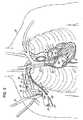
- Fig. 1Aillustrates one of many possible general configurations of a blood circulation assist system 10 implanted in accordance with the inventive aspects. Devices and systems configured in accordance with the teachings herein may be implanted in any suitable surgical manner, including but not limited to those discussed generally herein.
- Fig. 1Ashows the system 10 implanted in a transvenous endoluminal manner and, in particular, illustrates an inflow cannula 12 passing through the venous system into the left atrium 14 of the heart 15 via the superior vena cava 16 and subclavian vein 18. Because cannula 12 passes through the venous system, it is more particularly referred to herein as a catheter 12.
- the inflow catheter 12exits at a site near the clavical of the patient 20.
- the distal end 12a of the catheter 12is positioned across the interatrial septum 30 generally at the location of the fossa ovalis such that the distal tip 12a of the catheter 12 is within the left atrium 14. Access may be made, for example, into any portion within the left side of the heart (e.g., the left atrium and/or left ventricle) to access oxygenated blood.
- the proximal end 12b of the catheter 12is coupled to the inlet 32 of a blood pump 34.
- any suitable blood pump 34may be used, including those described in U.S. Patent Nos. 6,176,848 ; 6,116,862 ; 6,942,611 ; and 6,623,475 or DE 10 2004 019 721.0 .
- An outflow catheter 36is connected between the outlet 38 of the pump 34 and an artery, such as the superficial axillary artery 40. Blood flow therefore travels in the direction of the arrows 42 from the left atrium 14, through the pump 34, and into the patient's arterial system through the outflow catheter 36.
- Fig. 1A-1illustrates an alternative system configuration in which the transvenous endoluminal implantation is performed via the jugular vein 50.
- the inflow catheter 12is brought from the jugular venous exit site 52 along a subcutaneous tunnel formed from the pectoral pocket where the pump 34 is situated. While the system implantation configurations shown in Figs. 1A and 1A-1 are representative and desirable, it will be appreciated that many other implantation configurations and schemes may be implemented depending on, for example, the needs of any particular patient or desires of the surgeon.
- Figs. 1B-1Dillustrate in a sequential fashion the technique and components used to perform a transeptal puncture into the left atrium 14.
- the proceduremay start from a subclavicular pectoral cut down 60 similar to that used for implantation of a pacemaker.
- Fig. 1Billustrates a transceptal system including a sheath or delivery catheter 62 and a dilator device 64 received in the delivery catheter 62.
- a needle(not shown) may be initially used to puncture the interatrial septum 30 generally at the location of the fossa ovalis. This needle may then be exchanged for a guidewire 66 that is directed into the left atrium 14 through the dilator device 64.
- FIG. 1Cillustrates the step of advancing the dilator 64 across the interatrial septum 30 over the guidewire 66.
- the guidewire 66is typically looped within the left atrium 14 to help avoid any trauma to the heart tissue by the distal tip 66a of the guidewire 66.
- Fig. 1Dillustrates the subsequent steps of advancing the transceptal sheath or delivery catheter 62 across the septum 30 (i.e., the tissue structure between the atrial chambers) and then retraction of the dilator 64 as illustrated by the arrow 70.
- the dilator 64is completely removed leaving behind the sheath or delivery catheter 62 with the distal tip 62a located in the left atrium 14 and the guidewire 66 for use during the next step of the procedure to deliver the inflow catheter 12.
- the inflow catheter 12which is the pump inflow catheter of the system, may be introduced over the guidewire 66 and through the transceptal delivery catheter or sheath 62.
- the inflow catheter 12includes first and second anchor elements 80, 82 fixed thereto with the first anchor element 80 being located more distally on the inflow catheter 12 than the second anchor element 82.
- the anchor elements 80, 82may be retained in a compact state during delivery through the delivery catheter or sheath 62 and may be expanded either selectively or automatically as they emerge from the delivery catheter 62 during a subsequent step or steps.
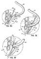
- Fig. 1Fillustrates the inflow catheter 12 is advanced until the most distal anchor element 80, that is, the first anchor element, is deployed within the left atrium 14 from the distal tip 62a of the delivery catheter 62.
- the first or distal anchor element 80may automatically expand due to an expanding mechanism associated therewith or due to the characteristics of the material forming the anchor element 80 itself as the anchor element 80 emerges from the delivery catheter 62.
- a mechanismmay be implemented for operation by the surgeon to selectively expand one or both anchor elements 80, 82 as desired during the procedure. As shown in Fig.
- both anchor elements 80, 82may be deployed within the left atrium 14 as the inflow catheter 12 is pushed out from the distal tip 62a of the delivery catheter or sheath 62. Then, as indicated by the arrow 90 in Fig. 1G , the inflow catheter 12 is pulled proximally until the second anchor element 82 is pulled through the aperture 92 created in the interatrial septum 30 and resides against the outside surface (relative to the left atrial chamber) of the interatrial septum 30 as shown in Fig. 1H .
- the second anchor element 82may be formed with a smaller maximum width dimension than the first anchor element 80.
- anchor element 80may have an expanded diameter of 14 mm while element 82 has an expanded diameter of 12 mm, in the case in which elements 80, 82 are substantially circular discs. This ensures that the smaller anchor element 82 may noticeably pop through the aperture 92 in the interatrial septum 30 leaving the larger anchor element 80 as a firm stop against the opposite side of the septum 30 within the left atrium 14. The resulting connection will generally appear as shown in Fig.
- anchor elements 80, 82themselves may be of various shapes, designs and configurations, and the distal end 12a of the inflow catheter 12 may or may not extend from the first anchor element 80 into the left atrium 14, as shown, but may instead be flush with the atrial side of the anchor element 80, or otherwise configured and shaped in any suitable manner.
- an outflow catheter 36is connected to the arterial system of the patient 20, such as illustrated.
- the outflow catheter 36may be connected to the axillary artery 40 through a suitable surgical incision and attachment procedure which may involve the use of suitable grafts and suturing 96.
- a supplemental blood flow pump 34having an inlet 32 and an outlet 38 is coupled to the inflow and outflow catheters 12, 36.
- the inflow and/or outflow catheters 12, 36may first be cut to a suitable length by an appropriate sterilized cutting tool 98 such that the system may be more easily implanted into, for example, a pectoral pacemaker pocket without kinking of catheters 12, 36 as illustrated in Fig. 1J .
- FIG. 2illustrates an alternative anchoring method in which the first and second anchor elements 80, 82 may reside on opposite sides of the tissue in a compact state, as shown, and then be selectively enlarged to anchor against and seal against the tissue which, in this example, is again the interatrial septum 30.
- the first anchor element 80which resides in the left atrium 14 (or other location in the left side of the heart) may be expanded and seated against the inside surface of the atrium 14 as the second anchor element 82 is pulled back through the aperture 92 in its compact state.
- the second anchor element 82may then be expanded against the outside surface of the septum 30 (relative to the left atrial chamber 14).
- the anchor elements 80, 82may or may not be differently sized.
- the anchor elements 80, 82may comprise any suitable configuration and may involve any suitable deployment method.
- One desirable shapeis a disc-shaped element that acts as a flange extending around the outside of the blood inflow cannula 12 and capable of forming a fluid tight seal against the heart tissue.
- the material of the anchor elements 80, 82may be, for example, a pliable and/or resilient material such as surgical grade silicone. Alternatively, any other material(s) may be used. For example, materials may be used that promote ingrowth of tissue or that are covered by a material that promotes ingrowth of tissue.
- the anchor elementsmay be self- expandable when removed from the delivery catheter 62 or may be expanded by any suitable mechanism operated by the surgeon. Other restraining members aside from the delivery catheter 62 may be used as well to initially restrain the anchor elements 80, 82 in compact states during delivery to the attachment or anchoring site and optionally during initial portions of the anchoring procedure.
- Fig. 3Aillustrates a fully implanted circulatory assist system 100 not in accordance with the invention.
- this system 100comprises an inflow cannula 102, a blood pump 104, and an outflow cannula 106.
- the outflow cannula 106may be connected to a superficial artery, such as the axillary artery 40 as previously described through the use of grafts (not shown) or in other suitable manners.
- the inflow cannula 102is attached directly to an exterior wall of the heart 15 on the left side, such as to the left atrial wall 14a, as shown.
- the inflow cannula 102instead of being directed through the patient's venous system, is instead directed to this exterior area of the heart 15 through any desired surgical approach, such as one of the approaches generally discussed below.
- the operation of the system 100is similar to that described above in terms of drawing oxygenated blood from the left side of the heart 15 into the inflow cannula 102, through the pump 104, and out to the arterial system via the outflow cannula 106.
- FIGs. 3B-3Fone illustrative procedure for connecting the inflow cannula 102 is shown.
- an access location 110such as the so-called Waterson's groove is exposed or otherwise accessed during a surgical procedure.
- An incisionmay be made with a scalpel 112 to expose the access location further.
- a small incision 120is made to access the interior of the left atrium 14 so as to allow for the insertion of the distal end portion 102a of the inflow cannula 102.
- the distal end portion 102a of the inflow cannula 102includes distal and proximal anchor elements 122, 124 similar to those previously described, however, other designs and configurations may be used instead.
- one or more purse string sutures 130, 132may be secured around the incision 120 in preparation for the insertion of the cannula 102, or after the insertion of the cannula 102.
- the inflow cannula 102may be inserted through the incision 120 such that both the distal and proximal anchor elements 122, 124 are within the left atrium 14 as shown in Fig. 3E . Then, as shown in Fig.
- the inflow cannula 102is withdrawn slightly proximally (toward the surgeon) to position the proximal anchor element 124 outside the left atrium 14 but leaving the distal anchor element 122 within the left atrium 14.
- the purse string suture or sutures 130, 132may be tightened and tied off to fully secure the tissue 140 between the distal and proximal anchor elements 122, 124 to provide a fluid tight or at least substantially fluid tight seal.
- any other aspects of the previously described embodimentmay be used in this embodiment as well, such as the use of various materials including surgical grade silicone for the inflow cannula 102 and anchor elements 122, 124, with or without tissue ingrowth material to further aide in providing a leak tight connection to the left atrial chamber.
- the purse string suture or sutures 130, 132may be tightened to a degree that is adequate to provide a leak tight seal.
- the tightened tissue 140should at least substantially fill or gather within the gap between the distal and proximal anchor elements 122, 124 as schematically shown in Fig. 4B . If additional gathering of tissue 140 is necessary, additional tissue 140 may be gathered with one or more additional purse string sutures.
- Fig. 5illustrates the inflow cannula 102 in greater detail.
- the cannula 102may be approximately 10 mm in diameter, with the proximal anchor element 124 being 12 mm in diameter and the distal anchor element 122 being 14 mm in diameter.
- the tip dimension d 1 extending outwardly from the distal anchor element 122is approximately 2 mm, while the thicknesses t 1 , t 2 along the longitudinal axis of the cannula 102 of anchor elements 122, 124 are each approximately 2.5 mm.
- the distance d 2 between the distal and proximal anchor elements 122, 124is approximately 4 mm.
- the inflow cannula 102which may be constructed from surgical grade silicone, may also include reinforcements in the form of stainless steel or Nitinol coils 150. It is desirable to have the inflow cannula 102 as flexible as possible, but still of a design that prevents kinking. In view of the flexibility of the cannula 102, it may be necessary to provide stiffness to at least the distal end portion 102a during insertion through the wall of the heart at access location 110 (or any other desired location). This stiffness may be provided only temporarily during the insertion procedure.
- a trocar(not shown) may be inserted temporarily through the proximal end 102b of cannula 102 and into the distal end portion 102a while inserting the cannula 102 into the heart 15 as described herein.
- a balloon-like or other expandable elementassociated with the trocar that engages the interior of the distal end 102a during the cannula insertion process.
- the trocarAfter the cannula 102 is properly positioned as described herein, the trocar could be removed and the remainder of the implantation process, such as connection of the pump 104 and outflow cannula 106 could take place.
- a similar processmay be used during a catheterization procedure as described herein.
- Surgical Open ThoracotomyIn this surgical approach, a relatively superior and caudal thoracotomy access is used to deliver the blood inflow cannula to the left atrium where it is anchored at a location on the roof of the atrium. This location on the atrium has specific benefit because the wall of the atrium is smooth and relatively large at this location, isolating the cannula tip from other structures within the atrium.
- a relatively lateral thoracotomy accessis used to deliver the blood inflow cannula to the left atrium where it is anchored at a location on the postero-medial wall near the interatrial septum.
- This locationis often called "Waterson's groove” as discussed above and is a common location to make a left atriotomy when performing mitral valve repair surgery. Waterson's groove is accessed surgically by dissecting the left atrium away from the right atrium at this posterior aspect, between the superior vena cava and the left pulmonary veins.
- the blood inflow cannulamay be implanted in a similar location as described above in that a tubular trocar may be used to access the intra-thoracic location (Waterson's groove, for example) where the cannula would be anchored through the heart wall.
- a tubular trocarmay be used to access the intra-thoracic location (Waterson's groove, for example) where the cannula would be anchored through the heart wall.
- the entire operationis performed through these relatively small tubular trocars thereby minimizing the size of the opening in the patient's chest.
- additional small holesare made to deliver trocars used in conjunction with the main delivery trocar to allow placement of an endoscopic camera and specialized surgical tools for grasping, cutting, suturing, cauterizing, or performing other operations on tissue.
- the cannulacan be delivered to the same location as in the open surgical technique (i.e. Waterson's groove) but with less invasive access across the chest wall.
- Transluminal -This method of implantation can, for example, involve directing the blood inflow cannula from the heart to the superficial remote pump location via a transluminal route.
- This transluminal routemay involve passing the cannula via the axillary and/or subclavian vein, through the superior vena cava into the left atrium and then anchoring the cannula into the left atrium by passing it through the intra-atrial septum, such as through the fossa ovalis.
- the cannulamight enter/exit the venous vasculature at the jugular vein.
- the cannula proximal endmay be routed to the superficial pectoral pump location by being tunneled under the skin or chest musculature.
- Over-the-Wire (Seldinger) TechniqueA method for implanting the cannula, whether in surgical or transluminal approaches, is to utilize a low profile and simple "over the wire” approach often called the Seldinger technique.
- the Seldinger technique for percutaneously placing a catheter into the lumen of a blood vesselinvolves inserting a needle into the vessel across its wall, and then following with a guide wire through the needle. Once the guide wire is placed across the skin into the vessel lumen, the needle can be removed and then a suitable catheter placed over the wire into the vessel lumen. This technique minimizes trauma to the vessel wall, as often the hole across the vessel wall is gently expanded or dilated by the catheter being introduced.
- the transluminal cannulacould be introduced into the jugular or subclavian vein after access to the vessel is obtained using the percutaneous Seldinger technique, where the cannula would be adapted to be introduced into the vessel over the guide wire.
- Such adaptationswould include an obturator or dilator within the inner lumen of the cannula and thereby providing support and lumen size matching to facilitate dilation and blood maintenance through the puncture site.
- a surgical tunnel from the pectoral pocket location of the pumpmay be made up to the subcutaneous location of the veinotomy, where the exposed end of the cannula would be secured and pulled through the tunnel to the pump pocket.
- the Seldinger techniquemight be utilized in the various surgical implantation approaches described above, where the cannula system would be specifically adapted to facilitate this implantation technique.
- the Seldinger techniqueis most commonly associated with percutaneous access to blood vessels
- an adapted version of the technique utilizing a specifically adapted cannula introduction systemis a highly preferred approach to surgical implantation where direct access to the heart itself is utilized.
- an atriotomycould be made by inserting a needle across the heart wall and a guide wire then placed therethrough. After removal of the needle, with bleeding controlled and minimal, the cannula system with specialized introduction obturator within can be introduced over the wire thereby maintaining many of the advantages of the so-called Seldinger technique even in a surgical approach.
Landscapes
- Health & Medical Sciences (AREA)
- Heart & Thoracic Surgery (AREA)
- Life Sciences & Earth Sciences (AREA)
- Engineering & Computer Science (AREA)
- Vascular Medicine (AREA)
- Hematology (AREA)
- Biomedical Technology (AREA)
- Anesthesiology (AREA)
- Animal Behavior & Ethology (AREA)
- General Health & Medical Sciences (AREA)
- Public Health (AREA)
- Veterinary Medicine (AREA)
- Cardiology (AREA)
- Pulmonology (AREA)
- Biophysics (AREA)
- Mechanical Engineering (AREA)
- External Artificial Organs (AREA)
- Prostheses (AREA)
Description
- This invention generally relates to medical devices and methods and, more particularly, to methods and devices for fluid coupling to the heart of a patient in systems for assisting blood circulation in a patient.
- Various devices and methods have been utilized to conduct blood from the heart to assist with blood circulation in a patient. This is often desirable or necessary in cases where a patient is experiencing congestive heart failure and a transplant organ has either not been located, or the patient is not a suitable candidate for a transplant. The blood pumps are typically attached directly to the left ventricle of the heart, however, at least one blood pump system locates the pump remotely, such as subcutaneously in the manner of a pacemaker. In this regard, see
U.S. Patent No. 6,530,876 . In this situation or similar situations, a cannula may be used to create an inflow conduit from the heart (an intra-thoracic location) to a pump located in a superficial (non-thoracic cavity) location, which may be the so-called "pacemaker pocket." Of course, other remote locations are possible as alternatives. The pacemaker pocket is a location usually accessed by a surgical incision generally parallel to and below the collarbone extending down toward the breast, and over the pectoral muscle. Sometimes the pacemaker pocket is made below the muscle. The pump, to which the cannula is connected, is intended to sit in the pectoral pocket, and is preferably but not limited to the right side of the chest. - One area in need of improvement is the anchoring mechanism used to fluidly connect the inflow conduit or cannula to the heart. The cannula can be connected and anchored to any chamber of the heart from which it is desired to conduct or conduit blood. One anchor point is the left side of the heart, such as the left atrium. This is shown in
U.S. Patent No. 6,530,876 . It would be desirable to ensure that this connection is as secure and leakage free as possible. In addition, the procedure for making the connection should be as simple as possible under the circumstances. - General cannula implantation methods known and usable in connection with the present invention may involve many different approaches and several of the representative approaches are described further below. For example, the cannula may be implanted by directly invading the thoracic cavity. Other surgical methods include so-called open heart surgery in which a median sternotomy is made to fully expose the heart within the thoracic cavity. Still other surgical methods include less invasive surgical methods such as a thoracotomy, mini-thoracotomy, thoracoscopic, or any other less invasive approaches. Any of these surgical methods can be used to implant the cannula in fluid communication with any desired location of the heart as described herein.
- Alternatively, a transluminal method of implanting the cannula may be used in which the thoracic cavity is not invaded directly, but rather the heart is accessed utilizing blood vessels naturally connecting into the heart. Translumial methods include so-called transvenous delivery of the cannula to the left side of the heart via the right side of the heart to which the major veins and the more distal peripheral veins provide natural conduits through which the cannula can be delivered. In this approach, the cannula may more precisely be referred to as a catheter. Transluminal methods generally utilize indirect visualization, such as by means of contrast-dye enhanced fluoroscopy and/or ultrasonic imaging to navigate devices through the vessels of the body.
JP 62-97650 U - The invention provides a device for establishing a blood flow conduit between a chamber in a heart of a patient and a remote location, the device comprising a cannula having an outer surface and proximal and distal end portions, the distal end portion including an opening communicating with a lumen of the cannula for allowing blood flow therethrough, the distal end portion and opening being configured for insertion into the chamber of the heart; and first and second anchor elements having respective maximum width dimensions extending outwardly from the outer surface of the cannula, the first anchor element being positioned more distally than the second anchor element and defining a tissue receiving space therebetween, and the maximum width dimension of the first anchor element being larger than the maximum width dimension of the second anchor element, whereby the first anchor element is configured to be positioned inside the heart chamber and the second anchor element is configured to be positioned outside the heart chamber with heart tissue held in the tissue receiving space therebetween, characterized in that the cannula further comprises a blood flow catheter configured to be introduced into the venous system of the patient in order to direct the distal end portion into the chamber of the heart, and in that the first and second anchor elements are movable between first, compact states during introduction via the venous system and second, expanded states for positioning on opposite sides of the heart tissue.
- Generally, the device is for establishing a blood flow conduit between a chamber in a heart of a patient and a remote location, such as a location at which a blood pump resides away from the heart. In this regard, the term "remote," as used herein means away from the heart but is not limited to any particular distance from the heart. The cannula is an inflow cannula having an outer surface and proximal and distal end portions (relative to a surgeon implanting the cannula). The distal end portion is configured for insertion into the chamber of the heart. First and second anchor elements having respective maximum width dimensions extend outwardly from the outer surface of the inflow cannula at its distal end portion. The first anchor element is positioned more distally than the second anchor element and a tissue receiving space is defined between the first and second anchor elements. The maximum width dimension of the first anchor element is larger than the maximum width dimension of the second anchor element in this aspect of the invention. The first anchor element is configured to be positioned inside the heart chamber and the second anchor element is configured to be positioned outside the heart chamber with heart tissue held in the tissue receiving space therebetween. The cannula may be installed in a patient through any suitable type of surgical procedure.
- In one embodiment, the device is implemented in a catheter based system. In this embodiment, the inflow cannula is more specifically a blood inflow catheter and the inflow catheter is configured to be directed into the venous system of the patient. The inflow catheter may be received by the delivery catheter for purposes of establishing the blood inflow conduit in a minimally invasive manner.
- A catheter system including the device may further include a blood pump having an inlet and an outlet. The outlet is adapted for connection to a remote location in the circulatory system of the patient via an outflow cannula or catheter and the inlet is adapted for connection to the inflow cannula.
- There is disclosed a method of establishing blood flow from a chamber in a heart of a patient to a remote location for providing supplemental blood flow from the heart. The method may comprise inserting at least a portion of a distal end portion of an inflow cannula into the chamber of the heart. The distal end portion includes first and second anchor elements each having a maximum width dimension in a direction perpendicular to a lengthwise axis of the inflow cannula, and the first anchor element has a larger maximum width dimension than the second anchor element. The method further comprises placing the first anchor element inside the chamber and against an inside surface of tissue defining the chamber, and placing the second anchor element outside the chamber and against an outside surface of the tissue defining the chamber.
- In another disclosed method, a distal end portion of an inflow cannula is inserted into a chamber of the heart and includes first and second anchor elements with the first anchor element being located more distally than the second anchor element, and with a tissue receiving space located between the first and second anchor elements. This method further comprises pulling the more proximally located second anchor element out of the chamber. The more proximally located second anchor element is engaged against an outside surface of tissue defining the chamber, while the first anchor element is left inside the chamber to engage an inside surface of the chamber such that the tissue is retained in the tissue receiving space and the cannula is in fluid communication with the chamber. If needed, various manners of further securing the tissue between the anchor elements may be used. One manner may be the use of one or more purse string type suture connections.
- Various additional features and aspects of the embodiments and scope of the invention will be more readily appreciated upon review of the following detailed description of the illustrative embodiments taken in conjunction with the accompanying drawings.
Fig. 1A is a schematic representation of chest anatomy, and illustrates one example of a pathway in the venous system used to access a patient's heart.Fig. 1A-1 is similar toFig. 1A , but illustrates another representative and illustrative cannula or catheter pathway.Fig. 1B is an enlarged view of the chest anatomy, including the heart, and illustrates an initial step in establishing a pathway to the left atrial chamber or left atrium of the heart.Fig. 1C illustrates an enlarged view of the heart and the catheter devices used during the initial portions of the procedure.Fig. 1D is a view similar toFig. 1C , but illustrating a subsequent portion of the procedure.Fig. 1E is a view similar toFig. 1D , but illustrating a subsequent portion of the procedure.Figs. 1F-1H are views similar toFigs. 1C-1E , but illustrate subsequent procedural steps involved with anchoring a blood inflow catheter to a wall of the left atrium.Fig. 1I is a view similar toFig. 1B , but illustrates a step of attaching a supplemental blood flow pump to proximal ends of the inflow and outflow catheters.Fig. 1J is a view similar toFig. 1I , but illustrates the fully implanted system with the supplemental blood flow pump implanted superficially in a pacemaker pocket location.Fig. 2 is a view similar toFig. 1H , but illustrating another alternative embodiment of the anchoring system and method of anchoring the inflow catheter to the heart tissue.Fig. 3A is a schematic representation of chest anatomy, and illustrates an example of another pathway, exterior to the venous system, used to access a patient's heart and implant a circulatory assist system not in accordance with the invention.Fig. 3B is an enlarged view of the heart illustrating a location at which an incision may be made to expose an access location to the interior of the heart.Fig. 3C is a view similar toFig. 3B , but illustrating the access location exposed and generally showing an inflow cannula being directed toward the access location.Fig. 3D is an enlarged view of the access location or area of the heart illustrating two purse string sutures applied around a small incision for receiving the distal end or tip portion of the inflow cannula.Fig. 3E is an enlarged view similar toFig. 3D , but illustrating the distal end portion of the inflow cannula completely inserted into the left atrium of the heart through the incision.Fig. 3F is a view similar toFig. 3E , but illustrating the distal end portion of the inflow cannula partially pulled back and the purse string sutures tightened.Figs. 4A and 4B are respective cross sectional views of the access location with the inflow cannula distal portion properly placed and respectively showing loose and tightened purse string sutures to illustrating the gathering of tissue between the cannula anchor elements.Fig. 5 is a longitudinal cross sectional view of the inflow cannula.Fig. 1A illustrates one of many possible general configurations of a blood circulation assistsystem 10 implanted in accordance with the inventive aspects. Devices and systems configured in accordance with the teachings herein may be implanted in any suitable surgical manner, including but not limited to those discussed generally herein.Fig. 1A shows thesystem 10 implanted in a transvenous endoluminal manner and, in particular, illustrates aninflow cannula 12 passing through the venous system into theleft atrium 14 of theheart 15 via thesuperior vena cava 16 andsubclavian vein 18. Becausecannula 12 passes through the venous system, it is more particularly referred to herein as acatheter 12. Theinflow catheter 12 exits at a site near the clavical of thepatient 20. Thedistal end 12a of thecatheter 12 is positioned across theinteratrial septum 30 generally at the location of the fossa ovalis such that thedistal tip 12a of thecatheter 12 is within theleft atrium 14. Access may be made, for example, into any portion within the left side of the heart (e.g., the left atrium and/or left ventricle) to access oxygenated blood. Theproximal end 12b of thecatheter 12 is coupled to theinlet 32 of ablood pump 34. As further shown, anysuitable blood pump 34 may be used, including those described inU.S. Patent Nos. 6,176,848 ;6,116,862 ;6,942,611 ; and6,623,475 orDE 10 2004 019 721.0outflow catheter 36 is connected between theoutlet 38 of thepump 34 and an artery, such as the superficialaxillary artery 40. Blood flow therefore travels in the direction of thearrows 42 from theleft atrium 14, through thepump 34, and into the patient's arterial system through theoutflow catheter 36.Fig. 1A-1 illustrates an alternative system configuration in which the transvenous endoluminal implantation is performed via thejugular vein 50. Theinflow catheter 12 is brought from the jugularvenous exit site 52 along a subcutaneous tunnel formed from the pectoral pocket where thepump 34 is situated. While the system implantation configurations shown inFigs. 1A and1A-1 are representative and desirable, it will be appreciated that many other implantation configurations and schemes may be implemented depending on, for example, the needs of any particular patient or desires of the surgeon.Figs. 1B-1D illustrate in a sequential fashion the technique and components used to perform a transeptal puncture into theleft atrium 14. For this application, the procedure may start from a subclavicular pectoral cut down 60 similar to that used for implantation of a pacemaker. More specifically,Fig. 1B illustrates a transceptal system including a sheath ordelivery catheter 62 and adilator device 64 received in thedelivery catheter 62. In this method, a needle (not shown) may be initially used to puncture theinteratrial septum 30 generally at the location of the fossa ovalis. This needle may then be exchanged for aguidewire 66 that is directed into theleft atrium 14 through thedilator device 64.Fig. 1C illustrates the step of advancing thedilator 64 across theinteratrial septum 30 over theguidewire 66. Theguidewire 66 is typically looped within theleft atrium 14 to help avoid any trauma to the heart tissue by thedistal tip 66a of theguidewire 66.Fig. 1D illustrates the subsequent steps of advancing the transceptal sheath ordelivery catheter 62 across the septum 30 (i.e., the tissue structure between the atrial chambers) and then retraction of thedilator 64 as illustrated by thearrow 70. Thedilator 64 is completely removed leaving behind the sheath ordelivery catheter 62 with thedistal tip 62a located in theleft atrium 14 and theguidewire 66 for use during the next step of the procedure to deliver theinflow catheter 12.- As shown in
Fig. 1E , theinflow catheter 12, which is the pump inflow catheter of the system, may be introduced over theguidewire 66 and through the transceptal delivery catheter orsheath 62. Theinflow catheter 12 includes first andsecond anchor elements first anchor element 80 being located more distally on theinflow catheter 12 than thesecond anchor element 82. In this configuration, theanchor elements sheath 62 and may be expanded either selectively or automatically as they emerge from thedelivery catheter 62 during a subsequent step or steps. Fig. 1F illustrates theinflow catheter 12 is advanced until the mostdistal anchor element 80, that is, the first anchor element, is deployed within theleft atrium 14 from thedistal tip 62a of thedelivery catheter 62. In this aspect, the first ordistal anchor element 80 may automatically expand due to an expanding mechanism associated therewith or due to the characteristics of the material forming theanchor element 80 itself as theanchor element 80 emerges from thedelivery catheter 62. Alternatively, a mechanism may be implemented for operation by the surgeon to selectively expand one or bothanchor elements Fig. 1G , bothanchor elements left atrium 14 as theinflow catheter 12 is pushed out from thedistal tip 62a of the delivery catheter orsheath 62. Then, as indicated by the arrow 90 inFig. 1G , theinflow catheter 12 is pulled proximally until thesecond anchor element 82 is pulled through theaperture 92 created in theinteratrial septum 30 and resides against the outside surface (relative to the left atrial chamber) of theinteratrial septum 30 as shown inFig. 1H . For purposes of assisting transfer of the second orproximal anchor element 82 across the interatrial wall orseptum 30 and providing perceptible feedback to the surgeon, thesecond anchor element 82 may be formed with a smaller maximum width dimension than thefirst anchor element 80. For example,anchor element 80 may have an expanded diameter of 14 mm whileelement 82 has an expanded diameter of 12 mm, in the case in whichelements smaller anchor element 82 may noticeably pop through theaperture 92 in theinteratrial septum 30 leaving thelarger anchor element 80 as a firm stop against the opposite side of theseptum 30 within theleft atrium 14. The resulting connection will generally appear as shown inFig. 1H , although it will be appreciated that theanchor elements distal end 12a of theinflow catheter 12 may or may not extend from thefirst anchor element 80 into theleft atrium 14, as shown, but may instead be flush with the atrial side of theanchor element 80, or otherwise configured and shaped in any suitable manner.- To complete the system, an
outflow catheter 36 is connected to the arterial system of thepatient 20, such as illustrated. For example, theoutflow catheter 36 may be connected to theaxillary artery 40 through a suitable surgical incision and attachment procedure which may involve the use of suitable grafts andsuturing 96. A supplementalblood flow pump 34, having aninlet 32 and anoutlet 38 is coupled to the inflow andoutflow catheters outflow catheters tool 98 such that the system may be more easily implanted into, for example, a pectoral pacemaker pocket without kinking ofcatheters Fig. 1J . - With reference to
Fig. 2 , like reference numerals indicate like elements as described above.Fig. 2 illustrates an alternative anchoring method in which the first andsecond anchor elements interatrial septum 30. As another alternative, thefirst anchor element 80 which resides in the left atrium 14 (or other location in the left side of the heart) may be expanded and seated against the inside surface of theatrium 14 as thesecond anchor element 82 is pulled back through theaperture 92 in its compact state. Thesecond anchor element 82 may then be expanded against the outside surface of the septum 30 (relative to the left atrial chamber 14). In this embodiment, as with the previous embodiment, theanchor elements - As mentioned above, the
anchor elements blood inflow cannula 12 and capable of forming a fluid tight seal against the heart tissue. The material of theanchor elements delivery catheter 62 or may be expanded by any suitable mechanism operated by the surgeon. Other restraining members aside from thedelivery catheter 62 may be used as well to initially restrain theanchor elements Fig. 3A illustrates a fully implantedcirculatory assist system 100 not in accordance with the invention. Again, like numerals in the drawings described below represent like elements as previously described. Specifically, thissystem 100 comprises aninflow cannula 102, ablood pump 104, and an outflow cannula 106. The outflow cannula 106 may be connected to a superficial artery, such as theaxillary artery 40 as previously described through the use of grafts (not shown) or in other suitable manners. Theinflow cannula 102 is attached directly to an exterior wall of theheart 15 on the left side, such as to the left atrial wall 14a, as shown. Theinflow cannula 102, instead of being directed through the patient's venous system, is instead directed to this exterior area of theheart 15 through any desired surgical approach, such as one of the approaches generally discussed below. Once implanted, the operation of thesystem 100 is similar to that described above in terms of drawing oxygenated blood from the left side of theheart 15 into theinflow cannula 102, through thepump 104, and out to the arterial system via the outflow cannula 106.- More specifically referring to
Figs. 3B-3F , one illustrative procedure for connecting theinflow cannula 102 is shown. In this regard, anaccess location 110 such as the so-called Waterson's groove is exposed or otherwise accessed during a surgical procedure. An incision may be made with ascalpel 112 to expose the access location further. As shown inFig. 3C , asmall incision 120 is made to access the interior of theleft atrium 14 so as to allow for the insertion of the distal end portion 102a of theinflow cannula 102. The distal end portion 102a of theinflow cannula 102 includes distal andproximal anchor elements Fig. 3D , one or more purse string sutures 130, 132 may be secured around theincision 120 in preparation for the insertion of thecannula 102, or after the insertion of thecannula 102. Theinflow cannula 102 may be inserted through theincision 120 such that both the distal andproximal anchor elements left atrium 14 as shown inFig. 3E . Then, as shown inFig. 3F , theinflow cannula 102 is withdrawn slightly proximally (toward the surgeon) to position theproximal anchor element 124 outside theleft atrium 14 but leaving thedistal anchor element 122 within theleft atrium 14. At this time, the purse string suture orsutures tissue 140 between the distal andproximal anchor elements inflow cannula 102 and anchorelements - As further shown in
Figs. 4A and 4B , the purse string suture orsutures tissue 140 should at least substantially fill or gather within the gap between the distal andproximal anchor elements Fig. 4B . If additional gathering oftissue 140 is necessary,additional tissue 140 may be gathered with one or more additional purse string sutures. Fig. 5 illustrates theinflow cannula 102 in greater detail. In this embodiment, thecannula 102 may be approximately 10 mm in diameter, with theproximal anchor element 124 being 12 mm in diameter and thedistal anchor element 122 being 14 mm in diameter. The tip dimension d1 extending outwardly from thedistal anchor element 122 is approximately 2 mm, while the thicknesses t1, t2 along the longitudinal axis of thecannula 102 ofanchor elements proximal anchor elements inflow cannula 102, which may be constructed from surgical grade silicone, may also include reinforcements in the form of stainless steel or Nitinol coils 150. It is desirable to have theinflow cannula 102 as flexible as possible, but still of a design that prevents kinking. In view of the flexibility of thecannula 102, it may be necessary to provide stiffness to at least the distal end portion 102a during insertion through the wall of the heart at access location 110 (or any other desired location). This stiffness may be provided only temporarily during the insertion procedure. For example, a trocar (not shown) may be inserted temporarily through the proximal end 102b ofcannula 102 and into the distal end portion 102a while inserting thecannula 102 into theheart 15 as described herein. To retain the distal end of the trocar in the distal end 102a of thecannula 102, there may be a balloon-like or other expandable element associated with the trocar that engages the interior of the distal end 102a during the cannula insertion process. After thecannula 102 is properly positioned as described herein, the trocar could be removed and the remainder of the implantation process, such as connection of thepump 104 and outflow cannula 106 could take place. A similar process may be used during a catheterization procedure as described herein.- Below, and as representative and nonlimiting examples, various surgical approaches are more fully described.
- Surgical Open Sternotomy - This approach allows full access to the heart, especially the left atrium, and allows access to several different locations where a blood inflow cannula might be attached to the heart. However, due to the highly invasive nature of this approach, less invasive implantation approaches may be more desirable to a surgeon.
- Surgical Open Thoracotomy - In this surgical approach, a relatively superior and caudal thoracotomy access is used to deliver the blood inflow cannula to the left atrium where it is anchored at a location on the roof of the atrium. This location on the atrium has specific benefit because the wall of the atrium is smooth and relatively large at this location, isolating the cannula tip from other structures within the atrium.
- In another suitable surgical method, a relatively lateral thoracotomy access is used to deliver the blood inflow cannula to the left atrium where it is anchored at a location on the postero-medial wall near the interatrial septum. This location is often called "Waterson's groove" as discussed above and is a common location to make a left atriotomy when performing mitral valve repair surgery. Waterson's groove is accessed surgically by dissecting the left atrium away from the right atrium at this posterior aspect, between the superior vena cava and the left pulmonary veins.
- Thoracoscopic Surgery - In this surgical method, the blood inflow cannula may be implanted in a similar location as described above in that a tubular trocar may be used to access the intra-thoracic location (Waterson's groove, for example) where the cannula would be anchored through the heart wall. In this minimally or less invasive surgical method, the entire operation is performed through these relatively small tubular trocars thereby minimizing the size of the opening in the patient's chest. Typically, additional small holes are made to deliver trocars used in conjunction with the main delivery trocar to allow placement of an endoscopic camera and specialized surgical tools for grasping, cutting, suturing, cauterizing, or performing other operations on tissue. Through the main trocar, the cannula can be delivered to the same location as in the open surgical technique (i.e. Waterson's groove) but with less invasive access across the chest wall.
- Transluminal - This method of implantation can, for example, involve directing the blood inflow cannula from the heart to the superficial remote pump location via a transluminal route. This transluminal route may involve passing the cannula via the axillary and/or subclavian vein, through the superior vena cava into the left atrium and then anchoring the cannula into the left atrium by passing it through the intra-atrial septum, such as through the fossa ovalis. Alternatively, the cannula might enter/exit the venous vasculature at the jugular vein. The cannula proximal end may be routed to the superficial pectoral pump location by being tunneled under the skin or chest musculature.
- Over-the-Wire (Seldinger) Technique - A method for implanting the cannula, whether in surgical or transluminal approaches, is to utilize a low profile and simple "over the wire" approach often called the Seldinger technique. The Seldinger technique for percutaneously placing a catheter into the lumen of a blood vessel involves inserting a needle into the vessel across its wall, and then following with a guide wire through the needle. Once the guide wire is placed across the skin into the vessel lumen, the needle can be removed and then a suitable catheter placed over the wire into the vessel lumen. This technique minimizes trauma to the vessel wall, as often the hole across the vessel wall is gently expanded or dilated by the catheter being introduced. Another key advantage of the technique is that blood loss is minimized because control of the hole size around whatever is inserted is maintained. As an example, the transluminal cannula could be introduced into the jugular or subclavian vein after access to the vessel is obtained using the percutaneous Seldinger technique, where the cannula would be adapted to be introduced into the vessel over the guide wire. Such adaptations would include an obturator or dilator within the inner lumen of the cannula and thereby providing support and lumen size matching to facilitate dilation and blood maintenance through the puncture site. Once the cannula is introduced via the percutaneous puncture site, a surgical tunnel from the pectoral pocket location of the pump may be made up to the subcutaneous location of the veinotomy, where the exposed end of the cannula would be secured and pulled through the tunnel to the pump pocket.
- Alternatively, a variation of the Seldinger technique might be utilized in the various surgical implantation approaches described above, where the cannula system would be specifically adapted to facilitate this implantation technique. Although the Seldinger technique is most commonly associated with percutaneous access to blood vessels, an adapted version of the technique utilizing a specifically adapted cannula introduction system is a highly preferred approach to surgical implantation where direct access to the heart itself is utilized. Here, for example, an atriotomy could be made by inserting a needle across the heart wall and a guide wire then placed therethrough. After removal of the needle, with bleeding controlled and minimal, the cannula system with specialized introduction obturator within can be introduced over the wire thereby maintaining many of the advantages of the so-called Seldinger technique even in a surgical approach.
- While the present invention has been illustrated by a description of various illustrative embodiments and while these embodiments have been described in some detail, additional advantages and modifications will readily appear to those skilled in the art. The various features of the invention may be used alone or any combinations depending on the needs and preferences of the user.
Claims (9)
- A device for establishing a blood flow conduit between a chamber in a heart of a patient and a remote location, the device comprising a cannula (12) having an outer surface and proximal and distal end portions, the distal end portion including an opening communicating with a lumen of the cannula for allowing blood flow therethrough, the distal end portion and opening being configured for insertion into the chamber of the heart; and first and second anchor elements (80, 82) having respective maximum width dimensions extending outwardly from the outer surface of the cannula, the first anchor element (80) being positioned more distally than the second anchor element (82) and defining a tissue receiving space therebetween, and the maximum width dimension of the first anchor element (80) being larger than the maximum width dimension of the second anchor element (82), whereby the first anchor element (80) is configured to be positioned inside the heart chamber and the second anchor element (82) is configured to be positioned outside the heart chamber with heart tissue held in the tissue receiving space therebetween,characterized in that the cannula further comprises a blood flow catheter configured to be introduced into the venous system of the patient in order to direct the distal end portion into the chamber of the heart, andin that the first and second anchor elements are movable between first, compact states during introduction via the venous system and second, expanded states for positioning on opposite sides of the heart tissue.
- The device of claim 1, wherein at least one of the first or second anchor elements (80, 82) further comprises an annular disc shaped element.
- The device of either claim 1 or claim 2, wherein at least one of the first or second anchor elements (80, 82) is formed from a pliable, resilient material.
- The device of any preceding claim, wherein the first and second anchor elements (80, 82) are formed from a material that promotes ingrowth of tissue.
- The device of any preceding claim, wherein the first and second anchor elements (80, 82) are self-expandable into the second, expanded states.
- A catheter system for establishing a blood flow conduit between a chamber in a heart of a patient and a remote location, the system comprising a delivery catheter (62), and a device of any preceding claim with the cannula acting as a blood inflow catheter
- The system of claim 6, wherein the delivery catheter (62) is configured to be a restraining member to maintain the first and second anchor elements (80, 82) in the first, compact states.
- A supplemental blood flow assist device for increasing blood flow between a chamber in a heart of a patient and a remote location in the circulatory system of the patient, the device comprising a blood pump (34) having an inlet and an outlet, the outlet being adapted for connection to the remote location in the circulatory system of the patient, and the device of any one of claims 1 to 5, the proximal end portion of the cannula (12) being configured for coupling to the inlet of the blood pump (34).
- The device of claim 8, further comprising a delivery catheter (62) configured to receive the cannula (12) such that the distal end portion of the cannula (12) is deliverable to the heart.
Priority Applications (1)
| Application Number | Priority Date | Filing Date | Title |
|---|---|---|---|
| EP14196639.0AEP2845614B1 (en) | 2006-08-30 | 2007-08-28 | Devices, methods and systems for establishing supplemental blood flow in the circulatory system |
Applications Claiming Priority (2)
| Application Number | Priority Date | Filing Date | Title |
|---|---|---|---|
| US82397106P | 2006-08-30 | 2006-08-30 | |
| EP07814495.3AEP2056899B1 (en) | 2006-08-30 | 2007-08-28 | Systems for establishing supplemental blood flow in the circulatory system |
Related Parent Applications (2)
| Application Number | Title | Priority Date | Filing Date |
|---|---|---|---|
| EP07814495.3ADivisionEP2056899B1 (en) | 2006-08-30 | 2007-08-28 | Systems for establishing supplemental blood flow in the circulatory system |
| EP07814495.3Division | 2007-08-28 |
Related Child Applications (2)
| Application Number | Title | Priority Date | Filing Date |
|---|---|---|---|
| EP14196639.0ADivisionEP2845614B1 (en) | 2006-08-30 | 2007-08-28 | Devices, methods and systems for establishing supplemental blood flow in the circulatory system |
| EP14196639.0ADivision-IntoEP2845614B1 (en) | 2006-08-30 | 2007-08-28 | Devices, methods and systems for establishing supplemental blood flow in the circulatory system |
Publications (2)
| Publication Number | Publication Date |
|---|---|
| EP2650029A1 EP2650029A1 (en) | 2013-10-16 |
| EP2650029B1true EP2650029B1 (en) | 2015-01-14 |
Family
ID=39136773
Family Applications (3)
| Application Number | Title | Priority Date | Filing Date |
|---|---|---|---|
| EP13173762.9AActiveEP2650029B1 (en) | 2006-08-30 | 2007-08-28 | Devices and systems for establishing supplemental blood flow in the circulatory system |
| EP07814495.3AActiveEP2056899B1 (en) | 2006-08-30 | 2007-08-28 | Systems for establishing supplemental blood flow in the circulatory system |
| EP14196639.0AActiveEP2845614B1 (en) | 2006-08-30 | 2007-08-28 | Devices, methods and systems for establishing supplemental blood flow in the circulatory system |
Family Applications After (2)
| Application Number | Title | Priority Date | Filing Date |
|---|---|---|---|
| EP07814495.3AActiveEP2056899B1 (en) | 2006-08-30 | 2007-08-28 | Systems for establishing supplemental blood flow in the circulatory system |
| EP14196639.0AActiveEP2845614B1 (en) | 2006-08-30 | 2007-08-28 | Devices, methods and systems for establishing supplemental blood flow in the circulatory system |
Country Status (6)
| Country | Link |
|---|---|
| US (3) | US9572917B2 (en) |
| EP (3) | EP2650029B1 (en) |
| JP (2) | JP5537939B2 (en) |
| CA (1) | CA2666881C (en) |
| ES (2) | ES2427238T3 (en) |
| WO (1) | WO2008027869A2 (en) |
Families Citing this family (81)
| Publication number | Priority date | Publication date | Assignee | Title |
|---|---|---|---|---|
| US6889082B2 (en) | 1997-10-09 | 2005-05-03 | Orqis Medical Corporation | Implantable heart assist system and method of applying same |
| US7416525B2 (en) | 2003-09-18 | 2008-08-26 | Myrakelle, Llc | Rotary blood pump |
| US7393181B2 (en) | 2004-09-17 | 2008-07-01 | The Penn State Research Foundation | Expandable impeller pump |
| CN102380135A (en) | 2006-03-23 | 2012-03-21 | 宾州研究基金会 | Heart assist device with expandable impeller pump |
| KR20090074110A (en) | 2006-03-31 | 2009-07-06 | 오퀴스 메디컬 코포레이션 | Rotary Blood Pump |
| US7905823B2 (en) | 2006-08-30 | 2011-03-15 | Circulite, Inc. | Devices, methods and systems for establishing supplemental blood flow in the circulatory system |
| US8333686B2 (en) | 2006-08-30 | 2012-12-18 | Circulite, Inc. | Cannula insertion devices, systems, and methods including a compressible member |
| EP2650029B1 (en)* | 2006-08-30 | 2015-01-14 | CircuLite, Inc. | Devices and systems for establishing supplemental blood flow in the circulatory system |
| US9504774B2 (en)* | 2007-10-01 | 2016-11-29 | Minvasc Devices, Llc | Intraatrial ventricular assist device |
| US8343029B2 (en) | 2007-10-24 | 2013-01-01 | Circulite, Inc. | Transseptal cannula, tip, delivery system, and method |
| US8821366B2 (en) | 2007-10-24 | 2014-09-02 | Circulite, Inc. | Transseptal cannula, tip, delivery system, and method |
| US8540616B2 (en) | 2008-05-05 | 2013-09-24 | Coherex Medical, Inc. | Ventricular assist device and related methods |
| WO2009137530A2 (en) | 2008-05-05 | 2009-11-12 | Coherex Medical, Inc. | Ventricular assist device and related methods |
| US20100249491A1 (en)* | 2009-03-27 | 2010-09-30 | Circulite, Inc. | Two-piece transseptal cannula, delivery system, and method of delivery |
| US8460168B2 (en) | 2009-03-27 | 2013-06-11 | Circulite, Inc. | Transseptal cannula device, coaxial balloon delivery device, and methods of using the same |
| EP2429603B1 (en)* | 2009-05-11 | 2019-09-18 | Mayo Foundation For Medical Education And Research | Treating congestive heart failure |
| CN102481398A (en) | 2009-07-01 | 2012-05-30 | 宾夕法尼亚州研究基金会 | Blood pump with expandable cannula |
| CA2768567C (en) | 2009-09-14 | 2017-03-21 | Circulite, Inc. | Endovascular anastomotic connector device, delivery system, and methods of delivery and use |
| US8333727B2 (en) | 2009-10-08 | 2012-12-18 | Circulite, Inc. | Two piece endovascular anastomotic connector |
| WO2011056823A2 (en)* | 2009-11-03 | 2011-05-12 | Coherex Medical, Inc. | Ventricular assist device and related methods |
| US9339599B2 (en)* | 2009-12-21 | 2016-05-17 | Sorin Group Usa, Inc. | Self-dilating cannula |
| US20110152915A1 (en)* | 2009-12-21 | 2011-06-23 | Tamer Ibrahim | Hemostatic stabilization system |
| WO2012033847A1 (en) | 2010-09-07 | 2012-03-15 | Spence Paul A | Cannula systems and methods |
| US10406340B2 (en)* | 2010-11-08 | 2019-09-10 | Kast Axess, Inc. | Vascular access port and catheter |
| ES2786754T3 (en)* | 2010-12-01 | 2020-10-13 | Abiomed Inc | Loading guide lumen |
| US8597170B2 (en) | 2011-01-05 | 2013-12-03 | Thoratec Corporation | Catheter pump |
| US8485961B2 (en) | 2011-01-05 | 2013-07-16 | Thoratec Corporation | Impeller housing for percutaneous heart pump |
| WO2012094641A2 (en) | 2011-01-06 | 2012-07-12 | Thoratec Corporation | Percutaneous heart pump |
| WO2012094535A2 (en) | 2011-01-06 | 2012-07-12 | Thoratec Corporation | Percutaneous heart pump |
| JP5656717B2 (en)* | 2011-03-31 | 2015-01-21 | 三菱重工業株式会社 | Devascularization and assistive heart |
| US8795253B2 (en) | 2011-04-05 | 2014-08-05 | Sorin Group Italia S.R.L. | Bi-directional perfusion cannula |
| US10813630B2 (en) | 2011-08-09 | 2020-10-27 | Corquest Medical, Inc. | Closure system for atrial wall |
| US10307167B2 (en) | 2012-12-14 | 2019-06-04 | Corquest Medical, Inc. | Assembly and method for left atrial appendage occlusion |
| US10314594B2 (en) | 2012-12-14 | 2019-06-11 | Corquest Medical, Inc. | Assembly and method for left atrial appendage occlusion |
| US20150025312A1 (en)* | 2011-08-09 | 2015-01-22 | Didier De Canniere | Introductory assembly and method for inserting intracardiac instruments |
| EP4218887A1 (en) | 2012-05-14 | 2023-08-02 | Tc1 Llc | Mechanical circulatory support device for stabilizing a patient after cardiogenic shock |
| US8721517B2 (en) | 2012-05-14 | 2014-05-13 | Thoratec Corporation | Impeller for catheter pump |
| US9872947B2 (en) | 2012-05-14 | 2018-01-23 | Tc1 Llc | Sheath system for catheter pump |
| US9446179B2 (en) | 2012-05-14 | 2016-09-20 | Thoratec Corporation | Distal bearing support |
| US9327067B2 (en) | 2012-05-14 | 2016-05-03 | Thoratec Corporation | Impeller for catheter pump |
| EP4186557A1 (en) | 2012-07-03 | 2023-05-31 | Tc1 Llc | Motor assembly for catheter pump |
| US9358329B2 (en) | 2012-07-03 | 2016-06-07 | Thoratec Corporation | Catheter pump |
| US9421311B2 (en) | 2012-07-03 | 2016-08-23 | Thoratec Corporation | Motor assembly for catheter pump |
| EP2908880B1 (en)* | 2012-10-16 | 2018-12-05 | Paul A. Spence | Devices for facilitating flow from the heart to a blood pump |
| KR20150126877A (en)* | 2013-03-07 | 2015-11-13 | 서클라이트, 인크. | Transseptal cannula, tip, delivery system, and method |
| WO2014164136A1 (en) | 2013-03-13 | 2014-10-09 | Thoratec Corporation | Fluid handling system |
| US11033728B2 (en) | 2013-03-13 | 2021-06-15 | Tc1 Llc | Fluid handling system |
| US11077294B2 (en) | 2013-03-13 | 2021-08-03 | Tc1 Llc | Sheath assembly for catheter pump |
| US9308302B2 (en) | 2013-03-15 | 2016-04-12 | Thoratec Corporation | Catheter pump assembly including a stator |
| EP4190376A1 (en) | 2013-03-15 | 2023-06-07 | Tc1 Llc | Catheter pump assembly including a stator |
| US10449274B2 (en) | 2013-06-26 | 2019-10-22 | Circulite, Inc. | System and method of facilitating connection between cannulae and a blood pump |
| US10702678B2 (en) | 2013-10-14 | 2020-07-07 | Gerstner Medical, Llc | Multiple balloon venous occlusion catheter |
| EP3076884B1 (en) | 2013-12-04 | 2020-02-05 | Heartware, Inc. | Apparatus for cutting an atrial wall |
| EP3102119A4 (en)* | 2014-02-06 | 2017-09-13 | Corquest Medical, Inc. | Introductory assembly and method for inserting intracardiac instruments |
| GB2527075A (en)* | 2014-03-17 | 2015-12-16 | Daassist As | Percutaneous system, devices and methods |
| EP3131599B1 (en) | 2014-04-15 | 2019-02-20 | Tc1 Llc | Catheter pump with access ports |
| EP3131597B1 (en) | 2014-04-15 | 2020-12-02 | Tc1 Llc | Catheter pump introducer systems |
| WO2015160943A1 (en) | 2014-04-15 | 2015-10-22 | Thoratec Corporation | Sensors for catheter pumps |
| US10583232B2 (en) | 2014-04-15 | 2020-03-10 | Tc1 Llc | Catheter pump with off-set motor position |
| EP3583973A1 (en) | 2014-08-18 | 2019-12-25 | Tc1 Llc | Guide features for percutaneous catheter pump |
| US9717832B2 (en) | 2015-01-06 | 2017-08-01 | HeartWave, Inc. | Axial flow rotor with downstream bearing wash flow |
| US9675738B2 (en) | 2015-01-22 | 2017-06-13 | Tc1 Llc | Attachment mechanisms for motor of catheter pump |
| US9770543B2 (en) | 2015-01-22 | 2017-09-26 | Tc1 Llc | Reduced rotational mass motor assembly for catheter pump |
| WO2016118781A2 (en) | 2015-01-22 | 2016-07-28 | Thoratec Corporation | Motor assembly with heat exchanger for catheter pump |
| US9907890B2 (en) | 2015-04-16 | 2018-03-06 | Tc1 Llc | Catheter pump with positioning brace |
| CN107735144B (en)* | 2015-05-07 | 2020-08-18 | 塞考利特公司 | Inflow cannula tunneling tool allowing rapid exchange with a dilating plug |
| US9717830B2 (en) | 2015-10-28 | 2017-08-01 | Circulite, Inc. | Inflow cannula and blood flow assist system |
| US10893847B2 (en) | 2015-12-30 | 2021-01-19 | Nuheart As | Transcatheter insertion system |
| US11160970B2 (en) | 2016-07-21 | 2021-11-02 | Tc1 Llc | Fluid seals for catheter pump motor assembly |
| EP3808401A1 (en) | 2016-07-21 | 2021-04-21 | Tc1 Llc | Gas-filled chamber for catheter pump motor assembly |
| US10537672B2 (en) | 2016-10-07 | 2020-01-21 | Nuheart As | Transcatheter device and system for the delivery of intracorporeal devices |
| US10335528B2 (en) | 2016-10-07 | 2019-07-02 | Nuheart As | Transcatheter method and system for the delivery of intracorporeal devices |
| AU2017339103B2 (en)* | 2016-10-07 | 2022-07-28 | Nuheart As | Transcatheter device and system for the delivery of intracorporeal devices |
| US10888646B2 (en) | 2017-04-28 | 2021-01-12 | Nuheart As | Ventricular assist device and method |
| US10537670B2 (en) | 2017-04-28 | 2020-01-21 | Nuheart As | Ventricular assist device and method |
| US10993807B2 (en) | 2017-11-16 | 2021-05-04 | Medtronic Vascular, Inc. | Systems and methods for percutaneously supporting and manipulating a septal wall |
| US11097115B2 (en)* | 2018-09-24 | 2021-08-24 | Galvani Bioelectronics Limited | Implantable pulse generator with suture holes and methods for implanting the same |
| JP7539414B2 (en) | 2019-05-14 | 2024-08-23 | オハロラン トニー | Shunt Device |
| FR3112579B1 (en)* | 2020-07-16 | 2022-09-09 | Hopitaux Paris Assist Publique | unloading blood pump system |
| CN113730794B (en)* | 2021-09-24 | 2024-07-23 | 安徽通灵仿生科技有限公司 | Interventional temporary left heart auxiliary device |
| WO2024186742A1 (en)* | 2023-03-03 | 2024-09-12 | The Regents Of The University Of California | Peripherally inserted cannula with active fixation |
Family Cites Families (115)
| Publication number | Priority date | Publication date | Assignee | Title |
|---|---|---|---|---|
| US2935068A (en) | 1955-08-04 | 1960-05-03 | Donaldson John Shearman | Surgical procedure and apparatus for use in carrying out the same |
| US3195540A (en) | 1963-03-29 | 1965-07-20 | Louis C Waller | Power supply for body implanted instruments |
| US3433227A (en) | 1965-10-25 | 1969-03-18 | Edward L Kettenbach | Surgical drains |
| US3903895A (en)* | 1973-01-05 | 1975-09-09 | Sherwood Medical Ind Inc | Cardiovascular catheter |
| US3942535A (en) | 1973-09-27 | 1976-03-09 | G. D. Searle & Co. | Rechargeable tissue stimulating system |
| US4033331A (en) | 1975-07-17 | 1977-07-05 | Guss Stephen B | Cardiac catheter and method of using same |
| US4534761A (en) | 1981-08-14 | 1985-08-13 | Bentley Laboratories, Inc. | Implant device |
| AU598200B2 (en) | 1985-07-30 | 1990-06-21 | Advanced Cardiovascular Systems Inc. | Dual dilation catheter assembly and miniature balloon dilatation catheter for use therewith |
| JPH046765Y2 (en)* | 1985-12-06 | 1992-02-24 | ||
| JPS62159659A (en)* | 1985-12-31 | 1987-07-15 | 日本ゼオン株式会社 | cannula |
| US4790825A (en) | 1986-09-05 | 1988-12-13 | Electro Catheter Corporation | Closed chest cannulation method and device for atrial-major artery bypass |
| US5697936A (en) | 1988-11-10 | 1997-12-16 | Cook Pacemaker Corporation | Device for removing an elongated structure implanted in biological tissue |
| US4995857A (en) | 1989-04-07 | 1991-02-26 | Arnold John R | Left ventricular assist device and method for temporary and permanent procedures |
| IT1240111B (en) | 1990-02-21 | 1993-11-27 | Sorin Biomedica Spa | SUTURE RING FOR CARDIAC VALVE PROSTHESES |
| US5514153A (en) | 1990-03-02 | 1996-05-07 | General Surgical Innovations, Inc. | Method of dissecting tissue layers |
| US5190528A (en) | 1990-10-19 | 1993-03-02 | Boston University | Percutaneous transseptal left atrial cannulation system |
| US5234408A (en) | 1990-11-20 | 1993-08-10 | Griffith Donald P | Tissue bondable cystostomy tube and method of cystostomy tube implantation |
| US5256146A (en) | 1991-10-11 | 1993-10-26 | W. D. Ensminger | Vascular catheterization system with catheter anchoring feature |
| FR2685208B1 (en) | 1991-12-23 | 1998-02-27 | Ela Medical Sa | VENTRICULAR CANNULA DEVICE. |
| US5171218A (en) | 1992-01-02 | 1992-12-15 | Trustees Of Boston University | Bidirectional femoral arterial cannula |
| US5290227A (en) | 1992-08-06 | 1994-03-01 | Pasque Michael K | Method of implanting blood pump in ascending aorta or main pulmonary artery |
| US5344443A (en) | 1992-09-17 | 1994-09-06 | Rem Technologies, Inc. | Heart pump |
| US5300107A (en) | 1992-10-22 | 1994-04-05 | Medtronic, Inc. | Universal tined myocardial pacing lead |
| US5330451A (en)* | 1992-12-17 | 1994-07-19 | Shelhigh, Inc. | Multi purpose perfusion cannula |
| US5287852A (en) | 1993-01-13 | 1994-02-22 | Direct Trends International Ltd. | Apparatus and method for maintaining a tracheal stoma |
| US5797960A (en) | 1993-02-22 | 1998-08-25 | Stevens; John H. | Method and apparatus for thoracoscopic intracardiac procedures |
| US5338301A (en) | 1993-08-26 | 1994-08-16 | Cordis Corporation | Extendable balloon-on-a-wire catheter, system and treatment procedure |
| WO1995007109A1 (en) | 1993-09-10 | 1995-03-16 | Ottawa Heart Institute Research Corporation | Electrohydraulic ventricular assist device |
| US5947892A (en) | 1993-11-10 | 1999-09-07 | Micromed Technology, Inc. | Rotary blood pump |
| EP1402908A3 (en) | 1994-04-15 | 2005-04-27 | Allegheny-Singer Research Institute | Blood pump device and method of producing |
| US5545191A (en) | 1994-05-06 | 1996-08-13 | Alfred E. Mann Foundation For Scientific Research | Method for optimally positioning and securing the external unit of a transcutaneous transducer of the skin of a living body |
| IL111953A (en) | 1994-12-12 | 2012-04-30 | Medical Influence Technologies Ltd | Device for catheter fixation |
| US5743845A (en) | 1995-01-12 | 1998-04-28 | Runge; Thomas M. | Biventricular pulsatile cardiac support system having a mechanically balanced stroke volume |
| US5658309A (en) | 1995-05-01 | 1997-08-19 | C. R. Bard, Inc. | Guidewire/inflation tube locking apparatus and method of use |
| US5924848A (en) | 1995-06-01 | 1999-07-20 | Advanced Bionics, Inc. | Blood pump having radial vanes with enclosed magnetic drive components |
| US5938412A (en) | 1995-06-01 | 1999-08-17 | Advanced Bionics, Inc. | Blood pump having rotor with internal bore for fluid flow |
| US5924975A (en) | 1995-08-30 | 1999-07-20 | International Business Machines Corporation | Linear pump |
| US5840070A (en) | 1996-02-20 | 1998-11-24 | Kriton Medical, Inc. | Sealless rotary blood pump |
| US5695471A (en) | 1996-02-20 | 1997-12-09 | Kriton Medical, Inc. | Sealless rotary blood pump with passive magnetic radial bearings and blood immersed axial bearings |
| DE19613564C1 (en) | 1996-04-04 | 1998-01-08 | Guenter Prof Dr Rau | Intravascular blood pump |
| US5738649A (en) | 1996-04-16 | 1998-04-14 | Cardeon Corporation | Peripheral entry biventricular catheter system for providing access to the heart for cardiopulmonary surgery or for prolonged circulatory support of the heart |
| US6074180A (en) | 1996-05-03 | 2000-06-13 | Medquest Products, Inc. | Hybrid magnetically suspended and rotated centrifugal pumping apparatus and method |
| US6270477B1 (en) | 1996-05-20 | 2001-08-07 | Percusurge, Inc. | Catheter for emboli containment |
| US5676670A (en) | 1996-06-14 | 1997-10-14 | Beth Israel Deaconess Medical Center | Catheter apparatus and method for creating a vascular bypass in-vivo |
| DE19625300A1 (en) | 1996-06-25 | 1998-01-02 | Guenter Prof Dr Rau | Blood pump |
| DE19629614A1 (en) | 1996-07-23 | 1998-01-29 | Cardiotools Herzchirurgietechn | Left-heart assist pump for post-operative period |
| NO302454B1 (en) | 1996-07-31 | 1998-03-09 | Kvaerner Asa | Method of Carbon Dioxide Removal from Gases |
| US5921971A (en) | 1996-09-13 | 1999-07-13 | Boston Scientific Corporation | Single operator exchange biliary catheter |
| US5728134A (en)* | 1996-09-17 | 1998-03-17 | Barak; Shlomo | Method and apparatus for hemostasis |
| US5944745A (en) | 1996-09-25 | 1999-08-31 | Medtronic, Inc. | Implantable medical device capable of prioritizing diagnostic data and allocating memory for same |
| ES2227718T3 (en) | 1996-10-04 | 2005-04-01 | United States Surgical Corporation | CIRCULATORY SUPPORT SYSTEM. |
| ATE290831T1 (en)* | 1996-11-07 | 2005-04-15 | St Jude Medical Atg Inc | MEDICAL TRANSPLANT CONNECTORS |
| US5741316A (en) | 1996-12-02 | 1998-04-21 | Light Sciences Limited Partnership | Electromagnetic coil configurations for power transmission through tissue |
| US6406420B1 (en) | 1997-01-02 | 2002-06-18 | Myocor, Inc. | Methods and devices for improving cardiac function in hearts |
| CA2275249C (en) | 1997-01-30 | 2004-03-23 | Boston Scientific Corporation | Pneumatically actuated tissue sampling device |
| JPH10305094A (en)* | 1997-05-09 | 1998-11-17 | Buaayu:Kk | Blood sending canula and blood sending device |
| ATE260126T1 (en) | 1997-06-25 | 2004-03-15 | Biotap As | TRANSCUTANE IMPLANT DEVICE |
| US6532964B2 (en) | 1997-07-11 | 2003-03-18 | A-Med Systems, Inc. | Pulmonary and circulatory blood flow support devices and methods for heart surgery procedures |
| US6123725A (en) | 1997-07-11 | 2000-09-26 | A-Med Systems, Inc. | Single port cardiac support apparatus |
| US5858009A (en) | 1997-08-14 | 1999-01-12 | Medtronic, Inc. | Multi-lumen cannula |
| US6183412B1 (en) | 1997-10-02 | 2001-02-06 | Micromed Technology, Inc. | Implantable pump system |
| UA56262C2 (en) | 1997-10-09 | 2003-05-15 | Орквіс Медікел Корпорейшн | Extracardiac pumping system for supplementing blood circulation |
| US6354299B1 (en) | 1997-10-27 | 2002-03-12 | Neuropace, Inc. | Implantable device for patient communication |
| US6540693B2 (en) | 1998-03-03 | 2003-04-01 | Senorx, Inc. | Methods and apparatus for securing medical instruments to desired locations in a patients body |
| US6599302B2 (en)* | 1998-06-10 | 2003-07-29 | Converge Medical, Inc. | Aortic aneurysm treatment systems |
| US6186999B1 (en) | 1998-08-27 | 2001-02-13 | The Cleveland Clinic Foundation | Rigid clampable cannula |
| US5948006A (en) | 1998-10-14 | 1999-09-07 | Advanced Bionics Corporation | Transcutaneous transmission patch |
| US6001056A (en) | 1998-11-13 | 1999-12-14 | Baxter International Inc. | Smooth ventricular assist device conduit |
| DE29821565U1 (en) | 1998-12-02 | 2000-06-15 | Impella Cardiotechnik AG, 52074 Aachen | Bearingless blood pump |
| AU2485100A (en) | 1998-12-23 | 2000-07-12 | A-Med Systems, Inc. | Left and right side heart support |
| US7288096B2 (en) | 2003-01-17 | 2007-10-30 | Origin Medsystems, Inc. | Apparatus for placement of cardiac defibrillator and pacer |
| US20030093104A1 (en) | 1999-10-29 | 2003-05-15 | Bonner Matthew D. | Methods and apparatus for providing intra-pericardial access |
| US6613062B1 (en) | 1999-10-29 | 2003-09-02 | Medtronic, Inc. | Method and apparatus for providing intra-pericardial access |
| US6669708B1 (en) | 1999-12-09 | 2003-12-30 | Michael Nissenbaum | Devices, systems and methods for creating sutureless on-demand vascular anastomoses and hollow organ communication channels |
| US6632200B2 (en) | 2000-01-25 | 2003-10-14 | St. Jude Medical, Daig Division | Hemostasis valve |
| DE10016422B4 (en) | 2000-04-01 | 2013-10-31 | Impella Cardiosystems Ag | Paracardiac blood pump |
| US6530876B1 (en) | 2000-04-25 | 2003-03-11 | Paul A. Spence | Supplemental heart pump methods and systems for supplementing blood through the heart |
| DE10040403A1 (en) | 2000-08-18 | 2002-02-28 | Impella Cardiotech Ag | Intracardiac blood pump |
| US20040236170A1 (en) | 2000-11-15 | 2004-11-25 | Ducksoo Kim | Method for surgically joining a ventricular assist device to the cardiovascular system of a living subject using a piercing introducer assembly |
| US6994666B2 (en) | 2001-06-05 | 2006-02-07 | Edwards Lifesciences Corporation | Non-porous smooth ventricular assist device conduit |
| US20030181843A1 (en)* | 2002-06-11 | 2003-09-25 | Scout Medical Technologies, Llc | Device and method providing arterial blood flow for perfusion of ischemic myocardium |
| US20040024285A1 (en) | 2002-06-21 | 2004-02-05 | Helmut Muckter | Blood pump with impeller |
| US8303511B2 (en)* | 2002-09-26 | 2012-11-06 | Pacesetter, Inc. | Implantable pressure transducer system optimized for reduced thrombosis effect |
| US7077801B2 (en) | 2003-02-19 | 2006-07-18 | Corlife Gbr | Methods and devices for improving cardiac output |
| AU2003901345A0 (en) | 2003-03-21 | 2003-04-03 | Ventracor Limited | Improved cannula |
| US7048681B2 (en) | 2003-03-28 | 2006-05-23 | Terumo Corporation | Method and apparatus for adjusting a length of the inflow conduit on a ventricular assist device |
| DE10316177B4 (en) | 2003-04-10 | 2007-05-31 | Cardiac Pacemakers, Inc., St. Paul | Pacemaker electrode arrangement |
| US7317951B2 (en) | 2003-07-25 | 2008-01-08 | Integrated Sensing Systems, Inc. | Anchor for medical implant placement and method of manufacture |
| WO2005037345A2 (en) | 2003-10-17 | 2005-04-28 | Vanderbilt University | Percutaneously-inserted ventricular assist devices and related methods |
| US7520850B2 (en) | 2003-11-19 | 2009-04-21 | Transoma Medical, Inc. | Feedback control and ventricular assist devices |
| US9241735B2 (en) | 2003-12-05 | 2016-01-26 | Onset Medical Corporation | Expandable percutaneous sheath |
| US7780692B2 (en) | 2003-12-05 | 2010-08-24 | Onset Medical Corporation | Expandable percutaneous sheath |
| US7585290B2 (en)* | 2004-01-20 | 2009-09-08 | Ethicon Endo-Surgery, Inc. | Medical device for providing access |
| DE102004019721A1 (en) | 2004-03-18 | 2005-10-06 | Medos Medizintechnik Ag | pump |
| US7699864B2 (en) | 2004-03-18 | 2010-04-20 | Onset Medical Corporation | Expandable medical access device |
| US7892203B2 (en) | 2004-09-09 | 2011-02-22 | Onset Medical Corporation | Expandable transluminal sheath |
| WO2006031596A2 (en) | 2004-09-09 | 2006-03-23 | Onset Medical Corporation | Expandable gastrointestinal sheath |
| US20060135962A1 (en) | 2004-09-09 | 2006-06-22 | Kick George F | Expandable trans-septal sheath |
| EP1819391B1 (en) | 2004-09-09 | 2020-02-19 | Onset Medical Corporation | Expandable transluminal sheath |
| US20060135946A1 (en) | 2004-12-21 | 2006-06-22 | C. R. Bard, Inc. | Hemostasis cuff for catheter securement |
| US20060253102A1 (en) | 2004-12-21 | 2006-11-09 | Nance Edward J | Non-expandable transluminal access sheath |
| US7340288B1 (en)* | 2005-02-07 | 2008-03-04 | Pacesetter, Inc. | Trans-septal intra-cardiac lead system |
| US7515971B1 (en)* | 2005-09-09 | 2009-04-07 | Pacesetter, Inc. | Left atrial pressure sensor lead |
| CA2655391C (en)* | 2006-06-21 | 2016-11-08 | Intrapace, Inc. | Endoscopic device delivery system |
| EP2650029B1 (en)* | 2006-08-30 | 2015-01-14 | CircuLite, Inc. | Devices and systems for establishing supplemental blood flow in the circulatory system |
| EP2061531B1 (en) | 2006-09-14 | 2016-04-13 | CircuLite, Inc. | Intravascular blood pump and catheter |
| US9393041B2 (en) | 2006-12-08 | 2016-07-19 | Onset Medical Corporation | Expandable medical access sheath |
| US8337518B2 (en) | 2006-12-20 | 2012-12-25 | Onset Medical Corporation | Expandable trans-septal sheath |
| US7722568B2 (en) | 2007-01-29 | 2010-05-25 | Onset Medical Corporation | Expandable intra-aortic balloon pump sheath |
| WO2008121888A1 (en) | 2007-03-30 | 2008-10-09 | Onset Medical Corporation | Expandable trans-septal sheath |
| US8343029B2 (en) | 2007-10-24 | 2013-01-01 | Circulite, Inc. | Transseptal cannula, tip, delivery system, and method |
| JP2011510796A (en) | 2008-02-05 | 2011-04-07 | シルク・ロード・メディカル・インコーポレイテッド | Intervention catheter system and method |
| WO2009117435A2 (en)* | 2008-03-17 | 2009-09-24 | Northwestern University | Devices and methods for percutaneous access, hemostasis, and closure |
| US9440054B2 (en) | 2008-05-14 | 2016-09-13 | Onset Medical Corporation | Expandable transapical sheath and method of use |
| US7951110B2 (en) | 2008-11-10 | 2011-05-31 | Onset Medical Corporation | Expandable spinal sheath and method of use |
- 2007
- 2007-08-28EPEP13173762.9Apatent/EP2650029B1/enactiveActive
- 2007-08-28CACA2666881Apatent/CA2666881C/ennot_activeExpired - Fee Related
- 2007-08-28JPJP2009526860Apatent/JP5537939B2/ennot_activeExpired - Fee Related
- 2007-08-28EPEP07814495.3Apatent/EP2056899B1/enactiveActive
- 2007-08-28WOPCT/US2007/076956patent/WO2008027869A2/enactiveSearch and Examination
- 2007-08-28ESES07814495Tpatent/ES2427238T3/enactiveActive
- 2007-08-28ESES13173762.9Tpatent/ES2528902T3/enactiveActive
- 2007-08-28EPEP14196639.0Apatent/EP2845614B1/enactiveActive
- 2009
- 2009-02-25USUS12/392,623patent/US9572917B2/enactiveActive
- 2013
- 2013-12-27JPJP2013271353Apatent/JP5819927B2/ennot_activeExpired - Fee Related
- 2017
- 2017-01-17USUS15/407,538patent/US9901667B2/enactiveActive
- 2018
- 2018-01-23USUS15/878,058patent/US10639410B2/enactiveActive
Also Published As
| Publication number | Publication date |
|---|---|
| EP2056899A4 (en) | 2012-03-28 |
| ES2427238T3 (en) | 2013-10-29 |
| EP2845614B1 (en) | 2016-05-25 |
| ES2528902T3 (en) | 2015-02-13 |
| EP2056899A2 (en) | 2009-05-13 |
| US20180147334A1 (en) | 2018-05-31 |
| HK1127474A1 (en) | 2009-09-25 |
| WO2008027869A2 (en) | 2008-03-06 |
| EP2650029A1 (en) | 2013-10-16 |
| JP2010502304A (en) | 2010-01-28 |
| US20170119944A1 (en) | 2017-05-04 |
| US9572917B2 (en) | 2017-02-21 |
| US9901667B2 (en) | 2018-02-27 |
| EP2056899B1 (en) | 2013-08-14 |
| US20090182188A1 (en) | 2009-07-16 |
| JP5537939B2 (en) | 2014-07-02 |
| HK1188577A1 (en) | 2014-05-09 |
| CA2666881A1 (en) | 2008-03-06 |
| WO2008027869A3 (en) | 2008-12-11 |
| EP2845614A1 (en) | 2015-03-11 |
| JP2014138845A (en) | 2014-07-31 |
| US10639410B2 (en) | 2020-05-05 |
| CA2666881C (en) | 2015-03-24 |
| JP5819927B2 (en) | 2015-11-24 |
Similar Documents
| Publication | Publication Date | Title |
|---|---|---|
| US10639410B2 (en) | Devices, methods and systems for establishing supplemental blood flow in the circulatory system | |
| EP2170431B1 (en) | Device for establishing supplemental circulatory blood flow | |
| US6447539B1 (en) | Method and apparatus for treating ischemic heart disease by providing transvenous myocardial perfusion | |
| US8470025B2 (en) | Cardiovascular procedures | |
| CA2265775A1 (en) | Apparatus for treating ischemic heart disease by providing transvenous myocardial perfusion | |
| JP2019530501A (en) | Transcatheter device and system for delivery of intracorporeal devices | |
| CN108348666B (en) | Inflow cannula and blood flow assist system | |
| US20070010781A1 (en) | Implantable aorto-coronary sinus shunt for myocardial revascularization | |
| HK1188577B (en) | Devices and systems for establishing supplemental blood flow in the circulatory system | |
| HK1127474B (en) | Systems for establishing supplemental blood flow in the circulatory system | |
| WO2007002616A2 (en) | Implantable aorto-coronary sinus shunt for myocardial revascularization and method of usng the same |
Legal Events
| Date | Code | Title | Description |
|---|---|---|---|
| PUAI | Public reference made under article 153(3) epc to a published international application that has entered the european phase | Free format text:ORIGINAL CODE: 0009012 | |
| AC | Divisional application: reference to earlier application | Ref document number:2056899 Country of ref document:EP Kind code of ref document:P | |
| AK | Designated contracting states | Kind code of ref document:A1 Designated state(s):AT BE BG CH CY CZ DE DK EE ES FI FR GB GR HU IE IS IT LI LT LU LV MC MT NL PL PT RO SE SI SK TR | |
| RAP1 | Party data changed (applicant data changed or rights of an application transferred) | Owner name:CIRCULITE, INC. | |
| REG | Reference to a national code | Ref country code:HK Ref legal event code:DE Ref document number:1188577 Country of ref document:HK | |
| 17P | Request for examination filed | Effective date:20140416 | |
| RBV | Designated contracting states (corrected) | Designated state(s):AT BE BG CH CY CZ DE DK EE ES FI FR GB GR HU IE IS IT LI LT LU LV MC MT NL PL PT RO SE SI SK TR | |
| RIC1 | Information provided on ipc code assigned before grant | Ipc:A61M 25/01 20060101ALI20140514BHEP Ipc:A61B 17/34 20060101ALI20140514BHEP Ipc:A61M 1/10 20060101AFI20140514BHEP | |
| GRAP | Despatch of communication of intention to grant a patent | Free format text:ORIGINAL CODE: EPIDOSNIGR1 | |
| INTG | Intention to grant announced | Effective date:20140821 | |
| GRAS | Grant fee paid | Free format text:ORIGINAL CODE: EPIDOSNIGR3 | |
| GRAA | (expected) grant | Free format text:ORIGINAL CODE: 0009210 | |
| AC | Divisional application: reference to earlier application | Ref document number:2056899 Country of ref document:EP Kind code of ref document:P | |
| AK | Designated contracting states | Kind code of ref document:B1 Designated state(s):AT BE BG CH CY CZ DE DK EE ES FI FR GB GR HU IE IS IT LI LT LU LV MC MT NL PL PT RO SE SI SK TR | |
| REG | Reference to a national code | Ref country code:GB Ref legal event code:FG4D | |
| REG | Reference to a national code | Ref country code:CH Ref legal event code:EP | |
| REG | Reference to a national code | Ref country code:IE Ref legal event code:FG4D | |
| REG | Reference to a national code | Ref country code:ES Ref legal event code:FG2A Ref document number:2528902 Country of ref document:ES Kind code of ref document:T3 Effective date:20150213 | |
| REG | Reference to a national code | Ref country code:AT Ref legal event code:REF Ref document number:706682 Country of ref document:AT Kind code of ref document:T Effective date:20150215 | |
| REG | Reference to a national code | Ref country code:DE Ref legal event code:R082 Ref document number:602007040092 Country of ref document:DE Representative=s name:2K PATENTANWAELTE BLASBERG KEWITZ & REICHEL PA, DE | |
| REG | Reference to a national code | Ref country code:DE Ref legal event code:R096 Ref document number:602007040092 Country of ref document:DE Effective date:20150305 | |
| REG | Reference to a national code | Ref country code:NL Ref legal event code:T3 | |
| REG | Reference to a national code | Ref country code:AT Ref legal event code:MK05 Ref document number:706682 Country of ref document:AT Kind code of ref document:T Effective date:20150114 | |
| REG | Reference to a national code | Ref country code:LT Ref legal event code:MG4D | |
| PG25 | Lapsed in a contracting state [announced via postgrant information from national office to epo] | Ref country code:FI Free format text:LAPSE BECAUSE OF FAILURE TO SUBMIT A TRANSLATION OF THE DESCRIPTION OR TO PAY THE FEE WITHIN THE PRESCRIBED TIME-LIMIT Effective date:20150114 Ref country code:BG Free format text:LAPSE BECAUSE OF FAILURE TO SUBMIT A TRANSLATION OF THE DESCRIPTION OR TO PAY THE FEE WITHIN THE PRESCRIBED TIME-LIMIT Effective date:20150414 Ref country code:SE Free format text:LAPSE BECAUSE OF FAILURE TO SUBMIT A TRANSLATION OF THE DESCRIPTION OR TO PAY THE FEE WITHIN THE PRESCRIBED TIME-LIMIT Effective date:20150114 Ref country code:LT Free format text:LAPSE BECAUSE OF FAILURE TO SUBMIT A TRANSLATION OF THE DESCRIPTION OR TO PAY THE FEE WITHIN THE PRESCRIBED TIME-LIMIT Effective date:20150114 | |
| REG | Reference to a national code | Ref country code:HK Ref legal event code:GR Ref document number:1188577 Country of ref document:HK | |
| PG25 | Lapsed in a contracting state [announced via postgrant information from national office to epo] | Ref country code:AT Free format text:LAPSE BECAUSE OF FAILURE TO SUBMIT A TRANSLATION OF THE DESCRIPTION OR TO PAY THE FEE WITHIN THE PRESCRIBED TIME-LIMIT Effective date:20150114 Ref country code:PL Free format text:LAPSE BECAUSE OF FAILURE TO SUBMIT A TRANSLATION OF THE DESCRIPTION OR TO PAY THE FEE WITHIN THE PRESCRIBED TIME-LIMIT Effective date:20150114 Ref country code:GR Free format text:LAPSE BECAUSE OF FAILURE TO SUBMIT A TRANSLATION OF THE DESCRIPTION OR TO PAY THE FEE WITHIN THE PRESCRIBED TIME-LIMIT Effective date:20150415 Ref country code:LV Free format text:LAPSE BECAUSE OF FAILURE TO SUBMIT A TRANSLATION OF THE DESCRIPTION OR TO PAY THE FEE WITHIN THE PRESCRIBED TIME-LIMIT Effective date:20150114 Ref country code:IS Free format text:LAPSE BECAUSE OF FAILURE TO SUBMIT A TRANSLATION OF THE DESCRIPTION OR TO PAY THE FEE WITHIN THE PRESCRIBED TIME-LIMIT Effective date:20150514 | |
| REG | Reference to a national code | Ref country code:DE Ref legal event code:R097 Ref document number:602007040092 Country of ref document:DE | |
| PG25 | Lapsed in a contracting state [announced via postgrant information from national office to epo] | Ref country code:CZ Free format text:LAPSE BECAUSE OF FAILURE TO SUBMIT A TRANSLATION OF THE DESCRIPTION OR TO PAY THE FEE WITHIN THE PRESCRIBED TIME-LIMIT Effective date:20150114 Ref country code:SK Free format text:LAPSE BECAUSE OF FAILURE TO SUBMIT A TRANSLATION OF THE DESCRIPTION OR TO PAY THE FEE WITHIN THE PRESCRIBED TIME-LIMIT Effective date:20150114 Ref country code:EE Free format text:LAPSE BECAUSE OF FAILURE TO SUBMIT A TRANSLATION OF THE DESCRIPTION OR TO PAY THE FEE WITHIN THE PRESCRIBED TIME-LIMIT Effective date:20150114 Ref country code:DK Free format text:LAPSE BECAUSE OF FAILURE TO SUBMIT A TRANSLATION OF THE DESCRIPTION OR TO PAY THE FEE WITHIN THE PRESCRIBED TIME-LIMIT Effective date:20150114 Ref country code:RO Free format text:LAPSE BECAUSE OF FAILURE TO SUBMIT A TRANSLATION OF THE DESCRIPTION OR TO PAY THE FEE WITHIN THE PRESCRIBED TIME-LIMIT Effective date:20150114 | |
| PLBE | No opposition filed within time limit | Free format text:ORIGINAL CODE: 0009261 | |
| STAA | Information on the status of an ep patent application or granted ep patent | Free format text:STATUS: NO OPPOSITION FILED WITHIN TIME LIMIT | |
| 26N | No opposition filed | Effective date:20151015 | |
| PG25 | Lapsed in a contracting state [announced via postgrant information from national office to epo] | Ref country code:IT Free format text:LAPSE BECAUSE OF FAILURE TO SUBMIT A TRANSLATION OF THE DESCRIPTION OR TO PAY THE FEE WITHIN THE PRESCRIBED TIME-LIMIT Effective date:20150114 | |
| PG25 | Lapsed in a contracting state [announced via postgrant information from national office to epo] | Ref country code:SI Free format text:LAPSE BECAUSE OF FAILURE TO SUBMIT A TRANSLATION OF THE DESCRIPTION OR TO PAY THE FEE WITHIN THE PRESCRIBED TIME-LIMIT Effective date:20150114 | |
| PG25 | Lapsed in a contracting state [announced via postgrant information from national office to epo] | Ref country code:MC Free format text:LAPSE BECAUSE OF FAILURE TO SUBMIT A TRANSLATION OF THE DESCRIPTION OR TO PAY THE FEE WITHIN THE PRESCRIBED TIME-LIMIT Effective date:20150114 Ref country code:LU Free format text:LAPSE BECAUSE OF FAILURE TO SUBMIT A TRANSLATION OF THE DESCRIPTION OR TO PAY THE FEE WITHIN THE PRESCRIBED TIME-LIMIT Effective date:20150828 | |
| REG | Reference to a national code | Ref country code:CH Ref legal event code:PL | |
| PG25 | Lapsed in a contracting state [announced via postgrant information from national office to epo] | Ref country code:LI Free format text:LAPSE BECAUSE OF NON-PAYMENT OF DUE FEES Effective date:20150831 Ref country code:CH Free format text:LAPSE BECAUSE OF NON-PAYMENT OF DUE FEES Effective date:20150831 | |
| PG25 | Lapsed in a contracting state [announced via postgrant information from national office to epo] | Ref country code:BE Free format text:LAPSE BECAUSE OF FAILURE TO SUBMIT A TRANSLATION OF THE DESCRIPTION OR TO PAY THE FEE WITHIN THE PRESCRIBED TIME-LIMIT Effective date:20150114 | |
| REG | Reference to a national code | Ref country code:IE Ref legal event code:MM4A | |
| PG25 | Lapsed in a contracting state [announced via postgrant information from national office to epo] | Ref country code:IE Free format text:LAPSE BECAUSE OF NON-PAYMENT OF DUE FEES Effective date:20150828 | |
| REG | Reference to a national code | Ref country code:FR Ref legal event code:PLFP Year of fee payment:10 | |
| PG25 | Lapsed in a contracting state [announced via postgrant information from national office to epo] | Ref country code:MT Free format text:LAPSE BECAUSE OF FAILURE TO SUBMIT A TRANSLATION OF THE DESCRIPTION OR TO PAY THE FEE WITHIN THE PRESCRIBED TIME-LIMIT Effective date:20150114 | |
| PG25 | Lapsed in a contracting state [announced via postgrant information from national office to epo] | Ref country code:HU Free format text:LAPSE BECAUSE OF FAILURE TO SUBMIT A TRANSLATION OF THE DESCRIPTION OR TO PAY THE FEE WITHIN THE PRESCRIBED TIME-LIMIT; INVALID AB INITIO Effective date:20070828 | |
| PG25 | Lapsed in a contracting state [announced via postgrant information from national office to epo] | Ref country code:CY Free format text:LAPSE BECAUSE OF FAILURE TO SUBMIT A TRANSLATION OF THE DESCRIPTION OR TO PAY THE FEE WITHIN THE PRESCRIBED TIME-LIMIT Effective date:20150114 | |
| REG | Reference to a national code | Ref country code:FR Ref legal event code:PLFP Year of fee payment:11 | |
| PG25 | Lapsed in a contracting state [announced via postgrant information from national office to epo] | Ref country code:TR Free format text:LAPSE BECAUSE OF FAILURE TO SUBMIT A TRANSLATION OF THE DESCRIPTION OR TO PAY THE FEE WITHIN THE PRESCRIBED TIME-LIMIT Effective date:20150114 Ref country code:PT Free format text:LAPSE BECAUSE OF FAILURE TO SUBMIT A TRANSLATION OF THE DESCRIPTION OR TO PAY THE FEE WITHIN THE PRESCRIBED TIME-LIMIT Effective date:20150114 | |
| REG | Reference to a national code | Ref country code:FR Ref legal event code:PLFP Year of fee payment:12 | |
| PGFP | Annual fee paid to national office [announced via postgrant information from national office to epo] | Ref country code:ES Payment date:20180903 Year of fee payment:12 Ref country code:NL Payment date:20180725 Year of fee payment:12 | |
| PGFP | Annual fee paid to national office [announced via postgrant information from national office to epo] | Ref country code:GB Payment date:20180720 Year of fee payment:12 | |
| REG | Reference to a national code | Ref country code:NL Ref legal event code:MM Effective date:20190901 | |
| GBPC | Gb: european patent ceased through non-payment of renewal fee | Effective date:20190828 | |
| PG25 | Lapsed in a contracting state [announced via postgrant information from national office to epo] | Ref country code:NL Free format text:LAPSE BECAUSE OF NON-PAYMENT OF DUE FEES Effective date:20190901 | |
| PG25 | Lapsed in a contracting state [announced via postgrant information from national office to epo] | Ref country code:GB Free format text:LAPSE BECAUSE OF NON-PAYMENT OF DUE FEES Effective date:20190828 | |
| REG | Reference to a national code | Ref country code:DE Ref legal event code:R079 Ref document number:602007040092 Country of ref document:DE Free format text:PREVIOUS MAIN CLASS: A61M0001100000 Ipc:A61M0060000000 | |
| REG | Reference to a national code | Ref country code:ES Ref legal event code:FD2A Effective date:20210108 | |
| PG25 | Lapsed in a contracting state [announced via postgrant information from national office to epo] | Ref country code:ES Free format text:LAPSE BECAUSE OF NON-PAYMENT OF DUE FEES Effective date:20190829 | |
| PGFP | Annual fee paid to national office [announced via postgrant information from national office to epo] | Ref country code:FR Payment date:20210722 Year of fee payment:15 | |
| PG25 | Lapsed in a contracting state [announced via postgrant information from national office to epo] | Ref country code:FR Free format text:LAPSE BECAUSE OF NON-PAYMENT OF DUE FEES Effective date:20220831 | |
| PGFP | Annual fee paid to national office [announced via postgrant information from national office to epo] | Ref country code:DE Payment date:20240723 Year of fee payment:18 |