EP2646085B1 - A drive assembly for an autoinjector and a method of assembling an autoinjector - Google Patents
A drive assembly for an autoinjector and a method of assembling an autoinjectorDownload PDFInfo
- Publication number
- EP2646085B1 EP2646085B1EP11793857.1AEP11793857AEP2646085B1EP 2646085 B1EP2646085 B1EP 2646085B1EP 11793857 AEP11793857 AEP 11793857AEP 2646085 B1EP2646085 B1EP 2646085B1
- Authority
- EP
- European Patent Office
- Prior art keywords
- autoinjector
- housing
- drive
- drug
- retaining means
- Prior art date
- Legal status (The legal status is an assumption and is not a legal conclusion. Google has not performed a legal analysis and makes no representation as to the accuracy of the status listed.)
- Active
Links
Images


Classifications
- A—HUMAN NECESSITIES
- A61—MEDICAL OR VETERINARY SCIENCE; HYGIENE
- A61M—DEVICES FOR INTRODUCING MEDIA INTO, OR ONTO, THE BODY; DEVICES FOR TRANSDUCING BODY MEDIA OR FOR TAKING MEDIA FROM THE BODY; DEVICES FOR PRODUCING OR ENDING SLEEP OR STUPOR
- A61M5/00—Devices for bringing media into the body in a subcutaneous, intra-vascular or intramuscular way; Accessories therefor, e.g. filling or cleaning devices, arm-rests
- A61M5/178—Syringes
- A61M5/20—Automatic syringes, e.g. with automatically actuated piston rod, with automatic needle injection, filling automatically
- A61M5/2033—Spring-loaded one-shot injectors with or without automatic needle insertion
- A—HUMAN NECESSITIES
- A61—MEDICAL OR VETERINARY SCIENCE; HYGIENE
- A61M—DEVICES FOR INTRODUCING MEDIA INTO, OR ONTO, THE BODY; DEVICES FOR TRANSDUCING BODY MEDIA OR FOR TAKING MEDIA FROM THE BODY; DEVICES FOR PRODUCING OR ENDING SLEEP OR STUPOR
- A61M5/00—Devices for bringing media into the body in a subcutaneous, intra-vascular or intramuscular way; Accessories therefor, e.g. filling or cleaning devices, arm-rests
- A61M5/178—Syringes
- A61M5/20—Automatic syringes, e.g. with automatically actuated piston rod, with automatic needle injection, filling automatically
- A61M2005/2006—Having specific accessories
- A61M2005/2013—Having specific accessories triggering of discharging means by contact of injector with patient body
- A—HUMAN NECESSITIES
- A61—MEDICAL OR VETERINARY SCIENCE; HYGIENE
- A61M—DEVICES FOR INTRODUCING MEDIA INTO, OR ONTO, THE BODY; DEVICES FOR TRANSDUCING BODY MEDIA OR FOR TAKING MEDIA FROM THE BODY; DEVICES FOR PRODUCING OR ENDING SLEEP OR STUPOR
- A61M5/00—Devices for bringing media into the body in a subcutaneous, intra-vascular or intramuscular way; Accessories therefor, e.g. filling or cleaning devices, arm-rests
- A61M5/178—Syringes
- A61M5/20—Automatic syringes, e.g. with automatically actuated piston rod, with automatic needle injection, filling automatically
- A61M2005/2073—Automatic syringes, e.g. with automatically actuated piston rod, with automatic needle injection, filling automatically preventing premature release, e.g. by making use of a safety lock
- A—HUMAN NECESSITIES
- A61—MEDICAL OR VETERINARY SCIENCE; HYGIENE
- A61M—DEVICES FOR INTRODUCING MEDIA INTO, OR ONTO, THE BODY; DEVICES FOR TRANSDUCING BODY MEDIA OR FOR TAKING MEDIA FROM THE BODY; DEVICES FOR PRODUCING OR ENDING SLEEP OR STUPOR
- A61M5/00—Devices for bringing media into the body in a subcutaneous, intra-vascular or intramuscular way; Accessories therefor, e.g. filling or cleaning devices, arm-rests
- A61M5/178—Syringes
- A61M5/31—Details
- A61M5/32—Needles; Details of needles pertaining to their connection with syringe or hub; Accessories for bringing the needle into, or holding the needle on, the body; Devices for protection of needles
- A61M5/3202—Devices for protection of the needle before use, e.g. caps
- A61M5/3204—Needle cap remover, i.e. devices to dislodge protection cover from needle or needle hub, e.g. deshielding devices
- Y—GENERAL TAGGING OF NEW TECHNOLOGICAL DEVELOPMENTS; GENERAL TAGGING OF CROSS-SECTIONAL TECHNOLOGIES SPANNING OVER SEVERAL SECTIONS OF THE IPC; TECHNICAL SUBJECTS COVERED BY FORMER USPC CROSS-REFERENCE ART COLLECTIONS [XRACs] AND DIGESTS
- Y10—TECHNICAL SUBJECTS COVERED BY FORMER USPC
- Y10T—TECHNICAL SUBJECTS COVERED BY FORMER US CLASSIFICATION
- Y10T29/00—Metal working
- Y10T29/53—Means to assemble or disassemble
Definitions
- the present inventionrelates to autoinjectors and in particular to a drive assembly for an autoinjector that permits for simple assembly of an autoinjector.
- An autoinjectoris a drug delivery device which contains a medical, therapeutic, diagnostic, pharmaceutical or cosmetic compound (drug) before it is administered, and which is used to administer the compound through the skin of the patient via a hollow needle. Autoinjectors may be used by the patient themselves or by a different user, and are also used to administer drugs to animals.
- Autoinjectorsare typically used because they reduce the amount of training and effort needed by a user compared with that needed for a syringe, by automating either or both processes of inserting the needle into the patient and expelling the drug through the needle. They can also reduce the fear of injection by hiding the needle from the patient.
- Autoinjectorstypically include a housing containing a drug and a plunger that is driven by an automatic mechanism to move the plunger within the housing to eject the drug.
- the automatic mechanismmay also move the needle relative to the housing to insert the needle into a subject.
- Motive power for the mechanismmay come from one or more springs or other power sources such as compressed gas.
- Such an auto-injectoris disclosed in WO 03/097133 .
- Autoinjectorsare used to deliver so-called crisis drugs such as epinephrine, where a patient may need to self-inject the drug while under the severe stress of anaphylactic shock. They are also used to deliver drugs for long-term conditions such as rheumatoid arthritis, where the patient may have limited dexterity. In both cases it is beneficial for the autoinjector to have a simple and easy user interface in order to maximise the likelihood that the patient is able to operate the autoinjector correctly and receive the drug. Some autoinjectors include a finger-operated button or other control to allow the patient to activate them, but this approach can be confusing and more difficult to use. Other autoinjectors advantageously incorporate a very simple user interface design where the autoinjector is activated and the drug delivered by the action of the patient pressing a skin sensor component against the injection site.
- Autoinjectorstypically have a housing which encloses a needle at the front end close to the injection site, a drug container, and one or more drive members such as springs towards the back of the device at the other end from the injection site.
- an autoinjectoris manufactured as partial subassemblies by a specialist device manufacturer, and these partial subassemblies are then assembled with a filled drug container at another site, often the filling facility for the drug container, to form the complete autoinjector.
- the device manufacturersare generally not able to handle the drug component. Equally, the filling facilities generally lack device assembly expertise or capability. For this reason it is advantageous to be able to safely transfer autoinjector subassemblies from the device manufacturer to the final assembly facility, and then assemble them with the filled drug container with minimum assembly operations and manufacturing complexity.
- autoinjectorsare typically shipped to the final assembly location as two subassemblies, a front subassembly including a skin sensor if incorporated into the design, and a rear subassembly including the power source in an energised condition, and a button if incorporated into the design. This requires the rear subassembly to contain the stored energy source safely before final assembly, without releasing the energy prematurely.
- Autoinjectors with activation buttons positioned on the rear subassembly of the autoinjectortypically rely on this button to retain the stored energy source safely before final assembly.
- the design of the autoinjectoris such that the autoinjector is activated only by the action of the patient pressing a skin sensor at the front end of the autoinjector onto the injection site, without the use of a separate finger-operated button, then there is a requirement for the rear subassembly to contain the stored energy source safely before final assembly, but to allow it to be released when needed during activation of the skin sensor which is in the front subassembly. This can be difficult and complex to achieve, and can increase the size and cost of the autoinjector. There is a risk that energy source can be released before final assembly due to handling forces.
- the present inventionrelates to a system and method of assembling an autoinjector.
- a drive mechanism for an autoinjectorthat can be assembled separately to a drug containing portion of the autoinjector and coupled to the drug containing portion as a final step in the manufacture of the autoinjector and changed from a first locked state, in which the drive mechanism cannot be activated, to a second unlocked state, in which the drive mechanism can be activated to cause a drug to be delivered to a patient from the drug containing portion.
- the change to the second unlocked stateis advantageously carried out before the autoinjector reaches the end user or patient.
- the inventionprovides a drive mechanism for an autoinjector, configured to be coupled to a drug containing portion to form a complete autoinjector, the drive mechanism comprising:
- the retaining meansmay comprise a locking component, the locking component engaging one or more apertures or locking surfaces on the housing in the first position.
- the locking componentmay be disengaged from the one or more apertures or locking surfaces on the housing in the second position.
- the locking componentmay be disengaged from the drive means in the second position.
- the locking componentmay be formed integrally with the housing and so form part of the housing at least in the first position.
- the resilient membermay also be integral with the housing.
- the resilient membermay comprise one or more deformable springs held within the housing.
- the drive meansmay further comprise a spring engaging component, the spring engaging component coupled to the resilient member and to the retaining means in the first position.
- the spring engaging componentmay form a pusher rod in an assembled autoinjector.
- the spring engaging componentmay have a first bearing surface and the locking component may have a second bearing surface, wherein, in the first position, the first bearing surface engages the second bearing surface.
- the locking componentmay be resilient and may be stressed in the second position.
- the locking componentmay be stressed in the first position and so biased into contact with a bearing surface or aperture on the housing or on the drive means. In this way the locking component is biased to retain the drive means in the first position and it requires a positive action on the locking component to release it from engagement with the housing or drive means.
- the locking componentengages a plurality of apertures in the housing.
- the aperturesmay be configured so that a specially adapted tool is required to move the locking component out of engagement with all of the apertures simultaneously to release the drive means.
- the drive meansWhen the drive mechanism is coupled to a front end component to form an autoinjector, the drive means is retained in a second deformed state in the second position.
- the drive meansis preferably retained in the second deformed state by the front end component and still stores sufficient potential energy for needle insertion and/or drug ejection when the autoinjector is to be used.
- the retaining meansmay be connected to the coupling means such that the retaining means cannot move to the second position when the coupling means is not engaged with a drug containing portion. Once the drive mechanism is coupled to the drug containing portion, the retaining means can be moved to the second position. This provides for additional security during transit.
- the coupling meansmay include a element that moves during coupling to expose an aperture in which the retaining means is engaged, exposure of the aperture allowing a tool to be used to disengage the retaining means.
- the coupling meansis preferably provided on the housing and may be a latch, aperture, screw fitting or any other suitable means to engage with a front end component of an autoinjector.
- the inventionprovides an autoinjector comprising a drive mechanism in accordance with the first aspect.
- the autoinjectorfurther comprises a front end portion, the front end portion retaining the drive means in a second deformed condition when the retaining means is in the second position.
- the front end portionpreferably comprises a release mechanism to release the drive means from the second deformed condition to deliver a drug.
- the release mechanismpreferably comprises a movable skin sensor, configured such that when the skin sensor is pressed onto an injection site, the skin sensor moves to release the drive means from the second deformed condition.
- the autoinjectorcomprises a drug container containing a drug to be dispensed and a plunger.
- the retaining means, or the spring engaging component, or both,may form a pusher rod configured to engage the plunger during operation of the autoinjector.
- the inventionprovides a method of assembling an autoinjector comprising the steps of:
- the inventionprovides a method for assembling an autoinjector comprising the steps of:
- the step of moving the retaining meansmay be performed as a consequence of the step of coupling or may be performed as a separate action. If it is performed as a separate action it may be performed as a step in an automated assembly process.
- the step of moving the retaining meansmay comprise pushing a portion or portions of the retaining means through one or more apertures in the first housing portion.
- the step of moving the retaining meansmay comprise removing a portion or portions of the retaining means from the first housing portion.
- the step of moving the retaining meansmay comprise breaking a portion or portions of the retaining means, rotating one portion against another or otherwise altering their relative states or conditions.
- the inventionprovides a kit for assembly into an autoinjector, the kit comprising: a drive mechanism, and a drug containing portion, the drive mechanism comprising:
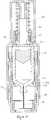
- FIG. 1is a cross section of an autoinjector in accordance with an embodiment of the invention.
- the autoinjectorcomprises a drug container 10 holding a drug 12.
- the drug containeris closed by a plunger 14 at its rear end.
- the drug containeris formed from cyclic olefin copolymer, but it may be formed from any suitable plastics material or may be formed of glass.
- the plungeris formed from a rubber material, such as styrene butadiene rubber.
- a hypodermic needle 16which is fixed to the drug container 10 using an adhesive, or another suitable fixing mechanism.
- the front end of the needle 16is embedded in a rubber sock 18, which is coupled to the drug container and completely seals the needle, keeping it sterile.
- the drug container and needle assemblyis held within an autoinjector housing 20. Also within the housing 20 is a drive mechanism comprising a stored energy source in the form of a helical spring 22 that is used to drive both insertion of the needle 16 into a patient and to move the plunger 14 within the drug container to expel the drug through the needle 16 into the patient. Any suitable deformable resilient member may be used as the stored energy source.
- An activation mechanismis held within a front portion of the housing 20.
- Retaining arms 24engage a front portion of the drug container against the action of the spring 22 to prevent activation of the autoinjector.
- a skin sensor component 26is provided that extends around the retaining arms. When the skin sensor component 26 is moved backward relative to the retaining arms, the front ends of the retaining arms 24 can move into cut-out portions 28 in the skin sensor, releasing the drug container 10 to move forward through the housing 20. Operation of the autoinjector is described in more detail with reference to Figures 9 to 13 .
- a safety cap 30is provided over the front end of the housing and skin sensor component 26, which engages the rubber sock 18. Removal of the safety cap also results in removal of the rubber sock. Activation of the autoinjector is not possible prior to removal of the safety cap 30.
- Figure 1bis a perspective view of the autoinjector of Figure 1a . It can be seen that the autoinjector has a generally round cross-section.
- the housingincludes a window 32, through which the contents of the drug container can be viewed.
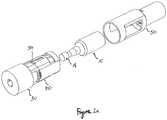
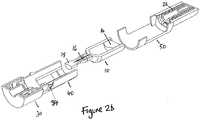
- the autoinjector of Figures 1a and 1bis assembled from three initially separate parts: a front end portion 40, including the safety cap and activation mechanism, the drug container 10, including the plunger 14 and the rubber sock 18 for keeping the needle and drug in a sterile condition, and a rear portion 50 including the drive mechanism.
- Figure 2ais a perspective view of these three separate parts in an unassembled state.
- Figure 2bshows a horizontal section of Figure 2a
- Figure 2cshows a vertical section of Figure 2a .
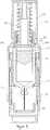
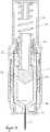
- Figure 3ashows a horizontal section through the rear portion 50, with the spring in a first compressed condition and the locking component in the first position.
- Figure 3bshows a corresponding vertical section through the rear portion.
- the rear portionincludes a rear housing 52, which includes window 32.
- the rear housing 52encases the drive mechanism.
- the drive mechanismcomprises a spring 22 in a first deformed condition, in this example a compressed condition.
- the spring 22is retained in the first compressed condition between the rear surface of the housing 54 and a spring engaging component 56.
- the spring engaging component 56acts as a pusher in the assembled autoinjector, as described with reference to Figures 9 to 13 .
- the spring engaging component 56is shown in Figure 5 and comprises a cylindrical portion 560 around which spring 22 sits, and a head portion 562 of larger diameter than the cylindrical portion 560.
- the head portioncomprises a rear bearing surface 564 against which the front end of spring 22 is pressed, and a front bearing surface 566 which engages a locking component 60.
- the locking component 60retains the spring engaging component and the spring 22 when in a first position.
- the front bearing surface 566is chamfered or angled in the region that engages the locking component 60 to allow the spring engaging component 56 to slide past the locking component 60 during drug delivery, as will be described in detail with reference to Figure 11 .
- the locking component 60bears against the spring engaging component and against the housing 52. Specifically, in a first position the locking component engages two apertures formed in the housing 52. The locking component 60 is thereby locked in the first position against the action of the spring 22, retaining the spring 22 in a first deformed condition.
- the locking component 60is shown separately in Figures 4a and 4b .
- the locking componentis in the form of a collar having eight legs extending at their proximal ends from a ring section 600.
- Two resilient legs 610diametrically opposite each other, have at their distal ends, inner bearing surfaces 615 extending radially inwards for engaging with the front bearing surface 566 of spring engaging component 56.
- a further two legs 620also have inner bearing surfaces 625 at their distal ends extending radially inwards for engaging with the front bearing surface 566 of spring engaging component 56.
- the inner bearing surfaces 615, 625are angled to match the angle of the front bearing surface 566. In this embodiment, the inner bearing surfaces are at an angle of about 45 degrees from the longitudinal axis of the spring engaging component.
- Legs 610also have radially outwardly extending lugs 605 at their distal ends. Lugs 605 engage with apertures 58 in the rear housing 52.
- the further legs 630are longer than legs 610 and 620 to allow the legs 610 and 620 to deflect freely when further legs 630 are in contact with the drug container. This allows the spring engaging component to pass through the locking component without the legs 610 and 620 of the locking component jamming on the drug container, as shown in Figure 11 .
- the locking component 60, spring engaging component 56 and housing 52are all formed from a plastics material such as polyoxymethylene (POM) and may be formed by injection moulding.
- POMpolyoxymethylene
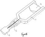
- Figure 6shows a horizontal section through the drug container 10.
- the drug container 10is closed by a plunger 14 at its rear end.
- the drug containeris formed from cyclic olefin copolymer, but it may be formed from any suitable plastics material or may be formed of glass.
- the plungeris formed from a rubber material, such as styrene butadiene rubber.
- a hypodermic needle 16is fixed to the drug container 10 using an adhesive, or another suitable fixing mechanism.
- the front end of the needle 16is embedded in a rubber sock 18, which is coupled to the drug container and completely seals the needle, keeping it sterile.
- FIG. 7shows a cross section through the front end portion 40.
- Front end portionincludes safety cap 30, skin sensor component 26, and front end housing 70.
- Front end housingis configured to receive the drug container 10.
- Resilient arms 24, which are configured to engage the front end of the drug container 10,are formed as part of the front end housing 70.
- Skin sensor component 26fits around, and is slidable on, the front end housing 70.
- Skin sensor component 26includes window portions 28, into which the free ends of the resilient arms can be displaced when the skin sensor component is pushed back on front end housing 70.
- Skin sensor component 26is retained on front end housing by the engagement of lugs on the front end housing (not shown) with a window (not shown) in the skin sensor component.
- Safety cap 30 capbe secured to the skin sensor component using any suitable mechanical fitting, such as a screw fitting or a push fitting.
- the front end housing, skin sensor component and safety capare all formed from polyester thermoplastic in this example, but may be formed from any suitable plastics material.
- Figure 8shows a cross section of an autoinjector assembled from the components described with reference to Figures 2 to 7 , in a locked state.
- the filled drug container 10is received in the front end portion 40.
- the rubber sock 18is pushed into the socket on the safety cap and received in a snap fitting so that subsequent removal of the safety cap 30 pulls the sock 18 off the needle.
- the rear portion 50is fitted over the drug container 10 and the front end housing 70 and is coupled and secured to the front end housing by latches 34 shown in Figures 1b , 2a and 2b .
- Latches 34engage with a front end of windows 32 in the rear portion housing 52.
- Any suitable coupling between the rear portion 50 and the front end portion 40may be used.
- a latch on the rear portion housingmay be used to engage an aperture in the front end portion housing, or a screw fitting may be used.
- Figure 8shows the autoinjector immediately after the three parts have been assembled to one other but before the autoinjector has been unlocked.
- the locking components 60are still received in apertures 58 in the rear portion housing 52, retaining the spring 22 in a first deformed condition. In this condition the autoinjector cannot be activated by the skin sensor 26.
- the lugs 605 of the locking component 60In order to unlock the autoinjector the lugs 605 of the locking component 60 must be pushed inside the rear portion housing 52.
- the locking component legsare resilient so that both lugs 605 must be pushed inwards simultaneously to release the locking component and a specifically designed tool can be used to do this during an automated filling and assembly process. The requirement to push more than one lug simultaneously prevents accidental unlocking before the autoinjector has been assembled.
- Figure 9shows a cross section of the autoinjector after it has been unlocked and with the safety cap 30 removed, but before use.
- the lugs 605are disengaged from the apertures 58 and the spring 22 has therefore been released from the first deformed condition and has expanded.
- the springis only allowed to expand a small amount and is retained in a second deformed condition by the abutment of the locking component 60 against the drug container 10.
- the lugs 635 on the locking componentabut the rear end of the drug container 10.
- the drug containeris prevented from forward movement by the resilient arms 24, which engage the front end of the drug container.
- the resilient armsare fixed relative to the rear portion housing 52 by the latches 34 engaging the windows 32, as shown in Figure 1b . In this second deformed condition the spring 22 still stores enough energy for the needle insertion and drug ejection operations.
- Figures 10 to 13show cross sections of the autoinjector at various stages during its use.
- Figure 10shows the autoinjector with the skin sensor component pushed back, as it would be when pressed against a patient's skin.
- the skin sensor component 26is moved rearward until the windows 28 in the skin sensor component align with the ends of the resilient arms 24. At this point the spring 22 is still in the second deformed condition.
- the force exerted by the spring 22 on the drug container 10pushes the resilient arms outward into the windows 28 allowing the drug container 10 to move forward through the front end housing 70. This is shown in Figure 11 .
- the locking componentis also moved forward into a region of the rear portion housing of increased diameter. This allows the legs of the locking component 60 to flex outwardly and the spring engaging component 56 to disengage from and move through the locking component 60.
- the spring engaging componentthen contacts the plunger 14 and acts as a pusher to drive both the drug container forward to insert the needle into a patient and to move the plunger 14 through drug container 10 to expel the drug through the needle 16.
- Figure 12shows the autoinjector with drug container 10 in its most forward position, with the needle 16 extending beyond the front end of the skin sensor component 26 into a patient. Further forward movement of the drug container is prevented by the front end housing 70 abutting the front end of the drug container.
- the plunger 14is then moved by the force of the expanding spring 22 through the drug container 10 to expel the drug 12 through the needle 16.
- Figure 13shows the plunger 14 at the front end of the drug container 10 with the drug delivery completed.
- the spring 22is then in its most extended position.
- Variations to the described embodimentare of course possible, such as the incorporation known elements such as additional needle safety mechanisms and different arrangements for attaching the needle to the drug container. It is also possible to use a differently shaped locking component or a plurality of separate locking components, for example.
- the locking componentsmay be removed from the autoinjector in an unlocking operation or may be broken in an unlocking operation, or portions of the locking components may be rotated relative to one another or their relative states otherwise altered.
- the inventionprovides a drive mechanism that can be assembled at a first location and delivered in a locked condition to a second location where a drug filling operation is carried out.
- the drive mechanismcan then be assembled to other components to form an autoinjector and the drive mechanism simply unlocked following assembly but prior to delivery to end users.
- the inventionis particularly advantageous for autoinjectors with front end activation, using a skin sensor or equivalent.
Landscapes
- Health & Medical Sciences (AREA)
- Vascular Medicine (AREA)
- Engineering & Computer Science (AREA)
- Anesthesiology (AREA)
- Biomedical Technology (AREA)
- Heart & Thoracic Surgery (AREA)
- Hematology (AREA)
- Life Sciences & Earth Sciences (AREA)
- Animal Behavior & Ethology (AREA)
- General Health & Medical Sciences (AREA)
- Public Health (AREA)
- Veterinary Medicine (AREA)
- Infusion, Injection, And Reservoir Apparatuses (AREA)
Description
- The present invention relates to autoinjectors and in particular to a drive assembly for an autoinjector that permits for simple assembly of an autoinjector.
- An autoinjector is a drug delivery device which contains a medical, therapeutic, diagnostic, pharmaceutical or cosmetic compound (drug) before it is administered, and which is used to administer the compound through the skin of the patient via a hollow needle. Autoinjectors may be used by the patient themselves or by a different user, and are also used to administer drugs to animals.
- Autoinjectors are typically used because they reduce the amount of training and effort needed by a user compared with that needed for a syringe, by automating either or both processes of inserting the needle into the patient and expelling the drug through the needle. They can also reduce the fear of injection by hiding the needle from the patient.
- Autoinjectors typically include a housing containing a drug and a plunger that is driven by an automatic mechanism to move the plunger within the housing to eject the drug. The automatic mechanism may also move the needle relative to the housing to insert the needle into a subject. Motive power for the mechanism may come from one or more springs or other power sources such as compressed gas. Such an auto-injector is disclosed in
WO 03/097133 - Autoinjectors are used to deliver so-called crisis drugs such as epinephrine, where a patient may need to self-inject the drug while under the severe stress of anaphylactic shock. They are also used to deliver drugs for long-term conditions such as rheumatoid arthritis, where the patient may have limited dexterity. In both cases it is beneficial for the autoinjector to have a simple and easy user interface in order to maximise the likelihood that the patient is able to operate the autoinjector correctly and receive the drug. Some autoinjectors include a finger-operated button or other control to allow the patient to activate them, but this approach can be confusing and more difficult to use. Other autoinjectors advantageously incorporate a very simple user interface design where the autoinjector is activated and the drug delivered by the action of the patient pressing a skin sensor component against the injection site.
- Autoinjectors typically have a housing which encloses a needle at the front end close to the injection site, a drug container, and one or more drive members such as springs towards the back of the device at the other end from the injection site. Typically an autoinjector is manufactured as partial subassemblies by a specialist device manufacturer, and these partial subassemblies are then assembled with a filled drug container at another site, often the filling facility for the drug container, to form the complete autoinjector. The device manufacturers are generally not able to handle the drug component. Equally, the filling facilities generally lack device assembly expertise or capability. For this reason it is advantageous to be able to safely transfer autoinjector subassemblies from the device manufacturer to the final assembly facility, and then assemble them with the filled drug container with minimum assembly operations and manufacturing complexity.
- In order to allow the drug container to be assembled into the final autoinjector, autoinjectors are typically shipped to the final assembly location as two subassemblies, a front subassembly including a skin sensor if incorporated into the design, and a rear subassembly including the power source in an energised condition, and a button if incorporated into the design. This requires the rear subassembly to contain the stored energy source safely before final assembly, without releasing the energy prematurely.
- Autoinjectors with activation buttons positioned on the rear subassembly of the autoinjector typically rely on this button to retain the stored energy source safely before final assembly. However if the design of the autoinjector is such that the autoinjector is activated only by the action of the patient pressing a skin sensor at the front end of the autoinjector onto the injection site, without the use of a separate finger-operated button, then there is a requirement for the rear subassembly to contain the stored energy source safely before final assembly, but to allow it to be released when needed during activation of the skin sensor which is in the front subassembly. This can be difficult and complex to achieve, and can increase the size and cost of the autoinjector. There is a risk that energy source can be released before final assembly due to handling forces.
- It is an object of the present invention to provide a drive mechanism for an autoinjector that can be safely shipped in locked state, in which it cannot be activated, but which can be simply assembled to another component or components to form an autoinjector, in which the drive mechanism can be simply activated.
- Aspects of the present invention are defined in the appended independent claims, to which reference should be made. The various aspects of the invention may be provided alone or in combination with one or more of the other aspects. Preferred features of the invention are defined in the dependent claims.
- The present invention relates to a system and method of assembling an autoinjector. In particular it relates to a drive mechanism for an autoinjector that can be assembled separately to a drug containing portion of the autoinjector and coupled to the drug containing portion as a final step in the manufacture of the autoinjector and changed from a first locked state, in which the drive mechanism cannot be activated, to a second unlocked state, in which the drive mechanism can be activated to cause a drug to be delivered to a patient from the drug containing portion. The change to the second unlocked state is advantageously carried out before the autoinjector reaches the end user or patient.
- In a first aspect the invention provides a drive mechanism for an autoinjector, configured to be coupled to a drug containing portion to form a complete autoinjector, the drive mechanism comprising:
- a housing;
- a drive means coupled to, or forming part of, the housing, the drive means comprising a resilient member;
- a retaining means coupled to, or forming part of, the housing, the retaining means engaging the drive means in a first position to retain the resilient member in a first deformed condition, and releasing the drive means when moved to a second position; and
- a coupling means for coupling with a drug containing portion, such that the drug containing portion retains the drive means in a second deformed condition when the retaining means is moved to the second position, wherein the drive means in the second deformed condition stores sufficient potential energy for driving the autoinjector.
- The retaining means may comprise a locking component, the locking component engaging one or more apertures or locking surfaces on the housing in the first position. The locking component may be disengaged from the one or more apertures or locking surfaces on the housing in the second position. Alternatively, or in addition, the locking component may be disengaged from the drive means in the second position.
- Alternatively, the locking component may be formed integrally with the housing and so form part of the housing at least in the first position. The resilient member may also be integral with the housing.
- The resilient member may comprise one or more deformable springs held within the housing. The drive means may further comprise a spring engaging component, the spring engaging component coupled to the resilient member and to the retaining means in the first position. The spring engaging component may form a pusher rod in an assembled autoinjector.
- The spring engaging component may have a first bearing surface and the locking component may have a second bearing surface, wherein, in the first position, the first bearing surface engages the second bearing surface.
- The locking component may be resilient and may be stressed in the second position. Alternatively the locking component may be stressed in the first position and so biased into contact with a bearing surface or aperture on the housing or on the drive means. In this way the locking component is biased to retain the drive means in the first position and it requires a positive action on the locking component to release it from engagement with the housing or drive means. Preferably, the locking component engages a plurality of apertures in the housing. The apertures may be configured so that a specially adapted tool is required to move the locking component out of engagement with all of the apertures simultaneously to release the drive means.
- When the drive mechanism is coupled to a front end component to form an autoinjector, the drive means is retained in a second deformed state in the second position. The drive means is preferably retained in the second deformed state by the front end component and still stores sufficient potential energy for needle insertion and/or drug ejection when the autoinjector is to be used.
- The retaining means may be connected to the coupling means such that the retaining means cannot move to the second position when the coupling means is not engaged with a drug containing portion. Once the drive mechanism is coupled to the drug containing portion, the retaining means can be moved to the second position. This provides for additional security during transit. For example, the coupling means may include a element that moves during coupling to expose an aperture in which the retaining means is engaged, exposure of the aperture allowing a tool to be used to disengage the retaining means.
- The coupling means is preferably provided on the housing and may be a latch, aperture, screw fitting or any other suitable means to engage with a front end component of an autoinjector.
- In a second aspect the invention provides an autoinjector comprising a drive mechanism in accordance with the first aspect. Preferably, the autoinjector further comprises a front end portion, the front end portion retaining the drive means in a second deformed condition when the retaining means is in the second position. The front end portion preferably comprises a release mechanism to release the drive means from the second deformed condition to deliver a drug. The release mechanism preferably comprises a movable skin sensor, configured such that when the skin sensor is pressed onto an injection site, the skin sensor moves to release the drive means from the second deformed condition.
- Preferably, the autoinjector comprises a drug container containing a drug to be dispensed and a plunger. The retaining means, or the spring engaging component, or both, may form a pusher rod configured to engage the plunger during operation of the autoinjector.
- In a third aspect, the invention provides a method of assembling an autoinjector comprising the steps of:
- assembling a drive mechanism containing an energised resilient drive member in a first retained state;
- assembling the drive mechanism to a drug containing portion
- releasing the energised resilient drive member to a second retained state so that it can subsequently provide a drive means for delivering a drug.
- In one embodiment, the invention provides a method for assembling an autoinjector comprising the steps of:
- placing a resilient drive member in a first housing portion;
- retaining the resilient drive member in the housing in a first deformed condition using a retaining means coupled to the drive member and the first housing portion in a first position;
- coupling the first housing portion to a second housing portion, the second housing portion containing a drug to be dispensed by the autoinjector;
- moving the retaining means to a second position to release the resilient drive member to second deformed condition, wherein in the second deformed condition the drive member stores sufficient potential energy to drive the autoinjector, e.g. for needle insertion and/or drug ejection when the autoinjector is to be used.
- The step of moving the retaining means may be performed as a consequence of the step of coupling or may be performed as a separate action. If it is performed as a separate action it may be performed as a step in an automated assembly process.
- The step of moving the retaining means may comprise pushing a portion or portions of the retaining means through one or more apertures in the first housing portion. Alternatively, the step of moving the retaining means may comprise removing a portion or portions of the retaining means from the first housing portion. Alternatively, or in addition, the step of moving the retaining means may comprise breaking a portion or portions of the retaining means, rotating one portion against another or otherwise altering their relative states or conditions.
- In a fourth aspect, the invention provides a kit for assembly into an autoinjector, the kit comprising: a drive mechanism, and a drug containing portion, the drive mechanism comprising:
- a housing;
- a drive means coupled to, or forming part of, the housing, the drive means comprising a resilient member;
- a retaining means coupled to, or forming part of, the housing, the retaining means engaging the drive means in a first position to retain the resilient member in a first deformed condition, and releasing the drive means when moved to a second position; and
- a coupling means for coupling with a drug containing portion;
- wherein, when the drive means is coupled to the drug containing portion, the drug containing portion retains the drive means in a second deformed condition when the retaining means is moved to the second position, wherein the drive means in the second deformed condition stores sufficient potential energy for driving the autoinjector.
- Embodiments of the invention will now be described, by way of example only, with reference to the accompanying drawings, in which:
Figure 1a is a cross sectional view of an assembled autoinjector in an unlocked state in accordance with the invention;Figure 1b is a perspective view of the autoinjector ofFigure 1a ;Figure 2a is a perspective view of the autoinjector ofFigure 1 in disassembled form;Figure 2b shows a horizontal section through theFigure 2a ;Figure 2c shows a vertical section through the autoinjector ofFigure 2a ;Figure 3a shows a horizontal section through the drive mechanism of the autoinjector ofFigure 2a ;Figure 3b shows a vertical section through the drive mechanism of the autoinjector ofFigure 2a ;Figure 4a is a perspective view of the locking component ofFigure 2a ;Figure 4b is a different perspective view of the locking component ofFigure 2a ;Figure 5 is a perspective view of the spring engaging component ofFigure 2a ;Figure 6 shows a horizontal section through the drug container ofFigure 2a ;Figure 7 shows a horizontal section through the front portion of the autoinjector ofFigure 2a ;Figure 8 shows a vertical section through an assembled autoinjector, in a locked state;Figure 9 is a section of the autoinjector ofFigure 1 with the safety cap removed;Figure 10 is a section of the autoinjector ofFigure 1 with the skin sensor depressed;Figure 11 is a section of the autoinjector ofFigure 1 with the drive means released from the second position;Figure 12 is a section of the autoinjector ofFigure 1 with the needle in an insertion position; andFigure 13 is a section of the autoinjector ofFigure 1 following delivery of the drug.Figure 1 is a cross section of an autoinjector in accordance with an embodiment of the invention. The autoinjector comprises adrug container 10 holding adrug 12. The drug container is closed by aplunger 14 at its rear end. In this embodiment, the drug container is formed from cyclic olefin copolymer, but it may be formed from any suitable plastics material or may be formed of glass. The plunger is formed from a rubber material, such as styrene butadiene rubber. At the front end of the drug container there is ahypodermic needle 16, which is fixed to thedrug container 10 using an adhesive, or another suitable fixing mechanism. The front end of theneedle 16 is embedded in arubber sock 18, which is coupled to the drug container and completely seals the needle, keeping it sterile.- The drug container and needle assembly is held within an
autoinjector housing 20. Also within thehousing 20 is a drive mechanism comprising a stored energy source in the form of ahelical spring 22 that is used to drive both insertion of theneedle 16 into a patient and to move theplunger 14 within the drug container to expel the drug through theneedle 16 into the patient. Any suitable deformable resilient member may be used as the stored energy source. - An activation mechanism is held within a front portion of the
housing 20. Retainingarms 24 engage a front portion of the drug container against the action of thespring 22 to prevent activation of the autoinjector. Askin sensor component 26 is provided that extends around the retaining arms. When theskin sensor component 26 is moved backward relative to the retaining arms, the front ends of the retainingarms 24 can move into cut-outportions 28 in the skin sensor, releasing thedrug container 10 to move forward through thehousing 20. Operation of the autoinjector is described in more detail with reference toFigures 9 to 13 . - A
safety cap 30 is provided over the front end of the housing andskin sensor component 26, which engages therubber sock 18. Removal of the safety cap also results in removal of the rubber sock. Activation of the autoinjector is not possible prior to removal of thesafety cap 30. Figure 1b is a perspective view of the autoinjector ofFigure 1a . It can be seen that the autoinjector has a generally round cross-section. The housing includes awindow 32, through which the contents of the drug container can be viewed.- The autoinjector of
Figures 1a and1b is assembled from three initially separate parts: afront end portion 40, including the safety cap and activation mechanism, thedrug container 10, including theplunger 14 and therubber sock 18 for keeping the needle and drug in a sterile condition, and arear portion 50 including the drive mechanism.Figure 2a is a perspective view of these three separate parts in an unassembled state.Figure 2b shows a horizontal section ofFigure 2a andFigure 2c shows a vertical section ofFigure 2a . These separate parts are assembled together at a final stage of manufacture, after the drug container has been filled with the required drug. - Each of the separate parts will now be described in more detail.
Figure 3a shows a horizontal section through therear portion 50, with the spring in a first compressed condition and the locking component in the first position.Figure 3b shows a corresponding vertical section through the rear portion. The rear portion includes arear housing 52, which includeswindow 32. Therear housing 52 encases the drive mechanism. The drive mechanism comprises aspring 22 in a first deformed condition, in this example a compressed condition. Thespring 22 is retained in the first compressed condition between the rear surface of thehousing 54 and aspring engaging component 56. Thespring engaging component 56 acts as a pusher in the assembled autoinjector, as described with reference toFigures 9 to 13 . Thespring engaging component 56 is shown inFigure 5 and comprises acylindrical portion 560 around whichspring 22 sits, and ahead portion 562 of larger diameter than thecylindrical portion 560. The head portion comprises arear bearing surface 564 against which the front end ofspring 22 is pressed, and afront bearing surface 566 which engages alocking component 60. Thelocking component 60 retains the spring engaging component and thespring 22 when in a first position. Thefront bearing surface 566 is chamfered or angled in the region that engages thelocking component 60 to allow thespring engaging component 56 to slide past thelocking component 60 during drug delivery, as will be described in detail with reference toFigure 11 . - The
locking component 60 bears against the spring engaging component and against thehousing 52. Specifically, in a first position the locking component engages two apertures formed in thehousing 52. Thelocking component 60 is thereby locked in the first position against the action of thespring 22, retaining thespring 22 in a first deformed condition. - The
locking component 60 is shown separately inFigures 4a and4b . The locking component is in the form of a collar having eight legs extending at their proximal ends from aring section 600. Tworesilient legs 610, diametrically opposite each other, have at their distal ends, inner bearing surfaces 615 extending radially inwards for engaging with thefront bearing surface 566 ofspring engaging component 56. A further twolegs 620 also have inner bearing surfaces 625 at their distal ends extending radially inwards for engaging with thefront bearing surface 566 ofspring engaging component 56. The inner bearing surfaces 615, 625 are angled to match the angle of thefront bearing surface 566. In this embodiment, the inner bearing surfaces are at an angle of about 45 degrees from the longitudinal axis of the spring engaging component.Legs 610 also have radially outwardly extendinglugs 605 at their distal ends.Lugs 605 engage withapertures 58 in therear housing 52. There are fourfurther legs 630 that have no inner bearing surfaces but have radially outward extendinglugs 635, which provide contact surfaces for the drug container when thespring 22 is in a second deformed condition, as shown inFigure 9 . Thefurther legs 630 are longer thanlegs legs further legs 630 are in contact with the drug container. This allows the spring engaging component to pass through the locking component without thelegs Figure 11 . - The
locking component 60,spring engaging component 56 andhousing 52 are all formed from a plastics material such as polyoxymethylene (POM) and may be formed by injection moulding. Figure 6 shows a horizontal section through thedrug container 10. As described with reference toFigure 1 , thedrug container 10 is closed by aplunger 14 at its rear end. In this embodiment, the drug container is formed from cyclic olefin copolymer, but it may be formed from any suitable plastics material or may be formed of glass. The plunger is formed from a rubber material, such as styrene butadiene rubber. At the front end of the drug container ahypodermic needle 16 is fixed to thedrug container 10 using an adhesive, or another suitable fixing mechanism. The front end of theneedle 16 is embedded in arubber sock 18, which is coupled to the drug container and completely seals the needle, keeping it sterile.Figure 7 shows a cross section through thefront end portion 40. Front end portion includessafety cap 30,skin sensor component 26, andfront end housing 70. Front end housing is configured to receive thedrug container 10.Resilient arms 24, which are configured to engage the front end of thedrug container 10, are formed as part of thefront end housing 70.Skin sensor component 26 fits around, and is slidable on, thefront end housing 70.Skin sensor component 26 includeswindow portions 28, into which the free ends of the resilient arms can be displaced when the skin sensor component is pushed back onfront end housing 70.Skin sensor component 26 is retained on front end housing by the engagement of lugs on the front end housing (not shown) with a window (not shown) in the skin sensor component.Safety cap 30 cap be secured to the skin sensor component using any suitable mechanical fitting, such as a screw fitting or a push fitting. The front end housing, skin sensor component and safety cap are all formed from polyester thermoplastic in this example, but may be formed from any suitable plastics material.Figure 8 shows a cross section of an autoinjector assembled from the components described with reference toFigures 2 to 7 , in a locked state. The filleddrug container 10 is received in thefront end portion 40. Therubber sock 18 is pushed into the socket on the safety cap and received in a snap fitting so that subsequent removal of thesafety cap 30 pulls thesock 18 off the needle. Therear portion 50 is fitted over thedrug container 10 and thefront end housing 70 and is coupled and secured to the front end housing bylatches 34 shown inFigures 1b ,2a and2b .Latches 34 engage with a front end ofwindows 32 in therear portion housing 52. Any suitable coupling between therear portion 50 and thefront end portion 40 may be used. For example, a latch on the rear portion housing may be used to engage an aperture in the front end portion housing, or a screw fitting may be used.Figure 8 shows the autoinjector immediately after the three parts have been assembled to one other but before the autoinjector has been unlocked. The lockingcomponents 60 are still received inapertures 58 in therear portion housing 52, retaining thespring 22 in a first deformed condition. In this condition the autoinjector cannot be activated by theskin sensor 26. In order to unlock the autoinjector thelugs 605 of thelocking component 60 must be pushed inside therear portion housing 52. The locking component legs are resilient so that bothlugs 605 must be pushed inwards simultaneously to release the locking component and a specifically designed tool can be used to do this during an automated filling and assembly process. The requirement to push more than one lug simultaneously prevents accidental unlocking before the autoinjector has been assembled.Figure 9 shows a cross section of the autoinjector after it has been unlocked and with thesafety cap 30 removed, but before use. Thelugs 605 are disengaged from theapertures 58 and thespring 22 has therefore been released from the first deformed condition and has expanded. The spring is only allowed to expand a small amount and is retained in a second deformed condition by the abutment of thelocking component 60 against thedrug container 10. Specifically thelugs 635 on the locking component abut the rear end of thedrug container 10. The drug container is prevented from forward movement by theresilient arms 24, which engage the front end of the drug container. The resilient arms are fixed relative to therear portion housing 52 by thelatches 34 engaging thewindows 32, as shown inFigure 1b . In this second deformed condition thespring 22 still stores enough energy for the needle insertion and drug ejection operations.Figures 10 to 13 show cross sections of the autoinjector at various stages during its use.Figure 10 shows the autoinjector with the skin sensor component pushed back, as it would be when pressed against a patient's skin. Theskin sensor component 26 is moved rearward until thewindows 28 in the skin sensor component align with the ends of theresilient arms 24. At this point thespring 22 is still in the second deformed condition.- The force exerted by the
spring 22 on thedrug container 10 pushes the resilient arms outward into thewindows 28 allowing thedrug container 10 to move forward through thefront end housing 70. This is shown inFigure 11 . The locking component is also moved forward into a region of the rear portion housing of increased diameter. This allows the legs of thelocking component 60 to flex outwardly and thespring engaging component 56 to disengage from and move through thelocking component 60. The spring engaging component then contacts theplunger 14 and acts as a pusher to drive both the drug container forward to insert the needle into a patient and to move theplunger 14 throughdrug container 10 to expel the drug through theneedle 16. - The force required to move the drug container forward is less that the force required to move the
plunger 14 within thedrug container 10, and so the drug container is moved first.Figure 12 shows the autoinjector withdrug container 10 in its most forward position, with theneedle 16 extending beyond the front end of theskin sensor component 26 into a patient. Further forward movement of the drug container is prevented by thefront end housing 70 abutting the front end of the drug container. - The
plunger 14 is then moved by the force of the expandingspring 22 through thedrug container 10 to expel thedrug 12 through theneedle 16.Figure 13 shows theplunger 14 at the front end of thedrug container 10 with the drug delivery completed. Thespring 22 is then in its most extended position. - Variations to the described embodiment are of course possible, such as the incorporation known elements such as additional needle safety mechanisms and different arrangements for attaching the needle to the drug container. It is also possible to use a differently shaped locking component or a plurality of separate locking components, for example. The locking components may be removed from the autoinjector in an unlocking operation or may be broken in an unlocking operation, or portions of the locking components may be rotated relative to one another or their relative states otherwise altered.
- The invention provides a drive mechanism that can be assembled at a first location and delivered in a locked condition to a second location where a drug filling operation is carried out. The drive mechanism can then be assembled to other components to form an autoinjector and the drive mechanism simply unlocked following assembly but prior to delivery to end users. The invention is particularly advantageous for autoinjectors with front end activation, using a skin sensor or equivalent.
Claims (15)
- An autoinjector comprising a drive mechanism and a drug containing portion, the drive mechanism comprising:a housing;a drive means coupled to, or forming part of, the housing, the drive means comprising a resilient member;a retaining means coupled to, or forming part of the housing, the retaining means engaging the drive means in a first position to retain the resilient member in a first deformed condition, and releasing the drive means when moved to a second position; anda coupling means for coupling with the drug containing portion,the drug containing portion being configured such that it retains the drive means in a second deformed condition when the retaining means is moved to the second position, wherein the drive means in the second deformed condition stores sufficient potential energy for driving the autoinjector, and further comprising a release mechanism configured to release the drive mechanism from the second deformed condition when the autoinjector is to be used.
- An autoinjector according to claim 1, wherein the retaining means comprises a locking component, the locking component engaging one or more apertures or locking surfaces on the housing in the first position.
- An autoinjector according to claim 2, wherein the locking component is disengaged from the one or more apertures or locking surfaces on the housing in the second position.
- An autoinjector according to claim 2 or 3, wherein the locking component is stressed in the first position.
- An autoinjector according to any preceding claim, wherein the drive means comprises a spring engaging component, the spring engaging component coupled to the resilient member and to the retaining means in the first position and wherein the spring engaging component has a first bearing surface and the locking component has a second bearing surface, wherein, in the first position, the first bearing surface engages the second bearing surface.
- An autoinjector according to claim 5, further comprising a drug container containing a drug to be dispensed and a plunger, wherein the spring engaging component forms a pusher rod configured to engage the plunger during operation of the autoinjector.
- An autoinjector according to any preceding claim wherein the retaining means engages a plurality of apertures in the housing.
- An autoinjector according to any preceding claim, wherein the retaining means is connected to the coupling means such that the retaining means cannot move to the second position when the coupling means is not engaged with a drug containing portion.
- An autoinjector according to any preceding claim, wherein the coupling means is a latch or aperture provided on the housing.
- An autoinjector according to any preceding claim, wherein the release mechanism comprises a movable skin sensor, configured such that when the skin sensor is pressed onto an injection site, the skin sensor moves to release the drive means from the second deformed condition.
- A method of assembling an autoinjector comprising the steps of:assembling a drive mechanism containing an energised resilient drive member in a first retained state;assembling the drive mechanism to a drug containing portion; andreleasing the energised resilient drive member to a second retained state so that it can subsequently be released from the second retained state to provide a drive means for delivering a drug when the autoinjector is to be used.
- A method according to claim 11, wherein:the step of assembling a drive mechanism comprises placing or forming a resilient drive member in a first housing portion and retaining the resilient drive member in the housing in a first deformed condition using a retaining means coupled to the drive member in a first position;the step of assembling the drive mechanism to a drug containing portion comprises coupling the first housing portion to a second housing portion, the second housing portion containing a drug to be dispensed by the autoinjector; andthe step of releasing comprises moving the retaining means to a second position to release the resilient drive member to second deformed condition, wherein the second housing portion retains the resilient drive member in the second deformed condition and wherein in the second deformed condition the drive member stores sufficient potential energy for needle insertion and/or drug ejection when the autoinjector is to be used.
- A method according to claim 12, wherein the step of moving the retaining means is performed as a consequence of the step of coupling.
- A method according to claim 12, wherein the step of moving the retaining means comprises pushing a portion or portions of the retaining means through one or more apertures in the first housing portion.
- A kit for assembly into an autoinjector, the kit comprising: a drive mechanism, and a drug containing portion, the drive mechanism comprising:a housing;a drive means coupled to, or forming part of, the housing, the drive means comprising a resilient member;a retaining means coupled to, or forming part of, the housing, the retaining means engaging the drive means in a first position to retain the resilient member in a first deformed condition, and releasing the drive means when moved to a second position; anda coupling means for coupling with a drug containing portion;wherein, when the drive means is coupled to the drug containing portion, the drug containing portion retains the drive means in a second deformed condition when the retaining means is moved to the second position, wherein the drive means in the second deformed condition stores sufficient potential energy for driving the autoinjector and is releasable from the second deformed condition by a user when the autoinjector is to be used.
Applications Claiming Priority (2)
| Application Number | Priority Date | Filing Date | Title |
|---|---|---|---|
| GBGB1020472.5AGB201020472D0 (en) | 2010-12-02 | 2010-12-02 | A drive assembly for an autoinjector |
| PCT/GB2011/052375WO2012073032A1 (en) | 2010-12-02 | 2011-12-01 | A drive assembly for an autoinjector and a method of assembling an autoinjector |
Publications (3)
| Publication Number | Publication Date |
|---|---|
| EP2646085A1 EP2646085A1 (en) | 2013-10-09 |
| EP2646085B1true EP2646085B1 (en) | 2019-07-10 |
| EP2646085B8 EP2646085B8 (en) | 2019-08-21 |
Family
ID=43531384
Family Applications (1)
| Application Number | Title | Priority Date | Filing Date |
|---|---|---|---|
| EP11793857.1AActiveEP2646085B8 (en) | 2010-12-02 | 2011-12-01 | A drive assembly for an autoinjector and a method of assembling an autoinjector |
Country Status (6)
| Country | Link |
|---|---|
| US (1) | US10166335B2 (en) |
| EP (1) | EP2646085B8 (en) |
| JP (1) | JP6151184B2 (en) |
| CN (1) | CN103328024B (en) |
| GB (1) | GB201020472D0 (en) |
| WO (1) | WO2012073032A1 (en) |
Families Citing this family (100)
| Publication number | Priority date | Publication date | Assignee | Title |
|---|---|---|---|---|
| AUPQ867900A0 (en) | 2000-07-10 | 2000-08-03 | Medrad, Inc. | Medical injector system |
| USD1031029S1 (en) | 2003-11-25 | 2024-06-11 | Bayer Healthcare Llc | Syringe plunger |
| US7666169B2 (en) | 2003-11-25 | 2010-02-23 | Medrad, Inc. | Syringe and syringe plungers for use with medical injectors |
| US8926569B2 (en) | 2006-03-15 | 2015-01-06 | Bayer Medical Care Inc. | Plunger covers and plungers for use in syringes and methods of fabricating plunger covers and plungers for use in syringes |
| USD942005S1 (en) | 2007-03-14 | 2022-01-25 | Bayer Healthcare Llc | Orange syringe plunger cover |
| USD847985S1 (en) | 2007-03-14 | 2019-05-07 | Bayer Healthcare Llc | Syringe plunger cover |
| BRPI0817907B8 (en) | 2007-10-02 | 2021-06-22 | Lamodel Ltd | apparatus for administering a substance to an individual |
| US8177749B2 (en) | 2008-05-20 | 2012-05-15 | Avant Medical Corp. | Cassette for a hidden injection needle |
| US8052645B2 (en) | 2008-07-23 | 2011-11-08 | Avant Medical Corp. | System and method for an injection using a syringe needle |
| CA3070618C (en) | 2008-05-20 | 2021-07-20 | Avant Medical Corp. | Autoinjector system |
| US7959598B2 (en) | 2008-08-20 | 2011-06-14 | Asante Solutions, Inc. | Infusion pump systems and methods |
| GB201020472D0 (en) | 2010-12-02 | 2011-01-19 | Oval Medical Technologies Ltd | A drive assembly for an autoinjector |
| US9173999B2 (en) | 2011-01-26 | 2015-11-03 | Kaleo, Inc. | Devices and methods for delivering medicaments from a multi-chamber container |
| PL2699293T3 (en) | 2011-04-20 | 2019-08-30 | Amgen Inc. | Autoinjector apparatus |
| EP2601992A1 (en) | 2011-12-08 | 2013-06-12 | Sanofi-Aventis Deutschland GmbH | Syringe carrier |
| EP4406568A3 (en) | 2012-03-30 | 2024-10-16 | Insulet Corporation | Fluid delivery device with transcutaneous access tool, insertion mechanism and blood glucose monitoring for use therewith |
| USD808010S1 (en)* | 2012-04-20 | 2018-01-16 | Amgen Inc. | Injection device |
| USD898908S1 (en) | 2012-04-20 | 2020-10-13 | Amgen Inc. | Pharmaceutical product cassette for an injection device |
| US9522235B2 (en) | 2012-05-22 | 2016-12-20 | Kaleo, Inc. | Devices and methods for delivering medicaments from a multi-chamber container |
| US9174003B2 (en) | 2012-09-28 | 2015-11-03 | Bayer Medical Care Inc. | Quick release plunger |
| EP2968773B1 (en) | 2013-03-13 | 2020-05-06 | Antares Pharma, Inc. | Push button safety injector |
| EP2777684A1 (en) | 2013-03-14 | 2014-09-17 | Sanofi-Aventis Deutschland GmbH | Medicament container carrier and adapter |
| ES2973257T3 (en) | 2013-03-15 | 2024-06-19 | Amgen Inc | Drug cassette, autoinjector and autoinjector system |
| CA2904661C (en) | 2013-03-15 | 2022-03-15 | Amgen Inc. | Drug cassette, autoinjector, and autoinjector system |
| CN105188806B (en)* | 2013-03-25 | 2018-06-19 | 卡贝欧洲有限公司 | Power packages lock |
| EP2823841A1 (en) | 2013-07-09 | 2015-01-14 | Sanofi-Aventis Deutschland GmbH | Autoinjector |
| US9561324B2 (en) | 2013-07-19 | 2017-02-07 | Bigfoot Biomedical, Inc. | Infusion pump system and method |
| ES2706738T3 (en)* | 2013-08-29 | 2019-04-01 | Sanofi Sa | Cap for a medication container |
| WO2015037545A1 (en)* | 2013-09-13 | 2015-03-19 | テルモ株式会社 | Liquid-administering instrument |
| DK3068471T3 (en)* | 2013-11-15 | 2020-03-23 | Sanofi Aventis Deutschland | PART AND DEVICE FOR PHARMACEUTICAL ADMINISTRATION, PHARMACEUTICAL ADMINISTRATION AND USE OF PART |
| EP2878319A1 (en)* | 2013-11-28 | 2015-06-03 | Sanofi-Aventis Deutschland GmbH | Boot remover |
| EP2878322A1 (en) | 2013-11-28 | 2015-06-03 | Sanofi-Aventis Deutschland GmbH | Needle cap remover and drug delivery device |
| CA2937327C (en)* | 2014-01-21 | 2018-02-27 | Parenteral Technologies, Llc | Force actuated injection device |
| US10625026B2 (en) | 2014-01-21 | 2020-04-21 | Parenteral Technologies, Llc | Force actuated injection device |
| AU2015231396B2 (en) | 2014-03-19 | 2018-12-06 | Bayer Healthcare Llc | System for syringe engagement to an injector |
| EP2923716A1 (en)* | 2014-03-28 | 2015-09-30 | Sanofi-Aventis Deutschland GmbH | Cap having a sheath removal mechanism |
| EP2923714A1 (en) | 2014-03-28 | 2015-09-30 | Sanofi-Aventis Deutschland GmbH | Autoinjector triggered by skin contact |
| EP2944340A1 (en)* | 2014-05-12 | 2015-11-18 | Sanofi | Activating mechanism for a medicament delivery device and medicament delivery device |
| EP2944341A1 (en) | 2014-05-12 | 2015-11-18 | Sanofi | Activating mechanism for a medicament delivery device and medicament delivery device |
| CN106470717B (en) | 2014-06-03 | 2020-09-11 | 安姆根有限公司 | Drug delivery system and method of use |
| US9415176B1 (en) | 2015-01-22 | 2016-08-16 | West Pharmaceutical Services, Inc. | Autoinjector having an end-of-dose visual indicator |
| US10695495B2 (en) | 2015-03-24 | 2020-06-30 | Kaleo, Inc. | Devices and methods for delivering a lyophilized medicament |
| US10881797B2 (en)* | 2015-04-24 | 2021-01-05 | Shl Medical Ag | Drive mechanism for an autoinjector |
| TW201705994A (en)* | 2015-06-03 | 2017-02-16 | 賽諾菲阿凡提斯德意志有限公司 | Automatic syringe and assembly method |
| TW201700117A (en) | 2015-06-03 | 2017-01-01 | 賽諾菲阿凡提斯德意志有限公司 | Syringe bracket and assembly method for autoinjector |
| CA2990950A1 (en) | 2015-06-30 | 2017-01-05 | Kaleo, Inc. | Auto-injectors for administration of a medicament within a prefilled syringe |
| US10576207B2 (en) | 2015-10-09 | 2020-03-03 | West Pharma. Services IL, Ltd. | Angled syringe patch injector |
| US10279123B2 (en)* | 2015-10-01 | 2019-05-07 | Noble International, Inc. | Microcartridge |
| US11318254B2 (en) | 2015-10-09 | 2022-05-03 | West Pharma. Services IL, Ltd. | Injector needle cap remover |
| US9480797B1 (en) | 2015-10-28 | 2016-11-01 | Bayer Healthcare Llc | System and method for syringe plunger engagement with an injector |
| WO2017076925A1 (en) | 2015-11-05 | 2017-05-11 | Sanofi-Aventis Deutschland Gmbh | Cartridge carrier assembly |
| EP3374905A1 (en) | 2016-01-13 | 2018-09-19 | Bigfoot Biomedical, Inc. | User interface for diabetes management system |
| HK1256995A1 (en) | 2016-01-14 | 2019-10-11 | Bigfoot Biomedical, Inc. | Occlusion resolution in medication delivery devices, systems, and methods |
| US10806859B2 (en) | 2016-01-14 | 2020-10-20 | Bigfoot Biomedical, Inc. | Adjusting insulin delivery rates |
| EP3711793B1 (en) | 2016-01-21 | 2021-12-01 | West Pharma Services IL, Ltd. | A method of connecting a cartridge to an automatic injector |
| US10646643B2 (en) | 2016-01-21 | 2020-05-12 | West Pharma. Services IL, Ltd. | Needle insertion and retraction mechanism |
| JP6885960B2 (en) | 2016-01-21 | 2021-06-16 | ウェスト ファーマ サービシーズ イスラエル リミテッド | Drug delivery device with visual indicators |
| US11389597B2 (en) | 2016-03-16 | 2022-07-19 | West Pharma. Services IL, Ltd. | Staged telescopic screw assembly having different visual indicators |
| US12383166B2 (en) | 2016-05-23 | 2025-08-12 | Insulet Corporation | Insulin delivery system and methods with risk-based set points |
| US10363374B2 (en) | 2016-05-26 | 2019-07-30 | Insulet Corporation | Multi-dose drug delivery device |
| US11338090B2 (en) | 2016-08-01 | 2022-05-24 | West Pharma. Services IL, Ltd. | Anti-rotation cartridge pin |
| JP7059251B2 (en) | 2016-08-01 | 2022-04-25 | ウェスト ファーマ サービシーズ イスラエル リミテッド | A spring that prevents the door from closing halfway |
| US10363372B2 (en) | 2016-08-12 | 2019-07-30 | Insulet Corporation | Plunger for drug delivery device |
| EP3730169B1 (en)* | 2016-08-14 | 2023-08-02 | Insulet Corporation | Drug delivery device with detection of position of the plunger |
| WO2018067645A1 (en) | 2016-10-07 | 2018-04-12 | Insulet Corporation | Multi-stage delivery system |
| US10780217B2 (en) | 2016-11-10 | 2020-09-22 | Insulet Corporation | Ratchet drive for on body delivery system |
| EP3500161A4 (en) | 2016-12-12 | 2020-01-08 | Bigfoot Biomedical, Inc. | ALARMS AND WARNINGS FOR MEDICINE DELIVERY DEVICES AND RELATED SYSTEMS AND METHODS |
| WO2018119218A1 (en) | 2016-12-23 | 2018-06-28 | Kaleo, Inc. | Medicament delivery device and methods for delivering drugs to infants and children |
| HUE063479T2 (en) | 2017-01-06 | 2024-01-28 | Bayer Healthcare Llc | Syringe plunger with dynamic seal |
| US10881792B2 (en) | 2017-01-13 | 2021-01-05 | Bigfoot Biomedical, Inc. | System and method for adjusting insulin delivery |
| US10500334B2 (en) | 2017-01-13 | 2019-12-10 | Bigfoot Biomedical, Inc. | System and method for adjusting insulin delivery |
| EP3568859A1 (en) | 2017-01-13 | 2019-11-20 | Bigfoot Biomedical, Inc. | Insulin delivery methods, systems and devices |
| US10758675B2 (en) | 2017-01-13 | 2020-09-01 | Bigfoot Biomedical, Inc. | System and method for adjusting insulin delivery |
| WO2018136699A1 (en) | 2017-01-19 | 2018-07-26 | Insulet Corporation | Cartridge hold-up volume reduction |
| US10695485B2 (en) | 2017-03-07 | 2020-06-30 | Insulet Corporation | Very high volume user filled drug delivery device |
| KR102414668B1 (en) | 2017-05-09 | 2022-06-29 | 에스에이치엘 메디컬 아게 | A transport lock assembly, and a drug delivery device comprising the transport lock assembly |
| EP3630226A1 (en) | 2017-05-30 | 2020-04-08 | West Pharma. Services Il, Ltd. | Modular drive train for wearable injector |
| US11419983B2 (en) | 2017-07-12 | 2022-08-23 | Shl Medical Ag | Transport assembly for a medicament delivery device and a medicament delivery device comprising the same |
| US10973978B2 (en) | 2017-08-03 | 2021-04-13 | Insulet Corporation | Fluid flow regulation arrangements for drug delivery devices |
| US11280327B2 (en) | 2017-08-03 | 2022-03-22 | Insulet Corporation | Micro piston pump |
| US11786668B2 (en) | 2017-09-25 | 2023-10-17 | Insulet Corporation | Drug delivery devices, systems, and methods with force transfer elements |
| HUE061426T2 (en) | 2018-02-27 | 2023-06-28 | Bayer Healthcare Llc | Syringe piston switch mechanism |
| USD928199S1 (en) | 2018-04-02 | 2021-08-17 | Bigfoot Biomedical, Inc. | Medication delivery device with icons |
| US10835685B2 (en)* | 2018-05-30 | 2020-11-17 | Amgen Inc. | Thermal spring release mechanism for a drug delivery device |
| US10874803B2 (en) | 2018-05-31 | 2020-12-29 | Insulet Corporation | Drug cartridge with drive system |
| US11229736B2 (en) | 2018-06-06 | 2022-01-25 | Insulet Corporation | Linear shuttle pump for drug delivery |
| EP3860692B1 (en)* | 2018-10-05 | 2024-06-19 | Phillips-Medisize A/S | Auto injector with effective insertion system |
| US11446435B2 (en) | 2018-11-28 | 2022-09-20 | Insulet Corporation | Drug delivery shuttle pump system and valve assembly |
| USD920343S1 (en) | 2019-01-09 | 2021-05-25 | Bigfoot Biomedical, Inc. | Display screen or portion thereof with graphical user interface associated with insulin delivery |
| CA3145580A1 (en) | 2019-08-09 | 2021-02-18 | Kaleo, Inc. | Devices and methods for delivery of substances within a prefilled syringe |
| US11369735B2 (en) | 2019-11-05 | 2022-06-28 | Insulet Corporation | Component positioning of a linear shuttle pump |
| BR112022023788A2 (en) | 2020-06-18 | 2022-12-27 | Bayer Healthcare Llc | SYSTEM AND METHOD OF COUPLING A SYRINGE PLUNGER WITH AN INJECTOR |
| CN112076364B (en)* | 2020-10-16 | 2024-05-17 | 山东威高普瑞医药包装有限公司 | Automatic injector |
| AU2022205300B2 (en) | 2021-01-08 | 2025-04-17 | Insulet Corporation | Single actuated precision dose intermediate pumping chamber |
| US12268847B1 (en) | 2021-02-10 | 2025-04-08 | Kaleo, Inc. | Devices and methods for delivery of substances within a medicament container |
| EP4346945A1 (en) | 2021-05-28 | 2024-04-10 | Insulet Corporation | Spring-based status sensors |
| US20240366883A1 (en)* | 2021-07-19 | 2024-11-07 | Becton, Dickinson And Company | Needle Shield Remover Assembly for Wearable Injector |
| US12097355B2 (en) | 2023-01-06 | 2024-09-24 | Insulet Corporation | Automatically or manually initiated meal bolus delivery with subsequent automatic safety constraint relaxation |
| KR102694745B1 (en)* | 2023-04-18 | 2024-08-14 | 주식회사 비에스엘 | Auto-injector with auditory feedback |
| CN117398234B (en)* | 2023-12-14 | 2024-03-12 | 北京茗视光眼科医院管理有限公司 | Cataract puncture outfit |
Citations (15)
| Publication number | Priority date | Publication date | Assignee | Title |
|---|---|---|---|---|
| DD245817A5 (en) | 1985-05-20 | 1987-05-20 | �������@���������@���Kk�� | AUTOMATIC INJECTION DEVICE |
| WO1999020327A2 (en) | 1997-10-21 | 1999-04-29 | I-Flow Corporation | Spring-actuated infusion syringe |
| US6793646B1 (en) | 1999-04-16 | 2004-09-21 | Becton Dickinson And Company | Pen style injector with automated substance combining feature |
| US20040225262A1 (en) | 2003-05-06 | 2004-11-11 | Fathallah Marwan A. | Autoinjector with extendable needle protector shroud |
| US20050222539A1 (en) | 2004-03-30 | 2005-10-06 | Pediamed Pharmaceuticals, Inc. | Automatic injection device |
| EP1759728A1 (en) | 2005-09-05 | 2007-03-07 | JCR Pharmaceuticals Co., Ltd. | Injection device for two-compartment syringes |
| EP1790366A1 (en) | 2005-11-29 | 2007-05-30 | JCR Pharmaceuticals Co., Ltd. | Injection device |
| WO2007083115A1 (en) | 2006-01-23 | 2007-07-26 | The Medical House Plc | Improved autoinjector supporting the syringe at the front |
| WO2008005315A2 (en) | 2006-06-30 | 2008-01-10 | Abbott Biotechnology Ltd. | Automatic injection device |
| US20080262438A1 (en) | 2007-03-22 | 2008-10-23 | Markus Bollenbach | Injection device with a time-constant delivery signal |
| US20090118669A1 (en) | 2004-11-24 | 2009-05-07 | Antonio Bendek | Automatic Reconstitution Injector Device |
| WO2010033808A2 (en) | 2008-09-18 | 2010-03-25 | Becton, Dickinson And Company | Medical injector with post-autoreconstitution dose setting and autoplunger drive |
| DE102008037310A1 (en) | 2008-08-11 | 2010-07-29 | Tecpharma Licensing Ag | Automatic injection device for the administration of a fixed dose |
| EP2010252B1 (en) | 2006-04-12 | 2010-12-22 | TecPharma Licensing AG | Injection device with tensioning spring and tensioning element |
| WO2012073032A1 (en) | 2010-12-02 | 2012-06-07 | Oval Medical Technologies Limited | A drive assembly for an autoinjector and a method of assembling an autoinjector |
Family Cites Families (19)
| Publication number | Priority date | Publication date | Assignee | Title |
|---|---|---|---|---|
| US6547764B2 (en)* | 2000-05-31 | 2003-04-15 | Novo Nordisk A/S | Double pointed injection needle |
| SE518981C2 (en)* | 2000-12-14 | 2002-12-17 | Shl Medical Ab | autoinjector |
| US20030105430A1 (en)* | 2001-11-30 | 2003-06-05 | Elan Pharma International Limited Wil House | Automatic injector |
| WO2003045480A1 (en)* | 2001-11-30 | 2003-06-05 | Novo Nordisk A/S | A safety needle assembly |
| GB0211294D0 (en) | 2002-05-17 | 2002-06-26 | Owen Mumford Ltd | Improvements relating to injection devices |
| AU2003275893B2 (en)* | 2002-11-25 | 2008-11-13 | Tecpharma Licensing Ag | Device for automatically injecting an active agent |
| DE10342059B4 (en)* | 2003-09-11 | 2007-03-01 | Tecpharma Licensing Ag | Delivery device with piercing and Ausschutinrichtung |
| GB0406458D0 (en)* | 2003-10-09 | 2004-04-28 | Liversidge Barry P | Safety medical needle assemblies |
| EP1715903B1 (en)* | 2004-01-23 | 2007-10-24 | The Medical House Plc | Injection device |
| GB2410188B (en)* | 2004-01-23 | 2006-01-25 | Medical House Plc | Injection device |
| US8048035B2 (en)* | 2004-08-06 | 2011-11-01 | Meridian Medical Technologies, Inc. | Automatic injector with needle cover |
| US7449012B2 (en)* | 2004-08-06 | 2008-11-11 | Meridian Medical Technologies, Inc. | Automatic injector |
| US20080195056A1 (en)* | 2005-06-21 | 2008-08-14 | Steven Bishop | Apparatus And Method For Injecting A Pharmaceutical |
| FR2899482A1 (en) | 2006-04-11 | 2007-10-12 | Becton Dickinson France Soc Pa | Automatic medicament/product injection device for patient, has safety shield coupled to housing, and provided in active state at end of needle insertion step before which product/medicament injection step is not started |
| WO2009103251A1 (en) | 2008-02-22 | 2009-08-27 | Vakos Xt A.S. | Three -chamber automatic injector |
| EP3636301A1 (en) | 2008-03-10 | 2020-04-15 | Antares Pharma, Inc. | Injector safety device |
| US9642971B2 (en)* | 2008-03-13 | 2017-05-09 | Becton, Dickinson And Company | Safety needle assembly |
| US8979807B2 (en) | 2008-09-29 | 2015-03-17 | Becton Dickinson France | Automatic injection device with audible indicator of completed injection |
| US8663174B2 (en)* | 2009-11-13 | 2014-03-04 | Becton, Dickinson And Company | Hub assembly having a hidden needle for a drug delivery pen |
- 2010
- 2010-12-02GBGBGB1020472.5Apatent/GB201020472D0/ennot_activeCeased
- 2011
- 2011-12-01JPJP2013541427Apatent/JP6151184B2/enactiveActive
- 2011-12-01EPEP11793857.1Apatent/EP2646085B8/enactiveActive
- 2011-12-01CNCN201180064512.9Apatent/CN103328024B/ennot_activeExpired - Fee Related
- 2011-12-01WOPCT/GB2011/052375patent/WO2012073032A1/enactiveApplication Filing
- 2011-12-01USUS13/989,556patent/US10166335B2/enactiveActive
Patent Citations (15)
| Publication number | Priority date | Publication date | Assignee | Title |
|---|---|---|---|---|
| DD245817A5 (en) | 1985-05-20 | 1987-05-20 | �������@���������@���Kk�� | AUTOMATIC INJECTION DEVICE |
| WO1999020327A2 (en) | 1997-10-21 | 1999-04-29 | I-Flow Corporation | Spring-actuated infusion syringe |
| US6793646B1 (en) | 1999-04-16 | 2004-09-21 | Becton Dickinson And Company | Pen style injector with automated substance combining feature |
| US20040225262A1 (en) | 2003-05-06 | 2004-11-11 | Fathallah Marwan A. | Autoinjector with extendable needle protector shroud |
| US20050222539A1 (en) | 2004-03-30 | 2005-10-06 | Pediamed Pharmaceuticals, Inc. | Automatic injection device |
| US20090118669A1 (en) | 2004-11-24 | 2009-05-07 | Antonio Bendek | Automatic Reconstitution Injector Device |
| EP1759728A1 (en) | 2005-09-05 | 2007-03-07 | JCR Pharmaceuticals Co., Ltd. | Injection device for two-compartment syringes |
| EP1790366A1 (en) | 2005-11-29 | 2007-05-30 | JCR Pharmaceuticals Co., Ltd. | Injection device |
| WO2007083115A1 (en) | 2006-01-23 | 2007-07-26 | The Medical House Plc | Improved autoinjector supporting the syringe at the front |
| EP2010252B1 (en) | 2006-04-12 | 2010-12-22 | TecPharma Licensing AG | Injection device with tensioning spring and tensioning element |
| WO2008005315A2 (en) | 2006-06-30 | 2008-01-10 | Abbott Biotechnology Ltd. | Automatic injection device |
| US20080262438A1 (en) | 2007-03-22 | 2008-10-23 | Markus Bollenbach | Injection device with a time-constant delivery signal |
| DE102008037310A1 (en) | 2008-08-11 | 2010-07-29 | Tecpharma Licensing Ag | Automatic injection device for the administration of a fixed dose |
| WO2010033808A2 (en) | 2008-09-18 | 2010-03-25 | Becton, Dickinson And Company | Medical injector with post-autoreconstitution dose setting and autoplunger drive |
| WO2012073032A1 (en) | 2010-12-02 | 2012-06-07 | Oval Medical Technologies Limited | A drive assembly for an autoinjector and a method of assembling an autoinjector |
Also Published As
| Publication number | Publication date |
|---|---|
| JP2014500089A (en) | 2014-01-09 |
| JP6151184B2 (en) | 2017-06-21 |
| CN103328024B (en) | 2016-08-10 |
| US20130317480A1 (en) | 2013-11-28 |
| WO2012073032A1 (en) | 2012-06-07 |
| GB201020472D0 (en) | 2011-01-19 |
| EP2646085A1 (en) | 2013-10-09 |
| US10166335B2 (en) | 2019-01-01 |
| EP2646085B8 (en) | 2019-08-21 |
| CN103328024A (en) | 2013-09-25 |
Similar Documents
| Publication | Publication Date | Title |
|---|---|---|
| EP2646085B1 (en) | A drive assembly for an autoinjector and a method of assembling an autoinjector | |
| EP2288398B1 (en) | Automatic injection mechanism with frontal buttress | |
| US10933193B2 (en) | Injection device | |
| EP3027247B1 (en) | Drug delivery device | |
| US10406288B2 (en) | Delivery mechanism for an autoinjector | |
| CN107735124B (en) | Injection device | |
| CN109069745B (en) | Injection device | |
| JP2021519669A (en) | Automatic injection device with memory elements | |
| WO2017178237A1 (en) | Injection device | |
| GB2504128A (en) | Automatic injector with a skin contact element | |
| EP3442621A1 (en) | Injection device |
Legal Events
| Date | Code | Title | Description |
|---|---|---|---|
| PUAI | Public reference made under article 153(3) epc to a published international application that has entered the european phase | Free format text:ORIGINAL CODE: 0009012 | |
| 17P | Request for examination filed | Effective date:20130611 | |
| AK | Designated contracting states | Kind code of ref document:A1 Designated state(s):AL AT BE BG CH CY CZ DE DK EE ES FI FR GB GR HR HU IE IS IT LI LT LU LV MC MK MT NL NO PL PT RO RS SE SI SK SM TR | |
| DAX | Request for extension of the european patent (deleted) | ||
| REG | Reference to a national code | Ref country code:DE Ref legal event code:R079 Ref document number:602011060383 Country of ref document:DE Free format text:PREVIOUS MAIN CLASS: A61M0005200000 Ipc:A61M0005320000 | |
| GRAP | Despatch of communication of intention to grant a patent | Free format text:ORIGINAL CODE: EPIDOSNIGR1 | |
| STAA | Information on the status of an ep patent application or granted ep patent | Free format text:STATUS: GRANT OF PATENT IS INTENDED | |
| RIC1 | Information provided on ipc code assigned before grant | Ipc:A61M 5/20 20060101ALI20181219BHEP Ipc:A61M 5/32 20060101AFI20181219BHEP | |
| INTG | Intention to grant announced | Effective date:20190121 | |
| RIN1 | Information on inventor provided before grant (corrected) | Inventor name:YOUNG, MATTHEW Inventor name:REBER, DOMINIC CHARLES Inventor name:HUANG, CONGYI | |
| GRAS | Grant fee paid | Free format text:ORIGINAL CODE: EPIDOSNIGR3 | |
| GRAA | (expected) grant | Free format text:ORIGINAL CODE: 0009210 | |
| STAA | Information on the status of an ep patent application or granted ep patent | Free format text:STATUS: THE PATENT HAS BEEN GRANTED | |
| AK | Designated contracting states | Kind code of ref document:B1 Designated state(s):AL AT BE BG CH CY CZ DE DK EE ES FI FR GB GR HR HU IE IS IT LI LT LU LV MC MK MT NL NO PL PT RO RS SE SI SK SM TR | |
| REG | Reference to a national code | Ref country code:GB Ref legal event code:FG4D | |
| REG | Reference to a national code | Ref country code:CH Ref legal event code:EP Ref country code:AT Ref legal event code:REF Ref document number:1152856 Country of ref document:AT Kind code of ref document:T Effective date:20190715 | |
| RAP2 | Party data changed (patent owner data changed or rights of a patent transferred) | Owner name:OVAL MEDICAL TECHNOLOGIES LIMITED | |
| REG | Reference to a national code | Ref country code:CH Ref legal event code:PK Free format text:BERICHTIGUNG B8 | |
| REG | Reference to a national code | Ref country code:DE Ref legal event code:R096 Ref document number:602011060383 Country of ref document:DE | |
| REG | Reference to a national code | Ref country code:IE Ref legal event code:FG4D | |
| REG | Reference to a national code | Ref country code:NL Ref legal event code:MP Effective date:20190710 | |
| REG | Reference to a national code | Ref country code:LT Ref legal event code:MG4D | |
| REG | Reference to a national code | Ref country code:AT Ref legal event code:MK05 Ref document number:1152856 Country of ref document:AT Kind code of ref document:T Effective date:20190710 | |
| PG25 | Lapsed in a contracting state [announced via postgrant information from national office to epo] | Ref country code:NO Free format text:LAPSE BECAUSE OF FAILURE TO SUBMIT A TRANSLATION OF THE DESCRIPTION OR TO PAY THE FEE WITHIN THE PRESCRIBED TIME-LIMIT Effective date:20191010 Ref country code:BG Free format text:LAPSE BECAUSE OF FAILURE TO SUBMIT A TRANSLATION OF THE DESCRIPTION OR TO PAY THE FEE WITHIN THE PRESCRIBED TIME-LIMIT Effective date:20191010 Ref country code:NL Free format text:LAPSE BECAUSE OF FAILURE TO SUBMIT A TRANSLATION OF THE DESCRIPTION OR TO PAY THE FEE WITHIN THE PRESCRIBED TIME-LIMIT Effective date:20190710 Ref country code:AT Free format text:LAPSE BECAUSE OF FAILURE TO SUBMIT A TRANSLATION OF THE DESCRIPTION OR TO PAY THE FEE WITHIN THE PRESCRIBED TIME-LIMIT Effective date:20190710 Ref country code:PT Free format text:LAPSE BECAUSE OF FAILURE TO SUBMIT A TRANSLATION OF THE DESCRIPTION OR TO PAY THE FEE WITHIN THE PRESCRIBED TIME-LIMIT Effective date:20191111 Ref country code:LT Free format text:LAPSE BECAUSE OF FAILURE TO SUBMIT A TRANSLATION OF THE DESCRIPTION OR TO PAY THE FEE WITHIN THE PRESCRIBED TIME-LIMIT Effective date:20190710 Ref country code:HR Free format text:LAPSE BECAUSE OF FAILURE TO SUBMIT A TRANSLATION OF THE DESCRIPTION OR TO PAY THE FEE WITHIN THE PRESCRIBED TIME-LIMIT Effective date:20190710 Ref country code:FI Free format text:LAPSE BECAUSE OF FAILURE TO SUBMIT A TRANSLATION OF THE DESCRIPTION OR TO PAY THE FEE WITHIN THE PRESCRIBED TIME-LIMIT Effective date:20190710 Ref country code:SE Free format text:LAPSE BECAUSE OF FAILURE TO SUBMIT A TRANSLATION OF THE DESCRIPTION OR TO PAY THE FEE WITHIN THE PRESCRIBED TIME-LIMIT Effective date:20190710 | |
| PG25 | Lapsed in a contracting state [announced via postgrant information from national office to epo] | Ref country code:AL Free format text:LAPSE BECAUSE OF FAILURE TO SUBMIT A TRANSLATION OF THE DESCRIPTION OR TO PAY THE FEE WITHIN THE PRESCRIBED TIME-LIMIT Effective date:20190710 Ref country code:GR Free format text:LAPSE BECAUSE OF FAILURE TO SUBMIT A TRANSLATION OF THE DESCRIPTION OR TO PAY THE FEE WITHIN THE PRESCRIBED TIME-LIMIT Effective date:20191011 Ref country code:IS Free format text:LAPSE BECAUSE OF FAILURE TO SUBMIT A TRANSLATION OF THE DESCRIPTION OR TO PAY THE FEE WITHIN THE PRESCRIBED TIME-LIMIT Effective date:20191110 Ref country code:RS Free format text:LAPSE BECAUSE OF FAILURE TO SUBMIT A TRANSLATION OF THE DESCRIPTION OR TO PAY THE FEE WITHIN THE PRESCRIBED TIME-LIMIT Effective date:20190710 Ref country code:LV Free format text:LAPSE BECAUSE OF FAILURE TO SUBMIT A TRANSLATION OF THE DESCRIPTION OR TO PAY THE FEE WITHIN THE PRESCRIBED TIME-LIMIT Effective date:20190710 Ref country code:ES Free format text:LAPSE BECAUSE OF FAILURE TO SUBMIT A TRANSLATION OF THE DESCRIPTION OR TO PAY THE FEE WITHIN THE PRESCRIBED TIME-LIMIT Effective date:20190710 | |
| PG25 | Lapsed in a contracting state [announced via postgrant information from national office to epo] | Ref country code:TR Free format text:LAPSE BECAUSE OF FAILURE TO SUBMIT A TRANSLATION OF THE DESCRIPTION OR TO PAY THE FEE WITHIN THE PRESCRIBED TIME-LIMIT Effective date:20190710 | |
| REG | Reference to a national code | Ref country code:DE Ref legal event code:R026 Ref document number:602011060383 Country of ref document:DE | |
| PLBI | Opposition filed | Free format text:ORIGINAL CODE: 0009260 | |
| PG25 | Lapsed in a contracting state [announced via postgrant information from national office to epo] | Ref country code:IT Free format text:LAPSE BECAUSE OF FAILURE TO SUBMIT A TRANSLATION OF THE DESCRIPTION OR TO PAY THE FEE WITHIN THE PRESCRIBED TIME-LIMIT Effective date:20190710 Ref country code:RO Free format text:LAPSE BECAUSE OF FAILURE TO SUBMIT A TRANSLATION OF THE DESCRIPTION OR TO PAY THE FEE WITHIN THE PRESCRIBED TIME-LIMIT Effective date:20190710 Ref country code:DK Free format text:LAPSE BECAUSE OF FAILURE TO SUBMIT A TRANSLATION OF THE DESCRIPTION OR TO PAY THE FEE WITHIN THE PRESCRIBED TIME-LIMIT Effective date:20190710 Ref country code:PL Free format text:LAPSE BECAUSE OF FAILURE TO SUBMIT A TRANSLATION OF THE DESCRIPTION OR TO PAY THE FEE WITHIN THE PRESCRIBED TIME-LIMIT Effective date:20190710 Ref country code:EE Free format text:LAPSE BECAUSE OF FAILURE TO SUBMIT A TRANSLATION OF THE DESCRIPTION OR TO PAY THE FEE WITHIN THE PRESCRIBED TIME-LIMIT Effective date:20190710 | |
| 26 | Opposition filed | Opponent name:HANSEPATENT PATENTANWAELTE ANDRESEN SCHOLZ PARTG MBB Effective date:20200413 | |
| PG25 | Lapsed in a contracting state [announced via postgrant information from national office to epo] | Ref country code:CZ Free format text:LAPSE BECAUSE OF FAILURE TO SUBMIT A TRANSLATION OF THE DESCRIPTION OR TO PAY THE FEE WITHIN THE PRESCRIBED TIME-LIMIT Effective date:20190710 Ref country code:SM Free format text:LAPSE BECAUSE OF FAILURE TO SUBMIT A TRANSLATION OF THE DESCRIPTION OR TO PAY THE FEE WITHIN THE PRESCRIBED TIME-LIMIT Effective date:20190710 Ref country code:IS Free format text:LAPSE BECAUSE OF FAILURE TO SUBMIT A TRANSLATION OF THE DESCRIPTION OR TO PAY THE FEE WITHIN THE PRESCRIBED TIME-LIMIT Effective date:20200224 Ref country code:SK Free format text:LAPSE BECAUSE OF FAILURE TO SUBMIT A TRANSLATION OF THE DESCRIPTION OR TO PAY THE FEE WITHIN THE PRESCRIBED TIME-LIMIT Effective date:20190710 | |
| PLAX | Notice of opposition and request to file observation + time limit sent | Free format text:ORIGINAL CODE: EPIDOSNOBS2 | |
| PG2D | Information on lapse in contracting state deleted | Ref country code:IS | |
| REG | Reference to a national code | Ref country code:CH Ref legal event code:PL | |
| REG | Reference to a national code | Ref country code:BE Ref legal event code:MM Effective date:20191231 | |
| PG25 | Lapsed in a contracting state [announced via postgrant information from national office to epo] | Ref country code:SI Free format text:LAPSE BECAUSE OF FAILURE TO SUBMIT A TRANSLATION OF THE DESCRIPTION OR TO PAY THE FEE WITHIN THE PRESCRIBED TIME-LIMIT Effective date:20190710 Ref country code:MC Free format text:LAPSE BECAUSE OF FAILURE TO SUBMIT A TRANSLATION OF THE DESCRIPTION OR TO PAY THE FEE WITHIN THE PRESCRIBED TIME-LIMIT Effective date:20190710 | |
| PLBB | Reply of patent proprietor to notice(s) of opposition received | Free format text:ORIGINAL CODE: EPIDOSNOBS3 | |
| PG25 | Lapsed in a contracting state [announced via postgrant information from national office to epo] | Ref country code:IE Free format text:LAPSE BECAUSE OF NON-PAYMENT OF DUE FEES Effective date:20191201 Ref country code:LU Free format text:LAPSE BECAUSE OF NON-PAYMENT OF DUE FEES Effective date:20191201 | |
| PG25 | Lapsed in a contracting state [announced via postgrant information from national office to epo] | Ref country code:BE Free format text:LAPSE BECAUSE OF NON-PAYMENT OF DUE FEES Effective date:20191231 Ref country code:LI Free format text:LAPSE BECAUSE OF NON-PAYMENT OF DUE FEES Effective date:20191231 Ref country code:CH Free format text:LAPSE BECAUSE OF NON-PAYMENT OF DUE FEES Effective date:20191231 | |
| PG25 | Lapsed in a contracting state [announced via postgrant information from national office to epo] | Ref country code:CY Free format text:LAPSE BECAUSE OF FAILURE TO SUBMIT A TRANSLATION OF THE DESCRIPTION OR TO PAY THE FEE WITHIN THE PRESCRIBED TIME-LIMIT Effective date:20190710 | |
| PG25 | Lapsed in a contracting state [announced via postgrant information from national office to epo] | Ref country code:MT Free format text:LAPSE BECAUSE OF FAILURE TO SUBMIT A TRANSLATION OF THE DESCRIPTION OR TO PAY THE FEE WITHIN THE PRESCRIBED TIME-LIMIT Effective date:20190710 Ref country code:HU Free format text:LAPSE BECAUSE OF FAILURE TO SUBMIT A TRANSLATION OF THE DESCRIPTION OR TO PAY THE FEE WITHIN THE PRESCRIBED TIME-LIMIT; INVALID AB INITIO Effective date:20111201 | |
| PG25 | Lapsed in a contracting state [announced via postgrant information from national office to epo] | Ref country code:MK Free format text:LAPSE BECAUSE OF FAILURE TO SUBMIT A TRANSLATION OF THE DESCRIPTION OR TO PAY THE FEE WITHIN THE PRESCRIBED TIME-LIMIT Effective date:20190710 | |
| APBM | Appeal reference recorded | Free format text:ORIGINAL CODE: EPIDOSNREFNO | |
| APBP | Date of receipt of notice of appeal recorded | Free format text:ORIGINAL CODE: EPIDOSNNOA2O | |
| APAH | Appeal reference modified | Free format text:ORIGINAL CODE: EPIDOSCREFNO | |
| APBQ | Date of receipt of statement of grounds of appeal recorded | Free format text:ORIGINAL CODE: EPIDOSNNOA3O | |
| P01 | Opt-out of the competence of the unified patent court (upc) registered | Effective date:20230530 | |
| PGFP | Annual fee paid to national office [announced via postgrant information from national office to epo] | Ref country code:DE Payment date:20241218 Year of fee payment:14 | |
| PGFP | Annual fee paid to national office [announced via postgrant information from national office to epo] | Ref country code:GB Payment date:20241023 Year of fee payment:14 | |
| APAN | Information on closure of appeal procedure modified | Free format text:ORIGINAL CODE: EPIDOSCNOA9O | |
| APBU | Appeal procedure closed | Free format text:ORIGINAL CODE: EPIDOSNNOA9O | |
| PGFP | Annual fee paid to national office [announced via postgrant information from national office to epo] | Ref country code:FR Payment date:20241206 Year of fee payment:14 | |
| RDAF | Communication despatched that patent is revoked | Free format text:ORIGINAL CODE: EPIDOSNREV1 |