EP2645626B1 - Home network identification method and device - Google Patents
Home network identification method and deviceDownload PDFInfo
- Publication number
- EP2645626B1 EP2645626B1EP20120290102EP12290102AEP2645626B1EP 2645626 B1EP2645626 B1EP 2645626B1EP 20120290102EP20120290102EP 20120290102EP 12290102 AEP12290102 AEP 12290102AEP 2645626 B1EP2645626 B1EP 2645626B1
- Authority
- EP
- European Patent Office
- Prior art keywords
- network
- home network
- function
- delay spread
- cds
- Prior art date
- Legal status (The legal status is an assumption and is not a legal conclusion. Google has not performed a legal analysis and makes no representation as to the accuracy of the status listed.)
- Not-in-force
Links
- 238000000034methodMethods0.000titleclaimsdescription35
- 230000005540biological transmissionEffects0.000claimsdescription9
- 230000006870functionEffects0.000description65
- 230000009466transformationEffects0.000description4
- 238000004458analytical methodMethods0.000description3
- 238000012545processingMethods0.000description3
- 238000004891communicationMethods0.000description2
- 230000002596correlated effectEffects0.000description2
- RYGMFSIKBFXOCR-UHFFFAOYSA-NCopperChemical compound[Cu]RYGMFSIKBFXOCR-UHFFFAOYSA-N0.000description1
- 230000008901benefitEffects0.000description1
- 238000012790confirmationMethods0.000description1
- 229910052802copperInorganic materials0.000description1
- 239000010949copperSubstances0.000description1
- 230000000875corresponding effectEffects0.000description1
- 230000001419dependent effectEffects0.000description1
- 238000010586diagramMethods0.000description1
- 238000005516engineering processMethods0.000description1
- 238000012423maintenanceMethods0.000description1
- 238000007726management methodMethods0.000description1
- 238000005259measurementMethods0.000description1
- 230000003449preventive effectEffects0.000description1
- 230000008569processEffects0.000description1
- 230000004044responseEffects0.000description1
- 238000013024troubleshootingMethods0.000description1
Images


Classifications
- H—ELECTRICITY
- H04—ELECTRIC COMMUNICATION TECHNIQUE
- H04L—TRANSMISSION OF DIGITAL INFORMATION, e.g. TELEGRAPHIC COMMUNICATION
- H04L41/00—Arrangements for maintenance, administration or management of data switching networks, e.g. of packet switching networks
- H04L41/12—Discovery or management of network topologies
- H—ELECTRICITY
- H04—ELECTRIC COMMUNICATION TECHNIQUE
- H04B—TRANSMISSION
- H04B3/00—Line transmission systems
- H04B3/54—Systems for transmission via power distribution lines
- H04B3/542—Systems for transmission via power distribution lines the information being in digital form
- H—ELECTRICITY
- H04—ELECTRIC COMMUNICATION TECHNIQUE
- H04L—TRANSMISSION OF DIGITAL INFORMATION, e.g. TELEGRAPHIC COMMUNICATION
- H04L12/00—Data switching networks
- H04L12/28—Data switching networks characterised by path configuration, e.g. LAN [Local Area Networks] or WAN [Wide Area Networks]
- H04L12/2803—Home automation networks
- H04L12/2807—Exchanging configuration information on appliance services in a home automation network
- H—ELECTRICITY
- H04—ELECTRIC COMMUNICATION TECHNIQUE
- H04L—TRANSMISSION OF DIGITAL INFORMATION, e.g. TELEGRAPHIC COMMUNICATION
- H04L41/00—Arrangements for maintenance, administration or management of data switching networks, e.g. of packet switching networks
- H04L41/04—Network management architectures or arrangements
- H04L41/046—Network management architectures or arrangements comprising network management agents or mobile agents therefor
- H—ELECTRICITY
- H04—ELECTRIC COMMUNICATION TECHNIQUE
- H04L—TRANSMISSION OF DIGITAL INFORMATION, e.g. TELEGRAPHIC COMMUNICATION
- H04L45/00—Routing or path finding of packets in data switching networks
- H04L45/02—Topology update or discovery
- H—ELECTRICITY
- H04—ELECTRIC COMMUNICATION TECHNIQUE
- H04B—TRANSMISSION
- H04B2203/00—Indexing scheme relating to line transmission systems
- H04B2203/54—Aspects of powerline communications not already covered by H04B3/54 and its subgroups
- H04B2203/5404—Methods of transmitting or receiving signals via power distribution lines
- H04B2203/5408—Methods of transmitting or receiving signals via power distribution lines using protocols
- H—ELECTRICITY
- H04—ELECTRIC COMMUNICATION TECHNIQUE
- H04B—TRANSMISSION
- H04B2203/00—Indexing scheme relating to line transmission systems
- H04B2203/54—Aspects of powerline communications not already covered by H04B3/54 and its subgroups
- H04B2203/5404—Methods of transmitting or receiving signals via power distribution lines
- H04B2203/5416—Methods of transmitting or receiving signals via power distribution lines by adding signals to the wave form of the power source
- H—ELECTRICITY
- H04—ELECTRIC COMMUNICATION TECHNIQUE
- H04B—TRANSMISSION
- H04B2203/00—Indexing scheme relating to line transmission systems
- H04B2203/54—Aspects of powerline communications not already covered by H04B3/54 and its subgroups
- H04B2203/5429—Applications for powerline communications
- H04B2203/5445—Local network
- H—ELECTRICITY
- H04—ELECTRIC COMMUNICATION TECHNIQUE
- H04L—TRANSMISSION OF DIGITAL INFORMATION, e.g. TELEGRAPHIC COMMUNICATION
- H04L25/00—Baseband systems
- H04L25/02—Details ; arrangements for supplying electrical power along data transmission lines
- H04L25/0202—Channel estimation
- H04L25/0222—Estimation of channel variability, e.g. coherence bandwidth, coherence time, fading frequency
- Y—GENERAL TAGGING OF NEW TECHNOLOGICAL DEVELOPMENTS; GENERAL TAGGING OF CROSS-SECTIONAL TECHNOLOGIES SPANNING OVER SEVERAL SECTIONS OF THE IPC; TECHNICAL SUBJECTS COVERED BY FORMER USPC CROSS-REFERENCE ART COLLECTIONS [XRACs] AND DIGESTS
- Y04—INFORMATION OR COMMUNICATION TECHNOLOGIES HAVING AN IMPACT ON OTHER TECHNOLOGY AREAS
- Y04S—SYSTEMS INTEGRATING TECHNOLOGIES RELATED TO POWER NETWORK OPERATION, COMMUNICATION OR INFORMATION TECHNOLOGIES FOR IMPROVING THE ELECTRICAL POWER GENERATION, TRANSMISSION, DISTRIBUTION, MANAGEMENT OR USAGE, i.e. SMART GRIDS
- Y04S40/00—Systems for electrical power generation, transmission, distribution or end-user application management characterised by the use of communication or information technologies, or communication or information technology specific aspects supporting them
Definitions
- the inventionrelates to a home network topology identification method and a management center device provided to carry out the method.
- G.hnInternational Telecommunication Union
- EP 2 365 661 A1discloses a method and devices for determining topology information of a network, the network comprising a set of transmission lines carrying associated transmission signals and associated devices. An estimate of crosstalk between every pair of lines of the set of transmission lines is determined. Distance information for at least one pair of transmission lines based on the estimates of crosstalk is derived.
- in-house networksalso known as home networks
- home networksTo date, troubleshooting and diagnostics of in-house networks, also known as home networks, from a remote location outside of the network is a challenging task.
- identification of size and structure of a home networkis challenging due to a potential large number of branches and terminations within the home network.
- Fig. 1examples of home networks with relatively simple structures and one branch and three branches, respectively, are shown in Fig. 1 .
- Channel gain functionsare depicted in Fig. 2 in an upper part for the one-branch network, and in a lower part of Fig. 2 for the three-branch network of Fig. 1 .
- FIG. 3schematically depicts a home network formed by a power line network or a twisted-pair network comprising twelve nodes and five branches.
- a lower part of Fig. 1shows another home network built up of coaxial line technology.
- PLCPower Line Communication
- Home networks based on mediasuch as power line cables, coaxial cables and twisted-pair cables comprise different segments, for instance branches in power lines and twisted-pair networks, as well as splitters in coaxial networks, that build up a multi-path propagation environment.
- a multi-path order characterized by the number of paths in the networkis described by a length of a channel impulse response, i.e. a channel delay spread.
- a channel delay spreadthe relationship between the channel delay spread and the network topology is evident.
- the channel delay spreadincreases.
- the channel delay spreadis a function of the home network topology.
- This relationshipcan be exploited to identify a network size and its structure by estimating the network signature through its channel delay spread. Furthermore, the network identification is improved by correlating an estimated network signature and network parameters obtained from the home network devices.
- the methodcomprises the following steps:
- a “residential gateway” as used in this applicationshall be understood particularly as a home network device that is provided to connect the home network with a wide area network (WAN).
- WANwide area network
- the phrase "blind network topology”, as used in this application,shall be understood particularly as a set of information on distances between the various network devices of the network, without comprising any structural information on the network.
- the transformation of the channel gain function into the time domainis preferably carried out by an inverse
- FFTFast Fourier transformation
- the at least one home network parametermay be obtained from at least one of the network devices via a network protocol within the network, such as TR-069, or any other protocol that appears to be suitable to the one of skills in the art.
- the methodscan allow for a reliable and fast identification of the home network topology.
- further topology parameterssuch as connected branches can unambiguously be derived for confirmation of assumptions regarding the network topology, and can be used as a basis of further analysis.
- Structural properties of the home network, such as branches,can be reliably identified and used for further fitting an estimated network topology to the measured data.
- the methodmay be carried out in an automatic way and also from a site that is remote from the home network.
- step (c) of the methodcomprises the following steps:
- the metric function that is applied to compare the computed channel gain estimate and the channel gain functionis based on a mean-squared error of the computed channel gain estimate, taken as an estimator to the channel gain function as a "true value".
- a mean-squared error of the computed channel gain estimatetaken as an estimator to the channel gain function as a "true value”.
- any other metric functionthat appears to be suitable to the one of skills in the art may be applied as well.
- the steps (c3) to (c6)are consecutively carried out with different selected interval lengths to obtain a measure of difference for each of the selected interval lengths, wherein the equivalent estimated channel delay spread function is determined by selecting an interval length of the window function from applying a pre-determined criterion on the measures of difference.
- the pre-determined criterioncan be an upper limit for a mean-squared error between the computed channel gain estimate and the channel gain function.
- the computed channel gain estimatecan be approximated to the channel gain function with a desired accuracy.
- steps (c1) to (c6)can of course be omitted, and the estimated channel delay spread function which already includes the information on the phase relationship, can be used for further identification.
- the at least one home network parameter that is correlated with the estimated blind network topologyis selected from a group of parameters consisting of bit error rate, device identity, time stamp, channel gain, domain identity, and data rate.
- the correlation of any of these parameters to the estimated blind network topologycan improve the reliability of the obtained information on the home network topology and can shorten a processing time required for an identification process.
- the collected home network parameteris forwarded to a remote management center device that is provided to carry out the method.
- a remote management center devicethat is provided to carry out the method.
- the costs of a home networkcan be substantially reduced and the effort of bringing service staff to the site of the home network can be avoided.
- This embodimentcan also allow for a more frequent analysis of the home network, providing an option of preventive maintenance.
- the home network parametercan be collected and forwarded to the remote management center device by the residential gateway.
- the home networksubstantially is a power line network.
- substantially a power line networkshall be understood particularly as a network that is based on power line cables, and in which at least 70% of all media that are employed for data transmission within the home network are formed as power line cables. As these are commonly available in homes, the method can be applied to a large percentage of existing home networks.
- the processing time required for home network topology identificationcan advantageously be kept short if in step (d) of the method only major reflections of the channel delay spread function are taken into account. Theoretically, there is an infinite number of reflections, so that sorting out irrelevant ones can substantially reduce the processing time.
- the phrase "major reflections”, as used in this application,shall be understood particularly to include those reflections which correspond to an upper 70% of amplitudes, preferably to an upper 60% and, mostly preferred, to an upper 50% of amplitudes that are sorted according to size.
- a management center deviceis provided that is remote from a home network having a plurality of network devices with a residential gateway among them, wherein the management center device is provided to carry out steps (1a) to (1e) of the described method.
- FIG. 1shows a home network 10 having a plurality of network devices 27, 28, 29 and a residential gateway 23 that is provided to connect the home network 10 with a wide area network WAN such as the Internet.
- the home network 10is designed as a power line network with nine nodes 1-9 and three branches 12, 13, 14.
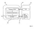
- a management center 24Remote from the home network 10 and connected to it via the residential gateway 23 is a management center 24 with a management center device 25 ( Fig. 7 ).
- a software moduleis provided to carry out steps of the home network topology identification method as described in the following.
- the steps 15-22( Figures 4 , 5 , and 7 ) are converted into a program code of the software module that is implementable in and executable by the management center device 25, so that the steps 15-22 of the home network topology identification method are carried out by the remote management center device 25.
- home network parametersare collected from the network devices by the residential gateway 23 via management protocol TR (Technical Report)-069 within the home network 10.
- the collected parameterscomprise device identities and transmission time stamps of all connected network devices 27, 28, 29. In general, they can be selected from a group of parameters consisting of bit error rate, device identity, time stamp, channel gain, domain identity, and data rate.
- a network channel gain function CGF of the home network 10 from one of the network devices 27, 28, 29is obtained by the residential gateway 23.
- the collected home network parameters and the network channel gain function CGFare forwarded to the remote management center device 25 via the residential gateway 23 in steps 15 and 16 ( Fig. 7 ).
- the management center device 25is provided to transform the channel gain function CGF into the time domain by applying an inverse Fast Fourier Transformation (iFFT) to obtain an equivalent channel delay spread function CDS ( Fig. 5 , upper part).
- iFFTinverse Fast Fourier Transformation
- the channel delay spread function CDSis shifted to a selected center time 26 such that an interval of non-zero values of the channel delay spread function CDS is substantially symmetric about the center time 26, as shown in Fig. 5 , middle part.
- a window functionis applied that is zero-valued outside of an interval of selected length ⁇ to the channel delay spread function CDS, wherein the interval of selected length ⁇ is substantially symmetric about the center time 26 ( Fig. 4 and Fig. 5 , middle part).
- a windowed estimated channel delay spread function CDS resulting from this step 18is depicted in a lower part of Fig. 5 on the left.
- the windowed estimated channel delay spread function CDSis shifted to a time origin (result not shown in Fig. 5 ), and the windowed estimated channel delay spread function CDS is converted into the frequency domain to obtain a computed channel gain estimate CCG, as shown in a lower part of Fig. 5 on the right.
- the computed channel gain estimate CCG and the channel gain function CGFare compared by applying a metric function for deriving a measure of difference ( Fig. 4 ).
- the metric functionconsists of a mean square error MSE computation taking the computed channel gain estimate CCG as an estimator and the channel gain function CGF as a "true" value, and summing up squared differences between values of the computed channel gain estimate CCG and values of the channel gain function CGF taken at the same frequency, wherein the summation is carried out over a frequency range shown in Fig. 2 , lower part, in equidistant frequency steps.
- a pre-determined criterion on the measure of differenceis stored in a memory unit of the management center device 25 (not shown).
- the management center device 25is provided to apply the pre-determined criterion on the obtained measure of difference between the computed channel gain estimate CCG and the channel gain function CGF.
- the management center device 25in another step 21 ( Fig. 4 ), is provided to increase the selected interval length ⁇ of the window function and to reiterate the steps 18-20 of
- steps 18-20are consecutively carried out by the management center device 25 with different selected interval lengths ⁇ to obtain a measure of difference for each of the selected interval lengths ⁇ , as shown in Fig. 4 , until one of the obtained measures of difference meets the pre-determined criterion. Then the method stops, and the a priori unknown start and end of the channel delay spread function CDS is determined by selecting the interval length w of the window function for which the criterion on the measures of difference was fulfilled.
- the blind network topologyis taken as a starting point for a final step 22 of the method ( Fig. 7 ), in which the estimated blind network topology is correlated with the collected home network parameters, comprising device identities and transmission time stamps of all connected network devices 27, 28, 29 to obtain at least one structural network topology parameter, such as an identified home network branch 12, 13, 14.
- the transmission time stamp and device identities of particular devicesmay be used to identify a branch 12, 13, 14 with a particular master device and slave network devices.
Landscapes
- Engineering & Computer Science (AREA)
- Computer Networks & Wireless Communication (AREA)
- Signal Processing (AREA)
- Automation & Control Theory (AREA)
- Power Engineering (AREA)
- Data Exchanges In Wide-Area Networks (AREA)
- Small-Scale Networks (AREA)
- Telephonic Communication Services (AREA)
Description
- The invention relates to a home network topology identification method and a management center device provided to carry out the method.
- International Telecommunication Union (ITU) standard "G.hn" was defined to enable broadband data communication required by in-house broadband applications. In G.hn, different domains are available for in-house network access by different media, like copper twisted-pairs, coaxial cables, and power line cables.
EP 2 365 661 A1- To date, troubleshooting and diagnostics of in-house networks, also known as home networks, from a remote location outside of the network is a challenging task. In particular, the identification of size and structure of a home network is challenging due to a potential large number of branches and terminations within the home network.
- To further illustrate the problem, examples of home networks with relatively simple structures and one branch and three branches, respectively, are shown in
Fig. 1 . Channel gain functions are depicted inFig. 2 in an upper part for the one-branch network, and in a lower part ofFig. 2 for the three-branch network ofFig. 1 . - More complex examples of home networks are described in
Fig. 3 . In an upper part,Fig. 3 schematically depicts a home network formed by a power line network or a twisted-pair network comprising twelve nodes and five branches. A lower part ofFig. 1 shows another home network built up of coaxial line technology. - When considering more complex home network topologies, such as in particular Power Line Communication (PLC) networks including a large number of nodes and branches, available solutions of home network topology identification methods are not as efficient as is desirable from a service operator perspective, due to a much more complex channel gain function and the huge number of reflections occurring in all branches of the home network.
- Home networks based on media such as power line cables, coaxial cables and twisted-pair cables comprise different segments, for instance branches in power lines and twisted-pair networks, as well as splitters in coaxial networks, that build up a multi-path propagation environment.
- In general, a multi-path order characterized by the number of paths in the network is described by a length of a channel impulse response, i.e. a channel delay spread. Naturally, the relationship between the channel delay spread and the network topology is evident. As the number of network segments increases, the multi-path order becomes higher. Consequently, the channel delay spread increases. In particular, the channel delay spread is a function of the home network topology.
- This relationship can be exploited to identify a network size and its structure by estimating the network signature through its channel delay spread. Furthermore, the network identification is improved by correlating an estimated network signature and network parameters obtained from the home network devices.
- According to an exemplary embodiment of a home network topology identification method, wherein the home network has a plurality of network devices with a residential gateway among them, the method comprises the following steps:
- (a) obtain at least one home network parameter from at least two of the network devices;
- (b) obtain a network channel gain function of the home network from one of the network devices;
- (c) transform the channel gain function into the time domain to obtain an equivalent estimated channel delay spread function;
- (d) obtain an estimated blind network topology from the estimated channel delay spread function and a propagation speed of the network, wherein a blind network topology is a set of information on distances between the network devices; and
- (e) correlate the estimated blind network topology with the at least one home network parameter to obtain at least one structural network topology parameter such as an identified home network branch.
- A "residential gateway" as used in this application, shall be understood particularly as a home network device that is provided to connect the home network with a wide area network (WAN). The phrase "blind network topology", as used in this application, shall be understood particularly as a set of information on distances between the various network devices of the network, without comprising any structural information on the network.
- The transformation of the channel gain function into the time domain is preferably carried out by an inverse
- Fourier transformation. In the case of a discrete measurement, an inverse Fast Fourier transformation (FFT) is preferred.
- The at least one home network parameter may be obtained from at least one of the network devices via a network protocol within the network, such as TR-069, or any other protocol that appears to be suitable to the one of skills in the art.
- The methods can allow for a reliable and fast identification of the home network topology. By correlating the information that is extracted from the channel delay spread function with the at least one home network parameter, further topology parameters such as connected branches can unambiguously be derived for confirmation of assumptions regarding the network topology, and can be used as a basis of further analysis. Structural properties of the home network, such as branches, can be reliably identified and used for further fitting an estimated network topology to the measured data.
- In a suitable embodiment, the method may be carried out in an automatic way and also from a site that is remote from the home network.
- In another preferred embodiment, and in case that a phase relationship of the network channel gain function is a priori unknown, step (c) of the method comprises the following steps:
- (c1) transform the channel gain function into the time domain;
- (c2) shift the channel delay spread function to a selected center time such that an interval of non-zero values of the channel delay spread function is substantially symmetric about the center time;
- (c3) apply a window function that is zero-valued outside of an interval of selected length to the channel delay spread function, wherein the interval of selected length is substantially symmetric about the center time;
- (c4) shift the windowed channel delay spread function to a time origin;
- (c5) convert the windowed channel delay spread function into the frequency domain to obtain a computed channel gain estimate;
- (c6) compare the computed channel gain estimate and the channel gain function by applying a metric function for deriving a measure of difference.
- Preferably, the metric function that is applied to compare the computed channel gain estimate and the channel gain function is based on a mean-squared error of the computed channel gain estimate, taken as an estimator to the channel gain function as a "true value". Generally, any other metric function that appears to be suitable to the one of skills in the art may be applied as well.
- By deriving the measure of difference between the computed channel gain estimate and the channel gain function, an estimate for a correctness of the phase relationship of the network channel gain function can be obtained.
- In yet another embodiment, the steps (c3) to (c6) are consecutively carried out with different selected interval lengths to obtain a measure of difference for each of the selected interval lengths, wherein the equivalent estimated channel delay spread function is determined by selecting an interval length of the window function from applying a pre-determined criterion on the measures of difference. Preferably, the pre-determined criterion can be an upper limit for a mean-squared error between the computed channel gain estimate and the channel gain function. Thus, the computed channel gain estimate can be approximated to the channel gain function with a desired accuracy.
- In case that the phase relationship of the network channel gain function is a priori known, steps (c1) to (c6) can of course be omitted, and the estimated channel delay spread function which already includes the information on the phase relationship, can be used for further identification.
- In another embodiment, the at least one home network parameter that is correlated with the estimated blind network topology is selected from a group of parameters consisting of bit error rate, device identity, time stamp, channel gain, domain identity, and data rate. The correlation of any of these parameters to the estimated blind network topology can improve the reliability of the obtained information on the home network topology and can shorten a processing time required for an identification process.
- In a further preferred embodiment, the collected home network parameter is forwarded to a remote management center device that is provided to carry out the method. By that, the costs of a home network can be substantially reduced and the effort of bringing service staff to the site of the home network can be avoided. This embodiment can also allow for a more frequent analysis of the home network, providing an option of preventive maintenance. Preferably, the home network parameter can be collected and forwarded to the remote management center device by the residential gateway.
- In another preferred embodiment, the home network substantially is a power line network. The phrase "substantially a power line network", as used in this application, shall be understood particularly as a network that is based on power line cables, and in which at least 70% of all media that are employed for data transmission within the home network are formed as power line cables. As these are commonly available in homes, the method can be applied to a large percentage of existing home networks.
- The processing time required for home network topology identification can advantageously be kept short if in step (d) of the method only major reflections of the channel delay spread function are taken into account. Theoretically, there is an infinite number of reflections, so that sorting out irrelevant ones can substantially reduce the processing time. The phrase "major reflections", as used in this application, shall be understood particularly to include those reflections which correspond to an upper 70% of amplitudes, preferably to an upper 60% and, mostly preferred, to an upper 50% of amplitudes that are sorted according to size.
- In another aspect, a management center device is provided that is remote from a home network having a plurality of network devices with a residential gateway among them, wherein the management center device is provided to carry out steps (1a) to (1e) of the described method. This can allow for a frequent, automated analysis of the home network at reduced costs and with a high reliability.
- These and other aspects of the invention will be apparent from and elucidated with reference to the embodiments described hereinafter.
- In the drawings:
Fig. 1 schematically depicts home network topologies comprising one branch and three branches, respectively;Fig. 2 shows measured channel gain functions of the home networks pursuant toFig. 1 ;Fig. 3 schematically shows further examples of home networks;Fig. 4 shows a flow chart of steps of an embodiment of the home network topology identification method;Fig. 5 schematically illustrates results of the steps pursuant toFig. 4 ;Fig. 6 shows distances of reflections obtained from estimated channel delay spread functions of the home networks pursuant toFig. 1 ;Fig. 7 shows a functional block diagram of an embodiment of the method.- Examples of
home networks home networks 10 and 10' shown inFig. 1 will be described. - A lower part of
Fig. 1 shows ahome network 10 having a plurality ofnetwork devices residential gateway 23 that is provided to connect thehome network 10 with a wide area network WAN such as the Internet. Thehome network 10 is designed as a power line network with nine nodes 1-9 and threebranches - Remote from the
home network 10 and connected to it via theresidential gateway 23 is amanagement center 24 with a management center device 25 (Fig. 7 ). A software module is provided to carry out steps of the home network topology identification method as described in the following. The steps 15-22 (Figures 4 ,5 , and7 ) are converted into a program code of the software module that is implementable in and executable by themanagement center device 25, so that the steps 15-22 of the home network topology identification method are carried out by the remotemanagement center device 25. - In a first step of the home network topology identification method (
Fig. 7 ), home network parameters are collected from the network devices by theresidential gateway 23 via management protocol TR (Technical Report)-069 within thehome network 10. The collected parameters comprise device identities and transmission time stamps of all connectednetwork devices - In a second step, a network channel gain function CGF of the
home network 10 from one of thenetwork devices residential gateway 23. The collected home network parameters and the network channel gain function CGF are forwarded to the remotemanagement center device 25 via theresidential gateway 23 insteps 15 and 16 (Fig. 7 ). - In the
next step 17, themanagement center device 25 is provided to transform the channel gain function CGF into the time domain by applying an inverse Fast Fourier Transformation (iFFT) to obtain an equivalent channel delay spread function CDS (Fig. 5 , upper part). - Due to an a priori unknown phase of the channel gain function CGF, an exact start and end of the channel delay spread function CDS is not known, and must therefore be estimated in another
step 18. To this end, the channel delay spread function CDS is shifted to a selectedcenter time 26 such that an interval of non-zero values of the channel delay spread function CDS is substantially symmetric about thecenter time 26, as shown inFig. 5 , middle part. Then, a window function is applied that is zero-valued outside of an interval of selected length α to the channel delay spread function CDS, wherein the interval of selected length α is substantially symmetric about the center time 26 (Fig. 4 andFig. 5 , middle part). A windowed estimated channel delay spread functionCDS resulting from thisstep 18 is depicted in a lower part ofFig. 5 on the left. - In another
step 19 of the method, the windowed estimated channel delay spread functionCDS is shifted to a time origin (result not shown inFig. 5 ), and the windowed estimated channel delay spread functionCDS is converted into the frequency domain to obtain a computed channel gain estimate CCG, as shown in a lower part ofFig. 5 on the right. - The computed channel gain estimate CCG and the channel gain function CGF are compared by applying a metric function for deriving a measure of difference (
Fig. 4 ). The metric function consists of a mean square error MSE computation taking the computed channel gain estimate CCG as an estimator and the channel gain function CGF as a "true" value, and summing up squared differences between values of the computed channel gain estimate CCG and values of the channel gain function CGF taken at the same frequency, wherein the summation is carried out over a frequency range shown inFig. 2 , lower part, in equidistant frequency steps. - A pre-determined criterion on the measure of difference is stored in a memory unit of the management center device 25 (not shown). In a
next step 20, themanagement center device 25 is provided to apply the pre-determined criterion on the obtained measure of difference between the computed channel gain estimate CCG and the channel gain function CGF. - If the obtained measure of difference fails to fulfill the pre-determined criterion, the
management center device 25, in another step 21 (Fig. 4 ), is provided to increase the selected interval length α of the window function and to reiterate the steps 18-20 of - applying the window function to the channel delay spread function CDS, wherein the interval of selected length α is substantially symmetric about the
center time 26; - shift the windowed channel delay spread function to the time origin;
- convert the windowed channel delay spread functionCDS into the frequency domain to obtain a new estimate of the computed channel gain CCG; and
- compare the new estimate of the computed channel gain CCG and the channel gain function CGF by applying the metric function for deriving a new measure of difference.
- These steps 18-20 are consecutively carried out by the
management center device 25 with different selected interval lengths α to obtain a measure of difference for each of the selected interval lengths α, as shown inFig. 4 , until one of the obtained measures of difference meets the pre-determined criterion. Then the method stops, and the a priori unknown start and end of the channel delay spread function CDS is determined by selecting the interval length w of the window function for which the criterion on the measures of difference was fulfilled. - Once the windowed channel delay spreadCDS function has been determined, the
management center device 25 is provided to obtain an estimated blind network topology from the windowed channel delay spread functionCDS and a propagation speed of the network by using the formula
- For an estimation of distances, only major reflections of the channel delay spread function CDS out of the theoretically infinite number of reflections are taken into account, as shown in
Fig. 6 . The home network size and its segments with corresponding distances are identified as different reflections ("events"), such as peaks and/or attenuations, as shown inFig. 6 (variable X denotes distance) in an upper part for the one-branch network 10', and in the lower part for the three-branch network 10. Thereby, the blind network topology, i.e. only distances, is estimated. - The blind network topology is taken as a starting point for a
final step 22 of the method (Fig. 7 ), in which the estimated blind network topology is correlated with the collected home network parameters, comprising device identities and transmission time stamps of all connectednetwork devices home network branch branch - It is obvious to the one or skills in the art that the described method is also applicable to sub-networks that exist in one of the
branches home network - While the invention has been illustrated and described in detail in the drawings and foregoing description, such illustration and description are to be considered illustrative or exemplary and not restrictive; the invention is not limited to the disclosed embodiments.
- Other variations to be disclosed embodiments can be understood and effected by those skilled in the art in practicing the claimed invention, from a study of the drawings, the disclosure, and the appended claims. In the claims, the word "comprising" does not exclude other elements or steps, and the indefinite article "a" or "an" does not exclude a plurality. The mere fact that certain measures are recited in mutually different dependent claims does not indicate that a combination of these measures cannot be used to advantage. Any reference signs in the claims should not be construed as limiting scope.

Claims (8)
- A home network topology identification method, wherein the home network (10; 11) has a plurality of network devices (27, 28, 29) with a residential gateway (23) among them, the method comprises the following steps:(1a) obtain at least one home network parameter from at least two of the network devices (27, 28, 29);(1b) obtain a network channel gain function, CGF, of the home network (10; 11) from one of the network devices (27, 28, 29);(1c) transform the network channel gain function, CGF, into the time domain to obtain an equivalent estimated channel delay spread function, CDS;(1d) obtain an estimated blind network topology from the estimated channel delay spread function, CDS, and a propagation speed of the network, wherein a blind network topology is a set of information on distances between the network devices (27, 28, 29); and(1e) correlate the estimated blind network topology with the at least one home network parameter to obtain at least one structural network topology parameter such as an identified home network branch (12, 13, 14).
- The method as claimed in claim 1, wherein a phase relationship of the network channel gain function, CGF, is a priori unknown, and wherein step (1c) comprises the following steps:(c1) transform the network channel gain function, CGF, into the time domain;(c2) shift the channel delay spread function, CDS, to a selected center time (26) such that an interval of non-zero values of the channel delay spread function, CDS, is substantially symmetric about the center time (26);(c3) apply a window function that is zero-valued outside of an interval of selected length to the channel delay spread function, CDS, wherein the interval of selected length is substantially symmetric about the center time (26);(c4) shift the windowed channel delay spread function, CDS, to a time origin;(c5) convert the windowed channel delay spread function, CDS, into the frequency domain to obtain a computed channel gain estimate, CCG;(c6) compare the computed channel gain estimate, CCG, and the channel gain function, CGF, by applying a metric function for deriving a measure of difference.
- The method as claimed in claim 2, wherein the steps (c3) to (c6) are consecutively carried out with different selected interval lengths to obtain a measure of difference for each of the selected interval lengths, and wherein the equivalent estimated channel delay spread function, CDS, is determined by selecting an interval length w of the window function from applying a pre-determined criterion on the measures of difference.
- The method as claimed in claim 1, wherein the home network parameter is selected from a group of parameters consisting of bit error rate, device identity, time stamp, channel gain, domain identity, and data rate.
- The method as claimed in claim 1, wherein the collected home network parameter and the network channel gain function, CGF, of the home network (10; 11) are forwarded to a remote management center (23), and wherein the method is carried out by a management center device (25) that is remote of the home network (10; 11).
- The method as claimed in claim 1, wherein the home network (10; 11) substantially is a power line network, wherein at least 70% of all media that are employed for data transmission within the home network (10; 11) are formed as power line cables.
- The method as claimed in claim 1, wherein in step (1d) only major reflections of the channel delay spread function, CDS, are taken into account, wherein major reflections particularly include reflections which correspond to an upper 70% of amplitudes, preferably to an upper 60% and, mostly preferred, to an upper 50% of amplitudes that are sorted according to size.
- A management center device (25) that is remote from a home network (10; 11) having a plurality of network devices (27, 28, 29) with a residential gateway (23) among them, wherein the management center device (25) is provided to carry out steps (1a) to (1e) of the method as claimed in claim 1.
Priority Applications (6)
| Application Number | Priority Date | Filing Date | Title |
|---|---|---|---|
| EP20120290102EP2645626B1 (en) | 2012-03-27 | 2012-03-27 | Home network identification method and device |
| US14/384,874US9755908B2 (en) | 2012-03-27 | 2013-03-25 | Home network identification method and device |
| JP2015502255AJP2015514363A (en) | 2012-03-27 | 2013-03-25 | Home network identification method and identification device |
| KR1020147026922AKR101529020B1 (en) | 2012-03-27 | 2013-03-25 | Home network identification method and device |
| PCT/EP2013/056179WO2013144044A1 (en) | 2012-03-27 | 2013-03-25 | Home network identification method and device |
| CN201380017159.8ACN104221324A (en) | 2012-03-27 | 2013-03-25 | Home network identification method and device |
Applications Claiming Priority (1)
| Application Number | Priority Date | Filing Date | Title |
|---|---|---|---|
| EP20120290102EP2645626B1 (en) | 2012-03-27 | 2012-03-27 | Home network identification method and device |
Publications (2)
| Publication Number | Publication Date |
|---|---|
| EP2645626A1 EP2645626A1 (en) | 2013-10-02 |
| EP2645626B1true EP2645626B1 (en) | 2015-05-13 |
Family
ID=48048007
Family Applications (1)
| Application Number | Title | Priority Date | Filing Date |
|---|---|---|---|
| EP20120290102Not-in-forceEP2645626B1 (en) | 2012-03-27 | 2012-03-27 | Home network identification method and device |
Country Status (6)
| Country | Link |
|---|---|
| US (1) | US9755908B2 (en) |
| EP (1) | EP2645626B1 (en) |
| JP (1) | JP2015514363A (en) |
| KR (1) | KR101529020B1 (en) |
| CN (1) | CN104221324A (en) |
| WO (1) | WO2013144044A1 (en) |
Families Citing this family (2)
| Publication number | Priority date | Publication date | Assignee | Title |
|---|---|---|---|---|
| US9386606B2 (en) | 2014-09-03 | 2016-07-05 | Motorola Solutions, Inc. | Methods and systems for embedding supplementary data channel in LTE-based communication systems |
| US9331881B2 (en)* | 2014-09-03 | 2016-05-03 | Motorola Solutions, Inc. | Methods and systems for embedding supplementary data channel in OFDM-based communication systems |
Family Cites Families (9)
| Publication number | Priority date | Publication date | Assignee | Title |
|---|---|---|---|---|
| US6704288B1 (en)* | 1999-10-07 | 2004-03-09 | General Instrument Corporation | Arrangement for discovering the topology of an HFC access network |
| US20040203431A1 (en)* | 2002-09-26 | 2004-10-14 | Cooper Michael Jaimie | Method and apparatus for determining the topology of a hybrid-fiber coaxial cable plant |
| AU2006268292B2 (en)* | 2005-07-10 | 2011-03-24 | Adaptive Spectrum And Signal Alignment, Incorporated | DSL system estimation |
| US7733989B2 (en) | 2005-12-05 | 2010-06-08 | Telefonaktiebolaget Lm Ericsson (Publ) | Method and system of channel estimation |
| KR100738342B1 (en)* | 2006-08-31 | 2007-07-12 | 한국전자통신연구원 | Down Topology Determination Apparatus and Method for Optical-Coaxial Mixed Networks |
| GB2443009A (en)* | 2006-10-17 | 2008-04-23 | Siconnect Ltd | Optimising data communications in a power line communiation system |
| KR101454025B1 (en) | 2008-03-31 | 2014-11-03 | 엘지전자 주식회사 | Apparatus and method for reproducing video using recording information in video display device |
| CN101552696B (en)* | 2009-04-17 | 2011-04-06 | 华为技术有限公司 | Method, system and apparatus for managing household network equipment |
| EP2365661A1 (en)* | 2010-03-08 | 2011-09-14 | Alcatel Lucent | Method and devices for network topology identification |
- 2012
- 2012-03-27EPEP20120290102patent/EP2645626B1/ennot_activeNot-in-force
- 2013
- 2013-03-25JPJP2015502255Apatent/JP2015514363A/enactivePending
- 2013-03-25WOPCT/EP2013/056179patent/WO2013144044A1/enactiveApplication Filing
- 2013-03-25CNCN201380017159.8Apatent/CN104221324A/enactivePending
- 2013-03-25USUS14/384,874patent/US9755908B2/enactiveActive
- 2013-03-25KRKR1020147026922Apatent/KR101529020B1/ennot_activeExpired - Fee Related
Also Published As
| Publication number | Publication date |
|---|---|
| US20150063162A1 (en) | 2015-03-05 |
| WO2013144044A1 (en) | 2013-10-03 |
| EP2645626A1 (en) | 2013-10-02 |
| JP2015514363A (en) | 2015-05-18 |
| CN104221324A (en) | 2014-12-17 |
| US9755908B2 (en) | 2017-09-05 |
| KR101529020B1 (en) | 2015-06-15 |
| KR20140138219A (en) | 2014-12-03 |
Similar Documents
| Publication | Publication Date | Title |
|---|---|---|
| EP1982432B1 (en) | A method and a system for cable or subscriber loop investigation performing loop topology identification | |
| US20120026908A1 (en) | Network measurements and diagnostics | |
| CN103080697B (en) | Apparatus, method and computer software for detecting topology changes in an electrical network | |
| Lehmann et al. | A diagnostic method for power line networks by channel estimation of PLC devices | |
| EP3519851A1 (en) | Telegram splitting-based localization | |
| CN101599939A (en) | The method of estimation of the Reference Signal Received Power of ofdm system and device | |
| EP2645626B1 (en) | Home network identification method and device | |
| Oliveira et al. | A sounding method based on OFDM modulation for PLC channel measurement | |
| US10470161B2 (en) | Method and system for measurement and characterization of channel delays for broadband power line communications | |
| EP2645634A1 (en) | PLC network topology extraction method using node-to-node transfer functions | |
| US12301695B2 (en) | Transmitter equalizer tap extraction | |
| Pagani et al. | Path identification in a power-line network based on channel transfer function measurements | |
| Joseph et al. | Modeling of broadband power line communication in last-mile networks | |
| CN112600726B (en) | Multi-station networking real-time data interaction method | |
| Ebmeyer et al. | Fronthaul synchronization requirements for distributed mimo in lifi systems | |
| US6956819B1 (en) | Method, apparatus and system for evaluating quality-of-service in packet switching network | |
| US11296748B2 (en) | Network management apparatus, customer premises equipment registration method therefor, and method for providing internet service to customer premises equipment | |
| EP3433937B1 (en) | Method and system for estimating crosstalk between electrical transmission lines | |
| CN115542071A (en) | A data transmission method in a no-signal area | |
| Badi et al. | Blind identification and equalization of channel based on higher-order cummulants: Application of mc-cdma systems | |
| CN105553525A (en) | An Interference Suppression Method Based on Rate Optimization for MIMO Power Line Networks | |
| Ravishankar et al. | Extraction of two wire and power line loop topology using customized genetic algorithms | |
| Ferrari et al. | Time of arrival estimation in power line communication systems for home smart grids | |
| Seijo et al. | Research Article Planning and Performance Challenges in Power Line Communications Networks for Smart Grids | |
| Musil et al. | General methodology of the in-field diagnostic and localization of noise source in G3-PLC network |
Legal Events
| Date | Code | Title | Description |
|---|---|---|---|
| PUAI | Public reference made under article 153(3) epc to a published international application that has entered the european phase | Free format text:ORIGINAL CODE: 0009012 | |
| AK | Designated contracting states | Kind code of ref document:A1 Designated state(s):AL AT BE BG CH CY CZ DE DK EE ES FI FR GB GR HR HU IE IS IT LI LT LU LV MC MK MT NL NO PL PT RO RS SE SI SK SM TR | |
| AX | Request for extension of the european patent | Extension state:BA ME | |
| 17P | Request for examination filed | Effective date:20140402 | |
| RBV | Designated contracting states (corrected) | Designated state(s):AL AT BE BG CH CY CZ DE DK EE ES FI FR GB GR HR HU IE IS IT LI LT LU LV MC MK MT NL NO PL PT RO RS SE SI SK SM TR | |
| RIC1 | Information provided on ipc code assigned before grant | Ipc:H04B 3/54 20060101ALN20140703BHEP Ipc:H04L 12/28 20060101ALI20140703BHEP Ipc:H04L 12/24 20060101AFI20140703BHEP | |
| 17Q | First examination report despatched | Effective date:20140711 | |
| RAP1 | Party data changed (applicant data changed or rights of an application transferred) | Owner name:ALCATEL LUCENT | |
| RIC1 | Information provided on ipc code assigned before grant | Ipc:H04L 12/24 20060101AFI20141110BHEP Ipc:H04L 12/28 20060101ALI20141110BHEP Ipc:H04B 3/54 20060101ALN20141110BHEP | |
| GRAP | Despatch of communication of intention to grant a patent | Free format text:ORIGINAL CODE: EPIDOSNIGR1 | |
| RIC1 | Information provided on ipc code assigned before grant | Ipc:H04B 3/54 20060101ALN20141209BHEP Ipc:H04L 12/28 20060101ALI20141209BHEP Ipc:H04L 12/24 20060101AFI20141209BHEP | |
| INTG | Intention to grant announced | Effective date:20141222 | |
| GRAS | Grant fee paid | Free format text:ORIGINAL CODE: EPIDOSNIGR3 | |
| GRAA | (expected) grant | Free format text:ORIGINAL CODE: 0009210 | |
| RIN1 | Information on inventor provided before grant (corrected) | Inventor name:GACANIN, HARIS | |
| AK | Designated contracting states | Kind code of ref document:B1 Designated state(s):AL AT BE BG CH CY CZ DE DK EE ES FI FR GB GR HR HU IE IS IT LI LT LU LV MC MK MT NL NO PL PT RO RS SE SI SK SM TR | |
| REG | Reference to a national code | Ref country code:GB Ref legal event code:FG4D | |
| REG | Reference to a national code | Ref country code:CH Ref legal event code:EP | |
| REG | Reference to a national code | Ref country code:IE Ref legal event code:FG4D | |
| REG | Reference to a national code | Ref country code:AT Ref legal event code:REF Ref document number:727166 Country of ref document:AT Kind code of ref document:T Effective date:20150615 | |
| REG | Reference to a national code | Ref country code:DE Ref legal event code:R096 Ref document number:602012007283 Country of ref document:DE Effective date:20150625 | |
| REG | Reference to a national code | Ref country code:AT Ref legal event code:MK05 Ref document number:727166 Country of ref document:AT Kind code of ref document:T Effective date:20150513 | |
| REG | Reference to a national code | Ref country code:NL Ref legal event code:MP Effective date:20150513 | |
| REG | Reference to a national code | Ref country code:LT Ref legal event code:MG4D | |
| PG25 | Lapsed in a contracting state [announced via postgrant information from national office to epo] | Ref country code:FI Free format text:LAPSE BECAUSE OF FAILURE TO SUBMIT A TRANSLATION OF THE DESCRIPTION OR TO PAY THE FEE WITHIN THE PRESCRIBED TIME-LIMIT Effective date:20150513 Ref country code:NO Free format text:LAPSE BECAUSE OF FAILURE TO SUBMIT A TRANSLATION OF THE DESCRIPTION OR TO PAY THE FEE WITHIN THE PRESCRIBED TIME-LIMIT Effective date:20150813 Ref country code:HR Free format text:LAPSE BECAUSE OF FAILURE TO SUBMIT A TRANSLATION OF THE DESCRIPTION OR TO PAY THE FEE WITHIN THE PRESCRIBED TIME-LIMIT Effective date:20150513 Ref country code:LT Free format text:LAPSE BECAUSE OF FAILURE TO SUBMIT A TRANSLATION OF THE DESCRIPTION OR TO PAY THE FEE WITHIN THE PRESCRIBED TIME-LIMIT Effective date:20150513 Ref country code:PT Free format text:LAPSE BECAUSE OF FAILURE TO SUBMIT A TRANSLATION OF THE DESCRIPTION OR TO PAY THE FEE WITHIN THE PRESCRIBED TIME-LIMIT Effective date:20150914 Ref country code:ES Free format text:LAPSE BECAUSE OF FAILURE TO SUBMIT A TRANSLATION OF THE DESCRIPTION OR TO PAY THE FEE WITHIN THE PRESCRIBED TIME-LIMIT Effective date:20150513 | |
| PG25 | Lapsed in a contracting state [announced via postgrant information from national office to epo] | Ref country code:RS Free format text:LAPSE BECAUSE OF FAILURE TO SUBMIT A TRANSLATION OF THE DESCRIPTION OR TO PAY THE FEE WITHIN THE PRESCRIBED TIME-LIMIT Effective date:20150513 Ref country code:BG Free format text:LAPSE BECAUSE OF FAILURE TO SUBMIT A TRANSLATION OF THE DESCRIPTION OR TO PAY THE FEE WITHIN THE PRESCRIBED TIME-LIMIT Effective date:20150813 Ref country code:LV Free format text:LAPSE BECAUSE OF FAILURE TO SUBMIT A TRANSLATION OF THE DESCRIPTION OR TO PAY THE FEE WITHIN THE PRESCRIBED TIME-LIMIT Effective date:20150513 Ref country code:GR Free format text:LAPSE BECAUSE OF FAILURE TO SUBMIT A TRANSLATION OF THE DESCRIPTION OR TO PAY THE FEE WITHIN THE PRESCRIBED TIME-LIMIT Effective date:20150814 Ref country code:AT Free format text:LAPSE BECAUSE OF FAILURE TO SUBMIT A TRANSLATION OF THE DESCRIPTION OR TO PAY THE FEE WITHIN THE PRESCRIBED TIME-LIMIT Effective date:20150513 Ref country code:IS Free format text:LAPSE BECAUSE OF FAILURE TO SUBMIT A TRANSLATION OF THE DESCRIPTION OR TO PAY THE FEE WITHIN THE PRESCRIBED TIME-LIMIT Effective date:20150913 | |
| PG25 | Lapsed in a contracting state [announced via postgrant information from national office to epo] | Ref country code:EE Free format text:LAPSE BECAUSE OF FAILURE TO SUBMIT A TRANSLATION OF THE DESCRIPTION OR TO PAY THE FEE WITHIN THE PRESCRIBED TIME-LIMIT Effective date:20150513 Ref country code:DK Free format text:LAPSE BECAUSE OF FAILURE TO SUBMIT A TRANSLATION OF THE DESCRIPTION OR TO PAY THE FEE WITHIN THE PRESCRIBED TIME-LIMIT Effective date:20150513 | |
| REG | Reference to a national code | Ref country code:DE Ref legal event code:R097 Ref document number:602012007283 Country of ref document:DE | |
| PG25 | Lapsed in a contracting state [announced via postgrant information from national office to epo] | Ref country code:CZ Free format text:LAPSE BECAUSE OF FAILURE TO SUBMIT A TRANSLATION OF THE DESCRIPTION OR TO PAY THE FEE WITHIN THE PRESCRIBED TIME-LIMIT Effective date:20150513 Ref country code:RO Free format text:LAPSE BECAUSE OF NON-PAYMENT OF DUE FEES Effective date:20150513 Ref country code:SK Free format text:LAPSE BECAUSE OF FAILURE TO SUBMIT A TRANSLATION OF THE DESCRIPTION OR TO PAY THE FEE WITHIN THE PRESCRIBED TIME-LIMIT Effective date:20150513 Ref country code:PL Free format text:LAPSE BECAUSE OF FAILURE TO SUBMIT A TRANSLATION OF THE DESCRIPTION OR TO PAY THE FEE WITHIN THE PRESCRIBED TIME-LIMIT Effective date:20150513 | |
| PLBE | No opposition filed within time limit | Free format text:ORIGINAL CODE: 0009261 | |
| STAA | Information on the status of an ep patent application or granted ep patent | Free format text:STATUS: NO OPPOSITION FILED WITHIN TIME LIMIT | |
| REG | Reference to a national code | Ref country code:FR Ref legal event code:PLFP Year of fee payment:5 | |
| 26N | No opposition filed | Effective date:20160216 | |
| PG25 | Lapsed in a contracting state [announced via postgrant information from national office to epo] | Ref country code:IT Free format text:LAPSE BECAUSE OF FAILURE TO SUBMIT A TRANSLATION OF THE DESCRIPTION OR TO PAY THE FEE WITHIN THE PRESCRIBED TIME-LIMIT Effective date:20150513 | |
| PG25 | Lapsed in a contracting state [announced via postgrant information from national office to epo] | Ref country code:SI Free format text:LAPSE BECAUSE OF FAILURE TO SUBMIT A TRANSLATION OF THE DESCRIPTION OR TO PAY THE FEE WITHIN THE PRESCRIBED TIME-LIMIT Effective date:20150513 | |
| PGFP | Annual fee paid to national office [announced via postgrant information from national office to epo] | Ref country code:GB Payment date:20160321 Year of fee payment:5 Ref country code:FR Payment date:20160321 Year of fee payment:5 | |
| PGFP | Annual fee paid to national office [announced via postgrant information from national office to epo] | Ref country code:DE Payment date:20160330 Year of fee payment:5 | |
| PG25 | Lapsed in a contracting state [announced via postgrant information from national office to epo] | Ref country code:BE Free format text:LAPSE BECAUSE OF FAILURE TO SUBMIT A TRANSLATION OF THE DESCRIPTION OR TO PAY THE FEE WITHIN THE PRESCRIBED TIME-LIMIT Effective date:20150513 | |
| PG25 | Lapsed in a contracting state [announced via postgrant information from national office to epo] | Ref country code:MC Free format text:LAPSE BECAUSE OF FAILURE TO SUBMIT A TRANSLATION OF THE DESCRIPTION OR TO PAY THE FEE WITHIN THE PRESCRIBED TIME-LIMIT Effective date:20150513 Ref country code:LU Free format text:LAPSE BECAUSE OF FAILURE TO SUBMIT A TRANSLATION OF THE DESCRIPTION OR TO PAY THE FEE WITHIN THE PRESCRIBED TIME-LIMIT Effective date:20160327 | |
| REG | Reference to a national code | Ref country code:CH Ref legal event code:PL | |
| REG | Reference to a national code | Ref country code:IE Ref legal event code:MM4A | |
| PG25 | Lapsed in a contracting state [announced via postgrant information from national office to epo] | Ref country code:LI Free format text:LAPSE BECAUSE OF NON-PAYMENT OF DUE FEES Effective date:20160331 Ref country code:CH Free format text:LAPSE BECAUSE OF NON-PAYMENT OF DUE FEES Effective date:20160331 Ref country code:IE Free format text:LAPSE BECAUSE OF NON-PAYMENT OF DUE FEES Effective date:20160327 | |
| PG25 | Lapsed in a contracting state [announced via postgrant information from national office to epo] | Ref country code:NL Free format text:LAPSE BECAUSE OF FAILURE TO SUBMIT A TRANSLATION OF THE DESCRIPTION OR TO PAY THE FEE WITHIN THE PRESCRIBED TIME-LIMIT Effective date:20150513 Ref country code:SE Free format text:LAPSE BECAUSE OF FAILURE TO SUBMIT A TRANSLATION OF THE DESCRIPTION OR TO PAY THE FEE WITHIN THE PRESCRIBED TIME-LIMIT Effective date:20150513 | |
| PG25 | Lapsed in a contracting state [announced via postgrant information from national office to epo] | Ref country code:MT Free format text:LAPSE BECAUSE OF FAILURE TO SUBMIT A TRANSLATION OF THE DESCRIPTION OR TO PAY THE FEE WITHIN THE PRESCRIBED TIME-LIMIT Effective date:20150513 | |
| REG | Reference to a national code | Ref country code:DE Ref legal event code:R119 Ref document number:602012007283 Country of ref document:DE | |
| GBPC | Gb: european patent ceased through non-payment of renewal fee | Effective date:20170327 | |
| REG | Reference to a national code | Ref country code:FR Ref legal event code:ST Effective date:20171130 | |
| PG25 | Lapsed in a contracting state [announced via postgrant information from national office to epo] | Ref country code:DE Free format text:LAPSE BECAUSE OF NON-PAYMENT OF DUE FEES Effective date:20171003 Ref country code:FR Free format text:LAPSE BECAUSE OF NON-PAYMENT OF DUE FEES Effective date:20170331 | |
| PG25 | Lapsed in a contracting state [announced via postgrant information from national office to epo] | Ref country code:GB Free format text:LAPSE BECAUSE OF NON-PAYMENT OF DUE FEES Effective date:20170327 | |
| PG25 | Lapsed in a contracting state [announced via postgrant information from national office to epo] | Ref country code:HU Free format text:LAPSE BECAUSE OF FAILURE TO SUBMIT A TRANSLATION OF THE DESCRIPTION OR TO PAY THE FEE WITHIN THE PRESCRIBED TIME-LIMIT; INVALID AB INITIO Effective date:20120327 Ref country code:SM Free format text:LAPSE BECAUSE OF FAILURE TO SUBMIT A TRANSLATION OF THE DESCRIPTION OR TO PAY THE FEE WITHIN THE PRESCRIBED TIME-LIMIT Effective date:20150513 Ref country code:CY Free format text:LAPSE BECAUSE OF FAILURE TO SUBMIT A TRANSLATION OF THE DESCRIPTION OR TO PAY THE FEE WITHIN THE PRESCRIBED TIME-LIMIT Effective date:20150513 | |
| PG25 | Lapsed in a contracting state [announced via postgrant information from national office to epo] | Ref country code:TR Free format text:LAPSE BECAUSE OF FAILURE TO SUBMIT A TRANSLATION OF THE DESCRIPTION OR TO PAY THE FEE WITHIN THE PRESCRIBED TIME-LIMIT Effective date:20150513 Ref country code:MT Free format text:LAPSE BECAUSE OF FAILURE TO SUBMIT A TRANSLATION OF THE DESCRIPTION OR TO PAY THE FEE WITHIN THE PRESCRIBED TIME-LIMIT Effective date:20160331 Ref country code:MK Free format text:LAPSE BECAUSE OF FAILURE TO SUBMIT A TRANSLATION OF THE DESCRIPTION OR TO PAY THE FEE WITHIN THE PRESCRIBED TIME-LIMIT Effective date:20150513 | |
| PG25 | Lapsed in a contracting state [announced via postgrant information from national office to epo] | Ref country code:AL Free format text:LAPSE BECAUSE OF FAILURE TO SUBMIT A TRANSLATION OF THE DESCRIPTION OR TO PAY THE FEE WITHIN THE PRESCRIBED TIME-LIMIT Effective date:20150513 |