EP2644509B1 - In-flight refuelling system - Google Patents
In-flight refuelling systemDownload PDFInfo
- Publication number
- EP2644509B1 EP2644509B1EP13156581.4AEP13156581AEP2644509B1EP 2644509 B1EP2644509 B1EP 2644509B1EP 13156581 AEP13156581 AEP 13156581AEP 2644509 B1EP2644509 B1EP 2644509B1
- Authority
- EP
- European Patent Office
- Prior art keywords
- hose
- cable
- udi
- module
- intermediate connecting
- Prior art date
- Legal status (The legal status is an assumption and is not a legal conclusion. Google has not performed a legal analysis and makes no representation as to the accuracy of the status listed.)
- Active
Links
Images


Classifications
- B—PERFORMING OPERATIONS; TRANSPORTING
- B60—VEHICLES IN GENERAL
- B60L—PROPULSION OF ELECTRICALLY-PROPELLED VEHICLES; SUPPLYING ELECTRIC POWER FOR AUXILIARY EQUIPMENT OF ELECTRICALLY-PROPELLED VEHICLES; ELECTRODYNAMIC BRAKE SYSTEMS FOR VEHICLES IN GENERAL; MAGNETIC SUSPENSION OR LEVITATION FOR VEHICLES; MONITORING OPERATING VARIABLES OF ELECTRICALLY-PROPELLED VEHICLES; ELECTRIC SAFETY DEVICES FOR ELECTRICALLY-PROPELLED VEHICLES
- B60L3/00—Electric devices on electrically-propelled vehicles for safety purposes; Monitoring operating variables, e.g. speed, deceleration or energy consumption
- B60L3/0023—Detecting, eliminating, remedying or compensating for drive train abnormalities, e.g. failures within the drive train
- B60L3/0069—Detecting, eliminating, remedying or compensating for drive train abnormalities, e.g. failures within the drive train relating to the isolation, e.g. ground fault or leak current
- B—PERFORMING OPERATIONS; TRANSPORTING
- B64—AIRCRAFT; AVIATION; COSMONAUTICS
- B64D—EQUIPMENT FOR FITTING IN OR TO AIRCRAFT; FLIGHT SUITS; PARACHUTES; ARRANGEMENT OR MOUNTING OF POWER PLANTS OR PROPULSION TRANSMISSIONS IN AIRCRAFT
- B64D39/00—Refuelling during flight
- B64D39/04—Adaptations of hose construction
- B—PERFORMING OPERATIONS; TRANSPORTING
- B60—VEHICLES IN GENERAL
- B60L—PROPULSION OF ELECTRICALLY-PROPELLED VEHICLES; SUPPLYING ELECTRIC POWER FOR AUXILIARY EQUIPMENT OF ELECTRICALLY-PROPELLED VEHICLES; ELECTRODYNAMIC BRAKE SYSTEMS FOR VEHICLES IN GENERAL; MAGNETIC SUSPENSION OR LEVITATION FOR VEHICLES; MONITORING OPERATING VARIABLES OF ELECTRICALLY-PROPELLED VEHICLES; ELECTRIC SAFETY DEVICES FOR ELECTRICALLY-PROPELLED VEHICLES
- B60L3/00—Electric devices on electrically-propelled vehicles for safety purposes; Monitoring operating variables, e.g. speed, deceleration or energy consumption
- B60L3/0023—Detecting, eliminating, remedying or compensating for drive train abnormalities, e.g. failures within the drive train
- B60L3/0046—Detecting, eliminating, remedying or compensating for drive train abnormalities, e.g. failures within the drive train relating to electric energy storage systems, e.g. batteries or capacitors
- B—PERFORMING OPERATIONS; TRANSPORTING
- B60—VEHICLES IN GENERAL
- B60L—PROPULSION OF ELECTRICALLY-PROPELLED VEHICLES; SUPPLYING ELECTRIC POWER FOR AUXILIARY EQUIPMENT OF ELECTRICALLY-PROPELLED VEHICLES; ELECTRODYNAMIC BRAKE SYSTEMS FOR VEHICLES IN GENERAL; MAGNETIC SUSPENSION OR LEVITATION FOR VEHICLES; MONITORING OPERATING VARIABLES OF ELECTRICALLY-PROPELLED VEHICLES; ELECTRIC SAFETY DEVICES FOR ELECTRICALLY-PROPELLED VEHICLES
- B60L3/00—Electric devices on electrically-propelled vehicles for safety purposes; Monitoring operating variables, e.g. speed, deceleration or energy consumption
- B60L3/04—Cutting off the power supply under fault conditions
- B—PERFORMING OPERATIONS; TRANSPORTING
- B60—VEHICLES IN GENERAL
- B60L—PROPULSION OF ELECTRICALLY-PROPELLED VEHICLES; SUPPLYING ELECTRIC POWER FOR AUXILIARY EQUIPMENT OF ELECTRICALLY-PROPELLED VEHICLES; ELECTRODYNAMIC BRAKE SYSTEMS FOR VEHICLES IN GENERAL; MAGNETIC SUSPENSION OR LEVITATION FOR VEHICLES; MONITORING OPERATING VARIABLES OF ELECTRICALLY-PROPELLED VEHICLES; ELECTRIC SAFETY DEVICES FOR ELECTRICALLY-PROPELLED VEHICLES
- B60L53/00—Methods of charging batteries, specially adapted for electric vehicles; Charging stations or on-board charging equipment therefor; Exchange of energy storage elements in electric vehicles
- B60L53/10—Methods of charging batteries, specially adapted for electric vehicles; Charging stations or on-board charging equipment therefor; Exchange of energy storage elements in electric vehicles characterised by the energy transfer between the charging station and the vehicle
- B60L53/14—Conductive energy transfer
- B60L53/16—Connectors, e.g. plugs or sockets, specially adapted for charging electric vehicles
- B—PERFORMING OPERATIONS; TRANSPORTING
- B60—VEHICLES IN GENERAL
- B60L—PROPULSION OF ELECTRICALLY-PROPELLED VEHICLES; SUPPLYING ELECTRIC POWER FOR AUXILIARY EQUIPMENT OF ELECTRICALLY-PROPELLED VEHICLES; ELECTRODYNAMIC BRAKE SYSTEMS FOR VEHICLES IN GENERAL; MAGNETIC SUSPENSION OR LEVITATION FOR VEHICLES; MONITORING OPERATING VARIABLES OF ELECTRICALLY-PROPELLED VEHICLES; ELECTRIC SAFETY DEVICES FOR ELECTRICALLY-PROPELLED VEHICLES
- B60L53/00—Methods of charging batteries, specially adapted for electric vehicles; Charging stations or on-board charging equipment therefor; Exchange of energy storage elements in electric vehicles
- B60L53/10—Methods of charging batteries, specially adapted for electric vehicles; Charging stations or on-board charging equipment therefor; Exchange of energy storage elements in electric vehicles characterised by the energy transfer between the charging station and the vehicle
- B60L53/14—Conductive energy transfer
- B60L53/18—Cables specially adapted for charging electric vehicles
- B—PERFORMING OPERATIONS; TRANSPORTING
- B64—AIRCRAFT; AVIATION; COSMONAUTICS
- B64D—EQUIPMENT FOR FITTING IN OR TO AIRCRAFT; FLIGHT SUITS; PARACHUTES; ARRANGEMENT OR MOUNTING OF POWER PLANTS OR PROPULSION TRANSMISSIONS IN AIRCRAFT
- B64D39/00—Refuelling during flight
- B—PERFORMING OPERATIONS; TRANSPORTING
- B64—AIRCRAFT; AVIATION; COSMONAUTICS
- B64D—EQUIPMENT FOR FITTING IN OR TO AIRCRAFT; FLIGHT SUITS; PARACHUTES; ARRANGEMENT OR MOUNTING OF POWER PLANTS OR PROPULSION TRANSMISSIONS IN AIRCRAFT
- B64D39/00—Refuelling during flight
- B64D39/06—Connecting hose to aircraft; Disconnecting hose therefrom
- B—PERFORMING OPERATIONS; TRANSPORTING
- B64—AIRCRAFT; AVIATION; COSMONAUTICS
- B64U—UNMANNED AERIAL VEHICLES [UAV]; EQUIPMENT THEREFOR
- B64U50/00—Propulsion; Power supply
- B64U50/30—Supply or distribution of electrical power
- B64U50/34—In-flight charging
- F—MECHANICAL ENGINEERING; LIGHTING; HEATING; WEAPONS; BLASTING
- F16—ENGINEERING ELEMENTS AND UNITS; GENERAL MEASURES FOR PRODUCING AND MAINTAINING EFFECTIVE FUNCTIONING OF MACHINES OR INSTALLATIONS; THERMAL INSULATION IN GENERAL
- F16L—PIPES; JOINTS OR FITTINGS FOR PIPES; SUPPORTS FOR PIPES, CABLES OR PROTECTIVE TUBING; MEANS FOR THERMAL INSULATION IN GENERAL
- F16L11/00—Hoses, i.e. flexible pipes
- F16L11/04—Hoses, i.e. flexible pipes made of rubber or flexible plastics
- F16L11/12—Hoses, i.e. flexible pipes made of rubber or flexible plastics with arrangements for particular purposes, e.g. specially profiled, with protecting layer, heated, electrically conducting
- F16L11/127—Hoses, i.e. flexible pipes made of rubber or flexible plastics with arrangements for particular purposes, e.g. specially profiled, with protecting layer, heated, electrically conducting electrically conducting
- F—MECHANICAL ENGINEERING; LIGHTING; HEATING; WEAPONS; BLASTING
- F16—ENGINEERING ELEMENTS AND UNITS; GENERAL MEASURES FOR PRODUCING AND MAINTAINING EFFECTIVE FUNCTIONING OF MACHINES OR INSTALLATIONS; THERMAL INSULATION IN GENERAL
- F16L—PIPES; JOINTS OR FITTINGS FOR PIPES; SUPPORTS FOR PIPES, CABLES OR PROTECTIVE TUBING; MEANS FOR THERMAL INSULATION IN GENERAL
- F16L11/00—Hoses, i.e. flexible pipes
- F16L11/22—Multi-channel hoses
- H—ELECTRICITY
- H01—ELECTRIC ELEMENTS
- H01R—ELECTRICALLY-CONDUCTIVE CONNECTIONS; STRUCTURAL ASSOCIATIONS OF A PLURALITY OF MUTUALLY-INSULATED ELECTRICAL CONNECTING ELEMENTS; COUPLING DEVICES; CURRENT COLLECTORS
- H01R12/00—Structural associations of a plurality of mutually-insulated electrical connecting elements, specially adapted for printed circuits, e.g. printed circuit boards [PCB], flat or ribbon cables, or like generally planar structures, e.g. terminal strips, terminal blocks; Coupling devices specially adapted for printed circuits, flat or ribbon cables, or like generally planar structures; Terminals specially adapted for contact with, or insertion into, printed circuits, flat or ribbon cables, or like generally planar structures
- H01R12/70—Coupling devices
- H01R12/77—Coupling devices for flexible printed circuits, flat or ribbon cables or like structures
- H—ELECTRICITY
- H01—ELECTRIC ELEMENTS
- H01R—ELECTRICALLY-CONDUCTIVE CONNECTIONS; STRUCTURAL ASSOCIATIONS OF A PLURALITY OF MUTUALLY-INSULATED ELECTRICAL CONNECTING ELEMENTS; COUPLING DEVICES; CURRENT COLLECTORS
- H01R13/00—Details of coupling devices of the kinds covered by groups H01R12/70 or H01R24/00 - H01R33/00
- H01R13/005—Electrical coupling combined with fluidic coupling
- H—ELECTRICITY
- H01—ELECTRIC ELEMENTS
- H01R—ELECTRICALLY-CONDUCTIVE CONNECTIONS; STRUCTURAL ASSOCIATIONS OF A PLURALITY OF MUTUALLY-INSULATED ELECTRICAL CONNECTING ELEMENTS; COUPLING DEVICES; CURRENT COLLECTORS
- H01R13/00—Details of coupling devices of the kinds covered by groups H01R12/70 or H01R24/00 - H01R33/00
- H01R13/66—Structural association with built-in electrical component
- H01R13/665—Structural association with built-in electrical component with built-in electronic circuit
- H01R13/6683—Structural association with built-in electrical component with built-in electronic circuit with built-in sensor
- B—PERFORMING OPERATIONS; TRANSPORTING
- B60—VEHICLES IN GENERAL
- B60L—PROPULSION OF ELECTRICALLY-PROPELLED VEHICLES; SUPPLYING ELECTRIC POWER FOR AUXILIARY EQUIPMENT OF ELECTRICALLY-PROPELLED VEHICLES; ELECTRODYNAMIC BRAKE SYSTEMS FOR VEHICLES IN GENERAL; MAGNETIC SUSPENSION OR LEVITATION FOR VEHICLES; MONITORING OPERATING VARIABLES OF ELECTRICALLY-PROPELLED VEHICLES; ELECTRIC SAFETY DEVICES FOR ELECTRICALLY-PROPELLED VEHICLES
- B60L2200/00—Type of vehicles
- B60L2200/10—Air crafts
- B—PERFORMING OPERATIONS; TRANSPORTING
- B60—VEHICLES IN GENERAL
- B60L—PROPULSION OF ELECTRICALLY-PROPELLED VEHICLES; SUPPLYING ELECTRIC POWER FOR AUXILIARY EQUIPMENT OF ELECTRICALLY-PROPELLED VEHICLES; ELECTRODYNAMIC BRAKE SYSTEMS FOR VEHICLES IN GENERAL; MAGNETIC SUSPENSION OR LEVITATION FOR VEHICLES; MONITORING OPERATING VARIABLES OF ELECTRICALLY-PROPELLED VEHICLES; ELECTRIC SAFETY DEVICES FOR ELECTRICALLY-PROPELLED VEHICLES
- B60L2240/00—Control parameters of input or output; Target parameters
- B60L2240/10—Vehicle control parameters
- B60L2240/36—Temperature of vehicle components or parts
- B—PERFORMING OPERATIONS; TRANSPORTING
- B60—VEHICLES IN GENERAL
- B60L—PROPULSION OF ELECTRICALLY-PROPELLED VEHICLES; SUPPLYING ELECTRIC POWER FOR AUXILIARY EQUIPMENT OF ELECTRICALLY-PROPELLED VEHICLES; ELECTRODYNAMIC BRAKE SYSTEMS FOR VEHICLES IN GENERAL; MAGNETIC SUSPENSION OR LEVITATION FOR VEHICLES; MONITORING OPERATING VARIABLES OF ELECTRICALLY-PROPELLED VEHICLES; ELECTRIC SAFETY DEVICES FOR ELECTRICALLY-PROPELLED VEHICLES
- B60L2240/00—Control parameters of input or output; Target parameters
- B60L2240/60—Navigation input
- B60L2240/66—Ambient conditions
- B60L2240/662—Temperature
- H—ELECTRICITY
- H01—ELECTRIC ELEMENTS
- H01R—ELECTRICALLY-CONDUCTIVE CONNECTIONS; STRUCTURAL ASSOCIATIONS OF A PLURALITY OF MUTUALLY-INSULATED ELECTRICAL CONNECTING ELEMENTS; COUPLING DEVICES; CURRENT COLLECTORS
- H01R2201/00—Connectors or connections adapted for particular applications
- H01R2201/26—Connectors or connections adapted for particular applications for vehicles
- Y—GENERAL TAGGING OF NEW TECHNOLOGICAL DEVELOPMENTS; GENERAL TAGGING OF CROSS-SECTIONAL TECHNOLOGIES SPANNING OVER SEVERAL SECTIONS OF THE IPC; TECHNICAL SUBJECTS COVERED BY FORMER USPC CROSS-REFERENCE ART COLLECTIONS [XRACs] AND DIGESTS
- Y02—TECHNOLOGIES OR APPLICATIONS FOR MITIGATION OR ADAPTATION AGAINST CLIMATE CHANGE
- Y02T—CLIMATE CHANGE MITIGATION TECHNOLOGIES RELATED TO TRANSPORTATION
- Y02T10/00—Road transport of goods or passengers
- Y02T10/60—Other road transportation technologies with climate change mitigation effect
- Y02T10/70—Energy storage systems for electromobility, e.g. batteries
- Y—GENERAL TAGGING OF NEW TECHNOLOGICAL DEVELOPMENTS; GENERAL TAGGING OF CROSS-SECTIONAL TECHNOLOGIES SPANNING OVER SEVERAL SECTIONS OF THE IPC; TECHNICAL SUBJECTS COVERED BY FORMER USPC CROSS-REFERENCE ART COLLECTIONS [XRACs] AND DIGESTS
- Y02—TECHNOLOGIES OR APPLICATIONS FOR MITIGATION OR ADAPTATION AGAINST CLIMATE CHANGE
- Y02T—CLIMATE CHANGE MITIGATION TECHNOLOGIES RELATED TO TRANSPORTATION
- Y02T10/00—Road transport of goods or passengers
- Y02T10/60—Other road transportation technologies with climate change mitigation effect
- Y02T10/7072—Electromobility specific charging systems or methods for batteries, ultracapacitors, supercapacitors or double-layer capacitors
- Y—GENERAL TAGGING OF NEW TECHNOLOGICAL DEVELOPMENTS; GENERAL TAGGING OF CROSS-SECTIONAL TECHNOLOGIES SPANNING OVER SEVERAL SECTIONS OF THE IPC; TECHNICAL SUBJECTS COVERED BY FORMER USPC CROSS-REFERENCE ART COLLECTIONS [XRACs] AND DIGESTS
- Y02—TECHNOLOGIES OR APPLICATIONS FOR MITIGATION OR ADAPTATION AGAINST CLIMATE CHANGE
- Y02T—CLIMATE CHANGE MITIGATION TECHNOLOGIES RELATED TO TRANSPORTATION
- Y02T10/00—Road transport of goods or passengers
- Y02T10/60—Other road transportation technologies with climate change mitigation effect
- Y02T10/72—Electric energy management in electromobility
- Y—GENERAL TAGGING OF NEW TECHNOLOGICAL DEVELOPMENTS; GENERAL TAGGING OF CROSS-SECTIONAL TECHNOLOGIES SPANNING OVER SEVERAL SECTIONS OF THE IPC; TECHNICAL SUBJECTS COVERED BY FORMER USPC CROSS-REFERENCE ART COLLECTIONS [XRACs] AND DIGESTS
- Y02—TECHNOLOGIES OR APPLICATIONS FOR MITIGATION OR ADAPTATION AGAINST CLIMATE CHANGE
- Y02T—CLIMATE CHANGE MITIGATION TECHNOLOGIES RELATED TO TRANSPORTATION
- Y02T90/00—Enabling technologies or technologies with a potential or indirect contribution to GHG emissions mitigation
- Y02T90/10—Technologies relating to charging of electric vehicles
- Y02T90/12—Electric charging stations
- Y—GENERAL TAGGING OF NEW TECHNOLOGICAL DEVELOPMENTS; GENERAL TAGGING OF CROSS-SECTIONAL TECHNOLOGIES SPANNING OVER SEVERAL SECTIONS OF THE IPC; TECHNICAL SUBJECTS COVERED BY FORMER USPC CROSS-REFERENCE ART COLLECTIONS [XRACs] AND DIGESTS
- Y02—TECHNOLOGIES OR APPLICATIONS FOR MITIGATION OR ADAPTATION AGAINST CLIMATE CHANGE
- Y02T—CLIMATE CHANGE MITIGATION TECHNOLOGIES RELATED TO TRANSPORTATION
- Y02T90/00—Enabling technologies or technologies with a potential or indirect contribution to GHG emissions mitigation
- Y02T90/10—Technologies relating to charging of electric vehicles
- Y02T90/14—Plug-in electric vehicles
- Y—GENERAL TAGGING OF NEW TECHNOLOGICAL DEVELOPMENTS; GENERAL TAGGING OF CROSS-SECTIONAL TECHNOLOGIES SPANNING OVER SEVERAL SECTIONS OF THE IPC; TECHNICAL SUBJECTS COVERED BY FORMER USPC CROSS-REFERENCE ART COLLECTIONS [XRACs] AND DIGESTS
- Y02—TECHNOLOGIES OR APPLICATIONS FOR MITIGATION OR ADAPTATION AGAINST CLIMATE CHANGE
- Y02T—CLIMATE CHANGE MITIGATION TECHNOLOGIES RELATED TO TRANSPORTATION
- Y02T90/00—Enabling technologies or technologies with a potential or indirect contribution to GHG emissions mitigation
- Y02T90/10—Technologies relating to charging of electric vehicles
- Y02T90/16—Information or communication technologies improving the operation of electric vehicles
Definitions
- This inventionrelates to a hose for conveying a fluid.
- Flexible hosesare used to transfer fluid from one place to another and common applications are for transferring water, pressurised air, hydraulic fluid or any other fluid from one piece of equipment to another.
- fluid at one end of the hoseis pressurised, possibly by a pump or header tank, and each end of the hose is provided with a connector that sealably connects the hose to the equipment. It is known to provide a hose for connecting one aircraft to another for the purpose of in-flight refuelling.
- In-flight refuelling systemsinvolve moving aviation fuel from a tanker aircraft to a receiving aircraft to increase the operating range and time of the receiving aircraft by overcoming the maximum fuel load limitation.
- the probe and drogue arrangementinvolves a flexible hose with a valve and a drogue at the distal end of the hose.
- the hoseis extended from the tanker aircraft and is pulled behind the tanker aircraft by the aerodynamic force created by the drogue, which also provides some positional stability.
- the receiving aircraftcomprises a probe extending forwardly from the nose or fuselage of the aircraft, and also has a valve at its distal end.
- the pilot of the aircraft to be refuelledcontrols and manoeuvres the aircraft to align the probe with the valve and the drogue and then moves the aircraft towards the tanker aircraft so that the probe connects with the valve on the hose. Once connection has been made, the valves can be opened to establish a fluid path, thereby allowing fuel to flow into the fuel tanks of the receiving aircraft.
- Flying boom refuelling systemshave a rigid boom that is deployed from the tanker aircraft, the position of which is typically controlled by an operator in the tanker aircraft.
- the boomcan carry a hose which has a valve at its distal end.
- the receiving aircraftcomprises a docking port that may be within the fuselage, or extending from the fuselage.
- the pilot of the receiving aircraftagain flies their aircraft into contact with the boom.
- the boom operatorcan control the finite position of the boom so there is a two-way process for making the connection.
- UAV'sUnmanned Aerial Vehicles
- AUAV'sAutonomous Unmanned Aerial Vehicles
- a limitation of UAV's and AUAV'sis the power that can be carried by onboard batteries which are recharged before each use.
- Aircraftcurrently communicate via radio or satellite communications which can place a large strain on the bandwidth of such systems.
- UAV's and AUAV's that are deployed as observerscan collect and store large amounts of data that is either transmitted over the communication channels or stored onboard the aircraft for later retrieval. Transmission over the communication channels requires more bandwidth which means more satellites, transmitters and receivers that can add considerable cost.
- communication channelsmay not be fast or secure enough to carry out some operations such as system diagnostics. Storing data onboard the aircraft delays the retrieval of that information and requires the aircraft to return to the ground. Therefore, the data storage capacity of an aircraft may also limit the aircraft's maximum operational time.
- US7137598discloses an in-flight refueling system, sensor system and method for detecting and damping changes in the disposition of an elongate hose extending from a tanker aircraft during an in-flight refueling operation.
- US3285544discloses a mid-air refueling system
- US6786455shows a method for engaging the drogue of a hose and drogue refueling system with the probe of a receiver aircraft for aerial refueling from a tanker aircraft.
- a hose for conveying fluidscomprising a wall defining a fluid carrying tube and a power and/or data transmission cable integrated into said wall, wherein the hose has a distal end and an intermediate connecting collar attached to said wall and having a ring portion that extends around the fluid carrying tube at said distal end, wherein said intermediate connecting collar is configured to form a connection, for the transfer of power and/or data from said cable, with a user definable module which is removably attachable to said distal end.
- the present inventionseeks to provide a hose for conveying fluids that seeks to alleviate or substantially overcome the problems with conventional fluid carrying hoses, including those mentioned above.
- the wallmay comprise an inner fluid carrying tube and an outer protective sheath and the cable may be positioned between the inner fluid carrying tube and the outer protective sheath.
- the wallmay comprise an inner fluid carrying tube and an outer protective sheath and the cable may be embedded within the outer protective sheath.
- the cablemay be wound around the inner fluid carrying tube to define a helical path along the hose.
- Helically winding the cable around the inner fluid carrying tubemeans that the cable is always at an angle to any bending of the hose, thereby reducing the stress induced in the cable.
- the cablecomprises a plurality of spaced insulated wires encased in a sleeve of low friction material to allow movement of the wires relative to the sleeve when the cable is subject to bending.
- the low friction casingreduces the stress placed on the wires as they move around within the casing. Also, allowing the wires to move within the casing means that the wires will move to the position of least stress during bending of the hose.
- the user definable modulemay comprise at least one of a position sensor, an accelerometer, a temperature sensor, a pressure sensor, a proximity sensor and a flow rate sensor.
- the conductors in the intermediate connecting collarmay extend from the first electrical terminal in a helical path and terminate at the second electrical terminal in a plane extending substantially at right angles to a longitudinal axis of the hose.
- the intermediate connecting collarhas an angled cut out that defines a face which is substantially perpendicular to the helical path of the cable, said first electrical terminal being mounted on said face.
- the angled cut outallows the helically wound cable to easily connect to the collar without having to bend the cable.
- the intermediate connecting collarmay comprise an end face which lies in a plane substantially at right angles to the longitudinal axis of the hose, said second electrical terminal being mounted to said end face.
- the user definable interface (UDI) modulecomprises two half tubular portions or shells that are attachable to each other to surround the distal end of the hose.
- the two part construction of the user definable moduleallows the user definable module to be easily removed from the hose for interchanging.
- the user definable modulemay be attachable to the intermediate connecting collar.
- a connectormay extend from the distal end of the hose to receive a probe, the connector extending distally beyond the user defined module.
- the user definable interface (UDI) modulecomprises a terminal connector configured to electrically connect to a mating terminal connector on a receiving probe, when the connector is connected to said receiving probe.
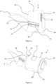
- Figure 1shows a tanker aircraft 2 with a refuelling hose 1 in a deployed position, trailing behind the aircraft.
- the refuelling hose 1is flexible and is mounted on a reel assembly within the tanker aircraft 2 so that operation of the reel assembly will deploy and retract the refuelling hose 1.
- the distal end 3 of the refuelling hose 1comprises a valve connector 4 that mates with a probe 5 on the receiving aircraft 6 and a drogue 7 that provides a stabilising aerodynamic force.
- the drag created by the drogue 7 as the tanker aircraft 2 moves through the airprovides a backwards force that drags the distal end 3 of the refuelling hose 1 behind the tanker aircraft 2 and in a position and orientation that is suitable for mating with the receiving aircraft 6.
- the drogue 7also helps reduce oscillations in the hose that would otherwise cause the distal end of the refuelling hose to move around.
- FIG. 2shows the distal end 3 of the refuelling hose 1 without a drogue attachment.
- the distal end 3comprises a mating connector 4 that provides the sealed mechanical connection between the hose 1 and the probe of the receiving aircraft.
- a user definable interface (UDI) module 11is mounted to the distal end of the refuelling hose 1 so that the connector 4 protrudes from one end of the module 11.
- the UDI module 11allows a user to configure the end of the refuelling hose 1 with different functionality for different applications as will become apparent from the description that follows below.
- a data and/or power transmission cable 9is wound around and embedded into the refuelling hose and terminates in an end connector 10 that connects the cable 9 to the UDI module 11 via an intermediate collar 18 (see below).
- FIG 3shows a perspective view of the refuelling hose 1 showing the cable 9 embedded within the refuelling hose 1.
- the hose 1comprises an inner fuel carrying hose 12 and an outer protective sheath 13 as well as a reinforcing sheath 14 that provides both increased strength and protection against electrical charges such as lightning strikes (part of the outer protective sheath 13 is removed in Figure 3 for clarity and to enable the path of the cable 9 to be seen).
- the cable 9is flat and flexible and comprises a plurality of conducting wires 15 to carry power, data or any other electrical signals.
- the cable 9is wrapped helically around the inner fuel carrying hose 12 and the reinforcing sheath 14 and is then covered by the outer protective sheath 13 so that the cable 9 is located between the reinforcing sheath 14 and the outer protective sheath 13.
- the cable 9may be embedded within the outer protective sheath 13.
- the wires 15themselves may be of any type, for example 4AWG wires for carrying power, wires for carrying data and/or power and/or fibre optic cables.
- the wires 15may be copper, aluminium or optical wave guides or other suitable conductors.
- the cable 9should be configured to carry both power and/or data signals with a degree of flexibility so that the hose 1 and cable 9 can be used with a variety of UDI modules, as explained in more detail hereinafter.
- the flexible hose 1During normal duty the flexible hose 1 is exposed to bending forces caused by winding the hose 1 on and off a storage reel on the tanker aircraft and also from turbulence during operation, as the hose moves around in the air.
- the cable 9is embedded within the hose 1 so will also be subject to those bending forces and there is a need to protect the cable 9, particularly the wires 15, from fatigue stresses. Bending the hose 1 and the cable 9 will exert tensile stress on one side of the wires 15 and compressive stress on the opposite side. Also, the direction of bending will change during operation, resulting in fatigue stress effects. The bending and fatigue stresses can alter the conductive properties of the wires 15 and affect the performance of the cable 9, possibly even causing the wires 15 to fail.
- each wireis provided with low friction insulation, made from a fluoropolymer or thermoplastic material, and the insulated wires 15 are contained within a low friction sleeve 17, also made from a fluoropolymer or thermoplastic material. This allows the insulated wires 15 to move around within the sleeve 17.
- the low friction contact between the insulated wires 15 and the sleeve 17allows the wires 15 to move around within the sleeve 17 to the position of least stress as the hose 1 bends, thereby reducing the bending and fatigue stresses induced in the power, signal and fibre optic wires 15.
- the outer surface of the sleeve 17is treated to allow it to be bonded to the outer protective sheath 13 or reinforcing sheath 14 of the hose 1.
- the treatment processcould be chemical etching, plasma arc or bespoke RF surface modification that allows adhesive to bond to the sleeve 17.
- EMIElectromagnetic Impulse
- An EMImay occur naturally, such as from a lightning strike or as a result of the systems themselves, for example a build up of static electricity or short circuits.
- EMImay be used intentionally as weapon and the systems of the aircraft and the refuelling apparatus need to be protected from any such attack.
- FIG 4shows a termination collar 18 that is fixed to the distal end of the refuelling hose to provide an electrical terminal and connection between the cable 9 and the UDI module 11 (see Figure 5 ).
- the termination collar 18is attached to the outer wall 13 (see Figure 3 ) of the refuelling hose 1 to securely and rigidly attach the termination collar 18 to the hose 1.
- the termination collar 18comprises a ring portion 19 with an inner diameter that is larger than and extends around the inner refuelling hose 12 and the mechanical connector 4 without interfering with the function of these components.
- the termination collar 18comprises an angled cut out 20 at the end of the termination collar 18 facing along the hose 1 towards the tanker aircraft.
- the cut outhas a face 47 that extends perpendicularly to the helix path of the cable 9 such that the face 47 is at 90 degrees relative to the helix angle of the cable 9.
- the face 47comprises an electrical connector 21 configured to receive the end 23 of the helically wound cable 9 and the sleeve 17 is adhered or bonded to the termination collar 18.
- the angled cut out 20 and the face 47allow the end 23 of the cable 9 to be easily received in the connector 21 without having to flex the cable 9 or disturb the helical path.
- the angled cut out 20extends from the face 47 at an angle that is closely matched to the helix angle of the cable 9 so that the termination collar 18 is shaped to allow the cable 9 to freely connect with the connector 21.
- the end 23 of the cable 9may be removably or permanently attached to the connector 21 on the termination collar 18.
- the connector 21may be a zero insertion force type connector with a clamping element to prevent disconnection.
- Conductors 24are embedded within the ring portion 19 of the termination collar 18 to connect the electrical connector 21 on angled face 47 to an electrical terminal 25 on the distal end 26 of the termination collar 18, facing away from the tanker aircraft.
- the conductors 24initially follow the helical path through the collar 18 but then turn so that they extend in an axial direction of the hose and terminate at the end face of the collar 18, which lies in a plane extending at right-angles to the longitudinal axis of the hose.
- the conductors 24may be copper, aluminium or optical wave guides. In this way, when the cable 9 is attached to the electrical connector 21, the cable 9 is in electrical contact with the terminal 25 on the end face 26 of the termination collar 18, so that electrical connection can then be made to the UDI module 11, as explained below with reference to Figure 5 .
- FIG. 5shows the distal end 3 of the refuelling hose 1 with the cable 9, termination collar 18 and the User Definable Interface (UDI) module 11 attached to the termination collar 18.
- the UDI module 11 and collar 18are shown as being partially transparent for the purposes of clarity only.
- the UDI module 11comprises two half-cylindrical portions or shells 27, 28 that are attachable to each other surrounding the refuelling hose 1.
- the UDI module 11may also be attachable to the end 26 of the termination collar 18.
- the two parts 27, 28 of the UDI module 11may be attachable to each other by a magnetic clamping system comprising a plurality of magnets, such as neodymium magnets, embedded in the mating faces of the two parts 27, 28.
- the magnets in each part 27, 28have opposing poles such that they attract each other and clamp the two parts 27, 28 together.
- the magnets in one of the two parts 27, 28are moveable so that the magnets can be moved from an aligned position for clamping to an unaligned positioned for separating the two parts 27, 28 of the UDI module 11.
- the magnetsmay be moveable by a manual lever or other actuator.
- the two parts 27, 28 of the UDI moduleare attachable by means of locking elements, fasteners, or any other suitable attachment that allows the UDI module 11 to be easily clamped and separated.
- the UDI module 11may also be attached to the outer face 26 of the termination collar 18 by any of the attachment means described above.
- the UDI module 11is easily removable from the refuelling hose 1 and can be changed during flight when the hose is retracted into the tanker aircraft 2.
- Different UDI modules 11may be configured in different ways for different applications, for example refuelling of different aircraft or in different conditions.
- the UDI module 11comprises an electrical connector 30 on the end face 31 of one of the half-cylindrical portions 27 that connects with the electrical terminal 25 on the end face 26 of the termination collar 18 to electrically connect the termination collar 18 to the UDI module 11.
- Conductors or wires 32are embedded into, or mounted to, the UDI module 11 to connect any devices that are mounted in the UDI module 11 to the connector 30 and therefore to the tanker aircraft 2 via the cable 9.
- Some examples of components that the UDI module 11may comprise are position sensors, accelerometers, pressure, temperature, flow rate sensors, connection sensors (to detect if the probe and hose are suitably mated) and so forth.
- the UDI module 11is able to provide whatever functionality is required for each individual refuelling aircraft, or even each individual operation.
- the cable 9provides the connectivity and the UDI module provides a platform for using any type of electrical equipment desired at the connection between the refuelling hose and the receiving aircraft.
- Figures 6a and 6bshow the two portions 27, 28 of the UDI module 11 that are attachable to each other and to the end 26 of the termination collar 18.
- the UDI module 11is fully configurable to change the connectivity and function of the refuelling hose 1 depending on the requirements of the user and the operation.
- Componentssuch as sensors and connectors can be embedded within or attached to the UDI modules 11 and different UDI modules 11 can be provided for different applications.
- Each different UDI module 11may utilise the wires 15 in the cable 9 differently so different connections will be required at the tanker end of the cable 9 as well.
- a user onboard the tanker aircraft 2may change the UDI module 11 by removing the two portions 27, 28 and swapping them for a different UDI module 11, thereby changing the functionality and capabilities of the refuelling hose 1.
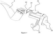
- Figure 7shows an example configuration of the UDI module 11 without the body of the UDI module 11 showing, for purposes of clarity.
- the UDI module 11comprises a power transfer unit 33, accelerometers 34 and heat and pressure sensors 35.
- the power transfer unit 33is positioned on an outer face of the UDI module 11 and power is provided to the unit from the tanker aircraft 2 along the cable 9 in the refuelling hose 1.
- the receiving aircraft 2will have a similar power transfer unit positioned on or near the probe 5 that connects with the refuelling hose 1 so that when the probe and the hose are connected, the two power transfer units are proximate to each other and power can be transferred from one aircraft to the other via induction.
- the accelerometers 34can be used to determine the position and/or stability of the distal end 3 of the refuelling hose 1 which may be useful for informing the operators or systems about the condition of the connection or if the hose 1 is stable enough for a connection to be made in the first place. For example, high acceleration during fuel transfer may trigger the fuel transfer operation to be stopped as a safety precaution. Temperature and pressure sensors 35 in the UDI module 11 can inform operators or systems about the state of the fuel being transferred and therefore if the systems are working effectively or if there might be a blockage or other problem. Low or high temperatures caused by the high altitudes or malfunctioning systems may be dangerous so temperature sensors may be used to determine if fuel transfer is safe and inform an operator or system when the fuel temperature is outside a safe range.
- a further optional component for the UDI module 11may include providing an electrical terminal (not shown) at the distal end 36 (see Figure 5 ) of the UDI module 11 that is configured to electrically connect to a connector on the receiving aircraft 6 when the refuelling connection is made.
- the receiving aircraftmay comprise an electrical connector assembly either on, or near, the probe 5 that connects to the UDI module, allowing power and/or data to be transferred between the tanker aircraft 2 and the receiving aircraft 6 via the cable 9 in the refuelling hose 1.
- the connectorsmay magnetically orientate and/or lock together to ensure alignment before a connection is made.
- concentric slip ringsmay be used on the distal end of the UDI module that connect to a compatible slip ring arrangement on the receiving aircraft.
- the electrical connection along the hose 1allows power and/or electrical signals to be carried from the tanker aircraft 2 to the receiving aircraft 6 and vice versa. Therefore, it is possible to provide power to the aircraft 6 being refuelled to recharge the batteries and extend the operating life of UAV's and AUAV's which carry limited life batteries. Furthermore, the tanker aircraft 2 is able to securely communicate with the receiving aircraft 6 to download data, such as surveillance images, or to upload instructions or perform diagnostic analysis on faulty or out of date systems. The data connection is more secure than a wireless alternative because it is direct, can not be intercepted and is protected from EMI and other such attacks.
- the UDI module 11may be fitted with a drogue that functions in the conventional manner.
- the UDI module 11may have aerodynamic control surfaces and an actuator to control the wings from the tanker aircraft 2 such that an operator onboard the tanker aircraft may control the attitude of the distal end of the refuelling hose 1 to facilitate the connection between the probe 5 and the distal end 3 of the hose 1.
- the UDI module 11is changeable so a tanker aircraft will be able to switch between these applications during flight, depending on the requirements of each refuelling operation and the equipment onboard the receiving aircraft.
Landscapes
- Engineering & Computer Science (AREA)
- Mechanical Engineering (AREA)
- Power Engineering (AREA)
- Transportation (AREA)
- General Engineering & Computer Science (AREA)
- Sustainable Development (AREA)
- Sustainable Energy (AREA)
- Life Sciences & Earth Sciences (AREA)
- Aviation & Aerospace Engineering (AREA)
- Chemical & Material Sciences (AREA)
- Combustion & Propulsion (AREA)
- Microelectronics & Electronic Packaging (AREA)
- Rigid Pipes And Flexible Pipes (AREA)
Description
- This invention relates to a hose for conveying a fluid.
- Flexible hoses are used to transfer fluid from one place to another and common applications are for transferring water, pressurised air, hydraulic fluid or any other fluid from one piece of equipment to another. Usually, fluid at one end of the hose is pressurised, possibly by a pump or header tank, and each end of the hose is provided with a connector that sealably connects the hose to the equipment. It is known to provide a hose for connecting one aircraft to another for the purpose of in-flight refuelling.
- In-flight refuelling systems involve moving aviation fuel from a tanker aircraft to a receiving aircraft to increase the operating range and time of the receiving aircraft by overcoming the maximum fuel load limitation.
- Currently, there are two main known methods of in-flight refuelling - 'probe and drogue' and `flying boom'. The probe and drogue arrangement involves a flexible hose with a valve and a drogue at the distal end of the hose. The hose is extended from the tanker aircraft and is pulled behind the tanker aircraft by the aerodynamic force created by the drogue, which also provides some positional stability. The receiving aircraft comprises a probe extending forwardly from the nose or fuselage of the aircraft, and also has a valve at its distal end. The pilot of the aircraft to be refuelled controls and manoeuvres the aircraft to align the probe with the valve and the drogue and then moves the aircraft towards the tanker aircraft so that the probe connects with the valve on the hose. Once connection has been made, the valves can be opened to establish a fluid path, thereby allowing fuel to flow into the fuel tanks of the receiving aircraft.
- Flying boom refuelling systems have a rigid boom that is deployed from the tanker aircraft, the position of which is typically controlled by an operator in the tanker aircraft. The boom can carry a hose which has a valve at its distal end. The receiving aircraft comprises a docking port that may be within the fuselage, or extending from the fuselage. The pilot of the receiving aircraft again flies their aircraft into contact with the boom. However, in this case, the boom operator can control the finite position of the boom so there is a two-way process for making the connection.
- Developments in aviation mean that the industry is changing to favour Unmanned Aerial Vehicles (UAV's) and Autonomous Unmanned Aerial Vehicles (AUAV's) and the refuelling requirements of these aircraft are very different to those of conventional aircraft. A limitation of UAV's and AUAV's is the power that can be carried by onboard batteries which are recharged before each use.
- Aircraft currently communicate via radio or satellite communications which can place a large strain on the bandwidth of such systems. UAV's and AUAV's that are deployed as observers can collect and store large amounts of data that is either transmitted over the communication channels or stored onboard the aircraft for later retrieval. Transmission over the communication channels requires more bandwidth which means more satellites, transmitters and receivers that can add considerable cost. Furthermore, communication channels may not be fast or secure enough to carry out some operations such as system diagnostics. Storing data onboard the aircraft delays the retrieval of that information and requires the aircraft to return to the ground. Therefore, the data storage capacity of an aircraft may also limit the aircraft's maximum operational time.
US7137598 discloses an in-flight refueling system, sensor system and method for detecting and damping changes in the disposition of an elongate hose extending from a tanker aircraft during an in-flight refueling operation.- It is known from
FR2714708 - The present invention seeks to provide a hose for conveying fluids that seeks to alleviate or substantially overcome the problems with conventional fluid carrying hoses, including those mentioned above.
- According to the invention, there is provided a system for conveying fluids as defined in
claim 1. - In one embodiment, the wall may comprise an inner fluid carrying tube and an outer protective sheath and the cable may be positioned between the inner fluid carrying tube and the outer protective sheath.
- In an alternative embodiment, the wall may comprise an inner fluid carrying tube and an outer protective sheath and the cable may be embedded within the outer protective sheath.
- Advantageously, the cable may be wound around the inner fluid carrying tube to define a helical path along the hose.
- Helically winding the cable around the inner fluid carrying tube means that the cable is always at an angle to any bending of the hose, thereby reducing the stress induced in the cable.
- Preferably, the cable comprises a plurality of spaced insulated wires encased in a sleeve of low friction material to allow movement of the wires relative to the sleeve when the cable is subject to bending.
- The low friction casing reduces the stress placed on the wires as they move around within the casing. Also, allowing the wires to move within the casing means that the wires will move to the position of least stress during bending of the hose.
- The user definable module may comprise at least one of a position sensor, an accelerometer, a temperature sensor, a pressure sensor, a proximity sensor and a flow rate sensor.
- The conductors in the intermediate connecting collar may extend from the first electrical terminal in a helical path and terminate at the second electrical terminal in a plane extending substantially at right angles to a longitudinal axis of the hose.
- Advantageously, the intermediate connecting collar has an angled cut out that defines a face which is substantially perpendicular to the helical path of the cable, said first electrical terminal being mounted on said face.
- The angled cut out allows the helically wound cable to easily connect to the collar without having to bend the cable.
- The intermediate connecting collar may comprise an end face which lies in a plane substantially at right angles to the longitudinal axis of the hose, said second electrical terminal being mounted to said end face.
- Preferably, the user definable interface (UDI) module comprises two half tubular portions or shells that are attachable to each other to surround the distal end of the hose.
- The two part construction of the user definable module allows the user definable module to be easily removed from the hose for interchanging.
- The user definable module may be attachable to the intermediate connecting collar.
- A connector may extend from the distal end of the hose to receive a probe, the connector extending distally beyond the user defined module.
- In one embodiment, the user definable interface (UDI) module comprises a terminal connector configured to electrically connect to a mating terminal connector on a receiving probe, when the connector is connected to said receiving probe.
- In this way, an electrical connection is made between the hose and the receiving probe which may be used for transmitting power and/or data.
- Embodiments of the invention will now be described, by way of example only and with reference to the accompanying drawings, in which;
Figure 1 shows a view of a refuelling tanker aircraft and an aircraft that is to be refuelled;Figure 2 shows a view of the distal end of a refuelling hose according to an embodiment of the invention;Figure 3 shows a perspective view of the refuelling hose ofFigure 2 , but omitting part of the outer protective sheath for the purposes of clarity;Figure 4 shows a view of the termination collar and electrical connector ofFigure 2 ;Figure 5 shows a view of the user definable interface module (UDI) for attachment to the refuelling hose;Figures 6a and 6b show views of the two portions of the UDI module; and,Figure 7 shows a view of an example configuration of the UDI module with the casing portions removed for clarity.Figure 1 shows atanker aircraft 2 with arefuelling hose 1 in a deployed position, trailing behind the aircraft. Therefuelling hose 1 is flexible and is mounted on a reel assembly within thetanker aircraft 2 so that operation of the reel assembly will deploy and retract therefuelling hose 1. Thedistal end 3 of therefuelling hose 1 comprises avalve connector 4 that mates with aprobe 5 on thereceiving aircraft 6 and a drogue 7 that provides a stabilising aerodynamic force. The drag created by the drogue 7 as thetanker aircraft 2 moves through the air provides a backwards force that drags thedistal end 3 of therefuelling hose 1 behind thetanker aircraft 2 and in a position and orientation that is suitable for mating with thereceiving aircraft 6. The drogue 7 also helps reduce oscillations in the hose that would otherwise cause the distal end of the refuelling hose to move around.Figure 2 shows thedistal end 3 of therefuelling hose 1 without a drogue attachment. Thedistal end 3 comprises amating connector 4 that provides the sealed mechanical connection between thehose 1 and the probe of the receiving aircraft. As will be described in more detail with reference toFigures 2 to 8, a user definable interface (UDI)module 11 is mounted to the distal end of therefuelling hose 1 so that theconnector 4 protrudes from one end of themodule 11. TheUDI module 11 allows a user to configure the end of therefuelling hose 1 with different functionality for different applications as will become apparent from the description that follows below. To electrically connect theUDI module 11 to the tanker aircraft, a data and/orpower transmission cable 9 is wound around and embedded into the refuelling hose and terminates in anend connector 10 that connects thecable 9 to theUDI module 11 via an intermediate collar 18 (see below).Figure 3 shows a perspective view of therefuelling hose 1 showing thecable 9 embedded within therefuelling hose 1. Thehose 1 comprises an innerfuel carrying hose 12 and an outerprotective sheath 13 as well as a reinforcingsheath 14 that provides both increased strength and protection against electrical charges such as lightning strikes (part of the outerprotective sheath 13 is removed inFigure 3 for clarity and to enable the path of thecable 9 to be seen). Thecable 9 is flat and flexible and comprises a plurality of conductingwires 15 to carry power, data or any other electrical signals. Thecable 9 is wrapped helically around the innerfuel carrying hose 12 and the reinforcingsheath 14 and is then covered by the outerprotective sheath 13 so that thecable 9 is located between the reinforcingsheath 14 and the outerprotective sheath 13. Alternatively, thecable 9 may be embedded within the outerprotective sheath 13. Thewires 15 themselves may be of any type, for example 4AWG wires for carrying power, wires for carrying data and/or power and/or fibre optic cables. Thewires 15 may be copper, aluminium or optical wave guides or other suitable conductors. Thecable 9 should be configured to carry both power and/or data signals with a degree of flexibility so that thehose 1 andcable 9 can be used with a variety of UDI modules, as explained in more detail hereinafter.- During normal duty the
flexible hose 1 is exposed to bending forces caused by winding thehose 1 on and off a storage reel on the tanker aircraft and also from turbulence during operation, as the hose moves around in the air. Thecable 9 is embedded within thehose 1 so will also be subject to those bending forces and there is a need to protect thecable 9, particularly thewires 15, from fatigue stresses. Bending thehose 1 and thecable 9 will exert tensile stress on one side of thewires 15 and compressive stress on the opposite side. Also, the direction of bending will change during operation, resulting in fatigue stress effects. The bending and fatigue stresses can alter the conductive properties of thewires 15 and affect the performance of thecable 9, possibly even causing thewires 15 to fail. - Helically winding the
cable 9 along the length of the hose reduces the stress in thewires 15 during operation because thewires 15 are always at an angle to the bending direction of thehose 1. Furthermore, each wire is provided with low friction insulation, made from a fluoropolymer or thermoplastic material, and theinsulated wires 15 are contained within alow friction sleeve 17, also made from a fluoropolymer or thermoplastic material. This allows theinsulated wires 15 to move around within thesleeve 17. The low friction contact between theinsulated wires 15 and thesleeve 17 allows thewires 15 to move around within thesleeve 17 to the position of least stress as thehose 1 bends, thereby reducing the bending and fatigue stresses induced in the power, signal andfibre optic wires 15. The outer surface of thesleeve 17 is treated to allow it to be bonded to the outerprotective sheath 13 or reinforcingsheath 14 of thehose 1. The treatment process could be chemical etching, plasma arc or bespoke RF surface modification that allows adhesive to bond to thesleeve 17. - In addition to stress protection, the
cable 9 is fully sheathed in aprotective layer 16 to protect thecable 9 and the systems attached to the cable from an Electromagnetic Impulse (EMI). An EMI may occur naturally, such as from a lightning strike or as a result of the systems themselves, for example a build up of static electricity or short circuits. Alternatively, EMI may be used intentionally as weapon and the systems of the aircraft and the refuelling apparatus need to be protected from any such attack. Figure 4 shows atermination collar 18 that is fixed to the distal end of the refuelling hose to provide an electrical terminal and connection between thecable 9 and the UDI module 11 (seeFigure 5 ). Thetermination collar 18 is attached to the outer wall 13 (seeFigure 3 ) of therefuelling hose 1 to securely and rigidly attach thetermination collar 18 to thehose 1. Thetermination collar 18 comprises aring portion 19 with an inner diameter that is larger than and extends around theinner refuelling hose 12 and themechanical connector 4 without interfering with the function of these components.- As shown in
Figure 4 thetermination collar 18 comprises an angled cut out 20 at the end of thetermination collar 18 facing along thehose 1 towards the tanker aircraft. The cut out has aface 47 that extends perpendicularly to the helix path of thecable 9 such that theface 47 is at 90 degrees relative to the helix angle of thecable 9. Theface 47 comprises anelectrical connector 21 configured to receive theend 23 of the helically woundcable 9 and thesleeve 17 is adhered or bonded to thetermination collar 18. The angled cut out 20 and theface 47 allow theend 23 of thecable 9 to be easily received in theconnector 21 without having to flex thecable 9 or disturb the helical path. The angled cut out 20 extends from theface 47 at an angle that is closely matched to the helix angle of thecable 9 so that thetermination collar 18 is shaped to allow thecable 9 to freely connect with theconnector 21. Theend 23 of thecable 9 may be removably or permanently attached to theconnector 21 on thetermination collar 18. Theconnector 21 may be a zero insertion force type connector with a clamping element to prevent disconnection.Conductors 24 are embedded within thering portion 19 of thetermination collar 18 to connect theelectrical connector 21 onangled face 47 to anelectrical terminal 25 on thedistal end 26 of thetermination collar 18, facing away from the tanker aircraft. Theconductors 24 initially follow the helical path through thecollar 18 but then turn so that they extend in an axial direction of the hose and terminate at the end face of thecollar 18, which lies in a plane extending at right-angles to the longitudinal axis of the hose. Theconductors 24 may be copper, aluminium or optical wave guides. In this way, when thecable 9 is attached to theelectrical connector 21, thecable 9 is in electrical contact with the terminal 25 on theend face 26 of thetermination collar 18, so that electrical connection can then be made to theUDI module 11, as explained below with reference toFigure 5 . Figure 5 shows thedistal end 3 of therefuelling hose 1 with thecable 9,termination collar 18 and the User Definable Interface (UDI)module 11 attached to thetermination collar 18. TheUDI module 11 andcollar 18 are shown as being partially transparent for the purposes of clarity only. TheUDI module 11 comprises two half-cylindrical portions orshells refuelling hose 1. TheUDI module 11 may also be attachable to theend 26 of thetermination collar 18.- The two
parts UDI module 11 may be attachable to each other by a magnetic clamping system comprising a plurality of magnets, such as neodymium magnets, embedded in the mating faces of the twoparts part parts parts parts UDI module 11. The magnets may be moveable by a manual lever or other actuator. Alternatively, the twoparts UDI module 11 to be easily clamped and separated. Similarly, theUDI module 11 may also be attached to theouter face 26 of thetermination collar 18 by any of the attachment means described above. - The
UDI module 11 is easily removable from therefuelling hose 1 and can be changed during flight when the hose is retracted into thetanker aircraft 2.Different UDI modules 11 may be configured in different ways for different applications, for example refuelling of different aircraft or in different conditions. - The
UDI module 11 comprises anelectrical connector 30 on theend face 31 of one of the half-cylindrical portions 27 that connects with theelectrical terminal 25 on theend face 26 of thetermination collar 18 to electrically connect thetermination collar 18 to theUDI module 11. Conductors orwires 32 are embedded into, or mounted to, theUDI module 11 to connect any devices that are mounted in theUDI module 11 to theconnector 30 and therefore to thetanker aircraft 2 via thecable 9. Some examples of components that theUDI module 11 may comprise are position sensors, accelerometers, pressure, temperature, flow rate sensors, connection sensors (to detect if the probe and hose are suitably mated) and so forth. TheUDI module 11 is able to provide whatever functionality is required for each individual refuelling aircraft, or even each individual operation. Thecable 9 provides the connectivity and the UDI module provides a platform for using any type of electrical equipment desired at the connection between the refuelling hose and the receiving aircraft. Figures 6a and 6b show the twoportions UDI module 11 that are attachable to each other and to theend 26 of thetermination collar 18. As explained above, theUDI module 11 is fully configurable to change the connectivity and function of therefuelling hose 1 depending on the requirements of the user and the operation. Components such as sensors and connectors can be embedded within or attached to theUDI modules 11 anddifferent UDI modules 11 can be provided for different applications. Eachdifferent UDI module 11 may utilise thewires 15 in thecable 9 differently so different connections will be required at the tanker end of thecable 9 as well. Before or between refuelling operations a user onboard thetanker aircraft 2 may change theUDI module 11 by removing the twoportions different UDI module 11, thereby changing the functionality and capabilities of therefuelling hose 1.Figure 7 shows an example configuration of theUDI module 11 without the body of theUDI module 11 showing, for purposes of clarity. In this case, theUDI module 11 comprises apower transfer unit 33,accelerometers 34 and heat andpressure sensors 35. Thepower transfer unit 33 is positioned on an outer face of theUDI module 11 and power is provided to the unit from thetanker aircraft 2 along thecable 9 in therefuelling hose 1. The receivingaircraft 2 will have a similar power transfer unit positioned on or near theprobe 5 that connects with therefuelling hose 1 so that when the probe and the hose are connected, the two power transfer units are proximate to each other and power can be transferred from one aircraft to the other via induction. Theaccelerometers 34 can be used to determine the position and/or stability of thedistal end 3 of therefuelling hose 1 which may be useful for informing the operators or systems about the condition of the connection or if thehose 1 is stable enough for a connection to be made in the first place. For example, high acceleration during fuel transfer may trigger the fuel transfer operation to be stopped as a safety precaution. Temperature andpressure sensors 35 in theUDI module 11 can inform operators or systems about the state of the fuel being transferred and therefore if the systems are working effectively or if there might be a blockage or other problem. Low or high temperatures caused by the high altitudes or malfunctioning systems may be dangerous so temperature sensors may be used to determine if fuel transfer is safe and inform an operator or system when the fuel temperature is outside a safe range.- A further optional component for the
UDI module 11 may include providing an electrical terminal (not shown) at the distal end 36 (seeFigure 5 ) of theUDI module 11 that is configured to electrically connect to a connector on the receivingaircraft 6 when the refuelling connection is made. The receiving aircraft may comprise an electrical connector assembly either on, or near, theprobe 5 that connects to the UDI module, allowing power and/or data to be transferred between thetanker aircraft 2 and the receivingaircraft 6 via thecable 9 in therefuelling hose 1. The connectors may magnetically orientate and/or lock together to ensure alignment before a connection is made. Alternatively, concentric slip rings may be used on the distal end of the UDI module that connect to a compatible slip ring arrangement on the receiving aircraft. - The electrical connection along the
hose 1 allows power and/or electrical signals to be carried from thetanker aircraft 2 to the receivingaircraft 6 and vice versa. Therefore, it is possible to provide power to theaircraft 6 being refuelled to recharge the batteries and extend the operating life of UAV's and AUAV's which carry limited life batteries. Furthermore, thetanker aircraft 2 is able to securely communicate with the receivingaircraft 6 to download data, such as surveillance images, or to upload instructions or perform diagnostic analysis on faulty or out of date systems. The data connection is more secure than a wireless alternative because it is direct, can not be intercepted and is protected from EMI and other such attacks. - Furthermore, the
UDI module 11 may be fitted with a drogue that functions in the conventional manner. Alternatively, theUDI module 11 may have aerodynamic control surfaces and an actuator to control the wings from thetanker aircraft 2 such that an operator onboard the tanker aircraft may control the attitude of the distal end of therefuelling hose 1 to facilitate the connection between theprobe 5 and thedistal end 3 of thehose 1. Again, theUDI module 11 is changeable so a tanker aircraft will be able to switch between these applications during flight, depending on the requirements of each refuelling operation and the equipment onboard the receiving aircraft. - The components, systems and methods described herein are applicable to any in-flight refuelling system including, but not limited to, 'manned tanker to manned aircraft', 'manned tanker to unmanned aircraft' and 'unmanned tanker to unmanned aircraft'. Furthermore, it will be appreciated that the invention as defined in the claims is applicable to other similar applications where a transfer of fluid is required from one moveable place to another. For example, ship-to-ship or ship-to-helicopter fluid transfer, or connections between oil and gas exploration and production equipment both on land and subsea.
Claims (11)
- A system for conveying a fluid comprising a hose (1), and a user-definable interface (UDI) module (11) for measuring a measurable parameter at a distal end (3) of the hose (1),wherein the hose (1) comprises a wall defining a fluid carrying tube, a power and/or data transmission cable (9) integrated into said wall, and an intermediate connecting collar (18) attached to said wall and having a ring portion (19) that extends around the fluid carrying tube at said distal end, wherein said intermediate connecting collar (18) is configured to form a connection, for the transfer of power and/or data from said cable (9), with said user definable interface (UDI) module (11) removably attachable to said distal end (3), the intermediate connecting collar (18) comprising first electrical terminals (21) to connect the cable (9) to conductors (24) in the ring portion (19) of the intermediate connecting collar (18), and second electrical terminals (25) spaced from the first electrical terminals to connect the conductors (24) in the ring portion (19) of the intermediate connecting collar (18) to the user definable interface (UDI) module (11), said conductors being embedded in said ring portion (19) of the intermediate connecting collar (18) and,wherein the user definable interface (UDI) module (11) comprises at least one or more components (34, 35) for determining a measurable parameter at the distal end (3) of the hose (1).
- The system of claim 1, wherein the wall comprises an inner fluid carrying tube (12) and an outer protective sheath (13) , wherein the cable (9) is positioned between the inner fluid carrying tube and the outer protective sheath.
- The system of claim 1, wherein the wall comprises an inner fluid carrying tube (12) and an outer protective sheath (13), wherein the cable (9) is embedded within the outer protective sheath.
- The system of claim 2 or 3, wherein the cable (9) is wound around the inner fluid carrying tube (12) to define a helical path along the hose.
- The system of claim 4, wherein the cable (9) comprises a plurality of spaced insulated wires (15) encased in a sleeve of low friction material (17) to allow movement of the wires relative to the sleeve when the cable is subject to bending.
- The system of any preceding claim, wherein the user definable interface (UDI) module (11) is tubular and surrounds the distal end (3) of the hose (1).
- The system of any preceding claim, wherein the conductors (24) in the intermediate connecting collar (18) extend from the first electrical terminal (21) in a helical path and terminate at the second electrical terminal (25) in a plane extending substantially at right angles to a longitudinal axis of the hose (1).
- The system of claim 7, wherein the intermediate connecting collar (18) has an angled cut out (20) that defines a face (47) which is substantially perpendicular to a helical path of the cable (9), said first electrical terminal (21) being mounted on said face.
- The system of claim 7, wherein the intermediate connecting collar (18) comprises an end face (26) which lies in a plane substantially at right angles to the longitudinal axis of the hose, said second electrical terminal (25) being mounted to said end face (26).
- The system of any preceding claim, wherein the user definable interface (UDI) module (11) is attachable to the intermediate connecting collar (18).
- The system of any of any preceding claim, wherein the user definable interface (UDI) module (11) comprises a connector (30) configured to connect to the second electrical terminals (25), when the user definable interface (UDI) module (11) is attached to the distal end (3) of the hose (1).
Applications Claiming Priority (1)
| Application Number | Priority Date | Filing Date | Title |
|---|---|---|---|
| GB1205551.3AGB2500669B (en) | 2012-03-29 | 2012-03-29 | Hose for conveying fluid |
Publications (3)
| Publication Number | Publication Date |
|---|---|
| EP2644509A2 EP2644509A2 (en) | 2013-10-02 |
| EP2644509A3 EP2644509A3 (en) | 2015-08-26 |
| EP2644509B1true EP2644509B1 (en) | 2024-03-27 |
Family
ID=46087336
Family Applications (1)
| Application Number | Title | Priority Date | Filing Date |
|---|---|---|---|
| EP13156581.4AActiveEP2644509B1 (en) | 2012-03-29 | 2013-02-25 | In-flight refuelling system |
Country Status (4)
| Country | Link |
|---|---|
| US (2) | US20130255986A1 (en) |
| EP (1) | EP2644509B1 (en) |
| ES (1) | ES2977454T3 (en) |
| GB (1) | GB2500669B (en) |
Families Citing this family (59)
| Publication number | Priority date | Publication date | Assignee | Title |
|---|---|---|---|---|
| GB2500669B (en) | 2012-03-29 | 2016-03-30 | Icon Polymer Group | Hose for conveying fluid |
| US9843179B1 (en)* | 2013-04-16 | 2017-12-12 | The United States Of America As Represented By The Secretary Of The Navy | Corrosion resistant termination connector for steel wire rope/minesweeping cable |
| EP2876052A1 (en)* | 2013-11-25 | 2015-05-27 | EADS Construcciones Aeronauticas S.A. | A hose and drogue in-flight refueling system with an active fuel pressure control |
| EP2915751B1 (en) | 2014-03-07 | 2016-09-28 | Airbus Defence and Space SA | A hose & drogue in-flight refueling method and system with an improved control of the hose & drogue motion |
| US10662625B2 (en)* | 2014-12-12 | 2020-05-26 | Delta Faucet Company | Sprayer hose assembly |
| CN104896206A (en)* | 2015-05-13 | 2015-09-09 | 王丽 | Airflow air supply pipe of freezing type drying machine |
| US10099799B2 (en)* | 2015-09-15 | 2018-10-16 | The Boeing Company | Articulated boom nozzle with torsion cable reel |
| GB2557648A (en)* | 2016-12-14 | 2018-06-27 | Polimer Kaucuk Sanayi Ve Pazarlama A S | Hose for guiding a fluid |
| GB2561524A (en)* | 2016-12-22 | 2018-10-24 | Linde Ag | A hose for connection to a gas cylinder |
| CN108267260B (en)* | 2016-12-30 | 2019-05-17 | 北京金风科创风电设备有限公司 | Electrical connections, fluid state testing devices, and fluid heat exchange systems |
| US11624326B2 (en) | 2017-05-21 | 2023-04-11 | Bj Energy Solutions, Llc | Methods and systems for supplying fuel to gas turbine engines |
| EP3418201A1 (en) | 2017-06-22 | 2018-12-26 | Airbus Defence and Space SA | In-flight electric reloading system |
| US11124314B2 (en)* | 2018-04-12 | 2021-09-21 | The Boeing Company | Systems and methods for transferring electric power to an aircraft during flight |
| ES2911913T3 (en)* | 2018-06-19 | 2022-05-23 | Airbus Defence & Space Sau | In-flight refueling hose and method for detecting damage to in-flight refueling hose |
| US11545280B2 (en) | 2018-08-23 | 2023-01-03 | The Esab Group Inc. | Cable hose with embedded features |
| GB2574078B (en)* | 2018-09-27 | 2020-05-20 | pitman James | Methods and systems for in-flight fuelling of aircraft |
| US11560845B2 (en) | 2019-05-15 | 2023-01-24 | Bj Energy Solutions, Llc | Mobile gas turbine inlet air conditioning system and associated methods |
| US11604113B2 (en) | 2019-09-13 | 2023-03-14 | Bj Energy Solutions, Llc | Fuel, communications, and power connection systems and related methods |
| US10815764B1 (en) | 2019-09-13 | 2020-10-27 | Bj Energy Solutions, Llc | Methods and systems for operating a fleet of pumps |
| US10961914B1 (en) | 2019-09-13 | 2021-03-30 | BJ Energy Solutions, LLC Houston | Turbine engine exhaust duct system and methods for noise dampening and attenuation |
| US10989180B2 (en) | 2019-09-13 | 2021-04-27 | Bj Energy Solutions, Llc | Power sources and transmission networks for auxiliary equipment onboard hydraulic fracturing units and associated methods |
| US12065968B2 (en) | 2019-09-13 | 2024-08-20 | BJ Energy Solutions, Inc. | Systems and methods for hydraulic fracturing |
| CA3092863C (en) | 2019-09-13 | 2023-07-18 | Bj Energy Solutions, Llc | Fuel, communications, and power connection systems and related methods |
| US11015536B2 (en) | 2019-09-13 | 2021-05-25 | Bj Energy Solutions, Llc | Methods and systems for supplying fuel to gas turbine engines |
| US11002189B2 (en) | 2019-09-13 | 2021-05-11 | Bj Energy Solutions, Llc | Mobile gas turbine inlet air conditioning system and associated methods |
| US11015594B2 (en) | 2019-09-13 | 2021-05-25 | Bj Energy Solutions, Llc | Systems and method for use of single mass flywheel alongside torsional vibration damper assembly for single acting reciprocating pump |
| CA3197583A1 (en) | 2019-09-13 | 2021-03-13 | Bj Energy Solutions, Llc | Fuel, communications, and power connection systems and related methods |
| US10895202B1 (en) | 2019-09-13 | 2021-01-19 | Bj Energy Solutions, Llc | Direct drive unit removal system and associated methods |
| CA3092865C (en) | 2019-09-13 | 2023-07-04 | Bj Energy Solutions, Llc | Power sources and transmission networks for auxiliary equipment onboard hydraulic fracturing units and associated methods |
| CA3092829C (en) | 2019-09-13 | 2023-08-15 | Bj Energy Solutions, Llc | Methods and systems for supplying fuel to gas turbine engines |
| US12338772B2 (en) | 2019-09-13 | 2025-06-24 | Bj Energy Solutions, Llc | Systems, assemblies, and methods to enhance intake air flow to a gas turbine engine of a hydraulic fracturing unit |
| US11708829B2 (en) | 2020-05-12 | 2023-07-25 | Bj Energy Solutions, Llc | Cover for fluid systems and related methods |
| US10968837B1 (en) | 2020-05-14 | 2021-04-06 | Bj Energy Solutions, Llc | Systems and methods utilizing turbine compressor discharge for hydrostatic manifold purge |
| US11428165B2 (en) | 2020-05-15 | 2022-08-30 | Bj Energy Solutions, Llc | Onboard heater of auxiliary systems using exhaust gases and associated methods |
| US11208880B2 (en) | 2020-05-28 | 2021-12-28 | Bj Energy Solutions, Llc | Bi-fuel reciprocating engine to power direct drive turbine fracturing pumps onboard auxiliary systems and related methods |
| US10961908B1 (en) | 2020-06-05 | 2021-03-30 | Bj Energy Solutions, Llc | Systems and methods to enhance intake air flow to a gas turbine engine of a hydraulic fracturing unit |
| US11208953B1 (en) | 2020-06-05 | 2021-12-28 | Bj Energy Solutions, Llc | Systems and methods to enhance intake air flow to a gas turbine engine of a hydraulic fracturing unit |
| US11109508B1 (en) | 2020-06-05 | 2021-08-31 | Bj Energy Solutions, Llc | Enclosure assembly for enhanced cooling of direct drive unit and related methods |
| US11111768B1 (en) | 2020-06-09 | 2021-09-07 | Bj Energy Solutions, Llc | Drive equipment and methods for mobile fracturing transportation platforms |
| US11066915B1 (en) | 2020-06-09 | 2021-07-20 | Bj Energy Solutions, Llc | Methods for detection and mitigation of well screen out |
| US10954770B1 (en) | 2020-06-09 | 2021-03-23 | Bj Energy Solutions, Llc | Systems and methods for exchanging fracturing components of a hydraulic fracturing unit |
| US11022526B1 (en) | 2020-06-09 | 2021-06-01 | Bj Energy Solutions, Llc | Systems and methods for monitoring a condition of a fracturing component section of a hydraulic fracturing unit |
| US11125066B1 (en) | 2020-06-22 | 2021-09-21 | Bj Energy Solutions, Llc | Systems and methods to operate a dual-shaft gas turbine engine for hydraulic fracturing |
| US11028677B1 (en) | 2020-06-22 | 2021-06-08 | Bj Energy Solutions, Llc | Stage profiles for operations of hydraulic systems and associated methods |
| US11933153B2 (en) | 2020-06-22 | 2024-03-19 | Bj Energy Solutions, Llc | Systems and methods to operate hydraulic fracturing units using automatic flow rate and/or pressure control |
| US11939853B2 (en) | 2020-06-22 | 2024-03-26 | Bj Energy Solutions, Llc | Systems and methods providing a configurable staged rate increase function to operate hydraulic fracturing units |
| US11473413B2 (en) | 2020-06-23 | 2022-10-18 | Bj Energy Solutions, Llc | Systems and methods to autonomously operate hydraulic fracturing units |
| US11466680B2 (en) | 2020-06-23 | 2022-10-11 | Bj Energy Solutions, Llc | Systems and methods of utilization of a hydraulic fracturing unit profile to operate hydraulic fracturing units |
| US11220895B1 (en) | 2020-06-24 | 2022-01-11 | Bj Energy Solutions, Llc | Automated diagnostics of electronic instrumentation in a system for fracturing a well and associated methods |
| US11149533B1 (en) | 2020-06-24 | 2021-10-19 | Bj Energy Solutions, Llc | Systems to monitor, detect, and/or intervene relative to cavitation and pulsation events during a hydraulic fracturing operation |
| US11193360B1 (en) | 2020-07-17 | 2021-12-07 | Bj Energy Solutions, Llc | Methods, systems, and devices to enhance fracturing fluid delivery to subsurface formations during high-pressure fracturing operations |
| CN111942188B (en)* | 2020-08-11 | 2022-04-12 | 北京京东乾石科技有限公司 | Unmanned aerial vehicle aerial charging system, charging method, device, equipment and medium |
| RU2748810C1 (en)* | 2020-10-16 | 2021-05-31 | Акционерное общество "Научно-производственное предприятие "Звезда" имени академика Г.И. Северина" | In-flight refueling unit fuel hose |
| RU203665U1 (en)* | 2020-12-04 | 2021-04-15 | Акционерное общество "Научно-производственное предприятие "Звезда" имени академика Г.И. Северина" | IN-FLIGHT FUEL HOSE |
| RU2749470C1 (en)* | 2020-12-04 | 2021-06-11 | Акционерное общество "Научно-производственное предприятие "Звезда" имени академика Г.И. Северина" | Fuel hose of the in-flight refueling unit |
| US11639654B2 (en) | 2021-05-24 | 2023-05-02 | Bj Energy Solutions, Llc | Hydraulic fracturing pumps to enhance flow of fracturing fluid into wellheads and related methods |
| CA3180024A1 (en) | 2021-10-25 | 2023-04-25 | Bj Energy Solutions, Llc | Systems and methods to reduce acoustic resonance or disrupt standing wave formation in a fluid manifold of a high-pressure fracturing system |
| GB2620987A (en)* | 2022-07-29 | 2024-01-31 | Baker Hughes Energy Technology UK Ltd | Pipe cable assembly |
| EP4545420A1 (en)* | 2023-10-24 | 2025-04-30 | Airbus Defence and Space, S.A.U. | Air to air refueling hose |
Citations (3)
| Publication number | Priority date | Publication date | Assignee | Title |
|---|---|---|---|---|
| US3127227A (en)* | 1961-02-27 | 1964-03-31 | Vacuum cleaner connector | |
| US3387319A (en)* | 1965-06-28 | 1968-06-11 | Electrolux Corp | Airflow-electric coupling for vacuum cleaner |
| DE1750392A1 (en)* | 1968-04-11 | 1970-11-12 | Gossler Kg Oscar | Device for connecting an electrical line to a hose |
Family Cites Families (85)
| Publication number | Priority date | Publication date | Assignee | Title |
|---|---|---|---|---|
| US482181A (en)* | 1892-09-06 | Electric connector for hose | ||
| US2438146A (en)* | 1945-06-07 | 1948-03-23 | American Brass Co | Flexible metal hose |
| US2663523A (en)* | 1949-08-02 | 1953-12-22 | Boeing Co | Aircraft interconnecting mechanism |
| US2949265A (en)* | 1954-03-22 | 1960-08-16 | Boeing Co | Articulated aircraft refueling boom |
| US2973163A (en)* | 1956-02-03 | 1961-02-28 | Flight Refueling Inc | Apparatus for trailing a fluid-transmitting hose or tow-line from an aircraft |
| US3023267A (en)* | 1959-03-05 | 1962-02-27 | Gen Cable Corp | Combination power and communication cable |
| US3034085A (en)* | 1959-12-09 | 1962-05-08 | Whirlpool Co | Combined fluid and electrical connector |
| US3285544A (en)* | 1964-02-26 | 1966-11-15 | Industrial Nucleonics Corp | Mid-air refueling system |
| IT957531B (en)* | 1971-03-10 | 1973-10-20 | Dornier Ag | MOORING ROPE FOR AERODINE |
| US3780208A (en)* | 1972-06-05 | 1973-12-18 | Moore & Co Samuel | Composite hose having a grounding wire enclosed in a sleeve and wrapped about the core tube of the hose |
| NL7414546A (en)* | 1973-11-15 | 1975-05-20 | Rhone Poulenc Sa | SMOOTH HEATING TUBE AND PROCESS FOR MANUFACTURING IT. |
| SE7401692L (en)* | 1974-02-08 | 1975-08-11 | Electrolux Ab | |
| US4059847A (en)* | 1976-09-01 | 1977-11-22 | Dayco Corporation | Hose having an electrically conductive layer for dissipating static electricity and method of making same |
| US4063790A (en)* | 1976-10-15 | 1977-12-20 | Dayco Corporation | Fluid conduit assembly |
| US4108701A (en)* | 1977-06-01 | 1978-08-22 | The Goodyear Tire & Rubber Company | Method for making hose incorporating an embedded static ground conductor |
| US4129270A (en)* | 1977-06-13 | 1978-12-12 | The Boeing Company | Air refueling boom pivot gimbal arrangements |
| US4162370A (en)* | 1977-06-24 | 1979-07-24 | Automation Industries, Inc. | Current carrying hose assembly |
| US4167645A (en)* | 1977-11-14 | 1979-09-11 | Dayco Corporation | Electrical current-carrying fluid hose construction |
| US4196464A (en)* | 1978-02-23 | 1980-04-01 | Eaton Corporation | Semi-conductive layer-containing reinforced pressure hose and method of making same |
| US4462649A (en)* | 1980-05-05 | 1984-07-31 | Dayco Corporation | Hose construction and method of making same |
| US4405969A (en)* | 1981-10-02 | 1983-09-20 | The Polymer Corporation | Anti-static hose assemblies |
| US4964692A (en)* | 1982-07-21 | 1990-10-23 | Smith & Nephew Dyonics, Inc. | Fiber bundle illumination system |
| JPS617809U (en)* | 1984-06-19 | 1986-01-17 | 住友電気工業株式会社 | shielded wire |
| GB8431067D0 (en)* | 1984-12-08 | 1985-01-16 | British Aerospace | Cable conduit system for vehicles |
| USH297H (en)* | 1985-08-12 | 1987-07-07 | The United States Of America As Represented By The Secretary Of The Air Force | Robotic refueling system for tactical and strategic aircraft |
| US4815816A (en)* | 1987-05-12 | 1989-03-28 | Rts Laboratories, Inc. | Image transportation device using incoherent fiber optics bundles and method of using same |
| JPH0416045Y2 (en)* | 1987-11-16 | 1992-04-10 | ||
| FR2659437B1 (en)* | 1990-03-07 | 1994-03-25 | Caoutchouc Manufacture Plastique | MEANS FOR LINEAR MARKING OF LENGTH, SPEED OR POSITIONING FOR FLEXIBLE ARTICLE OF LARGE LENGTH. |
| FR2662229B1 (en)* | 1990-05-17 | 1992-07-31 | Coflexip | FLEXIBLE TUBULAR DUCT HAVING INCORPORATED HEATING MEANS. |
| US5102012A (en)* | 1990-08-31 | 1992-04-07 | Dayco Products, Inc. | Fuel dispensing system having a flexible hose with a static dissipater and a fuel leak detector |
| US5220130A (en)* | 1991-08-06 | 1993-06-15 | Cooper Industries, Inc. | Dual insulated data cable |
| US5170011A (en)* | 1991-09-25 | 1992-12-08 | Teleflex Incorporated | Hose assembly |
| FR2714708B1 (en)* | 1994-01-05 | 1996-03-08 | Giat Ind Sa | Flexible tubular conduit comprising an information transmission cable. |
| US5600752A (en)* | 1994-03-11 | 1997-02-04 | Industrial Design Laboratories, Inc. | Flexible gas hose assembly with concentric helical tube members having reinforcement spring coils |
| US5573206A (en)* | 1994-08-19 | 1996-11-12 | Able Corporation | Hose and drogue boom refueling system, for aircraft |
| US5539624A (en)* | 1995-01-17 | 1996-07-23 | Durodyne, Inc. | Illuminated hose |
| US7498509B2 (en)* | 1995-09-28 | 2009-03-03 | Fiberspar Corporation | Composite coiled tubing end connector |
| US5921285A (en)* | 1995-09-28 | 1999-07-13 | Fiberspar Spoolable Products, Inc. | Composite spoolable tube |
| CA2163702C (en)* | 1995-11-24 | 2000-05-30 | Mark Beauchamp | Flame resistant electric cable |
| US6441308B1 (en)* | 1996-06-07 | 2002-08-27 | Cable Design Technologies, Inc. | Cable with dual layer jacket |
| US6061490A (en)* | 1997-08-01 | 2000-05-09 | Mitsubishi Rayon Co., Ltd. | Optical fiber bundle with bundling member |
| US6114632A (en)* | 1998-03-05 | 2000-09-05 | Planas, Sr.; Alberto E. | Integrated power and data communication hybrid cable assembly for local area computer network |
| GB2345199B (en)* | 1998-12-22 | 2003-06-04 | Philip Head | Tubing and conductors or conduits |
| JP2003509806A (en)* | 1999-09-07 | 2003-03-11 | ユティルクス・コーポレーション | Cable through which fluid flows |
| US6445576B1 (en)* | 2000-02-25 | 2002-09-03 | Intel Corporation | Tilt mounted hard drive bay |
| US6604711B1 (en)* | 2000-11-20 | 2003-08-12 | Sargent Fletcher, Inc. | Autonomous system for the aerial refueling or decontamination of unmanned airborne vehicles |
| US6901191B2 (en)* | 2001-11-12 | 2005-05-31 | Corning Cable Systems Llc | High density fiber optic cable |
| US6710243B2 (en)* | 2002-06-27 | 2004-03-23 | Capativa Tech, Inc. | Structure of signal line |
| US6786455B1 (en)* | 2002-09-05 | 2004-09-07 | Asher Bartov | Method for engaging a probe and drogue for aerial refueling |
| US7152828B1 (en)* | 2002-11-01 | 2006-12-26 | Sargent Fletcher, Inc. | Method and apparatus for the hookup of unmanned/manned (“hum”) multi purpose vehicles with each other |
| US7041935B2 (en)* | 2002-11-12 | 2006-05-09 | Thermal Dynamics Corporation | Apparatus and methods for connecting a plasma arc torch lead to a power supply |
| US6811427B2 (en)* | 2002-11-15 | 2004-11-02 | Western Digital Technologies, Inc. | Robust serial advanced technology attachment (SATA) cable connector |
| NO324787B1 (en)* | 2003-06-16 | 2007-12-10 | Aker Subsea As | Submarine control cable / production line |
| US7226302B2 (en)* | 2003-09-22 | 2007-06-05 | Scotech Systems Inc. | Vacuum cleaner current-carrying hose connection system |
| US7837151B1 (en)* | 2003-11-01 | 2010-11-23 | Sargent Fletcher, Inc. | Method and apparatus for the hookup of unmanned/manned (“HUM”) multi purpose air vehicles with each other |
| WO2005047748A1 (en)* | 2003-11-12 | 2005-05-26 | Huber+Suhner Ag | Tube for the transport of particularly powdery materials generating an electrostatic charge |
| US7313000B2 (en)* | 2003-12-05 | 2007-12-25 | Ultra Products, Inc. | Power distribution system for a personal computer |
| US7185854B2 (en)* | 2004-06-18 | 2007-03-06 | The Boeing Company | In-flight refueling system and method for extending and retracting an in-flight refueling device |
| US7281687B2 (en)* | 2004-07-14 | 2007-10-16 | The Boeing Company | In-flight refueling system and method for facilitating emergency separation of in-flight refueling system components |
| US7097139B2 (en)* | 2004-07-22 | 2006-08-29 | The Boeing Company | In-flight refueling system, damping device and method for damping oscillations in in-flight refueling system components |
| US7137598B2 (en)* | 2004-08-26 | 2006-11-21 | The Boeing Company | In-flight refueling system, sensor system and method for damping oscillations in in-flight refueling system components |
| US7637458B2 (en)* | 2005-06-08 | 2009-12-29 | The Boeing Company | Systems and methods for providing back-up hydraulic power for aircraft, including tanker aircraft |
| US7219857B2 (en)* | 2005-06-20 | 2007-05-22 | The Boeing Company | Controllable refueling drogues and associated systems and methods |
| US7172444B1 (en)* | 2005-07-28 | 2007-02-06 | Jui-Shu Huang | Hard drive contact pin connector device |
| FR2903475B1 (en)* | 2006-07-05 | 2011-10-21 | Sofanou Sa | ANNELED PROTECTIVE TUBULAR SHEATH COMPRISING A HINGE AND DEVICE FOR MANUFACTURING SUCH A SHEATH |
| ITMI20061436A1 (en)* | 2006-07-21 | 2008-01-22 | Colbachini Spa | PERFECT TYPE OF FLEXIBLE HOSE, WITH INCORPORATED ELECTRICAL CABLE. |
| GB2443671B (en)* | 2006-11-13 | 2011-03-09 | Steven Martin Hudson | Data transmission between electro-statically charged bodies |
| US20080250632A1 (en)* | 2007-02-12 | 2008-10-16 | Dayton Douglas C | System and method of a conformable cable |
| US7900866B2 (en)* | 2007-10-18 | 2011-03-08 | The Boeing Company | System and methods for airborne launch and recovery of aircraft |
| US8231083B2 (en)* | 2007-10-18 | 2012-07-31 | The Boeing Company | System and methods for airborne launch and recovery of aircraft |
| US8332081B2 (en)* | 2008-05-22 | 2012-12-11 | Eads Construcciones Aeronauticas, S.A. | Methods and systems for reducing the phenomenon of structural coupling in the control system of an in-flight refuelling boom |
| US7887358B2 (en)* | 2008-07-08 | 2011-02-15 | Adtron Corporation | Connector clamp |
| JP5197300B2 (en)* | 2008-10-21 | 2013-05-15 | 株式会社マキタ | Hose with cord and dust collector |
| JP5592394B2 (en)* | 2008-12-17 | 2014-09-17 | ザ・ボーイング・カンパニー | Automatic reduction of the force applied to the refueling boom |
| DE102009022796B4 (en)* | 2009-05-27 | 2015-12-03 | Airbus Operations Gmbh | Device for laying a cable harness installed in an aircraft |
| US8220746B1 (en)* | 2009-05-29 | 2012-07-17 | The Boeing Company | Broad speed range inflatable drogue canopy |
| EP2467916A4 (en)* | 2009-08-21 | 2014-06-04 | Titeflex Corp | ENERGY DISSIPATING TUBES, SEALING DEVICES AND METHODS OF MANUFACTURING AND INSTALLATION THEREOF |
| US8083536B2 (en)* | 2009-08-31 | 2011-12-27 | Ocz Technology Group Inc | Connector assembly and method for SATA drives |
| US8763955B1 (en)* | 2009-08-31 | 2014-07-01 | The Boeing Company | Method and apparatus for controlling a refueling drogue |
| US7972167B2 (en)* | 2009-09-14 | 2011-07-05 | Better Place GmbH | Electrical connector with a flexible blade-shaped housing with a handle with an opening |
| JP5679553B2 (en)* | 2010-11-24 | 2015-03-04 | 矢崎総業株式会社 | Wire harness |
| US20120160536A1 (en)* | 2010-12-23 | 2012-06-28 | Mike Beining | Fluid connector with hose cutting ring |
| US20130037323A1 (en)* | 2011-08-12 | 2013-02-14 | Jaime Smith | Electroluminescent systems |
| US9150311B2 (en)* | 2012-01-04 | 2015-10-06 | Israel Aerospace Industries Ltd. | Systems and methods for air vehicles |
| GB2500669B (en) | 2012-03-29 | 2016-03-30 | Icon Polymer Group | Hose for conveying fluid |
- 2012
- 2012-03-29GBGB1205551.3Apatent/GB2500669B/enactiveActive
- 2013
- 2013-02-25EPEP13156581.4Apatent/EP2644509B1/enactiveActive
- 2013-02-25ESES13156581Tpatent/ES2977454T3/enactiveActive
- 2013-03-22USUS13/848,753patent/US20130255986A1/ennot_activeAbandoned
- 2016
- 2016-09-28USUS15/278,071patent/US10267439B2/enactiveActive
Patent Citations (3)
| Publication number | Priority date | Publication date | Assignee | Title |
|---|---|---|---|---|
| US3127227A (en)* | 1961-02-27 | 1964-03-31 | Vacuum cleaner connector | |
| US3387319A (en)* | 1965-06-28 | 1968-06-11 | Electrolux Corp | Airflow-electric coupling for vacuum cleaner |
| DE1750392A1 (en)* | 1968-04-11 | 1970-11-12 | Gossler Kg Oscar | Device for connecting an electrical line to a hose |
Also Published As
| Publication number | Publication date |
|---|---|
| GB2500669B (en) | 2016-03-30 |
| US10267439B2 (en) | 2019-04-23 |
| ES2977454T3 (en) | 2024-08-23 |
| US20170241576A1 (en) | 2017-08-24 |
| GB201205551D0 (en) | 2012-05-09 |
| EP2644509A3 (en) | 2015-08-26 |
| US20130255986A1 (en) | 2013-10-03 |
| EP2644509A2 (en) | 2013-10-02 |
| GB2500669A (en) | 2013-10-02 |
Similar Documents
| Publication | Publication Date | Title |
|---|---|---|
| US10267439B2 (en) | Hose for conveying fluid | |
| US7185854B2 (en) | In-flight refueling system and method for extending and retracting an in-flight refueling device | |
| EP2892109B1 (en) | Systems and methods for electrical harness construction | |
| US8985219B2 (en) | System and method for connection and installation of underwater lines | |
| US20200010193A1 (en) | Method and Apparatus for Unmanned Aerial Maritime Float Vehicle That Sense and Report Relevant Data from Physical and Operational Environment | |
| EP2759478B1 (en) | Tip with nozzle load sensing and wireless communication functionality for refueling boom | |
| US8371536B2 (en) | Aircraft electrical power transfer assembly | |
| EP3043064B1 (en) | Wind turbine with lightning protection system | |
| EP2835313B1 (en) | Multipurpose flying boom | |
| US9296486B2 (en) | In-flight refueling systems with a digital communication sub-system | |
| US6786455B1 (en) | Method for engaging a probe and drogue for aerial refueling | |
| EP2531695B1 (en) | Spoolable signal conduction and connection line and method | |
| US10099799B2 (en) | Articulated boom nozzle with torsion cable reel | |
| WO2013114138A2 (en) | Improved subsea installation deployment | |
| US9784937B2 (en) | Cable assembly having electrical power conductors and fiber optic data lines | |
| EP3870510B1 (en) | Fuel hose assembly for in-flight fuelling of aircraft | |
| EP3221933B1 (en) | Automated cable breakout assembly and method | |
| EP2370317B1 (en) | Automatically alleviating forces on a refueling boom | |
| RU2784626C1 (en) | Method for transmitting electrical signals from the electrical system of the launcher to the electrical system of the separated object | |
| EP4098543A1 (en) | Underwater charging | |
| EP4336088A1 (en) | Extendible mast with integrated transmission element | |
| WO2014068313A9 (en) | Improved subsea installation deployment | |
| Jenkins et al. | Utilizing pressure balanced oil filled (PBOF) hose cable assemblies with electric and fiber optic connectors | |
| CN108657451A (en) | A kind of air communications unmanned plane telescopic protection device | |
| CN118984518A (en) | Electrostatic discharge system and transportation |
Legal Events
| Date | Code | Title | Description |
|---|---|---|---|
| PUAI | Public reference made under article 153(3) epc to a published international application that has entered the european phase | Free format text:ORIGINAL CODE: 0009012 | |
| AK | Designated contracting states | Kind code of ref document:A2 Designated state(s):AL AT BE BG CH CY CZ DE DK EE ES FI FR GB GR HR HU IE IS IT LI LT LU LV MC MK MT NL NO PL PT RO RS SE SI SK SM TR | |
| AX | Request for extension of the european patent | Extension state:BA ME | |
| PUAL | Search report despatched | Free format text:ORIGINAL CODE: 0009013 | |
| AK | Designated contracting states | Kind code of ref document:A3 Designated state(s):AL AT BE BG CH CY CZ DE DK EE ES FI FR GB GR HR HU IE IS IT LI LT LU LV MC MK MT NL NO PL PT RO RS SE SI SK SM TR | |
| AX | Request for extension of the european patent | Extension state:BA ME | |
| RIC1 | Information provided on ipc code assigned before grant | Ipc:B64D 39/00 20060101AFI20150723BHEP | |
| 17P | Request for examination filed | Effective date:20160601 | |
| RBV | Designated contracting states (corrected) | Designated state(s):AL AT BE BG CH CY CZ DE DK EE ES FI FR GB GR HR HU IE IS IT LI LT LU LV MC MK MT NL NO PL PT RO RS SE SI SK SM TR | |
| STAA | Information on the status of an ep patent application or granted ep patent | Free format text:STATUS: EXAMINATION IS IN PROGRESS | |
| 17Q | First examination report despatched | Effective date:20181116 | |
| 19U | Interruption of proceedings before grant | Effective date:20181218 | |
| 19W | Proceedings resumed before grant after interruption of proceedings | Effective date:20200302 | |
| RAP1 | Party data changed (applicant data changed or rights of an application transferred) | Owner name:CROSSLINK TECHNOLOGY HOLDINGS LIMITED | |
| GRAP | Despatch of communication of intention to grant a patent | Free format text:ORIGINAL CODE: EPIDOSNIGR1 | |
| STAA | Information on the status of an ep patent application or granted ep patent | Free format text:STATUS: GRANT OF PATENT IS INTENDED | |
| INTG | Intention to grant announced | Effective date:20230515 | |
| GRAS | Grant fee paid | Free format text:ORIGINAL CODE: EPIDOSNIGR3 | |
| GRAA | (expected) grant | Free format text:ORIGINAL CODE: 0009210 | |
| STAA | Information on the status of an ep patent application or granted ep patent | Free format text:STATUS: THE PATENT HAS BEEN GRANTED | |
| AK | Designated contracting states | Kind code of ref document:B1 Designated state(s):AL AT BE BG CH CY CZ DE DK EE ES FI FR GB GR HR HU IE IS IT LI LT LU LV MC MK MT NL NO PL PT RO RS SE SI SK SM TR | |
| REG | Reference to a national code | Ref country code:GB Ref legal event code:FG4D | |
| REG | Reference to a national code | Ref country code:CH Ref legal event code:EP | |
| REG | Reference to a national code | Ref country code:DE Ref legal event code:R096 Ref document number:602013085486 Country of ref document:DE | |
| REG | Reference to a national code | Ref country code:IE Ref legal event code:FG4D | |
| PG25 | Lapsed in a contracting state [announced via postgrant information from national office to epo] | Ref country code:LT Free format text:LAPSE BECAUSE OF FAILURE TO SUBMIT A TRANSLATION OF THE DESCRIPTION OR TO PAY THE FEE WITHIN THE PRESCRIBED TIME-LIMIT Effective date:20240327 | |
| REG | Reference to a national code | Ref country code:LT Ref legal event code:MG9D | |
| PG25 | Lapsed in a contracting state [announced via postgrant information from national office to epo] | Ref country code:GR Free format text:LAPSE BECAUSE OF FAILURE TO SUBMIT A TRANSLATION OF THE DESCRIPTION OR TO PAY THE FEE WITHIN THE PRESCRIBED TIME-LIMIT Effective date:20240628 | |
| PG25 | Lapsed in a contracting state [announced via postgrant information from national office to epo] | Ref country code:RS Free format text:LAPSE BECAUSE OF FAILURE TO SUBMIT A TRANSLATION OF THE DESCRIPTION OR TO PAY THE FEE WITHIN THE PRESCRIBED TIME-LIMIT Effective date:20240627 Ref country code:HR Free format text:LAPSE BECAUSE OF FAILURE TO SUBMIT A TRANSLATION OF THE DESCRIPTION OR TO PAY THE FEE WITHIN THE PRESCRIBED TIME-LIMIT Effective date:20240327 | |
| PG25 | Lapsed in a contracting state [announced via postgrant information from national office to epo] | Ref country code:RS Free format text:LAPSE BECAUSE OF FAILURE TO SUBMIT A TRANSLATION OF THE DESCRIPTION OR TO PAY THE FEE WITHIN THE PRESCRIBED TIME-LIMIT Effective date:20240627 Ref country code:NO Free format text:LAPSE BECAUSE OF FAILURE TO SUBMIT A TRANSLATION OF THE DESCRIPTION OR TO PAY THE FEE WITHIN THE PRESCRIBED TIME-LIMIT Effective date:20240627 Ref country code:LT Free format text:LAPSE BECAUSE OF FAILURE TO SUBMIT A TRANSLATION OF THE DESCRIPTION OR TO PAY THE FEE WITHIN THE PRESCRIBED TIME-LIMIT Effective date:20240327 Ref country code:HR Free format text:LAPSE BECAUSE OF FAILURE TO SUBMIT A TRANSLATION OF THE DESCRIPTION OR TO PAY THE FEE WITHIN THE PRESCRIBED TIME-LIMIT Effective date:20240327 Ref country code:GR Free format text:LAPSE BECAUSE OF FAILURE TO SUBMIT A TRANSLATION OF THE DESCRIPTION OR TO PAY THE FEE WITHIN THE PRESCRIBED TIME-LIMIT Effective date:20240628 Ref country code:FI Free format text:LAPSE BECAUSE OF FAILURE TO SUBMIT A TRANSLATION OF THE DESCRIPTION OR TO PAY THE FEE WITHIN THE PRESCRIBED TIME-LIMIT Effective date:20240327 Ref country code:BG Free format text:LAPSE BECAUSE OF FAILURE TO SUBMIT A TRANSLATION OF THE DESCRIPTION OR TO PAY THE FEE WITHIN THE PRESCRIBED TIME-LIMIT Effective date:20240327 | |
| REG | Reference to a national code | Ref country code:NL Ref legal event code:MP Effective date:20240327 | |
| REG | Reference to a national code | Ref country code:ES Ref legal event code:FG2A Ref document number:2977454 Country of ref document:ES Kind code of ref document:T3 Effective date:20240823 | |
| PG25 | Lapsed in a contracting state [announced via postgrant information from national office to epo] | Ref country code:SE Free format text:LAPSE BECAUSE OF FAILURE TO SUBMIT A TRANSLATION OF THE DESCRIPTION OR TO PAY THE FEE WITHIN THE PRESCRIBED TIME-LIMIT Effective date:20240327 Ref country code:LV Free format text:LAPSE BECAUSE OF FAILURE TO SUBMIT A TRANSLATION OF THE DESCRIPTION OR TO PAY THE FEE WITHIN THE PRESCRIBED TIME-LIMIT Effective date:20240327 | |
| PG25 | Lapsed in a contracting state [announced via postgrant information from national office to epo] | Ref country code:NL Free format text:LAPSE BECAUSE OF FAILURE TO SUBMIT A TRANSLATION OF THE DESCRIPTION OR TO PAY THE FEE WITHIN THE PRESCRIBED TIME-LIMIT Effective date:20240327 | |
| REG | Reference to a national code | Ref country code:AT Ref legal event code:MK05 Ref document number:1669699 Country of ref document:AT Kind code of ref document:T Effective date:20240327 | |
| PG25 | Lapsed in a contracting state [announced via postgrant information from national office to epo] | Ref country code:NL Free format text:LAPSE BECAUSE OF FAILURE TO SUBMIT A TRANSLATION OF THE DESCRIPTION OR TO PAY THE FEE WITHIN THE PRESCRIBED TIME-LIMIT Effective date:20240327 | |
| PG25 | Lapsed in a contracting state [announced via postgrant information from national office to epo] | Ref country code:IS Free format text:LAPSE BECAUSE OF FAILURE TO SUBMIT A TRANSLATION OF THE DESCRIPTION OR TO PAY THE FEE WITHIN THE PRESCRIBED TIME-LIMIT Effective date:20240727 | |
| PG25 | Lapsed in a contracting state [announced via postgrant information from national office to epo] | Ref country code:PT Free format text:LAPSE BECAUSE OF FAILURE TO SUBMIT A TRANSLATION OF THE DESCRIPTION OR TO PAY THE FEE WITHIN THE PRESCRIBED TIME-LIMIT Effective date:20240729 Ref country code:SM Free format text:LAPSE BECAUSE OF FAILURE TO SUBMIT A TRANSLATION OF THE DESCRIPTION OR TO PAY THE FEE WITHIN THE PRESCRIBED TIME-LIMIT Effective date:20240327 | |
| PG25 | Lapsed in a contracting state [announced via postgrant information from national office to epo] | Ref country code:EE Free format text:LAPSE BECAUSE OF FAILURE TO SUBMIT A TRANSLATION OF THE DESCRIPTION OR TO PAY THE FEE WITHIN THE PRESCRIBED TIME-LIMIT Effective date:20240327 Ref country code:CZ Free format text:LAPSE BECAUSE OF FAILURE TO SUBMIT A TRANSLATION OF THE DESCRIPTION OR TO PAY THE FEE WITHIN THE PRESCRIBED TIME-LIMIT Effective date:20240327 | |
| PG25 | Lapsed in a contracting state [announced via postgrant information from national office to epo] | Ref country code:AT Free format text:LAPSE BECAUSE OF FAILURE TO SUBMIT A TRANSLATION OF THE DESCRIPTION OR TO PAY THE FEE WITHIN THE PRESCRIBED TIME-LIMIT Effective date:20240327 | |
| PG25 | Lapsed in a contracting state [announced via postgrant information from national office to epo] | Ref country code:PL Free format text:LAPSE BECAUSE OF FAILURE TO SUBMIT A TRANSLATION OF THE DESCRIPTION OR TO PAY THE FEE WITHIN THE PRESCRIBED TIME-LIMIT Effective date:20240327 | |
| PG25 | Lapsed in a contracting state [announced via postgrant information from national office to epo] | Ref country code:SK Free format text:LAPSE BECAUSE OF FAILURE TO SUBMIT A TRANSLATION OF THE DESCRIPTION OR TO PAY THE FEE WITHIN THE PRESCRIBED TIME-LIMIT Effective date:20240327 | |
| PG25 | Lapsed in a contracting state [announced via postgrant information from national office to epo] | Ref country code:SM Free format text:LAPSE BECAUSE OF FAILURE TO SUBMIT A TRANSLATION OF THE DESCRIPTION OR TO PAY THE FEE WITHIN THE PRESCRIBED TIME-LIMIT Effective date:20240327 Ref country code:SK Free format text:LAPSE BECAUSE OF FAILURE TO SUBMIT A TRANSLATION OF THE DESCRIPTION OR TO PAY THE FEE WITHIN THE PRESCRIBED TIME-LIMIT Effective date:20240327 Ref country code:RO Free format text:LAPSE BECAUSE OF FAILURE TO SUBMIT A TRANSLATION OF THE DESCRIPTION OR TO PAY THE FEE WITHIN THE PRESCRIBED TIME-LIMIT Effective date:20240327 Ref country code:PT Free format text:LAPSE BECAUSE OF FAILURE TO SUBMIT A TRANSLATION OF THE DESCRIPTION OR TO PAY THE FEE WITHIN THE PRESCRIBED TIME-LIMIT Effective date:20240729 Ref country code:PL Free format text:LAPSE BECAUSE OF FAILURE TO SUBMIT A TRANSLATION OF THE DESCRIPTION OR TO PAY THE FEE WITHIN THE PRESCRIBED TIME-LIMIT Effective date:20240327 Ref country code:IS Free format text:LAPSE BECAUSE OF FAILURE TO SUBMIT A TRANSLATION OF THE DESCRIPTION OR TO PAY THE FEE WITHIN THE PRESCRIBED TIME-LIMIT Effective date:20240727 Ref country code:EE Free format text:LAPSE BECAUSE OF FAILURE TO SUBMIT A TRANSLATION OF THE DESCRIPTION OR TO PAY THE FEE WITHIN THE PRESCRIBED TIME-LIMIT Effective date:20240327 Ref country code:CZ Free format text:LAPSE BECAUSE OF FAILURE TO SUBMIT A TRANSLATION OF THE DESCRIPTION OR TO PAY THE FEE WITHIN THE PRESCRIBED TIME-LIMIT Effective date:20240327 Ref country code:AT Free format text:LAPSE BECAUSE OF FAILURE TO SUBMIT A TRANSLATION OF THE DESCRIPTION OR TO PAY THE FEE WITHIN THE PRESCRIBED TIME-LIMIT Effective date:20240327 | |
| PG25 | Lapsed in a contracting state [announced via postgrant information from national office to epo] | Ref country code:IT Free format text:LAPSE BECAUSE OF FAILURE TO SUBMIT A TRANSLATION OF THE DESCRIPTION OR TO PAY THE FEE WITHIN THE PRESCRIBED TIME-LIMIT Effective date:20240327 | |
| PG25 | Lapsed in a contracting state [announced via postgrant information from national office to epo] | Ref country code:IT Free format text:LAPSE BECAUSE OF FAILURE TO SUBMIT A TRANSLATION OF THE DESCRIPTION OR TO PAY THE FEE WITHIN THE PRESCRIBED TIME-LIMIT Effective date:20240327 | |
| REG | Reference to a national code | Ref country code:DE Ref legal event code:R097 Ref document number:602013085486 Country of ref document:DE | |
| PG25 | Lapsed in a contracting state [announced via postgrant information from national office to epo] | Ref country code:DK Free format text:LAPSE BECAUSE OF FAILURE TO SUBMIT A TRANSLATION OF THE DESCRIPTION OR TO PAY THE FEE WITHIN THE PRESCRIBED TIME-LIMIT Effective date:20240327 | |
| PG25 | Lapsed in a contracting state [announced via postgrant information from national office to epo] | Ref country code:DK Free format text:LAPSE BECAUSE OF FAILURE TO SUBMIT A TRANSLATION OF THE DESCRIPTION OR TO PAY THE FEE WITHIN THE PRESCRIBED TIME-LIMIT Effective date:20240327 | |
| PLBE | No opposition filed within time limit | Free format text:ORIGINAL CODE: 0009261 | |
| STAA | Information on the status of an ep patent application or granted ep patent | Free format text:STATUS: NO OPPOSITION FILED WITHIN TIME LIMIT | |
| 26N | No opposition filed | Effective date:20250103 | |
| PGFP | Annual fee paid to national office [announced via postgrant information from national office to epo] | Ref country code:DE Payment date:20250319 Year of fee payment:13 | |
| PG25 | Lapsed in a contracting state [announced via postgrant information from national office to epo] | Ref country code:SI Free format text:LAPSE BECAUSE OF FAILURE TO SUBMIT A TRANSLATION OF THE DESCRIPTION OR TO PAY THE FEE WITHIN THE PRESCRIBED TIME-LIMIT Effective date:20240327 | |
| PGFP | Annual fee paid to national office [announced via postgrant information from national office to epo] | Ref country code:FR Payment date:20250228 Year of fee payment:13 | |
| PGFP | Annual fee paid to national office [announced via postgrant information from national office to epo] | Ref country code:GB Payment date:20250228 Year of fee payment:13 | |
| PGFP | Annual fee paid to national office [announced via postgrant information from national office to epo] | Ref country code:ES Payment date:20250331 Year of fee payment:13 | |
| PG25 | Lapsed in a contracting state [announced via postgrant information from national office to epo] | Ref country code:MC Free format text:LAPSE BECAUSE OF FAILURE TO SUBMIT A TRANSLATION OF THE DESCRIPTION OR TO PAY THE FEE WITHIN THE PRESCRIBED TIME-LIMIT Effective date:20240327 | |
| REG | Reference to a national code | Ref country code:CH Ref legal event code:PL |