EP2644002B1 - Radiation pattern recognition system and method for a mobile communications device - Google Patents
Radiation pattern recognition system and method for a mobile communications deviceDownload PDFInfo
- Publication number
- EP2644002B1 EP2644002B1EP10860032.1AEP10860032AEP2644002B1EP 2644002 B1EP2644002 B1EP 2644002B1EP 10860032 AEP10860032 AEP 10860032AEP 2644002 B1EP2644002 B1EP 2644002B1
- Authority
- EP
- European Patent Office
- Prior art keywords
- wireless
- technology
- mode
- antenna
- antennas
- Prior art date
- Legal status (The legal status is an assumption and is not a legal conclusion. Google has not performed a legal analysis and makes no representation as to the accuracy of the status listed.)
- Active
Links
- 230000005855radiationEffects0.000titleclaimsdescription87
- 238000000034methodMethods0.000titleclaimsdescription81
- 238000003909pattern recognitionMethods0.000titledescription10
- 238000010295mobile communicationMethods0.000titledescription5
- 230000008569processEffects0.000claimsdescription54
- 238000005516engineering processMethods0.000claimsdescription43
- 238000004891communicationMethods0.000claimsdescription34
- 230000033001locomotionEffects0.000claimsdescription9
- 230000003044adaptive effectEffects0.000claimsdescription6
- 238000010521absorption reactionMethods0.000claimsdescription3
- 230000002068genetic effectEffects0.000claimsdescription3
- 230000007774longtermEffects0.000claimsdescription3
- 101100176188Onchocerca volvulus gmr-1 geneProteins0.000claims2
- 238000003860storageMethods0.000description11
- 230000005540biological transmissionEffects0.000description8
- 241000276425Xiphophorus maculatusSpecies0.000description6
- 239000004020conductorSubstances0.000description6
- 230000006870functionEffects0.000description6
- 239000013598vectorSubstances0.000description5
- 230000001413cellular effectEffects0.000description4
- 238000004590computer programMethods0.000description4
- 238000012545processingMethods0.000description4
- 238000004364calculation methodMethods0.000description3
- 230000002085persistent effectEffects0.000description3
- 230000008859changeEffects0.000description2
- 230000001351cycling effectEffects0.000description2
- 238000013480data collectionMethods0.000description2
- 238000013500data storageMethods0.000description2
- 230000001419dependent effectEffects0.000description2
- 238000010586diagramMethods0.000description2
- 235000019580granularityNutrition0.000description2
- 230000002452interceptive effectEffects0.000description2
- 230000003287optical effectEffects0.000description2
- 230000009467reductionEffects0.000description2
- 230000003595spectral effectEffects0.000description2
- 101100521334Mus musculus Prom1 geneProteins0.000description1
- 230000009286beneficial effectEffects0.000description1
- 238000004422calculation algorithmMethods0.000description1
- 238000010276constructionMethods0.000description1
- 238000013461designMethods0.000description1
- 238000009826distributionMethods0.000description1
- 230000007613environmental effectEffects0.000description1
- 238000005562fadingMethods0.000description1
- 238000001914filtrationMethods0.000description1
- 230000005484gravityEffects0.000description1
- 238000011068loading methodMethods0.000description1
- 238000007726management methodMethods0.000description1
- 238000004519manufacturing processMethods0.000description1
- 238000005259measurementMethods0.000description1
- 230000000116mitigating effectEffects0.000description1
- 238000012986modificationMethods0.000description1
- 230000004048modificationEffects0.000description1
- 230000000135prohibitive effectEffects0.000description1
- 230000001105regulatory effectEffects0.000description1
- 230000004044responseEffects0.000description1
- 239000004065semiconductorSubstances0.000description1
Images


Classifications
- H—ELECTRICITY
- H04—ELECTRIC COMMUNICATION TECHNIQUE
- H04M—TELEPHONIC COMMUNICATION
- H04M1/00—Substation equipment, e.g. for use by subscribers
- H04M1/02—Constructional features of telephone sets
- H04M1/0202—Portable telephone sets, e.g. cordless phones, mobile phones or bar type handsets
- H—ELECTRICITY
- H04—ELECTRIC COMMUNICATION TECHNIQUE
- H04W—WIRELESS COMMUNICATION NETWORKS
- H04W24/00—Supervisory, monitoring or testing arrangements
- H04W24/02—Arrangements for optimising operational condition
- H—ELECTRICITY
- H01—ELECTRIC ELEMENTS
- H01Q—ANTENNAS, i.e. RADIO AERIALS
- H01Q1/00—Details of, or arrangements associated with, antennas
- H01Q1/12—Supports; Mounting means
- H01Q1/22—Supports; Mounting means by structural association with other equipment or articles
- H01Q1/24—Supports; Mounting means by structural association with other equipment or articles with receiving set
- H01Q1/241—Supports; Mounting means by structural association with other equipment or articles with receiving set used in mobile communications, e.g. GSM
- H01Q1/242—Supports; Mounting means by structural association with other equipment or articles with receiving set used in mobile communications, e.g. GSM specially adapted for hand-held use
- H—ELECTRICITY
- H01—ELECTRIC ELEMENTS
- H01Q—ANTENNAS, i.e. RADIO AERIALS
- H01Q1/00—Details of, or arrangements associated with, antennas
- H01Q1/52—Means for reducing coupling between antennas; Means for reducing coupling between an antenna and another structure
- H—ELECTRICITY
- H01—ELECTRIC ELEMENTS
- H01Q—ANTENNAS, i.e. RADIO AERIALS
- H01Q21/00—Antenna arrays or systems
- H01Q21/29—Combinations of different interacting antenna units for giving a desired directional characteristic
- H01Q21/293—Combinations of different interacting antenna units for giving a desired directional characteristic one unit or more being an array of identical aerial elements
- H—ELECTRICITY
- H01—ELECTRIC ELEMENTS
- H01Q—ANTENNAS, i.e. RADIO AERIALS
- H01Q3/00—Arrangements for changing or varying the orientation or the shape of the directional pattern of the waves radiated from an antenna or antenna system
- H01Q3/26—Arrangements for changing or varying the orientation or the shape of the directional pattern of the waves radiated from an antenna or antenna system varying the relative phase or relative amplitude of energisation between two or more active radiating elements; varying the distribution of energy across a radiating aperture
- H01Q3/2605—Array of radiating elements provided with a feedback control over the element weights, e.g. adaptive arrays
- H01Q3/2611—Means for null steering; Adaptive interference nulling
- H—ELECTRICITY
- H04—ELECTRIC COMMUNICATION TECHNIQUE
- H04B—TRANSMISSION
- H04B7/00—Radio transmission systems, i.e. using radiation field
- H04B7/02—Diversity systems; Multi-antenna system, i.e. transmission or reception using multiple antennas
- H04B7/04—Diversity systems; Multi-antenna system, i.e. transmission or reception using multiple antennas using two or more spaced independent antennas
- H04B7/06—Diversity systems; Multi-antenna system, i.e. transmission or reception using multiple antennas using two or more spaced independent antennas at the transmitting station
- H04B7/0686—Hybrid systems, i.e. switching and simultaneous transmission
- H04B7/0689—Hybrid systems, i.e. switching and simultaneous transmission using different transmission schemes, at least one of them being a diversity transmission scheme
- H—ELECTRICITY
- H04—ELECTRIC COMMUNICATION TECHNIQUE
- H04B—TRANSMISSION
- H04B7/00—Radio transmission systems, i.e. using radiation field
- H04B7/02—Diversity systems; Multi-antenna system, i.e. transmission or reception using multiple antennas
- H04B7/04—Diversity systems; Multi-antenna system, i.e. transmission or reception using multiple antennas using two or more spaced independent antennas
- H04B7/08—Diversity systems; Multi-antenna system, i.e. transmission or reception using multiple antennas using two or more spaced independent antennas at the receiving station
- H04B7/0868—Hybrid systems, i.e. switching and combining
- H04B7/0871—Hybrid systems, i.e. switching and combining using different reception schemes, at least one of them being a diversity reception scheme
- H—ELECTRICITY
- H04—ELECTRIC COMMUNICATION TECHNIQUE
- H04B—TRANSMISSION
- H04B7/00—Radio transmission systems, i.e. using radiation field
- H04B7/02—Diversity systems; Multi-antenna system, i.e. transmission or reception using multiple antennas
- H04B7/04—Diversity systems; Multi-antenna system, i.e. transmission or reception using multiple antennas using two or more spaced independent antennas
- H04B7/0413—MIMO systems
- H—ELECTRICITY
- H04—ELECTRIC COMMUNICATION TECHNIQUE
- H04B—TRANSMISSION
- H04B7/00—Radio transmission systems, i.e. using radiation field
- H04B7/02—Diversity systems; Multi-antenna system, i.e. transmission or reception using multiple antennas
- H04B7/04—Diversity systems; Multi-antenna system, i.e. transmission or reception using multiple antennas using two or more spaced independent antennas
- H04B7/06—Diversity systems; Multi-antenna system, i.e. transmission or reception using multiple antennas using two or more spaced independent antennas at the transmitting station
- H04B7/0602—Diversity systems; Multi-antenna system, i.e. transmission or reception using multiple antennas using two or more spaced independent antennas at the transmitting station using antenna switching
- H04B7/0608—Antenna selection according to transmission parameters
- H—ELECTRICITY
- H04—ELECTRIC COMMUNICATION TECHNIQUE
- H04B—TRANSMISSION
- H04B7/00—Radio transmission systems, i.e. using radiation field
- H04B7/02—Diversity systems; Multi-antenna system, i.e. transmission or reception using multiple antennas
- H04B7/04—Diversity systems; Multi-antenna system, i.e. transmission or reception using multiple antennas using two or more spaced independent antennas
- H04B7/06—Diversity systems; Multi-antenna system, i.e. transmission or reception using multiple antennas using two or more spaced independent antennas at the transmitting station
- H04B7/0613—Diversity systems; Multi-antenna system, i.e. transmission or reception using multiple antennas using two or more spaced independent antennas at the transmitting station using simultaneous transmission
- H04B7/0615—Diversity systems; Multi-antenna system, i.e. transmission or reception using multiple antennas using two or more spaced independent antennas at the transmitting station using simultaneous transmission of weighted versions of same signal
- H04B7/0617—Diversity systems; Multi-antenna system, i.e. transmission or reception using multiple antennas using two or more spaced independent antennas at the transmitting station using simultaneous transmission of weighted versions of same signal for beam forming
- H—ELECTRICITY
- H04—ELECTRIC COMMUNICATION TECHNIQUE
- H04B—TRANSMISSION
- H04B7/00—Radio transmission systems, i.e. using radiation field
- H04B7/02—Diversity systems; Multi-antenna system, i.e. transmission or reception using multiple antennas
- H04B7/04—Diversity systems; Multi-antenna system, i.e. transmission or reception using multiple antennas using two or more spaced independent antennas
- H04B7/08—Diversity systems; Multi-antenna system, i.e. transmission or reception using multiple antennas using two or more spaced independent antennas at the receiving station
- H04B7/0802—Diversity systems; Multi-antenna system, i.e. transmission or reception using multiple antennas using two or more spaced independent antennas at the receiving station using antenna selection
- H—ELECTRICITY
- H04—ELECTRIC COMMUNICATION TECHNIQUE
- H04B—TRANSMISSION
- H04B7/00—Radio transmission systems, i.e. using radiation field
- H04B7/02—Diversity systems; Multi-antenna system, i.e. transmission or reception using multiple antennas
- H04B7/04—Diversity systems; Multi-antenna system, i.e. transmission or reception using multiple antennas using two or more spaced independent antennas
- H04B7/08—Diversity systems; Multi-antenna system, i.e. transmission or reception using multiple antennas using two or more spaced independent antennas at the receiving station
- H04B7/0837—Diversity systems; Multi-antenna system, i.e. transmission or reception using multiple antennas using two or more spaced independent antennas at the receiving station using pre-detection combining
- H04B7/0842—Weighted combining
- H04B7/086—Weighted combining using weights depending on external parameters, e.g. direction of arrival [DOA], predetermined weights or beamforming
- H—ELECTRICITY
- H04—ELECTRIC COMMUNICATION TECHNIQUE
- H04W—WIRELESS COMMUNICATION NETWORKS
- H04W88/00—Devices specially adapted for wireless communication networks, e.g. terminals, base stations or access point devices
- H04W88/02—Terminal devices
- H04W88/06—Terminal devices adapted for operation in multiple networks or having at least two operational modes, e.g. multi-mode terminals
Definitions
- the present patent disclosuregenerally relates to wireless communication devices or user equipment (UE) devices, examples of which include mobile handheld devices such as pagers, cellular phones, personal digital assistants (PDAs), smartphones, wirelessly enabled portable computers, and the like. More particularly, and not by way of any limitation, the present patent disclosure is directed to utilizing a radiation pattern recognition scheme for purposes of an antenna application on a wireless communication device.
- UEuser equipment
- Wireless cellular networksare growing rapidly around the world and this trend is likely to continue for several years. The progress in radio technology enables new and improved services. Wireless services such as, e.g., transmission of voice, fax, data, interactive multimedia services (e.g., video-on-demand) and Internet access are all being supported in today's networks. Wireless networks must provide these services in a wide range of environments, spanning dense urban, suburban, and rural areas. Varying mobility needs as well as achieving secure communications must also be addressed.
- Antennasare well known components of a wireless UE device.
- WO 2008/076024relates to a method and an arrangement for a mobile telecommunication network for selecting an antenna mode to be used for communication between a radio network and a mobile terminal operating in discontinuous reception mode.
- the arrangementcomprises a determiner configured to determine a mode list comprising antenna modes both supported by the radio network and the mobile terminal, associating means configured to associate each antenna mode in the mode list with a degree of a pre-defined performance measure, retrieving means configured to retrieve information indicating the pre-defined performance measure for the mobile terminal, and a selector configured to select an antenna mode from the mode list at least based on the retrieved information.
- US 2007/0216584relates to a portable wireless device realizing high-speed transmission in downlink communication in a used state that a foldable portable wireless device is held in a hand of the user and ensuring a high antenna radiation efficiency.
- platy conductorsare arranged in the longitudinal direction on the back of a display section of an upper case.
- the signal of a transmission circuitis distributed by a power distributor.
- One signalis fed to a platy conductor through a phase shifter and the other is fed to the platy conductor or the platy conductor from a high-frequency switch through a transmission/reception duplexer or a transmission/reception duplexer.
- the high-frequency switchselectively feeds power to either the platy conductor or the platy conductor according to the signal from a gravity sensor.
- the received signalis extracted by the transmission/reception duplexers, amplified by a receiving circuit and a receiving circuit, and multiplied by a predetermined weight coefficient by a demodulating section and combined.
- KR 2002/0052442relates to a method for pushing data in a mobile system which is provided to transmit a large amount of data to a terminal at a high speed using an IS-P5C's high-speed data service function.
- a systemconfirms the capacity of a base station through an MSC(Mobile Switching Center).
- a push server in the systemacquires a subscriber list from the MSC.
- the systembased on the subscriber list transmitted from the push server, calls a service user's terminal if the base station, in which the service user is located, is in an available state.
- the terminalcalled from the system, confirms that the call is for push service, and executes an application in charge of push service. Accordingly, the traffic channel between the terminal and the base station is set up.
- the systemtransmits push data to the terminal.
- the terminalstores the received data after checking the integrity. Then the terminal informs the user that the push data have been received and stored.
- US 2010/120466relates to a method, an apparatus, and a computer program for providing multi-mode antenna switching, wherein a processor is configured to determine active radio protocols of a radio communication and a mode of use of the apparatus, and to control the selection of at least one antenna for the radio communication in response to which radio protocols are active and how the apparatus is used or held.
- the present patent disclosureis broadly directed to providing a radiation pattern recognition scheme in a wireless UE device for purposes of an antenna application whereby the performance of the device may be improved.
- a "smart antenna" applicationmay be provided with the wireless UE device wherein one or more smart antennas of the UE device may be configured to recognize the environment in which the UE device is operating and accordingly adapt the performance of the UE device.
- an embodiment of a method operable on a wireless UE devicecomprises one or more of the following features or acts: identifying a current usage mode in which the wireless UE device is being used, the wireless UE including one or more antennas adapted for radio communication with a telecommunications network; matching the current usage mode with a set of benchmark radiation patterns associated with each of the one or more antennas; and providing the matched set of benchmark radiation patterns to an antenna application executing on the wireless UE device.
- the current usage mode of the wireless UE devicemay be identified by way of using at least a portion of multivariate situational data that is representative of the UE device's environment.
- an embodiment of a wireless UE devicecomprises one or more of the following features: means for identifying a current usage mode in which the wireless UE device is being used, the wireless UE having one or more antennas adapted for radio communication with a telecommunications network; means for matching the current usage mode with a set of benchmark radiation patterns associated with each of the one or more antennas; and an antenna application module configured to use the matched set of benchmark radiation patterns, whereby the antenna application module may optimize the performance of the wireless UE device, for example, by providing enhanced signal selectivity and directivity.
- the present patent applicationalso discloses an additional embodiment of a wireless UE device that comprises one or more of the following features: one or more antennas adapted for radio communication with a telecommunications network; a memory comprising a database of benchmark radiation patterns for each of the one or more antennas in one or more usage modes associated with the wireless UE device; and processor configured to execute an antenna application process for optimizing the wireless UE device performance based at least in part upon using the set of benchmark radiation patterns indicative of the environment in which the wireless UE device is operating.
- the antenna applicationmay be configured to optimize the antenna itself (i.e., optimizing the antenna performance), the data processing, the process that selects the antenna or antennas, the process that controls appropriate modulation and coding schemes (MCS), or the process that controls transmit power levels, or any combination thereof.
- optimizing the antenna performancei.e., optimizing the antenna performance
- MCSmodulation and coding schemes
- the wireless UE devicemay comprise any mobile communications device or a mobile terminal or station that is adapted to operate in a diversified radio network environment comprised of one or more networks deployed by respective operators using any known or heretofore unknown technologies, for example, including but not limited to wide area cellular networks, WiFi networks, Wi-MAX networks, television (TV) broadcast networks, satellite communications networks, and the like.
- radio frequencies utilized in the diverse network technologiesmay comprise different licensed spectral bands, unlicensed spectral bands, shared or pooled radio frequencies, other lightly licensed bands, fixed TV white space bands, and so on.
- the wireless UE devicemay be adapted to operate in a packet-switched mode, circuit-switched mode, or both, using radio frequencies compatible with Global System for Mobile Communications (GSM) networks, Enhanced Data Rates for GSM Evolution (EDGE) networks, Integrated Digital Enhanced Networks (IDEN), Code Division Multiple Access (CDMA) networks, Universal Mobile Telecommunications System (UMTS) networks, any 2nd- 2.5- 3rd- or subsequent Generation networks, Long Term Evolution (LTE) networks (i.e., Enhanced UMTS Terrestrial Radio Access or E-UTRA networks), networks capable of High Speed Downlink Packet Access (HSDPA) or High Speed Uplink Packet Access (HSUPA), or wireless networks employing standards such as Institute of Electrical and Electronics Engineers (IEEE) standards, like IEEE 802.1 la/b/g
- scheme 100comprises identifying a current usage mode in which the handset (i.e., the wireless UE) device is being used based on collecting what may be referred to as "situational data".
- situational datamay include but not limited to the wireless UE device's orientation, proximity to a user of the wireless UE device, motion or movement associated with the wireless UE device, indication of usage of a keypad of the wireless UE device, indication of usage of a touch screen of the wireless UE device, indication of usage of a speaker and/or a microphone of the wireless UE device, location of the wireless UE device, location of any impediments relative to the wireless UE device (e.g., a user's hands, etc.), location of obstructions such as tunnels, trees, tall buildings, topographic features affecting radio communications, etc., indication of usage of a short-range radio frequency communication subsystem of the wireless UE device (e.g., Bluetooth communications or WiFi communications, etc.), global positioning information, identification of one or
- an accelerometermay be provided that detects movement of the wireless UE device in one or more axes of the device.
- the X axismay be defined along the width of the wireless UE device, with positive values in the right hand direction;
- the Y axismay be defined along the length of the wireless UE device, with positive values on the "down" direction;
- the Z axisalong the depth of the wireless UE device, i.e., going through the body or screen of the device.
- Such an accelerometermay detect movement in the three axes by sensing small voltage changes that occur in the accelerometer during movement in each of the three axes. The voltage changes may then be processed to determine or estimate whether a user of the wireless UE device is walking, cycling, running, in a car, etc. Such information may then be processed in conjunction with other collected situational data to determine, identify or otherwise estimate a usage mode of the wireless UE device. By way of illustration, if the user is walking and watching a video, then it may be predicted, expected, estimated or otherwise determined with a level of likelihood that the user is holding the UE device in his hand and watching the video.
- the UE deviceis in a usage mode where the device is in the user's pocket or on his arm or on his body in a holder, holster or a clip and the like.
- a gyroscopethat may be used to determine the device orientation by measuring the angular movements along any of the three axes.
- the gyroscopechanges the level whereby a corresponding voltage change is generated. The voltage changes may then be used to calculate the angle/orientation of a moving object.
- any appropriate type of gyroscopesmay be used for determining orientation, e.g., electromechanical gyroscopes, electronic or solid-state gyroscopes, laser gyroscopes, micro-electro mechanical systems (MEMS) gyroscopes, and the like.
- the angular orientation of the wireless UE devicemay be referenced to a universal coordinate system. Based on such situational data, an appropriate process executing on the wireless UE device may be used to determine or otherwise estimate how/whether the UE device is held or oriented in a particular fashion.
- Other components and techniquese.g., motion sensors, proximity sensors, location sensors, biometry-based sensors, thermal sensors, tactile sensors, optical sensors, etc. may also be provided in the wireless UE device for collecting one or more pieces of the situational data.
- Such techniquesmay be adapted to provide an indication of whether one or more subsystems of the wireless UE device are being used, such as, the keypad, speaker/microphone, short-range communication system, etc., in addition to collecting information relative to the physical environment in which the wireless UE device is placed.
- a multivariate collection of situational datamay be used for identifying or otherwise estimating a current usage mode of the wireless UE device. It will be apparent to one skilled in the art that any number of usage modes may be defined for a wireless UE device based on the way the device is contemplated for use.
- such usage modesmay include but not limited to: a voice call mode, a video call mode, a data session mode, a multimedia call mode, a Voice over Internet Protocol (VoIP) mode, a speakerphone mode, a mode of positioning the wireless UE device near a user's ear, a mode of placing the wireless UE device in a user's holster, a mode of placing the wireless UE device in a cradle, a mode of placing the wireless UE device in a holder, a mode of placing the wireless UE device on a clip, a WiFi use mode, a Bluetooth use mode, and a mode of placing the wireless UE device at a place positioned away from a user's body, and the like.
- VoIPVoice over Internet Protocol
- Additional usage mode scenariosmay be holding the device in front of a user's body with two hands, holding the device to a side of the user's head with a particular hand (e.g., the left hand), holding the device to a side of the user's body in the right hand, the device placed in a pocket of the user's clothing, the device being docked in a car pod, and the like.
- a usage mode estimator executing on the wireless UE devicemay use any heuristic, probabilistic, deterministic, rule-based, fuzzy-logic-based, or learning-based process that can synthesize the multivariate situational data and arrive at a usage mode determination or identification.
- the scheme 100further involves matching the current usage mode with a set of benchmark radiation patterns associated with each of the antennas of the wireless UE device as set forth in block 104.
- benchmark radiation patternsmay be predetermined by a manufacturer of the device for each of the antennas and the usage modes that the device is expected to operate in.
- a radiation pattern of an antennadescribes the relative strength of the radiated field in various directions from the antenna at a distance.
- the radiation patternis a reception pattern as well, since it also describes the receiving properties of the antenna.
- the radiation pattern of an antennais the same whether the antenna is used in transmission (i.e., transmit mode or uplink mode) or reception (i.e., receive mode or downlink mode).
- This propertyis generally referred to as reciprocity.
- the transmit mode radiation patternsand receive mode radiation patterns of an antenna unless otherwise specifically noted.
- the teachings of the present disclosureare equally applicable to transmit mode radiation patterns as well as receive mode radiation patterns, mutatis mutandis.
- a radiation patternis measured as the variation of the field intensity of an antenna as an angular function and may be shown in a graphical representation of the distribution of radiation from the antenna as a function of angle.
- the radiation patternis three-dimensional in the horizontal or vertical planes, wherein the pattern measurements may be presented in either a rectangular or a polar format.
- the radiation patterncan also be represented by the collection of a number of two-dimensional radiation patterns in the elevation dimension.
- the radiation patterns associated with each antenna of a wireless UE devicemay be measured or otherwise determined on a usage mode by usage mode basis.
- the identified set of benchmark radiation patternsmay be provided to an antenna application executing on the wireless UE device for purposes of optimizing the overall antenna performance of the UE device (block 106).
- additional datasuch as information pertaining to the usage mode, antenna parametric data, Specific Absorption Rate (SAR) values of the antennas, etc. may also be provided to the intended antenna application.
- antenna parametric datamay comprise radiation efficiency, directivity, gain, impedance, reflection coefficients, quality factor, peak/average power, bandwidth, and the like.
- the antenna application running on the wireless UE devicemay therefore incorporate or use such radiation pattern data and additional data to function as a "smart" antenna application that can enhance the radio communication capabilities of the wireless UE device.
- the antenna applicationmay be one of a beam forming process, a beam steering process, an antenna selection process for a multi-input and multi-output (MIMO) antenna application, an antenna selection process for a weighted multi-antenna process, a least-mean-squares (LMS) weighting process, a recursive least squares (RLS) weighting process, a constant modulus weighting process, a constant modulus weighting process, and a genetic adaptive antenna selection process.
- MIMOmulti-input and multi-output
- RLSrecursive least squares
- the antenna applicationmay therefore determine appropriate weights (i.e., amplitudes and phases of different antenna elements) for forming a beam with most of the radiation energy in one preferred direction (i.e., the main lobe) while minimizing any side lobes.
- an antenna selection processmay be implemented such that only those antennas whose SAR values satisfy applicable regulatory and environmental safeguards may be used for beam forming or beam steering.
- the antenna applicationmay be configured to optimize transmit power levels, reduce bit error rates (BERs), and the like, in conjunction with appropriate modulation and coding schemes (MCS).
- BERsbit error rates
- MCSmodulation and coding schemes
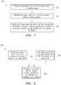
- FIG. 2depicts an example embodiment of a method 200 whereby a wireless UE device may be provided that is configured for radiation pattern recognition for purposes of the present patent application.
- a device manufacturer or a third-party providermay measure or otherwise determine radiation patterns for each antenna of a mobile handset (i.e., a wireless UE device) on a usage mode basis (block 202).
- various parametric data and SAR values associated with each antenna in each usage modemay be measured or otherwise determined (block 204).
- measured radiation patterns and the parametric datamay be stored in the wireless UE device (e.g., in a nonvolatile memory) (block 206).
- such informationmay be pushed (e.g., post-manufacture) to the wireless UE device by a network node which may be a website of the wireless UE device's manufacturer, a base station of a telecommunications network (e.g., a GSM network), an eNB node of a telecommunications network (e.g., an LTE network), or a trusted device management node configured to update the wireless UE device's software/firmware.
- a network nodewhich may be a website of the wireless UE device's manufacturer, a base station of a telecommunications network (e.g., a GSM network), an eNB node of a telecommunications network (e.g., an LTE network), or a trusted device management node configured to update the wireless UE device's software/firmware.
- FIGS. 3A and 3Bdepict example data representations relative to benchmark radiation patterns and SAR parametrics for each antenna and each usage mode of a mobile communications device (i.e., a wireless UE device) according to an embodiment of the present patent application.
- Reference numeral 300Arefers to a representation of radiation patterns for a plurality of antennas of a wireless UE device that is contemplated for use in a plurality of usage modes.
- Reference numeral 302refers to N usage modes whereas reference numeral 304 refers to M antennas.
- radiation pattern data for such a scenariocan theoretically comprise MxN patterns, which data can be provided in a number of ways and granularities.
- the radiation pattern datamay be stored as figures or pictures, either 3-D or 2-D representations of polar or rectangular formats.
- the radiation pattern datamay be sub-sampled data or full pattern data, depending on storage requirements and capabilities.
- Rad Pat (1,1)refers to the radiation pattern measured for antenna 1 in usage mode 1.
- Rad Pat (M,N)refers to the radiation pattern measured for antenna M in usage mode N. Accordingly, if a particular usage mode I is identified or otherwise estimated for the wireless UE device based on the collected situational data, a set of M radiation patterns ⁇ Rad Pat (1,1); Rad Pat (2,1), ..., Rad Pat(M,I) ⁇ may be provided as an input to a smart antenna application executing on the wireless UE device.
- Reference numeral 300Brefers to a representation of SAR data associated with a plurality of antennas of a wireless UE device that is contemplated for use in a plurality of usage modes. Analogous to FIG. 3A , representation 300B in FIG. 3B refers to a scenario where N usage modes are contemplated for a UE device having M antennas.
- SAR (1,1)refers to the SAR value associated with antenna 1 in usage mode 1.
- SAR (M,N)refers to the SAR value for antenna M in usage mode N.
- a set of M SAR values ⁇ SAR (1,J); SAR (2,J), ..., SAR (M,J) ⁇may also be provided as an input to a smart antenna application executing on the wireless UE device.
- a subset of antennasmay have SAR values that may be greater than allowed limits and therefore may not be considered for an antenna application.
- a wireless UE devicemay build its internal radiation pattern library as and when it identifies a new usage mode, whereupon applicable radiation pattern data may be downloaded to the device.
- FIGS. 4A-4Cdepict example benchmark radiation patterns for a particular antenna of a wireless UE device 402 for different usage modes.
- Reference numeral 400A in FIG. 4Arefers to a free space antenna radiation pattern associated with the wireless UE device 402 that may be applicable in a usage mode wherein the UE device 402 is positioned on a flat surface at a position away from the user.
- Reference numeral 404refers to the main lobe of the radiation pattern along the Z-axis of the device 402.
- Reference numeral 400B in FIG. 4Brefers to an antenna radiation pattern is a voice usage scenario with specific touch and elevation angles with respect to the device 402.
- Reference numerals 410 and 412refer to two predominant lobes of radiation for this particular usage mode.
- 4Crefers to an antenna radiation pattern in a data session mode for a specific hand grip and elevation angle with respect to the device 402.
- Reference numerals 420 and 422refer to two predominant lobes of radiation for this usage mode. Similar to the three radiation patterns shown in FIGS. 4A-4C , other radiation patterns may be measured or otherwise determined with respect to other usage modes for each and every antenna of a wireless UE device.
- a situational data collection and usage scenario recognition module 502is configured to collect multivariate situational data as described hereinabove.
- a pattern storage module 504is configured to store radiation pattern data in different formats and at different levels of granularity depending on the application.
- a matching module 506e.g., a first matching module is configured to match the current usage mode/situation with a pattern library and SAR data. Based on the usage/situational data and the particular type of antenna application to be used, an optimum subset of antennas may be determined by an antenna selection and parametric calculation module 510.
- various weights or coefficientsmay be calculated depending on the intended antenna application.
- another matching module 508e.g., a second matching module
- the parameter librarymay include for each antenna a set of parametric data that may comprise various antenna parameters including the weights/coefficients.
- a smart antenna application module 512may receive the output generated by the antenna selection and parametric calculation module 510 or the matched antenna parameters as well as the radiation pattern data to apply in an intended antenna application algorithm or process such as, e.g., beam steering, beam forming, multi-antenna weighting, adaptive antenna selection, switched-beam application, etc. as described hereinabove.
- a parameter library searche.g., performed by module 508
- a pattern library searche.g., performed by module 506
- One implementationis to identify the best antenna or set of antenna elements to use from the pattern library search. For example, such identification may include elements integrated into the front, back, top or sides of a wireless UE device or it may include external antenna elements (e.g., built into a car frame or associated with a remote (e.g., Bluetooth) speaker), or both. The identification can also be based on measured SAR values.
- certain antennasmay have to be disabled when used next to the user's head as they may exceed the SAR limit.
- such antennascan be used in the data mode or next to the body.
- a calculationmay be performed to determine (e.g., actual computations or via a look-up table) the set of parameters (antenna element weights) needed to realize the desired radiation pattern over the selected antenna elements or to realize the specific smart antenna application objective. Accordingly, a straightforward pattern library search may be used if the computational load on the wireless device for calculating the parameters for the designated smart antenna application is not severe.
- a pre-calculated antenna parameters stored on the handsetmay be used for some applications, for example, as part of the matching process of module 508.
- the set of antenna element weighting parametersmay be provided as an input to an antenna application for achieving the desired antenna radiation pattern using the selected set of antenna elements.
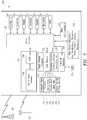
- FIG. 6depicts an example embodiment of a portion 600 of a wireless UE device that may be configured to use radiation pattern information, usage mode information, antenna parametrics, etc. as part of a smart antenna application.
- the embodiment illustrated in FIG. 6is directed to employing a smart antenna application in the receive mode operation.
- a plurality of antennas 602-1 through 602-Mare each connected to a respective converter 604-1 through 604-M for down-converting the received radio signals to appropriate outputs, which are then sampled and digitized via analog-to-digital converters (ADC) 608-1 through 608-M.
- ADCanalog-to-digital converters
- the various RF signal processing elementsmay be implemented in hardware as one or more circuits depending on the implementation. Regardless of the exact hardware implementation, however, the RF signal processing is configured to yield signal outputs X 1 to X M 606-1 to 606-M that are provided to a smart antenna application module 610, such as, e.g., a beam former.
- Signals X 1 to X M 606-1 to 606-Mtypically contain both the desired signal and the interfering signals, which may be appropriately scaled by a set of complex gain parameters W 1 to W M 614-1 to 614-M (also referred to as a gain vector or weight vector).
- a combiner 616is configured to combine the weight vector parameters W 1 to W M 614-1 to 614-M with signals X 1 to X M 606-1 to 606-M to generate an array output signal Y 618.
- output signal Y 618is provided to a demodulator 620 to provide an appropriate signal to the remainder of the wireless UE device (e.g., for further processing in the upper layers).
- the array output Y 618 from the combiner 616may also be compared with a desired signal or signal property, that is, a reference signal 630, in an error signal generator 622 to generate an error signal 624 that is operable as a control input.
- An adaptive process 612may be configured to adaptively minimize the error signal 624 and thereby change or modulate the weight vectors W 1 to W M 614-1 to 614-M according to some max/min criteria. Such modulated weight vectors W 1 to W M 614-1 to 614-M may be fed back to combine with signals X 1 to X M 606-1 to 606-M for modulating the scaling process.
- the adaptive process 612may also receive usage/scenario mode information 626, matched radiation pattern information 628 as well as SAR and antenna parametrics (including, e.g., known antenna weights or coefficients) 627 to further refine the scaling process.
- FIG. 7depicts a block diagram of an example wireless UE device 700 according to one embodiment of the present patent application.
- Wireless UE device 700may be provided with a communication subsystem 704 that includes an antenna assembly 708 (with one or more antennas), suitable transceiver circuits 706 operable with one or more RATs, as well as additional hardware/software components such as, e.g., signal processors, A/D and D/A converters, oscillators, and the like.
- a microprocessor 702providing for the overall control of the device 700 is operably coupled to the communication subsystem 704 that can operate with various access technologies, operating bands/frequencies and networks (for example, to effectuate multi-mode communications in voice, data, media, or any combination thereof).
- the particular design of the communication subsystem/module 704may be dependent upon the communications network(s) with which the device is intended to operate, e.g., as exemplified by infrastructure elements 799 and 797.
- Microprocessor 702also interfaces with additional device subsystems such as input/output (I/O) 718, serial port 720, display 722, keyboard or keypad 724, speaker 726, microphone 728, random access memory (RAM) 730, other communications facilities 732, which may include for example a short-range communications subsystem, and any other device subsystems generally labeled as reference numeral 733.
- additional device subsystemsmay include accelerometers, gyroscopes, motion sensors, location sensors, temperature sensors, and the like that are configured to facilitate collection of multivariate situational data.
- SIM/USIM interface 734(also generalized as a Removable User Identity Module (RUIM) interface) is also provided in communication with the microprocessor 702 and a UICC 731 having suitable SIM/USIM applications.
- RUIMRemovable User Identity Module
- persistent storage module 735i.e., non-volatile storage subsystem
- persistent storage module 735may be segregated into different areas, e.g., transport stack 745, storage area for computer programs 736, as well as data storage regions such as device state 737, address book 739, other personal information manager (PIM) data 741, and a connect module manager including an IT policy module as well as other data storage areas generally labeled as reference numeral 743.
- the persistent memorymay include appropriate software/firmware 750 necessary to effectuate one or more radio channel sensing operations, filtering, usage mode estimation, radiation pattern/parameter matching, and smart antenna application processes, etc., in conjunction with one or more subsystems set forth herein under control of the microprocessor 702 or specialized circuitry.
- Powered componentsmay receive power from any power source (not shown in FIG. 7 ).
- the power sourcemay be, for example, a battery, but the power source may also include a connection to power source external to wireless UE device 700, such as a charger.
- an onboard storage module or a removal storage module 795may be provided as a database for storing benchmark radiation pattern data (i.e., pattern library), antenna parameters (i.e., parameter library), and the like for purposes of effectuating radiation pattern recognition as set forth in the present patent disclosure.
- benchmark radiation pattern datai.e., pattern library
- antenna parametersi.e., parameter library
- a search in a data librarymay begin, wherein the data library may comprise pre-stored antenna radiation patterns and pre-calculated antenna parameters.
- the pattern library portionmay contains MxN premeasured radiation patterns wherein each describes the pattern of one of the antennas in a given usage scenario.
- the data in the pattern librarycan be stored in different formats depending on the smart antenna application for which the radiation pattern recognition techniques may be used. Examples of such formats may comprise detailed high-resolution data, sub-sampled data, pattern figures or pictures, etc.
- the antenna parameters library portionmay contain pre-calculated antenna parameters for a given antenna application if such antenna application is computationally prohibitive.
- a parametric librarymay serve as an alternative to the pattern library, in one variation, and may offer more efficient solutions for certain computationally expensive antenna applications.
- the data search processesare configured to be responsive to recognizing the environment in which a UE device is operating and, accordingly, the matching processes are operative to select the "best" antennas and patterns that best match the mode in which the UE device is functioning.
- Such added intelligenceis configured to enhance a select antenna application to perform its designated function.
- radio communicationsmay be rendered highly secure because the radio signals transmitted by a smart antenna with enhanced signal selectivity and directivity cannot be easily tracked or received by other antennas.
- non-transitory computer accessible storagesuch storage may include semiconductor memory, internal and external computer storage media and encompasses, but is not limited to, nonvolatile media, volatile media, and transmission media.
- Nonvolatile mediamay include CD-ROMs, magnetic tapes, PROMs, Flash memory, or optical media.
- Volatile mediamay include dynamic memory, caches, RAMs, etc.
- computer-accessible mediumencompasses "computer-readable medium” as well as "computer executable medium.”
Landscapes
- Engineering & Computer Science (AREA)
- Computer Networks & Wireless Communication (AREA)
- Signal Processing (AREA)
- Mobile Radio Communication Systems (AREA)
Description
- The present patent disclosure generally relates to wireless communication devices or user equipment (UE) devices, examples of which include mobile handheld devices such as pagers, cellular phones, personal digital assistants (PDAs), smartphones, wirelessly enabled portable computers, and the like. More particularly, and not by way of any limitation, the present patent disclosure is directed to utilizing a radiation pattern recognition scheme for purposes of an antenna application on a wireless communication device.
- Wireless cellular networks are growing rapidly around the world and this trend is likely to continue for several years. The progress in radio technology enables new and improved services. Wireless services such as, e.g., transmission of voice, fax, data, interactive multimedia services (e.g., video-on-demand) and Internet access are all being supported in today's networks. Wireless networks must provide these services in a wide range of environments, spanning dense urban, suburban, and rural areas. Varying mobility needs as well as achieving secure communications must also be addressed.
- Antennas are well known components of a wireless UE device. Currently several advances are being made in the field of antennas used for wireless UE devices. Despite the current advances, additional improvements and enhancements are being constantly pursued.
WO 2008/076024 relates to a method and an arrangement for a mobile telecommunication network for selecting an antenna mode to be used for communication between a radio network and a mobile terminal operating in discontinuous reception mode. The arrangement comprises a determiner configured to determine a mode list comprising antenna modes both supported by the radio network and the mobile terminal, associating means configured to associate each antenna mode in the mode list with a degree of a pre-defined performance measure, retrieving means configured to retrieve information indicating the pre-defined performance measure for the mobile terminal, and a selector configured to select an antenna mode from the mode list at least based on the retrieved information.US 2007/0216584 relates to a portable wireless device realizing high-speed transmission in downlink communication in a used state that a foldable portable wireless device is held in a hand of the user and ensuring a high antenna radiation efficiency. In the portable wireless device, platy conductors are arranged in the longitudinal direction on the back of a display section of an upper case. The signal of a transmission circuit is distributed by a power distributor. One signal is fed to a platy conductor through a phase shifter and the other is fed to the platy conductor or the platy conductor from a high-frequency switch through a transmission/reception duplexer or a transmission/reception duplexer. The high-frequency switch selectively feeds power to either the platy conductor or the platy conductor according to the signal from a gravity sensor. The received signal is extracted by the transmission/reception duplexers, amplified by a receiving circuit and a receiving circuit, and multiplied by a predetermined weight coefficient by a demodulating section and combined.KR 2002/0052442 US 2010/120466 relates to a method, an apparatus, and a computer program for providing multi-mode antenna switching, wherein a processor is configured to determine active radio protocols of a radio communication and a mode of use of the apparatus, and to control the selection of at least one antenna for the radio communication in response to which radio protocols are active and how the apparatus is used or held.- The present invention is set out in the independent claims, with some optional features set out in the claims dependent thereto.
- A more complete understanding of the embodiments of the present patent disclosure may be had by reference to the following Detailed Description when taken in conjunction with the accompanying drawings wherein:
FIG. 1 depicts an example embodiment of a method for purposes of the present patent application;FIG. 2 depicts an example embodiment of another method for purposes of the present patent application;FIGS. 3A and 3B depict example data representations relative to benchmark radiation patterns and SAR parametrics for each antenna and each usage mode of a mobile communications device (also referred to as a wireless user equipment (UE) device) according to an embodiment of the present patent application;FIGS. 4A-4C depict example benchmark radiation patterns for an antenna of a wireless UE device for different usage modes;FIG. 5 depicts an example embodiment of a radiation pattern recognition scheme and use thereof for a smart antenna application;FIG. 6 depicts an example embodiment of a portion of a wireless UE device that may be configured to use radiation pattern information, usage mode information, antenna parametrics, etc. as part of a smart antenna application; andFIG. 7 depicts a block diagram of an example wireless UE device according to one embodiment of the present patent application.- The present patent disclosure is broadly directed to providing a radiation pattern recognition scheme in a wireless UE device for purposes of an antenna application whereby the performance of the device may be improved. In one example implementation, a "smart antenna" application may be provided with the wireless UE device wherein one or more smart antennas of the UE device may be configured to recognize the environment in which the UE device is operating and accordingly adapt the performance of the UE device.
- In one aspect, an embodiment of a method operable on a wireless UE device is disclosed. The embodiment comprises one or more of the following features or acts: identifying a current usage mode in which the wireless UE device is being used, the wireless UE including one or more antennas adapted for radio communication with a telecommunications network; matching the current usage mode with a set of benchmark radiation patterns associated with each of the one or more antennas; and providing the matched set of benchmark radiation patterns to an antenna application executing on the wireless UE device. In one implementation, the current usage mode of the wireless UE device may be identified by way of using at least a portion of multivariate situational data that is representative of the UE device's environment.
- In another aspect, an embodiment of a wireless UE device is disclosed. The embodiment comprises one or more of the following features: means for identifying a current usage mode in which the wireless UE device is being used, the wireless UE having one or more antennas adapted for radio communication with a telecommunications network; means for matching the current usage mode with a set of benchmark radiation patterns associated with each of the one or more antennas; and an antenna application module configured to use the matched set of benchmark radiation patterns, whereby the antenna application module may optimize the performance of the wireless UE device, for example, by providing enhanced signal selectivity and directivity.
- The present patent application also discloses an additional embodiment of a wireless UE device that comprises one or more of the following features: one or more antennas adapted for radio communication with a telecommunications network; a memory comprising a database of benchmark radiation patterns for each of the one or more antennas in one or more usage modes associated with the wireless UE device; and processor configured to execute an antenna application process for optimizing the wireless UE device performance based at least in part upon using the set of benchmark radiation patterns indicative of the environment in which the wireless UE device is operating. For example, the antenna application may be configured to optimize the antenna itself (i.e., optimizing the antenna performance), the data processing, the process that selects the antenna or antennas, the process that controls appropriate modulation and coding schemes (MCS), or the process that controls transmit power levels, or any combination thereof.
- Embodiments of systems, methods, apparatuses and associated tangible computer-readable media having instructions and tangible computer program products, where applicable, relating to radiation pattern recognition by a wireless UE device for purposes of an antenna application process according to the teachings the present patent disclosure will now be described with reference to various examples of how the embodiments can be made and used. Like reference numerals are used throughout the description and several views of the drawings to indicate like or corresponding parts to the extent feasible, wherein the various elements may not necessarily be drawn to scale. Referring to the drawings, and more particularly to
FIG. 1 , depicted therein is an example embodiment of ascheme 100 of the present patent application wherein a set of benchmark radiation patterns based on a usage mode associated with the wireless UE device may be provided to an antenna application process executing on the wireless UE device. For purposes of the present patent application, the wireless UE device may comprise any mobile communications device or a mobile terminal or station that is adapted to operate in a diversified radio network environment comprised of one or more networks deployed by respective operators using any known or heretofore unknown technologies, for example, including but not limited to wide area cellular networks, WiFi networks, Wi-MAX networks, television (TV) broadcast networks, satellite communications networks, and the like. Further, radio frequencies utilized in the diverse network technologies may comprise different licensed spectral bands, unlicensed spectral bands, shared or pooled radio frequencies, other lightly licensed bands, fixed TV white space bands, and so on. Furthermore, the wireless UE device may be adapted to operate in a packet-switched mode, circuit-switched mode, or both, using radio frequencies compatible with Global System for Mobile Communications (GSM) networks, Enhanced Data Rates for GSM Evolution (EDGE) networks, Integrated Digital Enhanced Networks (IDEN), Code Division Multiple Access (CDMA) networks, Universal Mobile Telecommunications System (UMTS) networks, any 2nd- 2.5- 3rd- or subsequent Generation networks, Long Term Evolution (LTE) networks (i.e., Enhanced UMTS Terrestrial Radio Access or E-UTRA networks), networks capable of High Speed Downlink Packet Access (HSDPA) or High Speed Uplink Packet Access (HSUPA), or wireless networks employing standards such as Institute of Electrical and Electronics Engineers (IEEE) standards, like IEEE 802.1 la/b/g/n standards or other related standards such as HiperLan standard, HiperLan II standard, Wi-MAX standard, OpenAir standard, and Bluetooth standard, as well as any mobile satellite communications technology such as Geo Mobile Radio (GMR)-1, and other satellite-based technologies, e.g., GPS. Accordingly, an example wireless UE device for purposes of the present patent disclosure may include one or more antennas configured to effectuate radio communication with any telecommunications network such as those set forth in hereinabove. - As illustrated in
block 102,scheme 100 comprises identifying a current usage mode in which the handset (i.e., the wireless UE) device is being used based on collecting what may be referred to as "situational data". By way of illustration, such situational data may include but not limited to the wireless UE device's orientation, proximity to a user of the wireless UE device, motion or movement associated with the wireless UE device, indication of usage of a keypad of the wireless UE device, indication of usage of a touch screen of the wireless UE device, indication of usage of a speaker and/or a microphone of the wireless UE device, location of the wireless UE device, location of any impediments relative to the wireless UE device (e.g., a user's hands, etc.), location of obstructions such as tunnels, trees, tall buildings, topographic features affecting radio communications, etc., indication of usage of a short-range radio frequency communication subsystem of the wireless UE device (e.g., Bluetooth communications or WiFi communications, etc.), global positioning information, identification of one or more radio access technologies (RATs) being used by the wireless UE device, signal/interference levels associated with radio channels corresponding to the RATs, channel loadings, and the like. - Appropriate hardware, software and/or firmware components may be provided with the wireless UE device that are configured for collecting one or more pieces of the foregoing situational data in any combination. For example, an accelerometer may be provided that detects movement of the wireless UE device in one or more axes of the device. In one embodiment, the X axis may be defined along the width of the wireless UE device, with positive values in the right hand direction; the Y axis may be defined along the length of the wireless UE device, with positive values on the "down" direction; and the Z axis along the depth of the wireless UE device, i.e., going through the body or screen of the device. Such an accelerometer may detect movement in the three axes by sensing small voltage changes that occur in the accelerometer during movement in each of the three axes. The voltage changes may then be processed to determine or estimate whether a user of the wireless UE device is walking, cycling, running, in a car, etc. Such information may then be processed in conjunction with other collected situational data to determine, identify or otherwise estimate a usage mode of the wireless UE device. By way of illustration, if the user is walking and watching a video, then it may be predicted, expected, estimated or otherwise determined with a level of likelihood that the user is holding the UE device in his hand and watching the video. However, if the user is cycling and listening to online music, it is more likely that the UE device is in a usage mode where the device is in the user's pocket or on his arm or on his body in a holder, holster or a clip and the like.
- Another component that may be provided in the wireless UE device with respect to collecting the situational data is a gyroscope that may be used to determine the device orientation by measuring the angular movements along any of the three axes. When a sensing element of the gyroscope shakes or tilts, the gyroscope changes the level whereby a corresponding voltage change is generated. The voltage changes may then be used to calculate the angle/orientation of a moving object. For purposes of the present disclosure, any appropriate type of gyroscopes may be used for determining orientation, e.g., electromechanical gyroscopes, electronic or solid-state gyroscopes, laser gyroscopes, micro-electro mechanical systems (MEMS) gyroscopes, and the like. Regardless of the type of gyroscopes used, the angular orientation of the wireless UE device may be referenced to a universal coordinate system. Based on such situational data, an appropriate process executing on the wireless UE device may be used to determine or otherwise estimate how/whether the UE device is held or oriented in a particular fashion.
- Other components and techniques, e.g., motion sensors, proximity sensors, location sensors, biometry-based sensors, thermal sensors, tactile sensors, optical sensors, etc. may also be provided in the wireless UE device for collecting one or more pieces of the situational data. Such techniques, for example, may be adapted to provide an indication of whether one or more subsystems of the wireless UE device are being used, such as, the keypad, speaker/microphone, short-range communication system, etc., in addition to collecting information relative to the physical environment in which the wireless UE device is placed.
- Based on the foregoing, accordingly, a multivariate collection of situational data may be used for identifying or otherwise estimating a current usage mode of the wireless UE device. It will be apparent to one skilled in the art that any number of usage modes may be defined for a wireless UE device based on the way the device is contemplated for use. By way of illustration, such usage modes may include but not limited to: a voice call mode, a video call mode, a data session mode, a multimedia call mode, a Voice over Internet Protocol (VoIP) mode, a speakerphone mode, a mode of positioning the wireless UE device near a user's ear, a mode of placing the wireless UE device in a user's holster, a mode of placing the wireless UE device in a cradle, a mode of placing the wireless UE device in a holder, a mode of placing the wireless UE device on a clip, a WiFi use mode, a Bluetooth use mode, and a mode of placing the wireless UE device at a place positioned away from a user's body, and the like. Additional usage mode scenarios may be holding the device in front of a user's body with two hands, holding the device to a side of the user's head with a particular hand (e.g., the left hand), holding the device to a side of the user's body in the right hand, the device placed in a pocket of the user's clothing, the device being docked in a car pod, and the like. Accordingly, a usage mode estimator executing on the wireless UE device may use any heuristic, probabilistic, deterministic, rule-based, fuzzy-logic-based, or learning-based process that can synthesize the multivariate situational data and arrive at a usage mode determination or identification.
- Continuing to refer to
FIG. 1 , upon identifying a particular usage mode that the wireless UE device is in, thescheme 100 further involves matching the current usage mode with a set of benchmark radiation patterns associated with each of the antennas of the wireless UE device as set forth inblock 104. In one embodiment, such benchmark radiation patterns may be predetermined by a manufacturer of the device for each of the antennas and the usage modes that the device is expected to operate in. As is well known, a radiation pattern of an antenna describes the relative strength of the radiated field in various directions from the antenna at a distance. The radiation pattern is a reception pattern as well, since it also describes the receiving properties of the antenna. That is, the radiation pattern of an antenna is the same whether the antenna is used in transmission (i.e., transmit mode or uplink mode) or reception (i.e., receive mode or downlink mode). This property is generally referred to as reciprocity. Accordingly, for purposes of the present patent disclosure, there will be no distinction made as between the transmit mode radiation patterns and receive mode radiation patterns of an antenna unless otherwise specifically noted. As such, the teachings of the present disclosure are equally applicable to transmit mode radiation patterns as well as receive mode radiation patterns,mutatis mutandis. - In general, a radiation pattern is measured as the variation of the field intensity of an antenna as an angular function and may be shown in a graphical representation of the distribution of radiation from the antenna as a function of angle. The radiation pattern is three-dimensional in the horizontal or vertical planes, wherein the pattern measurements may be presented in either a rectangular or a polar format. The radiation pattern can also be represented by the collection of a number of two-dimensional radiation patterns in the elevation dimension. As will be further described in detail below, the radiation patterns associated with each antenna of a wireless UE device may be measured or otherwise determined on a usage mode by usage mode basis.
- After the radiation patterns corresponding to a current usage mode have been identified, the identified set of benchmark radiation patterns may be provided to an antenna application executing on the wireless UE device for purposes of optimizing the overall antenna performance of the UE device (block 106). In a further variation, additional data such as information pertaining to the usage mode, antenna parametric data, Specific Absorption Rate (SAR) values of the antennas, etc. may also be provided to the intended antenna application. For example, antenna parametric data may comprise radiation efficiency, directivity, gain, impedance, reflection coefficients, quality factor, peak/average power, bandwidth, and the like. The antenna application running on the wireless UE device may therefore incorporate or use such radiation pattern data and additional data to function as a "smart" antenna application that can enhance the radio communication capabilities of the wireless UE device. By way of illustration, the antenna application may be one of a beam forming process, a beam steering process, an antenna selection process for a multi-input and multi-output (MIMO) antenna application, an antenna selection process for a weighted multi-antenna process, a least-mean-squares (LMS) weighting process, a recursive least squares (RLS) weighting process, a constant modulus weighting process, a constant modulus weighting process, and a genetic adaptive antenna selection process. For example, the antenna application may therefore determine appropriate weights (i.e., amplitudes and phases of different antenna elements) for forming a beam with most of the radiation energy in one preferred direction (i.e., the main lobe) while minimizing any side lobes. In another example, an antenna selection process may be implemented such that only those antennas whose SAR values satisfy applicable regulatory and environmental safeguards may be used for beam forming or beam steering. In yet another example, the antenna application may be configured to optimize transmit power levels, reduce bit error rates (BERs), and the like, in conjunction with appropriate modulation and coding schemes (MCS).
FIG. 2 depicts an example embodiment of amethod 200 whereby a wireless UE device may be provided that is configured for radiation pattern recognition for purposes of the present patent application. For example, a device manufacturer or a third-party provider may measure or otherwise determine radiation patterns for each antenna of a mobile handset (i.e., a wireless UE device) on a usage mode basis (block 202). Additionally, various parametric data and SAR values associated with each antenna in each usage mode may be measured or otherwise determined (block 204). In one implementation, measured radiation patterns and the parametric data may be stored in the wireless UE device (e.g., in a nonvolatile memory) (block 206). In another implementation, such information may be pushed (e.g., post-manufacture) to the wireless UE device by a network node which may be a website of the wireless UE device's manufacturer, a base station of a telecommunications network (e.g., a GSM network), an eNB node of a telecommunications network (e.g., an LTE network), or a trusted device management node configured to update the wireless UE device's software/firmware.FIGS. 3A and 3B depict example data representations relative to benchmark radiation patterns and SAR parametrics for each antenna and each usage mode of a mobile communications device (i.e., a wireless UE device) according to an embodiment of the present patent application.Reference numeral 300A refers to a representation of radiation patterns for a plurality of antennas of a wireless UE device that is contemplated for use in a plurality of usage modes.Reference numeral 302 refers to N usage modes whereasreference numeral 304 refers to M antennas. Accordingly, radiation pattern data for such a scenario can theoretically comprise MxN patterns, which data can be provided in a number of ways and granularities. For example, the radiation pattern data may be stored as figures or pictures, either 3-D or 2-D representations of polar or rectangular formats. The radiation pattern data may be sub-sampled data or full pattern data, depending on storage requirements and capabilities. By way of example, Rad Pat (1,1) refers to the radiation pattern measured forantenna 1 inusage mode 1. Likewise, Rad Pat (M,N) refers to the radiation pattern measured for antenna M in usage mode N. Accordingly, if a particular usage mode I is identified or otherwise estimated for the wireless UE device based on the collected situational data, a set of M radiation patterns {Rad Pat (1,1); Rad Pat (2,1), ..., Rad Pat(M,I)} may be provided as an input to a smart antenna application executing on the wireless UE device.Reference numeral 300B refers to a representation of SAR data associated with a plurality of antennas of a wireless UE device that is contemplated for use in a plurality of usage modes. Analogous toFIG. 3A ,representation 300B inFIG. 3B refers to a scenario where N usage modes are contemplated for a UE device having M antennas. By way of example, SAR (1,1) refers to the SAR value associated withantenna 1 inusage mode 1. Likewise, SAR (M,N) refers to the SAR value for antenna M in usage mode N. Accordingly, if a particular usage mode J is identified or otherwise estimated for the wireless UE device based on the collected situational data, a set of M SAR values {SAR (1,J); SAR (2,J), ..., SAR (M,J)} may also be provided as an input to a smart antenna application executing on the wireless UE device. Additionally, as alluded to previously, out of the M antennas, a subset of antennas may have SAR values that may be greater than allowed limits and therefore may not be considered for an antenna application.- Those skilled in the art will recognize that not all MxN radiation patterns or MxN SAR values may be populated since such data may be inapplicable for certain usage modes. Further, where the UE device determines its usage mode dynamically and transmits such information to a network node, only applicable radiation patterns, SAR values and other antenna parametrics may be downloaded for use with an antenna application. In a further variation, if an estimated usage mode is not exactly matched to any predetermined usage modes, an extrapolated set of radiation patterns may be determined based on the usage mode that is closest to the estimated usage mode. In a still further variation, a wireless UE device may build its internal radiation pattern library as and when it identifies a new usage mode, whereupon applicable radiation pattern data may be downloaded to the device.
FIGS. 4A-4C depict example benchmark radiation patterns for a particular antenna of awireless UE device 402 for different usage modes.Reference numeral 400A inFIG. 4A refers to a free space antenna radiation pattern associated with thewireless UE device 402 that may be applicable in a usage mode wherein theUE device 402 is positioned on a flat surface at a position away from the user.Reference numeral 404 refers to the main lobe of the radiation pattern along the Z-axis of thedevice 402.Reference numeral 400B inFIG. 4B refers to an antenna radiation pattern is a voice usage scenario with specific touch and elevation angles with respect to thedevice 402.Reference numerals Reference numeral 400C inFIG. 4C refers to an antenna radiation pattern in a data session mode for a specific hand grip and elevation angle with respect to thedevice 402.Reference numerals FIGS. 4A-4C , other radiation patterns may be measured or otherwise determined with respect to other usage modes for each and every antenna of a wireless UE device.- Referring now to
FIG. 5 , depicted therein is an example embodiment of a radiationpattern recognition scheme 500 and use thereof for a smart antenna application. A situational data collection and usagescenario recognition module 502 is configured to collect multivariate situational data as described hereinabove. Apattern storage module 504 is configured to store radiation pattern data in different formats and at different levels of granularity depending on the application. A matching module 506 (e.g., a first matching module) is configured to match the current usage mode/situation with a pattern library and SAR data. Based on the usage/situational data and the particular type of antenna application to be used, an optimum subset of antennas may be determined by an antenna selection andparametric calculation module 510. Additionally, for the selected subset of antennas, various weights or coefficients may be calculated depending on the intended antenna application. Alternatively or additionally, another matching module 508 (e.g., a second matching module) is configured to match the current usage mode/situation determined by thescenario recognition module 502 with a parameter library, e.g., on the wireless UE device. The parameter library may include for each antenna a set of parametric data that may comprise various antenna parameters including the weights/coefficients. A smartantenna application module 512 may receive the output generated by the antenna selection andparametric calculation module 510 or the matched antenna parameters as well as the radiation pattern data to apply in an intended antenna application algorithm or process such as, e.g., beam steering, beam forming, multi-antenna weighting, adaptive antenna selection, switched-beam application, etc. as described hereinabove. - It should be appreciated that for a selected usage scenario determined by the usage
scenario recognition module 502, two implementations may be provided based on whether a parameter library search (e.g., performed by module 508) is performed in conjunction with a pattern library search (e.g., performed by module 506) or not for a designated smart antenna application. One implementation is to identify the best antenna or set of antenna elements to use from the pattern library search. For example, such identification may include elements integrated into the front, back, top or sides of a wireless UE device or it may include external antenna elements (e.g., built into a car frame or associated with a remote (e.g., Bluetooth) speaker), or both. The identification can also be based on measured SAR values. That is, certain antennas may have to be disabled when used next to the user's head as they may exceed the SAR limit. However, such antennas can be used in the data mode or next to the body. A calculation may be performed to determine (e.g., actual computations or via a look-up table) the set of parameters (antenna element weights) needed to realize the desired radiation pattern over the selected antenna elements or to realize the specific smart antenna application objective. Accordingly, a straightforward pattern library search may be used if the computational load on the wireless device for calculating the parameters for the designated smart antenna application is not severe. In another implementation, instead of computing antenna parameters on the wireless UE device, a pre-calculated antenna parameters stored on the handset may be used for some applications, for example, as part of the matching process ofmodule 508. This implementation may be beneficial if the applicable antenna weights/parameters are environment-independent and therefore can be obtained beforehand. As a result, the pre-stored antenna parameter library implementation may offer a faster solution where the intended smart antenna application is computationally expensive. Regardless of which implementation is used, the set of antenna element weighting parameters may be provided as an input to an antenna application for achieving the desired antenna radiation pattern using the selected set of antenna elements. FIG. 6 depicts an example embodiment of aportion 600 of a wireless UE device that may be configured to use radiation pattern information, usage mode information, antenna parametrics, etc. as part of a smart antenna application. By way of example, the embodiment illustrated inFIG. 6 is directed to employing a smart antenna application in the receive mode operation. However, as discussed in previous sections, a similar embodiment may be employed in the transmit mode operation of the wireless UE device as well. A plurality of antennas 602-1 through 602-M are each connected to a respective converter 604-1 through 604-M for down-converting the received radio signals to appropriate outputs, which are then sampled and digitized via analog-to-digital converters (ADC) 608-1 through 608-M. It should be appreciated that the various RF signal processing elements (e.g., converters 604-1 to 604-M and ADCs 608-1 to 608-M) may be implemented in hardware as one or more circuits depending on the implementation. Regardless of the exact hardware implementation, however, the RF signal processing is configured to yield signal outputs X1 to XM 606-1 to 606-M that are provided to a smartantenna application module 610, such as, e.g., a beam former. Signals X1 to XM 606-1 to 606-M typically contain both the desired signal and the interfering signals, which may be appropriately scaled by a set of complex gain parameters W1 to WM 614-1 to 614-M (also referred to as a gain vector or weight vector). Acombiner 616 is configured to combine the weight vector parameters W1 to WM 614-1 to 614-M with signals X1 to XM 606-1 to 606-M to generate an arrayoutput signal Y 618. In operation,output signal Y 618 is provided to ademodulator 620 to provide an appropriate signal to the remainder of the wireless UE device (e.g., for further processing in the upper layers).- The
array output Y 618 from thecombiner 616 may also be compared with a desired signal or signal property, that is, areference signal 630, in anerror signal generator 622 to generate anerror signal 624 that is operable as a control input. Anadaptive process 612 may be configured to adaptively minimize theerror signal 624 and thereby change or modulate the weight vectors W1 to WM 614-1 to 614-M according to some max/min criteria. Such modulated weight vectors W1 to WM 614-1 to 614-M may be fed back to combine with signals X1 to XM 606-1 to 606-M for modulating the scaling process. Additionally, theadaptive process 612 may also receive usage/scenario mode information 626, matchedradiation pattern information 628 as well as SAR and antenna parametrics (including, e.g., known antenna weights or coefficients) 627 to further refine the scaling process. FIG. 7 depicts a block diagram of an examplewireless UE device 700 according to one embodiment of the present patent application.Wireless UE device 700 may be provided with acommunication subsystem 704 that includes an antenna assembly 708 (with one or more antennas),suitable transceiver circuits 706 operable with one or more RATs, as well as additional hardware/software components such as, e.g., signal processors, A/D and D/A converters, oscillators, and the like. Amicroprocessor 702 providing for the overall control of thedevice 700 is operably coupled to thecommunication subsystem 704 that can operate with various access technologies, operating bands/frequencies and networks (for example, to effectuate multi-mode communications in voice, data, media, or any combination thereof). As will be apparent to those skilled in the field of communications, the particular design of the communication subsystem/module 704 may be dependent upon the communications network(s) with which the device is intended to operate, e.g., as exemplified byinfrastructure elements Microprocessor 702 also interfaces with additional device subsystems such as input/output (I/O) 718,serial port 720,display 722, keyboard orkeypad 724,speaker 726,microphone 728, random access memory (RAM) 730,other communications facilities 732, which may include for example a short-range communications subsystem, and any other device subsystems generally labeled asreference numeral 733. Example additional device subsystems may include accelerometers, gyroscopes, motion sensors, location sensors, temperature sensors, and the like that are configured to facilitate collection of multivariate situational data. To support access as well as authentication and key generation, a SIM/USIM interface 734 (also generalized as a Removable User Identity Module (RUIM) interface) is also provided in communication with themicroprocessor 702 and aUICC 731 having suitable SIM/USIM applications.- Operating system software and other system software may be embodied in a persistent storage module 735 (i.e., non-volatile storage subsystem) which may be implemented using Flash memory or another appropriate memory. In one implementation,
persistent storage module 735 may be segregated into different areas, e.g.,transport stack 745, storage area forcomputer programs 736, as well as data storage regions such asdevice state 737,address book 739, other personal information manager (PIM)data 741, and a connect module manager including an IT policy module as well as other data storage areas generally labeled asreference numeral 743. Additionally, the persistent memory may include appropriate software/firmware 750 necessary to effectuate one or more radio channel sensing operations, filtering, usage mode estimation, radiation pattern/parameter matching, and smart antenna application processes, etc., in conjunction with one or more subsystems set forth herein under control of themicroprocessor 702 or specialized circuitry. Powered components may receive power from any power source (not shown inFIG. 7 ). The power source may be, for example, a battery, but the power source may also include a connection to power source external towireless UE device 700, such as a charger. Further, an onboard storage module or aremoval storage module 795 may be provided as a database for storing benchmark radiation pattern data (i.e., pattern library), antenna parameters (i.e., parameter library), and the like for purposes of effectuating radiation pattern recognition as set forth in the present patent disclosure. - Based on the foregoing description, it should be realized that in an example embodiment of the present disclosure, appropriate situational data collection may be carried using known and or heretofore unknown techniques. Once a usage mode is identified based on the collected situational data, a search in a data library may begin, wherein the data library may comprise pre-stored antenna radiation patterns and pre-calculated antenna parameters. The pattern library portion may contains MxN premeasured radiation patterns wherein each describes the pattern of one of the antennas in a given usage scenario. The data in the pattern library can be stored in different formats depending on the smart antenna application for which the radiation pattern recognition techniques may be used. Examples of such formats may comprise detailed high-resolution data, sub-sampled data, pattern figures or pictures, etc. The antenna parameters library portion may contain pre-calculated antenna parameters for a given antenna application if such antenna application is computationally prohibitive. Such a parametric library may serve as an alternative to the pattern library, in one variation, and may offer more efficient solutions for certain computationally expensive antenna applications. The data search processes are configured to be responsive to recognizing the environment in which a UE device is operating and, accordingly, the matching processes are operative to select the "best" antennas and patterns that best match the mode in which the UE device is functioning. Such added intelligence is configured to enhance a select antenna application to perform its designated function. Those skilled in the art will further recognize that added intelligence for smart antenna applications in state-of-the-art 4G technologies can enhance the capabilities of the mobile device and associated cellular system, whereby faster bit rates, reduction in multi-user interference, increase in range, multi-path mitigation, and reduction of errors due to multi-path fading, etc. may be achieved. Additionally, radio communications may be rendered highly secure because the radio signals transmitted by a smart antenna with enhanced signal selectivity and directivity cannot be easily tracked or received by other antennas.
- Various processes, structures, components and functions set forth above in detail, in particular associated with usage/scenario identification processes, radiation pattern recognition and matching processes, and antenna application processes and sub-processes thereof may be embodied in software, firmware, hardware, or in any combination thereof, and may accordingly comprise suitable computer-implemented methods or systems for purposes of the present disclosure. Where the processes are embodied in software, such software may comprise program instructions that form a computer program product, instructions on a computer-accessible media, uploadable service application software, or software downloadable from a remote station, and the like. Further, where the processes, data structures, or both, are stored in non-transitory computer accessible storage, such storage may include semiconductor memory, internal and external computer storage media and encompasses, but is not limited to, nonvolatile media, volatile media, and transmission media. Nonvolatile media may include CD-ROMs, magnetic tapes, PROMs, Flash memory, or optical media. Volatile media may include dynamic memory, caches, RAMs, etc. As used herein, the phrase "computer-accessible medium" encompasses "computer-readable medium" as well as "computer executable medium."
- It is believed that the operation and construction of the embodiments of the present patent application will be apparent from the Detailed Description set forth above. While example embodiments have been shown and described, it should be readily understood that various changes and modifications could be made therein without departing from the scope of the present disclosure as set forth in the following claims.
Claims (13)
- A method operable on a wireless user equipment (UE) device, said method comprising:identifying a current usage mode in which said wireless UE device is being used, said wireless UE having one or more antennas for radio communication with a telecommunications network;the method beingcharacterized by further comprising matching said current usage mode with a set of benchmark radiation patterns associated with each of said one or more antennas;determining a set of antenna parameters based on said current usage mode;matching said current usage mode with a set of Specific Absorption Rate (SAR) parameters associated with each of said one or more antennas in said current usage mode; andproviding said matched set of benchmark radiation patterns, said antenna parameters, and said SAR parameters to an antenna application executing on said wireless UE device.
- The method as recited in claim 1 wherein said current usage mode is identified by collecting situational data that comprises at least one of said wireless UE device's orientation, proximity to a user of said wireless UE device, motion associated with said wireless UE device, indication of usage of a key pad of said wireless UE device, indication of usage of a touch screen of said wireless UE device, indication of usage of a speaker and a microphone of said wireless UE device, location of said wireless UE device, location of impediments relative to said wireless UE device, indication of usage of a short-range radio frequency communication subsystem of said wireless UE device, global positioning information, identification of one or more radio access technologies (RATs) being used by said wireless UE device, and interference levels associated with radio channels corresponding to said RATs.
- The method as recited in claim 2 wherein at least a portion of said situational data is determined by at least one of an accelerometer and a gyroscope of said wireless UE device.
- The method as recited in any of claims 1-3 wherein said current usage mode comprises at least one of: a voice call mode, a video call mode, a data session mode, a multimedia call mode, a Voice over Internet Protocol (VoIP) mode, a speakerphone mode, a mode of positioning said wireless UE device near a user's ear, a mode of placing said wireless UE device in a user's holster, a mode of placing said wireless UE device in a cradle, a mode of placing said wireless UE device in a holder, a mode of placing said wireless UE device on a clip, a WiFi use mode, a Bluetooth use mode, and a mode of placing said wireless UE device at a place positioned away from a user's body.
- The method as recited in any of claims 1-4 wherein said matching said current usage mode with a set of benchmark radiation patterns comprises comparing said usage mode against a database of radiation patterns that are determined for each of said one or more antennas in a plurality of usage modes.
- The method as recited in claim 5 wherein said database of radiation patterns comprises at least one of a plurality of transmit mode radiation patterns and a plurality of receive mode radiation patterns, and further wherein said database of radiation patterns is stored locally on said wireless UE device or pushed to said wireless UE device by a network node.
- The method as recited in claim 6 wherein said network node comprises one of a website of said wireless UE device's manufacturer, a base station of said telecommunications network, an eNB node of said telecommunications network, and a trusted device management node.
- The method as recited in any of claims 1-7 wherein said one or more antennas are adapted for radio communication using a radio access technology selected from IEEE 802.11a technology, IEEE 802.11b technology, IEEE 802.11g technology, IEEE 802.11n technology, GSM/EDGE Radio Access Network (GERAN) technology, Universal Mobile Telecommunications System (UMTS) technology, Evolution - Data Optimized (EVDO) technology, Code Division Multiple Access (CDMA) technology, Time Division Multiple Access (TDMA) technology, Long-Term Evolution (LTE) technology, HiperLan technology, HiperLan II technology, Wi-MAX technology, OpenAir technology, Bluetooth technology, and GMR-1 technology.
- The method as recited in any of claims 1-8 wherein said antenna application comprises at least one of a beam forming process, a beam steering process, an antenna selection process for a multi-input and multi-output (MIMO) antenna application, an antenna selection process for a weighted multi-antenna process, a least-mean-squares (LMS) weighting process, a recursive least squares (RLS) weighting process, a constant modulus weighting process, and a genetic adaptive antenna selection process.
- The method as recited in claim 1 wherein said set of antenna parameters are determined by searching a parameter library or by computing based on said antenna application.
- A wireless user equipment (UE) device comprising:one or more antennas adapted for radio communication with a telecommunications network;a memory comprising a database of benchmark radiation patterns for each of said one or more antennas in one or more usage modes associated with said wireless UE device; anda processor configured to:execute instructions for identifying a current usage mode in which said wireless UE device is being used;execute instructions for matching said current usage mode with a set of benchmark radiation patterns associated with each of said one or more antennas based on querying the database of benchmark radiation patterns;execute instructions for determining a set of antenna parameters based on said current usage mode;execute instructions for matching said current usage mode with a set of Specific Absorption Rate (SAR) parameters associated with each of said one or more antennas in said current usage mode; andexecute an antenna application process for optimizing performance of said wireless UE device based at least in part upon using said set of benchmark radiation patterns, said antenna patterns, and said SAR parameters.
- The wireless UE device as recited in claim 11 wherein said one or more antennas are adapted for radio communication using a radio access technology selected from IEEE 802.11a technology, IEEE 802.11b technology, IEEE 802.11g technology, IEEE 802.11n technology, GSM/EDGE Radio Access Network (GERAN) technology, Universal Mobile Telecommunications System (UMTS) technology, Evolution - Data Optimized (EVDO) technology, Code Division Multiple Access (CDMA) technology, Time Division Multiple Access (TDMA) technology, Long-Term Evolution (LTE) technology, HiperLan technology, HiperLan II technology, Wi-MAX technology, OpenAir technology, Bluetooth technology, and GMR-1 technology.
- The wireless UE device as recited in any of claims 11-12 wherein said antenna application process comprises at least one of a beam forming process, a beam steering process, an antenna selection process for a multi-input and multi-output (MIMO) antenna application, an antenna selection process for a weighted multi-antenna process, a least-mean-squares (LMS) weighting process, a recursive least squares (RLS) weighting process, a constant modulus weighting process, and a genetic adaptive antenna selection process.
Applications Claiming Priority (1)
| Application Number | Priority Date | Filing Date | Title |
|---|---|---|---|
| PCT/CA2010/001864WO2012068660A1 (en) | 2010-11-26 | 2010-11-26 | Radiation pattern recognition system and method for a mobile communications device |
Publications (3)
| Publication Number | Publication Date |
|---|---|
| EP2644002A1 EP2644002A1 (en) | 2013-10-02 |
| EP2644002A4 EP2644002A4 (en) | 2017-04-26 |
| EP2644002B1true EP2644002B1 (en) | 2018-10-03 |
Family
ID=46145316
Family Applications (1)
| Application Number | Title | Priority Date | Filing Date |
|---|---|---|---|
| EP10860032.1AActiveEP2644002B1 (en) | 2010-11-26 | 2010-11-26 | Radiation pattern recognition system and method for a mobile communications device |
Country Status (5)
| Country | Link |
|---|---|
| US (1) | US8954121B2 (en) |
| EP (1) | EP2644002B1 (en) |
| CN (1) | CN103229587B (en) |
| CA (1) | CA2818888C (en) |
| WO (1) | WO2012068660A1 (en) |
Families Citing this family (72)
| Publication number | Priority date | Publication date | Assignee | Title |
|---|---|---|---|---|
| US8538351B2 (en) | 2010-07-20 | 2013-09-17 | Blackberry Limited | Radiation power level control system and method for a wireless communication device based on a tracked radiation history |
| EP2644002B1 (en) | 2010-11-26 | 2018-10-03 | BlackBerry Limited | Radiation pattern recognition system and method for a mobile communications device |
| US10129929B2 (en)* | 2011-07-24 | 2018-11-13 | Ethertronics, Inc. | Antennas configured for self-learning algorithms and related methods |
| KR101801117B1 (en)* | 2011-07-27 | 2017-11-27 | 삼성전자주식회사 | Metals used for antennas and sensor elements and apparatus coupled therewith in portable wireless terminal |
| US8995938B2 (en) | 2011-11-14 | 2015-03-31 | Blackberry Limited | Radiation power level control system and method for a wireless communication device having tunable elements |
| WO2013080457A1 (en)* | 2011-11-28 | 2013-06-06 | 京セラ株式会社 | Wireless communication system, method for controlling wireless communication system, base station, and mobile station |
| JP5148740B1 (en)* | 2011-11-30 | 2013-02-20 | 株式会社東芝 | Portable information terminal |
| US9070974B2 (en) | 2012-05-21 | 2015-06-30 | Qualcomm Incorporated | Antenna switching devices, methods, and systems for simultaneous communication |
| US9344174B2 (en) | 2012-05-21 | 2016-05-17 | Qualcomm Incorporated | Systems, apparatus, and methods for antenna selection |
| US10257727B2 (en) | 2013-03-15 | 2019-04-09 | DGS Global Systems, Inc. | Systems methods, and devices having databases and automated reports for electronic spectrum management |
| US10122479B2 (en) | 2017-01-23 | 2018-11-06 | DGS Global Systems, Inc. | Systems, methods, and devices for automatic signal detection with temporal feature extraction within a spectrum |
| US12256233B2 (en) | 2013-03-15 | 2025-03-18 | Digital Global Systems, Inc. | Systems and methods for automated financial settlements for dynamic spectrum sharing |
| US10299149B2 (en) | 2013-03-15 | 2019-05-21 | DGS Global Systems, Inc. | Systems, methods, and devices for electronic spectrum management |
| US10237770B2 (en) | 2013-03-15 | 2019-03-19 | DGS Global Systems, Inc. | Systems, methods, and devices having databases and automated reports for electronic spectrum management |
| US9526074B2 (en) | 2013-03-15 | 2016-12-20 | Google Technology Holdings LLC | Methods and apparatus for determining a transmit antenna gain and a spatial mode of a device |
| US10231206B2 (en) | 2013-03-15 | 2019-03-12 | DGS Global Systems, Inc. | Systems, methods, and devices for electronic spectrum management for identifying signal-emitting devices |
| US8798548B1 (en) | 2013-03-15 | 2014-08-05 | DGS Global Systems, Inc. | Systems, methods, and devices having databases for electronic spectrum management |
| US10271233B2 (en) | 2013-03-15 | 2019-04-23 | DGS Global Systems, Inc. | Systems, methods, and devices for automatic signal detection with temporal feature extraction within a spectrum |
| US12356206B2 (en) | 2013-03-15 | 2025-07-08 | Digital Global Systems, Inc. | Systems and methods for automated financial settlements for dynamic spectrum sharing |
| US8750156B1 (en) | 2013-03-15 | 2014-06-10 | DGS Global Systems, Inc. | Systems, methods, and devices for electronic spectrum management for identifying open space |
| US10219163B2 (en) | 2013-03-15 | 2019-02-26 | DGS Global Systems, Inc. | Systems, methods, and devices for electronic spectrum management |
| US10257728B2 (en) | 2013-03-15 | 2019-04-09 | DGS Global Systems, Inc. | Systems, methods, and devices for electronic spectrum management |
| US9078162B2 (en) | 2013-03-15 | 2015-07-07 | DGS Global Systems, Inc. | Systems, methods, and devices for electronic spectrum management |
| US11646918B2 (en) | 2013-03-15 | 2023-05-09 | Digital Global Systems, Inc. | Systems, methods, and devices for electronic spectrum management for identifying open space |
| US8805292B1 (en) | 2013-03-15 | 2014-08-12 | DGS Global Systems, Inc. | Systems, methods, and devices for electronic spectrum management for identifying signal-emitting devices |
| US10257729B2 (en) | 2013-03-15 | 2019-04-09 | DGS Global Systems, Inc. | Systems, methods, and devices having databases for electronic spectrum management |
| US8787836B1 (en) | 2013-03-15 | 2014-07-22 | DGS Global Systems, Inc. | Systems, methods, and devices having databases and automated reports for electronic spectrum management |
| US10244504B2 (en) | 2013-03-15 | 2019-03-26 | DGS Global Systems, Inc. | Systems, methods, and devices for geolocation with deployable large scale arrays |
| US9426754B2 (en)* | 2013-06-13 | 2016-08-23 | Blackberry Limited | Device dynamic total RF power compensation |
| CN103747391B (en)* | 2013-06-26 | 2018-03-06 | 苏州联科盛世科技有限公司 | Audio amplifier and its control method with double wireless modes |
| KR102194839B1 (en) | 2014-04-10 | 2020-12-24 | 삼성전자주식회사 | Method of Controlling for Transmission Power and Device therefor |
| KR102349713B1 (en) | 2014-10-20 | 2022-01-12 | 삼성전자주식회사 | Operation Method of communication channel and Electronic device supporting the same |
| CN104483680B (en)* | 2014-12-15 | 2017-04-12 | 南京林洋电力科技有限公司 | Mobile positioning system and anti-interference method thereof |
| US9525499B2 (en)* | 2014-12-24 | 2016-12-20 | Intel Corporation | Cellular up-link harmonic spurs mitigation in Wi-Fi and Bluetooth receivers |
| US20170251422A1 (en)* | 2016-02-29 | 2017-08-31 | Qualcomm Innovation Center, Inc. | Mobile device with multiple wifi interfaces |
| CN107222878B (en)* | 2016-03-22 | 2020-12-22 | 中国移动通信集团终端有限公司 | Terminal testing method and device |
| CN105933013A (en)* | 2016-06-17 | 2016-09-07 | 上海大学 | Communication antenna matching system based on Android platform |
| DE102016112128A1 (en)* | 2016-07-01 | 2018-01-04 | Intel IP Corporation | Determination circuit and apparatus, mobile transceiver, communication device, method for determining, computer program and memory for determining a spatial transmission mode |
| US10498951B2 (en) | 2017-01-23 | 2019-12-03 | Digital Global Systems, Inc. | Systems, methods, and devices for unmanned vehicle detection |
| MX2019008607A (en) | 2017-01-23 | 2019-11-11 | Digital Global Systems Inc | Systems, methods, and devices for automatic signal detection with temporal feature extraction within a spectrum. |
| US10459020B2 (en) | 2017-01-23 | 2019-10-29 | DGS Global Systems, Inc. | Systems, methods, and devices for automatic signal detection based on power distribution by frequency over time within a spectrum |
| US12183213B1 (en) | 2017-01-23 | 2024-12-31 | Digital Global Systems, Inc. | Unmanned vehicle recognition and threat management |
| US10529241B2 (en) | 2017-01-23 | 2020-01-07 | Digital Global Systems, Inc. | Unmanned vehicle recognition and threat management |
| US10700794B2 (en) | 2017-01-23 | 2020-06-30 | Digital Global Systems, Inc. | Systems, methods, and devices for automatic signal detection based on power distribution by frequency over time within an electromagnetic spectrum |
| US12205477B2 (en) | 2017-01-23 | 2025-01-21 | Digital Global Systems, Inc. | Unmanned vehicle recognition and threat management |
| US10090892B1 (en)* | 2017-03-20 | 2018-10-02 | Intel Corporation | Apparatus and a method for data detecting using a low bit analog-to-digital converter |
| CN106973408A (en)* | 2017-03-27 | 2017-07-21 | 努比亚技术有限公司 | Antenna allocation method and device |
| WO2019161076A1 (en) | 2018-02-19 | 2019-08-22 | Digital Global Systems, Inc. | Systems, methods, and devices for unmanned vehicle detection and threat management |
| US11589361B2 (en)* | 2018-05-16 | 2023-02-21 | Telefonaktiebolaget Lm Ericsson (Publ) | Uplink-downlink co-scheduling with beam control and passive intermodulation awareness |
| US10943461B2 (en) | 2018-08-24 | 2021-03-09 | Digital Global Systems, Inc. | Systems, methods, and devices for automatic signal detection based on power distribution by frequency over time |
| US10587299B1 (en)* | 2018-09-28 | 2020-03-10 | Ca, Inc. | Controlling transmissions mode based on tracked cumulative emissions and proximity |
| US11070279B2 (en) | 2018-12-14 | 2021-07-20 | Qualcomm Incorporated | Flexible beamforming techniques for wireless devices |
| US11394437B2 (en) | 2018-12-14 | 2022-07-19 | Qualcomm Incorporated | Beamforming codebook adaptation for flexible wireless devices |
| US12075365B2 (en)* | 2019-05-13 | 2024-08-27 | Nokia Technologies Oy | Handling of radio link failures in telecommunication systems |
| US11510047B2 (en)* | 2019-08-12 | 2022-11-22 | Dell Products, Lp | Learning based wireless performance adjustment for mobile information handling system |
| KR20210057576A (en)* | 2019-11-12 | 2021-05-21 | 삼성전자주식회사 | Method afor signal transmission and reception for multi-modal appratus of millimeter-wave spectrum |
| CN111328132B (en)* | 2020-02-25 | 2022-12-09 | 维沃移动通信有限公司 | Method for adjusting transmitting power and electronic equipment |
| US20230246698A1 (en)* | 2020-06-26 | 2023-08-03 | Telefonaktiebolaget Lm Ericsson (Publ) | Configuring a user equipment |
| US11343381B2 (en) | 2020-07-16 | 2022-05-24 | T-Mobile Usa, Inc. | Identifying and resolving telecommunication network problems using network experience score |
| CN113917241B (en)* | 2021-09-06 | 2023-05-09 | 西安电子科技大学 | Method, system, device and terminal for fast measurement and estimation of antenna pattern |
| US12245254B2 (en)* | 2021-09-16 | 2025-03-04 | Qualcomm Incorporated | Dynamic antenna radiation pattern notification |
| US12192790B2 (en) | 2021-10-27 | 2025-01-07 | T-Mobile Usa, Inc. | Predicting an attribute of a wireless telecommunication network, such as a 5G network |
| US11800398B2 (en) | 2021-10-27 | 2023-10-24 | T-Mobile Usa, Inc. | Predicting an attribute of an immature wireless telecommunication network, such as a 5G network |
| US11973548B2 (en) | 2022-02-03 | 2024-04-30 | T-Mobile Usa, Inc. | Adjusting a configuration of a wireless telecommunication network |
| USD1046883S1 (en)* | 2022-03-29 | 2024-10-15 | Tmy Technology Inc. | Display screen or portion thereof with graphical user interface |
| USD1044833S1 (en)* | 2022-03-29 | 2024-10-01 | Tmy Technology Inc. | Display screen or portion thereof with graphical user interface |
| USD1044834S1 (en)* | 2022-03-29 | 2024-10-01 | Tmy Technology Inc. | Display screen or portion thereof with graphical user interface |
| USD1046884S1 (en)* | 2022-04-25 | 2024-10-15 | Tmy Technology Inc. | Display screen or portion thereof with graphical user interface |
| USD1048052S1 (en)* | 2022-05-23 | 2024-10-22 | Tmy Technology Inc. | Display screen or portion thereof with graphical user interface |
| TWI873427B (en)* | 2022-06-06 | 2025-02-21 | 緯創資通股份有限公司 | Power setting method and electronic device |
| US12388718B2 (en) | 2022-10-26 | 2025-08-12 | T-Mobile Usa, Inc. | Predicting a likelihood of a predetermined action associated with a mobile device |
| EP4366179A1 (en)* | 2022-11-07 | 2024-05-08 | INTEL Corporation | Radio transmission management in multi-modem configurations |
Family Cites Families (39)
| Publication number | Priority date | Publication date | Assignee | Title |
|---|---|---|---|---|
| US5524275A (en) | 1993-12-17 | 1996-06-04 | Ericsson Ge Mobile Communications Inc. | Averaged RF exposure control |
| FI963389L (en) | 1996-08-30 | 1998-03-01 | Nokia Mobile Phones Ltd | Handset guidance system |
| FI106759B (en) | 1996-11-13 | 2001-03-30 | Nokia Mobile Phones Ltd | Restriction system for the transmission power of a mobile phone |
| US6031495A (en) | 1997-07-02 | 2000-02-29 | Centurion Intl., Inc. | Antenna system for reducing specific absorption rates |
| WO2002005443A2 (en) | 2000-07-07 | 2002-01-17 | Ericsson Inc. | Portable communication device with rf output power capped when the device operates in very close proximity to a human body |
| KR20020052442A (en) | 2000-12-26 | 2002-07-04 | 엘지전자 주식회사 | Method of Data Pushing in Mobile Phone |
| FR2823412B1 (en) | 2001-04-06 | 2003-06-13 | Sagem | METHOD FOR MONITORING A LEVEL OF ABSORPTION OF SIGNALS TRANSMITTED BY A MOBILE TELEPHONE |
| DE10136215C1 (en) | 2001-07-25 | 2003-02-13 | Siemens Ag | Transmission energy regulation method for mobile telephone limits transmission energy when used in immediate proximity to user |
| US7146139B2 (en) | 2001-09-28 | 2006-12-05 | Siemens Communications, Inc. | System and method for reducing SAR values |
| US7610027B2 (en) | 2002-06-05 | 2009-10-27 | Meshnetworks, Inc. | Method and apparatus to maintain specification absorption rate at a wireless node |
| KR100498964B1 (en) | 2003-03-05 | 2005-07-01 | 삼성전자주식회사 | A Method And Apparatus For Adjusting Specific Absorption Rate In Mobile Terminal |
| US6985113B2 (en) | 2003-04-18 | 2006-01-10 | Matsushita Electric Industrial Co., Ltd. | Radio antenna apparatus provided with controller for controlling SAR and radio communication apparatus using the same radio antenna apparatus |
| KR100536404B1 (en) | 2003-09-25 | 2005-12-12 | 주식회사 스카이텔레텍 | Method for controlling angle of antenna according to SAR level and method for indicating SAR level to user in mobile phone |
| US8023984B2 (en) | 2003-10-06 | 2011-09-20 | Research In Motion Limited | System and method of controlling transmit power for mobile wireless devices with multi-mode operation of antenna |
| US6965776B2 (en) | 2003-11-21 | 2005-11-15 | Motorola, Inc. | Portable communication device and network and methods therefore |
| JP4199697B2 (en)* | 2004-05-31 | 2008-12-17 | パナソニック株式会社 | Portable radio |
| JP4566825B2 (en)* | 2005-06-03 | 2010-10-20 | レノボ・シンガポール・プライベート・リミテッド | Method for controlling antenna of portable terminal device and portable terminal device |
| US20070111681A1 (en) | 2005-11-14 | 2007-05-17 | Alberth William P Jr | Transmit power allocation in wireless communication devices |
| KR100663518B1 (en) | 2006-01-19 | 2007-01-02 | 삼성전자주식회사 | Antenna switch device of mobile terminal |
| JP5105767B2 (en)* | 2006-04-26 | 2012-12-26 | 株式会社東芝 | Information processing apparatus and operation control method thereof |
| FI20065449A0 (en) | 2006-06-29 | 2006-06-29 | Nokia Corp | Power consumption monitoring method, power consumption monitoring device, computer program product, computer program distribution medium and communication medium |
| WO2008076024A1 (en)* | 2006-12-20 | 2008-06-26 | Telefonaktiebolaget Lm Ericsson (Publ) | Method and arrangement for selecting an antenna mode in a mobile telecommunication network |
| US20090047998A1 (en) | 2007-08-16 | 2009-02-19 | Motorola, Inc. | Method and apparatus for controlling power transmission levels for a mobile station having transmit diversity |
| US20100120466A1 (en)* | 2008-11-12 | 2010-05-13 | Nokia Corporation | Multi-mode antenna switching |
| US8744539B2 (en) | 2009-05-01 | 2014-06-03 | Netgear, Inc. | Method and apparatus for controlling radiation characteristics of transmitter of wireless device in correspondence with transmitter orientation |
| US20110014879A1 (en)* | 2009-07-17 | 2011-01-20 | Motorola, Inc. | Customized antenna arrangement |
| US8483632B2 (en) | 2009-11-13 | 2013-07-09 | Motorola Mobility Llc | Radiated power control systems and methods in wireless communication devices |
| US8731496B2 (en) | 2009-12-18 | 2014-05-20 | Quantance, Inc. | Power amplifier power controller |
| US8358615B2 (en) | 2010-03-11 | 2013-01-22 | Research In Motion Limited | Modulation and coding scheme selection method for a specific absorption rate compliant communication device |
| US8538351B2 (en) | 2010-07-20 | 2013-09-17 | Blackberry Limited | Radiation power level control system and method for a wireless communication device based on a tracked radiation history |
| EP2410661B1 (en) | 2010-07-20 | 2014-10-29 | BlackBerry Limited | Radiation power level control system and method for a wireless communication device based on a tracked radiation history |
| KR101722237B1 (en) | 2010-09-28 | 2017-03-31 | 삼성전자주식회사 | Device and method for controlling power in mobile telephone |
| US8565205B2 (en) | 2010-11-04 | 2013-10-22 | Qualcomm Incorporated | Specific absorption rate backoff in power headroom report |
| EP2644002B1 (en) | 2010-11-26 | 2018-10-03 | BlackBerry Limited | Radiation pattern recognition system and method for a mobile communications device |
| US8644778B2 (en) | 2011-01-21 | 2014-02-04 | Nokia Corporation | Usage of measurement antenna transmitting communication signal for power adjustment in wireless device |
| US8909282B2 (en) | 2011-03-04 | 2014-12-09 | Qualcomm Incorporated | Systems and methods for dynamic transmission power limit back-off for specific absorption rate compliance |
| US8781437B2 (en) | 2011-03-04 | 2014-07-15 | Qualcomm Incorporated | Systems and methods for dynamic transmission power limit back-off for specific absorption rate compliance |
| JP5368503B2 (en) | 2011-03-31 | 2013-12-18 | 株式会社エヌ・ティ・ティ・ドコモ | Method used in mobile station and radio communication system |
| US8995938B2 (en) | 2011-11-14 | 2015-03-31 | Blackberry Limited | Radiation power level control system and method for a wireless communication device having tunable elements |
- 2010
- 2010-11-26EPEP10860032.1Apatent/EP2644002B1/enactiveActive
- 2010-11-26WOPCT/CA2010/001864patent/WO2012068660A1/enactiveApplication Filing
- 2010-11-26CACA2818888Apatent/CA2818888C/enactiveActive
- 2010-11-26USUS13/880,412patent/US8954121B2/enactiveActive
- 2010-11-26CNCN201080070371.7Apatent/CN103229587B/enactiveActive
Non-Patent Citations (1)
| Title |
|---|
| None* |
Also Published As
| Publication number | Publication date |
|---|---|
| US8954121B2 (en) | 2015-02-10 |
| US20130217450A1 (en) | 2013-08-22 |
| CN103229587A (en) | 2013-07-31 |
| EP2644002A4 (en) | 2017-04-26 |
| WO2012068660A1 (en) | 2012-05-31 |
| CN103229587B (en) | 2016-07-20 |
| CA2818888C (en) | 2017-08-15 |
| EP2644002A1 (en) | 2013-10-02 |
| CA2818888A1 (en) | 2012-05-31 |
Similar Documents
| Publication | Publication Date | Title |
|---|---|---|
| EP2644002B1 (en) | Radiation pattern recognition system and method for a mobile communications device | |
| EP2403057B1 (en) | Controlling a beamforming antenna using reconfigurable parasitic elements | |
| US8995938B2 (en) | Radiation power level control system and method for a wireless communication device having tunable elements | |
| EP3276853B1 (en) | Wireless communication apparatus and wireless communication control method | |
| EP2829045B1 (en) | Smart antenna system using orientation sensors | |
| JP5073517B2 (en) | MIMO antenna apparatus and wireless communication apparatus including the same | |
| US20170194706A1 (en) | Method and Apparatus for Directing an Antenna Beam based on Motion of a Communication Device | |
| KR102684475B1 (en) | Beam selection method and device | |
| KR20200080849A (en) | Method for determinig optimal beam and an electronic device thereof | |
| CN102724726A (en) | Method and device for switching multiple input multiple output (MIMO) mode in transmission mode (TM8) in long-term evolution (LTE) system | |
| JP2014036317A (en) | Radio communication system and radio communication control method | |
| JP2008085897A (en) | Wireless communication apparatus and wireless communication method | |
| JP2008042802A (en) | Adaptive antenna device and wireless communication device including the same | |
| JP2011234286A (en) | Mobile communication terminal, mobile communication terminal control program, and antenna selection method for mobile communication terminal | |
| CN111615169B (en) | Signal processing method and related device | |
| JP6269038B2 (en) | Wireless communication system, wireless communication apparatus, and computer program | |
| EP1142061B1 (en) | Control of multidirectional antenna structure in a primary station for use in a radio communication network | |
| JP2002185391A (en) | Antenna directivity control method for mobile phone terminal and mobile phone terminal | |
| KR20250035971A (en) | Method and apparatus for beam selection in a wireless communication system | |
| JP2005064626A (en) | Base station equipment | |
| CN116347420A (en) | UE searching method, device, equipment and storage medium of millimeter wave base station | |
| CN119135192A (en) | Electronic device, method for controlling beam direction | |
| KR20040049195A (en) | A device and a operating method thereof initializing weight vector for smart antenna | |
| JP2007243498A (en) | Communication system and communication method |
Legal Events
| Date | Code | Title | Description |
|---|---|---|---|
| PUAI | Public reference made under article 153(3) epc to a published international application that has entered the european phase | Free format text:ORIGINAL CODE: 0009012 | |
| 17P | Request for examination filed | Effective date:20130522 | |
| AK | Designated contracting states | Kind code of ref document:A1 Designated state(s):AL AT BE BG CH CY CZ DE DK EE ES FI FR GB GR HR HU IE IS IT LI LT LU LV MC MK MT NL NO PL PT RO RS SE SI SK SM TR | |
| RAP1 | Party data changed (applicant data changed or rights of an application transferred) | Owner name:BLACKBERRY LIMITED | |
| DAX | Request for extension of the european patent (deleted) | ||
| RA4 | Supplementary search report drawn up and despatched (corrected) | Effective date:20170324 | |
| RIC1 | Information provided on ipc code assigned before grant | Ipc:H04B 7/0413 20170101ALN20170320BHEP Ipc:H04B 7/08 20060101ALI20170320BHEP Ipc:H04W 88/06 20090101ALN20170320BHEP Ipc:H01Q 1/52 20060101ALI20170320BHEP Ipc:H01Q 21/29 20060101ALI20170320BHEP Ipc:H01Q 1/24 20060101ALI20170320BHEP Ipc:H01Q 3/26 20060101ALI20170320BHEP Ipc:H04W 24/02 20090101AFI20170320BHEP Ipc:H04B 7/06 20060101ALI20170320BHEP | |
| REG | Reference to a national code | Ref country code:DE Ref legal event code:R079 Ref document number:602010054135 Country of ref document:DE Free format text:PREVIOUS MAIN CLASS: H04W0088060000 Ipc:H04W0024020000 | |
| GRAP | Despatch of communication of intention to grant a patent | Free format text:ORIGINAL CODE: EPIDOSNIGR1 | |
| RIC1 | Information provided on ipc code assigned before grant | Ipc:H01Q 3/26 20060101ALI20180322BHEP Ipc:H01Q 1/24 20060101ALI20180322BHEP Ipc:H04B 7/06 20060101ALI20180322BHEP Ipc:H04B 7/08 20060101ALI20180322BHEP Ipc:H04W 88/06 20090101ALN20180322BHEP Ipc:H04W 24/02 20090101AFI20180322BHEP Ipc:H01Q 1/52 20060101ALI20180322BHEP Ipc:H01Q 21/29 20060101ALI20180322BHEP Ipc:H04B 7/0413 20170101ALN20180322BHEP | |
| INTG | Intention to grant announced | Effective date:20180423 | |
| GRAS | Grant fee paid | Free format text:ORIGINAL CODE: EPIDOSNIGR3 | |
| GRAA | (expected) grant | Free format text:ORIGINAL CODE: 0009210 | |
| AK | Designated contracting states | Kind code of ref document:B1 Designated state(s):AL AT BE BG CH CY CZ DE DK EE ES FI FR GB GR HR HU IE IS IT LI LT LU LV MC MK MT NL NO PL PT RO RS SE SI SK SM TR | |
| REG | Reference to a national code | Ref country code:GB Ref legal event code:FG4D | |
| REG | Reference to a national code | Ref country code:CH Ref legal event code:EP Ref country code:AT Ref legal event code:REF Ref document number:1050003 Country of ref document:AT Kind code of ref document:T Effective date:20181015 | |
| REG | Reference to a national code | Ref country code:IE Ref legal event code:FG4D Ref country code:DE Ref legal event code:R096 Ref document number:602010054135 Country of ref document:DE | |
| REG | Reference to a national code | Ref country code:NL Ref legal event code:MP Effective date:20181003 | |
| REG | Reference to a national code | Ref country code:LT Ref legal event code:MG4D | |
| REG | Reference to a national code | Ref country code:AT Ref legal event code:MK05 Ref document number:1050003 Country of ref document:AT Kind code of ref document:T Effective date:20181003 | |
| PG25 | Lapsed in a contracting state [announced via postgrant information from national office to epo] | Ref country code:NL Free format text:LAPSE BECAUSE OF FAILURE TO SUBMIT A TRANSLATION OF THE DESCRIPTION OR TO PAY THE FEE WITHIN THE PRESCRIBED TIME-LIMIT Effective date:20181003 | |
| PG25 | Lapsed in a contracting state [announced via postgrant information from national office to epo] | Ref country code:CZ Free format text:LAPSE BECAUSE OF FAILURE TO SUBMIT A TRANSLATION OF THE DESCRIPTION OR TO PAY THE FEE WITHIN THE PRESCRIBED TIME-LIMIT Effective date:20181003 Ref country code:FI Free format text:LAPSE BECAUSE OF FAILURE TO SUBMIT A TRANSLATION OF THE DESCRIPTION OR TO PAY THE FEE WITHIN THE PRESCRIBED TIME-LIMIT Effective date:20181003 Ref country code:IS Free format text:LAPSE BECAUSE OF FAILURE TO SUBMIT A TRANSLATION OF THE DESCRIPTION OR TO PAY THE FEE WITHIN THE PRESCRIBED TIME-LIMIT Effective date:20190203 Ref country code:NO Free format text:LAPSE BECAUSE OF FAILURE TO SUBMIT A TRANSLATION OF THE DESCRIPTION OR TO PAY THE FEE WITHIN THE PRESCRIBED TIME-LIMIT Effective date:20190103 Ref country code:AT Free format text:LAPSE BECAUSE OF FAILURE TO SUBMIT A TRANSLATION OF THE DESCRIPTION OR TO PAY THE FEE WITHIN THE PRESCRIBED TIME-LIMIT Effective date:20181003 Ref country code:LV Free format text:LAPSE BECAUSE OF FAILURE TO SUBMIT A TRANSLATION OF THE DESCRIPTION OR TO PAY THE FEE WITHIN THE PRESCRIBED TIME-LIMIT Effective date:20181003 Ref country code:ES Free format text:LAPSE BECAUSE OF FAILURE TO SUBMIT A TRANSLATION OF THE DESCRIPTION OR TO PAY THE FEE WITHIN THE PRESCRIBED TIME-LIMIT Effective date:20181003 Ref country code:LT Free format text:LAPSE BECAUSE OF FAILURE TO SUBMIT A TRANSLATION OF THE DESCRIPTION OR TO PAY THE FEE WITHIN THE PRESCRIBED TIME-LIMIT Effective date:20181003 Ref country code:BG Free format text:LAPSE BECAUSE OF FAILURE TO SUBMIT A TRANSLATION OF THE DESCRIPTION OR TO PAY THE FEE WITHIN THE PRESCRIBED TIME-LIMIT Effective date:20190103 Ref country code:HR Free format text:LAPSE BECAUSE OF FAILURE TO SUBMIT A TRANSLATION OF THE DESCRIPTION OR TO PAY THE FEE WITHIN THE PRESCRIBED TIME-LIMIT Effective date:20181003 Ref country code:PL Free format text:LAPSE BECAUSE OF FAILURE TO SUBMIT A TRANSLATION OF THE DESCRIPTION OR TO PAY THE FEE WITHIN THE PRESCRIBED TIME-LIMIT Effective date:20181003 | |
| PG25 | Lapsed in a contracting state [announced via postgrant information from national office to epo] | Ref country code:PT Free format text:LAPSE BECAUSE OF FAILURE TO SUBMIT A TRANSLATION OF THE DESCRIPTION OR TO PAY THE FEE WITHIN THE PRESCRIBED TIME-LIMIT Effective date:20190203 Ref country code:AL Free format text:LAPSE BECAUSE OF FAILURE TO SUBMIT A TRANSLATION OF THE DESCRIPTION OR TO PAY THE FEE WITHIN THE PRESCRIBED TIME-LIMIT Effective date:20181003 Ref country code:GR Free format text:LAPSE BECAUSE OF FAILURE TO SUBMIT A TRANSLATION OF THE DESCRIPTION OR TO PAY THE FEE WITHIN THE PRESCRIBED TIME-LIMIT Effective date:20190104 Ref country code:RS Free format text:LAPSE BECAUSE OF FAILURE TO SUBMIT A TRANSLATION OF THE DESCRIPTION OR TO PAY THE FEE WITHIN THE PRESCRIBED TIME-LIMIT Effective date:20181003 Ref country code:SE Free format text:LAPSE BECAUSE OF FAILURE TO SUBMIT A TRANSLATION OF THE DESCRIPTION OR TO PAY THE FEE WITHIN THE PRESCRIBED TIME-LIMIT Effective date:20181003 | |
| REG | Reference to a national code | Ref country code:CH Ref legal event code:PL | |
| REG | Reference to a national code | Ref country code:DE Ref legal event code:R097 Ref document number:602010054135 Country of ref document:DE | |
| PG25 | Lapsed in a contracting state [announced via postgrant information from national office to epo] | Ref country code:IT Free format text:LAPSE BECAUSE OF FAILURE TO SUBMIT A TRANSLATION OF THE DESCRIPTION OR TO PAY THE FEE WITHIN THE PRESCRIBED TIME-LIMIT Effective date:20181003 Ref country code:DK Free format text:LAPSE BECAUSE OF FAILURE TO SUBMIT A TRANSLATION OF THE DESCRIPTION OR TO PAY THE FEE WITHIN THE PRESCRIBED TIME-LIMIT Effective date:20181003 Ref country code:LU Free format text:LAPSE BECAUSE OF NON-PAYMENT OF DUE FEES Effective date:20181126 | |
| PLBE | No opposition filed within time limit | Free format text:ORIGINAL CODE: 0009261 | |
| STAA | Information on the status of an ep patent application or granted ep patent | Free format text:STATUS: NO OPPOSITION FILED WITHIN TIME LIMIT | |
| REG | Reference to a national code | Ref country code:BE Ref legal event code:MM Effective date:20181130 | |
| REG | Reference to a national code | Ref country code:IE Ref legal event code:MM4A | |
| PG25 | Lapsed in a contracting state [announced via postgrant information from national office to epo] | Ref country code:LI Free format text:LAPSE BECAUSE OF NON-PAYMENT OF DUE FEES Effective date:20181130 Ref country code:SM Free format text:LAPSE BECAUSE OF FAILURE TO SUBMIT A TRANSLATION OF THE DESCRIPTION OR TO PAY THE FEE WITHIN THE PRESCRIBED TIME-LIMIT Effective date:20181003 Ref country code:EE Free format text:LAPSE BECAUSE OF FAILURE TO SUBMIT A TRANSLATION OF THE DESCRIPTION OR TO PAY THE FEE WITHIN THE PRESCRIBED TIME-LIMIT Effective date:20181003 Ref country code:SK Free format text:LAPSE BECAUSE OF FAILURE TO SUBMIT A TRANSLATION OF THE DESCRIPTION OR TO PAY THE FEE WITHIN THE PRESCRIBED TIME-LIMIT Effective date:20181003 Ref country code:RO Free format text:LAPSE BECAUSE OF FAILURE TO SUBMIT A TRANSLATION OF THE DESCRIPTION OR TO PAY THE FEE WITHIN THE PRESCRIBED TIME-LIMIT Effective date:20181003 Ref country code:CH Free format text:LAPSE BECAUSE OF NON-PAYMENT OF DUE FEES Effective date:20181130 Ref country code:MC Free format text:LAPSE BECAUSE OF FAILURE TO SUBMIT A TRANSLATION OF THE DESCRIPTION OR TO PAY THE FEE WITHIN THE PRESCRIBED TIME-LIMIT Effective date:20181003 | |
| 26N | No opposition filed | Effective date:20190704 | |
| PG25 | Lapsed in a contracting state [announced via postgrant information from national office to epo] | Ref country code:SI Free format text:LAPSE BECAUSE OF FAILURE TO SUBMIT A TRANSLATION OF THE DESCRIPTION OR TO PAY THE FEE WITHIN THE PRESCRIBED TIME-LIMIT Effective date:20181003 Ref country code:IE Free format text:LAPSE BECAUSE OF NON-PAYMENT OF DUE FEES Effective date:20181126 | |
| PG25 | Lapsed in a contracting state [announced via postgrant information from national office to epo] | Ref country code:BE Free format text:LAPSE BECAUSE OF NON-PAYMENT OF DUE FEES Effective date:20181130 | |
| PG25 | Lapsed in a contracting state [announced via postgrant information from national office to epo] | Ref country code:MT Free format text:LAPSE BECAUSE OF NON-PAYMENT OF DUE FEES Effective date:20181126 | |
| PG25 | Lapsed in a contracting state [announced via postgrant information from national office to epo] | Ref country code:TR Free format text:LAPSE BECAUSE OF FAILURE TO SUBMIT A TRANSLATION OF THE DESCRIPTION OR TO PAY THE FEE WITHIN THE PRESCRIBED TIME-LIMIT Effective date:20181003 | |
| PG25 | Lapsed in a contracting state [announced via postgrant information from national office to epo] | Ref country code:MK Free format text:LAPSE BECAUSE OF NON-PAYMENT OF DUE FEES Effective date:20181003 Ref country code:HU Free format text:LAPSE BECAUSE OF FAILURE TO SUBMIT A TRANSLATION OF THE DESCRIPTION OR TO PAY THE FEE WITHIN THE PRESCRIBED TIME-LIMIT; INVALID AB INITIO Effective date:20101126 Ref country code:CY Free format text:LAPSE BECAUSE OF FAILURE TO SUBMIT A TRANSLATION OF THE DESCRIPTION OR TO PAY THE FEE WITHIN THE PRESCRIBED TIME-LIMIT Effective date:20181003 | |
| REG | Reference to a national code | Ref country code:DE Ref legal event code:R082 Ref document number:602010054135 Country of ref document:DE Ref country code:DE Ref legal event code:R081 Ref document number:602010054135 Country of ref document:DE Owner name:MALIKIE INNOVATIONS LTD., IE Free format text:FORMER OWNER: BLACKBERRY LIMITED, WATERLOO, ONTARIO, CA | |
| REG | Reference to a national code | Ref country code:GB Ref legal event code:732E Free format text:REGISTERED BETWEEN 20240620 AND 20240627 | |
| PGFP | Annual fee paid to national office [announced via postgrant information from national office to epo] | Ref country code:DE Payment date:20241128 Year of fee payment:15 | |
| PGFP | Annual fee paid to national office [announced via postgrant information from national office to epo] | Ref country code:GB Payment date:20241126 Year of fee payment:15 | |
| PGFP | Annual fee paid to national office [announced via postgrant information from national office to epo] | Ref country code:FR Payment date:20241126 Year of fee payment:15 |