EP2638692B1 - Remote video production - Google Patents
Remote video productionDownload PDFInfo
- Publication number
- EP2638692B1 EP2638692B1EP11840463.1AEP11840463AEP2638692B1EP 2638692 B1EP2638692 B1EP 2638692B1EP 11840463 AEP11840463 AEP 11840463AEP 2638692 B1EP2638692 B1EP 2638692B1
- Authority
- EP
- European Patent Office
- Prior art keywords
- data
- communication
- crew
- members
- site
- Prior art date
- Legal status (The legal status is an assumption and is not a legal conclusion. Google has not performed a legal analysis and makes no representation as to the accuracy of the status listed.)
- Active
Links
Images


Classifications
- H—ELECTRICITY
- H04—ELECTRIC COMMUNICATION TECHNIQUE
- H04N—PICTORIAL COMMUNICATION, e.g. TELEVISION
- H04N5/00—Details of television systems
- H04N5/222—Studio circuitry; Studio devices; Studio equipment
- H04N5/28—Mobile studios
- H—ELECTRICITY
- H04—ELECTRIC COMMUNICATION TECHNIQUE
- H04H—BROADCAST COMMUNICATION
- H04H60/00—Arrangements for broadcast applications with a direct linking to broadcast information or broadcast space-time; Broadcast-related systems
- H04H60/02—Arrangements for generating broadcast information; Arrangements for generating broadcast-related information with a direct linking to broadcast information or to broadcast space-time; Arrangements for simultaneous generation of broadcast information and broadcast-related information
- H04H60/04—Studio equipment; Interconnection of studios
- H04H60/05—Mobile studios
- H—ELECTRICITY
- H04—ELECTRIC COMMUNICATION TECHNIQUE
- H04N—PICTORIAL COMMUNICATION, e.g. TELEVISION
- H04N23/00—Cameras or camera modules comprising electronic image sensors; Control thereof
- H04N23/60—Control of cameras or camera modules
- H04N23/66—Remote control of cameras or camera parts, e.g. by remote control devices
- H—ELECTRICITY
- H04—ELECTRIC COMMUNICATION TECHNIQUE
- H04N—PICTORIAL COMMUNICATION, e.g. TELEVISION
- H04N5/00—Details of television systems
- H04N5/222—Studio circuitry; Studio devices; Studio equipment
Definitions
- the present inventionrelates to a system for the remote video and/or audio production, said system comprising a first part related to the control room for said video production and a second part on the site of an event to be recorded, where said first and second part communicate with each other by means of a data stream.
- Outside broadcastingis the production of television or radio programmes (typically to cover news and sports events) from a mobile television studio.
- This mobile control roomis known as an "Outside Broadcasting Van", “OB Van”, “OB Bus”, “mobile unit”, “remote truck”, “live truck”, “live eye”, or “production truck”.
- the mobile OB Busis positioned at, or near, a remote site of recording and signals from cameras and microphones on the remote site of recording come into the OB Bus for processing and transmission to a center for possibly final production and finally broadcasting.
- a crossbar switchis an assembly of individual switches between multiple inputs and multiple outputs. The switches are arranged in a matrix. If the crossbar switch has M inputs and N outputs, then a crossbar has a matrix with M x N crosspoints or places where the "bars" cross. At each crosspoint is a switch; when closed, it connects one of M inputs to one of N outputs.
- a given crossbaris a single layer, non-blocking switch. Collections of crossbars can be used to implement multiple layer and/or blocking switches.
- a crossbar switching systemis also called a co-ordinate switching system. One input can be connected to several outputs simultaneously, just as several inputs can be connected to one output simultaneously.
- a communication matrixis a unit with the characteristics and logical function of a crossbar switch but which necessarily does not have to be a traditional hardware crossbar switch; it can be any switch with multiple inputs and outputs which can be controlled to connect one input to one or several outputs simultaneously and one or several inputs to one output simultaneously.
- Some cameras for video productioncomprises the camera head and a camera control unit (CCU) where high speed real time communication must be maintained between the camera head and camera control unit during all time of capturing the video signal, both for communicating control signals to and from the camera head and for communicating the actual video signal.
- a multiplexed cableusually a triaxial cable or hybrid fiber cable, is used for the communication between the camera head and the CCU.
- Each signal and function to control and manage the camera and the actual camera signalcan be derived from the CCU and transported to the OB bus by means of any other type of signal transportation.
- remote video productionwhere a distance can be found between the site for the event and the control room and where required communication is established between the site and control room by means of a data stream.
- An example of remote video productioncan be found in patent publication US 2009/0290070 A1 and WO 2007/028619 A2 , where the latter discloses remote video production where all camera feeds are provided as low bandwidth preview feeds together with one selected high bandwidth live camera feed.
- An OB Busis also limited in its capabilities to function as a control room compared to a standard control room; it would be desirable to have all the conveniences and equipment of a normal control room on site for the recording of an event at a distance from the normal control room.
- the present inventionteaches that the data stream is adapted to be sent between the first and second part by means of a wide area network, such as the Internet.
- a signal pathis established through the wide area network between said first and second part, which signal path comprises at least a first and la second path, that a first signal path is adapted to transport primary data, where the first signal path is adapted to provide a quality of service with zero time delay in the transportation of primary data, and that the second signal path is adapted to transport secondary data, which secondary data can accept a lower quality of service.
- the primary datais real time data, such as video and audio signals.
- the secondary datacomprises data relating to many different kinds of information where the real-time requirements are not as high as for the actual video and audio signals.
- This datacan for instance be remote camera control data through which it is possible to control remote cameras on the site from the control room, it can be control data between any camera remote control panel in the control room and any camera control unit at the site, it can be remote audio control data through which it is possible to control remote audio on the site from the control room, it can be data for error management and error control of equipment on the site from the control room, and it can be voice communication between members of a first crew in the control room and members of a second crew on the site where such voice communication is not critical for any time delays. Some voice communication between members of the first crew and members of the second crew may have real time requirements in which case data for transporting this communication will be primary data.
- the first partcomprises a first communication matrix, where first input and output connections are dedicated to members of the first crew through which the first communication matrix is adapted to enable any required communication between the members of the first crew.
- the inventionalso teaches that the second part comprises a second communication matrix, where second input and output connections are dedicated to members of the second crew through which the second communication matrix is adapted to enable any required communication between the members of the second crew.
- the primary or secondary datacomprises incoming data to the third and fourth input connections and outgoing data from the third and fourth output connections, which will enable the communication between members of mutually different crews.
- the secondary datacomprises control data required to set up, manage and control the second communication matrix from the control room.
- the second communication matrixis configured and managed to be a logical mirror of the first communication matrix.
- the second signal pathis divided into several different signal paths each providing different quality of service, where data related to real time apptications, such as remote control of equipment and voice communication between crew members, is adapted to be communicated through a signal path with a higher quality of service than data related to non real time applications, such as error management and management of the communication matrixes.
- real time data other than the actual video and audio signalsuch as voice communication between crew members and remote control of equipment, can be regarded as being primary data and thus be communicated through the first signal path.
- One way of realise the signal pathis that at least the first signal path is realized by means of optical fiber communication.
- the second signal pathis realized by means of optical fiber communication.
- the first partcan be adapted to communicate with several separate second parts, thereby enabling the remote production of events taking place on different sites or of different events not related to each other.
- the advantages of a system according to the present inventionare that the communication of data that is required between the site of the event and the control room in a system for remote video and/or audio production can be realised so that live broadcast is possible without any time delay due to the distance between the site of the event and the control room.
- the present inventioncan also be used for a remote audio production recording only audio from a remote site. Even if pure audio might not require the same bandwidth for communicating the audio information as video or video and audio information, the principles and the system according to the present invention can also be used for pure audio production.
- the inventive systemcomprises a first part 1 related to the control room 11 for the video production and a second part 2 on the site 21 of an event to be recorded.
- the first and second part 1, 2are adapted to communicate with each other by means of a data stream 3', which data stream is adapted to be sent between the first and second part 1, 2 by means of a wide area network 3, such as the Internet.
- the present inventionproposes that a signal path 31 is established through the wide area network between the first and second part 1,2 and that the signal path 31 comprises at least a first 311 and a second 312 path.
- the first signal path 311is adapted to transport primary data 311' and to provide a quality of service with zero time delay in the transportation of primary data 311'.
- the second signal path 312is adapted to transport secondary data 312', which secondary data can accept a lower quality of service than the quality of service provided by the first signal path 311.
- the primary data 311'is real time data such as video and audio signals.
- the audio and video signalsare sent without any management of the signal at the site 21, such as compression or synchronization. This will require high bandwidth for standard definition video and even higher for high definition video. If the signal is compressed then even high definition video can be sent with lower bandwidth than uncompressed standard definition video, however, the compression of the signal before sending the signal will cause some delay. It is thus possible to choose a compressed signal with a very short delay requiring a lower bandwidth or an uncompressed signal without the delay for compression but requiring a higher bandwidth.
- the secondary data 312'comprises data related to signals or information that does not necessarily have real time requirements.
- Secondary data 312'can for instance be remote camera control data through which it is possible to control a remote camera 24 on the site 21 from the control room 11, it can be control data between any camera remote control panel 14 in the control room 11 and any camera control unit 25 at the site 21 for the indirect control of a camera 26, or remote audio control data through which it is possible to control remote audio 27 on the site 21 from the control room 11.
- These examples of secondary data 312'might still have some real time requirements even if they might not have the strict requirement of zero time delay.
- the signal protocol used for the control of remote cameras 24 or remote audio 27, such as microphone preamplifiers,can for instance be RS422 or RS232, which are standard protocols that require very low bandwidth for communication.
- Secondary data 312' with even lower communication requirementsare data for error management and error control of equipment on the site 21 from the control room 11 or data related to back up of other real time data such as back up of video and audio information.
- Data related to the voice communication between members 12a, 12b of a first crew 12 in the control room 11 and members 22a, 22b of a second crew 22 on the site 21might have requirements of zero time delay and is then regarded to be primary data 311'. This data could also be regarded as secondary data 312' depending on the urgency of the communication.
- the present inventionteaches that communication between members 12a, 12b of the first crew 12 and members 22a, 22b of the second crew 22 can be realised as will be described in relation to figure 2 .
- the first part 1comprises a first communication matrix 13, and that in this first communication matrix 13 are first input 131i and output 131o connections dedicated to members 12a, 12b of the first crew 12.
- This means that the first communication matrix 13is adapted to enable any required communication between members of the first crew in the control room through these first input and output connections 131i, 131o.
- the second part 2comprises a second communication matrix 23, and that in this second communication matrix 23 are second input 232i and output 232o connections dedicated to members 22a, 22b of the second crew 22.
- the second communication matrix 23is adapted to enable any required communication between members of the second crew at the site through these second input and output connections 232.
- third input 133i and output 133o connections in the first communication matrix 13are dedicated to members 22a, 22b of the second crew 22 as if these members of the second crew were present in the control room 11.
- fourth input 234i and output 234o connections in the second communication matrix 23are dedicated to members 12a, 12b of the first crew 12 as if these members of the first crew were present at the site 21.
- a connection between a member 12a of the first crew 12 and a member 22a of the second crew 22can thus be established by communicating outgoing data from the third output connections 133o to the fourth input connections 234i and outgoing data from the fourth output connections 234o to the third input connections 133i.
- This datais communicated by means of the signal path 31 as being first 311' or secondary 312' data depending on the real-time requirements of the communication, and comprises outgoing data from the third 133o and fourth 234o output connections and incoming data to the third 133i and fourth 234i input connections.
- input connection "3" and output connection “C” amongst the first connections 131i, 133o on the first communication matrix 13has been allocated to the member 12a on the first crew 12.
- input connection "3" and output connection “C” amongst the fourth connections 234i, 234o on the second matrix 23are also allocated to the same member 12a on the first crew 12.
- input connection "6" and output connection “F” amongst the second connections 232i, 232o on the second communication matrix 23has been allocated to the member 22a on the second crew 22.
- input connection "6" and output connection “F” amongst the third connections 133i, 133o on the first matrix 13are also allocated to the same member 22a on the second crew 22.
- a pathis established from the member of the second team 22a to the member of the first team 12a in the same way, that is from input connection "6" amongst the second connections 232i to output connection "C” amongst the fourth output connections 234o on the second communication matrix 23, from this fourth output connection 234o via the signal path 31 to input connection "6" amongst the third connections 133i on the first communication matrix 13, and from this input connection "6" amongst the third connections 133i to output connection "C” amongst the first connections 131o on the first communication matrix 13.
- the secondary data 312'comprises control data Ctrl23 required to set up, manage and control the second communication matrix 23 from the control room 11, which means that all connections required between different crew members can be established from the control room regardless of which crew the members belong to.
- the second communication matrix 23is configured and managed to be a logical mirror of the first communication matrix 13, which means that any connection or any release of a connection made between an input connection and an output connection in the first communication matrix 13 is also made simultaneously between corresponding input connection and output connection on the second communication matrix 23.
- Thiscan be achieved by copying the control signal ctrl13 used to control the first communication matrix 13 and send it as secondary data 312' to function as a control signal ctrl23 to the second communication matrix 23.
- Different data streams belonging to the secondary data 312'may have mutually different requirements regarding the delay in communication.
- the second signal path 312is divided into several different signal paths each providing different quality of service, where data related to real time applications, such as remote control of equipment and voice communication between crew members, is adapted to be communicated through a signal path with a higher quality of service than data related to non real time applications, such as error management and management of the communication matrixes.
- the present inventionproposes that in order to achieve required quality of service in the communication at least the first signal path 311 is realized by means of optical fiber communication.
- the second signal path 312is realized by means of optical fiber communication.
- Figure 3shows schematically that the first part 1 may be a standard part or equipment in a control room 11 for video production and the second part 2a, 2b, .., 2n may be a standard part that can be positioned at different sites 21a, 21b, ..., 21n that are frequently used for video recordings, such as arenas for sports or other entertainment.
- Thiswill provide an easily accessible interface between sites that are frequently used and equipment that is brought to the site for recording, where it is easy for the control room 11 to connect to the second part 2a, 2b, ..., 2n over the wide area network 3 and access the equipment used on the site.
- the second part 2xmay also be a mobile part that can be moved and transported to a remote site 21x without having the problems of moving a complete OB Bus.
- the first part 1is adapted to communicate with two or more separate second parts 2a, 2b, ..., 2n, 2x simultaneously, which second parts can be positioned at different sites or at a distance from each other on one large site hosting a large event, where the separate second parts may be used for remote video and/or audio production related to an event taking place on several different sites or related to different events not related to each other.
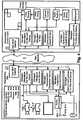
- Figure 4shows an illustration of different functions and components that can be present at a control room 11 and at a site 21, where it is shown that the first part 1 can comprise a fiber MUX DeMUX and units for managing incoming video signal, tally signal or "on air signal", camera control signal, audio control signal and the intercom signal used for communication between members of the different crews.
- the first part 1can comprise a fiber MUX DeMUX and units for managing incoming video signal, tally signal or "on air signal", camera control signal, audio control signal and the intercom signal used for communication between members of the different crews.
- the second part 2can comprise a fiber MUX DeMux and units for managing the video signal, the tally signal, camera control signals, audio control signals and the intercom signal.
Landscapes
- Engineering & Computer Science (AREA)
- Signal Processing (AREA)
- Multimedia (AREA)
- Selective Calling Equipment (AREA)
- Two-Way Televisions, Distribution Of Moving Picture Or The Like (AREA)
- Studio Devices (AREA)
- Small-Scale Networks (AREA)
- Data Exchanges In Wide-Area Networks (AREA)
- Mobile Radio Communication Systems (AREA)
- Telephonic Communication Services (AREA)
- Traffic Control Systems (AREA)
Description
- The present invention relates to a system for the remote video and/or audio production, said system comprising a first part related to the control room for said video production and a second part on the site of an event to be recorded, where said first and second part communicate with each other by means of a data stream.
- Outside broadcasting is the production of television or radio programmes (typically to cover news and sports events) from a mobile television studio. This mobile control room is known as an "Outside Broadcasting Van", "OB Van", "OB Bus", "mobile unit", "remote truck", "live truck", "live eye", or "production truck". The mobile OB Bus is positioned at, or near, a remote site of recording and signals from cameras and microphones on the remote site of recording come into the OB Bus for processing and transmission to a center for possibly final production and finally broadcasting. There is also a lot of verbal communication between the persons on the site and the persons in the OB Bus and communication of data besides the actual signals from cameras and microphones, such as meta data from the different equipment used to capture the signals on the site and control data used to control the cameras and microphones on the site from the OB Bus.
- A crossbar switch is an assembly of individual switches between multiple inputs and multiple outputs. The switches are arranged in a matrix. If the crossbar switch has M inputs and N outputs, then a crossbar has a matrix with M x N crosspoints or places where the "bars" cross. At each crosspoint is a switch; when closed, it connects one of M inputs to one of N outputs. A given crossbar is a single layer, non-blocking switch. Collections of crossbars can be used to implement multiple layer and/or blocking switches. A crossbar switching system is also called a co-ordinate switching system. One input can be connected to several outputs simultaneously, just as several inputs can be connected to one output simultaneously.
- In this description it shall be understood that a communication matrix is a unit with the characteristics and logical function of a crossbar switch but which necessarily does not have to be a traditional hardware crossbar switch; it can be any switch with multiple inputs and outputs which can be controlled to connect one input to one or several outputs simultaneously and one or several inputs to one output simultaneously.
- In a recording and production of media material there are several persons with different tasks involved, for example during a video production there are the persons at the actual site, such as camera men, audio technicians and reporters, and there are the persons in the OB Bus, such as video and audio technicians, mixers, producers, graphic designers, lightning artists and editors. These persons have to be able to communicate with each other, both on the site, within the OB Bus and also between the site and the OB Bus. For this it is known to use a communication matrix through which is it possible to enable the communication between any persons on the site of the event and in the OB Bus.
- Some cameras for video production comprises the camera head and a camera control unit (CCU) where high speed real time communication must be maintained between the camera head and camera control unit during all time of capturing the video signal, both for communicating control signals to and from the camera head and for communicating the actual video signal. A multiplexed cable, usually a triaxial cable or hybrid fiber cable, is used for the communication between the camera head and the CCU. Each signal and function to control and manage the camera and the actual camera signal can be derived from the CCU and transported to the OB bus by means of any other type of signal transportation.
- It is also known to provide remote video production where a distance can be found between the site for the event and the control room and where required communication is established between the site and control room by means of a data stream. An example of remote video production can be found in patent publication
US 2009/0290070 A1 andWO 2007/028619 A2 , where the latter discloses remote video production where all camera feeds are provided as low bandwidth preview feeds together with one selected high bandwidth live camera feed. - There are many problems with the use of the traditional OB Bus, such as the transportation of the bus itself, travel time and cost for the crew on the OB Bus, environmental problems in the transportation and the use of the bus on site. These problems are multiplied on big events where there might be many buses on one and the same site from different production or broadcasting teams.
- It is also a problem to even transport an OB Bus to some events since the site for the event might be on a place that is hard to reach with a large bus.
- An OB Bus is also limited in its capabilities to function as a control room compared to a standard control room; it would be desirable to have all the conveniences and equipment of a normal control room on site for the recording of an event at a distance from the normal control room.
- For these reasons there have been some attempts to provide the possibility for remote video and audio production where the crew that usually is in the OB Bus on the site for the event can remain in the normal control room and only the crew required to acquire the actual signals needed to record the event with necessary equipment are moved to the site of the event, and where information is communicated between the site and the control room by means of some kind of data stream.
- It is still a technical problem to establish a system for the remote video and/or audio production over large distances, such as between cities, over countries, over continents or between continents, where the system comprises a first part related to the control room for the video production and a second part on the site of an event to be recorded and where the first and second part communicate with each other by means of a data stream.
- It is a problem to find required bandwidth to transport all information needed to establish a system for remote video and/or audio production and to optimize the use of available bandwidth for such communication.
- It is also a problem to prioritize between different signals between the first and the second part in order to optimize the use of available bandwidth in the communication.
- It is a technical problem to provide possibilities for members of a first crew in the control room and members of a second crew on the site to communicate freely with each other over large distances.
- It is also a problem to set up and manage such communication possibilities between members of the first and second crew over large distances.
- With the purpose of solving one or more of the above indicated problems, and from the standpoint of the above indicated field of invention, the present invention teaches that the data stream is adapted to be sent between the first and second part by means of a wide area network, such as the Internet.
- It is proposed that a signal path is established through the wide area network between said first and second part, which signal path comprises at least a first and la second path, that a first signal path is adapted to transport primary data, where the first signal path is adapted to provide a quality of service with zero time delay in the transportation of primary data, and that the second signal path is adapted to transport secondary data, which secondary data can accept a lower quality of service.
- The primary data is real time data, such as video and audio signals.
- The secondary data comprises data relating to many different kinds of information where the real-time requirements are not as high as for the actual video and audio signals. This data can for instance be remote camera control data through which it is possible to control remote cameras on the site from the control room, it can be control data between any camera remote control panel in the control room and any camera control unit at the site, it can be remote audio control data through which it is possible to control remote audio on the site from the control room, it can be data for error management and error control of equipment on the site from the control room, and it can be voice communication between members of a first crew in the control room and members of a second crew on the site where such voice communication is not critical for any time delays. Some voice communication between members of the first crew and members of the second crew may have real time requirements in which case data for transporting this communication will be primary data.
- Communication between crew members on the two different teams is important and according to the invention, in order to provide required communication possibilities between the two teams, the first part comprises a first communication matrix, where first input and output connections are dedicated to members of the first crew through which the first communication matrix is adapted to enable any required communication between the members of the first crew.
- The invention also teaches that the second part comprises a second communication matrix, where second input and output connections are dedicated to members of the second crew through which the second communication matrix is adapted to enable any required communication between the members of the second crew.
- These two matrixes will enable communication for respective crew members in the control room and at the site, however in order to also provide communication between the two different crews the third input and output connections in the first communication matrix are dedicated to members of the second crew as if the members of the second crew were present in the control room, and that fourth input and output connections in the second communication matrix are dedicated to members of the first crew as if the members of the first crew were present at the site. The primary or secondary data, depending on the real-time requirements of the communication, comprises incoming data to the third and fourth input connections and outgoing data from the third and fourth output connections, which will enable the communication between members of mutually different crews.
- With the purpose of providing a possibility to set up and manage the second matrix from the control room the secondary data comprises control data required to set up, manage and control the second communication matrix from the control room. The second communication matrix is configured and managed to be a logical mirror of the first communication matrix.
- Since there are many different kinds of secondary data with mutually different requirements regarding the quality of service for communicated information and with the purpose of enable an optimization of available bandwidth for the data stream it is proposed that the second signal path is divided into several different signal paths each providing different quality of service, where data related to real time apptications, such as remote control of equipment and voice communication between crew members, is adapted to be communicated through a signal path with a higher quality of service than data related to non real time applications, such as error management and management of the communication matrixes.
- It should also be understood that real time data other than the actual video and audio signal, such as voice communication between crew members and remote control of equipment, can be regarded as being primary data and thus be communicated through the first signal path.
- It should also be understood that if there is sufficient bandwidth in the signal path, then it is possible to establish the second signal path in the same path and with the same quality of service as the first signal path. Thus it is possible that any kind of data, even data with very low transmission requirements, or even all of the data between the first and second unit, can be communicated with zero time delay if required bandwidth is available.
- One way of realise the signal path is that at least the first signal path is realized by means of optical fiber communication.
- It is also possible that the second signal path is realized by means of optical fiber communication.
- It should be understood that the first part can be adapted to communicate with several separate second parts, thereby enabling the remote production of events taking place on different sites or of different events not related to each other.
- The advantages of a system according to the present invention are that the communication of data that is required between the site of the event and the control room in a system for remote video and/or audio production can be realised so that live broadcast is possible without any time delay due to the distance between the site of the event and the control room.
- It is an advantage to provide the possibility of unlimited possibilities for the crew in the control room and the crew at the site of the event to communicate with each other just as if they were at the same location communicating through one mutual communication matrix.
- It is also an advantage to produce the video and/ or audio material from a distant live event with the comfort and equipment level of a normal control room compared to an OB Bus.
- A system according to the present invention will now be described in detail with reference to the accompanying drawings, in which:
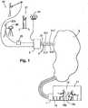
- Figure 1
- is a schematic and simplified illustration of a system according to the present invention,
- Figure 2
- is a schematic and simplified illustration of a first and second communication matrix adapted to function together according to the present invention,
- Figure 3
- is a schematic and simplified illustration of a first part communicating with several separate second parts, and
- Figure 4
- is a schematic illustration of components included in an inventive system.
- The present invention will now be described with reference to
figure 1 showing a system for remote video and/or audio production. - It shall be understood that in the description of the present invention a video and audio production is described, however, the present invention can also be used for a remote audio production recording only audio from a remote site. Even if pure audio might not require the same bandwidth for communicating the audio information as video or video and audio information, the principles and the system according to the present invention can also be used for pure audio production.
- The inventive system comprises a
first part 1 related to thecontrol room 11 for the video production and asecond part 2 on thesite 21 of an event to be recorded. - The first and
second part second part wide area network 3, such as the Internet. - It is possible to set up and dedicate a point to point pathway between the first and
second part wide area network 3 and thereby create a virtual Intranet on the wide area network through which safe communication can be established between the first and the second unit. Communication can be safe in many ways, such as in the sense that data is delivered uncompromised, in the sense that it is not monitored by an unauthorized party and in the sense that it is delivered on time. Even if all of these aspects are important it should be understood that the present invention relates to the time aspect of the data communication in the communication of real time information. - The present invention proposes that a
signal path 31 is established through the wide area network between the first andsecond part signal path 31 comprises at least a first 311 and a second 312 path. - The
first signal path 311 is adapted to transport primary data 311' and to provide a quality of service with zero time delay in the transportation of primary data 311'. Thesecond signal path 312 is adapted to transport secondary data 312', which secondary data can accept a lower quality of service than the quality of service provided by thefirst signal path 311. - The primary data 311' is real time data such as video and audio signals. In order to provide the shortest possible delay it is proposed that the audio and video signals are sent without any management of the signal at the
site 21, such as compression or synchronization. This will require high bandwidth for standard definition video and even higher for high definition video. If the signal is compressed then even high definition video can be sent with lower bandwidth than uncompressed standard definition video, however, the compression of the signal before sending the signal will cause some delay. It is thus possible to choose a compressed signal with a very short delay requiring a lower bandwidth or an uncompressed signal without the delay for compression but requiring a higher bandwidth. - The secondary data 312' comprises data related to signals or information that does not necessarily have real time requirements.
- Secondary data 312' can for instance be remote camera control data through which it is possible to control a
remote camera 24 on thesite 21 from thecontrol room 11, it can be control data between any cameraremote control panel 14 in thecontrol room 11 and anycamera control unit 25 at thesite 21 for the indirect control of acamera 26, or remote audio control data through which it is possible to control remote audio 27 on thesite 21 from thecontrol room 11. These examples of secondary data 312' might still have some real time requirements even if they might not have the strict requirement of zero time delay. - The signal protocol used for the control of
remote cameras 24 or remote audio 27, such as microphone preamplifiers, can for instance be RS422 or RS232, which are standard protocols that require very low bandwidth for communication. - Other examples of secondary data 312' with even lower communication requirements are data for error management and error control of equipment on the
site 21 from thecontrol room 11 or data related to back up of other real time data such as back up of video and audio information. - Data related to the voice communication between
members first crew 12 in thecontrol room 11 andmembers second crew 22 on thesite 21 might have requirements of zero time delay and is then regarded to be primary data 311'. This data could also be regarded as secondary data 312' depending on the urgency of the communication. - Regardless of the priority of this communication the present invention teaches that communication between
members first crew 12 andmembers second crew 22 can be realised as will be described in relation tofigure 2 . - It is proposed that the
first part 1 comprises afirst communication matrix 13, and that in thisfirst communication matrix 13 arefirst input 131i and output 131o connections dedicated tomembers first crew 12. This means that thefirst communication matrix 13 is adapted to enable any required communication between members of the first crew in the control room through these first input andoutput connections 131i, 131o. - In the same way it is proposed that the
second part 2 comprises asecond communication matrix 23, and that in thissecond communication matrix 23 are second input 232i and output 232o connections dedicated tomembers second crew 22. This means that thesecond communication matrix 23 is adapted to enable any required communication between members of the second crew at the site through these second input and output connections 232. - These two
communication matrixes members first crew 12 and the communication betweenmembers second crew 22. However, the present invention also provides the possibilities for anymember first crew 12 to communicate with anymember second crew 22 and vice versa. - In order to provide this possibility it is proposed that third input 133i and output 133o connections in the
first communication matrix 13 are dedicated tomembers second crew 22 as if these members of the second crew were present in thecontrol room 11. In the same way it is proposed thatfourth input 234i and output 234o connections in thesecond communication matrix 23 are dedicated tomembers first crew 12 as if these members of the first crew were present at thesite 21. - A connection between a
member 12a of thefirst crew 12 and amember 22a of thesecond crew 22 can thus be established by communicating outgoing data from the third output connections 133o to thefourth input connections 234i and outgoing data from the fourth output connections 234o to the third input connections 133i. - This data is communicated by means of the
signal path 31 as being first 311' or secondary 312' data depending on the real-time requirements of the communication, and comprises outgoing data from the third 133o and fourth 234o output connections and incoming data to the third 133i and fourth 234i input connections. - An example of a connection between a
member 12a on thefirst crew 12 and amember 22a on thesecond crew 22 will now be described as an illustrating example of the inventive way of providing this connection. - In this example input connection "3" and output connection "C" amongst the
first connections 131i, 133o on thefirst communication matrix 13 has been allocated to themember 12a on thefirst crew 12. According to the invention input connection "3" and output connection "C" amongst thefourth connections 234i, 234o on thesecond matrix 23 are also allocated to thesame member 12a on thefirst crew 12. - Also in this example input connection "6" and output connection "F" amongst the second connections 232i, 232o on the
second communication matrix 23 has been allocated to themember 22a on thesecond crew 22. According to the invention input connection "6" and output connection "F" amongst the third connections 133i, 133o on thefirst matrix 13 are also allocated to thesame member 22a on thesecond crew 22. - In order to enable these two
members first input connections 131i on thefirst communication matrix 13 is to be connected to output connection "F" amongst the second output connections 232o on thesecond communication matrix 23. - This is achieved by switching the incoming data from input connection "3" amongst the
first input connections 131i to output connection "F" amongst the third output connections 133o on thefirst communication matrix 13, the data is then communicated through thesignal path 31 to thesecond communication matrix 23 to input connection "3" amongst thefourth input connections 234i on thesecond communication matrix 23. The data is then switched from input connection "3" amongst thefourth input connections 234i to output connection "F" amongst the second output connections 232o on thesecond communication matrix 23 and a path from themember 12a on thefirst crew 12 to themember 22a of thesecond crew 22 has been established. - In order to provide a two way communication between the two
members second team 22a to the member of thefirst team 12a in the same way, that is from input connection "6" amongst the second connections 232i to output connection "C" amongst the fourth output connections 234o on thesecond communication matrix 23, from this fourth output connection 234o via thesignal path 31 to input connection "6" amongst the third connections 133i on thefirst communication matrix 13, and from this input connection "6" amongst the third connections 133i to output connection "C" amongst the first connections 131o on thefirst communication matrix 13. - It is proposed that the secondary data 312' comprises control data Ctrl23 required to set up, manage and control the
second communication matrix 23 from thecontrol room 11, which means that all connections required between different crew members can be established from the control room regardless of which crew the members belong to. - It is also proposed that the
second communication matrix 23 is configured and managed to be a logical mirror of thefirst communication matrix 13, which means that any connection or any release of a connection made between an input connection and an output connection in thefirst communication matrix 13 is also made simultaneously between corresponding input connection and output connection on thesecond communication matrix 23. This means that in the example above when aconnection 13a is made between the input connection "3" amongst the first input connections 133i and output connection "F" amongst the third output connections 133o on thefirst communication matrix 13 thecorresponding connection 23a is also made simultaneously between input connection "3" amongst thefourth input connections 234i and output connection "F" amongst the second output connections 232o on thesecond communication matrix 23. This can be achieved by copying the control signal ctrl13 used to control thefirst communication matrix 13 and send it as secondary data 312' to function as a control signal ctrl23 to thesecond communication matrix 23. - Different data streams belonging to the secondary data 312' may have mutually different requirements regarding the delay in communication. In order to provide a possibility to prioritize and optimize the use of available bandwidth for the complete data stream 3' between the first and
second part second signal path 312 is divided into several different signal paths each providing different quality of service, where data related to real time applications, such as remote control of equipment and voice communication between crew members, is adapted to be communicated through a signal path with a higher quality of service than data related to non real time applications, such as error management and management of the communication matrixes. - The present invention proposes that in order to achieve required quality of service in the communication at least the
first signal path 311 is realized by means of optical fiber communication. - It is also proposed that the
second signal path 312 is realized by means of optical fiber communication. Figure 3 shows schematically that thefirst part 1 may be a standard part or equipment in acontrol room 11 for video production and thesecond part different sites control room 11 to connect to thesecond part wide area network 3 and access the equipment used on the site.- The
second part 2x may also be a mobile part that can be moved and transported to aremote site 21x without having the problems of moving a complete OB Bus. - It is also proposed that the
first part 1 is adapted to communicate with two or more separatesecond parts Figure 4 shows an illustration of different functions and components that can be present at acontrol room 11 and at asite 21, where it is shown that thefirst part 1 can comprise a fiber MUX DeMUX and units for managing incoming video signal, tally signal or "on air signal", camera control signal, audio control signal and the intercom signal used for communication between members of the different crews.- It is also shown that the
second part 2 can comprise a fiber MUX DeMux and units for managing the video signal, the tally signal, camera control signals, audio control signals and the intercom signal.
Claims (7)
- System for remote video and/or audio production, said system comprising a first part (1) related to the control room (11) for said video production and a second part (2) on the site (21) of an event to be recorded, where said first and second part (1, 2) communicate with each other by means of a data stream (3'), where said data stream (3') is adapted to be sent between said first and second part (1, 2) by means of a wide area network (3), and where a signal path (31) is established through said wide area network (3) between said first and second part (1, 2), in, that said signal path comprises at least a first and a second path (311, 312); that a first signal path (311) is adapted to transport real time data, such as video and audio signals, here called primary data (311'), that said first signal path is adapted to provide a quality of service required for the transportation of real time data, that said second signal path (312) is adapted to transport secondary data (312'), which secondary data (312') can accept a lower quality of service characterized, that said first signal path (311) is adapted to two way communication between said first and second part (1, 2) when required, that said second signal path (312) is adapted to two way communication between said first and second part (1, 2), that data related to the voice communication between members (12a, 12b) of a first crew (12) in said control room (11) and members (22a, 22b) of a second crew (22) on said site (21) is regarded as being primary data (311') or secondary data (312') depending on the real time requirements of the communication, that said secondary data (312') comprises remote camera control data through which it is possible to control remote cameras (24) on said site (21) from said control room (11), such as control data between any camera remote control panel (14) in said control room (11) and any camera control unit (25) at said site (21), that said secondary data (312') comprises remote audio control data through which it is possible to control remote audio (27) on said site (21) from said control room (11), that said secondary data (312') comprises data for error management and error control of equipment on said site (21) from said control room (11 that said first part (1) comprises a first communication matrix (13), that in said first communication matrix (13) are first input (131i) and output (131o) connections dedicated to members (12a, 12b) of said first crew (12), that said first communication matrix (13) is adapted to enable any required communication between members (12a, 12b) of said first crew (12) in said control room through said first input and output connections (131i, 131o), that said second part (2) comprises a second communication matrix (23), that in said second communication matrix (23) are second input (232i) and output (232o) connections dedicated to members (22a, 22b) of said second crew (22), that said second communication matrix (23) is adapted to enable any required communication between members of said second crew (22) at said site through said second input and output connections (232i, 232o), that in said first communication matrix (13) are third input (133i) and output (133o) connections dedicated to members (22a, 22b) of said second crew (22) as if said members of said second crew were present in said control room (11), that in said second communication matrix (23) are fourth input (234i) and output (234o) connections dedicated to members (12a, 12b) of said first crew (12) as if said members of said first crew were present at said site (21), that outgoing data from said third output connections (133o) are communicated to said fourth input connections (234i), that outgoing data from said fourth output connections (234o) are communicated to said third input connections (133i), that said primary or secondary data (311', 312'), depending on the real-time requirements of the communication, comprises incoming data to said third and fourth input connections (133i, 234i) and outgoing data from said third and fourth output connections (133o, 234o), that said secondary data (312') comprises control data (Ctrl23) required to set up, manage and control said second communication matrix (23) from said control room (11), and that said second communication matrix (23) is configured and managed to be a logical mirror of said first communication matrix (13).
- System according to claim 1,characterized in, that said second signal path (312) is divided into several different signal paths each providing different quality of service, where data related to real time applications, such as remote control of equipment and voice communication between crew members, is adapted to be communicated through a signal path with a higher quality of service than data related to non real time applications, such as error management and management of the communication matrixes.
- System according to any preceding claim,characterized in, that at least said first signal path (311) is realized by means of optical fiber communication.
- System according to claim 3,characterized in, that said second signal path (312) is realized by means of optical fiber communication.
- System according to any preceding claim,characterized in, that said second part (2a, 2b, ..., 2n) is a stationary part located at a site (21a, 21b, ..., 21n) frequently used for events to be recorded.
- System according to any one of claim 1 to 4,characterized in, that said second part (2x) is a mobile part moveable to any site (21x) used for an event to be recorded.
- System according to any preceding claim,characterized in, that said first part (1) is adapted to communicate with two or more second parts (2a, 2b, ..., 2n, 2x) simultaneously.
Priority Applications (1)
| Application Number | Priority Date | Filing Date | Title |
|---|---|---|---|
| PL11840463TPL2638692T3 (en) | 2010-11-09 | 2011-11-02 | Remote video production |
Applications Claiming Priority (2)
| Application Number | Priority Date | Filing Date | Title |
|---|---|---|---|
| SE1051176ASE535910E (en) | 2010-11-09 | 2010-11-09 | Video production via a long distance network |
| PCT/SE2011/051308WO2012064256A1 (en) | 2010-11-09 | 2011-11-02 | Remote video production |
Publications (3)
| Publication Number | Publication Date |
|---|---|
| EP2638692A1 EP2638692A1 (en) | 2013-09-18 |
| EP2638692A4 EP2638692A4 (en) | 2014-04-30 |
| EP2638692B1true EP2638692B1 (en) | 2017-10-18 |
Family
ID=46051193
Family Applications (1)
| Application Number | Title | Priority Date | Filing Date |
|---|---|---|---|
| EP11840463.1AActiveEP2638692B1 (en) | 2010-11-09 | 2011-11-02 | Remote video production |
Country Status (16)
| Country | Link |
|---|---|
| US (1) | US9253417B2 (en) |
| EP (1) | EP2638692B1 (en) |
| JP (2) | JP2014502076A (en) |
| KR (2) | KR20130121864A (en) |
| CN (1) | CN103262519B (en) |
| AU (1) | AU2011326861B2 (en) |
| BR (1) | BR112013011529B1 (en) |
| CA (1) | CA2816794C (en) |
| DK (1) | DK2638692T3 (en) |
| EA (1) | EA201390608A1 (en) |
| ES (1) | ES2655918T3 (en) |
| NO (1) | NO2638692T3 (en) |
| PL (1) | PL2638692T3 (en) |
| SE (1) | SE535910E (en) |
| WO (1) | WO2012064256A1 (en) |
| ZA (1) | ZA201302992B (en) |
Families Citing this family (5)
| Publication number | Priority date | Publication date | Assignee | Title |
|---|---|---|---|---|
| DE102007045835B4 (en) | 2007-09-25 | 2012-12-20 | Metaio Gmbh | Method and device for displaying a virtual object in a real environment |
| DE102007045834B4 (en) | 2007-09-25 | 2012-01-26 | Metaio Gmbh | Method and device for displaying a virtual object in a real environment |
| US10440403B2 (en)* | 2017-01-27 | 2019-10-08 | Gvbb Holdings S.A.R.L. | System and method for controlling media content capture for live video broadcast production |
| CN110379435A (en)* | 2019-09-04 | 2019-10-25 | 体奥动力(北京)体育传播有限公司 | A kind of audio-frequency processing method and device |
| US11003415B1 (en)* | 2019-12-12 | 2021-05-11 | New England Sports Network, Inc. | Audio/visual production system for transmitting audio-video signals and managing interrupt signals with low latency |
Citations (1)
| Publication number | Priority date | Publication date | Assignee | Title |
|---|---|---|---|---|
| WO2007028619A2 (en)* | 2005-09-08 | 2007-03-15 | Earth Television Network Gmbh | System for recording and/or live broadcasting reports |
Family Cites Families (23)
| Publication number | Priority date | Publication date | Assignee | Title |
|---|---|---|---|---|
| JP3972381B2 (en)* | 1996-04-12 | 2007-09-05 | ソニー株式会社 | Information transfer apparatus and information transfer method |
| US7024677B1 (en)* | 1998-12-18 | 2006-04-04 | Thomson Licensing | System and method for real time video production and multicasting |
| US6452612B1 (en)* | 1998-12-18 | 2002-09-17 | Parkervision, Inc. | Real time video production system and method |
| CA2375688A1 (en)* | 2000-04-05 | 2001-10-11 | Sony United Kingdom Limited | Identifying and processing of audio and/or video material |
| CA2410187A1 (en)* | 2000-05-25 | 2001-11-29 | Georgia Hilton | Global virtual audio production studio |
| JP2003143152A (en)* | 2001-10-31 | 2003-05-16 | Nippon Telegr & Teleph Corp <Ntt> | Communication method and system, transmission device, termination device |
| EP1331808B8 (en) | 2002-01-16 | 2014-10-15 | Thomson Licensing | Production system, control area for a production system and image capturing system for a production system |
| JP4259816B2 (en)* | 2002-06-06 | 2009-04-30 | シャープ株式会社 | Information provision system |
| US20040230997A1 (en)* | 2003-05-13 | 2004-11-18 | Broadcom Corporation | Single-chip cable set-top box |
| JP2005012388A (en)* | 2003-06-18 | 2005-01-13 | Hitachi Instruments Service Co Ltd | Wireless camera selection information display system |
| US7432949B2 (en)* | 2003-08-20 | 2008-10-07 | Christophe Remy | Mobile videoimaging, videocommunication, video production (VCVP) system |
| US20050239399A1 (en)* | 2004-04-21 | 2005-10-27 | Karabinis Peter D | Mobile terminals and set top boxes including multiple satellite band service links, and related systems and methods |
| JP4572107B2 (en) | 2004-12-02 | 2010-10-27 | 日本電気株式会社 | Wireless communication system |
| JP2006210975A (en) | 2005-01-25 | 2006-08-10 | Hitachi Kokusai Electric Inc | Dynamic range measurement method for optical transmission line |
| EP1694031A1 (en)* | 2005-02-18 | 2006-08-23 | Thomson Licensing S.A. | Method for performing data transport over a serial bus using internet protocol and apparatus for use in the method |
| WO2007023626A1 (en) | 2005-08-24 | 2007-03-01 | Megachips Corporation | Network camera, management server, and video distribution system |
| JP4844232B2 (en)* | 2006-05-18 | 2011-12-28 | ソニー株式会社 | Signal transmission system, imaging device, control device, and signal transmission method |
| CN101584157B (en)* | 2006-09-26 | 2013-12-11 | 利弗有限公司 | Remote transmission system |
| JP2010534971A (en)* | 2007-07-26 | 2010-11-11 | ノマド イノベーションズ リミテッド ライアビリティ カンパニー | Full-duplex network-based apparatus and method |
| KR100961443B1 (en) | 2007-12-19 | 2010-06-09 | 한국전자통신연구원 | Hierarchical transmission / reception apparatus and method for improving availability of broadcasting service |
| US20090290070A1 (en) | 2008-05-20 | 2009-11-26 | All Mobile Video | Systems and methods for remote video production |
| WO2009158726A1 (en)* | 2008-06-27 | 2009-12-30 | Walters Clifford A | Compact camera-mountable video encoder, studio rack-mountable video encoder, configuration device, and broadcasting network utilizing the same |
| JP2010161568A (en)* | 2009-01-07 | 2010-07-22 | Mitsubishi Electric Corp | Multi-rate passive optical network master station device |
- 2010
- 2010-11-09SESE1051176Apatent/SE535910E/enunknown
- 2011
- 2011-11-02BRBR112013011529-7Apatent/BR112013011529B1/enactiveIP Right Grant
- 2011-11-02AUAU2011326861Apatent/AU2011326861B2/enactiveActive
- 2011-11-02ESES11840463.1Tpatent/ES2655918T3/enactiveActive
- 2011-11-02EAEA201390608Apatent/EA201390608A1/enunknown
- 2011-11-02KRKR1020137014753Apatent/KR20130121864A/ennot_activeCeased
- 2011-11-02KRKR1020157033095Apatent/KR101700308B1/enactiveActive
- 2011-11-02EPEP11840463.1Apatent/EP2638692B1/enactiveActive
- 2011-11-02PLPL11840463Tpatent/PL2638692T3/enunknown
- 2011-11-02CNCN201180052896.2Apatent/CN103262519B/enactiveActive
- 2011-11-02NONO11840463Apatent/NO2638692T3/nounknown
- 2011-11-02USUS13/884,240patent/US9253417B2/enactiveActive
- 2011-11-02DKDK11840463.1Tpatent/DK2638692T3/enactive
- 2011-11-02JPJP2013536564Apatent/JP2014502076A/enactivePending
- 2011-11-02WOPCT/SE2011/051308patent/WO2012064256A1/enactiveApplication Filing
- 2011-11-02CACA2816794Apatent/CA2816794C/enactiveActive
- 2013
- 2013-04-24ZAZA2013/02992Apatent/ZA201302992B/enunknown
- 2016
- 2016-05-24JPJP2016103202Apatent/JP2016171590A/enactivePending
Patent Citations (1)
| Publication number | Priority date | Publication date | Assignee | Title |
|---|---|---|---|---|
| WO2007028619A2 (en)* | 2005-09-08 | 2007-03-15 | Earth Television Network Gmbh | System for recording and/or live broadcasting reports |
Also Published As
| Publication number | Publication date |
|---|---|
| PL2638692T3 (en) | 2018-03-30 |
| BR112013011529A2 (en) | 2017-10-17 |
| EA201390608A1 (en) | 2013-10-30 |
| CN103262519B (en) | 2017-02-22 |
| US9253417B2 (en) | 2016-02-02 |
| EP2638692A4 (en) | 2014-04-30 |
| KR20150137127A (en) | 2015-12-08 |
| BR112013011529B1 (en) | 2021-08-31 |
| SE1051176A1 (en) | 2012-05-10 |
| ES2655918T3 (en) | 2018-02-22 |
| SE535910E (en) | 2017-09-05 |
| US20130278786A1 (en) | 2013-10-24 |
| AU2011326861B2 (en) | 2015-05-21 |
| EP2638692A1 (en) | 2013-09-18 |
| DK2638692T3 (en) | 2018-01-22 |
| NO2638692T3 (en) | 2018-03-17 |
| AU2011326861A1 (en) | 2013-05-23 |
| CA2816794A1 (en) | 2012-05-18 |
| CA2816794C (en) | 2017-11-21 |
| WO2012064256A1 (en) | 2012-05-18 |
| KR20130121864A (en) | 2013-11-06 |
| KR101700308B1 (en) | 2017-01-26 |
| CN103262519A (en) | 2013-08-21 |
| SE535910C2 (en) | 2013-02-12 |
| JP2016171590A (en) | 2016-09-23 |
| JP2014502076A (en) | 2014-01-23 |
| ZA201302992B (en) | 2014-06-25 |
Similar Documents
| Publication | Publication Date | Title |
|---|---|---|
| USRE48325E1 (en) | Embedded audio routing switcher | |
| EP2638692B1 (en) | Remote video production | |
| CN102547142B (en) | A kind of management of the video matrix based on meeting and the method for control | |
| CN110445773A (en) | Fire-fighting command regulator control system based on Internet of Things | |
| US9148613B1 (en) | Systems, methods, and software for merging video viewing cells | |
| CN101547341B (en) | Method and device for realizing intercommunication of video monitoring system and video service system | |
| KR20100029099A (en) | Dual use video mixer crosspoint matrix | |
| EP2920957B1 (en) | Method of operating a video processing apparatus | |
| US20150296147A1 (en) | Method of operating a video processing apparatus | |
| Komagata et al. | 4K/8K (UHD-1)/UHD-2) Production Studios for UHDTV Broadcasting | |
| Sneddon et al. | Large scale deployment of SMPTE 2110: The IP live production facility | |
| WO2020054391A1 (en) | Network system, network management device, and network management method |
Legal Events
| Date | Code | Title | Description |
|---|---|---|---|
| PUAI | Public reference made under article 153(3) epc to a published international application that has entered the european phase | Free format text:ORIGINAL CODE: 0009012 | |
| 17P | Request for examination filed | Effective date:20130610 | |
| AK | Designated contracting states | Kind code of ref document:A1 Designated state(s):AL AT BE BG CH CY CZ DE DK EE ES FI FR GB GR HR HU IE IS IT LI LT LU LV MC MK MT NL NO PL PT RO RS SE SI SK SM TR | |
| DAX | Request for extension of the european patent (deleted) | ||
| A4 | Supplementary search report drawn up and despatched | Effective date:20140327 | |
| RIC1 | Information provided on ipc code assigned before grant | Ipc:H04H 20/04 20080101ALI20140321BHEP Ipc:H04N 5/222 20060101AFI20140321BHEP Ipc:H04H 60/04 20080101ALI20140321BHEP Ipc:H04N 5/232 20060101ALI20140321BHEP Ipc:H04N 5/28 20060101ALI20140321BHEP Ipc:H04H 60/05 20080101ALI20140321BHEP | |
| TPAC | Observations filed by third parties | Free format text:ORIGINAL CODE: EPIDOSNTIPA | |
| 17Q | First examination report despatched | Effective date:20150202 | |
| GRAP | Despatch of communication of intention to grant a patent | Free format text:ORIGINAL CODE: EPIDOSNIGR1 | |
| INTG | Intention to grant announced | Effective date:20160523 | |
| GRAJ | Information related to disapproval of communication of intention to grant by the applicant or resumption of examination proceedings by the epo deleted | Free format text:ORIGINAL CODE: EPIDOSDIGR1 | |
| RAP1 | Party data changed (applicant data changed or rights of an application transferred) | Owner name:TWENTYFOURSEVEN LIVE AB | |
| INTC | Intention to grant announced (deleted) | ||
| GRAS | Grant fee paid | Free format text:ORIGINAL CODE: EPIDOSNIGR3 | |
| GRAP | Despatch of communication of intention to grant a patent | Free format text:ORIGINAL CODE: EPIDOSNIGR1 | |
| INTG | Intention to grant announced | Effective date:20170418 | |
| GRAA | (expected) grant | Free format text:ORIGINAL CODE: 0009210 | |
| AK | Designated contracting states | Kind code of ref document:B1 Designated state(s):AL AT BE BG CH CY CZ DE DK EE ES FI FR GB GR HR HU IE IS IT LI LT LU LV MC MK MT NL NO PL PT RO RS SE SI SK SM TR | |
| RAP1 | Party data changed (applicant data changed or rights of an application transferred) | Owner name:MOVING MEDIA NORDIC AB | |
| REG | Reference to a national code | Ref country code:GB Ref legal event code:FG4D | |
| REG | Reference to a national code | Ref country code:CH Ref legal event code:EP | |
| REG | Reference to a national code | Ref country code:AT Ref legal event code:REF Ref document number:938866 Country of ref document:AT Kind code of ref document:T Effective date:20171115 Ref country code:IE Ref legal event code:FG4D | |
| REG | Reference to a national code | Ref country code:DE Ref legal event code:R096 Ref document number:602011042573 Country of ref document:DE | |
| REG | Reference to a national code | Ref country code:FR Ref legal event code:PLFP Year of fee payment:7 | |
| REG | Reference to a national code | Ref country code:CH Ref legal event code:NV Representative=s name:FELBER UND PARTNER AG, CH | |
| REG | Reference to a national code | Ref country code:NL Ref legal event code:FP | |
| REG | Reference to a national code | Ref country code:DK Ref legal event code:T3 Effective date:20180117 | |
| REG | Reference to a national code | Ref country code:ES Ref legal event code:FG2A Ref document number:2655918 Country of ref document:ES Kind code of ref document:T3 Effective date:20180222 | |
| REG | Reference to a national code | Ref country code:LT Ref legal event code:MG4D | |
| REG | Reference to a national code | Ref country code:AT Ref legal event code:MK05 Ref document number:938866 Country of ref document:AT Kind code of ref document:T Effective date:20171018 | |
| REG | Reference to a national code | Ref country code:NO Ref legal event code:T2 Effective date:20171018 | |
| PG25 | Lapsed in a contracting state [announced via postgrant information from national office to epo] | Ref country code:LT Free format text:LAPSE BECAUSE OF FAILURE TO SUBMIT A TRANSLATION OF THE DESCRIPTION OR TO PAY THE FEE WITHIN THE PRESCRIBED TIME-LIMIT Effective date:20171018 Ref country code:SE Free format text:LAPSE BECAUSE OF FAILURE TO SUBMIT A TRANSLATION OF THE DESCRIPTION OR TO PAY THE FEE WITHIN THE PRESCRIBED TIME-LIMIT Effective date:20171018 | |
| PG25 | Lapsed in a contracting state [announced via postgrant information from national office to epo] | Ref country code:IS Free format text:LAPSE BECAUSE OF FAILURE TO SUBMIT A TRANSLATION OF THE DESCRIPTION OR TO PAY THE FEE WITHIN THE PRESCRIBED TIME-LIMIT Effective date:20180218 Ref country code:BG Free format text:LAPSE BECAUSE OF FAILURE TO SUBMIT A TRANSLATION OF THE DESCRIPTION OR TO PAY THE FEE WITHIN THE PRESCRIBED TIME-LIMIT Effective date:20180118 Ref country code:HR Free format text:LAPSE BECAUSE OF FAILURE TO SUBMIT A TRANSLATION OF THE DESCRIPTION OR TO PAY THE FEE WITHIN THE PRESCRIBED TIME-LIMIT Effective date:20171018 Ref country code:RS Free format text:LAPSE BECAUSE OF FAILURE TO SUBMIT A TRANSLATION OF THE DESCRIPTION OR TO PAY THE FEE WITHIN THE PRESCRIBED TIME-LIMIT Effective date:20171018 Ref country code:AT Free format text:LAPSE BECAUSE OF FAILURE TO SUBMIT A TRANSLATION OF THE DESCRIPTION OR TO PAY THE FEE WITHIN THE PRESCRIBED TIME-LIMIT Effective date:20171018 Ref country code:GR Free format text:LAPSE BECAUSE OF FAILURE TO SUBMIT A TRANSLATION OF THE DESCRIPTION OR TO PAY THE FEE WITHIN THE PRESCRIBED TIME-LIMIT Effective date:20180119 Ref country code:LV Free format text:LAPSE BECAUSE OF FAILURE TO SUBMIT A TRANSLATION OF THE DESCRIPTION OR TO PAY THE FEE WITHIN THE PRESCRIBED TIME-LIMIT Effective date:20171018 | |
| REG | Reference to a national code | Ref country code:DE Ref legal event code:R097 Ref document number:602011042573 Country of ref document:DE | |
| PG25 | Lapsed in a contracting state [announced via postgrant information from national office to epo] | Ref country code:CZ Free format text:LAPSE BECAUSE OF FAILURE TO SUBMIT A TRANSLATION OF THE DESCRIPTION OR TO PAY THE FEE WITHIN THE PRESCRIBED TIME-LIMIT Effective date:20171018 Ref country code:EE Free format text:LAPSE BECAUSE OF FAILURE TO SUBMIT A TRANSLATION OF THE DESCRIPTION OR TO PAY THE FEE WITHIN THE PRESCRIBED TIME-LIMIT Effective date:20171018 Ref country code:MC Free format text:LAPSE BECAUSE OF FAILURE TO SUBMIT A TRANSLATION OF THE DESCRIPTION OR TO PAY THE FEE WITHIN THE PRESCRIBED TIME-LIMIT Effective date:20171018 Ref country code:SK Free format text:LAPSE BECAUSE OF FAILURE TO SUBMIT A TRANSLATION OF THE DESCRIPTION OR TO PAY THE FEE WITHIN THE PRESCRIBED TIME-LIMIT Effective date:20171018 | |
| PLBE | No opposition filed within time limit | Free format text:ORIGINAL CODE: 0009261 | |
| STAA | Information on the status of an ep patent application or granted ep patent | Free format text:STATUS: NO OPPOSITION FILED WITHIN TIME LIMIT | |
| PG25 | Lapsed in a contracting state [announced via postgrant information from national office to epo] | Ref country code:SM Free format text:LAPSE BECAUSE OF FAILURE TO SUBMIT A TRANSLATION OF THE DESCRIPTION OR TO PAY THE FEE WITHIN THE PRESCRIBED TIME-LIMIT Effective date:20171018 Ref country code:RO Free format text:LAPSE BECAUSE OF FAILURE TO SUBMIT A TRANSLATION OF THE DESCRIPTION OR TO PAY THE FEE WITHIN THE PRESCRIBED TIME-LIMIT Effective date:20171018 Ref country code:LU Free format text:LAPSE BECAUSE OF NON-PAYMENT OF DUE FEES Effective date:20171102 | |
| 26N | No opposition filed | Effective date:20180719 | |
| PG25 | Lapsed in a contracting state [announced via postgrant information from national office to epo] | Ref country code:MT Free format text:LAPSE BECAUSE OF NON-PAYMENT OF DUE FEES Effective date:20171102 | |
| PG25 | Lapsed in a contracting state [announced via postgrant information from national office to epo] | Ref country code:SI Free format text:LAPSE BECAUSE OF FAILURE TO SUBMIT A TRANSLATION OF THE DESCRIPTION OR TO PAY THE FEE WITHIN THE PRESCRIBED TIME-LIMIT Effective date:20171018 | |
| PG25 | Lapsed in a contracting state [announced via postgrant information from national office to epo] | Ref country code:HU Free format text:LAPSE BECAUSE OF FAILURE TO SUBMIT A TRANSLATION OF THE DESCRIPTION OR TO PAY THE FEE WITHIN THE PRESCRIBED TIME-LIMIT; INVALID AB INITIO Effective date:20111102 | |
| PG25 | Lapsed in a contracting state [announced via postgrant information from national office to epo] | Ref country code:CY Free format text:LAPSE BECAUSE OF NON-PAYMENT OF DUE FEES Effective date:20171018 | |
| PG25 | Lapsed in a contracting state [announced via postgrant information from national office to epo] | Ref country code:MK Free format text:LAPSE BECAUSE OF FAILURE TO SUBMIT A TRANSLATION OF THE DESCRIPTION OR TO PAY THE FEE WITHIN THE PRESCRIBED TIME-LIMIT Effective date:20171018 | |
| PG25 | Lapsed in a contracting state [announced via postgrant information from national office to epo] | Ref country code:TR Free format text:LAPSE BECAUSE OF FAILURE TO SUBMIT A TRANSLATION OF THE DESCRIPTION OR TO PAY THE FEE WITHIN THE PRESCRIBED TIME-LIMIT Effective date:20171018 | |
| PG25 | Lapsed in a contracting state [announced via postgrant information from national office to epo] | Ref country code:PT Free format text:LAPSE BECAUSE OF FAILURE TO SUBMIT A TRANSLATION OF THE DESCRIPTION OR TO PAY THE FEE WITHIN THE PRESCRIBED TIME-LIMIT Effective date:20171018 | |
| PG25 | Lapsed in a contracting state [announced via postgrant information from national office to epo] | Ref country code:AL Free format text:LAPSE BECAUSE OF FAILURE TO SUBMIT A TRANSLATION OF THE DESCRIPTION OR TO PAY THE FEE WITHIN THE PRESCRIBED TIME-LIMIT Effective date:20171018 | |
| PGFP | Annual fee paid to national office [announced via postgrant information from national office to epo] | Ref country code:NL Payment date:20241126 Year of fee payment:14 | |
| PGFP | Annual fee paid to national office [announced via postgrant information from national office to epo] | Ref country code:DE Payment date:20241128 Year of fee payment:14 | |
| PGFP | Annual fee paid to national office [announced via postgrant information from national office to epo] | Ref country code:NO Payment date:20241119 Year of fee payment:14 | |
| PGFP | Annual fee paid to national office [announced via postgrant information from national office to epo] | Ref country code:DK Payment date:20241126 Year of fee payment:14 | |
| PGFP | Annual fee paid to national office [announced via postgrant information from national office to epo] | Ref country code:BE Payment date:20241126 Year of fee payment:14 Ref country code:PL Payment date:20241029 Year of fee payment:14 Ref country code:FI Payment date:20241126 Year of fee payment:14 | |
| PGFP | Annual fee paid to national office [announced via postgrant information from national office to epo] | Ref country code:GB Payment date:20241126 Year of fee payment:14 | |
| PGFP | Annual fee paid to national office [announced via postgrant information from national office to epo] | Ref country code:FR Payment date:20241126 Year of fee payment:14 | |
| PGFP | Annual fee paid to national office [announced via postgrant information from national office to epo] | Ref country code:IE Payment date:20241119 Year of fee payment:14 | |
| PGFP | Annual fee paid to national office [announced via postgrant information from national office to epo] | Ref country code:IT Payment date:20241125 Year of fee payment:14 Ref country code:ES Payment date:20241216 Year of fee payment:14 | |
| PGFP | Annual fee paid to national office [announced via postgrant information from national office to epo] | Ref country code:CH Payment date:20241201 Year of fee payment:14 |