EP2637011A1 - Method and apparatus for measuring the geometric structure of an optical component - Google Patents
Method and apparatus for measuring the geometric structure of an optical componentDownload PDFInfo
- Publication number
- EP2637011A1 EP2637011A1EP12290084.8AEP12290084AEP2637011A1EP 2637011 A1EP2637011 A1EP 2637011A1EP 12290084 AEP12290084 AEP 12290084AEP 2637011 A1EP2637011 A1EP 2637011A1
- Authority
- EP
- European Patent Office
- Prior art keywords
- signal
- face
- transformation
- measurement
- estimate
- Prior art date
- Legal status (The legal status is an assumption and is not a legal conclusion. Google has not performed a legal analysis and makes no representation as to the accuracy of the status listed.)
- Withdrawn
Links
- 238000000034methodMethods0.000titleclaimsabstractdescription38
- 230000003287optical effectEffects0.000titleclaimsabstractdescription38
- 238000004088simulationMethods0.000claimsabstractdescription47
- 239000000523sampleSubstances0.000claimsabstractdescription39
- 238000005259measurementMethods0.000claimsdescription101
- 230000009466transformationEffects0.000claimsdescription100
- 238000004364calculation methodMethods0.000claimsdescription15
- 239000003550markerSubstances0.000claimsdescription13
- 101000703681Homo sapiens Single-minded homolog 1Proteins0.000claimsdescription3
- 101000616761Homo sapiens Single-minded homolog 2Proteins0.000claimsdescription3
- 102100031980Single-minded homolog 1Human genes0.000claimsdescription3
- 102100021825Single-minded homolog 2Human genes0.000claimsdescription3
- 230000000737periodic effectEffects0.000claimsdescription3
- 230000000750progressive effectEffects0.000claimsdescription3
- 238000006243chemical reactionMethods0.000abstract4
- 230000005540biological transmissionEffects0.000description12
- 238000005457optimizationMethods0.000description7
- 238000004422calculation algorithmMethods0.000description6
- 230000008901benefitEffects0.000description4
- 241000287107PasserSpecies0.000description3
- PXFBZOLANLWPMH-UHFFFAOYSA-N16-EpiaffinineNatural productsC1C(C2=CC=CC=C2N2)=C2C(=O)CC2C(=CC)CN(C)C1C2COPXFBZOLANLWPMH-UHFFFAOYSA-N0.000description2
- 238000012804iterative processMethods0.000description2
- 239000011159matrix materialSubstances0.000description2
- 238000000691measurement methodMethods0.000description2
- 230000001131transforming effectEffects0.000description2
- 238000001429visible spectrumMethods0.000description2
- 238000010835comparative analysisMethods0.000description1
- 230000001066destructive effectEffects0.000description1
- 230000000694effectsEffects0.000description1
- 238000003754machiningMethods0.000description1
- 238000004519manufacturing processMethods0.000description1
- 238000011326mechanical measurementMethods0.000description1
- 238000012986modificationMethods0.000description1
- 230000004048modificationEffects0.000description1
- 239000003607modifierSubstances0.000description1
- 230000005855radiationEffects0.000description1
- 238000001028reflection methodMethods0.000description1
Images


Classifications
- G—PHYSICS
- G01—MEASURING; TESTING
- G01B—MEASURING LENGTH, THICKNESS OR SIMILAR LINEAR DIMENSIONS; MEASURING ANGLES; MEASURING AREAS; MEASURING IRREGULARITIES OF SURFACES OR CONTOURS
- G01B11/00—Measuring arrangements characterised by the use of optical techniques
- G01B11/24—Measuring arrangements characterised by the use of optical techniques for measuring contours or curvatures
- G01B11/25—Measuring arrangements characterised by the use of optical techniques for measuring contours or curvatures by projecting a pattern, e.g. one or more lines, moiré fringes on the object
- G—PHYSICS
- G01—MEASURING; TESTING
- G01M—TESTING STATIC OR DYNAMIC BALANCE OF MACHINES OR STRUCTURES; TESTING OF STRUCTURES OR APPARATUS, NOT OTHERWISE PROVIDED FOR
- G01M11/00—Testing of optical apparatus; Testing structures by optical methods not otherwise provided for
- G01M11/02—Testing optical properties
- G01M11/0242—Testing optical properties by measuring geometrical properties or aberrations
- G01M11/025—Testing optical properties by measuring geometrical properties or aberrations by determining the shape of the object to be tested
- G—PHYSICS
- G01—MEASURING; TESTING
- G01M—TESTING STATIC OR DYNAMIC BALANCE OF MACHINES OR STRUCTURES; TESTING OF STRUCTURES OR APPARATUS, NOT OTHERWISE PROVIDED FOR
- G01M11/00—Testing of optical apparatus; Testing structures by optical methods not otherwise provided for
- G01M11/02—Testing optical properties
- G01M11/0242—Testing optical properties by measuring geometrical properties or aberrations
- G01M11/0257—Testing optical properties by measuring geometrical properties or aberrations by analyzing the image formed by the object to be tested
- G01M11/0264—Testing optical properties by measuring geometrical properties or aberrations by analyzing the image formed by the object to be tested by using targets or reference patterns
- G—PHYSICS
- G01—MEASURING; TESTING
- G01M—TESTING STATIC OR DYNAMIC BALANCE OF MACHINES OR STRUCTURES; TESTING OF STRUCTURES OR APPARATUS, NOT OTHERWISE PROVIDED FOR
- G01M11/00—Testing of optical apparatus; Testing structures by optical methods not otherwise provided for
- G01M11/02—Testing optical properties
- G01M11/0242—Testing optical properties by measuring geometrical properties or aberrations
- G01M11/0271—Testing optical properties by measuring geometrical properties or aberrations by using interferometric methods
Definitions
- the present inventionrelates to a method and a system for measuring the geometric or optical structure of an optical component.
- the method according to the inventionmakes it possible to measure absolutely the two faces of an optical component.
- Absolute measurementis understood to mean a measurement that does not require any prior knowledge of the component apart from its refractive index. Face measurement is susceptible to many industrial applications. It is particularly useful in the ophthalmic field for the control or measurement of ophthalmic lenses; in this case, the realization of complex faces requires the simultaneous determination of hundreds of coefficients.
- EP-A-0 644 411 in the name of the applicantdescribes a deflectometry apparatus in reflection or in transmission.
- This apparatusallows measurement by reflection or transmission of the geometric structure of an optical component.
- the principle of such a measuring deviceis to illuminate the optical component to be measured by known wavefront radiation - in the simplest case a plane wave - and to measure the wavefront after reflection or transmission. on the optical component to be measured.
- the measurement of the wavefront after reflection or transmissionmakes it possible to go back to the geometrical characteristics of the component to be measured.
- the present inventionaims to solve the aforementioned drawbacks and proposes to determine the structure of a component from 2 non-destructive measurements each made on at least one of the faces, each of these faces is unknown a priori. This determination is further based on a digital reconstruction of each of the component faces from said measurements.
- the inventionachieves this goal by virtue of the features of claim 1, according to a first aspect and the features of claim 14, according to a second aspect.
- the method according to the inventionhas the advantage of making a determination of the structure of a component which is very fast compared to existing direct mechanical measurement techniques.
- the first measurementis for example a measurement in reflection
- the second measurementis carried out for example in transmission.
- the first measurementis a measurement of fringe reflection deflectometry and the second measurement is a Hartmann type measurement, but alternatively the first measurement may be a measurement of deformation of an optical signal reflected by the first face and the second measurement is a magnification measurement of an optical signal transmitted by the first and second faces.
- the method according to the inventionalso has the advantage of being able to be implemented from existing equipment configured to perform face measurements but which do not include calculation means for reconstructing these faces in a reference frame which is not related to themselves.
- a third advantage of the method according to the inventionis related to the form in which the determination of the structure is produced: the steps of reconstruction of the faces presented below use a representation of the faces in an analytical form.
- the structure of the component as it is delivered by the method according to the inventionhas an analytical form: this is particularly suitable for the subsequent use of the estimated structure in numerical simulation means.
- the various embodiments of the inventionfind applications in the measurement or control of machined parts: for example ophthalmic lenses.
- the production of complex facesrequires the simultaneous determination of hundreds of coefficients.
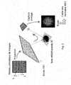
- the figure 1represents a flow chart comprising 5 steps of a method for measuring the geometric structure of a component according to one embodiment of the invention. In what follows, these five steps are explained and detailed for measuring the geometric structure of an ophthalmic lens having a first face 10, for example convex, and a second face 20, for example concave.
- the componentis a progressive ophthalmic lens.
- Step S1Measuring the first face 10 by a fringe reflection method
- a periodic fringe network PS1is projected, constituted for example by light strips of width L uniformly illuminated by white light and separated by strips of width L which are not illuminated.
- the fringe networkis reflected by the face 10 and forms a distorted image of the network.
- This imageis captured by an image capture device, for example a digital camera sensitive to light in the visible spectrum.
- This image(or set of several images) is used to calculate a map MS1 of the normal directions to the face 10 in a chosen number of its points.
- the transformation T1makes it possible to pass from the signal PS1 to a card MS1 of "measured" normals of the face 10.
- a simulationmakes it possible to obtain a first estimate ES1 of the normals for a known initial face.
- the MS1 map of the measured normalsis the target of a reconstruction problem that is solved by optimization at the later step S10.
- the present inventionis not limited to the embodiment described by way of example; thus, it is possible to use other methods for measuring the first signal MS1 than the deflectometry of fringe in reflection, for example a deflectometry method using projection fringes or using an Ronchi grating.
- Step S2Transmission Measurement, Through the First and Second Faces Using a Hartmann Method:
- a parallel-beam optical beam PS2is sent through the faces 10 and 20 of the component to be measured.
- the beams constituting the beamundergo a refraction-related deviation at the two interfaces 10, 20 of the component.
- Part of the deviated raysthen pass through a matrix of openings to form secondary beams which are finally intercepted by a screen.
- An image of the screenis captured by an image capture device, for example a digital camera sensitive to light in the visible spectrum, the offsets of the secondary beams translated into deviations of the incident light rays characteristic of the effect are acquired. optical component measured.
- these offsetsare translated into a map MS2 of the normals at the wavefront transmitted by the component.
- the transformation T2makes it possible to pass from the signal PS2 to a card MS2 of "measured" deviations.
- the knowledge of the ray deviationis associated with a modeling of the behavior of the Hartmann type measuring system.
- the simulation of the deviation of the light rays by the measured componentmakes it possible to obtain deviations for a known initial component.
- the MS2 map of the measured deviationsis the target of a reconstruction problem which is solved by optimization at the subsequent step S20.
- the present inventionis not limited to the embodiment described by way of example; thus, other methods can be used to measure the second signal MS2 than Hartmann's deflectometry in transmission, such as for example a Shack-Hartmann deflectometry method, transmission fringes or Schlieren.
- the first signal MS1results from the first transformation of the first probe signal PS1 by said first face 10; and the second signal MS2 results from the second transformation of the second probe signal PS2 by said first face 10 and said second face 20.
- the first signal MS1results from the first transformation of the first probe signal PS1 by said first face 10 and said second face 20; and the second signal MS2 results from the second transformation of the second probe signal PS2 by said first face 10 and said second face 20.
- the first signal MS1results from the first transformation of the first probe signal PS1 by said first face 10; and the second signal MS2 results from the second transformation of the second probe signal PS2 by said second face 20.
- the first and / or the second probe signal(PS1, PS2) is an optical signal.
- the first signal MS1is a normal map to the first face 10 obtained by deflectometry measurement of an optical signal constituted by a periodic grating reflected by the first face 10 and the measurement step S2 of the second signal MS2 is a deflectometry measurement of an optical signal transmitted by the first and second faces 10, 20.
- the step S1 of measuring the first signal MS1is a measurement of deformation of an optical signal reflected by the first face 10 and the step 52 of measuring the second signal MS2 is a measurement of magnification of an optical signal transmitted by the first and the second face 10, 20.
- the measurement steps S1, S2are implemented by a single device.
- Step S3Determining a third transformation to move from the first marker R1 to the second marker R2
- the measurement MS2 of the second faceis carried out in a reference R2. It is necessary to know a transformation to go from the R1 mark to the R2 mark.
- the step of reconstructing the second face 20 from a second measurement MS2 carried out in transmissiongenerally does not in itself make it possible to position and orient the second estimated face (or reconstructed) with respect to the first estimated face .
- the knowledge of a third transformation for passing from a first reference R1 linked to the measurement of the first signal MS1 to a second reference R2 related to the measurement of the second signal MS2is necessary to achieve this.
- R1here means reference of an affine space, defined by an origin and 3 independent directions.
- the third transformationis therefore an affine transformation which can be defined by means of a vector which separates the origin of R1 and the origin of R2 and a rotation matrix of order 3 to express the rotations necessary to pass.
- axes of the reference R1 to the axes of the R2mark.
- the knowledge of the third transformationpasses through an independent determination of the measurement of the first and the second signal MS2.
- the third transformationcan be determined at a reference point: the thickness in the center of the component is measured for example using a system to mechanical or optical probing. This makes it possible to know the distance between the faces 10 and 20 of the component at this reference point.
- Step S3depends on the type of measurement performed in steps S1 and S2.
- steps S1 and S2relate to attitudes (for example in a mechanical probing)
- the information availableis sufficient to completely reconstruct the face.
- the measurementconcerns data of order one (for example normals, or optical deviations), there is an indeterminacy and the reconstruction can not take place without giving the altitude of a point of the face (the problem of reconstruction has an infinity of solutions).
- a measurement of the thickness at the center of the componentmakes it possible to position the face to be reconstructed in space.
- the prism measurementcan be directly translated into a transformation between the first face and the second face. If the prism measurement is performed by an incident ray that is not normal to the first face, then the prism depends on the second face. It is therefore necessary to reconstruct simultaneously the second face and the orientation of the second face in space (the altitude being given by the measurement of the center thickness). In the latter situation, the step S20 described below leads to a simultaneous determination of the third transformation and the second face 20.
- the present inventionis not limited to the embodiment described by way of example;
- methods for determining the third transformationother than the transmission optical methods mentioned, for example an optical method in reflection, by mechanical probing or by optical probing.
- the measurement steps S1, 52are performed on different measurement equipment. This makes a common measurement repository necessary to absolutely position the component in the space.
- the first and second measurementscan be made, each using a micro-circle pointing system carried on one of the faces of the component or alternatively through a common mechanical reference between measuring systems which guarantees a positioning in an equivalent reference in each of them.
- a self-centered mechanical clamp located in spaceis used.
- the step (S3) for determining the third transformationcomprises a thickness measurement of the component.
- the step (S3) for determining the third transformationfurther includes a measurement of the prism of the component.
- Step S10Estimation of the first face 10 made in particular from the first signal MS1.
- a first reconstructionaims to estimate the first face 10 of the component. Considering a first virtual face 11 positioned in space under the same conditions (position and orientation) as the first face 10 of the physical component during the deformation measurement of the fringe network.
- the reference in which the measurement MS1 is carried outis called R1 and in which the position of the first face 10 and the position of the first virtual face 11 is known.
- Starting valuesare defined for the first virtual face 11, for example a spherical shape.
- the simulation of the transformation of the signal PS1 by the virtual face 11makes it possible to calculate an estimate ES1 of the normals of the virtual face 11.
- a cost function V1is then defined, which can be calculated for current values of the virtual face 11 of the component; this cost function V1 is designed to present a minimum or maximum value when the values of the estimate ES1 of the measurement made with the virtual face 11 are equal to the values of the measurement MS1.
- the value of the cost functionquantifies the difference between the simulation of measurement ES1 and measurement MS1. For each measurement point, we can consider the norm of the vector equal to the difference between the normal indicating vector that comes from the measurement and the vector indicating the normal that comes from the simulation.
- a cost functioncan be the quadratic sum of the vector norms for all measurement points.
- an iterative optimization algorithmmodifies the virtual face 11 in order to decrease the cost function V1.
- a least squares algorithmis used such as Gauss-Newton, or Levenberg-Marquardt described in Numerical Optimization, Bonnas et al., Springer 2003.
- the algorithmproposes a new virtual face 11; the simulation of the transformation T1 by this new virtual face 11 makes it possible to calculate a new value V1 of the cost function.
- the iterative processis interrupted for example when when a stop criterion is verified for example when the value taken by the cost function V1 can no longer be reduced, or when the value of the cost function V1 is less than a threshold given.
- a virtual face 11which is a correct estimate of the measured face since the difference between the measurement and the simulation of this measurement via the transformation T1 is reduced.
- Step S20Estimation of the second face 20 made in particular from the first report MS2.
- a virtual componentis constituted, the first face of which is the result of the reconstruction of the first face 10 estimated from the measurement MS1, and the second face of which is a second virtual face 21.
- the third transformation determined at the step S3is the law of passage of the reference frame R1 in which is expressed the first estimated face towards the reference R2 in which is the position of the second face 20 is identified during the measurement carried out in step 2. This third transformation makes it possible to constructing the virtual component in the space and placing it virtually under the same conditions as the component (the physical part) during the measurement carried out in step S2.
- the norm of the vector equal to the difference between the measured deviated vector and the simulated deviated vectorcan be considered.
- a cost functioncan be the quadratic sum of these norms.
- an iterative optimization algorithmmodifies the virtual face 21 of the component in order to decrease the value of the cost function V2.
- a least squares algorithmsuch as Gauss-Newton, or Levenberg-Marquardt ("Numerical Optimization", Bonnas et al., Springer, 2003) can be used for this purpose.
- the algorithmproposes a new virtual face 21; the simulation of the transformation T2 by this new face 21 makes it possible to calculate a new value V2 of the cost function.
- the iterative processstops, for example, when the value of the cost function can no longer be reduced, or when the value of the cost function is lower than a given threshold.
- We then have a virtual face 21which is an estimate E2 of the measured face 20 since the difference between the measurement and the simulation of this measurement via the transformation T2 is small.
- the estimate 21 of said second face 20is obtained further from the estimate 11 of said first face 10.
- the estimation steps S10, S20comprise a step where the virtual face 11, 21 is expressed in an analytical form.
- the advantage of this stepis to accelerate the calculations, and ultimately provide an estimate of the geometric structure of the component in a form easily manipulated in subsequent numerical calculations.
- the estimate of the first surface 10serves to estimate the second surface 20.
- the first calculation means CM1performs a measurement of deformation of an optical signal reflected by the first face 10; and the second calculation means CM2 carries out a magnification measurement of an optical signal transmitted by the first and second faces 10, 20.
- a systemcomprises measurement means MM1, MM2 of an optical measurement system configured to perform measurements of faces 10, 20 of an optical component expressed in a reference system specific to said system. .
- One of the applications of this measurement of the geometric structure to an ophthalmic lensmay be the comparative analysis of a lens after machining with a nominal part, for example to study the conformity of the piece produced.
- the measured ophthalmic lens and the nominal partare brought back into a common reference frame, for example linked to the part where the measurement is made.
- the position of the measured ophthalmic lens and of the nominal partis then determined in the measurement reference frame either by the association of a mechanical reference on the lens and the workpiece, such as a flat surface, or by the permanent marking score. on the lens and the piece, of the micro-circle type.
- an embodimentmeans that a particular feature, structure, or characteristic described in connection with the embodiment may be included in at least one implementation of the invention.
- the appearances of the phrase “in one embodiment” at various places in the foregoing detailed descriptionare not necessarily all referable to the same embodiment, Similarly, separate or alternative embodiments are not necessarily mutually exclusive. other embodiments.
Landscapes
- Physics & Mathematics (AREA)
- Geometry (AREA)
- General Physics & Mathematics (AREA)
- Chemical & Material Sciences (AREA)
- Analytical Chemistry (AREA)
- Engineering & Computer Science (AREA)
- Computer Vision & Pattern Recognition (AREA)
- Length Measuring Devices By Optical Means (AREA)
- Testing Of Optical Devices Or Fibers (AREA)
Abstract
Description
Translated fromFrenchLa présente invention a pour objet un procédé et un système de mesure de la structure géométrique ou optique d'un composant optique.The present invention relates to a method and a system for measuring the geometric or optical structure of an optical component.
Le procédé selon l'invention permet de mesurer de façon absolue les deux faces d'un composant optique. On entend par mesure absolue une mesure qui ne nécessite aucune connaissance préalable du composant hormis son indice de réfraction. La mesure de faces est susceptible de nombreuses applications industrielles. Elle est notamment utile dans le domaine ophtalmique pour le contrôle ou la mesure de lentilles ophtalmiques; dans ce cas, la réalisation de faces complexes nécessite la détermination simultanée de centaines de coefficients.The method according to the invention makes it possible to measure absolutely the two faces of an optical component. Absolute measurement is understood to mean a measurement that does not require any prior knowledge of the component apart from its refractive index. Face measurement is susceptible to many industrial applications. It is particularly useful in the ophthalmic field for the control or measurement of ophthalmic lenses; in this case, the realization of complex faces requires the simultaneous determination of hundreds of coefficients.
Cette section est destinée à introduire le lecteur aux divers aspects de l'art, qui peuvent être liés à différents aspects de la présente invention qui sont décrits et / ou revendiqués ci-dessous. Cette discussion est considérée comme utile pour fournir au lecteur des informations d'arrière-plan afin de faciliter une meilleure compréhension des différents aspects de la présente invention. En conséquence, il doit être entendu que ces déclarations doivent être lues à cette lumière, et non comme un exposé de l'art antérieur.This section is intended to introduce the reader to various aspects of the art, which may be related to various aspects of the present invention that are described and / or claimed below. This discussion is considered useful for providing the reader with background information to facilitate a better understanding of the various aspects of the present invention. Accordingly, it must be understood that these statements must be read in this light, and not as a statement of the prior art.
On sait ainsi déterminer la géométrie d'une face du composant; la géométrie de l'autre face du composant étant supposée connue pour les calculs. Il existe donc un besoin d'un appareil de mesure, qui permette de déterminer les différentes caractéristiques d'un composant optique, et notamment de ses deux faces. Un tel appareil permet notamment de mesurer efficacement des lentilles ophtalmiques progressives, en déterminant de façon exacte la forme de chacune de leurs deux faces et en positionnant parfaitement une face par rapport à l'autre sans avoir à formuler d'hypothèse sur l'une de ces faces.It is thus possible to determine the geometry of a face of the component; the geometry of the other face of the component being assumed to be known for the calculations. There is therefore a need for a measuring apparatus, which makes it possible to determine the various characteristics of an optical component, and in particular of its two faces. Such an apparatus makes it possible in particular to effectively measure progressive ophthalmic lenses, by accurately determining the shape of each of their two faces and by perfectly positioning one face relative to the other without having to formulate a hypothesis on one of these faces.
Par ailleurs, on sait mesurer les faces d'un composant optique à l'aide d'un palpeur mécanique fonctionnant face par face. Mais la durée d'une mesure d'une face est importante et il reste toujours difficile de positionner la mesure de la première face par rapport à la deuxième face.Moreover, it is known to measure the faces of an optical component using a mechanical probe operating face-to-face. But the duration of a measurement of a face is important and it is still difficult to position the measurement of the first face with respect to the second face.
La présente invention a pour but de résoudre les inconvénients précités et propose de déterminer la structure d'un composant à partir de 2 mesures non destructives réalisées chacune sur au moins une des faces, chacune de ces faces est inconnue a priori. Cette détermination est en outre fondée sur une reconstruction numérique de chacune des faces du composant à partir desdites mesures.The present invention aims to solve the aforementioned drawbacks and proposes to determine the structure of a component from 2 non-destructive measurements each made on at least one of the faces, each of these faces is unknown a priori. This determination is further based on a digital reconstruction of each of the component faces from said measurements.
L'invention atteint ce but grâce aux caractéristiques de la revendication 1, selon un premier aspect et grâce aux caractéristiques de la revendication 14, selon un deuxième aspect.The invention achieves this goal by virtue of the features of
Les revendications secondaires présentent des conceptions avantageuses et des perfectionnements de l'invention.The secondary claims show advantageous designs and improvements of the invention.
Selon le premier aspect, l'invention concerne un procédé de mesure de la structure géométrique d'un composant délimité par une première face 10 et une deuxième face 20; ledit procédé comprenant les étapes de:
- S1 Mesure d'un premier signal MS1 résultant d'une première transformation d'un premier signal sonde PS1 par au moins ladite
première face 10, une première simulation de ladite première transformation permettant d'obtenir une première estimation ES1 du signal résultant de ladite première transformation du premier signal sonde PS1 par au moins une première face virtuelle 11 connue et positionnée dans un premier repère de mesure R1 de manière identique à laditepremière face 10 lors de la mesure du premier signal MS1; - S2 Mesure d'un deuxième signal MS2 résultant d'une deuxième transformation d'un deuxième signal sonde PS2 par au moins ladite
deuxième face 20, une deuxième simulation de ladite deuxième transformation permettant d'obtenir une deuxième estimation ES2 du signal résultant de ladite deuxième transformation du deuxième signal sonde PS2 par au moins une deuxième face virtuelle 21 connue et positionnée dans un deuxième repère de mesure R2 de manière identique à laditedeuxième face 20 lors de la mesure du deuxième signal MS2; - S3 Détermination d'une troisième transformation permettant de passer du premier repère R1 au deuxième repère R2 ;
- S10 Estimation de ladite
première face 10 réalisée à partir du premier signal MS1, de ladite première simulation et d'une première fonction coût V1 quantifiant un écart entre l'estimation ES1 et le premier signal MS1; - S20 Estimation de ladite
deuxième face 20 réalisée à partir du deuxième signal MS2, de ladite deuxième simulation, de ladite troisième transformation et d'une deuxième fonction coût V2 quantifiant un écart entre l'estimation ES2 et le deuxième signal MS2.
- S1 Measuring a first signal MS1 resulting from a first transformation of a first probe signal PS1 by at least said
first face 10, a first simulation of said first transformation making it possible to obtain a first estimate ES1 of the signal resulting from said first transforming the first probe signal PS1 by at least a first known virtual face 11 and positioned in a first measurement mark R1 identically to saidfirst face 10 during the measurement of the first signal MS1; - S2 Measuring a second signal MS2 resulting from a second transformation of a second probe signal PS2 by at least said
second face 20, a second simulation of said second transformation making it possible to obtain a second estimate ES2 of the signal resulting from said second transforming the second probe signal PS2 by at least one known second virtual face 21 and positioned in a second measurement marker R2 identically to saidsecond face 20 during the measurement of the second signal MS2; - S3 Determining a third transformation to go from the first marker R1 to the second marker R2;
- S10 Estimate said
first face 10 made from the first signal MS1, said first simulation and a first cost function V1 quantifying a difference between the estimate ES1 and the first signal MS1; - S20 Estimate of said
second face 20 made from the second signal MS2, said second simulation, said third transformation and a second function cost V2 quantifying a difference between the estimate ES2 and the second signal MS2.
Selon le deuxième aspect, l'invention concerne un système de mesure de la structure géométrique d'un composant délimité par une première face 10 et une deuxième face 20; ledit système comportant:
- un premier moyen de mesure MM1 d'un premier signal MS1 résultant d'une première transformation d'un premier signal sonde PS1 par au moins ladite
première face 10, une première simulation de ladite première transformation permettant d'obtenir une première estimation ES1 du signal résultant de ladite première transformation du premier signal sonde PS1 par au moins une première face 11 virtuelle connue et positionnée dans un premier repère de mesure R1 de manière identique à laditepremière face 10 lors de la mesure du premier signal MS1; - un deuxième moyen de mesure MM2 d'un deuxième signal MS2 résultant d'une deuxième transformation d'un deuxième signal sonde PS2 par au moins ladite
deuxième face 20, une deuxième simulation de ladite deuxième transformation permettant d'obtenir une deuxième estimation ES2 du signal résultant de ladite deuxième transformation du deuxième signal sonde PS2 par au moins une deuxième face 21 virtuelle connue et positionnée dans un premier repère de mesure R2 de manière identique à laditedeuxième face 20 lors de la mesure du deuxième signal MS2; - un moyen MD pour déterminer une troisième transformation permettant de passer du premier repère R1 au deuxième repère R2
- un premier moyen de calcul CM1 configuré pour estimer ladite
première face 10 à partir du premier signal MS1, de ladite première simulation, d'une première face 11 virtuelle et d'une première fonction coût V1 quantifiant un écart entre la première estimation ES1 et le premier signal MS1; - un deuxième moyen de calcul CM2 configuré pour estimer ladite
deuxième face 20 à partir du deuxième signal MS2, de ladite deuxième simulation, d'une deuxième face 21 virtuelle, de ladite troisième transformation et d'une deuxième fonction coût V2 quantifiant un écart entre la deuxième estimation ES2 et le deuxième signal M52.
- un premier moyen de calcul CM1 configuré pour estimer ladite
- first measuring means MM1 of a first signal MS1 resulting from a first transformation of a first probe signal PS1 by at least said
first face 10, a first simulation of said first transformation making it possible to obtain a first estimate ES1 of the signal resulting from said first transformation of the first probe signal PS1 by at least a first virtual face 11 known and positioned in a first measurement mark R1 identically to saidfirst face 10 during the measurement of the first signal MS1; - a second measurement means MM2 of a second signal MS2 resulting from a second transformation of a second probe signal PS2 by at least said
second face 20, a second simulation of said second transformation making it possible to obtain a second estimate ES2 of the signal resulting from said second transformation of the second probe signal PS2 by at least one known second virtual face 21 and positioned in a first measurement mark R2 identically to saidsecond face 20 when measuring the second signal MS2; - MD means for determining a third transformation for passing from the first marker R1 to the second marker R2
- a first calculation means CM1 configured to estimate said
first face 10 from the first signal MS1, said first simulation, a first virtual face 11 and a first cost function V1 quantifying a difference between the first estimate ES1 and the first first signal MS1; - a second calculation means CM2 configured to estimate said
second face 20 from the second signal MS2, said second simulation, a second virtual face 21, said third transformation and a second function cost V2 quantifying a difference between the second estimate ES2 and the second signal M52.
- a first calculation means CM1 configured to estimate said
La méthode selon l'invention présente l'avantage de réaliser une détermination de la structure d'un composant qui est très rapide par rapport aux techniques de mesure mécaniques directes existantes.The method according to the invention has the advantage of making a determination of the structure of a component which is very fast compared to existing direct mechanical measurement techniques.
Par ailleurs, il est possible de mettre en oeuvre la méthode selon l'invention en employant deux mesures réalisées sur chacune des faces qui sont de nature très différente. La première mesure est par exemple une mesure en réflexion, la seconde mesure est réalisée par exemple en transmission. Mais d'autres géométries sont possibles comme réflexion/réflexion ou transmission/transmission. De même, la première mesure est une mesure de défléctométrie par réflexion de franges et la deuxième mesure est une mesure, du type Hartmann mais alternativement la première mesure peut aussi bien être une mesure de déformation d'un signal optique réfléchi par la première face et la deuxième mesure est une mesure de grossissement d'un signal optique transmis par la première et la deuxième face.Furthermore, it is possible to implement the method according to the invention by employing two measurements made on each of the faces which are of a very different nature. The first measurement is for example a measurement in reflection, the second measurement is carried out for example in transmission. But other geometries are possible as reflection / reflection or transmission / transmission. Similarly, the first measurement is a measurement of fringe reflection deflectometry and the second measurement is a Hartmann type measurement, but alternatively the first measurement may be a measurement of deformation of an optical signal reflected by the first face and the second measurement is a magnification measurement of an optical signal transmitted by the first and second faces.
Ainsi, la methode selon l'invention présente également l'avantage de pouvoir être mise en oeuvre à partir d'équipements existant configurés pour réaliser des mesures de faces mais qui ne comprennent pas des moyens de calcul pour reconstruire ces faces dans un référentiel qui n'est pas lié à eux-même.Thus, the method according to the invention also has the advantage of being able to be implemented from existing equipment configured to perform face measurements but which do not include calculation means for reconstructing these faces in a reference frame which is not related to themselves.
Un troisième avantage de la méthode selon l'invention est lié à la forme sous laquelle la détermination de la structure est produite : les étapes de reconstruction des faces présentées plus bas emploient une représentation des faces sous une forme analytique. En outre; la structure du composant telle qu'elle est délivrée par la méthode selon l'invention possède une forme analytique : ceci est particulièrement adaptée à l'emploi ultérieur de la structure estimée dans des moyens de simulations numériques.A third advantage of the method according to the invention is related to the form in which the determination of the structure is produced: the steps of reconstruction of the faces presented below use a representation of the faces in an analytical form. In addition; the structure of the component as it is delivered by the method according to the invention has an analytical form: this is particularly suitable for the subsequent use of the estimated structure in numerical simulation means.
Les différents modes de réalisation de l'invention trouvent des applications dans la mesure ou le contrôle de pièces usinées : par exemple des lentilles ophtalmiques. Dans ce cas, la réalisation de faces complexes nécessite la détermination simultanée de centaines de coefficients.The various embodiments of the invention find applications in the measurement or control of machined parts: for example ophthalmic lenses. In this case, the production of complex faces requires the simultaneous determination of hundreds of coefficients.
L'invention sera mieux comprise et illustrée au moyen des modes de réalisation et les exemples d'exécution suivants, nullement limitatifs, en référence aux figures annexées sur lesquelles:
Figure 1 , montre l'ordinogramme d'une méthode de mesure selon un mode de réalisation de l'invention ;Figure 2 , présente un exemple de mesure d'un premier signal MS1 mise en oeuvre dans ladite méthode selon un mode de réalisation de l'invention ;Figure 3 présente un exemple d'étape de mesure d'un deuxième signal MS2 mise en oeuvre dans ladite méthode selon un mode de réalisation de l'invention;Figure 4 présente un exemple d'étape de détermination d'une troisième transformation mise en oeuvre dans ladite méthode selon un mode de réalisation de l'invention;Figure 5 , présente schématiquement un mode de réalisation d'un système de mesure de la structure d'un composant selon un mode de réalisation de l'invention.
Figure 1 shows the flow chart of a measurement method according to one embodiment of the invention;Figure 2 shows an example of measurement of a first signal MS1 implemented in said method according to one embodiment of the invention;Figure 3 shows an exemplary step of measuring a second signal MS2 implemented in said method according to one embodiment of the invention;Figure 4 shows an exemplary step of determining a third transformation implemented in said method according to one embodiment of the invention;Figure 5 , schematically presents an embodiment of a system for measuring the structure of a component according to one embodiment of the invention.
Il est entendu que les chiffres et les descriptions de la présente invention ont été simplifiés pour-illustrer les éléments qui sont pertinents pour une compréhension claire de la présente invention, tout en éliminant, à des fins de clarté, de nombreux autres éléments trouvés dans les procédés de mesure par reconstruction des faces d'un composant optique. Cependant, parce que ces éléments sont bien connus dans l'art antérieur, une discussion détaillée de ces éléments n'est pas prévue ici. La présente divulgation est dirigée vers toutes ces variations et les modifications connues de l'homme de l'art.It is understood that the figures and descriptions of the present invention have been simplified to illustrate the elements that are relevant to a clear understanding of the present invention, while eliminating, for clarity, many other elements found in the present invention. measurement methods by reconstruction of the faces of an optical component. However, because these elements are well known in the prior art, a detailed discussion of these elements is not provided here. The present disclosure is directed to all such variations and modifications known to those skilled in the art.
La
Avantageusement, le composant est une lentille ophtalmique progressive.Advantageously, the component is a progressive ophthalmic lens.
Comme représenté sur la
Bien entendu, la présente invention n'est pas limitée au mode de réalisation décrit à titre d'exemple; ainsi, on peut utiliser pour mesurer le première signal MS1 d'autres méthodes que la déflectométrie de frange en réflexion comme par exemple une méthode de déflectométrie par franges en projection ou en utilisant un réseau de Ronchi.Of course, the present invention is not limited to the embodiment described by way of example; thus, it is possible to use other methods for measuring the first signal MS1 than the deflectometry of fringe in reflection, for example a deflectometry method using projection fringes or using an Ronchi grating.
Comme représenté sur la
La connaissance de la déviation des rayons est associée à une modélisation du comportement du système de mesure de type Hartmann. La simulation de la déviation des rayons lumineux par le composant mesuré permet d'obtenir des déviations pour un composant initial connu. La carte MS2 des déviations mesurées constitue la cible d'un problème de reconstruction qui est résolu par optimisation à l'étape ultérieure S20.The knowledge of the ray deviation is associated with a modeling of the behavior of the Hartmann type measuring system. The simulation of the deviation of the light rays by the measured component makes it possible to obtain deviations for a known initial component. The MS2 map of the measured deviations is the target of a reconstruction problem which is solved by optimization at the subsequent step S20.
Bien entendu, la présente invention n'est pas limitée au mode de réalisation décrit à titre d'exemple; ainsi, on peut utiliser pour mesurer le deuxième signal MS2 d'autres méthodes que la déflectométrie de Hartmann en transmission comme par exemple une méthode de déflectométrie de Shack-Hartmann, par franges en transmission ou par Schlieren.Of course, the present invention is not limited to the embodiment described by way of example; thus, other methods can be used to measure the second signal MS2 than Hartmann's deflectometry in transmission, such as for example a Shack-Hartmann deflectometry method, transmission fringes or Schlieren.
Dans un premier mode de réalisation, le premier signal MS1 résulte de la première transformation du premier signal sonde PS1 par ladite première face 10; et le deuxième signal MS2 résulte de la deuxième transformation du deuxième signal sonde PS2 par ladite première face 10 et ladite deuxième face 20.In a first embodiment, the first signal MS1 results from the first transformation of the first probe signal PS1 by said
Dans un deuxième mode de réalisation, le premier signal MS1 résulte de la première transformation du premier signal sonde PS1 par ladite première face 10 et ladite deuxième face 20; et le deuxième signal MS2 résulte de la deuxième transformation du deuxième signal sonde PS2 par ladite première face 10 et ladite deuxième face 20.In a second embodiment, the first signal MS1 results from the first transformation of the first probe signal PS1 by said
Dans un troisième mode de réalisation, le premier signal MS1 résulte de la première transformation du premier signal sonde PS1 par ladite première face 10; et le deuxième signal MS2 résulte de la deuxième transformation du deuxième signal sonde PS2 par ladite deuxième face 20.In a third embodiment, the first signal MS1 results from the first transformation of the first probe signal PS1 by said
Avantageusement, le premier et/ou le deuxième signal sonde (PS1, PS2) est un signal optique.Advantageously, the first and / or the second probe signal (PS1, PS2) is an optical signal.
Avantageusement, le premier signal MS1 est une carte de normales à la première face 10 obtenue par mesure de déflectométrie d'un signal optique constitué par un réseau périodique réfléchi par la première face 10 et l'étape S2 de mesure du deuxième signal MS2 est une mesure déflectométrie d'un signal optique transmis par la première et la deuxième face 10, 20.Advantageously, the first signal MS1 is a normal map to the
Avantageusement, : l'étape S1 de mesure du premier signal MS1 est une mesure de déformation d'un signal optique réfléchi par la première face 10 et l'étape 52 de mesure du deuxième signal MS2 est une mesure de grossissement d'un signal optique transmis par la première et la deuxième face 10, 20.Advantageously, the step S1 of measuring the first signal MS1 is a measurement of deformation of an optical signal reflected by the
Avantageusement, les étapes de mesure S1, S2 sont mises en oeuvre par un unique équipement.Advantageously, the measurement steps S1, S2 are implemented by a single device.
Lorsque la mesure du premier signal MS1 dans un repère R1 est réalisée en réflexion sur la première face 10, seule une reconstruction de la première face 10 est réalisable à partir de cette première mesure SM1. La mesure MS2 de la deuxième face est réalisée dans un repère R2. Il est nécessaire de connaître une transformation pour passer du repère R1 au repère R2. L'étape de reconstruction de la deuxième face 20 à partir d'une deuxième mesure MS2 réalisée en transmission ne permet en général pas à elle seule de positionner et d'orienter la deuxième face estimée (ou reconstruite) par rapport à la première face estimée. La connaissance d'une troisième transformation permettant de passer d'un premier repère R1 lié à la mesure du premier signal MS1 à un deuxième repère R2 lié à la mesure du deuxième signal MS2 est nécessaire pour y parvenir.When the measurement of the first signal MS1 in a reference frame R1 is carried out in reflection on the
Par repère R1, R2 on entend ici repère d'un espace affine, défini par une origine et 3 directions indépendantes. La troisième transformation est donc une transformation affine qui peut donc être définie au moyen d'un vecteur qui sépare l'origine de R1 et l'origine de R2 et d'une matrice de rotation d'ordre 3 pour exprimer les rotations nécessaire pour passer des axes du repère R1 aux axes du repère R2.By reference R1, R2 here means reference of an affine space, defined by an origin and 3 independent directions. The third transformation is therefore an affine transformation which can be defined by means of a vector which separates the origin of R1 and the origin of R2 and a rotation matrix of order 3 to express the rotations necessary to pass. axes of the reference R1 to the axes of the R2 mark.
Pour le présent mode de réalisation, la connaissance de la troisième transformation passe par une détermination indépendante de la mesure du premier et du deuxième signal MS2.For the present embodiment, the knowledge of the third transformation passes through an independent determination of the measurement of the first and the second signal MS2.
Comme représenté sur la
L'étape S3 dépend du type de mesure effectuée aux étapes S1 et S2.Step S3 depends on the type of measurement performed in steps S1 and S2.
En effet, si la mesure des étapes S1 et S2 concerne des attitudes (par exemple dans un palpage mécanique), les informations dont on dispose sont suffisantes pour reconstruire entièrement la face.Indeed, if the measurement of steps S1 and S2 relates to attitudes (for example in a mechanical probing), the information available is sufficient to completely reconstruct the face.
Si la mesure concerne des données d'ordre un (par exemple des normales, ou des déviations optiques), il y a une indétermination et la reconstruction ne peut avoir lieu sans donner l'altitude d'un point de la face (le problème de reconstruction a une infinité de solutions). Pour résoudre ce problème, une mesure de l'épaisseur au centre du composant permet de positionner dans l'espace la face à reconstruire.If the measurement concerns data of order one (for example normals, or optical deviations), there is an indeterminacy and the reconstruction can not take place without giving the altitude of a point of the face (the problem of reconstruction has an infinity of solutions). To solve this problem, a measurement of the thickness at the center of the component makes it possible to position the face to be reconstructed in space.
Dans le cas d'une mesure d'ordre 2 (par exemple une mesure de courbure, ou de grandissement) il y a deux indéterminations. Il faut donner une altitude en un point de la face et une normale en un point de la face pour garantir l'unicité de la solution. Ainsi, on peut mesurer l'épaisseur au centre du composant pour déterminer l'altitude de la deuxième face, ainsi que le prisme du composant qui indiquera une normale à la deuxième face.In the case of a measure of order 2 (for example a measurement of curvature, or of magnification) there are two indeterminations. It is necessary to give an altitude at a point of the face and a normal at a point of the face to guarantee the uniqueness of the solution. Thus, it is possible to measure the thickness in the center of the component to determine the altitude of the second face, as well as the prism of the component which will indicate a normal to the second face.
Si le prisme est mesuré par un moyen optique à l'aide d'un rayon incident normal à la première face, alors la mesure de prisme peut être directement traduite en transformation entre la première face et !a deuxième face. Si la mesure de prisme est effectuée par un rayon incident qui n'est pas normal à la première face, alors le prisme dépend de la deuxième face. Il faut donc reconstruire simultanément la deuxième face et l'orientation de la deuxième face dans l'espace (l'altitude étant donnée par la mesure de l'épaisseur centre). Dans cette dernière situation, l'étape S20 decrite plus bas, conduit à une détermination simultanée de la troisième transformation et de la deuxième face 20.If the prism is measured by optical means using an incident ray normal to the first face, then the prism measurement can be directly translated into a transformation between the first face and the second face. If the prism measurement is performed by an incident ray that is not normal to the first face, then the prism depends on the second face. It is therefore necessary to reconstruct simultaneously the second face and the orientation of the second face in space (the altitude being given by the measurement of the center thickness). In the latter situation, the step S20 described below leads to a simultaneous determination of the third transformation and the
Bien entendu, la présente invention n'est pas limitée au mode de réalisation décrit à titre d'exemple; ainsi, on peut utiliser pour déterminer la troisième transformation d'autres méthodes que les méthodes optiques en transmission évoquées comme par exemple une méthode optique en réflexion, par palpage mécanique ou encore par palpage optique.Of course, the present invention is not limited to the embodiment described by way of example; Thus, it is possible to use methods for determining the third transformation other than the transmission optical methods mentioned, for example an optical method in reflection, by mechanical probing or by optical probing.
Les étapes de mesure S1, 52 sont réalisées sur des équipements de mesures différents. Cela rend nécessaire un référentiel de mesure commun pour positionner de façon absolue le composant dans l'espace. Pour le présent mode de réalisation, la première et la deuxième mesures peuvent être réalisées, chacune, à l'aide d'un système de pointé des micro-cercles portés sur l'une des faces du composant ou alternativement grâce un référentiel mécanique commun entre les systèmes de mesure qui garantit alors un positionnement dans un repère équivalent dans chacun d'entre eux. Pour ce faire, on utilise par exemple : une pince mécanique auto-centrée repérée dans l'espace.The measurement steps S1, 52 are performed on different measurement equipment. This makes a common measurement repository necessary to absolutely position the component in the space. For the present embodiment, the first and second measurements can be made, each using a micro-circle pointing system carried on one of the faces of the component or alternatively through a common mechanical reference between measuring systems which guarantees a positioning in an equivalent reference in each of them. For this purpose, for example, a self-centered mechanical clamp located in space is used.
Selon un mode de réalisation, l'étape (S3) de détermination de la troisième transformation comporte une mesure d'épaisseur du composant.According to one embodiment, the step (S3) for determining the third transformation comprises a thickness measurement of the component.
Selon un mode de réalisation, l'étape (S3) de détermination de la troisième transformation comporte en outre une mesure du prisme du composant.According to one embodiment, the step (S3) for determining the third transformation further includes a measurement of the prism of the component.
Une première reconstruction vise à estimer la première face 10 du composant. On considère une première face virtuelle 11 positionnée dans l'espace dans les mêmes conditions (position et orientation) que la première face 10 du composant physique lors de la mesure de déformation du réseau de franges. On appelle R1 le repère dans lequel est réalisée la mesure MS1 et dans lequel la position de la première face 10 et la position de la première face virtuelle 11 est connue.A first reconstruction aims to estimate the
Le principe d'une reconstruction par optimisation est connu en soi.The principle of an optimization reconstruction is known per se.
On définit des valeurs de départ pour la première face virtuelle 11, par exemple une forme sphérique. La simulation de la transformation du signal PS1 par la face virtuelle 11 permet de calculer une estimation ES1 des normales de la face virtuelle 11.Starting values are defined for the first virtual face 11, for example a spherical shape. The simulation of the transformation of the signal PS1 by the virtual face 11 makes it possible to calculate an estimate ES1 of the normals of the virtual face 11.
On définit ensuite une fonction coût V1, susceptible d'être calculée pour des valeurs courantes de la face virtuelle 11 du composant; cette fonction coût V1 est conçue pour présenter une valeur minimale ou maximale lorsque les valeurs de l'estimation ES1 de la mesure réalisée avec la face virtuelle 11 sont égales aux valeurs de la mesure MS1.A cost function V1 is then defined, which can be calculated for current values of the virtual face 11 of the component; this cost function V1 is designed to present a minimum or maximum value when the values of the estimate ES1 of the measurement made with the virtual face 11 are equal to the values of the measurement MS1.
La valeur de la fonction coût permet de quantifier l'écart entre la simulation de la mesure ES1 et la mesure MS1. Pour chaque point de mesure, on peut considérer la norme du vecteur égal à la différence entre le vecteur indiquant la normale qui est issu de la mesure et le vecteur indiquant la normale qui est issu de la simulation. Une fonction coût peut être la somme quadratique des normes des vecteurs pour tous points de mesure.The value of the cost function quantifies the difference between the simulation of measurement ES1 and measurement MS1. For each measurement point, we can consider the norm of the vector equal to the difference between the normal indicating vector that comes from the measurement and the vector indicating the normal that comes from the simulation. A cost function can be the quadratic sum of the vector norms for all measurement points.
Ensuite, un algorithme d'optimisation itératif modifie la face virtuelle 11 afin de faire diminuer la fonction coût V1. Par exemple on emploie un algorithme de moindres carrés tel que Gauss-Newton, ou Levenberg-Marquardt décrite dans « Numerical Optimization », Bonnas et al., Springer 2003. A chaque itération, l'algorithme propose une nouvelle face virtuelle 11; la simulation de la transformation T1 par cette nouvelle face virtuelle 11 permet de calculer une nouvelle valeur V1 de la fonction coût.Then, an iterative optimization algorithm modifies the virtual face 11 in order to decrease the cost function V1. For example, a least squares algorithm is used such as Gauss-Newton, or Levenberg-Marquardt described in Numerical Optimization, Bonnas et al., Springer 2003. At each iteration, the algorithm proposes a new virtual face 11; the simulation of the transformation T1 by this new virtual face 11 makes it possible to calculate a new value V1 of the cost function.
Le processus itératif est interrompu par exemple lorsque lorsque qu'un critère d'arrêt est vérifié par exemple lorsque la valeur prise par la fonction coût V1 ne peut plus être diminuée, ou bien lorsque la valeur de la fonction coût V1 est inférieure à un seuil donné. On a alors une face virtuelle 11 qui est une estimation correcte de la face 10 mesurée puisque l'écart entre la mesure et la simulation de cette mesure via la transformation T1 est réduite.The iterative process is interrupted for example when when a stop criterion is verified for example when the value taken by the cost function V1 can no longer be reduced, or when the value of the cost function V1 is less than a threshold given. We then have a virtual face 11 which is a correct estimate of the measured face since the difference between the measurement and the simulation of this measurement via the transformation T1 is reduced.
On constitue un composant virtuel, dont la première face est le résultat de la reconstruction de la première face 10 estimée à partir de la mesure MS1, et dont la deuxième face est une deuxième face virtuelle 21. La la troisième transformation déterminée à l'étape S3 est la loi de passage du repère R1 dans lequel est exprimé la première face estimée vers le repère R2 dans lequel est la position de la deuxième face 20 est repérée au cours de la mesure réalisée à l'étape 2. Cette troisième transformation permet de construire le composant virtuel dans l'espace et de le placer virtuellement dans les mêmes conditions que le composant (la pièce physique) au cours de la mesure réalisée à l'étape S2.A virtual component is constituted, the first face of which is the result of the reconstruction of the
La simulation de la transformation T2 du signal PS2 par ce composant virtuel initial de calculer une estimation d'un deuxième signal, c'est-à-dire qu'on sait obtenir par le calcul une carte de déviation (des faisceaux secondaires du signal sond PS2) produites par le composant virtuel.The simulation of the T2 transformation of the PS2 signal by this initial virtual component to calculate an estimate of a second signal, that is to say it is possible to obtain by calculation a deflection map (secondary beams of the signal signal PS2) produced by the virtual component.
Pour chaque point de cette carte de déviation, on peut considérer la norme du vecteur égal à la différence entre le vecteur dévié mesuré et le vecteur dévié simulé. Une fonction coût peut être la somme quadratique de ces normes.For each point of this deflection map, the norm of the vector equal to the difference between the measured deviated vector and the simulated deviated vector can be considered. A cost function can be the quadratic sum of these norms.
Ensuite, un algorithme d'optimisation itératif modifie la face virtuelle 21 du composant afin de faire diminuer la valeur de la fonction coût V2. Un algorithme de moindres carrés tel que Gauss-Newton, ou Levenberg-Marquardt (« Numerical Optimization », Bonnas et al., Springer, 2003) peut être utilisé dans ce but. A chaque itération, l'algorithme propose une nouvelle face virtuelle 21 ; la simulation de la transformation T2 par cette nouvelle face 21 permet de calculer une nouvelle valeur V2 de la fonction coût. Le processus itératif s'arrête par exemple lorsque la valeur de la fonction coût ne peut plus être diminuée, ou bien lorsque la valeur de la fonction coût est inférieure à un seuil donné. On a alors une face virtuelle 21 qui est une estimation E2 de la face 20 mesurée puisque l'écart entre la mesure et la simulation de cette mesure via la transformation T2 est faible.Then, an iterative optimization algorithm modifies the virtual face 21 of the component in order to decrease the value of the cost function V2. A least squares algorithm such as Gauss-Newton, or Levenberg-Marquardt ("Numerical Optimization", Bonnas et al., Springer, 2003) can be used for this purpose. At each iteration, the algorithm proposes a new virtual face 21; the simulation of the transformation T2 by this new face 21 makes it possible to calculate a new value V2 of the cost function. The iterative process stops, for example, when the value of the cost function can no longer be reduced, or when the value of the cost function is lower than a given threshold. We then have a virtual face 21 which is an estimate E2 of the measured
Avantageusement, chaque étape d'estimation S10, S20 est itérative, chaque itération consistant à :
- a Exécuter la simulation SIM1, SIM2 à partir d'au moins une face virtuelle 11, 21 et du signal sonde PS1 ; PS2 pour obtenir une estimation ES1, ES2 du signal mesuré ;
- b Mesurer l'écart entre l'estimation ES1, ES2 calculée à l'étape a et le signal mesuré MS1; MS2 au moyen de la fonction coût V1, V2 ;
- c Si un critère d'arrêt l'écart mesuré à l'étape b n'est pas vérifié, modifier la face virtuelle 11 ; 21 de manière à réduire ledit écart et revenir à l'étape a ;
- d Estimer
la face
- a Executing the simulation SIM1, SIM2 from at least one virtual face 11, 21 and the probe signal PS1; PS2 to obtain an estimate ES1, ES2 of the measured signal;
- b Measure the difference between the estimate ES1, ES2 calculated in step a and the measured signal MS1; MS2 using the cost function V1, V2;
- c If a stopping criterion the difference measured in step b is not verified, modify the virtual face 11; 21 to reduce said gap and return to step a;
- d estimate the
face
Avantageusement, l'estimation 21 de ladite deuxième face 20 est obtenue en outre à partir de l'estimation 11 de ladite première face 10.Advantageously, the estimate 21 of said
Avantageusement, les étapes d'estimation S10, S20 comportent une étape où la face virtuelle 11, 21 est exprimée sous une forme analytique. L'avantage constitué par cette étape est d'accélérer les calculs, et de fournir in fine une estimation de la structure géométrique du composant sous une forme aisément manipulable lors de calculs numériques ultérieurs.Advantageously, the estimation steps S10, S20 comprise a step where the virtual face 11, 21 is expressed in an analytical form. The advantage of this step is to accelerate the calculations, and ultimately provide an estimate of the geometric structure of the component in a form easily manipulated in subsequent numerical calculations.
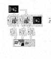
La
- un premier moyen de mesure MM1 d'un premier signal MS1 résultant d'une première transformation d'un premier signal sonde PS1 par au moins ladite première
face 10, une première simulation de ladite première transformation permettant d'obtenir une première estimation ES1 du signal résultant de ladite première transformation du premier signal sonde P51 par au moins une première face 11 virtuelle connue et positionnée dans un premier repère de mesure R1 de manière identique à ladite première face 10 lors de la mesure du premier signal MS1; - un deuxième moyen de mesure MM2 d'un deuxième signal MS2 résultant d'une deuxième transformation d'un deuxième signal sonde PS2 par au moins ladite deuxième
face 20, une deuxième simulation de ladite deuxième transformation permettant d'obtenir une deuxième estimation E52 du signal résultant de ladite deuxième transformation du deuxième signal sonde PS2 par au moins une deuxième face 21 virtuelle connue et positionnée dans un premier repère de mesure R2 de manière identique à ladite deuxième face 20 lors de la mesure du deuxième signal MS2; - un moyen MD pour déterminer une troisième transformation permettant de passer du premier repère R1 au deuxième repère R2
- un premier moyen de calcul CM1 configuré pour estimer ladite première face 10 à partir du premier signal MS1, de ladite première simulation, d'une première face 11 virtuelle et d'une première fonction coût V1 quantifiant un écart entre la première estimation ES1 et le premier signal MS1;
- un deuxième moyen de calcul CM2 configuré pour estimer ladite deuxième face 20 à partir du deuxième signal MS2, de ladite deuxième simulation, d'une deuxième face 21 virtuelle, de ladite troisième transformation et d'une deuxième fonction coût V2 quantifiant un écart entre la deuxième estimation ES2 et le deuxième signal MS2.
- first measuring means MM1 of a first signal MS1 resulting from a first transformation of a first probe signal PS1 by at least said
first face 10, a first simulation of said first transformation making it possible to obtain a first estimate ES1 of the signal resulting from said first transformation of the first probe signal P51 by at least a first known virtual face 11 and positioned in a first measurement mark R1 identically to saidfirst face 10 when measuring the first signal MS1; - second measuring means MM2 of a second signal MS2 resulting from a second transformation of a second probe signal PS2 by at least said
second face 20, a second simulation of said second transformation making it possible to obtain a second estimate E52 of the signal resulting from said second transformation of the second probe signal PS2 by at least one known second virtual face 21 and positioned in a first measurement mark R2 identically to saidsecond face 20 when measuring the second signal MS2; - MD means for determining a third transformation for passing from the first marker R1 to the second marker R2
- a first calculation means CM1 configured to estimate said
first face 10 from the first signal MS1, said first simulation, a first virtual face 11 and a first cost function V1 quantifying a difference between the first estimate ES1 and the first first signal MS1; - a second calculation means CM2 configured to estimate said
second face 20 from the second signal MS2, said second simulation, a second virtual face 21 of said third transformation and a second cost function V2 quantifying a difference between the second estimate ES2 and the second signal MS2.
Dans l'exemple représenté sur la
Avantageusement, un système selon un mode de réalisation de l'invention comporte des moyens de mesures MM1, MM2 d'un système de mesure optique configuré pour réaliser des mesure de faces 10, 20 d'un composant optique exprimé dans un repère propre audit système.Advantageously, a system according to one embodiment of the invention comprises measurement means MM1, MM2 of an optical measurement system configured to perform measurements of
L'une des applications de cette mesure de la structure géométrique à une lentille ophtalmique peut être l'analyse comparative d'une lentille après usinage avec une pièce nominale par exemple pour étudier la conformité de la pièce produite.One of the applications of this measurement of the geometric structure to an ophthalmic lens may be the comparative analysis of a lens after machining with a nominal part, for example to study the conformity of the piece produced.
Il faut définir pour cela un référentiel absolu commun à la lentille ophtalmique mesurée et à la pièce nominale. Pour ce faire, on ramène la lentille ophtalmique mesurée et la pièce nominale dans un référentiel commun, par exeple lié à la pièce où est réalisée la mesure. On détermine alors la position de la lentille ophtalmique mesurée et de la pièce nominale dans le référentiel de mesure soit par l'association d'un répère mécanique sur la lentille et la pièce, comme par exemple un méplat, soit par le pointage de marquages permanent sur la lentille et la pièce, du type micro-cercles.For this purpose, it is necessary to define an absolute reference system common to the measured ophthalmic lens and to the nominal part. To do this, the measured ophthalmic lens and the nominal part are brought back into a common reference frame, for example linked to the part where the measurement is made. The position of the measured ophthalmic lens and of the nominal part is then determined in the measurement reference frame either by the association of a mechanical reference on the lens and the workpiece, such as a flat surface, or by the permanent marking score. on the lens and the piece, of the micro-circle type.
Dans ce qui précède, la référence à « un mode de réalisation » signifie qu'une caractéristique particulière, la structure, ou une caractéristique décrite en relation avec le mode de réalisation peut être incluse dans au moins une mise en oeuvre de l'invention. Les apparitions de l'expression «dans un mode de réalisation" à divers endroits dans la description détaillée qui précède ne se référent pas nécessairement tous au même mode de réalisation. De même, des modes de réalisation distincts ou alternatifs ne sont pas nécessairement mutuellement exclusifs d'autres modes de réalisation.In the foregoing, the reference to "an embodiment" means that a particular feature, structure, or characteristic described in connection with the embodiment may be included in at least one implementation of the invention. The appearances of the phrase "in one embodiment" at various places in the foregoing detailed description are not necessarily all referable to the same embodiment, Similarly, separate or alternative embodiments are not necessarily mutually exclusive. other embodiments.
Claims (15)
Translated fromFrenchPriority Applications (15)
| Application Number | Priority Date | Filing Date | Title |
|---|---|---|---|
| EP12290084.8AEP2637011A1 (en) | 2012-03-09 | 2012-03-09 | Method and apparatus for measuring the geometric structure of an optical component |
| JP2014560397AJP6223368B2 (en) | 2012-03-09 | 2013-03-08 | Method and tool for measuring the geometric structure of an optical element |
| MX2014010784AMX338853B (en) | 2012-03-09 | 2013-03-08 | Method and tool for measuring the geometric structure of an optical component. |
| PCT/EP2013/054751WO2013132072A1 (en) | 2012-03-09 | 2013-03-08 | Method and tool for measuring the geometric structure of an optical component |
| NZ628795ANZ628795A (en) | 2012-03-09 | 2013-03-08 | Method and tool for measuring the geometric structure of an optical component |
| BR112014022264-9ABR112014022264B1 (en) | 2012-03-09 | 2013-03-08 | method and system for measuring the geometric structure of an optical component |
| CA2864866ACA2864866C (en) | 2012-03-09 | 2013-03-08 | Method and tool for measuring the geometric structure of an optical component |
| KR1020147024926AKR102022888B1 (en) | 2012-03-09 | 2013-03-08 | Method and tool for measuring the geometric structure of an optical component |
| CN201380013373.6ACN104169704B (en) | 2012-03-09 | 2013-03-08 | Method and kit for for the geometry for measuring optical module |
| US14/384,119US9109976B2 (en) | 2012-03-09 | 2013-03-08 | Method and tool for measuring the geometric structure of an optical component |
| AU2013229379AAU2013229379B2 (en) | 2012-03-09 | 2013-03-08 | Method and tool for measuring the geometric structure of an optical component |
| EP13708795.3AEP2823279B1 (en) | 2012-03-09 | 2013-03-08 | Method and apparatus for measuring the geometric structure of an optical component |
| RU2014140808ARU2618746C2 (en) | 2012-03-09 | 2013-03-08 | Method and device for measuring geometrical structure of optical component |
| IN7627DEN2014IN2014DN07627A (en) | 2012-03-09 | 2013-03-08 | |
| ZA2014/06182AZA201406182B (en) | 2012-03-09 | 2014-08-22 | Method and tool for measuring the geometric structure of an optical component |
Applications Claiming Priority (1)
| Application Number | Priority Date | Filing Date | Title |
|---|---|---|---|
| EP12290084.8AEP2637011A1 (en) | 2012-03-09 | 2012-03-09 | Method and apparatus for measuring the geometric structure of an optical component |
Publications (1)
| Publication Number | Publication Date |
|---|---|
| EP2637011A1true EP2637011A1 (en) | 2013-09-11 |
Family
ID=47846012
Family Applications (2)
| Application Number | Title | Priority Date | Filing Date |
|---|---|---|---|
| EP12290084.8AWithdrawnEP2637011A1 (en) | 2012-03-09 | 2012-03-09 | Method and apparatus for measuring the geometric structure of an optical component |
| EP13708795.3AActiveEP2823279B1 (en) | 2012-03-09 | 2013-03-08 | Method and apparatus for measuring the geometric structure of an optical component |
Family Applications After (1)
| Application Number | Title | Priority Date | Filing Date |
|---|---|---|---|
| EP13708795.3AActiveEP2823279B1 (en) | 2012-03-09 | 2013-03-08 | Method and apparatus for measuring the geometric structure of an optical component |
Country Status (14)
| Country | Link |
|---|---|
| US (1) | US9109976B2 (en) |
| EP (2) | EP2637011A1 (en) |
| JP (1) | JP6223368B2 (en) |
| KR (1) | KR102022888B1 (en) |
| CN (1) | CN104169704B (en) |
| AU (1) | AU2013229379B2 (en) |
| BR (1) | BR112014022264B1 (en) |
| CA (1) | CA2864866C (en) |
| IN (1) | IN2014DN07627A (en) |
| MX (1) | MX338853B (en) |
| NZ (1) | NZ628795A (en) |
| RU (1) | RU2618746C2 (en) |
| WO (1) | WO2013132072A1 (en) |
| ZA (1) | ZA201406182B (en) |
Cited By (2)
| Publication number | Priority date | Publication date | Assignee | Title |
|---|---|---|---|---|
| EP3012619A1 (en)* | 2014-10-21 | 2016-04-27 | Isra Surface Vision GmbH | Method for determining a local refractive power and device for same |
| US9818021B2 (en) | 2014-10-21 | 2017-11-14 | Isra Surface Vision Gmbh | Method for determining a local refractive power and device therefor |
Families Citing this family (1)
| Publication number | Priority date | Publication date | Assignee | Title |
|---|---|---|---|---|
| RU2650857C1 (en)* | 2017-04-06 | 2018-04-17 | Федеральное государственное бюджетное образовательное учреждение высшего образования "Кубанский государственный технологический университет" (ФГБОУ ВО "КубГТУ") | System for determining geometric parameters of three-dimensional objects |
Citations (7)
| Publication number | Priority date | Publication date | Assignee | Title |
|---|---|---|---|---|
| EP0644411A1 (en) | 1993-09-17 | 1995-03-22 | ESSILOR INTERNATIONAL (Compagnie Générale d'Optique) | Procedure and apparatus for the absolute measurement of the geometrical or optical structure of an optical component |
| US6256098B1 (en)* | 1998-11-23 | 2001-07-03 | Inray Ltd. | Method for determining and designing optical elements |
| JP2001227908A (en)* | 2000-02-18 | 2001-08-24 | Canon Inc | Optical measuring device |
| FR2813391A1 (en)* | 2000-08-22 | 2002-03-01 | Essilor Int | METHOD AND APPARATUS FOR TRANSMISSION MEASUREMENT OF THE GEOMETRIC STRUCTURE OF AN OPTICAL COMPONENT |
| DE102004047531A1 (en)* | 2004-09-30 | 2006-05-04 | Kemper, Björn, Dr.rer.nat. | Interferometric simultaneous measurement of the topography and refractive index of the surface of an object by measuring the spatial phase distributions from both transmission and reflection interferograms |
| EP2228623A1 (en)* | 2009-03-11 | 2010-09-15 | Fujinon Corporation | Three-dimensional shape measuring method and device |
| US20110134438A1 (en)* | 2009-12-07 | 2011-06-09 | Canon Kabushiki Kaisha | Refractive index distribution measuring method and refractive index distribution measuring apparatus |
Family Cites Families (15)
| Publication number | Priority date | Publication date | Assignee | Title |
|---|---|---|---|---|
| AU642768B2 (en)* | 1990-10-02 | 1993-10-28 | Ciba-Geigy Ag | A method of surface-cleaning and/or sterilising optical components, especially contact lenses |
| US6072570A (en)* | 1997-07-24 | 2000-06-06 | Innotech | Image quality mapper for progressive eyeglasses |
| FR2783938B1 (en)* | 1998-09-28 | 2000-11-17 | Essilor Int | TORIC OPHTHALMIC LENSES |
| US7034949B2 (en)* | 2001-12-10 | 2006-04-25 | Ophthonix, Inc. | Systems and methods for wavefront measurement |
| JP2003269952A (en)* | 2002-03-13 | 2003-09-25 | Canon Inc | Three-dimensional shape measuring apparatus and method |
| CN100510845C (en)* | 2002-05-31 | 2009-07-08 | 克劳斯鲍斯光学有限公司 | Progressive addition power lens |
| DE10337894A1 (en)* | 2003-08-18 | 2005-03-17 | Robert Bosch Gmbh | Optical measuring system for acquiring geometric data from surfaces |
| EP2008058B1 (en)* | 2006-04-07 | 2012-12-05 | Abbott Medical Optics Inc. | Geometric measurement system and method of measuring a geometric characteristic of an object |
| US7573643B2 (en)* | 2006-08-16 | 2009-08-11 | Technion Research & Development Foundation Ltd. | Method and apparatus for designing transmissive optical surfaces |
| KR20100015475A (en)* | 2007-04-05 | 2010-02-12 | 가부시키가이샤 니콘 | Geometry measurement instrument and method for measuring geometry |
| JP2010085335A (en)* | 2008-10-01 | 2010-04-15 | Fujinon Corp | Lightwave interference measuring instrument |
| FR2938934B1 (en)* | 2008-11-25 | 2017-07-07 | Essilor Int - Cie Generale D'optique | GLASSES OF EYEWEAR PROVIDING OPHTHALMIC VISION AND ADDITIONAL VISION |
| JP5591063B2 (en) | 2009-11-12 | 2014-09-17 | キヤノン株式会社 | Measuring method and measuring device |
| JP5442122B2 (en) | 2010-07-15 | 2014-03-12 | キヤノン株式会社 | Measuring method for measuring shape of test surface, measuring apparatus and optical element manufacturing method |
| JP5618727B2 (en) | 2010-09-21 | 2014-11-05 | キヤノン株式会社 | Shape measuring method and shape measuring device |
- 2012
- 2012-03-09EPEP12290084.8Apatent/EP2637011A1/ennot_activeWithdrawn
- 2013
- 2013-03-08AUAU2013229379Apatent/AU2013229379B2/enactiveActive
- 2013-03-08CACA2864866Apatent/CA2864866C/enactiveActive
- 2013-03-08NZNZ628795Apatent/NZ628795A/enunknown
- 2013-03-08EPEP13708795.3Apatent/EP2823279B1/enactiveActive
- 2013-03-08CNCN201380013373.6Apatent/CN104169704B/enactiveActive
- 2013-03-08ININ7627DEN2014patent/IN2014DN07627A/enunknown
- 2013-03-08KRKR1020147024926Apatent/KR102022888B1/enactiveActive
- 2013-03-08WOPCT/EP2013/054751patent/WO2013132072A1/enactiveApplication Filing
- 2013-03-08JPJP2014560397Apatent/JP6223368B2/enactiveActive
- 2013-03-08BRBR112014022264-9Apatent/BR112014022264B1/enactiveIP Right Grant
- 2013-03-08RURU2014140808Apatent/RU2618746C2/enactive
- 2013-03-08USUS14/384,119patent/US9109976B2/enactiveActive
- 2013-03-08MXMX2014010784Apatent/MX338853B/enactiveIP Right Grant
- 2014
- 2014-08-22ZAZA2014/06182Apatent/ZA201406182B/enunknown
Patent Citations (7)
| Publication number | Priority date | Publication date | Assignee | Title |
|---|---|---|---|---|
| EP0644411A1 (en) | 1993-09-17 | 1995-03-22 | ESSILOR INTERNATIONAL (Compagnie Générale d'Optique) | Procedure and apparatus for the absolute measurement of the geometrical or optical structure of an optical component |
| US6256098B1 (en)* | 1998-11-23 | 2001-07-03 | Inray Ltd. | Method for determining and designing optical elements |
| JP2001227908A (en)* | 2000-02-18 | 2001-08-24 | Canon Inc | Optical measuring device |
| FR2813391A1 (en)* | 2000-08-22 | 2002-03-01 | Essilor Int | METHOD AND APPARATUS FOR TRANSMISSION MEASUREMENT OF THE GEOMETRIC STRUCTURE OF AN OPTICAL COMPONENT |
| DE102004047531A1 (en)* | 2004-09-30 | 2006-05-04 | Kemper, Björn, Dr.rer.nat. | Interferometric simultaneous measurement of the topography and refractive index of the surface of an object by measuring the spatial phase distributions from both transmission and reflection interferograms |
| EP2228623A1 (en)* | 2009-03-11 | 2010-09-15 | Fujinon Corporation | Three-dimensional shape measuring method and device |
| US20110134438A1 (en)* | 2009-12-07 | 2011-06-09 | Canon Kabushiki Kaisha | Refractive index distribution measuring method and refractive index distribution measuring apparatus |
Non-Patent Citations (2)
| Title |
|---|
| BARBOSA E A ET AL: "Measurement of low-derivative surface lenses by two-laser holography with Bi12TiO20 crystals", APPLIED OPTICS, OPTICAL SOCIETY OF AMERICA, WASHINGTON, DC; US, vol. 48, no. 27, 20 September 2009 (2009-09-20), pages 5114 - 5120, XP001548435, ISSN: 0003-6935, [retrieved on 20090910], DOI: 10.1364/AO.48.005114* |
| BONNAS ET AL.: "Numerical Optimization", 2003, SPRINGER |
Cited By (3)
| Publication number | Priority date | Publication date | Assignee | Title |
|---|---|---|---|---|
| EP3012619A1 (en)* | 2014-10-21 | 2016-04-27 | Isra Surface Vision GmbH | Method for determining a local refractive power and device for same |
| JP2016105075A (en)* | 2014-10-21 | 2016-06-09 | イスラ サーフィス ヴィズィオーン ゲーエムベーハー | Method for determining local refractive index and device therefor |
| US9818021B2 (en) | 2014-10-21 | 2017-11-14 | Isra Surface Vision Gmbh | Method for determining a local refractive power and device therefor |
Also Published As
| Publication number | Publication date |
|---|---|
| CA2864866C (en) | 2020-07-07 |
| RU2618746C2 (en) | 2017-05-11 |
| EP2823279B1 (en) | 2019-12-25 |
| CA2864866A1 (en) | 2013-09-12 |
| BR112014022264A2 (en) | 2017-06-20 |
| KR102022888B1 (en) | 2019-11-25 |
| IN2014DN07627A (en) | 2015-05-15 |
| AU2013229379A1 (en) | 2014-09-04 |
| AU2013229379B2 (en) | 2016-11-24 |
| BR112014022264B1 (en) | 2020-11-10 |
| CN104169704B (en) | 2018-04-24 |
| WO2013132072A1 (en) | 2013-09-12 |
| CN104169704A (en) | 2014-11-26 |
| ZA201406182B (en) | 2016-02-24 |
| US9109976B2 (en) | 2015-08-18 |
| RU2014140808A (en) | 2016-05-10 |
| KR20140132725A (en) | 2014-11-18 |
| US20150055126A1 (en) | 2015-02-26 |
| MX2014010784A (en) | 2015-04-17 |
| MX338853B (en) | 2016-05-02 |
| BR112014022264A8 (en) | 2018-08-14 |
| NZ628795A (en) | 2016-11-25 |
| JP6223368B2 (en) | 2017-11-01 |
| EP2823279A1 (en) | 2015-01-14 |
| JP2015509599A (en) | 2015-03-30 |
Similar Documents
| Publication | Publication Date | Title |
|---|---|---|
| US9947118B2 (en) | Non-interferometric phase measurement | |
| EP0644411B1 (en) | Procedure and apparatus for the absolute measurement of the geometrical or optical structure of an optical component | |
| CN107895348B (en) | Polarization image restoration method under non-uniform light field in scattering environment | |
| FR2869408A1 (en) | METHOD AND DEVICE FOR DETERMINING THE SHAPE AND LOCAL NORMALS OF REFLECTIVE SURFACES | |
| WO2011117539A1 (en) | Method and equipment for detecting the presence and extent of defects in an optical component | |
| CN111386449B (en) | Stress analysis system for curved surface material inspection | |
| EP1224448B1 (en) | Method and apparatus for transmission measurement of the geometric structure of an optical component | |
| EP2880629B1 (en) | Method for the non-destructive testing of a blade preform | |
| JP7204428B2 (en) | Eccentricity measuring method, lens manufacturing method, and eccentricity measuring device | |
| EP2909671B1 (en) | Method for designing a single-path imager able to estimate the depth of field | |
| EP3039377A1 (en) | Method and device for determining the position and orientation of a specular surface forming a diopter | |
| JP2025093957A (en) | Multicore Fiber Imaging | |
| EP2637011A1 (en) | Method and apparatus for measuring the geometric structure of an optical component | |
| Zhu et al. | Three-dimensional measurement of fringe projection based on the camera response function of the polarization system | |
| FR2956734A1 (en) | Method for identifying dynamic deformation level by mode of blade of aircraft engine, involves constructing three-dimensional dynamic displacement field, and determining deformation field of piece by spatially deriving displacement field | |
| EP2739936A1 (en) | Method for the absolute measurement of the flatness of the surfaces of optical elements | |
| EP2828635A1 (en) | System for measuring a zone of separation in a substrate | |
| EP4483138A1 (en) | Systems and methods for analysing the surface quality of a substrate with parallel faces | |
| KR101796223B1 (en) | System and methode for measuring refractive index distribution | |
| FR2985811A1 (en) | OPTICAL DEVICE, OPTICAL TEST BENCH AND OPTICAL TEST METHOD. | |
| EP3835748A1 (en) | System for controlling at least one component of an optical element | |
| Chen et al. | Multi-Spot Image Denoising Correction and Three-Dimensional Shape Measurement of Cylindrical Shaft Parts Based on Deep Learning | |
| Gu et al. | In situ fast measurement of the radius of curvature for the plano-convex lens with deep-learning based on the point spread functions | |
| CN116295101A (en) | Integrated surface shape measurement and defect positioning method and system for analyzing single-frame interferogram | |
| Shen et al. | Extended monocular 3D imaging |
Legal Events
| Date | Code | Title | Description |
|---|---|---|---|
| PUAI | Public reference made under article 153(3) epc to a published international application that has entered the european phase | Free format text:ORIGINAL CODE: 0009012 | |
| AK | Designated contracting states | Kind code of ref document:A1 Designated state(s):AL AT BE BG CH CY CZ DE DK EE ES FI FR GB GR HR HU IE IS IT LI LT LU LV MC MK MT NL NO PL PT RO RS SE SI SK SM TR | |
| AX | Request for extension of the european patent | Extension state:BA ME | |
| STAA | Information on the status of an ep patent application or granted ep patent | Free format text:STATUS: THE APPLICATION IS DEEMED TO BE WITHDRAWN | |
| 18D | Application deemed to be withdrawn | Effective date:20140312 |