EP2636998A1 - Data encoder for receiving position information and method for operating same - Google Patents
Data encoder for receiving position information and method for operating sameDownload PDFInfo
- Publication number
- EP2636998A1 EP2636998A1EP12158554.1AEP12158554AEP2636998A1EP 2636998 A1EP2636998 A1EP 2636998A1EP 12158554 AEP12158554 AEP 12158554AEP 2636998 A1EP2636998 A1EP 2636998A1
- Authority
- EP
- European Patent Office
- Prior art keywords
- image
- optical code
- transmitter
- information
- rotation
- Prior art date
- Legal status (The legal status is an assumption and is not a legal conclusion. Google has not performed a legal analysis and makes no representation as to the accuracy of the status listed.)
- Granted
Links
- 238000000034methodMethods0.000titleclaimsdescription25
- 230000003287optical effectEffects0.000claimsabstractdescription111
- 239000000463materialSubstances0.000claimsabstractdescription18
- 230000005540biological transmissionEffects0.000claimsabstractdescription9
- 238000001454recorded imageMethods0.000claimsdescription22
- 238000006073displacement reactionMethods0.000claimsdescription20
- 238000011156evaluationMethods0.000claimsdescription16
- 230000000295complement effectEffects0.000claimsdescription13
- 238000012545processingMethods0.000claimsdescription8
- 230000009466transformationEffects0.000claimsdescription8
- 238000004590computer programMethods0.000claimsdescription7
- 239000011159matrix materialSubstances0.000description12
- 238000001514detection methodMethods0.000description10
- 238000009795derivationMethods0.000description5
- 238000012986modificationMethods0.000description3
- 230000004048modificationEffects0.000description3
- 239000013589supplementSubstances0.000description3
- 230000001419dependent effectEffects0.000description2
- 238000004519manufacturing processMethods0.000description2
- 238000005070samplingMethods0.000description2
- 230000000712assemblyEffects0.000description1
- 238000000429assemblyMethods0.000description1
- 230000008901benefitEffects0.000description1
- 238000011161developmentMethods0.000description1
- 230000000694effectsEffects0.000description1
- 230000014509gene expressionEffects0.000description1
- 238000005259measurementMethods0.000description1
- 230000001151other effectEffects0.000description1
- 230000001502supplementing effectEffects0.000description1
- 238000000844transformationMethods0.000description1
- 230000007704transitionEffects0.000description1
- 238000013519translationMethods0.000description1
Images

Classifications
- G—PHYSICS
- G01—MEASURING; TESTING
- G01D—MEASURING NOT SPECIALLY ADAPTED FOR A SPECIFIC VARIABLE; ARRANGEMENTS FOR MEASURING TWO OR MORE VARIABLES NOT COVERED IN A SINGLE OTHER SUBCLASS; TARIFF METERING APPARATUS; MEASURING OR TESTING NOT OTHERWISE PROVIDED FOR
- G01D5/00—Mechanical means for transferring the output of a sensing member; Means for converting the output of a sensing member to another variable where the form or nature of the sensing member does not constrain the means for converting; Transducers not specially adapted for a specific variable
- G01D5/26—Mechanical means for transferring the output of a sensing member; Means for converting the output of a sensing member to another variable where the form or nature of the sensing member does not constrain the means for converting; Transducers not specially adapted for a specific variable characterised by optical transfer means, i.e. using infrared, visible, or ultraviolet light
- G01D5/32—Mechanical means for transferring the output of a sensing member; Means for converting the output of a sensing member to another variable where the form or nature of the sensing member does not constrain the means for converting; Transducers not specially adapted for a specific variable characterised by optical transfer means, i.e. using infrared, visible, or ultraviolet light with attenuation or whole or partial obturation of beams of light
- G01D5/34—Mechanical means for transferring the output of a sensing member; Means for converting the output of a sensing member to another variable where the form or nature of the sensing member does not constrain the means for converting; Transducers not specially adapted for a specific variable characterised by optical transfer means, i.e. using infrared, visible, or ultraviolet light with attenuation or whole or partial obturation of beams of light the beams of light being detected by photocells
- G01D5/347—Mechanical means for transferring the output of a sensing member; Means for converting the output of a sensing member to another variable where the form or nature of the sensing member does not constrain the means for converting; Transducers not specially adapted for a specific variable characterised by optical transfer means, i.e. using infrared, visible, or ultraviolet light with attenuation or whole or partial obturation of beams of light the beams of light being detected by photocells using displacement encoding scales
- G01D5/34776—Absolute encoders with analogue or digital scales
- G01D5/34792—Absolute encoders with analogue or digital scales with only digital scales or both digital and incremental scales
- G—PHYSICS
- G01—MEASURING; TESTING
- G01D—MEASURING NOT SPECIALLY ADAPTED FOR A SPECIFIC VARIABLE; ARRANGEMENTS FOR MEASURING TWO OR MORE VARIABLES NOT COVERED IN A SINGLE OTHER SUBCLASS; TARIFF METERING APPARATUS; MEASURING OR TESTING NOT OTHERWISE PROVIDED FOR
- G01D2205/00—Indexing scheme relating to details of means for transferring or converting the output of a sensing member
- G01D2205/90—Two-dimensional encoders, i.e. having one or two codes extending in two directions
Definitions
- the inventionrelates to a transmitter for obtaining position information and a method for operating a transmitter.
- Such transducersare known per se.
- Such transducersare known per se.
- the inventionfurther relates to an assembly with such a transmitter, so for example a drive or an electric motor to get there as position information information with respect to a speed or position of the motor / drive or generally of the respective unit.
- the transmitter to be described hereis based on an optical scanning of a material measure. This is also known, for example, with incremental encoders.
- the EP 1 677 081 B1suggests the use of a diffractive-scale measure for a transmitter to obtain position information.
- a transmitter for obtaining a position informationwith the features of claim 1.
- the Transmitting / receiving unit for detecting an image of the optical codecomprises at least one areal detector with a plurality of optically sensitive elements, which are each arranged in a plurality of rows and columns of the detector.
- the advantage of the inventionis that with the use of a flat detector, so for example a CCD array sensor, a larger area of the material measure resulting reflections or transmissions can be detected.
- a detection of an image of the optical codeis still possible even if in the prior art according to the EP 1 677 081 B1 proposed use of a CCD line sensor, the relevant image information, so a zeroth or first diffraction due to the optical code or higher diffraction orders just can not be detected.
- planar image with the planar detectorie an image which is recorded with a plurality of sensitive elements arranged in a plurality of rows and columns of the detector, offers possibilities for improving the evaluation of the image and a derivation of position information therefrom.
- the optical codecomprises at least two significant picture elements, usually three, four, five or more significant picture elements, wherein significant picture elements are identifiable in an image recordable with the detector by the optical code and identified significant picture elements as the basis for an evaluation of the image and for a derivation of a position information can be used from the picture.
- Significant picture elementsare picture elements, namely, in particular, groups of picture elements which are basically identifiable in the picture which can be recorded by the detector and thus distinguishable from information otherwise contained in the picture. The structure of the significant picture elements is thus chosen so that their shape does not result in the representation of the information covered by the optical code.
- An example of a possible shape of such a significant picture element or significant picture elementsis then a 2x2 or 3x3 matrix, which always leads to set pixels when a corresponding picture is taken with the detector.
- a position of one or more significant picture elementsis specifically a border area of an image resulting from an optical code into consideration.
- an identification of at least two significant picture elementscan automatically be used to derive a statement as to whether the captured image is possibly shifted or rotated in relation to a receiving area of the detector. With the derivation of such clues on the basis of identified significant picture elements, these can be used as the basis for an evaluation of the picture and a derivation of a position information therefrom.
- these termsmean the image taken by the detector or components thereof. However, it should be noted that the image is due to each scanned microstructured optical code. In this respect, the respective microstructure within the measuring standard already comprises the basis for an image resulting from its scanning, regardless of whether this is detected completely or partially with a detector or not.
- optical codeis initially created in the respective microstructure of the material measure. Upon scanning of the microstructure arises - also as an optical code - a bundle of rays due to a reflection or transmission at the microstructure. Finally, the optical code is, of course, also contained in an image which is recorded by a detector positioned wholly or partly in such a beam path. It should therefore be pointed out that, especially with regard to the above-mentioned terms and similar expressions, the factual context provides information about the concrete meaning.
- the optical codecomprises three or four significant picture elements arranged, for example, in the region of the corner points of the optical code, it is possible, especially if all three or four significant picture elements can be identified in the picture taken by the detector, to make an accurate statement make any shift, rotation or scaling of the captured image. Additionally or alternatively, the fact whether all significant pixels or at least a sufficient number of significant pixels have been identified can be used as the basis for deciding whether the image is useful for deriving positional information.
- the optical codecomprises redundant information. If the optical code comprises redundant information, it may be sufficient if the image of the optical code detected by the detector is also at a possible Displacement or rotation is at least as far usable that with an additional evaluation of the redundant information applied in the optical code information and thus essentially the position information can be determined.
- the optical code in a matrix-like structurecomprises information and a complementary representation of the same information, in particular a complex conjugate representation of the same information. Then it is possible to apply the optical code such that in the matrix-like structure, for example, a certain number of lines contain the respective information and other lines a complementary representation of the same information. Even if, for example, those lines of the optical code which contain the actual information are not detected by the flat detector due to misalignment or other effects and thus are not part of the recorded image, there is the possibility of the information applied in the optical code to capture, for example, when the conjugate complex representation of the same information has been completely detected by the area detector and thus become part of the recorded image.
- the recorded imagecomprises, for example, only parts of the information and also only parts of the complex conjugate representation of the same information. Then it may be possible to supplement or reconstruct the missing components of the information based on the detected components of the complementary representation of the same information.
- an image of the optical codeis recorded with the detector, wherein significant pixels are identified in the recorded image and wherein identified image elements as a basis be used for an evaluation of the image by using at least two identified significant pixels, a shift or a rotation or a scaling of the recorded image is determined.
- the significant pixelscan be searched in the image taken by the detector.
- the search in the recorded picturemay therefore relate to a search for corresponding sections with pixels set uniformly or not. When such a section is found, a significant pixel is identified.
- the position of an identified significant pixel with respect to the detection range of the detectorthat is, with respect to the matrix-like structure of the optically sensitive elements included therein. Accordingly, if several significant picture elements have been identified and their position has been determined in the recorded image, it is possible to deduce from the resulting position information on any displacement, rotation and / or scaling of the image taken by the optical code.
- Thiscan be used as the basis for an evaluation of the image and for a derivation of position information from the image, for example, by deriving a position information only if a sufficient number of significant pixels has been identified and thus it is clear that at least a presumably sufficient section from the optical code in the captured image.
- itcan be automatically decided with regard to a possibly determined displacement, rotation and / or scaling, whether a determined displacement, rotation and / or scaling remains in an area that still allows a meaningful evaluation of the recorded image with regard to a derivative of a position information.
- a determined displacement or rotation or scaling of the recorded imageis automatically compensated.
- a shift or rotation or scaling of the recorded imageis referred to individually or together as a falsification of the recorded image. If such a corruption of the recorded image is compensated for, the image can be evaluated despite the corruption and position information can be derived from the image. This ensures that the transmitter still provides position information even if with the same constellation with previous sensors no or no reliable position information can be obtained.
- missing parts of the optical codeare supplemented on the basis of the redundant information comprised by the optical code.
- the missing parts of the optical codecan be deduced from the identified significant pixels and their position in the captured image, and that missing part as far as possible from the redundant ones Information to be supplemented.
- the position of the identified significant pixelsthus provides an indication of start and end points of the optical code and thus an indication of which portions of the optical code may not be detected and which portions of the optical code for supplementing or reconstructing the unrecognized portion of the optical code be considered.
- a determined displacement or rotation or scaling, ie falsification, of the recorded imageis compensated.
- a transformationcan be applied to the image, which reverses (compensates) the determined displacement or rotation or scaling.
- the captured imagemay be shifted to the left in accordance with the detected displacement, for example to center the optical code in the captured image.
- Such a shift or rotation or scaling of the captured image to compensate for a detected corruptionis referred to individually or collectively as a transformation.
- Another alternative for compensating for a determined falsification of the recorded imageis that, when the image is evaluated, a reading position is adapted in accordance with the determined falsification.
- the imagecan thus be centered again either by suitable transformation, for example, in order to be able to evaluate the image with respect to a defined reading position.
- the reading positionmay be adjusted according to the detected displacement or the like to achieve the same result.
- the image of the optical codealso wholly or partially diffractions higher order of the same optical code and that an evaluation of the image of the optical code and plausibility checks based on the diffractions higher Order includes.
- the reliability of the transmitterThe position information supplied increases again in such an embodiment of the method, because if the optical code resulting, for example, due to a zero or first order diffraction is not detected in the image taken by the detector, but an image of the optical code due to a higher order diffraction , it may also be possible to derive the position information contained in the optical code on the basis of such higher-order diffractions.
- each diffraction ordercan be evaluated individually and then the position information determined on the basis of each diffraction order compared with each other.
- the transmitterprovides position information only if the position information determined for the different diffraction orders coincide completely or within predetermined or predefinable limits.
- an average or the like of the individual position informationis formed and this mean value is output by the measuring sensor as an output signal.
- position informationfor example, that position information is output that results from evaluating a lowest detected diffraction order and that the output signal is supplemented by a plausibility information based on the position information due to higher diffraction orders, so that the output signal of the transmitter used subordinate unit can recognize the resilience of the output signal supplied by the transmitter based on such a plausibility information.
- a transmitter for obtaining positional informationwhich is determined by the or the method as described herein and hereinafter and includes means for carrying out the method, individual methods or multiple methods.
- the inventionis preferably implemented in software.
- the inventionis thus on the one hand also a computer program with executable by a computer program code instructions and on the other hand, a storage medium with such a computer program and finally a transmitter or a transmitter containing unit, so for example a drive or a drive system in its or their memory Means for performing the method and its embodiments such a computer program is loaded or loadable.
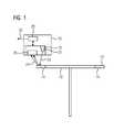
- FIG. 1schematically shows a simplified rotatable disc 10 with a material measure.
- a material measureare - also only schematically simplified - an absolute track 12 and an incremental track 14 shown.
- the measuring graduationthat is to say the absolute track 12 and / or the incremental track 14 is scanned with a measuring transmitter, here and hereinafter also referred to only briefly as transducer 16, for obtaining position information. This is shown for a scan of the absolute track 12.
- the transmitter 16comprises a transmitting / receiving unit 18 for obtaining a position information. With this, the respective material measure 12, 14 is scanned.
- the transmitting / receiving unit 18comprises at least one beam source 20 for generating a scanning beam 22, that is to say in particular a beam source 20 for generating a laser beam.
- the scanning beam 22experiences at the material measure either a reflection or transmission. Shown is a reflection 24 and correspondingly a reflected beam.
- the two arrows representing the reflection 24should also be an indication that in a particular embodiment of the transmitter 16 and a method for its operation on the one hand, a zeroth or first diffraction order of the reflection 24 or transmission and on the other hand higher diffraction orders (illustrated by the second arrow) can be examined.
- the reflection 24 or transmissionprovides an image of an optical code microstructured in the scanned scale.
- a planar detector 26 - hereinafter referred to as detector 26 for short -provided with a plurality of optically sensitive elements, said optically sensitive elements in a known manner in a plurality of rows and columns of the detector 26 are arranged.
- a CCD array sensorfor example the applicant's microcontroller MSP430, is considered as a detector.
- a processing unit 28in the form of or in the manner of a microprocessor is provided.
- the processing unit 28can also be an integral part of the transmitting / receiving unit 18, as is the case with the microcontroller MSP430.
- the measuring sensor 16For the respective position information, the measuring sensor 16 generates an output signal 30 that can be processed by downstream units.
- the rotatable disk 10is just one example of how position information, in this case position information relating to the rotational position of the disk 10, can be obtained with a sensor 16.
- a disk 10may be associated with a drive (not shown) and there, for example, a motor axis to detect a rotational speed or rotational position of the motor axis.
- a disk 10is only one example of a mounting location of a material measure. In principle, the material measure could, for example, in a drive also directly on the respective monitored axis, so for example the motor axis, be appropriate.
- FIG. 1Accordingly, it is chosen especially with regard to graphically easy to represent and therefore clear conditions. In this case, no particular attention is paid to a representation of absolute and incremental tracks 12, 14 that is even approximately true in size, and simultaneous scanning of absolute and incremental tracks 12, 14 and simultaneous detection of an image of a resulting reflection or transmission is also possible. Finally, also measuring standards and their sampling possible and reasonable, which have only one absolute track 12 or only one incremental track 14.
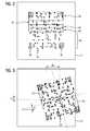
- FIG. 2shows by way of example a representation of an image of an optical code recorded with the detector 26.
- the representation in FIG. 2shows, on the one hand, the image 32 recorded by the detector 26, but also the optical code 34 encompassed by the image 32.
- the optical code 34and thus also the one in FIG. 2
- the image 32 taken therefromcomprises a number of significant pixels 36 highlighted in the illustration with the letter "M" (for "markerbits"), this representation representing only the significant pixels 36 of other pixels shown as dots for each make further description distinguishable.
- the significant pixels 36are a collection of pixels that are predetermined in terms of their extent in the x and y directions and in the status of the pixels included therein (set or not set).
- An example of a significant pixel 36is a 2x2 matrix, which accordingly comprises four pixels with all pixels set.
- the optical code 34 / image 32 captured therebyincludes five such significant pixels 36, with only individual such pixels 36 being designated by the corresponding reference numeral 36.
- the significant picture elements 36are located in the corners of the optical code 34.
- Another significant picture element 36is located in the center of the optical code 34.
- a starting point of the captured image 32 and, for example, a sequence of pixels included thereinmay be identified as encoding absolute position information 38.
- another group of pixelsmay be called a dump row 40, an elliptical track 42, and / or additional information 44, which includes, for example, a certificate of authenticity, spread information and / or write bits.
- a portion of the optical code 34may be identified with a complementary representation 46 of the information encompassed by the optical code 34.
- FIG. 3shows a corrupted image 32 of an optical code 34.
- the corruptionis evident in that the optical code 34 is shifted and rotated with respect to the image 32 so that the detector 26 has not completely detected the optical code 34 and that from the detector 26 taken picture 32 corresponding to the optical code 34 does not fully cover.
- the distortionis in terms of displacement in the illustration in FIG. 3 denoted by dx and dy to indicate the displacement in the x or y direction, respectively.
- the rotation of the optical code 34 with respect to the captured image 32is represented by the angle ⁇ .
- the actual displacement dx, dy and the rotation ⁇can be determined on the basis of an identification of the significant picture elements 36 (FIG. FIG. 2 ; in FIG. 3 not referred to again).
- the usability of the image 32 captured by the optical code 34may be used to derive position information getting closed.
- the in FIG. 3shown distortion of the optical code 34, so the displacement and rotation of the optical code 34 with respect to the detection range of the detector 26, the result that a part of the complementary representation 46 of the information contained in the optical code 34 is not detected.
- "real" informationis completely captured so that missing information 48 does not necessarily arrive. Namely, because the partial detection of the optical code 34 only concerns the part having a complementary representation 46 of the information contained by the optical code 34, while an upper half of the optical code 34 is completely detected, it is basically possible to derive from it the optical code 34 Derive contained information.
- missing information 48can be reconstructed or supplemented on the basis of redundant information 50. If the complementary representation 46 included in the lower half of the optical code 34 is to be used, for example, for verifying a position information derived from the upper half of the optical code 34, the evaluability of the complementary representation 46 is very important. Then the missing information 48 can be supplemented on the basis of the redundant information 50 and after such a supplement, a complete complementary representation 46 of the optical code 34 is available.
- FIG. 3shown only a small missing information 48, if, for example, the right upper significant pixel 36 is outside the detection range of the detector 26, so does not become part of the image 32, and thus the absolute information 38 (FIG. FIG. 2 ) is only partially covered by the captured image 32, also a so far missing information from the complementary representation 46 of the information ( FIG. 2 ) be won.
- a detected corruptionsuch as a detected displacement and / or a detected rotation and / or a detected scaling is compensated by a suitable inverse transformation.
- a read positionfrom which the image 32 recorded by the optical code 34 is evaluated, is adapted.
- FIG. 4finally shows an example in which the microstructured optical code 34 (FIG. 2, FIG. 3 ) not only a zeroth or first diffraction order has been included, as in 2 and FIG. 3 is shown, but in which higher diffraction orders of the optical code 34 are added.
- the representation in FIG. 4is however simplified to obtain a sufficient clarity.
- the optical code 34is only a line-shaped code and not, as in 2 and FIG. 3 shown as a matrix. Both variants, ie a line-shaped code or a matrix-shaped code, are thinkable and usable.
- FIG. 4Plotted horizontal and vertical lines, which divide the representation into a total of nine fields in a 3x3 structure, are not part of the captured image 32 and are only intended to facilitate the identification of individual image sections.
- An image section in the center of the image 32is therefore intended to represent a zero-order diffraction image of the microstructured optical code 34.
- the right and left as well as top and bottom of this central image section shown Image sectionsare corresponding images of higher order diffractions. Accordingly, one can understand the individual image sections as a window and the central image section / the central window, for example, as “window 0.0", the right next window as “window 1.0" and the adjacent window on the left as " Designate window -1.0 ".
- FIG. 4 illustrated frame 52is intended to be a actually detected with the detector 26 area of in FIG. 4 designated image 32. It can be seen that, according to the newly introduced notation, exactly four windows, namely the windows 0.0; 1.0; 0, -1 and -1, -1 are recorded. Thus, an image is detected due to zero order diffraction of the optical code 34 and multiple higher order diffraction orders of the same optical code 34.
- This multiple detection of the optical code 34allows a multiple evaluation of the optical code 34 and a plausibility check regarding the position information obtained in the evaluation of each optical code 34 included in the image 32.
- FIG. 4 illustrated variant for reliable evaluation of an optical code 34can in principle with the in the 2 and FIG. 3 combined variant, so that from each window in FIG. 4 derivable position information unlike a line-shaped display of the optical code 34 is even safer or at least safer readable.
- At least three significant picture elements 36are required in order to be able to recognize, for example, different distortions in the x and y directions. If it can be assumed on a case-by-case basis that distortion in the x and y directions is equal or approximately the same, in the ideal case, detection of two significant picture elements 36 would be sufficient.
- plausibility checksare required, for example, not any "outermost point on an outermost line" may be used as a significant picture element 36 are assumed, because with extreme displacements this outermost point, for example, can simply be the last pixel detected by the matrix and the actually significant pixel has long been outside the matrix.
- One possibilityis to determine a distance between this supposed significant pixel and an opposite significant pixel and to check if this distance is still plausible.
- the significant picture elements 36are also suitable for detecting possible distortions of the recorded image.
- a distortion of the entire recorded image in the x-directioncan be assumed.
- Such a distortionwould also be expected in the other pixels picked up by the detector.
- the inverse transformationone would have to try to cancel such a distortion again.
Landscapes
- Physics & Mathematics (AREA)
- General Physics & Mathematics (AREA)
- Length Measuring Devices By Optical Means (AREA)
- Optical Transform (AREA)
Abstract
Translated fromGermanDescription
Translated fromGermanDie Erfindung betrifft einen Messwertgeber zum Erhalt einer Positionsinformation sowie ein Verfahren zum Betrieb eines Messwertgebers. Solche Messwertgeber sind an sich bekannt. Exemplarisch kann auf sogenannte Inkrementalgeber verwiesen werden. Die Erfindung betrifft im Weiteren auch ein Aggregat mit einem solchen Messwertgeber, also zum Beispiel einen Antrieb oder einen Elektromotor, um dort als Positionsinformation eine Information in Bezug auf eine Geschwindigkeit oder Lage des Motors/Antriebs oder allgemein des jeweiligen Aggregats zu erhalten.The invention relates to a transmitter for obtaining position information and a method for operating a transmitter. Such transducers are known per se. As an example, refer to so-called incremental encoders. The invention further relates to an assembly with such a transmitter, so for example a drive or an electric motor to get there as position information information with respect to a speed or position of the motor / drive or generally of the respective unit.
Der hier zu beschreibende Messwertgeber basiert auf einer optischen Abtastung einer Maßverkörperung. Dies ist zum Beispiel bei Inkrementalgebern ebenfalls bekannt.The transmitter to be described here is based on an optical scanning of a material measure. This is also known, for example, with incremental encoders.
Die
Noch nicht ganz optimal ist die Eignung solcher Messwertgeber für den industriellen Einsatz, speziell wenn es darum geht, besondere Anforderungen an die Genauigkeit und Verlässlichkeit der gelieferten Positionsinformationen zu erfüllen.The suitability of such transmitters for industrial use is not entirely optimal, especially when it comes to meeting special demands on the accuracy and reliability of the delivered position information.
Wenn bei im Stand der Technik bekannten Lösungen eine rotierende diffraktive Scheibe oder ein sonstiges Element mit einer entsprechenden Maßverkörperung mithilfe einer optischen Einheit (Sendediode und optischer Sensor) abgetastet und elektrisch ausgewertet wird, unterliegen die Bauteile und Baugruppen eines solchen diffraktiven Messwertgebers und deren Anbringung / Justierung immer gewissen mechanischen Toleranzen, die das empfangene Bild im optischen Sensor verschieben oder verzerren. Als Sensor kommen bisher im Wesentlichen einfache CCD-Zeilen oder sogenannte Pin-Dioden zum Einsatz, um die Kosten der Sensoreinheit möglichst gering zu halten. Allerdings kann bei sehr großen Verschiebungen oder Rotationen des empfangenen Bildes die Sensorfläche verlassen werden und eine fehlerhafte Positionsinformation, also zum Beispiel eine fehlerhafte Winkelmessung zur Folge haben. Somit sind die Toleranzen bei bisherigen Ausführungsformen diffraktiver Messwertgeber stark eingeschränkt. Dies wirkt sich wiederum negativ auf die Gesamtkosten (Herstellungskosten) des diffraktiven Messwertgebers aus, da die Herstellung so exakt erfolgen muss, dass mechanische Toleranzen auf ein Minimum reduziert sind.When in solutions known in the prior art a rotating diffractive disk or other element with a corresponding measuring standard is scanned and electrically evaluated by means of an optical unit (transmitting diode and optical sensor), the components and assemblies of such a diffractive sensor are subject to their mounting / adjustment always certain mechanical tolerances that move or distort the received image in the optical sensor. As a sensor come so far essentially Simple CCD lines or so-called pin diodes used to keep the cost of the sensor unit as low as possible. However, in the case of very large displacements or rotations of the received image, the sensor surface can be left and erroneous position information, that is, for example, a faulty angle measurement result. Thus, the tolerances are severely limited in previous embodiments of diffractive sensors. This in turn has a negative effect on the total cost (manufacturing costs) of the diffractive transmitter, since the production must be so accurate that mechanical tolerances are reduced to a minimum.
Eine Aufgabe der Erfindung besteht entsprechend darin, einen auf einer Verwendung einer diffraktiv wirkenden Maßverkörperung basierenden Messwertgeber derart fortzubilden, dass eine Ermittlung einer Positionsinformation so weit wie möglich auch dann noch erfolgt, wenn der Messwertgeber nicht exakt justiert ist oder wenn sich eine Justierung im Betrieb, zum Beispiel aufgrund von Temperatureinflüssen, ändert.Accordingly, it is an object of the invention to improve a measuring transmitter based on the use of a diffracting measuring standard in such a way that position information is determined as far as possible even if the transmitter is not precisely adjusted or if an adjustment during operation, for example, due to temperature influences, changes.
Diese Aufgabe wird erfindungsgemäß mit einem Messwertgeber zum Erhalt einer Positionsinformation mit den Merkmalen des Anspruchs 1 gelöst. Dazu ist bei einem Messwertgeber zum Erhalt einer Positionsinformation, wobei mit einer Sende-/Empfangseinheit eine Maßverkörperung abgetastet wird, wobei die Maßverkörperung diffraktiv wirkende mikrostrukturierte Felder umfasst und wobei sich aufgrund einer Reflektion oder Transmission an der Maßverkörperung ein optischer Code ergibt, vorgesehen, dass die Sende-/Empfangseinheit zum Erfassen eines Bildes des optischen Codes zumindest einen flächigen Detektor mit einer Mehrzahl von optisch sensitiven Elementen umfasst, die jeweils in einer Mehrzahl von Zeilen und Spalten des Detektors angeordnet sind.This object is achieved with a transmitter for obtaining a position information with the features of claim 1. For this purpose, in the case of a transmitter for obtaining position information, wherein a material measure is scanned with a transmitter / receiver unit, wherein the material measure comprises diffractively acting microstructured fields and wherein an optical code results due to reflection or transmission on the material measure, it is provided that the Transmitting / receiving unit for detecting an image of the optical code comprises at least one areal detector with a plurality of optically sensitive elements, which are each arranged in a plurality of rows and columns of the detector.
Der Vorteil der Erfindung besteht darin, dass mit der Verwendung eines flächigen Detektors, also zum Beispiel einem CCD-Array-Sensor, ein größerer Bereich von sich an der Maßverkörperung ergebenden Reflektionen oder Transmissionen erfasst werden kann. Bei einer ungenauen Justierung des Messwertgebers oder dessen Detektors ist damit auch dann noch eine Erfassung eines Bilds des optischen Codes möglich, wenn bei der im Stand der Technik gemäß der
Zudem bietet die Erfassung eines flächigen Bild mit dem flächigen Detektor, also eines Bild, das mit mehreren in einer Mehrzahl von Zeilen und Spalten des Detektors angeordneten sensitiven Elementen aufgenommen wird, Möglichkeiten, um die Auswertung des Bildes und eine Ableitung einer Positionsinformation daraus zu verbessern.In addition, the acquisition of a planar image with the planar detector, ie an image which is recorded with a plurality of sensitive elements arranged in a plurality of rows and columns of the detector, offers possibilities for improving the evaluation of the image and a derivation of position information therefrom.
Vorteilhafte Ausgestaltungen der Erfindung sind Gegenstand der Unteransprüche. Dabei verwendete Rückbeziehungen weisen auf die weitere Ausbildung des Gegenstandes des Hauptanspruches durch die Merkmale des jeweiligen Unteranspruches hin. Sie sind nicht als ein Verzicht auf die Erzielung eines selbständigen, gegenständlichen Schutzes für die Merkmalskombinationen der rückbezogenen Unteransprüche zu verstehen. Des Weiteren ist im Hinblick auf eine Auslegung der Ansprüche bei einer näheren Konkretisierung eines Merkmals in einem nachgeordneten Anspruch davon auszugehen, dass eine derartige Beschränkung in den jeweils vorangehenden Ansprüchen nicht vorhanden ist.Advantageous embodiments of the invention are the subject of the dependent claims. Here used backlinks indicate the further development of the subject matter of the main claim by the features of the respective subclaim. They should not be construed as a waiver of obtaining independent, objective protection for the feature combinations of the dependent claims. Furthermore, with a view to an interpretation of the claims in a closer specification of a feature in a subordinate claim, it is to be assumed that such a restriction does not exist in the respective preceding claims.
Bei einer besonderen Ausführungsform des Messwertgebers ist vorgesehen, dass der optische Code zumindest zwei signifikante Bildelemente, üblicherweise drei, vier, fünf oder mehr signifikante Bildelemente umfasst, wobei signifikante Bildelemente in einem mit dem Detektor vom optischen Code aufnehmbaren Bild identifizierbar sind und wobei identifizierte signifikante Bildelemente als Grundlage für eine Auswertung des Bilds und für eine Ableitung einer Positionsinformation aus dem Bild verwendbar sind. Signifikante Bildelemente sind Bildelemente, nämlich insbesondere Gruppen von Bildpunkten, die in dem mit dem Detektor aufnehmbaren Bild grundsätzlich identifizierbar und somit von in dem Bild ansonsten enthaltenen Informationen unterscheidbar sind. Die Struktur der signifikanten Bildelemente wird demnach so gewählt, dass sich deren Form bei der Darstellung der von dem optischen Code umfassten Information nicht ergibt. Ein Beispiel für eine mögliche Gestalt eines solchen signifikanten Bildelements oder signifikanter Bildelemente ist danach eine 2x2 oder 3x3-Matrix, die jeweils bei Aufnahme eines entsprechenden Bildes mit dem Detektor durchgängig zu gesetzten Bildpunkten führt. Als Position einzelner oder mehrerer signifikanter Bildelemente kommt speziell ein Randbereich eines aufgrund eines optischen Codes resultierenden Bildes in Betracht. Bei einem aus einer Abtastung eines optischen Codes resultierenden Bild kann also bei einer Identifikation von zumindest zwei signifikanten Bildelementen automatisch eine Aussage darüber abgeleitet werden, ob das erfasste Bild in Bezug auf einen Aufnahmebereich des Detektors eventuell verschoben oder gedreht ist. Mit der Ableitung solcher Anhaltspunkte anhand identifizierter signifikanter Bildelemente sind diese als Grundlage für eine Auswertung des Bilds und einer Ableitung einer Positionsinformation daraus verwendbar.In a particular embodiment of the transmitter, it is provided that the optical code comprises at least two significant picture elements, usually three, four, five or more significant picture elements, wherein significant picture elements are identifiable in an image recordable with the detector by the optical code and identified significant picture elements as the basis for an evaluation of the image and for a derivation of a position information can be used from the picture. Significant picture elements are picture elements, namely, in particular, groups of picture elements which are basically identifiable in the picture which can be recorded by the detector and thus distinguishable from information otherwise contained in the picture. The structure of the significant picture elements is thus chosen so that their shape does not result in the representation of the information covered by the optical code. An example of a possible shape of such a significant picture element or significant picture elements is then a 2x2 or 3x3 matrix, which always leads to set pixels when a corresponding picture is taken with the detector. As a position of one or more significant picture elements is specifically a border area of an image resulting from an optical code into consideration. In the case of an image resulting from a scan of an optical code, an identification of at least two significant picture elements can automatically be used to derive a statement as to whether the captured image is possibly shifted or rotated in relation to a receiving area of the detector. With the derivation of such clues on the basis of identified significant picture elements, these can be used as the basis for an evaluation of the picture and a derivation of a position information therefrom.
Mit Rückgriff auf die Erläuterung in den vorangegangenen Absätzen sei hier angemerkt, dass die Verwendung von Begriffen wie Bild, Bildinformation, Bildelement und dergleichen im Zusammenhang mit der hier beschriebenen Erfindung mehrdeutig sein kann.With reference to the discussion in the preceding paragraphs, it should be noted that the use of terms such as image, image information, pixel and the like may be ambiguous in the context of the invention described herein.
Grundsätzlich meinen diese Begriffe das von dem Detektor aufgenommene Bild oder Bestandteile davon. Allerdings ist zu berücksichtigen, dass sich das Bild aufgrund eines jeweils abgetasteten mikrostrukturell angelegten optischen Codes ergibt. Insofern umfasst die jeweilige Mikrostruktur innerhalb der Maßverkörperung bereits die Grundlage für ein sich bei deren Abtastung ergebendes Bild und zwar unabhängig davon, ob dieses mit einem Detektor ganz oder teilweise erfasst wird oder nicht.Basically, these terms mean the image taken by the detector or components thereof. However, it should be noted that the image is due to each scanned microstructured optical code. In this respect, the respective microstructure within the measuring standard already comprises the basis for an image resulting from its scanning, regardless of whether this is detected completely or partially with a detector or not.
Vor diesem Hintergrund rechtfertigt es sich, auch in Bezug auf die Mikrostruktur der Maßverkörperung von einem Bild oder Bildinformationen zu sprechen, nämlich dem in der Mikrostruktur angelegten Bild oder den in der Mikrostruktur angelegten Bildinformationen. Ähnliches gilt für den Begriff optischer Code. Der optische Code ist zunächst in der jeweiligen Mikrostruktur der Maßverkörperung angelegt. Bei Abtastung der Mikrostruktur entsteht - gleichfalls als optischer Code - ein Strahlenbüschel aufgrund einer Reflektion oder Transmission an der Mikrostruktur. Schließlich ist der optische Code selbstverständlich auch in einem Bild enthalten, das von einem ganz oder teilweise in einen solchen Strahlgang positionierten Detektor aufgenommen wird. Es ist also darauf hinzuweisen, dass speziell in Bezug auf die oben genannten Begriffe und ähnliche Ausdrücke jeweils der Sachzusammenhang Auskunft über die konkrete Bedeutung gibt.Against this background, it is justifiable to speak of an image or image information with regard to the microstructure of the material measure, namely the image created in the microstructure or the image information applied in the microstructure. The same applies to the term optical code. The optical code is initially created in the respective microstructure of the material measure. Upon scanning of the microstructure arises - also as an optical code - a bundle of rays due to a reflection or transmission at the microstructure. Finally, the optical code is, of course, also contained in an image which is recorded by a detector positioned wholly or partly in such a beam path. It should therefore be pointed out that, especially with regard to the above-mentioned terms and similar expressions, the factual context provides information about the concrete meaning.
Wenn der optische Code drei oder vier signifikante Bildelemente umfasst, die zum Beispiel im Bereich der Eckpunkte des optischen Codes angeordnet sind, lässt sich, speziell wenn alle drei oder vier signifikanten Bildelemente in dem durch den Detektor aufgenommenem Bild identifiziert werden können, eine genaue Aussage über eine etwaige Verschiebung, Rotation oder Skalierung des aufgenommenen Bildes treffen. Zusätzlich oder alternativ kann die Tatsache, ob alle signifikanten Bildelemente oder zumindest eine ausreichende Anzahl signifikanter Bildelemente identifiziert wurde, als Grundlage für eine Entscheidung, ob das Bild für eine Ableitung einer Positionsinformation verwendbar ist, hergenommen werden.If the optical code comprises three or four significant picture elements arranged, for example, in the region of the corner points of the optical code, it is possible, especially if all three or four significant picture elements can be identified in the picture taken by the detector, to make an accurate statement make any shift, rotation or scaling of the captured image. Additionally or alternatively, the fact whether all significant pixels or at least a sufficient number of significant pixels have been identified can be used as the basis for deciding whether the image is useful for deriving positional information.
Bei einer besonderen Ausführungsform des Messwertgebers ist vorgesehen, dass der optische Code redundante Informationen umfasst. Wenn der optische Code redundante Informationen umfasst, reicht es möglicherweise aus, wenn das von dem Detektor erfasste Bild des optischen Codes auch bei einer eventuellen Verschiebung oder Rotation zumindest so weit verwendbar ist, dass mit einer zusätzlichen Auswertung der redundanten Information die im optischen Code angelegte Information und damit im Wesentlichen die Positionsinformation ermittelbar ist.In a particular embodiment of the transmitter, it is provided that the optical code comprises redundant information. If the optical code comprises redundant information, it may be sufficient if the image of the optical code detected by the detector is also at a possible Displacement or rotation is at least as far usable that with an additional evaluation of the redundant information applied in the optical code information and thus essentially the position information can be determined.
Bei einer besonderen Ausführungsform kommt in Betracht, dass der optische Code in einer matrixartigen Struktur eine Information und eine komplementäre Darstellung derselben Information, insbesondere eine konjugiert komplexe Darstellung derselben Information, umfasst. Dann ist es möglich, den optischen Code so anzulegen, dass in der matrixartigen Struktur zum Beispiel eine bestimmte Anzahl von Zeilen die jeweilige Information und andere Zeilen eine komplementäre Darstellung derselben Information enthalten. Selbst wenn dann zum Beispiel diejenigen Zeilen des optischen Codes, welche die eigentliche Information enthalten, aufgrund einer Fehljustierung oder anderer Effekte nicht von dem flächigen Detektor erfasst werden und damit nicht Bestandteil des aufgenommenen Bildes sind, besteht die Möglichkeit, die in dem optischen Code angelegte Information zu erfassen, zum Beispiel wenn die konjugiert komplexe Darstellung derselben Information vollständig von dem flächigen Detektor erfasst und damit Bestandteil des aufgenommenen Bildes geworden ist.In a particular embodiment, it is considered that the optical code in a matrix-like structure comprises information and a complementary representation of the same information, in particular a complex conjugate representation of the same information. Then it is possible to apply the optical code such that in the matrix-like structure, for example, a certain number of lines contain the respective information and other lines a complementary representation of the same information. Even if, for example, those lines of the optical code which contain the actual information are not detected by the flat detector due to misalignment or other effects and thus are not part of the recorded image, there is the possibility of the information applied in the optical code to capture, for example, when the conjugate complex representation of the same information has been completely detected by the area detector and thus become part of the recorded image.
Eine andere Situation ergibt sich, wenn das aufgenommene Bild zum Beispiel nur Teile der Information und ebenfalls nur Teile der konjugiert komplexen Darstellung derselben Information umfasst. Dann ist es unter Umständen möglich, die fehlenden Bestandteile der Information aufgrund der erfassten Bestandteile der komplementären Darstellung derselben Information zu ergänzen oder zu rekonstruieren.Another situation arises when the recorded image comprises, for example, only parts of the information and also only parts of the complex conjugate representation of the same information. Then it may be possible to supplement or reconstruct the missing components of the information based on the detected components of the complementary representation of the same information.
Bei einem Verfahren zum Betrieb eines Messwertgebers wie hier und nachfolgend beschrieben ist vorgesehen, dass mit dem Detektor ein Bild des optischen Codes aufgenommen wird, wobei in dem aufgenommenen Bild signifikante Bildelemente identifiziert werden und wobei identifizierte Bildelemente als Grundlage für eine Auswertung des Bildes verwendet werden, indem mit mindestens zwei identifizierten signifikanten Bildelementen eine Verschiebung oder eine Rotation oder eine Skalierung des aufgenommenen Bildes ermittelt wird.In a method for operating a transmitter as described here and below, it is provided that an image of the optical code is recorded with the detector, wherein significant pixels are identified in the recorded image and wherein identified image elements as a basis be used for an evaluation of the image by using at least two identified significant pixels, a shift or a rotation or a scaling of the recorded image is determined.
Eine Identifizierung signifikanter Bildelemente erfordert, dass eine erwartete Form der signifikanten Bildelemente bekannt ist, was ohne weiteres möglich ist, denn diese sind Bestandteil des mikrostrukturell angelegten optischen Codes. Die signifikanten Bildelemente können demnach in dem von dem Detektor aufgenommenen Bild gesucht werden. Bei einem signifikanten Bildelement mit zum Beispiel einer 2x2- oder einer 3x3-Dimension kann sich also die Suche in dem aufgenommenen Bild auf eine Suche nach entsprechenden Abschnitten mit jeweils gleichmäßig gesetzten oder nicht gesetzten Bildpunkten beziehen. Wenn ein solcher Abschnitt gefunden wurde, ist ein signifikantes Bildelement identifiziert. Wichtig ist dabei vor allem die Position eines identifizierten signifikanten Bildelements in Bezug auf den Erfassungsbereich des Detektors, also in Bezug auf die matrixartige Struktur der davon umfassten optisch sensitiven Elemente. Wenn demnach mehrere signifikante Bildelemente identifiziert wurden und deren Position im aufgenommenen Bild ermittelt wurde, lässt sich aus den sich so ergebenden Positionsinformationen auf eine eventuelle Verschiebung, Rotation und/oder Skalierung des von dem optischen Code aufgenommenen Bildes schließen.Identification of significant pixels requires that an expected shape of the significant pixels be known, which is readily possible because they are part of the microstructured optical code. Accordingly, the significant pixels can be searched in the image taken by the detector. In the case of a significant picture element with, for example, a 2x2 or a 3x3 dimension, the search in the recorded picture may therefore relate to a search for corresponding sections with pixels set uniformly or not. When such a section is found, a significant pixel is identified. Of particular importance is the position of an identified significant pixel with respect to the detection range of the detector, that is, with respect to the matrix-like structure of the optically sensitive elements included therein. Accordingly, if several significant picture elements have been identified and their position has been determined in the recorded image, it is possible to deduce from the resulting position information on any displacement, rotation and / or scaling of the image taken by the optical code.
Dies kann als Grundlage für eine Auswertung des Bildes und für eine Ableitung einer Positionsinformation aus dem Bild verwendet werden, indem zum Beispiel eine Ableitung einer Positionsinformation nur dann erfolgt, wenn eine ausreichende Anzahl signifikanter Bildelemente identifiziert wurde und demnach feststeht, dass zumindest ein voraussichtlich ausreichender Ausschnitt aus dem optischen Code in dem aufgenommenen Bild enthalten ist. In einem optionalen weiteren Schritt kann in Ansehung einer eventuell festgestellten Verschiebung, Rotation und/oder Skalierung automatisch entschieden werden, ob eine festgestellte Verschiebung, Rotation und/oder Skalierung in einem Bereich bleibt, der noch eine sinnvolle Auswertung des aufgenommenen Bildes im Hinblick auf eine Ableitung einer Positionsinformation erlaubt.This can be used as the basis for an evaluation of the image and for a derivation of position information from the image, for example, by deriving a position information only if a sufficient number of significant pixels has been identified and thus it is clear that at least a presumably sufficient section from the optical code in the captured image. In an optional further step, it can be automatically decided with regard to a possibly determined displacement, rotation and / or scaling, whether a determined displacement, rotation and / or scaling remains in an area that still allows a meaningful evaluation of the recorded image with regard to a derivative of a position information.
Bei einer besonderen Ausführungsform des Verfahrens ist vorgesehen, dass eine ermittelte Verschiebung oder Rotation oder Skalierung des aufgenommenen Bildes automatisch kompensiert wird. Zur Vermeidung von Wiederholungen wird im Folgenden eine Verschiebung oder Rotation oder Skalierung des aufgenommenen Bildes einzeln oder zusammen als Verfälschung des aufgenommenen Bildes bezeichnet. Wenn eine solche Verfälschung des aufgenommenen Bildes kompensiert wird, kann das Bild trotz der Verfälschung ausgewertet werden und aus dem Bild eine Positionsinformation abgeleitet werden. Dies gewährleistet, dass der Messwertgeber auch dann noch Positionsinformationen liefert, wenn bei gleicher Konstellation mit bisherigen Messwertgebern keine oder keine verlässlichen Positionsinformationen mehr zu erhalten sind.In a particular embodiment of the method it is provided that a determined displacement or rotation or scaling of the recorded image is automatically compensated. To avoid repetition, a shift or rotation or scaling of the recorded image is referred to individually or together as a falsification of the recorded image. If such a corruption of the recorded image is compensated for, the image can be evaluated despite the corruption and position information can be derived from the image. This ensures that the transmitter still provides position information even if with the same constellation with previous sensors no or no reliable position information can be obtained.
Bei einer Ausführungsform des Verfahrens zum Betrieb eines Messwertgebers wie hier und nachfolgend beschrieben ist vorgesehen, dass bei einer ermittelten Verschiebung oder Rotation oder Skalierung des aufgenommenen Bildes in dem Bild fehlende Teile des optischen Codes anhand der von dem optischen Code umfassten redundanten Information ergänzt werden. Wenn also aufgrund einer Verfälschung des aufgenommenen Bildes nur Teile des optischen Codes erfasst sind, kann anhand der identifizierten signifikanten Bildelemente und deren Position in dem erfassten Bild auf den Umfang der fehlenden Teile des optischen Codes geschlossen werden und dieser fehlende Teil soweit wie möglich aus den redundanten Informationen ergänzt werden. Die Position der identifizierten signifikanten Bildelemente liefert insoweit einen Anhalt für Start- und Randpunkte des optischen Codes und demnach einen Anhalt, welche Teile des optischen Codes eventuell nicht erfasst sind und welche Teile des optischen Codes für eine Ergänzung oder Rekonstruktion des nicht erfassten Teils des optischen Codes in Betracht kommen.In one embodiment of the method for operating a transmitter, as described here and below, it is provided that in the case of a determined shift or rotation or scaling of the recorded image in the image, missing parts of the optical code are supplemented on the basis of the redundant information comprised by the optical code. Thus, if only parts of the optical code are detected due to corruption of the captured image, the missing parts of the optical code can be deduced from the identified significant pixels and their position in the captured image, and that missing part as far as possible from the redundant ones Information to be supplemented. The position of the identified significant pixels thus provides an indication of start and end points of the optical code and thus an indication of which portions of the optical code may not be detected and which portions of the optical code for supplementing or reconstructing the unrecognized portion of the optical code be considered.
Bei einer weiteren Ausführungsform des Verfahrens ist vorgesehen, dass eine ermittelte Verschiebung oder Rotation oder Skalierung, also Verfälschung, des aufgenommenen Bildes kompensiert wird. Dabei kommen grundsätzlich zwei Möglichkeiten der Kompensation in Betracht. Zum einen kann auf das Bild eine Transformation angewandt werden, welche die ermittelte Verschiebung oder Rotation oder Skalierung rückgängig macht (kompensiert). Bei einer etwaigen Verfälschung, die sich zum Beispiel ausschließlich in einer Verschiebung des optischen Codes im aufgenommenen Bild nach rechts ausdrückt, kann das aufgenommene Bild entsprechend der festgestellten Verschiebung nach links verschoben werden, um zum Beispiel den optischen Code im aufgenommenen Bild zu zentrieren. Eine solche Verschiebung oder Drehung oder Skalierung des aufgenommenen Bildes zur Kompensation einer festgestellten Verfälschung wird einzeln oder zusammen als Transformation bezeichnet. Aus der sogenannten digitalen Bildverarbeitung sind Operatoren bekannt, die solche Transformationen (Translation, Rotation, Skalierung) bewirken. Eine andere Alternative zur Kompensation einer ermittelten Verfälschung des aufgenommenen Bildes besteht darin, dass bei einer Auswertung des Bildes eine Leseposition entsprechend der ermittelten Verfälschung angepasst wird. Zurückkommend auf das Beispiel einer Verschiebung als Verfälschung kann das Bild also entweder durch geeignete Transformation zum Beispiel wieder zentriert werden, um das Bild in Bezug auf eine definierte Leseposition auswerten zu können. Alternativ kann die Leseposition auch entsprechend der festgestellten Verschiebung oder dergleichen angepasst werden, um das gleiche Ergebnis zu erreichen.In a further embodiment of the method, it is provided that a determined displacement or rotation or scaling, ie falsification, of the recorded image is compensated. In principle, two possibilities of compensation come into consideration. On the one hand, a transformation can be applied to the image, which reverses (compensates) the determined displacement or rotation or scaling. For example, in the event of any distortion, expressed for example only in a shift of the optical code in the captured image to the right, the captured image may be shifted to the left in accordance with the detected displacement, for example to center the optical code in the captured image. Such a shift or rotation or scaling of the captured image to compensate for a detected corruption is referred to individually or collectively as a transformation. From the so-called digital image processing operators are known that cause such transformations (translation, rotation, scaling). Another alternative for compensating for a determined falsification of the recorded image is that, when the image is evaluated, a reading position is adapted in accordance with the determined falsification. Returning to the example of a shift as falsification, the image can thus be centered again either by suitable transformation, for example, in order to be able to evaluate the image with respect to a defined reading position. Alternatively, the reading position may be adjusted according to the detected displacement or the like to achieve the same result.
Als sinnvolle Ergänzung eines Verfahrens zum Betrieb eines Messwertgebers wie hier und nachfolgend beschrieben kommt in Betracht, dass das Bild des optischen Codes auch ganz oder teilweise Beugungen höherer Ordnung desselben optischen Codes umfasst und dass eine Auswertung des Bilds des optischen Codes auch Plausibilitätskontrollen anhand der Beugungen höherer Ordnung umfasst. Die Verlässlichkeit der von dem Messwertgeber gelieferten Positionsinformation steigt bei einer solchen Ausführungsform des Verfahrens nochmals an, denn wenn der zum Beispiel aufgrund einer Beugung nullter oder erster Ordnung resultierende optische Code in dem von dem Detektor aufgenommenen Bild nicht erfasst ist, wohl aber ein Bild des optischen Codes aufgrund einer Beugung höherer Ordnung, kann eventuell auch anhand solcher Beugungen höherer Ordnungen die in dem optischen Code enthaltene Positionsinformation abgeleitet werden. Wenn das von dem Detektor erfasste Bild des optischen Codes ganz oder teilweise Beugungen höherer Ordnung desselben optischen Codes umfasst, können zum Beispiel bei einer vollständigen Erfassung verschiedener Beugungsordnungen jede Beugungsordnung einzeln ausgewertet und anschließend die sich aufgrund jeder Beugungsordnung ermittelte Positionsinformation miteinander verglichen werden. Mit diesen Informationen ist es möglich, dass der Messwertgeber eine Positionsinformation nur dann bereitstellt, wenn die für die unterschiedlichen Beugungsordnungen ermittelten Positionsinformationen ganz oder innerhalb vorgegebener oder vorgebbarer Grenzen übereinstimmen. Alternativ kann auch vorgesehen sein, dass bei anhand von unterschiedlichen Beugungsordnungen resultierenden unterschiedlichen Positionsinformationen zum Beispiel ein Mittelwert oder dergleichen der einzelnen Positionsinformationen gebildet wird und dieser Mittelwert vom Messwertgeber als Ausgangssignal ausgegeben wird. Des Weiteren kann auch vorgesehen sein, dass als Positionsinformation zum Beispiel diejenige Positionsinformation ausgegeben wird, die sich aufgrund einer Auswertung einer niedrigsten erfassten Beugungsordnung ergibt und dass das Ausgangssignal anhand der Positionsinformationen aufgrund höherer Beugungsordnungen um eine Plausibilitätsinformation ergänzt wird, so dass eine das Ausgangssignal des Messwertgebers verwendende nachgeordnete Einheit anhand einer solchen Plausibilitätsinformation die Belastbarkeit des vom Messwertgeber gelieferten Ausgangssignals erkennen kann.As a useful supplement to a method for operating a transmitter as described here and below, it comes into consideration that the image of the optical code also wholly or partially diffractions higher order of the same optical code and that an evaluation of the image of the optical code and plausibility checks based on the diffractions higher Order includes. The reliability of the transmitter The position information supplied increases again in such an embodiment of the method, because if the optical code resulting, for example, due to a zero or first order diffraction is not detected in the image taken by the detector, but an image of the optical code due to a higher order diffraction , it may also be possible to derive the position information contained in the optical code on the basis of such higher-order diffractions. If the image of the optical code detected by the detector comprises, wholly or partly, higher-order diffractions of the same optical code, for example, upon complete detection of different diffraction orders, each diffraction order can be evaluated individually and then the position information determined on the basis of each diffraction order compared with each other. With this information, it is possible that the transmitter provides position information only if the position information determined for the different diffraction orders coincide completely or within predetermined or predefinable limits. Alternatively, it can also be provided that in the case of different position information resulting from different diffraction orders, for example, an average or the like of the individual position information is formed and this mean value is output by the measuring sensor as an output signal. Furthermore, it can also be provided that as position information, for example, that position information is output that results from evaluating a lowest detected diffraction order and that the output signal is supplemented by a plausibility information based on the position information due to higher diffraction orders, so that the output signal of the transmitter used subordinate unit can recognize the resilience of the output signal supplied by the transmitter based on such a plausibility information.
Die oben genannte Aufgabe wird auch mit einem Messwertgeber zum Erhalt einer Positionsinformation gelöst, der nach dem oder den Verfahren wie hier und im Folgenden beschrieben arbeitet und dazu Mittel zur Durchführung des Verfahrens, einzelner Verfahren oder mehrerer Verfahren umfasst. Die Erfindung ist dabei bevorzugt in Software implementiert. Die Erfindung ist damit einerseits auch ein Computerprogramm mit durch einen Computer ausführbaren Programmcodeanweisungen und andererseits ein Speichermedium mit einem derartigen Computerprogramm sowie schließlich auch ein Messwertgeber oder eine den Messwertgeber enthaltende Einheit, also zum Beispiel ein Antrieb oder ein Antriebssystem, in dessen bzw. deren Speicher als Mittel zur Durchführung des Verfahrens und seiner Ausgestaltungen ein solches Computerprogramm geladen oder ladbar ist.The above object is also achieved with a transmitter for obtaining positional information, which is determined by the or the method as described herein and hereinafter and includes means for carrying out the method, individual methods or multiple methods. The invention is preferably implemented in software. The invention is thus on the one hand also a computer program with executable by a computer program code instructions and on the other hand, a storage medium with such a computer program and finally a transmitter or a transmitter containing unit, so for example a drive or a drive system in its or their memory Means for performing the method and its embodiments such a computer program is loaded or loadable.
Nachfolgend wird ein Ausführungsbeispiel der Erfindung anhand der Zeichnung näher erläutert. Einander entsprechende Gegenstände oder Elemente sind in allen Figuren mit den gleichen Bezugszeichen versehen.An embodiment of the invention will be explained in more detail with reference to the drawing. Corresponding objects or elements are provided in all figures with the same reference numerals.
Das oder jedes Ausführungsbeispiel ist nicht als Einschränkung der Erfindung zu verstehen. Vielmehr sind im Rahmen der vorliegenden Offenbarung Abänderungen und Modifikationen möglich, insbesondere solche Varianten und Kombinationen, die zum Beispiel durch Kombination oder Abwandlung von einzelnen in Verbindung mit den im allgemeinen oder speziellen Beschreibungsteil beschriebenen sowie in den Ansprüchen und/oder der Zeichnung enthaltenen Merkmalen bzw. Elementen oder Verfahrensschritten für den Fachmann im Hinblick auf die Lösung der Aufgabe entnehmbar sind und durch kombinierbare Merkmale zu einem neuen Gegenstand oder zu neuen Verfahrensschritten bzw. Verfahrensschrittfolgen führen.The or each embodiment is not to be understood as limiting the invention. Rather, in the context of the present disclosure, modifications and modifications are possible, in particular those variants and combinations, for example, by combination or modification of individual in combination with the described in the general or specific description part and in the claims and / or the drawing features or Elements or process steps for the expert with regard to solving the problem can be removed and lead by combinable features to a new subject or to new process steps or process steps.
Es zeigen
- FIG 1
- einen Messwertgeber zur Abtastung einer optische Codes umfassenden Maßverkörperung zum Erhalt einer Positionsinformation,
- FIG 2
- eine Darstellung eines Bildes eines mit einem vom Messwertgeber umfassten Detektor aufgenommenen optischen Codes,
- FIG 3
- ein verfälschtes Bild eines optischen Codes und
- FIG 4
- ein Beispiel für eine gleichzeitige Erfassung unterschiedlicher Beugungsordnungen desselben optischen Codes.
- FIG. 1
- a transmitter for sampling a code comprising optical codes for obtaining position information,
- FIG. 2
- a representation of an image of an optical code recorded with a detector comprised by the transmitter,
- FIG. 3
- a distorted image of an optical code and
- FIG. 4
- an example of a simultaneous detection of different diffraction orders of the same optical code.
Der Messwertgeber 16 umfasst zum Erhalt einer Positionsinformation eine Sende-/Empfangseinheit 18. Mit dieser wird die jeweilige Maßverkörperung 12, 14 abgetastet. Dazu umfasst die Sende-/Empfangseinheit 18 zumindest eine Strahlquelle 20 zum Erzeugen eines Abtaststrahls 22, also insbesondere eine Strahlquelle 20 zum Erzeugen eines Laserstrahls. Der Abtaststrahl 22 erfährt an der Maßverkörperung entweder eine Reflektion oder Transmission. Gezeigt ist eine Reflektion 24 und entsprechend ein reflektierter Strahl. Die beiden die Reflektion 24 darstellenden Pfeile sollen auch als Hinweis dafür stehen, dass bei einer besonderen Ausführungsform des Messwertgebers 16 und eines Verfahrens zu dessen Betrieb einerseits eine nullte oder erste Beugungsordnung der Reflektion 24 oder Transmission und andererseits höhere Beugungsordnungen (verdeutlicht durch den zweiten Pfeil) untersucht werden können.The
Die Reflektion 24 oder Transmission liefert ein Bild eines in der abgetasteten Maßverkörperung mikrostrukturell angelegten optischen Codes. Zur Erfassung dieses Bilds ist als Detektor 26 ein flächiger Detektor 26 - im Folgenden mitunter kurz nur als Detektor 26 bezeichnet - mit einer Mehrzahl von optisch sensitiven Elementen vorgesehen, wobei diese optisch sensitiven Elemente in an sich bekannter Art und Weise in einer Mehrzahl von Zeilen und Spalten des Detektors 26 angeordnet sind. Als Detektor kommt demnach ein CCD-Array-Sensor, zum Beispiel der Mikrocontroller MSP430 der Anmelderin, in Betracht. Zur Auswertung des jeweils aufgenommenen Bildes ist eine Verarbeitungseinheit 28 in Form von oder nach Art eines Mikroprozessors vorgesehen. Die Verarbeitungseinheit 28 kann auch integraler Bestandteil der Sende-/Empfangseinheit 18 sein, wie dies beim Mikrocontroller MSP430 der Fall ist. Für die jeweilige Positionsinformation generiert der Messwertgeber 16 ein durch nachgeordnete Einheiten verarbeitbares Ausgangssignal 30.The
Die drehbare Scheibe 10 ist nur ein Beispiel, wie sich mit einem Messwertgeber 16 eine Positionsinformation, hier eine Positionsinformation hinsichtlich der Rotationslage der Scheibe 10, erhalten lässt. Eine solche Scheibe 10 kann einem Antrieb (nicht dargestellt) und dort zum Beispiel einer Motorachse zugeordnet sein, um eine Drehzahl oder Rotationslage der Motorachse zu erfassen. Eine Scheibe 10 ist darüber hinaus auch nur ein Beispiel für einen Anbringungsort einer Maßverkörperung. Grundsätzlich könnte die Maßverkörperung zum Beispiel bei einem Antrieb auch direkt an der jeweils überwachten Achse, also zum Beispiel der Motorachse, angebracht sein.The
Die Darstellung in
Bei der Darstellung in
Die Verfälschung ist hinsichtlich der Verschiebung in der Darstellung in
Anhand der Anzahl und der Position identifizierter signifikanter Bildelemente 36 kann unabhängig von oder zusätzlich zu einer Erkennung einer Verschiebung oder Rotation oder Skalierung des optischen Codes 34 in dem aufgenommenen Bild 32 auch auf eine Verwendbarkeit des von dem optischen Code 34 aufgenommenen Bildes 32 zur Ableitung einer Positionsinformation geschlossen werden. Ausgehend von einer Struktur des optischen Codes 34, wie anhand von
Unabhängig davon lässt sich eine fehlende Information 48 aufgrund einer redundanten Information 50 rekonstruieren oder ergänzen. Wenn die in von der unteren Hälfte des optischen Codes 34 umfasste komplementäre Darstellung 46 zum Beispiel zur Verifikation einer anhand der oberen Hälfte des optischen Codes 34 abgeleiteten Positionsinformation verwendet werden soll, kommt es auf die Auswertbarkeit der komplementären Darstellung 46 sehr wohl an. Dann kann die fehlende Information 48 anhand der redundanten Information 50 ergänzt werden und nach einer solchen Ergänzung steht eine vollständige komplementäre Darstellung 46 des optischen Codes 34 zur Verfügung.Irrespective of this, missing
Unabhängig von der in
Zum Auswerten eines verfälschten Bildes 32 eines optischen Codes 34 kann vorgesehen sein, dass eine festgestellte Verfälschung, etwa eine festgestellte Verschiebung und/oder eine festgestellte Rotation und/oder eine festgestellte Skalierung durch eine geeignete inverse Transformation kompensiert wird. Alternativ ist auch möglich, dass anhand der festgestellten Verfälschung eine Leseposition, ab der das von dem optischen Code 34 aufgenommene Bild 32 ausgewertet wird, angepasst wird.For evaluating a corrupted
Die in
Ein in
Obwohl die Erfindung im Detail durch das Ausführungsbeispiel näher illustriert und beschrieben wurde, so ist die Erfindung nicht durch das oder die offenbarten Beispiele eingeschränkt und andere Variationen können vom Fachmann hieraus abgeleitet werden, ohne den Schutzumfang der Erfindung zu verlassen.Although the invention has been illustrated and described in detail by the embodiment, the invention is not limited by the or the disclosed examples and other variations can be derived therefrom by those skilled in the art without departing from the scope of the invention.
Einzelne im Vordergrund stehende Aspekte der hier eingereichten Beschreibung lassen sich damit kurz wie folgt zusammenfassen:
- Die hier vorgelegte Beschreibung betrifft im Wesentlichen zwei Aspekte. Zunächst einen "kontruktiven" Aspekt, nämlich den Übergang man von einem bisher zeilenförmigen Sensor zu einem flächigen Sensor, also insbesondere von einer CCD-Zeile zu einer CCD-Matrix. Danach ein insbesondere in Software implementierten Aspekt, der darauf abgestellt ist, dass aus dem von der CCD-Matrix aufgenommenen Bild erkannt wird, ob dieses eventuell verschoben rotiert oder skaliert ist. Diese Verschiebung, Skalierung oder Rotation wird anhand signifikanter Bildelemente 36 erkannt. Diese
signifikanten Bildelemente 36 befinden sich bevorzugt an den äußeren Ecken, entweder allen äußeren Ecken oder zumindest einzelnen äußeren Ecken. Wenn diese signifikanten Bildelemente 36 oder zumindest zwei oder drei signifikante Bildelemente 36 erkannt werden, kann auf eine Verschiebung, Skalierung oder Rotation geschlossen werden und wenn deren Parameter bekannt sind, kann das aufgenommene Bild zum Beispiel durch eine Rücktransformation wieder in eine normale Position, eine normale Skalierung und eine normale Rotation umgerechnet werden und darin kann dann eine Auswertung der von der CCD-Matrix aufgenommenen Daten erfolgen.
- The description presented here essentially relates to two aspects. First, a "constructive" aspect, namely the transition one from a previously linear sensor to a flat sensor, ie in particular from a CCD line to a CCD matrix. After that, an aspect implemented in particular in software, which is designed to detect from the image taken by the CCD matrix whether this image is possibly rotated or scaled. This shift, scaling or rotation is detected on the basis of
significant pixels 36. Thesesignificant pixels 36 are preferably located at the outer corners, either all outer corners, or at least individual outer corners. If thesesignificant picture elements 36 or at least two or threesignificant picture elements 36 are detected, a shift, scaling or rotation can be inferred and if their parameters are known, the recorded image can be returned to a normal position, a normal position, for example by an inverse transformation Scaling and a normal rotation are converted and can then take place an evaluation of the data recorded by the CCD matrix.
Normalerweise werden mindestens drei signifikante Bildelemente 36 benötigt, um zum Beispiel auch unterschiedliche Verzerrungen in x- und y-Richtung erkennen zu können. Wenn man im Einzelfall davon ausgehen kann, dass eine Verzerrung in x-und y-Richtung gleich oder näherungsweise gleich ist, würde im Idealfall auch noch eine Erkennung von zwei signifikanten Bildelementen 36 ausreichen. Für die Erkennung der signifikanten Bildelemente 36 sind Plausibilitätskontrollen erforderlich, denn es darf zum Beispiel nicht irgendein "äußerster Punkt auf einer äußersten Linie" als signifikantes Bildelement 36 angenommen werden, weil bei extremen Verschiebungen dieser äußerste Punkt z.B. auch einfach nur noch der letzte von der Matrix erfasste Bildpunkt sein kann und der tatsächlich signifikante Bildpunkt sich schon lange außerhalb der Matrix befindet. Eine Möglichkeit ist, dass man einen Abstand zwischen diesem vermeintlichen signifikanten Bildpunkt und einem gegenüberliegenden signifikanten Bildpunkt ermittelt und überprüft, ob dieser Abstand noch plausibel ist.Normally, at least three
Die signifikanten Bildelemente 36, speziell wenn diese selbst matrixartig strukturiert sind, zum Beispiel mit einer 2x2 oder einer 3x3 Struktur usw., eignen sich auch, um eventuelle Verzerrungen des aufgenommenen Bildes zu erkennen. Bei einem signifikanten Bildelement 36 mit einer 2x2 Struktur, das tatsächlich in Form einer 3x2 Struktur aufgenommen wurde, kann von einer Verzerrung des gesamten aufgenommenen Bildes in x-Richtung ausgegangen werden. Eine solche Verzerrung würde man auch bei den anderen von dem Detektor aufgenommenen Bildpunkten erwarten. Bei der Rücktransformation müsste man gerade versuchen, eine solche Verzerrung wieder aufzuheben.The
Claims (13)
Translated fromGermandadurch gekennzeichnet, dass die Sende-/Empfangseinheit (18) zum Erfassen eines Bildes (32) des optischen Codes (34) zumindest einen flächigen Detektor (26) mit einer Mehrzahl von optisch sensitiven Elementen umfasst, die jeweils in einer Mehrzahl von Zeilen und Spalten des Detektors (26) angeordnet sind.Transducer (16) for obtaining a position information, wherein with a transmitting / receiving unit (18) is scanned a material measure, wherein the material measure includes diffractive microstructured fields and which results due to a reflection or transmission to the material measure an optical code (34) .
characterized in that the transceiver unit (18) for capturing an image (32) of the optical code (34) comprises at least one areal detector (26) with a plurality of optically sensitive elements, each in a plurality of rows and columns of the detector (26) are arranged.
Priority Applications (1)
| Application Number | Priority Date | Filing Date | Title |
|---|---|---|---|
| EP12158554.1AEP2636998B1 (en) | 2012-03-08 | 2012-03-08 | Data encoder for receiving position information and method for operating same |
Applications Claiming Priority (1)
| Application Number | Priority Date | Filing Date | Title |
|---|---|---|---|
| EP12158554.1AEP2636998B1 (en) | 2012-03-08 | 2012-03-08 | Data encoder for receiving position information and method for operating same |
Publications (2)
| Publication Number | Publication Date |
|---|---|
| EP2636998A1true EP2636998A1 (en) | 2013-09-11 |
| EP2636998B1 EP2636998B1 (en) | 2014-05-14 |
Family
ID=45930572
Family Applications (1)
| Application Number | Title | Priority Date | Filing Date |
|---|---|---|---|
| EP12158554.1ANot-in-forceEP2636998B1 (en) | 2012-03-08 | 2012-03-08 | Data encoder for receiving position information and method for operating same |
Country Status (1)
| Country | Link |
|---|---|
| EP (1) | EP2636998B1 (en) |
Cited By (2)
| Publication number | Priority date | Publication date | Assignee | Title |
|---|---|---|---|---|
| WO2019080353A1 (en)* | 2017-10-24 | 2019-05-02 | 上海科世达-华阳汽车电器有限公司 | Position sensor and gear-shifting device |
| EP3399336B1 (en) | 2017-05-05 | 2022-03-16 | Leuze electronic GmbH + Co. KG | Positioning device |
Families Citing this family (1)
| Publication number | Priority date | Publication date | Assignee | Title |
|---|---|---|---|---|
| CN112585431A (en) | 2018-06-07 | 2021-03-30 | P·M·约翰逊 | Linear and rotary multi-track absolute position encoder and method of use |
Citations (4)
| Publication number | Priority date | Publication date | Assignee | Title |
|---|---|---|---|---|
| US5965879A (en)* | 1997-05-07 | 1999-10-12 | The United States Of America As Represented By The Administrator Of The National Aeronautics And Space Administration | Method and apparatus for ultra-high-sensitivity, incremental and absolute optical encoding |
| EP1420229A1 (en)* | 2002-11-12 | 2004-05-19 | Mitutoyo Corporation | Periodic scale with integrated code for an absolute position transducer |
| US20070146730A1 (en)* | 2005-12-23 | 2007-06-28 | Wright C D | Method for determining the position of a first moving component relative to a second component and device for applying said method |
| EP1677081B1 (en) | 2004-12-30 | 2009-03-25 | Delphi Technologies Inc. | Method of determining the position of a first element moving relatively to a second element and apparatus using the method. |
- 2012
- 2012-03-08EPEP12158554.1Apatent/EP2636998B1/ennot_activeNot-in-force
Patent Citations (4)
| Publication number | Priority date | Publication date | Assignee | Title |
|---|---|---|---|---|
| US5965879A (en)* | 1997-05-07 | 1999-10-12 | The United States Of America As Represented By The Administrator Of The National Aeronautics And Space Administration | Method and apparatus for ultra-high-sensitivity, incremental and absolute optical encoding |
| EP1420229A1 (en)* | 2002-11-12 | 2004-05-19 | Mitutoyo Corporation | Periodic scale with integrated code for an absolute position transducer |
| EP1677081B1 (en) | 2004-12-30 | 2009-03-25 | Delphi Technologies Inc. | Method of determining the position of a first element moving relatively to a second element and apparatus using the method. |
| US20070146730A1 (en)* | 2005-12-23 | 2007-06-28 | Wright C D | Method for determining the position of a first moving component relative to a second component and device for applying said method |
Cited By (2)
| Publication number | Priority date | Publication date | Assignee | Title |
|---|---|---|---|---|
| EP3399336B1 (en) | 2017-05-05 | 2022-03-16 | Leuze electronic GmbH + Co. KG | Positioning device |
| WO2019080353A1 (en)* | 2017-10-24 | 2019-05-02 | 上海科世达-华阳汽车电器有限公司 | Position sensor and gear-shifting device |
Also Published As
| Publication number | Publication date |
|---|---|
| EP2636998B1 (en) | 2014-05-14 |
Similar Documents
| Publication | Publication Date | Title |
|---|---|---|
| DE3520239C2 (en) | ||
| DE102010012858B4 (en) | Device and method for rotational alignment of a tube head relative to a tube body | |
| EP0172323B1 (en) | Measuring apparatus | |
| WO2018069405A1 (en) | Motor vehicle and method for a 360° detection of the surroundings | |
| EP2665930B1 (en) | Method for determining the inclination of a tower | |
| EP2203720B1 (en) | Detector element matrix for an optical position measuring device | |
| EP3080012A1 (en) | Beverage capsule, beverage preparation system and method for identifying a beverage capsule | |
| DE10028136B4 (en) | position measuring system | |
| EP3064902B1 (en) | System for determining positions | |
| EP2101143A1 (en) | Method and device for recording the shape of transparent refractive objects | |
| EP3327611A1 (en) | Detection device and method for detecting an object using a plurality of optoelectronic sensors | |
| EP1269762A1 (en) | Protective device for safeguarding a dangerous area and method for verifying the functional reliability of such a device | |
| EP2636998B1 (en) | Data encoder for receiving position information and method for operating same | |
| EP0837300A2 (en) | Procedure to measure the contours of objects | |
| EP3398706A1 (en) | Method and device for post processing of gearwheel workpieces | |
| EP1195579A2 (en) | Method and apparatus for determining the absolute position | |
| DE102019220247A1 (en) | Method and arrangement for the optical calibration of axes of rotation for coordinate measurements | |
| DE2307482C3 (en) | Method for writing additional information in a memory that is only to be read out | |
| EP2669636B1 (en) | Data encoder for receiving position information and method for operating the same | |
| EP3367128A1 (en) | Surveillance arrangement | |
| EP3839443A1 (en) | Encoder device and method for determining a kinematic value | |
| DE102019209849B4 (en) | Method and control device for distance-measuring image processing for a stereo camera device for a vehicle and stereo camera system with a stereo camera device and a control device | |
| EP2187617A1 (en) | Assembly for airplane-supported image data recording of the surface of a celestial body | |
| EP2667157A1 (en) | Data encoder for receiving position information, method for operating same and use of such a data encoder for monitoring an engine | |
| DE2521229A1 (en) | Contactless measurement of electric railway wire height and position - involves using photoelectric sensors in shadow graph system |
Legal Events
| Date | Code | Title | Description |
|---|---|---|---|
| PUAI | Public reference made under article 153(3) epc to a published international application that has entered the european phase | Free format text:ORIGINAL CODE: 0009012 | |
| 17P | Request for examination filed | Effective date:20121210 | |
| AK | Designated contracting states | Kind code of ref document:A1 Designated state(s):AL AT BE BG CH CY CZ DE DK EE ES FI FR GB GR HR HU IE IS IT LI LT LU LV MC MK MT NL NO PL PT RO RS SE SI SK SM TR | |
| AX | Request for extension of the european patent | Extension state:BA ME | |
| GRAP | Despatch of communication of intention to grant a patent | Free format text:ORIGINAL CODE: EPIDOSNIGR1 | |
| INTG | Intention to grant announced | Effective date:20131126 | |
| GRAS | Grant fee paid | Free format text:ORIGINAL CODE: EPIDOSNIGR3 | |
| GRAA | (expected) grant | Free format text:ORIGINAL CODE: 0009210 | |
| AK | Designated contracting states | Kind code of ref document:B1 Designated state(s):AL AT BE BG CH CY CZ DE DK EE ES FI FR GB GR HR HU IE IS IT LI LT LU LV MC MK MT NL NO PL PT RO RS SE SI SK SM TR | |
| REG | Reference to a national code | Ref country code:GB Ref legal event code:FG4D Free format text:NOT ENGLISH | |
| REG | Reference to a national code | Ref country code:AT Ref legal event code:REF Ref document number:668624 Country of ref document:AT Kind code of ref document:T Effective date:20140615 | |
| REG | Reference to a national code | Ref country code:DE Ref legal event code:R096 Ref document number:502012000710 Country of ref document:DE Effective date:20140618 Ref country code:IE Ref legal event code:FG4D Free format text:LANGUAGE OF EP DOCUMENT: GERMAN | |
| REG | Reference to a national code | Ref country code:NL Ref legal event code:VDEP Effective date:20140514 | |
| REG | Reference to a national code | Ref country code:LT Ref legal event code:MG4D | |
| PG25 | Lapsed in a contracting state [announced via postgrant information from national office to epo] | Ref country code:IS Free format text:LAPSE BECAUSE OF FAILURE TO SUBMIT A TRANSLATION OF THE DESCRIPTION OR TO PAY THE FEE WITHIN THE PRESCRIBED TIME-LIMIT Effective date:20140914 Ref country code:NO Free format text:LAPSE BECAUSE OF FAILURE TO SUBMIT A TRANSLATION OF THE DESCRIPTION OR TO PAY THE FEE WITHIN THE PRESCRIBED TIME-LIMIT Effective date:20140814 Ref country code:FI Free format text:LAPSE BECAUSE OF FAILURE TO SUBMIT A TRANSLATION OF THE DESCRIPTION OR TO PAY THE FEE WITHIN THE PRESCRIBED TIME-LIMIT Effective date:20140514 Ref country code:CY Free format text:LAPSE BECAUSE OF FAILURE TO SUBMIT A TRANSLATION OF THE DESCRIPTION OR TO PAY THE FEE WITHIN THE PRESCRIBED TIME-LIMIT Effective date:20140514 Ref country code:GR Free format text:LAPSE BECAUSE OF FAILURE TO SUBMIT A TRANSLATION OF THE DESCRIPTION OR TO PAY THE FEE WITHIN THE PRESCRIBED TIME-LIMIT Effective date:20140815 Ref country code:LT Free format text:LAPSE BECAUSE OF FAILURE TO SUBMIT A TRANSLATION OF THE DESCRIPTION OR TO PAY THE FEE WITHIN THE PRESCRIBED TIME-LIMIT Effective date:20140514 | |
| PG25 | Lapsed in a contracting state [announced via postgrant information from national office to epo] | Ref country code:SE Free format text:LAPSE BECAUSE OF FAILURE TO SUBMIT A TRANSLATION OF THE DESCRIPTION OR TO PAY THE FEE WITHIN THE PRESCRIBED TIME-LIMIT Effective date:20140514 Ref country code:PL Free format text:LAPSE BECAUSE OF FAILURE TO SUBMIT A TRANSLATION OF THE DESCRIPTION OR TO PAY THE FEE WITHIN THE PRESCRIBED TIME-LIMIT Effective date:20140514 Ref country code:ES Free format text:LAPSE BECAUSE OF FAILURE TO SUBMIT A TRANSLATION OF THE DESCRIPTION OR TO PAY THE FEE WITHIN THE PRESCRIBED TIME-LIMIT Effective date:20140514 Ref country code:HR Free format text:LAPSE BECAUSE OF FAILURE TO SUBMIT A TRANSLATION OF THE DESCRIPTION OR TO PAY THE FEE WITHIN THE PRESCRIBED TIME-LIMIT Effective date:20140514 Ref country code:LV Free format text:LAPSE BECAUSE OF FAILURE TO SUBMIT A TRANSLATION OF THE DESCRIPTION OR TO PAY THE FEE WITHIN THE PRESCRIBED TIME-LIMIT Effective date:20140514 Ref country code:RS Free format text:LAPSE BECAUSE OF FAILURE TO SUBMIT A TRANSLATION OF THE DESCRIPTION OR TO PAY THE FEE WITHIN THE PRESCRIBED TIME-LIMIT Effective date:20140514 | |
| PG25 | Lapsed in a contracting state [announced via postgrant information from national office to epo] | Ref country code:PT Free format text:LAPSE BECAUSE OF FAILURE TO SUBMIT A TRANSLATION OF THE DESCRIPTION OR TO PAY THE FEE WITHIN THE PRESCRIBED TIME-LIMIT Effective date:20140915 | |
| PG25 | Lapsed in a contracting state [announced via postgrant information from national office to epo] | Ref country code:CZ Free format text:LAPSE BECAUSE OF FAILURE TO SUBMIT A TRANSLATION OF THE DESCRIPTION OR TO PAY THE FEE WITHIN THE PRESCRIBED TIME-LIMIT Effective date:20140514 Ref country code:SK Free format text:LAPSE BECAUSE OF FAILURE TO SUBMIT A TRANSLATION OF THE DESCRIPTION OR TO PAY THE FEE WITHIN THE PRESCRIBED TIME-LIMIT Effective date:20140514 Ref country code:DK Free format text:LAPSE BECAUSE OF FAILURE TO SUBMIT A TRANSLATION OF THE DESCRIPTION OR TO PAY THE FEE WITHIN THE PRESCRIBED TIME-LIMIT Effective date:20140514 Ref country code:EE Free format text:LAPSE BECAUSE OF FAILURE TO SUBMIT A TRANSLATION OF THE DESCRIPTION OR TO PAY THE FEE WITHIN THE PRESCRIBED TIME-LIMIT Effective date:20140514 Ref country code:RO Free format text:LAPSE BECAUSE OF FAILURE TO SUBMIT A TRANSLATION OF THE DESCRIPTION OR TO PAY THE FEE WITHIN THE PRESCRIBED TIME-LIMIT Effective date:20140514 | |
| REG | Reference to a national code | Ref country code:DE Ref legal event code:R097 Ref document number:502012000710 Country of ref document:DE | |
| PG25 | Lapsed in a contracting state [announced via postgrant information from national office to epo] | Ref country code:NL Free format text:LAPSE BECAUSE OF FAILURE TO SUBMIT A TRANSLATION OF THE DESCRIPTION OR TO PAY THE FEE WITHIN THE PRESCRIBED TIME-LIMIT Effective date:20140514 | |
| PLBE | No opposition filed within time limit | Free format text:ORIGINAL CODE: 0009261 | |
| STAA | Information on the status of an ep patent application or granted ep patent | Free format text:STATUS: NO OPPOSITION FILED WITHIN TIME LIMIT | |
| 26N | No opposition filed | Effective date:20150217 | |
| PG25 | Lapsed in a contracting state [announced via postgrant information from national office to epo] | Ref country code:IT Free format text:LAPSE BECAUSE OF FAILURE TO SUBMIT A TRANSLATION OF THE DESCRIPTION OR TO PAY THE FEE WITHIN THE PRESCRIBED TIME-LIMIT Effective date:20140514 | |
| REG | Reference to a national code | Ref country code:DE Ref legal event code:R097 Ref document number:502012000710 Country of ref document:DE Effective date:20150217 | |
| PG25 | Lapsed in a contracting state [announced via postgrant information from national office to epo] | Ref country code:SI Free format text:LAPSE BECAUSE OF FAILURE TO SUBMIT A TRANSLATION OF THE DESCRIPTION OR TO PAY THE FEE WITHIN THE PRESCRIBED TIME-LIMIT Effective date:20140514 | |
| PG25 | Lapsed in a contracting state [announced via postgrant information from national office to epo] | Ref country code:MC Free format text:LAPSE BECAUSE OF FAILURE TO SUBMIT A TRANSLATION OF THE DESCRIPTION OR TO PAY THE FEE WITHIN THE PRESCRIBED TIME-LIMIT Effective date:20140514 Ref country code:LU Free format text:LAPSE BECAUSE OF FAILURE TO SUBMIT A TRANSLATION OF THE DESCRIPTION OR TO PAY THE FEE WITHIN THE PRESCRIBED TIME-LIMIT Effective date:20150308 | |
| REG | Reference to a national code | Ref country code:CH Ref legal event code:PL | |
| REG | Reference to a national code | Ref country code:FR Ref legal event code:ST Effective date:20151130 | |
| REG | Reference to a national code | Ref country code:IE Ref legal event code:MM4A | |
| PG25 | Lapsed in a contracting state [announced via postgrant information from national office to epo] | Ref country code:LI Free format text:LAPSE BECAUSE OF NON-PAYMENT OF DUE FEES Effective date:20150331 Ref country code:CH Free format text:LAPSE BECAUSE OF NON-PAYMENT OF DUE FEES Effective date:20150331 Ref country code:IE Free format text:LAPSE BECAUSE OF NON-PAYMENT OF DUE FEES Effective date:20150308 | |
| PG25 | Lapsed in a contracting state [announced via postgrant information from national office to epo] | Ref country code:FR Free format text:LAPSE BECAUSE OF NON-PAYMENT OF DUE FEES Effective date:20150331 | |
| PGFP | Annual fee paid to national office [announced via postgrant information from national office to epo] | Ref country code:DE Payment date:20160520 Year of fee payment:5 | |
| GBPC | Gb: european patent ceased through non-payment of renewal fee | Effective date:20160308 | |
| PG25 | Lapsed in a contracting state [announced via postgrant information from national office to epo] | Ref country code:MT Free format text:LAPSE BECAUSE OF FAILURE TO SUBMIT A TRANSLATION OF THE DESCRIPTION OR TO PAY THE FEE WITHIN THE PRESCRIBED TIME-LIMIT Effective date:20140514 | |
| PG25 | Lapsed in a contracting state [announced via postgrant information from national office to epo] | Ref country code:GB Free format text:LAPSE BECAUSE OF NON-PAYMENT OF DUE FEES Effective date:20160308 | |
| PG25 | Lapsed in a contracting state [announced via postgrant information from national office to epo] | Ref country code:HU Free format text:LAPSE BECAUSE OF FAILURE TO SUBMIT A TRANSLATION OF THE DESCRIPTION OR TO PAY THE FEE WITHIN THE PRESCRIBED TIME-LIMIT; INVALID AB INITIO Effective date:20120308 Ref country code:SM Free format text:LAPSE BECAUSE OF FAILURE TO SUBMIT A TRANSLATION OF THE DESCRIPTION OR TO PAY THE FEE WITHIN THE PRESCRIBED TIME-LIMIT Effective date:20140514 Ref country code:BG Free format text:LAPSE BECAUSE OF FAILURE TO SUBMIT A TRANSLATION OF THE DESCRIPTION OR TO PAY THE FEE WITHIN THE PRESCRIBED TIME-LIMIT Effective date:20140514 | |
| PG25 | Lapsed in a contracting state [announced via postgrant information from national office to epo] | Ref country code:BE Free format text:LAPSE BECAUSE OF NON-PAYMENT OF DUE FEES Effective date:20150331 | |
| PG25 | Lapsed in a contracting state [announced via postgrant information from national office to epo] | Ref country code:TR Free format text:LAPSE BECAUSE OF FAILURE TO SUBMIT A TRANSLATION OF THE DESCRIPTION OR TO PAY THE FEE WITHIN THE PRESCRIBED TIME-LIMIT Effective date:20140514 | |
| REG | Reference to a national code | Ref country code:DE Ref legal event code:R119 Ref document number:502012000710 Country of ref document:DE | |
| PG25 | Lapsed in a contracting state [announced via postgrant information from national office to epo] | Ref country code:DE Free format text:LAPSE BECAUSE OF NON-PAYMENT OF DUE FEES Effective date:20171003 | |
| REG | Reference to a national code | Ref country code:AT Ref legal event code:MM01 Ref document number:668624 Country of ref document:AT Kind code of ref document:T Effective date:20170308 | |
| PG25 | Lapsed in a contracting state [announced via postgrant information from national office to epo] | Ref country code:MK Free format text:LAPSE BECAUSE OF FAILURE TO SUBMIT A TRANSLATION OF THE DESCRIPTION OR TO PAY THE FEE WITHIN THE PRESCRIBED TIME-LIMIT Effective date:20140514 | |
| PG25 | Lapsed in a contracting state [announced via postgrant information from national office to epo] | Ref country code:AT Free format text:LAPSE BECAUSE OF NON-PAYMENT OF DUE FEES Effective date:20170308 | |
| PG25 | Lapsed in a contracting state [announced via postgrant information from national office to epo] | Ref country code:AL Free format text:LAPSE BECAUSE OF FAILURE TO SUBMIT A TRANSLATION OF THE DESCRIPTION OR TO PAY THE FEE WITHIN THE PRESCRIBED TIME-LIMIT Effective date:20140514 |