EP2636295B1 - Lawn-care apparatus - Google Patents
Lawn-care apparatusDownload PDFInfo
- Publication number
- EP2636295B1 EP2636295B1EP12158420.5AEP12158420AEP2636295B1EP 2636295 B1EP2636295 B1EP 2636295B1EP 12158420 AEP12158420 AEP 12158420AEP 2636295 B1EP2636295 B1EP 2636295B1
- Authority
- EP
- European Patent Office
- Prior art keywords
- battery
- compartment
- lawn
- care apparatus
- care
- Prior art date
- Legal status (The legal status is an assumption and is not a legal conclusion. Google has not performed a legal analysis and makes no representation as to the accuracy of the status listed.)
- Active
Links
Images


Classifications
- A—HUMAN NECESSITIES
- A01—AGRICULTURE; FORESTRY; ANIMAL HUSBANDRY; HUNTING; TRAPPING; FISHING
- A01D—HARVESTING; MOWING
- A01D69/00—Driving mechanisms or parts thereof for harvesters or mowers
- A01D69/02—Driving mechanisms or parts thereof for harvesters or mowers electric
- A—HUMAN NECESSITIES
- A01—AGRICULTURE; FORESTRY; ANIMAL HUSBANDRY; HUNTING; TRAPPING; FISHING
- A01D—HARVESTING; MOWING
- A01D34/00—Mowers; Mowing apparatus of harvesters
- A01D34/001—Accessories not otherwise provided for
- Y—GENERAL TAGGING OF NEW TECHNOLOGICAL DEVELOPMENTS; GENERAL TAGGING OF CROSS-SECTIONAL TECHNOLOGIES SPANNING OVER SEVERAL SECTIONS OF THE IPC; TECHNICAL SUBJECTS COVERED BY FORMER USPC CROSS-REFERENCE ART COLLECTIONS [XRACs] AND DIGESTS
- Y02—TECHNOLOGIES OR APPLICATIONS FOR MITIGATION OR ADAPTATION AGAINST CLIMATE CHANGE
- Y02E—REDUCTION OF GREENHOUSE GAS [GHG] EMISSIONS, RELATED TO ENERGY GENERATION, TRANSMISSION OR DISTRIBUTION
- Y02E60/00—Enabling technologies; Technologies with a potential or indirect contribution to GHG emissions mitigation
- Y02E60/10—Energy storage using batteries
Definitions
- the present inventionrelates to a lawn-care apparatus, and in particular to an improved battery-compartment arrangement for a lawn-care apparatus.
- Battery compartments of this typetypically include an openable cover to protect the battery compartment and its contents, e.g. from rain.
- Problems associated with such devicesinclude difficulty in loading/unloading the battery due to the placement and orientation of the battery-compartment, and a loss of balance of the lawn-care device owing to the location of the battery.
- a vertical-loading batterymay initially be easy to install since the installation is aided by gravity, they can be difficult to remove from the lawn-care apparatus due to the weight and downward orientation of the battery.
- the end usermust remove the battery from the lawn-care apparatus by lifting the battery with his or her fingers, sometimes also by pinching the side of the battery. This can be uncomfortable and awkward for the end user to lift such a weight from the lawn-care apparatus.
- such battery-compartmentsare provided with an openable cover to protect the battery-compartment and battery from exposure.
- these coversare frequently self-closing, under either gravity or spring-assisted, and the end user is therefore often forced to use one hand to hold open the battery-compartment cover, thus only one remaining hand is available for removal of the battery.
- Lawn-care apparatus known in the artalso employ mid-mounted or rear-mounted battery-compartments for mid-mounted or rear-mounted batteries.
- the centre of gravity of the apparatusis shifted significantly towards the rear of the device (with respect to the normal operating direction of the apparatus).
- Mid-mounted or rear-mounted batteriesonly compound this problem by being located towards the rear of the apparatus, thus the front of the apparatus is more likely to lift from the ground when in use, and fail to engage the lawn properly causing an uneven cut and possibly lawn damage.
- extra ballastmust be installed at the front of the lawn-care apparatus to address this problem.
- US3973378discloses an upright cordless grass trimmer incorporating a rearwardly opening cavity in which a battery pack is mounted.
- the cavityis formed with a depth less than the length of the battery pack which facilitates removal since the pack cannot enter fully into the cavity.
- a lawn-care apparatushaving a battery-compartment comprising an access opening for inserting and ejecting a battery, and the battery-compartment is upwardly-inclined with respect to the operating plane of the apparatus, and away from the opening.
- the upwardly-inclined battery-compartmentmeans that any incidental precipitation will not run down the battery-compartment to the electrical contacts and cause damage.
- the battery-compartmentis inclined at angle of 5 or more degrees from the horizontal, so the battery descends under gravity from the battery-compartment when released.
- the battery-compartment openingis forward-facing, and more preferably the battery-compartment is located towards the front of the apparatus. This provides ballast to balance the effects of the grass box getting heavier through use, without the need to include extra mass, thereby increasing the overall weight, and construction cost, of the apparatus.
- the apparatushas a removable battery to power the apparatus.
- the batterymay be removed for easier charging.
- the apparatuscomprises at least one front wheel aligned with the direction of operation of the apparatus, and the battery has a centre of mass located no further than 150mm behind the rotational centre of the wheel when the battery is correctly engaged with the battery-compartment, and even more preferably no further than 50mm behind the rotational centre of the wheel. This maintains the battery near the front wheel(s) of the apparatus allowing the weight of the battery to assist in maintaining the balance of the device.
- the apparatusfurther comprises a battery-engaging latch to engage with and retain a battery inserted in the compartment. This helps secure the battery in the battery-compartment and protect against accidental ejection of the battery during use.
- the battery-engaging latchhas a release lever to disengage the latch from the battery.
- the lawn-care apparatusis a ground-supported vegetation cutter, preferably a lawnmower, or a lawn rake or a scarifier.
- the battery-compartment openinghas an openable cover which is hingeably attached. This cover helps prevent accidental ejection of the battery by covering the battery and associated latch during use of the apparatus.
- the apparatuscomprises a deck section which houses the battery-compartment.
- This deckmay be assembled separately to the cutting section of the lawn-care apparatus.
- a lawn-care apparatussuch as a lawnmower (100) comprising a deck cover (110) mounted to the top of the main lawnmower chassis, and four wheels (500) arranged two on each side at either end (not all shown).
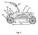
- the normal forward direction of operation of the lawnmower (100)is indicated in each figure by the arrow (OD).
- the deck cover (110)includes a battery-compartment (200) situated towards the front of the lawnmower (100).
- the battery-compartment (200)is a substantially elongate space for receiving and securing a battery (400).
- the battery-compartment (200)has an upper roof section (250) providing cover for the battery-compartment (200) and also a forward-facing opening (210) with respect to the operating direction (OD) of the lawnmower (100).
- the battery-compartment (200)is upwardly-inclined away from the forward-facing opening (210), at approximately 15° from the horizontal operating plane of the lawnmower (100).
- a removable battery (400)comprising cells within a housing is placeable inside the battery-compartment (200).
- the battery (400)is releasable from the battery-compartment (200).
- the battery (400)is designed with a number of grooves on its underside (not shown) to engage with a series of complementary engagement means (not shown) on the lower surface of the battery-compartment (200), ensuring the battery (400) sits properly in the battery-compartment (200).
- the battery-compartment (200)has one or more electrical contacts (220) for engaging with the battery (400) when the battery (400) is fully engaged with the battery-compartment (200).
- the contacts (220)are situated towards the rear of the upwardly-inclined battery-compartment (200) under the roof section (250), away from the opening (210). Owing to the inclination of the battery-compartment (200) away from the opening (210), the contacts (220) are therefore sheltered and protected from water, rain and other precipitation by the roof section (250) at the rear of the battery-compartment (200).
- the battery-compartment (200)further comprises a battery-engaging latch (310) towards the rear of the battery-compartment (200) for engaging with the underside of the battery (400) when it is successfully inserted into the battery-compartment (400).
- the latch (310)prevents the battery (400) from disengaging with the electrical contacts (220) and being accidentally ejected from the battery-compartment (200).
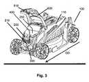
- the latch (310)is pivotally connected to the battery-compartment (200) and further comprises a release lever (300) at one end of the pivotal latch (310), visible in Figures 3 and 4 .
- the battery (400)has a corresponding detent (not shown) for engaging with the battery-engaging latch (310), maintaining the battery (400) in position within the battery-compartment (200) until the battery-engaging latch (310) is lowered by operation of the release lever (300).
- the deck cover (110)further comprises a battery-compartment cover (600).
- the cover (600)is hingeably attached to the deck cover (110) rearward of the battery-compartment opening (210) and acts to provide an additional level of protection to the battery (400) and the electrical contacts (220) inside the battery-compartment (200).
- the cover (600)closes over the opening (210), and opens to provide access to the battery-compartment (200).
- the cover (600)is shown in an open position in Figures 1 to 4 , and a closed position in Figure 5 .
- the cover (600)also comprises a latch (610) which engages with the deck cover (110) at the opposite end from the hinged attachment to the deck cover (110).
- the latch (610)provides a further level of security, preventing the cover (600) accidentally opening without user interaction.
- the cover latch (610)is released to allow the cover (600) to be moved from a closed position ( Figure 5 ) to an open position ( Figures 1 to 4 ). With the cover (600) in the open position, the battery-compartment (200) is accessible through the opening (210), and without the need to move the roof section (250).
- the battery-compartment (250)is arranged so that the battery (400) may be inserted into the battery-compartment (200) through the opening (210) without displacing the roof section (250).
- the battery (400)is placed in front of the opening (210) (see Figures 2 and 4 ) and correctly aligned so that the grooves on the underside of the battery (400) align with the corresponding means in the battery-compartment (200) and the electrical contacts on the battery (400) will engage with the contacts (220) inside the battery-compartment (200).
- the battery-compartment (200)is angled upwardly away from the opening (210) (with respect to the operating plane of the lawn mower) at approximately 15°.
- the battery (400)in order to insert the battery (400) into the battery-compartment (200), the battery (400) must be pushed upwards, into the battery-compartment (200) through the opening (210) until the battery (400) engages with the electrical contacts (220) at the rear of the battery-compartment (200) with respect to the operating direction (OD) of the lawn-mower (100).
- the roof section (250)provides cover for the electrical contacts (220) inside the battery-compartment (200).
- the battery-engaging latch (310)engages with the underside of the battery (400), securing the battery (400) in place inside the battery-compartment (200).
- the cover (600)may then be lowered over the opening (210) and the cover latch (610) engaged with the deck cover (110).
- the battery (400)When the battery (400) is correctly engaged in the battery-compartment (200), the battery (400) has a centre located about 30mm behind the rotational axis of the front wheel (500) with respect to the operating direction of the lawnmower.
- the lawnmower (100)may then be operated with power being delivered from the battery (400) via the contacts (220) to the motor (not shown) of the lawnmower (100).
- the location of the battery (400) near the front of lawnmower (100) when correctly engaged with the contacts (220)means that the battery's weight is able to off-set some of the imbalance caused by the weight of the grass box (not shown) at the rear of the device (with respect to the operating direction (OD) of the lawnmower (100)). Therefore, additional ballast may be avoided. Manufacturing costs may also be reduced.
- the opposite procedure to the one detailed aboveis carried out.
- the cover latch (610)is released, and the cover (600) is opened so that the opening (210) of the battery-compartment (200) is accessible.
- the pivotally-attached battery-engaging latch (310)is released, by operating the release lever (300) from the end of the battery-compartment (200). Owing to the inclined nature of the battery-compartment (200), the battery (400) descends under gravity out of the battery-compartment (200) automatically upon release of the latch (310). The user catches the battery (400) and removes it from the battery-compartment (200). Throughout the ejection, the roof section (250) remains in place, providing cover to the electrical contacts (220). There is no need to displace the roof section (250) to gain access to insert or eject the battery (400).
- the process of installing, and removing the battery (400) from the battery-compartment (200) of the lawnmower (100)is improved by the upwardly-inclined nature of the battery-compartment (200). Owing to the upward inclination of the battery-compartment (200), even when the battery (400) is not installed (e.g. during charging), the electrical contacts (220) are protected from any incidental rainfall/precipitation by the roof (250) of the battery compartment (200).
- the forward-facing opening (210)allows insertion and ejection to be carried out without any obstacles getting in the way, and the forward placement of the battery (400) in the battery-compartment (200) provides a useful counterweight to the grass box (not shown) of the lawnmower (100), removing the need for additional front ballast to balance the lawnmower (100) in use.
- the battery housing (400)is designed to be self-sealing with respect to the battery compartment (200) to provide additional protection from the elements.
- the battery-compartment (200) and opening (210)do not face directly forward with respect to the operating direction (OD) of the lawnmower (100) but instead are angled away from the forward direction, e.g. to allow side-loading of the battery (400).
- the battery-compartmentmay be angled at any angle above the horizontal operating plane of the lawnmower (100).
- the lawn-care apparatuscould also be any ground-supported vegetation cutter, e.g. a lawn rake or scarifier.
- the lawnmower (100)does not comprise the hingeably attached cover (600).
- a battery (400)can be installed/ejected without the need to hold open the battery-compartment cover (600) with one hand. Throughout the installation/ejection process, and with the battery (400) either installed or removed from the battery-compartment (200), the electrical contacts (220) remain shielded by the roof-section (250) and any incidental precipitation will not reach the contacts (220) through the opening (210) thanks to the inclination of the battery-compartment (200).
- the centre of mass of the battery (400)may be situated anywhere up to 150mm behind the rotational axis of the front wheel(s) (500) with respect to the operating direction (OD) of the apparatus.
Landscapes
- Life Sciences & Earth Sciences (AREA)
- Environmental Sciences (AREA)
- Harvester Elements (AREA)
- Battery Mounting, Suspending (AREA)
Description
- The present invention relates to a lawn-care apparatus, and in particular to an improved battery-compartment arrangement for a lawn-care apparatus.
- Many battery-powered lawn-care apparatuses, for example lawnmowers, employ removable batteries which are insertable by lowering them into a downwardly-inclined (vertical or sloped) battery-compartment. Battery compartments of this type typically include an openable cover to protect the battery compartment and its contents, e.g. from rain.
- Problems associated with such devices include difficulty in loading/unloading the battery due to the placement and orientation of the battery-compartment, and a loss of balance of the lawn-care device owing to the location of the battery.
- Whilst a vertical-loading battery may initially be easy to install since the installation is aided by gravity, they can be difficult to remove from the lawn-care apparatus due to the weight and downward orientation of the battery. The end user must remove the battery from the lawn-care apparatus by lifting the battery with his or her fingers, sometimes also by pinching the side of the battery. This can be uncomfortable and awkward for the end user to lift such a weight from the lawn-care apparatus.
- Typically, such battery-compartments are provided with an openable cover to protect the battery-compartment and battery from exposure. However, these covers are frequently self-closing, under either gravity or spring-assisted, and the end user is therefore often forced to use one hand to hold open the battery-compartment cover, thus only one remaining hand is available for removal of the battery.
- Lawn-care apparatus known in the art also employ mid-mounted or rear-mounted battery-compartments for mid-mounted or rear-mounted batteries. As the grass box of the lawn-care apparatus is filled with grass clippings, the centre of gravity of the apparatus is shifted significantly towards the rear of the device (with respect to the normal operating direction of the apparatus). Mid-mounted or rear-mounted batteries only compound this problem by being located towards the rear of the apparatus, thus the front of the apparatus is more likely to lift from the ground when in use, and fail to engage the lawn properly causing an uneven cut and possibly lawn damage. Typically, extra ballast must be installed at the front of the lawn-care apparatus to address this problem.
- One such prior art device is described in
US3973378 , which discloses an upright cordless grass trimmer incorporating a rearwardly opening cavity in which a battery pack is mounted. The cavity is formed with a depth less than the length of the battery pack which facilitates removal since the pack cannot enter fully into the cavity. - Accordingly there is the need for an improved battery-compartment arrangement.
- According to the invention there is provided, in its broadest sense, a lawn-care apparatus having a battery-compartment comprising an access opening for inserting and ejecting a battery, and the battery-compartment is upwardly-inclined with respect to the operating plane of the apparatus, and away from the opening. The upwardly-inclined battery-compartment means that any incidental precipitation will not run down the battery-compartment to the electrical contacts and cause damage.
- Preferably the battery-compartment is inclined at angle of 5 or more degrees from the horizontal, so the battery descends under gravity from the battery-compartment when released.
- Preferably, the battery-compartment opening is forward-facing, and more preferably the battery-compartment is located towards the front of the apparatus. This provides ballast to balance the effects of the grass box getting heavier through use, without the need to include extra mass, thereby increasing the overall weight, and construction cost, of the apparatus.
- Preferably the apparatus has a removable battery to power the apparatus. The battery may be removed for easier charging.
- Preferably, the apparatus comprises at least one front wheel aligned with the direction of operation of the apparatus, and the battery has a centre of mass located no further than 150mm behind the rotational centre of the wheel when the battery is correctly engaged with the battery-compartment, and even more preferably no further than 50mm behind the rotational centre of the wheel. This maintains the battery near the front wheel(s) of the apparatus allowing the weight of the battery to assist in maintaining the balance of the device.
- Preferably the apparatus further comprises a battery-engaging latch to engage with and retain a battery inserted in the compartment. This helps secure the battery in the battery-compartment and protect against accidental ejection of the battery during use.
- Preferably the battery-engaging latch has a release lever to disengage the latch from the battery.
- Preferably the lawn-care apparatus is a ground-supported vegetation cutter, preferably a lawnmower, or a lawn rake or a scarifier.
- Optionally, the battery-compartment opening has an openable cover which is hingeably attached. This cover helps prevent accidental ejection of the battery by covering the battery and associated latch during use of the apparatus.
- Preferably, the apparatus comprises a deck section which houses the battery-compartment. This deck may be assembled separately to the cutting section of the lawn-care apparatus.
- The above, and other aspects of the present invention will now be described in further detail, by way of example only, with reference to the accompanying drawings, in which;
Figure 1 is a side-on view of an embodiment of a lawn-care apparatus in accordance with the present invention with a battery inserted and battery-compartment cover open;Figure 2 is the side-on view of the lawn-care apparatus ofFigure 1 , with the battery in front of the battery-compartment;Figure 3 is a perspective view of the lawn-care apparatus ofFigure 1 , with the battery inserted, and the battery-compartment cover open;Figure 4 is a perspective view of the lawn-care apparatus ofFigure 1 , with the battery in front of the battery-compartment; andFigure 5 is a perspective view of the lawn-care apparatus ofFigure 1 , with the battery-compartment cover closed.- For clarity, only the essential components for an understanding of the present invention are illustrated and specifically described herein. The remainder of the apparatus will be understood by the skilled person as being conventional.
- As shown in
Figures 1 to 5 , there is provided a lawn-care apparatus, such as a lawnmower (100) comprising a deck cover (110) mounted to the top of the main lawnmower chassis, and four wheels (500) arranged two on each side at either end (not all shown). The normal forward direction of operation of the lawnmower (100) is indicated in each figure by the arrow (OD). - The deck cover (110) includes a battery-compartment (200) situated towards the front of the lawnmower (100). The battery-compartment (200) is a substantially elongate space for receiving and securing a battery (400). The battery-compartment (200) has an upper roof section (250) providing cover for the battery-compartment (200) and also a forward-facing opening (210) with respect to the operating direction (OD) of the lawnmower (100). The battery-compartment (200) is upwardly-inclined away from the forward-facing opening (210), at approximately 15° from the horizontal operating plane of the lawnmower (100).
- As shown in
Figures 1 and3 , a removable battery (400) comprising cells within a housing is placeable inside the battery-compartment (200). As shown inFigures 2 and4 , the battery (400) is releasable from the battery-compartment (200). The battery (400) is designed with a number of grooves on its underside (not shown) to engage with a series of complementary engagement means (not shown) on the lower surface of the battery-compartment (200), ensuring the battery (400) sits properly in the battery-compartment (200). - As shown in
Figure 4 , the battery-compartment (200) has one or more electrical contacts (220) for engaging with the battery (400) when the battery (400) is fully engaged with the battery-compartment (200). The contacts (220) are situated towards the rear of the upwardly-inclined battery-compartment (200) under the roof section (250), away from the opening (210). Owing to the inclination of the battery-compartment (200) away from the opening (210), the contacts (220) are therefore sheltered and protected from water, rain and other precipitation by the roof section (250) at the rear of the battery-compartment (200). As can be seen inFigure 4 , the battery-compartment (200) further comprises a battery-engaging latch (310) towards the rear of the battery-compartment (200) for engaging with the underside of the battery (400) when it is successfully inserted into the battery-compartment (400). The latch (310) prevents the battery (400) from disengaging with the electrical contacts (220) and being accidentally ejected from the battery-compartment (200). The latch (310) is pivotally connected to the battery-compartment (200) and further comprises a release lever (300) at one end of the pivotal latch (310), visible inFigures 3 and4 . The battery (400) has a corresponding detent (not shown) for engaging with the battery-engaging latch (310), maintaining the battery (400) in position within the battery-compartment (200) until the battery-engaging latch (310) is lowered by operation of the release lever (300). - The deck cover (110) further comprises a battery-compartment cover (600). The cover (600) is hingeably attached to the deck cover (110) rearward of the battery-compartment opening (210) and acts to provide an additional level of protection to the battery (400) and the electrical contacts (220) inside the battery-compartment (200). The cover (600) closes over the opening (210), and opens to provide access to the battery-compartment (200). The cover (600) is shown in an open position in
Figures 1 to 4 , and a closed position inFigure 5 . - The cover (600) also comprises a latch (610) which engages with the deck cover (110) at the opposite end from the hinged attachment to the deck cover (110). The latch (610) provides a further level of security, preventing the cover (600) accidentally opening without user interaction.
- To insert a battery (400) into the empty battery-compartment (200), the cover latch (610) is released to allow the cover (600) to be moved from a closed position (
Figure 5 ) to an open position (Figures 1 to 4 ). With the cover (600) in the open position, the battery-compartment (200) is accessible through the opening (210), and without the need to move the roof section (250). The battery-compartment (250) is arranged so that the battery (400) may be inserted into the battery-compartment (200) through the opening (210) without displacing the roof section (250). The battery (400) is placed in front of the opening (210) (seeFigures 2 and4 ) and correctly aligned so that the grooves on the underside of the battery (400) align with the corresponding means in the battery-compartment (200) and the electrical contacts on the battery (400) will engage with the contacts (220) inside the battery-compartment (200). The battery-compartment (200) is angled upwardly away from the opening (210) (with respect to the operating plane of the lawn mower) at approximately 15°. Therefore, in order to insert the battery (400) into the battery-compartment (200), the battery (400) must be pushed upwards, into the battery-compartment (200) through the opening (210) until the battery (400) engages with the electrical contacts (220) at the rear of the battery-compartment (200) with respect to the operating direction (OD) of the lawn-mower (100). Throughout the insertion of the battery, the roof section (250) provides cover for the electrical contacts (220) inside the battery-compartment (200). - Once the battery (400) is fully engaged with the battery-compartment (200) and the electrical contacts (220), the battery-engaging latch (310) engages with the underside of the battery (400), securing the battery (400) in place inside the battery-compartment (200). The cover (600) may then be lowered over the opening (210) and the cover latch (610) engaged with the deck cover (110).
- When the battery (400) is correctly engaged in the battery-compartment (200), the battery (400) has a centre located about 30mm behind the rotational axis of the front wheel (500) with respect to the operating direction of the lawnmower. The lawnmower (100) may then be operated with power being delivered from the battery (400) via the contacts (220) to the motor (not shown) of the lawnmower (100).
- The location of the battery (400) near the front of lawnmower (100) when correctly engaged with the contacts (220) means that the battery's weight is able to off-set some of the imbalance caused by the weight of the grass box (not shown) at the rear of the device (with respect to the operating direction (OD) of the lawnmower (100)). Therefore, additional ballast may be avoided. Manufacturing costs may also be reduced.
- In order to remove the battery (400) from the battery-compartment (200) of the lawnmower (100), the opposite procedure to the one detailed above is carried out. The cover latch (610) is released, and the cover (600) is opened so that the opening (210) of the battery-compartment (200) is accessible. The pivotally-attached battery-engaging latch (310) is released, by operating the release lever (300) from the end of the battery-compartment (200). Owing to the inclined nature of the battery-compartment (200), the battery (400) descends under gravity out of the battery-compartment (200) automatically upon release of the latch (310). The user catches the battery (400) and removes it from the battery-compartment (200). Throughout the ejection, the roof section (250) remains in place, providing cover to the electrical contacts (220). There is no need to displace the roof section (250) to gain access to insert or eject the battery (400).
- The process of installing, and removing the battery (400) from the battery-compartment (200) of the lawnmower (100) is improved by the upwardly-inclined nature of the battery-compartment (200). Owing to the upward inclination of the battery-compartment (200), even when the battery (400) is not installed (e.g. during charging), the electrical contacts (220) are protected from any incidental rainfall/precipitation by the roof (250) of the battery compartment (200). The forward-facing opening (210) allows insertion and ejection to be carried out without any obstacles getting in the way, and the forward placement of the battery (400) in the battery-compartment (200) provides a useful counterweight to the grass box (not shown) of the lawnmower (100), removing the need for additional front ballast to balance the lawnmower (100) in use.
- In alternative embodiments (not shown), the battery housing (400) is designed to be self-sealing with respect to the battery compartment (200) to provide additional protection from the elements. In another embodiment of the invention (not shown), the battery-compartment (200) and opening (210) do not face directly forward with respect to the operating direction (OD) of the lawnmower (100) but instead are angled away from the forward direction, e.g. to allow side-loading of the battery (400).
- In a further embodiment, the battery-compartment may be angled at any angle above the horizontal operating plane of the lawnmower (100).
- The lawn-care apparatus could also be any ground-supported vegetation cutter, e.g. a lawn rake or scarifier.
- In a further embodiment, the lawnmower (100) does not comprise the hingeably attached cover (600). A battery (400) can be installed/ejected without the need to hold open the battery-compartment cover (600) with one hand. Throughout the installation/ejection process, and with the battery (400) either installed or removed from the battery-compartment (200), the electrical contacts (220) remain shielded by the roof-section (250) and any incidental precipitation will not reach the contacts (220) through the opening (210) thanks to the inclination of the battery-compartment (200).
- In another embodiment, the centre of mass of the battery (400) may be situated anywhere up to 150mm behind the rotational axis of the front wheel(s) (500) with respect to the operating direction (OD) of the apparatus.
- While the embodiments described herein are intended as an exemplary lawn-care apparatus, it will be appreciated by those skilled in the art that the present invention is not limited to the embodiments illustrated. Those skilled in the art will envision many other possible variations and modifications by means of the skilled person's common knowledge without departing from the scope of the invention as defined in the claims.
Claims (13)
- A lawn-care apparatus (100) having a battery-compartment (200), the battery-compartment (200) having an access opening (210), wherein
the battery-compartment (200) is upwardly-inclined with respect to the operating plane of the apparatus, and away from the opening (210). - A lawn-care apparatus (100) according to Claim 1, wherein the battery-compartment (200) is inclined at an angle greater than 5° from the horizontal.
- A lawn-care apparatus (100) according to Claims 1 or 2, wherein during use, a battery (400) inserted into the battery-compartment (200) will automatically be ejected under gravity from the battery-compartment (200) upon release of the battery-engaging latch (310).
- A lawn-care apparatus (100) according to any preceding claim, wherein the opening (210) is forward-facing with respect to an operating direction (OD) of the apparatus (100).
- A lawn-care apparatus (100) according to any preceding claim, wherein the battery-compartment (200) is located towards the front of the apparatus, with respect to the operating direction (OD) of the apparatus.
- A lawn-care apparatus (100) according to any previous claim, further comprising a removable battery (400).
- A lawn-care apparatus (100) according to Claim 6, wherein the apparatus comprises at least one front wheel (500) aligned with the direction of operation (OD) of the apparatus, and the battery (400) has a centre of mass located no further than 150mm behind the rotational axis of the wheel (500) with respect to the operating direction of the apparatus, when the battery (400) is engaged with the battery-compartment (200).
- A lawn-care apparatus (100) according to Claim 7, wherein the battery (400) has a centre of mass located no further than 50mm behind the rotational axis of the wheel (500).
- A lawn-care apparatus (100) according to any previous claim, further comprising a battery-engaging latch (310) to engage with, and retain, a battery inserted in the compartment (200).
- A lawn-care apparatus (100) according to Claim 9, wherein the battery-engaging latch (310) has a release lever (300) to disengage the latch (310) from a battery inserted into the battery-compartment (200).
- A lawn-care apparatus (100) according to any previous claim, wherein the lawn-care apparatus (100) is a ground-supported vegetation cutter, preferably a lawnmower, a lawn rake or a scarifier.
- A lawn-care apparatus (100) according to any previous claim, wherein the battery-compartment opening (210) further comprises an additional openable cover (600).
- A lawn-care apparatus (100) according to any previous claim, wherein the apparatus comprises a deck section (110) which comprises the battery-compartment (200).
Priority Applications (3)
| Application Number | Priority Date | Filing Date | Title |
|---|---|---|---|
| EP12158420.5AEP2636295B1 (en) | 2012-03-07 | 2012-03-07 | Lawn-care apparatus |
| US13/782,685US9711767B2 (en) | 2012-03-07 | 2013-03-01 | Lawn-care apparatus with an accessible battery compartment |
| CN201310067844.3ACN103299778B (en) | 2012-03-07 | 2013-03-04 | Lawn-care apparatus |
Applications Claiming Priority (1)
| Application Number | Priority Date | Filing Date | Title |
|---|---|---|---|
| EP12158420.5AEP2636295B1 (en) | 2012-03-07 | 2012-03-07 | Lawn-care apparatus |
Publications (2)
| Publication Number | Publication Date |
|---|---|
| EP2636295A1 EP2636295A1 (en) | 2013-09-11 |
| EP2636295B1true EP2636295B1 (en) | 2014-09-10 |
Family
ID=45833167
Family Applications (1)
| Application Number | Title | Priority Date | Filing Date |
|---|---|---|---|
| EP12158420.5AActiveEP2636295B1 (en) | 2012-03-07 | 2012-03-07 | Lawn-care apparatus |
Country Status (3)
| Country | Link |
|---|---|
| US (1) | US9711767B2 (en) |
| EP (1) | EP2636295B1 (en) |
| CN (1) | CN103299778B (en) |
Families Citing this family (24)
| Publication number | Priority date | Publication date | Assignee | Title |
|---|---|---|---|---|
| CN105794411B (en)* | 2014-12-30 | 2020-04-07 | 南京德朔实业有限公司 | Power tool |
| CN105794388A (en)* | 2014-12-30 | 2016-07-27 | 南京德朔实业有限公司 | Power tool |
| CN204539996U (en)* | 2015-03-27 | 2015-08-12 | Ac(澳门离岸商业服务)有限公司 | Power modules and power tools for power tools |
| USD841572S1 (en) | 2016-03-08 | 2019-02-26 | Briggs & Stratton Corporation | Battery |
| CN106416467B (en)* | 2016-08-29 | 2019-04-26 | 宁波奇亚园林工具有限公司 | A kind of rotary-cutting machine translucent cover |
| JP2018088853A (en)* | 2016-11-30 | 2018-06-14 | 本田技研工業株式会社 | Electric working machine |
| DE112017008227B4 (en)* | 2017-11-22 | 2024-02-29 | Honda Motor Co., Ltd. | working machine |
| CN107771502A (en)* | 2017-12-06 | 2018-03-09 | 嘉兴南洋职业技术学院 | Weeder |
| US12342761B2 (en) | 2017-12-28 | 2025-07-01 | Nanjing Chervon Industry Co., Ltd. | Outdoor moving device |
| EP4570055A3 (en) | 2017-12-28 | 2025-08-27 | Nanjing Chervon Industry Co., Ltd. | Electric riding lawn mower |
| JP7046739B2 (en)* | 2018-07-02 | 2022-04-04 | 本田技研工業株式会社 | Working machine |
| US20230122499A1 (en)* | 2019-10-11 | 2023-04-20 | Ariens Company | Power source and control system for a lawn mower |
| US12030402B2 (en) | 2020-11-09 | 2024-07-09 | Zimeno Inc. | Battery swap system |
| DE112021007129T5 (en)* | 2021-02-18 | 2024-01-04 | Honda Motor Co., Ltd. | vehicle |
| US12296694B2 (en) | 2021-03-10 | 2025-05-13 | Techtronic Cordless Gp | Lawnmowers |
| CN218998877U (en) | 2021-06-25 | 2023-05-12 | 南京泉峰科技有限公司 | riding lawn mower |
| US20230119910A1 (en)* | 2021-10-14 | 2023-04-20 | Briggs & Stratton, Llc | Lawn Tractor with Removable Battery Packs |
| US11407298B1 (en)* | 2021-11-15 | 2022-08-09 | Amos Power, Inc. | Removable battery unit for an electric vehicle |
| USD1014573S1 (en) | 2022-04-01 | 2024-02-13 | Amos Power, Inc. | Removable track unit for a robotic vehicle |
| USD1014569S1 (en) | 2022-04-01 | 2024-02-13 | Amos Power, Inc. | Robotic vehicle |
| US11547035B1 (en) | 2022-05-24 | 2023-01-10 | Amos Power, Inc. | Lift assist for an electrically driven hitch on an robotic vehicle |
| EP4310621B1 (en) | 2022-07-19 | 2025-02-12 | Techtronic Cordless GP | Display for controlling robotic tool |
| EP4340296B1 (en) | 2022-07-29 | 2025-04-09 | Techtronic Cordless GP | Generation of a cryptography key for a robotic garden tool |
| USD1065046S1 (en) | 2022-09-16 | 2025-03-04 | Briggs & Stratton, Llc | Battery |
Family Cites Families (52)
| Publication number | Priority date | Publication date | Assignee | Title |
|---|---|---|---|---|
| US3973378A (en)* | 1975-03-18 | 1976-08-10 | Disston, Inc. | Cordless grass trimmer having removable battery pack |
| US4435486A (en)* | 1982-06-04 | 1984-03-06 | Pomaro Nicholas T | Quick disconnect battery installation and charging system |
| US4756978A (en)* | 1986-11-19 | 1988-07-12 | Walter Nitcher | Battery and mount |
| US4930300A (en)* | 1989-06-02 | 1990-06-05 | Deere & Company | Lawn mower battery mounting |
| US5085043A (en)* | 1990-06-01 | 1992-02-04 | Black & Decker Inc. | Electro-mechanical interlock and module system for lawn mower or other electrical device |
| US5228531A (en)* | 1991-06-14 | 1993-07-20 | Deere & Company | Battery hold-down mechanism |
| DE4137162A1 (en)* | 1991-11-12 | 1993-05-13 | Wolf Dietrich Zinck | Battery-operated electric lawnmower using permanent D.C. motor - with battery simply electrically disconnected and removed for replacement without requiring any special tools |
| US5360307A (en)* | 1992-12-07 | 1994-11-01 | Windsor Industries | Battery transfer technique for vehicle |
| US5606851A (en)* | 1993-09-22 | 1997-03-04 | Briggs & Stratton Corporation | Battery-powered lawn cutting system |
| USD361771S (en)* | 1994-07-19 | 1995-08-29 | John Ledingham | Lawnmower |
| EP0712779B1 (en)* | 1994-11-18 | 2002-06-05 | Yamaha Hatsudoki Kabushiki Kaisha | Battery holding structure |
| US6170179B1 (en)* | 1995-06-07 | 2001-01-09 | Karen A. Paytas | Battery powered electric snow thrower |
| DE19528167C1 (en)* | 1995-08-01 | 1996-08-29 | Wolf Geraete Gmbh Vertrieb | Lawn mower with battery charged electric motor |
| US5727372A (en)* | 1996-05-30 | 1998-03-17 | The Toro Company | On-board charging system for electric lawn mower |
| JP3160759B2 (en)* | 1996-09-17 | 2001-04-25 | 本田技研工業株式会社 | Electric lawn mower |
| US5934053A (en)* | 1996-11-01 | 1999-08-10 | Fillman; Alan R. | Removable battery tray system for an electrically powered mower |
| FR2768298B1 (en)* | 1997-09-12 | 1999-11-12 | Wolf Outils | LAWNMOWER WITH ELECTRIC MOTOR |
| IT1320305B1 (en)* | 1999-05-25 | 2003-11-26 | Honda Motor Co Ltd | BATTERY CHANGE EQUIPMENT. |
| US6525511B2 (en)* | 2000-08-11 | 2003-02-25 | Milwaukee Electric Tool Corporation | Adapter for a power tool battery |
| US6523334B1 (en)* | 2000-10-26 | 2003-02-25 | Textron Inc. | Battery-powered walk-behind greensmower |
| US7007446B2 (en)* | 2000-10-26 | 2006-03-07 | Textron Inc. | Battery-powered walk-behind greensmower |
| US6487837B1 (en)* | 2001-06-05 | 2002-12-03 | Textron Inc. | Articularly mounted battery-powered walk-behind reel lawnmower |
| TWI248783B (en)* | 2001-08-22 | 2006-02-11 | Honda Motor Co Ltd | Electric lawn mower |
| US7989969B2 (en)* | 2002-06-06 | 2011-08-02 | Black & Decker Inc. | Universal power tool battery pack coupled to a portable internal combustion engine |
| US7111443B2 (en)* | 2002-10-11 | 2006-09-26 | The Toro Copmany | Walk reel mower with electric drive and automatic slow down system |
| US7320843B2 (en)* | 2004-02-27 | 2008-01-22 | Great Stuff, Inc. | Battery assembly with shielded terminals |
| DE102005036449A1 (en)* | 2005-08-03 | 2007-02-08 | Robert Bosch Gmbh | Electrical appliance, in particular electric hand tool |
| US7413045B2 (en)* | 2005-11-30 | 2008-08-19 | Karma Medical Products Co., Ltd. | Battery quick-release structure for an electric mobility scooter |
| GB0615241D0 (en)* | 2006-08-01 | 2006-09-06 | Bosch Gmbh Robert | Lawn-care apparatus |
| US7741793B2 (en)* | 2006-10-17 | 2010-06-22 | Mtd Products Inc | Hybrid electric device |
| US7479754B2 (en)* | 2006-10-17 | 2009-01-20 | Desa Ip Llc | Hybrid electric lawnmower |
| US7728534B2 (en)* | 2006-10-17 | 2010-06-01 | Mtd Products Inc | Hybrid electric lawnmower |
| US8227943B2 (en)* | 2008-02-25 | 2012-07-24 | Lee Melvin Harbin | Power system retrofit kit for mobile workstation and retrofit method |
| US8653786B2 (en)* | 2008-04-25 | 2014-02-18 | Black & Decker Inc. | Cordless mower including battery with two charging connectors |
| US8429885B2 (en)* | 2008-04-25 | 2013-04-30 | Black & Decker Inc. | Cordless mower including cooling air flow arrangement |
| US20090266042A1 (en)* | 2008-04-25 | 2009-10-29 | Mooney P Wade | Mower |
| US7963344B2 (en)* | 2008-09-03 | 2011-06-21 | Black & Decker Inc. | Tiller with removable battery |
| TWI357865B (en)* | 2008-12-03 | 2012-02-11 | Ind Tech Res Inst | A swift pluggable and lockable battery structure |
| US7762049B2 (en) | 2008-12-31 | 2010-07-27 | Black & Decker Inc. | Electric mower having two-motion activation system |
| USD614125S1 (en)* | 2009-02-16 | 2010-04-20 | Andreas Stihl Ag & Co. Kg | Battery |
| US8037669B2 (en)* | 2009-04-28 | 2011-10-18 | Husqvarna Consumer Outdoor Products N.A., Inc. | Baffle based battery housing |
| JP2011003656A (en)* | 2009-06-17 | 2011-01-06 | Toshiba Corp | Semiconductor device |
| USD620030S1 (en)* | 2009-09-11 | 2010-07-20 | Black & Decker Inc. | Mower |
| USD627372S1 (en)* | 2010-05-28 | 2010-11-16 | Black & Decker Inc. | Mower |
| EP2718149A4 (en)* | 2011-05-13 | 2015-04-01 | Vehicle battery storage compartment | |
| JP5805437B2 (en)* | 2011-06-14 | 2015-11-04 | 株式会社マキタ | Electric lawn mower |
| US9496531B2 (en)* | 2011-06-14 | 2016-11-15 | Makita Corporation | Battery devices |
| JP5694065B2 (en)* | 2011-06-14 | 2015-04-01 | 株式会社マキタ | Electric lawn mower |
| JP5689753B2 (en)* | 2011-06-14 | 2015-03-25 | 株式会社マキタ | Electric lawn mower |
| ITMI20111511A1 (en)* | 2011-08-08 | 2013-02-09 | Ggp Italy Spa | ELECTRICAL BATTERY CONNECTION DEVICE. |
| US20130312382A1 (en)* | 2012-05-25 | 2013-11-28 | Makita Corporation | Lawn mower |
| US9083195B2 (en)* | 2012-10-15 | 2015-07-14 | Raymond J. Lewis | Power harvesting system for battery operated appliances |
- 2012
- 2012-03-07EPEP12158420.5Apatent/EP2636295B1/enactiveActive
- 2013
- 2013-03-01USUS13/782,685patent/US9711767B2/enactiveActive
- 2013-03-04CNCN201310067844.3Apatent/CN103299778B/enactiveActive
Also Published As
| Publication number | Publication date |
|---|---|
| US20130239533A1 (en) | 2013-09-19 |
| US9711767B2 (en) | 2017-07-18 |
| CN103299778A (en) | 2013-09-18 |
| EP2636295A1 (en) | 2013-09-11 |
| CN103299778B (en) | 2018-10-30 |
Similar Documents
| Publication | Publication Date | Title |
|---|---|---|
| EP2636295B1 (en) | Lawn-care apparatus | |
| EP1692930B1 (en) | Rotary lawn mower with pivotal mulch door | |
| US8850782B2 (en) | Lawnmower safety | |
| EP2534938B1 (en) | Electric lawn mowers | |
| US4800712A (en) | Grass catcher mounting system | |
| US20030182919A1 (en) | Deck assembly for a self-propelled, walk-behind rotary lawn mower | |
| US20100115901A1 (en) | Lawn mower having collecting and mulching modes | |
| US20130049477A1 (en) | Electric-powered cultivator | |
| US9254563B2 (en) | Power tool | |
| EP2710877B1 (en) | Lawn mower | |
| US9320202B2 (en) | Debris removal system for a lawn mower | |
| US5983613A (en) | Vacuum mower | |
| TW201103418A (en) | Electric cultivator | |
| US9750186B2 (en) | Walk-behind mower including debris container | |
| US6966169B2 (en) | Mowing machine chute cleaner apparatuses and methods | |
| EP3437453B1 (en) | Riding grass-mower | |
| US8555608B2 (en) | Mulching lawn mower rear discharge pathway and shield | |
| US4080774A (en) | Mower | |
| EP3297416B1 (en) | Walk behind lawn mower with a collector dump assembly | |
| US4103478A (en) | Mower support for rear mounted grass catcher | |
| US20180368313A1 (en) | Discharge guard assembly for a mower | |
| US12022773B2 (en) | Lawn mower and associated attachment | |
| EP4602906A1 (en) | Lawn mower | |
| JPS61234710A (en) | Riding mower | |
| AU2008207339A1 (en) | An Improved Lawnmower Catcher |
Legal Events
| Date | Code | Title | Description |
|---|---|---|---|
| PUAI | Public reference made under article 153(3) epc to a published international application that has entered the european phase | Free format text:ORIGINAL CODE: 0009012 | |
| AK | Designated contracting states | Kind code of ref document:A1 Designated state(s):AL AT BE BG CH CY CZ DE DK EE ES FI FR GB GR HR HU IE IS IT LI LT LU LV MC MK MT NL NO PL PT RO RS SE SI SK SM TR | |
| AX | Request for extension of the european patent | Extension state:BA ME | |
| RIN1 | Information on inventor provided before grant (corrected) | Inventor name:LING, MATTHEW Inventor name:ARMSTRONG, GAVIN BEN Inventor name:JUENGER, DENNIS Inventor name:PRINCE, MATHEW | |
| 17P | Request for examination filed | Effective date:20140311 | |
| RBV | Designated contracting states (corrected) | Designated state(s):AL AT BE BG CH CY CZ DE DK EE ES FI FR GB GR HR HU IE IS IT LI LT LU LV MC MK MT NL NO PL PT RO RS SE SI SK SM TR | |
| GRAP | Despatch of communication of intention to grant a patent | Free format text:ORIGINAL CODE: EPIDOSNIGR1 | |
| INTG | Intention to grant announced | Effective date:20140509 | |
| RIN1 | Information on inventor provided before grant (corrected) | Inventor name:JUENGER, DENNIS Inventor name:LING, MATTHEW Inventor name:ARMSTRONG, GAVIN BEN Inventor name:PRICE, MATHEW | |
| GRAS | Grant fee paid | Free format text:ORIGINAL CODE: EPIDOSNIGR3 | |
| GRAA | (expected) grant | Free format text:ORIGINAL CODE: 0009210 | |
| AK | Designated contracting states | Kind code of ref document:B1 Designated state(s):AL AT BE BG CH CY CZ DE DK EE ES FI FR GB GR HR HU IE IS IT LI LT LU LV MC MK MT NL NO PL PT RO RS SE SI SK SM TR | |
| REG | Reference to a national code | Ref country code:GB Ref legal event code:FG4D | |
| REG | Reference to a national code | Ref country code:CH Ref legal event code:EP | |
| REG | Reference to a national code | Ref country code:IE Ref legal event code:FG4D | |
| REG | Reference to a national code | Ref country code:AT Ref legal event code:REF Ref document number:686182 Country of ref document:AT Kind code of ref document:T Effective date:20141015 | |
| REG | Reference to a national code | Ref country code:DE Ref legal event code:R096 Ref document number:602012003011 Country of ref document:DE Effective date:20141023 | |
| REG | Reference to a national code | Ref country code:SE Ref legal event code:TRGR | |
| PG25 | Lapsed in a contracting state [announced via postgrant information from national office to epo] | Ref country code:LT Free format text:LAPSE BECAUSE OF FAILURE TO SUBMIT A TRANSLATION OF THE DESCRIPTION OR TO PAY THE FEE WITHIN THE PRESCRIBED TIME-LIMIT Effective date:20140910 Ref country code:ES Free format text:LAPSE BECAUSE OF FAILURE TO SUBMIT A TRANSLATION OF THE DESCRIPTION OR TO PAY THE FEE WITHIN THE PRESCRIBED TIME-LIMIT Effective date:20140910 Ref country code:FI Free format text:LAPSE BECAUSE OF FAILURE TO SUBMIT A TRANSLATION OF THE DESCRIPTION OR TO PAY THE FEE WITHIN THE PRESCRIBED TIME-LIMIT Effective date:20140910 Ref country code:NO Free format text:LAPSE BECAUSE OF FAILURE TO SUBMIT A TRANSLATION OF THE DESCRIPTION OR TO PAY THE FEE WITHIN THE PRESCRIBED TIME-LIMIT Effective date:20141210 Ref country code:GR Free format text:LAPSE BECAUSE OF FAILURE TO SUBMIT A TRANSLATION OF THE DESCRIPTION OR TO PAY THE FEE WITHIN THE PRESCRIBED TIME-LIMIT Effective date:20141211 | |
| REG | Reference to a national code | Ref country code:NL Ref legal event code:VDEP Effective date:20140910 | |
| REG | Reference to a national code | Ref country code:LT Ref legal event code:MG4D | |
| PG25 | Lapsed in a contracting state [announced via postgrant information from national office to epo] | Ref country code:RS Free format text:LAPSE BECAUSE OF FAILURE TO SUBMIT A TRANSLATION OF THE DESCRIPTION OR TO PAY THE FEE WITHIN THE PRESCRIBED TIME-LIMIT Effective date:20140910 Ref country code:CY Free format text:LAPSE BECAUSE OF FAILURE TO SUBMIT A TRANSLATION OF THE DESCRIPTION OR TO PAY THE FEE WITHIN THE PRESCRIBED TIME-LIMIT Effective date:20140910 Ref country code:HR Free format text:LAPSE BECAUSE OF FAILURE TO SUBMIT A TRANSLATION OF THE DESCRIPTION OR TO PAY THE FEE WITHIN THE PRESCRIBED TIME-LIMIT Effective date:20140910 Ref country code:LV Free format text:LAPSE BECAUSE OF FAILURE TO SUBMIT A TRANSLATION OF THE DESCRIPTION OR TO PAY THE FEE WITHIN THE PRESCRIBED TIME-LIMIT Effective date:20140910 | |
| REG | Reference to a national code | Ref country code:AT Ref legal event code:MK05 Ref document number:686182 Country of ref document:AT Kind code of ref document:T Effective date:20140910 | |
| PG25 | Lapsed in a contracting state [announced via postgrant information from national office to epo] | Ref country code:NL Free format text:LAPSE BECAUSE OF FAILURE TO SUBMIT A TRANSLATION OF THE DESCRIPTION OR TO PAY THE FEE WITHIN THE PRESCRIBED TIME-LIMIT Effective date:20140910 | |
| PG25 | Lapsed in a contracting state [announced via postgrant information from national office to epo] | Ref country code:SK Free format text:LAPSE BECAUSE OF FAILURE TO SUBMIT A TRANSLATION OF THE DESCRIPTION OR TO PAY THE FEE WITHIN THE PRESCRIBED TIME-LIMIT Effective date:20140910 Ref country code:RO Free format text:LAPSE BECAUSE OF FAILURE TO SUBMIT A TRANSLATION OF THE DESCRIPTION OR TO PAY THE FEE WITHIN THE PRESCRIBED TIME-LIMIT Effective date:20140910 Ref country code:EE Free format text:LAPSE BECAUSE OF FAILURE TO SUBMIT A TRANSLATION OF THE DESCRIPTION OR TO PAY THE FEE WITHIN THE PRESCRIBED TIME-LIMIT Effective date:20140910 Ref country code:PT Free format text:LAPSE BECAUSE OF FAILURE TO SUBMIT A TRANSLATION OF THE DESCRIPTION OR TO PAY THE FEE WITHIN THE PRESCRIBED TIME-LIMIT Effective date:20150112 Ref country code:CZ Free format text:LAPSE BECAUSE OF FAILURE TO SUBMIT A TRANSLATION OF THE DESCRIPTION OR TO PAY THE FEE WITHIN THE PRESCRIBED TIME-LIMIT Effective date:20140910 Ref country code:IS Free format text:LAPSE BECAUSE OF FAILURE TO SUBMIT A TRANSLATION OF THE DESCRIPTION OR TO PAY THE FEE WITHIN THE PRESCRIBED TIME-LIMIT Effective date:20150110 | |
| PG25 | Lapsed in a contracting state [announced via postgrant information from national office to epo] | Ref country code:AT Free format text:LAPSE BECAUSE OF FAILURE TO SUBMIT A TRANSLATION OF THE DESCRIPTION OR TO PAY THE FEE WITHIN THE PRESCRIBED TIME-LIMIT Effective date:20140910 Ref country code:PL Free format text:LAPSE BECAUSE OF FAILURE TO SUBMIT A TRANSLATION OF THE DESCRIPTION OR TO PAY THE FEE WITHIN THE PRESCRIBED TIME-LIMIT Effective date:20140910 | |
| REG | Reference to a national code | Ref country code:DE Ref legal event code:R097 Ref document number:602012003011 Country of ref document:DE | |
| PLBE | No opposition filed within time limit | Free format text:ORIGINAL CODE: 0009261 | |
| STAA | Information on the status of an ep patent application or granted ep patent | Free format text:STATUS: NO OPPOSITION FILED WITHIN TIME LIMIT | |
| PG25 | Lapsed in a contracting state [announced via postgrant information from national office to epo] | Ref country code:DK Free format text:LAPSE BECAUSE OF FAILURE TO SUBMIT A TRANSLATION OF THE DESCRIPTION OR TO PAY THE FEE WITHIN THE PRESCRIBED TIME-LIMIT Effective date:20140910 | |
| 26N | No opposition filed | Effective date:20150611 | |
| PG25 | Lapsed in a contracting state [announced via postgrant information from national office to epo] | Ref country code:IT Free format text:LAPSE BECAUSE OF FAILURE TO SUBMIT A TRANSLATION OF THE DESCRIPTION OR TO PAY THE FEE WITHIN THE PRESCRIBED TIME-LIMIT Effective date:20140910 | |
| PG25 | Lapsed in a contracting state [announced via postgrant information from national office to epo] | Ref country code:MC Free format text:LAPSE BECAUSE OF FAILURE TO SUBMIT A TRANSLATION OF THE DESCRIPTION OR TO PAY THE FEE WITHIN THE PRESCRIBED TIME-LIMIT Effective date:20140910 Ref country code:LU Free format text:LAPSE BECAUSE OF FAILURE TO SUBMIT A TRANSLATION OF THE DESCRIPTION OR TO PAY THE FEE WITHIN THE PRESCRIBED TIME-LIMIT Effective date:20150307 | |
| REG | Reference to a national code | Ref country code:CH Ref legal event code:PL | |
| PG25 | Lapsed in a contracting state [announced via postgrant information from national office to epo] | Ref country code:SI Free format text:LAPSE BECAUSE OF FAILURE TO SUBMIT A TRANSLATION OF THE DESCRIPTION OR TO PAY THE FEE WITHIN THE PRESCRIBED TIME-LIMIT Effective date:20140910 | |
| REG | Reference to a national code | Ref country code:IE Ref legal event code:MM4A | |
| PG25 | Lapsed in a contracting state [announced via postgrant information from national office to epo] | Ref country code:IE Free format text:LAPSE BECAUSE OF NON-PAYMENT OF DUE FEES Effective date:20150307 Ref country code:LI Free format text:LAPSE BECAUSE OF NON-PAYMENT OF DUE FEES Effective date:20150331 Ref country code:CH Free format text:LAPSE BECAUSE OF NON-PAYMENT OF DUE FEES Effective date:20150331 | |
| REG | Reference to a national code | Ref country code:FR Ref legal event code:PLFP Year of fee payment:5 | |
| PGFP | Annual fee paid to national office [announced via postgrant information from national office to epo] | Ref country code:SE Payment date:20160322 Year of fee payment:5 | |
| PG25 | Lapsed in a contracting state [announced via postgrant information from national office to epo] | Ref country code:BE Free format text:LAPSE BECAUSE OF FAILURE TO SUBMIT A TRANSLATION OF THE DESCRIPTION OR TO PAY THE FEE WITHIN THE PRESCRIBED TIME-LIMIT Effective date:20140910 | |
| PG25 | Lapsed in a contracting state [announced via postgrant information from national office to epo] | Ref country code:MT Free format text:LAPSE BECAUSE OF FAILURE TO SUBMIT A TRANSLATION OF THE DESCRIPTION OR TO PAY THE FEE WITHIN THE PRESCRIBED TIME-LIMIT Effective date:20140910 | |
| REG | Reference to a national code | Ref country code:FR Ref legal event code:PLFP Year of fee payment:6 | |
| PG25 | Lapsed in a contracting state [announced via postgrant information from national office to epo] | Ref country code:SM Free format text:LAPSE BECAUSE OF FAILURE TO SUBMIT A TRANSLATION OF THE DESCRIPTION OR TO PAY THE FEE WITHIN THE PRESCRIBED TIME-LIMIT Effective date:20140910 Ref country code:BG Free format text:LAPSE BECAUSE OF FAILURE TO SUBMIT A TRANSLATION OF THE DESCRIPTION OR TO PAY THE FEE WITHIN THE PRESCRIBED TIME-LIMIT Effective date:20140910 Ref country code:HU Free format text:LAPSE BECAUSE OF FAILURE TO SUBMIT A TRANSLATION OF THE DESCRIPTION OR TO PAY THE FEE WITHIN THE PRESCRIBED TIME-LIMIT; INVALID AB INITIO Effective date:20120307 | |
| PG25 | Lapsed in a contracting state [announced via postgrant information from national office to epo] | Ref country code:TR Free format text:LAPSE BECAUSE OF FAILURE TO SUBMIT A TRANSLATION OF THE DESCRIPTION OR TO PAY THE FEE WITHIN THE PRESCRIBED TIME-LIMIT Effective date:20140910 | |
| REG | Reference to a national code | Ref country code:SE Ref legal event code:EUG | |
| PG25 | Lapsed in a contracting state [announced via postgrant information from national office to epo] | Ref country code:SE Free format text:LAPSE BECAUSE OF NON-PAYMENT OF DUE FEES Effective date:20170308 | |
| REG | Reference to a national code | Ref country code:FR Ref legal event code:PLFP Year of fee payment:7 | |
| PG25 | Lapsed in a contracting state [announced via postgrant information from national office to epo] | Ref country code:MK Free format text:LAPSE BECAUSE OF FAILURE TO SUBMIT A TRANSLATION OF THE DESCRIPTION OR TO PAY THE FEE WITHIN THE PRESCRIBED TIME-LIMIT Effective date:20140910 | |
| PG25 | Lapsed in a contracting state [announced via postgrant information from national office to epo] | Ref country code:AL Free format text:LAPSE BECAUSE OF FAILURE TO SUBMIT A TRANSLATION OF THE DESCRIPTION OR TO PAY THE FEE WITHIN THE PRESCRIBED TIME-LIMIT Effective date:20140910 | |
| PGFP | Annual fee paid to national office [announced via postgrant information from national office to epo] | Ref country code:FR Payment date:20250324 Year of fee payment:14 | |
| PGFP | Annual fee paid to national office [announced via postgrant information from national office to epo] | Ref country code:GB Payment date:20250324 Year of fee payment:14 | |
| PGFP | Annual fee paid to national office [announced via postgrant information from national office to epo] | Ref country code:DE Payment date:20250522 Year of fee payment:14 |