EP2633726B1 - Method and apparatus for uplink transmit power adjustment - Google Patents
Method and apparatus for uplink transmit power adjustmentDownload PDFInfo
- Publication number
- EP2633726B1 EP2633726B1EP10859037.3AEP10859037AEP2633726B1EP 2633726 B1EP2633726 B1EP 2633726B1EP 10859037 AEP10859037 AEP 10859037AEP 2633726 B1EP2633726 B1EP 2633726B1
- Authority
- EP
- European Patent Office
- Prior art keywords
- transmit power
- antenna
- adjustment phase
- selected antenna
- power adjustment
- Prior art date
- Legal status (The legal status is an assumption and is not a legal conclusion. Google has not performed a legal analysis and makes no representation as to the accuracy of the status listed.)
- Not-in-force
Links
- 238000000034methodMethods0.000titleclaimsdescription32
- 238000012360testing methodMethods0.000claimsdescription53
- 230000003247decreasing effectEffects0.000claimsdescription52
- 230000005540biological transmissionEffects0.000claimsdescription32
- 238000005562fadingMethods0.000claimsdescription29
- 238000005259measurementMethods0.000claimsdescription29
- 230000008859changeEffects0.000claimsdescription13
- 238000004891communicationMethods0.000claimsdescription9
- 230000008014freezingEffects0.000claimsdescription3
- 238000007710freezingMethods0.000claimsdescription3
- 230000000694effectsEffects0.000description22
- 238000010586diagramMethods0.000description19
- 238000004422calculation algorithmMethods0.000description12
- 230000009467reductionEffects0.000description6
- 230000008901benefitEffects0.000description5
- 238000004590computer programMethods0.000description4
- 230000009286beneficial effectEffects0.000description2
- 230000003111delayed effectEffects0.000description2
- 230000006870functionEffects0.000description2
- 230000007774longtermEffects0.000description2
- 230000004044responseEffects0.000description2
- 108010003272Hyaluronate lyaseProteins0.000description1
- 238000004364calculation methodMethods0.000description1
- 238000011156evaluationMethods0.000description1
- 238000013507mappingMethods0.000description1
- 230000007246mechanismEffects0.000description1
- 230000008450motivationEffects0.000description1
- 238000012545processingMethods0.000description1
- 238000003908quality control methodMethods0.000description1
Images


Classifications
- H—ELECTRICITY
- H04—ELECTRIC COMMUNICATION TECHNIQUE
- H04W—WIRELESS COMMUNICATION NETWORKS
- H04W52/00—Power management, e.g. Transmission Power Control [TPC] or power classes
- H04W52/04—Transmission power control [TPC]
- H04W52/18—TPC being performed according to specific parameters
- H04W52/22—TPC being performed according to specific parameters taking into account previous information or commands
- H04W52/221—TPC being performed according to specific parameters taking into account previous information or commands using past power control commands
- H—ELECTRICITY
- H04—ELECTRIC COMMUNICATION TECHNIQUE
- H04B—TRANSMISSION
- H04B7/00—Radio transmission systems, i.e. using radiation field
- H04B7/02—Diversity systems; Multi-antenna system, i.e. transmission or reception using multiple antennas
- H04B7/04—Diversity systems; Multi-antenna system, i.e. transmission or reception using multiple antennas using two or more spaced independent antennas
- H04B7/0413—MIMO systems
- H04B7/0456—Selection of precoding matrices or codebooks, e.g. using matrices antenna weighting
- H04B7/046—Selection of precoding matrices or codebooks, e.g. using matrices antenna weighting taking physical layer constraints into account
- H04B7/0465—Selection of precoding matrices or codebooks, e.g. using matrices antenna weighting taking physical layer constraints into account taking power constraints at power amplifier or emission constraints, e.g. constant modulus, into account
- H—ELECTRICITY
- H04—ELECTRIC COMMUNICATION TECHNIQUE
- H04B—TRANSMISSION
- H04B7/00—Radio transmission systems, i.e. using radiation field
- H04B7/02—Diversity systems; Multi-antenna system, i.e. transmission or reception using multiple antennas
- H04B7/04—Diversity systems; Multi-antenna system, i.e. transmission or reception using multiple antennas using two or more spaced independent antennas
- H04B7/06—Diversity systems; Multi-antenna system, i.e. transmission or reception using multiple antennas using two or more spaced independent antennas at the transmitting station
- H04B7/0613—Diversity systems; Multi-antenna system, i.e. transmission or reception using multiple antennas using two or more spaced independent antennas at the transmitting station using simultaneous transmission
- H04B7/0615—Diversity systems; Multi-antenna system, i.e. transmission or reception using multiple antennas using two or more spaced independent antennas at the transmitting station using simultaneous transmission of weighted versions of same signal
- H04B7/0617—Diversity systems; Multi-antenna system, i.e. transmission or reception using multiple antennas using two or more spaced independent antennas at the transmitting station using simultaneous transmission of weighted versions of same signal for beam forming
- H—ELECTRICITY
- H04—ELECTRIC COMMUNICATION TECHNIQUE
- H04W—WIRELESS COMMUNICATION NETWORKS
- H04W52/00—Power management, e.g. Transmission Power Control [TPC] or power classes
- H04W52/04—Transmission power control [TPC]
- H04W52/06—TPC algorithms
- H04W52/14—Separate analysis of uplink or downlink
- H04W52/146—Uplink power control
- H—ELECTRICITY
- H04—ELECTRIC COMMUNICATION TECHNIQUE
- H04W—WIRELESS COMMUNICATION NETWORKS
- H04W52/00—Power management, e.g. Transmission Power Control [TPC] or power classes
- H04W52/04—Transmission power control [TPC]
- H04W52/38—TPC being performed in particular situations
- H04W52/42—TPC being performed in particular situations in systems with time, space, frequency or polarisation diversity
- H—ELECTRICITY
- H04—ELECTRIC COMMUNICATION TECHNIQUE
- H04B—TRANSMISSION
- H04B17/00—Monitoring; Testing
- H04B17/10—Monitoring; Testing of transmitters
- H04B17/11—Monitoring; Testing of transmitters for calibration
- H04B17/12—Monitoring; Testing of transmitters for calibration of transmit antennas, e.g. of the amplitude or phase
- H—ELECTRICITY
- H04—ELECTRIC COMMUNICATION TECHNIQUE
- H04W—WIRELESS COMMUNICATION NETWORKS
- H04W52/00—Power management, e.g. Transmission Power Control [TPC] or power classes
- H04W52/04—Transmission power control [TPC]
- H04W52/54—Signalisation aspects of the TPC commands, e.g. frame structure
- H—ELECTRICITY
- H04—ELECTRIC COMMUNICATION TECHNIQUE
- H04W—WIRELESS COMMUNICATION NETWORKS
- H04W72/00—Local resource management
- H04W72/04—Wireless resource allocation
- H04W72/044—Wireless resource allocation based on the type of the allocated resource
- H04W72/046—Wireless resource allocation based on the type of the allocated resource the resource being in the space domain, e.g. beams
Definitions
- the present inventionrelates to uplink transmit power adjustment in a wireless communications system, and in particular to methods and arrangements for transmit power adjustments in connection with uplink transmit diversity.
- power controlis used to meet the desired quality of service targets.
- the power controlmay be implemented both in a user equipment (UE) to meet a downlink quality target and also in a base station (BS) to meet an uplink quality target.
- UEuser equipment
- BSbase station
- the downlink (DL)is the transmission path from the base station to the user equipment
- the uplink (UL)is the transmission path from the user equipment to the base station. It is important that the power control is able to maintain the desired quality of service target despite varying radio conditions, which is often the case in wireless communication systems.
- CDMACode Division Multiple Access
- WCDMAWideband Code Division Multiple Access
- HSPA+Evolved HSPA
- the inner loop power controlalso called fast power control, runs every time slot, which is typically less than 1 ms (e.g. 0.67 ms in WCDMA).
- WCDMAthe inner loop power control runs in both uplink and downlink.
- the fast inner-loop power controladjusts the transmit power of the sender towards a specific Signal to Interference and noise Ratio (SIR) target at the receiver.
- SIRSignal to Interference and noise Ratio
- the aim of the uplink and downlink inner loop power controlsis to counter the effect of fast fading, while maintaining the desired SIR target.
- the power controlalso compensates for the near-far problem, so that a signal received from users far out in a cell are not swamped out by stronger signals from users close to the base stations.
- the user equipmentestimates the SIR on some known reference or pilot symbols and compares it with some SIR target corresponding to a given service, e.g. Block Error Rate (BLER), certain Bit Error Rate (BER) requirements and spreading factor used etc.
- BLERBlock Error Rate
- BERBit Error Rate
- WCDMAdownlink SIR is measured on Dedicated Physical Control Channel (DPCCH), which comprises pilots bits and Transmit Power Control (TPC) bits.
- DPCCHDedicated Physical Control Channel
- TPCTransmit Power Control
- the TPC bitswhich correspond to TPC commands, are also used for uplink power control and the pilot bits are primarily used for channel estimations. If the estimated SIR is less than the SIR target then the user equipment generates an UP command, otherwise it generates a DOWN command. In response the base station will increase (in case of UP) or decrease (in case of DOWN) its downlink transmit power.
- TPC commands for uplink power controlare carried on Dedicated Physical Channel (DPCH) or Fractional DPCH (F-DPCH) from the base station to the user equipment. The user equipment will increase (in case of UP) or decrease (in case of DOWN) its uplink transmit power in response to the received TPC commands.
- DPCHDedicated Physical Channel
- F-DPCHFractional DPCH
- the aim of the outer loop power controlis to adjust the SIR target value used by the inner loop power control as previously explained, while maintaining a certain link quality.
- the quality targete.g. BLER of the data
- the quality targetis set by the network and is expected from the user equipment to consistently maintain this target to ensure the desired quality of service is met throughout the session. Due to the varying radio link conditions e.g. user mobility, fast fading etc, the mapping between the SIR target and BLER changes over time. This is a key point as it requires frequent adjustment of the SIR target to maintain the desired value of BLER.
- This mechanism of adjusting the SIR targetis also referred to as outer loop power control, quality control or outer loop scheme.
- the transmission of data over the air in a wireless communication systemis performed by using a plurality of different physical channels, for example Dedicated Physical Control CHannel (DPCCH), Dedicated Physical Data CHannel (DPDCH), Enhanced Dedicated Physical Control CHannel (E-DPCCH) and Enhanced Dedicated Physical Data CHannel (E-DPDCH).
- DPCCHDedicated Physical Control CHannel
- DPDCHDedicated Physical Data CHannel
- E-DPCCHEnhanced Dedicated Physical Control CHannel
- E-DPDCHEnhanced Dedicated Physical Data CHannel
- E-DPDCHEnhanced Dedicated Physical Data CHannel
- the rationale behind uplink transmit diversityis to adapt the pre-coding weights so that user and network performance is maximized.
- the antenna weightsmay be associated with different constraints.
- PApower amplifier
- Switched antenna transmit diversitycan be seen as a special case of beamforming where one of the antenna weights is 1 (i.e. switched on) and the antenna weight of any other antenna of the UE is 0 (i.e. switched off).
- a fundamental idea behind uplink transmit diversityis to exploit variations in the effective channel to improve user and network performance.
- the term effective channelincorporates effects of transmit antenna(s), transmit antenna weights, receiving antenna(s), as well as the wireless channel between transmitting and receiving antennas.
- a commonly considered application scenario of beamformingis a UE with two PAs that typically transmits with equal power on two antennas.
- Beamforming algorithms proposed in 3GPPuse phase differences between the antennas based on a code book, which means that the phase difference is chosen among a set of possible phases.
- One algorithm to find the best phase difference discussed in 3GPPis to evaluate the effect of changing phase by examining the received TPC bits. For example, if the phase difference is increased and the corresponding TPC bits indicate that power should be increased, this implies that the increased phase difference resulted in worse channel and consequently, the phase should be restored or decreased.
- the gain from using beamformingoriginates from the diversity gain that is obtained by using two or more transmit antennas.
- the increased gainmeans that lower transmission power is needed to reach the desired SIR target.
- the lower transmission powerresults in lower interference between cells (inter-cell interference), which may lead to higher cell throughput.
- the diversity gainis more or less directly shown as a coverage gain.
- Channel conditionscan differ a lot between different transmit antennas. There are two major reasons for this: fast fading differences between the antennas, and fixed antenna gain imbalance between the antennas. For a high speed user the difference between the antenna channels vary very fast, but for a stationary laptop the channel differences can be more or less constant (or very slow varying). It is also common that a primary antenna has a better antenna gain than a secondary antenna. In the current 3GPP evaluations of UL Tx diversity, a fixed imbalance between two transmit antennas of 0 or 4 dB and a random (per UE) imbalance with standard deviation of 2.25 dB are being studied. Hence, it is not uncommon or unrealistic that there is a large antenna gain imbalance between the antennas.
- Document US 2008/151798(A1 ) describes that a mobile terminal reduces its power consumption by selectively switching between a diversity mode and a non-diversity mode.
- the mobile terminalmonitors the total output power of two or more of its transmitters, and selectively switches between the diversity mode and the non-diversity mode based on the total output power.
- the mobile terminalmay also selectively switch between the diversity and non-diversity modes based on a difference in output power levels between the two or more transmitters.
- An object of the present inventionis to provide a method and apparatus for transmit power adjustment in connection with uplink transmit diversity.
- a first embodimentprovides a method for transmit power adjustment in a user equipment of a wireless communications system.
- the methodcomprises performing uplink transmission by means of beamforming, which means that simultaneous uplink transmission from a plurality of antennas of the user equipment is carried out.
- the methodfurther comprises performing a first transmit power adjustment phase.
- the first transmit power adjustment phaseincludes decreasing the transmit power of a selected antenna by a selected decrease amount during a first measurement period.
- the transmit power of the selected antenna, prior to the decrease,was lower than or equal to the transmit power of another antenna of the plurality of antennas.
- the first transmit power adjustment phasealso includes analyzing a number of transmit power control, TPC, commands corresponding to the first measurement period to determine a result of the decreased transmit power of the selected antenna, indicating a change in received power at a base station.
- the first transmit power adjustment phaseis completed and the transmit power of the selected antenna prior to the decrease by the decrease amount is resumed.
- the first power adjustment phaseis completed and the uplink transmission continues with the decreased transmit power of the selected antenna.
- a second embodimentprovides a user equipment for use in a wireless communication system.
- the user equipmentcomprises a plurality of antennas adapted for simultaneous uplink transmission and transmit power control circuits configured to control the transmit power of the plurality of antennas.
- the transmit power control circuitsare configured to perform a first transmit power adjustment phase.
- the first transmit power adjustment phaseincludes decreasing the transmit power of a selected antenna by a selected decrease amount during a first measurement period. The transmit power of the selected antenna prior to the decrease was lower than or equal to the transmit power of another antenna of the plurality of antennas.
- the first transmit power adjustment phasealso includes analyzing a number of received transmit power control, TPC, commands corresponding to the first measurement period to determine a result of the decreased transmit power of the selected antenna, indicating a change in received power at a base station.
- the first transmit power adjustment phaseis completed and the transmit power of the selected antenna is controlled to resume the transmit power of the selected antenna prior to the decrease by the decrease amount.
- the first power adjustment phaseis completed and the transmit power of the selected antenna is controlled to continue uplink transmission with the decreased transmit power of the selected antenna.
- An advantage of the embodiments described aboveis that they may allow for decreased power usage in case of uplink beamforming with one or several inferior antennas and/or differing channel conditions for different antennas.
- the term "antenna”is interchangeable with the term “antenna element”. Therefore when referring herein to a user equipment with multiple antennas this includes user equipment's with a multiple element antenna arrangement.
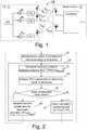
- FIG. 1is a schematic block diagram illustrating transmit and receive diversity in the uplink in general.
- a user equipment (UE) 11comprises a plurality of transmit antennas a 1 , a 2 , ..., aN from which an input signal s(t) may be transmitted to a base station 12.
- Transmission antenna weights w 1 , w 2 , ..., w Nare used to control the transmit diversity. If the transmission antenna weights are set in such a way that the input signal s(t) is transmitted from a plurality of antennas simultaneously this is called beamforming, as mentioned above.
- the transmissions from the transmit antennas a 1 , a 2 , ..., a Nare received by receive antennas b 1 , ..., b M of the base station 12 and fed to a combiner.
- receive antennas b 1 , ..., b M of the base station 12and fed to a combiner.
- a plurality of different channelsalso referred to as paths or links
- the different channels h i, jmay experience different radio conditions.
- each transmit antenna a 1 , a 2 , ..., aNis provided with a separate power amplifier (PA), but depending on the type of transmit diversity technique to be applied it may also be possible to let several antennas share a PA.
- PApower amplifier
- the inventors of the present inventionhave recognized that, in a case of beamforming with a large difference between the transmit antennas a 1 , a 2 , ..., aN, it is sub-optimal to transmit with equal power on all antennas.
- An inferior antennawill not lead to any substantial gain in received power but will instead produce a significant amount of interference for other users. This may reduce much of the gain that can be obtained by applying beamforming. If the gain difference between the antennas would be known, the effects caused by the differences could be accounted for in the beamforming algorithm.
- each transmit antennahas a control channel (a DPCCH in HSPA)
- a DPCCH in HSPAit is rather straight-forward to measure the received signal and estimate which of the antennas is inferior.
- the situationis more difficult.
- DLdownlink
- ULuplink
- Embodiments disclosed hereinpropose to estimate the difference of the total channel gain for different antennas, reduce or adjust the transmission power on an inferior antenna.
- the reduction of power on the inferior antennawill only lead to a slight reduction of received power at the base station (i.e. the Node B in a HSPA system) for this particular user and may be compensated for by power control.
- the reduction of transmission power on the inferior antennawill reduce the particular UE's power consumption and most importantly, reduce the interference caused by the inferior antenna.
- the inferior antennamay only be inferior for the received power from the particular user, it may still cause a lot of interference for other user equipments.
- the antenna with the highest transmit poweris the antenna that contributes the most to the received power at the base station in normal cases. Therefore any other antennas are expected to be inferior relative to the antenna with the highest transmit power.
- the estimation of the channel gain difference for the different antennasis done by altering the transmit power of an inferior antenna during a transmit power adjustment phase.
- the effect of the altered poweris seen in corresponding received TPC bits and depending on the outcome, the transmit power can be either reduced, increased or left unchanged according to different embodiments, which will be explained in further detail below.
- Fig. 2is a flow diagram illustrating an embodiment of a method for transmit power adjustment in the user equipment 11.
- a step 21simultaneous transmission from a plurality of antennas a 1 , a 2 ,...a N is carried out.
- a transmit power adjustment phase 22is performed.
- the transmit power of a selected one of the antennasis decreased by a selected decrease amount.
- the selected antennais the antenna a 2 , which is a secondary antenna that is suspected to be inferior relative to a primary antenna a 1 since the contribution to the received power at the base station 12 from the antenna a 2 is expected to be less than the contribution from the antenna a 1 .
- the reason for thismay be that the antenna a 2 has lower gain than the antenna a 1 or have worse channel conditions. It is further assumed that the selected decrease amount is ⁇ down dB.
- a number of TPC commands, which are received in the user equipment,are analyzed.
- the TPC commands that are analyzedare expected to reflect a change in received power at the base station 12 as a result of the decreased transmit power of the selected antenna a 2 .
- a result of the decreased transmit power of the selected antennais determined, which indicates the change in received power at the base station. If for instance the TPC commands following the decreased transmit power of the selected antenna indicate that the transmit power should be raised considerably, this indicates that received power at the base station has become much worse.
- the TPC commands following the decreased transmit power of the selected antennae.g. indicate that the transmit power should not be raised or raised by a minor amount, this indicates no or minor effects on the received transmit power at the base station as a result of the decreased transmit power of the selected antenna.
- the result of the decreased transmit powermay for instance be determined as the mean of the number of TPC commands in step 24, but it is also possible to use another function of the number of TPC commands as the result of the decreased transmit power. It is thereafter determined if the result of the decreased transmit power is higher than or equal to a predetermined decrease threshold value limit_down, in a step 25. If the determination in step 25 is affirmative, this indicates a significant undesired effect of the decreased transmit power. Therefore the transmit power prior to the decrease is resumed in a step 26. In this exemplary embodiment step 26 means that the transmit power of the antenna a 2 is increased with ⁇ down dB to resume the transmit power prior to the transmit power adjustment phase. If the determination in step 25 is negative, this indicates a minor acceptable effect of the decreased transmit power.
- the transmit power adjustment phasemay optionally be repeated cyclically, which is illustrated with dashed arrows in Fig. 2 .
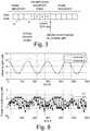
- Fig. 3illustrates such a freezing of the phase during the transmit power adjustment phase.
- Fig. 3illustrates a stream of TPC bits which are received in consecutive TPC slots 31.
- the transmit power adjustment phasein time and phase adjustment phases are illustrated. In practice, the phase adjustments phase would generally be longer than the transmit power phase. Beamforming phase adjustments are performed before and after, but not during a transmit power adjustment phase.
- the transmit power of the selected antennais changed at the beginning of the transmit power adjustment phase and maintained during a measurement period.
- the transmit power adjustment phasewhich comprises a test to decrease the transmit power of a selected antenna may be repeated e.g. at cyclical intervals. If the transmit power of an antenna has been decreased, perhaps several times, it may be of interest to increase the transmit power of that antenna later on. Therefore a number of alternative ways of increasing the transmit power of a selected antenna are suggested according to different alternative embodiments presented herein.
- One way of increasing the transmit poweris to automatically increase the transmit power of the selected antenna by a selected increase amount (e.g. 1 dB) a certain period of time after completion of the transmit power adjustment phase 22 that included the test to decrease the transmit power. In most cases it would be a natural choice to only perform this increase if the transmit power of the selected antenna was actually decreased during the transmit power adjustment phase, since the overall aim is to keep the total transmit power down.
- a selected increase amounte.g. 1 dB
- the transmit poweris only increased in cases where this has a relevant effect on the received power at the base station.
- a test similar to the decrease test described in connection with Fig. 2 and the transmit power adjustment phase 22can be applied to test if it is beneficial to increase the transmit power.
- the transmit power of an inferior antennamay be temporarily increased to an increase test level during a short measurement period. If the corresponding TPC commands indicate that the effective channel became better as a result of the increase, the previous transmit power of the selected antenna may be increased by a selected increase amount, e.g. 3 dB.
- the increased test levelmay be determined to be a level that guarantees that the effect of the increase can be detected.
- the selected increase amountcan be a smaller increase of e.g. a few dB.
- the transmit powermay have been raised to a very high level during the test, the increased transmit power level that is maintained after and as a result of the increase test may be much lower than transmit power during the increase test.
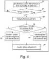
- Fig. 4is a flow diagram of a method for transmit power adjustment in a user equipment.
- the method in Fig. 4starts with beamforming transmission, i.e. simultaneous transmission form a plurality of antennas of the user equipment, in a step 21.
- a transmit power adjustment phase with a decrease test, step 22,is performed alternately with a transmit power adjustment phase with an increase test, step 44.
- the tests to decrease or increaseare performed interchangeably, every second test by checking a transmit power adjustment phase number in a step 43.
- the decrease testis performed, and if the number is even the increase test is performed.
- Other embodimentsmay apply different criteria for determining which test to perform and may use a different distribution between the decrease and increase tests, e.g. two consecutive decrease tests followed by one increase test.
- beamforming phase adjustmentsare freezed during any transmit power adjustment phase, step 42, and then resumed after the completion of the transmit power adjustment phase, step 45.
- the methodincludes a step 41 in which the variation of the fading is analyzed to determine if the fading is above a predetermined limit, V max .
- Thisis an optional step that is performed in this particular embodiment to give an indication of whether it is a suitable time or not for a transmit power adjustment phase. It may be advantageous to perform the transmit power adjustment phases when the fading is relatively constant. This would ensure that the result of the decrease or increase test is not contaminated by effects of fading. Thus, when to do transmit power adjustment phase may be decided by measuring and estimating fading a number of slots prior to the transmit power adjustment phase. TPC commands can also be analyzed to give an indication of whether the fading is relatively constant.
- the average of the TPC bits(coded as 1 and -1) is close to -1, this indicates that the fading is increasing (approaching a peak). If the average of the TPC bits is close to 1, this indicates that the fading is decreasing (approaching a dip). If the average of the TPC bits is close to zero this implies that the fading is relatively constant. There are several known ways of measuring or estimating fading which could be used in the step 41 to determine if the fading is constant enough for it to be an appropriate time for a transmit power adjustment phase.
- a number of TPC commands, which are received in the user equipmentare analyzed.
- the TPC commands which are analyzedare expected to reflect a change in received power at the base station 12 as a result of the increased transmit power of the selected antenna a 2 .
- a result of the increased transmit power of the selected antennais determined, which indicates the change in received power at the base station. If for instance the TPC commands following the increased transmit power of the selected antenna indicate that the transmit power should be lowered considerably, this indicates that received power at the base station has become much better.
- the TPC commands following the increased transmit power of the selected antennae.g. indicate that the transmit power should not be lowered or lowered by a minor amount, this indicates no or minor effects on the received transmit power at the base station as a result of the increased transmit power of the selected antenna.
- the result of the increased transmit powermay for instance be determined as the mean of the number of TPC commands in the step 52, but it is also possible to use another function of the number of TPC commands as the result of the increased transmit power. It is thereafter determined if the result of the increased transmit power is higher than or equal to a predetermined increase threshold value limit_up, in a step 53. If the determination in step 53 is affirmative, this indicates no or a very little effect of the increased transmit power. Therefore the transmit power prior to the increase, P t 2,old , is resumed in a step 54. If the determination in step 53 is negative, this indicates a significant effect of the increased transmit power. Thus it is decided in a step 55 to increase the transmit power prior to the increase, P t 2,old , by a selected increase amount, ⁇ up after the completion of the transmit power adjustment phase.
- the algorithm under operationis depicted in Fig. 8 , using a really simple cosine channel model.
- the upper diagram of Fig. 8shows a simple cosine channel gain for the first antenna (channel 1) and the second antenna (channel 2).
- the lower diagram of Fig. 8depicts the power decrease on the second antenna obtained by the algorithm. Note that the peaks in transmission power when testing for increasing power does not lead to power peaks in received power since the second antenna has a low gain in cases when the transmission power has large peaks.
- a further example of an optional feature according to yet another exemplary embodimentis to collect and analyze TPC commands during a number N of measurement periods and thereafter make a decision on transmit power adjustment.
- the parameter Ncan be selected to give a test which is sensitive to relatively short term changes in antenna gains (by selecting a low value of N) or to only react on long term imbalances (by selecting a high value for N).
- the power of selected antennacan be at most lowered to a predetermined minimum level relative to the transmit power of another antenna in order to avoid too large received power peaks.
- the above mentioned decrease threshold value and increase threshold valueare to be chosen based on how sensitive the test should be for altering the power of the selected antenna.
- the user equipmentis provided with more than two antennas that are used for uplink beamforming, it is possible to perform transmit power adjustment phases selecting one of the inferior antennas at a time in turns. It is also possible to perform transmit power adjustment phases to test a set of antennas at a time. This might make sense if there is an antenna configuration which gives a dependence between several antennas, e.g. four antennas out of which a first and a second always have the same power and a third and a fourth always have the same power.
- Fig. 6is a schematic block diagram of an exemplary embodiment of the UE 11 in Fig. 1 .
- the UE 11comprises an antenna a 1 and an antenna a 2 , but the UE 11 may also comprise further antennas.
- the UEincludes receiver circuits 61 and transmitter circuits 62. Alternatively the receiver and transmitter circuits may be integrated in a transceiver unit.
- the transmitter circuits 62 and antennas a 1 , a 2are particularly configured to perform beamforming transmission as in the steps 21, 22 23, 26, 27, 44, 51, 54 and 55 of Figs. 2 , 4 and 5 respectively.
- Processing circuits 63are provided, which optionally comprise fading analysis circuits for performing the optional step 41 of Fig. 4 and transmit power control circuits 65, adapted to perform or at least control the transmit power adjustment phases 22 and 44 of Figs. 2 , 4 and 5 .
- Fig. 7is a schematic block diagram of another exemplary embodiment of the UE 11.
- Fig. 7may be an alternative description of the exemplary embodiment shown in Fig. 6 .
- the UE 11comprises antennas a 1 and a 2 .
- the UEalso comprises an input unit 71 which is adapted to receive downlink signals, including e.g. TPC commands, and an output unit 72 for output of uplink signals.
- the input unit 71 and the output unit 72may be integrated in hardware of the UE 11.
- the UE 11is furthermore provided with a CPU 73, which may be a single unit or composed of several units that are configured to perform steps of procedures described herein.
- At least one computer program product 74is included in the UE 11.
- the computer program product 74may be embodied in the form of a non-volatile memory, e.g. an EEPROM, a flash memory or a disc drive.
- the computer program product 74comprises computer program submodules.
- Fig. 7shows a decrease test submodule 75 for performing a transmit power adjustment phase with a decrease test as in the step 22, an increase test submodule 76 for performing a transmit power adjustment phase with an increase test as in the step 44, a freeze phase adjustment submodule 77 for controlling the freezing of phase adjustments in the steps 42 and 45, and a fading analysis submodule 78 for performing the fading analysis of the step 41.
- the submodules 75-78essentially perform the steps 22 and 41-45 of the flow diagrams of Fig.
- the UEwhen the different submodules 75-78 are run on the CPU 53, the UE performs the steps 22 and 41-45 illustrated in Fig. 2 or 4 .
- the submodules 75-78would generally be implemented in software, although implementations completely or partly in firmware, hardware or combinations thereof are also feasible.
- an advantage of embodiments described aboveis that they may improve performance in a case of open-loop uplink beam forming when one of the antennas is inferior compared to another antenna, and still transmit the same amount of power on the inferior antenna. Also, in a case when the channel of one of the antennas is much worse than the channel of another antenna, it is not optimal to transmit equal power on both antennas.
- the embodiments presented hereinmay be used to optimize the power usage of the user equipment in case of an inferior antenna and/or differing channel conditions. In cases with power amplifiers for each antenna, this will reduce the interference from the user equipment and thereby increase capacity. If the UE has one common power amplifier it is also possible to gain in coverage with this invention.
- Fig. 9is a diagram that illustrates that lowering the power on a second antenna which is inferior relative to a first antenna (and still maintaining the SIR target at the base station), can lead to relatively large reductions in power usage (and hence interference reduction). As seen from Fig. 9 , a 3 dB antenna difference lowers the used transmit power by 10%, and a 6 dB difference lowers used power by 27%. Note that these calculations are without taking fast fading into consideration.
- TPC commandsare transmitted for other purposes, but can be interpreted and used in other ways than originally intended as described above.
Landscapes
- Engineering & Computer Science (AREA)
- Computer Networks & Wireless Communication (AREA)
- Signal Processing (AREA)
- Mobile Radio Communication Systems (AREA)
Description
- The present invention relates to uplink transmit power adjustment in a wireless communications system, and in particular to methods and arrangements for transmit power adjustments in connection with uplink transmit diversity.
- In communication systems based on e.g. Code Divisional Multiple Access (CDMA), power control is used to meet the desired quality of service targets. The power control may be implemented both in a user equipment (UE) to meet a downlink quality target and also in a base station (BS) to meet an uplink quality target. In wireless communication networks, the downlink (DL) is the transmission path from the base station to the user equipment, and the uplink (UL) is the transmission path from the user equipment to the base station. It is important that the power control is able to maintain the desired quality of service target despite varying radio conditions, which is often the case in wireless communication systems.
- Most CDMA systems, such as cdma 2000, Wideband Code Division Multiple Access (WCDMA), and the extensions of WCDMA called High Speed Packet Access (HSPA) and Evolved HSPA (HSPA+) applies inner loop power control and outer loop power control. The inner loop power control, also called fast power control, runs every time slot, which is typically less than 1 ms (e.g. 0.67 ms in WCDMA). In WCDMA the inner loop power control runs in both uplink and downlink. The fast inner-loop power control adjusts the transmit power of the sender towards a specific Signal to Interference and noise Ratio (SIR) target at the receiver. The aim of the uplink and downlink inner loop power controls is to counter the effect of fast fading, while maintaining the desired SIR target. In the uplink the power control also compensates for the near-far problem, so that a signal received from users far out in a cell are not swamped out by stronger signals from users close to the base stations. During every slot the user equipment estimates the SIR on some known reference or pilot symbols and compares it with some SIR target corresponding to a given service, e.g. Block Error Rate (BLER), certain Bit Error Rate (BER) requirements and spreading factor used etc. In WCDMA, downlink SIR is measured on Dedicated Physical Control Channel (DPCCH), which comprises pilots bits and Transmit Power Control (TPC) bits. The TPC bits, which correspond to TPC commands, are also used for uplink power control and the pilot bits are primarily used for channel estimations. If the estimated SIR is less than the SIR target then the user equipment generates an UP command, otherwise it generates a DOWN command. In response the base station will increase (in case of UP) or decrease (in case of DOWN) its downlink transmit power. TPC commands for uplink power control are carried on Dedicated Physical Channel (DPCH) or Fractional DPCH (F-DPCH) from the base station to the user equipment. The user equipment will increase (in case of UP) or decrease (in case of DOWN) its uplink transmit power in response to the received TPC commands.
- The aim of the outer loop power control is to adjust the SIR target value used by the inner loop power control as previously explained, while maintaining a certain link quality. The quality target (e.g. BLER of the data) is set by the network and is expected from the user equipment to consistently maintain this target to ensure the desired quality of service is met throughout the session. Due to the varying radio link conditions e.g. user mobility, fast fading etc, the mapping between the SIR target and BLER changes over time. This is a key point as it requires frequent adjustment of the SIR target to maintain the desired value of BLER. This mechanism of adjusting the SIR target is also referred to as outer loop power control, quality control or outer loop scheme.
- The transmission of data over the air in a wireless communication system is performed by using a plurality of different physical channels, for example Dedicated Physical Control CHannel (DPCCH), Dedicated Physical Data CHannel (DPDCH), Enhanced Dedicated Physical Control CHannel (E-DPCCH) and Enhanced Dedicated Physical Data CHannel (E-DPDCH). The power consumptions of these are generally related to each other by power offsets, i.e. beta-values or gain factor relative the power level of the DPCCH.
- Currently the Third Generation Partnership Project (3GPP) is evaluating the potential benefits of uplink transmit (Tx) diversity in the context of High-Speed Uplink Packet Access (HSUPA). An aim is to enhance uplink capacity and UE power consumption. With uplink transmit diversity UEs that are equipped with two or more transmit antennas are capable of utilizing all of them for uplink transmissions. This is achieved by multiplying a UE output signal s(t) with a set of complex pre-coding weights w" where i=1 ...N with N denoting the number of transmit antennas. The rationale behind uplink transmit diversity is to adapt the pre-coding weights so that user and network performance is maximized. Depending on UE implementation the antenna weights may be associated with different constraints.
- Within 3GPP two classes of transmit diversity are considered:
- Switched antenna transmit diversity, where the UE at any given time-instance transmits from one of its antennas only. Thus if Wi≠0, Wj=0 for all j≠i.
- Beamforming where the UE at a given time-instance can transmit from more than one antenna simultaneously. By means of beamforming it is possible to shape an overall antenna beam in the direction of a target receiver.
- While switched antenna transmit diversity is possible for UE implementations with a single power amplifier (PA) the beam forming solutions may require one PA for each transmit antenna.
- Switched antenna transmit diversity can be seen as a special case of beamforming where one of the antenna weights is 1 (i.e. switched on) and the antenna weight of any other antenna of the UE is 0 (i.e. switched off).
- A fundamental idea behind uplink transmit diversity is to exploit variations in the effective channel to improve user and network performance. The term effective channel here incorporates effects of transmit antenna(s), transmit antenna weights, receiving antenna(s), as well as the wireless channel between transmitting and receiving antennas.
- A commonly considered application scenario of beamforming is a UE with two PAs that typically transmits with equal power on two antennas. Beamforming algorithms proposed in 3GPP use phase differences between the antennas based on a code book, which means that the phase difference is chosen among a set of possible phases. One algorithm to find the best phase difference discussed in 3GPP is to evaluate the effect of changing phase by examining the received TPC bits. For example, if the phase difference is increased and the corresponding TPC bits indicate that power should be increased, this implies that the increased phase difference resulted in worse channel and consequently, the phase should be restored or decreased.
- The gain from using beamforming originates from the diversity gain that is obtained by using two or more transmit antennas. The increased gain means that lower transmission power is needed to reach the desired SIR target. In an interference limited system, the lower transmission power results in lower interference between cells (inter-cell interference), which may lead to higher cell throughput. For a power limited UE, the diversity gain is more or less directly shown as a coverage gain.
- Channel conditions can differ a lot between different transmit antennas. There are two major reasons for this: fast fading differences between the antennas, and fixed antenna gain imbalance between the antennas. For a high speed user the difference between the antenna channels vary very fast, but for a stationary laptop the channel differences can be more or less constant (or very slow varying). It is also common that a primary antenna has a better antenna gain than a secondary antenna. In the current 3GPP evaluations of UL Tx diversity, a fixed imbalance between two transmit antennas of 0 or 4 dB and a random (per UE) imbalance with standard deviation of 2.25 dB are being studied. Hence, it is not uncommon or unrealistic that there is a large antenna gain imbalance between the antennas.
- From the above description it is apparent that there are many factors that may need to be considered in order to achieve efficient power control both in the downlink and in the uplink.
- Document
US 2008/151798 (A1 ) describes that a mobile terminal reduces its power consumption by selectively switching between a diversity mode and a non-diversity mode. The mobile terminal monitors the total output power of two or more of its transmitters, and selectively switches between the diversity mode and the non-diversity mode based on the total output power. The mobile terminal may also selectively switch between the diversity and non-diversity modes based on a difference in output power levels between the two or more transmitters. - An object of the present invention is to provide a method and apparatus for transmit power adjustment in connection with uplink transmit diversity.
- The above stated object is achieved by means of a method and a user equipment according to the independent claims.
- A first embodiment provides a method for transmit power adjustment in a user equipment of a wireless communications system. The method comprises performing uplink transmission by means of beamforming, which means that simultaneous uplink transmission from a plurality of antennas of the user equipment is carried out. The method further comprises performing a first transmit power adjustment phase. The first transmit power adjustment phase includes decreasing the transmit power of a selected antenna by a selected decrease amount during a first measurement period. The transmit power of the selected antenna, prior to the decrease, was lower than or equal to the transmit power of another antenna of the plurality of antennas. The first transmit power adjustment phase also includes analyzing a number of transmit power control, TPC, commands corresponding to the first measurement period to determine a result of the decreased transmit power of the selected antenna, indicating a change in received power at a base station. If the result of the decreased transmit power is above or equal to a decrease threshold value, then the first transmit power adjustment phase is completed and the transmit power of the selected antenna prior to the decrease by the decrease amount is resumed. On the other hand, if the result of the decreased transmit power is below the decrease threshold value, then the first power adjustment phase is completed and the uplink transmission continues with the decreased transmit power of the selected antenna.
- A second embodiment provides a user equipment for use in a wireless communication system. The user equipment comprises a plurality of antennas adapted for simultaneous uplink transmission and transmit power control circuits configured to control the transmit power of the plurality of antennas. The transmit power control circuits are configured to perform a first transmit power adjustment phase. The first transmit power adjustment phase includes decreasing the transmit power of a selected antenna by a selected decrease amount during a first measurement period. The transmit power of the selected antenna prior to the decrease was lower than or equal to the transmit power of another antenna of the plurality of antennas. The first transmit power adjustment phase also includes analyzing a number of received transmit power control, TPC, commands corresponding to the first measurement period to determine a result of the decreased transmit power of the selected antenna, indicating a change in received power at a base station. If the result of the decreased transmit power is above or equal to a decrease threshold value, then the first transmit power adjustment phase is completed and the transmit power of the selected antenna is controlled to resume the transmit power of the selected antenna prior to the decrease by the decrease amount. On the other hand, if the result of the decreased transmit power is below the decrease threshold value, then the first power adjustment phase is completed and the transmit power of the selected antenna is controlled to continue uplink transmission with the decreased transmit power of the selected antenna.
- An advantage of the embodiments described above is that they may allow for decreased power usage in case of uplink beamforming with one or several inferior antennas and/or differing channel conditions for different antennas.
- Further advantages and features of embodiments of the present invention will become apparent when reading the following detailed description in conjunction with the drawings.
Fig. 1 is a schematic block diagram illustrating transmit and receive diversity in the uplink in general.Fig. 2 is a flow diagram illustrating an embodiment of a method for transmit power adjustment in a user equipment.Fig. 3 is a schematic block diagram illustrating a part of an embodiment of a method for transmit power adjustment.Fig. 4 is a flow diagram illustrating an alternative embodiment of a method for transmit power adjustment in a user equipment.Fig. 5 is a flow diagram illustrating an exemplary embodiment of one of the method steps illustrated inFig. 4 .Fig. 6 is a schematic block diagram of an embodiment of a user equipment (UE) configured for beamforming and transmit power control.Fig. 7 is a schematic block diagram of an alternative embodiment of a user equipment configured for beamforming and transmit power control.Fig. 8 includes diagrams illustrating power decrease obtained by implementation of an algorithm according to an embodiment, in case of a simple cosine channel gain for two antennas.Fig. 9 is a diagram illustrating reductions in power usage that may be achieved by implementing embodiments of the present invention.- The present invention will now be described more fully hereinafter with reference to the accompanying drawings, in which preferred embodiments of the invention are shown. This invention may, however, be embodied in many different forms and should not be construed as limited to the embodiments set forth herein; rather, these embodiments are provided so that this disclosure will be thorough and complete, and will fully convey the scope of the invention to those skilled in the art. In the drawings, like reference signs refer to like elements.
- As used herein the term "antenna" is interchangeable with the term "antenna element". Therefore when referring herein to a user equipment with multiple antennas this includes user equipment's with a multiple element antenna arrangement.
Fig. 1 is a schematic block diagram illustrating transmit and receive diversity in the uplink in general. A user equipment (UE) 11 comprises a plurality of transmit antennas a1, a2, ..., aN from which an input signal s(t) may be transmitted to abase station 12. Transmission antenna weights w1, w2, ..., wN are used to control the transmit diversity. If the transmission antenna weights are set in such a way that the input signal s(t) is transmitted from a plurality of antennas simultaneously this is called beamforming, as mentioned above. The transmissions from the transmit antennas a1, a2, ..., aN are received by receive antennas b1, ..., bM of thebase station 12 and fed to a combiner. As illustrated inFig. 1 , when both transmit and receive diversity is applied, there exist a plurality of different channels (also referred to as paths or links) in the radio interface between theuser equipment 11 and thebase station 12. The channels between the respective antennas of the user equipment and the base station are denoted hi, j, where i=1, ..., N and j=1, ..., M inFig. 1 . The different channels hi, j may experience different radio conditions. In the example illustrated inFig. 1 each transmit antenna a1, a2, ..., aN is provided with a separate power amplifier (PA), but depending on the type of transmit diversity technique to be applied it may also be possible to let several antennas share a PA.- The inventors of the present invention have recognized that, in a case of beamforming with a large difference between the transmit antennas a1, a2, ..., aN, it is sub-optimal to transmit with equal power on all antennas. An inferior antenna will not lead to any substantial gain in received power but will instead produce a significant amount of interference for other users. This may reduce much of the gain that can be obtained by applying beamforming. If the gain difference between the antennas would be known, the effects caused by the differences could be accounted for in the beamforming algorithm.
- In a case when each transmit antenna has a control channel (a DPCCH in HSPA), it is rather straight-forward to measure the received signal and estimate which of the antennas is inferior. However, for the case with only one shared DPCCH, the situation is more difficult.
- One way to assess the long term gain difference would be by using downlink (DL) measurements and assuming that the difference seen in the downlink would mirror the gain difference in uplink (UL). However, measuring the DL channel only catches the slow varying fading, i.e. pathloss and shadow fading. The case with a moving user where the fast fading of the channel varies will not be caught. Also, the exemplary case with a stationary laptop where one of the antennas is in a fast fading dip, will not be caught by measuring the DL channel. Embodiments disclosed herein propose to estimate the difference of the total channel gain for different antennas, reduce or adjust the transmission power on an inferior antenna.
- A motivation for this is that the reduction of power on the inferior antenna will only lead to a slight reduction of received power at the base station (i.e. the Node B in a HSPA system) for this particular user and may be compensated for by power control. At the same time, the reduction of transmission power on the inferior antenna will reduce the particular UE's power consumption and most importantly, reduce the interference caused by the inferior antenna. Note that the inferior antenna may only be inferior for the received power from the particular user, it may still cause a lot of interference for other user equipments.
- It can be expected that the antenna with the highest transmit power is the antenna that contributes the most to the received power at the base station in normal cases. Therefore any other antennas are expected to be inferior relative to the antenna with the highest transmit power.
- The estimation of the channel gain difference for the different antennas is done by altering the transmit power of an inferior antenna during a transmit power adjustment phase. The effect of the altered power is seen in corresponding received TPC bits and depending on the outcome, the transmit power can be either reduced, increased or left unchanged according to different embodiments, which will be explained in further detail below.
Fig. 2 is a flow diagram illustrating an embodiment of a method for transmit power adjustment in theuser equipment 11. In astep 21, simultaneous transmission from a plurality of antennas a1, a2,...aN is carried out. Thereafter a transmitpower adjustment phase 22 is performed. During the transmitpower adjustment phase 22, the transmit power of a selected one of the antennas is decreased by a selected decrease amount. In this exemplary embodiment it is assumed that the selected antenna is the antenna a2, which is a secondary antenna that is suspected to be inferior relative to a primary antenna a1 since the contribution to the received power at thebase station 12 from the antenna a2 is expected to be less than the contribution from the antenna a1. The reason for this may be that the antenna a2 has lower gain than the antenna a1 or have worse channel conditions. It is further assumed that the selected decrease amount is δdown dB. The decreased transmit power of antenna a2Pt2_Test during the transmit power adjustment phase is thus
- In a step 23 a number of TPC commands, which are received in the user equipment, are analyzed. The TPC commands that are analyzed are expected to reflect a change in received power at the
base station 12 as a result of the decreased transmit power of the selected antenna a2. From the analysis of the TPC commands a result of the decreased transmit power of the selected antenna is determined, which indicates the change in received power at the base station. If for instance the TPC commands following the decreased transmit power of the selected antenna indicate that the transmit power should be raised considerably, this indicates that received power at the base station has become much worse. On the other hand if the TPC commands following the decreased transmit power of the selected antenna e.g. indicate that the transmit power should not be raised or raised by a minor amount, this indicates no or minor effects on the received transmit power at the base station as a result of the decreased transmit power of the selected antenna. - The result of the decreased transmit power may for instance be determined as the mean of the number of TPC commands in
step 24, but it is also possible to use another function of the number of TPC commands as the result of the decreased transmit power. It is thereafter determined if the result of the decreased transmit power is higher than or equal to a predetermined decrease threshold value limit_down, in astep 25. If the determination instep 25 is affirmative, this indicates a significant undesired effect of the decreased transmit power. Therefore the transmit power prior to the decrease is resumed in astep 26. In thisexemplary embodiment step 26 means that the transmit power of the antenna a2 is increased with δdown dB to resume the transmit power prior to the transmit power adjustment phase. If the determination instep 25 is negative, this indicates a minor acceptable effect of the decreased transmit power. Thus it is decided in astep 27 to keep the decreased transmit power after the completion of the transmit power adjustment phase. In thisexemplary embodiment step 27 means that the transmission continues with the transmit power of the antenna a2 equal to the decreased transmit power during the transmit power adjustment phase (Pt2=Pt2_Test). The transmit power adjustment phase may optionally be repeated cyclically, which is illustrated with dashed arrows inFig. 2 . - In order to isolate the effect of the decreased transmit power of the selected antenna during the transmit power adjustment phase, it may be beneficial to freeze any phase adjustments of the beamforming algorithm during the transmit
power adjustment phase 22.Fig. 3 illustrates such a freezing of the phase during the transmit power adjustment phase.Fig. 3 illustrates a stream of TPC bits which are received inconsecutive TPC slots 31. The transmit power adjustment phase in time and phase adjustment phases are illustrated. In practice, the phase adjustments phase would generally be longer than the transmit power phase. Beamforming phase adjustments are performed before and after, but not during a transmit power adjustment phase. The transmit power of the selected antenna is changed at the beginning of the transmit power adjustment phase and maintained during a measurement period. Since there is a certain delay in the reception of TPC bits it expected that a number of TPC bits received during the transmit power adjustment phase relates to the situation prior to the measurement period and thus may be "contaminated" by effects from previous phase adjustments. In the example illustrated inFig. 3 it is expected that out of four TPC commands or bits that are received during the transmit power adjustment phase, the two first TPC commands relate to the situation prior to the measurement period, while the two last TPC commands relate to the measurement period. Therefore the two last TPC commands are collected and analyzed to determine the result of the changed transmit power of the selected antenna. Based on the determined result of the changed transmit power it is determined which transmit power to continue with upon completion of the transmit power adjustment phase. The phase adjustments are resumed again upon completion of the transmit power adjustment phase. - As mentioned above the transmit power adjustment phase which comprises a test to decrease the transmit power of a selected antenna may be repeated e.g. at cyclical intervals. If the transmit power of an antenna has been decreased, perhaps several times, it may be of interest to increase the transmit power of that antenna later on. Therefore a number of alternative ways of increasing the transmit power of a selected antenna are suggested according to different alternative embodiments presented herein.
- One way of increasing the transmit power is to automatically increase the transmit power of the selected antenna by a selected increase amount (e.g. 1 dB) a certain period of time after completion of the transmit
power adjustment phase 22 that included the test to decrease the transmit power. In most cases it would be a natural choice to only perform this increase if the transmit power of the selected antenna was actually decreased during the transmit power adjustment phase, since the overall aim is to keep the total transmit power down. - According to some embodiments the transmit power is only increased in cases where this has a relevant effect on the received power at the base station. A test similar to the decrease test described in connection with
Fig. 2 and the transmitpower adjustment phase 22 can be applied to test if it is beneficial to increase the transmit power. Thus the transmit power of an inferior antenna may be temporarily increased to an increase test level during a short measurement period. If the corresponding TPC commands indicate that the effective channel became better as a result of the increase, the previous transmit power of the selected antenna may be increased by a selected increase amount, e.g. 3 dB. - When performing an increase test as described above, it may be advantageous to raise the transmit power of the selected antenna considerably. The reason is that once the power of the selected antenna has been decreased sufficiently, so that it has a much lower transmit power than another antenna used simultaneously for beamforming, the effect of increasing or decreasing the transmit power from this level is difficult to detect since the power already is so low. However, if the increase during the measurement period raises the transmit power of the selected antenna to e.g. the same level as the transmit power of the antenna that currently has the highest transmit power, the effect of the increase can be detected. Thus the increased test level may be determined to be a level that guarantees that the effect of the increase can be detected. At the same time if it is determined as a result of the increase test that the transmit power should be increased compared to the transmit power prior to the increase test, the selected increase amount can be a smaller increase of e.g. a few dB. Thus, even though the transmit power may have been raised to a very high level during the test, the increased transmit power level that is maintained after and as a result of the increase test may be much lower than transmit power during the increase test.
- The above described tests to decrease or to increase the transmit power of a selected antenna may be performed cyclically and alternately during different transmit power adjustment phases.
Fig. 4 illustrates such an embodiment.Fig. 4 is a flow diagram of a method for transmit power adjustment in a user equipment. The method inFig. 4 starts with beamforming transmission, i.e. simultaneous transmission form a plurality of antennas of the user equipment, in astep 21. A transmit power adjustment phase with a decrease test,step 22, is performed alternately with a transmit power adjustment phase with an increase test,step 44. In the embodiment disclosed inFig. 4 the tests to decrease or increase are performed interchangeably, every second test by checking a transmit power adjustment phase number in astep 43. If the transmit power adjustment phase number is odd, the decrease test is performed, and if the number is even the increase test is performed. Other embodiments may apply different criteria for determining which test to perform and may use a different distribution between the decrease and increase tests, e.g. two consecutive decrease tests followed by one increase test. - In the embodiment illustrated in
Fig. 4 beamforming phase adjustments are freezed during any transmit power adjustment phase,step 42, and then resumed after the completion of the transmit power adjustment phase,step 45. - It is also illustrated in
Fig. 4 that the method includes a step 41 in which the variation of the fading is analyzed to determine if the fading is above a predetermined limit, Vmax. This is an optional step that is performed in this particular embodiment to give an indication of whether it is a suitable time or not for a transmit power adjustment phase. It may be advantageous to perform the transmit power adjustment phases when the fading is relatively constant. This would ensure that the result of the decrease or increase test is not contaminated by effects of fading. Thus, when to do transmit power adjustment phase may be decided by measuring and estimating fading a number of slots prior to the transmit power adjustment phase. TPC commands can also be analyzed to give an indication of whether the fading is relatively constant. If the average of the TPC bits (coded as 1 and -1) is close to -1, this indicates that the fading is increasing (approaching a peak). If the average of the TPC bits is close to 1, this indicates that the fading is decreasing (approaching a dip). If the average of the TPC bits is close to zero this implies that the fading is relatively constant. There are several known ways of measuring or estimating fading which could be used in the step 41 to determine if the fading is constant enough for it to be an appropriate time for a transmit power adjustment phase. Fig. 5 is a flow diagram illustrating an exemplary embodiment ofstep 44 inFig. 4 , i.e. an exemplary embodiment of a transmit power adjustment phase with an increase test. It is assumed here that that the selected antenna is antenna a2 ofFig. 1 . In astep 51 the transmit power of the selected antenna (here the antenna a2) is increased to an increased test level Pt2_HIGH. The increased transmit power of antenna a2 Pt2_Test during the transmit power adjustment phase is thus
- In a step 52 a number of TPC commands, which are received in the user equipment are analyzed. The TPC commands which are analyzed are expected to reflect a change in received power at the
base station 12 as a result of the increased transmit power of the selected antenna a2. From the analysis of the TPC commands a result of the increased transmit power of the selected antenna is determined, which indicates the change in received power at the base station. If for instance the TPC commands following the increased transmit power of the selected antenna indicate that the transmit power should be lowered considerably, this indicates that received power at the base station has become much better. On the other hand if the TPC commands following the increased transmit power of the selected antenna e.g. indicate that the transmit power should not be lowered or lowered by a minor amount, this indicates no or minor effects on the received transmit power at the base station as a result of the increased transmit power of the selected antenna. - The result of the increased transmit power may for instance be determined as the mean of the number of TPC commands in the
step 52, but it is also possible to use another function of the number of TPC commands as the result of the increased transmit power. It is thereafter determined if the result of the increased transmit power is higher than or equal to a predetermined increase threshold value limit_up, in astep 53. If the determination instep 53 is affirmative, this indicates no or a very little effect of the increased transmit power. Therefore the transmit power prior to the increase, Pt2,old, is resumed in astep 54. If the determination instep 53 is negative, this indicates a significant effect of the increased transmit power. Thus it is decided in astep 55 to increase the transmit power prior to the increase, Pt2,old, by a selected increase amount, δup after the completion of the transmit power adjustment phase. - An exemplary embodiment of an algorithm for transmit power adjustment of a user equipment with a first antenna and a second antenna will now be explained below. It is assumed that the second antenna is the inferior antenna. Let Pt1 and Pt2 be the power at time t on the first and second antenna, respectively. As the algorithm runs, Pt2 will be adjusted compared to Pt1. The aim is to adjust Pt2 down if this does not deteriorate the received power at the base station too much. Pt1 and Pt2 are controlled simultaneously, e.g. a TPC power up command will increase both power levels by 1 dB. Further, define P2min and P2max as the minimum and maximum allowed power on the second antenna. Further, assume that P2max = Pt1 (in this exemplary algorithm the second antenna is not allowed to have higher power than the first antenna). When the algorithm starts, Pt1= Pt2 and TPCmean = 0.
- 1. At each transmit power adjustment phase, test the 2nd antenna.
- a. Turn off phase adjustments during the transmit power adjustment phase
- b. IF ODD transmit power adjustment phase number:
- i. Test to decrease Pt2 relative to Pt1
- ii. 2nd antenna tested by decreasing transmit power on 2nd antenna as Pt2_Test= Pt2-δdown
- iii. Keep the decreased transmit power during measurement period
- iv. Await delayed TPC command(s) corresponding to this measurement period, and calculate:

- v. IF TPCmean > limit_down (effect of lowering power)
Resume previous Pt2 = Pt2_Test + ∂down (no change of power) - vi. ELSE if TPCmean < limit_down (no effect of lowering power)
Keep decreased power Pt2 = Pt2_Test - vii. END
- c. ELSE if EVEN transmit power adjustment phase number:
- i. Test to increase Pt2
- ii. 2nd antenna tested by setting transmit power on 2nd antenna as: Pt2_Test = Pt1, i.e. 2nd antenna has equal power as 1st antenna, during measurement period. The old transmit power is saved as: Pt2,old = Pt2.
- iii. Await delayed TPC command(s) corresponding to this measurement period, and calculate:

- iv. IF TPCmean >= limit_up (no effect of increasing power)
Keep old transmit power Pt2 = Pt2,old - v. ELSE if TPCmean < limit_up (effect of increasing power)
Increase transmit power:
- vi. END
- d. END ODD/EVEN if case
- The algorithm under operation is depicted in
Fig. 8 , using a really simple cosine channel model. The upper diagram ofFig. 8 shows a simple cosine channel gain for the first antenna (channel 1) and the second antenna (channel 2). The lower diagram ofFig. 8 depicts the power decrease on the second antenna obtained by the algorithm. Note that the peaks in transmission power when testing for increasing power does not lead to power peaks in received power since the second antenna has a low gain in cases when the transmission power has large peaks. - From the above descriptions of different embodiments of methods for transmit power adjustment it is clear that there are several different ways in which the methods can be adapted for different implementations and application scenarios. A further example of an optional feature according to yet another exemplary embodiment is to collect and analyze TPC commands during a number N of measurement periods and thereafter make a decision on transmit power adjustment. The parameter N can be selected to give a test which is sensitive to relatively short term changes in antenna gains (by selecting a low value of N) or to only react on long term imbalances (by selecting a high value for N).
- In some embodiments the power of selected antenna can be at most lowered to a predetermined minimum level relative to the transmit power of another antenna in order to avoid too large received power peaks.
- The above mentioned decrease threshold value and increase threshold value are to be chosen based on how sensitive the test should be for altering the power of the selected antenna.
- If the user equipment is provided with more than two antennas that are used for uplink beamforming, it is possible to perform transmit power adjustment phases selecting one of the inferior antennas at a time in turns. It is also possible to perform transmit power adjustment phases to test a set of antennas at a time. This might make sense if there is an antenna configuration which gives a dependence between several antennas, e.g. four antennas out of which a first and a second always have the same power and a third and a fourth always have the same power.
Fig. 6 is a schematic block diagram of an exemplary embodiment of theUE 11 inFig. 1 . As illustrated inFig. 6 , theUE 11 comprises an antenna a1 and an antenna a2, but theUE 11 may also comprise further antennas. The UE includesreceiver circuits 61 andtransmitter circuits 62. Alternatively the receiver and transmitter circuits may be integrated in a transceiver unit. Thetransmitter circuits 62 and antennas a1, a2 are particularly configured to perform beamforming transmission as in thesteps Figs. 2 ,4 and5 respectively.Processing circuits 63 are provided, which optionally comprise fading analysis circuits for performing the optional step 41 ofFig. 4 and transmitpower control circuits 65, adapted to perform or at least control the transmit power adjustment phases 22 and 44 ofFigs. 2 ,4 and5 .Fig. 7 is a schematic block diagram of another exemplary embodiment of theUE 11.Fig. 7 may be an alternative description of the exemplary embodiment shown inFig. 6 . TheUE 11 comprises antennas a1 and a2. The UE also comprises aninput unit 71 which is adapted to receive downlink signals, including e.g. TPC commands, and anoutput unit 72 for output of uplink signals. Theinput unit 71 and theoutput unit 72 may be integrated in hardware of theUE 11. TheUE 11 is furthermore provided with aCPU 73, which may be a single unit or composed of several units that are configured to perform steps of procedures described herein. At least onecomputer program product 74 is included in theUE 11. Thecomputer program product 74 may be embodied in the form of a non-volatile memory, e.g. an EEPROM, a flash memory or a disc drive. Thecomputer program product 74 comprises computer program submodules.Fig. 7 shows adecrease test submodule 75 for performing a transmit power adjustment phase with a decrease test as in thestep 22, anincrease test submodule 76 for performing a transmit power adjustment phase with an increase test as in thestep 44, a freezephase adjustment submodule 77 for controlling the freezing of phase adjustments in thesteps analysis submodule 78 for performing the fading analysis of the step 41. The submodules 75-78 essentially perform thesteps 22 and 41-45 of the flow diagrams ofFig. 2 or4 . In other words, when the different submodules 75-78 are run on theCPU 53, the UE performs thesteps 22 and 41-45 illustrated inFig. 2 or4 . The submodules 75-78 would generally be implemented in software, although implementations completely or partly in firmware, hardware or combinations thereof are also feasible.- From the description above it is apparent that an advantage of embodiments described above is that they may improve performance in a case of open-loop uplink beam forming when one of the antennas is inferior compared to another antenna, and still transmit the same amount of power on the inferior antenna. Also, in a case when the channel of one of the antennas is much worse than the channel of another antenna, it is not optimal to transmit equal power on both antennas. The embodiments presented herein may be used to optimize the power usage of the user equipment in case of an inferior antenna and/or differing channel conditions. In cases with power amplifiers for each antenna, this will reduce the interference from the user equipment and thereby increase capacity. If the UE has one common power amplifier it is also possible to gain in coverage with this invention.
Fig. 9 is a diagram that illustrates that lowering the power on a second antenna which is inferior relative to a first antenna (and still maintaining the SIR target at the base station), can lead to relatively large reductions in power usage (and hence interference reduction). As seen fromFig. 9 , a 3 dB antenna difference lowers the used transmit power by 10%, and a 6 dB difference lowers used power by 27%. Note that these calculations are without taking fast fading into consideration.- Another advantage of the above described embodiments is that they make use of already existing feedback information, namely TPC commands, to determine if the transmit power of the selected antenna should be adjusted. Thus the above described embodiments do not require any new type of feedback information. The TPC commands are transmitted for other purposes, but can be interpreted and used in other ways than originally intended as described above.
- In the drawings and specification, there have been disclosed typical preferred embodiments of the invention and, although specific terms are employed, they are used in a generic and descriptive sense only and not for purposes of limitation, the scope of the invention being set forth in the following claims.


Claims (22)
- A method for transmit power adjustment in a user equipment (11) of a wireless communications system (10), the method comprising:performing (21) uplink transmission by means of beamforming, such that simultaneous uplink transmission from a plurality of antennas (a1, a2, aN) of the user equipment (11) is carried out;performing a first transmit power adjustment phase (22), wherein the first transmit power adjustment phase comprises:decreasing (23) the transmit power of a selected antenna (a2) by a selected decrease amount during a first measurement period, wherein the transmit power of the selected antenna prior to the decrease was lower than or equal to the transmit power of another antenna (ai) of the plurality of antennas;analyzing (24) a plurality of transmit power control, TPC, commands corresponding to the first measurement period to determine a result of the decreased transmit power of the selected antenna (a2) indicating a change in received power at a base station (12); andcompleting the first transmit power adjustment phase by selectively (i) resuming (26) the transmit power of the selected antenna (a2) prior to the decrease by the decrease amount, if (25) the result of the decreased transmit power is above or equal to a decrease threshold value or(ii) continuing (27) the uplink transmission with the decreased transmit power of the selected antenna (82) if (25) the result of the decreased transmit power indicates a change in received power at the base station (12) which is below the decrease threshold value.
- The method according to claim 1, further comprising freezing (42) any beamforming phase adjustments of the uplink transmission during the first transmit power adjustment phase (22).
- The method according to claim 1 or 2, further comprising performing a second transmit power adjustment phase (44), wherein the second transmit power adjustment phase comprises:increasing (51) the transmit power of the selected antenna (a2) to an increased test level during a second measurement period;analyzing (52) a plurality of received TPC commands corresponding to the second measurement period to determine a result of the increased transmit power of the selected antenna indicating a change in received power at a base station (12); andcompleting the second transmit power adjustment phase by selectively (i) resuming (54) the transmit power of the selected antenna (a2) prior to the increase to the increased test level, if (53) the result of the increased transmit power is above or equal to an increase threshold value or(ii) continuing (55) the uplink transmission with a transmit power of the selected antenna (a2) which is increased by a selected increase amount compared to the transmit power of the selected antenna (32) prior to the second transmit power adjustment phase (44).
- The method according to claim 3, wherein said increased test level is-equal to the transmit power of said other antenna (a1).
- The method according to claim 3 or 4, wherein the first and second transmit power adjustment phases (22, 44) are repeated cyclically and alternately.
- The method according to claim 1 or 2, further comprising increasing the transmit power of the selected antenna by a selected increase amount a period of time after completion of the first power adjustment phase (22).
- The method according to claim 6, wherein the first transmit power adjustment phase (22) is repeated cyclically.
- The method according to any of claims 1-7, wherein the result of the decreased transmit power of the selected antenna is determined as a mean of said plurality of TPC commands.
- The method according to any of claims 1-8 wherein said first transmit power adjustment phase (22) comprises a plurality of measurement periods during which the transmit power of the selected antenna (a2) is decreased by the selected decrease amount and wherein said result of the decreased transmit power is determined by analyzing a plurality of TPC commands corresponding to the plurality of measurement periods.
- The method according to any of claims 1-9, wherein the power of the selected transmit antenna (a2) is at most decreased to a predetermined minimum level relative to the transmit power of said other antenna (a1).
- The method according to any of claims 1-10, further comprising performing fading analysis prior to the first transmit power adjustment phase to determine (41) if the variation of the fading is below a predetermined limit, and wherein the first transmit power adjustment phase (22) is performed when it is determined that the fading is below the predetermined limit.
- A user equipment (11) for use in a wireless communication system (10), the user equipment (11) comprising a plurality of antennas (a1, a2, aN) adapted for simultaneous uplink transmission and transmit power control circuits (65) configured to control the transmit power of the plurality of antennas (a1, a2, aN), wherein the transmit power control circuits (65) are configured to perform a first transmit power adjustment phase (22), wherein the first transmit power adjustment phase (22) comprises:decreasing (23) the transmit power of a selected antenna (a2) by a selected decrease amount during a first measurement period, wherein the transmit power of the selected antenna prior to the decrease was lower than or equal to the transmit power of another antenna (a1) of the plurality of antennas;analyzing (24) a plurality of received transmit power control, TPC, commands corresponding to the first measurement period to determine a result of the decreased transmit power of the selected antenna (a2) indicating a change in received power at a base station (12); andcompleting the first transmit power adjustment phase by selectively (i) controlling (26) the transmit power of the selected antenna (a2) to resume the transmit power of the selected antenna (a2) prior to the decrease by the decrease amount, if (25) the result of the decreased transmit power is above or equal to a decrease threshold value or(ii) controlling (27) the transmit power of the selected antenna (a2) to continue uplink transmission with the decreased transmit power of the selected antenna (82) if (25) the result of the decreased transmit power indicates a change in received power at the base station (12) which is below the decrease threshold value.
- The user equipment (11) of claim 12, wherein the transmit power control circuits (65) are further configured to freeze (42) any beamforming phase adjustments of the uplink transmission during the first transmit power adjustment phase (22).
- The user equipment (11) of claim 12 or 13, wherein the transmit power control circuits (65) are further configured to perform a second transmit power adjustment phase (44), wherein the second transmit power adjustment phase comprises:increasing (51) the transmit power of the selected antenna to an increased test level during a second measurement period;analyzing (52) a plurality of TPC commands corresponding to the second measurement period to determine a result of the increased transmit power of the selected antenna indicating a change in received power at a base station; andcompleting the second transmit power adjustment phase (44) by selectively (i) controlling (54) the transmit power of the selected antenna (32) to resume the transmit power of the selected antenna (a2) prior to the increase to the increased test level, if (53) the result of the increased transmit power is above or equal to an increase threshold value or(ii) controlling (55) the transmit power of the selected antenna {Q2) to continue uplink transmission with a transmit power of the selected antenna (a2) which is increased by a selected increase amount compared to the transmit power of the selected antenna (a2) prior to the second transmit power adjustment phase (44).
- The user equipment (11) according to claim 14, wherein said increased test level is equal to the transmit power of said other antenna (a1).
- The user equipment (11) according to claim 14 or 15, wherein the transmit power control circuits (65) are configured to repeat the first and second transmit power adjustment phases (22, 44) cyclically and alternately.
- The user equipment (11) according to claim 12, wherein the transmit power control circuits (65) are configured to increase the transmit power of the selected antenna (a2) by a selected increase amount a period of time after completion of the first power adjustment phase (22).
- The user equipment (11) method according to claim 17, wherein the transmit power control circuits (65) are configured to repeat the first transmit power adjustment phase (22) cyclically.
- The user equipment (11) according to any of claims 12-18, wherein the transmit power control circuits (65) are configured to determine the result of the decreased transmit power of the selected antenna as a mean of said plurality of TPC commands.
- The user equipment (11) according to any of claims 12-19 wherein said transmit power control circuits (65) are configured to perform a plurality of measurement periods during the first transmit power adjustment phase (22) during which plurality of measurement periods the transmit power of the selected antenna (a2) is decreased by the selected decrease amount, and wherein said transmit power control circuits (65) are further configured to determine the result of the decreased transmit power by analyzing a plurality of TPC commands corresponding to the plurality of measurement periods.
- The user equipment (11) according to any of claims 12-20, wherein the transmit power control circuits (65) are configured to decrease the power of the selected transmit antenna (a2) at most to a predetermined minimum level relative to the transmit power of the first antenna (a1).
- The user equipment (11) according to any of claims 12-21, further comprising fading analysis circuits (64) configured to perform fading analysis prior to the first transmit power adjustment phase to determine (41) if the variation of the fading is below a predetermined limit, and wherein the transmit power control circuits (65) are configured to perform the first transmit power adjustment phase (22) when it is determined that the fading is below the predetermined limit.
Applications Claiming Priority (1)
| Application Number | Priority Date | Filing Date | Title |
|---|---|---|---|
| PCT/SE2010/051171WO2012057663A1 (en) | 2010-10-28 | 2010-10-28 | Method and apparatus for uplink transmit power adjustment |
Publications (3)
| Publication Number | Publication Date |
|---|---|
| EP2633726A1 EP2633726A1 (en) | 2013-09-04 |
| EP2633726A4 EP2633726A4 (en) | 2015-12-02 |
| EP2633726B1true EP2633726B1 (en) | 2018-01-03 |
Family
ID=45994160
Family Applications (1)
| Application Number | Title | Priority Date | Filing Date |
|---|---|---|---|
| EP10859037.3ANot-in-forceEP2633726B1 (en) | 2010-10-28 | 2010-10-28 | Method and apparatus for uplink transmit power adjustment |
Country Status (3)
| Country | Link |
|---|---|
| US (1) | US9167535B2 (en) |
| EP (1) | EP2633726B1 (en) |
| WO (1) | WO2012057663A1 (en) |
Families Citing this family (172)
| Publication number | Priority date | Publication date | Assignee | Title |
|---|---|---|---|---|
| US9113347B2 (en) | 2012-12-05 | 2015-08-18 | At&T Intellectual Property I, Lp | Backhaul link for distributed antenna system |
| US10009065B2 (en) | 2012-12-05 | 2018-06-26 | At&T Intellectual Property I, L.P. | Backhaul link for distributed antenna system |
| GB2513634B (en)* | 2013-05-02 | 2020-08-19 | Cisco Tech Inc | Power management in a cellular system |
| US9525524B2 (en) | 2013-05-31 | 2016-12-20 | At&T Intellectual Property I, L.P. | Remote distributed antenna system |
| US9999038B2 (en) | 2013-05-31 | 2018-06-12 | At&T Intellectual Property I, L.P. | Remote distributed antenna system |
| US20150085755A1 (en)* | 2013-09-23 | 2015-03-26 | Qualcomm Incorporated | Coordinated determination of physical layer identifier and transmit power |
| US8897697B1 (en) | 2013-11-06 | 2014-11-25 | At&T Intellectual Property I, Lp | Millimeter-wave surface-wave communications |
| US9209902B2 (en) | 2013-12-10 | 2015-12-08 | At&T Intellectual Property I, L.P. | Quasi-optical coupler |
| US9692101B2 (en) | 2014-08-26 | 2017-06-27 | At&T Intellectual Property I, L.P. | Guided wave couplers for coupling electromagnetic waves between a waveguide surface and a surface of a wire |
| US9768833B2 (en) | 2014-09-15 | 2017-09-19 | At&T Intellectual Property I, L.P. | Method and apparatus for sensing a condition in a transmission medium of electromagnetic waves |
| US10063280B2 (en) | 2014-09-17 | 2018-08-28 | At&T Intellectual Property I, L.P. | Monitoring and mitigating conditions in a communication network |
| US9628854B2 (en) | 2014-09-29 | 2017-04-18 | At&T Intellectual Property I, L.P. | Method and apparatus for distributing content in a communication network |
| US9615269B2 (en) | 2014-10-02 | 2017-04-04 | At&T Intellectual Property I, L.P. | Method and apparatus that provides fault tolerance in a communication network |
| US9685992B2 (en) | 2014-10-03 | 2017-06-20 | At&T Intellectual Property I, L.P. | Circuit panel network and methods thereof |
| US9503189B2 (en) | 2014-10-10 | 2016-11-22 | At&T Intellectual Property I, L.P. | Method and apparatus for arranging communication sessions in a communication system |
| US9973299B2 (en) | 2014-10-14 | 2018-05-15 | At&T Intellectual Property I, L.P. | Method and apparatus for adjusting a mode of communication in a communication network |
| US9762289B2 (en) | 2014-10-14 | 2017-09-12 | At&T Intellectual Property I, L.P. | Method and apparatus for transmitting or receiving signals in a transportation system |
| US9564947B2 (en) | 2014-10-21 | 2017-02-07 | At&T Intellectual Property I, L.P. | Guided-wave transmission device with diversity and methods for use therewith |
| US9312919B1 (en) | 2014-10-21 | 2016-04-12 | At&T Intellectual Property I, Lp | Transmission device with impairment compensation and methods for use therewith |
| US9769020B2 (en) | 2014-10-21 | 2017-09-19 | At&T Intellectual Property I, L.P. | Method and apparatus for responding to events affecting communications in a communication network |
| US9577306B2 (en) | 2014-10-21 | 2017-02-21 | At&T Intellectual Property I, L.P. | Guided-wave transmission device and methods for use therewith |
| US9780834B2 (en) | 2014-10-21 | 2017-10-03 | At&T Intellectual Property I, L.P. | Method and apparatus for transmitting electromagnetic waves |
| US9627768B2 (en) | 2014-10-21 | 2017-04-18 | At&T Intellectual Property I, L.P. | Guided-wave transmission device with non-fundamental mode propagation and methods for use therewith |
| US9520945B2 (en) | 2014-10-21 | 2016-12-13 | At&T Intellectual Property I, L.P. | Apparatus for providing communication services and methods thereof |
| US9653770B2 (en) | 2014-10-21 | 2017-05-16 | At&T Intellectual Property I, L.P. | Guided wave coupler, coupling module and methods for use therewith |
| US9800327B2 (en) | 2014-11-20 | 2017-10-24 | At&T Intellectual Property I, L.P. | Apparatus for controlling operations of a communication device and methods thereof |
| US9742462B2 (en) | 2014-12-04 | 2017-08-22 | At&T Intellectual Property I, L.P. | Transmission medium and communication interfaces and methods for use therewith |
| US10243784B2 (en) | 2014-11-20 | 2019-03-26 | At&T Intellectual Property I, L.P. | System for generating topology information and methods thereof |
| US9654173B2 (en) | 2014-11-20 | 2017-05-16 | At&T Intellectual Property I, L.P. | Apparatus for powering a communication device and methods thereof |
| US9954287B2 (en) | 2014-11-20 | 2018-04-24 | At&T Intellectual Property I, L.P. | Apparatus for converting wireless signals and electromagnetic waves and methods thereof |
| US10340573B2 (en) | 2016-10-26 | 2019-07-02 | At&T Intellectual Property I, L.P. | Launcher with cylindrical coupling device and methods for use therewith |
| US9461706B1 (en) | 2015-07-31 | 2016-10-04 | At&T Intellectual Property I, Lp | Method and apparatus for exchanging communication signals |
| US9997819B2 (en) | 2015-06-09 | 2018-06-12 | At&T Intellectual Property I, L.P. | Transmission medium and method for facilitating propagation of electromagnetic waves via a core |
| US9680670B2 (en) | 2014-11-20 | 2017-06-13 | At&T Intellectual Property I, L.P. | Transmission device with channel equalization and control and methods for use therewith |
| US9544006B2 (en) | 2014-11-20 | 2017-01-10 | At&T Intellectual Property I, L.P. | Transmission device with mode division multiplexing and methods for use therewith |
| US10009067B2 (en) | 2014-12-04 | 2018-06-26 | At&T Intellectual Property I, L.P. | Method and apparatus for configuring a communication interface |
| CN107005954B (en)* | 2014-12-12 | 2020-06-05 | 瑞典爱立信有限公司 | Radio link management in a combined cell |
| US10144036B2 (en) | 2015-01-30 | 2018-12-04 | At&T Intellectual Property I, L.P. | Method and apparatus for mitigating interference affecting a propagation of electromagnetic waves guided by a transmission medium |
| US9876570B2 (en) | 2015-02-20 | 2018-01-23 | At&T Intellectual Property I, Lp | Guided-wave transmission device with non-fundamental mode propagation and methods for use therewith |
| US9749013B2 (en) | 2015-03-17 | 2017-08-29 | At&T Intellectual Property I, L.P. | Method and apparatus for reducing attenuation of electromagnetic waves guided by a transmission medium |
| US9705561B2 (en) | 2015-04-24 | 2017-07-11 | At&T Intellectual Property I, L.P. | Directional coupling device and methods for use therewith |
| US10224981B2 (en) | 2015-04-24 | 2019-03-05 | At&T Intellectual Property I, Lp | Passive electrical coupling device and methods for use therewith |
| US9793954B2 (en) | 2015-04-28 | 2017-10-17 | At&T Intellectual Property I, L.P. | Magnetic coupling device and methods for use therewith |
| US9948354B2 (en) | 2015-04-28 | 2018-04-17 | At&T Intellectual Property I, L.P. | Magnetic coupling device with reflective plate and methods for use therewith |
| US9748626B2 (en) | 2015-05-14 | 2017-08-29 | At&T Intellectual Property I, L.P. | Plurality of cables having different cross-sectional shapes which are bundled together to form a transmission medium |
| US9490869B1 (en) | 2015-05-14 | 2016-11-08 | At&T Intellectual Property I, L.P. | Transmission medium having multiple cores and methods for use therewith |
| US9871282B2 (en) | 2015-05-14 | 2018-01-16 | At&T Intellectual Property I, L.P. | At least one transmission medium having a dielectric surface that is covered at least in part by a second dielectric |
| US10650940B2 (en) | 2015-05-15 | 2020-05-12 | At&T Intellectual Property I, L.P. | Transmission medium having a conductive material and methods for use therewith |
| US10679767B2 (en) | 2015-05-15 | 2020-06-09 | At&T Intellectual Property I, L.P. | Transmission medium having a conductive material and methods for use therewith |
| US9917341B2 (en) | 2015-05-27 | 2018-03-13 | At&T Intellectual Property I, L.P. | Apparatus and method for launching electromagnetic waves and for modifying radial dimensions of the propagating electromagnetic waves |
| US10812174B2 (en) | 2015-06-03 | 2020-10-20 | At&T Intellectual Property I, L.P. | Client node device and methods for use therewith |
| US10103801B2 (en) | 2015-06-03 | 2018-10-16 | At&T Intellectual Property I, L.P. | Host node device and methods for use therewith |
| US9866309B2 (en) | 2015-06-03 | 2018-01-09 | At&T Intellectual Property I, Lp | Host node device and methods for use therewith |
| US10154493B2 (en) | 2015-06-03 | 2018-12-11 | At&T Intellectual Property I, L.P. | Network termination and methods for use therewith |
| US9912381B2 (en) | 2015-06-03 | 2018-03-06 | At&T Intellectual Property I, Lp | Network termination and methods for use therewith |
| US10348391B2 (en) | 2015-06-03 | 2019-07-09 | At&T Intellectual Property I, L.P. | Client node device with frequency conversion and methods for use therewith |
| US9913139B2 (en) | 2015-06-09 | 2018-03-06 | At&T Intellectual Property I, L.P. | Signal fingerprinting for authentication of communicating devices |
| US9608692B2 (en) | 2015-06-11 | 2017-03-28 | At&T Intellectual Property I, L.P. | Repeater and methods for use therewith |
| US10142086B2 (en) | 2015-06-11 | 2018-11-27 | At&T Intellectual Property I, L.P. | Repeater and methods for use therewith |
| US9820146B2 (en) | 2015-06-12 | 2017-11-14 | At&T Intellectual Property I, L.P. | Method and apparatus for authentication and identity management of communicating devices |
| US9667317B2 (en) | 2015-06-15 | 2017-05-30 | At&T Intellectual Property I, L.P. | Method and apparatus for providing security using network traffic adjustments |
| US9640850B2 (en) | 2015-06-25 | 2017-05-02 | At&T Intellectual Property I, L.P. | Methods and apparatus for inducing a non-fundamental wave mode on a transmission medium |
| US9509415B1 (en) | 2015-06-25 | 2016-11-29 | At&T Intellectual Property I, L.P. | Methods and apparatus for inducing a fundamental wave mode on a transmission medium |
| US9865911B2 (en) | 2015-06-25 | 2018-01-09 | At&T Intellectual Property I, L.P. | Waveguide system for slot radiating first electromagnetic waves that are combined into a non-fundamental wave mode second electromagnetic wave on a transmission medium |
| US9853342B2 (en) | 2015-07-14 | 2017-12-26 | At&T Intellectual Property I, L.P. | Dielectric transmission medium connector and methods for use therewith |
| US10044409B2 (en) | 2015-07-14 | 2018-08-07 | At&T Intellectual Property I, L.P. | Transmission medium and methods for use therewith |
| US9836957B2 (en) | 2015-07-14 | 2017-12-05 | At&T Intellectual Property I, L.P. | Method and apparatus for communicating with premises equipment |
| US9882257B2 (en) | 2015-07-14 | 2018-01-30 | At&T Intellectual Property I, L.P. | Method and apparatus for launching a wave mode that mitigates interference |
| US10320586B2 (en) | 2015-07-14 | 2019-06-11 | At&T Intellectual Property I, L.P. | Apparatus and methods for generating non-interfering electromagnetic waves on an insulated transmission medium |
| US10341142B2 (en) | 2015-07-14 | 2019-07-02 | At&T Intellectual Property I, L.P. | Apparatus and methods for generating non-interfering electromagnetic waves on an uninsulated conductor |
| US10170840B2 (en) | 2015-07-14 | 2019-01-01 | At&T Intellectual Property I, L.P. | Apparatus and methods for sending or receiving electromagnetic signals |
| US10033107B2 (en) | 2015-07-14 | 2018-07-24 | At&T Intellectual Property I, L.P. | Method and apparatus for coupling an antenna to a device |
| US10148016B2 (en) | 2015-07-14 | 2018-12-04 | At&T Intellectual Property I, L.P. | Apparatus and methods for communicating utilizing an antenna array |
| US10205655B2 (en) | 2015-07-14 | 2019-02-12 | At&T Intellectual Property I, L.P. | Apparatus and methods for communicating utilizing an antenna array and multiple communication paths |
| US10033108B2 (en) | 2015-07-14 | 2018-07-24 | At&T Intellectual Property I, L.P. | Apparatus and methods for generating an electromagnetic wave having a wave mode that mitigates interference |
| US9847566B2 (en) | 2015-07-14 | 2017-12-19 | At&T Intellectual Property I, L.P. | Method and apparatus for adjusting a field of a signal to mitigate interference |
| US9628116B2 (en) | 2015-07-14 | 2017-04-18 | At&T Intellectual Property I, L.P. | Apparatus and methods for transmitting wireless signals |
| US9722318B2 (en) | 2015-07-14 | 2017-08-01 | At&T Intellectual Property I, L.P. | Method and apparatus for coupling an antenna to a device |
| US9793951B2 (en) | 2015-07-15 | 2017-10-17 | At&T Intellectual Property I, L.P. | Method and apparatus for launching a wave mode that mitigates interference |
| US10090606B2 (en) | 2015-07-15 | 2018-10-02 | At&T Intellectual Property I, L.P. | Antenna system with dielectric array and methods for use therewith |
| US9608740B2 (en) | 2015-07-15 | 2017-03-28 | At&T Intellectual Property I, L.P. | Method and apparatus for launching a wave mode that mitigates interference |
| US9749053B2 (en) | 2015-07-23 | 2017-08-29 | At&T Intellectual Property I, L.P. | Node device, repeater and methods for use therewith |
| US9871283B2 (en) | 2015-07-23 | 2018-01-16 | At&T Intellectual Property I, Lp | Transmission medium having a dielectric core comprised of plural members connected by a ball and socket configuration |
| US9912027B2 (en) | 2015-07-23 | 2018-03-06 | At&T Intellectual Property I, L.P. | Method and apparatus for exchanging communication signals |
| US10784670B2 (en) | 2015-07-23 | 2020-09-22 | At&T Intellectual Property I, L.P. | Antenna support for aligning an antenna |
| US9948333B2 (en) | 2015-07-23 | 2018-04-17 | At&T Intellectual Property I, L.P. | Method and apparatus for wireless communications to mitigate interference |
| US9735833B2 (en) | 2015-07-31 | 2017-08-15 | At&T Intellectual Property I, L.P. | Method and apparatus for communications management in a neighborhood network |
| US10020587B2 (en) | 2015-07-31 | 2018-07-10 | At&T Intellectual Property I, L.P. | Radial antenna and methods for use therewith |
| US9967173B2 (en) | 2015-07-31 | 2018-05-08 | At&T Intellectual Property I, L.P. | Method and apparatus for authentication and identity management of communicating devices |
| US9904535B2 (en) | 2015-09-14 | 2018-02-27 | At&T Intellectual Property I, L.P. | Method and apparatus for distributing software |
| US10136434B2 (en) | 2015-09-16 | 2018-11-20 | At&T Intellectual Property I, L.P. | Method and apparatus for use with a radio distributed antenna system having an ultra-wideband control channel |
| US10079661B2 (en) | 2015-09-16 | 2018-09-18 | At&T Intellectual Property I, L.P. | Method and apparatus for use with a radio distributed antenna system having a clock reference |
| US9705571B2 (en) | 2015-09-16 | 2017-07-11 | At&T Intellectual Property I, L.P. | Method and apparatus for use with a radio distributed antenna system |
| US10009063B2 (en) | 2015-09-16 | 2018-06-26 | At&T Intellectual Property I, L.P. | Method and apparatus for use with a radio distributed antenna system having an out-of-band reference signal |
| US10051629B2 (en) | 2015-09-16 | 2018-08-14 | At&T Intellectual Property I, L.P. | Method and apparatus for use with a radio distributed antenna system having an in-band reference signal |
| US10009901B2 (en) | 2015-09-16 | 2018-06-26 | At&T Intellectual Property I, L.P. | Method, apparatus, and computer-readable storage medium for managing utilization of wireless resources between base stations |
| US9769128B2 (en) | 2015-09-28 | 2017-09-19 | At&T Intellectual Property I, L.P. | Method and apparatus for encryption of communications over a network |
| US9729197B2 (en) | 2015-10-01 | 2017-08-08 | At&T Intellectual Property I, L.P. | Method and apparatus for communicating network management traffic over a network |
| US10074890B2 (en) | 2015-10-02 | 2018-09-11 | At&T Intellectual Property I, L.P. | Communication device and antenna with integrated light assembly |
| US9882277B2 (en) | 2015-10-02 | 2018-01-30 | At&T Intellectual Property I, Lp | Communication device and antenna assembly with actuated gimbal mount |
| US9876264B2 (en) | 2015-10-02 | 2018-01-23 | At&T Intellectual Property I, Lp | Communication system, guided wave switch and methods for use therewith |
| US10665942B2 (en) | 2015-10-16 | 2020-05-26 | At&T Intellectual Property I, L.P. | Method and apparatus for adjusting wireless communications |
| US10355367B2 (en) | 2015-10-16 | 2019-07-16 | At&T Intellectual Property I, L.P. | Antenna structure for exchanging wireless signals |
| US10051483B2 (en) | 2015-10-16 | 2018-08-14 | At&T Intellectual Property I, L.P. | Method and apparatus for directing wireless signals |
| US9912419B1 (en) | 2016-08-24 | 2018-03-06 | At&T Intellectual Property I, L.P. | Method and apparatus for managing a fault in a distributed antenna system |
| US9860075B1 (en) | 2016-08-26 | 2018-01-02 | At&T Intellectual Property I, L.P. | Method and communication node for broadband distribution |
| US11405877B2 (en)* | 2016-09-02 | 2022-08-02 | Sony Group Corporation | Downlink synchronization signals |
| US10291311B2 (en) | 2016-09-09 | 2019-05-14 | At&T Intellectual Property I, L.P. | Method and apparatus for mitigating a fault in a distributed antenna system |
| US11032819B2 (en) | 2016-09-15 | 2021-06-08 | At&T Intellectual Property I, L.P. | Method and apparatus for use with a radio distributed antenna system having a control channel reference signal |
| US10340600B2 (en) | 2016-10-18 | 2019-07-02 | At&T Intellectual Property I, L.P. | Apparatus and methods for launching guided waves via plural waveguide systems |
| US10135147B2 (en) | 2016-10-18 | 2018-11-20 | At&T Intellectual Property I, L.P. | Apparatus and methods for launching guided waves via an antenna |
| US10135146B2 (en) | 2016-10-18 | 2018-11-20 | At&T Intellectual Property I, L.P. | Apparatus and methods for launching guided waves via circuits |
| US9876605B1 (en) | 2016-10-21 | 2018-01-23 | At&T Intellectual Property I, L.P. | Launcher and coupling system to support desired guided wave mode |
| US10811767B2 (en) | 2016-10-21 | 2020-10-20 | At&T Intellectual Property I, L.P. | System and dielectric antenna with convex dielectric radome |
| US10374316B2 (en) | 2016-10-21 | 2019-08-06 | At&T Intellectual Property I, L.P. | System and dielectric antenna with non-uniform dielectric |
| US9991580B2 (en) | 2016-10-21 | 2018-06-05 | At&T Intellectual Property I, L.P. | Launcher and coupling system for guided wave mode cancellation |
| US10312567B2 (en) | 2016-10-26 | 2019-06-04 | At&T Intellectual Property I, L.P. | Launcher with planar strip antenna and methods for use therewith |
| US10224634B2 (en) | 2016-11-03 | 2019-03-05 | At&T Intellectual Property I, L.P. | Methods and apparatus for adjusting an operational characteristic of an antenna |
| US10291334B2 (en) | 2016-11-03 | 2019-05-14 | At&T Intellectual Property I, L.P. | System for detecting a fault in a communication system |
| US10225025B2 (en) | 2016-11-03 | 2019-03-05 | At&T Intellectual Property I, L.P. | Method and apparatus for detecting a fault in a communication system |
| US10498044B2 (en) | 2016-11-03 | 2019-12-03 | At&T Intellectual Property I, L.P. | Apparatus for configuring a surface of an antenna |
| US10090594B2 (en) | 2016-11-23 | 2018-10-02 | At&T Intellectual Property I, L.P. | Antenna system having structural configurations for assembly |
| US10535928B2 (en) | 2016-11-23 | 2020-01-14 | At&T Intellectual Property I, L.P. | Antenna system and methods for use therewith |
| US10340601B2 (en) | 2016-11-23 | 2019-07-02 | At&T Intellectual Property I, L.P. | Multi-antenna system and methods for use therewith |
| US10178445B2 (en) | 2016-11-23 | 2019-01-08 | At&T Intellectual Property I, L.P. | Methods, devices, and systems for load balancing between a plurality of waveguides |
| US10340603B2 (en) | 2016-11-23 | 2019-07-02 | At&T Intellectual Property I, L.P. | Antenna system having shielded structural configurations for assembly |
| US10361489B2 (en) | 2016-12-01 | 2019-07-23 | At&T Intellectual Property I, L.P. | Dielectric dish antenna system and methods for use therewith |
| US10305190B2 (en) | 2016-12-01 | 2019-05-28 | At&T Intellectual Property I, L.P. | Reflecting dielectric antenna system and methods for use therewith |
| US10637149B2 (en) | 2016-12-06 | 2020-04-28 | At&T Intellectual Property I, L.P. | Injection molded dielectric antenna and methods for use therewith |
| US10694379B2 (en) | 2016-12-06 | 2020-06-23 | At&T Intellectual Property I, L.P. | Waveguide system with device-based authentication and methods for use therewith |
| US10727599B2 (en) | 2016-12-06 | 2020-07-28 | At&T Intellectual Property I, L.P. | Launcher with slot antenna and methods for use therewith |
| US10020844B2 (en) | 2016-12-06 | 2018-07-10 | T&T Intellectual Property I, L.P. | Method and apparatus for broadcast communication via guided waves |
| US10382976B2 (en) | 2016-12-06 | 2019-08-13 | At&T Intellectual Property I, L.P. | Method and apparatus for managing wireless communications based on communication paths and network device positions |
| US10819035B2 (en) | 2016-12-06 | 2020-10-27 | At&T Intellectual Property I, L.P. | Launcher with helical antenna and methods for use therewith |
| US10755542B2 (en) | 2016-12-06 | 2020-08-25 | At&T Intellectual Property I, L.P. | Method and apparatus for surveillance via guided wave communication |
| US10135145B2 (en) | 2016-12-06 | 2018-11-20 | At&T Intellectual Property I, L.P. | Apparatus and methods for generating an electromagnetic wave along a transmission medium |
| US10326494B2 (en) | 2016-12-06 | 2019-06-18 | At&T Intellectual Property I, L.P. | Apparatus for measurement de-embedding and methods for use therewith |
| US9927517B1 (en) | 2016-12-06 | 2018-03-27 | At&T Intellectual Property I, L.P. | Apparatus and methods for sensing rainfall |
| US10439675B2 (en) | 2016-12-06 | 2019-10-08 | At&T Intellectual Property I, L.P. | Method and apparatus for repeating guided wave communication signals |
| US9893795B1 (en) | 2016-12-07 | 2018-02-13 | At&T Intellectual Property I, Lp | Method and repeater for broadband distribution |
| US10389029B2 (en) | 2016-12-07 | 2019-08-20 | At&T Intellectual Property I, L.P. | Multi-feed dielectric antenna system with core selection and methods for use therewith |
| US10446936B2 (en) | 2016-12-07 | 2019-10-15 | At&T Intellectual Property I, L.P. | Multi-feed dielectric antenna system and methods for use therewith |
| US10547348B2 (en) | 2016-12-07 | 2020-01-28 | At&T Intellectual Property I, L.P. | Method and apparatus for switching transmission mediums in a communication system |
| US10243270B2 (en) | 2016-12-07 | 2019-03-26 | At&T Intellectual Property I, L.P. | Beam adaptive multi-feed dielectric antenna system and methods for use therewith |
| US10359749B2 (en) | 2016-12-07 | 2019-07-23 | At&T Intellectual Property I, L.P. | Method and apparatus for utilities management via guided wave communication |
| US10139820B2 (en) | 2016-12-07 | 2018-11-27 | At&T Intellectual Property I, L.P. | Method and apparatus for deploying equipment of a communication system |
| US10027397B2 (en) | 2016-12-07 | 2018-07-17 | At&T Intellectual Property I, L.P. | Distributed antenna system and methods for use therewith |
| US10168695B2 (en) | 2016-12-07 | 2019-01-01 | At&T Intellectual Property I, L.P. | Method and apparatus for controlling an unmanned aircraft |
| US9998870B1 (en) | 2016-12-08 | 2018-06-12 | At&T Intellectual Property I, L.P. | Method and apparatus for proximity sensing |
| US10069535B2 (en) | 2016-12-08 | 2018-09-04 | At&T Intellectual Property I, L.P. | Apparatus and methods for launching electromagnetic waves having a certain electric field structure |
| US9911020B1 (en) | 2016-12-08 | 2018-03-06 | At&T Intellectual Property I, L.P. | Method and apparatus for tracking via a radio frequency identification device |
| US10103422B2 (en) | 2016-12-08 | 2018-10-16 | At&T Intellectual Property I, L.P. | Method and apparatus for mounting network devices |
| US10601494B2 (en) | 2016-12-08 | 2020-03-24 | At&T Intellectual Property I, L.P. | Dual-band communication device and method for use therewith |
| US10326689B2 (en) | 2016-12-08 | 2019-06-18 | At&T Intellectual Property I, L.P. | Method and system for providing alternative communication paths |
| US10530505B2 (en) | 2016-12-08 | 2020-01-07 | At&T Intellectual Property I, L.P. | Apparatus and methods for launching electromagnetic waves along a transmission medium |
| US10389037B2 (en) | 2016-12-08 | 2019-08-20 | At&T Intellectual Property I, L.P. | Apparatus and methods for selecting sections of an antenna array and use therewith |
| US10777873B2 (en) | 2016-12-08 | 2020-09-15 | At&T Intellectual Property I, L.P. | Method and apparatus for mounting network devices |
| US10411356B2 (en) | 2016-12-08 | 2019-09-10 | At&T Intellectual Property I, L.P. | Apparatus and methods for selectively targeting communication devices with an antenna array |
| US10916969B2 (en) | 2016-12-08 | 2021-02-09 | At&T Intellectual Property I, L.P. | Method and apparatus for providing power using an inductive coupling |
| US10938108B2 (en) | 2016-12-08 | 2021-03-02 | At&T Intellectual Property I, L.P. | Frequency selective multi-feed dielectric antenna system and methods for use therewith |
| US10264586B2 (en) | 2016-12-09 | 2019-04-16 | At&T Mobility Ii Llc | Cloud-based packet controller and methods for use therewith |
| US9838896B1 (en) | 2016-12-09 | 2017-12-05 | At&T Intellectual Property I, L.P. | Method and apparatus for assessing network coverage |
| US10340983B2 (en) | 2016-12-09 | 2019-07-02 | At&T Intellectual Property I, L.P. | Method and apparatus for surveying remote sites via guided wave communications |
| US10090893B2 (en) | 2016-12-22 | 2018-10-02 | Futurewei Technologies, Inc. | Frequency division multiple antenna distribution |
| US9973940B1 (en) | 2017-02-27 | 2018-05-15 | At&T Intellectual Property I, L.P. | Apparatus and methods for dynamic impedance matching of a guided wave launcher |
| US10298293B2 (en) | 2017-03-13 | 2019-05-21 | At&T Intellectual Property I, L.P. | Apparatus of communication utilizing wireless network devices |
| CN109309520B (en) | 2017-07-26 | 2023-04-14 | 三星电子株式会社 | Method and device for wireless communication using antenna array |
| CN109842926B (en)* | 2017-11-27 | 2021-06-29 | 华为技术有限公司 | Method, device and system for power control |
| TWI658707B (en)* | 2017-12-14 | 2019-05-01 | 財團法人工業技術研究院 | Communication system and operating method thereof |
| WO2019231823A1 (en) | 2018-05-29 | 2019-12-05 | Skyworks Solutions, Inc. | Beamforming communication systems with power control based on antenna pattern configuration |
| US11368918B2 (en)* | 2019-06-06 | 2022-06-21 | Qualcomm Incorporated | Using a spatial reference signal for pathloss determination |
| US11909125B2 (en)* | 2020-02-12 | 2024-02-20 | Apple Inc. | Wireless networks with antenna array scaling capabilities |
Family Cites Families (14)
| Publication number | Priority date | Publication date | Assignee | Title |
|---|---|---|---|---|
| US6977967B1 (en)* | 1995-03-31 | 2005-12-20 | Qualcomm Incorporated | Method and apparatus for performing fast power control in a mobile communication system |
| JP3389951B2 (en)* | 2000-02-07 | 2003-03-24 | 日本電気株式会社 | CDMA mobile communication system and downlink transmission power control method in the CDMA mobile communication system |
| US8249187B2 (en)* | 2002-05-09 | 2012-08-21 | Google Inc. | System, method and apparatus for mobile transmit diversity using symmetric phase difference |
| DE60230981D1 (en)* | 2001-05-31 | 2009-03-12 | Magnolia Broadband Inc | COMMUNICATION DEVICE WITH INTELLIGENT ANTENNA USING A QUALITY DISPLAY SIGNAL |
| EP1878127A4 (en)* | 2005-04-26 | 2015-04-15 | Texas Instruments Inc | Method and apparatus for transmit power control in wireless data communication systems |
| US7480517B2 (en)* | 2005-04-27 | 2009-01-20 | Motorola, Inc. | Method of power control in a wireless communication system |
| CN101114851B (en)* | 2006-07-24 | 2010-10-20 | 大唐移动通信设备有限公司 | Power control method and device for HSDPA |
| US9590715B2 (en)* | 2006-12-22 | 2017-03-07 | Sony Corporation | WCDMA power saving with transmit diversity |
| EP2279635B1 (en)* | 2008-03-13 | 2013-02-13 | Telefonaktiebolaget L M Ericsson (PUBL) | Methods and arrangements for uplink multicarrier power control in a wireless communications system |
| AR076392A1 (en)* | 2009-04-23 | 2011-06-08 | Interdigital Patent Holdings | METHOD AND APPLIANCE FOR A POWER SCALE FOR MULTI-CARRIER WIRELESS TERMINALS |
| US8462741B2 (en)* | 2009-08-04 | 2013-06-11 | Qualcomm Incorporated | Uplink power control for multiple transmit antennas |
| US8428521B2 (en) | 2009-08-04 | 2013-04-23 | Qualcomm Incorporated | Control for uplink in MIMO communication system |
| CA2777215C (en)* | 2009-10-09 | 2017-10-31 | Telefonaktiebolaget L M Ericsson (Publ) | Methods and devices for uplink diversity transmission |
| WO2011053220A1 (en) | 2009-10-30 | 2011-05-05 | Telefonaktiebolaget L M Ericsson (Publ) | Method and apparatus for supporting uplink transmit diversity |
- 2010
- 2010-10-28EPEP10859037.3Apatent/EP2633726B1/ennot_activeNot-in-force
- 2010-10-28USUS13/880,808patent/US9167535B2/ennot_activeExpired - Fee Related
- 2010-10-28WOPCT/SE2010/051171patent/WO2012057663A1/enactiveApplication Filing
Non-Patent Citations (1)
| Title |
|---|
| None* |
Also Published As
| Publication number | Publication date |
|---|---|
| WO2012057663A1 (en) | 2012-05-03 |
| EP2633726A4 (en) | 2015-12-02 |
| EP2633726A1 (en) | 2013-09-04 |
| US9167535B2 (en) | 2015-10-20 |
| US20130230008A1 (en) | 2013-09-05 |
Similar Documents
| Publication | Publication Date | Title |
|---|---|---|
| EP2633726B1 (en) | Method and apparatus for uplink transmit power adjustment | |
| US10405337B2 (en) | Method, apparatus and system for uplink rank adaptation | |
| JP3736429B2 (en) | Cellular system, base station, mobile station, and communication control method | |
| JP4557431B2 (en) | System and method for combining power control commands during soft handoff in a DS / CDMA cellular system | |
| US8830904B2 (en) | Method for controlling uplink power control considering multiplexing rate/ratio | |
| JPWO2003037027A1 (en) | Mobile communication system and communication method for mobile communication system | |
| EP3047591B1 (en) | Inter-cell coordination in cellular deployment | |
| JP2011517203A (en) | Interference reduction in communication networks by scheduling and link adaptation | |
| US20110281525A1 (en) | Method of Estimating Path Loss for a Channel | |
| CN103945515B (en) | Power Control, method for parameter configuration and device | |
| EP2725853A1 (en) | Uplink power control method, base station and user equipment | |
| US9723570B2 (en) | Power control method and apparatus | |
| EP2859762B1 (en) | Cell selection in cellular communication systems | |
| CN102077657B (en) | Power control method, equipment and base station thereof | |
| US9961644B2 (en) | Fast fading power restriction | |
| KR20110085521A (en) | Apparatus and Method for Transmitting Power in Wireless Communication System | |
| US9585055B2 (en) | Method and base station of adjusting uplink load variance due to uplink beam direction change | |
| Muhammad et al. | Uplink closed loop power control for LTE system | |
| US8442444B2 (en) | Method of transmit power control and device thereof | |
| US20130242794A1 (en) | Methods and devices for configuring antenna mode for uplink communication | |
| US20170006553A1 (en) | Power control method and device | |
| CN105191430B (en) | Method for controlling the transmit power of a device-to-device link of a user equipment | |
| US20230156610A1 (en) | Method and apparatus for controlling uplink transmission power | |
| KR101241909B1 (en) | Method For Modified Fractional Power Control | |
| Purnachand et al. | Performance analysis of open loop and closed loop power control schemes for LTE uplink |
Legal Events
| Date | Code | Title | Description |
|---|---|---|---|
| PUAI | Public reference made under article 153(3) epc to a published international application that has entered the european phase | Free format text:ORIGINAL CODE: 0009012 | |
| 17P | Request for examination filed | Effective date:20130305 | |
| AK | Designated contracting states | Kind code of ref document:A1 Designated state(s):AL AT BE BG CH CY CZ DE DK EE ES FI FR GB GR HR HU IE IS IT LI LT LU LV MC MK MT NL NO PL PT RO RS SE SI SK SM TR | |
| DAX | Request for extension of the european patent (deleted) | ||
| RA4 | Supplementary search report drawn up and despatched (corrected) | Effective date:20151029 | |
| RIC1 | Information provided on ipc code assigned before grant | Ipc:H04W 72/04 20090101ALN20151023BHEP Ipc:H04W 52/14 20090101ALI20151023BHEP Ipc:H04W 52/42 20090101AFI20151023BHEP Ipc:H04B 7/04 20060101ALI20151023BHEP Ipc:H04W 52/54 20090101ALN20151023BHEP Ipc:H04B 17/12 20150101ALN20151023BHEP Ipc:H04B 7/06 20060101ALI20151023BHEP Ipc:H04W 52/22 20090101ALI20151023BHEP | |
| 17Q | First examination report despatched | Effective date:20151127 | |
| GRAP | Despatch of communication of intention to grant a patent | Free format text:ORIGINAL CODE: EPIDOSNIGR1 | |
| STAA | Information on the status of an ep patent application or granted ep patent | Free format text:STATUS: GRANT OF PATENT IS INTENDED | |
| RIC1 | Information provided on ipc code assigned before grant | Ipc:H04W 52/42 20090101AFI20170629BHEP Ipc:H04W 52/22 20090101ALI20170629BHEP Ipc:H04B 17/12 20150101ALN20170629BHEP Ipc:H04W 72/04 20090101ALN20170629BHEP Ipc:H04B 7/06 20060101ALI20170629BHEP Ipc:H04W 52/54 20090101ALN20170629BHEP Ipc:H04W 52/14 20090101ALI20170629BHEP Ipc:H04B 7/04 20170101ALI20170629BHEP | |
| INTG | Intention to grant announced | Effective date:20170720 | |
| GRAS | Grant fee paid | Free format text:ORIGINAL CODE: EPIDOSNIGR3 | |
| GRAA | (expected) grant | Free format text:ORIGINAL CODE: 0009210 | |
| STAA | Information on the status of an ep patent application or granted ep patent | Free format text:STATUS: THE PATENT HAS BEEN GRANTED | |
| AK | Designated contracting states | Kind code of ref document:B1 Designated state(s):AL AT BE BG CH CY CZ DE DK EE ES FI FR GB GR HR HU IE IS IT LI LT LU LV MC MK MT NL NO PL PT RO RS SE SI SK SM TR | |
| REG | Reference to a national code | Ref country code:GB Ref legal event code:FG4D | |
| REG | Reference to a national code | Ref country code:CH Ref legal event code:EP Ref country code:AT Ref legal event code:REF Ref document number:961342 Country of ref document:AT Kind code of ref document:T Effective date:20180115 | |
| REG | Reference to a national code | Ref country code:IE Ref legal event code:FG4D | |
| REG | Reference to a national code | Ref country code:DE Ref legal event code:R096 Ref document number:602010047871 Country of ref document:DE | |
| REG | Reference to a national code | Ref country code:NL Ref legal event code:MP Effective date:20180103 | |
| REG | Reference to a national code | Ref country code:LT Ref legal event code:MG4D | |
| REG | Reference to a national code | Ref country code:AT Ref legal event code:MK05 Ref document number:961342 Country of ref document:AT Kind code of ref document:T Effective date:20180103 | |
| PG25 | Lapsed in a contracting state [announced via postgrant information from national office to epo] | Ref country code:NL Free format text:LAPSE BECAUSE OF FAILURE TO SUBMIT A TRANSLATION OF THE DESCRIPTION OR TO PAY THE FEE WITHIN THE PRESCRIBED TIME-LIMIT Effective date:20180103 | |
| PG25 | Lapsed in a contracting state [announced via postgrant information from national office to epo] | Ref country code:NO Free format text:LAPSE BECAUSE OF FAILURE TO SUBMIT A TRANSLATION OF THE DESCRIPTION OR TO PAY THE FEE WITHIN THE PRESCRIBED TIME-LIMIT Effective date:20180403 Ref country code:FI Free format text:LAPSE BECAUSE OF FAILURE TO SUBMIT A TRANSLATION OF THE DESCRIPTION OR TO PAY THE FEE WITHIN THE PRESCRIBED TIME-LIMIT Effective date:20180103 Ref country code:LT Free format text:LAPSE BECAUSE OF FAILURE TO SUBMIT A TRANSLATION OF THE DESCRIPTION OR TO PAY THE FEE WITHIN THE PRESCRIBED TIME-LIMIT Effective date:20180103 Ref country code:HR Free format text:LAPSE BECAUSE OF FAILURE TO SUBMIT A TRANSLATION OF THE DESCRIPTION OR TO PAY THE FEE WITHIN THE PRESCRIBED TIME-LIMIT Effective date:20180103 Ref country code:ES Free format text:LAPSE BECAUSE OF FAILURE TO SUBMIT A TRANSLATION OF THE DESCRIPTION OR TO PAY THE FEE WITHIN THE PRESCRIBED TIME-LIMIT Effective date:20180103 Ref country code:CY Free format text:LAPSE BECAUSE OF FAILURE TO SUBMIT A TRANSLATION OF THE DESCRIPTION OR TO PAY THE FEE WITHIN THE PRESCRIBED TIME-LIMIT Effective date:20180103 | |
| PG25 | Lapsed in a contracting state [announced via postgrant information from national office to epo] | Ref country code:PL Free format text:LAPSE BECAUSE OF FAILURE TO SUBMIT A TRANSLATION OF THE DESCRIPTION OR TO PAY THE FEE WITHIN THE PRESCRIBED TIME-LIMIT Effective date:20180103 Ref country code:RS Free format text:LAPSE BECAUSE OF FAILURE TO SUBMIT A TRANSLATION OF THE DESCRIPTION OR TO PAY THE FEE WITHIN THE PRESCRIBED TIME-LIMIT Effective date:20180103 Ref country code:BG Free format text:LAPSE BECAUSE OF FAILURE TO SUBMIT A TRANSLATION OF THE DESCRIPTION OR TO PAY THE FEE WITHIN THE PRESCRIBED TIME-LIMIT Effective date:20180403 Ref country code:LV Free format text:LAPSE BECAUSE OF FAILURE TO SUBMIT A TRANSLATION OF THE DESCRIPTION OR TO PAY THE FEE WITHIN THE PRESCRIBED TIME-LIMIT Effective date:20180103 Ref country code:SE Free format text:LAPSE BECAUSE OF FAILURE TO SUBMIT A TRANSLATION OF THE DESCRIPTION OR TO PAY THE FEE WITHIN THE PRESCRIBED TIME-LIMIT Effective date:20180103 Ref country code:IS Free format text:LAPSE BECAUSE OF FAILURE TO SUBMIT A TRANSLATION OF THE DESCRIPTION OR TO PAY THE FEE WITHIN THE PRESCRIBED TIME-LIMIT Effective date:20180503 Ref country code:GR Free format text:LAPSE BECAUSE OF FAILURE TO SUBMIT A TRANSLATION OF THE DESCRIPTION OR TO PAY THE FEE WITHIN THE PRESCRIBED TIME-LIMIT Effective date:20180404 Ref country code:AT Free format text:LAPSE BECAUSE OF FAILURE TO SUBMIT A TRANSLATION OF THE DESCRIPTION OR TO PAY THE FEE WITHIN THE PRESCRIBED TIME-LIMIT Effective date:20180103 | |
| REG | Reference to a national code | Ref country code:DE Ref legal event code:R097 Ref document number:602010047871 Country of ref document:DE | |
| PG25 | Lapsed in a contracting state [announced via postgrant information from national office to epo] | Ref country code:EE Free format text:LAPSE BECAUSE OF FAILURE TO SUBMIT A TRANSLATION OF THE DESCRIPTION OR TO PAY THE FEE WITHIN THE PRESCRIBED TIME-LIMIT Effective date:20180103 Ref country code:AL Free format text:LAPSE BECAUSE OF FAILURE TO SUBMIT A TRANSLATION OF THE DESCRIPTION OR TO PAY THE FEE WITHIN THE PRESCRIBED TIME-LIMIT Effective date:20180103 Ref country code:IT Free format text:LAPSE BECAUSE OF FAILURE TO SUBMIT A TRANSLATION OF THE DESCRIPTION OR TO PAY THE FEE WITHIN THE PRESCRIBED TIME-LIMIT Effective date:20180103 Ref country code:RO Free format text:LAPSE BECAUSE OF FAILURE TO SUBMIT A TRANSLATION OF THE DESCRIPTION OR TO PAY THE FEE WITHIN THE PRESCRIBED TIME-LIMIT Effective date:20180103 | |
| PLBE | No opposition filed within time limit | Free format text:ORIGINAL CODE: 0009261 | |
| STAA | Information on the status of an ep patent application or granted ep patent | Free format text:STATUS: NO OPPOSITION FILED WITHIN TIME LIMIT | |
| PG25 | Lapsed in a contracting state [announced via postgrant information from national office to epo] | Ref country code:CZ Free format text:LAPSE BECAUSE OF FAILURE TO SUBMIT A TRANSLATION OF THE DESCRIPTION OR TO PAY THE FEE WITHIN THE PRESCRIBED TIME-LIMIT Effective date:20180103 Ref country code:SK Free format text:LAPSE BECAUSE OF FAILURE TO SUBMIT A TRANSLATION OF THE DESCRIPTION OR TO PAY THE FEE WITHIN THE PRESCRIBED TIME-LIMIT Effective date:20180103 Ref country code:SM Free format text:LAPSE BECAUSE OF FAILURE TO SUBMIT A TRANSLATION OF THE DESCRIPTION OR TO PAY THE FEE WITHIN THE PRESCRIBED TIME-LIMIT Effective date:20180103 Ref country code:DK Free format text:LAPSE BECAUSE OF FAILURE TO SUBMIT A TRANSLATION OF THE DESCRIPTION OR TO PAY THE FEE WITHIN THE PRESCRIBED TIME-LIMIT Effective date:20180103 | |
| 26N | No opposition filed | Effective date:20181005 | |
| PG25 | Lapsed in a contracting state [announced via postgrant information from national office to epo] | Ref country code:SI Free format text:LAPSE BECAUSE OF FAILURE TO SUBMIT A TRANSLATION OF THE DESCRIPTION OR TO PAY THE FEE WITHIN THE PRESCRIBED TIME-LIMIT Effective date:20180103 | |
| REG | Reference to a national code | Ref country code:CH Ref legal event code:PL | |
| REG | Reference to a national code | Ref country code:BE Ref legal event code:MM Effective date:20181031 | |
| PG25 | Lapsed in a contracting state [announced via postgrant information from national office to epo] | Ref country code:LU Free format text:LAPSE BECAUSE OF NON-PAYMENT OF DUE FEES Effective date:20181028 Ref country code:MC Free format text:LAPSE BECAUSE OF FAILURE TO SUBMIT A TRANSLATION OF THE DESCRIPTION OR TO PAY THE FEE WITHIN THE PRESCRIBED TIME-LIMIT Effective date:20180103 | |
| REG | Reference to a national code | Ref country code:IE Ref legal event code:MM4A | |
| PG25 | Lapsed in a contracting state [announced via postgrant information from national office to epo] | Ref country code:LI Free format text:LAPSE BECAUSE OF NON-PAYMENT OF DUE FEES Effective date:20181031 Ref country code:CH Free format text:LAPSE BECAUSE OF NON-PAYMENT OF DUE FEES Effective date:20181031 Ref country code:BE Free format text:LAPSE BECAUSE OF NON-PAYMENT OF DUE FEES Effective date:20181031 | |
| PG25 | Lapsed in a contracting state [announced via postgrant information from national office to epo] | Ref country code:IE Free format text:LAPSE BECAUSE OF NON-PAYMENT OF DUE FEES Effective date:20181028 Ref country code:FR Free format text:LAPSE BECAUSE OF NON-PAYMENT OF DUE FEES Effective date:20181031 | |
| PG25 | Lapsed in a contracting state [announced via postgrant information from national office to epo] | Ref country code:MT Free format text:LAPSE BECAUSE OF NON-PAYMENT OF DUE FEES Effective date:20181028 | |
| PG25 | Lapsed in a contracting state [announced via postgrant information from national office to epo] | Ref country code:TR Free format text:LAPSE BECAUSE OF FAILURE TO SUBMIT A TRANSLATION OF THE DESCRIPTION OR TO PAY THE FEE WITHIN THE PRESCRIBED TIME-LIMIT Effective date:20180103 | |
| PG25 | Lapsed in a contracting state [announced via postgrant information from national office to epo] | Ref country code:PT Free format text:LAPSE BECAUSE OF FAILURE TO SUBMIT A TRANSLATION OF THE DESCRIPTION OR TO PAY THE FEE WITHIN THE PRESCRIBED TIME-LIMIT Effective date:20180103 | |
| PG25 | Lapsed in a contracting state [announced via postgrant information from national office to epo] | Ref country code:HU Free format text:LAPSE BECAUSE OF FAILURE TO SUBMIT A TRANSLATION OF THE DESCRIPTION OR TO PAY THE FEE WITHIN THE PRESCRIBED TIME-LIMIT; INVALID AB INITIO Effective date:20101028 Ref country code:MK Free format text:LAPSE BECAUSE OF NON-PAYMENT OF DUE FEES Effective date:20180103 | |
| PGFP | Annual fee paid to national office [announced via postgrant information from national office to epo] | Ref country code:DE Payment date:20201028 Year of fee payment:11 Ref country code:GB Payment date:20201027 Year of fee payment:11 | |
| REG | Reference to a national code | Ref country code:DE Ref legal event code:R119 Ref document number:602010047871 Country of ref document:DE | |
| GBPC | Gb: european patent ceased through non-payment of renewal fee | Effective date:20211028 | |
| PG25 | Lapsed in a contracting state [announced via postgrant information from national office to epo] | Ref country code:GB Free format text:LAPSE BECAUSE OF NON-PAYMENT OF DUE FEES Effective date:20211028 Ref country code:DE Free format text:LAPSE BECAUSE OF NON-PAYMENT OF DUE FEES Effective date:20220503 |