EP2633603B1 - Electric motor - Google Patents
Electric motorDownload PDFInfo
- Publication number
- EP2633603B1 EP2633603B1EP11764102.7AEP11764102AEP2633603B1EP 2633603 B1EP2633603 B1EP 2633603B1EP 11764102 AEP11764102 AEP 11764102AEP 2633603 B1EP2633603 B1EP 2633603B1
- Authority
- EP
- European Patent Office
- Prior art keywords
- brake
- electric motor
- housing
- motor according
- guide part
- Prior art date
- Legal status (The legal status is an assumption and is not a legal conclusion. Google has not performed a legal analysis and makes no representation as to the accuracy of the status listed.)
- Active
Links
Images


Classifications
- H—ELECTRICITY
- H02—GENERATION; CONVERSION OR DISTRIBUTION OF ELECTRIC POWER
- H02K—DYNAMO-ELECTRIC MACHINES
- H02K7/00—Arrangements for handling mechanical energy structurally associated with dynamo-electric machines, e.g. structural association with mechanical driving motors or auxiliary dynamo-electric machines
- H02K7/10—Structural association with clutches, brakes, gears, pulleys or mechanical starters
- H02K7/102—Structural association with clutches, brakes, gears, pulleys or mechanical starters with friction brakes
- H02K7/1021—Magnetically influenced friction brakes
- H02K7/1023—Magnetically influenced friction brakes using electromagnets
- H02K7/1025—Magnetically influenced friction brakes using electromagnets using axial electromagnets with generally annular air gap
- H—ELECTRICITY
- H02—GENERATION; CONVERSION OR DISTRIBUTION OF ELECTRIC POWER
- H02K—DYNAMO-ELECTRIC MACHINES
- H02K5/00—Casings; Enclosures; Supports
- H02K5/04—Casings or enclosures characterised by the shape, form or construction thereof
- H02K5/15—Mounting arrangements for bearing-shields or end plates
- H—ELECTRICITY
- H02—GENERATION; CONVERSION OR DISTRIBUTION OF ELECTRIC POWER
- H02K—DYNAMO-ELECTRIC MACHINES
- H02K7/00—Arrangements for handling mechanical energy structurally associated with dynamo-electric machines, e.g. structural association with mechanical driving motors or auxiliary dynamo-electric machines
- H02K7/10—Structural association with clutches, brakes, gears, pulleys or mechanical starters
- H02K7/102—Structural association with clutches, brakes, gears, pulleys or mechanical starters with friction brakes
- H—ELECTRICITY
- H02—GENERATION; CONVERSION OR DISTRIBUTION OF ELECTRIC POWER
- H02K—DYNAMO-ELECTRIC MACHINES
- H02K2213/00—Specific aspects, not otherwise provided for and not covered by codes H02K2201/00 - H02K2211/00
- H02K2213/06—Machines characterised by the presence of fail safe, back up, redundant or other similar emergency arrangements
Definitions
- the inventionrelates to an electric motor.
- the inventionis therefore the object of developing an electric motor, in particular to make safe.
- the objectis achieved in the electric motor according to the features indicated in claim 1. Further embodiments of the invention are defined in the dependent claims 2-11.
- the advantage hereis that two brakes torque, so braking torque, can lead to the rotor shaft.
- the securitycan be increased.
- the brakesare executable according to different principles of action. In this way, an even greater security can be achieved by the different principles of action. Even when designed as an electromagnetically actuated spring brake different modes of action can be realized, such as DC brake or AC brake.
- the first brake in a housing part, in particular bearing plate, added, in particular,is received in a substantially cup-shaped depression and is screw-connected.
- the advantage hereis that the first brake can be formed vorkomplettiert and in a housing for the brake forming and thus dissipating the heat of the brake housing part is receivable.
- the housing partthen has a magnetic shielding function.
- the housing partreceives a bearing of the rotor shaft of the motor.
- the advantage hereis that forces can be derived from the bearing to the housing part and also the heat of the bearing on the housing part to the environment is derived.
- the heat of the brake coilis derivable to the environment and the magnetic field guided in the coil core.
- bearings and coil winding of the brakesit in same axial region or the corresponding covered axial regions overlap.
- the housing partis received in a substantially cup-shaped depression and screw connected.
- the advantage hereis that the housing part has a simple shape to be produced.
- both brakesare designed as electromagnetically actuable spring-pressure brakes, spring elements being supported on the coil body of the electromagnet which, when the electromagnet is not energized, press an armature disk onto a lining carrier, which is thus pressed onto a friction disk, the armature disk being arranged in a manner fixed against rotation relative to the friction disk and the electromagnet and is arranged axially displaceable, wherein the lining carrier with the rotor shaft of the electric motor rotatably and axially displaceably connected.
- the first and the second brakeare precompletely formed by a friction disc axially spaced by a guide member to a coil core of the brake and is fixed, wherein the guide member is provided for axially guiding an armature disc of the brake, wherein the armature disc in the circumferential direction positively limited and held is from the leadership part.
- the advantage hereis that the vorkomplettATOR brake in their function before the joining of the engine is verifiable as a unit. In addition, it is designed as a storable unit and thus easy to use for logistical purposes.
- the guide memberhas a first axial portion for guiding the armature disc and a second axial portion having an external thread for screwing into a threaded bore of the spool core.
- the advantage hereis that by means of the guide member a vorkomplettator design is made possible and the guide member for holding the parts of the brake is used.
- a hexagon socketis provided at an axial end region of the guide part, in particular so that the guide part can be screwed by means of a hexagonal tool into a threaded bore of the spool core.
- the advantage hereis that a simple production is possible.
- the spool core of the first brakereceives a bearing of the rotor shaft.
- the guide memberhas a recess with internal thread, so that a friction disc of the brake is screw-connected to the guide member by means of a screw, in particular against a shoulder on the outer periphery of the guide member can be fixed.
- the advantage hereis that a cohesion of the friction plate and the spool core is made possible, wherein a distance can be maintained, so that in the space a lining carrier and an armature disc are axially movable but radially limited.
- the first brakeis received in an axially extended executed bearing plate on which the second brake is mounted, in particular wherein the bearing plate acts as a braking surface for a lining carrier of the second brake, wherein the lining carrier is acted upon by an axially displaceable by means of spring elements anchor plate ,
- the bearing plateacts as a braking surface for a lining carrier of the second brake, wherein the lining carrier is acted upon by an axially displaceable by means of spring elements anchor plate
- a sealing discis arranged between a space region which comprises the first brake and a space region which comprises the stator, in particular has a seal towards the rotor shaft, such as a labyrinth seal.
- a terminal boxis attached to the axially extended executed bearing plate.
- the advantage hereis that a holding function for this purpose executable from the end plate, whereby also electrical lines through a recess in the bearing plate for Jardinberiech the stator of the motor are feasible.
- the first and second brakesare precompleted, so the brakes are functionally verifiable before assembling the entire engine with brakes.
- the advantage hereis that a simple handling and manufacturing is possible.
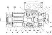
- the brake motorhas a rotor shaft 18, which is mounted in the bearing plate 9 via a bearing 10.
- This bearing plate 9is screw-connected to the housing part 12, which has cooling fins 11.
- the laminated stator coreis frictionally connected, in particular also releasably connected, shrunk and / or potted with casting compound.
- Associated stator windingsare provided in recesses of the stator lamination stack, wherein in FIG. 1 the deflection regions 8 of the stator windings are visible.
- a first and axially below a second brakeis arranged, wherein the brakes are electromagnetically actuated.
- a fanis provided at the axial end portion of the motor for Cooling the brakes and the engine.
- the cooling air flowis directed along the housing of the brake motor in a substantially axial direction.
- the first of these brakeshas a trained as a coil core bearing plate 14 which is screw-connected to the housing part 12, wherein a seal is interposed in the screw connection.
- the material of the end shieldis magnetizable, in particular ferromagnetic.
- the Bremsspuienwickiung 1is arranged in a substantially annular recess of the bearing plate 14.
- a driver 6so an externally toothed Veryakteil, by means of feather key in the circumferential direction positively, so rotatably connected, the external teeth in the axial direction of the rotor shaft is executed, so that provided with an internal toothing lining carrier 4 in the circumferential direction positively but in the axial direction slidably arranged.
- the lining carrier 4has axially on both sides friction linings.
- a friction disc 5is arranged, which is screw-connected to a housing part of the motor and thus dissipates frictional heat to this housing part.
- a 13 screwwhich is preferably designed as a stud screw used. This screw 13 additionally serves to guide the armature disk 3.
- the integrated design of the bearing plate 14 as a coil corealso allows the direct heat dissipation of the brake coil 1 to the environment.
- the electromagnetically actuated spring-loaded brake described in the radial directionis housing-forming surrounded by the bearing plate 14th
- the electric motoris arranged, wherein it is tightly connected, so sealed by a seal.
- a second brakeis arranged together with a fan and optionally with an angle sensor or angular velocity sensor.
- the first brakecan be designated as a built-in brake.
- the second brakeis designed in the manner of a mounting brake.
- the operation of the mounting brakeis again similar to the described operation of the built-in brake.
- the mounting brakeis screwed by means of the friction disc 15 to the bearing plate 14.
- the coil core 16receives the brake coil winding 21, in the energization of the armature plate 22 is moved axially against the spring force generated by spring elements.
- On the rotatably connected to the rotor shaft 18 driver 20is in turn rotationally fixed but axially displaceable a lining carrier 23 is provided with friction linings arranged on both sides.
- a fan 19is arranged. To protect a screwed to the bearing plate 14 fan cover the fan 19 is provided surrounding.
- the bearing 17is received in the bearing plate 14. Thus, this also absorbs the corresponding forces. Since the heat absorbed by the bearing plate 14 heat is dissipated directly to the environment, also the bearing 17 is accommodated for supporting the rotor shaft 18 and the material of the end shield 14 is selected and shaped so that the magnetic fields generated by the winding are guided integrated in the bearing plate 14 several technical functions.
- Attached to the bearing plate 14 on the side facing away from the engine attachment brakehas an independent housing, in particular, which is formed together with the fan guard. This housing is bolted to the bearing shield at a well-defined interface. In this case, a seal is provided and a centering means, such as centering collar.
- a centering meanssuch as centering collar.
- the attachment brakeother attachments, such as comprising an angle sensor or the like, executable.
- the bearing plate 14has a corresponding interface, so that different motors, in particular optional synchronous motor, asynchronous motor, LSPM motor, reluctance motor or the like, are connectable to the interface.
- the operation and / or action principles of the two brakesare designed differently.
- a first brakeis operated with direct current and the other brake with alternating current.
- FIG. 2another motor is shown, here the in FIG. 3 shown pre-completed first brake is inserted into a bearing plate 41 which receives the second brake.
- the vorkomplettiere brakeis in turn composed of a bobbin 38 with coil winding, supported on the compression springs 53 and an anchor plate 37 axially push away from the bobbin 38 when the coil winding is de-energized.
- the armature disk 37is guided by axially extending guide parts 54 and pressed onto the lining carrier 36, which has friction linings on both sides and is pressed onto the friction disk 35.
- the precompletioncauses the in FIG. 3 shown brake can be transported as such and forms a storable unit, that is held together.
- the guide members 54on a first axial portion which serves for guidance, that is cylindrical and smooth running on the outside.
- an external thread 58is provided, with which the respective guide part 54 in the Bobbin 38 is screwed, in particular in a respective threaded bore 59 of the bobbin 38th
- An internal hexagon 56is arranged on the axial end region of the guide part 54 facing away from the axial external thread region, with the result that the guide part 54 can be screwed into a correspondingly assigned threaded bore 59 of the coil body 38 with a hexagonal tool.
- an internally threaded boreis provided, into which screws 55 can be screwed.
- the friction plate 35is pressed by the screws 55 against a shoulder of the guide member and thus determines the distance between the friction plate 35 and spool core 38.
- the brakeis held together as a unit despite the axial mobility of the armature disc 37.
- the lining carrier 36is secured against falling out of the brake by circumferentially three or more guide members 54 are provided, which are arranged on a diameter which is larger is the outer diameter of the lining carrier 36.
- the terminal box 505can be screwed onto the bearing plate 41.
- the extended bearing plate 41receives the pre-completed brake (36, 37, 38, 504) and is bolted to the stator housing portion 502 of the synchronous motor.
- this Statorgekoruseteilis completed by means of a bearing plate 501st
- the rotor shaft 31is rotatably connected to a driver 506, which is designed with axially extending external teeth for the built-in brake, and with a driver 507, which is designed with axially extending external teeth for the mounting brake.
- the precompleted brake after FIG. 3is screw-connected with the axially extended executed bearing plate of the second brake, ie in a recess of roughly speaking cup-shaped designed bearing plate.
- the screwis performed with continuous connecting screws 40.
- the synchronous motor after FIG. 2in turn has a rotor shaft 31 which is mounted in the bearing plate 501 via a first bearing 30.
- permanent magnets 32are arranged on the rotor shaft, which interact with the stator windings provided on the laminated stator core 33.
- a driver 34is again arranged on the rotor shaft 31, so that an axially movable friction lining carrier is positively connected in the circumferential direction.
- the armature disk 37presses the lining carrier against the friction disk 35.
- this brakecorresponds to the structure and operation of the precompleted brake after FIG. 2 and is now installed in the bearing plate (41, 45) as a built-in brake.
- the bearing plate (41, 45)but also takes up the bearing 43 of the rotor shaft 31.
- the bearing plate (41, 45)has a centering seat 39, on which the precompleted installation brake can be connected and thus aligned during connection.
- Attached to the bearing plate (41, 45)is a mounting brake which does not receive a bearing of the rotor shaft 31 but is arranged on the side 42 of the bearing 43 facing away from the installation brake.
- the mounting brakeis constructed in a similar manner as the installation brake, so that therefore a coil core 47 is screw-connected to the bearing plate (41, 45).
- the coil core 47accommodates a coil winding whose magnetic field attracts the armature disk when the coil winding 48 is energized.
- spring elementspush the armature disk in turn on a lining carrier 50, which is axially movable and connected in the circumferential direction positively connected to a driver which is rotatably connected to the rotor shaft.
- the armature disk 44presses the lining carrier 50 against the friction disk 51.
- the armature disk 44is in turn axially guided, the friction disk 51 releasably connected to the spool core 47th
- an angle sensor 46is arranged.
- a sealing washer 52in particular made of plastic. This prevents abrasion of the lining carrier from getting into the engine area.
- the sealing washer 52is also sealed to the rotor shaft 31, in particular with a labyrinth seal or the like.
- the engine areais sufficiently sealed from the area of the built-in brake, in particular to at least substantially prevent the penetration of abrasion into the engine area.
- FIG. 6is shown attached to the asynchronous brake, which is designed as a built-in brake, so the housing forms on its axial end forming a housing, and sealed with the friction plate 401 to the engine with the sealing ring 607 is connected.
- a second brakeis designed as a mounting brake and sealed with the bearing plate, so the housing part of the built-in brake, connected by means of the sealing ring 602.
- the mounting brakeis screwed by means of screws 603 to the bearing plate (404, 14).
- a fan coveris provided housing forming, from which only the manually operable operating lever of the manual ventilation unit 601 protrudes. By means of actuation of this manual ventilation unit 601, the brake can be released, ie in the currentless case, the braking force can be switched off.
- a driver 605with axially extending external teeth for the built-in brake and axially spaced therefrom by the bearing 17, a driver 606 is provided with axially extending external teeth for the attachment brake.
Landscapes
- Engineering & Computer Science (AREA)
- Power Engineering (AREA)
- Physics & Mathematics (AREA)
- Electromagnetism (AREA)
- Braking Arrangements (AREA)
- Connection Of Motors, Electrical Generators, Mechanical Devices, And The Like (AREA)
- Motor Or Generator Frames (AREA)
Description
Translated fromGermanDie Erfindung betrifft einen Elektromotor.The invention relates to an electric motor.
Es ist allgemein bekannt, Motoren mit einer Bremse zu verbinden.It is well known to connect motors to a brake.
Aus der
Aus derFrom the
Aus derFrom the
Aus derFrom the
Der Erfindung liegt daher die Aufgabe zugrunde, einen Elektromotor weiterzubilden, insbesondere sicher zu gestalten.The invention is therefore the object of developing an electric motor, in particular to make safe.
Erfindungsgemäß wird die Aufgabe bei dem Elektromotor nach den in Anspruch 1 angegebenen Merkmalen gelöst. Weitere Ausgestaltungen der Erfindung sind in den abhängigen Ansprüchen 2 - 11 definiert. Von Vorteil ist dabei, dass zwei Bremsen Drehmoment, also Bremsmoment, an die Rotorwelle führen können. Somit ist die Sicherheit erhöhbar. Insbesondere sind die Bremsen nach verschiedenen Wirkprinzipien ausführbar. Auf diese Weise ist durch die unterschiedlichen Wirkprinzipien eine noch weiter erhöhte Sicherheit erreichbar. Auch bei Ausführung als elektromagnetisch betätigbare Federdruckbremse sind unterschiedliche Wirkweisen realisierbar, wie Gleichstrombremse oder Wechselstrombremse.According to the invention, the object is achieved in the electric motor according to the features indicated in
Bei einer vorteilhaften Ausgestaltung ist die erste Bremse in einem Gehäuseteil, insbesondere Lagerschild, aufgenommen, insbesondere in einer im Wesentlichen topfförmigen Vertiefung aufgenommen ist und schraubverbunden ist. Von Vorteil ist dabei, dass die erste Bremse vorkomplettiert ausbildbar ist und in einem für die Bremse gehäusebildenden und somit die Wärme der Bremse abführenden Gehäuseteil aufnehmbar ist. Außerdem hat das Gehäuseteil dann auch Magnetfeld-abschirmende Funktion.In an advantageous embodiment, the first brake in a housing part, in particular bearing plate, added, in particular, is received in a substantially cup-shaped depression and is screw-connected. The advantage here is that the first brake can be formed vorkomplettiert and in a housing for the brake forming and thus dissipating the heat of the brake housing part is receivable. In addition, the housing part then has a magnetic shielding function.
Bei einer vorteilhaften Ausgestaltung ist die erste Bremse in einem Gehäuseteil, insbesondere Lagerschild, aufgenommen, welches als Spulenkern der Spulenwicklung des Elektromagneten der Bremse fungiert. Von Vorteil ist dabei, dass das Gehäuseteil mehrere Funktionen ausführt und somit die Anzahl der notwendigen Teile für das Herstellen des Motors mit Bremsen gering ist.In an advantageous embodiment, the first brake in a housing part, in particular end shield, added, which acts as a coil core of the coil winding of the electromagnet of the brake. The advantage here is that the housing part performs several functions and thus the number of parts necessary for the manufacture of the engine with brakes is low.
Bei einer vorteilhaften Ausgestaltung nimmt das Gehäuseteil ein Lager der Rotorwelle des Motors auf. Von Vorteil ist dabei, dass Kräfte vom Lager ans Gehäuseteil ableitbar sind und ebenso die Wärme des Lagers über das Gehäuseteil an die Umgebung ableitbar ist. Außerdem ist die Wärme der Bremsspule ableitbar an die Umgebung und das Magnetfeld geführt im Spulenkern. Insbesondere sitzen Lager und Spulenwicklung der Bremse im gleichen axialen Bereich oder die entsprechend überdeckten axialen Bereiche überschneiden sich.In an advantageous embodiment, the housing part receives a bearing of the rotor shaft of the motor. The advantage here is that forces can be derived from the bearing to the housing part and also the heat of the bearing on the housing part to the environment is derived. In addition, the heat of the brake coil is derivable to the environment and the magnetic field guided in the coil core. In particular, bearings and coil winding of the brake sit in same axial region or the corresponding covered axial regions overlap.
Bei einer vorteilhaften Ausgestaltung ist das Gehäuseteil in einer im Wesentlichen topfförmigen Vertiefung aufgenommen und schraubverbunden. Von Vorteil ist dabei, dass das Gehäuseteil eine einfach herzustellende Formgebung aufweist.In an advantageous embodiment, the housing part is received in a substantially cup-shaped depression and screw connected. The advantage here is that the housing part has a simple shape to be produced.
Erfindungsgemäß sind beide Bremsen als elektromagnetisch betätigbare Federdruckbremse ausgeführt, wobei am Spulenkörper des Elektromagneten Federelemente abgestützt sind, die bei Nichtbestromung des Elektromagneten eine Ankerscheibe auf einen Belagträger drücken, der somit auf eine Reibscheibe gedrückt wird, wobei die Ankerscheibe drehfest zur Reibscheibe und zum Elektromagneten angeordnet ist und axial verschiebbar angeordnet ist, wobei der Belagträger mit der Rotorwelle des Elektromotors drehfest und axial verschiebbar verbunden ist. Von Vorteil ist dabei, dass bei Nichtbestromung die Bremse einfällt und somit bei Stromausfall Bremskraft erzeugt wird, wodurch die Sicherheit erhöht ist.According to theinvention , both brakes are designed as electromagnetically actuable spring-pressure brakes, spring elements being supported on the coil body of the electromagnet which, when the electromagnet is not energized, press an armature disk onto a lining carrier, which is thus pressed onto a friction disk, the armature disk being arranged in a manner fixed against rotation relative to the friction disk and the electromagnet and is arranged axially displaceable, wherein the lining carrier with the rotor shaft of the electric motor rotatably and axially displaceably connected. The advantage here is that when Nichtbestromung the brake is incident and thus in case of power failure braking force is generated, whereby the safety is increased.
Erfindungsgemäß sind die erste und die zweite Bremse vorkomplettiert ausgebildet, indem eine Reibscheibe mittels eines Führungsteils axial beabstandet zu einem Spulenkern der Bremse und festgelegt ist, wobei das Führungsteil zur axialen Führung einer Ankerscheibe der Bremse vorgesehen ist, wobei die Ankerscheibe in Umfangsrichtung formschlüssig begrenzt und gehalten ist vom Führungsteil. Von Vorteil ist dabei, dass die vorkomplettierte Bremse in ihrer Funktion schon vor dem Zusammenfügen des Motors überprüfbar ist als Einheit. Außerdem ist sie als lagerfähige Einheit ausgeführt und somit für logistische Zwecke einfach benutzbar. Das Führungsteil weist einen ersten axialen Abschnitt auf zur Führung der Ankerscheibe und einen zweiten axialen Abschnitt auf, der ein Außengewinde zum Einschrauben in eine Gewindebohrung des Spulenkerns aufweist. Von Vorteil ist dabei, dass mittels des Führungsteils eine vorkomplettierte Ausführung ermöglicht ist und das Führungsteil zum Zusammenhalten der Teile der Bremse verwendbar ist. Bei einer vorteilhaften Ausgestaltung ist an einem axialen Endbereich des Führungsteils ein innensechskant vorgesehen, insbesondere so dass das Führungsteil mittels eines Sechskant-Werkzeugs in eine Gewindebohrung des Spulenkerns einschraubbar ist. Von Vorteil ist dabei, dass eine einfache Herstellung ermöglicht ist.According to theinvention , the first and the second brake are precompletely formed by a friction disc axially spaced by a guide member to a coil core of the brake and is fixed, wherein the guide member is provided for axially guiding an armature disc of the brake, wherein the armature disc in the circumferential direction positively limited and held is from the leadership part. The advantage here is that the vorkomplettierte brake in their function before the joining of the engine is verifiable as a unit. In addition, it is designed as a storable unit and thus easy to use for logistical purposes. The guide member has a first axial portion for guiding the armature disc and a second axial portion having an external thread for screwing into a threaded bore of the spool core. The advantage here is that by means of the guide member a vorkomplettierte design is made possible and the guide member for holding the parts of the brake is used. In an advantageous embodiment, a hexagon socket is provided at an axial end region of the guide part, in particular so that the guide part can be screwed by means of a hexagonal tool into a threaded bore of the spool core. The advantage here is that a simple production is possible.
Bei einer vorteilhaften Ausgestaltung nimmt der Spulenkern der ersten Bremse ein Lager der Rotorwelle auf. Von Vorteil ist dabei, dass mehrere Funktionen realisiert sind mit einem einzigen Gehäuseteil.In an advantageous embodiment, the spool core of the first brake receives a bearing of the rotor shaft. The advantage here is that several functions are realized with a single housing part.
Bei einer vorteilhaften Ausgestaltung weist das Führungsteil eine Ausnehmung mit Innengewinde auf, so dass eine Reibscheibe der Bremse mittels einer Schraube an das Führungsteil schraubverbindbar ist, insbesondere gegen einen Absatz am Außenumfang des Führungsteils festlegbar ist. Von Vorteil ist dabei, dass ein Zusammenhalten der Reibscheibe und des Spulenkerns ermöglicht ist, wobei ein Abstand einhaltbar ist, so dass im Zwischenraum ein Belagträger und eine Ankerscheibe axial beweglich aber radial begrenzt gehalten sind.In an advantageous embodiment, the guide member has a recess with internal thread, so that a friction disc of the brake is screw-connected to the guide member by means of a screw, in particular against a shoulder on the outer periphery of the guide member can be fixed. The advantage here is that a cohesion of the friction plate and the spool core is made possible, wherein a distance can be maintained, so that in the space a lining carrier and an armature disc are axially movable but radially limited.
Bei einer vorteilhaften Ausgestaltung ist die erste Bremse in einem axial verlängert ausgeführten Lagerschild aufgenommen, an dem die zweite Bremse angebaut ist, insbesondere wobei das Lagerschild als Bremsfläche für einen Belagträger der zweiten Bremse fungiert, wobei der Belagträger von einer mittels Federelementen axial verschiebbaren Ankerscheibe beaufschlagt wird. Von Vorteil ist dabei, dass eine besonders einfache Herstellung ausführbar ist und das Lagerschild auch einen Anteil der Bremswärme der Anbaubremse an die Umgebung abführt.In an advantageous embodiment, the first brake is received in an axially extended executed bearing plate on which the second brake is mounted, in particular wherein the bearing plate acts as a braking surface for a lining carrier of the second brake, wherein the lining carrier is acted upon by an axially displaceable by means of spring elements anchor plate , The advantage here is that a particularly simple production is executable and the bearing plate also dissipates a portion of the braking heat of the attachment brake to the environment.
Bei einer vorteilhaften Ausgestaltung ist zwischen einem Raumbereich, der die erste Bremse umfasst, und einem Raumbereich, der den Stator umfasst, eine Dichtscheibe angeordnet, insbesondere weist die zur Rotorwelle hin eine Abdichtung, wie Labyrinth-Dichtung, auf. Von Vorteil ist dabei, dass kein Abrieb der Reibbeläge des Belagträgers in den motorraumberiech gelangen kann.In an advantageous embodiment, a sealing disc is arranged between a space region which comprises the first brake and a space region which comprises the stator, in particular has a seal towards the rotor shaft, such as a labyrinth seal. The advantage here is that no abrasion of the friction linings of the lining carrier can get into the motorraumberiech.
Bei einer vorteilhaften Ausgestaltung ist ein Anschlusskasten am axial verlängert ausgeführten Lagerschild befestigt. Von Vorteil ist dabei, dass auch eine Haltefunktion hierfür ausführbar ist vom Lagerschild, wobei auch elektrische Leitungen durch eine Ausnehmung im Lagerschild zum Raumberiech des Stators des Motors führbar sind.In an advantageous embodiment, a terminal box is attached to the axially extended executed bearing plate. The advantage here is that a holding function for this purpose executable from the end plate, whereby also electrical lines through a recess in the bearing plate for Raumberiech the stator of the motor are feasible.
Erfindungsgemäß sind die erste und zweite Bremse vorkomplettiert ausgebildet, die Bremsen sind also vor dem Zusammenbauen des gesamten Motors mit Bremsen funktionsüberprüfbar. Von Vorteil ist dabei, dass eine einfaches Handhaben und Herstellen ermöglicht ist.According to theinvention , the first and second brakes are precompleted, so the brakes are functionally verifiable before assembling the entire engine with brakes. The advantage here is that a simple handling and manufacturing is possible.
Die Erfindung wird nun anhand von Abbildungen näher erläutert:
- in der
Figur 1 - In der
Figur 2 - In der
Figur 3 - In der
Figur 4Gehäuseteil 404 gezeigt, das gemäßFigur 6 - In der
Figur 5Figur 2 - In der
Figur 6Figur 1
- in the
FIG. 1 a first inventive brake motor is shown, in which the electric motor is designed as an asynchronous motor. - In the
FIG. 2 a further inventive brake motor is shown in cross section, in which the electric motor is designed as a synchronous motor. - In the
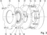
FIG. 3 is an vorkomplettierte brake shown in exploded view. - In the
FIG. 4 the installation of the vorkomplettierten brake is shown in ahousing part 404, according toFIG. 6 can be attached to an electric motor. - In the
FIG. 5 is that tooFIG. 2 corresponding exploded view of a brake motor running. - In the
FIG. 6 is that tooFIG. 1 corresponding exploded view of a brake motor running.
In der
Zugehörige Statorwicklungen sind in Ausnehmungen des Statorblechpakets vorgesehen, wobei in
Am vom Lagerschild 9 abgewandten axialen Endbereich des Gehäuseteils ist eine erste und axial nachfolgend eine zweite Bremse angeordnet, wobei die Bremsen elektromagnetisch betätigbar sind. Außerdem ist am axialen Endbereich des Motors ein Lüfter vorgesehen zur Kühlung der Bremsen und des Motors. Hierzu wird der Kühlluftstrom am Gehäuse des Bremsmotors in im Wesentlichen axialer Richtung entlang gelenkt.At the end facing away from the
Die erste dieser Bremsen weist ein als Spulenkern ausgebildetes Lagerschild 14 auf, das mit dem Gehäuseteil 12 schraubverbunden ist, wobei eine Dichtung in der Schraubverbindung zwischengeordnet ist. Das Material des Lagerschildes ist magnetisierbar, insbesondere ferromagnetisch. In einer im Wesentlichen ringförmigen Vertiefung des Lagerschilds 14 ist die Bremsspuienwickiung 1 angeordnet.The first of these brakes has a trained as a coil
Eine axial vor der Bremsspulenwicklung, axial verschiebbare und geführte, aber verdrehgesichert angeordnete Ankerscheibe 3 wird bei Bestromung der Bremsspulenwicklung 1 von dieser angezogen und entgegen der von Federelementen 2 erzeugten Federkraft axial auf die Bremsspulenwicklung 1 hin bewegt. Dabei stützen sich die Federelemente 2 auch gegen das Lagerschild 14 ab.An axially before the brake coil winding, axially displaceable and guided, but secured against
Auf der Rotorwelle 18 ist ein Mitnehmer 6, also ein außenverzahntes Verzahnteil, mittels Passfederverbindung in Umfangsrichtung formschlüssig, also drehfest, verbunden Dabei ist die Außenverzahnung in Achsrichtung der Rotorwelle ausgeführt, so dass ein mit einer innenverzahnung versehener Belagträger 4 in Umfangsrichtung formschlüssig aber in axialer Richtung verschiebbar angeordnet ist. Der Belagträger 4 weist axial an beiden Seiten Reibbeläge auf.On the
Auf der von der Ankerscheibe abgewandten axialen Seite des Belagträgers 4 ist eine Reibscheibe 5 angeordnet, die mit einem Gehäuseteil des Motors schraubverbindbar ist und somit Reibwärme ableitet an dieses Gehäuseteil.On the side remote from the armature disk axial side of the
Zur Schraubverbindung ist eine13 Schraube, die vorzugswiese als Stiftschraube ausgeführt ist, verwendet. Diese Schraube 13 dient zusätzlich auch der Führung der Ankerscheibe 3.For the screw connection is a 13 screw, which is preferably designed as a stud screw used. This
Die integrierte Ausführung des Lagerschildes 14 als Spulenkern ermöglicht auch die direkte Wärmeabfuhr der Bremsspule 1 an die Umgebung. Außerdem ist die beschriebene elektromagnetisch betätigbare Federdruckbremse in radialer Richtung gehäusebildend umgeben vom Lagerschild 14.The integrated design of the bearing
Axial vor der Bremse ist der Elektromotor angeordnet, wobei er dicht verbunden ist, also abgedichtet durch eine Dichtung. Axial hinter der Bremse ist eine zweite Bremse angeordnet zusammen mit einem Lüfter und gegebenenfalls mit einem Winkelsensor oder Winkelgeschwindigkeitssensor.Axially in front of the brake, the electric motor is arranged, wherein it is tightly connected, so sealed by a seal. Axially behind the brake, a second brake is arranged together with a fan and optionally with an angle sensor or angular velocity sensor.
Die erste Bremse ist wegen ihres kompakten, ins Lagerschild 14 als Gehäuseteil integrierten Aufbaus als Einbaubremse bezeichenbar. Hingegen ist die zweite Bremse nach Art einer Anbaubremse ausgeführt.Because of its compact design integrated into the
Die Funktionsweise der Anbaubremse ist wiederum gleichartig zur geschilderten Funktionsweise der Einbaubremse.The operation of the mounting brake is again similar to the described operation of the built-in brake.
Dabei ist die Anbaubremse mittels der Reibscheibe 15 angeschraubt an das Lagerschild 14. Der Spulenkern 16 nimmt wiederum die Bremsspulenwicklung 21 auf, bei deren Bestromung die Ankerscheibe 22 axial gegen die von Federelementen erzeugte Federkraft bewegt wird. Auf dem mit der Rotorwelle 18 drehfest verbundenen Mitnehmer 20 ist wiederum drehfest aber axial verschiebbar ein Belagträger 23 mit beidseitig angeordneten Reibbelägen vorgesehen. Somit wird bei Einfallen der Bremse, also bei Nichtbestromung der Bremsspulenwicklung 21, der Belagträger 23 von der Ankerscheibe 22 auf die Reibscheibe 15 gedrückt.In this case, the mounting brake is screwed by means of the
Am axialen Ende ist ein Lüfter 19 angeordnet. Zum Schutz ist eine mit dem Lagerschild 14 schraubverbundene Lüfterhaube den Lüfter 19 umgebend vorgesehen.At the axial end a
Das Lager 17 ist im Lagerschild 14 aufgenommen. Somit nimmt dieses auch die entsprechenden Kräfte auf. Da auch die Wärme vom Lagerschild 14 aufgenommene Wärme direkt an die Umgebung abführbar ist, außerdem das Lager 17 aufgenommen ist zur Lagerung der Rotorwelle 18 und das Material des Lagerschilds 14 derart ausgewählt und geformt ist, dass die von der Wicklung erzeugten Magnetfelder geführt werden, sind im Lagerschild 14 mehrere technische Funktionen integriert.The
Die ans Lagerschild 14 auf der vom Motor abgewandten Seite angebaute Anbaubremse weist ein eigenständiges Gehäuse auf, insbesondere das zusammen mit der Lüfterhaube gebildet ist. Dieses Gehäuse ist mit dem Lagerschild an einer wohldefinierten Schnittstelle schraubverbunden. Dabei ist eine Dichtung vorgesehen und ein Zentriermittel, wie Zentrierbund. Statt der Anbaubremse sind auch andere Anbauten, wie beispielsweise umfassend einen Winkelsensor oder dergleichen, ausführbar.Attached to the bearing
Auch zum Motor hin weist das Lagerschild 14 eine entsprechende Schnittstelle auf, so dass verschiedene Motoren, insbesondere wahlweise Synchronmotor, Asynchronmotor, LSPM-Motor, Reluktanzmotor oder dergleichen, verbindbar sind an der Schnittstelle.Also towards the engine, the bearing
Bei weiteren erfindungsgemäßen Ausführungsbeispielen sind die Funktionsweise und/oder Wirkprinzipien der beiden Bremsen verschieden ausgeführt. Beispielsweise ist eine erste Bremse mit Gleichstrom und die andere Bremse mit Wechselstrom betrieben.In further embodiments of the invention, the operation and / or action principles of the two brakes are designed differently. For example, a first brake is operated with direct current and the other brake with alternating current.
In der
Dabei ist die vorkomplettierte Bremse wiederum aus einem Spulenkörper 38 mit Spulenwicklung zusammengesetzt, an dem sich Druckfedern 53 abstützen und eine Ankerscheibe 37 axial vom Spulenkörper 38 wegdrücken, wenn die Spulenwicklung unbestromt ist. Dabei wird die Ankerscheibe 37 von sich axial erstreckenden Führungsteilen 54 geführt und auf den Belagträger 36 gedrückt, welcher beidseitig Reibbeläge aufweist und auf die Reibscheibe 35 gedrückt wird.The vorkomplettierte brake is in turn composed of a
Die Vorkomplettierung bewirkt, dass die in
Hierzu weisen die Führungsteile 54 einen ersten axialen Bereich auf, der zur Führung dient, also an der Außenseite zylindrisch und glatt ausgeführt ist. In einem zweiten axialen Bereich ist ein Außengewinde 58 vorgesehen, mit dem das jeweilige Führungsteil 54 in den Spulenkörper 38 eingeschraubt ist, insbesondere in eine jeweilige Gewindebohrung 59 des Spulenkörpers 38.For this purpose, the
An der vom axialen Außengewinde-Bereich abgewandten axialen Endbereich des Führungsteils 54 ist ein Innensechskant 56 angeordnet, wodurch das Führungsteil 54 mit einem Sechskant-Werkzeug in eine entsprechend zugeordnete Gewindebohrung 59 des Spulenkörpers 38 einschraubbar ist. Axial tiefer als der Innensechskant 56, also axial sich anschließend an den Bereich des Innensechskants 56 ist eine Innengewindebohrung vorgesehen, in die Schrauben 55 einschraubbar. Dabei wird die Reibscheibe 35 von den Schrauben 55 gegen einen Absatz des Führungsteils gedrückt und somit der Abstand zwischen Reibscheibe 35 und Spulenkern 38 festgelegt.An
Auf diese Weise ist die Bremse als Einheit zusammengehalten trotz der axialen Beweglichkeit der Ankerscheibe 37. Außerdem ist der Belagträger 36 gegen ein Herausfallen aus der Bremse gesichert, indem in Umfangsrichtung drei oder mehr Führungsteile 54 vorgesehen sind, die auf einem Durchmesser angeordnet sind, der größer ist als der Außendurchmesser des Belagträgers 36.In this way, the brake is held together as a unit despite the axial mobility of the
Wie in
Die Rotorwelle 31 ist mit einem Mitnehmer 506 drehfest verbunden, der mit axial verlaufender Außenverzahnung für die Einbaubremse ausgeführt ist, und mit einem Mitnehmer 507, der mit axial verlaufender Außenverzahnung für die Anbaubremse ausgeführt ist.The
Die vorkomplettierte Bremse nach
Der Synchronmotor nach
Des Weiteren ist auf der Rotorwelle 31 wiederum ein Mitnehmer 34 angeordnet, so dass ein axial bewegbarer Reibbelagträger in Umfangsrichtung formschlüssig verbunden ist. Bei Nicht-Bestromung der Spulenwicklung 38 drückt die Ankerscheibe 37 den Belagträger gegen die Reibscheibe 35.Furthermore, a
Somit entspricht diese Bremse nach Aufbau und Wirkungsweise der vorkomplettierten Bremse nach
Des Weiteren weist das Lagerschild (41, 45) einen Zentriersitz 39 auf, an dem die vorkomplettierte Einbaubremse verbindbar ist und somit ausgerichtet wird beim Verbinden.Furthermore, the bearing plate (41, 45) has a centering
An das Lagerschild (41, 45) ist eine Anbaubremse angebaut, die kein Lager der Rotorwelle 31 aufnimmt sondern auf der von der Einbaubremse abgewandten Seite 42 des Lagers 43 angeordnet ist.Attached to the bearing plate (41, 45) is a mounting brake which does not receive a bearing of the
Die Anbaubremse ist in gleichartiger Weise aufgebaut wie die Einbaubremse, so dass also ein Spulenkern 47 schraubverbunden ist mit dem Lagerschild (41, 45). Im Spulenkern 47 ist eine Spulenwicklung aufgenommen, deren Magnetfeld bei Bestromung der Spulenwicklung 48 die Ankerscheibe anzieht. Bei Nichtbestromung drücken Federelemente die Ankerscheibe wiederum auf einen Belagträger 50, welcher axial beweglich und in Umfangsrichtung formschlüssig mit einem Mitnehmer verbunden ist, der drehfest mit der Rotorwelle verbunden ist. Dabei drückt dann die Ankerscheibe 44 den Belagträger 50 gegen die Reibscheibe 51. Die Ankerscheibe 44 ist wiederum axial geführt die Reibscheibe 51 lösbar verbunden mit dem Spulenkern 47.The mounting brake is constructed in a similar manner as the installation brake, so that therefore a
Am motorabgewandten Endbereich der Anbaubremse ist ein Winkelsensor 46 angeordnet.At the motor remote end portion of the mounting brake an
Zwischen Motorbereich und Einbaubremse ist eine Dichtscheibe 52, insbesondere aus Kunststoff, angeordnet. Somit ist verhindert, dass Abrieb des Belagträgers in den Motorbereich gelangt. Die Dichtscheibe 52 ist auch zur Rotorwelle 31 hin abgedichtet ausgeführt, insbesondere mit einer Labyrinthdichtung oder dergleichen. Somit ist der Motorbereich vom Bereich der Einbaubremse genügend abgedichtet, insbesondere um das Eindringen von Abrieb in den Motorbereich zumindest im Wesentlichen zu verhindern.Between the engine area and the built-in brake is a sealing
Bei dem erfindungsgemäßen Ausführungsbeispiel nach
Auf der Rotorwelle 18 ist ein Mitnehmer 605 mit axial verlaufender Außenverzahnung für die Einbaubremse und axial hiervon beabstandet durch das Lager 17 ein Mitnehmer 606 mit axial verlaufender Außenverzahnung für die Anbaubremse vorgesehen.On the
- 1 Bremsspulenwicklung1 brake coil winding
- 2 Federelemente2 spring elements
- 3 Ankerscheibe3 anchor plate
- 4 Belagträger4 lining carrier
- 5 Reibscheibe5 friction disc
- 6 Mitnehmer6 drivers
- 7 Statorblechpaket7 stator core
- 8 Umlenkbereich der Statorwicklungen8 deflection area of the stator windings
- 9 Lagerschild9 end shield
- 10 Lager10 bearings
- 11 Kühlrippen11 cooling fins
- 12 Gehäuseteil12 housing part
- 13 Schraube13 screw
- 14, 404 als Spulenkern ausgebildetes Lagerschild14, 404 designed as a coil core bearing plate
- 15 Reibscheibe15 friction disc
- 16 Spulenkern16 spool core
- 17 Lager17 bearings
- 18 Rotorwelle18 rotor shaft
- 19 Lüfter19 fans
- 20 Mitnehmer20 drivers
- 21 Bremsspulenwicklung21 brake coil winding
- 22 Ankerscheibe22 anchor plate
- 23 Belagträger23 lining carrier
- 30 Lager30 bearings
- 31 Rotorwelle31 rotor shaft
- 32 Dauermagnete32 permanent magnets
- 33 Statorblechpaket33 stator laminated core
- 34 Mitnehmer34 drivers
- 35 Reibscheibe35 friction disc
- 36 Belagträger36 lining carrier
- 37 Ankerscheibe37 anchor disc
- 38 Spulenkörper mit Spulenwicklung38 bobbin with coil winding
- 39 Zentriersitz39 centering seat
- 40 Verbindungsschraube40 connecting screw
- 41 Lagerschild, axial verlängert ausgeführt41 end shield, axially extended executed
- 42 Spulenkern42 spool core
- 43 Lager43 bearings
- 44 Ankerscheibe44 anchor plate
- 45 Lagerschild45 bearing plate
- 46 Winkelsensor46 angle sensor
- 47 Spulenkern47 spool core
- 48 Spulenwicklung48 coil winding
- 50 Belagträger50 lining carrier
- 51 Reibscheibe51 friction disc
- 52 Dichtscheibe, insbesondere Kunststoff-Dichtscheibe52 sealing washer, in particular plastic sealing washer
- 53 Druckfedern53 compression springs
- 54 Führungsteil54 guide part
- 55 Schraube zum Anschrauben der Reibscheibe gegen die Stufe des Führungsteils 5455 Screw for screwing the friction disc against the step of the
guide member 54 - 56 Innensechskant56 hexagon socket
- 57 Absatz57 paragraph
- 58 Außengewinde58 external thread
- 59 Gewindebohrung59 threaded hole
- 401 Dichtscheibe401 sealing washer
- 402 Schraube402 screw
- 403 Hülse403 sleeve
- 404 Lagerschild404 bearing plate
- 501 Lagerschild501 bearing plate
- 502 Gehäuseteil des Synchronmotors502 housing part of the synchronous motor
- 503 Gehäuseteil503 housing part
- 504 Reibscheibe504 friction disc
- 505 Anschlusskasten505 connection box
- 506 Mitnehmer mit axial verlaufender Außenverzahnung für Einbaubremse506 Driver with axial external toothing for built-in brake
- 507 Mitnehmer mit axial verlaufender Außenverzahnung für Anbaubremse507 Driver with axial external teeth for attachment brake
- 601 Handlüfteinheit601 manual ventilation unit
- 602 Dichtring602 sealing ring
- 603 Schraube603 screw
- 604 Lüfterhaube604 fan cover
- 605 Mitnehmer mit axial verlaufender Außenverzahnung für Einbaubremse605 Carrier with axial external toothing for built-in brake
- 606 Mitnehmer mit axial verlaufender Außenverzahnung für Anbaubremse606 Driver with axial external teeth for attachment brake
- 607 Dichtring607 sealing ring
Claims (11)
- Electric motor having a first brake and a second brake,
wherein the first brake is arranged in the housing of the motor,
wherein the housing encloses the stator windings of the motor so as to form a housing and is assembled from housing parts (12, 502, 503), in particular by means of respective sealed screw connections between the housing parts (12, 502, 503),
wherein the second brake is attached to the motor, in particular therefore is attached to the housing of the motor,
wherein both brakes are embodied as electromagnetically actuable spring-loaded brakes, wherein spring elements (2) are supported against the coil body of the electromagnet, which spring elements, when no power is being supplied to the electromagnet, press an armature disc (3, 22, 37, 44) against a lining carrier (4, 23, 36, 50) which is thus pressed against a friction disc (5, 15, 35, 51, 504), wherein the armature disc (3, 22, 37, 44) is arranged in a rotationally fixed manner relative to the friction disc (5, 15, 35, 51, 504) and to the electromagnet and is arranged in an axially displaceable manner, wherein the lining carrier (4, 23, 36, 50) is connected to the rotor shaft (18, 31) of the electric motor in a rotationally fixed and axially displaceable manner,
characterized in that
the first and second brakes are in pre-assembled form, and the brakes can therefore be checked for proper functioning prior to assembling the entire motor with brakes, whereby a friction disc (5, 15, 35, 51, 504) is arranged at an axial spacing from a coil core (16, 42, 47) of the brake by means of a guide part and is fixed in position,
wherein the guide part is provided for axially guiding the armature disc (3, 22, 37, 44) of the brake,
wherein the armature disc (3, 22, 37, 44) is delimited and held by the guide part with a form fit in the circumferential direction,
wherein the guide part has a first axial section for guiding the armature disc (3, 22, 37, 44) and a second axial section (58) which has an external thread for screwing into a threaded bore of the coil core (16, 42, 47). - Electric motor according to claim 1,
characterized in that
the first brake is accommodated in a housing part (12, 502, 503), in particular an end shield (9, 41, 45, 404, 501), in particular is accommodated and screw-connected in a substantially pot-shaped depression. - Electric motor according to one of the preceding claims,
characterized in that
the first brake is accommodated in a housing part (12, 502, 503), in particular an end shield (9, 41, 45, 404, 501), which acts as a coil core (16, 42, 47) of the coil winding of the electromagnet of the brake. - Electric motor according to one of the preceding claims,
characterized in that
the housing part (12, 502, 503) accommodates a bearing (10, 17, 30, 43) of the rotor shaft (18, 31) of the motor. - Electric motor according to one of the preceding claims,
characterized in that
the housing part (12, 502, 503) is accommodated and screw-connected in a substantially pot-shaped depression. - Electric motor according to one of the preceding claims,
characterized in that
a hexagon socket is provided on an axial end region of the guide part, in particular such that the guide part can be screwed into a threaded bore of the coil core (16, 42, 47) by means of a hexagon tool. - Electric motor according to one of the preceding claims,
characterized in that
the coil core (16, 42, 47) of the first brake accommodates a bearing (10, 17, 30, 43) of the rotor shaft (18, 31). - Electric motor according to one of the preceding claims,
characterized in that
the guide part has a recess with an internal thread such that a friction disc (5, 15, 35, 51, 504) of the brake can be screw-connected to the guide part by means of a screw, in particular can be fixed in position against a shoulder on the outer circumference of the guide part. - Electric motor according to one of the preceding claims,
characterized in that
the first brake is accommodated in an axially extended end shield (9, 41, 45, 404, 501), to which the second brake is attached, in particular wherein the end shield (9, 41, 45, 404, 501) acts as a braking surface for a lining carrier (4, 23, 36, 50) of the second brake, wherein load is applied to the lining carrier (4, 23, 36, 50) by an armature disc (3, 22, 37, 44) which is axially displaceable by means of spring elements (2). - Electric motor according to one of the preceding claims,
characterized in that
a sealing disc is arranged between a spatial region which comprises the first brake and a spatial region which comprises the stator, said sealing disc having in particular a sealing means, such as a labyrinth seal, towards the rotor shaft (18, 31) . - Electric motor according to one of the preceding claims,
characterized in that
a terminal box is fastened to the axially extended end shield (9, 41, 45, 404, 501).
Applications Claiming Priority (2)
| Application Number | Priority Date | Filing Date | Title |
|---|---|---|---|
| DE102010049748.7ADE102010049748B4 (en) | 2010-10-29 | 2010-10-29 | electric motor |
| PCT/EP2011/004678WO2012055462A2 (en) | 2010-10-29 | 2011-09-19 | Electric motor |
Publications (2)
| Publication Number | Publication Date |
|---|---|
| EP2633603A2 EP2633603A2 (en) | 2013-09-04 |
| EP2633603B1true EP2633603B1 (en) | 2018-08-22 |
Family
ID=44735871
Family Applications (1)
| Application Number | Title | Priority Date | Filing Date |
|---|---|---|---|
| EP11764102.7AActiveEP2633603B1 (en) | 2010-10-29 | 2011-09-19 | Electric motor |
Country Status (3)
| Country | Link |
|---|---|
| EP (1) | EP2633603B1 (en) |
| DE (1) | DE102010049748B4 (en) |
| WO (1) | WO2012055462A2 (en) |
Cited By (1)
| Publication number | Priority date | Publication date | Assignee | Title |
|---|---|---|---|---|
| WO2024227588A1 (en) | 2023-05-03 | 2024-11-07 | Sew-Eurodrive Gmbh & Co. Kg | Electric motor having an electromagnetically actuatable brake |
Families Citing this family (16)
| Publication number | Priority date | Publication date | Assignee | Title |
|---|---|---|---|---|
| DE102012019415B4 (en) | 2012-10-04 | 2023-12-21 | Sew-Eurodrive Gmbh & Co Kg | Electric motor, especially with a redundant brake arrangement |
| EP2905877B1 (en)* | 2012-10-04 | 2018-08-01 | Mitsubishi Electric Corporation | Rotary electric machine having integrated drive control device |
| CN111615780B (en)* | 2018-01-12 | 2023-05-02 | 索尤若驱动有限及两合公司 | Drive and method for manufacturing it |
| CN113728548A (en)* | 2019-04-25 | 2021-11-30 | 米沃奇电动工具公司 | Motor brake coil for electric tool |
| WO2020233836A1 (en)* | 2019-05-21 | 2020-11-26 | Sew-Eurodrive Gmbh & Co. Kg | Drive comprising an electric motor with a rotor shaft, angle sensor and hood part as well as connection module, and method for producing a drive |
| EP3981066A4 (en) | 2019-06-10 | 2023-02-08 | Milwaukee Electric Tool Corporation | MOTOR BRAKING USING SELECTIVELY LINKABLE RESISTOR |
| DE102022004256A1 (en) | 2021-11-30 | 2023-06-01 | Sew-Eurodrive Gmbh & Co Kg | Drive, comprising a transmission with a transmission housing, an electromagnetically actuable brake arrangement and an electric motor |
| DE102022004298A1 (en) | 2021-11-30 | 2023-06-01 | Sew-Eurodrive Gmbh & Co Kg | Drive, comprising a transmission with a transmission housing, an electromagnetically actuable brake arrangement and an electric motor |
| WO2023099025A1 (en) | 2021-11-30 | 2023-06-08 | Sew-Eurodrive Gmbh & Co. Kg | Drive, having a transmission with a transmission housing, an electromagnetically actuatable brake assembly and an electric motor |
| DE102022004230A1 (en) | 2021-11-30 | 2023-06-01 | Sew-Eurodrive Gmbh & Co Kg | Drive, comprising a transmission with a transmission housing, an electromagnetically actuable brake arrangement and an electric motor |
| WO2023099027A1 (en) | 2021-11-30 | 2023-06-08 | Sew-Eurodrive Gmbh & Co. | Drive having a transmission with a transmission housing, an electromagnetically actuatable brake assembly, and an electric motor |
| DE102023001876A1 (en) | 2022-06-06 | 2023-12-07 | Sew-Eurodrive Gmbh & Co Kg | Geared motor and system with control electronics and geared motor |
| DE102023001878A1 (en) | 2022-06-08 | 2023-12-14 | Sew-Eurodrive Gmbh & Co Kg | Geared motor with brake |
| DE102024000140A1 (en) | 2023-02-15 | 2024-08-22 | Sew-Eurodrive Gmbh & Co Kg | Electromagnetically operated brake and electric motor with electromagnetically operated brake |
| DE102024104311A1 (en) | 2023-03-14 | 2024-09-19 | Sew-Eurodrive Gmbh & Co Kg | Brake arrangement, in particular for an electric motor, for braking a shaft |
| WO2024193925A1 (en) | 2023-03-20 | 2024-09-26 | Sew-Eurodrive Gmbh & Co. Kg | Electromagnetically actuatable brake and electric motor having an electromagnetically actuatable brake |
Family Cites Families (10)
| Publication number | Priority date | Publication date | Assignee | Title |
|---|---|---|---|---|
| GB779349A (en) | 1952-10-17 | 1957-07-17 | Robert Gilmour Letourneau | Improvements in electromagnetic brakes |
| FI114419B (en) | 1994-04-07 | 2004-10-15 | Kone Corp | The elevator machinery |
| DE19737485C1 (en) | 1997-08-28 | 1999-06-17 | Stromag Ag | Electromagnetically-operated brake |
| WO2004057732A1 (en)* | 2002-12-19 | 2004-07-08 | Sew-Eurodrive Gmbh & Co | Adapter, gear motor and modular gear motor system |
| FR2857348B1 (en) | 2003-07-08 | 2005-12-02 | Leroy Somer Moteurs | BRAKE SYSTEM WITH SECURED TORQUE RETRIEVAL |
| TWI272757B (en) | 2003-11-20 | 2007-02-01 | Sumitomo Heavy Industries | Motor built-in cylinder |
| DE102004033745B4 (en) | 2004-04-01 | 2006-08-17 | Sew-Eurodrive Gmbh & Co. Kg | electric motor |
| FR2877160B1 (en) | 2004-10-27 | 2010-11-26 | Eurocopter France | ELECTROMECHANICAL MOTOR WITH DOUBLE OUTPUT |
| FR2890499B1 (en)* | 2005-09-05 | 2007-11-16 | Leroy Somer Moteurs | ROTATING ELECTRIC MACHINE |
| KR100751035B1 (en)* | 2006-05-22 | 2007-08-21 | 주식회사 한국체인모터 | drive |
- 2010
- 2010-10-29DEDE102010049748.7Apatent/DE102010049748B4/enactiveActive
- 2011
- 2011-09-19WOPCT/EP2011/004678patent/WO2012055462A2/enactiveApplication Filing
- 2011-09-19EPEP11764102.7Apatent/EP2633603B1/enactiveActive
Non-Patent Citations (1)
| Title |
|---|
| None* |
Cited By (2)
| Publication number | Priority date | Publication date | Assignee | Title |
|---|---|---|---|---|
| WO2024227588A1 (en) | 2023-05-03 | 2024-11-07 | Sew-Eurodrive Gmbh & Co. Kg | Electric motor having an electromagnetically actuatable brake |
| DE102024110431A1 (en) | 2023-05-03 | 2024-11-07 | Sew-Eurodrive Gmbh & Co Kg | electric motor with electromagnetically operated brake |
Also Published As
| Publication number | Publication date |
|---|---|
| WO2012055462A2 (en) | 2012-05-03 |
| EP2633603A2 (en) | 2013-09-04 |
| DE102010049748A1 (en) | 2012-05-03 |
| DE102010049748B4 (en) | 2022-09-08 |
| WO2012055462A3 (en) | 2012-07-26 |
Similar Documents
| Publication | Publication Date | Title |
|---|---|---|
| EP2633603B1 (en) | Electric motor | |
| EP2633605B1 (en) | Brake | |
| EP2633604B1 (en) | Kit for the production of different electric motors of a group of electric motors and method of production | |
| DE102012019415B4 (en) | Electric motor, especially with a redundant brake arrangement | |
| EP3271996B1 (en) | Electric motor | |
| EP2061141B1 (en) | Electric machine with magnetic brake attached to the rotor | |
| EP2617123B1 (en) | Electric motor | |
| EP0111350A1 (en) | Electric motor equipped with arresting brake | |
| DE3508227C1 (en) | Electromagnetically actuable friction brake and clutch device for an electric motor drive, especially for industrial sewing machines | |
| WO1994003960A1 (en) | Electric machine system | |
| DE60205878T2 (en) | BRAKE COUPLING ARRANGEMENT | |
| EP2901037B1 (en) | Brake system and electric motor comprising said brake system | |
| EP2275700B1 (en) | Electromagnetic friction coupling | |
| EP3289670B1 (en) | Transmission system | |
| DE10103736C2 (en) | Electromagnetically ventilated spring-applied brake with a brake rotor that can be pressed against an abutment flange | |
| DE102022002717A1 (en) | Electric motor with brake arrangement | |
| DE19814078B4 (en) | Electromagnetic spring pressure brake | |
| EP2504600B1 (en) | Electromagnetically actuable brake and method for operating a brake | |
| WO2008141998A1 (en) | Brake unit for an electrical machine, end shield comprising such a brake unit and electrical machine | |
| WO2024193925A1 (en) | Electromagnetically actuatable brake and electric motor having an electromagnetically actuatable brake | |
| WO2024170199A1 (en) | Electromagnetically actuatable brake and electric motor having an electromagnetically actuatable brake | |
| DE102014013732A1 (en) | Drive arrangement with sensor |
Legal Events
| Date | Code | Title | Description |
|---|---|---|---|
| PUAI | Public reference made under article 153(3) epc to a published international application that has entered the european phase | Free format text:ORIGINAL CODE: 0009012 | |
| 17P | Request for examination filed | Effective date:20130529 | |
| AK | Designated contracting states | Kind code of ref document:A2 Designated state(s):AL AT BE BG CH CY CZ DE DK EE ES FI FR GB GR HR HU IE IS IT LI LT LU LV MC MK MT NL NO PL PT RO RS SE SI SK SM TR | |
| DAX | Request for extension of the european patent (deleted) | ||
| 17Q | First examination report despatched | Effective date:20171109 | |
| GRAP | Despatch of communication of intention to grant a patent | Free format text:ORIGINAL CODE: EPIDOSNIGR1 | |
| INTG | Intention to grant announced | Effective date:20180411 | |
| GRAS | Grant fee paid | Free format text:ORIGINAL CODE: EPIDOSNIGR3 | |
| GRAA | (expected) grant | Free format text:ORIGINAL CODE: 0009210 | |
| REG | Reference to a national code | Ref country code:FR Ref legal event code:PLFP Year of fee payment:8 | |
| AK | Designated contracting states | Kind code of ref document:B1 Designated state(s):AL AT BE BG CH CY CZ DE DK EE ES FI FR GB GR HR HU IE IS IT LI LT LU LV MC MK MT NL NO PL PT RO RS SE SI SK SM TR | |
| REG | Reference to a national code | Ref country code:GB Ref legal event code:FG4D Free format text:NOT ENGLISH | |
| REG | Reference to a national code | Ref country code:CH Ref legal event code:EP Ref country code:CH Ref legal event code:NV Representative=s name:HEPP WENGER RYFFEL AG, CH | |
| REG | Reference to a national code | Ref country code:AT Ref legal event code:REF Ref document number:1033603 Country of ref document:AT Kind code of ref document:T Effective date:20180915 | |
| REG | Reference to a national code | Ref country code:IE Ref legal event code:FG4D Free format text:LANGUAGE OF EP DOCUMENT: GERMAN | |
| REG | Reference to a national code | Ref country code:DE Ref legal event code:R096 Ref document number:502011014636 Country of ref document:DE | |
| REG | Reference to a national code | Ref country code:SE Ref legal event code:TRGR | |
| REG | Reference to a national code | Ref country code:NL Ref legal event code:MP Effective date:20180822 | |
| REG | Reference to a national code | Ref country code:LT Ref legal event code:MG4D | |
| PG25 | Lapsed in a contracting state [announced via postgrant information from national office to epo] | Ref country code:LT Free format text:LAPSE BECAUSE OF FAILURE TO SUBMIT A TRANSLATION OF THE DESCRIPTION OR TO PAY THE FEE WITHIN THE PRESCRIBED TIME-LIMIT Effective date:20180822 Ref country code:IS Free format text:LAPSE BECAUSE OF FAILURE TO SUBMIT A TRANSLATION OF THE DESCRIPTION OR TO PAY THE FEE WITHIN THE PRESCRIBED TIME-LIMIT Effective date:20181222 Ref country code:RS Free format text:LAPSE BECAUSE OF FAILURE TO SUBMIT A TRANSLATION OF THE DESCRIPTION OR TO PAY THE FEE WITHIN THE PRESCRIBED TIME-LIMIT Effective date:20180822 Ref country code:GR Free format text:LAPSE BECAUSE OF FAILURE TO SUBMIT A TRANSLATION OF THE DESCRIPTION OR TO PAY THE FEE WITHIN THE PRESCRIBED TIME-LIMIT Effective date:20181123 Ref country code:FI Free format text:LAPSE BECAUSE OF FAILURE TO SUBMIT A TRANSLATION OF THE DESCRIPTION OR TO PAY THE FEE WITHIN THE PRESCRIBED TIME-LIMIT Effective date:20180822 Ref country code:NO Free format text:LAPSE BECAUSE OF FAILURE TO SUBMIT A TRANSLATION OF THE DESCRIPTION OR TO PAY THE FEE WITHIN THE PRESCRIBED TIME-LIMIT Effective date:20181122 Ref country code:BG Free format text:LAPSE BECAUSE OF FAILURE TO SUBMIT A TRANSLATION OF THE DESCRIPTION OR TO PAY THE FEE WITHIN THE PRESCRIBED TIME-LIMIT Effective date:20181122 Ref country code:NL Free format text:LAPSE BECAUSE OF FAILURE TO SUBMIT A TRANSLATION OF THE DESCRIPTION OR TO PAY THE FEE WITHIN THE PRESCRIBED TIME-LIMIT Effective date:20180822 | |
| PG25 | Lapsed in a contracting state [announced via postgrant information from national office to epo] | Ref country code:HR Free format text:LAPSE BECAUSE OF FAILURE TO SUBMIT A TRANSLATION OF THE DESCRIPTION OR TO PAY THE FEE WITHIN THE PRESCRIBED TIME-LIMIT Effective date:20180822 Ref country code:LV Free format text:LAPSE BECAUSE OF FAILURE TO SUBMIT A TRANSLATION OF THE DESCRIPTION OR TO PAY THE FEE WITHIN THE PRESCRIBED TIME-LIMIT Effective date:20180822 Ref country code:AL Free format text:LAPSE BECAUSE OF FAILURE TO SUBMIT A TRANSLATION OF THE DESCRIPTION OR TO PAY THE FEE WITHIN THE PRESCRIBED TIME-LIMIT Effective date:20180822 | |
| PG25 | Lapsed in a contracting state [announced via postgrant information from national office to epo] | Ref country code:CZ Free format text:LAPSE BECAUSE OF FAILURE TO SUBMIT A TRANSLATION OF THE DESCRIPTION OR TO PAY THE FEE WITHIN THE PRESCRIBED TIME-LIMIT Effective date:20180822 Ref country code:ES Free format text:LAPSE BECAUSE OF FAILURE TO SUBMIT A TRANSLATION OF THE DESCRIPTION OR TO PAY THE FEE WITHIN THE PRESCRIBED TIME-LIMIT Effective date:20180822 Ref country code:RO Free format text:LAPSE BECAUSE OF FAILURE TO SUBMIT A TRANSLATION OF THE DESCRIPTION OR TO PAY THE FEE WITHIN THE PRESCRIBED TIME-LIMIT Effective date:20180822 Ref country code:EE Free format text:LAPSE BECAUSE OF FAILURE TO SUBMIT A TRANSLATION OF THE DESCRIPTION OR TO PAY THE FEE WITHIN THE PRESCRIBED TIME-LIMIT Effective date:20180822 Ref country code:PL Free format text:LAPSE BECAUSE OF FAILURE TO SUBMIT A TRANSLATION OF THE DESCRIPTION OR TO PAY THE FEE WITHIN THE PRESCRIBED TIME-LIMIT Effective date:20180822 | |
| REG | Reference to a national code | Ref country code:DE Ref legal event code:R097 Ref document number:502011014636 Country of ref document:DE | |
| PG25 | Lapsed in a contracting state [announced via postgrant information from national office to epo] | Ref country code:DK Free format text:LAPSE BECAUSE OF FAILURE TO SUBMIT A TRANSLATION OF THE DESCRIPTION OR TO PAY THE FEE WITHIN THE PRESCRIBED TIME-LIMIT Effective date:20180822 Ref country code:SK Free format text:LAPSE BECAUSE OF FAILURE TO SUBMIT A TRANSLATION OF THE DESCRIPTION OR TO PAY THE FEE WITHIN THE PRESCRIBED TIME-LIMIT Effective date:20180822 Ref country code:SM Free format text:LAPSE BECAUSE OF FAILURE TO SUBMIT A TRANSLATION OF THE DESCRIPTION OR TO PAY THE FEE WITHIN THE PRESCRIBED TIME-LIMIT Effective date:20180822 | |
| REG | Reference to a national code | Ref country code:BE Ref legal event code:MM Effective date:20180930 | |
| REG | Reference to a national code | Ref country code:IE Ref legal event code:MM4A | |
| PG25 | Lapsed in a contracting state [announced via postgrant information from national office to epo] | Ref country code:MC Free format text:LAPSE BECAUSE OF FAILURE TO SUBMIT A TRANSLATION OF THE DESCRIPTION OR TO PAY THE FEE WITHIN THE PRESCRIBED TIME-LIMIT Effective date:20180822 Ref country code:LU Free format text:LAPSE BECAUSE OF NON-PAYMENT OF DUE FEES Effective date:20180919 | |
| PLBE | No opposition filed within time limit | Free format text:ORIGINAL CODE: 0009261 | |
| STAA | Information on the status of an ep patent application or granted ep patent | Free format text:STATUS: NO OPPOSITION FILED WITHIN TIME LIMIT | |
| 26N | No opposition filed | Effective date:20190523 | |
| PG25 | Lapsed in a contracting state [announced via postgrant information from national office to epo] | Ref country code:IE Free format text:LAPSE BECAUSE OF NON-PAYMENT OF DUE FEES Effective date:20180919 | |
| PG25 | Lapsed in a contracting state [announced via postgrant information from national office to epo] | Ref country code:SI Free format text:LAPSE BECAUSE OF FAILURE TO SUBMIT A TRANSLATION OF THE DESCRIPTION OR TO PAY THE FEE WITHIN THE PRESCRIBED TIME-LIMIT Effective date:20180822 Ref country code:BE Free format text:LAPSE BECAUSE OF NON-PAYMENT OF DUE FEES Effective date:20180930 | |
| PG25 | Lapsed in a contracting state [announced via postgrant information from national office to epo] | Ref country code:MT Free format text:LAPSE BECAUSE OF FAILURE TO SUBMIT A TRANSLATION OF THE DESCRIPTION OR TO PAY THE FEE WITHIN THE PRESCRIBED TIME-LIMIT Effective date:20180822 | |
| PG25 | Lapsed in a contracting state [announced via postgrant information from national office to epo] | Ref country code:TR Free format text:LAPSE BECAUSE OF FAILURE TO SUBMIT A TRANSLATION OF THE DESCRIPTION OR TO PAY THE FEE WITHIN THE PRESCRIBED TIME-LIMIT Effective date:20180822 | |
| PG25 | Lapsed in a contracting state [announced via postgrant information from national office to epo] | Ref country code:PT Free format text:LAPSE BECAUSE OF FAILURE TO SUBMIT A TRANSLATION OF THE DESCRIPTION OR TO PAY THE FEE WITHIN THE PRESCRIBED TIME-LIMIT Effective date:20180822 Ref country code:HU Free format text:LAPSE BECAUSE OF FAILURE TO SUBMIT A TRANSLATION OF THE DESCRIPTION OR TO PAY THE FEE WITHIN THE PRESCRIBED TIME-LIMIT; INVALID AB INITIO Effective date:20110919 | |
| PG25 | Lapsed in a contracting state [announced via postgrant information from national office to epo] | Ref country code:MK Free format text:LAPSE BECAUSE OF NON-PAYMENT OF DUE FEES Effective date:20180822 Ref country code:CY Free format text:LAPSE BECAUSE OF FAILURE TO SUBMIT A TRANSLATION OF THE DESCRIPTION OR TO PAY THE FEE WITHIN THE PRESCRIBED TIME-LIMIT Effective date:20180822 | |
| PGFP | Annual fee paid to national office [announced via postgrant information from national office to epo] | Ref country code:DE Payment date:20240930 Year of fee payment:14 | |
| PGFP | Annual fee paid to national office [announced via postgrant information from national office to epo] | Ref country code:GB Payment date:20240801 Year of fee payment:14 | |
| PGFP | Annual fee paid to national office [announced via postgrant information from national office to epo] | Ref country code:FR Payment date:20240808 Year of fee payment:14 | |
| PGFP | Annual fee paid to national office [announced via postgrant information from national office to epo] | Ref country code:AT Payment date:20240910 Year of fee payment:14 | |
| PGFP | Annual fee paid to national office [announced via postgrant information from national office to epo] | Ref country code:IT Payment date:20240812 Year of fee payment:14 Ref country code:SE Payment date:20240812 Year of fee payment:14 | |
| PGFP | Annual fee paid to national office [announced via postgrant information from national office to epo] | Ref country code:CH Payment date:20241001 Year of fee payment:14 |