EP2632696B1 - Process and apparatus for fabrication of three-dimensional objects - Google Patents
Process and apparatus for fabrication of three-dimensional objectsDownload PDFInfo
- Publication number
- EP2632696B1 EP2632696B1EP11781918.5AEP11781918AEP2632696B1EP 2632696 B1EP2632696 B1EP 2632696B1EP 11781918 AEP11781918 AEP 11781918AEP 2632696 B1EP2632696 B1EP 2632696B1
- Authority
- EP
- European Patent Office
- Prior art keywords
- ink
- layer
- polymer
- dimensional
- certain embodiments
- Prior art date
- Legal status (The legal status is an assumption and is not a legal conclusion. Google has not performed a legal analysis and makes no representation as to the accuracy of the status listed.)
- Active
Links
- 238000004519manufacturing processMethods0.000titleclaimsdescription52
- 238000000034methodMethods0.000titleclaimsdescription48
- 230000008569processEffects0.000titleclaimsdescription23
- 229920000642polymerPolymers0.000claimsdescription122
- 238000000151depositionMethods0.000claimsdescription45
- 239000000463materialSubstances0.000claimsdescription43
- 238000007639printingMethods0.000claimsdescription37
- 239000003054catalystSubstances0.000claimsdescription15
- KDLHZDBZIXYQEI-UHFFFAOYSA-NPalladiumChemical compound[Pd]KDLHZDBZIXYQEI-UHFFFAOYSA-N0.000claimsdescription12
- 238000001465metallisationMethods0.000claimsdescription10
- 239000004480active ingredientSubstances0.000claimsdescription9
- 239000000975dyeSubstances0.000claimsdescription7
- BQCADISMDOOEFD-UHFFFAOYSA-NSilverChemical compound[Ag]BQCADISMDOOEFD-UHFFFAOYSA-N0.000claimsdescription6
- 229910052763palladiumInorganic materials0.000claimsdescription6
- 239000000049pigmentSubstances0.000claimsdescription6
- BASFCYQUMIYNBI-UHFFFAOYSA-NplatinumChemical compound[Pt]BASFCYQUMIYNBI-UHFFFAOYSA-N0.000claimsdescription6
- 229910052709silverInorganic materials0.000claimsdescription6
- 239000004332silverSubstances0.000claimsdescription6
- KJTLSVCANCCWHF-UHFFFAOYSA-NRutheniumChemical compound[Ru]KJTLSVCANCCWHF-UHFFFAOYSA-N0.000claimsdescription3
- 229910017052cobaltInorganic materials0.000claimsdescription3
- 239000010941cobaltSubstances0.000claimsdescription3
- GUTLYIVDDKVIGB-UHFFFAOYSA-Ncobalt atomChemical compound[Co]GUTLYIVDDKVIGB-UHFFFAOYSA-N0.000claimsdescription3
- 229910052741iridiumInorganic materials0.000claimsdescription3
- GKOZUEZYRPOHIO-UHFFFAOYSA-Niridium atomChemical compound[Ir]GKOZUEZYRPOHIO-UHFFFAOYSA-N0.000claimsdescription3
- 229910052762osmiumInorganic materials0.000claimsdescription3
- SYQBFIAQOQZEGI-UHFFFAOYSA-Nosmium atomChemical compound[Os]SYQBFIAQOQZEGI-UHFFFAOYSA-N0.000claimsdescription3
- 229910052697platinumInorganic materials0.000claimsdescription3
- 229910052707rutheniumInorganic materials0.000claimsdescription3
- 230000005855radiationEffects0.000claims1
- 239000000976inkSubstances0.000description208
- 239000010410layerSubstances0.000description177
- XECAHXYUAAWDEL-UHFFFAOYSA-Nacrylonitrile butadiene styreneChemical compoundC=CC=C.C=CC#N.C=CC1=CC=CC=C1XECAHXYUAAWDEL-UHFFFAOYSA-N0.000description43
- 229920000122acrylonitrile butadiene styrenePolymers0.000description43
- 239000004676acrylonitrile butadiene styreneSubstances0.000description43
- 230000008021depositionEffects0.000description33
- 239000004615ingredientSubstances0.000description17
- 238000012360testing methodMethods0.000description16
- 229920001707polybutylene terephthalatePolymers0.000description13
- 230000003993interactionEffects0.000description11
- 229920005989resinPolymers0.000description11
- 239000011347resinSubstances0.000description11
- -1polybutylene terephthalatePolymers0.000description10
- WYURNTSHIVDZCO-UHFFFAOYSA-NTetrahydrofuranChemical compoundC1CCOC1WYURNTSHIVDZCO-UHFFFAOYSA-N0.000description8
- 239000011248coating agentSubstances0.000description8
- 238000000576coating methodMethods0.000description8
- 239000004922lacquerSubstances0.000description8
- 238000004113cell cultureMethods0.000description7
- 229920000747poly(lactic acid)Polymers0.000description7
- 238000010100freeform fabricationMethods0.000description6
- 239000007787solidSubstances0.000description6
- 239000000243solutionSubstances0.000description6
- 239000002904solventSubstances0.000description6
- XLYOFNOQVPJJNP-UHFFFAOYSA-NwaterSubstancesOXLYOFNOQVPJJNP-UHFFFAOYSA-N0.000description6
- 239000004952PolyamideSubstances0.000description5
- 239000007788liquidSubstances0.000description5
- 230000003287optical effectEffects0.000description5
- 229920002647polyamidePolymers0.000description5
- 229920000089Cyclic olefin copolymerPolymers0.000description4
- XEEYBQQBJWHFJM-UHFFFAOYSA-NIronChemical compound[Fe]XEEYBQQBJWHFJM-UHFFFAOYSA-N0.000description4
- 239000007864aqueous solutionSubstances0.000description4
- 238000005452bendingMethods0.000description4
- 230000008901benefitEffects0.000description4
- 210000004027cellAnatomy0.000description4
- 238000011960computer-aided designMethods0.000description4
- 238000004090dissolutionMethods0.000description4
- 239000004014plasticizerSubstances0.000description4
- 239000007921spraySubstances0.000description4
- YLQBMQCUIZJEEH-UHFFFAOYSA-NtetrahydrofuranNatural productsC=1C=COC=1YLQBMQCUIZJEEH-UHFFFAOYSA-N0.000description4
- 229920000106Liquid crystal polymerPolymers0.000description3
- 239000004977Liquid-crystal polymers (LCPs)Substances0.000description3
- 229920003171Poly (ethylene oxide)Polymers0.000description3
- 239000004696Poly ether ether ketoneSubstances0.000description3
- DNIAPMSPPWPWGF-UHFFFAOYSA-NPropylene glycolChemical compoundCC(O)CODNIAPMSPPWPWGF-UHFFFAOYSA-N0.000description3
- HEMHJVSKTPXQMS-UHFFFAOYSA-MSodium hydroxideChemical compound[OH-].[Na+]HEMHJVSKTPXQMS-UHFFFAOYSA-M0.000description3
- 239000004566building materialSubstances0.000description3
- 229920001577copolymerPolymers0.000description3
- 230000001965increasing effectEffects0.000description3
- 238000005495investment castingMethods0.000description3
- 229910052751metalInorganic materials0.000description3
- 239000002184metalSubstances0.000description3
- 238000007747platingMethods0.000description3
- 229920000058polyacrylatePolymers0.000description3
- 229920001610polycaprolactonePolymers0.000description3
- 229920000515polycarbonatePolymers0.000description3
- 239000004417polycarbonateSubstances0.000description3
- 229920000647polyepoxidePolymers0.000description3
- 229920000728polyesterPolymers0.000description3
- 229920002530polyetherether ketonePolymers0.000description3
- 229920000098polyolefinPolymers0.000description3
- 229920000915polyvinyl chloridePolymers0.000description3
- 239000004800polyvinyl chlorideSubstances0.000description3
- 239000004094surface-active agentSubstances0.000description3
- 229920002725thermoplastic elastomerPolymers0.000description3
- 230000001960triggered effectEffects0.000description3
- RZVAJINKPMORJF-UHFFFAOYSA-NAcetaminophenChemical compoundCC(=O)NC1=CC=C(O)C=C1RZVAJINKPMORJF-UHFFFAOYSA-N0.000description2
- 102000008186CollagenHuman genes0.000description2
- 108010035532CollagenProteins0.000description2
- RYGMFSIKBFXOCR-UHFFFAOYSA-NCopperChemical compound[Cu]RYGMFSIKBFXOCR-UHFFFAOYSA-N0.000description2
- 239000004641Diallyl-phthalateSubstances0.000description2
- 102000016942ElastinHuman genes0.000description2
- 108010014258ElastinProteins0.000description2
- LYCAIKOWRPUZTN-UHFFFAOYSA-NEthylene glycolChemical compoundOCCOLYCAIKOWRPUZTN-UHFFFAOYSA-N0.000description2
- WSFSSNUMVMOOMR-UHFFFAOYSA-NFormaldehydeChemical compoundO=CWSFSSNUMVMOOMR-UHFFFAOYSA-N0.000description2
- 102000006395GlobulinsHuman genes0.000description2
- 108010044091GlobulinsProteins0.000description2
- PXHVJJICTQNCMI-UHFFFAOYSA-NNickelChemical compound[Ni]PXHVJJICTQNCMI-UHFFFAOYSA-N0.000description2
- 239000004698PolyethyleneSubstances0.000description2
- 239000004642PolyimideSubstances0.000description2
- 239000004793PolystyreneSubstances0.000description2
- WCUXLLCKKVVCTQ-UHFFFAOYSA-MPotassium chlorideChemical compound[Cl-].[K+]WCUXLLCKKVVCTQ-UHFFFAOYSA-M0.000description2
- XUIMIQQOPSSXEZ-UHFFFAOYSA-NSiliconChemical compound[Si]XUIMIQQOPSSXEZ-UHFFFAOYSA-N0.000description2
- 239000008186active pharmaceutical agentSubstances0.000description2
- 239000003513alkaliSubstances0.000description2
- 230000003110anti-inflammatory effectEffects0.000description2
- 239000003146anticoagulant agentSubstances0.000description2
- 229940127219anticoagulant drugDrugs0.000description2
- 239000002246antineoplastic agentSubstances0.000description2
- 229920000249biocompatible polymerPolymers0.000description2
- 229920002988biodegradable polymerPolymers0.000description2
- 239000004621biodegradable polymerSubstances0.000description2
- QUDWYFHPNIMBFC-UHFFFAOYSA-Nbis(prop-2-enyl) benzene-1,2-dicarboxylateChemical compoundC=CCOC(=O)C1=CC=CC=C1C(=O)OCC=CQUDWYFHPNIMBFC-UHFFFAOYSA-N0.000description2
- 210000002449bone cellAnatomy0.000description2
- RJTANRZEWTUVMA-UHFFFAOYSA-Nboron;n-methylmethanamineChemical compound[B].CNCRJTANRZEWTUVMA-UHFFFAOYSA-N0.000description2
- 210000003321cartilage cellAnatomy0.000description2
- 230000003197catalytic effectEffects0.000description2
- 230000008859changeEffects0.000description2
- 229940044683chemotherapy drugDrugs0.000description2
- 229920001436collagenPolymers0.000description2
- 238000010276constructionMethods0.000description2
- 229910052802copperInorganic materials0.000description2
- 239000010949copperSubstances0.000description2
- 238000013461designMethods0.000description2
- 239000012153distilled waterSubstances0.000description2
- 238000001035dryingMethods0.000description2
- 229920002549elastinPolymers0.000description2
- 238000005516engineering processMethods0.000description2
- 239000003822epoxy resinSubstances0.000description2
- 238000005530etchingMethods0.000description2
- 238000011156evaluationMethods0.000description2
- LNEPOXFFQSENCJ-UHFFFAOYSA-NhaloperidolChemical compoundC1CC(O)(C=2C=CC(Cl)=CC=2)CCN1CCCC(=O)C1=CC=C(F)C=C1LNEPOXFFQSENCJ-UHFFFAOYSA-N0.000description2
- 239000000017hydrogelSubstances0.000description2
- 230000001506immunosuppresive effectEffects0.000description2
- 230000002401inhibitory effectEffects0.000description2
- 229910052742ironInorganic materials0.000description2
- 210000003292kidney cellAnatomy0.000description2
- 238000001459lithographyMethods0.000description2
- 210000005229liver cellAnatomy0.000description2
- 150000002689maleic acidsChemical class0.000description2
- 230000007246mechanismEffects0.000description2
- 239000000203mixtureSubstances0.000description2
- 210000000663muscle cellAnatomy0.000description2
- 210000002569neuronAnatomy0.000description2
- 210000000496pancreasAnatomy0.000description2
- 229920003023plasticPolymers0.000description2
- 239000004033plasticSubstances0.000description2
- 229920001306poly(lactide-co-caprolactone)Polymers0.000description2
- 229920002492poly(sulfone)Polymers0.000description2
- 239000004632polycaprolactoneSubstances0.000description2
- 229920001223polyethylene glycolPolymers0.000description2
- 229920000139polyethylene terephthalatePolymers0.000description2
- 229920001721polyimidePolymers0.000description2
- 239000013047polymeric layerSubstances0.000description2
- 229920002223polystyrenePolymers0.000description2
- 229920002635polyurethanePolymers0.000description2
- 239000004814polyurethaneSubstances0.000description2
- RUOJZAUFBMNUDX-UHFFFAOYSA-Npropylene carbonateChemical compoundCC1COC(=O)O1RUOJZAUFBMNUDX-UHFFFAOYSA-N0.000description2
- 150000003839saltsChemical class0.000description2
- 238000000110selective laser sinteringMethods0.000description2
- 239000010703siliconSubstances0.000description2
- 229910052710siliconInorganic materials0.000description2
- SQGYOTSLMSWVJD-UHFFFAOYSA-Nsilver(1+) nitrateChemical compound[Ag+].[O-]N(=O)=OSQGYOTSLMSWVJD-UHFFFAOYSA-N0.000description2
- 210000004927skin cellAnatomy0.000description2
- 210000001519tissueAnatomy0.000description2
- 2380000101463D printingMethods0.000description1
- HBTAOSGHCXUEKI-UHFFFAOYSA-N4-chloro-n,n-dimethyl-3-nitrobenzenesulfonamideChemical compoundCN(C)S(=O)(=O)C1=CC=C(Cl)C([N+]([O-])=O)=C1HBTAOSGHCXUEKI-UHFFFAOYSA-N0.000description1
- BSYNRYMUTXBXSQ-UHFFFAOYSA-NAspirinChemical compoundCC(=O)OC1=CC=CC=C1C(O)=OBSYNRYMUTXBXSQ-UHFFFAOYSA-N0.000description1
- 108010027612BatroxobinProteins0.000description1
- DKPFZGUDAPQIHT-UHFFFAOYSA-NButyl acetateNatural productsCCCCOC(C)=ODKPFZGUDAPQIHT-UHFFFAOYSA-N0.000description1
- PMATZTZNYRCHOR-CGLBZJNRSA-NCyclosporin AChemical compoundCC[C@@H]1NC(=O)[C@H]([C@H](O)[C@H](C)C\C=C\C)N(C)C(=O)[C@H](C(C)C)N(C)C(=O)[C@H](CC(C)C)N(C)C(=O)[C@H](CC(C)C)N(C)C(=O)[C@@H](C)NC(=O)[C@H](C)NC(=O)[C@H](CC(C)C)N(C)C(=O)[C@H](C(C)C)NC(=O)[C@H](CC(C)C)N(C)C(=O)CN(C)C1=OPMATZTZNYRCHOR-CGLBZJNRSA-N0.000description1
- 229930105110Cyclosporin ANatural products0.000description1
- 108010036949CyclosporineProteins0.000description1
- 239000004593EpoxySubstances0.000description1
- HKVAMNSJSFKALM-GKUWKFKPSA-NEverolimusChemical compoundC1C[C@@H](OCCO)[C@H](OC)C[C@@H]1C[C@@H](C)[C@H]1OC(=O)[C@@H]2CCCCN2C(=O)C(=O)[C@](O)(O2)[C@H](C)CC[C@H]2C[C@H](OC)/C(C)=C/C=C/C=C/[C@@H](C)C[C@@H](C)C(=O)[C@H](OC)[C@H](O)/C(C)=C/[C@@H](C)C(=O)C1HKVAMNSJSFKALM-GKUWKFKPSA-N0.000description1
- HTTJABKRGRZYRN-UHFFFAOYSA-NHeparinChemical compoundOC1C(NC(=O)C)C(O)OC(COS(O)(=O)=O)C1OC1C(OS(O)(=O)=O)C(O)C(OC2C(C(OS(O)(=O)=O)C(OC3C(C(O)C(O)C(O3)C(O)=O)OS(O)(=O)=O)C(CO)O2)NS(O)(=O)=O)C(C(O)=O)O1HTTJABKRGRZYRN-UHFFFAOYSA-N0.000description1
- 101000691618Homo sapiens Inactive phospholipase C-like protein 1Proteins0.000description1
- HEFNNWSXXWATRW-UHFFFAOYSA-NIbuprofenChemical compoundCC(C)CC1=CC=C(C(C)C(O)=O)C=C1HEFNNWSXXWATRW-UHFFFAOYSA-N0.000description1
- 102100026207Inactive phospholipase C-like protein 1Human genes0.000description1
- MGJKQDOBUOMPEZ-UHFFFAOYSA-NN,N'-dimethylureaChemical compoundCNC(=O)NCMGJKQDOBUOMPEZ-UHFFFAOYSA-N0.000description1
- SECXISVLQFMRJM-UHFFFAOYSA-NN-MethylpyrrolidoneChemical compoundCN1CCCC1=OSECXISVLQFMRJM-UHFFFAOYSA-N0.000description1
- 239000000020NitrocelluloseSubstances0.000description1
- 229930012538PaclitaxelNatural products0.000description1
- OFOBLEOULBTSOW-UHFFFAOYSA-NPropanedioic acidNatural productsOC(=O)CC(O)=OOFOBLEOULBTSOW-UHFFFAOYSA-N0.000description1
- QJJXYPPXXYFBGM-LFZNUXCKSA-NTacrolimusChemical compoundC1C[C@@H](O)[C@H](OC)C[C@@H]1\C=C(/C)[C@@H]1[C@H](C)[C@@H](O)CC(=O)[C@H](CC=C)/C=C(C)/C[C@H](C)C[C@H](OC)[C@H]([C@H](C[C@H]2C)OC)O[C@@]2(O)C(=O)C(=O)N2CCCC[C@H]2C(=O)O1QJJXYPPXXYFBGM-LFZNUXCKSA-N0.000description1
- NSOXQYCFHDMMGV-UHFFFAOYSA-NTetrakis(2-hydroxypropyl)ethylenediamineChemical compoundCC(O)CN(CC(C)O)CCN(CC(C)O)CC(C)ONSOXQYCFHDMMGV-UHFFFAOYSA-N0.000description1
- SLINHMUFWFWBMU-UHFFFAOYSA-NTriisopropanolamineChemical compoundCC(O)CN(CC(C)O)CC(C)OSLINHMUFWFWBMU-UHFFFAOYSA-N0.000description1
- 229920004890Triton X-100Polymers0.000description1
- 239000013504Triton X-100Substances0.000description1
- 239000006096absorbing agentSubstances0.000description1
- 229960001138acetylsalicylic acidDrugs0.000description1
- 150000001252acrylic acid derivativesChemical class0.000description1
- NIXOWILDQLNWCW-UHFFFAOYSA-Nacrylic acid groupChemical groupC(C=C)(=O)ONIXOWILDQLNWCW-UHFFFAOYSA-N0.000description1
- 239000000654additiveSubstances0.000description1
- 229930013930alkaloidNatural products0.000description1
- 150000001336alkenesChemical class0.000description1
- 229940100198alkylating agentDrugs0.000description1
- 239000002168alkylating agentSubstances0.000description1
- 230000000781anti-lymphocytic effectEffects0.000description1
- 230000000340anti-metaboliteEffects0.000description1
- 230000001494anti-thymocyte effectEffects0.000description1
- 229940100197antimetaboliteDrugs0.000description1
- 239000002256antimetaboliteSubstances0.000description1
- 239000004599antimicrobialSubstances0.000description1
- 230000004888barrier functionEffects0.000description1
- 229960002210batroxobinDrugs0.000description1
- JUPQTSLXMOCDHR-UHFFFAOYSA-Nbenzene-1,4-diol;bis(4-fluorophenyl)methanoneChemical compoundOC1=CC=C(O)C=C1.C1=CC(F)=CC=C1C(=O)C1=CC=C(F)C=C1JUPQTSLXMOCDHR-UHFFFAOYSA-N0.000description1
- 239000011230binding agentSubstances0.000description1
- 238000005266castingMethods0.000description1
- 229960001265ciclosporinDrugs0.000description1
- 239000003086colorantSubstances0.000description1
- 238000004040coloringMethods0.000description1
- 238000009500colour coatingMethods0.000description1
- JZCCFEFSEZPSOG-UHFFFAOYSA-Lcopper(II) sulfate pentahydrateChemical compoundO.O.O.O.O.[Cu+2].[O-]S([O-])(=O)=OJZCCFEFSEZPSOG-UHFFFAOYSA-L0.000description1
- 239000003246corticosteroidSubstances0.000description1
- 229960001334corticosteroidsDrugs0.000description1
- 239000013078crystalSubstances0.000description1
- 229930182912cyclosporinNatural products0.000description1
- 230000032798delaminationEffects0.000description1
- 229960001193diclofenac sodiumDrugs0.000description1
- 229940031578diisopropyl adipateDrugs0.000description1
- IRXRGVFLQOSHOH-UHFFFAOYSA-Ldipotassium;oxalateChemical compound[K+].[K+].[O-]C(=O)C([O-])=OIRXRGVFLQOSHOH-UHFFFAOYSA-L0.000description1
- 239000006185dispersionSubstances0.000description1
- 239000003534dna topoisomerase inhibitorSubstances0.000description1
- FBZANXDWQAVSTQ-UHFFFAOYSA-NdodecamethylpentasiloxaneChemical compoundC[Si](C)(C)O[Si](C)(C)O[Si](C)(C)O[Si](C)(C)O[Si](C)(C)CFBZANXDWQAVSTQ-UHFFFAOYSA-N0.000description1
- 229940087203dodecamethylpentasiloxaneDrugs0.000description1
- 230000002708enhancing effectEffects0.000description1
- 125000003700epoxy groupChemical group0.000description1
- 229960005167everolimusDrugs0.000description1
- 238000011049fillingMethods0.000description1
- KANJSNBRCNMZMV-ABRZTLGGSA-NfondaparinuxChemical compoundO[C@@H]1[C@@H](NS(O)(=O)=O)[C@@H](OC)O[C@H](COS(O)(=O)=O)[C@H]1O[C@H]1[C@H](OS(O)(=O)=O)[C@@H](O)[C@H](O[C@@H]2[C@@H]([C@@H](OS(O)(=O)=O)[C@H](O[C@H]3[C@@H]([C@@H](O)[C@H](O[C@@H]4[C@@H]([C@@H](O)[C@H](O)[C@@H](COS(O)(=O)=O)O4)NS(O)(=O)=O)[C@H](O3)C(O)=O)O)[C@@H](COS(O)(=O)=O)O2)NS(O)(=O)=O)[C@H](C(O)=O)O1KANJSNBRCNMZMV-ABRZTLGGSA-N0.000description1
- 229960001318fondaparinuxDrugs0.000description1
- 239000013538functional additiveSubstances0.000description1
- 230000004927fusionEffects0.000description1
- 229960002897heparinDrugs0.000description1
- 229920000669heparinPolymers0.000description1
- FUZZWVXGSFPDMH-UHFFFAOYSA-MhexanoateChemical compoundCCCCCC([O-])=OFUZZWVXGSFPDMH-UHFFFAOYSA-M0.000description1
- 239000001257hydrogenSubstances0.000description1
- 229910052739hydrogenInorganic materials0.000description1
- WGCNASOHLSPBMP-UHFFFAOYSA-NhydroxyacetaldehydeNatural productsOCC=OWGCNASOHLSPBMP-UHFFFAOYSA-N0.000description1
- 229960001680ibuprofenDrugs0.000description1
- VZCYOOQTPOCHFL-UPHRSURJSA-Nmaleic acidChemical compoundOC(=O)\C=C/C(O)=OVZCYOOQTPOCHFL-UPHRSURJSA-N0.000description1
- 239000011976maleic acidSubstances0.000description1
- 230000008018meltingEffects0.000description1
- 238000002844meltingMethods0.000description1
- 150000002734metacrylic acid derivativesChemical class0.000description1
- 150000002739metalsChemical class0.000description1
- XJRBAMWJDBPFIM-UHFFFAOYSA-Nmethyl vinyl etherChemical compoundCOC=CXJRBAMWJDBPFIM-UHFFFAOYSA-N0.000description1
- HPNSFSBZBAHARI-UHFFFAOYSA-Nmicophenolic acidNatural productsOC1=C(CC=C(C)CCC(O)=O)C(OC)=C(C)C2=C1C(=O)OC2HPNSFSBZBAHARI-UHFFFAOYSA-N0.000description1
- 229960000951mycophenolic acidDrugs0.000description1
- HPNSFSBZBAHARI-RUDMXATFSA-Nmycophenolic acidChemical compoundOC1=C(C\C=C(/C)CCC(O)=O)C(OC)=C(C)C2=C1C(=O)OC2HPNSFSBZBAHARI-RUDMXATFSA-N0.000description1
- 229910052759nickelInorganic materials0.000description1
- LGQLOGILCSXPEA-UHFFFAOYSA-Lnickel sulfateChemical compound[Ni+2].[O-]S([O-])(=O)=OLGQLOGILCSXPEA-UHFFFAOYSA-L0.000description1
- 229910000363nickel(II) sulfateInorganic materials0.000description1
- 229920001220nitrocellulosPolymers0.000description1
- 150000002894organic compoundsChemical class0.000description1
- 125000002524organometallic groupChemical group0.000description1
- 229960001592paclitaxelDrugs0.000description1
- 239000003973paintSubstances0.000description1
- YJVFFLUZDVXJQI-UHFFFAOYSA-Lpalladium(ii) acetateChemical compound[Pd+2].CC([O-])=O.CC([O-])=OYJVFFLUZDVXJQI-UHFFFAOYSA-L0.000description1
- 229960005489paracetamolDrugs0.000description1
- 230000000737periodic effectEffects0.000description1
- 229920000848poly(L-lactide-ε-caprolactone)Polymers0.000description1
- 229920001606poly(lactic acid-co-glycolic acid)Polymers0.000description1
- 229920001515polyalkylene glycolPolymers0.000description1
- 229920001451polypropylene glycolPolymers0.000description1
- 229920002451polyvinyl alcoholPolymers0.000description1
- 235000019422polyvinyl alcoholNutrition0.000description1
- 229920000036polyvinylpyrrolidonePolymers0.000description1
- 239000001267polyvinylpyrrolidoneSubstances0.000description1
- 235000013855polyvinylpyrrolidoneNutrition0.000description1
- 239000001103potassium chlorideSubstances0.000description1
- 235000011164potassium chlorideNutrition0.000description1
- 102000004196processed proteins & peptidesHuman genes0.000description1
- 108090000765processed proteins & peptidesProteins0.000description1
- 239000000047productSubstances0.000description1
- SCUZVMOVTVSBLE-UHFFFAOYSA-Nprop-2-enenitrile;styreneChemical compoundC=CC#N.C=CC1=CC=CC=C1SCUZVMOVTVSBLE-UHFFFAOYSA-N0.000description1
- 102000004169proteins and genesHuman genes0.000description1
- 108090000623proteins and genesProteins0.000description1
- ZAHRKKWIAAJSAO-UHFFFAOYSA-NrapamycinNatural productsCOCC(O)C(=C/C(C)C(=O)CC(OC(=O)C1CCCCN1C(=O)C(=O)C2(O)OC(CC(OC)C(=CC=CC=CC(C)CC(C)C(=O)C)C)CCC2C)C(C)CC3CCC(O)C(C3)OC)CZAHRKKWIAAJSAO-UHFFFAOYSA-N0.000description1
- 229920006395saturated elastomerPolymers0.000description1
- 238000006748scratchingMethods0.000description1
- 230000002393scratching effectEffects0.000description1
- 229910001961silver nitrateInorganic materials0.000description1
- 229960002930sirolimusDrugs0.000description1
- QFJCIRLUMZQUOT-HPLJOQBZSA-NsirolimusChemical compoundC1C[C@@H](O)[C@H](OC)C[C@@H]1C[C@@H](C)[C@H]1OC(=O)[C@@H]2CCCCN2C(=O)C(=O)[C@](O)(O2)[C@H](C)CC[C@H]2C[C@H](OC)/C(C)=C/C=C/C=C/[C@@H](C)C[C@@H](C)C(=O)[C@H](OC)[C@H](O)/C(C)=C/[C@@H](C)C(=O)C1QFJCIRLUMZQUOT-HPLJOQBZSA-N0.000description1
- 150000003384small moleculesChemical class0.000description1
- 239000001509sodium citrateSubstances0.000description1
- NLJMYIDDQXHKNR-UHFFFAOYSA-Ksodium citrateChemical compoundO.O.[Na+].[Na+].[Na+].[O-]C(=O)CC(O)(CC([O-])=O)C([O-])=ONLJMYIDDQXHKNR-UHFFFAOYSA-K0.000description1
- JGMJQSFLQWGYMQ-UHFFFAOYSA-Msodium;2,6-dichloro-n-phenylaniline;acetateChemical compound[Na+].CC([O-])=O.ClC1=CC=CC(Cl)=C1NC1=CC=CC=C1JGMJQSFLQWGYMQ-UHFFFAOYSA-M0.000description1
- 210000000130stem cellAnatomy0.000description1
- 229920000638styrene acrylonitrilePolymers0.000description1
- 239000000126substanceSubstances0.000description1
- 239000013589supplementSubstances0.000description1
- 229920001059synthetic polymerPolymers0.000description1
- 229960001967tacrolimusDrugs0.000description1
- QJJXYPPXXYFBGM-SHYZHZOCSA-NtacrolimusNatural productsCO[C@H]1C[C@H](CC[C@@H]1O)C=C(C)[C@H]2OC(=O)[C@H]3CCCCN3C(=O)C(=O)[C@@]4(O)O[C@@H]([C@H](C[C@H]4C)OC)[C@@H](C[C@H](C)CC(=C[C@@H](CC=C)C(=O)C[C@H](O)[C@H]2C)C)OCQJJXYPPXXYFBGM-SHYZHZOCSA-N0.000description1
- RCINICONZNJXQF-MZXODVADSA-NtaxolChemical compoundO([C@@H]1[C@@]2(C[C@@H](C(C)=C(C2(C)C)[C@H](C([C@]2(C)[C@@H](O)C[C@H]3OC[C@]3([C@H]21)OC(C)=O)=O)OC(=O)C)OC(=O)[C@H](O)[C@@H](NC(=O)C=1C=CC=CC=1)C=1C=CC=CC=1)O)C(=O)C1=CC=CC=C1RCINICONZNJXQF-MZXODVADSA-N0.000description1
- 238000010998test methodMethods0.000description1
- 229920001187thermosetting polymerPolymers0.000description1
- 229940044693topoisomerase inhibitorDrugs0.000description1
- VZCYOOQTPOCHFL-UHFFFAOYSA-Ntrans-butenedioic acidNatural productsOC(=O)C=CC(O)=OVZCYOOQTPOCHFL-UHFFFAOYSA-N0.000description1
- 238000013519translationMethods0.000description1
- 229960005080warfarinDrugs0.000description1
- PJVWKTKQMONHTI-UHFFFAOYSA-NwarfarinChemical compoundOC=1C2=CC=CC=C2OC(=O)C=1C(CC(=O)C)C1=CC=CC=C1PJVWKTKQMONHTI-UHFFFAOYSA-N0.000description1
- 229920003169water-soluble polymerPolymers0.000description1
- 238000009736wettingMethods0.000description1
- ZXIBCJHYVWYIKI-PZJWPPBQSA-NximelagatranChemical compoundC1([C@@H](NCC(=O)OCC)C(=O)N2[C@@H](CC2)C(=O)NCC=2C=CC(=CC=2)C(\N)=N\O)CCCCC1ZXIBCJHYVWYIKI-PZJWPPBQSA-N0.000description1
- 229960001522ximelagatranDrugs0.000description1
- CGTADGCBEXYWNE-JUKNQOCSSA-NzotarolimusChemical compoundN1([C@H]2CC[C@@H](C[C@@H](C)[C@H]3OC(=O)[C@@H]4CCCCN4C(=O)C(=O)[C@@]4(O)[C@H](C)CC[C@H](O4)C[C@@H](/C(C)=C/C=C/C=C/[C@@H](C)C[C@@H](C)C(=O)[C@H](OC)[C@H](O)/C(C)=C/[C@@H](C)C(=O)C3)OC)C[C@H]2OC)C=NN=N1CGTADGCBEXYWNE-JUKNQOCSSA-N0.000description1
- 229950009819zotarolimusDrugs0.000description1
Images


Classifications
- B—PERFORMING OPERATIONS; TRANSPORTING
- B33—ADDITIVE MANUFACTURING TECHNOLOGY
- B33Y—ADDITIVE MANUFACTURING, i.e. MANUFACTURING OF THREE-DIMENSIONAL [3-D] OBJECTS BY ADDITIVE DEPOSITION, ADDITIVE AGGLOMERATION OR ADDITIVE LAYERING, e.g. BY 3-D PRINTING, STEREOLITHOGRAPHY OR SELECTIVE LASER SINTERING
- B33Y10/00—Processes of additive manufacturing
- B—PERFORMING OPERATIONS; TRANSPORTING
- B29—WORKING OF PLASTICS; WORKING OF SUBSTANCES IN A PLASTIC STATE IN GENERAL
- B29C—SHAPING OR JOINING OF PLASTICS; SHAPING OF MATERIAL IN A PLASTIC STATE, NOT OTHERWISE PROVIDED FOR; AFTER-TREATMENT OF THE SHAPED PRODUCTS, e.g. REPAIRING
- B29C67/00—Shaping techniques not covered by groups B29C39/00 - B29C65/00, B29C70/00 or B29C73/00
- B—PERFORMING OPERATIONS; TRANSPORTING
- B29—WORKING OF PLASTICS; WORKING OF SUBSTANCES IN A PLASTIC STATE IN GENERAL
- B29C—SHAPING OR JOINING OF PLASTICS; SHAPING OF MATERIAL IN A PLASTIC STATE, NOT OTHERWISE PROVIDED FOR; AFTER-TREATMENT OF THE SHAPED PRODUCTS, e.g. REPAIRING
- B29C64/00—Additive manufacturing, i.e. manufacturing of three-dimensional [3D] objects by additive deposition, additive agglomeration or additive layering, e.g. by 3D printing, stereolithography or selective laser sintering
- B29C64/10—Processes of additive manufacturing
- B29C64/106—Processes of additive manufacturing using only liquids or viscous materials, e.g. depositing a continuous bead of viscous material
- B—PERFORMING OPERATIONS; TRANSPORTING
- B29—WORKING OF PLASTICS; WORKING OF SUBSTANCES IN A PLASTIC STATE IN GENERAL
- B29C—SHAPING OR JOINING OF PLASTICS; SHAPING OF MATERIAL IN A PLASTIC STATE, NOT OTHERWISE PROVIDED FOR; AFTER-TREATMENT OF THE SHAPED PRODUCTS, e.g. REPAIRING
- B29C35/00—Heating, cooling or curing, e.g. crosslinking or vulcanising; Apparatus therefor
- B29C35/02—Heating or curing, e.g. crosslinking or vulcanizing during moulding, e.g. in a mould
- B29C35/08—Heating or curing, e.g. crosslinking or vulcanizing during moulding, e.g. in a mould by wave energy or particle radiation
- B29C35/0805—Heating or curing, e.g. crosslinking or vulcanizing during moulding, e.g. in a mould by wave energy or particle radiation using electromagnetic radiation
- B—PERFORMING OPERATIONS; TRANSPORTING
- B29—WORKING OF PLASTICS; WORKING OF SUBSTANCES IN A PLASTIC STATE IN GENERAL
- B29C—SHAPING OR JOINING OF PLASTICS; SHAPING OF MATERIAL IN A PLASTIC STATE, NOT OTHERWISE PROVIDED FOR; AFTER-TREATMENT OF THE SHAPED PRODUCTS, e.g. REPAIRING
- B29C37/00—Component parts, details, accessories or auxiliary operations, not covered by group B29C33/00 or B29C35/00
- B29C37/0067—Using separating agents during or after moulding; Applying separating agents on preforms or articles, e.g. to prevent sticking to each other
- B—PERFORMING OPERATIONS; TRANSPORTING
- B29—WORKING OF PLASTICS; WORKING OF SUBSTANCES IN A PLASTIC STATE IN GENERAL
- B29C—SHAPING OR JOINING OF PLASTICS; SHAPING OF MATERIAL IN A PLASTIC STATE, NOT OTHERWISE PROVIDED FOR; AFTER-TREATMENT OF THE SHAPED PRODUCTS, e.g. REPAIRING
- B29C64/00—Additive manufacturing, i.e. manufacturing of three-dimensional [3D] objects by additive deposition, additive agglomeration or additive layering, e.g. by 3D printing, stereolithography or selective laser sintering
- B29C64/10—Processes of additive manufacturing
- B29C64/106—Processes of additive manufacturing using only liquids or viscous materials, e.g. depositing a continuous bead of viscous material
- B29C64/112—Processes of additive manufacturing using only liquids or viscous materials, e.g. depositing a continuous bead of viscous material using individual droplets, e.g. from jetting heads
- B—PERFORMING OPERATIONS; TRANSPORTING
- B29—WORKING OF PLASTICS; WORKING OF SUBSTANCES IN A PLASTIC STATE IN GENERAL
- B29C—SHAPING OR JOINING OF PLASTICS; SHAPING OF MATERIAL IN A PLASTIC STATE, NOT OTHERWISE PROVIDED FOR; AFTER-TREATMENT OF THE SHAPED PRODUCTS, e.g. REPAIRING
- B29C64/00—Additive manufacturing, i.e. manufacturing of three-dimensional [3D] objects by additive deposition, additive agglomeration or additive layering, e.g. by 3D printing, stereolithography or selective laser sintering
- B29C64/10—Processes of additive manufacturing
- B29C64/106—Processes of additive manufacturing using only liquids or viscous materials, e.g. depositing a continuous bead of viscous material
- B29C64/118—Processes of additive manufacturing using only liquids or viscous materials, e.g. depositing a continuous bead of viscous material using filamentary material being melted, e.g. fused deposition modelling [FDM]
- B—PERFORMING OPERATIONS; TRANSPORTING
- B29—WORKING OF PLASTICS; WORKING OF SUBSTANCES IN A PLASTIC STATE IN GENERAL
- B29C—SHAPING OR JOINING OF PLASTICS; SHAPING OF MATERIAL IN A PLASTIC STATE, NOT OTHERWISE PROVIDED FOR; AFTER-TREATMENT OF THE SHAPED PRODUCTS, e.g. REPAIRING
- B29C64/00—Additive manufacturing, i.e. manufacturing of three-dimensional [3D] objects by additive deposition, additive agglomeration or additive layering, e.g. by 3D printing, stereolithography or selective laser sintering
- B29C64/10—Processes of additive manufacturing
- B29C64/106—Processes of additive manufacturing using only liquids or viscous materials, e.g. depositing a continuous bead of viscous material
- B29C64/124—Processes of additive manufacturing using only liquids or viscous materials, e.g. depositing a continuous bead of viscous material using layers of liquid which are selectively solidified
- B29C64/129—Processes of additive manufacturing using only liquids or viscous materials, e.g. depositing a continuous bead of viscous material using layers of liquid which are selectively solidified characterised by the energy source therefor, e.g. by global irradiation combined with a mask
- B29C64/135—Processes of additive manufacturing using only liquids or viscous materials, e.g. depositing a continuous bead of viscous material using layers of liquid which are selectively solidified characterised by the energy source therefor, e.g. by global irradiation combined with a mask the energy source being concentrated, e.g. scanning lasers or focused light sources
- B—PERFORMING OPERATIONS; TRANSPORTING
- B29—WORKING OF PLASTICS; WORKING OF SUBSTANCES IN A PLASTIC STATE IN GENERAL
- B29C—SHAPING OR JOINING OF PLASTICS; SHAPING OF MATERIAL IN A PLASTIC STATE, NOT OTHERWISE PROVIDED FOR; AFTER-TREATMENT OF THE SHAPED PRODUCTS, e.g. REPAIRING
- B29C64/00—Additive manufacturing, i.e. manufacturing of three-dimensional [3D] objects by additive deposition, additive agglomeration or additive layering, e.g. by 3D printing, stereolithography or selective laser sintering
- B29C64/10—Processes of additive manufacturing
- B29C64/165—Processes of additive manufacturing using a combination of solid and fluid materials, e.g. a powder selectively bound by a liquid binder, catalyst, inhibitor or energy absorber
- B—PERFORMING OPERATIONS; TRANSPORTING
- B29—WORKING OF PLASTICS; WORKING OF SUBSTANCES IN A PLASTIC STATE IN GENERAL
- B29C—SHAPING OR JOINING OF PLASTICS; SHAPING OF MATERIAL IN A PLASTIC STATE, NOT OTHERWISE PROVIDED FOR; AFTER-TREATMENT OF THE SHAPED PRODUCTS, e.g. REPAIRING
- B29C64/00—Additive manufacturing, i.e. manufacturing of three-dimensional [3D] objects by additive deposition, additive agglomeration or additive layering, e.g. by 3D printing, stereolithography or selective laser sintering
- B29C64/40—Structures for supporting 3D objects during manufacture and intended to be sacrificed after completion thereof
- B—PERFORMING OPERATIONS; TRANSPORTING
- B33—ADDITIVE MANUFACTURING TECHNOLOGY
- B33Y—ADDITIVE MANUFACTURING, i.e. MANUFACTURING OF THREE-DIMENSIONAL [3-D] OBJECTS BY ADDITIVE DEPOSITION, ADDITIVE AGGLOMERATION OR ADDITIVE LAYERING, e.g. BY 3-D PRINTING, STEREOLITHOGRAPHY OR SELECTIVE LASER SINTERING
- B33Y30/00—Apparatus for additive manufacturing; Details thereof or accessories therefor
- B—PERFORMING OPERATIONS; TRANSPORTING
- B33—ADDITIVE MANUFACTURING TECHNOLOGY
- B33Y—ADDITIVE MANUFACTURING, i.e. MANUFACTURING OF THREE-DIMENSIONAL [3-D] OBJECTS BY ADDITIVE DEPOSITION, ADDITIVE AGGLOMERATION OR ADDITIVE LAYERING, e.g. BY 3-D PRINTING, STEREOLITHOGRAPHY OR SELECTIVE LASER SINTERING
- B33Y70/00—Materials specially adapted for additive manufacturing
- B—PERFORMING OPERATIONS; TRANSPORTING
- B29—WORKING OF PLASTICS; WORKING OF SUBSTANCES IN A PLASTIC STATE IN GENERAL
- B29C—SHAPING OR JOINING OF PLASTICS; SHAPING OF MATERIAL IN A PLASTIC STATE, NOT OTHERWISE PROVIDED FOR; AFTER-TREATMENT OF THE SHAPED PRODUCTS, e.g. REPAIRING
- B29C35/00—Heating, cooling or curing, e.g. crosslinking or vulcanising; Apparatus therefor
- B29C35/02—Heating or curing, e.g. crosslinking or vulcanizing during moulding, e.g. in a mould
- B29C35/08—Heating or curing, e.g. crosslinking or vulcanizing during moulding, e.g. in a mould by wave energy or particle radiation
- B29C35/0805—Heating or curing, e.g. crosslinking or vulcanizing during moulding, e.g. in a mould by wave energy or particle radiation using electromagnetic radiation
- B29C2035/0822—Heating or curing, e.g. crosslinking or vulcanizing during moulding, e.g. in a mould by wave energy or particle radiation using electromagnetic radiation using IR radiation
- B—PERFORMING OPERATIONS; TRANSPORTING
- B29—WORKING OF PLASTICS; WORKING OF SUBSTANCES IN A PLASTIC STATE IN GENERAL
- B29C—SHAPING OR JOINING OF PLASTICS; SHAPING OF MATERIAL IN A PLASTIC STATE, NOT OTHERWISE PROVIDED FOR; AFTER-TREATMENT OF THE SHAPED PRODUCTS, e.g. REPAIRING
- B29C35/00—Heating, cooling or curing, e.g. crosslinking or vulcanising; Apparatus therefor
- B29C35/02—Heating or curing, e.g. crosslinking or vulcanizing during moulding, e.g. in a mould
- B29C35/08—Heating or curing, e.g. crosslinking or vulcanizing during moulding, e.g. in a mould by wave energy or particle radiation
- B29C35/0805—Heating or curing, e.g. crosslinking or vulcanizing during moulding, e.g. in a mould by wave energy or particle radiation using electromagnetic radiation
- B29C2035/0827—Heating or curing, e.g. crosslinking or vulcanizing during moulding, e.g. in a mould by wave energy or particle radiation using electromagnetic radiation using UV radiation
- B—PERFORMING OPERATIONS; TRANSPORTING
- B29—WORKING OF PLASTICS; WORKING OF SUBSTANCES IN A PLASTIC STATE IN GENERAL
- B29C—SHAPING OR JOINING OF PLASTICS; SHAPING OF MATERIAL IN A PLASTIC STATE, NOT OTHERWISE PROVIDED FOR; AFTER-TREATMENT OF THE SHAPED PRODUCTS, e.g. REPAIRING
- B29C35/00—Heating, cooling or curing, e.g. crosslinking or vulcanising; Apparatus therefor
- B29C35/02—Heating or curing, e.g. crosslinking or vulcanizing during moulding, e.g. in a mould
- B29C35/08—Heating or curing, e.g. crosslinking or vulcanizing during moulding, e.g. in a mould by wave energy or particle radiation
- B29C35/0805—Heating or curing, e.g. crosslinking or vulcanizing during moulding, e.g. in a mould by wave energy or particle radiation using electromagnetic radiation
- B29C2035/0855—Heating or curing, e.g. crosslinking or vulcanizing during moulding, e.g. in a mould by wave energy or particle radiation using electromagnetic radiation using microwave
- B—PERFORMING OPERATIONS; TRANSPORTING
- B29—WORKING OF PLASTICS; WORKING OF SUBSTANCES IN A PLASTIC STATE IN GENERAL
- B29C—SHAPING OR JOINING OF PLASTICS; SHAPING OF MATERIAL IN A PLASTIC STATE, NOT OTHERWISE PROVIDED FOR; AFTER-TREATMENT OF THE SHAPED PRODUCTS, e.g. REPAIRING
- B29C35/00—Heating, cooling or curing, e.g. crosslinking or vulcanising; Apparatus therefor
- B29C35/02—Heating or curing, e.g. crosslinking or vulcanizing during moulding, e.g. in a mould
- B29C35/08—Heating or curing, e.g. crosslinking or vulcanizing during moulding, e.g. in a mould by wave energy or particle radiation
- B29C35/0805—Heating or curing, e.g. crosslinking or vulcanizing during moulding, e.g. in a mould by wave energy or particle radiation using electromagnetic radiation
- B29C2035/0861—Heating or curing, e.g. crosslinking or vulcanizing during moulding, e.g. in a mould by wave energy or particle radiation using electromagnetic radiation using radio frequency
- B—PERFORMING OPERATIONS; TRANSPORTING
- B29—WORKING OF PLASTICS; WORKING OF SUBSTANCES IN A PLASTIC STATE IN GENERAL
- B29K—INDEXING SCHEME ASSOCIATED WITH SUBCLASSES B29B, B29C OR B29D, RELATING TO MOULDING MATERIALS OR TO MATERIALS FOR MOULDS, REINFORCEMENTS, FILLERS OR PREFORMED PARTS, e.g. INSERTS
- B29K2071/00—Use of polyethers, e.g. PEEK, i.e. polyether-etherketone or PEK, i.e. polyetherketone or derivatives thereof, as moulding material
- B—PERFORMING OPERATIONS; TRANSPORTING
- B29—WORKING OF PLASTICS; WORKING OF SUBSTANCES IN A PLASTIC STATE IN GENERAL
- B29K—INDEXING SCHEME ASSOCIATED WITH SUBCLASSES B29B, B29C OR B29D, RELATING TO MOULDING MATERIALS OR TO MATERIALS FOR MOULDS, REINFORCEMENTS, FILLERS OR PREFORMED PARTS, e.g. INSERTS
- B29K2073/00—Use of other polymers having oxygen as the only hetero atom in the main chain, as moulding material
- B—PERFORMING OPERATIONS; TRANSPORTING
- B29—WORKING OF PLASTICS; WORKING OF SUBSTANCES IN A PLASTIC STATE IN GENERAL
- B29K—INDEXING SCHEME ASSOCIATED WITH SUBCLASSES B29B, B29C OR B29D, RELATING TO MOULDING MATERIALS OR TO MATERIALS FOR MOULDS, REINFORCEMENTS, FILLERS OR PREFORMED PARTS, e.g. INSERTS
- B29K2075/00—Use of PU, i.e. polyureas or polyurethanes or derivatives thereof, as moulding material
- B—PERFORMING OPERATIONS; TRANSPORTING
- B29—WORKING OF PLASTICS; WORKING OF SUBSTANCES IN A PLASTIC STATE IN GENERAL
- B29K—INDEXING SCHEME ASSOCIATED WITH SUBCLASSES B29B, B29C OR B29D, RELATING TO MOULDING MATERIALS OR TO MATERIALS FOR MOULDS, REINFORCEMENTS, FILLERS OR PREFORMED PARTS, e.g. INSERTS
- B29K2995/00—Properties of moulding materials, reinforcements, fillers, preformed parts or moulds
- B29K2995/0018—Properties of moulding materials, reinforcements, fillers, preformed parts or moulds having particular optical properties, e.g. fluorescent or phosphorescent
- B29K2995/002—Coloured
- Y—GENERAL TAGGING OF NEW TECHNOLOGICAL DEVELOPMENTS; GENERAL TAGGING OF CROSS-SECTIONAL TECHNOLOGIES SPANNING OVER SEVERAL SECTIONS OF THE IPC; TECHNICAL SUBJECTS COVERED BY FORMER USPC CROSS-REFERENCE ART COLLECTIONS [XRACs] AND DIGESTS
- Y10—TECHNICAL SUBJECTS COVERED BY FORMER USPC
- Y10T—TECHNICAL SUBJECTS COVERED BY FORMER US CLASSIFICATION
- Y10T428/00—Stock material or miscellaneous articles
- Y10T428/24—Structurally defined web or sheet [e.g., overall dimension, etc.]
- Y10T428/24802—Discontinuous or differential coating, impregnation or bond [e.g., artwork, printing, retouched photograph, etc.]
- Y10T428/24893—Discontinuous or differential coating, impregnation or bond [e.g., artwork, printing, retouched photograph, etc.] including particulate material
- Y10T428/24901—Discontinuous or differential coating, impregnation or bond [e.g., artwork, printing, retouched photograph, etc.] including particulate material including coloring matter
- Y—GENERAL TAGGING OF NEW TECHNOLOGICAL DEVELOPMENTS; GENERAL TAGGING OF CROSS-SECTIONAL TECHNOLOGIES SPANNING OVER SEVERAL SECTIONS OF THE IPC; TECHNICAL SUBJECTS COVERED BY FORMER USPC CROSS-REFERENCE ART COLLECTIONS [XRACs] AND DIGESTS
- Y10—TECHNICAL SUBJECTS COVERED BY FORMER USPC
- Y10T—TECHNICAL SUBJECTS COVERED BY FORMER US CLASSIFICATION
- Y10T428/00—Stock material or miscellaneous articles
- Y10T428/24—Structurally defined web or sheet [e.g., overall dimension, etc.]
- Y10T428/24802—Discontinuous or differential coating, impregnation or bond [e.g., artwork, printing, retouched photograph, etc.]
- Y10T428/24917—Discontinuous or differential coating, impregnation or bond [e.g., artwork, printing, retouched photograph, etc.] including metal layer
Definitions
- This disclosurerelates to a method and apparatus for fabricating three-dimensional objects from polymer-based material.
- this inventionrelates to a three-dimensional fabrication apparatus having a print head and ink delivery system.
- CADComputer Aided Design
- layer manufacturingwhich entails building an object on a layer-by- layer and point-by-point basis.
- Examples of commercially available solid freeform fabrication systemsinclude stereo lithography, selective laser sintering, laminated object manufacturing, and fused deposition modeling.
- Other examples of solid freeform fabrication systemsare known to those of skill in the art.
- Forming objects automatically in three dimensionsis useful in verifying CAD databases, assessing aesthetics, checking ergonomics of design, aiding in tool and fixture design, creating conceptual models and sales/marketing tools, generating patterns for investment casting, reducing or eliminating engineering changes in production, and providing small production runs.
- US 6 165 406 Adiscloses a freeform fabrication process and apparatus for making a colorful 3-D object.
- the processincludes (1) operating a multiple-channel droplet deposition device for supplying and, on demand, ejecting droplets of multiple liquid compositions containing a solidifiable baseline body-building material and different colorants; (2) providing a support platform a distance from this deposition device to receive the droplets therefrom; and (3) during the droplet ejecting process, moving the deposition device and the platform relative to one another in an X-Y plane and in a Z direction orthogonal to the X-Y plane so that the droplets are deposited to form multiple layers to build a colorful 3-D object.
- US 2010/195122 A1discloses a method for printing a painted three-dimensional object. Each layer of the object is printed so that only the external circumference of the layer contains colored material.
- US 2004/251574 A1discloses a method for producing an object formed through solid freeform fabrication includes dispensing a binder on successive layers of build material with a single first dispensing member; and coloring the successive layers with at least one second dispensing member, where the second dispensing member over-dispenses the first dispensing member.
- US 2007/108664 A1discloses a process for chemically etching a stereolithography resin involves chemically etching a shaped object of the resin at a temperature in a range of from about 20°C to about 30°C for a time of from about 30 seconds to about 60 seconds with a saturated aqueous solution of permanganate.
- EP 1 925 428 A1discloses a method and system for making a partially coated product having at least one coated area and at least one non-coated area.
- WO 98/09798discloses the features of the preamble of claim 1.
- aspects of the inventionare directed to fabrication of three-dimensional objects.
- the three-dimensional objectsmay have high-resolution color.
- the present inventionprovides a three-dimensional fabrication method comprising: (a) depositing a first polymer layer; (b) printing a first ink layer on to the first polymer layer; (c) depositing a second polymer layer on to the first ink layer; (d) printing a second ink layer on to the second polymer layer; and (e) repeating steps (a)-(d) to form a three-dimensional object, wherein at least one of the first and second ink layers includes an ink comprising electroless metallization catalysts.
- the first and the second ink layermay each include a plurality of ink layers.
- the first and second polymer layermay each include a plurality of polymer layers.
- forming at least one of the first and second ink layersmay include utilizing an ink further comprising at least one of pigments, dyes, and catalysts.
- the electroless metallization catalystsmay be selected from the group including palladium, ruthenium, platinum, silver, osmium, iridium, and cobalt.
- the electroless metallization catalystis palladium or silver.
- forming at least one of the first and second ink layersincludes utilizing a color ink.
- At least one of the first and second ink layersis deposited along a circumferential edge of at least one of the first and second polymer layers. In certain embodiments forming at least one of the first and second ink layers may include utilizing an ink that is selected based on its solubility parameter in relation to a polymer solubility parameter.
- forming at least one of the first and second polymer layersincludes utilizing a polymeric material selected from acrylonitrile butadiene styrene, polyacrylates, polyolefins, cyclic olefin polymers and copolymers, polycarbonates, polyamides, polyimides, polyethylene and polybutylene terephthalate, liquid crystal polymer resins, poly ether ether ketone, thermoplastic elastomers, polystyrenes, polyvinyl chloride, polysulfones, polyurethanes, polyamides, polyesters, epoxy resins, silicon resin, a diallyl phthalate resin, a cellulosic plastic, a rosin-modified maleic acid resin, copolymers thereof, collagen, elastin, hydrogels, xerogels, polycaprolactone, poly(D,L-lactide-co-glycolide), polylactide, poly(lactide-co-caprolact
- a support structureis formed adjacent to the three-dimensional object during the fabrication process.
- the support structuremay be removed from the three-dimensional object.
- a releasable ink layermay be printed between the three-dimensional object and the support structure.
- forming the support structuremay include utilizing a polymeric material that is similar to a polymeric material used to form the three-dimensional object.
- the polymeric materialmay be a water soluble, solvent soluble, or alkali soluble polymer.
- the support structurehas an external ink layer that includes at least one ingredient that is soluble in a polymeric material included in the support structure.
- the at least one ingredientaccelerates dissolution of the polymeric material of the support structure, or in alternative embodiments, the at least one ingredient causes the external ink layer to dissolve prior to the dissolution of the polymeric material of the support structure.
- an overcoat layeris applied to at least one of the first and second ink layers.
- the overcoat layeris a lacquer, in some embodiments the overcoat layer is applied to the three-dimensional object.
- the overcoat layeris a translucent or transparent polymeric material.
- at least one of the first and second ink layersis treated with a heat source, an energy source, or combinations thereof.
- the heat sourcemay be selected from the group having conventional, conduction, radiant, and combinations thereof.
- the energy sourcemay be an electromagnetic energy source.
- the electromagnetic energy sourcemay be selected from the group having infrared, near infrared, visible, ultraviolet, radiofrequency, microwave, and combinations thereof.
- the printing of at least one of the first or second ink layersforms a target pattern that may be used to optical!' align a three-dimensional printing apparatus.
- At least one of the first and second ink layersincludes a releasable ink or a plasticizing ink.
- forming a first portion of at least one of the first and second ink layersincludes utilizing a first ink and a second portion of at least one of the first and second ink layers is formed utilizing a second ink.
- the first inkis a plasticizing ink and the second ink is a plasticizing ink with a higher concentration of plasticizer than the first ink.
- the first ink and the second inkprovide different surface properties between the first portion and the second portion of the ink layer.
- forming at least one of the first and second ink layersincludes utilizing a plasticizing ink creating a smooth surface on the three-dimensional object. In certain embodiments forming at least one of the first and second ink layers includes utilizing an ink comprising at least one ingredient that is soluble in the first and second polymer layer. In certain embodiments forming at least one of the first and second ink layers includes utilizing an ink comprising an active ingredient.
- the active ingredientmay be a pharmaceutical ingredient including an anti-inflammatory ingredient, an ingredient inhibiting neointimal growth, an anticoagulant, an antibody, an immunosuppressive ingredient, chemotherapeutic drugs, or combinations thereof. In alternative embodiments the active ingredient may be a cell culture including stem cells, cartilage cells, bone cells, muscle cells, skin cells, pancreas cells, kidney cells, liver cells, nerve cells, or combinations thereof.
- a three-dimensional fabrication apparatusincluding: (a) a polymer deposition apparatus; and (b) a printing apparatus including a print head and ink delivery system.
- the printing apparatusmay be attached to the polymer deposition apparatus.
- the polymer deposition apparatusincludes an extruder and the print head and ink delivery system is attached to the extruder.
- the polymer deposition apparatusincludes an extruder and the print head and ink delivery system is attached to the polymer deposition apparatus separate from the extruder.
- the polymer deposition apparatusis selected from the group having a fusion deposition modeling apparatus, a laminated object manufacturing apparatus, and a photopolymer three-dimensional deposition apparatus.
- the print head and ink delivery systemincludes a print head selected from the group including a thermal print head, a piezo print head, a MEMS print head, and an electrostatic print head.
- the print head and ink delivery systemincludes a print head selected from the group having a plotter-style single nozzle unit, a continuous ink jet, and a drop-on demand system.
- a method for selecting an ink for three-dimensional fabrication of a three-dimensional objectincluding: (a) selecting a polymer; (b) calculating the polymer's Hansen solubility parameter; (c) selecting an ink; (d) calculating the ink's Hansen solubility parameter; (e) comparing the polymer's Hansen solubility parameter to the ink's Hansen solubility parameter to determine if the ink would be a releasable ink or a plasticizing ink; and (f) utilizing the polymer and the ink to form a three-dimensional object by three-dimensional fabrication.
- a methodincluding (a) depositing a first polymer layer to form a three-dimensional object; (b) printing an ink layer on to the three-dimensional object to form a shell.
- the three-dimensional fabrication methodfurther includes depositing at least one second polymer layer on to the shell.
- the second polymer layeris formed utilizing a translucent or transparent polymeric material.
- the present inventionprovides a method for fabricating a three- dimensional object.
- three-dimensional fabricationis used to refer to the method of building a three-dimensional object layer-by-layer.
- Three-dimensional fabricationrefers to the combination of depositing at least one layer of a polymer and printing at least one layer of an ink to form a three-dimensional object.
- a "layer"is formed by a single pass of a deposition apparatus or a printing apparatus.
- the at least one polymer layer and at least one ink layermay be deposited and printed in any order.
- multiple polymer layersmay be deposited prior to an ink layer being printed.
- the polymer and ink layersmay alternate by individual or multiple layers.
- Various deposition methodsare known in the art, including, but not limited to, fused deposition modeling, laminated object manufacturing, stereo lithography, and selective laser sintering.
- the inventionmay be performed with a three-dimensional deposition apparatus, such as that used for fused deposition modeling, including an extruder assembly that dispenses a polymer.
- the polymerforms a three-dimensional object in a layer-by-layer process on a build platform.
- the extruder assemblymay be stationary, or may allow for movement in the XY axes, for movement in the X axis or Y axis only, and/or for rotational or angular movements.
- the build platformgenerally has indexed movement options in the Z axis.
- each movement in the Z axismay correspond to a specific layer thickness for the manufacture of a three-dimensional object.
- the build platformmay allow for optional movement in the XY axes, for movement in the X axis or Y axis only, and/or for rotational or angular movements.
- Extruder assembly 12dispenses polymer 14 onto build platform 18, in a layer-by-layer process, to form three-dimensional object 16. Once three-dimensional object 16 is completed it may be removed from build platform 18 and a new project may begin.
- a three-dimensional fabrication apparatusincludes a deposition apparatus and a printing apparatus.
- the deposition apparatusmay be similar to that used for fused deposition examples.
- the deposition apparatusincludes an extruder assembly that dispenses a polymer.
- the polymerforms a three-dimensional object in a layer-by- layer process on a build platform.
- the printing apparatusincludes a print head and ink delivery system for depositing various inks during production of any three-dimensional objects using the three-dimensional fabrication apparatus.
- the extruder headmay be stationary, or may allow for movement in the XY axes, for movement in the X axis or Y axis only, and/or for rotational or angular movements.
- the build platformgenerally has indexed movement options in the Z axis. Additionally, in certain examples the build platform may allow for optional movement in the XY axes, for movement in the X axis or Y axis only, and/or for rotational or angular movements.
- the print head and ink delivery systemmay deposit inks in a layer-by-layer fashion.
- the inksmay be color inks and/or functional inks.
- the print head and ink delivery systemmay be stationary, or in alternative embodiments, may allow for movement in the XY axes, for movement in the X axis or Y axis only, and/or for rotational or angular movements.
- the printing of the inksmay be triggered by an optical limit switch or a linear encoder.
- a schematic of a three-dimensional fabrication apparatusincluding a deposition apparatus similar to that used for fused deposition modeling and a printing apparatus having a print head and ink delivery system, is provided in Figure 2 .
- a three-dimensional fabrication apparatusincludes extruder assembly 32 that dispenses polymer 34, in a layer-by-layer process, to form three-dimensional object 36 on build platform 38.
- the fabrication apparatusincludes print head and ink delivery system 40, which dispenses ink on three-dimensional object 36, in a layer- by-layer process, during the build process.
- the printing apparatus having the print head and ink delivery systemis attached to the same mechanism as the deposition apparatus having the extruder, such that it travels with the deposition apparatus.
- the printing apparatusis attached to an independent moving or stationary mechanism that is attached to the three-dimensional fabrication apparatus.
- the printing apparatusis aligned with the deposition apparatus, but not attached to the deposition apparatus.
- the printing apparatusincludes a print head(s) that may be, for example, a piezoelectric print head, a thermal print head, a MEMS print head, an electrostatic print head, or combinations thereof.
- the printing apparatusincludes a print head that may be a plotter type single nozzle unit, a continuous ink jet, or a drop on demand system.
- the print head of the printing apparatusmay be positioned at any angle within the range of +45 to -45 degrees relative to the extruder of the deposition apparatus.
- printing apparatusis paired with any solid freeform fabrication apparatus that builds three-dimensional polymer objects by utilizing a layer-by-layer build process.
- apparatusesinclude a laminated object manufacturing apparatus or a three-dimensional photopolymer apparatus.
- the inventionprovides a three-dimensional fabrication method including depositing a first polymer layer, printing a first ink layer on to the first polymer layer, depositing a second polymer layer on to the first ink layer, and printing a second ink layer on to the second polymer layer.
- the fabrication processmay be repeated until a completed three-dimensional object is formed.
- the first and second polymer layermay each include a plurality of polymer layers.
- the plurality of polymer layers forming a first (or second) polymer layerneed not all be formed of the same polymer, but may include one or more distinct polymers.
- the first and second ink layermay each include a plurality of ink layers.
- the plurality of ink layers forming a first (or second) ink layerneed not all be formed of the same ink, but may include one or more distinct inks.
- the polymer layers and ink layersmay be deposited in varying number and in varying order when fabricating a three- dimensional object. Further, the polymer layers and/or the ink layers need not extend completely over the previously deposited layer. In some instances, an ink layer may be deposited only over a portion of the previously deposited polymer (or ink) layer. For example, an ink layer may be encapsulated between two surrounding polymer layers. In certain embodiments the printing or depositing of one layer onto another may cause the two layers to bind to one another.
- an ink layer printed between two polymer layersmay have at least one ingredient that is soluble in the polymeric material of the two polymer layers and causes a bond to form between the two polymer layers in binding to one another.
- an ink layermay be printed on a completed three-dimensional object to form a coating.
- the coatingmay act as a shell having a thickness of, for example, 0.01-5 mm.
- an overcoat layermay be applied to an ink layer.
- the overcoat layermay be a lacquer, and in alternative embodiments, may be a translucent or transparent polymer.
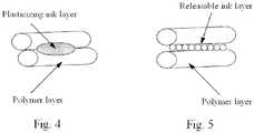
- an ink layermay be printed along the perimeter edge of a polymer layer.
- the ink layerincludes an ink that diffuses into the perimeter edge of the polymer layer.
- the perimeter ink layermay be printed on a polymer where the polymer includes a transparent or translucent polymeric material.
- the perimeter ink layer printed on a transparent or translucent polymermay create an optical illusion such that it appears the ink layer extends into the polymer layer.
- an additional polymeric layermay be applied to the perimeter of the ink layer, thereby providing protection from delamination or scratching, where the polymeric material may include a transparent or translucent polymeric material.
- the three-dimensional fabrication methodmay be utilized in certain embodiments to optically align the three-dimensional fabrication apparatus.
- an ink layer patternsuch as, for example, a target pattern, is printed on one or several layers of a sacrificial three-dimensional object or innocuously printed on any three-dimensional object.
- the ink layer patternis scanned with an optical sensor and the results of an optical alignment test are used to position the print head and ink jet delivery system as well as the extruder relative to the three-dimensional object.
- a layer of polymermay be deposited fully prior to a layer of ink being printed onto the layer of polymer.
- a layer of inkmay be printed onto the same layer of polymer.
- a first portion of at least one ink layermay include a first ink and a second portion of the at least one ink layer may include a second ink.
- a first portion of at least one polymer layermay include a first polymeric material and a second portion of the at least one polymeric layer may include a second polymeric material.
- FIG. 3A schematic of a three-dimensional fabrication process is provided in Figure 3 .
- An ink layeris formed on a polymer layer by having print head and ink delivery system 54 deposit ink droplets 52, optionally including dyes or pigments, onto polymer 56.
- Ink droplets 52form interaction area 58 where the ink contacts polymer 56.
- a support structureis formed adjacent to, or attached to, a three-dimensional object during the three-dimensional fabrication process.
- the three-dimensional apparatusis formed from a polymeric material.
- the deposition apparatusis used to form the support structure.
- a second deposition apparatusis used to form the support structure.
- the support structureis removable from the three-dimensional object.
- a releasable ink layeris printed between the three-dimensional object and the support structure, in some embodiments the releasable ink layer may be printed on the three-dimensional object only at the location where the support structure is attached. In certain embodiments the support structure may be broken into smaller pieces for removal.
- a polymeric material of the support structureis similar to, or in some embodiments is the same as, a polymeric material used to form the three- dimensional object.
- the support structure and/or the three-dimensional objectmay be formed of one or more polymeric materials.
- the support structuremay include a polymeric material that is a water soluble, solvent soluble, or alkali soluble polymer, such as, for example water soluble wax, polyethylene oxide and glycol-based polymers, polyvinyl pyrrolidone-based polymers, methyl vinyl ether, or maleic acid-based polymers.
- the support structuremay have an external ink layer.
- the external ink layerhas at least one ingredient that is soluble in a polymeric material included in the support structure.
- the at least one ingredient in the polymeric materialmay accelerate dissolution of the polymeric material.
- the at least one ingredientmay be, for example, low molecular weight compounds, such as, polyethylene glycols, polypropylene glycols, polyalkylene glycols, or polyethylene oxide.
- the at least one ingredient in the polymeric materialcauses the external ink layer to dissolve prior to the dissolution of the polymeric material of the support structure.
- the at least one ingredientmay be, for example, salts such as potassium chloride, potassium oxalate, or sodium citrate, low molecular weight water soluble polymers such as polyvinyl alcohols, or polyethylene oxides or water soluble organic compounds such as dimethyl urea, or propylene glycol.
- saltssuch as potassium chloride, potassium oxalate, or sodium citrate
- low molecular weight water soluble polymerssuch as polyvinyl alcohols, or polyethylene oxides or water soluble organic compounds such as dimethyl urea, or propylene glycol.
- At least one of the polymer layersmay include a polymeric material, such as, for example, acrylonitrile butadiene styrene (“ABS”), polyacrylates, polyolefins, cyclic olefin polymers and copolymers, polycarbonates, polyamides, polyimides, polyethylene and polybutylene terephthalate, liquid crystal polymer resins ("LCP”), polyether ether ketone (“PEEK”), thermoplastic elastomers (“TPE”), polystyrenes, polyvinyl chloride, polysulfones, polyacrylates, polyurethanes, polyamides, polyesters, polyolefins, epoxy resins, silicon resin, a diallyl phthalate resin, a cellulosic plastic, a rosin-modified maleic acid resin, copolymers thereof, any- other macromolecular structure, and combinations thereof.
- ABSacrylonitrile butadiene styrene
- the polymeris acrylonitrile butadiene styrene.
- the polymer layermay include a biocompatible or biodegradable polymeric material, such as, for example, collagen, elastin, hydrogels, xerogels, proteins, peptides, or a combination of any of them.
- the polymer layermay include a synthetic polymer, such as, for example, polycaprolactone ("PCL”), poly(D,L-lactide-co-glycolide) (“PLGA”), polylactide (“PLA”), poly(lactide-co-caprolactone) (“PLCL”), or a combination of any of them.
- the first polymer layeris wetted by application of the first ink layer.
- the ink of the first ink layeris a plasticizing or soluble ink that may be diffused into the first polymer layer(s).
- the polymer and ink layersmay be treated with plasma or corona discharge, in some embodiments the layers may be treated by passing the source of the discharge above the surface of the layers at, for example, a 1-5 mm distance.
- the print head and ink delivery system of the printing apparatusprints an ink layer.
- at least one of the ink layersincludes an ink having, for example, dyes, pigments, and/or catalysts.
- the inkis a color ink.
- the catalystsmay be electroless metallization catalysts.
- the electroless metallizationmay be, for example, a salt, or an organometallic complex of palladium, ruthenium, platinum, silver, osmium, iridium, or cobalt. In some embodiments other metals of Groups 8, 9, 10, and 11 of the Chemical Periodic Table are within the scope of this invention.
- the inkmay include an electroless metallization catalyst that is silver or palladium.
- the ink, the polymeric material, or both the ink and the polymeric materialmay include an active ingredient.
- the active ingredientmay be, for example, an active pharmaceutical ingredient or a cell culture.
- an active pharmaceutical ingredientmay be, for example, an anti-inflammatory ingredient, such as, for example, corticosteroids, diclofenac sodium, aspirin, ibuprofen, or acetaminophen; an ingredient inhibiting neointimal growth, such as, for example, everolimus, paclitaxel, or zotarolimus; an anticoagulant, such as, warfarin, heparin, fondaparinux, ximelagatran, or batroxobin; an immunosuppressive ingredient, such as, for example, cyclosporin, tacrolimus, sirolimus, or mycophenolic acid; an antibody, such as, for example, monoclonal anti-IL-2R ⁇ receptor antibodies, polyclonal anti-T-cell antibodies, anti
- a cell culturemay include, for example, stern cells, cartilage cells, bone cells, muscle cells, skin cells, pancreas cells, kidney cells, liver cells, nerve cells, or a combination of any of them.
- a cell culturemay be a live cell culture.
- a single ink or polymer layer having an active ingredientmay be printed/deposited.
- a number of ink or polymer layersmay be printed in a row. It is currently understood that by varying the number of ink or polymer layers having an active ingredient, the concentration and/or amount of the active ingredient on the three-dimensional object may be varied.
- an ink layeris formed utilizing an ink including a cell culture on a polymer layer formed utilizing a biocompatible or biodegradable polymer.
- an ink layer formed utilizing an ink including a cell culturemay form live tissue on a biocompatible or biodegradable polymer. In certain embodiments the live tissue will correspond to the type of cells in the ceil culture.
- the inkmay have a viscosity within the range of 10 -3 Pa ⁇ s to 2x10 -1 Pa ⁇ s (1 to 150 cps), within the range of 10 -3 Pa ⁇ s to 5x10 -2 Pa ⁇ s (1 to 50 cps), or within the range of 10 -3 Pa ⁇ s to 2x10 -2 Pa ⁇ s (1 to 22 cps), at a temperature of 25°C.
- the inkmay have a surface tension within the range of 0.018 - 0.072 N/m (18 to 72 dynes/cm), within the range of 0.02 - 0.04 N/m (20 to 40 dynes/cm), or within the range of 0.022 - 0.033 N/m (22 to 33 dynes/cm), at a temperature of 25°C.
- the inkmay be individually selected based on the solubility parameter of the ink and the solubility parameter of the polymer of the three- dimensional object.
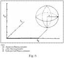
- solubility parametersalso known as Hildebrand solubility parameters ( ⁇ ) and Hansen solubility parameters
- ⁇the energy of dispersion bonds
- ⁇ pdipole-dipole intermolecular force
- ⁇ hhydrogen bonding
- the Hansen solubility parameters of the two materialsmay be used to determine if one material will dissolve in the other, such as a polymer into a solvent or an ink.
- a value called an interaction radius (Ro)is given to the material to be dissolved.
- the interaction radius of the material to be dissolved, such as a polymermay define a sphere in Hansen space. If the second material, such as an ink, is within the sphere defined by the interaction radius then the polymer may be considered to dissolve into the ink.
- D(I-P)is the distance between the ink and the center of the polymer solubility sphere
- ⁇ x iis the Hansen component (as defined above) for an ink
- ⁇ xpis the Hansen component (as defined above) for the polymer.
- a specific inkmay be selected based on its solubility interaction with the specific polymer utilized for the three-dimensional object.
- the solubility of the ink in the polymermay be enhanced by utilizing heat or energy sources.
- enhanced solubility in the inkprovides additional benefits, including, for example, enhancing the drying characteristics of the ink.
- the heat sourcemay be, for example, conventional heat, conduction, radiant, or combinations thereof.
- the heat or energy sourceis applied after the three-dimensional object is fabricated.
- the heat or energy sourceis applied during fabrication of the three-dimensional object.
- the energy sourcemay be an electromagnetic energy source.
- the electromagnetic energy sourcemay be, for example, infrared, near infrared, visible, radiofrequency, microwave, or combinations thereof.
- many polymers and inksare transparent in the visible to infrared range, but in certain embodiments the polymer may be supplemented with pigments, dyes, or electroless metallization catalysts that may absorb energy in the same range, thus increasing process efficiency.
- various infrared, near infrared, visible energy, microwave, or radiofrequency absorbersmay be used to supplement the ink.
- the inkmay have a solubility parameter that falls within the radius of interaction, as defined by Equation 2. Inks that have a solubility parameter that fall within the radius of interaction are referred to here as plasticizing inks.
- a plasticizing inkmay be utilized to provide a color coating or shell, to deliver a functional coating, or to improve surface quality of a three- dimensional polymer object.
- the plasticizing inkfurther includes functional additives including, for example, electroless metallization or other catalysts, antimicrobial agents, or release additives.
- the plasticizing inkprovides a coating to a three-dimensional polymer object that may be cured.
- the coatingis a UV curable coating.
- the curable coatingmay create a smoother surface on the three-dimensional polymer object by filling in any gaps in an untreated surface of the object.
- three-dimensional polymer objectsformed with a polymer and a plasticizing ink by the method according to the invention, may be used to produce models for investment casting, also known as lost-wax casting. It is currently understood that in certain embodiments the plasticizing ink allows for a cleaner burnout process during the casting.
- a first portion of at least one of the ink is layersis formed utilizing a plasticizing ink and a second portion of the ink layer is formed utilizing a second plasticizing ink that has a higher concentration of plasticizer than the first ink.
- a difference in the amount of plasticizer in two different inkscan cause a different in the surface or material properties of the ink layer.
- a three-dimensional object formed utilizing a plasticizing ink having a high concentration of plasticizermay exhibit an increased flexibility as compared to a three-dimensional object formed utilizing an ink that is not a plasticizing ink.
- a plasticizing inkcreates a smooth surface on a three- dimensional object. It is currently understood that the plasticizing ink dissolves a portion of the surface of a polymer layer thereby creating a smoother surface.
- the print head and ink delivery systemincludes an ink that has a solubility parameter that falls outside the radius of interaction, as defined by Equation 2.
- Inks that have a solubility parameter that fall outside the radius of interactionare referred to here as releasing inks.
- releasing inksmay be utilized to aid in releasing a support structure from a three-dimensional polymer object.
- releasing inksmay provide a shell on a three-dimensional object.
- the releasing inksmay further include, for example, dyes, pigments, or catalysts to be utilized in forming the shell.
- the shellmay be a color shell.
- a fixing liquidmay be any liquid or solution with a solubility parameter within the radius of interaction as defined by Equation 2.
- the fixing process of the color shell on the three-dimensional objectmay be accelerated by application of, for example, heat, light, or electromagnetic energy.
- any volatile componentsmay be evaporated with or without a vacuum.
- an ink utilized in the three-dimensional fabrication methodmay have a low binding affinity to the specific polymer that is being utilized to form a three-dimensional object thereby resulting in low adhesion of the ink to the polymer.
- the inkis printed onto the polymer to form a color shell, at least one final layer of polymer may be deposited onto the color shell to assist in retaining the ink on the three-dimensional object.
- the polymer for the final layermay be, for example, transparent or translucent, and may be selected from the group having acrylates, methacrylates, polycarbonates, poly (acrylonitrile butadiene styrene), polyesters, transparent polyamides, cycloaliphatic olefins polymers and copolymers, styrene acrylonitrile polymer, polyvinyl chloride, epoxies.
- a reflective or opaque ink layermay be printed onto the polymer prior to printing the color shell.
- the low adhesion inksmay be printed on the polymer of the three-dimensional object to form an outer color shell and the color shell may then be sprayed with a permanent transparent lacquer to form a coating of lacquer on the color shell.
- the lacquermay, for example, protect the outer color shell of the three-dimensional object.
- the lacquermay be, for example, a fast drying solution of a polymer, such as a translucent or transparent polymer.
- the lacquermay be, for example, a solution of nitrocellulose in butyl acetate.
- the lacquermay be, for example, a fast curing, thermosetting, UV or IR curable resin.
- ABSacrylonitrile butadiene styrene
- the color coated ABS plateswere dipped in tetrahydrofuran, a volatile solvent. The plates were then placed in an oven at 60°C for 10 minutes. The plates were removed from the oven and the ASTM Standards D3359 Test was repeated. The results showed improved color adhesion to the ABS plates.
- Ink containing 99.8% Diisopropyl Adipate and 0.2% Zonlyl FSO surfactant (DuPont) and trace amount of black dye extracted from a Sharpie (rtm)were deposited with a fountain pen tip onto ABS plates and ABS 3-D objects produced from ABS on a Dimension 1200 ES (rtm) printer.
- the adhesion of the color patternswas tested with, and passed, the ASTM Standards D3359 Test Methods for Measuring Adhesion by Tape Test.
- Ink containing 99.8% propylene carbonate and 0.2% Zonlyl FSO surfactant (DuPont)was deposited with a fountain pen tip on a polybutylene terephthalate (“PBT") plate.
- PBTpolybutylene terephthalate
- a second PBT platewas placed on the color coated PBT plate and placed in an oven at 105°C. After 30 minutes the two PBT plates had adhered together. The adhesion of the two plates occurred at a temperature well below PBT's melting temperature of 223°C. The test was repeated with two uncoated PBT plates placed in the oven at 105°C. The plates did not adhere to one another.
- Dodecamethylpentasiloxane liquidwas deposited directly onto an ABS plate using a fountain pen tip.
- the coated ABS platewas then covered with a second, clean, ABS plate and clamped together.
- the two plateswere placed in an oven at 150°C for 35 minutes. Upon removing the plates from the oven, the two ABS plates were separated easily. The test was repeated with two clean ABS plates clamped together and placed in the oven at 150°C for 35 minutes. The two plates appeared to sinter to one another.
- Ink containing 1.5% by weight of palladium acetate in N-Methylpyrrolidonewas deposited with a fountain pen tip in a predetermined pattern onto a PBT plate.
- the coated platewas placed in an oven at 70°C for 10 minutes. After the coated PBT plate was removed from the oven, the patterned surface was treated with 2% borane dimethylamine complex (DMAB) aqueous solution for 2 minutes and then washed with distilled water.
- DMABborane dimethylamine complex
- the treated, coated PBT plateswere then submerged in electroless nickel plating solution (Caswell) at a temperature of 90°C for 25 minutes.
- the PBT platesdeveloped bright, electrically conductive metal deposits in the patterned area.
- a catalytic inkwas prepared by dissolving 1.0g of silver nitrate in 99ml of 40% w/w aqueous solution of tetrahydrofuran.
- the catalytic inkwas deposited in a predetermined pattern using a fountain tip pen onto the surface of the ABS plates.
- the patterned ABS plateswere then placed in an oven at 70°C for 15 minutes. After the ABS plates were removed from the oven, the patterned surface was treated with 2% borane dimethylamine complex (DMAB) aqueous solution for 2 minutes at 45°C and then washed with distilled water.
- DMAB2% borane dimethylamine complex
- the treated, coated ABS plateswere then submerged in electroless copper plating solution A (Table 1) at a temperature of 60°C for 15 minutes.
- ABS platesdeveloped bright, electrically conductive metal deposits in the patterned area.
- a Cannon Pixma IP 2702 (rtm) printerwas equipped with thermal Inkjet print heads.
- a color-patterned layerwas printed onto ABS plates that were 0,12 mm (5 mils) thick, and the adhesion of the color was tested utilizing ASTM Standards D3359 Test for Measuring Adhesion by Tape Test. The results showed that the adhesion of the color-patterned layer to the ABS plates was low.
- a color-patterned layerwas printed onto 0,12 mm (5 mils) thick ABS plates, and a second ABS plate was placed onto the printed color layer and the two plates were fused together using a hot electric iron.
- the image qualityappeared to be good on both sides of the ABS plates.
- the fused ABS plateswere subjected to excessive bending and adhesion testing using utilizing ASTM Standards D3359 Test for Measuring Adhesion by Tape Test. The image did not distort during the excessive bending and the showed good adhesion.
- a 0,12 mm (5 mils) thick ABS platewas spray coated with Krylon Flat (rtm) Spray Paint and subsequently dried.
- the Cannon Pixma IP 2702 (rtm) printer of example 7was then used to print a color-patterned layer onto a 5 mm thick untreated ABS plate.
- the color- patterned ABS platewas then placed with the color-patterned side face down on the spray coated ABS plate and sintered with a hot electric iron.
- the image quality of the color-patterned layerappeared more prominent and sharp than the image produced in Example 7.
- the Cannon Pixma IP 2702 (rtm) printer of example 7was used to print a color-patterned layer onto a 0,12 mm (5 mils) thick ABS plate. The image quality was good.
- the color- patterned side of the ABS platewas then spray coated with Krylon Crystal Clear (rtm) Acrylic and dried for one hour. After the treated ABS sheets had dried, they were subjected to excessive bending and adhesion testing using scotch tape. The image did not distort during the excessive bending and the showed good adhesion to the ABS plate.
- a fused deposition modeling machine for forming a three-dimensional objectwas assembled from the commercially available kit Rap Man USA version 3. (rtm). The machine was then equipped with an (rtm) evaluation kit, which allows for printing with a thermal Inkjet ("TO") printhead. The hardware and firmware of the machine was modified so that the TIJ printhead could be used to print ink layers during the layer-by-layer construction of the three-dimensional object. The TIJ printing was triggered by an optical limit switch attached to the X axis of the machine.
- a three-dimensional objectwas formed of PLA polymer, obtained from UltiMachine, South Pittsburg, TN, using the modified machine.
- the three-dimensional objectwas 20 X 20 X 6 mm and the individual layer thickness was 0.25 mm (24 layers).
- An image of a crosswas printed on the top layer (layer #24) of the three-dimensional PLA polymer object (rtm) black ink. The image was easily removed from the three-dimensional object with a paper towel.
- An image of a crosswas printed on one layer below the top layer (layer #23) of the three-dimensional PLA polymer object using HP 45 (rtm) ink.
- the imagewas sharp, had good contrast, and the integrity of the image did not change when the surface of the object was rubbed with a paper towel.
- the imagealso passed the ASTM Standards D3359 Test.
- An image of a crosswas printing on multiple layers (layers #3-23) of the three-dimensional PLA polymer object using HP 45 (rtm) ink.
- the imagewas positioned 0.25 mm from the perimeter edge of the three-dimensional object.
- the imagewas sharp, had good contrast, and integrity in both the XY and Z axes that did not change when the surface of the object was rubbed with a paper towel.
- the imagealso passed the A.STM Standards D3359 Test.
- a fused deposition modeling machine for forming three dimensional objectswas assembled from the commercially available kit Rap Man USA version 3.1.0 (rtm) The machine was then equipped with an HP 2.5 (rtm) evaluation kit, which allows for printing with a thermal Inkjet ("TIJ") printhead. The hardware and firmware of the machine was modified so that the TIJ printhead could be used to print ink layers during the layer-by-layer construction of a three-dimensional object. The TIJ printing was triggered by a linear encoder attached to the X axis of the machine.
Landscapes
- Engineering & Computer Science (AREA)
- Chemical & Material Sciences (AREA)
- Materials Engineering (AREA)
- Manufacturing & Machinery (AREA)
- Physics & Mathematics (AREA)
- Optics & Photonics (AREA)
- Mechanical Engineering (AREA)
- Health & Medical Sciences (AREA)
- Electromagnetism (AREA)
- Toxicology (AREA)
- Oral & Maxillofacial Surgery (AREA)
- Thermal Sciences (AREA)
Description
- This disclosure relates to a method and apparatus for fabricating three-dimensional objects from polymer-based material. In particular, this invention relates to a three-dimensional fabrication apparatus having a print head and ink delivery system.
- With the increased use of Computer Aided Design (CAD) solid modeling systems a new frontier of manufacturing technology has emerged that enables translation of the CAD output data into a three-dimensional physical object. This technology is commonly referred to as solid freeform fabrication or layer manufacturing, which entails building an object on a layer-by- layer and point-by-point basis. Examples of commercially available solid freeform fabrication systems include stereo lithography, selective laser sintering, laminated object manufacturing, and fused deposition modeling. Other examples of solid freeform fabrication systems are known to those of skill in the art.
- Forming objects automatically in three dimensions is useful in verifying CAD databases, assessing aesthetics, checking ergonomics of design, aiding in tool and fixture design, creating conceptual models and sales/marketing tools, generating patterns for investment casting, reducing or eliminating engineering changes in production, and providing small production runs.
US 6 165 406 A discloses a freeform fabrication process and apparatus for making a colorful 3-D object. The process includes (1) operating a multiple-channel droplet deposition device for supplying and, on demand, ejecting droplets of multiple liquid compositions containing a solidifiable baseline body-building material and different colorants; (2) providing a support platform a distance from this deposition device to receive the droplets therefrom; and (3) during the droplet ejecting process, moving the deposition device and the platform relative to one another in an X-Y plane and in a Z direction orthogonal to the X-Y plane so that the droplets are deposited to form multiple layers to build a colorful 3-D object.US 2010/195122 A1 discloses a method for printing a painted three-dimensional object. Each layer of the object is printed so that only the external circumference of the layer contains colored material. The building material used may be transparent, and a white colored material may be used as a barrier between the building material and the colored material.US 2004/251574 A1 discloses a method for producing an object formed through solid freeform fabrication includes dispensing a binder on successive layers of build material with a single first dispensing member; and coloring the successive layers with at least one second dispensing member, where the second dispensing member over-dispenses the first dispensing member.US 2007/108664 A1 discloses a process for chemically etching a stereolithography resin involves chemically etching a shaped object of the resin at a temperature in a range of from about 20°C to about 30°C for a time of from about 30 seconds to about 60 seconds with a saturated aqueous solution of permanganate.EP 1 925 428 A1 discloses a method and system for making a partially coated product having at least one coated area and at least one non-coated area.WO 98/09798 - Aspects of the invention are directed to fabrication of three-dimensional objects. The three-dimensional objects may have high-resolution color.
- The present invention provides a three-dimensional fabrication method comprising: (a) depositing a first polymer layer; (b) printing a first ink layer on to the first polymer layer; (c) depositing a second polymer layer on to the first ink layer; (d) printing a second ink layer on to the second polymer layer; and (e) repeating steps (a)-(d) to form a three-dimensional object, wherein at least one of the first and second ink layers includes an ink comprising electroless metallization catalysts.
- In certain embodiments the first and the second ink layer may each include a plurality of ink layers. In certain embodiments the first and second polymer layer may each include a plurality of polymer layers. In certain embodiments forming at least one of the first and second ink layers may include utilizing an ink further comprising at least one of pigments, dyes, and catalysts. In some embodiments the electroless metallization catalysts may be selected from the group including palladium, ruthenium, platinum, silver, osmium, iridium, and cobalt. In certain embodiments the electroless metallization catalyst is palladium or silver. In certain embodiments forming at least one of the first and second ink layers includes utilizing a color ink. In certain embodiments at least one of the first and second ink layers is deposited along a circumferential edge of at least one of the first and second polymer layers. In certain embodiments forming at least one of the first and second ink layers may include utilizing an ink that is selected based on its solubility parameter in relation to a polymer solubility parameter.
- In certain embodiments, forming at least one of the first and second polymer layers includes utilizing a polymeric material selected from acrylonitrile butadiene styrene, polyacrylates, polyolefins, cyclic olefin polymers and copolymers, polycarbonates, polyamides, polyimides, polyethylene and polybutylene terephthalate, liquid crystal polymer resins, poly ether ether ketone, thermoplastic elastomers, polystyrenes, polyvinyl chloride, polysulfones, polyurethanes, polyamides, polyesters, epoxy resins, silicon resin, a diallyl phthalate resin, a cellulosic plastic, a rosin-modified maleic acid resin, copolymers thereof, collagen, elastin, hydrogels, xerogels, polycaprolactone, poly(D,L-lactide-co-glycolide), polylactide, poly(lactide-co-caprolactone), or combinations thereof. In certain exemplary embodiments, forming at least one of the first and second polymer layers includes utilizing acrylonitrile butadiene styrene ("ABS").
- In some embodiments a support structure is formed adjacent to the three-dimensional object during the fabrication process. In certain embodiments the support structure may be removed from the three-dimensional object. In some embodiments a releasable ink layer may be printed between the three-dimensional object and the support structure. In certain embodiments forming the support structure may include utilizing a polymeric material that is similar to a polymeric material used to form the three-dimensional object. In some embodiments the polymeric material may be a water soluble, solvent soluble, or alkali soluble polymer. In some embodiments the support structure has an external ink layer that includes at least one ingredient that is soluble in a polymeric material included in the support structure. In certain embodiments the at least one ingredient accelerates dissolution of the polymeric material of the support structure, or in alternative embodiments, the at least one ingredient causes the external ink layer to dissolve prior to the dissolution of the polymeric material of the support structure.
- In certain embodiments an overcoat layer is applied to at least one of the first and second ink layers. In some embodiments the overcoat layer is a lacquer, in some embodiments the overcoat layer is applied to the three-dimensional object. In some embodiments the overcoat layer is a translucent or transparent polymeric material. In certain embodiments at least one of the first and second ink layers is treated with a heat source, an energy source, or combinations thereof. In some embodiments the heat source may be selected from the group having conventional, conduction, radiant, and combinations thereof. In some embodiments the energy source may be an electromagnetic energy source. In certain embodiments the electromagnetic energy source may be selected from the group having infrared, near infrared, visible, ultraviolet, radiofrequency, microwave, and combinations thereof. in some embodiments the printing of at least one of the first or second ink layers forms a target pattern that may be used to optical!)' align a three-dimensional printing apparatus.
- In certain embodiments at least one of the first and second ink layers includes a releasable ink or a plasticizing ink. In certain embodiments forming a first portion of at least one of the first and second ink layers includes utilizing a first ink and a second portion of at least one of the first and second ink layers is formed utilizing a second ink. In some embodiments the first ink is a plasticizing ink and the second ink is a plasticizing ink with a higher concentration of plasticizer than the first ink. In some embodiments the first ink and the second ink provide different surface properties between the first portion and the second portion of the ink layer. In some embodiments forming at least one of the first and second ink layers includes utilizing a plasticizing ink creating a smooth surface on the three-dimensional object. In certain embodiments forming at least one of the first and second ink layers includes utilizing an ink comprising at least one ingredient that is soluble in the first and second polymer layer. In certain embodiments forming at least one of the first and second ink layers includes utilizing an ink comprising an active ingredient. In some embodiments the active ingredient may be a pharmaceutical ingredient including an anti-inflammatory ingredient, an ingredient inhibiting neointimal growth, an anticoagulant, an antibody, an immunosuppressive ingredient, chemotherapeutic drugs, or combinations thereof. In alternative embodiments the active ingredient may be a cell culture including stem cells, cartilage cells, bone cells, muscle cells, skin cells, pancreas cells, kidney cells, liver cells, nerve cells, or combinations thereof.
- In an aspect not claimed in the present patent, there is provided a three-dimensional fabrication apparatus including: (a) a polymer deposition apparatus; and (b) a printing apparatus including a print head and ink delivery system. In certain examples the printing apparatus may be attached to the polymer deposition apparatus. In certain examples the polymer deposition apparatus includes an extruder and the print head and ink delivery system is attached to the extruder. In alternative examples the polymer deposition apparatus includes an extruder and the print head and ink delivery system is attached to the polymer deposition apparatus separate from the extruder.
- In certain examples the polymer deposition apparatus is selected from the group having a fusion deposition modeling apparatus, a laminated object manufacturing apparatus, and a photopolymer three-dimensional deposition apparatus. In certain examples the print head and ink delivery system includes a print head selected from the group including a thermal print head, a piezo print head, a MEMS print head, and an electrostatic print head. In certain embodiments the print head and ink delivery system includes a print head selected from the group having a plotter-style single nozzle unit, a continuous ink jet, and a drop-on demand system.
- In an aspect not claimed in the present patent, there is provided a method for selecting an ink for three-dimensional fabrication of a three-dimensional object including: (a) selecting a polymer; (b) calculating the polymer's Hansen solubility parameter; (c) selecting an ink; (d) calculating the ink's Hansen solubility parameter; (e) comparing the polymer's Hansen solubility parameter to the ink's Hansen solubility parameter to determine if the ink would be a releasable ink or a plasticizing ink; and (f) utilizing the polymer and the ink to form a three-dimensional object by three-dimensional fabrication.
- In an aspect not claimed in the present patent, there is provided a method including (a) depositing a first polymer layer to form a three-dimensional object; (b) printing an ink layer on to the three-dimensional object to form a shell. In certain examples the three-dimensional fabrication method further includes depositing at least one second polymer layer on to the shell. In certain examples the second polymer layer is formed utilizing a translucent or transparent polymeric material.
- These and other aspects, along with advantages and features of the present invention here disclosed, will become apparent through reference to the following detailed description. Furthermore, it is to be understood that the features of the various embodiments described here are not mutually exclusive and can exist in various combinations and permutations.
- In the drawings, like reference characters generally refer to the same parts throughout the different views. Also, the drawings are not necessarily to scale, emphasis instead generally being placed upon illustrating the principles of the invention. In the following description, various embodiments of the present invention are described with reference to the following drawings, in which:
Figure 1 depicts a schematic configuration of a prior art Filament Deposition Modeling apparatus.Figure 2 depicts a schematic configuration of a fabrication apparatus according to an aspect of the present invention.Figure 3 depicts a schematic configuration of a fabrication process according to an aspect of the present invention.Figure 4 depicts a schematic representation of a plasticizing ink between two polymer layers.Figure 5 depicts a schematic representation of a releasable ink between two polymer layers.Figure 6 depicts a graphic representation of the interaction of an ink and a polymer as defined by the equation D(I-P) = [4(δdi - δdp)2 + (δpi - δpp)2 + (δhi - δhp)2]0.5- It would be desirable to provide a three-dimensional manufacturing method that is able to produce a variety of three-dimensional objects. At least certain of the embodiments of the new method can provide high-resolution color manipulating capabilities. At least certain of the embodiments of the new method and apparatus can provide functional three-dimensional objects. Additional features and advantages of some or all of the three-dimensional manufacturing methods disclosed here will be apparent to those who are skilled in three-dimensional manufacturing given the benefit of the following summary and description of exemplary, non-limiting examples.
- The present invention provides a method for fabricating a three- dimensional object.
- As used here, "three-dimensional fabrication" is used to refer to the method of building a three-dimensional object layer-by-layer. Three-dimensional fabrication refers to the combination of depositing at least one layer of a polymer and printing at least one layer of an ink to form a three-dimensional object. As used here, a "layer" is formed by a single pass of a deposition apparatus or a printing apparatus. In some embodiments the at least one polymer layer and at least one ink layer may be deposited and printed in any order. For example, in certain embodiments, multiple polymer layers may be deposited prior to an ink layer being printed. In alternative embodiments the polymer and ink layers may alternate by individual or multiple layers. Various deposition methods are known in the art, including, but not limited to, fused deposition modeling, laminated object manufacturing, stereo lithography, and selective laser sintering.
- For example, the invention may be performed with a three-dimensional deposition apparatus, such as that used for fused deposition modeling, including an extruder assembly that dispenses a polymer. In some embodiments the polymer forms a three-dimensional object in a layer-by-layer process on a build platform. In some embodiments once the build of the three-dimensional object is complete, the object may be removed from the build platform and a new project may begin. In certain embodiments the extruder assembly may be stationary, or may allow for movement in the XY axes, for movement in the X axis or Y axis only, and/or for rotational or angular movements. In certain embodiments the build platform generally has indexed movement options in the Z axis. In alternative embodiments other movements may also be provided. In certain embodiments each movement in the Z axis may correspond to a specific layer thickness for the manufacture of a three-dimensional object. In addition, in certain embodiments the build platform may allow for optional movement in the XY axes, for movement in the X axis or Y axis only, and/or for rotational or angular movements.
- A known fused deposition modeling apparatus is shown in
Figure 1 .Extruder assembly 12 dispensespolymer 14 ontobuild platform 18, in a layer-by-layer process, to form three-dimensional object 16. Once three-dimensional object 16 is completed it may be removed frombuild platform 18 and a new project may begin. - In certain examples, a three-dimensional fabrication apparatus includes a deposition apparatus and a printing apparatus. In some embodiments the deposition apparatus may be similar to that used for fused deposition examples. In some examples the deposition apparatus includes an extruder assembly that dispenses a polymer. In certain examples the polymer forms a three-dimensional object in a layer-by- layer process on a build platform. In certain examples the printing apparatus includes a print head and ink delivery system for depositing various inks during production of any three-dimensional objects using the three-dimensional fabrication apparatus. In some examples the extruder head may be stationary, or may allow for movement in the XY axes, for movement in the X axis or Y axis only, and/or for rotational or angular movements. In certain examples the build platform generally has indexed movement options in the Z axis. Additionally, in certain examples the build platform may allow for optional movement in the XY axes, for movement in the X axis or Y axis only, and/or for rotational or angular movements.
- In some embodiments, as the three-dimensional object is fabricated, the print head and ink delivery system may deposit inks in a layer-by-layer fashion. In certain embodiments the inks may be color inks and/or functional inks. In certain embodiments the print head and ink delivery system may be stationary, or in alternative embodiments, may allow for movement in the XY axes, for movement in the X axis or Y axis only, and/or for rotational or angular movements. In certain embodiments the printing of the inks may be triggered by an optical limit switch or a linear encoder.
- A schematic of a three-dimensional fabrication apparatus, including a deposition apparatus similar to that used for fused deposition modeling and a printing apparatus having a print head and ink delivery system, is provided in
Figure 2 . A three-dimensional fabrication apparatus includesextruder assembly 32 that dispensespolymer 34, in a layer-by-layer process, to form three-dimensional object 36 onbuild platform 38. In addition, the fabrication apparatus includes print head andink delivery system 40, which dispenses ink on three-dimensional object 36, in a layer- by-layer process, during the build process. - In certain examples, the printing apparatus having the print head and ink delivery system is attached to the same mechanism as the deposition apparatus having the extruder, such that it travels with the deposition apparatus. In alternative examples the printing apparatus is attached to an independent moving or stationary mechanism that is attached to the three-dimensional fabrication apparatus. In alternative examples the printing apparatus is aligned with the deposition apparatus, but not attached to the deposition apparatus. In certain examples the printing apparatus includes a print head(s) that may be, for example, a piezoelectric print head, a thermal print head, a MEMS print head, an electrostatic print head, or combinations thereof. In alternative examples the printing apparatus includes a print head that may be a plotter type single nozzle unit, a continuous ink jet, or a drop on demand system. In certain examples the print head of the printing apparatus may be positioned at any angle within the range of +45 to -45 degrees relative to the extruder of the deposition apparatus.
- In alternative examples printing apparatus is paired with any solid freeform fabrication apparatus that builds three-dimensional polymer objects by utilizing a layer-by-layer build process. Non-limiting examples of such apparatuses include a laminated object manufacturing apparatus or a three-dimensional photopolymer apparatus.
- The invention provides a three-dimensional fabrication method including depositing a first polymer layer, printing a first ink layer on to the first polymer layer, depositing a second polymer layer on to the first ink layer, and printing a second ink layer on to the second polymer layer. In some embodiments the fabrication process may be repeated until a completed three-dimensional object is formed. In certain embodiments the first and second polymer layer may each include a plurality of polymer layers. The plurality of polymer layers forming a first (or second) polymer layer need not all be formed of the same polymer, but may include one or more distinct polymers. In certain embodiments the first and second ink layer may each include a plurality of ink layers. The plurality of ink layers forming a first (or second) ink layer need not all be formed of the same ink, but may include one or more distinct inks. In certain embodiments the polymer layers and ink layers may be deposited in varying number and in varying order when fabricating a three- dimensional object. Further, the polymer layers and/or the ink layers need not extend completely over the previously deposited layer. In some instances, an ink layer may be deposited only over a portion of the previously deposited polymer (or ink) layer. For example, an ink layer may be encapsulated between two surrounding polymer layers. In certain embodiments the printing or depositing of one layer onto another may cause the two layers to bind to one another. In some embodiments the binding of one layer to another means the layers do not separate from one another during the build process. In some embodiments an ink layer printed between two polymer layers may have at least one ingredient that is soluble in the polymeric material of the two polymer layers and causes a bond to form between the two polymer layers in binding to one another. In certain embodiments an ink layer may be printed on a completed three-dimensional object to form a coating. In certain embodiments the coating may act as a shell having a thickness of, for example, 0.01-5 mm. In certain embodiments an overcoat layer may be applied to an ink layer. In some embodiments the overcoat layer may be a lacquer, and in alternative embodiments, may be a translucent or transparent polymer.
- In certain embodiments an ink layer may be printed along the perimeter edge of a polymer layer. In some embodiments the ink layer includes an ink that diffuses into the perimeter edge of the polymer layer. In certain embodiments the perimeter ink layer may be printed on a polymer where the polymer includes a transparent or translucent polymeric material. In some embodiments the perimeter ink layer printed on a transparent or translucent polymer may create an optical illusion such that it appears the ink layer extends into the polymer layer. In certain embodiments an additional polymeric layer may be applied to the perimeter of the ink layer, thereby providing protection from delamination or scratching, where the polymeric material may include a transparent or translucent polymeric material.
- The three-dimensional fabrication method may be utilized in certain embodiments to optically align the three-dimensional fabrication apparatus. In certain embodiments an ink layer pattern, such as, for example, a target pattern, is printed on one or several layers of a sacrificial three-dimensional object or innocuously printed on any three-dimensional object. In some embodiments the ink layer pattern is scanned with an optical sensor and the results of an optical alignment test are used to position the print head and ink jet delivery system as well as the extruder relative to the three-dimensional object.
- In certain embodiments a layer of polymer may be deposited fully prior to a layer of ink being printed onto the layer of polymer. In alternative embodiments while the polymer is in the process of being deposited, a layer of ink may be printed onto the same layer of polymer. In some embodiments a first portion of at least one ink layer may include a first ink and a second portion of the at least one ink layer may include a second ink. In certain embodiments a first portion of at least one polymer layer may include a first polymeric material and a second portion of the at least one polymeric layer may include a second polymeric material.
- A schematic of a three-dimensional fabrication process is provided in
Figure 3 . An ink layer is formed on a polymer layer by having print head andink delivery system 54deposit ink droplets 52, optionally including dyes or pigments, ontopolymer 56.Ink droplets 52form interaction area 58 where theink contacts polymer 56. - In certain embodiments a support structure is formed adjacent to, or attached to, a three-dimensional object during the three-dimensional fabrication process. In certain embodiments the three-dimensional apparatus is formed from a polymeric material. In some embodiments the deposition apparatus is used to form the support structure. In alternative embodiments a second deposition apparatus is used to form the support structure. In certain embodiments the support structure is removable from the three-dimensional object. In certain embodiments a releasable ink layer is printed between the three-dimensional object and the support structure, in some embodiments the releasable ink layer may be printed on the three-dimensional object only at the location where the support structure is attached. In certain embodiments the support structure may be broken into smaller pieces for removal.
- In certain embodiments a polymeric material of the support structure is similar to, or in some embodiments is the same as, a polymeric material used to form the three- dimensional object. The support structure and/or the three-dimensional object may be formed of one or more polymeric materials. In some embodiments the support structure may include a polymeric material that is a water soluble, solvent soluble, or alkali soluble polymer, such as, for example water soluble wax, polyethylene oxide and glycol-based polymers, polyvinyl pyrrolidone-based polymers, methyl vinyl ether, or maleic acid-based polymers.
- In some embodiments the support structure may have an external ink layer. In certain embodiments the external ink layer has at least one ingredient that is soluble in a polymeric material included in the support structure. In some embodiments the at least one ingredient in the polymeric material may accelerate dissolution of the polymeric material. In certain embodiments the at least one ingredient, may be, for example, low molecular weight compounds, such as, polyethylene glycols, polypropylene glycols, polyalkylene glycols, or polyethylene oxide. In alternative embodiments the at least one ingredient in the polymeric material causes the external ink layer to dissolve prior to the dissolution of the polymeric material of the support structure. In some embodiments the at least one ingredient, may be, for example, salts such as potassium chloride, potassium oxalate, or sodium citrate, low molecular weight water soluble polymers such as polyvinyl alcohols, or polyethylene oxides or water soluble organic compounds such as dimethyl urea, or propylene glycol.
- In certain embodiments at least one of the polymer layers may include a polymeric material, such as, for example, acrylonitrile butadiene styrene ("ABS"), polyacrylates, polyolefins, cyclic olefin polymers and copolymers, polycarbonates, polyamides, polyimides, polyethylene and polybutylene terephthalate, liquid crystal polymer resins ("LCP"), polyether ether ketone ("PEEK"), thermoplastic elastomers ("TPE"), polystyrenes, polyvinyl chloride, polysulfones, polyacrylates, polyurethanes, polyamides, polyesters, polyolefins, epoxy resins, silicon resin, a diallyl phthalate resin, a cellulosic plastic, a rosin-modified maleic acid resin, copolymers thereof, any- other macromolecular structure, and combinations thereof. In certain embodiments the polymer is acrylonitrile butadiene styrene. In certain embodiments the polymer layer may include a biocompatible or biodegradable polymeric material, such as, for example, collagen, elastin, hydrogels, xerogels, proteins, peptides, or a combination of any of them. In some embodiments the polymer layer may include a synthetic polymer, such as, for example, polycaprolactone ("PCL"), poly(D,L-lactide-co-glycolide) ("PLGA"), polylactide ("PLA"), poly(lactide-co-caprolactone) ("PLCL"), or a combination of any of them.
- In certain embodiments the first polymer layer is wetted by application of the first ink layer. In certain embodiments the ink of the first ink layer is a plasticizing or soluble ink that may be diffused into the first polymer layer(s). In certain embodiments to obtain improved wetting characteristics, the polymer and ink layers may be treated with plasma or corona discharge, in some embodiments the layers may be treated by passing the source of the discharge above the surface of the layers at, for example, a 1-5 mm distance.
- In certain embodiments the print head and ink delivery system of the printing apparatus prints an ink layer. In certain embodiments at least one of the ink layers includes an ink having, for example, dyes, pigments, and/or catalysts. In some embodiments the ink is a color ink. In certain embodiments the catalysts may be electroless metallization catalysts. In certain embodiments the electroless metallization may be, for example, a salt, or an organometallic complex of palladium, ruthenium, platinum, silver, osmium, iridium, or cobalt. In some embodiments other metals of Groups 8, 9, 10, and 11 of the Chemical Periodic Table are within the scope of this invention. In certain embodiments the ink may include an electroless metallization catalyst that is silver or palladium.
- In some embodiments the ink, the polymeric material, or both the ink and the polymeric material may include an active ingredient. In some embodiments the active ingredient may be, for example, an active pharmaceutical ingredient or a cell culture. In certain embodiments an active pharmaceutical ingredient, may be, for example, an anti-inflammatory ingredient, such as, for example, corticosteroids, diclofenac sodium, aspirin, ibuprofen, or acetaminophen; an ingredient inhibiting neointimal growth, such as, for example, everolimus, paclitaxel, or zotarolimus; an anticoagulant, such as, warfarin, heparin, fondaparinux, ximelagatran, or batroxobin; an immunosuppressive ingredient, such as, for example, cyclosporin, tacrolimus, sirolimus, or mycophenolic acid; an antibody, such as, for example, monoclonal anti-IL-2Rα receptor antibodies, polyclonal anti-T-cell antibodies, anti-thymocyte globulin ("ATG"), or anti-lymphocyte globulin ("ALG"); or chemotherapeutic drugs, such as, for example, alkylating agents, antimetabolites, plant alkaloids, or topoisomerase inhibitors; or a combination of any of them. In some embodiments a cell culture may include, for example, stern cells, cartilage cells, bone cells, muscle cells, skin cells, pancreas cells, kidney cells, liver cells, nerve cells, or a combination of any of them. In some embodiments a cell culture may be a live cell culture.
- In some embodiments a single ink or polymer layer having an active ingredient may be printed/deposited. In alternative embodiments a number of ink or polymer layers may be printed in a row. It is currently understood that by varying the number of ink or polymer layers having an active ingredient, the concentration and/or amount of the active ingredient on the three-dimensional object may be varied. In certain embodiments an ink layer is formed utilizing an ink including a cell culture on a polymer layer formed utilizing a biocompatible or biodegradable polymer. In some embodiments an ink layer formed utilizing an ink including a cell culture may form live tissue on a biocompatible or biodegradable polymer. In certain embodiments the live tissue will correspond to the type of cells in the ceil culture.
- In certain embodiments the ink may have a viscosity within the range of 10-3 Pa·s to 2x10⁻¹ Pa·s (1 to 150 cps), within the range of 10-3 Pa·s to 5x10⁻² Pa·s (1 to 50 cps), or within the range of 10-3 Pa·s to 2x10⁻² Pa·s (1 to 22 cps), at a temperature of 25°C. In certain embodiments the ink may have a surface tension within the range of 0.018 - 0.072 N/m (18 to 72 dynes/cm), within the range of 0.02 - 0.04 N/m (20 to 40 dynes/cm), or within the range of 0.022 - 0.033 N/m (22 to 33 dynes/cm), at a temperature of 25°C.
- In certain embodiments the ink may be individually selected based on the solubility parameter of the ink and the solubility parameter of the polymer of the three- dimensional object. It is currently understood that solubility parameters, also known as Hildebrand solubility parameters (δ) and Hansen solubility parameters, are a result of various intermolecular forces, including the energy of dispersion bonds (δd), dipole-dipole intermolecular force (δp), and hydrogen bonding (δh). Specific Hildebrand solubility parameters may be calculated using the equation:

- If two materials have similar Hildebrand solubility parameters it is likely that they will be able to interact with each other. In some embodiments the Hansen solubility parameters of the two materials may be used to determine if one material will dissolve in the other, such as a polymer into a solvent or an ink. A value called an interaction radius (Ro) is given to the material to be dissolved. The interaction radius of the material to be dissolved, such as a polymer, may define a sphere in Hansen space. If the second material, such as an ink, is within the sphere defined by the interaction radius then the polymer may be considered to dissolve into the ink. The sphere is defined by the equation:

- In certain embodiments a specific ink may be selected based on its solubility interaction with the specific polymer utilized for the three-dimensional object. In some embodiments the solubility of the ink in the polymer may be enhanced by utilizing heat or energy sources. In certain embodiments enhanced solubility in the ink provides additional benefits, including, for example, enhancing the drying characteristics of the ink. In certain embodiments the heat source may be, for example, conventional heat, conduction, radiant, or combinations thereof. In certain embodiments the heat or energy source is applied after the three-dimensional object is fabricated. In alternative embodiments the heat or energy source is applied during fabrication of the three-dimensional object. In alternative embodiments, for example, the energy source may be an electromagnetic energy source. In certain embodiments the electromagnetic energy source may be, for example, infrared, near infrared, visible, radiofrequency, microwave, or combinations thereof. Many polymers and inks are transparent in the visible to infrared range, but in certain embodiments the polymer may be supplemented with pigments, dyes, or electroless metallization catalysts that may absorb energy in the same range, thus increasing process efficiency. Additionally, in certain embodiments, various infrared, near infrared, visible energy, microwave, or radiofrequency absorbers may be used to supplement the ink.
- In certain embodiments the ink may have a solubility parameter that falls within the radius of interaction, as defined by Equation 2. Inks that have a solubility parameter that fall within the radius of interaction are referred to here as plasticizing inks. In certain embodiments a plasticizing ink may be utilized to provide a color coating or shell, to deliver a functional coating, or to improve surface quality of a three- dimensional polymer object. In certain embodiments the plasticizing ink further includes functional additives including, for example, electroless metallization or other catalysts, antimicrobial agents, or release additives. In certain embodiments the plasticizing ink provides a coating to a three-dimensional polymer object that may be cured. In certain embodiments the coating is a UV curable coating. In some embodiments the curable coating may create a smoother surface on the three-dimensional polymer object by filling in any gaps in an untreated surface of the object.
- In certain embodiments three-dimensional polymer objects, formed with a polymer and a plasticizing ink by the method according to the invention, may be used to produce models for investment casting, also known as lost-wax casting. It is currently understood that in certain embodiments the plasticizing ink allows for a cleaner burnout process during the casting.
- In certain embodiments a first portion of at least one of the ink is layers is formed utilizing a plasticizing ink and a second portion of the ink layer is formed utilizing a second plasticizing ink that has a higher concentration of plasticizer than the first ink. In some embodiments a difference in the amount of plasticizer in two different inks can cause a different in the surface or material properties of the ink layer. In some embodiments a three-dimensional object formed utilizing a plasticizing ink having a high concentration of plasticizer may exhibit an increased flexibility as compared to a three-dimensional object formed utilizing an ink that is not a plasticizing ink. In certain embodiments a plasticizing ink creates a smooth surface on a three- dimensional object. It is currently understood that the plasticizing ink dissolves a portion of the surface of a polymer layer thereby creating a smoother surface.
- In alternative examples the print head and ink delivery system includes an ink that has a solubility parameter that falls outside the radius of interaction, as defined by Equation 2. Inks that have a solubility parameter that fall outside the radius of interaction are referred to here as releasing inks. In certain embodiments releasing inks may be utilized to aid in releasing a support structure from a three-dimensional polymer object. In alternative embodiments releasing inks may provide a shell on a three-dimensional object. In some embodiments the releasing inks may further include, for example, dyes, pigments, or catalysts to be utilized in forming the shell. In certain embodiments the shell may be a color shell. In certain embodiments three- dimensional objects with a color shell of releasing ink may be treated with a fixing liquid, in certain embodiments a fixing liquid may be any liquid or solution with a solubility parameter within the radius of interaction as defined by Equation 2. In certain embodiments the fixing process of the color shell on the three-dimensional object may be accelerated by application of, for example, heat, light, or electromagnetic energy. In certain embodiments any volatile components may be evaporated with or without a vacuum.
- In alternative embodiments an ink utilized in the three-dimensional fabrication method may have a low binding affinity to the specific polymer that is being utilized to form a three-dimensional object thereby resulting in low adhesion of the ink to the polymer. In certain embodiments if the ink is printed onto the polymer to form a color shell, at least one final layer of polymer may be deposited onto the color shell to assist in retaining the ink on the three-dimensional object. In such embodiments, the polymer for the final layer may be, for example, transparent or translucent, and may be selected from the group having acrylates, methacrylates, polycarbonates, poly (acrylonitrile butadiene styrene), polyesters, transparent polyamides, cycloaliphatic olefins polymers and copolymers, styrene acrylonitrile polymer, polyvinyl chloride, epoxies. In certain embodiments a reflective or opaque ink layer may be printed onto the polymer prior to printing the color shell.
- In alternative embodiments the low adhesion inks may be printed on the polymer of the three-dimensional object to form an outer color shell and the color shell may then be sprayed with a permanent transparent lacquer to form a coating of lacquer on the color shell. In certain embodiments the lacquer may, for example, protect the outer color shell of the three-dimensional object. In some embodiments the lacquer may be, for example, a fast drying solution of a polymer, such as a translucent or transparent polymer. In certain embodiments the lacquer may be, for example, a solution of nitrocellulose in butyl acetate. In certain alternative embodiments the lacquer may be, for example, a fast curing, thermosetting, UV or IR curable resin.
- A Lexmark 22420 (rtm) ink jet printer was equipped with thermal print heads to provide good color coverage on flat acrylonitrile butadiene styrene ("ABS"), ABS plates were obtained from McMaster Can-. A color layer was printed onto ABS plates and the adhesion of the color was tested utilizing ASTM Standards D3359 Test for Measuring Adhesion by Tape Test. The results showed that the adhesion of the color layer to the ABS plates was low.
- In order to improve the color adhesion, the color coated ABS plates were dipped in tetrahydrofuran, a volatile solvent. The plates were then placed in an oven at 60°C for 10 minutes. The plates were removed from the oven and the ASTM Standards D3359 Test was repeated. The results showed improved color adhesion to the ABS plates.
- The application of a color layer to ABS plates was repeated, but the color coated plates were dipped in propylene carbonate, a non-volatile solvent, instead of volatile tetrahydrofuran. The ABS plates were then placed in the oven at 60°C for 10 minutes and the color adhesion was tested following the ASTM Standards D3359 Test. The results were similar to the results obtained with the tetrahydrofuran plates.
- Ink containing 99.8% Diisopropyl Adipate and 0.2% Zonlyl FSO surfactant (DuPont) and trace amount of black dye extracted from a Sharpie (rtm) were deposited with a fountain pen tip onto ABS plates and ABS 3-D objects produced from ABS on a Dimension 1200 ES (rtm) printer. The adhesion of the color patterns was tested with, and passed, the ASTM Standards D3359 Test Methods for Measuring Adhesion by Tape Test.
- Ink containing 99.8% propylene carbonate and 0.2% Zonlyl FSO surfactant (DuPont) was deposited with a fountain pen tip on a polybutylene terephthalate ("PBT") plate. A second PBT plate was placed on the color coated PBT plate and placed in an oven at 105°C. After 30 minutes the two PBT plates had adhered together. The adhesion of the two plates occurred at a temperature well below PBT's melting temperature of 223°C. The test was repeated with two uncoated PBT plates placed in the oven at 105°C. The plates did not adhere to one another.
- Dodecamethylpentasiloxane liquid was deposited directly onto an ABS plate using a fountain pen tip. The coated ABS plate was then covered with a second, clean, ABS plate and clamped together. The two plates were placed in an oven at 150°C for 35 minutes. Upon removing the plates from the oven, the two ABS plates were separated easily. The test was repeated with two clean ABS plates clamped together and placed in the oven at 150°C for 35 minutes. The two plates appeared to sinter to one another.
- Ink containing 1.5% by weight of palladium acetate in N-Methylpyrrolidone was deposited with a fountain pen tip in a predetermined pattern onto a PBT plate. The coated plate was placed in an oven at 70°C for 10 minutes. After the coated PBT plate was removed from the oven, the patterned surface was treated with 2% borane dimethylamine complex (DMAB) aqueous solution for 2 minutes and then washed with distilled water. The treated, coated PBT plates were then submerged in electroless nickel plating solution (Caswell) at a temperature of 90°C for 25 minutes. The PBT plates developed bright, electrically conductive metal deposits in the patterned area.
- A catalytic ink was prepared by dissolving 1.0g of silver nitrate in 99ml of 40% w/w aqueous solution of tetrahydrofuran. The catalytic ink was deposited in a predetermined pattern using a fountain tip pen onto the surface of the ABS plates. The patterned ABS plates were then placed in an oven at 70°C for 15 minutes. After the ABS plates were removed from the oven, the patterned surface was treated with 2% borane dimethylamine complex (DMAB) aqueous solution for 2 minutes at 45°C and then washed with distilled water. The treated, coated ABS plates were then submerged in electroless copper plating solution A (Table 1) at a temperature of 60°C for 15 minutes. The ABS plates developed bright, electrically conductive metal deposits in the patterned area.
Tabic 1 200 mL of electroless copper plating solution Copper sulfate pentahydrate 8.00g Formalin 20.80g Sodium hydroxide 12.50g Tetrahydroxypropyl ethylenediamine 12.Mg Triisopropanol amine 2.00g Nickel sulfate 0.03g Triton X-100 surfactant 0.02g - A Cannon Pixma IP 2702 (rtm) printer was equipped with thermal Inkjet print heads. A color-patterned layer was printed onto ABS plates that were 0,12 mm (5 mils) thick, and the adhesion of the color was tested utilizing ASTM Standards D3359 Test for Measuring Adhesion by Tape Test. The results showed that the adhesion of the color-patterned layer to the ABS plates was low.
- In order to improve the color adhesion of the color-patterned layer, a color-patterned layer was printed onto 0,12 mm (5 mils) thick ABS plates, and a second ABS plate was placed onto the printed color layer and the two plates were fused together using a hot electric iron. The image quality appeared to be good on both sides of the ABS plates. The fused ABS plates were subjected to excessive bending and adhesion testing using utilizing ASTM Standards D3359 Test for Measuring Adhesion by Tape Test. The image did not distort during the excessive bending and the showed good adhesion.
- A 0,12 mm (5 mils) thick ABS plate was spray coated with Krylon Flat (rtm) Spray Paint and subsequently dried. The Cannon Pixma IP 2702 (rtm) printer of example 7 was then used to print a color-patterned layer onto a 5 mm thick untreated ABS plate. The color- patterned ABS plate was then placed with the color-patterned side face down on the spray coated ABS plate and sintered with a hot electric iron. The image quality of the color-patterned layer appeared more prominent and sharp than the image produced in Example 7.
- The Cannon Pixma IP 2702 (rtm) printer of example 7 was used to print a color-patterned layer onto a 0,12 mm (5 mils) thick ABS plate. The image quality was good. The color- patterned side of the ABS plate was then spray coated with Krylon Crystal Clear (rtm) Acrylic and dried for one hour. After the treated ABS sheets had dried, they were subjected to excessive bending and adhesion testing using scotch tape. The image did not distort during the excessive bending and the showed good adhesion to the ABS plate.
- A fused deposition modeling machine for forming a three-dimensional object was assembled from the commercially available kit Rap Man USA version 3. (rtm). The machine was then equipped with an (rtm) evaluation kit, which allows for printing with a thermal Inkjet ("TO") printhead. The hardware and firmware of the machine was modified so that the TIJ printhead could be used to print ink layers during the layer-by-layer construction of the three-dimensional object. The TIJ printing was triggered by an optical limit switch attached to the X axis of the machine.
- A three-dimensional object was formed of PLA polymer, obtained from UltiMachine, South Pittsburg, TN, using the modified machine. The three-dimensional object was 20 X 20 X 6 mm and the individual layer thickness was 0.25 mm (24 layers).
- An image of a cross was printed on the top layer (layer #24) of the three-dimensional PLA polymer object (rtm) black ink. The image was easily removed from the three-dimensional object with a paper towel.
- An image of a cross was printed on one layer below the top layer (layer #23) of the three-dimensional PLA polymer object using HP 45 (rtm) ink. The image was sharp, had good contrast, and the integrity of the image did not change when the surface of the object was rubbed with a paper towel. The image also passed the ASTM Standards D3359 Test.
- An image of a cross was printing on multiple layers (layers #3-23) of the three-dimensional PLA polymer object using HP 45 (rtm) ink. The image was positioned 0.25 mm from the perimeter edge of the three-dimensional object. The image was sharp, had good contrast, and integrity in both the XY and Z axes that did not change when the surface of the object was rubbed with a paper towel. The image also passed the A.STM Standards D3359 Test.
- A fused deposition modeling machine for forming three dimensional objects was assembled from the commercially available kit Rap Man USA version 3.1.0 (rtm) The machine was then equipped with an HP 2.5 (rtm) evaluation kit, which allows for printing with a thermal Inkjet ("TIJ") printhead. The hardware and firmware of the machine was modified so that the TIJ printhead could be used to print ink layers during the layer-by-layer construction of a three-dimensional object. The TIJ printing was triggered by a linear encoder attached to the X axis of the machine.


Claims (10)
- A three-dimensional fabrication method comprising:(a) depositing a first polymer layer;(b) printing a first ink layer on to the first polymer layer;(c) depositing a second polymer layer on to the first ink layer;(d) printing a second ink layer on to the second polymer layer; and(e) repeating steps (a)-(d) to form a three-dimensional object,characterized in that at least one of the first and second ink layers includes an ink comprising electroless metallization catalysts.
- The three-dimensional fabrication method of claim 1, wherein at least one of the first and second ink layers includes an ink further comprising at least one of pigments, dyes, or active ingredients.
- The three-dimensional fabrication method of claim 1, wherein the electroless metallization catalysts are selected from the group consisting of palladium, ruthenium, platinum, silver, osmium, iridium and cobalt.
- The three-dimensional fabrication method of claim 1, wherein at least one of the first and second ink layers includes a color ink.
- The three-dimensional fabrication method of claim 1, wherein at least one of the first ink and second ink layers is treated with a heat source, an energy source or a combination of a heat source and energy source.
- The three-dimensional fabrication method of claim 5, wherein the heat source is selected from the group consisting of conventional, conduction, radiation, and combinations thereof.
- The three-dimensional fabrication method of claim 5, wherein the energy source is an electromagnetic energy source and is selected from the group consisting of infrared, near infrared, visible, radiofrequency, microwave, and combinations thereof.
- The three-dimensional fabrication method of claim 1, wherein a support structure is formed adjacent to the three-dimensional object during the three-dimensional fabrication process.
- The three-dimensional fabrication method of claim 8, wherein the support structure includes a polymeric material that is similar to a polymeric material used to form the three-dimensional object.
- The three-dimensional fabrication method of claim 1, wherein at least one of the first and second ink layers is deposited along a perimeter edge of at least one of the first and second polymer layers.
Priority Applications (2)
| Application Number | Priority Date | Filing Date | Title |
|---|---|---|---|
| EP20188100.0AEP3747632A1 (en) | 2010-10-27 | 2011-10-26 | Process and apparatus for fabrication of three-dimensional objects |
| PL11781918TPL2632696T3 (en) | 2010-10-27 | 2011-10-26 | Process and apparatus for fabrication of three-dimensional objects |
Applications Claiming Priority (3)
| Application Number | Priority Date | Filing Date | Title |
|---|---|---|---|
| US40740110P | 2010-10-27 | 2010-10-27 | |
| US201161451350P | 2011-03-10 | 2011-03-10 | |
| PCT/US2011/057837WO2012058278A2 (en) | 2010-10-27 | 2011-10-26 | Process and apparatus for fabrication of three-dimensional objects |
Related Child Applications (1)
| Application Number | Title | Priority Date | Filing Date |
|---|---|---|---|
| EP20188100.0ADivisionEP3747632A1 (en) | 2010-10-27 | 2011-10-26 | Process and apparatus for fabrication of three-dimensional objects |
Publications (2)
| Publication Number | Publication Date |
|---|---|
| EP2632696A2 EP2632696A2 (en) | 2013-09-04 |
| EP2632696B1true EP2632696B1 (en) | 2020-07-29 |
Family
ID=44936545
Family Applications (2)
| Application Number | Title | Priority Date | Filing Date |
|---|---|---|---|
| EP11781918.5AActiveEP2632696B1 (en) | 2010-10-27 | 2011-10-26 | Process and apparatus for fabrication of three-dimensional objects |
| EP20188100.0AWithdrawnEP3747632A1 (en) | 2010-10-27 | 2011-10-26 | Process and apparatus for fabrication of three-dimensional objects |
Family Applications After (1)
| Application Number | Title | Priority Date | Filing Date |
|---|---|---|---|
| EP20188100.0AWithdrawnEP3747632A1 (en) | 2010-10-27 | 2011-10-26 | Process and apparatus for fabrication of three-dimensional objects |
Country Status (8)
| Country | Link |
|---|---|
| US (4) | US9227366B2 (en) |
| EP (2) | EP2632696B1 (en) |
| JP (4) | JP5905477B2 (en) |
| KR (1) | KR101446091B1 (en) |
| CN (2) | CN107089004B (en) |
| ES (1) | ES2823975T3 (en) |
| PL (1) | PL2632696T3 (en) |
| WO (1) | WO2012058278A2 (en) |
Families Citing this family (118)
| Publication number | Priority date | Publication date | Assignee | Title |
|---|---|---|---|---|
| EP2632696B1 (en) | 2010-10-27 | 2020-07-29 | Rize Inc. | Process and apparatus for fabrication of three-dimensional objects |
| JP5890990B2 (en)* | 2010-11-01 | 2016-03-22 | 株式会社キーエンス | Model material for optical modeling product formation, support material for shape support during optical modeling of optical modeling product, and manufacturing method of optical modeling product in inkjet optical modeling method |
| WO2013010108A1 (en)* | 2011-07-13 | 2013-01-17 | Nuvotronics, Llc | Methods of fabricating electronic and mechanical structures |
| EP2914433B1 (en)* | 2012-11-05 | 2018-03-28 | Stratasys Ltd. | System and method for direct inkjet printing of 3d objects |
| CN103847240B (en)* | 2012-11-30 | 2016-06-08 | 李华容 | Three-dimensional digital printer and stereoscopic picture printing method thereof |
| US8974213B1 (en)* | 2013-09-02 | 2015-03-10 | Massivit 3D Printing Technologies Ltd | Large shells manufacturing apparatus |
| CN105555867B (en) | 2013-09-11 | 2018-08-24 | 东丽株式会社 | Heat fusing laminated type three-dimensional modeling raw material and heat fusing laminated type 3D printing equipment filiform |
| CN105579492B (en) | 2013-09-26 | 2017-10-27 | 普立万公司 | Aromatic polyimides for 3D printing processes |
| KR101676534B1 (en)* | 2013-09-30 | 2016-11-15 | 주식회사 엘지화학 | Thermoplastic Resin comprising Polyimide |
| US10843401B2 (en) | 2013-11-01 | 2020-11-24 | Kraton Polymers U.S. Llc | Fuse molded three dimensional article and a method for making the same |
| KR101525508B1 (en)* | 2013-11-15 | 2015-06-03 | 주식회사 우존 | Apparatus for printing electrolyte and Method thereof |
| US9873229B2 (en)* | 2013-11-21 | 2018-01-23 | Hankookin, Inc. | Three-dimensional object development |
| US9233507B2 (en)* | 2013-11-22 | 2016-01-12 | Charles Bibas | 3D printing apparatus with sensor device |
| TWI548534B (en)* | 2013-12-13 | 2016-09-11 | 三緯國際立體列印科技股份有限公司 | Three dimensional printing apparatus and nozzle temperature adjustment method thereof |
| US10889059B2 (en) | 2014-01-16 | 2021-01-12 | Hewlett-Packard Development Company, L.P. | Generating three-dimensional objects |
| US10220564B2 (en) | 2014-01-16 | 2019-03-05 | Hewlett-Packard Development Company, L.P. | Generating three-dimensional objects |
| US10486373B2 (en) | 2014-01-16 | 2019-11-26 | Hewlett-Packard Development Company, L.P. | Penetration barrier for additive manufacturing |
| KR101872628B1 (en) | 2014-01-16 | 2018-06-28 | 휴렛-팩커드 디벨롭먼트 컴퍼니, 엘.피. | Generating a three-dimensional object |
| SG11201606795VA (en)* | 2014-02-19 | 2016-09-29 | Basf Se | Polymers as support material for use in fused filament fabrication |
| JP6287318B2 (en)* | 2014-02-21 | 2018-03-07 | 三菱ケミカル株式会社 | Resin composition and method for producing three-dimensional object |
| JP6374018B2 (en)* | 2014-03-11 | 2018-08-15 | スリーディー システムズ インコーポレーテッド | 3D printing coloring |
| JP2015189024A (en)* | 2014-03-27 | 2015-11-02 | セイコーエプソン株式会社 | Manufacturing method of shaped objects |
| JP2015189007A (en)* | 2014-03-27 | 2015-11-02 | セイコーエプソン株式会社 | Manufacturing method of shaped objects |
| PL407996A1 (en)* | 2014-04-24 | 2015-10-26 | Tomasz Płuciennik | Method for printing of spatial 3D object and the device for printing of the spatial 3D object |
| EP3145402A4 (en)* | 2014-05-20 | 2018-03-07 | The Medical College of Wisconsin, Inc. | System and method for fabricating electromagnetic field enhancing objects for magnetic resonance imaging |
| NL2012940B1 (en)* | 2014-06-03 | 2016-06-22 | Leapfrog B V | Device and method for forming a colored workpiece by means of stereolithography. |
| US20170100887A1 (en)* | 2014-06-09 | 2017-04-13 | Empire Technology Development Llc | Fused filament fabrication materials and methods of use thereof |
| AU2015280230B2 (en) | 2014-06-23 | 2019-05-16 | Carbon, Inc. | Polyurethane resins having multiple mechanisms of hardening for use in producing three-dimensional objects |
| WO2015199711A1 (en)* | 2014-06-27 | 2015-12-30 | Hewlett-Packard Development Company, L.P. | Radio frequency identification capsule |
| NL2013096B1 (en)* | 2014-06-30 | 2016-07-11 | Leapfrog B V | Device and method for forming a colored workpiece by means of 3D extrusion. |
| JP2016035017A (en) | 2014-08-04 | 2016-03-17 | セイコーエプソン株式会社 | Cellulose material, cellulose member and recorded matter |
| JP2016037571A (en)* | 2014-08-08 | 2016-03-22 | Jsr株式会社 | Resin composition for modeling and filament for modeling |
| EP2985134A1 (en)* | 2014-08-16 | 2016-02-17 | BEEVC - Electronic Systems Lda. | Process and apparatus to colour a part manufactured by 3d printing |
| WO2016035021A1 (en)* | 2014-09-03 | 2016-03-10 | Universita' Di Pisa | Thermoplastic polymer composition |
| EP3200974B1 (en)* | 2014-10-03 | 2020-09-23 | Hewlett-Packard Development Company, L.P. | Aligning an agent distributor |
| CN104354297B (en)* | 2014-10-23 | 2016-08-17 | 陕西科技大学 | 3D printing technique is utilized to carry out the method that paper package box manufactures molding |
| US9771487B2 (en)* | 2014-11-10 | 2017-09-26 | Xerox Corporation | Method of three-dimensional printing |
| JP6550727B2 (en) | 2014-11-21 | 2019-07-31 | セイコーエプソン株式会社 | Liquid composition, shaped article and method for producing shaped article |
| JP2016098313A (en) | 2014-11-21 | 2016-05-30 | セイコーエプソン株式会社 | Cellulose-based material, liquid composition, molded object, and method for manufacturing molded object |
| CN107111225B (en) | 2014-12-23 | 2021-07-27 | 普利司通美国轮胎运营有限责任公司 | Additive Manufacturing Methods for Polymer Products |
| US11001049B2 (en) | 2015-01-12 | 2021-05-11 | Avient Corporation | Support material for 3D printing of polymer compounds |
| JP2016141113A (en)* | 2015-02-04 | 2016-08-08 | 富士ゼロックス株式会社 | Lamination molding device and lamination molding program |
| JP6485097B2 (en)* | 2015-02-19 | 2019-03-20 | セイコーエプソン株式会社 | Three-dimensional object shaping apparatus, three-dimensional object shaping apparatus control method, and three-dimensional object shaping apparatus control program |
| TWI540163B (en)* | 2015-03-10 | 2016-07-01 | 國立臺灣科技大學 | Light-cured resin compsition for three-dimensional printing |
| US20160271874A1 (en)* | 2015-03-20 | 2016-09-22 | EP Technologies LLC | 3d printers having plasma applicators and methods of using same |
| KR101690149B1 (en)* | 2015-03-25 | 2016-12-27 | 성정훈 | Three-Dimensional Printer enabling easily separation of support |
| JP6582485B2 (en) | 2015-03-27 | 2019-10-02 | セイコーエプソン株式会社 | Composition, method for producing shaped article, and shaped article |
| JP2016188283A (en) | 2015-03-30 | 2016-11-04 | セイコーエプソン株式会社 | Composition set, method for producing shaped article, and shaped article |
| KR101694733B1 (en)* | 2015-04-10 | 2017-01-12 | 한국광기술원 | Device for manufacturing phantom using 3d printer and manufacturing method thereof |
| WO2016165785A1 (en)* | 2015-04-17 | 2016-10-20 | Hewlett-Packard Development Company, L.P. | Detection of an anomaly in a three-dimensional printer |
| NL2014678B1 (en)* | 2015-04-20 | 2017-01-20 | Bond High Performance 3D Tech B V | Fused deposition modeling. |
| KR102037558B1 (en)* | 2015-07-20 | 2019-10-28 | 주식회사 엘지화학 | An Ink Composition for 3D Printing Support and the Manufacturing Method using the Same |
| CN113386359B (en) | 2015-08-14 | 2023-08-29 | 斯特拉塔西斯公司 | Support material formulation and method for producing three-dimensional model objects |
| JP6710506B2 (en)* | 2015-08-21 | 2020-06-17 | 株式会社ミマキエンジニアリング | Inkjet modeling method |
| WO2017044735A1 (en)* | 2015-09-10 | 2017-03-16 | Dow Corning Corporation | 3d printing method utilizing thermoplastic silicone composition |
| US10829629B2 (en)* | 2015-10-23 | 2020-11-10 | Chemson Polymer-Additive Ag | Vinyl chloride polymers and compositions for additive manufacturing |
| KR102053481B1 (en) | 2015-11-03 | 2019-12-06 | 주식회사 엘지화학 | A forming method for three dimentional sculptures |
| TWI625246B (en)* | 2015-12-07 | 2018-06-01 | 研能科技股份有限公司 | Ink-jet cartrige structure |
| CN108290345A (en)* | 2015-12-11 | 2018-07-17 | 沙特基础工业全球技术有限公司 | Increasing material manufacturing method for improving interlayer adhesion force |
| EP3390006B1 (en) | 2015-12-17 | 2021-01-27 | Bridgestone Americas Tire Operations, LLC | Additive manufacturing cartridges and processes for producing cured polymeric products by additive manufacturing |
| GB2545903A (en)* | 2015-12-23 | 2017-07-05 | Mcor Tech Ltd | Colour 3D printing apparatus and a corresponding colour 3D printing method |
| TW201722689A (en) | 2015-12-30 | 2017-07-01 | 國立臺灣科技大學 | Color fused deposition modeling three-dimensional printing apparatus and color fused deposition modeling three-dimensional printing method that applies dye directly to materials |
| JP6145525B1 (en)* | 2016-02-03 | 2017-06-14 | ホッティーポリマー株式会社 | Filament and method for producing filament |
| KR101942244B1 (en) | 2016-02-26 | 2019-01-28 | 주식회사 엘지화학 | An Ink Composition for 3D Printing Support and the Manufacturing Method using the Same |
| CN107199699B (en)* | 2016-03-18 | 2020-02-04 | 三纬国际立体列印科技股份有限公司 | Layer-cutting printing method of color three-dimensional model |
| EP3442781B1 (en) | 2016-04-15 | 2022-02-09 | Hewlett-Packard Development Company, L.P. | Material sets |
| EP3447629A4 (en)* | 2016-04-22 | 2019-11-27 | Inktec Co., Ltd. | INK JET LAMINATED PRINTING SYSTEM AND METHOD CAPABLE OF PRESENTING A 3D EFFECT |
| US11193030B2 (en) | 2016-06-24 | 2021-12-07 | Avient Corporation | COC polymer compounds for 3D printing |
| EP3433084B1 (en)* | 2016-07-20 | 2024-01-10 | Hewlett-Packard Development Company, L.P. | Forming microstructures in 3d printing |
| KR20180025116A (en)* | 2016-08-29 | 2018-03-08 | 에스브이에스 주식회사 | 3D printer with surface processing function and 3D printing method uging the same |
| CN109982848A (en)* | 2016-08-30 | 2019-07-05 | 雷兹公司 | Manufacture the method with the three-dimension object that support construction can be removed |
| JP7023935B2 (en) | 2016-09-09 | 2022-02-22 | メルク パテント ゲゼルシャフト ミット ベシュレンクテル ハフツング | Process for manufacturing solid drug dosage forms |
| WO2018049365A1 (en) | 2016-09-12 | 2018-03-15 | Sabic Global Technologies B.V. | Sacrificial high heat support materials for additive manufacturing processes |
| CN107839236B (en)* | 2016-09-21 | 2019-07-30 | 三纬国际立体列印科技股份有限公司 | Calibration method of 3D printer |
| CA3039553A1 (en)* | 2016-10-07 | 2018-04-12 | The Governing Council Of The University Of Toronto | Tissue printer |
| WO2018081053A1 (en) | 2016-10-27 | 2018-05-03 | Bridgestone Americas Tire Operations, Llc | Processes for producing cured polymeric products by additive manufacturing |
| CN106346989B (en)* | 2016-11-03 | 2017-12-01 | 郝凌云 | Mathematical education Geometric figure drawing instrument |
| TWI609765B (en)* | 2016-11-16 | 2018-01-01 | 三緯國際立體列印科技股份有限公司 | Printing head module |
| TW201819157A (en) | 2016-11-22 | 2018-06-01 | 三緯國際立體列印科技股份有限公司 | Method for printing colored object of 3D printer |
| CN106738874B (en)* | 2016-11-24 | 2019-01-29 | 南京航空航天大学 | Method for quickly removing 3D printing support |
| JP6381614B2 (en) | 2016-11-29 | 2018-08-29 | マクセルホールディングス株式会社 | Support material composition |
| JP6988484B2 (en) | 2016-12-15 | 2022-01-05 | 三菱ケミカル株式会社 | Modeling material, modeled object and manufacturing method of modeled object |
| TWI680861B (en)* | 2017-01-05 | 2020-01-01 | 三緯國際立體列印科技股份有限公司 | Printing method for coloring compensation of 3d printer |
| TWI711531B (en)* | 2017-01-05 | 2020-12-01 | 三緯國際立體列印科技股份有限公司 | Three dimensional printing apparatus and inkjet colouring method thereof |
| CN106915084B (en)* | 2017-03-07 | 2019-04-02 | 杭州杭景模型有限公司 | 3D printer and its print platform |
| JP6930176B2 (en)* | 2017-03-29 | 2021-09-01 | 株式会社リコー | Set of three-dimensional modeling composition, manufacturing method of three-dimensional modeling object, and three-dimensional modeling device |
| TWI695786B (en)* | 2017-04-11 | 2020-06-11 | 三緯國際立體列印科技股份有限公司 | Method for printing model of 3d printer |
| CN110382207B (en)* | 2017-04-18 | 2021-11-05 | 惠普发展公司,有限责任合伙企业 | Increase conductivity at selected locations of 3D objects |
| EP3395572A1 (en)* | 2017-04-24 | 2018-10-31 | Covestro Deutschland AG | Additive production method with multiple thermoplastic polyurethanes |
| TWI674978B (en)* | 2017-04-28 | 2019-10-21 | 三緯國際立體列印科技股份有限公司 | Color three-dimensional printing method and three-dimensional printing equipment |
| WO2019005044A1 (en)* | 2017-06-28 | 2019-01-03 | Hewlett-Packard Development Company, L.P. | Three-dimensional printed part |
| TWI711545B (en)* | 2017-07-04 | 2020-12-01 | 三緯國際立體列印科技股份有限公司 | Three-dimensional printing method |
| DE102017218892B4 (en)* | 2017-10-23 | 2023-11-09 | Fraunhofer-Gesellschaft zur Förderung der angewandten Forschung e.V. | Device and method for the additive production of three-dimensional components |
| JP6800349B2 (en) | 2017-11-24 | 2020-12-16 | アルプスアルパイン株式会社 | Operating device |
| EP3684861B1 (en) | 2017-11-30 | 2023-12-27 | Hewlett-Packard Development Company, L.P. | 3d-printed articles |
| CN107825715A (en)* | 2017-12-14 | 2018-03-23 | 广州形优科技有限公司 | A kind of method for improving Polyjet technology transparent material printer model transparencies |
| EP3732019A1 (en)* | 2017-12-31 | 2020-11-04 | Stratasys Ltd. | 3d printing of catalytic formulation for selective metal deposition |
| WO2019140329A1 (en) | 2018-01-12 | 2019-07-18 | Rize, Inc. | Full color gamut, high resolution three-dimensional object |
| WO2019157307A1 (en)* | 2018-02-08 | 2019-08-15 | Georgia Tech Research Corporation | Solution-based additive manufacturing |
| US11014293B2 (en)* | 2018-03-08 | 2021-05-25 | Ricoh Co., Ltd. | Additive manufacturing using photothermal dyes for high efficiency sintering |
| GB201804010D0 (en)* | 2018-03-13 | 2018-04-25 | Univ Kyoto | Structured nanoporous materials, manufacture of structured nanoporous materials and applications of structured nanoporous materials |
| JP7028690B2 (en)* | 2018-03-29 | 2022-03-02 | 三菱重工業株式会社 | Fused Deposition Modeling Method, Fused Deposition Modeling Manufacturing Method, and Structure with Fused Deposition Modeling Partly |
| CN108556343A (en)* | 2018-04-13 | 2018-09-21 | 东莞市榴花艺术有限公司 | A kind of surface coloring method of 3D printing |
| CA3097530A1 (en)* | 2018-04-19 | 2019-10-24 | Poly-Med, Inc. | Macromers and compositions for photocuring processes |
| CN108588006A (en)* | 2018-05-10 | 2018-09-28 | 华东理工大学 | A kind of biological support and its preparation method and application for liver cell dimensional culture |
| US11999097B2 (en)* | 2018-05-21 | 2024-06-04 | Virginia Tech Intellectual Properties, Inc. | Selective deposition of materials for composite structures via additive manufacturing |
| WO2020026709A1 (en)* | 2018-07-30 | 2020-02-06 | コニカミノルタ株式会社 | Three-dimensional modeling material, three-dimensional model production method using same, and three-dimensional model |
| WO2020064375A1 (en) | 2018-09-24 | 2020-04-02 | Signify Holding B.V. | Fdm printed material resistant to solvent induced cracking |
| WO2020073040A1 (en)* | 2018-10-05 | 2020-04-09 | Hercules Llc | Support materials for three-dimensional printing |
| CN111267346B (en)* | 2018-12-03 | 2022-11-29 | 海德堡印刷机械股份公司 | Encoding a component during manufacturing in a 3D printing method |
| CN111497222B (en)* | 2020-05-15 | 2022-03-11 | 浙江迅实科技有限公司 | 3D printing method for quickly removing printing support |
| PL3925786T3 (en)* | 2020-06-18 | 2024-03-25 | Heraeus Electronics Gmbh & Co. Kg | Additive printing method for printing a functional print pattern on a surface of a three-dimensional object, associated computer program and computer-readable medium |
| LU101897B1 (en) | 2020-06-27 | 2022-01-10 | BigRep GmbH | 3D-printing system and method |
| EP4323172A4 (en)* | 2021-04-14 | 2025-03-05 | Nanyang Technological University | ADDITIVE MANUFACTURING SYSTEM, METHODS OF FORMING THE SAME AND FORMING A COMPOSITE STRUCTURE |
| US20240246288A1 (en)* | 2021-05-10 | 2024-07-25 | Hewlett-Packard Development Company, L.P. | Three-dimensional printing with post-print thermal treatment |
| US12172379B2 (en) | 2021-08-11 | 2024-12-24 | General Electric Company | Cleaning system for additive manufacturing |
| CN117183331B (en)* | 2023-09-06 | 2024-07-23 | 张家港爵启科技有限公司 | 3D printing modeling method based on digital twin three-dimensional model |
| CN117416041B (en)* | 2023-10-20 | 2024-12-10 | 太原理工大学 | A multi-mode 3D printer head and a collaborative printing method using the same |
Citations (5)
| Publication number | Priority date | Publication date | Assignee | Title |
|---|---|---|---|---|
| WO1998009798A1 (en)* | 1996-09-04 | 1998-03-12 | Z Corporation | Three dimensional printing materials system and method of use |
| US6165406A (en)* | 1999-05-27 | 2000-12-26 | Nanotek Instruments, Inc. | 3-D color model making apparatus and process |
| JP2004255839A (en)* | 2003-02-28 | 2004-09-16 | Hitachi Printing Solutions Ltd | Ink jet type three-dimensional modeling apparatus and modeling method |
| US20070108664A1 (en)* | 2005-11-14 | 2007-05-17 | National Research Council Of Canada | Process for chemical etching of parts fabricated by stereolithography |
| WO2008103450A2 (en)* | 2007-02-22 | 2008-08-28 | Z Corporation | Three dimensional printing material system and method using plasticizer-assisted sintering |
Family Cites Families (90)
| Publication number | Priority date | Publication date | Assignee | Title |
|---|---|---|---|---|
| US4463359A (en) | 1979-04-02 | 1984-07-31 | Canon Kabushiki Kaisha | Droplet generating method and apparatus thereof |
| DE3378966D1 (en) | 1982-05-28 | 1989-02-23 | Xerox Corp | Pressure pulse droplet ejector and array |
| JPS6013557A (en) | 1983-07-04 | 1985-01-24 | Nec Corp | Ink jet type printing head |
| US4665492A (en) | 1984-07-02 | 1987-05-12 | Masters William E | Computer automated manufacturing process and system |
| JPS6141119A (en)* | 1984-07-31 | 1986-02-27 | Shin Meiwa Ind Co Ltd | Photoswitch using photoelastic method |
| US4575330A (en) | 1984-08-08 | 1986-03-11 | Uvp, Inc. | Apparatus for production of three-dimensional objects by stereolithography |
| US4571599A (en) | 1984-12-03 | 1986-02-18 | Xerox Corporation | Ink cartridge for an ink jet printer |
| US4749347A (en) | 1985-08-29 | 1988-06-07 | Viljo Valavaara | Topology fabrication apparatus |
| JPH0678929B2 (en) | 1986-06-05 | 1994-10-05 | 株式会社石田衡器製作所 | Weighing device |
| US4752352A (en) | 1986-06-06 | 1988-06-21 | Michael Feygin | Apparatus and method for forming an integral object from laminations |
| US4863538A (en) | 1986-10-17 | 1989-09-05 | Board Of Regents, The University Of Texas System | Method and apparatus for producing parts by selective sintering |
| US4879568A (en) | 1987-01-10 | 1989-11-07 | Am International, Inc. | Droplet deposition apparatus |
| US4752498A (en) | 1987-03-02 | 1988-06-21 | Fudim Efrem V | Method and apparatus for production of three-dimensional objects by photosolidification |
| US5015312A (en) | 1987-09-29 | 1991-05-14 | Kinzie Norman F | Method and apparatus for constructing a three-dimensional surface of predetermined shape and color |
| US4829324A (en) | 1987-12-23 | 1989-05-09 | Xerox Corporation | Large array thermal ink jet printhead |
| US5637175A (en) | 1988-10-05 | 1997-06-10 | Helisys Corporation | Apparatus for forming an integral object from laminations |
| WO1990003893A1 (en) | 1988-10-05 | 1990-04-19 | Michael Feygin | An improved apparatus and method for forming an integral object from laminations |
| GB8824014D0 (en) | 1988-10-13 | 1988-11-23 | Am Int | High density multi-channel array electrically pulsed droplet deposition apparatus |
| GB2233928B (en) | 1989-05-23 | 1992-12-23 | Brother Ind Ltd | Apparatus and method for forming three-dimensional article |
| JP2738017B2 (en) | 1989-05-23 | 1998-04-08 | ブラザー工業株式会社 | 3D molding equipment |
| US5216616A (en) | 1989-06-26 | 1993-06-01 | Masters William E | System and method for computer automated manufacture with reduced object shape distortion |
| US5234636A (en) | 1989-09-29 | 1993-08-10 | 3D Systems, Inc. | Methods of coating stereolithographic parts |
| US5121329A (en) | 1989-10-30 | 1992-06-09 | Stratasys, Inc. | Apparatus and method for creating three-dimensional objects |
| US5136515A (en) | 1989-11-07 | 1992-08-04 | Richard Helinski | Method and means for constructing three-dimensional articles by particle deposition |
| US5387380A (en) | 1989-12-08 | 1995-02-07 | Massachusetts Institute Of Technology | Three-dimensional printing techniques |
| US5204055A (en) | 1989-12-08 | 1993-04-20 | Massachusetts Institute Of Technology | Three-dimensional printing techniques |
| US5065170A (en) | 1990-06-22 | 1991-11-12 | Xerox Corporation | Ink jet printer having a staggered array printhead |
| US5257657A (en) | 1990-07-11 | 1993-11-02 | Incre, Inc. | Method for producing a free-form solid-phase object from a material in the liquid phase |
| US5259593A (en) | 1990-08-30 | 1993-11-09 | University Of Southern California | Apparatus for droplet stream manufacturing |
| US5226948A (en) | 1990-08-30 | 1993-07-13 | University Of Southern California | Method and apparatus for droplet stream manufacturing |
| US5171360A (en) | 1990-08-30 | 1992-12-15 | University Of Southern California | Method for droplet stream manufacturing |
| JP2597778B2 (en) | 1991-01-03 | 1997-04-09 | ストラタシイス,インコーポレイテッド | Three-dimensional object assembling system and assembling method |
| US5740051A (en) | 1991-01-25 | 1998-04-14 | Sanders Prototypes, Inc. | 3-D model making |
| US5506607A (en) | 1991-01-25 | 1996-04-09 | Sanders Prototypes Inc. | 3-D model maker |
| US5402162A (en) | 1991-08-16 | 1995-03-28 | Compaq Computer Corporation | Integrated multi-color ink jet printhead |
| US5247180A (en) | 1991-12-30 | 1993-09-21 | Texas Instruments Incorporated | Stereolithographic apparatus and method of use |
| JPH0678929A (en) | 1992-06-30 | 1994-03-22 | Sainetsukusu Internatl Kk | Biopsy needle device |
| US5301863A (en) | 1992-11-04 | 1994-04-12 | Prinz Fritz B | Automated system for forming objects by incremental buildup of layers |
| US5490882A (en) | 1992-11-30 | 1996-02-13 | Massachusetts Institute Of Technology | Process for removing loose powder particles from interior passages of a body |
| JPH0678929U (en)* | 1993-04-16 | 1994-11-04 | 日新電機株式会社 | Optical limit switch |
| JP3402694B2 (en)* | 1993-09-28 | 2003-05-06 | 武藤工業株式会社 | Three-dimensional resin model creation device |
| US5879489A (en) | 1993-11-24 | 1999-03-09 | Burns; Marshall | Method and apparatus for automatic fabrication of three-dimensional objects |
| US5514232A (en) | 1993-11-24 | 1996-05-07 | Burns; Marshall | Method and apparatus for automatic fabrication of three-dimensional objects |
| US5503785A (en) | 1994-06-02 | 1996-04-02 | Stratasys, Inc. | Process of support removal for fused deposition modeling |
| US5555176A (en) | 1994-10-19 | 1996-09-10 | Bpm Technology, Inc. | Apparatus and method for making three-dimensional articles using bursts of droplets |
| JPH08208154A (en)* | 1995-02-03 | 1996-08-13 | Toshiba Corp | elevator |
| US5669433A (en) | 1995-09-08 | 1997-09-23 | Aeroquip Corporation | Method for creating a free-form metal three-dimensional article using a layer-by-layer deposition of a molten metal |
| US5718951A (en) | 1995-09-08 | 1998-02-17 | Aeroquip Corporation | Method and apparatus for creating a free-form three-dimensional article using a layer-by-layer deposition of a molten metal and deposition of a powdered metal as a support material |
| US5746844A (en) | 1995-09-08 | 1998-05-05 | Aeroquip Corporation | Method and apparatus for creating a free-form three-dimensional article using a layer-by-layer deposition of molten metal and using a stress-reducing annealing process on the deposited metal |
| US5617911A (en) | 1995-09-08 | 1997-04-08 | Aeroquip Corporation | Method and apparatus for creating a free-form three-dimensional article using a layer-by-layer deposition of a support material and a deposition material |
| US5738817A (en) | 1996-02-08 | 1998-04-14 | Rutgers, The State University | Solid freeform fabrication methods |
| US5905477A (en) | 1996-08-12 | 1999-05-18 | Shimadzu Corporation | Head-up display having installation mechanism |
| US6228923B1 (en) | 1997-04-02 | 2001-05-08 | Stratasys, Inc. | Water soluble rapid prototyping support and mold material |
| US6129872A (en) | 1998-08-29 | 2000-10-10 | Jang; Justin | Process and apparatus for creating a colorful three-dimensional object |
| JP2000225647A (en) | 1999-02-08 | 2000-08-15 | Hyper Photon System:Kk | Stereo lithographic device |
| US6259962B1 (en) | 1999-03-01 | 2001-07-10 | Objet Geometries Ltd. | Apparatus and method for three dimensional model printing |
| US6776602B2 (en) | 1999-04-20 | 2004-08-17 | Stratasys, Inc. | Filament cassette and loading system |
| US7754807B2 (en) | 1999-04-20 | 2010-07-13 | Stratasys, Inc. | Soluble material and process for three-dimensional modeling |
| JP3779492B2 (en)* | 1999-05-27 | 2006-05-31 | 杉村精工株式会社 | 3D modeling machine |
| US6722872B1 (en) | 1999-06-23 | 2004-04-20 | Stratasys, Inc. | High temperature modeling apparatus |
| JP2001018297A (en)* | 1999-07-09 | 2001-01-23 | Canon Inc | Color solid model forming method and apparatus |
| US6658314B1 (en) | 1999-10-06 | 2003-12-02 | Objet Geometries Ltd. | System and method for three dimensional model printing |
| JP2001347572A (en) | 2000-06-06 | 2001-12-18 | Sanyo Electric Co Ltd | Stereolithography |
| JP2002001828A (en) | 2000-06-16 | 2002-01-08 | Minolta Co Ltd | Adhesive liquid, coloring material and coloring method |
| US6682688B1 (en) | 2000-06-16 | 2004-01-27 | Matsushita Electric Works, Ltd. | Method of manufacturing a three-dimensional object |
| JP4493814B2 (en)* | 2000-07-28 | 2010-06-30 | ナブテスコ株式会社 | Method and apparatus for producing colored shaped article made of curable resin |
| US20020171177A1 (en)* | 2001-03-21 | 2002-11-21 | Kritchman Elisha M. | System and method for printing and supporting three dimensional objects |
| US20040080078A1 (en)* | 2002-10-25 | 2004-04-29 | Collins David C. | Methods and systems for producing a desired apparent coloring in an object produced through rapid prototyping |
| US7270665B2 (en)* | 2003-06-11 | 2007-09-18 | Sdgi Holdings, Inc. | Variable offset spinal fixation system |
| US7794636B2 (en) | 2003-06-13 | 2010-09-14 | Hewlett-Packard Development Company, L.P. | Methods to produce an object through solid freeform fabrication |
| JP2005050969A (en)* | 2003-07-31 | 2005-02-24 | Cluster Technology Co Ltd | Electrical circuit component and manufacturing method thereof |
| JP2005059324A (en)* | 2003-08-08 | 2005-03-10 | Ricoh Co Ltd | 3D additive manufacturing equipment |
| US7232850B2 (en)* | 2003-10-03 | 2007-06-19 | Huntsman Advanced Materials Americas Inc. | Photocurable compositions for articles having stable tensile properties |
| US7824001B2 (en) | 2004-09-21 | 2010-11-02 | Z Corporation | Apparatus and methods for servicing 3D printers |
| JP2006192710A (en)* | 2005-01-13 | 2006-07-27 | Sekisui Chem Co Ltd | Molten resin extruding, laminating and shaping method and apparatus therefor |
| US7236166B2 (en)* | 2005-01-18 | 2007-06-26 | Stratasys, Inc. | High-resolution rapid manufacturing |
| US8986383B2 (en) | 2005-03-24 | 2015-03-24 | Igip, Llc | End cap and connector for a spinal implant |
| US7680555B2 (en) | 2006-04-03 | 2010-03-16 | Stratasys, Inc. | Auto tip calibration in an extrusion apparatus |
| EP1925428A1 (en) | 2006-11-23 | 2008-05-28 | Nederlandse Organisatie voor Toegepast-Natuuurwetenschappelijk Onderzoek TNO | Method and apparatus for making partially coated products |
| US20080153947A1 (en)* | 2006-12-21 | 2008-06-26 | Richard Benton Booth | Methods and systems for fabricating fire retardant materials |
| JP4692495B2 (en)* | 2007-02-22 | 2011-06-01 | パナソニック電工株式会社 | Board material repair method, decorative board material, wood board material, and board material repair device manufactured by repairing the board material repair method |
| US7744364B2 (en)* | 2007-06-21 | 2010-06-29 | Stratasys, Inc. | Extrusion tip cleaning assembly |
| JP5540304B2 (en)* | 2008-07-17 | 2014-07-02 | 独立行政法人理化学研究所 | Fabrication of three-dimensional cellular tissue using electrostatic inkjet phenomenon |
| EP2199065B1 (en)* | 2008-12-19 | 2012-03-21 | Agfa Graphics N.V. | Image processing method for three-dimensional printing |
| US7991498B2 (en)* | 2009-02-03 | 2011-08-02 | Objet Geometries Ltd. | Method and system for building painted three-dimensional objects |
| JP2010228316A (en)* | 2009-03-27 | 2010-10-14 | Fujifilm Corp | Manufacturing method of three-dimensional structure |
| US20100256255A1 (en)* | 2009-04-07 | 2010-10-07 | Charles Stevens | Jettable ink composition |
| EP2632696B1 (en) | 2010-10-27 | 2020-07-29 | Rize Inc. | Process and apparatus for fabrication of three-dimensional objects |
| JP6029522B2 (en) | 2013-04-16 | 2016-11-24 | 東京エレクトロン株式会社 | Method for forming a pattern |
| US9162529B2 (en) | 2013-11-07 | 2015-10-20 | Inertia Engineering + Design Inc. | Caster |
- 2011
- 2011-10-26EPEP11781918.5Apatent/EP2632696B1/enactiveActive
- 2011-10-26CNCN201710080587.5Apatent/CN107089004B/ennot_activeExpired - Fee Related
- 2011-10-26KRKR1020137009540Apatent/KR101446091B1/ennot_activeExpired - Fee Related
- 2011-10-26CNCN201180052249.1Apatent/CN103180125B/ennot_activeExpired - Fee Related
- 2011-10-26ESES11781918Tpatent/ES2823975T3/enactiveActive
- 2011-10-26JPJP2013536772Apatent/JP5905477B2/ennot_activeExpired - Fee Related
- 2011-10-26USUS13/881,554patent/US9227366B2/enactiveActive
- 2011-10-26EPEP20188100.0Apatent/EP3747632A1/ennot_activeWithdrawn
- 2011-10-26WOPCT/US2011/057837patent/WO2012058278A2/enactiveApplication Filing
- 2011-10-26PLPL11781918Tpatent/PL2632696T3/enunknown
- 2015
- 2015-06-17JPJP2015121652Apatent/JP2015221568A/enactivePending
- 2015-12-10USUS14/965,470patent/US10265910B2/enactiveActive
- 2017
- 2017-06-12JPJP2017114834Apatent/JP6776186B2/ennot_activeExpired - Fee Related
- 2018
- 2018-05-29USUS15/991,448patent/US10357918B2/enactiveActive
- 2019
- 2019-06-07USUS16/434,997patent/US11148354B2/enactiveActive
- 2020
- 2020-07-27JPJP2020126117Apatent/JP2020196265A/enactivePending
Patent Citations (5)
| Publication number | Priority date | Publication date | Assignee | Title |
|---|---|---|---|---|
| WO1998009798A1 (en)* | 1996-09-04 | 1998-03-12 | Z Corporation | Three dimensional printing materials system and method of use |
| US6165406A (en)* | 1999-05-27 | 2000-12-26 | Nanotek Instruments, Inc. | 3-D color model making apparatus and process |
| JP2004255839A (en)* | 2003-02-28 | 2004-09-16 | Hitachi Printing Solutions Ltd | Ink jet type three-dimensional modeling apparatus and modeling method |
| US20070108664A1 (en)* | 2005-11-14 | 2007-05-17 | National Research Council Of Canada | Process for chemical etching of parts fabricated by stereolithography |
| WO2008103450A2 (en)* | 2007-02-22 | 2008-08-28 | Z Corporation | Three dimensional printing material system and method using plasticizer-assisted sintering |
Also Published As
| Publication number | Publication date |
|---|---|
| JP5905477B2 (en) | 2016-04-20 |
| US10265910B2 (en) | 2019-04-23 |
| EP3747632A1 (en) | 2020-12-09 |
| US9227366B2 (en) | 2016-01-05 |
| EP2632696A2 (en) | 2013-09-04 |
| US20140162033A1 (en) | 2014-06-12 |
| PL2632696T3 (en) | 2021-03-08 |
| KR101446091B1 (en) | 2014-10-06 |
| CN103180125A (en) | 2013-06-26 |
| US20190291338A1 (en) | 2019-09-26 |
| ES2823975T3 (en) | 2021-05-11 |
| US20180272596A1 (en) | 2018-09-27 |
| CN107089004B (en) | 2019-08-16 |
| JP2017226214A (en) | 2017-12-28 |
| JP6776186B2 (en) | 2020-10-28 |
| JP2013540629A (en) | 2013-11-07 |
| WO2012058278A3 (en) | 2012-07-12 |
| US11148354B2 (en) | 2021-10-19 |
| KR20130079539A (en) | 2013-07-10 |
| JP2015221568A (en) | 2015-12-10 |
| US20160096324A1 (en) | 2016-04-07 |
| JP2020196265A (en) | 2020-12-10 |
| CN107089004A (en) | 2017-08-25 |
| WO2012058278A2 (en) | 2012-05-03 |
| US10357918B2 (en) | 2019-07-23 |
| CN103180125B (en) | 2017-03-01 |
Similar Documents
| Publication | Publication Date | Title |
|---|---|---|
| EP2632696B1 (en) | Process and apparatus for fabrication of three-dimensional objects | |
| US20210394457A1 (en) | Poylmeric composition for use as a temporary support material in extrusion based additive manufacturing | |
| KR101938124B1 (en) | Powder material for three-dimensional object formation, hardening liquid and three-dimensional object formation kit, and formation method and formation apparatus of three-dimensional object | |
| US9969153B2 (en) | Three-dimensional modeling and/or manufacturing apparatus, and related processes | |
| CN109476079A (en) | 3D printer and method for manufacturing object | |
| US20040005374A1 (en) | Creating objects through X and Z movement of print heads | |
| JP2015143023A (en) | Manufacturing method of shaped object | |
| JP2015123687A (en) | Manufacturing method and control device of shaped object | |
| US20210354200A1 (en) | Additive manufacturing of transitioned three-dimensional object | |
| CN105773974B (en) | A plastic 3D printing device | |
| Wild | Integration of functional circuits into FDM parts | |
| JPWO2013108884A1 (en) | Method for producing complex polymer | |
| CN1325368C (en) | Method for rapid manufacturing three-dimensional complex micro structure | |
| CN205601177U (en) | Plastics 3D printing apparatus | |
| CN106346772A (en) | Three-dimensional full-color composite printing device | |
| JP6944849B2 (en) | Manufacturing method of three-dimensional model and support material composition for three-dimensional model | |
| WO2022069984A1 (en) | Method and device for manufacturing an object by stereolithographic 3d printing | |
| Sahoo | A Preliminary Study of Conductive Filaments Printed Via Fused Filament Fabrication | |
| HK1213528B (en) | Device and method for producing three-dimensional structures |
Legal Events
| Date | Code | Title | Description |
|---|---|---|---|
| PUAI | Public reference made under article 153(3) epc to a published international application that has entered the european phase | Free format text:ORIGINAL CODE: 0009012 | |
| 17P | Request for examination filed | Effective date:20130410 | |
| AK | Designated contracting states | Kind code of ref document:A2 Designated state(s):AL AT BE BG CH CY CZ DE DK EE ES FI FR GB GR HR HU IE IS IT LI LT LU LV MC MK MT NL NO PL PT RO RS SE SI SK SM TR | |
| DAX | Request for extension of the european patent (deleted) | ||
| RAP1 | Party data changed (applicant data changed or rights of an application transferred) | Owner name:FILE2PART, INC. | |
| RIN1 | Information on inventor provided before grant (corrected) | Inventor name:FILE2PART, INC. | |
| 17Q | First examination report despatched | Effective date:20150617 | |
| PUAG | Search results despatched under rule 164(2) epc together with communication from examining division | Free format text:ORIGINAL CODE: 0009017 | |
| 17Q | First examination report despatched | Effective date:20151208 | |
| B565 | Issuance of search results under rule 164(2) epc | Effective date:20151208 | |
| TPAC | Observations filed by third parties | Free format text:ORIGINAL CODE: EPIDOSNTIPA | |
| STAA | Information on the status of an ep patent application or granted ep patent | Free format text:STATUS: EXAMINATION IS IN PROGRESS | |
| RAP1 | Party data changed (applicant data changed or rights of an application transferred) | Owner name:RIZE INC. | |
| RIN1 | Information on inventor provided before grant (corrected) | Inventor name:RIZE INC. | |
| REG | Reference to a national code | Ref country code:DE Ref legal event code:R079 Ref document number:602011067991 Country of ref document:DE Free format text:PREVIOUS MAIN CLASS: B29C0067000000 Ipc:B29C0064106000 | |
| RIC1 | Information provided on ipc code assigned before grant | Ipc:B29C 64/30 20170101ALI20190503BHEP Ipc:B33Y 10/00 20150101ALI20190503BHEP Ipc:B33Y 70/00 20150101ALI20190503BHEP Ipc:B29C 64/112 20170101ALI20190503BHEP Ipc:B33Y 40/00 20150101ALI20190503BHEP Ipc:B29C 64/106 20170101AFI20190503BHEP | |
| GRAP | Despatch of communication of intention to grant a patent | Free format text:ORIGINAL CODE: EPIDOSNIGR1 | |
| STAA | Information on the status of an ep patent application or granted ep patent | Free format text:STATUS: GRANT OF PATENT IS INTENDED | |
| INTG | Intention to grant announced | Effective date:20190627 | |
| RIN1 | Information on inventor provided before grant (corrected) | Inventor name:GILLER, EUGENE | |
| GRAJ | Information related to disapproval of communication of intention to grant by the applicant or resumption of examination proceedings by the epo deleted | Free format text:ORIGINAL CODE: EPIDOSDIGR1 | |
| GRAP | Despatch of communication of intention to grant a patent | Free format text:ORIGINAL CODE: EPIDOSNIGR1 | |
| STAA | Information on the status of an ep patent application or granted ep patent | Free format text:STATUS: EXAMINATION IS IN PROGRESS | |
| GRAJ | Information related to disapproval of communication of intention to grant by the applicant or resumption of examination proceedings by the epo deleted | Free format text:ORIGINAL CODE: EPIDOSDIGR1 | |
| GRAP | Despatch of communication of intention to grant a patent | Free format text:ORIGINAL CODE: EPIDOSNIGR1 | |
| STAA | Information on the status of an ep patent application or granted ep patent | Free format text:STATUS: GRANT OF PATENT IS INTENDED | |
| INTC | Intention to grant announced (deleted) | ||
| GRAJ | Information related to disapproval of communication of intention to grant by the applicant or resumption of examination proceedings by the epo deleted | Free format text:ORIGINAL CODE: EPIDOSDIGR1 | |
| STAA | Information on the status of an ep patent application or granted ep patent | Free format text:STATUS: EXAMINATION IS IN PROGRESS | |
| INTG | Intention to grant announced | Effective date:20200205 | |
| GRAP | Despatch of communication of intention to grant a patent | Free format text:ORIGINAL CODE: EPIDOSNIGR1 | |
| INTC | Intention to grant announced (deleted) | ||
| STAA | Information on the status of an ep patent application or granted ep patent | Free format text:STATUS: GRANT OF PATENT IS INTENDED | |
| INTG | Intention to grant announced | Effective date:20200224 | |
| GRAS | Grant fee paid | Free format text:ORIGINAL CODE: EPIDOSNIGR3 | |
| GRAA | (expected) grant | Free format text:ORIGINAL CODE: 0009210 | |
| STAA | Information on the status of an ep patent application or granted ep patent | Free format text:STATUS: THE PATENT HAS BEEN GRANTED | |
| AK | Designated contracting states | Kind code of ref document:B1 Designated state(s):AL AT BE BG CH CY CZ DE DK EE ES FI FR GB GR HR HU IE IS IT LI LT LU LV MC MK MT NL NO PL PT RO RS SE SI SK SM TR | |
| REG | Reference to a national code | Ref country code:GB Ref legal event code:FG4D | |
| REG | Reference to a national code | Ref country code:CH Ref legal event code:EP | |
| REG | Reference to a national code | Ref country code:DE Ref legal event code:R096 Ref document number:602011067991 Country of ref document:DE | |
| REG | Reference to a national code | Ref country code:AT Ref legal event code:REF Ref document number:1295283 Country of ref document:AT Kind code of ref document:T Effective date:20200815 | |
| REG | Reference to a national code | Ref country code:IE Ref legal event code:FG4D | |
| REG | Reference to a national code | Ref country code:NL Ref legal event code:FP | |
| REG | Reference to a national code | Ref country code:LT Ref legal event code:MG4D | |
| PGFP | Annual fee paid to national office [announced via postgrant information from national office to epo] | Ref country code:NL Payment date:20201027 Year of fee payment:10 | |
| REG | Reference to a national code | Ref country code:AT Ref legal event code:MK05 Ref document number:1295283 Country of ref document:AT Kind code of ref document:T Effective date:20200729 | |
| PG25 | Lapsed in a contracting state [announced via postgrant information from national office to epo] | Ref country code:FI Free format text:LAPSE BECAUSE OF FAILURE TO SUBMIT A TRANSLATION OF THE DESCRIPTION OR TO PAY THE FEE WITHIN THE PRESCRIBED TIME-LIMIT Effective date:20200729 Ref country code:GR Free format text:LAPSE BECAUSE OF FAILURE TO SUBMIT A TRANSLATION OF THE DESCRIPTION OR TO PAY THE FEE WITHIN THE PRESCRIBED TIME-LIMIT Effective date:20201030 Ref country code:PT Free format text:LAPSE BECAUSE OF FAILURE TO SUBMIT A TRANSLATION OF THE DESCRIPTION OR TO PAY THE FEE WITHIN THE PRESCRIBED TIME-LIMIT Effective date:20201130 Ref country code:HR Free format text:LAPSE BECAUSE OF FAILURE TO SUBMIT A TRANSLATION OF THE DESCRIPTION OR TO PAY THE FEE WITHIN THE PRESCRIBED TIME-LIMIT Effective date:20200729 Ref country code:LT Free format text:LAPSE BECAUSE OF FAILURE TO SUBMIT A TRANSLATION OF THE DESCRIPTION OR TO PAY THE FEE WITHIN THE PRESCRIBED TIME-LIMIT Effective date:20200729 Ref country code:SE Free format text:LAPSE BECAUSE OF FAILURE TO SUBMIT A TRANSLATION OF THE DESCRIPTION OR TO PAY THE FEE WITHIN THE PRESCRIBED TIME-LIMIT Effective date:20200729 Ref country code:BG Free format text:LAPSE BECAUSE OF FAILURE TO SUBMIT A TRANSLATION OF THE DESCRIPTION OR TO PAY THE FEE WITHIN THE PRESCRIBED TIME-LIMIT Effective date:20201029 Ref country code:AT Free format text:LAPSE BECAUSE OF FAILURE TO SUBMIT A TRANSLATION OF THE DESCRIPTION OR TO PAY THE FEE WITHIN THE PRESCRIBED TIME-LIMIT Effective date:20200729 Ref country code:NO Free format text:LAPSE BECAUSE OF FAILURE TO SUBMIT A TRANSLATION OF THE DESCRIPTION OR TO PAY THE FEE WITHIN THE PRESCRIBED TIME-LIMIT Effective date:20201029 | |
| PGFP | Annual fee paid to national office [announced via postgrant information from national office to epo] | Ref country code:GB Payment date:20201104 Year of fee payment:10 Ref country code:FR Payment date:20201028 Year of fee payment:10 Ref country code:ES Payment date:20201207 Year of fee payment:10 Ref country code:IT Payment date:20201110 Year of fee payment:10 Ref country code:DE Payment date:20201103 Year of fee payment:10 | |
| PG25 | Lapsed in a contracting state [announced via postgrant information from national office to epo] | Ref country code:RS Free format text:LAPSE BECAUSE OF FAILURE TO SUBMIT A TRANSLATION OF THE DESCRIPTION OR TO PAY THE FEE WITHIN THE PRESCRIBED TIME-LIMIT Effective date:20200729 Ref country code:LV Free format text:LAPSE BECAUSE OF FAILURE TO SUBMIT A TRANSLATION OF THE DESCRIPTION OR TO PAY THE FEE WITHIN THE PRESCRIBED TIME-LIMIT Effective date:20200729 Ref country code:IS Free format text:LAPSE BECAUSE OF FAILURE TO SUBMIT A TRANSLATION OF THE DESCRIPTION OR TO PAY THE FEE WITHIN THE PRESCRIBED TIME-LIMIT Effective date:20201129 | |
| PG25 | Lapsed in a contracting state [announced via postgrant information from national office to epo] | Ref country code:DK Free format text:LAPSE BECAUSE OF FAILURE TO SUBMIT A TRANSLATION OF THE DESCRIPTION OR TO PAY THE FEE WITHIN THE PRESCRIBED TIME-LIMIT Effective date:20200729 Ref country code:EE Free format text:LAPSE BECAUSE OF FAILURE TO SUBMIT A TRANSLATION OF THE DESCRIPTION OR TO PAY THE FEE WITHIN THE PRESCRIBED TIME-LIMIT Effective date:20200729 Ref country code:CZ Free format text:LAPSE BECAUSE OF FAILURE TO SUBMIT A TRANSLATION OF THE DESCRIPTION OR TO PAY THE FEE WITHIN THE PRESCRIBED TIME-LIMIT Effective date:20200729 Ref country code:SM Free format text:LAPSE BECAUSE OF FAILURE TO SUBMIT A TRANSLATION OF THE DESCRIPTION OR TO PAY THE FEE WITHIN THE PRESCRIBED TIME-LIMIT Effective date:20200729 Ref country code:RO Free format text:LAPSE BECAUSE OF FAILURE TO SUBMIT A TRANSLATION OF THE DESCRIPTION OR TO PAY THE FEE WITHIN THE PRESCRIBED TIME-LIMIT Effective date:20200729 | |
| REG | Reference to a national code | Ref country code:DE Ref legal event code:R097 Ref document number:602011067991 Country of ref document:DE | |
| REG | Reference to a national code | Ref country code:ES Ref legal event code:FG2A Ref document number:2823975 Country of ref document:ES Kind code of ref document:T3 Effective date:20210511 | |
| PG25 | Lapsed in a contracting state [announced via postgrant information from national office to epo] | Ref country code:AL Free format text:LAPSE BECAUSE OF FAILURE TO SUBMIT A TRANSLATION OF THE DESCRIPTION OR TO PAY THE FEE WITHIN THE PRESCRIBED TIME-LIMIT Effective date:20200729 | |
| PGFP | Annual fee paid to national office [announced via postgrant information from national office to epo] | Ref country code:PL Payment date:20210219 Year of fee payment:10 | |
| REG | Reference to a national code | Ref country code:CH Ref legal event code:PL | |
| PLBE | No opposition filed within time limit | Free format text:ORIGINAL CODE: 0009261 | |
| STAA | Information on the status of an ep patent application or granted ep patent | Free format text:STATUS: NO OPPOSITION FILED WITHIN TIME LIMIT | |
| PG25 | Lapsed in a contracting state [announced via postgrant information from national office to epo] | Ref country code:MC Free format text:LAPSE BECAUSE OF FAILURE TO SUBMIT A TRANSLATION OF THE DESCRIPTION OR TO PAY THE FEE WITHIN THE PRESCRIBED TIME-LIMIT Effective date:20200729 Ref country code:LU Free format text:LAPSE BECAUSE OF NON-PAYMENT OF DUE FEES Effective date:20201026 Ref country code:SK Free format text:LAPSE BECAUSE OF FAILURE TO SUBMIT A TRANSLATION OF THE DESCRIPTION OR TO PAY THE FEE WITHIN THE PRESCRIBED TIME-LIMIT Effective date:20200729 | |
| 26N | No opposition filed | Effective date:20210430 | |
| REG | Reference to a national code | Ref country code:BE Ref legal event code:MM Effective date:20201031 | |
| PG25 | Lapsed in a contracting state [announced via postgrant information from national office to epo] | Ref country code:SI Free format text:LAPSE BECAUSE OF FAILURE TO SUBMIT A TRANSLATION OF THE DESCRIPTION OR TO PAY THE FEE WITHIN THE PRESCRIBED TIME-LIMIT Effective date:20200729 Ref country code:LI Free format text:LAPSE BECAUSE OF NON-PAYMENT OF DUE FEES Effective date:20201031 Ref country code:CH Free format text:LAPSE BECAUSE OF NON-PAYMENT OF DUE FEES Effective date:20201031 Ref country code:BE Free format text:LAPSE BECAUSE OF NON-PAYMENT OF DUE FEES Effective date:20201031 | |
| PG25 | Lapsed in a contracting state [announced via postgrant information from national office to epo] | Ref country code:IE Free format text:LAPSE BECAUSE OF NON-PAYMENT OF DUE FEES Effective date:20201026 | |
| REG | Reference to a national code | Ref country code:DE Ref legal event code:R119 Ref document number:602011067991 Country of ref document:DE | |
| PG25 | Lapsed in a contracting state [announced via postgrant information from national office to epo] | Ref country code:TR Free format text:LAPSE BECAUSE OF FAILURE TO SUBMIT A TRANSLATION OF THE DESCRIPTION OR TO PAY THE FEE WITHIN THE PRESCRIBED TIME-LIMIT Effective date:20200729 Ref country code:MT Free format text:LAPSE BECAUSE OF FAILURE TO SUBMIT A TRANSLATION OF THE DESCRIPTION OR TO PAY THE FEE WITHIN THE PRESCRIBED TIME-LIMIT Effective date:20200729 Ref country code:CY Free format text:LAPSE BECAUSE OF FAILURE TO SUBMIT A TRANSLATION OF THE DESCRIPTION OR TO PAY THE FEE WITHIN THE PRESCRIBED TIME-LIMIT Effective date:20200729 | |
| REG | Reference to a national code | Ref country code:NL Ref legal event code:MM Effective date:20211101 | |
| GBPC | Gb: european patent ceased through non-payment of renewal fee | Effective date:20211026 | |
| PG25 | Lapsed in a contracting state [announced via postgrant information from national office to epo] | Ref country code:MK Free format text:LAPSE BECAUSE OF FAILURE TO SUBMIT A TRANSLATION OF THE DESCRIPTION OR TO PAY THE FEE WITHIN THE PRESCRIBED TIME-LIMIT Effective date:20200729 | |
| PG25 | Lapsed in a contracting state [announced via postgrant information from national office to epo] | Ref country code:NL Free format text:LAPSE BECAUSE OF NON-PAYMENT OF DUE FEES Effective date:20211101 Ref country code:GB Free format text:LAPSE BECAUSE OF NON-PAYMENT OF DUE FEES Effective date:20211026 Ref country code:DE Free format text:LAPSE BECAUSE OF NON-PAYMENT OF DUE FEES Effective date:20220503 | |
| PG25 | Lapsed in a contracting state [announced via postgrant information from national office to epo] | Ref country code:FR Free format text:LAPSE BECAUSE OF NON-PAYMENT OF DUE FEES Effective date:20211031 | |
| PG25 | Lapsed in a contracting state [announced via postgrant information from national office to epo] | Ref country code:IT Free format text:LAPSE BECAUSE OF NON-PAYMENT OF DUE FEES Effective date:20211026 | |
| REG | Reference to a national code | Ref country code:ES Ref legal event code:FD2A Effective date:20230220 | |
| PG25 | Lapsed in a contracting state [announced via postgrant information from national office to epo] | Ref country code:ES Free format text:LAPSE BECAUSE OF NON-PAYMENT OF DUE FEES Effective date:20211027 | |
| PG25 | Lapsed in a contracting state [announced via postgrant information from national office to epo] | Ref country code:PL Free format text:LAPSE BECAUSE OF NON-PAYMENT OF DUE FEES Effective date:20211026 |