EP2632378B1 - Catheter apparatuses having multi-electrode arrays for renal neuromodulation and associated systems - Google Patents
Catheter apparatuses having multi-electrode arrays for renal neuromodulation and associated systemsDownload PDFInfo
- Publication number
- EP2632378B1 EP2632378B1EP11784840.8AEP11784840AEP2632378B1EP 2632378 B1EP2632378 B1EP 2632378B1EP 11784840 AEP11784840 AEP 11784840AEP 2632378 B1EP2632378 B1EP 2632378B1
- Authority
- EP
- European Patent Office
- Prior art keywords
- treatment
- support structure
- region
- slots
- energy delivery
- Prior art date
- Legal status (The legal status is an assumption and is not a legal conclusion. Google has not performed a legal analysis and makes no representation as to the accuracy of the status listed.)
- Active
Links
- 230000004007neuromodulationEffects0.000titleclaimsdescription32
- 238000003491arrayMethods0.000titledescription4
- 230000001965increasing effectEffects0.000claimsdescription33
- 230000000750progressive effectEffects0.000claimsdescription30
- 230000033001locomotionEffects0.000claimsdescription22
- 210000004204blood vesselAnatomy0.000claimsdescription14
- 238000011282treatmentMethods0.000description494
- 210000002254renal arteryAnatomy0.000description239
- 238000005516engineering processMethods0.000description100
- 230000001225therapeutic effectEffects0.000description90
- 238000004422calculation algorithmMethods0.000description87
- 230000003902lesionEffects0.000description87
- 210000001519tissueAnatomy0.000description84
- 230000017531blood circulationEffects0.000description74
- 230000002889sympathetic effectEffects0.000description62
- 210000005036nerveAnatomy0.000description43
- 238000000034methodMethods0.000description36
- 210000003734kidneyAnatomy0.000description32
- 238000003780insertionMethods0.000description31
- 230000037431insertionEffects0.000description31
- 210000002820sympathetic nervous systemAnatomy0.000description31
- 210000001367arteryAnatomy0.000description27
- 230000008859changeEffects0.000description27
- 239000012530fluidSubstances0.000description26
- 239000000835fiberSubstances0.000description24
- 238000010438heat treatmentMethods0.000description24
- 230000004323axial lengthEffects0.000description23
- 230000001537neural effectEffects0.000description23
- 210000004369bloodAnatomy0.000description22
- 239000008280bloodSubstances0.000description22
- 239000000463materialSubstances0.000description22
- 230000004044responseEffects0.000description21
- 238000011156evaluationMethods0.000description20
- 229910001000nickel titaniumInorganic materials0.000description20
- 238000001816coolingMethods0.000description19
- 230000000694effectsEffects0.000description19
- HLXZNVUGXRDIFK-UHFFFAOYSA-Nnickel titaniumChemical compound[Ti].[Ti].[Ti].[Ti].[Ti].[Ti].[Ti].[Ti].[Ti].[Ti].[Ti].[Ni].[Ni].[Ni].[Ni].[Ni].[Ni].[Ni].[Ni].[Ni].[Ni].[Ni].[Ni].[Ni].[Ni]HLXZNVUGXRDIFK-UHFFFAOYSA-N0.000description19
- 230000009467reductionEffects0.000description19
- 230000007704transitionEffects0.000description19
- 210000000709aortaAnatomy0.000description18
- 206010020772HypertensionDiseases0.000description17
- 210000004027cellAnatomy0.000description17
- 230000004075alterationEffects0.000description16
- SFLSHLFXELFNJZ-QMMMGPOBSA-N(-)-norepinephrineChemical compoundNC[C@H](O)C1=CC=C(O)C(O)=C1SFLSHLFXELFNJZ-QMMMGPOBSA-N0.000description15
- 210000002569neuronAnatomy0.000description15
- 229960002748norepinephrineDrugs0.000description15
- SFLSHLFXELFNJZ-UHFFFAOYSA-NnorepinephrineNatural productsNCC(O)C1=CC=C(O)C(O)=C1SFLSHLFXELFNJZ-UHFFFAOYSA-N0.000description15
- -1polyethylene terephthalatePolymers0.000description15
- 230000002159abnormal effectEffects0.000description14
- 230000004913activationEffects0.000description14
- 229920000642polymerPolymers0.000description14
- 208000027418Wounds and injuryDiseases0.000description13
- 230000003227neuromodulating effectEffects0.000description13
- 208000020832chronic kidney diseaseDiseases0.000description12
- 230000006378damageEffects0.000description12
- 230000007423decreaseEffects0.000description12
- 238000010586diagramMethods0.000description12
- 230000005684electric fieldEffects0.000description12
- 230000002829reductive effectEffects0.000description12
- 206010019280Heart failuresDiseases0.000description11
- 238000002679ablationMethods0.000description11
- 238000013459approachMethods0.000description11
- 230000008901benefitEffects0.000description11
- 238000002347injectionMethods0.000description11
- 239000007924injectionSubstances0.000description11
- 210000005166vasculatureAnatomy0.000description11
- FAPWRFPIFSIZLT-UHFFFAOYSA-MSodium chlorideChemical compound[Na+].[Cl-]FAPWRFPIFSIZLT-UHFFFAOYSA-M0.000description10
- 210000003484anatomyAnatomy0.000description10
- 208000037265diseases, disorders, signs and symptomsDiseases0.000description10
- 238000005259measurementMethods0.000description10
- 229910052751metalInorganic materials0.000description10
- 239000002184metalSubstances0.000description10
- 210000000056organAnatomy0.000description10
- BASFCYQUMIYNBI-UHFFFAOYSA-NplatinumChemical compound[Pt]BASFCYQUMIYNBI-UHFFFAOYSA-N0.000description10
- 230000008660renal denervationEffects0.000description10
- 239000011780sodium chlorideSubstances0.000description10
- 208000003098Ganglion CystsDiseases0.000description9
- 208000005400Synovial CystDiseases0.000description9
- 230000009471actionEffects0.000description9
- 230000001684chronic effectEffects0.000description9
- 230000006854communicationEffects0.000description9
- 238000004891communicationMethods0.000description9
- 208000014674injuryDiseases0.000description9
- 210000000278spinal cordAnatomy0.000description9
- 102100028255ReninHuman genes0.000description8
- 108090000783ReninProteins0.000description8
- 230000036760body temperatureEffects0.000description8
- 206010012601diabetes mellitusDiseases0.000description8
- 201000010099diseaseDiseases0.000description8
- 210000001105femoral arteryAnatomy0.000description8
- 210000000609gangliaAnatomy0.000description8
- 230000000638stimulationEffects0.000description8
- 238000002560therapeutic procedureMethods0.000description8
- 239000004642PolyimideSubstances0.000description7
- 230000015572biosynthetic processEffects0.000description7
- 210000002808connective tissueAnatomy0.000description7
- 238000013461designMethods0.000description7
- 208000028208end stage renal diseaseDiseases0.000description7
- 201000000523end stage renal failureDiseases0.000description7
- 230000036961partial effectEffects0.000description7
- 229920001721polyimidePolymers0.000description7
- 230000001953sensory effectEffects0.000description7
- 239000012781shape memory materialSubstances0.000description7
- 229910001220stainless steelInorganic materials0.000description7
- 239000010935stainless steelSubstances0.000description7
- 206010022489Insulin ResistanceDiseases0.000description6
- 208000001145Metabolic SyndromeDiseases0.000description6
- 201000000690abdominal obesity-metabolic syndromeDiseases0.000description6
- 210000003050axonAnatomy0.000description6
- 230000036772blood pressureEffects0.000description6
- 230000006870functionEffects0.000description6
- 238000002847impedance measurementMethods0.000description6
- 230000002093peripheral effectEffects0.000description6
- 229920000139polyethylene terephthalatePolymers0.000description6
- 239000005020polyethylene terephthalateSubstances0.000description6
- 230000008327renal blood flowEffects0.000description6
- 230000002459sustained effectEffects0.000description6
- 210000000331sympathetic gangliaAnatomy0.000description6
- 238000013519translationMethods0.000description6
- 208000001072type 2 diabetes mellitusDiseases0.000description6
- 239000004696Poly ether ether ketoneSubstances0.000description5
- 239000004952PolyamideSubstances0.000description5
- 239000004698PolyethyleneSubstances0.000description5
- 238000004458analytical methodMethods0.000description5
- 230000000712assemblyEffects0.000description5
- 238000000429assemblyMethods0.000description5
- 210000004556brainAnatomy0.000description5
- 230000000747cardiac effectEffects0.000description5
- 210000003169central nervous systemAnatomy0.000description5
- PCHJSUWPFVWCPO-UHFFFAOYSA-NgoldChemical compound[Au]PCHJSUWPFVWCPO-UHFFFAOYSA-N0.000description5
- 229910052737goldInorganic materials0.000description5
- 239000010931goldSubstances0.000description5
- 210000003090iliac arteryAnatomy0.000description5
- 150000002739metalsChemical class0.000description5
- 230000004048modificationEffects0.000description5
- 238000012986modificationMethods0.000description5
- 230000035479physiological effects, processes and functionsEffects0.000description5
- 229910052697platinumInorganic materials0.000description5
- 229920002647polyamidePolymers0.000description5
- 229920002530polyetherether ketonePolymers0.000description5
- 229920000573polyethylenePolymers0.000description5
- 230000029058respiratory gaseous exchangeEffects0.000description5
- 210000000225synapseAnatomy0.000description5
- 230000009885systemic effectEffects0.000description5
- 230000002792vascularEffects0.000description5
- 208000004990Cardiorenal syndromeDiseases0.000description4
- DGAQECJNVWCQMB-PUAWFVPOSA-MIlexoside XXIXChemical compoundC[C@@H]1CC[C@@]2(CC[C@@]3(C(=CC[C@H]4[C@]3(CC[C@@H]5[C@@]4(CC[C@@H](C5(C)C)OS(=O)(=O)[O-])C)C)[C@@H]2[C@]1(C)O)C)C(=O)O[C@H]6[C@@H]([C@H]([C@@H]([C@H](O6)CO)O)O)O.[Na+]DGAQECJNVWCQMB-PUAWFVPOSA-M0.000description4
- 208000007536ThrombosisDiseases0.000description4
- 206010047139VasoconstrictionDiseases0.000description4
- UCTWMZQNUQWSLP-UHFFFAOYSA-NadrenalineChemical compoundCNCC(O)C1=CC=C(O)C(O)=C1UCTWMZQNUQWSLP-UHFFFAOYSA-N0.000description4
- 230000002411adverseEffects0.000description4
- TZCXTZWJZNENPQ-UHFFFAOYSA-Lbarium sulfateChemical compound[Ba+2].[O-]S([O-])(=O)=OTZCXTZWJZNENPQ-UHFFFAOYSA-L0.000description4
- 230000033228biological regulationEffects0.000description4
- 230000001276controlling effectEffects0.000description4
- 229920001577copolymerPolymers0.000description4
- 230000008878couplingEffects0.000description4
- 238000010168coupling processMethods0.000description4
- 238000005859coupling reactionMethods0.000description4
- 230000001419dependent effectEffects0.000description4
- 238000001514detection methodMethods0.000description4
- 238000001802infusionMethods0.000description4
- 230000000977initiatory effectEffects0.000description4
- 208000017169kidney diseaseDiseases0.000description4
- 230000003907kidney functionEffects0.000description4
- 230000001404mediated effectEffects0.000description4
- 230000000144pharmacologic effectEffects0.000description4
- 210000002796renal veinAnatomy0.000description4
- 229910052708sodiumInorganic materials0.000description4
- 239000011734sodiumSubstances0.000description4
- 210000002466splanchnic nerveAnatomy0.000description4
- 239000000126substanceSubstances0.000description4
- 238000007669thermal treatmentMethods0.000description4
- 238000012546transferMethods0.000description4
- 230000009466transformationEffects0.000description4
- 230000001131transforming effectEffects0.000description4
- 230000025033vasoconstrictionEffects0.000description4
- 208000024172Cardiovascular diseaseDiseases0.000description3
- 208000007530Essential hypertensionDiseases0.000description3
- 208000007177Left Ventricular HypertrophyDiseases0.000description3
- 239000004743PolypropyleneSubstances0.000description3
- 206010041277Sodium retentionDiseases0.000description3
- 239000000853adhesiveSubstances0.000description3
- 230000001070adhesive effectEffects0.000description3
- 210000001943adrenal medullaAnatomy0.000description3
- 210000004079adrenergic fiberAnatomy0.000description3
- 210000000702aorta abdominalAnatomy0.000description3
- 230000009286beneficial effectEffects0.000description3
- 238000009529body temperature measurementMethods0.000description3
- 239000002131composite materialSubstances0.000description3
- 230000008602contractionEffects0.000description3
- 230000005574cross-species transmissionEffects0.000description3
- 230000034994deathEffects0.000description3
- 230000024924glomerular filtrationEffects0.000description3
- 230000020169heat generationEffects0.000description3
- 208000013403hyperactivityDiseases0.000description3
- 230000001631hypertensive effectEffects0.000description3
- 230000001939inductive effectEffects0.000description3
- 230000030214innervationEffects0.000description3
- 230000007246mechanismEffects0.000description3
- 210000004249mesenteric artery inferiorAnatomy0.000description3
- 239000000203mixtureSubstances0.000description3
- 230000008035nerve activityEffects0.000description3
- 230000007604neuronal communicationEffects0.000description3
- 230000007935neutral effectEffects0.000description3
- 238000012014optical coherence tomographyMethods0.000description3
- 238000004806packaging method and processMethods0.000description3
- 210000001428peripheral nervous systemAnatomy0.000description3
- 229920001155polypropylenePolymers0.000description3
- 238000012545processingMethods0.000description3
- 210000002321radial arteryAnatomy0.000description3
- 210000000115thoracic cavityAnatomy0.000description3
- 210000001631vena cava inferiorAnatomy0.000description3
- UCTWMZQNUQWSLP-VIFPVBQESA-N(R)-adrenalineChemical compoundCNC[C@H](O)C1=CC=C(O)C(O)=C1UCTWMZQNUQWSLP-VIFPVBQESA-N0.000description2
- 229930182837(R)-adrenalineNatural products0.000description2
- 239000005541ACE inhibitorSubstances0.000description2
- 108060003345Adrenergic ReceptorProteins0.000description2
- 102000017910Adrenergic receptorHuman genes0.000description2
- PQSUYGKTWSAVDQ-ZVIOFETBSA-NAldosteroneChemical compoundC([C@@]1([C@@H](C(=O)CO)CC[C@H]1[C@@H]1CC2)C=O)[C@H](O)[C@@H]1[C@]1(C)C2=CC(=O)CC1PQSUYGKTWSAVDQ-ZVIOFETBSA-N0.000description2
- PQSUYGKTWSAVDQ-UHFFFAOYSA-NAldosteroneNatural productsC1CC2C3CCC(C(=O)CO)C3(C=O)CC(O)C2C2(C)C1=CC(=O)CC2PQSUYGKTWSAVDQ-UHFFFAOYSA-N0.000description2
- 102000005862Angiotensin IIHuman genes0.000description2
- 101800000733Angiotensin-2Proteins0.000description2
- 229910000014Bismuth subcarbonateInorganic materials0.000description2
- 206010007558Cardiac failure chronicDiseases0.000description2
- 206010016803Fluid overloadDiseases0.000description2
- 241000282412HomoSpecies0.000description2
- CZGUSIXMZVURDU-JZXHSEFVSA-NIle(5)-angiotensin IIChemical compoundC([C@@H](C(=O)N[C@@H]([C@@H](C)CC)C(=O)N[C@@H](CC=1NC=NC=1)C(=O)N1[C@@H](CCC1)C(=O)N[C@@H](CC=1C=CC=CC=1)C([O-])=O)NC(=O)[C@@H](NC(=O)[C@H](CCCNC(N)=[NH2+])NC(=O)[C@@H]([NH3+])CC([O-])=O)C(C)C)C1=CC=C(O)C=C1CZGUSIXMZVURDU-JZXHSEFVSA-N0.000description2
- 206010028851NecrosisDiseases0.000description2
- 208000008589ObesityDiseases0.000description2
- 208000001132OsteoporosisDiseases0.000description2
- 206010035039PiloerectionDiseases0.000description2
- 229920002614Polyether block amidePolymers0.000description2
- 208000004531Renal Artery ObstructionDiseases0.000description2
- 206010038378Renal artery stenosisDiseases0.000description2
- BQCADISMDOOEFD-UHFFFAOYSA-NSilverChemical compound[Ag]BQCADISMDOOEFD-UHFFFAOYSA-N0.000description2
- 206010042434Sudden deathDiseases0.000description2
- 239000000219SympatholyticSubstances0.000description2
- OIPILFWXSMYKGL-UHFFFAOYSA-NacetylcholineChemical compoundCC(=O)OCC[N+](C)(C)COIPILFWXSMYKGL-UHFFFAOYSA-N0.000description2
- 229960004373acetylcholineDrugs0.000description2
- OIRDTQYFTABQOQ-KQYNXXCUSA-NadenosineChemical compoundC1=NC=2C(N)=NC=NC=2N1[C@@H]1O[C@H](CO)[C@@H](O)[C@H]1OOIRDTQYFTABQOQ-KQYNXXCUSA-N0.000description2
- 229960002478aldosteroneDrugs0.000description2
- 238000004873anchoringMethods0.000description2
- 239000002333angiotensin II receptor antagonistSubstances0.000description2
- 229950006323angiotensin iiDrugs0.000description2
- 229940125364angiotensin receptor blockerDrugs0.000description2
- 229940044094angiotensin-converting-enzyme inhibitorDrugs0.000description2
- 210000002376aorta thoracicAnatomy0.000description2
- 210000004191axillary arteryAnatomy0.000description2
- 239000002876beta blockerSubstances0.000description2
- 229940097320beta blocking agentDrugs0.000description2
- MGLUJXPJRXTKJM-UHFFFAOYSA-Lbismuth subcarbonateChemical compoundO=[Bi]OC(=O)O[Bi]=OMGLUJXPJRXTKJM-UHFFFAOYSA-L0.000description2
- 229940036358bismuth subcarbonateDrugs0.000description2
- WMWLMWRWZQELOS-UHFFFAOYSA-Nbismuth(III) oxideInorganic materialsO=[Bi]O[Bi]=OWMWLMWRWZQELOS-UHFFFAOYSA-N0.000description2
- 210000002302brachial arteryAnatomy0.000description2
- 238000004364calculation methodMethods0.000description2
- 210000000038chestAnatomy0.000description2
- 239000011248coating agentSubstances0.000description2
- 238000000576coating methodMethods0.000description2
- 238000002591computed tomographyMethods0.000description2
- 239000004020conductorSubstances0.000description2
- 230000002638denervationEffects0.000description2
- 238000010790dilutionMethods0.000description2
- 239000012895dilutionSubstances0.000description2
- 208000035475disorderDiseases0.000description2
- 239000002934diureticSubstances0.000description2
- 229940030606diureticsDrugs0.000description2
- 230000003828downregulationEffects0.000description2
- 239000003814drugSubstances0.000description2
- 239000013013elastic materialSubstances0.000description2
- 230000007831electrophysiologyEffects0.000description2
- 238000002001electrophysiologyMethods0.000description2
- 229960005139epinephrineDrugs0.000description2
- 238000009472formulationMethods0.000description2
- 210000004907glandAnatomy0.000description2
- 230000010243gut motilityEffects0.000description2
- 230000000004hemodynamic effectEffects0.000description2
- 230000001976improved effectEffects0.000description2
- 238000001727in vivoMethods0.000description2
- 238000002608intravascular ultrasoundMethods0.000description2
- 210000002439juxtaglomerular apparatusAnatomy0.000description2
- 210000005246left atriumAnatomy0.000description2
- 210000005240left ventricleAnatomy0.000description2
- 230000000670limiting effectEffects0.000description2
- 210000004072lungAnatomy0.000description2
- 230000013011matingEffects0.000description2
- 238000012544monitoring processMethods0.000description2
- 230000004899motilityEffects0.000description2
- 230000017074necrotic cell deathEffects0.000description2
- 210000004126nerve fiberAnatomy0.000description2
- 239000012811non-conductive materialSubstances0.000description2
- 235000020824obesityNutrition0.000description2
- 230000003287optical effectEffects0.000description2
- 210000004789organ systemAnatomy0.000description2
- 230000010355oscillationEffects0.000description2
- RVTZCBVAJQQJTK-UHFFFAOYSA-Noxygen(2-);zirconium(4+)Chemical compound[O-2].[O-2].[Zr+4]RVTZCBVAJQQJTK-UHFFFAOYSA-N0.000description2
- 230000007310pathophysiologyEffects0.000description2
- 230000010412perfusionEffects0.000description2
- 230000000737periodic effectEffects0.000description2
- 210000005259peripheral bloodAnatomy0.000description2
- 239000011886peripheral bloodSubstances0.000description2
- 230000036470plasma concentrationEffects0.000description2
- HWLDNSXPUQTBOD-UHFFFAOYSA-Nplatinum-iridium alloyChemical compound[Ir].[Pt]HWLDNSXPUQTBOD-UHFFFAOYSA-N0.000description2
- 230000001242postsynaptic effectEffects0.000description2
- 230000003518presynaptic effectEffects0.000description2
- 230000037452primingEffects0.000description2
- 230000008569processEffects0.000description2
- 210000001747pupilAnatomy0.000description2
- 230000010344pupil dilationEffects0.000description2
- 239000000700radioactive tracerSubstances0.000description2
- 230000009103reabsorptionEffects0.000description2
- 230000008085renal dysfunctionEffects0.000description2
- 230000036454renin-angiotensin systemEffects0.000description2
- 230000000241respiratory effectEffects0.000description2
- 210000005245right atriumAnatomy0.000description2
- 230000028327secretionEffects0.000description2
- 238000000926separation methodMethods0.000description2
- 229910001285shape-memory alloyInorganic materials0.000description2
- 238000007493shaping processMethods0.000description2
- 229910052709silverInorganic materials0.000description2
- 239000004332silverSubstances0.000description2
- 239000007787solidSubstances0.000description2
- 230000009295sperm incapacitationEffects0.000description2
- 230000004083survival effectEffects0.000description2
- 230000035900sweatingEffects0.000description2
- 230000008700sympathetic activationEffects0.000description2
- 229910052715tantalumInorganic materials0.000description2
- GUVRBAGPIYLISA-UHFFFAOYSA-Ntantalum atomChemical compound[Ta]GUVRBAGPIYLISA-UHFFFAOYSA-N0.000description2
- 238000011269treatment regimenMethods0.000description2
- 210000005239tubuleAnatomy0.000description2
- WFKWXMTUELFFGS-UHFFFAOYSA-NtungstenChemical compound[W]WFKWXMTUELFFGS-UHFFFAOYSA-N0.000description2
- 229910052721tungstenInorganic materials0.000description2
- 239000010937tungstenSubstances0.000description2
- 238000002604ultrasonographyMethods0.000description2
- 238000011144upstream manufacturingMethods0.000description2
- 230000002485urinary effectEffects0.000description2
- 210000003462veinAnatomy0.000description2
- 230000000007visual effectEffects0.000description2
- 239000000602vitalliumSubstances0.000description2
- 201000001320AtherosclerosisDiseases0.000description1
- 208000037260Atherosclerotic PlaqueDiseases0.000description1
- 208000023275Autoimmune diseaseDiseases0.000description1
- 239000002126C01EB10 - AdenosineSubstances0.000description1
- 206010007559Cardiac failure congestiveDiseases0.000description1
- 108010009685Cholinergic ReceptorsProteins0.000description1
- 208000011231Crohn diseaseDiseases0.000description1
- 208000004483DyspareuniaDiseases0.000description1
- 108090000790EnzymesProteins0.000description1
- 102000004190EnzymesHuman genes0.000description1
- 208000010228Erectile DysfunctionDiseases0.000description1
- 208000029422HypernatremiaDiseases0.000description1
- 206010020853Hypertonic bladderDiseases0.000description1
- 206010021639IncontinenceDiseases0.000description1
- 206010061216InfarctionDiseases0.000description1
- 229910000575Ir alloyInorganic materials0.000description1
- 229920000271Kevlar®Polymers0.000description1
- 241001465754MetazoaSpecies0.000description1
- 102000019315Nicotinic acetylcholine receptorsHuman genes0.000description1
- 108050006807Nicotinic acetylcholine receptorsProteins0.000description1
- 229910018487Ni—CrInorganic materials0.000description1
- 206010033645PancreatitisDiseases0.000description1
- 206010036049Polycystic ovariesDiseases0.000description1
- 206010037211Psychomotor hyperactivityDiseases0.000description1
- 229910001260Pt alloyInorganic materials0.000description1
- 208000001647Renal InsufficiencyDiseases0.000description1
- 206010061481Renal injuryDiseases0.000description1
- 206010063897Renal ischaemiaDiseases0.000description1
- 208000007107Stomach UlcerDiseases0.000description1
- 206010049418Sudden Cardiac DeathDiseases0.000description1
- 239000004830Super GlueSubstances0.000description1
- 206010046555Urinary retentionDiseases0.000description1
- 206010047281Ventricular arrhythmiaDiseases0.000description1
- 206010047700VomitingDiseases0.000description1
- SXJWJPRKJZXMTL-UHFFFAOYSA-N[Mo].[Cr].[Co].[Ni].[Pt]Chemical compound[Mo].[Cr].[Co].[Ni].[Pt]SXJWJPRKJZXMTL-UHFFFAOYSA-N0.000description1
- HZEWFHLRYVTOIW-UHFFFAOYSA-N[Ti].[Ni]Chemical compound[Ti].[Ni]HZEWFHLRYVTOIW-UHFFFAOYSA-N0.000description1
- 230000003187abdominal effectEffects0.000description1
- 230000001594aberrant effectEffects0.000description1
- 238000009825accumulationMethods0.000description1
- 102000034337acetylcholine receptorsHuman genes0.000description1
- 230000003213activating effectEffects0.000description1
- 230000001154acute effectEffects0.000description1
- 206010000891acute myocardial infarctionDiseases0.000description1
- 230000003044adaptive effectEffects0.000description1
- 230000002730additional effectEffects0.000description1
- 229960005305adenosineDrugs0.000description1
- 238000004026adhesive bondingMethods0.000description1
- 210000004100adrenal glandAnatomy0.000description1
- 229910045601alloyInorganic materials0.000description1
- 239000000956alloySubstances0.000description1
- 238000000137annealingMethods0.000description1
- 230000003466anti-cipated effectEffects0.000description1
- 229920003235aromatic polyamidePolymers0.000description1
- 238000000418atomic force spectrumMethods0.000description1
- 229910001566austeniteInorganic materials0.000description1
- 230000002567autonomic effectEffects0.000description1
- 210000003403autonomic nervous systemAnatomy0.000description1
- 238000005452bendingMethods0.000description1
- 230000002457bidirectional effectEffects0.000description1
- 210000000013bile ductAnatomy0.000description1
- 239000000560biocompatible materialSubstances0.000description1
- 230000000903blocking effectEffects0.000description1
- 230000036471bradycardiaEffects0.000description1
- 208000006218bradycardiaDiseases0.000description1
- 210000000748cardiovascular systemAnatomy0.000description1
- 150000003943catecholaminesChemical class0.000description1
- 210000005056cell bodyAnatomy0.000description1
- PRQRQKBNBXPISG-UHFFFAOYSA-Nchromium cobalt molybdenum nickelChemical compound[Cr].[Co].[Ni].[Mo]PRQRQKBNBXPISG-UHFFFAOYSA-N0.000description1
- VNNRSPGTAMTISX-UHFFFAOYSA-Nchromium nickelChemical compound[Cr].[Ni]VNNRSPGTAMTISX-UHFFFAOYSA-N0.000description1
- 230000004087circulationEffects0.000description1
- 230000001112coagulating effectEffects0.000description1
- 230000015271coagulationEffects0.000description1
- 238000005345coagulationMethods0.000description1
- 230000001427coherent effectEffects0.000description1
- 206010009887colitisDiseases0.000description1
- 210000001072colonAnatomy0.000description1
- 238000007906compressionMethods0.000description1
- 230000006835compressionEffects0.000description1
- 238000004590computer programMethods0.000description1
- 238000007796conventional methodMethods0.000description1
- 238000002788crimpingMethods0.000description1
- 210000001787dendriteAnatomy0.000description1
- 210000003298dental enamelAnatomy0.000description1
- 238000011161developmentMethods0.000description1
- 230000018109developmental processEffects0.000description1
- 238000006073displacement reactionMethods0.000description1
- 238000002224dissectionMethods0.000description1
- 238000009826distributionMethods0.000description1
- 230000002222downregulating effectEffects0.000description1
- 230000009977dual effectEffects0.000description1
- 239000012777electrically insulating materialSubstances0.000description1
- 238000010336energy treatmentMethods0.000description1
- 210000000105enteric nervous systemAnatomy0.000description1
- 230000007613environmental effectEffects0.000description1
- 210000003238esophagusAnatomy0.000description1
- FGBJXOREULPLGL-UHFFFAOYSA-Nethyl cyanoacrylateChemical compoundCCOC(=O)C(=C)C#NFGBJXOREULPLGL-UHFFFAOYSA-N0.000description1
- 230000002349favourable effectEffects0.000description1
- 210000003191femoral veinAnatomy0.000description1
- 239000002657fibrous materialSubstances0.000description1
- 229920005570flexible polymerPolymers0.000description1
- 238000002594fluoroscopyMethods0.000description1
- 238000009432framingMethods0.000description1
- 210000000232gallbladderAnatomy0.000description1
- 230000030135gastric motilityEffects0.000description1
- 210000001035gastrointestinal tractAnatomy0.000description1
- 210000004392genitaliaAnatomy0.000description1
- 210000003128headAnatomy0.000description1
- 208000019622heart diseaseDiseases0.000description1
- 210000005003heart tissueAnatomy0.000description1
- 208000006454hepatitisDiseases0.000description1
- 231100000283hepatitisToxicity0.000description1
- 201000011200hepatorenal syndromeDiseases0.000description1
- 230000009097homeostatic mechanismEffects0.000description1
- 230000013632homeostatic processEffects0.000description1
- 230000003054hormonal effectEffects0.000description1
- 230000001077hypotensive effectEffects0.000description1
- 210000003111iliac veinAnatomy0.000description1
- 201000001881impotenceDiseases0.000description1
- 230000007574infarctionEffects0.000description1
- 208000000509infertilityDiseases0.000description1
- 230000036512infertilityEffects0.000description1
- 231100000535infertilityToxicity0.000description1
- 230000002401inhibitory effectEffects0.000description1
- 238000011221initial treatmentMethods0.000description1
- 230000000266injurious effectEffects0.000description1
- 238000009413insulationMethods0.000description1
- 230000002452interceptive effectEffects0.000description1
- GKOZUEZYRPOHIO-UHFFFAOYSA-Niridium atomChemical compound[Ir]GKOZUEZYRPOHIO-UHFFFAOYSA-N0.000description1
- 230000002427irreversible effectEffects0.000description1
- 208000002551irritable bowel syndromeDiseases0.000description1
- 230000007794irritationEffects0.000description1
- 208000028867ischemiaDiseases0.000description1
- 239000004761kevlarSubstances0.000description1
- 201000006370kidney failureDiseases0.000description1
- 210000002429large intestineAnatomy0.000description1
- 210000003041ligamentAnatomy0.000description1
- 239000007788liquidSubstances0.000description1
- 210000004185liverAnatomy0.000description1
- 230000007774longtermEffects0.000description1
- 210000004705lumbosacral regionAnatomy0.000description1
- 210000001365lymphatic vesselAnatomy0.000description1
- 238000003754machiningMethods0.000description1
- 238000012423maintenanceMethods0.000description1
- 230000014759maintenance of locationEffects0.000description1
- 238000007726management methodMethods0.000description1
- 238000004519manufacturing processMethods0.000description1
- 239000003550markerSubstances0.000description1
- 238000010297mechanical methods and processMethods0.000description1
- 238000002844meltingMethods0.000description1
- 230000008018meltingEffects0.000description1
- 210000001363mesenteric artery superiorAnatomy0.000description1
- 239000007769metal materialSubstances0.000description1
- SYHGEUNFJIGTRX-UHFFFAOYSA-NmethylenedioxypyrovaleroneChemical compoundC=1C=C2OCOC2=CC=1C(=O)C(CCC)N1CCCC1SYHGEUNFJIGTRX-UHFFFAOYSA-N0.000description1
- 238000000465mouldingMethods0.000description1
- 210000000944nerve tissueAnatomy0.000description1
- 210000000653nervous systemAnatomy0.000description1
- 210000000118neural pathwayAnatomy0.000description1
- 230000010004neural pathwayEffects0.000description1
- 230000001272neurogenic effectEffects0.000description1
- 239000002858neurotransmitter agentSubstances0.000description1
- 239000000615nonconductorSubstances0.000description1
- 238000011022operating instructionMethods0.000description1
- 238000011369optimal treatmentMethods0.000description1
- 238000013021overheatingMethods0.000description1
- 210000000496pancreasAnatomy0.000description1
- 230000001734parasympathetic effectEffects0.000description1
- 210000001002parasympathetic nervous systemAnatomy0.000description1
- 230000037361pathwayEffects0.000description1
- 230000008855peristalsisEffects0.000description1
- 230000004962physiological conditionEffects0.000description1
- 230000005371pilomotor reflexEffects0.000description1
- 201000010065polycystic ovary syndromeDiseases0.000description1
- 229920005594polymer fiberPolymers0.000description1
- 239000002861polymer materialSubstances0.000description1
- 210000002970posterior hypothalamusAnatomy0.000description1
- 230000002028prematureEffects0.000description1
- 206010036596premature ejaculationDiseases0.000description1
- 238000002360preparation methodMethods0.000description1
- 238000003825pressingMethods0.000description1
- 239000000047productSubstances0.000description1
- 230000002035prolonged effectEffects0.000description1
- 230000005180public healthEffects0.000description1
- 230000000541pulsatile effectEffects0.000description1
- 238000005086pumpingMethods0.000description1
- 230000005855radiationEffects0.000description1
- 210000000664rectumAnatomy0.000description1
- 239000003507refrigerantSubstances0.000description1
- 230000009711regulatory functionEffects0.000description1
- 210000005085renal fasciaAnatomy0.000description1
- 238000009877renderingMethods0.000description1
- 230000003938response to stressEffects0.000description1
- 210000005241right ventricleAnatomy0.000description1
- 238000005096rolling processMethods0.000description1
- 238000005070samplingMethods0.000description1
- 239000004576sandSubstances0.000description1
- 210000002265sensory receptor cellAnatomy0.000description1
- 102000027509sensory receptorsHuman genes0.000description1
- 108091008691sensory receptorsProteins0.000description1
- 210000004999sex organAnatomy0.000description1
- 229920000431shape-memory polymerPolymers0.000description1
- 210000000813small intestineAnatomy0.000description1
- 229910000679solderInorganic materials0.000description1
- 230000000392somatic effectEffects0.000description1
- 238000001228spectrumMethods0.000description1
- 210000001032spinal nerveAnatomy0.000description1
- 230000006641stabilisationEffects0.000description1
- 238000011105stabilizationMethods0.000description1
- 239000007858starting materialSubstances0.000description1
- 230000002966stenotic effectEffects0.000description1
- 230000001954sterilising effectEffects0.000description1
- 238000004659sterilization and disinfectionMethods0.000description1
- 210000002784stomachAnatomy0.000description1
- 210000003270subclavian arteryAnatomy0.000description1
- 239000000758substrateSubstances0.000description1
- 239000013589supplementSubstances0.000description1
- 230000008093supporting effectEffects0.000description1
- 210000000106sweat glandAnatomy0.000description1
- 230000002782sympathoadrenal effectEffects0.000description1
- 230000000946synaptic effectEffects0.000description1
- 230000005062synaptic transmissionEffects0.000description1
- 229920002994synthetic fiberPolymers0.000description1
- 239000012209synthetic fiberSubstances0.000description1
- 210000003813thumbAnatomy0.000description1
- 238000002054transplantationMethods0.000description1
- 230000032258transportEffects0.000description1
- 238000007514turningMethods0.000description1
- 210000003932urinary bladderAnatomy0.000description1
- 206010046947vaginismusDiseases0.000description1
- 208000019553vascular diseaseDiseases0.000description1
- 230000002861ventricularEffects0.000description1
- 239000011800void materialSubstances0.000description1
- 230000008673vomitingEffects0.000description1
- 230000002618waking effectEffects0.000description1
- 238000003466weldingMethods0.000description1
- 210000000707wristAnatomy0.000description1
Images


Classifications
- A—HUMAN NECESSITIES
- A61—MEDICAL OR VETERINARY SCIENCE; HYGIENE
- A61B—DIAGNOSIS; SURGERY; IDENTIFICATION
- A61B18/00—Surgical instruments, devices or methods for transferring non-mechanical forms of energy to or from the body
- A61B18/04—Surgical instruments, devices or methods for transferring non-mechanical forms of energy to or from the body by heating
- A61B18/12—Surgical instruments, devices or methods for transferring non-mechanical forms of energy to or from the body by heating by passing a current through the tissue to be heated, e.g. high-frequency current
- A61B18/14—Probes or electrodes therefor
- A61B18/1492—Probes or electrodes therefor having a flexible, catheter-like structure, e.g. for heart ablation
- A—HUMAN NECESSITIES
- A61—MEDICAL OR VETERINARY SCIENCE; HYGIENE
- A61B—DIAGNOSIS; SURGERY; IDENTIFICATION
- A61B18/00—Surgical instruments, devices or methods for transferring non-mechanical forms of energy to or from the body
- A61B18/04—Surgical instruments, devices or methods for transferring non-mechanical forms of energy to or from the body by heating
- A61B18/12—Surgical instruments, devices or methods for transferring non-mechanical forms of energy to or from the body by heating by passing a current through the tissue to be heated, e.g. high-frequency current
- A61B18/14—Probes or electrodes therefor
- A—HUMAN NECESSITIES
- A61—MEDICAL OR VETERINARY SCIENCE; HYGIENE
- A61L—METHODS OR APPARATUS FOR STERILISING MATERIALS OR OBJECTS IN GENERAL; DISINFECTION, STERILISATION OR DEODORISATION OF AIR; CHEMICAL ASPECTS OF BANDAGES, DRESSINGS, ABSORBENT PADS OR SURGICAL ARTICLES; MATERIALS FOR BANDAGES, DRESSINGS, ABSORBENT PADS OR SURGICAL ARTICLES
- A61L29/00—Materials for catheters, medical tubing, cannulae, or endoscopes or for coating catheters
- A61L29/04—Macromolecular materials
- A—HUMAN NECESSITIES
- A61—MEDICAL OR VETERINARY SCIENCE; HYGIENE
- A61M—DEVICES FOR INTRODUCING MEDIA INTO, OR ONTO, THE BODY; DEVICES FOR TRANSDUCING BODY MEDIA OR FOR TAKING MEDIA FROM THE BODY; DEVICES FOR PRODUCING OR ENDING SLEEP OR STUPOR
- A61M25/00—Catheters; Hollow probes
- A61M25/0067—Catheters; Hollow probes characterised by the distal end, e.g. tips
- A61M25/0074—Dynamic characteristics of the catheter tip, e.g. openable, closable, expandable or deformable
- A—HUMAN NECESSITIES
- A61—MEDICAL OR VETERINARY SCIENCE; HYGIENE
- A61M—DEVICES FOR INTRODUCING MEDIA INTO, OR ONTO, THE BODY; DEVICES FOR TRANSDUCING BODY MEDIA OR FOR TAKING MEDIA FROM THE BODY; DEVICES FOR PRODUCING OR ENDING SLEEP OR STUPOR
- A61M25/00—Catheters; Hollow probes
- A61M25/01—Introducing, guiding, advancing, emplacing or holding catheters
- A61M25/0105—Steering means as part of the catheter or advancing means; Markers for positioning
- A61M25/0133—Tip steering devices
- A61M25/0138—Tip steering devices having flexible regions as a result of weakened outer material, e.g. slots, slits, cuts, joints or coils
- A—HUMAN NECESSITIES
- A61—MEDICAL OR VETERINARY SCIENCE; HYGIENE
- A61M—DEVICES FOR INTRODUCING MEDIA INTO, OR ONTO, THE BODY; DEVICES FOR TRANSDUCING BODY MEDIA OR FOR TAKING MEDIA FROM THE BODY; DEVICES FOR PRODUCING OR ENDING SLEEP OR STUPOR
- A61M25/00—Catheters; Hollow probes
- A61M25/01—Introducing, guiding, advancing, emplacing or holding catheters
- A61M25/0105—Steering means as part of the catheter or advancing means; Markers for positioning
- A61M25/0133—Tip steering devices
- A61M25/0147—Tip steering devices with movable mechanical means, e.g. pull wires
- A—HUMAN NECESSITIES
- A61—MEDICAL OR VETERINARY SCIENCE; HYGIENE
- A61B—DIAGNOSIS; SURGERY; IDENTIFICATION
- A61B18/00—Surgical instruments, devices or methods for transferring non-mechanical forms of energy to or from the body
- A61B2018/00005—Cooling or heating of the probe or tissue immediately surrounding the probe
- A61B2018/00011—Cooling or heating of the probe or tissue immediately surrounding the probe with fluids
- A61B2018/00023—Cooling or heating of the probe or tissue immediately surrounding the probe with fluids closed, i.e. without wound contact by the fluid
- A—HUMAN NECESSITIES
- A61—MEDICAL OR VETERINARY SCIENCE; HYGIENE
- A61B—DIAGNOSIS; SURGERY; IDENTIFICATION
- A61B18/00—Surgical instruments, devices or methods for transferring non-mechanical forms of energy to or from the body
- A61B2018/00315—Surgical instruments, devices or methods for transferring non-mechanical forms of energy to or from the body for treatment of particular body parts
- A61B2018/00345—Vascular system
- A61B2018/00404—Blood vessels other than those in or around the heart
- A—HUMAN NECESSITIES
- A61—MEDICAL OR VETERINARY SCIENCE; HYGIENE
- A61B—DIAGNOSIS; SURGERY; IDENTIFICATION
- A61B18/00—Surgical instruments, devices or methods for transferring non-mechanical forms of energy to or from the body
- A61B2018/00315—Surgical instruments, devices or methods for transferring non-mechanical forms of energy to or from the body for treatment of particular body parts
- A61B2018/00434—Neural system
- A—HUMAN NECESSITIES
- A61—MEDICAL OR VETERINARY SCIENCE; HYGIENE
- A61B—DIAGNOSIS; SURGERY; IDENTIFICATION
- A61B18/00—Surgical instruments, devices or methods for transferring non-mechanical forms of energy to or from the body
- A61B2018/00315—Surgical instruments, devices or methods for transferring non-mechanical forms of energy to or from the body for treatment of particular body parts
- A61B2018/00505—Urinary tract
- A61B2018/00511—Kidney
- A—HUMAN NECESSITIES
- A61—MEDICAL OR VETERINARY SCIENCE; HYGIENE
- A61B—DIAGNOSIS; SURGERY; IDENTIFICATION
- A61B18/00—Surgical instruments, devices or methods for transferring non-mechanical forms of energy to or from the body
- A61B2018/00571—Surgical instruments, devices or methods for transferring non-mechanical forms of energy to or from the body for achieving a particular surgical effect
- A61B2018/00577—Ablation
- A—HUMAN NECESSITIES
- A61—MEDICAL OR VETERINARY SCIENCE; HYGIENE
- A61B—DIAGNOSIS; SURGERY; IDENTIFICATION
- A61B18/00—Surgical instruments, devices or methods for transferring non-mechanical forms of energy to or from the body
- A61B2018/00571—Surgical instruments, devices or methods for transferring non-mechanical forms of energy to or from the body for achieving a particular surgical effect
- A61B2018/00595—Cauterization
- A—HUMAN NECESSITIES
- A61—MEDICAL OR VETERINARY SCIENCE; HYGIENE
- A61B—DIAGNOSIS; SURGERY; IDENTIFICATION
- A61B18/00—Surgical instruments, devices or methods for transferring non-mechanical forms of energy to or from the body
- A61B18/04—Surgical instruments, devices or methods for transferring non-mechanical forms of energy to or from the body by heating
- A61B18/12—Surgical instruments, devices or methods for transferring non-mechanical forms of energy to or from the body by heating by passing a current through the tissue to be heated, e.g. high-frequency current
- A61B18/14—Probes or electrodes therefor
- A61B2018/1405—Electrodes having a specific shape
- A61B2018/1435—Spiral
- A—HUMAN NECESSITIES
- A61—MEDICAL OR VETERINARY SCIENCE; HYGIENE
- A61B—DIAGNOSIS; SURGERY; IDENTIFICATION
- A61B18/00—Surgical instruments, devices or methods for transferring non-mechanical forms of energy to or from the body
- A61B18/04—Surgical instruments, devices or methods for transferring non-mechanical forms of energy to or from the body by heating
- A61B18/12—Surgical instruments, devices or methods for transferring non-mechanical forms of energy to or from the body by heating by passing a current through the tissue to be heated, e.g. high-frequency current
- A61B18/14—Probes or electrodes therefor
- A61B2018/1467—Probes or electrodes therefor using more than two electrodes on a single probe
- A—HUMAN NECESSITIES
- A61—MEDICAL OR VETERINARY SCIENCE; HYGIENE
- A61M—DEVICES FOR INTRODUCING MEDIA INTO, OR ONTO, THE BODY; DEVICES FOR TRANSDUCING BODY MEDIA OR FOR TAKING MEDIA FROM THE BODY; DEVICES FOR PRODUCING OR ENDING SLEEP OR STUPOR
- A61M25/00—Catheters; Hollow probes
- A61M25/0021—Catheters; Hollow probes characterised by the form of the tubing
- A61M25/0041—Catheters; Hollow probes characterised by the form of the tubing pre-formed, e.g. specially adapted to fit with the anatomy of body channels
- A—HUMAN NECESSITIES
- A61—MEDICAL OR VETERINARY SCIENCE; HYGIENE
- A61M—DEVICES FOR INTRODUCING MEDIA INTO, OR ONTO, THE BODY; DEVICES FOR TRANSDUCING BODY MEDIA OR FOR TAKING MEDIA FROM THE BODY; DEVICES FOR PRODUCING OR ENDING SLEEP OR STUPOR
- A61M25/00—Catheters; Hollow probes
- A61M25/01—Introducing, guiding, advancing, emplacing or holding catheters
- A61M25/0105—Steering means as part of the catheter or advancing means; Markers for positioning
- A61M25/0133—Tip steering devices
Definitions
- the present technologyrelates generally to renal neuromodulation and associated systems.
- several embodimentsare directed to multi-electrode radio frequency (RF) ablation catheter apparatuses for intravascular renal neuromodulation and associated systems.
- RFradio frequency
- the sympathetic nervous systemis a primarily involuntary bodily control system typically associated with stress responses. Fibers of the SNS innervate tissue in almost every organ system of the human body and can affect characteristics such as pupil diameter, gut motility, and urinary output. Such regulation can have adaptive utility in maintaining homeostasis or in preparing the body for rapid response to environmental factors. Chronic activation of the SNS, however, is a common maladaptive response that can drive the progression of many disease states. Excessive activation of the renal SNS in particular has been identified experimentally and in humans as a likely contributor to the complex pathophysiology of hypertension, states of volume overload (such as heart failure), and progressive renal disease. For example, radiotracer dilution has demonstrated increased renal norepinephrine (NE) spillover rates in patients with essential hypertension.
- NErenal norepinephrine
- Cardio-renal sympathetic nerve hyperactivitycan be particularly pronounced in patients with heart failure. For example, an exaggerated NE overflow from the heart and kidneys to plasma is often found in these patients. Heightened SNS activation commonly characterizes both chronic and end stage renal disease. In patients with end stage renal disease, NE plasma levels above the median have been demonstrated to be predictive for cardiovascular diseases and several causes of death. This is also true for patients suffering from diabetic or contrast nephropathy. Evidence suggests that sensory afferent signals originating from diseased kidneys are major contributors to initiating and sustaining elevated central sympathetic outflow.
- Sympathetic nerves innervating the kidneysterminate in the blood vessels, the juxtaglomerular apparatus, and the renal tubules. Stimulation of the renal sympathetic nerves can cause increased renin release, increased sodium (Na + ) reabsorption, and a reduction of renal blood flow. These neural regulation components of renal function are considerably stimulated in disease states characterized by heightened sympathetic tone and likely contribute to increased blood pressure in hypertensive patients. The reduction of renal blood flow and glomerular filtration rate as a result of renal sympathetic efferent stimulation is likely a cornerstone of the loss of renal function in cardio-renal syndrome (i.e., renal dysfunction as a progressive complication of chronic heart failure).
- Pharmacologic strategies to thwart the consequences of renal efferent sympathetic stimulationinclude centrally acting sympatholytic drugs, beta blockers (intended to reduce renin release), angiotensin converting enzyme inhibitors and receptor blockers (intended to block the action of angiotensin II and aldosterone activation consequent to renin release), and diuretics (intended to counter the renal sympathetic mediated sodium and water retention).
- These pharmacologic strategieshave significant limitations including limited efficacy, compliance issues, side effects, and others. Accordingly, there is a strong public-health need for alternative treatment strategies.
- WO 2006/041881describes methods and apparatus for renal neuromodulation. The invention is defined in appended independent claim 1, preferred embodiments are described in the dependent claims.
- the present technologyis directed to apparatuses, systems, and methods for achieving electrically- and/or thermally-induced renal neuromodulation (i.e., rendering neural fibers that innervate the kidney inert or inactive or otherwise completely or partially reduced in function) by percutaneous transluminal intravascular access.
- embodiments of the present technologyrelate to apparatuses, systems, and methods that incorporate a catheter treatment device having a multi-electrode array movable between a delivery or low-profile state (e.g., a generally straight shape) and a deployed state (e.g., a radially expanded, generally helical shape).
- the electrodes or energy delivery elements carried by the arrayare configured to deliver energy (e.g., electrical energy, radio frequency (RF) electrical energy, pulsed electrical energy, thermal energy) to a renal artery after being advanced via catheter along a percutaneous transluminal path (e.g., a femoral artery puncture, an iliac artery and the aorta, a radial artery, or another suitable intravascular path).
- energye.g., electrical energy, radio frequency (RF) electrical energy, pulsed electrical energy, thermal energy
- RFradio frequency
- the multi-electrode arrayis sized and shaped so that the electrodes or energy delivery elements contact an interior wall of the renal artery when the array is in the deployed (e.g., helical) state within the renal artery.
- the helical shape of the deployed arrayallows blood to flow through the helix, which is expected to help prevent occlusion of the renal artery during activation of the energy delivery element.
- blood flow in and around the arraymay cool the associated electrodes and/or the surrounding tissue.
- cooling the energy delivery elementsallows for the delivery of higher power levels at lower temperatures than may be reached without cooling. This feature is expected to help create deeper and/or larger lesions during therapy, reduce intimal surface temperature, and/or allow longer activation times with reduced risk of overheating during treatment.
- distal and proximaldefine a position or direction with respect to the treating clinician or clinician's control device (e.g., a handle assembly).
- distalor disally are a position distant from or in a direction away from the clinician or clinician's control device.
- Proximal and proximallyare a position near or in a direction toward the clinician or clinician's control device.
- Renal neuromodulationis the partial or complete incapacitation or other effective disruption of nerves innervating the kidneys.
- renal neuromodulationcomprises inhibiting, reducing, and/or blocking neural communication along neural fibers (i.e., efferent and/or afferent nerve fibers) innervating the kidneys.
- neural fibersi.e., efferent and/or afferent nerve fibers
- Such incapacitationcan be long-term (e.g., permanent or for periods of months, years, or decades) or short-term (e.g., for periods of minutes, hours, days, or weeks).
- Renal neuromodulationis expected to efficaciously treat several clinical conditions characterized by increased overall sympathetic activity, and in particular conditions associated with central sympathetic over stimulation such as hypertension, heart failure, acute myocardial infarction, metabolic syndrome, insulin resistance, diabetes, left ventricular hypertrophy, chronic and end stage renal disease, inappropriate fluid retention in heart failure, cardio-renal syndrome, and sudden death.
- the reduction of afferent neural signalscontributes to the systemic reduction of sympathetic tone/drive, and renal neuromodulation is expected to be useful in treating several conditions associated with systemic sympathetic over activity or hyperactivity. Renal neuromodulation can potentially benefit a variety of organs and bodily structures innervated by sympathetic nerves.
- a reduction in central sympathetic drivemay reduce insulin resistance that afflicts patients with metabolic syndrome and Type II diabetics.
- osteoporosiscan be sympathetically activated and might benefit from the downregulation of sympathetic drive that accompanies renal neuromodulation.
- Various techniquescan be used to partially or completely incapacitate neural pathways, such as those innervating the kidney.
- energye.g., electrical energy, thermal energy
- the purposeful application of energy to tissue by energy delivery element(s)can induce one or more desired thermal heating effects on localized regions of the renal artery and adjacent regions of the renal plexus RP, which lay intimately within or adjacent to the adventitia of the renal artery.
- the purposeful application of the thermal heating effectscan achieve neuromodulation along all or a portion of the renal plexus RP.
- the thermal heating effectscan include both thermal ablation and non-ablative thermal alteration or damage (e.g., via sustained heating and/or resistive heating). Desired thermal heating effects may include raising the temperature of target neural fibers above a desired threshold to achieve non-ablative thermal alteration, or above a higher temperature to achieve ablative thermal alteration.
- the target temperaturecan be above body temperature (e.g., approximately 37°C) but less than about 45°C for non-ablative thermal alteration, or the target temperature can be about 45°C or higher for the ablative thermal alteration.
- thermal energyin excess of a body temperature of about 37°C, but below a temperature of about 45°C, may induce thermal alteration via moderate heating of the target neural fibers or of vascular structures that perfuse the target fibers.
- the target neural fibersare denied perfusion resulting in necrosis of the neural tissue.
- thismay induce non-ablative thermal alteration in the fibers or structures.
- Exposure to heat above a temperature of about 45°C, or above about 60°Cmay induce thermal alteration via substantial heating of the fibers or structures. For example, such higher temperatures may thermally ablate the target neural fibers or the vascular structures.
- RSNArenal sympathetic nerve activity
- FIG. 1illustrates a renal neuromodulation system 10 (“system 10") configured in accordance with an embodiment of the present technology.
- the system 10includes an intravascular treatment device 12 operably coupled to an energy source or energy generator 26.
- the treatment device 12e.g., a catheter
- the treatment device 12includes an elongated shaft 16 having a proximal portion 18, a handle 34 at a proximal region of the proximal portion 18, and a distal portion 20 extending distally relative to the proximal portion 18.
- the treatment device 12further includes a therapeutic assembly or treatment section 21 at the distal portion 20 of the shaft 16.
- the therapeutic assembly 21can include an array of two or more electrodes or energy delivery elements 24 configured to be delivered to a renal blood vessel (e.g., a renal artery) in a low-profile configuration.
- a renal blood vessele.g., a renal artery
- the therapeutic assembly 21is further configured to be deployed into an expanded state (e.g., a generally helical or spiral configuration) for delivering energy at the treatment site and providing therapeutically-effective electrically- and/or thermally-induced renal neuromodulation.
- the deployed statemay be non-helical provided that the deployed state delivers the energy to the treatment site.
- the therapeutic assembly 21may be placed or transformed into the deployed state or arrangement via remote actuation, e.g., via an actuator 36, such as a knob, pin, or lever carried by the handle 34. In other embodiments, however, the therapeutic assembly 21 may be transformed between the delivery and deployed states using other suitable mechanisms or techniques.
- the proximal end of the therapeutic assembly 21is carried by or affixed to the distal portion 20 of the elongated shaft 16.
- a distal end of the therapeutic assembly 21may terminate the treatment device 12 with, for example, an atraumatic rounded tip or cap.
- the distal end of the therapeutic assembly 21may be configured to engage another element of the system 10 or treatment device 12.
- the distal end of the therapeutic assembly 21may define a passageway for engaging a guide wire (not shown) for delivery of the treatment device using over-the-wire (“OTW”) or rapid exchange (“RX”) techniques. Further details regarding such arrangements are described below with reference to Figures 9A-17E .
- the energy source or energy generator 26(e.g., a RF energy generator) is configured to generate a selected form and magnitude of energy for delivery to the target treatment site via the energy delivery elements 24.
- the energy generator 26can be electrically coupled to the treatment device 12 via a cable 28.
- At least one supply wire(not shown) passes along the elongated shaft 16 or through a lumen in the elongated shaft 16 to the energy delivery elements 24 and transmits the treatment energy to the energy delivery elements 24.
- each energy delivery element 24includes its own supply wire. In other embodiments, however, two or more energy delivery elements 24 may be electrically coupled to the same supply wire.
- a control mechanismsuch as foot pedal 32, may be connected (e.g., pneumatically connected or electrically connected) to the energy generator 26 to allow the operator to initiate, terminate and, optionally, adjust various operational characteristics of the generator, including, but not limited to, power delivery.
- the system 10may also include a remote control device (not shown) that can be positioned in a sterile field and operably coupled to the energy delivery elements 24.
- the remote control deviceis configured to allow for selectively turning on/off the electrodes.
- the remote control devicemay be built into the handle assembly 34.
- the energy generator 26can be configured to deliver the treatment energy via an automated control algorithm 30 and/or under the control of the clinician.
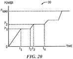
- the energy generator 26may include one or more evaluation or feedback algorithms 31 to provide feedback to the clinician before, during, and/or after therapy. Further details regarding suitable control algorithms and evaluation/feedback algorithms are described below with reference to Figures 20-27 .
- the system 10may be configured to provide delivery of a monopolar electric field via the energy delivery elements 24.
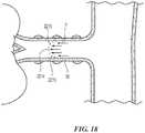
- a neutral or dispersive electrode 38may be electrically connected to the energy generator 26 and attached to the exterior of the patient (as shown in Figure 2 ).
- one or more sensorssuch as one or more temperature (e.g., thermocouple, thermistor, etc.), impedance, pressure, optical, flow, chemical or other sensors, may be located proximate to or within the energy delivery elements 24 and connected to one or more supply wires (not shown).
- a total of two supply wiresmay be included, in which both wires could transmit the signal from the sensor and one wire could serve dual purpose and also convey the energy to the energy delivery elements 24.
- a different number of supply wiresmay be used to transmit energy to the energy delivery elements 24.
- the energy generator 26may be part of a device or monitor that may include processing circuitry, such as a microprocessor, and a display.
- the processing circuitrymay be configured to execute stored instructions relating to the control algorithm 30.
- the monitormay be configured to communicate with the treatment device 12 (e.g., via cable 28) to control power to the energy delivery elements 24 and/or to obtain signals from the energy delivery elements 24 or any associated sensors.
- the monitormay be configured to provide indications of power levels or sensor data, such as audio, visual or other indications, or may be configured to communicate the information to another device.
- the energy generator 26may also be configured to be operably coupled to a catheter lab screen or system for displaying treatment information.
- FIG. 2illustrates modulating renal nerves with an embodiment of the system 10.
- the treatment device 12provides access to the renal plexus RP through an intravascular path P, such as a percutaneous access site in the femoral (illustrated), brachial, radial, or axillary artery to a targeted treatment site within a respective renal artery RA.
- an intravascular path Psuch as a percutaneous access site in the femoral (illustrated), brachial, radial, or axillary artery to a targeted treatment site within a respective renal artery RA.
- a section of the proximal portion 18 of the shaft 16is exposed externally of the patient.
- the clinicianmay advance the shaft 16 through the sometimes tortuous intravascular path P and remotely manipulate the distal portion 20 of the shaft 16.
- Image guidancee.g., computed tomography (CT), fluoroscopy, intravascular ultrasound (IVUS), optical coherence tomography (OCT), or another suitable guidance modality, or combinations thereof, may be used to aid the clinician's manipulation. Further, in some embodiments, image guidance components (e.g., IVUS, OCT) may be incorporated into the treatment device 12 itself. After the therapeutic assembly 21 is adequately positioned in the renal artery RA, it can be radially expanded or otherwise deployed using the handle 34 or other suitable means until the energy delivery elements 24 are in stable contact with the inner wall of the renal artery RA.
- CTcomputed tomography
- IVUSintravascular ultrasound
- OCToptical coherence tomography
- the purposeful application of energy from the energy delivery elements 24is then applied to tissue to induce one or more desired neuromodulating effects on localized regions of the renal artery and adjacent regions of the renal plexus RP, which lay intimately within, adjacent to, or in close proximity to the adventitia of the renal artery RA.
- the purposeful application of the energymay achieve neuromodulation along all or at least a portion of the renal plexus RP.
- the neuromodulating effectsare generally a function of, at least in part, power, time, contact between the energy delivery elements 24 and the vessel wall, and blood flow through the vessel.
- the neuromodulating effectsmay include denervation, thermal ablation, and non-ablative thermal alteration or damage (e.g., via sustained heating and/or resistive heating).
- Desired thermal heating effectsmay include raising the temperature of target neural fibers above a desired threshold to achieve non-ablative thermal alteration, or above a higher temperature to achieve ablative thermal alteration.
- the target temperaturemay be above body temperature (e.g., approximately 37°C) but less than about 45°C for non-ablative thermal alteration, or the target temperature may be about 45°C or higher for the ablative thermal alteration.
- Desired non-thermal neuromodulation effectsmay include altering the electrical signals transmitted in a nerve.
- the energy delivery elements 24 of the therapeutic assembly 21may be proximate to, adjacent to, or carried by (e.g., adhered to, threaded over, wound over, and/or crimped to) a support structure 22.
- the proximal end of the support structure 22is preferably coupled to the distal portion 20 of the elongated shaft 16 via a coupling (not shown).
- the couplingmay be an integral component of the elongated shaft 16 (i.e., may not be a separate piece) or the coupling may be a separate piece such as a collar (e.g., a radiopaque band) wrapped around an exterior surface of the elongated shaft 16 to secure the support structure 22 to the elongated shaft 16.
- the support structure 22may be associated with the elongated shaft 16 using another arrangement and/or different features.
- the energy delivery elements 24may form or define selected portions of, or the entirety of, the support structure 22 itself. That is, as is described in further detail below, the support structure 22 may be capable of delivering energy.
- the therapeutic assembly 21may function with a single energy delivery element, it will be appreciated that the therapeutic assembly 21 preferably includes a plurality of energy delivery elements 24 associated with or defining the support structure 22.
- the energy delivery elements 24may deliver power independently (i.e., may be used in a monopolar fashion), either simultaneously, selectively, or sequentially, and/or may deliver power between any desired combination of the elements (i.e., may be used in a bipolar fashion).
- the clinicianoptionally may choose which energy delivery element(s) 24 are used for power delivery in order to form highly customized lesion(s) within the renal artery having a variety of shapes or patterns.
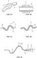
- Figure 3Ais a cross-sectional view illustrating one embodiment of the distal portion 20 of the shaft 16 and the therapeutic assembly 21 in a delivery state (e.g., low-profile or collapsed configuration) within a renal artery RA
- Figures 3B and 3Cillustrate the therapeutic assembly 21 in a deployed state (e.g., expanded or helical configuration) within the renal artery.
- the collapsed or delivery arrangement of the therapeutic assembly 21defines a low profile about the longitudinal axis A-A of the assembly such that a transverse dimension of the therapeutic assembly 21 is sufficiently small to define a clearance distance between an arterial wall 55 and the treatment device 12.
- the delivery statefacilitates insertion and/or removal of the treatment device 12 and, if desired, repositioning of the therapeutic assembly 21 within the renal artery RA.
- the geometry of the support structure 22facilitates movement of the therapeutic assembly 21 through a guide catheter 90 to the treatment site in the renal artery RA.
- the therapeutic assembly 21is sized and shaped to fit within the renal artery RA and has a diameter that is less than a renal artery inner diameter 52 and a length (from a proximal end of the therapeutic assembly 21 to a distal end of the therapeutic assembly 21) that is less than a renal artery length 54.
- the geometry of the support structure 22is also arranged to define (in the delivery state) a minimum transverse dimension about its central axis that is less than the renal artery inner diameter 52 and a maximum length in the direction of the central axis that is preferably less than the renal artery length 54.
- the minimum diameter of the therapeutic assembly 21is approximately equal to the interior diameter of the elongated shaft 16.
- the distal portion 20 of the shaft 16may flex in a substantial fashion to gain entrance into a respective left/right renal artery by following a path defined by a guide catheter, a guide wire, or a sheath.
- the flexing of distal portion 20may be imparted by the guide catheter 90, such as a renal guide catheter with a preformed bend near the distal end that directs the shaft 16 along a desired path, from the percutaneous insertion site to the renal artery RA.
- the treatment device 12may be directed to the treatment site within the renal artery RA by engaging and tracking a guide wire (e.g., guide wire 66 of Figure 2 ) that is inserted into the renal artery RA and extends to the percutaneous access site.
- a guide wiree.g., guide wire 66 of Figure 2
- the guide wireis preferably first delivered into the renal artery RA and the elongated shaft 16 comprising a guide wire lumen is then passed over the guide wire into the renal artery RA.
- a tubular delivery sheath 1291(described in greater detail below with reference to Figures 16A and 16B ) is passed over the guide wire (i.e., the lumen defined by the delivery sheath slides over the guide wire) into the renal artery RA.
- the guide wiremay be removed and exchanged for a treatment catheter (e.g., treatment device 12) that may be delivered through the delivery sheath 1291 into the renal artery RA.
- the distal portion 20can be directed or "steered” into the renal artery RA via the handle assembly 34 ( Figures 1 and 2 ), for example, by an actuatable element 36 or by another control element.
- the flexing of the elongated shaft 16may be accomplished as provided in U.S. Patent Application No. 12/545,648 , published as US20100168731 , "Apparatus, Systems, and Methods for achieving Intravascular, Thermally-Induced Renal Neuromodulation" to Wu et al.
- the treatment device 12 and its distal portion 20may be flexed by being inserted through a steerable guide catheter (not shown) that includes a preformed or steerable bend near its distal end that can be adjusted or re-shaped by manipulation from the proximal end of the guide catheter.
- a steerable guide catheternot shown
- the maximum outer dimension (e.g., diameter) of any section of the treatment device 12, including elongated shaft 16 and the energy delivery elements 24 of the therapeutic assembly 21can be defined by an inner diameter of the guide catheter 90 through which the device 12 is passed.
- an 8 French guide catheterhaving, for example, an inner diameter of approximately 0.091 inch (2.31 mm) may be used as a guide catheter to access the renal artery. Allowing for a reasonable clearance tolerance between the energy delivery elements 24 and the guide catheter, the maximum outer dimension of the therapeutic assembly 21 is generally less than or equal to approximately 0.085 inch (2.16 mm).
- the expanded or helical configurationpreferably defines a maximum width of less than or equal to approximately 0.085 inch (2.16 mm).
- a therapeutic assembly 21 having a helical support structure 22 that is to be routed within a 5 French guide catheterpreferably has an outer dimension or maximum width of no greater than about 0.053 inch (1.35 mm).
- the guide catheter and the therapeutic assembly 21define a ratio of diameters of about 1.5:1.
- the helical structure and energy delivery element 24 that are to be delivered within a 6 French guide catheterwould have an outer dimension of no great than 0.070 inch (1.78 mm).
- other suitable guide cathetersmay be used, and outer dimensions and/or arrangements of the treatment device 12 can vary accordingly.
- the therapeutic assembly 21After locating the therapeutic assembly 21 at the distal portion 20 of the shaft 16 in the renal artery RA, the therapeutic assembly 21 is transformed from its delivery state to its deployed state or deployed arrangement. The transformation may be initiated using an arrangement of device components as described herein with respect to the particular embodiments and their various modes of deployment. As described in greater detail below and in accordance with one or more embodiments of the present technology, the therapeutic assembly may be deployed by a control member, such as for example a pull- or tension-wire, guide wire, shaft or stylet engaged internally or externally with the support structure of the therapeutic assembly to apply a deforming or shaping force to the assembly to transform it into its deployed state. Alternatively, the therapeutic assembly 21 may be self expanding or deploying such that removal of a radial restraint results in deployment of the assembly. Further, the modality used to transform the therapeutic assembly 21 from the delivery state into the deployed state may, in most embodiments, be reversed to transform the therapeutic assembly 21 back to the delivery state from the deployed state.
- a control membersuch as for example a pull
- FIG. 3B and 3CFurther manipulation of the support structure 22 and the energy delivery elements 24 within the respective renal artery RA establishes apposition of the energy delivery elements 24 against the tissue along an interior wall of the respective renal artery RA.
- the therapeutic assembly 21is expanded within the renal artery RA such that the energy delivery elements 24 are in contact with the renal artery wall 55.
- manipulation of the distal portion 20will also facilitate contact between the energy delivery elements 24 and the wall of the renal artery.
- Embodiments of the support structures described hereine.g., the support structure 22
- the support structure 22 or other suitable support structures described hereinpreferably provide for a consistent contact force against the arterial wall 55 that may allow for consistent lesion formation.
- the alignmentmay also include alignment of geometrical aspects of the energy delivery elements 24 with the renal artery wall 55.
- alignmentmay include alignment of the longitudinal surface of the individual energy delivery elements 24 with the artery wall 55.
- an embodimentmay comprise energy delivery elements 24 having a structured shape or inactive surface, and alignment may include aligning the energy delivery elements 24 such that the structured shape or inactive surface is not in contact with the artery wall 55.
- the therapeutic assembly 21defines a substantially helical support structure 22 in contact with the renal artery wall 55 along a helical path.
- pressure from the helical structurecan be applied to a large range of radial directions without applying pressure to a circumference of the vessel.
- the helically-shaped therapeutic assembly 21is expected to provide stable contact between the energy delivery elements 24 and the artery wall 55 when the wall moves in any direction.
- pressure applied to the vessel wall 55 along a helical pathis less likely to stretch or distend a circumference of a vessel that could thereby cause injury to the vessel tissue.
- Still another feature of the expanded helical structureis that it may contact the vessel wall in a large range of radial directions and maintain a sufficiently open lumen in the vessel allowing blood to flow through the helix during therapy.
- the support structure 22defines a maximum axial length of the therapeutic assembly 21 that is approximately equal to or less than a renal artery length 54 of a main renal artery (i.e., a section of a renal artery proximal to a bifurcation). Because this length can vary from patient to patient, it is envisioned that the deployed helical-shaped support structure 22 may be fabricated in different sizes (e.g., with varying lengths L and/or diameters D as shown in Figure 4A ) that may be appropriate for different patients.
- the helical-shaped therapeutic assembly 21provides for circumferentially discontinuous contact between the energy delivery elements 24 and the inner wall 55 of the renal artery RA. That is, the helical path may comprise a partial arc (i.e., ⁇ 360°), a complete arc (i.e., 360°) or a more than complete arc (i.e., >360°) along the inner wall of a vessel about the longitudinal axis of the vessel. In some embodiments, however, the arc is not substantially in one plane normal to the central axis of the artery, but instead preferably defines an obtuse angle with the central axis of the artery.
- Figure 4Ais a plan view of an embodiment of a therapeutic or treatment assembly 21 for use with a treatment device (e.g., treatment device 12) in accordance with an embodiment of the technology
- Figure 4Bis an isometric view of the therapeutic assembly 21 of Figure 4A
- the energy delivery elements 24 depicted in Figures 4A and 4Bare merely for illustrative purposes, and it will be appreciated that the treatment assembly 21 can include a different number and/or arrangement of energy delivery elements 24.
- a helixmay be characterized, at least in part, by its overall diameter D, length L, helix angle ⁇ (an angle between a tangent line to the helix and its axis), pitch HP (longitudinal distance of one complete helix turn measured parallel to its axis), and number of revolutions (number of times the helix completes a 360° revolution about its axis).
- the deployed or expanded configuration of the helixmay be characterized by its axial length L along the axis of elongation in free space, e.g., not restricted by a vessel wall or other structure.
- the helical support structure 22radially expands from its delivery state, its diameter D increases and its length L decreases. That is, when the helical structure deploys, a distal end 22a moves axially towards the proximal end 22b (or vice versa). Accordingly, the deployed length L is less than the unexpanded or delivery length.
- only one of the distal end portion 22a or the proximal end portion 22b of the support structure 22is fixedly coupled to the elongated shaft 16 or an extension thereof.
- the support structure 22may be transformed to its deployed or expanded configuration by twisting the distal and proximal end portions 22a and 22b relative to one another.
- the deployed helically-shaped support structure 22optionally comprises a distal extension 26a distal to the helical portion that is relatively straight and may terminate with an atraumatic (e.g., rounded) tip 50.
- the distal extension 26a including the tip 50may reduce the risk of injuring the blood vessel as the helical structure is expanding and/or as a delivery sheath is retracted, and may facilitate alignment of the helical structure in a vessel as it expands.
- the distal extension 26ais generally straight (but flexible) and has a length of less than about 40 mm (e.g., between 2 mm and 10 mm).
- the tip 50can be made from a polymer or metal that is fixed to the end of the structural element by adhesive, welding, crimping, over-molding, and/or solder. In other embodiments, the tip 50 may be made from the same material as the structural element and fabricated into the tip 50 by machining or melting. In other embodiments, the distal extension 26a may have a different configuration and/or features. For example, in some embodiments the tip 50 may comprise an energy delivery element or a radiopaque marker. Further, the distal extension 26a is an optional feature that may not be included in all embodiments.
- the helical structuremay also optionally have a proximal extension 26b that is relatively straight compared to the helically shaped region of the support structure 22.
- the proximal extension 26bmay be an extension of the support structure 22 and may have a length between 0 mm and 40 mm (e.g., between about 2 and 10 mm).
- the proximal extension 26bmay be comprised of a separate material (e.g., a polymer fiber) with more flexibility than the rest of the support structure 22.
- the proximal extension 26bis configured to provide a flexible connection between the helical region of the support structure 22 and the distal end of the elongated shaft 16 ( Figure 1 ).
- This featureis expected to facilitate alignment of the deployed helical support structure 22 with the vessel wall by reducing the force transferred from the elongated shaft 16 to the helical region of the helical structure 22. This may be useful, for example, when the elongated shaft is biased toward a side of the vessel wall or if the elongated shaft moves relative to the vessel wall allowing the helical structure to remain positioned.
- the dimensions of the deployed helically-shaped structure 22are influenced by its physical characteristics and its configuration (e.g., expanded vs. unexpanded), which in turn may be selected with renal artery geometry in mind.
- the axial length L of the deployed helical structuremay be selected to be no longer than a patient's renal artery (e.g., the length 54 of renal artery RA of Figures 3A and 3B ).
- the distance between the access site and the ostium of the renal arteryis generally greater than the length of a renal artery from the aorta and the most distal treatment site along the length of the renal artery, which is typically less than about 7 cm.
- the elongated shaft 16( Figure 1 ) is at least 40 cm and the helical structure is less than about 7 cm in its unexpanded length L.
- a length in an unexpanded configuration of no more than about 4 cmmay be suitable for use in a large population of patients and provide a long contact area when in an expanded configuration and, in some embodiments, provide a long region for placement of multiple energy delivery elements; however, a shorter length (e.g., less than about 2 cm) in an unexpanded configuration may be used in patients with shorter renal arteries.
- the helical structure 22may also be designed to work with typical renal artery diameters.
- the diameter 52 ( Figure 3A ) of the renal artery RAmay vary between about 2 mm and about 10 mm.
- the placement of the energy delivery elements 24 on the helical structure 22may be selected with regard to an estimated location of the renal plexus RP relative to the renal artery RA.
- a section or support structure of the therapeutic assembly 21, when allowed to fully deploy to an unconstrained configurationcomprises a helical shape having a diameter D less than about 15 mm (e.g., about 12 mm, 10 mm, 8 mm, or 6 mm); a length L less than or equal to about 40 mm (e.g., less than about 25 mm, less than about 20 mm, less than about 15 mm); a helix angle ⁇ of between about 20° and 75° (e.g., between about 35° and 55°); a range of revolutions between 0.25 and 6 (e.g., between 0.75 and 2, between 0.75 and 1.25); and a pitch HP between about 5 mm and 20 mm (e.g., between about 7 mm and 13 mm).
- a helical shapehaving a diameter D less than about 15 mm (e.g., about 12 mm, 10 mm, 8 mm, or 6 mm); a length L less than or equal to about 40 mm (e.g.
- the therapeutic assembly 21may be configured to expand radially from its delivery state with a diameter about its central axis being approximately 10 mm to a delivery state in which the energy delivery elements 24 are in contact with the artery wall.
- the deployed helically-shaped support structure 22may be generally cylindrical (i.e., a helical diameter can be generally consistent along a majority of its length). It is also contemplated, however, that the structure 22 may have variations such as a conical helical shape, a tapered structural element, clockwise or counterclockwise pathway, consistent or varied pitch.
- the support structure 22can include a solid structural element, e.g., a wire, tube, coiled or braided cable.
- the support structure 22may be formed from biocompatible metals and/or polymers, including polyethylene terephthalate (PET), polyamide, polyimide, polyethylene block amide copolymer, polypropylene, or polyether ether ketone (PEEK) polymers.
- PETpolyethylene terephthalate
- PEEKpolyether ether ketone
- the support structure 22may be electrically nonconductive, electrically conductive (e.g., stainless steel, nitinol, silver, platinum, nickel-cobalt-chromium-molybdenum alloy), or a combination of electrically conductive and nonconductive materials.
- the support structure 22may be formed of a pre-shaped material, such as spring temper stainless steel or nitinol.
- the structure 22may be formed, at least in part, from radiopaque materials that are capable of being fluoroscopically imaged to allow a clinician to determine if the treatment assembly 21 is appropriately placed and/or deployed in the renal artery.
- Radiopaque materialsmay include, for example, barium sulfate, bismuth trioxide, bismuth subcarbonate, powdered tungsten, powdered tantalum, or various formulations of certain metals, including gold and platinum, and these materials may be directly incorporated into structural elements 22 or may form a partial or complete coating on the helical structure 22.
- the helical structure 22may be designed to apply a desired outward radial force to the renal artery wall 55 ( Figures 3A and 3B ) when inserted and expanded to contact the inner surface of the renal artery wall 55 ( Figures 3A and 3B ).
- the radial forcemay be selected to avoid injury from stretching or distending the renal artery RA when the helical structure 22 is expanded against the artery wall 55 within the patient. Radial forces that may avoid injuring the renal artery RA yet provide adequate stabilization force may be determined by calculating the radial force exerted on an artery wall by typical blood pressure.
- a suitable radial forcemay be less than or equal to about 300 mN/mm (e.g., less than 200 mN/mm).
- Factors that may influence the applied radial forceinclude the geometry and the stiffness of the support structure 22.
- the support structure 22is about 0.003-0.009 inch (0.08-0.23 mm) in diameter.
- the structural element diametermay be selected to facilitate a desired conformability and/or radial force against the renal artery when expanded.
- a support structure 22 formed from a stiffer materiale.g., metal
- the outward pressure of the helical support structure 22may be assessed in vivo by an associated pressure transducer.
- certain secondary processesmay harden or soften the fiber material to affect strength and stiffness.
- these secondary processesmay be varied to give the same starting material different final properties.
- the elastic range or softnessmay be increased to impart improved flexibility.
- the secondary processing of shape memory alloysinfluences the transition temperature, i.e., the temperature at which the structure exhibits a desired radial strength and stiffness.
- this transition temperaturemay be set at normal body temperature (e.g., around 37°C) or in a range between about 37°C and 45°C.
- a transition temperaturecan be well below body temperature, for example below 0°C.
- the helical structuremay be formed from an elastic or super elastic material such as nitinol that is thermally engineered into a desired helical shape.
- the helical structure 22may be formed from multiple materials such as one or more polymers and metals.
- the support structure 22 of the treatment assembly 21, when not inserted into a patient,is capable of deploying to a maximum diameter that is larger than the diameter in its delivery state.
- the helically-shaped structure 22may be sized so that the maximum diameter is larger than the lumen diameter 52 of the renal artery RA.
- the helically-shaped structure 22expands radially to span the renal artery lumen and, at its largest circumferential section, is approximately or slightly less than (e.g., in embodiments in which the energy delivery elements 24 fill some of the space) the diameter 52 of the renal artery RA.
- a slight amount of vessel distensionmay be caused without undue injury and the structure 22 may expand such that its largest circumferential section is slightly more than the diameter 52 of the renal artery RA, or such that one or more energy delivery elements 24 are slightly pressed into the wall 55 of the renal artery RA.
- a helically-shaped assembly or array that causes slight and non-injurious distension of an artery wall 55may advantageously provide stable contact force between the energy delivery elements 24 and the artery wall 55 and/or hold the energy delivery elements 24 in place even as the artery moves with respiratory motion and pulsing blood flow. Because this diameter 52 of the renal artery RA varies from patient to patient, the treatment assembly 21 may be capable of assuming a range of diameters between the delivery diameter and the maximum diameter.
- one feature of the deployed therapeutic assembly 21 in the helical configurationis that the energy delivery elements 24 associated with the helical structure may be placed into stable contact with a vessel wall to reliably create consistent lesions. Further, multiple energy delivery elements 24 may be placed along the helical structure with appropriate spacing to achieve a desired lesion configuration within the target vessel.
- Another feature of several embodiments of the therapeutic assembly 21 having the helical configuration described aboveis that the assembly may be expanded to fit within a relatively wide range of different vessel diameters and/or with various tortuosities.
- the embodiments provided hereinmay be used in conjunction with one or more energy delivery elements 24.
- the deployed helically-shaped structure carrying the energy delivery elements 24is configured to provide a therapeutic energy delivery to the renal artery without any repositioning.
- Illustrative embodiments of the energy delivery elements 24are shown in Figures 5A-5D .
- the energy delivery elements 24 associated with the helical structure 22may be separate elements or may be an integral part of the helical structure 22. In some patients, it may be desirable to use the energy delivery element(s) 24 to create a single lesion or multiple focal lesions that are spaced around the circumference of the renal artery.
- a single focal lesion with desired longitudinal and/or circumferential dimensions, one or more full-circle lesions, multiple circumferentially spaced focal lesions at a common longitudinal position, spiral-shaped lesions, interrupted spiral lesions, generally linear lesions, and/or multiple longitudinally spaced discrete focal lesions at a common circumferential position alternatively or additionallymay be created.
- the energy delivery elements 24may be used to create lesions having a variety of other geometric shapes or patterns.
- the formed lesionsmay be spaced apart around the circumference of the renal artery and the same formed lesions also may be spaced apart along the longitudinal axis of the renal artery.
- the formed lesion patternas viewed from a proximal or distal end of the vessel, to extend at least approximately all the way around the circumference of the renal artery.
- each formed lesioncovers an arc of the circumference, and each of the lesions, as viewed from an end of the vessel, abut or overlap adjacent or other lesions in the pattern to create either an actual circumferential lesion or a virtually circumferential lesion.
- the formed lesions defining an actual circumferential lesionlie in a single plane perpendicular to a longitudinal axis of the renal artery.
- a virtually circumferential lesionis defined by multiple lesions that may not all lie in a single perpendicular plane, although more than one lesion of the pattern can be so formed.
- At least one of the formed lesions comprising the virtually circumferential lesionis axially spaced apart from other lesions.
- a virtually circumferential lesioncan comprise six lesions created in a single helical pattern along the renal artery such that each lesion spans an arc extending along at least one sixth of the vessel circumference such that the resulting pattern of lesions completely encompasses the vessel circumference when viewed from an end of the vessel.
- a virtually circumferential lesioncan comprise a different number of lesions. It is also desirable that each lesion be sufficiently deep to penetrate into and beyond the adventitia to thereby affect the renal plexus. However, lesions that are too deep (e.g., >5mm) run the risk of interfering with non-target tissue and tissue structures (e.g., a renal vein) so a controlled depth of energy treatment is also desirable.
- energy delivery elements 24may be distributed on the helical structure 22 in a desired arrangement.
- the axial distances between the energy delivery elements 24may be selected so that the edges of the lesions formed by individual energy delivery elements 24 on the renal artery wall 55 are overlapping or non-overlapping.
- One or both of the axial distances xx or yymay be about 2 mm to about 1 cm.
- the axial distances xx or yymay be in the range of about 2 mm to about 5 mm.
- the energy delivery elements 24may be spaced apart about 30 mm.
- the energy delivery elements 24are spaced apart about 11 mm.
- the energy delivery elements 24are spaced apart about 17.5 mm.
- the axial distance xxmay be less than, about equal to, or greater than the axial distance yy.
- Spacing of energy delivery elements 24may be characterized by a helical length distance zz, that is, the distance between energy delivery elements along the path of the helical structure 22.
- the helical length distance zzmay be chosen based on the size of lesions created by energy delivery elements 24 so the lesions either overlap or do not overlap.
- the energy delivery elements 24are both longitudinally and circumferentially offset from one another.
- Figure 4Cis an end view of the helical structure 22 showing the angular offset or separation of the energy delivery elements 24 from one another around the circumference of the deployed helical structure 22.
- energy delivery element 24cis offset from energy delivery element 24a by angle 150 and offset from energy delivery element 24b by angle 152.
- the offset anglesmay be selected such that, when energy is applied to the renal artery via energy delivery elements 24a, 24b, and 24c, the lesions may or may not overlap circumferentially.
- Figure 4Dis a side view of a vessel with formed lesions 340 that circumferentially and/or longitudinally overlap, but do not overlap along a helical path.
- lesions 340can be formed by energy delivery elements 24 to have a circumferential overlap 341 as viewed from one end of the vessel (e.g., Figure 4C ) and/or a longitudinal overlap 342, but may not produce a helical length overlap, instead forming a helical length gap 343.
- energy delivery elements 24may take the form of electrodes for applying an electrical field of RF energy to a vessel wall and be configured to produce lesions that are about 5 mm in diameter with the electrodes spaced apart by helical length distance of about 6 to 7 mm.
- a helical lesion pattern with any suitable number of turnsmay be formed.
- the treatment device 12may employ a single energy application to form a complex lesion pattern.
- the embodiments illustrated in Figures 4A-4Care exemplary, may be schematic in nature, may not correlate exactly to one another, and are shown only for the purposes of clarifying certain aspects of the technology.
- the number and spacing of energy delivery elements 24are different in each of Figures 4A-4C , and lesions formed by the illustrated embodiments may not create a sufficiently overlapping pattern to achieve a virtually circumferential lesion as described above, particularly when applying energy in only one deployment of the treatment assembly 21 without repositioning.
- the individual energy delivery elements 24are connected to energy generator 26 ( Figure 1 ) and are sized and configured to contact an internal wall of the renal artery.
- the energy delivery element 24may be operated in a monopolar or unipolar mode.
- a return path for the applied RF electric fieldis established, e.g., by an external dispersive electrode (shown as element 38 in Figures 1 and 2 ), also called an indifferent electrode or neutral electrode.
- the monopolar application of RF electric field energyserves to ohmically or resistively heat tissue in the vicinity of the electrode.
- the application of the RF electrical fieldthermally injures tissue.
- the treatment objectiveis to thermally induce neuromodulation (e.g., necrosis, thermal alteration or ablation) in the targeted neural fibers.
- the thermal injuryforms a lesion in the vessel wall.
- a RF electrical fieldmay be delivered with an oscillating or pulsed intensity that does not thermally injure the tissue whereby neuromodulation in the targeted nerves is accomplished by electrical modification of the nerve signals.
- the active surface area of the energy delivery element 24is defined as the energy transmitting area of the element 24 that may be placed in intimate contact against tissue. Too much contact area between the energy delivery element and the vessel wall may create unduly high temperatures at or around the interface between the tissue and the energy delivery element, thereby creating excessive heat generation at this interface. This excessive heat may create a lesion that is circumferentially too large. This may also lead to undesirable thermal application to the vessel wall. In some instances, too much contact can also lead to small, shallow lesions. Too little contact between the energy delivery element and the vessel wall may result in superficial heating of the vessel wall, thereby creating a lesion that is too small (e.g., ⁇ 10% of vessel circumference) and/or too shallow.
- Too much contact area between the energy delivery element and the vessel wallmay result in superficial heating of the vessel wall, thereby creating a lesion that is too small (e.g., ⁇ 10% of vessel circumference) and/or too shallow.
- the active surface area of contact (ASA) between the energy delivery element 24 and the inner vessel wallhas great bearing on the efficiency and control of the generation of a thermal energy field across the vessel wall to thermally affect targeted neural fibers in the renal plexus.
- ASAactive surface area of contact
- the ASA of the energy delivery elementis important to creating lesions of desirable size and depth
- the ratio between the ASA and total surface area (TSA) of the energy delivery element 24 and electrode 46is also important.
- the ASA to TSA ratioinfluences lesion formation in two ways: (1) the degree of resistive heating via the electric field, and (2) the effects of blood flow or other convective cooling elements such as injected or infused saline.
- an RF electric fieldcauses lesion formation via resistive heating of tissue exposed to the electric field.
- the higher the ASA to TSA ratioi.e., the greater the contact between the electrode and tissue), the greater the resistive heating, e.g., the larger the lesion that is formed.
- the flow of blood over the non-contacting portion of the electrodeprovides conductive and convective cooling of the electrode, thereby carrying excess thermal energy away from the interface between the vessel wall and electrode.
- the ratio of ASA to TSAis too high (e.g., more than 50%), resistive heating of the tissue may be too aggressive and not enough excess thermal energy is being carried away, resulting in excessive heat generation and increased potential for stenotic injury, thrombus formation and undesirable lesion size. If the ratio of ASA to TSA is too low (e.g., 10%), then there is too little resistive heating of tissue, thereby resulting in superficial heating and smaller and shallower lesions.
- the ASA of the energy delivery elements 24 contacting tissuemay be expressed as 0.25 TSA ⁇ ASA ⁇ 0.50 TSA
- An ASA to TSA ratio of over 50%may still be effective without excessive heat generation by compensating with a reduced power delivery algorithm and/or by using convective cooling of the electrode by exposing it to blood flow.
- electrode coolingcan be achieved by injecting or infusing cooling liquids such as saline (e.g., room temperature saline or chilled saline) over the electrode and into the blood stream.
- the maximum outer diameter (or cross-sectional dimension for non-circular cross-section) of the energy delivery element 24may be the largest diameter encountered along the length of the elongated shaft 16 distal to the handle assembly 34.
- the maximum outer diameter (or cross-sectional dimension) of the energy delivery element 24is constrained by the maximum inner diameter of the guide catheter through which the elongated shaft 16 is to be passed through the intravascular path 14.
- an 8 French guide catheterwhich has an inner diameter of approximately 0.091 inch (2.31 mm)
- the maximum diameter of the electrode 46is constrained to about 0.085 inch (2.16 mm).
- the maximum diameter of the energy delivery element 24is constrained to about 0.070 inch (1.78 mm), e.g., about 0.050 inch (1.27 mm).
- maximum diameter of the energy delivery element 24is constrained to about 0.053 inch (1.35 mm).
- the energy delivery element 24may have an outer diameter of from about 0.049 to about 0.051 inch (1.24 mm-1.30 mm).
- the energy delivery elements 24also may have a minimum outer diameter of about 0.020 inch (0.51 mm) to provide sufficient cooling and lesion size.
- the energy delivery element 24may have a length of about 1 mm to about 3 mm.
- the energy delivery element 24in which the energy delivery element 24 is a resistive heating element, the energy delivery element 24 have a maximum outer diameter from about 0.049 to 0.051 inch (1.24 mm-1.30 mm) and a length of about 10 mm to 30 mm.
- One embodiment of energy delivery elements 24, for example,provides for a multiple array of 4-6 electrodes disposed about a support structure (e.g., a tubular structure).
- the energy delivery elements 24, for example,may be gold electrodes or alternatively, platinum, platinum-iridium, or another suitable material.
- the electrodesmay measure about 0.030 inch ID x 0.0325 OD inch x 0.060 inch in length (0.76 mm x 0.83 mm x 1.52 mm).
- the electrodesmay measure 0.029 inch ID x 0.033 inch OD x 0.060 inch length (0.72 mm x 0.83 mm x 1.52 mm).
- the electrodesmay measure 0.038 inch ID x 0.042 inch OD x 0.060 inch length (0.97 mm x 1.07 mm x 1.52 mm). Moreover, the electrodes may be appropriately electrically insulated from the support structure with the supply wire array of each of the electrodes jacketed in a polymer so as to provide for a compact packaged electrode array assembly about the support structure 22.
- the outer diameter of the treatment device 12may be defined by the one or more energy delivery elements 24 and may be further defined by elements such as e.g., control wire 168 as shown in Figure 8A .
- control wire 168may be used with an 8 French guide catheter and may comprise energy delivery element(s) 24 with a diameter between about 0.049 to 0.053 inch (1.24 mm to 1.35 mm) and a control wire with a diameter between about 0.005 to 0.015 inch (0.13 mm to 0.38 mm) in diameter.
- the arrangement and/or dimensions of the energy delivery elements 24 and/or control wiremay vary.
- the helical structure 22may be formed of an electrically conductive material.
- the helical structure 22may be made from nitinol wire, cable, or tube.
- wire leads 19may connect the helical structure 22 to energy generator 26.
- the helical structure 22forms a contact region with the renal artery wall and acts as the energy delivery element 24.
- the helical structure 22is capable of producing a continuous helical lesion.
- a helical structure 22 that is configured to be an energy delivery element 24may optionally comprise sensors 33 positioned on, in, and/or proximate to the helical structure 22 and may be electrically connected to supply wires 35.
- the electrically conductive helical structure 22is insulated at least in part. That is, the conductive helical structure is partially covered with an electrically insulating material and the uncovered portions of the helical structure 22 serve as one or more conductive energy delivery elements 24.
- the energy delivery elements 24may be any size, shape, or number, and may be positioned relative to one another as provided herein.
- Energy delivery element 24may be configured to deliver thermal energy, i.e., to heat up and conduct thermal energy to tissue.
- energy delivery elementsmay be an electrically resistive element such as a thermistor or a coil made from electrically resistive wire so that when electrical current is passed through the energy delivery element heat is produced.
- An electrically resistive wiremay be for example an alloy such as nickel-chromium with a diameter for example between 48 and 30 AWG.
- the resistive wiremay be electrically insulated for example with polyimide enamel.
- the energy delivery elements 24may be angularly repositioned relative to the renal artery during treatment. Referring back to Figures 1 and 2 , for example, this angular repositioning may be achieved by compressing the therapeutic assembly 21 and rotating the elongated shaft 16 of the treatment device 12 via the handle assembly 34. In addition to the angular or circumferential repositioning of the energy delivery elements 24, the energy delivery elements 24 optionally may also be repositioned along the lengthwise or longitudinal dimension of the renal artery. This longitudinal repositioning may be achieved, for example, by translating the elongated shaft 16 of treatment device 12 via handle assembly 34, and may occur before, after, or concurrent with angular repositioning of the energy delivery elements 24.
- repositioning the energy delivery elements 24 in both the longitudinal and angular dimensionsplaces the energy delivery elements 24 in contact with the interior wall 55 of the renal artery RA at a second treatment site for treating the renal plexus RP.
- energymay then be delivered via the energy delivery elements 24 to form a second focal lesion at this second treatment site.
- the initial treatmentmay result in two or more lesions, and repositioning may allow additional lesions to be created.
- the lesions created via repositioning of the helically-shaped support structure 22are angularly and longitudinally offset from the initial lesion(s) about the angular and lengthwise dimensions of the renal artery RA, respectively.
- the composite lesion pattern created along the renal artery RA by the initial energy application and all subsequent energy applications after any repositioning of the energy delivery element(s) 24may effectively result in a discontinuous lesion (i.e., it is formed from multiple, longitudinally and angularly spaced treatment sites).
- the energy delivery element 24may be in the form of an electrically conductive wire.
- a conductive wire 500may be wound about the helical structure 22 to form a coiled electrode 24'.
- the coiled electrode 24'may provide increased surface area for delivering energy.
- the coiled electrode 24'may form a generally continuous helical lesion in a single energy application.
- the coiled electrode 24'may be wound in any manner about the helical structure 22, depending on the desired lesion.
- the coiled electrode 24'may form a continuous path along a length of the helix or the coiled structure may form one or more short discrete electrodes separated by non-conducting sections.
- portions of the coiled electrode 24'may be positioned on the helical structure to come in contact with the vessel wall when the helical structure is expanded, while other portions of the coiled electrode 24' may be positioned away from the vessel wall when the helical structure is expanded to allow lesions to be discontinuous. Further, in such an arrangement, regions of the coiled electrode 24' that do not contact the renal artery may contribute to cooling of the energy delivery elements 24', as described in greater detail below. The positioning and number of conductive portions forming the energy delivery elements 24' may be selected according to a desired lesion pattern.
- energy delivery elements 24preferably comprise metal electrodes with rounded ends and a lumen.
- the nitinol helical support structure 22is preferably electrically insulated (e.g., with PET) and the electrodes 24 are mounted over the insulation.
- Supply wires 25connect the electrodes to an energy source (not shown) and deliver energy (e.g., RF electrical current) to the electrodes 24.
- the rounded endsreduce mechanical irritation to the vessel wall and provide a more consistent current density when energy is delivered compared to electrodes with square or sharper ends.
- the energy delivery elements 24may alternatively comprise other forms as noted, such as a coil electrode 24' described above with reference to Figure 5D .
- the structural element 510 that forms the helical structure 22may be the energy delivery element 24' itself, as seen, for example in Figure 5C .
- FIG. 6Aillustrates an embodiment of a treatment device 112 including an elongated shaft 116 having different mechanical and functional regions configured in accordance with an embodiment of the technology.
- the elongated shaft 116 of the treatment device 112for example, includes a distal region with a therapeutic or treatment assembly 121 for delivery and deployment at a renal artery site for treatment and, in particular, for renal denervation.
- Disposed at a proximal end of the elongated shaft 116is a handle assembly 134 for manipulation of the elongated shaft 116 and the therapeutic assembly 121.
- the handle assembly 134is configured with an actuator 136 (schematically shown) to provide for remote operation of a control member (e.g., control wire 168 of Figures 6E or 8A ) for controlling or transforming the therapeutic assembly 121 between a delivery state and a deployed state.
- a control membere.g., control wire 168 of Figures 6E or 8A
- suitable handle assembliesmay be found, for example, in U.S. Patent Application No. 12/759,641 , "Handle Assemblies for Intravascular Treatment Devices and Associated System sand Methods" to Clark et al., published as US20100249773 .
- the treatment device 112is configured to deliver the therapeutic assembly 121 to a treatment site in a delivery (e.g., low-profile) state in which the assembly 121 is substantially linear (e.g., straight) such that energy delivery elements (not shown) carried by a support structure 122 of the treatment assembly 121 are substantially axially aligned along the support member 122.
- a deliverye.g., low-profile
- the handle assembly 134is operated for actuation of a control member that transforms the therapeutic assembly 121 from the delivery state to a deployed state.
- the control membercomprises a control wire 168 ( Figure 8A ) disposed within an internal lumen of the tubular support structure 122.
- control wire 168may be affixed at or near the distal end of the support structure 122, and the opposite end of the control wire 168 terminates within the handle assembly 134.
- the handle assembly 134is configured for manipulating the control wire 168 to transform the therapeutic assembly 121 between the delivery and the deployed states.
- the tension in the control wire 168provides for a proximally and axially directed force that acts on the support structure 122. Under the influence of the tension force in the control wire 168 and, in operation within a patient under the influence of a radial constraint of the patient's renal arterial wall, the support structure 122 deforms so as to deploy into the helical geometry to bring the energy delivery elements into stable contact with the wall of the renal artery.
- the support structure 122may be a tubular member having a plurality of slots, cuts, through holes, and/or openings selectively formed or disposed about the support structure 122.
- the tubular support structure 122may have a number of features generally similar to the features of support structure 22 described above.
- the support structure 122may be formed from biocompatible metals and/or polymers, including PET, polyamide, polyimide, polyethylene block amide copolymer, polypropylene, or PEEK polymers, and the slots are preferably laser cut into the tubular structure in a desired configuration.
- the support structure 122may be electrically nonconductive, electrically conductive (e.g., stainless steel, nitinol, silver, platinum nickel-cobalt-chromium-molybdenum alloy), or a combination of electrically conductive and nonconductive materials.
- the support structure 122may be formed of a pre-shaped material, such as spring temper stainless steel or nitinol.
- the support structure 122may be formed, at least in part, from radiopaque materials that are capable of being imaged fluoroscopically to allow a clinician to determine if the support structure 122 is appropriately placed and/or deployed in the renal artery.
- Radiopaque materialsmay include barium sulfate, bismuth trioxide, bismuth subcarbonate, powdered tungsten, powdered tantalum, or various formulations of certain metals, including gold, platinum, and platinum-iridium, and these materials may be directly incorporated into the support structure 122 or may form a partial or complete coating of the support structure 122.
- the tubular structure 122includes a distal deflection region 122a, an intermediate orientation region 122b proximal to the distal deflection region 122a, and a transition or flexible region 122c proximal to the orientation region 122b.
- the deflection region 122ais configured to have a substantially helical geometry upon deployment.
- the orientation region 122bis configured to locate or bias the deflection region 122a away from a longitudinal axis B of the elongated shaft 116 and toward a wall of the renal artery.
- the transition region 122cis configured to provide flexibility to the treatment device 112 as the elongated shaft 112 is advanced through the sometimes tortuous intravascular path from the percutaneous access site to the targeted treatment site within the respective renal artery (as described above with reference to Figure 2 ). Further details regarding various mechanical and functional aspects of the different regions of the treatment device 112 are described below.
- Figure 6Bis a plan view of a slot pattern configured in accordance with one embodiment of the technology.
- the deflection region 122amay be defined by a plurality of substantially equal length transverse slots 128 arranged along the support structure 122 in a spiral fashion.
- the orientation region 122bmay be defined by a plurality of axially spaced transverse slots 130 in which at least two slots differ in length. Further, as best seen in Figure 6A , the orientation region 122b can have a smaller axial length than the deflection region 122a.
- the transition region 122cis located proximally of the orientation region 122b and has an axial length greater than each of the deflection region 122a and the orientation region 122b.
- the transition region 122ccan include a continuous spiral cut or slit 132 having a varying pitch along the support structure 122.
- the pitch of the spiral cut 132can increase proximally along the elongated shaft 116. Further details regarding various mechanical and functional aspects of the regions of the treatment device 112 are described below.
- Figure 6Cis a perspective view of the treatment device 112 including the support structure 122 in a delivery state (e.g., low-profile or collapsed configuration) outside of a patient in accordance with an embodiment of the present technology
- Figure 6Dis a perspective view of the support structure 122 in a deployed state (e.g., expanded configuration).
- the support structure 122 in Figures 6C and 6Dis shown without energy delivery elements disposed about the support structure 122.
- the support structure 122comprises a tubular member having a central lumen to define a longitudinal axis B-B.
- the support structure 122includes a proximal generally flexible transition region 122c, an intermediate orientation region 122b, and a distal deflection region 122a.
- the support structure 122is selectively transformable between the delivery state ( Figure 6C ) and the deployed state ( Figure 6D ) by application of a force having at least a proximally directed axial component and preferably applied at or near the distal end 126a to transform distal deflection region 122a and intermediate orientation region 122b.
- an axial force applied at or near the distal end 126a directed at least partially in the proximal directiondeflects the distal deflection region 122a of the support structure 122 such that it forms the helically-shaped support structure such as is shown in Figure 6D (e.g., within the renal artery) to bring one or more energy delivery elements (not shown) into contact with the inner wall of the renal artery.
- the deflection region 122aincludes a plurality of slots 128a, 128b, 128c,... 128n.
- the plurality of slots 128a-128nare selectively formed, spaced, and/or oriented about the longitudinal axis B-B such that the distal deflection region 122a deflects in a predictable manner to form a helical geometry in the deployed state within the renal artery.
- the distal region 122amay define a non-helical geometry in its fully expanded configuration, such as, for example, a substantially circular geometry as shown in Figure 6E .
- the control wire 168is disposed in the central lumen of the support structure 122, and is anchored at or near the distal end 126a. When the control wire 168 is placed under tension in the proximal direction, at least a portion of the deflection region 122a (in the absence of any restriction in the radial direction) deflects from the substantially straight shape of Figure 6C to form the substantial circular shape of Figure 6E .
- a portion of the deflection region 122adeflects such that the deflection slots 128a-n deform and close or approximately close (as shown schematically in Figure 6E ) and provide contact between the edges of the support structure 122 framing a central region in each slot 128. Further details regarding the configuration of the slots are described below.
- the deflection region 122ais arranged to deflect about a center of curvature Z to define a first radius of curvature r with respect to a first surface 122d of the support member 122, and a second radius of curvature R with respect to a second surface 122e.
- the second radius of curvature Ris greater than the first radius of curvature r with the difference being the width or diameter d of the support member 122 measured at its outer surface.
- the deflection region 122adeforms to define a substantially helical deployed shape (as depicted in Figure 6D ) instead of the substantial circular shape defined in the absence of radial constraint (as depicted in Figure 6E ).
- the proportions of the substantially helical deployed shapee.g., the diameter and pitch of the helix
- the substantially helical deployed shapecan vary according to the inner diameter of the lumen (e.g., the renal artery lumen) within which the deflection region 122a is deformed.
- the arrangement and configuration of the slots 128a-128n( Figure 6C ) further define the geometry of the deflectable distal region 122a.
- Figure 6Fschematically illustrates a slot pattern for slots 128 in accordance with one embodiment of the technology to illustrate the slot spacing and orientation about the deflection region 122a of the support member 122. Although only four slots 128a-d are shown in Figure 6F , it will be appreciated that the deflection region 122a can have any number of desired slots 128. Referring to Figures 6E and 6F together, the centers of the slots 128 are disposed and spaced along a progressive axis C-C.
- the progressive axis C-Cdefines a progressive angle ⁇ with the longitudinal axis B-B of the support structure 122 ( Figure 6A ) to define an angular spacing of ⁇ about the center of curvature Z ( Figure 6E ) in the unconstrained deployed state.
- the centers of the slots 128a-128dare shown as substantially equidistantly spaced at a distance x. Alternatively, however, the center spacing between the slots may vary (x1, x2, etc.) along the progressive axis C-C.
- Each slot 128further defines a maximum arc length L about the longitudinal axis B-B and a maximum slot width W in the direction of the longitudinal axis B-B.
- each slotma have a width W ranging from about 0.0005 to 0.010 inch (0.01 to 0.25 mm) and a slot arc length L of about 0.0005 to 0.010 inch (0.01 to 0.25 mm) so as to define a first radius of curvature r in an unconstrained deflected state that ranges between about 3.5 to 6 mm (7 to 12 mm diameter).
- Minimizing the first radius of curvature r at a maximum application of axial force through the deflection region 122a of the support member 122defines the flexibility of the deflection region 122a. Accordingly, the smaller the first radius of curvature r , the greater the flexibility; the greater the first radius of curvature r , the greater the stiffness. Thus, the flexibility and/or stiffness of the deflection region 122a of the support member 122 can be defined by selecting the number and/or width of slots of the distal region 122a.
- the deflection region 122acan include approximately 2 to 100 slots, with each having a slot width W ranging from about 0.0005 to 0.010 inch (0.01 to 0.25 mm) and a slot arc length L of about 0.0005 to 0.010 inch (0.01 to 0.25 mm) so as to define a first radius of curvature r in an unconstrained deflected state that ranges between about 3.5 to 6 mm (7 to 12 mm diameter).
- Figure 6Gis a schematic plan view of a treatment device 112' configured in accordance with another embodiment of the technology.
- a deflection region 122'a of the treatment device 112'may include a low or reduced number of deflection slots 128 (e.g., three slots 128a-c are shown) such that the deflection region 122'a defines a substantially polygonal geometry when under a tension load at its distal end (i.e., from control wire 168).
- a different number of slots 128may be used to selectively form a desired geometry for the treatment device 112'.
- the deflection region 122ais defined by a plurality of deflection slots 128 in which each slot 128 extends substantially transverse to the longitudinal axis B-B of the support structure 122 with the slots 128 being of substantially similar arc length.
- the centers of the slots 128 of the deflection region 122aare generally spaced apart along a progressive axis CC that is skewed from the longitudinal axis BB such that the slots 128 of the deflection region 122a progress in a generally spiral fashion along the support structure 122 in the axial direction (as best seen in Figure 6C ).
- the plurality of slots 128 of the deflection region 122aare selectively formed, spaced, and/or oriented about the longitudinal axis B-B such that the deflection region 122a deflects or deforms in a predictable manner so as to preferably form a helical geometry when in a deployed state (e.g., within the renal artery).
- the deflection region 122aincludes a pattern of deflection slots 128 arranged in accordance with one embodiment of the technology to illustrate the slot spacing and orientation about the support member 122 ( Figure 6A ).
- the centers of the deflection slots 128are disposed and spaced along progressive axis C-C.
- the progressive axis C-Cdefines a progressive angle ⁇ 1 with the longitudinal axis B-B of the support structure 122 ( Figure 6A ).
- the progressive angle ⁇ 1defines and, more particularly, directly corresponds to a pitch angle of the helical geometry defined by the support structure 122 when in a deployed state.
- the progressive angle ⁇ 1can range from, for example, about zero degrees (0°) to about six degrees (6°), e.g., one-half degree, (0.5°), two degrees (2°), etc.
- the centers of the deflection slots 128are shown as substantially equidistantly spaced apart. In other embodiments, however, the center spacing between slots 128 may vary along the progressive axis C-C.
- the total number of slots 128 defining the deflection region 122acan be from about 2 to 100 slots (e.g., about 80 slots). In one particular embodiment, the total axial length of the deflection region 122a is about one inch (2.54 cm). In other embodiments, however, the deflection region 122a can have a different number of slots 128 and/or the slots can have different dimensions or arrangements relative to each other.
- each of the deflection slots 128comprises a substantially rectangular central region 129a that extends generally perpendicular to and about the central longitudinal axis B-B of the shaft 116.
- the elongate lateral walls of the central region 129adefine a slot width W therebetween (e.g., about 0.0015 inch (0.038 mm)) to define a maximum gap that may be closed when the slot 128 deforms during deflection of region 122a.
- Each slot 128further comprises lateral regions 129b in communication or contiguous with the central region 129a.
- the lateral regions 129bare substantially circular and have a diameter (e.g., 0.0060 inch (0.15 mm)) to define regions for stress relief at the ends of slots 128.
- the spacing between the centers of the substantially circular lateral regions 129bdefine an arc length L (e.g., about 0.040 inch (1.02 mm)) about the longitudinal axis of the structure 122.
- these lateral regions 129bmay be formed as elliptical cuts on a non-perpendicular angle relative to the longitudinal axis B-B of the support structure 122, 122', 122".
- the deflection slotscan be more specifically formed to provide a desired flexibility and deflection in the deflection region 122a of the support member 122.
- Figures 6H and 6Iillustrate a deflection region 122a" having deflection slots 128' configured in accordance with another embodiment of the technology.
- the deflection slots 128'extend substantially transverse to the progressive axis C-C and are substantially symmetrical about the progressive axis C-C.
- the slots 128'can be generally "I-shaped" and include a central region 129a extending perpendicular to the progressive axis C-C with two enlarged lateral regions 129b disposed about the central slot region 129a. Further, the walls of the support structure 122" forming the perimeter of each of the lateral regions 129b define a substantially rectangular geometry preferably extending substantially parallel to the longitudinal axis B-B of the support structure 122" with the corners of the rectangular-shaped openings being radiused.
- the central region 129a of the slots 128'can include a substantially circular cut-out region 129c formed in communication with the lateral regions 129b. Alternatively, in some embodiments the central region 129c of the slots 128' may be generally rectangular and not include a circular cut-out.
- the distal slots 128'extend about the longitudinal axis B-B of the support structure 122" at an arc length L' of, for example, less than about 0.05 inch (1.27 mm), e.g., about 0.04 inch (1.02 mm).
- the lateral regions 129bdefine the maximum width W' of the deflection slot 128' to be, for example, about 0.03 inch (0.76 mm).
- the circular portion 129c of central region 129ais contiguous with or in communication with the lateral regions and includes a central circular cut-out 129c having a diameter of e.g., about 0.01 inch (0.25 mm).
- the central region 129adefines a minimum width of, e.g., about 0.02 inch (0.51 mm) in the longitudinal direction of the support structure.
- the total number of slots 128' in the distal regionis less than 30 slots (e.g., 25 slots), the slot spacing is about 0.03-0.04 inch (0.76-1.02 mm), and the slots are equally spaced apart in the distal deflection region 122".
- the distal regionmay have a different number of slots and/or the slots may have a different arrangement (e.g., different dimensions, different or non-equal spacing between slots, etc.).
- Figure 6Jis an alternative slot arrangement 128" that can be used, for example, in either the deflection region 122a or the orientation region 122b (described in greater detail below) of the support structure 122.
- the illustrative slot 128"includes a central region 129'a that extends substantially perpendicular and about the longitudinal axis B-B of the support structure 122.
- the opposed lateral walls of the central region 129'aare generally arcuate, each defining a radius of curvature (e.g., about 0.06 inch (1.52 mm)) with a maximum gap WWW therebetween (e.g., about 0.005 inch (0.13 mm)) to define the maximum slot gap that may be partially or fully closed during deflection of the support structure 122.
- a radius of curvaturee.g., about 0.06 inch (1.52 mm)
- WWWe.g., about 0.005 inch (0.13 mm
- lateral regions 129'bdisposed about the longitudinal axis B-B of the support structure 122.
- the lateral regions 129'bare substantially circular and each have a diameter (e.g., 0.005 inch (0.13 mm)) to define regions for stress relief.
- the spacing between the centers of the curved lateral regions 129'bdefine a length LLL (e.g., about 0.04 inch (1.02 mm)) about the longitudinal axis B-B of the support structure 122.
- LLLe.g. 0.04 inch (1.02 mm
- These lateral regions 129'bmay be formed, for example as elliptical cuts on a non-perpendicular angle relative to a longitudinal axis of the shaft.
- the configuration of a slot in the deflection region 122a and/or orientation region 122b of the elongated shaftcan impact the flexibility of the support structure 122.
- the inclusion (or absence) of the circular cut-out 129c in the central region 129a of a slot 128, 128', 128"can vary the number of contact points between the sidewalls of the slots disposed about the bisecting axis of the slot.
- Figure 6Killustrates a portion of the distal region 122a" in a deflected or bent configuration.
- the central circular cut-out 129cprovides for two contact points 602 between the sidewalls of central region 129a-one point of contact between each of the lateral regions 129b and the central circular cut-out 129c.
- the absence of a central circular cut-out 129cprovides for a single contact point 602 between the walls of the central region 129c when along a deflected portion of the distal region 122".
- the deflection slots 128, 128', 128" described abovemay be formed perpendicular or generally perpendicular to either the longitudinal axis B-B or the progressive axis C-C without impairing the ability of the support member 122, 122', 122" to form the desired helical geometry when in a deployed state.
- slots 128, 128", 128'"are deformed such that the walls defining central regions 129a, 129"a (as shown, for example, in Figures 6B , 6I, and 6J ) approach each other to narrow the corresponding gap widths W, WW, WWW up to and including fully closing the gap wherein one or more pairs of opposing contact points touch each other (as shown schematically in Figure 6E and described above with reference to Figures 6K and 6L ).
- the orientation region 122bdefined by a plurality of orientation slots 130. It may be desirable to control the orientation of the helical axis relative to the longitudinal axis B-B of the support structure 122. For example, in a therapeutic assembly incorporating the support structure 122, it may be desirable to direct the therapeutic assembly in a selected direction away from the longitudinal axis B-B such that at least a portion of the deflection region 122a is laterally off-set from the proximal end 126b of the support structure 122 and/or a distal end of the elongated shaft 116.
- the orientation region 122bcan include orientation slots or openings 130 that are formed, spaced and/or oriented to provide for an orientation axis B-B that is skewed (e.g., from about 45 degrees (45°) to about 90 degrees (90°)) relative to the longitudinal axis B-B and orients the helically shaped geometry of the deflection region 122a adjacent the renal artery wall with the helical axis directed axially along the renal artery.
- orientation axis B-Bthat is skewed (e.g., from about 45 degrees (45°) to about 90 degrees (90°)) relative to the longitudinal axis B-B and orients the helically shaped geometry of the deflection region 122a adjacent the renal artery wall with the helical axis directed axially along the renal artery.
- the orientation slots 130can have a variety of different arrangements/configurations. Referring to Figure 6B (and with reference to Figure 6M ), for example, the centers of orientation slots 130 are disposed and spaced along an orientation axis D-D that is radially offset from the progressive axis C-C (e.g., by about 90° about the longitudinal axis B-B of the support structure 122).
- the orientation axis D-Dmay extend generally parallel to the longitudinal axis B-B or, alternatively, may be skewed at a selected angle relative to the longitudinal axis B-B (as described in greater detail below with reference to Figure 6N ).
- the centers of the orientation slots 130are shown as substantially equidistantly spaced apart.
- each slot 130may vary along the orientation axis D-D.
- Each slot 130defines a maximum arc length LL about the longitudinal axis B-B and a maximum slot width WW in the direction of the longitudinal axis B-B.
- the orientation slots 130can include groups of slots of varying arc length LL about the longitudinal axis B-B.
- the orientation slots 130can include a first group of orientation slots 130a having a first arc length, a second group of orientation slots 130b having a second arc length less than the first arc length of the first group of orientation slots 130a, and a third group of orientation slots 130c having a third arc length less than the second arc length of group 130b.
- the first group of orientation slots 130ahas an arc length of about 0.038 inch (0.97 mm)
- the second group of orientation slots 130bhas an arc length of about 0.034 inch (0.86 mm)
- the third group of orientation slots 130chas an arc length of about 0.03 inch (0.76 mm).
- the orientation slots 130may have different sizes and/or arrangements relative to each other.
- one or more groups of orientation slots 130may have different slot widths (in addition to, or in lieu of, varying arc lengths).
- the total number of slots 130 defining the orientation region 122bis less than 20 slots (e.g., about 5 to 15 slots, about 6 to 12 slots, etc.) equally spaced over the orientation region 122b. Further, in one particular embodiment, the total axial length of the orientation region 122b is about 0.2 to 0.25 inch (5.08 to 6.35 mm). In other embodiments, the orientation region 122b may have a different number of slots and/or a different arrangement and/or dimensions.
- orientation slots 130'may be substantially elongated defining a preferably maximum arc length LL' about the longitudinal axis B-B and a maximum slot width WW in the direction of the longitudinal axis B-B.
- each orientation slot 130'has a width W' ranging from about 0.0005 to 0.010 inch (0.01 mm to 0.03 mm) and a slot arc length LL' of about 0.0005 to 0.010 inch (0.01 mm to 0.03 mm) so as to define a first radius of curvature r in an unconstrained deflected state that ranges between about 7 to 12 mm.
- the orientation slots 130'may have other dimensions and/or arrangements.
- the orientation slots 130'extend generally perpendicular to the orientation axis D-D and are substantially symmetrical about the orientation axis D-D.
- the orientation slots 130'are generally "I-shaped" having a central region 131a extending perpendicular to the orientation axis D-D with two enlarged lateral regions 131b disposed about the central slot region 131a for stress relief.
- the walls of the support structure 122" forming the perimeter of each of the lateral regions 131bcan define, for example, a substantially rectangular geometry extending substantially parallel to the longitudinal axis B-B of the support structure 122" with the corners of the rectangular-shaped openings being radiused (not shown).
- central regions 131a of the individual orientation slots 130'may be generally rectangular, or may have another suitable shape.
- Each of the orientation slots 130' depicted in Figure 6Ican include a substantial rectangular central region 131a that extends substantially perpendicular and about the longitudinal axis B-B of the support structure 122.
- the elongate lateral walls of the central region 131adefine a gap therebetween (e.g., about 0.0015 inch (0.038 mm)) to define the maximum closing gap of the slot during deflection of the structure 122.
- Each slot 130'can also include lateral regions 131b disposed about the longitudinal axis B-B and in communication or contiguous with the central region 131a.
- the lateral regions 131bdefine a substantially rectangular geometry preferably extending substantially parallel to the longitudinal axis B-B of the support structure 122" with the corners of the rectangular-shaped openings being radiused to define regions for stress relief.
- the spacing between the centers of the substantially rectangular lateral regions 131bdefine an arc length L (e.g., about 0.04 inch (1.02 mm)) about the longitudinal axis B-B of the support structure 122".
- lateral regions 131bmay be formed as elliptical cuts on a non-perpendicular angle relative to the longitudinal axis B-B of the support structure 122, 122', 122".
- the total number of slots 130' in the orientation regionis generally less than ten slots, e.g., five slots, the slot spacing can be, e.g., about 0.03 to 0.04 inch (0.76 mm to 1.02 mm), and the slots 130' can be equally spaced apart.
- the orientation axis D-Dcan be generally parallel to the longitudinal axis B-B and radially offset from the progressive axis C-C at a minimum arc length distance of, e.g., about 0.01 inch (0.25 mm) over an angle ranging from about 50° to less than 90° about the longitudinal axis B-B of the support structure 122".
- the orientation slots 130may be disposed along an orientation axis that is substantially skewed with respect to the longitudinal axis B-B.
- Figure 6Nis a plan view of a slot pattern configured in accordance with another embodiment of the technology.
- the orientation slots 130are disposed on an orientation axis D 2 -D 2 that may be skewed relative to the longitudinal axis B-B by an angle ⁇ 2 ranging from, e.g., about 0 degrees (0°) to about 45 degrees (45°).
- the angled orientation axis D 2 -D 2provides for an orientation region 122b having a tapered helical geometry upon deployment of the support structure 122.
- Figure 6Ofor example, is a schematic illustration of a portion of a treatment device having a support structure including the slot pattern of Figure 6N in a deployed state within a renal artery of a patient.
- the flexible region 122ccan include, for example, the transitional helical or spiral slit or cut 132 having a variable pitch over its length.
- the variable pitch of the spiral cut 132 along the length of the flexible region 122cprovides the support structure 122 with variable flexibility along the length of the elongated shaft 116.
- the transitional cut 132extends over an axial length of, e.g., about 170 mm initiating proximal to the orientation region 122b. In other embodiments, however, the transitional cut 132 may have a different length.
- the pitch of the transition cut 132may vary over the length of the transition cut to define multiple, different transition regions (four transition regions 132a, 132b, 132c, and 132d are shown in Figure 6C ). More specifically, in one embodiment, the cut 132 defines a first transitional portion 132a having a first pitch by forming, e.g., five revolutions about the tubular support structure 122 at a spacing of 0.02 inch (0.51 mm) and transitions to a second transitional portion 132b having a second pitch defined by, e.g., five revolutions at a spacing of 0.040 inch (1.02 mm).
- the cut 132continues to define a third transitional portion 132a having a third pitch defined by, e.g., ten revolutions at a spacing of 0.06 inch (1.52 mm) and transitions to a fourth pitch defined by, e.g., twenty revolutions at a spacing of 0.08 inch (2.03 mm).
- a third pitchdefined by, e.g., ten revolutions at a spacing of 0.06 inch (1.52 mm) and transitions to a fourth pitch defined by, e.g., twenty revolutions at a spacing of 0.08 inch (2.03 mm).
- the transitional cut 132may have a generally constant width of, e.g., about 0.0005 inch (0.01 mm) over its length, or the width of the transitional cut 132 may vary over its length.
- the transitional cut 132can also include at each end a substantially circular void contiguous with or in communication with the transitional cut. In other embodiments, however, the transitional cut 132 can have a different arrangement and/or different dimensions. For example, rather than having stepwise increases in pitch, the transitional cut 132 may have a continuously increasing pitch from the distal end to the proximal end of transition region 122c.
- opening or aperturesmay be selectively formed in the elongated shaft 116 to provide the desired flexibility.
- the individual openings or apertures of the flexible region 122ccan, for example, have centers disposed along an axis that extends parallel to the central longitudinal axis B-B of the support structure 122.
- Figures 7A and 7Billustrate the support structure 122 with an alternate arrangement for the flexible region 122c, having through holes or openings 132'a, 132'b, 132'c that each extend through the tubular support structure 122.
- the openings 132'can be alternately disposed on axes that are angularly spaced from one another about the longitudinal axis B-B of the support structure 122.
- opening 132'bis angularly disposed at 90° relative to the axially adjacent openings 132'a and 132'c.
- the openings 132'may have a different arrangement.
- FIG 8Ais a broken perspective view in partial section of a treatment device 100 including a catheter having an elongated shaft 116 with a distal region 120 having a support structure 122 for delivery and deployment of a therapeutic or treatment assembly 121 at a target treatment site in a lumen and, in particular, for performing renal denervation within a renal artery.
- a handle assembly 134Disposed at a proximal end of the elongated shaft 116 is a handle assembly 134, shown schematically, for manipulation of the elongated shaft 116 and the therapeutic assembly 121. More specifically, the handle assembly 134 is configured to provide for remote operation of a control member 168 (e.g., a control wire) for controlling or transforming the therapeutic assembly 121 between a delivery state and a deployed state (shown in Figure 8A ).
- a control member 168e.g., a control wire
- the system 100is configured to deliver the therapeutic assembly 121 to the treatment site in a delivery state (not shown) in which the therapeutic assembly 121 is substantially linear (e.g., straight) such that the energy delivery elements 124 are substantially axially aligned along the support member 122.
- Energy supply wires 25may be disposed along an outer surface of the support member 122 and coupled to each of the energy delivery elements 124 for supplying treatment energy to the respective energy delivery elements 124.
- control member 168may be affixed at or near the distal end 126a of the support structure 122 (e.g., terminating in a tip member 174).
- the opposite end of the control member 168can terminate within the handle assembly 134 and be operably coupled to an actuator for transforming the therapeutic assembly 121 between the delivery and the deployed state.
- the tension in the control member 168can provide a proximal and/or axially directed force to the distal end 126a of the support structure 122.
- the distal region 122b of the support structure 122deflects.
- the distal deflection region 122apreferably include a plurality of slots 128 (only two are shown as 128'a and 128'b). As described above, the slots 128'a and 128'b are disposed along a progressive axis.
- the slots 128'a and 128'b formed in the distal region 122a of the support structurebias the deflection of the distal region 122a so as to form one or more curved portions, each having a radius of curvature preferably defined by the number of deflection slots 128, the individual slot width, slot configuration, and/or slot arrangement..
- the distal region 122acontinues to deflect, it radially expands placing one or more of the spaced-apart energy elements 124 into contact with the inner wall 55 of the renal artery.
- the support structure 122when subject to the tension of the control wire 168 and the radial constraints of the vessel wall 55, is configured to form a substantially helical shape so as to axially space and radially offset the energy delivery elements 124 from one another. Moreover, because the deflection region 122a of the support structure 122 is configured to form a helical geometry within the renal artery when under a tension load, the treatment assembly 121 is not expected to radially overload the wall 55 of the renal artery. Rather, the support structure 122 deforms to form the helix under a continuously increasing tension load.
- an amount of tension to fully deploy the therapeutic assembly 121is typically less than, for example, about 1.5 lbf (pound-force) (0.68 kgF) applied at the distal end 126a of the therapeutic assembly 121, e.g., between about 1 lbf (0.45 kgF) to about 1.5 lbf (0.68 kgF).
- the slots 128'are disposed along the interior surface of the helix with the supply wires 25 for the energy delivery elements 24 disposed on an outer surface of the helix so as to form a "spine" of the assembly.
- the supply wires 25can extend along the length of the treatment device 112 to an appropriately configured energy generator (not shown).
- the support structure 122 of the therapeutic assembly 121includes a proximal portion that defines an orientation region 122b of the assembly for locating the therapeutic assembly adjacent to the wall of the renal artery.
- the proximal region of the support structure 122includes a plurality of orientation slots 130'.
- the orientation region 122bdeflects in a radially outward direction within the renal artery to locate the therapeutic assembly 121 into contact with the arterial wall 55. More specifically, the slots 130' deform under the tension force so as to deflect the orientation region 122b radially outward from the longitudinal axis B-B of the support structure 122.
- the resultant helical geometry of the therapeutic assembly 121 at the distal end of the support structure 122is preferably offset from the longitudinal axis B-B at the proximal end of the support structure 122 such that the helical axis H-H and the longitudinal axis B-B of the support structure 122 are non-coaxial.
- the axes H-H, B-Bmay be parallel to one another or, alternatively, skewed with respect to one another.
- the proximal end of the support structure 122can be coupled to a separate member forming the elongated shaft 116 of the device 112.
- the support structure 122 and the elongated shaft 116may be a single unitary member that extends proximally from the distal end 126a into the handle assembly 134.
- the tubular support structure 122is formed from a metallic shape-memory material (e.g., nitinol).
- the support structure 122can have an axial length of less than five inches (12.7 cm) and, more specifically, about two inches (5.08 cm); an outer diameter of about 0.020 inch (0.57 mm) and, more specifically, ranging between about 0.016 inch (0.41 mm) to about 0.018 inch (0.46 mm); a tubular wall thickness of less than 0.005 inch (0.13 mm) and, more particularly, about 0.003 inch (0.08 mm).
- the elongated shaft 116can be formed from stainless steel metal tubing having an outer diameter of, e.g., about 0.020 (0.57 mm) to about 0.060 inch (1.52 mm).
- a joint 119may be provided therebetween to provide the desired transfer of torque from the elongated shaft 116 to the support structure 122 when navigating to the treatment site. More specifically, each end of the support structure 122 and the elongated shaft 116 may respectively include mating notches that permit the ends of the tubular members to interlock with one another as shown in the joint assembly 120.
- disposed about the joint 119is a stainless steel sleeve that is crimped about the juncture to provide additional support to the joint 119.
- control member 168can be a control rod or wire that extends the axial length of the catheter device 112 from at or near the distal end 126a of the support structure 122 to the handle assembly 134.
- the control wire 168can be comprised of ultra high molecular weight (UHMW) fiber, such as for example high strength, gel-spun fiber sold under the trademark SPECTRA or other sufficiently strong polyethylene fiber.
- UHMWultra high molecular weight
- nitinol, a para-aramid synthetic fiber sold under the trademark KEVLAR, or other mono- or multi-filament typescan be used provided they are compatible with the application and can transfer the tensile force to the distal end of the therapeutic assembly 121 over the length of the treatment device 112.
- the control wire 168may be anchored at or near the distal end 126a of the support structure 122.
- Figures 8B-8Dillustrate various anchoring configurations for the control wire 168. More specifically, as shown in Figure 8B , the distal end 126a of the support structure includes a slot adjacent the axial opening to tie and anchor the control wire 168 therethrough. In an alternate anchoring arrangement shown in Figure 8C , the control wire 168 extends through the axial opening at the distal end 126a.
- the control wire 168can be encased in a coil 174 material to stop the control wire 168 from sliding proximally into the distal portion of the support structure 122.
- Figure 8Dillustrates another tip 174 configured in accordance with an embodiment of the disclosure.
- the control wire 168can be tripled-knotted to provide an enlarged surface of the control wire 168 on which to coat the polymer material that is formed into a tip.
- control wire 168can extend through the elongated shaft 116 to the handle assembly 134.
- frictionoccurs between the moving control wire 168 and the interior of the relatively stationary elongated shaft.
- One embodiment of the control wire 168 assemblyis configured to minimize the friction contact between the control wire 168 and the interior of the elongated shaft 116.
- a sleeve 170can be disposed and bound to the control wire 168 to provide a relatively low-friction outer surface.
- the sleeve 170preferably has axial length that is less than that of the elongated shaft 116 and, more preferably, covers a substantially proximal portion of the control wire 168 within the elongated shaft 116.
- the tubular sleeve 170is configured to move with the control wire 168 and acts as a bearing surface against the interior of the elongated shaft 116, thereby reducing friction between the control wire 168 and the elongated shaft 116.
- a control membermay be configured to be outside of the support structure of the treatment assembly that carries the energy delivery elements.
- the support structure of the treatment assemblymay instead be externally wound or wrapped around the control member.
- the control memberengages a portion of the support structure to apply a force that converts the support structure and the treatment assembly between its delivery and deployed state.
- Figures 9A and 9Billustrate a distal portion of a treatment device 212 configured in accordance with further embodiments of the present technology. More specifically, Figures 9A and 9B illustrate a treatment assembly 221 having a tubular support structure 222 helically wrapped about a control member 268 with a plurality of energy delivery elements 224 disposed about the support structure 222.
- the support structure 222can include a number of features generally similar to the support structures 22 and 122 described above.
- a distal region or portion 222a of the support structure 222terminates in an end piece (e.g., a conical or bullet-shaped tip 250) or, alternatively, a collar, shaft, or cap.
- the tip 250can include a rounded distal portion to facilitate atraumatic insertion of the treatment device 212 into a renal artery.
- a proximal region or portion 222b of the support structure 222is coupled to and affixed to an elongated shaft 216 of the treatment device 212.
- the elongated shaft 216defines a central passageway for passage of a control member 268.
- the control member 268may be, for example, a solid wire made from a metal or polymer.
- the control member 268extends from the elongated shaft 216 and is affixed to the distal region 222a of the support structure 222 at the tip 250. Moreover, the control member 268 slidably passes through the elongated shaft 216 to an actuator 236 in a handle assembly 234.
- control member 268is configured to move distally and proximally through the elongated shaft 216 so as to move the distal region 222a of the support structure 222 accordingly.
- Distal and proximal movement of the distal region 222arespectively lengthen and shorten the axial length of the helix of the support structure 222 so as to transform the treatment assembly 221 between a delivery ( Figure 9B ) and deployed state ( Figure 9A ) such that the energy delivery elements 224 move a radial distance Y to engage the walls of the renal artery (not shown).
- the treatment assemblymay not be affixed to a control member at the distal region of the tubular support structure.
- Figure 9Cillustrates another embodiment of a treatment device 212' and treatment assembly 221' having a helical shaped support structure 222 with a plurality of energy delivery elements 224 disposed about the helical support structure 222.
- a distal end region 222a of the support structure 222is coupled to a collar element 274 that includes a passage sized and shaped to slidably accommodate the control member 268 that terminates at an end piece 250.
- control member 268comprises control wire that extends from the elongated shaft 216 and moves distally and proximally through the elongated shaft 216 and the collar element 274.
- a stopper member 275can be connected to the control wire 268 proximal to the collar element 274.
- the control wire 268facilitates the expansion and/or contraction of the helical support structure 222 when it is pulled or pushed to shorten or lengthen the helical support structure 222. For example, pulling (i.e., an increase in tension) of the control wire 268 may trigger expansion of the helical structure 222, while pushing (i.e., an increase in compression) of the control wire 268 may lengthen the helical support structure 222 to a compressed configuration.
- helical structure 222has elastic or super-elastic properties such that when force is removed the helical structure 222 elastically returns to a relaxed state. Force may be applied by the end piece 250 or the stopper member 275 to transform the treatment assembly 221' between the delivery and deployed states.
- control wire 268may be pushed distally such that the stopper member 275 engages and distally moves the collar element 274 so as to lengthen the support structure 222 and reduce its diameter placing it in a delivery state.
- control wire 268may be pulled proximally to cause end piece 250 to engage and proximally move the collar element 274 so as to shorten the helical support structure 222 and increase its diameter, thereby placing it in a deployed state.
- the helical support structure 222When the helical support structure 222 has a pre-formed helical shape memory, the helical support structure 222 elastically expands to its pre-formed shape when the collar element 274 is not engaged with either the stopper member 275 or the end piece 250. In this way the helical support structure 222 may expand to contact the inner wall of the renal artery with a relatively consistent force. Furthermore, in some embodiments the force exerted in the renal arterial wall by the pre-formed helical structure 222 may be less dependent on the operator's control at the handle assembly 234 ( Figure 9A ).
- FIGS 9D and 9Eillustrate another embodiment of a treatment device 212".
- control member 268'comprises a hollow tube defining an internal passage for a guide wire 266 to facilitate insertion of the treatment assembly 221 through an intravascular path to a renal artery.
- the treatment device 212"is configured for an OTW or RX delivery as described herein.
- the control member 268'defines an internal lumen extending through the control member and composed of, for example, a polyimide tube with wall thickness less than about 0.003 inch (0.08 mm) (e.g., about 0.001 inch (0.02 mm)) and a lumen with a diameter of less than about 0.015 inch (0.38 mm) (e.g., about 0.014 inch (0.36 mm)).
- the device 212"transforms the configuration of the treatment assembly 221 between the delivery state and the deployed state in a manner similar to that of treatment device 212 shown and described with respect to Figures 9A and 9B .
- FIGS 10A and 10Bare side views of another embodiment of a treatment device 310 having an OTW configuration and including a tubular control member 368 defining a guide wire lumen that extends substantially the entire length of the device.
- the control member 368is configured to slidably receive a guide wire 366 such that the treatment device 310 may be tracked over the guide wire 366 using over-the-wire techniques.
- the control member 368is slidably disposed within an elongated shaft 316.
- the control member 368is allowed to slide relative to the elongated shaft 316 within a thin-walled sleeve (not shown) that is attached to an inner surface of the elongated shaft 316 using thermal or adhesive bonding methods.
- the thin-walled sleevemay be formed out of a polymeric material such as, but not limited to, polyimide. In other embodiments, however, the treatment device 310 may not include the sleeve.
- the treatment device 310also includes a treatment assembly 312 extending between a distal portion of the elongated shaft 316 and a distal portion of the control member 368.
- the treatment assembly 312is deployable at a target location within the vasculature and includes multiple (e.g., six) energy delivery elements 324 (e.g., electrodes) for delivering energy from an energy generator 326 to a vessel wall.
- the energy delivery elements or electrodes 324may be equally spaced apart along the length of the support structure 322. In other embodiments, however, the number and/or arrangements of the energy delivery elements 324 may vary.
- the axial length of the support structure 322can be between, e.g., about 17 mm to 20 mm. In other embodiments, however, the support structure 322 may have a different length so long as the structure sufficiently supports the number of electrodes in a desired electrode spacing pattern.
- the energy delivery elements 324may be a series of separate band electrodes spaced along that support structure 322. Band or tubular electrodes may be used in some embodiments, for example, because they have lower power requirements for ablation as compared to disc or flat electrodes. In other embodiments, however, disc or flat electrodes are also suitable for use. In still another embodiment, electrodes having a spiral or coil shape may be utilized. In one embodiment, the individual energy delivery elements 324 may have a length ranging from approximately 1-5 mm, and the spacing between each of the energy delivery elements 324 may range from approximately 1-10 mm. In other embodiments, however, the energy delivery elements 324 may have different dimensions and/or arrangements.
- the energy delivery elements 324may be formed from any suitable metallic material (e.g., gold, platinum, an alloy of platinum and iridium, etc.). In one embodiment, for example, energy delivery elements 324 may be 99.95% pure gold with an inner diameter that ranges between about 0.025 inch (0.64 mm) and 0.030 inch (0.76 mm), and an outer diameter that ranges between about 0.030 inch (0.76 mm) and 0.035 inch (0.89 mm) . Electrodes of smaller or larger dimensions, i.e., diameter and length, are also suitable for use herein.
- Each energy delivery element or electrode 324is electrically connected to the generator 326 by a conductor or wire (not shown) extending through a lumen of the elongated shaft 316.
- Each electrode 324may be welded or otherwise electrically coupled to the distal end of its energy supply wire and each wire can extend through the elongated shaft 316 for the entire length of shaft such that a proximal end thereof is coupled to the generator 326.
- the support structure 322may comprise a shape memory component that extends at least the length of the assembly 312.
- Shape memory support structure 322is utilized to deploy or transform the treatment assembly 312 from a delivery state shown in Figure 10A (i.e., a substantially straightened form) to a deployed state shown in Figure 10B (i.e., a preset spiral or helical form).
- the shape memory component of support structure 322may be constructed from a shape memory material that is pre-formed or pre-shaped into the deployed state. Certain shape memory materials have the ability to return to a predefined or predetermined shape when subjected to certain thermal conditions.
- shape memory materialssuch as nickel-titanium (nitinol) or shape memory polymers or electro-active polymers
- nitinolnickel-titanium
- shape memory polymers or electro-active polymersWhen shape memory materials, such as nickel-titanium (nitinol) or shape memory polymers or electro-active polymers, are at a relatively low temperature, items formed therefrom may generally be deformed quite easily into a new shape that they retain until exposed to a relatively higher transformation temperature, which in embodiments hereof is above a normal body temperature of 37°C, that then returns the items to the predefined or predetermined shape they held prior to the deformation.
- support structure 322may be formed from such a shape memory material, inserted into the body in a deformed, low profile straightened state, and returned to a "remembered" preset shape once shape memory support structure 322 is exposed to a transformation temperature in vivo.
- shape memory support structure 322has at least two stages of size or shape, a generally straightened or stretched-out coil configuration of a sufficiently low profile for delivery to the treatment site as shown in Figure 10A and a spiral or helical configuration that places energy delivery elements 324 into contact with a vessel wall 55, which is shown as a dashed line in Figure 10B .
- the delivery statemay also be achieved by mechanically straightening shape memory support structure 322 by the operator or via a tensioning device.
- a delivery diameter D1 of shape memory support structure 322may be between about 1 and 2 mm to accommodate delivery to a target vessel, such as a renal artery.
- the treatment assembly 312may also include an insulating component (not shown) that functions to electrically isolate shape memory support structure 322 from the energy delivery element 324.
- the insulating componentfor example, can include a tubular sheath defining a lumen that is formed from an electrically insulative material, such as polyethylene block amide copolymer.
- the insulating componentmay have an outer diameter of approximately 0.027 inch (0.69 mm) and an inner diameter of approximately 0.023 inch (0.59 mm).
- the insulating componentis configured to house shape memory support structure 322 as well as housing wires to provide additional protection thereto, and electrodes 324 are attached to or disposed around insulating component.
- a distal end of the insulating componentmay be attached to a distal end of guide wire shaft 368 by any suitable method such as an adhesive, a sleeve, or other mechanical method.
- the distal end of the insulating componentis preferably attached to the distal end of guide wire shaft 368 via a cyanoacrylate adhesive and a polymer sleeve surrounds and holds together the distal ends to form a tapered distal tip 350 of the treatment assembly 312.
- the insulating componentmay have a different arrangement relative to the treatment assembly 312.
- Both shape memory support structure 322 and the insulating componentpreferably extend along the length treatment assembly 312 and proximally extend into the distal end of the shaft 316, e.g., at least one or two centimeters, such that the proximal end of shape memory support structure 322 is sufficiently removed from the energy delivery elements 324 to avoid any thermal effects therefrom.
- the distal end of the insulating componentproximally retracts such that the treatment assembly 312 radially expands into contact with vessel wall, since the distal end of the insulating component is coupled to distal end of inner tubular shaft 368.
- the control member 368also slightly proximally retracts within elongated shaft 316 in order to allow deployment of the treatment assembly 312.
- control memberis configured as a wire, tubular shaft or other inner member that applies a force at or near the distal end of the support structure to alter the configuration of the therapeutic assembly between a delivery state and a deployed state.
- an actuating forcemay be applied at or near the proximal end of the therapeutic assembly to transform the configuration of the assembly.
- FIGS 11A and 11Billustrate an embodiment of a treatment device 612 configured to apply a deforming force to a proximal end of the treatment assembly.
- the treatment device 612includes a tubular elongated shaft 616 having a proximal end coupled to a handle assembly 634 and a distal end coupled to a treatment assembly 621.
- the illustrated treatment assembly 621includes a tubular support structure 622 carrying a plurality of energy delivery elements 624. Energy supply wires (omitted for clarity) extend internally or externally along the support structure 622 to provide a treatment energy to the energy delivery elements 624.
- a proximal end 622b of the support structure 622is disposed within and affixed to the distal end of the tubular elongated shaft 616.
- the support structure 622defines a preferably helical shape wrapped about a tubular control member 668 having an internal lumen for passage of a guide wire 666 that can extend distally beyond the treatment assembly 621 and proximally beyond the handle assembly 634. Accordingly, the treatment device 612 is configured for an over-the-wire delivery.
- the support structure distal end 622ais coupled to a distal region of the tubular control member 668.
- the control member 668extends proximally into the elongated shaft 616 and is affixed to an internal surface of the handle assembly 634. Accordingly, the distal end 622a of the support structure 622 can remain at a fixed distance from the handle assembly 634.
- the elongated shaft 616extends proximally into the handle assembly 634, and is coupled to an actuator 636.
- the actuator 636provides for linear displacement or direct longitudinal translation of the elongated shaft 616.
- the actuator 636is shown schematically as a slider-in-groove assembly. In operation, proximal translation of the actuator 636 translates the axial shaft 616 proximally with respect to handle assembly 634 and thus to inner member 668.
- the distal end of the elongated shaft 616applies a tension force to the affixed proximal end 622b of the support structure 622.
- proximal translation of the proximal end 622a of the support structure 622elongates the structure so as to place the treatment assembly 612 in a low profile delivery state ( Figure 11A ).
- Distal translation of the actuator 636results in compressing the support structure 622 axially so as to place the treatment assembly 612 into a deployed state (as best seen in Figure 11B ).
- FIG. 11Cillustrates an alternate arrangement of the handle assembly 634 that provides for a pivot-type actuator 636' to axially translate the elongated shaft 616.
- the actuator 636'can include a pivot connection to the elongated shaft 616. Accordingly, angular rotation of actuator 636' about the pivot connection linearly translates the elongated shaft 616. The amount of angular rotation of the actuator 636' can be controlled by the distance between elongated shaft 616 and the pivot point.
- Figure 11Dillustrates another alternate configuration of the handle assembly 634 including a gear-type actuator 636" to linearly translate the elongated shaft 616.
- the actuator 636"includes a knob or thumb roller connected to a small gear.
- the elongated shaft 616may be connected to a larger gear engaged with the a small gear such that the small gear rotates, which in turn rotates the larger gear and translates the elongated shaft 616.
- the difference in gear sizesallows a small roller rotation to create a large translation of the elongated shaft 616.
- the treatment assembly of the deviceswas altered between a delivery state and a deployed state by pushing or pulling on either a proximal end or a distal end of the support structure depending upon the configuration.
- the treatment devicemay be configured for selectively applying a force at or near either the proximal or the distal end of the support structure such that a clinician may select the end for relevant movement depending, for example, the constraints around the supporting structure.
- the treatment assemblycan be movable between the delivery and deployed states by either inserting or retracting a control member (e.g., an insertion member, stylet, pre-shaped member, etc.) into a distal treatment section or portion of a tubular support structure.
- a control membere.g., an insertion member, stylet, pre-shaped member, etc.
- Figures 12A and 12Bare side perspective views of a portion of a treatment device 700 configured in accordance with an additional embodiment of the technology. More specifically, Figure 12A illustrates the treatment device 700 in a delivery state (e.g., low-profile or collapsed configuration) outside a patient, and Figure 12B illustrates the treatment device 700 in a deployed state (e.g., expanded configuration).
- the treatment device 700includes an elongated shaft 701 having a distal portion 702, and a treatment section 704 at the distal portion 702.
- the treatment device 700also includes a plurality of energy delivery elements 706 carried by the treatment section 704.
- the treatment device 700further includes a control member 708 (shown schematically in broken lines) coupled to the treatment device 700 and slidably moveable relative to the treatment section 704.
- the treatment section 704 or the control member 708comprises a pre-formed helical shape, and the other of the treatment section 704 and the control member 708 comprises a substantially straight shape.
- the treatment section 704 and the control member 708are movable relative to one another to alter the treatment device 700 between a low-profile delivery state ( Figure 12A ) and an expanded delivery state having the pre-formed helical shape ( Figure 12B ).
- control member 708is shown in both Figures 12A and 12B .
- the control member 708may be either inserted into or withdrawn from the treatment section 704 to alter the treatment device 700 between the delivery and deployed states.
- control member 708can include a stylet, stiffening mandrel, straightening member, or a procedural guide wire extending along at least a portion of the length of the treatment device 700 and configured to straighten a pre-shaped helical treatment section 704 of the treatment device 700 during delivery. More specifically, the control member 708 facilitates the expansion and/or contraction of the treatment section 704 when the control member 708 is pulled or pushed, respectively, relative to the treatment section 704.
- a pre-shaped control membere.g., stylet or pre-shaped member
- Figures 13A-15Bare directed to various embodiments of treatment devices including features generally similar to the treatment device 700 described above with reference to Figures 12A and 12B .
- Figures 13A and 13Bare cross-sectional views of a treatment device 712 including a treatment section or assembly 721 having a plurality of energy delivery elements 724 carried by a relatively flexible tubular support structure 722 defining a central lumen 729.
- the tubular support structure 722includes a distal end 722a having an axial opening for passage of a guide wire 766 ( Figure 13A ) extending through the lumen 729.
- the tubular support structure 722has a proximal end 722b coupled to or affixed to the distal end of a tubular elongated shaft 716.
- the elongated shaft 716defines a central lumen for housing the guide wire 766. Accordingly, the present configuration provides for an over-the-wire delivery from an access site in which the guide wire 766 is initially inserted to a treatment site (e.g., within a renal artery), and the treatment device 712 is installed over the guide wire 766. Inserting the substantially straight and linear guide wire 766 through the flexible tubular support structure 722 maintains the tubular support structure 722 in a normally straight shape so as to place the treatment assembly 721 into a low profile delivery state for delivery to the treatment site in the renal artery.
- the guide wire 766may be of a constant stiffness along its length or may have a variable stiffness or flexibility along its length so as to provide increased flexibility, for example, in the proximal to distal direction.
- control member 768( Figure 13B ) is inserted at a proximal end of the device 712 and advanced distally through the elongated shaft 716 into the central lumen 729 of the tubular support structure 722.
- the distal region of the control member 768can have a pre-set deployed shape (e.g., a helical shape) when unconstrained to define the deployed state of the treatment assembly 721.
- the control member 768may be made from a super-elastic nitinol material having a pre-set or pre-formed helical shape. Alternatively, the control member can be made from a shape-memory material.
- the control member 768is sufficiently elastic so as to be straightened for insertion at the proximal end of the device, for example, at the handle 734.
- the control member 768may be inserted directly into the elongated shaft 716.
- the control member 768may be first housed inside of a more rigid insertion tube 769 ( Figure 13B ) to straighten out the control wire 768 and facilitate insertion of the control member 768 into the catheter device 712.
- the treatment assembly 721can be inserted into the proximal end of the elongated shaft 716 and, once located at the treatment site within the renal artery, the insertion tube 769 can be retracted to allow the control member 768 to deploy.
- control member 768imparts a force on the tubular support structure 722, thereby deforming it in to an expanded helical configuration and deploying the treatment assembly 721 to locate the energy delivery elements 724 against the wall of the renal artery.
- a plurality of electrical delivery elements 724are configured as multiple electrodes 724 mounted onto a flexible, somewhat distensible tube 722 (e.g., a tube made of polyethylene block amide copolymer such as PEBAX® 5533D, or a lower durometer material).
- the tubular support structure 722may be constructed from other polymers, e.g., PET, polyamide, polyimide, PEBAX, polypropylene, or PEEK polymers that provide the desired flexibility.
- the tubular support structure 722has an inner diameter of about 0.03 inch (0.76 mm) and an outer diameter of about 0.04 inch (1.02 mm) and a length of about 4 cm.
- the electrodes 724can be cylindrical electrodes and, in one embodiment, can have an inner diameter of about 0.042 inch (1.07 mm), an outer diameter of about 0.046 inch (1.17 mm), and a length of about 1 mm.
- the electrodes 724can be spaced between 3 to 5 mm apart and bonded to the tubular support structure 722 using an adhesive.
- Electrode conductive power supply wires 725can extend proximally along and outside the tubular support structure 722.
- the proximal end 722b of the flexible support structure 722 with the electrodes 724is placed over the distal end of tubular elongated shaft 716 and bonded in place.
- the elongated shaft 716can include a polyamide tube.
- the shaft 716has an inner diameter about of 0.025 inch (0.64 mm) and an outer diameter of about 0.03 inch (0.76 mm) with a length of about 100 cm.
- the elongated shafthas an inner diameter of 0.026 inch (0.66 mm) and an outer diameter of 0.028 inch (0.71 mm) and/or other suitable dimensions.
- An outer tubular jacket 717can surround the shaft 716 and abut or overlap the proximal end 722a of the tubular support structure 722.
- the control member 768 for deploying the treatment assembly 721can include, for example, a nitinol wire pre-shaped with a helical configuration over the distal region of the control member 768.
- the control member 768has a diameter of about 0.015 inch (0.38 mm) and tapers distally to a tip having a diameter of 0.008 inch (0.20 mm).
- Several different diameters of pre-shaped control members 768can be made to accommodate different diameter renal arteries with each having a diameter ranging from about 4.0 mm to about 8.0 mm.
- the control member 768is more pliable at temperatures below the A f ⁇ , and therefore the helical region can be straightened manually with relative ease. Accordingly, the control member 768 can then be inserted directly into the proximal end of the catheter without the need for the "rigid insertion tube 769." Once the distal region of the control member 768 is positioned within the tubular support structure 722 surrounded by the multiple electrodes 824, raising the temperature of the shape memory control member 768 above the A f will allow it to assume the helical configuration, deform the tubular support structure 722 and press the electrodes 724 into the arterial wall allowing the tissue ablation to occur.
- the surrounding blood flowcan cool the electrodes 724 and the control member 768 below the A f , allowing the control member 768 to become more pliable for removal from the catheter.
- various methodscan be used to heat the control member 768 to transform its shape.
- the control member 768is disposed in the optional insertion tube 769.
- the insertion tube 769can be made from a variety of materials including braided polyimide, PEEK, and/or stainless steel and can have dimensions such that the insertion tube 769 can slide easily through the elongated shaft 716.
- the pre-shaped control member 768has a total axial delivery length that is greater that then the axial length of the insertion tube 769 such that the guide wire 766 can be advanced and retracted from the proximal end of the catheter device 712.
- the guide wireis completely removed from the tubular support structure 722 before insertion of the pre-shaped control member 768 because there is only a single lumen in the elongated shaft of the catheter for receiving the guide wire 766 and the control member 768.
- Further embodiments of treatment devicesinclude for an elongated shaft with multiple lumens to provide multiple passageways in which to hold a control member, a guide wire, supply wires, and/or an injectable fluid (e.g., contrast, medicine, or saline). Accordingly, such treatment devices provide for an over-the-wire delivery and deployment of a treatment assembly with an insertable member without the need to remove the guide wire completely from the catheter.
- FIGs 14A and 14Bare broken longitudinal cross-sectional views of a treatment device 812 configured in accordance with another embodiment of the present technology.
- the treatment device 812includes a treatment assembly 821 having a plurality of energy delivery elements 824 carried by a relatively flexible tubular support structure 822 defining a central lumen 829.
- the tubular support structure 822includes a distal end 822a having an axial opening 823 for passage of a guide wire 866 extending through the central lumen 829.
- the tubular support structure 822has a proximal end 822b coupled or affixed to the distal end of an elongated tubular shaft 816.
- the elongated shaft 816can define a first internal lumen 813 for housing the guide wire 866.
- the guide wire 866exits proximally from a conventional hub/luer fitting located, for example, at the handle 834. Accordingly, the illustrated configuration provides for an OTW delivery from the access site to the treatment site. Inserting the substantially straight guide wire 866 through the flexible tubular support structure 822 straightens the tubular support structure 822 so as to place the treatment assembly 821 into a low profile delivery state for delivery to the treatment site in the renal artery.
- the tubular shaft 816further includes a second internal lumen 814 for housing a control member 868 for deployment of the treatment assembly 821.
- the tubular shaft 816may have multiple lumens to hold the shape insertion members, supply wires, and/or an injectable fluid (e.g., contrast, medicine, or saline).
- Figures 14A and 14Bshow the two lumens 813, 814 formed within the integral tubular shaft 816.
- the first and second lumens 813 and 814can be defined by separate tubular shafts disposed within the outer tubular shaft 816.
- the control member 868can be maintained in a substantially linear configuration.
- the guide wire 866can be retracted from the tubular support structure 822 into the first lumen 813, and the control member 868 can be advanced distally into the central lumen 829 of the tubular support structure 822. Because each of the control member 868 and the guide wire 866 have independent lumens in which they reside, the guide wire 866 needs only be retracted a sufficient distance proximally to exit the tubular support structure 822 of the treatment assembly 821 so as to allow the control member 868 to fill the support structure 822 and deploy the treatment assembly 821. In several embodiments, for example, the guide wire 866 can be retracted 10-20 cm (e.g., about 15 cm) to clear the tubular support structure 822 for deployment of the treatment assembly 821.
- the control member 868can have a pre-set deployed shape that defines a helical shape when unconstrained to define the deployed state of the treatment assembly 821.
- the control member 868may be made from a super-elastic nitinol material having a pre-set helical shape.
- the elastic control member 868can impart a force on the tubular support structure 822 deforming it in to an expanded helical configuration (e.g., as shown in Figure 14B ), so as to deploy the treatment assembly 821 and locate the energy delivery elements 824 against the wall of the renal artery.
- a tubular support structurecan include at least two or more independent lumens or passageways.
- Figures 14C and 14Dillustrate a treatment device 912 including a treatment assembly 921 with a plurality of energy delivery elements 924.
- a tubular support structure 922defines at least two internal lumens.
- a first lumen 928can include an axial opening at its distal end and can be adapted to accept a guide wire 966 having a diameter of less than about 0.015 inch (0.38 mm) for insertion and retraction from the first lumen 928.
- the support structure 922can be delivered into a renal artery using an OTW approach as discussed above.
- the distal end 922a of the tubular support structure 922may terminate in a rounded distal tip to facilitate atraumatic insertion of the treatment device into the renal artery.
- a second lumen 930is adapted to hold a deployment member 968 having a pre-set distal region defining a helical shape in a deployed state.
- the therapeutic assembly 921can be placed into a low-profile delivery state (e.g., as shown in Figure 14C ) by inserting the guide wire 966 through the first lumen 928 of the support structure 922 for delivery to a renal artery.
- the substantially linear guide wire 966can overcome the pre-set helical shape in the flexible deployment member 968 to maintain the therapeutic assembly 921 in the delivery state.
- the guide wire 966may be of a constant stiffness along its length or, alternatively, may have a variable stiffness or flexibility along its length so as to provide increased stiffness, for example, in the proximal to distal direction.
- the therapeutic assembly 921can be deployed by retracting the guide wire 966 out of the first lumen 928 of the support structure 922 such that it is generally located within the elongated shaft 916 (e.g., within one of the plurality of lumens formed within the elongated shaft 916).
- the deployment member 968can impart a deforming force on the tubular support structure 922 that deforms it to the helical shape so as to deploy the therapeutic assembly 921 (e.g., as shown in Figure 14D ).
- the guide wire 966provides a control member to alter the therapeutic assembly between the delivery and the deployed states.
- the first lumen 928may be used to deliver a fluid distally, such as saline to cool the energy delivery element 924 during energy delivery.
- the deployment member 968may be retractable to control the delivery and deployment states of the treatment assembly 921 and the guide wire 966 or other straightening stylet can remain in the first lumen 928 during deployment.
- the guide wire 966can be sufficiently rigid to place the treatment assembly 921 in the low profile configuration for delivery, yet flexible enough to allow the deployment member 968 to impart a force on the assembly 921 to place the support structure 922 and the treatment assembly 921 in the deployment configuration.
- FIGs 15A and 15Billustrate still another embodiment a treatment device 1012 that allows a guide wire 1066 to remain at least partially inserted in an elongated shaft 1016 during treatment.
- the treatment device 1012includes a single lumen in each of a tubular support structure 1022 and the elongated shaft 1016.
- the treatment device 1012includes a treatment assembly 1021 having a plurality of energy delivery elements 1024 mounted to the tubular support structure 1022 defining a single central lumen 1029.
- the support structure 1022may be covered with an electrical insulator, e.g., with a heat shrink tube of a polymer such as PET.
- the tubular support structure 1022may also include a distal end 1022a having an axial opening 1023 to allow the guide wire 1066 to project beyond the distal end 1022a.
- the distal end 1022amay terminate in a rounded distal portion (e.g., as shown in broken lines).
- the tubular support structure 1022can have a proximal end 1022b coupled to the distal end of the elongated shaft 1016.
- the central lumen 1029 of the support structure 1022can extend through the elongated shaft 1016 to receive the guide wire 1066 and allow for an OTW delivery.
- inserting the substantially straight guide wire 1066 through the tubular support structure 1022straightens the tubular support structure 1022 so as to place the treatment assembly 1021 into a low-profile delivery state (e.g., as shown in Figure 15A ) for delivery to the treatment site in the renal artery.
- a low-profile delivery statee.g., as shown in Figure 15A
- the tubular support member 1022may be made from an elastic or super elastic material, e.g., nitinol tubing or polymer-composite tubing including braided or coiled filaments of nitinol.
- the support structure 1022can have an inner diameter less than or equal to about 0.015 inch (0.38 mm), e.g., about 0.010 inch (0.25 mm), and a wall thickness of less than about 0.005 inch (0.13 mm), e.g., about 0.003 inch (0.76 mm).
- the tubular support structure 1022may also be made from a shape-memory material, e.g., nitinol having a pre-formed helical deployed shape.
- the tubular support structure 1022may includes a pre-shaped inner member (e.g., inner tubing) or an outer frame structure (not shown) that biases the tubular support structure 1022 into the helical deployment configuration.
- a pre-shaped inner membere.g., inner tubing
- an outer frame structurenot shown
- the guide wire 1066With the guide wire 1066 disposed in the central lumen 1029, the guide wire 1066 imparts a straightening force on the tubular support structure 1022 so as to define the low profile or collapsed delivery configuration shown in Figure 15A .
- the guide wire 1066may be of a constant stiffness along its length or, alternatively, may have a variable stiffness or flexibility along its length so as to provide increased flexibility (e.g., in the proximal to distal direction).
- the guide wire 1066can be retracted proximally into the elongated shaft 1016 so as to remove the guide wire 1066 from the support structure 1022.
- the support structure 1022can deploy into a helical configuration. Accordingly, the guide wire 1066 acts as a control member for altering the configuration of the treatment assembly 1021 between the delivery and the deployed states.
- the catheter devicesmay further include an external sheath that can be disposed and retracted over the treatment assembly to alter its delivery and deployed configurations.
- a treatment device 1212can be used in conjunction with a delivery sheath 1291 that forms a sheath around a treatment assembly 1221 and an elongated shaft 1216.
- a guide catheter 1290 of a particular sizemay be advantageous to use to facilitate insertion of the treatment device 1221 through the femoral artery.
- a delivery sheath 1291may be used in conjunction with the guide catheter 1290 to gain access to a renal artery and deliver a contained expandable helical structure 1222.
- the delivery sheath 1291may be used in conjunction with a guide wire (not shown) as described previously.
- a working length of the elongated shaft 1216may be about 40 cm to about 125 cm. If, for example, a 55 cm length guide catheter is used, then this working length may be about 70 cm to about 80 cm. If a 90 cm length guide catheter 1290 is used, then this working length may be about 105 cm to about 115 cm. In a representative embodiment where no guide catheter 1290 is used, then this working length may be about 40 cm to about 50 cm. In still other embodiments, a variety of other different dimensions and/or arrangements may be used.
- the treatment assembly 1221includes a helical structure 1222 that may be held in a low profile delivery configuration by the delivery sheath 1291. Removal of the delivery sheath 1291 allows the helical support structure 1222 to deploy and place the energy delivery elements 1224 into contact with the wall of the renal artery.
- the deployment of the support structure 1222may be passive (e.g., the structure has a pre-set deployed shape) or active (e.g., the deployment is facilitated by a pre-shaped stylet or a tension wire).
- the helical support structure 1222may by coupled to a control member (e.g., a control wire) that compresses the helical structure prior to removal or repositioning of the treatment device 1212.
- a control membere.g., a control wire
- the helical support structure 1222may be progressively repositioned within the renal artery to provide a plurality of locations for energy delivery.
- Figure 16Bshows the embodiment of a catheter with a helical structure 1222 of Figure 16A with the delivery sheath 1291 retracted allowing the helical structure 22 to elastically expand to its deployed configuration in a renal artery. It should be noted that, in Figure 16A , the sheath 1291 and treatment assembly 1221 are drawn oversized for clarity.
- a sheathcan be used to hold the components of the treatment assembly together, particularly as the device is navigated through to the treatment site within the renal artery.
- the treatment assembly 221can include a spine or support structure 222 of nitinol material with a plurality of electrodes 224 disposed thereabout.
- the nitinol support structure 222can be helically wrapped about a braided polyamide inner member 268. In the delivery state of the treatment assembly 221 of Figure 9B , the support structure 222 may lie adjacent to the inner member 268 over its length.
- a sheathcan be disposed over the treatment assembly 221. Sheaths may also be employed with the treatment assemblies described above with reference to Figures 10A-11B and other suitable treatment assemblies described herein.
- a sheathmay also be used to support a treatment assembly in its delivery configuration, even when the treatment assembly has a shape-forming insertion member disposed in the lumen of the flexible tubular support structure.
- a sheath(not shown) can be disposed over support structure 722.
- the sheathprevents the treatment assembly 721 from deploying to its fullest transverse dimension.
- the sheathcan be retracted.
- the tubular support structure 722is preferable stiff enough to allow for guidable insertion to the treatment site without the use of the stylet or shaping member, but flexible enough to take on the shape of the inserted control member 768 once the sheath is withdrawn.
- the insertable control member 768can be sheathed to minimize or eliminate the premature deployment of the treatment assembly upon insertion of the control member. Accordingly, once the sheath is removed, the insertion member 768 can expand to its full deployment configuration.
- the stylet 768is positioned in the distal end treatment assembly 721 of the device 712 while the device is at the treatment site (e.g., within the renal artery).
- the stylet 768is sheathed in a low-profile configuration during insertion by insertion tube 769.
- the insertion tube 769is removed from the pre-formed stylet 768 after insertion, allowing the stylet 768 to take its helical shape in the manner described above.
- the stylet 768can provide structure and a desired level of rigidity to the device 712 to help guide and position the device 712 during delivery and then give it the desired helical arrangement upon deployment.
- the guide wireis described as extending within the elongated shaft of the catheter from at least the distal end of the treatment assembly to a location proximal of the handle assembly.
- the guide wire axial lengthmay be greater than that of the catheter elongated shaft and its distal treatment assembly.
- the rapid exchange examples described below with reference to Figures 17A-17Emay also be used with any of the treatment devices described herein that employ a guide wire and OTW delivery techniques.
- FIG 17Ais a broken side view in part section of a distal portion of a treatment device 1410 with a rapid exchange configuration in accordance with an embodiment of the technology.
- the treatment device 1410includes a treatment assembly 1421 helically disposed about a tubular control member 1468 that defines an internal lumen for passage over a guide wire 1466.
- the tubular control member 1468extends proximally within the elongated shaft 1416 of the treatment device 1410, which is shown at least partially disposed within a guide catheter 1490.
- the tubular control member 1468includes an opening 1470 proximal to the treatment assembly 1421, but distal of a handle assembly (not shown) for exit of the guide wire 1466.
- the elongated shaft 1416also preferably includes an opening 1472 for exit of the guide wire 1466 and passage into the guide catheter 1490. Because the guide wire 1466 does not need to extend proximally through the elongated shaft 1416 to the handle assembly (not shown), its overall length can be reduced.
- Figures 17B and 17Cillustrate another embodiment of a treatment device 1600 with a rapid exchange configuration in accordance with another embodiment of the technology. More specifically, Figure 17B is a broken side view in part section of a distal portion the treatment device 1600 in a delivery state, and Figure 17C is a broken side view of the treatment device 1600 in a deployed state.
- the treatment device 1600includes a treatment assembly 1621 having a tubular support structure 1622 with a plurality of energy delivery elements 1624 disposed about the support structure 1622.
- the support structure 1622extends proximally within at least a portion of the elongated shaft 1616 of the treatment device 1600.
- Energy supply wires 1625preferably extend within the tubular support structure 1622 to provide energy from an external generator source (not shown) to each of the energy delivery elements 1624.
- the tubular support structure 1622extends distally about a tubular member 1680 in a spiral or helical manner and terminates along an outer surface of the tubular member 1680 and is preferably bonded at a distal region 1680a of the tubular member 1680.
- the tubular member 1680provides the treatment assembly 1621 with an inner member disposed within the helix defined by the support structure 1622 that can be used to control the distal region of the support structure 1622 to alter the support structure 1622 of the treatment assembly 1621 between a delivery and a deployed configuration.
- the treatment device 1600further includes a control member 1668 coupled to a proximal region of the tubular member 1680 for pushing distally and pulling proximally the inner member 1680 so as to move respectively the distal end 1622a of the tubular support structure 1622 in the distal and proximal directions with respect to the distal end of the shaft 1616.
- Distal movement of the distal end 1622a of the support structure 1622lengthens an axial length of the helical shaped support structure 1622 and places the treatment assembly 1621 in the delivery configuration (as seen in Figure 17B ). Likewise, proximal movement of the distal end 1622a of the support structure 1622 shortens an axial length of the helical shaped support structure 1622 to place the treatment assembly 1621 in the deployed configuration shown in Figure 17C .
- the control member 1668may be configured as a push-pull rod.
- the push-pull rodcan extend axially within the elongated shaft 1616 and, in some embodiments, within an independent lumen in the elongated shaft 1616 separate from a lumen carrying power supply wires 1625 for the treatment assembly 1621.
- the tubular inner member 1680defines a internal lumen for passage of a guide wire 1666. Accordingly, the tubular inner member 1680 includes an axial opening at a distal end region 1680a for passage of the guide wire 1666.
- the proximal end region 1680b of the tubular inner member 1680is configured for a proximal passage and exit of the guide wire 1666.
- the proximal region 1680bmay terminate, for example, in an oblique elongated opening 1682 for exiting of the guide wire 1666.
- the proximal region 1680b of the inner member 1680may be affixed to the distal end of the push-pull member 1668 such that the push-pull member 1668 can control the axial distance between the guide wire exit 1682 and the elongated shaft 1668.
- the distal end of the push-pull member 1668may include a taper or angled end to increase the cross-sectional area of the push-pull member 1668 for bonding to the inner tubular member 1680. Because the arrangement of the inner member 1680 and the push-pull member 1668 maintains the guide wire exit opening external to the elongated shaft 1616, the arrangement provides for a rapid exchange configuration.
- the guide wire exit opening 1682provides that the guide wire 1666 can extend parallel and external to the elongated shaft 1616.
- manipulation of the guide wire 1666does not require that the guide wire 1666 extend proximally within the full length of the elongated shaft 1616 and beyond, for example, through a handle assembly.
- the guide wire length 1666may have a reduced length, e.g., about 180 cm.
- the guide wire 1666need only be retracted an amount sufficient to proximally retract the distal end of the guide wire from the guide wire exit opening 1682.
- the elongated shaft 1616is configured to engage the proximal region of the inner tubular member 1680 in the deployed configuration of the treatment assembly 1621. More specifically, the distal region of the elongated shaft 1616 is formed so as to form a mating fit with the external portion of the proximal end 1680b of the tubular member 1680 in the deployed configuration. As shown in Figure 17C , the push-pull member 1668 is fully retracted so as to deploy the treatment assembly 1621. The retraction of the push-pull member 1668 locates the proximal end 1680b adjacent the distal end of elongated shaft 1616.
- the distal end of the elongated shaft 1616preferably includes a taper such that the internal lumen for the energy supply wires 1625 and the linear portion of the tubular support structure 1622 extend distally beyond the internal lumen which houses the push-pull member 1668.
- the tapere.g., skived or oblique notch
- the taperis sized and shaped to receive the proximal end 1680b of the inner tubular member when located adjacent the elongated shaft 1616.
- the treatment assembly 1621may have a maximum delivery length ranging from, for example, about 8 mm to about 50 mm, e.g., about 15 mm to about 50 mm. In a deployed configuration, the treatment assembly 1621 may have a maximum axial length of, e.g., about 45 mm.
- the tubular member 1680may have an axial length ranging from about 2-50 cm. with an opening 1682 having an axial length of, e.g., about 2-8 mm.
- the push-pull rod 1668may be configured to alter the axial distance between the distal end of the elongated shaft 1616 and the opening 1682 of the inner tubular member 1680 over a distance of, e.g., 1mm to about 30 mm.
- the elongated shaft 1616 and the guide wire 1666may extend parallel to one another within a surrounding guide catheter 1690.
- the catheter device 1612can be configured such that the opening 1682 is located inside or outside the guide catheter 1690.
- the treatment assembly 1721includes a tubular support structure 1722 having a proximal portion that extends proximally into the elongated shaft to carry the energy supply wires for the energy delivery elements 1724 disposed about the support structure 1722.
- Extending parallel to the proximal portion of the tubular support structure 1722are a control member 1768 that includes a push-pull rod.
- a tubular member 1780defining an internal lumen for passage of a guide wire 1766.
- Each of the distal end region 1722a of the support structure 1722 and the pull-push rod member 1768is preferably affixed to the tubular member 1780 such that axial movement of the push-pull member 1768 moves the distal end of the tubular support structure 1722 and the tubular member 1780 along the guide wire 1766.
- the tubular support structure 1722is preferably helically wrapped about the tubular member 1780 such that the tubular member 1780 is internal to the helix defined by the support member 1722.
- the distal and proximal movement of the distal region 1722arespectively extends and reduces the axial length of the helical tubular support structure 1722 to place the treatment assembly 1721 in the delivery and deployed configurations.
- Proximal of the treatment assembly 1721, distal of the handle assembly along the tubular member 1780is an opening 1782 to provide for a rapid exchange configuration.
- the tubular support structure 1722cannot be rotated about the tubular member 1780 and its axial opening through which the guide wire passes. Accordingly, to provide for a distal end 1722a that rotates about the guide wire lumen of the member 1780, the push-pull member 1768 and the distal end 1722a of the tubular support member 1722a are coupled to but separable from the tubular member 1780 as seen for example, in Figure 17E . More specifically the tubular member 1780 is preferably detachable or independently rotatable with respect to the tubular support structure 1722 and the push-pull member 1768.
- a rotatable distal region of the treatment assembly 1721is rotatable about the guide wire 1766. Moreover, because the distal region of the treatment assembly 1721 is rotatable about the tubular member 1780, the proximal guide wire exit 1782 can remain fixed relative to the treatment assembly 1721 such that the rapid exchange configuration does not interfere with rotation of the treatment assembly.
- a sleeve 1785is provided to which the distal end of the tubular support structure 1722 and the push-pull member 1768 are affixed.
- the sleeve 1785further defines an internal passage for slidably receiving the member 1780.
- the sleeve 1785provides for a tip assembly of the treatment assembly which axially slides and rotates about the tubular member 1780.
- the configurationfurther provides rotation of the support structure 1722 and the push-pull member 1768 of the assembly relative to the tubular member 1780 while maintaining the preferably generally helical shape without the support structure 1722 "wrapping up" around the tubular member 1780 and losing the desired shape/configuration while manipulating the treatment assembly within the vessel.
- the energy generator 26may supply a continuous or pulsed RF electric field to the energy delivery elements 24.
- a continuous delivery of RF energyis desirable, the application of RF energy in pulses may allow the application of relatively higher energy levels (e.g., higher power), longer or shorter total duration times, and/or better controlled intravascular renal neuromodulation therapy. Pulsed energy may also allow for the use of a smaller electrode.
- the desired treatmentmay be accomplished by other means, e.g., by coherent or incoherent light; direct thermal modification (e.g., with a heated or cooled fluid or resistive heating element or cryogenic applicator); microwave; ultrasound (including high intensity focused ultrasound); diode laser; radiation; a tissue heating fluid; and/or a cryogenic refrigerant.
- coherent or incoherent lighte.g., direct thermal modification (e.g., with a heated or cooled fluid or resistive heating element or cryogenic applicator); microwave; ultrasound (including high intensity focused ultrasound); diode laser; radiation; a tissue heating fluid; and/or a cryogenic refrigerant.
- energy deliverymay be monitored and controlled via data collected with one or more sensors, such as temperature sensors (e.g., thermocouples, thermistors, etc.), impedance sensors, pressure sensors, optical sensors, flow sensors, chemical sensors, etc., which may be incorporated into or on the energy delivery elements 24, the support structure 22, and/or in/on adjacent areas on the distal portion 20.
- a sensormay be incorporated into the energy delivery element(s) 24 in a manner that specifies whether the sensor(s) are in contact with tissue at the treatment site and/or are facing blood flow.
- the ability to specify sensor placement relative to tissue and blood flowis highly significant, since a temperature gradient across the electrode from the side facing blood flow to the side in contact with the vessel wall may be up to about 15°C. Significant gradients across the electrode in other sensed data (e.g., flow, pressure, impedance, etc.) also are expected.
- the sensor(s)may, for example, be incorporated on the side of one or more energy delivery elements 24 that contact the vessel wall at the treatment site during power and energy delivery or may be incorporated on the opposing side of one or more energy delivery elements 24 that face blood flow during energy delivery, and/or may be incorporated within certain regions of the energy delivery elements 24 (e.g., distal, proximal, quandrants, etc.).
- multiple sensorsmay be provided at multiple positions along the electrode or energy delivery element array and/or relative to blood flow. For example, a plurality of circumferentially and/or longitudinally spaced sensors may be provided.
- a first sensormay contact the vessel wall during treatment, and a second sensor may face blood flow.
- various microsensorsmay be used to acquire data corresponding to the energy delivery elements 24, the vessel wall and/or the blood flowing across the energy delivery elements 24.
- arrays of micro thermocouples and/or impedance sensorsmay be implemented to acquire data along the energy delivery elements 24 or other parts of the treatment device.
- Sensor datamay be acquired or monitored prior to, simultaneous with, or after the delivery of energy or in between pulses of energy, when applicable.
- the monitored datamay be used in a feedback loop to better control therapy, e.g., to determine whether to continue or stop treatment, and it may facilitate controlled delivery of an increased or reduced power or a longer or shorter duration therapy.
- Non-target tissuemay be protected by blood flow within the respective renal artery that serves as a conductive and/or convective heat sink that carries away excess thermal energy.
- the native circulation of blood in the respective renal arteryserves to remove excess thermal energy from the non-target tissue and the energy delivery element.
- the removal of excess thermal energy by blood flowalso allows for treatments of higher power, where more power may be delivered to the target tissue as thermal energy is carried away from the electrode and non-target tissue.
- intravascularly-delivered thermal energyheats target neural fibers located proximate to the vessel wall to modulate the target neural fibers, while blood flow within the respective renal artery protects non-target tissue of the vessel wall from excessive or undesirable thermal injury.
- techniques and/or technologiesmay be implemented by the clinician to increase perfusion through the renal artery or to the energy delivery elements 24 themselves. These techniques include positioning partial occlusion elements (e.g., balloons) within upstream vascular bodies such as the aorta, or within a portion of the renal artery to improve flow across the energy delivery element.
- Figure 18illustrates hypothetical blood flow in a renal artery.
- Blood flow (F)is thought to be laminar, e.g., to exhibit a gradient of flow rates such that in an area closest to the center of the artery, e.g., area 2214, the blood flow F may be faster relative to areas closer to the renal artery wall 55, e.g., areas 2215. Accordingly, the blood flow F nearest the location of the energy delivery elements 24 is relatively slow. Because cooling of the energy delivery elements 24 is mediated by blood flow, improved cooling may be achieved by redirecting the blood flow F in the renal artery so that the blood flowing around the energy delivery elements 24 is relatively faster.
- Figure 19Aillustrates an embodiment in which a fluid redirecting element 2220 is positioned within the center of the renal artery. Accordingly, the flowing blood, represented by arrows 2216, including faster flowing blood, is redirected towards the energy delivery elements 24.
- the fluid redirecting elementmay be any biocompatible material, such as a polymer, that is positioned to encourage blood flow towards the energy delivery elements 24 carried by a mesh structure 3422.
- the fluid redirecting element 2220may extend from the distal end region 20 of the elongated shaft 16, generally along the axis A-A of the elongated shaft 16.
- the fluid redirecting element 2220may include an integral passage (not shown) of an inner member sized and shaped to accommodate the guide wire.
- an axial length of the fluid redirecting element 2220may be at least 25%, at least 50%, or at least 75% of an axial length of the mesh structure 2220 in the expanded configuration.
- the fluid redirecting element 2220may extend at least far enough into the mesh structure 3422 so that an imaginary axis through the energy delivery elements 24 and orthogonal to the axis A-A intersects the fluid redirecting element 2220.
- the diameter 2228 of the fluid redirecting element 2220may be expandable such that in its unexpanded state it is generally compatible with insertion, repositioning, and removal of the mesh structure 3422 and in its expanded state it is configured to redirect blood flow toward areas closer to the renal artery wall, e.g., areas 2215.
- the mesh structure 3422in a collapsed configuration, the mesh structure 3422 may conform to the shape of the fluid redirecting element 2220.
- the diameter 2228may be slightly larger than, about equal to, or less than a diameter of the elongated shaft 16. In one embodiment, the diameter 2228 may be less than about 2.18mm.
- active coolingmay be provided to remove excess thermal energy and protect non-target tissues.
- a thermal fluid infusatemay be injected, infused, or otherwise delivered into the vessel in an open circuit system.
- Thermal fluid infusates used for active coolingmay, for example, include (room temperature or chilled) saline or some other biocompatible fluid.
- the thermal fluid infusate(s)may, for example, be introduced through the treatment device 12 via one or more infusion lumens and/or ports.
- the thermal fluid infusate(s)When introduced into the bloodstream, the thermal fluid infusate(s) may, for example, be introduced through a guide catheter at a location upstream from the energy delivery elements 24 or at other locations relative to the tissue for which protection is sought.
- the delivery of a thermal fluid infusate in the vicinity of the treatment sitemay, for example, allow for the application of increased/higher power treatment, may allow for the maintenance of lower temperature at the vessel wall during energy delivery, may facilitate the creation of deeper or larger lesions, may facilitate a reduction in treatment time, may allow for the use of a smaller electrode size, or a combination thereof.
- treatment devicesconfigured in accordance with embodiments of the technology may include features for an open circuit cooling system, such as a lumen in fluid communication with a source of infusate and a pumping mechanism (e.g., manual injection or a motorized pump) for injection or infusion of saline or some other biocompatible thermal fluid infusate from outside the patient, through elongated shaft 16 and towards the energy delivery elements 24 into the patient's bloodstream during energy delivery.
- a pumping mechanisme.g., manual injection or a motorized pump
- the distal end region 20 of the elongated shaft 16may include one or more ports for injection or infusion of saline directly at the treatment site.
- any one of the embodiments of the treatment devices described hereinmay be delivered using OTW or RX techniques.
- the elongated shaft 16includes a passage or lumen accommodating passage of a guide wire.
- any one of the treatment devices 12 described hereinmay be deployed using a conventional guide catheter or pre-curved renal guide catheter (e.g., as shown in Figures 3A and 3B ).
- a guide catheterWhen using a guide catheter, the femoral artery is exposed and cannulated at the base of the femoral triangle, using conventional techniques.
- a guide wireis inserted through the access site and passed using image guidance through the femoral artery, into the iliac artery and aorta, and into either the left or right renal artery.
- a guide cathetermay be passed over the guide wire into the accessed renal artery. The guide wire is then removed.
- a renal guide catheterwhich is specifically shaped and configured to access a renal artery, may be used to avoid using a guide wire.
- the treatment devicemay be routed from the femoral artery to the renal artery using angiographic guidance and without the need of a guide catheter.
- a guide catheterWhen a guide catheter is used, at least three delivery approaches may be implemented. In one approach, one or more of the aforementioned delivery techniques may be used to position a guide catheter within the renal artery just distal to the entrance of the renal artery. The treatment device is then routed via the guide catheter into the renal artery. Once the treatment device is properly positioned within the renal artery, the guide catheter is retracted from the renal artery into the abdominal aorta. In this approach, the guide catheter should be sized and configured to accommodate passage of the treatment device. For example, a 6 French guide catheter may be used.
- a first guide catheteris placed at the entrance of the renal artery (with or without a guide wire).
- a second guide catheteralso called a delivery sheath
- the treatment deviceis then routed via the second guide catheter into the renal artery.
- the second guide catheteris retracted, leaving the first guide catheter at the entrance to the renal artery.
- the first and second guide cathetersshould be sized and configured to accommodate passage of the second guide catheter within the first guide catheter (i.e., the inner diameter of the first guide catheter should be greater than the outer diameter of the second guide catheter). For example, a 8 French guide catheter may be used for the first guide catheter, and 5 French guide catheter may be used for the second guide catheter.
- a renal guide catheteris positioned within the abdominal aorta, just proximal to the entrance of the renal artery.
- the treatment device 12 as described hereinis passed through the guide catheter and into the accessed renal artery.
- the elongated shaftmakes atraumatic passage through the guide catheter, in response to forces applied to the elongated shaft 16 through the handle assembly 34.
- a treatment administered using the system 10constitutes delivering energy through the energy delivery elements or electrodes 24 to the inner wall of a renal artery for a predetermined amount of time (e.g., 120 sec).
- Multiple treatmentse.g., 4-6
- a technical objective of a treatmentmay be, for example, to heat tissue to a desired depth (e.g., at least about 3 mm) to a temperature that would lesion a nerve (e.g., about 65°C).
- a clinical objective of the proceduretypically is to neuromodulate (e.g., lesion) a sufficient number of renal nerves (either efferent or afferent nerves of the sympathetic renal plexus) to cause a reduction in sympathetic tone.
- a treatmente.g., tissue is heated to about 65°C to a depth of about 3 mm
- the probability of forming a lesion of renal nerve tissueis high.
- the operation of the system 10may be stopped or modified. For example, certain indications may result in cessation of energy delivery and an appropriate message may be displayed, such as on display 33.
- Factors that may result in a display message and/or cessation or modification of a treatment protocolinclude, but are not limited to, indications of an impedance, blood flow, and/or temperature measurement or change that is outside of accepted or expected thresholds and/or ranges that may be predetermined or calculated.
- a messagecan indicate information such as a type of patient condition (e.g., an abnormal patient condition), the type and/or value of the parameter that falls outside an accepted or expected threshold, an indication of suggested action for a clinician, or an indication that energy delivery has been stopped.
- a type of patient conditione.g., an abnormal patient condition
- the type and/or value of the parameter that falls outside an accepted or expected thresholde.g., the type and/or value of the parameter that falls outside an accepted or expected threshold
- an indication of suggested action for a cliniciane.g., a clinician
- energy deliveryis stopped and a message indicating completion of the treatment may be displayed.
- a treatmentcan be completed without initiating an indication of an abnormal patient condition and yet an event or combination of events could occur that alters (e.g., decreases) the probability of a technically successful treatment.
- an electrode that is delivering energycould move or be inadvertently placed with insufficient contact between the electrode and the wall of a renal artery, thereby resulting in insufficient lesion depth or temperature. Therefore, even when a treatment is completed without an indication of abnormal patient condition, it may be difficult to evaluate the technical success of the treatment.
- indications of abnormal patient conditionsmay be reported by the system 10, it may be difficult to understand the causes of the abnormal patient conditions (such as temperature and/or impedance values that fall outside of expected ranges).
- one or more evaluation/feedback algorithms 31may be provided that are executed on a processor-based component of the system 10, such as one or more components provided with the generator 26.
- the one or more evaluation/feedback algorithms 31may be able to provide a user with meaningful feedback that can be used in evaluating a given treatment and/or that can be used in learning the significance of certain types of abnormal patient conditions and how to reduce the occurrence of such conditions. For example, if a particular parameter (e.g., an impedance or temperature value) causes or indicates that treatment did not proceed as expected and (in some instances), may have resulted in a technically unsuccessful treatment, the system 10 can provide feedback (e.g., via the display 33) to alert the clinician.
- a particular parametere.g., an impedance or temperature value
- the alert to the cliniciancan range from a simple notification of unsuccessful treatment to a recommendation that a particular parameter of the treatment (e.g., the impedance value(s) during treatment, placement of the energy delivery elements 24 within the patient, etc.) be modified in a subsequent treatment.
- the system 10can accordingly learn from completed treatment cycles and modify subsequent treatment parameters based on such learning to improve efficacy.
- Non-exhaustive examples of measurements the one or more evaluation/feedback algorithms 31may consider include measurements related to change(s) in temperature over a specified time, a maximum temperature, a maximum average temperature, a minimum temperature, a temperature at a predetermined or calculated time relative to a predetermined or calculated temperature, an average temperature over a specified time, a maximum blood flow, a minimum blood flow, a blood flow at a predetermined or calculated time relative to a predetermined or calculated blood flow, an average blood flow over time, a maximum impedance, a minimum impedance, an impedance at a predetermined or calculated time relative to a predetermined or calculated impedance, a change in impedance over a specified time, or a change in impedance relative to a change in temperature over a specified time.
- Measurementsmay be taken at one or more predetermined times, ranges of times, calculated times, and/or times when or relative to when a measured event occurs. It will be appreciated that the foregoing list merely provides a number of examples of different measurements, and other suitable measurements may be used.
- the generator 26desirably includes a processor including a memory component with instructions for executing an algorithm 30 (see Figure 1 ) for controlling the delivery of power and energy to the energy delivery device.
- the algorithm 30,a representative embodiment of which is depicted in Figure 3 , may be implemented as a conventional computer program for execution by a processor coupled to the generator 26.
- a clinician using step-by-step instructionsmay also implement the algorithm 30 manually.
- the operating parameters monitored in accordance with the algorithmmay include, for example, temperature, time, impedance, power, blood flow, flow velocity, volumetric flow rate, blood pressure, heart rate, etc.
- Discrete values in temperaturemay be used to trigger changes in power or energy delivery.
- high values in temperaturee.g., 85°C
- Timeadditionally or alternatively may be used to prevent undesirable thermal alteration to non-target tissue.
- a set timee.g., 2 minutes is checked to prevent indefinite delivery of power.
- Impedancemay be used to measure tissue changes. Impedance indicates the electrical property of the treatment site. In thermal inductive embodiments, when an electric field is applied to the treatment site, the impedance will decrease as the tissue cells become less resistive to current flow. If too much energy is applied, tissue desiccation or coagulation may occur near the electrode, which would increase the impedance as the cells lose water retention and/or the electrode surface area decreases (e.g., via the accumulation of coagulum). Thus, an increase in tissue impedance may be indicative or predictive of undesirable thermal alteration to target or non-target tissue. In other embodiments, the impedance value may be used to assess contact of the energy delivery element(s) 24 with the tissue.
- a relatively small difference between the impedance values of the individual electrodesmay be indicative of good contact with the tissue.
- a stable valuemay be indicative of good contact.
- impedance information from the one or more electrodesmay be provided to a downstream monitor, which in turn may provide an indication to a clinician related to the quality of the energy delivery element(s) 24 contact with the tissue.
- poweris an effective parameter to monitor in controlling the delivery of therapy.
- Poweris a function of voltage and current.
- the algorithm 30may tailor the voltage and/or current to achieve a desired power.
- Derivatives of the aforementioned parametersalso may be used to trigger changes in power or energy delivery.
- the rate of change in temperaturecould be monitored such that power output is reduced in the event that a sudden rise in temperature is detected.
- the rate of change of impedancecould be monitored such that power output is reduced in the event that a sudden rise in impedance is detected.
- the control algorithm 30includes instructions to the generator 26 to gradually adjust its power output to a first power level P 1 (e.g., 5 watts) over a first time period t 1 (e.g., 15 seconds).
- P 1e.g., 5 watts
- t 1e.g. 15 seconds
- the power increase during the first time periodis generally linear.
- the generator 26increases its power output at a generally constant rate of P 1 /t 1 .
- the power increasemay be non-linear (e.g., exponential or parabolic) with a variable rate of increase.
- the algorithmmay hold at P 1 until a new time t 2 for a predetermined period of time t 2 - t 1 (e.g., 3 seconds).
- t 2power is increased by a predetermined increment (e.g., 1 watt) to P 2 over a predetermined period of time, t 3 - t 2 (e.g., 1 second).
- This power ramp in predetermined increments of about 1 watt over predetermined periods of timemay continue until a maximum power P MAX is achieved or some other condition is satisfied.
- P MAXis 8 watts.
- P MAXis 10 watts.
- the powermay be maintained at the maximum power P MAX for a desired period of time or up to the desired total treatment time (e.g., up to about 120 seconds).
- the algorithm 30illustratively includes a power-control algorithm.
- the algorithm 30alternatively may include a temperature-control algorithm.
- powermay be gradually increased until a desired temperature (or temperatures) is obtained for a desired duration (or durations).
- a combination power-control and temperature-control algorithmmay be provided.
- the algorithm 30includes monitoring certain operating parameters (e.g., temperature, time, impedance, power, flow velocity, volumetric flow rate, blood pressure, heart rate, etc.).
- the operating parametersmay be monitored continuously or periodically.
- the algorithm 30checks the monitored parameters against predetermined parameter profiles to determine whether the parameters individually or in combination fall within the ranges set by the predetermined parameter profiles. If the monitored parameters fall within the ranges set by the predetermined parameter profiles, then treatment may continue at the commanded power output. If monitored parameters fall outside the ranges set by the predetermined parameter profiles, the algorithm 30 adjusts the commanded power output accordingly. For example, if a target temperature (e.g., 65°C) is achieved, then power delivery is kept constant until the total treatment time (e.g., 120 seconds) has expired.
- a target temperaturee.g., 65°C
- a first temperature thresholde.g., 70°C
- poweris reduced in predetermined increments (e.g., 0.5 watts, 1.0 watts, etc.) until a target temperature is achieved.
- a second power thresholde.g. 85°C
- the systemmay be equipped with various audible and visual alarms to alert the operator of certain conditions.
- the magnitude of maximum power delivered during renal neuromodulation treatment in accordance with the present technologymay be relatively low (e.g., less than about 15 Watts, less than about 10 Watts, less than about 8 Watts, etc.) as compared, for example, to the power levels utilized in electrophysiology treatments to achieve cardiac tissue ablation (e.g., power levels greater than about 15 Watts, greater than about 30 Watts, etc.).
- the flow rate and/or total volume of intravascular infusate injection needed to maintain the energy delivery element and/or non-target tissue at or below a desired temperature during power delivery(e.g., at or below about 50°C, for example, or at or below about 45°C) also may be relatively lower than would be required at the higher power levels used, for example, in electrophysiology treatments (e.g., power levels above about 15 Watts).
- the relative reduction in flow rate and/or total volume of intravascular infusate infusionadvantageously may facilitate the use of intravascular infusate in higher risk patient groups that would be contraindicated were higher power levels and, thus, correspondingly higher infusate rates/volumes utilized (e.g., patients with heart disease, heart failure, renal insufficiency and/or diabetes mellitus).
- Figure 21is a block diagram of a treatment algorithm 2180 configured in accordance with an embodiment of the present technology.
- the algorithm 2180is configured to evaluate events in a treatment, determine the probability of technical success of the treatment and display a message accordingly to provide feedback to an operator of the system 10 (or another suitable treatment system). If the treatment is determined to have a predetermined probability of sub optimal technical success, a message indicating that the treatment did not proceed as expected may be displayed.
- Alternative implementationscan categorize a treatment into several ranges of probabilities of success, such as probability of success on a scale of 1 to 5.
- the algorithm 2180can evaluate if a treatment belongs in a high probability of success category, a very low probability of success category, or somewhere in between.
- Variables that characterize a treatment and that may be used by the algorithm 2180 in evaluating a treatmentinclude, but are not limited to: time (i.e., treatment duration), power, change in temperature, maximum temperature, mean temperature, blood flow, standard deviation of temperature or impedance, change in impedance, or combinations of these or other variables.
- timei.e., treatment duration
- powerchange in temperature
- maximum temperaturemean temperature
- blood flowstandard deviation of temperature or impedance
- change in impedanceor combinations of these or other variables.
- some or all of the variablesmay be provided to the algorithm 2180 as treatment data 2182.
- the treatment data 2180may be assessed based on a cascade or series of different categories or degrees of criteria 2184.
- Favorable assessment of the treatment data 2182 in view of one of the criteria 2184may result in the display (block 2186) of a message indicating the treatment was acceptable or successful. Failure of the treatment data 2182 to be found acceptable in view of a criterion 2184 may result in the treatment data dropping
- failure of the treatment data to be found acceptable in view of all of the criteria 2184may result in an additional evaluation being performed, such as the depicted analysis and scoring step 2188.
- the output of the analysis and scoring stepe.g., a score 2190
- the treatmentmay be deemed acceptable, and the corresponding screen displayed (block 2186), or not acceptable, and a screen 2194 displayed indicating that treatment did not proceed as expected.
- the algorithm 2180can include an automatic action (e.g., automatic reduction of the power level supplied to the energy source) in response to an indication that treatment did not proceed as expected.
- Figure 21depicts a generalized and simplified implementation of a treatment evaluation algorithm
- Figure 22depicts a more detailed example of one embodiment of a treatment evaluation algorithm 2200.
- the treatment evaluation algorithm 2200may be computed following the completion of a treatment (block 2202), which may be 120 seconds long (as depicted) or some other suitable duration, and using data and/or measurements derived over the course of the treatment.
- decision blocks 2204, 2206, 2208, and 2210 in the flowchartare associated with different criteria and screen out those treatments that appear to have one or more criteria outside a pre-determined range (i.e., do not have a high probability of success) based on observed or measured data 2202 over the course of the completed treatment.
- those treatments that are not screened out at decision blocks 2204, 2206, 2208, and 2210enter a linear discriminant analysis (LDA) 2212 to further evaluate the treatment.
- LDAlinear discriminant analysis
- Values assigned to each step (i.e., evaluation by a respective criterion) and coefficients 2214 used in the LDAcan be derived from data collected from several treatments and/or from experience gained from animal studies.
- the first decision block 2204evaluates the initial temperature response to energy delivery by checking if the change in average temperature in the first 15 seconds is greater than 14°C.
- average temperaturerefers to the average over a short amount of time (e.g., 3 seconds), which essentially filters large fluctuations at high frequency caused by pulsatile blood flow.
- a temperature rise in the treatment electrodeis a result of heat conducting from tissue to the electrode. If an electrode is not in sufficient contact with a vessel wall, energy is delivered into the blood flowing around it and the temperature of the electrode is not increased as much.
- this initial temperature responsemay indicate sufficient electrode contact, contact force, and/or blood flow rate, at least in the beginning of the treatment and, if no indication that treatment did not proceed as expected is encountered for the remainder of the treatment, there is not a high probability that the treatment was less than optimal or technically unsuccessful.
- a positive answer at decision block 2204results in a "Treatment Complete" message 2220 being displayed.
- this initial temperature responsemay indicate that the electrode may not have had sufficient contact with the vessel wall.
- a negative answer at decision block 2204results in proceeding to criteria 2206 for further evaluation.
- the hottest temperatureis evaluated by checking if the maximum average temperature is greater than, e.g., 56°C.
- a temperature rise above a threshold levele.g., 56°C
- a temperature above thresholdmay be sufficient to indicate successful lesion formation despite the fact that at decision block 2204 the initial rise in temperature did not indicate sufficient contact.
- the electrodemay not have had sufficient contact initially but then contact could have been made at least for enough time to cause the vessel wall to heat up such that the temperature sensor in the electrode reads above 56°C.
- a positive result at decision block 2206results in a "Treatment Complete" message 2220 being displayed. However, a negative result at decision block 2206 indicates that the maximum average temperature did not rise enough.
- the algorithm 2200proceeds to decision block 2208 for further evaluation.
- the mean temperatureis evaluated during a period when power is sustained at its maximum amount (i.e., the ramping up period is eliminated from the mean calculation). In one embodiment, this evaluation consists of determining whether the mean real time temperature is above 53°C during the period from 45 seconds to 120 seconds. In this manner, this criterion checks to determine if temperature was above a threshold for a certain duration. If decision block 2208 yields a positive determination then, despite the fact that the initial temperature response and the maximum average temperature were insufficient to indicate technical success (i.e., decision blocks 2204 and 2206 were failed), the mean temperature during the last 75 seconds indicates sufficient contact for sufficient time.
- a positive result at decision block 2208results in a "Treatment Complete" message 2220 being displayed.
- a negative result at decision block 2208indicates that the mean real time temperature in the sustained power stage was not sufficient and the algorithm 2200 proceeds to decision block 2210 for further evaluation of the treatment.
- the change in impedanceis evaluated by checking if the percentage of impedance change during a predetermined period of time (e.g., 45 seconds to 114 seconds), is greater than a predetermined value (e.g., 14%) of the initial impedance.
- the initial impedanceis determined as the impedance shortly after the beginning of treatment (e.g., at 6 seconds) to eliminate possible misreadings in impedance measurement prior to this period (e.g., due to contrast injection).
- RFradiofrequency
- LDA 2212a combination of events is evaluated along with a rating of importance for each event.
- the criteria evaluated at decision blocks 2204, 2206, 2208, 2210are included in the LDA 2212.
- three additional criteriamay be included: (1) standard deviation of average temperature (which can provide an indication of the degree of sliding motion caused by respiration); (2) standard deviation of real time temperature (which can provide an indication of variable blood flow and/or contact force and/or intermittent contact); and (3) adjusted change in average impedance at the end of the treatment (which can further characterize change in impedance and provide an indication of change in temperature of tissue).
- the algorithm 2200is configured to evaluate a treatment and display a message indicating that treatment is complete or, alternatively, that treatment did not proceed as expected. Based on the message describing the evaluation of the treatment, the clinician (or the system using automated techniques) can then decide whether further treatments may be necessary and/or if one or more parameters should be modified in subsequent treatments. In the above-described examples, for example, the algorithm 2200 may evaluate a number of situations generally related to poor contact between the electrode and vessel wall to help determine if the treatment was less than optimal.
- poor contactmay occur when an electrode slides back and forth as the patient breaths and the artery moves, when an electrode becomes displaced when a patient moves, when the catheter is moved inadvertently, when a catheter is not deflected to the degree needed to apply sufficient contact or contact force between the electrode and vessel wall, and/or when an electrode is placed in a precarious position.
- the system 10can provide feedback to alert the clinician to modify one or more treatment parameters during a subsequent treatment.
- Such evaluation and feedback of a treatmentis expected to help clinicians learn to improve their placement technique to get better contact and reduce the frequency of technically unsuccessful treatments.
- the system 10may generate a message related to high temperature conditions.
- tissue temperaturemay increase above a specified level.
- a temperature sensore.g., thermocouple, thermistor, etc.
- positioned in or near the electrodeprovides an indication of temperature in the electrode and, to some extent, an indication of tissue temperature.
- the electrodedoes not heat directly as energy is delivered to tissue. Instead, tissue is heated and the heat conducts to the electrode and the temperature sensor in the electrode.
- the system 10may cease energy delivery if the real time temperature rises above a predefined maximum temperature (e.g., 85°C). In such an event, the system may generate a message indicating the high temperature condition. However, depending on the circumstances, different actions by the clinician may be appropriate.
- a predefined maximum temperaturee.g. 85°C
- tissue becomes too hotestablished temperature thresholds can be exceeded.
- established temperature thresholdscan be exceeded.
- the implications of high tissue temperatureare that an acute constriction of the artery or a protrusion of the artery wall could occur. This can happen right away or within a short time (e.g., about 50 seconds to about 100 seconds) after the occurrence of the high temperature is noted and a message is generated. In such an occurrence, the clinician may be instructed to image the treatment site to watch for a constriction or protrusion before starting another treatment.
- Figure 23is a block diagram illustrating an algorithm 2250 for providing operator feedback when a high temperature condition is detected in accordance with an embodiment of the present technology.
- the algorithm 2250is executed in response to a high temperature condition (block 2252) and evaluates (decision block 2254) data from the treatment to determine if the high temperature condition involved a situation that included sudden instability or if it did not. Sudden instability can be caused, for example, by sudden movement of the patient or catheter, thereby causing the electrode to be pushed harder (i.e., contact force is increased) into the vessel wall, which could also be accompanied by movement to another location.
- a first messagemay be displayed (block 2256), such as an indication that a high temperature has been detected and an instruction to image the treatment site to determine if the site has been damaged.
- an alternative messagemay be displayed (block 2258) that, in addition to indicating the occurrence of the high temperature and instructing the clinician to image the treatment site, may also indicate the possibility that the electrode may have moved from its original site. Such feedback may prompt the clinician to compare previous images and avoid treating again on either of the original site or the site to which the electrode has moved.
- the system 10may generate a message related to the occurrence of high impedance.
- impedance to RF current passing from a treatment electrode through the body to a dispersive return electrodecan provide an indication of characteristics of the tissue that is in contact with the treatment electrode.
- an electrode positioned in the blood stream in a renal arterymay measure a lower impedance than an electrode contacting the vessel wall.
- tissue temperature risesits impedance decreases.
- the tissue gets too hotit may desicate and its impedance may increase.
- impedancewill decrease.
- the system 10may be configured to cease energy delivery if the real time impedance rise is higher than a predefined maximum change in impedance from the starting impedance.
- Figure 24is a block diagram illustrating an algorithm 2270 for providing operator feedback upon occurrence of a high impedance condition in accordance with an embodiment of the present technology.
- the algorithm 2270evaluates data from the treatment and determines if detection of a high impedance event (block 2272) was likely to involve a situation in which (a) tissue temperature was high and desiccation was likely, (b) the electrode moved, or (c) there was poor electrode contact or no electrode contact with the vessel wall.
- the algorithm 170evaluates the data to determine which, if any, of these three situations occurred and displays one of three messages 2274, 2276, or 2278 accordingly.
- the maximum average temperature during the treatmentis evaluated (decision block 2280). If this temperature is above a certain threshold (e.g., at or above 60°C) then the high impedance may be attributed to high tissue temperature resulting in desiccation. In this event, message 2274 may be displayed instructing the clinician to check for a constriction or protrusion (i.e., to image the treatment site) and to avoid treating again in the same location. Conversely, if the temperature is below the threshold (e.g., below 60°C), the algorithm 2270 proceeds to decision block 2282.
- a certain thresholde.g., at or above 60°C
- the algorithm 2270evaluates if the high impedance event occurred early in treatment (e.g., in the first 20 seconds of energy delivery) when power is relatively low. If yes, it is unlikely that tissue temperature was high and more likely that the electrode initially had poor or no contact and subsequently established better contact, causing impedance to jump. In this event message 2276 may be displayed instructing the clinician to attempt to establish better contact and repeat treatment at the same site. However, if the event occurs later in treatment (e.g., more than 20 seconds elapsed), the algorithm 2270 proceeds to decision block 2284.
- the algorithm 2270evaluates when the high impedance event occurred during treatment. For example, if the event occurred after a predetermined period of time (e.g., 45 seconds), when the power has reached high levels, the algorithm proceeds to decision block 2286. However, if the event occurred when power is being ramped up and is not at its highest (e.g., between 20 seconds and 45 seconds), the algorithm proceeds to decision block 2288.
- a predetermined period of timee.g. 45 seconds
- the algorithm 2270calculates the percentage change in impedance (% ⁇ Z) at the time of the high impedance event compared to the impedance at a specified time (e.g., 45 seconds). This is the period when power is sustained at a high level.
- % ⁇ Zis greater than or equal to a predetermined amount (e.g., 7%) then it may be likely that tissue began to desiccate due to high temperature.
- message 2274may be displayed instructing the clinician to check for a constriction or protrusion (i.e., to image the treatment site) and to avoid treating again in the same location. Otherwise, tissue desiccation is less likely and it is more likely that the electrode moved to cause the high impedance event.
- message 2278may be displayed notifying the clinician that the electrode may have moved. In the event the electrode has moved or may have moved, it is unlikely that tissue temperature reached a high level. Accordingly, it is expected that treating in the same location can be done if there are no or limited other locations to perform another treatment.
- the algorithm 2270may determine whether a sudden instability occurred. If such instability was present, it is likely that the electrode moved. In this event, message 2278 may be displayed notifying the clinician that the electrode may have moved. As discussed above, the clinician may exhibit caution and avoid treating the original location or the location to which the electrode moved or the clinician may opt to treat in the same location if no other sites or a limited number of sites are available for further treatment. Otherwise, if no sudden instability occurred, it is more likely that the electrode had poor contact. In this event, message 2276 may be displayed instructing the clinician to attempt to establish better contact and that treating the same site is safe.
- the same objective of detecting high impedance conditionscan be achieved using alternate measurements and calculations.
- temperature and impedance datais taken for a sample time interval (e.g., 20 seconds).
- the standard deviation of the impedance and temperature datais calculated.
- a first standard temperature for an intervalis calculated as the standard deviation of the temperature divided by the standard deviation of the temperature at the initial time interval. If the standard deviation of the impedance measurements is greater than or equal to a pre-determined value (e.g., 10 Ohms), and the first standard temperature is greater than a pre-determined threshold (e.g., 3), then the algorithm 2270 can display message 2276, indicating poor electrode contact. However, if the standard deviation of the impedance measurement is outside the acceptable range, but the first standard temperature is within the acceptable range, then message 2278 will be displayed to alert the clinician that there is electrode instability.
- a pre-determined valuee.g. 10 Ohms
- a pre-determined thresholde.g. 3
- the impedance of two or more electrodes 24can each provide an independent impedance reading.
- the impedance readings of the electrodes 24are typically different due to the anatomy of the vasculature, as the catheter 12 will conform to the path of least resistance, often bending at vasculature curves to only contact one wall of the renal artery.
- the therapeutic assembly 22can be expanded circumferentially to contact the entire circumferential surface of a segment of the renal artery wall.
- This expansioncan place multiple electrodes 24 in contact with the renal artery wall.
- the impedance values of the individual electrodes 24can increase and/or approach the same value. With good, stable contact, fluctuations of impedance values also reduce as described above.
- the energy generator 26can continually or continuously monitor the individual impedance values. The values can then be compared to determine when contact has been effectively made, as an indication of successful treatment. In further embodiments, a moving average of impedance can be compared to a pre-determined range of variability of impedance values with limits set to guide stability measures.
- the system 10may generate a message related to the occurrence of vasoconstriction.
- blood vesselsmay contract to a less-than-optimal diameter. Constricted blood vessels can lead to reduced blood flow, increased treatment site temperatures, and increased blood pressure.
- Vasoconstrictioncan be measured by sampling the amplitude (the "envelope") of real-time temperature data. The current envelope can be compared to a previous envelope sample taken (e.g., 200 ms prior).
- a pre-determined valuee.g., less than -0.5°C, or, in other words, there is a less than a 0.5 degree reduction in the present envelope value compared to the envelope value at the previous time point
- measurementsare taken at a future time point (e.g., in 5 seconds).
- a given temperature thresholde.g., more than 1°C
- an algorithm 2500may determine that an undesirably high level of constriction exists, and can cease/alter energy delivery. In such an event, the system 10 may generate a message indicating the high constriction condition.
- different actions by the clinicianmay be appropriate.
- Figure 25is a block diagram illustrating an algorithm 2500 for providing operator feedback when a high degree of vessel constriction is detected in accordance with an embodiment of the present technology.
- the algorithm 2500is executed in response to a high constriction level (e.g., vessels constricted at or below a certain diameter) (Block 2502) and evaluates (decision block 2504) data from the treatment to determine if the high constriction level involved a situation that included sudden instability or if it did not.
- An indication of sudden instabilitycan indicate that the electrode 24 moved.
- a first messagemay be displayed (block 2506), such as an indication that a high constriction level has been detected and an instruction to a clinician to reduce treatment power.
- the energy levelmay be automatically altered in response to the detected constriction level.
- an alternative messagemay be displayed (block 2508) that, in addition to indicating the occurrence of the high constriction level and instructions to the clinician, may also indicate the possibility that the electrode 24 may have moved from its original site. Such feedback may prompt the clinician to alter or cease treatment.
- the system 10may generate a message related to the occurrence of an abnormal heart rate.
- heart ratemay exceed or fall below desirable conditions (e.g., temporary procedural or chronic bradycardia).
- Instantaneous heart ratecan be determined by measuring real-time temperature and impedance. More specifically, a real-time temperature reading can be filtered, for example, between 0.5 Hz and 2.5 Hz using a second order Butterworth filter. Local maxima of the filtered signal are determined. The local maxima are the detected peaks of the real-temperature signal.
- the instantaneous beat rateis the interval between the peaks, as the signal peaks correspond to the periodic change in the cardiac cycle.
- the system 10may cease/alter energy delivery if the heart rate falls outside a desirable range. In such an event, the system may generate a message indicating the adverse heart rate condition. However, depending on the circumstances, different actions by the clinician may be appropriate.
- Figure 26Ais a block diagram illustrating an algorithm 2600 for providing operator feedback/instructions upon detection of an abnormal heart rate condition in accordance with an embodiment of the present technology.
- the algorithm 2600may be executed in response to an abnormal heart rate condition (e.g., above or below a pre-determined threshold) (Block 2602).
- an abnormal heart rate conditione.g., above or below a pre-determined threshold
- the algorithm 2600evaluates data from the treatment to determine if the detected abnormal heart rate condition involved a situation that included sudden instability. An indication of sudden instability can indicate that the electrode moved.
- a first messagemay be displayed to the clinician (block 2606), such as an indication that an abnormal heart rate has been detected and an instruction to the clinician to reduce treatment power.
- the energy levelmay be automatically altered in response to the detected adverse heart rate.
- an alternative messagemay be displayed (block 2608) that, in addition to indicating the occurrence of the abnormal heart rate and instructions to the clinician, may also indicate the possibility that the electrode may have moved from its original site. Such feedback may prompt the clinician to alter or cease treatment.
- the system 10may also be configured to generate a message related to low blood flow conditions. For example, if blood flow falls below a certain level during treatment (or if vessels are undesirably narrow), the convective heat removed from the electrode 24 and tissue surface is reduced. Excessively high tissue temperatures can lead to the negative outcomes described above, such as thrombosis, charring, unreliable lesion size, etc. Reducing power from the generator 26 to prevent the tissue from reaching an unacceptable temperature can lead to insufficient lesion depth, and nerves may not be heated to sufficient ablation temperatures. An algorithm can be used to measure blood flow or the loss of heat to the blood stream.
- blood flowcan be measured with a flow meter or a Doppler sensor placed in the renal artery on a separate catheter or on the treatment catheter 12.
- heat loss or thermal decaycan be measured by delivering energy (e.g., RF energy) to raise a blood, tissue, or substrate temperature. The energy can be turned off and the algorithm can include monitoring the temperature as a gauge of thermal decay. A rapid thermal decay may represent sufficient blood flow, while a gradual thermal decay may represent low blood flow.
- the algorithm 2610can indicate a low blood flow if the slope of real-time temperature measurements over the starting temperature exceeds a preset threshold (e.g., 2.75) and the average temperature is greater than a preset temperature (e.g., 65°C).
- thermal decay and/or blood flowcan be characterized by measuring temperature oscillations of an electrode delivering RF or resistive heat. At a given temperature or power delivery amplitude/magnitude, a narrow oscillation range may indicate a relatively low thermal decay/blood flow.
- Figure 26Bis a block diagram illustrating an algorithm 2610 for providing operator feedback/instructions upon occurrence of a low blood flow condition in accordance with an embodiment of the present technology.
- the algorithm 2610is executed in response to a detected low blood flow condition (e.g., flow below a pre-determined threshold) (Block 2612).
- the algorithm 2610evaluates data from the treatment to determine if the low blood flow condition involved a situation that included sudden instability.
- a first messagemay be displayed (block 2616), such as an indication that low blood flow has been detected and an instruction to a clinician to reduce treatment power.
- an alternative messagemay be displayed (block 2618) that, in addition to indicating the occurrence of low blood flow and instructions to the clinician, may also indicate the possibility that the electrode may have moved from its original site. As noted above, such feedback may prompt the clinician to alter or cease treatment.
- the energy delivery algorithm 2610can include automatically altering one or more conditions or characteristics of treatment or of the catheter to improve blood flow.
- the algorithm 2610can respond to a low blood flow by pulsing the energy provided to the energy delivery element 264 rather than providing continuous energy. This may allow the lower blood flow to more adequately remove heat from the tissue surface while still creating a sufficiently deep lesion to ablate a nerve.
- the algorithm 2610can include responding to a low blood flow by cooling the electrodes, as described in further detail in International Patent Application No. PCT/US2011/033491, filed April 26, 2011 , Published as WO2011139589 , and U.S. Patent App. No. 12/871,457, filed August 30, 2010 , published as US2011264011 .
- the algorithm 2610can respond to a low blood flow by requiring a manual increase of blood flow to the region.
- a non-occlusive ballooncan be inflated in the abdominal aorta, thereby increasing pressure and flow in the renal artery.
- the ballooncan be incorporated on the treatment catheter or on a separate catheter.
- Figures 27A and 27Bare screen shots illustrating representative generator display screens configured in accordance with aspects of the present technology.
- Figure 27Ais a display screen 2700 for enhanced impedance tracking during treatment.
- the display 2700includes a graphical display 2710 that tracks impedance measurements in real time over a selected period of time (e.g., 100 seconds).
- This graphical display 2710can be a dynamic, rolling display that is updated at periodic intervals to provide an operator with both instantaneous and historical tracking of impedance measurements.
- the display 2710can also includes an impedance display 2720 with the current impedance as well as a standard deviation indication 2722 for the impedance.
- the standard deviation indication 2722is configured to flash when this value is greater than 10. Such an indication can alert the operator of a contrast injection that is affecting the measurement or that the electrode may be unstable. Further information about contrast injection indications are described below.
- Figure 27Bis another representative display screen 2730 with additional information for an operator.
- the display screen 2730is configured to alert the operator of a contrast injection and that the system is waiting for contrast to clear before commencing (e.g., disable RF for approximately 1 to 2 seconds until contrast clears).
- the display screen 2730may be configured to provide other alert messages (e.g., "POSSIBLE UNSTABLE ELECTRODE,” etc.).
- the additional information provided in the display screens 2710 and 2730 described aboveis expected to improve contact assessment prior to RF ON, and improve treatment efficiency and efficacy.
- an algorithmcan continuously check for contrast injection/stability during pre-RF ON. If the electrode is stable and there is no contrast for ⁇ 1 second, the baseline impedance Z is set equal to the average impedance Z over 1 second.
- the real time impedanceis compared with two standard deviations of the mean impedance value within a one second window. In another specific example, the real time impedance may be compared with a fixed number (e.g., determine if the standard deviation is greater than 10). In still other examples, other arrangements may be used.
- the electrodemay not stable (i.e., drifting, moving, etc.) and one or both of the message(s) described above with reference to Figures 27A and 27B may be displayed to the user (e.g., "WAITING FOR CONTRAST TO CLEAR," "POSSIBLE UNSTABLE ELECTRODE”).
- the algorithmmay be configured to factor in the standard deviation of a real time temperature measurement to look for excursions of the real time temperature below a starting body temperature. The exact value for the temperature excursion cut off can vary.
- the systemis configured such that if there is an increase in impedance (e.g., standard deviation > 10) accompanied by a drop in real time temperature, the system will flag a Contrast Detected event leading to the "WAITING FOR CONTRAST TO CLEAR" message to be displayed to the operator.
- impedancee.g., standard deviation > 10
- the systemmay modify/adjust various treatment parameters based on detected conditions without displaying such messages to the clinician.
- one or more components of the system 10 shown in Figure 1may be packaged together in a kit 276 for convenient delivery to and use by the customer/clinical operator.
- Components suitable for packaginginclude, the treatment device 12, the cable 28 for connecting the treatment device 12 to the energy generator 26, the neutral or dispersive electrode 38, and one or more guide catheters (e.g., a renal guide catheter). Cable 28 may also be integrated into the treatment device 12 such that both components are packaged together.
- Each componentmay have its own sterile packaging (for components requiring sterilization) or the components may have dedicated sterilized compartments within the kit packaging.
- This kitmay also include step-by-step instructions 280 for use that provide the operator with technical product features and operating instructions for using the system 10 and treatment device 12, including all methods of insertion, delivery, placement, and use of the treatment device 12 disclosed herein.
- a renal blood vessele.g., renal artery
- the apparatuses, methods and systems described hereinmay also be used for other intravascular treatments.
- the aforementioned catheter system, or select aspects of such systemmay be placed in other peripheral blood vessels to deliver energy and/or electric fields to achieve a neuromodulatory affect by altering nerves proximate to these other peripheral blood vessels.
- Some examplesinclude the nerves encircling the celiac trunk, superior mesenteric artery, and inferior mesenteric artery.
- Sympathetic nerves proximate to or encircling the arterial blood vessel known as the celiac trunkmay pass through the celiac ganglion and follow branches of the celiac trunk to innervate the stomach, small intestine, abdominal blood vessels, liver, bile ducts, gallbladder, pancreas, adrenal glands, and kidneys. Modulating these nerves in whole (or in part via selective modulation) may enable treatment of conditions including, but not limited to, diabetes, pancreatitis, obesity, hypertension, obesity related hypertension, hepatitis, hepatorenal syndrome, gastric ulcers, gastric motility disorders, irritable bowel syndrome, and autoimmune disorders such as Crohn's disease.
- Sympathetic nerves proximate to or encircling the arterial blood vessel known as the inferior mesenteric arterymay pass through the inferior mesenteric ganglion and follow branches of the inferior mesenteric artery to innervate the colon, rectum, bladder, sex organs, and external genitalia. Modulating these nerves in whole (or in part via selective modulation) may enable treatment of conditions including, but not limited to, GI motility disorders, colitis, urinary retention, hyperactive bladder, incontinence, infertility, polycystic ovarian syndrome, premature ejaculation, erectile dysfunction, dyspareunia, and vaginismus.
- the disclosed apparatuses, methods and systemsmay also be used to deliver treatment from within a peripheral vein or lymphatic vessel.
- the Sympathetic Nervous Systemis a branch of the autonomic nervous system along with the enteric nervous system and parasympathetic nervous system. It is always active at a basal level (called sympathetic tone) and becomes more active during times of stress. Like other parts of the nervous system, the sympathetic nervous system operates through a series of interconnected neurons. Sympathetic neurons are frequently considered part of the peripheral nervous system (PNS), although many lie within the central nervous system (CNS). Sympathetic neurons of the spinal cord (which is part of the CNS) communicate with peripheral sympathetic neurons via a series of sympathetic ganglia. Within the ganglia, spinal cord sympathetic neurons join peripheral sympathetic neurons through synapses. Spinal cord sympathetic neurons are therefore called presynaptic (or preganglionic) neurons, while peripheral sympathetic neurons are called postsynaptic (or postganglionic) neurons.
- preganglionic sympathetic neuronsrelease acetylcholine, a chemical messenger that binds and activates nicotinic acetylcholine receptors on postganglionic neurons.
- postganglionic neuronsprincipally release noradrenaline (norepinephrine). Prolonged activation may elicit the release of adrenaline from the adrenal medulla.
- norepinephrine and epinephrinebind adrenergic receptors on peripheral tissues. Binding to adrenergic receptors causes a neuronal and hormonal response. The physiologic manifestations include pupil dilation, increased heart rate, occasional vomiting, and increased blood pressure. Increased sweating is also seen due to binding of cholinergic receptors of the sweat glands.
- the sympathetic nervous systemis responsible for up- and down-regulating many homeostatic mechanisms in living organisms. Fibers from the SNS innervate tissues in almost every organ system, providing at least some regulatory function to things as diverse as pupil diameter, gut motility, and urinary output. This response is also known as sympatho-adrenal response of the body, as the preganglionic sympathetic fibers that end in the adrenal medulla (but also all other sympathetic fibers) secrete acetylcholine, which activates the secretion of adrenaline (epinephrine) and to a lesser extent noradrenaline (norepinephrine). Therefore, this response that acts primarily on the cardiovascular system is mediated directly via impulses transmitted through the sympathetic nervous system and indirectly via catecholamines secreted from the adrenal medulla.
- the SNSprovides a network of nerves that allows the brain to communicate with the body.
- Sympathetic nervesoriginate inside the vertebral column, toward the middle of the spinal cord in the intermediolateral cell column (or lateral horn), beginning at the first thoracic segment of the spinal cord and are thought to extend to the second or third lumbar segments. Because its cells begin in the thoracic and lumbar regions of the spinal cord, the SNS is said to have a thoracolumbar outflow. Axons of these nerves leave the spinal cord through the anterior rootlet/root. They pass near the spinal (sensory) ganglion, where they enter the anterior rami of the spinal nerves.
- the axonsIn order to reach the target organs and glands, the axons should travel long distances in the body, and, to accomplish this, many axons relay their message to a second cell through synaptic transmission. The ends of the axons link across a space, the synapse, to the dendrites of the second cell. The first cell (the presynaptic cell) sends a neurotransmitter across the synaptic cleft where it activates the second cell (the postsynaptic cell). The message is then carried to the final destination.
- gangliaIn the SNS and other components of the peripheral nervous system, these synapses are made at sites called ganglia.
- the cell that sends its fiberis called a preganglionic cell, while the cell whose fiber leaves the ganglion is called a postganglionic cell.
- the preganglionic cells of the SNSare located between the first thoracic (T1) segment and third lumbar (L3) segments of the spinal cord.
- Postganglionic cellshave their cell bodies in the ganglia and send their axons to target organs or glands.
- the gangliainclude not just the sympathetic trunks but also the cervical ganglia (superior, middle and inferior), which sends sympathetic nerve fibers to the head and thorax organs, and the celiac and mesenteric ganglia (which send sympathetic fibers to the gut).
- the kidneyis innervated by the renal plexus RP, which is intimately associated with the renal artery.
- the renal plexus RPis an autonomic plexus that surrounds the renal artery and is embedded within the adventitia of the renal artery.
- the renal plexus RPextends along the renal artery until it arrives at the substance of the kidney. Fibers contributing to the renal plexus RP arise from the celiac ganglion, the superior mesenteric ganglion, the aorticorenal ganglion and the aortic plexus.
- the renal plexus RPalso referred to as the renal nerve, is predominantly comprised of sympathetic components. There is no (or at least very minimal) parasympathetic innervation of the kidney.
- Preganglionic neuronal cell bodiesare located in the intermediolateral cell column of the spinal cord. Preganglionic axons pass through the paravertebral ganglia (they do not synapse) to become the lesser splanchnic nerve, the least splanchnic nerve, first lumbar splanchnic nerve, second lumbar splanchnic nerve, and travel to the celiac ganglion, the superior mesenteric ganglion, and the aorticorenal ganglion. Postganglionic neuronal cell bodies exit the celiac ganglion, the superior mesenteric ganglion, and the aorticorenal ganglion to the renal plexus RP and are distributed to the renal vasculature.
- Efferent messagesmay trigger changes in different parts of the body simultaneously.
- the sympathetic nervous systemmay accelerate heart rate; widen bronchial passages; decrease motility (movement) of the large intestine; constrict blood vessels; increase peristalsis in the esophagus; cause pupil dilation, piloerection (goose bumps) and perspiration (sweating); and raise blood pressure.
- Afferent messagescarry signals from various organs and sensory receptors in the body to other organs and, particularly, the brain.
- renin-angiotensin-aldosterone systemhas been a longstanding, but somewhat ineffective, approach for reducing over-activity of the SNS.
- the renal sympathetic nervous systemhas been identified as a major contributor to the complex pathophysiology of hypertension, states of volume overload (such as heart failure), and progressive renal disease, both experimentally and in humans.
- Studies employing radiotracer dilution methodology to measure overflow of norepinephrine from the kidneys to plasmarevealed increased renal norepinephrine (NE) spillover rates in patients with essential hypertension, particularly so in young hypertensive subjects, which in concert with increased NE spillover from the heart, is consistent with the hemodynamic profile typically seen in early hypertension and characterized by an increased heart rate, cardiac output, and renovascular resistance.
- NErenal norepinephrine
- Sympathetic nerves to the kidneysterminate in the blood vessels, the juxtaglomerular apparatus and the renal tubules. Stimulation of the renal sympathetic nerves causes increased renin release, increased sodium (Na+) reabsorption, and a reduction of renal blood flow. These components of the neural regulation of renal function are considerably stimulated in disease states characterized by heightened sympathetic tone and clearly contribute to the rise in blood pressure in hypertensive patients. The reduction of renal blood flow and glomerular filtration rate as a result of renal sympathetic efferent stimulation is likely a cornerstone of the loss of renal function in cardio-renal syndrome, which is renal dysfunction as a progressive complication of chronic heart failure, with a clinical course that typically fluctuates with the patient's clinical status and treatment.
- Pharmacologic strategies to thwart the consequences of renal efferent sympathetic stimulationinclude centrally acting sympatholytic drugs, beta blockers (intended to reduce renin release), angiotensin converting enzyme inhibitors and receptor blockers (intended to block the action of angiotensin II and aldosterone activation consequent to renin release) and diuretics (intended to counter the renal sympathetic mediated sodium and water retention).
- the current pharmacologic strategieshave significant limitations including limited efficacy, compliance issues, side effects and others.
- the kidneyscommunicate with integral structures in the central nervous system via renal sensory afferent nerves.
- renal injurymay induce activation of sensory afferent signals.
- renal ischemia, reduction in stroke volume or renal blood flow, or an abundance of adenosine enzymemay trigger activation of afferent neural communication.
- this afferent communicationmight be from the kidney to the brain or might be from one kidney to the other kidney (via the central nervous system).
- These afferent signalsare centrally integrated and may result in increased sympathetic outflow.
- This sympathetic driveis directed towards the kidneys, thereby activating the RAAS and inducing increased renin secretion, sodium retention, volume retention and vasoconstriction.
- Central sympathetic over activityalso impacts other organs and bodily structures innervated by sympathetic nerves such as the heart and the peripheral vasculature, resulting in the described adverse effects of sympathetic activation, several aspects of which also contribute to the rise in blood pressure.
- renal denervationis likely to be valuable in the treatment of several clinical conditions characterized by increased overall and particularly renal sympathetic activity such as hypertension, metabolic syndrome, insulin resistance, diabetes, left ventricular hypertrophy, chronic end stage renal disease, inappropriate fluid retention in heart failure, cardio-renal syndrome, and sudden death.
- renal denervationmight also be useful in treating other conditions associated with systemic sympathetic hyperactivity.
- renal denervationmay also benefit other organs and bodily structures innervated by sympathetic nerves, including those identified in Figure 29 .
- a reduction in central sympathetic drivemay reduce the insulin resistance that afflicts people with metabolic syndrome and Type II diabetics.
- patients with osteoporosisare also sympathetically activated and might also benefit from the down regulation of sympathetic drive that accompanies renal denervation.
- neuromodulation of a left and/or right renal plexus RPmay be achieved through intravascular access.
- FIG 32Ablood moved by contractions of the heart is conveyed from the left ventricle of the heart by the aorta.
- the aortadescends through the thorax and branches into the left and right renal arteries.
- Below the renal arteriesthe aorta bifurcates at the left and right iliac arteries.
- the left and right iliac arteriesdescend, respectively, through the left and right legs and join the left and right femoral arteries.
- the bloodcollects in veins and returns to the heart, through the femoral veins into the iliac veins and into the inferior vena cava.
- the inferior vena cavabranches into the left and right renal veins. Above the renal veins, the inferior vena cava ascends to convey blood into the right atrium of the heart. From the right atrium, the blood is pumped through the right ventricle into the lungs, where it is oxygenated. From the lungs, the oxygenated blood is conveyed into the left atrium. From the left atrium, the oxygenated blood is conveyed by the left ventricle back to the aorta.
- the femoral arterymay be accessed and cannulated at the base of the femoral triangle just inferior to the midpoint of the inguinal ligament.
- a cathetermay be inserted percutaneously into the femoral artery through this access site, passed through the iliac artery and aorta, and placed into either the left or right renal artery. This comprises an intravascular path that offers minimally invasive access to a respective renal artery and/or other renal blood vessels.
- the wrist, upper arm, and shoulder regionprovide other locations for introduction of catheters into the arterial system.
- catheterization of either the radial, brachial, or axillary arterymay be utilized in select cases.
- Catheters introduced via these access pointsmay be passed through the subclavian artery on the left side (or via the subclavian and brachiocephalic arteries on the right side), through the aortic arch, down the descending aorta and into the renal arteries using standard angiographic technique.
- properties and characteristics of the renal vasculaturemay impose constraints upon and/or inform the design of apparatus, systems, and methods for achieving such renal neuromodulation. Some of these properties and characteristics may vary across the patient population and/or within a specific patient across time, as well as in response to disease states, such as hypertension, chronic kidney disease, vascular disease, end-stage renal disease, insulin resistance, diabetes, metabolic syndrome, etc. These properties and characteristics, as explained herein, may have bearing on the efficacy of the procedure and the specific design of the intravascular device. Properties of interest may include, for example, material/mechanical, spatial, fluid dynamic/hemodynamic and/or thermodynamic properties.
- a cathetermay be advanced percutaneously into either the left or right renal artery via a minimally invasive intravascular path.
- minimally invasive renal arterial accessmay be challenging, for example, because as compared to some other arteries that are routinely accessed using catheters, the renal arteries are often extremely tortuous, may be of relatively small diameter, and/or may be of relatively short length.
- renal arterial atherosclerosisis common in many patients, particularly those with cardiovascular disease. Renal arterial anatomy also may vary significantly from patient to patient, which further complicates minimally invasive access.
- the neuromodulatory apparatusincludes an energy delivery element, such as an electrode
- consistent positioning and appropriate contact force applied by the energy delivery element to the vessel wallare important for predictability.
- navigationis impeded by the tight space within a renal artery, as well as tortuosity of the artery.
- establishing consistent contactis complicated by patient movement, respiration, and/or the cardiac cycle because these factors may cause significant movement of the renal artery relative to the aorta, and the cardiac cycle may transiently distend the renal artery (i.e., cause the wall of the artery to pulse.
- Sufficient energyshould be delivered to or heat removed from the target renal nerves to modulate the target renal nerves without excessively cooling or heating the vessel wall to the extent that the wall is frozen, desiccated, or otherwise potentially affected to an undesirable extent.
- a potential clinical complication associated with excessive heatingis thrombus formation from coagulating blood flowing through the artery. Given that this thrombus may cause a kidney infarct, thereby causing irreversible damage to the kidney, thermal treatment from within the renal artery should be applied carefully.
- the complex fluid mechanics and thermodynamic conditions present in the renal artery during treatmentmay be important in applying energy (e.g., heating thermal energy) and/or removing heat from the tissue (e.g., cooling thermal conditions) from within the renal artery.
- energye.g., heating thermal energy
- tissuee.g., cooling thermal conditions
- the neuromodulatory apparatusshould also be configured to allow for adjustable positioning and repositioning of the energy delivery element within the renal artery since location of treatment may also impact clinical efficacy. For example, it may be helpful to apply a full circumferential treatment from within the renal artery given that the renal nerves may be spaced circumferentially around a renal artery. In some situations, full-circle lesion likely resulting from a continuous circumferential treatment may be potentially related to renal artery stenosis. Therefore, the formation of more complex lesions along a longitudinal dimension of the renal artery via the mesh structures described herein and/or repositioning of the neuromodulatory apparatus to multiple treatment locations may be desirable.
- a benefit of creating a circumferential ablationmay outweigh the potential of renal artery stenosis or the risk may be mitigated with certain embodiments or in certain patients and creating a circumferential ablation could be a goal.
- variable positioning and repositioning of the neuromodulatory apparatusmay prove to be useful in circumstances where the renal artery is particularly tortuous or where there are proximal branch vessels off the renal artery main vessel, making treatment in certain locations challenging.
- Manipulation of a device in a renal arteryshould also consider mechanical injury imposed by the device on the renal artery. Motion of a device in an artery, for example by inserting, manipulating, negotiating bends and so forth, may contribute to dissection, perforation, denuding intima, or disrupting the interior elastic lamina.
- Blood flow through a renal arterymay be temporarily occluded for a short time with minimal or no complications.
- occlusion for a significant amount of timeshould be avoided because to prevent injury to the kidney such as ischemia. It could be beneficial to avoid occlusion all together or, if occlusion is beneficial to the embodiment, to limit the duration of occlusion, for example to 2-5 minutes.
- various independent and dependent properties of the renal vasculatureinclude, for example, (a) vessel diameter, vessel length, intima-media thickness, coefficient of friction, and tortuosity; (b) distensibility, stiffness and modulus of elasticity of the vessel wall; (c) peak systolic, end-diastolic blood flow velocity, as well as the mean systolic-diastolic peak blood flow velocity, and mean/max volumetric blood flow rate; (d) specific heat capacity of blood and/or of the vessel wall, thermal conductivity of blood and/or of the vessel wall, and/or thermal convectivity of blood flow past a vessel wall treatment site and/or radiative heat transfer;
- Renal artery vessel diameter, D RAtypically is in a range of about 2-10 mm, with most of the patient population having a D RA of about 4mm to about 8mm and an average of about 6 mm.
- Renal artery vessel length, L RAbetween its ostium at the aorta/renal artery juncture and its distal branchings, generally is in a range of about 5-70 mm, and a significant portion of the patient population is in a range of about 20-50mm.
- the composite Intima-Media Thickness, IMT(i.e., the radial outward distance from the artery's luminal surface to the adventitia containing target neural structures) also is notable and generally is in a range of about 0.5-2.5 mm, with an average of about 1.5 mm. Although a certain depth of treatment is important to reach the target neural fibers, the treatment should not be too deep (e.g., > 5 mm from inner wall of the renal artery) to avoid non-target tissue and anatomical structures such as the renal vein.
- An additional property of the renal artery that may be of interestis the degree of renal motion relative to the aorta, induced by respiration and/or blood flow pulsatility.
- a patient's kidney, which located at the distal end of the renal arterymay move as much as 4" cranially with respiratory excursion. This may impart significant motion to the renal artery connecting the aorta and the kidney, thereby requiring from the neuromodulatory apparatus a unique balance of stiffness and flexibility to maintain contact between the thermal treatment element and the vessel wall during cycles of respiration.
- the take-off angle between the renal artery and the aortamay vary significantly between patients, and also may vary dynamically within a patient, e.g., due to kidney motion. The take-off angle generally may be in a range of about 30°-135°.
Landscapes
- Health & Medical Sciences (AREA)
- Life Sciences & Earth Sciences (AREA)
- Engineering & Computer Science (AREA)
- Veterinary Medicine (AREA)
- Public Health (AREA)
- General Health & Medical Sciences (AREA)
- Animal Behavior & Ethology (AREA)
- Surgery (AREA)
- Biomedical Technology (AREA)
- Heart & Thoracic Surgery (AREA)
- Medical Informatics (AREA)
- Molecular Biology (AREA)
- Physics & Mathematics (AREA)
- Otolaryngology (AREA)
- Nuclear Medicine, Radiotherapy & Molecular Imaging (AREA)
- Plasma & Fusion (AREA)
- Hematology (AREA)
- Biophysics (AREA)
- Pulmonology (AREA)
- Anesthesiology (AREA)
- Cardiology (AREA)
- Mechanical Engineering (AREA)
- Epidemiology (AREA)
- Surgical Instruments (AREA)
- Media Introduction/Drainage Providing Device (AREA)
- Electrotherapy Devices (AREA)
Description
- The present technology relates generally to renal neuromodulation and associated systems. In particular, several embodiments are directed to multi-electrode radio frequency (RF) ablation catheter apparatuses for intravascular renal neuromodulation and associated systems.
- The sympathetic nervous system (SNS) is a primarily involuntary bodily control system typically associated with stress responses. Fibers of the SNS innervate tissue in almost every organ system of the human body and can affect characteristics such as pupil diameter, gut motility, and urinary output. Such regulation can have adaptive utility in maintaining homeostasis or in preparing the body for rapid response to environmental factors. Chronic activation of the SNS, however, is a common maladaptive response that can drive the progression of many disease states. Excessive activation of the renal SNS in particular has been identified experimentally and in humans as a likely contributor to the complex pathophysiology of hypertension, states of volume overload (such as heart failure), and progressive renal disease. For example, radiotracer dilution has demonstrated increased renal norepinephrine (NE) spillover rates in patients with essential hypertension.
- Cardio-renal sympathetic nerve hyperactivity can be particularly pronounced in patients with heart failure. For example, an exaggerated NE overflow from the heart and kidneys to plasma is often found in these patients. Heightened SNS activation commonly characterizes both chronic and end stage renal disease. In patients with end stage renal disease, NE plasma levels above the median have been demonstrated to be predictive for cardiovascular diseases and several causes of death. This is also true for patients suffering from diabetic or contrast nephropathy. Evidence suggests that sensory afferent signals originating from diseased kidneys are major contributors to initiating and sustaining elevated central sympathetic outflow.
- Sympathetic nerves innervating the kidneys terminate in the blood vessels, the juxtaglomerular apparatus, and the renal tubules. Stimulation of the renal sympathetic nerves can cause increased renin release, increased sodium (Na+) reabsorption, and a reduction of renal blood flow. These neural regulation components of renal function are considerably stimulated in disease states characterized by heightened sympathetic tone and likely contribute to increased blood pressure in hypertensive patients. The reduction of renal blood flow and glomerular filtration rate as a result of renal sympathetic efferent stimulation is likely a cornerstone of the loss of renal function in cardio-renal syndrome (i.e., renal dysfunction as a progressive complication of chronic heart failure). Pharmacologic strategies to thwart the consequences of renal efferent sympathetic stimulation include centrally acting sympatholytic drugs, beta blockers (intended to reduce renin release), angiotensin converting enzyme inhibitors and receptor blockers (intended to block the action of angiotensin II and aldosterone activation consequent to renin release), and diuretics (intended to counter the renal sympathetic mediated sodium and water retention). These pharmacologic strategies, however, have significant limitations including limited efficacy, compliance issues, side effects, and others. Accordingly, there is a strong public-health need for alternative treatment strategies.
WO 2006/041881 describes methods and apparatus for renal neuromodulation. The invention is defined in appendedindependent claim 1, preferred embodiments are described in the dependent claims. - Many aspects of the present disclosure can be better understood with reference to the following drawings. The components in the drawings are not necessarily to scale. Instead, emphasis is placed on illustrating clearly the principles of the present disclosure.
Figure 1 illustrates an intravascular renal neuromodulation system configured in accordance with an embodiment of the present technology.Figure 2 illustrates modulating renal nerves with a multi-electrode catheter apparatus in accordance with an embodiment of the present technology.Figure 3A is a view of a distal portion of a catheter shaft and a multi-electrode array in a delivery state (e.g., low-profile or collapsed configuration) within a renal artery used in conjunction with a guide catheter in accordance with an embodiment of the present technology.Figure 3B is a view of the distal portion of the catheter shaft and the multi-electrode array ofFigure 3A in a deployed state (e.g., expanded configuration) within a renal artery in accordance with an embodiment of the technology.Figure 3C is a partially cutaway, isometric view of a treatment device in a deployed state within a renal artery in accordance with an embodiment of the technology.Figure 4A is a plan view of a treatment assembly for use in a treatment device in accordance with an embodiment of the technology.Figure 4B is an isometric view of the treatment assembly ofFigure 4A .Figure 4C is an end view of the helical structure ofFigure 4B showing the angular offset of energy delivery elements in a treatment assembly in accordance with an embodiment of the technology.Figure 4D is a side view of a vessel with lesions prophetically formed by a treatment assembly that circumferentially and longitudinally overlap but do not overlap along a helical path.Figure 5A-5D illustrate various embodiments of energy delivery elements or devices for use with the treatment assembly ofFigures 4A and 4B .Figure 5E illustrates an embodiment of a treatment assembly in which the support structure is electrically conductive and serves as the energy delivery element.Figure 6A illustrates an embodiment of a treatment device including an elongated shaft having different mechanical and functional regions configured in accordance with an embodiment of the technology.Figure 6B is a plan view of a slot pattern for use in the treatment device ofFigure 6A .Figure 6C is a perspective view of a distal portion of the treatment device ofFigure 6A in a delivery state (e.g., low-profile or collapsed configuration) outside a patient in accordance with an embodiment of the technology.Figure 6D is a perspective view of the treatment device ofFigure 6C in a deployed state (e.g., expanded configuration) outside a patient.Figure 6E is a partially schematic plan view of a distal region of the support structure ofFigure 6A in a generally helically-shaped deployed state.Figure 6F is a partially schematic plan view of a distal portion of a treatment device of in a polygon-shaped deployed state in accordance with another embodiment of the technology.Figure 6G is a plan view of a slot pattern for use in the treatment device ofFigure 6A in accordance with another embodiment of the technology.Figure 6H is a perspective view of a support structure for use in a treatment device configured in accordance with another embodiment of the technology.Figure 6I is a plan view of an embodiment of a slot pattern for use in the support structure ofFigure 6H .Figure 6J is a plan view of a slot pattern for use with a treatment device configured in accordance with an embodiment of the technology.Figures 6K and 6L illustrate deformed slots of the support structure ofFigure 6H in a deployed state in accordance with an embodiment of the technology.Figure 6M is a plan view of a slot pattern for use with a treatment device configured in accordance with an embodiment of the technology.Figure 6N is a plan view of a slot pattern for use with a treatment device configured in accordance with an embodiment of the technology.Figure 6O is a schematic illustration of a portion of a treatment device having a support structure including the slot pattern ofFigure 6N in a deployed state within a renal artery of a patient.Figure 7A is a plan view of a hole pattern for use with a treatment device configured in accordance with an embodiment of the technology.Figure 7B is a perspective view of a distal portion of a treatment device including a flexible region having the hole pattern ofFigure 7A in a delivery state outside a patient.Figure 8A is a broken perspective view in partial section of a treatment device including the slot pattern ofFigure 6I configured in accordance with an embodiment of the technology.Figures 8B-8D illustrate various configurations of a distal end of a support structure configured in accordance with embodiments of the present technology.Figure 9A illustrates a treatment device configured in accordance with an embodiment of the present technology in a deployed state (e.g., expanded configuration) outside a patient.Figure 9B illustrates the treatment device ofFigure 9A in a delivery state (e.g., low-profile or collapsed configuration).Figure 9C illustrates another embodiment of a treatment device configured in accordance with an embodiment of the present technology in a deployed state.Figure 9D illustrates yet another embodiment of a treatment device in a delivery state.Figure 9E illustrates the device ofFigure 9D in a deployed state.Figure 10A is broken plan view of another treatment device in a delivery state outside a patient in accordance with an embodiment of the technology.Figure 10B is a detailed view of a distal portion of the device ofFigure 10A in a deployed state.Figure 11A is a broken side view in part section of a treatment device in a delivery state in accordance with another embodiment of the technology.Figure 11B is a broken side view in part section of the treatment device ofFigure 11A in a deployed state.Figure 11C is a longitudinal cross-sectional view of a handle assembly for use in the device ofFigure 11A in accordance with an embodiment of the present technology.Figure 11D is a longitudinal cross-sectional view of another handle assembly for use in the device ofFigure 11A in accordance with an embodiment of the present technology.Figure 12A is a side view of a distal portion of a treatment device in a delivery state (e.g., low-profile or collapsed configuration) outside a patient in accordance with an embodiment of the present technology.Figure 12B is a side view of the distal portion of the treatment device ofFigure 12B in a deployed state (e.g., expanded configuration) outside the patient.Figure 13A is a broken side view in part section of a treatment device in a delivery state in accordance an embodiment of the present technology.Figure 13B is a broken side view in part section of the embodiment ofFigure 13A in a deployed state within a renal artery.Figure 14A is a broken longitudinal cross-sectional view of another embodiment of a treatment device in a delivery state in accordance an embodiment of the present technology.Figure 14B is a broken side view in part section of the embodiment ofFigure 14A in a deployed state within a renal artery.Figure 14C is a longitudinal cross-sectional view of a distal portion of another embodiment of a treatment device in a delivery state in accordance an embodiment of the present technology.Figure 14D is a broken longitudinal cross-sectional view of the embodiment ofFigure 14C in a deployed state within a renal artery.Figure 15A is a longitudinal cross-sectional view of a distal portion of another embodiment of a treatment device in a delivery state in accordance an embodiment of the present technology.Figure 15B is a broken side view in part section of the embodiment ofFigure 15A in a deployed state within a renal artery.Figure 16A is a cross-sectional view of one embodiment a treatment device in a delivery state within a patient's renal artery in accordance an embodiment of the present technology.Figure 16B is a cross-sectional view of one embodiment a treatment device in a deployed state within a patient's renal artery in accordance an embodiment of the present technology.Figure 17A is a broken side view in part section of a distal portion a rapid-exchange type of a treatment device configured in accordance an embodiment of the present technology.Figure 17B is a broken side view in part section of a distal portion of a rapid-exchange type of a treatment device in a delivery state in accordance an embodiment of the present technology.Figure 17C is a broken side view of a distal portion of the treatment device ofFigure 17B in a deployed state.Figure 17C is a broken side view in part section of a distal portion of another embodiment of a rapid-exchange type of a treatment device in accordance an embodiment of the present technology.Figure 17D is a broken side view in part section of a distal portion of another rapid-exchange type of a treatment device in accordance an embodiment of the present technology.Figure 17E is a broken side view in part section of a distal portion of yet another embodiment of a rapid-exchange type of a treatment device in accordance an embodiment of the present technology.Figure 18 is an illustration of theoretical blood flow in a renal artery in accordance with an embodiment of the technology.Figure 19A is a cross-sectional view of a treatment assembly including a fluid redirecting element within a renal artery in accordance with an embodiment of the present technology.Figure 19B is a side view of a support structure with a schematic illustration of a fluid redirecting element in a delivery state (e.g., low-profile or collapsed configuration) outside a patient in accordance with an embodiment of the present technology.Figure 20 is a graph depicting an energy delivery algorithm that may be used in conjunction with the system ofFigure 1 in accordance with an embodiment of the technology.Figures 21 and22 are block diagrams illustrating algorithms for evaluating a treatment in accordance with embodiments of the present technology.Figure 23 is a block diagram illustrating an algorithm for providing operator feedback upon occurrence of a high temperature condition in accordance with an embodiment of the present technology.Figure 24 is a block diagram illustrating an algorithm for providing operator feedback upon occurrence of a high impedance condition in accordance with an embodiment of the present technology.Figure 25 is a block diagram illustrating an algorithm for providing operator feedback upon occurrence of a high degree of vessel constriction in accordance with an embodiment of the present technology.Figure 26A is a block diagram illustrating an algorithm for providing operator feedback upon occurrence of an abnormal heart rate condition in accordance with an embodiment of the present technology.Figure 26B is a block diagram illustrating an algorithm for providing operator feedback upon occurrence of a low blood flow condition in accordance with an embodiment of the present technology.Figures 27A and 27B are screen shots illustrating representative generator display screens configured in accordance with aspects of the present technology.Figure 28 is an illustration of a kit containing packaged components of the system ofFigure 1 in accordance with an embodiment of the technology.Figure 29 is a conceptual illustration of the sympathetic nervous system (SNS) and how the brain communicates with the body via the SNS.Figure 30 is an enlarged anatomic view of nerves innervating a left kidney to form the renal plexus surrounding the left renal artery.Figures 31A and 31B provide anatomic and conceptual views of a human body, respectively, depicting neural efferent and afferent communication between the brain and kidneys.Figures 32A and 32B are, respectively, anatomic views of the arterial and venous vasculatures of a human.- The present technology is directed to apparatuses, systems, and methods for achieving electrically- and/or thermally-induced renal neuromodulation (i.e., rendering neural fibers that innervate the kidney inert or inactive or otherwise completely or partially reduced in function) by percutaneous transluminal intravascular access. In particular, embodiments of the present technology relate to apparatuses, systems, and methods that incorporate a catheter treatment device having a multi-electrode array movable between a delivery or low-profile state (e.g., a generally straight shape) and a deployed state (e.g., a radially expanded, generally helical shape). The electrodes or energy delivery elements carried by the array are configured to deliver energy (e.g., electrical energy, radio frequency (RF) electrical energy, pulsed electrical energy, thermal energy) to a renal artery after being advanced via catheter along a percutaneous transluminal path (e.g., a femoral artery puncture, an iliac artery and the aorta, a radial artery, or another suitable intravascular path). The multi-electrode array is sized and shaped so that the electrodes or energy delivery elements contact an interior wall of the renal artery when the array is in the deployed (e.g., helical) state within the renal artery. In addition, the helical shape of the deployed array allows blood to flow through the helix, which is expected to help prevent occlusion of the renal artery during activation of the energy delivery element. Further, blood flow in and around the array may cool the associated electrodes and/or the surrounding tissue. In some embodiments, cooling the energy delivery elements allows for the delivery of higher power levels at lower temperatures than may be reached without cooling. This feature is expected to help create deeper and/or larger lesions during therapy, reduce intimal surface temperature, and/or allow longer activation times with reduced risk of overheating during treatment.
- Specific details of several embodiments of the technology are described below with reference to
Figures 1-32B . Although many of the embodiments are described below with respect to devices, systems, and methods for intravascular modulation of renal nerves using multi-electrode arrays, other applications and other embodiments in addition to those described herein are within the scope of the technology. Additionally, several other embodiments of the technology can have different configurations, components, or procedures than those described herein. A person of ordinary skill in the art, therefore, will accordingly understand that the technology can have other embodiments with additional elements, or the technology can have other embodiments without several of the features shown and described below with reference toFigures 1-32B . - As used herein, the terms "distal" and "proximal" define a position or direction with respect to the treating clinician or clinician's control device (e.g., a handle assembly). "Distal" or "distally" are a position distant from or in a direction away from the clinician or clinician's control device. "Proximal" and "proximally" are a position near or in a direction toward the clinician or clinician's control device.
- Renal neuromodulation is the partial or complete incapacitation or other effective disruption of nerves innervating the kidneys. In particular, renal neuromodulation comprises inhibiting, reducing, and/or blocking neural communication along neural fibers (i.e., efferent and/or afferent nerve fibers) innervating the kidneys. Such incapacitation can be long-term (e.g., permanent or for periods of months, years, or decades) or short-term (e.g., for periods of minutes, hours, days, or weeks). Renal neuromodulation is expected to efficaciously treat several clinical conditions characterized by increased overall sympathetic activity, and in particular conditions associated with central sympathetic over stimulation such as hypertension, heart failure, acute myocardial infarction, metabolic syndrome, insulin resistance, diabetes, left ventricular hypertrophy, chronic and end stage renal disease, inappropriate fluid retention in heart failure, cardio-renal syndrome, and sudden death. The reduction of afferent neural signals contributes to the systemic reduction of sympathetic tone/drive, and renal neuromodulation is expected to be useful in treating several conditions associated with systemic sympathetic over activity or hyperactivity. Renal neuromodulation can potentially benefit a variety of organs and bodily structures innervated by sympathetic nerves. For example, a reduction in central sympathetic drive may reduce insulin resistance that afflicts patients with metabolic syndrome and Type II diabetics. Additionally, osteoporosis can be sympathetically activated and might benefit from the downregulation of sympathetic drive that accompanies renal neuromodulation. A more detailed description of pertinent patient anatomy and physiology is provided in Section IX below.
- Various techniques can be used to partially or completely incapacitate neural pathways, such as those innervating the kidney. The purposeful application of energy (e.g., electrical energy, thermal energy) to tissue by energy delivery element(s) can induce one or more desired thermal heating effects on localized regions of the renal artery and adjacent regions of the renal plexus RP, which lay intimately within or adjacent to the adventitia of the renal artery. The purposeful application of the thermal heating effects can achieve neuromodulation along all or a portion of the renal plexus RP.
- The thermal heating effects can include both thermal ablation and non-ablative thermal alteration or damage (e.g., via sustained heating and/or resistive heating). Desired thermal heating effects may include raising the temperature of target neural fibers above a desired threshold to achieve non-ablative thermal alteration, or above a higher temperature to achieve ablative thermal alteration. For example, the target temperature can be above body temperature (e.g., approximately 37°C) but less than about 45°C for non-ablative thermal alteration, or the target temperature can be about 45°C or higher for the ablative thermal alteration.
- More specifically, exposure to thermal energy (heat) in excess of a body temperature of about 37°C, but below a temperature of about 45°C, may induce thermal alteration via moderate heating of the target neural fibers or of vascular structures that perfuse the target fibers. In cases where vascular structures are affected, the target neural fibers are denied perfusion resulting in necrosis of the neural tissue. For example, this may induce non-ablative thermal alteration in the fibers or structures. Exposure to heat above a temperature of about 45°C, or above about 60°C, may induce thermal alteration via substantial heating of the fibers or structures. For example, such higher temperatures may thermally ablate the target neural fibers or the vascular structures. In some patients, it may be desirable to achieve temperatures that thermally ablate the target neural fibers or the vascular structures, but that are less than about 90°C, or less than about 85°C, or less than about 80°C, and/or less than about 75°C. Regardless of the type of heat exposure utilized to induce the thermal neuromodulation, a reduction in renal sympathetic nerve activity ("RSNA") is expected.
Figure 1 illustrates a renal neuromodulation system 10 ("system 10") configured in accordance with an embodiment of the present technology. Thesystem 10 includes anintravascular treatment device 12 operably coupled to an energy source orenergy generator 26. In the embodiment shown inFigure 1 , the treatment device 12 (e.g., a catheter) includes anelongated shaft 16 having aproximal portion 18, ahandle 34 at a proximal region of theproximal portion 18, and adistal portion 20 extending distally relative to theproximal portion 18. Thetreatment device 12 further includes a therapeutic assembly ortreatment section 21 at thedistal portion 20 of theshaft 16. As explained in further detail below, thetherapeutic assembly 21 can include an array of two or more electrodes orenergy delivery elements 24 configured to be delivered to a renal blood vessel (e.g., a renal artery) in a low-profile configuration. Upon delivery to the target treatment site within the renal blood vessel, thetherapeutic assembly 21 is further configured to be deployed into an expanded state (e.g., a generally helical or spiral configuration) for delivering energy at the treatment site and providing therapeutically-effective electrically- and/or thermally-induced renal neuromodulation. Alternatively, the deployed state may be non-helical provided that the deployed state delivers the energy to the treatment site. In some embodiments, thetherapeutic assembly 21 may be placed or transformed into the deployed state or arrangement via remote actuation, e.g., via anactuator 36, such as a knob, pin, or lever carried by thehandle 34. In other embodiments, however, thetherapeutic assembly 21 may be transformed between the delivery and deployed states using other suitable mechanisms or techniques.- The proximal end of the
therapeutic assembly 21 is carried by or affixed to thedistal portion 20 of theelongated shaft 16. A distal end of thetherapeutic assembly 21 may terminate thetreatment device 12 with, for example, an atraumatic rounded tip or cap. Alternatively, the distal end of thetherapeutic assembly 21 may be configured to engage another element of thesystem 10 ortreatment device 12. For example, the distal end of thetherapeutic assembly 21 may define a passageway for engaging a guide wire (not shown) for delivery of the treatment device using over-the-wire ("OTW") or rapid exchange ("RX") techniques. Further details regarding such arrangements are described below with reference toFigures 9A-17E . - The energy source or energy generator 26 (e.g., a RF energy generator) is configured to generate a selected form and magnitude of energy for delivery to the target treatment site via the
energy delivery elements 24. Theenergy generator 26 can be electrically coupled to thetreatment device 12 via acable 28. At least one supply wire (not shown) passes along theelongated shaft 16 or through a lumen in theelongated shaft 16 to theenergy delivery elements 24 and transmits the treatment energy to theenergy delivery elements 24. In some embodiments, eachenergy delivery element 24 includes its own supply wire. In other embodiments, however, two or moreenergy delivery elements 24 may be electrically coupled to the same supply wire. A control mechanism, such asfoot pedal 32, may be connected (e.g., pneumatically connected or electrically connected) to theenergy generator 26 to allow the operator to initiate, terminate and, optionally, adjust various operational characteristics of the generator, including, but not limited to, power delivery. Thesystem 10 may also include a remote control device (not shown) that can be positioned in a sterile field and operably coupled to theenergy delivery elements 24. The remote control device is configured to allow for selectively turning on/off the electrodes. In other embodiments, the remote control device may be built into thehandle assembly 34. Theenergy generator 26 can be configured to deliver the treatment energy via anautomated control algorithm 30 and/or under the control of the clinician. In addition, theenergy generator 26 may include one or more evaluation orfeedback algorithms 31 to provide feedback to the clinician before, during, and/or after therapy. Further details regarding suitable control algorithms and evaluation/feedback algorithms are described below with reference toFigures 20-27 . - In some embodiments, the
system 10 may be configured to provide delivery of a monopolar electric field via theenergy delivery elements 24. In such embodiments, a neutral ordispersive electrode 38 may be electrically connected to theenergy generator 26 and attached to the exterior of the patient (as shown inFigure 2 ). Additionally, one or more sensors (not shown), such as one or more temperature (e.g., thermocouple, thermistor, etc.), impedance, pressure, optical, flow, chemical or other sensors, may be located proximate to or within theenergy delivery elements 24 and connected to one or more supply wires (not shown). For example, a total of two supply wires may be included, in which both wires could transmit the signal from the sensor and one wire could serve dual purpose and also convey the energy to theenergy delivery elements 24. Alternatively, a different number of supply wires may be used to transmit energy to theenergy delivery elements 24. - The
energy generator 26 may be part of a device or monitor that may include processing circuitry, such as a microprocessor, and a display. The processing circuitry may be configured to execute stored instructions relating to thecontrol algorithm 30. The monitor may be configured to communicate with the treatment device 12 (e.g., via cable 28) to control power to theenergy delivery elements 24 and/or to obtain signals from theenergy delivery elements 24 or any associated sensors. The monitor may be configured to provide indications of power levels or sensor data, such as audio, visual or other indications, or may be configured to communicate the information to another device. For example, theenergy generator 26 may also be configured to be operably coupled to a catheter lab screen or system for displaying treatment information. Figure 2 (with additional reference toFigure 30 ) illustrates modulating renal nerves with an embodiment of thesystem 10. Thetreatment device 12 provides access to the renal plexus RP through an intravascular path P, such as a percutaneous access site in the femoral (illustrated), brachial, radial, or axillary artery to a targeted treatment site within a respective renal artery RA. As illustrated, a section of theproximal portion 18 of theshaft 16 is exposed externally of the patient. By manipulating theproximal portion 18 of theshaft 16 from outside the intravascular path P, the clinician may advance theshaft 16 through the sometimes tortuous intravascular path P and remotely manipulate thedistal portion 20 of theshaft 16. Image guidance, e.g., computed tomography (CT), fluoroscopy, intravascular ultrasound (IVUS), optical coherence tomography (OCT), or another suitable guidance modality, or combinations thereof, may be used to aid the clinician's manipulation. Further, in some embodiments, image guidance components (e.g., IVUS, OCT) may be incorporated into thetreatment device 12 itself. After thetherapeutic assembly 21 is adequately positioned in the renal artery RA, it can be radially expanded or otherwise deployed using thehandle 34 or other suitable means until theenergy delivery elements 24 are in stable contact with the inner wall of the renal artery RA. The purposeful application of energy from theenergy delivery elements 24 is then applied to tissue to induce one or more desired neuromodulating effects on localized regions of the renal artery and adjacent regions of the renal plexus RP, which lay intimately within, adjacent to, or in close proximity to the adventitia of the renal artery RA. The purposeful application of the energy may achieve neuromodulation along all or at least a portion of the renal plexus RP.- The neuromodulating effects are generally a function of, at least in part, power, time, contact between the
energy delivery elements 24 and the vessel wall, and blood flow through the vessel. The neuromodulating effects may include denervation, thermal ablation, and non-ablative thermal alteration or damage (e.g., via sustained heating and/or resistive heating). Desired thermal heating effects may include raising the temperature of target neural fibers above a desired threshold to achieve non-ablative thermal alteration, or above a higher temperature to achieve ablative thermal alteration. For example, the target temperature may be above body temperature (e.g., approximately 37°C) but less than about 45°C for non-ablative thermal alteration, or the target temperature may be about 45°C or higher for the ablative thermal alteration. Desired non-thermal neuromodulation effects may include altering the electrical signals transmitted in a nerve. - In some embodiments, the
energy delivery elements 24 of thetherapeutic assembly 21 may be proximate to, adjacent to, or carried by (e.g., adhered to, threaded over, wound over, and/or crimped to) asupport structure 22. The proximal end of thesupport structure 22 is preferably coupled to thedistal portion 20 of theelongated shaft 16 via a coupling (not shown). The coupling may be an integral component of the elongated shaft 16 (i.e., may not be a separate piece) or the coupling may be a separate piece such as a collar (e.g., a radiopaque band) wrapped around an exterior surface of theelongated shaft 16 to secure thesupport structure 22 to theelongated shaft 16. In other embodiments, however, thesupport structure 22 may be associated with theelongated shaft 16 using another arrangement and/or different features. - In still another embodiment, the
energy delivery elements 24 may form or define selected portions of, or the entirety of, thesupport structure 22 itself. That is, as is described in further detail below, thesupport structure 22 may be capable of delivering energy. Moreover, although in some embodiments thetherapeutic assembly 21 may function with a single energy delivery element, it will be appreciated that thetherapeutic assembly 21 preferably includes a plurality ofenergy delivery elements 24 associated with or defining thesupport structure 22. When multipleenergy delivery elements 24 are provided, theenergy delivery elements 24 may deliver power independently (i.e., may be used in a monopolar fashion), either simultaneously, selectively, or sequentially, and/or may deliver power between any desired combination of the elements (i.e., may be used in a bipolar fashion). Furthermore, the clinician optionally may choose which energy delivery element(s) 24 are used for power delivery in order to form highly customized lesion(s) within the renal artery having a variety of shapes or patterns. Figure 3A is a cross-sectional view illustrating one embodiment of thedistal portion 20 of theshaft 16 and thetherapeutic assembly 21 in a delivery state (e.g., low-profile or collapsed configuration) within a renal artery RA, andFigures 3B and3C illustrate thetherapeutic assembly 21 in a deployed state (e.g., expanded or helical configuration) within the renal artery. Referring first toFigure 3A , the collapsed or delivery arrangement of thetherapeutic assembly 21 defines a low profile about the longitudinal axis A-A of the assembly such that a transverse dimension of thetherapeutic assembly 21 is sufficiently small to define a clearance distance between anarterial wall 55 and thetreatment device 12. The delivery state facilitates insertion and/or removal of thetreatment device 12 and, if desired, repositioning of thetherapeutic assembly 21 within the renal artery RA.- In the collapsed configuration, for example, the geometry of the
support structure 22 facilitates movement of thetherapeutic assembly 21 through aguide catheter 90 to the treatment site in the renal artery RA. Moreover, in the collapsed configuration, thetherapeutic assembly 21 is sized and shaped to fit within the renal artery RA and has a diameter that is less than a renal artery inner diameter 52 and a length (from a proximal end of thetherapeutic assembly 21 to a distal end of the therapeutic assembly 21) that is less than arenal artery length 54. Further, as described in greater detail below, the geometry of thesupport structure 22 is also arranged to define (in the delivery state) a minimum transverse dimension about its central axis that is less than the renal artery inner diameter 52 and a maximum length in the direction of the central axis that is preferably less than therenal artery length 54. In one embodiment, for example, the minimum diameter of thetherapeutic assembly 21 is approximately equal to the interior diameter of theelongated shaft 16. - The
distal portion 20 of theshaft 16 may flex in a substantial fashion to gain entrance into a respective left/right renal artery by following a path defined by a guide catheter, a guide wire, or a sheath. For example, the flexing ofdistal portion 20 may be imparted by theguide catheter 90, such as a renal guide catheter with a preformed bend near the distal end that directs theshaft 16 along a desired path, from the percutaneous insertion site to the renal artery RA. In another embodiment, thetreatment device 12 may be directed to the treatment site within the renal artery RA by engaging and tracking a guide wire (e.g.,guide wire 66 ofFigure 2 ) that is inserted into the renal artery RA and extends to the percutaneous access site. In operation, the guide wire is preferably first delivered into the renal artery RA and theelongated shaft 16 comprising a guide wire lumen is then passed over the guide wire into the renal artery RA. In some guide wire procedures, a tubular delivery sheath 1291 (described in greater detail below with reference toFigures 16A and 16B ) is passed over the guide wire (i.e., the lumen defined by the delivery sheath slides over the guide wire) into the renal artery RA. Once the delivery sheath 1291 (Figure 16A ) is placed in the renal artery RA, the guide wire may be removed and exchanged for a treatment catheter (e.g., treatment device 12) that may be delivered through thedelivery sheath 1291 into the renal artery RA. Furthermore, in some embodiments, thedistal portion 20 can be directed or "steered" into the renal artery RA via the handle assembly 34 (Figures 1 and2 ), for example, by anactuatable element 36 or by another control element. In particular, the flexing of theelongated shaft 16 may be accomplished as provided inU.S. Patent Application No. 12/545,648 , published asUS20100168731 , "Apparatus, Systems, and Methods for achieving Intravascular, Thermally-Induced Renal Neuromodulation" to Wu et al. Alternatively, or in addition, thetreatment device 12 and itsdistal portion 20 may be flexed by being inserted through a steerable guide catheter (not shown) that includes a preformed or steerable bend near its distal end that can be adjusted or re-shaped by manipulation from the proximal end of the guide catheter. - The maximum outer dimension (e.g., diameter) of any section of the
treatment device 12, includingelongated shaft 16 and theenergy delivery elements 24 of thetherapeutic assembly 21 can be defined by an inner diameter of theguide catheter 90 through which thedevice 12 is passed. In one particular embodiment, for example, an 8 French guide catheter having, for example, an inner diameter of approximately 0.091 inch (2.31 mm) may be used as a guide catheter to access the renal artery. Allowing for a reasonable clearance tolerance between theenergy delivery elements 24 and the guide catheter, the maximum outer dimension of thetherapeutic assembly 21 is generally less than or equal to approximately 0.085 inch (2.16 mm). For a therapeutic assembly having a substantially helical support structure for carrying theenergy delivery elements 24, the expanded or helical configuration preferably defines a maximum width of less than or equal to approximately 0.085 inch (2.16 mm). However, use of a smaller 5 French guide catheter may require the use of smaller outer diameters along thetreatment device 12. For example, atherapeutic assembly 21 having ahelical support structure 22 that is to be routed within a 5 French guide catheter preferably has an outer dimension or maximum width of no greater than about 0.053 inch (1.35 mm). In still other embodiments, it may be desirable to have atherapeutic assembly 21 with a maximum width substantially under 0.053 inch (1.35 mm) provided there is sufficient clearance between the energy delivery elements and the guide catheter. Moreover, in some embodiments it may be desirable to have an arrangement in which the guide catheter and thetherapeutic assembly 21 define a ratio of diameters of about 1.5:1. In another example, the helical structure andenergy delivery element 24 that are to be delivered within a 6 French guide catheter would have an outer dimension of no great than 0.070 inch (1.78 mm). In still further examples, other suitable guide catheters may be used, and outer dimensions and/or arrangements of thetreatment device 12 can vary accordingly. - After locating the
therapeutic assembly 21 at thedistal portion 20 of theshaft 16 in the renal artery RA, thetherapeutic assembly 21 is transformed from its delivery state to its deployed state or deployed arrangement. The transformation may be initiated using an arrangement of device components as described herein with respect to the particular embodiments and their various modes of deployment. As described in greater detail below and in accordance with one or more embodiments of the present technology, the therapeutic assembly may be deployed by a control member, such as for example a pull- or tension-wire, guide wire, shaft or stylet engaged internally or externally with the support structure of the therapeutic assembly to apply a deforming or shaping force to the assembly to transform it into its deployed state. Alternatively, thetherapeutic assembly 21 may be self expanding or deploying such that removal of a radial restraint results in deployment of the assembly. Further, the modality used to transform thetherapeutic assembly 21 from the delivery state into the deployed state may, in most embodiments, be reversed to transform thetherapeutic assembly 21 back to the delivery state from the deployed state. - Further manipulation of the
support structure 22 and theenergy delivery elements 24 within the respective renal artery RA establishes apposition of theenergy delivery elements 24 against the tissue along an interior wall of the respective renal artery RA. For example, as shown inFigures 3B and3C , thetherapeutic assembly 21 is expanded within the renal artery RA such that theenergy delivery elements 24 are in contact with therenal artery wall 55. In some embodiments, manipulation of thedistal portion 20 will also facilitate contact between theenergy delivery elements 24 and the wall of the renal artery. Embodiments of the support structures described herein (e.g., the support structure 22) are expected to ensure that the contact force between the renal arteryinner wall 55 and theenergy delivery elements 24 does not exceed a maximum value. In addition, thesupport structure 22 or other suitable support structures described herein preferably provide for a consistent contact force against thearterial wall 55 that may allow for consistent lesion formation. - The alignment may also include alignment of geometrical aspects of the
energy delivery elements 24 with therenal artery wall 55. For example, in embodiments in which theenergy delivery elements 24 have a cylindrical shape with rounded ends, alignment may include alignment of the longitudinal surface of the individualenergy delivery elements 24 with theartery wall 55. In another example, an embodiment may compriseenergy delivery elements 24 having a structured shape or inactive surface, and alignment may include aligning theenergy delivery elements 24 such that the structured shape or inactive surface is not in contact with theartery wall 55. - As best seen in
Figures 3B and3C , in the deployed state, thetherapeutic assembly 21 defines a substantiallyhelical support structure 22 in contact with therenal artery wall 55 along a helical path. One advantage of this arrangement is that pressure from the helical structure can be applied to a large range of radial directions without applying pressure to a circumference of the vessel. Thus, the helically-shapedtherapeutic assembly 21 is expected to provide stable contact between theenergy delivery elements 24 and theartery wall 55 when the wall moves in any direction. Furthermore, pressure applied to thevessel wall 55 along a helical path is less likely to stretch or distend a circumference of a vessel that could thereby cause injury to the vessel tissue. Still another feature of the expanded helical structure is that it may contact the vessel wall in a large range of radial directions and maintain a sufficiently open lumen in the vessel allowing blood to flow through the helix during therapy. - As best seen in
Figure 3B , in the deployed state, thesupport structure 22 defines a maximum axial length of thetherapeutic assembly 21 that is approximately equal to or less than arenal artery length 54 of a main renal artery (i.e., a section of a renal artery proximal to a bifurcation). Because this length can vary from patient to patient, it is envisioned that the deployed helical-shapedsupport structure 22 may be fabricated in different sizes (e.g., with varying lengths L and/or diameters D as shown inFigure 4A ) that may be appropriate for different patients. Referring toFigures 3B and3C , in the deployed state, the helical-shapedtherapeutic assembly 21 provides for circumferentially discontinuous contact between theenergy delivery elements 24 and theinner wall 55 of the renal artery RA. That is, the helical path may comprise a partial arc (i.e., < 360°), a complete arc (i.e., 360°) or a more than complete arc (i.e., >360°) along the inner wall of a vessel about the longitudinal axis of the vessel. In some embodiments, however, the arc is not substantially in one plane normal to the central axis of the artery, but instead preferably defines an obtuse angle with the central axis of the artery. Figure 4A is a plan view of an embodiment of a therapeutic ortreatment assembly 21 for use with a treatment device (e.g., treatment device 12) in accordance with an embodiment of the technology, andFigure 4B is an isometric view of thetherapeutic assembly 21 ofFigure 4A . Theenergy delivery elements 24 depicted inFigures 4A and 4B are merely for illustrative purposes, and it will be appreciated that thetreatment assembly 21 can include a different number and/or arrangement ofenergy delivery elements 24.- As shown in
Figures 4A and 4B , a helix may be characterized, at least in part, by its overall diameter D, length L, helix angle α (an angle between a tangent line to the helix and its axis), pitch HP (longitudinal distance of one complete helix turn measured parallel to its axis), and number of revolutions (number of times the helix completes a 360° revolution about its axis). - In particular, the deployed or expanded configuration of the helix may be characterized by its axial length L along the axis of elongation in free space, e.g., not restricted by a vessel wall or other structure. As the
helical support structure 22 radially expands from its delivery state, its diameter D increases and its length L decreases. That is, when the helical structure deploys, adistal end 22a moves axially towards theproximal end 22b (or vice versa). Accordingly, the deployed length L is less than the unexpanded or delivery length. In certain embodiments, only one of thedistal end portion 22a or theproximal end portion 22b of thesupport structure 22 is fixedly coupled to theelongated shaft 16 or an extension thereof. In other embodiments, thesupport structure 22 may be transformed to its deployed or expanded configuration by twisting the distal andproximal end portions - Referring to
Figure 4B , the deployed helically-shapedsupport structure 22 optionally comprises adistal extension 26a distal to the helical portion that is relatively straight and may terminate with an atraumatic (e.g., rounded)tip 50. Thedistal extension 26a including thetip 50 may reduce the risk of injuring the blood vessel as the helical structure is expanding and/or as a delivery sheath is retracted, and may facilitate alignment of the helical structure in a vessel as it expands. In some embodiments, thedistal extension 26a is generally straight (but flexible) and has a length of less than about 40 mm (e.g., between 2 mm and 10 mm). Thetip 50 can be made from a polymer or metal that is fixed to the end of the structural element by adhesive, welding, crimping, over-molding, and/or solder. In other embodiments, thetip 50 may be made from the same material as the structural element and fabricated into thetip 50 by machining or melting. In other embodiments, thedistal extension 26a may have a different configuration and/or features. For example, in some embodiments thetip 50 may comprise an energy delivery element or a radiopaque marker. Further, thedistal extension 26a is an optional feature that may not be included in all embodiments. - The helical structure may also optionally have a
proximal extension 26b that is relatively straight compared to the helically shaped region of thesupport structure 22. Theproximal extension 26b, for example, may be an extension of thesupport structure 22 and may have a length between 0 mm and 40 mm (e.g., between about 2 and 10 mm). Alternatively, theproximal extension 26b may be comprised of a separate material (e.g., a polymer fiber) with more flexibility than the rest of thesupport structure 22. Theproximal extension 26b is configured to provide a flexible connection between the helical region of thesupport structure 22 and the distal end of the elongated shaft 16 (Figure 1 ). This feature is expected to facilitate alignment of the deployedhelical support structure 22 with the vessel wall by reducing the force transferred from theelongated shaft 16 to the helical region of thehelical structure 22. This may be useful, for example, when the elongated shaft is biased toward a side of the vessel wall or if the elongated shaft moves relative to the vessel wall allowing the helical structure to remain positioned. - Referring back to
Figures 4A and 4B together (and with reference toFigures 3A and 3B ), the dimensions of the deployed helically-shapedstructure 22 are influenced by its physical characteristics and its configuration (e.g., expanded vs. unexpanded), which in turn may be selected with renal artery geometry in mind. For example, the axial length L of the deployed helical structure may be selected to be no longer than a patient's renal artery (e.g., thelength 54 of renal artery RA ofFigures 3A and 3B ). For example, the distance between the access site and the ostium of the renal artery (e.g., the distance from a femoral access site to the renal artery is typically about 40 cm to about 55 cm) is generally greater than the length of a renal artery from the aorta and the most distal treatment site along the length of the renal artery, which is typically less than about 7 cm. Accordingly, it is envisioned that the elongated shaft 16 (Figure 1 ) is at least 40 cm and the helical structure is less than about 7 cm in its unexpanded length L. A length in an unexpanded configuration of no more than about 4 cm may be suitable for use in a large population of patients and provide a long contact area when in an expanded configuration and, in some embodiments, provide a long region for placement of multiple energy delivery elements; however, a shorter length (e.g., less than about 2 cm) in an unexpanded configuration may be used in patients with shorter renal arteries. Thehelical structure 22 may also be designed to work with typical renal artery diameters. For example, the diameter 52 (Figure 3A ) of the renal artery RA may vary between about 2 mm and about 10 mm. In a particular embodiment, the placement of theenergy delivery elements 24 on thehelical structure 22 may be selected with regard to an estimated location of the renal plexus RP relative to the renal artery RA. - In another specific embodiment, a section or support structure of the
therapeutic assembly 21, when allowed to fully deploy to an unconstrained configuration (i.e., outside of the body as shown inFigures 4A and 4B ), comprises a helical shape having a diameter D less than about 15 mm (e.g., about 12 mm, 10 mm, 8 mm, or 6 mm); a length L less than or equal to about 40 mm (e.g., less than about 25 mm, less than about 20 mm, less than about 15 mm); a helix angle α of between about 20° and 75° (e.g., between about 35° and 55°); a range of revolutions between 0.25 and 6 (e.g., between 0.75 and 2, between 0.75 and 1.25); and a pitch HP between about 5 mm and 20 mm (e.g., between about 7 mm and 13 mm). In another example, thetherapeutic assembly 21 may be configured to expand radially from its delivery state with a diameter about its central axis being approximately 10 mm to a delivery state in which theenergy delivery elements 24 are in contact with the artery wall. The foregoing dimensions/angles are associated with specific embodiments of the technology, and it will be appreciated that therapeutic assemblies configured in accordance with other embodiments of the technology may have different arrangements and/or configurations. - In some embodiments, the deployed helically-shaped
support structure 22 may be generally cylindrical (i.e., a helical diameter can be generally consistent along a majority of its length). It is also contemplated, however, that thestructure 22 may have variations such as a conical helical shape, a tapered structural element, clockwise or counterclockwise pathway, consistent or varied pitch. - In one embodiment, the
support structure 22 can include a solid structural element, e.g., a wire, tube, coiled or braided cable. Thesupport structure 22 may be formed from biocompatible metals and/or polymers, including polyethylene terephthalate (PET), polyamide, polyimide, polyethylene block amide copolymer, polypropylene, or polyether ether ketone (PEEK) polymers. In some embodiments, thesupport structure 22 may be electrically nonconductive, electrically conductive (e.g., stainless steel, nitinol, silver, platinum, nickel-cobalt-chromium-molybdenum alloy), or a combination of electrically conductive and nonconductive materials. In one particular embodiment, for example, thesupport structure 22 may be formed of a pre-shaped material, such as spring temper stainless steel or nitinol. Furthermore, in particular embodiments, thestructure 22 may be formed, at least in part, from radiopaque materials that are capable of being fluoroscopically imaged to allow a clinician to determine if thetreatment assembly 21 is appropriately placed and/or deployed in the renal artery. Radiopaque materials may include, for example, barium sulfate, bismuth trioxide, bismuth subcarbonate, powdered tungsten, powdered tantalum, or various formulations of certain metals, including gold and platinum, and these materials may be directly incorporated intostructural elements 22 or may form a partial or complete coating on thehelical structure 22. - Generally, the
helical structure 22 may be designed to apply a desired outward radial force to the renal artery wall 55 (Figures 3A and 3B ) when inserted and expanded to contact the inner surface of the renal artery wall 55 (Figures 3A and 3B ). The radial force may be selected to avoid injury from stretching or distending the renal artery RA when thehelical structure 22 is expanded against theartery wall 55 within the patient. Radial forces that may avoid injuring the renal artery RA yet provide adequate stabilization force may be determined by calculating the radial force exerted on an artery wall by typical blood pressure. For example, a suitable radial force may be less than or equal to about 300 mN/mm (e.g., less than 200 mN/mm). Factors that may influence the applied radial force include the geometry and the stiffness of thesupport structure 22. In one particular embodiment, thesupport structure 22 is about 0.003-0.009 inch (0.08-0.23 mm) in diameter. Depending on the composition of thesupport structure 22, the structural element diameter may be selected to facilitate a desired conformability and/or radial force against the renal artery when expanded. For example, asupport structure 22 formed from a stiffer material (e.g., metal) may be thinner relative to asupport structure 22 formed from a highly flexible polymer to achieve similar flexibilities and radial force profiles. The outward pressure of thehelical support structure 22 may be assessed in vivo by an associated pressure transducer. - In addition, certain secondary processes, including heat treating and annealing may harden or soften the fiber material to affect strength and stiffness. In particular, for shape-memory alloys such as nitinol, these secondary processes may be varied to give the same starting material different final properties. For example, the elastic range or softness may be increased to impart improved flexibility. The secondary processing of shape memory alloys influences the transition temperature, i.e., the temperature at which the structure exhibits a desired radial strength and stiffness. In embodiments that employ shape memory properties, such as shape memory nitinol, this transition temperature may be set at normal body temperature (e.g., around 37°C) or in a range between about 37°C and 45°C. In other embodiments that comprise super elastic nitinol, a transition temperature can be well below body temperature, for example below 0°C. Alternatively, the helical structure may be formed from an elastic or super elastic material such as nitinol that is thermally engineered into a desired helical shape. Alternatively, the
helical structure 22 may be formed from multiple materials such as one or more polymers and metals. - Referring back to
Figures 3B and3C together, it should be understood that thesupport structure 22 of thetreatment assembly 21, when not inserted into a patient, is capable of deploying to a maximum diameter that is larger than the diameter in its delivery state. Further, the helically-shapedstructure 22 may be sized so that the maximum diameter is larger than the lumen diameter 52 of the renal artery RA. When inserted into a patient and transformed to the deployed state, however, the helically-shapedstructure 22 expands radially to span the renal artery lumen and, at its largest circumferential section, is approximately or slightly less than (e.g., in embodiments in which theenergy delivery elements 24 fill some of the space) the diameter 52 of the renal artery RA. A slight amount of vessel distension may be caused without undue injury and thestructure 22 may expand such that its largest circumferential section is slightly more than the diameter 52 of the renal artery RA, or such that one or moreenergy delivery elements 24 are slightly pressed into thewall 55 of the renal artery RA. A helically-shaped assembly or array that causes slight and non-injurious distension of anartery wall 55 may advantageously provide stable contact force between theenergy delivery elements 24 and theartery wall 55 and/or hold theenergy delivery elements 24 in place even as the artery moves with respiratory motion and pulsing blood flow. Because this diameter 52 of the renal artery RA varies from patient to patient, thetreatment assembly 21 may be capable of assuming a range of diameters between the delivery diameter and the maximum diameter. - As provided above, one feature of the deployed
therapeutic assembly 21 in the helical configuration is that theenergy delivery elements 24 associated with the helical structure may be placed into stable contact with a vessel wall to reliably create consistent lesions. Further, multipleenergy delivery elements 24 may be placed along the helical structure with appropriate spacing to achieve a desired lesion configuration within the target vessel. Another feature of several embodiments of thetherapeutic assembly 21 having the helical configuration described above is that the assembly may be expanded to fit within a relatively wide range of different vessel diameters and/or with various tortuosities. - It should be understood that the embodiments provided herein may be used in conjunction with one or more
energy delivery elements 24. As described in greater detail below, the deployed helically-shaped structure carrying theenergy delivery elements 24 is configured to provide a therapeutic energy delivery to the renal artery without any repositioning. Illustrative embodiments of theenergy delivery elements 24 are shown inFigures 5A-5D . Theenergy delivery elements 24 associated with thehelical structure 22 may be separate elements or may be an integral part of thehelical structure 22. In some patients, it may be desirable to use the energy delivery element(s) 24 to create a single lesion or multiple focal lesions that are spaced around the circumference of the renal artery. A single focal lesion with desired longitudinal and/or circumferential dimensions, one or more full-circle lesions, multiple circumferentially spaced focal lesions at a common longitudinal position, spiral-shaped lesions, interrupted spiral lesions, generally linear lesions, and/or multiple longitudinally spaced discrete focal lesions at a common circumferential position alternatively or additionally may be created. In still further embodiments, theenergy delivery elements 24 may be used to create lesions having a variety of other geometric shapes or patterns. - Depending on the size, shape, and number of the
energy delivery elements 24, the formed lesions may be spaced apart around the circumference of the renal artery and the same formed lesions also may be spaced apart along the longitudinal axis of the renal artery. In particular embodiments, it is desirable for each formed lesion to cover at least 10% of the vessel circumference to increase the probability of affecting the renal plexus. Furthermore, to achieve denervation of the kidney, it is considered desirable for the formed lesion pattern, as viewed from a proximal or distal end of the vessel, to extend at least approximately all the way around the circumference of the renal artery. In other words, each formed lesion covers an arc of the circumference, and each of the lesions, as viewed from an end of the vessel, abut or overlap adjacent or other lesions in the pattern to create either an actual circumferential lesion or a virtually circumferential lesion. The formed lesions defining an actual circumferential lesion lie in a single plane perpendicular to a longitudinal axis of the renal artery. A virtually circumferential lesion is defined by multiple lesions that may not all lie in a single perpendicular plane, although more than one lesion of the pattern can be so formed. At least one of the formed lesions comprising the virtually circumferential lesion is axially spaced apart from other lesions. In a non-limiting example, a virtually circumferential lesion can comprise six lesions created in a single helical pattern along the renal artery such that each lesion spans an arc extending along at least one sixth of the vessel circumference such that the resulting pattern of lesions completely encompasses the vessel circumference when viewed from an end of the vessel. In other examples, however, a virtually circumferential lesion can comprise a different number of lesions. It is also desirable that each lesion be sufficiently deep to penetrate into and beyond the adventitia to thereby affect the renal plexus. However, lesions that are too deep (e.g., >5mm) run the risk of interfering with non-target tissue and tissue structures (e.g., a renal vein) so a controlled depth of energy treatment is also desirable. - As shown in
Figures 4A and 4B ,energy delivery elements 24 may be distributed on thehelical structure 22 in a desired arrangement. For example, the axial distances between theenergy delivery elements 24 may be selected so that the edges of the lesions formed by individualenergy delivery elements 24 on therenal artery wall 55 are overlapping or non-overlapping. One or both of the axial distances xx or yy may be about 2 mm to about 1 cm. In a particular embodiment, the axial distances xx or yy may be in the range of about 2 mm to about 5 mm. In another embodiment, theenergy delivery elements 24 may be spaced apart about 30 mm. In still another embodiment, theenergy delivery elements 24 are spaced apart about 11 mm. In yet another embodiment, theenergy delivery elements 24 are spaced apart about 17.5 mm. Further, the axial distance xx may be less than, about equal to, or greater than the axial distance yy. - Spacing of
energy delivery elements 24 may be characterized by a helical length distance zz, that is, the distance between energy delivery elements along the path of thehelical structure 22. The helical length distance zz may be chosen based on the size of lesions created byenergy delivery elements 24 so the lesions either overlap or do not overlap. According to the invention, theenergy delivery elements 24 are both longitudinally and circumferentially offset from one another.Figure 4C , for example, is an end view of thehelical structure 22 showing the angular offset or separation of theenergy delivery elements 24 from one another around the circumference of the deployedhelical structure 22. In particular,energy delivery element 24c is offset fromenergy delivery element 24a byangle 150 and offset fromenergy delivery element 24b byangle 152. The offset angles may be selected such that, when energy is applied to the renal artery viaenergy delivery elements Figure 4D is a side view of a vessel with formedlesions 340 that circumferentially and/or longitudinally overlap, but do not overlap along a helical path. More specifically,lesions 340 can be formed byenergy delivery elements 24 to have acircumferential overlap 341 as viewed from one end of the vessel (e.g.,Figure 4C ) and/or alongitudinal overlap 342, but may not produce a helical length overlap, instead forming a helical length gap 343. For example,energy delivery elements 24 may take the form of electrodes for applying an electrical field of RF energy to a vessel wall and be configured to produce lesions that are about 5 mm in diameter with the electrodes spaced apart by helical length distance of about 6 to 7 mm. Depending on the number and positioning of theenergy delivery elements 24, a helical lesion pattern with any suitable number of turns may be formed. As such, thetreatment device 12 may employ a single energy application to form a complex lesion pattern. It should be noted that the embodiments illustrated inFigures 4A-4C are exemplary, may be schematic in nature, may not correlate exactly to one another, and are shown only for the purposes of clarifying certain aspects of the technology. As such, the number and spacing ofenergy delivery elements 24 are different in each ofFigures 4A-4C , and lesions formed by the illustrated embodiments may not create a sufficiently overlapping pattern to achieve a virtually circumferential lesion as described above, particularly when applying energy in only one deployment of thetreatment assembly 21 without repositioning.- Referring back to
Figure 3B , the individualenergy delivery elements 24 are connected to energy generator 26 (Figure 1 ) and are sized and configured to contact an internal wall of the renal artery. In the illustrated embodiment, theenergy delivery element 24 may be operated in a monopolar or unipolar mode. In this arrangement, a return path for the applied RF electric field is established, e.g., by an external dispersive electrode (shown aselement 38 inFigures 1 and2 ), also called an indifferent electrode or neutral electrode. The monopolar application of RF electric field energy serves to ohmically or resistively heat tissue in the vicinity of the electrode. The application of the RF electrical field thermally injures tissue. The treatment objective is to thermally induce neuromodulation (e.g., necrosis, thermal alteration or ablation) in the targeted neural fibers. The thermal injury forms a lesion in the vessel wall. Alternatively, a RF electrical field may be delivered with an oscillating or pulsed intensity that does not thermally injure the tissue whereby neuromodulation in the targeted nerves is accomplished by electrical modification of the nerve signals. - The active surface area of the
energy delivery element 24 is defined as the energy transmitting area of theelement 24 that may be placed in intimate contact against tissue. Too much contact area between the energy delivery element and the vessel wall may create unduly high temperatures at or around the interface between the tissue and the energy delivery element, thereby creating excessive heat generation at this interface. This excessive heat may create a lesion that is circumferentially too large. This may also lead to undesirable thermal application to the vessel wall. In some instances, too much contact can also lead to small, shallow lesions. Too little contact between the energy delivery element and the vessel wall may result in superficial heating of the vessel wall, thereby creating a lesion that is too small (e.g., < 10% of vessel circumference) and/or too shallow. - The active surface area of contact (ASA) between the
energy delivery element 24 and the inner vessel wall (e.g., renal artery wall 55) has great bearing on the efficiency and control of the generation of a thermal energy field across the vessel wall to thermally affect targeted neural fibers in the renal plexus. While the ASA of the energy delivery element is important to creating lesions of desirable size and depth, the ratio between the ASA and total surface area (TSA) of theenergy delivery element 24 and electrode 46 is also important. The ASA to TSA ratio influences lesion formation in two ways: (1) the degree of resistive heating via the electric field, and (2) the effects of blood flow or other convective cooling elements such as injected or infused saline. For example, an RF electric field causes lesion formation via resistive heating of tissue exposed to the electric field. The higher the ASA to TSA ratio (i.e., the greater the contact between the electrode and tissue), the greater the resistive heating, e.g., the larger the lesion that is formed. As discussed in greater detail below, the flow of blood over the non-contacting portion of the electrode (TSA minus ASA) provides conductive and convective cooling of the electrode, thereby carrying excess thermal energy away from the interface between the vessel wall and electrode. If the ratio of ASA to TSA is too high (e.g., more than 50%), resistive heating of the tissue may be too aggressive and not enough excess thermal energy is being carried away, resulting in excessive heat generation and increased potential for stenotic injury, thrombus formation and undesirable lesion size. If the ratio of ASA to TSA is too low (e.g., 10%), then there is too little resistive heating of tissue, thereby resulting in superficial heating and smaller and shallower lesions. In a representative embodiment, the ASA of theenergy delivery elements 24 contacting tissue may be expressed as
- Various size constraints for an
energy delivery element 24 may be imposed for clinical reasons by the maximum desired dimensions of the guide catheter, as well as by the size and anatomy of the renal artery lumen itself. In some embodiments such as those shown inFigure 13 and25 , the maximum outer diameter (or cross-sectional dimension for non-circular cross-section) of theenergy delivery element 24 may be the largest diameter encountered along the length of theelongated shaft 16 distal to thehandle assembly 34. As previously discussed, for clinical reasons, the maximum outer diameter (or cross-sectional dimension) of theenergy delivery element 24 is constrained by the maximum inner diameter of the guide catheter through which theelongated shaft 16 is to be passed through theintravascular path 14. Assuming that an 8 French guide catheter (which has an inner diameter of approximately 0.091 inch (2.31 mm)) is, from a clinical perspective, the largest desired catheter to be used to access the renal artery, and allowing for a reasonable clearance tolerance between theenergy delivery element 24 and the guide catheter, the maximum diameter of the electrode 46 is constrained to about 0.085 inch (2.16 mm). In the event a 6 French guide catheter is used instead of an 8 French guide catheter, then the maximum diameter of theenergy delivery element 24 is constrained to about 0.070 inch (1.78 mm), e.g., about 0.050 inch (1.27 mm). In the event a 5 French guide catheter is used, then maximum diameter of theenergy delivery element 24 is constrained to about 0.053 inch (1.35 mm). - Based upon these constraints and the aforementioned power delivery considerations, the
energy delivery element 24 may have an outer diameter of from about 0.049 to about 0.051 inch (1.24 mm-1.30 mm). Theenergy delivery elements 24 also may have a minimum outer diameter of about 0.020 inch (0.51 mm) to provide sufficient cooling and lesion size. In some embodiments, theenergy delivery element 24 may have a length of about 1 mm to about 3 mm. In some embodiments in which theenergy delivery element 24 is a resistive heating element, theenergy delivery element 24 have a maximum outer diameter from about 0.049 to 0.051 inch (1.24 mm-1.30 mm) and a length of about 10 mm to 30 mm. One embodiment ofenergy delivery elements 24, for example, provides for a multiple array of 4-6 electrodes disposed about a support structure (e.g., a tubular structure). Theenergy delivery elements 24, for example, may be gold electrodes or alternatively, platinum, platinum-iridium, or another suitable material. In one particular embodiment, the electrodes may measure about 0.030 inch ID x 0.0325 OD inch x 0.060 inch in length (0.76 mm x 0.83 mm x 1.52 mm). In still another particular embodiment, the electrodes may measure 0.029 inch ID x 0.033 inch OD x 0.060 inch length (0.72 mm x 0.83 mm x 1.52 mm). In yet another particular embodiment, the electrodes may measure 0.038 inch ID x 0.042 inch OD x 0.060 inch length (0.97 mm x 1.07 mm x 1.52 mm). Moreover, the electrodes may be appropriately electrically insulated from the support structure with the supply wire array of each of the electrodes jacketed in a polymer so as to provide for a compact packaged electrode array assembly about thesupport structure 22. - In other embodiments, the outer diameter of the
treatment device 12 may be defined by the one or moreenergy delivery elements 24 and may be further defined by elements such as e.g.,control wire 168 as shown inFigure 8A . For example, particular embodiments may be used with an 8 French guide catheter and may comprise energy delivery element(s) 24 with a diameter between about 0.049 to 0.053 inch (1.24 mm to 1.35 mm) and a control wire with a diameter between about 0.005 to 0.015 inch (0.13 mm to 0.38 mm) in diameter. In other embodiments, however, the arrangement and/or dimensions of theenergy delivery elements 24 and/or control wire may vary. - In certain embodiments, the
helical structure 22 may be formed of an electrically conductive material. For example, thehelical structure 22 may be made from nitinol wire, cable, or tube. As shown inFigure 5E , wire leads 19 may connect thehelical structure 22 toenergy generator 26. Thehelical structure 22 forms a contact region with the renal artery wall and acts as theenergy delivery element 24. In this configuration, thehelical structure 22 is capable of producing a continuous helical lesion. Ahelical structure 22 that is configured to be anenergy delivery element 24 may optionally comprisesensors 33 positioned on, in, and/or proximate to thehelical structure 22 and may be electrically connected to supplywires 35. - In other embodiments, the electrically conductive
helical structure 22 is insulated at least in part. That is, the conductive helical structure is partially covered with an electrically insulating material and the uncovered portions of thehelical structure 22 serve as one or more conductiveenergy delivery elements 24. Theenergy delivery elements 24 may be any size, shape, or number, and may be positioned relative to one another as provided herein. Energy delivery element 24 may be configured to deliver thermal energy, i.e., to heat up and conduct thermal energy to tissue. For example, energy delivery elements may be an electrically resistive element such as a thermistor or a coil made from electrically resistive wire so that when electrical current is passed through the energy delivery element heat is produced. An electrically resistive wire may be for example an alloy such as nickel-chromium with a diameter for example between 48 and 30 AWG. The resistive wire may be electrically insulated for example with polyimide enamel.- In certain embodiments, the
energy delivery elements 24 may be angularly repositioned relative to the renal artery during treatment. Referring back toFigures 1 and2 , for example, this angular repositioning may be achieved by compressing thetherapeutic assembly 21 and rotating theelongated shaft 16 of thetreatment device 12 via thehandle assembly 34. In addition to the angular or circumferential repositioning of theenergy delivery elements 24, theenergy delivery elements 24 optionally may also be repositioned along the lengthwise or longitudinal dimension of the renal artery. This longitudinal repositioning may be achieved, for example, by translating theelongated shaft 16 oftreatment device 12 viahandle assembly 34, and may occur before, after, or concurrent with angular repositioning of theenergy delivery elements 24. With reference toFigure 3B , repositioning theenergy delivery elements 24 in both the longitudinal and angular dimensions places theenergy delivery elements 24 in contact with theinterior wall 55 of the renal artery RA at a second treatment site for treating the renal plexus RP. In operation, energy may then be delivered via theenergy delivery elements 24 to form a second focal lesion at this second treatment site. For embodiments in which multipleenergy delivery elements 24 are associated with the helical structure, the initial treatment may result in two or more lesions, and repositioning may allow additional lesions to be created. - In certain embodiments, the lesions created via repositioning of the helically-shaped
support structure 22 are angularly and longitudinally offset from the initial lesion(s) about the angular and lengthwise dimensions of the renal artery RA, respectively. The composite lesion pattern created along the renal artery RA by the initial energy application and all subsequent energy applications after any repositioning of the energy delivery element(s) 24 may effectively result in a discontinuous lesion (i.e., it is formed from multiple, longitudinally and angularly spaced treatment sites). - In an alternative embodiment, the
energy delivery element 24 may be in the form of an electrically conductive wire. As shown inFigure 5D , for example, aconductive wire 500 may be wound about thehelical structure 22 to form a coiled electrode 24'. The coiled electrode 24' may provide increased surface area for delivering energy. For example, the coiled electrode 24' may form a generally continuous helical lesion in a single energy application. The coiled electrode 24' may be wound in any manner about thehelical structure 22, depending on the desired lesion. For example, the coiled electrode 24' may form a continuous path along a length of the helix or the coiled structure may form one or more short discrete electrodes separated by non-conducting sections. In other embodiments, portions of the coiled electrode 24' may be positioned on the helical structure to come in contact with the vessel wall when the helical structure is expanded, while other portions of the coiled electrode 24' may be positioned away from the vessel wall when the helical structure is expanded to allow lesions to be discontinuous. Further, in such an arrangement, regions of the coiled electrode 24' that do not contact the renal artery may contribute to cooling of the energy delivery elements 24', as described in greater detail below. The positioning and number of conductive portions forming the energy delivery elements 24' may be selected according to a desired lesion pattern. - In the embodiments shown in
Figures 5A and 5B ,energy delivery elements 24 preferably comprise metal electrodes with rounded ends and a lumen. The nitinolhelical support structure 22 is preferably electrically insulated (e.g., with PET) and theelectrodes 24 are mounted over the insulation.Supply wires 25 connect the electrodes to an energy source (not shown) and deliver energy (e.g., RF electrical current) to theelectrodes 24. The rounded ends reduce mechanical irritation to the vessel wall and provide a more consistent current density when energy is delivered compared to electrodes with square or sharper ends. Theenergy delivery elements 24 may alternatively comprise other forms as noted, such as a coil electrode 24' described above with reference toFigure 5D . In another embodiment, thestructural element 510 that forms thehelical structure 22 may be the energy delivery element 24' itself, as seen, for example inFigure 5C . - The representative embodiments provided herein include features that may be combined with one another and with the features of other disclosed embodiments. In an effort to provide a concise description of these embodiments, not all features of an actual implementation are described in the specification. It should be appreciated that in the development of any such actual implementation, as in any engineering or design project, numerous implementation-specific decisions should be made to achieve the developers' specific goals, such as compliance with system-related and business-related constraints, which may vary from one implementation to another.
Figure 6A illustrates an embodiment of atreatment device 112 including anelongated shaft 116 having different mechanical and functional regions configured in accordance with an embodiment of the technology. Theelongated shaft 116 of thetreatment device 112, for example, includes a distal region with a therapeutic ortreatment assembly 121 for delivery and deployment at a renal artery site for treatment and, in particular, for renal denervation. Disposed at a proximal end of theelongated shaft 116 is ahandle assembly 134 for manipulation of theelongated shaft 116 and thetherapeutic assembly 121. More specifically, thehandle assembly 134 is configured with an actuator 136 (schematically shown) to provide for remote operation of a control member (e.g.,control wire 168 ofFigures 6E or8A ) for controlling or transforming thetherapeutic assembly 121 between a delivery state and a deployed state. Further details regarding suitable handle assemblies may be found, for example, inU.S. Patent Application No. 12/759,641 , "Handle Assemblies for Intravascular Treatment Devices and Associated System sand Methods" to Clark et al., published asUS20100249773 .- The
treatment device 112 is configured to deliver thetherapeutic assembly 121 to a treatment site in a delivery (e.g., low-profile) state in which theassembly 121 is substantially linear (e.g., straight) such that energy delivery elements (not shown) carried by asupport structure 122 of thetreatment assembly 121 are substantially axially aligned along thesupport member 122. Once located at the treatment site within the renal artery, thehandle assembly 134 is operated for actuation of a control member that transforms thetherapeutic assembly 121 from the delivery state to a deployed state. In one embodiment, for example, the control member comprises a control wire 168 (Figure 8A ) disposed within an internal lumen of thetubular support structure 122. One end of thecontrol wire 168 may be affixed at or near the distal end of thesupport structure 122, and the opposite end of thecontrol wire 168 terminates within thehandle assembly 134. As mentioned previously, thehandle assembly 134 is configured for manipulating thecontrol wire 168 to transform thetherapeutic assembly 121 between the delivery and the deployed states. The tension in thecontrol wire 168 provides for a proximally and axially directed force that acts on thesupport structure 122. Under the influence of the tension force in thecontrol wire 168 and, in operation within a patient under the influence of a radial constraint of the patient's renal arterial wall, thesupport structure 122 deforms so as to deploy into the helical geometry to bring the energy delivery elements into stable contact with the wall of the renal artery. - To provide for the desired deformation upon deployment, the
support structure 122 may be a tubular member having a plurality of slots, cuts, through holes, and/or openings selectively formed or disposed about thesupport structure 122. Thetubular support structure 122 may have a number of features generally similar to the features ofsupport structure 22 described above. For example, thesupport structure 122 may be formed from biocompatible metals and/or polymers, including PET, polyamide, polyimide, polyethylene block amide copolymer, polypropylene, or PEEK polymers, and the slots are preferably laser cut into the tubular structure in a desired configuration. In particular embodiments, thesupport structure 122 may be electrically nonconductive, electrically conductive (e.g., stainless steel, nitinol, silver, platinum nickel-cobalt-chromium-molybdenum alloy), or a combination of electrically conductive and nonconductive materials. In one particular embodiment, thesupport structure 122 may be formed of a pre-shaped material, such as spring temper stainless steel or nitinol. Moreover, in some embodiments thesupport structure 122 may be formed, at least in part, from radiopaque materials that are capable of being imaged fluoroscopically to allow a clinician to determine if thesupport structure 122 is appropriately placed and/or deployed in the renal artery. Radiopaque materials may include barium sulfate, bismuth trioxide, bismuth subcarbonate, powdered tungsten, powdered tantalum, or various formulations of certain metals, including gold, platinum, and platinum-iridium, and these materials may be directly incorporated into thesupport structure 122 or may form a partial or complete coating of thesupport structure 122. - The location, orientation and/or configuration of the slots, cuts, through holes, and/or openings formed or disposed about the
support structure 122 define the deformation of the structure. Moreover, the slots, cuts, through holes, and/or openings can be varied along thetubular structure 122 so as to define varying regions of deformation along the structure. In the embodiment illustrated inFigure 6A , for example, thetubular structure 122 includes adistal deflection region 122a, anintermediate orientation region 122b proximal to thedistal deflection region 122a, and a transition orflexible region 122c proximal to theorientation region 122b. As will be described in greater detail below, thedeflection region 122a is configured to have a substantially helical geometry upon deployment. Theorientation region 122b is configured to locate or bias thedeflection region 122a away from a longitudinal axis B of theelongated shaft 116 and toward a wall of the renal artery. Thetransition region 122c is configured to provide flexibility to thetreatment device 112 as theelongated shaft 112 is advanced through the sometimes tortuous intravascular path from the percutaneous access site to the targeted treatment site within the respective renal artery (as described above with reference toFigure 2 ). Further details regarding various mechanical and functional aspects of the different regions of thetreatment device 112 are described below. Figure 6B is a plan view of a slot pattern configured in accordance with one embodiment of the technology. Referring toFigures 6A and6B together, for example, thedeflection region 122a may be defined by a plurality of substantially equal lengthtransverse slots 128 arranged along thesupport structure 122 in a spiral fashion. Theorientation region 122b may be defined by a plurality of axially spacedtransverse slots 130 in which at least two slots differ in length. Further, as best seen inFigure 6A , theorientation region 122b can have a smaller axial length than thedeflection region 122a. Thetransition region 122c is located proximally of theorientation region 122b and has an axial length greater than each of thedeflection region 122a and theorientation region 122b. In the illustrated embodiment, thetransition region 122c can include a continuous spiral cut or slit 132 having a varying pitch along thesupport structure 122. In one embodiment, for example, the pitch of the spiral cut 132 can increase proximally along theelongated shaft 116. Further details regarding various mechanical and functional aspects of the regions of thetreatment device 112 are described below.Figure 6C is a perspective view of thetreatment device 112 including thesupport structure 122 in a delivery state (e.g., low-profile or collapsed configuration) outside of a patient in accordance with an embodiment of the present technology, andFigure 6D is a perspective view of thesupport structure 122 in a deployed state (e.g., expanded configuration). For ease of understanding, thesupport structure 122 inFigures 6C and 6D is shown without energy delivery elements disposed about thesupport structure 122.- Referring to
Figures 6C and 6D together, thesupport structure 122 comprises a tubular member having a central lumen to define a longitudinal axis B-B. As described above, thesupport structure 122 includes a proximal generallyflexible transition region 122c, anintermediate orientation region 122b, and adistal deflection region 122a. Thesupport structure 122 is selectively transformable between the delivery state (Figure 6C ) and the deployed state (Figure 6D ) by application of a force having at least a proximally directed axial component and preferably applied at or near thedistal end 126a to transformdistal deflection region 122a andintermediate orientation region 122b. In one embodiment, for example, an axial force applied at or near thedistal end 126a directed at least partially in the proximal direction deflects thedistal deflection region 122a of thesupport structure 122 such that it forms the helically-shaped support structure such as is shown inFigure 6D (e.g., within the renal artery) to bring one or more energy delivery elements (not shown) into contact with the inner wall of the renal artery. - As mentioned above, to provide the
support structure 122 with the desired deflection and deployment configuration, thedeflection region 122a includes a plurality ofslots slots 128a-128n are selectively formed, spaced, and/or oriented about the longitudinal axis B-B such that thedistal deflection region 122a deflects in a predictable manner to form a helical geometry in the deployed state within the renal artery. Outside of the renal artery or other lumen that may radially constrain deflection of thedistal region 122a, thedistal region 122a may define a non-helical geometry in its fully expanded configuration, such as, for example, a substantially circular geometry as shown inFigure 6E . As shown therein, thecontrol wire 168 is disposed in the central lumen of thesupport structure 122, and is anchored at or near thedistal end 126a. When thecontrol wire 168 is placed under tension in the proximal direction, at least a portion of thedeflection region 122a (in the absence of any restriction in the radial direction) deflects from the substantially straight shape ofFigure 6C to form the substantial circular shape ofFigure 6E . More specifically, referring toFigures 6C-6E together, a portion of thedeflection region 122a deflects such that thedeflection slots 128a-n deform and close or approximately close (as shown schematically inFigure 6E ) and provide contact between the edges of thesupport structure 122 framing a central region in eachslot 128. Further details regarding the configuration of the slots are described below. - The
deflection region 122a is arranged to deflect about a center of curvature Z to define a first radius of curvaturer with respect to afirst surface 122d of thesupport member 122, and a second radius of curvatureR with respect to asecond surface 122e. The second radius of curvatureR is greater than the first radius of curvaturer with the difference being the width or diameter d of thesupport member 122 measured at its outer surface. Under a radial constraint of, for example, the inner wall of a renal artery, thedeflection region 122a deforms to define a substantially helical deployed shape (as depicted inFigure 6D ) instead of the substantial circular shape defined in the absence of radial constraint (as depicted inFigure 6E ). Thus, the proportions of the substantially helical deployed shape (e.g., the diameter and pitch of the helix) can vary according to the inner diameter of the lumen (e.g., the renal artery lumen) within which thedeflection region 122a is deformed. - The arrangement and configuration of the
slots 128a-128n (Figure 6C ) further define the geometry of the deflectabledistal region 122a.Figure 6F , for example, schematically illustrates a slot pattern forslots 128 in accordance with one embodiment of the technology to illustrate the slot spacing and orientation about thedeflection region 122a of thesupport member 122. Although only fourslots 128a-d are shown inFigure 6F , it will be appreciated that thedeflection region 122a can have any number of desiredslots 128. Referring toFigures 6E and 6F together, the centers of theslots 128 are disposed and spaced along a progressive axis C-C. The progressive axis C-C defines a progressive angle θ with the longitudinal axis B-B of the support structure 122 (Figure 6A ) to define an angular spacing of γ about the center of curvature Z (Figure 6E ) in the unconstrained deployed state. The centers of theslots 128a-128d are shown as substantially equidistantly spaced at a distance x. Alternatively, however, the center spacing between the slots may vary (x1, x2, etc.) along the progressive axis C-C. Eachslot 128 further defines a maximum arc length L about the longitudinal axis B-B and a maximum slot width W in the direction of the longitudinal axis B-B. - The total number of
slots 128 in theregion 122a under deflection multiplied by the slot width W populated in a specific length defines the first radius of curvature r in the deflected portion of thedeflection region 122a (when placed in an unconstrained deployed state). In one particular embodiment, for example, each slot ma have a width W ranging from about 0.0005 to 0.010 inch (0.01 to 0.25 mm) and a slot arc length L of about 0.0005 to 0.010 inch (0.01 to 0.25 mm) so as to define a first radius of curvature r in an unconstrained deflected state that ranges between about 3.5 to 6 mm (7 to 12 mm diameter). Minimizing the first radius of curvaturer at a maximum application of axial force through thedeflection region 122a of thesupport member 122 defines the flexibility of thedeflection region 122a. Accordingly, the smaller the first radius of curvaturer, the greater the flexibility; the greater the first radius of curvaturer, the greater the stiffness. Thus, the flexibility and/or stiffness of thedeflection region 122a of thesupport member 122 can be defined by selecting the number and/or width of slots of thedistal region 122a. In one embodiment, for example, thedeflection region 122a can include approximately 2 to 100 slots, with each having a slot width W ranging from about 0.0005 to 0.010 inch (0.01 to 0.25 mm) and a slot arc length L of about 0.0005 to 0.010 inch (0.01 to 0.25 mm) so as to define a first radius of curvature r in an unconstrained deflected state that ranges between about 3.5 to 6 mm (7 to 12 mm diameter). - Because the first radius of curvature r of the
deflection region 122a is directly related to the number ofslots 128, the number ofslots 128 can be few in number so as to provide for a non-continuous radius of curvature in a segment of thedeflection region 122a such that the segment is substantially polygonal.Figure 6G , for example, is a schematic plan view of a treatment device 112' configured in accordance with another embodiment of the technology. A deflection region 122'a of the treatment device 112' may include a low or reduced number of deflection slots 128 (e.g., threeslots 128a-c are shown) such that the deflection region 122'a defines a substantially polygonal geometry when under a tension load at its distal end (i.e., from control wire 168). In other embodiments, a different number ofslots 128 may be used to selectively form a desired geometry for the treatment device 112'. - Referring back to
Figures 6B and6C and as noted previously, thedeflection region 122a is defined by a plurality ofdeflection slots 128 in which eachslot 128 extends substantially transverse to the longitudinal axis B-B of thesupport structure 122 with theslots 128 being of substantially similar arc length. Moreover, with reference toFigure 6F , the centers of theslots 128 of thedeflection region 122a are generally spaced apart along a progressive axis CC that is skewed from the longitudinal axis BB such that theslots 128 of thedeflection region 122a progress in a generally spiral fashion along thesupport structure 122 in the axial direction (as best seen inFigure 6C ). The plurality ofslots 128 of thedeflection region 122a are selectively formed, spaced, and/or oriented about the longitudinal axis B-B such that thedeflection region 122a deflects or deforms in a predictable manner so as to preferably form a helical geometry when in a deployed state (e.g., within the renal artery). - Referring again to
Figure 6B , for example, thedeflection region 122a includes a pattern ofdeflection slots 128 arranged in accordance with one embodiment of the technology to illustrate the slot spacing and orientation about the support member 122 (Figure 6A ). The centers of thedeflection slots 128 are disposed and spaced along progressive axis C-C. The progressive axis C-C defines a progressive angle θ1 with the longitudinal axis B-B of the support structure 122 (Figure 6A ). The progressive angle θ1 defines and, more particularly, directly corresponds to a pitch angle of the helical geometry defined by thesupport structure 122 when in a deployed state. The progressive angle θ1 can range from, for example, about zero degrees (0°) to about six degrees (6°), e.g., one-half degree, (0.5°), two degrees (2°), etc. The centers of thedeflection slots 128 are shown as substantially equidistantly spaced apart. In other embodiments, however, the center spacing betweenslots 128 may vary along the progressive axis C-C. The total number ofslots 128 defining thedeflection region 122a can be from about 2 to 100 slots (e.g., about 80 slots). In one particular embodiment, the total axial length of thedeflection region 122a is about one inch (2.54 cm). In other embodiments, however, thedeflection region 122a can have a different number ofslots 128 and/or the slots can have different dimensions or arrangements relative to each other. - In one embodiment, each of the
deflection slots 128 comprises a substantially rectangularcentral region 129a that extends generally perpendicular to and about the central longitudinal axis B-B of theshaft 116. The elongate lateral walls of thecentral region 129a define a slot width W therebetween (e.g., about 0.0015 inch (0.038 mm)) to define a maximum gap that may be closed when theslot 128 deforms during deflection ofregion 122a. Eachslot 128 further compriseslateral regions 129b in communication or contiguous with thecentral region 129a. In one embodiment, thelateral regions 129b are substantially circular and have a diameter (e.g., 0.0060 inch (0.15 mm)) to define regions for stress relief at the ends ofslots 128. The spacing between the centers of the substantially circularlateral regions 129b define an arc length L (e.g., about 0.040 inch (1.02 mm)) about the longitudinal axis of thestructure 122. In some embodiments, theselateral regions 129b may be formed as elliptical cuts on a non-perpendicular angle relative to the longitudinal axis B-B of thesupport structure - Alternate configurations of the deflection slots are possible. For example, the deflection slots can be more specifically formed to provide a desired flexibility and deflection in the
deflection region 122a of thesupport member 122.Figures 6H and 6I , for example, illustrate adeflection region 122a" having deflection slots 128' configured in accordance with another embodiment of the technology. In this embodiment, the deflection slots 128' extend substantially transverse to the progressive axis C-C and are substantially symmetrical about the progressive axis C-C. The slots 128', for example, can be generally "I-shaped" and include acentral region 129a extending perpendicular to the progressive axis C-C with two enlargedlateral regions 129b disposed about thecentral slot region 129a. Further, the walls of thesupport structure 122" forming the perimeter of each of thelateral regions 129b define a substantially rectangular geometry preferably extending substantially parallel to the longitudinal axis B-B of thesupport structure 122" with the corners of the rectangular-shaped openings being radiused. Thecentral region 129a of the slots 128' can include a substantially circular cut-outregion 129c formed in communication with thelateral regions 129b. Alternatively, in some embodiments thecentral region 129c of the slots 128' may be generally rectangular and not include a circular cut-out. - As best seen in
Figure 6I , the distal slots 128' extend about the longitudinal axis B-B of thesupport structure 122" at an arc length L' of, for example, less than about 0.05 inch (1.27 mm), e.g., about 0.04 inch (1.02 mm). Thelateral regions 129b define the maximum width W' of the deflection slot 128' to be, for example, about 0.03 inch (0.76 mm). Thecircular portion 129c ofcentral region 129a is contiguous with or in communication with the lateral regions and includes a central circular cut-out 129c having a diameter of e.g., about 0.01 inch (0.25 mm). Thecentral region 129a defines a minimum width of, e.g., about 0.02 inch (0.51 mm) in the longitudinal direction of the support structure. In one particular embodiment, the total number of slots 128' in the distal region is less than 30 slots (e.g., 25 slots), the slot spacing is about 0.03-0.04 inch (0.76-1.02 mm), and the slots are equally spaced apart in thedistal deflection region 122". In other embodiments, however, the distal region may have a different number of slots and/or the slots may have a different arrangement (e.g., different dimensions, different or non-equal spacing between slots, etc.). - Alternate slot, cut, and/or opening configurations can provide desired flexibility, stress-relief or other performance characteristics.
Figure 6J , for example, is analternative slot arrangement 128" that can be used, for example, in either thedeflection region 122a or theorientation region 122b (described in greater detail below) of thesupport structure 122. Theillustrative slot 128" includes a central region 129'a that extends substantially perpendicular and about the longitudinal axis B-B of thesupport structure 122. The opposed lateral walls of the central region 129'a are generally arcuate, each defining a radius of curvature (e.g., about 0.06 inch (1.52 mm)) with a maximum gap WWW therebetween (e.g., about 0.005 inch (0.13 mm)) to define the maximum slot gap that may be partially or fully closed during deflection of thesupport structure 122. Further, disposed about the longitudinal axis B-B of thesupport structure 122 are lateral regions 129'b in communication or contiguous with the central region 129'a. The lateral regions 129'b are substantially circular and each have a diameter (e.g., 0.005 inch (0.13 mm)) to define regions for stress relief. The spacing between the centers of the curved lateral regions 129'b define a length LLL (e.g., about 0.04 inch (1.02 mm)) about the longitudinal axis B-B of thesupport structure 122. These lateral regions 129'b may be formed, for example as elliptical cuts on a non-perpendicular angle relative to a longitudinal axis of the shaft. - The configuration of a slot in the
deflection region 122a and/ororientation region 122b of the elongated shaft can impact the flexibility of thesupport structure 122. For example, as shown inFigures 6K and 6L , the inclusion (or absence) of the circular cut-out 129c in thecentral region 129a of aslot Figure 6K , for example, illustrates a portion of thedistal region 122a" in a deflected or bent configuration. The central circular cut-out 129c provides for twocontact points 602 between the sidewalls ofcentral region 129a-one point of contact between each of thelateral regions 129b and the central circular cut-out 129c. In contrast and with reference toFigure 6L , the absence of a central circular cut-out 129c provides for asingle contact point 602 between the walls of thecentral region 129c when along a deflected portion of thedistal region 122". - It should also be noted that, in order to facilitate fabrication of the
support members deflection slots support member - Further, as described above with reference to
Figure 6E , whensupport structure 122 is transformed from the delivery state to the deployed state,slots central regions 129a, 129"a (as shown, for example, inFigures 6B ,6I, and 6J ) approach each other to narrow the corresponding gap widths W, WW, WWW up to and including fully closing the gap wherein one or more pairs of opposing contact points touch each other (as shown schematically inFigure 6E and described above with reference toFigures 6K and 6L ). - Referring back again to
Figures 6A-6D and as discussed previously, disposed proximally of thedeflection region 122a is theorientation region 122b defined by a plurality oforientation slots 130. It may be desirable to control the orientation of the helical axis relative to the longitudinal axis B-B of thesupport structure 122. For example, in a therapeutic assembly incorporating thesupport structure 122, it may be desirable to direct the therapeutic assembly in a selected direction away from the longitudinal axis B-B such that at least a portion of thedeflection region 122a is laterally off-set from theproximal end 126b of thesupport structure 122 and/or a distal end of theelongated shaft 116. As best seen inFigure 6D , for example, theorientation region 122b can include orientation slots oropenings 130 that are formed, spaced and/or oriented to provide for an orientation axis B-B that is skewed (e.g., from about 45 degrees (45°) to about 90 degrees (90°)) relative to the longitudinal axis B-B and orients the helically shaped geometry of thedeflection region 122a adjacent the renal artery wall with the helical axis directed axially along the renal artery. - The
orientation slots 130 can have a variety of different arrangements/configurations. Referring toFigure 6B (and with reference toFigure 6M ), for example, the centers oforientation slots 130 are disposed and spaced along an orientation axis D-D that is radially offset from the progressive axis C-C (e.g., by about 90° about the longitudinal axis B-B of the support structure 122). The orientation axis D-D may extend generally parallel to the longitudinal axis B-B or, alternatively, may be skewed at a selected angle relative to the longitudinal axis B-B (as described in greater detail below with reference toFigure 6N ). In the illustrated embodiment, the centers of theorientation slots 130 are shown as substantially equidistantly spaced apart. In other embodiments, however, the spacing between theindividual slots 130 may vary along the orientation axis D-D. Eachslot 130 defines a maximum arc length LL about the longitudinal axis B-B and a maximum slot width WW in the direction of the longitudinal axis B-B. - Referring to
Figure 6B , in one embodiment theorientation slots 130 can include groups of slots of varying arc length LL about the longitudinal axis B-B. For example, theorientation slots 130 can include a first group oforientation slots 130a having a first arc length, a second group oforientation slots 130b having a second arc length less than the first arc length of the first group oforientation slots 130a, and a third group oforientation slots 130c having a third arc length less than the second arc length ofgroup 130b. For example, in one particular embodiment, the first group oforientation slots 130a has an arc length of about 0.038 inch (0.97 mm), the second group oforientation slots 130b has an arc length of about 0.034 inch (0.86 mm), and the third group oforientation slots 130c has an arc length of about 0.03 inch (0.76 mm). In other embodiments, however, theorientation slots 130 may have different sizes and/or arrangements relative to each other. For example, in some embodiments one or more groups oforientation slots 130 may have different slot widths (in addition to, or in lieu of, varying arc lengths). - In one embodiment, the total number of
slots 130 defining theorientation region 122b is less than 20 slots (e.g., about 5 to 15 slots, about 6 to 12 slots, etc.) equally spaced over theorientation region 122b. Further, in one particular embodiment, the total axial length of theorientation region 122b is about 0.2 to 0.25 inch (5.08 to 6.35 mm). In other embodiments, theorientation region 122b may have a different number of slots and/or a different arrangement and/or dimensions. - Alternate configurations of the orientation slots are possible. For example, Referring back again to the pattern illustrated in
Figure 6I , orientation slots 130' may be substantially elongated defining a preferably maximum arc length LL' about the longitudinal axis B-B and a maximum slot width WW in the direction of the longitudinal axis B-B. In one particular embodiment, for example, each orientation slot 130' has a width W' ranging from about 0.0005 to 0.010 inch (0.01 mm to 0.03 mm) and a slot arc length LL' of about 0.0005 to 0.010 inch (0.01 mm to 0.03 mm) so as to define a first radius of curvature r in an unconstrained deflected state that ranges between about 7 to 12 mm. In other embodiments, however, the orientation slots 130' may have other dimensions and/or arrangements. - In the illustrated embodiment, the orientation slots 130' extend generally perpendicular to the orientation axis D-D and are substantially symmetrical about the orientation axis D-D. The orientation slots 130' are generally "I-shaped" having a
central region 131a extending perpendicular to the orientation axis D-D with two enlargedlateral regions 131b disposed about thecentral slot region 131a for stress relief. In this embodiment, the walls of thesupport structure 122" forming the perimeter of each of thelateral regions 131b can define, for example, a substantially rectangular geometry extending substantially parallel to the longitudinal axis B-B of thesupport structure 122" with the corners of the rectangular-shaped openings being radiused (not shown). Further,central regions 131a of the individual orientation slots 130' may be generally rectangular, or may have another suitable shape. - Each of the orientation slots 130' depicted in
Figure 6I can include a substantial rectangularcentral region 131a that extends substantially perpendicular and about the longitudinal axis B-B of thesupport structure 122. The elongate lateral walls of thecentral region 131a define a gap therebetween (e.g., about 0.0015 inch (0.038 mm)) to define the maximum closing gap of the slot during deflection of thestructure 122. Each slot 130' can also includelateral regions 131b disposed about the longitudinal axis B-B and in communication or contiguous with thecentral region 131a. Thelateral regions 131b define a substantially rectangular geometry preferably extending substantially parallel to the longitudinal axis B-B of thesupport structure 122" with the corners of the rectangular-shaped openings being radiused to define regions for stress relief. The spacing between the centers of the substantially rectangularlateral regions 131b define an arc length L (e.g., about 0.04 inch (1.02 mm)) about the longitudinal axis B-B of thesupport structure 122". Alternatively,lateral regions 131b may be formed as elliptical cuts on a non-perpendicular angle relative to the longitudinal axis B-B of thesupport structure - In some embodiments, the total number of slots 130' in the orientation region is generally less than ten slots, e.g., five slots, the slot spacing can be, e.g., about 0.03 to 0.04 inch (0.76 mm to 1.02 mm), and the slots 130' can be equally spaced apart. Further, in some embodiments the orientation axis D-D can be generally parallel to the longitudinal axis B-B and radially offset from the progressive axis C-C at a minimum arc length distance of, e.g., about 0.01 inch (0.25 mm) over an angle ranging from about 50° to less than 90° about the longitudinal axis B-B of the
support structure 122". - In yet another embodiment, the
orientation slots 130 may be disposed along an orientation axis that is substantially skewed with respect to the longitudinal axis B-B.Figure 6N , for example, is a plan view of a slot pattern configured in accordance with another embodiment of the technology. In this embodiment, theorientation slots 130 are disposed on an orientation axis D2-D2 that may be skewed relative to the longitudinal axis B-B by an angle θ2 ranging from, e.g., about 0 degrees (0°) to about 45 degrees (45°). The angled orientation axis D2-D2 provides for anorientation region 122b having a tapered helical geometry upon deployment of thesupport structure 122.Figure 6O , for example, is a schematic illustration of a portion of a treatment device having a support structure including the slot pattern ofFigure 6N in a deployed state within a renal artery of a patient. - Referring again to
Figure 6A , disposed proximally of theorientation region 122b is the flexible ortransition region 122c. As noted above, theflexible region 122c can include, for example, the transitional helical or spiral slit or cut 132 having a variable pitch over its length. The variable pitch of the spiral cut 132 along the length of theflexible region 122c provides thesupport structure 122 with variable flexibility along the length of theelongated shaft 116. In one embodiment, for example, thetransitional cut 132 extends over an axial length of, e.g., about 170 mm initiating proximal to theorientation region 122b. In other embodiments, however, thetransitional cut 132 may have a different length. - As illustrated in
Figures 6C and 6D , in some embodiments the pitch of the transition cut 132 may vary over the length of the transition cut to define multiple, different transition regions (fourtransition regions Figure 6C ). More specifically, in one embodiment, thecut 132 defines a firsttransitional portion 132a having a first pitch by forming, e.g., five revolutions about thetubular support structure 122 at a spacing of 0.02 inch (0.51 mm) and transitions to a secondtransitional portion 132b having a second pitch defined by, e.g., five revolutions at a spacing of 0.040 inch (1.02 mm). Thecut 132 continues to define a thirdtransitional portion 132a having a third pitch defined by, e.g., ten revolutions at a spacing of 0.06 inch (1.52 mm) and transitions to a fourth pitch defined by, e.g., twenty revolutions at a spacing of 0.08 inch (2.03 mm). It should be appreciated in the above example that, considering each sequentialtransitional portion 132 in order from the distal end to the proximal end oftransition region 122c, the slit pitch spacing increases and the flexibility oftubular support structure 122 decreases. - The
transitional cut 132 may have a generally constant width of, e.g., about 0.0005 inch (0.01 mm) over its length, or the width of thetransitional cut 132 may vary over its length. Thetransitional cut 132 can also include at each end a substantially circular void contiguous with or in communication with the transitional cut. In other embodiments, however, thetransitional cut 132 can have a different arrangement and/or different dimensions. For example, rather than having stepwise increases in pitch, thetransitional cut 132 may have a continuously increasing pitch from the distal end to the proximal end oftransition region 122c. - Alternate slot, cut and/or opening configurations can provide for the desired flexibility, stress-relief or other performance characteristics in the
flexible region 122c in lieu of the transition cut 132. In some embodiments, for example, opening or apertures may be selectively formed in theelongated shaft 116 to provide the desired flexibility. The individual openings or apertures of theflexible region 122c can, for example, have centers disposed along an axis that extends parallel to the central longitudinal axis B-B of thesupport structure 122.Figures 7A and 7B , for example, illustrate thesupport structure 122 with an alternate arrangement for theflexible region 122c, having through holes or openings 132'a, 132'b, 132'c that each extend through thetubular support structure 122. The openings 132', for example, can be alternately disposed on axes that are angularly spaced from one another about the longitudinal axis B-B of thesupport structure 122. In the illustrated embodiment, for example, opening 132'b is angularly disposed at 90° relative to the axially adjacent openings 132'a and 132'c. In other embodiments, however, the openings 132' may have a different arrangement. Figure 8A is a broken perspective view in partial section of atreatment device 100 including a catheter having anelongated shaft 116 with adistal region 120 having asupport structure 122 for delivery and deployment of a therapeutic ortreatment assembly 121 at a target treatment site in a lumen and, in particular, for performing renal denervation within a renal artery. Disposed at a proximal end of theelongated shaft 116 is ahandle assembly 134, shown schematically, for manipulation of theelongated shaft 116 and thetherapeutic assembly 121. More specifically, thehandle assembly 134 is configured to provide for remote operation of a control member 168 (e.g., a control wire) for controlling or transforming thetherapeutic assembly 121 between a delivery state and a deployed state (shown inFigure 8A ).- The
system 100 is configured to deliver thetherapeutic assembly 121 to the treatment site in a delivery state (not shown) in which thetherapeutic assembly 121 is substantially linear (e.g., straight) such that theenergy delivery elements 124 are substantially axially aligned along thesupport member 122.Energy supply wires 25 may be disposed along an outer surface of thesupport member 122 and coupled to each of theenergy delivery elements 124 for supplying treatment energy to the respectiveenergy delivery elements 124. Once located at the treatment site within the renal artery, actuation of thecontrol member 168 that transforms thetherapeutic assembly 121 from the delivery state to the deployed state as shown. In the illustrated embodiment, thecontrol wire 168 is disposed within thetubular support structure 122. One end of thecontrol member 168 may be affixed at or near thedistal end 126a of the support structure 122 (e.g., terminating in a tip member 174). The opposite end of thecontrol member 168 can terminate within thehandle assembly 134 and be operably coupled to an actuator for transforming thetherapeutic assembly 121 between the delivery and the deployed state. - The tension in the
control member 168 can provide a proximal and/or axially directed force to thedistal end 126a of thesupport structure 122. For example, under the influence of the tension force in thecontrol member 168, thedistal region 122b of thesupport structure 122 deflects. Thedistal deflection region 122a preferably include a plurality of slots 128 (only two are shown as 128'a and 128'b). As described above, the slots 128'a and 128'b are disposed along a progressive axis. The slots 128'a and 128'b formed in thedistal region 122a of the support structure bias the deflection of thedistal region 122a so as to form one or more curved portions, each having a radius of curvature preferably defined by the number ofdeflection slots 128, the individual slot width, slot configuration, and/or slot arrangement.. As thedistal region 122a continues to deflect, it radially expands placing one or more of the spaced-apartenergy elements 124 into contact with theinner wall 55 of the renal artery. Thesupport structure 122, when subject to the tension of thecontrol wire 168 and the radial constraints of thevessel wall 55, is configured to form a substantially helical shape so as to axially space and radially offset theenergy delivery elements 124 from one another. Moreover, because thedeflection region 122a of thesupport structure 122 is configured to form a helical geometry within the renal artery when under a tension load, thetreatment assembly 121 is not expected to radially overload thewall 55 of the renal artery. Rather, thesupport structure 122 deforms to form the helix under a continuously increasing tension load. - As discussed above, the progressive angle of the axis (e.g., progressive axis C-C) along which the
deflection slots therapeutic assembly 121 is typically less than, for example, about 1.5 lbf (pound-force) (0.68 kgF) applied at thedistal end 126a of thetherapeutic assembly 121, e.g., between about 1 lbf (0.45 kgF) to about 1.5 lbf (0.68 kgF). In the helically shaped deployed state ofFigure 8A , the slots 128' are disposed along the interior surface of the helix with thesupply wires 25 for theenergy delivery elements 24 disposed on an outer surface of the helix so as to form a "spine" of the assembly. Thesupply wires 25 can extend along the length of thetreatment device 112 to an appropriately configured energy generator (not shown). - The
support structure 122 of thetherapeutic assembly 121 includes a proximal portion that defines anorientation region 122b of the assembly for locating the therapeutic assembly adjacent to the wall of the renal artery. As shown inFigure 8A , the proximal region of thesupport structure 122 includes a plurality of orientation slots 130'. In operation, upon actuation of thehandle assembly 134 to place thecontrol wire 168 under tension, theorientation region 122b deflects in a radially outward direction within the renal artery to locate thetherapeutic assembly 121 into contact with thearterial wall 55. More specifically, the slots 130' deform under the tension force so as to deflect theorientation region 122b radially outward from the longitudinal axis B-B of thesupport structure 122. In the fully deployed state, the resultant helical geometry of thetherapeutic assembly 121 at the distal end of thesupport structure 122 is preferably offset from the longitudinal axis B-B at the proximal end of thesupport structure 122 such that the helical axis H-H and the longitudinal axis B-B of thesupport structure 122 are non-coaxial. The axes H-H, B-B may be parallel to one another or, alternatively, skewed with respect to one another. - The proximal end of the
support structure 122 can be coupled to a separate member forming theelongated shaft 116 of thedevice 112. Alternatively, thesupport structure 122 and theelongated shaft 116 may be a single unitary member that extends proximally from thedistal end 126a into thehandle assembly 134. In one embodiment, thetubular support structure 122 is formed from a metallic shape-memory material (e.g., nitinol). Further, in one embodiment thesupport structure 122 can have an axial length of less than five inches (12.7 cm) and, more specifically, about two inches (5.08 cm); an outer diameter of about 0.020 inch (0.57 mm) and, more specifically, ranging between about 0.016 inch (0.41 mm) to about 0.018 inch (0.46 mm); a tubular wall thickness of less than 0.005 inch (0.13 mm) and, more particularly, about 0.003 inch (0.08 mm). In several embodiments, theelongated shaft 116 can be formed from stainless steel metal tubing having an outer diameter of, e.g., about 0.020 (0.57 mm) to about 0.060 inch (1.52 mm). In coupling theproximal support structure 122 to theelongated shaft 116, a joint 119 may be provided therebetween to provide the desired transfer of torque from theelongated shaft 116 to thesupport structure 122 when navigating to the treatment site. More specifically, each end of thesupport structure 122 and theelongated shaft 116 may respectively include mating notches that permit the ends of the tubular members to interlock with one another as shown in thejoint assembly 120. In some embodiments, disposed about the joint 119 is a stainless steel sleeve that is crimped about the juncture to provide additional support to the joint 119. - As noted above, the
control member 168 can be a control rod or wire that extends the axial length of thecatheter device 112 from at or near thedistal end 126a of thesupport structure 122 to thehandle assembly 134. Thecontrol wire 168 can be comprised of ultra high molecular weight (UHMW) fiber, such as for example high strength, gel-spun fiber sold under the trademark SPECTRA or other sufficiently strong polyethylene fiber. Alternatively, nitinol, a para-aramid synthetic fiber sold under the trademark KEVLAR, or other mono- or multi-filament types can be used provided they are compatible with the application and can transfer the tensile force to the distal end of thetherapeutic assembly 121 over the length of thetreatment device 112. - To provide the desired tensile force at the distal end of the
therapeutic assembly 121, thecontrol wire 168 may be anchored at or near thedistal end 126a of thesupport structure 122.Figures 8B-8D , for example, illustrate various anchoring configurations for thecontrol wire 168. More specifically, as shown inFigure 8B , thedistal end 126a of the support structure includes a slot adjacent the axial opening to tie and anchor thecontrol wire 168 therethrough. In an alternate anchoring arrangement shown inFigure 8C , thecontrol wire 168 extends through the axial opening at thedistal end 126a. Thecontrol wire 168 can be encased in acoil 174 material to stop thecontrol wire 168 from sliding proximally into the distal portion of thesupport structure 122.Figure 8D illustrates anothertip 174 configured in accordance with an embodiment of the disclosure. In this arrangement, thecontrol wire 168 can be tripled-knotted to provide an enlarged surface of thecontrol wire 168 on which to coat the polymer material that is formed into a tip. - Referring back to
Figure 8A , thecontrol wire 168 can extend through theelongated shaft 116 to thehandle assembly 134. In operation of thehandle assembly 134 to tension and release thecontrol wire 168 when transforming the therapeutic assembly between deployed and delivered states, friction occurs between the movingcontrol wire 168 and the interior of the relatively stationary elongated shaft. One embodiment of thecontrol wire 168 assembly is configured to minimize the friction contact between thecontrol wire 168 and the interior of theelongated shaft 116. For example, as shown inFigure 8A , asleeve 170 can be disposed and bound to thecontrol wire 168 to provide a relatively low-friction outer surface. Thesleeve 170 preferably has axial length that is less than that of theelongated shaft 116 and, more preferably, covers a substantially proximal portion of thecontrol wire 168 within theelongated shaft 116. During operation of thehandle assembly 134 to tension and release thecontrol wire 168, thetubular sleeve 170 is configured to move with thecontrol wire 168 and acts as a bearing surface against the interior of theelongated shaft 116, thereby reducing friction between thecontrol wire 168 and theelongated shaft 116. - In several embodiments, a control member may be configured to be outside of the support structure of the treatment assembly that carries the energy delivery elements. For example, the support structure of the treatment assembly may instead be externally wound or wrapped around the control member. In such arrangements, the control member engages a portion of the support structure to apply a force that converts the support structure and the treatment assembly between its delivery and deployed state.
Figures 9A and 9B , for example, illustrate a distal portion of atreatment device 212 configured in accordance with further embodiments of the present technology. More specifically,Figures 9A and 9B illustrate atreatment assembly 221 having atubular support structure 222 helically wrapped about acontrol member 268 with a plurality ofenergy delivery elements 224 disposed about thesupport structure 222. Thesupport structure 222 can include a number of features generally similar to thesupport structures - In the illustrated embodiment, a distal region or
portion 222a of thesupport structure 222 terminates in an end piece (e.g., a conical or bullet-shaped tip 250) or, alternatively, a collar, shaft, or cap. Thetip 250 can include a rounded distal portion to facilitate atraumatic insertion of thetreatment device 212 into a renal artery. A proximal region orportion 222b of thesupport structure 222 is coupled to and affixed to anelongated shaft 216 of thetreatment device 212. Theelongated shaft 216 defines a central passageway for passage of acontrol member 268. Thecontrol member 268 may be, for example, a solid wire made from a metal or polymer. Thecontrol member 268 extends from theelongated shaft 216 and is affixed to thedistal region 222a of thesupport structure 222 at thetip 250. Moreover, thecontrol member 268 slidably passes through theelongated shaft 216 to anactuator 236 in ahandle assembly 234. - In this embodiment, the
control member 268 is configured to move distally and proximally through theelongated shaft 216 so as to move thedistal region 222a of thesupport structure 222 accordingly. Distal and proximal movement of thedistal region 222a respectively lengthen and shorten the axial length of the helix of thesupport structure 222 so as to transform thetreatment assembly 221 between a delivery (Figure 9B ) and deployed state (Figure 9A ) such that theenergy delivery elements 224 move a radial distance Y to engage the walls of the renal artery (not shown). - In an alternate embodiment, the treatment assembly may not be affixed to a control member at the distal region of the tubular support structure.
Figure 9C , for example, illustrates another embodiment of a treatment device 212' and treatment assembly 221' having a helical shapedsupport structure 222 with a plurality ofenergy delivery elements 224 disposed about thehelical support structure 222. Adistal end region 222a of thesupport structure 222 is coupled to acollar element 274 that includes a passage sized and shaped to slidably accommodate thecontrol member 268 that terminates at anend piece 250. In this embodiment, thecontrol member 268 comprises control wire that extends from theelongated shaft 216 and moves distally and proximally through theelongated shaft 216 and thecollar element 274. Astopper member 275 can be connected to thecontrol wire 268 proximal to thecollar element 274. - The
control wire 268 facilitates the expansion and/or contraction of thehelical support structure 222 when it is pulled or pushed to shorten or lengthen thehelical support structure 222. For example, pulling (i.e., an increase in tension) of thecontrol wire 268 may trigger expansion of thehelical structure 222, while pushing (i.e., an increase in compression) of thecontrol wire 268 may lengthen thehelical support structure 222 to a compressed configuration. In some embodiments,helical structure 222 has elastic or super-elastic properties such that when force is removed thehelical structure 222 elastically returns to a relaxed state. Force may be applied by theend piece 250 or thestopper member 275 to transform the treatment assembly 221' between the delivery and deployed states. For example, thecontrol wire 268 may be pushed distally such that thestopper member 275 engages and distally moves thecollar element 274 so as to lengthen thesupport structure 222 and reduce its diameter placing it in a delivery state. Alternatively, thecontrol wire 268 may be pulled proximally to causeend piece 250 to engage and proximally move thecollar element 274 so as to shorten thehelical support structure 222 and increase its diameter, thereby placing it in a deployed state. - When the
helical support structure 222 has a pre-formed helical shape memory, thehelical support structure 222 elastically expands to its pre-formed shape when thecollar element 274 is not engaged with either thestopper member 275 or theend piece 250. In this way thehelical support structure 222 may expand to contact the inner wall of the renal artery with a relatively consistent force. Furthermore, in some embodiments the force exerted in the renal arterial wall by the pre-formedhelical structure 222 may be less dependent on the operator's control at the handle assembly 234 (Figure 9A ). Figures 9D and 9E illustrate another embodiment of atreatment device 212". In this embodiment, control member 268' comprises a hollow tube defining an internal passage for aguide wire 266 to facilitate insertion of thetreatment assembly 221 through an intravascular path to a renal artery. Accordingly, thetreatment device 212" is configured for an OTW or RX delivery as described herein. The control member 268' defines an internal lumen extending through the control member and composed of, for example, a polyimide tube with wall thickness less than about 0.003 inch (0.08 mm) (e.g., about 0.001 inch (0.02 mm)) and a lumen with a diameter of less than about 0.015 inch (0.38 mm) (e.g., about 0.014 inch (0.36 mm)). In addition to engaging and tracking along theguide wire 266, thedevice 212" transforms the configuration of thetreatment assembly 221 between the delivery state and the deployed state in a manner similar to that oftreatment device 212 shown and described with respect toFigures 9A and 9B .Figures 10A and 10B are side views of another embodiment of atreatment device 310 having an OTW configuration and including atubular control member 368 defining a guide wire lumen that extends substantially the entire length of the device. Thecontrol member 368 is configured to slidably receive aguide wire 366 such that thetreatment device 310 may be tracked over theguide wire 366 using over-the-wire techniques. Thecontrol member 368 is slidably disposed within anelongated shaft 316. In one embodiment, thecontrol member 368 is allowed to slide relative to theelongated shaft 316 within a thin-walled sleeve (not shown) that is attached to an inner surface of theelongated shaft 316 using thermal or adhesive bonding methods. The thin-walled sleeve may be formed out of a polymeric material such as, but not limited to, polyimide. In other embodiments, however, thetreatment device 310 may not include the sleeve.- The
treatment device 310 also includes atreatment assembly 312 extending between a distal portion of theelongated shaft 316 and a distal portion of thecontrol member 368. Thetreatment assembly 312 is deployable at a target location within the vasculature and includes multiple (e.g., six) energy delivery elements 324 (e.g., electrodes) for delivering energy from anenergy generator 326 to a vessel wall. In some embodiment, the energy delivery elements orelectrodes 324 may be equally spaced apart along the length of thesupport structure 322. In other embodiments, however, the number and/or arrangements of theenergy delivery elements 324 may vary. The axial length of thesupport structure 322 can be between, e.g., about 17 mm to 20 mm. In other embodiments, however, thesupport structure 322 may have a different length so long as the structure sufficiently supports the number of electrodes in a desired electrode spacing pattern. - The
energy delivery elements 324 may be a series of separate band electrodes spaced along thatsupport structure 322. Band or tubular electrodes may be used in some embodiments, for example, because they have lower power requirements for ablation as compared to disc or flat electrodes. In other embodiments, however, disc or flat electrodes are also suitable for use. In still another embodiment, electrodes having a spiral or coil shape may be utilized. In one embodiment, the individualenergy delivery elements 324 may have a length ranging from approximately 1-5 mm, and the spacing between each of theenergy delivery elements 324 may range from approximately 1-10 mm. In other embodiments, however, theenergy delivery elements 324 may have different dimensions and/or arrangements. - The
energy delivery elements 324 may be formed from any suitable metallic material (e.g., gold, platinum, an alloy of platinum and iridium, etc.). In one embodiment, for example,energy delivery elements 324 may be 99.95% pure gold with an inner diameter that ranges between about 0.025 inch (0.64 mm) and 0.030 inch (0.76 mm), and an outer diameter that ranges between about 0.030 inch (0.76 mm) and 0.035 inch (0.89 mm) . Electrodes of smaller or larger dimensions, i.e., diameter and length, are also suitable for use herein. - Each energy delivery element or
electrode 324 is electrically connected to thegenerator 326 by a conductor or wire (not shown) extending through a lumen of theelongated shaft 316. Eachelectrode 324 may be welded or otherwise electrically coupled to the distal end of its energy supply wire and each wire can extend through theelongated shaft 316 for the entire length of shaft such that a proximal end thereof is coupled to thegenerator 326. - The
support structure 322 may comprise a shape memory component that extends at least the length of theassembly 312. Shapememory support structure 322 is utilized to deploy or transform thetreatment assembly 312 from a delivery state shown inFigure 10A (i.e., a substantially straightened form) to a deployed state shown inFigure 10B (i.e., a preset spiral or helical form). More particularly, the shape memory component ofsupport structure 322 may be constructed from a shape memory material that is pre-formed or pre-shaped into the deployed state. Certain shape memory materials have the ability to return to a predefined or predetermined shape when subjected to certain thermal conditions. When shape memory materials, such as nickel-titanium (nitinol) or shape memory polymers or electro-active polymers, are at a relatively low temperature, items formed therefrom may generally be deformed quite easily into a new shape that they retain until exposed to a relatively higher transformation temperature, which in embodiments hereof is above a normal body temperature of 37°C, that then returns the items to the predefined or predetermined shape they held prior to the deformation. In some embodiments,support structure 322 may be formed from such a shape memory material, inserted into the body in a deformed, low profile straightened state, and returned to a "remembered" preset shape once shapememory support structure 322 is exposed to a transformation temperature in vivo. Thus, shapememory support structure 322 has at least two stages of size or shape, a generally straightened or stretched-out coil configuration of a sufficiently low profile for delivery to the treatment site as shown inFigure 10A and a spiral or helical configuration that placesenergy delivery elements 324 into contact with avessel wall 55, which is shown as a dashed line inFigure 10B . The delivery state may also be achieved by mechanically straightening shapememory support structure 322 by the operator or via a tensioning device. Referring toFigure 10A , in one embodiment a delivery diameter D1 of shapememory support structure 322 may be between about 1 and 2 mm to accommodate delivery to a target vessel, such as a renal artery. - The
treatment assembly 312 may also include an insulating component (not shown) that functions to electrically isolate shapememory support structure 322 from theenergy delivery element 324. The insulating component, for example, can include a tubular sheath defining a lumen that is formed from an electrically insulative material, such as polyethylene block amide copolymer. In an embodiment, the insulating component may have an outer diameter of approximately 0.027 inch (0.69 mm) and an inner diameter of approximately 0.023 inch (0.59 mm). The insulating component is configured to house shapememory support structure 322 as well as housing wires to provide additional protection thereto, andelectrodes 324 are attached to or disposed around insulating component. A distal end of the insulating component may be attached to a distal end ofguide wire shaft 368 by any suitable method such as an adhesive, a sleeve, or other mechanical method. In one embodiment depicted inFigure 10A , the distal end of the insulating component is preferably attached to the distal end ofguide wire shaft 368 via a cyanoacrylate adhesive and a polymer sleeve surrounds and holds together the distal ends to form a tapereddistal tip 350 of thetreatment assembly 312. In other embodiments, however, the insulating component may have a different arrangement relative to thetreatment assembly 312. - Both shape
memory support structure 322 and the insulating component preferably extend along thelength treatment assembly 312 and proximally extend into the distal end of theshaft 316, e.g., at least one or two centimeters, such that the proximal end of shapememory support structure 322 is sufficiently removed from theenergy delivery elements 324 to avoid any thermal effects therefrom. - As the shape
memory support structure 322 of thetreatment assembly 312 assumes the deployed configuration, the distal end of the insulating component proximally retracts such that thetreatment assembly 312 radially expands into contact with vessel wall, since the distal end of the insulating component is coupled to distal end of innertubular shaft 368. Thecontrol member 368 also slightly proximally retracts withinelongated shaft 316 in order to allow deployment of thetreatment assembly 312. - In each of the previously described embodiments of the treatment or therapeutic devices, the control member is configured as a wire, tubular shaft or other inner member that applies a force at or near the distal end of the support structure to alter the configuration of the therapeutic assembly between a delivery state and a deployed state. In other embodiments, however, an actuating force may be applied at or near the proximal end of the therapeutic assembly to transform the configuration of the assembly.
Figures 11A and 11B , for example, illustrate an embodiment of atreatment device 612 configured to apply a deforming force to a proximal end of the treatment assembly. Thetreatment device 612 includes a tubularelongated shaft 616 having a proximal end coupled to ahandle assembly 634 and a distal end coupled to atreatment assembly 621. The illustratedtreatment assembly 621 includes atubular support structure 622 carrying a plurality ofenergy delivery elements 624. Energy supply wires (omitted for clarity) extend internally or externally along thesupport structure 622 to provide a treatment energy to theenergy delivery elements 624. Aproximal end 622b of thesupport structure 622 is disposed within and affixed to the distal end of the tubularelongated shaft 616. Thesupport structure 622 defines a preferably helical shape wrapped about atubular control member 668 having an internal lumen for passage of aguide wire 666 that can extend distally beyond thetreatment assembly 621 and proximally beyond thehandle assembly 634. Accordingly, thetreatment device 612 is configured for an over-the-wire delivery. The support structuredistal end 622a is coupled to a distal region of thetubular control member 668. Thecontrol member 668 extends proximally into theelongated shaft 616 and is affixed to an internal surface of thehandle assembly 634. Accordingly, thedistal end 622a of thesupport structure 622 can remain at a fixed distance from thehandle assembly 634.- The
elongated shaft 616 extends proximally into thehandle assembly 634, and is coupled to anactuator 636. In one embodiment, theactuator 636 provides for linear displacement or direct longitudinal translation of theelongated shaft 616. Theactuator 636 is shown schematically as a slider-in-groove assembly. In operation, proximal translation of theactuator 636 translates theaxial shaft 616 proximally with respect to handleassembly 634 and thus toinner member 668. The distal end of theelongated shaft 616 applies a tension force to the affixedproximal end 622b of thesupport structure 622. Because thedistal end 622a of thesupport structure 622 is affixed to thecontrol member 668, proximal translation of theproximal end 622a of thesupport structure 622 elongates the structure so as to place thetreatment assembly 612 in a low profile delivery state (Figure 11A ). Distal translation of theactuator 636 results in compressing thesupport structure 622 axially so as to place thetreatment assembly 612 into a deployed state (as best seen inFigure 11B ). - Alternate configurations of the
handle assembly 634 can provide the desired axial translation of theelongated shaft 616.Figure 11C , for example, illustrates an alternate arrangement of thehandle assembly 634 that provides for a pivot-type actuator 636' to axially translate theelongated shaft 616. The actuator 636' can include a pivot connection to theelongated shaft 616. Accordingly, angular rotation of actuator 636' about the pivot connection linearly translates theelongated shaft 616. The amount of angular rotation of the actuator 636' can be controlled by the distance betweenelongated shaft 616 and the pivot point.Figure 11D illustrates another alternate configuration of thehandle assembly 634 including a gear-type actuator 636" to linearly translate theelongated shaft 616. In one embodiment, for example, theactuator 636" includes a knob or thumb roller connected to a small gear. Theelongated shaft 616 may be connected to a larger gear engaged with the a small gear such that the small gear rotates, which in turn rotates the larger gear and translates theelongated shaft 616. The difference in gear sizes allows a small roller rotation to create a large translation of theelongated shaft 616. - In the previously described embodiments of the treatment device, the treatment assembly of the devices was altered between a delivery state and a deployed state by pushing or pulling on either a proximal end or a distal end of the support structure depending upon the configuration. It should be understood that the treatment device may be configured for selectively applying a force at or near either the proximal or the distal end of the support structure such that a clinician may select the end for relevant movement depending, for example, the constraints around the supporting structure.
- In several alternate configurations, the treatment assembly can be movable between the delivery and deployed states by either inserting or retracting a control member (e.g., an insertion member, stylet, pre-shaped member, etc.) into a distal treatment section or portion of a tubular support structure.
Figures 12A and 12B , for example, are side perspective views of a portion of atreatment device 700 configured in accordance with an additional embodiment of the technology. More specifically,Figure 12A illustrates thetreatment device 700 in a delivery state (e.g., low-profile or collapsed configuration) outside a patient, andFigure 12B illustrates thetreatment device 700 in a deployed state (e.g., expanded configuration). Referring toFigures 12A and 12B together, thetreatment device 700 includes anelongated shaft 701 having adistal portion 702, and atreatment section 704 at thedistal portion 702. Thetreatment device 700 also includes a plurality ofenergy delivery elements 706 carried by thetreatment section 704. Thetreatment device 700 further includes a control member 708 (shown schematically in broken lines) coupled to thetreatment device 700 and slidably moveable relative to thetreatment section 704. As will be described in greater detail below, thetreatment section 704 or thecontrol member 708 comprises a pre-formed helical shape, and the other of thetreatment section 704 and thecontrol member 708 comprises a substantially straight shape. Thetreatment section 704 and thecontrol member 708 are movable relative to one another to alter thetreatment device 700 between a low-profile delivery state (Figure 12A ) and an expanded delivery state having the pre-formed helical shape (Figure 12B ). For purposes of illustration,control member 708 is shown in bothFigures 12A and 12B . As described in greater detail below, in various embodiments, thecontrol member 708 may be either inserted into or withdrawn from thetreatment section 704 to alter thetreatment device 700 between the delivery and deployed states. - For example, in one embodiment described below, the
control member 708 can include a stylet, stiffening mandrel, straightening member, or a procedural guide wire extending along at least a portion of the length of thetreatment device 700 and configured to straighten a pre-shapedhelical treatment section 704 of thetreatment device 700 during delivery. More specifically, thecontrol member 708 facilitates the expansion and/or contraction of thetreatment section 704 when thecontrol member 708 is pulled or pushed, respectively, relative to thetreatment section 704. In another embodiment, a pre-shaped control member (e.g., stylet or pre-shaped member) can provide a helical shape to a relatively flexible,distal portion 702 of thetreatment device 700. Figures 13A-15B are directed to various embodiments of treatment devices including features generally similar to thetreatment device 700 described above with reference toFigures 12A and 12B .Figures 13A and 13B , for example, are cross-sectional views of atreatment device 712 including a treatment section orassembly 721 having a plurality ofenergy delivery elements 724 carried by a relatively flexibletubular support structure 722 defining acentral lumen 729. Thetubular support structure 722 includes adistal end 722a having an axial opening for passage of a guide wire 766 (Figure 13A ) extending through thelumen 729. Thetubular support structure 722 has aproximal end 722b coupled to or affixed to the distal end of a tubularelongated shaft 716. Theelongated shaft 716 defines a central lumen for housing theguide wire 766. Accordingly, the present configuration provides for an over-the-wire delivery from an access site in which theguide wire 766 is initially inserted to a treatment site (e.g., within a renal artery), and thetreatment device 712 is installed over theguide wire 766. Inserting the substantially straight andlinear guide wire 766 through the flexibletubular support structure 722 maintains thetubular support structure 722 in a normally straight shape so as to place thetreatment assembly 721 into a low profile delivery state for delivery to the treatment site in the renal artery. Theguide wire 766 may be of a constant stiffness along its length or may have a variable stiffness or flexibility along its length so as to provide increased flexibility, for example, in the proximal to distal direction.- Once the
treatment device 712 is delivered overguide wire 766 to a desired position within the renal artery, theguide wire 766 is retracted completely fromtreatment device 712 and an elongate control member 768 (Figure 13B ) is inserted at a proximal end of thedevice 712 and advanced distally through theelongated shaft 716 into thecentral lumen 729 of thetubular support structure 722. The distal region of thecontrol member 768 can have a pre-set deployed shape (e.g., a helical shape) when unconstrained to define the deployed state of thetreatment assembly 721. Thecontrol member 768 may be made from a super-elastic nitinol material having a pre-set or pre-formed helical shape. Alternatively, the control member can be made from a shape-memory material. - The
control member 768 is sufficiently elastic so as to be straightened for insertion at the proximal end of the device, for example, at thehandle 734. Thecontrol member 768 may be inserted directly into theelongated shaft 716. Alternatively, thecontrol member 768 may be first housed inside of a more rigid insertion tube 769 (Figure 13B ) to straighten out thecontrol wire 768 and facilitate insertion of thecontrol member 768 into thecatheter device 712. In this embodiment, thetreatment assembly 721 can be inserted into the proximal end of theelongated shaft 716 and, once located at the treatment site within the renal artery, theinsertion tube 769 can be retracted to allow thecontrol member 768 to deploy. As shown inFigure 13B , thecontrol member 768 imparts a force on thetubular support structure 722, thereby deforming it in to an expanded helical configuration and deploying thetreatment assembly 721 to locate theenergy delivery elements 724 against the wall of the renal artery. - In a particular embodiment, a plurality of
electrical delivery elements 724 are configured asmultiple electrodes 724 mounted onto a flexible, somewhat distensible tube 722 (e.g., a tube made of polyethylene block amide copolymer such as PEBAX® 5533D, or a lower durometer material). In other embodiments, thetubular support structure 722 may be constructed from other polymers, e.g., PET, polyamide, polyimide, PEBAX, polypropylene, or PEEK polymers that provide the desired flexibility. In one embodiment, thetubular support structure 722 has an inner diameter of about 0.03 inch (0.76 mm) and an outer diameter of about 0.04 inch (1.02 mm) and a length of about 4 cm. Theelectrodes 724 can be cylindrical electrodes and, in one embodiment, can have an inner diameter of about 0.042 inch (1.07 mm), an outer diameter of about 0.046 inch (1.17 mm), and a length of about 1 mm. Theelectrodes 724 can be spaced between 3 to 5 mm apart and bonded to thetubular support structure 722 using an adhesive. Electrode conductivepower supply wires 725 can extend proximally along and outside thetubular support structure 722. - In several embodiments, the
proximal end 722b of theflexible support structure 722 with theelectrodes 724 is placed over the distal end of tubularelongated shaft 716 and bonded in place. Theelongated shaft 716, for example, can include a polyamide tube. In one embodiment, theshaft 716 has an inner diameter about of 0.025 inch (0.64 mm) and an outer diameter of about 0.03 inch (0.76 mm) with a length of about 100 cm. In other embodiments, the elongated shaft has an inner diameter of 0.026 inch (0.66 mm) and an outer diameter of 0.028 inch (0.71 mm) and/or other suitable dimensions. An outertubular jacket 717 can surround theshaft 716 and abut or overlap theproximal end 722a of thetubular support structure 722. - The
control member 768 for deploying thetreatment assembly 721 can include, for example, a nitinol wire pre-shaped with a helical configuration over the distal region of thecontrol member 768. In one embodiment, thecontrol member 768 has a diameter of about 0.015 inch (0.38 mm) and tapers distally to a tip having a diameter of 0.008 inch (0.20 mm). Several different diameters ofpre-shaped control members 768 can be made to accommodate different diameter renal arteries with each having a diameter ranging from about 4.0 mm to about 8.0 mm. Thecontrol member 768 can have a shape memory transformation temperature that is slightly above body temperature (e.g., austenite finish temperature Af=42°C). Thecontrol member 768 is more pliable at temperatures below the Af<, and therefore the helical region can be straightened manually with relative ease. Accordingly, thecontrol member 768 can then be inserted directly into the proximal end of the catheter without the need for the "rigid insertion tube 769." Once the distal region of thecontrol member 768 is positioned within thetubular support structure 722 surrounded by themultiple electrodes 824, raising the temperature of the shapememory control member 768 above the Af will allow it to assume the helical configuration, deform thetubular support structure 722 and press theelectrodes 724 into the arterial wall allowing the tissue ablation to occur. Once the ablation is completed and theenergy source 26 turned off, the surrounding blood flow can cool theelectrodes 724 and thecontrol member 768 below the Af, allowing thecontrol member 768 to become more pliable for removal from the catheter. Those skilled in the art will understand that various methods can be used to heat thecontrol member 768 to transform its shape. - In the embodiment illustrated in
Figure 13B , thecontrol member 768 is disposed in theoptional insertion tube 769. Theinsertion tube 769 can be made from a variety of materials including braided polyimide, PEEK, and/or stainless steel and can have dimensions such that theinsertion tube 769 can slide easily through theelongated shaft 716. Thepre-shaped control member 768 has a total axial delivery length that is greater that then the axial length of theinsertion tube 769 such that theguide wire 766 can be advanced and retracted from the proximal end of thecatheter device 712. - In the above described embodiments that use the flexible
tubular support structure 722 and theinsertion tube 769 for delivery and deployment of the therapeutic assembly, the guide wire is completely removed from thetubular support structure 722 before insertion of thepre-shaped control member 768 because there is only a single lumen in the elongated shaft of the catheter for receiving theguide wire 766 and thecontrol member 768. Further embodiments of treatment devices, however, include for an elongated shaft with multiple lumens to provide multiple passageways in which to hold a control member, a guide wire, supply wires, and/or an injectable fluid (e.g., contrast, medicine, or saline). Accordingly, such treatment devices provide for an over-the-wire delivery and deployment of a treatment assembly with an insertable member without the need to remove the guide wire completely from the catheter. Figures 14A and 14B , for example, are broken longitudinal cross-sectional views of atreatment device 812 configured in accordance with another embodiment of the present technology. As shown inFigure 14A , thetreatment device 812 includes atreatment assembly 821 having a plurality ofenergy delivery elements 824 carried by a relatively flexibletubular support structure 822 defining acentral lumen 829. Thetubular support structure 822 includes adistal end 822a having anaxial opening 823 for passage of aguide wire 866 extending through thecentral lumen 829. Thetubular support structure 822 has aproximal end 822b coupled or affixed to the distal end of an elongatedtubular shaft 816. Theelongated shaft 816 can define a firstinternal lumen 813 for housing theguide wire 866. Theguide wire 866 exits proximally from a conventional hub/luer fitting located, for example, at thehandle 834. Accordingly, the illustrated configuration provides for an OTW delivery from the access site to the treatment site. Inserting the substantiallystraight guide wire 866 through the flexibletubular support structure 822 straightens thetubular support structure 822 so as to place thetreatment assembly 821 into a low profile delivery state for delivery to the treatment site in the renal artery.- The
tubular shaft 816 further includes a secondinternal lumen 814 for housing acontrol member 868 for deployment of thetreatment assembly 821. Thetubular shaft 816 may have multiple lumens to hold the shape insertion members, supply wires, and/or an injectable fluid (e.g., contrast, medicine, or saline).Figures 14A and 14B show the twolumens tubular shaft 816. Alternatively, the first andsecond lumens tubular shaft 816. Within the secondinternal lumen 814 of thetubular shaft 816, thecontrol member 868 can be maintained in a substantially linear configuration. Once thetreatment device 812 is placed in a desired position within a renal artery, theguide wire 866 can be retracted from thetubular support structure 822 into thefirst lumen 813, and thecontrol member 868 can be advanced distally into thecentral lumen 829 of thetubular support structure 822. Because each of thecontrol member 868 and theguide wire 866 have independent lumens in which they reside, theguide wire 866 needs only be retracted a sufficient distance proximally to exit thetubular support structure 822 of thetreatment assembly 821 so as to allow thecontrol member 868 to fill thesupport structure 822 and deploy thetreatment assembly 821. In several embodiments, for example, theguide wire 866 can be retracted 10-20 cm (e.g., about 15 cm) to clear thetubular support structure 822 for deployment of thetreatment assembly 821. - The
control member 868 can have a pre-set deployed shape that defines a helical shape when unconstrained to define the deployed state of thetreatment assembly 821. Thecontrol member 868 may be made from a super-elastic nitinol material having a pre-set helical shape. Once located within thesupport structure 822, theelastic control member 868 can impart a force on thetubular support structure 822 deforming it in to an expanded helical configuration (e.g., as shown inFigure 14B ), so as to deploy thetreatment assembly 821 and locate theenergy delivery elements 824 against the wall of the renal artery. - In other embodiments of the device with the multi-lumen elongated shaft, a tubular support structure can include at least two or more independent lumens or passageways. For example,
Figures 14C and 14D illustrate a treatment device 912 including a treatment assembly 921 with a plurality ofenergy delivery elements 924. Atubular support structure 922 defines at least two internal lumens. Afirst lumen 928 can include an axial opening at its distal end and can be adapted to accept aguide wire 966 having a diameter of less than about 0.015 inch (0.38 mm) for insertion and retraction from thefirst lumen 928. Accordingly, thesupport structure 922 can be delivered into a renal artery using an OTW approach as discussed above. In other embodiments, thedistal end 922a of thetubular support structure 922 may terminate in a rounded distal tip to facilitate atraumatic insertion of the treatment device into the renal artery. Asecond lumen 930 is adapted to hold adeployment member 968 having a pre-set distal region defining a helical shape in a deployed state. - The therapeutic assembly 921 can be placed into a low-profile delivery state (e.g., as shown in
Figure 14C ) by inserting theguide wire 966 through thefirst lumen 928 of thesupport structure 922 for delivery to a renal artery. The substantiallylinear guide wire 966 can overcome the pre-set helical shape in theflexible deployment member 968 to maintain the therapeutic assembly 921 in the delivery state. Theguide wire 966 may be of a constant stiffness along its length or, alternatively, may have a variable stiffness or flexibility along its length so as to provide increased stiffness, for example, in the proximal to distal direction. Once the treatment assembly 921 is positioned at the target treatment site in the renal artery, the therapeutic assembly 921 can be deployed by retracting theguide wire 966 out of thefirst lumen 928 of thesupport structure 922 such that it is generally located within the elongated shaft 916 (e.g., within one of the plurality of lumens formed within the elongated shaft 916). With theguide wire 966 removed from thesupport structure 922, thedeployment member 968 can impart a deforming force on thetubular support structure 922 that deforms it to the helical shape so as to deploy the therapeutic assembly 921 (e.g., as shown inFigure 14D ). Accordingly, theguide wire 966 provides a control member to alter the therapeutic assembly between the delivery and the deployed states. Optionally, thefirst lumen 928 may be used to deliver a fluid distally, such as saline to cool theenergy delivery element 924 during energy delivery. - In another embodiment, the
deployment member 968 may be retractable to control the delivery and deployment states of the treatment assembly 921 and theguide wire 966 or other straightening stylet can remain in thefirst lumen 928 during deployment. In such an arrangement, theguide wire 966 can be sufficiently rigid to place the treatment assembly 921 in the low profile configuration for delivery, yet flexible enough to allow thedeployment member 968 to impart a force on the assembly 921 to place thesupport structure 922 and the treatment assembly 921 in the deployment configuration. Figures 15A and 15B illustrate still another embodiment atreatment device 1012 that allows aguide wire 1066 to remain at least partially inserted in anelongated shaft 1016 during treatment. As shown inFigure 15A , thetreatment device 1012 includes a single lumen in each of atubular support structure 1022 and theelongated shaft 1016. Thetreatment device 1012 includes a treatment assembly 1021 having a plurality ofenergy delivery elements 1024 mounted to thetubular support structure 1022 defining a singlecentral lumen 1029. Thesupport structure 1022 may be covered with an electrical insulator, e.g., with a heat shrink tube of a polymer such as PET. Thetubular support structure 1022 may also include adistal end 1022a having anaxial opening 1023 to allow theguide wire 1066 to project beyond thedistal end 1022a. In some embodiments, thedistal end 1022a may terminate in a rounded distal portion (e.g., as shown in broken lines). Thetubular support structure 1022 can have aproximal end 1022b coupled to the distal end of theelongated shaft 1016. Thecentral lumen 1029 of thesupport structure 1022 can extend through theelongated shaft 1016 to receive theguide wire 1066 and allow for an OTW delivery. In operation, inserting the substantiallystraight guide wire 1066 through thetubular support structure 1022 straightens thetubular support structure 1022 so as to place the treatment assembly 1021 into a low-profile delivery state (e.g., as shown inFigure 15A ) for delivery to the treatment site in the renal artery.- The
tubular support member 1022 may be made from an elastic or super elastic material, e.g., nitinol tubing or polymer-composite tubing including braided or coiled filaments of nitinol. In several embodiments, thesupport structure 1022 can have an inner diameter less than or equal to about 0.015 inch (0.38 mm), e.g., about 0.010 inch (0.25 mm), and a wall thickness of less than about 0.005 inch (0.13 mm), e.g., about 0.003 inch (0.76 mm). Thetubular support structure 1022 may also be made from a shape-memory material, e.g., nitinol having a pre-formed helical deployed shape. As an alternative to using a pre-formed shape, thetubular support structure 1022 may includes a pre-shaped inner member (e.g., inner tubing) or an outer frame structure (not shown) that biases thetubular support structure 1022 into the helical deployment configuration. - With the
guide wire 1066 disposed in thecentral lumen 1029, theguide wire 1066 imparts a straightening force on thetubular support structure 1022 so as to define the low profile or collapsed delivery configuration shown inFigure 15A . Theguide wire 1066 may be of a constant stiffness along its length or, alternatively, may have a variable stiffness or flexibility along its length so as to provide increased flexibility (e.g., in the proximal to distal direction). To deploy the treatment assembly 1021, theguide wire 1066 can be retracted proximally into theelongated shaft 1016 so as to remove theguide wire 1066 from thesupport structure 1022. As shown inFigure 15B , in the absence of a straightening force, thesupport structure 1022 can deploy into a helical configuration. Accordingly, theguide wire 1066 acts as a control member for altering the configuration of the treatment assembly 1021 between the delivery and the deployed states. - Although the embodiments of the treatment or catheter devices previously described include an arrangement of the treatment assembly and a control member to place the assembly in a low-profile delivery state, the catheter devices may further include an external sheath that can be disposed and retracted over the treatment assembly to alter its delivery and deployed configurations. For example, as shown in
Figures 16A and 16B , atreatment device 1212 can be used in conjunction with adelivery sheath 1291 that forms a sheath around atreatment assembly 1221 and anelongated shaft 1216. As noted, in certain embodiments, it may be advantageous to use aguide catheter 1290 of a particular size to facilitate insertion of thetreatment device 1221 through the femoral artery. Adelivery sheath 1291 may be used in conjunction with theguide catheter 1290 to gain access to a renal artery and deliver a contained expandablehelical structure 1222. Alternatively, thedelivery sheath 1291 may be used in conjunction with a guide wire (not shown) as described previously. When used in conjunction with theguide catheter 1290, a working length of theelongated shaft 1216 may be about 40 cm to about 125 cm. If, for example, a 55 cm length guide catheter is used, then this working length may be about 70 cm to about 80 cm. If a 90 cmlength guide catheter 1290 is used, then this working length may be about 105 cm to about 115 cm. In a representative embodiment where noguide catheter 1290 is used, then this working length may be about 40 cm to about 50 cm. In still other embodiments, a variety of other different dimensions and/or arrangements may be used. - In the depicted embodiment, the
treatment assembly 1221 includes ahelical structure 1222 that may be held in a low profile delivery configuration by thedelivery sheath 1291. Removal of thedelivery sheath 1291 allows thehelical support structure 1222 to deploy and place theenergy delivery elements 1224 into contact with the wall of the renal artery. The deployment of thesupport structure 1222 may be passive (e.g., the structure has a pre-set deployed shape) or active (e.g., the deployment is facilitated by a pre-shaped stylet or a tension wire). Regardless of the type of expansion, thehelical support structure 1222 may by coupled to a control member (e.g., a control wire) that compresses the helical structure prior to removal or repositioning of thetreatment device 1212. In particular embodiments, depending on the placement and number ofenergy delivery elements 1224, thehelical support structure 1222 may be progressively repositioned within the renal artery to provide a plurality of locations for energy delivery.Figure 16B shows the embodiment of a catheter with ahelical structure 1222 ofFigure 16A with thedelivery sheath 1291 retracted allowing thehelical structure 22 to elastically expand to its deployed configuration in a renal artery. It should be noted that, inFigure 16A , thesheath 1291 andtreatment assembly 1221 are drawn oversized for clarity. - In one particular embodiment, a sheath can be used to hold the components of the treatment assembly together, particularly as the device is navigated through to the treatment site within the renal artery. With reference to
Figures 9A and 9B , thetreatment assembly 221 can include a spine orsupport structure 222 of nitinol material with a plurality ofelectrodes 224 disposed thereabout. Thenitinol support structure 222 can be helically wrapped about a braided polyamideinner member 268. In the delivery state of thetreatment assembly 221 ofFigure 9B , thesupport structure 222 may lie adjacent to theinner member 268 over its length. In order to minimize substantial separation between thesupport structure 222 and theinner member 268 when thetreatment assembly 221 is bent or curved during delivery, a sheath can be disposed over thetreatment assembly 221. Sheaths may also be employed with the treatment assemblies described above with reference toFigures 10A-11B and other suitable treatment assemblies described herein. - A sheath may also be used to support a treatment assembly in its delivery configuration, even when the treatment assembly has a shape-forming insertion member disposed in the lumen of the flexible tubular support structure. For example, with reference to
Figures 13A and 13B , a sheath (not shown) can be disposed oversupport structure 722. Upon retraction of theguide wire 766 and insertion of acontrol member 768 into the lumen of thesupport structure 722, the sheath prevents thetreatment assembly 721 from deploying to its fullest transverse dimension. To permit theassembly 721 to deploy completely to the desired helical configuration, the sheath can be retracted. Alternatively or in addition, thetubular support structure 722 is preferable stiff enough to allow for guidable insertion to the treatment site without the use of the stylet or shaping member, but flexible enough to take on the shape of the insertedcontrol member 768 once the sheath is withdrawn. Further, in the alternative or in addition to, theinsertable control member 768 can be sheathed to minimize or eliminate the premature deployment of the treatment assembly upon insertion of the control member. Accordingly, once the sheath is removed, theinsertion member 768 can expand to its full deployment configuration. - In still further embodiments with reference to
Figures 13A and 13B , thestylet 768 is positioned in the distalend treatment assembly 721 of thedevice 712 while the device is at the treatment site (e.g., within the renal artery). In this embodiment, for example, thestylet 768 is sheathed in a low-profile configuration during insertion byinsertion tube 769. Theinsertion tube 769 is removed from thepre-formed stylet 768 after insertion, allowing thestylet 768 to take its helical shape in the manner described above. In this embodiment, thestylet 768 can provide structure and a desired level of rigidity to thedevice 712 to help guide and position thedevice 712 during delivery and then give it the desired helical arrangement upon deployment. - In some of the over-the-wire embodiments of the treatment catheter device described above, the guide wire is described as extending within the elongated shaft of the catheter from at least the distal end of the treatment assembly to a location proximal of the handle assembly. In order to disengage the catheter from the guide wire requires retracting the full length of the guide wire proximally from the access site. Accordingly, the guide wire axial length may be greater than that of the catheter elongated shaft and its distal treatment assembly. To provide for an operation and manipulation of a shorter guide wire, and in particular to minimize the retraction distance to disengage the catheter from the guide wire, it may be desirable to have a treatment catheter device that provides for a rapid-exchange configuration. The rapid exchange examples described below with reference to
Figures 17A-17E may also be used with any of the treatment devices described herein that employ a guide wire and OTW delivery techniques. Figure 17A , for example, is a broken side view in part section of a distal portion of atreatment device 1410 with a rapid exchange configuration in accordance with an embodiment of the technology. Thetreatment device 1410 includes atreatment assembly 1421 helically disposed about atubular control member 1468 that defines an internal lumen for passage over aguide wire 1466. Thetubular control member 1468 extends proximally within theelongated shaft 1416 of thetreatment device 1410, which is shown at least partially disposed within aguide catheter 1490. To provide for a rapid exchange configuration in which theguide wire 1466 extends at least partially parallel to and externally to theelongated shaft 1416, thetubular control member 1468 includes anopening 1470 proximal to thetreatment assembly 1421, but distal of a handle assembly (not shown) for exit of theguide wire 1466. Theelongated shaft 1416 also preferably includes anopening 1472 for exit of theguide wire 1466 and passage into theguide catheter 1490. Because theguide wire 1466 does not need to extend proximally through theelongated shaft 1416 to the handle assembly (not shown), its overall length can be reduced.Figures 17B and17C illustrate another embodiment of atreatment device 1600 with a rapid exchange configuration in accordance with another embodiment of the technology. More specifically,Figure 17B is a broken side view in part section of a distal portion thetreatment device 1600 in a delivery state, andFigure 17C is a broken side view of thetreatment device 1600 in a deployed state. Referring toFigures 17B and17C together, thetreatment device 1600 includes atreatment assembly 1621 having atubular support structure 1622 with a plurality ofenergy delivery elements 1624 disposed about thesupport structure 1622. Thesupport structure 1622 extends proximally within at least a portion of theelongated shaft 1616 of thetreatment device 1600.Energy supply wires 1625 preferably extend within thetubular support structure 1622 to provide energy from an external generator source (not shown) to each of theenergy delivery elements 1624. Thetubular support structure 1622 extends distally about atubular member 1680 in a spiral or helical manner and terminates along an outer surface of thetubular member 1680 and is preferably bonded at adistal region 1680a of thetubular member 1680.- The
tubular member 1680 provides thetreatment assembly 1621 with an inner member disposed within the helix defined by thesupport structure 1622 that can be used to control the distal region of thesupport structure 1622 to alter thesupport structure 1622 of thetreatment assembly 1621 between a delivery and a deployed configuration. Thetreatment device 1600 further includes acontrol member 1668 coupled to a proximal region of thetubular member 1680 for pushing distally and pulling proximally theinner member 1680 so as to move respectively thedistal end 1622a of thetubular support structure 1622 in the distal and proximal directions with respect to the distal end of theshaft 1616. Distal movement of thedistal end 1622a of thesupport structure 1622 lengthens an axial length of the helical shapedsupport structure 1622 and places thetreatment assembly 1621 in the delivery configuration (as seen inFigure 17B ). Likewise, proximal movement of thedistal end 1622a of thesupport structure 1622 shortens an axial length of the helical shapedsupport structure 1622 to place thetreatment assembly 1621 in the deployed configuration shown inFigure 17C . In one embodiment, thecontrol member 1668 may be configured as a push-pull rod. For example, the push-pull rod can extend axially within theelongated shaft 1616 and, in some embodiments, within an independent lumen in theelongated shaft 1616 separate from a lumen carryingpower supply wires 1625 for thetreatment assembly 1621. - The tubular
inner member 1680 defines a internal lumen for passage of aguide wire 1666. Accordingly, the tubularinner member 1680 includes an axial opening at adistal end region 1680a for passage of theguide wire 1666. Theproximal end region 1680b of the tubularinner member 1680 is configured for a proximal passage and exit of theguide wire 1666. Theproximal region 1680b may terminate, for example, in an obliqueelongated opening 1682 for exiting of theguide wire 1666. In some embodiments, theproximal region 1680b of theinner member 1680 may be affixed to the distal end of the push-pull member 1668 such that the push-pull member 1668 can control the axial distance between theguide wire exit 1682 and theelongated shaft 1668. Further, in some embodiments the distal end of the push-pull member 1668 may include a taper or angled end to increase the cross-sectional area of the push-pull member 1668 for bonding to theinner tubular member 1680. Because the arrangement of theinner member 1680 and the push-pull member 1668 maintains the guide wire exit opening external to theelongated shaft 1616, the arrangement provides for a rapid exchange configuration. - In particular, the guide
wire exit opening 1682 provides that theguide wire 1666 can extend parallel and external to theelongated shaft 1616. Thus, manipulation of theguide wire 1666 does not require that theguide wire 1666 extend proximally within the full length of theelongated shaft 1616 and beyond, for example, through a handle assembly. Accordingly, in some embodiments theguide wire length 1666 may have a reduced length, e.g., about 180 cm. Moreover, to the extent it may be desired to disengage thetreatment assembly 1621 from theguide wire 1666, theguide wire 1666 need only be retracted an amount sufficient to proximally retract the distal end of the guide wire from the guidewire exit opening 1682. - In one embodiment, the
elongated shaft 1616 is configured to engage the proximal region of theinner tubular member 1680 in the deployed configuration of thetreatment assembly 1621. More specifically, the distal region of theelongated shaft 1616 is formed so as to form a mating fit with the external portion of theproximal end 1680b of thetubular member 1680 in the deployed configuration. As shown inFigure 17C , the push-pull member 1668 is fully retracted so as to deploy thetreatment assembly 1621. The retraction of the push-pull member 1668 locates theproximal end 1680b adjacent the distal end ofelongated shaft 1616. The distal end of theelongated shaft 1616 preferably includes a taper such that the internal lumen for theenergy supply wires 1625 and the linear portion of thetubular support structure 1622 extend distally beyond the internal lumen which houses the push-pull member 1668. The taper (e.g., skived or oblique notch) at the distal end of theelongated shaft 1616 is sized and shaped to receive theproximal end 1680b of the inner tubular member when located adjacent theelongated shaft 1616. - In one embodiment, the
treatment assembly 1621 may have a maximum delivery length ranging from, for example, about 8 mm to about 50 mm, e.g., about 15 mm to about 50 mm. In a deployed configuration, thetreatment assembly 1621 may have a maximum axial length of, e.g., about 45 mm. Thetubular member 1680 may have an axial length ranging from about 2-50 cm. with anopening 1682 having an axial length of, e.g., about 2-8 mm. The push-pull rod 1668 may be configured to alter the axial distance between the distal end of theelongated shaft 1616 and theopening 1682 of theinner tubular member 1680 over a distance of, e.g., 1mm to about 30 mm. Theelongated shaft 1616 and theguide wire 1666 may extend parallel to one another within a surroundingguide catheter 1690. The catheter device 1612 can be configured such that theopening 1682 is located inside or outside theguide catheter 1690. - An alternate embodiment of the treatment device 1710 is shown in
Figure 17D . In this embodiment, thetreatment assembly 1721 includes atubular support structure 1722 having a proximal portion that extends proximally into the elongated shaft to carry the energy supply wires for theenergy delivery elements 1724 disposed about thesupport structure 1722. Extending parallel to the proximal portion of thetubular support structure 1722 are acontrol member 1768 that includes a push-pull rod. Also preferably extending parallel to the push-pull control member 1768 is atubular member 1780 defining an internal lumen for passage of aguide wire 1766. Each of thedistal end region 1722a of thesupport structure 1722 and the pull-push rod member 1768 is preferably affixed to thetubular member 1780 such that axial movement of the push-pull member 1768 moves the distal end of thetubular support structure 1722 and thetubular member 1780 along theguide wire 1766. Thetubular support structure 1722 is preferably helically wrapped about thetubular member 1780 such that thetubular member 1780 is internal to the helix defined by thesupport member 1722. The distal and proximal movement of thedistal region 1722a respectively extends and reduces the axial length of the helicaltubular support structure 1722 to place thetreatment assembly 1721 in the delivery and deployed configurations. Proximal of thetreatment assembly 1721, distal of the handle assembly along thetubular member 1780 is anopening 1782 to provide for a rapid exchange configuration. - Because the push-
pull member 1768 and thedistal end 1722a of the tubular support structure are affixed to thetubular member 1780, thetubular support structure 1722 cannot be rotated about thetubular member 1780 and its axial opening through which the guide wire passes. Accordingly, to provide for adistal end 1722a that rotates about the guide wire lumen of themember 1780, the push-pull member 1768 and thedistal end 1722a of thetubular support member 1722a are coupled to but separable from thetubular member 1780 as seen for example, inFigure 17E . More specifically thetubular member 1780 is preferably detachable or independently rotatable with respect to thetubular support structure 1722 and the push-pull member 1768. Accordingly, a rotatable distal region of thetreatment assembly 1721 is rotatable about theguide wire 1766. Moreover, because the distal region of thetreatment assembly 1721 is rotatable about thetubular member 1780, the proximalguide wire exit 1782 can remain fixed relative to thetreatment assembly 1721 such that the rapid exchange configuration does not interfere with rotation of the treatment assembly. - In the embodiment shown in
Figure 17E , asleeve 1785 is provided to which the distal end of thetubular support structure 1722 and the push-pull member 1768 are affixed. Thesleeve 1785 further defines an internal passage for slidably receiving themember 1780. Thesleeve 1785 provides for a tip assembly of the treatment assembly which axially slides and rotates about thetubular member 1780. The configuration further provides rotation of thesupport structure 1722 and the push-pull member 1768 of the assembly relative to thetubular member 1780 while maintaining the preferably generally helical shape without thesupport structure 1722 "wrapping up" around thetubular member 1780 and losing the desired shape/configuration while manipulating the treatment assembly within the vessel. - Referring back to
Figure 1 , theenergy generator 26 may supply a continuous or pulsed RF electric field to theenergy delivery elements 24. Although a continuous delivery of RF energy is desirable, the application of RF energy in pulses may allow the application of relatively higher energy levels (e.g., higher power), longer or shorter total duration times, and/or better controlled intravascular renal neuromodulation therapy. Pulsed energy may also allow for the use of a smaller electrode. - Although many of the embodiments described herein pertain to electrical systems configured for the delivery of RF energy, it is contemplated that the desired treatment may be accomplished by other means, e.g., by coherent or incoherent light; direct thermal modification (e.g., with a heated or cooled fluid or resistive heating element or cryogenic applicator); microwave; ultrasound (including high intensity focused ultrasound); diode laser; radiation; a tissue heating fluid; and/or a cryogenic refrigerant.
- As previously discussed, energy delivery may be monitored and controlled via data collected with one or more sensors, such as temperature sensors (e.g., thermocouples, thermistors, etc.), impedance sensors, pressure sensors, optical sensors, flow sensors, chemical sensors, etc., which may be incorporated into or on the
energy delivery elements 24, thesupport structure 22, and/or in/on adjacent areas on thedistal portion 20. A sensor may be incorporated into the energy delivery element(s) 24 in a manner that specifies whether the sensor(s) are in contact with tissue at the treatment site and/or are facing blood flow. The ability to specify sensor placement relative to tissue and blood flow is highly significant, since a temperature gradient across the electrode from the side facing blood flow to the side in contact with the vessel wall may be up to about 15°C. Significant gradients across the electrode in other sensed data (e.g., flow, pressure, impedance, etc.) also are expected. - The sensor(s) may, for example, be incorporated on the side of one or more
energy delivery elements 24 that contact the vessel wall at the treatment site during power and energy delivery or may be incorporated on the opposing side of one or moreenergy delivery elements 24 that face blood flow during energy delivery, and/or may be incorporated within certain regions of the energy delivery elements 24 (e.g., distal, proximal, quandrants, etc.). In some embodiments, multiple sensors may be provided at multiple positions along the electrode or energy delivery element array and/or relative to blood flow. For example, a plurality of circumferentially and/or longitudinally spaced sensors may be provided. In one embodiment, a first sensor may contact the vessel wall during treatment, and a second sensor may face blood flow. - Additionally or alternatively, various microsensors may be used to acquire data corresponding to the
energy delivery elements 24, the vessel wall and/or the blood flowing across theenergy delivery elements 24. For example, arrays of micro thermocouples and/or impedance sensors may be implemented to acquire data along theenergy delivery elements 24 or other parts of the treatment device. Sensor data may be acquired or monitored prior to, simultaneous with, or after the delivery of energy or in between pulses of energy, when applicable. The monitored data may be used in a feedback loop to better control therapy, e.g., to determine whether to continue or stop treatment, and it may facilitate controlled delivery of an increased or reduced power or a longer or shorter duration therapy. - Non-target tissue may be protected by blood flow within the respective renal artery that serves as a conductive and/or convective heat sink that carries away excess thermal energy. For example, referring to
Figures 1 and18 together, since blood flow is not blocked by theelongated shaft 16, the helically-shapedtherapeutic assembly 21, and theenergy delivery elements 24 it carries, the native circulation of blood in the respective renal artery serves to remove excess thermal energy from the non-target tissue and the energy delivery element. The removal of excess thermal energy by blood flow also allows for treatments of higher power, where more power may be delivered to the target tissue as thermal energy is carried away from the electrode and non-target tissue. In this way, intravascularly-delivered thermal energy heats target neural fibers located proximate to the vessel wall to modulate the target neural fibers, while blood flow within the respective renal artery protects non-target tissue of the vessel wall from excessive or undesirable thermal injury. - It may also be desirable to provide enhanced cooling by inducing additional native blood flow across the
energy delivery elements 24. For example, techniques and/or technologies may be implemented by the clinician to increase perfusion through the renal artery or to theenergy delivery elements 24 themselves. These techniques include positioning partial occlusion elements (e.g., balloons) within upstream vascular bodies such as the aorta, or within a portion of the renal artery to improve flow across the energy delivery element. Figure 18 , for example, illustrates hypothetical blood flow in a renal artery. Blood flow (F) is thought to be laminar, e.g., to exhibit a gradient of flow rates such that in an area closest to the center of the artery, e.g.,area 2214, the blood flow F may be faster relative to areas closer to therenal artery wall 55, e.g.,areas 2215. Accordingly, the blood flow F nearest the location of theenergy delivery elements 24 is relatively slow. Because cooling of theenergy delivery elements 24 is mediated by blood flow, improved cooling may be achieved by redirecting the blood flow F in the renal artery so that the blood flowing around theenergy delivery elements 24 is relatively faster.Figure 19A illustrates an embodiment in which afluid redirecting element 2220 is positioned within the center of the renal artery. Accordingly, the flowing blood, represented byarrows 2216, including faster flowing blood, is redirected towards theenergy delivery elements 24. The fluid redirecting element may be any biocompatible material, such as a polymer, that is positioned to encourage blood flow towards theenergy delivery elements 24 carried by amesh structure 3422.- Referring to
Figures 19A and 19B together, thefluid redirecting element 2220 may extend from thedistal end region 20 of theelongated shaft 16, generally along the axis A-A of theelongated shaft 16. For embodiments in which a guide wire (not shown) is used, thefluid redirecting element 2220 may include an integral passage (not shown) of an inner member sized and shaped to accommodate the guide wire. In addition, in some embodiments, an axial length of thefluid redirecting element 2220 may be at least 25%, at least 50%, or at least 75% of an axial length of themesh structure 2220 in the expanded configuration. In any case, in order to maximize redirected blood flow, thefluid redirecting element 2220 may extend at least far enough into themesh structure 3422 so that an imaginary axis through theenergy delivery elements 24 and orthogonal to the axis A-A intersects thefluid redirecting element 2220. Thediameter 2228 of thefluid redirecting element 2220 may be expandable such that in its unexpanded state it is generally compatible with insertion, repositioning, and removal of themesh structure 3422 and in its expanded state it is configured to redirect blood flow toward areas closer to the renal artery wall, e.g.,areas 2215. As shown inFigure 19B , in a collapsed configuration, themesh structure 3422 may conform to the shape of thefluid redirecting element 2220. Thediameter 2228 may be slightly larger than, about equal to, or less than a diameter of theelongated shaft 16. In one embodiment, thediameter 2228 may be less than about 2.18mm. - In addition, or as an alternative, to passively utilizing blood flow as a heat sink, active cooling may be provided to remove excess thermal energy and protect non-target tissues. For example, a thermal fluid infusate may be injected, infused, or otherwise delivered into the vessel in an open circuit system. Thermal fluid infusates used for active cooling may, for example, include (room temperature or chilled) saline or some other biocompatible fluid. The thermal fluid infusate(s) may, for example, be introduced through the
treatment device 12 via one or more infusion lumens and/or ports. When introduced into the bloodstream, the thermal fluid infusate(s) may, for example, be introduced through a guide catheter at a location upstream from theenergy delivery elements 24 or at other locations relative to the tissue for which protection is sought. The delivery of a thermal fluid infusate in the vicinity of the treatment site (via an open circuit system and/or via a closed circuit system) may, for example, allow for the application of increased/higher power treatment, may allow for the maintenance of lower temperature at the vessel wall during energy delivery, may facilitate the creation of deeper or larger lesions, may facilitate a reduction in treatment time, may allow for the use of a smaller electrode size, or a combination thereof. - Accordingly, treatment devices configured in accordance with embodiments of the technology may include features for an open circuit cooling system, such as a lumen in fluid communication with a source of infusate and a pumping mechanism (e.g., manual injection or a motorized pump) for injection or infusion of saline or some other biocompatible thermal fluid infusate from outside the patient, through
elongated shaft 16 and towards theenergy delivery elements 24 into the patient's bloodstream during energy delivery. In addition, thedistal end region 20 of theelongated shaft 16 may include one or more ports for injection or infusion of saline directly at the treatment site. - As mentioned previously, any one of the embodiments of the treatment devices described herein may be delivered using OTW or RX techniques. When delivered in this manner, the
elongated shaft 16 includes a passage or lumen accommodating passage of a guide wire. Alternatively, any one of thetreatment devices 12 described herein may be deployed using a conventional guide catheter or pre-curved renal guide catheter (e.g., as shown inFigures 3A and 3B ). When using a guide catheter, the femoral artery is exposed and cannulated at the base of the femoral triangle, using conventional techniques. In one exemplary approach, a guide wire is inserted through the access site and passed using image guidance through the femoral artery, into the iliac artery and aorta, and into either the left or right renal artery. A guide catheter may be passed over the guide wire into the accessed renal artery. The guide wire is then removed. Alternatively, a renal guide catheter, which is specifically shaped and configured to access a renal artery, may be used to avoid using a guide wire. Still alternatively, the treatment device may be routed from the femoral artery to the renal artery using angiographic guidance and without the need of a guide catheter. - When a guide catheter is used, at least three delivery approaches may be implemented. In one approach, one or more of the aforementioned delivery techniques may be used to position a guide catheter within the renal artery just distal to the entrance of the renal artery. The treatment device is then routed via the guide catheter into the renal artery. Once the treatment device is properly positioned within the renal artery, the guide catheter is retracted from the renal artery into the abdominal aorta. In this approach, the guide catheter should be sized and configured to accommodate passage of the treatment device. For example, a 6 French guide catheter may be used.
- In a second approach, a first guide catheter is placed at the entrance of the renal artery (with or without a guide wire). A second guide catheter (also called a delivery sheath) is passed via the first guide catheter (with or without the assistance of a guide wire) into the renal artery. The treatment device is then routed via the second guide catheter into the renal artery. Once the treatment device is properly positioned within the renal artery the second guide catheter is retracted, leaving the first guide catheter at the entrance to the renal artery. In this approach the first and second guide catheters should be sized and configured to accommodate passage of the second guide catheter within the first guide catheter (i.e., the inner diameter of the first guide catheter should be greater than the outer diameter of the second guide catheter). For example, a 8 French guide catheter may be used for the first guide catheter, and 5 French guide catheter may be used for the second guide catheter.
- In a third approach, a renal guide catheter is positioned within the abdominal aorta, just proximal to the entrance of the renal artery. The
treatment device 12 as described herein is passed through the guide catheter and into the accessed renal artery. The elongated shaft makes atraumatic passage through the guide catheter, in response to forces applied to theelongated shaft 16 through thehandle assembly 34. - Referring back to
Figure 1 , a treatment administered using thesystem 10 constitutes delivering energy through the energy delivery elements orelectrodes 24 to the inner wall of a renal artery for a predetermined amount of time (e.g., 120 sec). Multiple treatments (e.g., 4-6) may be administered in both the left and right renal arteries to achieve the desired coverage. A technical objective of a treatment may be, for example, to heat tissue to a desired depth (e.g., at least about 3 mm) to a temperature that would lesion a nerve (e.g., about 65°C). A clinical objective of the procedure typically is to neuromodulate (e.g., lesion) a sufficient number of renal nerves (either efferent or afferent nerves of the sympathetic renal plexus) to cause a reduction in sympathetic tone. If the technical objective of a treatment is met (e.g., tissue is heated to about 65°C to a depth of about 3 mm) the probability of forming a lesion of renal nerve tissue is high. The greater the number of technically successful treatments, the greater the probability of modulating a sufficient proportion of renal nerves, and thus the greater the probability of clinical success. - Throughout the treatment there may be a number of states that are indicative of a possibility that the treatment may not be successful. In certain embodiments, based on indications of these states, the operation of the
system 10 may be stopped or modified. For example, certain indications may result in cessation of energy delivery and an appropriate message may be displayed, such as ondisplay 33. Factors that may result in a display message and/or cessation or modification of a treatment protocol include, but are not limited to, indications of an impedance, blood flow, and/or temperature measurement or change that is outside of accepted or expected thresholds and/or ranges that may be predetermined or calculated. A message can indicate information such as a type of patient condition (e.g., an abnormal patient condition), the type and/or value of the parameter that falls outside an accepted or expected threshold, an indication of suggested action for a clinician, or an indication that energy delivery has been stopped. However, if no unexpected or aberrant measurements are observed, energy may continue to be delivered at the target site in accordance with a programmed profile for a specified duration resulting in a complete treatment. Following a completed treatment, energy delivery is stopped and a message indicating completion of the treatment may be displayed. - However, a treatment can be completed without initiating an indication of an abnormal patient condition and yet an event or combination of events could occur that alters (e.g., decreases) the probability of a technically successful treatment. For example, an electrode that is delivering energy could move or be inadvertently placed with insufficient contact between the electrode and the wall of a renal artery, thereby resulting in insufficient lesion depth or temperature. Therefore, even when a treatment is completed without an indication of abnormal patient condition, it may be difficult to evaluate the technical success of the treatment. Likewise, to the extent that indications of abnormal patient conditions may be reported by the
system 10, it may be difficult to understand the causes of the abnormal patient conditions (such as temperature and/or impedance values that fall outside of expected ranges). - As noted above, one or more evaluation/
feedback algorithms 31 may be provided that are executed on a processor-based component of thesystem 10, such as one or more components provided with thegenerator 26. In such implementations, the one or more evaluation/feedback algorithms 31 may be able to provide a user with meaningful feedback that can be used in evaluating a given treatment and/or that can be used in learning the significance of certain types of abnormal patient conditions and how to reduce the occurrence of such conditions. For example, if a particular parameter (e.g., an impedance or temperature value) causes or indicates that treatment did not proceed as expected and (in some instances), may have resulted in a technically unsuccessful treatment, thesystem 10 can provide feedback (e.g., via the display 33) to alert the clinician. The alert to the clinician can range from a simple notification of unsuccessful treatment to a recommendation that a particular parameter of the treatment (e.g., the impedance value(s) during treatment, placement of theenergy delivery elements 24 within the patient, etc.) be modified in a subsequent treatment. Thesystem 10 can accordingly learn from completed treatment cycles and modify subsequent treatment parameters based on such learning to improve efficacy. Non-exhaustive examples of measurements the one or more evaluation/feedback algorithms 31 may consider include measurements related to change(s) in temperature over a specified time, a maximum temperature, a maximum average temperature, a minimum temperature, a temperature at a predetermined or calculated time relative to a predetermined or calculated temperature, an average temperature over a specified time, a maximum blood flow, a minimum blood flow, a blood flow at a predetermined or calculated time relative to a predetermined or calculated blood flow, an average blood flow over time, a maximum impedance, a minimum impedance, an impedance at a predetermined or calculated time relative to a predetermined or calculated impedance, a change in impedance over a specified time, or a change in impedance relative to a change in temperature over a specified time. Measurements may be taken at one or more predetermined times, ranges of times, calculated times, and/or times when or relative to when a measured event occurs. It will be appreciated that the foregoing list merely provides a number of examples of different measurements, and other suitable measurements may be used. - With the treatments disclosed herein for delivering therapy to target tissue, it may be beneficial for energy to be delivered to the target neural structures in a controlled manner. The controlled delivery of energy will allow the zone of thermal treatment to extend into the renal fascia while reducing undesirable energy delivery or thermal effects to the vessel wall. A controlled delivery of energy may also result in a more consistent, predictable and efficient overall treatment. Accordingly, the
generator 26 desirably includes a processor including a memory component with instructions for executing an algorithm 30 (seeFigure 1 ) for controlling the delivery of power and energy to the energy delivery device. Thealgorithm 30, a representative embodiment of which is depicted inFigure 3 , may be implemented as a conventional computer program for execution by a processor coupled to thegenerator 26. A clinician using step-by-step instructions may also implement thealgorithm 30 manually. - The operating parameters monitored in accordance with the algorithm may include, for example, temperature, time, impedance, power, blood flow, flow velocity, volumetric flow rate, blood pressure, heart rate, etc. Discrete values in temperature may be used to trigger changes in power or energy delivery. For example, high values in temperature (e.g., 85°C) could indicate tissue desiccation in which case the algorithm may decrease or stop the power and energy delivery to prevent undesirable thermal effects to target or non-target tissue. Time additionally or alternatively may be used to prevent undesirable thermal alteration to non-target tissue. For each treatment, a set time (e.g., 2 minutes) is checked to prevent indefinite delivery of power.
- Impedance may be used to measure tissue changes. Impedance indicates the electrical property of the treatment site. In thermal inductive embodiments, when an electric field is applied to the treatment site, the impedance will decrease as the tissue cells become less resistive to current flow. If too much energy is applied, tissue desiccation or coagulation may occur near the electrode, which would increase the impedance as the cells lose water retention and/or the electrode surface area decreases (e.g., via the accumulation of coagulum). Thus, an increase in tissue impedance may be indicative or predictive of undesirable thermal alteration to target or non-target tissue. In other embodiments, the impedance value may be used to assess contact of the energy delivery element(s) 24 with the tissue. For multiple electrode configurations (e.g., when the energy delivery element(s) 24 includes two or more electrodes,) a relatively small difference between the impedance values of the individual electrodes may be indicative of good contact with the tissue. For a single electrode configuration, a stable value may be indicative of good contact. Accordingly, impedance information from the one or more electrodes may be provided to a downstream monitor, which in turn may provide an indication to a clinician related to the quality of the energy delivery element(s) 24 contact with the tissue.
- Additionally or alternatively, power is an effective parameter to monitor in controlling the delivery of therapy. Power is a function of voltage and current. The
algorithm 30 may tailor the voltage and/or current to achieve a desired power. - Derivatives of the aforementioned parameters (e.g., rates of change) also may be used to trigger changes in power or energy delivery. For example, the rate of change in temperature could be monitored such that power output is reduced in the event that a sudden rise in temperature is detected. Likewise, the rate of change of impedance could be monitored such that power output is reduced in the event that a sudden rise in impedance is detected.
- As seen in
Figure 20 , when a clinician initiates treatment (e.g., via thefoot pedal 32 illustrated inFigure 1 ), thecontrol algorithm 30 includes instructions to thegenerator 26 to gradually adjust its power output to a first power level P1 (e.g., 5 watts) over a first time period t1 (e.g., 15 seconds). The power increase during the first time period is generally linear. As a result, thegenerator 26 increases its power output at a generally constant rate of P1/t1. Alternatively, the power increase may be non-linear (e.g., exponential or parabolic) with a variable rate of increase. Once P1 and t1 are achieved, the algorithm may hold at P1 until a new time t2 for a predetermined period of time t2 - t1 (e.g., 3 seconds). At t2 power is increased by a predetermined increment (e.g., 1 watt) to P2 over a predetermined period of time, t3 - t2 (e.g., 1 second). This power ramp in predetermined increments of about 1 watt over predetermined periods of time may continue until a maximum power PMAX is achieved or some other condition is satisfied. In one embodiment, PMAX is 8 watts. In another embodiment PMAX is 10 watts. Optionally, the power may be maintained at the maximum power PMAX for a desired period of time or up to the desired total treatment time (e.g., up to about 120 seconds). - In
Figure 20 , thealgorithm 30 illustratively includes a power-control algorithm. However, it should be understood that thealgorithm 30 alternatively may include a temperature-control algorithm. For example, power may be gradually increased until a desired temperature (or temperatures) is obtained for a desired duration (or durations). In another embodiment, a combination power-control and temperature-control algorithm may be provided. - As discussed, the
algorithm 30 includes monitoring certain operating parameters (e.g., temperature, time, impedance, power, flow velocity, volumetric flow rate, blood pressure, heart rate, etc.). The operating parameters may be monitored continuously or periodically. Thealgorithm 30 checks the monitored parameters against predetermined parameter profiles to determine whether the parameters individually or in combination fall within the ranges set by the predetermined parameter profiles. If the monitored parameters fall within the ranges set by the predetermined parameter profiles, then treatment may continue at the commanded power output. If monitored parameters fall outside the ranges set by the predetermined parameter profiles, thealgorithm 30 adjusts the commanded power output accordingly. For example, if a target temperature (e.g., 65°C) is achieved, then power delivery is kept constant until the total treatment time (e.g., 120 seconds) has expired. If a first temperature threshold (e.g., 70°C) is achieved or exceeded, then power is reduced in predetermined increments (e.g., 0.5 watts, 1.0 watts, etc.) until a target temperature is achieved. If a second power threshold (e.g., 85°C) is achieved or exceeded, thereby indicating an undesirable condition, then power delivery may be terminated. The system may be equipped with various audible and visual alarms to alert the operator of certain conditions. - The following is a non-exhaustive list of events under which
algorithm 30 may adjust and/or terminate/discontinue the commanded power output: - (1) The measured temperature exceeds a maximum temperature threshold (e.g., from about 70 to about 85°C.).
- (2) The average temperature derived from the measured temperature exceeds an average temperature threshold (e.g., about 65°C).
- (3) The rate of change of the measured temperature exceeds a rate of change threshold.
- (4) The temperature rise over a period of time is below a minimum temperature change threshold while the
generator 26 has non-zero output. Poor contact between the energy delivery element(s) 24 and the arterial wall may cause such a condition. - (5) A measured impedance exceeds or falls outside an impedance threshold (e.g., <20 Ohms or >500 Ohms).
- (6) A measured impedance exceeds a relative threshold (e.g., impedance decreases from a starting or baseline value and then rises above this baseline value)
- (7) A measured power exceeds a power threshold (e.g., >8 Watts or >10 Watts).
- (8) A measured duration of power delivery exceeds a time threshold (e.g., >120 seconds).
- Advantageously, the magnitude of maximum power delivered during renal neuromodulation treatment in accordance with the present technology may be relatively low (e.g., less than about 15 Watts, less than about 10 Watts, less than about 8 Watts, etc.) as compared, for example, to the power levels utilized in electrophysiology treatments to achieve cardiac tissue ablation (e.g., power levels greater than about 15 Watts, greater than about 30 Watts, etc.). Since relatively low power levels may be utilized to achieve such renal neuromodulation, the flow rate and/or total volume of intravascular infusate injection needed to maintain the energy delivery element and/or non-target tissue at or below a desired temperature during power delivery (e.g., at or below about 50°C, for example, or at or below about 45°C) also may be relatively lower than would be required at the higher power levels used, for example, in electrophysiology treatments (e.g., power levels above about 15 Watts). In embodiments in which active cooling is used, the relative reduction in flow rate and/or total volume of intravascular infusate infusion advantageously may facilitate the use of intravascular infusate in higher risk patient groups that would be contraindicated were higher power levels and, thus, correspondingly higher infusate rates/volumes utilized (e.g., patients with heart disease, heart failure, renal insufficiency and/or diabetes mellitus).
Figure 21 is a block diagram of atreatment algorithm 2180 configured in accordance with an embodiment of the present technology. Thealgorithm 2180 is configured to evaluate events in a treatment, determine the probability of technical success of the treatment and display a message accordingly to provide feedback to an operator of the system 10 (or another suitable treatment system). If the treatment is determined to have a predetermined probability of sub optimal technical success, a message indicating that the treatment did not proceed as expected may be displayed. Alternative implementations can categorize a treatment into several ranges of probabilities of success, such as probability of success on a scale of 1 to 5. Similarly, in certain implementations, thealgorithm 2180 can evaluate if a treatment belongs in a high probability of success category, a very low probability of success category, or somewhere in between.- Variables that characterize a treatment and that may be used by the
algorithm 2180 in evaluating a treatment include, but are not limited to: time (i.e., treatment duration), power, change in temperature, maximum temperature, mean temperature, blood flow, standard deviation of temperature or impedance, change in impedance, or combinations of these or other variables. For example, some or all of the variables may be provided to thealgorithm 2180 astreatment data 2182. In this generalized depiction of analgorithm 2180, thetreatment data 2180 may be assessed based on a cascade or series of different categories or degrees ofcriteria 2184. Favorable assessment of thetreatment data 2182 in view of one of thecriteria 2184 may result in the display (block 2186) of a message indicating the treatment was acceptable or successful. Failure of thetreatment data 2182 to be found acceptable in view of acriterion 2184 may result in the treatment data dropping to thenext evaluation criterion 2184. - In the depicted embodiment, failure of the treatment data to be found acceptable in view of all of the
criteria 2184 may result in an additional evaluation being performed, such as the depicted analysis andscoring step 2188. The output of the analysis and scoring step (e.g., a score 2190) may be evaluated (block 2192). Based on thisevaluation 2192, the treatment may be deemed acceptable, and the corresponding screen displayed (block 2186), or not acceptable, and ascreen 2194 displayed indicating that treatment did not proceed as expected. In still further embodiments, thealgorithm 2180 can include an automatic action (e.g., automatic reduction of the power level supplied to the energy source) in response to an indication that treatment did not proceed as expected. - While
Figure 21 depicts a generalized and simplified implementation of a treatment evaluation algorithm,Figure 22 depicts a more detailed example of one embodiment of atreatment evaluation algorithm 2200. Thetreatment evaluation algorithm 2200 may be computed following the completion of a treatment (block 2202), which may be 120 seconds long (as depicted) or some other suitable duration, and using data and/or measurements derived over the course of the treatment. - In the depicted embodiment, it is considered likely that the greatest probability of less than ideal treatment occurs when an electrode is not in consistent contact with the vessel wall. Accordingly, decision blocks 2204, 2206, 2208, and 2210 in the flowchart are associated with different criteria and screen out those treatments that appear to have one or more criteria outside a pre-determined range (i.e., do not have a high probability of success) based on observed or measured
data 2202 over the course of the completed treatment. In the depicted embodiment, those treatments that are not screened out at decision blocks 2204, 2206, 2208, and 2210 enter a linear discriminant analysis (LDA) 2212 to further evaluate the treatment. In other embodiments, other suitable analyses may be performed instead of the depicted LDA. Values assigned to each step (i.e., evaluation by a respective criterion) andcoefficients 2214 used in the LDA can be derived from data collected from several treatments and/or from experience gained from animal studies. - In the depicted embodiment, the
first decision block 2204 evaluates the initial temperature response to energy delivery by checking if the change in average temperature in the first 15 seconds is greater than 14°C. In one implementation, average temperature refers to the average over a short amount of time (e.g., 3 seconds), which essentially filters large fluctuations at high frequency caused by pulsatile blood flow. As will be appreciated, a temperature rise in the treatment electrode is a result of heat conducting from tissue to the electrode. If an electrode is not in sufficient contact with a vessel wall, energy is delivered into the blood flowing around it and the temperature of the electrode is not increased as much. With this in mind, if the change in average temperature in the first 15 seconds is greater than, e.g., 14°C, this initial temperature response may indicate sufficient electrode contact, contact force, and/or blood flow rate, at least in the beginning of the treatment and, if no indication that treatment did not proceed as expected is encountered for the remainder of the treatment, there is not a high probability that the treatment was less than optimal or technically unsuccessful. Thus, a positive answer atdecision block 2204 results in a "Treatment Complete"message 2220 being displayed. However, if the change in average temperature in the first 15 seconds is less than or equal to, e.g., 14°C, this initial temperature response may indicate that the electrode may not have had sufficient contact with the vessel wall. Thus, a negative answer atdecision block 2204 results in proceeding tocriteria 2206 for further evaluation. - At
decision block 2206 the hottest temperature is evaluated by checking if the maximum average temperature is greater than, e.g., 56°C. A temperature rise above a threshold level (e.g., 56°C), regardless of duration, may be enough to allow technical success. Thus, a temperature above threshold may be sufficient to indicate successful lesion formation despite the fact that atdecision block 2204 the initial rise in temperature did not indicate sufficient contact. For example, the electrode may not have had sufficient contact initially but then contact could have been made at least for enough time to cause the vessel wall to heat up such that the temperature sensor in the electrode reads above 56°C. A positive result atdecision block 2206 results in a "Treatment Complete"message 2220 being displayed. However, a negative result atdecision block 2206 indicates that the maximum average temperature did not rise enough. Thealgorithm 2200, therefore, proceeds todecision block 2208 for further evaluation. - At
decision block 2208 the mean temperature is evaluated during a period when power is sustained at its maximum amount (i.e., the ramping up period is eliminated from the mean calculation). In one embodiment, this evaluation consists of determining whether the mean real time temperature is above 53°C during the period from 45 seconds to 120 seconds. In this manner, this criterion checks to determine if temperature was above a threshold for a certain duration. Ifdecision block 2208 yields a positive determination then, despite the fact that the initial temperature response and the maximum average temperature were insufficient to indicate technical success (i.e., decision blocks 2204 and 2206 were failed), the mean temperature during the last 75 seconds indicates sufficient contact for sufficient time. For example, it is possible that a sufficient lesion was made and yet the maximum average temperature measured in the electrode was not greater than 56°C because there is high blood flow pulling heat from the electrode. Therefore, a positive result atdecision block 2208 results in a "Treatment Complete"message 2220 being displayed. However, a negative result atdecision block 2208 indicates that the mean real time temperature in the sustained power stage was not sufficient and thealgorithm 2200 proceeds todecision block 2210 for further evaluation of the treatment. - At
decision block 2210 the change in impedance is evaluated by checking if the percentage of impedance change during a predetermined period of time (e.g., 45 seconds to 114 seconds), is greater than a predetermined value (e.g., 14%) of the initial impedance. The initial impedance is determined as the impedance shortly after the beginning of treatment (e.g., at 6 seconds) to eliminate possible misreadings in impedance measurement prior to this period (e.g., due to contrast injection). As will be appreciated, the impedance of tissue to radiofrequency (RF) electrical current decreases as the tissue temperature increases until the tissue is heated enough to cause it to desiccate at which point its impedance starts to rise. Therefore, a decrease in tissue impedance can indicate a rise in tissue temperature. The percentage change in real time impedance over the sustained power stage may be calculated as follows:
decision block 2210 yields a positive determination then, despite the fact that the previous three decision blocks failed to show that there was a sufficient rise in temperature (i.e., decision blocks 2204, 2206, and 2208 were failed), the change in impedance could indicate that tissue was heated sufficiently but the temperature sensor in the electrode did not rise enough. For example, very high blood flow could cause the electrode temperature to remain relatively low even if the tissue was heated. Therefore, a positive result atdecision block 2210 results in a "Treatment Complete"message 2220 being displayed. However, a negative result atdecision block 2210 results in thealgorithm 2200 proceeding to perform aLDA 2212. - At
LDA 2212, a combination of events is evaluated along with a rating of importance for each event. In the depicted embodiment, for example, the criteria evaluated at decision blocks 2204, 2206, 2208, 2210 are included in theLDA 2212. In addition, in this implementation, three additional criteria may be included: (1) standard deviation of average temperature (which can provide an indication of the degree of sliding motion caused by respiration); (2) standard deviation of real time temperature (which can provide an indication of variable blood flow and/or contact force and/or intermittent contact); and (3) adjusted change in average impedance at the end of the treatment (which can further characterize change in impedance and provide an indication of change in temperature of tissue). If this analysis determines the combination of variables to have a significant impact on reducing technical success (e.g., a LDA score <0 at decision block 2222) then an "Unexpected Treatment"message 2224 is displayed. Otherwise, a "Treatment Complete"message 2220 is displayed. - It will be appreciated that the various parameters described above are merely representative examples associated with one embodiment of the
algorithm 2200, and one or more of these parameters may vary in other embodiments. Further, the specific values described above with respect to particular portions of the treatment may be modified/changed in other embodiments based on, for example, different device configurations, electrode configurations, treatment protocols, etc. - As described above, the
algorithm 2200 is configured to evaluate a treatment and display a message indicating that treatment is complete or, alternatively, that treatment did not proceed as expected. Based on the message describing the evaluation of the treatment, the clinician (or the system using automated techniques) can then decide whether further treatments may be necessary and/or if one or more parameters should be modified in subsequent treatments. In the above-described examples, for example, thealgorithm 2200 may evaluate a number of situations generally related to poor contact between the electrode and vessel wall to help determine if the treatment was less than optimal. For example, poor contact may occur when an electrode slides back and forth as the patient breaths and the artery moves, when an electrode becomes displaced when a patient moves, when the catheter is moved inadvertently, when a catheter is not deflected to the degree needed to apply sufficient contact or contact force between the electrode and vessel wall, and/or when an electrode is placed in a precarious position. Further, as described above, if a particular parameter or set of parameters may have contributed to or resulted in a less than optimal treatment, the system 10 (Figure 1 ) can provide feedback to alert the clinician to modify one or more treatment parameters during a subsequent treatment. Such evaluation and feedback of a treatment is expected to help clinicians learn to improve their placement technique to get better contact and reduce the frequency of technically unsuccessful treatments. - While the preceding describes generalized evaluation of the technical success of a treatment, another form of feedback that may be useful to an operator of the system 10 (
Figure 1 ) is feedback related to specific types of patient or treatment conditions. For example, thesystem 10 may generate a message related to high temperature conditions. In particular, during a treatment while energy is being delivered, tissue temperature may increase above a specified level. A temperature sensor (e.g., thermocouple, thermistor, etc.) positioned in or near the electrode provides an indication of temperature in the electrode and, to some extent, an indication of tissue temperature. The electrode does not heat directly as energy is delivered to tissue. Instead, tissue is heated and the heat conducts to the electrode and the temperature sensor in the electrode. In one implementation, thesystem 10 may cease energy delivery if the real time temperature rises above a predefined maximum temperature (e.g., 85°C). In such an event, the system may generate a message indicating the high temperature condition. However, depending on the circumstances, different actions by the clinician may be appropriate. - If tissue becomes too hot, established temperature thresholds can be exceeded. The implications of high tissue temperature are that an acute constriction of the artery or a protrusion of the artery wall could occur. This can happen right away or within a short time (e.g., about 50 seconds to about 100 seconds) after the occurrence of the high temperature is noted and a message is generated. In such an occurrence, the clinician may be instructed to image the treatment site to watch for a constriction or protrusion before starting another treatment.
Figure 23 , for example, is a block diagram illustrating analgorithm 2250 for providing operator feedback when a high temperature condition is detected in accordance with an embodiment of the present technology. In one implementation thealgorithm 2250 is executed in response to a high temperature condition (block 2252) and evaluates (decision block 2254) data from the treatment to determine if the high temperature condition involved a situation that included sudden instability or if it did not. Sudden instability can be caused, for example, by sudden movement of the patient or catheter, thereby causing the electrode to be pushed harder (i.e., contact force is increased) into the vessel wall, which could also be accompanied by movement to another location. In the event that sudden instability is not detected atdecision block 2254, a first message may be displayed (block 2256), such as an indication that a high temperature has been detected and an instruction to image the treatment site to determine if the site has been damaged. In the event that sudden instability is detected atdecision block 2254, an alternative message may be displayed (block 2258) that, in addition to indicating the occurrence of the high temperature and instructing the clinician to image the treatment site, may also indicate the possibility that the electrode may have moved from its original site. Such feedback may prompt the clinician to compare previous images and avoid treating again on either of the original site or the site to which the electrode has moved.- As with high temperature, in certain circumstances the system 10 (
Figure 1 ) may generate a message related to the occurrence of high impedance. As will be appreciated, impedance to RF current passing from a treatment electrode through the body to a dispersive return electrode can provide an indication of characteristics of the tissue that is in contact with the treatment electrode. For example, an electrode positioned in the blood stream in a renal artery may measure a lower impedance than an electrode contacting the vessel wall. Furthermore, as tissue temperature rises its impedance decreases. However, if the tissue gets too hot it may desicate and its impedance may increase. During a treatment as tissue is gradually heated it is expected that impedance will decrease. A significant rise in impedance can be a result of an undesired situation such as tissue desication or electrode movement. In certain implementations, thesystem 10 may be configured to cease energy delivery if the real time impedance rise is higher than a predefined maximum change in impedance from the starting impedance. Figure 24 , for example, is a block diagram illustrating analgorithm 2270 for providing operator feedback upon occurrence of a high impedance condition in accordance with an embodiment of the present technology. In the depicted embodiment, thealgorithm 2270 evaluates data from the treatment and determines if detection of a high impedance event (block 2272) was likely to involve a situation in which (a) tissue temperature was high and desiccation was likely, (b) the electrode moved, or (c) there was poor electrode contact or no electrode contact with the vessel wall. Thealgorithm 170 evaluates the data to determine which, if any, of these three situations occurred and displays one of threemessages - In accordance with one embodiment of the
algorithm 2270, upon detection of a high impedance (block 2272), the maximum average temperature during the treatment is evaluated (decision block 2280). If this temperature is above a certain threshold (e.g., at or above 60°C) then the high impedance may be attributed to high tissue temperature resulting in desiccation. In this event,message 2274 may be displayed instructing the clinician to check for a constriction or protrusion (i.e., to image the treatment site) and to avoid treating again in the same location. Conversely, if the temperature is below the threshold (e.g., below 60°C), thealgorithm 2270 proceeds todecision block 2282. - In the depicted embodiment, at
decision block 2282, thealgorithm 2270 evaluates if the high impedance event occurred early in treatment (e.g., in the first 20 seconds of energy delivery) when power is relatively low. If yes, it is unlikely that tissue temperature was high and more likely that the electrode initially had poor or no contact and subsequently established better contact, causing impedance to jump. In thisevent message 2276 may be displayed instructing the clinician to attempt to establish better contact and repeat treatment at the same site. However, if the event occurs later in treatment (e.g., more than 20 seconds elapsed), thealgorithm 2270 proceeds to decision block 2284. - At decision block 2284, the
algorithm 2270 evaluates when the high impedance event occurred during treatment. For example, if the event occurred after a predetermined period of time (e.g., 45 seconds), when the power has reached high levels, the algorithm proceeds to decision block 2286. However, if the event occurred when power is being ramped up and is not at its highest (e.g., between 20 seconds and 45 seconds), the algorithm proceeds todecision block 2288. - At decision block 2286, the
algorithm 2270 calculates the percentage change in impedance (%ΔZ) at the time of the high impedance event compared to the impedance at a specified time (e.g., 45 seconds). This is the period when power is sustained at a high level. In one embodiment, the percentage change in impedance is calculated as:
message 2274 may be displayed instructing the clinician to check for a constriction or protrusion (i.e., to image the treatment site) and to avoid treating again in the same location. Otherwise, tissue desiccation is less likely and it is more likely that the electrode moved to cause the high impedance event. In this event,message 2278 may be displayed notifying the clinician that the electrode may have moved. In the event the electrode has moved or may have moved, it is unlikely that tissue temperature reached a high level. Accordingly, it is expected that treating in the same location can be done if there are no or limited other locations to perform another treatment. - At
decision block 2288, thealgorithm 2270 may determine whether a sudden instability occurred. If such instability was present, it is likely that the electrode moved. In this event,message 2278 may be displayed notifying the clinician that the electrode may have moved. As discussed above, the clinician may exhibit caution and avoid treating the original location or the location to which the electrode moved or the clinician may opt to treat in the same location if no other sites or a limited number of sites are available for further treatment. Otherwise, if no sudden instability occurred, it is more likely that the electrode had poor contact. In this event,message 2276 may be displayed instructing the clinician to attempt to establish better contact and that treating the same site is safe. - The same objective of detecting high impedance conditions can be achieved using alternate measurements and calculations. For example, in a further embodiment of the
algorithm 2270, temperature and impedance data is taken for a sample time interval (e.g., 20 seconds). At a shorter time interval (e.g., every 1.5 seconds), the standard deviation of the impedance and temperature data is calculated. A first standard temperature for an interval is calculated as the standard deviation of the temperature divided by the standard deviation of the temperature at the initial time interval. If the standard deviation of the impedance measurements is greater than or equal to a pre-determined value (e.g., 10 Ohms), and the first standard temperature is greater than a pre-determined threshold (e.g., 3), then thealgorithm 2270 can displaymessage 2276, indicating poor electrode contact. However, if the standard deviation of the impedance measurement is outside the acceptable range, but the first standard temperature is within the acceptable range, thenmessage 2278 will be displayed to alert the clinician that there is electrode instability. - In accordance with a further embodiment of the
algorithm 2270, the impedance of two or more electrodes 24 (e.g., positioned on thetreatment region 22 of thecatheter 12 ofFigure 1 ) can each provide an independent impedance reading. During delivery of thetherapeutic assembly 22 to the treatment site (e.g., within the renal artery), the impedance readings of theelectrodes 24 are typically different due to the anatomy of the vasculature, as thecatheter 12 will conform to the path of least resistance, often bending at vasculature curves to only contact one wall of the renal artery. In some embodiments, once thetherapeutic assembly 22 is in position for treatment, thetherapeutic assembly 22 can be expanded circumferentially to contact the entire circumferential surface of a segment of the renal artery wall. This expansion can placemultiple electrodes 24 in contact with the renal artery wall. As thetherapeutic assembly 22 is expanded into the treatment configuration and theelectrodes 24 make increased contact with the renal artery wall, the impedance values of theindividual electrodes 24 can increase and/or approach the same value. With good, stable contact, fluctuations of impedance values also reduce as described above. Theenergy generator 26 can continually or continuously monitor the individual impedance values. The values can then be compared to determine when contact has been effectively made, as an indication of successful treatment. In further embodiments, a moving average of impedance can be compared to a pre-determined range of variability of impedance values with limits set to guide stability measures. - In further embodiments, the
system 10 may generate a message related to the occurrence of vasoconstriction. In particular, while treatment is being delivered, blood vessels may contract to a less-than-optimal diameter. Constricted blood vessels can lead to reduced blood flow, increased treatment site temperatures, and increased blood pressure. Vasoconstriction can be measured by sampling the amplitude (the "envelope") of real-time temperature data. The current envelope can be compared to a previous envelope sample taken (e.g., 200 ms prior). If the difference between the current envelope and the previous time point envelope is less than a pre-determined value (e.g., less than -0.5°C, or, in other words, there is a less than a 0.5 degree reduction in the present envelope value compared to the envelope value at the previous time point), then measurements are taken at a future time point (e.g., in 5 seconds). If the difference in average temperature at the future time point and the current time point is more than a given temperature threshold (e.g., more than 1°C), then analgorithm 2500 may determine that an undesirably high level of constriction exists, and can cease/alter energy delivery. In such an event, thesystem 10 may generate a message indicating the high constriction condition. However, depending on the circumstances, different actions by the clinician may be appropriate. Figure 25 , for example, is a block diagram illustrating analgorithm 2500 for providing operator feedback when a high degree of vessel constriction is detected in accordance with an embodiment of the present technology. In one implementation, thealgorithm 2500 is executed in response to a high constriction level (e.g., vessels constricted at or below a certain diameter) (Block 2502) and evaluates (decision block 2504) data from the treatment to determine if the high constriction level involved a situation that included sudden instability or if it did not. An indication of sudden instability can indicate that theelectrode 24 moved.- In the event that sudden instability is not detected at
decision block 2504, a first message may be displayed (block 2506), such as an indication that a high constriction level has been detected and an instruction to a clinician to reduce treatment power. In further embodiments, the energy level may be automatically altered in response to the detected constriction level. In the event that sudden instability is detected atdecision block 2504, an alternative message may be displayed (block 2508) that, in addition to indicating the occurrence of the high constriction level and instructions to the clinician, may also indicate the possibility that theelectrode 24 may have moved from its original site. Such feedback may prompt the clinician to alter or cease treatment. - Like other physiological conditions mentioned above, in certain circumstances the
system 10 may generate a message related to the occurrence of an abnormal heart rate. In particular, while treatment is being delivered, heart rate may exceed or fall below desirable conditions (e.g., temporary procedural or chronic bradycardia). Instantaneous heart rate can be determined by measuring real-time temperature and impedance. More specifically, a real-time temperature reading can be filtered, for example, between 0.5 Hz and 2.5 Hz using a second order Butterworth filter. Local maxima of the filtered signal are determined. The local maxima are the detected peaks of the real-temperature signal. The instantaneous beat rate is the interval between the peaks, as the signal peaks correspond to the periodic change in the cardiac cycle. - In one implementation, the
system 10 may cease/alter energy delivery if the heart rate falls outside a desirable range. In such an event, the system may generate a message indicating the adverse heart rate condition. However, depending on the circumstances, different actions by the clinician may be appropriate. Figure 26A , for example, is a block diagram illustrating analgorithm 2600 for providing operator feedback/instructions upon detection of an abnormal heart rate condition in accordance with an embodiment of the present technology. In one implementation, for example, thealgorithm 2600 may be executed in response to an abnormal heart rate condition (e.g., above or below a pre-determined threshold) (Block 2602). Atdecision block 2604, thealgorithm 2600 evaluates data from the treatment to determine if the detected abnormal heart rate condition involved a situation that included sudden instability. An indication of sudden instability can indicate that the electrode moved.- In the event that sudden instability is not detected at
decision block 2604, a first message may be displayed to the clinician (block 2606), such as an indication that an abnormal heart rate has been detected and an instruction to the clinician to reduce treatment power. In further embodiments, the energy level may be automatically altered in response to the detected adverse heart rate. In the event that sudden instability is detected atdecision block 2604, an alternative message may be displayed (block 2608) that, in addition to indicating the occurrence of the abnormal heart rate and instructions to the clinician, may also indicate the possibility that the electrode may have moved from its original site. Such feedback may prompt the clinician to alter or cease treatment. - The
system 10 may also be configured to generate a message related to low blood flow conditions. For example, if blood flow falls below a certain level during treatment (or if vessels are undesirably narrow), the convective heat removed from theelectrode 24 and tissue surface is reduced. Excessively high tissue temperatures can lead to the negative outcomes described above, such as thrombosis, charring, unreliable lesion size, etc. Reducing power from thegenerator 26 to prevent the tissue from reaching an unacceptable temperature can lead to insufficient lesion depth, and nerves may not be heated to sufficient ablation temperatures. An algorithm can be used to measure blood flow or the loss of heat to the blood stream. In one embodiment, blood flow can be measured with a flow meter or a Doppler sensor placed in the renal artery on a separate catheter or on thetreatment catheter 12. In another embodiment, heat loss or thermal decay can be measured by delivering energy (e.g., RF energy) to raise a blood, tissue, or substrate temperature. The energy can be turned off and the algorithm can include monitoring the temperature as a gauge of thermal decay. A rapid thermal decay may represent sufficient blood flow, while a gradual thermal decay may represent low blood flow. For example, in one embodiment, thealgorithm 2610 can indicate a low blood flow if the slope of real-time temperature measurements over the starting temperature exceeds a preset threshold (e.g., 2.75) and the average temperature is greater than a preset temperature (e.g., 65°C). In further embodiments, thermal decay and/or blood flow can be characterized by measuring temperature oscillations of an electrode delivering RF or resistive heat. At a given temperature or power delivery amplitude/magnitude, a narrow oscillation range may indicate a relatively low thermal decay/blood flow. Figure 26B , for example, is a block diagram illustrating analgorithm 2610 for providing operator feedback/instructions upon occurrence of a low blood flow condition in accordance with an embodiment of the present technology. In one implementation, thealgorithm 2610 is executed in response to a detected low blood flow condition (e.g., flow below a pre-determined threshold) (Block 2612). Atblock 2614, thealgorithm 2610 evaluates data from the treatment to determine if the low blood flow condition involved a situation that included sudden instability. In the event that sudden instability is not detected atdecision block 2614, a first message may be displayed (block 2616), such as an indication that low blood flow has been detected and an instruction to a clinician to reduce treatment power. In the event that sudden instability is detected, an alternative message may be displayed (block 2618) that, in addition to indicating the occurrence of low blood flow and instructions to the clinician, may also indicate the possibility that the electrode may have moved from its original site. As noted above, such feedback may prompt the clinician to alter or cease treatment.- In further embodiments, if blood flow or thermal decay values are lower than a typical or pre-determined threshold, the
energy delivery algorithm 2610 can include automatically altering one or more conditions or characteristics of treatment or of the catheter to improve blood flow. For example, in one embodiment, thealgorithm 2610 can respond to a low blood flow by pulsing the energy provided to the energy delivery element 264 rather than providing continuous energy. This may allow the lower blood flow to more adequately remove heat from the tissue surface while still creating a sufficiently deep lesion to ablate a nerve. - In another embodiment, the
algorithm 2610 can include responding to a low blood flow by cooling the electrodes, as described in further detail in International Patent Application No.PCT/US2011/033491, filed April 26, 2011 , Published asWO2011139589 , andU.S. Patent App. No. 12/871,457, filed August 30, 2010 US2011264011 . - In a further embodiment, the
algorithm 2610 can respond to a low blood flow by requiring a manual increase of blood flow to the region. For example, a non-occlusive balloon can be inflated in the abdominal aorta, thereby increasing pressure and flow in the renal artery. The balloon can be incorporated on the treatment catheter or on a separate catheter. Figures 27A and 27B are screen shots illustrating representative generator display screens configured in accordance with aspects of the present technology.Figure 27A , for example, is adisplay screen 2700 for enhanced impedance tracking during treatment. Thedisplay 2700 includes agraphical display 2710 that tracks impedance measurements in real time over a selected period of time (e.g., 100 seconds). Thisgraphical display 2710, for example, can be a dynamic, rolling display that is updated at periodic intervals to provide an operator with both instantaneous and historical tracking of impedance measurements. Thedisplay 2710 can also includes animpedance display 2720 with the current impedance as well as astandard deviation indication 2722 for the impedance. In one embodiment, thestandard deviation indication 2722 is configured to flash when this value is greater than 10. Such an indication can alert the operator of a contrast injection that is affecting the measurement or that the electrode may be unstable. Further information about contrast injection indications are described below.Figure 27B , for example, is anotherrepresentative display screen 2730 with additional information for an operator. In this example, thedisplay screen 2730 is configured to alert the operator of a contrast injection and that the system is waiting for contrast to clear before commencing (e.g., disable RF for approximately 1 to 2 seconds until contrast clears). In another embodiment, thedisplay screen 2730 may be configured to provide other alert messages (e.g., "POSSIBLE UNSTABLE ELECTRODE," etc.). The additional information provided in thedisplay screens - The additional information described above with reference to
Figures 27A and10B can be generated based on the algorithms described herein, or other suitable algorithms. In one embodiment, for example, an algorithm can continuously check for contrast injection/stability during pre-RF ON. If the electrode is stable and there is no contrast for ≥ 1 second, the baseline impedance Z is set equal to the average impedance Z over 1 second. In one particular example, the real time impedance is compared with two standard deviations of the mean impedance value within a one second window. In another specific example, the real time impedance may be compared with a fixed number (e.g., determine if the standard deviation is greater than 10). In still other examples, other arrangements may be used. - If the real time impedance measurement is within this range, no message is displayed. However, if the real time impedance is not within two standard deviations of the mean, the electrode may not stable (i.e., drifting, moving, etc.) and one or both of the message(s) described above with reference to
Figures 27A and 27B may be displayed to the user (e.g., "WAITING FOR CONTRAST TO CLEAR," "POSSIBLE UNSTABLE ELECTRODE"). By way of example, for contrast injection detection, in addition to the standard deviation of the impedance, the algorithm may be configured to factor in the standard deviation of a real time temperature measurement to look for excursions of the real time temperature below a starting body temperature. The exact value for the temperature excursion cut off can vary. In one particular example, the system is configured such that if there is an increase in impedance (e.g., standard deviation > 10) accompanied by a drop in real time temperature, the system will flag a Contrast Detected event leading to the "WAITING FOR CONTRAST TO CLEAR" message to be displayed to the operator. In other examples, however, other algorithms and/or ranges may be used to determine contrast injection events and/or the stability of the electrode. Further, in some embodiments the system may modify/adjust various treatment parameters based on detected conditions without displaying such messages to the clinician. - As shown in
Figure 28 , one or more components of thesystem 10 shown inFigure 1 may be packaged together in akit 276 for convenient delivery to and use by the customer/clinical operator. Components suitable for packaging include, thetreatment device 12, thecable 28 for connecting thetreatment device 12 to theenergy generator 26, the neutral ordispersive electrode 38, and one or more guide catheters (e.g., a renal guide catheter).Cable 28 may also be integrated into thetreatment device 12 such that both components are packaged together. Each component may have its own sterile packaging (for components requiring sterilization) or the components may have dedicated sterilized compartments within the kit packaging. This kit may also include step-by-step instructions 280 for use that provide the operator with technical product features and operating instructions for using thesystem 10 andtreatment device 12, including all methods of insertion, delivery, placement, and use of thetreatment device 12 disclosed herein. - Although certain embodiments of the present techniques relate to at least partially denervating a kidney of a patient to block afferent and/or efferent neural communication from within a renal blood vessel (e.g., renal artery), the apparatuses, methods and systems described herein may also be used for other intravascular treatments. For example, the aforementioned catheter system, or select aspects of such system, may be placed in other peripheral blood vessels to deliver energy and/or electric fields to achieve a neuromodulatory affect by altering nerves proximate to these other peripheral blood vessels. There are a number of arterial vessels arising from the aorta which travel alongside a rich collection of nerves to target organs. Utilizing the arteries to access and modulate these nerves may have clear therapeutic potential in a number of disease states. Some examples include the nerves encircling the celiac trunk, superior mesenteric artery, and inferior mesenteric artery.
- Sympathetic nerves proximate to or encircling the arterial blood vessel known as the celiac trunk may pass through the celiac ganglion and follow branches of the celiac trunk to innervate the stomach, small intestine, abdominal blood vessels, liver, bile ducts, gallbladder, pancreas, adrenal glands, and kidneys. Modulating these nerves in whole (or in part via selective modulation) may enable treatment of conditions including, but not limited to, diabetes, pancreatitis, obesity, hypertension, obesity related hypertension, hepatitis, hepatorenal syndrome, gastric ulcers, gastric motility disorders, irritable bowel syndrome, and autoimmune disorders such as Crohn's disease.
- Sympathetic nerves proximate to or encircling the arterial blood vessel known as the inferior mesenteric artery may pass through the inferior mesenteric ganglion and follow branches of the inferior mesenteric artery to innervate the colon, rectum, bladder, sex organs, and external genitalia. Modulating these nerves in whole (or in part via selective modulation) may enable treatment of conditions including, but not limited to, GI motility disorders, colitis, urinary retention, hyperactive bladder, incontinence, infertility, polycystic ovarian syndrome, premature ejaculation, erectile dysfunction, dyspareunia, and vaginismus.
- While arterial access and treatments received have been provided herein, the disclosed apparatuses, methods and systems may also be used to deliver treatment from within a peripheral vein or lymphatic vessel.
- The following discussion provides further details regarding pertinent patient anatomy and physiology. This section is intended to supplement and expand upon the previous discussion regarding the relevant anatomy and physiology, and to provide additional context regarding the disclosed technology and the therapeutic benefits associated with renal denervation. For example, as mentioned previously, several properties of the renal vasculature may inform the design of treatment devices and associated methods for achieving renal neuromodulation via intravascular access, and impose specific design requirements for such devices. Specific design requirements may include accessing the renal artery, facilitating stable contact between the energy delivery elements of such devices and a luminal surface or wall of the renal artery, and/or effectively modulating the renal nerves with the neuromodulatory apparatus.
- The Sympathetic Nervous System (SNS) is a branch of the autonomic nervous system along with the enteric nervous system and parasympathetic nervous system. It is always active at a basal level (called sympathetic tone) and becomes more active during times of stress. Like other parts of the nervous system, the sympathetic nervous system operates through a series of interconnected neurons. Sympathetic neurons are frequently considered part of the peripheral nervous system (PNS), although many lie within the central nervous system (CNS). Sympathetic neurons of the spinal cord (which is part of the CNS) communicate with peripheral sympathetic neurons via a series of sympathetic ganglia. Within the ganglia, spinal cord sympathetic neurons join peripheral sympathetic neurons through synapses. Spinal cord sympathetic neurons are therefore called presynaptic (or preganglionic) neurons, while peripheral sympathetic neurons are called postsynaptic (or postganglionic) neurons.
- At synapses within the sympathetic ganglia, preganglionic sympathetic neurons release acetylcholine, a chemical messenger that binds and activates nicotinic acetylcholine receptors on postganglionic neurons. In response to this stimulus, postganglionic neurons principally release noradrenaline (norepinephrine). Prolonged activation may elicit the release of adrenaline from the adrenal medulla.
- Once released, norepinephrine and epinephrine bind adrenergic receptors on peripheral tissues. Binding to adrenergic receptors causes a neuronal and hormonal response. The physiologic manifestations include pupil dilation, increased heart rate, occasional vomiting, and increased blood pressure. Increased sweating is also seen due to binding of cholinergic receptors of the sweat glands.
- The sympathetic nervous system is responsible for up- and down-regulating many homeostatic mechanisms in living organisms. Fibers from the SNS innervate tissues in almost every organ system, providing at least some regulatory function to things as diverse as pupil diameter, gut motility, and urinary output. This response is also known assympatho-adrenal response of the body, as the preganglionic sympathetic fibers that end in the adrenal medulla (but also all other sympathetic fibers) secrete acetylcholine, which activates the secretion of adrenaline (epinephrine) and to a lesser extent noradrenaline (norepinephrine). Therefore, this response that acts primarily on the cardiovascular system is mediated directly via impulses transmitted through the sympathetic nervous system and indirectly via catecholamines secreted from the adrenal medulla.
- Science typically looks at the SNS as an automatic regulation system, that is, one that operates without the intervention of conscious thought. Some evolutionary theorists suggest that the sympathetic nervous system operated in early organisms to maintain survival as the sympathetic nervous system is responsible for priming the body for action. One example of this priming is in the moments before waking, in which sympathetic outflow spontaneously increases in preparation for action.
- As shown in
Figure 29 , the SNS provides a network of nerves that allows the brain to communicate with the body. Sympathetic nerves originate inside the vertebral column, toward the middle of the spinal cord in the intermediolateral cell column (or lateral horn), beginning at the first thoracic segment of the spinal cord and are thought to extend to the second or third lumbar segments. Because its cells begin in the thoracic and lumbar regions of the spinal cord, the SNS is said to have athoracolumbar outflow. Axons of these nerves leave the spinal cord through the anterior rootlet/root. They pass near the spinal (sensory) ganglion, where they enter the anterior rami of the spinal nerves. However, unlike somatic innervation, they quickly separate out through white rami connectors which connect to either the paravertebral (which lie near the vertebral column) or prevertebral (which lie near the aortic bifurcation) ganglia extending alongside the spinal column. - In order to reach the target organs and glands, the axons should travel long distances in the body, and, to accomplish this, many axons relay their message to a second cell through synaptic transmission. The ends of the axons link across a space, the synapse, to the dendrites of the second cell. The first cell (the presynaptic cell) sends a neurotransmitter across the synaptic cleft where it activates the second cell (the postsynaptic cell). The message is then carried to the final destination.
- In the SNS and other components of the peripheral nervous system, these synapses are made at sites called ganglia. The cell that sends its fiber is called a preganglionic cell, while the cell whose fiber leaves the ganglion is called a postganglionic cell. As mentioned previously, the preganglionic cells of the SNS are located between the first thoracic (T1) segment and third lumbar (L3) segments of the spinal cord. Postganglionic cells have their cell bodies in the ganglia and send their axons to target organs or glands.
- The ganglia include not just the sympathetic trunks but also the cervical ganglia (superior, middle and inferior), which sends sympathetic nerve fibers to the head and thorax organs, and the celiac and mesenteric ganglia (which send sympathetic fibers to the gut).
- As
Figure 30 shows, the kidney is innervated by the renal plexus RP, which is intimately associated with the renal artery. The renal plexus RP is an autonomic plexus that surrounds the renal artery and is embedded within the adventitia of the renal artery. The renal plexus RP extends along the renal artery until it arrives at the substance of the kidney. Fibers contributing to the renal plexus RP arise from the celiac ganglion, the superior mesenteric ganglion, the aorticorenal ganglion and the aortic plexus. The renal plexus RP, also referred to as the renal nerve, is predominantly comprised of sympathetic components. There is no (or at least very minimal) parasympathetic innervation of the kidney. - Preganglionic neuronal cell bodies are located in the intermediolateral cell column of the spinal cord. Preganglionic axons pass through the paravertebral ganglia (they do not synapse) to become the lesser splanchnic nerve, the least splanchnic nerve, first lumbar splanchnic nerve, second lumbar splanchnic nerve, and travel to the celiac ganglion, the superior mesenteric ganglion, and the aorticorenal ganglion. Postganglionic neuronal cell bodies exit the celiac ganglion, the superior mesenteric ganglion, and the aorticorenal ganglion to the renal plexus RP and are distributed to the renal vasculature.
- Messages travel through the SNS in a bidirectional flow. Efferent messages may trigger changes in different parts of the body simultaneously. For example, the sympathetic nervous system may accelerate heart rate; widen bronchial passages; decrease motility (movement) of the large intestine; constrict blood vessels; increase peristalsis in the esophagus; cause pupil dilation, piloerection (goose bumps) and perspiration (sweating); and raise blood pressure. Afferent messages carry signals from various organs and sensory receptors in the body to other organs and, particularly, the brain.
- Hypertension, heart failure and chronic kidney disease are a few of many disease states that result from chronic activation of the SNS, especially the renal sympathetic nervous system. Chronic activation of the SNS is a maladaptive response that drives the progression of these disease states. Pharmaceutical management of the renin-angiotensin-aldosterone system (RAAS) has been a longstanding, but somewhat ineffective, approach for reducing over-activity of the SNS.
- As mentioned above, the renal sympathetic nervous system has been identified as a major contributor to the complex pathophysiology of hypertension, states of volume overload (such as heart failure), and progressive renal disease, both experimentally and in humans. Studies employing radiotracer dilution methodology to measure overflow of norepinephrine from the kidneys to plasma revealed increased renal norepinephrine (NE) spillover rates in patients with essential hypertension, particularly so in young hypertensive subjects, which in concert with increased NE spillover from the heart, is consistent with the hemodynamic profile typically seen in early hypertension and characterized by an increased heart rate, cardiac output, and renovascular resistance. It is now known that essential hypertension is commonly neurogenic, often accompanied by pronounced sympathetic nervous system overactivity.
- Activation of cardiorenal sympathetic nerve activity is even more pronounced in heart failure, as demonstrated by an exaggerated increase of NE overflow from the heart and the kidneys to plasma in this patient group. In line with this notion is the recent demonstration of a strong negative predictive value of renal sympathetic activation on all-cause mortality and heart transplantation in patients with congestive heart failure, which is independent of overall sympathetic activity, glomerular filtration rate, and left ventricular ejection fraction. These findings support the notion that treatment regimens that are designed to reduce renal sympathetic stimulation have the potential to improve survival in patients with heart failure.
- Both chronic and end stage renal disease are characterized by heightened sympathetic nervous activation. In patients with end stage renal disease, plasma levels of norepinephrine above the median have been demonstrated to be predictive for both all-cause death and death from cardiovascular disease. This is also true for patients suffering from diabetic or contrast nephropathy. There is compelling evidence suggesting that sensory afferent signals originating from the diseased kidneys are major contributors to initiating and sustaining elevated central sympathetic outflow in this patient group; this facilitates the occurrence of the well known adverse consequences of chronic sympathetic over activity, such as hypertension, left ventricular hypertrophy, ventricular arrhythmias, sudden cardiac death, insulin resistance, diabetes, and metabolic syndrome.
- Sympathetic nerves to the kidneys terminate in the blood vessels, the juxtaglomerular apparatus and the renal tubules. Stimulation of the renal sympathetic nerves causes increased renin release, increased sodium (Na+) reabsorption, and a reduction of renal blood flow. These components of the neural regulation of renal function are considerably stimulated in disease states characterized by heightened sympathetic tone and clearly contribute to the rise in blood pressure in hypertensive patients. The reduction of renal blood flow and glomerular filtration rate as a result of renal sympathetic efferent stimulation is likely a cornerstone of the loss of renal function in cardio-renal syndrome, which is renal dysfunction as a progressive complication of chronic heart failure, with a clinical course that typically fluctuates with the patient's clinical status and treatment. Pharmacologic strategies to thwart the consequences of renal efferent sympathetic stimulation include centrally acting sympatholytic drugs, beta blockers (intended to reduce renin release), angiotensin converting enzyme inhibitors and receptor blockers (intended to block the action of angiotensin II and aldosterone activation consequent to renin release) and diuretics (intended to counter the renal sympathetic mediated sodium and water retention). However, the current pharmacologic strategies have significant limitations including limited efficacy, compliance issues, side effects and others.
- The kidneys communicate with integral structures in the central nervous system via renal sensory afferent nerves. Several forms of "renal injury" may induce activation of sensory afferent signals. For example, renal ischemia, reduction in stroke volume or renal blood flow, or an abundance of adenosine enzyme may trigger activation of afferent neural communication. As shown in
Figures 31A and 31B , this afferent communication might be from the kidney to the brain or might be from one kidney to the other kidney (via the central nervous system). These afferent signals are centrally integrated and may result in increased sympathetic outflow. This sympathetic drive is directed towards the kidneys, thereby activating the RAAS and inducing increased renin secretion, sodium retention, volume retention and vasoconstriction. Central sympathetic over activity also impacts other organs and bodily structures innervated by sympathetic nerves such as the heart and the peripheral vasculature, resulting in the described adverse effects of sympathetic activation, several aspects of which also contribute to the rise in blood pressure. - The physiology therefore suggests that (i) modulation of tissue with efferent sympathetic nerves will reduce inappropriate renin release, salt retention, and reduction of renal blood flow, and that (ii) modulation of tissue with afferent sensory nerves will reduce the systemic contribution to hypertension and other disease states associated with increased central sympathetic tone through its direct effect on the posterior hypothalamus as well as the contralateral kidney. In addition to the central hypotensive effects of afferent renal denervation, a desirable reduction of central sympathetic outflow to various other sympathetically innervated organs such as the heart and the vasculature is anticipated.
- As provided above, renal denervation is likely to be valuable in the treatment of several clinical conditions characterized by increased overall and particularly renal sympathetic activity such as hypertension, metabolic syndrome, insulin resistance, diabetes, left ventricular hypertrophy, chronic end stage renal disease, inappropriate fluid retention in heart failure, cardio-renal syndrome, and sudden death. Since the reduction of afferent neural signals contributes to the systemic reduction of sympathetic tone/drive, renal denervation might also be useful in treating other conditions associated with systemic sympathetic hyperactivity. Accordingly, renal denervation may also benefit other organs and bodily structures innervated by sympathetic nerves, including those identified in
Figure 29 . For example, as previously discussed, a reduction in central sympathetic drive may reduce the insulin resistance that afflicts people with metabolic syndrome and Type II diabetics. Additionally, patients with osteoporosis are also sympathetically activated and might also benefit from the down regulation of sympathetic drive that accompanies renal denervation. - In accordance with the present technology, neuromodulation of a left and/or right renal plexus RP, which is intimately associated with a left and/or right renal artery, may be achieved through intravascular access. As
Figure 32A shows, blood moved by contractions of the heart is conveyed from the left ventricle of the heart by the aorta. The aorta descends through the thorax and branches into the left and right renal arteries. Below the renal arteries, the aorta bifurcates at the left and right iliac arteries. The left and right iliac arteries descend, respectively, through the left and right legs and join the left and right femoral arteries. - As
Figure 32B shows, the blood collects in veins and returns to the heart, through the femoral veins into the iliac veins and into the inferior vena cava. The inferior vena cava branches into the left and right renal veins. Above the renal veins, the inferior vena cava ascends to convey blood into the right atrium of the heart. From the right atrium, the blood is pumped through the right ventricle into the lungs, where it is oxygenated. From the lungs, the oxygenated blood is conveyed into the left atrium. From the left atrium, the oxygenated blood is conveyed by the left ventricle back to the aorta. - As will be described in greater detail later, the femoral artery may be accessed and cannulated at the base of the femoral triangle just inferior to the midpoint of the inguinal ligament. A catheter may be inserted percutaneously into the femoral artery through this access site, passed through the iliac artery and aorta, and placed into either the left or right renal artery. This comprises an intravascular path that offers minimally invasive access to a respective renal artery and/or other renal blood vessels.
- The wrist, upper arm, and shoulder region provide other locations for introduction of catheters into the arterial system. For example, catheterization of either the radial, brachial, or axillary artery may be utilized in select cases. Catheters introduced via these access points may be passed through the subclavian artery on the left side (or via the subclavian and brachiocephalic arteries on the right side), through the aortic arch, down the descending aorta and into the renal arteries using standard angiographic technique.
- Since neuromodulation of a left and/or right renal plexus RP may be achieved in accordance with the present technology through intravascular access, properties and characteristics of the renal vasculature may impose constraints upon and/or inform the design of apparatus, systems, and methods for achieving such renal neuromodulation. Some of these properties and characteristics may vary across the patient population and/or within a specific patient across time, as well as in response to disease states, such as hypertension, chronic kidney disease, vascular disease, end-stage renal disease, insulin resistance, diabetes, metabolic syndrome, etc. These properties and characteristics, as explained herein, may have bearing on the efficacy of the procedure and the specific design of the intravascular device. Properties of interest may include, for example, material/mechanical, spatial, fluid dynamic/hemodynamic and/or thermodynamic properties.
- As discussed previously, a catheter may be advanced percutaneously into either the left or right renal artery via a minimally invasive intravascular path. However, minimally invasive renal arterial access may be challenging, for example, because as compared to some other arteries that are routinely accessed using catheters, the renal arteries are often extremely tortuous, may be of relatively small diameter, and/or may be of relatively short length. Furthermore, renal arterial atherosclerosis is common in many patients, particularly those with cardiovascular disease. Renal arterial anatomy also may vary significantly from patient to patient, which further complicates minimally invasive access. Significant inter-patient variation may be seen, for example, in relative tortuosity, diameter, length, and/or atherosclerotic plaque burden, as well as in the take-off angle at which a renal artery branches from the aorta. Apparatus, systems and methods for achieving renal neuromodulation via intravascular access should account for these and other aspects of renal arterial anatomy and its variation across the patient population when minimally invasively accessing a renal artery.
- In addition to complicating renal arterial access, specifics of the renal anatomy also complicate establishment of stable contact between neuromodulatory apparatus and a luminal surface or wall of a renal artery. When the neuromodulatory apparatus includes an energy delivery element, such as an electrode, consistent positioning and appropriate contact force applied by the energy delivery element to the vessel wall are important for predictability. However, navigation is impeded by the tight space within a renal artery, as well as tortuosity of the artery. Furthermore, establishing consistent contact is complicated by patient movement, respiration, and/or the cardiac cycle because these factors may cause significant movement of the renal artery relative to the aorta, and the cardiac cycle may transiently distend the renal artery (i.e., cause the wall of the artery to pulse.
- Even after accessing a renal artery and facilitating stable contact between neuromodulatory apparatus and a luminal surface of the artery, nerves in and around the adventia of the artery should be safely modulated via the neuromodulatory apparatus. Effectively applying thermal treatment from within a renal artery is non-trivial given the potential clinical complications associated with such treatment. For example, the intima and media of the renal artery are highly vulnerable to thermal injury. As discussed in greater detail below, the intima-media thickness separating the vessel lumen from its adventitia means that target renal nerves may be multiple millimeters distant from the luminal surface of the artery. Sufficient energy should be delivered to or heat removed from the target renal nerves to modulate the target renal nerves without excessively cooling or heating the vessel wall to the extent that the wall is frozen, desiccated, or otherwise potentially affected to an undesirable extent. A potential clinical complication associated with excessive heating is thrombus formation from coagulating blood flowing through the artery. Given that this thrombus may cause a kidney infarct, thereby causing irreversible damage to the kidney, thermal treatment from within the renal artery should be applied carefully. Accordingly, the complex fluid mechanics and thermodynamic conditions present in the renal artery during treatment, particularly those that may impact heat transfer dynamics at the treatment site, may be important in applying energy (e.g., heating thermal energy) and/or removing heat from the tissue (e.g., cooling thermal conditions) from within the renal artery.
- The neuromodulatory apparatus should also be configured to allow for adjustable positioning and repositioning of the energy delivery element within the renal artery since location of treatment may also impact clinical efficacy. For example, it may be tempting to apply a full circumferential treatment from within the renal artery given that the renal nerves may be spaced circumferentially around a renal artery. In some situations, full-circle lesion likely resulting from a continuous circumferential treatment may be potentially related to renal artery stenosis. Therefore, the formation of more complex lesions along a longitudinal dimension of the renal artery via the mesh structures described herein and/or repositioning of the neuromodulatory apparatus to multiple treatment locations may be desirable. It should be noted, however, that a benefit of creating a circumferential ablation may outweigh the potential of renal artery stenosis or the risk may be mitigated with certain embodiments or in certain patients and creating a circumferential ablation could be a goal. Additionally, variable positioning and repositioning of the neuromodulatory apparatus may prove to be useful in circumstances where the renal artery is particularly tortuous or where there are proximal branch vessels off the renal artery main vessel, making treatment in certain locations challenging. Manipulation of a device in a renal artery should also consider mechanical injury imposed by the device on the renal artery. Motion of a device in an artery, for example by inserting, manipulating, negotiating bends and so forth, may contribute to dissection, perforation, denuding intima, or disrupting the interior elastic lamina.
- Blood flow through a renal artery may be temporarily occluded for a short time with minimal or no complications. However, occlusion for a significant amount of time should be avoided because to prevent injury to the kidney such as ischemia. It could be beneficial to avoid occlusion all together or, if occlusion is beneficial to the embodiment, to limit the duration of occlusion, for example to 2-5 minutes.
- Based on the above described challenges of (1) renal artery intervention, (2) consistent and stable placement of the treatment element against the vessel wall, (3) effective application of treatment across the vessel wall, (4) positioning and potentially repositioning the treatment apparatus to allow for multiple treatment locations, and (5) avoiding or limiting duration of blood flow occlusion, various independent and dependent properties of the renal vasculature that may be of interest include, for example, (a) vessel diameter, vessel length, intima-media thickness, coefficient of friction, and tortuosity; (b) distensibility, stiffness and modulus of elasticity of the vessel wall; (c) peak systolic, end-diastolic blood flow velocity, as well as the mean systolic-diastolic peak blood flow velocity, and mean/max volumetric blood flow rate; (d) specific heat capacity of blood and/or of the vessel wall, thermal conductivity of blood and/or of the vessel wall, and/or thermal convectivity of blood flow past a vessel wall treatment site and/or radiative heat transfer; (e) renal artery motion relative to the aorta induced by respiration, patient movement, and/or blood flow pulsatility: and (f) as well as the take-off angle of a renal artery relative to the aorta. These properties will be discussed in greater detail with respect to the renal arteries. However, dependent on the apparatus, systems and methods utilized to achieve renal neuromodulation, such properties of the renal arteries, also may guide and/or constrain design characteristics.
- As noted above, an apparatus positioned within a renal artery should conform to the geometry of the artery. Renal artery vessel diameter, DRA, typically is in a range of about 2-10 mm, with most of the patient population having a DRA of about 4mm to about 8mm and an average of about 6 mm. Renal artery vessel length, LRA, between its ostium at the aorta/renal artery juncture and its distal branchings, generally is in a range of about 5-70 mm, and a significant portion of the patient population is in a range of about 20-50mm. Since the target renal plexus is embedded within the adventitia of the renal artery, the composite Intima-Media Thickness, IMT, (i.e., the radial outward distance from the artery's luminal surface to the adventitia containing target neural structures) also is notable and generally is in a range of about 0.5-2.5 mm, with an average of about 1.5 mm. Although a certain depth of treatment is important to reach the target neural fibers, the treatment should not be too deep (e.g., > 5 mm from inner wall of the renal artery) to avoid non-target tissue and anatomical structures such as the renal vein.
- An additional property of the renal artery that may be of interest is the degree of renal motion relative to the aorta, induced by respiration and/or blood flow pulsatility. A patient's kidney, which located at the distal end of the renal artery, may move as much as 4" cranially with respiratory excursion. This may impart significant motion to the renal artery connecting the aorta and the kidney, thereby requiring from the neuromodulatory apparatus a unique balance of stiffness and flexibility to maintain contact between the thermal treatment element and the vessel wall during cycles of respiration. Furthermore, the take-off angle between the renal artery and the aorta may vary significantly between patients, and also may vary dynamically within a patient, e.g., due to kidney motion. The take-off angle generally may be in a range of about 30°-135°.
- The above detailed descriptions of embodiments of the technology are not intended to be exhaustive or to limit the technology to the precise form disclosed above. Although specific embodiments of, and examples for, the technology are described above for illustrative purposes, various equivalent modifications are possible within the scope of the technology, as those skilled in the relevant art will recognize. For example, while steps are presented in a given order, alternative embodiments may perform steps in a different order. The various embodiments described herein may also be combined to provide further embodiments.
- From the foregoing, it will be appreciated that specific embodiments of the technology have been described herein for purposes of illustration, but well-known structures and functions have not been shown or described in detail to avoid unnecessarily obscuring the description of the embodiments of the technology. Where the context permits, singular or plural terms may also include the plural or singular term, respectively.
- Moreover, unless the word "or" is expressly limited to mean only a single item exclusive from the other items in reference to a list of two or more items, then the use of "or" in such a list is to be interpreted as including (a) any single item in the list, (b) all of the items in the list, or (c) any combination of the items in the list. Additionally, the term "comprising" is used throughout to mean including at least the recited feature(s) such that any greater number of the same feature and/or additional types of other features are not precluded. It will also be appreciated that specific embodiments have been described herein for purposes of illustration, but that various modifications may be made without deviating from the technology. Further, while advantages associated with certain embodiments of the technology have been described in the context of those embodiments, other embodiments may also exhibit such advantages, and not all embodiments need necessarily exhibit such advantages to fall within the scope of the technology. Accordingly, the disclosure and associated technology can encompass other embodiments not expressly shown or described herein.


Claims (15)
- A catheter apparatus for renal neuromodulation, comprising:an elongated, flexible tubular member (122) extending along a longitudinal axis (B), wherein the elongated tubular member (122) has a proximal portion, a distal portion, and a central lumen therein, and wherein the tubular member (122) comprises-a deflection region (122a) at the distal portion, wherein the deflection region (122a) includes a plurality of slots (128a-n) in a wall of the tubular member and substantially transverse to the longitudinal axis (B); andan orientation region (122b) adjacent to the deflection region (122a) and between the deflection region (122a) and a distal end of the proximal portion of the elongated tubular member (122), wherein the orientation region (122b) includes a plurality of slots (130) in the wall of the tubular member (122) and substantially transverse to the longitudinal axis (B);wherein the tubular member (122) is selectively transformable between-a first state in which the deflection region (122a) is generally straight extending along the longitudinal axis (B), anda second state in which the deflection region (122a) comprises a generally helically-shaped structure and the orientation region (122b) has an elbow shape such that the distal end of the proximal portion of the tubular member is aimed through an interior of the helix;a plurality of energy delivery elements (124) carried by the deflection region (122a) and including at least a first energy delivery element and a second energy delivery element, wherein, when the tubular member (122) is in the second state, the first and second energy delivery elements (124) are axially and radially spaced from one another about the longitudinal axis (B) and both longitudinally and circumferentially offset from one another; anda control member (168) operatively engaged with the tubular member (122) to control movement of the flexible tubular member between the first state and the second state.
- The catheter apparatus of claim 1 wherein, in the second state, the deflection region (122a) defines a helical axis (H) generally parallel with the longitudinal axis (B) and about which the helical structure revolves to define a plurality of revolutions and a helical diameter of the helical structure, and wherein the helical structure has a distal end and a proximal end spaced along the helical axis to define a helix length.
- The catheter apparatus of claim 2 wherein the orientation region (122b) is configured to substantially axially align the helical axis (H) with the longitudinal axis (B) when the tubular member is in the second state, and wherein the slots (130) of the orientation region (122b) are radially offset about the longitudinal axis (B) from the slots (128a-n) of the deflection region (122a).
- The catheter apparatus of claim 1 wherein the helical shaped structure comprises at least two revolutions to define at least two contact points for engaging a wall of a renal blood vessel.
- The catheter apparatus of claim 1 wherein:the slots (128a-n) of the deflection region (122a) are elongated deflection slots generally parallel to each other along the tubular member (122), and wherein the deflection slots (128a-n) extend completely through the wall of the tubular member (122); andthe slots (130) of the orientation region (122b) are elongated orientation slots generally parallel to each other along the tubular member (122), and wherein the orientation slots (130) extend completely through the wall of the tubular member (122).
- The catheter apparatus of claim 5 wherein:center points of each of the orientation slots (130) in the orientation region (122b) are spaced apart along a first progressive axis (D) extending along the length of the tubular member (122); andcenter points of each of the deflection slots (128a-n) in the deflection region (122a) are spaced apart along a second progressive axis (C) extending along the length of the tubular member (122) and radially offset about the longitudinal axis (B) from the first progressive axis (C).
- The catheter apparatus of claim 6 wherein, in the first state:the first progressive axis (D) is substantially parallel to the longitudinal axis (B); andthe second progressive (C) axis defines an angle of about 0.5 degrees (0.5°) or of about two degrees (2°) with respect to a line parallel to the longitudinal axis (B).
- The catheter apparatus of claim 6 wherein, in the first state, the first progressive axis (D) defines an angle of between about 45 degrees (45°) and 90 degrees (90°) with respect to a line parallel to the longitudinal axis (B).
- The catheter apparatus of claim 1 wherein the plurality of slots (128, 130) in at least one of the deflection and orientation regions (122a, 122b) includes at least one opening elongated circumferentially about the longitudinal axis (B) over an angle of about 300°.
- The catheter apparatus of claim 9 wherein the at least one opening defines an arc length of about 0.04 inch (1.02 mm).
- The catheter apparatus of claim 9 wherein the at least one opening includes a central region (129a) and two end regions (129b) disposed about and contiguous with the central region (129a), and wherein the central region (129a) and the two end regions (129b) each define a width of the opening extending in the direction of the longitudinal axis (B), the width defined by the two end regions (129b) being greater than the width defined by the central region (129a).
- The catheter apparatus of claim 11 wherein each of the two end regions (129b) are substantially circular, or wherein each of the two end regions (129b) and the central region (129a) are substantially rectangular, and wherein the two end regions (129b) are elongated parallel to the longitudinal axis (B) and the central region (129a) is elongated perpendicular to the longitudinal axis (B), or wherein each of the two end regions (129b) are substantially rectangular and elongated parallel to the longitudinal axis (B), and the central region (129a) defines a circular portion centered about the opening.
- The catheter apparatus of claim 1 wherein the plurality of slots (128a-n) in the deflection region (122a) comprises 30 or fewer deflection slots, and wherein the indiviudal deflection slots (128) are spaced apart from one another by a distance from about 0.03 inch (0.76 mm) to about 0.04 inch (1.02 mm).
- The catheter apparatus of claim 1 wherein the control member (168) comprises a wire disposed in the central lumen, and wherein the wire has a first end portion coupled to the distal portion of the tubular member (122) such that increasing a tension in the wire controls selectively transforms the deflection region (122a) of the tubular member between the first state and the second state.
- The catheter apparatus of claim 14, further comprising a handle (134) assembly at the proximal portion of the tubular member, and wherein a second end portion of the wire is operably coupled to the handle (134) to apply the tension in the wire.
Applications Claiming Priority (10)
| Application Number | Priority Date | Filing Date | Title |
|---|---|---|---|
| US40653110P | 2010-10-25 | 2010-10-25 | |
| US40696810P | 2010-10-26 | 2010-10-26 | |
| US201161572290P | 2011-01-28 | 2011-01-28 | |
| US201161528086P | 2011-08-26 | 2011-08-26 | |
| US201161528108P | 2011-08-26 | 2011-08-26 | |
| US201161528091P | 2011-08-26 | 2011-08-26 | |
| US201161528001P | 2011-08-26 | 2011-08-26 | |
| US201161528684P | 2011-08-29 | 2011-08-29 | |
| US201161546512P | 2011-10-12 | 2011-10-12 | |
| PCT/US2011/057754WO2012061159A1 (en) | 2010-10-25 | 2011-10-25 | Catheter apparatuses having multi-electrode arrays for renal neuromodulation and associated systems and methods |
Publications (2)
| Publication Number | Publication Date |
|---|---|
| EP2632378A1 EP2632378A1 (en) | 2013-09-04 |
| EP2632378B1true EP2632378B1 (en) | 2018-10-17 |
Family
ID=73451211
Family Applications (4)
| Application Number | Title | Priority Date | Filing Date |
|---|---|---|---|
| EP11784840.8AActiveEP2632378B1 (en) | 2010-10-25 | 2011-10-25 | Catheter apparatuses having multi-electrode arrays for renal neuromodulation and associated systems |
| EP11779061.8AActiveEP2632376B1 (en) | 2010-10-25 | 2011-10-25 | Catheter apparatuses having multi-electrode arrays for renal neuromodulation |
| EP16180890.2AActiveEP3100696B1 (en) | 2010-10-25 | 2011-10-25 | Catheter apparatuses having multi-electrode arrays for renal neuromodulation |
| EP11779062.6AActiveEP2632377B1 (en) | 2010-10-25 | 2011-10-25 | Catheter apparatuses having multi-electrode arrays for renal neuromodulation and associated systems |
Family Applications After (3)
| Application Number | Title | Priority Date | Filing Date |
|---|---|---|---|
| EP11779061.8AActiveEP2632376B1 (en) | 2010-10-25 | 2011-10-25 | Catheter apparatuses having multi-electrode arrays for renal neuromodulation |
| EP16180890.2AActiveEP3100696B1 (en) | 2010-10-25 | 2011-10-25 | Catheter apparatuses having multi-electrode arrays for renal neuromodulation |
| EP11779062.6AActiveEP2632377B1 (en) | 2010-10-25 | 2011-10-25 | Catheter apparatuses having multi-electrode arrays for renal neuromodulation and associated systems |
Country Status (13)
| Country | Link |
|---|---|
| US (5) | US8998894B2 (en) |
| EP (4) | EP2632378B1 (en) |
| JP (4) | JP2013540563A (en) |
| KR (3) | KR101912960B1 (en) |
| CN (7) | CN105902311B (en) |
| AU (2) | AU2011239316A1 (en) |
| BR (3) | BR112013010002A2 (en) |
| CA (3) | CA2816040A1 (en) |
| IL (3) | IL225258A0 (en) |
| MX (3) | MX2013004235A (en) |
| RU (3) | RU2013123775A (en) |
| TW (3) | TWI559951B (en) |
| WO (3) | WO2012061164A1 (en) |
Families Citing this family (418)
| Publication number | Priority date | Publication date | Assignee | Title |
|---|---|---|---|---|
| US7220257B1 (en) | 2000-07-25 | 2007-05-22 | Scimed Life Systems, Inc. | Cryotreatment device and method |
| US8016823B2 (en) | 2003-01-18 | 2011-09-13 | Tsunami Medtech, Llc | Medical instrument and method of use |
| US6702811B2 (en) | 1999-04-05 | 2004-03-09 | Medtronic, Inc. | Ablation catheter assembly with radially decreasing helix and method of use |
| US9433457B2 (en) | 2000-12-09 | 2016-09-06 | Tsunami Medtech, Llc | Medical instruments and techniques for thermally-mediated therapies |
| US8444636B2 (en) | 2001-12-07 | 2013-05-21 | Tsunami Medtech, Llc | Medical instrument and method of use |
| US20140018880A1 (en) | 2002-04-08 | 2014-01-16 | Medtronic Ardian Luxembourg S.A.R.L. | Methods for monopolar renal neuromodulation |
| US8774913B2 (en) | 2002-04-08 | 2014-07-08 | Medtronic Ardian Luxembourg S.A.R.L. | Methods and apparatus for intravasculary-induced neuromodulation |
| US7653438B2 (en) | 2002-04-08 | 2010-01-26 | Ardian, Inc. | Methods and apparatus for renal neuromodulation |
| DE202004021953U1 (en) | 2003-09-12 | 2013-06-19 | Vessix Vascular, Inc. | Selectable eccentric remodeling and / or ablation of atherosclerotic material |
| US8579892B2 (en) | 2003-10-07 | 2013-11-12 | Tsunami Medtech, Llc | Medical system and method of use |
| US20050153309A1 (en) | 2003-12-22 | 2005-07-14 | David Hoon | Method and apparatus for in vivo surveillance of circulating biological components |
| US8396548B2 (en) | 2008-11-14 | 2013-03-12 | Vessix Vascular, Inc. | Selective drug delivery in a lumen |
| US9713730B2 (en) | 2004-09-10 | 2017-07-25 | Boston Scientific Scimed, Inc. | Apparatus and method for treatment of in-stent restenosis |
| US8019435B2 (en) | 2006-05-02 | 2011-09-13 | Boston Scientific Scimed, Inc. | Control of arterial smooth muscle tone |
| EP2076198A4 (en) | 2006-10-18 | 2009-12-09 | Minnow Medical Inc | Inducing desirable temperature effects on body tissue |
| JP5559539B2 (en) | 2006-10-18 | 2014-07-23 | べシックス・バスキュラー・インコーポレイテッド | System that induces desirable temperature effects on body tissue |
| EP2455036B1 (en) | 2006-10-18 | 2015-07-15 | Vessix Vascular, Inc. | Tuned RF energy and electrical tissue characterization for selective treatment of target tissues |
| US7655004B2 (en) | 2007-02-15 | 2010-02-02 | Ethicon Endo-Surgery, Inc. | Electroporation ablation apparatus, system, and method |
| US9924992B2 (en) | 2008-02-20 | 2018-03-27 | Tsunami Medtech, Llc | Medical system and method of use |
| US8721632B2 (en) | 2008-09-09 | 2014-05-13 | Tsunami Medtech, Llc | Methods for delivering energy into a target tissue of a body |
| US8888792B2 (en) | 2008-07-14 | 2014-11-18 | Ethicon Endo-Surgery, Inc. | Tissue apposition clip application devices and methods |
| US8768469B2 (en) | 2008-08-08 | 2014-07-01 | Enteromedics Inc. | Systems for regulation of blood pressure and heart rate |
| EP2355737B1 (en) | 2008-11-17 | 2021-08-11 | Boston Scientific Scimed, Inc. | Selective accumulation of energy without knowledge of tissue topography |
| US8157834B2 (en) | 2008-11-25 | 2012-04-17 | Ethicon Endo-Surgery, Inc. | Rotational coupling device for surgical instrument with flexible actuators |
| US9254168B2 (en) | 2009-02-02 | 2016-02-09 | Medtronic Advanced Energy Llc | Electro-thermotherapy of tissue using penetrating microelectrode array |
| US11284931B2 (en) | 2009-02-03 | 2022-03-29 | Tsunami Medtech, Llc | Medical systems and methods for ablating and absorbing tissue |
| US9345541B2 (en) | 2009-09-08 | 2016-05-24 | Medtronic Advanced Energy Llc | Cartridge assembly for electrosurgical devices, electrosurgical unit and methods of use thereof |
| US11998266B2 (en) | 2009-10-12 | 2024-06-04 | Otsuka Medical Devices Co., Ltd | Intravascular energy delivery |
| US20110098704A1 (en) | 2009-10-28 | 2011-04-28 | Ethicon Endo-Surgery, Inc. | Electrical ablation devices |
| US9161801B2 (en) | 2009-12-30 | 2015-10-20 | Tsunami Medtech, Llc | Medical system and method of use |
| EP2544616B1 (en) | 2010-03-11 | 2017-09-06 | Medtronic Advanced Energy LLC | Bipolar electrosurgical cutter with position insensitive return electrode contact |
| WO2011126580A2 (en) | 2010-04-09 | 2011-10-13 | Minnow Medical, Inc. | Power generating and control apparatus for the treatment of tissue |
| US9192790B2 (en) | 2010-04-14 | 2015-11-24 | Boston Scientific Scimed, Inc. | Focused ultrasonic renal denervation |
| US8473067B2 (en) | 2010-06-11 | 2013-06-25 | Boston Scientific Scimed, Inc. | Renal denervation and stimulation employing wireless vascular energy transfer arrangement |
| US8920417B2 (en) | 2010-06-30 | 2014-12-30 | Medtronic Advanced Energy Llc | Electrosurgical devices and methods of use thereof |
| US9155589B2 (en) | 2010-07-30 | 2015-10-13 | Boston Scientific Scimed, Inc. | Sequential activation RF electrode set for renal nerve ablation |
| US9408661B2 (en) | 2010-07-30 | 2016-08-09 | Patrick A. Haverkost | RF electrodes on multiple flexible wires for renal nerve ablation |
| US9358365B2 (en) | 2010-07-30 | 2016-06-07 | Boston Scientific Scimed, Inc. | Precision electrode movement control for renal nerve ablation |
| US9084609B2 (en) | 2010-07-30 | 2015-07-21 | Boston Scientific Scime, Inc. | Spiral balloon catheter for renal nerve ablation |
| US9463062B2 (en) | 2010-07-30 | 2016-10-11 | Boston Scientific Scimed, Inc. | Cooled conductive balloon RF catheter for renal nerve ablation |
| US9943353B2 (en) | 2013-03-15 | 2018-04-17 | Tsunami Medtech, Llc | Medical system and method of use |
| KR101912960B1 (en) | 2010-10-25 | 2018-10-29 | 메드트로닉 아르디언 룩셈부르크 에스에이알엘 | Catheter Appratuses having Multi-Electrode Arrays for Renal Neuromodulation and Associated Systems and Methods |
| US8974451B2 (en) | 2010-10-25 | 2015-03-10 | Boston Scientific Scimed, Inc. | Renal nerve ablation using conductive fluid jet and RF energy |
| US12256984B2 (en) | 2010-10-25 | 2025-03-25 | Medtronic Ireland Manufacturing Unlimited Company | Catheter apparatuses having multi-electrode arrays for renal neuromodulation and associated systems and methods |
| US9023040B2 (en) | 2010-10-26 | 2015-05-05 | Medtronic Advanced Energy Llc | Electrosurgical cutting devices |
| US20120158104A1 (en) | 2010-10-26 | 2012-06-21 | Medtronic Ardian Luxembourg S.A.R.L. | Neuromodulation cryotherapeutic devices and associated systems and methods |
| US9220558B2 (en) | 2010-10-27 | 2015-12-29 | Boston Scientific Scimed, Inc. | RF renal denervation catheter with multiple independent electrodes |
| US10792096B2 (en) | 2010-11-08 | 2020-10-06 | Baylis Medical Company Inc. | Medical device having a support structure |
| ES2912362T3 (en) | 2010-11-09 | 2022-05-25 | Aegea Medical Inc | Method of placement and apparatus for delivering steam to the uterus |
| US9028485B2 (en) | 2010-11-15 | 2015-05-12 | Boston Scientific Scimed, Inc. | Self-expanding cooling electrode for renal nerve ablation |
| US9668811B2 (en) | 2010-11-16 | 2017-06-06 | Boston Scientific Scimed, Inc. | Minimally invasive access for renal nerve ablation |
| US9089350B2 (en) | 2010-11-16 | 2015-07-28 | Boston Scientific Scimed, Inc. | Renal denervation catheter with RF electrode and integral contrast dye injection arrangement |
| US9326751B2 (en) | 2010-11-17 | 2016-05-03 | Boston Scientific Scimed, Inc. | Catheter guidance of external energy for renal denervation |
| US9060761B2 (en) | 2010-11-18 | 2015-06-23 | Boston Scientific Scime, Inc. | Catheter-focused magnetic field induced renal nerve ablation |
| US9192435B2 (en) | 2010-11-22 | 2015-11-24 | Boston Scientific Scimed, Inc. | Renal denervation catheter with cooled RF electrode |
| US9023034B2 (en) | 2010-11-22 | 2015-05-05 | Boston Scientific Scimed, Inc. | Renal ablation electrode with force-activatable conduction apparatus |
| US8560086B2 (en) | 2010-12-02 | 2013-10-15 | St. Jude Medical, Atrial Fibrillation Division, Inc. | Catheter electrode assemblies and methods of construction therefor |
| US20120157993A1 (en) | 2010-12-15 | 2012-06-21 | Jenson Mark L | Bipolar Off-Wall Electrode Device for Renal Nerve Ablation |
| US9220561B2 (en) | 2011-01-19 | 2015-12-29 | Boston Scientific Scimed, Inc. | Guide-compatible large-electrode catheter for renal nerve ablation with reduced arterial injury |
| US9233241B2 (en) | 2011-02-28 | 2016-01-12 | Ethicon Endo-Surgery, Inc. | Electrical ablation devices and methods |
| US9254169B2 (en) | 2011-02-28 | 2016-02-09 | Ethicon Endo-Surgery, Inc. | Electrical ablation devices and methods |
| US9427281B2 (en) | 2011-03-11 | 2016-08-30 | Medtronic Advanced Energy Llc | Bronchoscope-compatible catheter provided with electrosurgical device |
| WO2012166467A1 (en) | 2011-05-27 | 2012-12-06 | Stryker Corporation | Assembly for percutaneously inserting an implantable medical device, steering the device to a target location and deploying the device |
| US9220433B2 (en) | 2011-06-30 | 2015-12-29 | Biosense Webster (Israel), Ltd. | Catheter with variable arcuate distal section |
| US20250177025A9 (en) | 2011-07-12 | 2025-06-05 | Verve Medical, Inc. | Treatment of Kidney Disease Using Renal Nerve Denervation Via the Renal Pelvis |
| CN103813745B (en) | 2011-07-20 | 2016-06-29 | 波士顿科学西美德公司 | In order to visualize, be directed at and to melt transcutaneous device and the method for nerve |
| EP2734264B1 (en) | 2011-07-22 | 2018-11-21 | Boston Scientific Scimed, Inc. | Nerve modulation system with a nerve modulation element positionable in a helical guide |
| US9662169B2 (en) | 2011-07-30 | 2017-05-30 | Biosense Webster (Israel) Ltd. | Catheter with flow balancing valve |
| US20130035681A1 (en)* | 2011-08-04 | 2013-02-07 | Boston Scientific Scimed, Inc. | Novel catheter for contiguous rf ablation |
| US9820811B2 (en) | 2011-08-26 | 2017-11-21 | Symap Medical (Suzhou), Ltd | System and method for mapping the functional nerves innervating the wall of arteries, 3-D mapping and catheters for same |
| US9022948B2 (en) | 2011-08-26 | 2015-05-05 | Symap Holding Limited | System and method for locating and identifying the functional nerves innervating the wall of arteries |
| CN103271766B (en)* | 2012-08-24 | 2015-08-26 | 苏州信迈医疗器械有限公司 | A device for mapping and ablation of renal nerves located on the distribution of renal arteries |
| US8702619B2 (en) | 2011-08-26 | 2014-04-22 | Symap Holding Limited | Mapping sympathetic nerve distribution for renal ablation and catheters for same |
| US9750565B2 (en) | 2011-09-30 | 2017-09-05 | Medtronic Advanced Energy Llc | Electrosurgical balloons |
| CA2851355C (en) | 2011-10-07 | 2020-02-18 | Aegea Medical Inc. | Integrity testing method and apparatus for delivering vapor to the uterus |
| WO2013055826A1 (en) | 2011-10-10 | 2013-04-18 | Boston Scientific Scimed, Inc. | Medical devices including ablation electrodes |
| US9420955B2 (en) | 2011-10-11 | 2016-08-23 | Boston Scientific Scimed, Inc. | Intravascular temperature monitoring system and method |
| EP2765940B1 (en) | 2011-10-11 | 2015-08-26 | Boston Scientific Scimed, Inc. | Off-wall electrode device for nerve modulation |
| US9364284B2 (en) | 2011-10-12 | 2016-06-14 | Boston Scientific Scimed, Inc. | Method of making an off-wall spacer cage |
| US9162046B2 (en) | 2011-10-18 | 2015-10-20 | Boston Scientific Scimed, Inc. | Deflectable medical devices |
| EP2768568B1 (en) | 2011-10-18 | 2020-05-06 | Boston Scientific Scimed, Inc. | Integrated crossing balloon catheter |
| US8951251B2 (en) | 2011-11-08 | 2015-02-10 | Boston Scientific Scimed, Inc. | Ostial renal nerve ablation |
| WO2013074813A1 (en) | 2011-11-15 | 2013-05-23 | Boston Scientific Scimed, Inc. | Device and methods for renal nerve modulation monitoring |
| US9119632B2 (en) | 2011-11-21 | 2015-09-01 | Boston Scientific Scimed, Inc. | Deflectable renal nerve ablation catheter |
| US9192766B2 (en) | 2011-12-02 | 2015-11-24 | Medtronic Ardian Luxembourg S.A.R.L. | Renal neuromodulation methods and devices for treatment of polycystic kidney disease |
| JP6441679B2 (en) | 2011-12-09 | 2018-12-19 | メタベンション インコーポレイテッド | Therapeutic neuromodulation of the liver system |
| US9131980B2 (en) | 2011-12-19 | 2015-09-15 | Medtronic Advanced Energy Llc | Electrosurgical devices |
| US9265969B2 (en) | 2011-12-21 | 2016-02-23 | Cardiac Pacemakers, Inc. | Methods for modulating cell function |
| US9028472B2 (en) | 2011-12-23 | 2015-05-12 | Vessix Vascular, Inc. | Methods and apparatuses for remodeling tissue of or adjacent to a body passage |
| EP2797534A1 (en) | 2011-12-28 | 2014-11-05 | Boston Scientific Scimed, Inc. | Device and methods for nerve modulation using a novel ablation catheter with polymeric ablative elements |
| US9050106B2 (en) | 2011-12-29 | 2015-06-09 | Boston Scientific Scimed, Inc. | Off-wall electrode device and methods for nerve modulation |
| US10213187B1 (en) | 2012-01-25 | 2019-02-26 | Mubin I. Syed | Method and apparatus for percutaneous superficial temporal artery access for carotid artery stenting |
| WO2013134469A1 (en) | 2012-03-07 | 2013-09-12 | Medtronic Ardian Luxembourg Sarl | Selective modulation of renal nerves |
| US9597018B2 (en) | 2012-03-08 | 2017-03-21 | Medtronic Ardian Luxembourg S.A.R.L. | Biomarker sampling in the context of neuromodulation devices, systems, and methods |
| WO2013134472A1 (en) | 2012-03-08 | 2013-09-12 | Medtronic Ardian Luxembourg S.A.R.L. | Renal neuromodulation methods and systems for treatment of hyperaldosteronism |
| AU2013230893B2 (en) | 2012-03-08 | 2015-12-03 | Medtronic Af Luxembourg S.A.R.L. | Neuromodulation and associated systems and methods for the management of pain |
| AU2013230781B2 (en) | 2012-03-08 | 2015-12-03 | Medtronic Af Luxembourg S.A.R.L. | Ovarian neuromodulation and associated systems and methods |
| WO2013134541A2 (en) | 2012-03-08 | 2013-09-12 | Medtronic Ardian Luxembourg Sarl | Gastrointestinal neuromodulation and associated systems and methods |
| AU2013230906A1 (en) | 2012-03-08 | 2014-09-18 | Medtronic Af Luxembourg S.A.R.L. | Neuromodulation and associated systems and methods for the treatment of sexual dysfunction |
| US9439598B2 (en)* | 2012-04-12 | 2016-09-13 | NeuroMedic, Inc. | Mapping and ablation of nerves within arteries and tissues |
| US20130296840A1 (en)* | 2012-05-01 | 2013-11-07 | Medtronic Ablation Frontiers Llc | Systems and methods for detecting tissue contact during ablation |
| US10660703B2 (en) | 2012-05-08 | 2020-05-26 | Boston Scientific Scimed, Inc. | Renal nerve modulation devices |
| US9717555B2 (en)* | 2012-05-14 | 2017-08-01 | Biosense Webster (Israel), Ltd. | Catheter with helical end section for vessel ablation |
| CN107374723B (en)* | 2012-05-11 | 2020-08-28 | 美敦力Af卢森堡有限责任公司 | Catheter apparatus |
| US9427255B2 (en) | 2012-05-14 | 2016-08-30 | Ethicon Endo-Surgery, Inc. | Apparatus for introducing a steerable camera assembly into a patient |
| CN108742951B (en) | 2012-06-06 | 2021-05-25 | 洋红医疗有限公司 | Artificial kidney valve |
| US9226792B2 (en) | 2012-06-12 | 2016-01-05 | Medtronic Advanced Energy Llc | Debridement device and method |
| CN102772249B (en)* | 2012-06-19 | 2015-01-21 | 深圳市惠泰医疗器械有限公司 | Radiofrequency ablation electrode catheter of renal artery rail |
| US8951296B2 (en)* | 2012-06-29 | 2015-02-10 | Medtronic Ardian Luxembourg S.A.R.L. | Devices and methods for photodynamically modulating neural function in a human |
| US9295842B2 (en) | 2012-07-05 | 2016-03-29 | Mc10, Inc. | Catheter or guidewire device including flow sensing and use thereof |
| US9168094B2 (en)* | 2012-07-05 | 2015-10-27 | Mc10, Inc. | Catheter device including flow sensing |
| US9545290B2 (en) | 2012-07-30 | 2017-01-17 | Ethicon Endo-Surgery, Inc. | Needle probe guide |
| CN103565514B (en)* | 2012-08-01 | 2015-05-06 | 四川锦江电子科技有限公司 | Double-control bent spiral electrophysiological catheter |
| US10314649B2 (en)* | 2012-08-02 | 2019-06-11 | Ethicon Endo-Surgery, Inc. | Flexible expandable electrode and method of intraluminal delivery of pulsed power |
| US9277957B2 (en) | 2012-08-15 | 2016-03-08 | Ethicon Endo-Surgery, Inc. | Electrosurgical devices and methods |
| US10321946B2 (en) | 2012-08-24 | 2019-06-18 | Boston Scientific Scimed, Inc. | Renal nerve modulation devices with weeping RF ablation balloons |
| EP3123973A1 (en)* | 2012-08-28 | 2017-02-01 | Boston Scientific Scimed, Inc. | Renal rf ablation system with a movable virtual electrode and related methods of use |
| US10898705B2 (en) | 2012-09-11 | 2021-01-26 | G&H Technologies, Llc | Electrical discharge irrigator apparatus and method |
| CA2884145C (en)* | 2012-09-11 | 2017-03-14 | American Eagle Instruments, Inc. | Electrical discharge irrigator apparatus and method |
| CN104780859B (en) | 2012-09-17 | 2017-07-25 | 波士顿科学西美德公司 | Self-positioning electrode systems and methods for renal neuromodulation |
| US9333035B2 (en) | 2012-09-19 | 2016-05-10 | Denervx LLC | Cooled microwave denervation |
| US10549127B2 (en) | 2012-09-21 | 2020-02-04 | Boston Scientific Scimed, Inc. | Self-cooling ultrasound ablation catheter |
| US10398464B2 (en) | 2012-09-21 | 2019-09-03 | Boston Scientific Scimed, Inc. | System for nerve modulation and innocuous thermal gradient nerve block |
| US20140088585A1 (en)* | 2012-09-26 | 2014-03-27 | Boston Scientific Scimed, Inc. | Catheter having rib and spine structure supporting multiple electrodes for renal nerve ablation |
| EP2903569B1 (en) | 2012-10-01 | 2020-12-16 | QMax, LLC | Helical balloon catheter |
| US11234760B2 (en) | 2012-10-05 | 2022-02-01 | Medtronic Advanced Energy Llc | Electrosurgical device for cutting and removing tissue |
| CN104869930B (en) | 2012-10-10 | 2020-12-25 | 波士顿科学国际有限公司 | Renal neuromodulation apparatus and methods |
| CN102940525A (en)* | 2012-10-17 | 2013-02-27 | 上海安通医疗科技有限公司 | Multi-pole helicoidal radiofrequency ablation conduit |
| ES2733273T3 (en)* | 2012-10-22 | 2019-11-28 | Medtronic Ardian Luxembourg | Catheters with improved flexibility |
| US9044575B2 (en) | 2012-10-22 | 2015-06-02 | Medtronic Adrian Luxembourg S.a.r.l. | Catheters with enhanced flexibility and associated devices, systems, and methods |
| CA2889674C (en)* | 2012-11-05 | 2023-02-28 | Autonomix Medical, Inc. | Systems, methods, and devices for monitoring and treatment of tissues within and/or through a lumen wall |
| KR102038632B1 (en) | 2012-11-06 | 2019-10-30 | 삼성전자주식회사 | surgical instrument, supporting device, and surgical robot system adopting the same |
| US9827036B2 (en) | 2012-11-13 | 2017-11-28 | Pulnovo Medical (Wuxi) Co., Ltd. | Multi-pole synchronous pulmonary artery radiofrequency ablation catheter |
| US11241267B2 (en) | 2012-11-13 | 2022-02-08 | Pulnovo Medical (Wuxi) Co., Ltd | Multi-pole synchronous pulmonary artery radiofrequency ablation catheter |
| CN102908191A (en) | 2012-11-13 | 2013-02-06 | 陈绍良 | Multipolar synchronous pulmonary artery radiofrequency ablation catheter |
| US12082868B2 (en) | 2012-11-13 | 2024-09-10 | Pulnovo Medical (Wuxi) Co., Ltd. | Multi-pole synchronous pulmonary artery radiofrequency ablation catheter |
| US9095321B2 (en) | 2012-11-21 | 2015-08-04 | Medtronic Ardian Luxembourg S.A.R.L. | Cryotherapeutic devices having integral multi-helical balloons and methods of making the same |
| WO2014081947A1 (en) | 2012-11-21 | 2014-05-30 | Syed Mubin I | System for the intravascular placement of a medical device |
| CN103830001B (en)* | 2012-11-23 | 2016-12-21 | 四川锦江电子科技有限公司 | Controllable bending spiral ablation catheter |
| GB2508905A (en)* | 2012-12-14 | 2014-06-18 | Gyrus Medical Ltd | Endoscopic instrument with bypass lead |
| US20140200639A1 (en) | 2013-01-16 | 2014-07-17 | Advanced Neuromodulation Systems, Inc. | Self-expanding neurostimulation leads having broad multi-electrode arrays |
| JP6372492B2 (en) | 2013-02-05 | 2018-08-15 | ハンドク カロス メディカル インコーポレイテッド | Denervation catheter |
| US10098527B2 (en) | 2013-02-27 | 2018-10-16 | Ethidcon Endo-Surgery, Inc. | System for performing a minimally invasive surgical procedure |
| US10076384B2 (en) | 2013-03-08 | 2018-09-18 | Symple Surgical, Inc. | Balloon catheter apparatus with microwave emitter |
| WO2014143571A1 (en) | 2013-03-11 | 2014-09-18 | Boston Scientific Scimed, Inc. | Medical devices for modulating nerves |
| WO2015061621A1 (en)* | 2013-10-24 | 2015-04-30 | Medtronic Ardian Luxembourg S.A.R.L. | Catheter apparatuses for pulmonary artery neuromodulation |
| WO2014163987A1 (en) | 2013-03-11 | 2014-10-09 | Boston Scientific Scimed, Inc. | Medical devices for modulating nerves |
| EP2968846B1 (en) | 2013-03-12 | 2022-05-04 | Baylis Medical Company Inc. | Medical device having a support structure |
| US11937873B2 (en) | 2013-03-12 | 2024-03-26 | Boston Scientific Medical Device Limited | Electrosurgical device having a lumen |
| US10383691B2 (en) | 2013-03-13 | 2019-08-20 | The Spectranetics Corporation | Last catheter with helical internal lumen |
| US9456872B2 (en) | 2013-03-13 | 2016-10-04 | The Spectranetics Corporation | Laser ablation catheter |
| US9283040B2 (en)* | 2013-03-13 | 2016-03-15 | The Spectranetics Corporation | Device and method of ablative cutting with helical tip |
| EP4233702A3 (en) | 2013-03-13 | 2023-12-20 | Magenta Medical Ltd. | Manufacture of an impeller |
| US10583231B2 (en) | 2013-03-13 | 2020-03-10 | Magenta Medical Ltd. | Blood pump |
| US9808311B2 (en) | 2013-03-13 | 2017-11-07 | Boston Scientific Scimed, Inc. | Deflectable medical devices |
| JP6462600B2 (en)* | 2013-03-14 | 2019-01-30 | ベイリス メディカル カンパニー インコーポレイテッドBaylis Medical Company Inc. | Electrosurgical device having a lumen |
| US9848948B2 (en)* | 2013-03-15 | 2017-12-26 | Biosense Webster (Israel) Ltd. | Catheter adapted for use with guide wire for accessing vessels |
| CN105142553A (en)* | 2013-03-15 | 2015-12-09 | 美敦力阿迪安卢森堡有限公司 | Direct heat ablation catheter |
| CN105142558A (en) | 2013-03-15 | 2015-12-09 | 美敦力阿迪安卢森堡有限公司 | Treatment device with electrode contact surface configured for enhancing uniformity of electrical energy distribution and associated devices and methods |
| US9179974B2 (en) | 2013-03-15 | 2015-11-10 | Medtronic Ardian Luxembourg S.A.R.L. | Helical push wire electrode |
| US9333113B2 (en) | 2013-03-15 | 2016-05-10 | Abbott Cardiovascular Systems Inc. | System and method for denervation |
| US9066726B2 (en) | 2013-03-15 | 2015-06-30 | Medtronic Ardian Luxembourg S.A.R.L. | Multi-electrode apposition judgment using pressure elements |
| CN105228546B (en) | 2013-03-15 | 2017-11-14 | 波士顿科学国际有限公司 | Medical devices and methods for treating hypertension utilizing impedance compensation |
| US10265122B2 (en) | 2013-03-15 | 2019-04-23 | Boston Scientific Scimed, Inc. | Nerve ablation devices and related methods of use |
| US20140275993A1 (en)* | 2013-03-15 | 2014-09-18 | Medtronic Ardian Luxembourg S.a.r.I. | Devices, Systems, and Methods for Specialization of Neuromodulation Treatment |
| JP2014180574A (en)* | 2013-03-15 | 2014-09-29 | Tidal Wave Technology Inc | Ablation catheter device and method |
| EP2967734B1 (en) | 2013-03-15 | 2019-05-15 | Boston Scientific Scimed, Inc. | Methods and apparatuses for remodeling tissue of or adjacent to a body passage |
| CN104095679A (en)* | 2013-04-12 | 2014-10-15 | 上海微创电生理医疗科技有限公司 | Multiple-electrode ablation catheter |
| CN105120939A (en)* | 2013-04-26 | 2015-12-02 | 泰尔茂株式会社 | Ablation catheter |
| CN105392519A (en)* | 2013-05-02 | 2016-03-09 | 道格拉斯·C·哈灵顿 | Devices and methods for detection and treatment of aortorenal ganglion |
| WO2014176785A1 (en)* | 2013-05-03 | 2014-11-06 | 上海安通医疗科技有限公司 | Nerve regulation device |
| EP2996754B1 (en)* | 2013-05-18 | 2023-04-26 | Medtronic Ardian Luxembourg S.à.r.l. | Neuromodulation catheters with shafts for enhanced flexibility and control and associated devices and systems |
| CA2913074C (en) | 2013-05-30 | 2023-09-12 | Graham H. Creasey | Topical neurological stimulation |
| US11229789B2 (en) | 2013-05-30 | 2022-01-25 | Neurostim Oab, Inc. | Neuro activator with controller |
| AU2014274903B2 (en) | 2013-06-05 | 2019-03-07 | Medtronic Ireland Manufacturing Unlimited Company | Modulation of targeted nerve fibers |
| CN103284788B (en)* | 2013-06-19 | 2015-06-10 | 上海安通医疗科技有限公司 | Radiofrequency ablatograph and radiofrequency ablation system |
| CN105473091B (en) | 2013-06-21 | 2020-01-21 | 波士顿科学国际有限公司 | Renal denervation balloon catheter with co-movable electrode supports |
| CN105473092B (en) | 2013-06-21 | 2019-05-17 | 波士顿科学国际有限公司 | The medical instrument for renal nerve ablation with rotatable shaft |
| US9707036B2 (en) | 2013-06-25 | 2017-07-18 | Boston Scientific Scimed, Inc. | Devices and methods for nerve modulation using localized indifferent electrodes |
| JP6366123B2 (en)* | 2013-06-26 | 2018-08-01 | 国立大学法人東京農工大学 | Insert system |
| CN105358084B (en) | 2013-07-01 | 2018-11-09 | 波士顿科学国际有限公司 | Medical instrument for renal nerve ablation |
| CN105377169B (en)* | 2013-07-11 | 2019-04-19 | 波士顿科学国际有限公司 | Devices and methods for neuromodulation |
| US10413357B2 (en) | 2013-07-11 | 2019-09-17 | Boston Scientific Scimed, Inc. | Medical device with stretchable electrode assemblies |
| US9925001B2 (en) | 2013-07-19 | 2018-03-27 | Boston Scientific Scimed, Inc. | Spiral bipolar electrode renal denervation balloon |
| US10695124B2 (en) | 2013-07-22 | 2020-06-30 | Boston Scientific Scimed, Inc. | Renal nerve ablation catheter having twist balloon |
| US10342609B2 (en) | 2013-07-22 | 2019-07-09 | Boston Scientific Scimed, Inc. | Medical devices for renal nerve ablation |
| US10114115B2 (en)* | 2013-07-25 | 2018-10-30 | GM Global Technology Operations LLC | Dynamic sensor array |
| CN105473093B (en) | 2013-08-22 | 2019-02-05 | 波士顿科学国际有限公司 | Flexible circuit with improved adhesion to renal neuromodulation balloon |
| US9907570B2 (en) | 2013-08-23 | 2018-03-06 | Oscor Inc. | Steerable medical devices |
| US9913684B2 (en)* | 2013-08-23 | 2018-03-13 | Oscor Inc. | Steerable ablation catheter for renal denervation |
| US9326816B2 (en)* | 2013-08-30 | 2016-05-03 | Medtronic Ardian Luxembourg S.A.R.L. | Neuromodulation systems having nerve monitoring assemblies and associated devices, systems, and methods |
| US9895194B2 (en) | 2013-09-04 | 2018-02-20 | Boston Scientific Scimed, Inc. | Radio frequency (RF) balloon catheter having flushing and cooling capability |
| US20150073515A1 (en)* | 2013-09-09 | 2015-03-12 | Medtronic Ardian Luxembourg S.a.r.I. | Neuromodulation Catheter Devices and Systems Having Energy Delivering Thermocouple Assemblies and Associated Methods |
| EP3043733A1 (en) | 2013-09-13 | 2016-07-20 | Boston Scientific Scimed, Inc. | Ablation balloon with vapor deposited cover layer |
| EP3052040A1 (en)* | 2013-09-30 | 2016-08-10 | Medtronic Ardian Luxembourg S.à.r.l. | Intravascular neuromodulation device having a spiral track and associated methods |
| JP2015073691A (en)* | 2013-10-08 | 2015-04-20 | テルモ株式会社 | Medical device |
| EP3057488B1 (en) | 2013-10-14 | 2018-05-16 | Boston Scientific Scimed, Inc. | High resolution cardiac mapping electrode array catheter |
| US11246654B2 (en) | 2013-10-14 | 2022-02-15 | Boston Scientific Scimed, Inc. | Flexible renal nerve ablation devices and related methods of use and manufacture |
| US9770606B2 (en) | 2013-10-15 | 2017-09-26 | Boston Scientific Scimed, Inc. | Ultrasound ablation catheter with cooling infusion and centering basket |
| US9962223B2 (en) | 2013-10-15 | 2018-05-08 | Boston Scientific Scimed, Inc. | Medical device balloon |
| EP3057521B1 (en) | 2013-10-18 | 2020-03-25 | Boston Scientific Scimed, Inc. | Balloon catheters with flexible conducting wires |
| US10433902B2 (en) | 2013-10-23 | 2019-10-08 | Medtronic Ardian Luxembourg S.A.R.L. | Current control methods and systems |
| EP3060152B1 (en)* | 2013-10-24 | 2019-09-25 | Medtronic Ardian Luxembourg S.à.r.l. | Catheter apparatuses for modulation of nerves in communication with the pulmonary system and associated systems |
| CN105658163B (en) | 2013-10-25 | 2020-08-18 | 波士顿科学国际有限公司 | Embedded thermocouple in denervation flexible circuit |
| US10390881B2 (en) | 2013-10-25 | 2019-08-27 | Denervx LLC | Cooled microwave denervation catheter with insertion feature |
| US20150126992A1 (en)* | 2013-11-05 | 2015-05-07 | Mogul Enterprises, Inc | Helical DeNervation Ablation Catheter Apparatus |
| US9987073B2 (en)* | 2013-11-19 | 2018-06-05 | Covidien Lp | Electrosurgical coagulation instrument including a suction pipe and a collapsible tip |
| US9764113B2 (en) | 2013-12-11 | 2017-09-19 | Magenta Medical Ltd | Curved catheter |
| US10314647B2 (en) | 2013-12-23 | 2019-06-11 | Medtronic Advanced Energy Llc | Electrosurgical cutting instrument |
| KR20160106582A (en)* | 2014-01-03 | 2016-09-12 | 엠씨10, 인크 | Catheter or guidewire device including flow sensing and use thereof |
| EP3091922B1 (en) | 2014-01-06 | 2018-10-17 | Boston Scientific Scimed, Inc. | Tear resistant flex circuit assembly |
| US20150209107A1 (en) | 2014-01-24 | 2015-07-30 | Denervx LLC | Cooled microwave denervation catheter configuration |
| CN106572881B (en) | 2014-02-04 | 2019-07-26 | 波士顿科学国际有限公司 | Alternative placement of thermal sensors on bipolar electrodes |
| US11000679B2 (en) | 2014-02-04 | 2021-05-11 | Boston Scientific Scimed, Inc. | Balloon protection and rewrapping devices and related methods of use |
| EP3492035B1 (en)* | 2014-02-06 | 2022-10-05 | St. Jude Medical, Cardiology Division, Inc. | Elongate medical device including chamfered ring electrode and variable shaft |
| US20240099988A1 (en)* | 2014-02-07 | 2024-03-28 | Verve Medical, Inc. | Treatment of Kidney Disease by Renal Pelvis Ablation |
| US20150223866A1 (en) | 2014-02-07 | 2015-08-13 | Verve Medical, Inc. | Methods and systems for ablation of the renal pelvis |
| US10813686B2 (en) | 2014-02-26 | 2020-10-27 | Medtronic Advanced Energy Llc | Electrosurgical cutting instrument |
| WO2015160972A1 (en)* | 2014-04-15 | 2015-10-22 | Qmax, Llc | Helical balloon catheter |
| CN105012009B (en)* | 2014-04-22 | 2018-09-28 | 上海微创电生理医疗科技有限公司 | A kind of renal artery radiofrequency ablation electrode catheter |
| CN106232043B (en)* | 2014-04-24 | 2019-07-23 | 美敦力阿迪安卢森堡有限公司 | Nerve modulation conduit and relevant system and method with braiding axle |
| US10610292B2 (en) | 2014-04-25 | 2020-04-07 | Medtronic Ardian Luxembourg S.A.R.L. | Devices, systems, and methods for monitoring and/or controlling deployment of a neuromodulation element within a body lumen and related technology |
| KR101672879B1 (en)* | 2014-04-29 | 2016-11-07 | 재단법인 아산사회복지재단 | Catheter assembly |
| US10478249B2 (en) | 2014-05-07 | 2019-11-19 | Pythagoras Medical Ltd. | Controlled tissue ablation techniques |
| US10179019B2 (en) | 2014-05-22 | 2019-01-15 | Aegea Medical Inc. | Integrity testing method and apparatus for delivering vapor to the uterus |
| EP3145425B1 (en) | 2014-05-22 | 2024-10-23 | CooperSurgical, Inc. | Systems for performing endometrial ablation |
| US10405924B2 (en) | 2014-05-30 | 2019-09-10 | The Spectranetics Corporation | System and method of ablative cutting and vacuum aspiration through primary orifice and auxiliary side port |
| US20150355413A1 (en)* | 2014-06-04 | 2015-12-10 | Corning Incorporated | Integrated torque jacket systems and methods for oct |
| CN104068930A (en)* | 2014-06-04 | 2014-10-01 | 远见企业有限公司 | Renal denervation ablation catheter with pre-bent catheter body |
| KR102650430B1 (en)* | 2014-07-11 | 2024-03-25 | 펄노보 메디컬 워시 컴퍼니, 리미티드 | Multi-pole synchronous pulmonary artery radiofrequency ablation catheter |
| JP6342247B2 (en)* | 2014-07-18 | 2018-06-13 | オリンパス株式会社 | Ultrasonic energy treatment device |
| JP6918692B2 (en)* | 2014-07-22 | 2021-08-11 | コーニンクレッカ フィリップス エヌ ヴェKoninklijke Philips N.V. | Intravascular devices, systems and methods with core wires with multiple flats |
| US11154712B2 (en) | 2014-08-28 | 2021-10-26 | Medtronic Ardian Luxembourg S.A.R.L. | Methods for assessing efficacy of renal neuromodulation and associated systems and devices |
| CN107072708B (en)* | 2014-09-23 | 2020-02-18 | 韩德卡洛斯医药株式会社 | Catheter and method of making the same |
| WO2016054379A1 (en) | 2014-10-01 | 2016-04-07 | Medtronic Ardian Luxembourg S.A.R.L. | Systems and methods for evaluating neuromodulation therapy via hemodynamic responses |
| CN105615990B (en)* | 2014-10-29 | 2019-07-23 | 上海微创电生理医疗科技股份有限公司 | A kind of electrophysiologicalcatheter catheter |
| US9981119B2 (en)* | 2014-10-29 | 2018-05-29 | Edwards Lifesciences Corporation | Bi-directional cannula |
| US10925579B2 (en)* | 2014-11-05 | 2021-02-23 | Otsuka Medical Devices Co., Ltd. | Systems and methods for real-time tracking of a target tissue using imaging before and during therapy delivery |
| WO2016075536A2 (en) | 2014-11-14 | 2016-05-19 | Medtronic Ardian Luxembourg S.A.R.L. | Catheter apparatuses for modulation of nerves in communication with the pulmonary system and associated systems and methods |
| JP6725178B2 (en) | 2014-11-19 | 2020-07-15 | エピックス セラピューティクス,インコーポレイテッド | Ablation apparatus, systems and methods using high resolution electrode assemblies |
| WO2016081611A1 (en) | 2014-11-19 | 2016-05-26 | Advanced Cardiac Therapeutics, Inc. | High-resolution mapping of tissue with pacing |
| CN113521503A (en) | 2014-12-01 | 2021-10-22 | 帕夫梅德有限公司 | Self-anchoring catheter and method of use |
| CA2969129A1 (en) | 2014-12-03 | 2016-06-09 | Metavention, Inc. | Systems and methods for modulating nerves or other tissue |
| US10667736B2 (en) | 2014-12-17 | 2020-06-02 | Medtronic Ardian Luxembourg S.A.R.L. | Systems and methods for assessing sympathetic nervous system tone for neuromodulation therapy |
| US9737361B2 (en)* | 2014-12-18 | 2017-08-22 | Abbott Cardiovascular Systems Inc. | System and method for a catheter |
| US11534239B2 (en) | 2014-12-22 | 2022-12-27 | Biosense Webster (Israel) Ltd. | Systems and method or uses of ablating cardiac tissue |
| CN107205774B (en) | 2015-01-28 | 2020-05-29 | 圣犹达医疗用品心脏病学部门有限公司 | Thermal mapping catheter |
| EP3360497B1 (en)* | 2015-02-03 | 2024-05-22 | Shanghai Golden Leaf Med Tec Co., Ltd. | Radio-frequency ablation catheter having spiral structure and device thereof |
| US10376308B2 (en) | 2015-02-05 | 2019-08-13 | Axon Therapies, Inc. | Devices and methods for treatment of heart failure by splanchnic nerve ablation |
| US10188456B2 (en) | 2015-02-18 | 2019-01-29 | Medtronic Xomed, Inc. | Electrode assembly for RF energy enabled tissue debridement device |
| US10376302B2 (en) | 2015-02-18 | 2019-08-13 | Medtronic Xomed, Inc. | Rotating electrical connector for RF energy enabled tissue debridement device |
| AU2016219980B2 (en) | 2015-02-18 | 2020-09-03 | Medtronic Xomed, Inc. | RF energy enabled tissue debridement device |
| WO2016134306A1 (en) | 2015-02-20 | 2016-08-25 | Mc10, Inc. | Automated detection and configuration of wearable devices based on on-body status, location, and/or orientation |
| US11077301B2 (en) | 2015-02-21 | 2021-08-03 | NeurostimOAB, Inc. | Topical nerve stimulator and sensor for bladder control |
| CN104667410B (en)* | 2015-03-12 | 2017-07-25 | 深圳橙果医疗科技有限公司 | Spine epidural minimally-invasive catheter system |
| US9636244B2 (en) | 2015-04-09 | 2017-05-02 | Mubin I. Syed | Apparatus and method for proximal to distal stent deployment |
| US12035961B2 (en) | 2015-04-13 | 2024-07-16 | Carlos Fernando Bazoberry | Radiofrequency denervation needle and method |
| US10786300B2 (en) | 2015-04-13 | 2020-09-29 | Carlos Fernando Bazoberry | Radiofrequency denervation needle and method |
| JP6945451B2 (en)* | 2015-04-14 | 2021-10-06 | コーニンクレッカ フィリップス エヌ ヴェKoninklijke Philips N.V. | Intravascular devices, systems and methods with a polymer jacket formed around a communication line wrapped around a core member. |
| US10383685B2 (en) | 2015-05-07 | 2019-08-20 | Pythagoras Medical Ltd. | Techniques for use with nerve tissue |
| WO2016185473A1 (en) | 2015-05-18 | 2016-11-24 | Magenta Medical Ltd. | Blood pump |
| JP2017006337A (en)* | 2015-06-19 | 2017-01-12 | ソニー株式会社 | Medical assist device and method, and medical assist system |
| US11389227B2 (en) | 2015-08-20 | 2022-07-19 | Medtronic Advanced Energy Llc | Electrosurgical device with multivariate control |
| US11051875B2 (en) | 2015-08-24 | 2021-07-06 | Medtronic Advanced Energy Llc | Multipurpose electrosurgical device |
| KR101748032B1 (en)* | 2015-09-03 | 2017-06-14 | 한국과학기술원 | Method and System for Renal Denervation using Integrated Circuit embedded multi electrode |
| CN105193498B (en)* | 2015-09-18 | 2019-03-08 | 先健科技(深圳)有限公司 | Ablation catheter device |
| US10207110B1 (en) | 2015-10-13 | 2019-02-19 | Axon Therapies, Inc. | Devices and methods for treatment of heart failure via electrical modulation of a splanchnic nerve |
| US10779976B2 (en) | 2015-10-30 | 2020-09-22 | Ram Medical Innovations, Llc | Apparatus and method for stabilization of procedural catheter in tortuous vessels |
| US9980838B2 (en) | 2015-10-30 | 2018-05-29 | Ram Medical Innovations Llc | Apparatus and method for a bifurcated catheter for use in hostile aortic arches |
| US11020256B2 (en) | 2015-10-30 | 2021-06-01 | Ram Medical Innovations, Inc. | Bifurcated “Y” anchor support for coronary interventions |
| US10492936B2 (en) | 2015-10-30 | 2019-12-03 | Ram Medical Innovations, Llc | Apparatus and method for improved access of procedural catheter in tortuous vessels |
| US10327929B2 (en) | 2015-10-30 | 2019-06-25 | Ram Medical Innovations, Llc | Apparatus and method for stabilization of procedural catheter in tortuous vessels |
| US20170143405A1 (en)* | 2015-11-20 | 2017-05-25 | Covidien Lp | Apparatuses, systems and methods for treating ulcerative colitis and other inflammatory bowel diseases |
| CN106852703A (en)* | 2015-12-08 | 2017-06-16 | 上海安通医疗科技有限公司 | A kind of radio frequency ablation catheter for renal artery |
| US10716612B2 (en) | 2015-12-18 | 2020-07-21 | Medtronic Advanced Energy Llc | Electrosurgical device with multiple monopolar electrode assembly |
| JP6570181B2 (en)* | 2016-01-12 | 2019-09-04 | 清明 本間 | Catheter and catheter system |
| US10448994B2 (en) | 2016-01-13 | 2019-10-22 | Abbott Cardiovascular Systems Inc. | Method of manufacturing a shaping structure for denervation |
| EP3410923B1 (en) | 2016-02-01 | 2021-10-13 | Medtronic Ardian Luxembourg S.à.r.l. | System for monitoring and evaluating neuromodulation therapy |
| EP3416551B1 (en) | 2016-02-19 | 2022-10-12 | Aegea Medical Inc. | Apparatus for determining the integrity of a bodily cavity |
| US10277386B2 (en) | 2016-02-22 | 2019-04-30 | Mc10, Inc. | System, devices, and method for on-body data and power transmission |
| US20190053847A1 (en)* | 2016-02-26 | 2019-02-21 | The Johns Hopkins University | Methods for selective treatment of renal sympathetic nerves |
| WO2017160808A1 (en) | 2016-03-15 | 2017-09-21 | Advanced Cardiac Therapeutics, Inc. | Improved devices, systems and methods for irrigated ablation |
| US10118696B1 (en) | 2016-03-31 | 2018-11-06 | Steven M. Hoffberg | Steerable rotating projectile |
| WO2017181142A1 (en) | 2016-04-14 | 2017-10-19 | Brandner Theresa | Medical devices utilizing shape memory alloys and associated systems and methods |
| CN109310340A (en) | 2016-04-19 | 2019-02-05 | Mc10股份有限公司 | Method and system for measuring sweat |
| US10736692B2 (en) | 2016-04-28 | 2020-08-11 | Medtronic Ardian Luxembourg S.A.R.L. | Neuromodulation and associated systems and methods for the treatment of cancer |
| WO2017199240A2 (en) | 2016-05-18 | 2017-11-23 | Pythagoras Medical Ltd. | Helical catheter |
| US10524859B2 (en) | 2016-06-07 | 2020-01-07 | Metavention, Inc. | Therapeutic tissue modulation devices and methods |
| US10543006B2 (en) | 2016-06-09 | 2020-01-28 | Boston Scientific Scimed, Inc. | Infusion catheter |
| CN109561890A (en) | 2016-06-09 | 2019-04-02 | 海马切克公司 | Harvester for detection and reversible capture of cells in in vivo body fluids |
| US10905329B2 (en) | 2016-06-09 | 2021-02-02 | Biosense Webster (Israel) Ltd. | Multi-function conducting elements for a catheter |
| US10173031B2 (en) | 2016-06-20 | 2019-01-08 | Mubin I. Syed | Interchangeable flush/selective catheter |
| US12403305B2 (en) | 2016-06-27 | 2025-09-02 | Galvanize Therapeutics, Inc. | Immunostimulation in the treatment of viral infection |
| WO2018005511A1 (en) | 2016-06-27 | 2018-01-04 | Gala Therapeutics, Inc. | Generator and a catheter with an electrode and a method for treating a lung passageway |
| WO2018023132A1 (en) | 2016-07-29 | 2018-02-01 | Axon Therepies, Inc. | Devices, systems, and methods for treatment of heart failure by splanchnic nerve ablation |
| US10447347B2 (en) | 2016-08-12 | 2019-10-15 | Mc10, Inc. | Wireless charger and high speed data off-loader |
| KR102067773B1 (en)* | 2016-08-25 | 2020-01-17 | 주식회사 한독칼로스메디칼 | Catheter for denervation |
| EP3518825B1 (en) | 2016-09-29 | 2020-05-27 | Magenta Medical Ltd. | Blood vessel tube |
| EP4066768B1 (en) | 2016-10-04 | 2023-11-22 | St. Jude Medical, Cardiology Division, Inc. | Ablation catheter tip with flexible electronic circuitry |
| WO2018067610A1 (en)* | 2016-10-04 | 2018-04-12 | St. Jude Medical, Cardiology Division, Inc. | Methods and devices for estimating tip-tissue coupling of an ablation catheter tip |
| US20180092682A1 (en)* | 2016-10-05 | 2018-04-05 | Medtronic Ardian Luxembourg S.A.R.L. | Spiral electrode for neuromodulation therapy |
| CA3039285A1 (en) | 2016-10-25 | 2018-05-03 | Magenta Medical Ltd. | Ventricular assist device |
| US10231784B2 (en)* | 2016-10-28 | 2019-03-19 | Medtronic Ardian Luxembourg S.A.R.L. | Methods and systems for optimizing perivascular neuromodulation therapy using computational fluid dynamics |
| WO2018081396A1 (en)* | 2016-10-31 | 2018-05-03 | Cook Medical Technologies Llc | Medical device with a shape-memory alloy coated inner surface |
| US11400205B2 (en) | 2016-11-23 | 2022-08-02 | Biosense Webster (Israel) Ltd. | Balloon-in-balloon irrigation balloon catheter |
| JP7094279B2 (en) | 2016-11-23 | 2022-07-01 | マジェンタ・メディカル・リミテッド | Blood pump |
| US10548566B2 (en) | 2016-12-08 | 2020-02-04 | Metal Industries Research & Development Centre | System and method for tracking signal of wire in a blood vessel |
| PT3554424T (en)* | 2016-12-16 | 2023-04-03 | Edwards Lifesciences Corp | Deployment systems, tools, and methods for delivering an anchoring device for a prosthetic valve |
| CN106691383A (en)* | 2016-12-27 | 2017-05-24 | 天津恒宇医疗科技有限公司 | High-passing-ability OCT imaging catheter |
| US10828091B2 (en) | 2016-12-28 | 2020-11-10 | Biosense Webster (Israel) Ltd. | Catheter with tapered support member for variable arcuate distal assembly |
| WO2018164766A1 (en)* | 2017-03-06 | 2018-09-13 | Ram Medical Innovations Llc | Apparatus and method for improved access of procedural catheter in tortuous vessels |
| US11116450B2 (en)* | 2017-03-09 | 2021-09-14 | Biosense Webster (Israel) Ltd. | Electrode assembly having spines with controlled flexibility |
| US10918832B2 (en)* | 2017-03-27 | 2021-02-16 | Biosense Webster (Israel) Ltd | Catheter with improved loop contraction and greater contraction displacement |
| CN110809448B (en) | 2017-04-27 | 2022-11-25 | Epix疗法公司 | Determining properties of contact between catheter tip and tissue |
| US12029545B2 (en) | 2017-05-30 | 2024-07-09 | Biosense Webster (Israel) Ltd. | Catheter splines as location sensors |
| US11116564B2 (en) | 2017-07-05 | 2021-09-14 | Medtronic Ardian Luxembourg S.A.R.L. | Methods for treating anxiety disorders in patients via renal neuromodulation |
| US10945788B2 (en) | 2017-07-05 | 2021-03-16 | Medtronic Ardian Luxembourg S.A.R.L. | Methods for treating depression in patients via renal neuromodulation |
| AU2018204841B2 (en) | 2017-07-05 | 2023-08-10 | Medtronic Ardian Luxembourg S.A.R.L. | Methods for treating post-traumatic stress disorder in patients via renal neuromodulation |
| US11666379B2 (en) | 2017-07-06 | 2023-06-06 | Biosense Webster (Israel) Ltd. | Temperature controlled short duration ablation with multiple electrodes |
| US11439809B2 (en)* | 2017-09-21 | 2022-09-13 | Covidien Lp | Systems, devices, and methods for ovarian denervation |
| US12023082B2 (en) | 2017-10-06 | 2024-07-02 | Medtronic Advanced Energy Llc | Hemostatic thermal sealer |
| US11071557B2 (en) | 2017-10-19 | 2021-07-27 | Medtronic Vascular, Inc. | Catheter for creating pulse wave within vasculature |
| US12403306B2 (en) | 2017-10-23 | 2025-09-02 | Cardiac Pacemakers, Inc. | Electric field shaping leads for treatment of cancer |
| US10765475B2 (en)* | 2017-10-31 | 2020-09-08 | Biosense Webster (Israel) Ltd. | All-in-one spiral catheter |
| CN111601636A (en) | 2017-11-07 | 2020-08-28 | Oab神经电疗科技公司 | Non-invasive neural activator with adaptive circuit |
| EP3709919A1 (en)* | 2017-11-17 | 2020-09-23 | Medtronic Ardian Luxembourg S.à.r.l. | Systems, devices, and associated methods for neuromodulation with enhanced nerve targeting |
| EP3488775A1 (en)* | 2017-11-22 | 2019-05-29 | Koninklijke Philips N.V. | Pulse wave velocity determination |
| US10561461B2 (en) | 2017-12-17 | 2020-02-18 | Axon Therapies, Inc. | Methods and devices for endovascular ablation of a splanchnic nerve |
| DK3731771T3 (en) | 2017-12-26 | 2023-08-28 | Galvanize Therapeutics Inc | V462033DK00 |
| DK3731772T3 (en)* | 2017-12-26 | 2024-06-03 | Galvanize Therapeutics Inc | SYSTEMS FOR THE TREATMENT OF DISEASE STATES AND DISORDERS |
| US10905808B2 (en) | 2018-01-10 | 2021-02-02 | Magenta Medical Ltd. | Drive cable for use with a blood pump |
| EP3638336B1 (en) | 2018-01-10 | 2022-04-06 | Magenta Medical Ltd. | Ventricular assist device |
| US20190223949A1 (en) | 2018-01-24 | 2019-07-25 | Medtronic Ardian Luxembourg S.A.R.L. | Multielectrode catheter |
| US11717343B2 (en) | 2018-01-24 | 2023-08-08 | Medtronic Ireland Manufacturing Unlimited Company | Systems, devices, and associated methods for neuromodulation in heterogeneous tissue environments |
| US12082917B2 (en) | 2018-01-24 | 2024-09-10 | Medtronic Ireland Manufacturing Unlimited Company | Systems, devices, and methods for assessing efficacy of renal neuromodulation therapy |
| US11478298B2 (en) | 2018-01-24 | 2022-10-25 | Medtronic Ardian Luxembourg S.A.R.L. | Controlled irrigation for neuromodulation systems and associated methods |
| US10786306B2 (en) | 2018-01-24 | 2020-09-29 | Medtronic Ardian Luxembourg S.A.R.L. | Denervation therapy |
| US11253189B2 (en) | 2018-01-24 | 2022-02-22 | Medtronic Ardian Luxembourg S.A.R.L. | Systems, devices, and methods for evaluating neuromodulation therapy via detection of magnetic fields |
| US10959669B2 (en) | 2018-01-24 | 2021-03-30 | Medtronic Ardian Luxembourg S.A.R.L. | Systems and methods for assessing the efficacy of neuromodulation therapy |
| CA3089217A1 (en) | 2018-01-26 | 2019-08-01 | Dorin Panescu | Methods and devices for endovascular ablation of a splanchnic nerve |
| US11007075B2 (en) | 2018-02-18 | 2021-05-18 | Ram Medical Innovations, Inc. | Vascular access devices and methods for lower limb interventions |
| US11167095B2 (en)* | 2018-03-08 | 2021-11-09 | Spiration, Inc. | Variable pitch flexible needle |
| US11712637B1 (en) | 2018-03-23 | 2023-08-01 | Steven M. Hoffberg | Steerable disk or ball |
| JPWO2019189702A1 (en)* | 2018-03-28 | 2021-04-01 | 株式会社Alivas | Treatment methods and medical devices |
| US10893927B2 (en) | 2018-03-29 | 2021-01-19 | Magenta Medical Ltd. | Inferior vena cava blood-flow implant |
| JP2021524314A (en)* | 2018-05-18 | 2021-09-13 | ナショナル ユニバーシティー オブ アイルランド, ゴールウェイ | A device for exfoliating the internal cavity |
| EP3768185B1 (en) | 2018-05-21 | 2023-06-14 | St. Jude Medical, Cardiology Division, Inc. | Radio-frequency ablation and direct current electroporation catheters |
| US11553960B2 (en) | 2018-07-31 | 2023-01-17 | Medtronic Ardian Luxembourg S.A.R.L. | Methods for treating patients with catheter-based renal neuromodulation |
| US11633120B2 (en) | 2018-09-04 | 2023-04-25 | Medtronic Ardian Luxembourg S.A.R.L. | Systems and methods for assessing efficacy of renal neuromodulation therapy |
| US11071585B2 (en) | 2018-09-14 | 2021-07-27 | Biosense Webster (Israel) Ltd. | Systems and methods of ablating cardiac tissue |
| CN113164127B (en) | 2018-10-06 | 2024-07-16 | 苏州信迈医疗科技股份有限公司 | System and method for mapping functional nerves innervating arterial wall and 3D mapping and catheter which can accomplish the same |
| US11266817B2 (en) | 2018-10-25 | 2022-03-08 | Medtronic Vascular, Inc. | Cavitation catheter |
| US11951308B2 (en)* | 2018-10-26 | 2024-04-09 | Daniel H. Kim | Apparatus and method for transoral minimally invasive treatment of gastrointestinal diseases |
| WO2020097476A1 (en)* | 2018-11-09 | 2020-05-14 | Taris Biomedical Llc | Drug delivery devices and systems for local drug delivery to the upper urinary tract |
| US11045628B2 (en) | 2018-12-11 | 2021-06-29 | Biosense Webster (Israel) Ltd. | Balloon catheter with high articulation |
| JP6808709B2 (en)* | 2018-12-25 | 2021-01-06 | 清明 本間 | Catheter and catheter system |
| AU2020211431B2 (en) | 2019-01-24 | 2024-10-24 | Magenta Medical Ltd | Ventricular assist device |
| IL265963A (en)* | 2019-04-10 | 2020-10-28 | Tamar Robotics Ltd | Needle with steering mechanism and tip navigation |
| WO2020219339A1 (en) | 2019-04-22 | 2020-10-29 | Boston Scientific Scimed, Inc. | Combination electrical and chemotherapeutic treatment of cancer |
| WO2020219337A1 (en)* | 2019-04-22 | 2020-10-29 | Boston Scientific Scimed, Inc. | Systems for administering electrical stimulation to treat cancer |
| CN113727753B (en) | 2019-04-22 | 2024-09-13 | 波士顿科学国际有限公司 | Electrical stimulation devices for cancer treatment |
| US11712561B2 (en) | 2019-04-23 | 2023-08-01 | Boston Scientific Scimed, Inc. | Electrical stimulation with thermal treatment or thermal monitoring |
| US11850422B2 (en) | 2019-04-23 | 2023-12-26 | Boston Scientific Scimed, Inc. | Electrodes for electrical stimulation to treat cancer |
| US11607542B2 (en) | 2019-04-23 | 2023-03-21 | Boston Scientific Scimed, Inc. | Electrical stimulation for cancer treatment with internal and external electrodes |
| KR102227910B1 (en)* | 2019-05-13 | 2021-03-12 | 인제대학교 산학협력단 | Multiple electrode wire and system containing the same |
| EP3972661B1 (en) | 2019-05-23 | 2024-09-11 | Magenta Medical Ltd. | Blood pumps |
| US20200376262A1 (en)* | 2019-05-30 | 2020-12-03 | Boston Scientific Neuromodulation Corporation | Systems and methods for making and using implantable electrical/optical stimulation leads and systems |
| EP3917426B1 (en) | 2019-06-20 | 2023-09-06 | Axon Therapies, Inc. | Devices for endovascular ablation of a splanchnic nerve |
| WO2020264214A1 (en) | 2019-06-26 | 2020-12-30 | Neurostim Technologies Llc | Non-invasive nerve activator with adaptive circuit |
| US20210015550A1 (en)* | 2019-07-17 | 2021-01-21 | Biosense Webster (Israel) Ltd. | Catheter for endovascular sympathetic denervation of spasmed intracranial arteries |
| KR102238795B1 (en)* | 2019-08-29 | 2021-04-09 | 주식회사 딥큐어 | Electrode apparatus for wrapping tube and method thereof |
| US12369975B2 (en) | 2019-09-12 | 2025-07-29 | Biosense Webster (Israel) Ltd. | Balloon catheter with force sensor |
| US11633228B2 (en) | 2019-10-04 | 2023-04-25 | Biosense Webster (Israel) Ltd. | Identifying pulmonary vein occlusion by dimension deformations of balloon catheter |
| US12369974B2 (en) | 2019-10-10 | 2025-07-29 | Biosense Webster (Israel) Ltd. | Touch indication of balloon-catheter ablation electrode via balloon surface temperature measurement |
| JP7349562B2 (en)* | 2019-10-31 | 2023-09-22 | セント・ジュード・メディカル,カーディオロジー・ディヴィジョン,インコーポレイテッド | Catheter including a deflectable shaft and method of assembling the same |
| US12137967B2 (en) | 2019-11-12 | 2024-11-12 | Biosense Webster (Israel) Ltd. | Accurate positioning and shape visualization of balloon catheter ablation tags |
| CN114728161A (en) | 2019-12-16 | 2022-07-08 | 神经科学技术有限责任公司 | Non-invasive neural activator with boosted charge delivery |
| CN113117239B (en)* | 2019-12-30 | 2025-08-29 | 杭州德诺电生理医疗科技有限公司 | Wire locking system and wire locking device |
| US11413090B2 (en) | 2020-01-17 | 2022-08-16 | Axon Therapies, Inc. | Methods and devices for endovascular ablation of a splanchnic nerve |
| US11642178B2 (en)* | 2020-02-07 | 2023-05-09 | Centerline Biomedical, Inc. | Guidewire |
| CN115515674A (en) | 2020-02-24 | 2022-12-23 | 波士顿科学国际有限公司 | Systems and methods for treating pancreatic cancer |
| EP4552680A3 (en)* | 2020-03-11 | 2025-07-16 | Stryker Corporation | Slotted catheter with fillers |
| WO2021186599A1 (en)* | 2020-03-18 | 2021-09-23 | 日本ライフライン株式会社 | Ablation system |
| EP3984589B1 (en) | 2020-04-07 | 2023-08-23 | Magenta Medical Ltd. | Magnetic phase sensing |
| CN111544110B (en)* | 2020-05-06 | 2021-07-20 | 安进医疗科技(北京)有限公司 | Endoscopic surgery electrode assembly |
| JP2023526440A (en)* | 2020-05-22 | 2023-06-21 | オーバスネイチ・メディカル・プライベート・リミテッド | preformed medical device |
| US12121286B2 (en) | 2020-07-23 | 2024-10-22 | Covidien Lp | Devices and methods for shallow depth ablation |
| US11819265B2 (en) | 2020-07-28 | 2023-11-21 | Biosense Webster (Israel) Ltd. | Cautious irreversible-electroporation (IRE) protocol for avoiding bubble generation |
| WO2022038546A1 (en) | 2020-08-18 | 2022-02-24 | St. Jude Medical, Cardiology Division, Inc. | High-density electrode catheters with magnetic position tracking |
| KR20220037903A (en)* | 2020-09-18 | 2022-03-25 | (주) 타우피엔유메디칼 | RF ablation catheter for atrial fibrillation, and method for artial fibrillation in use of it |
| US12239364B2 (en) | 2020-10-07 | 2025-03-04 | Biosense Webster (Israel) Ltd. | Printed proximal electrodes of an expandable catheter for use as a common electrode |
| US11974803B2 (en) | 2020-10-12 | 2024-05-07 | Biosense Webster (Israel) Ltd. | Basket catheter with balloon |
| KR102296026B1 (en) | 2020-12-03 | 2021-09-02 | 주식회사 딥큐어 | Electrode device |
| US11957852B2 (en) | 2021-01-14 | 2024-04-16 | Biosense Webster (Israel) Ltd. | Intravascular balloon with slidable central irrigation tube |
| KR102296027B1 (en)* | 2021-02-10 | 2021-09-01 | 주식회사 딥큐어 | Electrode apparatus for blocking or controlling nerve inside body |
| US11849995B2 (en) | 2021-02-18 | 2023-12-26 | Biosense Webster (Israel) Ltd. | Detection of balloon catheter tissue contact using optical measurement |
| US20220370119A1 (en)* | 2021-05-18 | 2022-11-24 | Biosense Webster (Israel) Ltd. | Catheter with multiple physically symmetrical ablation electrodes that are asymmetric electrically |
| KR102347531B1 (en) | 2021-06-08 | 2022-01-07 | 주식회사 딥큐어 | Electrode unit and electrode device comprising the same |
| US20230008044A1 (en)* | 2021-07-09 | 2023-01-12 | Biosense Webster (Israel) Ltd. | Pulsed field ablation catheter |
| KR102388034B1 (en)* | 2021-07-29 | 2022-04-20 | 주식회사 딥큐어 | Electrode apparatus for blocking or controlling nerve inside body |
| JP7627989B2 (en) | 2021-08-18 | 2025-02-07 | ディープキュア インコーポレイテッド | Electrode device for blocking or modulating nerves in the body |
| CN117897109A (en) | 2021-08-18 | 2024-04-16 | 迪普库雷公司 | Electrode devices used to block or modulate nerves in the body |
| EP4391941A1 (en)* | 2021-08-24 | 2024-07-03 | Medtronic Ireland Manufacturing Unlimited Company | Neuromodulation catheter |
| JP7699877B2 (en)* | 2021-08-25 | 2025-06-30 | ディープキュア インコーポレイテッド | Electrode device for blocking or modulating nerves in the body |
| US20230101016A1 (en) | 2021-09-27 | 2023-03-30 | Medtronic, Inc. | Intra-body electrode with a poly(3,4-ethylenedioxythiophene)-based coating |
| US20250114140A1 (en)* | 2021-09-30 | 2025-04-10 | Medtronic Ireland Manufacturing Unlimited Company | Distal jacket holes for wire threading and electrode weld alignment |
| CN114191707B (en)* | 2021-12-15 | 2022-12-23 | 广东花至美容科技有限公司 | Skin impedance-based cosmetic instrument radio frequency power control method and equipment |
| EP4452378A1 (en)* | 2021-12-22 | 2024-10-30 | Medtronic Ireland Manufacturing Unlimited Company | Catheter with hypotube having exchange joint opening |
| WO2023117484A1 (en)* | 2021-12-22 | 2023-06-29 | Medtronic Ireland Manufacturing Unlimited Company | Neuromodulation catheter including multiple helical therapeutic elements |
| CN114699163A (en)* | 2022-04-11 | 2022-07-05 | 南京德文医学科技有限公司 | A radiofrequency ablation catheter with a cooling bladder |
| KR102818812B1 (en) | 2022-07-26 | 2025-06-13 | 주식회사 딥큐어 | Electrode apparatus for blocking or controlling nerve inside body |
| KR102818849B1 (en) | 2022-10-25 | 2025-06-16 | 주식회사 딥큐어 | Electrode apparatus for blocking or controlling nerve inside body |
| KR102599513B1 (en)* | 2022-11-07 | 2023-11-07 | 주식회사 칼로스메디칼 | Denervation catheter for manipulable according to blood vessel diameter |
| KR20240148464A (en)* | 2023-04-04 | 2024-10-11 | 주식회사 딥큐어 | Electrode apparatus for blocking or controlling nerve inside body |
| KR20240153085A (en) | 2023-04-14 | 2024-10-22 | 주식회사 딥큐어 | Electrode apparatus for blocking or controlling nerve inside body and surgical robot using the electrode apparatus |
| IL312416A (en)* | 2023-05-03 | 2024-12-01 | Biosense Webster Israel Ltd | Single Sensor for Physiologic Signal Measurement with Position and Tissue Proximity Indication |
| WO2025010239A1 (en)* | 2023-07-05 | 2025-01-09 | Boston Scientific Scimed, Inc. | Medical access cannulas |
| CN117122405B (en)* | 2023-10-13 | 2024-06-11 | 山东维心医疗器械有限公司 | Electric coagulator for pathologic through vein interventional therapy |
Citations (1)
| Publication number | Priority date | Publication date | Assignee | Title |
|---|---|---|---|---|
| US20020004644A1 (en)* | 1999-11-22 | 2002-01-10 | Scimed Life Systems, Inc. | Methods of deploying helical diagnostic and therapeutic element supporting structures within the body |
Family Cites Families (715)
| Publication number | Priority date | Publication date | Assignee | Title |
|---|---|---|---|---|
| US1031990A (en) | 1912-01-08 | 1912-07-09 | Ralph R Essig | Toy. |
| US1026408A (en) | 1912-01-24 | 1912-05-14 | Alfred H Koeller | Wind-shield. |
| GB1456509A (en) | 1973-02-20 | 1976-11-24 | Dow Corning Ltd | Bonding silicone rubber to wood and masonry |
| US4154246A (en) | 1977-07-25 | 1979-05-15 | Leveen Harry H | Field intensification in radio frequency thermotherapy |
| US4169464A (en) | 1977-12-16 | 1979-10-02 | Cordis Corporation | Catheter for selective catheterization of aortic branches |
| US4419819A (en) | 1982-01-29 | 1983-12-13 | Medtronic, Inc. | Method of making biomedical lead with lobed lead anchor |
| US4488561A (en) | 1983-06-27 | 1984-12-18 | Medtronic, Inc. | Pacing lead with insertable memory coil |
| EP0132344A3 (en) | 1983-07-20 | 1986-01-22 | Purdue Research Foundation | Improved catheter based cardiac output sensor |
| US4618600A (en) | 1984-04-19 | 1986-10-21 | Biotechnology Research Associates, J.V. | Novel polypeptide diuretic/vasodilators |
| US4649936A (en) | 1984-10-11 | 1987-03-17 | Case Western Reserve University | Asymmetric single electrode cuff for generation of unidirectionally propagating action potentials for collision blocking |
| US4602624A (en) | 1984-10-11 | 1986-07-29 | Case Western Reserve University | Implantable cuff, method of manufacture, and method of installation |
| JPS61116595A (en) | 1984-11-12 | 1986-06-04 | Riso Kagaku Corp | Thermal stencil paper |
| JPS61151245A (en) | 1984-12-25 | 1986-07-09 | Sumitomo Electric Ind Ltd | Method for treating surface of porous thin membrane material |
| US4706671A (en) | 1985-05-02 | 1987-11-17 | Weinrib Harry P | Catheter with coiled tip |
| US4660571A (en) | 1985-07-18 | 1987-04-28 | Cordis Corporation | Percutaneous lead having radially adjustable electrode |
| US5449343A (en) | 1985-07-30 | 1995-09-12 | Advanced Cardiovascular Systems, Inc. | Steerable dilatation catheter |
| US4709698A (en) | 1986-05-14 | 1987-12-01 | Thomas J. Fogarty | Heatable dilation catheter |
| US4796643A (en) | 1986-09-30 | 1989-01-10 | Telectronics N.V. | Medical electrode leads |
| US5231995A (en) | 1986-11-14 | 1993-08-03 | Desai Jawahar M | Method for catheter mapping and ablation |
| US5365926A (en) | 1986-11-14 | 1994-11-22 | Desai Jawahar M | Catheter for mapping and ablation and method therefor |
| US4834724A (en) | 1987-04-06 | 1989-05-30 | Geiss Alan C | Device for aspirating fluids from a body cavity or hollow organ |
| US4781682A (en) | 1987-08-13 | 1988-11-01 | Patel Piyush V | Catheter having support flaps and method of inserting catheter |
| US5154705A (en) | 1987-09-30 | 1992-10-13 | Lake Region Manufacturing Co., Inc. | Hollow lumen cable apparatus |
| US4819661A (en) | 1987-10-26 | 1989-04-11 | Cardiac Pacemakers, Inc. | Positive fixation cardiac electrode with drug elution capabilities |
| US4860769A (en) | 1987-11-12 | 1989-08-29 | Thomas J. Fogarty | Implantable defibrillation electrode |
| US4957118A (en) | 1988-01-15 | 1990-09-18 | Jay Erlebacher | Electrode lead |
| US4890623A (en) | 1988-03-14 | 1990-01-02 | C. R. Bard, Inc. | Biopotential sensing device and method for making |
| DE68917895T2 (en) | 1988-06-06 | 1995-02-02 | Sumitomo Electric Industries | CATHETER. |
| GB8814898D0 (en) | 1988-06-22 | 1988-07-27 | Evans J M | Catheters & methods of manufacture |
| EP0352955A3 (en) | 1988-07-22 | 1990-05-09 | Baxter International Inc. | Metal hot tip catheter with fused tip and temperature feedback loop |
| US4921484A (en) | 1988-07-25 | 1990-05-01 | Cordis Corporation | Mesh balloon catheter device |
| US5249585A (en) | 1988-07-28 | 1993-10-05 | Bsd Medical Corporation | Urethral inserted applicator for prostate hyperthermia |
| US4998923A (en) | 1988-08-11 | 1991-03-12 | Advanced Cardiovascular Systems, Inc. | Steerable dilatation catheter |
| US4995868A (en) | 1988-10-12 | 1991-02-26 | Bard Limited | Catheter |
| US4920979A (en) | 1988-10-12 | 1990-05-01 | Huntington Medical Research Institute | Bidirectional helical electrode for nerve stimulation |
| US4955377A (en) | 1988-10-28 | 1990-09-11 | Lennox Charles D | Device and method for heating tissue in a patient's body |
| US5011488A (en) | 1988-12-07 | 1991-04-30 | Robert Ginsburg | Thrombus extraction system |
| AU4945490A (en) | 1989-01-06 | 1990-08-01 | Angioplasty Systems Inc. | Electrosurgical catheter for resolving atherosclerotic plaque |
| US5779698A (en) | 1989-01-18 | 1998-07-14 | Applied Medical Resources Corporation | Angioplasty catheter system and method for making same |
| US4976711A (en) | 1989-04-13 | 1990-12-11 | Everest Medical Corporation | Ablation catheter with selectively deployable electrodes |
| SE8902630L (en) | 1989-07-31 | 1991-02-01 | Radi Medical Systems | CATS, CONTROL AND COMBINATION THEREOF |
| US5156610A (en) | 1989-08-18 | 1992-10-20 | Evi Corporation | Catheter atherotome |
| US5071424A (en) | 1989-08-18 | 1991-12-10 | Evi Corporation | Catheter atherotome |
| US5211651A (en) | 1989-08-18 | 1993-05-18 | Evi Corporation | Catheter atherotome |
| US5282484A (en) | 1989-08-18 | 1994-02-01 | Endovascular Instruments, Inc. | Method for performing a partial atherectomy |
| US5002067A (en) | 1989-08-23 | 1991-03-26 | Medtronic, Inc. | Medical electrical lead employing improved penetrating electrode |
| US5133365A (en) | 1989-09-14 | 1992-07-28 | Cardiac Pacemakers, Inc. | Implantable tapered spiral endocardial lead for use in internal defibrillation |
| US5016808A (en) | 1989-09-14 | 1991-05-21 | Cardiac Pacemakers, Inc. | Implantable tapered spiral endocardial lead for use in internal defibrillation |
| US5209723A (en) | 1990-01-08 | 1993-05-11 | The Curators Of The University Of Missouri | Multiple lumen catheter for hemodialysis |
| US5158564A (en) | 1990-02-14 | 1992-10-27 | Angiomed Ag | Atherectomy apparatus |
| US5052998A (en) | 1990-04-04 | 1991-10-01 | Zimmon David S | Indwelling stent and method of use |
| US5071407A (en) | 1990-04-12 | 1991-12-10 | Schneider (U.S.A.) Inc. | Radially expandable fixation member |
| US5054501A (en) | 1990-05-16 | 1991-10-08 | Brigham & Women's Hospital | Steerable guide wire for cannulation of tubular or vascular organs |
| US5188602A (en) | 1990-07-12 | 1993-02-23 | Interventional Thermodynamics, Inc. | Method and device for delivering heat to hollow body organs |
| US5163928A (en) | 1991-01-07 | 1992-11-17 | Franklin Electronic Publishers, Incorporated | Self-centering catheter |
| US5228442A (en) | 1991-02-15 | 1993-07-20 | Cardiac Pathways Corporation | Method for mapping, ablation, and stimulation using an endocardial catheter |
| US5329923A (en) | 1991-02-15 | 1994-07-19 | Lundquist Ingemar H | Torquable catheter |
| US5425364A (en) | 1991-02-15 | 1995-06-20 | Cardiac Pathways Corporation | Flexible strip assembly without feedthrough holes and device utilizing the same |
| US5156151A (en) | 1991-02-15 | 1992-10-20 | Cardiac Pathways Corporation | Endocardial mapping and ablation system and catheter probe |
| AU660444B2 (en) | 1991-02-15 | 1995-06-29 | Ingemar H. Lundquist | Torquable catheter and method |
| US5345936A (en) | 1991-02-15 | 1994-09-13 | Cardiac Pathways Corporation | Apparatus with basket assembly for endocardial mapping |
| WO1992015356A1 (en) | 1991-03-01 | 1992-09-17 | Baxter International Inc. | Cardiovascular catheter having discrete regions of varying flexibility |
| US5188619A (en) | 1991-04-24 | 1993-02-23 | Gene E. Myers Enterprises, Inc. | Internal thoractic artery catheter |
| DE4113703C2 (en) | 1991-04-26 | 1995-05-04 | Thomas Osypka | Guide catheter with pre-bent end area |
| US5330496A (en) | 1991-05-06 | 1994-07-19 | Alferness Clifton A | Vascular catheter assembly for tissue penetration and for cardiac stimulation and methods thereof |
| IT1245528B (en) | 1991-05-06 | 1994-09-29 | Mini Ricerca Scient Tecnolog | CATHETER FOR ANGIOPLASTIC AND METHOD FOR ITS OBTAINING. |
| WO1992020291A1 (en) | 1991-05-24 | 1992-11-26 | Applied Medical Resources, Inc. | Articulating tissue cutter assembly |
| US5741429A (en) | 1991-09-05 | 1998-04-21 | Cardia Catheter Company | Flexible tubular device for use in medical applications |
| DE69226539T2 (en) | 1991-09-05 | 1999-04-29 | Mayo Foundation For Medical Education And Research, Rochester, Minn. | BENDING TUBULAR DEVICE FOR MEDICAL APPLICATIONS |
| US5628775A (en) | 1991-11-08 | 1997-05-13 | Ep Technologies, Inc. | Flexible bond for sleeves enclosing a bendable electrode tip assembly |
| CA2106410C (en) | 1991-11-08 | 2004-07-06 | Stuart D. Edwards | Ablation electrode with insulated temperature sensing elements |
| CA2082315C (en) | 1991-11-13 | 1997-03-18 | Harold I. Pearsall | Catheter |
| US5358514A (en) | 1991-12-18 | 1994-10-25 | Alfred E. Mann Foundation For Scientific Research | Implantable microdevice with self-attaching electrodes |
| US5697882A (en) | 1992-01-07 | 1997-12-16 | Arthrocare Corporation | System and method for electrosurgical cutting and ablation |
| US5683366A (en) | 1992-01-07 | 1997-11-04 | Arthrocare Corporation | System and method for electrosurgical tissue canalization |
| WO1993014689A2 (en) | 1992-01-22 | 1993-08-05 | Winston Thomas R | Medical catheter using ultrasound mapping with external transducers |
| US5327905A (en) | 1992-02-14 | 1994-07-12 | Boaz Avitall | Biplanar deflectable catheter for arrhythmogenic tissue ablation |
| US5354297A (en) | 1992-02-14 | 1994-10-11 | Boaz Avitall | Biplanar deflectable catheter for arrhythmogenic tissue ablation |
| US5263493A (en) | 1992-02-24 | 1993-11-23 | Boaz Avitall | Deflectable loop electrode array mapping and ablation catheter for cardiac chambers |
| US5300099A (en) | 1992-03-06 | 1994-04-05 | Urologix, Inc. | Gamma matched, helical dipole microwave antenna |
| US5239999A (en) | 1992-03-27 | 1993-08-31 | Cardiac Pathways Corporation | Helical endocardial catheter probe |
| EP0634907B1 (en) | 1992-04-10 | 1997-01-29 | Cardiorhythm | Intracardiac electrical potential reference catheter |
| WO1993020878A1 (en) | 1992-04-10 | 1993-10-28 | Cardiorhythm | Shapable handle for steerable electrode catheter |
| US5318525A (en) | 1992-04-10 | 1994-06-07 | Medtronic Cardiorhythm | Steerable electrode catheter |
| WO1993020886A1 (en) | 1992-04-13 | 1993-10-28 | Ep Technologies, Inc. | Articulated systems for cardiac ablation |
| US5345031A (en) | 1992-04-16 | 1994-09-06 | The Trustees Of Princeton University | Reduction of aromatic halide content |
| US5300068A (en) | 1992-04-21 | 1994-04-05 | St. Jude Medical, Inc. | Electrosurgical apparatus |
| US5263492A (en) | 1992-04-30 | 1993-11-23 | Guy Voyce | Recording goniometer |
| US5324284A (en) | 1992-06-05 | 1994-06-28 | Cardiac Pathways, Inc. | Endocardial mapping and ablation system utilizing a separately controlled ablation catheter and method |
| AU682003B2 (en) | 1992-06-26 | 1997-09-18 | Schneider (Usa) Inc. | Catheter with expandable wire mesh tip |
| US5772590A (en) | 1992-06-30 | 1998-06-30 | Cordis Webster, Inc. | Cardiovascular catheter with laterally stable basket-shaped electrode array with puller wire |
| US5399164A (en) | 1992-11-02 | 1995-03-21 | Catheter Imaging Systems | Catheter having a multiple durometer |
| US5542916A (en) | 1992-08-12 | 1996-08-06 | Vidamed, Inc. | Dual-channel RF power delivery system |
| US5484400A (en) | 1992-08-12 | 1996-01-16 | Vidamed, Inc. | Dual channel RF delivery system |
| US6623516B2 (en) | 1992-08-13 | 2003-09-23 | Mark A. Saab | Method for changing the temperature of a selected body region |
| WO1994007446A1 (en) | 1992-10-05 | 1994-04-14 | Boston Scientific Corporation | Device and method for heating tissue |
| US5634899A (en) | 1993-08-20 | 1997-06-03 | Cortrak Medical, Inc. | Simultaneous cardiac pacing and local drug delivery method |
| WO1994010922A1 (en) | 1992-11-13 | 1994-05-26 | Ep Technologies, Inc. | Cardial ablation systems using temperature monitoring |
| US5441483A (en) | 1992-11-16 | 1995-08-15 | Avitall; Boaz | Catheter deflection control |
| CA2109980A1 (en) | 1992-12-01 | 1994-06-02 | Mir A. Imran | Steerable catheter with adjustable bend location and/or radius and method |
| SE9203733D0 (en) | 1992-12-11 | 1992-12-11 | Siemens Elema Ab | defibrillation |
| US5256141A (en) | 1992-12-22 | 1993-10-26 | Nelson Gencheff | Biological material deployment method and apparatus |
| US5387233A (en) | 1993-01-11 | 1995-02-07 | Incontrol, Inc. | Intravenous cardiac lead with improved fixation and method |
| IT1266217B1 (en) | 1993-01-18 | 1996-12-27 | Xtrode Srl | ELECTROCATHETER FOR MAPPING AND INTERVENTION ON HEART CAVITIES. |
| US5358493A (en) | 1993-02-18 | 1994-10-25 | Scimed Life Systems, Inc. | Vascular access catheter and methods for manufacture thereof |
| US5636634A (en) | 1993-03-16 | 1997-06-10 | Ep Technologies, Inc. | Systems using guide sheaths for introducing, deploying, and stabilizing cardiac mapping and ablation probes |
| EP0673225A4 (en) | 1993-03-16 | 1996-01-24 | Ep Technologies | Cardiac mapping and ablation systems. |
| US5476495A (en) | 1993-03-16 | 1995-12-19 | Ep Technologies, Inc. | Cardiac mapping and ablation systems |
| JP3345786B2 (en) | 1993-03-17 | 2002-11-18 | ジャパンゴアテックス株式会社 | Flexible tube and method of manufacturing the same |
| US5383856A (en) | 1993-03-19 | 1995-01-24 | Bersin; Robert M. | Helical spiral balloon catheter |
| US5523092A (en) | 1993-04-14 | 1996-06-04 | Emory University | Device for local drug delivery and methods for using the same |
| US5716410A (en) | 1993-04-30 | 1998-02-10 | Scimed Life Systems, Inc. | Temporary stent and method of use |
| US5611777A (en) | 1993-05-14 | 1997-03-18 | C.R. Bard, Inc. | Steerable electrode catheter |
| US5693082A (en) | 1993-05-14 | 1997-12-02 | Fidus Medical Technology Corporation | Tunable microwave ablation catheter system and method |
| EP0706345B1 (en) | 1993-07-01 | 2003-02-19 | Boston Scientific Limited | Imaging, electrical potential sensing, and ablation catheters |
| US5860974A (en) | 1993-07-01 | 1999-01-19 | Boston Scientific Corporation | Heart ablation catheter with expandable electrode and method of coupling energy to an electrode on a catheter shaft |
| US5545200A (en) | 1993-07-20 | 1996-08-13 | Medtronic Cardiorhythm | Steerable electrophysiology catheter |
| US5487757A (en) | 1993-07-20 | 1996-01-30 | Medtronic Cardiorhythm | Multicurve deflectable catheter |
| US5405374A (en) | 1993-08-25 | 1995-04-11 | Medtronic, Inc. | Transvenous defibrillation lead and method of use |
| US5807395A (en) | 1993-08-27 | 1998-09-15 | Medtronic, Inc. | Method and apparatus for RF ablation and hyperthermia |
| US5980516A (en) | 1993-08-27 | 1999-11-09 | Medtronic, Inc. | Method and apparatus for R-F ablation |
| US5427118A (en) | 1993-10-04 | 1995-06-27 | Baxter International Inc. | Ultrasonic guidewire |
| CA2174129C (en) | 1993-10-14 | 2004-03-09 | Sidney D. Fleischman | Electrode elements for forming lesion patterns |
| US5582609A (en) | 1993-10-14 | 1996-12-10 | Ep Technologies, Inc. | Systems and methods for forming large lesions in body tissue using curvilinear electrode elements |
| US5673695A (en) | 1995-08-02 | 1997-10-07 | Ep Technologies, Inc. | Methods for locating and ablating accessory pathways in the heart |
| US5545193A (en) | 1993-10-15 | 1996-08-13 | Ep Technologies, Inc. | Helically wound radio-frequency emitting electrodes for creating lesions in body tissue |
| WO1995010322A1 (en) | 1993-10-15 | 1995-04-20 | Ep Technologies, Inc. | Creating complex lesion patterns in body tissue |
| WO1995010225A1 (en) | 1993-10-15 | 1995-04-20 | Ep Technologies, Inc. | Multiple electrode element for mapping and ablating |
| US5575810A (en) | 1993-10-15 | 1996-11-19 | Ep Technologies, Inc. | Composite structures and methods for ablating tissue to form complex lesion patterns in the treatment of cardiac conditions and the like |
| US5571147A (en) | 1993-11-02 | 1996-11-05 | Sluijter; Menno E. | Thermal denervation of an intervertebral disc for relief of back pain |
| CA2102250A1 (en) | 1993-11-02 | 1995-05-03 | Robert S. Schwartz | Flexible catheter guidewire |
| US5575766A (en) | 1993-11-03 | 1996-11-19 | Daig Corporation | Process for the nonsurgical mapping and treatment of atrial arrhythmia using catheters guided by shaped guiding introducers |
| US5497774A (en) | 1993-11-03 | 1996-03-12 | Daig Corporation | Guiding introducer for left atrium |
| US5564440A (en) | 1993-11-03 | 1996-10-15 | Daig Corporation | Method for mopping and/or ablation of anomalous conduction pathways |
| US5599346A (en) | 1993-11-08 | 1997-02-04 | Zomed International, Inc. | RF treatment system |
| US5507743A (en) | 1993-11-08 | 1996-04-16 | Zomed International | Coiled RF electrode treatment apparatus |
| AU680569B2 (en) | 1993-11-10 | 1997-07-31 | Cardiorhythm | Electrode array catheter |
| US5487385A (en) | 1993-12-03 | 1996-01-30 | Avitall; Boaz | Atrial mapping and ablation catheter system |
| US5730127A (en) | 1993-12-03 | 1998-03-24 | Avitall; Boaz | Mapping and ablation catheter system |
| US6099524A (en) | 1994-01-28 | 2000-08-08 | Cardiac Pacemakers, Inc. | Electrophysiological mapping and ablation catheter and method |
| US5462545A (en) | 1994-01-31 | 1995-10-31 | New England Medical Center Hospitals, Inc. | Catheter electrodes |
| US5505201A (en) | 1994-04-20 | 1996-04-09 | Case Western Reserve University | Implantable helical spiral cuff electrode |
| US5882333A (en) | 1994-05-13 | 1999-03-16 | Cardima, Inc. | Catheter with deflectable distal section |
| US5617854A (en) | 1994-06-22 | 1997-04-08 | Munsif; Anand | Shaped catheter device and method |
| US6405732B1 (en) | 1994-06-24 | 2002-06-18 | Curon Medical, Inc. | Method to treat gastric reflux via the detection and ablation of gastro-esophageal nerves and receptors |
| US6009877A (en) | 1994-06-24 | 2000-01-04 | Edwards; Stuart D. | Method for treating a sphincter |
| JP3564141B2 (en) | 1994-06-27 | 2004-09-08 | ボストン サイエンティフィック リミテッド | System for controlling tissue ablation using multiple temperature sensing elements |
| US5680860A (en) | 1994-07-07 | 1997-10-28 | Cardiac Pathways Corporation | Mapping and/or ablation catheter with coilable distal extremity and method for using same |
| US5690611A (en) | 1994-07-08 | 1997-11-25 | Daig Corporation | Process for the treatment of atrial arrhythima using a catheter guided by shaped giding introducers |
| US5810802A (en) | 1994-08-08 | 1998-09-22 | E.P. Technologies, Inc. | Systems and methods for controlling tissue ablation using multiple temperature sensing elements |
| US5476498A (en) | 1994-08-15 | 1995-12-19 | Incontrol, Inc. | Coronary sinus channel lead and method |
| US5609151A (en) | 1994-09-08 | 1997-03-11 | Medtronic, Inc. | Method for R-F ablation |
| US5519172A (en) | 1994-09-13 | 1996-05-21 | W. L. Gore & Associates, Inc. | Jacket material for protection of electrical conductors |
| US5545475A (en) | 1994-09-20 | 1996-08-13 | W. L. Gore & Associates | Microfiber-reinforced porous polymer film and a method for manufacturing the same and composites made thereof |
| US5509909A (en) | 1994-10-06 | 1996-04-23 | Moy; Grant G. | Bent chest tube assembly |
| US5885278A (en) | 1994-10-07 | 1999-03-23 | E.P. Technologies, Inc. | Structures for deploying movable electrode elements |
| US5722401A (en) | 1994-10-19 | 1998-03-03 | Cardiac Pathways Corporation | Endocardial mapping and/or ablation catheter probe |
| US5554114A (en) | 1994-10-20 | 1996-09-10 | Micro Therapeutics, Inc. | Infusion device with preformed shape |
| GB9501424D0 (en) | 1995-01-25 | 1995-03-15 | Carrie Len | Epidural catheter |
| IT1278372B1 (en) | 1995-02-15 | 1997-11-20 | Sorin Biomedica Cardio Spa | CATHETER, PARTICULARLY FOR THE TREATMENT OF HEART ARRHYTHMIA. |
| DE19507929A1 (en) | 1995-02-24 | 1996-09-05 | Biotronik Mess & Therapieg | Electrode system for measuring the monophasic action potential |
| DE69637107T2 (en) | 1995-02-28 | 2008-02-28 | Boston Scientific Corp., Natick | Device made of polymer for transmitting a torque |
| JP3507503B2 (en) | 1995-03-10 | 2004-03-15 | インプラ・インコーポレーテッド | Sealable stent for body cavity, method for producing the same, and method for introducing the same into body cavity |
| US5676662A (en) | 1995-03-17 | 1997-10-14 | Daig Corporation | Ablation catheter |
| NL1000183C2 (en) | 1995-04-20 | 1996-10-22 | Clemens Josephus Jacobs | Catheter. |
| AU5558096A (en) | 1995-05-01 | 1996-11-21 | Medtronic Cardiorhythm | Dual curve ablation catheter and method |
| US5681280A (en) | 1995-05-02 | 1997-10-28 | Heart Rhythm Technologies, Inc. | Catheter control system |
| DE69635423T2 (en) | 1995-05-04 | 2006-06-08 | Sherwood Services Ag | THERMAL SURGERY SYSTEM WITH COLD ELECTRIC TIP |
| WO1996038196A1 (en) | 1995-06-02 | 1996-12-05 | Guided Medical Systems, Inc. | Composite guide catheter of adjustable shape |
| US6149620A (en) | 1995-11-22 | 2000-11-21 | Arthrocare Corporation | System and methods for electrosurgical tissue treatment in the presence of electrically conductive fluid |
| US6090104A (en) | 1995-06-07 | 2000-07-18 | Cordis Webster, Inc. | Catheter with a spirally wound flat ribbon electrode |
| US6322558B1 (en) | 1995-06-09 | 2001-11-27 | Engineering & Research Associates, Inc. | Apparatus and method for predicting ablation depth |
| US5827272A (en) | 1995-08-07 | 1998-10-27 | Medtronic Cardiorhythm | Simplified torquing electrode catheter |
| US5672174A (en) | 1995-08-15 | 1997-09-30 | Rita Medical Systems, Inc. | Multiple antenna ablation apparatus and method |
| US5707400A (en) | 1995-09-19 | 1998-01-13 | Cyberonics, Inc. | Treating refractory hypertension by nerve stimulation |
| US5700282A (en) | 1995-10-13 | 1997-12-23 | Zabara; Jacob | Heart rhythm stabilization using a neurocybernetic prosthesis |
| US6283951B1 (en) | 1996-10-11 | 2001-09-04 | Transvascular, Inc. | Systems and methods for delivering drugs to selected locations within the body |
| US6283960B1 (en) | 1995-10-24 | 2001-09-04 | Oratec Interventions, Inc. | Apparatus for delivery of energy to a surgical site |
| US5843050A (en) | 1995-11-13 | 1998-12-01 | Micro Therapeutics, Inc. | Microcatheter |
| US5823955A (en) | 1995-11-20 | 1998-10-20 | Medtronic Cardiorhythm | Atrioventricular valve tissue ablation catheter and method |
| SE9504333D0 (en) | 1995-12-04 | 1995-12-04 | Pacesetter Ab | Guidewire assembly |
| US5931830A (en) | 1995-12-07 | 1999-08-03 | Sarcos L.C. | Hollow coil guide wire apparatus for catheters |
| DE19546941A1 (en) | 1995-12-15 | 1997-06-19 | Biotronik Mess & Therapieg | Single electrode for two-chamber pacemaker systems, especially for DDD pacemaker systems |
| US6413255B1 (en) | 1999-03-09 | 2002-07-02 | Thermage, Inc. | Apparatus and method for treatment of tissue |
| US5895398A (en) | 1996-02-02 | 1999-04-20 | The Regents Of The University Of California | Method of using a clot capture coil |
| US5695506A (en) | 1996-02-06 | 1997-12-09 | Devices For Vascular Intervention | Catheter device with a flexible housing |
| AU1705897A (en) | 1996-02-13 | 1997-09-02 | Cardiovascular Dynamics, Inc. | Hybrid catherer shaft |
| US5807249A (en) | 1996-02-16 | 1998-09-15 | Medtronic, Inc. | Reduced stiffness, bidirectionally deflecting catheter assembly |
| US6436056B1 (en) | 1996-02-28 | 2002-08-20 | Boston Scientific Corporation | Polymeric implements for torque transmission |
| US6036687A (en) | 1996-03-05 | 2000-03-14 | Vnus Medical Technologies, Inc. | Method and apparatus for treating venous insufficiency |
| US6032077A (en) | 1996-03-06 | 2000-02-29 | Cardiac Pathways Corporation | Ablation catheter with electrical coupling via foam drenched with a conductive fluid |
| US5755760A (en) | 1996-03-11 | 1998-05-26 | Medtronic, Inc. | Deflectable catheter |
| JP3529537B2 (en) | 1996-03-25 | 2004-05-24 | テルモ株式会社 | Electrode catheter |
| US5997526A (en) | 1996-03-25 | 1999-12-07 | The Uab Research Foundation | Shape memory catheter |
| EP0944353B1 (en) | 1996-04-02 | 2002-11-06 | Cordis Webster, Inc. | Electrophysiology catheter with a bullseye electrode |
| US5755761A (en) | 1996-04-26 | 1998-05-26 | Pharmatarget, Inc. | Atrial pacing catheter and method having multiple electrodes in the right atrium and coronary sinus |
| US6042578A (en) | 1996-05-13 | 2000-03-28 | Schneider (Usa) Inc. | Catheter reinforcing braids |
| US5899892A (en) | 1996-05-31 | 1999-05-04 | Scimed Life Systems, Inc. | Catheter having distal fiber braid |
| US6546280B2 (en) | 1996-06-18 | 2003-04-08 | Cook Incorporated | Indwelling catheter |
| US5727555A (en) | 1996-06-18 | 1998-03-17 | Cook Incorporated | Indwelling catheter |
| US6223070B1 (en) | 1998-03-16 | 2001-04-24 | Cook, Inc. | Indwelling catheter |
| US5899890A (en) | 1996-06-21 | 1999-05-04 | Medtronic, Inc. | Flow-directed catheter system and method of use |
| US5827242A (en) | 1996-06-21 | 1998-10-27 | Medtronic, Inc. | Reinforced catheter body and method for its fabrication |
| US5944710A (en) | 1996-06-24 | 1999-08-31 | Genetronics, Inc. | Electroporation-mediated intravascular delivery |
| US6246912B1 (en) | 1996-06-27 | 2001-06-12 | Sherwood Services Ag | Modulated high frequency tissue modification |
| US5983141A (en) | 1996-06-27 | 1999-11-09 | Radionics, Inc. | Method and apparatus for altering neural tissue function |
| US5882346A (en) | 1996-07-15 | 1999-03-16 | Cardiac Pathways Corporation | Shapable catheter using exchangeable core and method of use |
| US5972019A (en) | 1996-07-25 | 1999-10-26 | Target Therapeutics, Inc. | Mechanical clot treatment device |
| US5826576A (en) | 1996-08-08 | 1998-10-27 | Medtronic, Inc. | Electrophysiology catheter with multifunction wire and method for making |
| US5800494A (en) | 1996-08-20 | 1998-09-01 | Fidus Medical Technology Corporation | Microwave ablation catheters having antennas with distal fire capabilities |
| US5697928A (en) | 1996-09-23 | 1997-12-16 | Uab Research Foundation | Cardic electrode catheter |
| US5891134A (en) | 1996-09-24 | 1999-04-06 | Goble; Colin | System and method for applying thermal energy to tissue |
| NL1004160C2 (en) | 1996-10-01 | 1998-04-02 | Cordis Europ | Ablation catheter with inductively heated heater. |
| US6311692B1 (en) | 1996-10-22 | 2001-11-06 | Epicor, Inc. | Apparatus and method for diagnosis and therapy of electrophysiological disease |
| US6719755B2 (en) | 1996-10-22 | 2004-04-13 | Epicor Medical, Inc. | Methods and devices for ablation |
| US7052493B2 (en)* | 1996-10-22 | 2006-05-30 | Epicor Medical, Inc. | Methods and devices for ablation |
| US20040260278A1 (en)* | 1996-10-22 | 2004-12-23 | Anderson Scott C. | Apparatus and method for ablating tissue |
| US6096036A (en) | 1998-05-05 | 2000-08-01 | Cardiac Pacemakers, Inc. | Steerable catheter with preformed distal shape and method for use |
| US5827268A (en) | 1996-10-30 | 1998-10-27 | Hearten Medical, Inc. | Device for the treatment of patent ductus arteriosus and method of using the device |
| US5893885A (en) | 1996-11-01 | 1999-04-13 | Cordis Webster, Inc. | Multi-electrode ablation catheter |
| US6091995A (en) | 1996-11-08 | 2000-07-18 | Surx, Inc. | Devices, methods, and systems for shrinking tissues |
| US5910150A (en) | 1996-12-02 | 1999-06-08 | Angiotrax, Inc. | Apparatus for performing surgery |
| US5954719A (en) | 1996-12-11 | 1999-09-21 | Irvine Biomedical, Inc. | System for operating a RF ablation generator |
| US5910129A (en) | 1996-12-19 | 1999-06-08 | Ep Technologies, Inc. | Catheter distal assembly with pull wires |
| US6076012A (en) | 1996-12-19 | 2000-06-13 | Ep Technologies, Inc. | Structures for supporting porous electrode elements |
| US6048329A (en) | 1996-12-19 | 2000-04-11 | Ep Technologies, Inc. | Catheter distal assembly with pull wires |
| SE9700373L (en) | 1997-02-04 | 1998-07-13 | Stig Bengmark | Probe for providing fluid communication with the small intestine |
| US5730741A (en) | 1997-02-07 | 1998-03-24 | Eclipse Surgical Technologies, Inc. | Guided spiral catheter |
| US5873865A (en) | 1997-02-07 | 1999-02-23 | Eclipse Surgical Technologies, Inc. | Spiral catheter with multiple guide holes |
| JP2002515801A (en) | 1997-02-12 | 2002-05-28 | オーレイテック インターヴェンションズ インコーポレイテッド | Concave tip for arthroscopic surgery |
| US6355016B1 (en) | 1997-03-06 | 2002-03-12 | Medtronic Percusurge, Inc. | Catheter core wire |
| US6086582A (en) | 1997-03-13 | 2000-07-11 | Altman; Peter A. | Cardiac drug delivery system |
| US5954761A (en) | 1997-03-25 | 1999-09-21 | Intermedics Inc. | Implantable endocardial lead assembly having a stent |
| JP3274384B2 (en) | 1997-03-31 | 2002-04-15 | 株式会社パイオラックス | Indwelling catheter and its insertion device |
| WO1998043530A1 (en) | 1997-03-31 | 1998-10-08 | Biosense Inc. | Deflectable catheter |
| US5879295A (en) | 1997-04-02 | 1999-03-09 | Medtronic, Inc. | Enhanced contact steerable bowing electrode catheter assembly |
| US5876373A (en) | 1997-04-04 | 1999-03-02 | Eclipse Surgical Technologies, Inc. | Steerable catheter |
| US5972026A (en) | 1997-04-07 | 1999-10-26 | Broncus Technologies, Inc. | Bronchial stenter having diametrically adjustable electrodes |
| US7027869B2 (en) | 1998-01-07 | 2006-04-11 | Asthmatx, Inc. | Method for treating an asthma attack |
| US5865815A (en) | 1997-04-25 | 1999-02-02 | Contimed, Inc. | Prostatic obstruction relief catheter |
| US6078840A (en) | 1997-04-30 | 2000-06-20 | Medtronic, Inc. | Medical electrical lead having improved fixation |
| AU7274598A (en) | 1997-04-30 | 1998-11-24 | Latis, Inc. | Light delivery catheter and method for the use thereof |
| WO1998050098A1 (en) | 1997-05-08 | 1998-11-12 | Microvena Corporation | Improved multi-durometer catheter |
| US6024740A (en) | 1997-07-08 | 2000-02-15 | The Regents Of The University Of California | Circumferential ablation device assembly |
| US5952671A (en) | 1997-05-09 | 1999-09-14 | Micron Technology, Inc. | Small electrode for a chalcogenide switching device and method for fabricating same |
| US6012457A (en) | 1997-07-08 | 2000-01-11 | The Regents Of The University Of California | Device and method for forming a circumferential conduction block in a pulmonary vein |
| AU7594398A (en) | 1997-05-23 | 1998-12-11 | Biosense, Inc. | Catheter with oblique lumen |
| US5895378A (en) | 1997-05-29 | 1999-04-20 | Target Therapeutics, Inc. | Flow-directed catheter having multiple tapers and radio-opaque markers |
| US6152912A (en) | 1997-06-10 | 2000-11-28 | Target Therapeutics, Inc. | Optimized high performance spiral-wound vascular catheter |
| US5951539A (en) | 1997-06-10 | 1999-09-14 | Target Therpeutics, Inc. | Optimized high performance multiple coil spiral-wound vascular catheter |
| USRE40279E1 (en) | 1997-06-26 | 2008-04-29 | Sherwood Services Ag | Method and system for neural tissue modification |
| WO1999000060A1 (en) | 1997-06-26 | 1999-01-07 | Advanced Coronary Intervention | Electrosurgical catheter for resolving obstructions by radio frequency ablation |
| US6565562B1 (en) | 1997-06-27 | 2003-05-20 | Baylis Medical Company Inc. | Method for the radio frequency perforation and the enlargement of a body tissue |
| US6514249B1 (en) | 1997-07-08 | 2003-02-04 | Atrionix, Inc. | Positioning system and method for orienting an ablation element within a pulmonary vein ostium |
| US6500174B1 (en) | 1997-07-08 | 2002-12-31 | Atrionix, Inc. | Circumferential ablation device assembly and methods of use and manufacture providing an ablative circumferential band along an expandable member |
| US6869431B2 (en) | 1997-07-08 | 2005-03-22 | Atrionix, Inc. | Medical device with sensor cooperating with expandable member |
| ATE433306T1 (en) | 1997-07-08 | 2009-06-15 | Univ California | DEVICE FOR CIRCUMFERENTIAL ABLATION |
| US6164283A (en) | 1997-07-08 | 2000-12-26 | The Regents Of The University Of California | Device and method for forming a circumferential conduction block in a pulmonary vein |
| US6117101A (en) | 1997-07-08 | 2000-09-12 | The Regents Of The University Of California | Circumferential ablation device assembly |
| WO1999006095A2 (en) | 1997-07-29 | 1999-02-11 | Ep Technologies, Inc. | Improved catheter distal end assemblies |
| US6125302A (en) | 1997-09-02 | 2000-09-26 | Advanced Bionics Corporation | Precurved modiolar-hugging cochlear electrode |
| AU8764998A (en) | 1997-09-04 | 1999-03-22 | Alcon Laboratories, Inc. | Flexible tube with circular grooves of varying width and depth |
| EP0900547B1 (en) | 1997-09-05 | 2007-05-30 | Biosense Webster, Inc. | Steerable catheter for detecting and revascularizing ischemic myocardial tissue |
| US5871531A (en) | 1997-09-25 | 1999-02-16 | Medtronic, Inc. | Medical electrical lead having tapered spiral fixation |
| US5891114A (en) | 1997-09-30 | 1999-04-06 | Target Therapeutics, Inc. | Soft-tip high performance braided catheter |
| US6048338A (en) | 1997-10-15 | 2000-04-11 | Scimed Life Systems, Inc. | Catheter with spiral cut transition member |
| US6190356B1 (en) | 1997-10-20 | 2001-02-20 | Robert M. Bersin | Helical spiral balloon catheter |
| US6156046A (en) | 1997-11-07 | 2000-12-05 | Prolifix Medical, Inc. | Methods and systems for treating obstructions in a body lumen |
| CA2309428A1 (en) | 1997-11-07 | 1999-05-20 | Prolifix Medical, Inc. | Methods and systems for treating obstructions in a body lumen |
| US6120500A (en) | 1997-11-12 | 2000-09-19 | Daig Corporation | Rail catheter ablation and mapping system |
| US6120476A (en) | 1997-12-01 | 2000-09-19 | Cordis Webster, Inc. | Irrigated tip catheter |
| US5935124A (en) | 1997-12-02 | 1999-08-10 | Cordis Webster, Inc. | Tip electrode with multiple temperature sensors |
| US6917834B2 (en) | 1997-12-03 | 2005-07-12 | Boston Scientific Scimed, Inc. | Devices and methods for creating lesions in endocardial and surrounding tissue to isolate focal arrhythmia substrates |
| US6273876B1 (en) | 1997-12-05 | 2001-08-14 | Intratherapeutics, Inc. | Catheter segments having circumferential supports with axial projection |
| US6280441B1 (en) | 1997-12-15 | 2001-08-28 | Sherwood Services Ag | Apparatus and method for RF lesioning |
| EP0937481A1 (en) | 1998-02-19 | 1999-08-25 | Precision Vascular Systems, Inc. | Catheter or guidewire with varying flexibility |
| US6273886B1 (en) | 1998-02-19 | 2001-08-14 | Curon Medical, Inc. | Integrated tissue heating and cooling apparatus |
| US6142993A (en) | 1998-02-27 | 2000-11-07 | Ep Technologies, Inc. | Collapsible spline structure using a balloon as an expanding actuator |
| US5951471A (en) | 1998-03-09 | 1999-09-14 | Irvine Biomedical, Inc. | Catheter-based coronary sinus mapping and ablation |
| US6308090B1 (en) | 1998-03-09 | 2001-10-23 | Irvine Biomedical, Inc. | Devices and methods for coronary sinus mapping |
| US6132456A (en) | 1998-03-10 | 2000-10-17 | Medtronic, Inc. | Arrangement for implanting an endocardial cardiac lead |
| US6078841A (en) | 1998-03-27 | 2000-06-20 | Advanced Bionics Corporation | Flexible positioner for use with implantable cochlear electrode array |
| US6071729A (en) | 1998-04-02 | 2000-06-06 | Jeffries; Thomas W. | Disruption of the cytochrome C gene in xylose-fermenting yeast |
| US6314325B1 (en) | 1998-04-07 | 2001-11-06 | William R. Fitz | Nerve hyperpolarization method and apparatus for pain relief |
| JP2002511292A (en) | 1998-04-13 | 2002-04-16 | プロリフィックス メディカル, インコーポレイテッド | Guidewire for accurate catheter positioning |
| US6219577B1 (en) | 1998-04-14 | 2001-04-17 | Global Vascular Concepts, Inc. | Iontophoresis, electroporation and combination catheters for local drug delivery to arteries and other body tissues |
| US6064902A (en) | 1998-04-16 | 2000-05-16 | C.R. Bard, Inc. | Pulmonary vein ablation catheter |
| US5968085A (en) | 1998-04-20 | 1999-10-19 | Medtronic, Inc. | Pacing lead with integral guidance using ultrasound |
| EP0951920B1 (en) | 1998-04-22 | 2004-10-20 | BIOTRONIK Mess- und Therapiegeräte GmbH & Co Ingenieurbüro Berlin | Electrode cable for attachement to a vessel wall |
| US6511492B1 (en) | 1998-05-01 | 2003-01-28 | Microvention, Inc. | Embolectomy catheters and methods for treating stroke and other small vessel thromboembolic disorders |
| US6146381A (en) | 1998-05-05 | 2000-11-14 | Cardiac Pacemakers, Inc. | Catheter having distal region for deflecting axial forces |
| US6592581B2 (en) | 1998-05-05 | 2003-07-15 | Cardiac Pacemakers, Inc. | Preformed steerable catheter with movable outer sleeve and method for use |
| US6074339A (en) | 1998-05-07 | 2000-06-13 | Medtronic Ave, Inc. | Expandable braid device and method for radiation treatment |
| US6327505B1 (en) | 1998-05-07 | 2001-12-04 | Medtronic, Inc. | Method and apparatus for rf intraluminal reduction and occlusion |
| US6231572B1 (en) | 1998-05-29 | 2001-05-15 | Applied Medical Resources Corporation | Electrosurgical catheter apparatus and method |
| US7198635B2 (en) | 2000-10-17 | 2007-04-03 | Asthmatx, Inc. | Modification of airways by application of energy |
| US6094596A (en) | 1998-06-19 | 2000-07-25 | Angeron Corporation | Transvenous defibrillation lead system for use in middle cardiac vein |
| WO1999065561A1 (en) | 1998-06-19 | 1999-12-23 | Cordis Webster, Inc. | Method and apparatus for transvascular treatment of tachycardia and fibrillation |
| US6322559B1 (en) | 1998-07-06 | 2001-11-27 | Vnus Medical Technologies, Inc. | Electrode catheter having coil structure |
| US6302903B1 (en) | 1998-07-07 | 2001-10-16 | Medtronic, Inc. | Straight needle apparatus for creating a virtual electrode used for the ablation of tissue |
| US6179860B1 (en) | 1998-08-19 | 2001-01-30 | Artemis Medical, Inc. | Target tissue localization device and method |
| US6610083B2 (en) | 1998-08-24 | 2003-08-26 | Radiant Medical, Inc. | Multiple lumen heat exchange catheters |
| US6228109B1 (en) | 1998-08-31 | 2001-05-08 | Lily Chen Tu | Methods for treating atherosclerosis and vulnerable plaques |
| US6123702A (en) | 1998-09-10 | 2000-09-26 | Scimed Life Systems, Inc. | Systems and methods for controlling power in an electrosurgical probe |
| US6053913A (en)* | 1998-09-10 | 2000-04-25 | Tu; Lily Chen | Rapid exchange stented balloon catheter having ablation capabilities |
| US6385472B1 (en) | 1999-09-10 | 2002-05-07 | Stereotaxis, Inc. | Magnetically navigable telescoping catheter and method of navigating telescoping catheter |
| US6102890A (en) | 1998-10-23 | 2000-08-15 | Scimed Life Systems, Inc. | Catheter having improved proximal shaft design |
| US10967045B2 (en) | 1998-11-02 | 2021-04-06 | Secretary of State for Health and Social Care | Multicomponent meningococcal vaccine |
| US6701176B1 (en) | 1998-11-04 | 2004-03-02 | Johns Hopkins University School Of Medicine | Magnetic-resonance-guided imaging, electrophysiology, and ablation |
| US7313444B2 (en) | 1998-11-20 | 2007-12-25 | Pacesetter, Inc. | Self-anchoring coronary sinus lead |
| WO2000035531A1 (en) | 1998-12-14 | 2000-06-22 | Tre Esse Progettazione Biomedica S.R.L. | Catheter system for performing intramyocardiac therapeutic treatment |
| US20070066972A1 (en) | 2001-11-29 | 2007-03-22 | Medwaves, Inc. | Ablation catheter apparatus with one or more electrodes |
| US6210408B1 (en) | 1999-02-24 | 2001-04-03 | Scimed Life Systems, Inc. | Guide wire system for RF recanalization of vascular blockages |
| US6129750A (en) | 1999-03-23 | 2000-10-10 | Cardiac Pacemakers, Inc. | Fixation mechanism for a coronary venous pacing lead |
| US6161049A (en) | 1999-03-26 | 2000-12-12 | Urologix, Inc. | Thermal therapy catheter |
| US6325797B1 (en) | 1999-04-05 | 2001-12-04 | Medtronic, Inc. | Ablation catheter and method for isolating a pulmonary vein |
| US20010007070A1 (en)* | 1999-04-05 | 2001-07-05 | Medtronic, Inc. | Ablation catheter assembly and method for isolating a pulmonary vein |
| US20050010095A1 (en)* | 1999-04-05 | 2005-01-13 | Medtronic, Inc. | Multi-purpose catheter apparatus and method of use |
| US6702811B2 (en) | 1999-04-05 | 2004-03-09 | Medtronic, Inc. | Ablation catheter assembly with radially decreasing helix and method of use |
| US20040044350A1 (en) | 1999-04-09 | 2004-03-04 | Evalve, Inc. | Steerable access sheath and methods of use |
| US6939346B2 (en) | 1999-04-21 | 2005-09-06 | Oratec Interventions, Inc. | Method and apparatus for controlling a temperature-controlled probe |
| WO2000066211A1 (en) | 1999-04-30 | 2000-11-09 | Usaminanotechnology, Inc. | Catheter and guide wire |
| WO2000066017A1 (en) | 1999-05-04 | 2000-11-09 | Curon Medical, Inc. | Electrodes for creating lesions in tissue regions at or near a sphincter |
| EP1179995B1 (en) | 1999-05-11 | 2007-01-31 | Atrionix, Inc. | Balloon anchor wire |
| US6758830B1 (en) | 1999-05-11 | 2004-07-06 | Atrionix, Inc. | Catheter positioning system |
| US6692490B1 (en) | 1999-05-18 | 2004-02-17 | Novasys Medical, Inc. | Treatment of urinary incontinence and other disorders by application of energy and drugs |
| DE29909082U1 (en) | 1999-05-25 | 1999-07-22 | Starck, Bernd, Dipl.-Ing., 75443 Ötisheim | Stimulation, sensing and / or defibrillation electrode and balloon catheter for inserting the electrode |
| US7171263B2 (en) | 1999-06-04 | 2007-01-30 | Impulse Dynamics Nv | Drug delivery device |
| US6890329B2 (en) | 1999-06-15 | 2005-05-10 | Cryocath Technologies Inc. | Defined deflection structure |
| US6546272B1 (en) | 1999-06-24 | 2003-04-08 | Mackinnon Nicholas B. | Apparatus for in vivo imaging of the respiratory tract and other internal organs |
| JP2003503119A (en) | 1999-06-25 | 2003-01-28 | エモリ ユニバーシティ | Vagal nerve stimulation device and method |
| US6620172B1 (en) | 1999-07-01 | 2003-09-16 | Medsource Technologies, Inc. | Entraining biological calculi |
| US6364904B1 (en) | 1999-07-02 | 2002-04-02 | Scimed Life Systems, Inc. | Helically formed stent/graft assembly |
| US6605061B2 (en) | 1999-07-14 | 2003-08-12 | Tricardia, L.L.C. | Catheter for drug injection in cardiovascular system |
| EP1207788A4 (en)* | 1999-07-19 | 2009-12-09 | St Jude Medical Atrial Fibrill | Apparatus and method for ablating tissue |
| US6625195B1 (en) | 1999-07-20 | 2003-09-23 | Joseph Reid Henrichs | Vertical cavity surface emitting laser that uses intracavity degenerate four wave mixing to produce phase-conjugated and distortion free collimated laser light |
| US6508804B2 (en) | 1999-07-28 | 2003-01-21 | Scimed Life Systems, Inc. | Catheter having continuous lattice and coil reinforcement |
| US6246914B1 (en) | 1999-08-12 | 2001-06-12 | Irvine Biomedical, Inc. | High torque catheter and methods thereof |
| US6442415B1 (en) | 1999-08-12 | 2002-08-27 | Magnetic Moments, L.L.C. | Contrast-enhanced coronary artery and coronary artery bypass graft imaging using an aortic root catheter injection with either magnetic resonance angiography or computed tomographic angiography |
| US6611720B2 (en) | 1999-08-12 | 2003-08-26 | Irvine Biomedical Inc. | High torque catheter possessing multi-directional deflectability and methods thereof |
| US6607520B2 (en) | 1999-09-15 | 2003-08-19 | The General Hospital Corporation | Coiled ablation catheter system |
| US6454775B1 (en) | 1999-12-06 | 2002-09-24 | Bacchus Vascular Inc. | Systems and methods for clot disruption and retrieval |
| CA2384866C (en) | 1999-09-28 | 2012-07-10 | Stuart D. Edwards | Treatment of tissue by application of energy and drugs |
| US6749560B1 (en) | 1999-10-26 | 2004-06-15 | Circon Corporation | Endoscope shaft with slotted tube |
| US6529756B1 (en) | 1999-11-22 | 2003-03-04 | Scimed Life Systems, Inc. | Apparatus for mapping and coagulating soft tissue in or around body orifices |
| CA2391488C (en)* | 1999-11-22 | 2012-04-03 | Boston Scientific Limited | Loop structures for supporting diagnostic and therapeutic elements in contact with body tissue |
| US6613046B1 (en) | 1999-11-22 | 2003-09-02 | Scimed Life Systems, Inc. | Loop structures for supporting diagnostic and therapeutic elements in contact with body tissue |
| US6745080B2 (en) | 1999-11-22 | 2004-06-01 | Scimed Life Systems, Inc. | Helical and pre-oriented loop structures for supporting diagnostic and therapeutic elements in contact with body tissue |
| US6542781B1 (en) | 1999-11-22 | 2003-04-01 | Scimed Life Systems, Inc. | Loop structures for supporting diagnostic and therapeutic elements in contact with body tissue |
| DE10042330A1 (en) | 1999-12-22 | 2002-03-14 | Hans Sachse | Small intestine probe, wall-reinforced |
| US6885888B2 (en) | 2000-01-20 | 2005-04-26 | The Cleveland Clinic Foundation | Electrical stimulation of the sympathetic nerve chain |
| US6628976B1 (en) | 2000-01-27 | 2003-09-30 | Biosense Webster, Inc. | Catheter having mapping assembly |
| US6859431B1 (en) | 2000-01-28 | 2005-02-22 | Ciena Corporation | System and method for calculating protection routes in a network prior to failure |
| US6514226B1 (en) | 2000-02-10 | 2003-02-04 | Chf Solutions, Inc. | Method and apparatus for treatment of congestive heart failure by improving perfusion of the kidney |
| US6540734B1 (en) | 2000-02-16 | 2003-04-01 | Advanced Cardiovascular Systems, Inc. | Multi-lumen extrusion tubing |
| US6770070B1 (en) | 2000-03-17 | 2004-08-03 | Rita Medical Systems, Inc. | Lung treatment apparatus and method |
| US20010031981A1 (en) | 2000-03-31 | 2001-10-18 | Evans Michael A. | Method and device for locating guidewire and treating chronic total occlusions |
| US6652517B1 (en) | 2000-04-25 | 2003-11-25 | Uab Research Foundation | Ablation catheter, system, and method of use thereof |
| ES2240470T3 (en) | 2000-06-13 | 2005-10-16 | Atrionix, Inc. | SURGICAL ABLATION PROBE THAT ALLOWS TO PERFORM A CIRCULAR INJURY. |
| CN1241658C (en) | 2000-07-13 | 2006-02-15 | 普罗里森姆股份有限公司 | A device for applying energy within the body of a living subject |
| US6482221B1 (en) | 2000-08-21 | 2002-11-19 | Counter Clockwise, Inc. | Manipulatable delivery catheter for occlusive devices (II) |
| US6584362B1 (en) | 2000-08-30 | 2003-06-24 | Cardiac Pacemakers, Inc. | Leads for pacing and/or sensing the heart from within the coronary veins |
| US6656195B2 (en) | 2000-09-22 | 2003-12-02 | Medtronic Xomed, Inc. | Flexible inner tubular members and rotary tissue cutting instruments having flexible inner tubular members |
| US6850801B2 (en) | 2001-09-26 | 2005-02-01 | Cvrx, Inc. | Mapping methods for cardiovascular reflex control devices |
| US6985774B2 (en) | 2000-09-27 | 2006-01-10 | Cvrx, Inc. | Stimulus regimens for cardiovascular reflex control |
| US6522926B1 (en) | 2000-09-27 | 2003-02-18 | Cvrx, Inc. | Devices and methods for cardiovascular reflex control |
| US7158832B2 (en) | 2000-09-27 | 2007-01-02 | Cvrx, Inc. | Electrode designs and methods of use for cardiovascular reflex control devices |
| US6845267B2 (en) | 2000-09-28 | 2005-01-18 | Advanced Bionics Corporation | Systems and methods for modulation of circulatory perfusion by electrical and/or drug stimulation |
| US7306591B2 (en) | 2000-10-02 | 2007-12-11 | Novasys Medical, Inc. | Apparatus and methods for treating female urinary incontinence |
| US6640120B1 (en) | 2000-10-05 | 2003-10-28 | Scimed Life Systems, Inc. | Probe assembly for mapping and ablating pulmonary vein tissue and method of using same |
| US6926669B1 (en) | 2000-10-10 | 2005-08-09 | Medtronic, Inc. | Heart wall ablation/mapping catheter and method |
| US6802857B1 (en) | 2000-10-11 | 2004-10-12 | Uab Research Foundation | MRI stent |
| US7104987B2 (en) | 2000-10-17 | 2006-09-12 | Asthmatx, Inc. | Control system and process for application of energy to airway walls and other mediums |
| US7646544B2 (en) | 2005-05-14 | 2010-01-12 | Batchko Robert G | Fluidic optical devices |
| US6616624B1 (en) | 2000-10-30 | 2003-09-09 | Cvrx, Inc. | Systems and method for controlling renovascular perfusion |
| US6579308B1 (en) | 2000-11-28 | 2003-06-17 | Scimed Life Systems, Inc. | Stent devices with detachable distal or proximal wires |
| US6676657B2 (en) | 2000-12-07 | 2004-01-13 | The United States Of America As Represented By The Department Of Health And Human Services | Endoluminal radiofrequency cauterization system |
| US6554827B2 (en) | 2000-12-11 | 2003-04-29 | Scimed Life Systems, Inc. | Radio frequency ablation system |
| US20020087151A1 (en) | 2000-12-29 | 2002-07-04 | Afx, Inc. | Tissue ablation apparatus with a sliding ablation instrument and method |
| US6527739B1 (en) | 2000-12-29 | 2003-03-04 | Advanced Cardiovascular Systems, Inc. | Spiraled balloon arrangement for treatment of a tortuous vessel |
| EP1363700A4 (en) | 2001-01-11 | 2005-11-09 | Rita Medical Systems Inc | Bone-treatment instrument and method |
| US6480747B2 (en) | 2001-01-16 | 2002-11-12 | Quetzal Biomedical, Inc. | Cardiac electrode catheter and method of manufacturing same |
| US6451045B1 (en) | 2001-02-22 | 2002-09-17 | Alsius Corporation | Heat exchange catheter having a helically wrapped heat exchanger |
| US6564096B2 (en) | 2001-02-28 | 2003-05-13 | Robert A. Mest | Method and system for treatment of tachycardia and fibrillation |
| DE10114725A1 (en) | 2001-03-21 | 2002-09-26 | Biotronik Mess & Therapieg | Intravascular lead |
| US6663627B2 (en) | 2001-04-26 | 2003-12-16 | Medtronic, Inc. | Ablation system and method of use |
| US7959626B2 (en) | 2001-04-26 | 2011-06-14 | Medtronic, Inc. | Transmural ablation systems and methods |
| US6648883B2 (en) | 2001-04-26 | 2003-11-18 | Medtronic, Inc. | Ablation system and method of use |
| US6909920B2 (en) | 2001-04-27 | 2005-06-21 | Medtronic, Inc. | System and method for positioning an implantable medical device within a body |
| WO2002087676A2 (en) | 2001-04-27 | 2002-11-07 | C.R. Bard, Inc. | Electrophysiology catheter for mapping and/or ablation |
| US6972016B2 (en) | 2001-05-01 | 2005-12-06 | Cardima, Inc. | Helically shaped electrophysiology catheter |
| US6585718B2 (en) | 2001-05-02 | 2003-07-01 | Cardiac Pacemakers, Inc. | Steerable catheter with shaft support system for resisting axial compressive loads |
| US20020169444A1 (en) | 2001-05-08 | 2002-11-14 | Mest Robert A. | Catheter having continuous braided electrode |
| WO2002089908A1 (en) | 2001-05-10 | 2002-11-14 | Super Dimension Ltd. | Steerable multiple electrode catheter and method |
| US6716207B2 (en) | 2001-05-22 | 2004-04-06 | Scimed Life Systems, Inc. | Torqueable and deflectable medical device shaft |
| US6771996B2 (en)* | 2001-05-24 | 2004-08-03 | Cardiac Pacemakers, Inc. | Ablation and high-resolution mapping catheter system for pulmonary vein foci elimination |
| US20030009208A1 (en) | 2001-07-05 | 2003-01-09 | Precision Vascular Systems, Inc. | Torqueable soft tip medical device and method of usage |
| US6738674B2 (en)* | 2001-07-25 | 2004-05-18 | Oscor Inc. | Implantable coronary sinus lead with mapping capabilities |
| US20030050635A1 (en) | 2001-08-22 | 2003-03-13 | Csaba Truckai | Embolization systems and techniques for treating tumors |
| US7778703B2 (en) | 2001-08-31 | 2010-08-17 | Bio Control Medical (B.C.M.) Ltd. | Selective nerve fiber stimulation for treating heart conditions |
| JP2005502417A (en) | 2001-09-19 | 2005-01-27 | ウロロジックス, インコーポレイテッド | Microwave ablation device |
| JP3607231B2 (en) | 2001-09-28 | 2005-01-05 | 有限会社日本エレクテル | High frequency heating balloon catheter |
| US7285116B2 (en) | 2004-05-15 | 2007-10-23 | Irvine Biomedical Inc. | Non-contact tissue ablation device and methods thereof |
| US7517349B2 (en) | 2001-10-22 | 2009-04-14 | Vnus Medical Technologies, Inc. | Electrosurgical instrument and method |
| US6614658B2 (en) | 2001-11-05 | 2003-09-02 | International Business Machines Corporation | Flexible cable stiffener for an optical transceiver |
| CN100508910C (en) | 2001-11-29 | 2009-07-08 | 麦迪威公司 | Radio frequency based catheter system with improved deflection and steering mechanism |
| EP1647232B1 (en) | 2001-12-03 | 2011-08-17 | Ekos Corporation | Catheter with multiple ultrasound radiating members |
| US7488338B2 (en) | 2001-12-27 | 2009-02-10 | Boston Scientific Scimed, Inc. | Catheter having an improved torque transmitting shaft |
| US20030125790A1 (en) | 2001-12-27 | 2003-07-03 | Vitaly Fastovsky | Deployment device, system and method for medical implantation |
| US6893436B2 (en) | 2002-01-03 | 2005-05-17 | Afx, Inc. | Ablation instrument having a flexible distal portion |
| US6817999B2 (en) | 2002-01-03 | 2004-11-16 | Afx, Inc. | Flexible device for ablation of biological tissue |
| US6486679B1 (en) | 2002-01-21 | 2002-11-26 | Kenneth David Holt | Wide-band ratiometric radio frequency bridge |
| US7967816B2 (en) | 2002-01-25 | 2011-06-28 | Medtronic, Inc. | Fluid-assisted electrosurgical instrument with shapeable electrode |
| US6814733B2 (en) | 2002-01-31 | 2004-11-09 | Biosense, Inc. | Radio frequency pulmonary vein isolation |
| US7311705B2 (en) | 2002-02-05 | 2007-12-25 | Medtronic, Inc. | Catheter apparatus for treatment of heart arrhythmia |
| US7236821B2 (en) | 2002-02-19 | 2007-06-26 | Cardiac Pacemakers, Inc. | Chronically-implanted device for sensing and therapy |
| ITBS20020039U1 (en) | 2002-03-20 | 2003-09-22 | Fogazzi Di Venturelli Andrea & | CATHETER WITH FLEXIBLE COOLED ELECTRODE |
| US6736835B2 (en) | 2002-03-21 | 2004-05-18 | Depuy Acromed, Inc. | Early intervention spinal treatment methods and devices for use therein |
| WO2008088766A1 (en) | 2002-03-22 | 2008-07-24 | Cordis Corporation | Rapid-exchange balloon catheter shaft and method |
| US7520863B2 (en) | 2002-03-22 | 2009-04-21 | Cordis Corporation | Guidewire with deflectable tip having improved torque characteristics |
| WO2003082403A2 (en) | 2002-03-27 | 2003-10-09 | Cvrx, Inc. | Devices and methods for cardiovascular reflex control via coupled electrodes |
| US20040147903A1 (en) | 2002-04-05 | 2004-07-29 | Lucas Latini | Microcatheter having tip relief region |
| US20070129761A1 (en) | 2002-04-08 | 2007-06-07 | Ardian, Inc. | Methods for treating heart arrhythmia |
| US7617005B2 (en) | 2002-04-08 | 2009-11-10 | Ardian, Inc. | Methods and apparatus for thermally-induced renal neuromodulation |
| US8131371B2 (en) | 2002-04-08 | 2012-03-06 | Ardian, Inc. | Methods and apparatus for monopolar renal neuromodulation |
| US7620451B2 (en) | 2005-12-29 | 2009-11-17 | Ardian, Inc. | Methods and apparatus for pulsed electric field neuromodulation via an intra-to-extravascular approach |
| US7162303B2 (en) | 2002-04-08 | 2007-01-09 | Ardian, Inc. | Renal nerve stimulation method and apparatus for treatment of patients |
| US8175711B2 (en) | 2002-04-08 | 2012-05-08 | Ardian, Inc. | Methods for treating a condition or disease associated with cardio-renal function |
| US7653438B2 (en) | 2002-04-08 | 2010-01-26 | Ardian, Inc. | Methods and apparatus for renal neuromodulation |
| US8150519B2 (en) | 2002-04-08 | 2012-04-03 | Ardian, Inc. | Methods and apparatus for bilateral renal neuromodulation |
| US8145317B2 (en) | 2002-04-08 | 2012-03-27 | Ardian, Inc. | Methods for renal neuromodulation |
| US8347891B2 (en) | 2002-04-08 | 2013-01-08 | Medtronic Ardian Luxembourg S.A.R.L. | Methods and apparatus for performing a non-continuous circumferential treatment of a body lumen |
| US7191015B2 (en) | 2002-04-11 | 2007-03-13 | Medtronic Vascular, Inc. | Devices and methods for transluminal or transthoracic interstitial electrode placement |
| DE10218427A1 (en)* | 2002-04-24 | 2003-11-06 | Biotronik Mess & Therapieg | Ablation device for cardiac tissue, in particular for creating a circular lesion around a vascular mouth in the heart |
| AUPS226402A0 (en)* | 2002-05-13 | 2002-06-13 | Advanced Metal Coatings Pty Limited | An ablation catheter |
| US6746474B2 (en) | 2002-05-31 | 2004-06-08 | Vahid Saadat | Apparatus and methods for cooling a region within the body |
| US6748953B2 (en) | 2002-06-11 | 2004-06-15 | Scimed Life Systems, Inc. | Method for thermal treatment of type II endoleaks in arterial aneurysms |
| JP3813112B2 (en) | 2002-06-26 | 2006-08-23 | テルモ株式会社 | Catheter and medical tubing |
| US7115134B2 (en) | 2002-07-22 | 2006-10-03 | Chambers Technology, Llc. | Catheter with flexible tip and shape retention |
| DE60334122D1 (en) | 2002-07-25 | 2010-10-21 | Boston Scient Ltd | MEDICAL DEVICE FOR NAVIGATING THROUGH ANATOMY |
| US7058456B2 (en)* | 2002-08-09 | 2006-06-06 | Concentric Medical, Inc. | Methods and devices for changing the shape of a medical device |
| US6780183B2 (en) | 2002-09-16 | 2004-08-24 | Biosense Webster, Inc. | Ablation catheter having shape-changing balloon |
| US6871085B2 (en)* | 2002-09-30 | 2005-03-22 | Medtronic, Inc. | Cardiac vein lead and guide catheter |
| US7282213B2 (en) | 2002-09-30 | 2007-10-16 | Medtronic, Inc. | Method for applying a drug coating to a medical device |
| US20040082947A1 (en) | 2002-10-25 | 2004-04-29 | The Regents Of The University Of Michigan | Ablation catheters |
| US20050033137A1 (en)* | 2002-10-25 | 2005-02-10 | The Regents Of The University Of Michigan | Ablation catheters and methods for their use |
| EP1565118B1 (en) | 2002-10-31 | 2016-03-09 | Boston Scientific Scimed, Inc. | Electrophysiology catheter with biased tip |
| DE10252325B4 (en) | 2002-11-11 | 2012-10-25 | Admedes Schuessler Gmbh | Radiofrequency thermal ablation probe and method of making the same |
| DE10257146A1 (en) | 2002-12-06 | 2004-06-24 | Admedes Schuessler Gmbh | Thermal ablation probe for minimal invasive body tissue high frequency thermal treatment has temperature sensor on star shaped flexible arms with adjustable protrusion from insulating sheath |
| US7404824B1 (en) | 2002-11-15 | 2008-07-29 | Advanced Cardiovascular Systems, Inc. | Valve aptation assist device |
| US20050004515A1 (en) | 2002-11-15 | 2005-01-06 | Hart Charles C. | Steerable kink resistant sheath |
| ITBS20020107A1 (en) | 2002-11-25 | 2004-05-26 | Invatec Srl | METAL TUBE WITH AT LEAST ONE PART OF LENGTH WITH VARIABLE FLEXIBILITY. |
| US7890188B2 (en) | 2002-12-19 | 2011-02-15 | Cardiac Pacemakers, Inc. | Implantable lead for septal placement of electrode with fixation mechanism in the pulmonary artery |
| US6945956B2 (en) | 2002-12-23 | 2005-09-20 | Medtronic, Inc. | Steerable catheter |
| US6847848B2 (en) | 2003-01-07 | 2005-01-25 | Mmtc, Inc | Inflatable balloon catheter structural designs and methods for treating diseased tissue of a patient |
| US6960207B2 (en) | 2003-01-21 | 2005-11-01 | St Jude Medical, Daig Division, Inc. | Ablation catheter having a virtual electrode comprising portholes and a porous conductor |
| US7013169B2 (en) | 2003-01-27 | 2006-03-14 | Cardiac Pacemakers, Inc. | Dual steer preshaped catheter |
| WO2006020920A2 (en) | 2003-01-29 | 2006-02-23 | Medtronic, Inc. | Catheter apparatus for treatment of heart arrhythmia |
| US6941953B2 (en) | 2003-02-20 | 2005-09-13 | Medwaves, Inc. | Preformed catheter set for use with a linear ablation system to produce ablation lines in the left and right atrium for treatment of atrial fibrillation |
| US6923808B2 (en) | 2003-02-24 | 2005-08-02 | Boston Scientific Scimed, Inc. | Probes having helical and loop shaped inflatable therapeutic elements |
| EP1605875A3 (en) | 2003-03-03 | 2005-12-28 | Sinus Rhythm Technologies, Inc. | Electrical block positioning devices and methods of use therefor |
| US7276062B2 (en) | 2003-03-12 | 2007-10-02 | Biosence Webster, Inc. | Deflectable catheter with hinge |
| US7186251B2 (en) | 2003-03-27 | 2007-03-06 | Cierra, Inc. | Energy based devices and methods for treatment of patent foramen ovale |
| US6939348B2 (en) | 2003-03-27 | 2005-09-06 | Cierra, Inc. | Energy based devices and methods for treatment of patent foramen ovale |
| US7001369B2 (en) | 2003-03-27 | 2006-02-21 | Scimed Life Systems, Inc. | Medical device |
| US7293562B2 (en) | 2003-03-27 | 2007-11-13 | Cierra, Inc. | Energy based devices and methods for treatment of anatomic tissue defects |
| US7597704B2 (en) | 2003-04-28 | 2009-10-06 | Atritech, Inc. | Left atrial appendage occlusion device with active expansion |
| US7221979B2 (en) | 2003-04-30 | 2007-05-22 | Medtronic, Inc. | Methods and apparatus for the regulation of hormone release |
| JP4212949B2 (en) | 2003-05-06 | 2009-01-21 | 朝日インテック株式会社 | Chemical injection device |
| WO2004105807A2 (en)* | 2003-05-27 | 2004-12-09 | Venture Manufacturing, Llc | Balloon centered radially expanding ablation device |
| US7149574B2 (en) | 2003-06-09 | 2006-12-12 | Palo Alto Investors | Treatment of conditions through electrical modulation of the autonomic nervous system |
| US7789877B2 (en) | 2003-07-02 | 2010-09-07 | St. Jude Medical, Atrial Fibrillation Division, Inc. | Ablation catheter electrode arrangement |
| US7670335B2 (en) | 2003-07-21 | 2010-03-02 | Biosense Webster, Inc. | Ablation device with spiral array ultrasound transducer |
| US7763012B2 (en) | 2003-09-02 | 2010-07-27 | St. Jude Medical, Cardiology Division, Inc. | Devices and methods for crossing a chronic total occlusion |
| DE202004021953U1 (en) | 2003-09-12 | 2013-06-19 | Vessix Vascular, Inc. | Selectable eccentric remodeling and / or ablation of atherosclerotic material |
| US7435248B2 (en) | 2003-09-26 | 2008-10-14 | Boston Scientific Scimed, Inc. | Medical probes for creating and diagnosing circumferential lesions within or around the ostium of a vessel |
| US7416549B2 (en) | 2003-10-10 | 2008-08-26 | Boston Scientific Scimed, Inc. | Multi-zone bipolar ablation probe assembly |
| US7480532B2 (en) | 2003-10-22 | 2009-01-20 | Cvrx, Inc. | Baroreflex activation for pain control, sedation and sleep |
| US7254451B2 (en) | 2003-11-20 | 2007-08-07 | Medtronic, Inc. | Implantable lead including sensor |
| CN1882288A (en) | 2003-11-25 | 2006-12-20 | 导管治疗有限公司 | A modular catheter |
| US8460286B2 (en) | 2004-01-16 | 2013-06-11 | St. Jude Medical, Atrial Fibrillation Division, Inc. | Conforming electrode |
| CN1913935B (en) | 2004-01-26 | 2010-05-12 | 导管治疗有限公司 | Catheter assembly with adjustable ring |
| US7637903B2 (en) | 2004-02-09 | 2009-12-29 | Cryocor, Inc. | Catheter articulation segment with alternating cuts |
| US8412348B2 (en) | 2004-05-06 | 2013-04-02 | Boston Scientific Neuromodulation Corporation | Intravascular self-anchoring integrated tubular electrode body |
| WO2005113057A1 (en) | 2004-05-17 | 2005-12-01 | C. R. Bard, Inc. | Articulated catheter |
| US8177779B2 (en) | 2004-06-02 | 2012-05-15 | Boston Scientific Scimed, Inc. | Controllable pressure cryogenic balloon treatment system and method |
| US20060004346A1 (en) | 2004-06-17 | 2006-01-05 | Begg John D | Bend relief |
| BRPI0514078A (en) | 2004-08-04 | 2008-05-27 | Intergraph Software Tech Co | method of preparing a composite image with non-uniform resolution |
| WO2006016481A1 (en) | 2004-08-10 | 2006-02-16 | Kaneka Corporation | Catheter tube for medical treatment and method of manufacturing the same |
| US20060041881A1 (en) | 2004-08-19 | 2006-02-23 | Adkasthala Bheema P | Universal upgrade architecture |
| WO2006031541A1 (en)* | 2004-09-09 | 2006-03-23 | Vnus Medical Technologies, Inc. | Methods and apparatus for treatment of hollow anatomical structures |
| US9713730B2 (en) | 2004-09-10 | 2017-07-25 | Boston Scientific Scimed, Inc. | Apparatus and method for treatment of in-stent restenosis |
| US7542808B1 (en) | 2004-09-17 | 2009-06-02 | Cardiac Pacemakers, Inc. | Lead and catheter assembly |
| US7458971B2 (en)* | 2004-09-24 | 2008-12-02 | Boston Scientific Scimed, Inc. | RF ablation probe with unibody electrode element |
| US20060074403A1 (en) | 2004-09-29 | 2006-04-06 | Nasser Rafiee | Curved catheter comprising a solid-walled metal tube with varying stiffness |
| US7524318B2 (en) | 2004-10-28 | 2009-04-28 | Boston Scientific Scimed, Inc. | Ablation probe with flared electrodes |
| WO2006052940A2 (en) | 2004-11-05 | 2006-05-18 | Asthmatx, Inc. | Medical device with procedure improvement features |
| WO2006052905A2 (en) | 2004-11-08 | 2006-05-18 | Cardima, Inc. | System and method for performing ablation and other medical procedures using an electrode array with flex circuit |
| DE602004010276D1 (en) | 2004-11-10 | 2008-01-03 | Creganna Technologies Ltd | Introducer catheter assembly for stents |
| US20060122587A1 (en) | 2004-11-17 | 2006-06-08 | Shiva Sharareh | Apparatus for real time evaluation of tissue ablation |
| US7989042B2 (en) | 2004-11-24 | 2011-08-02 | Boston Scientific Scimed, Inc. | Medical devices with highly flexible coated hypotube |
| WO2006065926A1 (en) | 2004-12-15 | 2006-06-22 | Cook Incorporated | Multifilar cable catheter |
| US7402151B2 (en) | 2004-12-17 | 2008-07-22 | Biocardia, Inc. | Steerable guide catheters and methods for their use |
| US8983582B2 (en) | 2004-12-20 | 2015-03-17 | Advanced Cardiovascular Systems, Inc. | Methods and apparatuses for positioning within an internal channel |
| US20060135953A1 (en)* | 2004-12-22 | 2006-06-22 | Wlodzimierz Kania | Tissue ablation system including guidewire with sensing element |
| US20060174129A1 (en) | 2005-01-31 | 2006-08-03 | Cyril Brignone | Authentication method and system for tagged items |
| US8007440B2 (en) | 2005-02-08 | 2011-08-30 | Volcano Corporation | Apparatus and methods for low-cost intravascular ultrasound imaging and for crossing severe vascular occlusions |
| US20080300587A1 (en) | 2005-03-02 | 2008-12-04 | Cathrx Ltd | Heat Treatment Catheter |
| CN2782017Y (en) | 2005-03-08 | 2006-05-24 | 深圳市惠泰医疗器械有限公司 | Electrical physiological electrode conduit |
| EP2438877B1 (en) | 2005-03-28 | 2016-02-17 | Vessix Vascular, Inc. | Intraluminal electrical tissue characterization and tuned RF energy for selective treatment of atheroma and other target tissues |
| US7727187B2 (en) | 2005-04-04 | 2010-06-01 | Cook Incorporated | Scored catheter device |
| US7806871B2 (en) | 2005-05-09 | 2010-10-05 | Boston Scientific Scimed, Inc. | Method and device for tissue removal and for delivery of a therapeutic agent or bulking agent |
| EP2759276A1 (en) | 2005-06-20 | 2014-07-30 | Medtronic Ablation Frontiers LLC | Ablation catheter |
| WO2007002304A2 (en) | 2005-06-22 | 2007-01-04 | Vnus Medical Technologies, Inc. | Methods and apparatus for introducing tumescent fluid to body tissue |
| US7717853B2 (en) | 2005-06-24 | 2010-05-18 | Henry Nita | Methods and apparatus for intracranial ultrasound delivery |
| EP3434232A1 (en) | 2005-06-29 | 2019-01-30 | ZOLL Circulation, Inc. | Devices, systems and methods for rapid endovascular cooling |
| US7390894B2 (en) | 2005-07-07 | 2008-06-24 | Mayo Foundation For Medical Education And Research | Glutathione S-transferase sequence variants |
| KR100721402B1 (en) | 2005-07-07 | 2007-05-23 | 와이더댄 주식회사 | Mobile telephone broadcasting system using DMB broadcasting and its method |
| AU2006268238A1 (en) | 2005-07-11 | 2007-01-18 | Medtronic Ablation Frontiers Llc | Low power tissue ablation system |
| US8140170B2 (en) | 2005-09-12 | 2012-03-20 | The Cleveland Clinic Foundation | Method and apparatus for renal neuromodulation |
| US7623899B2 (en) | 2005-09-16 | 2009-11-24 | Biosense Webster, Inc. | Catheter with flexible pre-shaped tip section |
| US7729782B2 (en) | 2005-11-15 | 2010-06-01 | Medtronic, Inc. | Delivery catheter |
| US7647124B2 (en) | 2005-11-15 | 2010-01-12 | Medtronic, Inc. | Delivery catheter |
| WO2007059277A1 (en) | 2005-11-16 | 2007-05-24 | William Cook Europe Aps | Cannula |
| US20070156114A1 (en) | 2005-12-29 | 2007-07-05 | Worley Seth J | Deflectable catheter with a flexibly attached tip section |
| US7993334B2 (en) | 2005-12-29 | 2011-08-09 | Boston Scientific Scimed, Inc. | Low-profile, expanding single needle ablation probe |
| WO2007117359A2 (en) | 2006-02-21 | 2007-10-18 | Worley Seth J | Coronary sinus lead for pacing the left atrium |
| US20070225781A1 (en) | 2006-03-21 | 2007-09-27 | Nidus Medical, Llc | Apparatus and methods for altering temperature in a region within the body |
| US7747334B2 (en) | 2006-03-23 | 2010-06-29 | Cardiac Pacemakers, Inc. | Left ventricular lead shapes |
| US7579550B2 (en) | 2006-03-31 | 2009-08-25 | Boston Scientific Scimed, Inc. | Flexible device shaft with angled spiral wrap |
| US8401650B2 (en) | 2008-04-10 | 2013-03-19 | Electrocore Llc | Methods and apparatus for electrical treatment using balloon and electrode |
| US8246574B2 (en) | 2006-04-21 | 2012-08-21 | Abbott Laboratories | Support catheter |
| US8019435B2 (en) | 2006-05-02 | 2011-09-13 | Boston Scientific Scimed, Inc. | Control of arterial smooth muscle tone |
| EP2015825B1 (en) | 2006-05-08 | 2014-04-23 | Cathrx Ltd | Shape imparting mechanism insertion |
| EP1857134A1 (en) | 2006-05-15 | 2007-11-21 | JOANNEUM RESEARCH Forschungsgesellschaft mbH | Catheter having an oblong slit |
| US20070265667A1 (en) | 2006-05-15 | 2007-11-15 | Dirk Muessig | Semi-automatic atrial defibrillation system, implantable atrial defibrillator and portable communication device |
| EP2018205A1 (en)* | 2006-05-19 | 2009-01-28 | Conmed Endoscopic Technologies, Inc. | Steerable medical instrument |
| US8103356B2 (en) | 2006-05-23 | 2012-01-24 | Vertech, Inc. | High frequency epidural neuromodulation catheter without needle for effectuating RF treatment |
| EP2035723A4 (en) | 2006-06-20 | 2011-11-30 | Aortx Inc | Torque shaft and torque drive |
| CN103222894B (en)* | 2006-06-28 | 2015-07-01 | 美敦力Af卢森堡公司 | Methods and systems for thermally-induced renal neuromodulation |
| US7708704B2 (en)* | 2006-07-31 | 2010-05-04 | Codman & Shurtleff, Pc | Interventional medical device component having an interrupted spiral section and method of making the same |
| WO2008031033A2 (en) | 2006-09-07 | 2008-03-13 | Spence Paul A | Ultrasonic implant, systems and methods related to diverting material in blood flow away from the head |
| US7785289B2 (en) | 2006-10-17 | 2010-08-31 | Boston Scientific Scimed, Inc. | Catheter with flexible, non-kinking elongate member |
| EP2455036B1 (en) | 2006-10-18 | 2015-07-15 | Vessix Vascular, Inc. | Tuned RF energy and electrical tissue characterization for selective treatment of target tissues |
| US8317773B2 (en) | 2006-11-07 | 2012-11-27 | Angio Dynamics, Inc. | Catheter with open faced sloped end portion |
| US8915926B2 (en) | 2006-11-08 | 2014-12-23 | Advanced Bionics Ag | Pre-curved electrode array loading tools |
| CN101622027A (en) | 2006-11-28 | 2010-01-06 | 导管治疗有限公司 | Catheter steering/insertion mechanism |
| AU2007231733B2 (en) | 2006-11-28 | 2014-03-13 | Cathrx Ltd | A catheter steering system |
| US7993481B2 (en) | 2006-12-28 | 2011-08-09 | St. Jude Medical, Atrial Fibrillation Division, Inc. | Catheter with embedded components and method of its manufacture |
| US8043288B2 (en) | 2006-12-28 | 2011-10-25 | St. Jude Medical, Atrial Fibrillation Division, Inc. | Virtual electrode ablation catheter with electrode tip and variable radius capability actuated with at least one rack and pinion mechanisms |
| US20080183265A1 (en)* | 2007-01-30 | 2008-07-31 | Cardiac Pacemakers, Inc. | Transvascular lead with proximal force relief |
| WO2008101244A2 (en) | 2007-02-18 | 2008-08-21 | Via Biomedical, Inc. | Guiding catheter support devices and methods |
| JP2010525913A (en) | 2007-05-09 | 2010-07-29 | コーニンクレッカ フィリップス エレクトロニクス エヌ ヴィ | Sensor probe for measuring physical properties inside the body lumen |
| US8103359B2 (en) | 2007-05-17 | 2012-01-24 | Cardiac Pacemakers, Inc. | Systems and methods for fixating transvenously implanted medical devices |
| US8630704B2 (en) | 2007-06-25 | 2014-01-14 | Cardiac Pacemakers, Inc. | Neural stimulation with respiratory rhythm management |
| US7863897B2 (en) | 2007-09-07 | 2011-01-04 | The General Hospital Corporation | Method and apparatus for characterizing the temporal resolution of an imaging device |
| EP2231060B1 (en) | 2007-12-10 | 2015-05-27 | Medtronic Ablation Frontiers LLC | Ablation catheter |
| US20090157048A1 (en) | 2007-12-18 | 2009-06-18 | Boston Scientific Scimed, Inc. | Spiral cut hypotube |
| US8118809B2 (en) | 2007-12-21 | 2012-02-21 | St. Jude Medical, Atrial Fibrillation Division, Inc. | Flexible conductive polymer electrode and method for ablation |
| WO2009121017A1 (en) | 2008-03-27 | 2009-10-01 | The Regents Of The University Of California | Balloon catheter for reducing restenosis via irreversible electroporation |
| EP2291132B1 (en) | 2008-05-15 | 2015-09-23 | Boston Scientific Scimed, Inc. | Apparatus for cryogenically ablating tissue and adjusting cryogenic ablation regions |
| US8437832B2 (en) | 2008-06-06 | 2013-05-07 | Biosense Webster, Inc. | Catheter with bendable tip |
| US8100859B2 (en) | 2008-06-24 | 2012-01-24 | Cook Medical Technologies Llc | Bent obturator |
| US8123739B2 (en) | 2008-08-19 | 2012-02-28 | Cook Medical Technologies Llc | Drainage catheter and method for catheterizing a patient |
| US9597145B2 (en) | 2008-08-20 | 2017-03-21 | Prostacare Pty Ltd | Non-thermal ablation system for treating tissue |
| US20100069882A1 (en) | 2008-09-18 | 2010-03-18 | Boston Scientific Scimed, Inc. | Medical device with preferential bending |
| AU2009310635B2 (en)* | 2008-10-31 | 2015-02-12 | Cathrx Ltd | A catheter assembly |
| US8720448B2 (en) | 2008-11-07 | 2014-05-13 | Hansen Medical, Inc. | Sterile interface apparatus |
| US11376061B2 (en) | 2008-11-11 | 2022-07-05 | Covidien Lp | Energy delivery device and methods of use |
| US20150105659A1 (en) | 2008-11-11 | 2015-04-16 | Covidien Lp | Energy delivery device and methods of use |
| US8317810B2 (en) | 2008-12-29 | 2012-11-27 | St. Jude Medical, Atrial Fibrillation Division, Inc. | Tissue puncture assemblies and methods for puncturing tissue |
| US8475450B2 (en)* | 2008-12-30 | 2013-07-02 | Biosense Webster, Inc. | Dual-purpose lasso catheter with irrigation |
| US20100168739A1 (en)* | 2008-12-31 | 2010-07-01 | Ardian, Inc. | Apparatus, systems, and methods for achieving intravascular, thermally-induced renal neuromodulation |
| US8652129B2 (en)* | 2008-12-31 | 2014-02-18 | Medtronic Ardian Luxembourg S.A.R.L. | Apparatus, systems, and methods for achieving intravascular, thermally-induced renal neuromodulation |
| WO2010091701A1 (en) | 2009-02-12 | 2010-08-19 | Umc Utrecht Holding B.V. | Ablation catheter and method for electrically isolating cardiac tissue |
| US8725228B2 (en) | 2009-02-20 | 2014-05-13 | Boston Scientific Scimed, Inc. | Steerable catheter having intermediate stiffness transition zone |
| US8929969B2 (en) | 2009-04-14 | 2015-01-06 | Medtronic Ablation Frontiers Llc | Catheter assembly and associated method |
| US20120035615A1 (en) | 2009-05-22 | 2012-02-09 | Advanced Bionics, Llc | Composite Stylet |
| US20100312056A1 (en)* | 2009-06-03 | 2010-12-09 | Gyrus, ACMI, Inc. | Endoscope shaft |
| AU2010266027B2 (en) | 2009-06-24 | 2015-05-07 | Shifamed Holdings, Llc | Steerable medical delivery devices and methods of use |
| US20110028962A1 (en) | 2009-07-31 | 2011-02-03 | Randell Werneth | Adjustable pulmonary vein ablation catheter |
| WO2011015218A1 (en) | 2009-08-06 | 2011-02-10 | Ls Medcap Gmbh | Catheter with two fenestrations |
| WO2011019838A2 (en) | 2009-08-14 | 2011-02-17 | Boston Scientific Scimed, Inc. | Systems and methods for making and using medical ablation systems having mapping catheters with improved anchoring ability |
| CN201469401U (en)* | 2009-08-21 | 2010-05-19 | 刘小青 | Spiral renal-artery-around renal sympathetic nerve radio-frequency ablation electrode catheter |
| US9387035B2 (en) | 2009-08-25 | 2016-07-12 | Medtronic Ablation Frontiers Llc | Bi-modal catheter steering mechanism |
| US9439721B2 (en) | 2009-08-25 | 2016-09-13 | Medtronic Ablation Frontiers Llc | Bi-modal linear and loop ablation catheter, and method |
| WO2011055143A2 (en) | 2009-11-04 | 2011-05-12 | Emcision Limited | Lumenal remodelling device and methods |
| US8376991B2 (en) | 2009-11-09 | 2013-02-19 | St. Jude Medical, Atrial Fibrillation Division, Inc. | Device for reducing axial shortening of catheter or sheath due to repeated deflection |
| WO2011060200A1 (en) | 2009-11-11 | 2011-05-19 | Innovative Pulmonary Solutions, Inc. | Systems, apparatuses, and methods for treating tissue and controlling stenosis |
| US8920415B2 (en) | 2009-12-16 | 2014-12-30 | Biosense Webster (Israel) Ltd. | Catheter with helical electrode |
| US8608735B2 (en) | 2009-12-30 | 2013-12-17 | Biosense Webster (Israel) Ltd. | Catheter with arcuate end section |
| US20110263921A1 (en) | 2009-12-31 | 2011-10-27 | Anthony Vrba | Patterned Denervation Therapy for Innervated Renal Vasculature |
| US8571665B2 (en) | 2010-03-23 | 2013-10-29 | Boston Scientific Neuromodulation Corporation | Helical radial spacing of contacts on a cylindrical lead |
| AU2011232335A1 (en) | 2010-03-24 | 2012-10-11 | Shifamed Holdings, Llc | Intravascular tissue disruption |
| EP2558016A2 (en) | 2010-04-14 | 2013-02-20 | Boston Scientific Scimed, Inc. | Renal artery denervation apparatus employing helical shaping arrangement |
| EP2566559B1 (en) | 2010-05-05 | 2019-12-18 | Cook Medical Technologies LLC | Turbulator for promoting uptake of a treatment agent |
| JP5886274B2 (en) | 2010-05-11 | 2016-03-16 | キャスアールエックス リミテッドCathrx Ltd | Catheter shape release mechanism |
| EP2389974B1 (en) | 2010-05-25 | 2014-04-23 | Miracor Medical Systems GmbH | A balloon catheter for introduction into a body vessel, in particular the coronary sinus |
| US9358365B2 (en) | 2010-07-30 | 2016-06-07 | Boston Scientific Scimed, Inc. | Precision electrode movement control for renal nerve ablation |
| US9408661B2 (en) | 2010-07-30 | 2016-08-09 | Patrick A. Haverkost | RF electrodes on multiple flexible wires for renal nerve ablation |
| US9084609B2 (en) | 2010-07-30 | 2015-07-21 | Boston Scientific Scime, Inc. | Spiral balloon catheter for renal nerve ablation |
| AU2011239313A1 (en) | 2010-10-25 | 2012-05-10 | Aboytes, Maria G. | Catheter apparatuses having multi-electrode arrays for renal neuromodulation and associated systems and methods |
| KR101912960B1 (en) | 2010-10-25 | 2018-10-29 | 메드트로닉 아르디언 룩셈부르크 에스에이알엘 | Catheter Appratuses having Multi-Electrode Arrays for Renal Neuromodulation and Associated Systems and Methods |
| US9028485B2 (en) | 2010-11-15 | 2015-05-12 | Boston Scientific Scimed, Inc. | Self-expanding cooling electrode for renal nerve ablation |
| US9192435B2 (en) | 2010-11-22 | 2015-11-24 | Boston Scientific Scimed, Inc. | Renal denervation catheter with cooled RF electrode |
| EP2645955B1 (en) | 2010-12-01 | 2016-10-26 | Boston Scientific Scimed, Inc. | Expandable angular vascular electrode for renal nerve ablation |
| US9220561B2 (en) | 2011-01-19 | 2015-12-29 | Boston Scientific Scimed, Inc. | Guide-compatible large-electrode catheter for renal nerve ablation with reduced arterial injury |
| US20120191079A1 (en) | 2011-01-20 | 2012-07-26 | Hansen Medical, Inc. | System and method for endoluminal and translumenal therapy |
| EP2667812A1 (en) | 2011-01-28 | 2013-12-04 | Medtronic Ardian Luxembourg S.à.r.l. | Ablation catheter equipped with a shape memory material |
| EP2491883B1 (en) | 2011-02-24 | 2014-06-18 | VascoMed GmbH | Catheter and catheter arrangement |
| WO2012130337A1 (en) | 2011-04-01 | 2012-10-04 | Flux Medical N.V. | System, device and method for ablation of a vessel's wall from the inside |
| CN102125725A (en) | 2011-04-06 | 2011-07-20 | 湖南依微迪医疗器械有限公司 | Catheter for endovascular treatment on hypertension |
| JP5763263B2 (en) | 2011-04-08 | 2015-08-12 | コビディエン エルピー | Flexible microwave catheter for natural or artificial lumens |
| CN102125460B (en) | 2011-04-15 | 2012-11-28 | 深圳市惠泰医疗器械有限公司 | Renal artery radio frequency ablation catheter as well as manufacturing method and application method thereof |
| WO2012149167A2 (en) | 2011-04-26 | 2012-11-01 | Christopher Gerard Kunis | Method and device for treatment of hypertension and other maladies |
| CN102198015B (en) | 2011-05-03 | 2013-11-06 | 上海微创电生理医疗科技有限公司 | Retractable spiral laminar ring type electrode catheter |
| CN102274075A (en) | 2011-05-03 | 2011-12-14 | 上海微创电生理医疗科技有限公司 | Multipolar punctiform electrode catheter for heat-induced kidney neuroregulation |
| EP2706939A4 (en) | 2011-05-09 | 2015-05-27 | Cyberheart Inc | Renovascular treatment device, system and method for radiosurgicauy alleviating hypertension |
| US20120290053A1 (en) | 2011-05-11 | 2012-11-15 | St. Jude Medical, Inc. | Renal nerve stimulation lead, delivery system, and method |
| WO2012158864A1 (en) | 2011-05-18 | 2012-11-22 | St. Jude Medical, Inc. | Apparatus and method of assessing transvascular denervation |
| US8909316B2 (en) | 2011-05-18 | 2014-12-09 | St. Jude Medical, Cardiology Division, Inc. | Apparatus and method of assessing transvascular denervation |
| JP5166576B2 (en) | 2011-07-07 | 2013-03-21 | シャープ株式会社 | GaN-based semiconductor device manufacturing method |
| EP2734264B1 (en) | 2011-07-22 | 2018-11-21 | Boston Scientific Scimed, Inc. | Nerve modulation system with a nerve modulation element positionable in a helical guide |
| US20130035681A1 (en) | 2011-08-04 | 2013-02-07 | Boston Scientific Scimed, Inc. | Novel catheter for contiguous rf ablation |
| WO2013028993A2 (en) | 2011-08-24 | 2013-02-28 | Boston Scientific Scimed, Inc. | Device and methods for nerve modulation |
| US20130053792A1 (en) | 2011-08-24 | 2013-02-28 | Ablative Solutions, Inc. | Expandable catheter system for vessel wall injection and muscle and nerve fiber ablation |
| US8702619B2 (en) | 2011-08-26 | 2014-04-22 | Symap Holding Limited | Mapping sympathetic nerve distribution for renal ablation and catheters for same |
| US9022948B2 (en) | 2011-08-26 | 2015-05-05 | Symap Holding Limited | System and method for locating and identifying the functional nerves innervating the wall of arteries |
| EP2750765A4 (en) | 2011-09-01 | 2015-07-01 | Perseus Biomed Inc | Method and system for tissue modulation |
| WO2013040201A2 (en) | 2011-09-14 | 2013-03-21 | Boston Scientific Scimed, Inc. | Ablation device with multiple ablation modes |
| CN106823131B (en) | 2011-09-30 | 2019-12-20 | 柯惠有限合伙公司 | Energy transfer device and method of use |
| US8498686B2 (en) | 2011-10-04 | 2013-07-30 | Biosense Webster (Israel), Ltd. | Mapping catheter with spiral electrode assembly |
| US20130090637A1 (en) | 2011-10-05 | 2013-04-11 | St. Jude Medical, Inc. | Catheter device and method for denervation |
| US20130090578A1 (en) | 2011-10-10 | 2013-04-11 | Boston Scientific Scimed, Inc. | Device and methods for renal nerve modulation |
| WO2013055826A1 (en) | 2011-10-10 | 2013-04-18 | Boston Scientific Scimed, Inc. | Medical devices including ablation electrodes |
| US20130090649A1 (en) | 2011-10-11 | 2013-04-11 | Boston Scientific Scimed, Inc. | Device and methods for renal nerve modulation |
| US20130090647A1 (en) | 2011-10-11 | 2013-04-11 | Boston Scientific Scimed, Inc. | Ablation catheter with insulated tip |
| EP2765940B1 (en) | 2011-10-11 | 2015-08-26 | Boston Scientific Scimed, Inc. | Off-wall electrode device for nerve modulation |
| US9364284B2 (en) | 2011-10-12 | 2016-06-14 | Boston Scientific Scimed, Inc. | Method of making an off-wall spacer cage |
| US9162046B2 (en) | 2011-10-18 | 2015-10-20 | Boston Scientific Scimed, Inc. | Deflectable medical devices |
| US20130096550A1 (en) | 2011-10-18 | 2013-04-18 | Boston Scientific Scimed, Inc. | Ablative catheter with electrode cooling and related methods of use |
| WO2013074683A1 (en) | 2011-11-14 | 2013-05-23 | Boston Scientific Scimed, Inc. | Ablation catheter with cryothermal balloon |
| US20140350553A1 (en) | 2011-11-21 | 2014-11-27 | Denerve Inc. | Renal artery ablation catheter and system |
| US9119632B2 (en) | 2011-11-21 | 2015-09-01 | Boston Scientific Scimed, Inc. | Deflectable renal nerve ablation catheter |
| CN202386778U (en) | 2011-11-29 | 2012-08-22 | 北京天助畅运医疗技术股份有限公司 | Radio-frequency melting device |
| CN102488552B (en) | 2011-12-15 | 2015-04-15 | 四川锦江电子科技有限公司 | Manageable spiral electrophysiology catheter |
| EP2793991B1 (en) | 2011-12-22 | 2019-02-06 | Boston Scientific Scimed, Inc. | Steerable sheath handle pulley mechanism |
| CN202426649U (en) | 2011-12-22 | 2012-09-12 | 王涛 | Ringlike multi-point radio-frequency ablation electrode |
| EP2797534A1 (en) | 2011-12-28 | 2014-11-05 | Boston Scientific Scimed, Inc. | Device and methods for nerve modulation using a novel ablation catheter with polymeric ablative elements |
| US9050106B2 (en) | 2011-12-29 | 2015-06-09 | Boston Scientific Scimed, Inc. | Off-wall electrode device and methods for nerve modulation |
| US20130172879A1 (en) | 2011-12-29 | 2013-07-04 | Boston Scientific Scimed, Inc. | Renal nerve modulation medical devices |
| US20130172880A1 (en) | 2011-12-29 | 2013-07-04 | Boston Scientific Scimed, Inc. | Renal nerve modulation devices and methods for renal nerve modulation |
| US8571654B2 (en) | 2012-01-17 | 2013-10-29 | Cyberonics, Inc. | Vagus nerve neurostimulator with multiple patient-selectable modes for treating chronic cardiac dysfunction |
| CN104159535A (en) | 2012-01-17 | 2014-11-19 | 波士顿科学西美德公司 | Renal nerve modulation devices and methods for making and using the same |
| CN202538132U (en) | 2012-02-06 | 2012-11-21 | 北京中孵友信医药科技股份有限公司 | Snakelike intracavitary catheter |
| US20130253628A1 (en) | 2012-03-22 | 2013-09-26 | Boston Scientific Scimed, Inc. | Device and methods for renal nerve modulation |
| CN202537649U (en) | 2012-04-10 | 2012-11-21 | 北京中孵友信医药科技股份有限公司 | Intracavity catheter with global location function |
| US9439598B2 (en) | 2012-04-12 | 2016-09-13 | NeuroMedic, Inc. | Mapping and ablation of nerves within arteries and tissues |
| US20130274730A1 (en) | 2012-04-12 | 2013-10-17 | Boston Scientific Scimed, Inc. | Ablation catheter and methods for nerve modulation |
| EP2836151B1 (en) | 2012-04-13 | 2016-10-26 | Covidien LP | Energy delivery device |
| US20130274737A1 (en) | 2012-04-16 | 2013-10-17 | Boston Scientific Scimed, Inc. | Renal nerve modulation catheter design |
| US20130274731A1 (en) | 2012-04-16 | 2013-10-17 | Boston Scientific Scimed, Inc. | Helical tubing devices and methods for fluid renal nerve modulation |
| US9113929B2 (en) | 2012-04-19 | 2015-08-25 | St. Jude Medical, Cardiology Division, Inc. | Non-electric field renal denervation electrode |
| WO2013165920A1 (en) | 2012-04-29 | 2013-11-07 | Synecor Llc | Intravascular electrode arrays for neuromodulation |
| US10660703B2 (en) | 2012-05-08 | 2020-05-26 | Boston Scientific Scimed, Inc. | Renal nerve modulation devices |
| US9717555B2 (en) | 2012-05-14 | 2017-08-01 | Biosense Webster (Israel), Ltd. | Catheter with helical end section for vessel ablation |
| US9439722B2 (en) | 2012-05-09 | 2016-09-13 | Biosense Webster (Israel) Ltd. | Ablation targeting nerves in or near the inferior vena cava and/or abdominal aorta for treatment of hypertension |
| CN107374723B (en) | 2012-05-11 | 2020-08-28 | 美敦力Af卢森堡有限责任公司 | Catheter apparatus |
| DE102012104705A1 (en) | 2012-05-31 | 2013-12-05 | Stefan G. Spitzer | Catheter system for performing denervation of sympathetic nerve at adventitia of wall of e.g. kidney artery of patient, has electrodes arranged at free ends of respective wires to deliver respective radio frequency energies |
| CN102772249B (en) | 2012-06-19 | 2015-01-21 | 深圳市惠泰医疗器械有限公司 | Radiofrequency ablation electrode catheter of renal artery rail |
| CN102743225B (en) | 2012-07-18 | 2014-04-02 | 深圳市惠泰医疗器械有限公司 | Radiofrequency ablation controlled electrode catheter for renal artery |
| US10321946B2 (en) | 2012-08-24 | 2019-06-18 | Boston Scientific Scimed, Inc. | Renal nerve modulation devices with weeping RF ablation balloons |
| EP3123973A1 (en) | 2012-08-28 | 2017-02-01 | Boston Scientific Scimed, Inc. | Renal rf ablation system with a movable virtual electrode and related methods of use |
| WO2014036160A2 (en) | 2012-08-28 | 2014-03-06 | Boston Scientific Scimed, Inc. | Renal nerve modulation and ablation catheter electrode design |
| CN202761434U (en) | 2012-08-29 | 2013-03-06 | 中国人民解放军第三军医大学第一附属医院 | Kidney sympathetic denervation multifunctional ablation catheter system |
| CN202843784U (en) | 2012-08-29 | 2013-04-03 | 中国人民解放军第三军医大学第一附属医院 | Renal sympathetic nerve ablation catheter system |
| CN102885649B (en) | 2012-08-29 | 2015-01-21 | 中国人民解放军第三军医大学第一附属医院 | Radio frequency cable controlled ablation catheter system for removing sympathetic nerve from kidney |
| CN102908189B (en) | 2012-08-29 | 2015-04-08 | 中国人民解放军第三军医大学第一附属医院 | Multifunctional ablation catheter system for denervation of renal sympathetic nerves |
| WO2014056460A1 (en) | 2012-08-29 | 2014-04-17 | 第三军医大学第一附属医院 | Multifunctional ablation catheter system for renal sympathetic denervation |
| CN102908188B (en) | 2012-08-29 | 2015-04-08 | 中国人民解放军第三军医大学第一附属医院 | Radio frequency ablation (RFA) catheter system for denervation of renal sympathetic nerves |
| CN102885648B (en) | 2012-08-29 | 2015-03-18 | 中国人民解放军第三军医大学第一附属医院 | Sympathetic nerve denervation ablation catheter system for kidneys |
| US20140094787A1 (en) | 2012-09-28 | 2014-04-03 | Boston Scientific Scimed, Inc. | Flexible renal nerve modulation device |
| US9301795B2 (en) | 2012-10-29 | 2016-04-05 | Ablative Solutions, Inc. | Transvascular catheter for extravascular delivery |
| US8740849B1 (en) | 2012-10-29 | 2014-06-03 | Ablative Solutions, Inc. | Peri-vascular tissue ablation catheter with support structures |
| US10286182B2 (en) | 2012-11-12 | 2019-05-14 | Boston Scientific Scimed, Inc. | Renal catheter shaft design |
| EP2759314A1 (en) | 2013-01-28 | 2014-07-30 | Biotronik AG | Catheter for renal nerve modulation |
| US20140249524A1 (en) | 2013-03-01 | 2014-09-04 | Boston Scientific Scimed, Inc. | System and method for performing renal nerve modulation |
| US20140303617A1 (en) | 2013-03-05 | 2014-10-09 | Neuro Ablation, Inc. | Intravascular nerve ablation devices & methods |
| WO2014163987A1 (en) | 2013-03-11 | 2014-10-09 | Boston Scientific Scimed, Inc. | Medical devices for modulating nerves |
| WO2014143571A1 (en) | 2013-03-11 | 2014-09-18 | Boston Scientific Scimed, Inc. | Medical devices for modulating nerves |
| US9256079B2 (en) | 2013-03-12 | 2016-02-09 | Micro-G Lacoste, Inc. | Polarized beam director and method |
| US20140276755A1 (en) | 2013-03-12 | 2014-09-18 | Boston Scientific Scimed, Inc. | Medical systems and methods for modulating nerves |
| US9808311B2 (en) | 2013-03-13 | 2017-11-07 | Boston Scientific Scimed, Inc. | Deflectable medical devices |
| US9333113B2 (en) | 2013-03-15 | 2016-05-10 | Abbott Cardiovascular Systems Inc. | System and method for denervation |
| US10265122B2 (en) | 2013-03-15 | 2019-04-23 | Boston Scientific Scimed, Inc. | Nerve ablation devices and related methods of use |
| EP2967734B1 (en) | 2013-03-15 | 2019-05-15 | Boston Scientific Scimed, Inc. | Methods and apparatuses for remodeling tissue of or adjacent to a body passage |
| WO2014176785A1 (en) | 2013-05-03 | 2014-11-06 | 上海安通医疗科技有限公司 | Nerve regulation device |
| AU2014274903B2 (en) | 2013-06-05 | 2019-03-07 | Medtronic Ireland Manufacturing Unlimited Company | Modulation of targeted nerve fibers |
| US9925001B2 (en) | 2013-07-19 | 2018-03-27 | Boston Scientific Scimed, Inc. | Spiral bipolar electrode renal denervation balloon |
| US9913684B2 (en) | 2013-08-23 | 2018-03-13 | Oscor Inc. | Steerable ablation catheter for renal denervation |
| US20150126992A1 (en) | 2013-11-05 | 2015-05-07 | Mogul Enterprises, Inc | Helical DeNervation Ablation Catheter Apparatus |
| JP2015119831A (en) | 2013-12-24 | 2015-07-02 | テルモ株式会社 | Ablation catheter |
| US20150223866A1 (en) | 2014-02-07 | 2015-08-13 | Verve Medical, Inc. | Methods and systems for ablation of the renal pelvis |
| US20150223877A1 (en) | 2014-02-12 | 2015-08-13 | Perseus-Biomed Inc. | Methods and systems for treating nerve structures |
| CN105012009B (en) | 2014-04-22 | 2018-09-28 | 上海微创电生理医疗科技有限公司 | A kind of renal artery radiofrequency ablation electrode catheter |
| EP3148467A1 (en) | 2014-05-28 | 2017-04-05 | Boston Scientific Scimed, Inc. | Nerve modulation devices with cooling capabilities |
| CN105167840A (en) | 2014-06-20 | 2015-12-23 | 上海安通医疗科技有限公司 | Multi-electrode renal artery radiofrequency ablation catheter |
| CN105326562A (en) | 2014-06-24 | 2016-02-17 | 上海安通医疗科技有限公司 | Catheter device for regulating renal nerves |
| JP2016086999A (en) | 2014-10-31 | 2016-05-23 | テルモ株式会社 | Ablation catheter |
| CN107427320A (en) | 2014-12-17 | 2017-12-01 | 导管治疗有限公司 | Improved conduit and its manufacture method |
| US9737361B2 (en) | 2014-12-18 | 2017-08-22 | Abbott Cardiovascular Systems Inc. | System and method for a catheter |
| US9795780B2 (en) | 2014-12-18 | 2017-10-24 | Abbott Cardiovascular Systems Inc. | System for denervation |
| CN205433878U (en) | 2015-12-08 | 2016-08-10 | 上海安通医疗科技有限公司 | Radiofrequency ablation catheter for renal arteries |
| CN205433879U (en) | 2015-12-08 | 2016-08-10 | 上海安通医疗科技有限公司 | Radiofrequency ablation catheter for renal arteries |
| CN205433876U (en) | 2016-02-06 | 2016-08-10 | 郭宇 | Smooth silk screw of orthopedics takes out instrument |
- 2011
- 2011-10-25KRKR1020137013579Apatent/KR101912960B1/enactiveActive
- 2011-10-25CNCN201610124692.XApatent/CN105902311B/enactiveActive
- 2011-10-25WOPCT/US2011/057761patent/WO2012061164A1/enactiveApplication Filing
- 2011-10-25MXMX2013004235Apatent/MX2013004235A/enunknown
- 2011-10-25BRBR112013010002-8Apatent/BR112013010002A2/ennot_activeApplication Discontinuation
- 2011-10-25EPEP11784840.8Apatent/EP2632378B1/enactiveActive
- 2011-10-25MXMX2013004241Apatent/MX2013004241A/ennot_activeApplication Discontinuation
- 2011-10-25WOPCT/US2011/057754patent/WO2012061159A1/enactiveApplication Filing
- 2011-10-25CACA2816040Apatent/CA2816040A1/ennot_activeAbandoned
- 2011-10-25BRBR112013010000Apatent/BR112013010000A2/ennot_activeIP Right Cessation
- 2011-10-25CNCN2011204117088Upatent/CN202665687U/ennot_activeExpired - Lifetime
- 2011-10-25CNCN2011103284088Apatent/CN103027747A/enactivePending
- 2011-10-25AUAU2011239316Apatent/AU2011239316A1/ennot_activeAbandoned
- 2011-10-25CNCN2011103283598Apatent/CN103027746A/enactivePending
- 2011-10-25JPJP2013536754Apatent/JP2013540563A/enactivePending
- 2011-10-25EPEP11779061.8Apatent/EP2632376B1/enactiveActive
- 2011-10-25MXMX2013004437Apatent/MX2013004437A/ennot_activeApplication Discontinuation
- 2011-10-25USUS13/281,361patent/US8998894B2/enactiveActive
- 2011-10-25CACA2811245Apatent/CA2811245A1/ennot_activeAbandoned
- 2011-10-25TWTW100138795Apatent/TWI559951B/ennot_activeIP Right Cessation
- 2011-10-25KRKR1020137013580Apatent/KR20140022772A/ennot_activeWithdrawn
- 2011-10-25RURU2013123775/14Apatent/RU2013123775A/ennot_activeApplication Discontinuation
- 2011-10-25CNCN201110328252.3Apatent/CN103027745B/enactiveActive
- 2011-10-25WOPCT/US2011/057756patent/WO2012061161A1/enactiveApplication Filing
- 2011-10-25CACA2811264Apatent/CA2811264C/enactiveActive
- 2011-10-25USUS13/281,360patent/US20120116382A1/ennot_activeAbandoned
- 2011-10-25BRBR112013010007Apatent/BR112013010007A2/ennot_activeApplication Discontinuation
- 2011-10-25TWTW100138797Apatent/TWI586399B/ennot_activeIP Right Cessation
- 2011-10-25USUS13/281,395patent/US8956352B2/enactiveActive
- 2011-10-25CNCN2011204119242Upatent/CN202654228U/ennot_activeExpired - Lifetime
- 2011-10-25EPEP16180890.2Apatent/EP3100696B1/enactiveActive
- 2011-10-25AUAU2011239320Apatent/AU2011239320B2/enactiveActive
- 2011-10-25TWTW100138794Apatent/TW201223583A/enunknown
- 2011-10-25CNCN2011204160745Upatent/CN202654229U/ennot_activeExpired - Lifetime
- 2011-10-25EPEP11779062.6Apatent/EP2632377B1/enactiveActive
- 2011-10-25RURU2013118107/14Apatent/RU2013118107A/ennot_activeApplication Discontinuation
- 2011-10-25JPJP2013536750Apatent/JP2013544131A/enactivePending
- 2011-10-25RURU2013118108/14Apatent/RU2013118108A/ennot_activeApplication Discontinuation
- 2011-10-25KRKR1020137013578Apatent/KR20130103763A/ennot_activeWithdrawn
- 2011-10-25JPJP2013536752Apatent/JP2013544133A/enactivePending
- 2013
- 2013-03-17ILIL225258Apatent/IL225258A0/enunknown
- 2013-03-17ILIL225259Apatent/IL225259A0/enunknown
- 2013-04-04ILIL225569Apatent/IL225569A0/enunknown
- 2015
- 2015-11-04USUS14/932,105patent/US10076382B2/enactiveActive
- 2015-11-24JPJP2015228956Apatent/JP6148314B2/enactiveActive
- 2018
- 2018-03-23USUS15/934,851patent/US11116572B2/enactiveActive
Patent Citations (1)
| Publication number | Priority date | Publication date | Assignee | Title |
|---|---|---|---|---|
| US20020004644A1 (en)* | 1999-11-22 | 2002-01-10 | Scimed Life Systems, Inc. | Methods of deploying helical diagnostic and therapeutic element supporting structures within the body |
Also Published As
Similar Documents
| Publication | Publication Date | Title |
|---|---|---|
| US11116572B2 (en) | Catheter apparatuses having multi-electrode arrays for renal neuromodulation and associated systems and methods | |
| EP2629690B1 (en) | Catheter apparatuses having expandable mesh structures for renal neuromodulation | |
| US12256984B2 (en) | Catheter apparatuses having multi-electrode arrays for renal neuromodulation and associated systems and methods | |
| EP4032492A1 (en) | Helical push wire electrode | |
| AU2011239313A1 (en) | Catheter apparatuses having multi-electrode arrays for renal neuromodulation and associated systems and methods | |
| AU2015202315A1 (en) | Catheter apparatuses having expandable mesh structures for renal neuromodulation and associated systems and methods |
Legal Events
| Date | Code | Title | Description |
|---|---|---|---|
| PUAI | Public reference made under article 153(3) epc to a published international application that has entered the european phase | Free format text:ORIGINAL CODE: 0009012 | |
| 17P | Request for examination filed | Effective date:20130419 | |
| AK | Designated contracting states | Kind code of ref document:A1 Designated state(s):AL AT BE BG CH CY CZ DE DK EE ES FI FR GB GR HR HU IE IS IT LI LT LU LV MC MK MT NL NO PL PT RO RS SE SI SK SM TR | |
| 17Q | First examination report despatched | Effective date:20170310 | |
| GRAP | Despatch of communication of intention to grant a patent | Free format text:ORIGINAL CODE: EPIDOSNIGR1 | |
| RIC1 | Information provided on ipc code assigned before grant | Ipc:A61B 18/14 20060101AFI20180412BHEP Ipc:A61M 25/01 20060101ALI20180412BHEP Ipc:A61M 25/00 20060101ALI20180412BHEP | |
| INTG | Intention to grant announced | Effective date:20180507 | |
| GRAS | Grant fee paid | Free format text:ORIGINAL CODE: EPIDOSNIGR3 | |
| GRAA | (expected) grant | Free format text:ORIGINAL CODE: 0009210 | |
| AK | Designated contracting states | Kind code of ref document:B1 Designated state(s):AL AT BE BG CH CY CZ DE DK EE ES FI FR GB GR HR HU IE IS IT LI LT LU LV MC MK MT NL NO PL PT RO RS SE SI SK SM TR | |
| REG | Reference to a national code | Ref country code:GB Ref legal event code:FG4D | |
| REG | Reference to a national code | Ref country code:CH Ref legal event code:EP | |
| REG | Reference to a national code | Ref country code:IE Ref legal event code:FG4D | |
| REG | Reference to a national code | Ref country code:DE Ref legal event code:R096 Ref document number:602011053011 Country of ref document:DE Ref country code:AT Ref legal event code:REF Ref document number:1053061 Country of ref document:AT Kind code of ref document:T Effective date:20181115 | |
| REG | Reference to a national code | Ref country code:NL Ref legal event code:MP Effective date:20181017 | |
| REG | Reference to a national code | Ref country code:LT Ref legal event code:MG4D | |
| REG | Reference to a national code | Ref country code:AT Ref legal event code:MK05 Ref document number:1053061 Country of ref document:AT Kind code of ref document:T Effective date:20181017 | |
| PG25 | Lapsed in a contracting state [announced via postgrant information from national office to epo] | Ref country code:NL Free format text:LAPSE BECAUSE OF FAILURE TO SUBMIT A TRANSLATION OF THE DESCRIPTION OR TO PAY THE FEE WITHIN THE PRESCRIBED TIME-LIMIT Effective date:20181017 | |
| PG25 | Lapsed in a contracting state [announced via postgrant information from national office to epo] | Ref country code:ES Free format text:LAPSE BECAUSE OF FAILURE TO SUBMIT A TRANSLATION OF THE DESCRIPTION OR TO PAY THE FEE WITHIN THE PRESCRIBED TIME-LIMIT Effective date:20181017 Ref country code:IS Free format text:LAPSE BECAUSE OF FAILURE TO SUBMIT A TRANSLATION OF THE DESCRIPTION OR TO PAY THE FEE WITHIN THE PRESCRIBED TIME-LIMIT Effective date:20190217 Ref country code:NO Free format text:LAPSE BECAUSE OF FAILURE TO SUBMIT A TRANSLATION OF THE DESCRIPTION OR TO PAY THE FEE WITHIN THE PRESCRIBED TIME-LIMIT Effective date:20190117 Ref country code:PL Free format text:LAPSE BECAUSE OF FAILURE TO SUBMIT A TRANSLATION OF THE DESCRIPTION OR TO PAY THE FEE WITHIN THE PRESCRIBED TIME-LIMIT Effective date:20181017 Ref country code:LT Free format text:LAPSE BECAUSE OF FAILURE TO SUBMIT A TRANSLATION OF THE DESCRIPTION OR TO PAY THE FEE WITHIN THE PRESCRIBED TIME-LIMIT Effective date:20181017 Ref country code:HR Free format text:LAPSE BECAUSE OF FAILURE TO SUBMIT A TRANSLATION OF THE DESCRIPTION OR TO PAY THE FEE WITHIN THE PRESCRIBED TIME-LIMIT Effective date:20181017 Ref country code:AT Free format text:LAPSE BECAUSE OF FAILURE TO SUBMIT A TRANSLATION OF THE DESCRIPTION OR TO PAY THE FEE WITHIN THE PRESCRIBED TIME-LIMIT Effective date:20181017 Ref country code:BG Free format text:LAPSE BECAUSE OF FAILURE TO SUBMIT A TRANSLATION OF THE DESCRIPTION OR TO PAY THE FEE WITHIN THE PRESCRIBED TIME-LIMIT Effective date:20190117 Ref country code:FI Free format text:LAPSE BECAUSE OF FAILURE TO SUBMIT A TRANSLATION OF THE DESCRIPTION OR TO PAY THE FEE WITHIN THE PRESCRIBED TIME-LIMIT Effective date:20181017 Ref country code:LV Free format text:LAPSE BECAUSE OF FAILURE TO SUBMIT A TRANSLATION OF THE DESCRIPTION OR TO PAY THE FEE WITHIN THE PRESCRIBED TIME-LIMIT Effective date:20181017 | |
| PG25 | Lapsed in a contracting state [announced via postgrant information from national office to epo] | Ref country code:AL Free format text:LAPSE BECAUSE OF FAILURE TO SUBMIT A TRANSLATION OF THE DESCRIPTION OR TO PAY THE FEE WITHIN THE PRESCRIBED TIME-LIMIT Effective date:20181017 Ref country code:SE Free format text:LAPSE BECAUSE OF FAILURE TO SUBMIT A TRANSLATION OF THE DESCRIPTION OR TO PAY THE FEE WITHIN THE PRESCRIBED TIME-LIMIT Effective date:20181017 Ref country code:RS Free format text:LAPSE BECAUSE OF FAILURE TO SUBMIT A TRANSLATION OF THE DESCRIPTION OR TO PAY THE FEE WITHIN THE PRESCRIBED TIME-LIMIT Effective date:20181017 Ref country code:GR Free format text:LAPSE BECAUSE OF FAILURE TO SUBMIT A TRANSLATION OF THE DESCRIPTION OR TO PAY THE FEE WITHIN THE PRESCRIBED TIME-LIMIT Effective date:20190118 Ref country code:PT Free format text:LAPSE BECAUSE OF FAILURE TO SUBMIT A TRANSLATION OF THE DESCRIPTION OR TO PAY THE FEE WITHIN THE PRESCRIBED TIME-LIMIT Effective date:20190217 | |
| REG | Reference to a national code | Ref country code:CH Ref legal event code:PL | |
| REG | Reference to a national code | Ref country code:BE Ref legal event code:MM Effective date:20181031 | |
| PG25 | Lapsed in a contracting state [announced via postgrant information from national office to epo] | Ref country code:LU Free format text:LAPSE BECAUSE OF NON-PAYMENT OF DUE FEES Effective date:20181025 | |
| REG | Reference to a national code | Ref country code:DE Ref legal event code:R097 Ref document number:602011053011 Country of ref document:DE | |
| PG25 | Lapsed in a contracting state [announced via postgrant information from national office to epo] | Ref country code:CZ Free format text:LAPSE BECAUSE OF FAILURE TO SUBMIT A TRANSLATION OF THE DESCRIPTION OR TO PAY THE FEE WITHIN THE PRESCRIBED TIME-LIMIT Effective date:20181017 Ref country code:IT Free format text:LAPSE BECAUSE OF FAILURE TO SUBMIT A TRANSLATION OF THE DESCRIPTION OR TO PAY THE FEE WITHIN THE PRESCRIBED TIME-LIMIT Effective date:20181017 Ref country code:DK Free format text:LAPSE BECAUSE OF FAILURE TO SUBMIT A TRANSLATION OF THE DESCRIPTION OR TO PAY THE FEE WITHIN THE PRESCRIBED TIME-LIMIT Effective date:20181017 | |
| PLBE | No opposition filed within time limit | Free format text:ORIGINAL CODE: 0009261 | |
| STAA | Information on the status of an ep patent application or granted ep patent | Free format text:STATUS: NO OPPOSITION FILED WITHIN TIME LIMIT | |
| PG25 | Lapsed in a contracting state [announced via postgrant information from national office to epo] | Ref country code:SM Free format text:LAPSE BECAUSE OF FAILURE TO SUBMIT A TRANSLATION OF THE DESCRIPTION OR TO PAY THE FEE WITHIN THE PRESCRIBED TIME-LIMIT Effective date:20181017 Ref country code:EE Free format text:LAPSE BECAUSE OF FAILURE TO SUBMIT A TRANSLATION OF THE DESCRIPTION OR TO PAY THE FEE WITHIN THE PRESCRIBED TIME-LIMIT Effective date:20181017 Ref country code:LI Free format text:LAPSE BECAUSE OF NON-PAYMENT OF DUE FEES Effective date:20181031 Ref country code:RO Free format text:LAPSE BECAUSE OF FAILURE TO SUBMIT A TRANSLATION OF THE DESCRIPTION OR TO PAY THE FEE WITHIN THE PRESCRIBED TIME-LIMIT Effective date:20181017 Ref country code:CH Free format text:LAPSE BECAUSE OF NON-PAYMENT OF DUE FEES Effective date:20181031 Ref country code:BE Free format text:LAPSE BECAUSE OF NON-PAYMENT OF DUE FEES Effective date:20181031 Ref country code:MC Free format text:LAPSE BECAUSE OF FAILURE TO SUBMIT A TRANSLATION OF THE DESCRIPTION OR TO PAY THE FEE WITHIN THE PRESCRIBED TIME-LIMIT Effective date:20181017 Ref country code:SK Free format text:LAPSE BECAUSE OF FAILURE TO SUBMIT A TRANSLATION OF THE DESCRIPTION OR TO PAY THE FEE WITHIN THE PRESCRIBED TIME-LIMIT Effective date:20181017 | |
| 26N | No opposition filed | Effective date:20190718 | |
| GBPC | Gb: european patent ceased through non-payment of renewal fee | Effective date:20190117 | |
| PG25 | Lapsed in a contracting state [announced via postgrant information from national office to epo] | Ref country code:SI Free format text:LAPSE BECAUSE OF FAILURE TO SUBMIT A TRANSLATION OF THE DESCRIPTION OR TO PAY THE FEE WITHIN THE PRESCRIBED TIME-LIMIT Effective date:20181017 | |
| PG25 | Lapsed in a contracting state [announced via postgrant information from national office to epo] | Ref country code:GB Free format text:LAPSE BECAUSE OF NON-PAYMENT OF DUE FEES Effective date:20190117 | |
| PG25 | Lapsed in a contracting state [announced via postgrant information from national office to epo] | Ref country code:MT Free format text:LAPSE BECAUSE OF NON-PAYMENT OF DUE FEES Effective date:20181025 | |
| PG25 | Lapsed in a contracting state [announced via postgrant information from national office to epo] | Ref country code:TR Free format text:LAPSE BECAUSE OF FAILURE TO SUBMIT A TRANSLATION OF THE DESCRIPTION OR TO PAY THE FEE WITHIN THE PRESCRIBED TIME-LIMIT Effective date:20181017 | |
| PG25 | Lapsed in a contracting state [announced via postgrant information from national office to epo] | Ref country code:HU Free format text:LAPSE BECAUSE OF FAILURE TO SUBMIT A TRANSLATION OF THE DESCRIPTION OR TO PAY THE FEE WITHIN THE PRESCRIBED TIME-LIMIT; INVALID AB INITIO Effective date:20111025 Ref country code:CY Free format text:LAPSE BECAUSE OF FAILURE TO SUBMIT A TRANSLATION OF THE DESCRIPTION OR TO PAY THE FEE WITHIN THE PRESCRIBED TIME-LIMIT Effective date:20181017 Ref country code:MK Free format text:LAPSE BECAUSE OF NON-PAYMENT OF DUE FEES Effective date:20181017 | |
| PGFP | Annual fee paid to national office [announced via postgrant information from national office to epo] | Ref country code:IE Payment date:20230921 Year of fee payment:13 | |
| PGFP | Annual fee paid to national office [announced via postgrant information from national office to epo] | Ref country code:FR Payment date:20240919 Year of fee payment:14 | |
| PGFP | Annual fee paid to national office [announced via postgrant information from national office to epo] | Ref country code:DE Payment date:20240919 Year of fee payment:14 |