EP2630935B1 - Glenoid extension block - Google Patents
Glenoid extension blockDownload PDFInfo
- Publication number
- EP2630935B1 EP2630935B1EP12157196.2AEP12157196AEP2630935B1EP 2630935 B1EP2630935 B1EP 2630935B1EP 12157196 AEP12157196 AEP 12157196AEP 2630935 B1EP2630935 B1EP 2630935B1
- Authority
- EP
- European Patent Office
- Prior art keywords
- glenoid
- implant
- glenoid implant
- implant according
- holding
- Prior art date
- Legal status (The legal status is an assumption and is not a legal conclusion. Google has not performed a legal analysis and makes no representation as to the accuracy of the status listed.)
- Active
Links
- 241001653121GlenoidesSpecies0.000titleclaimsdescription63
- 239000007943implantSubstances0.000claimsdescription57
- 210000000988bone and boneAnatomy0.000claimsdescription9
- 210000002758humerusAnatomy0.000claimsdescription4
- 239000000463materialSubstances0.000claimsdescription4
- 229910052751metalInorganic materials0.000claimsdescription3
- 239000002184metalSubstances0.000claimsdescription3
- 239000004033plasticSubstances0.000claimsdescription3
- 238000005553drillingMethods0.000description5
- 238000000034methodMethods0.000description3
- 238000003306harvestingMethods0.000description2
- 238000007493shaping processMethods0.000description2
- 208000002055Bankart LesionsDiseases0.000description1
- 208000010392Bone FracturesDiseases0.000description1
- 206010023204Joint dislocationDiseases0.000description1
- 206010065433Ligament ruptureDiseases0.000description1
- 239000004696Poly ether ether ketoneSubstances0.000description1
- 208000008877Shoulder DislocationDiseases0.000description1
- RTAQQCXQSZGOHL-UHFFFAOYSA-NTitaniumChemical compound[Ti]RTAQQCXQSZGOHL-UHFFFAOYSA-N0.000description1
- JUPQTSLXMOCDHR-UHFFFAOYSA-Nbenzene-1,4-diol;bis(4-fluorophenyl)methanoneChemical compoundOC1=CC=C(O)C=C1.C1=CC(F)=CC=C1C(=O)C1=CC=C(F)C=C1JUPQTSLXMOCDHR-UHFFFAOYSA-N0.000description1
- 210000000845cartilageAnatomy0.000description1
- 230000007547defectEffects0.000description1
- 230000007850degenerationEffects0.000description1
- 230000001419dependent effectEffects0.000description1
- 239000002245particleSubstances0.000description1
- 229920002530polyetherether ketonePolymers0.000description1
- 230000008439repair processEffects0.000description1
- 210000000323shoulder jointAnatomy0.000description1
- 229910001220stainless steelInorganic materials0.000description1
- 239000010935stainless steelSubstances0.000description1
- 239000010936titaniumSubstances0.000description1
- 229910052719titaniumInorganic materials0.000description1
Images

Classifications
- A—HUMAN NECESSITIES
- A61—MEDICAL OR VETERINARY SCIENCE; HYGIENE
- A61F—FILTERS IMPLANTABLE INTO BLOOD VESSELS; PROSTHESES; DEVICES PROVIDING PATENCY TO, OR PREVENTING COLLAPSING OF, TUBULAR STRUCTURES OF THE BODY, e.g. STENTS; ORTHOPAEDIC, NURSING OR CONTRACEPTIVE DEVICES; FOMENTATION; TREATMENT OR PROTECTION OF EYES OR EARS; BANDAGES, DRESSINGS OR ABSORBENT PADS; FIRST-AID KITS
- A61F2/00—Filters implantable into blood vessels; Prostheses, i.e. artificial substitutes or replacements for parts of the body; Appliances for connecting them with the body; Devices providing patency to, or preventing collapsing of, tubular structures of the body, e.g. stents
- A61F2/02—Prostheses implantable into the body
- A61F2/30—Joints
- A61F2/40—Joints for shoulders
- A61F2/4081—Glenoid components, e.g. cups
- A—HUMAN NECESSITIES
- A61—MEDICAL OR VETERINARY SCIENCE; HYGIENE
- A61F—FILTERS IMPLANTABLE INTO BLOOD VESSELS; PROSTHESES; DEVICES PROVIDING PATENCY TO, OR PREVENTING COLLAPSING OF, TUBULAR STRUCTURES OF THE BODY, e.g. STENTS; ORTHOPAEDIC, NURSING OR CONTRACEPTIVE DEVICES; FOMENTATION; TREATMENT OR PROTECTION OF EYES OR EARS; BANDAGES, DRESSINGS OR ABSORBENT PADS; FIRST-AID KITS
- A61F2/00—Filters implantable into blood vessels; Prostheses, i.e. artificial substitutes or replacements for parts of the body; Appliances for connecting them with the body; Devices providing patency to, or preventing collapsing of, tubular structures of the body, e.g. stents
- A61F2/02—Prostheses implantable into the body
- A61F2/30—Joints
- A61F2/30767—Special external or bone-contacting surface, e.g. coating for improving bone ingrowth
- A—HUMAN NECESSITIES
- A61—MEDICAL OR VETERINARY SCIENCE; HYGIENE
- A61F—FILTERS IMPLANTABLE INTO BLOOD VESSELS; PROSTHESES; DEVICES PROVIDING PATENCY TO, OR PREVENTING COLLAPSING OF, TUBULAR STRUCTURES OF THE BODY, e.g. STENTS; ORTHOPAEDIC, NURSING OR CONTRACEPTIVE DEVICES; FOMENTATION; TREATMENT OR PROTECTION OF EYES OR EARS; BANDAGES, DRESSINGS OR ABSORBENT PADS; FIRST-AID KITS
- A61F2/00—Filters implantable into blood vessels; Prostheses, i.e. artificial substitutes or replacements for parts of the body; Appliances for connecting them with the body; Devices providing patency to, or preventing collapsing of, tubular structures of the body, e.g. stents
- A61F2/02—Prostheses implantable into the body
- A61F2/30—Joints
- A61F2/46—Special tools for implanting artificial joints
- A61F2/4603—Special tools for implanting artificial joints for insertion or extraction of endoprosthetic joints or of accessories thereof
- A61F2/4612—Special tools for implanting artificial joints for insertion or extraction of endoprosthetic joints or of accessories thereof of shoulders
- A—HUMAN NECESSITIES
- A61—MEDICAL OR VETERINARY SCIENCE; HYGIENE
- A61F—FILTERS IMPLANTABLE INTO BLOOD VESSELS; PROSTHESES; DEVICES PROVIDING PATENCY TO, OR PREVENTING COLLAPSING OF, TUBULAR STRUCTURES OF THE BODY, e.g. STENTS; ORTHOPAEDIC, NURSING OR CONTRACEPTIVE DEVICES; FOMENTATION; TREATMENT OR PROTECTION OF EYES OR EARS; BANDAGES, DRESSINGS OR ABSORBENT PADS; FIRST-AID KITS
- A61F2/00—Filters implantable into blood vessels; Prostheses, i.e. artificial substitutes or replacements for parts of the body; Appliances for connecting them with the body; Devices providing patency to, or preventing collapsing of, tubular structures of the body, e.g. stents
- A61F2/02—Prostheses implantable into the body
- A61F2/30—Joints
- A61F2002/30001—Additional features of subject-matter classified in A61F2/28, A61F2/30 and subgroups thereof
- A61F2002/30108—Shapes
- A61F2002/30199—Three-dimensional shapes
- A61F2002/30261—Three-dimensional shapes parallelepipedal
- A—HUMAN NECESSITIES
- A61—MEDICAL OR VETERINARY SCIENCE; HYGIENE
- A61F—FILTERS IMPLANTABLE INTO BLOOD VESSELS; PROSTHESES; DEVICES PROVIDING PATENCY TO, OR PREVENTING COLLAPSING OF, TUBULAR STRUCTURES OF THE BODY, e.g. STENTS; ORTHOPAEDIC, NURSING OR CONTRACEPTIVE DEVICES; FOMENTATION; TREATMENT OR PROTECTION OF EYES OR EARS; BANDAGES, DRESSINGS OR ABSORBENT PADS; FIRST-AID KITS
- A61F2/00—Filters implantable into blood vessels; Prostheses, i.e. artificial substitutes or replacements for parts of the body; Appliances for connecting them with the body; Devices providing patency to, or preventing collapsing of, tubular structures of the body, e.g. stents
- A61F2/02—Prostheses implantable into the body
- A61F2/30—Joints
- A61F2/30721—Accessories
- A61F2/30728—Collars; Bone edge protectors
- A61F2002/30731—Bone edge protectors
Definitions
- the inventionrelates to an implant useful for increasing stability of the shoulder and specifically in the treatment of anterior shoulder instability.
- Fractures of the anterior glenoidmay be caused by anterior shoulder dislocation. Such fractures, also known as Bankart lesion lead to continuing shoulder instability.
- WO 2008/015670 A2 and EP 2 135 566 A1disclose instruments and methods for repairing such a fracture by fixing a coracoid graft to the glenoid. Here harvesting, shaping, drilling and shuttling require a significant amount of time and specific skills of the surgeon.
- the problem to be solved by the inventionis to simplify repairs of fractured/degenerated anterior glenoids and to offer the surgeon reliable tools for repairing such fractures/degenerations.
- the glenoid implantis an anatomically shaped body. It may comprise metal and/or plastic materials. It may furthermore comprise a metal like titanium, stainless steel or a plastic material like PEEK. It may also comprise any combination of such materials.
- the glenoid implantprovides means for attachment to a glenoid. Attachment may be done by screws or other fixation means.
- the glenoid implanthas a contact surface adapted to extend the surface of the glenoid and to bear the Humerus head or at least part of it.
- This implantover the prior art is that the time and effort needed for harvesting, shaping and drilling can be saved. Furthermore it can be placed and fixed more easily. Failure of the autograft like breakage or resorption during and after fixation are not likely to occur as in the prior art.
- the body of the glenoid implantis roughly cuboidal shaped and the contact surface may be a recess in a top surface of the implant.
- the body of the glenoid implanthas rounded edges.
- the glenoid implanthas at least one hole for inserting a screw to attach the glenoid implant to the glenoid.
- the holepreferably has a screw head seating area and preferably allows the screw to be mounted in a predetermined range of angles. Most preferably there are two holes.
- the implantthere is at least one means for holding the implant by a tool.
- This toolmay be a handle.
- the means for holdingis a hole which may have non-circular shape to prevent rotation.
- At least one recessbetween mounting surface and the contact surface. There may any number of such recesses.
- glenoid implantsare available in different sizes adapted to bone sizes and sizes of glenoid defects.
- kits of glenoid implantscomprises a choice of different sized implants.
- a further aspect of the inventionrelates to a method of repairing a fractured and/or degenerated anterior glenoid.
- fractured particlesare removed from the glenoid or in the case of a degenerated glenoid the bone to implant contact surface is refreshed.
- a mounting surfaceis generated at the glenoid, preferably by using a shaver and/or osteotome.
- an appropriate size of glenoid implantis selected.
- the selected glenoid implantis positioned at the glenoid, preferably by using an implant holding tool.
- the location of the holes to be drilled into the glenoidmay be marked.
- the holesmay be drilled directly by using the glenoid implant as drilling jig. Then the screws are screwed into the holes. As a further alternative the screws may be inserted without drilling or preliminary fixed wires. Some steps like selecting the size of the implant may be exchanged in the order with other steps without affecting the result of the method.
- the glenoid implant 10has a mounting surface 11 by which it is attached to the glenoid.
- Mounting surface 11may have a 3-dimensional structure contacting the glenoid to enhance bone ingrowth.
- the glenoid implantpreferably has cuboidal shape. Although it may have any other shape as long as it allows fixation to the glenoid and adaption to the glenoid surface.
- the top surface 14may have a recess serving as contact surface 20 adapted to the surface form of the glenoid 50 and to interface with the humerus head.
- Opposed to the top surfaceis a bottom surface 13.
- first sidewall 15 and a second sidewall 16which are preferably rounded.
- a hole 23which may be used to align the implant with at lest one guide pin, which has previously been placed in the bone. Furthermore such a hole may be used by a handle for holding the implant.
- Two holes 21, 22are protruding the glenoid implant from mounting surface to rear surface. They have an inner shape providing a screw head seating area for holding the head of a screw 40. They preferably allow orientation of the screw in a predetermined range of angles to provide flexibility in mounting.
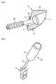
- Figure 2shows a slightly modified design of the glenoid implant.
- the sidewalls 15, 16are not rounded.
- a screw 40is inserted through hole 22.
- This screwis preferably a self-cutting screw.
- Between the mounting surface 11 and the contact surface 20there are three recesses through which suture anchors may be applied into the bone. There may any number of such recesses.
- Figure 3shows a cutout view of the glenoid implant. This figure further shows a typical configuration of the holes 21, 22 for holding the screw 40.
- the protrusions 29 for improving fixation of the implant to the boneare shown in a side view. There is preferably at least one such protrusion and most preferably there is a plurality of such protrusions.
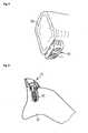
- FIG 4the implant 10 is shown attached to a holding tool 30.
- This holding toolcomprises of a handle 31 attached to a shaft 32.
- the shafthas an end which fits into hole 23 of the implant. The surgeon may hold the implant at a selected location at the glenoid when drilling the screw holes and/or inserting the screws.
- Figure 5shows the implant 10 attached to the glenoid 50.
- FIG 6a cross-section of the glenoid 50 is shown with a cross-section of the implant 10 attached thereto by means of the screw 40.
Landscapes
- Health & Medical Sciences (AREA)
- Vascular Medicine (AREA)
- General Health & Medical Sciences (AREA)
- Oral & Maxillofacial Surgery (AREA)
- Transplantation (AREA)
- Engineering & Computer Science (AREA)
- Biomedical Technology (AREA)
- Cardiology (AREA)
- Life Sciences & Earth Sciences (AREA)
- Heart & Thoracic Surgery (AREA)
- Animal Behavior & Ethology (AREA)
- Orthopedic Medicine & Surgery (AREA)
- Public Health (AREA)
- Veterinary Medicine (AREA)
- Prostheses (AREA)
- Surgical Instruments (AREA)
Description
- The invention relates to an implant useful for increasing stability of the shoulder and specifically in the treatment of anterior shoulder instability.
- Fractures of the anterior glenoid may be caused by anterior shoulder dislocation. Such fractures, also known as Bankart lesion lead to continuing shoulder instability.
WO 2008/015670 A2 andEP 2 135 566 A1 disclose instruments and methods for repairing such a fracture by fixing a coracoid graft to the glenoid. Here harvesting, shaping, drilling and shuttling require a significant amount of time and specific skills of the surgeon. - Various shoulder joint prostheses are disclosed in
EP 1 815 825 A1 , EP 1 510 190 A1 ,FR 2 825 263 A1 FR 2 843 293 A1 FR 2 578 162 A1 - The problem to be solved by the invention is to simplify repairs of fractured/degenerated anterior glenoids and to offer the surgeon reliable tools for repairing such fractures/degenerations.
- The invention is described in the independent claims. The depend-ent claims relate to further improvements of the invention.
- The glenoid implant is an anatomically shaped body. It may comprise metal and/or plastic materials. It may furthermore comprise a metal like titanium, stainless steel or a plastic material like PEEK. It may also comprise any combination of such materials. The glenoid implant provides means for attachment to a glenoid. Attachment may be done by screws or other fixation means. The glenoid implant has a contact surface adapted to extend the surface of the glenoid and to bear the Humerus head or at least part of it.
- The main advantage of this implant over the prior art is that the time and effort needed for harvesting, shaping and drilling can be saved. Furthermore it can be placed and fixed more easily. Failure of the autograft like breakage or resorption during and after fixation are not likely to occur as in the prior art.
- Preferably the body of the glenoid implant is roughly cuboidal shaped and the contact surface may be a recess in a top surface of the implant.
- It is furthermore preferred, if the body of the glenoid implant has rounded edges.
- In a further preferred embodiment the glenoid implant has at least one hole for inserting a screw to attach the glenoid implant to the glenoid. The hole preferably has a screw head seating area and preferably allows the screw to be mounted in a predetermined range of angles. Most preferably there are two holes.
- In a further embodiment there is at least one means for holding the implant by a tool. This tool may be a handle. Preferably the means for holding is a hole which may have non-circular shape to prevent rotation.
- Preferably there is at least one recess between mounting surface and the contact surface. There may any number of such recesses.
- Preferably glenoid implants are available in different sizes adapted to bone sizes and sizes of glenoid defects.
- Preferably a kit of glenoid implants comprises a choice of different sized implants.
- A further aspect of the invention relates to a method of repairing a fractured and/or degenerated anterior glenoid. In a first step fractured particles are removed from the glenoid or in the case of a degenerated glenoid the bone to implant contact surface is refreshed. In the same time or in the following step a mounting surface is generated at the glenoid, preferably by using a shaver and/or osteotome. In the next step an appropriate size of glenoid implant is selected. Then the selected glenoid implant is positioned at the glenoid, preferably by using an implant holding tool. In the next step the location of the holes to be drilled into the glenoid may be marked. Alternatively the holes may be drilled directly by using the glenoid implant as drilling jig. Then the screws are screwed into the holes. As a further alternative the screws may be inserted without drilling or preliminary fixed wires. Some steps like selecting the size of the implant may be exchanged in the order with other steps without affecting the result of the method.
- In the following the invention will be described by way of example, without limitation of the general inventive concept, on examples of embodiment with reference to the drawings.
Figure 1 shows the glenoid implant.Figure 2 shows a slightly modified design of the glenoid implant.Figure 3 shows a cutout view of the implant.Figure 4 shows the implant attached to a holding tool.Figure 5 shows theimplant 10 attached to theglenoid 50.Figure 6 shows a cross-section of an implant screwed to a glenoid.- In
figure 1 a preferred embodiment according to the invention is shown. Theglenoid implant 10 has amounting surface 11 by which it is attached to the glenoid.Mounting surface 11 may have a 3-dimensional structure contacting the glenoid to enhance bone ingrowth. The glenoid implant preferably has cuboidal shape. Although it may have any other shape as long as it allows fixation to the glenoid and adaption to the glenoid surface. There may be arear surface 12 opposed to the mounting surface. The top surface 14 may have a recess serving ascontact surface 20 adapted to the surface form of theglenoid 50 and to interface with the humerus head. Opposed to the top surface is abottom surface 13. There are afirst sidewall 15 and asecond sidewall 16 which are preferably rounded. In thesidewall 15 there is ahole 23, which may be used to align the implant with at lest one guide pin, which has previously been placed in the bone. Furthermore such a hole may be used by a handle for holding the implant. Twoholes screw 40. They preferably allow orientation of the screw in a predetermined range of angles to provide flexibility in mounting. Figure 2 shows a slightly modified design of the glenoid implant. Here thesidewalls screw 40 is inserted throughhole 22. This screw is preferably a self-cutting screw. Between the mountingsurface 11 and thecontact surface 20 there are three recesses through which suture anchors may be applied into the bone. There may any number of such recesses.Figure 3 shows a cutout view of the glenoid implant. This figure further shows a typical configuration of theholes screw 40. Furthermore theprotrusions 29 for improving fixation of the implant to the bone are shown in a side view. There is preferably at least one such protrusion and most preferably there is a plurality of such protrusions.- In
figure 4 theimplant 10 is shown attached to a holdingtool 30. This holding tool comprises of ahandle 31 attached to ashaft 32. The shaft has an end which fits intohole 23 of the implant. The surgeon may hold the implant at a selected location at the glenoid when drilling the screw holes and/or inserting the screws. Figure 5 shows theimplant 10 attached to the glenoid 50.- In
figure 6 a cross-section of the glenoid 50 is shown with a cross-section of theimplant 10 attached thereto by means of thescrew 40. - 10
- glenoid implant
- 11
- mounting surface
- 12
- rear surface
- 13
- bottom surface
- 14
- top surface
- 15
- first sidewall
- 16
- second sidewall
- 20
- contact surface
- 21
- first hole
- 22
- second hole
- 23
- hole
- 24
- third hole
- 25
- protrusions
- 26
- bevel
- 29
- protrusion
- 30
- implant holding tool
- 31
- handle
- 32
- shaft
- 40
- screw
- 50
- glenoid
Claims (8)
- Glenoid implant (10) comprising of metal and/or plastic materials, having a contact surface (20) adapted to the surface form of the glenoid and to interface with a humerus head,
wherein
the glenoid implant (10) is adapted to extend radially the surface of the glenoid that bears the humerus head to a side of the glenoid, further comprising at least one hole (21, 22) with a screw head seating area for holding the head of a screw (40) which is adapted to be screwed into the side of the glenoid. - Glenoid implant according to claim 1,
wherein
the body of the glenoid implant (10) is roughly cuboidal shaped and has a recess forming the contact surface (20). - Glenoid implant according to claim 1 or 2,
wherein
the body of the glenoid implant (10) has rounded edges. - Glenoid implant according to any one of the preceding claims,
wherein
the body of the glenoid implant (10) has at least one means (23) for holding the implant by a tool. - Glenoid implant according to any one of the preceding claims,
wherein
at least one means (23) for holding the implant by a tool is a hole which has a non-circular shape to prevent rotation. - Glenoid implant according to any one of the preceding claims,
wherein
the implant has a mounting surface (11) for contacting the glenoid and the mounting surface has a 3-dimensional structure to enhance bone ingrowth. - Glenoid implant according to any one of the preceding claims,
wherein
at least one recess is between a mounting surface (11) and the contact surface (20) through which at least one suture anchors may be applied into the bone. - Kit of glenoid implants comprising a plurality of different sized glenoid implant according to any one of the preceding claims.
Priority Applications (4)
| Application Number | Priority Date | Filing Date | Title |
|---|---|---|---|
| EP12157196.2AEP2630935B1 (en) | 2012-02-27 | 2012-02-27 | Glenoid extension block |
| JP2013035752AJP6147024B2 (en) | 2012-02-27 | 2013-02-26 | Glenoid expansion block |
| US13/777,782US9216091B2 (en) | 2012-02-27 | 2013-02-26 | Glenoid extension block |
| US14/965,582US9610167B2 (en) | 2012-02-27 | 2015-12-10 | Glenoid extension block |
Applications Claiming Priority (1)
| Application Number | Priority Date | Filing Date | Title |
|---|---|---|---|
| EP12157196.2AEP2630935B1 (en) | 2012-02-27 | 2012-02-27 | Glenoid extension block |
Publications (2)
| Publication Number | Publication Date |
|---|---|
| EP2630935A1 EP2630935A1 (en) | 2013-08-28 |
| EP2630935B1true EP2630935B1 (en) | 2014-12-31 |
Family
ID=45811275
Family Applications (1)
| Application Number | Title | Priority Date | Filing Date |
|---|---|---|---|
| EP12157196.2AActiveEP2630935B1 (en) | 2012-02-27 | 2012-02-27 | Glenoid extension block |
Country Status (3)
| Country | Link |
|---|---|
| US (2) | US9216091B2 (en) |
| EP (1) | EP2630935B1 (en) |
| JP (1) | JP6147024B2 (en) |
Families Citing this family (37)
| Publication number | Priority date | Publication date | Assignee | Title |
|---|---|---|---|---|
| US6520964B2 (en) | 2000-05-01 | 2003-02-18 | Std Manufacturing, Inc. | System and method for joint resurface repair |
| US8177841B2 (en) | 2000-05-01 | 2012-05-15 | Arthrosurface Inc. | System and method for joint resurface repair |
| US6610067B2 (en) | 2000-05-01 | 2003-08-26 | Arthrosurface, Incorporated | System and method for joint resurface repair |
| US7914545B2 (en) | 2002-12-03 | 2011-03-29 | Arthrosurface, Inc | System and method for retrograde procedure |
| US8388624B2 (en) | 2003-02-24 | 2013-03-05 | Arthrosurface Incorporated | Trochlear resurfacing system and method |
| AU2004293042A1 (en) | 2003-11-20 | 2005-06-09 | Arthrosurface, Inc. | Retrograde delivery of resurfacing devices |
| WO2006004885A2 (en) | 2004-06-28 | 2006-01-12 | Arthrosurface, Inc. | System for articular surface replacement |
| US7828853B2 (en) | 2004-11-22 | 2010-11-09 | Arthrosurface, Inc. | Articular surface implant and delivery system |
| US9358029B2 (en) | 2006-12-11 | 2016-06-07 | Arthrosurface Incorporated | Retrograde resection apparatus and method |
| EP2262448A4 (en) | 2008-03-03 | 2014-03-26 | Arthrosurface Inc | Bone resurfacing system and method |
| US10945743B2 (en) | 2009-04-17 | 2021-03-16 | Arthrosurface Incorporated | Glenoid repair system and methods of use thereof |
| AU2010236182A1 (en) | 2009-04-17 | 2011-11-24 | Arthrosurface Incorporated | Glenoid resurfacing system and method |
| WO2010121250A1 (en) | 2009-04-17 | 2010-10-21 | Arthrosurface Incorporated | Glenoid resurfacing system and method |
| CA2771332C (en) | 2009-08-27 | 2020-11-10 | Cotera, Inc. | Method and apparatus for force redistribution in articular joints |
| US9861408B2 (en) | 2009-08-27 | 2018-01-09 | The Foundry, Llc | Method and apparatus for treating canine cruciate ligament disease |
| US9278004B2 (en)* | 2009-08-27 | 2016-03-08 | Cotera, Inc. | Method and apparatus for altering biomechanics of the articular joints |
| US10349980B2 (en) | 2009-08-27 | 2019-07-16 | The Foundry, Llc | Method and apparatus for altering biomechanics of the shoulder |
| EP2542165A4 (en) | 2010-03-05 | 2015-10-07 | Arthrosurface Inc | Tibial resurfacing system and method |
| US9066716B2 (en) | 2011-03-30 | 2015-06-30 | Arthrosurface Incorporated | Suture coil and suture sheath for tissue repair |
| EP2804565B1 (en) | 2011-12-22 | 2018-03-07 | Arthrosurface Incorporated | System for bone fixation |
| EP2630935B1 (en)* | 2012-02-27 | 2014-12-31 | Arthrex, Inc. | Glenoid extension block |
| WO2014008126A1 (en) | 2012-07-03 | 2014-01-09 | Arthrosurface Incorporated | System and method for joint resurfacing and repair |
| US9492200B2 (en) | 2013-04-16 | 2016-11-15 | Arthrosurface Incorporated | Suture system and method |
| US10624748B2 (en) | 2014-03-07 | 2020-04-21 | Arthrosurface Incorporated | System and method for repairing articular surfaces |
| US9931219B2 (en) | 2014-03-07 | 2018-04-03 | Arthrosurface Incorporated | Implant and anchor assembly |
| US11607319B2 (en) | 2014-03-07 | 2023-03-21 | Arthrosurface Incorporated | System and method for repairing articular surfaces |
| CN107405109B (en)* | 2015-03-10 | 2021-07-16 | 史密夫和内修有限公司 | Open LATARJET procedure for correcting anterior lower glenoid bone loss |
| US10327789B2 (en) | 2015-12-29 | 2019-06-25 | Medos International Sarl | Methods and systems for preparing bone for a surgical procedure |
| WO2018052965A1 (en)* | 2016-09-19 | 2018-03-22 | Smith & Nephew, Inc. | Glenoid implant and method of use thereof |
| EP3644906B1 (en)* | 2017-06-29 | 2022-02-23 | Encore Medical, L.P. (D/B/A DJO Surgical) | Glenosphere with inserts for augmented fixation |
| US11160663B2 (en) | 2017-08-04 | 2021-11-02 | Arthrosurface Incorporated | Multicomponent articular surface implant |
| CA3086956A1 (en) | 2018-01-02 | 2019-07-11 | Cartiheal (2009) Ltd. | Implantation tool and protocol for optimized solid substrates promoting cell and tissue growth |
| EP3911280A1 (en) | 2019-01-15 | 2021-11-24 | Biopoly, Llc | Implant systems for repair of a humeral head |
| EP3911281A1 (en)* | 2019-01-15 | 2021-11-24 | Biopoly, Llc | Implant systems for repair of a glenoid cavity |
| WO2020186099A1 (en) | 2019-03-12 | 2020-09-17 | Arthrosurface Incorporated | Humeral and glenoid articular surface implant systems and methods |
| US11213406B2 (en) | 2019-07-10 | 2022-01-04 | Arthrex, Inc. | Graft preparation station for repairing bone defects |
| CA3154424A1 (en)* | 2019-10-16 | 2021-04-29 | Eugene Willis BRABSTON | Glenoid bone graft retention plate |
Family Cites Families (81)
| Publication number | Priority date | Publication date | Assignee | Title |
|---|---|---|---|---|
| GB1324990A (en)* | 1969-08-25 | 1973-07-25 | Nat Res Dev | Prosthetic shoulder joint devices |
| US4502161A (en)* | 1981-09-21 | 1985-03-05 | Wall W H | Prosthetic meniscus for the repair of joints |
| FR2578162A1 (en)* | 1985-03-04 | 1986-09-05 | Rambert Andre | Cup for total prosthesis of the hip or of the shoulder |
| DE3816676A1 (en) | 1988-05-17 | 1989-11-23 | S & G Implants Gmbh | SHOULDER BOARD |
| US6099531A (en)* | 1998-08-20 | 2000-08-08 | Bonutti; Peter M. | Changing relationship between bones |
| SE516039C3 (en)* | 2000-03-23 | 2002-01-09 | Philippe Kopylov Ab | Sound substitute for the distal radioulnar joint |
| US9561110B2 (en)* | 2000-07-18 | 2017-02-07 | Encore Medical, L.P. | Elbow prosthesis |
| FR2825263A1 (en)* | 2001-05-30 | 2002-12-06 | Tecknimed | Shoulder joint prosthesis has cap on humerus to engage socket with movement limiting stop surfaces |
| US8753402B2 (en)* | 2001-07-27 | 2014-06-17 | Biomet Manufacturing, Llc | Modular humeral head resurfacing system |
| FR2836039B1 (en)* | 2002-02-15 | 2004-10-01 | Tornier Sa | GLENOIDAL COMPONENT OF SHOULDER PROSTHESIS AND TOTAL SHOULDER PROSTHESIS INCORPORATING SUCH COMPONENT |
| US20040006393A1 (en)* | 2002-07-03 | 2004-01-08 | Brian Burkinshaw | Implantable prosthetic knee for lateral compartment |
| FR2843293B1 (en)* | 2002-08-08 | 2005-07-01 | Didier Capon | PROTHETIC IMPLANT FOR THE JOINT OF AN ANATOMIC MEMBER |
| US7124762B2 (en)* | 2002-08-15 | 2006-10-24 | Arthrex, Inc. | Dovetail meniscal allograft technique and system |
| AU2004232009B2 (en)* | 2003-04-18 | 2009-08-06 | Ascension Orthopedics, Inc. | Interpositional biarticular disk implant |
| US7625408B2 (en)* | 2003-07-22 | 2009-12-01 | Avanta Orthopaedics, Llc | Prosthetic wrist implant |
| FR2859099B1 (en) | 2003-08-25 | 2006-01-06 | Tornier Sa | GLENOIDAL COMPONENT OF SHOULDER PROSTHESIS AND TOTAL SHOULDER PROSTHESIS INCORPORATING SUCH COMPONENT |
| US20050049710A1 (en)* | 2003-08-28 | 2005-03-03 | O'driscoll Shawn W. | Prosthesis for partial replacement of an articulating surface on bone |
| US6969407B2 (en)* | 2003-12-22 | 2005-11-29 | Depuy Products, Inc. | Modular radial component for a total wrist arthroplasty |
| US7942880B2 (en)* | 2004-02-18 | 2011-05-17 | Bertram Iii Morton | Geometric replacements for defective bone |
| US20060079963A1 (en)* | 2004-10-07 | 2006-04-13 | Regan Hansen | Semiconstrained shoulder prosthetic for treatment of rotator cuff arthropathy |
| US20060111786A1 (en)* | 2004-11-22 | 2006-05-25 | Orthopedic Development Corporation | Metallic prosthetic implant for use in minimally invasive acromio-clavicular shoulder joint hemi-arthroplasty |
| US7160329B2 (en)* | 2004-12-01 | 2007-01-09 | Mayo Foundation For Medical Research And Education | Radial-capitellar implant |
| US20060200248A1 (en)* | 2005-03-03 | 2006-09-07 | Laurent Beguin | Prosthesis for the glenoid cavity of the scapula |
| US7291169B2 (en)* | 2005-04-15 | 2007-11-06 | Zimmer Technology, Inc. | Cartilage implant |
| US7572293B2 (en)* | 2005-06-30 | 2009-08-11 | Depuy Products, Inc. | Tibial insert and associated surgical method |
| US7819924B2 (en)* | 2005-11-14 | 2010-10-26 | Ascension Orthopedics, Inc. | Distal radioulnar joint prosthesis |
| US7618454B2 (en)* | 2005-12-07 | 2009-11-17 | Zimmer Spine, Inc. | Transforaminal lumbar interbody fusion spacers |
| US7959680B2 (en)* | 2006-02-02 | 2011-06-14 | Biomet Manufacturing Corp. | Method and apparatus for performing a shoulder implant procedure |
| PL1854431T3 (en)* | 2006-05-12 | 2010-05-31 | Synthes Gmbh | Joint endoprosthesis |
| US8764839B2 (en)* | 2006-06-22 | 2014-07-01 | DePuy Synthes Products, LLC | Tibial insert having a keel including a bore formed therein |
| AU2007280012B2 (en)* | 2006-07-31 | 2013-01-31 | T.A.G. Medical Devices - Agriculture Cooperative Ltd. | Arthroscopic bone transplanting procedure, and medical instruments useful therein |
| JP5851080B2 (en)* | 2006-09-06 | 2016-02-03 | スミス アンド ネフュー インコーポレーテッド | Implants with transition surfaces and related processes |
| US20090287309A1 (en)* | 2007-01-30 | 2009-11-19 | Tornier Sas | Intra-articular joint replacement |
| US7572294B2 (en)* | 2007-03-07 | 2009-08-11 | Biomet Manufacturing Corp. | Method and apparatus for removing an acetabular bearing |
| US20100131069A1 (en)* | 2007-08-01 | 2010-05-27 | Jeffrey Halbrecht | Method and system for patella tendon realignment |
| US20090105840A1 (en)* | 2007-10-18 | 2009-04-23 | Inbone Technologies, Inc. | Fibular stiffener and bony defect replacer |
| WO2009108789A1 (en)* | 2008-02-29 | 2009-09-03 | Vot, Llc | Tibial prosthesis |
| US7991599B2 (en)* | 2008-04-09 | 2011-08-02 | Active Implants Corporation | Meniscus prosthetic device selection and implantation methods |
| US8052755B2 (en)* | 2008-05-09 | 2011-11-08 | Remi Sciences, Inc. | Ulnar head prosthesis system |
| CA2726412A1 (en)* | 2008-06-19 | 2009-12-23 | Moximed, Inc. | Implantable brace for providing joint support |
| EP2135566B1 (en) | 2008-06-20 | 2011-03-09 | Arthrex, Inc. | Latarjet instrumentation |
| EP2135562B1 (en)* | 2008-06-20 | 2015-09-09 | Arthrex, Inc. | Wedged profile plate |
| US9808345B2 (en)* | 2008-07-24 | 2017-11-07 | Iorthopedics, Inc. | Resilient arthroplasty device |
| AU2010236182A1 (en)* | 2009-04-17 | 2011-11-24 | Arthrosurface Incorporated | Glenoid resurfacing system and method |
| CN102458270A (en)* | 2009-06-24 | 2012-05-16 | 定制Med整形(私人)有限公司 | A positioning guide and a bone cutting guide system |
| CA2771332C (en)* | 2009-08-27 | 2020-11-10 | Cotera, Inc. | Method and apparatus for force redistribution in articular joints |
| US9278004B2 (en)* | 2009-08-27 | 2016-03-08 | Cotera, Inc. | Method and apparatus for altering biomechanics of the articular joints |
| JP2013504389A (en)* | 2009-09-11 | 2013-02-07 | アーティキュリンクス, インコーポレイテッド | Disc-shaped orthopedic device |
| US8257444B2 (en)* | 2009-09-21 | 2012-09-04 | Linares Medical Devices, Llc | End surface mounted plugs incorporated into an artificial joint and including cushioned soft plastic between outer hardened plastic layers |
| WO2011049471A1 (en)* | 2009-10-22 | 2011-04-28 | Pranesh Kumar | Knee prosthesis |
| US8721727B2 (en)* | 2009-11-24 | 2014-05-13 | Tornier Sas | Glenoid component with offset center and associated methods |
| CA2782137A1 (en)* | 2009-12-11 | 2011-06-16 | Conformis, Inc. | Patient-specific and patient-engineered orthopedic implants |
| US8657859B2 (en)* | 2009-12-16 | 2014-02-25 | Advanced Veterinary Solutions | Implant for promoting stability of the canine stifle joint |
| US8506569B2 (en)* | 2009-12-31 | 2013-08-13 | DePuy Synthes Products, LLC | Reciprocating rasps for use in an orthopaedic surgical procedure |
| WO2013033447A2 (en)* | 2011-09-01 | 2013-03-07 | Grotz R Thomas | Resilient interpositional arthroplasty device |
| WO2011112710A1 (en)* | 2010-03-09 | 2011-09-15 | Rolston Lindsey R | Device for unicompartmental knee arthroplasty |
| US9579106B2 (en)* | 2010-03-31 | 2017-02-28 | New York Society For The Relief Of The Ruptured And Crippled, Maintaining The Hospital For Special Surgery | Shoulder arthroplasty instrumentation |
| US9408652B2 (en)* | 2010-04-27 | 2016-08-09 | Tornier Sas | Intra-articular joint replacement and method |
| WO2011149590A1 (en)* | 2010-05-27 | 2011-12-01 | Synthes Usa, Llc | Allogenic articular cavity prosthesis |
| US20120022655A1 (en)* | 2010-07-26 | 2012-01-26 | Moximed, Inc. | Absorber design for implantable device |
| US9232955B2 (en)* | 2010-08-12 | 2016-01-12 | Smith & Nephew, Inc. | Methods and devices for installing standard and reverse shoulder implants |
| US9254155B2 (en)* | 2010-10-29 | 2016-02-09 | The Cleveland Clinic Foundation | System and method for assisting with arrangement of a stock instrument with respect to a patient tissue |
| EP2632349B1 (en)* | 2010-10-29 | 2018-03-07 | The Cleveland Clinic Foundation | System for assisting with attachment of a stock implant to a patient tissue |
| US9763679B2 (en)* | 2011-03-18 | 2017-09-19 | DePuy Synthes Products, Inc. | Combination driver/anti-rotation handle for shoulder arthroplasty |
| US20140142578A1 (en)* | 2011-07-12 | 2014-05-22 | Materialise N.V. | Surgical instrument for the positioning of an alignment element |
| US9451973B2 (en)* | 2011-10-27 | 2016-09-27 | Biomet Manufacturing, Llc | Patient specific glenoid guide |
| WO2013086402A1 (en)* | 2011-12-08 | 2013-06-13 | Moximed, Inc. | Spacers for redistributing forces for the patella |
| US8845744B2 (en)* | 2012-01-09 | 2014-09-30 | Biomet Manufacturing, Llc | Ulnar head implant |
| EP2630935B1 (en)* | 2012-02-27 | 2014-12-31 | Arthrex, Inc. | Glenoid extension block |
| US9248022B2 (en)* | 2012-03-27 | 2016-02-02 | DePuy Synthes Products, Inc. | Method of implanting a glenoid defect-filling component |
| US8945229B2 (en)* | 2012-03-27 | 2015-02-03 | DePuy Synthes Products, LLC | Reverse shoulder orthopaedic implant having a metaglene component with a screw locking cap |
| CN106667543B (en)* | 2012-03-30 | 2020-09-01 | 德普伊新特斯产品有限责任公司 | Stemless humeral component and associated surgical instrument and method |
| US8900245B2 (en)* | 2012-06-07 | 2014-12-02 | Howmedica Osteonics Corp. | Glenosphere inserter and impactor |
| US10350078B2 (en)* | 2012-06-27 | 2019-07-16 | Arthrosurface, Inc. | Devices, apparatuses, kits, and methods for repair of articular surface and/or articular rim |
| CA2907537C (en)* | 2012-08-01 | 2020-08-25 | Exactech, Inc. | Prosthetic devices to improve joint mechanics in arthroplasty |
| US20150223941A1 (en)* | 2012-08-27 | 2015-08-13 | Conformis, Inc. | Methods, Devices and Techniques for Improved Placement and Fixation of Shoulder Implant Components |
| US9204977B2 (en)* | 2012-12-11 | 2015-12-08 | Biomet Manufacturing, Llc | Patient-specific acetabular guide for anterior approach |
| US9839438B2 (en)* | 2013-03-11 | 2017-12-12 | Biomet Manufacturing, Llc | Patient-specific glenoid guide with a reusable guide holder |
| US9044330B2 (en)* | 2013-03-12 | 2015-06-02 | DePuy Synthes Products, Inc. | System and method for implanting a secondary glenoid prosthesis |
| AU2014317989A1 (en)* | 2013-09-05 | 2016-03-17 | Smith & Nephew, Inc. | Patient-matched acetabular augment with alignment guide |
| US20150112348A1 (en)* | 2013-10-21 | 2015-04-23 | Biomet Manufacturing, Llc | Manipulate guide registration surface |
- 2012
- 2012-02-27EPEP12157196.2Apatent/EP2630935B1/enactiveActive
- 2013
- 2013-02-26USUS13/777,782patent/US9216091B2/enactiveActive
- 2013-02-26JPJP2013035752Apatent/JP6147024B2/enactiveActive
- 2015
- 2015-12-10USUS14/965,582patent/US9610167B2/enactiveActive
Also Published As
| Publication number | Publication date |
|---|---|
| JP2013172965A (en) | 2013-09-05 |
| US20130238099A1 (en) | 2013-09-12 |
| US9216091B2 (en) | 2015-12-22 |
| US20160095709A1 (en) | 2016-04-07 |
| US9610167B2 (en) | 2017-04-04 |
| EP2630935A1 (en) | 2013-08-28 |
| JP6147024B2 (en) | 2017-06-14 |
Similar Documents
| Publication | Publication Date | Title |
|---|---|---|
| EP2630935B1 (en) | Glenoid extension block | |
| JP6947802B2 (en) | Patient-specific augmented glenoid system | |
| US11696835B2 (en) | Revision implant augments, systems, and methods | |
| CN102596103B (en) | Cranial implant and component set including same | |
| US9668791B2 (en) | Surgical implant device, method and apparatus for implanting thereof | |
| US8137358B2 (en) | Method and apparatus for positioning an implant | |
| EP3166540B1 (en) | A surgical joint implant | |
| EP3334384B1 (en) | Glenoid fossa prosthesis | |
| US20200237407A1 (en) | Strut Plate And Cabling System | |
| US20150005833A1 (en) | Bone cutting screw |
Legal Events
| Date | Code | Title | Description |
|---|---|---|---|
| PUAI | Public reference made under article 153(3) epc to a published international application that has entered the european phase | Free format text:ORIGINAL CODE: 0009012 | |
| AK | Designated contracting states | Kind code of ref document:A1 Designated state(s):AL AT BE BG CH CY CZ DE DK EE ES FI FR GB GR HR HU IE IS IT LI LT LU LV MC MK MT NL NO PL PT RO RS SE SI SK SM TR | |
| AX | Request for extension of the european patent | Extension state:BA ME | |
| 17P | Request for examination filed | Effective date:20130923 | |
| RBV | Designated contracting states (corrected) | Designated state(s):AL AT BE BG CH CY CZ DE DK EE ES FI FR GB GR HR HU IE IS IT LI LT LU LV MC MK MT NL NO PL PT RO RS SE SI SK SM TR | |
| GRAP | Despatch of communication of intention to grant a patent | Free format text:ORIGINAL CODE: EPIDOSNIGR1 | |
| RIC1 | Information provided on ipc code assigned before grant | Ipc:A61F 2/40 20060101AFI20131021BHEP Ipc:A61F 2/46 20060101ALI20131021BHEP | |
| INTG | Intention to grant announced | Effective date:20131121 | |
| GRAP | Despatch of communication of intention to grant a patent | Free format text:ORIGINAL CODE: EPIDOSNIGR1 | |
| GRAS | Grant fee paid | Free format text:ORIGINAL CODE: EPIDOSNIGR3 | |
| INTG | Intention to grant announced | Effective date:20140611 | |
| GRAA | (expected) grant | Free format text:ORIGINAL CODE: 0009210 | |
| AK | Designated contracting states | Kind code of ref document:B1 Designated state(s):AL AT BE BG CH CY CZ DE DK EE ES FI FR GB GR HR HU IE IS IT LI LT LU LV MC MK MT NL NO PL PT RO RS SE SI SK SM TR | |
| REG | Reference to a national code | Ref country code:CH Ref legal event code:EP Ref country code:GB Ref legal event code:FG4D | |
| REG | Reference to a national code | Ref country code:IE Ref legal event code:FG4D | |
| REG | Reference to a national code | Ref country code:AT Ref legal event code:REF Ref document number:703905 Country of ref document:AT Kind code of ref document:T Effective date:20150215 | |
| REG | Reference to a national code | Ref country code:DE Ref legal event code:R096 Ref document number:602012004581 Country of ref document:DE Effective date:20150219 | |
| PG25 | Lapsed in a contracting state [announced via postgrant information from national office to epo] | Ref country code:LT Free format text:LAPSE BECAUSE OF FAILURE TO SUBMIT A TRANSLATION OF THE DESCRIPTION OR TO PAY THE FEE WITHIN THE PRESCRIBED TIME-LIMIT Effective date:20141231 Ref country code:NO Free format text:LAPSE BECAUSE OF FAILURE TO SUBMIT A TRANSLATION OF THE DESCRIPTION OR TO PAY THE FEE WITHIN THE PRESCRIBED TIME-LIMIT Effective date:20150331 Ref country code:FI Free format text:LAPSE BECAUSE OF FAILURE TO SUBMIT A TRANSLATION OF THE DESCRIPTION OR TO PAY THE FEE WITHIN THE PRESCRIBED TIME-LIMIT Effective date:20141231 | |
| REG | Reference to a national code | Ref country code:NL Ref legal event code:VDEP Effective date:20141231 | |
| REG | Reference to a national code | Ref country code:LT Ref legal event code:MG4D | |
| PG25 | Lapsed in a contracting state [announced via postgrant information from national office to epo] | Ref country code:GR Free format text:LAPSE BECAUSE OF FAILURE TO SUBMIT A TRANSLATION OF THE DESCRIPTION OR TO PAY THE FEE WITHIN THE PRESCRIBED TIME-LIMIT Effective date:20150401 Ref country code:LV Free format text:LAPSE BECAUSE OF FAILURE TO SUBMIT A TRANSLATION OF THE DESCRIPTION OR TO PAY THE FEE WITHIN THE PRESCRIBED TIME-LIMIT Effective date:20141231 Ref country code:SE Free format text:LAPSE BECAUSE OF FAILURE TO SUBMIT A TRANSLATION OF THE DESCRIPTION OR TO PAY THE FEE WITHIN THE PRESCRIBED TIME-LIMIT Effective date:20141231 Ref country code:RS Free format text:LAPSE BECAUSE OF FAILURE TO SUBMIT A TRANSLATION OF THE DESCRIPTION OR TO PAY THE FEE WITHIN THE PRESCRIBED TIME-LIMIT Effective date:20141231 Ref country code:HR Free format text:LAPSE BECAUSE OF FAILURE TO SUBMIT A TRANSLATION OF THE DESCRIPTION OR TO PAY THE FEE WITHIN THE PRESCRIBED TIME-LIMIT Effective date:20141231 | |
| REG | Reference to a national code | Ref country code:AT Ref legal event code:MK05 Ref document number:703905 Country of ref document:AT Kind code of ref document:T Effective date:20141231 | |
| PG25 | Lapsed in a contracting state [announced via postgrant information from national office to epo] | Ref country code:NL Free format text:LAPSE BECAUSE OF FAILURE TO SUBMIT A TRANSLATION OF THE DESCRIPTION OR TO PAY THE FEE WITHIN THE PRESCRIBED TIME-LIMIT Effective date:20141231 | |
| PG25 | Lapsed in a contracting state [announced via postgrant information from national office to epo] | Ref country code:CZ Free format text:LAPSE BECAUSE OF FAILURE TO SUBMIT A TRANSLATION OF THE DESCRIPTION OR TO PAY THE FEE WITHIN THE PRESCRIBED TIME-LIMIT Effective date:20141231 Ref country code:SK Free format text:LAPSE BECAUSE OF FAILURE TO SUBMIT A TRANSLATION OF THE DESCRIPTION OR TO PAY THE FEE WITHIN THE PRESCRIBED TIME-LIMIT Effective date:20141231 Ref country code:ES Free format text:LAPSE BECAUSE OF FAILURE TO SUBMIT A TRANSLATION OF THE DESCRIPTION OR TO PAY THE FEE WITHIN THE PRESCRIBED TIME-LIMIT Effective date:20141231 Ref country code:RO Free format text:LAPSE BECAUSE OF FAILURE TO SUBMIT A TRANSLATION OF THE DESCRIPTION OR TO PAY THE FEE WITHIN THE PRESCRIBED TIME-LIMIT Effective date:20141231 | |
| PG25 | Lapsed in a contracting state [announced via postgrant information from national office to epo] | Ref country code:AT Free format text:LAPSE BECAUSE OF FAILURE TO SUBMIT A TRANSLATION OF THE DESCRIPTION OR TO PAY THE FEE WITHIN THE PRESCRIBED TIME-LIMIT Effective date:20141231 Ref country code:IS Free format text:LAPSE BECAUSE OF FAILURE TO SUBMIT A TRANSLATION OF THE DESCRIPTION OR TO PAY THE FEE WITHIN THE PRESCRIBED TIME-LIMIT Effective date:20150430 Ref country code:PL Free format text:LAPSE BECAUSE OF FAILURE TO SUBMIT A TRANSLATION OF THE DESCRIPTION OR TO PAY THE FEE WITHIN THE PRESCRIBED TIME-LIMIT Effective date:20141231 | |
| PG25 | Lapsed in a contracting state [announced via postgrant information from national office to epo] | Ref country code:LU Free format text:LAPSE BECAUSE OF FAILURE TO SUBMIT A TRANSLATION OF THE DESCRIPTION OR TO PAY THE FEE WITHIN THE PRESCRIBED TIME-LIMIT Effective date:20150227 | |
| REG | Reference to a national code | Ref country code:CH Ref legal event code:PL | |
| REG | Reference to a national code | Ref country code:DE Ref legal event code:R097 Ref document number:602012004581 Country of ref document:DE | |
| PG25 | Lapsed in a contracting state [announced via postgrant information from national office to epo] | Ref country code:DK Free format text:LAPSE BECAUSE OF FAILURE TO SUBMIT A TRANSLATION OF THE DESCRIPTION OR TO PAY THE FEE WITHIN THE PRESCRIBED TIME-LIMIT Effective date:20141231 Ref country code:CH Free format text:LAPSE BECAUSE OF NON-PAYMENT OF DUE FEES Effective date:20150228 Ref country code:EE Free format text:LAPSE BECAUSE OF FAILURE TO SUBMIT A TRANSLATION OF THE DESCRIPTION OR TO PAY THE FEE WITHIN THE PRESCRIBED TIME-LIMIT Effective date:20141231 Ref country code:LI Free format text:LAPSE BECAUSE OF NON-PAYMENT OF DUE FEES Effective date:20150228 Ref country code:MC Free format text:LAPSE BECAUSE OF FAILURE TO SUBMIT A TRANSLATION OF THE DESCRIPTION OR TO PAY THE FEE WITHIN THE PRESCRIBED TIME-LIMIT Effective date:20141231 | |
| PLBE | No opposition filed within time limit | Free format text:ORIGINAL CODE: 0009261 | |
| STAA | Information on the status of an ep patent application or granted ep patent | Free format text:STATUS: NO OPPOSITION FILED WITHIN TIME LIMIT | |
| REG | Reference to a national code | Ref country code:IE Ref legal event code:MM4A | |
| 26N | No opposition filed | Effective date:20151001 | |
| REG | Reference to a national code | Ref country code:FR Ref legal event code:PLFP Year of fee payment:5 | |
| PG25 | Lapsed in a contracting state [announced via postgrant information from national office to epo] | Ref country code:IE Free format text:LAPSE BECAUSE OF NON-PAYMENT OF DUE FEES Effective date:20150227 | |
| PG25 | Lapsed in a contracting state [announced via postgrant information from national office to epo] | Ref country code:SI Free format text:LAPSE BECAUSE OF FAILURE TO SUBMIT A TRANSLATION OF THE DESCRIPTION OR TO PAY THE FEE WITHIN THE PRESCRIBED TIME-LIMIT Effective date:20141231 | |
| PG25 | Lapsed in a contracting state [announced via postgrant information from national office to epo] | Ref country code:BE Free format text:LAPSE BECAUSE OF FAILURE TO SUBMIT A TRANSLATION OF THE DESCRIPTION OR TO PAY THE FEE WITHIN THE PRESCRIBED TIME-LIMIT Effective date:20141231 | |
| PG25 | Lapsed in a contracting state [announced via postgrant information from national office to epo] | Ref country code:MT Free format text:LAPSE BECAUSE OF FAILURE TO SUBMIT A TRANSLATION OF THE DESCRIPTION OR TO PAY THE FEE WITHIN THE PRESCRIBED TIME-LIMIT Effective date:20141231 | |
| REG | Reference to a national code | Ref country code:FR Ref legal event code:PLFP Year of fee payment:6 | |
| PG25 | Lapsed in a contracting state [announced via postgrant information from national office to epo] | Ref country code:SM Free format text:LAPSE BECAUSE OF FAILURE TO SUBMIT A TRANSLATION OF THE DESCRIPTION OR TO PAY THE FEE WITHIN THE PRESCRIBED TIME-LIMIT Effective date:20141231 Ref country code:HU Free format text:LAPSE BECAUSE OF FAILURE TO SUBMIT A TRANSLATION OF THE DESCRIPTION OR TO PAY THE FEE WITHIN THE PRESCRIBED TIME-LIMIT; INVALID AB INITIO Effective date:20120227 Ref country code:BG Free format text:LAPSE BECAUSE OF FAILURE TO SUBMIT A TRANSLATION OF THE DESCRIPTION OR TO PAY THE FEE WITHIN THE PRESCRIBED TIME-LIMIT Effective date:20141231 | |
| PG25 | Lapsed in a contracting state [announced via postgrant information from national office to epo] | Ref country code:CY Free format text:LAPSE BECAUSE OF FAILURE TO SUBMIT A TRANSLATION OF THE DESCRIPTION OR TO PAY THE FEE WITHIN THE PRESCRIBED TIME-LIMIT Effective date:20141231 | |
| PG25 | Lapsed in a contracting state [announced via postgrant information from national office to epo] | Ref country code:PT Free format text:LAPSE BECAUSE OF FAILURE TO SUBMIT A TRANSLATION OF THE DESCRIPTION OR TO PAY THE FEE WITHIN THE PRESCRIBED TIME-LIMIT Effective date:20150501 | |
| PG25 | Lapsed in a contracting state [announced via postgrant information from national office to epo] | Ref country code:TR Free format text:LAPSE BECAUSE OF FAILURE TO SUBMIT A TRANSLATION OF THE DESCRIPTION OR TO PAY THE FEE WITHIN THE PRESCRIBED TIME-LIMIT Effective date:20141231 | |
| REG | Reference to a national code | Ref country code:FR Ref legal event code:PLFP Year of fee payment:7 | |
| PG25 | Lapsed in a contracting state [announced via postgrant information from national office to epo] | Ref country code:MK Free format text:LAPSE BECAUSE OF FAILURE TO SUBMIT A TRANSLATION OF THE DESCRIPTION OR TO PAY THE FEE WITHIN THE PRESCRIBED TIME-LIMIT Effective date:20141231 | |
| PG25 | Lapsed in a contracting state [announced via postgrant information from national office to epo] | Ref country code:AL Free format text:LAPSE BECAUSE OF FAILURE TO SUBMIT A TRANSLATION OF THE DESCRIPTION OR TO PAY THE FEE WITHIN THE PRESCRIBED TIME-LIMIT Effective date:20141231 | |
| PGFP | Annual fee paid to national office [announced via postgrant information from national office to epo] | Ref country code:FR Payment date:20241231 Year of fee payment:14 | |
| PGFP | Annual fee paid to national office [announced via postgrant information from national office to epo] | Ref country code:DE Payment date:20241231 Year of fee payment:14 | |
| PGFP | Annual fee paid to national office [announced via postgrant information from national office to epo] | Ref country code:IT Payment date:20250110 Year of fee payment:14 Ref country code:GB Payment date:20250102 Year of fee payment:14 |