EP2629875B1 - Breathing air production and filtration system - Google Patents
Breathing air production and filtration systemDownload PDFInfo
- Publication number
- EP2629875B1 EP2629875B1EP11835085.9AEP11835085AEP2629875B1EP 2629875 B1EP2629875 B1EP 2629875B1EP 11835085 AEP11835085 AEP 11835085AEP 2629875 B1EP2629875 B1EP 2629875B1
- Authority
- EP
- European Patent Office
- Prior art keywords
- intake air
- assembly
- air
- communication
- pressure
- Prior art date
- Legal status (The legal status is an assumption and is not a legal conclusion. Google has not performed a legal analysis and makes no representation as to the accuracy of the status listed.)
- Active
Links
Images


Classifications
- A—HUMAN NECESSITIES
- A62—LIFE-SAVING; FIRE-FIGHTING
- A62B—DEVICES, APPARATUS OR METHODS FOR LIFE-SAVING
- A62B7/00—Respiratory apparatus
- A62B7/10—Respiratory apparatus with filter elements
- A—HUMAN NECESSITIES
- A62—LIFE-SAVING; FIRE-FIGHTING
- A62B—DEVICES, APPARATUS OR METHODS FOR LIFE-SAVING
- A62B29/00—Devices, e.g. installations, for rendering harmless or for keeping off harmful chemical agents
- A—HUMAN NECESSITIES
- A62—LIFE-SAVING; FIRE-FIGHTING
- A62B—DEVICES, APPARATUS OR METHODS FOR LIFE-SAVING
- A62B15/00—Installations affording protection against poisonous or injurious substances, e.g. with separate breathing apparatus
- A—HUMAN NECESSITIES
- A62—LIFE-SAVING; FIRE-FIGHTING
- A62B—DEVICES, APPARATUS OR METHODS FOR LIFE-SAVING
- A62B18/00—Breathing masks or helmets, e.g. affording protection against chemical agents or for use at high altitudes or incorporating a pump or compressor for reducing the inhalation effort
- A62B18/02—Masks
- A—HUMAN NECESSITIES
- A62—LIFE-SAVING; FIRE-FIGHTING
- A62B—DEVICES, APPARATUS OR METHODS FOR LIFE-SAVING
- A62B7/00—Respiratory apparatus
- A62B7/12—Respiratory apparatus with fresh-air hose
- A—HUMAN NECESSITIES
- A62—LIFE-SAVING; FIRE-FIGHTING
- A62B—DEVICES, APPARATUS OR METHODS FOR LIFE-SAVING
- A62B9/00—Component parts for respiratory or breathing apparatus
- A62B9/006—Indicators or warning devices, e.g. of low pressure, contamination
- A—HUMAN NECESSITIES
- A62—LIFE-SAVING; FIRE-FIGHTING
- A62B—DEVICES, APPARATUS OR METHODS FOR LIFE-SAVING
- A62B9/00—Component parts for respiratory or breathing apparatus
- A62B9/02—Valves
- F—MECHANICAL ENGINEERING; LIGHTING; HEATING; WEAPONS; BLASTING
- F24—HEATING; RANGES; VENTILATING
- F24F—AIR-CONDITIONING; AIR-HUMIDIFICATION; VENTILATION; USE OF AIR CURRENTS FOR SCREENING
- F24F8/00—Treatment, e.g. purification, of air supplied to human living or working spaces otherwise than by heating, cooling, humidifying or drying
- F24F8/10—Treatment, e.g. purification, of air supplied to human living or working spaces otherwise than by heating, cooling, humidifying or drying by separation, e.g. by filtering
- F24F8/108—Treatment, e.g. purification, of air supplied to human living or working spaces otherwise than by heating, cooling, humidifying or drying by separation, e.g. by filtering using dry filter elements
- F—MECHANICAL ENGINEERING; LIGHTING; HEATING; WEAPONS; BLASTING
- F24—HEATING; RANGES; VENTILATING
- F24F—AIR-CONDITIONING; AIR-HUMIDIFICATION; VENTILATION; USE OF AIR CURRENTS FOR SCREENING
- F24F8/00—Treatment, e.g. purification, of air supplied to human living or working spaces otherwise than by heating, cooling, humidifying or drying
- F24F8/10—Treatment, e.g. purification, of air supplied to human living or working spaces otherwise than by heating, cooling, humidifying or drying by separation, e.g. by filtering
- F24F8/15—Treatment, e.g. purification, of air supplied to human living or working spaces otherwise than by heating, cooling, humidifying or drying by separation, e.g. by filtering by chemical means
- F24F8/158—Treatment, e.g. purification, of air supplied to human living or working spaces otherwise than by heating, cooling, humidifying or drying by separation, e.g. by filtering by chemical means using active carbon
- F—MECHANICAL ENGINEERING; LIGHTING; HEATING; WEAPONS; BLASTING
- F24—HEATING; RANGES; VENTILATING
- F24F—AIR-CONDITIONING; AIR-HUMIDIFICATION; VENTILATION; USE OF AIR CURRENTS FOR SCREENING
- F24F8/00—Treatment, e.g. purification, of air supplied to human living or working spaces otherwise than by heating, cooling, humidifying or drying
- F24F8/10—Treatment, e.g. purification, of air supplied to human living or working spaces otherwise than by heating, cooling, humidifying or drying by separation, e.g. by filtering
- F24F8/15—Treatment, e.g. purification, of air supplied to human living or working spaces otherwise than by heating, cooling, humidifying or drying by separation, e.g. by filtering by chemical means
- F24F8/167—Treatment, e.g. purification, of air supplied to human living or working spaces otherwise than by heating, cooling, humidifying or drying by separation, e.g. by filtering by chemical means using catalytic reactions
Definitions
- Embodiments of the present disclosurerelate to an air breathing system usable in a chemical plant, refinery, or other facility where workers need to breathe good quality air while working in a harsh environment.
- Acute effects from airborne pollutantsmay also include non-respiratory signs and symptoms, which may depend upon toxicological characteristics of the substances involved.
- Ventilation systemswhich vary as to design, use, specifications, and maintenance. Most ventilation systems restrict the movement of air in and between various departments, and the systems may have specific ventilation and filtration capabilities to dilute and remove contamination, airborne microorganisms, viruses, hazardous chemicals, radioactive substances, and the like.
- Vaporous chemicalssuch as acetic acid, benzene, formaldehyde, nitrous oxide, and xylene, carry health warnings and can often affect a person's immune system if the person is exposed to the chemical.
- US 2010/032040 A1describes a breathable air safety system for civilians in a building structure in an emergency.
- US 4 670 223 Adescribes an apparatus for producing sterile air suitable for being administered to intensive-care patients in hospitals using atmospheric air.
- US 7 647 927 B2describes a breathing apparatus operable in a self-contained mode, where a breathable gas is delivered to a user from a source or in a filtered mode of operation, where ambient air is filtered and delivered to the user.
- US 2007/082601 A1describes a dilution ventilation control system for use in a one-pass, critical environments.
- US 2009/004047 A1describes an air supply apparatus for supplying sterilized air to users.
- US 2003/211825 A1describes methods and systems for enhancing air quality in buildings.
- WO 2010/014014 A1describes a mobile breathing-air compressor unit arranged for use in an explosive environment.
- a breathing air production and filtration systemhas an air generation assembly and a distribution assembly.
- the generation assemblyhas a compressor and filtration components to generate breathing air.
- the distribution assemblyhas collection pots with multiple connections for manifolds. For their part, the manifolds have multiple connectors for the respirators of end users.
- the systemuses a monitoring control system with various wireless sensors to monitor operation of the system and the quality of breathing air produced. These sensors include an in-line sensor detecting constituents or contaminants in the breathing air. The sensors also include pressure, temperature, and flow sensors monitoring the operation of the system. An automatic switchover is provided for switching the system to a back-up supply of high-pressure reserve air if needed.
- FIG. 1illustrates a system 10 according to the present disclosure for producing filtered breathing air and delivering the breathing air to end users in a work environment.
- the system 10has a generation assembly 12 that generates the breathing air from ambient air in a remote environment.
- the generation assembly 12includes a compressor 20, a wet tank 30, a particle filter 40, a coalescing filter 45, drying towers 50, a catalytic converter 60, charcoal filters 65, and a dry tank 70. All of these components of the generation assembly 12 can be mounted on a skid or trailer, which can be positioned far from work areas.
- a second part of the system 10includes a distribution assembly 14 in communication with the generation assembly 12.
- the distribution assembly 14receives the generated breathing air from the generation assembly 12 and delivers it to the end users located in work areas of a potentially hazardous environment.
- the distribution assembly 14has one or more tanks or collection pots 80A-B and one or more distribution manifolds 90, which can be placed in various work areas.
- the system 10also includes a monitoring control system 200, which monitors and controls the system 10 using various sensors and communication links to be described in more detail later.
- the monitoring control system 200can verify that clean breathing air is produced on-site.
- the system 200can monitor samples of the breathing air in real time and can test parameters of the sampled breathing air, such as contaminant content, pressure, temperature, quality, etc., to verify the proper production and delivery of the breathing air.
- the system 10typically uses a single generation assembly 12 as described, although additional generation assemblies 12 can be connected to the system 10 to increase the volume of air provided, if necessary. However, for purposes of the present disclosure, reference is made to a single generation assembly 12.
- the compressor 20compresses the ambient air in the remote environment. Any suitable type of compressor 20 can be used. As it operates, the compressor 12 takes in the ambient air through an inlet filter 22 and compresses the air to a desired pressure. From the compressor 20, the compressed air passes through the assembly's other components (e.g., wet tank 30, particle filter 40, coalescing filter 45, drying towers 50, catalytic converter 60, charcoal filters 65, and dry tank 70), which provide air filtration and purification.
- the assembly's filtration capabilitiescan be designed to filter out particle contaminants, moisture (water), oil vapor carryover, and carbon monoxide (CO) so that the generated breathing air will be of high quality. Other gases and hydrocarbons can be adsorbed as well.
- the assembly 12in one implementation can provide 200 actual cubic feet per minute (acfm) of breathing quality air at 125-psig at its outlet ( i.e., at the discharge of the dry tank 70).
- the breathing airpasses to the distribution assembly 14 to be distributed to the end users in the work areas.
- the distribution assembly 14uses an arrangement of various air hoses 17, 19, and 92 of different diameters (e.g., 2-inch, 3 ⁇ 4-inch, and 3/8-inch diameters) between the assembly's components (i.e., pots 80A-B and manifolds 90A-B).
- the collection pots 80A-Bare usually situated in the work areas away from the generation assembly 12 and connected to it by a 2-inch diameter hose 17.
- the collection pots 80A-Bcan use a tank similar to the dry tank 70. In some implementations, the distribution assembly 14 can use one or more collection pots 80A-B depending on the relative locations where the breathing air is needed. Each collection pot 80A-B provides air-volume surge capacity in the system 10 and gives a dampening effect on the supplied air stream. This helps the distribution assembly 12 maintain a consistent flow and pressure of breathing air to the end users.
- the arrangement between generation assembly 12 and the collection pots 80A-Bdepends on the number of collection pots 80A-B deployed and the connection network between them.
- Each collection pot 80A-Bcan have as many as thirty (30) discharge outlets.
- Each of the outletscan be a 3 ⁇ 4-in. connection and can connect to one of the distribution manifolds 90 via a 3 ⁇ 4-in. hose 19.
- the distribution manifolds 90provide hose connections to individual end users using the outlets (e.g., eight 3/8-in. outlets for hoses 92).
- the air consumption for each end userranges between 4-8 standard cubic feet per minute (scfm) of breathing air.
- the individual end usersare connected by the 3/8-in. hoses 92 from the manifold 90 to their breathing apparatus or respirators (not shown).
- a full facemask respiratorprovides a delivery pressure of 1.5-psig.
- a somewhat higher pressureis preferably delivered to the respirators, and each respirator can have a built-in regulator that drops the air pressure down to the facemask's 1.5-psi level.
- the system 10maintains a pressure of 80-100-psig at the collection pots 80A-80B for the regulators to work properly.
- Figure 1shows a typical configuration of the system 10 having one generation assembly 12 feeding two collection pots 80A-80B and various connected distribution manifolds 90.
- the lengths of the connecting hoses 17 and 19 between the generation assembly 12, pots 80A-B, and manifolds 90depend on the implementation.
- 2-in. hoses 17connect the generation assembly 12 to the collection pots 80A-B, and these hoses 17 can range between 200 to 2,000-ft. in length.
- Hoses 19 of 3 ⁇ 4-in.connect between the collection pots 80A-B and distribution manifolds 90, and these hoses 19 can be up to 200-ft.
- hoses 92 of 3/8-in.connect between the individual end user connection and the manifold 90, and these hoses 92 can be up to 300-ft. long.
- the system 10uses the monitoring control system 200 to monitor and control the system 10 using various sensors and communication links to be described in more detail later.
- the monitoring control system 200includes a control unit 210, which can be a computer or the like.
- the control unit 210has a storage device 212 and a communication interface 214.
- the storage device 212can be any suitable device for storing monitored parameters for the system 10.
- the communication interface 214can use a wired and/or wireless network to communicate with various sensors, alarms, solenoids, actuators, and other components of the disclosed system 10.
- those components intended to be separate from the skid holding the generation assembly 12use wireless communications with the control unit 210.
- an in-line sensor 220is disposed in communication with the breathing air from the generation assembly 12 before delivery to the collection pots 80A-B. As it operates, the in-line sensor 220 continuously monitors the breathing air for constituents and contaminants, such as O 2 , CO 2 , CO, combustibles, H 2 S, oil mist, and the like. Then, the in-line sensor 220 operatively communicates readings with the control unit 210 through a wired or wireless connection so the control unit 210 can record appropriate readings and can take certain actions during an event.
- the monitoring control system 200can also monitor the ambient air coming into the intake of the system 10 using periodic sampling with a sensor 24 to check the initial quality of the ambient air used to generate the breathing air.
- FIG. 1illustrates a schematic of a skid 100 for the disclosed system 10
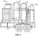
- Figure 3shows an example of the skid 100 mounted on a trailer 102.
- the skid 100holds the compressor 20, the wet tank 30, the particle filter 40, the coalescing filter 45, and the dry tank 70, among other components of the generation assembly 12.
- the monitoring control system 200is either integrated into or associated with the skid 100.
- the wet tank 30can have a tie-in connection for a backup compressor to connect thereto, should the main compressor 20 fail.
- the skid 100has a discharge connection 16, which can be a 2-inch crow's foot connector for connecting the generation assembly 12 to components of the distribution assembly (14; Fig. 1 ) described herein.
- the actual worksitecan be from 100 feet to 1/4 mile away from the skid 100, and the outlet pressure of the generation assembly 12 is preferably 110 to 125 psi.
- the skid 100can also have an inlet connection 18 for connecting to a regulator and auxiliary air supply.
- this inlet connection 18can connect to a reserve supply of high-pressure breathing air on a tube trailer or the like-an example of which is described later.
- a controllable switch-over 230 having a solenoid valveinterconnects the auxiliary connection 18 to the skid's outlet. Further details of the reserve supply and the switch-over 230 as well as how the monitoring control system 200 uses them will be described later.
- the power supply 110 to the components of the skid 100is divided into three subsystems.
- a first power subsystem 112supplies power to the compressor 20, which can be a twin-screw compressor with an electric motor. If the compressor 20 fails or its power supply is compromised, other components detailed below can remain powered improving operation of the assembly 12.
- a second power subsystem 114supplies power to the filtration components of the skid 100
- a third power subsystem 116supplies power to the detection components on the skid 100.
- detection componentsinclude gas detection sensors, pressure sensors, and the like described in more detail herein that are used to monitor and detect issues with the air supply being generated. Having the power supply 110 divided in this way is advantageous to the assembly's operation when one or more of the components, compressor 20, etc. fail and back-up compressors or the like need to be connected to the skid 100.
- FIGs 4A-4Cillustrate another arrangement of a breathing air production and filtration system 10 according to the present disclosure.
- the system 10has a breathing air generation assembly 12 ( Figs. 4A-4B ) and a distribution assembly 14 ( Fig. 4C ).
- the generation assembly 12generates the breathing air and can be mounted on a skid or trailer.
- a discharge outlet 16 on the generation assembly 12 ( Fig. 4B )can connect to a large hose 17 for communicating with the distribution assembly 14 ( Fig. 4C ). In general, this connection at the outlet 16 can be a 2-in. crow's foot connector.
- the generation assembly 12has a compressor 20, a wet tank 30, a particle filter 40, a coalescing filter 45, drying towers 50, a catalytic converter 60, charcoal filters 65, and a dry tank 70.
- a drying control 55can be provided for the drying towers 50 to route generated breathing air to the towers 50 on an alternating basis.
- the distribution assembly 14connects to the generation assembly 12 with a large hose 17 extending from the connector 16.
- the distribution assembly 14delivers the breathing air to the end users at the various work areas.
- the distribution assembly 14has a single collection pot 80 and one or more distribution manifolds 90.
- the wet tank 30, dry tank 70, and collection pot 80can each have a capacity of 240 gallons.
- the catalytic converter 60can be filled with hyppolite and can convert carbon monoxide (CO) to carbon dioxide (CO 2 ).
- the system 10also includes the monitoring control system 200, which monitors and controls the system 10.
- an in-line sensor 220continuously monitors for constituents of the breathing air (e.g., oxygen percentage, carbon dioxide part-per-million, etc.) and monitors for contaminants, such as CO, H 2 S, combustibles, oil mist, and/or other undesirable contaminants.
- the constituents being monitored and the acceptable levels of eachdepend on the desired air quality standard being used.
- a preferred in-line sensor 220 for the system 10includes a photoionization detector (PID) and a wireless modem (transmitter) so the sensor 220 can provide real-time gas measurements of volatile organic compounds of interest to the control unit 210. Measurements for other substances, such as hydrogen sulfide, chlorine, oxygen, carbon dioxide or the like, can be tested with additional sensor elements.
- PIDphotoionization detector
- wireless modemtransmitter
- the in-line sensor 220includes an AreaRAE gas monitor, such as the AreaRAE Steel Gas Monitor or MultiRAE Plus Gas Detector from RAE Systems, of San Jose, CA.
- the preferred gas monitorhas instrumentation for in-line monitoring in an air stream of the disclosed generation assembly 12.
- the in-line sensor 220operatively communicates with a flow controller 225.
- the flow controller 225connects to an analyzer switch 223 of an alarm 224 and connects to a solenoid 222 for a gate valve 221. If a contaminant is detected with the in-line sensor 220, for example, the flow controller 225 shuts off air flow from the generation assembly 12 using the solenoid 222 and gate valve 221.
- the flow controller 225can also activate the alarm 224 whenever any of the monitored parameters goes out of range.
- the closed gate valve 221closes off communication of the generated breathing air to the dry tank 70. Instead, the air can be routed to a pressure control valve 227 and vented to atmosphere if needed.
- the flow controller 225can also be coupled to an alarm element transmitter 226 that can connect to the control unit 210 using either a wired or a wireless connection.
- the control unit 210can store details of alarm conditions in its storage device 212 for later retrieval and analysis, which may be useful in resolving issues with the system 10, its operation, its placement, etc.
- the system 10provides back-up breathing air should operation of the generation assembly 12 fail or a contaminant is detected.
- the system 10couples to a reserve air supply 400, which can be a high-pressure tube trailer as disclosed below with reference to Figure 8 .
- the reserve air supply 400connects by a high-pressure hose 408 to the dry tank 70.
- a pressure control valve 232 set at 125 psi and a controllable switch-over 230connect in line with the reserve air supply 400. If the compressor 20 fails or if some other problem arises, then the control unit 210 activates the controllable switch-over 230 to supply high-pressure air from the reserve supply 400 to the dry tank 70 for the system 10.
- This reserve supply 400can then be used temporarily until a new compressor is connected or a backup compressor is activated, at which point the controllable switchover 230 can be deactivated.
- FIGs 5A-5Cillustrate yet another arrangement of the disclosed system 10. This arrangement is similar to that described above in Figures 4A-4C .
- the system 10has two collection pots 80A-B as well as additional sensing features for the monitoring and control system 200.
- the alarm element transmitter 226 coupled to the flow controller 225sends a wireless signal to the control unit 210 via a suitable wireless connection, although a wired connection could be used.
- the information communicatedcan be used by the control unit 210 for data logging and storage in the storage device 212. This can be beneficial in reviewing whether any events with contaminants occurred so issues with the system 10 can be resolved.
- the wireless signalcan also be used by the control unit 210 to activate the automatic switch-over 230 to change to the reserve supply 400 and shut off the breathing air supplied by the generation assembly 12.
- the reserve air supply 400connects by a 1 ⁇ 4-inch high-pressure hose 408 to a fitting 18 on the generation assembly 12.
- piping connecting from this fitting 18passes a pressure control valve 19 and the switchover 230 before reaching an inlet on the dry tank 70.
- the controllable switchover 230is shown having a pressure sensor 232, a controllable gate valve 234, and an actuator (e.g., solenoid) 236.
- the switch-over 230can be activated to feed air from the reserve supply 400 should the compressor 20 fail, if the pressure supply by the generation assembly 12 fails below a minimum threshold, if a contaminant is detected, or if any other suitable reason warrants.
- the solenoid 236is activated to open flow through the gate valve 234 so back-up air can be supplied to the dry tank 70.
- the pressure control valve 19is preferably set to 125 psi to control the supply of air into the generation assembly 12 during backup operations.
- the monitoring control system 200Connected from the dry tank 70, the monitoring control system 200 includes a flow meter 240 and a transmitter 242 for sending signals to the control unit 210 via an appropriate interface.
- the information from the flow meter 240indicates the flow produced by the generation assembly 12 being discharged from the dry tank 70 to the distribution assembly 14 in Figure 5C .
- the control unit 210can log this information in storage 212 and can alter operation of other components of the system 10 to deal with an undesirable, low flow level being discharged.
- the monitoring control system 200includes pressure/temperature sensors 250A-B and transmitters 252 associated with each collection pot 80A-80B.
- the sensors 250A-Bdetect the pressure and temperature of the associated collection pot 80A-B and send the information to the control unit 210 via the transmitters 252.
- This informationcan be logged in storage for later reporting and can be used by the control unit 210 to change operation of other components of the system 10.
- the monitoring control system 200can monitor pressure to determine if operation should be shut down, if switching to back-up air supply should be done, or the like.
- the monitoring control system 200can monitor temperature to shutdown the system 10 when the temperature of the breathing air is too high, for example.
- control unit 210can log data from the various sensors (e.g., pressure sensors, temperature sensors, flow meter, in-line sensor, etc.) repeatedly over a time interval so the information can be stored for later reporting. This time interval can be about every ten (10) seconds in one implementation to provide comprehensive monitoring and recording. Moreover, as discussed herein, the control unit 210 can use received information to control other components of the system 10, such as switching to reserve supply 400, increasing system pressures, etc., should the monitored sensor data fall outside of a threshold or a range.
- sensorse.g., pressure sensors, temperature sensors, flow meter, in-line sensor, etc.
- This time intervalcan be about every ten (10) seconds in one implementation to provide comprehensive monitoring and recording.
- control unit 210can use received information to control other components of the system 10, such as switching to reserve supply 400, increasing system pressures, etc., should the monitored sensor data fall outside of a threshold or a range.
- Figures 6A-6Billustrate embodiments of a breathing manifold 90 for the disclosed system 10.
- the disclosed system 10distributes breathing air to one or more manifolds 90.
- the manifolds 90can provide at least grade "D" breathing air, as identified by the Compressed Gas Association of the United States.
- An example of a manifold 90 useable with the system 10the Killer Bee TM manifold manufactured by Total Safety in Houston, Texas.
- the preferred manifold 90is an eight-way manifold with a pressure regulator and a low-pressure warning alarm preferably mounted on a stand.
- the manifold 90facilitates distribution of pressurized air to a lower pressure for breathable air by using at least three (and preferably eight) take-out connections, although more than eight take out connections can be used.
- the manifold 90has a manifold body 328 that can be between approximately 3-in. and 12-in. long.
- the manifold 90is made of stainless steel and has one or more supports (not shown) connected to the manifold body 328.
- the manifold body 328has a chamber 330.
- Various take-out connectionse.g., 332 are disposed on the manifold body 328.
- a first plug 348can be located on one end of the chamber 330, while a second plug 350 can be located on the other end of the chamber 330.
- the regulator 352is in fluid communication with the chamber 330 for receiving the pressurized breathing air and then reducing the pressurized breathing air to a breathable pressure.
- the regulator 352can have a regulator body 354, an inlet port 356 connected to the regulator body 354, and an outlet port 358 connected to the regulator body 354.
- An example of a regulator usable with the breathing systemis a Victor regulator available from Masthead distributors of Clinton Drive, Houston, Texas.
- An inlet pressure gauge 360can be connected to the inlet port.
- An outlet pressure gauge 362can be connected to outlet port to monitor and measure the pressure of the breathing air.
- a regulator conduit 364connects from the outlet port to the manifold body 328 and communicates with the chamber 330.
- the conduitscan have an inside diameter ranging from 1 inch to about 3 inches, although the inside diameter of the conduits is dependent upon air flow rates desired through the breathing air conduit.
- a pressure relief valve 366is connected to the regulator body 354, and one pressure relief valve 366 per manifold 90 is typically used.
- a low-pressure alarm 368is connected to the inlet port. The alarm 368 provides a signal, or alarm, such as a flashing light or a noise, when the air conduit pressure falls below 500-psi.
- Figure 7shows an arrangement of collection pots 80A-B and manifolds 90 for the disclosed system 10.
- a typical configuration of the system 10is shown in Figure 7 (as with Fig. 1 and others) in which one generation assembly 12 (most of which is not shown) feeds the distribution assembly 14.
- the distribution assembly 14has two collection pots 80A-80B and various connected distribution manifolds 90.
- Various hoses 17 and 19connect the components of the system 10 together, and other hoses 92 connect to end users.
- the lengths and diameters of the connecting hoses 17 and 19 between the assembly 12, pots 80A-B, and manifolds 90depend on the implementation. In general, an acceptable distance between components and the resulting end pressure produced are governed by the diameter of the hoses 17 and 19 and the related air flow passing through the hoses 17 and 19 to produce a relative pressure drop. The larger the hose diameter, the less pressure drop to occur with the flow and distance. These considerations are taken into account when arranging the components of the system 10 at a worksite.
- Figure 7The arrangement of Figure 7 is discussed in connection with the capacity and other capabilities of the disclosed system 10.
- Various numbers of end userscan be supported by the system 10 at any given time when particular pressure levels are maintained in the collection pots 80A-80B.
- the discussion that followsreviews the capacity of the system 10 when pressures of 100-psig and/or 60-psig are maintained in the collection pots 80A-B.
- Three different casesare discussed below using Pipeflo and Aspen Hysys process simulation software to perform analysis.
- the system 10uses two (2) collection pots 80A-B, even though the system 10 can have one or more pots 80A-B. All the same, use of two pots 80A-B has been done as a typical arrangement.
- Overall analysisshows that a system configuration (50-ft. of a 2-in. hose 17 for the main feed line and 200-ft. of 2-in. hose 19 for each collection pot 80A-B) allows as many as 277 users to be hooked up to the system 10 at any time.
- the two collection pots 80A-80Bare each maintained at pressures of 60-psig and 100-psig, respectively.
- the compressor 20delivers a constant supply of 200-acfm of air at a pressure of 125-psig (228.2 Ib-moles/hr).
- the 2-in. hose 17 between the generation assembly 12 and the collection pots 80A-Bcan be assumed to be 200-ft, which is a minimum length normally used.
- the 3 ⁇ 4-in. hose 17was assumed at 200-ft., and the 3/8-in. hoses 92 to the end users were assumed to be 250-ft each.
- the end users connected to the 60-psig pot 80Awere assumed to consume 7-scfm/user, while those end users connected to the 100-psig pots 80B were assumed to consume 6-scfm/user.
- the 2-in. hose 17 between the generation assembly 12 and each of the collection pots 80A-80Bmay be 2000 ft., while the other hoses 19 and 92 can be kept the same.
- end users connected to the 60-psig pot 80Bare assumed to consume 7-scfm/user, while those connected to the 100-psig pot 80A are assumed to consume 6-scfm/user.
- the pressure drop in the 2-inch hose 17limits the system's capacity.
- the compressor 20in such a circumstance may work intermittently, as per end user consumption, to give an average flow rate over time that is less than the compressor nominal capacity.
- the two collection pot 80A-80Bboth have pressures maintained at 60-psig.
- the 2-in. hose 17 between the generation assembly 12 and the collection pots 80A-80Bmay be 200 ft. to allow for consumption of the full compressor capacity of 200-acfm of air flow.
- the 3 ⁇ 4-in. hose 19may be 200-ft., and the 3/8-in. individual end user hoses 92 may be 250-ft. each.
- the end user air consumptionis assumed to be 7-scfm/ user. Analysis shows that up to 256 end users can be connected via the two collection pots 80A-80B in this configuration.
- the collection pots 80A-80Bare both at 60-psig, while the 2-in. hose 17 between the generation assembly 12 and the collection pots 80A-80B may be at a maximum length of 2000-ft. Other hose lengths are same as above (i.e. the 3 ⁇ 4-in. hose 19 is assumed at 200-ft., and the 3/8-in. end user hoses 92 are assumed at 250-ft. each).
- the end user air consumptionis assumed to be 7-scfm/user. Analysis shows that up to 186 end users can be connected via the two collection pots 80A-80B in this configuration, with an average compressed air flow of 208 Ib-m/hr.
- the end user hose (3/8-in.) 92is limiting and should not extend beyond 100-ft. in length. However, lower pressure at collection pots 80A-B allows for a longer 2-in. hose 17 can run (e.g., 950 ft.).
- the two collection pots 80A-Bare both maintained at 100-psig.
- the 2-in. hose 17 between the generation assembly 12 and the collection pots 80A-Bis assumed at a minimum length of 200-ft.
- the 3 ⁇ 4-in. hose 19is assumed at 200-ft.
- the 3/8-in. end user hoses 92are assumed at 250-ft. each.
- Air consumptionis assumed to be 6-scfm/user. Analysis shows that 298 end users can be connected to the two collection pots 80A-80B.
- the 2-in. hose 17 between the generation assembly 12 and the collection pots 80A-Bis assumed at the maximum length of 2000-ft.
- the 3 ⁇ 4-in. hose 19is assumed at 200-ft.
- the 3/8-in. end user hoses 92are assumed at 250-ft. each.
- air consumption at 6-scfm/useranalysis suggests that when running the system to maintain 100-psig in the collection pots 80A-B with the hose 17 length of 2000-ft., the average air flow will be reduced to approximately 93.96-acfm (140 Ib-m/hr).
- the outlet(at the generation assembly 12) can be increased to 3-in. or 4-in. coming out from the generation assembly 12 for the main feed line hoses 17 and can be increased to 3-in. branches feeding from the dry tank 70 to the collection pots 80A-B. This will allow the use of long hoses while still operating the compressor 20 at its full capacity.
- An alternative to using a larger diameter hose 17 to feed the collection pots 80A-B when these are a long distance away from the traileris to use a type of respirator that allows the pots 80A-B to operate at 60 instead of 100-psig.
- the lower pot pressurecan limit the maximum length of 3/8-inch hoses that can be used.
- hose 19is the least limiting component and takes the least pressure drop. Accordingly, lengths of 3 ⁇ 4-in. hose 19 can be added between the pots 80A-80B and the supply manifolds 90 to reach the end users. These hoses can be used instead of the need to use a longer 2-in. hose 17 from the generation assembly 12 to the collection pots 80A-80B.
- the number of usersmay remain constant so that the system operates under steady-state conditions.
- the number of users and their individual air demand ratesdo change over time as the system operates.
- the system 10is designed to operate effectively under such transient conditions, such as when users hook-up and unhook.
- FIG 8illustrates a reserve supply 400 for connection to the disclosed system 10 as a back-up high-pressure air supply.
- the reserve supply 400includes a number (8) of cylinders or tubes 402 that can mount on a bulk tube trailer. Each tube 402 can hold breathable air at 3000-psig.
- Angle valves 404connect the tubes 402 to an outlet 406, which can connect to the disclosed system 10 of the present disclosure using a 1 ⁇ 4-inch high-pressure hose (408).
Landscapes
- Health & Medical Sciences (AREA)
- Engineering & Computer Science (AREA)
- Chemical & Material Sciences (AREA)
- Pulmonology (AREA)
- Emergency Management (AREA)
- Business, Economics & Management (AREA)
- General Health & Medical Sciences (AREA)
- Chemical Kinetics & Catalysis (AREA)
- Combustion & Propulsion (AREA)
- Mechanical Engineering (AREA)
- General Engineering & Computer Science (AREA)
- General Chemical & Material Sciences (AREA)
- Toxicology (AREA)
- Life Sciences & Earth Sciences (AREA)
- Zoology (AREA)
- Respiratory Apparatuses And Protective Means (AREA)
Description
- Embodiments of the present disclosure relate to an air breathing system usable in a chemical plant, refinery, or other facility where workers need to breathe good quality air while working in a harsh environment.
- People in industrialized nations spend more than 90% of their time indoors, and many industry-related occupations require personnel to work in conditions having airborne pollutants. The lung is the most common site of injury by airborne pollutants. Acute effects from airborne pollutants may also include non-respiratory signs and symptoms, which may depend upon toxicological characteristics of the substances involved.
- To improve air quality, facilities use ventilation systems, which vary as to design, use, specifications, and maintenance. Most ventilation systems restrict the movement of air in and between various departments, and the systems may have specific ventilation and filtration capabilities to dilute and remove contamination, airborne microorganisms, viruses, hazardous chemicals, radioactive substances, and the like.
- In addition to ventilation systems, some work environments can have hazards, and personnel need uncontaminated breathing air supplied to them while working in the hazardous environments. For example, various chemicals used in industrial processes are known to be hazardous to people in and around a work environment if the chemicals are not handled or ventilated properly. Vaporous chemicals, such as acetic acid, benzene, formaldehyde, nitrous oxide, and xylene, carry health warnings and can often affect a person's immune system if the person is exposed to the chemical.
- In addition, situations arise in which volatile, toxic, and particulate laden gasses may be generated or leak into an interior room of a building or other confined space-potentially exposing personnel to hazards. Personnel in work environments may also be exposed to the presence of gasses, such as vapors from hydrocarbon based products as well as natural or liquefied petroleum gasses within an enclosure or confined space, such as an interior room of a building. In some cases, hazardous materials, such as volatile organic compounds, cannot be vented from an interior space to the atmosphere. Some examples of these volatile organic compounds include automobile and aircraft paints, resurfacing materials, porcelain paints, reducers, glues, cleaning agents, grain dust, and hydrocarbon fumes. These materials must be carefully evacuated from the interior space to avoid adverse effects, including unwanted combustion of such materials.
US 2010/032040 A1 describes a breathable air safety system for civilians in a building structure in an emergency.US 4 670 223 A describes an apparatus for producing sterile air suitable for being administered to intensive-care patients in hospitals using atmospheric air.US 7 647 927 B2 describes a breathing apparatus operable in a self-contained mode, where a breathable gas is delivered to a user from a source or in a filtered mode of operation, where ambient air is filtered and delivered to the user.US 2007/082601 A1 describes a dilution ventilation control system for use in a one-pass, critical environments.US 2009/004047 A1 describes an air supply apparatus for supplying sterilized air to users.US 2003/211825 A1 describes methods and systems for enhancing air quality in buildings.WO 2010/014014 A1 describes a mobile breathing-air compressor unit arranged for use in an explosive environment.- There is a need to produce and filter breathing air for personnel working in a variety conditions and potentially exposed to hazards.The subject matter of the present disclosure is directed to addressing this need.
- The invention is defined in
claims - In particular, a breathing air production and filtration system is disclosed. The
system has an air generation assembly and a distribution assembly. The generation assembly has a compressor and filtration components to generate breathing air. The distribution assembly has collection pots with multiple connections for manifolds. For their part, the manifolds have multiple connectors for the respirators of end users. The system uses a monitoring control system with various wireless sensors to monitor operation of the system and the quality of breathing air produced. These sensors include an in-line sensor detecting constituents or contaminants in the breathing air. The sensors also include pressure, temperature, and flow sensors monitoring the operation of the system. An automatic switchover is provided for switching the system to a back-up supply of high-pressure reserve air if needed. - The foregoing summary is not intended to summarize each potential embodiment or every aspect of the present disclosure.
- The following conversion table applies for the units from the imperial system to the international system: (1 psi) 0,0689476 Bar; (1 cubic foot per minute) 28,3168 litre per minute; (1 foot) 0,3048 metre; (1 Mile) 1,60934 kilometre; (1 gallon) 3,78541 litre.
Fig. 1 illustrates a breathing air production and filtration system according to the present disclosure.Fig. 2 illustrates a schematic of a skid for the disclosed system.Fig. 3 shows an example of a skid for the disclosed system.Figs. 4A-4C illustrate another arrangement of a breathing air production and filtration system according to the present disclosure.Figs. 5A-5C illustrate yet another arrangement of a breathing air production and filtration system according to the present disclosure.Figs. 6A-6B illustrate a breathing manifold for the disclosed system.Fig. 7 shows an arrangement of collection pots and manifolds for the disclosed system.Fig. 8 illustrates a reserve supply for the disclosed system.Figure 1 illustrates asystem 10 according to the present disclosure for producing filtered breathing air and delivering the breathing air to end users in a work environment. Thesystem 10 has ageneration assembly 12 that generates the breathing air from ambient air in a remote environment. To do this, thegeneration assembly 12 includes acompressor 20, awet tank 30, aparticle filter 40, a coalescingfilter 45,drying towers 50, acatalytic converter 60,charcoal filters 65, and adry tank 70. All of these components of thegeneration assembly 12 can be mounted on a skid or trailer, which can be positioned far from work areas.- A second part of the
system 10 includes adistribution assembly 14 in communication with thegeneration assembly 12. Thedistribution assembly 14 receives the generated breathing air from thegeneration assembly 12 and delivers it to the end users located in work areas of a potentially hazardous environment. To deliver the air, thedistribution assembly 14 has one or more tanks orcollection pots 80A-B and one ormore distribution manifolds 90, which can be placed in various work areas. - Finally, the
system 10 also includes amonitoring control system 200, which monitors and controls thesystem 10 using various sensors and communication links to be described in more detail later. Overall, themonitoring control system 200 can verify that clean breathing air is produced on-site. For example, thesystem 200 can monitor samples of the breathing air in real time and can test parameters of the sampled breathing air, such as contaminant content, pressure, temperature, quality, etc., to verify the proper production and delivery of the breathing air. - As hinted above, overall operation of the
system 10 begins with thegeneration assembly 12 generating the breathing air. Thesystem 10 typically uses asingle generation assembly 12 as described, althoughadditional generation assemblies 12 can be connected to thesystem 10 to increase the volume of air provided, if necessary. However, for purposes of the present disclosure, reference is made to asingle generation assembly 12. - In the
generation assembly 12, thecompressor 20 compresses the ambient air in the remote environment. Any suitable type ofcompressor 20 can be used. As it operates, thecompressor 12 takes in the ambient air through aninlet filter 22 and compresses the air to a desired pressure. From thecompressor 20, the compressed air passes through the assembly's other components (e.g.,wet tank 30,particle filter 40, coalescingfilter 45, drying towers 50,catalytic converter 60,charcoal filters 65, and dry tank 70), which provide air filtration and purification. For example, the assembly's filtration capabilities can be designed to filter out particle contaminants, moisture (water), oil vapor carryover, and carbon monoxide (CO) so that the generated breathing air will be of high quality. Other gases and hydrocarbons can be adsorbed as well. After generating the breathing air, theassembly 12 in one implementation can provide 200 actual cubic feet per minute (acfm) of breathing quality air at 125-psig at its outlet (i.e., at the discharge of the dry tank 70). - After being compressed, filtered, and the like, the breathing air passes to the
distribution assembly 14 to be distributed to the end users in the work areas. To communicate the breathing air, thedistribution assembly 14 uses an arrangement ofvarious air hoses pots 80A-B andmanifolds 90A-B). When thesystem 10 is installed at a worksite, for example, thecollection pots 80A-B are usually situated in the work areas away from thegeneration assembly 12 and connected to it by a 2-inch diameter hose 17. - In the
distribution assembly 14, thecollection pots 80A-B can use a tank similar to thedry tank 70. In some implementations, thedistribution assembly 14 can use one ormore collection pots 80A-B depending on the relative locations where the breathing air is needed. Eachcollection pot 80A-B provides air-volume surge capacity in thesystem 10 and gives a dampening effect on the supplied air stream. This helps thedistribution assembly 12 maintain a consistent flow and pressure of breathing air to the end users. - The arrangement between
generation assembly 12 and thecollection pots 80A-B depends on the number ofcollection pots 80A-B deployed and the connection network between them. Eachcollection pot 80A-B can have as many as thirty (30) discharge outlets. Each of the outlets can be a ¾-in. connection and can connect to one of thedistribution manifolds 90 via a ¾-in.hose 19. - For their part, the
distribution manifolds 90 provide hose connections to individual end users using the outlets (e.g., eight 3/8-in. outlets for hoses 92). The air consumption for each end user (scfm/user) ranges between 4-8 standard cubic feet per minute (scfm) of breathing air. The individual end users are connected by the 3/8-in.hoses 92 from the manifold 90 to their breathing apparatus or respirators (not shown). Typically, a full facemask respirator provides a delivery pressure of 1.5-psig. However, a somewhat higher pressure is preferably delivered to the respirators, and each respirator can have a built-in regulator that drops the air pressure down to the facemask's 1.5-psi level. Thus, in one implementation, thesystem 10 maintains a pressure of 80-100-psig at thecollection pots 80A-80B for the regulators to work properly. Figure 1 shows a typical configuration of thesystem 10 having onegeneration assembly 12 feeding twocollection pots 80A-80B and variousconnected distribution manifolds 90. The lengths of the connectinghoses generation assembly 12,pots 80A-B, andmanifolds 90 depend on the implementation. In general, 2-in.hoses 17 connect thegeneration assembly 12 to thecollection pots 80A-B, and thesehoses 17 can range between 200 to 2,000-ft. in length.Hoses 19 of ¾-in. connect between thecollection pots 80A-B anddistribution manifolds 90, and thesehoses 19 can be up to 200-ft. Finally,hoses 92 of 3/8-in. connect between the individual end user connection and the manifold 90, and thesehoses 92 can be up to 300-ft. long.- As discussed above, the
system 10 uses themonitoring control system 200 to monitor and control thesystem 10 using various sensors and communication links to be described in more detail later. Themonitoring control system 200 includes acontrol unit 210, which can be a computer or the like. Thecontrol unit 210 has astorage device 212 and acommunication interface 214. Thestorage device 212 can be any suitable device for storing monitored parameters for thesystem 10. Thecommunication interface 214 can use a wired and/or wireless network to communicate with various sensors, alarms, solenoids, actuators, and other components of the disclosedsystem 10. Preferably, those components intended to be separate from the skid holding thegeneration assembly 12 use wireless communications with thecontrol unit 210. - As part of the
monitoring control system 200, an in-line sensor 220 is disposed in communication with the breathing air from thegeneration assembly 12 before delivery to thecollection pots 80A-B. As it operates, the in-line sensor 220 continuously monitors the breathing air for constituents and contaminants, such as O2, CO2, CO, combustibles, H2S, oil mist, and the like. Then, the in-line sensor 220 operatively communicates readings with thecontrol unit 210 through a wired or wireless connection so thecontrol unit 210 can record appropriate readings and can take certain actions during an event. Themonitoring control system 200 can also monitor the ambient air coming into the intake of thesystem 10 using periodic sampling with asensor 24 to check the initial quality of the ambient air used to generate the breathing air. - As mentioned above, components of the
generation assembly 12 can be mounted on a skid or trailer, which can be remotely located from work areas. To that end,Figure 2 illustrates a schematic of askid 100 for the disclosedsystem 10, andFigure 3 shows an example of theskid 100 mounted on atrailer 102. Theskid 100 holds thecompressor 20, thewet tank 30, theparticle filter 40, the coalescingfilter 45, and thedry tank 70, among other components of thegeneration assembly 12. Themonitoring control system 200 is either integrated into or associated with theskid 100. - The
wet tank 30 can have a tie-in connection for a backup compressor to connect thereto, should themain compressor 20 fail. To deliver the breathing air, theskid 100 has adischarge connection 16, which can be a 2-inch crow's foot connector for connecting thegeneration assembly 12 to components of the distribution assembly (14;Fig. 1 ) described herein. The actual worksite can be from 100 feet to 1/4 mile away from theskid 100, and the outlet pressure of thegeneration assembly 12 is preferably 110 to 125 psi. - The
skid 100 can also have aninlet connection 18 for connecting to a regulator and auxiliary air supply. For example, thisinlet connection 18 can connect to a reserve supply of high-pressure breathing air on a tube trailer or the like-an example of which is described later. A controllable switch-over 230 having a solenoid valve interconnects theauxiliary connection 18 to the skid's outlet. Further details of the reserve supply and the switch-over 230 as well as how themonitoring control system 200 uses them will be described later. - The
power supply 110 to the components of theskid 100 is divided into three subsystems. Afirst power subsystem 112 supplies power to thecompressor 20, which can be a twin-screw compressor with an electric motor. If thecompressor 20 fails or its power supply is compromised, other components detailed below can remain powered improving operation of theassembly 12. - In particular, a
second power subsystem 114 supplies power to the filtration components of theskid 100, and athird power subsystem 116 supplies power to the detection components on theskid 100. These detection components include gas detection sensors, pressure sensors, and the like described in more detail herein that are used to monitor and detect issues with the air supply being generated. Having thepower supply 110 divided in this way is advantageous to the assembly's operation when one or more of the components,compressor 20, etc. fail and back-up compressors or the like need to be connected to theskid 100. Figures 4A-4C illustrate another arrangement of a breathing air production andfiltration system 10 according to the present disclosure. As before, thesystem 10 has a breathing air generation assembly 12 (Figs. 4A-4B ) and a distribution assembly 14 (Fig. 4C ). As noted before, thegeneration assembly 12 generates the breathing air and can be mounted on a skid or trailer. Adischarge outlet 16 on the generation assembly 12 (Fig. 4B ) can connect to alarge hose 17 for communicating with the distribution assembly 14 (Fig. 4C ). In general, this connection at theoutlet 16 can be a 2-in. crow's foot connector.- As shown in
Figures 4A-4B , thegeneration assembly 12 has acompressor 20, awet tank 30, aparticle filter 40, a coalescingfilter 45, drying towers 50, acatalytic converter 60,charcoal filters 65, and adry tank 70. A dryingcontrol 55 can be provided for the drying towers 50 to route generated breathing air to thetowers 50 on an alternating basis. - As shown in
Figure 4C , thedistribution assembly 14 connects to thegeneration assembly 12 with alarge hose 17 extending from theconnector 16. Thedistribution assembly 14 delivers the breathing air to the end users at the various work areas. In this arrangement, thedistribution assembly 14 has asingle collection pot 80 and one or more distribution manifolds 90. - As shown in
Figures 4A-4C , thewet tank 30,dry tank 70, andcollection pot 80 can each have a capacity of 240 gallons. Thecatalytic converter 60 can be filled with hyppolite and can convert carbon monoxide (CO) to carbon dioxide (CO2). - The
system 10 also includes themonitoring control system 200, which monitors and controls thesystem 10. Again, an in-line sensor 220 continuously monitors for constituents of the breathing air (e.g., oxygen percentage, carbon dioxide part-per-million, etc.) and monitors for contaminants, such as CO, H2S, combustibles, oil mist, and/or other undesirable contaminants. The constituents being monitored and the acceptable levels of each depend on the desired air quality standard being used. - A preferred in-
line sensor 220 for thesystem 10 includes a photoionization detector (PID) and a wireless modem (transmitter) so thesensor 220 can provide real-time gas measurements of volatile organic compounds of interest to thecontrol unit 210. Measurements for other substances, such as hydrogen sulfide, chlorine, oxygen, carbon dioxide or the like, can be tested with additional sensor elements. One suitable example for the in-line sensor 220 includes an AreaRAE gas monitor, such as the AreaRAE Steel Gas Monitor or MultiRAE Plus Gas Detector from RAE Systems, of San Jose, CA. The preferred gas monitor has instrumentation for in-line monitoring in an air stream of the disclosedgeneration assembly 12. - The in-
line sensor 220 operatively communicates with aflow controller 225. In turn, theflow controller 225 connects to ananalyzer switch 223 of analarm 224 and connects to asolenoid 222 for agate valve 221. If a contaminant is detected with the in-line sensor 220, for example, theflow controller 225 shuts off air flow from thegeneration assembly 12 using thesolenoid 222 andgate valve 221. Theflow controller 225 can also activate thealarm 224 whenever any of the monitored parameters goes out of range. - When operated by the
solenoid 222, theclosed gate valve 221 closes off communication of the generated breathing air to thedry tank 70. Instead, the air can be routed to apressure control valve 227 and vented to atmosphere if needed. Theflow controller 225 can also be coupled to analarm element transmitter 226 that can connect to thecontrol unit 210 using either a wired or a wireless connection. Thecontrol unit 210 can store details of alarm conditions in itsstorage device 212 for later retrieval and analysis, which may be useful in resolving issues with thesystem 10, its operation, its placement, etc. - The
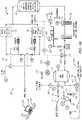
system 10 provides back-up breathing air should operation of thegeneration assembly 12 fail or a contaminant is detected. For this purpose, thesystem 10 couples to areserve air supply 400, which can be a high-pressure tube trailer as disclosed below with reference toFigure 8 . As shown, thereserve air supply 400 connects by a high-pressure hose 408 to thedry tank 70. Apressure control valve 232 set at 125 psi and a controllable switch-over 230 connect in line with thereserve air supply 400. If thecompressor 20 fails or if some other problem arises, then thecontrol unit 210 activates the controllable switch-over 230 to supply high-pressure air from thereserve supply 400 to thedry tank 70 for thesystem 10. Thisreserve supply 400 can then be used temporarily until a new compressor is connected or a backup compressor is activated, at which point thecontrollable switchover 230 can be deactivated. Figures 5A-5C illustrate yet another arrangement of the disclosedsystem 10. This arrangement is similar to that described above inFigures 4A-4C . Here, thesystem 10 has twocollection pots 80A-B as well as additional sensing features for the monitoring andcontrol system 200. In particular, thealarm element transmitter 226 coupled to theflow controller 225 sends a wireless signal to thecontrol unit 210 via a suitable wireless connection, although a wired connection could be used. The information communicated can be used by thecontrol unit 210 for data logging and storage in thestorage device 212. This can be beneficial in reviewing whether any events with contaminants occurred so issues with thesystem 10 can be resolved. The wireless signal can also be used by thecontrol unit 210 to activate the automatic switch-over 230 to change to thereserve supply 400 and shut off the breathing air supplied by thegeneration assembly 12.- Looking at the switch-over 230 in more detail, the
reserve air supply 400 connects by a ¼-inch high-pressure hose 408 to a fitting 18 on thegeneration assembly 12. In turn, piping connecting from this fitting 18 passes apressure control valve 19 and theswitchover 230 before reaching an inlet on thedry tank 70. For its part, thecontrollable switchover 230 is shown having apressure sensor 232, acontrollable gate valve 234, and an actuator (e.g., solenoid) 236. The switch-over 230 can be activated to feed air from thereserve supply 400 should thecompressor 20 fail, if the pressure supply by thegeneration assembly 12 fails below a minimum threshold, if a contaminant is detected, or if any other suitable reason warrants. For example, if the pressure of thegeneration assembly 12 as measured by thepressure sensor 232 off thedry tank 70 falls below 80-psi, then thesolenoid 236 is activated to open flow through thegate valve 234 so back-up air can be supplied to thedry tank 70. Thepressure control valve 19 is preferably set to 125 psi to control the supply of air into thegeneration assembly 12 during backup operations. - Connected from the
dry tank 70, themonitoring control system 200 includes aflow meter 240 and atransmitter 242 for sending signals to thecontrol unit 210 via an appropriate interface. The information from theflow meter 240 indicates the flow produced by thegeneration assembly 12 being discharged from thedry tank 70 to thedistribution assembly 14 inFigure 5C . Thecontrol unit 210 can log this information instorage 212 and can alter operation of other components of thesystem 10 to deal with an undesirable, low flow level being discharged. - As best shown in
Figure 5C , themonitoring control system 200 includes pressure/temperature sensors 250A-B andtransmitters 252 associated with eachcollection pot 80A-80B. The sensors 250A-B detect the pressure and temperature of the associatedcollection pot 80A-B and send the information to thecontrol unit 210 via thetransmitters 252. This information can be logged in storage for later reporting and can be used by thecontrol unit 210 to change operation of other components of thesystem 10. For example, themonitoring control system 200 can monitor pressure to determine if operation should be shut down, if switching to back-up air supply should be done, or the like. Themonitoring control system 200 can monitor temperature to shutdown thesystem 10 when the temperature of the breathing air is too high, for example. - Overall, the
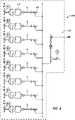
control unit 210 can log data from the various sensors (e.g., pressure sensors, temperature sensors, flow meter, in-line sensor, etc.) repeatedly over a time interval so the information can be stored for later reporting. This time interval can be about every ten (10) seconds in one implementation to provide comprehensive monitoring and recording. Moreover, as discussed herein, thecontrol unit 210 can use received information to control other components of thesystem 10, such as switching toreserve supply 400, increasing system pressures, etc., should the monitored sensor data fall outside of a threshold or a range. Figures 6A-6B illustrate embodiments of abreathing manifold 90 for the disclosedsystem 10. As noted previously, the disclosedsystem 10 distributes breathing air to one ormore manifolds 90. Preferably, themanifolds 90 can provide at least grade "D" breathing air, as identified by the Compressed Gas Association of the United States. An example of a manifold 90 useable with thesystem 10 the Killer Bee™ manifold manufactured by Total Safety in Houston, Texas.- The
preferred manifold 90 is an eight-way manifold with a pressure regulator and a low-pressure warning alarm preferably mounted on a stand. The manifold 90 facilitates distribution of pressurized air to a lower pressure for breathable air by using at least three (and preferably eight) take-out connections, although more than eight take out connections can be used. - Details of the manifold 90 are shown in
Figures 6A-6B as well as aregulator 352 usable with the manifold 90 if needed. The manifold 90 has amanifold body 328 that can be between approximately 3-in. and 12-in. long. The manifold 90 is made of stainless steel and has one or more supports (not shown) connected to themanifold body 328. - The
manifold body 328 has achamber 330. Various take-out connections (e.g., 332) are disposed on themanifold body 328. Afirst plug 348 can be located on one end of thechamber 330, while asecond plug 350 can be located on the other end of thechamber 330. - The
regulator 352 is in fluid communication with thechamber 330 for receiving the pressurized breathing air and then reducing the pressurized breathing air to a breathable pressure. Theregulator 352 can have aregulator body 354, aninlet port 356 connected to theregulator body 354, and anoutlet port 358 connected to theregulator body 354. An example of a regulator usable with the breathing system is a Victor regulator available from Masthead distributors of Clinton Drive, Houston, Texas. - An
inlet pressure gauge 360 can be connected to the inlet port. Anoutlet pressure gauge 362 can be connected to outlet port to monitor and measure the pressure of the breathing air. A regulator conduit 364 connects from the outlet port to themanifold body 328 and communicates with thechamber 330. The conduits can have an inside diameter ranging from 1 inch to about 3 inches, although the inside diameter of the conduits is dependent upon air flow rates desired through the breathing air conduit. - A pressure relief valve 366 is connected to the
regulator body 354, and one pressure relief valve 366 permanifold 90 is typically used. A low-pressure alarm 368 is connected to the inlet port. Thealarm 368 provides a signal, or alarm, such as a flashing light or a noise, when the air conduit pressure falls below 500-psi. Figure 7 shows an arrangement ofcollection pots 80A-B andmanifolds 90 for the disclosedsystem 10. A typical configuration of thesystem 10 is shown inFigure 7 (as withFig. 1 and others) in which one generation assembly 12 (most of which is not shown) feeds thedistribution assembly 14. In turn, thedistribution assembly 14 has twocollection pots 80A-80B and variousconnected distribution manifolds 90.Various hoses system 10 together, andother hoses 92 connect to end users.- The lengths and diameters of the connecting
hoses assembly 12,pots 80A-B, andmanifolds 90 depend on the implementation. In general, an acceptable distance between components and the resulting end pressure produced are governed by the diameter of thehoses hoses system 10 at a worksite. - The arrangement of
Figure 7 is discussed in connection with the capacity and other capabilities of the disclosedsystem 10. Various numbers of end users can be supported by thesystem 10 at any given time when particular pressure levels are maintained in thecollection pots 80A-80B. The discussion that follows reviews the capacity of thesystem 10 when pressures of 100-psig and/or 60-psig are maintained in thecollection pots 80A-B. Three different cases are discussed below using Pipeflo and Aspen Hysys process simulation software to perform analysis. - In all three cases, the
system 10 uses two (2)collection pots 80A-B, even though thesystem 10 can have one ormore pots 80A-B. All the same, use of twopots 80A-B has been done as a typical arrangement. Overall analysis shows that a system configuration (50-ft. of a 2-in.hose 17 for the main feed line and 200-ft. of 2-in.hose 19 for eachcollection pot 80A-B) allows as many as 277 users to be hooked up to thesystem 10 at any time. - In a first configuration, for example, the two
collection pots 80A-80B are each maintained at pressures of 60-psig and 100-psig, respectively. For this configuration, thecompressor 20 delivers a constant supply of 200-acfm of air at a pressure of 125-psig (228.2 Ib-moles/hr). The 2-in.hose 17 between thegeneration assembly 12 and thecollection pots 80A-B can be assumed to be 200-ft, which is a minimum length normally used. The ¾-in.hose 17 was assumed at 200-ft., and the 3/8-in.hoses 92 to the end users were assumed to be 250-ft each. The end users connected to the 60-psig pot 80A, were assumed to consume 7-scfm/user, while those end users connected to the 100-psigpots 80B were assumed to consume 6-scfm/user. - With one
pot 80A operating at 100-psi and theother pot 80B at 60-psi and using 200 ft. of 2-in.hose 17, analysis indicates that 149 and 128 users, respectively, can be connected via thecollection pots 80A-B operating at a minimum pressure of 100-psig and 60-psig, respectively. This analysis considers the pressure drops occurring in the connectinghoses - In a worst case of this arrangement, the 2-in.
hose 17 between thegeneration assembly 12 and each of thecollection pots 80A-80B may be 2000 ft., while theother hoses psig pot 80B are assumed to consume 7-scfm/user, while those connected to the 100-psig pot 80A are assumed to consume 6-scfm/user. Under these conditions, the pressure drop in the 2-inch hose 17 limits the system's capacity. Thecompressor 20 in such a circumstance may work intermittently, as per end user consumption, to give an average flow rate over time that is less than the compressor nominal capacity. - Analysis shows that up to 73 and 61 end users, respectively, can be connected via the
collection pots 80A-80B at any one time when operating at a minimum pressure of 100-psig and 60-psig, respectively. The average air flow rate under these conditions will be in the neighborhood of 93.96-acfm (140 Ib-m/hr). - In a second configuration, the two
collection pot 80A-80B both have pressures maintained at 60-psig. The 2-in.hose 17 between thegeneration assembly 12 and thecollection pots 80A-80B may be 200 ft. to allow for consumption of the full compressor capacity of 200-acfm of air flow. The ¾-in.hose 19 may be 200-ft., and the 3/8-in. individualend user hoses 92 may be 250-ft. each. The end user air consumption is assumed to be 7-scfm/ user. Analysis shows that up to 256 end users can be connected via the twocollection pots 80A-80B in this configuration. - In another scenario, the
collection pots 80A-80B are both at 60-psig, while the 2-in.hose 17 between thegeneration assembly 12 and thecollection pots 80A-80B may be at a maximum length of 2000-ft. Other hose lengths are same as above (i.e. the ¾-in.hose 19 is assumed at 200-ft., and the 3/8-in.end user hoses 92 are assumed at 250-ft. each). The end user air consumption is assumed to be 7-scfm/user. Analysis shows that up to 186 end users can be connected via the twocollection pots 80A-80B in this configuration, with an average compressed air flow of 208 Ib-m/hr. Due to the 60-psig in thecollection pots 80A-B, the end user hose (3/8-in.) 92 is limiting and should not extend beyond 100-ft. in length. However, lower pressure atcollection pots 80A-B allows for a longer 2-in.hose 17 can run (e.g., 950 ft.). - In a third configuration, the two
collection pots 80A-B are both maintained at 100-psig. The 2-in.hose 17 between thegeneration assembly 12 and thecollection pots 80A-B is assumed at a minimum length of 200-ft. Meanwhile, the ¾-in.hose 19 is assumed at 200-ft., and the 3/8-in.end user hoses 92 are assumed at 250-ft. each. Air consumption is assumed to be 6-scfm/user. Analysis shows that 298 end users can be connected to the twocollection pots 80A-80B. - In a worst case, the 2-in.
hose 17 between thegeneration assembly 12 and thecollection pots 80A-B is assumed at the maximum length of 2000-ft. The ¾-in.hose 19 is assumed at 200-ft., and the 3/8-in.end user hoses 92 are assumed at 250-ft. each. With air consumption at 6-scfm/user, analysis suggests that when running the system to maintain 100-psig in thecollection pots 80A-B with thehose 17 length of 2000-ft., the average air flow will be reduced to approximately 93.96-acfm (140 Ib-m/hr). - As the 2-
inch hoses 17 feeding thecollection pots 80A-B increase in length, they become limiting on the air flow, if thepots 80A-B must be maintained at 100-psig. Therefore, if a long distance is needed between thegeneration assembly 12 andpots 80A-80B, the outlet (at the generation assembly 12) can be increased to 3-in. or 4-in. coming out from thegeneration assembly 12 for the mainfeed line hoses 17 and can be increased to 3-in. branches feeding from thedry tank 70 to thecollection pots 80A-B. This will allow the use of long hoses while still operating thecompressor 20 at its full capacity. - An alternative to using a
larger diameter hose 17 to feed thecollection pots 80A-B when these are a long distance away from the trailer is to use a type of respirator that allows thepots 80A-B to operate at 60 instead of 100-psig. However, the lower pot pressure can limit the maximum length of 3/8-inch hoses that can be used. - In the
system 10, the length of ¾-in.hose 19 is the least limiting component and takes the least pressure drop. Accordingly, lengths of ¾-in.hose 19 can be added between thepots 80A-80B and the supply manifolds 90 to reach the end users. These hoses can be used instead of the need to use a longer 2-in.hose 17 from thegeneration assembly 12 to thecollection pots 80A-80B. - During operation, the number of users may remain constant so that the system operates under steady-state conditions. However, in many circumstances, the number of users and their individual air demand rates do change over time as the system operates. The
system 10 is designed to operate effectively under such transient conditions, such as when users hook-up and unhook. Figure 8 illustrates areserve supply 400 for connection to the disclosedsystem 10 as a back-up high-pressure air supply. Thereserve supply 400 includes a number (8) of cylinders ortubes 402 that can mount on a bulk tube trailer. Eachtube 402 can hold breathable air at 3000-psig.Angle valves 404 connect thetubes 402 to anoutlet 406, which can connect to the disclosedsystem 10 of the present disclosure using a ¼-inch high-pressure hose (408).- Details of a
distribution manifold 90 as used herein as well as other components for a breathing system are disclosed inU.S. Pat. No. 7,347,204 , entitled "Breathing Air System for a Facility ". - If not already discussed, preferred hoses, sizes, connections, capacities, pressures, valves, and other details are disclosed in the Figures of
U.S. Provisional Pat. Appl. No. 61/394,703
Claims (14)
- A breathing air system, comprising:a compressor assembly (20) generating intake air;a first power subsystem (112) supplying power to the compressor assembly (20);a filtration assembly (10) in communication with the compressor assembly (20) and filtering the intake air;a second power subsystem (114) supplying power to the filtration assembly (10);one or more collection pots (80A-B) in communication with the filtration assembly (10) and collecting the intake air;one or more distribution manifolds (90A-B) in communication with the one or more collection pots (80A-B) and distributing the intake air to one or more breathing hoses (92);one or more wireless sensors (220, 232, 240, 250A-B) in communication with the intake air from the filtration assembly (10) and continuously monitoring the intake air for one or more parameters;a monitoring unit (200) in wireless communication with the one or more wireless sensors (220, 232, 240, 250A-B) and obtaining readings of the one or more parameters monitored by the one or more wireless sensors (220, 232, 240, 250A-B); anda third power subsystem (116) supplying power to the monitoring unit (200);wherein each of the power subsystems (112, 114, 116) is independently operable.
- The system of claim 1, wherein the monitoring unit (200) obtains the readings periodically and stores the obtained readings in memory (212).
- The system of claim 1, further comprising at least one of:a drying component (50) drying the intake air;a catalytic converter (60) converting carbon monoxide in the intake air to carbon dioxide; anda charcoal filter (65) filtering the intake air.
- The system of claim 1, wherein the one or more wireless sensors (220, 232, 240, 250A-B) comprise:a flow meter (240) in communication with the intake air to the one or more collection pots (80A-B) and measuring flow of the intake air; and/orone or more pressure sensors (232) measuring pressure of the intake air at the one or more collection pots (80A-B); and/orone or more temperature sensors (250A-B) measuring temperature of the intake air at the one or more collection pots (80A-B).
- The system of claim 1, further comprising a switch-over assembly (230) in communication with intake air from a stored air source (400), wherein the switch-over assembly (230) selectively communicates the intake air from the stored air source (400) to the one or more collection pots (80A-B).
- The system of claim 5,wherein the switch-over assembly (230) communicates the intake air from the stored air source (400) automatically in response to the one or more parameters indicating at least one contaminant in the intake air; orwherein the switch-over assembly (230) communicates the intake air from the stored air source (400) automatically in response to pressure of the intake air from the filtration assembly (10) falling below a threshold; and/orwherein the switch-over assembly (230) comprises:a pressure sensor (232) measuring the pressure of the intake air from the filtration assembly (10);a solenoid (222) activated in response to the pressure sensor (232); anda controllable gate valve (221) opening with the activation of the solenoid (222).
- The system of claim 1, wherein the one or more wireless sensors (220, 232, 240, 250A-B) comprise a contaminant detection sensor (220) in communication in line with the intake air communicated to the one or more collection pots (80A-B) and measuring the intake air for presence of one or more contaminants.
- The system of claim 7,wherein the contaminant detection sensor (220) comprises a photoionization detector detecting the one or more contaminants in an air stream of the intake air communicated past the photoionization detector; orwherein the contaminant detection sensor (220) comprises a pressure control valve (227) in communication with a vent, the pressure control valve (227) venting the intake air to the vent automatically in response to the presence of at least one of the one or more contaminants in the intake air.
- The system of claim 7, wherein the contaminant detection sensor (220) comprises a controller (225) generating an alarm condition automatically in response to the presence of at least one of the one or more contaminants in the intake air.
- The system of claim 9, wherein the controller (225) communicates the alarm condition wirelessly to the monitoring unit (200) or activates a local alarm in response to the alarm condition.
- The system of claim 7, wherein the contaminant detection sensor (220) closes communication of the intake air from the filtration assembly (10) to the one or more collection pots (80A-B) automatically in response to the presence of at least one of the one or more contaminants in the intake air.
- The system of claim 11, wherein the contaminant detection sensor (220) comprises a solenoid (222) and a controllable gate valve (221), the solenoid (222) activating the controllable gate valve (221) to close communication of the intake air from the filtration assembly (10).
- The system of claim 1, further comprising:a close-off assembly selectively preventing the intake air from the filtration assembly (10) from communicating to the one or more collection pots (80A-B);the monitoring assembly (200) having a contaminant detection sensor (220) for detecting one or more contaminants, the contaminant detection sensor (220) in communication in line with the intake air from the filtration assembly (10) and continuously monitoring the intake air for the one or more contaminants, the monitoring unit (200) automatically activating the close-off assembly in response to detection of at least one of the one or more contaminants with the contaminant detection sensor (220).
- A method of producing breathing air, the method comprising:providing a compressor assembly (20) generating intake air, a filtration assembly (10) in communication with the compressor assembly (20) and filtering the intake air, a monitoring unit (200) in wireless communication with one or more wireless sensors (220, 232, 240, 250A-B) for obtaining readings of one or more parameters monitored by the one or more wireless sensors (220, 232, 240, 250A-B), a first power subsystem (112) supplying power to the compressor assembly (20), a second power subsystem (114) supplying power to the filtration assembly (10), and a third power subsystem (116) supplying power to the monitoring unit (200);receiving intake air from the compressor assembly (20);collecting the intake air in one or more collection pots (80A-B) of a distribution system, wherein the one or more collection pots (80A-B) are in communication with the filtration assembly (10);distributing the intake air from the one or more collection pots (80A-B) to one or more breathing hoses (92);continuously monitoring the intake air communicated to the one or more collection pots (80A-B) for one or more parameters; andperiodically recording readings of the continuous monitoring communicated wirelessly in the distribution system;wherein each of the power subsystems (112, 114, 116) is independently operable.
Applications Claiming Priority (2)
| Application Number | Priority Date | Filing Date | Title |
|---|---|---|---|
| US39470310P | 2010-10-19 | 2010-10-19 | |
| PCT/US2011/056927WO2012054634A1 (en) | 2010-10-19 | 2011-10-19 | Breathing air production and filtration system |
Publications (3)
| Publication Number | Publication Date |
|---|---|
| EP2629875A1 EP2629875A1 (en) | 2013-08-28 |
| EP2629875A4 EP2629875A4 (en) | 2017-08-16 |
| EP2629875B1true EP2629875B1 (en) | 2022-11-30 |
Family
ID=45975603
Family Applications (1)
| Application Number | Title | Priority Date | Filing Date |
|---|---|---|---|
| EP11835085.9AActiveEP2629875B1 (en) | 2010-10-19 | 2011-10-19 | Breathing air production and filtration system |
Country Status (4)
| Country | Link |
|---|---|
| US (2) | US8840841B2 (en) |
| EP (1) | EP2629875B1 (en) |
| CA (1) | CA2815201C (en) |
| WO (1) | WO2012054634A1 (en) |
Families Citing this family (13)
| Publication number | Priority date | Publication date | Assignee | Title |
|---|---|---|---|---|
| US9696703B2 (en)* | 2013-05-18 | 2017-07-04 | Fipak Research And Development Company | Method and apparatus for ensuring air quality in a building, including method and apparatus for controlling a working device using a handheld unit having scanning, networking, display and input capability |
| US10549131B2 (en) | 2014-07-29 | 2020-02-04 | C.J. Spray, Inc. | Apparatus, components, methods and techniques for controlling equipment operation |
| US20180340991A1 (en)* | 2014-11-20 | 2018-11-29 | The Medical College Of Wisconsin, Inc. | High q-factor magnetic resonance imaging radio frequency coil device and methods |
| CN107635874B (en) | 2015-05-22 | 2020-10-16 | 庞巴迪公司 | Aircraft air quality monitoring system and method |
| WO2016189421A1 (en) | 2015-05-22 | 2016-12-01 | Bombardier Inc. | Airflow management in cabin of aircraft |
| US10957180B2 (en) | 2017-05-12 | 2021-03-23 | Robert Levine | Confined space failsafe access system |
| US11045800B1 (en)* | 2020-10-21 | 2021-06-29 | Lawrence Kaplan | Laboratory on location test system for accreditation of breathing air quality |
| US11893834B2 (en)* | 2021-01-27 | 2024-02-06 | Honeywell International Inc. | Supply air contamination detection |
| CA3232756A1 (en)* | 2021-09-21 | 2023-03-30 | Turn2 Specialty Companies, Llc | Breathing systems and methods for making and using such systems |
| WO2024005901A1 (en)* | 2022-06-29 | 2024-01-04 | Rescue Air Systems, Inc. | Method and systems of mobile data processing device based remote monitoring of a firefighter air replenishment system providing access to breathable air |
| EP4511790A1 (en) | 2022-06-29 | 2025-02-26 | Rescue Air Systems, INC. | Methods and system of incident based camera device activation in a firefighter air replenishment system having breathable air supplied therein |
| AU2023299124A1 (en)* | 2022-06-29 | 2024-10-31 | Rescue Air Systems, Inc. | Method and system of air parameter based automatic purging of breathable air within a firefighter air replenishment system |
| US12315317B2 (en) | 2022-06-29 | 2025-05-27 | Rescue Air Systems, Inc. | Method and system of sensor-based smart unlocking of a firefighter air replenishment system |
Family Cites Families (22)
| Publication number | Priority date | Publication date | Assignee | Title |
|---|---|---|---|---|
| FR2539629B1 (en)* | 1983-01-26 | 1987-08-21 | Lemasne Sa | PROCESS FOR PRODUCING STERILE AIR FOR MEDICAL USE AND INSTALLATION FOR CARRYING OUT SAID METHOD |
| US4510930A (en) | 1983-03-08 | 1985-04-16 | The United States Of America As Represented By The United States Department Of Energy | Breathable gas distribution apparatus |
| US4870961A (en) | 1986-09-22 | 1989-10-03 | Barnard Gordon D | Medical ventilator tube and manifold assembly |
| US4862931A (en) | 1988-04-22 | 1989-09-05 | Vella Louis J | Apparatus and method for refilling self-contained breathing apparatus |
| US5129928A (en)* | 1991-06-26 | 1992-07-14 | Air Innovative Systems, Inc. | Environment treatment |
| US7644560B2 (en) | 1998-09-10 | 2010-01-12 | The Bowden Group | System and method for providing a regulated atmosphere for packaging perishable goods |
| US6371110B1 (en)* | 1999-03-25 | 2002-04-16 | Enviromental Tectonics Corporation | Automatic release apparatus and methods for respirator devices |
| US20020152328A1 (en) | 2001-04-11 | 2002-10-17 | Mellanox Technologies, Ltd. | Network adapter with shared database for message context information |
| US6832952B2 (en)* | 2002-05-08 | 2004-12-21 | Honeywell International Inc. | Methods and apparatus for storing and delivering air to buildings |
| US20040182394A1 (en)* | 2003-03-21 | 2004-09-23 | Alvey Jeffrey Arthur | Powered air purifying respirator system and self contained breathing apparatus |
| US7647927B2 (en)* | 2003-08-22 | 2010-01-19 | Wilcox Industries Corp. | Self-contained breathing system |
| US7347204B1 (en) | 2004-01-29 | 2008-03-25 | Total Safety Us, Inc. | Breathing air system for a facility |
| WO2006099337A2 (en) | 2005-03-10 | 2006-09-21 | Aircuity, Inc. | Multipoint air sampling system having common sensors to provide blended air quality parameter information for monitoring and building control |
| US20070101867A1 (en)* | 2005-11-08 | 2007-05-10 | Hunter Charles E | Air sterilization apparatus |
| US8381726B2 (en)* | 2006-08-16 | 2013-02-26 | Rescue Air Systems, Inc. | Safety system and method of an underground mine |
| FR2919811B1 (en)* | 2007-08-08 | 2010-10-15 | Saint Gobain Quartz Sas | MEDIA FOR PHOTOCATALYTIC FILTER |
| US8199005B2 (en) | 2007-11-06 | 2012-06-12 | Honeywell International Inc. | System and methods for using a wireless sensor in conjunction with a host controller |
| US20090133730A1 (en) | 2007-11-28 | 2009-05-28 | Mcvey Jack E | System and method for sheltering individuals in a hazardous environment |
| US9242126B2 (en)* | 2008-07-23 | 2016-01-26 | Rescue Air Systems, Inc. | Breathable air safety system for civilians in a building structure in an emergency |
| NO333388B1 (en) | 2008-07-31 | 2013-05-21 | Scan Tech As | Apparatus for breathing air compressor and method for producing compressed breath air using a mobile breathing air compressor unit |
| US7860662B2 (en)* | 2008-12-17 | 2010-12-28 | Scott Technologies, Inc. | Systems and methods for determining filter service lives |
| DE102009037380B4 (en)* | 2009-08-13 | 2013-05-29 | B/E Aerospace Systems Gmbh | Sauerstoffnotversorgungsvorrichtung |
- 2011
- 2011-10-19EPEP11835085.9Apatent/EP2629875B1/enactiveActive
- 2011-10-19WOPCT/US2011/056927patent/WO2012054634A1/enactiveApplication Filing
- 2011-10-19CACA2815201Apatent/CA2815201C/enactiveActive
- 2011-10-19USUS13/277,036patent/US8840841B2/enactiveActive
- 2014
- 2014-09-19USUS14/491,474patent/US10124196B2/enactiveActive
Also Published As
| Publication number | Publication date |
|---|---|
| EP2629875A1 (en) | 2013-08-28 |
| CA2815201C (en) | 2017-08-22 |
| US10124196B2 (en) | 2018-11-13 |
| US20150068518A1 (en) | 2015-03-12 |
| US20120266889A1 (en) | 2012-10-25 |
| CA2815201A1 (en) | 2012-04-26 |
| WO2012054634A1 (en) | 2012-04-26 |
| US8840841B2 (en) | 2014-09-23 |
| EP2629875A4 (en) | 2017-08-16 |
Similar Documents
| Publication | Publication Date | Title |
|---|---|---|
| EP2629875B1 (en) | Breathing air production and filtration system | |
| US7594545B2 (en) | System and methods for preventing ignition and fire via a maintained hypoxic environment | |
| US8607617B2 (en) | Oxygen tank monitoring | |
| EP2493580B1 (en) | Method of reducing corrosion in a dry fire protection sprinkler system | |
| US7844400B1 (en) | System for sampling fluid from a well with a gas trap | |
| US11596759B2 (en) | Methods and systems for a medical gas delivery module | |
| US7481095B2 (en) | Liquid particle mass measurement in gas streams | |
| CN116324373A (en) | Method and system for medical gas quality monitor | |
| US20210396411A1 (en) | Safety shutdown systems and methods for lng, crude oil refineries, petrochemical plants, and other facilities | |
| CN108328144B (en) | Oil gas recovery system of storage tank and nitrogen sealing process | |
| US7347204B1 (en) | Breathing air system for a facility | |
| EP3261728B1 (en) | Breathing air system | |
| CN111750266B (en) | An oxygen supply system and control method using a liquid oxygen tank | |
| US11035768B2 (en) | Early warning system for error detection in nitrogen generators | |
| CN219239258U (en) | Device for monitoring oil gas recovery of gas station | |
| US20170067233A1 (en) | System for preventing contaminant intrusion in water supply networks | |
| CN106693225B (en) | A kind of industrial piping system compressed air filtering humidifier and its method | |
| Allen | Pressurization Systems | |
| US20140088874A1 (en) | Cloud computing system for sampling fluid from a well with a gas trap | |
| CN217894802U (en) | Self-gas storage type elevator emergency stop and emergency breathing system | |
| US20240001167A1 (en) | Method and system of automatic switching between sources of breathable air in a firefighter air replenishment system in accordance with air parameter based automatic purging of a compromised form thereof | |
| Garg et al. | Piped Medical Gas Supply System (MGPS) | |
| CN206880959U (en) | A kind of industrial piping system compressed air filters humidification device | |
| Biswas et al. | A safety system for gas source molecular beam epitaxy | |
| Duval | Problems in pumping aggressive, poisonous and explosive gases |
Legal Events
| Date | Code | Title | Description |
|---|---|---|---|
| PUAI | Public reference made under article 153(3) epc to a published international application that has entered the european phase | Free format text:ORIGINAL CODE: 0009012 | |
| 17P | Request for examination filed | Effective date:20130516 | |
| AK | Designated contracting states | Kind code of ref document:A1 Designated state(s):AL AT BE BG CH CY CZ DE DK EE ES FI FR GB GR HR HU IE IS IT LI LT LU LV MC MK MT NL NO PL PT RO RS SE SI SK SM TR | |
| DAX | Request for extension of the european patent (deleted) | ||
| RIN1 | Information on inventor provided before grant (corrected) | Inventor name:ROBERTS, RICK | |
| RA4 | Supplementary search report drawn up and despatched (corrected) | Effective date:20170714 | |
| RIC1 | Information provided on ipc code assigned before grant | Ipc:B01D 35/14 20060101AFI20170710BHEP Ipc:A62B 15/00 20060101ALI20170710BHEP | |
| STAA | Information on the status of an ep patent application or granted ep patent | Free format text:STATUS: EXAMINATION IS IN PROGRESS | |
| 17Q | First examination report despatched | Effective date:20180717 | |
| GRAP | Despatch of communication of intention to grant a patent | Free format text:ORIGINAL CODE: EPIDOSNIGR1 | |
| STAA | Information on the status of an ep patent application or granted ep patent | Free format text:STATUS: GRANT OF PATENT IS INTENDED | |
| INTG | Intention to grant announced | Effective date:20220511 | |
| RAP3 | Party data changed (applicant data changed or rights of an application transferred) | Owner name:TOTAL SAFETY U.S., INC. | |
| GRAS | Grant fee paid | Free format text:ORIGINAL CODE: EPIDOSNIGR3 | |
| GRAA | (expected) grant | Free format text:ORIGINAL CODE: 0009210 | |
| STAA | Information on the status of an ep patent application or granted ep patent | Free format text:STATUS: THE PATENT HAS BEEN GRANTED | |
| AK | Designated contracting states | Kind code of ref document:B1 Designated state(s):AL AT BE BG CH CY CZ DE DK EE ES FI FR GB GR HR HU IE IS IT LI LT LU LV MC MK MT NL NO PL PT RO RS SE SI SK SM TR | |
| REG | Reference to a national code | Ref country code:CH Ref legal event code:EP Ref country code:GB Ref legal event code:FG4D | |
| REG | Reference to a national code | Ref country code:AT Ref legal event code:REF Ref document number:1534225 Country of ref document:AT Kind code of ref document:T Effective date:20221215 Ref country code:DE Ref legal event code:R096 Ref document number:602011073487 Country of ref document:DE | |
| REG | Reference to a national code | Ref country code:IE Ref legal event code:FG4D | |
| REG | Reference to a national code | Ref country code:NL Ref legal event code:FP | |
| REG | Reference to a national code | Ref country code:LT Ref legal event code:MG9D | |
| PG25 | Lapsed in a contracting state [announced via postgrant information from national office to epo] | Ref country code:SE Free format text:LAPSE BECAUSE OF FAILURE TO SUBMIT A TRANSLATION OF THE DESCRIPTION OR TO PAY THE FEE WITHIN THE PRESCRIBED TIME-LIMIT Effective date:20221130 Ref country code:PT Free format text:LAPSE BECAUSE OF FAILURE TO SUBMIT A TRANSLATION OF THE DESCRIPTION OR TO PAY THE FEE WITHIN THE PRESCRIBED TIME-LIMIT Effective date:20230331 Ref country code:NO Free format text:LAPSE BECAUSE OF FAILURE TO SUBMIT A TRANSLATION OF THE DESCRIPTION OR TO PAY THE FEE WITHIN THE PRESCRIBED TIME-LIMIT Effective date:20230228 Ref country code:LT Free format text:LAPSE BECAUSE OF FAILURE TO SUBMIT A TRANSLATION OF THE DESCRIPTION OR TO PAY THE FEE WITHIN THE PRESCRIBED TIME-LIMIT Effective date:20221130 Ref country code:FI Free format text:LAPSE BECAUSE OF FAILURE TO SUBMIT A TRANSLATION OF THE DESCRIPTION OR TO PAY THE FEE WITHIN THE PRESCRIBED TIME-LIMIT Effective date:20221130 Ref country code:ES Free format text:LAPSE BECAUSE OF FAILURE TO SUBMIT A TRANSLATION OF THE DESCRIPTION OR TO PAY THE FEE WITHIN THE PRESCRIBED TIME-LIMIT Effective date:20221130 | |
| REG | Reference to a national code | Ref country code:AT Ref legal event code:MK05 Ref document number:1534225 Country of ref document:AT Kind code of ref document:T Effective date:20221130 | |
| PG25 | Lapsed in a contracting state [announced via postgrant information from national office to epo] | Ref country code:RS Free format text:LAPSE BECAUSE OF FAILURE TO SUBMIT A TRANSLATION OF THE DESCRIPTION OR TO PAY THE FEE WITHIN THE PRESCRIBED TIME-LIMIT Effective date:20221130 Ref country code:PL Free format text:LAPSE BECAUSE OF FAILURE TO SUBMIT A TRANSLATION OF THE DESCRIPTION OR TO PAY THE FEE WITHIN THE PRESCRIBED TIME-LIMIT Effective date:20221130 Ref country code:LV Free format text:LAPSE BECAUSE OF FAILURE TO SUBMIT A TRANSLATION OF THE DESCRIPTION OR TO PAY THE FEE WITHIN THE PRESCRIBED TIME-LIMIT Effective date:20221130 Ref country code:IS Free format text:LAPSE BECAUSE OF FAILURE TO SUBMIT A TRANSLATION OF THE DESCRIPTION OR TO PAY THE FEE WITHIN THE PRESCRIBED TIME-LIMIT Effective date:20230330 Ref country code:HR Free format text:LAPSE BECAUSE OF FAILURE TO SUBMIT A TRANSLATION OF THE DESCRIPTION OR TO PAY THE FEE WITHIN THE PRESCRIBED TIME-LIMIT Effective date:20221130 Ref country code:GR Free format text:LAPSE BECAUSE OF FAILURE TO SUBMIT A TRANSLATION OF THE DESCRIPTION OR TO PAY THE FEE WITHIN THE PRESCRIBED TIME-LIMIT Effective date:20230301 | |
| P01 | Opt-out of the competence of the unified patent court (upc) registered | Effective date:20230523 | |
| PG25 | Lapsed in a contracting state [announced via postgrant information from national office to epo] | Ref country code:SM Free format text:LAPSE BECAUSE OF FAILURE TO SUBMIT A TRANSLATION OF THE DESCRIPTION OR TO PAY THE FEE WITHIN THE PRESCRIBED TIME-LIMIT Effective date:20221130 Ref country code:RO Free format text:LAPSE BECAUSE OF FAILURE TO SUBMIT A TRANSLATION OF THE DESCRIPTION OR TO PAY THE FEE WITHIN THE PRESCRIBED TIME-LIMIT Effective date:20221130 Ref country code:EE Free format text:LAPSE BECAUSE OF FAILURE TO SUBMIT A TRANSLATION OF THE DESCRIPTION OR TO PAY THE FEE WITHIN THE PRESCRIBED TIME-LIMIT Effective date:20221130 Ref country code:DK Free format text:LAPSE BECAUSE OF FAILURE TO SUBMIT A TRANSLATION OF THE DESCRIPTION OR TO PAY THE FEE WITHIN THE PRESCRIBED TIME-LIMIT Effective date:20221130 Ref country code:CZ Free format text:LAPSE BECAUSE OF FAILURE TO SUBMIT A TRANSLATION OF THE DESCRIPTION OR TO PAY THE FEE WITHIN THE PRESCRIBED TIME-LIMIT Effective date:20221130 Ref country code:AT Free format text:LAPSE BECAUSE OF FAILURE TO SUBMIT A TRANSLATION OF THE DESCRIPTION OR TO PAY THE FEE WITHIN THE PRESCRIBED TIME-LIMIT Effective date:20221130 | |
| PG25 | Lapsed in a contracting state [announced via postgrant information from national office to epo] | Ref country code:SK Free format text:LAPSE BECAUSE OF FAILURE TO SUBMIT A TRANSLATION OF THE DESCRIPTION OR TO PAY THE FEE WITHIN THE PRESCRIBED TIME-LIMIT Effective date:20221130 Ref country code:AL Free format text:LAPSE BECAUSE OF FAILURE TO SUBMIT A TRANSLATION OF THE DESCRIPTION OR TO PAY THE FEE WITHIN THE PRESCRIBED TIME-LIMIT Effective date:20221130 | |
| REG | Reference to a national code | Ref country code:DE Ref legal event code:R097 Ref document number:602011073487 Country of ref document:DE | |
| PLBE | No opposition filed within time limit | Free format text:ORIGINAL CODE: 0009261 | |
| STAA | Information on the status of an ep patent application or granted ep patent | Free format text:STATUS: NO OPPOSITION FILED WITHIN TIME LIMIT | |
| 26N | No opposition filed | Effective date:20230831 | |
| PG25 | Lapsed in a contracting state [announced via postgrant information from national office to epo] | Ref country code:SI Free format text:LAPSE BECAUSE OF FAILURE TO SUBMIT A TRANSLATION OF THE DESCRIPTION OR TO PAY THE FEE WITHIN THE PRESCRIBED TIME-LIMIT Effective date:20221130 | |
| PG25 | Lapsed in a contracting state [announced via postgrant information from national office to epo] | Ref country code:IT Free format text:LAPSE BECAUSE OF FAILURE TO SUBMIT A TRANSLATION OF THE DESCRIPTION OR TO PAY THE FEE WITHIN THE PRESCRIBED TIME-LIMIT Effective date:20221130 Ref country code:MC Free format text:LAPSE BECAUSE OF FAILURE TO SUBMIT A TRANSLATION OF THE DESCRIPTION OR TO PAY THE FEE WITHIN THE PRESCRIBED TIME-LIMIT Effective date:20221130 | |
| REG | Reference to a national code | Ref country code:CH Ref legal event code:PL | |
| PG25 | Lapsed in a contracting state [announced via postgrant information from national office to epo] | Ref country code:LU Free format text:LAPSE BECAUSE OF NON-PAYMENT OF DUE FEES Effective date:20231019 | |
| PG25 | Lapsed in a contracting state [announced via postgrant information from national office to epo] | Ref country code:LU Free format text:LAPSE BECAUSE OF NON-PAYMENT OF DUE FEES Effective date:20231019 | |
| PG25 | Lapsed in a contracting state [announced via postgrant information from national office to epo] | Ref country code:CH Free format text:LAPSE BECAUSE OF NON-PAYMENT OF DUE FEES Effective date:20231031 | |
| PG25 | Lapsed in a contracting state [announced via postgrant information from national office to epo] | Ref country code:FR Free format text:LAPSE BECAUSE OF NON-PAYMENT OF DUE FEES Effective date:20231031 Ref country code:CH Free format text:LAPSE BECAUSE OF NON-PAYMENT OF DUE FEES Effective date:20231031 | |
| PG25 | Lapsed in a contracting state [announced via postgrant information from national office to epo] | Ref country code:IE Free format text:LAPSE BECAUSE OF NON-PAYMENT OF DUE FEES Effective date:20231019 | |
| PGFP | Annual fee paid to national office [announced via postgrant information from national office to epo] | Ref country code:GB Payment date:20240829 Year of fee payment:14 | |
| PGFP | Annual fee paid to national office [announced via postgrant information from national office to epo] | Ref country code:BE Payment date:20240917 Year of fee payment:14 | |
| PGFP | Annual fee paid to national office [announced via postgrant information from national office to epo] | Ref country code:NL Payment date:20240917 Year of fee payment:14 | |
| PG25 | Lapsed in a contracting state [announced via postgrant information from national office to epo] | Ref country code:IE Free format text:LAPSE BECAUSE OF NON-PAYMENT OF DUE FEES Effective date:20231019 | |
| PG25 | Lapsed in a contracting state [announced via postgrant information from national office to epo] | Ref country code:BG Free format text:LAPSE BECAUSE OF FAILURE TO SUBMIT A TRANSLATION OF THE DESCRIPTION OR TO PAY THE FEE WITHIN THE PRESCRIBED TIME-LIMIT Effective date:20221130 | |
| PG25 | Lapsed in a contracting state [announced via postgrant information from national office to epo] | Ref country code:BG Free format text:LAPSE BECAUSE OF FAILURE TO SUBMIT A TRANSLATION OF THE DESCRIPTION OR TO PAY THE FEE WITHIN THE PRESCRIBED TIME-LIMIT Effective date:20221130 | |
| REG | Reference to a national code | Ref country code:DE Ref legal event code:R081 Ref document number:602011073487 Country of ref document:DE Owner name:TOTAL SAFETY U.S., INC., PASADENA, US Free format text:FORMER OWNER: TOTAL SAFETY U.S., INC., HOUSTON, US | |
| PGFP | Annual fee paid to national office [announced via postgrant information from national office to epo] | Ref country code:DE Payment date:20240904 Year of fee payment:14 | |
| PG25 | Lapsed in a contracting state [announced via postgrant information from national office to epo] | Ref country code:CY Free format text:LAPSE BECAUSE OF FAILURE TO SUBMIT A TRANSLATION OF THE DESCRIPTION OR TO PAY THE FEE WITHIN THE PRESCRIBED TIME-LIMIT; INVALID AB INITIO Effective date:20111019 | |
| PG25 | Lapsed in a contracting state [announced via postgrant information from national office to epo] | Ref country code:HU Free format text:LAPSE BECAUSE OF FAILURE TO SUBMIT A TRANSLATION OF THE DESCRIPTION OR TO PAY THE FEE WITHIN THE PRESCRIBED TIME-LIMIT; INVALID AB INITIO Effective date:20111019 |