EP2628634B1 - Vehicle seat back structure - Google Patents
Vehicle seat back structureDownload PDFInfo
- Publication number
- EP2628634B1 EP2628634B1EP11851961.0AEP11851961AEP2628634B1EP 2628634 B1EP2628634 B1EP 2628634B1EP 11851961 AEP11851961 AEP 11851961AEP 2628634 B1EP2628634 B1EP 2628634B1
- Authority
- EP
- European Patent Office
- Prior art keywords
- slit
- pad
- seat back
- seat
- suspending
- Prior art date
- Legal status (The legal status is an assumption and is not a legal conclusion. Google has not performed a legal analysis and makes no representation as to the accuracy of the status listed.)
- Active
Links
- 230000000149penetrating effectEffects0.000claimsdescription4
- 230000002349favourable effectEffects0.000description12
- 238000005452bendingMethods0.000description6
- 239000000463materialSubstances0.000description6
- 230000002542deteriorative effectEffects0.000description5
- 239000004744fabricSubstances0.000description2
- 238000012986modificationMethods0.000description2
- 230000004048modificationEffects0.000description2
- JOYRKODLDBILNP-UHFFFAOYSA-NEthyl urethaneChemical compoundCCOC(N)=OJOYRKODLDBILNP-UHFFFAOYSA-N0.000description1
- 230000015572biosynthetic processEffects0.000description1
- 230000000694effectsEffects0.000description1
- 239000006260foamSubstances0.000description1
- 239000010985leatherSubstances0.000description1
- 239000004745nonwoven fabricSubstances0.000description1
- 230000003014reinforcing effectEffects0.000description1
- 210000000689upper legAnatomy0.000description1
Images


Classifications
- B—PERFORMING OPERATIONS; TRANSPORTING
- B60—VEHICLES IN GENERAL
- B60N—SEATS SPECIALLY ADAPTED FOR VEHICLES; VEHICLE PASSENGER ACCOMMODATION NOT OTHERWISE PROVIDED FOR
- B60N2/00—Seats specially adapted for vehicles; Arrangement or mounting of seats in vehicles
- B60N2/24—Seats specially adapted for vehicles; Arrangement or mounting of seats in vehicles for particular purposes or particular vehicles
- B60N2/42—Seats specially adapted for vehicles; Arrangement or mounting of seats in vehicles for particular purposes or particular vehicles the seat constructed to protect the occupant from the effect of abnormal g-forces, e.g. crash or safety seats
- B60N2/4207—Seats specially adapted for vehicles; Arrangement or mounting of seats in vehicles for particular purposes or particular vehicles the seat constructed to protect the occupant from the effect of abnormal g-forces, e.g. crash or safety seats characterised by the direction of the g-forces
- B60N2/4214—Seats specially adapted for vehicles; Arrangement or mounting of seats in vehicles for particular purposes or particular vehicles the seat constructed to protect the occupant from the effect of abnormal g-forces, e.g. crash or safety seats characterised by the direction of the g-forces longitudinal
- B60N2/4228—Seats specially adapted for vehicles; Arrangement or mounting of seats in vehicles for particular purposes or particular vehicles the seat constructed to protect the occupant from the effect of abnormal g-forces, e.g. crash or safety seats characterised by the direction of the g-forces longitudinal due to impact coming from the rear
- B—PERFORMING OPERATIONS; TRANSPORTING
- B60—VEHICLES IN GENERAL
- B60N—SEATS SPECIALLY ADAPTED FOR VEHICLES; VEHICLE PASSENGER ACCOMMODATION NOT OTHERWISE PROVIDED FOR
- B60N2/00—Seats specially adapted for vehicles; Arrangement or mounting of seats in vehicles
- B60N2/24—Seats specially adapted for vehicles; Arrangement or mounting of seats in vehicles for particular purposes or particular vehicles
- B60N2/42—Seats specially adapted for vehicles; Arrangement or mounting of seats in vehicles for particular purposes or particular vehicles the seat constructed to protect the occupant from the effect of abnormal g-forces, e.g. crash or safety seats
- B60N2/427—Seats or parts thereof displaced during a crash
- B60N2/42709—Seats or parts thereof displaced during a crash involving residual deformation or fracture of the structure
- B—PERFORMING OPERATIONS; TRANSPORTING
- B60—VEHICLES IN GENERAL
- B60N—SEATS SPECIALLY ADAPTED FOR VEHICLES; VEHICLE PASSENGER ACCOMMODATION NOT OTHERWISE PROVIDED FOR
- B60N2/00—Seats specially adapted for vehicles; Arrangement or mounting of seats in vehicles
- B60N2/24—Seats specially adapted for vehicles; Arrangement or mounting of seats in vehicles for particular purposes or particular vehicles
- B60N2/42—Seats specially adapted for vehicles; Arrangement or mounting of seats in vehicles for particular purposes or particular vehicles the seat constructed to protect the occupant from the effect of abnormal g-forces, e.g. crash or safety seats
- B60N2/427—Seats or parts thereof displaced during a crash
- B60N2/42727—Seats or parts thereof displaced during a crash involving substantially rigid displacement
- B60N2/42745—Seats or parts thereof displaced during a crash involving substantially rigid displacement of the back-rest
- B—PERFORMING OPERATIONS; TRANSPORTING
- B60—VEHICLES IN GENERAL
- B60N—SEATS SPECIALLY ADAPTED FOR VEHICLES; VEHICLE PASSENGER ACCOMMODATION NOT OTHERWISE PROVIDED FOR
- B60N2/00—Seats specially adapted for vehicles; Arrangement or mounting of seats in vehicles
- B60N2/58—Seat coverings
- B60N2/5816—Seat coverings attachments thereof
- B60N2/5825—Seat coverings attachments thereof by hooks, staples, clips, snap fasteners or the like
- B—PERFORMING OPERATIONS; TRANSPORTING
- B60—VEHICLES IN GENERAL
- B60N—SEATS SPECIALLY ADAPTED FOR VEHICLES; VEHICLE PASSENGER ACCOMMODATION NOT OTHERWISE PROVIDED FOR
- B60N2/00—Seats specially adapted for vehicles; Arrangement or mounting of seats in vehicles
- B60N2/64—Back-rests or cushions
- B60N2/643—Back-rests or cushions shape of the back-rests
- B—PERFORMING OPERATIONS; TRANSPORTING
- B60—VEHICLES IN GENERAL
- B60N—SEATS SPECIALLY ADAPTED FOR VEHICLES; VEHICLE PASSENGER ACCOMMODATION NOT OTHERWISE PROVIDED FOR
- B60N2/00—Seats specially adapted for vehicles; Arrangement or mounting of seats in vehicles
- B60N2/64—Back-rests or cushions
- B60N2/646—Back-rests or cushions shape of the cushion
- B—PERFORMING OPERATIONS; TRANSPORTING
- B60—VEHICLES IN GENERAL
- B60N—SEATS SPECIALLY ADAPTED FOR VEHICLES; VEHICLE PASSENGER ACCOMMODATION NOT OTHERWISE PROVIDED FOR
- B60N2/00—Seats specially adapted for vehicles; Arrangement or mounting of seats in vehicles
- B60N2/68—Seat frames
- B—PERFORMING OPERATIONS; TRANSPORTING
- B60—VEHICLES IN GENERAL
- B60N—SEATS SPECIALLY ADAPTED FOR VEHICLES; VEHICLE PASSENGER ACCOMMODATION NOT OTHERWISE PROVIDED FOR
- B60N2/00—Seats specially adapted for vehicles; Arrangement or mounting of seats in vehicles
- B60N2/80—Head-rests
- B60N2/888—Head-rests with arrangements for protecting against abnormal g-forces, e.g. by displacement of the head-rest
- B—PERFORMING OPERATIONS; TRANSPORTING
- B60—VEHICLES IN GENERAL
- B60N—SEATS SPECIALLY ADAPTED FOR VEHICLES; VEHICLE PASSENGER ACCOMMODATION NOT OTHERWISE PROVIDED FOR
- B60N2/00—Seats specially adapted for vehicles; Arrangement or mounting of seats in vehicles
- B60N2/90—Details or parts not otherwise provided for
- B60N2/986—Side-rests
- B—PERFORMING OPERATIONS; TRANSPORTING
- B60—VEHICLES IN GENERAL
- B60N—SEATS SPECIALLY ADAPTED FOR VEHICLES; VEHICLE PASSENGER ACCOMMODATION NOT OTHERWISE PROVIDED FOR
- B60N2/00—Seats specially adapted for vehicles; Arrangement or mounting of seats in vehicles
- B60N2/70—Upholstery springs ; Upholstery
Definitions
- the present inventionrelates to a seat back structure for a vehicle.
- a vehicle seatis proposed that protects a portion of the neck of a passenger sitting in the seat when a collision with the vehicle occurs from the rear (hereinafter, referred to as a rear collision) (for example, see JP H11-34707 A).
- the vehicle seat described in Patent Document 1has a headrest on the upper edge of the seat back. Further, the seat back contains a stress transferring mechanism that works upon receiving a predetermined value or more of the impact load.
- the seat backincludes a pad member having a side pad member and a center pad member. Between the side pad member and the center pad member, a slit is provided so as to penetrate the pad member from the front side to the rear side. Then, with this slit, the side pad member and the center pad member are configured to have a divided formation (see FIG. 3 in JP H11-34707 A ).
- the center pad memberis provided with a slit that penetrates the center pad member from the front side to the rear side. With this slit, the center pad member is divided vertically into two pieces (see FIG. 4 of JP H11-34707 A ).
- the upper body of the passengeris pressed rearward due to the impact load and sinks into the center pad member. Then, the center pad member is bent at the slit, and moves backward while the impact load occurring at the time of the rear collision is effectively transferred to the stress transferring mechanism such as a link mechanism by way of the center pad member. With the stress transferring mechanism operating due to the impact load, the headrest is moved upward while being moved toward the side of the head of the passenger.
- the vehicle seat described in JP H11-34707 Areliably receives the head portion of the passenger with the headrest at the time of rear collision, thereby protecting a portion of the neck of the passenger.
- JP 2010 036807 Aon which the preamble of claim 1 is based, a wire is arranged at the vicinity of corner edge portion of the bottom surface of recess and the hole, and a hook is inserted of the recess, and the hook is hooked to the wire.
- the wireis not provided at a position which avoids the slit but the wire is provided to passing inside of the suspending grooves.
- US 2008/136237 A1 , US 6,386,577 B1 , JP 2010-179748 and US 6,003,939each disclose a seat back structure for a vehicle having a headrest, a seat back frame, and a pad disposed in front of a surface of the seat back frame, wherein the pad includes a backrest surface, and right and left side supports each provided on either side of the backrest surface in a seat width direction, a right slit portion and a left slit portion are provided between the backrest surface and the right and the left side supports, respectively, each of the right slit portion and the left slit portion having a slit penetrating the pad in a thickness direction of the pad and extending in a vertical direction of the pad, the right and the left slit portions are spaced apart from each other in the seat width direction, the pad has a skin covering an outer surface thereof, the pad is provided with a suspending groove, the skin is engaged at an inner side of the suspending groove, and a suspending wire is
- US 4,609,226shows a seat cushion structure for a vehicle having a seat frame, and a pad disposed in a surface of the seat frame, wherein the pad includes a cushion surface, and right and left side supports each provided on either side of the cushion surface in a seat width direction, a right slit portion and a left slit portion are provided between the cushion surface and the right and the left side supports, respectively, each of the right slit portion and the left slit portion having a slit penetrating the pad in a thickness direction of the pad and extending in a vertical direction of the pad, the right and the left slit portions are spaced apart from each other in the seat width direction, the pad has a skin covering an outer surface thereof, the pad is provided with a suspending groove, the skin is engaged at an inner side of the suspending groove, and a suspending wire is embedded in the suspending groove.
- the present inventionaddresses a problem of providing a vehicle seat that can protect the portion of the neck of the passenger at the time of rear collision while maintaining a favorable cushion performance.
- the present inventionprovides a seat back structure in accordance with claim 1.
- the left and right slit portionsare provided between the backrest surface and the right and the left side supports, whereby the pad is sectioned between the backrest surface, and the right and the left side supports.
- the right and the left slit portionsare spaced apart from each other in the seat width direction (in the horizontal direction), so that unlike JP H11-34707 A , the pad is not divided in the vertical direction.
- the backrest surface of the padis prevented from bending and deforming, which prevents the pad from partially sinking. This makes it possible to prevent the sitting state of the passenger from deteriorating.
- the padhas a skin covering an outer surface thereof; the pad is provided with a suspending groove; and the skin is engaged at the inner side of the suspending groove.
- the position of the backrest surface slitis not limited by the position of the suspending groove.
- the slit provided to the right and the left slit portionsis formed by multiple slits, and the slits are provided so as to be spaced apart from each other in the vertical direction.
- the strength of the padcan be adjusted by setting the number or the length or the width of these slits as appropriate.
- this configurationit is possible to adjust the degree of sinking of the passenger into the pad. This prevents the pad from bending and deforming, and the passenger from locally sinking, which makes it possible to prevent the sitting state of the passenger from deteriorating during driving.
- a recessed portionwhich does not penetrate the pad in the thickness direction, is provided on a back surface side of the pad so as to extend in the vertical direction.
- the padhas a lining member on the back surface of the pad, and an opening portion extending in the vertical direction is provided at a position of the lining member corresponding to a bottom portion of the recessed portion.
- the recessed portionis provided at a center portion in the seat width direction.
- the recessed portionis formed by multiple recessed portions, and the recessed portions is provided so as to be spaced apart from each other in the seat width direction.
- At least one of the slits included in the left slit portionis located at a position vertically the same as the position of at least one of the slits included in the right slit portion.
- the portions located between the backrest surface, and the right and the left side supportsdeform symmetrically in the right-left direction at the time of rear collision. With this configuration, the backrest surface moves rearwards without shifting in the right-left direction, whereby the head portion of the passenger can be reliably received by the headrest.
- the forward direction when the vehicle travelsis also referred to as the front direction; the rearward direction when the vehicle travels is also referred to as the rearward direction; the width direction of the vehicle is also referred to as the horizontal direction; and the upward and the downward directions in the vertical direction of the vehicle are also referred to as the upward and the downward, respectively.
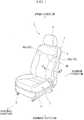
- FIG. 1is a perspective view illustrating a vehicle seat 1.
- This vehicle seat 1is a separate-type seat provided on the driver's seat side or passenger's seat side.
- the vehicle seat 1includes a seat cushion 2 that supports a portion of the body ranging from the hip to the thigh of the passenger, a seat back 3 that supports a portion of the body ranging from the shoulder to the waist of the passenger, and the headrest 4 that supports the head portion of the passenger.
- the seat cushion 2is supported by a floor of the vehicle (not illustrated) by way of a seat rail 5 so as to be able to slide in the front-and-rear direction.
- the seat back 3has the lower end portion jointed with the rear end portion of the seat cushion 2 in a hinged manner, and is supported in a tiltable manner with a hinge shaft (not illustrated) acting as a center.
- the headrest 4is supported by the upper portion of the seat back 3 in a manner such that they can approach or be separated from each other.
- FIG. 2is an exploded perspective view illustrating the seat back 3.
- the seat back 3has a seat back frame 6 serving as a frame, and a cushion unit 7 attached to the front portion of the seat back frame 6.
- the seat back frame 6has a frame portion 18 formed integrally by a substantially U-shaped skeletal frame pipe, and a member unit 15 disposed below the frame portion 18 and is formed into a substantially rectangular shape when viewed from the front thereof.
- a support mat 16is stretched with elastic force applied by a reinforcing wire 19.
- a support wire 17is stretched with elastic force.
- the cushion unit 7is supported by the support mat 16 and the support wire 17.
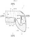
- FIG. 3is a sectional view illustrating a schematic configuration taken along the line A-A in FIG. 1 .
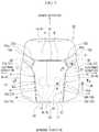
- FIG. 4is a front view of a pad 10.
- the cushion unit 7has a pad 10 having a substantially rectangular shape when viewed on the plane and formed by a thick cushion material such as urethane foam and skins 12 and 13 covering the outer surface of the cushion material.
- the pad 10has a backrest surface 8 that supports a back surface of a passenger's body ranging from the flank to the waist of the passenger, and a side support 9 (left side support 9a and right side support 9b) that supports side portions of the passenger ranging from the flank to the waist.
- the skins 12 and 13are made, for example, out of cloth or leather, and include a front skin 12 covering the backrest surface 8 and a side skin 13 covering the side support 9.
- the pad 10is provided with the backrest surface 8 including an upper area 8a and a lower area 8b disposed below the upper area 8a.
- the lower area 8bis provided substantially at the center in the horizontal direction (width direction) of the pad 10 so as to extend in the vertical direction.
- the upper area 8ahas a width extending in the vertical direction of approximately one-third of the pad 10 from the upper edge.
- an upper suspending groove 35extends in the horizontal direction when viewed from the front direction so as to have a constant width and constant depth.
- the upper suspending groove 35is provided at the lower part of the upper area 8a so as to extend along the horizontal direction when viewed from the front direction.
- An end edge portion 35a 1 on the left side and an end edge portion 35b 1 on the right side of the upper suspending groove 35are provided so as to be sloped upward toward a side portion 10a on the left side of the pad 10 and a side portion 10b on the right side of the pad 10, respectively.
- the front skin 12is fixed so as to be pulled into the upper suspending groove 35. Note that the width and the depth of the upper suspending groove 35 are set depending on applications.
- an upper suspending wire 31is embedded in the pad 10 so as to extend along the upper suspending groove 35.
- the upper suspending wire 31is inserted into an engagement ring 41.
- the engagement ring 41is partially embedded into the pad 10 so as to be exposed from the bottom portion of the upper suspending groove 35.
- a left side support 9a on the left side and a right side support 9b on the right side when viewed from the front directionare provided at both side portions (left and right) of the lower area 8b of the backrest surface 8.
- the side supports 9a and 9bprotrude forward relative to the backrest surface 8. Further, the side supports 9a and 9b are provided in a manner such that the amount of protrusion forward thereof gradually increases with distance toward the outer side of the seat in the seat width direction (in the horizontal direction).
- side suspending grooves 36(left-side suspending groove 36a and right-side suspending groove 36b) having a constant width and constant depth are provided so as to extend along the vertical direction.
- the side suspending grooves 36a and 36beach curve diagonally downwards from the side portions 10a and 10b of the pad 10 when viewed from the front direction, and forms a curved portion 37 (left-side curved portion 37a and right-side curved portion 37b).
- the side suspending grooves 36a, 36b located further below the curved portions 37extend toward a lower end 10c of the pad 10, and are provided on the side surface of the lower area 8b so as to extend along the vertical direction.
- the front skin 12 and the side skin 13are fixed so as to be pulled into the side suspending grooves 36a, 36b.
- side slit portions (slit portion) 46are provided so as to extend along the left-side suspending groove 36a and the right-side suspending groove 36b. These side slit portions 46 are each formed by a group of slits having one or more slits 46a therein. In the case where each of the side slit portions 46 has multiple slits 46a, these slits 46a are separated from each other in the vertical direction.
- At least one of the slits 46a contained in the side slit portion 46 on the left side in the horizontal direction and at least one of the slits 46a contained in the side slit portion 46 on the right sideare located at the same position with respect to the vertical direction.
- each of the right and the left side slit portions 46has two slits 46a. Note that the length of each of the slits 46a in the vertical direction is set depending on applications.
- FIG. 5is a sectional view illustrating a schematic configuration taken along the line B-B in FIG. 4 .
- each of the side slit portions 46basically has a similar configuration.
- the side slit portion 46 provided to the right-side suspending groove 36bwill be described below, and explanation of the side slit portion 46 provided to the left-side suspending groove 36a is omitted.
- the slit 46a of the side slit portion 46is formed so as to be penetrated from the bottom portion 38 of the right-side suspending groove 36b toward the back surface 10d of the pad 10 in the front and rear direction (thickness direction) of the pad 10.
- the width in the horizontal direction of the slit 46ais set to be substantially constant. Further, the center of the slit 46a in the horizontal direction is substantially matched with the center of the right-side suspending groove 36b in the horizontal direction.
- the width of the slit 46ais set so as to be narrower than that of the right-side suspending groove 36b and is set for example so as to be approximately half of the width of the right-side suspending groove 36b.
- the back surface 10d of the pad 10is provided with a lining member 50, which will be described later.
- the lining member 50has a through-hole 51 at a position corresponding to the side slit portion 46.
- side suspending wires 32(32a, 32b) are embedded in a position at the rear of the bottom portion of the side suspending groove 36.
- the side suspending wire 32is inserted into the engagement ring 41.
- the side suspending wire 32is embedded in the pad 10 so as to be partially exposed from the bottom portion of the side suspending groove 36.
- the side slit portion 46is provided along the side suspending groove 36.
- the side suspending wire 32is provided at a position corresponding to the slit 46a in such a way that the wire is bent in the horizontal direction toward the center of the seat while avoiding the slit 46a. With this configuration, the side suspending wire 32 is not exposed to the inside of the slit 46a.
- the front skin 12 and the side skin 13are fixed at the inside of the upper suspending groove 35 and the inside of the side suspending groove 36 as described above.
- an engagement part 43 having a hook portion 43ais stitched at an end portion on the upper suspending groove 35 side and an end portion on the side suspending groove 36 side of each of the front skin 12 and the side skin 13.
- the hook portion 43ais engaged with the engagement ring 41 having the upper suspending wire 31 and the side suspending wire 32 inserted therein, whereby the front skin 12 and the side skin 13 are pulled to the inner side of the upper suspending groove 35 and the inner side of the side suspending groove 36. This makes it possible to engage the front skin 12 and the side skin 13 with the inner side of the pad 10.
- FIG. 6is a sectional view illustrating a schematic configuration taken along the line C-C in FIG. 4 .
- an upper slit (backrest surface slit) 45is provided so as to penetrate the pad 10 in the front and rear direction (thickness direction).
- the backrest surface slit 45is provided above the side slit portion 46 described above. Further, the backrest surface slit 45 is provided on both sides of the lower area 8b of the backrest surface 8 in the horizontal direction so as to extend along the vertical direction. More specifically, as illustrated in FIG. 4 , when viewed from the front direction, the backrest surface slit 45 on the left side is provided so as to connect the left-side curved portion 35a of the upper suspending groove 35 with the left-side curved portion 37a of the left-side suspending groove 36a, and the backrest surface slit 45 on the right side is provided so as to connect the right-side curved portion 35b of the upper suspending groove 35 with the left-side curved portion 37b of the right-side suspending groove 36b.
- multiple slits 46aare disposed so as to be separated from each other in the vertical direction, and form a slit group (slit portion) 46.
- the width of the backrest surface slit 45is substantially constant in the horizontal direction and is set so as to be substantially the same as the width of the side slit portion 46 described above. Note that, as with the case with the side slit portion 46, the through-hole 51 is provided at a position corresponding to the backrest surface slit 45 of the lining member 50.
- FIG. 7is a sectional view illustrating a schematic configuration taken along the line D-D in FIG. 4 .
- the back surface 10d of the pad 10is provided with recessed portions 52 extending along the vertical direction.
- the width, the depth, the vertical length, and the number of each of the recessed portions 52are set depending on applications.
- one recessed portion 52is provided substantially at a center in the horizontal direction, and one recessed portion 52 is provided on the right and the left sides of the center recessed portion 52.
- three recessed portions 52 in totalare provided so as to be arranged in parallel in the horizontal direction.
- the number of the recessed portions 52is not limited to three, and any number may be set depending on applications.
- the back surface 10d provided at the rear of the pad 10has the lining member 50.
- the lining member 50is provided so as to cover the back surface 10d of the pad 10, and extend along the surface of the back surface 10d.
- the lining member 50is formed, for example, by a rough blanket and is integrally formed with the pad 10.
- the lining member 50is provided in order to prevent noises from occurring due to friction with the support mat 16 (see FIG. 2 and FIG. 3 ) and prevent damage from occurring in the pad 10.
- an opening portion 50ais provided at a position of the lining member 50 corresponding to the bottom portion 52a of the recessed portion 52.
- the opening portion 50ais formed, for example, by cutting and removing an area 50b of the lining member 50 located at a position corresponding to the bottom portion 52a of the recessed portion 52.
- the lower area 8b of the backrest surface 8moves rearwards, and the upper body of the passenger sinks into the pad 10. After this, the head portion of the passenger moves nearer to the headrest 4 (see FIG. 1 ), and then, the head portion of the passenger is received by the headrest 4.
- the side slit portion 46is provided between the right and the left sides of the backrest surface 8 and the side support 9, and the pad 10 is sectioned between the backrest surface 8 and the right and the left side supports 9.
- the backrest surface 8moves rearward at the time of rear collision, whereby it is possible to cause the upper body of the passenger to sink into the pad 10.
- Thismakes it possible to reduce the distance between the head portion of the passenger and the headrest 4 at the time of rear collision, and then, cause the headrest 4 to receive the head portion of the passenger.
- the side slit portions 46are spaced apart from each other in the horizontal direction.
- the pad 10is not divided in the vertical direction.
- the backrest surface 8 of the pad 10is prevented from bending and deforming, which prevents the pad 10 from locally sinking. This makes it possible to prevent the sitting state of the passenger from deteriorating.
- the pad 10is provided with the backrest surface slit 45 and the side slit portion 46 having multiple slits 46a spaced apart from each other in the vertical direction, whereby it is possible to adjust the strength of the pad 10 by setting the number of or the length of the backrest surface slits 45 and the slits 46a as appropriate.
- this configurationit is possible to adjust the degree of sinking of the passenger into the pad 10. This makes it possible to prevent the pad 10 from bending and deforming, or prevent the passenger from locally sinking into the pad 10. As a result, it is possible to prevent the sitting state of the passenger from deteriorating during driving. Thus, it is possible to effectively protect the portion of the neck of the passenger at the time of rear collision while maintaining favorable cushion performance.
- the positions of the upper suspending groove 35 and the side suspending groove 36are determined depending on design of the vehicle seat 1.
- the slit 46amay be formed by using the upper suspending groove 35 and the side suspending groove 36.
- the position of the slit 46ais limited depending on the positions of the upper suspending groove 35 and the side suspending groove 36.
- the backrest surface slit 45is provided to the backrest surface 8, the backrest surface slit 45 can be disposed at any position regardless of the design of the seat.
- the back surface 10d of the pad 10is provided with the recessed portion 52 extending in the vertical direction, whereby it is possible to increase the surface length of the back surface 10d of the pad 10 in the horizontal direction.
- the back surface 10d of the pad 10can be made elongated in the horizontal direction, whereby it is possible to secure the sufficient amount of depth for the upper body of the passenger to sink into the pad 10 at the time of rear collision.
- the opening portion 50ais provided at a position of the lining member 50 corresponding to the bottom portion 52a of the recessed portion 52 on the back surface 10d of the pad 10, whereby the lining member 50 can be elongated so as to correspond to the elongation of the back surface 10d of the pad 10 in the horizontal direction.
- the recessed portion 52is provided at the center in the horizontal direction, whereby the center portion of the back surface 10d of the pad 10 elongates. This makes it possible to secure the sufficient amount of depth for the passenger to sink at the time of rear collision. Thus, it is possible to effectively protect the portion of the neck of the passenger at the time of rear collision while maintaining the favorable cushion performance.
- multiple recessed portions 52are provided so as to be spaced apart from each other in the horizontal direction, whereby the back surface 10d of the pad 10 elongates over the entire horizontal direction of the back surface 10d. This makes it possible to secure the sufficient amount of depth for the upper body of the passenger to sink into the pad 10. Thus, it is possible to effectively protect the portion of the neck of the passenger at the time of rear collision while maintaining the favorable cushion performance.
- At least one of the slits 46a in the side slit portion 46 on the left side in the horizontal directionis located at the position vertically the same as that of at least one of the slits 46a in the side slit portion 46 on the right side in the horizontal direction, whereby the portions located between the backrest surface 8 and the right and the left side supports 9a, 9b deform symmetrically in the right-left direction at the time of rear collision.
- the backrest surface 8can move rearward without shifting in the right-left direction, so that the head portion of the passenger can be reliably received by the headrest 4.
- This embodimenthas been described using an example in which the vehicle seat 1 is disposed on the driver's seat side or passenger's seat side.
- this embodimentis not limited to the vehicle seat 1 disposed on the driver's seat side or passenger's seat side.
- the lining member 50is formed by a rough blanket, and the opening portion 50a is provided to the rough blanket.
- the material of the lining member 50is not limited to the rough blanket, and it may be possible to employ PP cloth, nonwoven fabric, or other materials.
- the opening portion 50acan be provided even if the material of the lining member 50 is changed to various materials.
- the side suspending wire 32is provided at a position corresponding to the slit 46a in such a way that the wire is bent in the horizontal direction toward the center of the seat while avoiding the slit 46a.
- the side suspending wire 32is not limited to the shape described above, and it may be possible for the side suspending wire 32, for example, to be bent outwards in the horizontal direction so as to avoid the side slit portion 46.
Landscapes
- Engineering & Computer Science (AREA)
- Aviation & Aerospace Engineering (AREA)
- Transportation (AREA)
- Mechanical Engineering (AREA)
- Seats For Vehicles (AREA)
- Chair Legs, Seat Parts, And Backrests (AREA)
Description
- The present invention relates to a seat back structure for a vehicle.
- A vehicle seat is proposed that protects a portion of the neck of a passenger sitting in the seat when a collision with the vehicle occurs from the rear (hereinafter, referred to as a rear collision) (for example, see JP H11-34707 A).
- The vehicle seat described in
Patent Document 1 has a headrest on the upper edge of the seat back. Further, the seat back contains a stress transferring mechanism that works upon receiving a predetermined value or more of the impact load. - The seat back includes a pad member having a side pad member and a center pad member. Between the side pad member and the center pad member, a slit is provided so as to penetrate the pad member from the front side to the rear side. Then, with this slit, the side pad member and the center pad member are configured to have a divided formation (see
FIG. 3 inJP H11-34707 A - Further, the center pad member is provided with a slit that penetrates the center pad member from the front side to the rear side. With this slit, the center pad member is divided vertically into two pieces (see
FIG. 4 ofJP H11-34707 A - If the vehicle is subjected to a rear collision, the upper body of the passenger is pressed rearward due to the impact load and sinks into the center pad member. Then, the center pad member is bent at the slit, and moves backward while the impact load occurring at the time of the rear collision is effectively transferred to the stress transferring mechanism such as a link mechanism by way of the center pad member. With the stress transferring mechanism operating due to the impact load, the headrest is moved upward while being moved toward the side of the head of the passenger.
- As described above, the vehicle seat described in
JP H11-34707 A - In
JP 2010 036807 A claim 1 is based, a wire is arranged at the vicinity of corner edge portion of the bottom surface of recess and the hole, and a hook is inserted of the recess, and the hook is hooked to the wire. The wire is not provided at a position which avoids the slit but the wire is provided to passing inside of the suspending grooves. US 2008/136237 A1 ,US 6,386,577 B1 ,JP 2010-179748 US 6,003,939 each disclose a seat back structure for a vehicle having a headrest, a seat back frame, and a pad disposed in front of a surface of the seat back frame, wherein the pad includes a backrest surface, and right and left side supports each provided on either side of the backrest surface in a seat width direction, a right slit portion and a left slit portion are provided between the backrest surface and the right and the left side supports, respectively, each of the right slit portion and the left slit portion having a slit penetrating the pad in a thickness direction of the pad and extending in a vertical direction of the pad, the right and the left slit portions are spaced apart from each other in the seat width direction, the pad has a skin covering an outer surface thereof, the pad is provided with a suspending groove, the skin is engaged at an inner side of the suspending groove, and a suspending wire is embedded in the suspending groove.US 4,609,226 shows a seat cushion structure for a vehicle having a seat frame, and a pad disposed in a surface of the seat frame, wherein the pad includes a cushion surface, and right and left side supports each provided on either side of the cushion surface in a seat width direction, a right slit portion and a left slit portion are provided between the cushion surface and the right and the left side supports, respectively, each of the right slit portion and the left slit portion having a slit penetrating the pad in a thickness direction of the pad and extending in a vertical direction of the pad, the right and the left slit portions are spaced apart from each other in the seat width direction, the pad has a skin covering an outer surface thereof, the pad is provided with a suspending groove, the skin is engaged at an inner side of the suspending groove, and a suspending wire is embedded in the suspending groove.- Incidentally, as the vehicle seat described in
JP H11-34707 A - In view of the facts described above, the present invention addresses a problem of providing a vehicle seat that can protect the portion of the neck of the passenger at the time of rear collision while maintaining a favorable cushion performance.
- To solve the problem described above, the present invention provides a seat back structure in accordance with
claim 1. - With the vehicle seat described above, the left and right slit portions are provided between the backrest surface and the right and the left side supports, whereby the pad is sectioned between the backrest surface, and the right and the left side supports. With this structure, it is possible to easily move the backrest surface rearwards at the time of rear collision to make the upper body of the passenger sink into the pad. This makes it possible to reduce the distance between the head portion of the passenger and the headrest, and then, cause the headrest to receive the head portion. Thus, it is possible to prevent the portion of the neck of the passenger from rapidly extending or bending, whereby it is possible to protect the portion of the neck.
- Further, the right and the left slit portions are spaced apart from each other in the seat width direction (in the horizontal direction), so that unlike
JP H11-34707 A - The pad has a skin covering an outer surface thereof; the pad is provided with a suspending groove; and the skin is engaged at the inner side of the suspending groove.
- Thus, even if the vehicle seat has the slit portions provided at the position of the suspending groove, the position of the backrest surface slit is not limited by the position of the suspending groove. Thus, it is possible to dispose the backrest surface slit at any position regardless of design of the seat.
- Preferably, the slit provided to the right and the left slit portions is formed by multiple slits, and the slits are provided so as to be spaced apart from each other in the vertical direction.
- Thus, the strength of the pad can be adjusted by setting the number or the length or the width of these slits as appropriate. With this configuration, it is possible to adjust the degree of sinking of the passenger into the pad. This prevents the pad from bending and deforming, and the passenger from locally sinking, which makes it possible to prevent the sitting state of the passenger from deteriorating during driving. Thus, it is possible to effectively protect the portion of the neck of the passenger at the time of rear collision while maintaining favorable cushion performance.
- Preferably, a recessed portion, which does not penetrate the pad in the thickness direction, is provided on a back surface side of the pad so as to extend in the vertical direction.
- Thus, it is possible to increase the surface length of the pad on the back surface side in the seat width direction (in the horizontal direction), and to extend the back surface of the pad in the horizontal direction. This makes it possible to secure the sufficient amount of depth for the upper body of the passenger to sink in the pad at the time of rear collision. Thus, it is possible to effectively protect the portion of the neck of the passenger at the time of rear collision while maintaining favorable cushion performance.
- Preferably, the pad has a lining member on the back surface of the pad, and an opening portion extending in the vertical direction is provided at a position of the lining member corresponding to a bottom portion of the recessed portion.
- This makes it possible to make the lining member elongate in response to the elongation of the back surface of the pad in the horizontal direction. With this configuration, it is possible to secure the sufficient amount of depth for the passenger to sink at the time of rear collision while maintaining the strength of the pad with the lining member provided on the back surface of the pad. Thus, it is possible to protect the portion of the neck of the passenger at the time of rear collision.
- Preferably, the recessed portion is provided at a center portion in the seat width direction.
- By this, it is possible to secure the sufficient amount of depth for the passenger to sink at the time of rear collision. Thus, it is possible to effectively protect the portion of the neck of the passenger at the time of rear collision while maintaining favorable cushion performance.
- Preferably, the recessed portion is formed by multiple recessed portions, and the recessed portions is provided so as to be spaced apart from each other in the seat width direction.
- By this, it is possible to secure the sufficient amount of depth for the upper body of the passenger to sink. Thus, it is possible to protect the portion of the neck of the passenger at the time of rear collision while maintaining favorable cushion performance.
- Preferably, at least one of the slits included in the left slit portion is located at a position vertically the same as the position of at least one of the slits included in the right slit portion.
- The portions located between the backrest surface, and the right and the left side supports deform symmetrically in the right-left direction at the time of rear collision. With this configuration, the backrest surface moves rearwards without shifting in the right-left direction, whereby the head portion of the passenger can be reliably received by the headrest.
FIG. 1 is a perspective view illustrating a vehicle seat when viewed from the front.FIG. 2 is an exploded perspective view illustrating the seat back.FIG. 3 is a sectional view illustrating a schematic configuration taken along the line A-A inFIG. 1 .FIG. 4 is a front view illustrating a pad.FIG. 5 is a sectional view illustrating a schematic configuration taken along the line B-B inFIG. 4 .FIG. 6 is a sectional view illustrating a schematic configuration taken along the line C-C inFIG. 4 .FIG. 7 is a sectional view illustrating a schematic configuration taken along the line D-D inFIG. 4 .- Hereinbelow, a vehicle seat according to an embodiment of the present invention will be described with reference to the drawings. Note that, for the purpose of convenience, in the description below, the forward direction when the vehicle travels is also referred to as the front direction; the rearward direction when the vehicle travels is also referred to as the rearward direction; the width direction of the vehicle is also referred to as the horizontal direction; and the upward and the downward directions in the vertical direction of the vehicle are also referred to as the upward and the downward, respectively.
FIG. 1 is a perspective view illustrating avehicle seat 1. Thisvehicle seat 1 is a separate-type seat provided on the driver's seat side or passenger's seat side.- As illustrated in
FIG. 1 , thevehicle seat 1 includes aseat cushion 2 that supports a portion of the body ranging from the hip to the thigh of the passenger, a seat back 3 that supports a portion of the body ranging from the shoulder to the waist of the passenger, and theheadrest 4 that supports the head portion of the passenger. - The
seat cushion 2 is supported by a floor of the vehicle (not illustrated) by way of aseat rail 5 so as to be able to slide in the front-and-rear direction. The seat back 3 has the lower end portion jointed with the rear end portion of theseat cushion 2 in a hinged manner, and is supported in a tiltable manner with a hinge shaft (not illustrated) acting as a center. Theheadrest 4 is supported by the upper portion of the seat back 3 in a manner such that they can approach or be separated from each other. FIG. 2 is an exploded perspective view illustrating the seat back 3.- As illustrated in
FIG. 2 , the seat back 3 has a seat backframe 6 serving as a frame, and acushion unit 7 attached to the front portion of the seat backframe 6. - The seat back
frame 6 has aframe portion 18 formed integrally by a substantially U-shaped skeletal frame pipe, and amember unit 15 disposed below theframe portion 18 and is formed into a substantially rectangular shape when viewed from the front thereof. - In the lower portion of the
frame portion 18, asupport mat 16 is stretched with elastic force applied by a reinforcingwire 19. Above thesupport mat 16, asupport wire 17 is stretched with elastic force. Thecushion unit 7 is supported by thesupport mat 16 and thesupport wire 17. FIG. 3 is a sectional view illustrating a schematic configuration taken along the line A-A inFIG. 1 .FIG. 4 is a front view of apad 10.- As illustrated in
FIG. 3 andFIG. 4 , thecushion unit 7 has apad 10 having a substantially rectangular shape when viewed on the plane and formed by a thick cushion material such as urethane foam andskins - The
pad 10 has abackrest surface 8 that supports a back surface of a passenger's body ranging from the flank to the waist of the passenger, and a side support 9 (left side support 9a andright side support 9b) that supports side portions of the passenger ranging from the flank to the waist. - The
skins front skin 12 covering thebackrest surface 8 and aside skin 13 covering theside support 9. - As illustrated in
FIG. 4 , thepad 10 is provided with thebackrest surface 8 including anupper area 8a and alower area 8b disposed below theupper area 8a. Thelower area 8b is provided substantially at the center in the horizontal direction (width direction) of thepad 10 so as to extend in the vertical direction. Then, theupper area 8a has a width extending in the vertical direction of approximately one-third of thepad 10 from the upper edge. - Further, between the
upper area 8a and thelower area 8b of thebackrest surface 8, an upper suspendinggroove 35 extends in the horizontal direction when viewed from the front direction so as to have a constant width and constant depth. The upper suspendinggroove 35 is provided at the lower part of theupper area 8a so as to extend along the horizontal direction when viewed from the front direction. Anend edge portion 35a1 on the left side and anend edge portion 35b1 on the right side of the upper suspendinggroove 35 are provided so as to be sloped upward toward aside portion 10a on the left side of thepad 10 and aside portion 10b on the right side of thepad 10, respectively. Thefront skin 12 is fixed so as to be pulled into the upper suspendinggroove 35. Note that the width and the depth of the upper suspendinggroove 35 are set depending on applications. - At the rearward of the bottom portion (not illustrated) of the upper suspending
groove 35, an upper suspendingwire 31 is embedded in thepad 10 so as to extend along the upper suspendinggroove 35. The upper suspendingwire 31 is inserted into anengagement ring 41. Theengagement ring 41 is partially embedded into thepad 10 so as to be exposed from the bottom portion of the upper suspendinggroove 35. - In the
pad 10, aleft side support 9a on the left side and aright side support 9b on the right side when viewed from the front direction are provided at both side portions (left and right) of thelower area 8b of thebackrest surface 8. The side supports 9a and 9b protrude forward relative to thebackrest surface 8. Further, the side supports 9a and 9b are provided in a manner such that the amount of protrusion forward thereof gradually increases with distance toward the outer side of the seat in the seat width direction (in the horizontal direction). - Between the
lower area 8b of thebackrest surface 8 and the right and the left side supports 9a, 9b, side suspending grooves 36 (left-side suspending groove 36a and right-side suspending groove 36b) having a constant width and constant depth are provided so as to extend along the vertical direction. Theside suspending grooves side portions pad 10 when viewed from the front direction, and forms a curved portion 37 (left-sidecurved portion 37a and right-sidecurved portion 37b). Theside suspending grooves curved portions 37 extend toward alower end 10c of thepad 10, and are provided on the side surface of thelower area 8b so as to extend along the vertical direction. Thefront skin 12 and theside skin 13 are fixed so as to be pulled into theside suspending grooves - In the
pad 10, side slit portions (slit portion) 46 are provided so as to extend along the left-side suspending groove 36a and the right-side suspending groove 36b. These side slitportions 46 are each formed by a group of slits having one ormore slits 46a therein. In the case where each of the side slitportions 46 hasmultiple slits 46a, theseslits 46a are separated from each other in the vertical direction. - It should be noted that it is preferable that at least one of the
slits 46a contained in the side slitportion 46 on the left side in the horizontal direction and at least one of theslits 46a contained in the side slitportion 46 on the right side are located at the same position with respect to the vertical direction. - In this embodiment, a description will be made of a case, as an example, in which each of the right and the left side slit
portions 46 has twoslits 46a. Note that the length of each of theslits 46a in the vertical direction is set depending on applications. FIG. 5 is a sectional view illustrating a schematic configuration taken along the line B-B inFIG. 4 . Note that each of the side slitportions 46 basically has a similar configuration. Thus, only the side slitportion 46 provided to the right-side suspending groove 36b will be described below, and explanation of the side slitportion 46 provided to the left-side suspending groove 36a is omitted.- As illustrated in
FIG. 5 , theslit 46a of the side slitportion 46 is formed so as to be penetrated from thebottom portion 38 of the right-side suspending groove 36b toward theback surface 10d of thepad 10 in the front and rear direction (thickness direction) of thepad 10. - The width in the horizontal direction of the
slit 46a is set to be substantially constant. Further, the center of theslit 46a in the horizontal direction is substantially matched with the center of the right-side suspending groove 36b in the horizontal direction. The width of theslit 46a is set so as to be narrower than that of the right-side suspending groove 36b and is set for example so as to be approximately half of the width of the right-side suspending groove 36b. Note that, theback surface 10d of thepad 10 is provided with a liningmember 50, which will be described later. The liningmember 50 has a through-hole 51 at a position corresponding to the side slitportion 46. - As illustrated in
FIG. 3 , side suspending wires 32 (32a, 32b) are embedded in a position at the rear of the bottom portion of theside suspending groove 36. Theside suspending wire 32 is inserted into theengagement ring 41. Then, theside suspending wire 32 is embedded in thepad 10 so as to be partially exposed from the bottom portion of theside suspending groove 36. - Here, as described above, the side slit
portion 46 is provided along theside suspending groove 36. Thus, as illustrated inFIG. 4 , theside suspending wire 32 is provided at a position corresponding to theslit 46a in such a way that the wire is bent in the horizontal direction toward the center of the seat while avoiding theslit 46a. With this configuration, theside suspending wire 32 is not exposed to the inside of theslit 46a. - As illustrated in
FIG. 3 , thefront skin 12 and theside skin 13 are fixed at the inside of the upper suspendinggroove 35 and the inside of theside suspending groove 36 as described above. - More specifically, an
engagement part 43 having ahook portion 43a is stitched at an end portion on the upper suspendinggroove 35 side and an end portion on theside suspending groove 36 side of each of thefront skin 12 and theside skin 13. Thehook portion 43a is engaged with theengagement ring 41 having the upper suspendingwire 31 and theside suspending wire 32 inserted therein, whereby thefront skin 12 and theside skin 13 are pulled to the inner side of the upper suspendinggroove 35 and the inner side of theside suspending groove 36. This makes it possible to engage thefront skin 12 and theside skin 13 with the inner side of thepad 10. FIG. 6 is a sectional view illustrating a schematic configuration taken along the line C-C inFIG. 4 .- As illustrated in
FIG. 4 andFIG. 6 , between the upper suspendinggroove 35 and the side suspending grooves 36 (36a, 36b) on thebackrest surface 8 of thepad 10, an upper slit (backrest surface slit) 45 is provided so as to penetrate thepad 10 in the front and rear direction (thickness direction). - The backrest surface slit 45 is provided above the side slit
portion 46 described above. Further, the backrest surface slit 45 is provided on both sides of thelower area 8b of thebackrest surface 8 in the horizontal direction so as to extend along the vertical direction. More specifically, as illustrated inFIG. 4 , when viewed from the front direction, the backrest surface slit 45 on the left side is provided so as to connect the left-sidecurved portion 35a of the upper suspendinggroove 35 with the left-sidecurved portion 37a of the left-side suspending groove 36a, and the backrest surface slit 45 on the right side is provided so as to connect the right-sidecurved portion 35b of the upper suspendinggroove 35 with the left-sidecurved portion 37b of the right-side suspending groove 36b. - Further,
multiple slits 46a are disposed so as to be separated from each other in the vertical direction, and form a slit group (slit portion) 46. - The width of the backrest surface slit 45 is substantially constant in the horizontal direction and is set so as to be substantially the same as the width of the side slit
portion 46 described above. Note that, as with the case with the side slitportion 46, the through-hole 51 is provided at a position corresponding to the backrest surface slit 45 of the liningmember 50. FIG. 7 is a sectional view illustrating a schematic configuration taken along the line D-D inFIG. 4 .- As illustrated in
FIG. 7 , theback surface 10d of thepad 10 is provided with recessedportions 52 extending along the vertical direction. The width, the depth, the vertical length, and the number of each of the recessedportions 52 are set depending on applications. - In this embodiment, for example, one recessed
portion 52 is provided substantially at a center in the horizontal direction, and one recessedportion 52 is provided on the right and the left sides of the center recessedportion 52. As described above, in this embodiment, three recessedportions 52 in total are provided so as to be arranged in parallel in the horizontal direction. However, the number of the recessedportions 52 is not limited to three, and any number may be set depending on applications. - The
back surface 10d provided at the rear of thepad 10 has the liningmember 50. The liningmember 50 is provided so as to cover theback surface 10d of thepad 10, and extend along the surface of theback surface 10d. The liningmember 50 is formed, for example, by a rough blanket and is integrally formed with thepad 10. The liningmember 50 is provided in order to prevent noises from occurring due to friction with the support mat 16 (seeFIG. 2 andFIG. 3 ) and prevent damage from occurring in thepad 10. - Further, an
opening portion 50a is provided at a position of the liningmember 50 corresponding to thebottom portion 52a of the recessedportion 52. Theopening portion 50a is formed, for example, by cutting and removing anarea 50b of the liningmember 50 located at a position corresponding to thebottom portion 52a of the recessedportion 52. - Next, operations of this embodiment will be described.
- When a vehicle has a rear collision, the upper body of a passenger is pressed against the
pad 10 due to impact load occurring at the time of collision. At this time, portions of thepad 10 located between theupper area 8a and thelower area 8b of thebackrest surface 8 and between thebackrest surface 8 and theside support 9 are bent with the backrest surface slit 45 and the side slitportion 46 having one ormore slits 46a while theback surface 10d of thepad 10 elongates. - Then, the
lower area 8b of thebackrest surface 8 moves rearwards, and the upper body of the passenger sinks into thepad 10. After this, the head portion of the passenger moves nearer to the headrest 4 (seeFIG. 1 ), and then, the head portion of the passenger is received by theheadrest 4. - According to this embodiment, the side slit
portion 46 is provided between the right and the left sides of thebackrest surface 8 and theside support 9, and thepad 10 is sectioned between thebackrest surface 8 and the right and the left side supports 9. With this configuration, thebackrest surface 8 moves rearward at the time of rear collision, whereby it is possible to cause the upper body of the passenger to sink into thepad 10. This makes it possible to reduce the distance between the head portion of the passenger and theheadrest 4 at the time of rear collision, and then, cause theheadrest 4 to receive the head portion of the passenger. Thus, it is possible to prevent the portion of the neck of the passenger from rapidly extending or bending, whereby it is possible to protect the portion of the neck of the passenger. - Further, the side slit
portions 46 are spaced apart from each other in the horizontal direction. Thus, unlikePatent Document 1, thepad 10 is not divided in the vertical direction. With this configuration, thebackrest surface 8 of thepad 10 is prevented from bending and deforming, which prevents thepad 10 from locally sinking. This makes it possible to prevent the sitting state of the passenger from deteriorating. Thus, it is possible to protect the portion of the neck of the passenger at the time of rear collision while maintaining favorable cushion performance. - Further, according to this embodiment, the
pad 10 is provided with the backrest surface slit 45 and the side slitportion 46 havingmultiple slits 46a spaced apart from each other in the vertical direction, whereby it is possible to adjust the strength of thepad 10 by setting the number of or the length of the backrest surface slits 45 and theslits 46a as appropriate. With this configuration, it is possible to adjust the degree of sinking of the passenger into thepad 10. This makes it possible to prevent thepad 10 from bending and deforming, or prevent the passenger from locally sinking into thepad 10. As a result, it is possible to prevent the sitting state of the passenger from deteriorating during driving. Thus, it is possible to effectively protect the portion of the neck of the passenger at the time of rear collision while maintaining favorable cushion performance. - Incidentally, in general, the positions of the upper suspending
groove 35 and theside suspending groove 36 are determined depending on design of thevehicle seat 1. Here, theslit 46a may be formed by using the upper suspendinggroove 35 and theside suspending groove 36. However, in this case, the position of theslit 46a is limited depending on the positions of the upper suspendinggroove 35 and theside suspending groove 36. On the other hand, according to this embodiment, since the backrest surface slit 45 is provided to thebackrest surface 8, the backrest surface slit 45 can be disposed at any position regardless of the design of the seat. - Further, according to this embodiment, the
back surface 10d of thepad 10 is provided with the recessedportion 52 extending in the vertical direction, whereby it is possible to increase the surface length of theback surface 10d of thepad 10 in the horizontal direction. With this configuration, theback surface 10d of thepad 10 can be made elongated in the horizontal direction, whereby it is possible to secure the sufficient amount of depth for the upper body of the passenger to sink into thepad 10 at the time of rear collision. Thus, it is possible to effectively protect the portion of the neck of the passenger at the time of rear collision while maintaining the favorable cushion performance. - Further, according to this embodiment, the
opening portion 50a is provided at a position of the liningmember 50 corresponding to thebottom portion 52a of the recessedportion 52 on theback surface 10d of thepad 10, whereby the liningmember 50 can be elongated so as to correspond to the elongation of theback surface 10d of thepad 10 in the horizontal direction. This makes it possible to secure the sufficient amount of depth for the passenger to sink at the time of rear collision while maintaining the strength of the pad with the liningmember 50 provided to the back surface of thepad 10. Thus, it is possible to protect the portion of the neck of the passenger at the time of rear collision. - Further, according to this embodiment, the recessed
portion 52 is provided at the center in the horizontal direction, whereby the center portion of theback surface 10d of thepad 10 elongates. This makes it possible to secure the sufficient amount of depth for the passenger to sink at the time of rear collision. Thus, it is possible to effectively protect the portion of the neck of the passenger at the time of rear collision while maintaining the favorable cushion performance. - Further, according to this embodiment, multiple recessed
portions 52 are provided so as to be spaced apart from each other in the horizontal direction, whereby theback surface 10d of thepad 10 elongates over the entire horizontal direction of theback surface 10d. This makes it possible to secure the sufficient amount of depth for the upper body of the passenger to sink into thepad 10. Thus, it is possible to effectively protect the portion of the neck of the passenger at the time of rear collision while maintaining the favorable cushion performance. - Further, according to this embodiment, at least one of the
slits 46a in the side slitportion 46 on the left side in the horizontal direction is located at the position vertically the same as that of at least one of theslits 46a in the side slitportion 46 on the right side in the horizontal direction, whereby the portions located between thebackrest surface 8 and the right and the left side supports 9a, 9b deform symmetrically in the right-left direction at the time of rear collision. With this configuration, thebackrest surface 8 can move rearward without shifting in the right-left direction, so that the head portion of the passenger can be reliably received by theheadrest 4. - It should be noted that the present invention is not limited to the embodiments described above, and various design modifications may be possible within the scope of the present claims.
- The positions, the shapes, the numbers, or other characteristics of the upper suspending
groove 35, theside suspending groove 36, the backrest surface slit 45, and the side slitportion 46 described in this embodiment are not limited to those described in this embodiment, and various modifications may be possible. - This embodiment has been described using an example in which the
vehicle seat 1 is disposed on the driver's seat side or passenger's seat side. However, this embodiment is not limited to thevehicle seat 1 disposed on the driver's seat side or passenger's seat side. For example, it may be possible to apply this embodiment to various kinds of vehicle seats such as a rear seat of the vehicle. - In this embodiment, the lining
member 50 is formed by a rough blanket, and theopening portion 50a is provided to the rough blanket. However, the material of the liningmember 50 is not limited to the rough blanket, and it may be possible to employ PP cloth, nonwoven fabric, or other materials. Theopening portion 50a can be provided even if the material of the liningmember 50 is changed to various materials. - The
side suspending wire 32 according to this embodiment is provided at a position corresponding to theslit 46a in such a way that the wire is bent in the horizontal direction toward the center of the seat while avoiding theslit 46a. However, theside suspending wire 32 is not limited to the shape described above, and it may be possible for theside suspending wire 32, for example, to be bent outwards in the horizontal direction so as to avoid the side slitportion 46. - 20 Coil
- 1 Vehicle seat
- 3 Seat back (seat back structure for a vehicle)
- 6 Seat back frame
- 8 Backrest surface
- 9(9a, 9b) Side support
- 10 Pad
- 10d Back surface
- 12, 13 Skin
- 45 Backrest surface slit (upper slit)
- 46 Side slit portion (slit portion)
- 46a Slit
- 50 Lining member
- 50a Opening portion
- 52 Recessed portion
- 52a Bottom portion
Claims (12)
- A seat back structure for a vehicle having a headrest (4), a seat back frame (6), and a pad (10) disposed in front of a surface of the seat back frame (6), whereinthe pad (10) includes a backrest surface (8), and right and left side supports (9a, 9b) each provided on either side of the backrest surface (8) in a seat width direction,a right slit portion (46) and a left slit portion (46) are provided between the backrest surface (8) and the right and the left side supports (9a, 9b), respectively, each of the right slit portion (46) and the left slit portion (46) having a slit (46a) penetrating the pad (10) in a thickness direction of the pad (10) and extending in a vertical direction of the pad (10),the right and the left slit portions (46) are spaced apart from each other in the seat width direction,the pad (10) has a skin (12, 13) covering an outer surface thereof,the pad (10) is provided with a suspending groove (36),the skin (12, 13) is engaged at an inner side (43a) of the suspending groove (36), anda suspending wire (32) is embedded in the suspending groove (36),characterized in thatthe suspending wire (32) at a position corresponding to the slit (46a) is bent in the horizontal direction outwards or toward the center of the seat while avoiding the slit (46a), such that the suspending wire (32) is not exposed to the inside of the slit (46a).
- The seat back structure for a vehicle according to Claim 1, whereinthe slit provided to each of the right and the left slit portions (46) includes a plurality of slits (46a), andthe slits are provided so as to be spaced apart from each other in the vertical direction.
- The seat back structure for a vehicle according to Claim 1 or 2, whereinthe side supports (9a, 9b) protrude forward relative to the backrest surface (8), andthe suspending wire (32) is provided at a position corresponding to the slit (46a) in such a way that the wire (32) is bent in a horizontal direction toward the center of the seat (1) while avoiding the slit (46a).
- The seat back structure for a vehicle according to any one of Claims 1 to 3, whereinthe backrest surface (8) is provided with a backrest surface slit (45) penetrating the pad (10) in the thickness direction of the pad (10), the backrest surface slit (45) being provided at an upper side than a center of the backrest surface (8) in the vertical direction.
- The seat back structure for a vehicle according to any one of Claims 1 to 4, whereina recessed portion (52), which does not penetrate the pad (10) in the thickness direction, is provided on a back surface side of the pad (10) so as to extend in the vertical direction, the recessed portion (52) being provided in between of the right slit portion (46) and the left slit portion (46).
- The seat back structure for a vehicle according to Claim 5, whereinthe suspending wire (32) is a right suspending wire and a left suspending wire which are respectively provided at a position corresponding to the right slit portion (46) and the left slit portion (46), andthe recessed portion (52) is provided in between of the right slit portion (46) and the left slit portion (46) in the horizontal direction.
- The seat back structure for a vehicle according to Claim 4, whereinthe backrest surface slit (45) is provided at both sides with respect to a center of the backrest surface (8) in the horizontal direction, anda recessed portion (52) is provided in between of the right slit portion (46) and the left slit portion (46).
- The seat back structure for a vehicle according to Claim 7, whereinthe recessed portion (52) is continuously provided until a height which corresponds with the backrest surface slit (45) in between of the right suspending wire (31) and the left suspending wire.
- The seat back structure for a vehicle according to any one of Claims 5 to 8, whereinthe pad (10) has a lining member (50) on the back surface side thereof, andan opening portion (50a) extending in the vertical direction is provided at a position of the lining member (50) corresponding to a bottom portion of the recessed portion (52).
- The seat back structure for a vehicle according to any one of Claims 5 to 9, whereinthe recessed portion (52) is provided at a center portion in the seat width direction.
- The seat back structure for a vehicle according to any one of Claims 5 to 9, whereinthe recessed portion (52) includes a plurality of recessed portion (52)s, andthe recessed portions (52) are provided so as to be spaced apart from each other in the seat width direction.
- The seat back structure for a vehicle according to Claim 2, whereinat least one of the slits (46a) included in the left slit portion (46) is located at a position vertically the same as at least one of the slits (46a) included in the right slit portion (46).
Applications Claiming Priority (2)
| Application Number | Priority Date | Filing Date | Title |
|---|---|---|---|
| JP2010287584 | 2010-12-24 | ||
| PCT/JP2011/077193WO2012086364A1 (en) | 2010-12-24 | 2011-11-25 | Vehicle seat back structure |
Publications (3)
| Publication Number | Publication Date |
|---|---|
| EP2628634A1 EP2628634A1 (en) | 2013-08-21 |
| EP2628634A4 EP2628634A4 (en) | 2014-05-07 |
| EP2628634B1true EP2628634B1 (en) | 2016-04-27 |
Family
ID=46313646
Family Applications (1)
| Application Number | Title | Priority Date | Filing Date |
|---|---|---|---|
| EP11851961.0AActiveEP2628634B1 (en) | 2010-12-24 | 2011-11-25 | Vehicle seat back structure |
Country Status (5)
| Country | Link |
|---|---|
| US (2) | US9056568B2 (en) |
| EP (1) | EP2628634B1 (en) |
| JP (1) | JP5576506B2 (en) |
| CN (2) | CN105539232B (en) |
| WO (1) | WO2012086364A1 (en) |
Families Citing this family (23)
| Publication number | Priority date | Publication date | Assignee | Title |
|---|---|---|---|---|
| CN108482198B (en) | 2012-10-01 | 2021-04-09 | 提爱思科技股份有限公司 | Chair back |
| FR3003819B1 (en)* | 2013-03-26 | 2016-12-30 | Expliseat | VEHICLE SEAT BACKREST HAVING A FRAGILIZED AREA THAT CAN BE TURNED |
| CN103863155B (en)* | 2014-02-18 | 2016-11-23 | 长春富维—江森自控汽车饰件系统有限公司 | A kind of motor vehicle seat back preventing from whipping |
| JP6179458B2 (en)* | 2014-05-20 | 2017-08-16 | トヨタ紡織株式会社 | Vehicle seat |
| JP6130820B2 (en)* | 2014-11-06 | 2017-05-17 | 東洋ゴム工業株式会社 | Seat pad |
| JP6102901B2 (en)* | 2014-12-19 | 2017-03-29 | トヨタ自動車株式会社 | Vehicle seat |
| US10173565B2 (en)* | 2016-05-18 | 2019-01-08 | Ford Global Technologies, Llc | Vehicle seat and headrest with dynamic impact energy management system |
| CN109153343B (en)* | 2016-07-20 | 2021-03-26 | 株式会社泰极爱思 | vehicle seat |
| JP6745211B2 (en)* | 2016-12-28 | 2020-08-26 | 株式会社ジェイエスピー | Sheet core material |
| US10266088B2 (en)* | 2017-01-31 | 2019-04-23 | Ford Global Technologies, Llc | Vehicle seating assembly having abrasion resistant bolster insert |
| GB201702823D0 (en)* | 2017-02-22 | 2017-04-05 | Acro Aircraft Seating Ltd | Seat part comprising a seat cover |
| USD862096S1 (en) | 2017-04-10 | 2019-10-08 | Nio Nextev Limited | Bench car seat |
| USD847523S1 (en)* | 2017-04-10 | 2019-05-07 | Nio Nextev Limited | Car seat |
| USD846902S1 (en)* | 2017-04-10 | 2019-04-30 | Nio Nextev Limited | Car seat |
| US10486565B2 (en)* | 2017-05-09 | 2019-11-26 | Lear Corporation | Dual firmness foam flex point elimination |
| WO2019069484A1 (en) | 2017-10-05 | 2019-04-11 | テイ・エス テック株式会社 | Vehicle seat |
| US10933786B2 (en) | 2017-11-27 | 2021-03-02 | Lear Corporation | Fixed attachment for hog ring tie-down trench |
| JP2020081171A (en) | 2018-11-20 | 2020-06-04 | 株式会社ブリヂストン | Seat pad, and manufacturing method for the same |
| JP7103587B2 (en)* | 2018-12-27 | 2022-07-20 | 日本発條株式会社 | Vehicle seat |
| JP7469618B2 (en)* | 2020-03-19 | 2024-04-17 | テイ・エス テック株式会社 | Vehicle seats |
| JP7554594B2 (en)* | 2020-07-31 | 2024-09-20 | アディエント ユーエス エルエルシー | Vehicle seat |
| US12420687B2 (en)* | 2021-05-28 | 2025-09-23 | Lear Corporation | Trim support member |
| CN115257494B (en)* | 2022-08-16 | 2024-01-12 | 恒大恒驰新能源汽车研究院(上海)有限公司 | Vehicle seat and vehicle |
Citations (2)
| Publication number | Priority date | Publication date | Assignee | Title |
|---|---|---|---|---|
| US6003939A (en)* | 1996-09-03 | 1999-12-21 | Toyota Jidosha Kabushiki Kaisha | Side air bag-carrying seat structure |
| JP2010036807A (en)* | 2008-08-07 | 2010-02-18 | Bridgestone Corp | Vehicular seat pad |
Family Cites Families (34)
| Publication number | Priority date | Publication date | Assignee | Title |
|---|---|---|---|---|
| US3630572A (en)* | 1969-09-23 | 1971-12-28 | Lear Siegler Inc | Seat assembly |
| US3639002A (en)* | 1970-04-06 | 1972-02-01 | Gulf & Western Metals Forming | Seat construction |
| SE445818B (en)* | 1984-02-23 | 1986-07-21 | Tachikawa Spring Co | FORDONSSETE |
| US4579389A (en)* | 1984-04-30 | 1986-04-01 | Tachikawa Spring Co. Ltd. | Vehicle seat |
| US4609226A (en)* | 1984-08-14 | 1986-09-02 | Tachikawa Spring Co., Ltd. | Vehicle seat |
| JPH0642511Y2 (en)* | 1988-01-19 | 1994-11-09 | 池田物産株式会社 | Vehicle seat |
| JP2544806B2 (en) | 1989-05-30 | 1996-10-16 | 三菱電機株式会社 | Method for manufacturing semiconductor device |
| JPH033246U (en)* | 1989-05-31 | 1991-01-14 | ||
| US5044693A (en)* | 1989-10-31 | 1991-09-03 | Tachi-S Co., Ltd. | Seat back structure of an automotive seat |
| JPH0528300A (en)* | 1991-07-18 | 1993-02-05 | Tokyo Electric Co Ltd | Bar code scan |
| US5338098A (en)* | 1993-04-23 | 1994-08-16 | Tachi-S Co., Ltd. | Seat back of an automotive seat |
| FR2730198B1 (en)* | 1995-02-08 | 1997-04-11 | Faure Bertrand Equipements Sa | HEADDRESS FOR VEHICLE SEAT BACKREST AND SEAT INCLUDING SUCH A HEADDRESS |
| JP3201591B2 (en) | 1997-07-22 | 2001-08-20 | ジョンソン コントロールズ オートモーティブ システムズ株式会社 | Vehicle seat |
| JP3464764B2 (en)* | 1998-09-16 | 2003-11-10 | 本田技研工業株式会社 | Airbag device for side collision |
| US6386577B1 (en) | 1999-03-29 | 2002-05-14 | Honda Giken Kogyokabushiki Kaisha | Side-collision air bag device |
| JP4442876B2 (en)* | 2004-07-06 | 2010-03-31 | テイ・エス テック株式会社 | Vehicle seat |
| WO2007142162A1 (en)* | 2006-06-02 | 2007-12-13 | Ts Tech Co., Ltd. | Vehicle seat |
| JP4925176B2 (en)* | 2006-07-07 | 2012-04-25 | テイ・エス テック株式会社 | Vehicle seat |
| JP5098297B2 (en)* | 2006-11-02 | 2012-12-12 | 株式会社ブリヂストン | Seat pad and seat |
| JP4459948B2 (en)* | 2006-12-11 | 2010-04-28 | 本田技研工業株式会社 | Vehicle seat |
| US7575278B2 (en)* | 2007-10-19 | 2009-08-18 | Toyota Boshoku Kabushiki Kaisha | Seat backs for vehicular seats |
| JP5181790B2 (en) | 2008-04-02 | 2013-04-10 | トヨタ紡織株式会社 | Headrest actuator |
| JP2010012990A (en)* | 2008-07-04 | 2010-01-21 | Ts Tech Co Ltd | Vehicular seat |
| JP5349906B2 (en)* | 2008-10-29 | 2013-11-20 | トヨタ紡織株式会社 | Cushion structure for vehicle seat |
| JP5372542B2 (en) | 2009-02-04 | 2013-12-18 | テイ・エス テック株式会社 | Vehicle seat |
| WO2010084910A1 (en)* | 2009-01-21 | 2010-07-29 | テイ・エス テック株式会社 | Vehicle seat |
| WO2010084911A1 (en)* | 2009-01-21 | 2010-07-29 | テイ・エス テック株式会社 | Vehicle seat |
| JP2010214973A (en)* | 2009-03-12 | 2010-09-30 | Nhk Spring Co Ltd | Seat device for vehicle |
| JP5085603B2 (en)* | 2009-04-24 | 2012-11-28 | 本田技研工業株式会社 | Seat back device |
| JP2010287584A (en) | 2009-06-09 | 2010-12-24 | Nichia Corp | Light emitting device |
| EP2657071B1 (en)* | 2010-12-24 | 2018-04-11 | TS Tech Co., Ltd. | Vehicle seat |
| JP2012250662A (en)* | 2011-06-06 | 2012-12-20 | Toyota Boshoku Corp | Vehicle seat |
| JP5782906B2 (en)* | 2011-08-04 | 2015-09-24 | トヨタ紡織株式会社 | Vehicle seat |
| JP5884644B2 (en)* | 2012-05-30 | 2016-03-15 | トヨタ紡織株式会社 | Vehicle seat |
- 2011
- 2011-11-25JPJP2012549697Apatent/JP5576506B2/enactiveActive
- 2011-11-25CNCN201510922715.7Apatent/CN105539232B/enactiveActive
- 2011-11-25CNCN201180062619.XApatent/CN103298654B/enactiveActive
- 2011-11-25USUS13/993,959patent/US9056568B2/enactiveActive
- 2011-11-25EPEP11851961.0Apatent/EP2628634B1/enactiveActive
- 2011-11-25WOPCT/JP2011/077193patent/WO2012086364A1/enactiveApplication Filing
- 2015
- 2015-05-15USUS14/713,436patent/US9771008B2/enactiveActive
Patent Citations (2)
| Publication number | Priority date | Publication date | Assignee | Title |
|---|---|---|---|---|
| US6003939A (en)* | 1996-09-03 | 1999-12-21 | Toyota Jidosha Kabushiki Kaisha | Side air bag-carrying seat structure |
| JP2010036807A (en)* | 2008-08-07 | 2010-02-18 | Bridgestone Corp | Vehicular seat pad |
Also Published As
| Publication number | Publication date |
|---|---|
| CN105539232A (en) | 2016-05-04 |
| EP2628634A1 (en) | 2013-08-21 |
| US9056568B2 (en) | 2015-06-16 |
| US20130270887A1 (en) | 2013-10-17 |
| CN103298654A (en) | 2013-09-11 |
| JPWO2012086364A1 (en) | 2014-05-22 |
| CN103298654B (en) | 2016-01-06 |
| US20150251570A1 (en) | 2015-09-10 |
| US9771008B2 (en) | 2017-09-26 |
| EP2628634A4 (en) | 2014-05-07 |
| CN105539232B (en) | 2018-05-04 |
| WO2012086364A1 (en) | 2012-06-28 |
| JP5576506B2 (en) | 2014-08-20 |
Similar Documents
| Publication | Publication Date | Title |
|---|---|---|
| EP2628634B1 (en) | Vehicle seat back structure | |
| US8632126B2 (en) | Vehicle seat | |
| EP2295288B1 (en) | Vehicle seat | |
| US8911014B2 (en) | Vehicle seat | |
| JP6276042B2 (en) | Vehicle seat | |
| EP2873556A1 (en) | Seat | |
| WO2010084911A1 (en) | Vehicle seat | |
| US10093202B2 (en) | Seatback frame | |
| JP6050097B2 (en) | Vehicle seat | |
| JP3201591B2 (en) | Vehicle seat | |
| JP7583315B2 (en) | Vehicle seats | |
| CN110709279B (en) | Lining element | |
| KR100309036B1 (en) | Front Seat Seat Back Cover Fastening Structure | |
| JP7598017B2 (en) | Vehicle seats | |
| JP4488854B2 (en) | Vehicle seat | |
| JP7037032B2 (en) | Vehicle seat | |
| JP4498125B2 (en) | Vehicle seat structure | |
| JP2019031225A (en) | Vehicle seat | |
| JP2017039491A (en) | Vehicle seat | |
| WO2007115889A2 (en) | Adjustable seat cushion |
Legal Events
| Date | Code | Title | Description |
|---|---|---|---|
| PUAI | Public reference made under article 153(3) epc to a published international application that has entered the european phase | Free format text:ORIGINAL CODE: 0009012 | |
| 17P | Request for examination filed | Effective date:20130514 | |
| AK | Designated contracting states | Kind code of ref document:A1 Designated state(s):AL AT BE BG CH CY CZ DE DK EE ES FI FR GB GR HR HU IE IS IT LI LT LU LV MC MK MT NL NO PL PT RO RS SE SI SK SM TR | |
| DAX | Request for extension of the european patent (deleted) | ||
| A4 | Supplementary search report drawn up and despatched | Effective date:20140408 | |
| RIC1 | Information provided on ipc code assigned before grant | Ipc:B60N 2/44 20060101ALI20140402BHEP Ipc:B60N 2/58 20060101ALI20140402BHEP Ipc:B60N 2/64 20060101ALI20140402BHEP Ipc:B60N 2/427 20060101ALI20140402BHEP Ipc:B60N 2/42 20060101AFI20140402BHEP | |
| 17Q | First examination report despatched | Effective date:20150223 | |
| GRAP | Despatch of communication of intention to grant a patent | Free format text:ORIGINAL CODE: EPIDOSNIGR1 | |
| INTG | Intention to grant announced | Effective date:20151126 | |
| GRAS | Grant fee paid | Free format text:ORIGINAL CODE: EPIDOSNIGR3 | |
| GRAA | (expected) grant | Free format text:ORIGINAL CODE: 0009210 | |
| AK | Designated contracting states | Kind code of ref document:B1 Designated state(s):AL AT BE BG CH CY CZ DE DK EE ES FI FR GB GR HR HU IE IS IT LI LT LU LV MC MK MT NL NO PL PT RO RS SE SI SK SM TR | |
| REG | Reference to a national code | Ref country code:GB Ref legal event code:FG4D | |
| REG | Reference to a national code | Ref country code:CH Ref legal event code:EP | |
| REG | Reference to a national code | Ref country code:AT Ref legal event code:REF Ref document number:794357 Country of ref document:AT Kind code of ref document:T Effective date:20160515 | |
| REG | Reference to a national code | Ref country code:IE Ref legal event code:FG4D | |
| REG | Reference to a national code | Ref country code:DE Ref legal event code:R096 Ref document number:602011026036 Country of ref document:DE | |
| REG | Reference to a national code | Ref country code:LT Ref legal event code:MG4D | |
| REG | Reference to a national code | Ref country code:NL Ref legal event code:MP Effective date:20160427 | |
| REG | Reference to a national code | Ref country code:AT Ref legal event code:MK05 Ref document number:794357 Country of ref document:AT Kind code of ref document:T Effective date:20160427 | |
| PG25 | Lapsed in a contracting state [announced via postgrant information from national office to epo] | Ref country code:NL Free format text:LAPSE BECAUSE OF FAILURE TO SUBMIT A TRANSLATION OF THE DESCRIPTION OR TO PAY THE FEE WITHIN THE PRESCRIBED TIME-LIMIT Effective date:20160427 | |
| PG25 | Lapsed in a contracting state [announced via postgrant information from national office to epo] | Ref country code:PL Free format text:LAPSE BECAUSE OF FAILURE TO SUBMIT A TRANSLATION OF THE DESCRIPTION OR TO PAY THE FEE WITHIN THE PRESCRIBED TIME-LIMIT Effective date:20160427 Ref country code:FI Free format text:LAPSE BECAUSE OF FAILURE TO SUBMIT A TRANSLATION OF THE DESCRIPTION OR TO PAY THE FEE WITHIN THE PRESCRIBED TIME-LIMIT Effective date:20160427 Ref country code:NO Free format text:LAPSE BECAUSE OF FAILURE TO SUBMIT A TRANSLATION OF THE DESCRIPTION OR TO PAY THE FEE WITHIN THE PRESCRIBED TIME-LIMIT Effective date:20160727 Ref country code:LT Free format text:LAPSE BECAUSE OF FAILURE TO SUBMIT A TRANSLATION OF THE DESCRIPTION OR TO PAY THE FEE WITHIN THE PRESCRIBED TIME-LIMIT Effective date:20160427 | |
| REG | Reference to a national code | Ref country code:FR Ref legal event code:PLFP Year of fee payment:6 | |
| PG25 | Lapsed in a contracting state [announced via postgrant information from national office to epo] | Ref country code:HR Free format text:LAPSE BECAUSE OF FAILURE TO SUBMIT A TRANSLATION OF THE DESCRIPTION OR TO PAY THE FEE WITHIN THE PRESCRIBED TIME-LIMIT Effective date:20160427 Ref country code:PT Free format text:LAPSE BECAUSE OF FAILURE TO SUBMIT A TRANSLATION OF THE DESCRIPTION OR TO PAY THE FEE WITHIN THE PRESCRIBED TIME-LIMIT Effective date:20160829 Ref country code:AT Free format text:LAPSE BECAUSE OF FAILURE TO SUBMIT A TRANSLATION OF THE DESCRIPTION OR TO PAY THE FEE WITHIN THE PRESCRIBED TIME-LIMIT Effective date:20160427 Ref country code:GR Free format text:LAPSE BECAUSE OF FAILURE TO SUBMIT A TRANSLATION OF THE DESCRIPTION OR TO PAY THE FEE WITHIN THE PRESCRIBED TIME-LIMIT Effective date:20160728 Ref country code:ES Free format text:LAPSE BECAUSE OF FAILURE TO SUBMIT A TRANSLATION OF THE DESCRIPTION OR TO PAY THE FEE WITHIN THE PRESCRIBED TIME-LIMIT Effective date:20160427 Ref country code:LV Free format text:LAPSE BECAUSE OF FAILURE TO SUBMIT A TRANSLATION OF THE DESCRIPTION OR TO PAY THE FEE WITHIN THE PRESCRIBED TIME-LIMIT Effective date:20160427 Ref country code:SE Free format text:LAPSE BECAUSE OF FAILURE TO SUBMIT A TRANSLATION OF THE DESCRIPTION OR TO PAY THE FEE WITHIN THE PRESCRIBED TIME-LIMIT Effective date:20160427 Ref country code:RS Free format text:LAPSE BECAUSE OF FAILURE TO SUBMIT A TRANSLATION OF THE DESCRIPTION OR TO PAY THE FEE WITHIN THE PRESCRIBED TIME-LIMIT Effective date:20160427 | |
| PG25 | Lapsed in a contracting state [announced via postgrant information from national office to epo] | Ref country code:BE Free format text:LAPSE BECAUSE OF FAILURE TO SUBMIT A TRANSLATION OF THE DESCRIPTION OR TO PAY THE FEE WITHIN THE PRESCRIBED TIME-LIMIT Effective date:20160427 Ref country code:IT Free format text:LAPSE BECAUSE OF FAILURE TO SUBMIT A TRANSLATION OF THE DESCRIPTION OR TO PAY THE FEE WITHIN THE PRESCRIBED TIME-LIMIT Effective date:20160427 | |
| REG | Reference to a national code | Ref country code:DE Ref legal event code:R097 Ref document number:602011026036 Country of ref document:DE | |
| PG25 | Lapsed in a contracting state [announced via postgrant information from national office to epo] | Ref country code:RO Free format text:LAPSE BECAUSE OF FAILURE TO SUBMIT A TRANSLATION OF THE DESCRIPTION OR TO PAY THE FEE WITHIN THE PRESCRIBED TIME-LIMIT Effective date:20160427 Ref country code:CZ Free format text:LAPSE BECAUSE OF FAILURE TO SUBMIT A TRANSLATION OF THE DESCRIPTION OR TO PAY THE FEE WITHIN THE PRESCRIBED TIME-LIMIT Effective date:20160427 Ref country code:DK Free format text:LAPSE BECAUSE OF FAILURE TO SUBMIT A TRANSLATION OF THE DESCRIPTION OR TO PAY THE FEE WITHIN THE PRESCRIBED TIME-LIMIT Effective date:20160427 Ref country code:SK Free format text:LAPSE BECAUSE OF FAILURE TO SUBMIT A TRANSLATION OF THE DESCRIPTION OR TO PAY THE FEE WITHIN THE PRESCRIBED TIME-LIMIT Effective date:20160427 Ref country code:EE Free format text:LAPSE BECAUSE OF FAILURE TO SUBMIT A TRANSLATION OF THE DESCRIPTION OR TO PAY THE FEE WITHIN THE PRESCRIBED TIME-LIMIT Effective date:20160427 | |
| PG25 | Lapsed in a contracting state [announced via postgrant information from national office to epo] | Ref country code:SM Free format text:LAPSE BECAUSE OF FAILURE TO SUBMIT A TRANSLATION OF THE DESCRIPTION OR TO PAY THE FEE WITHIN THE PRESCRIBED TIME-LIMIT Effective date:20160427 | |
| PLBE | No opposition filed within time limit | Free format text:ORIGINAL CODE: 0009261 | |
| STAA | Information on the status of an ep patent application or granted ep patent | Free format text:STATUS: NO OPPOSITION FILED WITHIN TIME LIMIT | |
| 26N | No opposition filed | Effective date:20170130 | |
| PG25 | Lapsed in a contracting state [announced via postgrant information from national office to epo] | Ref country code:SI Free format text:LAPSE BECAUSE OF FAILURE TO SUBMIT A TRANSLATION OF THE DESCRIPTION OR TO PAY THE FEE WITHIN THE PRESCRIBED TIME-LIMIT Effective date:20160427 | |
| REG | Reference to a national code | Ref country code:CH Ref legal event code:PL | |
| PG25 | Lapsed in a contracting state [announced via postgrant information from national office to epo] | Ref country code:CH Free format text:LAPSE BECAUSE OF NON-PAYMENT OF DUE FEES Effective date:20161130 Ref country code:LI Free format text:LAPSE BECAUSE OF NON-PAYMENT OF DUE FEES Effective date:20161130 | |
| REG | Reference to a national code | Ref country code:IE Ref legal event code:MM4A | |
| PG25 | Lapsed in a contracting state [announced via postgrant information from national office to epo] | Ref country code:LU Free format text:LAPSE BECAUSE OF NON-PAYMENT OF DUE FEES Effective date:20161130 | |
| REG | Reference to a national code | Ref country code:FR Ref legal event code:PLFP Year of fee payment:7 | |
| PG25 | Lapsed in a contracting state [announced via postgrant information from national office to epo] | Ref country code:IE Free format text:LAPSE BECAUSE OF NON-PAYMENT OF DUE FEES Effective date:20161125 | |
| PG25 | Lapsed in a contracting state [announced via postgrant information from national office to epo] | Ref country code:HU Free format text:LAPSE BECAUSE OF FAILURE TO SUBMIT A TRANSLATION OF THE DESCRIPTION OR TO PAY THE FEE WITHIN THE PRESCRIBED TIME-LIMIT; INVALID AB INITIO Effective date:20111125 Ref country code:CY Free format text:LAPSE BECAUSE OF FAILURE TO SUBMIT A TRANSLATION OF THE DESCRIPTION OR TO PAY THE FEE WITHIN THE PRESCRIBED TIME-LIMIT Effective date:20160427 | |
| PG25 | Lapsed in a contracting state [announced via postgrant information from national office to epo] | Ref country code:MK Free format text:LAPSE BECAUSE OF FAILURE TO SUBMIT A TRANSLATION OF THE DESCRIPTION OR TO PAY THE FEE WITHIN THE PRESCRIBED TIME-LIMIT Effective date:20160427 Ref country code:MC Free format text:LAPSE BECAUSE OF FAILURE TO SUBMIT A TRANSLATION OF THE DESCRIPTION OR TO PAY THE FEE WITHIN THE PRESCRIBED TIME-LIMIT Effective date:20160427 Ref country code:IS Free format text:LAPSE BECAUSE OF FAILURE TO SUBMIT A TRANSLATION OF THE DESCRIPTION OR TO PAY THE FEE WITHIN THE PRESCRIBED TIME-LIMIT Effective date:20160427 | |
| PG25 | Lapsed in a contracting state [announced via postgrant information from national office to epo] | Ref country code:BG Free format text:LAPSE BECAUSE OF FAILURE TO SUBMIT A TRANSLATION OF THE DESCRIPTION OR TO PAY THE FEE WITHIN THE PRESCRIBED TIME-LIMIT Effective date:20160427 | |
| PG25 | Lapsed in a contracting state [announced via postgrant information from national office to epo] | Ref country code:MT Free format text:LAPSE BECAUSE OF NON-PAYMENT OF DUE FEES Effective date:20161125 | |
| REG | Reference to a national code | Ref country code:FR Ref legal event code:PLFP Year of fee payment:8 | |
| PG25 | Lapsed in a contracting state [announced via postgrant information from national office to epo] | Ref country code:TR Free format text:LAPSE BECAUSE OF FAILURE TO SUBMIT A TRANSLATION OF THE DESCRIPTION OR TO PAY THE FEE WITHIN THE PRESCRIBED TIME-LIMIT Effective date:20160427 Ref country code:AL Free format text:LAPSE BECAUSE OF FAILURE TO SUBMIT A TRANSLATION OF THE DESCRIPTION OR TO PAY THE FEE WITHIN THE PRESCRIBED TIME-LIMIT Effective date:20160427 | |
| REG | Reference to a national code | Ref country code:GB Ref legal event code:732E Free format text:REGISTERED BETWEEN 20230907 AND 20230913 | |
| REG | Reference to a national code | Ref country code:DE Ref legal event code:R081 Ref document number:602011026036 Country of ref document:DE Owner name:TS TECH CO., LTD., ASAKA-SHI, JP Free format text:FORMER OWNERS: TS TECH CO., LTD., ASAKA-SHI, SAITAMA, JP; HONDA GIKEN KOGYO K.K., TOKYO, JP | |
| PGFP | Annual fee paid to national office [announced via postgrant information from national office to epo] | Ref country code:DE Payment date:20241001 Year of fee payment:14 | |
| PGFP | Annual fee paid to national office [announced via postgrant information from national office to epo] | Ref country code:GB Payment date:20241002 Year of fee payment:14 | |
| PGFP | Annual fee paid to national office [announced via postgrant information from national office to epo] | Ref country code:FR Payment date:20241001 Year of fee payment:14 |