EP2627262B1 - Apparatus for guiding a suture thread - Google Patents
Apparatus for guiding a suture threadDownload PDFInfo
- Publication number
- EP2627262B1 EP2627262B1EP20110782270EP11782270AEP2627262B1EP 2627262 B1EP2627262 B1EP 2627262B1EP 20110782270EP20110782270EP 20110782270EP 11782270 AEP11782270 AEP 11782270AEP 2627262 B1EP2627262 B1EP 2627262B1
- Authority
- EP
- European Patent Office
- Prior art keywords
- suture
- plunger
- sleeve
- suture thread
- suture device
- Prior art date
- Legal status (The legal status is an assumption and is not a legal conclusion. Google has not performed a legal analysis and makes no representation as to the accuracy of the status listed.)
- Active
Links
- 238000000034methodMethods0.000description8
- 210000004872soft tissueAnatomy0.000description3
- 210000001519tissueAnatomy0.000description3
- 230000000295complement effectEffects0.000description2
- 238000001356surgical procedureMethods0.000description2
- 230000017423tissue regenerationEffects0.000description2
- 238000013519translationMethods0.000description2
- 230000004075alterationEffects0.000description1
- 230000006835compressionEffects0.000description1
- 238000007906compressionMethods0.000description1
- 230000000994depressogenic effectEffects0.000description1
- 238000013461designMethods0.000description1
- 210000003811fingerAnatomy0.000description1
- 238000003780insertionMethods0.000description1
- 230000037431insertionEffects0.000description1
- 230000014759maintenance of locationEffects0.000description1
- 230000005499meniscusEffects0.000description1
- 238000012986modificationMethods0.000description1
- 230000004048modificationEffects0.000description1
- 210000000513rotator cuffAnatomy0.000description1
- 210000003813thumbAnatomy0.000description1
- 210000002105tongueAnatomy0.000description1
- 239000011800void materialSubstances0.000description1
Images


Classifications
- A—HUMAN NECESSITIES
- A61—MEDICAL OR VETERINARY SCIENCE; HYGIENE
- A61B—DIAGNOSIS; SURGERY; IDENTIFICATION
- A61B17/00—Surgical instruments, devices or methods
- A61B17/04—Surgical instruments, devices or methods for suturing wounds; Holders or packages for needles or suture materials
- A61B17/0469—Suturing instruments for use in minimally invasive surgery, e.g. endoscopic surgery
- A—HUMAN NECESSITIES
- A61—MEDICAL OR VETERINARY SCIENCE; HYGIENE
- A61B—DIAGNOSIS; SURGERY; IDENTIFICATION
- A61B17/00—Surgical instruments, devices or methods
- A61B17/04—Surgical instruments, devices or methods for suturing wounds; Holders or packages for needles or suture materials
- A61B17/0482—Needle or suture guides
- A—HUMAN NECESSITIES
- A61—MEDICAL OR VETERINARY SCIENCE; HYGIENE
- A61B—DIAGNOSIS; SURGERY; IDENTIFICATION
- A61B17/00—Surgical instruments, devices or methods
- A61B17/04—Surgical instruments, devices or methods for suturing wounds; Holders or packages for needles or suture materials
- A—HUMAN NECESSITIES
- A61—MEDICAL OR VETERINARY SCIENCE; HYGIENE
- A61B—DIAGNOSIS; SURGERY; IDENTIFICATION
- A61B17/00—Surgical instruments, devices or methods
- A61B17/04—Surgical instruments, devices or methods for suturing wounds; Holders or packages for needles or suture materials
- A61B17/0483—Hand-held instruments for holding sutures
- A—HUMAN NECESSITIES
- A61—MEDICAL OR VETERINARY SCIENCE; HYGIENE
- A61B—DIAGNOSIS; SURGERY; IDENTIFICATION
- A61B17/00—Surgical instruments, devices or methods
- A61B2017/00367—Details of actuation of instruments, e.g. relations between pushing buttons, or the like, and activation of the tool, working tip, or the like
- A61B2017/00407—Ratchet means
- A—HUMAN NECESSITIES
- A61—MEDICAL OR VETERINARY SCIENCE; HYGIENE
- A61B—DIAGNOSIS; SURGERY; IDENTIFICATION
- A61B17/00—Surgical instruments, devices or methods
- A61B17/04—Surgical instruments, devices or methods for suturing wounds; Holders or packages for needles or suture materials
- A61B17/0401—Suture anchors, buttons or pledgets, i.e. means for attaching sutures to bone, cartilage or soft tissue; Instruments for applying or removing suture anchors
- A61B2017/0464—Suture anchors, buttons or pledgets, i.e. means for attaching sutures to bone, cartilage or soft tissue; Instruments for applying or removing suture anchors for soft tissue
- A—HUMAN NECESSITIES
- A61—MEDICAL OR VETERINARY SCIENCE; HYGIENE
- A61B—DIAGNOSIS; SURGERY; IDENTIFICATION
- A61B17/00—Surgical instruments, devices or methods
- A61B17/04—Surgical instruments, devices or methods for suturing wounds; Holders or packages for needles or suture materials
- A61B17/0469—Suturing instruments for use in minimally invasive surgery, e.g. endoscopic surgery
- A61B2017/047—Suturing instruments for use in minimally invasive surgery, e.g. endoscopic surgery having at least one proximally pointing needle located at the distal end of the instrument, e.g. for suturing trocar puncture wounds starting from inside the body
- A—HUMAN NECESSITIES
- A61—MEDICAL OR VETERINARY SCIENCE; HYGIENE
- A61B—DIAGNOSIS; SURGERY; IDENTIFICATION
- A61B17/00—Surgical instruments, devices or methods
- A61B17/04—Surgical instruments, devices or methods for suturing wounds; Holders or packages for needles or suture materials
- A61B2017/0496—Surgical instruments, devices or methods for suturing wounds; Holders or packages for needles or suture materials for tensioning sutures
Definitions
- the present disclosurerelates generally to a suture device configured to guide a suture thread according to the preamble of claim 1.
- a suture deviceis configured to guide a suture thread.
- the suture deviceincludes a sleeve and a plunger.
- the sleeveincludes a sleeve body that defines a proximal end, and a distal end spaced from the proximal end along a central axis.
- the sleevedefines an opening that extends along the central axis between the proximal end and the distal end.
- the plungerincludes a plunger body that extends along the central axis when the plunger is disposed in the opening of the sleeve.
- the plungerdefines a clamp, the clamp including a pair of surfaces that are configured to capture the suture thread so as to releasably attach the suture thread to the plunger.
- the plungeris slidably disposed in the opening of the sleeve and movable distally from a first retracted position in which a distal portion of the suture thread is located in the suture device to a second advanced position in which the distal portion of the suture thread extends out of the suture device.
- a tissue repair assembly 18includes a suture device 20 and at least one suture thread 24 that is configured to be releasably fixed to the suture device 20, for instance when approximating soft tissue of a patient.
- the suture device 20defines a proximal end 27 and a distal end 29 that is opposite the proximal end 27. It should be appreciated that the terms "proximal” and “distal” and derivatives thereof used with respect to the suture device refer to a direction from the distal end 29 toward the proximal end 27, and a direction from the proximal end 27 toward the distal end 29, respectively.
- the suture device 20generally includes a sleeve 22 that extends substantially along a central axis 23, at least a portion of which can extend along a longitudinal direction L, or can extend along any suitable alternative direction as desired. It should be appreciated that the term “longitudinal” and derivatives thereof refer to a direction along or parallel to the longitudinal direction L. The terms “radial,” “transverse,” and derivatives thereof refer to a direction substantially perpendicular to the central axis 23.
- the sleeve 22includes a sleeve body 25 that defines a proximal end 26 and an opposed distal end 28 that is spaced from the proximal end along the central axis 23.
- the suture device 20defines a proximal end 27 and a distal end 29 opposite the proximal end 27.
- the sleeve 22further defines a central opening 30 that extends substantially longitudinally through the sleeve body 25 from the proximal end 26 to the distal end 28.
- the opening 30can be cylindrical or any can define suitable alternative shape as desired.
- the suture thread 24can be a multifilament or a braided structure, or any alternatively constructed thread.
- the suture device 20includes an actuation assembly 31 that can be disposed at the proximal end 27 of the device 20, and can further include a tip end 35 that can be disposed at the distal end 29 of the suture device 20.
- the actuation assembly 31is disposed proximal with respect to the tip end 35.
- the tip end 35can define a cannulated hook 36 that, in turn, can define a distal tip 68 that facilitates movement of the hook 36 through a body tissue wall of a patient and into a body cavity.
- the distal tip 68can be acuminate or alternatively shaped as desired.
- the cannulated hook 36can be curved in a plane that contains the central axis 23 so that the hook 36 can be passed around a desired body portion of a patient when passing the hook through the tissue.
- the actuation assembly 31can include an actuator 33 and a handle assembly 45.
- the actuator 33can include a pushbutton 56 and a plunger 32, and is operable to advance a distal end 38 of the suture thread 24 from a location recessed with respect to the distal tip 68, and thus recessed in the suture device 20, to a location that is out, for instance distal, of the suture device 20.
- the suture device 20is operable from a first retracted configuration and a second advanced configuration that causes the suture thread 24 to likewise translate between a first retracted position ( Figs. 1-2A ) and a second advanced position ( Figs.
- the first retracted position of the suture thread 24can be recessed with respect to the distal tip 68, and the second advanced position can be distal with respect to the distal tip 68.
- the first retracted position of the suture thread 24can be distal with respect to the distal tip 68, and the second advanced position can be disposed further distal with respect to the distal tip 68 than the first retracted position.
- the distal end 38 of the suture thread 24moves distally from the first retracted position to the second advanced position.
- the handle assembly 45includes a handle 46 that is configured to be fixedly connected to the sleeve 22, for instance at the proximal end 26, and a fastener 48 that is configured to removably connect the handle 46 to the sleeve 22.
- the handle 46is configured as a brace that stabilizes the sleeve 22 as a distal actuation force is applied to the actuator 33, such that distal translation of the actuator 33 causes the suture device 20 to actuate from the first retracted configuration to the second advanced configuration.
- a usercan grip the handle 46 while simultaneously applying the distal actuation force to the actuator 33, such that the actuator 33 can advance distally with respect to the handle 46.
- the actuatorcan likewise receive a proximally directed force that causes the actuator 33 to translate proximally, thereby causing the suture device 20 to iterate from the second advanced configuration to the first retracted configuration. It can thus be said that the suture device 20 is configured to iterated between the first retracted configuration and the second advanced configuration.
- the handle 46includes a stem 47 and a grip 49 that extends longitudinally proximal from, and laterally out from, the proximal end of the stem 47. Thus, the step 47 extends distal from the grip 49.
- the handle 46can be substantially T-shaped as illustrated, or can alternatively define any suitable shape as desired.
- the handle 46defines an aperture 52 that extends longitudinally through the stem 47 and the grip 49 at a location in alignment with the central opening 30 of the sleeve 22.
- the handle 46and in particular the stem 47, can define a stop member illustrated as a neck 43 that divides the aperture 52 into a first or proximal channel 52A and a second or distal channel 52B.
- the neck 43further defines a necked aperture portion 52C of the aperture that is disposed between the proximal and distal channels 52A and 52B, and defines a cross-sectional dimension or diameter less that that of the proximal and distal channels 52A and 52B.
- a diametercan alternatively be referred to as a cross-sectional dimension, for instance that is not circular.
- the first channel 52Ais configured to receive or otherwise retain the distal end of the push button 56
- the second channel 52Bis configured to receive or otherwise retain the proximal end 26 of the sleeve 22.
- the neck 43defines a first proximal abutment surface 43A, and a second distal abutment surface 43B.
- the fastener 48is illustrated as a traveler that can be configured as a nut 72 that is threadedly mated with the distal end of the stem 47.
- rotation of the nut 72 relative to the stem 47 in a first directioncan cause the nut 72 to travel, or translate, proximally along the stem 47.
- the stem 47defines a chuck 70 having a ramped surface that abuts a complementary ramped surface of the nut 72.
- the ramped surfaces of the nut 72biases the ramped surface of the stem 47 against the sleeve 22, thereby creating a friction fit that fixes the stem 47 to the sleeve 22, thereby removably connecting the handle 46 onto the sleeve 22.
- rotation of the nut 72 relative to the stem 47 in a second direction opposite the first directioncan cause the nut 72 to travel, or translate, distally along the stem 47, which causes the ramped surface of the nut 72 to be removed from the complementary ramped surface of the stem 47, thereby removing the friction fit of the step 47 and the sleeve 22.
- the handle 46can then be removed from the sleeve 22.
- the handle 46can be connected to the sleeve in accordance with any suitable alternative embodiment.
- the handle 46can be integral with the sleeve 22.
- the actuator 33includes a pushbutton 56 and a plunger 32 that is connected, either integrally or discreetly, to the pushbutton 56.
- the pushbutton 56defines a grip 53 and a slider 50 that extends distally from the grip.
- the grip 53defines a transverse diameter greater than that of the slider 50, and the slider 50 is configured to be slidably received in the first channel 52A of the handle 46.
- the distal end of the slider 50can abut the first abutment surface 43A of the stop member 43 to limit the distal travel of the plunger actuator 33 relative to the handle 45 and sleeve 22.
- abutment between the distal end of the actuator grip 53 and the proximal end of the handle grip 49can limit the distal travel of the plunger actuator 33 relative to the handle 45 and sleeve 22.
- the pushbutton 56defines an aperture 51 that extends longitudinally through the grip 53 and the slider 50, in alignment with the aperture 52 of the handle 46 and thus also in alignment with the opening 30 of the sleeve 22.
- the plunger 32includes a plunger body 57 that defines a distal end 42 and a longitudinally opposed proximal end 44.
- the plunger body 57has an outer diameter smaller than that of the slider 50, such that the plunger 32 is configured to extend longitudinally through the first channel 52A, the necked channel 52B, and the second channel 52C.
- the plunger 32is further sized to be slidably received in the opening 30 in the sleeve 22.
- the plunger 32defines a channel 40 that extends longitudinally along the entire length of the plunger body 57, between the distal and proximal ends 42 and 44, respectively.
- the channel 40can be substantially U-shaped in cross-section, substantially V-shaped in cross-section, and thus can taper curvedly, conically, nonlinearly, or in any alternative suitable shape from the outer perimeter of the plunger body 57 along a direction toward the central axis 23, such that the channel 40 is configured to receive the suture thread 24.
- the plunger 32defines a clamp 34 that is configured to releasably secure the suture thread 32 to the plunger body 57.
- the clamp 34includes a section 41 of the channel 40 that can define a portion up to all of the channel 40.
- the section 41 of the channel 40is disposed proximate to the distal end 42 of the plunger body 57.
- the channel 40can include more than one clamps 34, for instance proximate to the distal end 42, the proximal end 44, and/or at a location between the distal and proximal ends 42 and 44.
- the narrowed section 41 of the channel 40can be substantially V-shaped or substantially U-shaped in cross-section, and thus can taper conically from the outer perimeter of the plunger body 57 towards the central axis 23 so as to define a transverse gap that is less than the cross-sectional dimension of the suture thread 24, so as to releasably retain the suture thread 24.
- the clamp 34includes a pair of opposed side surfaces 54 of the plunger body 57 that define the narrowed section 41 of the channel 40.
- the side surfaces 54extend relative to each other and taper toward each other along a direction substantially transverse to the central axis 23.
- the side surfacesare tapered toward each other along a direction from the outer perimeter of the plunger body 57 toward the central axis 23 so as to define a gap between the side surfaces 54 that narrows along a direction from the outer perimeter of the plunger body 57 toward the central axis 23.
- the side surfacesdefine an angle ⁇ sufficient to cause the suture thread 24 to be wedged by the plunger body 57 in the narrowed section 41 of the channel 40, for instance between the side surfaces 54.
- the side surfaces 54define a transverse dimension therebetween that is less than that of the suture thread 24. Accordingly, the suture thread 24 can be quickly and easily releasably attached to the plunger 32 by imparting a force onto the suture thread 24 that causes the suture thread 24 to move radially inward at the narrowed section 41 of the channel 40. For instance, the suture thread 24 can be inserted into the narrowed section 41 of the channel 40 along the transverse direction, which causes the side surfaces 54 to compress the suture thread 24, thereby capturing the suture thread 24 in the plunger body 57 between the side surfaces 54. The suture thread 24 can likewise be released from the clamp 34 in an easy and quick manner by applying a transverse outward force to the suture thread 24 that dislodges the suture thread 24 from the clamp 34.
- the side surfaces 54can be smooth, or textured so as to assist in retention of the suture thread 24.
- the angle ⁇can be within a range having an upper end as desired, including approximately 50°, or more particularly approximately 40°, and a lower end greater than 0°, for instance greater than approximately 20°, such as greater than approximately 30°. It should thus be appreciated that the narrowed section 41 can be configured to wedge suture threads of different diameters.
- the clamp 34is elastically configured so that the suture thread 24 is clipped into the plunger 32.
- the suture thread 24can be compressed as it is inserted into the clamp 34, and the compression can be reduced or eliminated once the suture thread 24 is fully received in the clamp 34.
- the opposed side surfaces 54 of the clamp 34can taper away from each other along a direction substantially transverse to the central axis 23.
- the side surfaces 54taper away from each other along a direction from the outer perimeter of the plunger body 57 toward the central axis 23.
- the tapered side surfaces 54can define elastic tongues 80 and 81 that are configured to flex away from each other as the suture thread 24 is inserted into the gap disposed between the side surfaces 54 along a radially inward direction from the outer perimeter of the plunger body 57 toward the central axis 23.
- the side surfaces 54 illustrated in Fig. 4Bare configured to capture the suture thread 24 in the plunger body 57.
- the side surfaces 54can extend substantially parallel to each other, such that the gap defined between the side surfaces the is sized less than a cross-sectional dimension of the suture thread 24 such that the opposed walls 54 compress the suture thread 24 when the suture thread 24 is disposed in the gap.
- at least a portion up to all of the gap defined between the opposed side surfaces 54is sized less than a cross-sectional dimension of the suture thread 24 such that the opposed walls 54 compress the suture thread 24 when the suture thread 24 is disposed in the gap.
- the device 20can include a cannulated hook 36 that extends from the distal end 28 of the sleeve 22.
- the hook 36can be press-fit into the sleeve 22, overmolded by the sleeve 22, or otherwise attached to the sleeve 22 as desired.
- the hook 36can be integral with the sleeve 22.
- the cannulation of the hook 36is aligned with the opening 30 of the sleeve 22, such that when the suture thread 24 is attached to the plunger 32, the suture thread 24 can be passed from the opening 30 in the sleeve 22 into and through the cannulated hook 36.
- the plunger 32can translate distally within the opening 30 of the sleeve 22 toward the hook 36.
- the plunger 32is inserted into the cannulation of the hook 36 when the actuator 33 is biased distally from a first retracted position to a second advanced position, thereby actuating the suture device 20 from the first retracted configuration to the second advanced configuration.
- the distal end 38 of the suture thread 24can be recessed from, or disposed proximate with respect to, the distal tip 68 of the hook 36.
- the distal end 38 of the suture thread 24can be disposed proximal with respect to the distal end of the sleeve 22 when the suture device 20 is in the first retracted configuration.
- the clamp 34carries the suture thread 24, and thus causes the suture thread 24 to translate distally to a location whereby the distal end 38 of the suture thread 24 extends out the device 20.
- the distal end 38extends from the hook 36 out the suture device 20. If the device does not include a hook 36, then the distal end 38 extends distally from the sleeve 22 out the suture device 20.
- the cannulated hook 36can be curved in more than one plane, such as two planes.
- the cannulated hook 36has a first curved section 58 and a second curved section 60, along a central axis 62 of the cannulated hook 36, which can be coincident with the central axis 23 of the suture device 20.
- the first curved section 58lies in a first plane and the second curved section 60 lies in a second plane that is angularly offset with respect to the first plane.
- the first planecontains the longitudinally extending portion of the central axis 23 of the device 20 and the central axis 62 of the cannulated hook 36.
- the second planeis angled to the first plane in such a way that the common line of the first and second planes extends orthogonally to the longitudinal direction L.
- the hook 36can be helically curved, which can be advantageous when performing shoulder surgery, in particular surgery on the rotator cuff or the meniscus, where limited anatomical space is available to move the tip end 35 of the device 20.
- the slider 50is connected to the proximal end 44 of the plunger 32 and has a greater diameter than the plunger 32.
- the plunger 32can be slim, and can have an outer cross-sectional dimension smaller than that of the opening 30 of the sleeve 22.
- the slider 50fits snugly in the proximal channel 52A defined by the aperture 52 of the handle 46.
- the handle 46, and in particular the aperture 52defines a guide member that causes the slider 50, and thus the plunger 23, to translate along the central axis 23.
- the outer cross-sectional dimension of the plunger 23can be substantially equal to that of the opening 30 of the sleeve 22.
- the slider 50comprises a push button 56 arranged at its rearward end so that the actuation assembly 31 has a syringe like design that provide an ergonomically friendly actuator for the user.
- the usercan brace two fingers under the grip 49 of the handle 46, and depress the pushbutton 56 by applying a distal biasing force to the grip 53 of the pushbutton 56 with his or her thumb.
- the suture thread 24is affixed to the plunger 32, for instance by capturing the suture thread 24 in the clamp 34 in the manner described above, and the plunger 32 is inserted longitudinally into the opening 30 of the sleeve 22.
- the actuator 33and also the plunger 32 which is attached to the actuator 33, is in a first retracted position.
- the plunger 32is in the first retracted position, the distal end 38 of the suture 24 does not extend out the device 20 in accordance with one embodiment.
- the distal end 38 of the suture thread 24can be disposed in the sleeve, and can reach the distal end 28 of the sleeve 22, or can alternatively extend into the cannulated hook 36.
- the cannulated hook 36can then be guided to a desired position within a body portion of a patient until the tip 68 of the hook 36 is in a desired position, such as a cavity within the patient's body.
- the cavitycan be a natural anatomical cavity, or can be created through the retraction of tissue.
- the plunger 32, and thus also the actuator 33is advanced distally from the first retracted position to the second advanced configuration, for instance until the slider 50 abuts the proximal abutment surface 43A of the neck 43.
- the plunger 32can extend into the cannulation of the hook 36 when the actuator 33 and the plunger 32 are in the respective second advanced positions.
- the plunger 32can be disposed proximal with respect to the cannulated hook 36 when the actuator 33 and the plunger 32 are in the respective first retracted positions, or alternatively the plunger 32 can be extend into the cannulation of the the cannulated hook 36 when the actuator 33 and the plunger 32 are in the respective first retracted positions, and the plunger 32 can extend further into the cannulation of the cannulated hook 26 when in the second advanced position.
- the plunger 32can terminate at a location proximal with respect to the cannulation of the hook 36 when the actuator 33 and the plunger 32 are in the respective second advanced configurations. Whether the plunger 32 is disposed in the cannulation of the hook 36 or is disposed proximal of the hook 36 when the plunger 32 is in the second advanced configuration, the suture thread 24 is guided such that the distal end 38 is translated out the device 20 as the plunger 32 is actuated from the first retracted position to the second advanced position.
- the distal end 36 of the suture strand 24can extend distally out the sleeve 22, and in accordance with one embodiment can extend distally out the cannulated hook 36 when the plunger 32, and thus the suture thread 24, advances from the first retracted position to the second advanced position.
- the distal end 38 of the suture thread 24can protrude any distance out the suture device 20 as desired, for instance between approximately 1 cm and 2 cm out the device 20.
- the distal end 38 of the suture thread 24can be grasped by another instrument, such as a clamp, and the suturing procedure can be completed.
- the suture device 20can pass the suture thread 24 through soft tissue of a patient and subsequently insert the distal end 38 into a target location, such as a cavity within a patient's body, in a quick and easy manner.
- the methodincludes the step of attaching the suture thread 24 to the plunger 32 such that a distal end 38 of the suture thread 32 protrudes from the distal end of the plunger 32.
- the plunger 32is placed in the opening 30 of the sleeve 22 in a first retracted position, whereby the distal end 38 of the suture thread 32 can be disposed proximal of the distal tip 68 of the hook 36.
- the distal end 38 of the suture thread 32can be disposed in the cannulation of the hook 36 or can be disposed in the opening 30 of the sleeve 22, for instance at the distal end 28, when the plunger 32 is in the first retracted position.
- the plunger 32can then be depressed distally, for instance by applying a manual biasing force onto the push button 56, thereby advancing the plunger 32 from the first retracted position to a second advanced position, which causes the plunger 32 to eject the distal end 38 of the suture thread 24 distally out the device 20.
- the distal end of the plunger body 57can extend to a location in the cannulation of the hook 36, or to a location proximal of the hook 36, when the plunger 32 is in the second advanced position.
- the distal end 38 of the suture thread 24can be extend out the suture device 20 when the plunger 32 is in the second advanced position.
- the suture thread 24can extend distal with respect to the sleeve, and can further extend distal with respect to the cannulated hook 36, for instance when the suture device 20 includes the cannulated hook 36.
- the distal end 38 of the suture thread 24can then be picked up with any suitable instrument, such as a clamp, to complete the suturing procedure.
- the instrumentcan grasp the suture thread 24 and place the suture thread in sufficient tension that causes the suture thread 24 to be dislodged from the clamp 34 and free the suture thread 24 for further distal translation with respect to the suture device 20.
- the hook 36can be driven and guided into soft tissue of the patient's body when inserting the device 20 the body.
- the plunger 32can eject the distal end 38 of the suture thread 24 distally out the hook 36.
- the distal end 38 of the suture threadcan be picked up with any suitable instrument once the distal end 38 extends distal with respect to the sleeve 22.
- a tissue repair kitcan include at least one sleeve 22, at least one handle 46 that is connected or configured to be connected to the proximal end of the sleeve 22, at least one plunger 32, and at least one hook 36 that is connected or configured to be connected to the sleeve 22.
- the kitcan include a plurality of differently shaped hooks 36.
- the different shapescan include one or more curves in a common plane or in multiple planes, and/or can further include differently shaped tips, , e.g. straight/ bent to the right / bent to the left so that the device can be adapted to a particular use.
- the sleeve 22can be coupled to the handle 46 as desired.
- the kitcan further include a plurality of suture threads 24, each having different diameters that are configured to be releasably fixed to the suture device 20, and in particular the plunger 32.
Landscapes
- Health & Medical Sciences (AREA)
- Life Sciences & Earth Sciences (AREA)
- Surgery (AREA)
- Heart & Thoracic Surgery (AREA)
- Engineering & Computer Science (AREA)
- Biomedical Technology (AREA)
- Nuclear Medicine, Radiotherapy & Molecular Imaging (AREA)
- Medical Informatics (AREA)
- Molecular Biology (AREA)
- Animal Behavior & Ethology (AREA)
- General Health & Medical Sciences (AREA)
- Public Health (AREA)
- Veterinary Medicine (AREA)
- Surgical Instruments (AREA)
- Materials For Medical Uses (AREA)
Description
- The present disclosure relates generally to a suture device configured to guide a suture thread according to the preamble of claim 1.
- One problem associated with conventional suture devices is that the insertion of the suture thread into the eye in the needle can be cumbersome and time consuming for the operator. Another problem with conventional suture devices is that they cannot handle both monofilament and braided suture in one instrument. This means that during a procedure an operator may have to switch between instruments in an inefficient and time consuming manner and also follow a complicated procedure simplification.
- From
US 5,722,981 a double needle ligature device is known which is based on the preamble of claim 1.US 2010 13 7888 also discloses a device according to the preamble of claim 1. - In accordance with one embodiment, a suture device is configured to guide a suture thread. The suture device includes a sleeve and a plunger. The sleeve includes a sleeve body that defines a proximal end, and a distal end spaced from the proximal end along a central axis. The sleeve defines an opening that extends along the central axis between the proximal end and the distal end. The plunger includes a plunger body that extends along the central axis when the plunger is disposed in the opening of the sleeve. The plunger defines a clamp, the clamp including a pair of surfaces that are configured to capture the suture thread so as to releasably attach the suture thread to the plunger. The plunger is slidably disposed in the opening of the sleeve and movable distally from a first retracted position in which a distal portion of the suture thread is located in the suture device to a second advanced position in which the distal portion of the suture thread extends out of the suture device.
- The foregoing summary, as well as the following detailed description of an example embodiment of the application, will be better understood when read in conjunction with the appended drawings, in which there is shown in the drawings an example embodiment for the purposes of illustration. It should be understood, however, that the application is not limited to the precise arrangements and instrumentalities shown. In the drawings:
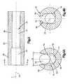
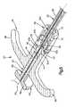
Fig. 1 is a sectional perspective view of a suture device constructed in accordance with one embodiment, showing the suture device in a first retracted configuration;Fig. 2A is a sectional side elevation view of the suture device illustrated inFig. 1 ;Fig. 2B is a sectional side elevation view of the suture device illustrated inFig. 2A , but shown in a second advanced configuration.Fig. 3 is an enlarged sectional side elevation view of the suture device illustrated inFig. 2 and taken along line 3-3;Fig. 4A is a sectional end view of the suture device illustrated inFig. 3 and taken alongline 4A-4A;Fig. 4B is a sectional end view similar toFig. 4A , but constructed in accordance with an alternative embodiment;Fig. 5 is an enlarged perspective view of a proximal end of the suture device illustrated inFig. 1 , showing a plunger; andFig. 6A is an enlarged perspective view of a distal end of the suture device illustrated inFig. 1 , showing the suture device in a second advanced configuration; andFig. 6B is an enlarged perspective view of the distal end of the suture device illustrated inFig. 1 constructed in accordance with an alternative embodiment.- Referring to
Figs. 1-2A , atissue repair assembly 18 includes asuture device 20 and at least onesuture thread 24 that is configured to be releasably fixed to thesuture device 20, for instance when approximating soft tissue of a patient. Thesuture device 20 defines aproximal end 27 and adistal end 29 that is opposite theproximal end 27. It should be appreciated that the terms "proximal" and "distal" and derivatives thereof used with respect to the suture device refer to a direction from thedistal end 29 toward theproximal end 27, and a direction from theproximal end 27 toward thedistal end 29, respectively. - The
suture device 20 generally includes asleeve 22 that extends substantially along acentral axis 23, at least a portion of which can extend along a longitudinal direction L, or can extend along any suitable alternative direction as desired. It should be appreciated that the term "longitudinal" and derivatives thereof refer to a direction along or parallel to the longitudinal direction L. The terms "radial," "transverse," and derivatives thereof refer to a direction substantially perpendicular to thecentral axis 23. Thesleeve 22 includes asleeve body 25 that defines aproximal end 26 and an opposeddistal end 28 that is spaced from the proximal end along thecentral axis 23. Similarly, thesuture device 20 defines aproximal end 27 and adistal end 29 opposite theproximal end 27. Thesleeve 22 further defines acentral opening 30 that extends substantially longitudinally through thesleeve body 25 from theproximal end 26 to thedistal end 28. The opening 30 can be cylindrical or any can define suitable alternative shape as desired. Thesuture thread 24 can be a multifilament or a braided structure, or any alternatively constructed thread. - The
suture device 20 includes anactuation assembly 31 that can be disposed at theproximal end 27 of thedevice 20, and can further include atip end 35 that can be disposed at thedistal end 29 of thesuture device 20. Thus, theactuation assembly 31 is disposed proximal with respect to thetip end 35. Thetip end 35 can define acannulated hook 36 that, in turn, can define adistal tip 68 that facilitates movement of thehook 36 through a body tissue wall of a patient and into a body cavity. Thedistal tip 68 can be acuminate or alternatively shaped as desired. Thecannulated hook 36 can be curved in a plane that contains thecentral axis 23 so that thehook 36 can be passed around a desired body portion of a patient when passing the hook through the tissue. - Referring also to
Fig. 5 , theactuation assembly 31 can include anactuator 33 and ahandle assembly 45. Theactuator 33 can include apushbutton 56 and aplunger 32, and is operable to advance adistal end 38 of thesuture thread 24 from a location recessed with respect to thedistal tip 68, and thus recessed in thesuture device 20, to a location that is out, for instance distal, of thesuture device 20. Thus, it can be said that thesuture device 20 is operable from a first retracted configuration and a second advanced configuration that causes thesuture thread 24 to likewise translate between a first retracted position (Figs. 1-2A ) and a second advanced position (Figs. 2B and6A-B ) that is distal with respect to the first retracted position. For instance, the first retracted position of thesuture thread 24 can be recessed with respect to thedistal tip 68, and the second advanced position can be distal with respect to thedistal tip 68. Alternatively, the first retracted position of thesuture thread 24 can be distal with respect to thedistal tip 68, and the second advanced position can be disposed further distal with respect to thedistal tip 68 than the first retracted position. Thus, thedistal end 38 of thesuture thread 24 moves distally from the first retracted position to the second advanced position. Thehandle assembly 45 includes ahandle 46 that is configured to be fixedly connected to thesleeve 22, for instance at theproximal end 26, and afastener 48 that is configured to removably connect thehandle 46 to thesleeve 22. Accordingly, thehandle 46 is configured as a brace that stabilizes thesleeve 22 as a distal actuation force is applied to theactuator 33, such that distal translation of theactuator 33 causes thesuture device 20 to actuate from the first retracted configuration to the second advanced configuration. For instance, a user can grip thehandle 46 while simultaneously applying the distal actuation force to theactuator 33, such that theactuator 33 can advance distally with respect to thehandle 46. The actuator can likewise receive a proximally directed force that causes theactuator 33 to translate proximally, thereby causing thesuture device 20 to iterate from the second advanced configuration to the first retracted configuration. It can thus be said that thesuture device 20 is configured to iterated between the first retracted configuration and the second advanced configuration. - The
handle 46 includes astem 47 and agrip 49 that extends longitudinally proximal from, and laterally out from, the proximal end of thestem 47. Thus, thestep 47 extends distal from thegrip 49. Thehandle 46 can be substantially T-shaped as illustrated, or can alternatively define any suitable shape as desired. Thehandle 46 defines anaperture 52 that extends longitudinally through thestem 47 and thegrip 49 at a location in alignment with thecentral opening 30 of thesleeve 22. - The
handle 46, and in particular thestem 47, can define a stop member illustrated as aneck 43 that divides theaperture 52 into a first or proximal channel 52A and a second or distal channel 52B. Theneck 43 further defines a necked aperture portion 52C of the aperture that is disposed between the proximal and distal channels 52A and 52B, and defines a cross-sectional dimension or diameter less that that of the proximal and distal channels 52A and 52B. In this regard, while various structure can be described herein as defining a diameter, it should be appreciated that the diameter can alternatively be referred to as a cross-sectional dimension, for instance that is not circular. The first channel 52A is configured to receive or otherwise retain the distal end of thepush button 56, and the second channel 52B is configured to receive or otherwise retain theproximal end 26 of thesleeve 22. Theneck 43 defines a first proximal abutment surface 43A, and a second distal abutment surface 43B. - The
fastener 48 is illustrated as a traveler that can be configured as anut 72 that is threadedly mated with the distal end of thestem 47. Thus, rotation of thenut 72 relative to thestem 47 in a first direction can cause thenut 72 to travel, or translate, proximally along thestem 47. Thestem 47 defines achuck 70 having a ramped surface that abuts a complementary ramped surface of thenut 72. Accordingly, as thenut 72 advances proximally along the distal end of thestem 47, the ramped surfaces of thenut 72 biases the ramped surface of thestem 47 against thesleeve 22, thereby creating a friction fit that fixes thestem 47 to thesleeve 22, thereby removably connecting thehandle 46 onto thesleeve 22. For instance, rotation of thenut 72 relative to thestem 47 in a second direction opposite the first direction can cause thenut 72 to travel, or translate, distally along thestem 47, which causes the ramped surface of thenut 72 to be removed from the complementary ramped surface of thestem 47, thereby removing the friction fit of thestep 47 and thesleeve 22. Thehandle 46 can then be removed from thesleeve 22. It should be appreciated that thehandle 46 can be connected to the sleeve in accordance with any suitable alternative embodiment. For instance, the thehandle 46 can be integral with thesleeve 22. - With continuing reference to
Figs. 1 ,2 , and5 , theactuator 33 includes apushbutton 56 and aplunger 32 that is connected, either integrally or discreetly, to thepushbutton 56. In accordance with the illustrated embodiment, thepushbutton 56 defines agrip 53 and aslider 50 that extends distally from the grip. Thegrip 53 defines a transverse diameter greater than that of theslider 50, and theslider 50 is configured to be slidably received in the first channel 52A of thehandle 46. The distal end of theslider 50 can abut the first abutment surface 43A of thestop member 43 to limit the distal travel of theplunger actuator 33 relative to thehandle 45 andsleeve 22. Additionally or alternatively, abutment between the distal end of theactuator grip 53 and the proximal end of thehandle grip 49 can limit the distal travel of theplunger actuator 33 relative to thehandle 45 andsleeve 22. Thepushbutton 56 defines anaperture 51 that extends longitudinally through thegrip 53 and theslider 50, in alignment with theaperture 52 of thehandle 46 and thus also in alignment with theopening 30 of thesleeve 22. - Referring now to
Figs. 1-4A , theplunger 32 includes aplunger body 57 that defines adistal end 42 and a longitudinally opposedproximal end 44. Theplunger body 57 has an outer diameter smaller than that of theslider 50, such that theplunger 32 is configured to extend longitudinally through the first channel 52A, the necked channel 52B, and the second channel 52C. Theplunger 32 is further sized to be slidably received in theopening 30 in thesleeve 22. Theplunger 32 defines achannel 40 that extends longitudinally along the entire length of theplunger body 57, between the distal and proximal ends 42 and 44, respectively. Thechannel 40 can be substantially U-shaped in cross-section, substantially V-shaped in cross-section, and thus can taper curvedly, conically, nonlinearly, or in any alternative suitable shape from the outer perimeter of theplunger body 57 along a direction toward thecentral axis 23, such that thechannel 40 is configured to receive thesuture thread 24. - In accordance with one embodiment, the
plunger 32 defines aclamp 34 that is configured to releasably secure thesuture thread 32 to theplunger body 57. In particular, theclamp 34 includes asection 41 of thechannel 40 that can define a portion up to all of thechannel 40. In accordance with the illustrated embodiment, thesection 41 of thechannel 40 is disposed proximate to thedistal end 42 of theplunger body 57. It should be appreciated that thechannel 40 can include more than one clamps 34, for instance proximate to thedistal end 42, theproximal end 44, and/or at a location between the distal and proximal ends 42 and 44. The narrowedsection 41 of thechannel 40 can be substantially V-shaped or substantially U-shaped in cross-section, and thus can taper conically from the outer perimeter of theplunger body 57 towards thecentral axis 23 so as to define a transverse gap that is less than the cross-sectional dimension of thesuture thread 24, so as to releasably retain thesuture thread 24. - In accordance with the illustrated embodiment, the
clamp 34 includes a pair of opposed side surfaces 54 of theplunger body 57 that define the narrowedsection 41 of thechannel 40. The side surfaces 54 extend relative to each other and taper toward each other along a direction substantially transverse to thecentral axis 23. For instance, the side surfaces are tapered toward each other along a direction from the outer perimeter of theplunger body 57 toward thecentral axis 23 so as to define a gap between the side surfaces 54 that narrows along a direction from the outer perimeter of theplunger body 57 toward thecentral axis 23. Thus, the side surfaces define an angle α sufficient to cause thesuture thread 24 to be wedged by theplunger body 57 in the narrowedsection 41 of thechannel 40, for instance between the side surfaces 54. For instance, the side surfaces 54 define a transverse dimension therebetween that is less than that of thesuture thread 24. Accordingly, thesuture thread 24 can be quickly and easily releasably attached to theplunger 32 by imparting a force onto thesuture thread 24 that causes thesuture thread 24 to move radially inward at the narrowedsection 41 of thechannel 40. For instance, thesuture thread 24 can be inserted into the narrowedsection 41 of thechannel 40 along the transverse direction, which causes the side surfaces 54 to compress thesuture thread 24, thereby capturing thesuture thread 24 in theplunger body 57 between the side surfaces 54. Thesuture thread 24 can likewise be released from theclamp 34 in an easy and quick manner by applying a transverse outward force to thesuture thread 24 that dislodges thesuture thread 24 from theclamp 34. - The side surfaces 54 can be smooth, or textured so as to assist in retention of the
suture thread 24. The angle α can be within a range having an upper end as desired, including approximately 50°, or more particularly approximately 40°, and a lower end greater than 0°, for instance greater than approximately 20°, such as greater than approximately 30°. It should thus be appreciated that the narrowedsection 41 can be configured to wedge suture threads of different diameters. - In accordance with an alternative embodiment shown in
Fig. 4B , theclamp 34 is elastically configured so that thesuture thread 24 is clipped into theplunger 32. For instance, thesuture thread 24 can be compressed as it is inserted into theclamp 34, and the compression can be reduced or eliminated once thesuture thread 24 is fully received in theclamp 34. For instance, the opposed side surfaces 54 of theclamp 34 can taper away from each other along a direction substantially transverse to thecentral axis 23. For instance, the side surfaces 54 taper away from each other along a direction from the outer perimeter of theplunger body 57 toward thecentral axis 23. In accordance with one embodiment, the tapered side surfaces 54 can defineelastic tongues suture thread 24 is inserted into the gap disposed between the side surfaces 54 along a radially inward direction from the outer perimeter of theplunger body 57 toward thecentral axis 23. Thus, the side surfaces 54 illustrated inFig. 4B are configured to capture thesuture thread 24 in theplunger body 57. - Alternatively still, it should be appreciated that the side surfaces 54 can extend substantially parallel to each other, such that the gap defined between the side surfaces the is sized less than a cross-sectional dimension of the
suture thread 24 such that theopposed walls 54 compress thesuture thread 24 when thesuture thread 24 is disposed in the gap. Thus, it should be appreciated that at least a portion up to all of the gap defined between the opposed side surfaces 54 is sized less than a cross-sectional dimension of thesuture thread 24 such that theopposed walls 54 compress thesuture thread 24 when thesuture thread 24 is disposed in the gap. - Referring again to
Figs. 1-2 , thedevice 20 can include a cannulatedhook 36 that extends from thedistal end 28 of thesleeve 22. Thehook 36 can be press-fit into thesleeve 22, overmolded by thesleeve 22, or otherwise attached to thesleeve 22 as desired. For instance, thehook 36 can be integral with thesleeve 22. The cannulation of thehook 36 is aligned with theopening 30 of thesleeve 22, such that when thesuture thread 24 is attached to theplunger 32, thesuture thread 24 can be passed from theopening 30 in thesleeve 22 into and through the cannulatedhook 36. In particular, theplunger 32 can translate distally within theopening 30 of thesleeve 22 toward thehook 36. In accordance with one embodiment, theplunger 32 is inserted into the cannulation of thehook 36 when theactuator 33 is biased distally from a first retracted position to a second advanced position, thereby actuating thesuture device 20 from the first retracted configuration to the second advanced configuration. When theplunger 32 is in the first retracted position, thedistal end 38 of thesuture thread 24 can be recessed from, or disposed proximate with respect to, thedistal tip 68 of thehook 36. For instance, thedistal end 38 of thesuture thread 24 can be disposed proximal with respect to the distal end of thesleeve 22 when thesuture device 20 is in the first retracted configuration. When theplunger 32 is biased to the second advanced position, theclamp 34 carries thesuture thread 24, and thus causes thesuture thread 24 to translate distally to a location whereby thedistal end 38 of thesuture thread 24 extends out thedevice 20. For instance, if thedevice 20 includes thehook 36, thedistal end 38 extends from thehook 36 out thesuture device 20. If the device does not include ahook 36, then thedistal end 38 extends distally from thesleeve 22 out thesuture device 20. - Referring now also to
Figs. 6A-B , the cannulatedhook 36 can be curved in more than one plane, such as two planes. For instance, in accordance with the illustrated embodiment, the cannulatedhook 36 has a firstcurved section 58 and a secondcurved section 60, along acentral axis 62 of the cannulatedhook 36, which can be coincident with thecentral axis 23 of thesuture device 20. In accordance with the illustrated embodiment, the firstcurved section 58 lies in a first plane and the secondcurved section 60 lies in a second plane that is angularly offset with respect to the first plane. The first plane contains the longitudinally extending portion of thecentral axis 23 of thedevice 20 and thecentral axis 62 of the cannulatedhook 36. The second plane is angled to the first plane in such a way that the common line of the first and second planes extends orthogonally to the longitudinal direction L. Thus, thehook 36 can be helically curved, which can be advantageous when performing shoulder surgery, in particular surgery on the rotator cuff or the meniscus, where limited anatomical space is available to move thetip end 35 of thedevice 20. - As described above, the
slider 50 is connected to theproximal end 44 of theplunger 32 and has a greater diameter than theplunger 32. Theplunger 32 can be slim, and can have an outer cross-sectional dimension smaller than that of theopening 30 of thesleeve 22. Theslider 50 fits snugly in the proximal channel 52A defined by theaperture 52 of thehandle 46. Thus thehandle 46, and in particular theaperture 52 defines a guide member that causes theslider 50, and thus theplunger 23, to translate along thecentral axis 23. Alternatively, the outer cross-sectional dimension of theplunger 23 can be substantially equal to that of theopening 30 of thesleeve 22. Further, theslider 50 comprises apush button 56 arranged at its rearward end so that theactuation assembly 31 has a syringe like design that provide an ergonomically friendly actuator for the user. For instance, the user can brace two fingers under thegrip 49 of thehandle 46, and depress thepushbutton 56 by applying a distal biasing force to thegrip 53 of thepushbutton 56 with his or her thumb. - During operation, the
suture thread 24 is affixed to theplunger 32, for instance by capturing thesuture thread 24 in theclamp 34 in the manner described above, and theplunger 32 is inserted longitudinally into theopening 30 of thesleeve 22. Thus, theactuator 33, and also theplunger 32 which is attached to theactuator 33, is in a first retracted position. When theplunger 32 is in the first retracted position, thedistal end 38 of thesuture 24 does not extend out thedevice 20 in accordance with one embodiment. For instance, when theplunger 32 is in the first retracted position, thedistal end 38 of thesuture thread 24 can can be disposed in the sleeve, and can reach thedistal end 28 of thesleeve 22, or can alternatively extend into the cannulatedhook 36. - The cannulated
hook 36 can then be guided to a desired position within a body portion of a patient until thetip 68 of thehook 36 is in a desired position, such as a cavity within the patient's body. The cavity can be a natural anatomical cavity, or can be created through the retraction of tissue. Next, theplunger 32, and thus also theactuator 33, is advanced distally from the first retracted position to the second advanced configuration, for instance until theslider 50 abuts the proximal abutment surface 43A of theneck 43. As illustrated inFig. 6A , theplunger 32 can extend into the cannulation of thehook 36 when theactuator 33 and theplunger 32 are in the respective second advanced positions. It should be appreciated that theplunger 32 can be disposed proximal with respect to the cannulatedhook 36 when theactuator 33 and theplunger 32 are in the respective first retracted positions, or alternatively theplunger 32 can be extend into the cannulation of the the cannulatedhook 36 when theactuator 33 and theplunger 32 are in the respective first retracted positions, and theplunger 32 can extend further into the cannulation of the cannulatedhook 26 when in the second advanced position. - Alternatively still, as illustrated in
Fig. 6B , theplunger 32 can terminate at a location proximal with respect to the cannulation of thehook 36 when theactuator 33 and theplunger 32 are in the respective second advanced configurations. Whether theplunger 32 is disposed in the cannulation of thehook 36 or is disposed proximal of thehook 36 when theplunger 32 is in the second advanced configuration, thesuture thread 24 is guided such that thedistal end 38 is translated out thedevice 20 as theplunger 32 is actuated from the first retracted position to the second advanced position. For instance, thedistal end 36 of thesuture strand 24 can extend distally out thesleeve 22, and in accordance with one embodiment can extend distally out the cannulatedhook 36 when theplunger 32, and thus thesuture thread 24, advances from the first retracted position to the second advanced position. - In accordance with one embodiment, the
distal end 38 of thesuture thread 24 can protrude any distance out thesuture device 20 as desired, for instance between approximately 1 cm and 2 cm out thedevice 20. Thus, thedistal end 38 of thesuture thread 24 can be grasped by another instrument, such as a clamp, and the suturing procedure can be completed. Thus, thesuture device 20 can pass thesuture thread 24 through soft tissue of a patient and subsequently insert thedistal end 38 into a target location, such as a cavity within a patient's body, in a quick and easy manner. - Following a method is provided for inserting the
suture thread 24 into a body portion of a patient using thesuture device 20. The method includes the step of attaching thesuture thread 24 to theplunger 32 such that adistal end 38 of thesuture thread 32 protrudes from the distal end of theplunger 32. Theplunger 32 is placed in theopening 30 of thesleeve 22 in a first retracted position, whereby thedistal end 38 of thesuture thread 32 can be disposed proximal of thedistal tip 68 of thehook 36. For instance, thedistal end 38 of thesuture thread 32 can be disposed in the cannulation of thehook 36 or can be disposed in theopening 30 of thesleeve 22, for instance at thedistal end 28, when theplunger 32 is in the first retracted position. Theplunger 32 can then be depressed distally, for instance by applying a manual biasing force onto thepush button 56, thereby advancing theplunger 32 from the first retracted position to a second advanced position, which causes theplunger 32 to eject thedistal end 38 of thesuture thread 24 distally out thedevice 20. For instance, the distal end of theplunger body 57 can extend to a location in the cannulation of thehook 36, or to a location proximal of thehook 36, when theplunger 32 is in the second advanced position. Thedistal end 38 of thesuture thread 24 can be extend out thesuture device 20 when theplunger 32 is in the second advanced position. For instance, thesuture thread 24 can extend distal with respect to the sleeve, and can further extend distal with respect to the cannulatedhook 36, for instance when thesuture device 20 includes the cannulatedhook 36. Thedistal end 38 of thesuture thread 24 can then be picked up with any suitable instrument, such as a clamp, to complete the suturing procedure. For instance, the instrument can grasp thesuture thread 24 and place the suture thread in sufficient tension that causes thesuture thread 24 to be dislodged from theclamp 34 and free thesuture thread 24 for further distal translation with respect to thesuture device 20. - In embodiments where the
sleeve 22 is connected to thehook 36, thehook 36 can be driven and guided into soft tissue of the patient's body when inserting thedevice 20 the body. Thus when thehook 36 is in a desired location, theplunger 32 can eject thedistal end 38 of thesuture thread 24 distally out thehook 36. In embodiments where thesuture device 20 does not include thehook 36, for instance when inserting thesuture thread 24 to an anatomical location that defines an anatomically natural void, thedistal end 38 of the suture thread can be picked up with any suitable instrument once thedistal end 38 extends distal with respect to thesleeve 22. - In accordance with one embodiment, a tissue repair kit can include at least one
sleeve 22, at least onehandle 46 that is connected or configured to be connected to the proximal end of thesleeve 22, at least oneplunger 32, and at least onehook 36 that is connected or configured to be connected to thesleeve 22. For instance, the kit can include a plurality of differently shaped hooks 36. The different shapes can include one or more curves in a common plane or in multiple planes, and/or can further include differently shaped tips, , e.g. straight/ bent to the right / bent to the left so that the device can be adapted to a particular use. In instances where thehook 36 is connected to thesleeve 22 as manufactured, thesleeve 22 can be coupled to thehandle 46 as desired. The kit can further include a plurality ofsuture threads 24, each having different diameters that are configured to be releasably fixed to thesuture device 20, and in particular theplunger 32. - The scope of the present application is not intended to be limited to the particular embodiments described herein. Furthermore, it should be appreciated that apparatus and methods described in connection with one embodiment can be equally applicable to all other embodiments unless otherwise indicated. One of ordinary skill in the art will readily appreciate from the present disclosure that apparatus and methods presently existing or later to be developed that perform substantially the same function or achieve substantially the same result as the corresponding embodiments described herein may be utilized according to the present invention. Thus, it will be appreciated by those skilled in the art that various modifications and alterations of the invention can be made without departing from the broad scope of the appended claims. Some of these have been discussed above and others will be apparent to those skilled in the art.
Claims (17)
- A suture device (20) configured to guide a suture thread (24), the suture device (20) comprising:a sleeve (22) including a sleeve body (25) that defines a proximal end (26) and a distal end (28) spaced from the proximal end along a central axis (23), the sleeve (22) defining an opening (30) extending along the central axis (23) between the proximal end (26) and the distal end (28); anda plunger (32) including a plunger body (57) that extends along the central axis (23) when the plunger (32) is disposed in the opening (30) of the sleeve (22), wherein the plunger (32) defines a clamp (34), the clamp (34) including a pair of surfaces (54) that are configured to capture the suture thread (24) so as to releasably attach the suture thread (24) to the plunger (32), and the plunger (32) is slidably disposed in the opening (30) of the sleeve (22) and movable distally from a first retracted position in which a distal portion of the suture thread (24) is located in the suture device (20) to a second advanced position in which the distal portion of the suture thread (24) extends out of the suture device (20), andcharacterised in thatthe plunger (32) defines a channel (40) that extends longitudinally along the entire length of the plunger body (57), the channel (40) configured to receive the suture thread.
- The suture device according to claim 1, wherein the clamp (34) defines a pair of opposed surfaces (54) that define a gap therebetween, at least a portion of the gap sized less than a cross-sectional dimension of the suture thread (24) such that the opposed walls compress the suture thread (24) when the suture thread (24) is disposed in the gap.
- The suture device according to claim 2, wherein the opposed surfaces (54) taper toward each other along a direction from a periphery of the plunger body (57) towards the central axis (23).
- The suture device according to claim 3, wherein the side surfaces (54) are angularly offset with respect to each other at an angle of no greater than 50°.
- The suture device according to claim 4, wherein the angle is no less than 20°.
- The suture device according to claim 2, wherein the opposed surfaces (54) taper away from each other along a direction from a periphery of the plunger body (57) towards the central axis (23).
- The suture device according to claim 2, wherein the clamp (34) is elastically configured so that the suture thread (24) is clipped into the plunger (32).
- The suture device according to claim 1, wherein the suture thread (24) Is one of a multifilament or braided structure.
- The suture device according to claim 1, wherein the clamp (34) comprises a narrowed section of the channel (40).
- The suture device according to claim 1, further comprising a cannulated hook (36) that extends distal with respect to the sleeve (22) and is configure to receive the suture thread (24) from the opening (30) of the sleeve (22).
- The suture device according to claim 10, wherein the cannulated hook (36) is acuminate.
- The suture device according to claim 10, wherein the cannulated hook (36) is curved in more than one plane.
- The suture device according to claim 1, further comprising a handle (46) that defines an aperture (52) aligned with the opening (30) of the sleeve (22) when the handle (46) is attached to the sleeve (22).
- The suture device according to claim 13, further comprising a slider (50) attached to the plunger (32), the slider (50) having a greater diameter than the plunger (32), wherein the slider (50) is slidably disposed in the aperture (52) of the handle (46).
- The suture device according to claim 14, wherein the handle (46) defines a neck (43) that divides the aperture (52) into a proximal channel (52A) and a distal channel (52B), and the neck (43) defines an abutment surfaces that is configured to abut the slider (50) when the plunger (32) is In the second advanced position.
- The suture device according to claim 14, further comprising a pushbutton (56) attached to the slider (50).
- The suture device according to claim 1, further comprising the suture thread (24).
Priority Applications (2)
| Application Number | Priority Date | Filing Date | Title |
|---|---|---|---|
| EP16193155.5AEP3150130B1 (en) | 2010-10-13 | 2011-10-12 | Apparatus for guiding a suture thread |
| EP15154357.6AEP2901942B1 (en) | 2010-10-13 | 2011-10-12 | Apparatus for guiding a suture thread |
Applications Claiming Priority (2)
| Application Number | Priority Date | Filing Date | Title |
|---|---|---|---|
| US39260110P | 2010-10-13 | 2010-10-13 | |
| PCT/US2011/055892WO2012064453A2 (en) | 2010-10-13 | 2011-10-12 | Method and apparatus for guiding a suture thread |
Related Child Applications (3)
| Application Number | Title | Priority Date | Filing Date |
|---|---|---|---|
| EP15154357.6ADivision-IntoEP2901942B1 (en) | 2010-10-13 | 2011-10-12 | Apparatus for guiding a suture thread |
| EP15154357.6ADivisionEP2901942B1 (en) | 2010-10-13 | 2011-10-12 | Apparatus for guiding a suture thread |
| EP16193155.5ADivisionEP3150130B1 (en) | 2010-10-13 | 2011-10-12 | Apparatus for guiding a suture thread |
Publications (2)
| Publication Number | Publication Date |
|---|---|
| EP2627262A2 EP2627262A2 (en) | 2013-08-21 |
| EP2627262B1true EP2627262B1 (en) | 2015-03-25 |
Family
ID=44947188
Family Applications (3)
| Application Number | Title | Priority Date | Filing Date |
|---|---|---|---|
| EP16193155.5AActiveEP3150130B1 (en) | 2010-10-13 | 2011-10-12 | Apparatus for guiding a suture thread |
| EP20110782270ActiveEP2627262B1 (en) | 2010-10-13 | 2011-10-12 | Apparatus for guiding a suture thread |
| EP15154357.6AActiveEP2901942B1 (en) | 2010-10-13 | 2011-10-12 | Apparatus for guiding a suture thread |
Family Applications Before (1)
| Application Number | Title | Priority Date | Filing Date |
|---|---|---|---|
| EP16193155.5AActiveEP3150130B1 (en) | 2010-10-13 | 2011-10-12 | Apparatus for guiding a suture thread |
Family Applications After (1)
| Application Number | Title | Priority Date | Filing Date |
|---|---|---|---|
| EP15154357.6AActiveEP2901942B1 (en) | 2010-10-13 | 2011-10-12 | Apparatus for guiding a suture thread |
Country Status (10)
| Country | Link |
|---|---|
| US (2) | US9226745B2 (en) |
| EP (3) | EP3150130B1 (en) |
| JP (2) | JP6023065B2 (en) |
| KR (1) | KR101880423B1 (en) |
| CN (2) | CN105266858B (en) |
| AU (2) | AU2011326756B2 (en) |
| BR (2) | BR122020000256B1 (en) |
| CA (1) | CA2813761A1 (en) |
| TW (1) | TW201235002A (en) |
| WO (1) | WO2012064453A2 (en) |
Families Citing this family (14)
| Publication number | Priority date | Publication date | Assignee | Title |
|---|---|---|---|---|
| JP2643433B2 (en) | 1989-04-12 | 1997-08-20 | 東レ株式会社 | Yarn winding device |
| JP2936948B2 (en) | 1993-02-25 | 1999-08-23 | 村田機械株式会社 | Automatic winder tension controller |
| US9801624B2 (en) | 2012-12-28 | 2017-10-31 | Cook Medical Technologies Llc | Surgical suture device and methods of using the same |
| CN103445813B (en)* | 2013-07-12 | 2015-05-27 | 厦门大博颖精医疗器械有限公司 | Rivet inserter |
| CN107106195B (en)* | 2014-12-25 | 2019-08-23 | 奥林巴斯株式会社 | Medical apparatus and medical system |
| US10702280B2 (en)* | 2015-11-10 | 2020-07-07 | Covidien Lp | Endoscopic reposable surgical clip applier |
| EP3410949A4 (en)* | 2016-02-05 | 2019-10-09 | Dura Tap LLC | DEVICES AND METHODS FOR SUTURE PLACEMENT |
| CN106214239B (en)* | 2016-07-26 | 2019-03-12 | 江苏双羊医疗器械有限公司 | It is hook-shaped to wear cable device |
| CN106214198A (en)* | 2016-09-29 | 2016-12-14 | 江苏省人民医院 | One can the stitching devices of " 8 " word staples ring |
| CN106264635A (en)* | 2016-09-29 | 2017-01-04 | 江苏省人民医院 | A kind of fibrous ring stitching devices being easy to separate suture |
| TWI601510B (en)* | 2016-11-07 | 2017-10-11 | 國立成功大學 | Bendable surgical instrument for suturing meniscus |
| US10639030B2 (en)* | 2017-12-06 | 2020-05-05 | Durastat Llc | Suturing device having adjustable distal end |
| USD912812S1 (en)* | 2019-04-24 | 2021-03-09 | Musc Foundation For Research Development | Looped skin hook |
| CN111803155B (en)* | 2020-06-24 | 2025-07-04 | 北京德益达美医疗科技有限公司 | Suture handles and soft tissue staplers |
Family Cites Families (42)
| Publication number | Priority date | Publication date | Assignee | Title |
|---|---|---|---|---|
| US919138A (en) | 1909-03-16 | 1909-04-20 | Clarence A Drake | Surgical needle. |
| US2625934A (en) | 1951-04-20 | 1953-01-20 | Thomas W Halliday | Surgical wire feeding device |
| US3013559A (en) | 1959-05-06 | 1961-12-19 | Wesley C Thomas | Instrument for closing flesh wounds |
| US3892240A (en)* | 1974-03-21 | 1975-07-01 | Charles Lanier Park | Surgical needle apparatus |
| US4224947A (en) | 1979-02-05 | 1980-09-30 | Mamoru Fukuda | Suturing apparatus |
| US4493323A (en) | 1982-12-13 | 1985-01-15 | University Of Iowa Research Foundation | Suturing device and method for using same |
| US4890615B1 (en) | 1987-11-05 | 1993-11-16 | Linvatec Corporation | Arthroscopic suturing instrument |
| US5254126A (en) | 1992-06-24 | 1993-10-19 | Ethicon, Inc. | Endoscopic suture punch |
| US5462562A (en) | 1993-05-17 | 1995-10-31 | Henry Ford Hospital | Suture passer and method of using |
| US5364410A (en)* | 1993-05-28 | 1994-11-15 | Ethicon, Inc. | Percutaneous suture externalizer |
| CN2164798Y (en)* | 1993-07-15 | 1994-05-18 | 四川省南充地区人民医院 | Knotting delivering device for operation deep |
| US5722981A (en) | 1993-10-08 | 1998-03-03 | Tahoe Surgical Instruments | Double needle ligature device |
| US5618290A (en)* | 1993-10-19 | 1997-04-08 | W.L. Gore & Associates, Inc. | Endoscopic suture passer and method |
| WO1995011630A1 (en) | 1993-10-25 | 1995-05-04 | Children's Medical Center Corporation | Retractable suture needle with self-contained driver |
| US5501692A (en)* | 1994-01-28 | 1996-03-26 | Riza; Erol D. | Laparoscopic suture snare |
| US5607435A (en) | 1994-05-23 | 1997-03-04 | Memory Medical Systems, Inc. | Instrument for endoscopic-type procedures |
| WO1996004954A1 (en) | 1994-08-17 | 1996-02-22 | Boston Scientific Corporation | Implant, and method and device for inserting the implant |
| US5573542A (en) | 1994-08-17 | 1996-11-12 | Tahoe Surgical Instruments-Puerto Rico | Endoscopic suture placement tool |
| US5569270A (en) | 1994-12-13 | 1996-10-29 | Weng; Edward E. | Laparoscopic surgical instrument |
| US5797927A (en) | 1995-09-22 | 1998-08-25 | Yoon; Inbae | Combined tissue clamping and suturing instrument |
| US5681333A (en) | 1995-11-08 | 1997-10-28 | Arthrex, Inc. | Method and apparatus for arthroscopic rotator cuff repair utilizing bone tunnels for suture attachment |
| US6090063A (en) | 1995-12-01 | 2000-07-18 | C. R. Bard, Inc. | Device, system and method for implantation of filaments and particles in the body |
| US5755728A (en)* | 1996-03-07 | 1998-05-26 | Maki; Neil J. | Suture apparatus with loop end portions |
| US5910148A (en)* | 1997-08-06 | 1999-06-08 | Mitek Surgical Products, Inc. | Suture retrograder |
| US7842050B2 (en) | 2001-02-26 | 2010-11-30 | Diduch David R | Suture passing devices |
| US7615059B2 (en) | 2001-05-30 | 2009-11-10 | Ams Research Corporation | Surgical suture passers and methods |
| US7112208B2 (en) | 2001-08-06 | 2006-09-26 | Morris John K | Compact suture punch with malleable needle |
| US20100137888A1 (en)* | 2003-01-03 | 2010-06-03 | Eye Plastic Surgery, Ltd. | Surgical Instrument for Endoscopic Suturing of Deep Subcutaneous Tissue |
| WO2004112616A2 (en)* | 2003-06-16 | 2004-12-29 | Ortheon Medical Llc | Suture cutter |
| US7473259B2 (en)* | 2003-06-30 | 2009-01-06 | Depuy Products, Inc. | Implant stabilizing instrument, kit and method |
| US7699857B2 (en) | 2003-07-07 | 2010-04-20 | Andrew Kim | Hydrodynamic suture passer |
| US7704262B2 (en) | 2004-06-18 | 2010-04-27 | Linvatec Corporation | Hollow suture needle with handle |
| JP2006175094A (en)* | 2004-12-24 | 2006-07-06 | Yamaguchi Univ | Surgical anastomosis |
| US8628541B2 (en) | 2005-05-26 | 2014-01-14 | Usgi Medical, Inc. | Methods and apparatus for securing and deploying tissue anchors |
| US8696688B2 (en)* | 2006-02-02 | 2014-04-15 | Biomet Sports Medicine, Llc | Method and apparatus for passing a flexible strand |
| US8043308B2 (en)* | 2006-12-14 | 2011-10-25 | Depuy Mitek, Inc. | Bone suture |
| CA2703129C (en)* | 2007-10-18 | 2016-02-16 | Neochord Inc. | Minimially invasive repair of a valve leaflet in a beating heart |
| ES2735225T3 (en) | 2008-04-02 | 2019-12-17 | Linvatec Corp | Meniscus repair device |
| US20100198235A1 (en) | 2008-09-29 | 2010-08-05 | Javin Cedric Pierce | Surgical suture passer and method for passing suture |
| WO2010048420A1 (en) | 2008-10-22 | 2010-04-29 | Cayenne Medical, Inc. | Arthroscopic suture passing devices and methods |
| CA2751735C (en)* | 2009-02-17 | 2016-11-08 | T.A.G. Medical Devices - Agriculture Cooperative Ltd. | Medical implement for manipulating sutures particularly useful in arthroscopic surgery |
| CN102405022B (en)* | 2009-03-14 | 2015-02-04 | 瓦索斯蒂奇股份有限公司 | Vessel access and closure device |
- 2011
- 2011-10-12EPEP16193155.5Apatent/EP3150130B1/enactiveActive
- 2011-10-12BRBR122020000256-5Apatent/BR122020000256B1/enactiveIP Right Grant
- 2011-10-12KRKR1020137008917Apatent/KR101880423B1/enactiveActive
- 2011-10-12JPJP2013533959Apatent/JP6023065B2/enactiveActive
- 2011-10-12AUAU2011326756Apatent/AU2011326756B2/enactiveActive
- 2011-10-12EPEP20110782270patent/EP2627262B1/enactiveActive
- 2011-10-12CNCN201510686963.6Apatent/CN105266858B/enactiveActive
- 2011-10-12USUS13/271,697patent/US9226745B2/enactiveActive
- 2011-10-12BRBR112013006809-4Apatent/BR112013006809B1/enactiveIP Right Grant
- 2011-10-12EPEP15154357.6Apatent/EP2901942B1/enactiveActive
- 2011-10-12WOPCT/US2011/055892patent/WO2012064453A2/enactiveApplication Filing
- 2011-10-12CACA2813761Apatent/CA2813761A1/ennot_activeAbandoned
- 2011-10-12TWTW100136929Apatent/TW201235002A/enunknown
- 2011-10-12CNCN201180049300.3Apatent/CN103153204B/enactiveActive
- 2015
- 2015-08-20USUS14/831,359patent/US10022121B2/enactiveActive
- 2016
- 2016-01-27AUAU2016200461Apatent/AU2016200461B2/enactiveActive
- 2016-10-06JPJP2016197897Apatent/JP6203926B2/enactiveActive
Also Published As
| Publication number | Publication date |
|---|---|
| TW201235002A (en) | 2012-09-01 |
| BR112013006809B1 (en) | 2020-08-25 |
| BR112013006809A2 (en) | 2016-07-12 |
| AU2016200461A1 (en) | 2016-02-18 |
| CN103153204B (en) | 2015-11-25 |
| BR122020000256B1 (en) | 2020-10-06 |
| WO2012064453A2 (en) | 2012-05-18 |
| EP2627262A2 (en) | 2013-08-21 |
| WO2012064453A3 (en) | 2012-10-11 |
| JP6203926B2 (en) | 2017-09-27 |
| EP2901942B1 (en) | 2017-11-22 |
| KR20130131322A (en) | 2013-12-03 |
| AU2011326756B2 (en) | 2015-10-29 |
| KR101880423B1 (en) | 2018-07-23 |
| CA2813761A1 (en) | 2012-05-18 |
| JP6023065B2 (en) | 2016-11-09 |
| EP3150130B1 (en) | 2019-07-03 |
| US10022121B2 (en) | 2018-07-17 |
| AU2016200461B2 (en) | 2017-08-17 |
| CN103153204A (en) | 2013-06-12 |
| CN105266858B (en) | 2018-06-15 |
| US9226745B2 (en) | 2016-01-05 |
| US20150351751A1 (en) | 2015-12-10 |
| EP2901942A1 (en) | 2015-08-05 |
| US20120095481A1 (en) | 2012-04-19 |
| JP2013544554A (en) | 2013-12-19 |
| JP2016221401A (en) | 2016-12-28 |
| AU2011326756A1 (en) | 2013-03-14 |
| CN105266858A (en) | 2016-01-27 |
| EP3150130A1 (en) | 2017-04-05 |
Similar Documents
| Publication | Publication Date | Title |
|---|---|---|
| EP2627262B1 (en) | Apparatus for guiding a suture thread | |
| US5382253A (en) | Clip applier tool | |
| US20070173865A1 (en) | Suture manipulating and cutting implement | |
| CA2914577C (en) | Suture passer and method of operating same | |
| JP2023052896A (en) | Devices and methods for suture placement | |
| JP2020527392A (en) | Suture placement device and method | |
| WO2005007201A3 (en) | Hydrodynamic suture passer | |
| KR101554577B1 (en) | Carpal ligament cutting device for treating carpal tunnel syndrome | |
| JP2020527385A (en) | Suture placement device and method |
Legal Events
| Date | Code | Title | Description |
|---|---|---|---|
| PUAI | Public reference made under article 153(3) epc to a published international application that has entered the european phase | Free format text:ORIGINAL CODE: 0009012 | |
| 17P | Request for examination filed | Effective date:20130302 | |
| AK | Designated contracting states | Kind code of ref document:A2 Designated state(s):AL AT BE BG CH CY CZ DE DK EE ES FI FR GB GR HR HU IE IS IT LI LT LU LV MC MK MT NL NO PL PT RO RS SE SI SK SM TR | |
| DAX | Request for extension of the european patent (deleted) | ||
| GRAP | Despatch of communication of intention to grant a patent | Free format text:ORIGINAL CODE: EPIDOSNIGR1 | |
| INTG | Intention to grant announced | Effective date:20141016 | |
| GRAS | Grant fee paid | Free format text:ORIGINAL CODE: EPIDOSNIGR3 | |
| GRAA | (expected) grant | Free format text:ORIGINAL CODE: 0009210 | |
| AK | Designated contracting states | Kind code of ref document:B1 Designated state(s):AL AT BE BG CH CY CZ DE DK EE ES FI FR GB GR HR HU IE IS IT LI LT LU LV MC MK MT NL NO PL PT RO RS SE SI SK SM TR | |
| REG | Reference to a national code | Ref country code:GB Ref legal event code:FG4D | |
| REG | Reference to a national code | Ref country code:CH Ref legal event code:EP Ref country code:CH Ref legal event code:NV Representative=s name:E. BLUM AND CO. AG PATENT- UND MARKENANWAELTE , CH | |
| REG | Reference to a national code | Ref country code:IE Ref legal event code:FG4D | |
| REG | Reference to a national code | Ref country code:DE Ref legal event code:R096 Ref document number:602011015092 Country of ref document:DE Effective date:20150507 | |
| REG | Reference to a national code | Ref country code:AT Ref legal event code:REF Ref document number:717368 Country of ref document:AT Kind code of ref document:T Effective date:20150515 | |
| PG25 | Lapsed in a contracting state [announced via postgrant information from national office to epo] | Ref country code:LT Free format text:LAPSE BECAUSE OF FAILURE TO SUBMIT A TRANSLATION OF THE DESCRIPTION OR TO PAY THE FEE WITHIN THE PRESCRIBED TIME-LIMIT Effective date:20150325 Ref country code:SE Free format text:LAPSE BECAUSE OF FAILURE TO SUBMIT A TRANSLATION OF THE DESCRIPTION OR TO PAY THE FEE WITHIN THE PRESCRIBED TIME-LIMIT Effective date:20150325 Ref country code:HR Free format text:LAPSE BECAUSE OF FAILURE TO SUBMIT A TRANSLATION OF THE DESCRIPTION OR TO PAY THE FEE WITHIN THE PRESCRIBED TIME-LIMIT Effective date:20150325 Ref country code:FI Free format text:LAPSE BECAUSE OF FAILURE TO SUBMIT A TRANSLATION OF THE DESCRIPTION OR TO PAY THE FEE WITHIN THE PRESCRIBED TIME-LIMIT Effective date:20150325 | |
| REG | Reference to a national code | Ref country code:AT Ref legal event code:MK05 Ref document number:717368 Country of ref document:AT Kind code of ref document:T Effective date:20150325 | |
| REG | Reference to a national code | Ref country code:LT Ref legal event code:MG4D | |
| PG25 | Lapsed in a contracting state [announced via postgrant information from national office to epo] | Ref country code:GR Free format text:LAPSE BECAUSE OF FAILURE TO SUBMIT A TRANSLATION OF THE DESCRIPTION OR TO PAY THE FEE WITHIN THE PRESCRIBED TIME-LIMIT Effective date:20150626 Ref country code:RS Free format text:LAPSE BECAUSE OF FAILURE TO SUBMIT A TRANSLATION OF THE DESCRIPTION OR TO PAY THE FEE WITHIN THE PRESCRIBED TIME-LIMIT Effective date:20150325 Ref country code:LV Free format text:LAPSE BECAUSE OF FAILURE TO SUBMIT A TRANSLATION OF THE DESCRIPTION OR TO PAY THE FEE WITHIN THE PRESCRIBED TIME-LIMIT Effective date:20150325 | |
| PG25 | Lapsed in a contracting state [announced via postgrant information from national office to epo] | Ref country code:NL Free format text:LAPSE BECAUSE OF FAILURE TO SUBMIT A TRANSLATION OF THE DESCRIPTION OR TO PAY THE FEE WITHIN THE PRESCRIBED TIME-LIMIT Effective date:20150325 | |
| PG25 | Lapsed in a contracting state [announced via postgrant information from national office to epo] | Ref country code:SK Free format text:LAPSE BECAUSE OF FAILURE TO SUBMIT A TRANSLATION OF THE DESCRIPTION OR TO PAY THE FEE WITHIN THE PRESCRIBED TIME-LIMIT Effective date:20150325 Ref country code:PT Free format text:LAPSE BECAUSE OF FAILURE TO SUBMIT A TRANSLATION OF THE DESCRIPTION OR TO PAY THE FEE WITHIN THE PRESCRIBED TIME-LIMIT Effective date:20150727 Ref country code:EE Free format text:LAPSE BECAUSE OF FAILURE TO SUBMIT A TRANSLATION OF THE DESCRIPTION OR TO PAY THE FEE WITHIN THE PRESCRIBED TIME-LIMIT Effective date:20150325 Ref country code:CZ Free format text:LAPSE BECAUSE OF FAILURE TO SUBMIT A TRANSLATION OF THE DESCRIPTION OR TO PAY THE FEE WITHIN THE PRESCRIBED TIME-LIMIT Effective date:20150325 Ref country code:RO Free format text:LAPSE BECAUSE OF FAILURE TO SUBMIT A TRANSLATION OF THE DESCRIPTION OR TO PAY THE FEE WITHIN THE PRESCRIBED TIME-LIMIT Effective date:20150325 Ref country code:ES Free format text:LAPSE BECAUSE OF FAILURE TO SUBMIT A TRANSLATION OF THE DESCRIPTION OR TO PAY THE FEE WITHIN THE PRESCRIBED TIME-LIMIT Effective date:20150325 | |
| PG25 | Lapsed in a contracting state [announced via postgrant information from national office to epo] | Ref country code:AT Free format text:LAPSE BECAUSE OF FAILURE TO SUBMIT A TRANSLATION OF THE DESCRIPTION OR TO PAY THE FEE WITHIN THE PRESCRIBED TIME-LIMIT Effective date:20150325 Ref country code:IS Free format text:LAPSE BECAUSE OF FAILURE TO SUBMIT A TRANSLATION OF THE DESCRIPTION OR TO PAY THE FEE WITHIN THE PRESCRIBED TIME-LIMIT Effective date:20150725 Ref country code:PL Free format text:LAPSE BECAUSE OF FAILURE TO SUBMIT A TRANSLATION OF THE DESCRIPTION OR TO PAY THE FEE WITHIN THE PRESCRIBED TIME-LIMIT Effective date:20150325 | |
| REG | Reference to a national code | Ref country code:DE Ref legal event code:R097 Ref document number:602011015092 Country of ref document:DE | |
| PG25 | Lapsed in a contracting state [announced via postgrant information from national office to epo] | Ref country code:DK Free format text:LAPSE BECAUSE OF FAILURE TO SUBMIT A TRANSLATION OF THE DESCRIPTION OR TO PAY THE FEE WITHIN THE PRESCRIBED TIME-LIMIT Effective date:20150325 | |
| PLBE | No opposition filed within time limit | Free format text:ORIGINAL CODE: 0009261 | |
| STAA | Information on the status of an ep patent application or granted ep patent | Free format text:STATUS: NO OPPOSITION FILED WITHIN TIME LIMIT | |
| 26N | No opposition filed | Effective date:20160105 | |
| PG25 | Lapsed in a contracting state [announced via postgrant information from national office to epo] | Ref country code:SI Free format text:LAPSE BECAUSE OF FAILURE TO SUBMIT A TRANSLATION OF THE DESCRIPTION OR TO PAY THE FEE WITHIN THE PRESCRIBED TIME-LIMIT Effective date:20150325 Ref country code:LU Free format text:LAPSE BECAUSE OF FAILURE TO SUBMIT A TRANSLATION OF THE DESCRIPTION OR TO PAY THE FEE WITHIN THE PRESCRIBED TIME-LIMIT Effective date:20151012 | |
| PG25 | Lapsed in a contracting state [announced via postgrant information from national office to epo] | Ref country code:MC Free format text:LAPSE BECAUSE OF FAILURE TO SUBMIT A TRANSLATION OF THE DESCRIPTION OR TO PAY THE FEE WITHIN THE PRESCRIBED TIME-LIMIT Effective date:20150325 | |
| REG | Reference to a national code | Ref country code:IE Ref legal event code:MM4A | |
| PG25 | Lapsed in a contracting state [announced via postgrant information from national office to epo] | Ref country code:BE Free format text:LAPSE BECAUSE OF FAILURE TO SUBMIT A TRANSLATION OF THE DESCRIPTION OR TO PAY THE FEE WITHIN THE PRESCRIBED TIME-LIMIT Effective date:20150325 | |
| REG | Reference to a national code | Ref country code:FR Ref legal event code:PLFP Year of fee payment:6 | |
| PG25 | Lapsed in a contracting state [announced via postgrant information from national office to epo] | Ref country code:IE Free format text:LAPSE BECAUSE OF NON-PAYMENT OF DUE FEES Effective date:20151012 | |
| PG25 | Lapsed in a contracting state [announced via postgrant information from national office to epo] | Ref country code:NO Free format text:LAPSE BECAUSE OF FAILURE TO SUBMIT A TRANSLATION OF THE DESCRIPTION OR TO PAY THE FEE WITHIN THE PRESCRIBED TIME-LIMIT Effective date:20150625 Ref country code:BG Free format text:LAPSE BECAUSE OF FAILURE TO SUBMIT A TRANSLATION OF THE DESCRIPTION OR TO PAY THE FEE WITHIN THE PRESCRIBED TIME-LIMIT Effective date:20150325 Ref country code:HU Free format text:LAPSE BECAUSE OF FAILURE TO SUBMIT A TRANSLATION OF THE DESCRIPTION OR TO PAY THE FEE WITHIN THE PRESCRIBED TIME-LIMIT; INVALID AB INITIO Effective date:20111012 Ref country code:SM Free format text:LAPSE BECAUSE OF FAILURE TO SUBMIT A TRANSLATION OF THE DESCRIPTION OR TO PAY THE FEE WITHIN THE PRESCRIBED TIME-LIMIT Effective date:20150325 | |
| PG25 | Lapsed in a contracting state [announced via postgrant information from national office to epo] | Ref country code:CY Free format text:LAPSE BECAUSE OF FAILURE TO SUBMIT A TRANSLATION OF THE DESCRIPTION OR TO PAY THE FEE WITHIN THE PRESCRIBED TIME-LIMIT Effective date:20150325 | |
| PG25 | Lapsed in a contracting state [announced via postgrant information from national office to epo] | Ref country code:MT Free format text:LAPSE BECAUSE OF FAILURE TO SUBMIT A TRANSLATION OF THE DESCRIPTION OR TO PAY THE FEE WITHIN THE PRESCRIBED TIME-LIMIT Effective date:20150325 | |
| REG | Reference to a national code | Ref country code:FR Ref legal event code:PLFP Year of fee payment:7 | |
| PG25 | Lapsed in a contracting state [announced via postgrant information from national office to epo] | Ref country code:MK Free format text:LAPSE BECAUSE OF FAILURE TO SUBMIT A TRANSLATION OF THE DESCRIPTION OR TO PAY THE FEE WITHIN THE PRESCRIBED TIME-LIMIT Effective date:20150325 Ref country code:TR Free format text:LAPSE BECAUSE OF FAILURE TO SUBMIT A TRANSLATION OF THE DESCRIPTION OR TO PAY THE FEE WITHIN THE PRESCRIBED TIME-LIMIT Effective date:20150325 | |
| REG | Reference to a national code | Ref country code:FR Ref legal event code:PLFP Year of fee payment:8 | |
| PG25 | Lapsed in a contracting state [announced via postgrant information from national office to epo] | Ref country code:AL Free format text:LAPSE BECAUSE OF FAILURE TO SUBMIT A TRANSLATION OF THE DESCRIPTION OR TO PAY THE FEE WITHIN THE PRESCRIBED TIME-LIMIT Effective date:20150325 | |
| PGFP | Annual fee paid to national office [announced via postgrant information from national office to epo] | Ref country code:GB Payment date:20240829 Year of fee payment:14 | |
| PGFP | Annual fee paid to national office [announced via postgrant information from national office to epo] | Ref country code:FR Payment date:20240909 Year of fee payment:14 | |
| PGFP | Annual fee paid to national office [announced via postgrant information from national office to epo] | Ref country code:IT Payment date:20240910 Year of fee payment:14 | |
| PGFP | Annual fee paid to national office [announced via postgrant information from national office to epo] | Ref country code:DE Payment date:20240904 Year of fee payment:14 | |
| PGFP | Annual fee paid to national office [announced via postgrant information from national office to epo] | Ref country code:CH Payment date:20241101 Year of fee payment:14 |