EP2626106B1 - Embolic filter frame - Google Patents
Embolic filter frameDownload PDFInfo
- Publication number
- EP2626106B1 EP2626106B1EP13154961.0AEP13154961AEP2626106B1EP 2626106 B1EP2626106 B1EP 2626106B1EP 13154961 AEP13154961 AEP 13154961AEP 2626106 B1EP2626106 B1EP 2626106B1
- Authority
- EP
- European Patent Office
- Prior art keywords
- frame
- filter
- support
- struts
- looped
- Prior art date
- Legal status (The legal status is an assumption and is not a legal conclusion. Google has not performed a legal analysis and makes no representation as to the accuracy of the status listed.)
- Expired - Lifetime
Links
- 230000003073embolic effectEffects0.000titleclaimsabstractdescription117
- 238000000034methodMethods0.000claimsdescription23
- 238000004519manufacturing processMethods0.000claimsdescription13
- 238000005520cutting processMethods0.000claimsdescription8
- 238000009760electrical discharge machiningMethods0.000claimsdescription2
- 238000005530etchingMethods0.000claimsdescription2
- XLYOFNOQVPJJNP-UHFFFAOYSA-NwaterSubstancesOXLYOFNOQVPJJNP-UHFFFAOYSA-N0.000claimsdescription2
- 238000010438heat treatmentMethods0.000claims2
- 238000010791quenchingMethods0.000claims1
- 230000000171quenching effectEffects0.000claims1
- 238000007789sealingMethods0.000abstractdescription9
- 239000000463materialSubstances0.000description14
- 230000002792vascularEffects0.000description11
- 238000006073displacement reactionMethods0.000description10
- 230000033001locomotionEffects0.000description8
- 239000012528membraneSubstances0.000description8
- 239000004812Fluorinated ethylene propyleneSubstances0.000description7
- 239000012530fluidSubstances0.000description7
- 229920009441perflouroethylene propylenePolymers0.000description7
- 230000001225therapeutic effectEffects0.000description6
- 239000000843powderSubstances0.000description5
- 235000020637scallopNutrition0.000description5
- 210000005166vasculatureAnatomy0.000description5
- 241000237503PectinidaeSpecies0.000description4
- 230000000694effectsEffects0.000description4
- 238000001914filtrationMethods0.000description4
- 229910001000nickel titaniumInorganic materials0.000description4
- 239000002243precursorSubstances0.000description4
- 208000007536ThrombosisDiseases0.000description3
- 230000004888barrier functionEffects0.000description3
- 230000001965increasing effectEffects0.000description3
- 208000014674injuryDiseases0.000description3
- 238000013152interventional procedureMethods0.000description3
- 230000003902lesionEffects0.000description3
- HLXZNVUGXRDIFK-UHFFFAOYSA-Nnickel titaniumChemical compound[Ti].[Ti].[Ti].[Ti].[Ti].[Ti].[Ti].[Ti].[Ti].[Ti].[Ti].[Ni].[Ni].[Ni].[Ni].[Ni].[Ni].[Ni].[Ni].[Ni].[Ni].[Ni].[Ni].[Ni].[Ni]HLXZNVUGXRDIFK-UHFFFAOYSA-N0.000description3
- 239000002245particleSubstances0.000description3
- 229920001343polytetrafluoroethylenePolymers0.000description3
- 239000004810polytetrafluoroethyleneSubstances0.000description3
- 230000007704transitionEffects0.000description3
- 238000013519translationMethods0.000description3
- 230000008733traumaEffects0.000description3
- 238000012800visualizationMethods0.000description3
- XEEYBQQBJWHFJM-UHFFFAOYSA-NIronChemical compound[Fe]XEEYBQQBJWHFJM-UHFFFAOYSA-N0.000description2
- 239000000853adhesiveSubstances0.000description2
- 230000001070adhesive effectEffects0.000description2
- 210000003484anatomyAnatomy0.000description2
- 238000002399angioplastyMethods0.000description2
- 230000009286beneficial effectEffects0.000description2
- 239000000560biocompatible materialSubstances0.000description2
- 239000008280bloodSubstances0.000description2
- 210000004369bloodAnatomy0.000description2
- 230000017531blood circulationEffects0.000description2
- 230000000916dilatatory effectEffects0.000description2
- 230000010102embolizationEffects0.000description2
- 238000005516engineering processMethods0.000description2
- 238000007667floatingMethods0.000description2
- 238000003780insertionMethods0.000description2
- 230000037431insertionEffects0.000description2
- 239000003550markerSubstances0.000description2
- 230000010412perfusionEffects0.000description2
- 229920000642polymerPolymers0.000description2
- 229920001296polysiloxanePolymers0.000description2
- -1polytetrafluoroethylenePolymers0.000description2
- 230000008569processEffects0.000description2
- 230000000250revascularizationEffects0.000description2
- 238000005476solderingMethods0.000description2
- 239000007787solidSubstances0.000description2
- 238000007669thermal treatmentMethods0.000description2
- 208000037260Atherosclerotic PlaqueDiseases0.000description1
- 0CCCC1(C2)CC*2C1Chemical compoundCCCC1(C2)CC*2C10.000description1
- 208000036829Device dislocationDiseases0.000description1
- 208000005189EmbolismDiseases0.000description1
- 241001465754MetazoaSpecies0.000description1
- 241000237509Patinopecten sp.Species0.000description1
- RTAQQCXQSZGOHL-UHFFFAOYSA-NTitaniumChemical compound[Ti]RTAQQCXQSZGOHL-UHFFFAOYSA-N0.000description1
- 230000002411adverseEffects0.000description1
- 208000007474aortic aneurysmDiseases0.000description1
- 238000005422blastingMethods0.000description1
- 230000000903blocking effectEffects0.000description1
- 230000036760body temperatureEffects0.000description1
- 238000005219brazingMethods0.000description1
- 230000001413cellular effectEffects0.000description1
- 230000008859changeEffects0.000description1
- 239000011248coating agentSubstances0.000description1
- 238000000576coating methodMethods0.000description1
- 238000004891communicationMethods0.000description1
- 230000006835compressionEffects0.000description1
- 238000007906compressionMethods0.000description1
- 238000001816coolingMethods0.000description1
- 238000007887coronary angioplastyMethods0.000description1
- 210000004351coronary vesselAnatomy0.000description1
- 230000000593degrading effectEffects0.000description1
- 238000013461designMethods0.000description1
- 239000013013elastic materialSubstances0.000description1
- 230000002708enhancing effectEffects0.000description1
- HQQADJVZYDDRJT-UHFFFAOYSA-Nethene;prop-1-eneChemical groupC=C.CC=CHQQADJVZYDDRJT-UHFFFAOYSA-N0.000description1
- 239000000835fiberSubstances0.000description1
- 230000009969flowable effectEffects0.000description1
- 229920002313fluoropolymerPolymers0.000description1
- 239000004811fluoropolymerSubstances0.000description1
- 230000001939inductive effectEffects0.000description1
- 229910052742ironInorganic materials0.000description1
- 230000001788irregularEffects0.000description1
- 208000028867ischemiaDiseases0.000description1
- 230000000302ischemic effectEffects0.000description1
- 238000005304joiningMethods0.000description1
- 239000007788liquidSubstances0.000description1
- 238000011068loading methodMethods0.000description1
- 238000005259measurementMethods0.000description1
- 239000000203mixtureSubstances0.000description1
- 238000012986modificationMethods0.000description1
- 230000004048modificationEffects0.000description1
- 238000012545processingMethods0.000description1
- 210000002254renal arteryAnatomy0.000description1
- 230000008439repair processEffects0.000description1
- 238000012552reviewMethods0.000description1
- 210000003752saphenous veinAnatomy0.000description1
- HBMJWWWQQXIZIP-UHFFFAOYSA-Nsilicon carbideChemical compound[Si+]#[C-]HBMJWWWQQXIZIP-UHFFFAOYSA-N0.000description1
- 229910010271silicon carbideInorganic materials0.000description1
- 230000002269spontaneous effectEffects0.000description1
- 229910001220stainless steelInorganic materials0.000description1
- 239000010935stainless steelSubstances0.000description1
- 230000002966stenotic effectEffects0.000description1
- 238000003756stirringMethods0.000description1
- 238000003860storageMethods0.000description1
- 238000001356surgical procedureMethods0.000description1
- 238000012360testing methodMethods0.000description1
- 238000002560therapeutic procedureMethods0.000description1
- 229920001169thermoplasticPolymers0.000description1
- 239000004416thermosoftening plasticSubstances0.000description1
- 239000010936titaniumSubstances0.000description1
- 229910052719titaniumInorganic materials0.000description1
- 238000012546transferMethods0.000description1
- 230000009466transformationEffects0.000description1
- 238000011144upstream manufacturingMethods0.000description1
- 238000003466weldingMethods0.000description1
Images


Classifications
- A—HUMAN NECESSITIES
- A61—MEDICAL OR VETERINARY SCIENCE; HYGIENE
- A61F—FILTERS IMPLANTABLE INTO BLOOD VESSELS; PROSTHESES; DEVICES PROVIDING PATENCY TO, OR PREVENTING COLLAPSING OF, TUBULAR STRUCTURES OF THE BODY, e.g. STENTS; ORTHOPAEDIC, NURSING OR CONTRACEPTIVE DEVICES; FOMENTATION; TREATMENT OR PROTECTION OF EYES OR EARS; BANDAGES, DRESSINGS OR ABSORBENT PADS; FIRST-AID KITS
- A61F2/00—Filters implantable into blood vessels; Prostheses, i.e. artificial substitutes or replacements for parts of the body; Appliances for connecting them with the body; Devices providing patency to, or preventing collapsing of, tubular structures of the body, e.g. stents
- A61F2/01—Filters implantable into blood vessels
- A61F2/0105—Open ended, i.e. legs gathered only at one side
- B—PERFORMING OPERATIONS; TRANSPORTING
- B23—MACHINE TOOLS; METAL-WORKING NOT OTHERWISE PROVIDED FOR
- B23P—METAL-WORKING NOT OTHERWISE PROVIDED FOR; COMBINED OPERATIONS; UNIVERSAL MACHINE TOOLS
- B23P11/00—Connecting or disconnecting metal parts or objects by metal-working techniques not otherwise provided for
- A—HUMAN NECESSITIES
- A61—MEDICAL OR VETERINARY SCIENCE; HYGIENE
- A61F—FILTERS IMPLANTABLE INTO BLOOD VESSELS; PROSTHESES; DEVICES PROVIDING PATENCY TO, OR PREVENTING COLLAPSING OF, TUBULAR STRUCTURES OF THE BODY, e.g. STENTS; ORTHOPAEDIC, NURSING OR CONTRACEPTIVE DEVICES; FOMENTATION; TREATMENT OR PROTECTION OF EYES OR EARS; BANDAGES, DRESSINGS OR ABSORBENT PADS; FIRST-AID KITS
- A61F2/00—Filters implantable into blood vessels; Prostheses, i.e. artificial substitutes or replacements for parts of the body; Appliances for connecting them with the body; Devices providing patency to, or preventing collapsing of, tubular structures of the body, e.g. stents
- A61F2/01—Filters implantable into blood vessels
- A61F2002/018—Filters implantable into blood vessels made from tubes or sheets of material, e.g. by etching or laser-cutting
- A—HUMAN NECESSITIES
- A61—MEDICAL OR VETERINARY SCIENCE; HYGIENE
- A61F—FILTERS IMPLANTABLE INTO BLOOD VESSELS; PROSTHESES; DEVICES PROVIDING PATENCY TO, OR PREVENTING COLLAPSING OF, TUBULAR STRUCTURES OF THE BODY, e.g. STENTS; ORTHOPAEDIC, NURSING OR CONTRACEPTIVE DEVICES; FOMENTATION; TREATMENT OR PROTECTION OF EYES OR EARS; BANDAGES, DRESSINGS OR ABSORBENT PADS; FIRST-AID KITS
- A61F2230/00—Geometry of prostheses classified in groups A61F2/00 - A61F2/26 or A61F2/82 or A61F9/00 or A61F11/00 or subgroups thereof
- A61F2230/0002—Two-dimensional shapes, e.g. cross-sections
- A61F2230/0004—Rounded shapes, e.g. with rounded corners
- A61F2230/0006—Rounded shapes, e.g. with rounded corners circular
- A—HUMAN NECESSITIES
- A61—MEDICAL OR VETERINARY SCIENCE; HYGIENE
- A61F—FILTERS IMPLANTABLE INTO BLOOD VESSELS; PROSTHESES; DEVICES PROVIDING PATENCY TO, OR PREVENTING COLLAPSING OF, TUBULAR STRUCTURES OF THE BODY, e.g. STENTS; ORTHOPAEDIC, NURSING OR CONTRACEPTIVE DEVICES; FOMENTATION; TREATMENT OR PROTECTION OF EYES OR EARS; BANDAGES, DRESSINGS OR ABSORBENT PADS; FIRST-AID KITS
- A61F2230/00—Geometry of prostheses classified in groups A61F2/00 - A61F2/26 or A61F2/82 or A61F9/00 or A61F11/00 or subgroups thereof
- A61F2230/0063—Three-dimensional shapes
- A61F2230/0067—Three-dimensional shapes conical
- Y—GENERAL TAGGING OF NEW TECHNOLOGICAL DEVELOPMENTS; GENERAL TAGGING OF CROSS-SECTIONAL TECHNOLOGIES SPANNING OVER SEVERAL SECTIONS OF THE IPC; TECHNICAL SUBJECTS COVERED BY FORMER USPC CROSS-REFERENCE ART COLLECTIONS [XRACs] AND DIGESTS
- Y10—TECHNICAL SUBJECTS COVERED BY FORMER USPC
- Y10T—TECHNICAL SUBJECTS COVERED BY FORMER US CLASSIFICATION
- Y10T29/00—Metal working
- Y10T29/49—Method of mechanical manufacture
- Y10T29/49826—Assembling or joining
Definitions
- the inventionrelates to embolic filter devices for placement in the vasculature and in particular, self-expanding frames used to support embolic filter elements.
- Embolic protectionis a concept of growing clinical importance directed at reducing the risk of embolic complications associated with interventional (i.e., transcatheter) and surgical procedures.
- embolic debrise.g., thrombus, clot, atheromatous plaque, etc.
- the therapeutic vascular procedures most commonly associated with adverse embolic complicationsinclude: carotid angloplasty with or without adjunctive stent placement; and revascularization of degenerated saphenous vein grafts.
- PTCApercutaneous transluminal coronary angioplasty
- surgical coronary artery by-pass graftingpercutaneous renal artery revascularization
- endovascular aortic aneurysm repairhave also been associated with complications attributable to atheromatous embolization.
- embolic protection devicesto capture and remove embolic debris, consequently, may improve patient outcomes by reducing the incidence of embolic complications.
- Embolic protection devicestypically act as an intervening barrier between the source of the clot or plaque and the downstream vasculature.
- Numerous devices and methods of embolic protectionhave been used adjunctively with percutaneous interventional procedures. These techniques, although varied, have a number of desirable features including: intraluminal delivery; flexibility; backability; small delivery profile to allow crossing of stenotic lesions; dimensional compatibility with conventional interventional implements; ability to minimize flow perturbations; thromboresistance; conformability of the barrier to the entire luminal cross section (even if irregular); and a means of safely removing the embolic protection device and trapped particulates.
- embolic protectionThere are two general strategies for achieving embolic protection: techniques that employ occlusion balloons; and techniques that employ an embolic filter.
- embolic filtersis a desirable means of achieving embolic protection because they allow continuous perfusion of the vasculature downstream to the device.
- Occlusion balloon techniqueshave been taught by the prior art and involve devices in which blood flow to the vasculature distal to the lesion is blocked by the inflation of an occlusive balloon positioned downstream to the site of intervention. Following therapy, the intraluminal compartment between the lesion site and the occlusion balloon is aspirated to evacuate any thrombus or atheromatous debris that may have been liberated during the interventional procedure.
- the principle drawback of occlusion balloon techniquesstems from the fact that during actuation, distal blood flow is completely inhibited, which can result in ischemic pain, distal stasis/thrombosis, and difficulties with fluoroscopic visualization due to contrast wash-out through the treated vascular segment
- a prior system described in US Patent 4,723,549 to Wholey, et al.combines a therapeutic catheter (e.g., angioplasty balloon) and integral distal embolic filter.
- a therapeutic cathetere.g., angioplasty balloon
- integral distal embolic filterBy incorporating a porous filter or embolus barrier at the distal end of a catheter, such as an angioplasty balloon catheter, particulates dislodged during an interventional procedure can be trapped and removed by same therapeutic device responsible for the embolization.
- One known deviceincludes a collapsible filter device positioned distal to a dilating balloon on the end of the balloon catheter.
- the filtercomprises a plurality of resilient ribs secured to circumference of the catheter that extend axially toward the dilating balloon. Filter material is secured to and between the ribs.
- the filterdeploys as a filter balloon is inflated to form a cup-shaped trap.
- the filterdoes not necessarily seal around the interior vessel wall. Thus, particles can pass between the filter and the vessel wall.
- the devicealso lacks longitudinal compliance. Thus, inadvertent movement of the catheter results in longitudinal translation of the filter, which can cause damage to the vessel wall and liberate embolic debris.
- the embolic filtersare incorporated directly into the distal end of a guide wire system for intravascular blood filtration. Given the current trends In both surgical and interventional practice, these devices are potentially the most versatile In their potential applications. These systems are typified by a filter frame that is attached to a guide wire that mechanically supports a porous filter element.
- the filter framemay include radially oriented struts, one or more circular hoops, or a pre-shaped basket configuration that deploys in the vessel.
- the filter elementIs typically comprised of a polymeric or metallic mesh net, which is attached to the filter frame and/or guide wire. In operation, blood flowing through the vessel is forced through the mesh filter element thereby capturing embolic material in the filter.
- Another example of a prior deviceuses an emboli capture device mounted on the distal end of a guide wire.
- the filter materialis coupled to a distal portion of the guide wire and is expanded across the lumen of a vessel by a fluid activated expandable member in communication with a lumen running the length of the guide wire.
- a fluid activated expandable memberin communication with a lumen running the length of the guide wire.
- filter materialmay interact with the clot to produce emboil.
- the devicealso lacks longitudinal compliance.
- Another devicewhich is adapted for deployment in a body vessel for collecting floating debris and emboli in a filter, Includes a collapsible proximally tapered frame to support the filter between a collapsed insertion profile and an expanded deployment profile.
- the tapered collapsible frameincludes a mouth that is sized to extend to the walls of the body vessel in the expanded deployed profile and substantially longitudinal struts that attach and tether the filter frame to the support wire.
- This devicealso lacks substantial longitudinal compliance.
- This devicehas the additional drawback of having an extended length due to the longitudinally oriented strut configuration of the tapered frame. This extended length complicates the navigation and placement of the filter within tortuous anatomy.
- a further example of an embolic filter systeminvolves a filter material fixed to cables or spines of a central guide wire.
- a movable core or fibers inside the guide wirecan be utilized to transition the cables or spines from approximately parallel to the guide wire to approximately perpendicular the guide wire.
- the filtermay not seal around the interior vessel wall. Thus, particles can pass between the filter and the entire vessel wall.
- This umbrella-type deviceis shallow when deployed so that, as it is being closed for removal, particles have the potential to escape.
- US 6,391,044(Yadav ) teaches a removable vascular filter system for blocking micro- and macro- emboli.
- the documentteaches the use of deploying and collapsing fibres for deploying and collapsing a filter membrane.
- the documentfurther teaches the use of structural wires to improve rigidity of the filter membrane in a deployed configuration.
- disadvantages associated with predicate devicesinclude lack of longitudinal compliance, extended deployed length of the frame and associated tethering elements, and inadequate apposition and sealing against a vessel wall.
- longitudinal complianceWithout longitudinal compliance, inadvertent movement of the filter catheter or support wire can displace the deployed filter and damage a vessel wall and/or introgenic vascular trauma, or, in extreme cases, result In the liberation of embolic debris.
- An extended deployed lengthaggravates proper filter deployment adjacent to vascular side branches or within tightly curved vessels, inadequate filter apposition and sealing against a vessel wall has the undesirable effect of allowing emboli passage.
- the radial force exerted by the filter against the vessel wallshould be optimized.
- Typical methods used to increase the radial force exerted by the filterinclude, for example, increasing the cross-sectional area (moment of inertia and therefore the stiffness) of the filter support frame and in particular the tethering elements of the frame.
- Enhanced radial forcecan also be achieved by incorporating additional support members or by enlarging the "relaxed" or deployed diameter of the filter frame relative to the diameter of the vessel Into which it is deployed.
- Some methods used to increase the radial forcehave the additional drawback of requiring thicker-walled, larger profile, delivery catheters. To accommodate the increased pressure exerted by the stiff frame (constrained within the delivery catheter) a commensurately thicker catheter wall is required, compromising the delivery profile.
- the present inventionis an improved embolic filter frame having looped support struts.
- the frame configuration of the present inventionprovides enhanced longitudinal compliance, improved sealing against a vessel wall, low profile delivery, and a short deployed length occupied by the frame and tethering elements.
- the present inventionincorporates a filter support frame having "looped" support struts.
- the "looped" strut configurationenhances the radial force imparted onto a vessel wall without entailing the undesirable side effects previously described.
- the looped strut configurationalso facilitates filter frame opposition when deployed in tortuous vascular anatomies.
- the looped support struts of the present inventionassume an essentially longitudinal configuration and impart minimal radial force onto the catheter wall. The thickness of the catheter wall or radial constraint can therefore be minimized to increase flexibility, decrease the catheter profile, and enhance insertion trackablity.
- the looped support strutsassume a looped configuration. Once in the deployed, looped configuration, the support struts exert a high degree of radial force onto the vessel wall, enhancing apposition and sealing.
- the looped support strutsalso provide a high degree of longitudinal compliance relative to conventional designs.
- the full length of the looped support strutsis positioned very close to the filter element, which minimizes the overall deployed length of the filter media support element.
- the deployed device of the present inventionexhibits a low degree of "longitudinal" stiffness.
- the devicein the deployed state, the device remains limp and compliant in the longitudinal direction. Consequently, minor longitudinal displacements of the support wire or catheter are not translated to the filter frame and vessel wall during guide wire manipulation.
- Another beneficial feature of the present inventionis that the looped struts and the central collar connecting the support struts to the support wire of the present invention are positioned essentially within the plane of the filter opening and, if desired, can even be positioned within the filter frame element itself. This improves the utility of the embolic filter of the present invention by reducing the overall deployed length of the filter support frame and allowing the filter to be deployed very close to the treatment site.
- an embolic filtercomprising: a support wire; an embolic filter frame having a filter support portion and multiple support struts mounted to the support wire; the support struts extending radially from the support wire; at least one support strut having a looped configuration when not in tension in a deployed state; and a filter element attached to the filter support portion.
- embolic filter of the first clausewherein the multiple support struts have looped configurations.
- embolic filter of the first clausewherein at least one support strut projects a looped configuration in two orthogonal views.
- embolic filter of the first clausewherein at least one support strut has an "s" shape.
- an embolic filtercomprising: a support wire having a longitudinal axis; an embolic filter frame including multiple support struts mounted to the support wire at an attachment point; the frame having a constrained delivery state and a non-tensioned deployed state; the embolic filter having a distal and proximal end; the frame having a filter opening when in the non-tensioned deployed state; the filter opening defining a plane essentially orthogonal to the support wire longitudinal axis; and the strut attachment point located distally from the plane of the filter opening.
- embolic filter of the fifth clausefurther comprising at least three looped support struts.
- embolic filter of the fifth clausewherein at least one support strut projects a looped configuration in two orthogonal views.
- an embolic filtercomprising: a support wire; an embolic filter frame including multiple struts mounted to the support wire; the struts having a constrained delivery state and a non-tensioned deployed state; the struts having an essentially linear configuration while in the constrained delivery state and an essentially looped configuration while in the non-tensioned deployed state; wherein the struts are adapted to transform from the straight configuration to the looped configuration during deployment.
- embolic filter of the eighth clausefurther comprising at least three looped support struts.
- embolic filter of the eighth clausewherein at least one support strut projects a looped configuration in two orthogonal views.
- an embolic filtercomprising: a support wire; an embolic filter frame including multiple support struts mounted to the support wire and extending radially therefrom; the struts having a constrained delivery state and a non-tensioned deployed state; at least one strut having a loop configuration when in the non-tensioned deployed state; and a filter element attached to the frame.
- embolic filter of the eleventh clausefurther comprising at least three looped support struts.
- embolic filter of the eleventh clausewherein at least one support strut projects a looped configuration in two orthogonal views.
- an embolic filtercomprising: a movable support wire having a maximum total displacement; a frame having multiple looped support struts and an unconstrained diameter; wherein a ratio of the frame unconstrained diameter divided by the support wire total displacement is greater than about 2.
- embolic filter of the fourteenth clausewherein at least one support strut projects a looped configuration in two orthogonal views.
- an embolic filteroomprising: a frame having multiple looped support struts, a deployed length and an unconstrained diameter; wherein the frame deployed length divided by the frame unconstrained diameter is between about 0.5 to about 1.
- embolic filter of the sixteenth clausewherein at least one support strut projects a looped configuration in two orthogonal views.
- an embolic filtercomprising: a frame having multiple looped support struts, a constrained delivery length and an unconstrained length; wherein the frame constrained delivery length divided by the unconstrained frame length is between about 2 to about 3.
- embolic filter of the eighteenth clausewherein at least one support strut projects a looped configuration in two orthogonal views.
- an endoluminal filter assemblycomprising a filter element; a support wire; a filter frame comprising at least two "s" shaped support struts attaching the filter element to the support wire.
- the endoluminal filter assembly of the twentieth clausewherein the filter frame is slidably attached to the support wire.
- an endoluminal filter assemblycomprising a support wire; a filter frame having a collar adapted to attach around the support wire and move relative thereto; a first stop attached to the support wire distal to the filter frame; a second stop attached to the support wire proximal to the filter frame; wherein movement of the filter frame along the support wire is constrained by the first and second stops.
- the endoluminal filter assembly of the twenty-second clausewherein the filter frame includes at least two looped support struts.
- a first embodiment of the present inventionIs shown in Figure 1 . Shown is an unconstrained, non-tensioned embolic filter assembly 30 of the present invention.
- the filter assembly 30comprises a frame 31 having two distinct portions: a filter support portion 32 and a series of looped struts or tethers 34. Each looped strut 34 is affixed to a central collar 46, which is then attached to a support wire 36 at attachment point 38. Multiple struts 34 emanate radially outward and are attached to the frame's filter support portion 32. Attached to the filter support portion 32 is a filter element 40. Also shown is a longitudinal axis 42, which is essentially coincident with the support wire 36.
- Embolic filter frames of the present inventioncan have 2, 3, 4, 5, 6, 7, 8 or more looped support struts.
- the number of support strutscan effect the profile and shape of the filter membrane opening 60.
- the frame configuration in Figure 1showing only three support struts for clarity, typically results In a filter opening having three "scallops" 41 which follow the profile of the filter support portion 32.
- additional support strutsBy incorporating additional support struts, the magnitude or size of each scallop 41 is reduced and the filter opening will more closely approximate a circle within a plane.
- six looped support strutsare incorporated into a frame of the present invention.
- the filter elementmay be trimmed to match the contour of the scallops so to avoid deflecting or disrupting fluid flow or potentially allowing inadvertent passage of emboli.
- the distal end 35 of the fitter elementis preferably provided with a slidable attachment around the support wire 36 so as to allow the filter element to change position relative to the support wire 36 between compacted and deployed dimensions. Additionally, a slidable interface between the distal end 35 and the support element allows the filter element to remain fully extended in the vessel at all times, even when the filter assembly is undergoing longitudinal compliance, as described herein.
- the filter elementmay be formed from an elastic material that can accommodate different distal end positions relative to the position of the filter frame.
- FIG. 2Shown in Figure 2 is an enlarged view of the unconstrained looped support struts of an embolic filter 30 of the present invention. Shown is a frame 31 having filter support portions 32 and three looped support struts 34. Also shown are support wire 36, central collar 46, collar to support wire attachment point 38, and a filter element 40. Shown is a preferred embodiment in which the looped support struts 34 are essentially "s" shaped.
- Figure 3Aillustrates the unconstrained embolic filter assembly 30 from Figures 1 and 2 . Shown are three preferred s-shaped, looped support struts 34 extending radially from the central collar 46. The support struts 34 extend from and are attached to a filter support portion 32. Attached to the filter support portion 32 is a filter element 40. The embolic filter 30, shown in an unconstrained state, has an unconstrained diameter 44.
- attachment point 38may comprise a rigidly secure fixation point between the support wire 36 and the centered collar 46, or it may comprise a slideable interface between the support wire 36 and central collar 46; thereby decoupling longitudinal or rotational motion of the support wire from the filter frame.
- the support struts 34extend radially and are attached to a filter support portion 32. Attached to the filter support portion 32 is a filter element 40.
- a "filter support portion”is defined as that portion of a filter frame that is at least partially attached to a filter element 40.
- a “support strut”is defined as that portion of a filter frame that supports the filter support portion and generally is not attached directly to the filter element 40.
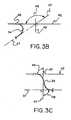
- a "looped support strut"is further illustrated in Figure 3B . Shown is the support strut 34 unattached to a filter element and constrained about a support wire or longitudinal axis 42.
- a reference axis 47drawn through the support strut 34 as shown, approximates the magnitude of a bend or loop in the support strut.
- the axis 47defines an angle 48 relative to the longitudinal axis 42 (also shown is a reference axis 49 which defines a 90 degree angle relative to the longitudinal axis 42). Shown is a looped support strut angle 48, which is greater than 90 degrees, relative to the longitudinal axis 42.
- a “looped strut”is therefore defined as a filter frame support strut, having a portion unattached to a filter element, wherein the strut has at least one bend equal to or greater than 90 degrees along the unattached portion.
- the looped anglecan be viewed and measured about any axis.
- a looped, embolic filter frame support strut having an "s" shapeis depicted in Figure 3C . Shown is the support strut 34 unattached to a filter element and constrained about a longitudinal axis 42. Also shown is an axis 37, which is parallel to the longitudinal axis 42. A reference axis 47, drawn through the support strut 34, as shown, approximates the magnitude of the bends or loops In the support strut. The axis 47 defines angles 48 relative to the longitudinal axis 42. Shown are two opposite bend angles 48, each of at least about 90 degrees.
- a "support strut having an 's' shape”Is defined as a filter frame support strut having a portion unattached to a filter element, wherein the strut has at least two opposite bends greater than about 90 degrees along the unattached portion.
- the angles 48can be viewed and measured about any axis.
- FIG. 4Shown is an embolic filter assembly 30 of the present invention deployed within a compliant vessel 50 (shown in longitudinal cross-section).
- the vessel 50defines an inner diameter which is slightly smaller, for example approximately 90%, than the unconstrained diameter of the device. This is shown as diameter 44 in Figure 3A .
- the "under-sized” vesseltherefore imparts a radial constraint to the deployed filter, which prevents the filter from expanding to a full, unconstrained diameter. In this process, an interference fit between the filter and vessel wall is achieved.
- the looped support struts 34 when constrained by a vesseltherefore exert a radial or expansive force 52 onto the vessel wall 50, forming a seal region 54.
- This radial, expansive force 52can also be referred to as the "hoop stress" or "radial force” applied to the vessel wall.
- unconstrained diameterAs the term “unconstrained diameter” is used herein, it is intended to describe the device of the present invention as it self-deploys on a tabletop. In this form it is both unconstrained and untensioned. This state Is also referred to herein as being “not in tension” or in a “non-tensioned” state.
- the support wire 36when rigidly fixed at or about the central collar, can be slightly displaced along the longitudinal axis 42 in directions 56 or 58 without significantly disrupting or translating to the seal region 54.
- the looped support struts 34therefore provide a degree of "longitudinal compliance" which effectively isolates the filter element from small support wire displacements.
- Devices of the presents invention having unconstrained diameters of about 6mm (0.24")can tolerate support wire displacements in directions 56 or 58 of about +/- 0.8mm (+/-0.03") or more, without causing a significant disruption or translation to the seal region 54.
- the support wiretherefore has a "maximum total displacement" before causing a disruption to the seal region 54.
- Longitudinal compliancecan be alternately expressed as a ratio of unconstrained diameter divided by the maximum total support wire displacement when rigidly fixed to the support wire (without disrupting or translating the seal region against the vessel wall).
- a device of the present inventioncan be deployed within a transparent elastic tube having a diameter of about 80% of the filter's unconstrained diameter. The maximum total support wire displacement (without disrupting or moving the seal region) can then be approximated.
- Devices of the present inventiondisplay ratios of unconstrained diameter divided by the maximum total displacement of the support wire of about 6 or less.
- the embolic filter of the present inventionhas a ratio of unconstrained diameter to maximum support wire displacement of about 5, about 4, about 3, about 2.5, about 2, about 1.5, about 1.2, or about 1.
- a relatively easy test to quantify longitudinal compliance in the present inventionis to deploy the filter apparatus within a silicone tube (such as that available from JAMAK Healthcare Technologies, Weatherford, TX) having a thin wall thickness of approximately 0.25 mm (0.01") and having an internal diameter of approximately 80% that of the unconstrained filter apparatus. It should be noted that the use of an 80% constrained diameter is preferred since a 20% interference fit between the device and the vessel will prevent device migration and provide adequate sealing.
- the support wire to which the apparatus is attachedmay be longitudinally manipulated. The maximum distance the support wire can be displaced (in a longitudinal direction) without moving the filter frame in relation to the silicone tubing is recorded as "longitudinal compliance.”
- the present inventionalso has the beneficial feature of a short deployed length, as depicted in Figures 5A through 5D .
- the short deployed length of the present inventionis a result of the looped struts and the central collar connecting the support struts to the support wire being positioned essentially within the plane of the filter opening.
- the looped strutscan be engineered to deploy to be directly within the plane of the opening to the filter element, slightly upstream of the opening, or even slightly downstream of the opening so as to orient within the filter frame element itself.
- Shown in Figure 5Ais an embolic filter 30 of the present invention in an unconstrained state having a proximal end 43 and a distal end 45.
- the filter element 40has a filter "opening" 60, which defines a plane having an x-axis 62 and an y-axis 64.
- the opening axis 62 and 64are positioned at the most proximal ends of the scallops 41.
- the opening plane shownis orthogonal to the support wire 36 and the longitudinal axis 42.
- the two axes 62, 64therefore define the plane of the filter opening 60.
- Looped struts 34, of the present inventionare joined onto a central collar 46, which is attached to the support wire 36 at attachment point 38 via either rigidly fixed or slideable means.
- FIG. 5BShown in Figure 5B is a filter element 40 having a filter opening 60, an y-axis 64, and a longitudinal axis 42.
- the axis 64is an "edge-view" of the plane of the filter opening. Axes 42 and 64 intersect at point 70. Point 70 is therefore on the plane of the filter opening.
- a point or location on the longitudinal axis 42is considered to be “offset distally” from the plane of the filter opening if the point lies within the filter element in the longitudinal direction labeled 72.
- a point or location on the longitudinal axis 42Is considered to be “offset proximally” from the plane of the filter opening if the point lies outside of the filter element in the longitudinal direction labeled 74.
- Figure 5Cillustrates a looped support strut 34 and central collar 46 of the present Invention having a support wire attachment point 38 which is rigidly fixed to the support wire and off-set distally from the plane of the filter opening 64. Shown is a support wire attachment point 38 positioned inside the filter element 40 in the distal direction 72. The magnitude of the attachment point offset is shown as element 80.
- Figure 5Dillustrates a looped support strut 34 and central collar 46 of the present invention having a support wire attachment point 38 which is rigidly fixed to the support wire and off-set proximally from the plane of the filter opening 64. Shown is a support wire attachment point 38, positioned outside of the filter element 40, in the proximal direction 74. The magnitude of the attachment point offset is shown as item 82.
- the relative magnitude of any off-set, along with the direction of the off-set between a support wire attachment point and the plane of the filter opening 64,can be expressed by an "offset ratio" of the strut attachment point off-set divided by the unconstrained diameter 44.
- an "offset ratio" of the strut attachment point off-set divided by the unconstrained diameter 44For example, a filter having a strut attachment point offset of 4mm and an unconstrained diameter of 10mm, would have a ratio of 0.4. This ratio can be applied to strut to support wire attachment points that are offset distally or proximally to the plane of the filter opening. A ratio of "zero" would reflect no offset, or in other words an attachment point lying in the plane of the filter opening.
- Embolic filters of the present inventioncan have distally offset ratios (of the attachment point off-set divided the unconstrained diameter) ranging from about 0 to about 1, with a preferred range of about 0 to about 0.7, with a most preferred range of about 0.2 to about 0.5. These distally offset ratios reflect strut/collar to support wire attachments positioned within the filter element.
- embolic filter of the present inventioncan have proximally offset ratios, reflecting strut/collar to support wire attachments positioned outside of the filter element. In these configurations, embolic filters of the present invention can have offset ratios (attachment point offset divided by the unconstrained diameter) ranging from about 0 to about 1.
- Devices of the present inventioncan be configured to have a strut to central collar attachment points that are significantly different than the central collar to support wire attachment points. For these configurations, both attachment points are then approximated by a point on the support wire that is in closest proximity to the strut.
- the looped support struts of the present Inventionallow a short deployed length that enhances navigation within tortuous vessels and allows deployment near vascular side-branches.
- a deviceshould be defined by at least one of the five ratios defined below.
- the deployed length of a filtercan be expressed by a first ratio of the deployed length divided by the unconstrained diameter of the filter.
- Shown in Figure 6Ais an embolic filter 30 of the present Invention having a filter element 40, looped struts 34, strut/collar to support wire attachment point 38 (lying outside of the filter element), and a unconstrained diameter 44.
- FIG. 6BShown in Figure 6B Is an embolic filter 30 of the present invention having a filter element 40, looped struts 34a, strut/collar to support wire attachment point 38 (lying within the filter element), and a unconstrained diameter 44. Shown is a deployed length 86, which is referenced from the opposing ends of the filter element, and does not include the looped struts 34a or the attachment point 38.
- Embolic filters of the present inventioncan have ratios of the deployed length 84, 86 divided by the filter unconstrained diameter 44, ranging from about 0.5 to about 7, with a preferred range of about 1 to about 5, with a most preferred range of about 2 to about 4.
- a similar expression of a filter deployed length or footprintis a second ratio of the deployed length of the frame (not including a filter element) divided by the frame unconstrained diameter.
- Shown in Figure 6Cis an embolic filter frame of the present invention having filter support portions 32 and looped struts 34, strut/collar to support wire attachment point 38 (lying outside of the filter element 40), and a unconstrained frame diameter 44. Shown is a frame deployed length 87, which does not include the filter element 40.
- FIG. 6DShown in Figure 6D Is an embolic filter frame of the present invention having filter support portions 32 and looped struts 34, strut/collar to support wire attachment point 38 (lying within the filter element 40), and a unconstrained diameter 44. Shown is a frame deployed length 88, which does not include the filter element 40.
- Embolic filters of the present inventioncan have ratios of the frame deployed length 87, 88 divided by the frame unconstrained diameter 44, ranging from about 0.1 to about 7, with a preferred range of about 0.3 to about 2, with a most preferred range of about 0.5 to about 1.
- looped struts of the present inventionrelate to the delivery aspects of the embolic filter as shown in Figures 7A through 7D .
- the looped support struts of the present Inventionwhen tensioned elongate and assume a compacted and essentially linear form. While constrained in this linear state by a delivery catheter or other constraint means, the support struts exert relatively little force onto the radial constraint means, which permits the radial constraint means to be very thin and/or delicate. The overall delivery profile and stiffness are therefore reduced over those required for prior embolic filter devices.
- the struts of the present inventionspontaneously open and assume a looped configuration, which exert a high degree of force onto the vessel wall, creating an enhanced filter to vessel wall seal.
- FIG. 7AShown in Figure 7A is an embolic filter 30 of the present invention having looped struts 34 attached to a central collar 46.
- the central collaris attached to a support wire 36.
- the support strutsemanate radially outward and are integral to (or joined to) a frame having a filter support portion 32.
- a filter element 40is attached to the filter support portion 32.
- the low force applied to the delivery catheter by the elongated looped strutfacilitates use of a relatively thin catheter wall 94.
- the looped struts of the present inventionspontaneously open and assume the configuration shown in Figures 4 and 7A , either spontaneously or through manipulation of the support wire and/or delivery catheter.
- struts 34 of an embolic filter of the present inventionare constrained in an "essentially linear" form, as shown in Figure 7D . While in this essentially linear form, the central support collar 46 (or strut to support wire attachment point 38) is positioned outside of the filter element 40. The central support collar 46 is also separated from the filter element 40 by the elongated and essentially linear support struts 34. Once properly deployed, however, the central support collar 46 (or strut to support wire attachment point 38) lies within the filter element 40, as shown in Figure 7A . The central support collar 46 (or strut to support wire attachment point 38) therefore moves or translates rotative to the filter element during deployment. Typical filters of the present invention undergo a relative translation (support collar to filter element) equal to at least 1/2 of the length of the constrained filter element 96 (as is shown in Figure 7D ).
- a total constrained delivery length 97 of an embolic filter of the present inventioncan have a third ratio of the total constrained delivery length 97 divided by the unconstrained length.
- this third ratiomay be about 1, about 2, about 2.5, about 3, about 3.5, or greater.
- the unconstrained lengthIs defined by length 84 ( Figure 6A ) or by length 86 ( Figure 6B ).
- embolic filters of the present inventioncan have a fourth ratio of the total constrained frame delivery length 98 divided by the unconstrained frame length.
- this fourth ratiomay be about 2, about 2.5, about 3, about 3.5, or greater.
- the unconstrained frame lengthIs defined by length 87 ( Figure 6C ) or by length 88 ( Figure 6D ).
- a fifth ratio relating to the short deployed lengthis the strut constrained delivery length divided by the strut unconstrained deployed length.
- the strut constrained delivery lengthis defined as the length of a strut portion 34 of the frame, not including the filter support portion 32, as shown in Figure 7D .
- the strut constrained delivery lengthis therefore a portion of the total frame length 98 in Figure 7D .
- the strut unconstrained lengthis defined as the length of a unconstrained strut 34a as shown in Figures 6C and 6D , not including the length of a filter support portion 32.
- Filter frames of the present inventioncan have ratios of the strut constrained delivery length divided by the strut unconstrained deployed length of about 2, of about 3, of about 4, of about 5, of about 6, or about 7, or more. Filter frames of the present invention preferably have ratios of the strut constrained delivery length divided by the strut unconstrained deployed length of about 3, of about 3.5, of about 4, of about 4.5, or about 5 or more. Most preferred ratios of strut constrained delivery length divided by the strut unconstrained deployed length are about 3, about 3.3, of about 3.6, or about 4, or more.
- Embolic filters of the present inventioncan be produced using a variety of common methods and processes.
- an embolic filter frame with looped strutscan be fabricated from any biocompatible material having adequate resilience and stiffness.
- nitinol, stainless steel, titanium, and polymersmay be employed as applicable materials.
- a precursor frame having looped strutsmay be fabricated in a planar sheet form and rolled and attached to itself to form a frame of the present invention.
- a cylindrical tubecan be cut and expanded or cut and compressed to form a frame of the present invention.
- Cutting processescan include lasers, stampings, etching, mill-cutting, water-jets, electrical discharge machining, or any other suitable process.
- Filter elements or membersused in conjunction with the looped struts of the present invention, can be produced using a variety of common materials, methods and processes.
- Suitable biocompatible materialsinclude, but are not limited to, metallic foilsor meshes, or sheets or meshes formed from various polymers, including fluoropolymers such as polytetrafluoroethylene.
- Filter memberscan be molded, cast, formed, or otherwise fabricated by joining various suitable materials.
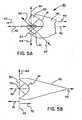
- Figures 8 through 12illustrate (but do not limit) various alternate embodiments of looped struts of the present invention.
- Shown in Figures 8A and 8Bis an embolic filter 30 having a preferred looped strut configuration 34.
- a preferred strut 34 of the present inventioncan have a looped shape or profile when viewed along two orthogonal axes. The struts 34 therefore project a looped configuration in two orthogonal views.
- Alternate strut configurations of the present inventioncan have looped shapes when viewed along different combinations of axes or along a single axis.
- FIGs 9A and 9Bare similar views to those of 8A and 8B, showing an alternate looped strut configuration wherein the alternate strut 34 has an essentially looped shape only when viewed along a single axis. Shown is a strut 34 having a looped shape in an end view ( Figure 9A ) and an essentially linear shape in a side view ( Figure 9B ).
- a strut of the present inventioncan have an essentially linear shape when viewed on end, while having a looped shape when viewed, for example from the side.
- This configurationis illustrated in Figures 10A and 10B , which show an alternate strut 34 having an essentially linear shape when viewed from the end ( Figure 10A ), while having a looped configuration when viewed from the side ( Figure 10B ).
- Looped support struts of the present inventioncan be configured with bends greater than about 90 degrees (as defined by Figure 3C ), greater than about 120 degrees, greater than about 180 degrees, greater than about 240 degrees, or more.
- a looped strut of the present invention having a bend greater than about 200 degreesis depicted in Figure 11A .
- the struts 34also have a looped configuration when viewed from another axis, In this case a side view, as shown in Figure 11B . Looped support struts of the present invention can therefore have different "loop" configurations when projected onto different viewing planes.
- Embolic filter frames of the present inventioncan have 2, 3, 4, 5, 6, 7, 8, or more looped support struts.
- Various multiple strut configurationsare depicted in Figures 12A through 12F .
- Figure 12Ashows an end view of an embolic filter of the present invention having 3 looped struts 34.
- Figure 12Bshows an end view of an embolic filter of the present invention having 4 looped struts 34.
- Figure 12Cshows an end view of an embolic filter of the present invention having 5 looped struts 34.
- Figure 12Dshows an end view of an embolic filter of the present Invention having 6 looped struts 34.
- Figure 12Eshows an end view of an embolic filter of the present invention having 7 looped struts 34.
- Figure 12Fshows an end view of an embolic filter of the present invention having 8 looped struts 34.
- FIG. 13An additional functional aspect of embolic filter frames of the present invention is shown in Figure 13 .
- an embolic filter 30having looped support struts 34, filter element 40 attached to the filter element support 32, central collar 46, and support wire 36.
- a compressive load 100is applied to the frame, which counteracts the radial force applied by the frame to the vessel.
- the compressive load 100causes a frame portion, in this case the filter element support portion 32, to deflect outwardly, as shown by item 102.
- the deflection 102can improve the sealing between the filter element 40 and the vessel wall, further reducing the advertent passage of emboli.
- the additional loading onto the vessel wallcan also reduce the possibility of "vascular trauma" caused by relative motion between the filter and the vessel, and opposition when deployed in curved vascular segments.
- Shown in Figure 14is an alternate configuration of a frame having looped struts 34 and having a simplified filter support portion (in contrast to the elongated filter support portions 32 shown in Figure 2 ). Shown are a support wire 36 and a filter element 40 attached directly to the ends of the six looped support struts 34 of the present invention.
- the support struts 34attach to the filter element 40 at attachment points 103. It should be appreciated that the length and shape of the struts 34 in this embodiment may be varied to accommodate bonding of struts 34 to different points on the filter element or to bond the filter element 40 along a partial length of the struts 34.
- An additional feature of a filter frame of the present inventionrelates to the looped strut "spontaneous" transformation from a constrained linear state to a "locked and inverted state, similar to that of "locking pliers" or an "off-center locking clamp". Once inverted, the looped struts maintain a stable, short length, looped configuration and must be tensioned to revert back to the constrained linear state.
- support wireas referred to and relating to the present invention, (for example, element 36 in Figure 1 ) can include a solid or hollow support wire or can include any other tubular article with at least one continuous lumen running therethrough.
- a suitable support wire for use with the present inventionmay include, but is not limited to, a guide wire.
- Filters of the present inventioncan be configured for deployment within a variety of articles, including, but not limited to, filtering applications within animal vessels, catheters, pipes, ducts, fluid conduits, tubes, hoses, material transfer conduits, storage containers, pumps, valves and other fluid containers.
- Filterable fluidsinclude gasses, liquids, plasma and flowable solids or particulate mixtures. Fluids can flow across the filters of the present invention, or the filters can be dragged or otherwise transported through a fluid.
- Filters of the present inventionare not limited to generally circular profiles (when viewed on end) and can have, when deployed an oval, triangular, square, polygon, or other profile.
- Filters of the present inventioncan also be combined, "ganged,” or used in conjunction with other devices such as diagnostic, visualization, therapeutic instruments, or other filters.
- the strut configurations of the present inventioncan also be incorporated into non-filtering devices, such as vessel occluders, indwelling diagnostic instruments, therapeutic instruments, or visualization devices.
- the device and the method of production of the present inventionmay be better understood by referring to the following example.
- a 0.9 mm nitinol tube 104with a wall thickness of approximately 0.09mm (obtained from SMA Inc, San Jose, CA) was laser cut by Laserage Technologies Inc, Waukegan, IL, to form a frame configuration of a single, undulating, integral, 6 apex ring.
- the frameincluded radiopaque marker housings 106 at each distal apex and tether or strut elements 34 extending from each proximal apex 108 and converging at the opposite end In a "collar" 46 of uncut parent material.
- This framewas then lightly grit blasted at 30 psi with 20-micron silicon carbide media in a grit blasting machine (Model MB1000 available from Comco Inc, Burbank, CA). The frame was then gently slid up a tapered mandrel until it achieved a functional size of approximately 6mm.
- the frame and mandrelwere then subjected to an initial thermal treatment to set the geometry in an initial, tapered (conical) configuration in an air convection oven (Carbolite Corporation, Sheffield, England).
- the framewas quenched In ambient temperature water and removed from the mandrel, resulting In a non-inverted frame.
- FIG 16Shown In Figure 16 is the non-inverted frame 110 having support struts 34, a central collar 46, apexes 108, and radiopaque marker housings 106.
- the frame portion distal to the apexes 108form a filter element support portion 32.
- the framewas then placed on a second mandrel, designed to constrain the outside of the frame while allowing the Inversion of the tether elements back upon themselves. Once constrained in the proper configuration, the tooling and frame were subjected to a second thermal treatment to set the final frame geometry and to set the nitinol transition to an appropriate temperature.
- the resulting inverted frameis depicted in Figure 17 .
- FIG. 17Shown in Figure 17 is an inverted frame 112 having six looped support struts 34a, apexes 108, radiopaque housings 106, and an integral central collar 46.
- the frame portion distal to the apexes 108form a filter element support portion 32.
- the frame(now at functional size and preferred geometry) was then lightly coated with fluorinated ethylene propylene (FEP) powder (e.g., FEP 5101,available from DuPont Corp, Wilmington, DE) by first stirring the powder in a kitchen blender (Hamilton Beach Blendmaster) after the powder was mixed Into a "cloud,” the frame was lowered Into the blender for approximately 5 seconds (enough time for FEP to build up onto the surface of the frame).
- FEP powderfluorinated ethylene propylene
- the frame, coated with FEP powderwas placed In an air convection oven (Grieve Oven, The Grieve Corporation, Round Lake, IL) set at 320 0 C for approximately one minute followed by air cooling to room temperature.
- FEPfluorinated ethylene propylene
- a typical filtering mediawas made by laser perforating one layer of a thin, polytetrafluoroethylene (PTFE) membrane using a 10-watt C0 2 laser.
- the membrane thicknessmeasured about 0.0002" (0.005 mm) and had tensile strengths of about 49,000 psi (about 340 KPa) in a first direction and of about 17,000 psi (about 120 KPa) in a second direction (perpendicular to the first direction).
- the tensile measurementswere performed at 200mm/min. load rate with a 1" (2.5 cm) jaw spacing.
- the membranehad a density of about 2.14g/cm 3 .
- the laser power and shutter time parameterswere adjusted to allow the laser to consistently create uniform 0.004" (0.1 mm) diameter holes in the membrane.
- the hole pattern geometrywas then adjusted to create a pattern with uniform hole size, uniform hole spacing, and uniform strength throughout the pattern.
- This perforated patternwas then folded on itself and heat-sealed using a local heat source (Weber soldering iron, EC2002M, (available through McMaster Carr, Santa Fe Springs, CA)) into a pattern which would result in a conical shape.
- the conical flat patternwas then trimmed with scissors, inverted, and mounted upon the FEP powder coated NiTi frame and attached though the application of localized heat (the heat causing the FEP coating on the frame to re-melt and flow onto the surface of the filter sack thus providing a biocompatable thermoplastic adhesive).
- a guide wire componentwas then inserted into the collar end of the frame and a small amount of instant adhesive (Loctite 401, Loctitle Corp, Rocky Hill, CT) was applied and dried to adhere and create a smooth transition from the guide wire to the outer diameter (OD) of the frame collar.
- a small amount of instant adhesiveLoctite 401, Loctitle Corp, Rocky Hill, CT
- attachment of the filter to the guide wirecould be accomplished by adhesion, welding, soldering, brazing, a combination of these, or a number of other methods.
- FIG. 18A through 18CA further embodiment of the present invention is illustrated in Figures 18A through 18C .
- the filter assembly 30includes a frame 31 that is slidably mounted to the support wire 36. This attachment may be accomplished through a variety of means, including by providing a collar 46 that is sized slightly larger than the support wire 36 to allow the collar to move relative to the support wire when in use. Stops 114a, 114b are provided on the support wire 36 to limit the range of relative movement between the filter assembly 30 and the support wire 36. Constructed in this manner, the filter assembly 30 has exceptional longitudinal compliance relative to the support wire in that the support wire can freely move between the stops 114 without translating longitudinal or rotational movement to the filter assembly. The full range of proximal and distal movement of the filter assembly 30 relative to the stops 114 is shown in Figures 18B and 18C .
Landscapes
- Health & Medical Sciences (AREA)
- Engineering & Computer Science (AREA)
- Life Sciences & Earth Sciences (AREA)
- Animal Behavior & Ethology (AREA)
- Oral & Maxillofacial Surgery (AREA)
- Biomedical Technology (AREA)
- Heart & Thoracic Surgery (AREA)
- Vascular Medicine (AREA)
- Cardiology (AREA)
- Transplantation (AREA)
- General Health & Medical Sciences (AREA)
- Public Health (AREA)
- Veterinary Medicine (AREA)
- Mechanical Engineering (AREA)
- Surgical Instruments (AREA)
- Prostheses (AREA)
Abstract
Description
- The invention relates to embolic filter devices for placement in the vasculature and in particular, self-expanding frames used to support embolic filter elements.
- Embolic protection is a concept of growing clinical importance directed at reducing the risk of embolic complications associated with interventional (i.e., transcatheter) and surgical procedures. In therapeutic vascular procedures, liberation of embolic debris (e.g., thrombus, clot, atheromatous plaque, etc.) can obstruct perfusion of the downstream vasculature, resulting in cellular ischemia and/or death. The therapeutic vascular procedures most commonly associated with adverse embolic complications include: carotid angloplasty with or without adjunctive stent placement; and revascularization of degenerated saphenous vein grafts. Additionally, percutaneous transluminal coronary angioplasty (PTCA) with or without adjunctive stent placement, surgical coronary artery by-pass grafting, percutaneous renal artery revascularization, and endovascular aortic aneurysm repair have also been associated with complications attributable to atheromatous embolization. The use of embolic protection devices to capture and remove embolic debris, consequently, may improve patient outcomes by reducing the incidence of embolic complications.
- Embolic protection devices typically act as an intervening barrier between the source of the clot or plaque and the downstream vasculature. Numerous devices and methods of embolic protection have been used adjunctively with percutaneous interventional procedures. These techniques, although varied, have a number of desirable features including: intraluminal delivery; flexibility; backability; small delivery profile to allow crossing of stenotic lesions; dimensional compatibility with conventional interventional implements; ability to minimize flow perturbations; thromboresistance; conformability of the barrier to the entire luminal cross section (even if irregular); and a means of safely removing the embolic protection device and trapped particulates. There are two general strategies for achieving embolic protection: techniques that employ occlusion balloons; and techniques that employ an embolic filter. The use of embolic filters is a desirable means of achieving embolic protection because they allow continuous perfusion of the vasculature downstream to the device.
- Occlusion balloon techniques have been taught by the prior art and involve devices in which blood flow to the vasculature distal to the lesion is blocked by the inflation of an occlusive balloon positioned downstream to the site of intervention. Following therapy, the intraluminal compartment between the lesion site and the occlusion balloon is aspirated to evacuate any thrombus or atheromatous debris that may have been liberated during the interventional procedure. The principle drawback of occlusion balloon techniques stems from the fact that during actuation, distal blood flow is completely inhibited, which can result in ischemic pain, distal stasis/thrombosis, and difficulties with fluoroscopic visualization due to contrast wash-out through the treated vascular segment
- A prior system described in
US Patent 4,723,549 to Wholey, et al. combines a therapeutic catheter (e.g., angioplasty balloon) and integral distal embolic filter. By incorporating a porous filter or embolus barrier at the distal end of a catheter, such as an angioplasty balloon catheter, particulates dislodged during an interventional procedure can be trapped and removed by same therapeutic device responsible for the embolization. One known device includes a collapsible filter device positioned distal to a dilating balloon on the end of the balloon catheter. The filter comprises a plurality of resilient ribs secured to circumference of the catheter that extend axially toward the dilating balloon. Filter material is secured to and between the ribs. The filter deploys as a filter balloon is inflated to form a cup-shaped trap. The filter, however, does not necessarily seal around the interior vessel wall. Thus, particles can pass between the filter and the vessel wall. The device also lacks longitudinal compliance. Thus, inadvertent movement of the catheter results in longitudinal translation of the filter, which can cause damage to the vessel wall and liberate embolic debris. - Other prior systems combine a guide wire and an embolic filter. The embolic filters are incorporated directly into the distal end of a guide wire system for intravascular blood filtration. Given the current trends In both surgical and interventional practice, these devices are potentially the most versatile In their potential applications. These systems are typified by a filter frame that is attached to a guide wire that mechanically supports a porous filter element. The filter frame may include radially oriented struts, one or more circular hoops, or a pre-shaped basket configuration that deploys in the vessel. The filter element Is typically comprised of a polymeric or metallic mesh net, which is attached to the filter frame and/or guide wire. In operation, blood flowing through the vessel is forced through the mesh filter element thereby capturing embolic material in the filter.
- Early devices of this type are described in the art, for example in
US Patent 5,695,519 to Summers, et aL , and include a removable intravascular filter mounted on a hollow guide wire for entrapping and retaining emboli. The filter is deployable by manipulation of an actuating wire that extends from the filter Into and through the hollow tube and out the proximal end. During positioning within a vessel, the filter material is not fully constrained so that, as the device is positioned through and past a clot, the filter material can potentially snag clot material creating freely floating emboli prior to deployment. The device also lacks longitudinal compliance. - Another example of a prior device, taught in
US Patent 5,814,064 to Daniel, et al. , uses an emboli capture device mounted on the distal end of a guide wire. The filter material is coupled to a distal portion of the guide wire and is expanded across the lumen of a vessel by a fluid activated expandable member in communication with a lumen running the length of the guide wire. During positioning, as the device is passed through and beyond the clot, filter material may interact with the clot to produce emboil. The device also lacks longitudinal compliance. - Another device, taught in
US Patent 6,152,946 to Broome, et al. , which is adapted for deployment in a body vessel for collecting floating debris and emboli in a filter, Includes a collapsible proximally tapered frame to support the filter between a collapsed insertion profile and an expanded deployment profile. The tapered collapsible frame includes a mouth that is sized to extend to the walls of the body vessel in the expanded deployed profile and substantially longitudinal struts that attach and tether the filter frame to the support wire. This device also lacks substantial longitudinal compliance. This device has the additional drawback of having an extended length due to the longitudinally oriented strut configuration of the tapered frame. This extended length complicates the navigation and placement of the filter within tortuous anatomy. - A further example of an embolic filter system, found in
PCT WO 98/33443 US 6,391,044 (Yadav ) teaches a removable vascular filter system for blocking micro- and macro- emboli. The document teaches the use of deploying and collapsing fibres for deploying and collapsing a filter membrane. The document further teaches the use of structural wires to improve rigidity of the filter membrane in a deployed configuration.- In summary, disadvantages associated with predicate devices include lack of longitudinal compliance, extended deployed length of the frame and associated tethering elements, and inadequate apposition and sealing against a vessel wall. Without longitudinal compliance, inadvertent movement of the filter catheter or support wire can displace the deployed filter and damage a vessel wall and/or introgenic vascular trauma, or, in extreme cases, result In the liberation of embolic debris. An extended deployed length aggravates proper filter deployment adjacent to vascular side branches or within tightly curved vessels, inadequate filter apposition and sealing against a vessel wall has the undesirable effect of allowing emboli passage.
- To ensure filter apposition and sealing against a vessel wall, without inducing undue vascular trauma, the radial force exerted by the filter against the vessel wall should be optimized. Typical methods used to increase the radial force exerted by the filter include, for example, increasing the cross-sectional area (moment of inertia and therefore the stiffness) of the filter support frame and in particular the tethering elements of the frame. Enhanced radial force can also be achieved by incorporating additional support members or by enlarging the "relaxed" or deployed diameter of the filter frame relative to the diameter of the vessel Into which it is deployed. These methods typically have the undesirable side effects of degrading the longitudinal compliance, adding to the compressed delivery profile, and, in some cases, increasing the deployed length. Some methods used to increase the radial force (for example, stiffer support frames) have the additional drawback of requiring thicker-walled, larger profile, delivery catheters. To accommodate the increased pressure exerted by the stiff frame (constrained within the delivery catheter) a commensurately thicker catheter wall is required, compromising the delivery profile.
- The present invention is an improved embolic filter frame having looped support struts. The frame configuration of the present invention provides enhanced longitudinal compliance, improved sealing against a vessel wall, low profile delivery, and a short deployed length occupied by the frame and tethering elements.
- To improve the apposition and sealing against a vessel wall, the present invention incorporates a filter support frame having "looped" support struts. The "looped" strut configuration enhances the radial force imparted onto a vessel wall without entailing the undesirable side effects previously described. The looped strut configuration also facilitates filter frame opposition when deployed in tortuous vascular anatomies. When in a tensioned or compressed delivery state, the looped support struts of the present invention assume an essentially longitudinal configuration and impart minimal radial force onto the catheter wall. The thickness of the catheter wall or radial constraint can therefore be minimized to increase flexibility, decrease the catheter profile, and enhance insertion trackablity. During the deployment procedure, the looped support struts assume a looped configuration. Once in the deployed, looped configuration, the support struts exert a high degree of radial force onto the vessel wall, enhancing apposition and sealing. The looped support struts also provide a high degree of longitudinal compliance relative to conventional designs. In addition, the full length of the looped support struts is positioned very close to the filter element, which minimizes the overall deployed length of the filter media support element.
- Among the important benefits of the present Invention is that the deployed device of the present invention exhibits a low degree of "longitudinal" stiffness. Thus, in the deployed state, the device remains limp and compliant in the longitudinal direction. Consequently, minor longitudinal displacements of the support wire or catheter are not translated to the filter frame and vessel wall during guide wire manipulation.
- Another beneficial feature of the present invention is that the looped struts and the central collar connecting the support struts to the support wire of the present invention are positioned essentially within the plane of the filter opening and, if desired, can even be positioned within the filter frame element itself. This improves the utility of the embolic filter of the present invention by reducing the overall deployed length of the filter support frame and allowing the filter to be deployed very close to the treatment site.
- These enhanced features and other attributes of the embolic filter of the present invention are better understood through review of the following specification.
- According to a first clause there is provided an embolic filter comprising: a support wire; an embolic filter frame having a filter support portion and multiple support struts mounted to the support wire; the support struts extending radially from the support wire; at least one support strut having a looped configuration when not in tension in a deployed state; and a filter element attached to the filter support portion.
- According to a second clause there is provided the embolic filter of the first clause wherein the multiple support struts have looped configurations.
- According to a third clause there is provided the embolic filter of the first clause wherein at least one support strut projects a looped configuration in two orthogonal views.
- According to a fourth clause there is provided the embolic filter of the first clause wherein at least one support strut has an "s" shape.
- According to a fifth clause there is provided an embolic filter comprising: a support wire having a longitudinal axis; an embolic filter frame including multiple support struts mounted to the support wire at an attachment point; the frame having a constrained delivery state and a non-tensioned deployed state; the embolic filter having a distal and proximal end; the frame having a filter opening when in the non-tensioned deployed state; the filter opening defining a plane essentially orthogonal to the support wire longitudinal axis; and the strut attachment point located distally from the plane of the filter opening.
- According to a sixth clause there is provided the embolic filter of the fifth clause further comprising at least three looped support struts.
- According to a seventh clause there is provided the embolic filter of the fifth clause wherein at least one support strut projects a looped configuration in two orthogonal views.
- According to an eight clause there is provided an embolic filter comprising: a support wire; an embolic filter frame including multiple struts mounted to the support wire; the struts having a constrained delivery state and a non-tensioned deployed state; the struts having an essentially linear configuration while in the constrained delivery state and an essentially looped configuration while in the non-tensioned deployed state; wherein the struts are adapted to transform from the straight configuration to the looped configuration during deployment.
- According to a ninth clause there is provided the embolic filter of the eighth clause further comprising at least three looped support struts.
- According to a tenth clause there is provided the embolic filter of the eighth clause wherein at least one support strut projects a looped configuration in two orthogonal views.
- According to an eleventh clause there is provided an embolic filter comprising: a support wire; an embolic filter frame including multiple support struts mounted to the support wire and extending radially therefrom; the struts having a constrained delivery state and a non-tensioned deployed state; at least one strut having a loop configuration when in the non-tensioned deployed state; and a filter element attached to the frame.
- According to a twelfth clause there is provided the embolic filter of the eleventh clause further comprising at least three looped support struts.
- According to a thirteenth clause there is provided the embolic filter of the eleventh clause wherein at least one support strut projects a looped configuration in two orthogonal views.
- According to a fourteenth clause there is provided an embolic filter comprising: a movable support wire having a maximum total displacement; a frame having multiple looped support struts and an unconstrained diameter; wherein a ratio of the frame unconstrained diameter divided by the support wire total displacement is greater than about 2.
- According to a fifteenth clause there is provided the embolic filter of the fourteenth clause wherein at least one support strut projects a looped configuration in two orthogonal views.
- According to a sixteenth clause there is provided an embolic filter oomprising: a frame having multiple looped support struts, a deployed length and an unconstrained diameter; wherein the frame deployed length divided by the frame unconstrained diameter is between about 0.5 to about 1.
- According to a seventeenth clause there is provided the embolic filter of the sixteenth clause wherein at least one support strut projects a looped configuration in two orthogonal views.
- According to an eighteenth clause there is provided an embolic filter comprising: a frame having multiple looped support struts, a constrained delivery length and an unconstrained length; wherein the frame constrained delivery length divided by the unconstrained frame length is between about 2 to about 3.
- According to a nineteenth clause there is provided the embolic filter of the eighteenth clause wherein at least one support strut projects a looped configuration in two orthogonal views.
- According to a twentieth clause there is provided an endoluminal filter assembly comprising a filter element; a support wire; a filter frame comprising at least two "s" shaped support struts attaching the filter element to the support wire.
- According to a twenty-first clause there is provided the endoluminal filter assembly of the twentieth clause wherein the filter frame is slidably attached to the support wire.
- According to a twenty-second clause there is provided an endoluminal filter assembly comprising a support wire; a filter frame having a collar adapted to attach around the support wire and move relative thereto; a first stop attached to the support wire distal to the filter frame; a second stop attached to the support wire proximal to the filter frame; wherein movement of the filter frame along the support wire is constrained by the first and second stops.
- According to a twenty-third clause there is provided the endoluminal filter assembly of the twenty-second clause wherein the filter frame includes at least two looped support struts.
- The operation of the present invention should become apparent from the following description when considered In conjunction with the accompanying drawings, in which:
Figure 1 is a three-quarter isometric view of an embolic filter of the present invention, with a support frame having three looped support struts.Figure 2 is an enlarged partial view of the support frame ofFigure 1 .Figure 3A Is an end view of the embolic filter ofFigure 1 , depicting the support frame assuming an unconstrained diameter.Figure 3B is a partial side-view of a looped support strut of the present invention, defining a bend angle in the support strut.Figure 3C is a partial side-view of a looped support strut of the present invention, defining an "s" shape in the support strut.Figure 4 is a three-quarter isometric view of an embolic filter of the present invention as deployed into a vessel.Figure 5A is a partial three-quarter isometric view of an embolic filter of the present invention, defining the filter opening planes.Figures 5B through 5D are side views of an embolic filter of the present invention Illustrating deployed diameters and various types of offset strut attachment points.Figures 6A and 6B are side views of an embolic filter of the present invention defining deployed diameters and overall lengths.Figures 6C and 6D are side views of an embolic filter frame of the present invention, defining deployed diameters and lengths.Figures 7A through 7C are side views of an embolic filter of the present invention, showing various stages of tensioning and elongation.Figure 7D is a side view of an embolic filter of the present invention constrained within a sheath.Figures 8A and 8B are, respectively, an end view and a side view of one embodiment of an embolic filter of the present invention, showing three support struts with loops, as viewed along two orthogonal axes.Figures 9A and 9B are, respectively, an end view and a side view of a further embodiment of an embolic filter of the present invention, showing three support struts with loops, as viewed along two orthogonal axes.Figures 10A and 10B are, respectively, an end view and a side view of another embodiment of an embolic filter of the present invention, showing three support struts with loops, as viewed along two orthogonal axes.Figures 11A and 11B are, respectively, an end view and a side view of still another embodiment of an embolic filter of the present invention, showing three support struts with loops, as viewed along two orthogonal axes.Figures 12A through 12F are end views of embolic filters embodiments of the present invention, showing, respectively, three, four, five, six, seven, and eight looped support struts.Figure 13 is a longitudinal cross-section view of an embolic filter frame of the present invention, depicting an enhanced radial force caused by vessel wall compression.Figure 14 is a side view of an embolic filter device of the present invention wherein the frame includes a truncated filter membrane support portion.Figure 15 is a three-quarter isometric view of a cut-out precursor tube used to fabricate a six-strut embolic filter frame of the present invention according to Example 1.Figure 16 is a three-quarter isometric view of the precursor tube ofFigure 15 that has been expanded to form a six-strut embolic filter frame of the present invention.Figure 17 is a side view of an expanded and inverted precursor tube used to fabricate a six-strut embolic filter frame of the present invention according to Example 1.Figures 18A through 18C are longitudinal cross-section views of another embodiment of an embolic filter device of the present invention having a slidable attachment between the filter frame and the support wire.- A first embodiment of the present invention Is shown in
Figure 1 . Shown is an unconstrained, non-tensionedembolic filter assembly 30 of the present invention. Thefilter assembly 30 comprises aframe 31 having two distinct portions: afilter support portion 32 and a series of looped struts or tethers 34. Each loopedstrut 34 is affixed to acentral collar 46, which is then attached to asupport wire 36 atattachment point 38. Multiple struts 34 emanate radially outward and are attached to the frame'sfilter support portion 32. Attached to thefilter support portion 32 is afilter element 40. Also shown is alongitudinal axis 42, which is essentially coincident with thesupport wire 36. - Embolic filter frames of the present invention can have 2, 3, 4, 5, 6, 7, 8 or more looped support struts. The number of support struts can effect the profile and shape of the
filter membrane opening 60. For example, the frame configuration inFigure 1 , showing only three support struts for clarity, typically results In a filter opening having three "scallops" 41 which follow the profile of thefilter support portion 32. By incorporating additional support struts, the magnitude or size of eachscallop 41 is reduced and the filter opening will more closely approximate a circle within a plane. In a preferred embodiment, six looped support struts are incorporated into a frame of the present invention. The filter element may be trimmed to match the contour of the scallops so to avoid deflecting or disrupting fluid flow or potentially allowing inadvertent passage of emboli. - The
distal end 35 of the fitter element is preferably provided with a slidable attachment around thesupport wire 36 so as to allow the filter element to change position relative to thesupport wire 36 between compacted and deployed dimensions. Additionally, a slidable interface between thedistal end 35 and the support element allows the filter element to remain fully extended in the vessel at all times, even when the filter assembly is undergoing longitudinal compliance, as described herein. Alternatively or additionally, the filter element may be formed from an elastic material that can accommodate different distal end positions relative to the position of the filter frame. - Shown in
Figure 2 is an enlarged view of the unconstrained looped support struts of anembolic filter 30 of the present invention. Shown is aframe 31 havingfilter support portions 32 and three looped support struts 34. Also shown aresupport wire 36,central collar 46, collar to supportwire attachment point 38, and afilter element 40. Shown is a preferred embodiment in which the looped support struts 34 are essentially "s" shaped. Figure 3A illustrates the unconstrainedembolic filter assembly 30 fromFigures 1 and 2 . Shown are three preferred s-shaped, looped support struts 34 extending radially from thecentral collar 46. The support struts 34 extend from and are attached to afilter support portion 32. Attached to thefilter support portion 32 is afilter element 40. Theembolic filter 30, shown in an unconstrained state, has anunconstrained diameter 44.- Referring again to
Figure 2 , shown are three looped support struts 34,support wire 36,central collar 46, collar to supportwire attachment point 38, and afilter element 40. It will be noted thatattachment point 38 may comprise a rigidly secure fixation point between thesupport wire 36 and the centeredcollar 46, or it may comprise a slideable interface between thesupport wire 36 andcentral collar 46; thereby decoupling longitudinal or rotational motion of the support wire from the filter frame. The support struts 34 extend radially and are attached to afilter support portion 32. Attached to thefilter support portion 32 is afilter element 40. A "filter support portion" is defined as that portion of a filter frame that is at least partially attached to afilter element 40. A "support strut" is defined as that portion of a filter frame that supports the filter support portion and generally is not attached directly to thefilter element 40. - A "looped support strut" is further illustrated in
Figure 3B . Shown is thesupport strut 34 unattached to a filter element and constrained about a support wire orlongitudinal axis 42. Areference axis 47, drawn through thesupport strut 34 as shown, approximates the magnitude of a bend or loop in the support strut. Theaxis 47 defines anangle 48 relative to the longitudinal axis 42 (also shown is areference axis 49 which defines a 90 degree angle relative to the longitudinal axis 42). Shown is a loopedsupport strut angle 48, which is greater than 90 degrees, relative to thelongitudinal axis 42. A "looped strut" is therefore defined as a filter frame support strut, having a portion unattached to a filter element, wherein the strut has at least one bend equal to or greater than 90 degrees along the unattached portion. The looped angle can be viewed and measured about any axis. - A looped, embolic filter frame support strut having an "s" shape is depicted in
Figure 3C . Shown is thesupport strut 34 unattached to a filter element and constrained about alongitudinal axis 42. Also shown is anaxis 37, which is parallel to thelongitudinal axis 42. Areference axis 47, drawn through thesupport strut 34, as shown, approximates the magnitude of the bends or loops In the support strut. Theaxis 47 definesangles 48 relative to thelongitudinal axis 42. Shown are two opposite bend angles 48, each of at least about 90 degrees. A "support strut having an 's' shape" Is defined as a filter frame support strut having a portion unattached to a filter element, wherein the strut has at least two opposite bends greater than about 90 degrees along the unattached portion. Theangles 48 can be viewed and measured about any axis. - The aspect of "longitudinal compliance" Is further clarified in
Figure 4 . Shown is anembolic filter assembly 30 of the present invention deployed within a compliant vessel 50 (shown in longitudinal cross-section). Thevessel 50 defines an inner diameter which is slightly smaller, for example approximately 90%, than the unconstrained diameter of the device. This is shown asdiameter 44 inFigure 3A . The "under-sized" vessel therefore imparts a radial constraint to the deployed filter, which prevents the filter from expanding to a full, unconstrained diameter. In this process, an interference fit between the filter and vessel wall is achieved. The looped support struts 34 when constrained by a vessel therefore exert a radial orexpansive force 52 onto thevessel wall 50, forming aseal region 54. This radial,expansive force 52 can also be referred to as the "hoop stress" or "radial force" applied to the vessel wall. - As the term "unconstrained diameter" is used herein, it is intended to describe the device of the present invention as it self-deploys on a tabletop. In this form it is both unconstrained and untensioned. This state Is also referred to herein as being "not in tension" or in a "non-tensioned" state.
- Once deployed, the
support wire 36, when rigidly fixed at or about the central collar, can be slightly displaced along thelongitudinal axis 42 indirections 56 or 58 without significantly disrupting or translating to theseal region 54. The looped support struts 34 therefore provide a degree of "longitudinal compliance" which effectively isolates the filter element from small support wire displacements. Devices of the presents invention having unconstrained diameters of about 6mm (0.24") can tolerate support wire displacements indirections 56 or 58 of about +/- 0.8mm (+/-0.03") or more, without causing a significant disruption or translation to theseal region 54. The support wire therefore has a "maximum total displacement" before causing a disruption to theseal region 54. - Longitudinal compliance can be alternately expressed as a ratio of unconstrained diameter divided by the maximum total support wire displacement when rigidly fixed to the support wire (without disrupting or translating the seal region against the vessel wall). To determine this ratio, a device of the present invention can be deployed within a transparent elastic tube having a diameter of about 80% of the filter's unconstrained diameter. The maximum total support wire displacement (without disrupting or moving the seal region) can then be approximated. Devices of the present invention display ratios of unconstrained diameter divided by the maximum total displacement of the support wire of about 6 or less. Preferably, the embolic filter of the present invention has a ratio of unconstrained diameter to maximum support wire displacement of about 5, about 4, about 3, about 2.5, about 2, about 1.5, about 1.2, or about 1.
- A relatively easy test to quantify longitudinal compliance in the present invention is to deploy the filter apparatus within a silicone tube (such as that available from JAMAK Healthcare Technologies, Weatherford, TX) having a thin wall thickness of approximately 0.25 mm (0.01") and having an internal diameter of approximately 80% that of theunconstrained filter apparatus. It should be noted that the use of an 80% constrained diameter is preferred since a 20% interference fit between the device and the vessel will prevent device migration and provide adequate sealing. Once deployed and at body temperature (approximately 37°C), the support wire to which the apparatus is attached may be longitudinally manipulated. The maximum distance the support wire can be displaced (in a longitudinal direction) without moving the filter frame in relation to the silicone tubing is recorded as "longitudinal compliance."
- The present invention also has the beneficial feature of a short deployed length, as depicted in
Figures 5A through 5D . The short deployed length of the present invention is a result of the looped struts and the central collar connecting the support struts to the support wire being positioned essentially within the plane of the filter opening. Depending upon the demands of particular applications, the looped struts can be engineered to deploy to be directly within the plane of the opening to the filter element, slightly upstream of the opening, or even slightly downstream of the opening so as to orient within the filter frame element itself. Shown inFigure 5A is anembolic filter 30 of the present invention in an unconstrained state having a proximal end 43 and adistal end 45. Thefilter element 40 has a filter "opening" 60, which defines a plane having anx-axis 62 and an y-axis 64. For filter openings withscallops 41, the openingaxis scallops 41. The opening plane shown is orthogonal to thesupport wire 36 and thelongitudinal axis 42. The twoaxes filter opening 60. Looped struts 34, of the present invention are joined onto acentral collar 46, which is attached to thesupport wire 36 atattachment point 38 via either rigidly fixed or slideable means. - Shown in
Figure 5B is afilter element 40 having afilter opening 60, an y-axis 64, and alongitudinal axis 42. Theaxis 64 is an "edge-view" of the plane of the filter opening.Axes point 70.Point 70 is therefore on the plane of the filter opening. For clarity, a point or location on thelongitudinal axis 42 is considered to be "offset distally" from the plane of the filter opening if the point lies within the filter element in the longitudinal direction labeled 72. Conversely, a point or location on thelongitudinal axis 42 Is considered to be "offset proximally" from the plane of the filter opening if the point lies outside of the filter element in the longitudinal direction labeled 74. Figure 5C illustrates a loopedsupport strut 34 andcentral collar 46 of the present Invention having a supportwire attachment point 38 which is rigidly fixed to the support wire and off-set distally from the plane of thefilter opening 64. Shown is a supportwire attachment point 38 positioned inside thefilter element 40 in thedistal direction 72. The magnitude of the attachment point offset is shown aselement 80.Figure 5D illustrates a loopedsupport strut 34 andcentral collar 46 of the present invention having a supportwire attachment point 38 which is rigidly fixed to the support wire and off-set proximally from the plane of thefilter opening 64. Shown is a supportwire attachment point 38, positioned outside of thefilter element 40, in theproximal direction 74. The magnitude of the attachment point offset is shown asitem 82.- The relative magnitude of any off-set, along with the direction of the off-set between a support wire attachment point and the plane of the
filter opening 64, can be expressed by an "offset ratio" of the strut attachment point off-set divided by theunconstrained diameter 44. For example, a filter having a strut attachment point offset of 4mm and an unconstrained diameter of 10mm, would have a ratio of 0.4. This ratio can be applied to strut to support wire attachment points that are offset distally or proximally to the plane of the filter opening. A ratio of "zero" would reflect no offset, or in other words an attachment point lying in the plane of the filter opening. - Embolic filters of the present invention can have distally offset ratios (of the attachment point off-set divided the unconstrained diameter) ranging from about 0 to about 1, with a preferred range of about 0 to about 0.7, with a most preferred range of about 0.2 to about 0.5. These distally offset ratios reflect strut/collar to support wire attachments positioned within the filter element. Similarly, embolic filter of the present invention can have proximally offset ratios, reflecting strut/collar to support wire attachments positioned outside of the filter element. In these configurations, embolic filters of the present invention can have offset ratios (attachment point offset divided by the unconstrained diameter) ranging from about 0 to about 1.
- Devices of the present invention can be configured to have a strut to central collar attachment points that are significantly different than the central collar to support wire attachment points. For these configurations, both attachment points are then approximated by a point on the support wire that is in closest proximity to the strut.
- The looped support struts of the present Invention allow a short deployed length that enhances navigation within tortuous vessels and allows deployment near vascular side-branches. To quantify as having the aspect of "short deployed length," a device should be defined by at least one of the five ratios defined below.
- The deployed length of a filter can be expressed by a first ratio of the deployed length divided by the unconstrained diameter of the filter. Shown in
Figure 6A is anembolic filter 30 of the present Invention having afilter element 40, looped struts 34, strut/collar to support wire attachment point 38 (lying outside of the filter element), and aunconstrained diameter 44. Shown is a deployedlength 84, which includes the looped struts 34 and theattachment point 38. - Shown in
Figure 6B Is anembolic filter 30 of the present invention having afilter element 40, loopedstruts 34a, strut/collar to support wire attachment point 38 (lying within the filter element), and aunconstrained diameter 44. Shown is a deployed length 86, which is referenced from the opposing ends of the filter element, and does not include the looped struts 34a or theattachment point 38. - Embolic filters of the present invention can have ratios of the deployed
length 84, 86 divided by the filterunconstrained diameter 44, ranging from about 0.5 to about 7, with a preferred range of about 1 to about 5, with a most preferred range of about 2 to about 4. - A similar expression of a filter deployed length or footprint is a second ratio of the deployed length of the frame (not including a filter element) divided by the frame unconstrained diameter. Shown in
Figure 6C is an embolic filter frame of the present invention havingfilter support portions 32 and loopedstruts 34, strut/collar to support wire attachment point 38 (lying outside of the filter element 40), and aunconstrained frame diameter 44. Shown is a frame deployedlength 87, which does not include thefilter element 40. - Shown In
Figure 6D Is an embolic filter frame of the present invention havingfilter support portions 32 and loopedstruts 34, strut/collar to support wire attachment point 38 (lying within the filter element 40), and aunconstrained diameter 44. Shown is a frame deployedlength 88, which does not include thefilter element 40. - Embolic filters of the present invention can have ratios of the frame deployed
length unconstrained diameter 44, ranging from about 0.1 to about 7, with a preferred range of about 0.3 to about 2, with a most preferred range of about 0.5 to about 1. - Additional benefits of the looped struts of the present invention relate to the delivery aspects of the embolic filter as shown in
Figures 7A through 7D . The looped support struts of the present Invention when tensioned elongate and assume a compacted and essentially linear form. While constrained in this linear state by a delivery catheter or other constraint means, the support struts exert relatively little force onto the radial constraint means, which permits the radial constraint means to be very thin and/or delicate. The overall delivery profile and stiffness are therefore reduced over those required for prior embolic filter devices. When the delivery catheter constraint is removed during deployment, the struts of the present invention spontaneously open and assume a looped configuration, which exert a high degree of force onto the vessel wall, creating an enhanced filter to vessel wall seal. - Shown in
Figure 7A is anembolic filter 30 of the present invention having loopedstruts 34 attached to acentral collar 46. The central collar is attached to asupport wire 36. The support struts emanate radially outward and are integral to (or joined to) a frame having afilter support portion 32. Afilter element 40 is attached to thefilter support portion 32. - When
tension 90 is applied to thesupport wire 36 andfilter element 40, the looped struts 34 elastically deform to the configuration shown inFigure 7B . Asfurther tension 90 is applied, theembolic filter 30 and the looped struts 34 continue to elongate until the looped struts assume an essentially linear or straight form as shown inFigure 7C . While in this elongated state, theembolic filter 30 can be inserted into a delivery catheter or withdrawn into a sheath. Shown inFigure 7D Is an elongatedembolic filter 30 of the present invention having loopedstruts 34 In an essentially linear configuration constrained in a delivercatheter 92. The low force applied to the delivery catheter by the elongated looped strut facilitates use of a relativelythin catheter wall 94. When the constraining delivery catheter is removed during filter deployment, the looped struts of the present invention spontaneously open and assume the configuration shown inFigures 4 and7A , either spontaneously or through manipulation of the support wire and/or delivery catheter. - During delivery within a vessel, struts 34 of an embolic filter of the present invention are constrained in an "essentially linear" form, as shown in
Figure 7D . While in this essentially linear form, the central support collar 46 (or strut to support wire attachment point 38) is positioned outside of thefilter element 40. Thecentral support collar 46 is also separated from thefilter element 40 by the elongated and essentially linear support struts 34. Once properly deployed, however, the central support collar 46 (or strut to support wire attachment point 38) lies within thefilter element 40, as shown inFigure 7A . The central support collar 46 (or strut to support wire attachment point 38) therefore moves or translates rotative to the filter element during deployment. Typical filters of the present invention undergo a relative translation (support collar to filter element) equal to at least 1/2 of the length of the constrained filter element 96 (as is shown inFigure 7D ). - Also shown in
Figure 7D is a totalconstrained delivery length 97 of an embolic filter of the present invention. Embolic filters of the present invention can have a third ratio of the totalconstrained delivery length 97 divided by the unconstrained length. For the present invention, this third ratio may be about 1, about 2, about 2.5, about 3, about 3.5, or greater. The unconstrained length Is defined by length 84 (Figure 6A ) or by length 86 (Figure 6B ). - Similarly, embolic filters of the present invention can have a fourth ratio of the total constrained
frame delivery length 98 divided by the unconstrained frame length. For the present Invention, this fourth ratio may be about 2, about 2.5, about 3, about 3.5, or greater. The unconstrained frame length Is defined by length 87 (Figure 6C ) or by length 88 (Figure 6D ). - A fifth ratio relating to the short deployed length is the strut constrained delivery length divided by the strut unconstrained deployed length. The strut constrained delivery length is defined as the length of a
strut portion 34 of the frame, not including thefilter support portion 32, as shown inFigure 7D . The strut constrained delivery length is therefore a portion of thetotal frame length 98 inFigure 7D . The strut unconstrained length is defined as the length of aunconstrained strut 34a as shown inFigures 6C and 6D , not including the length of afilter support portion 32. Filter frames of the present invention can have ratios of the strut constrained delivery length divided by the strut unconstrained deployed length of about 2, of about 3, of about 4, of about 5, of about 6, or about 7, or more. Filter frames of the present invention preferably have ratios of the strut constrained delivery length divided by the strut unconstrained deployed length of about 3, of about 3.5, of about 4, of about 4.5, or about 5 or more. Most preferred ratios of strut constrained delivery length divided by the strut unconstrained deployed length are about 3, about 3.3, of about 3.6, or about 4, or more. - Embolic filters of the present invention can be produced using a variety of common methods and processes. For example, an embolic filter frame with looped struts can be fabricated from any biocompatible material having adequate resilience and stiffness. For example, nitinol, stainless steel, titanium, and polymers may be employed as applicable materials. A precursor frame having looped struts may be fabricated in a planar sheet form and rolled and attached to itself to form a frame of the present invention. Alternately, a cylindrical tube can be cut and expanded or cut and compressed to form a frame of the present invention. Cutting processes can include lasers, stampings, etching, mill-cutting, water-jets, electrical discharge machining, or any other suitable process.
- Filter elements or members, used in conjunction with the looped struts of the present invention, can be produced using a variety of common materials, methods and processes. Suitable biocompatible materials include, but are not limited to, metallic foilsor meshes, or sheets or meshes formed from various polymers, including fluoropolymers such as polytetrafluoroethylene. Filter members can be molded, cast, formed, or otherwise fabricated by joining various suitable materials.
Figures 8 through 12 illustrate (but do not limit) various alternate embodiments of looped struts of the present invention. Shown inFigures 8A and 8B is anembolic filter 30 having a preferred loopedstrut configuration 34. Apreferred strut 34 of the present invention can have a looped shape or profile when viewed along two orthogonal axes. Thestruts 34 therefore project a looped configuration in two orthogonal views.- Alternate strut configurations of the present invention can have looped shapes when viewed along different combinations of axes or along a single axis. For example, shown in
Figures 9A and 9B are similar views to those of 8A and 8B, showing an alternate looped strut configuration wherein thealternate strut 34 has an essentially looped shape only when viewed along a single axis. Shown is astrut 34 having a looped shape in an end view (Figure 9A ) and an essentially linear shape in a side view (Figure 9B ). - Alternately, a strut of the present invention can have an essentially linear shape when viewed on end, while having a looped shape when viewed, for example from the side. This configuration is illustrated in
Figures 10A and 10B , which show analternate strut 34 having an essentially linear shape when viewed from the end (Figure 10A ), while having a looped configuration when viewed from the side (Figure 10B ). - Looped support struts of the present invention can be configured with bends greater than about 90 degrees (as defined by
Figure 3C ), greater than about 120 degrees, greater than about 180 degrees, greater than about 240 degrees, or more. For example, a looped strut of the present invention having a bend greater than about 200 degrees is depicted inFigure 11A . Shown is anembolic filter 30 having looped support struts 34 with "spiral" bends of about 200 degrees or more. Thestruts 34 also have a looped configuration when viewed from another axis, In this case a side view, as shown inFigure 11B . Looped support struts of the present invention can therefore have different "loop" configurations when projected onto different viewing planes. - Shown in all
Figures 8 through 11 are embolic filters having three, looped support struts with support wire attachment points 38 andcentral support collars 46, lying essentially within the filter element, as previously described InFigures 5A and 5B . Embolic filter frames of the present invention can have 2, 3, 4, 5, 6, 7, 8, or more looped support struts. Various multiple strut configurations are depicted inFigures 12A through 12F . Figure 12A shows an end view of an embolic filter of the present invention having 3 looped struts 34.Figure 12B shows an end view of an embolic filter of the present invention having 4 looped struts 34.Figure 12C shows an end view of an embolic filter of the present invention having 5 looped struts 34.Figure 12D shows an end view of an embolic filter of the present Invention having 6 looped struts 34.Figure 12E shows an end view of an embolic filter of the present invention having 7 looped struts 34.Figure 12F shows an end view of an embolic filter of the present invention having 8 looped struts 34.- An additional functional aspect of embolic filter frames of the present invention is shown in
Figure 13 . Shown is anembolic filter 30 having looped support struts 34,filter element 40 attached to thefilter element support 32,central collar 46, andsupport wire 36. When deployed within an undersized vessel (that is, a vessel that is undersized relative to the filters relaxed fully deployed diameter), acompressive load 100 is applied to the frame, which counteracts the radial force applied by the frame to the vessel. Thecompressive load 100 causes a frame portion, in this case the filterelement support portion 32, to deflect outwardly, as shown byitem 102. Thedeflection 102 can improve the sealing between thefilter element 40 and the vessel wall, further reducing the advertent passage of emboli. The additional loading onto the vessel wall can also reduce the possibility of "vascular trauma" caused by relative motion between the filter and the vessel, and opposition when deployed in curved vascular segments. - Shown in
Figure 14 is an alternate configuration of a frame having loopedstruts 34 and having a simplified filter support portion (in contrast to the elongatedfilter support portions 32 shown inFigure 2 ). Shown are asupport wire 36 and afilter element 40 attached directly to the ends of the six looped support struts 34 of the present invention. The support struts 34 attach to thefilter element 40 at attachment points 103. It should be appreciated that the length and shape of thestruts 34 in this embodiment may be varied to accommodate bonding ofstruts 34 to different points on the filter element or to bond thefilter element 40 along a partial length of thestruts 34. - An additional feature of a filter frame of the present invention relates to the looped strut "spontaneous" transformation from a constrained linear state to a "locked and inverted state, similar to that of "locking pliers" or an "off-center locking clamp". Once inverted, the looped struts maintain a stable, short length, looped configuration and must be tensioned to revert back to the constrained linear state.
- The term "support wire", as referred to and relating to the present invention, (for example,
element 36 inFigure 1 ) can include a solid or hollow support wire or can include any other tubular article with at least one continuous lumen running therethrough. A suitable support wire for use with the present invention may include, but is not limited to, a guide wire. - Filters of the present invention can be configured for deployment within a variety of articles, including, but not limited to, filtering applications within animal vessels, catheters, pipes, ducts, fluid conduits, tubes, hoses, material transfer conduits, storage containers, pumps, valves and other fluid containers. Filterable fluids include gasses, liquids, plasma and flowable solids or particulate mixtures. Fluids can flow across the filters of the present invention, or the filters can be dragged or otherwise transported through a fluid. Filters of the present invention are not limited to generally circular profiles (when viewed on end) and can have, when deployed an oval, triangular, square, polygon, or other profile. Filters of the present invention can also be combined, "ganged," or used in conjunction with other devices such as diagnostic, visualization, therapeutic instruments, or other filters. The strut configurations of the present invention can also be incorporated into non-filtering devices, such as vessel occluders, indwelling diagnostic instruments, therapeutic instruments, or visualization devices.
- Without intending to limit the scope of the present invention, the device and the method of production of the present invention may be better understood by referring to the following example.
- As shown in
Figure 15 , a 0.9mm nitinol tube 104, with a wall thickness of approximately 0.09mm (obtained from SMA Inc, San Jose, CA) was laser cut by Laserage Technologies Inc, Waukegan, IL, to form a frame configuration of a single, undulating, integral, 6 apex ring. The frame includedradiopaque marker housings 106 at each distal apex and tether or strutelements 34 extending from eachproximal apex 108 and converging at the opposite end In a "collar" 46 of uncut parent material. This frame was then lightly grit blasted at 30 psi with 20-micron silicon carbide media in a grit blasting machine (Model MB1000 available from Comco Inc, Burbank, CA). The frame was then gently slid up a tapered mandrel until it achieved a functional size of approximately 6mm. - The frame and mandrel were then subjected to an initial thermal treatment to set the geometry in an initial, tapered (conical) configuration in an air convection oven (Carbolite Corporation, Sheffield, England). The frame was quenched In ambient temperature water and removed from the mandrel, resulting In a non-inverted frame.
- Shown In
Figure 16 is thenon-inverted frame 110 having support struts 34, acentral collar 46,apexes 108, andradiopaque marker housings 106. The frame portion distal to theapexes 108 form a filterelement support portion 32. The frame was then placed on a second mandrel, designed to constrain the outside of the frame while allowing the Inversion of the tether elements back upon themselves. Once constrained in the proper configuration, the tooling and frame were subjected to a second thermal treatment to set the final frame geometry and to set the nitinol transition to an appropriate temperature. The resulting inverted frame is depicted inFigure 17 . - Shown in
Figure 17 is aninverted frame 112 having six looped support struts 34a, apexes 108,radiopaque housings 106, and an integralcentral collar 46. The frame portion distal to theapexes 108 form a filterelement support portion 32. - One skilled in the art will appreciate that variances in the filter frame material(s), dimensions, geometry, and/or processing can all be made to create alternate embodiments with varying desirable properties. For example, the relative position of the
central collar 46 to theapexes 108 can be varied according toFigures 5C and 5D . - The frame (now at functional size and preferred geometry) was then lightly coated with fluorinated ethylene propylene (FEP) powder (e.g., FEP 5101,available from DuPont Corp, Wilmington, DE) by first stirring the powder in a kitchen blender (Hamilton Beach Blendmaster) after the powder was mixed Into a "cloud," the frame was lowered Into the blender for approximately 5 seconds (enough time for FEP to build up onto the surface of the frame). The frame, coated with FEP powder, was placed In an air convection oven (Grieve Oven, The Grieve Corporation, Round Lake, IL) set at 3200C for approximately one minute followed by air cooling to room temperature.
- A typical filtering media was made by laser perforating one layer of a thin, polytetrafluoroethylene (PTFE) membrane using a 10-watt C02 laser. The membrane thickness measured about 0.0002" (0.005 mm) and had tensile strengths of about 49,000 psi (about 340 KPa) in a first direction and of about 17,000 psi (about 120 KPa) in a second direction (perpendicular to the first direction). The tensile measurements were performed at 200mm/min. load rate with a 1" (2.5 cm) jaw spacing. The membrane had a density of about 2.14g/cm3. The laser power and shutter time parameters were adjusted to allow the laser to consistently create uniform 0.004" (0.1 mm) diameter holes in the membrane. The hole pattern geometry was then adjusted to create a pattern with uniform hole size, uniform hole spacing, and uniform strength throughout the pattern. This perforated pattern was then folded on itself and heat-sealed using a local heat source (Weber soldering iron, EC2002M, (available through McMaster Carr, Santa Fe Springs, CA)) into a pattern which would result in a conical shape. The conical flat pattern was then trimmed with scissors, inverted, and mounted upon the FEP powder coated NiTi frame and attached though the application of localized heat (the heat causing the FEP coating on the frame to re-melt and flow onto the surface of the filter sack thus providing a biocompatable thermoplastic adhesive).
- A guide wire component was then inserted into the collar end of the frame and a small amount of instant adhesive (Loctite 401, Loctitle Corp, Rocky Hill, CT) was applied and dried to adhere and create a smooth transition from the guide wire to the outer diameter (OD) of the frame collar. One skilled in the art will realize that attachment of the filter to the guide wire could be accomplished by adhesion, welding, soldering, brazing, a combination of these, or a number of other methods.
- The resulting embolic filter is as shown and described above with respect to
Figure 1 et seq. - A further embodiment of the present invention is illustrated In
Figures 18A through 18C . In this embodiment thefilter assembly 30 includes aframe 31 that is slidably mounted to thesupport wire 36. This attachment may be accomplished through a variety of means, including by providing acollar 46 that is sized slightly larger than thesupport wire 36 to allow the collar to move relative to the support wire when in use.Stops support wire 36 to limit the range of relative movement between thefilter assembly 30 and thesupport wire 36. Constructed in this manner, thefilter assembly 30 has exceptional longitudinal compliance relative to the support wire in that the support wire can freely move between the stops 114 without translating longitudinal or rotational movement to the filter assembly. The full range of proximal and distal movement of thefilter assembly 30 relative to the stops 114 is shown inFigures 18B and 18C . - While particular embodiments of the present invention have been illustrated and described herein, the present invention should not be limited to such illustrations and descriptions. It should be apparent that changes and modifications may be Incorporated and embodied as part of the present invention within the scope of the following claims.
Claims (14)
- A method of making a frame (31) for an endoluminal assembly (30), comprising:providing a cylindrical tube (104);cutting the cylindrical tube (104) to form a frame (31) which comprises:a collar (46) configured for attachment to a support wire (36);a support portion (32) for attachment to a filter element (40);multiple support struts (34), configured to extend radially outward from the collar (46) to the support portion (32).
- A method of making a frame (31) according to claim 1, wherein cutting the cylindrical tube (104) comprises cutting by laser, stamping, etching, mill cutting, water jet or electrical discharge machining.
- A method of making a frame (31) according to claim 1 or 2, wherein the method further comprises expanding or compressing the cylindrical tube (104) to provide the frame (31).
- A method of making a frame (31) according to any of claims 1 to 3, wherein at least one support strut (34) has a looped configuration in a deployed state.
- A method of making a frame (31) according to any of claims 1 to 4, wherein at least one support strut (34) projects a looped configuration in two orthogonal views.
- A method of making a frame (31) according to any of claims 1 to 5, wherein at least one support strut (34) has an "s" shape.
- A method of making a frame (31) according to any of claims 1 to 6, wherein, in a deployed state, at least one support strut (34) is positioned essentially in a plane of an opening of a filter.
- A method of making a frame (31) according to any of claims 1 to 7, wherein, in a deployed state, the collar (46) is positioned within a cavity defined by a filter (30), is positioned essentially in a plane of an opening of a filter (30), or is positioned distal of an opening of a filter (30).
- A method of making a frame (31) according to any of claims 1 to 8, wherein the frame comprises two or more support struts (34).
- A method of making a frame (31) according to any of claims 1 to 9, wherein the method further comprises:mounting the frame onto a tapered mandrel;heating and then quenching the frame to provide a non-inverted frame (110) having a tapered configuration;mounting the non-inverted frame (110) on a second mandrel configured to constrain an outside of the frame whilst allowing the inversion of the multiple support struts (34) back upon themselves;heating the frame to provide an inverted frame (112).
- A method of making a frame (31) according to any of claims 1 to 10, wherein the method comprises cutting a single cylindrical tube (104) to form the frame (31).
- A method of making a frame (31) according to any of claims 1 to 11, further comprising attaching a filter element (40) to the support portion (32) to provide an embolic filter assembly (30).
- A frame (31) for an endoluminal assembly obtained according to the method of any of claims 1 to 12, the method comprising:providing a cylindrical tube (104);cutting the cylindrical tube (104) to form a frame (31) which comprises:a collar (46) configured for attachment to a support wire (36);a support portion (32) for attachment to a filter element (40);multiple support struts (34), configured to extend radially outward from the collar (46) to the support portion (32).
- A delivery catheter (92) comprising the frame (31) of claim 13.
Applications Claiming Priority (2)
| Application Number | Priority Date | Filing Date | Title |
|---|---|---|---|
| US10/273,859US20040093012A1 (en) | 2002-10-17 | 2002-10-17 | Embolic filter frame having looped support strut elements |
| EP20030809115EP1558325B1 (en) | 2002-10-17 | 2003-10-16 | Embolic filter frame having looped support strut elements |
Related Parent Applications (3)
| Application Number | Title | Priority Date | Filing Date |
|---|---|---|---|
| EP20030809115Division-IntoEP1558325B1 (en) | 2002-10-17 | 2003-10-16 | Embolic filter frame having looped support strut elements |
| EP20030809115DivisionEP1558325B1 (en) | 2002-10-17 | 2003-10-16 | Embolic filter frame having looped support strut elements |
| EP03809115.3Division | 2003-10-16 |
Publications (3)
| Publication Number | Publication Date |
|---|---|
| EP2626106A1 EP2626106A1 (en) | 2013-08-14 |
| EP2626106B1true EP2626106B1 (en) | 2015-09-09 |
| EP2626106B8 EP2626106B8 (en) | 2015-11-11 |
Family
ID=32106464
Family Applications (6)
| Application Number | Title | Priority Date | Filing Date |
|---|---|---|---|
| EP20130154960WithdrawnEP2626105A1 (en) | 2002-10-17 | 2003-10-16 | Embolic filter frame |
| EP20030809115Expired - LifetimeEP1558325B1 (en) | 2002-10-17 | 2003-10-16 | Embolic filter frame having looped support strut elements |
| EP20090007542Expired - LifetimeEP2098263B1 (en) | 2002-10-17 | 2003-10-16 | Embolic filter frame having looped support strut elements |
| EP13154957.8AExpired - LifetimeEP2636423B1 (en) | 2002-10-17 | 2003-10-16 | Embolic filter frame |
| EP13154961.0AExpired - LifetimeEP2626106B8 (en) | 2002-10-17 | 2003-10-16 | Embolic filter frame |
| EP20130154959CeasedEP2626104A1 (en) | 2002-10-17 | 2003-10-16 | Device frame |
Family Applications Before (4)
| Application Number | Title | Priority Date | Filing Date |
|---|---|---|---|
| EP20130154960WithdrawnEP2626105A1 (en) | 2002-10-17 | 2003-10-16 | Embolic filter frame |
| EP20030809115Expired - LifetimeEP1558325B1 (en) | 2002-10-17 | 2003-10-16 | Embolic filter frame having looped support strut elements |
| EP20090007542Expired - LifetimeEP2098263B1 (en) | 2002-10-17 | 2003-10-16 | Embolic filter frame having looped support strut elements |
| EP13154957.8AExpired - LifetimeEP2636423B1 (en) | 2002-10-17 | 2003-10-16 | Embolic filter frame |
Family Applications After (1)
| Application Number | Title | Priority Date | Filing Date |
|---|---|---|---|
| EP20130154959CeasedEP2626104A1 (en) | 2002-10-17 | 2003-10-16 | Device frame |
Country Status (8)
| Country | Link |
|---|---|
| US (6) | US20040093012A1 (en) |
| EP (6) | EP2626105A1 (en) |
| JP (4) | JP4620465B2 (en) |
| AT (1) | ATE519519T1 (en) |
| AU (1) | AU2003301259A1 (en) |
| CA (1) | CA2502225C (en) |
| ES (2) | ES2555610T3 (en) |
| WO (1) | WO2004034884A2 (en) |
Families Citing this family (143)
| Publication number | Priority date | Publication date | Assignee | Title |
|---|---|---|---|---|
| US6402771B1 (en) | 1999-12-23 | 2002-06-11 | Guidant Endovascular Solutions | Snare |
| US6660021B1 (en) | 1999-12-23 | 2003-12-09 | Advanced Cardiovascular Systems, Inc. | Intravascular device and system |
| US6575997B1 (en) | 1999-12-23 | 2003-06-10 | Endovascular Technologies, Inc. | Embolic basket |
| US6695813B1 (en) | 1999-12-30 | 2004-02-24 | Advanced Cardiovascular Systems, Inc. | Embolic protection devices |
| US7918820B2 (en) | 1999-12-30 | 2011-04-05 | Advanced Cardiovascular Systems, Inc. | Device for, and method of, blocking emboli in vessels such as blood arteries |
| US6540722B1 (en) | 1999-12-30 | 2003-04-01 | Advanced Cardiovascular Systems, Inc. | Embolic protection devices |
| US6939362B2 (en)* | 2001-11-27 | 2005-09-06 | Advanced Cardiovascular Systems, Inc. | Offset proximal cage for embolic filtering devices |
| US6964670B1 (en) | 2000-07-13 | 2005-11-15 | Advanced Cardiovascular Systems, Inc. | Embolic protection guide wire |
| US6537294B1 (en) | 2000-10-17 | 2003-03-25 | Advanced Cardiovascular Systems, Inc. | Delivery systems for embolic filter devices |
| US6893451B2 (en) | 2000-11-09 | 2005-05-17 | Advanced Cardiovascular Systems, Inc. | Apparatus for capturing objects beyond an operative site utilizing a capture device delivered on a medical guide wire |
| US6506203B1 (en) | 2000-12-19 | 2003-01-14 | Advanced Cardiovascular Systems, Inc. | Low profile sheathless embolic protection system |
| US7044952B2 (en) | 2001-06-06 | 2006-05-16 | Sdgi Holdings, Inc. | Dynamic multilock anterior cervical plate system having non-detachably fastened and moveable segments |
| US7338510B2 (en) | 2001-06-29 | 2008-03-04 | Advanced Cardiovascular Systems, Inc. | Variable thickness embolic filtering devices and method of manufacturing the same |
| US6599307B1 (en) | 2001-06-29 | 2003-07-29 | Advanced Cardiovascular Systems, Inc. | Filter device for embolic protection systems |
| US6638294B1 (en) | 2001-08-30 | 2003-10-28 | Advanced Cardiovascular Systems, Inc. | Self furling umbrella frame for carotid filter |
| US6592606B2 (en) | 2001-08-31 | 2003-07-15 | Advanced Cardiovascular Systems, Inc. | Hinged short cage for an embolic protection device |
| US8262689B2 (en) | 2001-09-28 | 2012-09-11 | Advanced Cardiovascular Systems, Inc. | Embolic filtering devices |
| US7241304B2 (en)* | 2001-12-21 | 2007-07-10 | Advanced Cardiovascular Systems, Inc. | Flexible and conformable embolic filtering devices |
| US20030187495A1 (en) | 2002-04-01 | 2003-10-02 | Cully Edward H. | Endoluminal devices, embolic filters, methods of manufacture and use |
| US6887258B2 (en) | 2002-06-26 | 2005-05-03 | Advanced Cardiovascular Systems, Inc. | Embolic filtering devices for bifurcated vessels |
| US7331973B2 (en) | 2002-09-30 | 2008-02-19 | Avdanced Cardiovascular Systems, Inc. | Guide wire with embolic filtering attachment |
| US7252675B2 (en) | 2002-09-30 | 2007-08-07 | Advanced Cardiovascular, Inc. | Embolic filtering devices |
| US20040093012A1 (en) | 2002-10-17 | 2004-05-13 | Cully Edward H. | Embolic filter frame having looped support strut elements |
| US20040088000A1 (en) | 2002-10-31 | 2004-05-06 | Muller Paul F. | Single-wire expandable cages for embolic filtering devices |
| US20040147955A1 (en)* | 2003-01-28 | 2004-07-29 | Scimed Life Systems, Inc. | Embolic protection filter having an improved filter frame |
| US8591540B2 (en) | 2003-02-27 | 2013-11-26 | Abbott Cardiovascular Systems Inc. | Embolic filtering devices |
| US6969396B2 (en)* | 2003-05-07 | 2005-11-29 | Scimed Life Systems, Inc. | Filter membrane with increased surface area |
| US7892251B1 (en) | 2003-11-12 | 2011-02-22 | Advanced Cardiovascular Systems, Inc. | Component for delivering and locking a medical device to a guide wire |
| US7678129B1 (en) | 2004-03-19 | 2010-03-16 | Advanced Cardiovascular Systems, Inc. | Locking component for an embolic filter assembly |
| CA2758946C (en) | 2004-05-25 | 2014-10-21 | Tyco Healthcare Group Lp | Vascular stenting for aneurysms |
| US8617234B2 (en) | 2004-05-25 | 2013-12-31 | Covidien Lp | Flexible vascular occluding device |
| US20060206200A1 (en) | 2004-05-25 | 2006-09-14 | Chestnut Medical Technologies, Inc. | Flexible vascular occluding device |
| US8623067B2 (en) | 2004-05-25 | 2014-01-07 | Covidien Lp | Methods and apparatus for luminal stenting |
| CA2565106C (en)* | 2004-05-25 | 2013-11-05 | Chestnut Medical Technologies, Inc. | Flexible vascular occluding device |
| EP1858437B1 (en)* | 2004-09-17 | 2011-08-24 | Nitinol Development Corporation | Shape memory thin film embolic protection device |
| CA2580209C (en)* | 2004-09-17 | 2013-11-12 | Nitinol Development Corporation | Shape memory thin film embolic protection device with frame |
| WO2006042114A1 (en) | 2004-10-06 | 2006-04-20 | Cook, Inc. | Emboli capturing device having a coil and method for capturing emboli |
| US9707071B2 (en) | 2004-11-24 | 2017-07-18 | Contego Medical Llc | Percutaneous transluminal angioplasty device with integral embolic filter |
| US20060149312A1 (en)* | 2004-12-30 | 2006-07-06 | Edward Arguello | Distal protection device with improved wall apposition |
| US8945169B2 (en) | 2005-03-15 | 2015-02-03 | Cook Medical Technologies Llc | Embolic protection device |
| US8221446B2 (en) | 2005-03-15 | 2012-07-17 | Cook Medical Technologies | Embolic protection device |
| US9259305B2 (en) | 2005-03-31 | 2016-02-16 | Abbott Cardiovascular Systems Inc. | Guide wire locking mechanism for rapid exchange and other catheter systems |
| US20060229658A1 (en)* | 2005-04-07 | 2006-10-12 | Stivland Timothy M | Embolic protection filter with reduced landing zone |
| AU2005332044B2 (en) | 2005-05-25 | 2012-01-19 | Covidien Lp | System and method for delivering and deploying and occluding device within a vessel |
| US8187298B2 (en) | 2005-08-04 | 2012-05-29 | Cook Medical Technologies Llc | Embolic protection device having inflatable frame |
| US8377092B2 (en)* | 2005-09-16 | 2013-02-19 | Cook Medical Technologies Llc | Embolic protection device |
| US8632562B2 (en) | 2005-10-03 | 2014-01-21 | Cook Medical Technologies Llc | Embolic protection device |
| US8182508B2 (en) | 2005-10-04 | 2012-05-22 | Cook Medical Technologies Llc | Embolic protection device |
| US8252017B2 (en) | 2005-10-18 | 2012-08-28 | Cook Medical Technologies Llc | Invertible filter for embolic protection |
| US8216269B2 (en)* | 2005-11-02 | 2012-07-10 | Cook Medical Technologies Llc | Embolic protection device having reduced profile |
| US8152831B2 (en) | 2005-11-17 | 2012-04-10 | Cook Medical Technologies Llc | Foam embolic protection device |
| US8152833B2 (en) | 2006-02-22 | 2012-04-10 | Tyco Healthcare Group Lp | Embolic protection systems having radiopaque filter mesh |
| WO2007126931A2 (en) | 2006-03-31 | 2007-11-08 | Ev3 Inc. | Embolic protection devices having radiopaque markers |
| US8409238B2 (en)* | 2006-05-18 | 2013-04-02 | Boston Scientific Scimed, Inc. | Mini cams on support loop for vessel stabilization |
| US20080071307A1 (en) | 2006-09-19 | 2008-03-20 | Cook Incorporated | Apparatus and methods for in situ embolic protection |
| WO2008094827A1 (en) | 2007-02-02 | 2008-08-07 | Ev3 Inc. | Embolic protection devices having short landing zones |
| US9901434B2 (en) | 2007-02-27 | 2018-02-27 | Cook Medical Technologies Llc | Embolic protection device including a Z-stent waist band |
| US8216209B2 (en) | 2007-05-31 | 2012-07-10 | Abbott Cardiovascular Systems Inc. | Method and apparatus for delivering an agent to a kidney |
| US7867273B2 (en) | 2007-06-27 | 2011-01-11 | Abbott Laboratories | Endoprostheses for peripheral arteries and other body vessels |
| US8613753B2 (en) | 2007-08-31 | 2013-12-24 | BiO2 Medical, Inc. | Multi-lumen central access vena cava filter apparatus and method of using same |
| US8668712B2 (en) | 2007-08-31 | 2014-03-11 | BiO2 Medical, Inc. | Multi-lumen central access vena cava filter apparatus and method of using same |
| US8252018B2 (en) | 2007-09-14 | 2012-08-28 | Cook Medical Technologies Llc | Helical embolic protection device |
| US9138307B2 (en) | 2007-09-14 | 2015-09-22 | Cook Medical Technologies Llc | Expandable device for treatment of a stricture in a body vessel |
| US8419748B2 (en) | 2007-09-14 | 2013-04-16 | Cook Medical Technologies Llc | Helical thrombus removal device |
| US8052717B2 (en)* | 2008-07-14 | 2011-11-08 | Boston Scientific Scimed, Inc. | Embolic protection device |
| US8388644B2 (en) | 2008-12-29 | 2013-03-05 | Cook Medical Technologies Llc | Embolic protection device and method of use |
| US20100286722A1 (en)* | 2009-05-11 | 2010-11-11 | Intersect Partners, Llc | Temporary venous filter system |
| US20110054515A1 (en) | 2009-08-25 | 2011-03-03 | John Bridgeman | Device and method for occluding the left atrial appendage |
| US20110054593A1 (en)* | 2009-08-28 | 2011-03-03 | Boston Scientific Scimed, Inc. | Sheathless embolic protection device |
| US9211123B2 (en)* | 2009-12-31 | 2015-12-15 | Cook Medical Technologies Llc | Intraluminal occlusion devices and methods of blocking the entry of fluid into bodily passages |
| AU2011217844B2 (en) | 2010-02-18 | 2014-09-25 | BiO2 Medical, Inc. | Vena cava filter catheter and method |
| JP5642170B2 (en)* | 2010-06-03 | 2014-12-17 | 株式会社グツドマン | Medical device for embolus capture |
| US9005234B2 (en) | 2010-12-30 | 2015-04-14 | Cook Medical Technologies Llc | Occlusion device |
| US9744033B2 (en) | 2011-04-01 | 2017-08-29 | W.L. Gore & Associates, Inc. | Elastomeric leaflet for prosthetic heart valves |
| US10117765B2 (en) | 2011-06-14 | 2018-11-06 | W.L. Gore Associates, Inc | Apposition fiber for use in endoluminal deployment of expandable implants |
| US8608771B2 (en) | 2011-07-13 | 2013-12-17 | Cook Medical Technologies Llc | Vascular occlusion device with enhanced feedback |
| US9554806B2 (en) | 2011-09-16 | 2017-01-31 | W. L. Gore & Associates, Inc. | Occlusive devices |
| JP5998147B2 (en)* | 2011-09-27 | 2016-09-28 | 寛治 井上 | Vascular free substance capture device |
| US9877858B2 (en) | 2011-11-14 | 2018-01-30 | W. L. Gore & Associates, Inc. | External steerable fiber for use in endoluminal deployment of expandable devices |
| US9782282B2 (en) | 2011-11-14 | 2017-10-10 | W. L. Gore & Associates, Inc. | External steerable fiber for use in endoluminal deployment of expandable devices |
| US9375308B2 (en) | 2012-03-13 | 2016-06-28 | W. L. Gore & Associates, Inc. | External steerable fiber for use in endoluminal deployment of expandable devices |
| US9668850B2 (en) | 2012-07-06 | 2017-06-06 | Cook Medical Technologies Llc | Conical vena cava filter with jugular or femoral retrieval |
| JP6426088B2 (en)* | 2012-07-25 | 2018-11-21 | ノベート・メディカル・リミテッド | Vascular filter device |
| US9204887B2 (en) | 2012-08-14 | 2015-12-08 | W. L. Gore & Associates, Inc. | Devices and systems for thrombus treatment |
| US9301831B2 (en) | 2012-10-30 | 2016-04-05 | Covidien Lp | Methods for attaining a predetermined porosity of a vascular device |
| US9452070B2 (en) | 2012-10-31 | 2016-09-27 | Covidien Lp | Methods and systems for increasing a density of a region of a vascular device |
| US9943427B2 (en) | 2012-11-06 | 2018-04-17 | Covidien Lp | Shaped occluding devices and methods of using the same |
| US9157174B2 (en) | 2013-02-05 | 2015-10-13 | Covidien Lp | Vascular device for aneurysm treatment and providing blood flow into a perforator vessel |
| CA2905422A1 (en) | 2013-03-14 | 2014-10-02 | Cardiovantage Medical, Inc. | Embolic protection devices and methods of use |
| BR112015023602A2 (en)* | 2013-03-15 | 2017-07-18 | Microvention Inc | embolic protection device |
| EP3666227A1 (en)* | 2013-06-14 | 2020-06-17 | Avantec Vascular Corporation | Inferior vena cava filter and retrieval systems |
| US11911258B2 (en) | 2013-06-26 | 2024-02-27 | W. L. Gore & Associates, Inc. | Space filling devices |
| JP6158616B2 (en)* | 2013-07-09 | 2017-07-05 | 株式会社パイオラックスメディカルデバイス | Foreign body capture device in body cavity |
| US10010398B2 (en) | 2013-10-01 | 2018-07-03 | Cook Medical Technologies Llc | Filter device, system, and method |
| US9782247B2 (en)* | 2014-02-18 | 2017-10-10 | Cook Medical Technologies, LLC | Flexible embolic double filter |
| JP6601501B2 (en) | 2014-11-04 | 2019-11-13 | ニプロ株式会社 | Catheter device internally provided with a longitudinal inflation element for compressing cancellous bone |
| EP3229729B1 (en) | 2014-12-12 | 2023-03-15 | Avantec Vascular Corporation | Ivc filter retrieval systems with interposed support members |
| US10278804B2 (en) | 2014-12-12 | 2019-05-07 | Avantec Vascular Corporation | IVC filter retrieval systems with releasable capture feature |
| AU2016209053B2 (en) | 2015-01-23 | 2020-04-16 | Contego Medical, Inc. | Interventional device having an integrated embolic filter and associated methods |
| CA2986047C (en) | 2015-05-14 | 2020-11-10 | W. L. Gore & Associates, Inc. | Devices and methods for occlusion of an atrial appendage |
| CA2986004C (en)* | 2015-05-15 | 2020-06-30 | Teleflex Medical Incorporated | Tethered filter assemblies and methods for use thereof |
| KR101712733B1 (en)* | 2015-06-23 | 2017-03-06 | 한양대학교 에리카산학협력단 | Robot for Vascular Intervention and System thereof |
| US10548579B2 (en) | 2015-07-29 | 2020-02-04 | Cardiac Pacemakers, Inc. | Left atrial appendage implant |
| EP3184077B1 (en)* | 2015-12-22 | 2021-09-22 | Cook Medical Technologies LLC | Filter device for implantation into a body vessel |
| JP6785106B2 (en)* | 2016-09-27 | 2020-11-18 | テルモ株式会社 | Medical system |
| CN110167482A (en) | 2016-12-22 | 2019-08-23 | 阿万泰血管公司 | Systems, devices and methods for retrieval systems with tethers |
| CA3055567C (en) | 2017-03-08 | 2021-11-23 | W. L. Gore & Associates, Inc. | Steering wire attach for angulation |
| US11173023B2 (en) | 2017-10-16 | 2021-11-16 | W. L. Gore & Associates, Inc. | Medical devices and anchors therefor |
| US12433634B2 (en) | 2017-12-21 | 2025-10-07 | W. L. Gore & Associates, Inc. | Catheter-based occlusion removal systems and method |
| EP3912576B1 (en) | 2017-12-21 | 2024-05-29 | W. L. Gore & Associates, Inc. | Catheter-based occlusion removal systems |
| SG11202008410YA (en) | 2018-03-07 | 2020-09-29 | Innovative Cardiovascular Solutions Llc | Embolic protection device |
| WO2019195860A2 (en) | 2018-04-04 | 2019-10-10 | Vdyne, Llc | Devices and methods for anchoring transcatheter heart valve |
| US11564693B2 (en)* | 2018-05-08 | 2023-01-31 | W. L. Gore & Associates, Inc. | Occluder devices |
| CN112584799A (en) | 2018-06-29 | 2021-03-30 | 阿万泰血管公司 | Systems and methods for implants and deployment devices |
| AU2018439076B2 (en) | 2018-08-31 | 2022-07-07 | W. L. Gore & Associates, Inc. | Apparatus, system, and method for steering an implantable medical device |
| US11071627B2 (en) | 2018-10-18 | 2021-07-27 | Vdyne, Inc. | Orthogonally delivered transcatheter heart valve frame for valve in valve prosthesis |
| US12186187B2 (en) | 2018-09-20 | 2025-01-07 | Vdyne, Inc. | Transcatheter deliverable prosthetic heart valves and methods of delivery |
| US10321995B1 (en) | 2018-09-20 | 2019-06-18 | Vdyne, Llc | Orthogonally delivered transcatheter heart valve replacement |
| US11344413B2 (en) | 2018-09-20 | 2022-05-31 | Vdyne, Inc. | Transcatheter deliverable prosthetic heart valves and methods of delivery |
| US10595994B1 (en) | 2018-09-20 | 2020-03-24 | Vdyne, Llc | Side-delivered transcatheter heart valve replacement |
| US11278437B2 (en) | 2018-12-08 | 2022-03-22 | Vdyne, Inc. | Compression capable annular frames for side delivery of transcatheter heart valve replacement |
| US11109969B2 (en) | 2018-10-22 | 2021-09-07 | Vdyne, Inc. | Guidewire delivery of transcatheter heart valve |
| US11253359B2 (en) | 2018-12-20 | 2022-02-22 | Vdyne, Inc. | Proximal tab for side-delivered transcatheter heart valves and methods of delivery |
| WO2020146842A1 (en) | 2019-01-10 | 2020-07-16 | Vdyne, Llc | Anchor hook for side-delivery transcatheter heart valve prosthesis |
| US11273032B2 (en) | 2019-01-26 | 2022-03-15 | Vdyne, Inc. | Collapsible inner flow control component for side-deliverable transcatheter heart valve prosthesis |
| US11185409B2 (en) | 2019-01-26 | 2021-11-30 | Vdyne, Inc. | Collapsible inner flow control component for side-delivered transcatheter heart valve prosthesis |
| WO2020181154A2 (en) | 2019-03-05 | 2020-09-10 | Vdyne, Inc. | Tricuspid regurgitation control devices for orthogonal transcatheter heart valve prosthesis |
| US11076956B2 (en) | 2019-03-14 | 2021-08-03 | Vdyne, Inc. | Proximal, distal, and anterior anchoring tabs for side-delivered transcatheter mitral valve prosthesis |
| US11173027B2 (en) | 2019-03-14 | 2021-11-16 | Vdyne, Inc. | Side-deliverable transcatheter prosthetic valves and methods for delivering and anchoring the same |
| US10555745B1 (en)* | 2019-04-09 | 2020-02-11 | Timothy William Ingraham Clark | Obstruction retrieval devices |
| CA3138875A1 (en) | 2019-05-04 | 2020-11-12 | Vdyne, Inc. | Cinch device and method for deployment of a side-delivered prosthetic heart valve in a native annulus |
| CN114126540A (en) | 2019-07-17 | 2022-03-01 | 波士顿科学医学有限公司 | Continuously covered left atrial appendage implant |
| EP4480458A3 (en) | 2019-08-20 | 2025-04-09 | Vdyne, Inc. | Delivery devices for side-deliverable transcatheter prosthetic valves |
| CN120531525A (en) | 2019-08-26 | 2025-08-26 | 维迪内股份有限公司 | Laterally deliverable transcatheter prosthetic valve and method for its delivery and anchoring |
| CN110811918B (en)* | 2019-11-20 | 2021-11-09 | 湖南埃普特医疗器械有限公司 | Recoverable filter and filter pusher |
| US11234813B2 (en) | 2020-01-17 | 2022-02-01 | Vdyne, Inc. | Ventricular stability elements for side-deliverable prosthetic heart valves and methods of delivery |
| WO2021195085A1 (en) | 2020-03-24 | 2021-09-30 | Boston Scientific Scimed, Inc. | Medical system for treating a left atrial appendage |
| JP7627761B2 (en) | 2020-11-30 | 2025-02-06 | ボストン サイエンティフィック サイムド,インコーポレイテッド | Implantable passive mean pressure sensor |
| US12383201B2 (en) | 2021-02-03 | 2025-08-12 | Boston Scientific Scimed, Inc. | Medical system for treating a left atrial appendage |
| EP4358872A1 (en) | 2021-06-22 | 2024-05-01 | Boston Scientific Scimed, Inc. | Left atrial appendage implant |
| CN117615720A (en) | 2021-07-08 | 2024-02-27 | 波士顿科学医学有限公司 | Left auricle closing device |
| WO2023038929A1 (en) | 2021-09-08 | 2023-03-16 | Boston Scientific Scimed, Inc. | Occlusive implant with multi-sharpness split tip soft tissue anchors |
| WO2024019606A1 (en)* | 2022-07-18 | 2024-01-25 | Нурлан Токтаганович ИСМАИЛОВ | Cutting catheter |
Family Cites Families (218)
| Publication number | Priority date | Publication date | Assignee | Title |
|---|---|---|---|---|
| DE3016729A1 (en) | 1980-04-30 | 1981-11-05 | Maxs Ag, Sachseln | BASKET FILTER |
| US4425908A (en)* | 1981-10-22 | 1984-01-17 | Beth Israel Hospital | Blood clot filter |
| US4643184A (en) | 1982-09-29 | 1987-02-17 | Mobin Uddin Kazi | Embolus trap |
| DE8426270U1 (en) | 1984-09-06 | 1985-02-14 | Veltrup, Elmar Michael, Dipl.-Ing., 4150 Krefeld | DEVICE FOR REMOVING SOLID BODIES OR DEPOSITS FROM BODY VESSELS |
| FR2580504B1 (en) | 1985-04-22 | 1987-07-10 | Pieronne Alain | FILTER FOR THE PARTIAL AND AT LEAST PROVISIONAL INTERRUPTION OF A VEIN AND CATHETER CARRYING THE FILTER |
| US4706671A (en) | 1985-05-02 | 1987-11-17 | Weinrib Harry P | Catheter with coiled tip |
| US4723549A (en)* | 1986-09-18 | 1988-02-09 | Wholey Mark H | Method and apparatus for dilating blood vessels |
| US5011488A (en) | 1988-12-07 | 1991-04-30 | Robert Ginsburg | Thrombus extraction system |
| US5211651A (en) | 1989-08-18 | 1993-05-18 | Evi Corporation | Catheter atherotome |
| DE8910603U1 (en) | 1989-09-06 | 1989-12-07 | Günther, Rolf W., Prof. Dr. | Device for removing blood clots from arteries and veins |
| GB2238485B (en)* | 1989-11-28 | 1993-07-14 | Cook William Europ | A collapsible filter for introduction in a blood vessel of a patient |
| CA2048120A1 (en) | 1990-08-06 | 1992-02-07 | William J. Drasler | Thrombectomy method and device |
| US6676627B1 (en) | 1990-08-06 | 2004-01-13 | Possis Medical, Inc. | Crossflow thrombectomy catheter and system |
| CA2048307C (en) | 1990-08-14 | 1998-08-18 | Rolf Gunther | Method and apparatus for filtering blood in a blood vessel of a patient |
| US5100423A (en) | 1990-08-21 | 1992-03-31 | Medical Engineering & Development Institute, Inc. | Ablation catheter |
| US5695518A (en) | 1990-12-28 | 1997-12-09 | Laerum; Frode | Filtering device for preventing embolism and/or distension of blood vessel walls |
| US5370685A (en) | 1991-07-16 | 1994-12-06 | Stanford Surgical Technologies, Inc. | Endovascular aortic valve replacement |
| US5192286A (en)* | 1991-07-26 | 1993-03-09 | Regents Of The University Of California | Method and device for retrieving materials from body lumens |
| FR2694687B1 (en) | 1992-08-12 | 1994-09-30 | Celsa Lg | Vascular prosthesis for filtering blood in a vessel and interventional device for such temporary filtering. |
| US5419774A (en) | 1993-07-13 | 1995-05-30 | Scimed Life Systems, Inc. | Thrombus extraction device |
| US5735892A (en)* | 1993-08-18 | 1998-04-07 | W. L. Gore & Associates, Inc. | Intraluminal stent graft |
| GB9319877D0 (en) | 1993-09-27 | 1993-11-10 | Queen Mary | Novel hybridoma & monoclonal antibodies produced thereby |
| US5495519A (en)* | 1993-10-04 | 1996-02-27 | E Lead Electronic Co., Ltd. | Control circuit for control of peripheral equipment of wireless communication appliance |
| FR2713081B1 (en) | 1993-11-29 | 1996-01-12 | Celsa Lg | Improved blood filter with two series of petal legs. |
| US6135977A (en) | 1994-02-16 | 2000-10-24 | Possis Medical, Inc. | Rheolytic catheter |
| US5449373A (en) | 1994-03-17 | 1995-09-12 | Medinol Ltd. | Articulated stent |
| US5853420A (en) | 1994-04-21 | 1998-12-29 | B. Braun Celsa | Assembly comprising a blood filter for temporary or definitive use and device for implanting it, corresponding filter and method of implanting such a filter |
| US5634942A (en) | 1994-04-21 | 1997-06-03 | B. Braun Celsa | Assembly comprising a blood filter for temporary or definitive use and a device for implanting it |
| ES2340142T3 (en) | 1994-07-08 | 2010-05-31 | Ev3 Inc. | SYSTEM TO CARRY OUT AN INTRAVASCULAR PROCEDURE. |
| WO2000053120A1 (en) | 1994-07-08 | 2000-09-14 | Microvena Corporation | Minimally invasive medical device deployment and retrieval system |
| US6123715A (en) | 1994-07-08 | 2000-09-26 | Amplatz; Curtis | Method of forming medical devices; intravascular occlusion devices |
| US5709704A (en)* | 1994-11-30 | 1998-01-20 | Boston Scientific Corporation | Blood clot filtering |
| US6214025B1 (en) | 1994-11-30 | 2001-04-10 | Boston Scientific Corporation | Self-centering, self-expanding and retrievable vena cava filter |
| US6171329B1 (en)* | 1994-12-19 | 2001-01-09 | Gore Enterprise Holdings, Inc. | Self-expanding defect closure device and method of making and using |
| JPH08187294A (en) | 1995-01-12 | 1996-07-23 | Clinical Supply:Kk | Filter for thrombus catching |
| CA2212084C (en) | 1995-02-02 | 2008-11-18 | Boston Scientific Corporation | Surgical wire basket extractor |
| US5833650A (en) | 1995-06-05 | 1998-11-10 | Percusurge, Inc. | Catheter apparatus and method for treating occluded vessels |
| US6083215A (en) | 1995-07-17 | 2000-07-04 | Milavetz; James J. | Method and apparatus for antegrade coronary perfusion |
| US6168604B1 (en)* | 1995-10-06 | 2001-01-02 | Metamorphic Surgical Devices, Llc | Guide wire device for removing solid objects from body canals |
| US5989281A (en)* | 1995-11-07 | 1999-11-23 | Embol-X, Inc. | Cannula with associated filter and methods of use during cardiac surgery |
| US5769816A (en)* | 1995-11-07 | 1998-06-23 | Embol-X, Inc. | Cannula with associated filter |
| US5695519A (en)* | 1995-11-30 | 1997-12-09 | American Biomed, Inc. | Percutaneous filter for carotid angioplasty |
| US6168622B1 (en) | 1996-01-24 | 2001-01-02 | Microvena Corporation | Method and apparatus for occluding aneurysms |
| US5688234A (en) | 1996-01-26 | 1997-11-18 | Cardiometrics Inc. | Apparatus and method for the treatment of thrombotic occlusions in vessels |
| EP1011889B1 (en) | 1996-01-30 | 2002-10-30 | Medtronic, Inc. | Articles for and methods of making stents |
| US5971938A (en) | 1996-04-02 | 1999-10-26 | Hart; Charles C. | Access device with expandable containment member |
| US6251133B1 (en) | 1996-05-03 | 2001-06-26 | Medinol Ltd. | Bifurcated stent with improved side branch aperture and method of making same |
| AU3122197A (en)* | 1996-05-14 | 1997-12-05 | Embol-X, Inc. | Aortic occluder with associated filter and methods of use during cardiac surgery |
| US6544276B1 (en) | 1996-05-20 | 2003-04-08 | Medtronic Ave. Inc. | Exchange method for emboli containment |
| US6270477B1 (en) | 1996-05-20 | 2001-08-07 | Percusurge, Inc. | Catheter for emboli containment |
| US6080170A (en) | 1996-07-26 | 2000-06-27 | Kensey Nash Corporation | System and method of use for revascularizing stenotic bypass grafts and other occluded blood vessels |
| US5730734A (en) | 1996-11-14 | 1998-03-24 | Scimed Life Systems, Inc. | Catheter systems with interchangeable parts |
| US5876367A (en) | 1996-12-05 | 1999-03-02 | Embol-X, Inc. | Cerebral protection during carotid endarterectomy and downstream vascular protection during other surgeries |
| EP1226797B1 (en) | 1997-02-03 | 2005-05-25 | Angioguard, Inc. | Vascular filter |
| US6391044B1 (en)* | 1997-02-03 | 2002-05-21 | Angioguard, Inc. | Vascular filter system |
| US5882329A (en) | 1997-02-12 | 1999-03-16 | Prolifix Medical, Inc. | Apparatus and method for removing stenotic material from stents |
| US5893869A (en) | 1997-02-19 | 1999-04-13 | University Of Iowa Research Foundation | Retrievable inferior vena cava filter system and method for use thereof |
| DE69827046T2 (en) | 1997-03-01 | 2005-03-03 | United Wire Ltd. | Device for repairing or processing a filter screen |
| US5827324A (en) | 1997-03-06 | 1998-10-27 | Scimed Life Systems, Inc. | Distal protection device |
| US6152946A (en) | 1998-03-05 | 2000-11-28 | Scimed Life Systems, Inc. | Distal protection device and method |
| US5814064A (en) | 1997-03-06 | 1998-09-29 | Scimed Life Systems, Inc. | Distal protection device |
| US5902475A (en) | 1997-04-08 | 1999-05-11 | Interventional Technologies, Inc. | Method for manufacturing a stent |
| US6726829B2 (en) | 1997-04-08 | 2004-04-27 | Scimed Life Systems, Inc. | Method of manufacturing a stent |
| EP1011532B1 (en) | 1997-04-23 | 2014-05-07 | Ethicon Endo-Surgery, Inc. | Bifurcated stent and distal protection system |
| US5911734A (en) | 1997-05-08 | 1999-06-15 | Embol-X, Inc. | Percutaneous catheter and guidewire having filter and medical device deployment capabilities |
| US5846260A (en) | 1997-05-08 | 1998-12-08 | Embol-X, Inc. | Cannula with a modular filter for filtering embolic material |
| US6176844B1 (en) | 1997-05-22 | 2001-01-23 | Peter Y. Lee | Catheter system for the isolation of a segment of blood vessel |
| US6059814A (en) | 1997-06-02 | 2000-05-09 | Medtronic Ave., Inc. | Filter for filtering fluid in a bodily passageway |
| US6761727B1 (en) | 1997-06-02 | 2004-07-13 | Medtronic Ave, Inc. | Filter assembly |
| JPH1122566A (en) | 1997-06-30 | 1999-01-26 | Burein Works:Kk | Combustion acceleration auxiliary device for internal combustion engine |
| US5941896A (en) | 1997-09-08 | 1999-08-24 | Montefiore Hospital And Medical Center | Filter and method for trapping emboli during endovascular procedures |
| US6361545B1 (en) | 1997-09-26 | 2002-03-26 | Cardeon Corporation | Perfusion filter catheter |
| US5925063A (en) | 1997-09-26 | 1999-07-20 | Khosravi; Farhad | Coiled sheet valve, filter or occlusive device and methods of use |
| US6066149A (en) | 1997-09-30 | 2000-05-23 | Target Therapeutics, Inc. | Mechanical clot treatment device with distal filter |
| US6099534A (en) | 1997-10-01 | 2000-08-08 | Scimed Life Systems, Inc. | Releasable basket |
| US5908435A (en) | 1997-10-23 | 1999-06-01 | Samuels; Shaun L. W. | Expandable lumen device and method of use |
| WO1999022673A1 (en) | 1997-11-03 | 1999-05-14 | C.R. Bard, Inc. | Temporary vascular filter guide wire |
| EP1028670B1 (en) | 1997-11-07 | 2008-01-02 | Salviac Limited | An embolic protection device |
| DE69839888D1 (en) | 1997-11-12 | 2008-09-25 | Genesis Technologies Llc | DEVICE FOR REMOVING OCCLUSIONS IN BIOLOGICAL PASSES |
| NL1007584C2 (en) | 1997-11-19 | 1999-05-20 | Cordis Europ | Vena cava filter. |
| US6443972B1 (en) | 1997-11-19 | 2002-09-03 | Cordis Europa N.V. | Vascular filter |
| US6755803B1 (en) | 1998-02-06 | 2004-06-29 | Possis Medical, Inc. | Single operator exchange fluid jet thrombectomy device |
| WO1999039648A1 (en) | 1998-02-10 | 1999-08-12 | Dubrul William R | Entrapping apparatus and method for use |
| EP1061856A1 (en)* | 1998-03-04 | 2000-12-27 | Bioguide Consulting, Inc. | Guidewire filter device |
| EP1065993B1 (en) | 1998-03-05 | 2010-08-11 | Boston Scientific Limited | Intraluminal stent |
| US6206868B1 (en) | 1998-03-13 | 2001-03-27 | Arteria Medical Science, Inc. | Protective device and method against embolization during treatment of carotid artery disease |
| JP2002503140A (en) | 1998-04-23 | 2002-01-29 | サイムド ライフ システムズ,インコーポレイテッド | Non-traumatic medical recovery device |
| US6450989B2 (en) | 1998-04-27 | 2002-09-17 | Artemis Medical, Inc. | Dilating and support apparatus with disease inhibitors and methods for use |
| US6007557A (en) | 1998-04-29 | 1999-12-28 | Embol-X, Inc. | Adjustable blood filtration system |
| US6511492B1 (en) | 1998-05-01 | 2003-01-28 | Microvention, Inc. | Embolectomy catheters and methods for treating stroke and other small vessel thromboembolic disorders |
| US6091980A (en) | 1998-05-12 | 2000-07-18 | Massachusetts Institute Of Technology | Stent slip sensing system and method |
| NL1009551C2 (en) | 1998-07-03 | 2000-01-07 | Cordis Europ | Vena cava filter with improvements for controlled ejection. |
| US6306163B1 (en) | 1998-08-04 | 2001-10-23 | Advanced Cardiovascular Systems, Inc. | Assembly for collecting emboli and method of use |
| US6179860B1 (en) | 1998-08-19 | 2001-01-30 | Artemis Medical, Inc. | Target tissue localization device and method |
| DE19843766A1 (en) | 1998-09-24 | 2000-03-30 | Bayer Ag | Substituted thiazole (in) ylidene aminosulfonylamino (thio) carbonyl triazolinones |
| US6051014A (en) | 1998-10-13 | 2000-04-18 | Embol-X, Inc. | Percutaneous filtration catheter for valve repair surgery and methods of use |
| US5989271A (en) | 1998-11-09 | 1999-11-23 | Possis Medical, Inc. | Flexible tip rheolytic thrombectomy catheter and method of constructing same |
| US20020138094A1 (en) | 1999-02-12 | 2002-09-26 | Thomas Borillo | Vascular filter system |
| US6171327B1 (en)* | 1999-02-24 | 2001-01-09 | Scimed Life Systems, Inc. | Intravascular filter and method |
| US6231589B1 (en) | 1999-03-22 | 2001-05-15 | Microvena Corporation | Body vessel filter |
| US6893450B2 (en) | 1999-03-26 | 2005-05-17 | Cook Urological Incorporated | Minimally-invasive medical retrieval device |
| US6277139B1 (en)* | 1999-04-01 | 2001-08-21 | Scion Cardio-Vascular, Inc. | Vascular protection and embolic material retriever |
| US7150756B2 (en)* | 1999-04-01 | 2006-12-19 | Scion Cardio-Vascular, Inc | Radiopaque locking frame, filter and flexible end |
| US6146370A (en) | 1999-04-07 | 2000-11-14 | Coaxia, Inc. | Devices and methods for preventing distal embolization from the internal carotid artery using flow reversal by partial occlusion of the external carotid artery |
| US6436120B1 (en) | 1999-04-20 | 2002-08-20 | Allen J. Meglin | Vena cava filter |
| US6267776B1 (en)* | 1999-05-03 | 2001-07-31 | O'connell Paul T. | Vena cava filter and method for treating pulmonary embolism |
| WO2000067665A1 (en) | 1999-05-07 | 2000-11-16 | Salviac Limited | Support frame for embolic protection device |
| US6918921B2 (en)* | 1999-05-07 | 2005-07-19 | Salviac Limited | Support frame for an embolic protection device |
| US20020058911A1 (en)* | 1999-05-07 | 2002-05-16 | Paul Gilson | Support frame for an embolic protection device |
| GB2365356A (en) | 1999-05-07 | 2002-02-20 | Salviac Ltd | An embolic protection device |
| US6068645A (en) | 1999-06-07 | 2000-05-30 | Tu; Hosheng | Filter system and methods for removing blood clots and biological material |
| US6179859B1 (en)* | 1999-07-16 | 2001-01-30 | Baff Llc | Emboli filtration system and methods of use |
| US6203561B1 (en) | 1999-07-30 | 2001-03-20 | Incept Llc | Integrated vascular device having thrombectomy element and vascular filter and methods of use |
| US7229463B2 (en) | 1999-07-30 | 2007-06-12 | Angioguard, Inc. | Vascular filter system for cardiopulmonary bypass |
| US6544279B1 (en)* | 2000-08-09 | 2003-04-08 | Incept, Llc | Vascular device for emboli, thrombus and foreign body removal and methods of use |
| US7306618B2 (en)* | 1999-07-30 | 2007-12-11 | Incept Llc | Vascular device for emboli and thrombi removal and methods of use |
| US6371970B1 (en)* | 1999-07-30 | 2002-04-16 | Incept Llc | Vascular filter having articulation region and methods of use in the ascending aorta |
| US7229462B2 (en)* | 1999-07-30 | 2007-06-12 | Angioguard, Inc. | Vascular filter system for carotid endarterectomy |
| US20020022858A1 (en) | 1999-07-30 | 2002-02-21 | Demond Jackson F. | Vascular device for emboli removal having suspension strut and methods of use |
| US6530939B1 (en) | 1999-07-30 | 2003-03-11 | Incept, Llc | Vascular device having articulation region and methods of use |
| US6142987A (en) | 1999-08-03 | 2000-11-07 | Scimed Life Systems, Inc. | Guided filter with support wire and methods of use |
| US6346116B1 (en)* | 1999-08-03 | 2002-02-12 | Medtronic Ave, Inc. | Distal protection device |
| WO2001015629A1 (en) | 1999-08-27 | 2001-03-08 | Microvena Corporation | Slideable vascular filter |
| US6187025B1 (en) | 1999-09-09 | 2001-02-13 | Noble-Met, Ltd. | Vascular filter |
| IL131863A0 (en) | 1999-09-10 | 2001-03-19 | Bruckheimer Elchanan | Intravascular device and method using it |
| US6458151B1 (en) | 1999-09-10 | 2002-10-01 | Frank S. Saltiel | Ostial stent positioning device and method |
| DE29916162U1 (en) | 1999-09-14 | 2000-01-13 | Cormedics GmbH, 82041 Deisenhofen | Vascular filter system |
| US6368328B1 (en) | 1999-09-16 | 2002-04-09 | Scimed Life Systems, Inc. | Laser-resistant medical retrieval device |
| US6325815B1 (en) | 1999-09-21 | 2001-12-04 | Microvena Corporation | Temporary vascular filter |
| US6939361B1 (en) | 1999-09-22 | 2005-09-06 | Nmt Medical, Inc. | Guidewire for a free standing intervascular device having an integral stop mechanism |
| US6364895B1 (en)* | 1999-10-07 | 2002-04-02 | Prodesco, Inc. | Intraluminal filter |
| US6375670B1 (en)* | 1999-10-07 | 2002-04-23 | Prodesco, Inc. | Intraluminal filter |
| AU1084101A (en) | 1999-10-14 | 2001-04-23 | United Stenting, Inc. | Stents with multilayered struts |
| US8414543B2 (en) | 1999-10-22 | 2013-04-09 | Rex Medical, L.P. | Rotational thrombectomy wire with blocking device |
| US6264672B1 (en) | 1999-10-25 | 2001-07-24 | Biopsy Sciences, Llc | Emboli capturing device |
| US6217589B1 (en) | 1999-10-27 | 2001-04-17 | Scimed Life Systems, Inc. | Retrieval device made of precursor alloy cable and method of manufacturing |
| US6994092B2 (en) | 1999-11-08 | 2006-02-07 | Ev3 Sunnyvale, Inc. | Device for containing embolic material in the LAA having a plurality of tissue retention structures |
| US6171328B1 (en) | 1999-11-09 | 2001-01-09 | Embol-X, Inc. | Intravascular catheter filter with interlocking petal design and methods of use |
| US6371971B1 (en) | 1999-11-15 | 2002-04-16 | Scimed Life Systems, Inc. | Guidewire filter and methods of use |
| AU2736901A (en) | 1999-12-23 | 2001-07-03 | Percusurge, Inc. | Strut design for an occlusion device |
| AU2737001A (en)* | 1999-12-23 | 2001-07-03 | Percusurge, Inc. | Vascular filters with radiopaque markings |
| US6660021B1 (en) | 1999-12-23 | 2003-12-09 | Advanced Cardiovascular Systems, Inc. | Intravascular device and system |
| US6402771B1 (en) | 1999-12-23 | 2002-06-11 | Guidant Endovascular Solutions | Snare |
| US6290710B1 (en) | 1999-12-29 | 2001-09-18 | Advanced Cardiovascular Systems, Inc. | Embolic protection device |
| US6540722B1 (en) | 1999-12-30 | 2003-04-01 | Advanced Cardiovascular Systems, Inc. | Embolic protection devices |
| US6695813B1 (en) | 1999-12-30 | 2004-02-24 | Advanced Cardiovascular Systems, Inc. | Embolic protection devices |
| DE10000137A1 (en)* | 2000-01-04 | 2001-07-12 | Pfm Prod Fuer Die Med Ag | Implantate for closing defect apertures in human or animal bodies, bearing structure of which can be reversed from secondary to primary form by elastic force |
| US6361546B1 (en)* | 2000-01-13 | 2002-03-26 | Endotex Interventional Systems, Inc. | Deployable recoverable vascular filter and methods for use |
| WO2001058382A2 (en) | 2000-02-11 | 2001-08-16 | Percusurge, Inc. | Intravascular device for filtering emboli |
| US6391037B1 (en)* | 2000-03-02 | 2002-05-21 | Prodesco, Inc. | Bag for use in the intravascular treatment of saccular aneurysms |
| US6346117B1 (en)* | 2000-03-02 | 2002-02-12 | Prodesco, Inc. | Bag for use in the intravascular treatment of saccular aneurysms |
| US6485502B2 (en) | 2000-03-10 | 2002-11-26 | T. Anthony Don Michael | Vascular embolism prevention device employing filters |
| US6695865B2 (en) | 2000-03-20 | 2004-02-24 | Advanced Bio Prosthetic Surfaces, Ltd. | Embolic protection device |
| US6485500B1 (en) | 2000-03-21 | 2002-11-26 | Advanced Cardiovascular Systems, Inc. | Emboli protection system |
| US20010031981A1 (en) | 2000-03-31 | 2001-10-18 | Evans Michael A. | Method and device for locating guidewire and treating chronic total occlusions |
| GB2369575A (en)* | 2000-04-20 | 2002-06-05 | Salviac Ltd | An embolic protection system |
| US6939362B2 (en) | 2001-11-27 | 2005-09-06 | Advanced Cardiovascular Systems, Inc. | Offset proximal cage for embolic filtering devices |
| US6740061B1 (en) | 2000-07-28 | 2004-05-25 | Ev3 Inc. | Distal protection device |
| US6527746B1 (en) | 2000-08-03 | 2003-03-04 | Ev3, Inc. | Back-loading catheter |
| US6485501B1 (en)* | 2000-08-11 | 2002-11-26 | Cordis Corporation | Vascular filter system with guidewire and capture mechanism |
| US6558405B1 (en) | 2000-08-29 | 2003-05-06 | Advanced Cardiovascular Systems, Inc. | Embolic filter |
| US6511496B1 (en)* | 2000-09-12 | 2003-01-28 | Advanced Cardiovascular Systems, Inc. | Embolic protection device for use in interventional procedures |
| US6893451B2 (en) | 2000-11-09 | 2005-05-17 | Advanced Cardiovascular Systems, Inc. | Apparatus for capturing objects beyond an operative site utilizing a capture device delivered on a medical guide wire |
| US6679893B1 (en) | 2000-11-16 | 2004-01-20 | Chestnut Medical Technologies, Inc. | Grasping device and method of use |
| US6517551B1 (en) | 2000-11-22 | 2003-02-11 | George Mark Driskill | Intravascular foreign object retrieval catheter |
| US6610077B1 (en) | 2001-01-23 | 2003-08-26 | Endovascular Technologies, Inc. | Expandable emboli filter and thrombectomy device |
| US6491660B2 (en) | 2001-01-23 | 2002-12-10 | Scimed Life Systems, Inc. | Frontal infusion system for intravenous burrs |
| US7214237B2 (en) | 2001-03-12 | 2007-05-08 | Don Michael T Anthony | Vascular filter with improved strength and flexibility |
| US6635070B2 (en) | 2001-05-21 | 2003-10-21 | Bacchus Vascular, Inc. | Apparatus and methods for capturing particulate material within blood vessels |
| US6599307B1 (en)* | 2001-06-29 | 2003-07-29 | Advanced Cardiovascular Systems, Inc. | Filter device for embolic protection systems |
| US7338510B2 (en) | 2001-06-29 | 2008-03-04 | Advanced Cardiovascular Systems, Inc. | Variable thickness embolic filtering devices and method of manufacturing the same |
| US6575996B1 (en) | 2001-06-29 | 2003-06-10 | Advanced Cardiovascular Systems, Inc. | Filter device for embolic protection system |
| US6551342B1 (en) | 2001-08-24 | 2003-04-22 | Endovascular Technologies, Inc. | Embolic filter |
| US7097651B2 (en) | 2001-09-06 | 2006-08-29 | Advanced Cardiovascular Systems, Inc. | Embolic protection basket |
| CA2457189C (en) | 2001-09-28 | 2011-08-09 | Boston Scientific Limited | Medical devices comprising nanomaterials and therapeutic methods utilizing the same |
| US8262689B2 (en) | 2001-09-28 | 2012-09-11 | Advanced Cardiovascular Systems, Inc. | Embolic filtering devices |
| US8562664B2 (en) | 2001-10-25 | 2013-10-22 | Advanced Cardiovascular Systems, Inc. | Manufacture of fine-grained material for use in medical devices |
| US6989020B2 (en) | 2001-11-15 | 2006-01-24 | Cordis Neurovascular, Inc. | Embolic coil retrieval system |
| US6890340B2 (en) | 2001-11-29 | 2005-05-10 | Medtronic Vascular, Inc. | Apparatus for temporary intraluminal protection |
| EP1455686A2 (en) | 2001-12-21 | 2004-09-15 | Salviac Limited | A support frame for an embolic protection device |
| US7241304B2 (en)* | 2001-12-21 | 2007-07-10 | Advanced Cardiovascular Systems, Inc. | Flexible and conformable embolic filtering devices |
| US20030181942A1 (en) | 2002-01-25 | 2003-09-25 | Sutton Gregg S. | Atrial appendage blood filtration systems |
| US20030144686A1 (en) | 2002-01-30 | 2003-07-31 | Embol-X, Inc. | Distal filtration devices and methods of use during aortic procedures |
| US7344549B2 (en) | 2002-01-31 | 2008-03-18 | Advanced Cardiovascular Systems, Inc. | Expandable cages for embolic filtering devices |
| US6773448B2 (en) | 2002-03-08 | 2004-08-10 | Ev3 Inc. | Distal protection devices having controllable wire motion |
| US20030176884A1 (en) | 2002-03-12 | 2003-09-18 | Marwane Berrada | Everted filter device |
| US20030187495A1 (en) | 2002-04-01 | 2003-10-02 | Cully Edward H. | Endoluminal devices, embolic filters, methods of manufacture and use |
| US8070769B2 (en) | 2002-05-06 | 2011-12-06 | Boston Scientific Scimed, Inc. | Inverted embolic protection filter |
| US20030229374A1 (en) | 2002-05-10 | 2003-12-11 | Salviac Limited | Embolic protection system |
| AU2003263454A1 (en) | 2002-09-19 | 2004-04-08 | Petrus Besselink | Vascular filter with improved strength and flexibility |
| US7252675B2 (en) | 2002-09-30 | 2007-08-07 | Advanced Cardiovascular, Inc. | Embolic filtering devices |
| ATE438354T1 (en) | 2002-10-02 | 2009-08-15 | Boston Scient Ltd | EXPANDABLE RECOVERY DEVICE |
| US20040093012A1 (en) | 2002-10-17 | 2004-05-13 | Cully Edward H. | Embolic filter frame having looped support strut elements |
| US7220271B2 (en) | 2003-01-30 | 2007-05-22 | Ev3 Inc. | Embolic filters having multiple layers and controlled pore size |
| US7163550B2 (en) | 2003-03-26 | 2007-01-16 | Scimed Life Systems, Inc. | Method for manufacturing medical devices from linear elastic materials while maintaining linear elastic properties |
| US7597704B2 (en) | 2003-04-28 | 2009-10-06 | Atritech, Inc. | Left atrial appendage occlusion device with active expansion |
| US7942892B2 (en) | 2003-05-01 | 2011-05-17 | Abbott Cardiovascular Systems Inc. | Radiopaque nitinol embolic protection frame |
| US7220269B1 (en) | 2003-11-06 | 2007-05-22 | Possis Medical, Inc. | Thrombectomy catheter system with occluder and method of using same |
| EP1841488A4 (en) | 2005-01-03 | 2015-08-05 | Crux Biomedical Inc | Retrievable endoluminal filter |
| US7717936B2 (en) | 2005-04-18 | 2010-05-18 | Salviac Limited | Device for loading an embolic protection filter into a catheter |
| US7645290B2 (en) | 2005-05-05 | 2010-01-12 | Lucas Paul R | Multi-functional thrombectomy device |
| US8109962B2 (en) | 2005-06-20 | 2012-02-07 | Cook Medical Technologies Llc | Retrievable device having a reticulation portion with staggered struts |
| US8632562B2 (en) | 2005-10-03 | 2014-01-21 | Cook Medical Technologies Llc | Embolic protection device |
| US8252017B2 (en) | 2005-10-18 | 2012-08-28 | Cook Medical Technologies Llc | Invertible filter for embolic protection |
| US20070191878A1 (en) | 2006-01-20 | 2007-08-16 | Segner Garland L | Body vessel filter |
| US7621946B2 (en) | 2006-03-06 | 2009-11-24 | Boston Scientific Scimed, Inc. | Implantable medical endoprosthesis delivery system with hub |
| US20080234722A1 (en) | 2006-06-14 | 2008-09-25 | Possis Medical, Inc. | Inferior vena cava filter on guidewire |
| US20080097401A1 (en) | 2006-09-22 | 2008-04-24 | Trapp Benjamin M | Cerebral vasculature device |
| US9149609B2 (en) | 2006-10-16 | 2015-10-06 | Embolitech, Llc | Catheter for removal of an organized embolic thrombus |
| US7912386B2 (en) | 2006-12-20 | 2011-03-22 | Xerox Corporation | Systems and methods for determining a charge-to-mass ratio, and a concentration, of one component of a mixture |
| US8088140B2 (en) | 2008-05-19 | 2012-01-03 | Mindframe, Inc. | Blood flow restorative and embolus removal methods |
| US9827084B2 (en) | 2007-10-26 | 2017-11-28 | Embolitech, Llc | Intravascular guidewire filter system for pulmonary embolism protection and embolism removal or maceration |
| JP5762955B2 (en) | 2008-06-23 | 2015-08-12 | ルーメン・バイオメディカル・インコーポレイテッドLumen Biomedical, Inc. | Embolization prevention during percutaneous heart valve replacement and similar procedures |
| CN102186427B (en) | 2008-09-22 | 2013-12-18 | 浩特斯博尔技术公司 | flow recovery system |
| US20100286722A1 (en) | 2009-05-11 | 2010-11-11 | Intersect Partners, Llc | Temporary venous filter system |
| US8357179B2 (en) | 2009-07-08 | 2013-01-22 | Concentric Medical, Inc. | Vascular and bodily duct treatment devices and methods |
| US20140309673A1 (en) | 2011-11-11 | 2014-10-16 | Nathan John Dacuycuy | Devices for removing vessel occlusions |
| US9204887B2 (en) | 2012-08-14 | 2015-12-08 | W. L. Gore & Associates, Inc. | Devices and systems for thrombus treatment |
- 2002
- 2002-10-17USUS10/273,859patent/US20040093012A1/ennot_activeAbandoned
- 2003
- 2003-10-16EPEP20130154960patent/EP2626105A1/ennot_activeWithdrawn
- 2003-10-16AUAU2003301259Apatent/AU2003301259A1/ennot_activeAbandoned
- 2003-10-16CACA2502225Apatent/CA2502225C/ennot_activeExpired - Fee Related
- 2003-10-16ESES13154961.0Tpatent/ES2555610T3/ennot_activeExpired - Lifetime
- 2003-10-16EPEP20030809115patent/EP1558325B1/ennot_activeExpired - Lifetime
- 2003-10-16JPJP2004545447Apatent/JP4620465B2/ennot_activeExpired - Fee Related
- 2003-10-16WOPCT/US2003/032962patent/WO2004034884A2/enactiveApplication Filing
- 2003-10-16EPEP20090007542patent/EP2098263B1/ennot_activeExpired - Lifetime
- 2003-10-16ATAT09007542Tpatent/ATE519519T1/ennot_activeIP Right Cessation
- 2003-10-16EPEP13154957.8Apatent/EP2636423B1/ennot_activeExpired - Lifetime
- 2003-10-16ESES09007542Tpatent/ES2369241T3/ennot_activeExpired - Lifetime
- 2003-10-16EPEP13154961.0Apatent/EP2626106B8/ennot_activeExpired - Lifetime
- 2003-10-16EPEP20130154959patent/EP2626104A1/ennot_activeCeased
- 2004
- 2004-12-22USUS11/020,809patent/US8231650B2/ennot_activeExpired - Fee Related
- 2009
- 2009-12-16JPJP2009285029Apatent/JP5065368B2/ennot_activeExpired - Fee Related
- 2012
- 2012-06-20JPJP2012138703Apatent/JP2012196515A/ennot_activeWithdrawn
- 2012-07-23USUS13/555,543patent/US9023076B2/ennot_activeExpired - Lifetime
- 2013
- 2013-03-14USUS13/804,153patent/US9023077B2/ennot_activeExpired - Lifetime
- 2015
- 2015-04-02USUS14/677,734patent/US9642691B2/ennot_activeExpired - Fee Related
- 2015-04-09JPJP2015080006Apatent/JP2015163207A/enactivePending
- 2017
- 2017-05-05USUS15/587,788patent/US20170265982A1/ennot_activeAbandoned
Also Published As
Similar Documents
| Publication | Publication Date | Title |
|---|---|---|
| EP2626106B1 (en) | Embolic filter frame | |
| WO2002011626A2 (en) | Vascular filter having articulation region and methods of use in the ascending aorta | |
| WO2001008742A9 (en) | Vascular filter having articulation region and methods of use in the ascending aorta | |
| WO2007081620A2 (en) | Stent with integral filter | |
| US20100168786A1 (en) | Support frame for an embolic protection device | |
| AU2017204628B2 (en) | Embolic filter frame having looped support strut elements | |
| AU2007234491B2 (en) | Embolic filter frame having looped support strut elements | |
| HK1188166B (en) | Embolic filter frame | |
| HK1188164A (en) | Embolic filter frame | |
| HK1188165A (en) | Embolic filter frame | |
| HK1188164B (en) | Embolic filter frame | |
| HK1188167A (en) | Device frame |
Legal Events
| Date | Code | Title | Description |
|---|---|---|---|
| PUAI | Public reference made under article 153(3) epc to a published international application that has entered the european phase | Free format text:ORIGINAL CODE: 0009012 | |
| AC | Divisional application: reference to earlier application | Ref document number:1558325 Country of ref document:EP Kind code of ref document:P | |
| AK | Designated contracting states | Kind code of ref document:A1 Designated state(s):AT BE BG CH CY CZ DE DK EE ES FI FR GB GR HU IE IT LI LU MC NL PT RO SE SI SK TR | |
| 17P | Request for examination filed | Effective date:20140213 | |
| RBV | Designated contracting states (corrected) | Designated state(s):AT BE BG CH CY CZ DE DK EE ES FI FR GB GR HU IE IT LI LU MC NL PT RO SE SI SK TR | |
| REG | Reference to a national code | Ref country code:HK Ref legal event code:DE Ref document number:1188166 Country of ref document:HK | |
| 17Q | First examination report despatched | Effective date:20140402 | |
| GRAP | Despatch of communication of intention to grant a patent | Free format text:ORIGINAL CODE: EPIDOSNIGR1 | |
| INTG | Intention to grant announced | Effective date:20150408 | |
| GRAP | Despatch of communication of intention to grant a patent | Free format text:ORIGINAL CODE: EPIDOSNIGR1 | |
| GRAS | Grant fee paid | Free format text:ORIGINAL CODE: EPIDOSNIGR3 | |
| INTG | Intention to grant announced | Effective date:20150709 | |
| GRAA | (expected) grant | Free format text:ORIGINAL CODE: 0009210 | |
| INTG | Intention to grant announced | Effective date:20150715 | |
| AC | Divisional application: reference to earlier application | Ref document number:1558325 Country of ref document:EP Kind code of ref document:P | |
| AK | Designated contracting states | Kind code of ref document:B1 Designated state(s):AT BE BG CH CY CZ DE DK EE ES FI FR GB GR HU IE IT LI LU MC NL PT RO SE SI SK TR | |
| REG | Reference to a national code | Ref country code:GB Ref legal event code:FG4D | |
| REG | Reference to a national code | Ref country code:AT Ref legal event code:REF Ref document number:747596 Country of ref document:AT Kind code of ref document:T Effective date:20150915 Ref country code:CH Ref legal event code:EP | |
| REG | Reference to a national code | Ref country code:IE Ref legal event code:FG4D | |
| RAP2 | Party data changed (patent owner data changed or rights of a patent transferred) | Owner name:W.L. GORE & ASSOCIATES, INC. | |
| REG | Reference to a national code | Ref country code:DE Ref legal event code:R096 Ref document number:60348036 Country of ref document:DE | |
| REG | Reference to a national code | Ref country code:FR Ref legal event code:PLFP Year of fee payment:13 | |
| REG | Reference to a national code | Ref country code:ES Ref legal event code:FG2A Ref document number:2555610 Country of ref document:ES Kind code of ref document:T3 Effective date:20160105 | |
| REG | Reference to a national code | Ref country code:NL Ref legal event code:MP Effective date:20150909 | |
| PG25 | Lapsed in a contracting state [announced via postgrant information from national office to epo] | Ref country code:FI Free format text:LAPSE BECAUSE OF FAILURE TO SUBMIT A TRANSLATION OF THE DESCRIPTION OR TO PAY THE FEE WITHIN THE PRESCRIBED TIME-LIMIT Effective date:20150909 Ref country code:GR Free format text:LAPSE BECAUSE OF FAILURE TO SUBMIT A TRANSLATION OF THE DESCRIPTION OR TO PAY THE FEE WITHIN THE PRESCRIBED TIME-LIMIT Effective date:20151210 | |
| REG | Reference to a national code | Ref country code:AT Ref legal event code:MK05 Ref document number:747596 Country of ref document:AT Kind code of ref document:T Effective date:20150909 | |
| PG25 | Lapsed in a contracting state [announced via postgrant information from national office to epo] | Ref country code:SE Free format text:LAPSE BECAUSE OF FAILURE TO SUBMIT A TRANSLATION OF THE DESCRIPTION OR TO PAY THE FEE WITHIN THE PRESCRIBED TIME-LIMIT Effective date:20150909 | |
| PG25 | Lapsed in a contracting state [announced via postgrant information from national office to epo] | Ref country code:NL Free format text:LAPSE BECAUSE OF FAILURE TO SUBMIT A TRANSLATION OF THE DESCRIPTION OR TO PAY THE FEE WITHIN THE PRESCRIBED TIME-LIMIT Effective date:20150909 | |
| PG25 | Lapsed in a contracting state [announced via postgrant information from national office to epo] | Ref country code:CZ Free format text:LAPSE BECAUSE OF FAILURE TO SUBMIT A TRANSLATION OF THE DESCRIPTION OR TO PAY THE FEE WITHIN THE PRESCRIBED TIME-LIMIT Effective date:20150909 Ref country code:SK Free format text:LAPSE BECAUSE OF FAILURE TO SUBMIT A TRANSLATION OF THE DESCRIPTION OR TO PAY THE FEE WITHIN THE PRESCRIBED TIME-LIMIT Effective date:20150909 Ref country code:EE Free format text:LAPSE BECAUSE OF FAILURE TO SUBMIT A TRANSLATION OF THE DESCRIPTION OR TO PAY THE FEE WITHIN THE PRESCRIBED TIME-LIMIT Effective date:20150909 | |
| PG25 | Lapsed in a contracting state [announced via postgrant information from national office to epo] | Ref country code:RO Free format text:LAPSE BECAUSE OF FAILURE TO SUBMIT A TRANSLATION OF THE DESCRIPTION OR TO PAY THE FEE WITHIN THE PRESCRIBED TIME-LIMIT Effective date:20150909 Ref country code:AT Free format text:LAPSE BECAUSE OF FAILURE TO SUBMIT A TRANSLATION OF THE DESCRIPTION OR TO PAY THE FEE WITHIN THE PRESCRIBED TIME-LIMIT Effective date:20150909 Ref country code:PT Free format text:LAPSE BECAUSE OF FAILURE TO SUBMIT A TRANSLATION OF THE DESCRIPTION OR TO PAY THE FEE WITHIN THE PRESCRIBED TIME-LIMIT Effective date:20160111 | |
| REG | Reference to a national code | Ref country code:CH Ref legal event code:PL | |
| REG | Reference to a national code | Ref country code:DE Ref legal event code:R097 Ref document number:60348036 Country of ref document:DE | |
| PG25 | Lapsed in a contracting state [announced via postgrant information from national office to epo] | Ref country code:MC Free format text:LAPSE BECAUSE OF FAILURE TO SUBMIT A TRANSLATION OF THE DESCRIPTION OR TO PAY THE FEE WITHIN THE PRESCRIBED TIME-LIMIT Effective date:20150909 | |
| PLBE | No opposition filed within time limit | Free format text:ORIGINAL CODE: 0009261 | |
| STAA | Information on the status of an ep patent application or granted ep patent | Free format text:STATUS: NO OPPOSITION FILED WITHIN TIME LIMIT | |
| PG25 | Lapsed in a contracting state [announced via postgrant information from national office to epo] | Ref country code:CH Free format text:LAPSE BECAUSE OF NON-PAYMENT OF DUE FEES Effective date:20151031 Ref country code:LI Free format text:LAPSE BECAUSE OF NON-PAYMENT OF DUE FEES Effective date:20151031 | |
| REG | Reference to a national code | Ref country code:HK Ref legal event code:GR Ref document number:1188166 Country of ref document:HK | |
| 26N | No opposition filed | Effective date:20160610 | |
| PG25 | Lapsed in a contracting state [announced via postgrant information from national office to epo] | Ref country code:SI Free format text:LAPSE BECAUSE OF FAILURE TO SUBMIT A TRANSLATION OF THE DESCRIPTION OR TO PAY THE FEE WITHIN THE PRESCRIBED TIME-LIMIT Effective date:20150909 Ref country code:DK Free format text:LAPSE BECAUSE OF FAILURE TO SUBMIT A TRANSLATION OF THE DESCRIPTION OR TO PAY THE FEE WITHIN THE PRESCRIBED TIME-LIMIT Effective date:20150909 | |
| REG | Reference to a national code | Ref country code:FR Ref legal event code:PLFP Year of fee payment:14 | |
| PG25 | Lapsed in a contracting state [announced via postgrant information from national office to epo] | Ref country code:BE Free format text:LAPSE BECAUSE OF FAILURE TO SUBMIT A TRANSLATION OF THE DESCRIPTION OR TO PAY THE FEE WITHIN THE PRESCRIBED TIME-LIMIT Effective date:20150909 | |
| PG25 | Lapsed in a contracting state [announced via postgrant information from national office to epo] | Ref country code:BG Free format text:LAPSE BECAUSE OF FAILURE TO SUBMIT A TRANSLATION OF THE DESCRIPTION OR TO PAY THE FEE WITHIN THE PRESCRIBED TIME-LIMIT Effective date:20150909 Ref country code:HU Free format text:LAPSE BECAUSE OF FAILURE TO SUBMIT A TRANSLATION OF THE DESCRIPTION OR TO PAY THE FEE WITHIN THE PRESCRIBED TIME-LIMIT; INVALID AB INITIO Effective date:20031016 | |
| PG25 | Lapsed in a contracting state [announced via postgrant information from national office to epo] | Ref country code:CY Free format text:LAPSE BECAUSE OF FAILURE TO SUBMIT A TRANSLATION OF THE DESCRIPTION OR TO PAY THE FEE WITHIN THE PRESCRIBED TIME-LIMIT Effective date:20150909 | |
| REG | Reference to a national code | Ref country code:FR Ref legal event code:PLFP Year of fee payment:15 | |
| PG25 | Lapsed in a contracting state [announced via postgrant information from national office to epo] | Ref country code:LU Free format text:LAPSE BECAUSE OF NON-PAYMENT OF DUE FEES Effective date:20151016 | |
| PG25 | Lapsed in a contracting state [announced via postgrant information from national office to epo] | Ref country code:TR Free format text:LAPSE BECAUSE OF FAILURE TO SUBMIT A TRANSLATION OF THE DESCRIPTION OR TO PAY THE FEE WITHIN THE PRESCRIBED TIME-LIMIT Effective date:20150909 | |
| REG | Reference to a national code | Ref country code:FR Ref legal event code:PLFP Year of fee payment:16 | |
| PGFP | Annual fee paid to national office [announced via postgrant information from national office to epo] | Ref country code:IT Payment date:20190918 Year of fee payment:17 Ref country code:IE Payment date:20190920 Year of fee payment:17 Ref country code:FR Payment date:20190919 Year of fee payment:17 | |
| PGFP | Annual fee paid to national office [announced via postgrant information from national office to epo] | Ref country code:GB Payment date:20190923 Year of fee payment:17 | |
| PGFP | Annual fee paid to national office [announced via postgrant information from national office to epo] | Ref country code:DE Payment date:20190918 Year of fee payment:17 | |
| PGFP | Annual fee paid to national office [announced via postgrant information from national office to epo] | Ref country code:ES Payment date:20191104 Year of fee payment:17 | |
| REG | Reference to a national code | Ref country code:DE Ref legal event code:R119 Ref document number:60348036 Country of ref document:DE | |
| GBPC | Gb: european patent ceased through non-payment of renewal fee | Effective date:20201016 | |
| PG25 | Lapsed in a contracting state [announced via postgrant information from national office to epo] | Ref country code:FR Free format text:LAPSE BECAUSE OF NON-PAYMENT OF DUE FEES Effective date:20201031 Ref country code:DE Free format text:LAPSE BECAUSE OF NON-PAYMENT OF DUE FEES Effective date:20210501 | |
| PG25 | Lapsed in a contracting state [announced via postgrant information from national office to epo] | Ref country code:GB Free format text:LAPSE BECAUSE OF NON-PAYMENT OF DUE FEES Effective date:20201016 | |
| PG25 | Lapsed in a contracting state [announced via postgrant information from national office to epo] | Ref country code:IE Free format text:LAPSE BECAUSE OF NON-PAYMENT OF DUE FEES Effective date:20201016 Ref country code:IT Free format text:LAPSE BECAUSE OF NON-PAYMENT OF DUE FEES Effective date:20201016 | |
| REG | Reference to a national code | Ref country code:ES Ref legal event code:FD2A Effective date:20220128 | |
| PG25 | Lapsed in a contracting state [announced via postgrant information from national office to epo] | Ref country code:ES Free format text:LAPSE BECAUSE OF NON-PAYMENT OF DUE FEES Effective date:20201017 |