EP2625120B1 - Portion capsule for producing a beverage with a portion capsule - Google Patents
Portion capsule for producing a beverage with a portion capsuleDownload PDFInfo
- Publication number
- EP2625120B1 EP2625120B1EP12772105.8AEP12772105AEP2625120B1EP 2625120 B1EP2625120 B1EP 2625120B1EP 12772105 AEP12772105 AEP 12772105AEP 2625120 B1EP2625120 B1EP 2625120B1
- Authority
- EP
- European Patent Office
- Prior art keywords
- capsule
- felt
- beverage
- portion capsule
- filter element
- Prior art date
- Legal status (The legal status is an assumption and is not a legal conclusion. Google has not performed a legal analysis and makes no representation as to the accuracy of the status listed.)
- Active
Links
- 239000002775capsuleSubstances0.000titleclaimsdescription117
- 235000013361beverageNutrition0.000titleclaimsdescription47
- 239000000835fiberSubstances0.000claimsdescription36
- 239000011148porous materialSubstances0.000claimsdescription28
- 235000013353coffee beverageNutrition0.000claimsdescription20
- 238000002360preparation methodMethods0.000claimsdescription19
- 235000016213coffeeNutrition0.000claimsdescription16
- 239000007788liquidSubstances0.000claimsdescription16
- 239000000126substanceSubstances0.000claimsdescription11
- 238000011049fillingMethods0.000claimsdescription9
- 235000013616teaNutrition0.000claimsdescription6
- 238000004519manufacturing processMethods0.000claimsdescription5
- 241001122767TheaceaeSpecies0.000claimsdescription4
- 239000008187granular materialSubstances0.000claimsdescription2
- 238000007669thermal treatmentMethods0.000claims1
- 239000010408filmSubstances0.000description13
- 238000007789sealingMethods0.000description11
- 238000000605extractionMethods0.000description9
- 239000000758substrateSubstances0.000description9
- 239000000843powderSubstances0.000description6
- 238000005187foamingMethods0.000description5
- XLYOFNOQVPJJNP-UHFFFAOYSA-NwaterSubstancesOXLYOFNOQVPJJNP-UHFFFAOYSA-N0.000description4
- 230000015572biosynthetic processEffects0.000description3
- 235000015114espressoNutrition0.000description3
- 239000013039cover filmSubstances0.000description2
- 238000005520cutting processMethods0.000description2
- 239000004744fabricSubstances0.000description2
- 239000011888foilSubstances0.000description2
- 239000000463materialSubstances0.000description2
- 238000000034methodMethods0.000description2
- 239000004033plasticSubstances0.000description2
- 229920000728polyesterPolymers0.000description2
- 206010010774ConstipationDiseases0.000description1
- 239000012876carrier materialSubstances0.000description1
- 239000003795chemical substances by applicationSubstances0.000description1
- 238000011109contaminationMethods0.000description1
- 238000009795derivationMethods0.000description1
- 239000000284extractSubstances0.000description1
- 238000009950feltingMethods0.000description1
- 238000001914filtrationMethods0.000description1
- 239000010419fine particleSubstances0.000description1
- 239000006260foamSubstances0.000description1
- 235000013305foodNutrition0.000description1
- 238000000227grindingMethods0.000description1
- 238000010438heat treatmentMethods0.000description1
- 238000002347injectionMethods0.000description1
- 239000007924injectionSubstances0.000description1
- 238000001746injection mouldingMethods0.000description1
- 238000003698laser cuttingMethods0.000description1
- 238000002156mixingMethods0.000description1
- 239000004745nonwoven fabricSubstances0.000description1
- 239000002245particleSubstances0.000description1
- 230000035699permeabilityEffects0.000description1
- 239000002985plastic filmSubstances0.000description1
- 229920006255plastic filmPolymers0.000description1
- 238000004080punchingMethods0.000description1
- 238000000926separation methodMethods0.000description1
- 235000014347soupsNutrition0.000description1
- 229920001169thermoplasticPolymers0.000description1
- 239000004416thermosoftening plasticSubstances0.000description1
- 230000007704transitionEffects0.000description1
- 238000002604ultrasonographyMethods0.000description1
- 239000000341volatile oilSubstances0.000description1
Images
Classifications
- B—PERFORMING OPERATIONS; TRANSPORTING
- B65—CONVEYING; PACKING; STORING; HANDLING THIN OR FILAMENTARY MATERIAL
- B65D—CONTAINERS FOR STORAGE OR TRANSPORT OF ARTICLES OR MATERIALS, e.g. BAGS, BARRELS, BOTTLES, BOXES, CANS, CARTONS, CRATES, DRUMS, JARS, TANKS, HOPPERS, FORWARDING CONTAINERS; ACCESSORIES, CLOSURES, OR FITTINGS THEREFOR; PACKAGING ELEMENTS; PACKAGES
- B65D85/00—Containers, packaging elements or packages, specially adapted for particular articles or materials
- B65D85/70—Containers, packaging elements or packages, specially adapted for particular articles or materials for materials not otherwise provided for
- B65D85/804—Disposable containers or packages with contents which are mixed, infused or dissolved in situ, i.e. without having been previously removed from the package
- B65D85/8043—Packages adapted to allow liquid to pass through the contents
- B65D85/8061—Filters
- A—HUMAN NECESSITIES
- A23—FOODS OR FOODSTUFFS; TREATMENT THEREOF, NOT COVERED BY OTHER CLASSES
- A23F—COFFEE; TEA; THEIR SUBSTITUTES; MANUFACTURE, PREPARATION, OR INFUSION THEREOF
- A23F3/00—Tea; Tea substitutes; Preparations thereof
- A23F3/16—Tea extraction; Tea extracts; Treating tea extract; Making instant tea
- A—HUMAN NECESSITIES
- A23—FOODS OR FOODSTUFFS; TREATMENT THEREOF, NOT COVERED BY OTHER CLASSES
- A23F—COFFEE; TEA; THEIR SUBSTITUTES; MANUFACTURE, PREPARATION, OR INFUSION THEREOF
- A23F5/00—Coffee; Coffee substitutes; Preparations thereof
- A23F5/24—Extraction of coffee; Coffee extracts; Making instant coffee
- A—HUMAN NECESSITIES
- A47—FURNITURE; DOMESTIC ARTICLES OR APPLIANCES; COFFEE MILLS; SPICE MILLS; SUCTION CLEANERS IN GENERAL
- A47J—KITCHEN EQUIPMENT; COFFEE MILLS; SPICE MILLS; APPARATUS FOR MAKING BEVERAGES
- A47J31/00—Apparatus for making beverages
- A47J31/06—Filters or strainers for coffee or tea makers ; Holders therefor
- A47J31/0657—Filters or strainers for coffee or tea makers ; Holders therefor for brewing coffee under pressure, e.g. for espresso machines
- A47J31/0668—Filters or strainers for coffee or tea makers ; Holders therefor for brewing coffee under pressure, e.g. for espresso machines specially adapted for cartridges
- B—PERFORMING OPERATIONS; TRANSPORTING
- B65—CONVEYING; PACKING; STORING; HANDLING THIN OR FILAMENTARY MATERIAL
- B65B—MACHINES, APPARATUS OR DEVICES FOR, OR METHODS OF, PACKAGING ARTICLES OR MATERIALS; UNPACKING
- B65B29/00—Packaging of materials presenting special problems
- B65B29/02—Packaging of substances, e.g. tea, which are intended to be infused in the package
- B—PERFORMING OPERATIONS; TRANSPORTING
- B65—CONVEYING; PACKING; STORING; HANDLING THIN OR FILAMENTARY MATERIAL
- B65D—CONTAINERS FOR STORAGE OR TRANSPORT OF ARTICLES OR MATERIALS, e.g. BAGS, BARRELS, BOTTLES, BOXES, CANS, CARTONS, CRATES, DRUMS, JARS, TANKS, HOPPERS, FORWARDING CONTAINERS; ACCESSORIES, CLOSURES, OR FITTINGS THEREFOR; PACKAGING ELEMENTS; PACKAGES
- B65D85/00—Containers, packaging elements or packages, specially adapted for particular articles or materials
- B65D85/70—Containers, packaging elements or packages, specially adapted for particular articles or materials for materials not otherwise provided for
- B65D85/804—Disposable containers or packages with contents which are mixed, infused or dissolved in situ, i.e. without having been previously removed from the package
Definitions
- the present inventionrelates to a portion capsule for producing a beverage, comprising a capsule body having a capsule bottom and a filling side, wherein between the capsule bottom and the filling side a cavity for receiving a powdery or liquid beverage substrate is formed and wherein disposed between the beverage substrate and the capsule bottom a filter element is.
- portion capsulesare well known in the art.
- EP 1792850 B1discloses generic portion capsules for coffee and espresso preparation.
- EP 1344722 A1 and US 2003/0172813 A1discloses generic portion capsules for coffee and espresso preparation.
- Such portion capsules for the preparation of a beverageare preferably frusto-conical or cylindrical in shape and are produced for example from a thermoformed plastic film or by plastic injection molding. They usually have an open Einglallseite with a collar edge on which a lid film is sealed or glued, a closed capsule bottom, wherein between the beverage substrate and the capsule bottom is arranged against the capsule bottom supporting particle screen.
- These sievesare either injection molded from a thermoplastic or deep-drawn from a Kunststoffofffie or embossed.
- the portion capsuleis introduced into a brewing chamber of a preparation device.
- the capsuleis preferably arranged on its closed bottom side by means of a brewing chamber Drain spike is opened and after sealing the brewing chamber, the filling side of the portion capsule closed with a closing foil is pierced by means of piercing means.
- preparation liquidpreferably hot water
- the preparation liquidflows through the beverage substrate and extracts and / or dissolves the substances required for the beverage production from the beverage substrate.
- a brewing water pressure of up to 20 baracts on the coffee powder to extract the essential oils. This pressure also acts on the lying between the coffee powder and the capsule bottom and before the pierced capsule outlet filter medium.
- the sudden pressure loss on the bottom of the filter mediumleads to the formation of foam in the drink, for example in the form of a crema of a coffee beverage.
- foamingis undesirable.
- a portion capsule for producing a beveragecomprising a capsule body with a capsule bottom and a filling side, wherein between the capsule bottom and the filling side a cavity for receiving a powdery or liquid beverage substrate is formed, wherein between the beverage substrate and the capsule bottom a filter element wherein the filter element comprises an open-pored nonwoven and / or felt and wherein the felt and / or the nonwoven fabric further comprises a middle first pore size in a first region facing the beverage substrate and a middle second pore size in a second region facing the capsule bottom, wherein the first Pore size is smaller than the second pore size.
- the portion capsule according to the inventioncompared to the prior art, it is possible for the first time to produce a crema-free filter coffee with a high-pressure coffee machine (with extraction pressures of up to 20 bar).
- the production of crema-free filter coffee by means of a high-capacity portion capsule machineis therefore possible for the first time.
- the portion capsule in the sense of the present inventioncomprises a hermetically sealed portion capsule.
- the filter elementpreferably comprises one, two or three carrier layers, which are correspondingly needled or felted to form the felt.
- a high-pressure portion capsule machine in the sense of the present inventioncomprises in particular a portion capsule machine which can build up a pressure of up to 20 bar.
- Such a high-pressure portion capsule machineis then also capable, for example, of using conventional portion capsules, i. Non-inventive portion capsules to make espresso and coffee with crema. It is conceivable that the filter element is formed from a non-woven or felt material without differentiated layers. In other words: Between the first and the second area there are no clear separation layers, but an undefined transition.
- the filter elementhas a carrier layer, wherein the carrier layer on the beverage substance side facing and on the capsule bottom facing side has a different entanglement and / or different fibers and / or fibers with different fiber thicknesses and / or different heat treatment.
- the carrier layer on the beverage substance side facing and on the capsule bottom facing sidehas a different entanglement and / or different fibers and / or fibers with different fiber thicknesses and / or different heat treatment.
- the filter elementhas a first felt layer and a second felt layer, wherein the first felt layer is disposed on a side facing the beverage substrate side of the filter element and wherein the second felt layer disposed on a capsule bottom side facing the filter element wherein the first felt layer has on average the first pore size and the second felt layer on average the second pore size.
- the filter element with the two different pore sizesis realized particularly simply by the use of two different felt layers.
- the two felt layerspreferably lie loosely on one another or are firmly connected to one another, for example, the two layers are needled, woven, glued and / or welded together.
- the felt in the first region and / or the first felt layeris formed from fibers having an average first fiber diameter and wherein the felt in the second region and / or the second felt layer of fibers with an average second Fiber diameter is formed, wherein the first fiber diameter is smaller on average than the second fiber diameter.
- the feltcomprises a felt made of plastic fine fibers, for example polyester fine fibers, which is in particular a random fiber and / or fiber-oriented felt.
- the feltpreferably comprises a mass occupancy (also referred to as grammage or basis weight) between 40 and 1600 grams per Square meters, more preferably between 200 and 900 grams per square meter, and most preferably from substantially 650 grams per square meter.
- a felt with a mass coverage of substantially 1150 grams per square meteris provided.
- the feltpreferably has a thickness between 0.20 and 5 millimeters, more preferably between 1.5 and 3.5 millimeters, and most preferably, of substantially 3.2 millimeters.
- the feltis formed such that the air permeability of the felt at 100 Pascal is preferably between 200 and 3000 l / (m 2 s), more preferably between 200 and 1000 (l / m 2 s), and most preferably substantially 600 l / (m 2 s) is. It has been found, in a surprising and unpredictable manner, that optimum results with regard to extraction efficiency, mixing and draining behavior as well as constipation resistance can be achieved with such felting materials.
- the feltis placed on the bottom of the capsule so that it rests as large as possible.
- the feltis sealed to the ground, in particular by ultrasound.
- the filter elementhas a felt structure.
- thisis a needled felt structure.
- the filter elementconsists of at least one felt structure and a support structure, in particular a fabric structure, wherein, particularly preferably the felt structure, at least in a subsection of the volume, comprises the support structure.
- the filter elementhas two felt structures which are separated from each other by the support structure. The thickness of the two felt structures may be the same or different.
- a felt structure facing the powder or teais thinner than the felt structure facing the capsule bottom, or vice versa.
- the surface of the felt structureis treated, for example, heat-treated, for example, to fix loose fibers.
- the filter element having a felt structureis merely inserted into the capsule, in particular on its bottom.
- the perforating agentcan penetrate into this filter element.
- a plurality of filter elements, the one or more felt structures and a support structurehave, arranged in the capsule one above the other, preferably connected together.
- the portion capsulehas an opening in the capsule bottom.
- a sealing film covering the openingis attached on the outside of the capsule bottom.
- the sealing filmcan be removed before entering the portion capsule in the portion capsule machine by a user, in particular deducted.
- the sealing filmit is conceivable for the sealing film to be perforated in the brewing chamber by means of a perforating means or to burst or split off when the extraction liquid is introduced into the portion capsule.
- the pressure build-up in the capsule interioris reduced by the opening in the capsule bottom, so that a virtually cream-free coffee can be produced.
- the openingis arranged in particular centrally in the capsule bottom and has a maximum diameter between 5 and 15 millimeters, preferably between 10 and 14 millimeters and particularly preferably of substantially 12 millimeters.
- the sealing filmpreferably has a release tab not fixedly connected to the capsule bottom to facilitate manual removal of the sealing film to a user.
- the sealing filmis preferably glued to the capsule bottom.
- Another object of the present inventionis the method for producing a beverage, wherein in the first step, the portion capsule according to the invention is provided, wherein in a second step, the portion capsule is inserted into a brewing chamber and wherein in a third step for the preparation of the beverage, a preparation liquid with a Pressure of up to 20 bar is introduced into the portion capsule.
- the portion capsuleis preferably designed such that a pressure of between 2 and 14 bar, preferably between 4 and 8 bar and particularly preferably 6 bar, builds up within the portion capsule during the extraction process.
- Another object of the present inventionis the use of a portion capsule for the preparation of a beverage, preferably for the preparation of a coffee and / or tea beverage.
- the portion capsule 1comprises a frusto-conical capsule body 2 with a capsule bottom 3 and with a collar edge 5 arranged on its filling side 4, onto which a cover foil 6 is welded or glued.
- the capsule bottom 5is either closed in the initial state or already has an outlet opening 20 in its initial state, which is sealed off in the example by means of a removable before the extraction process or perforatable in the brewing chamber sealing film (not shown).
- Between the capsule bottom 3 and the lid film 6is thus a, in the initial state of the portion capsule 1 preferably air and aroma tightly closed cavity 100, formed, which is filled with a powdery and granular beverage substance 101.
- the beverage substance 101comprises, for example, a coffee and / or tea granules.
- a filter element 7consisting of a felt arranged on the inside 3a of the capsule bottom 3, ie within the cavity 100.
- the feltis either loosely on the inside 3a of the capsule bottom 3 or is fixed, ie preferably cohesively connected to the inside 3a of the capsule body bottom 3.
- the filter element 7is attached in particular only in an edge region 3 'of the capsule bottom 3 on the capsule bottom 3 cohesively.
- the feltpreferably comprises a felt made of polyester fine fibers.
- the filter element 7is preferably cut out of a fabric web by punching, laser cutting, water jet cutting, ultrasonic cutting and / or the like.
- the feltfurther comprises a first region 200 facing the beverage substance 101 and a second region 201 facing the capsule bottom 3.
- the felthas on average a first pore size
- the felt in the second region 201has on average a second pore size.
- the first pore sizeis smaller than the second pore size.
- the felt for obtaining the two different regions 200, 201 with different pore sizecomprises a carrier material which is needled to different degrees in the first region 200 and in the second region 201 and / or in the first region 200 and in the second region 201 with different fibers is felted.
- the feltis needled more strongly on the side facing the beverage substance 101 than on the side facing the capsule bottom 3, so that the pore size on the side facing the beverage substance 101 is on average lower.
- FIG. 2is a portion capsule 1 according to the in FIG. 1 illustrated exemplified embodiment of the present invention, wherein the portion capsule 1 in the FIG. 2 is arranged in a closed brewing chamber 8.
- the Brewing chamber 8consists of a first brewing chamber element 9 and a second brewing chamber element 10, wherein the first brewing chamber element 9 is provided to introduce the portion capsule 1 movable relative to the second brewing chamber element 10 or vice versa. Between the two Brühschettin 9, 10, a seal 11 is arranged.
- the first brewing chamber element 9essentially consists of a closing piston 12 with piercing elements 13a, 13b for opening the lidding film 6 of the portion capsule 1, a preparation liquid feed 14 and the seal 11.
- the second brewing chamber element 10essentially comprises a brewing chamber bell 15 partially enclosing the portioning capsule 1 arranged at the bottom of the brewing chamber bell 15 spout 16 which is provided with drain grooves 17, and a beverage outlet 18.
- the brewing chamber 8is in an open state, not shown, in which the first and the second brewing chamber element 9, 10th are spaced apart to ensure a supply of the portion capsule 1, and the illustrated closed state in which a preparation process for producing a beverage by means of the portion capsule 1 is feasible. In the closed state, the brewing chamber 8 is sealed pressure-tight.
- the cover film 6When transferring the brewing chamber 8 from the opened state into the illustrated closed state, the cover film 6 is pierced by the piercing elements 13a, 13b, so that the preparation liquid, in particular hot brewing water, passes through the preparation liquid feed 14 under pressure into the cavity 100 of the portion capsule 1.
- the capsule bottom 3is preferably perforated when closing the brewing chamber 8 by a perforating means designed as a discharge spike 16, so that an outlet opening 20 is produced in the capsule base 3, through which the produced beverage liquid from the portion capsule 1 in Direction of the beverage process 18 can emerge.
- the drainage spike 16On its lateral surface on the drainage grooves 17.
- the capsule bottom 3has an outlet opening 20, which is sealed in the initial state with a sealing film to seal the cavity 100 hermetically sealed.
- the sealing filmBefore inserting the portion capsule 1 in brewing chamber 8, the sealing film is peeled off by a user by hand, so that the discharge spike 16 unhindered by the Outlet opening 8 can protrude into the portion capsule 1.
- the sealing filmis not manually removed by the user, but is perforated by the discharge mandrel 16 when closing the brewing chamber 8.
- the preparation liquid entering the cavity 100 under a pressure of up to 20 barinteracts within the cavity 100 with the beverage substance 101, whereby the beverage is formed.
- the beveragesubsequently flows out of the portion capsule 1 through the filter element 7 and through the outlet opening 20.
- the formation of crema due to the novel filter element 7is effectively avoided, although the brewing chamber 8 is operated at a pressure of up to 20 bar.
- FIGS. 3a and 3bshow different embodiments of the filter element 7 of the portion capsule 1 according to the in Figures 1 and 2 illustrated exemplary embodiment.
- This in FIG. 3a illustrated filter element 7has only a single felt layer, which has in its first region 200, the first pore size and in its second region 201, the larger second pore size.
- the different pore sizesare achieved, for example, by using in the first region 200 fibers having a first average fiber diameter to form the felt, while in the second region 201 fibers having a second average fiber diameter are used to form the felt, the second fiber diameter being larger than the first fiber diameter is.
- illustrated filter element 7has a felt constructed from two separate felt layers.
- the feltcomprises a first felt layer 202 and a second felt layer 203.
- the first and the second felt layer 202, 203lie loosely on one another or are firmly connected to one another. It is conceivable, for example, that the first, the second felt layer 202, 203 are firmly interwoven, glued or welded.
- the first felt layer 202has the first pore size and thus represents the first region 200, while the second felt layer 203 has the larger second pore size and thus represents the second region 201.
- the first and second felt layers 202, 203are separated from each other by an intermediate layer (not shown) are spaced.
Landscapes
- Engineering & Computer Science (AREA)
- Mechanical Engineering (AREA)
- Food Science & Technology (AREA)
- Life Sciences & Earth Sciences (AREA)
- Chemical & Material Sciences (AREA)
- Polymers & Plastics (AREA)
- Apparatus For Making Beverages (AREA)
- Tea And Coffee (AREA)
Description
Translated fromGermanDie vorliegende Erfindung betrifft eine Portionskapsel zur Herstellung eines Getränks, aufweisend einen Kapselkörper mit einem Kapselboden und einer Einfüllseite, wobei zwischen dem Kapselboden und der Einfüllseite ein Hohlraum zur Aufnahme eines pulverförmigen oder flüssigen Getränkesubstrats ausgebildet ist und wobei zwischen dem Getränkesubstrat und dem Kapselboden ein Filterelement angeordnet ist.The present invention relates to a portion capsule for producing a beverage, comprising a capsule body having a capsule bottom and a filling side, wherein between the capsule bottom and the filling side a cavity for receiving a powdery or liquid beverage substrate is formed and wherein disposed between the beverage substrate and the capsule bottom a filter element is.
Solche Portionskapseln sind aus dem Stand der Technik allgemein bekannt. Beispielsweise sind in den Druckschiften
Derartige Portionskapseln zur Herstellung eines Getränkes sind bevorzugt kegelstumpfförmig oder zylindrisch geformt und werden beispielsweise aus einer tiefgezogenen Kunststofffolie oder im Kunststoffspritzverfahren hergestellt. Sie haben üblicherweise eine offene Einfüllseite mit einem Kragenrand, auf den eine Deckelfolie aufgesiegelt oder aufgeklebt wird, einen geschlossenen Kapselboden, wobei zwischen dem Getränkesubstrat und dem Kapselboden ein sich gegen den Kapselboden abstützendes Partikelsieb angeordnet ist. Diese Siebe sind entweder aus einem thermoplastischen Kunststoff gespritzt oder aus einer Kunstofffolie tiefgezogen oder geprägt.Such portion capsules for the preparation of a beverage are preferably frusto-conical or cylindrical in shape and are produced for example from a thermoformed plastic film or by plastic injection molding. They usually have an open Einfüllseite with a collar edge on which a lid film is sealed or glued, a closed capsule bottom, wherein between the beverage substrate and the capsule bottom is arranged against the capsule bottom supporting particle screen. These sieves are either injection molded from a thermoplastic or deep-drawn from a Kunstofffie or embossed.
Für die Zubereitung eines Kaffeegetränkes wird die Portionskapsel in eine Brühkammer eines Zubereitungsgerätes eingebracht. Nach oder während des Schließvorganges der Brühkammer wird die Kapsel bevorzugt auf ihrer geschlossenen Bodenseite mittels eines in der Brühkammer angeordneten Ablaufdornes geöffnet und nach dem Abdichten der Brühkammer wird die mit einer Verschlussfolie verschlossene Einfüllseite der Portionskapsel mittels Einstechmitteln angestochen. Anschließend wird Zubereitungsflüssigkeit, vorzugsweise heißes Wasser, unter Druck in die Portionskapsel gefördert. Die Zubereitungsflüssigkeit durchströmt das Getränkesubstrat und extrahiert und/oder löst die für die Getränkeherstellung benötigten Stoffe aus dem Getränkesubstrat aus. Für die Zubereitung eines Espresso wirkt zum Extrahieren der ätherischen Öle beispielsweise ein Brühwasserdruck von bis zu 20 bar auf das Kaffepulver. Dieser Druck wirkt ferner auch auf das zwischen dem Kaffeepulver und dem Kapselboden und vor dem eingestochenen Kapselauslauf liegende Filtermedium ein.For the preparation of a coffee beverage, the portion capsule is introduced into a brewing chamber of a preparation device. After or during the closing process of the brewing chamber, the capsule is preferably arranged on its closed bottom side by means of a brewing chamber Drain spike is opened and after sealing the brewing chamber, the filling side of the portion capsule closed with a closing foil is pierced by means of piercing means. Subsequently, preparation liquid, preferably hot water, is conveyed under pressure into the portion capsule. The preparation liquid flows through the beverage substrate and extracts and / or dissolves the substances required for the beverage production from the beverage substrate. For the preparation of an espresso, for example, a brewing water pressure of up to 20 bar acts on the coffee powder to extract the essential oils. This pressure also acts on the lying between the coffee powder and the capsule bottom and before the pierced capsule outlet filter medium.
Der plötzliche Druckverlust auf der Unterseite des Filtermediums führt zur Schaumbildung im Getränk, beispielsweise in Form einer Crema eines Kaffeegetränks. Für bestimmte Getränke, beispielsweise den klassischen Filterkaffee ohne Crema, welcher insbesondere in den USA & Skandinavien konsumiert wird, ist eine Schaumbildung jedoch unerwünscht.The sudden pressure loss on the bottom of the filter medium leads to the formation of foam in the drink, for example in the form of a crema of a coffee beverage. For certain beverages, for example the classic filter coffee without crema, which is consumed in particular in the USA and Scandinavia, foaming is undesirable.
Es war deshalb die Aufgabe der vorliegenden Erfindung, eine Portionskapsel mit einer Filteranordnung zur Verfügung zu stellen, bei welcher eine im Vergleich zum Stand der Technik reduzierte bis nahezu keine Schaumbildung erzielt wird oder bei welcher eine Schaumbildung komplett vermieden wird, auch wenn die Portionskapsel in einer Hochdruck-Extraktionsmachine extrahiert wird.It was therefore the object of the present invention to provide a portion capsule with a filter arrangement in which a reduced compared to the prior art to almost no foaming is achieved or in which foaming is completely avoided, even if the portion capsule in a High-pressure extraction machine is extracted.
Gelöst wird diese Aufgabe mit einer Portionskapsel zur Herstellung eines Getränks, aufweisend einen Kapselkörper mit einem Kapselboden und einer Einfüllseite, wobei zwischen dem Kapselboden und der Einfüllseite ein Hohlraum zur Aufnahme eines pulverförmigen oder flüssigen Getränkesubstrats ausgebildet ist, wobei zwischen dem Getränkesubstrat und dem Kapselboden ein Filterelement angeordnet ist, wobei das Filterelement ein offenporiges Vlies und/oder Filz umfasst und wobei der Filz und/oder das Vlies ferner in einem dem Getränkesubstrat zugewandten ersten Bereich eine mittlere erste Porengröße und in einem dem Kapselboden zugewandten zweiten Bereich eine mittlere zweite Porengröße aufweist, wobei die erste Porengröße kleiner als die zweite Porengröße ist.This object is achieved with a portion capsule for producing a beverage, comprising a capsule body with a capsule bottom and a filling side, wherein between the capsule bottom and the filling side a cavity for receiving a powdery or liquid beverage substrate is formed, wherein between the beverage substrate and the capsule bottom a filter element wherein the filter element comprises an open-pored nonwoven and / or felt and wherein the felt and / or the nonwoven fabric further comprises a middle first pore size in a first region facing the beverage substrate and a middle second pore size in a second region facing the capsule bottom, wherein the first Pore size is smaller than the second pore size.
In vorteilhafter Weise ist es mit der erfindungsgemäßen Portionskapsel im Vergleich zum Stand der Technik erstmals möglich, einen Crema freien Filterkaffee mit einer Hochdruck-Kaffeemaschine (mit Extraktionsdrücken bis zu 20 bar) zu erzeugen. Insbesondere ist somit erstmals auch die Herstellung von Crema freien Filterkaffee mittels einer Hochdruck-Portionskapselmaschine möglich. Diese Vorteile werden dadurch erreicht, dass die Extraktionsflüssigkeit sich beim Durchtritt durch das Filterelement bereits entspannen kann, so dass kein abrupter Druckverlust an der Unterseite des Filterelements auftritt. Die Schaumbildung wird somit im Vergleich zum Stand der Technik erheblich reduziert bzw. in Abhängigkeit vom Kaffee und seines Mahlgrads vollständig verhindert. Gleichzeitig wird eine geringe Porengröße auf der der Getränkesubstanz zugewandten Seite ermöglicht, so dass hierdurch eine effektive Filterung erzielt wird und keine Feinpartikel aus der Kapsel in das Getränk geschwemmt werden, welche beispielsweise zu einer unerwünschten Verunreinigung des Getränks führen würden. Die Portionskapsel im Sinne der vorliegenden Erfindung umfasst eine hermetisch dichte Portionskapsel. Dies bedeutet, dass das in der Portionskapsel befindliche Getränke- oder Lebensmittelpulver, beispielsweise Kaffeepulver, Suppenpulver oder Tee, vor dem Extraktionsvorgang im Wesentlichen aromadicht gegenüber der Umwelt verschlossen ist. Das Filterelement umfasst vorzugsweise eine, zwei oder drei Trägerschichten, welche zur Bildung des Filzes entsprechend vernadelt bzw. verfilzt sind. Eine Hochdruck-Portionskapselmaschine im Sinne der vorliegenden Erfindung umfasst insbesondere eine Portionskapselmaschine, die einen Druck von bis 20 bar aufbauen kann. Eine solche Hochdruck-Portionskapselmaschine ist dann beispielsweise auch in der Lage bei Verwendung von konventionellen Portionskapseln, d.h. nicht erfindungsgemäßen Portionskapseln, Espresso und Kaffee mit Crema herzustellen. Denkbar ist, dass das Filterelement aus einem Vlies- oder Filzmaterial ohne differenzierte Schichten ausgebildet ist. Mit anderen Worten: Zwischen dem ersten und dem zweiten Bereich sind keine klaren Trennschichten, sondern ein undefinierter Übergang gegeben.Advantageously, with the portion capsule according to the invention compared to the prior art, it is possible for the first time to produce a crema-free filter coffee with a high-pressure coffee machine (with extraction pressures of up to 20 bar). In particular, the production of crema-free filter coffee by means of a high-capacity portion capsule machine is therefore possible for the first time. These advantages are achieved in that the extraction liquid can already relax when passing through the filter element, so that no abrupt pressure loss occurs at the bottom of the filter element. The foaming is thus significantly reduced compared to the prior art or completely prevented depending on the coffee and its degree of grinding. At the same time, a small pore size is made possible on the side facing the beverage substance, so that an effective filtering is achieved and no fine particles from the capsule are swept into the beverage, which would, for example, lead to undesired contamination of the beverage. The portion capsule in the sense of the present invention comprises a hermetically sealed portion capsule. This means that the beverage or food powder present in the portion capsule, for example coffee powder, soup powder or tea, is essentially closed to the environment in an aroma-tight manner before the extraction process. The filter element preferably comprises one, two or three carrier layers, which are correspondingly needled or felted to form the felt. A high-pressure portion capsule machine in the sense of the present invention comprises in particular a portion capsule machine which can build up a pressure of up to 20 bar. Such a high-pressure portion capsule machine is then also capable, for example, of using conventional portion capsules, i. Non-inventive portion capsules to make espresso and coffee with crema. It is conceivable that the filter element is formed from a non-woven or felt material without differentiated layers. In other words: Between the first and the second area there are no clear separation layers, but an undefined transition.
Gemäß einer weiteren Ausführungsform der vorliegenden Erfindung ist vorgesehen, dass das Filterelement eine Trägerschicht aufweist, wobei die Trägerschicht auf der der Getränkesubstanz zugewandten Seite und auf der dem Kapselboden zugewandten Seite eine unterschiedliche Verfilzung und/oder unterschiedliche Fasern und/oder Fasern mit unterschiedlichen Faserdicken und/oder unterschiedliche Wärmebehandlung aufweist. In vorteilhafter Weise ist somit eine vergleichsweise einfache und kostengünstige Herstellung des Filterelements mit den zwei unterschiedlichen Porengrößen aufweisenden ersten und zweiten Bereich möglichAccording to a further embodiment of the present invention it is provided that the filter element has a carrier layer, wherein the carrier layer on the beverage substance side facing and on the capsule bottom facing side has a different entanglement and / or different fibers and / or fibers with different fiber thicknesses and / or different heat treatment. Advantageously, a comparatively simple and cost-effective production of the filter element with the first and second regions having two different pore sizes is thus possible
Gemäß einer weiteren Ausführungsform der vorliegenden Erfindung ist vorgesehen, dass das Filterelement eine erste Filzschicht und eine zweite Filzschicht aufweist, wobei die erste Filzschicht auf einer dem Getränkesubstrat zugewandten Seite des Filterelements angeordnet ist und wobei die zweite Filzschicht auf einer dem Kapselboden zugewandten Seite des Filterelements angeordnet ist, wobei die erste Filzschicht im Mittel die erste Porengröße und die zweite Filzschicht im Mittel die zweite Porengröße aufweist. In vorteilhafter Weise wird das Filterelement mit den zwei unterschiedlichen Porengrößen durch die Verwendung zweier unterschiedlicher Filzschichten besonders einfach realisiert. Die beiden Filzschichten liegen vorzugsweise locker aufeinander auf oder sind fest miteinander verbunden, beispielsweise sind die beiden Schicht miteinander vernadelt, verwebt, verklebt und/oder verschweißt.According to a further embodiment of the present invention, it is provided that the filter element has a first felt layer and a second felt layer, wherein the first felt layer is disposed on a side facing the beverage substrate side of the filter element and wherein the second felt layer disposed on a capsule bottom side facing the filter element wherein the first felt layer has on average the first pore size and the second felt layer on average the second pore size. Advantageously, the filter element with the two different pore sizes is realized particularly simply by the use of two different felt layers. The two felt layers preferably lie loosely on one another or are firmly connected to one another, for example, the two layers are needled, woven, glued and / or welded together.
Gemäß einer weiteren Ausführungsform der vorliegenden Erfindung ist vorgesehen, dass der Filz im ersten Bereich und/oder die erste Filzschicht aus Fasern mit einem durchschnittlichen ersten Faserdurchmesser gebildet ist und wobei der Filz im zweiten Bereich und/oder die zweite Filzschicht aus Fasern mit einem durchschnittlichen zweiten Faserdurchmesser gebildet ist, wobei der erste Faserdurchmesser im Mittel kleiner als der zweite Faserdurchmesser ist. Mittels unterschiedlicher Faserdurchmesser ist in vorteilhafter Weise eine einfache Realisierung der unterschiedlichen Porendurchmesser zu erzielen.According to a further embodiment of the present invention it is provided that the felt in the first region and / or the first felt layer is formed from fibers having an average first fiber diameter and wherein the felt in the second region and / or the second felt layer of fibers with an average second Fiber diameter is formed, wherein the first fiber diameter is smaller on average than the second fiber diameter. By means of different fiber diameters, a simple realization of the different pore diameters can be achieved in an advantageous manner.
Gemäß einer weiteren Ausführungsform der vorliegenden Erfindung ist vorgesehen, dass der Filz einen aus Kunststoff-Feinfasern, beispielsweise Polyester-Feinfasern, hergestellten Filzstoff umfasst, welcher insbesondere ein Wirrfaser- und/oder faserorientierter-Filzstoff ist. Der Filz umfasst bevorzugt eine Massenbelegung (auch als Grammatur oder Flächengewicht bezeichnet) zwischen 40 und 1600 Gramm pro Quadratmeter, besonders bevorzugt zwischen 200 und 900 Gramm pro Quadratmeter, und ganz besonders bevorzugt, von im Wesentlichen 650 Gramm pro Quadratmeter auf. Alternativ ist ganz besonders bevorzugt ein Filz mit einer Massenbelegung von im Wesentlichen 1150 Gramm pro Quadratmeter vorgesehen. Der Filz weist bevorzugt eine Dicke zwischen 0,20 und 5 Millimetern, besonders bevorzugt zwischen 1,5 und 3,5 Millimetern, und ganz besonders bevorzugt, von im Wesentlichen 3,2 Millimetern auf. Der Filz ist derart ausgebildet, dass die Luftdurchlässigkeit des Filzes bei 100 Pascal bevorzugt zwischen 200 und 3000 l/(m2s), besonders bevorzugt zwischen 200 und 1000 (l/m2s) und ganz besonders bevorzugt, im Wesentlichen bei 600 l/(m2s) liegt. Es hat sich in überraschender und nicht vorhersehbarer Weise gezeigt, dass mit derartigen Filzstoffen optimale Ergebnisse hinsichtlich Extraktionseffizienz, Durchmisch- und Abfließverhalten, sowie Verstopfungsresistenz zu erzielen sind.According to a further embodiment of the present invention, it is provided that the felt comprises a felt made of plastic fine fibers, for example polyester fine fibers, which is in particular a random fiber and / or fiber-oriented felt. The felt preferably comprises a mass occupancy (also referred to as grammage or basis weight) between 40 and 1600 grams per Square meters, more preferably between 200 and 900 grams per square meter, and most preferably from substantially 650 grams per square meter. Alternatively, most preferably, a felt with a mass coverage of substantially 1150 grams per square meter is provided. The felt preferably has a thickness between 0.20 and 5 millimeters, more preferably between 1.5 and 3.5 millimeters, and most preferably, of substantially 3.2 millimeters. The felt is formed such that the air permeability of the felt at 100 Pascal is preferably between 200 and 3000 l / (m2 s), more preferably between 200 and 1000 (l / m2 s), and most preferably substantially 600 l / (m2 s) is. It has been found, in a surprising and unpredictable manner, that optimum results with regard to extraction efficiency, mixing and draining behavior as well as constipation resistance can be achieved with such felting materials.
Vorzugsweise wird der Filz so auf dem Boden der Kapsel angeordnet dass er möglichst großflächig anliegt. Besonders bevorzugt wird der Filz an den Boden gesiegelt, insbesondere durch Ultraschall.Preferably, the felt is placed on the bottom of the capsule so that it rests as large as possible. Particularly preferably, the felt is sealed to the ground, in particular by ultrasound.
Gemäß einem weiteren Gegenstand oder einer weiteren Ausführungsform der vorliegenden Erfindung weist das Filterelement eine Filzstruktur auf. Insbesondere handelt es sich dabei um eine Nadelfilzstruktur. Vorzugsweise besteht das Filterelement aus mindestens einer Filzstruktur und einer Trägerstruktur, insbesondere einer Gewebestruktur, wobei, besonders bevorzugt die Filzstruktur, zumindest in einen Teilabschnitt des Volumens, die Trägerstruktur umfasst. Vorzugsweise weist das Filterelement zwei Filzstrukturen auf, die durch die Trägerstruktur voneinander getrennt sind. Die Dicke der beiden Filzstrukturen kann gleich oder unterschiedlich sein. Vorzugsweise ist eine dem Pulver oder Tee zugewandte Filzstruktur dünner als die dem Kapselboden zugewandte Filzstruktur oder umgekehrt. Vorzugsweise wird die Oberfläche der Filzstruktur behandelt, beispielsweise wärmebehandelt, um beispielsweise lose Fasern zu fixieren. Vorzugsweise wird das eine Filzstruktur aufweisende Filterelement lediglich in die Kapsel, insbesondere auf deren Boden, eingelegt. Beim Perforieren kann das Perforationsmittel in dieses Filterelement eindringen. Vorzugsweise werden mehrere Filterelemente, die eine oder mehrere Filzstrukturen und eine Trägerstruktur aufweisen, in der Kapsel übereinander angeordnet, vorzugsweise miteinander verbunden.According to a further object or another embodiment of the present invention, the filter element has a felt structure. In particular, this is a needled felt structure. Preferably, the filter element consists of at least one felt structure and a support structure, in particular a fabric structure, wherein, particularly preferably the felt structure, at least in a subsection of the volume, comprises the support structure. Preferably, the filter element has two felt structures which are separated from each other by the support structure. The thickness of the two felt structures may be the same or different. Preferably, a felt structure facing the powder or tea is thinner than the felt structure facing the capsule bottom, or vice versa. Preferably, the surface of the felt structure is treated, for example, heat-treated, for example, to fix loose fibers. Preferably, the filter element having a felt structure is merely inserted into the capsule, in particular on its bottom. When perforating the perforating agent can penetrate into this filter element. Preferably, a plurality of filter elements, the one or more felt structures and a support structure have, arranged in the capsule one above the other, preferably connected together.
Gemäß einer weiteren bevorzugten Ausführungsform der vorliegenden Erfindung, weist die Portionskapsel eine Öffnung im Kapselboden auf. Auf der Außenseite des Kapselbodens ist eine die Öffnung bedeckende Dichtfolie angebracht. Die Dichtfolie kann vor dem Eingeben der Portionskapsel in die Portionskapselmaschine von einem Benutzer entfernt, insbesondere abgezogen werden. Alternativ ist denkbar, dass die Dichtfolie in der Brühkammer mittels eines Perforationsmittels perforiert wird oder beim Einleiten der Extraktionsflüssigkeit in die Portionskapsel auf- bzw. abplatzt. Vorteilhafterweise wird durch die Öffnung im Kapselboden der Druckaufbau im Kapselinneren reduziert, so dass ein nahezu cremafreier Kaffee herstellbar ist. Die Öffnung ist insbesondere zentral im Kapselboden angeordnet und weist einen maximalen Durchmesser zwischen 5 und 15 Millimeter, vorzugsweise zwischen 10 und 14 Millimeter und besonders bevorzugt von im Wesentlichen 12 Millimetern auf. Die Dichtfolie weist vorzugsweise eine nicht fest mit dem Kapselboden verbundene Abziehlasche auf, um einem Benutzer das manuelle Entfernen der Dichtfolie zu erleichtern. Die Dichtfolie ist vorzugsweise an den Kapselboden geklebt.According to a further preferred embodiment of the present invention, the portion capsule has an opening in the capsule bottom. On the outside of the capsule bottom, a sealing film covering the opening is attached. The sealing film can be removed before entering the portion capsule in the portion capsule machine by a user, in particular deducted. Alternatively, it is conceivable for the sealing film to be perforated in the brewing chamber by means of a perforating means or to burst or split off when the extraction liquid is introduced into the portion capsule. Advantageously, the pressure build-up in the capsule interior is reduced by the opening in the capsule bottom, so that a virtually cream-free coffee can be produced. The opening is arranged in particular centrally in the capsule bottom and has a maximum diameter between 5 and 15 millimeters, preferably between 10 and 14 millimeters and particularly preferably of substantially 12 millimeters. The sealing film preferably has a release tab not fixedly connected to the capsule bottom to facilitate manual removal of the sealing film to a user. The sealing film is preferably glued to the capsule bottom.
Ein weiterer Gegenstand der vorliegenden Erfindung ist das Verfahren zur Herstellung eines Getränkes, wobei im ersten Schritt die erfindungsgemäße Portionskapsel bereitgestellt wird, wobei in einem zweiten Schritt die Portionskapsel in eine Brühkammer eingelegt wird und wobei in einem dritten Schritt zur Herstellung des Getränks eine Zubereitungsflüssigkeit mit einem Druck von bis zu 20 bar in die Portionskapsel eingeleitet wird. Bevorzugt ist die Portionskapsel derart ausgebildet, dass sich während des Extraktionsvorgangs innerhalb der Portionskapsel ein Druck zwischen 2 und 14 bar, vorzugsweise zwischen 4 und 8 bar und besonders bevorzugt 6 bar aufbaut.Another object of the present invention is the method for producing a beverage, wherein in the first step, the portion capsule according to the invention is provided, wherein in a second step, the portion capsule is inserted into a brewing chamber and wherein in a third step for the preparation of the beverage, a preparation liquid with a Pressure of up to 20 bar is introduced into the portion capsule. The portion capsule is preferably designed such that a pressure of between 2 and 14 bar, preferably between 4 and 8 bar and particularly preferably 6 bar, builds up within the portion capsule during the extraction process.
Ein weiterer Gegenstand der vorliegenden Erfindung ist die Verwendung einer Portionskapsel zur Herstellung eines Getränks, vorzugsweise zur Herstellung eines Kaffee- und/oder Teegetränks.Another object of the present invention is the use of a portion capsule for the preparation of a beverage, preferably for the preparation of a coffee and / or tea beverage.
Ausführungsbeispiele der Erfindung sind in den Figuren dargestellt und in der nachfolgenden Beschreibung näher erläutert. Die Figuren sind lediglich beispielhaft beschrieben und schränken den allgemeinen Erfindungsgedanken nicht ein.Embodiments of the invention are illustrated in the figures and explained in more detail in the following description. The figures are merely exemplary described and do not limit the general idea of the invention.
- Figur 1FIG. 1
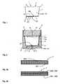
- zeigt einen Längsschnitt durch eine Portionskapsel gemäß einer beispielhaften Ausführungsform der vorliegenden Erfindung, die für die Zubereitung von Kaffee eingerichtet ist.shows a longitudinal section through a portion capsule according to an exemplary embodiment of the present invention, which is adapted for the preparation of coffee.
- Figur 2FIG. 2
- zeigt einen Längsschnitt durch eine in einer geschlossenen Brühkammer liegende Portionskapsel gemäß der beispielhaften Ausführungsform der vorliegenden Erfindung.shows a longitudinal section through a lying in a closed brewing compartment capsule according to the exemplary embodiment of the present invention.
- Figuren 3a, 3bFIGS. 3a, 3b
- zeigen zwei unterschiedliche Ausführungsformen des Filterelementes der Portionskapsel gemäß der beispielhaften Ausführungsform der vorliegenden Erfindung.show two different embodiments of the filter element of the portion capsule according to the exemplary embodiment of the present invention.
In den verschiedenen Figuren sind gleiche Teile stets mit den gleichen Bezugszeichen versehen und werden daher in der Regel auch jeweils nur einmal benannt bzw. erwähnt.In the various figures, the same parts are always provided with the same reference numerals and are therefore usually named or mentioned only once in each case.
In
Der Filz weist ferner einen der Getränkesubstanz 101 zugewandten ersten Bereich 200 und einen dem Kapselboden 3 zugewandten zweiten Bereich 201 auf. Im ersten Bereich 200 weist der Filz im Mittel eine erste Porengröße auf, während der Filz im zweiten Bereich 201 im Mittel eine zweite Porengröße aufweist. Die erste Porengröße ist dabei kleiner als die zweite Porengröße. Das durch das Filterelement 7 hindurchtretende Getränk kann sich somit schon im zweiten Bereich 201 und somit innerhalb des Filterelements 7 beginnen zu entspannen, so dass der plötzliche Druckabfall am unteren Rand des Filz geringer ausfällt und die Schaumbildung reduziert wird. In einzigartiger Weise wird somit bei einer Extraktion der Portionskapsel 1 in einer Hochdruck-Kaffeemaschine, welche beispielsweise in einem Druckbereich von bis zu 20 bar arbeitet, die Bildung einer Crema auf dem Kaffee vollständig verhindert oder zumindest deutlich reduziert ist.The felt further comprises a
Denkbar ist, dass der Filz zur Erzielung der zwei unterschiedlichen Bereiche 200, 201 mit unterschiedlicher Porengröße ein Trägermaterial umfasst, welches im ersten Bereich 200 und im zweiten Bereich 201 unterschiedlich stark vernadelt und/oder im ersten Bereich 200 und im zweiten Bereich 201 mit unterschiedlichen Fasern verfilzt wird. Vorzugsweise wird der Filz auf der der Getränkesubstanz 101 zugewandten Seite stärker vernadelt, als auf der dem Kapselboden 3 zugewandten Seite, so dass die Porengröße auf der der Getränkesubstanz 101 zugewandten Seite im Mittel geringer ist.It is conceivable that the felt for obtaining the two
In
Das in
Das in
- 11
- Portionskapselportion capsule
- 22
- Kapselkörpercapsule body
- 33
- Kapselbodencapsule base
- 3a3a
- Innenseiteinside
- 3'3 '
- Randbereichborder area
- 44
- Einfüllseitefilling side
- 55
- Kragenrandcollar edge
- 66
- Deckelfoliecover film
- 77
- Filterelementfilter element
- 88th
- Brühkammerbrewing
- 99
- Erstes BrühkammerelementFirst brewing chamber element
- 1010
- Zweites BrühkammerelementSecond brewing chamber element
- 1111
- Dichtungpoetry
- 1212
- Schließkolbenclosing piston
- 13a13a
- Einstechelementestabbing
- 13b13b
- Einstechelementestabbing
- 1414
- ZubereitungsflüssigkeitszuführungPreparation liquid supply
- 1515
- BrühkammerglockeBrühkammerglocke
- 1616
- Ablaufdornexpiration Dorn
- 1717
- Ablaufrillendrainage grooves
- 1818
- Getränkeablaufdrinks flow
- 2020
- Austrittsöffnungoutlet opening
- 100100
- Hohlraumcavity
- 101101
- Getränkesubstanzbeverage substance
- 200200
- Erster BereichFirst area
- 201201
- Zweiter BereichSecond area
- 202202
- Erste FilzschichtFirst felt layer
- 203203
- Zweite FilzschichtSecond felt layer
Claims (7)
- A portion capsule (1) for producing a beverage, having a capsule body (2) with a capsule base (3) and a filling side (4), wherein a cavity (100) for accommodating a pulverulent, granular or liquid beverage base (101), in particular coffee or tea granules, is formed between the capsule base (3) and the filling side (4), and wherein a filter element (7) is arranged between the beverage base (101) and the capsule base (3), wherein the filter element (7) comprises an open-pore felt and/or nonwoven,characterized in that the felt and/or the nonwoven have/has an average first pore size in a first region (200) which faces the beverage base (101) and an average second pore size in a second region (201) which faces the capsule base (3), wherein the first pore size is smaller than the second pore size.
- The portion capsule (1) as claimed in claim 1, wherein the filter element (7) has a support layer, wherein the support layer has a different entanglement and/or different fibers and/or fibers with different fiber thicknesses and/or different thermal treatment on that side which faces the beverage substance (101) and on that side which faces the capsule base (3).
- The portion capsule (1) as claimed in claim 1, wherein the filter element (7) has a first felt layer (202) and a second felt layer (203), wherein the first felt layer (202) is arranged on a side of the filter element (7) which faces the beverage base (101), and wherein the second felt layer (203) is arranged on a side of the filter element (7) which faces the capsule base (3), wherein the first felt layer (202) has the first pore size on average and the second felt layer (203) has the second pore size on average.
- The portion capsule (1) as claimed in one of the preceding claims, wherein the felt in the first region (200) and/or the first felt layer (201) are/is formed from fibers with an average first fiber diameter, and wherein the felt in the second region (201) and/or the second felt layer (202) are/is formed from fibers with an average second fiber diameter, wherein the first fiber diameter is smaller than the second fiber diameter.
- The portion capsule (1) as claimed in claim 4, wherein the felt has at least a third felt layer which is preferably arranged between the first and second felt layers (201, 202), wherein the third felt layer is formed particularly preferably from fibers with an average third fiber diameter, wherein the third fiber diameter is very particularly preferably larger than the first fiber diameter and/or smaller than the second fiber diameter.
- A method for producing a beverage, wherein a portion capsule (1) as claimed in one of the preceding claims is provided in a first step, wherein the portion capsule (1) is inserted into a brewing chamber (8) in a second step, and wherein a preparation liquid is introduced into the portion capsule (1) at a pressure of up to 20 bar in a third step, in order to produce the beverage.
- The use of a portion capsule (1) as claimed in one of claims 1 to 5 for producing a beverage, preferably for producing a coffee and/or tea beverage.
Priority Applications (1)
| Application Number | Priority Date | Filing Date | Title |
|---|---|---|---|
| PL12772105TPL2625120T3 (en) | 2011-10-13 | 2012-10-10 | Portion capsule for producing a beverage with a portion capsule |
Applications Claiming Priority (2)
| Application Number | Priority Date | Filing Date | Title |
|---|---|---|---|
| DE102011115833ADE102011115833A1 (en) | 2011-10-13 | 2011-10-13 | Portion capsule for making a drink with a portion capsule |
| PCT/EP2012/070059WO2013053757A1 (en) | 2011-10-13 | 2012-10-10 | Portion capsule for producing a beverage with a portion capsule |
Publications (2)
| Publication Number | Publication Date |
|---|---|
| EP2625120A1 EP2625120A1 (en) | 2013-08-14 |
| EP2625120B1true EP2625120B1 (en) | 2015-04-01 |
Family
ID=47016708
Family Applications (1)
| Application Number | Title | Priority Date | Filing Date |
|---|---|---|---|
| EP12772105.8AActiveEP2625120B1 (en) | 2011-10-13 | 2012-10-10 | Portion capsule for producing a beverage with a portion capsule |
Country Status (16)
| Country | Link |
|---|---|
| US (1) | US9409703B2 (en) |
| EP (1) | EP2625120B1 (en) |
| JP (1) | JP6034306B2 (en) |
| KR (1) | KR101961084B1 (en) |
| CN (1) | CN103201197B (en) |
| AU (1) | AU2012323066C1 (en) |
| BR (1) | BR112013011612A2 (en) |
| CA (1) | CA2815948C (en) |
| DE (1) | DE102011115833A1 (en) |
| DK (1) | DK2625120T3 (en) |
| ES (1) | ES2539351T3 (en) |
| PL (1) | PL2625120T3 (en) |
| PT (1) | PT2625120E (en) |
| RU (2) | RU2546426C2 (en) |
| WO (1) | WO2013053757A1 (en) |
| ZA (1) | ZA201302986B (en) |
Families Citing this family (29)
| Publication number | Priority date | Publication date | Assignee | Title |
|---|---|---|---|---|
| US10722066B2 (en)* | 2010-12-04 | 2020-07-28 | Adrian Rivera | Windowed single serving brewing material holder |
| US11832755B2 (en)* | 2007-07-13 | 2023-12-05 | Adrian Rivera | Brewing material container for a beverage brewer |
| US12396588B2 (en) | 2007-07-13 | 2025-08-26 | Adrian Rivera Maynez Enterprises, Inc. | Brewing material container for a beverage brewer |
| US10071851B2 (en) | 2010-07-12 | 2018-09-11 | Robert Bao Vu | Apparatus and products for producing beverages, and methods for making and using same |
| SMT201900157T1 (en) | 2010-07-22 | 2019-05-10 | K Fee System Gmbh | Portion capsule having an identifier |
| US8895090B2 (en) | 2010-09-22 | 2014-11-25 | K-Fee System Gmbh | Portion capsule and method for producing the same |
| DE102011012881A1 (en) | 2010-09-22 | 2012-03-22 | Krüger Gmbh & Co. Kg | Portion capsule and method of making a beverage with a portion capsule |
| US8707855B2 (en) | 2011-05-09 | 2014-04-29 | Eko Brands, Llc | Beverage Brewing Device |
| DE102012105282A1 (en) | 2012-06-18 | 2013-12-19 | K-Fee System Gmbh | Portion capsule and method of making a beverage with a portion capsule |
| DE102012223291A1 (en) | 2012-12-14 | 2014-06-18 | K-Fee System Gmbh | Portion capsule and method of making a beverage with a portion capsule |
| JP6676532B2 (en) | 2014-03-11 | 2020-04-08 | ラバッツァ プロフェッショナル ノース アメリカ,エルエルシーLavazza Professional North America,Llc | Beverage preparation capsule |
| DK3122660T3 (en)* | 2014-03-24 | 2019-10-14 | Nestle Sa | COFFEE COVER AND SYSTEM FOR PREPARING A COFFEE EXTRACT WITH SUCH A COVER |
| EP3131833B2 (en)* | 2014-04-17 | 2025-06-11 | K-fee System GmbH | Portion capsule for the praparation of a beverage and process to produce such a beverage by using said capsule |
| CN107074439B (en) | 2014-06-12 | 2019-02-01 | K-Fee系统股份有限公司 | Dosing container comprising calendered fibrous material |
| WO2015189316A1 (en)* | 2014-06-12 | 2015-12-17 | K-Fee System Gmbh | Single serve capsule with acid-treated tea |
| AR100911A1 (en)* | 2014-06-18 | 2016-11-09 | K Fee System Gmbh | SYSTEM FOR THE PREPARATION OF A TEA DRINK |
| WO2016120411A1 (en)* | 2015-01-28 | 2016-08-04 | K-Fee System Gmbh | Single serve capsule comprising a finely ground granulate |
| WO2016120376A1 (en)* | 2015-01-28 | 2016-08-04 | K-Fee System Gmbh | Single serve capsule containing a beverage substrate from pulverized coffee-cherry pulp |
| WO2016135105A1 (en) | 2015-02-27 | 2016-09-01 | K-Fee System Gmbh | Single serve capsule comprising a filter element connected thereto by sealing |
| ES2791960T3 (en)* | 2015-06-09 | 2020-11-06 | K Fee System Gmbh | Single-dose capsule, system and procedure for the preparation of a drink |
| PT3307647T (en)* | 2015-06-10 | 2019-10-28 | K Fee System Gmbh | Capsule with a three layer fleece |
| WO2017009369A1 (en) | 2015-07-13 | 2017-01-19 | K-Fee System Gmbh | Filter element having a cut-out |
| WO2017046352A1 (en) | 2015-09-18 | 2017-03-23 | K-Fee System Gmbh | Adapter for a single serve capsule |
| US12185867B2 (en) | 2015-10-30 | 2025-01-07 | Adrian Rivera | Beverage brewer spray apparatus having accommodation for multiple dispersion members |
| EP3367854B1 (en)* | 2015-10-30 | 2021-07-28 | Adrian Rivera | Dynamic water dispersion and brewing chamber cleaner |
| US11638499B2 (en) | 2020-05-27 | 2023-05-02 | Adrian Rivera | Beverage brewer spray apparatus having multiple dispersion members |
| US12227323B2 (en) | 2018-07-27 | 2025-02-18 | Gcs German Capsule Solution Gmbh | Method for producing a portion capsule |
| US11805934B1 (en)* | 2020-10-21 | 2023-11-07 | Adrian Rivera | Brewing material lid and container for a beverage brewer |
| US20220287494A1 (en)* | 2021-03-12 | 2022-09-15 | Nexe Innovations Inc. | Beverage pod |
Family Cites Families (27)
| Publication number | Priority date | Publication date | Assignee | Title |
|---|---|---|---|---|
| US7490542B2 (en)* | 1920-02-11 | 2009-02-17 | I.T.A.Ca S.R.L. | Cartridge for coffee and soluble products and relative method of producing a beverage and apparatus for extracting a beverage |
| US2010123A (en)* | 1931-05-11 | 1935-08-06 | Resinox Corp | Synthetic varnish composition |
| US2926088A (en)* | 1955-02-08 | 1960-02-23 | Phillip P Spiselman | Method of brewing coffee |
| US4605123A (en)* | 1983-12-15 | 1986-08-12 | Ethyl Corporation | Infusion package |
| CH673082A5 (en)* | 1987-10-01 | 1990-02-15 | Nestle Sa | |
| AU1505192A (en)* | 1991-05-10 | 1992-11-12 | Societe Des Produits Nestle S.A. | Sealed cartridge for the prepartion of a beverage |
| US5411661A (en)* | 1993-05-26 | 1995-05-02 | Ultrapure Systems, Inc. | Water filter module |
| US5644973A (en)* | 1995-06-22 | 1997-07-08 | Kwangju Electronics Co., Ltd. | Device for brewing the roasted and ground beans of the coffee in a vending machine |
| JP4656618B2 (en)* | 2001-02-09 | 2011-03-23 | 旭化成せんい株式会社 | Extraction filter |
| JP4368066B2 (en)* | 2001-02-21 | 2009-11-18 | 旭化成せんい株式会社 | Extraction filter with steaming function |
| CA2421128C (en)* | 2002-03-14 | 2008-05-20 | Robert Hale | Beverage cartridge and filter assembly |
| DE10211327B4 (en) | 2002-03-14 | 2015-09-24 | Caffitaly System S.P.A. | Portion capsule with a particulate extractable by water substance for the preparation of a beverage |
| US7055684B2 (en)* | 2002-05-24 | 2006-06-06 | Anderson Michael R | Dispensing capsule for a liquid container |
| JP2004337405A (en)* | 2003-05-16 | 2004-12-02 | Key Coffee Inc | Coffee bag with multi-person support |
| DE102005058336A1 (en) | 2005-12-02 | 2007-06-06 | Tchibo Gmbh | portion capsule |
| PL1967099T3 (en)* | 2007-03-06 | 2010-06-30 | Nestec Sa | Device for preparing a food liquid from a capsule |
| US7910145B2 (en)* | 2007-05-31 | 2011-03-22 | Marco Reati | Precharged ground coffee capsule, method for its production and apparatus for implementing said method |
| PT2100824E (en)* | 2008-03-12 | 2011-07-27 | Nestec Sa | Capsule with flow control and filtering member( |
| EP2364930B1 (en)* | 2009-03-19 | 2018-12-05 | Nestec S.A. | Capsule for preparing coffee in a device comprising a cartridge holder with relief and recessed elements |
| PT2239211E (en)* | 2009-04-09 | 2014-05-07 | Nestec Sa | Capsule for preparation of a beverage with delaminating or breakable seal at delivery wall |
| EP2865613B1 (en)* | 2009-06-17 | 2017-09-06 | Koninklijke Douwe Egberts B.V. | System, method and capsule for preparing a beverage |
| JP5486332B2 (en) | 2010-02-02 | 2014-05-07 | 旭化成せんい株式会社 | Biodegradable non-woven fabric |
| US8895090B2 (en)* | 2010-09-22 | 2014-11-25 | K-Fee System Gmbh | Portion capsule and method for producing the same |
| DE102011012881A1 (en)* | 2010-09-22 | 2012-03-22 | Krüger Gmbh & Co. Kg | Portion capsule and method of making a beverage with a portion capsule |
| EP2444339A1 (en)* | 2010-10-25 | 2012-04-25 | Nestec S.A. | A capsule for preparation of a beverage |
| ITUD20110097A1 (en)* | 2011-06-23 | 2012-12-24 | San Marco Spa | "COFFEE MAKING MACHINE" |
| US20140220190A1 (en)* | 2013-02-04 | 2014-08-07 | Coffee Star S.A. | Capsule for the Preparation of Beverages |
- 2011
- 2011-10-13DEDE102011115833Apatent/DE102011115833A1/ennot_activeWithdrawn
- 2012
- 2012-10-10EPEP12772105.8Apatent/EP2625120B1/enactiveActive
- 2012-10-10PTPT127721058Tpatent/PT2625120E/enunknown
- 2012-10-10AUAU2012323066Apatent/AU2012323066C1/enactiveActive
- 2012-10-10RURU2013120909/12Apatent/RU2546426C2/ennot_activeIP Right Cessation
- 2012-10-10KRKR1020137012125Apatent/KR101961084B1/enactiveActive
- 2012-10-10ESES12772105.8Tpatent/ES2539351T3/enactiveActive
- 2012-10-10RURU2015103050/12Apatent/RU2604595C2/enactive
- 2012-10-10BRBR112013011612Apatent/BR112013011612A2/enactiveSearch and Examination
- 2012-10-10CACA2815948Apatent/CA2815948C/enactiveActive
- 2012-10-10DKDK12772105.8Tpatent/DK2625120T3/enactive
- 2012-10-10CNCN201280003632.2Apatent/CN103201197B/enactiveActive
- 2012-10-10PLPL12772105Tpatent/PL2625120T3/enunknown
- 2012-10-10JPJP2013553972Apatent/JP6034306B2/enactiveActive
- 2012-10-10WOPCT/EP2012/070059patent/WO2013053757A1/enactiveApplication Filing
- 2013
- 2013-04-24ZAZA2013/02986Apatent/ZA201302986B/enunknown
- 2013-05-07USUS13/888,809patent/US9409703B2/enactiveActive
Also Published As
| Publication number | Publication date |
|---|---|
| ES2539351T3 (en) | 2015-06-30 |
| CA2815948C (en) | 2019-08-20 |
| PT2625120E (en) | 2015-07-21 |
| KR20140076526A (en) | 2014-06-20 |
| CA2815948A1 (en) | 2013-04-18 |
| WO2013053757A1 (en) | 2013-04-18 |
| RU2013120909A (en) | 2014-11-20 |
| EP2625120A1 (en) | 2013-08-14 |
| JP2014509233A (en) | 2014-04-17 |
| ZA201302986B (en) | 2014-06-25 |
| US9409703B2 (en) | 2016-08-09 |
| AU2012323066A1 (en) | 2013-05-23 |
| AU2012323066C1 (en) | 2015-06-04 |
| AU2012323066B2 (en) | 2015-02-19 |
| DE102011115833A1 (en) | 2013-04-18 |
| CN103201197B (en) | 2015-11-25 |
| US20130243910A1 (en) | 2013-09-19 |
| KR101961084B1 (en) | 2019-03-25 |
| RU2604595C2 (en) | 2016-12-10 |
| DK2625120T3 (en) | 2015-07-06 |
| PL2625120T3 (en) | 2015-08-31 |
| BR112013011612A2 (en) | 2017-08-01 |
| RU2015103050A (en) | 2015-05-20 |
| JP6034306B2 (en) | 2016-11-30 |
| CN103201197A (en) | 2013-07-10 |
| RU2546426C2 (en) | 2015-04-10 |
Similar Documents
| Publication | Publication Date | Title |
|---|---|---|
| EP2625120B1 (en) | Portion capsule for producing a beverage with a portion capsule | |
| EP3131833B1 (en) | Portion capsule for the praparation of a beverage and process to produce such a beverage by using said capsule | |
| EP2861508B2 (en) | Portion capsule and method for producing a beverage by means of a portion capsule | |
| EP2961671B1 (en) | Portion capsule and method for producing a beverage by means of a portion capsule | |
| EP3023360B1 (en) | Capsule and use of a capsule | |
| DE202009018817U1 (en) | System and capsule for preparing a drink | |
| WO2014090567A1 (en) | Portion capsule and method for producing a beverage by means of a portion capsule | |
| EP2958832A1 (en) | Single serve capsule and system | |
| EP3154874A1 (en) | Single serve capsule with a calendered fibrous material | |
| EP3307647B1 (en) | Capsule with a three layer fleece | |
| WO2015193451A1 (en) | System for producing a tea beverage | |
| EP3310693B2 (en) | Capsule for preparation of beverages |
Legal Events
| Date | Code | Title | Description |
|---|---|---|---|
| PUAI | Public reference made under article 153(3) epc to a published international application that has entered the european phase | Free format text:ORIGINAL CODE: 0009012 | |
| 17P | Request for examination filed | Effective date:20130508 | |
| AK | Designated contracting states | Kind code of ref document:A1 Designated state(s):AL AT BE BG CH CY CZ DE DK EE ES FI FR GB GR HR HU IE IS IT LI LT LU LV MC MK MT NL NO PL PT RO RS SE SI SK SM TR | |
| GRAJ | Information related to disapproval of communication of intention to grant by the applicant or resumption of examination proceedings by the epo deleted | Free format text:ORIGINAL CODE: EPIDOSDIGR1 | |
| GRAP | Despatch of communication of intention to grant a patent | Free format text:ORIGINAL CODE: EPIDOSNIGR1 | |
| GRAP | Despatch of communication of intention to grant a patent | Free format text:ORIGINAL CODE: EPIDOSNIGR1 | |
| DAX | Request for extension of the european patent (deleted) | ||
| INTG | Intention to grant announced | Effective date:20141015 | |
| INTC | Intention to grant announced (deleted) | ||
| INTG | Intention to grant announced | Effective date:20141107 | |
| GRAS | Grant fee paid | Free format text:ORIGINAL CODE: EPIDOSNIGR3 | |
| GRAA | (expected) grant | Free format text:ORIGINAL CODE: 0009210 | |
| AK | Designated contracting states | Kind code of ref document:B1 Designated state(s):AL AT BE BG CH CY CZ DE DK EE ES FI FR GB GR HR HU IE IS IT LI LT LU LV MC MK MT NL NO PL PT RO RS SE SI SK SM TR | |
| REG | Reference to a national code | Ref country code:GB Ref legal event code:FG4D Free format text:NOT ENGLISH | |
| REG | Reference to a national code | Ref country code:CH Ref legal event code:EP | |
| REG | Reference to a national code | Ref country code:IE Ref legal event code:FG4D Free format text:LANGUAGE OF EP DOCUMENT: GERMAN | |
| REG | Reference to a national code | Ref country code:DE Ref legal event code:R096 Ref document number:502012002733 Country of ref document:DE Effective date:20150513 | |
| REG | Reference to a national code | Ref country code:AT Ref legal event code:REF Ref document number:718934 Country of ref document:AT Kind code of ref document:T Effective date:20150515 | |
| REG | Reference to a national code | Ref country code:ES Ref legal event code:FG2A Ref document number:2539351 Country of ref document:ES Kind code of ref document:T3 Effective date:20150630 | |
| REG | Reference to a national code | Ref country code:DK Ref legal event code:T3 Effective date:20150702 | |
| REG | Reference to a national code | Ref country code:NL Ref legal event code:T3 | |
| REG | Reference to a national code | Ref country code:PT Ref legal event code:SC4A Free format text:AVAILABILITY OF NATIONAL TRANSLATION Effective date:20150612 | |
| REG | Reference to a national code | Ref country code:SE Ref legal event code:TRGR | |
| REG | Reference to a national code | Ref country code:NO Ref legal event code:T2 Effective date:20150401 | |
| REG | Reference to a national code | Ref country code:PL Ref legal event code:T3 | |
| REG | Reference to a national code | Ref country code:LT Ref legal event code:MG4D | |
| REG | Reference to a national code | Ref country code:FR Ref legal event code:PLFP Year of fee payment:4 | |
| PG25 | Lapsed in a contracting state [announced via postgrant information from national office to epo] | Ref country code:CZ Free format text:LAPSE BECAUSE OF FAILURE TO SUBMIT A TRANSLATION OF THE DESCRIPTION OR TO PAY THE FEE WITHIN THE PRESCRIBED TIME-LIMIT Effective date:20150401 Ref country code:LT Free format text:LAPSE BECAUSE OF FAILURE TO SUBMIT A TRANSLATION OF THE DESCRIPTION OR TO PAY THE FEE WITHIN THE PRESCRIBED TIME-LIMIT Effective date:20150401 Ref country code:HR Free format text:LAPSE BECAUSE OF FAILURE TO SUBMIT A TRANSLATION OF THE DESCRIPTION OR TO PAY THE FEE WITHIN THE PRESCRIBED TIME-LIMIT Effective date:20150401 | |
| PG25 | Lapsed in a contracting state [announced via postgrant information from national office to epo] | Ref country code:LV Free format text:LAPSE BECAUSE OF FAILURE TO SUBMIT A TRANSLATION OF THE DESCRIPTION OR TO PAY THE FEE WITHIN THE PRESCRIBED TIME-LIMIT Effective date:20150401 Ref country code:IS Free format text:LAPSE BECAUSE OF FAILURE TO SUBMIT A TRANSLATION OF THE DESCRIPTION OR TO PAY THE FEE WITHIN THE PRESCRIBED TIME-LIMIT Effective date:20150801 Ref country code:GR Free format text:LAPSE BECAUSE OF FAILURE TO SUBMIT A TRANSLATION OF THE DESCRIPTION OR TO PAY THE FEE WITHIN THE PRESCRIBED TIME-LIMIT Effective date:20150702 Ref country code:RS Free format text:LAPSE BECAUSE OF FAILURE TO SUBMIT A TRANSLATION OF THE DESCRIPTION OR TO PAY THE FEE WITHIN THE PRESCRIBED TIME-LIMIT Effective date:20150401 | |
| REG | Reference to a national code | Ref country code:DE Ref legal event code:R097 Ref document number:502012002733 Country of ref document:DE | |
| PG25 | Lapsed in a contracting state [announced via postgrant information from national office to epo] | Ref country code:EE Free format text:LAPSE BECAUSE OF FAILURE TO SUBMIT A TRANSLATION OF THE DESCRIPTION OR TO PAY THE FEE WITHIN THE PRESCRIBED TIME-LIMIT Effective date:20150401 | |
| PLBE | No opposition filed within time limit | Free format text:ORIGINAL CODE: 0009261 | |
| STAA | Information on the status of an ep patent application or granted ep patent | Free format text:STATUS: NO OPPOSITION FILED WITHIN TIME LIMIT | |
| PG25 | Lapsed in a contracting state [announced via postgrant information from national office to epo] | Ref country code:RO Free format text:LAPSE BECAUSE OF NON-PAYMENT OF DUE FEES Effective date:20150401 Ref country code:SK Free format text:LAPSE BECAUSE OF FAILURE TO SUBMIT A TRANSLATION OF THE DESCRIPTION OR TO PAY THE FEE WITHIN THE PRESCRIBED TIME-LIMIT Effective date:20150401 | |
| 26N | No opposition filed | Effective date:20160105 | |
| PG25 | Lapsed in a contracting state [announced via postgrant information from national office to epo] | Ref country code:LU Free format text:LAPSE BECAUSE OF FAILURE TO SUBMIT A TRANSLATION OF THE DESCRIPTION OR TO PAY THE FEE WITHIN THE PRESCRIBED TIME-LIMIT Effective date:20151010 Ref country code:SI Free format text:LAPSE BECAUSE OF FAILURE TO SUBMIT A TRANSLATION OF THE DESCRIPTION OR TO PAY THE FEE WITHIN THE PRESCRIBED TIME-LIMIT Effective date:20150401 | |
| PG25 | Lapsed in a contracting state [announced via postgrant information from national office to epo] | Ref country code:MC Free format text:LAPSE BECAUSE OF FAILURE TO SUBMIT A TRANSLATION OF THE DESCRIPTION OR TO PAY THE FEE WITHIN THE PRESCRIBED TIME-LIMIT Effective date:20150401 | |
| REG | Reference to a national code | Ref country code:FR Ref legal event code:PLFP Year of fee payment:5 | |
| PG25 | Lapsed in a contracting state [announced via postgrant information from national office to epo] | Ref country code:BG Free format text:LAPSE BECAUSE OF FAILURE TO SUBMIT A TRANSLATION OF THE DESCRIPTION OR TO PAY THE FEE WITHIN THE PRESCRIBED TIME-LIMIT Effective date:20150401 Ref country code:HU Free format text:LAPSE BECAUSE OF FAILURE TO SUBMIT A TRANSLATION OF THE DESCRIPTION OR TO PAY THE FEE WITHIN THE PRESCRIBED TIME-LIMIT; INVALID AB INITIO Effective date:20121010 Ref country code:SM Free format text:LAPSE BECAUSE OF FAILURE TO SUBMIT A TRANSLATION OF THE DESCRIPTION OR TO PAY THE FEE WITHIN THE PRESCRIBED TIME-LIMIT Effective date:20150401 | |
| PG25 | Lapsed in a contracting state [announced via postgrant information from national office to epo] | Ref country code:CY Free format text:LAPSE BECAUSE OF FAILURE TO SUBMIT A TRANSLATION OF THE DESCRIPTION OR TO PAY THE FEE WITHIN THE PRESCRIBED TIME-LIMIT Effective date:20150401 | |
| PG25 | Lapsed in a contracting state [announced via postgrant information from national office to epo] | Ref country code:MT Free format text:LAPSE BECAUSE OF FAILURE TO SUBMIT A TRANSLATION OF THE DESCRIPTION OR TO PAY THE FEE WITHIN THE PRESCRIBED TIME-LIMIT Effective date:20150401 | |
| REG | Reference to a national code | Ref country code:FR Ref legal event code:PLFP Year of fee payment:6 | |
| PG25 | Lapsed in a contracting state [announced via postgrant information from national office to epo] | Ref country code:MK Free format text:LAPSE BECAUSE OF FAILURE TO SUBMIT A TRANSLATION OF THE DESCRIPTION OR TO PAY THE FEE WITHIN THE PRESCRIBED TIME-LIMIT Effective date:20150401 | |
| REG | Reference to a national code | Ref country code:FR Ref legal event code:PLFP Year of fee payment:7 | |
| PG25 | Lapsed in a contracting state [announced via postgrant information from national office to epo] | Ref country code:AL Free format text:LAPSE BECAUSE OF FAILURE TO SUBMIT A TRANSLATION OF THE DESCRIPTION OR TO PAY THE FEE WITHIN THE PRESCRIBED TIME-LIMIT Effective date:20150401 | |
| PGFP | Annual fee paid to national office [announced via postgrant information from national office to epo] | Ref country code:IE Payment date:20191021 Year of fee payment:8 Ref country code:NO Payment date:20191022 Year of fee payment:8 | |
| PGFP | Annual fee paid to national office [announced via postgrant information from national office to epo] | Ref country code:DK Payment date:20191022 Year of fee payment:8 | |
| PGFP | Annual fee paid to national office [announced via postgrant information from national office to epo] | Ref country code:TR Payment date:20191031 Year of fee payment:8 | |
| REG | Reference to a national code | Ref country code:NO Ref legal event code:MMEP Ref country code:DK Ref legal event code:EBP Effective date:20201031 | |
| PG25 | Lapsed in a contracting state [announced via postgrant information from national office to epo] | Ref country code:NO Free format text:LAPSE BECAUSE OF NON-PAYMENT OF DUE FEES Effective date:20201031 | |
| PG25 | Lapsed in a contracting state [announced via postgrant information from national office to epo] | Ref country code:IE Free format text:LAPSE BECAUSE OF NON-PAYMENT OF DUE FEES Effective date:20201010 | |
| PG25 | Lapsed in a contracting state [announced via postgrant information from national office to epo] | Ref country code:DK Free format text:LAPSE BECAUSE OF NON-PAYMENT OF DUE FEES Effective date:20201031 | |
| PG25 | Lapsed in a contracting state [announced via postgrant information from national office to epo] | Ref country code:TR Free format text:LAPSE BECAUSE OF NON-PAYMENT OF DUE FEES Effective date:20201010 | |
| P01 | Opt-out of the competence of the unified patent court (upc) registered | Effective date:20230517 | |
| PGFP | Annual fee paid to national office [announced via postgrant information from national office to epo] | Ref country code:PL Payment date:20240930 Year of fee payment:13 | |
| PGFP | Annual fee paid to national office [announced via postgrant information from national office to epo] | Ref country code:NL Payment date:20241023 Year of fee payment:13 | |
| PGFP | Annual fee paid to national office [announced via postgrant information from national office to epo] | Ref country code:PT Payment date:20241003 Year of fee payment:13 | |
| PGFP | Annual fee paid to national office [announced via postgrant information from national office to epo] | Ref country code:DE Payment date:20241022 Year of fee payment:13 | |
| PGFP | Annual fee paid to national office [announced via postgrant information from national office to epo] | Ref country code:BE Payment date:20241022 Year of fee payment:13 Ref country code:FI Payment date:20241022 Year of fee payment:13 | |
| PGFP | Annual fee paid to national office [announced via postgrant information from national office to epo] | Ref country code:GB Payment date:20241024 Year of fee payment:13 | |
| PGFP | Annual fee paid to national office [announced via postgrant information from national office to epo] | Ref country code:FR Payment date:20241025 Year of fee payment:13 Ref country code:AT Payment date:20241021 Year of fee payment:13 | |
| PGFP | Annual fee paid to national office [announced via postgrant information from national office to epo] | Ref country code:IT Payment date:20241031 Year of fee payment:13 Ref country code:ES Payment date:20241118 Year of fee payment:13 | |
| PGFP | Annual fee paid to national office [announced via postgrant information from national office to epo] | Ref country code:SE Payment date:20241023 Year of fee payment:13 | |
| PGFP | Annual fee paid to national office [announced via postgrant information from national office to epo] | Ref country code:CH Payment date:20241101 Year of fee payment:13 |