EP2624601B1 - Short-range radio communication system and method for operating the same - Google Patents
Short-range radio communication system and method for operating the sameDownload PDFInfo
- Publication number
- EP2624601B1 EP2624601B1EP13153275.6AEP13153275AEP2624601B1EP 2624601 B1EP2624601 B1EP 2624601B1EP 13153275 AEP13153275 AEP 13153275AEP 2624601 B1EP2624601 B1EP 2624601B1
- Authority
- EP
- European Patent Office
- Prior art keywords
- stylus pen
- content
- src
- terminal
- control unit
- Prior art date
- Legal status (The legal status is an assumption and is not a legal conclusion. Google has not performed a legal analysis and makes no representation as to the accuracy of the status listed.)
- Not-in-force
Links
Images


Classifications
- H—ELECTRICITY
- H04—ELECTRIC COMMUNICATION TECHNIQUE
- H04M—TELEPHONIC COMMUNICATION
- H04M1/00—Substation equipment, e.g. for use by subscribers
- H04M1/02—Constructional features of telephone sets
- H04M1/0202—Portable telephone sets, e.g. cordless phones, mobile phones or bar type handsets
- H04M1/0279—Improving the user comfort or ergonomics
- H04M1/0285—Pen-type handsets
- G—PHYSICS
- G06—COMPUTING OR CALCULATING; COUNTING
- G06F—ELECTRIC DIGITAL DATA PROCESSING
- G06F3/00—Input arrangements for transferring data to be processed into a form capable of being handled by the computer; Output arrangements for transferring data from processing unit to output unit, e.g. interface arrangements
- G06F3/01—Input arrangements or combined input and output arrangements for interaction between user and computer
- G06F3/03—Arrangements for converting the position or the displacement of a member into a coded form
- G06F3/033—Pointing devices displaced or positioned by the user, e.g. mice, trackballs, pens or joysticks; Accessories therefor
- G06F3/0354—Pointing devices displaced or positioned by the user, e.g. mice, trackballs, pens or joysticks; Accessories therefor with detection of 2D relative movements between the device, or an operating part thereof, and a plane or surface, e.g. 2D mice, trackballs, pens or pucks
- G06F3/03545—Pens or stylus
- G—PHYSICS
- G06—COMPUTING OR CALCULATING; COUNTING
- G06F—ELECTRIC DIGITAL DATA PROCESSING
- G06F3/00—Input arrangements for transferring data to be processed into a form capable of being handled by the computer; Output arrangements for transferring data from processing unit to output unit, e.g. interface arrangements
- G06F3/01—Input arrangements or combined input and output arrangements for interaction between user and computer
- G06F3/03—Arrangements for converting the position or the displacement of a member into a coded form
- G06F3/033—Pointing devices displaced or positioned by the user, e.g. mice, trackballs, pens or joysticks; Accessories therefor
- G06F3/038—Control and interface arrangements therefor, e.g. drivers or device-embedded control circuitry
- H—ELECTRICITY
- H04—ELECTRIC COMMUNICATION TECHNIQUE
- H04B—TRANSMISSION
- H04B7/00—Radio transmission systems, i.e. using radiation field
- H04B7/24—Radio transmission systems, i.e. using radiation field for communication between two or more posts
- H—ELECTRICITY
- H04—ELECTRIC COMMUNICATION TECHNIQUE
- H04W—WIRELESS COMMUNICATION NETWORKS
- H04W4/00—Services specially adapted for wireless communication networks; Facilities therefor
- H04W4/80—Services using short range communication, e.g. near-field communication [NFC], radio-frequency identification [RFID] or low energy communication
- H—ELECTRICITY
- H04—ELECTRIC COMMUNICATION TECHNIQUE
- H04W—WIRELESS COMMUNICATION NETWORKS
- H04W76/00—Connection management
- H04W76/10—Connection setup
- H04W76/14—Direct-mode setup
Definitions
- US2010190437discloses a wireless communication device is arrange lo provide at least one Near Field Communication service to a user.
- the wireless communication devicecomprises a Near Field Communication unit for storing a plurality of application elements for use in providing a plurality of Near Field Communication services, and a plurality of Near Field Communication managing elements.
- Each of the plurality of Near Field Communication managing elementsis associated with at least one of the plurality of application elements stored in the Near Field Communication unit for managing the at least one associated application element of the plurality of application elements.
- a user interface elementinterfaces with at least some of the Near Field Communication managing elements and provides information to a user relating to the Near Field Communication services provided by the plurality of application elements associated with the al least some the Near Field Communication managing elements.
- the user interface elementin response to user selection of a Near Field Communication service based on the user provided information is further arranged to activate the Near Field Communication managing element of the selected Near Field Communication service to manage the at least one associated application element.
- an object of the present inventionis to provide a system for improving a User eXperience (UX) in exchanging information by Short-range Radio Communication (SRC) according to claim 1.
- UXUser eXperience
- SRCShort-range Radio Communication
- Exemplary embodiments of the present inventionprovide a system for improving a User eXperience (UX) in exchanging information by Short-range Radio Communication (SRC), and a method for operating the same.
- UXUser eXperience
- SRCShort-range Radio Communication
- a first terminal and a second terminalare SRC-connected, share information of the first terminal is transmitted to the second terminal.
- a usermay determine share information by touch.
- information exchange between the first terminal and the second terminalmay be performed through a stylus pen.
- the SRC function of the stylus penmay be implemented as a near-field communication (NFC) function.
- the stylus penincludes a unit for storing information and a unit for controlling information reception/transmission from/to a counterpart terminal.
- the exemplary embodiments of present inventionmay provide an improved UX when exchanging information between devices by SRC.
- FIG. 1Aillustrates a configuration of an SRC system according to an exemplary embodiment of the present invention.
- FIG. 1Billustrates a configuration of an SRC system according to an exemplary embodiment of the present invention.
- the SRC systemmay include a first terminal 100 and a second terminal 200/300 that are capable of SRC.
- predetermined information of the first terminal 100may be transmitted to the second terminal 200/300.
- the first terminal 100may approach a particular portion 302 of the second terminal 300.
- the particular portion 302may be visually distinguished so as to be recognizable to a user.
- a usermay determine share information such as a picture, a moving image, a Uniform Resource Locator (URL), and a contact number by touch.
- URLUniform Resource Locator
- the second terminal 200/300may execute a program or process for processing information received from the first terminal 100.
- the second terminal 200/300may execute an image viewer to read a received picture file.
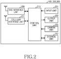
- FIG. 2is a block diagram of a terminal according to an exemplary embodiment of the present invention.
- the terminal 100/200/300may include an input unit 201, an output unit 203, a camera unit 205, a storage unit 207, an SRC interface unit 209, a cellular interface unit 211, and a control unit 213.
- examples of the terminal 100/200/300include a portable terminal, a mobile phone, a mobile pad, a media player, a tablet computer, a handheld computer, and a Personal Digital Assistant (PDA).
- PDAPersonal Digital Assistant
- the input unit 201may include a plurality of buttons, and output input data corresponding to the button pressed by a user, to the control unit 213.
- the input unit 201may include a microphone, and output voice data corresponding to user voice, to the control unit 213.
- the control unit 213may modulate the voice data received from the microphone.
- the output unit 203may include a display and a speaker, and output images or voices under the control of the control unit 213.
- the control unit 213may demodulate image data and output the result to the output unit 203, and may demodulate voice data and output the result to the output unit 203.
- the camera unit 205may capture an image of an object to generate image data, and output the image data to the control unit 213.
- the control unit 213may modulate the image data received from the camera unit 205.
- the storage unit 207may store a program for controlling an overall operation of the terminal 100/200/300, and various data that are input/output when a control operation of the terminal 100/200/300 is performed.
- the SRC interface unit 209may have at least one of mechanical, electrical and software configurations for SRC such as NFC, Bluetooth, and WiFi Direct, and exchange data with a counterpart terminal.
- the cellular interface unit 211may have mechanical, electrical and software configurations for cellular communication.
- the cellular interface unit 211may down-convert a Radio Frequency (RF) signal received through an antenna and provide the result to the control unit 213, and may up-convert a baseband signal from the control unit 213 and transmit the result through the antenna.
- RFRadio Frequency
- the control unit 213may control an overall operation of the terminal 100/200/300, and may process and control operations of the present invention.
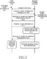
- a userdetermines share information in the first terminal 100 in step 301.
- the first terminal 100requests transmission of the determined share information to the second terminal 200/300 in step 305.
- the useraccepts transmission of the share information to the second terminal 200/300 in step 307, and the second terminal 200/300 responds to the first terminal 100 in step 309.
- the first terminal 100transmits the share information to the second terminal 200/300 in step 311, and the second terminal 200/300 receives and stores the share information from the first terminal 100 in step 313.
- the second terminal 200/300notifies this to the first terminal 100 in step 315.
- the first terminal 100performs a process corresponding to the response in step 317. For example, the first terminal 100 releases the share setting of the share information.
- the second terminal 200/300executes a program or process for processing the received share information in step 319. For example, the second terminal 200/300 executes an image viewer to read a received picture file.
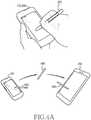
- FIG. 4Ais a diagram illustrating a configuration of an SRC system according to an exemplary embodiment of the present invention.
- the SRC systemmay include a first terminal 100, a second terminal 200, and a stylus pen 400.
- the first terminal 100, the second terminal 200, and the stylus pen 400have an SRC function.
- the stylus pen 400is used to designate a position on a touchscreen.
- the userdetermines share information on the touchscreen of the first terminal 100 by using the stylus pen 400.
- the first terminal 100transmits the determined share information to the stylus pen 400, and the stylus pen 400 receives and stores the share information from the first terminal 100.
- the stylus pen 400 and the second terminal 200approach and recognize each other and are SRC-connected, and the stylus pen 400 transmits the stored share information to the second terminal 200 automatically or according to a user determination.
- the second terminal 200executes a program or process for processing the share information received from the stylus pen 400.
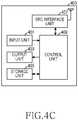
- FIG. 4Bis a diagram illustrating a stylus pen according to an exemplary embodiment of the present invention.
- the stylus pen 400may include an input unit 401, an output unit 403, a storage unit 405, an SRC interface unit 407, and a control unit 409.
- the storage unit 405may store a program for controlling an overall operation of the stylus pen 400, and various data that are input/output when a control operation of the stylus pen 400 is performed.
- the SRC interface unit 407may have mechanical, electrical and software configurations for SRC such as NFC, Bluetooth, and WiFi Direct, and exchange data with a counterpart terminal.
- the control unit 409may control an overall operation of the stylus pen 400, and may process and control operations of the present invention.
- FIG. 6is a communication flow diagram of an SRC system according to an exemplary embodiment of the present invention.
- the second terminal 200/300executes a program or process for processing the received metadata in step 615.
- the second terminal 200/300provides the user with content, format, right condition, and creator information of the share information.
- At least one of the first terminal 100, the stylus pen 400 and the second terminal 200/300determines from the metadata whether a Bluetooth or WiFi Direct connection is necessary.
- Bluetooth or WiFi Directwhich provides a higher data rate than NFC, may be more appropriate.
- the NFC connectionis used to follow the process described above with reference to FIGs. 3 and 5 .
- the first terminal 100 or the stylus pen 400 and the second terminal 200/300are Bluetooth or WiFi Direct-connected through authentication in step 619.
- the first terminal 100 or the stylus pen 400transmits the share information to the second terminal 200/300 in step 621.
- the second terminal 200/300receives and stores the share information from the first terminal 100 or the stylus pen 400 in step 623, and notifies of the completion of reception of the share information to the terminal 100 or the stylus pen 400 in step 625.
- the first terminal 100 or the stylus pen 400performs a process corresponding to the notification in step 627. For example, the first terminal 100 or the stylus pen 400 deletes the share information.
- the second terminal 200/300executes a program or process for processing the received share information in step 629, an example of which will be described below with reference to the drawings.
- a usertouches at least one contact number in a contact number list on a touchscreen of a first terminal 100 by using a stylus pen 400.
- the first terminal 100transmits contact number information touched with the stylus pen 400 to the stylus pen 400 by using at least one of NFC, Bluetooth and WiFi Direct, and the stylus pen 400 receives and stores the contact number information from the first terminal 100.
- the stylus pen 400transmits the stored contact number information received from the first terminal 100, to the second terminal 200 by using at least one of NFC, Bluetooth and WiFi Direct.
- the second terminal 200receives the contact number information from the stylus pen 400, and executes a program or process for processing the received contact number information. For example, the second terminal 200 performs contact number registration, a call, or the like.
- a usertouches at least one music file in a music list on a touchscreen of a first terminal 100 by using a stylus pen 400.
- the first terminal 100transmits the touched music file to the stylus pen 400 by using at least one of NFC, Bluetooth and WiFi Direct, and the stylus pen 400 receives and stores the music file from the first terminal 100.
- the stylus pen 400transmits the stored music file received from the first terminal 100, to the second terminal 200 by using at least one of NFC, Bluetooth and WiFi Direct.
- the second terminal 200receives the music file from the stylus pen 400, and executes a program or process for processing the received music file. For example, the second terminal 200 performs addition to a play list, reproduction through a music play program, or the like.
- Fig. 9illustrates a UI screen according to an exemplary embodiment of the present invention.
- a usertouches at least one picture file in an image thumbnail on a touchscreen of a first terminal 100 by using a stylus pen 400.
- the first terminal 100transmits the touched picture file to the stylus pen 400 by using at least one of NFC, Bluetooth and WiFi Direct, and the stylus pen 400 receives and stores the picture file from the first terminal 100.
- the stylus pen 400transmits the stored picture file received from the first terminal 100, to the second terminal 200 by using at least one of NFC, Bluetooth and WiFi Direct.
- the second terminal 200receives the picture file from the stylus pen 400, and executes a program or process for processing the received picture file. For example, the second terminal 200 opens the received picture file through an image viewer.
- Fig. 10illustrates a UI screen according to an exemplary embodiment of the present invention.
- a usertouches a webpage on a touchscreen of a first terminal 100 by using a stylus pen 400.
- the first terminal 100transmits a URL of the webpage to the stylus pen 400 by using at least one of NFC, Bluetooth and WiFi Direct, and the stylus pen 400 receives and stores the URL from the first terminal 100.
- the stylus pen 400transmits the stored URL received from the first terminal 100, to the second terminal 200 by using at least one of NFC, Bluetooth and WiFi Direct.
- the second terminal 200receives the URL from the stylus pen 400, and executes a program or process for processing the received URL. For example, the second terminal 200 connects to the URL through a web viewer.
- Fig. 13illustrates a UI screen according to an exemplary embodiment of the present invention.
- Fig. 14illustrates a UI screen according to an exemplary embodiment of the present invention.
- the user experience in exchanging information by SRCmay be enhanced.
- Any such softwaremay be stored in the form of volatile or non-volatile storage such as, for example, a storage device like a ROM, whether erasable or rewritable or not, or in the form of memory such as, for example, RAM, memory chips, device or integrated circuits or on an optically or magnetically readable medium such as, for example, a CD, DVD, magnetic disk or magnetic tape or the like.
- volatile or non-volatile storagesuch as, for example, a storage device like a ROM, whether erasable or rewritable or not
- memorysuch as, for example, RAM, memory chips, device or integrated circuits or on an optically or magnetically readable medium such as, for example, a CD, DVD, magnetic disk or magnetic tape or the like.
- the storage devices and storage mediaare embodiments of machine-readable storage that are suitable for storing a program or programs comprising instructions that, when executed, implement embodiments of the present invention.
Landscapes
- Engineering & Computer Science (AREA)
- General Engineering & Computer Science (AREA)
- Theoretical Computer Science (AREA)
- Signal Processing (AREA)
- Computer Networks & Wireless Communication (AREA)
- Human Computer Interaction (AREA)
- Physics & Mathematics (AREA)
- General Physics & Mathematics (AREA)
- Telephone Function (AREA)
- User Interface Of Digital Computer (AREA)
- Information Transfer Between Computers (AREA)
- Mobile Radio Communication Systems (AREA)
Description
- The present invention relates to a Short-range Radio Communication (SRC) system. More particularly, the present invention relates to a system for sharing information between two devices by near field communication and a method for operating the same.
- Short-range Radio Communication (SRC) enables data exchange between devices within a short distance. Since SRC enables interactive communication through read and write operations, it is applied to various service fields such as electronic payment, ticketing, door lock, and product certification. Recently, as the utilization of SRC increases, the tendency of applying SRC to portable terminals increases.
- In addition, as extensive multimedia are provided, the capabilities of portable terminals increases, and a User Interface (UI) providing a smooth interaction between a user and a portable terminal becomes more important.
- Generally, in the past, SRC has been used merely to exchange simple data. There is therefore a need for a system providing a user interface capable of satisfying users and a method for operating the same.
US20110070834 discloses a Near Field Communications (NFC) tag includes a housing and a magnet carried by the housing and configured to be magnetically sensed by a magnetic sensor carried by a communications device to activate an NFC circuit within the communications device to communicate using an NFC communications protocol. A data store stores data regarding a function of the communications device to be magnetically coupled by the magnet. The data store is configured to be read by the communications device using an NFC communication protocol after the NFC circuit had been activated.EP2541800 discloses an electronic device and a method of operating the same. The electronic device and the method of operating the electronic device may effectively form a connection between two or more electronic devices by allowing a relaying device to transfer connection information between the electronic devices to a counterpart.US2010190437 discloses a wireless communication device is arrange lo provide at least one Near Field Communication service to a user. The wireless communication device comprises a Near Field Communication unit for storing a plurality of application elements for use in providing a plurality of Near Field Communication services, and a plurality of Near Field Communication managing elements. Each of the plurality of Near Field Communication managing elements is associated with at least one of the plurality of application elements stored in the Near Field Communication unit for managing the at least one associated application element of the plurality of application elements. A user interface element interfaces with at least some of the Near Field Communication managing elements and provides information to a user relating to the Near Field Communication services provided by the plurality of application elements associated with the al least some the Near Field Communication managing elements. In operation, the user interface element in response to user selection of a Near Field Communication service based on the user provided information is further arranged to activate the Near Field Communication managing element of the selected Near Field Communication service to manage the at least one associated application element.US 2010/0144273 discloses a partable device, provided with communication control unit which performs communications with an external device via a first wireless communication unit of which communication distance is short and which is capable of performing high-speed communications or a second wireless communication unit of which communication distance is long compared with the first wireless communication unit and which is capable of performing low-speed communications. A communication state judging unit judges a communication state of the communications with the external device via the first wireless communication unit or the second wireless communication unit. The communication control unit performs switching between the communications with the external device via the first wireless communication unit and the communications with the external device via the second wireless communication unit based on the communication state judged by the communication state judging unit and/or a transmission data amount to be transmitted to the external device.- Objects of the present invention are to address at least the above-mentioned problems and/or disadvantages and to provide at least the advantages described below. Accordingly, an object of the present invention is to provide a system for improving a User eXperience (UX) in exchanging information by Short-range Radio Communication (SRC) according to
claim 1. - Further advantageous embodiments of the invention are defined in the dependent claims.
- Other aspects, advantages, and salient features of the invention will become apparent to those skilled in the art from the following detailed description, which, taken in conjunction with the annexed drawings, discloses exemplary embodiments of the invention. The embodiments and/or examples of the following description which are not covered by the appended claims are considered as not being part of the present invention.
- The above and other aspects, features and advantages of certain exemplary embodiments of the present invention will be more apparent from the following description taken in conjunction with the accompanying drawings, in which:
FIG. 1A is a diagram illustrating a configuration of a Short-range Radio Communication (SRC) system according to an exemplary embodiment of the present invention;FIG. 1B is a diagram illustrating a configuration of an SRC system according to an exemplary embodiment of the present invention;FIG. 2 is a block diagram of a portable terminal according to an exemplary embodiment of the present invention;FIG. 3 is a communication flow diagram of an SRC system according to an exemplary embodiment of the present invention;FIG. 4A is a diagram illustrating a configuration of an SRC system according to an exemplary embodiment of the present invention;FIG. 4B is a diagram illustrating a stylus pen according to an exemplary embodiment of the present invention;FIG. 4C is a block diagram of a stylus pen according to an exemplary embodiment of the present invention;FIG. 5 is a communication flow diagram of an SRC system according to an exemplary embodiment of the present invention;FIG. 6 is a communication flow diagram of an SRC system according to an exemplary embodiment of the present invention;FIG. 7 is a diagram illustrating a User Interface (UI) screen according to an exemplary embodiment of the present invention;FIG. 8 is a diagram illustrating a UI screen according to an exemplary embodiment of the present invention;FIG. 9 is a diagram illustrating a UI screen according to an exemplary embodiment of the present invention;FIG. 10 is a diagram illustrating a UI screen according to an exemplary embodiment of the present invention;FIG. 11 is a diagram illustrating a UI screen according to an exemplary embodiment of the present invention;FIG. 12 is a diagram illustrating a UI screen according to an exemplary embodiment of the present invention;FIG. 13 is a diagram illustrating a UI screen according to an exemplary embodiment of the present invention; andFIG. 14 is a diagram illustrating a UI screen according to an exemplary embodiment of the present invention.- Throughout the drawings, it should be noted that like reference numbers are used to depict the same or similar elements, features, and structures.
- The following description with reference to the accompanying drawings is provided to assist in a comprehensive understanding of exemplary embodiments of the invention as defined by the claims and their equivalents. It includes various specific details to assist in that understanding but these are to be regarded as merely exemplary. Accordingly, those of ordinary skill in the art will recognize that various changes and modifications of the embodiments described herein can be made without departing from the scope of the invention. In addition, descriptions of well-known functions and constructions may be omitted for clarity and conciseness.
- The terms and words used in the following description and claims are not limited to the bibliographical meanings, but, are merely used by the inventor to enable a clear and consistent understanding of the invention. Accordingly, it should be apparent to those skilled in the art that the following description of exemplary embodiments of the present invention is provided for illustration purpose only and not for the purpose of limiting the invention as defined by the appended claims and their equivalents.
- It is to be understood that the singular forms "a," "an," and "the" include plural referents unless the context clearly dictates otherwise. Thus, for example, reference to "a component surface" includes reference to one or more of such surfaces.
- Exemplary embodiments of the present invention provide a system for improving a User eXperience (UX) in exchanging information by Short-range Radio Communication (SRC), and a method for operating the same. In an exemplary embodiment of the present invention, when a first terminal and a second terminal are SRC-connected, share information of the first terminal is transmitted to the second terminal. When the first terminal uses a touchscreen, a user may determine share information by touch. In an exemplary embodiment of the present invention, information exchange between the first terminal and the second terminal may be performed through a stylus pen. The SRC function of the stylus pen may be implemented as a near-field communication (NFC) function. In addition, the stylus pen includes a unit for storing information and a unit for controlling information reception/transmission from/to a counterpart terminal. The exemplary embodiments of present invention may provide an improved UX when exchanging information between devices by SRC.
FIG. 1A illustrates a configuration of an SRC system according to an exemplary embodiment of the present invention.FIG. 1B illustrates a configuration of an SRC system according to an exemplary embodiment of the present invention.- Referring to
FIGs. 1A and1B , the SRC system may include afirst terminal 100 and asecond terminal 200/300 that are capable of SRC. When thefirst terminal 100 and thesecond terminal 200/300 approach and recognize each other and are SRC-connected, predetermined information of thefirst terminal 100 may be transmitted to thesecond terminal 200/300. In one exemplary embodiment, when thesecond terminal 300 is larger than thefirst terminal 100, thefirst terminal 100 may approach aparticular portion 302 of thesecond terminal 300. Theparticular portion 302 may be visually distinguished so as to be recognizable to a user. When thefirst terminal 100 uses a touchscreen, a user may determine share information such as a picture, a moving image, a Uniform Resource Locator (URL), and a contact number by touch. When thefirst terminal 100 and thesecond terminal 200/300 are SRC-connected, share information of thefirst terminal 100 may be transmitted to thesecond terminal 200/300 automatically or according to user determination. Thesecond terminal 200/300 may execute a program or process for processing information received from thefirst terminal 100. For example, thesecond terminal 200/300 may execute an image viewer to read a received picture file. FIG. 2 is a block diagram of a terminal according to an exemplary embodiment of the present invention.- Referring to
FIG. 2 , the terminal 100/200/300 may include aninput unit 201, anoutput unit 203, acamera unit 205, astorage unit 207, anSRC interface unit 209, acellular interface unit 211, and acontrol unit 213. In the following description, examples of the terminal 100/200/300 include a portable terminal, a mobile phone, a mobile pad, a media player, a tablet computer, a handheld computer, and a Personal Digital Assistant (PDA). The following description will be made based on a general configuration of the above examples. - The
input unit 201 may include a plurality of buttons, and output input data corresponding to the button pressed by a user, to thecontrol unit 213. In addition, theinput unit 201 may include a microphone, and output voice data corresponding to user voice, to thecontrol unit 213. Thecontrol unit 213 may modulate the voice data received from the microphone. - The
output unit 203 may include a display and a speaker, and output images or voices under the control of thecontrol unit 213. Thecontrol unit 213 may demodulate image data and output the result to theoutput unit 203, and may demodulate voice data and output the result to theoutput unit 203. - The
camera unit 205 may capture an image of an object to generate image data, and output the image data to thecontrol unit 213. Thecontrol unit 213 may modulate the image data received from thecamera unit 205. - The
storage unit 207 may store a program for controlling an overall operation of the terminal 100/200/300, and various data that are input/output when a control operation of the terminal 100/200/300 is performed. - The
SRC interface unit 209 may have at least one of mechanical, electrical and software configurations for SRC such as NFC, Bluetooth, and WiFi Direct, and exchange data with a counterpart terminal. - The
cellular interface unit 211 may have mechanical, electrical and software configurations for cellular communication. Thecellular interface unit 211 may down-convert a Radio Frequency (RF) signal received through an antenna and provide the result to thecontrol unit 213, and may up-convert a baseband signal from thecontrol unit 213 and transmit the result through the antenna. - The
control unit 213 may control an overall operation of the terminal 100/200/300, and may process and control operations of the present invention. FIG. 3 is a communication flow diagram of an SRC system according to an exemplary embodiment of the present invention.- Referring to
FIG. 3 , a user determines share information in thefirst terminal 100 instep 301. When thefirst terminal 100 and thesecond terminal 200/300 approach each other and are SRC-connected instep 303, the first terminal 100 requests transmission of the determined share information to thesecond terminal 200/300 instep 305. The user accepts transmission of the share information to thesecond terminal 200/300 instep 307, and thesecond terminal 200/300 responds to thefirst terminal 100 instep 309. Thefirst terminal 100 transmits the share information to thesecond terminal 200/300 instep 311, and thesecond terminal 200/300 receives and stores the share information from thefirst terminal 100 instep 313. When completing reception of the share information, thesecond terminal 200/300 notifies this to thefirst terminal 100 in step 315. Thefirst terminal 100 performs a process corresponding to the response instep 317. For example, thefirst terminal 100 releases the share setting of the share information. Thesecond terminal 200/300 executes a program or process for processing the received share information instep 319. For example, thesecond terminal 200/300 executes an image viewer to read a received picture file. FIG. 4A is a diagram illustrating a configuration of an SRC system according to an exemplary embodiment of the present invention.- Referring to
FIG. 4A , the SRC system may include afirst terminal 100, asecond terminal 200, and astylus pen 400. Thefirst terminal 100, thesecond terminal 200, and thestylus pen 400 have an SRC function. Thestylus pen 400 is used to designate a position on a touchscreen. - The user determines share information on the touchscreen of the
first terminal 100 by using thestylus pen 400. Thefirst terminal 100 transmits the determined share information to thestylus pen 400, and thestylus pen 400 receives and stores the share information from thefirst terminal 100. - The
stylus pen 400 and thesecond terminal 200 approach and recognize each other and are SRC-connected, and thestylus pen 400 transmits the stored share information to thesecond terminal 200 automatically or according to a user determination. Thesecond terminal 200 executes a program or process for processing the share information received from thestylus pen 400. FIG. 4B is a diagram illustrating a stylus pen according to an exemplary embodiment of the present invention.- Referring to
FIG. 4B , thestylus pen 400 may have a general pen shape, and may includeinput units display 43, aspeaker 44, amicrophone 45, a memory, a power supply unit, and a control unit (not shown). In addition, thestylus pen 400 may store share information to be transmitted to a counterpart terminal, in the memory, display the details of the stored share information on thedisplay 43 to the user, and receive a control signal, such as selection and transmission of the share information, from the user through theinput units stylus pen 400 may reproduce an audio file stored in the memory, through thespeaker 44. In addition, thestylus pen 400 may SRC-communicate with a terminal, demodulate audio data or image data received from the terminal, and output the results thedisplay 43 and thespeaker 44. In addition, thestylus pen 400 may SRC-communicate with a terminal, and transmit audio data input through themicrophone 45, to the terminal. According to this configuration, thestylus pen 400 may be used for a Bluetooth call of a terminal. The control unit may control an overall operation of thestylus pen 400, and may process and control operations of the present invention. FIG. 4C is a block diagram of a stylus pen according to an exemplary embodiment of the present invention.- Referring to
FIG. 4C , thestylus pen 400 may include aninput unit 401, anoutput unit 403, astorage unit 405, anSRC interface unit 407, and acontrol unit 409. - The
input unit 401 may include a plurality of buttons, and output input data corresponding to the button pressed by a user, to thecontrol unit 409. In addition, theinput unit 401 may include a microphone, and output voice data corresponding to user voice, to thecontrol unit 409. Thecontrol unit 409 may modulate the voice data received from the microphone. - The
output unit 403 may include a display and a speaker, and output images or voices under the control of thecontrol unit 409. Thecontrol unit 409 may demodulate image data and output the result to theoutput unit 403, and may demodulate voice data and output the result to theoutput unit 403. - The
storage unit 405 may store a program for controlling an overall operation of thestylus pen 400, and various data that are input/output when a control operation of thestylus pen 400 is performed. - The
SRC interface unit 407 may have mechanical, electrical and software configurations for SRC such as NFC, Bluetooth, and WiFi Direct, and exchange data with a counterpart terminal. - The
control unit 409 may control an overall operation of thestylus pen 400, and may process and control operations of the present invention. FIG. 5 is a communication flow diagram of an SRC system according to an exemplary embodiment of the present invention.- Referring to
FIG. 4 , afirst terminal 100 and astylus pen 400 are SRC-connected instep 501, and a user determines share information on a touchscreen of thefirst terminal 100 by using thestylus pen 400 instep 503. The first terminal 100 requests transmission of the determined share information to thestylus pen 400 in step 505. Thestylus pen 400 responds to the share information transmission in step 507, and thefirst terminal 100 transmits the share information to thestylus pen 400 in step 509. Thestylus pen 400 receives and stores the share information from thefirst terminal 100 instep 511, and notifies of the completion of reception of the share information to thefirst terminal 100 instep 513. Thefirst terminal 100 performs a process corresponding to the notification instep 514. For example, thefirst terminal 100 releases the determination of the share information. - The
stylus pen 400 and asecond terminal 200/300 are SRC-connected instep 515, and thestylus pen 400 requests transmission of the determined share information to thesecond terminal 200/300 in step 517. The user accepts transmission of the share information to thesecond terminal 200/300 instep 519, and thesecond terminal 200/300 responds to the share information transmission request in step 521. Thestylus pen 400 transmits the share information to thesecond terminal 200/300 instep 523. Thesecond terminal 200/300 receives and stores the share information from thestylus pen 400 instep 525, and notifies of the completion of reception of the share information to thestylus pen 400 instep 527. Thestylus pen 400 performs a process corresponding to the notification instep 529. For example, thestylus pen 400 may delete the share information. Thesecond terminal 200/300 executes a program or process for processing the received share information instep 531, an example of which will be described below with reference to the drawings. FIG. 6 is a communication flow diagram of an SRC system according to an exemplary embodiment of the present invention.- Referring to
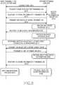
FIG. 6 , afirst terminal 100 or astylus pen 400 is NFC-connected to asecond terminal 200/300 instep 601, and thefirst terminal 100 or thestylus pen 400 requests transmission of share information to thesecond terminal 200/300 instep 603. A user accepts transmission of the share information instep 605, and thesecond terminal 200/300 responds to the share information transmission request instep 607. Thefirst terminal 100 or thestylus pen 400 transmits metadata of the share information to thesecond terminal 200/300 instep 609. Thesecond terminal 200/300 receives and stores the metadata from thefirst terminal 100 or thestylus pen 400 instep 611, and notifies of the completion of reception of the metadata to the terminal 100 or thestylus pen 400 instep 613. Thesecond terminal 200/300 executes a program or process for processing the received metadata instep 615. For example, thesecond terminal 200/300 provides the user with content, format, right condition, and creator information of the share information. At least one of thefirst terminal 100, thestylus pen 400 and thesecond terminal 200/300 determines from the metadata whether a Bluetooth or WiFi Direct connection is necessary. When the amount of share information is considerable, it may be difficult to transmit the share data through the NFC connection. Therefore, using Bluetooth or WiFi Direct, which provides a higher data rate than NFC, may be more appropriate. When the Bluetooth or WiFi Direct connection is not necessary, the NFC connection is used to follow the process described above with reference toFIGs. 3 and5 . When the Bluetooth or WiFi Direct connection is more appropriate instep 617, thefirst terminal 100 or thestylus pen 400 and thesecond terminal 200/300 are Bluetooth or WiFi Direct-connected through authentication instep 619. Thefirst terminal 100 or thestylus pen 400 transmits the share information to thesecond terminal 200/300 instep 621. Thesecond terminal 200/300 receives and stores the share information from thefirst terminal 100 or thestylus pen 400 instep 623, and notifies of the completion of reception of the share information to the terminal 100 or thestylus pen 400 instep 625. Thefirst terminal 100 or thestylus pen 400 performs a process corresponding to the notification instep 627. For example, thefirst terminal 100 or thestylus pen 400 deletes the share information. Thesecond terminal 200/300 executes a program or process for processing the received share information instep 629, an example of which will be described below with reference to the drawings. Fig. 7 illustrates a User Interface (UI) screen according to an exemplary embodiment of the present invention.- Referring to
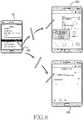
FIG. 7 , a user touches at least one contact number in a contact number list on a touchscreen of afirst terminal 100 by using astylus pen 400. Thefirst terminal 100 transmits contact number information touched with thestylus pen 400 to thestylus pen 400 by using at least one of NFC, Bluetooth and WiFi Direct, and thestylus pen 400 receives and stores the contact number information from thefirst terminal 100. When the user touches a touchscreen of asecond terminal 200 by using thestylus pen 400, thestylus pen 400 transmits the stored contact number information received from thefirst terminal 100, to thesecond terminal 200 by using at least one of NFC, Bluetooth and WiFi Direct. Thesecond terminal 200 receives the contact number information from thestylus pen 400, and executes a program or process for processing the received contact number information. For example, thesecond terminal 200 performs contact number registration, a call, or the like. Fig. 8 illustrates a UI screen according to an exemplary embodiment of the present invention.- Referring to
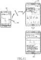
FIG. 8 , a user touches at least one music file in a music list on a touchscreen of afirst terminal 100 by using astylus pen 400. Thefirst terminal 100 transmits the touched music file to thestylus pen 400 by using at least one of NFC, Bluetooth and WiFi Direct, and thestylus pen 400 receives and stores the music file from thefirst terminal 100. When the user touches a touchscreen of asecond terminal 200 by using thestylus pen 400, thestylus pen 400 transmits the stored music file received from thefirst terminal 100, to thesecond terminal 200 by using at least one of NFC, Bluetooth and WiFi Direct. Thesecond terminal 200 receives the music file from thestylus pen 400, and executes a program or process for processing the received music file. For example, thesecond terminal 200 performs addition to a play list, reproduction through a music play program, or the like. Fig. 9 illustrates a UI screen according to an exemplary embodiment of the present invention.- Referring to
FIG. 9 , a user touches at least one picture file in an image thumbnail on a touchscreen of afirst terminal 100 by using astylus pen 400. Thefirst terminal 100 transmits the touched picture file to thestylus pen 400 by using at least one of NFC, Bluetooth and WiFi Direct, and thestylus pen 400 receives and stores the picture file from thefirst terminal 100. When the user touches a touchscreen of asecond terminal 200 by using thestylus pen 400, thestylus pen 400 transmits the stored picture file received from thefirst terminal 100, to thesecond terminal 200 by using at least one of NFC, Bluetooth and WiFi Direct. Thesecond terminal 200 receives the picture file from thestylus pen 400, and executes a program or process for processing the received picture file. For example, thesecond terminal 200 opens the received picture file through an image viewer. Fig. 10 illustrates a UI screen according to an exemplary embodiment of the present invention.- Referring to
FIG. 10 , a user designates a position in an electronic map on a touchscreen of afirst terminal 100 by using astylus pen 400. Thefirst terminal 100 transmits the designated position information to thestylus pen 400 by using at least one of NFC, Bluetooth and WiFi Direct, and thestylus pen 400 receives and stores the position information from thefirst terminal 100. When the user touches a touchscreen of asecond terminal 200 by using thestylus pen 400, thestylus pen 400 transmits the stored position information received from thefirst terminal 100, to thesecond terminal 200 by using at least one of NFC, Bluetooth and WiFi Direct. Thesecond terminal 200 receives the position information from thestylus pen 400, and executes a program or process for processing the received position information. For example, thesecond terminal 200 performs a position search through an electronic map. Fig. 11 illustrates a UI screen according to an exemplary embodiment of the present invention.- Referring to
FIG. 11 , a user touches a webpage on a touchscreen of afirst terminal 100 by using astylus pen 400. Thefirst terminal 100 transmits a URL of the webpage to thestylus pen 400 by using at least one of NFC, Bluetooth and WiFi Direct, and thestylus pen 400 receives and stores the URL from thefirst terminal 100. When the user touches a touchscreen of asecond terminal 200 by using thestylus pen 400, thestylus pen 400 transmits the stored URL received from thefirst terminal 100, to thesecond terminal 200 by using at least one of NFC, Bluetooth and WiFi Direct. Thesecond terminal 200 receives the URL from thestylus pen 400, and executes a program or process for processing the received URL. For example, thesecond terminal 200 connects to the URL through a web viewer. Fig. 12 illustrates a UI screen according to an exemplary embodiment of the present invention.- Referring to
FIG. 12 , a user touches a multimedia object (e.g., an image or text) in a webpage on a touchscreen of afirst terminal 100 by using astylus pen 400. Thefirst terminal 100 downloads the touched multimedia object from a server, and transmits the downloaded multimedia object to thestylus pen 400 by using at least one of NFC, Bluetooth and WiFi Direct. Thestylus pen 400 receives and stores the multimedia object from thefirst terminal 100. When the user touches a touchscreen of asecond terminal 200 by using thestylus pen 400, thestylus pen 400 transmits the stored multimedia object to thesecond terminal 200 by using at least one of NFC, Bluetooth and WiFi Direct. Thesecond terminal 200 receives the multimedia object from thestylus pen 400, and executes a program or process for processing the received multimedia object. For example, thesecond terminal 200 opens the multimedia object through a text viewer or an image viewer. Fig. 13 illustrates a UI screen according to an exemplary embodiment of the present invention.- Referring to
FIG. 13 , a user touches a plurality of music files in a music list on a touchscreen of afirst terminal 100 by using astylus pen 400. Thefirst terminal 100 transmits the touched music files to thestylus pen 400 by using at least one of NFC, Bluetooth and WiFi Direct, and thestylus pen 400 receives and stores the music files from thefirst terminal 100. When the user touches a touchscreen of asecond terminal 200 by using thestylus pen 400, thestylus pen 400 transmits the stored music files received from thefirst terminal 100, to thesecond terminal 200 by using at least one of NFC, Bluetooth and WiFi Direct. As described above, thestylus pen 400 may beforehand transmit metadata of music files to thesecond terminal 100, and thesecond terminal 200 may process the metadata and display a list of music files, which may be received from thestylus pen 400, to the user. The user may select a desired music file from the list. Thesecond terminal 200 may request transmission of the music files selected by the user, from thestylus pen 400, and receive the selected music files from thestylus pen 400. Fig. 14 illustrates a UI screen according to an exemplary embodiment of the present invention.- When a user touches the touchscreen of the
second terminal 200 by using thestylus pen 400, thestylus pen 400 transmits metadata of prestored information to thesecond terminal 200 by using at least one of NFC, Bluetooth and WiFi Direct. Thesecond terminal 200 may process the metadata, generate a list of the information provided by thestylus pen 400, and display the list to the user. The user may select desired information from the list. Thesecond terminal 200 may request transmission of the information selected by the user, from thestylus pen 400, and receive the selected information from thestylus pen 400. - Consequently, by directly or indirectly using the SRC system and the operating method thereof according to the exemplary embodiments of the present invention, the user experience in exchanging information by SRC may be enhanced.
- It will be appreciated that embodiments of the present invention according to the claims and description in the specification can be realized in the form of hardware, software or a combination of hardware and software.
- Any such software may be stored in a computer readable storage medium. The computer readable storage medium stores one or more programs (software modules), the one or more programs comprising instructions, which when executed by one or more processors in an electronic device, cause the electronic device to perform a method of the present invention.
- Any such software may be stored in the form of volatile or non-volatile storage such as, for example, a storage device like a ROM, whether erasable or rewritable or not, or in the form of memory such as, for example, RAM, memory chips, device or integrated circuits or on an optically or magnetically readable medium such as, for example, a CD, DVD, magnetic disk or magnetic tape or the like. It will be appreciated that the storage devices and storage media are embodiments of machine-readable storage that are suitable for storing a program or programs comprising instructions that, when executed, implement embodiments of the present invention.
- Accordingly, embodiments provide a program comprising code for implementing apparatus or a method as claimed in any one of the claims of this specification and a machine-readable storage storing such a program. Still further, such programs may be conveyed electronically via any medium such as a communication signal carried over a wired or wireless connection and embodiments suitably encompass the same.
- While the invention has been shown and described with reference to certain exemplary embodiments thereof, it will be understood by those skilled in the art that various changes in form and details may be made therein without departing from the scope of the invention as defined by the appended claims. Therefore, the scope of the invention is defined not by the detailed description of the invention but by the appended claims, and all differences within the scope will be construed as being included in the present invention.
Claims (11)
- A communication system comprising an electronic device (100, 300) and a stylus pen (400) capable of connecting to each other by one or more Short-range-Radio Communications, SRCs, the electronic device comprising:a touch screen configured to receive a touch input by the stylus pen; an interface unit (209) configured to communicate, with the stylus pen, via the one or more SRCs; anda control unit (213) configured to:display contents on the touch screen,detect a touch input by the stylus pen on the touch screen,determine at least one content of the displayed contents based on the detected touch input, andtransmit the determined at least one content to the stylus pen via the one or more SRCs,wherein the control unit (213) is configured to:transmit (609) metadata describing the determined at least one content to the stylus pen via a first SRC,determine (617), from the metadata describing the determined at least one content, whether a second SRC is needed to transmit the determined at least one content, wherein the second SRC provides a higher data rate than a first SRC,if the second SRC is needed to transmit the determined at least one content, connect to the stylus pen by the second SRC, and transmit the determined at least one content to the stylus pen via the second SRC, andif the second SRC is not needed to transmit the determined at least one content, transmit the determined at least one content to the stylus pen via the first SRC.
- The communication system of claim 1, wherein the control unit is further configured to receive at least one second content from the stylus pen (400) through the one or more SRCs.
- The communication system of claim 2, wherein the control unit is configured to:receive metadata describing the at least one second content from the stylus pen;display, on the touch screen, a list of based on the received metadata describing the at least one second content;detect a touch input by the stylus pen on the touch screen to select at least one list entry in the displayed list; andreceive the at least one second content from the stylus pen according to the selected at least one list entry.
- The communication system of claim 2, wherein the control unit is further configured to:receive second metadata describing the at least one second contents from the stylus pen via a third SRC,determine, from the second metadata describing the at least one second content, whether a fourth SRC is needed to receive the at least one second content, wherein the fourth SRC provides a higher data rate than a third SRC,if the fourth SRC is needed to receive the at least one second content, connect to the stylus pen by the fourth SRC, and receiving the at least one second content from the stylus pen via the fourth SRC, andif the fourth SRC is not needed to receive the at least one second content, receive the at least one second content from the stylus pen via the third SRC.
- The communication system of claim 2, wherein the at least one content includes at least one of image data, audio data, map location data, contact information, and a uniform resource locator, URL.
- The communication system of claim 5, wherein the control unit is further configured to:select an application for outputting the received at least one second content, andexecute the selected application to output the received at least one second content.
- The communication system of claim 6, wherein the control unit is further configured to execute an image view application to display image data when the received at least one second content includes the image data.
- The communication system of claim 6, wherein the control unit is further configured to execute an audio play application to output audio data when the received at least one second content includes the audio data.
- The communication system of claim 6, wherein the control unit is further configured to execute an electronic map application to display map location data when the received at least one second content includes the map location data.
- The communication system of claim 6, wherein the control unit is further configured to execute a contact number registration application to register contact information when the received at least one second content includes the contact information.
- The communication system of claim 6, wherein the control unit is further configured to execute a web view application to access an URL when the received at least one second content includes the URL
Applications Claiming Priority (1)
| Application Number | Priority Date | Filing Date | Title |
|---|---|---|---|
| KR1020120010715AKR101985275B1 (en) | 2012-02-02 | 2012-02-02 | Close renage radio communication system and therof operating method |
Publications (3)
| Publication Number | Publication Date |
|---|---|
| EP2624601A2 EP2624601A2 (en) | 2013-08-07 |
| EP2624601A3 EP2624601A3 (en) | 2013-09-11 |
| EP2624601B1true EP2624601B1 (en) | 2018-08-08 |
Family
ID=47632876
Family Applications (1)
| Application Number | Title | Priority Date | Filing Date |
|---|---|---|---|
| EP13153275.6ANot-in-forceEP2624601B1 (en) | 2012-02-02 | 2013-01-30 | Short-range radio communication system and method for operating the same |
Country Status (8)
| Country | Link |
|---|---|
| US (2) | US20130203353A1 (en) |
| EP (1) | EP2624601B1 (en) |
| JP (1) | JP6356945B2 (en) |
| KR (1) | KR101985275B1 (en) |
| CN (1) | CN103246439A (en) |
| AU (1) | AU2013200201B2 (en) |
| TW (1) | TWI619386B (en) |
| WO (1) | WO2013115512A1 (en) |
Families Citing this family (36)
| Publication number | Priority date | Publication date | Assignee | Title |
|---|---|---|---|---|
| US9077696B2 (en)* | 2012-04-26 | 2015-07-07 | Qualcomm Incorporated | Transferring data items amongst computing devices using metadata that identifies a location of a transferred item |
| KR101967670B1 (en)* | 2012-06-15 | 2019-04-11 | 삼성전자주식회사 | Wireless communication method between terminals |
| WO2014046424A1 (en)* | 2012-09-18 | 2014-03-27 | Samsung Electronics Co., Ltd. | Information transmission method and system, and device |
| US20140256250A1 (en)* | 2013-03-11 | 2014-09-11 | Barnesandnoble.Com Llc | Peer-to-peer data transfer using near field communication (nfc)-enabled styluses |
| KR102064934B1 (en)* | 2013-07-17 | 2020-02-11 | 삼성전자 주식회사 | Method and apparatus for transmitting/receiving data between a wireless terminal and electronic pen |
| KR102122483B1 (en)* | 2013-08-29 | 2020-06-12 | 삼성전자주식회사 | Method for sharing media data and an electronic device thereof |
| CN104426583B (en)* | 2013-08-29 | 2018-05-29 | 华为终端(东莞)有限公司 | Data transmission method, device and near-field communication equipment based on near-field communication |
| KR102147088B1 (en) | 2013-09-03 | 2020-08-24 | 삼성전자 주식회사 | Method and apparatus for offering received information to user in a electronic device |
| TWI484385B (en) | 2013-09-09 | 2015-05-11 | Henghao Technology Co Ltd | Touch panel and method of using same |
| CN109144362A (en)* | 2013-10-17 | 2019-01-04 | 华为技术有限公司 | content sharing method and terminal device |
| CN104571899B (en)* | 2013-10-24 | 2019-03-29 | 联想(北京)有限公司 | A kind of information interacting method and electronic equipment |
| CN104636033B (en)* | 2013-11-06 | 2018-12-14 | 联想(北京)有限公司 | Information processing method, information processing equipment and electronic equipment |
| CN103595798A (en)* | 2013-11-14 | 2014-02-19 | 福州瑞芯微电子有限公司 | Somatic sense sharing master/slave device and method based on WIFI Direct |
| US10251032B2 (en) | 2014-01-20 | 2019-04-02 | Samsung Electronics Co., Ltd. | Electronic device for sharing data and method for controlling the same |
| CN104834458A (en)* | 2014-02-11 | 2015-08-12 | 中兴通讯股份有限公司 | Equipment paring method and device based on touch screen |
| JP6403398B2 (en)* | 2014-02-27 | 2018-10-10 | キヤノン株式会社 | COMMUNICATION DEVICE, ITS CONTROL METHOD, PROGRAM |
| KR102219857B1 (en)* | 2014-03-18 | 2021-02-24 | 삼성전자주식회사 | An electronic device and operating method thereof |
| CN104954049A (en)* | 2014-03-31 | 2015-09-30 | 小米科技有限责任公司 | Data file transmission method and device thereof |
| KR102191345B1 (en) | 2014-04-03 | 2020-12-15 | 삼성전자 주식회사 | Inputting device, method and system for electronic apparatus |
| US9780837B2 (en)* | 2014-08-29 | 2017-10-03 | Freelinc Technologies | Spatially enabled secure communications |
| US20160252954A1 (en)* | 2015-02-27 | 2016-09-01 | Microsoft Technology Licensing, Llc | Control apparatus |
| US9924019B2 (en) | 2015-05-15 | 2018-03-20 | Microsoft Technology Licensing, Llc | Automatic device pairing |
| KR102518912B1 (en) | 2016-05-16 | 2023-04-07 | 삼성전자주식회사 | Input device for sharing content and method thereof |
| CN106131299A (en)* | 2016-06-15 | 2016-11-16 | 惠州Tcl移动通信有限公司 | A kind of mobile terminal character method for transmission processing and mobile terminal |
| CN106209976A (en)* | 2016-06-21 | 2016-12-07 | 广州视睿电子科技有限公司 | Information sharing method and system |
| KR102514324B1 (en)* | 2016-07-20 | 2023-03-28 | 신철호 | Method for Providing WiFi Sharing Service |
| CN108259315A (en)* | 2017-01-16 | 2018-07-06 | 广州市动景计算机科技有限公司 | Online picture sharing method, equipment, client and electronic equipment |
| JP6717764B2 (en)* | 2017-02-15 | 2020-07-01 | シャープ株式会社 | Information processing system |
| JP6549750B2 (en)* | 2018-04-04 | 2019-07-24 | シャープ株式会社 | Display device, linkage system, control method and program |
| US10719148B2 (en) | 2018-07-10 | 2020-07-21 | Microsoft Technology Licensing, Llc | Coupling a pen device to a companion device based on pen proximity |
| KR102227274B1 (en) | 2018-08-09 | 2021-03-15 | 삼성전자주식회사 | Electronic pen device including a button, method for operation in the electronic pen device and system |
| KR102738792B1 (en)* | 2019-01-02 | 2024-12-06 | 삼성전자주식회사 | Electronic device for sharing content by using stylus pen and method for controlling thereof |
| CN111867148B (en)* | 2019-04-30 | 2024-08-06 | 青岛海信移动通信技术有限公司 | Method and device for establishing device connection and data transmission |
| CN111813299A (en)* | 2020-05-29 | 2020-10-23 | 维沃移动通信有限公司 | Information sharing method, information sharing device and electronic device |
| CN113099434B (en)* | 2021-04-20 | 2022-03-11 | 深圳市旭联信息技术有限公司 | Wireless co-screen device for magnetically attracting and connecting transmitting end and receiving end |
| CN113705269A (en)* | 2021-08-31 | 2021-11-26 | 维沃移动通信有限公司 | Information code identification method, touch device, information code identification device and electronic equipment |
Citations (1)
| Publication number | Priority date | Publication date | Assignee | Title |
|---|---|---|---|---|
| US20100144273A1 (en)* | 2008-12-05 | 2010-06-10 | Sekikawa Yusuke | Portable device |
Family Cites Families (45)
| Publication number | Priority date | Publication date | Assignee | Title |
|---|---|---|---|---|
| JPH05233125A (en)* | 1991-09-09 | 1993-09-10 | Fujitsu Ltd | Multimedia information input device |
| FI103837B (en)* | 1994-12-22 | 1999-09-30 | Nokia Mobile Phones Ltd | Procedure for data transfer and processing |
| US6473728B1 (en)* | 1996-05-23 | 2002-10-29 | Sun Microsystems, Inc. | On-demand, multi-language business card printer |
| KR20010039039A (en)* | 1999-10-28 | 2001-05-15 | 조영선 | A Cellular Phone for Data Communication |
| JP2000324557A (en)* | 2000-01-01 | 2000-11-24 | Toshiba Corp | Information devices and PC cards |
| US20030038790A1 (en)* | 2001-08-22 | 2003-02-27 | Seiko Epson Corporation | Information processing system, input/output apparatus, personal digital assistant, and display apparatus |
| KR100834623B1 (en)* | 2001-09-26 | 2008-06-02 | 삼성전자주식회사 | Operation Control Method of Communication Terminal Using Wireless Headset Electronic Pen and Wireless Headset Electronic Pen Therefor |
| JP4040403B2 (en)* | 2001-11-27 | 2008-01-30 | ソニー株式会社 | Information processing apparatus and method, recording medium, and program |
| US9165478B2 (en)* | 2003-04-18 | 2015-10-20 | International Business Machines Corporation | System and method to enable blind people to have access to information printed on a physical document |
| US7171203B2 (en)* | 2004-01-07 | 2007-01-30 | Research In Motion Limited | Apparatus, and associated method, for facilitating selection by a mobile node of a network through which to communicate |
| EP1562349B1 (en)* | 2004-02-04 | 2007-08-01 | Sony Ericsson Mobile Communications AB | Sharing of media file including META information |
| JP4394544B2 (en)* | 2004-09-03 | 2010-01-06 | シャープ株式会社 | Portable information equipment |
| TWI260505B (en)* | 2004-10-29 | 2006-08-21 | Inventec Appliances Corp | Pen input device, pen input system, and controlling method of pen input system |
| US20060227121A1 (en)* | 2005-03-30 | 2006-10-12 | Microsoft Corporation | Systems and methods for providing a dual mode input device in a computing system |
| JP4534854B2 (en)* | 2005-04-26 | 2010-09-01 | ソニー株式会社 | Information processing system, information processing apparatus and method, and program |
| CN101233516B (en)* | 2005-08-01 | 2016-07-06 | 皇家飞利浦电子股份有限公司 | Utilize dynamic profile organising content |
| JP5020494B2 (en)* | 2005-10-12 | 2012-09-05 | キヤノン株式会社 | Wireless communication apparatus and control method thereof |
| US7562822B1 (en)* | 2005-12-30 | 2009-07-21 | Leapfrog Enterprises, Inc. | Methods and devices for creating and processing content |
| US7813697B2 (en)* | 2007-01-05 | 2010-10-12 | Apple Inc. | Power efficient high speed communication systems and methods |
| US8284951B2 (en)* | 2007-05-29 | 2012-10-09 | Livescribe, Inc. | Enhanced audio recording for smart pen computing systems |
| US8638319B2 (en)* | 2007-05-29 | 2014-01-28 | Livescribe Inc. | Customer authoring tools for creating user-generated content for smart pen applications |
| JP4952433B2 (en)* | 2007-08-08 | 2012-06-13 | ソニー株式会社 | Information processing apparatus and method, and information processing system |
| TWI352306B (en)* | 2007-12-18 | 2011-11-11 | Wistron Corp | Touch-sensitive screen electronic apparatus and co |
| EP2283691A4 (en)* | 2008-06-06 | 2014-10-22 | Samsung Electronics Co Ltd | METHOD AND SYSTEM FOR MANAGING DATA IN A NEAR FIELD COMMUNICATION NETWORK |
| JP5426843B2 (en)* | 2008-06-25 | 2014-02-26 | キヤノン株式会社 | Information processing apparatus, information processing method, program, and storage medium for storing program |
| JP5071324B2 (en)* | 2008-09-26 | 2012-11-14 | 株式会社デンソーウェーブ | Portable terminal device and data copy method |
| EP2211480B1 (en)* | 2009-01-26 | 2013-10-23 | Motorola Mobility LLC | Wireless communication device for providing at least one near field communication service |
| JP2010178289A (en)* | 2009-02-02 | 2010-08-12 | Fujifilm Corp | Method, system and program for managing linguistic content, linguistic content transmitter, and linguistic content receiver |
| US20100257239A1 (en)* | 2009-04-02 | 2010-10-07 | Qualcomm Incorporated | Method and apparatus for establishing a social network through file transfers |
| US8363020B2 (en)* | 2009-08-27 | 2013-01-29 | Symbol Technologies, Inc. | Methods and apparatus for pressure-based manipulation of content on a touch screen |
| JP5257312B2 (en)* | 2009-09-24 | 2013-08-07 | 富士通モバイルコミュニケーションズ株式会社 | Mobile terminal and communication method in mobile terminal |
| US8340577B2 (en)* | 2009-09-24 | 2012-12-25 | Research In Motion Limited | Communications device using electromagnet and activated communications circuit |
| EP2302560B1 (en)* | 2009-09-24 | 2016-06-22 | BlackBerry Limited | System and associated nfc tag using plurality of nfc tags associated with location or devices to communicate with communications device |
| EP3322100B1 (en)* | 2010-01-14 | 2020-01-01 | France Brevets | Electronic device and method of operating the same |
| US20110183614A1 (en)* | 2010-01-25 | 2011-07-28 | Kabushiki Kaisha Toshiba | Communication terminal |
| KR101080532B1 (en)* | 2010-01-29 | 2011-11-04 | 주식회사 팬택 | Communication Terminal and Data Transmission Method Thereof |
| JP5478298B2 (en)* | 2010-02-25 | 2014-04-23 | オリンパス株式会社 | Portable wireless terminal, wireless terminal device, and wireless communication system |
| CN102771064B (en)* | 2010-02-26 | 2015-09-30 | Lg电子株式会社 | Electronic device and method of operation thereof |
| JP2012015803A (en)* | 2010-06-30 | 2012-01-19 | Toshiba Corp | Communication device, program, and communication method |
| US9265074B2 (en)* | 2011-10-06 | 2016-02-16 | Qualcomm Incorporated | Pen-based content transfer system and method thereof |
| JP5954024B2 (en)* | 2012-07-27 | 2016-07-20 | ブラザー工業株式会社 | Communication device |
| KR102070013B1 (en)* | 2012-08-27 | 2020-01-30 | 삼성전자주식회사 | Contents Operating Method And Electronic Device operating the same |
| US9164658B2 (en)* | 2012-10-12 | 2015-10-20 | Cellco Partnership | Flexible selection tool for mobile devices |
| KR102219857B1 (en)* | 2014-03-18 | 2021-02-24 | 삼성전자주식회사 | An electronic device and operating method thereof |
| US9678585B2 (en)* | 2014-05-13 | 2017-06-13 | Lenovo (Singapore) Pte. Ltd. | Pen switching between active and passive status |
- 2012
- 2012-02-02KRKR1020120010715Apatent/KR101985275B1/ennot_activeExpired - Fee Related
- 2012-12-26USUS13/727,321patent/US20130203353A1/ennot_activeAbandoned
- 2012-12-28JPJP2012287082Apatent/JP6356945B2/ennot_activeExpired - Fee Related
- 2013
- 2013-01-15AUAU2013200201Apatent/AU2013200201B2/ennot_activeCeased
- 2013-01-18WOPCT/KR2013/000431patent/WO2013115512A1/ennot_activeCeased
- 2013-01-30EPEP13153275.6Apatent/EP2624601B1/ennot_activeNot-in-force
- 2013-01-30TWTW102103401Apatent/TWI619386B/ennot_activeIP Right Cessation
- 2013-02-04CNCN2013100436069Apatent/CN103246439A/enactivePending
- 2016
- 2016-11-15USUS15/352,210patent/US20170064055A1/ennot_activeAbandoned
Patent Citations (1)
| Publication number | Priority date | Publication date | Assignee | Title |
|---|---|---|---|---|
| US20100144273A1 (en)* | 2008-12-05 | 2010-06-10 | Sekikawa Yusuke | Portable device |
Also Published As
| Publication number | Publication date |
|---|---|
| EP2624601A3 (en) | 2013-09-11 |
| KR101985275B1 (en) | 2019-09-03 |
| JP6356945B2 (en) | 2018-07-11 |
| EP2624601A2 (en) | 2013-08-07 |
| AU2013200201B2 (en) | 2016-02-11 |
| TW201342888A (en) | 2013-10-16 |
| KR20130089389A (en) | 2013-08-12 |
| US20170064055A1 (en) | 2017-03-02 |
| AU2013200201A1 (en) | 2013-08-22 |
| CN103246439A (en) | 2013-08-14 |
| TWI619386B (en) | 2018-03-21 |
| WO2013115512A1 (en) | 2013-08-08 |
| JP2013162515A (en) | 2013-08-19 |
| US20130203353A1 (en) | 2013-08-08 |
Similar Documents
| Publication | Publication Date | Title |
|---|---|---|
| EP2624601B1 (en) | Short-range radio communication system and method for operating the same | |
| US10855615B2 (en) | Device and method for sharing content using the same | |
| CN112996141B (en) | Image sharing method and electronic equipment | |
| EP2391104B1 (en) | Information processing apparatus, information processing system, and program | |
| CN103426013B (en) | Equipment, system and method for carrying out log recording near field communication tag interaction | |
| US20160239547A1 (en) | Method and apparatus for recommending content based on activities of a plurality of users | |
| KR20090036542A (en) | Data communication in electronic device | |
| CN110083486B (en) | Method, apparatus and recording medium for interacting with external terminal | |
| US20140045426A1 (en) | Apparatus and method for communicating data in mobile device having near field communication module | |
| KR102192701B1 (en) | Copy and paste between devices | |
| CN104662577A (en) | Apparatus for uploading contents, user terminal apparatus for downloading contents, server, contents sharing system and their contents sharing method | |
| CN115150213B (en) | Function migration method and device | |
| US10812956B2 (en) | Electronic device enabling NFC communication | |
| US9674686B2 (en) | Apparatus and method for pairing mobile devices | |
| KR102203131B1 (en) | Method for management file and electronic device thereof | |
| KR101987463B1 (en) | Mobile terminal and method for controlling of the same | |
| CN115145474A (en) | A function migration method and device | |
| WO2022206630A1 (en) | Function migration method and apparatus | |
| EP2555499B1 (en) | Mobile terminal and method of controlling the same | |
| KR20150061353A (en) | Method for operating application and electronic device thereof | |
| KR20170025573A (en) | Mobile terminal and method for controlling the same |
Legal Events
| Date | Code | Title | Description |
|---|---|---|---|
| PUAI | Public reference made under article 153(3) epc to a published international application that has entered the european phase | Free format text:ORIGINAL CODE: 0009012 | |
| 17P | Request for examination filed | Effective date:20130130 | |
| AK | Designated contracting states | Kind code of ref document:A2 Designated state(s):AL AT BE BG CH CY CZ DE DK EE ES FI FR GB GR HR HU IE IS IT LI LT LU LV MC MK MT NL NO PL PT RO RS SE SI SK SM TR | |
| AX | Request for extension of the european patent | Extension state:BA ME | |
| PUAL | Search report despatched | Free format text:ORIGINAL CODE: 0009013 | |
| AK | Designated contracting states | Kind code of ref document:A3 Designated state(s):AL AT BE BG CH CY CZ DE DK EE ES FI FR GB GR HR HU IE IS IT LI LT LU LV MC MK MT NL NO PL PT RO RS SE SI SK SM TR | |
| AX | Request for extension of the european patent | Extension state:BA ME | |
| RIC1 | Information provided on ipc code assigned before grant | Ipc:H04W 4/00 20090101AFI20130807BHEP Ipc:G06F 3/0354 20130101ALI20130807BHEP Ipc:G06F 3/038 20130101ALI20130807BHEP Ipc:G06F 3/0488 20130101ALI20130807BHEP | |
| STAA | Information on the status of an ep patent application or granted ep patent | Free format text:STATUS: EXAMINATION IS IN PROGRESS | |
| 17Q | First examination report despatched | Effective date:20170713 | |
| REG | Reference to a national code | Ref country code:DE Ref legal event code:R079 Ref document number:602013041461 Country of ref document:DE Free format text:PREVIOUS MAIN CLASS: H04W0004000000 Ipc:H04W0004800000 | |
| GRAP | Despatch of communication of intention to grant a patent | Free format text:ORIGINAL CODE: EPIDOSNIGR1 | |
| STAA | Information on the status of an ep patent application or granted ep patent | Free format text:STATUS: GRANT OF PATENT IS INTENDED | |
| RIC1 | Information provided on ipc code assigned before grant | Ipc:H04W 4/80 20180101AFI20180215BHEP Ipc:H04W 76/14 20180101ALI20180215BHEP Ipc:G06F 3/0354 20130101ALI20180215BHEP Ipc:G06F 3/038 20130101ALI20180215BHEP Ipc:H04B 7/24 20060101ALI20180215BHEP | |
| INTG | Intention to grant announced | Effective date:20180302 | |
| GRAS | Grant fee paid | Free format text:ORIGINAL CODE: EPIDOSNIGR3 | |
| GRAA | (expected) grant | Free format text:ORIGINAL CODE: 0009210 | |
| STAA | Information on the status of an ep patent application or granted ep patent | Free format text:STATUS: THE PATENT HAS BEEN GRANTED | |
| AK | Designated contracting states | Kind code of ref document:B1 Designated state(s):AL AT BE BG CH CY CZ DE DK EE ES FI FR GB GR HR HU IE IS IT LI LT LU LV MC MK MT NL NO PL PT RO RS SE SI SK SM TR | |
| REG | Reference to a national code | Ref country code:GB Ref legal event code:FG4D | |
| REG | Reference to a national code | Ref country code:AT Ref legal event code:REF Ref document number:1028474 Country of ref document:AT Kind code of ref document:T Effective date:20180815 Ref country code:CH Ref legal event code:EP | |
| REG | Reference to a national code | Ref country code:IE Ref legal event code:FG4D | |
| REG | Reference to a national code | Ref country code:DE Ref legal event code:R096 Ref document number:602013041461 Country of ref document:DE | |
| REG | Reference to a national code | Ref country code:NL Ref legal event code:FP | |
| REG | Reference to a national code | Ref country code:LT Ref legal event code:MG4D | |
| REG | Reference to a national code | Ref country code:AT Ref legal event code:MK05 Ref document number:1028474 Country of ref document:AT Kind code of ref document:T Effective date:20180808 | |
| PG25 | Lapsed in a contracting state [announced via postgrant information from national office to epo] | Ref country code:SE Free format text:LAPSE BECAUSE OF FAILURE TO SUBMIT A TRANSLATION OF THE DESCRIPTION OR TO PAY THE FEE WITHIN THE PRESCRIBED TIME-LIMIT Effective date:20180808 Ref country code:RS Free format text:LAPSE BECAUSE OF FAILURE TO SUBMIT A TRANSLATION OF THE DESCRIPTION OR TO PAY THE FEE WITHIN THE PRESCRIBED TIME-LIMIT Effective date:20180808 Ref country code:PL Free format text:LAPSE BECAUSE OF FAILURE TO SUBMIT A TRANSLATION OF THE DESCRIPTION OR TO PAY THE FEE WITHIN THE PRESCRIBED TIME-LIMIT Effective date:20180808 Ref country code:FI Free format text:LAPSE BECAUSE OF FAILURE TO SUBMIT A TRANSLATION OF THE DESCRIPTION OR TO PAY THE FEE WITHIN THE PRESCRIBED TIME-LIMIT Effective date:20180808 Ref country code:BG Free format text:LAPSE BECAUSE OF FAILURE TO SUBMIT A TRANSLATION OF THE DESCRIPTION OR TO PAY THE FEE WITHIN THE PRESCRIBED TIME-LIMIT Effective date:20181108 Ref country code:LT Free format text:LAPSE BECAUSE OF FAILURE TO SUBMIT A TRANSLATION OF THE DESCRIPTION OR TO PAY THE FEE WITHIN THE PRESCRIBED TIME-LIMIT Effective date:20180808 Ref country code:AT Free format text:LAPSE BECAUSE OF FAILURE TO SUBMIT A TRANSLATION OF THE DESCRIPTION OR TO PAY THE FEE WITHIN THE PRESCRIBED TIME-LIMIT Effective date:20180808 Ref country code:IS Free format text:LAPSE BECAUSE OF FAILURE TO SUBMIT A TRANSLATION OF THE DESCRIPTION OR TO PAY THE FEE WITHIN THE PRESCRIBED TIME-LIMIT Effective date:20181208 Ref country code:NO Free format text:LAPSE BECAUSE OF FAILURE TO SUBMIT A TRANSLATION OF THE DESCRIPTION OR TO PAY THE FEE WITHIN THE PRESCRIBED TIME-LIMIT Effective date:20181108 Ref country code:GR Free format text:LAPSE BECAUSE OF FAILURE TO SUBMIT A TRANSLATION OF THE DESCRIPTION OR TO PAY THE FEE WITHIN THE PRESCRIBED TIME-LIMIT Effective date:20181109 | |
| REG | Reference to a national code | Ref country code:CH Ref legal event code:PK Free format text:BERICHTIGUNGEN | |
| RIC2 | Information provided on ipc code assigned after grant | Ipc:G06F 3/0354 20130101ALI20180215BHEP Ipc:H04W 4/80 20180101AFI20180215BHEP Ipc:G06F 3/038 20130101ALI20180215BHEP Ipc:H04W 76/14 20180101ALI20180215BHEP Ipc:H04B 7/24 20060101ALI20180215BHEP | |
| PG25 | Lapsed in a contracting state [announced via postgrant information from national office to epo] | Ref country code:HR Free format text:LAPSE BECAUSE OF FAILURE TO SUBMIT A TRANSLATION OF THE DESCRIPTION OR TO PAY THE FEE WITHIN THE PRESCRIBED TIME-LIMIT Effective date:20180808 Ref country code:LV Free format text:LAPSE BECAUSE OF FAILURE TO SUBMIT A TRANSLATION OF THE DESCRIPTION OR TO PAY THE FEE WITHIN THE PRESCRIBED TIME-LIMIT Effective date:20180808 Ref country code:AL Free format text:LAPSE BECAUSE OF FAILURE TO SUBMIT A TRANSLATION OF THE DESCRIPTION OR TO PAY THE FEE WITHIN THE PRESCRIBED TIME-LIMIT Effective date:20180808 | |
| PG25 | Lapsed in a contracting state [announced via postgrant information from national office to epo] | Ref country code:CZ Free format text:LAPSE BECAUSE OF FAILURE TO SUBMIT A TRANSLATION OF THE DESCRIPTION OR TO PAY THE FEE WITHIN THE PRESCRIBED TIME-LIMIT Effective date:20180808 Ref country code:ES Free format text:LAPSE BECAUSE OF FAILURE TO SUBMIT A TRANSLATION OF THE DESCRIPTION OR TO PAY THE FEE WITHIN THE PRESCRIBED TIME-LIMIT Effective date:20180808 Ref country code:RO Free format text:LAPSE BECAUSE OF FAILURE TO SUBMIT A TRANSLATION OF THE DESCRIPTION OR TO PAY THE FEE WITHIN THE PRESCRIBED TIME-LIMIT Effective date:20180808 Ref country code:IT Free format text:LAPSE BECAUSE OF FAILURE TO SUBMIT A TRANSLATION OF THE DESCRIPTION OR TO PAY THE FEE WITHIN THE PRESCRIBED TIME-LIMIT Effective date:20180808 Ref country code:EE Free format text:LAPSE BECAUSE OF FAILURE TO SUBMIT A TRANSLATION OF THE DESCRIPTION OR TO PAY THE FEE WITHIN THE PRESCRIBED TIME-LIMIT Effective date:20180808 | |
| REG | Reference to a national code | Ref country code:DE Ref legal event code:R097 Ref document number:602013041461 Country of ref document:DE | |
| PG25 | Lapsed in a contracting state [announced via postgrant information from national office to epo] | Ref country code:DK Free format text:LAPSE BECAUSE OF FAILURE TO SUBMIT A TRANSLATION OF THE DESCRIPTION OR TO PAY THE FEE WITHIN THE PRESCRIBED TIME-LIMIT Effective date:20180808 Ref country code:SM Free format text:LAPSE BECAUSE OF FAILURE TO SUBMIT A TRANSLATION OF THE DESCRIPTION OR TO PAY THE FEE WITHIN THE PRESCRIBED TIME-LIMIT Effective date:20180808 Ref country code:SK Free format text:LAPSE BECAUSE OF FAILURE TO SUBMIT A TRANSLATION OF THE DESCRIPTION OR TO PAY THE FEE WITHIN THE PRESCRIBED TIME-LIMIT Effective date:20180808 | |
| PLBE | No opposition filed within time limit | Free format text:ORIGINAL CODE: 0009261 | |
| STAA | Information on the status of an ep patent application or granted ep patent | Free format text:STATUS: NO OPPOSITION FILED WITHIN TIME LIMIT | |
| 26N | No opposition filed | Effective date:20190509 | |
| PG25 | Lapsed in a contracting state [announced via postgrant information from national office to epo] | Ref country code:SI Free format text:LAPSE BECAUSE OF FAILURE TO SUBMIT A TRANSLATION OF THE DESCRIPTION OR TO PAY THE FEE WITHIN THE PRESCRIBED TIME-LIMIT Effective date:20180808 Ref country code:MC Free format text:LAPSE BECAUSE OF FAILURE TO SUBMIT A TRANSLATION OF THE DESCRIPTION OR TO PAY THE FEE WITHIN THE PRESCRIBED TIME-LIMIT Effective date:20180808 | |
| REG | Reference to a national code | Ref country code:CH Ref legal event code:PL | |
| PG25 | Lapsed in a contracting state [announced via postgrant information from national office to epo] | Ref country code:LU Free format text:LAPSE BECAUSE OF NON-PAYMENT OF DUE FEES Effective date:20190130 | |
| REG | Reference to a national code | Ref country code:BE Ref legal event code:MM Effective date:20190131 | |
| REG | Reference to a national code | Ref country code:IE Ref legal event code:MM4A | |
| PG25 | Lapsed in a contracting state [announced via postgrant information from national office to epo] | Ref country code:FR Free format text:LAPSE BECAUSE OF NON-PAYMENT OF DUE FEES Effective date:20190131 | |
| PG25 | Lapsed in a contracting state [announced via postgrant information from national office to epo] | Ref country code:BE Free format text:LAPSE BECAUSE OF NON-PAYMENT OF DUE FEES Effective date:20190131 | |
| PG25 | Lapsed in a contracting state [announced via postgrant information from national office to epo] | Ref country code:LI Free format text:LAPSE BECAUSE OF NON-PAYMENT OF DUE FEES Effective date:20190131 Ref country code:CH Free format text:LAPSE BECAUSE OF NON-PAYMENT OF DUE FEES Effective date:20190131 | |
| PG25 | Lapsed in a contracting state [announced via postgrant information from national office to epo] | Ref country code:IE Free format text:LAPSE BECAUSE OF NON-PAYMENT OF DUE FEES Effective date:20190130 | |
| PGFP | Annual fee paid to national office [announced via postgrant information from national office to epo] | Ref country code:NL Payment date:20191223 Year of fee payment:8 | |
| PG25 | Lapsed in a contracting state [announced via postgrant information from national office to epo] | Ref country code:TR Free format text:LAPSE BECAUSE OF FAILURE TO SUBMIT A TRANSLATION OF THE DESCRIPTION OR TO PAY THE FEE WITHIN THE PRESCRIBED TIME-LIMIT Effective date:20180808 | |
| PGFP | Annual fee paid to national office [announced via postgrant information from national office to epo] | Ref country code:GB Payment date:20191223 Year of fee payment:8 Ref country code:DE Payment date:20191220 Year of fee payment:8 | |
| PG25 | Lapsed in a contracting state [announced via postgrant information from national office to epo] | Ref country code:PT Free format text:LAPSE BECAUSE OF FAILURE TO SUBMIT A TRANSLATION OF THE DESCRIPTION OR TO PAY THE FEE WITHIN THE PRESCRIBED TIME-LIMIT Effective date:20181208 Ref country code:MT Free format text:LAPSE BECAUSE OF NON-PAYMENT OF DUE FEES Effective date:20190130 | |
| PG25 | Lapsed in a contracting state [announced via postgrant information from national office to epo] | Ref country code:CY Free format text:LAPSE BECAUSE OF FAILURE TO SUBMIT A TRANSLATION OF THE DESCRIPTION OR TO PAY THE FEE WITHIN THE PRESCRIBED TIME-LIMIT Effective date:20180808 | |
| PG25 | Lapsed in a contracting state [announced via postgrant information from national office to epo] | Ref country code:HU Free format text:LAPSE BECAUSE OF FAILURE TO SUBMIT A TRANSLATION OF THE DESCRIPTION OR TO PAY THE FEE WITHIN THE PRESCRIBED TIME-LIMIT; INVALID AB INITIO Effective date:20130130 | |
| REG | Reference to a national code | Ref country code:DE Ref legal event code:R119 Ref document number:602013041461 Country of ref document:DE | |
| REG | Reference to a national code | Ref country code:NL Ref legal event code:MM Effective date:20210201 | |
| GBPC | Gb: european patent ceased through non-payment of renewal fee | Effective date:20210130 | |
| PG25 | Lapsed in a contracting state [announced via postgrant information from national office to epo] | Ref country code:NL Free format text:LAPSE BECAUSE OF NON-PAYMENT OF DUE FEES Effective date:20210201 | |
| PG25 | Lapsed in a contracting state [announced via postgrant information from national office to epo] | Ref country code:GB Free format text:LAPSE BECAUSE OF NON-PAYMENT OF DUE FEES Effective date:20210130 Ref country code:DE Free format text:LAPSE BECAUSE OF NON-PAYMENT OF DUE FEES Effective date:20210803 | |
| PG25 | Lapsed in a contracting state [announced via postgrant information from national office to epo] | Ref country code:MK Free format text:LAPSE BECAUSE OF FAILURE TO SUBMIT A TRANSLATION OF THE DESCRIPTION OR TO PAY THE FEE WITHIN THE PRESCRIBED TIME-LIMIT Effective date:20180808 |