EP2624100B1 - Eccentric rotating mass actuator optimization for haptic effects - Google Patents
Eccentric rotating mass actuator optimization for haptic effectsDownload PDFInfo
- Publication number
- EP2624100B1 EP2624100B1EP13153402.6AEP13153402AEP2624100B1EP 2624100 B1EP2624100 B1EP 2624100B1EP 13153402 AEP13153402 AEP 13153402AEP 2624100 B1EP2624100 B1EP 2624100B1
- Authority
- EP
- European Patent Office
- Prior art keywords
- erm
- erm actuator
- actuator
- haptic effect
- time
- Prior art date
- Legal status (The legal status is an assumption and is not a legal conclusion. Google has not performed a legal analysis and makes no representation as to the accuracy of the status listed.)
- Not-in-force
Links
Images


Classifications
- G—PHYSICS
- G06—COMPUTING OR CALCULATING; COUNTING
- G06F—ELECTRIC DIGITAL DATA PROCESSING
- G06F3/00—Input arrangements for transferring data to be processed into a form capable of being handled by the computer; Output arrangements for transferring data from processing unit to output unit, e.g. interface arrangements
- G06F3/01—Input arrangements or combined input and output arrangements for interaction between user and computer
- G06F3/016—Input arrangements with force or tactile feedback as computer generated output to the user
- B—PERFORMING OPERATIONS; TRANSPORTING
- B06—GENERATING OR TRANSMITTING MECHANICAL VIBRATIONS IN GENERAL
- B06B—METHODS OR APPARATUS FOR GENERATING OR TRANSMITTING MECHANICAL VIBRATIONS OF INFRASONIC, SONIC, OR ULTRASONIC FREQUENCY, e.g. FOR PERFORMING MECHANICAL WORK IN GENERAL
- B06B1/00—Methods or apparatus for generating mechanical vibrations of infrasonic, sonic, or ultrasonic frequency
- G—PHYSICS
- G08—SIGNALLING
- G08B—SIGNALLING OR CALLING SYSTEMS; ORDER TELEGRAPHS; ALARM SYSTEMS
- G08B6/00—Tactile signalling systems, e.g. personal calling systems
- H—ELECTRICITY
- H04—ELECTRIC COMMUNICATION TECHNIQUE
- H04M—TELEPHONIC COMMUNICATION
- H04M19/00—Current supply arrangements for telephone systems
- H04M19/02—Current supply arrangements for telephone systems providing ringing current or supervisory tones, e.g. dialling tone or busy tone
- H04M19/04—Current supply arrangements for telephone systems providing ringing current or supervisory tones, e.g. dialling tone or busy tone the ringing-current being generated at the substations
- H04M19/047—Vibrating means for incoming calls
Definitions
- One embodimentis directed to an actuator, and in particular to an actuator used to generate haptic effects.
- kinesthetic feedbacksuch as active and resistive force feedback
- tactile feedbacksuch as vibration, texture, and heat
- Haptic feedbackcan provide cues that enhance and simplify the user interface.
- vibration effects, or vibrotactile haptic effectsmay be useful in providing cues to users of electronic devices to alert the user to specific events, or provide realistic feedback to create greater sensory immersion within a simulated or virtual environment.
- US 2003/025595 A1discloses a method for providing tactile stimulation to a hand in a manner that is cosmetically inoffensive and does not interfere with use of the hand for daily functions, while taking advantage of a unique nerve network of the hand that allows accurate localization of a tactile pattern. It further discloses a tactile interface.
- actuatorsused for this purpose include an electromagnetic actuator such as an Eccentric Rotating Mass (“ERM”) in which an eccentric mass is moved by a motor, a Linear Resonant Actuator (“LRA”) in which a mass attached to a spring is driven back and forth, or a “smart material” such as piezoelectric, electro-active polymers or shape memory alloys.
- EEMEccentric Rotating Mass
- LRALinear Resonant Actuator
- a “smart material”such as piezoelectric, electro-active polymers or shape memory alloys.
- Many of these actuators, and the devices that they interact withhave built-in resonant frequencies that optimally are dynamically determined and controlled so that drive signals that generate the haptic effects can be most effective and efficient, such as the optimization of an LRA device as disclosed in U. S. Pat. No. 7,843,277 .
- the performance characteristics of an actuatorsuch as the rise time, brake time, and steady state voltage, may vary based on the design and manufacturer of the actuator, and may also change during the life of the actuator because of physical shocks, temperature fluctuations, fatigue, and wear and tear. Further, device manufacturers want the freedom to substitute different actuators at will based on cost, availability and performance characteristics without adversely affecting the haptic feedback provided by the device or requiring costly reconfiguration by hand.
- the inventionis directed to a method of generating a haptic effect using an Eccentric Rotating Mass (ERM) actuator comprising the features of claim 1 and a haptically enabled system comprising the features of claim 7.
- ERMEccentric Rotating Mass
- One embodimentis a system that generates a haptic effect using an Eccentric Rotating Mass (“ERM”) actuator.
- the systemdetermines a back electromotive force ("EMF") of the ERM actuator and receives a haptic effect signal comprising one or more parameters, where one of the parameters is a voltage amplitude level as a function of time.
- EMFback electromotive force
- the systemvaries the voltage amplitude level based at least on the back EMF, and applies the varied haptic effect signal to the ERM actuator.
- One embodimentis a system the generates haptic effects using an Eccentric Rotating Mass (“ERM”) actuator.
- the systemcharacterizes the ERM actuator using back electromotive force (“EMF”) in order to derive operating parameters, including rise time, brake time, and revolutions per minute discrepancies.
- EMFback electromotive force
- the operating parametersare then used by a controller in generating haptic effect signals in order to optimize the behavior of the system.
- Fig. 1is a block diagram of a haptically-enabled system 10 in accordance with one embodiment of the present invention.
- System 10includes a touch sensitive surface 11 or other type of user interface mounted within a housing 15, and may include mechanical keys/buttons 13.
- a haptic feedback systemInternal to system 10 is a haptic feedback system that generates vibrations on system 10. In one embodiment, the vibrations are generated on touch surface 11.
- the haptic feedback systemincludes a processor or controller 12. Coupled to processor 12 is a memory 20 and an actuator drive circuit 16, which is coupled to an ERM actuator 18.
- Processor 12may be any type of general purpose processor, or could be a processor specifically designed to provide haptic effects, such as an application-specific integrated circuit ("ASIC").
- ASICapplication-specific integrated circuit
- Processor 12may be the same processor that operates the entire system 10, or may be a separate processor.
- Processor 12can decide what haptic effects are to be played and the order in which the effects are played based on high level parameters. In general, the high level parameters that define a particular haptic effect include magnitude, frequency and duration. Low level parameters such as streaming motor commands could also be used to determine a particular haptic effect.
- a haptic effectmay be considered "dynamic” if it includes some variation of these parameters when the haptic effect is generated or a variation of these parameters based on a user's interaction.
- Processor 12outputs the control signals to actuator drive circuit 16, which includes electronic components and circuitry used to supply ERM 18 with the required electrical current and voltage (i.e., "motor signals") to cause the desired haptic effects.
- System 10may include more than one ERM 18, and each ERM may include a separate drive circuit 16, all coupled to a common processor 12.
- Memory device 20can be any type of storage device or computer-readable medium, such as random access memory (“RAM”) or read-only memory (“ROM”).
- RAMrandom access memory
- ROMread-only memory
- Memory 20stores instructions executed by processor 12.
- memory 20includes an ERM drive module 22 which are instructions that, when executed by processor 12, generate drive signals for ERM 18 while also using the back EMF from ERM 18 to adjusting the drive signals, as disclosed in more detail below.
- Memory 20may also be located internal to processor 12, or any combination of internal and external memory.
- Touch surface 11recognizes touches, and may also recognize the position and magnitude of touches on the surface.
- the data corresponding to the touchesis sent to processor 12, or another processor within system 10, and processor 12 interprets the touches and in response generates haptic effect signals.
- Touch surface 11may sense touches using any sensing technology, including capacitive sensing, resistive sensing, surface acoustic wave sensing, pressure sensing, optical sensing, etc.
- Touch surface 11may sense multi-touch contacts and may be capable of distinguishing multiple touches that occur at the same time.
- Touch surface 11may be a touchscreen that generates and displays images for the user to interact with, such as keys, dials, etc., or may be a touchpad with minimal or no images.
- System 10may be a handheld device, such a cellular telephone, personal digital assistant ("PDA"), smartphone, computer tablet, gaming console, etc., or may be any other type of device that provides a user interface and includes a haptic effect system that includes one or more ERM actuators.
- the user interfacemay be a touch sensitive surface, or can be any other type of user interface such as a mouse, touchpad, mini-joystick, scroll wheel, trackball, game pads or game controllers, etc.
- each ERMmay have a different rotational capability in order to create a wide range of haptic effects on the device.
- System 10may also include one or more sensors. In one embodiment, one of the sensors is an accelerometer (not shown) that measures the acceleration of ERM 18 and system 10.
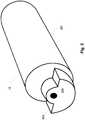
- Fig. 2is a cut-away partial perspective view of ERM 18 of Fig. 1 in accordance with one embodiment of the present invention.
- ERM 18includes a rotating mass 201 having an off-center weight 203 that rotates about an axis of rotation 205.
- any type of motormay be coupled to ERM 18 to cause rotation in one or both directions around axis of rotation 205 in response to the amount and polarity of voltage applied to the motor across two leads of the motor (not shown in Fig. 2 ).
- One embodiment of the present inventiondetermines the angular speed of ERM 18 during a monitoring period of a drive signal.
- Angular speedis a scalar measure of rotation rate, and represents the magnitude of the vector quantity angular velocity.
- Angular speed or frequency win radians per second, correlates to frequency v in cycles per second, also called Hz, by a factor of 2 ⁇ .
- the drive signal applied to ERM 18 by drive circuit 16 of Fig. 1includes a drive period where at least one drive pulse is applied to ERM 18, and a monitoring period where the back EMF (also referred to as the "counter-electromotive force" ("CEMF")) of the rotating mass 201 is received and used to determine the angular speed of ERM 18.
- CEMFcounter-electromotive force
- the drive period and the monitoring periodare concurrent and the present invention dynamically determines the angular speed of ERM 18 during both the drive and monitoring periods.
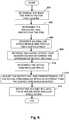
- Fig. 3is a flow diagram of the functionality of ERM drive module 22 to determine a steady-state counter EMF ("SSCE") level of ERM 18 in accordance with one embodiment of the present invention.
- the SSCEis a back EMF target to be achieved for substantially maximum force and can be considered a subset of all back EMFs that can be measured.
- the functionality of the flow diagram of Fig. 3 , and Figs. 4-7 below,is implemented by software stored in memory or other computer readable or tangible medium, and executed by a processor.
- the functionalitymay be performed by hardware (e.g., through the use of an application specific integrated circuit ("ASIC"), a programmable gate array (“PGA”), a field programmable gate array (“FPGA”), etc.), or any combination of hardware and software.
- ASICapplication specific integrated circuit
- PGAprogrammable gate array
- FPGAfield programmable gate array
- module 22receives or is otherwise provided with the rated voltage of ERM 18.
- the rated voltage or standard voltageis the operating voltage level recommended by the manufacturer of ERM 18. In one embodiment, the rated voltage level is 3 volts.
- the rated voltagemay be determined by any means, including but not limited to automatic detection by the system, encoding in a nonvolatile memory or input by hand from a manufacturer or end user.
- the rated voltageis applied to ERM 18 for a test time of T1.
- the rated voltagemay be applied either continuously or in one or more pulses.
- Test time T1may be automatically determined, encoded in non-volatile memory, or input by hand, but should be long enough to enable ERM 18 to achieve a steady-state angular speed given the applied rated voltage. Typical values for test time T1 may range between 200 ms and 1000 ms.
- ERM 18has achieved a steady-state angular speed
- SSCEsteady-state counter EMF
- Fig. 4is a flow diagram of the functionality of ERM drive module 22 to determine a rise time of ERM 18 in accordance with one embodiment of the present invention.
- the functionality of Fig. 4is not initiated after the functionality of Fig. 3 until the back EMF returns to zero as the ERM spools down.
- a test time T2is set to a low initial value, such as 10 ms, but the initial value for T2 may be any value which is likely to be less than the rise time for ERM 18.
- the rated or an overdrive voltageis applied to ERM 18 for time T2.
- the overdrive voltageis a voltage level that is higher than the rated voltage for ERM 18. In one embodiment, the overdrive voltage level is 5 volts. In embodiments where an overdrive voltage is used with ERM 18 during operations, the overdrive voltage is applied at 403.
- the benefits of using an overdrive voltage during operation of system 10is a greater dynamic range of haptic effects and a faster response time (spool up and spool down). If overdrive voltage is not used, the rated voltage is applied at 403.
- the back EMFis read from ERM 18 as a status signal.
- the rise timeis set to the value of T2.
- the rise time determined at 409is shorter when overdrive voltage is used at 403 as opposed to rated voltage.
- the rise time upper threshold valuemay be any value, but typical values may range between 90% and 110% of the rated voltage SSCE.
- the incremental rise time valuemay also be any value, but typical values may range between 10 ms and 60 ms, but can be up to 200 ms for slow, high inertia motors.
- Fig. 5is a flow diagram of the functionality of ERM drive module 22 to determine a brake time of ERM 18 in accordance with one embodiment of the present invention.
- a test time T3is set to a low initial value, such as 5 ms, but the initial value for T3 may be any value which is likely to be less than the brake time for ERM 18.
- the rated or overdrive voltageis applied to ERM 18 for at least rise time T2. If using the rated voltage, there is no typical limit on how long the voltage can be applied. If using overdrive voltage, the voltage in one embodiment is applied for approximately the rise time T2 and not much longer. The purpose when applying overdrive voltage is to get the actuator into a target acceleration voltage spin once it has achieved equilibrium.
- the full reverse overdrive voltageis applied to ERM 18 for test time T3 (if using overdrive voltage during operation of system 10) or otherwise the full reverse rated voltage is applied for test time T3.
- the back EMFis read from ERM 18 as a status signal.
- a brake time lower threshold valuesuch as 10% of the SSCE
- the brake timeis set to the value of T3. Otherwise, at 513 the system waits for the back EMF of ERM 18 to return to zero, and at 515 an incremental brake time value, such as 5 ms, is added to T3.
- the functionalitythen continues to 503.
- the brake time lower threshold valuemay be any value, but typical values may range between 0% and 20% of the SSCE.
- the incremental brake time valuemay also be any value, but typical values may range between 5 ms and 40 ms for embodiments of system 10 that use overdrive voltage during operations.
- the rise time and brake time of ERM 18is derived.
- the functionality of Figs. 3-5is performed in conjunction with the manufacture of system 10 using test bench measurements.
- the functionality of Figs. 3-5is performed "on-board" system 10 such as whenever system 10 is powered on.
- an accelerometer of system 10can be used to read vibration level and this parameter can be used instead of back EMF or in conjunction with the back EMF value to continuously correct and improve the model throughout the lifetime of the device by measuring real data points.
- the derived values for back EMF, rise time, and brake timeare used to vary a haptic signal by linking the targeted back EMF levels to vibration/acceleration levels.
- the following pseudo-code in one embodimentcan be used for the linking:
- ERM rise time and brake timeThe following is an example of the use of a derived ERM rise time and brake time to provide more precise haptic effects when overdrive voltage is used.
- an ERM devicesuch as ERM 18 has a rated voltage rise time of 40 ms and a decay time of 40 ms, an overdrive rise time of 30 ms, a reverse overdrive brake time of 20 ms, and that a device application must provide a single continuous 50 ms haptic effect to a user.
- the device applicationsimply instructs the system to provide a 50 ms rated voltage to the ERM, for the first 40 ms the haptic effect is less than maximum, for the next 10 ms the haptic effect is at maximum, and then for the next 40 ms the haptic effect will continue while the ERM angular speed returns to zero.
- the single 50 ms voltageis converted to three separate voltages: first, an overdrive voltage is applied to the ERM for the overdrive rise time of 30 ms, second, a rated voltage is applied to the ERM for the 20 ms remaining time of the haptic effect, and third, a reverse overdrive voltage is applied to the ERM for the overdrive brake time of 20 ms.
- an overdrive voltageis applied to the ERM for the overdrive rise time of 30 ms
- a rated voltageis applied to the ERM for the 20 ms remaining time of the haptic effect
- a reverse overdrive voltageis applied to the ERM for the overdrive brake time of 20 ms.
- a target accelerationcan be a "low rumble", such as 30% of rated voltage steady state back EMF.
- the "overdrive portion”would instead use substantially the maximum rated voltage to speed up the rise time to the 30% strength level.
- both a non-overdrive and overdrive systemwould use the substantially maximum available voltage in order to stop the motor quickly.
- Embodiments disclosed abovecontrol the ERM when generating haptic effects based on time varying control of the voltage across the motor.
- the actual motor speedis affected by many varying factors such as brush and bearing friction, solder joint resistance, etc.
- the "same" ERM motorswhen controlled at a given voltage, turn at different rates, and subsequently so does the acceleration generated by each motor. Controlling haptic strength only through voltage feedback is therefore not ideal because of variance in the production of the motor.
- the ERMis controlled based on its instantaneous speed.
- the speed of the ERMis proportional to the back EMF of the ERM (which is measured as disclosed in Figs. 3-5 above) and can be measured instantaneously using various methods.
- the voltage across the ERMcan be adjusted so that the motor is always turning at the desired speed.
- a time varying speed profilecan be used to define a haptic effect rather than a time varying voltage profile.
- Fig. 6is a flow diagram of the functionality of ERM drive module 22 when using back EMF to adjust the speed of ERM 18 in accordance with one embodiment of the present invention.
- the back EMF speed factor for the ERMis determined.
- the back EMF of ERM 18is sampled at various RPMs. In one embodiment, the sampling occurs before installation of ERM 18 into system 10 using an accelerometer to measure acceleration frequency, which represents the angular speed (or with other measurement tools) and a voltmeter to measure back EMF. In other embodiments, the measurements can be made onboard.
- the speed-voltage factor for ERM 18is determined. To characterize the relationship between output voltage and angular speed, the angular speed of the motor is sampled at various output voltages. As with 602, in one embodiment the functionality of 604 can be completed before installation of ERM 18 into system 10 using an accelerometer to measure acceleration frequency, which represents the angular speed (or with other measurement tools) and a voltmeter to measure back EMF.
- an angular speed versus time profile for a haptic effect generated by ERM 18is generated or retrieved if previously generated when a haptic effect is to be played by processor 12.
- the haptic effect to be generatedis retrieved, and the approximate output voltage is determined using the angular speed versus time profile from 606.
- the actual ERM angular speedis determined by applying a voltage across ERM 18 and measuring the back EMF of ERM 18 while intermittently interrupting the output voltage across ERM 18 and then using the back EMF speed factor determined at 602.
- the output voltageis adjusted proportionately if the actual ERM angular speed is different than the desired ERM angular speed.
- 608 and 610are then repeated a finite number of times, or can be continuously repeated to always adjust to real time events.
- a haptic effect authorcan create a haptic effect as long or as short as he/she wants.
- the haptic effectis comprised of a series of regularly time-indexed values of speed or motor voltage. Generally, haptic effects consist of 3 - 10 time-steps, and for ERMs each time-step lasts 5 ms in one embodiment. 608 and 610 are generally repeated until the end of the haptic effect is reached.
- the haptic effectspecifies the initial output voltage and the target speed, in which case the functionality of 614 is not necessary.
- embodimentsuse a measurement of the back EMF of an ERM actuator in order to characterize the particular ERM actuator and to optimize the haptic effects signals that are applied to the ERM in order to generate haptic effects.
- the measurement of the back EMFcan be accomplished by measuring the voltage across the leads of the ERM, so additional measurement apparatuses are not needed in many embodiments to achieve the optimized results.
- the back EMFcan be used to determine if the motor is currently in motion before playing a new effect.
- This embodimentcan compensate for an "effect" cascade, using a model to determine/estimate if a counterweight is currently in rotation (so static friction is already broken, has momentum) and requires a reduced input force to create the desired haptic effect.
- Fig. 7is a flow diagram of the functionality of ERM drive module 22 when using back EMF to determine if the motor is spinning before generating haptic effects in accordance with one embodiment of the present invention.
- a request to start a new haptic eventis received.
- the haptic output levelis calculated and the haptic force is reduced according to a model based on the back EMF level, as disclosed above.
- the haptic output levelis calculated normally.
- the haptic forceis output.
Landscapes
- Engineering & Computer Science (AREA)
- General Engineering & Computer Science (AREA)
- Theoretical Computer Science (AREA)
- Physics & Mathematics (AREA)
- General Physics & Mathematics (AREA)
- Human Computer Interaction (AREA)
- Signal Processing (AREA)
- Mechanical Engineering (AREA)
- User Interface Of Digital Computer (AREA)
- Apparatuses For Generation Of Mechanical Vibrations (AREA)
Description
- One embodiment is directed to an actuator, and in particular to an actuator used to generate haptic effects.
- Electronic device manufacturers strive to produce a rich interface for users. Conventional devices use visual and auditory cues to provide feedback to a user. In some interface devices, kinesthetic feedback (such as active and resistive force feedback) and/or tactile feedback (such as vibration, texture, and heat) is also provided to the user, more generally known collectively as "haptic feedback" or "haptic effects". Haptic feedback can provide cues that enhance and simplify the user interface. Specifically, vibration effects, or vibrotactile haptic effects, may be useful in providing cues to users of electronic devices to alert the user to specific events, or provide realistic feedback to create greater sensory immersion within a simulated or virtual environment.
US 2003/025595 A1 discloses a method for providing tactile stimulation to a hand in a manner that is cosmetically inoffensive and does not interfere with use of the hand for daily functions, while taking advantage of a unique nerve network of the hand that allows accurate localization of a tactile pattern. It further discloses a tactile interface.- In order to generate vibration effects, many devices utilize some type of actuator. Known actuators used for this purpose include an electromagnetic actuator such as an Eccentric Rotating Mass ("ERM") in which an eccentric mass is moved by a motor, a Linear Resonant Actuator ("LRA") in which a mass attached to a spring is driven back and forth, or a "smart material" such as piezoelectric, electro-active polymers or shape memory alloys. Many of these actuators, and the devices that they interact with, have built-in resonant frequencies that optimally are dynamically determined and controlled so that drive signals that generate the haptic effects can be most effective and efficient, such as the optimization of an LRA device as disclosed in
U. S. Pat. No. 7,843,277 . - The performance characteristics of an actuator such as the rise time, brake time, and steady state voltage, may vary based on the design and manufacturer of the actuator, and may also change during the life of the actuator because of physical shocks, temperature fluctuations, fatigue, and wear and tear. Further, device manufacturers want the freedom to substitute different actuators at will based on cost, availability and performance characteristics without adversely affecting the haptic feedback provided by the device or requiring costly reconfiguration by hand.
- The invention is directed to a method of generating a haptic effect using an Eccentric Rotating Mass (ERM) actuator comprising the features of claim 1 and a haptically enabled system comprising the features of claim 7. One embodiment is a system that generates a haptic effect using an Eccentric Rotating Mass ("ERM") actuator. The system determines a back electromotive force ("EMF") of the ERM actuator and receives a haptic effect signal comprising one or more parameters, where one of the parameters is a voltage amplitude level as a function of time. The system varies the voltage amplitude level based at least on the back EMF, and applies the varied haptic effect signal to the ERM actuator.
Fig. 1 is a block diagram of a haptically-enabled system in accordance with one embodiment of the present invention.Fig. 2 is a cut-away partial perspective view of the ERM ofFig. 1 in accordance with one embodiment of the present invention.Fig. 3 is a flow diagram of the functionality of the ERM drive module ofFig. 1 to determine a steady-state counter EMF ("SSCE") level of the ERM in accordance with one embodiment of the present invention.Fig. 4 is a flow diagram of the functionality of the ERM drive module to determine a rise time of the ERM in accordance with one embodiment of the present invention.Fig. 5 is a flow diagram of the functionality of the ERM drive module to determine a brake time of the ERM in accordance with one embodiment of the present invention.Fig. 6 is a flow diagram of the functionality of the ERM drive module when using back EMF to adjust the speed of the ERM in accordance with one embodiment of the present invention.Fig. 7 is a flow diagram of the functionality of the ERM drive module when using back EMF to determine if the motor is spinning before generating haptic effects in accordance with one embodiment of the present invention.- One embodiment is a system the generates haptic effects using an Eccentric Rotating Mass ("ERM") actuator. The system characterizes the ERM actuator using back electromotive force ("EMF") in order to derive operating parameters, including rise time, brake time, and revolutions per minute discrepancies. The operating parameters are then used by a controller in generating haptic effect signals in order to optimize the behavior of the system.
Fig. 1 is a block diagram of a haptically-enabledsystem 10 in accordance with one embodiment of the present invention.System 10 includes a touchsensitive surface 11 or other type of user interface mounted within ahousing 15, and may include mechanical keys/buttons 13. Internal tosystem 10 is a haptic feedback system that generates vibrations onsystem 10. In one embodiment, the vibrations are generated ontouch surface 11.- The haptic feedback system includes a processor or
controller 12. Coupled toprocessor 12 is amemory 20 and anactuator drive circuit 16, which is coupled to anERM actuator 18.Processor 12 may be any type of general purpose processor, or could be a processor specifically designed to provide haptic effects, such as an application-specific integrated circuit ("ASIC").Processor 12 may be the same processor that operates theentire system 10, or may be a separate processor.Processor 12 can decide what haptic effects are to be played and the order in which the effects are played based on high level parameters. In general, the high level parameters that define a particular haptic effect include magnitude, frequency and duration. Low level parameters such as streaming motor commands could also be used to determine a particular haptic effect. A haptic effect may be considered "dynamic" if it includes some variation of these parameters when the haptic effect is generated or a variation of these parameters based on a user's interaction. Processor 12 outputs the control signals toactuator drive circuit 16, which includes electronic components and circuitry used to supplyERM 18 with the required electrical current and voltage (i.e., "motor signals") to cause the desired haptic effects.System 10 may include more than oneERM 18, and each ERM may include aseparate drive circuit 16, all coupled to acommon processor 12.Memory device 20 can be any type of storage device or computer-readable medium, such as random access memory ("RAM") or read-only memory ("ROM").Memory 20 stores instructions executed byprocessor 12. Among the instructions,memory 20 includes anERM drive module 22 which are instructions that, when executed byprocessor 12, generate drive signals forERM 18 while also using the back EMF fromERM 18 to adjusting the drive signals, as disclosed in more detail below.Memory 20 may also be located internal toprocessor 12, or any combination of internal and external memory.Touch surface 11 recognizes touches, and may also recognize the position and magnitude of touches on the surface. The data corresponding to the touches is sent toprocessor 12, or another processor withinsystem 10, andprocessor 12 interprets the touches and in response generates haptic effect signals.Touch surface 11 may sense touches using any sensing technology, including capacitive sensing, resistive sensing, surface acoustic wave sensing, pressure sensing, optical sensing, etc.Touch surface 11 may sense multi-touch contacts and may be capable of distinguishing multiple touches that occur at the same time.Touch surface 11 may be a touchscreen that generates and displays images for the user to interact with, such as keys, dials, etc., or may be a touchpad with minimal or no images.System 10 may be a handheld device, such a cellular telephone, personal digital assistant ("PDA"), smartphone, computer tablet, gaming console, etc., or may be any other type of device that provides a user interface and includes a haptic effect system that includes one or more ERM actuators. The user interface may be a touch sensitive surface, or can be any other type of user interface such as a mouse, touchpad, mini-joystick, scroll wheel, trackball, game pads or game controllers, etc. In embodiments with more than one ERM, each ERM may have a different rotational capability in order to create a wide range of haptic effects on the device.System 10 may also include one or more sensors. In one embodiment, one of the sensors is an accelerometer (not shown) that measures the acceleration ofERM 18 andsystem 10.Fig. 2 is a cut-away partial perspective view ofERM 18 ofFig. 1 in accordance with one embodiment of the present invention.ERM 18 includes a rotatingmass 201 having an off-center weight 203 that rotates about an axis ofrotation 205. In operation, any type of motor may be coupled toERM 18 to cause rotation in one or both directions around axis ofrotation 205 in response to the amount and polarity of voltage applied to the motor across two leads of the motor (not shown inFig. 2 ). It will be recognized that an application of voltage in the same direction of rotation will have an acceleration effect and cause theERM 18 to increase its rotational speed, and that an application of voltage in the opposite direction of rotation will have a braking effect and cause theERM 18 to decrease or even reverse its rotational speed.- One embodiment of the present invention determines the angular speed of
ERM 18 during a monitoring period of a drive signal. Angular speed is a scalar measure of rotation rate, and represents the magnitude of the vector quantity angular velocity. Angular speed or frequency w, in radians per second, correlates to frequency v in cycles per second, also called Hz, by a factor of 2π. The drive signal applied toERM 18 bydrive circuit 16 ofFig. 1 includes a drive period where at least one drive pulse is applied toERM 18, and a monitoring period where the back EMF (also referred to as the "counter-electromotive force" ("CEMF")) of therotating mass 201 is received and used to determine the angular speed ofERM 18. In another embodiment, the drive period and the monitoring period are concurrent and the present invention dynamically determines the angular speed ofERM 18 during both the drive and monitoring periods. Fig. 3 is a flow diagram of the functionality ofERM drive module 22 to determine a steady-state counter EMF ("SSCE") level ofERM 18 in accordance with one embodiment of the present invention. The SSCE is a back EMF target to be achieved for substantially maximum force and can be considered a subset of all back EMFs that can be measured. In one embodiment, the functionality of the flow diagram ofFig. 3 , andFigs. 4-7 below, is implemented by software stored in memory or other computer readable or tangible medium, and executed by a processor. In other embodiments, the functionality may be performed by hardware (e.g., through the use of an application specific integrated circuit ("ASIC"), a programmable gate array ("PGA"), a field programmable gate array ("FPGA"), etc.), or any combination of hardware and software.- At 301,
module 22 receives or is otherwise provided with the rated voltage ofERM 18. The rated voltage or standard voltage is the operating voltage level recommended by the manufacturer ofERM 18. In one embodiment, the rated voltage level is 3 volts. The rated voltage may be determined by any means, including but not limited to automatic detection by the system, encoding in a nonvolatile memory or input by hand from a manufacturer or end user. - At 303, the rated voltage is applied to
ERM 18 for a test time of T1. The rated voltage may be applied either continuously or in one or more pulses. Test time T1 may be automatically determined, encoded in non-volatile memory, or input by hand, but should be long enough to enableERM 18 to achieve a steady-state angular speed given the applied rated voltage. Typical values for test time T1 may range between 200 ms and 1000 ms. - Once
ERM 18 has achieved a steady-state angular speed, at 305 the value ofERM 18 steady-state counter EMF ("SSCE") is measured during the monitoring period, and at 307 the SSCE value is stored in memory as a status signal. Fig. 4 is a flow diagram of the functionality ofERM drive module 22 to determine a rise time ofERM 18 in accordance with one embodiment of the present invention. In one embodiment, the functionality ofFig. 4 is not initiated after the functionality ofFig. 3 until the back EMF returns to zero as the ERM spools down.- At 401, a test time T2 is set to a low initial value, such as 10 ms, but the initial value for T2 may be any value which is likely to be less than the rise time for
ERM 18. - At 403, the rated or an overdrive voltage is applied to
ERM 18 for time T2. The overdrive voltage is a voltage level that is higher than the rated voltage forERM 18. In one embodiment, the overdrive voltage level is 5 volts. In embodiments where an overdrive voltage is used withERM 18 during operations, the overdrive voltage is applied at 403. The benefits of using an overdrive voltage during operation ofsystem 10 is a greater dynamic range of haptic effects and a faster response time (spool up and spool down). If overdrive voltage is not used, the rated voltage is applied at 403. - At 405, the back EMF is read from
ERM 18 as a status signal. - At 407, if the back EMF is greater than a rise time upper threshold value, such as 90% of the SSCE determined in
Fig. 3 , then at 409 the rise time is set to the value of T2. Typically, the rise time determined at 409 is shorter when overdrive voltage is used at 403 as opposed to rated voltage. - Otherwise, at 411 the system waits for the back EMF of
ERM 18 to return to zero, and at 413 an incremental rise time value, such as 10 ms, is added to T2. Functionality then continues at 403. The rise time upper threshold value may be any value, but typical values may range between 90% and 110% of the rated voltage SSCE. The incremental rise time value may also be any value, but typical values may range between 10 ms and 60 ms, but can be up to 200 ms for slow, high inertia motors. Fig. 5 is a flow diagram of the functionality ofERM drive module 22 to determine a brake time ofERM 18 in accordance with one embodiment of the present invention.- At 501, a test time T3 is set to a low initial value, such as 5 ms, but the initial value for T3 may be any value which is likely to be less than the brake time for
ERM 18. - At 503, the rated or overdrive voltage is applied to
ERM 18 for at least rise time T2. If using the rated voltage, there is no typical limit on how long the voltage can be applied. If using overdrive voltage, the voltage in one embodiment is applied for approximately the rise time T2 and not much longer. The purpose when applying overdrive voltage is to get the actuator into a target acceleration voltage spin once it has achieved equilibrium. - At 505, the full reverse overdrive voltage is applied to
ERM 18 for test time T3 (if using overdrive voltage during operation of system 10) or otherwise the full reverse rated voltage is applied for test time T3. - At 507, the back EMF is read from
ERM 18 as a status signal. At 509, if the back EMF is less than a brake time lower threshold value, such as 10% of the SSCE, then at 511 the brake time is set to the value of T3. Otherwise, at 513 the system waits for the back EMF ofERM 18 to return to zero, and at 515 an incremental brake time value, such as 5 ms, is added to T3. The functionality then continues to 503. The brake time lower threshold value may be any value, but typical values may range between 0% and 20% of the SSCE. The incremental brake time value may also be any value, but typical values may range between 5 ms and 40 ms for embodiments ofsystem 10 that use overdrive voltage during operations. - As a result of the functionality of
Figs. 3-5 , the rise time and brake time ofERM 18 is derived. In one embodiment, the functionality ofFigs. 3-5 is performed in conjunction with the manufacture ofsystem 10 using test bench measurements. In another embodiment, the functionality ofFigs. 3-5 is performed "on-board"system 10 such as wheneversystem 10 is powered on. In another embodiment, an accelerometer ofsystem 10 can be used to read vibration level and this parameter can be used instead of back EMF or in conjunction with the back EMF value to continuously correct and improve the model throughout the lifetime of the device by measuring real data points. - In one embodiment, the derived values for back EMF, rise time, and brake time are used to vary a haptic signal by linking the targeted back EMF levels to vibration/acceleration levels. The following pseudo-code in one embodiment can be used for the linking:
- if(vibrating)
- if current_acceleration_backemf >= target.acceleration-backemf
- then stop.overdrive and set voltage to target
- elseif(braking)
- if current_acceleration_backemf == 0
- then stop braking and cut voltage
- The following is an example of the use of a derived ERM rise time and brake time to provide more precise haptic effects when overdrive voltage is used. Assume that an ERM device such as
ERM 18 has a rated voltage rise time of 40 ms and a decay time of 40 ms, an overdrive rise time of 30 ms, a reverse overdrive brake time of 20 ms, and that a device application must provide a single continuous 50 ms haptic effect to a user. If the device application simply instructs the system to provide a 50 ms rated voltage to the ERM, for the first 40 ms the haptic effect is less than maximum, for the next 10 ms the haptic effect is at maximum, and then for the next 40 ms the haptic effect will continue while the ERM angular speed returns to zero. - With an embodiment of the present invention, the single 50 ms voltage is converted to three separate voltages: first, an overdrive voltage is applied to the ERM for the overdrive rise time of 30 ms, second, a rated voltage is applied to the ERM for the 20 ms remaining time of the haptic effect, and third, a reverse overdrive voltage is applied to the ERM for the overdrive brake time of 20 ms. With this example, the resulting haptic effect reaches maximum 10 ms sooner and returns to zero 20 ms sooner than without using the present invention, providing a more precise and therefore more compelling haptic experience to the user.
- In another example, a target acceleration can be a "low rumble", such as 30% of rated voltage steady state back EMF. For a non-overdrive capable system, the "overdrive portion" would instead use substantially the maximum rated voltage to speed up the rise time to the 30% strength level. For braking, both a non-overdrive and overdrive system would use the substantially maximum available voltage in order to stop the motor quickly.
- Embodiments disclosed above control the ERM when generating haptic effects based on time varying control of the voltage across the motor. However, the actual motor speed is affected by many varying factors such as brush and bearing friction, solder joint resistance, etc. As a result, because of manufacturing tolerances, the "same" ERM motors, when controlled at a given voltage, turn at different rates, and subsequently so does the acceleration generated by each motor. Controlling haptic strength only through voltage feedback is therefore not ideal because of variance in the production of the motor.
- In one embodiment, to compensate for ERM variances, the ERM is controlled based on its instantaneous speed. The speed of the ERM is proportional to the back EMF of the ERM (which is measured as disclosed in
Figs. 3-5 above) and can be measured instantaneously using various methods. Using the instantaneous motor speed, the voltage across the ERM can be adjusted so that the motor is always turning at the desired speed. Then, a time varying speed profile can be used to define a haptic effect rather than a time varying voltage profile. Fig. 6 is a flow diagram of the functionality ofERM drive module 22 when using back EMF to adjust the speed ofERM 18 in accordance with one embodiment of the present invention.- At 602, the back EMF speed factor for the ERM is determined. To characterize the relationship between the back EMF to angular speed of
ERM 18, the back EMF ofERM 18 is sampled at various RPMs. In one embodiment, the sampling occurs before installation ofERM 18 intosystem 10 using an accelerometer to measure acceleration frequency, which represents the angular speed (or with other measurement tools) and a voltmeter to measure back EMF. In other embodiments, the measurements can be made onboard. - At 604, the speed-voltage factor for
ERM 18 is determined. To characterize the relationship between output voltage and angular speed, the angular speed of the motor is sampled at various output voltages. As with 602, in one embodiment the functionality of 604 can be completed before installation ofERM 18 intosystem 10 using an accelerometer to measure acceleration frequency, which represents the angular speed (or with other measurement tools) and a voltmeter to measure back EMF. - At 606, based on the measurements at 602 and 604, an angular speed versus time profile for a haptic effect generated by
ERM 18 is generated or retrieved if previously generated when a haptic effect is to be played byprocessor 12. - At 608, the haptic effect to be generated is retrieved, and the approximate output voltage is determined using the angular speed versus time profile from 606.
- At 610, the actual ERM angular speed is determined by applying a voltage across
ERM 18 and measuring the back EMF ofERM 18 while intermittently interrupting the output voltage acrossERM 18 and then using the back EMF speed factor determined at 602. - At 612, the output voltage is adjusted proportionately if the actual ERM angular speed is different than the desired ERM angular speed. 608 and 610 are then repeated a finite number of times, or can be continuously repeated to always adjust to real time events. A haptic effect author can create a haptic effect as long or as short as he/she wants. The haptic effect is comprised of a series of regularly time-indexed values of speed or motor voltage. Generally, haptic effects consist of 3 - 10 time-steps, and for ERMs each time-step lasts 5 ms in one embodiment. 608 and 610 are generally repeated until the end of the haptic effect is reached.
- At 614, when it is time to adjust the ERM angular speed to the next speed, 608, 610 and 612 are repeated until there are no more angular speed steps. In one embodiment, the haptic effect specifies the initial output voltage and the target speed, in which case the functionality of 614 is not necessary.
- As disclosed, embodiments use a measurement of the back EMF of an ERM actuator in order to characterize the particular ERM actuator and to optimize the haptic effects signals that are applied to the ERM in order to generate haptic effects. The measurement of the back EMF can be accomplished by measuring the voltage across the leads of the ERM, so additional measurement apparatuses are not needed in many embodiments to achieve the optimized results.
- In another embodiment, the back EMF can be used to determine if the motor is currently in motion before playing a new effect. This embodiment can compensate for an "effect" cascade, using a model to determine/estimate if a counterweight is currently in rotation (so static friction is already broken, has momentum) and requires a reduced input force to create the desired haptic effect.
Fig. 7 is a flow diagram of the functionality ofERM drive module 22 when using back EMF to determine if the motor is spinning before generating haptic effects in accordance with one embodiment of the present invention. - At 701, a request to start a new haptic event is received.
- at 703, the back EMF levels are tested.
- At 705, based on the back EMF levels, it is determined whether the motor is spinning.
- If yes at 705 (i.e., the motor is spinning), at 707 the haptic output level is calculated and the haptic force is reduced according to a model based on the back EMF level, as disclosed above.
- If no at 705 (i.e., the motor is not spinning), at 709 the haptic output level is calculated normally.
- At 711, the haptic force is output.
Claims (9)
- A method of generating a haptic effect using an Eccentric Rotating Mass ERM actuator (18), the ERM actuator (18) comprising a rated voltage, the method comprising:determining a back electromotive force EMF of the ERM actuator (18);characterized by the further steps of:based on the back EMF, determining a rise time or a brake time of the ERM actuator (18);receiving a haptic effect signal comprising one or more parameters, wherein one of the parameters is a voltage amplitude level as a function of time;varying the voltage amplitude level based at least on the rise time or the brake time, the varying comprising applying an overdrive voltage during the rise time or applying a reverse overdrive voltage during the brake time; andapplying the varied haptic effect signal to the ERM actuator (18).
- The method of claim 1, wherein the varied haptic effect signal is applied to the ERM actuator (18) when the ERM actuator (18) is operated in a haptically enabled device (10), and the back EMF is determined before the ERM actuator (18) is placed in the haptically enabled device (10).
- The method of claim 1, wherein the varied haptic effect signal is applied to the ERM actuator (18) when the ERM actuator (18) is operated in a haptically enabled device (10), and the back EMF is determined while the ERM actuator (18) is operated in the haptically enabled device (10).
- The method of claim 1, further comprising:determining a relationship of an angular speed and the back EMF for the ERM actuator (18); andvarying the voltage amplitude level based at least on the relationship.
- The method of claim 1, further comprising:using the back EMF to determine if the actuator (18) is spinning.
- A computer readable medium (20) having instructions stored thereon that, when executed by a processor (12), cause the processor (12) to generate a haptic effect using an Eccentric Rotating Mass ERM actuator (18) by executing the methods of claims 1-5.
- A haptically enabled system (10) comprising:an Eccentric Rotating Mass ERM actuator (18) comprising a rated voltage; anda controller (12) coupled to the ERM actuator (18),characterized in thatthe controller (12) is adapted to receive a back electromotive force EMF of the ERM actuator (18) and based on the back EMF to determine a rise time or a brake time of the ERM actuator (18), and to receive a haptic effect signal comprising one or more parameters, wherein one of the parameters is a voltage amplitude level as a function of time;the controller (12) is adapted to vary the voltage amplitude level based at least on the rise time or the brake time, the varying comprising applying an overdrive voltage during the rise time or applying a reverse overdrive voltage during the brake time; andthe controller (12) is adapted to apply the varied haptic effect signal to the ERM actuator (18).
- The haptically enabled system of claim 7, wherein the varied haptic effect signal is applied to the ERM actuator (18), and the back EMF is determined before the ERM actuator (18) is placed in the haptically enabled system (10).
- The haptically enabled system of claim 7, wherein the varied haptic effect signal is applied to the ERM actuator (18), and the back EMF is determined while the ERM actuator (18) is operated in the haptically enabled system (10).
Priority Applications (1)
| Application Number | Priority Date | Filing Date | Title |
|---|---|---|---|
| EP17169009.2AEP3232300B1 (en) | 2012-02-01 | 2013-01-31 | Eccentric rotating mass actuator optimization for haptic effects |
Applications Claiming Priority (1)
| Application Number | Priority Date | Filing Date | Title |
|---|---|---|---|
| US201261593719P | 2012-02-01 | 2012-02-01 |
Related Child Applications (2)
| Application Number | Title | Priority Date | Filing Date |
|---|---|---|---|
| EP17169009.2ADivision-IntoEP3232300B1 (en) | 2012-02-01 | 2013-01-31 | Eccentric rotating mass actuator optimization for haptic effects |
| EP17169009.2ADivisionEP3232300B1 (en) | 2012-02-01 | 2013-01-31 | Eccentric rotating mass actuator optimization for haptic effects |
Publications (2)
| Publication Number | Publication Date |
|---|---|
| EP2624100A1 EP2624100A1 (en) | 2013-08-07 |
| EP2624100B1true EP2624100B1 (en) | 2017-06-14 |
Family
ID=47740802
Family Applications (2)
| Application Number | Title | Priority Date | Filing Date |
|---|---|---|---|
| EP13153402.6ANot-in-forceEP2624100B1 (en) | 2012-02-01 | 2013-01-31 | Eccentric rotating mass actuator optimization for haptic effects |
| EP17169009.2AActiveEP3232300B1 (en) | 2012-02-01 | 2013-01-31 | Eccentric rotating mass actuator optimization for haptic effects |
Family Applications After (1)
| Application Number | Title | Priority Date | Filing Date |
|---|---|---|---|
| EP17169009.2AActiveEP3232300B1 (en) | 2012-02-01 | 2013-01-31 | Eccentric rotating mass actuator optimization for haptic effects |
Country Status (5)
| Country | Link |
|---|---|
| US (6) | US8791799B2 (en) |
| EP (2) | EP2624100B1 (en) |
| JP (3) | JP6125852B2 (en) |
| KR (1) | KR20130089211A (en) |
| CN (2) | CN107479708A (en) |
Families Citing this family (53)
| Publication number | Priority date | Publication date | Assignee | Title |
|---|---|---|---|---|
| US7765333B2 (en) | 2004-07-15 | 2010-07-27 | Immersion Corporation | System and method for ordering haptic effects |
| US9039531B2 (en)* | 2013-02-05 | 2015-05-26 | Microsoft Technology Licensing, Llc | Rumble motor movement detection |
| US9520822B2 (en)* | 2013-04-26 | 2016-12-13 | Texas Instruments Incorporated | Circuits and methods for driving eccentric rotating mass motors |
| US9196135B2 (en)* | 2013-06-28 | 2015-11-24 | Immersion Corporation | Uniform haptic actuator response with a variable supply voltage |
| US9213408B2 (en) | 2013-10-08 | 2015-12-15 | Immersion Corporation | Generating haptic effects while minimizing cascading |
| KR102214437B1 (en)* | 2014-01-10 | 2021-02-10 | 삼성전자주식회사 | Method for copying contents in a computing device, method for pasting contents in a computing device, and the computing device |
| US20150323994A1 (en)* | 2014-05-07 | 2015-11-12 | Immersion Corporation | Dynamic haptic effect modification |
| US10379614B2 (en)* | 2014-05-19 | 2019-08-13 | Immersion Corporation | Non-collocated haptic cues in immersive environments |
| US10109161B2 (en)* | 2015-08-21 | 2018-10-23 | Immersion Corporation | Haptic driver with attenuation |
| KR102489956B1 (en) | 2015-12-30 | 2023-01-17 | 엘지디스플레이 주식회사 | Display device and method of driving the same |
| KR102489827B1 (en) | 2015-12-31 | 2023-01-17 | 엘지디스플레이 주식회사 | Display device |
| JP7036752B6 (en) | 2016-06-29 | 2022-05-30 | コーニンクレッカ フィリップス エヌ ヴェ | EAP actuator and drive method |
| JP2018030107A (en)* | 2016-08-26 | 2018-03-01 | レノボ・シンガポール・プライベート・リミテッド | Haptic feedback system, electronic equipment and method for generating haptic feedback |
| US10671167B2 (en)* | 2016-09-01 | 2020-06-02 | Apple Inc. | Electronic device including sensed location based driving of haptic actuators and related methods |
| KR102666083B1 (en) | 2016-10-31 | 2024-05-13 | 엘지디스플레이 주식회사 | Touch sensitive device and display device comprising the same |
| KR102611514B1 (en) | 2016-11-25 | 2023-12-06 | 엘지디스플레이 주식회사 | Touch sensitive device and display device comprising the same |
| US10333443B2 (en) | 2016-12-06 | 2019-06-25 | Dialog Semiconductor (Uk) Limited | Apparatus and method for controlling a device |
| KR102720400B1 (en) | 2016-12-07 | 2024-10-21 | 엘지디스플레이 주식회사 | Touch sensitive device and display device comprising the same |
| KR102715526B1 (en) | 2016-12-08 | 2024-10-08 | 엘지디스플레이 주식회사 | Touch sensitive device, display device comprising the same and method for manufacturing the same |
| US10732714B2 (en) | 2017-05-08 | 2020-08-04 | Cirrus Logic, Inc. | Integrated haptic system |
| KR102355285B1 (en) | 2017-07-14 | 2022-01-24 | 엘지디스플레이 주식회사 | Touch sensitive device and display device comprising the same |
| US10467869B2 (en) | 2017-07-30 | 2019-11-05 | Immersion Corporation | Apparatus and method for providing boost protection logic |
| JP2019050708A (en)* | 2017-09-12 | 2019-03-28 | 株式会社フコク | Tactile actuator |
| KR102445118B1 (en) | 2017-10-18 | 2022-09-19 | 엘지디스플레이 주식회사 | Touch sensitive device and display device comprising the same |
| US20190121433A1 (en)* | 2017-10-20 | 2019-04-25 | Immersion Corporation | Determining a haptic profile using a built-in accelerometer |
| US10360774B1 (en)* | 2018-01-05 | 2019-07-23 | Immersion Corporation | Method and device for enabling pitch control for a haptic effect |
| US11175739B2 (en) | 2018-01-26 | 2021-11-16 | Immersion Corporation | Method and device for performing actuator control based on an actuator model |
| US10877562B2 (en) | 2018-03-02 | 2020-12-29 | Htc Corporation | Motion detection system, motion detection method and computer-readable recording medium thereof |
| US10832537B2 (en) | 2018-04-04 | 2020-11-10 | Cirrus Logic, Inc. | Methods and apparatus for outputting a haptic signal to a haptic transducer |
| US10747321B2 (en) | 2018-06-15 | 2020-08-18 | Immersion Corporation | Systems and methods for differential optical position sensing for haptic actuation |
| US10936068B2 (en)* | 2018-06-15 | 2021-03-02 | Immersion Corporation | Reference signal variation for generating crisp haptic effects |
| US10579146B2 (en) | 2018-06-15 | 2020-03-03 | Immersion Corporation | Systems and methods for multi-level closed loop control of haptic effects |
| US10395489B1 (en) | 2018-06-15 | 2019-08-27 | Immersion Corporation | Generation and braking of vibrations |
| KR20200001770A (en)* | 2018-06-28 | 2020-01-07 | 주식회사 동운아나텍 | Apparatus and method for control an actuator |
| KR102120410B1 (en)* | 2018-06-28 | 2020-06-09 | 주식회사 동운아나텍 | Apparatus and method for control an actuator |
| US11269415B2 (en) | 2018-08-14 | 2022-03-08 | Cirrus Logic, Inc. | Haptic output systems |
| WO2020055404A1 (en)* | 2018-09-12 | 2020-03-19 | Google Llc | Controlling haptic output for trackpad |
| US10332367B1 (en)* | 2018-10-17 | 2019-06-25 | Capital One Services, Llc | Systems and methods for using haptic vibration for inter device communication |
| GB201817495D0 (en) | 2018-10-26 | 2018-12-12 | Cirrus Logic Int Semiconductor Ltd | A force sensing system and method |
| US12176781B2 (en) | 2019-03-29 | 2024-12-24 | Cirrus Logic Inc. | Methods and systems for estimating transducer parameters |
| US12035445B2 (en) | 2019-03-29 | 2024-07-09 | Cirrus Logic Inc. | Resonant tracking of an electromagnetic load |
| US10976825B2 (en) | 2019-06-07 | 2021-04-13 | Cirrus Logic, Inc. | Methods and apparatuses for controlling operation of a vibrational output system and/or operation of an input sensor system |
| US11121661B2 (en)* | 2019-06-20 | 2021-09-14 | Cirrus Logic, Inc. | Minimizing transducer settling time |
| CN110489845A (en)* | 2019-08-09 | 2019-11-22 | 瑞声科技(新加坡)有限公司 | Motor vibrations model building method, sense of touch implementation method and its device |
| US11380175B2 (en)* | 2019-10-24 | 2022-07-05 | Cirrus Logic, Inc. | Reproducibility of haptic waveform |
| US12276687B2 (en) | 2019-12-05 | 2025-04-15 | Cirrus Logic Inc. | Methods and systems for estimating coil impedance of an electromagnetic transducer |
| EP4066369B1 (en) | 2019-12-16 | 2025-08-20 | Huawei Technologies Co., Ltd. | Multifunctional haptic actuator |
| US11662821B2 (en)* | 2020-04-16 | 2023-05-30 | Cirrus Logic, Inc. | In-situ monitoring, calibration, and testing of a haptic actuator |
| US12244253B2 (en) | 2020-04-16 | 2025-03-04 | Cirrus Logic Inc. | Restricting undesired movement of a haptic actuator |
| CN111782046A (en)* | 2020-06-30 | 2020-10-16 | 瑞声新能源发展(常州)有限公司科教城分公司 | Haptic effect acquisition method and system |
| CN115885240A (en)* | 2020-08-27 | 2023-03-31 | 高通股份有限公司 | Braking Control for Haptic Feedback Devices |
| US11933822B2 (en) | 2021-06-16 | 2024-03-19 | Cirrus Logic Inc. | Methods and systems for in-system estimation of actuator parameters |
| US11908310B2 (en) | 2021-06-22 | 2024-02-20 | Cirrus Logic Inc. | Methods and systems for detecting and managing unexpected spectral content in an amplifier system |
Family Cites Families (31)
| Publication number | Priority date | Publication date | Assignee | Title |
|---|---|---|---|---|
| US4794392A (en)* | 1987-02-20 | 1988-12-27 | Motorola, Inc. | Vibrator alert device for a communication receiver |
| JP3432470B2 (en)* | 1992-03-18 | 2003-08-04 | シチズン時計株式会社 | Electronics |
| US5436622A (en)* | 1993-07-06 | 1995-07-25 | Motorola, Inc. | Variable frequency vibratory alert method and structure |
| US5780958A (en)* | 1995-11-03 | 1998-07-14 | Aura Systems, Inc. | Piezoelectric vibrating device |
| US6057753A (en)* | 1997-07-03 | 2000-05-02 | Projects Unlimited, Inc. | Vibrational transducer |
| JP2000042491A (en)* | 1998-07-31 | 2000-02-15 | Matsushita Electric Ind Co Ltd | Notification device by vibration |
| US6762745B1 (en)* | 1999-05-10 | 2004-07-13 | Immersion Corporation | Actuator control providing linear and continuous force output |
| US8169402B2 (en)* | 1999-07-01 | 2012-05-01 | Immersion Corporation | Vibrotactile haptic feedback devices |
| US20030025595A1 (en) | 2001-06-22 | 2003-02-06 | Edwin Langberg | Tactile interface |
| CN103440040B (en)* | 2001-11-01 | 2018-02-16 | 意美森公司 | Method and apparatus for providing sense of touch |
| JP2004147386A (en)* | 2002-10-22 | 2004-05-20 | Sony Corp | Vibration generator and electronic apparatus |
| US7798982B2 (en)* | 2002-11-08 | 2010-09-21 | Engineering Acoustics, Inc. | Method and apparatus for generating a vibrational stimulus |
| KR20060075262A (en)* | 2004-12-28 | 2006-07-04 | 삼성전자주식회사 | Phase change method of BLC motor |
| WO2006136085A1 (en) | 2005-06-20 | 2006-12-28 | Luhao Leng | Composite plate cabinet |
| EP2380640A3 (en)* | 2005-06-27 | 2011-12-28 | Coactive Drive Corporation | Synchronized vibration device for haptic feedback |
| US7920694B2 (en)* | 2006-02-03 | 2011-04-05 | Immersion Corporation | Generation of consistent haptic effects |
| US7938009B2 (en)* | 2006-02-03 | 2011-05-10 | Immersion Corporation | Haptic device testing |
| US8405618B2 (en)* | 2006-03-24 | 2013-03-26 | Northwestern University | Haptic device with indirect haptic feedback |
| JP2008123651A (en)* | 2006-11-15 | 2008-05-29 | Hitachi Global Storage Technologies Netherlands Bv | Disk drive device and calibration method thereof |
| US8378965B2 (en)* | 2007-04-10 | 2013-02-19 | Immersion Corporation | Vibration actuator with a unidirectional drive |
| US8621348B2 (en)* | 2007-05-25 | 2013-12-31 | Immersion Corporation | Customizing haptic effects on an end user device |
| CN101325390B (en)* | 2008-07-24 | 2011-04-20 | 珠海格力电器股份有限公司 | Control method of direct current brushless motor |
| US7843277B2 (en) | 2008-12-16 | 2010-11-30 | Immersion Corporation | Haptic feedback generation based on resonant frequency |
| US8077021B2 (en)* | 2009-03-03 | 2011-12-13 | Empire Technology Development Llc | Dynamic tactile interface |
| US9746923B2 (en)* | 2009-03-12 | 2017-08-29 | Immersion Corporation | Systems and methods for providing features in a friction display wherein a haptic effect is configured to vary the coefficient of friction |
| WO2010105004A1 (en)* | 2009-03-12 | 2010-09-16 | Immersion Corporation | Systems and methods for using multiple actuators to realize textures |
| KR101628782B1 (en)* | 2009-03-20 | 2016-06-09 | 삼성전자주식회사 | Apparatus and method for providing haptic function using multi vibrator in portable terminal |
| US8487759B2 (en)* | 2009-09-30 | 2013-07-16 | Apple Inc. | Self adapting haptic device |
| US20110115754A1 (en)* | 2009-11-17 | 2011-05-19 | Immersion Corporation | Systems and Methods For A Friction Rotary Device For Haptic Feedback |
| US20120229264A1 (en)* | 2011-03-09 | 2012-09-13 | Analog Devices, Inc. | Smart linear resonant actuator control |
| WO2012135373A2 (en)* | 2011-04-01 | 2012-10-04 | Analog Devices, Inc. | A dedicated user interface controller for feedback responses |
- 2013
- 2013-01-31EPEP13153402.6Apatent/EP2624100B1/ennot_activeNot-in-force
- 2013-01-31JPJP2013017782Apatent/JP6125852B2/enactiveActive
- 2013-01-31EPEP17169009.2Apatent/EP3232300B1/enactiveActive
- 2013-01-31USUS13/755,423patent/US8791799B2/ennot_activeExpired - Fee Related
- 2013-02-01CNCN201710699211.2Apatent/CN107479708A/enactivePending
- 2013-02-01CNCN201310080012.5Apatent/CN103324305B/ennot_activeExpired - Fee Related
- 2013-02-01KRKR1020130011958Apatent/KR20130089211A/ennot_activeAbandoned
- 2014
- 2014-06-25USUS14/314,605patent/US9202354B2/ennot_activeExpired - Fee Related
- 2015
- 2015-11-18USUS14/944,527patent/US9710065B2/ennot_activeExpired - Fee Related
- 2017
- 2017-04-04JPJP2017074211Apatent/JP6470341B2/ennot_activeExpired - Fee Related
- 2017-06-05USUS15/613,709patent/US9921656B2/ennot_activeExpired - Fee Related
- 2018
- 2018-01-31USUS15/884,649patent/US10101815B2/ennot_activeExpired - Fee Related
- 2018-10-12USUS16/159,557patent/US20190041992A1/ennot_activeAbandoned
- 2019
- 2019-01-16JPJP2019005273Apatent/JP2019072716A/ennot_activeCeased
Also Published As
| Publication number | Publication date |
|---|---|
| KR20130089211A (en) | 2013-08-09 |
| US9202354B2 (en) | 2015-12-01 |
| US8791799B2 (en) | 2014-07-29 |
| JP2017136593A (en) | 2017-08-10 |
| US20140327530A1 (en) | 2014-11-06 |
| CN103324305B (en) | 2017-08-25 |
| EP2624100A1 (en) | 2013-08-07 |
| US20160070353A1 (en) | 2016-03-10 |
| CN107479708A (en) | 2017-12-15 |
| JP2013158769A (en) | 2013-08-19 |
| JP6470341B2 (en) | 2019-02-13 |
| US20170269694A1 (en) | 2017-09-21 |
| US9921656B2 (en) | 2018-03-20 |
| CN103324305A (en) | 2013-09-25 |
| JP6125852B2 (en) | 2017-05-10 |
| EP3232300B1 (en) | 2019-09-04 |
| US20180150140A1 (en) | 2018-05-31 |
| US20130194084A1 (en) | 2013-08-01 |
| EP3232300A1 (en) | 2017-10-18 |
| US20190041992A1 (en) | 2019-02-07 |
| US9710065B2 (en) | 2017-07-18 |
| US10101815B2 (en) | 2018-10-16 |
| JP2019072716A (en) | 2019-05-16 |
Similar Documents
| Publication | Publication Date | Title |
|---|---|---|
| US10101815B2 (en) | Eccentric rotating mass actuator optimization for haptic effects | |
| US9507423B2 (en) | Generating haptic effects while minimizing cascading | |
| KR20190091218A (en) | Method and device for performing actuator control based on an actuator model | |
| KR101665144B1 (en) | Systems and methods for resonance detection | |
| US20150323994A1 (en) | Dynamic haptic effect modification | |
| EP2762999B1 (en) | Overdrive voltage for an actuator to generate haptic effects | |
| US20110115709A1 (en) | Systems And Methods For Increasing Haptic Bandwidth In An Electronic Device | |
| US20090313542A1 (en) | User Interface Impact Actuator | |
| EP2752731B1 (en) | Haptically-enabled system with braking | |
| EP3930922B1 (en) | Determining an amplitude of a braking portion of a waveform of a driving voltage signal for a linear resonant actuator | |
| EP3582083A1 (en) | Systems and methods for controlling actuator drive signals for improving transient response characteristics |
Legal Events
| Date | Code | Title | Description |
|---|---|---|---|
| PUAI | Public reference made under article 153(3) epc to a published international application that has entered the european phase | Free format text:ORIGINAL CODE: 0009012 | |
| AK | Designated contracting states | Kind code of ref document:A1 Designated state(s):AL AT BE BG CH CY CZ DE DK EE ES FI FR GB GR HR HU IE IS IT LI LT LU LV MC MK MT NL NO PL PT RO RS SE SI SK SM TR | |
| AX | Request for extension of the european patent | Extension state:BA ME | |
| 17P | Request for examination filed | Effective date:20140204 | |
| RBV | Designated contracting states (corrected) | Designated state(s):AL AT BE BG CH CY CZ DE DK EE ES FI FR GB GR HR HU IE IS IT LI LT LU LV MC MK MT NL NO PL PT RO RS SE SI SK SM TR | |
| RAP1 | Party data changed (applicant data changed or rights of an application transferred) | Owner name:IMMERSION CORPORATION | |
| RIC1 | Information provided on ipc code assigned before grant | Ipc:H04M 19/04 20060101ALN20161104BHEP Ipc:G08B 6/00 20060101ALI20161104BHEP Ipc:G06F 3/01 20060101AFI20161104BHEP | |
| GRAP | Despatch of communication of intention to grant a patent | Free format text:ORIGINAL CODE: EPIDOSNIGR1 | |
| STAA | Information on the status of an ep patent application or granted ep patent | Free format text:STATUS: GRANT OF PATENT IS INTENDED | |
| RIC1 | Information provided on ipc code assigned before grant | Ipc:H04M 19/04 20060101ALN20161208BHEP Ipc:G08B 6/00 20060101ALI20161208BHEP Ipc:G06F 3/01 20060101AFI20161208BHEP | |
| INTG | Intention to grant announced | Effective date:20170104 | |
| GRAS | Grant fee paid | Free format text:ORIGINAL CODE: EPIDOSNIGR3 | |
| GRAA | (expected) grant | Free format text:ORIGINAL CODE: 0009210 | |
| STAA | Information on the status of an ep patent application or granted ep patent | Free format text:STATUS: THE PATENT HAS BEEN GRANTED | |
| AK | Designated contracting states | Kind code of ref document:B1 Designated state(s):AL AT BE BG CH CY CZ DE DK EE ES FI FR GB GR HR HU IE IS IT LI LT LU LV MC MK MT NL NO PL PT RO RS SE SI SK SM TR | |
| REG | Reference to a national code | Ref country code:GB Ref legal event code:FG4D | |
| REG | Reference to a national code | Ref country code:CH Ref legal event code:EP Ref country code:AT Ref legal event code:REF Ref document number:901561 Country of ref document:AT Kind code of ref document:T Effective date:20170615 | |
| REG | Reference to a national code | Ref country code:IE Ref legal event code:FG4D | |
| REG | Reference to a national code | Ref country code:DE Ref legal event code:R096 Ref document number:602013022140 Country of ref document:DE | |
| REG | Reference to a national code | Ref country code:NL Ref legal event code:MP Effective date:20170614 | |
| REG | Reference to a national code | Ref country code:LT Ref legal event code:MG4D | |
| PG25 | Lapsed in a contracting state [announced via postgrant information from national office to epo] | Ref country code:GR Free format text:LAPSE BECAUSE OF FAILURE TO SUBMIT A TRANSLATION OF THE DESCRIPTION OR TO PAY THE FEE WITHIN THE PRESCRIBED TIME-LIMIT Effective date:20170915 Ref country code:LT Free format text:LAPSE BECAUSE OF FAILURE TO SUBMIT A TRANSLATION OF THE DESCRIPTION OR TO PAY THE FEE WITHIN THE PRESCRIBED TIME-LIMIT Effective date:20170614 Ref country code:HR Free format text:LAPSE BECAUSE OF FAILURE TO SUBMIT A TRANSLATION OF THE DESCRIPTION OR TO PAY THE FEE WITHIN THE PRESCRIBED TIME-LIMIT Effective date:20170614 Ref country code:FI Free format text:LAPSE BECAUSE OF FAILURE TO SUBMIT A TRANSLATION OF THE DESCRIPTION OR TO PAY THE FEE WITHIN THE PRESCRIBED TIME-LIMIT Effective date:20170614 Ref country code:NO Free format text:LAPSE BECAUSE OF FAILURE TO SUBMIT A TRANSLATION OF THE DESCRIPTION OR TO PAY THE FEE WITHIN THE PRESCRIBED TIME-LIMIT Effective date:20170914 | |
| REG | Reference to a national code | Ref country code:AT Ref legal event code:MK05 Ref document number:901561 Country of ref document:AT Kind code of ref document:T Effective date:20170614 | |
| PG25 | Lapsed in a contracting state [announced via postgrant information from national office to epo] | Ref country code:SE Free format text:LAPSE BECAUSE OF FAILURE TO SUBMIT A TRANSLATION OF THE DESCRIPTION OR TO PAY THE FEE WITHIN THE PRESCRIBED TIME-LIMIT Effective date:20170614 Ref country code:LV Free format text:LAPSE BECAUSE OF FAILURE TO SUBMIT A TRANSLATION OF THE DESCRIPTION OR TO PAY THE FEE WITHIN THE PRESCRIBED TIME-LIMIT Effective date:20170614 Ref country code:RS Free format text:LAPSE BECAUSE OF FAILURE TO SUBMIT A TRANSLATION OF THE DESCRIPTION OR TO PAY THE FEE WITHIN THE PRESCRIBED TIME-LIMIT Effective date:20170614 Ref country code:NL Free format text:LAPSE BECAUSE OF FAILURE TO SUBMIT A TRANSLATION OF THE DESCRIPTION OR TO PAY THE FEE WITHIN THE PRESCRIBED TIME-LIMIT Effective date:20170614 Ref country code:BG Free format text:LAPSE BECAUSE OF FAILURE TO SUBMIT A TRANSLATION OF THE DESCRIPTION OR TO PAY THE FEE WITHIN THE PRESCRIBED TIME-LIMIT Effective date:20170914 | |
| REG | Reference to a national code | Ref country code:FR Ref legal event code:PLFP Year of fee payment:6 | |
| PG25 | Lapsed in a contracting state [announced via postgrant information from national office to epo] | Ref country code:CZ Free format text:LAPSE BECAUSE OF FAILURE TO SUBMIT A TRANSLATION OF THE DESCRIPTION OR TO PAY THE FEE WITHIN THE PRESCRIBED TIME-LIMIT Effective date:20170614 Ref country code:SK Free format text:LAPSE BECAUSE OF FAILURE TO SUBMIT A TRANSLATION OF THE DESCRIPTION OR TO PAY THE FEE WITHIN THE PRESCRIBED TIME-LIMIT Effective date:20170614 Ref country code:RO Free format text:LAPSE BECAUSE OF FAILURE TO SUBMIT A TRANSLATION OF THE DESCRIPTION OR TO PAY THE FEE WITHIN THE PRESCRIBED TIME-LIMIT Effective date:20170614 Ref country code:AT Free format text:LAPSE BECAUSE OF FAILURE TO SUBMIT A TRANSLATION OF THE DESCRIPTION OR TO PAY THE FEE WITHIN THE PRESCRIBED TIME-LIMIT Effective date:20170614 Ref country code:EE Free format text:LAPSE BECAUSE OF FAILURE TO SUBMIT A TRANSLATION OF THE DESCRIPTION OR TO PAY THE FEE WITHIN THE PRESCRIBED TIME-LIMIT Effective date:20170614 | |
| PG25 | Lapsed in a contracting state [announced via postgrant information from national office to epo] | Ref country code:IS Free format text:LAPSE BECAUSE OF FAILURE TO SUBMIT A TRANSLATION OF THE DESCRIPTION OR TO PAY THE FEE WITHIN THE PRESCRIBED TIME-LIMIT Effective date:20171014 Ref country code:IT Free format text:LAPSE BECAUSE OF FAILURE TO SUBMIT A TRANSLATION OF THE DESCRIPTION OR TO PAY THE FEE WITHIN THE PRESCRIBED TIME-LIMIT Effective date:20170614 Ref country code:PL Free format text:LAPSE BECAUSE OF FAILURE TO SUBMIT A TRANSLATION OF THE DESCRIPTION OR TO PAY THE FEE WITHIN THE PRESCRIBED TIME-LIMIT Effective date:20170614 Ref country code:ES Free format text:LAPSE BECAUSE OF FAILURE TO SUBMIT A TRANSLATION OF THE DESCRIPTION OR TO PAY THE FEE WITHIN THE PRESCRIBED TIME-LIMIT Effective date:20170614 Ref country code:SM Free format text:LAPSE BECAUSE OF FAILURE TO SUBMIT A TRANSLATION OF THE DESCRIPTION OR TO PAY THE FEE WITHIN THE PRESCRIBED TIME-LIMIT Effective date:20170614 | |
| REG | Reference to a national code | Ref country code:DE Ref legal event code:R097 Ref document number:602013022140 Country of ref document:DE | |
| PLBE | No opposition filed within time limit | Free format text:ORIGINAL CODE: 0009261 | |
| STAA | Information on the status of an ep patent application or granted ep patent | Free format text:STATUS: NO OPPOSITION FILED WITHIN TIME LIMIT | |
| PG25 | Lapsed in a contracting state [announced via postgrant information from national office to epo] | Ref country code:DK Free format text:LAPSE BECAUSE OF FAILURE TO SUBMIT A TRANSLATION OF THE DESCRIPTION OR TO PAY THE FEE WITHIN THE PRESCRIBED TIME-LIMIT Effective date:20170614 | |
| 26N | No opposition filed | Effective date:20180315 | |
| PG25 | Lapsed in a contracting state [announced via postgrant information from national office to epo] | Ref country code:SI Free format text:LAPSE BECAUSE OF FAILURE TO SUBMIT A TRANSLATION OF THE DESCRIPTION OR TO PAY THE FEE WITHIN THE PRESCRIBED TIME-LIMIT Effective date:20170614 | |
| REG | Reference to a national code | Ref country code:CH Ref legal event code:PL | |
| PG25 | Lapsed in a contracting state [announced via postgrant information from national office to epo] | Ref country code:LU Free format text:LAPSE BECAUSE OF NON-PAYMENT OF DUE FEES Effective date:20180131 | |
| REG | Reference to a national code | Ref country code:IE Ref legal event code:MM4A | |
| REG | Reference to a national code | Ref country code:BE Ref legal event code:MM Effective date:20180131 | |
| PG25 | Lapsed in a contracting state [announced via postgrant information from national office to epo] | Ref country code:LI Free format text:LAPSE BECAUSE OF NON-PAYMENT OF DUE FEES Effective date:20180131 Ref country code:CH Free format text:LAPSE BECAUSE OF NON-PAYMENT OF DUE FEES Effective date:20180131 Ref country code:BE Free format text:LAPSE BECAUSE OF NON-PAYMENT OF DUE FEES Effective date:20180131 | |
| PG25 | Lapsed in a contracting state [announced via postgrant information from national office to epo] | Ref country code:IE Free format text:LAPSE BECAUSE OF NON-PAYMENT OF DUE FEES Effective date:20180131 | |
| PGFP | Annual fee paid to national office [announced via postgrant information from national office to epo] | Ref country code:DE Payment date:20190129 Year of fee payment:7 Ref country code:FR Payment date:20190125 Year of fee payment:7 Ref country code:GB Payment date:20190128 Year of fee payment:7 | |
| PG25 | Lapsed in a contracting state [announced via postgrant information from national office to epo] | Ref country code:MC Free format text:LAPSE BECAUSE OF FAILURE TO SUBMIT A TRANSLATION OF THE DESCRIPTION OR TO PAY THE FEE WITHIN THE PRESCRIBED TIME-LIMIT Effective date:20170614 | |
| PG25 | Lapsed in a contracting state [announced via postgrant information from national office to epo] | Ref country code:MT Free format text:LAPSE BECAUSE OF NON-PAYMENT OF DUE FEES Effective date:20180131 | |
| PG25 | Lapsed in a contracting state [announced via postgrant information from national office to epo] | Ref country code:TR Free format text:LAPSE BECAUSE OF FAILURE TO SUBMIT A TRANSLATION OF THE DESCRIPTION OR TO PAY THE FEE WITHIN THE PRESCRIBED TIME-LIMIT Effective date:20170614 | |
| PG25 | Lapsed in a contracting state [announced via postgrant information from national office to epo] | Ref country code:PT Free format text:LAPSE BECAUSE OF FAILURE TO SUBMIT A TRANSLATION OF THE DESCRIPTION OR TO PAY THE FEE WITHIN THE PRESCRIBED TIME-LIMIT Effective date:20170614 Ref country code:HU Free format text:LAPSE BECAUSE OF FAILURE TO SUBMIT A TRANSLATION OF THE DESCRIPTION OR TO PAY THE FEE WITHIN THE PRESCRIBED TIME-LIMIT; INVALID AB INITIO Effective date:20130131 | |
| PG25 | Lapsed in a contracting state [announced via postgrant information from national office to epo] | Ref country code:CY Free format text:LAPSE BECAUSE OF FAILURE TO SUBMIT A TRANSLATION OF THE DESCRIPTION OR TO PAY THE FEE WITHIN THE PRESCRIBED TIME-LIMIT Effective date:20170614 Ref country code:MK Free format text:LAPSE BECAUSE OF NON-PAYMENT OF DUE FEES Effective date:20170614 | |
| PG25 | Lapsed in a contracting state [announced via postgrant information from national office to epo] | Ref country code:AL Free format text:LAPSE BECAUSE OF FAILURE TO SUBMIT A TRANSLATION OF THE DESCRIPTION OR TO PAY THE FEE WITHIN THE PRESCRIBED TIME-LIMIT Effective date:20170614 | |
| REG | Reference to a national code | Ref country code:DE Ref legal event code:R119 Ref document number:602013022140 Country of ref document:DE | |
| GBPC | Gb: european patent ceased through non-payment of renewal fee | Effective date:20200131 | |
| PG25 | Lapsed in a contracting state [announced via postgrant information from national office to epo] | Ref country code:FR Free format text:LAPSE BECAUSE OF NON-PAYMENT OF DUE FEES Effective date:20200131 Ref country code:DE Free format text:LAPSE BECAUSE OF NON-PAYMENT OF DUE FEES Effective date:20200801 Ref country code:GB Free format text:LAPSE BECAUSE OF NON-PAYMENT OF DUE FEES Effective date:20200131 |