EP2623050B1 - Instrument for use in shoulder arthroplasty - Google Patents
Instrument for use in shoulder arthroplastyDownload PDFInfo
- Publication number
- EP2623050B1 EP2623050B1EP13151417.6AEP13151417AEP2623050B1EP 2623050 B1EP2623050 B1EP 2623050B1EP 13151417 AEP13151417 AEP 13151417AEP 2623050 B1EP2623050 B1EP 2623050B1
- Authority
- EP
- European Patent Office
- Prior art keywords
- section
- bore
- guide
- proximal portion
- instrument
- Prior art date
- Legal status (The legal status is an assumption and is not a legal conclusion. Google has not performed a legal analysis and makes no representation as to the accuracy of the status listed.)
- Active
Links
Images


Classifications
- A—HUMAN NECESSITIES
- A61—MEDICAL OR VETERINARY SCIENCE; HYGIENE
- A61B—DIAGNOSIS; SURGERY; IDENTIFICATION
- A61B17/00—Surgical instruments, devices or methods
- A61B17/16—Instruments for performing osteoclasis; Drills or chisels for bones; Trepans
- A61B17/1662—Instruments for performing osteoclasis; Drills or chisels for bones; Trepans for particular parts of the body
- A61B17/1684—Instruments for performing osteoclasis; Drills or chisels for bones; Trepans for particular parts of the body for the shoulder
- A—HUMAN NECESSITIES
- A61—MEDICAL OR VETERINARY SCIENCE; HYGIENE
- A61B—DIAGNOSIS; SURGERY; IDENTIFICATION
- A61B17/00—Surgical instruments, devices or methods
- A61B17/16—Instruments for performing osteoclasis; Drills or chisels for bones; Trepans
- A61B17/1613—Component parts
- A61B17/1615—Drill bits, i.e. rotating tools extending from a handpiece to contact the worked material
- A61B17/1617—Drill bits, i.e. rotating tools extending from a handpiece to contact the worked material with mobile or detachable parts
- A—HUMAN NECESSITIES
- A61—MEDICAL OR VETERINARY SCIENCE; HYGIENE
- A61B—DIAGNOSIS; SURGERY; IDENTIFICATION
- A61B17/00—Surgical instruments, devices or methods
- A61B17/16—Instruments for performing osteoclasis; Drills or chisels for bones; Trepans
- A61B17/17—Guides or aligning means for drills, mills, pins or wires
- A61B17/1739—Guides or aligning means for drills, mills, pins or wires specially adapted for particular parts of the body
- A—HUMAN NECESSITIES
- A61—MEDICAL OR VETERINARY SCIENCE; HYGIENE
- A61B—DIAGNOSIS; SURGERY; IDENTIFICATION
- A61B17/00—Surgical instruments, devices or methods
- A61B17/16—Instruments for performing osteoclasis; Drills or chisels for bones; Trepans
- A61B17/1637—Hollow drills or saws producing a curved cut, e.g. cylindrical
- A—HUMAN NECESSITIES
- A61—MEDICAL OR VETERINARY SCIENCE; HYGIENE
- A61B—DIAGNOSIS; SURGERY; IDENTIFICATION
- A61B17/00—Surgical instruments, devices or methods
- A61B17/16—Instruments for performing osteoclasis; Drills or chisels for bones; Trepans
- A61B17/1697—Instruments for performing osteoclasis; Drills or chisels for bones; Trepans specially adapted for wire insertion
- A—HUMAN NECESSITIES
- A61—MEDICAL OR VETERINARY SCIENCE; HYGIENE
- A61B—DIAGNOSIS; SURGERY; IDENTIFICATION
- A61B17/00—Surgical instruments, devices or methods
- A61B17/16—Instruments for performing osteoclasis; Drills or chisels for bones; Trepans
- A61B17/17—Guides or aligning means for drills, mills, pins or wires
- A61B17/1739—Guides or aligning means for drills, mills, pins or wires specially adapted for particular parts of the body
- A61B17/1778—Guides or aligning means for drills, mills, pins or wires specially adapted for particular parts of the body for the shoulder
- A—HUMAN NECESSITIES
- A61—MEDICAL OR VETERINARY SCIENCE; HYGIENE
- A61F—FILTERS IMPLANTABLE INTO BLOOD VESSELS; PROSTHESES; DEVICES PROVIDING PATENCY TO, OR PREVENTING COLLAPSING OF, TUBULAR STRUCTURES OF THE BODY, e.g. STENTS; ORTHOPAEDIC, NURSING OR CONTRACEPTIVE DEVICES; FOMENTATION; TREATMENT OR PROTECTION OF EYES OR EARS; BANDAGES, DRESSINGS OR ABSORBENT PADS; FIRST-AID KITS
- A61F2/00—Filters implantable into blood vessels; Prostheses, i.e. artificial substitutes or replacements for parts of the body; Appliances for connecting them with the body; Devices providing patency to, or preventing collapsing of, tubular structures of the body, e.g. stents
- A61F2/02—Prostheses implantable into the body
- A61F2/30—Joints
- A61F2/40—Joints for shoulders
- A61F2/4081—Glenoid components, e.g. cups
- A—HUMAN NECESSITIES
- A61—MEDICAL OR VETERINARY SCIENCE; HYGIENE
- A61F—FILTERS IMPLANTABLE INTO BLOOD VESSELS; PROSTHESES; DEVICES PROVIDING PATENCY TO, OR PREVENTING COLLAPSING OF, TUBULAR STRUCTURES OF THE BODY, e.g. STENTS; ORTHOPAEDIC, NURSING OR CONTRACEPTIVE DEVICES; FOMENTATION; TREATMENT OR PROTECTION OF EYES OR EARS; BANDAGES, DRESSINGS OR ABSORBENT PADS; FIRST-AID KITS
- A61F2/00—Filters implantable into blood vessels; Prostheses, i.e. artificial substitutes or replacements for parts of the body; Appliances for connecting them with the body; Devices providing patency to, or preventing collapsing of, tubular structures of the body, e.g. stents
- A61F2/02—Prostheses implantable into the body
- A61F2/30—Joints
- A61F2/30767—Special external or bone-contacting surface, e.g. coating for improving bone ingrowth
- A61F2/30771—Special external or bone-contacting surface, e.g. coating for improving bone ingrowth applied in original prostheses, e.g. holes or grooves
- A61F2002/30878—Special external or bone-contacting surface, e.g. coating for improving bone ingrowth applied in original prostheses, e.g. holes or grooves with non-sharp protrusions, for instance contacting the bone for anchoring, e.g. keels, pegs, pins, posts, shanks, stems, struts
- A61F2002/30891—Plurality of protrusions
Definitions
- the present inventionrelates generally to the field of orthopaedics, and, more particularly, to an instrument for use in shoulder arthroplasty.
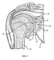
- a typical shoulder or glenohumeral jointis formed in a human body where the humerus 10 movably contacts the scapula 12.
- the scapula 12includes a glenoid fossa 14 that forms a socket against which the head of the humerus 10 articulates.
- the scapula 12includes cartilage 16 that facilitates such articulation.
- Beneath the cartilageis subchondral bone 18 that forms a wall of a glenoid vault 20 that defines a cavity which contains cancellous bone 22.
- the subchondral bone 18 that forms the glenoid vault 20defines a glenoid rim 24 at a periphery of the glenoid vault 20 that is attached to the cartilage 16.
- the glenoid fossa 14may become worn, especially at its posterior and/or superior portions thereby causing severe shoulder pain and limiting the range of motion of the patient's shoulder joint.
- a shoulder arthroplastymay be performed. Arthroplasty is the surgical replacement of one or more bone structures of a joint with one or more prostheses.
- the conventional glenoid componenttypically provides a generally laterally or outwardly facing generally concave bearing surface against which a prosthetic humeral head (or, alternatively, the spared natural humeral head in the case of a glenoid hemi-arthroplasty) may bear during operation of the joint.
- the conventional glenoid componenttypically also includes a generally medially or inwardly projecting stem for fixing the glenoid component in a cavity constructed by suitably resecting the glenoid fossa 14 and suitably resecting cancellous bone 22 from the glenoid vault 20.
- the goal of shoulder arthroplastyis to restore normal kinematics to the shoulder.
- known systemsattempt to replicate the normal kinematics by carefully controlling the geometry of the articulating surfaces in the joint as well as the positioning of the prostheses in the bones in which the prostheses are implanted.
- the articulating surface of a humeral componentis typically spherical and positioning of the humeral component is accomplished by using the anatomical neck of the humerus as the reference plane for reconstruction of the humeral head.
- the articulating surface of the glenoidis typically formed with a radius of curvature that is much larger than the radius of curvature of the humeral component.
- the increased radius of curvature of the glenoid articulating surfacecan be from 2 to 6 mm larger than the radius of curvature for the humeral component in these systems.
- the glenoid componentis positioned in the geometric centre of the glenoid fossa.
- the geometric centreis established by generating a line from the most superior point of the glenoid rim to the most inferior point of the glenoid rim ("Saller's line").
- a second lineis generated between the most posterior point of the glenoid rim and the most anterior point of the glenoid rim.
- the intersection of the two generated linesis considered to be the geometric centre of the area circumscribed by the glenoid rim.
- FIG. 2shows a sagittal view of the scapula 12.
- Saller's line 30extends between the most superior point 32 of the glenoid rim 24 to the most inferior point 34 of the glenoid rim 24.
- a second line 36extends from the most posterior point 38 of the glenoid rim 24 and the most anterior point 40 of the glenoid rim.
- the geometric centre 42 of the glenoid fossa 14is located at the intersection of the line 36 and Saller's line 30.
- the terms anterior, posterior, superior, and inferior, unless otherwise specifically described,are used with respect to the orientation of the scapula 12 as shown in FIG. 2 .
- a guide pinis positioned through the glenoid fossa.
- a reameris then used to shape the scapula to receive a glenoid component, typically by forming a cavity in the glenoid vault.
- a boreis drilled using the guide pin as a guide.
- the guide pinis then removed.
- a drill guideis introduced into the prepared cavity and additional bores are drilled for each of the offset pegs.
- a trial glenoid componentis then implanted in the prepared cavity and, if the fit appears to be satisfactory, the trial is removed and a glenoid component is implanted in the prepared cavity.
- CH-693446discloses a handtool for transmitting rotational drive to a driver tip, the handtool having a first portion for connection to a rotational drive and a second portion which has a tip for engaging a screwdriver bit.
- the handtoolincludes a universal joint transmission connection between the first and second portions.
- the inventionprovides an instrumentation kit for use in preparing a bone to receive a prosthetic component, as defined in claim 1.
- the kitcan be used in a method of preparing a shoulder to receive a glenoid component which includes accessing a glenoid of a shoulder, rotationally coupling a distal portion of a combination device to an instrument, applying a torque to a proximal portion of the combination device, transferring the applied torque from the proximal portion to the distal portion through a pivoting connection, rotating the instrument using the transferred applied torque, and reaming a portion of the glenoid with a rotating reaming section of the instrument using the transferred applied torque.
- the methodincludes pivoting the proximal portion with respect to the distal portion after reaming the portion of the glenoid, rotating the instrument using the pivoted proximal portion, and forming a bore in the glenoid using a first drill guide defined by the instrument.
- the step of rotationally coupling the combination device and the instrumentcomprises:
- the step of rotationally coupling the combination device and the instrumentinvolves inserting the guide wire into a third guide bore in the proximal portion.
- the step of pivoting the proximal portion with respect to the distal portioninvolves moving the proximal portion away from the instrument so that the guide wire is no longer within the third guide bore.
- the step of pivoting the proximal portion with respect to the distal portionincludes pivoting the proximal portion about a pin extending through a first tine of the proximal portion and a second tine of the distal portion.
- the step of moving the proximal portion away from the instrumentdecouples the distal portion of the combination device and the instrument, and the method includes:
- the methodincludes rotating the recoupled distal portion and instrument using the pivoted proximal portion.
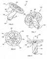
- FIGs. 3 to 5show a glenoid component 100.
- the glenoid component 100includes a body portion 102 including a spherical articulating surface 104 and an opposite bone contacting surface 106.
- An outer wall 108extends away from the bone contacting surface 106 and defines an outer periphery of the body portion 102.
- the bone contacting surface 106is generally convex.
- a finned centre peg 110extends away from the nadir of the bone contacting surface 106 as viewed in FIG. 5 .
- Three offset pegs 112, 114, 116extend away from the bone contacting surface 106 at locations between the centre peg 110 and the outer wall 108.
- the nadir 118 of the spherical articulating surface 104is located on the centerline 120 of the glenoid component 100.
- the glenoid component 100is an integrally formed unit made from a durable biocompatible plastic or any other suitable durable biocompatible material.
- the glenoid component 100may be made from a polyethylene.
- One particular polyethylene that is well suited for glenoid component 100is a high molecular weight polyethylene, for example ultra-high molecular weight polyethylene ("UHMWPE").
- UHMWPEultra-high molecular weight polyethylene
- Components made from a UHMWPE materialare sold by Johnson & Johnson of New Brunswick, New Jersey under the trade mark MARATHON. Details of the material are disclosed in US-6228900 and US-6281264 .
- the portions of the glenoid component 100 other than the articulating surface 104may be made from a suitable biocompatible metal such as, for example, a cobalt chromium alloy, a stainless steel alloy, a titanium alloy, or any other suitable durable material.
- the articulating surface 104is secured to the body portion 102 in any suitable manner.
- articulating surface 104may be bonded to body portion 102, or articulating surface 104 could be made from polyethylene and compression moulded to body portion 102.
- the articulating surface 104may be glued to the body portion 102 by, for example, an adhesive.
- articulating surface 104may be mechanically interlocked to the body portion 102 by taper locking or otherwise press-fitting the articulating surface 104 into the body 102 and the body 102 may include any other suitable interlocking features, for example, rib(s), lip(s), detent(s), and/or other protrusion(s) and mating groove(s), channel(s), or indent(s) (not shown).
- one or more of the outer wall 108, the bone contacting surface 106, the centre peg 110 and the offset pegs 112, 114, 116may include a porous coating to facilitate bone in-growth into the glenoid component 100.
- the porous coatingmay be any suitable porous coating.
- An example of a suitable porous coatingis used in products sold by Johnson & Johnson of New Brunswick, New Jersey under the trade mark POROCOAT. Details of such a coating are disclosed in US-3855638 .
- a combination reamer/drill device 130includes a drive section 132, a body section 134, and a drill or boring section 136.
- the drive section 132 in this instrumentis a hexagonally shaped bore defined in the body section 134.
- a number of reaming fins 140extend from the lower central portion of the body section 134 toward the drill section 136.
- the reaming fins 140curve proximally and outwardly from the lower central portion of the body section 134 to the outer periphery of the body section 134.
- the reaming fins 140include an arcuate leading edge 142.
- the body section 134defines a number of through-holes at locations between adjacent reaming fins 140.
- the through-holes in the instrument of FIGs. 6 to 9include three drill guides 146 and three ports 148.
- the drill section 136extends away from the body section 134 to a distal tip 150.
- Two flutes 152, 154extend helically about the drill section 136 between the body section 134 and the distal tip 150.
- a guide bore 156extends from the distal tip 150 to the drive section 132.
- a kitmay include one or more combination reamer/drill devices 130 along with various instrumentation to facilitate use of the combination reamer/drill device 130.
- FIGs. 10 to 12show a combination power extension/anti-rotation device 160 which is included in the kit.
- the combination power extension/anti-rotation device 160includes a longitudinally extending proximal portion 162 and a longitudinally extending distal portion 164.
- the proximal portion 162includes a power receiving portion 166 and a junction portion 168.
- the power receiving portion 166is sized and configured to couple with a power tool (not shown) and includes a pair of opposing power receiving flats 170 and a pair of coupling grooves 172 and 174 which extend about the power receiving portion 166 between the power receiving flats 170.
- the junction portion 168includes two tines 180, 182 which define a receiving area 184 between them.
- a guide bore 186extends from the receiving area 184 to the proximal tip 188 of the proximal portion 162.
- Two bores 190, 192extend through the respective tines 180, 182.
- the distal portion 164includes a power transfer portion 200 at a distal end 202.
- the power transfer portion 200is shaped to be complimentary to the drive section 132 of the combination reamer/drill 130. In the instrument of FIGs. 10 to 12 , the power transfer portion 200 is thus a hexagonally shaped protrusion sized to fit within the drive section 132.
- a junction portion 204is located at a proximal end 206 of the distal portion 164.
- the junction portion 204includes two tines 208, 210 which define an upper receiving area 212 and a lower receiving area 214 between them.
- a guide bore 216extends from the lower receiving area 214 to the distal end 202 of the distal portion 164.
- Two bores 218, 220extend through the respective tines 208, 210.
- the bores 218, 220are countersunk so that two pins 222, 224 may be received therein and be flush with the outer surface of the tines 208, 210.
- the tines 180, 182 of the proximal portion 162are received with in the upper receiving area 212 of the distal portion 162. Additionally, the bores 190, 192 are aligned with the bores 218, 220, respectively.
- the pin 222is positioned within the aligned bores 190, 218, while the pin 224 is positioned within the aligned bores 192, 220.
- the pins 222, 224 and bores 190, 192, 218, 220are configured to allow the proximal portion 162 to pivot with respect to the distal portion 164 about an axis defined by the pins 222, 224.
- the pins 222, 224in one embodiment are in the form of rivets.
- the pins 222, 224are threadedly engaged with the bores 190, 192, respectively and configured to articulate with the bores 218, 220.
- the guide bore 186 and the guide bore 216lie within the same plane when the combination power extension/anti-rotation handle 160 is assembled. As the proximal portion 162 is pivoted with respect to the distal portion 164, the guide bore 186 pivots within that same plane. Accordingly, the guide bores 186, 216 may be pivoted into alignment with each other. When the guide bores 186, 216 are aligned, the proximal portion 162 and the distal portion 164 are longitudinally aligned as shown in FIG. 10 .
- a kit including the combination reamer/drill device 130 and the power extension/anti-rotation handle 160may be used in preparing a shoulder to receive a glenoid component such as glenoid component 100 in accordance with a procedure 230 shown in FIG. 13 .
- a scapulais accessed at block 232 in accordance with a desired surgical approach.
- a guide wirewhich is provided in the kit along with other instrumentation used in the procedure 230, is positioned on the scapula. Positioning of the guide wire may be computer aided. Optionally, the guide wire is positioned based upon identification of the centre of an inferior glenoid circle.
- FIG. 14shows a guide wire 236 implanted into a glenoid 238 of a scapula 240.
- FIG. 20shows a guide wire 236 which has been positioned with the aid of a guide plate 242 and a guide plate manipulator 244.
- a combination reamer/drill device 130is positioned with the guide bore 156 aligned with the guide wire 236.
- the combination reamer/drill device 130is then moved toward the guide wire 236 and at block 246 the guide wire 236 is used to guide the combination reamer/drill device 130 to a location adjacent to the glenoid 238 of the scapula 240 as shown in FIG. 15 .
- a combination power extension/anti-rotation handle 160is coupled to the combination device 130 by first aligning the guide bore 216 (see FIG. 12 ) with the guide wire 236. The combination power extension/anti-rotation handle 160 is then moved over the guide wire 236 until the guide wire 236 extends through the guide bore 216 and into the lower receiving area 214. The proximal portion 162 is then pivoted with respect to the distal portion 164 as necessary to align the guide bore 186 with the guide wire 236. The combination power extension/anti-rotation handle 160 is then moved over the guide wire 236 until the power transfer portion 200 is adjacent to the drive section 132 of the combination reamer/drill device 130.
- the combination power extension/anti-rotation handle 160is rotated on the guide wire 236 to rotationally align the shaped power transfer portion 200 with the shaped drive section 132 and the power transfer portion 200 is inserted into the drive section 132 resulting in the configuration of FIG. 16 .
- a rotary tool(not shown) is then coupled to the combination power extension/ anti-rotation handle 160 at block 250.
- the rotary toolis coupled to the power receiving portion 166 of the proximal portion 162 so as to be indirectly coupled to the combination reamer/drill device 130.
- Poweris then applied to the rotary tool causing the rotary tool to rotate the combination power extension/anti-rotation handle 160.
- Rotary forceis transferred to the drive section 132 of the combination reamer/drill device 130 through the power transfer portion 164 (see FIG. 12 ). More specifically, torque is passed from the rotary tool to the power receiving portion 166.
- the tines 180, 182, 208, 210are configured such that the torque received by the proximal portion 162 is transferred to the tines 208, 210 through the tines 180, 182.
- the torqueis then transferred from the power transfer portion 200 to the drive section 132, causing the combination reamer/drill device 130 to rotate.
- the drill section 136contacts the glenoid 238 and begins to bore a hole in the glenoid 238.
- the reaming fins 140are initially spaced apart from the glenoid 238 as shown in FIG. 17 . Accordingly, no reaming occurs.
- the combination reamer/drill device 130is guided by the guide wire 236 such that the reaming fins 140 come into contact with the glenoid 238 as shown in FIG. 18 .
- the power toolis deenergized and disconnected at block 254.
- the size of the drill section 132is selected to be complimentary to the size of the centre peg 110 of the glenoid component 100.
- the bore formed by the drill section 132is sized to receive the finned centre peg 110.
- the combination power extension/anti-rotation handle 160is then backed away from the combination reamer/drill device 130 along the guide wire 236 at block 256 until the end of the guide wire 126 is located within the receiving area 184 of the proximal portion 162 resulting in the configuration shown in FIG. 19 . While the guide wire was within the guide bore 186 of the proximal portion 162, the proximal portion 162 was maintained in alignment with the distal portion 164 which enables smooth transfer of torque through the combination power extension/anti-rotation handle 160. Once the guide wire 236 is no longer within the guide bore 186, however, the proximal portion 162 may be pivoted with respect to the distal portion 164 to the configuration shown in FIG. 20 (block 258).
- the combination power extension/anti-rotation handle 160is coupled to the combination device 130 substantially in the manner described above.
- the proximal portion 162may be used as a handle to rotate the coupled combination power extension/anti-rotation handle 160 and combination reamer/drill device 130 about an axis defined by the guide wire 236 as indicated by the arrow 262 of FIG. 21 .
- the combination power extension/anti-rotation handle 160is thus used to align a drill guide 146 in the combination reamer/drill device 130 with a desired location (block 264).
- a handle similar to the handle shown attached to the guide plate manipulator 244 of FIG. 14may be included in the kit. Such a handle may be removably coupled to the power receiving portion 166 of the proximal portion 162 to facilitate manipulation of the combination power extension/anti-rotation handle 160.
- the ability to pivot the proximal portion 162provides a surgeon with a relatively unobstructed view of the combination reamer/drill device 130. Accordingly, the surgeon may view the reamed surface of the glenoid 238 through the drill guides 146. This allows a surgeon to view the location in the scapula 240 at which the offset fixation pegs 112, 114, 116 of the glenoid component 100 will be anchored.
- the surgeonmay orient the combination reamer/drill device 130 such that each of the drill guides 146 is aligned with portions of the scapula 240 that can provide a good anchor for the offset fixation pegs 112, 114, 116.
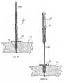
- FIGs. 22 and 23show a drill bit 266 positioned in a drill guide 146 of the combination device 130.
- the combination power extension/anti-rotation handle 160may be used to steady the combination reamer/drill device 130 during the drilling process.
- the offset of the proximal portion 162 from the axis defined by the guide wire 236results in a mechanical advantage in maintaining the combination reamer/drill device 130 at the desired orientation.
- Blocks 264, 268may be repeated as desired to form additional holes.
- the combination reamer/drill device 130is removed at block 270.
- the combination power extension/anti-rotation handle 160may be used to aid in removal of the combination reamer/drill device 130.
- the glenoid componentis implanted.
- the glenoid component 100has a lower bone contacting surface 106 shaped complimentary to the reaming cross-section of the reaming fins 140.
- the lower bone contacting surface 106is curved complimentary to the distal curve of the reaming fins 140.
- the reaming fins 140may be configured to produce a flat bottomed area if a glenoid component with a flat lower bone contacting surface is used. Accordingly, a kit can include different combination devices with differently shaped reaming cross-sections.
- proximal portion 162is only pivotably connected to the distal portion 164
- proximal portionis both pivotably and slidably connected to the distal portion. This can be accomplished by providing longitudinal slots connected to the bores 218, 220.
- the proximal portionmay be moved toward the distal portion.
- additional featuresmay be incorporated in the proximal and distal portions which are selectively interlocked. This arrangement allows for a more robust connection between the proximal portion and the distal portion which is useful in instruments in which weaker materials are desired to be used in forming a combination power extension/anti-rotation handle.
- the guide bores in the proximal portion and the distal portionare positioned substantially immediately adjacent to one another when the proximal and distal portions are aligned.
- pivoting between the proximal and distal portionsis enabled by moving the combination power extension/anti-rotation handle such that the guide wire does not extend into the guide bore in the proximal portion.
Landscapes
- Health & Medical Sciences (AREA)
- Surgery (AREA)
- Life Sciences & Earth Sciences (AREA)
- Biomedical Technology (AREA)
- Medical Informatics (AREA)
- Orthopedic Medicine & Surgery (AREA)
- Oral & Maxillofacial Surgery (AREA)
- Engineering & Computer Science (AREA)
- Dentistry (AREA)
- Heart & Thoracic Surgery (AREA)
- Nuclear Medicine, Radiotherapy & Molecular Imaging (AREA)
- Molecular Biology (AREA)
- Animal Behavior & Ethology (AREA)
- General Health & Medical Sciences (AREA)
- Public Health (AREA)
- Veterinary Medicine (AREA)
- Surgical Instruments (AREA)
- Prostheses (AREA)
Description
- The present invention relates generally to the field of orthopaedics, and, more particularly, to an instrument for use in shoulder arthroplasty.
- As shown in
FIG. 1 , a typical shoulder or glenohumeral joint is formed in a human body where thehumerus 10 movably contacts thescapula 12. Thescapula 12 includes aglenoid fossa 14 that forms a socket against which the head of thehumerus 10 articulates. At this socket, thescapula 12 includescartilage 16 that facilitates such articulation. Beneath the cartilage issubchondral bone 18 that forms a wall of aglenoid vault 20 that defines a cavity which containscancellous bone 22. Thesubchondral bone 18 that forms theglenoid vault 20 defines aglenoid rim 24 at a periphery of theglenoid vault 20 that is attached to thecartilage 16. During the lifetime of a patient, theglenoid fossa 14 may become worn, especially at its posterior and/or superior portions thereby causing severe shoulder pain and limiting the range of motion of the patient's shoulder joint. To alleviate such pain and increase the patient's range of motion, a shoulder arthroplasty may be performed. Arthroplasty is the surgical replacement of one or more bone structures of a joint with one or more prostheses. - Shoulder arthroplasty often involves replacement of the glenoid fossa of the scapula with a prosthetic glenoid component. The conventional glenoid component typically provides a generally laterally or outwardly facing generally concave bearing surface against which a prosthetic humeral head (or, alternatively, the spared natural humeral head in the case of a glenoid hemi-arthroplasty) may bear during operation of the joint. The conventional glenoid component typically also includes a generally medially or inwardly projecting stem for fixing the glenoid component in a cavity constructed by suitably resecting the
glenoid fossa 14 and suitably resectingcancellous bone 22 from theglenoid vault 20. - The goal of shoulder arthroplasty is to restore normal kinematics to the shoulder. Accordingly, known systems attempt to replicate the normal kinematics by carefully controlling the geometry of the articulating surfaces in the joint as well as the positioning of the prostheses in the bones in which the prostheses are implanted. Thus, the articulating surface of a humeral component is typically spherical and positioning of the humeral component is accomplished by using the anatomical neck of the humerus as the reference plane for reconstruction of the humeral head.
- Traditionally, shoulder joints have been understood to exhibit translation of the humeral component on the glenoid component in addition to rotation. Thus, the articulating surface of the glenoid is typically formed with a radius of curvature that is much larger than the radius of curvature of the humeral component. The increased radius of curvature of the glenoid articulating surface can be from 2 to 6 mm larger than the radius of curvature for the humeral component in these systems.
- In known systems, the glenoid component is positioned in the geometric centre of the glenoid fossa. The geometric centre is established by generating a line from the most superior point of the glenoid rim to the most inferior point of the glenoid rim ("Saller's line"). A second line is generated between the most posterior point of the glenoid rim and the most anterior point of the glenoid rim. The intersection of the two generated lines is considered to be the geometric centre of the area circumscribed by the glenoid rim. By way of example,
FIG. 2 shows a sagittal view of thescapula 12. InFIG. 2 , Saller'sline 30 extends between the mostsuperior point 32 of theglenoid rim 24 to the mostinferior point 34 of theglenoid rim 24. Asecond line 36 extends from the mostposterior point 38 of theglenoid rim 24 and the mostanterior point 40 of the glenoid rim. Thegeometric centre 42 of theglenoid fossa 14 is located at the intersection of theline 36 and Saller'sline 30. As used herein, the terms anterior, posterior, superior, and inferior, unless otherwise specifically described, are used with respect to the orientation of thescapula 12 as shown inFIG. 2 . - Once a surgeon determines the placement of the glenoid component, a guide pin is positioned through the glenoid fossa. A reamer is then used to shape the scapula to receive a glenoid component, typically by forming a cavity in the glenoid vault. For glenoid components including a centre peg for fixation of the glenoid component within the glenoid vault, a bore is drilled using the guide pin as a guide. The guide pin is then removed. For glenoid components including offset pegs in addition to the centre peg for fixation of the glenoid component within the glenoid vault, a drill guide is introduced into the prepared cavity and additional bores are drilled for each of the offset pegs. A trial glenoid component is then implanted in the prepared cavity and, if the fit appears to be satisfactory, the trial is removed and a glenoid component is implanted in the prepared cavity.
CH-693446 - There exists a need for reducing the instrumentation required to properly prepare the scapula to receive a glenoid component, allowing simplification of methods for shoulder joint replacement.
- The invention provides an instrumentation kit for use in preparing a bone to receive a prosthetic component, as defined in claim 1.
- The kit can be used in a method of preparing a shoulder to receive a glenoid component which includes accessing a glenoid of a shoulder, rotationally coupling a distal portion of a combination device to an instrument, applying a torque to a proximal portion of the combination device, transferring the applied torque from the proximal portion to the distal portion through a pivoting connection, rotating the instrument using the transferred applied torque, and reaming a portion of the glenoid with a rotating reaming section of the instrument using the transferred applied torque.
- Optionally, the method includes pivoting the proximal portion with respect to the distal portion after reaming the portion of the glenoid, rotating the instrument using the pivoted proximal portion, and forming a bore in the glenoid using a first drill guide defined by the instrument.
- Optionally, the step of rotationally coupling the combination device and the instrument comprises:
- positioning a guide wire in the shoulder,
- inserting the guide wire into a first guide bore in the instrument, and
- inserting the guide wire into a second guide bore in the distal portion.
- Optionally, the step of rotationally coupling the combination device and the instrument involves inserting the guide wire into a third guide bore in the proximal portion.
- Optionally, the step of pivoting the proximal portion with respect to the distal portion involves moving the proximal portion away from the instrument so that the guide wire is no longer within the third guide bore.
- Optionally, the step of pivoting the proximal portion with respect to the distal portion includes pivoting the proximal portion about a pin extending through a first tine of the proximal portion and a second tine of the distal portion.
- Optionally, the step of moving the proximal portion away from the instrument decouples the distal portion of the combination device and the instrument, and the method includes:
- moving the distal portion along the guide wire toward the instrument using the pivoted proximal portion,
- rotationally aligning the distal portion and the instrument using the pivoted proximal portion, and
- recoupling the distal portion and the instrument using the pivoted proximal portion.
- Optionally, the method includes rotating the recoupled distal portion and instrument using the pivoted proximal portion.
- Embodiments of the invention are described below by way of example with reference to the accompanying drawings, in which:
FIG. 1 is a coronal view of an anatomically normal shoulder joint.FIG. 2 is a sagittal view of the shoulder joint ofFIG. 1 .FIG. 3 is a bottom perspective view of a circular glenoid component that may be implanted in a scapula.FIG. 4 is a bottom plan view of the circular glenoid component ofFIG. 3 .FIG. 5 is a side plan view of the circular glenoid component ofFIG. 3 .FIG. 6 is a side perspective view of a combination reamer/drill device that may be used to simultaneously form a bore for receiving a peg of a glenoid component and to ream a glenoid fossa to receive the glenoid component.FIG. 7 is a bottom perspective view of the combination device ofFIG. 6 showing the guide bore extending from a distal tip of the combination device.FIG. 8 is a bottom plan view of the combination device ofFIG. 6 .FIG. 9 is a side plan view of the combination device ofFIG. 6 showing the guide bore extending to a drive section which in this device is a hexagonally shaped bore in a body section of the combination device.FIG. 10 is a perspective view of a combination power extension/anti-rotation handle which may be used with the combination device ofFIG. 6 to couple a power rotary tool (not shown) to the combination device.FIG. 11 is a bottom plan view of the combination power extension/anti-rotation handle ofFIG. 10 showing a guide bore which extends from a distal tip of the lower portion.FIG. 12 is a side cross sectional view of the combination power extension/anti-rotation handle ofFIG. 10 .FIG. 13 is a flowchart showing steps in medical procedure that may be used to implant the circular glenoid component ofFIG. 3 into a scapula using the combination device ofFIG. 10 .FIG. 14 is a perspective view of the scapula ofFIG. 2 with a guide wire positioned in the scapula using a guide template and a guide template manipulator.FIG. 15 is a partial cross-sectional view of the scapula ofFIG. 14 with the combination reamer/drill device ofFIG. 6 guided to a location adjacent to the glenoid fossa by the guide wire ofFIG. 14 .FIG. 16 is a partial cross-sectional view of the scapula ofFIG. 14 with the combination power extension/anti-rotation handle ofFIG. 10 coupled to the combination reamer/drill device ofFIG. 6 , both the combination power extension/anti-rotation handle and the combination reamer/drill device guided to a location adjacent to the glenoid fossa by the guide wire ofFIG. 14 .FIG. 17 is a partial cross-sectional view of the scapula ofFIG. 14 and the coupled combination power extension/anti-rotation handle and the combination reamer/drill devices ofFIG. 16 after the combination reamer/drill device has been used to form a bore in preparation for implanting the glenoid component ofFIG.3 into the scapula.FIG. 18 is a partial cross-sectional view of the scapula ofFIG. 14 and the coupled combination power extension/anti-rotation handle and the combination reamer/drill devices ofFIG. 16 after the combination reamer/drill device has been used to simultaneously ream the glenoid fossa and form a bore in preparation for implanting the glenoid component ofFIG.3 into the scapula.FIG. 19 is a perspective view of the scapula ofFIG. 14 after the combination power extension/anti-rotation handle has been withdrawn along theguide wire 236 to a location that allows pivoting of the proximal portion of the combination power extension/anti-rotation handle.FIG. 20 is a perspective view of the combination power extension/anti-rotation handle after the proximal portion of the combination power extension/anti-rotation handle has been pivoted.FIG. 21 is a perspective view of the scapula ofFIG. 14 after the pivoted combination power extension/anti-rotation handle ofFIG. 20 has been guided by the guide wire ofFIG. 14 and coupled with the combination reamer/drill device ofFIG. 6 allowing a user to manually orient the combination reamer/drill device on the scapula.FIG. 22 is a perspective view of the scapula ofFIG. 14 with the combination reamer/drill device ofFIG. 6 used to guide a drill bit to form a bore to receive an offset peg of the glenoid component ofFIG. 3 while the pivoted combination power extension/anti-rotation handle ofFIG. 20 has been used to manually stabilize the combination reamer/drill device on the scapula.FIG. 23 is a perspective view of the combination reamer/drill device ofFIG. 6 and drill bit ofFIG. 22 with the pivoted combination power extension/anti-rotation handle ofFIG. 20 .- The same reference numerals are used in the drawings to refer to the same parts.
- Referring to the drawings,
FIGs. 3 to 5 show aglenoid component 100. Theglenoid component 100 includes abody portion 102 including a spherical articulatingsurface 104 and an oppositebone contacting surface 106. Anouter wall 108 extends away from thebone contacting surface 106 and defines an outer periphery of thebody portion 102. Thebone contacting surface 106 is generally convex. Afinned centre peg 110 extends away from the nadir of thebone contacting surface 106 as viewed inFIG. 5 . Three offsetpegs bone contacting surface 106 at locations between thecentre peg 110 and theouter wall 108. Thenadir 118 of the spherical articulatingsurface 104 is located on thecenterline 120 of theglenoid component 100. - The
glenoid component 100 is an integrally formed unit made from a durable biocompatible plastic or any other suitable durable biocompatible material. For example, theglenoid component 100 may be made from a polyethylene. One particular polyethylene that is well suited forglenoid component 100 is a high molecular weight polyethylene, for example ultra-high molecular weight polyethylene ("UHMWPE"). Components made from a UHMWPE material are sold by Johnson & Johnson of New Brunswick, New Jersey under the trade mark MARATHON. Details of the material are disclosed inUS-6228900 andUS-6281264 . - In components in which the articulating
surface 104 and the other portions of theglenoid component 100 are made from different materials, the portions of theglenoid component 100 other than the articulatingsurface 104 may be made from a suitable biocompatible metal such as, for example, a cobalt chromium alloy, a stainless steel alloy, a titanium alloy, or any other suitable durable material. In these components, the articulatingsurface 104 is secured to thebody portion 102 in any suitable manner. For example, articulatingsurface 104 may be bonded tobody portion 102, or articulatingsurface 104 could be made from polyethylene and compression moulded tobody portion 102. Alternately, the articulatingsurface 104 may be glued to thebody portion 102 by, for example, an adhesive. Alternatively, articulatingsurface 104 may be mechanically interlocked to thebody portion 102 by taper locking or otherwise press-fitting the articulatingsurface 104 into thebody 102 and thebody 102 may include any other suitable interlocking features, for example, rib(s), lip(s), detent(s), and/or other protrusion(s) and mating groove(s), channel(s), or indent(s) (not shown). - In other components, one or more of the
outer wall 108, thebone contacting surface 106, thecentre peg 110 and the offset pegs 112, 114, 116 may include a porous coating to facilitate bone in-growth into theglenoid component 100. The porous coating may be any suitable porous coating. An example of a suitable porous coating is used in products sold by Johnson & Johnson of New Brunswick, New Jersey under the trade mark POROCOAT. Details of such a coating are disclosed inUS-3855638 . - In order to implant the
glenoid component 100 into a scapula, the scapula must first be prepared to receive theglenoid component 100. A device which can be used to prepare the scapula to receive theglenoid component 100 is shown inFIGs. 6 to 9 . With reference toFIGs. 6 to 9 , a combination reamer/drill device 130 includes adrive section 132, abody section 134, and a drill orboring section 136. Thedrive section 132 in this instrument is a hexagonally shaped bore defined in thebody section 134. - A number of reaming
fins 140 extend from the lower central portion of thebody section 134 toward thedrill section 136. The reamingfins 140 curve proximally and outwardly from the lower central portion of thebody section 134 to the outer periphery of thebody section 134. The reamingfins 140 include an arcuate leading edge 142.Thebody section 134 defines a number of through-holes at locations between adjacent reamingfins 140. The through-holes in the instrument ofFIGs. 6 to 9 include three drill guides 146 and threeports 148. - The
drill section 136 extends away from thebody section 134 to adistal tip 150. Twoflutes drill section 136 between thebody section 134 and thedistal tip 150. A guide bore 156 extends from thedistal tip 150 to thedrive section 132. - As discussed in further detail below, a kit may include one or more combination reamer/
drill devices 130 along with various instrumentation to facilitate use of the combination reamer/drill device 130.FIGs. 10 to 12 show a combination power extension/anti-rotation device 160 which is included in the kit. The combination power extension/anti-rotation device 160 includes a longitudinally extendingproximal portion 162 and a longitudinally extendingdistal portion 164. Theproximal portion 162 includes apower receiving portion 166 and ajunction portion 168. Thepower receiving portion 166 is sized and configured to couple with a power tool (not shown) and includes a pair of opposingpower receiving flats 170 and a pair ofcoupling grooves power receiving portion 166 between thepower receiving flats 170. - The
junction portion 168 includes twotines area 184 between them. A guide bore 186 extends from the receivingarea 184 to theproximal tip 188 of theproximal portion 162. Two bores 190, 192 extend through therespective tines - The
distal portion 164 includes apower transfer portion 200 at adistal end 202. Thepower transfer portion 200 is shaped to be complimentary to thedrive section 132 of the combination reamer/drill 130. In the instrument ofFIGs. 10 to 12 , thepower transfer portion 200 is thus a hexagonally shaped protrusion sized to fit within thedrive section 132. - A
junction portion 204 is located at aproximal end 206 of thedistal portion 164. Thejunction portion 204 includes twotines upper receiving area 212 and alower receiving area 214 between them. A guide bore 216 extends from thelower receiving area 214 to thedistal end 202 of thedistal portion 164. Two bores 218, 220 extend through therespective tines bores pins tines - When the combination power extension/
anti-rotation handle 160 is assembled, thetines proximal portion 162 are received with in theupper receiving area 212 of thedistal portion 162. Additionally, thebores bores pin 222 is positioned within the aligned bores 190, 218, while thepin 224 is positioned within the aligned bores 192, 220. Thepins proximal portion 162 to pivot with respect to thedistal portion 164 about an axis defined by thepins pins pins bores bores - Additionally, the guide bore 186 and the guide bore 216 lie within the same plane when the combination power extension/
anti-rotation handle 160 is assembled. As theproximal portion 162 is pivoted with respect to thedistal portion 164, the guide bore 186 pivots within that same plane. Accordingly, the guide bores 186, 216 may be pivoted into alignment with each other. When the guide bores 186, 216 are aligned, theproximal portion 162 and thedistal portion 164 are longitudinally aligned as shown inFIG. 10 . - A kit including the combination reamer/
drill device 130 and the power extension/anti-rotation handle 160 may be used in preparing a shoulder to receive a glenoid component such asglenoid component 100 in accordance with aprocedure 230 shown inFIG. 13 . Initially, a scapula is accessed atblock 232 in accordance with a desired surgical approach. Atblock 234, a guide wire, which is provided in the kit along with other instrumentation used in theprocedure 230, is positioned on the scapula. Positioning of the guide wire may be computer aided. Optionally, the guide wire is positioned based upon identification of the centre of an inferior glenoid circle. By way of example,FIG. 14 shows aguide wire 236 implanted into a glenoid 238 of ascapula 240.FIG. 20 shows aguide wire 236 which has been positioned with the aid of aguide plate 242 and aguide plate manipulator 244. - Once the guide wire is positioned, a combination reamer/
drill device 130 is positioned with the guide bore 156 aligned with theguide wire 236. The combination reamer/drill device 130 is then moved toward theguide wire 236 and atblock 246 theguide wire 236 is used to guide the combination reamer/drill device 130 to a location adjacent to the glenoid 238 of thescapula 240 as shown inFIG. 15 . - At
block 248, a combination power extension/anti-rotation handle 160 is coupled to thecombination device 130 by first aligning the guide bore 216 (seeFIG. 12 ) with theguide wire 236. The combination power extension/anti-rotation handle 160 is then moved over theguide wire 236 until theguide wire 236 extends through the guide bore 216 and into thelower receiving area 214. Theproximal portion 162 is then pivoted with respect to thedistal portion 164 as necessary to align the guide bore 186 with theguide wire 236. The combination power extension/anti-rotation handle 160 is then moved over theguide wire 236 until thepower transfer portion 200 is adjacent to thedrive section 132 of the combination reamer/drill device 130. If needed, the combination power extension/anti-rotation handle 160 is rotated on theguide wire 236 to rotationally align the shapedpower transfer portion 200 with the shapeddrive section 132 and thepower transfer portion 200 is inserted into thedrive section 132 resulting in the configuration ofFIG. 16 . - A rotary tool (not shown) is then coupled to the combination power extension/ anti-rotation handle 160 at
block 250. Thus, the rotary tool is coupled to thepower receiving portion 166 of theproximal portion 162 so as to be indirectly coupled to the combination reamer/drill device 130. - Power is then applied to the rotary tool causing the rotary tool to rotate the combination power extension/
anti-rotation handle 160. Rotary force is transferred to thedrive section 132 of the combination reamer/drill device 130 through the power transfer portion 164 (seeFIG. 12 ). More specifically, torque is passed from the rotary tool to thepower receiving portion 166. Thetines proximal portion 162 is transferred to thetines tines power transfer portion 200 to thedrive section 132, causing the combination reamer/drill device 130 to rotate. - As the combination reamer/
drill device 130 initially rotates about theguide wire 236, thedrill section 136 contacts the glenoid 238 and begins to bore a hole in the glenoid 238. The reamingfins 140, however, are initially spaced apart from the glenoid 238 as shown inFIG. 17 . Accordingly, no reaming occurs. As a hole is formed in the glenoid 238 by thedrill section 136, the combination reamer/drill device 130 is guided by theguide wire 236 such that the reamingfins 140 come into contact with the glenoid 238 as shown inFIG. 18 . Continued rotation of the combination reamer/drill device 130 with the rotary tool thus causes simultaneous reaming of the glenoid 238 with the reamingfins 140 and boring of thescapula 240 with thedrill section 136 atblock 252. - Once the glenoid 238 has been reamed to the desired depth, the power tool is deenergized and disconnected at
block 254. The size of thedrill section 132, both in length and diameter, is selected to be complimentary to the size of thecentre peg 110 of theglenoid component 100. Thus, upon completion of the reaming, the bore formed by thedrill section 132 is sized to receive thefinned centre peg 110. - The combination power extension/
anti-rotation handle 160 is then backed away from the combination reamer/drill device 130 along theguide wire 236 atblock 256 until the end of the guide wire 126 is located within the receivingarea 184 of theproximal portion 162 resulting in the configuration shown inFIG. 19 . While the guide wire was within the guide bore 186 of theproximal portion 162, theproximal portion 162 was maintained in alignment with thedistal portion 164 which enables smooth transfer of torque through the combination power extension/anti-rotation handle 160. Once theguide wire 236 is no longer within the guide bore 186, however, theproximal portion 162 may be pivoted with respect to thedistal portion 164 to the configuration shown inFIG. 20 (block 258). - At
block 260, the combination power extension/anti-rotation handle 160 is coupled to thecombination device 130 substantially in the manner described above. However, since theguide wire 236 does not extend through theproximal portion 162, theproximal portion 162 may be used as a handle to rotate the coupled combination power extension/anti-rotation handle 160 and combination reamer/drill device 130 about an axis defined by theguide wire 236 as indicated by thearrow 262 ofFIG. 21 . The combination power extension/anti-rotation handle 160 is thus used to align adrill guide 146 in the combination reamer/drill device 130 with a desired location (block 264). Optionally, a handle similar to the handle shown attached to theguide plate manipulator 244 ofFIG. 14 may be included in the kit. Such a handle may be removably coupled to thepower receiving portion 166 of theproximal portion 162 to facilitate manipulation of the combination power extension/anti-rotation handle 160. - The ability to pivot the
proximal portion 162 provides a surgeon with a relatively unobstructed view of the combination reamer/drill device 130. Accordingly, the surgeon may view the reamed surface of the glenoid 238 through the drill guides 146. This allows a surgeon to view the location in thescapula 240 at which the offset fixation pegs 112, 114, 116 of theglenoid component 100 will be anchored. In instruments according to this example in which the number and positioning of the drill guides 146 are complimentary to the number and positioning of the offset fixation pegs 112, 114, 116, the surgeon may orient the combination reamer/drill device 130 such that each of the drill guides 146 is aligned with portions of thescapula 240 that can provide a good anchor for the offset fixation pegs 112, 114, 116. - Once the combination reamer/
drill device 130 is aligned at theblock 264, a drill bit is inserted through one of the drill guides 146 to drill an additional bore at a location spaced apart from the first bore formed using thedrill section 136 atblock 230. By way of example,FIGs. 22 and 23 show adrill bit 266 positioned in adrill guide 146 of thecombination device 130. The combination power extension/anti-rotation handle 160 may be used to steady the combination reamer/drill device 130 during the drilling process. The offset of theproximal portion 162 from the axis defined by theguide wire 236 results in a mechanical advantage in maintaining the combination reamer/drill device 130 at the desired orientation.Blocks - Once all of the desired holes are formed, the combination reamer/
drill device 130 is removed atblock 270. The combination power extension/anti-rotation handle 160 may be used to aid in removal of the combination reamer/drill device 130. Atblock 272, the glenoid component is implanted. In this example, theglenoid component 100 has a lowerbone contacting surface 106 shaped complimentary to the reaming cross-section of the reamingfins 140. Thus, in this example the lowerbone contacting surface 106 is curved complimentary to the distal curve of the reamingfins 140. In other examples, the reamingfins 140 may be configured to produce a flat bottomed area if a glenoid component with a flat lower bone contacting surface is used. Accordingly, a kit can include different combination devices with differently shaped reaming cross-sections. - Moreover, while in the instrument shown in
FIGs. 10 to 12 theproximal portion 162 is only pivotably connected to thedistal portion 164, in another instrument the proximal portion is both pivotably and slidably connected to the distal portion. This can be accomplished by providing longitudinal slots connected to thebores - In yet another instrument, the guide bores in the proximal portion and the distal portion are positioned substantially immediately adjacent to one another when the proximal and distal portions are aligned. In this instrument, pivoting between the proximal and distal portions is enabled by moving the combination power extension/anti-rotation handle such that the guide wire does not extend into the guide bore in the proximal portion.
Claims (5)
- An instrumentation kit for use in preparing a bone to receive a prosthetic component, comprising at least one first combination device (160) which includes a proximal portion (162) configured to couple with a torque providing device and a distal portion (164) configured to couple with a first instrument (130), in which:the proximal portion has first and second tines (180, 182) at one end, andthe distal portion has first and second tines (208, 210) at one end,the first tine (180) on the proximal portion being pivotally connected to the first tine (208) on the distal portion, and the second tine (182) on the proximal portion being pivotally connected to the second tine (210) on the distal portion so that the at least one first combination device can be pivoted between:a first position in which the proximal portion and the distal portion are (i) longitudinally aligned and (ii) configured to transfer a torque received by the proximal portion to the distal portion, anda second position in which the proximal portion and the distal position are (i) not longitudinally aligned and (ii) configured to transfer a torque received by the proximal portion to the distal portion,characterisedinthat the kit includes a guide wire (236), and the proximal portion (162) of the first combination device has a first guide bore (186) extending through it and the distal portion (164) has a second guide bore (216) extending through it, the first guide bore being aligned with the second guide bore when the first combination device is in its first position allowing the guide wire to extend through the proximal and distal portions, and the first guide bore being not aligned with the second guide bore when the first combination device is in its second position allowing the guide wire to extend through the distal portion but not through the proximal portion.
- The instrumentation kit of claim 1, in which:the first and second tines (180, 182) on the proximal portion (162) define a first receiving area (184) between them,the first and second tines (208, 210) on the distal portion (164) define a second receiving area (214) between them,the first guide bore (186) extends from the proximal tip (188) of the proximal portion to the first receiving area, andthe second guide bore (216) extends from the distal end (202) of the distal portion to the second receiving area.
- The instrumentation kit of claim 1, in which the said first instrument (130) is included in the kit and comprises:a boring section (136) configured to rotationally form a first bore in a bone,a drive section (132) operably connected to the boring section and configured to receive a rotational force,a reaming section (140) positioned proximally from the boring section and operably connected to the drive section, the reaming section configured to rotationally ream a portion of the bone, andat least one drill guide (146) configured to guide a drill bit and positioned so as to guide the drill bit to form a second bore in the bone at a location spaced apart from the first bore,in which the reaming section and the boring section are positioned with respect to each other such that when the combination device is positioned against the bone and the rotational force is applied to the drive section, the boring section rotationally forms a portion of the first bore in the bone and the reaming section simultaneously rotationally reams a portion of the bone adjacent to the first bore.
- The kit of claim 3, in which:the first instrument (130) includes a third guide bore (156) extending from a distal tip (150) of the boring section (136) to the drive section (132), andthe third guide bore (156) is aligned with the second guide bore (216) when the distal portion (164) is coupled with the first instrument.
- The kit of claim 3, which includes a second instrument, the second instrument comprising:a boring section (136) configured to rotationally form a first bore in the bone,a drive section (132) operably connected to the boring section and configured to receive a rotational force, anda reaming section (140) positioned proximally from the boring section and operably connected to the drive section, the reaming section configured to rotationally ream a portion of the bone, in which the second instrument defines a reaming diameter different from a reaming diameter defined by the first instrument.
Applications Claiming Priority (1)
| Application Number | Priority Date | Filing Date | Title |
|---|---|---|---|
| US13/363,583US9763679B2 (en) | 2011-03-18 | 2012-02-01 | Combination driver/anti-rotation handle for shoulder arthroplasty |
Publications (2)
| Publication Number | Publication Date |
|---|---|
| EP2623050A1 EP2623050A1 (en) | 2013-08-07 |
| EP2623050B1true EP2623050B1 (en) | 2014-11-26 |
Family
ID=47627998
Family Applications (1)
| Application Number | Title | Priority Date | Filing Date |
|---|---|---|---|
| EP13151417.6AActiveEP2623050B1 (en) | 2012-02-01 | 2013-01-16 | Instrument for use in shoulder arthroplasty |
Country Status (6)
| Country | Link |
|---|---|
| EP (1) | EP2623050B1 (en) |
| JP (1) | JP6192943B2 (en) |
| CN (1) | CN103239260B (en) |
| AU (2) | AU2013200329A1 (en) |
| DK (1) | DK2623050T3 (en) |
| ES (1) | ES2528706T3 (en) |
Families Citing this family (2)
| Publication number | Priority date | Publication date | Assignee | Title |
|---|---|---|---|---|
| WO2016183437A1 (en)* | 2015-05-13 | 2016-11-17 | Smith & Nephew, Inc. | System for orthopedic implantation preparation |
| US9737313B1 (en) | 2016-11-07 | 2017-08-22 | Roger C. Sohn | Shoulder reamer devices, systems including the same, and related methods |
Family Cites Families (16)
| Publication number | Priority date | Publication date | Assignee | Title |
|---|---|---|---|---|
| US2487203A (en)* | 1946-07-17 | 1949-11-08 | Arthur L Wilber | Flexible drive for drills |
| CA962806A (en) | 1970-06-04 | 1975-02-18 | Ontario Research Foundation | Surgical prosthetic device |
| US5180384A (en)* | 1991-02-08 | 1993-01-19 | Mikhail Michael W E | Method for implanting a patellar prosthesis |
| JPH05123336A (en)* | 1991-11-08 | 1993-05-21 | Aisin Seiki Co Ltd | Surgery device for artificial joint replacement |
| CA2166450C (en) | 1995-01-20 | 2008-03-25 | Ronald Salovey | Chemically crosslinked ultrahigh molecular weight polyethylene for artificial human joints |
| US6228900B1 (en) | 1996-07-09 | 2001-05-08 | The Orthopaedic Hospital And University Of Southern California | Crosslinking of polyethylene for low wear using radiation and thermal treatments |
| US6379386B1 (en)* | 1997-09-09 | 2002-04-30 | Stryker Technologies Corporation | Anatomic glenoid shoulder prosthesis together with methods and tools for implanting same |
| US6045302A (en)* | 1999-03-04 | 2000-04-04 | Orr; Pat | Drill bit retriever device |
| CH693446A5 (en) | 1999-06-10 | 2003-08-15 | Precimed Sa | Hand tool with universal joint transmission has spring-loaded stud interacting by friction with cylindrical surfaces of spider |
| US6689138B2 (en)* | 2001-01-19 | 2004-02-10 | Precimed S.A. | Torque-transmitting coupling |
| US7217271B2 (en)* | 2002-09-13 | 2007-05-15 | Symmetry Medical, Inc. | Orthopaedic reamer driver for minimally invasive surgery |
| US20070043376A1 (en)* | 2003-02-21 | 2007-02-22 | Osteobiologics, Inc. | Bone and cartilage implant delivery device |
| US7338498B2 (en)* | 2003-03-31 | 2008-03-04 | Depuy Products, Inc. | Prosthetic implant, trial and associated method |
| RU2400186C2 (en)* | 2005-04-11 | 2010-09-27 | Имплиант Лтд. | Introduction of anterior and posterior spinal prostheses |
| US7815433B2 (en)* | 2005-06-10 | 2010-10-19 | Tti Turner Technology Instruments Inc. | Adjustable tool drive arrangement |
| EP2451365B1 (en)* | 2009-07-10 | 2015-07-01 | Kirk Promotion LTD. | Hip joint instrument |
- 2013
- 2013-01-16ESES13151417.6Tpatent/ES2528706T3/enactiveActive
- 2013-01-16EPEP13151417.6Apatent/EP2623050B1/enactiveActive
- 2013-01-16DKDK13151417.6Tpatent/DK2623050T3/enactive
- 2013-01-23AUAU2013200329Apatent/AU2013200329A1/ennot_activeAbandoned
- 2013-01-31JPJP2013016623Apatent/JP6192943B2/enactiveActive
- 2013-02-01CNCN201310040886.8Apatent/CN103239260B/enactiveActive
- 2018
- 2018-08-20AUAU2018217341Apatent/AU2018217341B2/enactiveActive
Also Published As
| Publication number | Publication date |
|---|---|
| DK2623050T3 (en) | 2015-01-26 |
| AU2018217341A1 (en) | 2018-09-06 |
| JP2013158648A (en) | 2013-08-19 |
| CN103239260A (en) | 2013-08-14 |
| AU2018217341B2 (en) | 2019-04-04 |
| ES2528706T3 (en) | 2015-02-11 |
| JP6192943B2 (en) | 2017-09-06 |
| AU2013200329A1 (en) | 2013-08-15 |
| CN103239260B (en) | 2016-11-23 |
| EP2623050A1 (en) | 2013-08-07 |
Similar Documents
| Publication | Publication Date | Title |
|---|---|---|
| US11369390B2 (en) | Method using a combination reamer/drill bit for shoulder arthroplasty | |
| US11298141B2 (en) | Method of using a combination driver/anti-rotation handle for shoulder arthroplasty | |
| EP2301481B1 (en) | Expandable reverse shoulder trial | |
| US8216320B2 (en) | Expanding trial stem for orthopaedic surgery | |
| US6875237B2 (en) | Driving instrument with variably angled joint and extended tip and method of use for minimally invasive hip surgery | |
| EP1905397B1 (en) | Instrument kit for a modular orthopaedic prosthesis | |
| US20060149390A1 (en) | Punch, implant and associated method | |
| AU2018217341B2 (en) | Combination driver/anti-rotation handle for shoulder arthroplasty | |
| US20230157832A1 (en) | Humeral Implant and Method |
Legal Events
| Date | Code | Title | Description |
|---|---|---|---|
| PUAI | Public reference made under article 153(3) epc to a published international application that has entered the european phase | Free format text:ORIGINAL CODE: 0009012 | |
| AK | Designated contracting states | Kind code of ref document:A1 Designated state(s):AL AT BE BG CH CY CZ DE DK EE ES FI FR GB GR HR HU IE IS IT LI LT LU LV MC MK MT NL NO PL PT RO RS SE SI SK SM TR | |
| AX | Request for extension of the european patent | Extension state:BA ME | |
| RAP1 | Party data changed (applicant data changed or rights of an application transferred) | Owner name:DEPUY SYNTHES PRODUCTS, LLC | |
| 17P | Request for examination filed | Effective date:20140124 | |
| RBV | Designated contracting states (corrected) | Designated state(s):AL AT BE BG CH CY CZ DE DK EE ES FI FR GB GR HR HU IE IS IT LI LT LU LV MC MK MT NL NO PL PT RO RS SE SI SK SM TR | |
| GRAP | Despatch of communication of intention to grant a patent | Free format text:ORIGINAL CODE: EPIDOSNIGR1 | |
| RIC1 | Information provided on ipc code assigned before grant | Ipc:A61B 17/16 20060101AFI20140626BHEP | |
| INTG | Intention to grant announced | Effective date:20140718 | |
| GRAS | Grant fee paid | Free format text:ORIGINAL CODE: EPIDOSNIGR3 | |
| GRAA | (expected) grant | Free format text:ORIGINAL CODE: 0009210 | |
| AK | Designated contracting states | Kind code of ref document:B1 Designated state(s):AL AT BE BG CH CY CZ DE DK EE ES FI FR GB GR HR HU IE IS IT LI LT LU LV MC MK MT NL NO PL PT RO RS SE SI SK SM TR | |
| REG | Reference to a national code | Ref country code:GB Ref legal event code:FG4D | |
| REG | Reference to a national code | Ref country code:CH Ref legal event code:NV Representative=s name:E. BLUM AND CO. AG PATENT- UND MARKENANWAELTE , CH Ref country code:CH Ref legal event code:EP | |
| REG | Reference to a national code | Ref country code:AT Ref legal event code:REF Ref document number:697725 Country of ref document:AT Kind code of ref document:T Effective date:20141215 | |
| REG | Reference to a national code | Ref country code:IE Ref legal event code:FG4D | |
| REG | Reference to a national code | Ref country code:DE Ref legal event code:R096 Ref document number:602013000509 Country of ref document:DE Effective date:20150108 | |
| REG | Reference to a national code | Ref country code:DK Ref legal event code:T3 Effective date:20150122 | |
| REG | Reference to a national code | Ref country code:ES Ref legal event code:FG2A Ref document number:2528706 Country of ref document:ES Kind code of ref document:T3 Effective date:20150211 | |
| REG | Reference to a national code | Ref country code:NL Ref legal event code:T3 | |
| REG | Reference to a national code | Ref country code:SE Ref legal event code:TRGR | |
| REG | Reference to a national code | Ref country code:LT Ref legal event code:MG4D | |
| PG25 | Lapsed in a contracting state [announced via postgrant information from national office to epo] | Ref country code:NO Free format text:LAPSE BECAUSE OF FAILURE TO SUBMIT A TRANSLATION OF THE DESCRIPTION OR TO PAY THE FEE WITHIN THE PRESCRIBED TIME-LIMIT Effective date:20150226 Ref country code:IS Free format text:LAPSE BECAUSE OF FAILURE TO SUBMIT A TRANSLATION OF THE DESCRIPTION OR TO PAY THE FEE WITHIN THE PRESCRIBED TIME-LIMIT Effective date:20150326 Ref country code:LT Free format text:LAPSE BECAUSE OF FAILURE TO SUBMIT A TRANSLATION OF THE DESCRIPTION OR TO PAY THE FEE WITHIN THE PRESCRIBED TIME-LIMIT Effective date:20141126 Ref country code:PT Free format text:LAPSE BECAUSE OF FAILURE TO SUBMIT A TRANSLATION OF THE DESCRIPTION OR TO PAY THE FEE WITHIN THE PRESCRIBED TIME-LIMIT Effective date:20150326 | |
| PG25 | Lapsed in a contracting state [announced via postgrant information from national office to epo] | Ref country code:RS Free format text:LAPSE BECAUSE OF FAILURE TO SUBMIT A TRANSLATION OF THE DESCRIPTION OR TO PAY THE FEE WITHIN THE PRESCRIBED TIME-LIMIT Effective date:20141126 Ref country code:CY Free format text:LAPSE BECAUSE OF FAILURE TO SUBMIT A TRANSLATION OF THE DESCRIPTION OR TO PAY THE FEE WITHIN THE PRESCRIBED TIME-LIMIT Effective date:20141126 Ref country code:GR Free format text:LAPSE BECAUSE OF FAILURE TO SUBMIT A TRANSLATION OF THE DESCRIPTION OR TO PAY THE FEE WITHIN THE PRESCRIBED TIME-LIMIT Effective date:20150227 Ref country code:HR Free format text:LAPSE BECAUSE OF FAILURE TO SUBMIT A TRANSLATION OF THE DESCRIPTION OR TO PAY THE FEE WITHIN THE PRESCRIBED TIME-LIMIT Effective date:20141126 Ref country code:LV Free format text:LAPSE BECAUSE OF FAILURE TO SUBMIT A TRANSLATION OF THE DESCRIPTION OR TO PAY THE FEE WITHIN THE PRESCRIBED TIME-LIMIT Effective date:20141126 | |
| PG25 | Lapsed in a contracting state [announced via postgrant information from national office to epo] | Ref country code:SK Free format text:LAPSE BECAUSE OF FAILURE TO SUBMIT A TRANSLATION OF THE DESCRIPTION OR TO PAY THE FEE WITHIN THE PRESCRIBED TIME-LIMIT Effective date:20141126 Ref country code:RO Free format text:LAPSE BECAUSE OF FAILURE TO SUBMIT A TRANSLATION OF THE DESCRIPTION OR TO PAY THE FEE WITHIN THE PRESCRIBED TIME-LIMIT Effective date:20141126 Ref country code:CZ Free format text:LAPSE BECAUSE OF FAILURE TO SUBMIT A TRANSLATION OF THE DESCRIPTION OR TO PAY THE FEE WITHIN THE PRESCRIBED TIME-LIMIT Effective date:20141126 Ref country code:EE Free format text:LAPSE BECAUSE OF FAILURE TO SUBMIT A TRANSLATION OF THE DESCRIPTION OR TO PAY THE FEE WITHIN THE PRESCRIBED TIME-LIMIT Effective date:20141126 | |
| REG | Reference to a national code | Ref country code:DE Ref legal event code:R097 Ref document number:602013000509 Country of ref document:DE | |
| PG25 | Lapsed in a contracting state [announced via postgrant information from national office to epo] | Ref country code:LU Free format text:LAPSE BECAUSE OF FAILURE TO SUBMIT A TRANSLATION OF THE DESCRIPTION OR TO PAY THE FEE WITHIN THE PRESCRIBED TIME-LIMIT Effective date:20150116 Ref country code:PL Free format text:LAPSE BECAUSE OF FAILURE TO SUBMIT A TRANSLATION OF THE DESCRIPTION OR TO PAY THE FEE WITHIN THE PRESCRIBED TIME-LIMIT Effective date:20141126 | |
| PG25 | Lapsed in a contracting state [announced via postgrant information from national office to epo] | Ref country code:MC Free format text:LAPSE BECAUSE OF FAILURE TO SUBMIT A TRANSLATION OF THE DESCRIPTION OR TO PAY THE FEE WITHIN THE PRESCRIBED TIME-LIMIT Effective date:20141126 | |
| PLBE | No opposition filed within time limit | Free format text:ORIGINAL CODE: 0009261 | |
| STAA | Information on the status of an ep patent application or granted ep patent | Free format text:STATUS: NO OPPOSITION FILED WITHIN TIME LIMIT | |
| 26N | No opposition filed | Effective date:20150827 | |
| REG | Reference to a national code | Ref country code:FR Ref legal event code:PLFP Year of fee payment:4 | |
| PG25 | Lapsed in a contracting state [announced via postgrant information from national office to epo] | Ref country code:SI Free format text:LAPSE BECAUSE OF FAILURE TO SUBMIT A TRANSLATION OF THE DESCRIPTION OR TO PAY THE FEE WITHIN THE PRESCRIBED TIME-LIMIT Effective date:20141126 | |
| REG | Reference to a national code | Ref country code:AT Ref legal event code:UEP Ref document number:697725 Country of ref document:AT Kind code of ref document:T Effective date:20141126 | |
| REG | Reference to a national code | Ref country code:FR Ref legal event code:PLFP Year of fee payment:5 | |
| PG25 | Lapsed in a contracting state [announced via postgrant information from national office to epo] | Ref country code:MT Free format text:LAPSE BECAUSE OF FAILURE TO SUBMIT A TRANSLATION OF THE DESCRIPTION OR TO PAY THE FEE WITHIN THE PRESCRIBED TIME-LIMIT Effective date:20141126 | |
| PG25 | Lapsed in a contracting state [announced via postgrant information from national office to epo] | Ref country code:BG Free format text:LAPSE BECAUSE OF FAILURE TO SUBMIT A TRANSLATION OF THE DESCRIPTION OR TO PAY THE FEE WITHIN THE PRESCRIBED TIME-LIMIT Effective date:20141126 Ref country code:HU Free format text:LAPSE BECAUSE OF FAILURE TO SUBMIT A TRANSLATION OF THE DESCRIPTION OR TO PAY THE FEE WITHIN THE PRESCRIBED TIME-LIMIT; INVALID AB INITIO Effective date:20130116 | |
| PG25 | Lapsed in a contracting state [announced via postgrant information from national office to epo] | Ref country code:TR Free format text:LAPSE BECAUSE OF FAILURE TO SUBMIT A TRANSLATION OF THE DESCRIPTION OR TO PAY THE FEE WITHIN THE PRESCRIBED TIME-LIMIT Effective date:20141126 | |
| REG | Reference to a national code | Ref country code:FR Ref legal event code:PLFP Year of fee payment:6 | |
| PGFP | Annual fee paid to national office [announced via postgrant information from national office to epo] | Ref country code:FI Payment date:20180110 Year of fee payment:6 Ref country code:DK Payment date:20180110 Year of fee payment:6 | |
| PG25 | Lapsed in a contracting state [announced via postgrant information from national office to epo] | Ref country code:SM Free format text:LAPSE BECAUSE OF FAILURE TO SUBMIT A TRANSLATION OF THE DESCRIPTION OR TO PAY THE FEE WITHIN THE PRESCRIBED TIME-LIMIT Effective date:20141126 | |
| PGFP | Annual fee paid to national office [announced via postgrant information from national office to epo] | Ref country code:SE Payment date:20180111 Year of fee payment:6 Ref country code:AT Payment date:20171228 Year of fee payment:6 | |
| PG25 | Lapsed in a contracting state [announced via postgrant information from national office to epo] | Ref country code:MK Free format text:LAPSE BECAUSE OF FAILURE TO SUBMIT A TRANSLATION OF THE DESCRIPTION OR TO PAY THE FEE WITHIN THE PRESCRIBED TIME-LIMIT Effective date:20141126 | |
| PG25 | Lapsed in a contracting state [announced via postgrant information from national office to epo] | Ref country code:AL Free format text:LAPSE BECAUSE OF FAILURE TO SUBMIT A TRANSLATION OF THE DESCRIPTION OR TO PAY THE FEE WITHIN THE PRESCRIBED TIME-LIMIT Effective date:20141126 | |
| REG | Reference to a national code | Ref country code:DK Ref legal event code:EBP Effective date:20190131 | |
| REG | Reference to a national code | Ref country code:AT Ref legal event code:MM01 Ref document number:697725 Country of ref document:AT Kind code of ref document:T Effective date:20190116 | |
| PG25 | Lapsed in a contracting state [announced via postgrant information from national office to epo] | Ref country code:FI Free format text:LAPSE BECAUSE OF NON-PAYMENT OF DUE FEES Effective date:20190116 Ref country code:SE Free format text:LAPSE BECAUSE OF NON-PAYMENT OF DUE FEES Effective date:20190117 | |
| PG25 | Lapsed in a contracting state [announced via postgrant information from national office to epo] | Ref country code:AT Free format text:LAPSE BECAUSE OF NON-PAYMENT OF DUE FEES Effective date:20190116 | |
| PG25 | Lapsed in a contracting state [announced via postgrant information from national office to epo] | Ref country code:DK Free format text:LAPSE BECAUSE OF NON-PAYMENT OF DUE FEES Effective date:20190131 | |
| PGFP | Annual fee paid to national office [announced via postgrant information from national office to epo] | Ref country code:NL Payment date:20241213 Year of fee payment:13 Ref country code:BE Payment date:20241220 Year of fee payment:13 | |
| PGFP | Annual fee paid to national office [announced via postgrant information from national office to epo] | Ref country code:GB Payment date:20241128 Year of fee payment:13 | |
| PGFP | Annual fee paid to national office [announced via postgrant information from national office to epo] | Ref country code:FR Payment date:20241209 Year of fee payment:13 | |
| PGFP | Annual fee paid to national office [announced via postgrant information from national office to epo] | Ref country code:IE Payment date:20241209 Year of fee payment:13 | |
| PGFP | Annual fee paid to national office [announced via postgrant information from national office to epo] | Ref country code:DE Payment date:20241203 Year of fee payment:13 | |
| PGFP | Annual fee paid to national office [announced via postgrant information from national office to epo] | Ref country code:ES Payment date:20250210 Year of fee payment:13 | |
| PGFP | Annual fee paid to national office [announced via postgrant information from national office to epo] | Ref country code:CH Payment date:20250201 Year of fee payment:13 | |
| PGFP | Annual fee paid to national office [announced via postgrant information from national office to epo] | Ref country code:IT Payment date:20241210 Year of fee payment:13 |