EP2621766B1 - Deformable lower windscreen cross-member - Google Patents
Deformable lower windscreen cross-memberDownload PDFInfo
- Publication number
- EP2621766B1 EP2621766B1EP11771218.2AEP11771218AEP2621766B1EP 2621766 B1EP2621766 B1EP 2621766B1EP 11771218 AEP11771218 AEP 11771218AEP 2621766 B1EP2621766 B1EP 2621766B1
- Authority
- EP
- European Patent Office
- Prior art keywords
- edge
- transverse
- motor vehicle
- windshield
- receiving
- Prior art date
- Legal status (The legal status is an assumption and is not a legal conclusion. Google has not performed a legal analysis and makes no representation as to the accuracy of the status listed.)
- Not-in-force
Links
Images
Classifications
- B—PERFORMING OPERATIONS; TRANSPORTING
- B62—LAND VEHICLES FOR TRAVELLING OTHERWISE THAN ON RAILS
- B62D—MOTOR VEHICLES; TRAILERS
- B62D25/00—Superstructure or monocoque structure sub-units; Parts or details thereof not otherwise provided for
- B62D25/08—Front or rear portions
- B—PERFORMING OPERATIONS; TRANSPORTING
- B62—LAND VEHICLES FOR TRAVELLING OTHERWISE THAN ON RAILS
- B62D—MOTOR VEHICLES; TRAILERS
- B62D25/00—Superstructure or monocoque structure sub-units; Parts or details thereof not otherwise provided for
- B62D25/08—Front or rear portions
- B62D25/081—Cowls
- B—PERFORMING OPERATIONS; TRANSPORTING
- B60—VEHICLES IN GENERAL
- B60R—VEHICLES, VEHICLE FITTINGS, OR VEHICLE PARTS, NOT OTHERWISE PROVIDED FOR
- B60R21/00—Arrangements or fittings on vehicles for protecting or preventing injuries to occupants or pedestrians in case of accidents or other traffic risks
- B60R21/34—Protecting non-occupants of a vehicle, e.g. pedestrians
- B—PERFORMING OPERATIONS; TRANSPORTING
- B62—LAND VEHICLES FOR TRAVELLING OTHERWISE THAN ON RAILS
- B62D—MOTOR VEHICLES; TRAILERS
- B62D25/00—Superstructure or monocoque structure sub-units; Parts or details thereof not otherwise provided for
- B62D25/08—Front or rear portions
- B62D25/14—Dashboards as superstructure sub-units
Definitions
- the present inventionrelates to a motor vehicle comprising a lower berry beam intended to be installed at the front of a motor vehicle.
- the front of motor vehicleshas a structure where join the windshield, the hood, and the deck that separates the engine compartment from the passenger compartment.
- the lower berry beamis secured to the deck so as to support the windshield on which it is based.
- the lower railis installed transversely and extends, according to vertical and longitudinal components of the vehicle, between a lower edge of the windshield and the deck which extends substantially vertically above said windshield.
- the lower berry beammust be strong enough.
- itusually comprises two transverse portions associated with each other, a lower upper berry and a lower lower berry crossbar, so as to form a transverse box, or hollow body, which directly supports the edge bottom of the windshield.
- a first portion having a transverse fixing edge and opposite a transverse receiving edgeis adjusted between the apron and the windshield.
- the first partis the lower upper berry rail.
- the fastening edgeis then engaged on the deck, while the lower edge of the windshield comes to bear in the transverse receiving edge.
- the second transverse portion of the cross memberhaving a transverse connecting edge and an opposite transverse support edge, is fitted against the first portion so that the connecting edge is connected to the first portion between the first fastening edge and the first receiving edge of the first part and that the bearing edge is connected to the transverse receiving edge of the first part forming a tubular element with the latter, which tubular element constitutes the transverse box.
- the second partis lower lower bay rail.
- the connecting edge of the second transverse portiondivides the first portion into a receiving portion which extends to the receiving edge forming a wall of the transverse box and an opposing attachment portion extending to the fastening edge of the first part and which joins the deck.
- This fixing portionis deformable by nature and it allows in case of pedestrian impact, that is to say the relative movement of a person to the windshield of the vehicle, that the windshield can precisely be sinking so as to dissipate some of the mechanical energy caused by the shock and thus preserve as much as possible, the vital parts of said pedestrian and in particular the head.
- a motor vehicle according to the preamble of claim 1is described in the document US 6,193,305 B1 .
- the transverse boxwhich is necessary for the support of the windshield, limits the deformation capacity of the aforementioned fixing portion and in parallel, the possibilities of dissipating the energy generated by the shock.
- a problem that arises and that aims to solve the present inventionis to provide a lower crossbar bay while maintaining the windshield of the motor vehicle, has increased deformation capabilities to preserve people during a shock .
- the present inventionprovides a motor vehicle comprising a lower cross of the front bay of a motor vehicle, intended to be installed transversely in a motor vehicle between a lower edge of the windshield and an apron located directly above the windshield. breeze, said crossbar comprising a first and a second transverse portion substantially parallel to each other, said first portion having a fixing edge adapted to be connected to said apron and a receiving edge opposite said fixing edge for receiving said lower edge of the windshield, while said second portion has on the one hand a connecting edge connected to said first portion between said first fixing edge and said first receiving edge by dividing said first portion into a portion of receiving extending to said receiving edge and an opposing attachment portion extending to said attachment edge, and secondly a bearing border opposite said connecting edge, said second and first transverse portions being for forming a transverse box to increase the stiffness of said cross member, while said first portion is adapted to bend along said connecting edge when said windshield is depressed under the effect of a shock.
- said bearing edge of said second portionis adapted to be connected to said deck so as to form said transverse box between said second portion and said fixing portion of said first portion in a position spaced from said lower edge of said windshield, while said receiving portion extends between said transverse box and said lower edge of the windshield.
- a feature of the inventionlies in the implementation of the transverse box, or hollow body, no longer directly in contact with the lower edge of the windshield, but in a position spaced from the latter, towards the deck, while that the receiving portion of the first cross portion extends precisely, it, between the transverse box and the lower edge of the windshield.
- the transverse boxin fact forms a beam whose stress deflection capabilities are much lower than those of a simple wall such as the receiving portion of the first transverse portion. Also, thanks to the deformation capabilities of this receiving portion, during the pedestrian impact against the windshield, the latter will sink as the receiving portion that supports plastically deforms and bends.
- said attachment portion of said first portionhas a transverse zone along said receiving portion substantially perpendicular to said second portion.
- the transverse zoneforms with the second part two adjacent walls of the transverse box at right angles, which improves its rigidity.
- said second portionhas a recess forming an inlet opening inside the transverse box. This inlet opening allows, in particular, the arrival of air for the ventilation circuit as will be explained in more detail below.
- said vehiclecomprises a transverse lower wall of heating duct, able to be connected to said apron, and said fixing edge of said first part is connected to said apron. through said transverse bottom wall.
- This transverse bottom wall of the heating ductextends in a longitudinal direction of the vehicle, from the deck on which it bears, towards the front of the vehicle at the base of the lower edge of the windshield and a vehicle hood edge adjacent to said lower windshield edge.
- the fastening edge of the first portion of the cross memberis secured to the deck by means of the transverse lower wall of the heating duct.
- said support edge of said second portionis preferably connected to said deck also via said lower transverse wall of heating duct.
- the transverse lower wall portion between the fastening edge of the first cross-member portion and the bearing edge of the second portion, the second portion itself and the attachment portion of the first portionform then a tubular structure constituting the transverse box. The latter is then directly connected to the deck.
- said transverse bottom wall of heating ducthas a first transverse wall edge, adapted to receive said fixing edge of said first portion, and a second transverse edge of opposite wall, able to extend in line with said receiving edge of said first portion.
- These two transverse edges of opposite wallsare curved towards each other so as to form a receptacle.
- this receptacleis also intended to receive water flowing between the edge of the hood and the lower edge of the windshield so that it can then be evacuated.
- said lower transverse wall of heating ducthas a transverse portion encased along said first transverse wall edge in a direction opposite to said fixing portion of said first portion.
- said recessed transverse portionhas an orifice to form a discharge opening along the deck. Such an orifice is made in a lateral portion of the transverse lower wall.
- said vehiclefurther comprises two damping side cups located substantially vertically above said receiving edge of said first portion, and said lower transverse wall of heating duct take support on said side cups of dampers.
- said lower crossbaris also supported laterally, via the lower transverse wall of the heating duct, on the lateral cups of dampers.
- said first and second transverse portions of said cross memberare made of a deformable metal material, so as to be plastically deformable during an impact, the mechanical energy absorbed then dissipating in the form of heat.
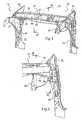
- the Figure 1illustrates a structural element 10 of a motor vehicle that extends transversely between a motor compartment 12 located towards the front of the motor vehicle and a cockpit 14 located rearwardly.
- the structural element 10has a lower crossbeam 16 which extends transversely under the bay 18 of the motor vehicle.
- the structural element 10also has two mutually opposing damping cup extensions 20, 22 on which a transverse lower wall of heating duct 24 is laterally supported, which will be described in more detail hereinafter. -after.
- the lower berry beam 16has a first portion 26, or upper belly lower rail, and a second portion 28, or lower berry bottom rail. The latter has a central recess 30 forming a first inlet opening through which the extension of the first part 26 can be seen.
- the first and second parts 26, 28are respectively made of a single piece of sheet metal with a thickness of between 1 mm and 0.5 mm, for example 0.65 mm of so that it can plastically deform if necessary as will be explained below.
- the structural element 10has two opposite legs 32, 34 between which, in line with the lower crossbeam 16, extends an apron not shown on this Figure 1 .
- opposite legs 32, 34extend two lateral uprights 33, 35, here partially shown and against which is applied respectively the lateral edges of a windshield not shown on this Figure 1 .
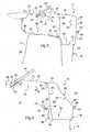
- an apron 42which extends substantially vertically between the passenger compartment 14 and the engine compartment 12, is supported by the lower transverse wall of heating duct 38 at the level of the curved edge 36.
- a windshield 44 having a lower edge of the windshield 45is partially shown and it extends to the right of the lower crossbar 16, the lower edge of the windshield 45 along the edge of a hood 43.
- the lower transverse wall of heating duct 38extends not only laterally but also longitudinally between its first curved edge 36 located towards the passenger compartment 14 and a second opposite curved edge 46 located towards the engine compartment 12. In addition, it is inclined from the second curved edge 46 towards the first curved edge 36, and it has on the one hand a first portion 48 bearing on the upper portion 40 of the damper cup riser 20 and on the other hand a second portion recessed 50 along the first curved edge 36. In this way, the first portion 48 of the lower transverse wall of heating duct 38 extends perpendicular to a slot 52 which extends transversely between the edge of the cover 43 and the lower edge of the windshield 45 so as to collect water flowing through the slot 52.
- the waterflows to the second part recessed 50 to then be discharged through an orifice 54 formed in the bottom of this second part 50.
- the lower transverse wall of heating duct 38also guides the air entering through the slot 52 to the ventilation system.
- the lower rack beam 16comprising the upper rack bottom rail, or first section 26, and the lower bay bottom rail, or second section 28, extend transversely from one post 33 to the other 35.
- the first part 26has a prolonged fixing edge 56 of a return 58 which itself bears on a flange 60 of the recessed portion 50 in return in the extension of the first curved edge 36.
- the first part 26has an opposite receiving edge 62 adapted to receive the lower edge of the windshield 45. The latter is secured to it by means of a bead of mastic 64.
- the second portion 28has a connecting edge 66 curved back and opposite, a bearing edge 68 also curved back.
- the connecting edge 66in return is connected to the first part 26 for example by welding points, while the support edge 68 is connected to the first part of the lower transverse wall of heating duct 38, at the edge of the second part 50. It can also be connected by welding points.
- the connected connecting edge 66divides the first portion 26 into two portions, a receiving portion 70 that extends in a jig, from the binding edge 66 to the receiving edge 62, and an opposite fixing portion 72, which extends from the connecting edge 66 to the fastening edge 56.
- the receiving portion 70has a first shelf portion 74, which extends substantially horizontally between the connecting edge 66 and the cover. breeze 44, and a first inclined portion 76, which extends opposite the windshield 44, while the opposite attachment portion 72 has a second shelf part 78, or transverse area, in the extension of the first part in tablet 74, and a second portion folded back 80, which extends to the fastening edge 56.
- the first tablet portion 74extends, in the longitudinal direction of the vehicle, a width of between 80 mm and 150 mm, while the second Part in tablet 78 extends over a width of between 100 mm and 200 mm. It will be observed that this width varies transversely, and in particular for the latter, between the middle of the lower crossbeam 16 and its ends.
- the second portion 28extends substantially perpendicularly to the two shelf portions 74, 78 while bearing on the lower transverse wall of heating duct 38, while the second folded portion 80 of the fixing portion 72 s extends substantially parallel to the second portion 28 to bear on the first curved edge 36 of the lower transverse wall of the heating duct 24.
- the second portion 28 of the lower crosspiece 16, the second portion of the tablet 78, the second part folded back 80 on the one hand, and the second part 50 of the lower transverse wall of heating duct 38constitutes a tubular element referred to herein as transverse box 82 or hollow body.
- This transverse box 82rests on the deck 42 but also partly at its opposite ends on the upper part 40 of the damper plate extensions 20, 22. On the other hand, it extends away from the windshield 44 and more particularly the lower edge 45, while the receiving portion 70 extends, forming a stem from the transverse box 82 at the connecting edge 66 of the second portion 28, to join the bottom edge of windshield 45 and receive it in its opposite receiving edge 62.
- the lower edge 45 of the windshield 44which is kept glued against the receiving edge 62 of the first part 26 by means of the mastic bead 64, is identical.
- the apron 42 supporting the second portion 50 of the lower transverse wall of heating duct 38which has a first portion 48 'constricted and extended by the curved edge 46'.
- the second portion 28has retained its shape and there is the central recess 30 forming the first air inlet opening within the transverse box 82 '. This air comes from the slot 52.
- the second part in tablet 78 'is narrower while the second part folded back 80' is inclined to its fixing edge 56 '.
- the second bent portion 80 'has another recess 86 forming an air outlet to the vehicle ventilation system.
- a Z-section 88is installed along the second part 50 so as to form another tubular element 90 forming a second hollow body.
- One of the flanges 92 of the Z-shaped sectionis connected to the first portion 48 'constricted from the lower transverse wall of heating duct 38, from below, while the other flange 94 is secured to the bottom of the second concealed part. 50.
- the Z-shaped section 88forms a transverse and complementary central reinforcement attached to the lower transverse wall of heating duct 38. This in particular makes it possible to stiffen the zone that extends transversely beneath the bay and therefore the acoustics in the motor vehicle.
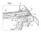
- This Figure 5illustrates the other end of the bottom bolster 16 for three quarters front, from the engine compartment. It contains the damping cup 22 the leg 34 and the opposite amount 35 as well as the first 26 and the second 28 parts of the bottom crossbar 16. Also, there is also the first portion 48 of the lower transverse wall of the duct. heating 38 and its second curved edge 46. In addition, it will be observed that the second portion 28 of the lower cross-member 16 has, at the level of the damper cup raiser 22, a second recess 96 for the discharge of water but also air inside the transverse box 82.
- transverse box 82, 82 'in one piece, is spaced from the connection zone between the lower windshield border 45 and the receiving edge 62 of the lower upper bay beam, or first part 26.
- the receiving portion 70 of the first portion 26will then deform by pivoting in counterclockwise around the junction zone between the connecting edge 66 of the second portion 28 and the first portion 26. In this way, by deforming and bending, the receiving portion 70 absorbs the mechanical energy caused by the pedestrian shock and dissipates it partly in the form of heat.
- the windshield 44 and the transverse box 82, 82 'being spaced from each other, when the windshield 44 is depressed, its amplitude of movement corresponding to the deformation of the single receiving portion 70 is greater than that it would have if the lower edge 45 was bearing directly against the transverse box 82, 82 '.
- a greater amount of mechanical energycan be absorbed while preserving the pedestrian during the impact.
- such an arrangementnot only allows the flow of air from the outside to the ventilation system through the transverse box 82, 82 ', but also the evacuation of the water collected at the wall transverse lower heating duct 38.
Landscapes
- Engineering & Computer Science (AREA)
- Mechanical Engineering (AREA)
- Chemical & Material Sciences (AREA)
- Combustion & Propulsion (AREA)
- Transportation (AREA)
- Body Structure For Vehicles (AREA)
Description
Translated fromFrenchLa présente invention se rapporte à un véhicule automobile comprenant une traverse inférieure de baie destinée à être installée à l'avant d'un véhicule automobile.The present invention relates to a motor vehicle comprising a lower berry beam intended to be installed at the front of a motor vehicle.
L'avant des véhicules automobiles présente une structure où viennent se rejoindre le pare-brise, le capot, et le tablier qui sépare le compartiment moteur de l'habitacle. La traverse inférieure de baie est solidaire du tablier de manière à pouvoir supporter le pare-brise sur laquelle il s'appuie. Aussi, la traverse inférieure est installée transversalement et elle s'étend, selon des composantes verticale et longitudinale du véhicule, entre une bordure inférieure du pare-brise et le tablier qui lui s'étend sensiblement à l'aplomb dudit pare-brise. Afin d'assurer son rôle de soutien du pare-brise, la traverse inférieure de baie doit être suffisamment résistante. Aussi, elle comprend usuellement deux parties transversales associées l'une à l'autre, une traverse inférieure de baie supérieure et une traverse inférieure de baie inférieure, de manière à former un caisson transversal, ou corps creux, sur lequel prend directement appui la bordure inférieure du pare-brise. Pour ce faire, parmi les deux parties transversales, une première partie présentant une bordure transversale de fixation et à l'opposé une bordure transversale de réception, est ajustée entre le tablier et le pare-brise. La première partie constitue la traverse inférieure de baie supérieure. La bordure de fixation est alors en prise sur le tablier, tandis que la bordure inférieure de pare-brise vient prendre appui dans la bordure transversale de réception. La seconde partie transversale de la traverse, présentant une bordure de liaison transversale et une bordure d'appui transversale opposée, est ajustée contre la première partie de façon que la bordure de liaison soit reliée à la première partie entre la première bordure de fixation et la première bordure de réception de la première partie et que la bordure d'appui soit reliée à la bordure transversale de réception de la première partie en formant un élément tubulaire avec cette dernière, lequel élément tubulaire constitue le caisson transversal. La seconde partie constitue la traverse inférieure de baie inférieure. En conséquence, la bordure inférieure de pare-brise est directement maintenue par le caisson transversal qui lui, prend appui latéralement dans la structure du véhicule automobile, et notamment sur les coupelles d'amortisseur.The front of motor vehicles has a structure where join the windshield, the hood, and the deck that separates the engine compartment from the passenger compartment. The lower berry beam is secured to the deck so as to support the windshield on which it is based. Also, the lower rail is installed transversely and extends, according to vertical and longitudinal components of the vehicle, between a lower edge of the windshield and the deck which extends substantially vertically above said windshield. To ensure its role of supporting the windshield, the lower berry beam must be strong enough. Also, it usually comprises two transverse portions associated with each other, a lower upper berry and a lower lower berry crossbar, so as to form a transverse box, or hollow body, which directly supports the edge bottom of the windshield. To do this, among the two transverse parts, a first portion having a transverse fixing edge and opposite a transverse receiving edge, is adjusted between the apron and the windshield. The first part is the lower upper berry rail. The fastening edge is then engaged on the deck, while the lower edge of the windshield comes to bear in the transverse receiving edge. The second transverse portion of the cross member, having a transverse connecting edge and an opposite transverse support edge, is fitted against the first portion so that the connecting edge is connected to the first portion between the first fastening edge and the first receiving edge of the first part and that the bearing edge is connected to the transverse receiving edge of the first part forming a tubular element with the latter, which tubular element constitutes the transverse box. The second part is lower lower bay rail. As a result, the lower edge of the windshield is directly maintained by the transverse box which is supported laterally in the structure of the motor vehicle, including the dampers cups.
Par ailleurs, la bordure de liaison de la seconde partie transversale divise la première partie, en une portion de réception qui s'étend vers la bordure de réception en formant une paroi du caisson transversal et en une portion de fixation opposée qui s'étend vers la bordure de fixation de la première partie et qui rejoint le tablier. Cette portion de fixation est par nature déformable et elle permet en cas de choc piéton, c'est-à-dire du mouvement relatif d'une personne vers le pare-brise du véhicule, que le pare-brise précisément puisse s'enfoncer de manière à dissiper une partie de l'énergie mécanique provoquée par le choc et ainsi préserver autant que faire se peut, les parties vitales dudit piéton et notamment la tête.Furthermore, the connecting edge of the second transverse portion divides the first portion into a receiving portion which extends to the receiving edge forming a wall of the transverse box and an opposing attachment portion extending to the fastening edge of the first part and which joins the deck. This fixing portion is deformable by nature and it allows in case of pedestrian impact, that is to say the relative movement of a person to the windshield of the vehicle, that the windshield can precisely be sinking so as to dissipate some of the mechanical energy caused by the shock and thus preserve as much as possible, the vital parts of said pedestrian and in particular the head.
On pourra se référer au document
Un véhicule automobile selon le préambule de la revendication 1 est décrit dans le document
Cependant, le caisson transversal qui est nécessaire au support du pare-brise, limite les capacités de déformation de la portion de fixation précitée et parallèlement, les possibilités de dissiper l'énergie engendrée par le choc.However, the transverse box which is necessary for the support of the windshield, limits the deformation capacity of the aforementioned fixing portion and in parallel, the possibilities of dissipating the energy generated by the shock.
Aussi, un problème qui se pose et que vise à résoudre la présente invention est de fournir une traverse inférieure de baie qui tout en maintenant le pare-brise du véhicule automobile, présente des capacités de déformation accrues pour préserver les personnes lors d'un choc.Also, a problem that arises and that aims to solve the present invention is to provide a lower crossbar bay while maintaining the windshield of the motor vehicle, has increased deformation capabilities to preserve people during a shock .
Dans ce but, la présente invention propose un vehicule automobile comprenant une traverse inféreure de baie avant de véhicule automobile, destinée à être installée transversalement dans un véhicule automobile entre une bordure inférieure de pare-brise et un tablier situé à l'aplomb du pare-brise, ladite traverse comprenant une première et une seconde parties transversales sensiblement parallèles entre elles, ladite première partie présentant une bordure de fixation apte à être reliée audit tablier et une bordure de réception opposée à ladite bordure de fixation pour recevoir ladite bordure inférieure de pare-brise, tandis que ladite seconde partie présente d'une part, une bordure de liaison reliée à ladite première partie entre ladite première bordure de fixation et ladite première bordure de réception en divisant ladite première partie en une portion de réception s'étendant vers ladite bordure de réception et en une portion de fixation opposée s'étendant vers ladite bordure de fixation, et d'autre part une bordure d'appui opposée à ladite bordure de liaison, lesdites seconde et première parties transversales étant destinées à former un caisson transversal pour augmenter la rigidité de ladite traverse, tandis que ladite première partie est apte à se plier le long de ladite bordure de liaison lorsque ledit pare-brise est enfoncé sous l'effet d'un choc. Selon l'invention, ladite bordure d'appui de ladite seconde partie est apte à être reliée audit tablier de manière à former ledit caisson transversal entre ladite seconde partie et ladite portion de fixation de ladite première partie dans une position écartée de ladite bordure inférieure de pare-brise, tandis que ladite portion de réception s'étend entre ledit caisson transversal et ladite bordure inférieure de pare-brise.For this purpose, the present invention provides a motor vehicle comprising a lower cross of the front bay of a motor vehicle, intended to be installed transversely in a motor vehicle between a lower edge of the windshield and an apron located directly above the windshield. breeze, said crossbar comprising a first and a second transverse portion substantially parallel to each other, said first portion having a fixing edge adapted to be connected to said apron and a receiving edge opposite said fixing edge for receiving said lower edge of the windshield, while said second portion has on the one hand a connecting edge connected to said first portion between said first fixing edge and said first receiving edge by dividing said first portion into a portion of receiving extending to said receiving edge and an opposing attachment portion extending to said attachment edge, and secondly a bearing border opposite said connecting edge, said second and first transverse portions being for forming a transverse box to increase the stiffness of said cross member, while said first portion is adapted to bend along said connecting edge when said windshield is depressed under the effect of a shock. According to the invention, said bearing edge of said second portion is adapted to be connected to said deck so as to form said transverse box between said second portion and said fixing portion of said first portion in a position spaced from said lower edge of said windshield, while said receiving portion extends between said transverse box and said lower edge of the windshield.
Ainsi, une caractéristique de l'invention réside dans la mise en oeuvre du caisson transversal, ou corps creux, non plus directement en contact avec la bordure inférieure de pare-brise, mais dans une position écartée de cette dernière, vers le tablier, tandis que la portion de réception de la première partie de traverse s'étend précisément, elle, entre le caisson transversal et la bordure inférieure de pare-brise. De la sorte, ce n'est plus directement le caisson transversal qui absorbe les efforts en cas de choc piéton, et d'enfoncement du pare-brise, mais la portion de réception de la première partie transversale qui tend alors à se plier vers le caisson le long de la bordure de liaison de la seconde partie reliée à la première partie de traverse. Le caisson transversal forme en effet une poutre dont les capacités de fléchissement sous contrainte sont bien plus faibles que celles d'une simple paroi comme la portion de réception de la première partie transversale. Aussi, grâce aux capacités de déformation de cette portion de réception, lors du choc piéton contre le pare-brise, ce dernier va s'enfoncer à mesure que la portion de réception qui le supporte se déforme plastiquement et se ploie.Thus, a feature of the invention lies in the implementation of the transverse box, or hollow body, no longer directly in contact with the lower edge of the windshield, but in a position spaced from the latter, towards the deck, while that the receiving portion of the first cross portion extends precisely, it, between the transverse box and the lower edge of the windshield. In this way, it is no longer directly the transverse box that absorbs the forces in case of pedestrian impact, and depression of the windshield, but the receiving portion of the first transverse portion which then tends to bend towards the box along the connecting edge of the second portion connected to the first portion of the cross member. The transverse box in fact forms a beam whose stress deflection capabilities are much lower than those of a simple wall such as the receiving portion of the first transverse portion. Also, thanks to the deformation capabilities of this receiving portion, during the pedestrian impact against the windshield, the latter will sink as the receiving portion that supports plastically deforms and bends.
Selon une caractéristique de l'invention particulièrement avantageuse, ladite portion de fixation de ladite première partie présente une zone transversale longeant ladite portion de réception sensiblement perpendiculairement à ladite seconde partie. Ainsi, la zone transversale forme avec la seconde partie deux parois adjacentes du caisson transversal à angle droit, ce qui améliore sa rigidité. Préférentiellement, ladite seconde partie présente un évidement formant une ouverture d'entrée à l'intérieur du caisson transversal. Cette ouverture d'entrée permet, notamment, l'arrivée de l'air pour le circuit de ventilation ainsi qu'on l'expliquera plus en détail ci-après.According to a particularly advantageous characteristic of the invention, said attachment portion of said first portion has a transverse zone along said receiving portion substantially perpendicular to said second portion. Thus, the transverse zone forms with the second part two adjacent walls of the transverse box at right angles, which improves its rigidity. Preferably, said second portion has a recess forming an inlet opening inside the transverse box. This inlet opening allows, in particular, the arrival of air for the ventilation circuit as will be explained in more detail below.
En outre, et selon un mode de mise en oeuvre de l'invention particulièrement avantageux, ledit véhicule comporte une paroi inférieure transversale de conduit de chauffage, apte à être reliée audit tablier, et ladite bordure de fixation de ladite première partie est reliée audit tablier par l'intermédiaire de ladite paroi inférieure transversale. Cette paroi inférieure transversale de conduit de chauffage, s'étend selon une direction longitudinale du véhicule, depuis le tablier sur lequel elle prend appui, vers l'avant du véhicule à l'aplomb de la bordure inférieure du pare-brise et d'un bord du capot du véhicule adjacent à ladite bordure inférieure de pare-brise. Ainsi, la bordure de fixation de la première partie de traverse est solidaire du tablier par l'intermédiaire de la paroi inférieure transversale de conduit de chauffage.In addition, and according to a particularly advantageous embodiment of the invention, said vehicle comprises a transverse lower wall of heating duct, able to be connected to said apron, and said fixing edge of said first part is connected to said apron. through said transverse bottom wall. This transverse bottom wall of the heating duct extends in a longitudinal direction of the vehicle, from the deck on which it bears, towards the front of the vehicle at the base of the lower edge of the windshield and a vehicle hood edge adjacent to said lower windshield edge. Thus, the fastening edge of the first portion of the cross member is secured to the deck by means of the transverse lower wall of the heating duct.
De plus, ladite bordure d'appui de ladite seconde partie est préférentiellement reliée audit tablier également par l'intermédiaire de ladite paroi inférieure transversale de conduit de chauffage. De la sorte, la portion de paroi inférieure transversale comprise entre la bordure de fixation de la première partie de traverse et la bordure d'appui de la seconde partie, la seconde partie elle-même et la portion de fixation de la première partie, forment alors une structure tubulaire constituant le caisson transversal. Ce dernier est alors directement relié au tablier.In addition, said support edge of said second portion is preferably connected to said deck also via said lower transverse wall of heating duct. In this way, the transverse lower wall portion between the fastening edge of the first cross-member portion and the bearing edge of the second portion, the second portion itself and the attachment portion of the first portion, form then a tubular structure constituting the transverse box. The latter is then directly connected to the deck.
Par ailleurs, ladite paroi inférieure transversale de conduit de chauffage présente une première bordure transversale de paroi, apte à recevoir ladite bordure de fixation de ladite première partie, et une seconde bordure transversale de paroi opposée, apte à s'étendre à l'aplomb de ladite bordure de réception de ladite première partie. Ces deux bordures transversales de parois opposées sont recourbées l'une vers l'autre de manière à former un réceptacle. Outre le guidage de l'air vers le circuit de ventilation, ce réceptacle est également destiné à recevoir l'eau qui s'écoule entre le bord du capot et la bordure inférieure de pare-brise pour pouvoir l'évacuer ensuite.Furthermore, said transverse bottom wall of heating duct has a first transverse wall edge, adapted to receive said fixing edge of said first portion, and a second transverse edge of opposite wall, able to extend in line with said receiving edge of said first portion. These two transverse edges of opposite walls are curved towards each other so as to form a receptacle. In addition to guiding the air towards the ventilation circuit, this receptacle is also intended to receive water flowing between the edge of the hood and the lower edge of the windshield so that it can then be evacuated.
Aussi, ladite paroi inférieure transversale de conduit de chauffage présente une portion transversale encaissée le long de ladite première bordure transversale de paroi dans un sens opposé à ladite portion de fixation de ladite première partie. De la sorte, l'eau qui s'écoule précisément entre le bord du capot et la bordure inférieure de pare-brise, s'achemine par gravité dans la portion transversale encaissée. Avantageusement, ladite portion transversale encaissée présente un orifice pour former une ouverture d'évacuation, le long du tablier. Un tel orifice est pratiqué dans une portion latérale de la paroi inférieure transversale.Also, said lower transverse wall of heating duct has a transverse portion encased along said first transverse wall edge in a direction opposite to said fixing portion of said first portion. In this way, the water flowing precisely between the edge of the hood and the lower edge of the windshield, flows by gravity in the transverse portion collected. Advantageously, said recessed transverse portion has an orifice to form a discharge opening along the deck. Such an orifice is made in a lateral portion of the transverse lower wall.
Selon un mode de réalisation de l'invention particulièrement avantageux, ledit véhicule comporte en outre, deux coupelles latérales d'amortisseur situées sensiblement à l'aplomb de ladite bordure de réception de ladite première partie, et ladite paroi inférieure transversale de conduit de chauffage vient prendre appui sur lesdites coupelles latérales d'amortisseurs. De la sorte, la traverse inférieure est également en appui latéralement, par l'intermédiaire de la paroi inférieure transversale de conduit de chauffage, sur les coupelles latérales d'amortisseurs.According to a particularly advantageous embodiment of the invention, said vehicle further comprises two damping side cups located substantially vertically above said receiving edge of said first portion, and said lower transverse wall of heating duct take support on said side cups of dampers. In this way, the lower crossbar is also supported laterally, via the lower transverse wall of the heating duct, on the lateral cups of dampers.
Avantageusement, lesdites première et seconde parties transversales de ladite traverse sont réalisées dans un matériau métallique déformable, de manière à pouvoir se déformer plastiquement lors d'un choc, l'énergie mécanique absorbée se dissipant alors sous la forme de chaleur.Advantageously, said first and second transverse portions of said cross member are made of a deformable metal material, so as to be plastically deformable during an impact, the mechanical energy absorbed then dissipating in the form of heat.
D'autres particularités et avantages de l'invention ressortiront à la lecture de la description faite ci-après d'un mode de réalisation particulier de l'invention, donné à titre indicatif mais non limitatif, en référence aux dessins annexés sur lesquels :
- la
Figure 1 est une vue schématique en perspective de trois quarts avant montrant un élément de structure d'un véhicule automobile incluant une traverse inférieure de baie selon l'invention ; - la
Figure 2 est une vue schématique en perspective de trois quarts arrière d'une partie de l'élément de structure représenté sur laFigure 1 ; - la
Figure 3 est une vue schématique en coupe axiale de la partie représentée sur laFigure 2 selon le plan III-III complétée par d'autres éléments ; - la
Figure 4 est une vue schématique en coupe axiale de l'élément de structure représenté sur laFigure 1 selon le plan IV-IV complété par d'autres éléments ; et, - la
Figure 5 est une vue schématique en perspective de trois quarts avant d'une autre partie de l'élément de structure représenté sur laFigure 1 .
- the
Figure 1 is a schematic view in perspective of three quarters front showing a structural element of a motor vehicle including a lower crossbeam according to the invention; - the
Figure 2 is a schematic perspective view of three quarters rear of a portion of the structural member shown in theFigure 1 ; - the
Figure 3 is a schematic view in axial section of the part shown on theFigure 2 according to plan III-III supplemented by other elements; - the
Figure 4 is a schematic axial sectional view of the structural element shown in FIG.Figure 1 according to plan IV-IV supplemented by other elements; and, - the
Figure 5 is a schematic perspective view of three quarters front of another part of the structural element shown on theFigure 1 .
La
L'élément de structure 10 présente deux jambes opposées 32, 34 entre lesquelles, à l'aplomb de la traverse inférieure de baie 16, vient s'étendre un tablier non représenté sur cette
On se reportera sur la
Ainsi, sur la
Au surplus, sont représentés sur cette
Ainsi, la paroi inférieure transversale de conduit de chauffage 38 s'étend non seulement latéralement mais aussi longitudinalement entre sa première bordure recourbée 36 située vers l'habitacle 14 et une seconde bordure recourbée opposée 46 située vers le compartiment moteur 12. De plus, elle est inclinée de la seconde bordure recourbée 46 vers la première bordure recourbée 36, et elle présente d'une part une première partie 48 en appui sur la partie supérieure 40 de la rehausse de coupelle d'amortisseur 20 et d'autre part une seconde partie encaissée 50 le long de la première bordure recourbée 36. De la sorte, la première partie 48 de la paroi inférieure transversale de conduit de chauffage 38 s'étend à l'aplomb d'une fente 52 qui s'étend transversalement entre le bord du capot 43 et la bordure inférieure de pare-brise 45 de manière à pouvoir recueillir l'eau qui s'écoule à travers cette fente 52. Aussi, par gravité l'eau s'écoule-t-elle vers la seconde partie encaissée 50 pour ensuite être évacuée à travers un orifice 54 ménagé dans le fond de cette seconde partie encaissée 50. Comme on l'expliquera dans la suite de la description, la paroi inférieure transversale de conduit de chauffage 38 permet également de guider l'air entrant à travers la fente 52 vers l'installation de ventilation.Thus, the lower transverse wall of
On va maintenant décrire plus en détail la traverse inférieure de baie 16, prise au droit de la rehausse de coupelle d'amortisseur 20, toujours en référence à la
Ainsi, la traverse inférieure de baie 16, comprenant la traverse inférieure de baie supérieure, ou première partie 26, et la traverse inférieure de baie inférieure, ou seconde partie 28, s'étendent transversalement d'un montant 33 à l'autre 35. La première partie 26 présente une bordure de fixation 56 prolongée d'un retour 58 qui vient lui-même en appui sur un rebord 60 de la partie encaissée 50 en retour dans le prolongement de la première bordure recourbée 36. À l'opposé de la bordure de fixation 56, la première partie 26 présente une bordure de réception opposée 62 apte à recevoir la bordure inférieure de pare-brise 45. Cette dernière y est solidarisée par l'intermédiaire d'un cordon de mastic 64.Thus, the
Quant à la seconde partie 28, elle présente une bordure de liaison 66 recourbée en retour et à l'opposé, une bordure d'appui 68 également recourbée en retour. La bordure de liaison 66 en retour est reliée à la première partie 26 par exemple par des points de soudure, tandis que la bordure d'appui 68 est reliée à la première partie de la paroi inférieure transversale de conduit de chauffage 38, au bord de la seconde partie encaissée 50. Elle peut également y être reliée par points de soudure. Ainsi, la bordure de liaison 66 reliée divise la première partie 26 en deux portions, une portion de réception 70 qui s'étend en potence, de la bordure de liaison 66 jusqu'à la bordure de réception 62, et une portion de fixation opposée 72, qui s'étend de la bordure de liaison 66 jusqu'à la bordure de fixation 56. La portion de réception 70 présente une première partie en tablette 74, qui s'étend sensiblement horizontalement entre la bordure de liaison 66 et le pare-brise 44, et une première partie inclinée 76, qui s'étend en regard du pare-brise 44, tandis que la portion de fixation opposée 72 présente une seconde partie en tablette 78, ou zone transversale, dans le prolongement de la première partie en tablette 74, et une seconde partie pliée en retour 80, qui s'étend jusqu'à la, bordure de fixation 56. La première partie en tablette 74 s'étend, selon la direction longitudinale du véhicule, sur une largeur comprise entre 80 mm et 150 mm, tandis que la seconde partie en tablette 78 s'étend sur une largeur comprise entre 100 mm et 200 mm. On observera que cette largeur varie transversalement, et notamment pour la dernière, entre le milieu de la traverse inférieure de baie 16 et ses extrémités.As for the
En outre, la seconde partie 28 s'étend sensiblement perpendiculairement aux deux parties en tablette 74, 78 en prenant appui sur la paroi inférieure transversale de conduit de chauffage 38, tandis que la seconde partie pliée en retour 80 de la portion de fixation 72 s'étend sensiblement parallèlement à la seconde partie 28 pour prendre appui sur la première bordure recourbée 36 de la paroi inférieure transversale de conduit de chauffage 24. De la sorte, la seconde partie 28 de traverse inférieure de baie 16, la seconde partie en tablette 78, la seconde partie pliée en retour 80 d'une part, et la seconde partie encaissée 50 de la paroi inférieure transversale de conduit de chauffage 38, d'autre part, constitue un élément tubulaire dénommé ici caisson transversal 82 ou corps creux. Ce caisson transversal 82 s'appuie sur le tablier 42 mais aussi en partie à ses extrémités opposées sur la partie supérieure 40 des rehausses de coupelle d'amortisseur 20, 22. En revanche, il s'étend à distance du pare-brise 44 et plus particulièrement de la bordure inférieure 45, tandis que la portion de réception 70 s'étend-elle, en formant potence à partir du caisson transversal 82 au niveau de la bordure de liaison 66 de la seconde partie 28, pour rejoindre la bordure inférieure de pare-brise 45 et la recevoir dans sa bordure de réception opposée 62.In addition, the
Avant de présenter les avantages de la structure décrite ci-dessus, on décrira tout d'abord en référence à la
On retrouve ainsi à l'identique la bordure inférieure 45 de pare-brise 44 maintenue collée contre la bordure de réception 62 de la première partie 26 au moyen du cordon de mastic 64. On y retrouve également le tablier 42 supportant la seconde partie encaissée 50 de la paroi inférieure transversale de conduit de chauffage 38, laquelle présente une première partie 48' étranglée et prolongée par la bordure recourbée 46'. La seconde partie 28 a conservé sa forme et on retrouve l'évidement central 30 formant la première ouverture d'entrée d'air à l'intérieur du caisson transversal 82'. Cet air provient de la fente 52. Par ailleurs, la seconde partie en tablette 78' est moins large tandis que la seconde partie pliée en retour 80' est en plan incliné jusqu'à sa bordure de fixation 56'. La seconde partie pliée 80' présente un autre évidement 86 formant une sortie d'air vers le système de ventilation du véhicule.Thus, the
Par ailleurs, et selon un mode de mise en oeuvre de l'invention particulièrement avantageux, un profilé en Z 88 est installé le long de la seconde partie encaissée 50 de manière à former un autre élément tubulaire 90 formant un second corps creux. L'une des ailes 92 du profilé en Z est reliée à la première partie 48' étranglée de la paroi inférieure transversale de conduit de chauffage 38, par le dessous, tandis que l'autre aile 94 est solidaire du fond de la seconde partie encaissée 50. Ainsi, le profilé en Z 88 forme un renfort central transversal et complémentaire accolé à la paroi inférieure transversale de conduit de chauffage 38. Cela permet notamment de rigidifier la zone qui s'étend transversalement sous la baie et par conséquent l'acoustique dans le véhicule automobile.Furthermore, and according to a particularly advantageous embodiment of the invention, a Z-
Enfin, on se référera à la
En se reportant sur les
Ainsi, grâce à cette disposition, en cas de choc piéton où la bordure inférieure 45 de pare-brise 44 est enfoncée vers le tablier 42 selon la flèche F, la portion de réception 70 de la première partie 26 va alors se déformer en pivotant dans un sens antihoraire autour de la zone de jonction entre la bordure de liaison 66 de la seconde partie 28 et la première partie 26. De la sorte, en se déformant et en se pliant, la portion de réception 70 absorbe l'énergie mécanique provoquée par le choc piéton et la dissipe en partie sous forme de chaleur. De plus, le pare-brise 44 et le caisson transversal 82, 82' étant écartés l'un de l'autre, lorsque le pare-brise 44 est enfoncé, son amplitude de mouvement correspondant à la déformation de l'unique portion de réception 70 est plus importante que celle qu'elle aurait si la bordure inférieure 45 était en appui directement contre le caisson transversal 82, 82'. En conséquence, une plus grande quantité d'énergie mécanique peut être absorbée tout en préservant le piéton lors du choc.Thus, thanks to this arrangement, in the event of a pedestrian impact where the
Au surplus, une telle disposition permet non seulement l'écoulement de l'air depuis l'extérieur vers le système de ventilation à travers le caisson transversal 82, 82', mais aussi l'évacuation de l'eau recueillie au niveau de la paroi inférieure transversale de conduit de chauffage 38.Moreover, such an arrangement not only allows the flow of air from the outside to the ventilation system through the
Claims (10)
- Motor vehicle comprising a lower crossbeam (16) for a front window opening intended to be installed transversely in said motor vehicle between a lower edge (45) of a windshield (44) and a bulkhead (42) situated plumb with the windshield (44), said crossbeam (16) comprising a first (26) and a second (28) transverse part which are substantially parallel to one another, said first part (26) having a fixing edge (56) that can be connected to said bulkhead (42) and a receiving edge (62) opposite said fixing edge to accept said windshield lower edge (45), while said second part (28) has, firstly, a connecting edge (66) connected to said first part (26) between said first fixing edge (56) and said first receiving edge (62), thereby dividing said first part into a receiving portion (70) extending toward said receiving edge and an opposite fixing portion (72) extending toward said fixing edge and, secondly, a resting edge (68) opposite said connecting edge (66), said second (28) and first (26) transverse parts being intended to form a transverse box structure (82) to increase the rigidity of said crossbeam (16), whereas said first part (26) is able to bend along said connecting edge (66) when said windshield (44) is pushed in under the effect of an impact,
characterized in that said resting edge (68) of said second part (28) can be connected to said bulkhead (42) in such a way as to form said transverse box structure (82) between said second part (28) and said fixing portion (72) of said first part (26) in a position distant from said windshield lower edge, whereas said receiving portion (70) extends between said transverse box structure (82) and said windshield lower edge (45). - Motor vehicle according to Claim 1,characterized in that said fixing portion (72) of said first part has a transverse zone (78) running alongside said receiving portion (70) substantially perpendicular to said second part (28).
- Motor vehicle according to either of Claims 1 and 2,characterized in that said second part (28) has a recess (30) forming an inlet opening providing access to the inside of the transverse box structure (82).
- Motor vehicle according to any one of Claims 1 to 3,characterized in that said vehicle further comprises a heating duct transverse lower wall (38) able to be connected to said bulkhead (42), andin that said fixing edge (56) of said first part (26) is connected to said bulkhead via said transverse lower wall (38).
- Motor vehicle according to Claim 4,characterized in that said resting edge (68) of said second part (28) is connected to said bulkhead (42) via said transverse lower wall (38).
- Motor vehicle according to either of Claims 4 and 5,characterized in that said heating duct transverse lower wall (38) has a first wall transverse edge (36), able to receive said fixing edge (56) of said first part (26), and an opposite second wall transverse edge (46), able to extend plumb with said receiving edge (62) of said first part.
- Motor vehicle according to Claim 6,characterized in that said heating duct transverse lower wall (38) has a transverse portion (50) which is sunken along said first wall transverse edge (36) in an opposite direction to said fixing portion (72) of said first part (26).
- Motor vehicle according to Claim 7,characterized in that said sunken transverse portion (50) has an orifice (54) to form a discharge opening.
- Motor vehicle according to any one of Claims 4 to 8,characterized in that said vehicle further comprises two lateral shock-absorber cups (20, 22) situated substantially plumb with said receiving edge (70) of said first part (26), andin that said heating duct transverse lower wall (38) rests on said lateral shock-absorber cups (20, 22).
- Motor vehicle according to any one of Claims 1 to 9,characterized in that said first (26) and second (28) transverse parts of said crossbeam (16) are made of a deformable metallic material.
Applications Claiming Priority (2)
| Application Number | Priority Date | Filing Date | Title |
|---|---|---|---|
| FR1057908AFR2965529A1 (en) | 2010-09-30 | 2010-09-30 | LOWER TRAY OF DEFORMABLE BAY |
| PCT/FR2011/052141WO2012042147A1 (en) | 2010-09-30 | 2011-09-19 | Deformable lower crossbeam for a window opening |
Publications (2)
| Publication Number | Publication Date |
|---|---|
| EP2621766A1 EP2621766A1 (en) | 2013-08-07 |
| EP2621766B1true EP2621766B1 (en) | 2015-07-01 |
Family
ID=43858452
Family Applications (1)
| Application Number | Title | Priority Date | Filing Date |
|---|---|---|---|
| EP11771218.2ANot-in-forceEP2621766B1 (en) | 2010-09-30 | 2011-09-19 | Deformable lower windscreen cross-member |
Country Status (7)
| Country | Link |
|---|---|
| US (1) | US8960777B2 (en) |
| EP (1) | EP2621766B1 (en) |
| JP (1) | JP6009446B2 (en) |
| KR (1) | KR101824719B1 (en) |
| CN (1) | CN103237689B (en) |
| FR (1) | FR2965529A1 (en) |
| WO (1) | WO2012042147A1 (en) |
Families Citing this family (8)
| Publication number | Priority date | Publication date | Assignee | Title |
|---|---|---|---|---|
| US20120074731A1 (en)* | 2010-03-16 | 2012-03-29 | Toyota Jidosha Kabushiki Kaisha | Front-side member structure |
| DE102011119561A1 (en)* | 2011-11-26 | 2013-05-29 | GM Global Technology Operations LLC (n. d. Gesetzen des Staates Delaware) | Support structure component for the body of a motor vehicle |
| FR2983450B1 (en)* | 2011-12-02 | 2014-05-16 | Renault Sa | MOTOR VEHICLE COMPRISING A TOP TRAVERSE OF AN APRON |
| CN104039635A (en)* | 2012-01-11 | 2014-09-10 | 本田技研工业株式会社 | Structure for front portion of vehicle |
| US9481397B2 (en) | 2014-06-11 | 2016-11-01 | Fca Italy S.P.A. | Motor vehicle body provided with a structure for receiving and draining water |
| CN104326027B (en)* | 2014-09-29 | 2017-07-07 | 上汽通用五菱汽车股份有限公司 | The preceding clapboard assembly that a kind of integrated level is high, performance is good |
| FR3035848B1 (en)* | 2015-05-07 | 2018-09-07 | Renault S.A.S. | BUS TRAILER FOR A MOTOR VEHICLE AND ASSOCIATED MOTOR VEHICLE |
| FR3035849B1 (en)* | 2015-05-07 | 2018-09-07 | Renault S.A.S. | BUS TRAILER FOR A MOTOR VEHICLE AND ASSOCIATED MOTOR VEHICLE |
Family Cites Families (18)
| Publication number | Priority date | Publication date | Assignee | Title |
|---|---|---|---|---|
| US4146263A (en)* | 1976-06-18 | 1979-03-27 | Toyo Kogyo Co., Ltd. | Vehicle body structure having a windshield and cowl panel assembly |
| JPH01278833A (en)* | 1988-04-29 | 1989-11-09 | Mazda Motor Corp | Windshield pane supporting structure for vehicle |
| JPH01176580U (en)* | 1988-06-02 | 1989-12-15 | ||
| JP3449463B2 (en)* | 1998-05-12 | 2003-09-22 | 本田技研工業株式会社 | Windshield support structure |
| JP3939861B2 (en)* | 1998-07-24 | 2007-07-04 | 本田技研工業株式会社 | Windshield support structure |
| JP3446712B2 (en)* | 2000-03-10 | 2003-09-16 | 日産自動車株式会社 | Car front body structure |
| FR2857932B1 (en)* | 2003-07-24 | 2005-09-23 | Renault Sa | DEFORMABLE LONGERON FOR MOTOR VEHICLE |
| JP4329469B2 (en)* | 2003-09-29 | 2009-09-09 | マツダ株式会社 | Front body structure of the vehicle |
| US7000979B2 (en)* | 2003-12-22 | 2006-02-21 | Nissan Technical Center North America, Inc. | Vehicle cowl structure with vent pipe |
| JP4386758B2 (en)* | 2004-02-25 | 2009-12-16 | 日本プラスト株式会社 | Cowl top cover |
| US7066533B2 (en)* | 2004-06-03 | 2006-06-27 | Ford Global Technologies, Llc | Tubular front end structure for automobiles and method for making the same |
| JP2006182197A (en)* | 2004-12-27 | 2006-07-13 | Toyota Motor Corp | Body front structure |
| JP4978147B2 (en)* | 2006-10-17 | 2012-07-18 | トヨタ車体株式会社 | Car cowl top structure |
| JP4692516B2 (en)* | 2007-06-01 | 2011-06-01 | 日産自動車株式会社 | Body frame structure |
| DE102007035489A1 (en)* | 2007-07-28 | 2009-01-29 | GM Global Technology Operations, Inc., Detroit | Motor vehicle with arched front wall |
| JP5067117B2 (en)* | 2007-10-25 | 2012-11-07 | マツダ株式会社 | Car cowl structure |
| JP4492689B2 (en)* | 2007-12-07 | 2010-06-30 | 日産自動車株式会社 | Car cowl structure |
| JP4613985B2 (en)* | 2008-07-15 | 2011-01-19 | 三菱自動車工業株式会社 | Vehicle cowl top structure |
- 2010
- 2010-09-30FRFR1057908Apatent/FR2965529A1/ennot_activeWithdrawn
- 2011
- 2011-09-19USUS13/877,053patent/US8960777B2/ennot_activeExpired - Fee Related
- 2011-09-19EPEP11771218.2Apatent/EP2621766B1/ennot_activeNot-in-force
- 2011-09-19JPJP2013530778Apatent/JP6009446B2/ennot_activeExpired - Fee Related
- 2011-09-19KRKR1020137010721Apatent/KR101824719B1/enactiveActive
- 2011-09-19CNCN201180056621.6Apatent/CN103237689B/ennot_activeExpired - Fee Related
- 2011-09-19WOPCT/FR2011/052141patent/WO2012042147A1/enactiveApplication Filing
Also Published As
| Publication number | Publication date |
|---|---|
| US8960777B2 (en) | 2015-02-24 |
| JP6009446B2 (en) | 2016-10-19 |
| KR20130115264A (en) | 2013-10-21 |
| US20130229031A1 (en) | 2013-09-05 |
| FR2965529A1 (en) | 2012-04-06 |
| CN103237689A (en) | 2013-08-07 |
| JP2013538745A (en) | 2013-10-17 |
| EP2621766A1 (en) | 2013-08-07 |
| WO2012042147A1 (en) | 2012-04-05 |
| CN103237689B (en) | 2016-01-13 |
| KR101824719B1 (en) | 2018-02-01 |
Similar Documents
| Publication | Publication Date | Title |
|---|---|---|
| EP2621766B1 (en) | Deformable lower windscreen cross-member | |
| EP1868871B1 (en) | Reinforcing structure for motor vehicle capable of limiting instrument panel vibrations, and corresponding motor vehicle | |
| FR2780927A1 (en) | DEVICE FOR FIXING THE BODIES OF A BUMPER ON A VEHICLE BODY WING | |
| EP1852316B1 (en) | Vehicle comprising a frame providing a support for a bumper. | |
| EP2763885B1 (en) | Motor vehicle dashboard crossmember arrangement and vehicle comprising such an arrangement | |
| FR3122134A1 (en) | FRONT BUMPER FRAME WITH CENTRAL PILLAR | |
| WO2008061824A1 (en) | Impact-absorbing assembly for a motor vehicle and corresponding front panel | |
| FR3105151A1 (en) | AUTOMOTIVE VEHICLE BODY REAR STRUCTURE WITH POLYMER FLOOR AND BATTERY HOLDER | |
| EP3983279B1 (en) | Reinforcement means for a front structure of a motor vehicle | |
| EP3097000B1 (en) | Body structure of a motor vehicle with reinforcements for distributing the forces linked to a rear shock absorber of the vehicle | |
| EP2630009B1 (en) | Mounting for a cowl vent grill, and cowl vent assembly including such a mounting | |
| EP1847445B1 (en) | Front structure of automobile and corresponding method | |
| FR3145128A1 (en) | Motor vehicle front bumper skin retaining support | |
| FR3152452A1 (en) | Automotive vehicle front bumper skin frame | |
| EP2049351A1 (en) | Automotive vehicle door leaf comprising a stiffener and vehicle provided with such a door leaf | |
| FR2884201A1 (en) | Front/rear bumper face-bar assembly for motor vehicle, has stiffening girder, where spacing between sides of girder is equal to longitudinal distance between skin and cross-member such that skin is held by supporting girder on cross-member | |
| EP3090925B1 (en) | Windshield bay cross member for a motor vehicle and associated motor vehicle | |
| EP1777126A1 (en) | Motor vehicle suitable for absorbing collisions with pedestrians | |
| EP4406787A1 (en) | Front bumper of a motor vehicle | |
| EP3585676B1 (en) | Reinforcement device for securing a central beam for a rear chassis of a vehicle | |
| EP3090924B1 (en) | Windshield bay cross member for a motor vehicle and associated motor vehicle | |
| FR3117075A1 (en) | Support for fixing an element to a motor vehicle floor and corresponding assembly | |
| EP4375166A1 (en) | Rear axle of a motor vehicle fixed on a bracket support linked to a liner of the beam | |
| EP4406789A1 (en) | Assembly for a front bumper | |
| FR3150178A1 (en) | ARRANGEMENT FOR THE FRONT OF A MOTOR VEHICLE AND MOTOR VEHICLE COMPRISING SUCH AN ARRANGEMENT |
Legal Events
| Date | Code | Title | Description |
|---|---|---|---|
| PUAI | Public reference made under article 153(3) epc to a published international application that has entered the european phase | Free format text:ORIGINAL CODE: 0009012 | |
| 17P | Request for examination filed | Effective date:20130328 | |
| AK | Designated contracting states | Kind code of ref document:A1 Designated state(s):AL AT BE BG CH CY CZ DE DK EE ES FI FR GB GR HR HU IE IS IT LI LT LU LV MC MK MT NL NO PL PT RO RS SE SI SK SM TR | |
| DAX | Request for extension of the european patent (deleted) | ||
| 17Q | First examination report despatched | Effective date:20140117 | |
| GRAP | Despatch of communication of intention to grant a patent | Free format text:ORIGINAL CODE: EPIDOSNIGR1 | |
| INTG | Intention to grant announced | Effective date:20150122 | |
| GRAS | Grant fee paid | Free format text:ORIGINAL CODE: EPIDOSNIGR3 | |
| GRAA | (expected) grant | Free format text:ORIGINAL CODE: 0009210 | |
| AK | Designated contracting states | Kind code of ref document:B1 Designated state(s):AL AT BE BG CH CY CZ DE DK EE ES FI FR GB GR HR HU IE IS IT LI LT LU LV MC MK MT NL NO PL PT RO RS SE SI SK SM TR | |
| REG | Reference to a national code | Ref country code:GB Ref legal event code:FG4D Free format text:NOT ENGLISH | |
| REG | Reference to a national code | Ref country code:AT Ref legal event code:REF Ref document number:733754 Country of ref document:AT Kind code of ref document:T Effective date:20150715 Ref country code:CH Ref legal event code:EP | |
| REG | Reference to a national code | Ref country code:IE Ref legal event code:FG4D Free format text:LANGUAGE OF EP DOCUMENT: FRENCH | |
| REG | Reference to a national code | Ref country code:DE Ref legal event code:R096 Ref document number:602011017526 Country of ref document:DE | |
| REG | Reference to a national code | Ref country code:AT Ref legal event code:MK05 Ref document number:733754 Country of ref document:AT Kind code of ref document:T Effective date:20150701 | |
| REG | Reference to a national code | Ref country code:NL Ref legal event code:MP Effective date:20150701 | |
| REG | Reference to a national code | Ref country code:LT Ref legal event code:MG4D | |
| PG25 | Lapsed in a contracting state [announced via postgrant information from national office to epo] | Ref country code:LT Free format text:LAPSE BECAUSE OF FAILURE TO SUBMIT A TRANSLATION OF THE DESCRIPTION OR TO PAY THE FEE WITHIN THE PRESCRIBED TIME-LIMIT Effective date:20150701 Ref country code:LV Free format text:LAPSE BECAUSE OF FAILURE TO SUBMIT A TRANSLATION OF THE DESCRIPTION OR TO PAY THE FEE WITHIN THE PRESCRIBED TIME-LIMIT Effective date:20150701 Ref country code:FI Free format text:LAPSE BECAUSE OF FAILURE TO SUBMIT A TRANSLATION OF THE DESCRIPTION OR TO PAY THE FEE WITHIN THE PRESCRIBED TIME-LIMIT Effective date:20150701 Ref country code:NO Free format text:LAPSE BECAUSE OF FAILURE TO SUBMIT A TRANSLATION OF THE DESCRIPTION OR TO PAY THE FEE WITHIN THE PRESCRIBED TIME-LIMIT Effective date:20151001 Ref country code:GR Free format text:LAPSE BECAUSE OF FAILURE TO SUBMIT A TRANSLATION OF THE DESCRIPTION OR TO PAY THE FEE WITHIN THE PRESCRIBED TIME-LIMIT Effective date:20151002 | |
| PG25 | Lapsed in a contracting state [announced via postgrant information from national office to epo] | Ref country code:HR Free format text:LAPSE BECAUSE OF FAILURE TO SUBMIT A TRANSLATION OF THE DESCRIPTION OR TO PAY THE FEE WITHIN THE PRESCRIBED TIME-LIMIT Effective date:20150701 Ref country code:RS Free format text:LAPSE BECAUSE OF FAILURE TO SUBMIT A TRANSLATION OF THE DESCRIPTION OR TO PAY THE FEE WITHIN THE PRESCRIBED TIME-LIMIT Effective date:20150701 Ref country code:AT Free format text:LAPSE BECAUSE OF FAILURE TO SUBMIT A TRANSLATION OF THE DESCRIPTION OR TO PAY THE FEE WITHIN THE PRESCRIBED TIME-LIMIT Effective date:20150701 Ref country code:SE Free format text:LAPSE BECAUSE OF FAILURE TO SUBMIT A TRANSLATION OF THE DESCRIPTION OR TO PAY THE FEE WITHIN THE PRESCRIBED TIME-LIMIT Effective date:20150701 Ref country code:PL Free format text:LAPSE BECAUSE OF FAILURE TO SUBMIT A TRANSLATION OF THE DESCRIPTION OR TO PAY THE FEE WITHIN THE PRESCRIBED TIME-LIMIT Effective date:20150701 Ref country code:IS Free format text:LAPSE BECAUSE OF FAILURE TO SUBMIT A TRANSLATION OF THE DESCRIPTION OR TO PAY THE FEE WITHIN THE PRESCRIBED TIME-LIMIT Effective date:20151101 Ref country code:PT Free format text:LAPSE BECAUSE OF FAILURE TO SUBMIT A TRANSLATION OF THE DESCRIPTION OR TO PAY THE FEE WITHIN THE PRESCRIBED TIME-LIMIT Effective date:20151102 Ref country code:ES Free format text:LAPSE BECAUSE OF FAILURE TO SUBMIT A TRANSLATION OF THE DESCRIPTION OR TO PAY THE FEE WITHIN THE PRESCRIBED TIME-LIMIT Effective date:20150701 | |
| REG | Reference to a national code | Ref country code:DE Ref legal event code:R097 Ref document number:602011017526 Country of ref document:DE | |
| PG25 | Lapsed in a contracting state [announced via postgrant information from national office to epo] | Ref country code:LU Free format text:LAPSE BECAUSE OF FAILURE TO SUBMIT A TRANSLATION OF THE DESCRIPTION OR TO PAY THE FEE WITHIN THE PRESCRIBED TIME-LIMIT Effective date:20150919 Ref country code:SK Free format text:LAPSE BECAUSE OF FAILURE TO SUBMIT A TRANSLATION OF THE DESCRIPTION OR TO PAY THE FEE WITHIN THE PRESCRIBED TIME-LIMIT Effective date:20150701 Ref country code:IT Free format text:LAPSE BECAUSE OF FAILURE TO SUBMIT A TRANSLATION OF THE DESCRIPTION OR TO PAY THE FEE WITHIN THE PRESCRIBED TIME-LIMIT Effective date:20150701 Ref country code:EE Free format text:LAPSE BECAUSE OF FAILURE TO SUBMIT A TRANSLATION OF THE DESCRIPTION OR TO PAY THE FEE WITHIN THE PRESCRIBED TIME-LIMIT Effective date:20150701 Ref country code:DK Free format text:LAPSE BECAUSE OF FAILURE TO SUBMIT A TRANSLATION OF THE DESCRIPTION OR TO PAY THE FEE WITHIN THE PRESCRIBED TIME-LIMIT Effective date:20150701 Ref country code:MC Free format text:LAPSE BECAUSE OF FAILURE TO SUBMIT A TRANSLATION OF THE DESCRIPTION OR TO PAY THE FEE WITHIN THE PRESCRIBED TIME-LIMIT Effective date:20150701 Ref country code:CZ Free format text:LAPSE BECAUSE OF FAILURE TO SUBMIT A TRANSLATION OF THE DESCRIPTION OR TO PAY THE FEE WITHIN THE PRESCRIBED TIME-LIMIT Effective date:20150701 | |
| REG | Reference to a national code | Ref country code:CH Ref legal event code:PL | |
| PLBE | No opposition filed within time limit | Free format text:ORIGINAL CODE: 0009261 | |
| STAA | Information on the status of an ep patent application or granted ep patent | Free format text:STATUS: NO OPPOSITION FILED WITHIN TIME LIMIT | |
| PG25 | Lapsed in a contracting state [announced via postgrant information from national office to epo] | Ref country code:RO Free format text:LAPSE BECAUSE OF FAILURE TO SUBMIT A TRANSLATION OF THE DESCRIPTION OR TO PAY THE FEE WITHIN THE PRESCRIBED TIME-LIMIT Effective date:20150701 | |
| 26N | No opposition filed | Effective date:20160404 | |
| REG | Reference to a national code | Ref country code:IE Ref legal event code:MM4A | |
| PG25 | Lapsed in a contracting state [announced via postgrant information from national office to epo] | Ref country code:LI Free format text:LAPSE BECAUSE OF NON-PAYMENT OF DUE FEES Effective date:20150930 Ref country code:IE Free format text:LAPSE BECAUSE OF NON-PAYMENT OF DUE FEES Effective date:20150919 Ref country code:CH Free format text:LAPSE BECAUSE OF NON-PAYMENT OF DUE FEES Effective date:20150930 | |
| PG25 | Lapsed in a contracting state [announced via postgrant information from national office to epo] | Ref country code:SI Free format text:LAPSE BECAUSE OF FAILURE TO SUBMIT A TRANSLATION OF THE DESCRIPTION OR TO PAY THE FEE WITHIN THE PRESCRIBED TIME-LIMIT Effective date:20150701 | |
| REG | Reference to a national code | Ref country code:FR Ref legal event code:PLFP Year of fee payment:6 | |
| PG25 | Lapsed in a contracting state [announced via postgrant information from national office to epo] | Ref country code:MT Free format text:LAPSE BECAUSE OF FAILURE TO SUBMIT A TRANSLATION OF THE DESCRIPTION OR TO PAY THE FEE WITHIN THE PRESCRIBED TIME-LIMIT Effective date:20150701 | |
| PG25 | Lapsed in a contracting state [announced via postgrant information from national office to epo] | Ref country code:HU Free format text:LAPSE BECAUSE OF FAILURE TO SUBMIT A TRANSLATION OF THE DESCRIPTION OR TO PAY THE FEE WITHIN THE PRESCRIBED TIME-LIMIT; INVALID AB INITIO Effective date:20110919 Ref country code:BG Free format text:LAPSE BECAUSE OF FAILURE TO SUBMIT A TRANSLATION OF THE DESCRIPTION OR TO PAY THE FEE WITHIN THE PRESCRIBED TIME-LIMIT Effective date:20150701 Ref country code:SM Free format text:LAPSE BECAUSE OF FAILURE TO SUBMIT A TRANSLATION OF THE DESCRIPTION OR TO PAY THE FEE WITHIN THE PRESCRIBED TIME-LIMIT Effective date:20150701 | |
| PG25 | Lapsed in a contracting state [announced via postgrant information from national office to epo] | Ref country code:CY Free format text:LAPSE BECAUSE OF FAILURE TO SUBMIT A TRANSLATION OF THE DESCRIPTION OR TO PAY THE FEE WITHIN THE PRESCRIBED TIME-LIMIT Effective date:20150701 Ref country code:NL Free format text:LAPSE BECAUSE OF FAILURE TO SUBMIT A TRANSLATION OF THE DESCRIPTION OR TO PAY THE FEE WITHIN THE PRESCRIBED TIME-LIMIT Effective date:20150701 | |
| PG25 | Lapsed in a contracting state [announced via postgrant information from national office to epo] | Ref country code:BE Free format text:LAPSE BECAUSE OF NON-PAYMENT OF DUE FEES Effective date:20150930 | |
| REG | Reference to a national code | Ref country code:FR Ref legal event code:PLFP Year of fee payment:7 | |
| PG25 | Lapsed in a contracting state [announced via postgrant information from national office to epo] | Ref country code:TR Free format text:LAPSE BECAUSE OF FAILURE TO SUBMIT A TRANSLATION OF THE DESCRIPTION OR TO PAY THE FEE WITHIN THE PRESCRIBED TIME-LIMIT Effective date:20150701 Ref country code:MK Free format text:LAPSE BECAUSE OF FAILURE TO SUBMIT A TRANSLATION OF THE DESCRIPTION OR TO PAY THE FEE WITHIN THE PRESCRIBED TIME-LIMIT Effective date:20150701 | |
| REG | Reference to a national code | Ref country code:FR Ref legal event code:PLFP Year of fee payment:8 | |
| PG25 | Lapsed in a contracting state [announced via postgrant information from national office to epo] | Ref country code:AL Free format text:LAPSE BECAUSE OF FAILURE TO SUBMIT A TRANSLATION OF THE DESCRIPTION OR TO PAY THE FEE WITHIN THE PRESCRIBED TIME-LIMIT Effective date:20150701 | |
| P01 | Opt-out of the competence of the unified patent court (upc) registered | Effective date:20230608 | |
| PGFP | Annual fee paid to national office [announced via postgrant information from national office to epo] | Ref country code:GB Payment date:20230920 Year of fee payment:13 | |
| PGFP | Annual fee paid to national office [announced via postgrant information from national office to epo] | Ref country code:FR Payment date:20230928 Year of fee payment:13 Ref country code:DE Payment date:20230920 Year of fee payment:13 | |
| REG | Reference to a national code | Ref country code:DE Ref legal event code:R119 Ref document number:602011017526 Country of ref document:DE | |
| GBPC | Gb: european patent ceased through non-payment of renewal fee | Effective date:20240919 | |
| PG25 | Lapsed in a contracting state [announced via postgrant information from national office to epo] | Ref country code:DE Free format text:LAPSE BECAUSE OF NON-PAYMENT OF DUE FEES Effective date:20250401 | |
| PG25 | Lapsed in a contracting state [announced via postgrant information from national office to epo] | Ref country code:GB Free format text:LAPSE BECAUSE OF NON-PAYMENT OF DUE FEES Effective date:20240919 | |
| PG25 | Lapsed in a contracting state [announced via postgrant information from national office to epo] | Ref country code:FR Free format text:LAPSE BECAUSE OF NON-PAYMENT OF DUE FEES Effective date:20240930 |