EP2621578B1 - Delivery catheter for delivering an implant, for example, bronchoscopically implanting a marker in a lung - Google Patents
Delivery catheter for delivering an implant, for example, bronchoscopically implanting a marker in a lungDownload PDFInfo
- Publication number
- EP2621578B1 EP2621578B1EP11830075.5AEP11830075AEP2621578B1EP 2621578 B1EP2621578 B1EP 2621578B1EP 11830075 AEP11830075 AEP 11830075AEP 2621578 B1EP2621578 B1EP 2621578B1
- Authority
- EP
- European Patent Office
- Prior art keywords
- marker
- catheter
- assembly
- markers
- target
- Prior art date
- Legal status (The legal status is an assumption and is not a legal conclusion. Google has not performed a legal analysis and makes no representation as to the accuracy of the status listed.)
- Active
Links
Images


Classifications
- A—HUMAN NECESSITIES
- A61—MEDICAL OR VETERINARY SCIENCE; HYGIENE
- A61N—ELECTROTHERAPY; MAGNETOTHERAPY; RADIATION THERAPY; ULTRASOUND THERAPY
- A61N5/00—Radiation therapy
- A61N5/10—X-ray therapy; Gamma-ray therapy; Particle-irradiation therapy
- A61N5/1048—Monitoring, verifying, controlling systems and methods
- A61N5/1049—Monitoring, verifying, controlling systems and methods for verifying the position of the patient with respect to the radiation beam
- A—HUMAN NECESSITIES
- A61—MEDICAL OR VETERINARY SCIENCE; HYGIENE
- A61M—DEVICES FOR INTRODUCING MEDIA INTO, OR ONTO, THE BODY; DEVICES FOR TRANSDUCING BODY MEDIA OR FOR TAKING MEDIA FROM THE BODY; DEVICES FOR PRODUCING OR ENDING SLEEP OR STUPOR
- A61M25/00—Catheters; Hollow probes
- A—HUMAN NECESSITIES
- A61—MEDICAL OR VETERINARY SCIENCE; HYGIENE
- A61B—DIAGNOSIS; SURGERY; IDENTIFICATION
- A61B90/00—Instruments, implements or accessories specially adapted for surgery or diagnosis and not covered by any of the groups A61B1/00 - A61B50/00, e.g. for luxation treatment or for protecting wound edges
- A61B90/39—Markers, e.g. radio-opaque or breast lesions markers
- A—HUMAN NECESSITIES
- A61—MEDICAL OR VETERINARY SCIENCE; HYGIENE
- A61M—DEVICES FOR INTRODUCING MEDIA INTO, OR ONTO, THE BODY; DEVICES FOR TRANSDUCING BODY MEDIA OR FOR TAKING MEDIA FROM THE BODY; DEVICES FOR PRODUCING OR ENDING SLEEP OR STUPOR
- A61M25/00—Catheters; Hollow probes
- A61M25/01—Introducing, guiding, advancing, emplacing or holding catheters
- A61M25/0105—Steering means as part of the catheter or advancing means; Markers for positioning
- A61M25/0108—Steering means as part of the catheter or advancing means; Markers for positioning using radio-opaque or ultrasound markers
- A—HUMAN NECESSITIES
- A61—MEDICAL OR VETERINARY SCIENCE; HYGIENE
- A61M—DEVICES FOR INTRODUCING MEDIA INTO, OR ONTO, THE BODY; DEVICES FOR TRANSDUCING BODY MEDIA OR FOR TAKING MEDIA FROM THE BODY; DEVICES FOR PRODUCING OR ENDING SLEEP OR STUPOR
- A61M25/00—Catheters; Hollow probes
- A61M25/01—Introducing, guiding, advancing, emplacing or holding catheters
- A61M25/09—Guide wires
- A—HUMAN NECESSITIES
- A61—MEDICAL OR VETERINARY SCIENCE; HYGIENE
- A61M—DEVICES FOR INTRODUCING MEDIA INTO, OR ONTO, THE BODY; DEVICES FOR TRANSDUCING BODY MEDIA OR FOR TAKING MEDIA FROM THE BODY; DEVICES FOR PRODUCING OR ENDING SLEEP OR STUPOR
- A61M31/00—Devices for introducing or retaining media, e.g. remedies, in cavities of the body
- A61M31/005—Devices for introducing or retaining media, e.g. remedies, in cavities of the body for contrast media
- A—HUMAN NECESSITIES
- A61—MEDICAL OR VETERINARY SCIENCE; HYGIENE
- A61B—DIAGNOSIS; SURGERY; IDENTIFICATION
- A61B1/00—Instruments for performing medical examinations of the interior of cavities or tubes of the body by visual or photographical inspection, e.g. endoscopes; Illuminating arrangements therefor
- A61B1/267—Instruments for performing medical examinations of the interior of cavities or tubes of the body by visual or photographical inspection, e.g. endoscopes; Illuminating arrangements therefor for the respiratory tract, e.g. laryngoscopes, bronchoscopes
- A61B1/2676—Bronchoscopes
- A—HUMAN NECESSITIES
- A61—MEDICAL OR VETERINARY SCIENCE; HYGIENE
- A61B—DIAGNOSIS; SURGERY; IDENTIFICATION
- A61B17/00—Surgical instruments, devices or methods
- A61B2017/00831—Material properties
- A61B2017/00867—Material properties shape memory effect
- A—HUMAN NECESSITIES
- A61—MEDICAL OR VETERINARY SCIENCE; HYGIENE
- A61B—DIAGNOSIS; SURGERY; IDENTIFICATION
- A61B34/00—Computer-aided surgery; Manipulators or robots specially adapted for use in surgery
- A61B34/20—Surgical navigation systems; Devices for tracking or guiding surgical instruments, e.g. for frameless stereotaxis
- A61B2034/2046—Tracking techniques
- A61B2034/2051—Electromagnetic tracking systems
- A—HUMAN NECESSITIES
- A61—MEDICAL OR VETERINARY SCIENCE; HYGIENE
- A61B—DIAGNOSIS; SURGERY; IDENTIFICATION
- A61B90/00—Instruments, implements or accessories specially adapted for surgery or diagnosis and not covered by any of the groups A61B1/00 - A61B50/00, e.g. for luxation treatment or for protecting wound edges
- A61B90/39—Markers, e.g. radio-opaque or breast lesions markers
- A61B2090/3987—Applicators for implanting markers
- A—HUMAN NECESSITIES
- A61—MEDICAL OR VETERINARY SCIENCE; HYGIENE
- A61B—DIAGNOSIS; SURGERY; IDENTIFICATION
- A61B90/00—Instruments, implements or accessories specially adapted for surgery or diagnosis and not covered by any of the groups A61B1/00 - A61B50/00, e.g. for luxation treatment or for protecting wound edges
- A61B90/39—Markers, e.g. radio-opaque or breast lesions markers
- A61B2090/3991—Markers, e.g. radio-opaque or breast lesions markers having specific anchoring means to fixate the marker to the tissue, e.g. hooks
- A—HUMAN NECESSITIES
- A61—MEDICAL OR VETERINARY SCIENCE; HYGIENE
- A61M—DEVICES FOR INTRODUCING MEDIA INTO, OR ONTO, THE BODY; DEVICES FOR TRANSDUCING BODY MEDIA OR FOR TAKING MEDIA FROM THE BODY; DEVICES FOR PRODUCING OR ENDING SLEEP OR STUPOR
- A61M25/00—Catheters; Hollow probes
- A61M25/01—Introducing, guiding, advancing, emplacing or holding catheters
- A61M25/09—Guide wires
- A61M2025/09166—Guide wires having radio-opaque features
Definitions
- the present inventionrelates to a catheter assembly for delivering a marker into a lumen, and more specifically, but not exclusively, is directed toward bronchoscopically implanting markers in the lung of a patient and further more particularly, but not exclusively, toward a pre-loaded delivery catheter with a marker wherein the marker includes an improved anti-migration device.
- Radiation therapyhas become a significant and highly successful process for treating prostate cancer, lung cancer, brain cancer and many other types of localized cancers. Radiation therapy procedures generally involve (a) planning processes to determine the parameters of the radiation (e.g., dose, shape, etc.), (b) patient setup processes to position the target at a desired location relative to the radiation beam, (c) radiation sessions to irradiate the cancer, and (d) verification processes to assess the efficacy of the radiation sessions. Many radiation therapy procedures require several radiation sessions (i.e., radiation fractions) over a period of approximately 5-45 days.
- the radiationshould be prescribed to a tight treatment margin around the target such that only a small volume of healthy tissue is irradiated.
- the treatment margin for prostate cancershould be selected to avoid irradiating rectal, bladder and bulbar urethral tissues.
- the treatment margin for lung cancershould be selected to avoid irradiating healthy lung tissue or other tissue. Therefore, it is not only desirable to increase the radiation dose delivered to the tumor, but it also desirable to mitigate irradiating healthy tissue.
- One difficulty of radiation therapyis that the target often moves within the patient either during or between radiation sessions.
- tumors in the lungsmove during radiation sessions because of respiration motion and cardiac functions (e.g., heartbeats and vasculature constriction/expansion).
- cardiac functionse.g., heartbeats and vasculature constriction/expansion.
- the treatment marginsare generally larger than desired so that the tumor does not move out of the treatment volume.
- the larger treatment marginsmay irradiate a larger volume of normal tissue.
- Localization and/or tracking of markerssuch as gold fiducials or electromagnetic transponders, implanted in proximity to the target or tumor may enable increased tumor radiation and decreased healthy tissue irradiation.
- markerssuch as gold fiducials or electromagnetic transponders
- fluoroscopic imaging of implanted gold fiducialsis limited by high doses of non-therapeutic imaging radiation, expensive fluoroscopic equipment, subjective image interpretation and poor implant stability.
- a tumoris first identified within the patient using an imaging system (e.g., X-ray, computerized tomography (CT), magnetic resonance imaging (MRI), or ultrasound system). The approximate location of the tumor relative to two or more alignment points on the exterior of the patient is then determined.
- CTcomputerized tomography
- MRImagnetic resonance imaging
- ultrasound systeme.g., X-ray, computerized tomography
- the approximate location of the tumor relative to two or more alignment points on the exterior of the patientis then determined.
- the external marksare aligned with a reference frame of the radiation delivery device to position the treatment target within the patient at the beam isocenter of the radiation beam (also referenced herein as the machine isocenter).
- the targetmay move relative to the external marks between the patient planning procedure and the treatment session and/or during the treatment session.
- the targetmay be offset from the machine isocenter even when the external marks are at their predetermined locations for positioning the target at the machine isocenter. Reducing or eliminating such an offset is desirable because any initial misalignment between the target and the radiation beam will likely cause normal tissue to be irradiated.
- the targetmoves during treatment because of respiration, organ filling, or cardiac conditions, any initial misalignment will likely further exacerbate irradiation of normal tissue.
- the day-by-day and moment-by-moment changes in target motionhave posed significant challenges for increasing the radiation dose applied to patients.
- Tumor target localizationhas been demonstrated utilizing implanted markers such as gold fiducials (balls and cylinders) and electromagnetic transponders.
- implanted markerssuch as gold fiducials (balls and cylinders) and electromagnetic transponders.
- One method of placement for these markers in the lungis to deliver them into the bronchus/ bronchioles of the lung and then force-fit the markers into the appropriate diameter bronchiole near the treatment target location.
- the implant location that permits a force-fit of the markersis likely not the most desired location, but one that simply accommodates the force fit.
- the act of breathingwhich effects a small enlargement/contraction cycle of the bronchioles, may dislodge the marker from its desired location.
- Many inhaled drugsalso effect changes in the diameter of the bronchioles.
- actions such as coughingwhich typically originate in the alveolar structures near the lung periphery, serve to force the markers from their desired locations to locations closer to the trachea.
- the airways in the lungsanatomically constitute an extensive network of conduits that reach all lung areas and lung tissues. Air enters the airways through the nose or mouth, travels through the trachea and into the bronchi and bronchioli of the lunch. The lungs are covered by a think membrane called the pleura. Because of these physiological characteristics of the airways, a marker placed in bronchi and bronchioli may cause pneumothorax when implanted, thus, there is a need for a new and improved device, system, and method for implanting a marker in the region proximate to a tumor or other lesion in the lung.
- One recent method for locating a target implanted within the bodyincludes a wireless implantable marker configured to be implanted surgically or percutaneously into a human body relative to a target location.
- the markersinclude a casing and a signal element in the casing that wirelessly transmits location signals in response to an excitation energy.
- One concern of using implanted markers in soft tissues, bronchi or bronchioliis that the markers may move within the patient after implantation.
- Calypso Medical Technologies, Inc.previously developed several anchors and fasteners for securing the markers to soft tissue structures, as disclosed in U.S. Publication No. 2003-0192557 A1 ,. Although these anchors may work for percutaneous or surgical implantation, they may be improved for bronchoscopic applications. Therefore, it would be desirable to further develop markers for bronchoscopic deployment and implantation.
- the present inventionprovides a catheter assembly as defined in claim 1.
- the retention elementmay be active; the push element; a sphere, ball, teardrop or pyramid shape; or a distal end stop.
- the assemblymay be further such that the distal end of the catheter or the marker has sharp edges that could puncture the luminal wall during implantation, or wherein the marker is shaped and positioned in the catheter such that no sharp edges are present that could puncture the luminal wall during implantation.
- the assemblymay further comprise a first stop and a section second stop, wherein the first stop limits advancement of the flexible pusher member and the second stop limits retractment of the flexible pusher member.
- Themay further comprise a sleeve fixedly retained at a distal end of the catheter; the sleeve having an inside diameter greater than an outside diameter of the catheter to allow the sleeve to slide a selected distance over the distal end of the catheter, wherein the sleeve extends a selected distance beyond the distal end of the catheter.
- the assemblymay further comprise a supply and loading device matably coupled with the distal end of the sleeve, configured to releasably retain the stored marker and transfer the marker from the supply and loading device to a distal end of the sleeve.
- the catheter and flexible push membermay be provided with dimensions such that the assembly can be passed down a working channel of a not forming part of the invention bronchoscope a selected distance for deployment of the marker a bronchial lumen within the lung.
- the catheter and flexible push membermay further be provided with dimensions such that the assembly can be passed down a working channel of an not forming part of the invention endoscope a selected distance for deployment of the marker in a lumen the digestive system.
- the catheter and flexible push membermay further be provided with dimensions such that the assembly can be passed into an artery or vein for deployment of the marker in a lumen within the cardiovascular system.
- the assemblymay further comprise a shipping tray and/or storage tray.
- Each one of the plurality f fasteners or legs of the anchorable marker assemblymay further include a shaped barb.
- the markermay be a gold seed.
- not forming part of the present inventionprovides a catheter assembly for delivering a marker into a lumen, the assembly comprising:
- FIGS. 1-26are isometric and cross-sectional views of exemplary bronchoscopic catheter assemblies in accordance with several aspects of the disclosure.
- proximalmeans nearest the trachea
- distalmeans nearest the alveoli
- the following disclosuredescribes several embodiments of wireless markers configured to be implanted and anchored within the lung of a human in a manner that prevents the markers from migrating from the implantation site.
- the markeris configured to reduce pneumothorax and may further be configured to include an anchor or anti-migration device.
- a bronchoscopic catheter assemblyincludes a marker pre-loaded at a distal end of a delivery catheter for bronchoscopically implanting the marker in peripheral airways of the lung.
- a marker storage and loading devicefor retaining the marker prior to loading in the distal end of the delivery catheter is described.
- the markercan extend a selected distance beyond the distal end of the delivery catheter to provide a leading end.
- the markermay be configured at the leading end to reduce pneumothorax.
- the markerincludes an integral anti-migration or anchoring device for preventing migration of the marker after placement of the marker in the lung.
- an anti-migration deviceis separate from the marker and positioned adjacent to the deployed marker to prevent migration of the marker in the lung after placement.
- the markeris shaped and sized to reduce migration.
- a marker for use in the bronchoscopic catheter assembly for localizing a target of a patientcomprises a casing, a magnetic transponder at least partially received in the casing, and an anchor carried by the casing.
- the casingis a biocompatible barrier configured to be implanted in the patient.
- the casingcan be a generally cylindrical capsule that is sized to fit within a catheter of a bronchoscope for bronchoscopic implantation, but the casing can have other geometric shapes, sizes, and configurations in other applications.
- the casingcan be larger for implanting the marker in the bronchus.
- the magnetic transponderproduces a wirelessly transmitted magnetic field in response to a wirelessly transmitted excitation energy.
- the magnetic transpondercan further comprise a magnetic core, a coil wrapped around the core, and a capacitor coupled to the coil.
- the anchorwhich can project from the casing, be integral to the casing, or be independent from the casing, secures the marker to an anatomical structure once the marker has been deployed from the bronchoscopic catheter assembly to prevent the marker from moving from the implantation site.
- the anchormay be detached from the marker.
- the markermay be secured to the anatomical structure by mechanical members or chemical attributes.
- the anchorcan further be configured for bronchoscopic implantation and have a shape and/or material that pierces, engages or otherwise interfaces with the anatomical anchoring site such that the marker cannot be easily dislodged.
- the casingis shaped to reduce migration of the marker, for example, the casing may be wedge shaped, include a hook, or have a surface texture.
- One such methodcomprises providing a transponder that produces a wirelessly transmitted magnetic field in response to a wirelessly transmitted excitation field and forming a casing around the transponder. This method can further include embedding, attaching or forming an anchor in the casing.
- the markermay be a gold fiducial, RFID tag, active marker or electromagnetic marker.
- the anchorcan be detached from the marker.
- the casingmay be the anchor.
- the markeris forcibly wedged into the lumen, however, this will work only for limited settings and circumstances.
- the markermust be approximately the same size as the lumen at the desired geographic placement location.
- the luminal wallmust possess the appropriate elastic characteristics to retain the force-fitted marker. Forces such as those caused by coughing and wheezing serve to dislodge the marker. Potentially, mucous transport systems in the bronchioles could dislodge a force-fit marker. Inhaled drugs may serve as broncho-dilators and bronchoconstrictors. Further, tumor shrinkage during radiation therapy and/or chemotherapy, diaphragmatic motion, the movement of air, and the various pressure profiles within the lung may serve to dislodge a positional marker.
- Human lungsare located on either side of the heart and occupying a large portion of the chest cavity from the collarbone to the diaphragm.
- the lungsare covered by a thin membrane called the pleura.
- Airtravels to the chest cavity through the trachea, which divides into two bronchi, each of which enters a lung.
- the bronchidivide and subdivide into a network of countless tubules.
- the smallest tubules, or bronchiolesenter cup-shaped air sacs known as alveoli, which number about 700 million in both lungs.
- any marker dislodgementwould typically result in the marker moving toward the trachea, since there is no mechanism to force the marker further into the decreasing diameter lumen. So, in the case of a force fit marker, a solitary secondary plug could serve to secure the marker in place. Feasibly, since the marker should not move further down the bronchiole structure due to its decreasing luminal diameter, the secondary securing device would need to provide only a marginal increase in holding capacity to keep the marker in place. It should be noted that in this case, since the retention device is located on the side closer to the trachea side, it will be located in a diameter that is incrementally larger than that of the marker location.
- a LRDluminal retention device
- a LRD rigid plugwould rely on the resiliency of the lumen to hold the plug in place, while a plug constructed of silicone, sponge, or other similar materials would inherently possess its own resiliency.
- the fibrin-thrombin type adhesives and adhesive blobscould be used to a) build a LRD plug in-place in the lumen to prevent the marker from dislodging, b) augment the diameter or attach a smaller sized LRD plug to the luminal wall, or c) used to glue the transponder directly to the wall.
- Cyanoacrylate adhesivescould be used in this application as well.
- the foamed-matrix biologically-based materialspossess mechanical properties similar to weak plastics prior to being exposed to body fluids, and could be pre-formed into acceptable shapes to force-fit into a lumen, but would shortly form a soft, biologically based plug once established in the mucous of the bronchial tree.
- LRD anchor or plugMany shapes can be utilized as an LRD anchor or plug, since the goal is to fixate the marker.
- Materialsmany include plastics, metals, adhesives, expandable sponges, and bio-materials (e.g. collagen, connective tissue derivatives). Additional embodiments include: wire or shaped metal "ring", hex, umbrella, etc.
- a form resembling a helical shaped wire springcan be advanced through a small diameter conduit to the desired location in a compressed state, expanding to the luminal diameter upon expulsion from the confines of the conduit, trapping the marker on one side.
- a plurality of materialscould be utilized, including, at least, metals, plastics, and matrix materials such as carbonfiber.
- the internally-springed, radially self-expander marker anchorallows for diametral growth or shrinkage of the lumen in which it resides, without requiring adjustment or positioning. While the device has been presented herein as a single anchor, it may be used in pairs within a lumen to trap a marker between the pair of anchors. As long as the marker cannot escape through the LRD device toward to the larger bronchiole structures the device should remains stationary and the goal will be realized.
- the ability of a device to be delivered in a compact, or compressed stateis a definite advantage. Further, the ability of a device to compensate for differences in lumen size and elasticity allows the use of a single device for a plurality of lumen sizes and, therefore, lumen locations.
- the markercan be forcibly wedged within the lumen, anchored to the luminal wall, entrapped against the luminal wall, anchored to the luminal wall using a leg of a bifurcation point, entrapped within the lumen by a second device, or trapped at a specific location within the lumen by the use of two secondary devices. Combinations of these methods may be employed as well.
- Figure 1Ais an isometric view of a bronchoscopic catheter assembly 200 for use in a working channel of a bronchoscope (not shown for clarity) and a storage and transportation device 240 having a receiving hoop 246 for releasably retaining a delivery catheter 212 during storage and transportation of the delivery catheter 212 in accordance with an embodiment of the invention.
- Figure 1Bis an isometric, expanded view of the bronchoscopic catheter assembly 200 of Figure 1A with a marker 220 loaded in the distal end 216 of the delivery catheter 212 and the storage and transportation device 240 cut away to show loading of the delivery catheter 212 in the receiving hoop 246.
- the bronchoscopic catheter assembly 200includes a delivery catheter 212 having a deployment channel 211 configured to releasably retain a marker 220 at a distal end 214 of the delivery catheter 212 such that the marker 220 extends a selected distance beyond a distal end 216 of the delivery catheter 212.
- the storage and transportation device 240for retaining the bronchoscopic catheter assembly 200 during storage and transportation is provided.
- the storage and transportation device 240includes a receiving hoop 246 for releasably retaining the delivery catheter 212.
- the storage and transportation device 240can include a housing 230 which is configured to releasably retain the receiving hopp in clips 232a, b.
- the housing 230may further include a guide 234 and/or an insertion guide assembly for guiding the distal end of the delivery catheter 212 therein.
- the housing 244additionally provides an alignment means for mating with the distal end of the catheter when loading the marker 220 into the catheter as discussed further with respect to Figure 5 .
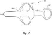
- a proximal end 214 of the delivery catheter 212is configured to engage a handle 210 having an actuator 222.
- the actuator 222is moveable between a first position and a second position along arrow A. In the second position, the actuator 222 moves towards and/or abuts a flange 224.
- the flange 224is configured to stop movement of the actuator 222 along line A by engaging the actuator 222 on a first side. On a second side, opposite the first side, the flange 224 retains the delivery catheter 212.
- the flange 224further includes a sleeve (not shown) for slidably receiving a push wire 218 therein.
- the push wire 218is retained by the body of the catheter and moves with the actuator 222.
- the push wire 218may be a Teflon wire, steel cable, steel wire, Nitanol ® or other flexible cable having sufficient rigidity to deploy the marker 220 when the actuator 222 is moved along line A.
- the push wire 218may include a disc shaped end 404 for engaging the marker 220.
- an end 404 of the push wire 218may be an appropriately shaped wire or rod.
- the end 404may have a diameter dimension slightly less than the diameter dimension of the channel 211 to allow the push wire 218 to slide co-axially therein. The distal end of the delivery catheter is described in greater detail below.
- the handle 210is configured to be moveable by an operator (not shown) and may further be configured to attach to the working channel of the bronchoscope.
- the handle 210can include an actuator 322 including a button or flat plate configured to be engaged by a digit of an operator's hand (not shown for purposes of clarity).
- the actuator 322abuts the housing 324 to stop axial movement along line A.
- the handle 210can include an actuator 322 including a ring configured to be engaged by a digit of an operator's hand.
- the housing 326can be ergonomically shaped to the hand of a user. Alternative configurations of the actuator can further be provided.
- the handle 210may further include a lock 326, shown in Figure 2 on the housing 324, to prevent accidental deployment of the marker.
- the delivery devicecan be a bronchoscope, catheter, or other device configured to pass through a lumen in the respiratory system of the patient.
- the delivery deviceincludes a handle and an elongated body attached to the handle. More specifically, the elongated body includes a proximal section at the handle and a distal section configured to pass through lumen in the respiratory system. In many embodiments, the distal section of the elongated body is flexible, but in other embodiments the entire elongated body can be flexible or rigid.
- the markeris supported by the elongated body at the distal section for deployment into the patient.
- the delivery devicefurther includes a deployment mechanism that is operable from the handle to release the marker into the patient.
- the deployment mechanismcan be a push rod that pushes the marker out of the distal section of the elongated body.
- the deployment mechanismcan include a cannula and a stylet slidably received in the cannula. In this arrangement, the cannula and stylet are configured to move together to project distally beyond the distal section of the elongated body, and then the cannula may be withdrawn proximally relative to the stylet to release the marker into the patient.
- the delivery devicecan further include a steering mechanism that is operable from the handle.
- the steering mechanismcan include an attachment point at the distal section and a slidable member configured to move longitudinally relative to the elongated body. Longitudinal movement of the slidable member flexes the distal section in a manner that steers the delivery device through bends and bifurcations in the lumen of the respiratory system.
- the steering mechanismcomprises a flexible support element and a flexible control element attached to the flexible support element such that tension applied to the control element flexes the flexible support element. Suitable steering mechanisms are set forth in U.S. Patent No. 6,702,780 and U.S. Patent Application Publication No. US 2003/0208101 .
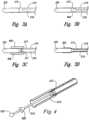
- an outside diameter of the marker 220can be approximately equal to the diameter of the channel 211.
- a sleeve 406can be placed at a distal end 216 of the delivery catheter 412.
- An inside diameter of the sleeve 406can be approximately equal to the outside diameter of the marker 220 and configured to releasably retain the marker 220.
- the channel 411can have an inside diameter smaller than the outside diameter of the marker 220.
- the sleeve 406may be made from a semi-rigid, rigid, or flexible material different from the catheter 412, or may be made from the same material as the catheter 412.
- the distal end 516 of the delivery catheter 512releasably retains the marker 220 by expanding around the marker 220.
- the inside diameter of the delivery catheter 512is less that the outside diameter of the marker 220.
- the delivery catheter 512is made from a sufficiently flexible material to allow the delivery catheter 512 to expand around the marker 220 and releasably retain the marker 220 prior to deployment.
- a materialfor example, coconut oil that is solid at room temperature and liquid at body temperature.
- the materialcould be liquid soluble, such as sucrose or NaCl; exposure to the lumen would detach the marker.
- a retention sleeve 606is placed at the distal end 616 of the delivery catheter 612.
- An inside diameter of the sleeve 606can be approximately equal to the outside diameter of the marker.
- the deployment wire or push wire 618includes an engagement member 620 and a deployment member 622.
- the engagement member 620is positioned at a distal end of the push wire and is configured as a ball end in Figure 4 .
- the engagement member 620may be a wedge, a plate or other geometric shape as appropriate.
- the deployment member 622is positioned co-axially at a predetermined distance away from the distal end of the push wire.
- the deployment member 622may be a tapered wedge as shown or may be any other geometric shape.
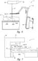
- Figure 5is a cross-sectional view of an exemplary healthy respiratory system 110 having markers 220a-c positioned therein.
- the respiratory system 110resides within a thorax 16 which occupies a space defined by a chest wall 12 and a diaphragm 13.
- the respiratory system 10includes trachea 16; left mainstem bronchus 20 and right mainstem bronchus 22 (primary, or first generation); lobar bronchial branches 24, 26, 28, 30, 32, 38 and 40 (second generation), and segmental branches 34 and 36 (third generation).
- the respiratory system 10further includes left lung lobes 42 and 44 and right lung lobes 46, 48 and 50.
- Each bronchial branch and sub-branchcommunicates with a different portion of a lung lobe, either the entire lung lobe or a portion thereof.
- the term "passageway"is meant to denote either a bronchi or bronchioli, and typically means a bronchial branch of any generation.
- three transponders 220a-care positioned in the respiratory system 110 of a patient in the proximity of a tumor or lesion 100.
- the transponders 220a-care used to localize a patient target treatment isocenter relative to a linear accelerator machine isocenter as described further herein.
- a patientundergoes a CT scan whereby the X, Y, and Z positions of the radiographic centers for all three transponders 220a-c as well as the X, Y, and Z position for the treatment target isocenter are identified.
- the three transponder positions that are positioned in the lungare localized electromagnetically and then used to calculate the position of the treatment target isocenter position and rotational offsets.
- the markers 220a-care placed in the respiratory system 110 by the bronchoscopic catheter assembly 200 as described further herein.
- the markers 220a-care preferably a small alternating magnetic transponder.
- the transponderscan each have a unique frequency relative to each other to allow for time and frequency multiplexing.
- the transponderscan accordingly include a core, a coil wound around the core, and a capacitor electrically coupled to the coil.
- the bronchoscopic catheter assembly 200can deploy one or more transponders, and as such is not limited to having three transponders as illustrated.
- the transpondersare localized using a source, sensor array, receiver, and localization algorithm as described further herein.
- the three transpondersmay be used to localize a treatment target isocenter relative to a linear accelerator radiation therapy treatment isocenter.
- the treatment target localizationmay include both translational offset (X, Y, and Z directions) and a rotational offset (pitch, yaw, and roll) relative to a linear accelerator coordinate reference frame.
- a distal end of a catheteris configured to reduce pneumothorax.
- the marker 220is pre-loaded into the distal end 216 of the delivery catheter 2 2 such that a portion of the marker 220 extends beyond the distal end 216 of the delivery catheter 212, thus providing a rounded leading end of the delivery catheter 212.
- pre-loading the cylindrical shaped markerprovides a rounded end shape to the delivery catheter 212; the rounded end shape keeps the delivery catheter 212 centered in the passageway.
- the rounded leading endalso maximizes the surface area of tissue (e.g. visceral pleura) that the distal end of the catheter contacts.
- tissuee.g. visceral pleura
- the catheter distal endis thus less likely to cut through tissue since it maximizes tissue surface area contact by incorporating a smooth rounded tip that does not include any edges that could concentrate force facilitate tissue perforation.
- FIGS 6 and 7illustrate various aspects of a radiation therapy system 1 for applying guided radiation therapy to a target 2 (e.g., a tumor) within a lung or other part of a patient 6.
- the radiation therapy system 1has a localization system 10 and a radiation delivery device 20.
- the localization system 10is a tracking unit that locates and tracks the actual position of the target 2 in real time during treatment planning, patient setup, and/or while applying ionizing radiation to the target from the radiation delivery device.
- the localization system 10continuously tracks the target and provides objective data (e.g., three-dimensional coordinates in an absolute reference frame) to a memory device, user interface, linear accelerator, and/or other device.
- objective datae.g., three-dimensional coordinates in an absolute reference frame
- the system 1is described below in the context of guided radiation therapy for treating a tumor or other target in the lung of the patient, but the system can be used for tracking and monitoring other targets within the patient for other therapeutic and/or diagnostic purposes.
- the radiation delivery source of the illustrated arrangementis an ionizing radiation device 20 (i.e., a linear accelerator).
- a linear acceleratorionizing radiation device 20
- Suitable linear acceleratorsare manufactured by Varian Medical Systems, Inc. of Palo Alto, California; Siemens Medical Systems, Inc. of Iselin, New Jersey; Elekta Instruments, Inc. of Iselin, New Jersey; or Mitsubishi Denki Kabushik Kaisha of Japan.
- Such linear acceleratorscan deliver conventional single or multi-field radiation therapy, 3D conformal radiation therapy (3D CRT), IMRT, stereotactic radiotherapy, and tomo therapy.
- 3D CRT3D conformal radiation therapy
- IMRTstereotactic radiotherapy
- the radiation delivery device 20can deliver a gated, contoured, or shaped beam 21 of ionizing radiation from a movable gantry 22 to an area or volume at a known location in an external, absolute reference frame relative to the radiation delivery device 20.
- the point or volume to which the ionizing radiation beam 21 is directedis referred to as the machine isocenter.
- the tracking systemincludes the localization system 10 and one or more markers 220.
- the localization system 10determines the actual location of the markers 220 in a three-dimensional reference frame, and the markers 220 are typically within the patient 6.
- three markers identified individually as markers 220a-care implanted in the lung of the patient 6 at locations in or near the target 2.
- a single marker, two markers, or more than three markerscan be used depending upon the particular application.
- the markers 220are desirably placed relative to the target 2 such that the markers 220 are at least substantially fixed relative to the target 2 (e.g., the markers move at least in direct proportion to the movement of the target).
- the relative positions between the markers 220 and the relative positions between a target isocenter T of the target 2 and the markers 220can be determined with respect to an external reference frame defined by a CT scanner or other type of imaging system during a treatment planning stage before the patient is placed on the table.
- the localization system 10tracks the three-dimensional coordinates of the markers 220 in real time relative to an absolute external reference frame during the patient setup process and while irradiating the patient to mitigate collateral effects on adjacent healthy tissue and to ensure that the desired dosage is applied to the target.
- Figure 8is a schematic view illustrating the operation of a localization system 10 and markers 220a-c for treating a tumor or other target in the lung of the patient.
- the localization system 10 and the markers 220a-care used to determine the location of the target 2 ( Figures 6 and 7 ) before, during, and after radiation sessions. More specifically, the localization system 10 determines the locations of the markers 220a-c and provides objective target position data to a memory, user interface, linear accelerator, and/or other device in real time during setup, treatment, deployment, simulation, surgery, and/or other medical procedures.
- real timemeans that indicia of objective coordinates are provided to a user interface at (a) a sufficiently high refresh rate (i.e., frequency) such that pauses in the data are not humanly discernable and (b) a sufficiently low latency to be at least substantially contemporaneous with the measurement of the location signal.
- real timeis defined by higher frequency ranges and lower latency ranges for providing the objective data to a radiation delivery device, or in still other arrangements real time is defined as providing objective data responsive to the location of the markers (e.g., at a frequency that adequately tracks the location of the target in real time and/or a latency that is substantially contemporaneous with obtaining position data of the markers).
- the localization system 10includes an excitation source 60 (e.g., a pulsed magnetic field generator), a sensor assembly 70, and a controller 80 coupled to both the excitation source 60 and the sensor assembly 70.
- the excitation source 60generates an excitation energy to energize at least one of the markers 220a-c in the patient 6 ( Figure 6 ).
- the excitation source 60 shown in Figure 8produces a pulsed magnetic field at different frequencies.
- the excitation source 60can frequency multiplex the magnetic field at a first frequency E1 to energize the first marker 220a, a second frequency E2 to energize the second marker 220b, and a third frequency E3 to energize the third marker 220c.
- the markers 220a-cIn response to the excitation energy, the markers 220a-c generate location signals L1-3 at unique response frequencies. More specifically, the first marker 220a generates a first location signal L1 at a first frequency in response to the excitation energy at the first frequency E1 , the second marker 220b generates a second location signal L2 at a second frequency in response to the excitation energy at the second frequency E2, and the third marker 220c generates a third location signal L3 at a third frequency in response to the excitation energy at the third frequency E3.
- the excitation sourcegenerates the magnetic field at frequencies E1 and E2
- the markers 220a-bgenerate location signals L1 and L2, respectively.
- the sensor assembly 70can include a plurality of coils to sense the location signals L1 -3 from the markers 220a-c.
- the sensor assembly 70can be a flat panel having a plurality of coils that are at least substantially coplanar relative to each other. In other arrangements, the sensor assembly 70 may be a non-planar array of coils.
- the controller 80includes hardware, software, or other computer- operable media containing instructions that operate the excitation source 60 to multiplex the excitation energy at the different frequencies E1-3. For example, the controller 80 causes the excitation source 60 to generate the excitation energy at the first frequency E1 for a first excitation period, and then the controller 80 causes the excitation source 60 to terminate the excitation energy at the first frequency E1 for a first sensing phase during which the sensor assembly 70 senses the first location signal L1 from the first marker 220a without the presence of the excitation energy at the first frequency E1.
- the controller 80then causes the excitation source 60 to: (a) generate the second excitation energy at the second frequency E2 for a second excitation period; and (b) terminate the excitation energy at the second frequency E2 for a second sensing phase during which the sensor assembly 70 senses the second location signal L2 from the second marker 220b without the presence of the second excitation energy at the second frequency E2.
- the controller 80then repeats this operation with the third excitation energy at the third frequency E3 such that the third marker 220c transmits the third location signal L3 to the sensor assembly 70 during a third sensing phase.
- the excitation source 60wirelessly transmits the excitation energy in the form of pulsed magnetic fields at the resonant frequencies of the markers 220a-c during excitation periods, and the markers 220a-c wirelessly transmit the location signals L1-3 to the sensor assembly 70 during sensing phases. It will be appreciated that the excitation and sensing phases can be repeated to permit averaging of the sensed signals to reduce noise.
- the computer-operable media in the controller 80, or in a separate signal processor, or other computeralso includes instructions to determine the absolute positions of each of the markers 220a-c in a three-dimensional reference frame. Based on signals provided by the sensor assembly 70 that correspond to the magnitude of each of the location signals L1-3, the controller 80 and/or a separate signal processor calculates the absolute coordinates of each of the markers 220a-c in the three-dimensional reference frame.
- the absolute coordinates of the markers 220a-care objective data that can be used to calculate the coordinates of the target in the reference frame. When multiple markers are used, the rotation of the target can also be calculated.
- the localization system 10 and at least one marker 220enable realtime tracking of the target 2 relative to the machine isocenter or another external reference frame outside of the patient during treatment planning, setup, radiation sessions, and at other times of the radiation therapy process.
- real-time trackingmeans collecting position data of the markers, determining the locations of the markers in an external reference frame, and providing an objective output in the external reference frame that is responsive to the location of the markers.
- the objective outputis provided at a frequency that adequately tracks the target in real time and/or a latency that is at least substantially contemporaneous with collecting the position data (e.g., within a generally concurrent period of time).
- real-time trackingis defined as determining the locations of the markers and calculating the location of the target relative to the machine isocenter at (a) a sufficiently high frequency so that pauses in representations of the target location at a user interface do not interrupt the procedure or are readily discernable by a human, and (b) a sufficiently low latency to be at least substantially contemporaneous with the measurement of the location signals from the markers.
- real timemeans that the localization system 10 calculates the absolute position of each individual marker 220 and/or the location of the target at a periodicity of 1 ms to 5 seconds, or in many applications at a periodicity of approximately 10-100 ms, or in some specific applications at a periodicity of approximately 20-50 ms.
- the periodicitycan be 12.5 ms (i.e., a frequency of 80 Hz), 16.667 ms (60 Hz), 20 ms (50 Hz), and/or 50 ms (20 Hz).
- real-time trackingcan further mean that the localization system 10 provides the absolute locations of the markers 220 and/or the target 2 to a memory device, user interface, linear accelerator, or other device within a latency of 10 ms to 5 seconds from the time the localization signals were transmitted from the markers 220.
- the localization systemgenerally provides the locations of the markers 220 and/or target 2 within a latency of about 20-50 ms.
- the localization system 10accordingly provides real-time tracking to monitor the position of the markers 220 and/or the target 2 with respect to an external reference frame in a manner that is expected to enhance the efficacy of radiation therapy because higher radiation doses can be applied to the target and collateral effects to healthy tissue can be mitigated.
- the system described hereinuses one or more markers to serve as registration points to characterize target location, rotation, and motion.
- the markershave a substantially fixed relationship with the target. If the markers did not have a substantially fixed relationship with the target, another type of tracking error would be incurred. This generally requires the markers to be fixed or positioned sufficiently close to the target in order that tracking errors be within clinically meaningful limits; thus, the markers may be placed in tissue or bone that exhibits representative motion of the target.
- a device that is representative of the target's motionwould include a marker retained in bronchi of a patient.
- the marker motionis a surrogate for the motion of the target. Accordingly, the marker is placed such that it moves in direct correlation to the target being tracked. Depending on the target being tracked, the direct correlation relationship between the target and the marker will vary. For example, with respect to soft tissue that moves substantially in response to the respirations of the patient, such as the lung, the marker may be placed in a bronchi to provide surrogate motion in direct correlation with target motion.
- FIG 9is a flow diagram not forming part of the invention illustrating several aspects and uses of realtime tracking to monitor the location and the status of the target.
- An integrated method 90 for radiation therapyincludes a radiation planning procedure 91 that determines the plan for applying the radiation to the patient over a number of radiation fractions.
- the radiation planning procedure 91typically includes an imaging stage in which images of a tumor or other types of targets are obtained using X-rays, CT, MR, or ultrasound imaging. The images are analyzed by a person to measure the relative distances between the markers and the relative position between the target and the markers.
- Figure 10Afor example, is a representation of a CT image showing a crosssection of the patient 6, the target 2, and a marker 220.
- the coordinates (x0, y0, z0) of the marker 220 in a reference frame RCT of the CT scannercan be determined by an operator.
- the coordinates of the tumorcan be determined in a similar manner to ascertain the offset between the marker and the target.
- the coordinates of a radiographic fiducial 30 in a reference frame RCT of the CT scannercan be determined by an operator.
- the localization system 10 and the markers 220enable an automated patient setup process for delivering the radiation.
- the method 90includes a setup procedure 92 in which the patient is positioned on a movable support table so that the target and markers are generally adjacent to the sensor assembly.
- the excitation sourceis activated to energize the markers, and the sensors measure the strength of the signals from the markers.
- the computer controllerthen (a) calculates objective values of the locations of the markers and the target relative to the machine isocenter, and (b) determines an objective offset value between the position of the target and the machine isocenter.
- the objective offset valuescan be provided to a user interface that displays the vertical, lateral, and longitudinal offsets of the target relative to the machine isocenter.
- a user interfacemay, additionally or instead, display target rotation.
- the objective valuesare provided to the user interface or other device by processing the position data from the field sensor 70 in the controller 80 or other computer without human interpretation of the data received by the sensor assembly 70. If the offset value is outside of an acceptable range, the computer automatically activates the control system of the support table to move the tabletop relative to the machine isocenter until the target isocenter is coincident with the machine isocenter.
- the computer controllergenerally provides the objective output data of the offset to the table control system in real time as defined above. For example, because the output is provided to the radiation delivery device, it can be at a high rate (1-20 ms) and a low latency (10-20 ms). If the output data is provided to a user interface in addition to or in lieu of the table controller, it can be at a relatively lower rate (20-50 ms) and higher latency (50-200 ms).
- the computer controlleralso determines the position and orientation of the markers relative to the position and orientation of simulated markers.
- the locations of the simulated markersare selected so that the target will be at the machine isocenter when the real markers are at the selected locations for the simulated markers. If the markers are not properly aligned and oriented with the simulated markers, the support table is adjusted as needed for proper marker alignment.
- This marker alignmentproperly positions the target along six dimensions, namely X, Y, Z, pitch, yaw, and roll. Accordingly, the patient is automatically positioned in the correct position and rotation relative to the machine isocenter for precise delivery of radiation therapy to the target.
- the method 90further includes a radiation session 93.
- Figure 12shows a further aspect of an automated process in which the localization system 10 tracks the target during the radiation session 93 and controls the radiation delivery source 20 according to the offset between the target and the machine isocenter. For example, if the position of the target is outside of a permitted degree or range of displacement from the machine isocenter, the localization system 10 sends a signal to interrupt the delivery of the radiation or prevent initial activation of the beam. In another embodiment, the localization system 10 sends signals to automatically reposition a table 27 and the patient 6 (as a unit) so that the target isocenter remains within a desired range of the machine isocenter during the radiation session 93 even if the target moves.
- the localization system 10sends signals to activate the radiation only when the target is within a desired range of the machine isocenter (e.g., gated therapy).
- the localization systemenables dynamic adjustment of the table 27 and/or the beam 21 in real time while irradiating the patient. Dynamic adjustment of the table 27 ensures that the radiation is accurately delivered to the target without requiring a large margin around the target.
- the localization system 10provides the objective data of the offset and/or rotation to the linear accelerator and/or the patient support table in real time as defined above.
- the localization systemgenerally provides the objective output to the radiation delivery device at least substantially contemporaneously with obtaining the position data of the markers and/or at a sufficient frequency to track the target in real time.
- the objective outputfor example, can be provided at a short periodicity (1-20 ms) and a low latency (10-20 ms) such that signals for controlling the beam 21 can be sent to the radiation delivery source 20 in the same time periods during a radiation session.
- the objective outputis provided a plurality of times during an "onbeam" period (e.g., 2, 5, 10, or more times while the beam is on).
- an "onbeam" periode.g. 2, 5, 10, or more times while the beam is on.
- the localization systemmay provide the objective output data of the target location and/or the marker locations at a periodicity of 10 ms or less and a latency of 10 ms or less.
- the method 90may further include a verification procedure 94 in which objective output data from the radiation session 93 is compared to the status of the parameters of the radiation beam.
- the method 90can further include a first decision (Block 95) in which the data from the verification procedure 94 is analyzed to determine whether the treatment is complete. If the treatment is not complete, the method 90 further includes a second decision (Block 96) in which the results of the verification procedure are analyzed to determine whether the treatment plan should be revised to compensate for changes in the target. If revisions are necessary, the method can proceed with repeating the planning procedure 91. On the other hand, if the treatment plan is providing adequate results, the method 90 can proceed by repeating the setup procedure 92, radiation session 93, and verification procedure 94 in a subsequent fraction of the radiation therapy.
- a first decisionBlock 95
- the method 90further includes a second decision (Block 96) in which the results of the verification procedure are analyzed to determine whether the treatment plan should be revised to compensate for changes in the target. If revisions are necessary, the method can proceed with repeating the planning procedure 91. On the other hand, if the treatment plan is providing adequate results, the method 90 can proceed by repeating the setup procedure 92
- the localization system 10provides several features, either individually or in combination with each other, that enhance the ability to accurately deliver high doses of radiation to targets within tight margins.
- many arrangements of the localization systemuse leadless markers that are substantially fixed with respect to the target. The markers accordingly move either directly with the target or in a relationship proportional to the movement of the target.
- many aspects of the localization system 10use a non-ionizing energy to track the leadless markers in an external, absolute reference frame in a manner that provides objective output.
- the objective outputis determined in a computer system without having a human interpret data (e.g., images) while the localization system 10 tracks the target and provides the objective output.
- the systemalso effectively eliminates inter-user variability associated with subjective interpretation of data (e.g., images).
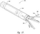
- an anchorable marker assemblyincludes a marker 220 having a casing, a magnetic transponder (e.g., a resonating circuit) at least partially encased in the casing, a shell assembly 702 and an anchor assembly.
- the anchor assemblyincludes an anchor disk 710 (shown in later figures) and fasteners 708 such as shape memory legs, extending from the anchor disk 712.
- an anchorable marker assembly 700may include a marker 220, a shell assembly 702 around the marker 220, an anchor disk 710 adjacent to a proximal end of the marker 220, and a plurality of fasteners or legs 708 attaching to the anchor disk 710 and extending proximally.
- the legs 708may further include an end stop 704 at a far proximal end.
- the end stop 704may further include a barb 706 extending at an angle outward.
- the anchor disk 710may be held in a fixed position in the shell assembly 702 by anchor sleeve 712 and adhesive 714.
- the shell assembly 702the anchor sleeve 712, the legs 708 and the anchor disk may interlock 716 during assembly.
- This mechanical interlock between the shell components and the Nitinol ® leg stability featureprovides a high intra-component mechanical strength.
- the legsmay be mated into grooves in the anchor disk, providing further positive mechanical interlock.
- Other interlock configurationsmay be used within the scope of this disclosure, including but not limited to: star shaped and inverted star shape anchor disk; direct leg-to-shell interlock; single piece multi-leg cage interlocks and the like.
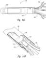
- FIG. 16A, 16B and 16Ca delivery catheter with a preloaded anchorable marker assembly, including the loaded catheter assembly of Figure 16A , is shown.
- Figure 16Bshows a cutaway view of the loaded catheter
- Figure 16Cshows a deployed view of the marker after it has been deployed from the catheter.
- the internal shell-cathetermay overlap for articulation in use.
- the exemplary configurationallows the distal end of the catheter to dock with the marker and articulation between the marker and the catheter provides axial flexibility and a reduction in forces when passing through tortuous or curved pathways.
- an internal shell-catheter overlapmay cover a sharp edge on the deliver catheter to avoid airway wall injury.
- the distal end of the push wireincludes an engagement member 720.
- the engagement memberis configured as a retention bulb shaped to retain the fasteners 708 when the anchorable marker assembly is retained in the delivery catheter prior to deployment.
- the engagement membermay take any geometrical shape to nest within and retain the fasteners when the anchorable marker assembly is retained in the delivery catheter prior to deployment.
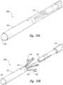
- Figure 18Ashows a preloaded delivery catheter 1800 and Figure 18B shows an anchorable marker assembly after being deployed from the delivery catheter.
- the distal end of the push wireincludes an engagement member 720.
- a breakaway meansis included between a first part 702a of the shell assembly 702 and a second part 702b of the shell assembly 702.
- the breakaway meansmay include a weakened portion of the shell assembly 702 in the form of a perforation, crease, thinned section or the like.
- a local deformation or crumple zonemay exist to accommodate permanent deformation in the shell.
- the deformation zonecan be designed to allow deformation in a specific region (e.g. between the first part 702a of the shell assembly 702 and the second part 702b of the shell assembly) without damage to function and performance of the shell assembly 702.
- the distal end of the push wireincludes an engagement member 720.
- the shell assembly 702extends proximally over the anchor disk 710 and over some portion of the fasteners 704 to form a skirt at the proximal end of the marker.
- the overlap at the marker/catheter interfaceensures that the marker and the catheter remain engaged during handling of preloaded catheters and while passing the preloaded catheter through small bend radii.
- the overlapprovides a flexibility at the marker/catheter interface and can further include an articulated section at the marker/catheter interface.
- Figure 20Ashows a preloaded delivery catheter 2000 and Figure B shows an anchorable marker assembly deployed from the delivery catheter.
- the distal end of the push wireincludes an engagement member 720.
- the engagement memberis configured as an interlock having recesses shaped to engage the fasteners 708 when the anchorable marker assembly is retained in the delivery catheter prior to deployment.
- the interlocking engagement memberprovides a positive mechanical interlock to retain the marker in the preloaded catheter.
- Figure 21Ashows a preloaded delivery catheter 2100 and Figure 21B shows an anchorable marker assembly deployed from the delivery catheter.
- the distal end of the push wireincludes an engagement member 720.
- the engagement memberis configured as a further interlock shape configured to include slots to receive the fasteners 708 when the anchorable marker assembly is retained in the delivery catheter prior to deployment.
- the engagement memberis configured as an interlock shaped to engage the fasteners 708 when the anchorable marker assembly is retained in the delivery catheter prior to deployment.
- the interlocking engagement memberprovides more positive mechanical interlock to retain the maker in the preloaded catheter.
- Figure 22Ashows a preloaded delivery catheter 2200 and Figure 22B shows an anchorable marker assembly deployed from the delivery catheter.
- the distal end of the push wireincludes an engagement member 720.
- the engagement memberis configured as a retention bulb which includes a collet for receiving an element of the fastener assembly shown in this embodiment to include a larger diameter head at a distal end for engaging the engagement member.
- the engagement memberis configured to receive the element 707a of the fastener assembly in the collet to provide a positive mechanical interlock to retain the anchorable marker assembly in the delivery catheter prior to deployment.
- Figure 23Ashows a preloaded delivery catheter 2300 and Figure 23B shows an anchorable marker assembly deployed from the delivery catheter.
- the markeris not preloaded in the delivery catheter.
- the distal end of the push wireincludes an engagement member 720.
- the engagement memberis configured as a retention rod which includes a collet for receiving an element 707b of the fastener assembly. The engagement member is configured to receive the retained member 707b in the collet to provide a positive mechanical interlock to retain the anchorable marker assembly in the delivery catheter prior to deployment.
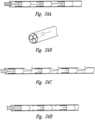
- FIGS. 24A-24Dcross-sectional and end views of the anchorable assemblies illustrating various loading and unloading configurations are shown.
- anchorable marker assembliesare shown loaded in the deliver catheter in series.
- An alternate loading configuration shown in Figure 24Bshows the anchorable assemblies loaded in parallel in a delivery catheter.
- Figure 24Can alternative unloading pattern is illustrated wherein the markers are directed to exit the delivery catheter out a side portal of the catheter.
- multiple individual anchorable marker assembliesare loaded in an untethered manner, separated by a dimple on the interior surface of the delivery catheter.
- separation meansmay include a mechanical plug, ridge, bladder or other separation device, or may include a spacer of fluid, paste, gel or the like.
- separation meansmay include a mechanical plug, ridge, bladder or other separation device, or may include a spacer of fluid, paste, gel or the like.
- a dimple at a distal end of the delivery cathetermay engage with a collar portion of the push wire to provide a first stop for preventing the user from over-deploying.
- a protrusion extending from an interior of the catheterconfigured to engage the collar portion of the push wire and provide a second stop configured to prevent over retraction of the push wire.
- two stopsmay be provided, however in this embodiment, both engage with a common protrusion shown on an interior of the catheter.
- a first stopprevents the user from retracting the push wire beyond a predetermined distance and a second stop prevents the user from over inserting the push wire beyond a predetermined distance.
- a second stopprevents the user from over inserting the push wire beyond a predetermined distance.
- alternative deployment stop configurationsare shown. It is recognized by those skilled in the art that alternative stops beyond the representative stops shown in Figures 25A-25D may be included and still fall within the scope of the disclosure.
- the distal end stopcan provide implant placement accuracy to less than 5 mm, by controlling the stroke required to deploy the implant from the retention sleeve.
- the distal end stopcan limit ball protrusion from the retention sleeve; hold the deployment wire centered with respect to the retention sleeve during loading; prevent the legs from becoming entrapped behind disk after deployment; and minimize the likelihood of implant legs catching on ball during retraction.
- the casingis a biocompatible barrier, which can be made from plastics, ceramics, glass or other suitable materials, and the casing is configured to be implanted in the patient.
- the casingcan be a generally cylindrical capsule that is sized to fit within a catheter for bronchoscopic implantation.
- the casingcan have a diameter of approximately 2 mm or less.
- the casingcan have a slightly larger diameter than the inside diameter of the delivery catheter to retain the casing in the catheter during placement.
- the magnetic transpondercan include a resonating circuit that produces a wirelessly transmitted signal in response to a wirelessly transmitted excitation field.
- the magnetic transpondercomprises a coil defined by a plurality of windings around a conductor.
- Many embodiments of the magnetic transponderalso include a capacitor coupled to the coil.
- the coilcan resonate at a resonant frequency solely using the parasitic capacitance of the windings without having a capacitor, or the resonant frequency can be produced using the combination of the coil and the capacitor.
- the coilaccordingly defines a signal transmitter that generates an alternating magnetic field at the selected resonant frequency in response to the excitation energy either by itself or in combination with the capacitor.
- the coilgenerally has 800-2000 turns, and the windings are preferably wound in a tightly layered coil.
- the magnetic transpondercan further include a core composed of a material having a suitable magnetic permeability.
- the corecan be a ferromagnetic element composed of ferrite or another material. Suitable embodiments of magnetic transponders are disclosed in U.S. Patent Nos. 7,289,839 and 8,196,589 .
- the anchormay be embedded in the marker or the anchor may be contained in the delivery catheter such that the anchor is deployed adjacent to the marker to prevent the marker from migrating.
- the fastenercan be a separate component attached to and/or embedded in the casing.
- a fastener or anchor protruding from the marker casing wherein the fastenercan be an integral extension of the casing.
- the fasteneris a separate component, it can be made from a suitable biocompatible material, such as metals, metal alloys, polymers, PEEK, glass, epoxy adhesive, silicone adhesive and/or other synthetic materials.
- an outer shapecan employ shape memory alloy features that "grow" into bronchiole as internal body temperature expands the alloy.
- a markercomprises a marker section configured to be localized and an anchor attached to the marker section.
- the anchorcomprises an expandable member that moves between a stored position having a first size and a deployed position having a second size greater than the first size.
- the anchorfor example, can be a stent, an umbrella-like expandable member, or an expandable cylindrical section as shown in the Figures.
- the designallows for the ability to retrieve the implant from airway after implantation.
- a commercially available accessory tooleg. biopsy forceps, snare, retrieval basket
- a single leg or multiple legs of the stability featureis used to grasp a single leg or multiple legs of the stability feature and retrieve from the airway.
- bronchoscopic implantation of an implant in the airwayhas a lower risk of complication when compared to a needle based percutaneous implantation in the airway, and therefore bronchscopic placement is the preferred method.
- An alternative embodimentprovides for central airway application, wherein the implant is implanted in a larger diameter airway.
- Design changes to the implantare expected to focus on a scale-up of the stability feature, designed for positional stability in larger airways, and potentially, allow for retrieval if needed.
- the implantmay be implanted in the airway wall; in which case, modification to the stability feature would focus on a scale-down of the stability feature.
- the catheter delivery devicecan be include a modified stability feature for implantation in organs, vessels and tissues other than lung airways percutaneously, laparoscopically, natural orifice transluminal endoscopiclly.
- the catheter deliver devicecan include an implant without a stability feature preloaded in a delivery catheter, for example for Catheterization of the Subarachnoid Space and placement in the brain.
- the stability featuremulti-legged design
- generic delivery cathetercould be used to deliver other devices such as a transponder, gold seeds, coils, or other fiducial markers in the lung.
- a delivery catheter designwhere more than one implant is preloaded in the distal end of the delivery catheter. Such a design would further improve ease of use, and eliminate the workflow due to exchange of the single use catheter after deployment, and introduction of the next delivery catheter.
- the userwithdraws the delivery catheter approximately 1-2cm so as to provide a space for the anchored transponder to be deployed in.
- Thisaccounts for the travel of the anchored transponder upon handle actuation/deployment, supports accurate placement of the anchored transponder and prevents bronchial injury or serious injury such as pneumothorax.
- Actuation/deploymentcan also by accomplished by simultaneous actuation of the handle and withdrawal of the catheter, or actuation/deployment without a space for the anchored transponder to be deployed in.
- a bronchoscopeis inserted into the nose or mouth of a patient past the vocal chords and into the lungs by threading a distal end through the bronchi. At least one marker is pre-loaded at the distal end 216 of the delivery catheter 212.
- the delivery catheter 212is positioned in the working channel of the bronchoscope such that the distal end 216 of the delivery catheter 212 is at or slightly beyond a distal end of the bronchoscope.
- the actuatoris engaged, causing the push wire to move axially within the channel and deploy the marker.
- a second markercan be deployed; the catheter can be repositioned prior to deploying a second catheter; the catheter can be removed and the bronchoscope can be removed or repositioned to deploy a second marker; or the catheter can be repositioned to deploy a second marker.
- an anti-migration device integral to the marker or separate from the markercan further be deployed to retain the marker in a desired position.
- the anti-migration deviceanchors the marker to the anatomical anchoring site as further described below.
- Anchored transpondersshould be placed in small airways (approximately 2-2.5 mm in diameter) that are within or near the tumor target to be treated. Preferred placement sites and the bronchoscopic path for reaching them should be determined before beginning the implantation procedure. Anchored transponders may be placed during a standalone procedure or in conjunction with diagnostic bronchoscopy. Implantation should be performed in an ambulatory procedure area or the operating room.
- Each anchored transponderincludes a small, passive, electrical component encapsulated in biocompatible glass with an affixed multi-legged anchoring feature.
- the legs of the anchoring featureare constrained in the pre-loaded delivery catheter and become unconstrained, expanding outward, when the anchored transponder is deployed in the airway.
- the transponder diameteris approximately 2 mm; when the legs are fully expanded, the diameter is approximately 5.5 mm.
- a separate delivery catheteris used to implant each anchored transponder into an airway within or near the treatment target.
- Each single-use, delivery catheteris pre-loaded with an anchored transponder.
- the distal end of the delivery catheteris approximately 2 mm in diameter.
- the retention sleeve located at the distal tip of the delivery catheterconstrains the legs of the anchored transponder around the deployment wire.
- the delivery catheteris marked with graduations to assist in monitoring the length of the delivery catheter that has passed through the bronchoscope and into the lung. In this embodiment, the graduations occur every centimeter with a heavier mark every fifth centimeter.
Landscapes
- Health & Medical Sciences (AREA)
- Life Sciences & Earth Sciences (AREA)
- Engineering & Computer Science (AREA)
- Biomedical Technology (AREA)
- Public Health (AREA)
- Veterinary Medicine (AREA)
- Animal Behavior & Ethology (AREA)
- General Health & Medical Sciences (AREA)
- Heart & Thoracic Surgery (AREA)
- Hematology (AREA)
- Anesthesiology (AREA)
- Biophysics (AREA)
- Pulmonology (AREA)
- Nuclear Medicine, Radiotherapy & Molecular Imaging (AREA)
- Pathology (AREA)
- Surgery (AREA)
- Oral & Maxillofacial Surgery (AREA)
- Medical Informatics (AREA)
- Molecular Biology (AREA)
- Radiology & Medical Imaging (AREA)
- Media Introduction/Drainage Providing Device (AREA)
Description
- The present invention relates to a catheter assembly for delivering a marker into a lumen, and more specifically, but not exclusively, is directed toward bronchoscopically implanting markers in the lung of a patient and further more particularly, but not exclusively, toward a pre-loaded delivery catheter with a marker wherein the marker includes an improved anti-migration device.
- Radiation therapy has become a significant and highly successful process for treating prostate cancer, lung cancer, brain cancer and many other types of localized cancers. Radiation therapy procedures generally involve (a) planning processes to determine the parameters of the radiation (e.g., dose, shape, etc.), (b) patient setup processes to position the target at a desired location relative to the radiation beam, (c) radiation sessions to irradiate the cancer, and (d) verification processes to assess the efficacy of the radiation sessions. Many radiation therapy procedures require several radiation sessions (i.e., radiation fractions) over a period of approximately 5-45 days.
- To improve the treatment of localized cancers with radiotherapy, it is generally desirable to increase the radiation dose because higher doses are more effective at destroying most cancers. Increasing the radiation dose, however, also increases the potential for complications to healthy tissues. The efficacy of radiation therapy accordingly depends on both the total dose of radiation delivered to the tumor and the dose of radiation delivered to normal tissue adjacent to the tumor. To protect the normal tissue adjacent to the tumor, the radiation should be prescribed to a tight treatment margin around the target such that only a small volume of healthy tissue is irradiated. For example, the treatment margin for prostate cancer should be selected to avoid irradiating rectal, bladder and bulbar urethral tissues. Similarly, the treatment margin for lung cancer should be selected to avoid irradiating healthy lung tissue or other tissue. Therefore, it is not only desirable to increase the radiation dose delivered to the tumor, but it also desirable to mitigate irradiating healthy tissue.
- One difficulty of radiation therapy is that the target often moves within the patient either during or between radiation sessions. For example, tumors in the lungs move during radiation sessions because of respiration motion and cardiac functions (e.g., heartbeats and vasculature constriction/expansion). To compensate for such movement, the treatment margins are generally larger than desired so that the tumor does not move out of the treatment volume. However, this is not a desirable solution because the larger treatment margins may irradiate a larger volume of normal tissue.
- Localization and/or tracking of markers, such as gold fiducials or electromagnetic transponders, implanted in proximity to the target or tumor may enable increased tumor radiation and decreased healthy tissue irradiation. However, fluoroscopic imaging of implanted gold fiducials is limited by high doses of non-therapeutic imaging radiation, expensive fluoroscopic equipment, subjective image interpretation and poor implant stability.
- Another challenge in radiation therapy is accurately aligning the tumor with the radiation beam. Current setup procedures generally align external reference markings on the patient with visual alignment guides for the radiation delivery device. For an example, a tumor is first identified within the patient using an imaging system (e.g., X-ray, computerized tomography (CT), magnetic resonance imaging (MRI), or ultrasound system). The approximate location of the tumor relative to two or more alignment points on the exterior of the patient is then determined. During setup, the external marks are aligned with a reference frame of the radiation delivery device to position the treatment target within the patient at the beam isocenter of the radiation beam (also referenced herein as the machine isocenter). Conventional setup procedures using external marks are generally inadequate because the target may move relative to the external marks between the patient planning procedure and the treatment session and/or during the treatment session. As such, the target may be offset from the machine isocenter even when the external marks are at their predetermined locations for positioning the target at the machine isocenter. Reducing or eliminating such an offset is desirable because any initial misalignment between the target and the radiation beam will likely cause normal tissue to be irradiated. Moreover, if the target moves during treatment because of respiration, organ filling, or cardiac conditions, any initial misalignment will likely further exacerbate irradiation of normal tissue. Thus, the day-by-day and moment-by-moment changes in target motion have posed significant challenges for increasing the radiation dose applied to patients.
- Conventional setup and treatment procedures using external marks also require a direct line-of-sight between the marks and a detector. This requirement renders these systems useless for implanted markers or markers that are otherwise in the patient (i.e., out of the line-of-sight of the detector and/or the light source). Thus, conventional optical tracking systems have many restrictions that limit their utility in medical applications. Thus, there is a continuing need for improved localization and tracking of markers, including an improved method of placing the marker and an improved system of preventing movement of the marker once placed.
- Tumor target localization has been demonstrated utilizing implanted markers such as gold fiducials (balls and cylinders) and electromagnetic transponders. One method of placement for these markers in the lung is to deliver them into the bronchus/ bronchioles of the lung and then force-fit the markers into the appropriate diameter bronchiole near the treatment target location. The implant location that permits a force-fit of the markers is likely not the most desired location, but one that simply accommodates the force fit. Additionally, the act of breathing, which effects a small enlargement/contraction cycle of the bronchioles, may dislodge the marker from its desired location. Many inhaled drugs also effect changes in the diameter of the bronchioles. Further, actions such as coughing, which typically originate in the alveolar structures near the lung periphery, serve to force the markers from their desired locations to locations closer to the trachea.
- Thus implanted marker usage for localization and tracking of lung tissue targets has proven challenging due to marker migration issues. Since markers are surrogates for the actual treatment target position, there is a need to minimize potential for marker migration throughout the entire course of radiation therapy (from treatment planning to last radiation fraction application). Initial positioning and maintenance of marker location should desirably be accomplished independent of bronchus/bronchiole size. The position of the marker needs to remain stationary regardless of feature changes within the bronchioles. A multiplicity of devices, methods, and systems are listed to accomplish that task.
- The airways in the lungs anatomically constitute an extensive network of conduits that reach all lung areas and lung tissues. Air enters the airways through the nose or mouth, travels through the trachea and into the bronchi and bronchioli of the lunch. The lungs are covered by a think membrane called the pleura. Because of these physiological characteristics of the airways, a marker placed in bronchi and bronchioli may cause pneumothorax when implanted, thus, there is a need for a new and improved device, system, and method for implanting a marker in the region proximate to a tumor or other lesion in the lung.
- One recent method for locating a target implanted within the body includes a wireless implantable marker configured to be implanted surgically or percutaneously into a human body relative to a target location. The markers include a casing and a signal element in the casing that wirelessly transmits location signals in response to an excitation energy. One concern of using implanted markers in soft tissues, bronchi or bronchioli is that the markers may move within the patient after implantation. To resolve this concern, Calypso Medical Technologies, Inc. previously developed several anchors and fasteners for securing the markers to soft tissue structures, as disclosed in
U.S. Publication No. 2003-0192557 A1 ,. Although these anchors may work for percutaneous or surgical implantation, they may be improved for bronchoscopic applications. Therefore, it would be desirable to further develop markers for bronchoscopic deployment and implantation. - The present invention provides a catheter assembly as defined in
claim 1. - The retention element may be active; the push element; a sphere, ball, teardrop or pyramid shape; or a distal end stop.
- The assembly may be further such that the distal end of the catheter or the marker has sharp edges that could puncture the luminal wall during implantation, or wherein the marker is shaped and positioned in the catheter such that no sharp edges are present that could puncture the luminal wall during implantation.
- The assembly may further comprise a first stop and a section second stop, wherein the first stop limits advancement of the flexible pusher member and the second stop limits retractment of the flexible pusher member.
- The may further comprise a sleeve fixedly retained at a distal end of the catheter; the sleeve having an inside diameter greater than an outside diameter of the catheter to allow the sleeve to slide a selected distance over the distal end of the catheter, wherein the sleeve extends a selected distance beyond the distal end of the catheter.
- The assembly may further comprise a supply and loading device matably coupled with the distal end of the sleeve, configured to releasably retain the stored marker and transfer the marker from the supply and loading device to a distal end of the sleeve.
- The catheter and flexible push member may be provided with dimensions such that the assembly can be passed down a working channel of a not forming part of the invention bronchoscope a selected distance for deployment of the marker a bronchial lumen within the lung.
- The catheter and flexible push member may further be provided with dimensions such that the assembly can be passed down a working channel of an not forming part of the invention endoscope a selected distance for deployment of the marker in a lumen the digestive system.
- The catheter and flexible push member may further be provided with dimensions such that the assembly can be passed into an artery or vein for deployment of the marker in a lumen within the cardiovascular system.
- The assembly may further comprise a shipping tray and/or storage tray. Each one of the plurality f fasteners or legs of the anchorable marker assembly may further include a shaped barb.
- The marker may be a gold seed.
- In a further aspect, not forming part of the present invention provides a catheter assembly for delivering a marker into a lumen, the assembly comprising:
- a catheter having a proximal end and a distal end, the distal end configured to receive a marker, the catheter configured to be passed into a lumen for deployment of the marker;
- an actuator having a housing coupled to a proximal end of the catheter and moveable between a first position and a second position, wherein the housing includes a first region having a first stiffness and a second region having a second stiffness; and
- a flexible pusher member fixedly attached to the actuator, wherein the flexible pusher member is contained in the catheter and extends co-axially substantially the entire length of the catheter.
- In the drawings, identical reference numbers identify similar elements or acts. The sizes and relative positions of elements in the drawings are not necessarily drawn to scale. For example, the shapes of various elements and angles are not drawn to scale, and some of these elements are arbitrarily enlarged and positioned to improve drawing legibility. Further, the particular shapes of the elements as drawn, are not intended to convey any information regarding the actual shape of the particular elements, and have been solely selected for ease of recognition in the drawings.
Figures 1-26 are isometric and cross-sectional views of exemplary bronchoscopic catheter assemblies in accordance with several aspects of the disclosure.- In the following description, certain specific details are set forth in order to provide a thorough understanding of various examples not forming part of the invention and various embodiments of the invention.
- Several features of a bronchoscopic catheter assembly not forming part of the invention, a marker or a marker with anchors in accordance with the description are set forth and illustrated in the Figures. For the purposes of brevity, like reference numbers refer to similar or identical components of the markers in the Figures. Additionally, throughout the specification, claims, and drawings, the term "proximal" means nearest the trachea, and "distal" means nearest the alveoli.
- The headings provided herein are for convenience only and do not interpret the scope or meaning of the claimed invention.
- The following disclosure describes several embodiments of wireless markers configured to be implanted and anchored within the lung of a human in a manner that prevents the markers from migrating from the implantation site. The marker is configured to reduce pneumothorax and may further be configured to include an anchor or anti-migration device.
- According to embodiments of the invention, a bronchoscopic catheter assembly includes a marker pre-loaded at a distal end of a delivery catheter for bronchoscopically implanting the marker in peripheral airways of the lung. A marker storage and loading device for retaining the marker prior to loading in the distal end of the delivery catheter is described. The marker can extend a selected distance beyond the distal end of the delivery catheter to provide a leading end. The marker may be configured at the leading end to reduce pneumothorax. According to the invention, the marker includes an integral anti-migration or anchoring device for preventing migration of the marker after placement of the marker in the lung. According to still further embodiments of the invention, an anti-migration device is separate from the marker and positioned adjacent to the deployed marker to prevent migration of the marker in the lung after placement. According to still further embodiments of the invention, the marker is shaped and sized to reduce migration.
- According to embodiments of the invention, a marker for use in the bronchoscopic catheter assembly for localizing a target of a patient comprises a casing, a magnetic transponder at least partially received in the casing, and an anchor carried by the casing. The casing is a biocompatible barrier configured to be implanted in the patient. The casing can be a generally cylindrical capsule that is sized to fit within a catheter of a bronchoscope for bronchoscopic implantation, but the casing can have other geometric shapes, sizes, and configurations in other applications. For example, the casing can be larger for implanting the marker in the bronchus. The magnetic transponder produces a wirelessly transmitted magnetic field in response to a wirelessly transmitted excitation energy. The magnetic transponder can further comprise a magnetic core, a coil wrapped around the core, and a capacitor coupled to the coil. The anchor, which can project from the casing, be integral to the casing, or be independent from the casing, secures the marker to an anatomical structure once the marker has been deployed from the bronchoscopic catheter assembly to prevent the marker from moving from the implantation site. According to aspects, the anchor may be detached from the marker. In another embodiment, the marker may be secured to the anatomical structure by mechanical members or chemical attributes.
- According to further aspects, an anchorable marker configured for bronchoscopic implantation for localizing a target of a patient comprises a casing, a transponder that produces a wirelessly transmitted magnetic field in response to a wirelessly transmitted excitation field, and an anchor partially embedded within the casing. The anchor can further be configured for bronchoscopic implantation and have a shape and/or material that pierces, engages or otherwise interfaces with the anatomical anchoring site such that the marker cannot be easily dislodged. Alternatively, the casing is shaped to reduce migration of the marker, for example, the casing may be wedge shaped, include a hook, or have a surface texture.
- Methods for manufacturing and using markers with anchors are disclosed but not formed part of the invention. One such method comprises providing a transponder that produces a wirelessly transmitted magnetic field in response to a wirelessly transmitted excitation field and forming a casing around the transponder. This method can further include embedding, attaching or forming an anchor in the casing. In alternative examples, the marker may be a gold fiducial, RFID tag, active marker or electromagnetic marker. In still further alternative examples, the anchor can be detached from the marker. In further examples, the casing may be the anchor.
- According to one current practice, the marker is forcibly wedged into the lumen, however, this will work only for limited settings and circumstances. The marker must be approximately the same size as the lumen at the desired geographic placement location. The luminal wall must possess the appropriate elastic characteristics to retain the force-fitted marker. Forces such as those caused by coughing and wheezing serve to dislodge the marker. Potentially, mucous transport systems in the bronchioles could dislodge a force-fit marker. Inhaled drugs may serve as broncho-dilators and bronchoconstrictors. Further, tumor shrinkage during radiation therapy and/or chemotherapy, diaphragmatic motion, the movement of air, and the various pressure profiles within the lung may serve to dislodge a positional marker.
- Human lungs are located on either side of the heart and occupying a large portion of the chest cavity from the collarbone to the diaphragm. The lungs are covered by a thin membrane called the pleura. Air travels to the chest cavity through the trachea, which divides into two bronchi, each of which enters a lung. The bronchi divide and subdivide into a network of countless tubules. The smallest tubules, or bronchioles, enter cup-shaped air sacs known as alveoli, which number about 700 million in both lungs. In the case of a marker that is force-fit into a bronchiole, given that bronchioles decrease in diameter toward the lung periphery, any marker dislodgement would typically result in the marker moving toward the trachea, since there is no mechanism to force the marker further into the decreasing diameter lumen. So, in the case of a force fit marker, a solitary secondary plug could serve to secure the marker in place. Feasibly, since the marker should not move further down the bronchiole structure due to its decreasing luminal diameter, the secondary securing device would need to provide only a marginal increase in holding capacity to keep the marker in place. It should be noted that in this case, since the retention device is located on the side closer to the trachea side, it will be located in a diameter that is incrementally larger than that of the marker location.
- Dependant upon the specific elastic properties at any specific bronchial location, a plurality of devices and methods exist for entrapping a marker in the bronchial lumen. A LRD (luminal retention device) embodied as a plug can be force fit into a tubular structure such as a bronchus, or other bodily lumen, to trap or hold in place a marker. A LRD rigid plug would rely on the resiliency of the lumen to hold the plug in place, while a plug constructed of silicone, sponge, or other similar materials would inherently possess its own resiliency. The fibrin-thrombin type adhesives and adhesive blobs could be used to a) build a LRD plug in-place in the lumen to prevent the marker from dislodging, b) augment the diameter or attach a smaller sized LRD plug to the luminal wall, or c) used to glue the transponder directly to the wall. Cyanoacrylate adhesives could be used in this application as well. A related product, the foamed-matrix biologically-based materials possess mechanical properties similar to weak plastics prior to being exposed to body fluids, and could be pre-formed into acceptable shapes to force-fit into a lumen, but would shortly form a soft, biologically based plug once established in the mucous of the bronchial tree.
- Many shapes can be utilized as an LRD anchor or plug, since the goal is to fixate the marker. Materials many include plastics, metals, adhesives, expandable sponges, and bio-materials (e.g. collagen, connective tissue derivatives). Additional embodiments include: wire or shaped metal "ring", hex, umbrella, etc. A form resembling a helical shaped wire spring can be advanced through a small diameter conduit to the desired location in a compressed state, expanding to the luminal diameter upon expulsion from the confines of the conduit, trapping the marker on one side. A plurality of materials could be utilized, including, at least, metals, plastics, and matrix materials such as carbonfiber.
- Further, the internally-springed, radially self-expander marker anchor allows for diametral growth or shrinkage of the lumen in which it resides, without requiring adjustment or positioning. While the device has been presented herein as a single anchor, it may be used in pairs within a lumen to trap a marker between the pair of anchors. As long as the marker cannot escape through the LRD device toward to the larger bronchiole structures the device should remains stationary and the goal will be realized.
- Consideration should be allowed for delivery of any of the devices as well. The ability of a device to be delivered in a compact, or compressed state, is a definite advantage. Further, the ability of a device to compensate for differences in lumen size and elasticity allows the use of a single device for a plurality of lumen sizes and, therefore, lumen locations. To fixate a marker within a lumen, the marker can be forcibly wedged within the lumen, anchored to the luminal wall, entrapped against the luminal wall, anchored to the luminal wall using a leg of a bifurcation point, entrapped within the lumen by a second device, or trapped at a specific location within the lumen by the use of two secondary devices. Combinations of these methods may be employed as well.
Figure 1A is an isometric view of abronchoscopic catheter assembly 200 for use in a working channel of a bronchoscope (not shown for clarity) and a storage andtransportation device 240 having a receivinghoop 246 for releasably retaining adelivery catheter 212 during storage and transportation of thedelivery catheter 212 in accordance with an embodiment of the invention.Figure 1B is an isometric, expanded view of thebronchoscopic catheter assembly 200 ofFigure 1A with amarker 220 loaded in thedistal end 216 of thedelivery catheter 212 and the storage andtransportation device 240 cut away to show loading of thedelivery catheter 212 in the receivinghoop 246. As shown inFigures 1A and 1B , thebronchoscopic catheter assembly 200 includes adelivery catheter 212 having a deployment channel 211 configured to releasably retain amarker 220 at adistal end 214 of thedelivery catheter 212 such that themarker 220 extends a selected distance beyond adistal end 216 of thedelivery catheter 212.- Referring now to
Figure 1A , the storage andtransportation device 240 for retaining thebronchoscopic catheter assembly 200 during storage and transportation is provided. The storage andtransportation device 240 includes a receivinghoop 246 for releasably retaining thedelivery catheter 212. The storage andtransportation device 240 can include ahousing 230 which is configured to releasably retain the receiving hopp inclips 232a, b. Thehousing 230 may further include aguide 234 and/or an insertion guide assembly for guiding the distal end of thedelivery catheter 212 therein. The housing 244 additionally provides an alignment means for mating with the distal end of the catheter when loading themarker 220 into the catheter as discussed further with respect toFigure 5 . - Referring now to
Figure 1A , aproximal end 214 of thedelivery catheter 212 is configured to engage ahandle 210 having anactuator 222. Theactuator 222 is moveable between a first position and a second position along arrow A. In the second position, theactuator 222 moves towards and/or abuts aflange 224. Theflange 224 is configured to stop movement of theactuator 222 along line A by engaging theactuator 222 on a first side. On a second side, opposite the first side, theflange 224 retains thedelivery catheter 212. Theflange 224 further includes a sleeve (not shown) for slidably receiving apush wire 218 therein. - The
push wire 218 is retained by the body of the catheter and moves with theactuator 222. Thepush wire 218 may be a Teflon wire, steel cable, steel wire, Nitanol® or other flexible cable having sufficient rigidity to deploy themarker 220 when theactuator 222 is moved along line A. As shown inFigure 3B , thepush wire 218 may include a disc shapedend 404 for engaging themarker 220. Alternatively, anend 404 of thepush wire 218 may be an appropriately shaped wire or rod. Theend 404 may have a diameter dimension slightly less than the diameter dimension of the channel 211 to allow thepush wire 218 to slide co-axially therein. The distal end of the delivery catheter is described in greater detail below. - The
handle 210 is configured to be moveable by an operator (not shown) and may further be configured to attach to the working channel of the bronchoscope. Referring now toFigure 2 , thehandle 210 can include anactuator 322 including a button or flat plate configured to be engaged by a digit of an operator's hand (not shown for purposes of clarity). Theactuator 322 abuts thehousing 324 to stop axial movement along line A. As shown inFigure 2 , thehandle 210 can include anactuator 322 including a ring configured to be engaged by a digit of an operator's hand. As further shown, thehousing 326 can be ergonomically shaped to the hand of a user. Alternative configurations of the actuator can further be provided. Thehandle 210 may further include alock 326, shown inFigure 2 on thehousing 324, to prevent accidental deployment of the marker. - It may be useful to deliver or deploy the
markers 40 into or at least proximate to a tumor located in the lung of the patient. Accordingly, the delivery device can be a bronchoscope, catheter, or other device configured to pass through a lumen in the respiratory system of the patient. Generally speaking, the delivery device includes a handle and an elongated body attached to the handle. More specifically, the elongated body includes a proximal section at the handle and a distal section configured to pass through lumen in the respiratory system. In many embodiments, the distal section of the elongated body is flexible, but in other embodiments the entire elongated body can be flexible or rigid. In operation, the marker is supported by the elongated body at the distal section for deployment into the patient. In several embodiments, the delivery device further includes a deployment mechanism that is operable from the handle to release the marker into the patient. The deployment mechanism can be a push rod that pushes the marker out of the distal section of the elongated body. In an alternative arrangement, the deployment mechanism can include a cannula and a stylet slidably received in the cannula. In this arrangement, the cannula and stylet are configured to move together to project distally beyond the distal section of the elongated body, and then the cannula may be withdrawn proximally relative to the stylet to release the marker into the patient. - According to still further embodiments, the delivery device can further include a steering mechanism that is operable from the handle. The steering mechanism can include an attachment point at the distal section and a slidable member configured to move longitudinally relative to the elongated body. Longitudinal movement of the slidable member flexes the distal section in a manner that steers the delivery device through bends and bifurcations in the lumen of the respiratory system. In other embodiments, the steering mechanism comprises a flexible support element and a flexible control element attached to the flexible support element such that tension applied to the control element flexes the flexible support element. Suitable steering mechanisms are set forth in
U.S. Patent No. 6,702,780 and U.S. Patent Application Publication No.US 2003/0208101 . - Referring now to
Figures 3A-3D , which are not embodiments of the invention, thedistal end 216 of thedelivery catheter 212 releasably retains themarker 220. As shown inFigure 3A , an outside diameter of themarker 220 can be approximately equal to the diameter of the channel 211. Alternatively, as shown inFigure 3C , asleeve 406 can be placed at adistal end 216 of thedelivery catheter 412. An inside diameter of thesleeve 406 can be approximately equal to the outside diameter of themarker 220 and configured to releasably retain themarker 220. According to this embodiment, thechannel 411 can have an inside diameter smaller than the outside diameter of themarker 220. Thesleeve 406 may be made from a semi-rigid, rigid, or flexible material different from thecatheter 412, or may be made from the same material as thecatheter 412. - Referring now to
Figure 3D , thedistal end 516 of thedelivery catheter 512 releasably retains themarker 220 by expanding around themarker 220. According to aspects of this embodiment, the inside diameter of thedelivery catheter 512 is less that the outside diameter of themarker 220. Thedelivery catheter 512 is made from a sufficiently flexible material to allow thedelivery catheter 512 to expand around themarker 220 and releasably retain themarker 220 prior to deployment. Alternatively, another method besides compression fit to hold the marker in place is to use a material for example, coconut oil that is solid at room temperature and liquid at body temperature. Alternately, the material could be liquid soluble, such as sucrose or NaCl; exposure to the lumen would detach the marker. - Referring now to
Figure 4 , a cut away schematic view of the distal end of a delivery catheter in accordance with an embodiment of the disclosure is shown. A retention sleeve 606 is placed at thedistal end 616 of the delivery catheter 612. An inside diameter of the sleeve 606 can be approximately equal to the outside diameter of the marker. The deployment wire orpush wire 618 includes anengagement member 620 and adeployment member 622. Theengagement member 620 is positioned at a distal end of the push wire and is configured as a ball end inFigure 4 . Alternatively, theengagement member 620 may be a wedge, a plate or other geometric shape as appropriate. Thedeployment member 622 is positioned co-axially at a predetermined distance away from the distal end of the push wire. As will be understood by one skilled in the art, thedeployment member 622 may be a tapered wedge as shown or may be any other geometric shape. Figure 5 is a cross-sectional view of an exemplary healthy respiratory system 110 havingmarkers 220a-c positioned therein. The respiratory system 110 resides within athorax 16 which occupies a space defined by achest wall 12 and a diaphragm 13. Therespiratory system 10 includestrachea 16; leftmainstem bronchus 20 and right mainstem bronchus 22 (primary, or first generation); lobarbronchial branches segmental branches 34 and 36 (third generation). Therespiratory system 10 further includesleft lung lobes right lung lobes - As shown in
Figure 5 , threetransponders 220a-c are positioned in the respiratory system 110 of a patient in the proximity of a tumor or lesion 100. Thetransponders 220a-c are used to localize a patient target treatment isocenter relative to a linear accelerator machine isocenter as described further herein. As a process step during radiation therapy treatment planning, a patient undergoes a CT scan whereby the X, Y, and Z positions of the radiographic centers for all threetransponders 220a-c as well as the X, Y, and Z position for the treatment target isocenter are identified. To localize a patient treatment target isocenter relative to the linear accelerator treatment target isocenter both prior to and during radiation therapy delivery, the three transponder positions that are positioned in the lung are localized electromagnetically and then used to calculate the position of the treatment target isocenter position and rotational offsets. - The
markers 220a-c are placed in the respiratory system 110 by thebronchoscopic catheter assembly 200 as described further herein. Themarkers 220a-c are preferably a small alternating magnetic transponder. The transponders can each have a unique frequency relative to each other to allow for time and frequency multiplexing. The transponders can accordingly include a core, a coil wound around the core, and a capacitor electrically coupled to the coil. Thebronchoscopic catheter assembly 200 can deploy one or more transponders, and as such is not limited to having three transponders as illustrated. The transponders are localized using a source, sensor array, receiver, and localization algorithm as described further herein. - In operation, the three transponders may be used to localize a treatment target isocenter relative to a linear accelerator radiation therapy treatment isocenter. The treatment target localization may include both translational offset (X, Y, and Z directions) and a rotational offset (pitch, yaw, and roll) relative to a linear accelerator coordinate reference frame.
- According to embodiments of the invention, a distal end of a catheter is configured to reduce pneumothorax. The
marker 220 is pre-loaded into thedistal end 216 of thedelivery catheter 2 2 such that a portion of themarker 220 extends beyond thedistal end 216 of thedelivery catheter 212, thus providing a rounded leading end of thedelivery catheter 212. Providing a rounded leading end of the distal end of thedelivery catheter 212 by pre-loading a cylindrical shaped marker, such as a transponder, reduces the puncture rate of the visceral pleura which can occur during bronchoscopic implantation, and thus reduces the likelihood of pneumothorax. Without being bound by theory, pre-loading the cylindrical shaped marker provides a rounded end shape to thedelivery catheter 212; the rounded end shape keeps thedelivery catheter 212 centered in the passageway. The rounded leading end also maximizes the surface area of tissue (e.g. visceral pleura) that the distal end of the catheter contacts. The catheter distal end is thus less likely to cut through tissue since it maximizes tissue surface area contact by incorporating a smooth rounded tip that does not include any edges that could concentrate force facilitate tissue perforation. Figures 6 and 7 illustrate various aspects of aradiation therapy system 1 for applying guided radiation therapy to a target 2 (e.g., a tumor) within a lung or other part of apatient 6. Theradiation therapy system 1 has alocalization system 10 and aradiation delivery device 20. Thelocalization system 10 is a tracking unit that locates and tracks the actual position of thetarget 2 in real time during treatment planning, patient setup, and/or while applying ionizing radiation to the target from the radiation delivery device. Moreover, thelocalization system 10 continuously tracks the target and provides objective data (e.g., three-dimensional coordinates in an absolute reference frame) to a memory device, user interface, linear accelerator, and/or other device. Thesystem 1 is described below in the context of guided radiation therapy for treating a tumor or other target in the lung of the patient, but the system can be used for tracking and monitoring other targets within the patient for other therapeutic and/or diagnostic purposes.- The radiation delivery source of the illustrated arrangement is an ionizing radiation device 20 (i.e., a linear accelerator). Suitable linear accelerators are manufactured by Varian Medical Systems, Inc. of Palo Alto, California; Siemens Medical Systems, Inc. of Iselin, New Jersey; Elekta Instruments, Inc. of Iselin, New Jersey; or Mitsubishi Denki Kabushik Kaisha of Japan. Such linear accelerators can deliver conventional single or multi-field radiation therapy, 3D conformal radiation therapy (3D CRT), IMRT, stereotactic radiotherapy, and tomo therapy. The
radiation delivery device 20 can deliver a gated, contoured, or shapedbeam 21 of ionizing radiation from amovable gantry 22 to an area or volume at a known location in an external, absolute reference frame relative to theradiation delivery device 20. The point or volume to which theionizing radiation beam 21 is directed is referred to as the machine isocenter. - The tracking system includes the
localization system 10 and one ormore markers 220. Thelocalization system 10 determines the actual location of themarkers 220 in a three-dimensional reference frame, and themarkers 220 are typically within thepatient 6. In the arrangement illustrated inFigures 6 and 7 , more specifically, three markers identified individually asmarkers 220a-c are implanted in the lung of thepatient 6 at locations in or near thetarget 2. In other applications, a single marker, two markers, or more than three markers can be used depending upon the particular application. Themarkers 220 are desirably placed relative to thetarget 2 such that themarkers 220 are at least substantially fixed relative to the target 2 (e.g., the markers move at least in direct proportion to the movement of the target). As discussed above, the relative positions between themarkers 220 and the relative positions between a target isocenter T of thetarget 2 and themarkers 220 can be determined with respect to an external reference frame defined by a CT scanner or other type of imaging system during a treatment planning stage before the patient is placed on the table. In the particular arrangement of thesystem 1 illustrated inFigures 6 and 7 , thelocalization system 10 tracks the three-dimensional coordinates of themarkers 220 in real time relative to an absolute external reference frame during the patient setup process and while irradiating the patient to mitigate collateral effects on adjacent healthy tissue and to ensure that the desired dosage is applied to the target. Figure 8 is a schematic view illustrating the operation of alocalization system 10 andmarkers 220a-c for treating a tumor or other target in the lung of the patient. Thelocalization system 10 and themarkers 220a-c are used to determine the location of the target 2 (Figures 6 and 7 ) before, during, and after radiation sessions. More specifically, thelocalization system 10 determines the locations of themarkers 220a-c and provides objective target position data to a memory, user interface, linear accelerator, and/or other device in real time during setup, treatment, deployment, simulation, surgery, and/or other medical procedures.- In one arrangement of the localization system, real time means that indicia of objective coordinates are provided to a user interface at (a) a sufficiently high refresh rate (i.e., frequency) such that pauses in the data are not humanly discernable and (b) a sufficiently low latency to be at least substantially contemporaneous with the measurement of the location signal. In other arrangements, real time is defined by higher frequency ranges and lower latency ranges for providing the objective data to a radiation delivery device, or in still other arrangements real time is defined as providing objective data responsive to the location of the markers (e.g., at a frequency that adequately tracks the location of the target in real time and/or a latency that is substantially contemporaneous with obtaining position data of the markers).
- The
localization system 10 includes an excitation source 60 (e.g., a pulsed magnetic field generator), asensor assembly 70, and acontroller 80 coupled to both theexcitation source 60 and thesensor assembly 70. Theexcitation source 60 generates an excitation energy to energize at least one of themarkers 220a-c in the patient 6 (Figure 6 ). Theexcitation source 60 shown inFigure 8 produces a pulsed magnetic field at different frequencies. For example, theexcitation source 60 can frequency multiplex the magnetic field at a first frequency E1 to energize thefirst marker 220a, a second frequency E2 to energize thesecond marker 220b, and a third frequency E3 to energize thethird marker 220c. In response to the excitation energy, themarkers 220a-c generate location signals L1-3 at unique response frequencies. More specifically, thefirst marker 220a generates a first location signal L1 at a first frequency in response to the excitation energy at the first frequency E1 , thesecond marker 220b generates a second location signal L2 at a second frequency in response to the excitation energy at the second frequency E2, and thethird marker 220c generates a third location signal L3 at a third frequency in response to the excitation energy at the third frequency E3. In an alternative arrangement with two markers, the excitation source generates the magnetic field at frequencies E1 and E2, and themarkers 220a-b generate location signals L1 and L2, respectively. - The
sensor assembly 70 can include a plurality of coils to sense the location signals L1 -3 from themarkers 220a-c. Thesensor assembly 70 can be a flat panel having a plurality of coils that are at least substantially coplanar relative to each other. In other arrangements, thesensor assembly 70 may be a non-planar array of coils. - The
controller 80 includes hardware, software, or other computer- operable media containing instructions that operate theexcitation source 60 to multiplex the excitation energy at the different frequencies E1-3. For example, thecontroller 80 causes theexcitation source 60 to generate the excitation energy at the first frequency E1 for a first excitation period, and then thecontroller 80 causes theexcitation source 60 to terminate the excitation energy at the first frequency E1 for a first sensing phase during which thesensor assembly 70 senses the first location signal L1 from thefirst marker 220a without the presence of the excitation energy at the first frequency E1. Thecontroller 80 then causes theexcitation source 60 to: (a) generate the second excitation energy at the second frequency E2 for a second excitation period; and (b) terminate the excitation energy at the second frequency E2 for a second sensing phase during which thesensor assembly 70 senses the second location signal L2 from thesecond marker 220b without the presence of the second excitation energy at the second frequency E2. Thecontroller 80 then repeats this operation with the third excitation energy at the third frequency E3 such that thethird marker 220c transmits the third location signal L3 to thesensor assembly 70 during a third sensing phase. As such, theexcitation source 60 wirelessly transmits the excitation energy in the form of pulsed magnetic fields at the resonant frequencies of themarkers 220a-c during excitation periods, and themarkers 220a-c wirelessly transmit the location signals L1-3 to thesensor assembly 70 during sensing phases. It will be appreciated that the excitation and sensing phases can be repeated to permit averaging of the sensed signals to reduce noise. - The computer-operable media in the
controller 80, or in a separate signal processor, or other computer also includes instructions to determine the absolute positions of each of themarkers 220a-c in a three-dimensional reference frame. Based on signals provided by thesensor assembly 70 that correspond to the magnitude of each of the location signals L1-3, thecontroller 80 and/or a separate signal processor calculates the absolute coordinates of each of themarkers 220a-c in the three-dimensional reference frame. The absolute coordinates of themarkers 220a-c are objective data that can be used to calculate the coordinates of the target in the reference frame. When multiple markers are used, the rotation of the target can also be calculated. - The
localization system 10 and at least onemarker 220 enable realtime tracking of thetarget 2 relative to the machine isocenter or another external reference frame outside of the patient during treatment planning, setup, radiation sessions, and at other times of the radiation therapy process. In many arrangements, real-time tracking means collecting position data of the markers, determining the locations of the markers in an external reference frame, and providing an objective output in the external reference frame that is responsive to the location of the markers. The objective output is provided at a frequency that adequately tracks the target in real time and/or a latency that is at least substantially contemporaneous with collecting the position data (e.g., within a generally concurrent period of time). - For example, several arrangements of real-time tracking are defined as determining the locations of the markers and calculating the location of the target relative to the machine isocenter at (a) a sufficiently high frequency so that pauses in representations of the target location at a user interface do not interrupt the procedure or are readily discernable by a human, and (b) a sufficiently low latency to be at least substantially contemporaneous with the measurement of the location signals from the markers. Alternatively, real time means that the
localization system 10 calculates the absolute position of eachindividual marker 220 and/or the location of the target at a periodicity of 1 ms to 5 seconds, or in many applications at a periodicity of approximately 10-100 ms, or in some specific applications at a periodicity of approximately 20-50 ms. In applications for user interfaces, for example, the periodicity can be 12.5 ms (i.e., a frequency of 80 Hz), 16.667 ms (60 Hz), 20 ms (50 Hz), and/or 50 ms (20 Hz). - Alternatively, real-time tracking can further mean that the
localization system 10 provides the absolute locations of themarkers 220 and/or thetarget 2 to a memory device, user interface, linear accelerator, or other device within a latency of 10 ms to 5 seconds from the time the localization signals were transmitted from themarkers 220. In more specific applications, the localization system generally provides the locations of themarkers 220 and/ortarget 2 within a latency of about 20-50 ms. Thelocalization system 10 accordingly provides real-time tracking to monitor the position of themarkers 220 and/or thetarget 2 with respect to an external reference frame in a manner that is expected to enhance the efficacy of radiation therapy because higher radiation doses can be applied to the target and collateral effects to healthy tissue can be mitigated. - The system described herein uses one or more markers to serve as registration points to characterize target location, rotation, and motion. In accordance with aspects of the embodiments, the markers have a substantially fixed relationship with the target. If the markers did not have a substantially fixed relationship with the target, another type of tracking error would be incurred. This generally requires the markers to be fixed or positioned sufficiently close to the target in order that tracking errors be within clinically meaningful limits; thus, the markers may be placed in tissue or bone that exhibits representative motion of the target. For example, with respect to the lung, a device that is representative of the target's motion would include a marker retained in bronchi of a patient.
- According to aspects of the present examples, the marker motion is a surrogate for the motion of the target. Accordingly, the marker is placed such that it moves in direct correlation to the target being tracked. Depending on the target being tracked, the direct correlation relationship between the target and the marker will vary. For example, with respect to soft tissue that moves substantially in response to the respirations of the patient, such as the lung, the marker may be placed in a bronchi to provide surrogate motion in direct correlation with target motion.
Figure 9 is a flow diagram not forming part of the invention illustrating several aspects and uses of realtime tracking to monitor the location and the status of the target. Anintegrated method 90 for radiation therapy includes aradiation planning procedure 91 that determines the plan for applying the radiation to the patient over a number of radiation fractions. Theradiation planning procedure 91 typically includes an imaging stage in which images of a tumor or other types of targets are obtained using X-rays, CT, MR, or ultrasound imaging. The images are analyzed by a person to measure the relative distances between the markers and the relative position between the target and the markers.Figure 10A , for example, is a representation of a CT image showing a crosssection of thepatient 6, thetarget 2, and amarker 220. Referring toFigure 10B , the coordinates (x0, y0, z0) of themarker 220 in a reference frame RCT of the CT scanner can be determined by an operator. The coordinates of the tumor can be determined in a similar manner to ascertain the offset between the marker and the target. Alternatively, the coordinates of a radiographic fiducial 30 in a reference frame RCT of the CT scanner can be determined by an operator.- The
localization system 10 and themarkers 220 enable an automated patient setup process for delivering the radiation. After developing a treatment plan, themethod 90 includes asetup procedure 92 in which the patient is positioned on a movable support table so that the target and markers are generally adjacent to the sensor assembly. As described above, the excitation source is activated to energize the markers, and the sensors measure the strength of the signals from the markers. The computer controller then (a) calculates objective values of the locations of the markers and the target relative to the machine isocenter, and (b) determines an objective offset value between the position of the target and the machine isocenter. Referring toFigure 11 , for example, the objective offset values can be provided to a user interface that displays the vertical, lateral, and longitudinal offsets of the target relative to the machine isocenter. A user interface may, additionally or instead, display target rotation. - One aspect of several arrangements of the
localization system 10 is that the objective values are provided to the user interface or other device by processing the position data from thefield sensor 70 in thecontroller 80 or other computer without human interpretation of the data received by thesensor assembly 70. If the offset value is outside of an acceptable range, the computer automatically activates the control system of the support table to move the tabletop relative to the machine isocenter until the target isocenter is coincident with the machine isocenter. The computer controller generally provides the objective output data of the offset to the table control system in real time as defined above. For example, because the output is provided to the radiation delivery device, it can be at a high rate (1-20 ms) and a low latency (10-20 ms). If the output data is provided to a user interface in addition to or in lieu of the table controller, it can be at a relatively lower rate (20-50 ms) and higher latency (50-200 ms). - In one arrangement, the computer controller also determines the position and orientation of the markers relative to the position and orientation of simulated markers. The locations of the simulated markers are selected so that the target will be at the machine isocenter when the real markers are at the selected locations for the simulated markers. If the markers are not properly aligned and oriented with the simulated markers, the support table is adjusted as needed for proper marker alignment. This marker alignment properly positions the target along six dimensions, namely X, Y, Z, pitch, yaw, and roll. Accordingly, the patient is automatically positioned in the correct position and rotation relative to the machine isocenter for precise delivery of radiation therapy to the target.
- Referring back to
Figure 9 , themethod 90 further includes aradiation session 93.Figure 12 shows a further aspect of an automated process in which thelocalization system 10 tracks the target during theradiation session 93 and controls theradiation delivery source 20 according to the offset between the target and the machine isocenter. For example, if the position of the target is outside of a permitted degree or range of displacement from the machine isocenter, thelocalization system 10 sends a signal to interrupt the delivery of the radiation or prevent initial activation of the beam. In another embodiment, thelocalization system 10 sends signals to automatically reposition a table 27 and the patient 6 (as a unit) so that the target isocenter remains within a desired range of the machine isocenter during theradiation session 93 even if the target moves. In still another embodiment, thelocalization system 10 sends signals to activate the radiation only when the target is within a desired range of the machine isocenter (e.g., gated therapy). In some embodiments, the localization system enables dynamic adjustment of the table 27 and/or thebeam 21 in real time while irradiating the patient. Dynamic adjustment of the table 27 ensures that the radiation is accurately delivered to the target without requiring a large margin around the target. - The
localization system 10 provides the objective data of the offset and/or rotation to the linear accelerator and/or the patient support table in real time as defined above. For example, as explained above with respect to automatically positioning the patent support table during thesetup procedure 92, the localization system generally provides the objective output to the radiation delivery device at least substantially contemporaneously with obtaining the position data of the markers and/or at a sufficient frequency to track the target in real time. The objective output, for example, can be provided at a short periodicity (1-20 ms) and a low latency (10-20 ms) such that signals for controlling thebeam 21 can be sent to theradiation delivery source 20 in the same time periods during a radiation session. In another example of real-time tracking, the objective output is provided a plurality of times during an "onbeam" period (e.g., 2, 5, 10, or more times while the beam is on). In the case of terminating or activating the radiation beam, or adjusting the leaves of a beam collimator, it is generally desirable to maximize the refresh rate and minimize the latency. In some arrangements, therefore, the localization system may provide the objective output data of the target location and/or the marker locations at a periodicity of 10 ms or less and a latency of 10 ms or less. Themethod 90 may further include averification procedure 94 in which objective output data from theradiation session 93 is compared to the status of the parameters of the radiation beam. - The
method 90 can further include a first decision (Block 95) in which the data from theverification procedure 94 is analyzed to determine whether the treatment is complete. If the treatment is not complete, themethod 90 further includes a second decision (Block 96) in which the results of the verification procedure are analyzed to determine whether the treatment plan should be revised to compensate for changes in the target. If revisions are necessary, the method can proceed with repeating theplanning procedure 91. On the other hand, if the treatment plan is providing adequate results, themethod 90 can proceed by repeating thesetup procedure 92,radiation session 93, andverification procedure 94 in a subsequent fraction of the radiation therapy. - The
localization system 10 provides several features, either individually or in combination with each other, that enhance the ability to accurately deliver high doses of radiation to targets within tight margins. For example, many arrangements of the localization system use leadless markers that are substantially fixed with respect to the target. The markers accordingly move either directly with the target or in a relationship proportional to the movement of the target. Moreover, many aspects of thelocalization system 10 use a non-ionizing energy to track the leadless markers in an external, absolute reference frame in a manner that provides objective output. In general, the objective output is determined in a computer system without having a human interpret data (e.g., images) while thelocalization system 10 tracks the target and provides the objective output. This significantly reduces the latency between the time when the position of the marker is sensed and the objective output is provided to a device or a user. For example, this enables an objective output responsive to the location of the target to be provided at least substantially contemporaneously with collecting the position data of the marker. The system also effectively eliminates inter-user variability associated with subjective interpretation of data (e.g., images). - Referring now to
Figure 13 , an anchorable marker assembly includes amarker 220 having a casing, a magnetic transponder (e.g., a resonating circuit) at least partially encased in the casing, ashell assembly 702 and an anchor assembly. The anchor assembly includes an anchor disk 710 (shown in later figures) andfasteners 708 such as shape memory legs, extending from theanchor disk 712. - Referring now to
Figures 14A and 14B , ananchorable marker assembly 700 may include amarker 220, ashell assembly 702 around themarker 220, ananchor disk 710 adjacent to a proximal end of themarker 220, and a plurality of fasteners orlegs 708 attaching to theanchor disk 710 and extending proximally. Thelegs 708 may further include anend stop 704 at a far proximal end. Theend stop 704 may further include abarb 706 extending at an angle outward. As further shown in the cutaway view ofFigure 14B , theanchor disk 710 may be held in a fixed position in theshell assembly 702 byanchor sleeve 712 and adhesive 714. - Referring now to
Figure 15 , an exploded view of theanchorable assembly 700 ofFigures 14A and 14B is shown. According to this embodiment, theshell assembly 702, theanchor sleeve 712, thelegs 708 and the anchor disk may interlock 716 during assembly. This mechanical interlock between the shell components and the Nitinol® leg stability feature provides a high intra-component mechanical strength. According to alternative embodiments, the legs may be mated into grooves in the anchor disk, providing further positive mechanical interlock. Other interlock configurations may be used within the scope of this disclosure, including but not limited to: star shaped and inverted star shape anchor disk; direct leg-to-shell interlock; single piece multi-leg cage interlocks and the like. - Referring now to
Figures 16A, 16B and16C a delivery catheter with a preloaded anchorable marker assembly, including the loaded catheter assembly ofFigure 16A , is shown.Figure 16B shows a cutaway view of the loaded catheter andFigure 16C shows a deployed view of the marker after it has been deployed from the catheter. As illustrated in this embodiment, the internal shell-catheter may overlap for articulation in use. The exemplary configuration allows the distal end of the catheter to dock with the marker and articulation between the marker and the catheter provides axial flexibility and a reduction in forces when passing through tortuous or curved pathways. Furthermore, an internal shell-catheter overlap may cover a sharp edge on the deliver catheter to avoid airway wall injury. - Referring now to
Figures 17A and 17B , apreloaded delivery catheter 1700 and an anchorable marker assembly deployed from the delivery catheter are shown. According to this embodiment, the distal end of the push wire includes anengagement member 720. In this embodiment, the engagement member is configured as a retention bulb shaped to retain thefasteners 708 when the anchorable marker assembly is retained in the delivery catheter prior to deployment. As will be appreciated by one skilled in the art, the engagement member may take any geometrical shape to nest within and retain the fasteners when the anchorable marker assembly is retained in the delivery catheter prior to deployment. Figure 18A shows apreloaded delivery catheter 1800 andFigure 18B shows an anchorable marker assembly after being deployed from the delivery catheter. According to this embodiment, the distal end of the push wire includes anengagement member 720. According to further aspects, a breakaway means is included between afirst part 702a of theshell assembly 702 and asecond part 702b of theshell assembly 702. In operation, the marker is deployed when the deployment force exceeds a breakaway force. The breakaway means may include a weakened portion of theshell assembly 702 in the form of a perforation, crease, thinned section or the like. According to alternative embodiments, a local deformation or crumple zone may exist to accommodate permanent deformation in the shell. The deformation zone can be designed to allow deformation in a specific region (e.g. between thefirst part 702a of theshell assembly 702 and thesecond part 702b of the shell assembly) without damage to function and performance of theshell assembly 702.- Referring now to
Figure 19A and 19B , apreloaded delivery catheter 1900 and an anchorable marker assembly deployed from the delivery catheter is shown. According to this embodiment, the distal end of the push wire includes anengagement member 720. In this embodiment, theshell assembly 702 extends proximally over theanchor disk 710 and over some portion of thefasteners 704 to form a skirt at the proximal end of the marker. According to aspects of this embodiment, the overlap at the marker/catheter interface ensures that the marker and the catheter remain engaged during handling of preloaded catheters and while passing the preloaded catheter through small bend radii. According to still further aspects, the overlap provides a flexibility at the marker/catheter interface and can further include an articulated section at the marker/catheter interface. Figure 20A shows apreloaded delivery catheter 2000 and Figure B shows an anchorable marker assembly deployed from the delivery catheter. According to this embodiment, the distal end of the push wire includes anengagement member 720. In this embodiment, the engagement member is configured as an interlock having recesses shaped to engage thefasteners 708 when the anchorable marker assembly is retained in the delivery catheter prior to deployment. According to aspects of this embodiment, the interlocking engagement member provides a positive mechanical interlock to retain the marker in the preloaded catheter.Figure 21A shows apreloaded delivery catheter 2100 andFigure 21B shows an anchorable marker assembly deployed from the delivery catheter. According to this embodiment, the distal end of the push wire includes anengagement member 720. In this embodiment, the engagement member is configured as a further interlock shape configured to include slots to receive thefasteners 708 when the anchorable marker assembly is retained in the delivery catheter prior to deployment. In this embodiment, the engagement member is configured as an interlock shaped to engage thefasteners 708 when the anchorable marker assembly is retained in the delivery catheter prior to deployment. According to aspects of this embodiment, the interlocking engagement member provides more positive mechanical interlock to retain the maker in the preloaded catheter.Figure 22A shows apreloaded delivery catheter 2200 andFigure 22B shows an anchorable marker assembly deployed from the delivery catheter. According to this embodiment, the distal end of the push wire includes anengagement member 720. In this embodiment, the engagement member is configured as a retention bulb which includes a collet for receiving an element of the fastener assembly shown in this embodiment to include a larger diameter head at a distal end for engaging the engagement member. The engagement member is configured to receive the element 707a of the fastener assembly in the collet to provide a positive mechanical interlock to retain the anchorable marker assembly in the delivery catheter prior to deployment.Figure 23A shows apreloaded delivery catheter 2300 andFigure 23B shows an anchorable marker assembly deployed from the delivery catheter. In alternative embodiments, the marker is not preloaded in the delivery catheter. According to this embodiment, the distal end of the push wire includes anengagement member 720. In this embodiment, the engagement member is configured as a retention rod which includes a collet for receiving an element 707b of the fastener assembly. The engagement member is configured to receive the retained member 707b in the collet to provide a positive mechanical interlock to retain the anchorable marker assembly in the delivery catheter prior to deployment.- Referring now to
Figures 24A-24D , cross-sectional and end views of the anchorable assemblies illustrating various loading and unloading configurations are shown. For example inFigure 24A , anchorable marker assemblies are shown loaded in the deliver catheter in series. An alternate loading configuration shown inFigure 24B shows the anchorable assemblies loaded in parallel in a delivery catheter. One skilled in the art will understand that a variety of single and multiple loading configurations are within the disclosure of this application. Referring now toFigure 24C , an alternative unloading pattern is illustrated wherein the markers are directed to exit the delivery catheter out a side portal of the catheter. According to the arrangement shown inFigure 24D , multiple individual anchorable marker assemblies are loaded in an untethered manner, separated by a dimple on the interior surface of the delivery catheter. As will be understood by one skilled in the art, separation means may include a mechanical plug, ridge, bladder or other separation device, or may include a spacer of fluid, paste, gel or the like.. Referring now toFigure 26 , multiple anchorable marker assemblies may alternatively be deployed from an interconnected configuration wherein the anti-migration element on a first marker engages with a retaining element on a second marker. - Referring now to
Figures 25A-25D , various positive stops are illustrated which provide controlled deployment stroke upon implementation. Referring toFigure 25A , a dimple at a distal end of the delivery catheter may engage with a collar portion of the push wire to provide a first stop for preventing the user from over-deploying. Also shown inFigure 25A is a protrusion extending from an interior of the catheter configured to engage the collar portion of the push wire and provide a second stop configured to prevent over retraction of the push wire. Referring toFigure 25B , two stops may be provided, however in this embodiment, both engage with a common protrusion shown on an interior of the catheter. According to this embodiment, a first stop prevents the user from retracting the push wire beyond a predetermined distance and a second stop prevents the user from over inserting the push wire beyond a predetermined distance. Referring toFigures 25C and 25D , alternative deployment stop configurations are shown. It is recognized by those skilled in the art that alternative stops beyond the representative stops shown inFigures 25A-25D may be included and still fall within the scope of the disclosure. Furthermore, in operation, the distal end stop can provide implant placement accuracy to less than 5 mm, by controlling the stroke required to deploy the implant from the retention sleeve. Additionally, the distal end stop can limit ball protrusion from the retention sleeve; hold the deployment wire centered with respect to the retention sleeve during loading; prevent the legs from becoming entrapped behind disk after deployment; and minimize the likelihood of implant legs catching on ball during retraction. - According to further aspects of the disclosure, the casing is a biocompatible barrier, which can be made from plastics, ceramics, glass or other suitable materials, and the casing is configured to be implanted in the patient. The casing can be a generally cylindrical capsule that is sized to fit within a catheter for bronchoscopic implantation. For example, the casing can have a diameter of approximately 2 mm or less. According to embodiments of the invention, the casing can have a slightly larger diameter than the inside diameter of the delivery catheter to retain the casing in the catheter during placement.
- According to still further aspects of the disclosure, the magnetic transponder can include a resonating circuit that produces a wirelessly transmitted signal in response to a wirelessly transmitted excitation field. In one embodiment, the magnetic transponder comprises a coil defined by a plurality of windings around a conductor. Many embodiments of the magnetic transponder also include a capacitor coupled to the coil. The coil can resonate at a resonant frequency solely using the parasitic capacitance of the windings without having a capacitor, or the resonant frequency can be produced using the combination of the coil and the capacitor. The coil accordingly defines a signal transmitter that generates an alternating magnetic field at the selected resonant frequency in response to the excitation energy either by itself or in combination with the capacitor. The coil generally has 800-2000 turns, and the windings are preferably wound in a tightly layered coil.
- The magnetic transponder can further include a core composed of a material having a suitable magnetic permeability. For example, the core can be a ferromagnetic element composed of ferrite or another material. Suitable embodiments of magnetic transponders are disclosed in
U.S. Patent Nos. 7,289,839 and8,196,589 . - Several of the embodiments shown in Figures illustrate the anchor may be embedded in the marker or the anchor may be contained in the delivery catheter such that the anchor is deployed adjacent to the marker to prevent the marker from migrating.
Alternatively, the fastener can be a separate component attached to and/or embedded in the casing. According to aspects of the invention, a fastener or anchor protruding from the marker casing wherein the fastener can be an integral extension of the casing. When the fastener is a separate component, it can be made from a suitable biocompatible material, such as metals, metal alloys, polymers, PEEK, glass, epoxy adhesive, silicone adhesive and/or other synthetic materials. An example of one such material is spring steel, although other "memory" metal alloys such as Nitinol(R) may be suitable. According to further aspects of the embodiments, an outer shape can employ shape memory alloy features that "grow" into bronchiole as internal body temperature expands the alloy. - Another embodiment of a marker comprises a marker section configured to be localized and an anchor attached to the marker section. The anchor comprises an expandable member that moves between a stored position having a first size and a deployed position having a second size greater than the first size. The anchor, for example, can be a stent, an umbrella-like expandable member, or an expandable cylindrical section as shown in the Figures.
- Alternative design of the anti-migration devices such as: legs without barbs; barbs contained on some of the legs but not others; a plurality of legs with unequal leg length; a braided stability feature; a coil stability feature, long length leg stability feature design; coils; interconnected legs and/or spring loaded stability features are all within the scope of the disclosure as will be understood by one skilled in the art.
- According to alternative aspects of the disclosure, the design allows for the ability to retrieve the implant from airway after implantation. During a bronchoscopic procedure, a commercially available accessory tool (eg. biopsy forceps, snare, retrieval basket) is used to grasp a single leg or multiple legs of the stability feature and retrieve from the airway.
- Further in accordance with the disclosure, bronchoscopic implantation of an implant in the airway has a lower risk of complication when compared to a needle based percutaneous implantation in the airway, and therefore bronchscopic placement is the preferred method.
- An alternative embodiment provides for central airway application, wherein the implant is implanted in a larger diameter airway. Design changes to the implant are expected to focus on a scale-up of the stability feature, designed for positional stability in larger airways, and potentially, allow for retrieval if needed. Alternatively the implant may be implanted in the airway wall; in which case, modification to the stability feature would focus on a scale-down of the stability feature.
- According to still further aspects of the disclosure, the catheter delivery device can be include a modified stability feature for implantation in organs, vessels and tissues other than lung airways percutaneously, laparoscopically, natural orifice transluminal endoscopiclly. Alternatively, the catheter deliver device can include an implant without a stability feature preloaded in a delivery catheter, for example for Catheterization of the Subarachnoid Space and placement in the brain. According to still further embodiments, the stability feature (multi-legged design) could be used to provide positional stability for other devices such as gold seeds, coils, or other fiducial markers implanted in airways in the lung. According to still further embodiments, generic delivery catheter could be used to deliver other devices such as a transponder, gold seeds, coils, or other fiducial markers in the lung. Further in accordance with the disclosure, a delivery catheter design where more than one implant is preloaded in the distal end of the delivery catheter. Such a design would further improve ease of use, and eliminate the workflow due to exchange of the single use catheter after deployment, and introduction of the next delivery catheter.
- In operation, once the distal end of the delivery catheter is positioned at the implantation site, the user withdraws the delivery catheter approximately 1-2cm so as to provide a space for the anchored transponder to be deployed in. This accounts for the travel of the anchored transponder upon handle actuation/deployment, supports accurate placement of the anchored transponder and prevents bronchial injury or serious injury such as pneumothorax. Actuation/deployment can also by accomplished by simultaneous actuation of the handle and withdrawal of the catheter, or actuation/deployment without a space for the anchored transponder to be deployed in.
- In operation, a bronchoscope is inserted into the nose or mouth of a patient past the vocal chords and into the lungs by threading a distal end through the bronchi. At least one marker is pre-loaded at the
distal end 216 of thedelivery catheter 212. Once the bronchoscope is positioned relative to the tumor or lesion, thedelivery catheter 212 is positioned in the working channel of the bronchoscope such that thedistal end 216 of thedelivery catheter 212 is at or slightly beyond a distal end of the bronchoscope. Once thedelivery catheter 212 is in the desired position, the actuator is engaged, causing the push wire to move axially within the channel and deploy the marker. After at least one marker is deployed, a second marker can be deployed; the catheter can be repositioned prior to deploying a second catheter; the catheter can be removed and the bronchoscope can be removed or repositioned to deploy a second marker; or the catheter can be repositioned to deploy a second marker. According to aspect of the invention, as the marker is deployed from the catheter, an anti-migration device integral to the marker or separate from the marker can further be deployed to retain the marker in a desired position. According to this aspect, the anti-migration device anchors the marker to the anatomical anchoring site as further described below. - Anchored transponders should be placed in small airways (approximately 2-2.5 mm in diameter) that are within or near the tumor target to be treated. Preferred placement sites and the bronchoscopic path for reaching them should be determined before beginning the implantation procedure. Anchored transponders may be placed during a standalone procedure or in conjunction with diagnostic bronchoscopy. Implantation should be performed in an ambulatory procedure area or the operating room.
- Each anchored transponder includes a small, passive, electrical component encapsulated in biocompatible glass with an affixed multi-legged anchoring feature. The legs of the anchoring feature are constrained in the pre-loaded delivery catheter and become unconstrained, expanding outward, when the anchored transponder is deployed in the airway. According to this embodiment, when completely constrained, the transponder diameter is approximately 2 mm; when the legs are fully expanded, the diameter is approximately 5.5 mm.
- Further in accordance with this embodiment, a separate delivery catheter is used to implant each anchored transponder into an airway within or near the treatment target. Each single-use, delivery catheter is pre-loaded with an anchored transponder. According to one embodiment, the distal end of the delivery catheter is approximately 2 mm in diameter. The retention sleeve located at the distal tip of the delivery catheter constrains the legs of the anchored transponder around the deployment wire. According to aspects of one embodiment, the delivery catheter is marked with graduations to assist in monitoring the length of the delivery catheter that has passed through the bronchoscope and into the lung. In this embodiment, the graduations occur every centimeter with a heavier mark every fifth centimeter.
- From the foregoing, it will be appreciated that specific embodiments of the invention have been described herein for purposes of illustration, but that various modifications may be made without deviating from the scope of the invention. Although specific embodiments of and examples are described herein for illustrative purposes, various modifications can be made without departing from the scope of the invention, as will be recognized by those skilled in the relevant art. The teachings provided herein of the invention can be applied to wireless markers, including gold seeds, not necessarily the exemplary electromagnetic transponders generally described above.
- Reference throughout this specification to "one embodiment" or "an embodiment" means that a particular feature, structure or characteristic described in connection with the embodiment is included in at least one embodiment of the present invention. Thus, the appearances of the phrases "in one embodiment" or "in an embodiment" in various places throughout this specification are not necessarily all referring to the same embodiment. Furthermore, the particular features, structures, or characteristics may be combined in any suitable manner in one or more embodiments.
- Unless the context requires otherwise, throughout the specification and claims which follow, the word "comprise" and variations thereof, such as, "comprises" and "comprising" are to be construed in an open, inclusive sense, which is as "including, but not limited to."
- The various embodiments described above can be combined to provide further embodiments. Aspects of the disclosure can be modified, if necessary, to employ systems, catheters, markers and concepts of the various patents, applications and publications to provide yet further embodiments of the invention.
- These and other changes can be made to the invention in light of the abovedetailed description.
Claims (11)
- A catheter assembly (200) for delivering a marker (220) into a lumen, the assembly comprising:a catheter (212) having a proximal end (214) and a distal end (216), wherein the distal end (216) is configured to receive the marker (220) and the catheter (212) is configured to be passed into the lumen for deployment of the marker (220);an actuator (222, 322) coupled to the proximal end (214) of the catheter (212) and moveable between a first position and a second position; anda flexible pusher member (218, 618) fixedly attached to the actuator (222, 322), wherein the flexible pusher member (218, 618) includes an engagement member (620,720), is contained in the catheter (212) and extends co-axially a length of the catheter (212);characterized by:an anchorable marker assembly (700) including the marker (220), a shell assembly (702) around the marker (220) and a plurality of fasteners or legs (708) extending proximally,wherein, in the first position, the engagement member (620, 720) retains the plurality of fasteners or legs (708) when the anchorable marker assembly (700) is retained in the catheter (212) prior to deployment and, in the second position, the engagement member (620, 720) is configured to deploy the anchorable marker assembly (700).
- The catheter assembly of claim 1, wherein the engagement member (620, 720) includes:an interlock having recesses shaped to engage the fasteners or legs (708) when the anchorable marker assembly (700) is retained in the catheter (212) prior to deployment;an interlock shape configured to include slots to receive the fasteners or legs (708) when the anchorable marker assembly (700) is retained in the catheter (212) prior to deployment;a retention bulb which includes a collet for receiving an element of the anchorable marker assembly (700), the anchorable marker assembly (700) including a larger diameter head at a distal end for engaging the engagement member (620, 720);a retention rod which includes a collet for receiving an element of the anchorable marker assembly (700);a ball or conical shape; ora distal end stop.
- The catheter assembly of claim 1 or 2, wherein the distal end (216) profile is a greater diameter to accommodate the marker (220) encapsulated in the catheter (212).
- The assembly of any one of claims 1 to 3, further comprising a first stop and a second stop, wherein the first stop limits advancement of the flexible pusher member (218) and the second stop limits retractment of the flexible pusher member (218).
- The assembly of any one of claims 1 to 4, further comprising a storage and transportation device (240) including a receiving hoop (246) for releasably retaining the catheter (212).
- The assembly of any one of claims 1 to 5, wherein the marker (220) has an outside diameter greater than the inside diameter of the catheter (212).
- The catheter assembly of any one of claims 1 to 6, further comprising a frequency indicator and/or a radiopaque ruler for indicating distance to target and intertransponder separations.
- The catheter assembly of any one of claims 1 to 7, further comprising a locking feature (326) on a handle of the actuator (222, 322).
- The catheter assembly of any one of claims 1 to 8, wherein the catheter includes an elongated body having a flexible distal section.
- The catheter assembly of claim 9, wherein the catheter includes an articulated section at an interface between the marker (220) and the catheter (212).
- The catheter assembly of any one of claims 1 to 10, wherein the legs (708) include a barb (706) extending at an angle outward.
Applications Claiming Priority (2)
| Application Number | Priority Date | Filing Date | Title |
|---|---|---|---|
| US38918410P | 2010-10-01 | 2010-10-01 | |
| PCT/US2011/054656WO2012045092A2 (en) | 2010-10-01 | 2011-10-03 | Delivery catheter for and method of delivering an implant, for example, bronchoscopically implanting a marker in a lung |
Publications (3)
| Publication Number | Publication Date |
|---|---|
| EP2621578A2 EP2621578A2 (en) | 2013-08-07 |
| EP2621578A4 EP2621578A4 (en) | 2014-05-14 |
| EP2621578B1true EP2621578B1 (en) | 2023-11-29 |
Family
ID=45893803
Family Applications (1)
| Application Number | Title | Priority Date | Filing Date |
|---|---|---|---|
| EP11830075.5AActiveEP2621578B1 (en) | 2010-10-01 | 2011-10-03 | Delivery catheter for delivering an implant, for example, bronchoscopically implanting a marker in a lung |
Country Status (5)
| Country | Link |
|---|---|
| US (2) | US9545506B2 (en) |
| EP (1) | EP2621578B1 (en) |
| JP (1) | JP6160000B2 (en) |
| CN (1) | CN103347454B (en) |
| WO (1) | WO2012045092A2 (en) |
Families Citing this family (40)
| Publication number | Priority date | Publication date | Assignee | Title |
|---|---|---|---|---|
| US9386942B2 (en)* | 2009-06-26 | 2016-07-12 | Cianna Medical, Inc. | Apparatus, systems, and methods for localizing markers or tissue structures within a body |
| US10852069B2 (en) | 2010-05-04 | 2020-12-01 | Fractal Heatsink Technologies, LLC | System and method for maintaining efficiency of a fractal heat sink |
| WO2012125704A2 (en)* | 2011-03-14 | 2012-09-20 | Topsfield Medical Gmbh | Implantable glenoid prostheses |
| US20130131505A1 (en)* | 2011-10-28 | 2013-05-23 | Navident Technologies, Inc. | Surgical location monitoring system and method using skin applied fiducial reference |
| CN105007832B (en) | 2013-01-09 | 2018-01-23 | 4科技有限公司 | Organize ancora equipment |
| DK2968832T3 (en) | 2013-03-14 | 2019-09-09 | Hollister Inc | PACKAGING FOR MEDICAL PRODUCTS |
| EP3041427B1 (en)* | 2013-09-06 | 2024-11-06 | Brigham and Women's Hospital, Inc. | System for a tissue resection margin measurement device |
| US20150130634A1 (en)* | 2013-11-14 | 2015-05-14 | Dexcom, Inc. | Indicator and analytics for sensor insertion in a continuous analyte monitoring system and related methods |
| US11344382B2 (en) | 2014-01-24 | 2022-05-31 | Elucent Medical, Inc. | Systems and methods comprising localization agents |
| US9968740B2 (en) | 2014-03-25 | 2018-05-15 | Surefire Medical, Inc. | Closed tip dynamic microvalve protection device |
| WO2015193728A2 (en)* | 2014-06-19 | 2015-12-23 | 4Tech Inc. | Cardiac tissue cinching |
| EP2979667B2 (en)* | 2014-07-30 | 2020-10-28 | Biotronik AG | Insertion device for insertion of a medical implant into a human and/or animal body |
| EP3203925B1 (en)* | 2014-10-08 | 2024-03-13 | Devicor Medical Products, Inc. | Biopsy marker |
| US20160287839A1 (en) | 2015-03-31 | 2016-10-06 | Surefire Medical, Inc. | Apparatus and Method for Infusing an Immunotherapy Agent to a Solid Tumor for Treatment |
| US9987097B2 (en) | 2015-10-02 | 2018-06-05 | Elucent Medical, Inc. | Signal tag detection components, devices, and systems |
| US9730764B2 (en) | 2015-10-02 | 2017-08-15 | Elucent Medical, Inc. | Signal tag detection components, devices, and systems |
| JP6810950B2 (en)* | 2015-10-15 | 2021-01-13 | 地方独立行政法人 大阪府立病院機構 | RF tag markers, luminescence markers and their detectors |
| AU2017209092B2 (en)* | 2016-01-21 | 2019-12-05 | The Cleveland Clinic Foundation | System and apparatus for assisting with submucosal dissections |
| CN109890300B (en) | 2016-08-12 | 2023-02-28 | 艾鲁森特医疗股份有限公司 | Surgical device guidance and monitoring devices, systems, and methods |
| US10780250B1 (en) | 2016-09-19 | 2020-09-22 | Surefire Medical, Inc. | System and method for selective pressure-controlled therapeutic delivery |
| US11400263B1 (en) | 2016-09-19 | 2022-08-02 | Trisalus Life Sciences, Inc. | System and method for selective pressure-controlled therapeutic delivery |
| KR102076292B1 (en)* | 2017-03-20 | 2020-02-12 | 한국원자력의학원 | Apparatus of Inserting a Marker into Lung for Monitoring the Motion of Lung |
| WO2019175931A1 (en)* | 2018-03-12 | 2019-09-19 | 日特エンジニアリング株式会社 | Tag for embedment |
| US10278779B1 (en) | 2018-06-05 | 2019-05-07 | Elucent Medical, Inc. | Exciter assemblies |
| US11850398B2 (en) | 2018-08-01 | 2023-12-26 | Trisalus Life Sciences, Inc. | Systems and methods for pressure-facilitated therapeutic agent delivery |
| CN112437679B (en)* | 2018-09-11 | 2023-02-03 | 朝日英达科株式会社 | Intracorporeal indwelling equipment |
| US11338117B2 (en)* | 2018-10-08 | 2022-05-24 | Trisalus Life Sciences, Inc. | Implantable dual pathway therapeutic agent delivery port |
| US11986358B2 (en) | 2019-03-27 | 2024-05-21 | Gyrus Acmi, Inc. | Surgical protection system |
| KR20200134921A (en)* | 2019-05-24 | 2020-12-02 | 주식회사 코스코메디칼 | Medical Florescent Marker |
| US12433597B2 (en) | 2019-06-04 | 2025-10-07 | Trisalus Life Sciences, Inc. | Atraumatic occlusive system with compartment for measurement of vascular pressure change |
| EP4013297A4 (en) | 2019-08-16 | 2023-12-13 | Poltorak Technologies, LLC | DEVICE AND METHOD FOR MEDICAL DIAGNOSTICS |
| CN211856471U (en) | 2019-08-22 | 2020-11-03 | 贝克顿·迪金森公司 | Quantitative testing system for echogenicity of echogenic medical instrument |
| CN211884905U (en) | 2019-08-22 | 2020-11-10 | 贝克顿·迪金森公司 | Balloon dilatation catheter and balloon thereof |
| CN112401971B (en) | 2019-08-23 | 2025-09-09 | 贝克顿·迪金森公司 | Stone extraction for percutaneous nephroscope surgical design kit |
| CN115399839B (en)* | 2021-12-24 | 2025-02-18 | 深圳惟德精准医疗科技有限公司 | Information processing method and related device |
| EP4510925A1 (en)* | 2022-04-22 | 2025-02-26 | The Brigham and Women's Hospital Inc. | System and method for a tissue resection margin measurement device |
| WO2024026349A2 (en) | 2022-07-26 | 2024-02-01 | Elucent Medical, Inc. | Systems and methods for wireless localization |
| CN115984227A (en)* | 2023-01-09 | 2023-04-18 | 北京瑞医博科技有限公司 | Error calculation method and device, electronic equipment and storage medium |
| WO2025049290A1 (en)* | 2023-08-28 | 2025-03-06 | The Brigham And Women’S Hospital, Inc. | System and method for percutaneous deployment of sensors |
| US20250295298A1 (en)* | 2024-03-22 | 2025-09-25 | Boston Scientific Scimed, Inc. | Devices, systems, and methods for medical lighting |
Family Cites Families (181)
| Publication number | Priority date | Publication date | Assignee | Title |
|---|---|---|---|---|
| US3967161A (en) | 1972-06-14 | 1976-06-29 | Lichtblau G J | A multi-frequency resonant tag circuit for use with an electronic security system having improved noise discrimination |
| GB1543155A (en) | 1975-05-02 | 1979-03-28 | Nat Res Dev | Transponders |
| US4023167A (en) | 1975-06-16 | 1977-05-10 | Wahlstrom Sven E | Radio frequency detection system and method for passive resonance circuits |
| NL7702946A (en) | 1976-04-03 | 1977-10-05 | Bizerba Werke Kraut Kg Wilh | METHOD AND ARRANGEMENT FOR DETERMINING THE PRESENCE OF OBJECTS IN A PARTICULAR CONTROL AREA, IN PARTICULAR FOR PREVENTION OF SHOP THEFT. |
| US4127110A (en) | 1976-05-24 | 1978-11-28 | Huntington Institute Of Applied Medical Research | Implantable pressure transducer |
| US4114601A (en) | 1976-08-09 | 1978-09-19 | Micro Tec Instrumentation, Inc. | Medical and surgical implement detection system |
| US4900303A (en) | 1978-03-10 | 1990-02-13 | Lemelson Jerome H | Dispensing catheter and method |
| US4222374A (en) | 1978-06-16 | 1980-09-16 | Metal Bellows Corporation | Septum locating apparatus |
| US4216860A (en)* | 1978-12-11 | 1980-08-12 | Electro-Catheter Corporation | Medical device container and method of manufacture |
| US4260990A (en) | 1979-11-08 | 1981-04-07 | Lichtblau G J | Asymmetrical antennas for use in electronic security systems |
| US4393872A (en) | 1980-05-27 | 1983-07-19 | Eder Instrument Co., Inc. | Aspirating surgical forceps |
| US4618822A (en) | 1984-04-18 | 1986-10-21 | Position Orientation Systems, Ltd. | Displacement sensing device utilizing adjustable tuned circuit |
| US4634975A (en) | 1984-09-17 | 1987-01-06 | Progressive Dynamics, Inc. | Method and apparatus for producing electromagnetic surveillance fields |
| DE3565767D1 (en) | 1984-10-24 | 1988-12-01 | Hakko Electric Machine Works C | Biopsy needle set |
| US4633250A (en) | 1985-01-07 | 1986-12-30 | Allied Corporation | Coplanar antenna for proximate surveillance systems |
| DE3506721A1 (en) | 1985-02-26 | 1986-08-28 | Hortmann GmbH, 7449 Neckartenzlingen | TRANSMISSION SYSTEM FOR IMPLANTED HEALTH PROSTHESES |
| US4909789A (en) | 1986-03-28 | 1990-03-20 | Olympus Optical Co., Ltd. | Observation assisting forceps |
| US4799495A (en) | 1987-03-20 | 1989-01-24 | National Standard Company | Localization needle assembly |
| US4991579A (en) | 1987-11-10 | 1991-02-12 | Allen George S | Method and apparatus for providing related images over time of a portion of the anatomy using fiducial implants |
| US5251127A (en) | 1988-02-01 | 1993-10-05 | Faro Medical Technologies Inc. | Computer-aided surgery apparatus |
| US4936823A (en) | 1988-05-04 | 1990-06-26 | Triangle Research And Development Corp. | Transendoscopic implant capsule |
| CN1049287A (en) | 1989-05-24 | 1991-02-20 | 住友电气工业株式会社 | The treatment conduit |
| US4994079A (en) | 1989-07-28 | 1991-02-19 | C. R. Bard, Inc. | Grasping forceps |
| US5107862A (en) | 1991-05-06 | 1992-04-28 | Fabian Carl E | Surgical implement detector utilizing a powered marker |
| US5031634A (en) | 1990-01-19 | 1991-07-16 | Beth Israel Hospital Assoc., Inc. | Adjustable biopsy needle-guide device |
| US5345927A (en) | 1990-03-02 | 1994-09-13 | Bonutti Peter M | Arthroscopic retractors |
| US5152776A (en) | 1990-04-03 | 1992-10-06 | Cordis Corporation | Balloon inflation device |
| US5170055A (en) | 1990-07-25 | 1992-12-08 | Care Wise Medical Products Corporation | Radiation detecting biopsy probe |
| US5395332A (en)* | 1990-08-28 | 1995-03-07 | Scimed Life Systems, Inc. | Intravascualr catheter with distal tip guide wire lumen |
| US5095224A (en) | 1990-08-31 | 1992-03-10 | Siemens-Pacesetter, Inc. | Interrupted resonance energy transfer system |
| US5353804A (en) | 1990-09-18 | 1994-10-11 | Peb Biopsy Corporation | Method and device for percutaneous exisional breast biopsy |
| US6405072B1 (en) | 1991-01-28 | 2002-06-11 | Sherwood Services Ag | Apparatus and method for determining a location of an anatomical target with reference to a medical apparatus |
| US5142292A (en) | 1991-08-05 | 1992-08-25 | Checkpoint Systems, Inc. | Coplanar multiple loop antenna for electronic article surveillance systems |
| US5425367A (en) | 1991-09-04 | 1995-06-20 | Navion Biomedical Corporation | Catheter depth, position and orientation location system |
| US5509900A (en) | 1992-03-02 | 1996-04-23 | Kirkman; Thomas R. | Apparatus and method for retaining a catheter in a blood vessel in a fixed position |
| US5707362A (en) | 1992-04-15 | 1998-01-13 | Yoon; Inbae | Penetrating instrument having an expandable anchoring portion for triggering protrusion of a safety member and/or retraction of a penetrating member |
| US6122341A (en) | 1992-06-12 | 2000-09-19 | Butler; William E. | System for determining target positions in the body observed in CT image data |
| US5325873A (en) | 1992-07-23 | 1994-07-05 | Abbott Laboratories | Tube placement verifier system |
| US5423334A (en) | 1993-02-01 | 1995-06-13 | C. R. Bard, Inc. | Implantable medical device characterization system |
| DE9422172U1 (en) | 1993-04-26 | 1998-08-06 | St. Louis University, St. Louis, Mo. | Specify the location of a surgical probe |
| US5409004A (en) | 1993-06-11 | 1995-04-25 | Cook Incorporated | Localization device with radiopaque markings |
| US5425382A (en) | 1993-09-14 | 1995-06-20 | University Of Washington | Apparatus and method for locating a medical tube in the body of a patient |
| US5446548A (en) | 1993-10-08 | 1995-08-29 | Siemens Medical Systems, Inc. | Patient positioning and monitoring system |
| EP0673661B1 (en) | 1994-03-25 | 2003-03-12 | Kabushiki Kaisha Toshiba | Radiotherapy system |
| JP2794162B2 (en) | 1994-05-21 | 1998-09-03 | 株式会社秋山製作所 | Surgical marker |
| US5528651A (en) | 1994-06-09 | 1996-06-18 | Elekta Instrument Ab | Positioning device and method for radiation treatment |
| JPH10508504A (en) | 1994-09-16 | 1998-08-25 | バイオプシス メディカル インコーポレイテッド | Method and apparatus for identifying and marking tissue |
| US5626630A (en) | 1994-10-13 | 1997-05-06 | Ael Industries, Inc. | Medical telemetry system using an implanted passive transponder |
| US6059734A (en) | 1995-01-06 | 2000-05-09 | Yoon; Inbae | Methods of collecting tissue at obstructed anatomical sites |
| US6690963B2 (en) | 1995-01-24 | 2004-02-10 | Biosense, Inc. | System for determining the location and orientation of an invasive medical instrument |
| FR2731343B1 (en) | 1995-03-08 | 1997-08-22 | De La Joliniere Jean H Bouquet | DEVICE FOR LOCATING SUSPECTED BREAST INJURIES AND APPARATUS FOR PLACING SAME |
| US5868673A (en) | 1995-03-28 | 1999-02-09 | Sonometrics Corporation | System for carrying out surgery, biopsy and ablation of a tumor or other physical anomaly |
| US6122541A (en) | 1995-05-04 | 2000-09-19 | Radionics, Inc. | Head band for frameless stereotactic registration |
| CN1185865A (en) | 1995-05-30 | 1998-06-24 | 传感电子公司 | EAS system antenna structure for improving interrogation field distribution |
| US5764052A (en) | 1995-06-16 | 1998-06-09 | Pacesetter, Inc. | Coil return energy measurement magnetic field sensor and method thereof |
| US5840148A (en) | 1995-06-30 | 1998-11-24 | Bio Medic Data Systems, Inc. | Method of assembly of implantable transponder |
| ES2180734T3 (en) | 1995-07-17 | 2003-02-16 | Flying Null Ltd | IMPROVEMENTS RELATED TO IDENTIFICATION ELEMENTS OR MAGNETIC MARKERS. |
| GB9514877D0 (en) | 1995-07-20 | 1995-09-20 | Marconi Gec Ltd | Magnetic resonance methods and apparatus |
| US5638819A (en) | 1995-08-29 | 1997-06-17 | Manwaring; Kim H. | Method and apparatus for guiding an instrument to a target |
| DE19532676C1 (en) | 1995-09-05 | 1997-05-07 | Inst Physikalische Hochtech Ev | Arrangement for determining the position of a marker in a cavity within the organism of a living being |
| US5769861A (en) | 1995-09-28 | 1998-06-23 | Brainlab Med. Computersysteme Gmbh | Method and devices for localizing an instrument |
| CA2233967A1 (en) | 1995-10-03 | 1997-04-10 | James E. Changus | Lumpectomy facilitating apparatus and methods related thereto |
| CA2187975C (en)* | 1995-10-20 | 2001-05-01 | Lisa W. Heaton | Surgical apparatus and method for marking tissue location |
| US5680106A (en) | 1995-10-27 | 1997-10-21 | International Business Machines Corporation | Multibit tag with stepwise variable frequencies |
| US5727552A (en) | 1996-01-11 | 1998-03-17 | Medtronic, Inc. | Catheter and electrical lead location system |
| US5815076A (en) | 1996-01-16 | 1998-09-29 | Sensormatic Electronics Corporation | Pulsed-signal magnetomechanical electronic article surveillance system with improved damping of transmitting antenna |
| US5711299A (en) | 1996-01-26 | 1998-01-27 | Manwaring; Kim H. | Surgical guidance method and system for approaching a target within a body |
| IL125758A (en) | 1996-02-15 | 2003-07-06 | Biosense Inc | Medical probes with field transducers |
| US5810851A (en) | 1996-03-05 | 1998-09-22 | Yoon; Inbae | Suture spring device |
| US5928137A (en) | 1996-05-03 | 1999-07-27 | Green; Philip S. | System and method for endoscopic imaging and endosurgery |
| GB9619693D0 (en) | 1996-09-20 | 1996-11-06 | Johnson & Johnson Medical | Apparatus and method for non-invasive measurement of a substance |
| US5757881A (en) | 1997-01-06 | 1998-05-26 | Siemens Business Communication Systems, Inc. | Redundant field-defining arrays for a radiation system |
| DE69813533T2 (en) | 1997-01-08 | 2004-02-12 | Fabian, Carl E., Miami Shores | SEARCH DEVICE FOR SURGICAL INSTRUMENTS WITH MARKINGS |
| EP1011424A1 (en) | 1997-03-03 | 2000-06-28 | Schneider Medical Technologies, Inc. | Imaging device and method |
| US5970499A (en) | 1997-04-11 | 1999-10-19 | Smith; Kurt R. | Method and apparatus for producing and accessing composite data |
| US5879297A (en) | 1997-05-08 | 1999-03-09 | Lucent Medical Systems, Inc. | System and method to determine the location and orientation of an indwelling medical device |
| US6161009A (en) | 1997-08-25 | 2000-12-12 | Hewlett-Packard Company | Latency time determination system for a transceiver |
| US6325758B1 (en) | 1997-10-27 | 2001-12-04 | Nomos Corporation | Method and apparatus for target position verification |
| US6067465A (en) | 1997-11-26 | 2000-05-23 | General Electric Company | System and method for detecting and tracking reference position changes with linear phase shift in magnetic resonance imaging |
| US6061644A (en) | 1997-12-05 | 2000-05-09 | Northern Digital Incorporated | System for determining the spatial position and orientation of a body |
| US5957934A (en) | 1997-12-22 | 1999-09-28 | Uri Rapoport | Method and apparatus for guiding a penetrating tool into a three-dimensional object |
| AU2022799A (en) | 1997-12-31 | 1999-07-19 | Surgical Navigation Technologies, Inc. | Wireless probe system for use with a stereotactic surgical device |
| US5910144A (en) | 1998-01-09 | 1999-06-08 | Endovascular Technologies, Inc. | Prosthesis gripping system and method |
| US6175760B1 (en) | 1998-02-17 | 2001-01-16 | University Of Iowa Research Foundation | Lesion localizer for nuclear medicine |
| US6026818A (en) | 1998-03-02 | 2000-02-22 | Blair Port Ltd. | Tag and detection device |
| EP1079724A1 (en) | 1998-05-13 | 2001-03-07 | Inbae Yoon | Penetrating endoscope and endoscopic surgical instrument with cmos image sensor and display |
| EP2289423A1 (en) | 1998-05-14 | 2011-03-02 | David N. Krag | System for bracketing tissue |
| US6363940B1 (en) | 1998-05-14 | 2002-04-02 | Calypso Medical Technologies, Inc. | System and method for bracketing and removing tissue |
| US6393096B1 (en) | 1998-05-27 | 2002-05-21 | Nomos Corporation | Planning method and apparatus for radiation dosimetry |
| US6261302B1 (en)* | 1998-06-26 | 2001-07-17 | Ethicon Endo-Surgery, Inc. | Applier for implantable surgical marker |
| NZ509667A (en) | 1998-08-06 | 2003-08-29 | Wisconsin Alumni Res Found | Delivery modification system for radiation therapy |
| US8788020B2 (en) | 1998-10-23 | 2014-07-22 | Varian Medical Systems, Inc. | Method and system for radiation application |
| US6937696B1 (en) | 1998-10-23 | 2005-08-30 | Varian Medical Systems Technologies, Inc. | Method and system for predictive physiological gating |
| US6377162B1 (en) | 1998-11-25 | 2002-04-23 | Ge Medical Systems Global Technology Company, Llc | Medical diagnostic field service method and apparatus |
| US6371904B1 (en) | 1998-12-24 | 2002-04-16 | Vivant Medical, Inc. | Subcutaneous cavity marking device and method |
| US20080039819A1 (en)* | 2006-08-04 | 2008-02-14 | Senorx, Inc. | Marker formed of starch or other suitable polysaccharide |
| US6173715B1 (en) | 1999-03-01 | 2001-01-16 | Lucent Medical Systems, Inc. | Magnetic anatomical marker and method of use |
| US7174201B2 (en) | 1999-03-11 | 2007-02-06 | Biosense, Inc. | Position sensing system with integral location pad and position display |
| US6501981B1 (en) | 1999-03-16 | 2002-12-31 | Accuray, Inc. | Apparatus and method for compensating for respiratory and patient motions during treatment |
| US6144875A (en) | 1999-03-16 | 2000-11-07 | Accuray Incorporated | Apparatus and method for compensating for respiratory and patient motion during treatment |
| US6416520B1 (en) | 1999-04-23 | 2002-07-09 | Sherwood Services Ag | Microdrive for probes |
| JP4125449B2 (en) | 1999-04-26 | 2008-07-30 | 順一 島田 | Small tumor tracking surgery system |
| EP1180963A1 (en) | 1999-05-03 | 2002-02-27 | Biotrack, Inc. | Systems and methods for targeting a breast lesion |
| US6264599B1 (en)* | 1999-08-10 | 2001-07-24 | Syntheon, Llc | Radioactive therapeutic seeds having fixation structure |
| US6307473B1 (en) | 1999-08-24 | 2001-10-23 | Sensormatic Electronics Corporation | Electronic article surveillance transmitter control using target range |
| US6702780B1 (en) | 1999-09-08 | 2004-03-09 | Super Dimension Ltd. | Steering configuration for catheter with rigid distal device |
| US6381485B1 (en) | 1999-10-28 | 2002-04-30 | Surgical Navigation Technologies, Inc. | Registration of human anatomy integrated for electromagnetic localization |
| US20030206614A1 (en) | 2000-01-31 | 2003-11-06 | Kendrick Lance A. | Method and apparatus for alignment of medical radiation beams using a body frame |
| US6478776B1 (en)* | 2000-04-05 | 2002-11-12 | Biocardia, Inc. | Implant delivery catheter system and methods for its use |
| US6535756B1 (en) | 2000-04-07 | 2003-03-18 | Surgical Navigation Technologies, Inc. | Trajectory storage apparatus and method for surgical navigation system |
| US6353655B1 (en) | 2000-08-23 | 2002-03-05 | Siemens Medical Solutions, Inc. | System and method for calculating fluence contributions from a source plane |
| WO2002025528A1 (en) | 2000-09-21 | 2002-03-28 | Theradoc.Com, Inc. | Systems and methods for manipulating medical data via a decision support system |
| US7447643B1 (en) | 2000-09-21 | 2008-11-04 | Theradoc.Com, Inc. | Systems and methods for communicating between a decision-support system and one or more mobile information devices |
| US20040122308A1 (en) | 2000-10-20 | 2004-06-24 | Wei Ding | Radiation dosimetry reports and a method of producing same |
| CA2324048A1 (en) | 2000-10-20 | 2002-04-20 | Wei Ding | Computer assisted radiotherapy dosimeter system and software therefor |
| EP2130511A1 (en) | 2000-11-17 | 2009-12-09 | Calypso Medical, Inc | System for locating and defining a target location within a human body |
| US6540679B2 (en) | 2000-12-28 | 2003-04-01 | Guided Therapy Systems, Inc. | Visual imaging system for ultrasonic probe |
| JP2002210029A (en) | 2001-01-19 | 2002-07-30 | Mitsubishi Electric Corp | Radiation therapy equipment |
| EP1226784B1 (en) | 2001-01-25 | 2007-04-11 | Matsushita Electric Industrial Co., Ltd. | Vital signs detection system and health control method |
| US20020193685A1 (en) | 2001-06-08 | 2002-12-19 | Calypso Medical, Inc. | Guided Radiation Therapy System |
| US6584339B2 (en) | 2001-06-27 | 2003-06-24 | Vanderbilt University | Method and apparatus for collecting and processing physical space data for use while performing image-guided surgery |
| US6510199B1 (en) | 2001-07-02 | 2003-01-21 | Siemens Medical Solutions Usa, Inc. | Method and system for providing radiation treatment to a patient |
| US7077842B1 (en)* | 2001-08-03 | 2006-07-18 | Cosman Jr Eric R | Over-the-wire high frequency electrode |
| CA2453822C (en)* | 2001-08-03 | 2011-02-22 | Tyco Healthcare Group Lp | Tissue marking apparatus and method |
| US7135978B2 (en) | 2001-09-14 | 2006-11-14 | Calypso Medical Technologies, Inc. | Miniature resonating marker assembly |
| CA2458595C (en) | 2001-10-11 | 2007-12-04 | Peter M. Wilson | Bronchial flow control devices and methods of use |
| US6838990B2 (en) | 2001-12-20 | 2005-01-04 | Calypso Medical Technologies, Inc. | System for excitation leadless miniature marker |
| US6812842B2 (en) | 2001-12-20 | 2004-11-02 | Calypso Medical Technologies, Inc. | System for excitation of a leadless miniature marker |
| US6822570B2 (en) | 2001-12-20 | 2004-11-23 | Calypso Medical Technologies, Inc. | System for spatially adjustable excitation of leadless miniature marker |
| US6882947B2 (en) | 2001-12-31 | 2005-04-19 | Teradyne, Inc. | Discrete fourier transform (DFT) leakage removal |
| US7221733B1 (en) | 2002-01-02 | 2007-05-22 | Varian Medical Systems Technologies, Inc. | Method and apparatus for irradiating a target |
| US6711431B2 (en) | 2002-02-13 | 2004-03-23 | Kinamed, Inc. | Non-imaging, computer assisted navigation system for hip replacement surgery |
| TW200304608A (en) | 2002-03-06 | 2003-10-01 | Z Kat Inc | System and method for using a haptic device in combination with a computer-assisted surgery system |
| CN1622843B (en) | 2002-03-12 | 2010-05-26 | 德国癌症研究公共权益基金会 | Devices for performing and validating treatments and associated controller computers |
| US20030206610A1 (en) | 2002-05-01 | 2003-11-06 | Collins William F. | Patient positioning system |
| US20030208101A1 (en) | 2002-05-03 | 2003-11-06 | Cecchi Michael D. | Embryo-implanting catheter control system and method of the same |
| US20030212412A1 (en) | 2002-05-09 | 2003-11-13 | Spiration, Inc. | Intra-bronchial obstructing device that permits mucus transport |
| US20060079764A1 (en) | 2004-07-23 | 2006-04-13 | Wright J N | Systems and methods for real time tracking of targets in radiation therapy and other medical applications |
| US20040068182A1 (en) | 2002-09-18 | 2004-04-08 | Misra Satrajit Chandra | Digitally reconstruced portal image and radiation therapy workflow incorporating the same |
| US7289599B2 (en) | 2002-10-04 | 2007-10-30 | Varian Medical Systems Technologies, Inc. | Radiation process and apparatus |
| JP2006501948A (en) | 2002-10-07 | 2006-01-19 | ノモス・コーポレーシヨン | Method and apparatus for target position verification |
| JP3960904B2 (en)* | 2002-11-08 | 2007-08-15 | オリンパスメディカルシステムズ株式会社 | Transendoscopic medical device |
| US6994712B1 (en)* | 2002-11-12 | 2006-02-07 | Biopsy Sciences, Llc | Bioabsorbable marker having external anchoring means |
| JP2004184676A (en) | 2002-12-03 | 2004-07-02 | Japan Aviation Electronics Industry Ltd | Alignment member for optical fiber array and optical fiber array manufactured using the same |
| US6889833B2 (en) | 2002-12-30 | 2005-05-10 | Calypso Medical Technologies, Inc. | Packaged systems for implanting markers in a patient and methods for manufacturing and using such systems |
| US7289839B2 (en) | 2002-12-30 | 2007-10-30 | Calypso Medical Technologies, Inc. | Implantable marker with a leadless signal transmitter compatible for use in magnetic resonance devices |
| US9248003B2 (en) | 2002-12-30 | 2016-02-02 | Varian Medical Systems, Inc. | Receiver used in marker localization sensing system and tunable to marker frequency |
| US7747307B2 (en) | 2003-03-04 | 2010-06-29 | Calypso Medical Technologies, Inc. | Method and system for marker localization |
| US7926491B2 (en) | 2002-12-31 | 2011-04-19 | Calypso Medical Technologies, Inc. | Method and apparatus for sensing field strength signals to estimate location of a wireless implantable marker |
| US7912529B2 (en) | 2002-12-30 | 2011-03-22 | Calypso Medical Technologies, Inc. | Panel-type sensor/source array assembly |
| US7247160B2 (en)* | 2002-12-30 | 2007-07-24 | Calypso Medical Technologies, Inc. | Apparatuses and methods for percutaneously implanting objects in patients |
| WO2004073655A2 (en) | 2003-02-19 | 2004-09-02 | New England Medical Center Hospitals, Inc. | Radiation phantom |
| US20070161884A1 (en) | 2003-04-02 | 2007-07-12 | Sicel Technologies, Inc. | Methods, systems, and computer program products for providing dynamic data of positional localization of target implants |
| US6934356B1 (en) | 2003-07-22 | 2005-08-23 | General Electric Company | System and method for dynamic generation of a single user interface for displaying and entry of medical imaging configuration data |
| US7343030B2 (en) | 2003-08-05 | 2008-03-11 | Imquant, Inc. | Dynamic tumor treatment system |
| US6999555B2 (en) | 2003-09-15 | 2006-02-14 | Varian Medical Systems Imaging Laboratory Gmbh | Systems and methods for processing data |
| US20050059887A1 (en) | 2003-09-16 | 2005-03-17 | Hassan Mostafavi | Localization of a target using in vivo markers |
| US20050080268A1 (en) | 2003-10-08 | 2005-04-14 | Yong-Moon Choi | Process of preparing O-carbamoyl compounds in the presence of active amine group |
| US7154991B2 (en) | 2003-10-17 | 2006-12-26 | Accuray, Inc. | Patient positioning assembly for therapeutic radiation system |
| US7280863B2 (en) | 2003-10-20 | 2007-10-09 | Magnetecs, Inc. | System and method for radar-assisted catheter guidance and control |
| US8196589B2 (en) | 2003-12-24 | 2012-06-12 | Calypso Medical Technologies, Inc. | Implantable marker with wireless signal transmitter |
| US6977504B2 (en) | 2003-12-31 | 2005-12-20 | Calypso Medical Technologies, Inc. | Receiver used in marker localization sensing system using coherent detection |
| US20050154280A1 (en) | 2003-12-31 | 2005-07-14 | Wright J. N. | Receiver used in marker localization sensing system |
| US7026927B2 (en) | 2003-12-31 | 2006-04-11 | Calypso Medical Technologies, Inc. | Receiver used in marker localization sensing system and having dithering in excitation pulses |
| US20050154284A1 (en) | 2003-12-31 | 2005-07-14 | Wright J. N. | Method and system for calibration of a marker localization sensing array |
| WO2005067563A2 (en) | 2004-01-12 | 2005-07-28 | Calypso Medical Technologies, Inc. | Instruments with location markers and methods for tracking instruments through anatomical passageways |
| EP1768747B1 (en) | 2004-06-24 | 2013-08-07 | Calypso Medical Technologies, INC. | Systems for treating a lung of a patient using guided radiation therapy or surgery |
| US8308789B2 (en)* | 2004-07-16 | 2012-11-13 | W. L. Gore & Associates, Inc. | Deployment system for intraluminal devices |
| US9586059B2 (en) | 2004-07-23 | 2017-03-07 | Varian Medical Systems, Inc. | User interface for guided radiation therapy |
| US8437449B2 (en) | 2004-07-23 | 2013-05-07 | Varian Medical Systems, Inc. | Dynamic/adaptive treatment planning for radiation therapy |
| WO2006012631A2 (en) | 2004-07-23 | 2006-02-02 | Calypso Medical Technologies, Inc. | Integrated radiation therapy systems and methods for treating a target in a patient |
| US7899513B2 (en) | 2004-07-23 | 2011-03-01 | Calypso Medical Technologies, Inc. | Modular software system for guided radiation therapy |
| US8095203B2 (en) | 2004-07-23 | 2012-01-10 | Varian Medical Systems, Inc. | Data processing for real-time tracking of a target in radiation therapy |
| WO2007015199A2 (en) | 2005-08-04 | 2007-02-08 | Koninklijke Philips Electronics, N.V. | Motion compensation in functional imaging |
| WO2007035798A2 (en)* | 2005-09-19 | 2007-03-29 | Calypso Medical Technologies, Inc. | Apparatus and methods for implanting objects, such as bronchoscopically implanting markers in the lung of patients |
| US7862496B2 (en) | 2005-11-10 | 2011-01-04 | Cianna Medical, Inc. | Brachytherapy apparatus and methods for using them |
| US8079964B2 (en) | 2008-02-25 | 2011-12-20 | Devicor Medical Products, Inc. | Method and apparatus for inserting biopsy site marker in marker body |
| JP5015087B2 (en)* | 2008-08-04 | 2012-08-29 | オリンパスメディカルシステムズ株式会社 | Transendoscopic medical device |
| US7942843B2 (en)* | 2008-08-18 | 2011-05-17 | Navotek Medical Ltd. | Implantation device for soft tissue markers and other implants |
| US20100204570A1 (en)* | 2009-02-06 | 2010-08-12 | Paul Lubock | Anchor markers |
| US20120101331A1 (en)* | 2009-05-28 | 2012-04-26 | Zvika Gilad | Apparatus for delivery of autonomous in-vivo capsules |
- 2011
- 2011-10-03EPEP11830075.5Apatent/EP2621578B1/enactiveActive
- 2011-10-03CNCN201180056890.2Apatent/CN103347454B/enactiveActive
- 2011-10-03USUS13/877,257patent/US9545506B2/enactiveActive
- 2011-10-03WOPCT/US2011/054656patent/WO2012045092A2/enactiveApplication Filing
- 2011-10-03JPJP2013531960Apatent/JP6160000B2/enactiveActive
- 2016
- 2016-12-20USUS15/385,121patent/US10293135B2/enactiveActive
Also Published As
| Publication number | Publication date |
|---|---|
| US20170209666A1 (en) | 2017-07-27 |
| JP6160000B2 (en) | 2017-07-12 |
| US10293135B2 (en) | 2019-05-21 |
| CN103347454A (en) | 2013-10-09 |
| WO2012045092A2 (en) | 2012-04-05 |
| US20130345561A1 (en) | 2013-12-26 |
| JP2013543401A (en) | 2013-12-05 |
| WO2012045092A3 (en) | 2013-07-25 |
| EP2621578A4 (en) | 2014-05-14 |
| EP2621578A2 (en) | 2013-08-07 |
| CN103347454B (en) | 2016-10-12 |
| US9545506B2 (en) | 2017-01-17 |
Similar Documents
| Publication | Publication Date | Title |
|---|---|---|
| EP2621578B1 (en) | Delivery catheter for delivering an implant, for example, bronchoscopically implanting a marker in a lung | |
| US10653496B2 (en) | Apparatus and methods for implanting objects, such as a bronchoscopically implanting markers in the lung of patients | |
| US11439847B2 (en) | Systems and methods for treating a lung of a patient using guided radiation therapy or surgery | |
| US20110130655A1 (en) | Implantable devices and methods for external beam radiation treatments | |
| US8473030B2 (en) | Vessel position and configuration imaging apparatus and methods | |
| JP2017209533A (en) | Heart treatment kit, system and method for radiosurgically alleviating arrhythmia | |
| US20060079764A1 (en) | Systems and methods for real time tracking of targets in radiation therapy and other medical applications | |
| EP1943988A1 (en) | Prosthesis deployment apparatus and methods | |
| JP2009532127A (en) | Nested catheter with electromagnetic coil for imaging and navigation during cardiac procedures | |
| KR20160034909A (en) | Medical device for radiotherapy treatment | |
| US20100298858A1 (en) | Methods and apparatus for external beam radiation treatments of resection cavities | |
| US9943704B1 (en) | Method and system for fiducials contained in removable device for radiation therapy | |
| Lin et al. | Robot-assisted minimally invasive brachytherapy for lung cancer |
Legal Events
| Date | Code | Title | Description |
|---|---|---|---|
| PUAI | Public reference made under article 153(3) epc to a published international application that has entered the european phase | Free format text:ORIGINAL CODE: 0009012 | |
| 17P | Request for examination filed | Effective date:20130422 | |
| AK | Designated contracting states | Kind code of ref document:A2 Designated state(s):AL AT BE BG CH CY CZ DE DK EE ES FI FR GB GR HR HU IE IS IT LI LT LU LV MC MK MT NL NO PL PT RO RS SE SI SK SM TR | |
| RAP1 | Party data changed (applicant data changed or rights of an application transferred) | Owner name:VARIAN MEDICAL SYSTEMS, INC. | |
| R17D | Deferred search report published (corrected) | Effective date:20130725 | |
| A4 | Supplementary search report drawn up and despatched | Effective date:20140414 | |
| RIC1 | Information provided on ipc code assigned before grant | Ipc:A61M 25/092 20060101AFI20140408BHEP | |
| DAX | Request for extension of the european patent (deleted) | ||
| STAA | Information on the status of an ep patent application or granted ep patent | Free format text:STATUS: EXAMINATION IS IN PROGRESS | |
| 17Q | First examination report despatched | Effective date:20170222 | |
| REG | Reference to a national code | Ref country code:DE Ref legal event code:R079 Ref document number:602011074441 Country of ref document:DE Free format text:PREVIOUS MAIN CLASS: A61M0025092000 Ipc:A61N0005100000 Ref country code:DE Ref legal event code:R079 Free format text:PREVIOUS MAIN CLASS: A61M0025092000 Ipc:A61N0005100000 | |
| RIC1 | Information provided on ipc code assigned before grant | Ipc:A61B 90/00 20160101ALI20230503BHEP Ipc:A61B 34/20 20160101ALI20230503BHEP Ipc:A61B 17/00 20060101ALI20230503BHEP Ipc:A61N 5/10 20060101AFI20230503BHEP | |
| GRAP | Despatch of communication of intention to grant a patent | Free format text:ORIGINAL CODE: EPIDOSNIGR1 | |
| STAA | Information on the status of an ep patent application or granted ep patent | Free format text:STATUS: GRANT OF PATENT IS INTENDED | |
| INTG | Intention to grant announced | Effective date:20230613 | |
| RIN1 | Information on inventor provided before grant (corrected) | Inventor name:QUIGLEY, FERGUS | |
| GRAS | Grant fee paid | Free format text:ORIGINAL CODE: EPIDOSNIGR3 | |
| GRAA | (expected) grant | Free format text:ORIGINAL CODE: 0009210 | |
| STAA | Information on the status of an ep patent application or granted ep patent | Free format text:STATUS: THE PATENT HAS BEEN GRANTED | |
| AK | Designated contracting states | Kind code of ref document:B1 Designated state(s):AL AT BE BG CH CY CZ DE DK EE ES FI FR GB GR HR HU IE IS IT LI LT LU LV MC MK MT NL NO PL PT RO RS SE SI SK SM TR | |
| REG | Reference to a national code | Ref country code:GB Ref legal event code:FG4D | |
| REG | Reference to a national code | Ref country code:CH Ref legal event code:EP | |
| REG | Reference to a national code | Ref country code:DE Ref legal event code:R096 Ref document number:602011074441 Country of ref document:DE | |
| REG | Reference to a national code | Ref country code:IE Ref legal event code:FG4D | |
| REG | Reference to a national code | Ref country code:LT Ref legal event code:MG9D | |
| REG | Reference to a national code | Ref country code:NL Ref legal event code:MP Effective date:20231129 | |
| PG25 | Lapsed in a contracting state [announced via postgrant information from national office to epo] | Ref country code:GR Free format text:LAPSE BECAUSE OF FAILURE TO SUBMIT A TRANSLATION OF THE DESCRIPTION OR TO PAY THE FEE WITHIN THE PRESCRIBED TIME-LIMIT Effective date:20240301 | |
| PG25 | Lapsed in a contracting state [announced via postgrant information from national office to epo] | Ref country code:IS Free format text:LAPSE BECAUSE OF FAILURE TO SUBMIT A TRANSLATION OF THE DESCRIPTION OR TO PAY THE FEE WITHIN THE PRESCRIBED TIME-LIMIT Effective date:20240329 | |
| PG25 | Lapsed in a contracting state [announced via postgrant information from national office to epo] | Ref country code:LT Free format text:LAPSE BECAUSE OF FAILURE TO SUBMIT A TRANSLATION OF THE DESCRIPTION OR TO PAY THE FEE WITHIN THE PRESCRIBED TIME-LIMIT Effective date:20231129 | |
| PG25 | Lapsed in a contracting state [announced via postgrant information from national office to epo] | Ref country code:ES Free format text:LAPSE BECAUSE OF FAILURE TO SUBMIT A TRANSLATION OF THE DESCRIPTION OR TO PAY THE FEE WITHIN THE PRESCRIBED TIME-LIMIT Effective date:20231129 | |
| PG25 | Lapsed in a contracting state [announced via postgrant information from national office to epo] | Ref country code:LT Free format text:LAPSE BECAUSE OF FAILURE TO SUBMIT A TRANSLATION OF THE DESCRIPTION OR TO PAY THE FEE WITHIN THE PRESCRIBED TIME-LIMIT Effective date:20231129 Ref country code:IS Free format text:LAPSE BECAUSE OF FAILURE TO SUBMIT A TRANSLATION OF THE DESCRIPTION OR TO PAY THE FEE WITHIN THE PRESCRIBED TIME-LIMIT Effective date:20240329 Ref country code:GR Free format text:LAPSE BECAUSE OF FAILURE TO SUBMIT A TRANSLATION OF THE DESCRIPTION OR TO PAY THE FEE WITHIN THE PRESCRIBED TIME-LIMIT Effective date:20240301 Ref country code:ES Free format text:LAPSE BECAUSE OF FAILURE TO SUBMIT A TRANSLATION OF THE DESCRIPTION OR TO PAY THE FEE WITHIN THE PRESCRIBED TIME-LIMIT Effective date:20231129 Ref country code:BG Free format text:LAPSE BECAUSE OF FAILURE TO SUBMIT A TRANSLATION OF THE DESCRIPTION OR TO PAY THE FEE WITHIN THE PRESCRIBED TIME-LIMIT Effective date:20240229 | |
| REG | Reference to a national code | Ref country code:AT Ref legal event code:MK05 Ref document number:1635510 Country of ref document:AT Kind code of ref document:T Effective date:20231129 | |
| PG25 | Lapsed in a contracting state [announced via postgrant information from national office to epo] | Ref country code:NL Free format text:LAPSE BECAUSE OF FAILURE TO SUBMIT A TRANSLATION OF THE DESCRIPTION OR TO PAY THE FEE WITHIN THE PRESCRIBED TIME-LIMIT Effective date:20231129 | |
| PG25 | Lapsed in a contracting state [announced via postgrant information from national office to epo] | Ref country code:SE Free format text:LAPSE BECAUSE OF FAILURE TO SUBMIT A TRANSLATION OF THE DESCRIPTION OR TO PAY THE FEE WITHIN THE PRESCRIBED TIME-LIMIT Effective date:20231129 Ref country code:RS Free format text:LAPSE BECAUSE OF FAILURE TO SUBMIT A TRANSLATION OF THE DESCRIPTION OR TO PAY THE FEE WITHIN THE PRESCRIBED TIME-LIMIT Effective date:20231129 Ref country code:PL Free format text:LAPSE BECAUSE OF FAILURE TO SUBMIT A TRANSLATION OF THE DESCRIPTION OR TO PAY THE FEE WITHIN THE PRESCRIBED TIME-LIMIT Effective date:20231129 Ref country code:NO Free format text:LAPSE BECAUSE OF FAILURE TO SUBMIT A TRANSLATION OF THE DESCRIPTION OR TO PAY THE FEE WITHIN THE PRESCRIBED TIME-LIMIT Effective date:20240229 Ref country code:NL Free format text:LAPSE BECAUSE OF FAILURE TO SUBMIT A TRANSLATION OF THE DESCRIPTION OR TO PAY THE FEE WITHIN THE PRESCRIBED TIME-LIMIT Effective date:20231129 Ref country code:LV Free format text:LAPSE BECAUSE OF FAILURE TO SUBMIT A TRANSLATION OF THE DESCRIPTION OR TO PAY THE FEE WITHIN THE PRESCRIBED TIME-LIMIT Effective date:20231129 Ref country code:HR Free format text:LAPSE BECAUSE OF FAILURE TO SUBMIT A TRANSLATION OF THE DESCRIPTION OR TO PAY THE FEE WITHIN THE PRESCRIBED TIME-LIMIT Effective date:20231129 | |
| PG25 | Lapsed in a contracting state [announced via postgrant information from national office to epo] | Ref country code:DK Free format text:LAPSE BECAUSE OF FAILURE TO SUBMIT A TRANSLATION OF THE DESCRIPTION OR TO PAY THE FEE WITHIN THE PRESCRIBED TIME-LIMIT Effective date:20231129 | |
| PG25 | Lapsed in a contracting state [announced via postgrant information from national office to epo] | Ref country code:CZ Free format text:LAPSE BECAUSE OF FAILURE TO SUBMIT A TRANSLATION OF THE DESCRIPTION OR TO PAY THE FEE WITHIN THE PRESCRIBED TIME-LIMIT Effective date:20231129 Ref country code:AT Free format text:LAPSE BECAUSE OF FAILURE TO SUBMIT A TRANSLATION OF THE DESCRIPTION OR TO PAY THE FEE WITHIN THE PRESCRIBED TIME-LIMIT Effective date:20231129 | |
| PG25 | Lapsed in a contracting state [announced via postgrant information from national office to epo] | Ref country code:SK Free format text:LAPSE BECAUSE OF FAILURE TO SUBMIT A TRANSLATION OF THE DESCRIPTION OR TO PAY THE FEE WITHIN THE PRESCRIBED TIME-LIMIT Effective date:20231129 | |
| PG25 | Lapsed in a contracting state [announced via postgrant information from national office to epo] | Ref country code:SM Free format text:LAPSE BECAUSE OF FAILURE TO SUBMIT A TRANSLATION OF THE DESCRIPTION OR TO PAY THE FEE WITHIN THE PRESCRIBED TIME-LIMIT Effective date:20231129 Ref country code:SK Free format text:LAPSE BECAUSE OF FAILURE TO SUBMIT A TRANSLATION OF THE DESCRIPTION OR TO PAY THE FEE WITHIN THE PRESCRIBED TIME-LIMIT Effective date:20231129 Ref country code:RO Free format text:LAPSE BECAUSE OF FAILURE TO SUBMIT A TRANSLATION OF THE DESCRIPTION OR TO PAY THE FEE WITHIN THE PRESCRIBED TIME-LIMIT Effective date:20231129 Ref country code:IT Free format text:LAPSE BECAUSE OF FAILURE TO SUBMIT A TRANSLATION OF THE DESCRIPTION OR TO PAY THE FEE WITHIN THE PRESCRIBED TIME-LIMIT Effective date:20231129 Ref country code:EE Free format text:LAPSE BECAUSE OF FAILURE TO SUBMIT A TRANSLATION OF THE DESCRIPTION OR TO PAY THE FEE WITHIN THE PRESCRIBED TIME-LIMIT Effective date:20231129 Ref country code:DK Free format text:LAPSE BECAUSE OF FAILURE TO SUBMIT A TRANSLATION OF THE DESCRIPTION OR TO PAY THE FEE WITHIN THE PRESCRIBED TIME-LIMIT Effective date:20231129 Ref country code:CZ Free format text:LAPSE BECAUSE OF FAILURE TO SUBMIT A TRANSLATION OF THE DESCRIPTION OR TO PAY THE FEE WITHIN THE PRESCRIBED TIME-LIMIT Effective date:20231129 Ref country code:AT Free format text:LAPSE BECAUSE OF FAILURE TO SUBMIT A TRANSLATION OF THE DESCRIPTION OR TO PAY THE FEE WITHIN THE PRESCRIBED TIME-LIMIT Effective date:20231129 | |
| PG25 | Lapsed in a contracting state [announced via postgrant information from national office to epo] | Ref country code:PT Free format text:LAPSE BECAUSE OF FAILURE TO SUBMIT A TRANSLATION OF THE DESCRIPTION OR TO PAY THE FEE WITHIN THE PRESCRIBED TIME-LIMIT Effective date:20240401 | |
| PG25 | Lapsed in a contracting state [announced via postgrant information from national office to epo] | Ref country code:PT Free format text:LAPSE BECAUSE OF FAILURE TO SUBMIT A TRANSLATION OF THE DESCRIPTION OR TO PAY THE FEE WITHIN THE PRESCRIBED TIME-LIMIT Effective date:20240401 | |
| REG | Reference to a national code | Ref country code:DE Ref legal event code:R097 Ref document number:602011074441 Country of ref document:DE | |
| PLBE | No opposition filed within time limit | Free format text:ORIGINAL CODE: 0009261 | |
| STAA | Information on the status of an ep patent application or granted ep patent | Free format text:STATUS: NO OPPOSITION FILED WITHIN TIME LIMIT | |
| PG25 | Lapsed in a contracting state [announced via postgrant information from national office to epo] | Ref country code:SI Free format text:LAPSE BECAUSE OF FAILURE TO SUBMIT A TRANSLATION OF THE DESCRIPTION OR TO PAY THE FEE WITHIN THE PRESCRIBED TIME-LIMIT Effective date:20231129 | |
| PG25 | Lapsed in a contracting state [announced via postgrant information from national office to epo] | Ref country code:SI Free format text:LAPSE BECAUSE OF FAILURE TO SUBMIT A TRANSLATION OF THE DESCRIPTION OR TO PAY THE FEE WITHIN THE PRESCRIBED TIME-LIMIT Effective date:20231129 | |
| 26N | No opposition filed | Effective date:20240830 | |
| PGFP | Annual fee paid to national office [announced via postgrant information from national office to epo] | Ref country code:DE Payment date:20241219 Year of fee payment:14 | |
| REG | Reference to a national code | Ref country code:CH Ref legal event code:PL | |
| GBPC | Gb: european patent ceased through non-payment of renewal fee | Effective date:20241003 | |
| PG25 | Lapsed in a contracting state [announced via postgrant information from national office to epo] | Ref country code:MC Free format text:LAPSE BECAUSE OF FAILURE TO SUBMIT A TRANSLATION OF THE DESCRIPTION OR TO PAY THE FEE WITHIN THE PRESCRIBED TIME-LIMIT Effective date:20231129 | |
| PG25 | Lapsed in a contracting state [announced via postgrant information from national office to epo] | Ref country code:GB Free format text:LAPSE BECAUSE OF NON-PAYMENT OF DUE FEES Effective date:20241003 | |
| PG25 | Lapsed in a contracting state [announced via postgrant information from national office to epo] | Ref country code:LU Free format text:LAPSE BECAUSE OF NON-PAYMENT OF DUE FEES Effective date:20241003 Ref country code:BE Free format text:LAPSE BECAUSE OF NON-PAYMENT OF DUE FEES Effective date:20241031 | |
| PG25 | Lapsed in a contracting state [announced via postgrant information from national office to epo] | Ref country code:FR Free format text:LAPSE BECAUSE OF NON-PAYMENT OF DUE FEES Effective date:20241031 | |
| PG25 | Lapsed in a contracting state [announced via postgrant information from national office to epo] | Ref country code:CH Free format text:LAPSE BECAUSE OF NON-PAYMENT OF DUE FEES Effective date:20241031 | |
| REG | Reference to a national code | Ref country code:BE Ref legal event code:MM Effective date:20241031 | |
| PG25 | Lapsed in a contracting state [announced via postgrant information from national office to epo] | Ref country code:FI Free format text:LAPSE BECAUSE OF FAILURE TO SUBMIT A TRANSLATION OF THE DESCRIPTION OR TO PAY THE FEE WITHIN THE PRESCRIBED TIME-LIMIT Effective date:20231129 |