EP2621409B1 - Prosthetic heart valve frame with flexible commissures - Google Patents
Prosthetic heart valve frame with flexible commissuresDownload PDFInfo
- Publication number
- EP2621409B1 EP2621409B1EP11831289.1AEP11831289AEP2621409B1EP 2621409 B1EP2621409 B1EP 2621409B1EP 11831289 AEP11831289 AEP 11831289AEP 2621409 B1EP2621409 B1EP 2621409B1
- Authority
- EP
- European Patent Office
- Prior art keywords
- valve
- stent
- wireform
- frame
- stent portion
- Prior art date
- Legal status (The legal status is an assumption and is not a legal conclusion. Google has not performed a legal analysis and makes no representation as to the accuracy of the status listed.)
- Active
Links
Images


Classifications
- A—HUMAN NECESSITIES
- A61—MEDICAL OR VETERINARY SCIENCE; HYGIENE
- A61F—FILTERS IMPLANTABLE INTO BLOOD VESSELS; PROSTHESES; DEVICES PROVIDING PATENCY TO, OR PREVENTING COLLAPSING OF, TUBULAR STRUCTURES OF THE BODY, e.g. STENTS; ORTHOPAEDIC, NURSING OR CONTRACEPTIVE DEVICES; FOMENTATION; TREATMENT OR PROTECTION OF EYES OR EARS; BANDAGES, DRESSINGS OR ABSORBENT PADS; FIRST-AID KITS
- A61F2/00—Filters implantable into blood vessels; Prostheses, i.e. artificial substitutes or replacements for parts of the body; Appliances for connecting them with the body; Devices providing patency to, or preventing collapsing of, tubular structures of the body, e.g. stents
- A61F2/02—Prostheses implantable into the body
- A61F2/24—Heart valves ; Vascular valves, e.g. venous valves; Heart implants, e.g. passive devices for improving the function of the native valve or the heart muscle; Transmyocardial revascularisation [TMR] devices; Valves implantable in the body
- A61F2/2427—Devices for manipulating or deploying heart valves during implantation
- A61F2/243—Deployment by mechanical expansion
- A—HUMAN NECESSITIES
- A61—MEDICAL OR VETERINARY SCIENCE; HYGIENE
- A61F—FILTERS IMPLANTABLE INTO BLOOD VESSELS; PROSTHESES; DEVICES PROVIDING PATENCY TO, OR PREVENTING COLLAPSING OF, TUBULAR STRUCTURES OF THE BODY, e.g. STENTS; ORTHOPAEDIC, NURSING OR CONTRACEPTIVE DEVICES; FOMENTATION; TREATMENT OR PROTECTION OF EYES OR EARS; BANDAGES, DRESSINGS OR ABSORBENT PADS; FIRST-AID KITS
- A61F2/00—Filters implantable into blood vessels; Prostheses, i.e. artificial substitutes or replacements for parts of the body; Appliances for connecting them with the body; Devices providing patency to, or preventing collapsing of, tubular structures of the body, e.g. stents
- A61F2/02—Prostheses implantable into the body
- A61F2/24—Heart valves ; Vascular valves, e.g. venous valves; Heart implants, e.g. passive devices for improving the function of the native valve or the heart muscle; Transmyocardial revascularisation [TMR] devices; Valves implantable in the body
- A61F2/2412—Heart valves ; Vascular valves, e.g. venous valves; Heart implants, e.g. passive devices for improving the function of the native valve or the heart muscle; Transmyocardial revascularisation [TMR] devices; Valves implantable in the body with soft flexible valve members, e.g. tissue valves shaped like natural valves
- A61F2/2415—Manufacturing methods
- A—HUMAN NECESSITIES
- A61—MEDICAL OR VETERINARY SCIENCE; HYGIENE
- A61F—FILTERS IMPLANTABLE INTO BLOOD VESSELS; PROSTHESES; DEVICES PROVIDING PATENCY TO, OR PREVENTING COLLAPSING OF, TUBULAR STRUCTURES OF THE BODY, e.g. STENTS; ORTHOPAEDIC, NURSING OR CONTRACEPTIVE DEVICES; FOMENTATION; TREATMENT OR PROTECTION OF EYES OR EARS; BANDAGES, DRESSINGS OR ABSORBENT PADS; FIRST-AID KITS
- A61F2/00—Filters implantable into blood vessels; Prostheses, i.e. artificial substitutes or replacements for parts of the body; Appliances for connecting them with the body; Devices providing patency to, or preventing collapsing of, tubular structures of the body, e.g. stents
- A61F2/02—Prostheses implantable into the body
- A61F2/24—Heart valves ; Vascular valves, e.g. venous valves; Heart implants, e.g. passive devices for improving the function of the native valve or the heart muscle; Transmyocardial revascularisation [TMR] devices; Valves implantable in the body
- A61F2/2412—Heart valves ; Vascular valves, e.g. venous valves; Heart implants, e.g. passive devices for improving the function of the native valve or the heart muscle; Transmyocardial revascularisation [TMR] devices; Valves implantable in the body with soft flexible valve members, e.g. tissue valves shaped like natural valves
- A61F2/2418—Scaffolds therefor, e.g. support stents
- A—HUMAN NECESSITIES
- A61—MEDICAL OR VETERINARY SCIENCE; HYGIENE
- A61F—FILTERS IMPLANTABLE INTO BLOOD VESSELS; PROSTHESES; DEVICES PROVIDING PATENCY TO, OR PREVENTING COLLAPSING OF, TUBULAR STRUCTURES OF THE BODY, e.g. STENTS; ORTHOPAEDIC, NURSING OR CONTRACEPTIVE DEVICES; FOMENTATION; TREATMENT OR PROTECTION OF EYES OR EARS; BANDAGES, DRESSINGS OR ABSORBENT PADS; FIRST-AID KITS
- A61F2/00—Filters implantable into blood vessels; Prostheses, i.e. artificial substitutes or replacements for parts of the body; Appliances for connecting them with the body; Devices providing patency to, or preventing collapsing of, tubular structures of the body, e.g. stents
- A61F2/02—Prostheses implantable into the body
- A61F2/24—Heart valves ; Vascular valves, e.g. venous valves; Heart implants, e.g. passive devices for improving the function of the native valve or the heart muscle; Transmyocardial revascularisation [TMR] devices; Valves implantable in the body
- A61F2/2427—Devices for manipulating or deploying heart valves during implantation
- A61F2/243—Deployment by mechanical expansion
- A61F2/2433—Deployment by mechanical expansion using balloon catheter
- A—HUMAN NECESSITIES
- A61—MEDICAL OR VETERINARY SCIENCE; HYGIENE
- A61F—FILTERS IMPLANTABLE INTO BLOOD VESSELS; PROSTHESES; DEVICES PROVIDING PATENCY TO, OR PREVENTING COLLAPSING OF, TUBULAR STRUCTURES OF THE BODY, e.g. STENTS; ORTHOPAEDIC, NURSING OR CONTRACEPTIVE DEVICES; FOMENTATION; TREATMENT OR PROTECTION OF EYES OR EARS; BANDAGES, DRESSINGS OR ABSORBENT PADS; FIRST-AID KITS
- A61F2220/00—Fixations or connections for prostheses classified in groups A61F2/00 - A61F2/26 or A61F2/82 or A61F9/00 or A61F11/00 or subgroups thereof
- A61F2220/0025—Connections or couplings between prosthetic parts, e.g. between modular parts; Connecting elements
- A61F2220/0075—Connections or couplings between prosthetic parts, e.g. between modular parts; Connecting elements sutured, ligatured or stitched, retained or tied with a rope, string, thread, wire or cable
- A—HUMAN NECESSITIES
- A61—MEDICAL OR VETERINARY SCIENCE; HYGIENE
- A61F—FILTERS IMPLANTABLE INTO BLOOD VESSELS; PROSTHESES; DEVICES PROVIDING PATENCY TO, OR PREVENTING COLLAPSING OF, TUBULAR STRUCTURES OF THE BODY, e.g. STENTS; ORTHOPAEDIC, NURSING OR CONTRACEPTIVE DEVICES; FOMENTATION; TREATMENT OR PROTECTION OF EYES OR EARS; BANDAGES, DRESSINGS OR ABSORBENT PADS; FIRST-AID KITS
- A61F2230/00—Geometry of prostheses classified in groups A61F2/00 - A61F2/26 or A61F2/82 or A61F9/00 or A61F11/00 or subgroups thereof
- A61F2230/0002—Two-dimensional shapes, e.g. cross-sections
- A61F2230/0028—Shapes in the form of latin or greek characters
- A61F2230/0054—V-shaped
- A—HUMAN NECESSITIES
- A61—MEDICAL OR VETERINARY SCIENCE; HYGIENE
- A61F—FILTERS IMPLANTABLE INTO BLOOD VESSELS; PROSTHESES; DEVICES PROVIDING PATENCY TO, OR PREVENTING COLLAPSING OF, TUBULAR STRUCTURES OF THE BODY, e.g. STENTS; ORTHOPAEDIC, NURSING OR CONTRACEPTIVE DEVICES; FOMENTATION; TREATMENT OR PROTECTION OF EYES OR EARS; BANDAGES, DRESSINGS OR ABSORBENT PADS; FIRST-AID KITS
- A61F2250/00—Special features of prostheses classified in groups A61F2/00 - A61F2/26 or A61F2/82 or A61F9/00 or A61F11/00 or subgroups thereof
- A61F2250/0014—Special features of prostheses classified in groups A61F2/00 - A61F2/26 or A61F2/82 or A61F9/00 or A61F11/00 or subgroups thereof having different values of a given property or geometrical feature, e.g. mechanical property or material property, at different locations within the same prosthesis
- A61F2250/0036—Special features of prostheses classified in groups A61F2/00 - A61F2/26 or A61F2/82 or A61F9/00 or A61F11/00 or subgroups thereof having different values of a given property or geometrical feature, e.g. mechanical property or material property, at different locations within the same prosthesis differing in thickness
- A—HUMAN NECESSITIES
- A61—MEDICAL OR VETERINARY SCIENCE; HYGIENE
- A61F—FILTERS IMPLANTABLE INTO BLOOD VESSELS; PROSTHESES; DEVICES PROVIDING PATENCY TO, OR PREVENTING COLLAPSING OF, TUBULAR STRUCTURES OF THE BODY, e.g. STENTS; ORTHOPAEDIC, NURSING OR CONTRACEPTIVE DEVICES; FOMENTATION; TREATMENT OR PROTECTION OF EYES OR EARS; BANDAGES, DRESSINGS OR ABSORBENT PADS; FIRST-AID KITS
- A61F2250/00—Special features of prostheses classified in groups A61F2/00 - A61F2/26 or A61F2/82 or A61F9/00 or A61F11/00 or subgroups thereof
- A61F2250/0058—Additional features; Implant or prostheses properties not otherwise provided for
- A61F2250/006—Additional features; Implant or prostheses properties not otherwise provided for modular
- A—HUMAN NECESSITIES
- A61—MEDICAL OR VETERINARY SCIENCE; HYGIENE
- A61F—FILTERS IMPLANTABLE INTO BLOOD VESSELS; PROSTHESES; DEVICES PROVIDING PATENCY TO, OR PREVENTING COLLAPSING OF, TUBULAR STRUCTURES OF THE BODY, e.g. STENTS; ORTHOPAEDIC, NURSING OR CONTRACEPTIVE DEVICES; FOMENTATION; TREATMENT OR PROTECTION OF EYES OR EARS; BANDAGES, DRESSINGS OR ABSORBENT PADS; FIRST-AID KITS
- A61F2250/00—Special features of prostheses classified in groups A61F2/00 - A61F2/26 or A61F2/82 or A61F9/00 or A61F11/00 or subgroups thereof
- A61F2250/0058—Additional features; Implant or prostheses properties not otherwise provided for
- A61F2250/0071—Additional features; Implant or prostheses properties not otherwise provided for breakable or frangible
Definitions
- the present applicationconcerns implantable prosthetic valves and valve frames, and related methods and systems, such as for example, prosthetic aortic valves that can be implanted using minimally invasive surgical techniques.
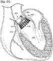
- the heartis a hollow muscular organ having four pumping chambers as seen in FIG. 1 : the left and right atria and the left and right ventricles, each provided with its own one-way valve.
- the natural heart valvesare identified as the aortic, mitral (or bicuspid), tricuspid, and pulmonary, and are each mounted in an annulus comprising dense fibrous rings attached either directly or indirectly to the atrial and ventricular muscle fibers. Each annulus defines a flow orifice.
- the atriaare the blood-receiving chambers, which pump blood into the ventricles.
- the ventriclesare the blood-discharging chambers.
- a wall composed of fibrous and muscular parts, called the interatrial septumseparates the right and left atriums (see FIGS. 2, 3 and 4 ).
- the fibrous interatrial septumis a materially stronger tissue structure compared to the more friable muscle tissue of the heart.
- An anatomic landmark on the interatrial septumis an oval, thumbprint sized depression called the oval fossa, or fossa ovalis (shown in FIG. 4 ).
- the synchronous pumping actions of the left and right sides of the heartconstitute the cardiac cycle.
- the cyclebegins with a period of ventricular relaxation, called ventricular diastole.
- the cycleends with a period of ventricular contraction, called ventricular systole.
- the four valvesensure that blood does not flow in the wrong direction during the cardiac cycle; that is, to ensure that the blood does not back flow from the ventricles into the corresponding atria, or back flow from the arteries into the corresponding ventricles.
- the mitral valveis between the left atrium and the left ventricle, the tricuspid valve between the right atrium and the right ventricle, the pulmonary valve is at the opening of the pulmonary artery, and the aortic valve is at the opening of the aorta.
- FIGS. 2 and 3show the anterior (A) portion of the mitral valve annulus abutting the non-coronary leaflet of the aortic valve.
- the mitral valve annulusis in the vicinity of the circumflex branch of the left coronary artery, and the posterior (P) side is near the coronary sinus and its tributaries.
- the mitral and tricuspid valvesare defined by fibrous rings of collagen, each called an annulus, which forms a part of the fibrous skeleton of the heart.
- the annulusprovides peripheral attachments for the two cusps or leaflets of the mitral valve (called the anterior and posterior cusps) and the three cusps or leaflets of the tricuspid valve.
- the free edges of the leafletsconnect to chordae tendinae from more than one papillary muscle, as seen in FIG. 1 . In a healthy heart, these muscles and their tendinous chords support the mitral and tricuspid valves, allowing the leaflets to resist the high pressure developed during contractions (pumping) of the left and right ventricles.
- Various surgical techniquesmay be used to repair a diseased or damaged valve.
- the damaged leafletsare typically excised and the annulus sculpted to receive a prosthetic valve.
- a prosthetic valveeither bioprosthetic or mechanical.
- Another, less drastic, method for treating defective valvesis through repair or reconstruction, which is typically used on minimally calcified valves.
- One problem with surgical therapyis the significant insult it imposes on chronically ill patients and the associated high morbidity and mortality rates associated with surgical repair.
- Minimally invasive surgical techniqueshave been and continue to be developed. In successfully performed minimally invasive techniques, a conventional sternotomy can be avoided. Access to the heart can be by way of upper sternotomy or thoracotomy allowing a smaller incision and typically shorter healing times, as well as less pain for the patient. Blood loss is typically lower with minimally invasive techniques, hospital stays are shorter, and there may be lower morbidity and mortality rates as compared to conventional surgical techniques.
- the valveis secured by attaching (e.g., suturing) the connecting band (and thereby, the entire contour of the underlying frame, including the cusp and commissure portions) to the surrounding natural tissue.
- attachinge.g., suturing
- the commissure portions of the frameremain fixedly attached to, and cannot move independently of, the tissue because the sewing band is coextensive with the undulating frame.
- suturing the complex, undulating periphery of the sewing bandcan be difficult and time consuming, as various parts of the valve can interfere with access to the sewing band.
- valves disclosed in the '418 and '845 patentscould be collapsed and inserted through a small incision, such as a thoracotomy, it would be difficult to suture them to the native annulus through such a small incision due to the configuration of the sewing band.
- Conventional surgical valveshave long-term durability, due in part to the flexibility of the valve structure, which allows the valve to flex slightly during physiologic loading. However, these surgical valves disadvantageously cannot be radially collapsed any appreciable amount, and therefore are not suitable for minimally invasive surgery procedures. Conventional surgical valves also require suturing to secure the valve to a patient's annulus. Such suturing can be disadvantageous in that it is time consuming and difficult, thus extending the length of surgery.
- the heart valve disclosed in the '961 applicationincludes two separate components: a base stent and a valve component that is mounted to the base stent after the base stent is deployed within the native valve.
- the base stentis radially expandable and serves to anchor the valve to a patient's annulus.
- the base stent of the '961 applicationis designed to cooperate with a conventional leaflet wireform (e.g., a separate valve component).
- the valve componentincludes a conventional, non-expandable surgical valve that is modified to include an expandable coupling stent that can be partially expanded to engage the base stent.
- the valve component disclosed in the '961 applicationis not collapsible for implantation through small surgical incisions.
- the heart valve disclosed in the '961 applicationincludes two separate frames, construction can be time consuming and costly.
- U.S. Patent Application Publication No. 2010-0036484discloses a balloon-expandable transcatheter heart valve and U.S. Patent Application Publication No. 2010-0049313 discloses a self-expandable transcatheter heart valve. Both of these heart valves are designed to be collapsed to a small profile and delivered through catheters.
- U.S. Patent Application Publication No. 2007-0213813discloses various heart valves that can be delivered via a catheter and implanted relatively quickly.
- US 2010/0185277 A1shows prosthetic heart valves which are collapsible and include a collapsible/expandable stent-like supporting structure and various components of flexible, sheet-like material that are attached to the supporting structure.
- US 2005/0065594 A1shows a prosthetic valve including an elongate generally cylindrical radially collapsible valve body scaffold defining a fluid passageway therethrough for retentive positioning within the lumen, and a radially collapsible leaf valve member supported by the scaffold and including a number of valve leafs deflectable between a closed position restricting fluid flow through the passageway and an open position permitting fluid flow through the passageway.
- an improved prosthetic heart valvethat facilitates placement through small incisions, facilitates easier implantation at the treatment site, and provides improved longevity.
- devices for, and associated methods of, implanting such improved prosthetic valves in a body lumenare also needed, especially a more efficient procedure that reduces the duration a patient needs extracorporeal circulation to undergo a cardiac valve replacement.
- Disclosed embodiments of a prosthetic heart valvecan be both radially collapsible (and therefore suitable for minimally invasive surgical techniques) and provide for relatively quick implantation ( e.g. , without sutures or with a reduced number of sutures required for implantation). Disclosed embodiments also exhibit flexibility in response to physiologic loading, thereby potentially increasing durability as compared to, for example, conventional transcatheter heart valves. Thus, disclosed embodiments of prosthetic heart valves can be implanted using small surgical incisions ( e.g ., via a thoracotomy) and few or no sutures for anchoring to a patient's valve.
- Disclosed embodimentscan combine the ability of surgical valves to undergo deflection or flexion during physiologic loading with the ability of transcatheter valves to be radially compressed for minimally invasive delivery methods. These and other advantages of the disclosed embodiments can result in quicker healing, less scarring, and reduced procedure times in some instances, as well as increased durability of the valve due at least partially to the valve's flexibility under physiologic loading.
- one specific embodimentcomprises a prosthetic heart valve frame that is radially expandable from a compressed configuration to an expanded configuration.
- the prosthetic valve framecomprises a stent portion adapted to anchor against a heart valve annulus, the stent portion defining a lumen therethrough, and a wireform portion adapted to support at least one valve leaflet.
- the prosthetic valve frameis in the compressed configuration, at least a portion of the wireform portion is positioned within the lumen defined by the stent portion and at least a part of the wireform portion is configured to undergo flexion during pulsatile-loading.
- the wireform portioncomprises a plurality of cusps (e.g., three cusps) each configured to engage with a respective valve leaflet.
- Each of the cuspscomprises a thinned portion configured to facilitate compression of the wireform portion.
- each of thinned portions of the cuspscan provide a point of least resistance to bending, thereby facilitating collapse or compression of the valve as a whole, and specifically of the wireform portion.
- At least a portion of the cuspsis positioned inside the lumen of the stent portion when the frame is in its compressed configuration.
- the cuspsare spaced apart from the stent portion along a longitudinal direction defined by the lumen of the stent portion in the expanded configuration.
- at least a portion of the cuspscan move from being positioned at least partially inside the lumen of the stent portion to a position longitudinally spaced from the stent portion ( e.g. , outside of the lumen of the stent portion).
- the stent portioncomprises a plurality of upright struts spaced around the circumference of the stent portion. The upright struts can extend to an outflow end of the wireform portion and can be configured to couple the wireform portion to the stent portion.
- Adjacent cuspscan be coupled to one another at each of the upright struts so as to form a commissure support at each upright strut.
- Some embodiments of a prosthetic valvecan comprise a plurality of leaflets each having two opposing tabs, the tabs of adjacent leaflets being configured to be coupled together at a respective commissure support.
- at least a portion of each of the leaflet tabscan be wrapped around at least a portion of an upright strut.
- the upright strutscan extend to a T-shaped termination positioned along a respective commissure support.
- At least a part of the wireform portionis configured to undergo flexion during pulsatile loading (e.g. , when implanted in a patient's native valve annulus).
- the upright struts and/or the commissure supportscan be configured to flex radially inward and/or radially outward in response to blood flow through the prosthetic valve after implantation.
- an inflow end of the stent portioncan be flared outward in the expanded configuration, the inflow end being opposite the wireform portion.
- the stent portion of some embodimentscan comprise a circumferential strut adjacent the wireform portion. Additionally or alternatively, the stent portion can comprise a plurality of vertical struts extending from an inflow end of the stent portion toward the wireform portion. In some embodiments, the vertical struts can be spaced apart from one another, positioned between adjacent upright struts, and can terminate at the circumferential strut, if present. Disclosed embodiments can comprise a flexible skirt (e.g., a fabric skirt, such as a polyester skirt) coupled to the stent portion and configured to prevent leakage through the stent portion.
- a flexible skirte.g., a fabric skirt, such as a polyester skirt
- a skirtcan be positioned on the inside and/or outside of the stent portion lumen (e.g ., one or more flexible skirts can be coupled to the inner surface of the stent portion and/or to the outer surface of the stent portion).
- the prosthetic valvecan include a sealing ring coupled to the wireform portion, the sealing ring being configured to be positioned supraannularly.
- a radially collapsible and expandable prosthetic heart valvecan comprise a frame configured to anchor the prosthetic heart valve to a patient's native valve, a leaflet-supporting structure comprising a plurality of leaflet-supporting cusps and a plurality of commissure posts, the commissure posts being positioned between adjacent leaflet-supporting cusps, wherein the commissure posts are configured to undergo cantilevered motion under physiologic loading, and a plurality of connecting segments spaced apart from one another, each connecting segment extending from a first end of the stent portion adjacent the leaflet-supporting structure to a leaflet-supporting cusp.
- the frame and the leaflet-supporting structurecan be undetachably coupled to one another to form a one-piece prosthetic heart valve.
- the leaflet-supporting structurecan comprise a cloth covering surrounding the leaflet-supporting cusps and the commissure posts.
- the prosthetic heart valvecan also be provided with a plurality of leaflets, each leaflet being coupled to a respective leaflet-supporting cusp by suturing to the cloth covering.
- the leafletscan be configured such that a central hole through the leaflets remains open when the prosthetic heart valve is at rest.
- the radially collapsible and expandable prosthetic heart valvecan also include a sealing ring coupled to the leaflet-supporting structure, the sealing ring being configured to be positioned supraannularly.
- a prosthetic heart valvethat is radially expandable from compressed configuration to an expanded configuration can comprise a plastically expandable (e.g ., balloon-expandable) stent portion configured to anchor the prosthetic valve against a heart valve annulus and a self-expandable wireform portion that is separate from the stent portion.
- the stent portioncan define a lumen therethrough, and the stent portion can be radially expandable from a collapsed state to an expanded state.
- the stent portioncan be a pre-crimped stent portion that is expandable from a pre-crimped state to an inflated state.
- the wireform portion and the stent portionare coupled together only by one or more non-metallic components or devices.
- both the wireform portion and the stent portioncan be coupled to a cloth-covered leaflet support stent, which effectively couples the wireform portion to the stent portion.
- the self-expandable wireform portioncan comprise at least one commissure support and at least one cusp adapted to support at least one valve leaflet, and the wireform portion can be radially expandable from a constrained configuration to a stress-free configuration.
- the stiffness of the stent portion in its collapsed stateis sufficient to prevent the wireform portion from expanding to its stress-free configuration.
- the stent portioncomprises stainless steel, cobalt chromium, or alloys or combinations thereof
- the wireform portioncomprises Nitinol, NiTiCr, NiTiCo, or alloys or combinations thereof.
- a prosthetic heart valvecan include a flexible leaflet support stent coupled to the wireform portion, and/or a sealing ring coupled to the flexible leaflet support stent and to the stent portion, wherein the sealing ring is configured to be positioned supraannularly.
- At least one valve leafletcan be at least partially wrapped around a respective post of a flexible leaflet support stent and the sealing ring can be sutured to a plurality of circular openings on the stent portion.
- the leafletscan each have two opposing tabs, where the tabs of adjacent leaflets are configured to be coupled together at a respective commissure support.
- at least a portion of each of the leaflet tabscan be wrapped around a post of a flexible leaflet support stent.
- the wireform portioncomprises three cusps configured to engage with a respective valve leaflet, and each of the cusps comprises a thinned portion configured to facilitate compression of the wireform portion.
- one method of implanting a prosthetic heart valvecomprises radially compressing a prosthetic heart valve to a compressed configuration, wherein the prosthetic heart valve comprises a stent portion configured to anchor the prosthetic heart valve to a patient's native valve and a leaflet-supporting structure, delivering the compressed prosthetic heart valve to or near a patient's native valve annulus, positioning the leaflet-supporting structure of the prosthetic heart valve supraannularly to a patient's aortic valve, and expanding the prosthetic heart valve to an expanded configuration, wherein the diameter of the prosthetic heart valve in the expanded configuration is greater than the diameter of the prosthetic heart valve in the compressed configuration, and wherein in the compressed configuration at least a portion of the leaflet-supporting structure is positioned within a lumen of the stent portion, and in the expanded configuration the leaflet-supporting structure is positioned externally to the lumen of the stent portion.
- the prosthetic heart valveincludes a one-piece prosthetic heart valve frame.
- delivering the prosthetic heart valvecan comprise delivering the prosthetic heart valve transapically.
- expanding the prosthetic heart valvecan effectively anchor the prosthetic heart valve without suturing the valve to the native valve.
- a pre-crimped balloon expandable stent portioncan be provided and configured to anchor the prosthetic heart valve to a patient's native valve.
- the pre-crimped stent portioncan be coupled to a self-expanding wireform portion and a plurality of leaflets to form the prosthetic heart valve, and the stent portion and the wireform portion can be coupled to one another via a cloth-covered flexible leaflet support stent.
- the diameter of the stent portion in an expanded configurationis greater than the diameter of the stent portion in a compressed configuration, and expansion of the stent portion can enable self-expansion of the wireform portion.
- valve portioncan further comprise a leaflet support stent and a sealing ring.
- the stiffness of the stent portion in its pre-crimped statecan be sufficient to prevent the wireform portion from self-expanding to its expanded state.
- the one or more non-metallic componentscan comprise a cloth-covered leaflet support stent and/or a sealing ring.
- self expandmeans to elastically recover from a collapsed (e.g., a compressed) configuration when an external restraint (e.g ., a suture, a sheath, or a holder) is removed.
- a componentalso self-expands if it expands upon exposure to a threshold temperature inside the body. Additionally, a component self-expands if it elastically recovers from a collapsed state in response to expansion of another component.
- the wireform portioncan self-expand after balloon expansion of the stent portion, where the stent portion is stiff enough to hold the wireform portion in its collapsed state, preventing self-expansion of the wireform portion while the stent portion is in its compressed configuration.
- balloon expandablemeans to plastically expand from a collapsed state with the use of an inflatable or expandable device, such as an inflatable balloon positioned on a delivery catheter.
- At restmeans a configuration of a valve and/or a frame when the respective valve and/or frame is still and free from externally applied loads (e.g ., pressure gradients through the valve, forces applied by retaining and/or delivery devices to retain the valve in a collapsed configuration).
- loadse.g ., pressure gradients through the valve, forces applied by retaining and/or delivery devices to retain the valve in a collapsed configuration.
- a structureis "undetachably coupled" to another structure if the structures cannot be separated from one another without destroying or otherwise rendering inoperable the device (e.g., the structures cannot be separated from one another without cutting through metal).
- wireformrefers generally to a portion of a prosthetic heart valve that supports the leaflets.
- a wireformmay or may not be formed from one or more pieces of wire.
- a wireformincludes a three-dimensional body formed of one or more wires or similarly-shaped elongate members.
- a wireform as used hereincan also be cut or otherwise formed from tubing or a sheet of material.
- each of the one or more membershas a substantially constant cross-sectional shape along its length.
- one or more of the elongate members forming the wireformcan have portions of varying cross-sectional shape or thickness along its length.
- elongate memberscan have a substantially solid, rectangular or square cross-sectional shape. Other cross-sectional shapes (e.g. , circular, annular, hollow rectangle) are also possible.
- Disclosed embodiments of a prosthetic heart valvecan advantageously provide a heart valve that allows for flexion (e.g., slight movement) during in vivo pulsatile loading as well as the capability to be radially compressed or collapsed for delivery, such as delivery via minimally invasive surgical techniques, and expanded. While the described embodiments relate to heart valve prostheses, disclosed concepts can also be applied to other types of valves as well.
- prosthetic heart valve framescan be categorized as being one-piece frames , as according to the present invention, or two-piece frames.
- FIGS. 5-18illustrate prosthetic valves and valve components utilizing one-piece frames.
- FIGS. 19-42illustrate prosthetic valves and valve components utilizing two-piece frames, not according to the present invention.
- the one-piece valve frameswill be discussed first, followed by the two-piece valve frames, but this organization does not in any way limit the scope of disclosed prosthetic heart valves.
- Variations and components discussed with respect to one frame typecan also be applied to the other frame type in some embodiments, and the disclosure should not be read to be otherwise limiting.
- the scope of the present inventionis defined by appended claims 1-5.
- FIG. 5shows a prosthetic heart valve 500, which generally includes a stent portion 502 and a wireform portion 504.
- the stent portion 502can be formed of a plurality of vertical and horizontally-extending struts 522, 524, and the wireform portion 504 can include leaflet-supporting cusps 514 and commissure supports 516.
- Upright struts 508(also referred to as commissure posts) can undetachably couple the stent portion 502 to the wireform portion 504.
- the prosthetic valve 500which is shown in an expanded configuration in FIG.
- FIG. 5can also include a plurality of leaflets 528, a flexible skirt 538 (shown partially broken away), a sealing ring 546 (shown partially broken away), and a cloth covering 530 (shown partially broken away) over the wireform portion 504, each of which will be described in further detail below.
- FIG. 6shows the prosthetic heart valve 500 implanted within a patient's native valve annulus 548 (e.g., aortic valve annulus 548).
- the prosthetic valve 500can be implanted such that at least a portion of the valve 500 is positioned supraannularly.
- the wireform portion 504can be positioned supraannularly, while the stent portion 502 is configured to anchor the prosthetic valve 500 in place within the native valve annulus 548.
- the stent portion 502can be slightly flared outward at the inflow end 510, such that the stent portion 502 frictionally engages the native valve annulus 548 to prevent migration of the prosthetic valve 500.
- an optional sealing ring 546can be provided adjacent the wireform portion 504. Said sealing ring can be configured to engage the shelf 552 of the native valve annulus 548 so as to prevent migration of the prosthetic valve 500 into the ventricle 550. The sealing ring 546 can also create a seal around the prosthetic valve 500 such that substantially no blood can pass between the native valve annulus 548 and the prosthetic valve 500.
- disclosed embodimentscan be positioned supraannularly to a patient's native valve (e.g. , the stent portion can be positioned at least partially within the annulus and at least part of the wireform portion can be positioned supraannularly).
- a prosthetic valvemay experience significant pressure during diastole, which can push the prosthetic valve down towards the ventricle.
- the cusps of the wireform portioncan be configured to engage with the annulus, creating a shelf to resist such pressure (e.g. , the cusps of the wireform portion can have a greater diameter than the native annulus).
- the optional flexible sealing ringcan be configured to rest on the native annulus when the prosthetic heart valve is deployed in place at the target site.
- the sealing ringcan have a greater diameter than the native annulus and can thereby further resist movement or dislodgement of the valve towards the ventricle.
- the wireform portion 504can comprise a plurality of cusps 514 configured to engage with a respective valve leaflet 528.
- prosthetic valve 500includes three cusps 514, each of the cusps 514 being configured to engage with one of three leaflets 528 secured to prosthetic valve 500.
- leafletscan be secured to the cusps 514 in a manner similar to conventional surgical valves, with the leaflets being sutured to the cloth covering 530 surrounding the cusps 514.
- the leaflets 528can open when exposed to a positive pressure gradient in a fluid (e.g., blood) passing between the inflow end 510 and the outflow end 512 and close (or coapt) when exposed to a negative pressure gradient between the inflow end 510 and the outflow end 512.
- a fluide.g., blood
- the leaflets 528When the leaflets 528 are closed, as shown in FIG. 5 , they can be configured to retain a central hole 554 through the center of the leaflets 528 when the valve 500 is at rest (e.g., not subject to any pressure gradient).
- a pressure gradiente.g.
- the leafletsafter implantation in a patient's native valve annulus (the leaflets can be configured to close completely such that substantially no blood leaks through the closed leaflets during diastole.
- Conventional prosthetic valves configured to be radially compressed for deliverydisadvantageously must be configured such that the leaflets close completely when the valve is at rest.
- each tab 532can extend between an upright strut 508 and an extension of one of the leaflet-supporting cusps 514 adjacent the outflow end 512 (e.g., adjacent the commissure support 516).
- Adjacent tabs 532can be at least partially wrapped around the respective upright strut 508 and coupled together ( e.g. , with sutures 534) around the upright strut 508.
- FIG. 5only one of the three sets of leaflet tabs 532 has been sutured together around an upright strut 508.
- the leafletscan additionally be secured to the frame such as by being sutured to the cloth covering 530 surrounding the cusps 514.
- valve leafletsexamples include pericardial tissue (e.g. , bovine, porcine, or cadaver pericardial tissue), biocompatible synthetic polymers, and any other suitable natural or synthetic material. While three leaflets are shown, various embodiments can comprise one, two, three, or more leaflets.
- the prosthetic valve 500can include a flexible skirt 538.
- the flexible skirt 538can be, for example, a polyester fabric (e.g. , Dacron) skirt.
- the flexible skirt 538is shown coupled to the inner surface of the stent portion 502 ( e.g. , positioned within a lumen 506 of the stent portion 502) and can be configured to prevent leakage through the stent portion 502 once the prosthetic valve 500 is implanted within a patient's native valve.
- the flexible skirt 538can be coupled to one or more of the vertical struts 522, such as to circular portions 540 adjacent the circumferential strut 520 (e.g., with sutures 542).
- skirt 538can be coupled to the stent portion 502 in additional places and/or in alternative arrangements.
- skirt 538can be positioned on the outer surface of the stent portion ( e.g. , outside of the lumen 506).
- the prosthetic valve 500can include a skirt on both the inside and outside surfaces of the stent portion 502.
- the prosthetic valvecan be provided without a flexible skirt 538.
- FIG. 5shows only a cut-away view of the skirt 538
- the skirt 538can extend around the entire circumference of the stent portion 502.
- the skirt 538can be essentially the same height as the stent portion 502.
- the skirt 538can extend substantially from an inflow end 510 and towards an outflow end 512, terminating, in some embodiments, at cusp portions 514, or alternatively, adjacent a circumferential strut 520 positioned near the wireform portion 504.
- the skirt 538can substantially cover the entire stent portion 502 and optionally the area of the wireform portion below the cusp portions 514.
- the skirt 538can be configured to only cover a portion of the stent portion 502.
- the cloth covering 530can be secured to the wireform portion 504 such that opposing longitudinal edges of the cloth 530 are brought together to form a seam external to the wireform portion 504 (see seam 1150 in FIG. 11 ).
- the seamcan be formed such as by suturing, adhesion, and/or other well-known cloth-edge joining techniques.
- the cloth covering 530can function to provide a substrate for suturing the leaflets to.
- the cloth covering 530can be sutured around the wireform portion 504 and the leaflets subsequently can be sutured to the cloth 530 along the contour of the leaflet-supporting cusps 514 (e.g., on the outside of the leaflet-supporting cusps 514).
- Cloth covering 530can comprise any suitable biocompatible material, such as polyester or polyethylene terephthalate.
- the flexible skirt 538can extend up to meet the cloth covering 530 on the wireform portion 504 so that there is no gap between them.
- the flexible skirt 538can be coupled to the cloth covering 530 so as to not impede movement of the leaflets 528 or cusps 514.
- the cusps 514move from their position in the expanded configuration to a position inside the lumen 506.
- the flexible skirt 538can be coupled to the stent portion 502, the circumferential strut 520, and/or the cloth covering 530 on the wireform portion 504 so as not to impede such movement of the cusps 514.
- the flexible skirt 538can follow the contour of the commissure supports 516 such that everything below the leaflets 528 is substantially sealed off.
- the prosthetic heart valve 500can include a flexible sewing ring or sealing ring structure, such as a tri-lobular sealing ring.
- the sealing ringcan be arranged such that sinus-shaped portions of the ring can be aligned with the cusps of the wireform portion.
- the sealing ringcan form a tight seal between the wireform portion and the stent portion of disclosed prosthetic heart valve frames, can form a tight seal between the prosthetic valve and native valve annulus, and/or can provide a suture point for securing the prosthetic valve frame to the native valve annulus (in addition to or instead of using the flared stent portion to anchor the valve frame).
- a flexible sealing ring 546can be coupled to the wireform portion 504 in some embodiments and can be used to attach nadir sutures to the patient's annulus.
- the sealing ring 546can be provided without suturing it to the native valve tissue.
- the sealing ring 546can additionally or alternatively be configured to provide a seal positioned between the wireform portion 504 and the stent portion 502 of the prosthetic heart valve frame, the seal being configured to enhance the effectiveness of or replace the flexible skirt discussed above.
- the sealing ring 546can be sewn to the wireform cloth 530 through the leaflets in some embodiments. In some embodiments, the leaflets can be sandwiched between the wireform cloth 530 and the sealing ring 546, which may or may not include a cloth covering itself.
- FIG. 5shows that the sealing ring 546 can be positioned on the wireform portion 504 adjacent the stent portion 502.
- FIGS. 7-8illustrate the frame 501 of the prosthetic heart valve 500 of FIG. 5 , with the frame still in its expanded configuration.
- the frame 501is shown without a plurality of leaflets, a cloth covering over a portion of the frame, a sealing ring, or a fabric or flexible skirt of another material, in order to provide a clear view of the frame.
- Frame 501comprises a stent portion 502 and a wireform portion 504 (wireform portion 504 is also referred to as a leaflet support portion).
- stent portion 502can be configured to anchor the frame 501 to a patient's native valve annulus and wireform portion 504 can be configured to receive and support at least one valve leaflet.
- the stent portion 502can engage an inner periphery of a body lumen (e.g., a native annulus) at the implantation site.
- Disclosed embodimentscan engage with the native annulus via the stent portion 502 and/or a sealing ring, such as by engaging the aortic annulus, the fibrous annulus, and/or the aorta wall (e.g., a position downstream from the location of the native leaflets)
- the stent portion 502defines a lumen 506 therethrough.
- the stent portion 502can comprise any suitable combination of struts and wires that can allow the stent portion to radially collapse to a compressed configuration for delivery, and that can also facilitate anchoring of the frame 501 within a patient's native valve.
- the specific embodiment shown in FIGS. 7-8includes a plurality of upright struts 508 spaced around the circumference of the stent portion 502.
- the upright struts 508can extend substantially from an inflow end 510 to an outflow end 512 of the frame 501.
- the inflow end 510corresponds to the end 510 of the stent portion 502 opposite the wireform portion 504.
- the upright strutsmay extend only partially towards the inflow end 510 and/or only partially towards the outflow end 512.
- the upright struts 508can be configured to couple the stent portion 502 to the wireform portion 504.
- the upright strutscan undetachably couple the stent portion 502 and the wireform portion 504 so that the frame 501 is a one-piece frame 501.
- each of the cusps 514includes a thinned portion 515 (best seen in FIG. 7 ) configured to facilitate compression of the wireform portion 504.
- the upright struts 508can, in some embodiments, carry at least a portion of the load due to pulsatile loading, and can therefore at least partially reduce the load on the cusps 514.
- the upright struts 508can at least partially compensate for any reduction in strength of the cusps 514 due to the thinned portion 515.
- the one or more thinned portions 515are configured to provide the cusps 514 with greater flexibility, especially near the thinned portions 515.
- the thinned portion 515can be configured to deform more readily than the adjacent, thicker, areas of the cusps 514.
- the thinned portions 515can be positioned substantially near the center of each cusp, but other configurations are also suitable.
- each cusp 514could include at least two thinned portions 515 spaced apart from each other along the cusp 514.
- the thinned portions 515can, for example, serve as a hinge and facilitate bending of the cusps 514 during transformation of the wireform portion 504 (and the frame 501 as a whole) from the expanded configuration shown in FIGS. 7-8 to a compressed configuration.
- the cusps 514are spaced apart from the stent portion 502 along a longitudinal direction defined by the lumen 506 of the stent portion 502.
- the cusps 514can be spaced apart from the stent portion 502 along the longitudinal axis Z in the shown expanded configuration.
- the cusps 514can be positioned further outward radially than the stent portion 502 when in the expanded configuration.
- the cusps 514can have a greater diameter in the expanded configuration than the circumferential strut 520. In this configuration, the cusps 514 can engage the native valve annulus (e.g., the shelf 552 of annulus 548 seen in FIG. 6 ).
- Adjacent cusps 514can be coupled to one another at each of the upright struts 508 so as to form a commissure support 516 at each upright strut 508 adjacent the outflow end 512.
- adjacent cusps 514a and 514bcan be coupled to one another at upright strut 508a to form a commissure support 516a.
- adjacent cusps 514a and 514ccan be coupled to one another at upright strut 508b to form commissure support 516b
- adjacent cusps 514b and 514ccan be coupled to one another at upright strut 508c to form commissure support 516c.
- the commissure supports 516can lean slightly outward relative to the lumen 506 (e.g., the central flow axis Z of the prosthetic valve frame 501) when the valve is at rest.
- the commissure supports 516can alternatively be oriented to lean inwardly at a slight angle relative to the longitudinal axis Z.
- the commissure supports 516can be substantially vertical ( e.g. , substantially parallel to the central flow axis) when the valve is at rest, as shown in FIG. 7 .
- At least part of the wireform portion 504is configured to undergo flexion (e.g. , can be configured to move slightly) during normal physiologic loading when implanted in a patient's native valve.
- the upright struts 508 and commissure supports 516e.g., the free end of the commissure supports 516 adjacent the outflow end 512
- the upright struts 508 and commissure supports 516can be configured to flex in the direction indicated by arrows 518 (e.g., radially inward) during each cardiac cycle, and likewise can be configured to move radially outward, returning to their original positions later in each cardiac cycle.
- the prosthetic valve frame 501can be positioned at the implantation site such that the cantilevered commissure supports 516 can deflect independently of the surrounding body lumen to which the valve frame 501 is secured.
- the ability of the commissure supports 516 to flex in this mannercan allow the leaflets supported by the commissure supports 516 and cusps 514 to close more gently, thereby relieving stress on the leaflets during diastole.
- the wireform portion 504 and/or the upright struts 508can be thinner than would normally be expected, in order to optimize the movement (e.g. , flexion) during pulsatile in vivo loading. Such flexion can contribute to the longevity and durability of disclosed prosthetic heart valve frames 500.
- the stiffness of the upright struts 508 and/or the wireform portion 504can be optimized such that the commissure supports 516 deflect under physiologic loading.
- the upright struts 508 and/or commissure supports 516can be configured to deflect an amount similar to that of conventional surgical valves and an amount greater than that of conventional transcatheter valves.
- a conventional transcatheter valvemay only flex tens of microns or less
- the presently disclosed valve framescan flex up to around 1 mm or more, with flexion varying slightly with different sized valve frames.
- the presently disclosed prosthetic heart valve framescan flex about 10-100 times more than conventional transcatheter valves.
- FIG. 9shows the deflection of a commissure support 516 under physiologic loading.
- the commissure support 516 and upright struts 508can move in a cantilevered fashion radially inward and outward during each cardiac cycle.
- the commissure support 516can deflect radially inward a distance ⁇ .
- ⁇can be about 1 mm or greater.
- the leafletscan advantageously be arranged to retain a central hole (e.g., the three-pointed star-shaped hole 554 seen in FIG. 5 where the leaflets meet in the center of the valve) when the valve is at rest (i.e., not subjected to any pressure gradient).
- a central holee.g., the three-pointed star-shaped hole 554 seen in FIG. 5 where the leaflets meet in the center of the valve
- the central holeUnder physiologic loading (and flexion of the commissures), the central hole is closed completely, but the leaflets generally come together in a controlled, gentle fashion.
- conventional transcatheter valvestypically cannot have such a central hole in the leaflets - the leaflets must be completely closed when the valve is at rest, because the valve is unable to flex.
- the leaflets of traditional transcatheter valvestend to collide together more forcefully, which can disadvantageously reduce the lifespan of the prosthetic valve.
- the stent portion 502 of the frame 501can be flared outward in its expanded configuration.
- the diameter of the lumen 506 at the inflow end 510 of the stent portion 502can be greater than the diameter of the lumen 506 of the stent portion 502 adjacent the wireform portion 504, thereby creating a flared stent portion 502.
- the flared configuration of the stent portion 502can facilitate anchoring of the stent portion 502 within the patient's native valve annulus without the use of sutures (or with a reduced number of sutures as compared with conventional prosthetic heart valves).
- the flared stent portion 502can engage with the valve annulus, keeping the frame 501 in position, with the wireform portion 504 being positioned distal to the annulus. Therefore, in some embodiments, at least part of the wireform portion 504 does not contact the native valve annulus once the frame 501 is implanted.
- the cusps 514 and/or a sealing ringmay contact the native valve annulus, while the commissure supports 516 do not.
- the leaflet-supporting cusps 514can protrude radially outward past the stent portion 502 (or at least past the upper end of stent portion 502 adjacent the cusps 514) so as to form an edge or shelf which can further discourage migration of the prosthetic heart valve frame 501 during diastole (e.g., the shelf formed by the cusps 514 could engage with or rest against the native annulus, thereby working together with the flared stent portion to prevent migration of the valve frame into the ventricle).
- the flared lower end of the stent portion 502can be positioned on one side of the native annulus and can have a diameter larger than the annulus to prevent migration in one direction
- the cusps 514can be positioned on the opposite side of the annulus and can have a diameter larger than the annulus to prevent migration in the opposite direction.
- the cusps 514can be shape set such that they are positioned further out radially than at least the upper end of stent portion 502 in the expanded configuration.
- the frame 501can include a circumferential strut 520.
- the circumferential strut 520can be positioned on the stent portion 502 adjacent the wireform portion 504 and can be configured to increase the radial stiffness of the stent portion 502 and/or increase the effective stiffness of the upright struts 508.
- Circumferential strut 520can be configured to be essentially straight ( e.g. , have an essentially flat side profile) when the frame 501 is in its expanded configuration and can be bent or folded with the frame 501 is in its compressed configuration.
- the circumferential strut 520can essentially serve as a boundary between the stent portion 502 and the wireform portion 504, although the upright struts 508 continue from one side of the circumferential strut 520 to the other.
- the stent portion 502can also include a plurality of vertical struts 522 that extend from the inflow end 510 to the circumferential strut 520.
- the vertical struts 522can be spaced apart from one another and a plurality of vertical struts 522 can be positioned between adjacent upright struts 508.
- At least one row of horizontally-extending struts 524can be positioned around the circumference of the stent portion, extending between adjacent vertical struts 522 and/or between an upright strut 508 and a vertical strut 522.
- FIGS. 5-8show three rows of horizontally extending struts 524, but more or fewer rows are also possible.
- the horizontally-extending struts 524can be substantially U-shaped or V-shaped, with the curved portion or vertex portion 526 arranged towards the outflow end 512 of the frame 501. Bending or extending of the horizontally-extending struts 524 can decrease or increase, respectively, the distance between adjacent vertical struts 522 or the distance between an adjacent vertical strut 522 and upright strut 508. Thus, the horizontally-extending struts 524 can facilitate compression of the stent portion 502 and therefore can facilitate compression of the overall frame 502. Other shapes and configurations of the stent portion are also possible. Generally, any shape or design can be provided as the stent portion of disclosed prosthetic heart valves that allow for radial compression and expansion of the stent portion.
- FIG. 10shows the valve frame 501 in a collapsed configuration (e.g., radially compressed for delivery).
- the circumferential strut 520can become pinched into a V shape between adjacent circular openings 540.
- the wireform portion 504is positioned at least partially inside the stent portion 502.
- At least a portion of the cusps 514is positioned inside ( e.g. , within) the lumen 506 of stent portion 502 in the compressed configuration.
- This positioningcan be accomplished via movement of the cusps 514 towards the inflow end 510 as the stent portion 502 is being radially crimped.
- the wireform portion 504can be configured to collapse further radially than the stent portion 502.
- the wireform portion 504can be configured to collapse less in the radial direction that does the stent portion 502.
- at least a portion of the wireform portion 504can be positioned at least partially outside the stent portion 502.
- at least a portion of the cusps 514can be positioned outside ( e.g ., against the outer surface) of stent portion 502 in the compressed configuration. This positioning can be accomplished via movement of the cusps 514 towards the inflow end 510 as the stent portion 502 is being radially crimped more than the cusps 514 (e.g., the stent portion 502 can be radially crimped to a smaller compressed diameter than the cusps 514).
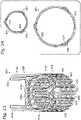
- FIGS. 11-14illustrate an additional embodiment of a prosthetic heart valve frame 1100.
- FIGS. 11-12show the valve frame 1100 in an expanded configuration and
- FIGS. 13-14show the prosthetic heart valve frame 1100 in an compressed, or collapsed configuration 1100'.
- the prosthetic heart valve frame 1100is similar to the prosthetic heart valve frame 501 of FIGS. 5-10 except that valve frame 1100 does not include a circumferential strut 520 on the stent portion. Additionally, the prosthetic valve frame 1100 does not include thinned portions on the leaflet-supporting cusps 1114 (e.g., thinned portions 515 of cusps 514). Either or both of these features can be provided with the embodiment shown in FIGS. 11-14 .
- Prosthetic valve frame 1100can comprise a stent portion 1102 and a leaflet structure 1104.
- Leafletsare not shown in FIGS. 11-14 , for clarity.
- stent portion 1102can be configured to anchor the prosthetic valve frame 1100 to a patient's native valve annulus and leaflet structure 1104 can be configured to receive and support at least one valve leaflet.
- the prosthetic valve frame 1100can define a lumen 1106 therethrough.
- the stent portion 1102can comprise any suitable combination of struts and/or wires that can allow the stent portion 1102 to radially collapse to a compressed configuration for delivery, and that can also facilitate anchoring of the expanded prosthetic valve frame 1100 within a patient's native valve.
- the leaflet structure 1104can comprise a plurality of leaflet-supporting cusps 1114 each configured to engage with a respective valve leaflet.
- the specific embodiment shown in FIGS. 11-14includes a plurality of commissure posts 1108 spaced around the circumference of the stent portion 1102 and positioned between adjacent leaflet-supporting cusps 1114.
- the commissure posts 1108can extend substantially from an inflow end 1110 to an outflow end 1112 of the prosthetic valve frame 1100.
- the inflow end 1110corresponds to the end 1110 of the stent portion 1102 opposite the leaflet structure 1104.
- the commissure postsmay extend only partially towards the inflow end 1110 and/or only partially towards the outflow end 1112.
- the commissure posts 1108can be configured to couple the stent portion 1102 to the leaflet structure 1104.
- the commissure posts 1108can undetachably connect the stent portion 1102 and the leaflet structure 1104 so that the prosthetic valve frame 1100 is a one-piece prosthetic valve frame 1100.
- At least a portion of the leaflet structure 1104can be positioned at least partially inside the frame 1102.
- at least a portion of the leaflet-supporting cusps 1114can be positioned inside (e.g., within) the lumen 1106 of frame 1102 in the compressed configuration. This positioning can be accomplished via movement of the cusps 1114 towards the inflow end 1110 as the frame 1102 is being radially crimped.
- the leaflet structure 1104can be configured to collapse further radially than the frame 1102.
- the leaflet structure 1104can be configured to collapse less in the radial direction that does the frame 1102.
- at least a portion of the leaflet structure 1104can be positioned at least partially outside the frame 1102.
- at least a portion of the cusps 1114can be positioned outside ( e.g. , against the outer surface) of frame 1102 in the compressed configuration. This positioning can be accomplished via movement of the cusps 1114 towards the inflow end 1110 as the frame 1102 is being radially crimped more than the cusps 1114 (e.g., the frame 1102 can be radially crimped to a smaller compressed diameter than the cusps 1114).
- At least part of the leaflet structure 1104can be configured to undergo flexion (e.g., can be configured to move slightly) during normal physiologic loading when expanded and implanted in a patient's native valve.
- flexione.g., can be configured to move slightly
- the commissure posts 1108 and commissure supports 1116can be configured to flex radially inward during each cardiac cycle, and likewise can be configured to flex radially outward to their original positions later in each cardiac cycle.
- Such flexioncan contribute to the longevity and durability of disclosed prosthetic heart valves 1100.
- FIGS. 11-12show the valve frame 1100 in an expanded configuration 1100.
- the stent portion 1102 of the prosthetic valve frame 1100can be flared outward in its expanded configuration, as shown in FIGS. 11-12 .
- the diameter of the lumen 1106 at the inflow end 1110 of the stent portion 1102can be greater than the diameter of the lumen 1106 of the stent portion 1102 adjacent the leaflet structure 1104, thereby creating a flared stent portion 1102.
- FIG. 12shows the valve frame 1100' in its compressed configuration inside the expanded valve frame 1100 for reference.
- disclosed prosthetic heart valvescan be compressed or crimped to about 60% of its expanded size (e.g., the diameter of the valve in its compressed configuration can be about 60% of the diameter in the expanded configuration).
- a 25 mm framecan be crimped to have an outer diameter of around 15 mm or less for delivery of the valve.
- Other sizes of prosthetic heart valvescan be compressed similar amounts.
- a size 19 mm valvecan be compressed to about 11.5 mm or less
- a 21 mm valvecan be compressed to about 12.75 mm or less
- a 23 mm valvecan be compressed to about 14 mm or less
- a size 27 mm valvecan be compressed to about 16.25 mm or less
- a size 29 mm valvecan be compressed to about 17.5 mm or less.
- the prosthetic heart valvecan be compressed to an even smaller diameter relative to the expanded diameter (e.g. , less than 60% of the expanded diameter).
- the stent portion 1102can include a plurality of vertical struts 1122 that extend from the inflow end 1110 towards the outflow end 1112.
- the vertical struts 1122can be spaced apart from one another and positioned between adjacent commissure posts 1108.
- At least one row of horizontally-extending struts 1124can be positioned around the circumference of the stent portion 1102, extending between adjacent vertical struts 1122 and/or between a commissure post 1108 and a vertical strut 1122.
- FIGS. 11-12 and 14show three rows of horizontally extending struts 1124, but more or fewer rows are also possible.
- the horizontally-extending struts 1124can be substantially U-shaped or V-shaped, with the curved portion or vertex portion 1126 arranged towards the outflow end 1112 of the prosthetic valve frame 1100. Bending or extending of the horizontally-extending struts 1124 can decrease or increase, respectively, the distance between adjacent vertical struts 1122 or the distance between an adjacent vertical strut 1122 and commissure post 1108. Thus, the horizontally-extending struts 1124 can facilitate compression of the stent portion 1102 and therefore can facilitate compression of the overall prosthetic valve 1100. Other shapes and configurations of the stent portion are also possible. Generally, any shape or design can be provided as the stent portion of disclosed prosthetic heart valves that allows for radial compression and expansion of the stent portion.
- FIG. 11shows a cloth covering 1130 that can be secured to the leaflet structure 1104 such that opposing longitudinal edges of the cloth 1130 are brought together to form a seam 1150 external to the leaflet structure 1104.
- the seamcan be formed such as by suturing, adhesion, and/or other well-known cloth-edge joining techniques.
- the cloth covering 1130can function to provide a substrate for suturing the leaflets to.
- the cloth covering 1130can be sutured around the leaflet structure 1104 and the leaflets subsequently can be sutured to the cloth 1130 along the contour of the leaflet-supporting cusps 1114 (e.g., on the outside of the leaflet-supporting cusps 1114).
- a sealing ring 1146( FIG. 11 ) can be sewn to the wireform cloth 1130 through the leaflets in some embodiments.
- the leafletscan be sandwiched between the wireform cloth 1130 and the sealing ring 1146, which may or may not include a cloth covering itself.
- FIG. 11shows that the sealing ring 1146 can be positioned on the leaflet structure 1104 adjacent the stent portion 1102.
- the sealing ring 1146can be positioned between the leaflet structure 1104 and the stent portion 1102 of disclosed prosthetic heart valve frames, and can form a tight seal between the frame 1100 and the native valve annulus.
- the sealing ring 1146can provide a suture point for securing the prosthetic valve frame to the native valve annulus (in addition to or instead of using the flared stent portion to anchor the valve frame).
- a flexible sealing ring 1146can be coupled to the leaflet structure 1104 in some embodiments and can be used to attach nadir sutures to the patient's annulus.
- the sealing ring 1146can be provided without suturing it to the native valve tissue.
- the sealing ring 1146can additionally or alternatively be configured to provide a seal positioned between the leaflet structure 1104 and the stent portion 1102 of the prosthetic heart valve frame, the sealing ring 1146 being configured to enhance the effectiveness of or replace the flexible skirt discussed above.
- disclosed embodimentscan be positioned supraannularly to a patient's native valve (e.g ., the stent portion can be positioned at least partially within the annulus and at least part of the leaflet structure 1104 can be positioned supraannularly) and can be subjected to pressure pushing the prosthetic valve 1100' down towards the patient's ventricle.
- the cusps 1114 of the leaflet structure 1104can be configured to engage with the annulus, creating a shelf to resist such pressure.
- the flexible sealing ring 1146can be configured to rest on the native valve annulus when the prosthetic heart valve is deployed in place at the target site.
- the sealing ring 1146can have a greater diameter than the native annulus and can thereby further resist movement or dislodgement of the valve 1100' towards the ventricle.
- the prosthetic heart valve frame 1100'can be provided with a plurality of leaflets, cloth coatings on the stent portion, an additional stent, and/or a flexible skirt coupled to the stent portion 1102 and configured to prevent leakage through the stent portion 1 102.
- FIGS. 17 and 18illustrate additional examples of a prosthetic heart valve frame.
- FIG. 17shows a prosthetic heart valve frame 1700 that is similar to the frame 501 of FIG. 7-8 except that the commissure post 1708 terminates at the circumferential strut 1720 rather than extending to the tip of the commissure support 1716 adjacent the outflow end 1712.
- the frame 1700additionally includes one or more connecting segments 1758 that couple the wireform portion 1704 to the stent portion 1702.
- the commissure posts 508effectively couple the wireform portion 504 to the stent portion 502, but in the embodiment of FIG. 17 , desirably only the connecting segments 1758 couple the wireform portion 1704 to the stent portion 1702.
- a connecting segment 1758can be positioned at approximately the center of each of the cusps 1714 in some examples. In other examples, the connecting segments 1758 can be positioned at other locations along the cusps 1714. In some examples, each cusp may include two or more connecting segments. In some examples, some cusps may include connecting segments, while others do not.
- the prosthetic heart valve frame 1700can be configured to radially collapse differently than other disclosed examples.
- the outflow end 1712e.g., the tips of the commissure supports 1716 adjacent the outflow end 1712
- at least part of the wireform portioncan be configured to move inside the lumen of the stent portion as the frame is transformed to the compressed configuration.
- frame 1700can effectively elongate along the longitudinal axis Z as it is radially compressed so that the wireform portion 1704 resides completely outside the stent portion 1702 when both components are compressed.
- FIG. 18shows a prosthetic heart valve frame 1800 that is similar to the frame 501 of FIGS. 7-8 except with respect to the commissure posts 508, 1808, respectively.
- the commissure post 508extends substantially from the inflow end 510 to the outflow end 512, terminating at the outflow end 512 of the commissure support 516.
- the commissure post 1808 in FIG. 18does not extend all the way to the outflow end 1812 of the commissure support 1816. Instead, the commissure post 1808 extends only to a T-shaped termination 1856.
- the T-shaped termination 1856can be positioned approximately equidistant from the circumferential strut 1820 and the outflow end 1812.
- the T-shaped termination 1856can be positioned higher or lower along the commissure support 1816 (e.g., closer to the outflow end 1812 as shown in FIG. 18 , or closer to the circumferential strut 1820).
- leaflet tabscan be configured to extend through the window 1860 created by the T-shaped termination.
- the leaflet tabscan be secured to the frame 1800 via techniques more similar to conventional surgical valves.
- a prosthetic heart valve framecan comprise any material that allows the frame to be radially collapsible and expandable. Preferable materials allow for slight flexion of at least a portion of the frame in response to pulsatile loading.
- suitable materials for forming the overall frameinclude superelastic materials such as Nitinol or NiTiCr, as well as stainless steel, cobalt, chromium, titanium, or alloys or combinations of the same (e.g., CoCr alloys).
- Some embodimentscan comprise a flexible biocompatible polymer, such as polypropylene or silicon. Different frame materials can be selected depending on the method of deployment.
- the framecan comprise a superelastic material for self-expanding embodiments, or a plastically deformable material such as CoCr for plastically expandable embodiments ( e.g. , embodiments that are deployed via balloon expansion).
- FIG. 15illustrates a section view of prosthetic heart valve frame 1100, taken along line 15-15 in FIG. 11 , but with two leaflets 1528a, 1528b visible in order to illustrate one method of leaflet attachment.
- at least a portion of upright strut 1108 and/or leaflet structure 1104can be covered with cloth 1130.
- the leaflets 1528a, 1528bcan be provided with tabs 1532a, 1532b on opposing ends of the leaflets 1528a, 1528b (although only one end of each leaflet 1528a, 1528b is visible in FIG. 15 ).
- Each tab 1532a, 1532bcan pass between an upright strut 1108 and a portion of a leaflet structure 1104 near the outflow end 1112, in a direction from the lumen 1106 outwards.
- a portion of the leaflet structure 1104 adjacent the outflow end 1112can be substantially vertical, thereby forming a commissure support 1116, such that a leaflet tab 1532a, 1532b can be positioned between the upright strut 1108 and the commissure support 1116 on each side of the upright strut 1108.
- the tabs 1532a, 1532b of adjacent leaflets 1528a, 1528bcan be wrapped at least partially around an upright strut 1108 and coupled together, such as by one or more sutures 1534. Coupling the leaflets together in this manner can position the suture securing the leaflets (e.g., a weak point of the valve) away from the greatest stresses due to physiologic loading, thereby minimizing the risk of leaflet failure at the suture point.
- the upright struts 1108 for leaflet attachmentcan simplify valve construction in some embodiments.
- some conventional surgical valvesrequire polyester inserts in order to prevent the leaflets from being pulled through the commissure supports during pressure loading
- the presently disclosed attachment methods and structurescan ensure that the leaflets 1528 are not pulled through the commissure supports without requiring such inserts.
- some embodimentscan include an insert or polymer stent piece at the point of leaflet attachment, as shown in FIG. 16 .
- FIG. 16illustrates a section view of a leaflet attachment arrangement similar to that shown in FIG. 15 , except that the embodiment of FIG. 16 includes additional sutures 1644 and also an additional insert or polymer (e.g ., polyester) stent piece 1636 positioned between the cloth 1130 covering the upright strut 1108 and the sutured tabs 1632a, 1632b of the leaflets 1628a, 1628b.
- the polyester stent piece 1636can, in some embodiments, carry at least a part of the leaflets' load and can substantially prevent the leaflets 1628 from pulling through the leaflet structure 1104 adjacent the commissure support 1116, in the case of, for example, fracture of an upright strut 1108.
- leafletscan be attached to disclosed embodiments of a collapsible prosthetic heart valve in ways similar to leaflet attachment for conventional surgical valves.
- the disclosed embodimentscan allow for radial compression of the prosthetic heart valve, unlike surgical valves.
- valves having a two-piece valve frameare not embodiments of the present invention.
- FIG. 19shows a prosthetic heart valve 600, which generally includes a stent portion 602 and a wireform portion 604.
- the stent portion 602 and the wireform portion 604can be separate components from one another, such that no metal couples the two structures in some embodiments, thus forming a two-piece valve frame.
- the stent portion 602 and the wireform portion 604are only coupled together by one or more non-metallic devices or components, such as one or more of a cloth covering, a flexible skirt, a flexible leaflet support stent, and/or a sealing ring.
- the stent portion 602can be balloon-expandable, while the wireform portion 604 can be formed from a shape memory material.
- the stent portion 602can be formed of a plurality of vertical and horizontally-extending struts 622, 624, and the wireform portion 604 can include leaflet-supporting cusps 614 and commissure supports 616.
- the prosthetic valve 600which is shown in an expanded configuration in FIG. 19 , can also include a plurality of leaflets 628, a flexible skirt 638 (shown partially broken away), a sealing ring 646 (shown partially broken away), a leaflet support stent 652 (shown partially broken away), and a cloth covering 630 (shown partially broken away) over the wireform portion 604, each of which will be described in further detail below.
- FIG. 20shows the prosthetic heart valve 600 implanted within a patient's native valve annulus 648 (e.g ., aortic valve annulus 648).
- the prosthetic valve 600can be implanted such that at least a portion of the valve 600 is positioned supraannularly.
- the wireform portion 604can be positioned supraannularly, while the stent portion 602 is configured to anchor the prosthetic valve 600 in place within the native valve annulus 648.
- the stent portion 602can be slightly flared outward at the inflow end 610, such that the stent portion 602 frictionally engages the native valve annulus 648 to prevent migration of the prosthetic valve 600.
- an optional sealing ring 646can be provided adjacent the wireform portion 604. Said sealing ring 646 can be configured to engage the shelf 653 of the native valve annulus 648 so as to prevent migration of the prosthetic valve 600 into the ventricle 650. The sealing ring 646 can also create a seal around the prosthetic valve 600 such that substantially no blood can pass between the native valve annulus 648 and the prosthetic valve 600.
- disclosed embodimentscan be positioned supraannularly to a patient's native valve (e.g. , the stent portion can be positioned at least partially within the annulus and at least part of the wireform portion can be positioned supraannularly).
- a prosthetic valvemay experience significant pressure during diastole, which can push the prosthetic valve down towards the ventricle.
- the cusps of the wireform portioncan be configured to engage with the annulus, creating a shelf to resist such pressure (e.g., the cusps of the wireform portion can have a greater diameter than the native annulus).
- the optional flexible sealing ringcan be configured to rest on the native annulus when the prosthetic heart valve is deployed in place at the target site.
- the sealing ringcan have a greater diameter than the native annulus and can thereby further resist movement or dislodgement of the valve towards the ventricle.
- the wireform portion 604can comprise a plurality of cusps 614 configured to engage with a respective valve leaflet 628.
- prosthetic valve 600includes three cusps 614, each of the cusps 614 being configured to engage with one of three leaflets 628 secured to prosthetic valve 600.
- leafletscan be secured to the cusps 614 in a manner similar to conventional surgical valves, with the leaflets being sutured to the cloth covering 630 surrounding the cusps 614.
- the leaflets 628can open when exposed to a positive pressure gradient in a fluid (e.g., blood) passing between the inflow end 610 and the outflow end 612 and close (or coapt) when exposed to a negative pressure gradient between the inflow end 610 and the outflow end 612.
- a fluide.g., blood
- the leaflets 628When the leaflets 628 are closed, as shown in FIG. 19 , they can be configured to retain a central hole 654 through the center of the leaflets 628 when the valve 600 is at rest (e.g., not subject to any pressure gradient).
- leaflets 628When the leaflets 628 are subjected to a pressure gradient (e.g ., after implantation in a patient's native valve annulus) the leaflets can be configured to close completely such that substantially no blood leaks through the closed leaflets during diastole.
- a pressure gradiente.g ., after implantation in a patient's native valve annulus
- conventional prosthetic valves configured to be radially compressed for deliverydisadvantageously must be configured such that the leaflets close completely when the valve is at rest.
- each tab 632can extend through an extension of one of the leaflet-supporting cusps 614 adjacent the outflow end 612 (e.g., through a respective commissure support 616).
- Adjacent tabs 632can be at least partially wrapped around a post of the leaflet support stent 652 and coupled together ( e.g. , with sutures) around the polymer stent 652.
- the leafletscan additionally be secured to the frame such as by being sutured to the cloth covering 630 surrounding the cusps 614.
- valve leafletsexamples include pericardial tissue (e.g ., bovine, porcine, or cadaver pericardial tissue), biocompatible synthetic polymers, and any other suitable natural or synthetic material. While three leaflets are shown, various embodiments can comprise one, two, three, or more leaflets.
- the prosthetic valve 600can include a flexible skirt 638.
- the flexible skirt 638can be, for example, a polyester fabric (e.g ., Dacron) skirt.
- the flexible skirt 638is shown coupled to the inner surface of the stent portion 602 ( e.g ., positioned within a lumen 606 of the stent portion 602) and can be configured to prevent leakage through the stent portion 602 once the prosthetic valve 600 is implanted within a patient's native valve.
- the flexible skirt 638can be coupled to one or more of the vertical struts 622, such as to circular portions 640 adjacent the circumferential strut 620 (e.g., with sutures 642).
- skirt 638can be coupled to the stent portion 602 in additional places and/or in alternative arrangements.
- the skirt 638can be coupled to a cloth covering surrounding the stent portion 602.
- skirt 638can be positioned on the outer surface of the stent portion ( e.g ., outside of the lumen 606).
- the prosthetic valve 600can include a skirt on both the inside and outside surfaces of the stent portion 602.
- the prosthetic valvecan be provided without a flexible skirt 638.
- FIG. 19shows only a cut-away view of the skirt 638
- the skirt 638can extend around the entire circumference of the stent portion 602.
- the skirt 638can be essentially the same height as the stent portion 602.
- the skirt 638can extend substantially from an inflow end 610 and towards an outflow end 612, terminating, in some embodiments, at cusp portions 614, or alternatively, adjacent a circumferential strut 620 positioned near the wireform portion 604.
- the skirt 638can substantially cover the entire stent portion 602 and optionally the area of the wireform portion below the cusp portions 614.
- the skirt 638can be configured to only cover a portion of the stent portion 602.
- the flexible skirt 638can extend up to meet the cloth covering 630 on the wireform portion 604 so that there is no gap between them.
- the flexible skirt 638can be coupled to the cloth covering 630 so as to not impede movement of the leaflets 628 or cusps 614.
- the flexible skirt 638can be coupled to the stent portion 602, the circumferential strut 620, and/or the cloth covering 630 on the wireform portion 604 so as not to impede such movement of the cusps 614.
- the flexible skirt 638can follow the contour of the commissure supports 616 such that everything below the leaflets 628 is substantially sealed off.
- the cloth covering 630can be secured to the wireform portion 604 such that opposing longitudinal edges of the cloth 630 are brought together to form a seam external to the wireform portion 604 (see seam 954 in FIG. 33 ).
- the seamcan be formed such as by suturing, adhesion, and/or other well-known cloth-edge joining techniques.
- the cloth covering 630can function to provide a substrate for suturing the leaflets to.
- the cloth covering 630can be sutured around the wireform portion 604 and the leaflets subsequently can be sutured to the cloth 630 along the contour of the leaflet-supporting cusps 614 (e.g., on the outside of the leaflet-supporting cusps 614).
- Cloth covering 630can comprise any suitable biocompatible material, such as polyester or polyethylene terephthalate.
- the prosthetic heart valve 600can include a flexible sewing ring or sealing ring structure 646, such as a tri-lobular sealing ring.
- the sealing ring 646can be arranged such that sinus-shaped portions of the ring can be aligned with the cusps 614 of the wireform portion 604.
- the sealing ring 646can form a tight seal between the wireform portion 604 and the stent portion 602 of disclosed prosthetic heart valve frames, can form a tight seal between the prosthetic valve and native valve annulus, and/or can provide a suture point for securing the prosthetic valve frame to the native valve annulus (in addition to or instead of using the flared stent portion to anchor the valve frame).
- the sealing ring 646can be sewn to the wireform cloth 630 through the leaflets 628 in some embodiments. In some embodiments, the leaflets 628 can be sandwiched between the wireform cloth 630 and the sealing ring 646, which may or may not include a cloth covering itself.
- the sealing ring 646can be coupled to a leaflet support stent 652, around which leaflet tabs 632 can be wrapped and secured.
- FIG. 19shows that the sealing ring 646 can be positioned on the wireform portion 604 adjacent the stent portion 602.
- the sealing ring 646can form a tight seal between the wireform portion 604 and the stent portion 602 of disclosed prosthetic heart valve frames, and/or can provide a suture point for securing the prosthetic valve frame to the native valve annulus (in addition to or instead of using the flared stent portion to anchor the valve frame).
- a flexible sealing ring 646can be coupled to the wireform portion 604 in some embodiments and can be used to attach nadir sutures to the patient's annulus.
- the sealing ring 646can be provided without suturing it to the native valve tissue.
- the sealing ring 646can additionally or alternatively be configured to provide a seal positioned between the wireform portion 604 and the stent portion 602 of the prosthetic heart valve frame, the seal being configured to enhance the effectiveness of or replace the flexible skirt discussed above.
- FIG. 21illustrates the frame 601 of the prosthetic heart valve 600 of FIG. 19 , with the frame still in its expanded configuration.
- FIG. 23illustrates the frame 601' in a collapsed configuration ( e.g. , for delivery).
- the frame 601, 601'is shown without a plurality of leaflets, a cloth covering over a portion of the frame, a sealing ring, or a fabric or flexible skirt of another material, in order to provide a clear view of the frame.
- frame 601can comprise a stent portion 602 and a wireform portion 604 (wireform portion 604 is also referred to as a leaflet support portion).
- the stent portion 602 and the wireform portion 604are separate components in that they are not connected to each other by any metallic components, such as metal struts or welds.
- the stent portion 602can be coupled to the wireform portion 604 via other components of the valve, as further described below.
- the stent portion 602can be configured to anchor the frame 601 to a patient's native valve annulus and the wireform portion 604 can be configured to receive and support at least one valve leaflet.
- the stent portion 602can engage an inner periphery of a body lumen (e.g., a native annulus) at the implantation site.
- a body lumene.g., a native annulus
- Disclosed embodimentscan engage with the native annulus via the stent portion 602 and/or a sealing ring, such as by engaging the aortic annulus, the fibrous annulus, or the aorta wall (e.g., a position downstream from the location of the native leaflets).
- the stent portion 602can define a lumen 606 therethrough.
- the stent portion 602can comprise any suitable combination of struts and wires that can allow the stent portion to radially collapse to a compressed configuration for delivery and expand to an expanded configuration for operation at the implantation site.
- the configuration of struts and wires of the stent portioncan also facilitate anchoring of the frame 601 within a patient's native valve.
- the inflow end 610corresponds to the end 610 of the stent portion 602 opposite the wireform portion 604.
- the outflow end 612corresponds to the end 612 of the wireform portion 604 opposite the stent portion 602.
- each of the cusps 614can include a thinned portion 615 ( FIG. 21 ) configured to facilitate compression of the wireform portion 604.
- Each cusp 614can include one or more thinned portions 615 that can be configured to provide the cusps 614 with greater flexibility, especially near the thinned portions 615.
- the thinned portion 615can be configured to deform more readily than the adjacent, thicker, areas of the cusps 614.
- the thinned portions 615can be positioned substantially near the center of each cusp, but other configurations are also suitable.
- each cusp 614could include at least two thinned portions 615 spaced apart from each other along the cusp 614.
- the thinned portions 615can, for example, serve as a hinge and facilitate bending of the cusps 614 during transformation of the wireform portion 604 (and the frame 601 as a whole) from the expanded configuration shown in FIG. 21 to a compressed configuration, such as the configuration shown in FIG. 23 .
- the cusps 614in an expanded configuration, can be spaced apart from the stent portion 602 along a longitudinal direction defined by the lumen 606 of the stent portion 602.
- the cusps 614can be spaced apart from the stent portion 602 along the longitudinal axis Z in the shown expanded configuration ( FIG. 21 ).
- the cusps 614can be positioned further outward radially than the stent portion 602 when in the expanded configuration.
- the cusps 614can have a greater diameter in the expanded configuration than the circumferential strut 620. In this configuration, the cusps 614 can engage the native valve annulus ( e.g ., the shelf 653 of annulus 648 seen in FIG. 20 ).
- Adjacent cusps 614can be coupled to one another at each of a plurality of commissure supports 616 adjacent the outflow end 612.
- adjacent cusps 614a and 614bcan be coupled to one another at commissure support 616a as shown in FIG. 23 .
- adjacent cusps 614a and 614ccan be coupled to one another at commissure support 616b
- adjacent cusps 614b and 614ccan be coupled to one another at commissure support 616c.
- the commissure supports 616can lean slightly outward relative to the lumen 606 ( e.g ., outward relative to the central flow axis Z of the prosthetic valve frame 601) when the valve is at rest.
- the commissure supports 616can alternatively be oriented to lean inwardly at a slight angle relative to the longitudinal axis Z.
- the commissure supports 616can be substantially vertical ( e.g. , substantially parallel to the central flow axis) when the valve is at rest, as shown in FIG. 21 .
- At least part of the wireform portion 604can be configured to undergo flexion (e.g., can be configured to move slightly) during normal physiologic loading when implanted in a patient's native valve.
- the commissure supports 616e.g., the free end of the commissure supports 616 adjacent the outflow end 612
- the commissure supports 616can be configured to flex in the direction indicated by arrow 618 (e.g., radially inward) during each cardiac cycle, and likewise can be configured to move radially outward, returning to their original positions later in each cardiac cycle.
- the prosthetic valve frame 601can be positioned at the implantation site such that the cantilevered commissure supports 616 can deflect independently of the surrounding body lumen to which the valve frame 601 is secured.
- the ability of the commissure supports 616 to flex in this mannercan allow the leaflets supported by the commissure supports 616 and cusps 614 to close more gently, thereby relieving stress on the leaflets during diastole.
- the wireform portion 604can be thinner than would normally be expected, in order to optimize the movement (e.g., flexion) during pulsatile in vivo loading. Such flexion can contribute to the longevity and durability of disclosed prosthetic heart valve frames 600.
- the stiffness of the wireform portion 604can be optimized such that the commissure supports 616 deflect under physiologic loading.
- the commissure supports 616can be configured to deflect an amount similar to that of conventional surgical valves and an amount greater than that of conventional transcatheter valves.
- a conventional transcatheter valvemay only flex tens of microns or less
- the presently disclosed valve framescan flex up to around 1 mm or more, with flexion varying slightly with different sized valve frames.
- the presently disclosed prosthetic heart valve framescan flex about 10-100 times more than conventional transcatheter valves.
- FIG. 22shows the deflection of a commissure support 616 under physiologic loading.
- the commissure support 616can move in a cantilevered fashion radially inward and outward during each cardiac cycle. As shown in FIG. 22 , the commissure support 616 can deflect radially inward a distance a. In some embodiments, ⁇ can be about 1 mm or greater.
- the leafletscan advantageously be arranged to retain a central hole (e.g., the three pointed star-shaped hole 654 seen in FIG. 19 where the leaflets meet in the center of the valve) when the valve is at rest (i.e., not subjected to any pressure gradient).
- a central holee.g., the three pointed star-shaped hole 654 seen in FIG. 19 where the leaflets meet in the center of the valve
- the central holeis closed completely, but the leaflets generally come together in a controlled, gentle fashion.
- conventional transcatheter valvestypically cannot have such a central hole in the leaflets - the leaflets must be completely closed when the valve is at rest, because the valve is unable to flex significantly.
- the leaflets of traditional transcatheter valvestend to collide together more forcefully, which can disadvantageously reduce the lifespan of the prosthetic valve.
- the stent portion 602 of the frame 601can be flared outward in its expanded configuration near the inflow end 610.
- the diameter of the lumen 606 at the inflow end 610 of the stent portion 602can be greater than the diameter of the lumen 606 of the stent portion 602 adjacent the wireform portion 604, thereby creating a flared stent portion 602.
- the flared configuration of the stent portion 602can facilitate anchoring of the stent portion 602 within the patient's native valve annulus without the use of sutures (or with a reduced number of sutures as compared with conventional prosthetic heart valves). For example, as shown in FIG.
- the flared stent portion 602can engage with the valve annulus 648, keeping the frame 601 in position, with the wireform portion 604 being positioned distal to the annulus. Therefore, in some embodiments, at least part of the wireform portion 604 does not contact the native valve annulus once the frame 601 is implanted. For example, in some embodiments, the cusps 614 and/or a sealing ring may contact the native valve annulus, while the commissure supports 616 do not.
- the leaflet-supporting cusps 614can protrude radially outward past the stent portion 602 (or at least past the upper end of stent portion 602 adjacent the cusps 614) so as to form an edge or shelf which can further discourage migration of the prosthetic heart valve frame 601 during diastole (e.g., the shelf formed by the cusps 614 could engage with or rest against the native annulus, thereby working together with the flared stent portion to prevent migration of the valve frame into the ventricle).
- the flared lower end of the stent portion 602can be positioned on one side of the native annulus and can have a diameter larger than the annulus to prevent migration in one direction
- the cusps 614can be positioned on the opposite side of the annulus and can have a diameter larger than the annulus to prevent migration in the opposite direction.
- the cusps 614can be shape set such that they are positioned further out radially than at least the end of stent portion 602 adjacent the wireform portion 604 in the expanded configuration.
- the frame 601can include one or more circumferential struts 620.
- the circumferential strut 620can be positioned on the stent portion 602 adjacent the wireform portion 604 and can be configured to increase the radial stiffness of the stent portion 602.
- Circumferential strut 620can follow the curvature of the upper end of the stent portion 602 when the stent portion 602 is in its expanded configuration and can be bent or folded when the stent portion 602 is in its compressed configuration (sections between vertical struts 622 can collapse or fold between the vertical struts 622 to facilitate crimping of the stent portion 602).
- the circumferential strut 620can essentially serve as a boundary between the stent portion 602 and the wireform portion 604.
- the circumferential strut 620can serve to limit the diameter of the stent portion 602 adjacent the wireform portion 604 in the expanded configuration.
- the circumferential strut 620can limit the diameter of the stent portion 602 at the end of the stent portion opposite the inflow end 610 so that it is no greater than the expanded diameter of the wireform portion 604. This can prevent over-expansion of the outflow end 612 of the stent portion 602 and the wireform portion 604.
- the circumferential strut 620can be a single continuous strut around the circumference of the stent portion 602.
- the circumferential strut 620can comprise a plurality of smaller struts positioned between adjacent vertical stent struts 622.
- the stent portion 602can include a plurality of vertical struts 622 that extend from the inflow end 610 towards the circumferential strut 620, if present. At least one row of horizontally-extending struts 624 can be positioned around the circumference of the stent portion 602, extending between adjacent vertical struts 622. FIG. 21 shows three rows of horizontally extending struts 624, but more or fewer rows are also possible. In the specific embodiment shown, the horizontally-extending struts 624 can be substantially U-shaped or V-shaped, with the curved portion or vertex portion 626 pointing towards the outflow end 612 of the frame 601.
- Bending or extending of the horizontally-extending struts 624can decrease or increase, respectively, the distance between adjacent vertical struts 622.
- the horizontally-extending struts 624can facilitate compression and expansion of the stent portion 602.
- different rows of horizontally-extending struts 624can be configured to expand different amounts, so as to facilitate the flared portion of the stent portion 602 near the inflow end 610.
- the row or rows nearest the inflow end 610can be configured to expand, elongate, or straighten more than the other row or rows of horizontally-extending struts, thereby allowing a portion of the stent portion 602 near the inflow end 610 to be flared outwards as shown in FIG. 21 .
- stent portionOther shapes and configurations of the stent portion are also possible. Generally, any shape or design can be provided as the stent portion of disclosed prosthetic heart valves that allow for radial compression and expansion of the stent portion.
- Embodiments of various stent portionscan include more or fewer horizontal and/or vertical struts than are shown in the drawings. Locations, orientations, and numbers of struts can be varied to alter radial force exerted by the pre-crimped stent portion and to optimize fatigue resistance in particular embodiments.
- FIGS. 23-24show the valve frame 601 in a collapsed configuration 601' (e.g., radially compressed for delivery).
- FIG. 24shows the collapsed frame 601' next to the expanded frame 601 for an example of one relative size difference between the two configurations.
- a prosthetic valve framecan be collapsed from a 25 mm size to a 14 mm outside diameter for delivery.
- both the stent portion and the wireform portioncan be collapsed to 14 mm outer diameter or less.
- the wireform portioncan be collapsed radially to the same diameter as a pre-crimped stent portion in some embodiments.
- the circumferential strut 620can become pinched into V-shaped sections between adjacent circular openings 640. Further, adjacent vertical struts 622 can move closer to one another as the frame 601' is collapsed (or can be closer to one another as compared to the expanded configuration). While FIG. 23 does not show thinned portions ( e.g ., thinned portions 615 shown in FIG. 21 ), in some embodiments, thinned portions of the cusps can also facilitate compression or crimping of the frame 601' to a reduced diameter for delivery.
- the stent portion 602can comprise a balloon-expandable material and can be rigid or stiff enough to constrain at least the cusps 614 of the wireform portion 604 in its collapsed state without any external constraints on the wireform portion 604, such as a sheath or band around the wireform portion.
- the wireform portion 604comprises a shape memory material (e.g ., Nitinol) and the stent portion 602 comprises a balloon expandable material
- the wireform portion 604can be secured to the stent portion 602 by sutures, a sealing ring, a leaflet support stent, cloth coverings, and/or some other coupling arrangement.
- the stent portion 602can be stiff enough in its compressed configuration that it can remain compressed despite any tendency of the wireform portion 604 to move to its unstressed, expanded configuration.
- the stiffness of the stent portion 602can substantially prevent at least the cusps 614 of the wireform portion 604 from expanding without any external restraining device on the wireform portion 604.
- an external sheath or other restraining devicecan be used to retain at least a portion of the wireform portion 604 in its crimped configuration.
- a restraintcan be positioned around all or a portion of the wireform portion. In some embodiments, a restraint can be positioned around the commissure supports 616 of the wireform portion in order to prevent premature expansion of the wireform portion 604.
- the balloon-expandable stent portion 602can be expanded. As the stent portion 602 is expanded, the wireform portion 604 follows. For example, the wireform portion 604 can expand to the extent the stent portion 602 allows it to expand.
- FIGS. 25 and 26-27illustrate alternative collapsed configurations for disclosed embodiments of a prosthetic heart valve.
- a prosthetic heart valve frame 700that includes a stent portion 702 and a wireform portion 704 can be compressed such that the stent portion 702 takes on a conical shape.
- a portion of the stent portion 702 adjacent the inflow end 710can be compressed more than a portion of the stent portion 702 adjacent the cusps 714 of the wireform portion ( e.g ., at the circumferential strut 720).
- the diameter of the stent portion 702 adjacent the inflow end 710can be less than the diameter of the stent portion 702 adjacent the wireform portion 704, in some compressed configurations.
- the stent portion 602 of FIG. 23is substantially cylindrical when compressed, with the diameter of the stent portion 602 adjacent the inflow end 610 being substantially equal to the diameter of the stent portion 602 adjacent the cusps 614 of the wireform portion 604.
- the frame 700can be cut or formed in a pre-crimped, substantially cylindrical collapsed configuration, and then further crimped into a conical configuration as shown in FIG. 25 .
- the tips of the commissure supports 1216can be radially compressed more than other areas of the wireform portion 1204.
- the commissure supports 1216can be radially compressed towards each other adjacent the outflow end 1212, while the compressed diameter of the wireform portion 1204 can increase towards the cusps 1214 adjacent the stent portion 1202.
- the cusps 1214can extend slightly farther radially outward than the stent portion 1202, adjacent the circumferential strut 1220 and the circular portions 1240. In the embodiments shown, the cusps 1214 do not extend any farther radially outward than the stent portion 1202 adjacent the circumferential strut 1220.
- the lowest points of the cusps 1214 opposite the outflow end 1212can be positioned slightly longitudinally lower than the circumferential strut 1220 such that the cusps 1214 overlap the stent portion 1202 slightly. In other embodiments, the lowest points of the cusps 1214 opposite the outflow end 1212 can be positioned directly adjacent to or slightly longitudinally higher than the circumferential strut 1220 such that the cusps 1214 do not overlap the stent portion 1202 at all.
- the stent portion 1202can be pre-crimped or compressed to a substantially cylindrical configuration as shown in FIG. 26 , or to a substantially conical configuration as shown in FIG. 25 .
- Disclosed embodiments of a prosthetic heart valve framecan comprise any material that allows the frame to be radially collapsible and expandable. Preferable materials allow for slight flexion of at least a portion of the frame in response to pulsatile loading.
- suitable materials for forming the wireform portioninclude superelastic materials such as Nitinol, NiTiCo, NiTiCr, or alloys or combinations thereof.
- suitable materials for forming the stent portioninclude plastically deformable materials (e.g., balloon expandable materials) such as stainless steel, cobalt, chromium, titanium, or alloys or combinations of the same (e.g., CoCr alloys).
- Some embodimentscan comprise a flexible biocompatible polymer, such as polypropylene or silicone.
- FIGS. 28-35 and FIGS. 40-42illustrate components of a subassembly for attaching one or more leaflets to the prosthetic heart valve frame described above.
- a flexible polymer stent 1470also referred to herein as a leaflet support stent 1470 ( FIGS. 28-29 ), and a sealing ring insert 880 ( FIG. 30 ) can be joined and covered by a rolled covering cloth.
- a leaflet support stent 2600 ( FIGS. 40-42 ) and the sealing ring insert 880 ( FIG. 30 )can be joined and covered by a rolled covering cloth.
- the sealing ring insert 880 and the adjacent clothcan be suture permeable (e.g., sutures can extend through the sealing ring) and can provide an attachment region for attaching the stent portion to the wireform portion of a prosthetic valve.
- the flexible stent 1470is shown in a neutral position.
- the flexible stent 1470is shown in a longitudinally collapsed position.
- the illustrated stent 1470defines an interior, substantially cylindrical volume 1471 defining a longitudinal axis 1472 of the stent.
- the flexible stent 1470comprises a circumferentially extending base member 1473. As shown, some base members 1473 can define longitudinally displaced undulations 1474 relative to, and positioned between, adjacent cusps 1475.
- Each of a plurality of posts 1476extends longitudinally from a proximal end 1477 adjacent a respective undulation 1474 to a distal end defining a post tip 1479.
- such a stent 1470can be formed from any flexible biocompatible polymer, such as, for example, polypropylene.
- the stent 1470can be made of silicone with or without a cloth core.
- the primary functions of the stent 1470are to provide additional support structure for supporting the leaflets in the tricuspid configuration under working conditions and to provide a structure to which the sealing ring can be attached.
- the stentis also sufficiently flexible to allow the valve to be longitudinally and/or radially collapsed to a smaller configuration for delivery.
- FIG. 29illustrates an isometric view of the stent 1470 in a longitudinally collapsed position.
- each of the post tips 1479has been folded radially inward from their respective neutral positions ( FIG. 28 ) and toward the longitudinal axis 1472 of the stent.
- the stent 1470In its longitudinally collapsed position, the stent 1470 can form a substantially conically shaped interior volume 1471', as shown in FIG. 29 .
- the stent 1470can also be radially collapsed in a manner similar to the wireform 1204, as shown in FIGS. 26 and 27 .
- the body 881 of the illustrated sealing ring insert 880comprises a frustoconical, annular body-of-rotation.
- the illustrated sealing ring body 881defines a body of rotation about a sealing ring axis 882 extending longitudinally of the body.
- the body 881defines a major circumference 883 having a major diameter and a minor circumference 884 having a minor diameter, and a tapering wall 885 extending between the major circumference 883 and the minor circumference 884.
- the wall 885can have a relatively smooth (i.e., untextured) inner surface 886.
- the wallcan have an outer surface 887 that is roughened, or provided with retention features ( e.g. , ridges, including barbs 888).
- the illustrated ridges 888 formed by the outer surface 887can provide the sealing ring portion 880 with an uneven outer contour that can engage the surrounding tissue of the implantation site. Such engagement can provide the prosthetic valve with improved purchase at the implantation site.
- the taper of the wall 885can facilitate placement at a desired implantation site as the minor circumference 884 first comes into contact with the surrounding tissue of the lumen.
- the barbs or other retention features 888can engage the surrounding tissue and at least partially retain the sealing ring 880 within the surrounding lumen.
- the sealing ringcan be secured in place by suturing in some embodiments, but such suturing is advantageously not required in some embodiments.
- the sealing ring insert 880preferably is flexible for allowing the prosthetic valve to collapse ( e.g. , longitudinally and/or radially collapse).
- the sealing ring insert 880comprises a silicone-based material, although other suture-permeable materials can be used.
- a stent covering cloth(e.g., a substantially cylindrical or tubular cloth) can be axially aligned with the flexible stent 1470 and the sealing ring insert 880.
- the longitudinal axis of the covering clothcan be co-axially aligned with the respective longitudinal axes 1472, 882 of the stent 1470 and the sealing ring 880.
- the covering clothcan comprise any suitable biocompatible fabric.
- the whole of the stent 1470can be inserted into the interior of the tubular cloth.
- the sealing ring insert 880can also be inserted into the interior of the tubular cloth.
- the sealing ring insert 880 and the stent 1470can be co-centrically positioned with respect to each other such that the sealing ring 880 circumscribes the base 1473 of the stent 1470.
- the minor circumference 884 of the sealing ring 880can be aligned with the lower edge of the base 1473 of the stent 1470.
- FIG. 31shows the completed subassembly 1700 of the flexible polymer stent 1470, the sealing ring 880, and the cloth covering 1790.
- the subassembly 1700can be secured to a wireform portion and/or stent portion of a prosthetic heart valve, as will be described below.
- FIGS. 40-42illustrate an alternative embodiment of a subassembly 2700 ( FIG. 41 ) that can be used in place of the subassembly 1700.
- FIG. 40shows a leaflet support stent 2600 that includes a stent frame 2602 and a plurality of commissure tips 2604.
- the stent frame 2602can be, for example, a flexible ( e.g ., radially compressible) stent frame comprising, for example, Nitinol or other superelastic material.
- the commissure tips 2604can comprise, for example, a biocompatible polymer such as a polyester.
- the stent frame 2602can be shaped to include three cusp support portions 2614 and three commissure portions 2608 spaced apart from one another, with a commissure portion 2608 positioned between each pair of adjacent cusp portions 2614.
- a commissure tip 2604can be secured to each of the commissure portions 2608 of the stent frame 2602.
- the commissure tips 2604can each include one or more sewing holes 2606 through which sutures 2610 can be passed and then wrapped around the respective commissure portion 2608, thereby securing each commissure tip to each respective commissure portion 2608. Other suitable means of attachment can also be used.
- the leaflet support stent 2600can have a reduced thickness as compared to conventional devices.
- some embodiments of the leaflet support stent 2600can be configured to have at least about a 1 mm lower profile than conventional devices.
- a conventional flexible support valvemay have a thickness of around 1.5 mm
- currently disclosed embodiments of a leaflet support valve 2600can allow for a reduced thickness of around 0.5 mm.
- the leaflet support stent 2600can be formed from a wire having a thickness of around 0.5 mm.
- commissure tips 2604are shown positioned on the inside of the stent frame 2602, they can alternatively be positioned on the outside of the stent frame 2602. In alternative embodiments, similar commissure tips can be configured to be positioned on top of the commissure portions 2608, and thus neither inside nor outside the stent frame 2602. In some embodiments, the commissure tips can be formed integrally with the stent frame. The commissure tips 2604 can be secured to the stent frame 2602 such that the commissure tips 2604 are substantially prevented from moving in the axial direction with respect to the stent frame 2602. However, the coupling of the commissure tips 2604 to the commissure portions 2608 can be configured so as not to interfere with the radial collapsibility of the overall leaflet support stent 2600.
- the leaflet support stent 2600can be combined with a sealing ring (e.g ., sealing ring 880 shown in FIG. 30 ) and covered in cloth 2730 as described above to form a collapsible stent subassembly 2700, seen in FIG. 41 .
- a sealing ringe.g ., sealing ring 880 shown in FIG. 30
- cloth 2730as described above to form a collapsible stent subassembly 2700, seen in FIG. 41 .
- the cloth-covered stent frame 2602', the cloth-covered commissure tips 2604', and the cloth-covered sealing ring 880'form the collapsible stent subassembly 2700.
- FIG. 42shows the subassembly 2700 in a radially collapsed configuration.
- Some embodiments of the subassembly 2700can be radially compressed to a relatively smaller diameter than the polymer stent of FIGS. 28-29 , as shown, and return to its expanded, unstressed configuration shown in FIG. 41 when any external crimping restraint is removed.
- the cloth-covered commissure posts 2604'can remain substantially vertical ( e.g. , substantially parallel to the axial direction of the leaflet support stent) such that they do not interfere with the radial compressibility of the subassembly 2700.
- the subassembly 2700can be combined with a collapsible wireform and stent portion as described herein to form a fully collapsible prosthetic heart valve.
- the leaflet support stent 2600 and/or subassembly 2700can be combined with ( e.g ., coupled to) a standalone surgical prosthetic valve or wireform portion that does not include a lower stent portion and is configured to be sutured to a patient's native valve.
- a standalone surgical prosthetic valve or wireform portionthat does not include a lower stent portion and is configured to be sutured to a patient's native valve.
- One such surgical prosthetic valveis disclosed in U.S. Patent Application No. 61/332,885 (referred to as "the '885 Application").
- the use of a disclosed embodiment of the leaflet support stent 2600 with such surgical prosthetic valves as disclosed in the '885 Applicationcan allow for use of a minimal size surgical incision when implanting such surgical
- FIG. 32shows a wireform 904 partially covered by a cloth frame cover 945.
- Opposing ends of a strip of cloth 945can be brought together to form a butt joint 947.
- Adjacent the butt joint 947, opposing longitudinal edges 948, 949 of the cloth 945can be wrapped around a cusp portion 914 of the wireform 904 and brought into opposing alignment with each other to form a seam 946 with the opposing edges.
- the seam 946can be completed by suturing, or other well-known cloth-edge joining techniques.
- the cloth 945can be wrapped around the entire wireform 904 as just described to arrive at the cloth-covered wireform 904' shown in FIG. 33 .
- Cloth coverscan be formed of any biocompatible fabric, such as, for example, polyethylene terephthalate. Other covering techniques are disclosed in U.S. Patent No. 7,473,275 .
- the cloth-covered wireform 904'comprises cusp regions 914' separated by commissure support portions 916.' Each commissure portion 916' extends from respective adjacent cusps 914' to respective distal ends joined to each other by an arcuate commissure tip.
- FIG. 34shows the cloth covered wireform 904' of FIG. 33 , with three leaflets 2028 positioned within the wireform.
- Each leaflet 2028includes two tabs 2032 positioned on opposing ends of the leaflet.
- Each respective tab 2032can be aligned with a tab 2032 of an adjacent leaflet, as shown.
- Each pair of aligned tabs 2032can be inserted between adjacent extensions of the wireform portion 904', near the commissure supports 916.'
- the tabs 2032can then be wrapped around a respective post 1476 of a cloth covered flexible stent (e.g., flexible stent 1470 of FIG. 28 or the leaflet support stent 2600 of FIGS. 40-42 ).
- a cloth covered flexible stente.g., flexible stent 1470 of FIG. 28 or the leaflet support stent 2600 of FIGS. 40-42 .
- the tabs 2032can be sutured or otherwise coupled to each other and/or to the post 1476.
- the leaflets 2028, the cloth covered wireform portion 904' and the cloth covered flexible stent/sealing ring subassemblye.g ., subassembly 1700 of FIG. 31 or subassembly 2700 of FIG. 41 . Coupling the leaflets together in this manner can position the suture securing the leaflets (e.g., a weak point of the valve) away from the greatest stresses due to physiologic loading, thereby minimizing the risk of leaflet failure at the suture point.
- the flexible stent and sealing ring subassembly 1700(or subassembly 2700) as described above can be coupled to the subassembly comprising the cloth covered wireform portion 904' and corresponding leaflets 2028 to form a valve portion 2105 of the valve.
- the leaflet support stent and sealing ring subassembly 2700 as described abovecan be used instead of the flexible stent subassembly 1700 to form the valve portion 2105. This combination can create a fully collapsible prosthetic heart valve.
- the valve portion 2105 shown in FIG. 35can be coupled to a stent portion ( e.g. , stent portion 602 of FIG. 19 ) to assemble a prosthetic valve.
- a stent portione.g. , stent portion 602 of FIG. 19
- the sealing ring 880can be sutured to the stent portion, such as to circular openings of vertical struts adjacent the wireform portion.
- the subassembly 1700 ( FIG. 31 ) or 2700 ( FIG. 41 )can matingly engage a corresponding contour of the covered wireform portion 904'. In other words, as shown, for example, in FIG.
- the cloth-covered posts 1476 of the subassembly 1700can be so sized and shaped as to overlie, or be inserted within, corresponding commissure portions 916' of the wireform 904'.
- the cloth covering the posts 1476 and flexible stent 1470can be sutured to the cloth covering 945 of the wireform 904'.
- the cloth 2730 covering posts 2604can be sutured to the cloth covering 945 of the wireform 904'.
- covers 1495can be positioned over the exposed portions of the commissure tabs 2032 of the leaflets 2028, and secured in place with sutures 2196.
- the coverscan be formed of any suitable biocompatible fabric or polymer.
- leafletscan be attached to disclosed embodiments of a collapsible prosthetic heart valve in ways similar to leaflet attachment for conventional surgical valves.
- the disclosed embodimentscan allow for radial compression of the prosthetic heart valve, unlike surgical valves.
- the entire valve portion 2105can be collapsible to a collapsed state or configuration for delivery.
- Disclosed embodiments of prosthetic heart valves utilizing one-piece or two-piece valve framescan be delivered to a patient's native valve annulus in a number of different ways.
- the framecan be shape set in the expanded configuration, and radially crimped ( e.g. , transformed into a compressed configuration and constrained within a sheath or similar structure) for delivery.
- Some embodimentscan be delivered to a patient's valve through a small incision (e.g., a thoracotomy) and a small aortotomy.
- the sheathcan be removed, thus allowing the frame to expand to the expanded configuration (e.g., the frame can expand to the configuration shape-set before implantation).
- expansion of the stent portione.g., by inflating a balloon
- expansion of the wireform portionwill allow for expansion of the wireform portion as it follows the stent portion.
- the framecan be compressed or collapsed to a collapsed delivery configuration (e.g., the compressed configuration) for introduction into a patient's body.
- the collapsed valvecan be inserted through an incision in a body lumen at an implantation site (e.g., a patient's native aortic valve annulus).
- the valvecan then be expanded, such as by a balloon or other mechanism, once positioned in or near the native valve annulus.
- the prosthetic valvecan be crimped on a delivery catheter for delivery, positioned at the target site, and expanded by a balloon such that the stent portion anchors the prosthetic valve in place.
- one or more suturescan be used to secure the valve in place at the implantation site. In some embodiments, no sutures are needed to secure the prosthetic valve.
- the prosthetic valvecan be positioned such that a sealing ring and/or leaflet cusps engage with the shelf of the native annulus. In some embodiments, the prosthetic valve can be radially compressed enough for transapical delivery, and thus can be delivered in a manner similar to conventional transcatheter heart valves.
- FIGS. 36-39illustrate various stages of implantation of one embodiment of two-piece prosthetic valve frame 601, shown in a simplified form.
- the two-piece frame 601includes a plastically expandable stent portion 602 and a self-expandable wireform portion 604 made of different materials which can be coupled together via one or more non-metallic components (not shown) as described above.
- the frame 601is illustrated without leaflets and other components of the valve discussed above.
- FIG. 36shows the frame 601 in a collapsed configuration, positioned on a delivery device 603 (e.g., a delivery catheter having an inflatable balloon).
- a delivery device 603e.g., a delivery catheter having an inflatable balloon.
- the stent portion 602has been collapsed into a substantially conical configuration, where the diameter of the stent portion 602 adjacent the inflow end 610 is less than the diameter of the stent portion 602 adjacent the circumferential strut 620 ( e.g., opposite the inflow end 610; adjacent the wireform portion 604).
- adjacent vertical struts 622are closer to one another near the inflow end than they are at the opposite end of the stent portion 602, near the wireform portion 604.
- the commissure supports 616 of the wireform portion 604are shown to be compressed more in the radial direction than are the cusps 614.
- the wireform portion 604can be held in this position by an external restraining sheath, valve holder, sutures, or other suitable techniques or mechanisms. As shown in FIGS. 36-38 , in some embodiments, a suture 617 can be positioned to hold the commissure supports 616 in a radially compressed configuration. Alternatively or additionally, the wireform portion can be held in this compressed configuration due to its coupling to the stent portion 602. In addition, the stent portion 602 can be stiff enough to retain its compressed configuration despite any expansion force applied to it by the wireform portion 604.
- the frame 601can then be expanded, such as by an inflatable balloon or other mechanism.
- FIG. 37illustrates partial inflation of the balloon 603.
- the stent portion 602has been expanded adjacent the inflow end 610, but the configuration of the circumferential strut 620 and the wireform portion 604 are substantially the same as in the delivery configuration shown in FIG. 36 .
- FIG. 38shows further expansion of the balloon 603.
- the stent portion 602has reached full expansion at both the inflow end 610 and adjacent the circumferential strut 620, yet the commissure supports 616 can be still at least partially compressed adjacent the outflow end 612.
- the circumferential strut 620when the circumferential strut 620 is fully expanded, the circumferential strut 620 can have an essentially flat side profile. For example, rather than being pinched into V-shaped sections as shown in FIG. 23 , the circumferential strut can appear substantially straight when viewed from a side elevation it the expanded configuration.
- FIG. 39shows the final expanded configuration of frame 601.
- a sheath and/or the suture 617can be removed (e.g., by cutting or pulling the suture) from the commissure supports 616 in order to allow the wireform portion to fully self-expand as shown in FIG. 39 .
- a valve holder on the delivery systemcan be used to hold the commissure supports 616 in a collapsed configuration, and the commissure supports 616 can be released from the valve holder by cutting one or more sutures 617 or by some other release mechanism.
- the sheathfirst can be partially withdrawn to allow expansion of the stent portion 602 ( FIGS. 37-38 ), and then fully withdrawn to allow expansion of the wireform portion 604, including commissure supports 616 ( FIG. 39 ).
- the stent portion 602can be expanded an amount sufficient to anchor the prosthetic valve in place.
- the frame 601can be expanded until the stent portion 602 engages the patient's native valve annulus.
- the stent portion 602can exert force radially outward against the native valve annulus, thereby securing the prosthetic valve in place.
- at least a portion of the prosthetic valvecan be positioned supraannularly.
- a sealing ring portion 646can be positioned supraannularly, such that it rests on the shelf 653, thereby preventing the valve from migrating into the ventricle 650.
- one or more suturescan be used to secure the prosthetic valve in place at the implantation site. In some embodiments, no sutures are needed to secure the prosthetic valve.
- the prosthetic valvecan be positioned such that a sealing ring and/or leaflet cusps engage with the shelf of the native annulus. In some embodiments, the prosthetic valve can be radially compressed enough for transapical delivery, and thus can be delivered in a manner similar to conventional transcatheter heart valves.
- any of the disclosed embodiments of a prosthetic heart valve framecan be provided and at least one valve leaflet can be secured to the prosthetic heart valve.
- the at least one valve leafletcan be secured to a one-piece prosthetic heart valve frame by passing a first and second leaflet tab between the upright strut and the wireform portion, and securing the first and second leaflet tabs to each other.
- Other methods of leaflet attachment for different valve frame typese.g., frames without upright struts
- a flexible skirtcan also be secured to the stent portion, the flexible skirt being configured to prevent leakage through the stent portion.
- the framecan be manufactured in two pieces (e.g., the stent portion and the wireform portion can be manufactured separately), and the two pieces can be subsequently joined together, such as by crimping, welding, and/or other methods of coupling or securing together.
- the prosthetic heart valve framecan be made as a single piece.
- the valve framecan be manufactured in two pieces and not joined together, other than by the other components of the valve (e.g., the sealing ring, flexible skirt, and/or cloth covering).
- the stent portion and the wireform portioncan be coupled to one another during assembly using, for example, cloth and/or sutures (e.g., sutures through the holes in the tops of upright struts).
- the framecan be cut ( e.g., laser cut, stamped, water-jet cut, or etched) from a sheet of material or from a hollow, metal tube of suitable material, such as Nitinol.
- the wireform portioncan be formed from a wire that has been shaped, with the two ends crimped, welded, or otherwise joined together.
- the stent portioncan be laser cut from tubing of a desire delivery diameter (e.g., pre-crimped).
- the stent portioncan be cut from 14mm outer diameter stainless steel tubing, and in this way would be pre-crimped for delivery.
- the stent portioncan be cut or formed in its crimped or collapsed configuration.
- the stent portioncan be cut or formed in an expanded or pre-crimped configuration and then further crimped for delivery. In some embodiments, the stent portion can be crimped into a substantially conical shape for delivery. The stent portion and the wireform portion can be coupled to one another during assembly using, for example, cloth and/or sutures.
- any method of forming a prosthetic heart valve frame or coupling the stent portion and wireform portion together to form a prosthetic heart valve framecan be suitable, as long as collapsibility of the prosthetic heart valve is retained.
- the valve framecan also be heat treated in some embodiments to, for example, form a flare at the inflow end of the stent portion.
- Other finishing processescan also be performed, such as microblasting and/or electropolishing.
Landscapes
- Health & Medical Sciences (AREA)
- Engineering & Computer Science (AREA)
- Cardiology (AREA)
- Biomedical Technology (AREA)
- Life Sciences & Earth Sciences (AREA)
- Transplantation (AREA)
- Heart & Thoracic Surgery (AREA)
- Vascular Medicine (AREA)
- Oral & Maxillofacial Surgery (AREA)
- Animal Behavior & Ethology (AREA)
- General Health & Medical Sciences (AREA)
- Public Health (AREA)
- Veterinary Medicine (AREA)
- Manufacturing & Machinery (AREA)
- Mechanical Engineering (AREA)
- Prostheses (AREA)
Description
- The present application concerns implantable prosthetic valves and valve frames, and related methods and systems, such as for example, prosthetic aortic valves that can be implanted using minimally invasive surgical techniques.
- In vertebrate animals, the heart is a hollow muscular organ having four pumping chambers as seen in
FIG. 1 : the left and right atria and the left and right ventricles, each provided with its own one-way valve. The natural heart valves are identified as the aortic, mitral (or bicuspid), tricuspid, and pulmonary, and are each mounted in an annulus comprising dense fibrous rings attached either directly or indirectly to the atrial and ventricular muscle fibers. Each annulus defines a flow orifice. - The atria are the blood-receiving chambers, which pump blood into the ventricles. The ventricles are the blood-discharging chambers. A wall composed of fibrous and muscular parts, called the interatrial septum separates the right and left atriums (see
FIGS. 2, 3 and 4 ). The fibrous interatrial septum is a materially stronger tissue structure compared to the more friable muscle tissue of the heart. An anatomic landmark on the interatrial septum is an oval, thumbprint sized depression called the oval fossa, or fossa ovalis (shown inFIG. 4 ). - The synchronous pumping actions of the left and right sides of the heart constitute the cardiac cycle. The cycle begins with a period of ventricular relaxation, called ventricular diastole. The cycle ends with a period of ventricular contraction, called ventricular systole. The four valves (see
FIGS. 2 and 3 ) ensure that blood does not flow in the wrong direction during the cardiac cycle; that is, to ensure that the blood does not back flow from the ventricles into the corresponding atria, or back flow from the arteries into the corresponding ventricles. The mitral valve is between the left atrium and the left ventricle, the tricuspid valve between the right atrium and the right ventricle, the pulmonary valve is at the opening of the pulmonary artery, and the aortic valve is at the opening of the aorta. FIGS. 2 and 3 show the anterior (A) portion of the mitral valve annulus abutting the non-coronary leaflet of the aortic valve. The mitral valve annulus is in the vicinity of the circumflex branch of the left coronary artery, and the posterior (P) side is near the coronary sinus and its tributaries.- The mitral and tricuspid valves are defined by fibrous rings of collagen, each called an annulus, which forms a part of the fibrous skeleton of the heart. The annulus provides peripheral attachments for the two cusps or leaflets of the mitral valve (called the anterior and posterior cusps) and the three cusps or leaflets of the tricuspid valve. The free edges of the leaflets connect to chordae tendinae from more than one papillary muscle, as seen in
FIG. 1 . In a healthy heart, these muscles and their tendinous chords support the mitral and tricuspid valves, allowing the leaflets to resist the high pressure developed during contractions (pumping) of the left and right ventricles. - When the left ventricle contracts after filling with blood from the left atrium, the walls of the ventricle move inward and release some of the tension from the papillary muscle and chords. The blood pushed up against the under-surface of the mitral leaflets causes them to rise toward the annulus plane of the mitral valve. As they progress toward the annulus, the leading edges of the anterior and posterior leaflet coapt and form a seal, closing the valve. In the healthy heart, leaflet coaptation occurs near the plane of the mitral annulus. The blood continues to be pressurized in the left ventricle until it is ejected into the aorta. Contraction of the papillary muscles is simultaneous with the contraction of the ventricle and serves to keep healthy valve leaflets tightly shut at peak contraction pressures exerted by the ventricle. The remaining cardiac valves operate in a similar fashion.
- Various surgical techniques may be used to repair a diseased or damaged valve. In a valve replacement operation, the damaged leaflets are typically excised and the annulus sculpted to receive a prosthetic valve. Due to aortic stenosis and other heart valve diseases, thousands of patients undergo surgery each year wherein the defective native heart valve is replaced by a prosthetic valve (either bioprosthetic or mechanical). Another, less drastic, method for treating defective valves is through repair or reconstruction, which is typically used on minimally calcified valves. One problem with surgical therapy is the significant insult it imposes on chronically ill patients and the associated high morbidity and mortality rates associated with surgical repair.
- When a valve is replaced, surgical implantation of the prosthetic valve has typically required an open-chest surgery, during which the heart is stopped and the patient is placed on cardiopulmonary bypass (a so-called "heart-lung machine"). In one common surgical procedure, the diseased native valve leaflets are excised and a prosthetic valve is sutured to the surrounding tissue of the valve annulus. Because of the trauma associated with the procedure and the attendant duration of extracorporeal blood circulation, mortality rates during surgery or shortly thereafter typically have been high. It is well established that risks to patients increase with the duration of extracorporeal circulation. Due to such risks, a substantial number of patients with defective valves are deemed inoperable because their condition is too frail to withstand the procedure. By some estimates, up to about 50% of patients suffering from aortic stenosis and who are older than 80 years cannot undergo surgery for aortic valve replacement using conventional open-chest surgery.
- Because of drawbacks associated with conventional open-heart surgery, percutaneous and minimally-invasive surgical approaches are garnering intense attention. Minimally invasive surgical techniques have been and continue to be developed. In successfully performed minimally invasive techniques, a conventional sternotomy can be avoided. Access to the heart can be by way of upper sternotomy or thoracotomy allowing a smaller incision and typically shorter healing times, as well as less pain for the patient. Blood loss is typically lower with minimally invasive techniques, hospital stays are shorter, and there may be lower morbidity and mortality rates as compared to conventional surgical techniques.
- To obtain at least some of the potential benefits of the smaller incisions required by minimally invasive surgical techniques, prosthetic valves compatible with such techniques are needed. For instance,
U.S. Patent No. 5,411,522 to Andersen et al. describes a collapsible valve percutaneously introduced in a compressed state through a catheter and expanded in the desired position by balloon inflation. - In another approach, a flexible heart valve especially suitable for implanting in the aortic annulus has been proposed in
U.S. Patent No. 6,558,418 to Carpentier, et al. , andU.S. Patent No. 6,736,845 to Marquez, et al. More particularly, Carpentier and Marquez disclose single and multi-element wireform assemblies that include flexible cusps between adjacent commissure portions extending therefrom. A suture-permeable connecting band attached to the disclosed prosthetic valve follows the shape of (i.e., is coextensive with) the underlying frame. In the Carpentier and Marquez approach, the valve is secured by attaching (e.g., suturing) the connecting band (and thereby, the entire contour of the underlying frame, including the cusp and commissure portions) to the surrounding natural tissue. Although this approach represents an advancement of surgically implantable valves, the commissure portions of the frame remain fixedly attached to, and cannot move independently of, the tissue because the sewing band is coextensive with the undulating frame. In addition, suturing the complex, undulating periphery of the sewing band can be difficult and time consuming, as various parts of the valve can interfere with access to the sewing band. Although the valves disclosed in the '418 and '845 patents could be collapsed and inserted through a small incision, such as a thoracotomy, it would be difficult to suture them to the native annulus through such a small incision due to the configuration of the sewing band. - Conventional surgical valves have long-term durability, due in part to the flexibility of the valve structure, which allows the valve to flex slightly during physiologic loading. However, these surgical valves disadvantageously cannot be radially collapsed any appreciable amount, and therefore are not suitable for minimally invasive surgery procedures. Conventional surgical valves also require suturing to secure the valve to a patient's annulus. Such suturing can be disadvantageous in that it is time consuming and difficult, thus extending the length of surgery.
- One heart valve designed to provide a faster method of securing the prosthetic valve to a patient's annulus is disclosed in
U.S. Patent Application No. 12/716,961 . The heart valve disclosed in the '961 application includes two separate components: a base stent and a valve component that is mounted to the base stent after the base stent is deployed within the native valve. The base stent is radially expandable and serves to anchor the valve to a patient's annulus. The base stent of the '961 application is designed to cooperate with a conventional leaflet wireform (e.g., a separate valve component). For example, the valve component includes a conventional, non-expandable surgical valve that is modified to include an expandable coupling stent that can be partially expanded to engage the base stent. Thus, the valve component disclosed in the '961 application is not collapsible for implantation through small surgical incisions. Further, because the heart valve disclosed in the '961 application includes two separate frames, construction can be time consuming and costly. - Other heart valves have been designed for minimally invasive surgery and/or percutaneous delivery methods. For example,
U.S. Patent Application Publication No. 2010-0036484 discloses a balloon-expandable transcatheter heart valve andU.S. Patent Application Publication No. 2010-0049313 discloses a self-expandable transcatheter heart valve. Both of these heart valves are designed to be collapsed to a small profile and delivered through catheters.U.S. Patent Application Publication No. 2007-0213813 ,U.S. Patent No. 7,201,772 , andU.S. Patent Application Publication No. 2008-0249619 also disclose various heart valves that can be delivered via a catheter and implanted relatively quickly. US 2010/0185277 A1 shows prosthetic heart valves which are collapsible and include a collapsible/expandable stent-like supporting structure and various components of flexible, sheet-like material that are attached to the supporting structure.US 2005/0065594 A1 shows a prosthetic valve including an elongate generally cylindrical radially collapsible valve body scaffold defining a fluid passageway therethrough for retentive positioning within the lumen, and a radially collapsible leaf valve member supported by the scaffold and including a number of valve leafs deflectable between a closed position restricting fluid flow through the passageway and an open position permitting fluid flow through the passageway.- Accordingly, there remains a need for an improved prosthetic heart valve that facilitates placement through small incisions, facilitates easier implantation at the treatment site, and provides improved longevity. In addition, devices for, and associated methods of, implanting such improved prosthetic valves in a body lumen are also needed, especially a more efficient procedure that reduces the duration a patient needs extracorporeal circulation to undergo a cardiac valve replacement.
- Disclosed embodiments of a prosthetic heart valve can be both radially collapsible (and therefore suitable for minimally invasive surgical techniques) and provide for relatively quick implantation (e.g., without sutures or with a reduced number of sutures required for implantation). Disclosed embodiments also exhibit flexibility in response to physiologic loading, thereby potentially increasing durability as compared to, for example, conventional transcatheter heart valves. Thus, disclosed embodiments of prosthetic heart valves can be implanted using small surgical incisions (e.g., via a thoracotomy) and few or no sutures for anchoring to a patient's valve. Disclosed embodiments can combine the ability of surgical valves to undergo deflection or flexion during physiologic loading with the ability of transcatheter valves to be radially compressed for minimally invasive delivery methods. These and other advantages of the disclosed embodiments can result in quicker healing, less scarring, and reduced procedure times in some instances, as well as increased durability of the valve due at least partially to the valve's flexibility under physiologic loading.
- For example, one specific embodiment comprises a prosthetic heart valve frame that is radially expandable from a compressed configuration to an expanded configuration. The prosthetic valve frame comprises a stent portion adapted to anchor against a heart valve annulus, the stent portion defining a lumen therethrough, and a wireform portion adapted to support at least one valve leaflet. When the prosthetic valve frame is in the compressed configuration, at least a portion of the wireform portion is positioned within the lumen defined by the stent portion and at least a part of the wireform portion is configured to undergo flexion during pulsatile-loading.
- The wireform portion comprises a plurality of cusps(e.g., three cusps) each configured to engage with a respective valve leaflet. Each of the cusps comprises a thinned portion configured to facilitate compression of the wireform portion. For example, each of thinned portions of the cusps can provide a point of least resistance to bending, thereby facilitating collapse or compression of the valve as a whole, and specifically of the wireform portion.
- At least a portion of the cusps is positioned inside the lumen of the stent portion when the frame is in its compressed configuration. The cusps are spaced apart from the stent portion along a longitudinal direction defined by the lumen of the stent portion in the expanded configuration. For example, as the prosthetic valve frame is transformed from the compressed configuration to the expanded configuration, at least a portion of the cusps can move from being positioned at least partially inside the lumen of the stent portion to a position longitudinally spaced from the stent portion (e.g., outside of the lumen of the stent portion). In some embodiments, the stent portion comprises a plurality of upright struts spaced around the circumference of the stent portion. The upright struts can extend to an outflow end of the wireform portion and can be configured to couple the wireform portion to the stent portion.
- Adjacent cusps can be coupled to one another at each of the upright struts so as to form a commissure support at each upright strut. Some embodiments of a prosthetic valve can comprise a plurality of leaflets each having two opposing tabs, the tabs of adjacent leaflets being configured to be coupled together at a respective commissure support. For example, at least a portion of each of the leaflet tabs can be wrapped around at least a portion of an upright strut. In some embodiments, the upright struts can extend to a T-shaped termination positioned along a respective commissure support.
- At least a part of the wireform portion is configured to undergo flexion during pulsatile loading (e.g., when implanted in a patient's native valve annulus). For example, the upright struts and/or the commissure supports can be configured to flex radially inward and/or radially outward in response to blood flow through the prosthetic valve after implantation. In some embodiments, an inflow end of the stent portion can be flared outward in the expanded configuration, the inflow end being opposite the wireform portion.
- The stent portion of some embodiments can comprise a circumferential strut adjacent the wireform portion. Additionally or alternatively, the stent portion can comprise a plurality of vertical struts extending from an inflow end of the stent portion toward the wireform portion. In some embodiments, the vertical struts can be spaced apart from one another, positioned between adjacent upright struts, and can terminate at the circumferential strut, if present. Disclosed embodiments can comprise a flexible skirt(e.g., a fabric skirt, such as a polyester skirt) coupled to the stent portion and configured to prevent leakage through the stent portion. A skirt can be positioned on the inside and/or outside of the stent portion lumen (e.g., one or more flexible skirts can be coupled to the inner surface of the stent portion and/or to the outer surface of the stent portion). Additionally or alternatively, the prosthetic valve can include a sealing ring coupled to the wireform portion, the sealing ring being configured to be positioned supraannularly.
- In an example which is not part of the invention, a radially collapsible and expandable prosthetic heart valve can comprise a frame configured to anchor the prosthetic heart valve to a patient's native valve, a leaflet-supporting structure comprising a plurality of leaflet-supporting cusps and a plurality of commissure posts, the commissure posts being positioned between adjacent leaflet-supporting cusps, wherein the commissure posts are configured to undergo cantilevered motion under physiologic loading, and a plurality of connecting segments spaced apart from one another, each connecting segment extending from a first end of the stent portion adjacent the leaflet-supporting structure to a leaflet-supporting cusp.
- The frame and the leaflet-supporting structure can be undetachably coupled to one another to form a one-piece prosthetic heart valve. The leaflet-supporting structure can comprise a cloth covering surrounding the leaflet-supporting cusps and the commissure posts. The prosthetic heart valve can also be provided with a plurality of leaflets, each leaflet being coupled to a respective leaflet-supporting cusp by suturing to the cloth covering. The leaflets can be configured such that a central hole through the leaflets remains open when the prosthetic heart valve is at rest. The radially collapsible and expandable prosthetic heart valve can also include a sealing ring coupled to the leaflet-supporting structure, the sealing ring being configured to be positioned supraannularly.
- Other examples of a prosthetic heart valve that is radially expandable from compressed configuration to an expanded configuration can comprise a plastically expandable (e.g., balloon-expandable) stent portion configured to anchor the prosthetic valve against a heart valve annulus and a self-expandable wireform portion that is separate from the stent portion. The stent portion can define a lumen therethrough, and the stent portion can be radially expandable from a collapsed state to an expanded state. In some examples, the stent portion can be a pre-crimped stent portion that is expandable from a pre-crimped state to an inflated state. In some examples, the wireform portion and the stent portion are coupled together only by one or more non-metallic components or devices. In one example, both the wireform portion and the stent portion can be coupled to a cloth-covered leaflet support stent, which effectively couples the wireform portion to the stent portion.
- The self-expandable wireform portion can comprise at least one commissure support and at least one cusp adapted to support at least one valve leaflet, and the wireform portion can be radially expandable from a constrained configuration to a stress-free configuration. In some examples, the stiffness of the stent portion in its collapsed state is sufficient to prevent the wireform portion from expanding to its stress-free configuration. In some examples, the stent portion comprises stainless steel, cobalt chromium, or alloys or combinations thereof, and the wireform portion comprises Nitinol, NiTiCr, NiTiCo, or alloys or combinations thereof.
- Some examples of a prosthetic heart valve can include a flexible leaflet support stent coupled to the wireform portion, and/or a sealing ring coupled to the flexible leaflet support stent and to the stent portion, wherein the sealing ring is configured to be positioned supraannularly.
- In some examples, at least one valve leaflet can be at least partially wrapped around a respective post of a flexible leaflet support stent and the sealing ring can be sutured to a plurality of circular openings on the stent portion. In some examples, the leaflets can each have two opposing tabs, where the tabs of adjacent leaflets are configured to be coupled together at a respective commissure support. For example, at least a portion of each of the leaflet tabs can be wrapped around a post of a flexible leaflet support stent. In some examples, the wireform portion comprises three cusps configured to engage with a respective valve leaflet, and each of the cusps comprises a thinned portion configured to facilitate compression of the wireform portion.
- Methods of making and using a prosthetic heart valve are also disclosed. For example, one method of implanting a prosthetic heart valve comprises radially compressing a prosthetic heart valve to a compressed configuration, wherein the prosthetic heart valve comprises a stent portion configured to anchor the prosthetic heart valve to a patient's native valve and a leaflet-supporting structure, delivering the compressed prosthetic heart valve to or near a patient's native valve annulus, positioning the leaflet-supporting structure of the prosthetic heart valve supraannularly to a patient's aortic valve, and expanding the prosthetic heart valve to an expanded configuration, wherein the diameter of the prosthetic heart valve in the expanded configuration is greater than the diameter of the prosthetic heart valve in the compressed configuration, and wherein in the compressed configuration at least a portion of the leaflet-supporting structure is positioned within a lumen of the stent portion, and in the expanded configuration the leaflet-supporting structure is positioned externally to the lumen of the stent portion.
- In some methods, the prosthetic heart valve includes a one-piece prosthetic heart valve frame. In some methods, delivering the prosthetic heart valve can comprise delivering the prosthetic heart valve transapically. In some methods, expanding the prosthetic heart valve can effectively anchor the prosthetic heart valve without suturing the valve to the native valve.
- In other methods, a pre-crimped balloon expandable stent portion can be provided and configured to anchor the prosthetic heart valve to a patient's native valve. The pre-crimped stent portion can be coupled to a self-expanding wireform portion and a plurality of leaflets to form the prosthetic heart valve, and the stent portion and the wireform portion can be coupled to one another via a cloth-covered flexible leaflet support stent. In some methods, the diameter of the stent portion in an expanded configuration is greater than the diameter of the stent portion in a compressed configuration, and expansion of the stent portion can enable self-expansion of the wireform portion.
- In another embodiment, a fully collapsible prosthetic heart valve that is radially expandable from a compressed configuration to an expanded configuration comprises: a valve portion comprising a self-expandable wireform portion and at least one valve leaflet, wherein the valve portion is radially expandable from a constrained state to an expanded state; and a pre-crimped balloon-expandable stent portion configured to anchor the prosthetic valve against a heart valve annulus, wherein the stent portion is coupled to the valve portion via one or more non-metallic components.
- In a further development of the embodiment, the valve portion can further comprise a leaflet support stent and a sealing ring.
- In another further development of the embodiment, the stiffness of the stent portion in its pre-crimped state can be sufficient to prevent the wireform portion from self-expanding to its expanded state.
- In another further development of the embodiment, the one or more non-metallic components can comprise a cloth-covered leaflet support stent and/or a sealing ring.
- The foregoing and other objects, features, and advantages of the invention will become more apparent from the following detailed description, which proceeds with reference to the accompanying figures.
FIG. 1 illustrates an anatomic anterior view of a human heart, with portions broken away and in section to view the interior heart chambers and adjacent structures.FIG. 2 illustrates an anatomic superior view of a section of the human heart showing the tricuspid valve in the right atrium, the mitral valve in the left atrium, and the aortic valve in between, with the tricuspid and mitral valves open and the aortic and pulmonary valves closed during ventricular diastole (ventricular filling) of the cardiac cycle.FIG. 3 shows an anatomic superior view of a section of the human heart shown inFIG. 2 , with the tricuspid and mitral valves closed and the aortic and pulmonary valves open during ventricular systole (ventricular emptying) of the cardiac cycle.FIG. 4 shows an anatomic anterior perspective view of the left and right atria, with portions broken away and in section to show the interior of the heart chambers and associated structures, such as the fossa ovalis, coronary sinus and the great cardiac vein.FIG. 5 shows a perspective view of one embodiment of a one piece prosthetic heart valve frame with leaflets partially secured to the frame.FIG. 6 shows a cutaway view of a human heart with a prosthetic heart valve implanted within the native valve annulus.FIG. 7 shows an elevation view of one embodiment of a one piece prosthetic heart valve frame in an expanded configuration.FIG. 8 shows a perspective view of the prosthetic heart valve frame ofFIG. 7 .FIG. 9 shows a close-up of a portion of the prosthetic heart valve frame ofFIG. 7 .FIG. 10 is a perspective view of the prosthetic heart valve frame ofFIGS. 7-8 in a collapsed configuration.FIG. 11 is an elevation view of another embodiment of a one piece prosthetic heart valve frame in an expanded configuration.FIG. 12 is a top plan view of the prosthetic valve frame ofFIG. 11 in an expanded configuration.FIG. 13 is a top plan view of the collapsed prosthetic heart valve frame ofFIGS. 11-12 .FIG. 14 shows an elevation view of the prosthetic heart valve frame ofFIGS. 11-13 in a collapsed configuration.FIG. 15 is a section view of one method of leaflet attachment, taken along line 12-12 inFIG. 11 .FIG. 16 is a section view of an alternative method of leaflet attachment.FIG. 17 is an elevation view of another embodiment of a one piece prosthetic heart valve frame.FIG. 18 is an elevation view of another embodiment of a one piece prosthetic heart valve frame.FIG. 19 shows a perspective view of one embodiment of a two piece prosthetic heart valve with leaflets partially secured.FIG. 20 shows a cutaway view of a human heart with a prosthetic heart valve implanted within the native valve annulus.FIG. 21 shows an elevation view of one embodiment of a two piece prosthetic heart valve frame in an expanded configuration.FIG. 22 shows a close-up of a portion of the prosthetic heart valve frame ofFIG. 21 .FIG. 23 is a perspective view of the prosthetic heart valve frame ofFIG. 21 in a collapsed configuration.FIG. 24 is a top plan view of the collapsed prosthetic heart valve frame ofFIG. 23 as compared to the expanded prosthetic heart valve frame ofFIG. 21 .FIG. 25 shows another embodiment of a collapsed configuration of the heart valve frame ofFIG. 21 .FIG. 26 shows an elevation view of the prosthetic heart valve frame ofFIG. 21 in a collapsed configuration for delivery.FIG. 27 shows a top plan view of the configuration shown inFIG. 26 .FIG. 28 shows a perspective view of one embodiment of a leaflet support stent for use with the disclosed prosthetic heart valve frame.FIG. 29 shows a perspective view of the leaflet support stent ofFIG. 28 , in a collapsed configuration.FIG. 30 shows a perspective view of one embodiment of a flexible sealing ring, without any cloth covering.FIG. 31 shows a perspective view of one embodiment of a subassembly, which includes the leaflet support stent ofFIGS. 28-29 and the sealing ring ofFIG. 30 , covered in cloth and coupled together.FIG. 32 shows a perspective view of one embodiment of a wireform portion in the process of being covered with cloth.FIG. 33 shows a perspective view of one embodiment of a wireform portion covered in cloth.FIG. 34 shows a perspective view of placement of leaflets within the cloth covered wireform portion ofFIG. 33 .FIG. 35 shows a perspective view of the cloth covered wireform portion and leaflets ofFIG. 34 in combination with the subassembly shown inFIG. 31 .FIG. 36 shows one embodiment of a two piece prosthetic heart valve frame in a collapsed configuration positioned for delivery on an inflatable device.FIG. 37 shows the prosthetic heart valve frame ofFIG. 36 , as the inflatable device begins to be inflated.FIG. 38 shows the prosthetic heart valve frame ofFIGS. 36-37 after further inflation of the inflatable device, showing full expansion of the stent portion.FIG. 39 shows the prosthetic heart valve frame ofFIGS. 36-38 after full expansion of the wireform portion and the stent portion.FIG. 40 shows a perspective view of another embodiment of a leaflet support stent for use with the disclosed prosthetic heart valve frame.FIG. 41 shows a side elevation view of the leaflet support stent shown inFIG. 40 , combined with a sealing ring and having a cloth covering surrounding it.FIG. 42 shows a top plan view of the cloth-covered leaflet support stent ofFIG. 41 , in a radially compressed configuration.- As used in this application and in the claims, the singular forms "a," "an," and "the" include the plural forms unless the context clearly dictates otherwise. Additionally, the term "includes" means "comprises." Although the operations of examples of the disclosed method may be described in a particular, sequential order for convenient presentation, it should be understood that the disclosed examples can encompass an order of operations other than the particular, sequential order disclosed. For example, operations described sequentially may in some cases be rearranged or performed concurrently. Further, descriptions and disclosures provided in association with one particular embodiment are not limited to that embodiment, and may be applied to any embodiment disclosed herein. Moreover, for the sake of simplicity, the attached figures may not show the various ways in which the disclosed system, method, and apparatus can be used in combination with other systems, methods, and apparatuses.
- As used herein, "self expand" means to elastically recover from a collapsed(e.g., a compressed) configuration when an external restraint (e.g., a suture, a sheath, or a holder) is removed. A component also self-expands if it expands upon exposure to a threshold temperature inside the body. Additionally, a component self-expands if it elastically recovers from a collapsed state in response to expansion of another component. For example, as will be described below, in some examples, the wireform portion can self-expand after balloon expansion of the stent portion, where the stent portion is stiff enough to hold the wireform portion in its collapsed state, preventing self-expansion of the wireform portion while the stent portion is in its compressed configuration.
- As used herein, "balloon expandable" means to plastically expand from a collapsed state with the use of an inflatable or expandable device, such as an inflatable balloon positioned on a delivery catheter.
- As used herein, "at rest" means a configuration of a valve and/or a frame when the respective valve and/or frame is still and free from externally applied loads (e.g., pressure gradients through the valve, forces applied by retaining and/or delivery devices to retain the valve in a collapsed configuration).
- As used herein, a structure is "undetachably coupled" to another structure if the structures cannot be separated from one another without destroying or otherwise rendering inoperable the device(e.g., the structures cannot be separated from one another without cutting through metal).
- As used herein, the term "wireform" refers generally to a portion of a prosthetic heart valve that supports the leaflets. A wireform may or may not be formed from one or more pieces of wire. A wireform includes a three-dimensional body formed of one or more wires or similarly-shaped elongate members. A wireform as used herein can also be cut or otherwise formed from tubing or a sheet of material. In some embodiments, each of the one or more members has a substantially constant cross-sectional shape along its length. In some embodiments, one or more of the elongate members forming the wireform can have portions of varying cross-sectional shape or thickness along its length. By way of example, elongate members can have a substantially solid, rectangular or square cross-sectional shape. Other cross-sectional shapes (e.g., circular, annular, hollow rectangle) are also possible.
- Disclosed embodiments of a prosthetic heart valve can advantageously provide a heart valve that allows for flexion(e.g., slight movement) duringin vivo pulsatile loading as well as the capability to be radially compressed or collapsed for delivery, such as delivery via minimally invasive surgical techniques, and expanded. While the described embodiments relate to heart valve prostheses, disclosed concepts can also be applied to other types of valves as well.
- Generally, disclosed embodiments of prosthetic heart valve frames can be categorized as being one-piece frames , as according to the present invention, or two-piece frames.
FIGS. 5-18 illustrate prosthetic valves and valve components utilizing one-piece frames.FIGS. 19-42 illustrate prosthetic valves and valve components utilizing two-piece frames, not according to the present invention. For convenience and clarity, the one-piece valve frames will be discussed first, followed by the two-piece valve frames, but this organization does not in any way limit the scope of disclosed prosthetic heart valves. Variations and components discussed with respect to one frame type can also be applied to the other frame type in some embodiments, and the disclosure should not be read to be otherwise limiting. The scope of the present invention is defined by appended claims 1-5. FIG. 5 shows aprosthetic heart valve 500, which generally includes astent portion 502 and awireform portion 504. Thestent portion 502 can be formed of a plurality of vertical and horizontally-extendingstruts wireform portion 504 can include leaflet-supportingcusps 514 and commissure supports 516. Upright struts 508 (also referred to as commissure posts) can undetachably couple thestent portion 502 to thewireform portion 504. Theprosthetic valve 500, which is shown in an expanded configuration inFIG. 5 , can also include a plurality ofleaflets 528, a flexible skirt 538 (shown partially broken away), a sealing ring 546 (shown partially broken away), and a cloth covering 530 (shown partially broken away) over thewireform portion 504, each of which will be described in further detail below.FIG. 6 shows theprosthetic heart valve 500 implanted within a patient's native valve annulus 548(e.g., aortic valve annulus 548). As shown, theprosthetic valve 500 can be implanted such that at least a portion of thevalve 500 is positioned supraannularly. For example, thewireform portion 504 can be positioned supraannularly, while thestent portion 502 is configured to anchor theprosthetic valve 500 in place within thenative valve annulus 548. Thestent portion 502 can be slightly flared outward at theinflow end 510, such that thestent portion 502 frictionally engages thenative valve annulus 548 to prevent migration of theprosthetic valve 500. Additionally or alternatively, anoptional sealing ring 546 can be provided adjacent thewireform portion 504. Said sealing ring can be configured to engage theshelf 552 of thenative valve annulus 548 so as to prevent migration of theprosthetic valve 500 into theventricle 550. The sealingring 546 can also create a seal around theprosthetic valve 500 such that substantially no blood can pass between thenative valve annulus 548 and theprosthetic valve 500.- Thus, disclosed embodiments can be positioned supraannularly to a patient's native valve (e.g., the stent portion can be positioned at least partially within the annulus and at least part of the wireform portion can be positioned supraannularly). In this position, a prosthetic valve may experience significant pressure during diastole, which can push the prosthetic valve down towards the ventricle. The cusps of the wireform portion can be configured to engage with the annulus, creating a shelf to resist such pressure (e.g., the cusps of the wireform portion can have a greater diameter than the native annulus). Additionally or alternatively, the optional flexible sealing ring can be configured to rest on the native annulus when the prosthetic heart valve is deployed in place at the target site. For example, the sealing ring can have a greater diameter than the native annulus and can thereby further resist movement or dislodgement of the valve towards the ventricle.
- Components of the
prosthetic valve 500 will now be described in greater detail. - Returning to
FIG. 5 , thewireform portion 504 can comprise a plurality ofcusps 514 configured to engage with arespective valve leaflet 528. For example,prosthetic valve 500 includes threecusps 514, each of thecusps 514 being configured to engage with one of threeleaflets 528 secured toprosthetic valve 500. For example, leaflets can be secured to thecusps 514 in a manner similar to conventional surgical valves, with the leaflets being sutured to the cloth covering 530 surrounding thecusps 514. In this manner, theleaflets 528 can open when exposed to a positive pressure gradient in a fluid(e.g., blood) passing between theinflow end 510 and theoutflow end 512 and close (or coapt) when exposed to a negative pressure gradient between theinflow end 510 and theoutflow end 512. When theleaflets 528 are closed, as shown inFIG. 5 , they can be configured to retain acentral hole 554 through the center of theleaflets 528 when thevalve 500 is at rest(e.g., not subject to any pressure gradient). When theleaflets 528 are subjected to a pressure gradient (e.g., after implantation in a patient's native valve annulus) the leaflets can be configured to close completely such that substantially no blood leaks through the closed leaflets during diastole. Conventional prosthetic valves configured to be radially compressed for delivery disadvantageously must be configured such that the leaflets close completely when the valve is at rest. - For illustration purposes, the
leaflets 528 are shown with coupling to theprosthetic valve 500 still in progress. Theleaflets 528 can each includetabs 532 at opposing ends of the leaflets. Thetabs 532 can facilitate coupling of theleaflets 528 to thewireform portion 504. For example, as will be explained in further detail below in connection withFIGS. 15-16 , eachtab 532 can extend between anupright strut 508 and an extension of one of the leaflet-supportingcusps 514 adjacent the outflow end 512(e.g., adjacent the commissure support 516).Adjacent tabs 532 can be at least partially wrapped around the respectiveupright strut 508 and coupled together (e.g., with sutures 534) around theupright strut 508. InFIG. 5 , only one of the three sets ofleaflet tabs 532 has been sutured together around anupright strut 508. The leaflets can additionally be secured to the frame such as by being sutured to the cloth covering 530 surrounding thecusps 514. - Examples of suitable materials for forming the valve leaflets include pericardial tissue (e.g., bovine, porcine, or cadaver pericardial tissue), biocompatible synthetic polymers, and any other suitable natural or synthetic material. While three leaflets are shown, various embodiments can comprise one, two, three, or more leaflets.
- In addition to leaflets, the
prosthetic valve 500 can include aflexible skirt 538. Theflexible skirt 538 can be, for example, a polyester fabric (e.g., Dacron) skirt. Theflexible skirt 538 is shown coupled to the inner surface of the stent portion 502 (e.g., positioned within alumen 506 of the stent portion 502) and can be configured to prevent leakage through thestent portion 502 once theprosthetic valve 500 is implanted within a patient's native valve. In the specific embodiment shown, theflexible skirt 538 can be coupled to one or more of thevertical struts 522, such as tocircular portions 540 adjacent the circumferential strut 520(e.g., with sutures 542). In other embodiments,skirt 538 can be coupled to thestent portion 502 in additional places and/or in alternative arrangements. - While
FIG. 5 shows theskirt 538 positioned within thelumen 506 of theprosthetic valve 500, in some embodiments,skirt 538 can be positioned on the outer surface of the stent portion (e.g., outside of the lumen 506). In some embodiments, theprosthetic valve 500 can include a skirt on both the inside and outside surfaces of thestent portion 502. In alternative embodiments, the prosthetic valve can be provided without aflexible skirt 538. - While
FIG. 5 shows only a cut-away view of theskirt 538, theskirt 538 can extend around the entire circumference of thestent portion 502. Additionally, as shown, theskirt 538 can be essentially the same height as thestent portion 502. For example, theskirt 538 can extend substantially from aninflow end 510 and towards anoutflow end 512, terminating, in some embodiments, atcusp portions 514, or alternatively, adjacent acircumferential strut 520 positioned near thewireform portion 504. Thus, theskirt 538 can substantially cover theentire stent portion 502 and optionally the area of the wireform portion below thecusp portions 514. In alternative embodiments, theskirt 538 can be configured to only cover a portion of thestent portion 502. - The cloth covering 530 can be secured to the
wireform portion 504 such that opposing longitudinal edges of thecloth 530 are brought together to form a seam external to the wireform portion 504 (seeseam 1150 inFIG. 11 ). The seam can be formed such as by suturing, adhesion, and/or other well-known cloth-edge joining techniques. The cloth covering 530 can function to provide a substrate for suturing the leaflets to. For example, the cloth covering 530 can be sutured around thewireform portion 504 and the leaflets subsequently can be sutured to thecloth 530 along the contour of the leaflet-supporting cusps 514(e.g., on the outside of the leaflet-supporting cusps 514). Thecloth 530 can also prevent the leaflets from contacting the metal of the leaflet-supportingcusps 514 and commissure supports 516, thereby potentially decreasing wear on the leaflets. Cloth covering 530 can comprise any suitable biocompatible material, such as polyester or polyethylene terephthalate. - In some embodiments, the
flexible skirt 538 can extend up to meet the cloth covering 530 on thewireform portion 504 so that there is no gap between them. Theflexible skirt 538 can be coupled to the cloth covering 530 so as to not impede movement of theleaflets 528 orcusps 514. For example, as will be described in further detail below, as theprosthetic valve 500 is compressed for delivery, in some embodiments thecusps 514 move from their position in the expanded configuration to a position inside thelumen 506. Theflexible skirt 538 can be coupled to thestent portion 502, thecircumferential strut 520, and/or the cloth covering 530 on thewireform portion 504 so as not to impede such movement of thecusps 514. In some embodiments, theflexible skirt 538 can follow the contour of the commissure supports 516 such that everything below theleaflets 528 is substantially sealed off. - The
prosthetic heart valve 500 can include a flexible sewing ring or sealing ring structure, such as a tri-lobular sealing ring. The sealing ring can be arranged such that sinus-shaped portions of the ring can be aligned with the cusps of the wireform portion. The sealing ring can form a tight seal between the wireform portion and the stent portion of disclosed prosthetic heart valve frames, can form a tight seal between the prosthetic valve and native valve annulus, and/or can provide a suture point for securing the prosthetic valve frame to the native valve annulus (in addition to or instead of using the flared stent portion to anchor the valve frame). For example, aflexible sealing ring 546 can be coupled to thewireform portion 504 in some embodiments and can be used to attach nadir sutures to the patient's annulus. In other embodiments, the sealingring 546 can be provided without suturing it to the native valve tissue. The sealingring 546 can additionally or alternatively be configured to provide a seal positioned between thewireform portion 504 and thestent portion 502 of the prosthetic heart valve frame, the seal being configured to enhance the effectiveness of or replace the flexible skirt discussed above. - The sealing
ring 546 can be sewn to thewireform cloth 530 through the leaflets in some embodiments. In some embodiments, the leaflets can be sandwiched between thewireform cloth 530 and thesealing ring 546, which may or may not include a cloth covering itself.FIG. 5 shows that the sealingring 546 can be positioned on thewireform portion 504 adjacent thestent portion 502. - Embodiments of a frame for use with a prosthetic heart valve will now be described.
FIGS. 7-8 illustrate theframe 501 of theprosthetic heart valve 500 ofFIG. 5 , with the frame still in its expanded configuration. Theframe 501 is shown without a plurality of leaflets, a cloth covering over a portion of the frame, a sealing ring, or a fabric or flexible skirt of another material, in order to provide a clear view of the frame. Frame 501 comprises astent portion 502 and a wireform portion 504 (wireform portion 504 is also referred to as a leaflet support portion). Generally,stent portion 502 can be configured to anchor theframe 501 to a patient's native valve annulus andwireform portion 504 can be configured to receive and support at least one valve leaflet. For example, once theprosthetic valve 500 is positioned at an implantation site, thestent portion 502 can engage an inner periphery of a body lumen(e.g., a native annulus) at the implantation site. Disclosed embodiments can engage with the native annulus via thestent portion 502 and/or a sealing ring, such as by engaging the aortic annulus, the fibrous annulus, and/or the aorta wall(e.g., a position downstream from the location of the native leaflets)- The
stent portion 502 defines alumen 506 therethrough. Thestent portion 502 can comprise any suitable combination of struts and wires that can allow the stent portion to radially collapse to a compressed configuration for delivery, and that can also facilitate anchoring of theframe 501 within a patient's native valve. - The specific embodiment shown in
FIGS. 7-8 includes a plurality of upright struts 508 spaced around the circumference of thestent portion 502. The upright struts 508 can extend substantially from aninflow end 510 to anoutflow end 512 of theframe 501. As shown inFIGS. 7-8 , theinflow end 510 corresponds to theend 510 of thestent portion 502 opposite thewireform portion 504. In alternative embodiments, the upright struts may extend only partially towards theinflow end 510 and/or only partially towards theoutflow end 512. The upright struts 508 can be configured to couple thestent portion 502 to thewireform portion 504. For example, the upright struts can undetachably couple thestent portion 502 and thewireform portion 504 so that theframe 501 is a one-piece frame 501. - According to the invention, each of the
cusps 514 includes a thinned portion 515 (best seen inFIG. 7 ) configured to facilitate compression of thewireform portion 504. The upright struts 508 can, in some embodiments, carry at least a portion of the load due to pulsatile loading, and can therefore at least partially reduce the load on thecusps 514. Thus, the upright struts 508 can at least partially compensate for any reduction in strength of thecusps 514 due to the thinned portion 515. - The one or more thinned portions 515 are configured to provide the
cusps 514 with greater flexibility, especially near the thinned portions 515. For example, the thinned portion 515 can be configured to deform more readily than the adjacent, thicker, areas of thecusps 514. In some embodiments, the thinned portions 515 can be positioned substantially near the center of each cusp, but other configurations are also suitable. For example, eachcusp 514 could include at least two thinned portions 515 spaced apart from each other along thecusp 514. The thinned portions 515 can, for example, serve as a hinge and facilitate bending of thecusps 514 during transformation of the wireform portion 504 (and theframe 501 as a whole) from the expanded configuration shown inFIGS. 7-8 to a compressed configuration. - As shown in
FIG. 7 , in an expanded configuration, thecusps 514 are spaced apart from thestent portion 502 along a longitudinal direction defined by thelumen 506 of thestent portion 502. For example, thecusps 514 can be spaced apart from thestent portion 502 along the longitudinal axis Z in the shown expanded configuration. Additionally or alternatively, thecusps 514 can be positioned further outward radially than thestent portion 502 when in the expanded configuration. For example, thecusps 514 can have a greater diameter in the expanded configuration than thecircumferential strut 520. In this configuration, thecusps 514 can engage the native valve annulus (e.g., theshelf 552 ofannulus 548 seen inFIG. 6 ). Adjacent cusps 514 can be coupled to one another at each of the upright struts 508 so as to form acommissure support 516 at eachupright strut 508 adjacent theoutflow end 512. For example, with reference toFIG. 8 ,adjacent cusps upright strut 508a to form acommissure support 516a. Similarly,adjacent cusps upright strut 508b to formcommissure support 516b, andadjacent cusps commissure support 516c.- The commissure supports 516 can lean slightly outward relative to the lumen 506(e.g., the central flow axis Z of the prosthetic valve frame 501) when the valve is at rest. The commissure supports 516 can alternatively be oriented to lean inwardly at a slight angle relative to the longitudinal axis Z. Alternatively, the commissure supports 516 can be substantially vertical (e.g., substantially parallel to the central flow axis) when the valve is at rest, as shown in
FIG. 7 . - At least part of the
wireform portion 504 is configured to undergo flexion (e.g., can be configured to move slightly) during normal physiologic loading when implanted in a patient's native valve. For example, the upright struts 508 and commissure supports 516(e.g., the free end of the commissure supports 516 adjacent the outflow end 512) can be configured to flex in the direction indicated by arrows 518(e.g., radially inward) during each cardiac cycle, and likewise can be configured to move radially outward, returning to their original positions later in each cardiac cycle. - The
prosthetic valve frame 501 can be positioned at the implantation site such that the cantilevered commissure supports 516 can deflect independently of the surrounding body lumen to which thevalve frame 501 is secured. The ability of the commissure supports 516 to flex in this manner can allow the leaflets supported by the commissure supports 516 andcusps 514 to close more gently, thereby relieving stress on the leaflets during diastole. - In some embodiments, the
wireform portion 504 and/or the upright struts 508 can be thinner than would normally be expected, in order to optimize the movement (e.g., flexion) during pulsatilein vivo loading. Such flexion can contribute to the longevity and durability of disclosed prosthetic heart valve frames 500. The stiffness of the upright struts 508 and/or thewireform portion 504 can be optimized such that the commissure supports 516 deflect under physiologic loading. - In some embodiments, the upright struts 508 and/or commissure supports 516 can be configured to deflect an amount similar to that of conventional surgical valves and an amount greater than that of conventional transcatheter valves. For example, while a conventional transcatheter valve may only flex tens of microns or less, the presently disclosed valve frames can flex up to around 1 mm or more, with flexion varying slightly with different sized valve frames. Thus, the presently disclosed prosthetic heart valve frames can flex about 10-100 times more than conventional transcatheter valves.
- For example,
FIG. 9 shows the deflection of acommissure support 516 under physiologic loading. Thecommissure support 516 andupright struts 508 can move in a cantilevered fashion radially inward and outward during each cardiac cycle. As shown inFIG. 9 , thecommissure support 516 can deflect radially inward a distance α. In some embodiments, α can be about 1 mm or greater. - Such flexion can be adjusted and optimized to improve hemodynamics through the valve. For example, as a result of this greater flexion, the leaflets can advantageously be arranged to retain a central hole(e.g., the three-pointed star-shaped
hole 554 seen inFIG. 5 where the leaflets meet in the center of the valve) when the valve is at rest(i.e., not subjected to any pressure gradient). Under physiologic loading (and flexion of the commissures), the central hole is closed completely, but the leaflets generally come together in a controlled, gentle fashion. On the other hand, conventional transcatheter valves typically cannot have such a central hole in the leaflets - the leaflets must be completely closed when the valve is at rest, because the valve is unable to flex. As a result, the leaflets of traditional transcatheter valves tend to collide together more forcefully, which can disadvantageously reduce the lifespan of the prosthetic valve. - Returning to
FIGS. 7-8 , thestent portion 502 of theframe 501 can be flared outward in its expanded configuration. For example, the diameter of thelumen 506 at theinflow end 510 of thestent portion 502 can be greater than the diameter of thelumen 506 of thestent portion 502 adjacent thewireform portion 504, thereby creating a flaredstent portion 502. - The flared configuration of the
stent portion 502 can facilitate anchoring of thestent portion 502 within the patient's native valve annulus without the use of sutures (or with a reduced number of sutures as compared with conventional prosthetic heart valves). For example, as shown inFIG. 6 , the flaredstent portion 502 can engage with the valve annulus, keeping theframe 501 in position, with thewireform portion 504 being positioned distal to the annulus. Therefore, in some embodiments, at least part of thewireform portion 504 does not contact the native valve annulus once theframe 501 is implanted. For example, in some embodiments, thecusps 514 and/or a sealing ring may contact the native valve annulus, while the commissure supports 516 do not. - In some embodiments, the leaflet-supporting
cusps 514 can protrude radially outward past the stent portion 502 (or at least past the upper end ofstent portion 502 adjacent the cusps 514) so as to form an edge or shelf which can further discourage migration of the prostheticheart valve frame 501 during diastole(e.g., the shelf formed by thecusps 514 could engage with or rest against the native annulus, thereby working together with the flared stent portion to prevent migration of the valve frame into the ventricle). In other words, the flared lower end of thestent portion 502 can be positioned on one side of the native annulus and can have a diameter larger than the annulus to prevent migration in one direction, while thecusps 514 can be positioned on the opposite side of the annulus and can have a diameter larger than the annulus to prevent migration in the opposite direction. For example, in embodiments where theframe 501 comprises Nitinol or another superelastic material (e.g., shape memory materials), thecusps 514 can be shape set such that they are positioned further out radially than at least the upper end ofstent portion 502 in the expanded configuration. - In some embodiments, the
frame 501 can include acircumferential strut 520. Thecircumferential strut 520 can be positioned on thestent portion 502 adjacent thewireform portion 504 and can be configured to increase the radial stiffness of thestent portion 502 and/or increase the effective stiffness of the upright struts 508.Circumferential strut 520 can be configured to be essentially straight (e.g., have an essentially flat side profile) when theframe 501 is in its expanded configuration and can be bent or folded with theframe 501 is in its compressed configuration. Thecircumferential strut 520 can essentially serve as a boundary between thestent portion 502 and thewireform portion 504, although the upright struts 508 continue from one side of thecircumferential strut 520 to the other. - The
stent portion 502 can also include a plurality ofvertical struts 522 that extend from theinflow end 510 to thecircumferential strut 520. Thevertical struts 522 can be spaced apart from one another and a plurality ofvertical struts 522 can be positioned between adjacent upright struts 508. At least one row of horizontally-extendingstruts 524 can be positioned around the circumference of the stent portion, extending between adjacentvertical struts 522 and/or between anupright strut 508 and avertical strut 522.FIGS. 5-8 show three rows of horizontally extendingstruts 524, but more or fewer rows are also possible. In the specific embodiment shown, the horizontally-extendingstruts 524 can be substantially U-shaped or V-shaped, with the curved portion orvertex portion 526 arranged towards theoutflow end 512 of theframe 501. Bending or extending of the horizontally-extendingstruts 524 can decrease or increase, respectively, the distance between adjacentvertical struts 522 or the distance between an adjacentvertical strut 522 andupright strut 508. Thus, the horizontally-extendingstruts 524 can facilitate compression of thestent portion 502 and therefore can facilitate compression of theoverall frame 502. Other shapes and configurations of the stent portion are also possible. Generally, any shape or design can be provided as the stent portion of disclosed prosthetic heart valves that allow for radial compression and expansion of the stent portion. FIG. 10 shows thevalve frame 501 in a collapsed configuration (e.g., radially compressed for delivery). As shown inFIG. 10 , when thevalve frame 501 is radially compressed, thecircumferential strut 520 can become pinched into a V shape between adjacentcircular openings 540. As shown inFIG. 10 , in the compressed configuration, at least a portion of thewireform portion 504 is positioned at least partially inside thestent portion 502. At least a portion of thecusps 514 is positioned inside (e.g., within) thelumen 506 ofstent portion 502 in the compressed configuration. This positioning can be accomplished via movement of thecusps 514 towards theinflow end 510 as thestent portion 502 is being radially crimped. Thus, thewireform portion 504 can be configured to collapse further radially than thestent portion 502.- In an alternative example, the
wireform portion 504 can be configured to collapse less in the radial direction that does thestent portion 502. For example, at least a portion of thewireform portion 504 can be positioned at least partially outside thestent portion 502. For example, at least a portion of thecusps 514 can be positioned outside (e.g., against the outer surface) ofstent portion 502 in the compressed configuration. This positioning can be accomplished via movement of thecusps 514 towards theinflow end 510 as thestent portion 502 is being radially crimped more than the cusps 514(e.g., thestent portion 502 can be radially crimped to a smaller compressed diameter than the cusps 514). FIGS. 11-14 illustrate an additional embodiment of a prostheticheart valve frame 1100.FIGS. 11-12 show thevalve frame 1100 in an expanded configuration andFIGS. 13-14 show the prostheticheart valve frame 1100 in an compressed, or collapsed configuration 1100'. The prostheticheart valve frame 1100 is similar to the prostheticheart valve frame 501 ofFIGS. 5-10 except thatvalve frame 1100 does not include acircumferential strut 520 on the stent portion. Additionally, theprosthetic valve frame 1100 does not include thinned portions on the leaflet-supporting cusps 1114(e.g., thinned portions 515 of cusps 514). Either or both of these features can be provided with the embodiment shown inFIGS. 11-14 .Prosthetic valve frame 1100 can comprise astent portion 1102 and aleaflet structure 1104. Leaflets are not shown inFIGS. 11-14 , for clarity. Generally,stent portion 1102 can be configured to anchor theprosthetic valve frame 1100 to a patient's native valve annulus andleaflet structure 1104 can be configured to receive and support at least one valve leaflet. Theprosthetic valve frame 1100 can define alumen 1106 therethrough. Thestent portion 1102 can comprise any suitable combination of struts and/or wires that can allow thestent portion 1102 to radially collapse to a compressed configuration for delivery, and that can also facilitate anchoring of the expandedprosthetic valve frame 1100 within a patient's native valve. Theleaflet structure 1104 can comprise a plurality of leaflet-supportingcusps 1114 each configured to engage with a respective valve leaflet.- The specific embodiment shown in
FIGS. 11-14 includes a plurality ofcommissure posts 1108 spaced around the circumference of thestent portion 1102 and positioned between adjacent leaflet-supportingcusps 1114. The commissure posts 1108 can extend substantially from aninflow end 1110 to anoutflow end 1112 of theprosthetic valve frame 1100. As shown inFIGS. 11-14 , theinflow end 1110 corresponds to theend 1110 of thestent portion 1102 opposite theleaflet structure 1104. In alternative embodiments, the commissure posts may extend only partially towards theinflow end 1110 and/or only partially towards theoutflow end 1112. The commissure posts 1108 can be configured to couple thestent portion 1102 to theleaflet structure 1104. For example, thecommissure posts 1108 can undetachably connect thestent portion 1102 and theleaflet structure 1104 so that theprosthetic valve frame 1100 is a one-pieceprosthetic valve frame 1100. - As shown in
FIGS. 13-14 , in a compressed configuration, at least a portion of theleaflet structure 1104 can be positioned at least partially inside theframe 1102. For example, at least a portion of the leaflet-supportingcusps 1114 can be positioned inside (e.g., within) thelumen 1106 offrame 1102 in the compressed configuration. This positioning can be accomplished via movement of thecusps 1114 towards theinflow end 1110 as theframe 1102 is being radially crimped. Thus, theleaflet structure 1104 can be configured to collapse further radially than theframe 1102. - Alternatively, the
leaflet structure 1104 can be configured to collapse less in the radial direction that does theframe 1102. For example, at least a portion of theleaflet structure 1104 can be positioned at least partially outside theframe 1102. For example, at least a portion of thecusps 1114 can be positioned outside (e.g., against the outer surface) offrame 1102 in the compressed configuration. This positioning can be accomplished via movement of thecusps 1114 towards theinflow end 1110 as theframe 1102 is being radially crimped more than the cusps 1114(e.g., theframe 1102 can be radially crimped to a smaller compressed diameter than the cusps 1114). - At least part of the
leaflet structure 1104 can be configured to undergo flexion (e.g., can be configured to move slightly) during normal physiologic loading when expanded and implanted in a patient's native valve. For example, thecommissure posts 1108 and commissure supports 1116 can be configured to flex radially inward during each cardiac cycle, and likewise can be configured to flex radially outward to their original positions later in each cardiac cycle. Such flexion can contribute to the longevity and durability of disclosedprosthetic heart valves 1100. FIGS. 11-12 show thevalve frame 1100 in an expandedconfiguration 1100. Thestent portion 1102 of theprosthetic valve frame 1100 can be flared outward in its expanded configuration, as shown inFIGS. 11-12 . For example, the diameter of thelumen 1106 at theinflow end 1110 of thestent portion 1102 can be greater than the diameter of thelumen 1106 of thestent portion 1102 adjacent theleaflet structure 1104, thereby creating a flaredstent portion 1102.FIG. 12 shows the valve frame 1100' in its compressed configuration inside the expandedvalve frame 1100 for reference. In some embodiments, disclosed prosthetic heart valves can be compressed or crimped to about 60% of its expanded size(e.g., the diameter of the valve in its compressed configuration can be about 60% of the diameter in the expanded configuration). In one specific embodiment, a 25 mm frame can be crimped to have an outer diameter of around 15 mm or less for delivery of the valve. Other sizes of prosthetic heart valves can be compressed similar amounts. For example, a size 19 mm valve can be compressed to about 11.5 mm or less, a 21 mm valve can be compressed to about 12.75 mm or less, a 23 mm valve can be compressed to about 14 mm or less, a size 27 mm valve can be compressed to about 16.25 mm or less, and a size 29 mm valve can be compressed to about 17.5 mm or less. In some embodiments, the prosthetic heart valve can be compressed to an even smaller diameter relative to the expanded diameter (e.g., less than 60% of the expanded diameter).- As seen in
FIGS. 11-14 , thestent portion 1102 can include a plurality ofvertical struts 1122 that extend from theinflow end 1110 towards theoutflow end 1112. Thevertical struts 1122 can be spaced apart from one another and positioned between adjacent commissure posts 1108. At least one row of horizontally-extendingstruts 1124 can be positioned around the circumference of thestent portion 1102, extending between adjacentvertical struts 1122 and/or between acommissure post 1108 and avertical strut 1122.FIGS. 11-12 and14 show three rows of horizontally extendingstruts 1124, but more or fewer rows are also possible. In the specific embodiment shown, the horizontally-extendingstruts 1124 can be substantially U-shaped or V-shaped, with the curved portion orvertex portion 1126 arranged towards theoutflow end 1112 of theprosthetic valve frame 1100. Bending or extending of the horizontally-extendingstruts 1124 can decrease or increase, respectively, the distance between adjacentvertical struts 1122 or the distance between an adjacentvertical strut 1122 andcommissure post 1108. Thus, the horizontally-extendingstruts 1124 can facilitate compression of thestent portion 1102 and therefore can facilitate compression of the overallprosthetic valve 1100. Other shapes and configurations of the stent portion are also possible. Generally, any shape or design can be provided as the stent portion of disclosed prosthetic heart valves that allows for radial compression and expansion of the stent portion. FIG. 11 shows a cloth covering 1130 that can be secured to theleaflet structure 1104 such that opposing longitudinal edges of thecloth 1130 are brought together to form aseam 1150 external to theleaflet structure 1104. The seam can be formed such as by suturing, adhesion, and/or other well-known cloth-edge joining techniques. The cloth covering 1130 can function to provide a substrate for suturing the leaflets to. For example, the cloth covering 1130 can be sutured around theleaflet structure 1104 and the leaflets subsequently can be sutured to thecloth 1130 along the contour of the leaflet-supporting cusps 1114(e.g., on the outside of the leaflet-supporting cusps 1114).- A sealing ring 1146 (
FIG. 11 ) can be sewn to thewireform cloth 1130 through the leaflets in some embodiments. In some embodiments, the leaflets can be sandwiched between thewireform cloth 1130 and thesealing ring 1146, which may or may not include a cloth covering itself.FIG. 11 shows that thesealing ring 1146 can be positioned on theleaflet structure 1104 adjacent thestent portion 1102. Thesealing ring 1146 can be positioned between theleaflet structure 1104 and thestent portion 1102 of disclosed prosthetic heart valve frames, and can form a tight seal between theframe 1100 and the native valve annulus. Additionally or alternatively, thesealing ring 1146 can provide a suture point for securing the prosthetic valve frame to the native valve annulus (in addition to or instead of using the flared stent portion to anchor the valve frame). For example, aflexible sealing ring 1146 can be coupled to theleaflet structure 1104 in some embodiments and can be used to attach nadir sutures to the patient's annulus. In other embodiments, thesealing ring 1146 can be provided without suturing it to the native valve tissue. Thesealing ring 1146 can additionally or alternatively be configured to provide a seal positioned between theleaflet structure 1104 and thestent portion 1102 of the prosthetic heart valve frame, thesealing ring 1146 being configured to enhance the effectiveness of or replace the flexible skirt discussed above. - As noted above, disclosed embodiments can be positioned supraannularly to a patient's native valve (e.g., the stent portion can be positioned at least partially within the annulus and at least part of the
leaflet structure 1104 can be positioned supraannularly) and can be subjected to pressure pushing the prosthetic valve 1100' down towards the patient's ventricle. As noted, thecusps 1114 of theleaflet structure 1104 can be configured to engage with the annulus, creating a shelf to resist such pressure. Additionally or alternatively, theflexible sealing ring 1146 can be configured to rest on the native valve annulus when the prosthetic heart valve is deployed in place at the target site. For example, thesealing ring 1146 can have a greater diameter than the native annulus and can thereby further resist movement or dislodgement of the valve 1100' towards the ventricle. - While
FIG. 11 does not show these components for clarity, the prosthetic heart valve frame 1100' can be provided with a plurality of leaflets, cloth coatings on the stent portion, an additional stent, and/or a flexible skirt coupled to thestent portion 1102 and configured to prevent leakage through thestent portion 1 102. FIGS. 17 and 18 illustrate additional examples of a prosthetic heart valve frame.FIG. 17 shows a prostheticheart valve frame 1700 that is similar to theframe 501 ofFIG. 7-8 except that thecommissure post 1708 terminates at thecircumferential strut 1720 rather than extending to the tip of thecommissure support 1716 adjacent theoutflow end 1712. Theframe 1700 additionally includes one or more connectingsegments 1758 that couple thewireform portion 1704 to thestent portion 1702. Thus, in the embodiment shown inFIGS. 7-8 the commissure posts 508 effectively couple thewireform portion 504 to thestent portion 502, but in the embodiment ofFIG. 17 , desirably only the connectingsegments 1758 couple thewireform portion 1704 to thestent portion 1702. A connectingsegment 1758 can be positioned at approximately the center of each of thecusps 1714 in some examples. In other examples, the connectingsegments 1758 can be positioned at other locations along thecusps 1714. In some examples, each cusp may include two or more connecting segments. In some examples, some cusps may include connecting segments, while others do not.- The prosthetic
heart valve frame 1700 can be configured to radially collapse differently than other disclosed examples. For example, when theframe 1700 is radially collapsed or compressed, the outflow end 1712(e.g., the tips of the commissure supports 1716 adjacent the outflow end 1712) can move away from thestent portion 1702 along the longitudinal axis Z. By contrast, in previously disclosed examples, at least part of the wireform portion can be configured to move inside the lumen of the stent portion as the frame is transformed to the compressed configuration. On the other hand,frame 1700 can effectively elongate along the longitudinal axis Z as it is radially compressed so that thewireform portion 1704 resides completely outside thestent portion 1702 when both components are compressed. FIG. 18 shows a prostheticheart valve frame 1800 that is similar to theframe 501 ofFIGS. 7-8 except with respect to the commissure posts 508, 1808, respectively. InFIGS. 7-8 , thecommissure post 508 extends substantially from theinflow end 510 to theoutflow end 512, terminating at theoutflow end 512 of thecommissure support 516. By contrast, thecommissure post 1808 inFIG. 18 does not extend all the way to theoutflow end 1812 of thecommissure support 1816. Instead, thecommissure post 1808 extends only to a T-shapedtermination 1856. The T-shapedtermination 1856 can be positioned approximately equidistant from thecircumferential strut 1820 and theoutflow end 1812. In other examples, the T-shapedtermination 1856 can be positioned higher or lower along the commissure support 1816(e.g., closer to theoutflow end 1812 as shown inFIG. 18 , or closer to the circumferential strut 1820). In this embodiment, leaflet tabs can be configured to extend through thewindow 1860 created by the T-shaped termination. Thus, rather than wrapping leaflet tabs around thecommissure post 1808, the leaflet tabs can be secured to theframe 1800 via techniques more similar to conventional surgical valves.- Disclosed embodiments of a prosthetic heart valve frame can comprise any material that allows the frame to be radially collapsible and expandable. Preferable materials allow for slight flexion of at least a portion of the frame in response to pulsatile loading. Examples of suitable materials for forming the overall frame(e.g., the stent portion and/or the wireform portion) include superelastic materials such as Nitinol or NiTiCr, as well as stainless steel, cobalt, chromium, titanium, or alloys or combinations of the same(e.g., CoCr alloys). Some embodiments can comprise a flexible biocompatible polymer, such as polypropylene or silicon. Different frame materials can be selected depending on the method of deployment. For example, the frame can comprise a superelastic material for self-expanding embodiments, or a plastically deformable material such as CoCr for plastically expandable embodiments (e.g., embodiments that are deployed via balloon expansion).
FIG. 15 illustrates a section view of prostheticheart valve frame 1100, taken along line 15-15 inFIG. 11 , but with twoleaflets FIG. 15 , at least a portion ofupright strut 1108 and/orleaflet structure 1104 can be covered withcloth 1130. Theleaflets tabs leaflets FIG. 15 ). Eachtab upright strut 1108 and a portion of aleaflet structure 1104 near theoutflow end 1112, in a direction from thelumen 1106 outwards. For example, a portion of theleaflet structure 1104 adjacent theoutflow end 1112 can be substantially vertical, thereby forming acommissure support 1116, such that aleaflet tab upright strut 1108 and thecommissure support 1116 on each side of theupright strut 1108.- The
tabs adjacent leaflets upright strut 1108 and coupled together, such as by one ormore sutures 1534. Coupling the leaflets together in this manner can position the suture securing the leaflets(e.g., a weak point of the valve) away from the greatest stresses due to physiologic loading, thereby minimizing the risk of leaflet failure at the suture point. - Furthermore, using the upright struts 1108 for leaflet attachment can simplify valve construction in some embodiments. For example, while some conventional surgical valves require polyester inserts in order to prevent the leaflets from being pulled through the commissure supports during pressure loading, the presently disclosed attachment methods and structures can ensure that the leaflets 1528 are not pulled through the commissure supports without requiring such inserts. However, some embodiments can include an insert or polymer stent piece at the point of leaflet attachment, as shown in
FIG. 16 . FIG. 16 illustrates a section view of a leaflet attachment arrangement similar to that shown inFIG. 15 , except that the embodiment ofFIG. 16 includesadditional sutures 1644 and also an additional insert or polymer (e.g., polyester)stent piece 1636 positioned between thecloth 1130 covering theupright strut 1108 and the suturedtabs leaflets polyester stent piece 1636 can, in some embodiments, carry at least a part of the leaflets' load and can substantially prevent the leaflets 1628 from pulling through theleaflet structure 1104 adjacent thecommissure support 1116, in the case of, for example, fracture of anupright strut 1108.- As shown in
FIGS. 15-16 , leaflets can be attached to disclosed embodiments of a collapsible prosthetic heart valve in ways similar to leaflet attachment for conventional surgical valves. However, the disclosed embodiments can allow for radial compression of the prosthetic heart valve, unlike surgical valves. - Additional details regarding suitable methods of leaflet attachment are discussed in
U.S. Provisional Patent Application No. 61/332,885 - The valves having a two-piece valve frame are not embodiments of the present invention.
FIG. 19 shows aprosthetic heart valve 600, which generally includes astent portion 602 and awireform portion 604. Thestent portion 602 and thewireform portion 604 can be separate components from one another, such that no metal couples the two structures in some embodiments, thus forming a two-piece valve frame. In some embodiments, thestent portion 602 and thewireform portion 604 are only coupled together by one or more non-metallic devices or components, such as one or more of a cloth covering, a flexible skirt, a flexible leaflet support stent, and/or a sealing ring. In some embodiments, thestent portion 602 can be balloon-expandable, while thewireform portion 604 can be formed from a shape memory material.- The
stent portion 602 can be formed of a plurality of vertical and horizontally-extendingstruts wireform portion 604 can include leaflet-supportingcusps 614 and commissure supports 616. Theprosthetic valve 600, which is shown in an expanded configuration inFIG. 19 , can also include a plurality ofleaflets 628, a flexible skirt 638 (shown partially broken away), a sealing ring 646 (shown partially broken away), a leaflet support stent 652 (shown partially broken away), and a cloth covering 630 (shown partially broken away) over thewireform portion 604, each of which will be described in further detail below. FIG. 20 shows theprosthetic heart valve 600 implanted within a patient's native valve annulus 648 (e.g., aortic valve annulus 648). As shown, theprosthetic valve 600 can be implanted such that at least a portion of thevalve 600 is positioned supraannularly. For example, thewireform portion 604 can be positioned supraannularly, while thestent portion 602 is configured to anchor theprosthetic valve 600 in place within thenative valve annulus 648. Thestent portion 602 can be slightly flared outward at theinflow end 610, such that thestent portion 602 frictionally engages thenative valve annulus 648 to prevent migration of theprosthetic valve 600. Additionally or alternatively, anoptional sealing ring 646 can be provided adjacent thewireform portion 604. Said sealingring 646 can be configured to engage theshelf 653 of thenative valve annulus 648 so as to prevent migration of theprosthetic valve 600 into theventricle 650. The sealingring 646 can also create a seal around theprosthetic valve 600 such that substantially no blood can pass between thenative valve annulus 648 and theprosthetic valve 600.- Thus, disclosed embodiments can be positioned supraannularly to a patient's native valve (e.g., the stent portion can be positioned at least partially within the annulus and at least part of the wireform portion can be positioned supraannularly). In this position, a prosthetic valve may experience significant pressure during diastole, which can push the prosthetic valve down towards the ventricle. The cusps of the wireform portion can be configured to engage with the annulus, creating a shelf to resist such pressure (e.g., the cusps of the wireform portion can have a greater diameter than the native annulus). Additionally or alternatively, the optional flexible sealing ring can be configured to rest on the native annulus when the prosthetic heart valve is deployed in place at the target site. For example, the sealing ring can have a greater diameter than the native annulus and can thereby further resist movement or dislodgement of the valve towards the ventricle.
- Components of the
prosthetic valve 600 will now be described in greater detail. - Returning to
FIG. 19 , thewireform portion 604 can comprise a plurality ofcusps 614 configured to engage with arespective valve leaflet 628. For example,prosthetic valve 600 includes threecusps 614, each of thecusps 614 being configured to engage with one of threeleaflets 628 secured toprosthetic valve 600. For example, leaflets can be secured to thecusps 614 in a manner similar to conventional surgical valves, with the leaflets being sutured to the cloth covering 630 surrounding thecusps 614. In this manner, theleaflets 628 can open when exposed to a positive pressure gradient in a fluid(e.g., blood) passing between theinflow end 610 and theoutflow end 612 and close (or coapt) when exposed to a negative pressure gradient between theinflow end 610 and theoutflow end 612. When theleaflets 628 are closed, as shown inFIG. 19 , they can be configured to retain acentral hole 654 through the center of theleaflets 628 when thevalve 600 is at rest(e.g., not subject to any pressure gradient). When theleaflets 628 are subjected to a pressure gradient (e.g., after implantation in a patient's native valve annulus) the leaflets can be configured to close completely such that substantially no blood leaks through the closed leaflets during diastole. By contrast, conventional prosthetic valves configured to be radially compressed for delivery disadvantageously must be configured such that the leaflets close completely when the valve is at rest. - For illustration purposes, the
leaflets 628 are shown with coupling to theprosthetic valve 600 still in progress. Theleaflets 628 can each includetabs 632 at opposing ends of the leaflets. Thetabs 632 can facilitate coupling of theleaflets 628 to thewireform portion 604. For example, as will be explained in further detail below in connection withFIGS. 34-35 , eachtab 632 can extend through an extension of one of the leaflet-supportingcusps 614 adjacent the outflow end 612(e.g., through a respective commissure support 616).Adjacent tabs 632 can be at least partially wrapped around a post of theleaflet support stent 652 and coupled together (e.g., with sutures) around thepolymer stent 652. The leaflets can additionally be secured to the frame such as by being sutured to the cloth covering 630 surrounding thecusps 614. - Examples of suitable materials for forming the valve leaflets include pericardial tissue (e.g., bovine, porcine, or cadaver pericardial tissue), biocompatible synthetic polymers, and any other suitable natural or synthetic material. While three leaflets are shown, various embodiments can comprise one, two, three, or more leaflets.
- In addition to leaflets, the
prosthetic valve 600 can include aflexible skirt 638. Theflexible skirt 638 can be, for example, a polyester fabric (e.g., Dacron) skirt. Theflexible skirt 638 is shown coupled to the inner surface of the stent portion 602 (e.g., positioned within alumen 606 of the stent portion 602) and can be configured to prevent leakage through thestent portion 602 once theprosthetic valve 600 is implanted within a patient's native valve. In the specific embodiment shown, theflexible skirt 638 can be coupled to one or more of thevertical struts 622, such as tocircular portions 640 adjacent the circumferential strut 620(e.g., with sutures 642). In other embodiments,skirt 638 can be coupled to thestent portion 602 in additional places and/or in alternative arrangements. In some embodiments, theskirt 638 can be coupled to a cloth covering surrounding thestent portion 602. - While
FIG. 19 shows theskirt 638 positioned within thelumen 606 of theprosthetic valve 600, in some embodiments,skirt 638 can be positioned on the outer surface of the stent portion (e.g., outside of the lumen 606). In some embodiments, theprosthetic valve 600 can include a skirt on both the inside and outside surfaces of thestent portion 602. In alternative embodiments, the prosthetic valve can be provided without aflexible skirt 638. - While
FIG. 19 shows only a cut-away view of theskirt 638, theskirt 638 can extend around the entire circumference of thestent portion 602. Additionally, as shown, theskirt 638 can be essentially the same height as thestent portion 602. For example, theskirt 638 can extend substantially from aninflow end 610 and towards anoutflow end 612, terminating, in some embodiments, atcusp portions 614, or alternatively, adjacent acircumferential strut 620 positioned near thewireform portion 604. Thus, theskirt 638 can substantially cover theentire stent portion 602 and optionally the area of the wireform portion below thecusp portions 614. In alternative embodiments, theskirt 638 can be configured to only cover a portion of thestent portion 602. - In some embodiments, the
flexible skirt 638 can extend up to meet the cloth covering 630 on thewireform portion 604 so that there is no gap between them. Theflexible skirt 638 can be coupled to the cloth covering 630 so as to not impede movement of theleaflets 628 orcusps 614. Theflexible skirt 638 can be coupled to thestent portion 602, thecircumferential strut 620, and/or the cloth covering 630 on thewireform portion 604 so as not to impede such movement of thecusps 614. In some embodiments, theflexible skirt 638 can follow the contour of the commissure supports 616 such that everything below theleaflets 628 is substantially sealed off. - The cloth covering 630 can be secured to the
wireform portion 604 such that opposing longitudinal edges of thecloth 630 are brought together to form a seam external to the wireform portion 604 (see seam 954 inFIG. 33 ). The seam can be formed such as by suturing, adhesion, and/or other well-known cloth-edge joining techniques. The cloth covering 630 can function to provide a substrate for suturing the leaflets to. For example, the cloth covering 630 can be sutured around thewireform portion 604 and the leaflets subsequently can be sutured to thecloth 630 along the contour of the leaflet-supporting cusps 614(e.g., on the outside of the leaflet-supporting cusps 614). Thecloth 630 can also prevent the leaflets from contacting the metal of the leaflet-supportingcusps 614 and commissure supports 616, thereby potentially decreasing wear on the leaflets. Cloth covering 630 can comprise any suitable biocompatible material, such as polyester or polyethylene terephthalate. - The
prosthetic heart valve 600 can include a flexible sewing ring or sealingring structure 646, such as a tri-lobular sealing ring. The sealingring 646 can be arranged such that sinus-shaped portions of the ring can be aligned with thecusps 614 of thewireform portion 604. The sealingring 646 can form a tight seal between thewireform portion 604 and thestent portion 602 of disclosed prosthetic heart valve frames, can form a tight seal between the prosthetic valve and native valve annulus, and/or can provide a suture point for securing the prosthetic valve frame to the native valve annulus (in addition to or instead of using the flared stent portion to anchor the valve frame). - The sealing
ring 646 can be sewn to thewireform cloth 630 through theleaflets 628 in some embodiments. In some embodiments, theleaflets 628 can be sandwiched between thewireform cloth 630 and thesealing ring 646, which may or may not include a cloth covering itself. The sealingring 646 can be coupled to aleaflet support stent 652, around which leaflettabs 632 can be wrapped and secured.FIG. 19 shows that the sealingring 646 can be positioned on thewireform portion 604 adjacent thestent portion 602. The sealingring 646 can form a tight seal between thewireform portion 604 and thestent portion 602 of disclosed prosthetic heart valve frames, and/or can provide a suture point for securing the prosthetic valve frame to the native valve annulus (in addition to or instead of using the flared stent portion to anchor the valve frame). For example, aflexible sealing ring 646 can be coupled to thewireform portion 604 in some embodiments and can be used to attach nadir sutures to the patient's annulus. In other embodiments, the sealingring 646 can be provided without suturing it to the native valve tissue. The sealingring 646 can additionally or alternatively be configured to provide a seal positioned between thewireform portion 604 and thestent portion 602 of the prosthetic heart valve frame, the seal being configured to enhance the effectiveness of or replace the flexible skirt discussed above. - Embodiments of a frame for use with a prosthetic heart valve will now be described.
FIG. 21 illustrates theframe 601 of theprosthetic heart valve 600 ofFIG. 19 , with the frame still in its expanded configuration.FIG. 23 illustrates the frame 601' in a collapsed configuration (e.g., for delivery). Theframe 601, 601' is shown without a plurality of leaflets, a cloth covering over a portion of the frame, a sealing ring, or a fabric or flexible skirt of another material, in order to provide a clear view of the frame. - As shown in
FIG. 21 ,frame 601 can comprise astent portion 602 and a wireform portion 604 (wireform portion 604 is also referred to as a leaflet support portion). In particular embodiments, thestent portion 602 and thewireform portion 604 are separate components in that they are not connected to each other by any metallic components, such as metal struts or welds. In such embodiments, thestent portion 602 can be coupled to thewireform portion 604 via other components of the valve, as further described below. - Generally, the
stent portion 602 can be configured to anchor theframe 601 to a patient's native valve annulus and thewireform portion 604 can be configured to receive and support at least one valve leaflet. For example, once theprosthetic valve 600 is positioned at an implantation site, thestent portion 602 can engage an inner periphery of a body lumen(e.g., a native annulus) at the implantation site. Disclosed embodiments can engage with the native annulus via thestent portion 602 and/or a sealing ring, such as by engaging the aortic annulus, the fibrous annulus, or the aorta wall(e.g., a position downstream from the location of the native leaflets). - The
stent portion 602 can define alumen 606 therethrough. Thestent portion 602 can comprise any suitable combination of struts and wires that can allow the stent portion to radially collapse to a compressed configuration for delivery and expand to an expanded configuration for operation at the implantation site. The configuration of struts and wires of the stent portion can also facilitate anchoring of theframe 601 within a patient's native valve. - As shown in
FIGS. 21 and23 , theinflow end 610 corresponds to theend 610 of thestent portion 602 opposite thewireform portion 604. Theoutflow end 612 corresponds to theend 612 of thewireform portion 604 opposite thestent portion 602. - In some specific embodiments, each of the
cusps 614 can include a thinned portion 615 (FIG. 21 ) configured to facilitate compression of thewireform portion 604. Eachcusp 614 can include one or more thinnedportions 615 that can be configured to provide thecusps 614 with greater flexibility, especially near the thinnedportions 615. For example, the thinnedportion 615 can be configured to deform more readily than the adjacent, thicker, areas of thecusps 614. In some embodiments, the thinnedportions 615 can be positioned substantially near the center of each cusp, but other configurations are also suitable. For example, eachcusp 614 could include at least two thinnedportions 615 spaced apart from each other along thecusp 614. The thinnedportions 615 can, for example, serve as a hinge and facilitate bending of thecusps 614 during transformation of the wireform portion 604 (and theframe 601 as a whole) from the expanded configuration shown inFIG. 21 to a compressed configuration, such as the configuration shown inFIG. 23 . - As shown in
FIG. 21 , in an expanded configuration, thecusps 614 can be spaced apart from thestent portion 602 along a longitudinal direction defined by thelumen 606 of thestent portion 602. For example, thecusps 614 can be spaced apart from thestent portion 602 along the longitudinal axis Z in the shown expanded configuration (FIG. 21 ). Additionally or alternatively, thecusps 614 can be positioned further outward radially than thestent portion 602 when in the expanded configuration. For example, thecusps 614 can have a greater diameter in the expanded configuration than thecircumferential strut 620. In this configuration, thecusps 614 can engage the native valve annulus (e.g., theshelf 653 ofannulus 648 seen inFIG. 20 ). Adjacent cusps 614 can be coupled to one another at each of a plurality of commissure supports 616 adjacent theoutflow end 612. For example,adjacent cusps commissure support 616a as shown inFIG. 23 . Similarly,adjacent cusps commissure support 616b, andadjacent cusps commissure support 616c.- The commissure supports 616 can lean slightly outward relative to the lumen 606 (e.g., outward relative to the central flow axis Z of the prosthetic valve frame 601) when the valve is at rest. The commissure supports 616 can alternatively be oriented to lean inwardly at a slight angle relative to the longitudinal axis Z. Alternatively, the commissure supports 616 can be substantially vertical (e.g., substantially parallel to the central flow axis) when the valve is at rest, as shown in
FIG. 21 . - At least part of the
wireform portion 604 can be configured to undergo flexion (e.g., can be configured to move slightly) during normal physiologic loading when implanted in a patient's native valve. For example, as shown inFIG. 22 , the commissure supports 616(e.g., the free end of the commissure supports 616 adjacent the outflow end 612) can be configured to flex in the direction indicated by arrow 618(e.g., radially inward) during each cardiac cycle, and likewise can be configured to move radially outward, returning to their original positions later in each cardiac cycle. - The
prosthetic valve frame 601 can be positioned at the implantation site such that the cantilevered commissure supports 616 can deflect independently of the surrounding body lumen to which thevalve frame 601 is secured. The ability of the commissure supports 616 to flex in this manner can allow the leaflets supported by the commissure supports 616 andcusps 614 to close more gently, thereby relieving stress on the leaflets during diastole. - In some embodiments, the
wireform portion 604 can be thinner than would normally be expected, in order to optimize the movement(e.g., flexion) during pulsatilein vivo loading. Such flexion can contribute to the longevity and durability of disclosed prosthetic heart valve frames 600. The stiffness of thewireform portion 604 can be optimized such that the commissure supports 616 deflect under physiologic loading. - In some embodiments, the commissure supports 616 can be configured to deflect an amount similar to that of conventional surgical valves and an amount greater than that of conventional transcatheter valves. For example, while a conventional transcatheter valve may only flex tens of microns or less, the presently disclosed valve frames can flex up to around 1 mm or more, with flexion varying slightly with different sized valve frames. Thus, the presently disclosed prosthetic heart valve frames can flex about 10-100 times more than conventional transcatheter valves.
- For example,
FIG. 22 shows the deflection of acommissure support 616 under physiologic loading. Thecommissure support 616 can move in a cantilevered fashion radially inward and outward during each cardiac cycle. As shown inFIG. 22 , thecommissure support 616 can deflect radially inward a distance a. In some embodiments, α can be about 1 mm or greater. - Such flexion can be adjusted and optimized to improve hemodynamics through the valve. For example, as a result of this greater flexion, the leaflets can advantageously be arranged to retain a central hole(e.g., the three pointed star-shaped
hole 654 seen inFIG. 19 where the leaflets meet in the center of the valve) when the valve is at rest(i.e., not subjected to any pressure gradient). Under physiologic loading (and flexion of the commissures), the central hole is closed completely, but the leaflets generally come together in a controlled, gentle fashion. On the other hand, conventional transcatheter valves typically cannot have such a central hole in the leaflets - the leaflets must be completely closed when the valve is at rest, because the valve is unable to flex significantly. As a result, the leaflets of traditional transcatheter valves tend to collide together more forcefully, which can disadvantageously reduce the lifespan of the prosthetic valve. - Returning to
FIG. 21 , thestent portion 602 of theframe 601 can be flared outward in its expanded configuration near theinflow end 610. For example, the diameter of thelumen 606 at theinflow end 610 of thestent portion 602 can be greater than the diameter of thelumen 606 of thestent portion 602 adjacent thewireform portion 604, thereby creating a flaredstent portion 602. The flared configuration of thestent portion 602 can facilitate anchoring of thestent portion 602 within the patient's native valve annulus without the use of sutures (or with a reduced number of sutures as compared with conventional prosthetic heart valves). For example, as shown inFIG. 20 , the flaredstent portion 602 can engage with thevalve annulus 648, keeping theframe 601 in position, with thewireform portion 604 being positioned distal to the annulus. Therefore, in some embodiments, at least part of thewireform portion 604 does not contact the native valve annulus once theframe 601 is implanted. For example, in some embodiments, thecusps 614 and/or a sealing ring may contact the native valve annulus, while the commissure supports 616 do not. - In some embodiments, the leaflet-supporting
cusps 614 can protrude radially outward past the stent portion 602 (or at least past the upper end ofstent portion 602 adjacent the cusps 614) so as to form an edge or shelf which can further discourage migration of the prostheticheart valve frame 601 during diastole(e.g., the shelf formed by thecusps 614 could engage with or rest against the native annulus, thereby working together with the flared stent portion to prevent migration of the valve frame into the ventricle). In other words, the flared lower end of thestent portion 602 can be positioned on one side of the native annulus and can have a diameter larger than the annulus to prevent migration in one direction, while thecusps 614 can be positioned on the opposite side of the annulus and can have a diameter larger than the annulus to prevent migration in the opposite direction. For example, in embodiments where thewireform portion 604 comprises Nitinol or another superelastic material (e.g., shape memory materials), thecusps 614 can be shape set such that they are positioned further out radially than at least the end ofstent portion 602 adjacent thewireform portion 604 in the expanded configuration. - In some embodiments, the
frame 601 can include one or more circumferential struts 620. Thecircumferential strut 620 can be positioned on thestent portion 602 adjacent thewireform portion 604 and can be configured to increase the radial stiffness of thestent portion 602.Circumferential strut 620 can follow the curvature of the upper end of thestent portion 602 when thestent portion 602 is in its expanded configuration and can be bent or folded when thestent portion 602 is in its compressed configuration (sections betweenvertical struts 622 can collapse or fold between thevertical struts 622 to facilitate crimping of the stent portion 602). Thecircumferential strut 620 can essentially serve as a boundary between thestent portion 602 and thewireform portion 604. - Further, the
circumferential strut 620 can serve to limit the diameter of thestent portion 602 adjacent thewireform portion 604 in the expanded configuration. For example, thecircumferential strut 620 can limit the diameter of thestent portion 602 at the end of the stent portion opposite theinflow end 610 so that it is no greater than the expanded diameter of thewireform portion 604. This can prevent over-expansion of theoutflow end 612 of thestent portion 602 and thewireform portion 604. In some embodiments, thecircumferential strut 620 can be a single continuous strut around the circumference of thestent portion 602. In some embodiments, thecircumferential strut 620 can comprise a plurality of smaller struts positioned between adjacent vertical stent struts 622. - The
stent portion 602 can include a plurality ofvertical struts 622 that extend from theinflow end 610 towards thecircumferential strut 620, if present. At least one row of horizontally-extendingstruts 624 can be positioned around the circumference of thestent portion 602, extending between adjacentvertical struts 622.FIG. 21 shows three rows of horizontally extendingstruts 624, but more or fewer rows are also possible. In the specific embodiment shown, the horizontally-extendingstruts 624 can be substantially U-shaped or V-shaped, with the curved portion orvertex portion 626 pointing towards theoutflow end 612 of theframe 601. Bending or extending of the horizontally-extendingstruts 624 can decrease or increase, respectively, the distance between adjacentvertical struts 622. Thus, the horizontally-extendingstruts 624 can facilitate compression and expansion of thestent portion 602. In some embodiments, different rows of horizontally-extendingstruts 624 can be configured to expand different amounts, so as to facilitate the flared portion of thestent portion 602 near theinflow end 610. For example, the row or rows nearest theinflow end 610 can be configured to expand, elongate, or straighten more than the other row or rows of horizontally-extending struts, thereby allowing a portion of thestent portion 602 near theinflow end 610 to be flared outwards as shown inFIG. 21 . - Other shapes and configurations of the stent portion are also possible. Generally, any shape or design can be provided as the stent portion of disclosed prosthetic heart valves that allow for radial compression and expansion of the stent portion. Embodiments of various stent portions can include more or fewer horizontal and/or vertical struts than are shown in the drawings. Locations, orientations, and numbers of struts can be varied to alter radial force exerted by the pre-crimped stent portion and to optimize fatigue resistance in particular embodiments.
FIGS. 23-24 show thevalve frame 601 in a collapsed configuration 601'(e.g., radially compressed for delivery).FIG. 24 shows the collapsed frame 601' next to the expandedframe 601 for an example of one relative size difference between the two configurations. In one specific example, a prosthetic valve frame can be collapsed from a 25 mm size to a 14 mm outside diameter for delivery. For example, both the stent portion and the wireform portion can be collapsed to 14 mm outer diameter or less. The wireform portion can be collapsed radially to the same diameter as a pre-crimped stent portion in some embodiments.- As shown in
FIG. 23 , when the valve frame 601' is radially compressed (or when the frame 601' is in a pre-crimped collapsed configuration), thecircumferential strut 620 can become pinched into V-shaped sections between adjacentcircular openings 640. Further, adjacentvertical struts 622 can move closer to one another as the frame 601' is collapsed (or can be closer to one another as compared to the expanded configuration). WhileFIG. 23 does not show thinned portions (e.g., thinnedportions 615 shown inFIG. 21 ), in some embodiments, thinned portions of the cusps can also facilitate compression or crimping of the frame 601' to a reduced diameter for delivery. - In some embodiments, the
stent portion 602 can comprise a balloon-expandable material and can be rigid or stiff enough to constrain at least thecusps 614 of thewireform portion 604 in its collapsed state without any external constraints on thewireform portion 604, such as a sheath or band around the wireform portion. For example, in embodiments where thewireform portion 604 comprises a shape memory material (e.g., Nitinol) and thestent portion 602 comprises a balloon expandable material, thewireform portion 604 can be secured to thestent portion 602 by sutures, a sealing ring, a leaflet support stent, cloth coverings, and/or some other coupling arrangement. Whatever the coupling, it can be configured such that at least thecusps 614 of thewireform portion 604 cannot be expanded beyond thestent portion 602. Furthermore, thestent portion 602 can be stiff enough in its compressed configuration that it can remain compressed despite any tendency of thewireform portion 604 to move to its unstressed, expanded configuration. Thus, the stiffness of thestent portion 602 can substantially prevent at least thecusps 614 of thewireform portion 604 from expanding without any external restraining device on thewireform portion 604. Additionally or alternatively, an external sheath or other restraining device can be used to retain at least a portion of thewireform portion 604 in its crimped configuration. For example, in some embodiments, a restraint can be positioned around all or a portion of the wireform portion. In some embodiments, a restraint can be positioned around the commissure supports 616 of the wireform portion in order to prevent premature expansion of thewireform portion 604. - Once the prosthetic valve has been positioned within a patient's valve, the balloon-
expandable stent portion 602 can be expanded. As thestent portion 602 is expanded, thewireform portion 604 follows. For example, thewireform portion 604 can expand to the extent thestent portion 602 allows it to expand. FIGS. 25 and26-27 illustrate alternative collapsed configurations for disclosed embodiments of a prosthetic heart valve. For example, as shown inFIG. 25 , a prostheticheart valve frame 700 that includes astent portion 702 and awireform portion 704 can be compressed such that thestent portion 702 takes on a conical shape. In this embodiment, a portion of thestent portion 702 adjacent theinflow end 710 can be compressed more than a portion of thestent portion 702 adjacent thecusps 714 of the wireform portion (e.g., at the circumferential strut 720). Thus, the diameter of thestent portion 702 adjacent theinflow end 710 can be less than the diameter of thestent portion 702 adjacent thewireform portion 704, in some compressed configurations. By comparison, thestent portion 602 ofFIG. 23 is substantially cylindrical when compressed, with the diameter of thestent portion 602 adjacent theinflow end 610 being substantially equal to the diameter of thestent portion 602 adjacent thecusps 614 of thewireform portion 604. In some embodiments, theframe 700 can be cut or formed in a pre-crimped, substantially cylindrical collapsed configuration, and then further crimped into a conical configuration as shown inFIG. 25 .- As shown in
FIGS. 26-27 , in some embodiments, the tips of the commissure supports 1216 can be radially compressed more than other areas of thewireform portion 1204. For example, the commissure supports 1216 can be radially compressed towards each other adjacent theoutflow end 1212, while the compressed diameter of thewireform portion 1204 can increase towards thecusps 1214 adjacent thestent portion 1202. In some embodiments, thecusps 1214 can extend slightly farther radially outward than thestent portion 1202, adjacent thecircumferential strut 1220 and thecircular portions 1240. In the embodiments shown, thecusps 1214 do not extend any farther radially outward than thestent portion 1202 adjacent thecircumferential strut 1220. In some embodiments, the lowest points of thecusps 1214 opposite theoutflow end 1212 can be positioned slightly longitudinally lower than thecircumferential strut 1220 such that thecusps 1214 overlap thestent portion 1202 slightly. In other embodiments, the lowest points of thecusps 1214 opposite theoutflow end 1212 can be positioned directly adjacent to or slightly longitudinally higher than thecircumferential strut 1220 such that thecusps 1214 do not overlap thestent portion 1202 at all. Thestent portion 1202 can be pre-crimped or compressed to a substantially cylindrical configuration as shown inFIG. 26 , or to a substantially conical configuration as shown inFIG. 25 . - Disclosed embodiments of a prosthetic heart valve frame can comprise any material that allows the frame to be radially collapsible and expandable. Preferable materials allow for slight flexion of at least a portion of the frame in response to pulsatile loading. Examples of suitable materials for forming the wireform portion include superelastic materials such as Nitinol, NiTiCo, NiTiCr, or alloys or combinations thereof. Examples of suitable materials for forming the stent portion include plastically deformable materials (e.g., balloon expandable materials) such as stainless steel, cobalt, chromium, titanium, or alloys or combinations of the same(e.g., CoCr alloys). Some embodiments can comprise a flexible biocompatible polymer, such as polypropylene or silicone.
FIGS. 28-35 andFIGS. 40-42 illustrate components of a subassembly for attaching one or more leaflets to the prosthetic heart valve frame described above. Aflexible polymer stent 1470, also referred to herein as a leaflet support stent 1470 (FIGS. 28-29 ), and a sealing ring insert 880 (FIG. 30 ) can be joined and covered by a rolled covering cloth. Alternatively, a leaflet support stent 2600 (FIGS. 40-42 ) and the sealing ring insert 880 (FIG. 30 ) can be joined and covered by a rolled covering cloth. The sealingring insert 880 and the adjacent cloth can be suture permeable (e.g., sutures can extend through the sealing ring) and can provide an attachment region for attaching the stent portion to the wireform portion of a prosthetic valve.- Referring to
FIG. 28 , theflexible stent 1470 is shown in a neutral position. InFIG. 29 , theflexible stent 1470 is shown in a longitudinally collapsed position. The illustratedstent 1470 defines an interior, substantiallycylindrical volume 1471 defining alongitudinal axis 1472 of the stent. Theflexible stent 1470 comprises a circumferentially extending base member 1473. As shown, some base members 1473 can define longitudinally displaced undulations 1474 relative to, and positioned between,adjacent cusps 1475. Each of a plurality ofposts 1476 extends longitudinally from aproximal end 1477 adjacent a respective undulation 1474 to a distal end defining apost tip 1479. In some instances, such astent 1470 can be formed from any flexible biocompatible polymer, such as, for example, polypropylene. In another implementation, thestent 1470 can be made of silicone with or without a cloth core. - The primary functions of the
stent 1470 are to provide additional support structure for supporting the leaflets in the tricuspid configuration under working conditions and to provide a structure to which the sealing ring can be attached. The stent is also sufficiently flexible to allow the valve to be longitudinally and/or radially collapsed to a smaller configuration for delivery. - The
stent 1470 can undergo high levels of strain without suffering plastic deformation or other damage. For example,FIG. 29 illustrates an isometric view of thestent 1470 in a longitudinally collapsed position. In the illustrated position, each of thepost tips 1479 has been folded radially inward from their respective neutral positions (FIG. 28 ) and toward thelongitudinal axis 1472 of the stent. In its longitudinally collapsed position, thestent 1470 can form a substantially conically shaped interior volume 1471', as shown inFIG. 29 . Although not illustrated, thestent 1470 can also be radially collapsed in a manner similar to thewireform 1204, as shown inFIGS. 26 and27 . - With reference to
FIG. 30 , an example of asealing ring insert 880 will now be described. Thebody 881 of the illustratedsealing ring insert 880 comprises a frustoconical, annular body-of-rotation. In other words, the illustratedsealing ring body 881 defines a body of rotation about asealing ring axis 882 extending longitudinally of the body. Thebody 881 defines amajor circumference 883 having a major diameter and aminor circumference 884 having a minor diameter, and atapering wall 885 extending between themajor circumference 883 and theminor circumference 884. Thewall 885 can have a relatively smooth(i.e., untextured)inner surface 886. The wall can have anouter surface 887 that is roughened, or provided with retention features (e.g., ridges, including barbs 888). - The illustrated
ridges 888 formed by theouter surface 887 can provide thesealing ring portion 880 with an uneven outer contour that can engage the surrounding tissue of the implantation site. Such engagement can provide the prosthetic valve with improved purchase at the implantation site. For example, the taper of thewall 885 can facilitate placement at a desired implantation site as theminor circumference 884 first comes into contact with the surrounding tissue of the lumen. As thesealing ring 880 is urged longitudinally into the lumen, the tissue can expand and slide longitudinally of theouter surface 887. The barbs or other retention features 888 can engage the surrounding tissue and at least partially retain thesealing ring 880 within the surrounding lumen. The sealing ring can be secured in place by suturing in some embodiments, but such suturing is advantageously not required in some embodiments. - In addition,
such ridges 888 can stiffen thesealing ring insert 880, adding to its resiliency. Even so, the sealingring 880 preferably is flexible for allowing the prosthetic valve to collapse (e.g., longitudinally and/or radially collapse). In some embodiments, the sealingring insert 880 comprises a silicone-based material, although other suture-permeable materials can be used. - A stent covering cloth(e.g., a substantially cylindrical or tubular cloth) can be axially aligned with the
flexible stent 1470 and the sealingring insert 880. In other words, the longitudinal axis of the covering cloth can be co-axially aligned with the respectivelongitudinal axes stent 1470 and thesealing ring 880. The covering cloth can comprise any suitable biocompatible fabric. - The whole of the
stent 1470 can be inserted into the interior of the tubular cloth. The sealingring insert 880 can also be inserted into the interior of the tubular cloth. As best shown inFIG. 31 , the sealingring insert 880 and thestent 1470 can be co-centrically positioned with respect to each other such that the sealingring 880 circumscribes the base 1473 of thestent 1470. Theminor circumference 884 of the sealingring 880 can be aligned with the lower edge of the base 1473 of thestent 1470. - Once the
stent 1470 and the sealingring insert 880 have been positioned within the tubular cloth, a free end portion of the cloth can be folded inwardly on itself. In other words, a "top" edge can be rolled inwardly toward the tube's interior and pulled through thecylindrical interior 1471 of thestent 1470 so as to line both the interior and exterior surfaces of thestent 1470 with the cloth and to juxtapose the opposing ends of the tubular cloth.FIG. 31 shows the completedsubassembly 1700 of theflexible polymer stent 1470, the sealingring 880, and the cloth covering 1790. Thesubassembly 1700 can be secured to a wireform portion and/or stent portion of a prosthetic heart valve, as will be described below. FIGS. 40-42 illustrate an alternative embodiment of a subassembly 2700 (FIG. 41 ) that can be used in place of thesubassembly 1700.FIG. 40 shows aleaflet support stent 2600 that includes astent frame 2602 and a plurality ofcommissure tips 2604. Thestent frame 2602 can be, for example, a flexible (e.g., radially compressible) stent frame comprising, for example, Nitinol or other superelastic material. Thecommissure tips 2604 can comprise, for example, a biocompatible polymer such as a polyester.- The
stent frame 2602 can be shaped to include threecusp support portions 2614 and threecommissure portions 2608 spaced apart from one another, with acommissure portion 2608 positioned between each pair ofadjacent cusp portions 2614. Acommissure tip 2604 can be secured to each of thecommissure portions 2608 of thestent frame 2602. For example, thecommissure tips 2604 can each include one ormore sewing holes 2606 through which sutures 2610 can be passed and then wrapped around therespective commissure portion 2608, thereby securing each commissure tip to eachrespective commissure portion 2608. Other suitable means of attachment can also be used. Theleaflet support stent 2600 can have a reduced thickness as compared to conventional devices. For example, some embodiments of theleaflet support stent 2600 can be configured to have at least about a 1 mm lower profile than conventional devices. In some embodiments, while a conventional flexible support valve may have a thickness of around 1.5 mm, currently disclosed embodiments of aleaflet support valve 2600 can allow for a reduced thickness of around 0.5 mm. For example, theleaflet support stent 2600 can be formed from a wire having a thickness of around 0.5 mm. When the valve portion of a prosthetic heart valve is positioned on top of theleaflet support stent 2600, the overall height of the prosthetic valve can therefore be reduced by around 1 mm as compared to the height of the overall prosthetic valve that includes a typical conventional stent instead. - While the
commissure tips 2604 are shown positioned on the inside of thestent frame 2602, they can alternatively be positioned on the outside of thestent frame 2602. In alternative embodiments, similar commissure tips can be configured to be positioned on top of thecommissure portions 2608, and thus neither inside nor outside thestent frame 2602. In some embodiments, the commissure tips can be formed integrally with the stent frame. Thecommissure tips 2604 can be secured to thestent frame 2602 such that thecommissure tips 2604 are substantially prevented from moving in the axial direction with respect to thestent frame 2602. However, the coupling of thecommissure tips 2604 to thecommissure portions 2608 can be configured so as not to interfere with the radial collapsibility of the overallleaflet support stent 2600. - The
leaflet support stent 2600 can be combined with a sealing ring (e.g., sealingring 880 shown inFIG. 30 ) and covered incloth 2730 as described above to form acollapsible stent subassembly 2700, seen inFIG. 41 . As shown inFIG. 41 , the cloth-covered stent frame 2602', the cloth-covered commissure tips 2604', and the cloth-covered sealing ring 880' form thecollapsible stent subassembly 2700. FIG. 42 shows thesubassembly 2700 in a radially collapsed configuration. Some embodiments of thesubassembly 2700 can be radially compressed to a relatively smaller diameter than the polymer stent ofFIGS. 28-29 , as shown, and return to its expanded, unstressed configuration shown inFIG. 41 when any external crimping restraint is removed. When thesubassembly 2700 is radially compressed, the cloth-covered commissure posts 2604' can remain substantially vertical (e.g., substantially parallel to the axial direction of the leaflet support stent) such that they do not interfere with the radial compressibility of thesubassembly 2700. Thus, thesubassembly 2700 can be combined with a collapsible wireform and stent portion as described herein to form a fully collapsible prosthetic heart valve. In some embodiments, theleaflet support stent 2600 and/orsubassembly 2700 can be combined with (e.g., coupled to) a standalone surgical prosthetic valve or wireform portion that does not include a lower stent portion and is configured to be sutured to a patient's native valve. One such surgical prosthetic valve is disclosed inU.S. Patent Application No. 61/332,885 leaflet support stent 2600 with such surgical prosthetic valves as disclosed in the '885 Application can allow for use of a minimal size surgical incision when implanting such surgical valves.FIG. 32 shows awireform 904 partially covered by acloth frame cover 945. Opposing ends of a strip ofcloth 945 can be brought together to form abutt joint 947. Adjacent the butt joint 947, opposinglongitudinal edges cloth 945 can be wrapped around acusp portion 914 of thewireform 904 and brought into opposing alignment with each other to form aseam 946 with the opposing edges. Theseam 946 can be completed by suturing, or other well-known cloth-edge joining techniques. Thecloth 945 can be wrapped around theentire wireform 904 as just described to arrive at the cloth-covered wireform 904' shown inFIG. 33 . Cloth covers can be formed of any biocompatible fabric, such as, for example, polyethylene terephthalate. Other covering techniques are disclosed inU.S. Patent No. 7,473,275 .- Similar to the
bare wireform 904, the cloth-covered wireform 904' comprises cusp regions 914' separated bycommissure support portions 916.' Each commissure portion 916' extends from respective adjacent cusps 914' to respective distal ends joined to each other by an arcuate commissure tip. FIG. 34 shows the cloth covered wireform 904' ofFIG. 33 , with threeleaflets 2028 positioned within the wireform. Eachleaflet 2028 includes twotabs 2032 positioned on opposing ends of the leaflet. Eachrespective tab 2032 can be aligned with atab 2032 of an adjacent leaflet, as shown. Each pair of alignedtabs 2032 can be inserted between adjacent extensions of the wireform portion 904', near the commissure supports 916.' Thetabs 2032 can then be wrapped around arespective post 1476 of a cloth covered flexible stent(e.g.,flexible stent 1470 ofFIG. 28 or theleaflet support stent 2600 ofFIGS. 40-42 ). Thetabs 2032 can be sutured or otherwise coupled to each other and/or to thepost 1476. In this way, theleaflets 2028, the cloth covered wireform portion 904' and the cloth covered flexible stent/sealing ring subassembly (e.g.,subassembly 1700 ofFIG. 31 orsubassembly 2700 ofFIG. 41 ) can be coupled together. Coupling the leaflets together in this manner can position the suture securing the leaflets(e.g., a weak point of the valve) away from the greatest stresses due to physiologic loading, thereby minimizing the risk of leaflet failure at the suture point.- As shown in
FIG. 35 , the flexible stent and sealing ring subassembly 1700 (or subassembly 2700) as described above can be coupled to the subassembly comprising the cloth covered wireform portion 904' andcorresponding leaflets 2028 to form avalve portion 2105 of the valve. In alternative embodiments, the leaflet support stent and sealingring subassembly 2700 as described above can be used instead of theflexible stent subassembly 1700 to form thevalve portion 2105. This combination can create a fully collapsible prosthetic heart valve. - The
valve portion 2105 shown inFIG. 35 can be coupled to a stent portion (e.g.,stent portion 602 ofFIG. 19 ) to assemble a prosthetic valve. For example, the sealingring 880 can be sutured to the stent portion, such as to circular openings of vertical struts adjacent the wireform portion. The subassembly 1700 (FIG. 31 ) or 2700 (FIG. 41 ) can matingly engage a corresponding contour of the covered wireform portion 904'. In other words, as shown, for example, inFIG. 35 , the cloth-coveredposts 1476 of the subassembly 1700 (or the cloth-covered commissure posts 2604' of subassembly 2700) can be so sized and shaped as to overlie, or be inserted within, corresponding commissure portions 916' of the wireform 904'. Once in position, the cloth covering theposts 1476 andflexible stent 1470 can be sutured to the cloth covering 945 of the wireform 904'. Similarly, inembodiments including subassembly 2700, thecloth 2730 coveringposts 2604 can be sutured to the cloth covering 945 of the wireform 904'. In addition, if desired, covers 1495 can be positioned over the exposed portions of thecommissure tabs 2032 of theleaflets 2028, and secured in place withsutures 2196. The covers can be formed of any suitable biocompatible fabric or polymer. - As shown in
FIGS. 34-35 , leaflets can be attached to disclosed embodiments of a collapsible prosthetic heart valve in ways similar to leaflet attachment for conventional surgical valves. However, the disclosed embodiments can allow for radial compression of the prosthetic heart valve, unlike surgical valves. For example, due to the collapsibility of the individual components (e.g., the wireform portion, the leaflet support stent, the sealing ring, and the leaflets) as well as the methods of attachment, theentire valve portion 2105 can be collapsible to a collapsed state or configuration for delivery. - Disclosed embodiments of prosthetic heart valves utilizing one-piece or two-piece valve frames can be delivered to a patient's native valve annulus in a number of different ways. For example, in embodiments where the frame comprises a superelastic material, the frame can be shape set in the expanded configuration, and radially crimped (e.g., transformed into a compressed configuration and constrained within a sheath or similar structure) for delivery. Some embodiments can be delivered to a patient's valve through a small incision (e.g., a thoracotomy) and a small aortotomy. Once positioned in or near the implantation site (e.g., patient's native aortic valve annulus), the sheath can be removed, thus allowing the frame to expand to the expanded configuration (e.g., the frame can expand to the configuration shape-set before implantation). Alternatively, in embodiments with no sheath constraining the wireform portion, expansion of the stent portion (e.g., by inflating a balloon) will allow for expansion of the wireform portion as it follows the stent portion.
- In embodiments where the frame comprises a non-superelastic material, the frame can be compressed or collapsed to a collapsed delivery configuration (e.g., the compressed configuration) for introduction into a patient's body. The collapsed valve can be inserted through an incision in a body lumen at an implantation site (e.g., a patient's native aortic valve annulus). The valve can then be expanded, such as by a balloon or other mechanism, once positioned in or near the native valve annulus. For example, the prosthetic valve can be crimped on a delivery catheter for delivery, positioned at the target site, and expanded by a balloon such that the stent portion anchors the prosthetic valve in place. In some embodiments, one or more sutures can be used to secure the valve in place at the implantation site. In some embodiments, no sutures are needed to secure the prosthetic valve. In some embodiments, the prosthetic valve can be positioned such that a sealing ring and/or leaflet cusps engage with the shelf of the native annulus. In some embodiments, the prosthetic valve can be radially compressed enough for transapical delivery, and thus can be delivered in a manner similar to conventional transcatheter heart valves.
- By way of example,
FIGS. 36-39 illustrate various stages of implantation of one embodiment of two-pieceprosthetic valve frame 601, shown in a simplified form. The two-piece frame 601 includes a plasticallyexpandable stent portion 602 and a self-expandable wireform portion 604 made of different materials which can be coupled together via one or more non-metallic components (not shown) as described above. For clarity, theframe 601 is illustrated without leaflets and other components of the valve discussed above.FIG. 36 shows theframe 601 in a collapsed configuration, positioned on a delivery device 603 (e.g., a delivery catheter having an inflatable balloon). - In the embodiment shown in
FIG. 36 , thestent portion 602 has been collapsed into a substantially conical configuration, where the diameter of thestent portion 602 adjacent theinflow end 610 is less than the diameter of thestent portion 602 adjacent the circumferential strut 620 (e.g., opposite theinflow end 610; adjacent the wireform portion 604). Thus, adjacentvertical struts 622 are closer to one another near the inflow end than they are at the opposite end of thestent portion 602, near thewireform portion 604. The commissure supports 616 of thewireform portion 604 are shown to be compressed more in the radial direction than are thecusps 614. Thewireform portion 604 can be held in this position by an external restraining sheath, valve holder, sutures, or other suitable techniques or mechanisms. As shown inFIGS. 36-38 , in some embodiments, asuture 617 can be positioned to hold the commissure supports 616 in a radially compressed configuration. Alternatively or additionally, the wireform portion can be held in this compressed configuration due to its coupling to thestent portion 602. In addition, thestent portion 602 can be stiff enough to retain its compressed configuration despite any expansion force applied to it by thewireform portion 604. - Once positioned at or near the implantation site, the
frame 601 can then be expanded, such as by an inflatable balloon or other mechanism.FIG. 37 illustrates partial inflation of theballoon 603. As compared toFIG. 36 , thestent portion 602 has been expanded adjacent theinflow end 610, but the configuration of thecircumferential strut 620 and thewireform portion 604 are substantially the same as in the delivery configuration shown inFIG. 36 . FIG. 38 shows further expansion of theballoon 603. InFIG. 38 , thestent portion 602 has reached full expansion at both theinflow end 610 and adjacent thecircumferential strut 620, yet the commissure supports 616 can be still at least partially compressed adjacent theoutflow end 612. In some embodiments, when thecircumferential strut 620 is fully expanded, thecircumferential strut 620 can have an essentially flat side profile. For example, rather than being pinched into V-shaped sections as shown inFIG. 23 , the circumferential strut can appear substantially straight when viewed from a side elevation it the expanded configuration.FIG. 39 shows the final expanded configuration offrame 601. For example, in some embodiments, a sheath and/or thesuture 617 can be removed (e.g., by cutting or pulling the suture) from the commissure supports 616 in order to allow the wireform portion to fully self-expand as shown inFIG. 39 . In some embodiments, a valve holder on the delivery system can be used to hold the commissure supports 616 in a collapsed configuration, and the commissure supports 616 can be released from the valve holder by cutting one ormore sutures 617 or by some other release mechanism. In embodiments where a sheath is used to restrain the prosthetic valve, the sheath first can be partially withdrawn to allow expansion of the stent portion 602 (FIGS. 37-38 ), and then fully withdrawn to allow expansion of thewireform portion 604, including commissure supports 616 (FIG. 39 ).- In some embodiments, the
stent portion 602 can be expanded an amount sufficient to anchor the prosthetic valve in place. For example, theframe 601 can be expanded until thestent portion 602 engages the patient's native valve annulus. In some embodiments, thestent portion 602 can exert force radially outward against the native valve annulus, thereby securing the prosthetic valve in place. In some embodiments, at least a portion of the prosthetic valve can be positioned supraannularly. For example, as shown inFIG. 20 , a sealingring portion 646 can be positioned supraannularly, such that it rests on theshelf 653, thereby preventing the valve from migrating into theventricle 650. - In some embodiments, one or more sutures can be used to secure the prosthetic valve in place at the implantation site. In some embodiments, no sutures are needed to secure the prosthetic valve. In some embodiments, the prosthetic valve can be positioned such that a sealing ring and/or leaflet cusps engage with the shelf of the native annulus. In some embodiments, the prosthetic valve can be radially compressed enough for transapical delivery, and thus can be delivered in a manner similar to conventional transcatheter heart valves.
- Methods of making and delivering a prosthetic heart valve using a one-piece or two-piece valve frame are also disclosed. For example, in one method, any of the disclosed embodiments of a prosthetic heart valve frame can be provided and at least one valve leaflet can be secured to the prosthetic heart valve. For example, the at least one valve leaflet can be secured to a one-piece prosthetic heart valve frame by passing a first and second leaflet tab between the upright strut and the wireform portion, and securing the first and second leaflet tabs to each other. Other methods of leaflet attachment for different valve frame types (e.g., frames without upright struts) are discussed above. A flexible skirt can also be secured to the stent portion, the flexible skirt being configured to prevent leakage through the stent portion.
- In some methods of making a prosthetic heart valve frame, the frame can be manufactured in two pieces (e.g., the stent portion and the wireform portion can be manufactured separately), and the two pieces can be subsequently joined together, such as by crimping, welding, and/or other methods of coupling or securing together. In other embodiments, the prosthetic heart valve frame can be made as a single piece. In still other embodiments, the valve frame can be manufactured in two pieces and not joined together, other than by the other components of the valve (e.g., the sealing ring, flexible skirt, and/or cloth covering). For example, the stent portion and the wireform portion can be coupled to one another during assembly using, for example, cloth and/or sutures (e.g., sutures through the holes in the tops of upright struts).
- The frame can be cut (e.g., laser cut, stamped, water-jet cut, or etched) from a sheet of material or from a hollow, metal tube of suitable material, such as Nitinol. In some embodiments, the wireform portion can be formed from a wire that has been shaped, with the two ends crimped, welded, or otherwise joined together. In some embodiments, the stent portion can be laser cut from tubing of a desire delivery diameter (e.g., pre-crimped). For example, the stent portion can be cut from 14mm outer diameter stainless steel tubing, and in this way would be pre-crimped for delivery. In other words, in some embodiments, the stent portion can be cut or formed in its crimped or collapsed configuration. In some embodiments, the stent portion can be cut or formed in an expanded or pre-crimped configuration and then further crimped for delivery. In some embodiments, the stent portion can be crimped into a substantially conical shape for delivery. The stent portion and the wireform portion can be coupled to one another during assembly using, for example, cloth and/or sutures.
- Generally, any method of forming a prosthetic heart valve frame or coupling the stent portion and wireform portion together to form a prosthetic heart valve frame can be suitable, as long as collapsibility of the prosthetic heart valve is retained. The valve frame can also be heat treated in some embodiments to, for example, form a flare at the inflow end of the stent portion. Other finishing processes can also be performed, such as microblasting and/or electropolishing.
- In view of the many possible embodiments to which the principles of the disclosed invention may be applied, it should be recognized that the illustrated embodiments are only preferred examples of the invention and should not be taken as limiting the scope of the invention. Rather, the scope of the invention is defined by the following claims.
Claims (5)
- A one-piece prosthetic heart valve frame (501) for a prosthetic heart valve (500), the prosthetic heart valve frame (501) being radially expandable from a compressed configuration to an expanded configuration, comprising:a stent portion (502) adapted to anchor against a heart valve annulus, the stent portion (502) defining a lumen (506) therethrough;a wireform portion (504) adapted to support at least one valve leaflet (528) of the prosthetic heart valve (500), wherein, when the prosthetic heart valve frame (501) is in the compressed configuration, at least a portion of the wireform portion (504) is positioned within the lumen (506) defined by the stent portion (502), and wherein at least a part of the wireform portion (504) is configured to undergo flexion during pulsatile loading;characterized in thatthe wireform portion (504) comprises a plurality of cusps (514) configured to engage with a respective valve leaflet (528), wherein each of the cusps (514) comprises a thinned portion (515) configured to facilitate compression of the wireform portion (504);in the compressed configuration, at least a portion of the cusps (514) is positioned inside the lumen (506) of the stent portion (502); andin the expanded configuration, the cusps (514) are configured to be spaced apart from the stent portion (502) along a longitudinal direction defined by the lumen (506) of the stent portion (502).
- The prosthetic heart valve frame (501) according to claim 1, wherein the stent portion (502) comprises a plurality of upright struts (508) spaced around the circumference of the stent portion (502), the upright struts (508) extending towards an outflow end of the wireform portion (504) and configured to couple the wireform portion (504) to the stent portion (502).
- The prosthetic heart valve frame (501) according to claim 2, wherein the upright struts (508) extend to a T-shaped termination (1856) positioned along a respective commissure support (1816).
- The prosthetic heart valve frame (501) according to claim 2, wherein adjacent cusps (514) are coupled to one another at each of the upright struts (508) so as to form a commissure support (516) at each upright strut (508).
- The prosthetic heart valve frame (501) according to claim 1, wherein an inflow end of the stent portion (502) is flared outward in the expanded configuration, the inflow end being opposite the wireform portion (504).
Applications Claiming Priority (4)
| Application Number | Priority Date | Filing Date | Title |
|---|---|---|---|
| US38683310P | 2010-09-27 | 2010-09-27 | |
| US201161472083P | 2011-04-05 | 2011-04-05 | |
| US13/237,556US8845720B2 (en) | 2010-09-27 | 2011-09-20 | Prosthetic heart valve frame with flexible commissures |
| PCT/US2011/053439WO2012047644A2 (en) | 2010-09-27 | 2011-09-27 | Prosthetic heart valve frame with flexible commissures |
Publications (3)
| Publication Number | Publication Date |
|---|---|
| EP2621409A2 EP2621409A2 (en) | 2013-08-07 |
| EP2621409A4 EP2621409A4 (en) | 2016-03-02 |
| EP2621409B1true EP2621409B1 (en) | 2022-07-06 |
Family
ID=45871414
Family Applications (1)
| Application Number | Title | Priority Date | Filing Date |
|---|---|---|---|
| EP11831289.1AActiveEP2621409B1 (en) | 2010-09-27 | 2011-09-27 | Prosthetic heart valve frame with flexible commissures |
Country Status (8)
| Country | Link |
|---|---|
| US (5) | US8845720B2 (en) |
| EP (1) | EP2621409B1 (en) |
| JP (1) | JP2013543399A (en) |
| CN (1) | CN103228232B (en) |
| AU (1) | AU2011312517B2 (en) |
| BR (1) | BR112013007159A2 (en) |
| CA (1) | CA2812536C (en) |
| WO (1) | WO2012047644A2 (en) |
Cited By (5)
| Publication number | Priority date | Publication date | Assignee | Title |
|---|---|---|---|---|
| US11617650B2 (en) | 2012-05-30 | 2023-04-04 | Neovasc Tiara Inc. | Methods and apparatus for loading a prosthesis onto a delivery system |
| US12036117B2 (en) | 2019-04-10 | 2024-07-16 | Neovasc Tiara Inc. | Prosthetic valve with natural blood flow |
| US12053369B2 (en) | 2011-11-23 | 2024-08-06 | Neovasc Tiara Inc. | Sequentially deployed transcatheter mitral valve prosthesis |
| US12138159B2 (en) | 2012-02-14 | 2024-11-12 | Neovasc Tiara Inc. | Methods and apparatus for engaging a valve prosthesis with tissue |
| US12201524B2 (en) | 2016-11-21 | 2025-01-21 | Neovasc Tiara Inc. | Methods and systems for rapid retraction of a transcatheter heart valve delivery system |
Families Citing this family (280)
| Publication number | Priority date | Publication date | Assignee | Title |
|---|---|---|---|---|
| US7959666B2 (en) | 2003-12-23 | 2011-06-14 | Sadra Medical, Inc. | Methods and apparatus for endovascularly replacing a heart valve |
| US7381219B2 (en) | 2003-12-23 | 2008-06-03 | Sadra Medical, Inc. | Low profile heart valve and delivery system |
| US20050137687A1 (en) | 2003-12-23 | 2005-06-23 | Sadra Medical | Heart valve anchor and method |
| US9526609B2 (en) | 2003-12-23 | 2016-12-27 | Boston Scientific Scimed, Inc. | Methods and apparatus for endovascularly replacing a patient's heart valve |
| US8603160B2 (en) | 2003-12-23 | 2013-12-10 | Sadra Medical, Inc. | Method of using a retrievable heart valve anchor with a sheath |
| DE102005003632A1 (en) | 2005-01-20 | 2006-08-17 | Fraunhofer-Gesellschaft zur Förderung der angewandten Forschung e.V. | Catheter for the transvascular implantation of heart valve prostheses |
| CN101991478B (en) | 2005-05-27 | 2013-04-24 | 心叶科技公司 | Stentless support structure |
| CA2881760C (en) | 2005-11-10 | 2017-06-13 | Arshad Quadri | Balloon-expandable, self-expanding, vascular prosthesis connecting stent |
| WO2008013915A2 (en) | 2006-07-28 | 2008-01-31 | Arshad Quadri | Percutaneous valve prosthesis and system and method for implanting same |
| US7896915B2 (en) | 2007-04-13 | 2011-03-01 | Jenavalve Technology, Inc. | Medical device for treating a heart valve insufficiency |
| ES2788453T3 (en)* | 2007-06-04 | 2020-10-21 | St Jude Medical Llc | Prosthetic heart valves |
| DE102007034363A1 (en)* | 2007-07-24 | 2009-01-29 | Biotronik Vi Patent Ag | endoprosthesis |
| EP3443938B1 (en) | 2007-09-26 | 2024-01-24 | St. Jude Medical, LLC | Collapsible prosthetic heart valves |
| US9532868B2 (en) | 2007-09-28 | 2017-01-03 | St. Jude Medical, Inc. | Collapsible-expandable prosthetic heart valves with structures for clamping native tissue |
| US20090105813A1 (en)* | 2007-10-17 | 2009-04-23 | Sean Chambers | Implantable valve device |
| ES2781686T3 (en) | 2007-12-14 | 2020-09-04 | Edwards Lifesciences Corp | Leaflet Junction Frame for a Prosthetic Valve |
| US8157853B2 (en) | 2008-01-24 | 2012-04-17 | Medtronic, Inc. | Delivery systems and methods of implantation for prosthetic heart valves |
| US8628566B2 (en)* | 2008-01-24 | 2014-01-14 | Medtronic, Inc. | Stents for prosthetic heart valves |
| US9044318B2 (en) | 2008-02-26 | 2015-06-02 | Jenavalve Technology Gmbh | Stent for the positioning and anchoring of a valvular prosthesis |
| BR112012021347A2 (en) | 2008-02-26 | 2019-09-24 | Jenavalve Tecnology Inc | stent for positioning and anchoring a valve prosthesis at an implantation site in a patient's heart |
| US20090276040A1 (en) | 2008-05-01 | 2009-11-05 | Edwards Lifesciences Corporation | Device and method for replacing mitral valve |
| EP2815724B2 (en) | 2008-07-15 | 2024-03-13 | St. Jude Medical, Inc. | Collapsible and re-expandable prosthetic heart valve cuff designs and complementary technological applications |
| CN102292053A (en) | 2008-09-29 | 2011-12-21 | 卡迪尔克阀门技术公司 | Heart valve |
| US8366767B2 (en) | 2009-03-30 | 2013-02-05 | Causper Medical Inc. | Methods and devices for transapical delivery of a sutureless valve prosthesis |
| CA2961053C (en) | 2009-04-15 | 2019-04-30 | Edwards Lifesciences Cardiaq Llc | Vascular implant and delivery system |
| NZ596179A (en) | 2009-04-29 | 2014-05-30 | Cleveland Clinic Foundation | Apparatus and method for replacing a diseased cardiac valve |
| US8652203B2 (en) | 2010-09-23 | 2014-02-18 | Cardiaq Valve Technologies, Inc. | Replacement heart valves, delivery devices and methods |
| US9730790B2 (en) | 2009-09-29 | 2017-08-15 | Edwards Lifesciences Cardiaq Llc | Replacement valve and method |
| US8449599B2 (en)* | 2009-12-04 | 2013-05-28 | Edwards Lifesciences Corporation | Prosthetic valve for replacing mitral valve |
| US8870950B2 (en) | 2009-12-08 | 2014-10-28 | Mitral Tech Ltd. | Rotation-based anchoring of an implant |
| US20110224785A1 (en)* | 2010-03-10 | 2011-09-15 | Hacohen Gil | Prosthetic mitral valve with tissue anchors |
| US8579964B2 (en) | 2010-05-05 | 2013-11-12 | Neovasc Inc. | Transcatheter mitral valve prosthesis |
| AU2011250971B2 (en) | 2010-05-10 | 2015-05-07 | Hlt, Inc. | Stentless support structure |
| US9554901B2 (en) | 2010-05-12 | 2017-01-31 | Edwards Lifesciences Corporation | Low gradient prosthetic heart valve |
| US10856978B2 (en) | 2010-05-20 | 2020-12-08 | Jenavalve Technology, Inc. | Catheter system |
| WO2011147849A1 (en) | 2010-05-25 | 2011-12-01 | Jenavalve Technology Inc. | Prosthetic heart valve and transcatheter delivered endoprosthesis comprising a prosthetic heart valve and a stent |
| WO2011163275A2 (en) | 2010-06-21 | 2011-12-29 | Cardiaq Valve Technologies, Inc. | Replacement heart valve |
| US9763657B2 (en) | 2010-07-21 | 2017-09-19 | Mitraltech Ltd. | Techniques for percutaneous mitral valve replacement and sealing |
| US8992604B2 (en) | 2010-07-21 | 2015-03-31 | Mitraltech Ltd. | Techniques for percutaneous mitral valve replacement and sealing |
| US11653910B2 (en) | 2010-07-21 | 2023-05-23 | Cardiovalve Ltd. | Helical anchor implantation |
| US9132009B2 (en) | 2010-07-21 | 2015-09-15 | Mitraltech Ltd. | Guide wires with commissural anchors to advance a prosthetic valve |
| US8641757B2 (en) | 2010-09-10 | 2014-02-04 | Edwards Lifesciences Corporation | Systems for rapidly deploying surgical heart valves |
| US9125741B2 (en) | 2010-09-10 | 2015-09-08 | Edwards Lifesciences Corporation | Systems and methods for ensuring safe and rapid deployment of prosthetic heart valves |
| DK4233795T3 (en) | 2010-10-05 | 2024-08-26 | Edwards Lifesciences Corp | Prosthetic heart valve |
| CA2822381C (en) | 2010-12-23 | 2019-04-02 | Foundry Newco Xii, Inc. | System for mitral valve repair and replacement |
| US9744033B2 (en) | 2011-04-01 | 2017-08-29 | W.L. Gore & Associates, Inc. | Elastomeric leaflet for prosthetic heart valves |
| JP5872692B2 (en) | 2011-06-21 | 2016-03-01 | トゥエルヴ, インコーポレイテッド | Artificial therapy device |
| US8795357B2 (en) | 2011-07-15 | 2014-08-05 | Edwards Lifesciences Corporation | Perivalvular sealing for transcatheter heart valve |
| US20140324164A1 (en) | 2011-08-05 | 2014-10-30 | Mitraltech Ltd. | Techniques for percutaneous mitral valve replacement and sealing |
| US8852272B2 (en) | 2011-08-05 | 2014-10-07 | Mitraltech Ltd. | Techniques for percutaneous mitral valve replacement and sealing |
| WO2013021374A2 (en) | 2011-08-05 | 2013-02-14 | Mitraltech Ltd. | Techniques for percutaneous mitral valve replacement and sealing |
| EP2739214B1 (en) | 2011-08-05 | 2018-10-10 | Cardiovalve Ltd | Percutaneous mitral valve replacement and sealing |
| US9554806B2 (en) | 2011-09-16 | 2017-01-31 | W. L. Gore & Associates, Inc. | Occlusive devices |
| US8900295B2 (en)* | 2011-09-26 | 2014-12-02 | Edwards Lifesciences Corporation | Prosthetic valve with ventricular tethers |
| JP6184963B2 (en) | 2011-10-05 | 2017-08-23 | ボストン サイエンティフィック サイムド,インコーポレイテッドBoston Scientific Scimed,Inc. | Thin seal material for replacement heart valve and method of forming the same |
| US11202704B2 (en) | 2011-10-19 | 2021-12-21 | Twelve, Inc. | Prosthetic heart valve devices, prosthetic mitral valves and associated systems and methods |
| JP6133309B2 (en) | 2011-10-19 | 2017-05-24 | トゥエルヴ, インコーポレイテッド | Prosthetic heart valve device |
| US9655722B2 (en) | 2011-10-19 | 2017-05-23 | Twelve, Inc. | Prosthetic heart valve devices, prosthetic mitral valves and associated systems and methods |
| US9039757B2 (en) | 2011-10-19 | 2015-05-26 | Twelve, Inc. | Prosthetic heart valve devices, prosthetic mitral valves and associated systems and methods |
| US9763780B2 (en) | 2011-10-19 | 2017-09-19 | Twelve, Inc. | Devices, systems and methods for heart valve replacement |
| EA201400478A1 (en) | 2011-10-19 | 2014-10-30 | Твелв, Инк. | DEVICES, SYSTEMS AND METHODS OF PROTESIZING THE HEART VALVE |
| CN104114127B (en)* | 2011-12-09 | 2017-09-05 | 爱德华兹生命科学公司 | Prosthetic heart valve with improved commissural support |
| US9078747B2 (en)* | 2011-12-21 | 2015-07-14 | Edwards Lifesciences Corporation | Anchoring device for replacing or repairing a heart valve |
| US9579198B2 (en) | 2012-03-01 | 2017-02-28 | Twelve, Inc. | Hydraulic delivery systems for prosthetic heart valve devices and associated methods |
| US9427315B2 (en) | 2012-04-19 | 2016-08-30 | Caisson Interventional, LLC | Valve replacement systems and methods |
| US9011515B2 (en) | 2012-04-19 | 2015-04-21 | Caisson Interventional, LLC | Heart valve assembly systems and methods |
| US9283072B2 (en) | 2012-07-25 | 2016-03-15 | W. L. Gore & Associates, Inc. | Everting transcatheter valve and methods |
| US10376360B2 (en) | 2012-07-27 | 2019-08-13 | W. L. Gore & Associates, Inc. | Multi-frame prosthetic valve apparatus and methods |
| US10966820B2 (en) | 2012-12-19 | 2021-04-06 | W. L. Gore & Associates, Inc. | Geometric control of bending character in prosthetic heart valve leaflets |
| US9101469B2 (en) | 2012-12-19 | 2015-08-11 | W. L. Gore & Associates, Inc. | Prosthetic heart valve with leaflet shelving |
| US10039638B2 (en) | 2012-12-19 | 2018-08-07 | W. L. Gore & Associates, Inc. | Geometric prosthetic heart valves |
| US10321986B2 (en) | 2012-12-19 | 2019-06-18 | W. L. Gore & Associates, Inc. | Multi-frame prosthetic heart valve |
| US9144492B2 (en) | 2012-12-19 | 2015-09-29 | W. L. Gore & Associates, Inc. | Truncated leaflet for prosthetic heart valves, preformed valve |
| US9968443B2 (en) | 2012-12-19 | 2018-05-15 | W. L. Gore & Associates, Inc. | Vertical coaptation zone in a planar portion of prosthetic heart valve leaflet |
| US9737398B2 (en) | 2012-12-19 | 2017-08-22 | W. L. Gore & Associates, Inc. | Prosthetic valves, frames and leaflets and methods thereof |
| US20150351906A1 (en) | 2013-01-24 | 2015-12-10 | Mitraltech Ltd. | Ventricularly-anchored prosthetic valves |
| US9655719B2 (en)* | 2013-01-29 | 2017-05-23 | St. Jude Medical, Cardiology Division, Inc. | Surgical heart valve flexible stent frame stiffener |
| US9439763B2 (en) | 2013-02-04 | 2016-09-13 | Edwards Lifesciences Corporation | Prosthetic valve for replacing mitral valve |
| US10583002B2 (en) | 2013-03-11 | 2020-03-10 | Neovasc Tiara Inc. | Prosthetic valve with anti-pivoting mechanism |
| US20140277427A1 (en) | 2013-03-14 | 2014-09-18 | Cardiaq Valve Technologies, Inc. | Prosthesis for atraumatically grasping intralumenal tissue and methods of delivery |
| US11406497B2 (en) | 2013-03-14 | 2022-08-09 | Jc Medical, Inc. | Heart valve prosthesis |
| CA2905422A1 (en) | 2013-03-14 | 2014-10-02 | Cardiovantage Medical, Inc. | Embolic protection devices and methods of use |
| US9730791B2 (en) | 2013-03-14 | 2017-08-15 | Edwards Lifesciences Cardiaq Llc | Prosthesis for atraumatically grasping intralumenal tissue and methods of delivery |
| US9681951B2 (en) | 2013-03-14 | 2017-06-20 | Edwards Lifesciences Cardiaq Llc | Prosthesis with outer skirt and anchors |
| US11259923B2 (en) | 2013-03-14 | 2022-03-01 | Jc Medical, Inc. | Methods and devices for delivery of a prosthetic valve |
| US9486314B2 (en) | 2013-03-15 | 2016-11-08 | Hlt, Inc. | Low-profile prosthetic valve structure |
| US9572665B2 (en) | 2013-04-04 | 2017-02-21 | Neovasc Tiara Inc. | Methods and apparatus for delivering a prosthetic valve to a beating heart |
| CN105307598B (en)* | 2013-04-19 | 2017-09-12 | 海峡接入控股(私人)有限公司 | Heart valve prosthesis |
| AU2014268631B2 (en) | 2013-05-20 | 2019-08-01 | Twelve, Inc. | Implantable heart valve devices, mitral valve repair devices and associated systems and methods |
| US11911258B2 (en) | 2013-06-26 | 2024-02-27 | W. L. Gore & Associates, Inc. | Space filling devices |
| CN105491978A (en) | 2013-08-30 | 2016-04-13 | 耶拿阀门科技股份有限公司 | Radially collapsible frame for a prosthetic valve and method for manufacturing such a frame |
| US9050188B2 (en) | 2013-10-23 | 2015-06-09 | Caisson Interventional, LLC | Methods and systems for heart valve therapy |
| US9414913B2 (en) | 2013-10-25 | 2016-08-16 | Medtronic, Inc. | Stented prosthetic heart valve |
| US9913715B2 (en) | 2013-11-06 | 2018-03-13 | St. Jude Medical, Cardiology Division, Inc. | Paravalvular leak sealing mechanism |
| EP4176844B1 (en) | 2013-11-06 | 2025-08-20 | St. Jude Medical, Cardiology Division, Inc. | Reduced profile prosthetic heart valve |
| CR20160240A (en)* | 2013-11-11 | 2016-08-04 | Edwards Lifesciences Cardiaq Llc | SYSTEMS AND METHODS FOR THE MANUFACTURE OF THE FRAME OF A CANNULA |
| US10314693B2 (en)* | 2013-11-27 | 2019-06-11 | St. Jude Medical, Cardiology Division, Inc. | Cuff stitching reinforcement |
| US10098734B2 (en)* | 2013-12-05 | 2018-10-16 | Edwards Lifesciences Corporation | Prosthetic heart valve and delivery apparatus |
| US9504565B2 (en) | 2013-12-06 | 2016-11-29 | W. L. Gore & Associates, Inc. | Asymmetric opening and closing prosthetic valve leaflet |
| EP3107497B1 (en) | 2014-02-21 | 2020-07-22 | Edwards Lifesciences CardiAQ LLC | Delivery device for controlled deployment of a replacement valve |
| USD755384S1 (en) | 2014-03-05 | 2016-05-03 | Edwards Lifesciences Cardiaq Llc | Stent |
| EP3131504B1 (en) | 2014-04-14 | 2023-03-15 | St. Jude Medical, Cardiology Division, Inc. | Leaflet abrasion mitigation in prosthetic heart valves |
| US9585752B2 (en) | 2014-04-30 | 2017-03-07 | Edwards Lifesciences Corporation | Holder and deployment system for surgical heart valves |
| JP6690834B2 (en) | 2014-05-06 | 2020-04-28 | ディーエスエム アイピー アセッツ ビー.ブイ.Dsm Ip Assets B.V. | Artificial valve and method of manufacturing artificial valve |
| EP3139866A4 (en)* | 2014-05-09 | 2017-12-13 | Foldax, Inc. | Replacement heart valves and their methods of use and manufacture |
| EP3142604B1 (en) | 2014-05-16 | 2024-01-10 | St. Jude Medical, Cardiology Division, Inc. | Transcatheter valve with paravalvular leak sealing ring |
| EP4470506A3 (en) | 2014-05-19 | 2025-01-08 | Edwards Lifesciences CardiAQ LLC | Replacement mitral valve with annular flap |
| US9532870B2 (en) | 2014-06-06 | 2017-01-03 | Edwards Lifesciences Corporation | Prosthetic valve for replacing a mitral valve |
| US9974647B2 (en) | 2014-06-12 | 2018-05-22 | Caisson Interventional, LLC | Two stage anchor and mitral valve assembly |
| CA2914094C (en) | 2014-06-20 | 2021-01-05 | Edwards Lifesciences Corporation | Surgical heart valves identifiable post-implant |
| USD867594S1 (en) | 2015-06-19 | 2019-11-19 | Edwards Lifesciences Corporation | Prosthetic heart valve |
| EP3174502B1 (en) | 2014-07-30 | 2022-04-06 | Cardiovalve Ltd | Apparatus for implantation of an articulatable prosthetic valve |
| BR112017003339A2 (en) | 2014-08-18 | 2017-11-28 | Gore & Ass | integral seamed structure for protective valves |
| US9827094B2 (en) | 2014-09-15 | 2017-11-28 | W. L. Gore & Associates, Inc. | Prosthetic heart valve with retention elements |
| KR20170066470A (en) | 2014-09-28 | 2017-06-14 | 카디오키네틱스 인크. | Apparatuses for treating cardiac dysfunction |
| US20160095701A1 (en)* | 2014-10-07 | 2016-04-07 | St. Jude Medical, Cardiology Division, Inc. | Bi-Leaflet Mitral Valve Design |
| US9750607B2 (en) | 2014-10-23 | 2017-09-05 | Caisson Interventional, LLC | Systems and methods for heart valve therapy |
| US9750605B2 (en)* | 2014-10-23 | 2017-09-05 | Caisson Interventional, LLC | Systems and methods for heart valve therapy |
| EP3220856B1 (en)* | 2014-11-17 | 2022-01-26 | Mitrassist Medical Ltd. | Heart valve prosthesis |
| US10531951B2 (en) | 2014-11-26 | 2020-01-14 | Edwards Lifesciences Corporation | Transcatheter prosthetic heart valve and delivery system |
| WO2016098877A1 (en)* | 2014-12-19 | 2016-06-23 | 国立研究開発法人国立循環器病研究センター | Substrate for forming artificial valve and artificial valve |
| JP7085349B2 (en)* | 2014-12-31 | 2022-06-16 | エンドロジックス エルエルシー | Dual inflatable arterial prosthesis |
| US9974651B2 (en) | 2015-02-05 | 2018-05-22 | Mitral Tech Ltd. | Prosthetic valve with axially-sliding frames |
| CN110141399B (en) | 2015-02-05 | 2021-07-27 | 卡迪尔维尔福股份有限公司 | Prosthetic valve with axial sliding frame |
| EP3270825B1 (en) | 2015-03-20 | 2020-04-22 | JenaValve Technology, Inc. | Heart valve prosthesis delivery system |
| WO2016153918A1 (en) | 2015-03-20 | 2016-09-29 | Cardiokinetix, Inc. | Systems and methods for delivering an implantable device |
| CN104720937B (en)* | 2015-03-26 | 2017-09-26 | 杭州启明医疗器械有限公司 | Valve support with reduced compressed length and valve replacement device with the valve support |
| CN104720936B (en)* | 2015-03-26 | 2017-07-07 | 杭州启明医疗器械有限公司 | Use of safe valve stents and valve replacement devices incorporating them |
| US10441416B2 (en) | 2015-04-21 | 2019-10-15 | Edwards Lifesciences Corporation | Percutaneous mitral valve replacement device |
| US10376363B2 (en) | 2015-04-30 | 2019-08-13 | Edwards Lifesciences Cardiaq Llc | Replacement mitral valve, delivery system for replacement mitral valve and methods of use |
| US10709555B2 (en) | 2015-05-01 | 2020-07-14 | Jenavalve Technology, Inc. | Device and method with reduced pacemaker rate in heart valve replacement |
| DE102015107242B4 (en)* | 2015-05-08 | 2022-11-03 | Highlife Sas | System for implanting an implant around a peripheral tissue structure in a heart and method for placing and delivering an implant on a guidewire of such a system |
| CA2986047C (en) | 2015-05-14 | 2020-11-10 | W. L. Gore & Associates, Inc. | Devices and methods for occlusion of an atrial appendage |
| CA2990872C (en) | 2015-06-22 | 2022-03-22 | Edwards Lifescience Cardiaq Llc | Actively controllable heart valve implant and methods of controlling same |
| US10092400B2 (en) | 2015-06-23 | 2018-10-09 | Edwards Lifesciences Cardiaq Llc | Systems and methods for anchoring and sealing a prosthetic heart valve |
| CA2989437C (en)* | 2015-07-02 | 2023-08-08 | Edwards Lifesciences Corporation | Hybrid heart valves adapted for post-implant expansion |
| CN107920894B (en) | 2015-07-02 | 2020-04-28 | 爱德华兹生命科学公司 | Integrated hybrid heart valve |
| US10327892B2 (en) | 2015-08-11 | 2019-06-25 | Boston Scientific Scimed Inc. | Integrated adaptive seal for prosthetic heart valves |
| US10238490B2 (en) | 2015-08-21 | 2019-03-26 | Twelve, Inc. | Implant heart valve devices, mitral valve repair devices and associated systems and methods |
| US10575951B2 (en) | 2015-08-26 | 2020-03-03 | Edwards Lifesciences Cardiaq Llc | Delivery device and methods of use for transapical delivery of replacement mitral valve |
| US10117744B2 (en) | 2015-08-26 | 2018-11-06 | Edwards Lifesciences Cardiaq Llc | Replacement heart valves and methods of delivery |
| US10350066B2 (en) | 2015-08-28 | 2019-07-16 | Edwards Lifesciences Cardiaq Llc | Steerable delivery system for replacement mitral valve and methods of use |
| US10080653B2 (en) | 2015-09-10 | 2018-09-25 | Edwards Lifesciences Corporation | Limited expansion heart valve |
| CA3007660A1 (en) | 2015-12-15 | 2017-06-22 | Neovasc Tiara Inc. | Transseptal delivery system |
| WO2017117388A1 (en) | 2015-12-30 | 2017-07-06 | Caisson Interventional, LLC | Systems and methods for heart valve therapy |
| US10433952B2 (en) | 2016-01-29 | 2019-10-08 | Neovasc Tiara Inc. | Prosthetic valve for avoiding obstruction of outflow |
| US10531866B2 (en) | 2016-02-16 | 2020-01-14 | Cardiovalve Ltd. | Techniques for providing a replacement valve and transseptal communication |
| USD815744S1 (en) | 2016-04-28 | 2018-04-17 | Edwards Lifesciences Cardiaq Llc | Valve frame for a delivery system |
| WO2017189276A1 (en) | 2016-04-29 | 2017-11-02 | Medtronic Vascular Inc. | Prosthetic heart valve devices with tethered anchors and associated systems and methods |
| WO2017195125A1 (en) | 2016-05-13 | 2017-11-16 | Jenavalve Technology, Inc. | Heart valve prosthesis delivery system and method for delivery of heart valve prosthesis with introducer sheath and loading system |
| US10828150B2 (en) | 2016-07-08 | 2020-11-10 | Edwards Lifesciences Corporation | Docking station for heart valve prosthesis |
| US10350062B2 (en) | 2016-07-21 | 2019-07-16 | Edwards Lifesciences Corporation | Replacement heart valve prosthesis |
| US20190231525A1 (en) | 2016-08-01 | 2019-08-01 | Mitraltech Ltd. | Minimally-invasive delivery systems |
| USD800908S1 (en) | 2016-08-10 | 2017-10-24 | Mitraltech Ltd. | Prosthetic valve element |
| CA3031187A1 (en) | 2016-08-10 | 2018-02-15 | Cardiovalve Ltd. | Prosthetic valve with concentric frames |
| US10646340B2 (en) | 2016-08-19 | 2020-05-12 | Edwards Lifesciences Corporation | Steerable delivery system for replacement mitral valve |
| WO2018039631A1 (en) | 2016-08-26 | 2018-03-01 | Edwards Lifesciences Corporation | Multi-portion replacement heat valve prosthesis |
| WO2018081461A1 (en) | 2016-10-28 | 2018-05-03 | Foldax, Inc. | Prosthetic heart valves with elastic support structures and related methods |
| US10758348B2 (en) | 2016-11-02 | 2020-09-01 | Edwards Lifesciences Corporation | Supra and sub-annular mitral valve delivery system |
| US10188514B2 (en)* | 2016-11-04 | 2019-01-29 | Highlife Sas | Transcatheter valve prosthesis |
| US10195027B2 (en) | 2016-11-04 | 2019-02-05 | Highlife Sas | Transcatheter valve prosthesis |
| US9999502B2 (en)* | 2016-11-04 | 2018-06-19 | Highlife Sas | Transcather valve prosthesis |
| US10456247B2 (en)* | 2016-11-04 | 2019-10-29 | Highlife Sas | Transcatheter valve prosthesis |
| US11376121B2 (en) | 2016-11-04 | 2022-07-05 | Highlife Sas | Transcatheter valve prosthesis |
| WO2018138658A1 (en) | 2017-01-27 | 2018-08-02 | Jenavalve Technology, Inc. | Heart valve mimicry |
| US12029647B2 (en)* | 2017-03-07 | 2024-07-09 | 4C Medical Technologies, Inc. | Systems, methods and devices for prosthetic heart valve with single valve leaflet |
| EP3600159B1 (en)* | 2017-03-22 | 2022-04-06 | Edwards Lifesciences Corporation | System for implanting and securing a bioprosthetic device to wet tissue |
| WO2018184226A1 (en)* | 2017-04-07 | 2018-10-11 | 上海甲悦医疗器械有限公司 | Prosthetic valve and prosthetic valve implanting method |
| US10575950B2 (en) | 2017-04-18 | 2020-03-03 | Twelve, Inc. | Hydraulic systems for delivering prosthetic heart valve devices and associated methods |
| US10702378B2 (en) | 2017-04-18 | 2020-07-07 | Twelve, Inc. | Prosthetic heart valve device and associated systems and methods |
| US10433961B2 (en) | 2017-04-18 | 2019-10-08 | Twelve, Inc. | Delivery systems with tethers for prosthetic heart valve devices and associated methods |
| US10792151B2 (en) | 2017-05-11 | 2020-10-06 | Twelve, Inc. | Delivery systems for delivering prosthetic heart valve devices and associated methods |
| EA201992406A1 (en)* | 2017-05-14 | 2020-04-20 | Навигейт Кардиак Стракчерз, Инк. | VALVE STENT FOR ORTHOTOPIC REPLACEMENT OF A DISABLED HEART VALVE AND DELIVERY SYSTEM |
| US20180333150A1 (en)* | 2017-05-16 | 2018-11-22 | Edwards Lifesciences Corporation | Trans-septal closure device |
| HUE064085T2 (en)* | 2017-05-31 | 2024-02-28 | Edwards Lifesciences Corp | Sealing member for prosthetic heart valve |
| US10646338B2 (en) | 2017-06-02 | 2020-05-12 | Twelve, Inc. | Delivery systems with telescoping capsules for deploying prosthetic heart valve devices and associated methods |
| US10709591B2 (en) | 2017-06-06 | 2020-07-14 | Twelve, Inc. | Crimping device and method for loading stents and prosthetic heart valves |
| CA3066361A1 (en) | 2017-06-07 | 2018-12-13 | Shifamed Holdings, Llc | Intravascular fluid movement devices, systems, and methods of use |
| US10828154B2 (en)* | 2017-06-08 | 2020-11-10 | Boston Scientific Scimed, Inc. | Heart valve implant commissure support structure |
| CN109009568B (en) | 2017-06-09 | 2023-10-31 | 上海微创心通医疗科技有限公司 | Mitral valve prosthesis, tricuspid valve prosthesis and stent thereof |
| WO2018237020A1 (en) | 2017-06-21 | 2018-12-27 | Edwards Lifesciences Corporation | CARDIAC EXPANDED CARDIAC VALVES IN THE FORM OF DOUBLE THREAD |
| ES2975102T3 (en) | 2017-06-30 | 2024-07-03 | Ohio State Innovation Foundation | Three-leaflet cardiac valve prosthesis |
| US10786352B2 (en) | 2017-07-06 | 2020-09-29 | Twelve, Inc. | Prosthetic heart valve devices and associated systems and methods |
| EP4112009A1 (en) | 2017-07-06 | 2023-01-04 | Edwards Lifesciences Corporation | Steerable rail delivery system |
| US10729541B2 (en) | 2017-07-06 | 2020-08-04 | Twelve, Inc. | Prosthetic heart valve devices and associated systems and methods |
| US11793633B2 (en) | 2017-08-03 | 2023-10-24 | Cardiovalve Ltd. | Prosthetic heart valve |
| US10888421B2 (en) | 2017-09-19 | 2021-01-12 | Cardiovalve Ltd. | Prosthetic heart valve with pouch |
| US10575948B2 (en) | 2017-08-03 | 2020-03-03 | Cardiovalve Ltd. | Prosthetic heart valve |
| US11246704B2 (en) | 2017-08-03 | 2022-02-15 | Cardiovalve Ltd. | Prosthetic heart valve |
| US12064347B2 (en) | 2017-08-03 | 2024-08-20 | Cardiovalve Ltd. | Prosthetic heart valve |
| US10537426B2 (en) | 2017-08-03 | 2020-01-21 | Cardiovalve Ltd. | Prosthetic heart valve |
| US10939996B2 (en) | 2017-08-16 | 2021-03-09 | Boston Scientific Scimed, Inc. | Replacement heart valve commissure assembly |
| CA3073834A1 (en) | 2017-08-25 | 2019-02-28 | Neovasc Tiara Inc. | Sequentially deployed transcatheter mitral valve prosthesis |
| WO2019055577A1 (en) | 2017-09-12 | 2019-03-21 | W. L. Gore & Associates, Inc. | Leaflet frame attachment for prosthetic valves |
| US20190083242A1 (en) | 2017-09-19 | 2019-03-21 | Cardiovalve Ltd. | Systems and methods for implanting a prosthetic valve within a native heart valve |
| CN111132636B (en)* | 2017-09-27 | 2022-04-08 | W.L.戈尔及同仁股份有限公司 | Prosthetic valve with expandable frame and related systems and methods |
| CN111163728B (en) | 2017-09-27 | 2022-04-29 | W.L.戈尔及同仁股份有限公司 | Prosthetic valve with mechanically coupled leaflets |
| US11090153B2 (en) | 2017-10-13 | 2021-08-17 | W. L. Gore & Associates, Inc. | Telescoping prosthetic valve and delivery system |
| US11173023B2 (en) | 2017-10-16 | 2021-11-16 | W. L. Gore & Associates, Inc. | Medical devices and anchors therefor |
| US9895226B1 (en) | 2017-10-19 | 2018-02-20 | Mitral Tech Ltd. | Techniques for use with prosthetic valve leaflets |
| EP3703618A1 (en) | 2017-10-31 | 2020-09-09 | W. L. Gore & Associates, Inc. | Prosthetic heart valve |
| CN111295158A (en) | 2017-10-31 | 2020-06-16 | W.L.戈尔及同仁股份有限公司 | Medical valve and valve leaflet for promoting tissue ingrowth |
| US11154397B2 (en) | 2017-10-31 | 2021-10-26 | W. L. Gore & Associates, Inc. | Jacket for surgical heart valve |
| JP7072062B2 (en) | 2017-10-31 | 2022-05-19 | ダブリュ.エル.ゴア アンド アソシエイツ,インコーポレイティド | Transcatheter placement system and related methods |
| WO2019094963A1 (en) | 2017-11-13 | 2019-05-16 | Shifamed Holdings, Llc | Intravascular fluid movement devices, systems, and methods of use |
| AU2018383609B2 (en) | 2017-12-11 | 2024-11-21 | California Institute Of Technology | Systems, devices, and methods relating to the manufacture of intravascularly implantable prosthetic valves |
| GB201720803D0 (en) | 2017-12-13 | 2018-01-24 | Mitraltech Ltd | Prosthetic Valve and delivery tool therefor |
| CN209864177U (en) | 2018-01-07 | 2019-12-31 | 苏州杰成医疗科技有限公司 | heart valve prosthesis |
| AU2019205321A1 (en) | 2018-01-07 | 2020-07-23 | Jc Medical, Inc. | Prosthetic heart valve delivery system |
| GB201800399D0 (en) | 2018-01-10 | 2018-02-21 | Mitraltech Ltd | Temperature-control during crimping of an implant |
| CN117481869A (en) | 2018-01-25 | 2024-02-02 | 爱德华兹生命科学公司 | Delivery system for assisting in recapture and repositioning of replacement valves after deployment |
| US10751160B2 (en)* | 2018-01-29 | 2020-08-25 | Gyrus Acmi, Inc. | Removable anchored lung volume reduction devices |
| CN112004563B (en) | 2018-02-01 | 2024-08-06 | 施菲姆德控股有限责任公司 | Intravascular blood pump and methods of use and manufacture |
| EP3758651B1 (en) | 2018-02-26 | 2022-12-07 | Boston Scientific Scimed, Inc. | Embedded radiopaque marker in adaptive seal |
| US11051934B2 (en) | 2018-02-28 | 2021-07-06 | Edwards Lifesciences Corporation | Prosthetic mitral valve with improved anchors and seal |
| US10980636B2 (en) | 2018-03-08 | 2021-04-20 | Symetis Sa | Implantable valve with attached polymeric components |
| EP3761908A1 (en) | 2018-03-08 | 2021-01-13 | Symetis SA | Heart valve sealing skirt with variable diameters |
| WO2019195860A2 (en) | 2018-04-04 | 2019-10-10 | Vdyne, Llc | Devices and methods for anchoring transcatheter heart valve |
| CN112399836B (en) | 2018-05-15 | 2024-10-15 | 波士顿科学国际有限公司 | Replacement heart valve commissure assembly |
| AU2018424859B2 (en)* | 2018-05-23 | 2024-04-04 | Corcym S.R.L. | A cardiac valve prosthesis |
| US12161857B2 (en) | 2018-07-31 | 2024-12-10 | Shifamed Holdings, Llc | Intravascular blood pumps and methods of use |
| US10779946B2 (en) | 2018-09-17 | 2020-09-22 | Cardiovalve Ltd. | Leaflet-testing apparatus |
| US11344413B2 (en) | 2018-09-20 | 2022-05-31 | Vdyne, Inc. | Transcatheter deliverable prosthetic heart valves and methods of delivery |
| US10595994B1 (en) | 2018-09-20 | 2020-03-24 | Vdyne, Llc | Side-delivered transcatheter heart valve replacement |
| US11071627B2 (en) | 2018-10-18 | 2021-07-27 | Vdyne, Inc. | Orthogonally delivered transcatheter heart valve frame for valve in valve prosthesis |
| US11278437B2 (en) | 2018-12-08 | 2022-03-22 | Vdyne, Inc. | Compression capable annular frames for side delivery of transcatheter heart valve replacement |
| US12186187B2 (en) | 2018-09-20 | 2025-01-07 | Vdyne, Inc. | Transcatheter deliverable prosthetic heart valves and methods of delivery |
| US10321995B1 (en) | 2018-09-20 | 2019-06-18 | Vdyne, Llc | Orthogonally delivered transcatheter heart valve replacement |
| WO2020073047A1 (en) | 2018-10-05 | 2020-04-09 | Shifamed Holdings, Llc | Intravascular blood pumps and methods of use |
| KR20210082188A (en)* | 2018-10-19 | 2021-07-02 | 에드워즈 라이프사이언시스 코포레이션 | Artificial heart valve with non-cylindrical frame |
| US12310847B2 (en) | 2018-10-19 | 2025-05-27 | Edwards Lifesciences Corporation | Prosthetic heart valve having non-cylindrical frame |
| US11109969B2 (en) | 2018-10-22 | 2021-09-07 | Vdyne, Inc. | Guidewire delivery of transcatheter heart valve |
| USD926322S1 (en) | 2018-11-07 | 2021-07-27 | W. L. Gore & Associates, Inc. | Heart valve cover |
| KR102208393B1 (en)* | 2018-11-07 | 2021-01-27 | (주) 태웅메디칼 | Artificial cardiac valve and Artificial cardiac valve set comprising the same |
| CN113271890B (en) | 2018-11-08 | 2024-08-30 | 内奥瓦斯克迪亚拉公司 | Ventricular deployment of transcatheter mitral valve prosthesis |
| EP4397278A3 (en)* | 2018-11-14 | 2024-09-11 | Edwards Lifesciences Corporation | Prosthetic heart valve having commissure support element |
| US11253359B2 (en) | 2018-12-20 | 2022-02-22 | Vdyne, Inc. | Proximal tab for side-delivered transcatheter heart valves and methods of delivery |
| WO2020146842A1 (en) | 2019-01-10 | 2020-07-16 | Vdyne, Llc | Anchor hook for side-delivery transcatheter heart valve prosthesis |
| US11185409B2 (en) | 2019-01-26 | 2021-11-30 | Vdyne, Inc. | Collapsible inner flow control component for side-delivered transcatheter heart valve prosthesis |
| US11273032B2 (en) | 2019-01-26 | 2022-03-15 | Vdyne, Inc. | Collapsible inner flow control component for side-deliverable transcatheter heart valve prosthesis |
| GB201901887D0 (en) | 2019-02-11 | 2019-04-03 | Cardiovalve Ltd | Device for conditioning ex vivo pericardial tissue |
| US11497601B2 (en) | 2019-03-01 | 2022-11-15 | W. L. Gore & Associates, Inc. | Telescoping prosthetic valve with retention element |
| WO2020181154A2 (en) | 2019-03-05 | 2020-09-10 | Vdyne, Inc. | Tricuspid regurgitation control devices for orthogonal transcatheter heart valve prosthesis |
| CA3132873A1 (en) | 2019-03-08 | 2020-09-17 | Neovasc Tiara Inc. | Retrievable prosthesis delivery system |
| US11076956B2 (en) | 2019-03-14 | 2021-08-03 | Vdyne, Inc. | Proximal, distal, and anterior anchoring tabs for side-delivered transcatheter mitral valve prosthesis |
| US11173027B2 (en) | 2019-03-14 | 2021-11-16 | Vdyne, Inc. | Side-deliverable transcatheter prosthetic valves and methods for delivering and anchoring the same |
| WO2020190855A1 (en) | 2019-03-18 | 2020-09-24 | Foldax, Inc. | Systems, devices, and methods relating to the manufacture of implantable prosthetic valves |
| CN109938879A (en)* | 2019-03-19 | 2019-06-28 | 上海欣吉特生物科技有限公司 | A kind of surgical valve and its implanted device |
| CA3135753C (en) | 2019-04-01 | 2023-10-24 | Neovasc Tiara Inc. | Controllably deployable prosthetic valve |
| ES2982566T3 (en) | 2019-04-23 | 2024-10-16 | Edwards Lifesciences Corp | Motorized implant delivery system |
| CN110025405B (en)* | 2019-05-02 | 2021-03-30 | 武汉唯柯医疗科技有限公司 | Balloon-expandable transcatheter valve |
| CA3138875A1 (en) | 2019-05-04 | 2020-11-12 | Vdyne, Inc. | Cinch device and method for deployment of a side-delivered prosthetic heart valve in a native annulus |
| US11439504B2 (en) | 2019-05-10 | 2022-09-13 | Boston Scientific Scimed, Inc. | Replacement heart valve with improved cusp washout and reduced loading |
| US11779742B2 (en) | 2019-05-20 | 2023-10-10 | Neovasc Tiara Inc. | Introducer with hemostasis mechanism |
| CN110063824A (en)* | 2019-06-10 | 2019-07-30 | 郑州美港高科生物科技有限公司 | A kind of vertebral artery stent |
| JP7520897B2 (en) | 2019-06-20 | 2024-07-23 | ニオバスク ティアラ インコーポレイテッド | Thin prosthetic mitral valve |
| WO2021011473A1 (en) | 2019-07-12 | 2021-01-21 | Shifamed Holdings, Llc | Intravascular blood pumps and methods of manufacture and use |
| US11654275B2 (en) | 2019-07-22 | 2023-05-23 | Shifamed Holdings, Llc | Intravascular blood pumps with struts and methods of use and manufacture |
| EP4480458A3 (en) | 2019-08-20 | 2025-04-09 | Vdyne, Inc. | Delivery devices for side-deliverable transcatheter prosthetic valves |
| CN120531525A (en) | 2019-08-26 | 2025-08-26 | 维迪内股份有限公司 | Laterally deliverable transcatheter prosthetic valve and method for its delivery and anchoring |
| US12121713B2 (en) | 2019-09-25 | 2024-10-22 | Shifamed Holdings, Llc | Catheter blood pumps and collapsible blood conduits |
| EP4501393A3 (en) | 2019-09-25 | 2025-04-09 | Shifamed Holdings, LLC | Catheter blood pumps and collapsible pump housings |
| CN119279862A (en)* | 2019-10-21 | 2025-01-10 | 美敦力爱尔兰制造无限公司 | Expandable stent with outflow commissure posts for transcatheter implantation of heart valve prostheses |
| EP4072650A4 (en) | 2019-12-11 | 2024-01-10 | Shifamed Holdings, LLC | Descending aorta and vena cava blood pumps |
| US11234813B2 (en) | 2020-01-17 | 2022-02-01 | Vdyne, Inc. | Ventricular stability elements for side-deliverable prosthetic heart valves and methods of delivery |
| US12011349B2 (en)* | 2020-03-04 | 2024-06-18 | Medtronic, Inc. | Balloon expandable stent with lengthened commissure posts for transcatheter implantation of a cardiac valve prosthesis |
| US11992403B2 (en)* | 2020-03-06 | 2024-05-28 | 4C Medical Technologies, Inc. | Devices, systems and methods for improving recapture of prosthetic heart valve device with stent frame having valve support with inwardly stent cells |
| EP4185241B1 (en)* | 2020-07-21 | 2024-11-13 | Edwards Lifesciences Corporation | Prosthetic heart valves with h-shaped commissure windows and methods for assembly thereof |
| US12279949B2 (en) | 2020-09-24 | 2025-04-22 | Cephea Valve Technologies, Inc. | Controlled expression of expandable heart valve |
| KR102231114B1 (en)* | 2020-10-16 | 2021-03-23 | (주) 태웅메디칼 | Artificial cardiac valve |
| US12357459B2 (en) | 2020-12-03 | 2025-07-15 | Cardiovalve Ltd. | Transluminal delivery system |
| CN114617675A (en)* | 2020-12-11 | 2022-06-14 | 山前(珠海)生物材料科技有限公司 | Heart valve support and artificial heart valve structure formed by same |
| EP4247297A1 (en) | 2020-12-18 | 2023-09-27 | Edwards Lifesciences Corporation | Storage jar assembly for aprosthetic heart valve |
| WO2023062551A1 (en) | 2021-10-12 | 2023-04-20 | Laguna Tech Usa, Inc. | Prosthesis heart valve device, delivery system, interventional system and relate method |
| ES3025841T3 (en)* | 2021-10-18 | 2025-06-09 | Meril Life Sciences Pvt Ltd | Prosthetic transcatheter heart valve (thv) system |
| CN115813607A (en)* | 2021-11-15 | 2023-03-21 | 南京圣德医疗科技有限公司 | Self-expanding biological valve |
| CN115153960B (en)* | 2022-06-27 | 2024-10-15 | 东华大学 | Reinforced seal type flocking skirt for prosthetic heart valve and prosthetic heart valve |
| US11701224B1 (en)* | 2022-06-28 | 2023-07-18 | Seven Summits Medical, Inc. | Prosthetic heart valve for multiple positions and applications |
| WO2024102411A1 (en) | 2022-11-09 | 2024-05-16 | Jenavalve Technology, Inc. | Catheter system for sequential deployment of an expandable implant |
| WO2025122263A1 (en)* | 2023-12-07 | 2025-06-12 | St. Jude Medical, Cardiology Division, Inc. | Methods for reducing leaflet stress |
Citations (3)
| Publication number | Priority date | Publication date | Assignee | Title |
|---|---|---|---|---|
| WO2001062189A1 (en)* | 2000-02-28 | 2001-08-30 | Fraunhofer-Gesellschaft zur Förderung der angewandten Forschung e.V. | Device for fastening and anchoring cardiac valve prostheses |
| US20050065594A1 (en)* | 1999-10-21 | 2005-03-24 | Scimed Life Systems, Inc. | Implantable prosthetic valve |
| US20100185277A1 (en)* | 2007-09-26 | 2010-07-22 | St. Jude Medical, Inc. | Collapsible prosthetic heart valves |
Family Cites Families (347)
| Publication number | Priority date | Publication date | Assignee | Title |
|---|---|---|---|---|
| US3143742A (en) | 1963-03-19 | 1964-08-11 | Surgitool Inc | Prosthetic sutureless heart valve |
| US3320972A (en) | 1964-04-16 | 1967-05-23 | Roy F High | Prosthetic tricuspid valve and method of and device for fabricating same |
| US3371352A (en) | 1965-01-19 | 1968-03-05 | Edwards Lab Inc | Heart valve for quick implantation having provision for ingrowth of tissue |
| GB1127325A (en) | 1965-08-23 | 1968-09-18 | Henry Berry | Improved instrument for inserting artificial heart valves |
| GB1172990A (en) | 1965-12-11 | 1969-12-03 | Valery Ivanovich Shumakov | Cardiac Valve Prosthesis and Instrument for Mounting and Fixing it in Position |
| US3574865A (en) | 1968-08-08 | 1971-04-13 | Michigan Instr Inc | Prosthetic sutureless heart valve |
| USRE30912E (en) | 1968-09-16 | 1982-04-27 | Hancock Laboratories, Inc. | Stent for heart valve |
| US3628535A (en) | 1969-11-12 | 1971-12-21 | Nibot Corp | Surgical instrument for implanting a prosthetic heart valve or the like |
| US3657744A (en) | 1970-05-08 | 1972-04-25 | Univ Minnesota | Method for fixing prosthetic implants in a living body |
| US3686740A (en) | 1970-06-19 | 1972-08-29 | Donald P Shiley | Method of assemblying a sutureless heart valve |
| US3755823A (en) | 1971-04-23 | 1973-09-04 | Hancock Laboratories Inc | Flexible stent for heart valve |
| US3839741A (en) | 1972-11-17 | 1974-10-08 | J Haller | Heart valve and retaining means therefor |
| US3997923A (en) | 1975-04-28 | 1976-12-21 | St. Jude Medical, Inc. | Heart valve prosthesis and suturing assembly and method of implanting a heart valve prosthesis in a heart |
| US4340091A (en) | 1975-05-07 | 1982-07-20 | Albany International Corp. | Elastomeric sheet materials for heart valve and other prosthetic implants |
| FR2298313A1 (en) | 1975-06-23 | 1976-08-20 | Usifroid | LINEAR REDUCER FOR VALVULOPLASTY |
| US4035849A (en) | 1975-11-17 | 1977-07-19 | William W. Angell | Heart valve stent and process for preparing a stented heart valve prosthesis |
| CA1069652A (en) | 1976-01-09 | 1980-01-15 | Alain F. Carpentier | Supported bioprosthetic heart valve with compliant orifice ring |
| US4084268A (en) | 1976-04-22 | 1978-04-18 | Shiley Laboratories, Incorporated | Prosthetic tissue heart valve |
| US4078468A (en) | 1976-10-21 | 1978-03-14 | Simon Civitello | Apparatus for extending a lower range of a stringed musical instrument |
| DK229077A (en) | 1977-05-25 | 1978-11-26 | Biocoating Aps | HEARTBALL PROSTHET AND PROCEDURE FOR MANUFACTURING IT |
| US4172295A (en) | 1978-01-27 | 1979-10-30 | Shiley Scientific, Inc. | Tri-cuspid three-tissue prosthetic heart valve |
| AR221872A1 (en) | 1979-03-16 | 1981-03-31 | Liotta Domingo S | IMPROVEMENTS IN IMPANTABLE HEART VALVES |
| GB2056023B (en) | 1979-08-06 | 1983-08-10 | Ross D N Bodnar E | Stent for a cardiac valve |
| US4388735A (en) | 1980-11-03 | 1983-06-21 | Shiley Inc. | Low profile prosthetic xenograft heart valve |
| EP0125393B1 (en) | 1980-11-03 | 1987-12-09 | Shiley Incorporated | Prosthetic heart valve |
| US4470157A (en) | 1981-04-27 | 1984-09-11 | Love Jack W | Tricuspid prosthetic tissue heart valve |
| US4364126A (en) | 1981-07-28 | 1982-12-21 | Vascor, Inc. | Heart valve with removable cusp protector band |
| US4501030A (en) | 1981-08-17 | 1985-02-26 | American Hospital Supply Corporation | Method of leaflet attachment for prosthetic heart valves |
| US4865600A (en) | 1981-08-25 | 1989-09-12 | Baxter International Inc. | Mitral valve holder |
| US4451936A (en) | 1981-12-21 | 1984-06-05 | American Hospital Supply Corporation | Supra-annular aortic valve |
| EP0084395B1 (en) | 1982-01-20 | 1986-08-13 | Martin Morris Black | Artificial heart valves |
| US4680031A (en) | 1982-11-29 | 1987-07-14 | Tascon Medical Technology Corporation | Heart valve prosthesis |
| SU1116573A1 (en) | 1983-01-07 | 1985-07-15 | Предприятие П/Я А-1619 | Bioprosthesis of heart valve |
| GB8300636D0 (en) | 1983-01-11 | 1983-02-09 | Black M M | Heart valve replacements |
| US4506394A (en) | 1983-01-13 | 1985-03-26 | Molrose Management, Ltd. | Cardiac valve prosthesis holder |
| US4535483A (en) | 1983-01-17 | 1985-08-20 | Hemex, Inc. | Suture rings for heart valves |
| AR229309A1 (en) | 1983-04-20 | 1983-07-15 | Barone Hector Daniel | MOUNT FOR CARDIAC VALVES |
| IL74460A (en) | 1983-09-02 | 1990-01-18 | Istec Ind & Technologies Ltd | Surgical implement particularly useful for suturing prosthetic valves |
| DE8327414U1 (en) | 1983-09-23 | 1984-02-02 | Reichart, Bruno, Prof. Dr. | HEART VALVE PROSTHESIS |
| US4626255A (en) | 1983-09-23 | 1986-12-02 | Christian Weinhold | Heart valve bioprothesis |
| US4629459A (en) | 1983-12-28 | 1986-12-16 | Shiley Inc. | Alternate stent covering for tissue valves |
| FR2568976B1 (en) | 1984-08-08 | 1986-12-19 | Stein Industrie | DEVICE FOR SUPPORTING LOW THICKNESS PIPING |
| GB8424582D0 (en) | 1984-09-28 | 1984-11-07 | Univ Glasgow | Heart valve prosthesis |
| NL8500538A (en) | 1985-02-26 | 1986-09-16 | Stichting Tech Wetenschapp | HEART VALVE PROSTHESIS, METHOD FOR MANUFACTURING A HEART VALVE PROSTHESIS AND MOLD USED THEREIN |
| US4888009A (en) | 1985-04-05 | 1989-12-19 | Abiomed, Inc. | Prosthetic heart valve |
| DE3541478A1 (en) | 1985-11-23 | 1987-05-27 | Beiersdorf Ag | HEART VALVE PROSTHESIS AND METHOD FOR THE PRODUCTION THEREOF |
| US4790843A (en) | 1986-06-16 | 1988-12-13 | Baxter Travenol Laboratories, Inc. | Prosthetic heart valve assembly |
| US4725274A (en) | 1986-10-24 | 1988-02-16 | Baxter Travenol Laboratories, Inc. | Prosthetic heart valve |
| US4914097A (en) | 1987-02-25 | 1990-04-03 | Mitsubishi Kasei Corporation | N-indanyl carboxamide derivative and agricultural/horticultural fungicide containing the derivative as active ingredient |
| SU1697790A1 (en) | 1987-03-02 | 1991-12-15 | Сибирский физико-технический институт им.В.Д.Кузнецова при Томском государственном университете им.В.В.Куйбышева | Heart valve prosthesis with mechanical fixing |
| US4851000A (en) | 1987-07-31 | 1989-07-25 | Pacific Biomedical Holdings, Ltd. | Bioprosthetic valve stent |
| US5010892A (en) | 1988-05-04 | 1991-04-30 | Triangle Research And Development Corp. | Body lumen measuring instrument |
| US4960424A (en) | 1988-06-30 | 1990-10-02 | Grooters Ronald K | Method of replacing a defective atrio-ventricular valve with a total atrio-ventricular valve bioprosthesis |
| US5032128A (en) | 1988-07-07 | 1991-07-16 | Medtronic, Inc. | Heart valve prosthesis |
| US5697375A (en) | 1989-09-18 | 1997-12-16 | The Research Foundation Of State University Of New York | Method and apparatus utilizing heart sounds for determining pressures associated with the left atrium |
| US4993428A (en) | 1990-02-12 | 1991-02-19 | Microstrain Company | Method of and means for implanting a pressure and force sensing apparatus |
| US5147391A (en) | 1990-04-11 | 1992-09-15 | Carbomedics, Inc. | Bioprosthetic heart valve with semi-permeable commissure posts and deformable leaflets |
| US5037434A (en) | 1990-04-11 | 1991-08-06 | Carbomedics, Inc. | Bioprosthetic heart valve with elastic commissures |
| US5411552A (en) | 1990-05-18 | 1995-05-02 | Andersen; Henning R. | Valve prothesis for implantation in the body and a catheter for implanting such valve prothesis |
| DK124690D0 (en) | 1990-05-18 | 1990-05-18 | Henning Rud Andersen | FAT PROTECTION FOR IMPLEMENTATION IN THE BODY FOR REPLACEMENT OF NATURAL FLEET AND CATS FOR USE IN IMPLEMENTING A SUCH FAT PROTECTION |
| US5163955A (en) | 1991-01-24 | 1992-11-17 | Autogenics | Rapid assembly, concentric mating stent, tissue heart valve with enhanced clamping and tissue alignment |
| US5489298A (en) | 1991-01-24 | 1996-02-06 | Autogenics | Rapid assembly concentric mating stent, tissue heart valve with enhanced clamping and tissue exposure |
| US5755782A (en) | 1991-01-24 | 1998-05-26 | Autogenics | Stents for autologous tissue heart valve |
| ES2028611A6 (en) | 1991-02-07 | 1992-07-01 | Garcia Gonzalez Moro Jose Beni | Artificial heart valve. |
| JPH05184611A (en) | 1991-03-19 | 1993-07-27 | Kenji Kusuhara | Valvular annulation retaining member and its attaching method |
| RU2124332C1 (en) | 1991-05-08 | 1999-01-10 | Ника Хелт Продактс Лимитид | Plastic-material support for heart valve prosthesis |
| BR9205978A (en) | 1991-05-08 | 1994-07-26 | Nika Health Products Ltd | Process and apparatus for the production of a heart valve prosthesis |
| US5397351A (en) | 1991-05-13 | 1995-03-14 | Pavcnik; Dusan | Prosthetic valve for percutaneous insertion |
| US5584803A (en) | 1991-07-16 | 1996-12-17 | Heartport, Inc. | System for cardiac procedures |
| US5370685A (en) | 1991-07-16 | 1994-12-06 | Stanford Surgical Technologies, Inc. | Endovascular aortic valve replacement |
| US5571215A (en) | 1993-02-22 | 1996-11-05 | Heartport, Inc. | Devices and methods for intracardiac procedures |
| US5704361A (en) | 1991-11-08 | 1998-01-06 | Mayo Foundation For Medical Education And Research | Volumetric image ultrasound transducer underfluid catheter system |
| US5489297A (en) | 1992-01-27 | 1996-02-06 | Duran; Carlos M. G. | Bioprosthetic heart valve with absorbable stent |
| US5258021A (en) | 1992-01-27 | 1993-11-02 | Duran Carlos G | Sigmoid valve annuloplasty ring |
| US5258023A (en) | 1992-02-12 | 1993-11-02 | Reger Medical Development, Inc. | Prosthetic heart valve |
| GB9206449D0 (en) | 1992-03-25 | 1992-05-06 | Univ Leeds | Artificial heart valve |
| US5332402A (en) | 1992-05-12 | 1994-07-26 | Teitelbaum George P | Percutaneously-inserted cardiac valve |
| US5316016A (en) | 1992-07-07 | 1994-05-31 | Scimed Life Systems, Inc. | Imaging balloon catheter and methods for use and manufacture |
| DE4222610A1 (en) | 1992-07-10 | 1994-01-13 | Jansen Josef Dr Ing | Support housing for flap and closing elements |
| US5314582A (en) | 1992-07-22 | 1994-05-24 | Chicopee | Cellulosic fiber of improved wettability |
| US5449384A (en) | 1992-09-28 | 1995-09-12 | Medtronic, Inc. | Dynamic annulus heart valve employing preserved porcine valve leaflets |
| US5336178A (en) | 1992-11-02 | 1994-08-09 | Localmed, Inc. | Intravascular catheter with infusion array |
| US5814097A (en) | 1992-12-03 | 1998-09-29 | Heartport, Inc. | Devices and methods for intracardiac procedures |
| US6283127B1 (en) | 1992-12-03 | 2001-09-04 | Wesley D. Sterman | Devices and methods for intracardiac procedures |
| US5713951A (en) | 1993-02-22 | 1998-02-03 | Heartport, Inc. | Thoracoscopic valve prosthesis delivery device |
| US6010531A (en) | 1993-02-22 | 2000-01-04 | Heartport, Inc. | Less-invasive devices and methods for cardiac valve surgery |
| US5431676A (en) | 1993-03-05 | 1995-07-11 | Innerdyne Medical, Inc. | Trocar system having expandable port |
| GB9312666D0 (en) | 1993-06-18 | 1993-08-04 | Vesely Ivan | Bioprostetic heart valve |
| US5396887A (en) | 1993-09-23 | 1995-03-14 | Cardiac Pathways Corporation | Apparatus and method for detecting contact pressure |
| US5713950A (en) | 1993-11-01 | 1998-02-03 | Cox; James L. | Method of replacing heart valves using flexible tubes |
| US5425741A (en) | 1993-12-17 | 1995-06-20 | Autogenics | Tissue cutting die |
| WO1995017139A1 (en) | 1993-12-22 | 1995-06-29 | Nicomo Ab | Cardiac valve holders |
| US5476510A (en) | 1994-04-21 | 1995-12-19 | Medtronic, Inc. | Holder for heart valve |
| CA2165187C (en) | 1994-04-22 | 1999-09-14 | Carol E. Eberhardt | Stented bioprosthetic heart valve |
| GB9408314D0 (en) | 1994-04-27 | 1994-06-15 | Cardio Carbon Co Ltd | Heart valve prosthesis |
| US5573007A (en) | 1994-08-08 | 1996-11-12 | Innerspace, Inc. | Gas column pressure monitoring catheters |
| US5533515A (en) | 1994-08-11 | 1996-07-09 | Foster-Miller | Solid state sphincter myometers |
| US5545133A (en) | 1994-09-16 | 1996-08-13 | Scimed Life Systems, Inc. | Balloon catheter with improved pressure source |
| US5562729A (en) | 1994-11-01 | 1996-10-08 | Biocontrol Technology, Inc. | Heart valve |
| US5776187A (en) | 1995-02-09 | 1998-07-07 | St. Jude Medical, Inc. | Combined holder tool and rotator for a prosthetic heart valve |
| US5618307A (en) | 1995-04-03 | 1997-04-08 | Heartport, Inc. | Clamp assembly and method of use |
| US5626607A (en) | 1995-04-03 | 1997-05-06 | Heartport, Inc. | Clamp assembly and method of use |
| US5752522A (en) | 1995-05-04 | 1998-05-19 | Cardiovascular Concepts, Inc. | Lesion diameter measurement catheter and method |
| US5824064A (en) | 1995-05-05 | 1998-10-20 | Taheri; Syde A. | Technique for aortic valve replacement with simultaneous aortic arch graft insertion and apparatus therefor |
| US5578076A (en) | 1995-05-24 | 1996-11-26 | St. Jude Medical, Inc. | Low profile holder for heart valve prosthesis |
| US5728152A (en) | 1995-06-07 | 1998-03-17 | St. Jude Medical, Inc. | Bioresorbable heart valve support |
| US5716417A (en) | 1995-06-07 | 1998-02-10 | St. Jude Medical, Inc. | Integral supporting structure for bioprosthetic heart valve |
| CA2223001A1 (en) | 1995-06-07 | 1996-12-19 | St. Jude Medical, Inc. | Direct suture orifice for mechanical heart valve |
| US5814098A (en) | 1995-06-07 | 1998-09-29 | St. Jude Medical, Inc. | Adjustable sizing apparatus |
| US5865801A (en) | 1995-07-18 | 1999-02-02 | Houser; Russell A. | Multiple compartmented balloon catheter with external pressure sensing |
| US5628789A (en) | 1995-09-11 | 1997-05-13 | St. Jude Medical, Inc. | Apparatus for attachment of heart valve holder to heart valve prosthesis |
| US5713952A (en) | 1995-09-11 | 1998-02-03 | St. Jude Medical, Inc. | Apparatus for attachment of heart valve holder to heart valve prosthesis |
| US5695503A (en) | 1995-09-14 | 1997-12-09 | St. Jude Medical, Inc. | Apparatus for attachment of heart valve holder to heart valve prosthesis |
| GB9519194D0 (en) | 1995-09-20 | 1995-11-22 | Univ Wales Medicine | Anorectal angle measurement |
| US5861028A (en) | 1996-09-09 | 1999-01-19 | Shelhigh Inc | Natural tissue heart valve and stent prosthesis and method for making the same |
| US20020068949A1 (en) | 1996-02-23 | 2002-06-06 | Williamson Warren P. | Extremely long wire fasteners for use in minimally invasive surgery and means and method for handling those fasteners |
| US5972004A (en) | 1996-02-23 | 1999-10-26 | Cardiovascular Technologies, Llc. | Wire fasteners for use in minimally invasive surgery and apparatus and methods for handling those fasteners |
| US6162233A (en) | 1996-02-23 | 2000-12-19 | Cardiovascular Technologies, Llc | Wire fasteners for use in minimally invasive surgery and means and methods for handling those fasteners |
| US6402780B2 (en) | 1996-02-23 | 2002-06-11 | Cardiovascular Technologies, L.L.C. | Means and method of replacing a heart valve in a minimally invasive manner |
| US5716370A (en) | 1996-02-23 | 1998-02-10 | Williamson, Iv; Warren | Means for replacing a heart valve in a minimally invasive manner |
| US5891160A (en) | 1996-02-23 | 1999-04-06 | Cardiovascular Technologies, Llc | Fastener delivery and deployment mechanism and method for placing the fastener in minimally invasive surgery |
| US5885228A (en) | 1996-05-08 | 1999-03-23 | Heartport, Inc. | Valve sizer and method of use |
| WO1997042871A1 (en) | 1996-05-10 | 1997-11-20 | Cardiovascular Concepts, Inc. | Lesion diameter measurement catheter and method |
| SE506299C2 (en) | 1996-05-20 | 1997-12-01 | Bertil Oredsson | Transducer to detect changes in cross-section of an elongated body cavity |
| US5855601A (en) | 1996-06-21 | 1999-01-05 | The Trustees Of Columbia University In The City Of New York | Artificial heart valve and method and device for implanting the same |
| DE19632263C1 (en) | 1996-08-09 | 1998-01-08 | Domed Medizintechnik Gmbh | Method and device for venous compression plethysmography |
| US5848969A (en) | 1996-10-28 | 1998-12-15 | Ep Technologies, Inc. | Systems and methods for visualizing interior tissue regions using expandable imaging structures |
| US5766240A (en) | 1996-10-28 | 1998-06-16 | Medtronic, Inc. | Rotatable suturing ring for prosthetic heart valve |
| US5919147A (en) | 1996-11-01 | 1999-07-06 | Jain; Krishna M. | Method and apparatus for measuring the vascular diameter of a vessel |
| EP0850607A1 (en) | 1996-12-31 | 1998-07-01 | Cordis Corporation | Valve prosthesis for implantation in body channels |
| US5924984A (en) | 1997-01-30 | 1999-07-20 | University Of Iowa Research Foundation | Anorectal probe apparatus having at least one muscular activity sensor |
| US5908450A (en) | 1997-02-28 | 1999-06-01 | Medtronic, Inc. | Physiologic mitral valve implantation holding system |
| US5928281A (en) | 1997-03-27 | 1999-07-27 | Baxter International Inc. | Tissue heart valves |
| US5833605A (en) | 1997-03-28 | 1998-11-10 | Shah; Ajit | Apparatus for vascular mapping and methods of use |
| US5957949A (en) | 1997-05-01 | 1999-09-28 | World Medical Manufacturing Corp. | Percutaneous placement valve stent |
| US6245102B1 (en) | 1997-05-07 | 2001-06-12 | Iowa-India Investments Company Ltd. | Stent, stent graft and stent valve |
| AU9225598A (en) | 1997-09-04 | 1999-03-22 | Endocore, Inc. | Artificial chordae replacement |
| US5984959A (en) | 1997-09-19 | 1999-11-16 | United States Surgical | Heart valve replacement tools and procedures |
| US5921934A (en) | 1997-11-25 | 1999-07-13 | Scimed Life Systems, Inc. | Methods and apparatus for non-uniform rotation distortion detection in an intravascular ultrasound imaging system |
| US6254642B1 (en) | 1997-12-09 | 2001-07-03 | Thomas V. Taylor | Perorally insertable gastroesophageal anti-reflux valve prosthesis and tool for implantation thereof |
| US6530952B2 (en) | 1997-12-29 | 2003-03-11 | The Cleveland Clinic Foundation | Bioprosthetic cardiovascular valve system |
| EP1049425B1 (en) | 1997-12-29 | 2009-11-25 | Cleveland Clinic Foundation The | System for minimally invasive insertion of a bioprosthetic heart valve |
| FR2776912B1 (en) | 1998-04-06 | 2000-08-04 | Houari Lofti | DEVICE FOR THE OPERATIVE OPERATION OF THE CARDIO-CIRCULATORY APPARATUS OF THE HUMAN OR ANIMAL BODY |
| US6176877B1 (en) | 1998-04-20 | 2001-01-23 | St. Jude Medical, Inc. | Two piece prosthetic heart valve |
| US6074418A (en) | 1998-04-20 | 2000-06-13 | St. Jude Medical, Inc. | Driver tool for heart valve prosthesis fasteners |
| US6059827A (en) | 1998-05-04 | 2000-05-09 | Axya Medical, Inc. | Sutureless cardiac valve prosthesis, and devices and methods for implanting them |
| US6157028A (en) | 1998-05-28 | 2000-12-05 | Jrh Biosciences, Inc. | Method for dose mapping to ensure proper amounts of gamma irradiation |
| US6106550A (en) | 1998-07-10 | 2000-08-22 | Sulzer Carbomedics Inc. | Implantable attaching ring |
| US6197054B1 (en) | 1998-09-01 | 2001-03-06 | Sulzer Carbomedics Inc. | Sutureless cuff for heart valves |
| US6334873B1 (en) | 1998-09-28 | 2002-01-01 | Autogenics | Heart valve having tissue retention with anchors and an outer sheath |
| US6066160A (en) | 1998-11-23 | 2000-05-23 | Quickie Llc | Passive knotless suture terminator for use in minimally invasive surgery and to facilitate standard tissue securing |
| WO2000032105A1 (en) | 1998-11-25 | 2000-06-08 | Ball Semiconductor, Inc. | Monitor for interventional procedures |
| US6126007A (en) | 1998-12-30 | 2000-10-03 | St. Jude Medical, Inc. | Tissue valve holder |
| CN2356656Y (en) | 1999-01-11 | 2000-01-05 | 北京思达医用装置有限公司 | Double-bilobate artificial cardiac valves |
| US6736845B2 (en) | 1999-01-26 | 2004-05-18 | Edwards Lifesciences Corporation | Holder for flexible heart valve |
| WO2000042950A2 (en)* | 1999-01-26 | 2000-07-27 | Edwards Lifesciences Corporation | Flexible heart valve |
| US6558418B2 (en) | 1999-01-26 | 2003-05-06 | Edwards Lifesciences Corporation | Flexible heart valve |
| US6896690B1 (en) | 2000-01-27 | 2005-05-24 | Viacor, Inc. | Cardiac valve procedure methods and devices |
| US6425916B1 (en) | 1999-02-10 | 2002-07-30 | Michi E. Garrison | Methods and devices for implanting cardiac valves |
| AU770243B2 (en) | 1999-04-09 | 2004-02-19 | Evalve, Inc. | Methods and apparatus for cardiac valve repair |
| AU4242800A (en) | 1999-04-23 | 2000-11-10 | St. Jude Medical Cardiovascular Group, Inc. | Artificial heart valve attachment apparatus |
| US7147663B1 (en) | 1999-04-23 | 2006-12-12 | St. Jude Medical Atg, Inc. | Artificial heart valve attachment apparatus and methods |
| US6790229B1 (en) | 1999-05-25 | 2004-09-14 | Eric Berreklouw | Fixing device, in particular for fixing to vascular wall tissue |
| US6217611B1 (en) | 1999-05-26 | 2001-04-17 | Sulzer Carbomedics Inc. | Modular heart valve prothesis |
| US6287339B1 (en) | 1999-05-27 | 2001-09-11 | Sulzer Carbomedics Inc. | Sutureless heart valve prosthesis |
| US6241765B1 (en) | 1999-07-15 | 2001-06-05 | Sulzer Carbomedics Inc. | Stapled heart prosthesis and method of installing same |
| US6312465B1 (en) | 1999-07-23 | 2001-11-06 | Sulzer Carbomedics Inc. | Heart valve prosthesis with a resiliently deformable retaining member |
| US6231561B1 (en) | 1999-09-20 | 2001-05-15 | Appriva Medical, Inc. | Method and apparatus for closing a body lumen |
| DE19945587A1 (en) | 1999-09-23 | 2001-05-10 | Co Don Ag | Procedure for inserting implants into human organs |
| US6371983B1 (en) | 1999-10-04 | 2002-04-16 | Ernest Lane | Bioprosthetic heart valve |
| US6312447B1 (en) | 1999-10-13 | 2001-11-06 | The General Hospital Corporation | Devices and methods for percutaneous mitral valve repair |
| US20070043435A1 (en) | 1999-11-17 | 2007-02-22 | Jacques Seguin | Non-cylindrical prosthetic valve system for transluminal delivery |
| US8579966B2 (en) | 1999-11-17 | 2013-11-12 | Medtronic Corevalve Llc | Prosthetic valve for transluminal delivery |
| US7018406B2 (en) | 1999-11-17 | 2006-03-28 | Corevalve Sa | Prosthetic valve for transluminal delivery |
| US7195641B2 (en) | 1999-11-19 | 2007-03-27 | Advanced Bio Prosthetic Surfaces, Ltd. | Valvular prostheses having metal or pseudometallic construction and methods of manufacture |
| US6458153B1 (en) | 1999-12-31 | 2002-10-01 | Abps Venture One, Ltd. | Endoluminal cardiac and venous valve prostheses and methods of manufacture and delivery thereof |
| US20010041914A1 (en) | 1999-11-22 | 2001-11-15 | Frazier Andrew G.C. | Tissue patch deployment catheter |
| BR0107897A (en) | 2000-01-27 | 2002-11-05 | 3F Therapeutics Inc | Prosthetic heart valve without stent, semi-lunar heart valve without stent, process for producing a prosthetic tubular heart valve without stent, process for making a prosthetic heart valve, and, process for producing a prosthetic valve |
| MXPA02007426A (en) | 2000-01-31 | 2003-10-14 | Cook Biotech Inc | Stent valves and uses of same. |
| US6821297B2 (en) | 2000-02-02 | 2004-11-23 | Robert V. Snyders | Artificial heart valve, implantation instrument and method therefor |
| DE10010073B4 (en) | 2000-02-28 | 2005-12-22 | Fraunhofer-Gesellschaft zur Förderung der angewandten Forschung e.V. | Anchoring for implantable heart valve prostheses |
| US6454799B1 (en)* | 2000-04-06 | 2002-09-24 | Edwards Lifesciences Corporation | Minimally-invasive heart valves and methods of use |
| US6468305B1 (en) | 2000-05-16 | 2002-10-22 | St. Jude Medical, Inc. | Two piece valve |
| US6805711B2 (en) | 2000-06-02 | 2004-10-19 | 3F Therapeutics, Inc. | Expandable medical implant and percutaneous delivery |
| US6409758B2 (en) | 2000-07-27 | 2002-06-25 | Edwards Lifesciences Corporation | Heart valve holder for constricting the valve commissures and methods of use |
| WO2002019951A1 (en) | 2000-09-07 | 2002-03-14 | Viacor, Inc. | Fixation band for affixing a prosthetic heart valve to tissue |
| WO2002022054A1 (en) | 2000-09-12 | 2002-03-21 | Gabbay S | Valvular prosthesis and method of using same |
| US7510572B2 (en) | 2000-09-12 | 2009-03-31 | Shlomo Gabbay | Implantation system for delivery of a heart valve prosthesis |
| US6893459B1 (en) | 2000-09-20 | 2005-05-17 | Ample Medical, Inc. | Heart valve annulus device and method of using same |
| US6461382B1 (en) | 2000-09-22 | 2002-10-08 | Edwards Lifesciences Corporation | Flexible heart valve having moveable commissures |
| US6974476B2 (en) | 2003-05-05 | 2005-12-13 | Rex Medical, L.P. | Percutaneous aortic valve |
| US6966925B2 (en) | 2000-12-21 | 2005-11-22 | Edwards Lifesciences Corporation | Heart valve holder and method for resisting suture looping |
| US20050182483A1 (en) | 2004-02-11 | 2005-08-18 | Cook Incorporated | Percutaneously placed prosthesis with thromboresistant valve portion |
| US8038708B2 (en) | 2001-02-05 | 2011-10-18 | Cook Medical Technologies Llc | Implantable device with remodelable material and covering material |
| US7374571B2 (en) | 2001-03-23 | 2008-05-20 | Edwards Lifesciences Corporation | Rolled minimally-invasive heart valves and methods of manufacture |
| US6733525B2 (en) | 2001-03-23 | 2004-05-11 | Edwards Lifesciences Corporation | Rolled minimally-invasive heart valves and methods of use |
| ES2223759T3 (en) | 2001-03-27 | 2005-03-01 | William Cook Europe Aps | AORTIC GRAFT DEVICE. |
| DE10121210B4 (en) | 2001-04-30 | 2005-11-17 | Universitätsklinikum Freiburg | Anchoring element for the intraluminal anchoring of a heart valve replacement and method for its production |
| US6936067B2 (en) | 2001-05-17 | 2005-08-30 | St. Jude Medical Inc. | Prosthetic heart valve with slit stent |
| KR100393548B1 (en)* | 2001-06-05 | 2003-08-02 | 주식회사 엠아이텍 | Stent |
| FR2826863B1 (en) | 2001-07-04 | 2003-09-26 | Jacques Seguin | ASSEMBLY FOR PLACING A PROSTHETIC VALVE IN A BODY CONDUIT |
| US7377938B2 (en) | 2001-07-19 | 2008-05-27 | The Cleveland Clinic Foundation | Prosthetic cardiac value and method for making same |
| FR2828091B1 (en) | 2001-07-31 | 2003-11-21 | Seguin Jacques | ASSEMBLY ALLOWING THE PLACEMENT OF A PROTHETIC VALVE IN A BODY DUCT |
| US7097659B2 (en) | 2001-09-07 | 2006-08-29 | Medtronic, Inc. | Fixation band for affixing a prosthetic heart valve to tissue |
| US20030050693A1 (en) | 2001-09-10 | 2003-03-13 | Quijano Rodolfo C. | Minimally invasive delivery system for annuloplasty rings |
| US6790237B2 (en) | 2001-10-09 | 2004-09-14 | Scimed Life Systems, Inc. | Medical stent with a valve and related methods of manufacturing |
| US6893460B2 (en) | 2001-10-11 | 2005-05-17 | Percutaneous Valve Technologies Inc. | Implantable prosthetic valve |
| US7201771B2 (en) | 2001-12-27 | 2007-04-10 | Arbor Surgical Technologies, Inc. | Bioprosthetic heart valve |
| US7033390B2 (en) | 2002-01-02 | 2006-04-25 | Medtronic, Inc. | Prosthetic heart valve system |
| US7189258B2 (en) | 2002-01-02 | 2007-03-13 | Medtronic, Inc. | Heart valve system |
| US20030130729A1 (en) | 2002-01-04 | 2003-07-10 | David Paniagua | Percutaneously implantable replacement heart valve device and method of making same |
| US7018404B2 (en) | 2002-01-24 | 2006-03-28 | St. Jude Medical, Inc. | Conduit for aorta or pulmonary artery replacement |
| US7252681B2 (en) | 2002-02-14 | 2007-08-07 | St. Medical, Inc. | Heart valve structures |
| US7708771B2 (en)* | 2002-02-26 | 2010-05-04 | Endovascular Technologies, Inc. | Endovascular graft device and methods for attaching components thereof |
| US6752828B2 (en) | 2002-04-03 | 2004-06-22 | Scimed Life Systems, Inc. | Artificial valve |
| WO2003094795A1 (en) | 2002-05-10 | 2003-11-20 | Cordis Corporation | Method of making a medical device having a thin wall tubular membrane over a structural frame |
| US7578843B2 (en) | 2002-07-16 | 2009-08-25 | Medtronic, Inc. | Heart valve prosthesis |
| US7172625B2 (en) | 2002-07-16 | 2007-02-06 | Medtronic, Inc. | Suturing rings for implantable heart valve prostheses |
| US7041132B2 (en) | 2002-08-16 | 2006-05-09 | 3F Therapeutics, Inc, | Percutaneously delivered heart valve and delivery means thereof |
| US7335218B2 (en) | 2002-08-28 | 2008-02-26 | Heart Leaflet Technologies, Inc. | Delivery device for leaflet valve |
| US6875231B2 (en) | 2002-09-11 | 2005-04-05 | 3F Therapeutics, Inc. | Percutaneously deliverable heart valve |
| US7137184B2 (en) | 2002-09-20 | 2006-11-21 | Edwards Lifesciences Corporation | Continuous heart valve support frame and method of manufacture |
| US8551162B2 (en) | 2002-12-20 | 2013-10-08 | Medtronic, Inc. | Biologically implantable prosthesis |
| US7399315B2 (en) | 2003-03-18 | 2008-07-15 | Edwards Lifescience Corporation | Minimally-invasive heart valve with cusp positioners |
| US7159593B2 (en) | 2003-04-17 | 2007-01-09 | 3F Therapeutics, Inc. | Methods for reduction of pressure effects of cardiac tricuspid valve regurgitation |
| US7175656B2 (en) | 2003-04-18 | 2007-02-13 | Alexander Khairkhahan | Percutaneous transcatheter heart valve replacement |
| AU2004233848B2 (en) | 2003-04-24 | 2010-03-04 | Cook Medical Technologies Llc | Artificial valve prosthesis with improved flow dynamics |
| US7201772B2 (en) | 2003-07-08 | 2007-04-10 | Ventor Technologies, Ltd. | Fluid flow prosthetic device |
| BRPI0412362A (en) | 2003-07-08 | 2006-09-05 | Ventor Technologies Ltd | prosthetic implant devices particularly for transarterial transport in the treatment of aortic stenoses and implantation methods for such devices |
| US7621948B2 (en) | 2003-07-21 | 2009-11-24 | The Trustees Of The University Of Pennsylvania | Percutaneous heart valve |
| DE10334868B4 (en) | 2003-07-29 | 2013-10-17 | Pfm Medical Ag | Implantable device as a replacement organ valve, its manufacturing process and basic body and membrane element for it |
| WO2005011534A1 (en) | 2003-07-31 | 2005-02-10 | Cook Incorporated | Prosthetic valve devices and methods of making such devices |
| US8021421B2 (en) | 2003-08-22 | 2011-09-20 | Medtronic, Inc. | Prosthesis heart valve fixturing device |
| EG24012A (en) | 2003-09-24 | 2008-03-23 | Wael Mohamed Nabil Lotfy | Valved balloon stent |
| US20050075719A1 (en) | 2003-10-06 | 2005-04-07 | Bjarne Bergheim | Minimally invasive valve replacement system |
| US7556647B2 (en) | 2003-10-08 | 2009-07-07 | Arbor Surgical Technologies, Inc. | Attachment device and methods of using the same |
| US7070616B2 (en) | 2003-10-31 | 2006-07-04 | Cordis Corporation | Implantable valvular prosthesis |
| US7186265B2 (en) | 2003-12-10 | 2007-03-06 | Medtronic, Inc. | Prosthetic cardiac valves and systems and methods for implanting thereof |
| US7261732B2 (en) | 2003-12-22 | 2007-08-28 | Henri Justino | Stent mounted valve |
| US9526609B2 (en)* | 2003-12-23 | 2016-12-27 | Boston Scientific Scimed, Inc. | Methods and apparatus for endovascularly replacing a patient's heart valve |
| AU2003299404A1 (en) | 2003-12-23 | 2005-08-11 | Laboratoires Perouse | Kit which is intended to be implanted in a conduit |
| US20050137694A1 (en) | 2003-12-23 | 2005-06-23 | Haug Ulrich R. | Methods and apparatus for endovascularly replacing a patient's heart valve |
| US20050137686A1 (en) | 2003-12-23 | 2005-06-23 | Sadra Medical, A Delaware Corporation | Externally expandable heart valve anchor and method |
| US7381219B2 (en) | 2003-12-23 | 2008-06-03 | Sadra Medical, Inc. | Low profile heart valve and delivery system |
| US7445631B2 (en) | 2003-12-23 | 2008-11-04 | Sadra Medical, Inc. | Methods and apparatus for endovascularly replacing a patient's heart valve |
| EP2529699B1 (en) | 2003-12-23 | 2014-01-29 | Sadra Medical, Inc. | Repositionable heart valve |
| US8840663B2 (en) | 2003-12-23 | 2014-09-23 | Sadra Medical, Inc. | Repositionable heart valve method |
| US7959666B2 (en) | 2003-12-23 | 2011-06-14 | Sadra Medical, Inc. | Methods and apparatus for endovascularly replacing a heart valve |
| US8828078B2 (en) | 2003-12-23 | 2014-09-09 | Sadra Medical, Inc. | Methods and apparatus for endovascular heart valve replacement comprising tissue grasping elements |
| US8603160B2 (en) | 2003-12-23 | 2013-12-10 | Sadra Medical, Inc. | Method of using a retrievable heart valve anchor with a sheath |
| US20050137691A1 (en) | 2003-12-23 | 2005-06-23 | Sadra Medical | Two piece heart valve and anchor |
| US8182528B2 (en) | 2003-12-23 | 2012-05-22 | Sadra Medical, Inc. | Locking heart valve anchor |
| US20050137687A1 (en) | 2003-12-23 | 2005-06-23 | Sadra Medical | Heart valve anchor and method |
| US7780725B2 (en) | 2004-06-16 | 2010-08-24 | Sadra Medical, Inc. | Everting heart valve |
| US20050149181A1 (en) | 2004-01-07 | 2005-07-07 | Medtronic, Inc. | Bileaflet prosthetic valve and method of manufacture |
| US7871435B2 (en) | 2004-01-23 | 2011-01-18 | Edwards Lifesciences Corporation | Anatomically approximate prosthetic mitral heart valve |
| US7862610B2 (en) | 2004-01-23 | 2011-01-04 | James Quintessenza | Bicuspid vascular valve and methods for making and implanting same |
| US7597711B2 (en) | 2004-01-26 | 2009-10-06 | Arbor Surgical Technologies, Inc. | Heart valve assembly with slidable coupling connections |
| DE602005019029D1 (en) | 2004-01-27 | 2010-03-11 | Med Inst Inc | RESISTANCE TO FIXING TO A MEDICAL PROSTHESIS |
| CA2556077C (en) | 2004-02-05 | 2012-05-01 | Children's Medical Center Corporation | Transcatheter delivery of a replacement heart valve |
| US7311730B2 (en) | 2004-02-13 | 2007-12-25 | Shlomo Gabbay | Support apparatus and heart valve prosthesis for sutureless implantation |
| CA2813136A1 (en) | 2004-02-27 | 2005-09-15 | Aortx, Inc. | Prosthetic heart valve delivery systems and methods |
| US7942927B2 (en) | 2004-03-15 | 2011-05-17 | Baker Medical Research Institute | Treating valve failure |
| NL1025830C2 (en) | 2004-03-26 | 2005-02-22 | Eric Berreklouw | Prosthesis e.g. heart valve secured in place by ring with shape memory material anchor, includes anchor temperature control system |
| JP2007530244A (en) | 2004-03-31 | 2007-11-01 | メッド・インスティテュート・インコーポレイテッド | Intraluminal graft with an artificial valve |
| BRPI0510107A (en) | 2004-04-23 | 2007-09-25 | 3F Therapeutics Inc | implantable protein valve |
| CA2563426C (en) | 2004-05-05 | 2013-12-24 | Direct Flow Medical, Inc. | Unstented heart valve with formed in place support structure |
| US20060052867A1 (en) | 2004-09-07 | 2006-03-09 | Medtronic, Inc | Replacement prosthetic heart valve, system and method of implant |
| US7704277B2 (en) | 2004-09-14 | 2010-04-27 | Edwards Lifesciences Ag | Device and method for treatment of heart valve regurgitation |
| AU2004324043A1 (en) | 2004-10-02 | 2006-04-20 | Christoph Hans Huber | Methods and devices for repair or replacement of heart valves or adjacent tissue without the need for full cardiopulmonary support |
| US20060085060A1 (en) | 2004-10-15 | 2006-04-20 | Campbell Louis A | Methods and apparatus for coupling an allograft tissue valve and graft |
| US7641687B2 (en) | 2004-11-02 | 2010-01-05 | Carbomedics Inc. | Attachment of a sewing cuff to a heart valve |
| US20060161249A1 (en) | 2004-11-22 | 2006-07-20 | Fidel Realyvasquez | Ring-shaped valve prosthesis attachment device |
| US20060122634A1 (en) | 2004-12-03 | 2006-06-08 | Ino Takashi H | Apparatus and method for delivering fasteners during valve replacement |
| US7989157B2 (en) | 2005-01-11 | 2011-08-02 | Medtronic, Inc. | Solution for storing bioprosthetic tissue used in a biological prosthesis |
| EP1838247A4 (en) | 2005-01-21 | 2009-06-10 | Innovia Llc | Stent-valve and deployment catheter for use therewith |
| CA2597066C (en) | 2005-02-07 | 2014-04-15 | Evalve, Inc. | Methods, systems and devices for cardiac valve repair |
| ITTO20050074A1 (en) | 2005-02-10 | 2006-08-11 | Sorin Biomedica Cardio Srl | CARDIAC VALVE PROSTHESIS |
| US8057538B2 (en) | 2005-02-18 | 2011-11-15 | Medtronic, Inc. | Valve holder |
| US20060195183A1 (en) | 2005-02-18 | 2006-08-31 | The Cleveland Clinic Foundation | Apparatus and methods for replacing a cardiac valve |
| US20060195186A1 (en) | 2005-02-28 | 2006-08-31 | Drews Michael J | Connectors for two piece heart valves and methods for implanting such heart valves |
| US8083793B2 (en) | 2005-02-28 | 2011-12-27 | Medtronic, Inc. | Two piece heart valves including multiple lobe valves and methods for implanting them |
| US8062359B2 (en)* | 2005-04-06 | 2011-11-22 | Edwards Lifesciences Corporation | Highly flexible heart valve connecting band |
| US7513909B2 (en) | 2005-04-08 | 2009-04-07 | Arbor Surgical Technologies, Inc. | Two-piece prosthetic valves with snap-in connection and methods for use |
| CN101194525B (en) | 2005-04-19 | 2012-03-21 | 高通股份有限公司 | Connection failure reporting in wireless communication systems |
| EP1893131A1 (en) | 2005-04-20 | 2008-03-05 | The Cleveland Clinic Foundation | Apparatus and method for replacing a cardiac valve |
| SE531468C2 (en) | 2005-04-21 | 2009-04-14 | Edwards Lifesciences Ag | An apparatus for controlling blood flow |
| US7914569B2 (en) | 2005-05-13 | 2011-03-29 | Medtronics Corevalve Llc | Heart valve prosthesis and methods of manufacture and use |
| US20060271172A1 (en) | 2005-05-16 | 2006-11-30 | Hassan Tehrani | Minimally Invasive Aortic Valve Replacement |
| JP4912395B2 (en)* | 2005-05-24 | 2012-04-11 | エドワーズ ライフサイエンシーズ コーポレイション | Rapid placement prosthetic heart valve |
| US8211169B2 (en) | 2005-05-27 | 2012-07-03 | Medtronic, Inc. | Gasket with collar for prosthetic heart valves and methods for using them |
| CN101991478B (en)* | 2005-05-27 | 2013-04-24 | 心叶科技公司 | Stentless support structure |
| US7238200B2 (en) | 2005-06-03 | 2007-07-03 | Arbor Surgical Technologies, Inc. | Apparatus and methods for making leaflets and valve prostheses including such leaflets |
| WO2007006057A1 (en) | 2005-07-06 | 2007-01-11 | The Cleveland Clinic Foundation | Apparatus and method for replacing a cardiac valve |
| US20070016288A1 (en) | 2005-07-13 | 2007-01-18 | Gurskis Donnell W | Two-piece percutaneous prosthetic heart valves and methods for making and using them |
| US7776084B2 (en)* | 2005-07-13 | 2010-08-17 | Edwards Lifesciences Corporation | Prosthetic mitral heart valve having a contoured sewing ring |
| US7611534B2 (en) | 2005-08-25 | 2009-11-03 | The Cleveland Clinic Foundation | Percutaneous atrioventricular valve and method of use |
| US7455689B2 (en) | 2005-08-25 | 2008-11-25 | Edwards Lifesciences Corporation | Four-leaflet stented mitral heart valve |
| EP1945142B1 (en) | 2005-09-26 | 2013-12-25 | Medtronic, Inc. | Prosthetic cardiac and venous valves |
| US20070129794A1 (en) | 2005-10-05 | 2007-06-07 | Fidel Realyvasquez | Method and apparatus for prosthesis attachment using discrete elements |
| DE102005051849B4 (en) | 2005-10-28 | 2010-01-21 | JenaValve Technology Inc., Wilmington | Device for implantation and attachment of heart valve prostheses |
| DE102005052628B4 (en) | 2005-11-04 | 2014-06-05 | Jenavalve Technology Inc. | Self-expanding, flexible wire mesh with integrated valvular prosthesis for the transvascular heart valve replacement and a system with such a device and a delivery catheter |
| WO2007054015A1 (en) | 2005-11-09 | 2007-05-18 | Ning Wen | An artificial heart valve stent and weaving method thereof |
| EP1959864B1 (en) | 2005-12-07 | 2018-03-07 | Medtronic, Inc. | Connection systems for two piece prosthetic heart valve assemblies |
| US20070142907A1 (en) | 2005-12-16 | 2007-06-21 | Micardia Corporation | Adjustable prosthetic valve implant |
| US20070213813A1 (en) | 2005-12-22 | 2007-09-13 | Symetis Sa | Stent-valves for valve replacement and associated methods and systems for surgery |
| US7967857B2 (en) | 2006-01-27 | 2011-06-28 | Medtronic, Inc. | Gasket with spring collar for prosthetic heart valves and methods for making and using them |
| US8147541B2 (en) | 2006-02-27 | 2012-04-03 | Aortx, Inc. | Methods and devices for delivery of prosthetic heart valves and other prosthetics |
| JP5102279B2 (en) | 2006-03-10 | 2012-12-19 | メドトロニック,インコーポレイテッド | Artificial valve introducer, method for producing the same and method for using the same |
| US7625403B2 (en) | 2006-04-04 | 2009-12-01 | Medtronic Vascular, Inc. | Valved conduit designed for subsequent catheter delivered valve therapy |
| US7740655B2 (en) | 2006-04-06 | 2010-06-22 | Medtronic Vascular, Inc. | Reinforced surgical conduit for implantation of a stented valve therein |
| US7591848B2 (en) | 2006-04-06 | 2009-09-22 | Medtronic Vascular, Inc. | Riveted stent valve for percutaneous use |
| US20070239269A1 (en) | 2006-04-07 | 2007-10-11 | Medtronic Vascular, Inc. | Stented Valve Having Dull Struts |
| US7727276B2 (en) | 2006-04-14 | 2010-06-01 | Machiraju Venkat R | System and method for heart valve replacement |
| US7806926B2 (en) | 2006-04-14 | 2010-10-05 | Edwards Lifesciences Corporation | Holders for prosthetic aortic heart valves |
| US20070244546A1 (en)* | 2006-04-18 | 2007-10-18 | Medtronic Vascular, Inc. | Stent Foundation for Placement of a Stented Valve |
| WO2007130880A1 (en) | 2006-04-29 | 2007-11-15 | Arbor Surgical Technologies, Inc | Guide shields for multiple component prosthetic heart valve assemblies and apparatus and methods for using them |
| JP2009535128A (en) | 2006-04-29 | 2009-10-01 | アーバー・サージカル・テクノロジーズ・インコーポレイテッド | Multi-part prosthetic heart valve assembly and apparatus and method for delivering the same |
| US20080021546A1 (en) | 2006-07-18 | 2008-01-24 | Tim Patz | System for deploying balloon-expandable heart valves |
| US8454684B2 (en) | 2006-08-02 | 2013-06-04 | Medtronic, Inc. | Heart valve holder for use in valve implantation procedures |
| US7871432B2 (en) | 2006-08-02 | 2011-01-18 | Medtronic, Inc. | Heart valve holder for use in valve implantation procedures |
| US8876894B2 (en)* | 2006-09-19 | 2014-11-04 | Medtronic Ventor Technologies Ltd. | Leaflet-sensitive valve fixation member |
| US7534261B2 (en) | 2006-10-02 | 2009-05-19 | Edwards Lifesciences Corporation | Sutureless heart valve attachment |
| US8147504B2 (en) | 2007-05-05 | 2012-04-03 | Medtronic, Inc. | Apparatus and methods for delivering fasteners during valve replacement |
| ES2788453T3 (en) | 2007-06-04 | 2020-10-21 | St Jude Medical Llc | Prosthetic heart valves |
| US8747458B2 (en) | 2007-08-20 | 2014-06-10 | Medtronic Ventor Technologies Ltd. | Stent loading tool and method for use thereof |
| US8834551B2 (en)* | 2007-08-31 | 2014-09-16 | Rex Medical, L.P. | Vascular device with valve for approximating vessel wall |
| US8273118B2 (en) | 2007-09-17 | 2012-09-25 | Medtronic, Inc. | Heart valve holder assembly for use in valve implantation procedures |
| WO2009045331A1 (en)* | 2007-09-28 | 2009-04-09 | St. Jude Medical, Inc. | Two-stage collapsible/expandable prosthetic heart valves and anchoring systems |
| US20090259305A1 (en) | 2008-04-12 | 2009-10-15 | Fred Lane | Implantable Prosthetic Holder and Handle |
| US9089422B2 (en) | 2008-01-24 | 2015-07-28 | Medtronic, Inc. | Markers for prosthetic heart valves |
| US20090192602A1 (en) | 2008-01-25 | 2009-07-30 | Medtronic, Inc. | Deformable Sizer and Holder Devices for Minimally Invasive Cardiac Surgery |
| US7993395B2 (en) | 2008-01-25 | 2011-08-09 | Medtronic, Inc. | Set of annuloplasty devices with varying anterior-posterior ratios and related methods |
| US8398704B2 (en)* | 2008-02-26 | 2013-03-19 | Jenavalve Technology, Inc. | Stent for the positioning and anchoring of a valvular prosthesis in an implantation site in the heart of a patient |
| PL4223257T3 (en) | 2008-06-06 | 2024-09-23 | Edwards Lifesciences Corporation | LOW-PROFILE TRANSCATHETIC HEART VALVE |
| US8652202B2 (en) | 2008-08-22 | 2014-02-18 | Edwards Lifesciences Corporation | Prosthetic heart valve and delivery apparatus |
| CN102292053A (en)* | 2008-09-29 | 2011-12-21 | 卡迪尔克阀门技术公司 | Heart valve |
| US8591573B2 (en)* | 2008-12-08 | 2013-11-26 | Hector Daniel Barone | Prosthetic valve for intraluminal implantation |
| US8308798B2 (en) | 2008-12-19 | 2012-11-13 | Edwards Lifesciences Corporation | Quick-connect prosthetic heart valve and methods |
| US9980818B2 (en) | 2009-03-31 | 2018-05-29 | Edwards Lifesciences Corporation | Prosthetic heart valve system with positioning markers |
| US20100256723A1 (en)* | 2009-04-03 | 2010-10-07 | Medtronic Vascular, Inc. | Prosthetic Valve With Device for Restricting Expansion |
| US8869982B2 (en) | 2009-12-18 | 2014-10-28 | Edwards Lifesciences Corporation | Prosthetic heart valve packaging and deployment system |
| US8795354B2 (en)* | 2010-03-05 | 2014-08-05 | Edwards Lifesciences Corporation | Low-profile heart valve and delivery system |
| US8986374B2 (en) | 2010-05-10 | 2015-03-24 | Edwards Lifesciences Corporation | Prosthetic heart valve |
| EP2603172A4 (en)* | 2010-08-09 | 2014-10-22 | Valvexchange Inc | Temporary sub-valvular check valve |
| US8562663B2 (en)* | 2010-10-26 | 2013-10-22 | Medtronic Ventor Technologies Ltd. | Devices and methods for loading a prosthesis onto a delivery system |
| US8926694B2 (en)* | 2012-03-28 | 2015-01-06 | Medtronic Vascular Galway Limited | Dual valve prosthesis for transcatheter valve implantation |
- 2011
- 2011-09-20USUS13/237,556patent/US8845720B2/enactiveActive
- 2011-09-27JPJP2013530417Apatent/JP2013543399A/ennot_activeWithdrawn
- 2011-09-27CNCN201180056811.8Apatent/CN103228232B/enactiveActive
- 2011-09-27CACA2812536Apatent/CA2812536C/enactiveActive
- 2011-09-27BRBR112013007159Apatent/BR112013007159A2/ennot_activeApplication Discontinuation
- 2011-09-27WOPCT/US2011/053439patent/WO2012047644A2/enactiveApplication Filing
- 2011-09-27EPEP11831289.1Apatent/EP2621409B1/enactiveActive
- 2011-09-27AUAU2011312517Apatent/AU2011312517B2/enactiveActive
- 2014
- 2014-08-22USUS14/466,912patent/US9861479B2/enactiveActive
- 2018
- 2018-01-08USUS15/864,992patent/US10736741B2/enactiveActive
- 2020
- 2020-08-10USUS16/989,826patent/US11207178B2/enactiveActive
- 2021
- 2021-12-22USUS17/645,690patent/US20220110743A1/enactivePending
Patent Citations (3)
| Publication number | Priority date | Publication date | Assignee | Title |
|---|---|---|---|---|
| US20050065594A1 (en)* | 1999-10-21 | 2005-03-24 | Scimed Life Systems, Inc. | Implantable prosthetic valve |
| WO2001062189A1 (en)* | 2000-02-28 | 2001-08-30 | Fraunhofer-Gesellschaft zur Förderung der angewandten Forschung e.V. | Device for fastening and anchoring cardiac valve prostheses |
| US20100185277A1 (en)* | 2007-09-26 | 2010-07-22 | St. Jude Medical, Inc. | Collapsible prosthetic heart valves |
Cited By (5)
| Publication number | Priority date | Publication date | Assignee | Title |
|---|---|---|---|---|
| US12053369B2 (en) | 2011-11-23 | 2024-08-06 | Neovasc Tiara Inc. | Sequentially deployed transcatheter mitral valve prosthesis |
| US12138159B2 (en) | 2012-02-14 | 2024-11-12 | Neovasc Tiara Inc. | Methods and apparatus for engaging a valve prosthesis with tissue |
| US11617650B2 (en) | 2012-05-30 | 2023-04-04 | Neovasc Tiara Inc. | Methods and apparatus for loading a prosthesis onto a delivery system |
| US12201524B2 (en) | 2016-11-21 | 2025-01-21 | Neovasc Tiara Inc. | Methods and systems for rapid retraction of a transcatheter heart valve delivery system |
| US12036117B2 (en) | 2019-04-10 | 2024-07-16 | Neovasc Tiara Inc. | Prosthetic valve with natural blood flow |
Also Published As
| Publication number | Publication date |
|---|---|
| WO2012047644A3 (en) | 2012-06-07 |
| EP2621409A2 (en) | 2013-08-07 |
| CN103228232A (en) | 2013-07-31 |
| US20140364943A1 (en) | 2014-12-11 |
| JP2013543399A (en) | 2013-12-05 |
| BR112013007159A2 (en) | 2016-06-14 |
| CA2812536C (en) | 2019-01-29 |
| US9861479B2 (en) | 2018-01-09 |
| CA2812536A1 (en) | 2012-04-12 |
| US20200368014A1 (en) | 2020-11-26 |
| AU2011312517B2 (en) | 2016-05-19 |
| US20120078357A1 (en) | 2012-03-29 |
| US11207178B2 (en) | 2021-12-28 |
| US20220110743A1 (en) | 2022-04-14 |
| US20180125644A1 (en) | 2018-05-10 |
| WO2012047644A2 (en) | 2012-04-12 |
| AU2011312517A1 (en) | 2013-04-18 |
| US8845720B2 (en) | 2014-09-30 |
| CN103228232B (en) | 2016-02-10 |
| EP2621409A4 (en) | 2016-03-02 |
| US10736741B2 (en) | 2020-08-11 |
Similar Documents
| Publication | Publication Date | Title |
|---|---|---|
| US11207178B2 (en) | Collapsible-expandable heart valves | |
| US11571299B2 (en) | Methods for manufacturing resilient prosthetic surgical heart valves | |
| US20240065834A1 (en) | Devices, systems and methods for heart valve replacement | |
| US9173737B2 (en) | Stented heart valve devices | |
| EP3760165A1 (en) | Stented heart valve devices | |
| WO2008103283A2 (en) | Delivery systems and methods of implantation for replacement prosthetic heart valves | |
| US20230149162A1 (en) | Prosthetic heart valve |
Legal Events
| Date | Code | Title | Description |
|---|---|---|---|
| PUAI | Public reference made under article 153(3) epc to a published international application that has entered the european phase | Free format text:ORIGINAL CODE: 0009012 | |
| 17P | Request for examination filed | Effective date:20130429 | |
| AK | Designated contracting states | Kind code of ref document:A2 Designated state(s):AL AT BE BG CH CY CZ DE DK EE ES FI FR GB GR HR HU IE IS IT LI LT LU LV MC MK MT NL NO PL PT RO RS SE SI SK SM TR | |
| DAX | Request for extension of the european patent (deleted) | ||
| RIC1 | Information provided on ipc code assigned before grant | Ipc:A61F 2/24 20060101AFI20151002BHEP | |
| A4 | Supplementary search report drawn up and despatched | Effective date:20160201 | |
| RIC1 | Information provided on ipc code assigned before grant | Ipc:A61F 2/24 20060101AFI20160126BHEP | |
| STAA | Information on the status of an ep patent application or granted ep patent | Free format text:STATUS: EXAMINATION IS IN PROGRESS | |
| 17Q | First examination report despatched | Effective date:20181212 | |
| GRAP | Despatch of communication of intention to grant a patent | Free format text:ORIGINAL CODE: EPIDOSNIGR1 | |
| STAA | Information on the status of an ep patent application or granted ep patent | Free format text:STATUS: GRANT OF PATENT IS INTENDED | |
| INTG | Intention to grant announced | Effective date:20220128 | |
| GRAS | Grant fee paid | Free format text:ORIGINAL CODE: EPIDOSNIGR3 | |
| GRAA | (expected) grant | Free format text:ORIGINAL CODE: 0009210 | |
| STAA | Information on the status of an ep patent application or granted ep patent | Free format text:STATUS: THE PATENT HAS BEEN GRANTED | |
| AK | Designated contracting states | Kind code of ref document:B1 Designated state(s):AL AT BE BG CH CY CZ DE DK EE ES FI FR GB GR HR HU IE IS IT LI LT LU LV MC MK MT NL NO PL PT RO RS SE SI SK SM TR | |
| REG | Reference to a national code | Ref country code:GB Ref legal event code:FG4D | |
| REG | Reference to a national code | Ref country code:AT Ref legal event code:REF Ref document number:1502326 Country of ref document:AT Kind code of ref document:T Effective date:20220715 Ref country code:CH Ref legal event code:EP | |
| REG | Reference to a national code | Ref country code:DE Ref legal event code:R096 Ref document number:602011073083 Country of ref document:DE | |
| REG | Reference to a national code | Ref country code:IE Ref legal event code:FG4D | |
| REG | Reference to a national code | Ref country code:LT Ref legal event code:MG9D | |
| REG | Reference to a national code | Ref country code:NL Ref legal event code:MP Effective date:20220706 | |
| PG25 | Lapsed in a contracting state [announced via postgrant information from national office to epo] | Ref country code:SE Free format text:LAPSE BECAUSE OF FAILURE TO SUBMIT A TRANSLATION OF THE DESCRIPTION OR TO PAY THE FEE WITHIN THE PRESCRIBED TIME-LIMIT Effective date:20220706 Ref country code:RS Free format text:LAPSE BECAUSE OF FAILURE TO SUBMIT A TRANSLATION OF THE DESCRIPTION OR TO PAY THE FEE WITHIN THE PRESCRIBED TIME-LIMIT Effective date:20220706 Ref country code:PT Free format text:LAPSE BECAUSE OF FAILURE TO SUBMIT A TRANSLATION OF THE DESCRIPTION OR TO PAY THE FEE WITHIN THE PRESCRIBED TIME-LIMIT Effective date:20221107 Ref country code:NO Free format text:LAPSE BECAUSE OF FAILURE TO SUBMIT A TRANSLATION OF THE DESCRIPTION OR TO PAY THE FEE WITHIN THE PRESCRIBED TIME-LIMIT Effective date:20221006 Ref country code:NL Free format text:LAPSE BECAUSE OF FAILURE TO SUBMIT A TRANSLATION OF THE DESCRIPTION OR TO PAY THE FEE WITHIN THE PRESCRIBED TIME-LIMIT Effective date:20220706 Ref country code:LV Free format text:LAPSE BECAUSE OF FAILURE TO SUBMIT A TRANSLATION OF THE DESCRIPTION OR TO PAY THE FEE WITHIN THE PRESCRIBED TIME-LIMIT Effective date:20220706 Ref country code:LT Free format text:LAPSE BECAUSE OF FAILURE TO SUBMIT A TRANSLATION OF THE DESCRIPTION OR TO PAY THE FEE WITHIN THE PRESCRIBED TIME-LIMIT Effective date:20220706 Ref country code:FI Free format text:LAPSE BECAUSE OF FAILURE TO SUBMIT A TRANSLATION OF THE DESCRIPTION OR TO PAY THE FEE WITHIN THE PRESCRIBED TIME-LIMIT Effective date:20220706 Ref country code:ES Free format text:LAPSE BECAUSE OF FAILURE TO SUBMIT A TRANSLATION OF THE DESCRIPTION OR TO PAY THE FEE WITHIN THE PRESCRIBED TIME-LIMIT Effective date:20220706 | |
| REG | Reference to a national code | Ref country code:AT Ref legal event code:MK05 Ref document number:1502326 Country of ref document:AT Kind code of ref document:T Effective date:20220706 | |
| PG25 | Lapsed in a contracting state [announced via postgrant information from national office to epo] | Ref country code:PL Free format text:LAPSE BECAUSE OF FAILURE TO SUBMIT A TRANSLATION OF THE DESCRIPTION OR TO PAY THE FEE WITHIN THE PRESCRIBED TIME-LIMIT Effective date:20220706 Ref country code:IS Free format text:LAPSE BECAUSE OF FAILURE TO SUBMIT A TRANSLATION OF THE DESCRIPTION OR TO PAY THE FEE WITHIN THE PRESCRIBED TIME-LIMIT Effective date:20221106 Ref country code:HR Free format text:LAPSE BECAUSE OF FAILURE TO SUBMIT A TRANSLATION OF THE DESCRIPTION OR TO PAY THE FEE WITHIN THE PRESCRIBED TIME-LIMIT Effective date:20220706 Ref country code:GR Free format text:LAPSE BECAUSE OF FAILURE TO SUBMIT A TRANSLATION OF THE DESCRIPTION OR TO PAY THE FEE WITHIN THE PRESCRIBED TIME-LIMIT Effective date:20221007 | |
| REG | Reference to a national code | Ref country code:DE Ref legal event code:R097 Ref document number:602011073083 Country of ref document:DE | |
| PG25 | Lapsed in a contracting state [announced via postgrant information from national office to epo] | Ref country code:SM Free format text:LAPSE BECAUSE OF FAILURE TO SUBMIT A TRANSLATION OF THE DESCRIPTION OR TO PAY THE FEE WITHIN THE PRESCRIBED TIME-LIMIT Effective date:20220706 Ref country code:RO Free format text:LAPSE BECAUSE OF FAILURE TO SUBMIT A TRANSLATION OF THE DESCRIPTION OR TO PAY THE FEE WITHIN THE PRESCRIBED TIME-LIMIT Effective date:20220706 Ref country code:MC Free format text:LAPSE BECAUSE OF FAILURE TO SUBMIT A TRANSLATION OF THE DESCRIPTION OR TO PAY THE FEE WITHIN THE PRESCRIBED TIME-LIMIT Effective date:20220706 Ref country code:DK Free format text:LAPSE BECAUSE OF FAILURE TO SUBMIT A TRANSLATION OF THE DESCRIPTION OR TO PAY THE FEE WITHIN THE PRESCRIBED TIME-LIMIT Effective date:20220706 Ref country code:CZ Free format text:LAPSE BECAUSE OF FAILURE TO SUBMIT A TRANSLATION OF THE DESCRIPTION OR TO PAY THE FEE WITHIN THE PRESCRIBED TIME-LIMIT Effective date:20220706 Ref country code:AT Free format text:LAPSE BECAUSE OF FAILURE TO SUBMIT A TRANSLATION OF THE DESCRIPTION OR TO PAY THE FEE WITHIN THE PRESCRIBED TIME-LIMIT Effective date:20220706 | |
| REG | Reference to a national code | Ref country code:CH Ref legal event code:PL | |
| PLBE | No opposition filed within time limit | Free format text:ORIGINAL CODE: 0009261 | |
| STAA | Information on the status of an ep patent application or granted ep patent | Free format text:STATUS: NO OPPOSITION FILED WITHIN TIME LIMIT | |
| REG | Reference to a national code | Ref country code:BE Ref legal event code:MM Effective date:20220930 | |
| PG25 | Lapsed in a contracting state [announced via postgrant information from national office to epo] | Ref country code:SK Free format text:LAPSE BECAUSE OF FAILURE TO SUBMIT A TRANSLATION OF THE DESCRIPTION OR TO PAY THE FEE WITHIN THE PRESCRIBED TIME-LIMIT Effective date:20220706 Ref country code:EE Free format text:LAPSE BECAUSE OF FAILURE TO SUBMIT A TRANSLATION OF THE DESCRIPTION OR TO PAY THE FEE WITHIN THE PRESCRIBED TIME-LIMIT Effective date:20220706 | |
| 26N | No opposition filed | Effective date:20230411 | |
| P01 | Opt-out of the competence of the unified patent court (upc) registered | Effective date:20230523 | |
| PG25 | Lapsed in a contracting state [announced via postgrant information from national office to epo] | Ref country code:LU Free format text:LAPSE BECAUSE OF NON-PAYMENT OF DUE FEES Effective date:20220927 Ref country code:AL Free format text:LAPSE BECAUSE OF FAILURE TO SUBMIT A TRANSLATION OF THE DESCRIPTION OR TO PAY THE FEE WITHIN THE PRESCRIBED TIME-LIMIT Effective date:20220706 | |
| PG25 | Lapsed in a contracting state [announced via postgrant information from national office to epo] | Ref country code:LI Free format text:LAPSE BECAUSE OF NON-PAYMENT OF DUE FEES Effective date:20220930 Ref country code:IE Free format text:LAPSE BECAUSE OF NON-PAYMENT OF DUE FEES Effective date:20220927 Ref country code:CH Free format text:LAPSE BECAUSE OF NON-PAYMENT OF DUE FEES Effective date:20220930 | |
| PG25 | Lapsed in a contracting state [announced via postgrant information from national office to epo] | Ref country code:SI Free format text:LAPSE BECAUSE OF FAILURE TO SUBMIT A TRANSLATION OF THE DESCRIPTION OR TO PAY THE FEE WITHIN THE PRESCRIBED TIME-LIMIT Effective date:20220706 | |
| PG25 | Lapsed in a contracting state [announced via postgrant information from national office to epo] | Ref country code:BE Free format text:LAPSE BECAUSE OF NON-PAYMENT OF DUE FEES Effective date:20220930 | |
| PG25 | Lapsed in a contracting state [announced via postgrant information from national office to epo] | Ref country code:IT Free format text:LAPSE BECAUSE OF FAILURE TO SUBMIT A TRANSLATION OF THE DESCRIPTION OR TO PAY THE FEE WITHIN THE PRESCRIBED TIME-LIMIT Effective date:20220706 | |
| PG25 | Lapsed in a contracting state [announced via postgrant information from national office to epo] | Ref country code:HU Free format text:LAPSE BECAUSE OF FAILURE TO SUBMIT A TRANSLATION OF THE DESCRIPTION OR TO PAY THE FEE WITHIN THE PRESCRIBED TIME-LIMIT; INVALID AB INITIO Effective date:20110927 | |
| PG25 | Lapsed in a contracting state [announced via postgrant information from national office to epo] | Ref country code:CY Free format text:LAPSE BECAUSE OF FAILURE TO SUBMIT A TRANSLATION OF THE DESCRIPTION OR TO PAY THE FEE WITHIN THE PRESCRIBED TIME-LIMIT Effective date:20220706 | |
| PG25 | Lapsed in a contracting state [announced via postgrant information from national office to epo] | Ref country code:MK Free format text:LAPSE BECAUSE OF FAILURE TO SUBMIT A TRANSLATION OF THE DESCRIPTION OR TO PAY THE FEE WITHIN THE PRESCRIBED TIME-LIMIT Effective date:20220706 | |
| PG25 | Lapsed in a contracting state [announced via postgrant information from national office to epo] | Ref country code:TR Free format text:LAPSE BECAUSE OF FAILURE TO SUBMIT A TRANSLATION OF THE DESCRIPTION OR TO PAY THE FEE WITHIN THE PRESCRIBED TIME-LIMIT Effective date:20220706 | |
| PG25 | Lapsed in a contracting state [announced via postgrant information from national office to epo] | Ref country code:BG Free format text:LAPSE BECAUSE OF FAILURE TO SUBMIT A TRANSLATION OF THE DESCRIPTION OR TO PAY THE FEE WITHIN THE PRESCRIBED TIME-LIMIT Effective date:20220706 | |
| PG25 | Lapsed in a contracting state [announced via postgrant information from national office to epo] | Ref country code:MT Free format text:LAPSE BECAUSE OF FAILURE TO SUBMIT A TRANSLATION OF THE DESCRIPTION OR TO PAY THE FEE WITHIN THE PRESCRIBED TIME-LIMIT Effective date:20220706 | |
| PGFP | Annual fee paid to national office [announced via postgrant information from national office to epo] | Ref country code:DE Payment date:20240730 Year of fee payment:14 | |
| PGFP | Annual fee paid to national office [announced via postgrant information from national office to epo] | Ref country code:GB Payment date:20240808 Year of fee payment:14 | |
| PGFP | Annual fee paid to national office [announced via postgrant information from national office to epo] | Ref country code:FR Payment date:20240808 Year of fee payment:14 |