EP2621246B1 - Arrangement and method for heating a medium by microwave radiation - Google Patents
Arrangement and method for heating a medium by microwave radiationDownload PDFInfo
- Publication number
- EP2621246B1 EP2621246B1EP13152019.9AEP13152019AEP2621246B1EP 2621246 B1EP2621246 B1EP 2621246B1EP 13152019 AEP13152019 AEP 13152019AEP 2621246 B1EP2621246 B1EP 2621246B1
- Authority
- EP
- European Patent Office
- Prior art keywords
- medium
- working space
- microwave radiation
- radiation
- microwave
- Prior art date
- Legal status (The legal status is an assumption and is not a legal conclusion. Google has not performed a legal analysis and makes no representation as to the accuracy of the status listed.)
- Active
Links
- 230000005855radiationEffects0.000titleclaimsdescription156
- 238000000034methodMethods0.000titleclaimsdescription27
- 238000010438heat treatmentMethods0.000titleclaimsdescription24
- 238000005259measurementMethods0.000claimsdescription23
- 239000000203mixtureSubstances0.000claimsdescription8
- 239000000126substanceSubstances0.000claimsdescription8
- 230000003321amplificationEffects0.000claimsdescription6
- 238000003199nucleic acid amplification methodMethods0.000claimsdescription6
- 238000006555catalytic reactionMethods0.000claimsdescription3
- 230000003213activating effectEffects0.000claimsdescription2
- 230000006399behaviorEffects0.000description12
- 239000004020conductorSubstances0.000description8
- 239000000463materialSubstances0.000description6
- 230000010363phase shiftEffects0.000description6
- 230000008859changeEffects0.000description5
- 238000013461designMethods0.000description5
- 238000001514detection methodMethods0.000description5
- 230000000694effectsEffects0.000description5
- 230000003993interactionEffects0.000description5
- 230000001419dependent effectEffects0.000description4
- 238000011156evaluationMethods0.000description4
- 230000002349favourable effectEffects0.000description4
- 239000007787solidSubstances0.000description4
- YXFVVABEGXRONW-UHFFFAOYSA-NTolueneChemical compoundCC1=CC=CC=C1YXFVVABEGXRONW-UHFFFAOYSA-N0.000description3
- 238000013459approachMethods0.000description3
- 230000008901benefitEffects0.000description3
- 239000007788liquidSubstances0.000description3
- 210000002381plasmaAnatomy0.000description3
- 238000003860storageMethods0.000description3
- CSCPPACGZOOCGX-UHFFFAOYSA-NAcetoneChemical compoundCC(C)=OCSCPPACGZOOCGX-UHFFFAOYSA-N0.000description2
- 229910001369BrassInorganic materials0.000description2
- XEEYBQQBJWHFJM-UHFFFAOYSA-NIronChemical compound[Fe]XEEYBQQBJWHFJM-UHFFFAOYSA-N0.000description2
- 239000010951brassSubstances0.000description2
- 238000005229chemical vapour depositionMethods0.000description2
- 229910052802copperInorganic materials0.000description2
- 239000010949copperSubstances0.000description2
- 230000008878couplingEffects0.000description2
- 238000010168coupling processMethods0.000description2
- 238000005859coupling reactionMethods0.000description2
- 238000001035dryingMethods0.000description2
- 238000002474experimental methodMethods0.000description2
- 239000004615ingredientSubstances0.000description2
- 230000035515penetrationEffects0.000description2
- 238000005240physical vapour depositionMethods0.000description2
- 230000008569processEffects0.000description2
- 230000004044responseEffects0.000description2
- 239000004065semiconductorSubstances0.000description2
- 230000003068static effectEffects0.000description2
- XLYOFNOQVPJJNP-UHFFFAOYSA-NwaterSubstancesOXLYOFNOQVPJJNP-UHFFFAOYSA-N0.000description2
- RYGMFSIKBFXOCR-UHFFFAOYSA-NCopperChemical compound[Cu]RYGMFSIKBFXOCR-UHFFFAOYSA-N0.000description1
- 230000009471actionEffects0.000description1
- 230000002411adverseEffects0.000description1
- 150000001298alcoholsChemical class0.000description1
- 230000015572biosynthetic processEffects0.000description1
- 239000013590bulk materialSubstances0.000description1
- 238000004891communicationMethods0.000description1
- 150000001875compoundsChemical class0.000description1
- 150000001879copperChemical class0.000description1
- 238000005336crackingMethods0.000description1
- 230000007547defectEffects0.000description1
- 238000009826distributionMethods0.000description1
- 235000013399edible fruitsNutrition0.000description1
- 238000005516engineering processMethods0.000description1
- 230000001747exhibiting effectEffects0.000description1
- 239000000835fiberSubstances0.000description1
- 235000013305foodNutrition0.000description1
- PCHJSUWPFVWCPO-UHFFFAOYSA-NgoldChemical compound[Au]PCHJSUWPFVWCPO-UHFFFAOYSA-N0.000description1
- 239000010931goldSubstances0.000description1
- 229910052737goldInorganic materials0.000description1
- 230000001771impaired effectEffects0.000description1
- 238000009434installationMethods0.000description1
- 238000011835investigationMethods0.000description1
- 229910052742ironInorganic materials0.000description1
- 230000001678irradiating effectEffects0.000description1
- 230000001788irregularEffects0.000description1
- 239000002184metalSubstances0.000description1
- 229910052751metalInorganic materials0.000description1
- 238000010327methods by industryMethods0.000description1
- 239000005445natural materialSubstances0.000description1
- 239000003921oilSubstances0.000description1
- 238000013021overheatingMethods0.000description1
- 150000002989phenolsChemical class0.000description1
- 230000008439repair processEffects0.000description1
- 239000002689soilSubstances0.000description1
- 239000002904solventSubstances0.000description1
- 238000004381surface treatmentMethods0.000description1
- 230000009897systematic effectEffects0.000description1
- 230000007704transitionEffects0.000description1
- 238000009827uniform distributionMethods0.000description1
- 239000002023woodSubstances0.000description1
Images


Classifications
- H—ELECTRICITY
- H05—ELECTRIC TECHNIQUES NOT OTHERWISE PROVIDED FOR
- H05B—ELECTRIC HEATING; ELECTRIC LIGHT SOURCES NOT OTHERWISE PROVIDED FOR; CIRCUIT ARRANGEMENTS FOR ELECTRIC LIGHT SOURCES, IN GENERAL
- H05B6/00—Heating by electric, magnetic or electromagnetic fields
- H05B6/64—Heating using microwaves
- H05B6/66—Circuits
- H05B6/68—Circuits for monitoring or control
- H05B6/686—Circuits comprising a signal generator and power amplifier, e.g. using solid state oscillators
- H—ELECTRICITY
- H05—ELECTRIC TECHNIQUES NOT OTHERWISE PROVIDED FOR
- H05B—ELECTRIC HEATING; ELECTRIC LIGHT SOURCES NOT OTHERWISE PROVIDED FOR; CIRCUIT ARRANGEMENTS FOR ELECTRIC LIGHT SOURCES, IN GENERAL
- H05B6/00—Heating by electric, magnetic or electromagnetic fields
- H05B6/64—Heating using microwaves
- H—ELECTRICITY
- H05—ELECTRIC TECHNIQUES NOT OTHERWISE PROVIDED FOR
- H05B—ELECTRIC HEATING; ELECTRIC LIGHT SOURCES NOT OTHERWISE PROVIDED FOR; CIRCUIT ARRANGEMENTS FOR ELECTRIC LIGHT SOURCES, IN GENERAL
- H05B2206/00—Aspects relating to heating by electric, magnetic, or electromagnetic fields covered by group H05B6/00
- H05B2206/04—Heating using microwaves
- H05B2206/044—Microwave heating devices provided with two or more magnetrons or microwave sources of other kind
Definitions
- the inventionrelates to an arrangement and a method for heating a medium located in a working space by means of microwave radiation, as this generic from the EP 1 471 773 A2 are known.
- the dimensions of the space in which the medium to be heated(henceforth working space), unequal to the wavelength or a multiple of the wavelength of the microwave radiation. This avoids that in the working space radiated microwave radiation is reflected on a wall of the working space in itself and a standing wave is generated.
- a combination of static reflections of the microwave radiation at the, an interior bounding walls of a housing and a dynamic reflection of the microwave radiation by means of at least one mode stirreris in the DE 103 29 411 B4 disclosed.
- each radiation sourceincludes an oscillator operating at a preset microwave frequency, a power amplifier amplifying signals generated by the oscillator, and means, e.g. As an antenna, for emitting the amplified signals as microwave radiation in the working space.
- Each power amplifier of the number of radiation sourcesis individually controllable, whereby the degree of amplification is controlled.
- the solutionis according to the EP 1 471 773 A2 very expensive and expensive.
- the EP 1 471 773 A2only possible to generate by each of the oscillators signals of a preset microwave frequency (henceforth: frequency).
- the frequency of the entire arrangementis fixed and no variation of the frequency possible.
- a change in the frequency of the arrangementwould be possible only by an exchange of the number of oscillators.
- the doctrine of EP 1 471 773 A2apart from its advantages, the question of how the individual contributions of frequencies and amplitudes of the microwave radiation and their interactions with each other and with the medium are to be separated.
- EP 2 051 564 A1 and EP 2 205 043 A1Arrangements are known in which deliberately causes a change in the phases of the radiated microwaves.
- phase rotatorsare provided in the arrangement, through which a targeted rotation of the phase angle can be effected.
- the EP 2 051 564 A1discloses the use of a microwave generator which communicates with power amplifiers per one antenna. Each of the power amplifiers, as well as the phase rotators are directly controlled by a controller controllable. Sensors are assigned to the antennas, by means of which measurement data in the working space can be detected and fed to the control. The sensors detect the reflected microwave radiation.
- a particular advantage of the solution according to the EP 2 051 564 A1is that an object located stationary in the working space can be specifically processed, for example heated, without having to move the object into or through the working space.
- Microwaves of different propertiesare disclosed according to the disclosure of EP 2 326 142 A1 radiated into a work space to heat an object of irregular shape. In this, as in the two solutions mentioned occurring phase shifts are expected and even desired.
- the inventionhas for its object to propose a way to heat media by means of microwave radiation can be avoided by means of the phase shifts between the radiated microwave radiation.
- an arrangement for heating a medium located in a working space by means of microwave radiationcomprising at least two radiation sources for providing microwave radiation, each with an individually controllable power amplifier, by which a signal generated by a generator, a microwave frequency exhibiting signal is amplified and with means for the radiation of the amplified signal as microwave radiation in a working space, which is determined by the arrangement of the radiation sources to each other in its spatial dimension, solved.
- the arrangementis characterized, the working space is designed along a longitudinal axis and the means for emitting the microwave radiation are waveguides.
- the waveguidesare like that aligned so that the radiation of the microwave radiation takes place in planes that are extended perpendicular to the longitudinal axis.
- the generatoris in signal communication with all power amplifiers so that the signal generated by the generator is applied to all power amplifiers.
- the generatoris tunable over a range of a certain frequency section within the microwave frequency range.
- measuring meansare provided with which measurement data can be detected in the working space.
- Each microwave sourcehas at least one measuring device each for acquiring measured data.
- the measuring means for acquiring measured dataare signal-technically connected to a control, by means of which at least the power amplifiers (5.2) can be controlled individually and there is at least one means for passing a medium through the working space, which is a guide element with a longitudinal axis of the elements, which runs parallel is aligned to the longitudinal axis.
- the microwave frequency rangeis from 300 MHz to 300 GHz (wavelengths from 1 m to 1 mm).
- the frequency sectionmay be any section of the microwave frequency range.
- the electromagnetic waves generated by the generatorare referred to as signals, while microwave radiation refers to the radiated signals amplified by one of the power amplifiers.
- a gainpreferably causes the low-energy signals to be amplified into microwave radiation whose energy is sufficient for an intended use of the arrangement according to the invention.
- the microwave radiationis emitted in the form of fields, wherein the fields can be directed radiated.
- the generator and the power amplifierare matched to one another.
- the maximum variability of the generator and power amplifier frequenciesis +/- 100 MHz.
- the core of the inventionis the frequency of the radiated from the at least two radiation sources microwave radiation by only a single generator produce. It is furthermore essential to the invention that the generator can be tuned so that a controlled change of the frequency is made possible even during an ongoing heating process.
- the generatormay comprise several components. For example, there may be a means for generating the signals (eg, a means for generating signals based on semiconductor devices) and a tunable means for selectively passing (eg, an oscillator, a filter or rectifier) the selected frequency.
- a radiation source in the sense of this descriptiondoes not include a generator.
- a work spacemay be a closed space such as the interior of a household or industrial microwave oven in which the medium is stationary. It can also be an open region through which the medium can pass and whose size is determined by an effective range of the emitted microwave radiation. Since media frequency-dependent and temperature-dependent, and thus also power-dependent, react differently to microwave radiation, an effective range is dependent on an interaction between the frequency and amplitude of the microwave radiation and the medium.
- the range of actionis to be understood as the distance between the radiation source and the farthest point of the medium on which an effect can be detected, and is always different from a penetration depth of the microwave radiation into the medium, if the radiation source does not touch directly on the surface of the medium , While an effective range in the vacuum is theoretically infinite, with an irradiation of media as well as solid bodies, effective ranges can only exist in the range of a few nanometers or micrometers.
- the working spacecan be enclosed, for example, by a grid made of a material reflecting microwave radiation whose grid width a passage of microwave radiation is not allowed, a passage of a, z.
- a gridmade of a material reflecting microwave radiation whose grid width a passage of microwave radiation is not allowed, a passage of a, z.
- Mediamay be all solid, liquid and gaseous substances and mixtures or plasmas and combinations thereof.
- each microwave source for the acquisition of measured dataallow the detection and evaluation of variables specific to the measuring means. This can be advantageously used to protect individual, some or all radiation sources. For example, a power amplification by a control can be individually reduced or prevented if the variables detected by the measuring means exceed a predetermined threshold value.
- each measuring means for detecting quantities for other evaluations, for. B. for investigations of the behavior of a medium when heated by means of microwave radiationbe provided. Also for this purpose, the measuring means is signal-technically connected to the controller.
- controlleris preferably designed as a computing, control and storage unit. From the controller there may be direct control lines to each of the power amplifiers as well as to each measuring means and to every other measuring means. It is also possible for the power amplifiers, the measuring means and the further measuring means to be controlled with addressed control signals, whereby the number of required control lines and measuring data lines can be reduced.
- the measuring means and the further measuring meansare shielded and arranged at the edge of the working space.
- the measuring means and the other measuring meansmay be, for example, infrared pyrometers or fiber optic sensors.
- the radiation sources with respect to their position relative to the working spaceare freely selectable.
- theymay be designed to be manually placed directly on a surface of the medium, e.g. B. a body to be heated, can be arranged.
- the radiation sourcesare designed as a compact and easy to handle unit. They may preferably be arranged in a respective housing and with this on a respective carrier.
- the spatial dimension, ie the specific spatial shape, of the working spaceis determined by the freely selectable positioning of the radiation sources.
- a further embodiment of the arrangement according to the inventionis characterized in that at least the means for emitting the microwave radiation are arranged in the working space in at least one support structure.
- a support structurecan limit the spatial dimension of the working space in at least one direction.
- a support structuremay in a simple case be a wall or walls of a working space and the means for radiation may be distributed in a certain way on or in the wall or the walls.
- the support structuremay for example also be a support such as a scaffold or a flexible mat.
- the support structurecan completely or partially enclose the working space. It is also possible that the support structure limits the working space in one direction and the spatial dimension of the working space is determined by the support structure and the effective width of the emitted microwave radiation.
- Waveguidesare usually used to a z. B. to conduct microwave radiation.
- microwave radiationis emitted via an antenna or transmitter into a waveguide.
- the microwave radiationis passed through the waveguide to an opening, which is preferably formed as a slot. Through the opening, the microwave radiation is radiated into the working space.
- the advantageis that the slot harmful back reflections are greatly reduced in the waveguide.
- a means for emitting the microwave radiation in the working spacemay be formed in an advantageous embodiment as a so-called slot radiator.
- a waveguide delimited by wallsat least one antenna head of an antenna for coupling microwave radiation into the waveguide is arranged. It is preferred if, in addition, a tuner for influencing the propagation and reflection behavior of the coupled-in microwave radiation is arranged in the waveguide.
- the coupled-in microwave radiationpropagates in the waveguide in a propagation direction.
- a slot for emitting the microwave radiation from the slot radiatoris present in a wall of the waveguide.
- the slotpreferably extends transversely to the propagation direction and is preferably at a distance from the antenna head which corresponds to half the wavelength (lambda / 2) of the microwave radiation.
- the length of the slot radiatoris greater than half the wavelength (lambda / 2) and smaller than the wavelength (lambda) of the microwave radiation.
- the antennamay have an inner conductor for conducting and coupling in a microwave radiation.
- the antennacan also be realized without an inner conductor.
- the antennamay, for example, be contacted by means of a detachable plug connection (eg SMA plug or N plug). It is also possible that a non-detachable contact, for example by a coaxial cable with a direct transition into the antenna, is present.
- the antenna headis preferably made of an electrically conductive material such as copper, iron, gold or brass.
- the antenna or the antenna headis mounted in the waveguide without fastening elements projecting into the waveguide.
- at least one blind holemay be present in one of the walls of the waveguide into which a region of the antenna or of the antenna head, for example the inner conductor, engages or is inserted.
- the Antenna or the antenna headcan be locked by a device located on the waveguide or outside of the waveguide.
- a plug connectionfor example an SMA plug
- the means for passing the medium through the working spaceis a bundle of guide elements with a bundle longitudinal axis
- this bundle longitudinal axisis preferably aligned parallel to the longitudinal axis.
- Guide elementscan be, for example, pipes, shafts or channels through which a liquid or gaseous medium flows. But it may also be conveyors by means of solids as z.
- B. bulk material or as a body through the working spaceare to lead (dynamic case).
- a passage of the medium through the working spacecan take place arbitrarily in time (for example, continuously, discontinuously) and spatially (route of execution). It is also possible that the medium is introduced into the working space, where it remains during its heating and is removed again (static case). For example, a body or a container with the medium to be heated (eg a filled autoclave) can be introduced into the working space.
- the generatoris interchangeable with at least one additional generator.
- a simple interchangeabilitycan be achieved, for example, that the generator, for. B. in a board, can be inserted.
- the generatoris easily replaceable in the event of a defect.
- Particularly favorableis the simple interchangeability in experimental arrangements in which, for example, a region of another frequency section becomes available by exchanging only one component of the arrangement. A physical exchange is a possibility to switch to another generator.
- the arrangementcan be used in addition to the heating of a medium by means of microwave radiation, for example, to investigate the response of the medium in the heating.
- the objectis further by a method for heating a medium located in a working space by means of microwave radiation and under Use of a device according to the invention solved.
- the steps of the method according to the inventionare successively introducing a medium into a working space. This is followed by the selection of a microwave frequency as a function of properties of the medium from a specific frequency range within the microwave frequency range. Subsequently, a generator is driven with control signals, which lead to generation of a signal with the selected microwave frequency. This is followed by generating the signal at the selected microwave frequency, passing the signal to at least one radiation source, amplifying the signal by means of the at least one radiation source to at least one amplified signal and emitting the at least one amplified signal as microwave radiation into the working space. At each of the radiation sources measurement data is detected, based on which control signals are generated at least for driving the gain of the signal.
- the selection of the microwave frequencycan be based on the knowledge of the material, the dimensioning and other properties (eg state of matter, temperature) of the medium. It is also possible to select a certain frequency on the basis of empirical sentences or arbitrarily. The frequency can be selected in further embodiments of the method before or with the introduction of the medium.
- the working spaceis determined by an arrangement of a plurality of radiation sources in its spatial dimensions.
- the method according to the inventionis extremely advantageous for investigating a behavior of the medium when heated by means of microwave radiation.
- microwave radiations of at least one first to nth characteristic expression of a certain range of property characteristics of a property of the microwave radiationare radiated into the working space one after the other.
- the first to nth measurement data assigned to the first to nth property characteristicsare recorded and compared with each other. From the measured data and their comparison, the behavior of the medium when heated by means of microwave radiation first to n-th Property characteristic derived. It is possible to investigate the behavior of the medium over time, in different areas of the working space and under different combinations of the first to nth characteristics of the microwave radiation.
- Propertiescan be, for example, the power of the microwave radiation or the frequency.
- the property expressionis the respective concrete value of the property, eg. B. a concrete representable amplitude of the microwave as the first property characteristic and a specific frequency as a second property characteristic of the power of the microwave radiation.
- the methodmakes it possible to examine media, for example, by irradiating the medium with microwave radiation of the first to nth properties and recording measured data. Thus, for example, optimized combinations of the first to nth property characteristics for a heating of the medium can be found.
- the methodcan also be used to search for a suitable spatial positioning of the radiation sources in which, for example, an efficient heating of the medium with simultaneous protection of all radiation sources against damaging influences can be achieved.
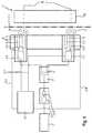
- a voltage source 1for supplying the device
- a tunable generator 2for generating a signal
- a distributor 3for directing the signal via one microwave line 4 to two radiation sources 5, each with a power amplifier 5.1 and a measuring means for Detection of measurement data 5.3, and designed as a computing, control and storage unit controller 6 is present, which is connected to the generator 2 and the radiation sources 5 via control lines 6.1 in combination.
- the supplied from the voltage source 1 and controllable by the controller 6 generator 2includes a vibration generator 2.1, which is composed of semiconductor devices, and an oscillator as a frequency filter 2.2.
- the generator 2can be continuously tuned over the range of the frequency range 1.8 to 2.8 GHz.
- the generator 2is tunable to a selected frequency from a frequency section of the microwave frequency range.
- a signal with the selected frequencycan be generated. Any generated signals whose frequencies do not correspond to the selected frequency are suppressed by the function of the frequency filter 2.2.
- the distributor 3the signal is distributed to the microwave lines 4.
- the signal provided in the arrangement according to the invention after the frequency filter 2.2is applied to each of the existing radiation sources 5.
- the signalis to be amplified by the power amplifier 5.1 and by means of a waveguide 5.2 as a microwave radiation 11th to radiate into a working space 7.
- the working space 7is bounded in one of its spatial dimensions by a wall of metal reflecting a microwave radiation 11 as a support structure 8, in which the radiation sources 5 are arranged in parallel planes E in the working space 7.
- the planes Eextend perpendicular to a longitudinal axis 7.1 of the working space 7.
- dimensions of the working space 7is determined by an effective width of the microwave radiation 11, the temperature, the frequency and an amplitude of the microwave radiation 11 and the Interactions with an irradiated medium 10 depends.
- a solid body to be heatedis introduced as the medium 10.
- the medium 10remains during the heating with respect to the working space 7 in an always same, stationary position.
- the measuring means for detecting measured data 5.3 arranged in the radiation source 5is a diode and serves to detect microwave radiation 11 which is reflected back from the medium 10 to the measuring means for acquiring measured data 5.3.
- the measuring means for acquiring measured data 5.3 of each radiation source 5is connected to the controller 6 via a respective measurement data line 5.4.
- Each power amplifier 5.1can be controlled directly and individually by the controller 6 via the control lines 6.1.
- a controltakes place as a function of the measurement data of the measuring means for acquiring measured data 5.3 in order to prevent damage to the radiation sources 5 by reflected microwave radiation 11.
- a second embodiment of the inventive arrangement according to Fig. 2corresponds to the basic structure according to Fig. 1 ,
- a temperature sensoris arranged as a further measuring means 12 for determining the temperature within the working space 7 and connected to the control 6 via a measuring data line 5.4.
- the working space 7is delimited in all its dimensions by walls (shown in simplified form as lines) which serve as support structures 8 for the radiation sources 5 (only two radiation sources 5 of a support structure 8 are shown) and through which the working space 7 is closed.
- a trained as a pipe guide element 9.1as a means for carrying the medium through the working space 9 along a longitudinal axis element 9.11 available.
- the element longitudinal axis 9.11runs parallel to the longitudinal axis 7.1.
- the guide element 9.1spans the working space 7 from a support structure 8 opening the media supply opening 9.2 to a judgmentab Operationsö réelle 9.3.In other embodiments of the arrangement can also outside the working space 7 and / or at the media supply port 9.2 and / or the media discharge opening 9.3 further measuring means 12, z , B. sensors, by which a state of the medium 10 as temperature, physical or chemical composition can be detected, be arranged.
- a design of a radiation source 5 according to Fig. 3is characterized by a carrier structure formed as a support structure 8, on which the power amplifier 5.1, the waveguide 5.2 and the measuring means for detecting measurement data 5.3 are enclosed by a housing 5.5.
- the radiation source 5is connected via the microwave line 4 to the distributor 3 (not shown) and via the control line 6.1 and the measurement data line 5.4 to the controller 6.
- the radiation source 5is to be mounted manually at a freely selectable position on the surface of a body to be heated as a medium 10.
- a working space 7is determined by the radiation source 5 and by the penetration depth of the microwave radiation 11 into the medium 10 (symbolized by dashed microwave radiation 11), which in this case is to be regarded as the effective width.
- This designcan be used, for example, as a flexible system for the gentle drying of wood or other natural substances, as well as all synthetically produced educts and products, wherein the use of microwave radiation 11 causes a controllable heating of the medium 10 in the interior. Water or other solvents are not trapped by already dried layers of the medium 10, but transported by still moist layers to the outside. By heating inside cracking in the medium 10 are largely avoided.
- the slot radiatorconsists of a waveguide 5.2 with a rectangular cross section and has a length L, a width B and a height H.
- the waveguide 5.2is bounded by walls 16. Opposite each other are, as walls 16, a first cover 16.1 and a second cover 16.2, a first side wall 16.3 and a second one Side wall 16.4 and an upper wall 16.5 and a lower wall 6.6 available.
- the upper wall 16.6has a slot 15 through which the microwave radiation 11 can be emitted from the slot radiator.
- the slot 15extends in the direction of the width B and is closer to the second lid 16.2 than on the first lid 16.1 available. According to Fig.
- the slot 15is one tenth of the length L from the second lid 16.2.
- the spatial position of the walls 16 and other elements of the slot radiatoris not relevant to the operation of the slot radiator. Only their relative position to each other and their dimensions is important. All information on the spatial orientation of the walls 16 are therefore exemplary.
- a tuner 17is arranged in the waveguide 5.2, which serves to selectively influence the propagation and reflection behavior of the coupled microwave radiation 11 and projects into the waveguide 5.2.
- the tuner 17is disposed opposite to the slot 15.
- an antenna 13is present, which is guided by the lower wall 16.5 and which has an antenna head 13.1.
- the antenna head 13.1protrudes into the waveguide 5.2 and serves to couple the microwave radiation 11 into the waveguide 5.2.
- the distance dis around lambda / 2, which corresponds to 6.1 cm in a microwave radiation 11 with a frequency of about 6.1 cm.
- the direction of the length Lis at the same time the propagation direction of the microwave radiation 11.
- the antenna head 13.1is designed as a sleeve made of brass. Inside the antenna head 13.1 there is a connector 18 in the form of a copper rod. The connector 18 protrudes from the antenna head 13.1 through the lower wall 16.5 and is contacted there by a receiving part of a connector 19. On the receiving part of the connector 19, a microwave line 4 can be connected. The receiving part of the connector 19 is disposed directly on the lower wall 16.5, whereby the antenna 13 is fixed.
- the antenna head 13.1protrudes from the lower wall 16.5 a first distance l1 perpendicular to the waveguide 5.2 inside.
- an inner conductor 14is inserted laterally, which extends in the direction of the length L over a second distance l2 to the first lid 16.1.
- first cover 16.1is a blind hole (only indicated) introduced, in which the inner conductor 14 is inserted with one end. Over the second distance l2 the inner conductor 14 is exposed.
- the antenna head 13.1may be designed differently in further embodiments of the invention.
- the connector 18may be replaced by a wire or a strand of a microwave feed line 4.
- the receiving part of the connector 19is not required.
- the connector 18it is possible for the connector 18 to be implemented as an element of the receiving part of the plug connection 19 or for the connector 18 to be realized as an element of a plug (not shown) of the plug connection 19.
- the application of the method according to the invention for investigating a behavior of the medium 10 during its heating by means of microwave radiation 11,is based on the second embodiment according to Fig. 2 explained.
- a frequency section of the microwave frequency range at which heating of the medium 10 is known to be selectedis selected.
- frequency sectionscan also be selected in which no heating takes place or heating is (still) questionable.
- the vibration generator 2.1 and the frequency filter 2.2are controlled so that a signal with the selected frequency is provided.
- the signalis an electromagnetic wave that vibrates at the selected frequency and has an amplitude.
- the distributor 3the signal is distributed to the microwave lines 4, so that this is applied to each of the radiation sources 5.
- Each of the power amplifiers 5.1is controlled by the controller 6 via the control lines 6.1 so that the amplitude of the signal amplified by each power amplifier 5.1 equal and the amplified signal is emitted via each waveguide 5.2 as microwave radiation 11 in the working space 7.
- the incident on the medium 10 microwave radiation 11is absorbed by the medium 10 according to its properties and / or reflected wholly or proportionately.
- Reflected and detected by one of the measuring means for the detection of measurement data 5.3 microwave radiation 11causes at least one response signal whose height as measured data via the measurement data line 5.4 to the controller. 6 is sent and evaluated there.
- the power amplifier 5.1is activated and a lower amplification is effected. Since the microwave radiation 11 impinging on the measuring device for acquiring measured data 5.3 can also originate from other radiation sources 5, in a further embodiment of the method the power amplifiers 5.1 of some or all of the other radiation sources 5 are also activated. By a controlled and systematic variation of the amplifications of the signal effected by the power amplifiers 5.1, a desired pattern of the control of the power amplifiers 5.1 for a respective combination of medium 10, positioning of the radiation sources 5 and dimensioning of the working space 7 can be sought.
- a "standard reflection profile" of the working space 7can be determined and stored. It is also possible to design the dimensioning of the working space 7 so that reflections of the microwave radiation 11 have no or a negligible influence on the measured data. Also, the walls of the working space 7 can be configured from material that is not reflective for microwave radiation 11, or the working space 7 can be designed in a number of directions of its dimensioning without walls.
- the frequencyis changed by driving the generator 2 by means of the controller 6.
- the frequencycan be set to specific values be set. Temperature-time curves can be recorded under constant conditions with variation of the frequency in order to determine an optimum frequency for a desired effect.
- the frequencyis tuned to the material. But it can also be changed continuously or discontinuously over a range of the frequency section. Such a change can also take place several times, for example at different temperatures of the medium 10 or of the working space 7.
- the first to nth propertiescan be set individually or in any combination.
- the measurement data acquired by the further measuring means 12are likewise transmitted to the controller 6 via measurement data lines 5.4.
- the acquired measurement dataare assigned to the information about the location of the detection of the first to nth property characteristics of the properties, evaluated and stored.
- the method according to the inventionit is possible to investigate the behavior of a medium 10 when it is heated in a wide variety of combinations of property characteristics. It is also possible to change the characteristic values controlled during a heating process and to investigate the resulting behavioral responses of the medium 10 associated with the characteristics, the positioning of the microwave sources 5, the design of the working space 7, the material and the dimension of the medium 10, and a default setting an assembly after its installation or repair to check or set up. Also, interactions based on common approaches to conducting scientific experiments can be used to investigate interactions between the above parameters.
- the methodmay also be used to optimize the process of fractionating a mixture of substances, activating ingredients of the medium, catalytic reactions, generating a plasma, or aligning molecules. The arrangement and the method can also be used when heating z. As contaminated soil or for the drying of bodies such. B. of fruits, are used, wherein an expulsion of water or Volatile substances and compounds such as alcohols, acetone, phenols, toluene, oils and the like primary goal.
Landscapes
- Physics & Mathematics (AREA)
- Electromagnetism (AREA)
- Constitution Of High-Frequency Heating (AREA)
- Control Of High-Frequency Heating Circuits (AREA)
- Physical Or Chemical Processes And Apparatus (AREA)
Description
Translated fromGermanDie Erfindung betrifft eine Anordnung und ein Verfahren zur Erwärmung eines in einem Arbeitsraum befindlichen Mediums mittels Mikrowellenstrahlung, wie diese gattungsgemäß aus der
In einer Vielzahl von bekannten Lösungen zur Erwärmung von Medien mittels Mikrowellenstrahlung besteht das Erfordernis, eine homogene Verteilung der Mikrowellenstrahlung in und um ein zu erwärmendes Medium herum zu erzeugen. Insbesondere soll die Ausbildung stehender Wellen vermieden werden, um lokale Überhitzungen (hot-spots) und lokale Bereiche zu vermeiden, an denen keine Erwärmung erfolgt.In a variety of known solutions for heating media by means of microwave radiation, there is a need to produce a homogeneous distribution of the microwave radiation in and around a medium to be heated. In particular, the formation of standing waves should be avoided in order to avoid local overheating (hot spots) and local areas where no heating takes place.
So ist es beispielsweise bei der Konstruktion von Mikrowellengeräten zur Erwärmung von Speisen üblich, die Abmessungen des Raumes, in dem sich das zu erwärmende Medium befindet (fortan: Arbeitsraum), ungleich der Wellenlänge oder eines Vielfachen der Wellenlänge der Mikrowellenstrahlung zu dimensionieren. Dadurch wird vermieden, dass in den Arbeitsraum abgestrahlte Mikrowellenstrahlung an einer Wand des Arbeitsraumes in sich selbst reflektiert und eine stehende Welle erzeugt wird.Thus, for example, in the design of microwave ovens for heating food, it is customary to dimension the dimensions of the space in which the medium to be heated (henceforth working space), unequal to the wavelength or a multiple of the wavelength of the microwave radiation. This avoids that in the working space radiated microwave radiation is reflected on a wall of the working space in itself and a standing wave is generated.
Eine Kombination von statischen Reflexionen der Mikrowellenstrahlung an den, einen Innenraum begrenzenden, Wänden eines Gehäuses und einer dynamischen Reflexion der Mikrowellenstrahlung mittels mindestens eines Modenrührers ist in der
Um eine gleichmäßige Verteilung von Mikrowellenstrahlung in einen Arbeitsraum zu erreichen, wird in der technischen Lehre der
Nachteilig an der angeführten Lösung ist, wie in der
Für Anwendungen, bei denen eine Phasenverschiebung der Mikrowellenstrahlung nicht erwünscht ist, beispielsweise in experimentellen Anordnungen in der Werkstoffkunde oder der Verfahrenstechnik, ist die Lösung nach der
Aus den Schriften
Durch die
Mikrowellen unterschiedlicher Eigenschaften werden gemäß der Offenbarung der
Der Erfindung liegt die Aufgabe zugrunde, eine Möglichkeit zur Erwärmung von Medien mittels Mikrowellenstrahlung vorzuschlagen, mittels der Phasenverschiebungen zwischen der abgestrahlten Mikrowellenstrahlung vermieden werden.The invention has for its object to propose a way to heat media by means of microwave radiation can be avoided by means of the phase shifts between the radiated microwave radiation.
Die Aufgabe wird durch eine Anordnung zur Erwärmung eines in einem Arbeitsraum befindlichen Mediums mittels Mikrowellenstrahlung, umfassend mindestens zwei Strahlungsquellen zur Bereitstellung von Mikrowellenstrahlung mit je einem individuell ansteuerbaren Leistungsverstärker, durch welchen ein von einem Generator generiertes, eine Mikrowellenfrequenz aufweisendes, Signal verstärkt wird sowie mit Mitteln zur Abstrahlung des verstärkten Signals als Mikrowellenstrahlung in einen Arbeitsraum, der durch die Anordnung der Strahlungsquellen zueinander in seiner räumlichen Dimension bestimmt ist, gelöst. Die Anordnung ist dadurch gekennzeichnet, der Arbeitsraum entlang einer Längsachse gestaltet ist und die Mittel zur Abstrahlung der Mikrowellenstrahlung Hohlleiter sind. Die Hohlleiter sind so ausgerichtet, dass die Abstrahlung der Mikrowellenstrahlung in Ebenen erfolgt, die senkrecht zur Längsachse ausgedehnt sind. Der Generator steht mit allen Leistungsverstärkern signaltechnisch in Verbindung, so dass das von dem Generator generierte Signal an allen Leistungsverstärkern anliegt. Außerdem ist der Generator über einen Bereich eines bestimmten Frequenzabschnitts innerhalb des Mikrowellenfrequenzbereiches durchstimmbar. In der Anordnung sind Messmittel vorhanden, mit denen Messdaten in dem Arbeitsraum erfassbar sind. Jede Mikrowellenquelle weist mindestens jeweils ein Messmittel zur Erfassung von Messdaten auf. Dabei sind die Messmittel zur Erfassung von Messdaten mit einer Steuerung signaltechnisch verbunden, durch die mindestens die Leistungsverstärker (5.2) individuell ansteuerbar sind und es ist mindestens ein Mittel zur Durchführung eines Mediums durch den Arbeitsraum vorhanden, das ein Führungselement mit einer Elementenlängsachse ist, die parallel zur Längsachse ausgerichtet ist.The object is achieved by an arrangement for heating a medium located in a working space by means of microwave radiation, comprising at least two radiation sources for providing microwave radiation, each with an individually controllable power amplifier, by which a signal generated by a generator, a microwave frequency exhibiting signal is amplified and with means for the radiation of the amplified signal as microwave radiation in a working space, which is determined by the arrangement of the radiation sources to each other in its spatial dimension, solved. The arrangement is characterized, the working space is designed along a longitudinal axis and the means for emitting the microwave radiation are waveguides. The waveguides are like that aligned so that the radiation of the microwave radiation takes place in planes that are extended perpendicular to the longitudinal axis. The generator is in signal communication with all power amplifiers so that the signal generated by the generator is applied to all power amplifiers. In addition, the generator is tunable over a range of a certain frequency section within the microwave frequency range. In the arrangement, measuring means are provided with which measurement data can be detected in the working space. Each microwave source has at least one measuring device each for acquiring measured data. In this case, the measuring means for acquiring measured data are signal-technically connected to a control, by means of which at least the power amplifiers (5.2) can be controlled individually and there is at least one means for passing a medium through the working space, which is a guide element with a longitudinal axis of the elements, which runs parallel is aligned to the longitudinal axis.
Der Mikrowellenfrequenzbereich reicht von 300 MHz bis 300 GHz (Wellenlängen von 1 m bis 1 mm). Der Frequenzabschnitt kann jeder Abschnitt des Mikrowellenfrequenzbereichs sein. Die von dem Generator generierten elektromagnetischen Wellen werden als Signale bezeichnet, während als Mikrowellenstrahlung die abgestrahlten, durch einen der Leistungsverstärker verstärkten, Signale bezeichnet werden. Eine Verstärkung bewirkt vorzugsweise, dass die niedrig energetischen Signale zu Mikrowellenstrahlung verstärkt werden, deren Energie für einen vorgesehenen Verwendungszweck der erfindungsgemäßen Anordnung ausreichend ist. Die Mikrowellenstrahlung wird in Form von Feldern abgestrahlt, wobei die Felder gerichtet abgestrahlt sein können.The microwave frequency range is from 300 MHz to 300 GHz (wavelengths from 1 m to 1 mm). The frequency section may be any section of the microwave frequency range. The electromagnetic waves generated by the generator are referred to as signals, while microwave radiation refers to the radiated signals amplified by one of the power amplifiers. A gain preferably causes the low-energy signals to be amplified into microwave radiation whose energy is sufficient for an intended use of the arrangement according to the invention. The microwave radiation is emitted in the form of fields, wherein the fields can be directed radiated.
Je höher der erreichte Wirkungsgrad der Anordnung sein soll, desto kleiner ist der wählbare Frequenzabschnitt. Um vorteilhaft einen möglichst hohen Wirkungsgrad zu erreichen, sind der Generator und der Leistungsverstärker aufeinander abgestimmt. Die maximale Variabilität der Frequenzen von Generator und Leistungsverstärker liegt bei +/- 100 MHz.The higher the efficiency of the arrangement should be, the smaller the selectable frequency range. In order to advantageously achieve the highest possible efficiency, the generator and the power amplifier are matched to one another. The maximum variability of the generator and power amplifier frequencies is +/- 100 MHz.
Kern der Erfindung ist, die Frequenz der von den mindestens zwei Strahlungsquellen abgestrahlten Mikrowellenstrahlung durch nur einen einzigen Generator zu erzeugen. Es ist ferner erfindungswesentlich, dass der Generator durchstimmbar ist, so dass selbst während eines laufenden Erwärmungsvorgangs eine gesteuerte Veränderung der Frequenz ermöglicht ist.The core of the invention is the frequency of the radiated from the at least two radiation sources microwave radiation by only a single generator produce. It is furthermore essential to the invention that the generator can be tuned so that a controlled change of the frequency is made possible even during an ongoing heating process.
Durch die Verbindung nur eines Generators mit den Strahlungsquellen ist vorteilhaft eine Phasenverschiebung der abgestrahlten Mikrowellenstrahlung vermieden. Zusammen mit einer individuellen Ansteuerbarkeit jedes Leistungsverstärkers ist es mittels der erfindungsgemäßen Anordnung möglich, Mikrowellenstrahlung nur einer einzigen Frequenz durch eine Anzahl von Strahlungsquellen in den Arbeitsraum abzustrahlen. Der Generator kann mehrere Bauteile umfassen. Beispielsweise kann ein Mittel zur Generierung der Signale (z. B. ein Mittel zur Generierung von Signalen auf Basis von Halbleiterbauelementen) und ein durchstimmbares Mittel zum selektiven Durchlass (z. B. ein Oszillator, ein Filter oder Gleichrichter) der ausgewählten Frequenz vorhanden sein. Abweichend von dem vorgenannten Stand der Technik beinhaltet eine Strahlungsquelle im Sinne dieser Beschreibung keinen Generator.By connecting only one generator to the radiation sources, a phase shift of the radiated microwave radiation is advantageously avoided. Together with an individual controllability of each power amplifier, it is possible by means of the arrangement according to the invention to radiate microwave radiation of only a single frequency through a number of radiation sources into the working space. The generator may comprise several components. For example, there may be a means for generating the signals (eg, a means for generating signals based on semiconductor devices) and a tunable means for selectively passing (eg, an oscillator, a filter or rectifier) the selected frequency. Deviating from the aforementioned prior art, a radiation source in the sense of this description does not include a generator.
Ein Arbeitsraum kann ein geschlossener Raum wie der Innenraum eines Haushalts- oder Industrie-Mikrowellengerätes sein, in dem das Medium stationär angeordnet ist. Er kann auch ein offener Bereich sein, durch den das Medium hindurchtreten kann und dessen Größe durch eine Wirkungsweite der abgestrahlten Mikrowellenstrahlung bestimmt ist. Da Medien frequenzabhängig und temperaturabhängig, und somit auch leistungsabhängig, unterschiedlich auf Mikrowellenstrahlung reagieren, ist eine Wirkungsweite abhängig von einer Wechselwirkung zwischen Frequenz und Amplitude der Mikrowellenstrahlung sowie dem Medium. Die Wirkungsweite ist als Distanz zwischen Strahlungsquelle und dem am weitest entfernten Punkt des Mediums, an dem eine Wirkung feststellbar ist, zu verstehen und ist immer dann verschieden von einer Eindringtiefe der Mikrowellenstrahlung in das Medium, wenn die Strahlungsquelle nicht unmittelbar auf der Oberfläche des Mediums aufsetzt. Während eine Wirkungsweite im Vakuum theoretisch unendlich ist, können bei einer Bestrahlung von Medien sowie festen Körpern Wirkungsweiten lediglich im Bereich weniger Nano- oder Mikrometer vorliegen.A work space may be a closed space such as the interior of a household or industrial microwave oven in which the medium is stationary. It can also be an open region through which the medium can pass and whose size is determined by an effective range of the emitted microwave radiation. Since media frequency-dependent and temperature-dependent, and thus also power-dependent, react differently to microwave radiation, an effective range is dependent on an interaction between the frequency and amplitude of the microwave radiation and the medium. The range of action is to be understood as the distance between the radiation source and the farthest point of the medium on which an effect can be detected, and is always different from a penetration depth of the microwave radiation into the medium, if the radiation source does not touch directly on the surface of the medium , While an effective range in the vacuum is theoretically infinite, with an irradiation of media as well as solid bodies, effective ranges can only exist in the range of a few nanometers or micrometers.
Der Arbeitsraum kann beispielsweise von einem Gitter aus einem für Mikrowellenstrahlung reflektierenden Material umschlossen sein, dessen Gitterweite einen Durchtritt von Mikrowellenstrahlung nicht erlaubt, ein Durchtritt eines, z. B. flüssigen oder gasförmigen, Mediums aber möglich ist. Medien können alle festen, flüssigen und gasförmigen Stoffe und Stoffgemische oder Plasmen sowie deren Kombinationen sein.The working space can be enclosed, for example, by a grid made of a material reflecting microwave radiation whose grid width a passage of microwave radiation is not allowed, a passage of a, z. As liquid or gaseous medium is possible. Media may be all solid, liquid and gaseous substances and mixtures or plasmas and combinations thereof.
Die in jeder Mikrowellenquelle enthaltenen Messmittel zur Erfassung von Messdaten erlauben eine Erfassung und Auswertung von für die Messmittel spezifischen Größen. Dies kann vorteilhaft zum Schutz einzelner, einiger oder aller Strahlungsquellen genutzt werden. Beispielsweise kann eine Leistungsverstärkung durch eine Steuerung individuell reduziert oder unterbunden sein, wenn die durch die Messmittel erfassten Größen einen vorbestimmten Schwellwert überschreiten. Des Weiteren kann jedes Messmittel zur Erfassung von Größen für andere Auswertungen, z. B. für Untersuchungen des Verhaltens eines Mediums bei seiner Erwärmung mittels Mikrowellenstrahlung, bereitgestellt sein. Auch dazu ist das Messmittel signaltechnisch mit der Steuerung verbunden.The measuring means contained in each microwave source for the acquisition of measured data allow the detection and evaluation of variables specific to the measuring means. This can be advantageously used to protect individual, some or all radiation sources. For example, a power amplification by a control can be individually reduced or prevented if the variables detected by the measuring means exceed a predetermined threshold value. Furthermore, each measuring means for detecting quantities for other evaluations, for. B. for investigations of the behavior of a medium when heated by means of microwave radiation, be provided. Also for this purpose, the measuring means is signal-technically connected to the controller.
Es ist ebenfalls eine vorteilhafte Ausführung der erfindungsgemäßen Anordnung, wenn in dem Arbeitsraum weitere Messmittel vorhanden und mit der Steuerung signaltechnisch, z. B. über bedrahtete oder unbedrahtete Messdatenleitungen, verbunden sind. Beispielsweise können durch weitere Messmittel Größen wie Temperaturen, Strahlungen, chemische Zusammensetzungen und Druck ortsaufgelöst erfasst sein. Die Steuerung ist vorzugsweise als Rechen-, Steuer- und Speichereinheit ausgebildet. Von der Steuerung können direkte Steuerleitungen zu jedem der Leistungsverstärker sowie zu jedem Messmittel und zu jedem weiteren Messmittel vorhanden sein. Es ist auch möglich, dass die Leistungsverstärker, die Messmittel und die weiteren Messmittel mit adressierten Steuersignalen ansteuerbar sind, wodurch die Anzahl von erforderlichen Steuerleitungen und Messdatenleitungen reduziert werden kann.It is also an advantageous embodiment of the arrangement according to the invention, if in the working space further measuring means present and with the control signal technology, z. B. wired or non-wired Messdatenleitungen connected. For example, variables such as temperatures, radiations, chemical compositions and pressure can be detected spatially resolved by further measuring means. The controller is preferably designed as a computing, control and storage unit. From the controller there may be direct control lines to each of the power amplifiers as well as to each measuring means and to every other measuring means. It is also possible for the power amplifiers, the measuring means and the further measuring means to be controlled with addressed control signals, whereby the number of required control lines and measuring data lines can be reduced.
Günstig ist es, wenn die Messmittel und die weiteren Messmittel geschirmt und am Rand des Arbeitsraums angeordnet sind. Die Messmittel sowie die weiteren Messmittel können beispielsweise Infrarot-Pyrometer oder faseroptische Sensoren sein.It is favorable if the measuring means and the further measuring means are shielded and arranged at the edge of the working space. The measuring means and the other measuring means may be, for example, infrared pyrometers or fiber optic sensors.
In einer ersten Ausführung der erfindungsgemäßen Anordnung sind die Strahlungsquellen bezüglich ihrer Position relativ zum Arbeitsraum frei wählbar. Sie können beispielsweise so gestaltet sein, dass sie manuell direkt auf einer Oberfläche des Mediums, z. B. eines zu erwärmenden Körpers, angeordnet werden können. Es ist von Vorteil, wenn die Strahlungsquellen als kompakte und leicht handhabbare Einheit gestaltet sind. Sie können vorzugsweise in je einem Gehäuse und mit diesem auf je einem Träger angeordnet sein. In einer solchen Ausführung der Anordnung ist die räumliche Dimension, also die konkrete räumliche Form, des Arbeitsraums durch die frei wählbare Positionierung der Strahlungsquellen bestimmt.In a first embodiment of the arrangement according to the invention, the radiation sources with respect to their position relative to the working space are freely selectable. For example, they may be designed to be manually placed directly on a surface of the medium, e.g. B. a body to be heated, can be arranged. It is advantageous if the radiation sources are designed as a compact and easy to handle unit. They may preferably be arranged in a respective housing and with this on a respective carrier. In such an embodiment of the arrangement, the spatial dimension, ie the specific spatial shape, of the working space is determined by the freely selectable positioning of the radiation sources.
Eine weitere Ausgestaltung der erfindungsgemäßen Anordnung zeichnet sich dadurch aus, dass mindestens die Mittel zur Abstrahlung der Mikrowellenstrahlung in den Arbeitsraum in mindestens einer Halterungsstruktur angeordnet sind. Eine solche Halterungsstruktur kann die räumliche Dimension des Arbeitsraums in mindestens einer Richtung begrenzen. Eine Halterungsstruktur kann in einem einfachen Fall eine Wand oder Wände eines Arbeitsraums sein und die Mittel zur Abstrahlung können in einer bestimmten Weise auf oder in der Wand oder den Wänden verteilt sein. Die Halterungsstruktur kann beispielsweise auch eine Halterung wie ein Gerüst oder eine flexible Matte sein.A further embodiment of the arrangement according to the invention is characterized in that at least the means for emitting the microwave radiation are arranged in the working space in at least one support structure. Such a support structure can limit the spatial dimension of the working space in at least one direction. A support structure may in a simple case be a wall or walls of a working space and the means for radiation may be distributed in a certain way on or in the wall or the walls. The support structure may for example also be a support such as a scaffold or a flexible mat.
Die Halterungsstruktur kann den Arbeitsraum ganz oder teilweise umschließen. Es ist auch möglich, dass die Halterungsstruktur den Arbeitsraum in einer Richtung begrenzt und die räumliche Dimension des Arbeitsraums durch die Halterungsstruktur und die Wirkungsweite der abgestrahlten Mikrowellenstrahlung bestimmt ist.The support structure can completely or partially enclose the working space. It is also possible that the support structure limits the working space in one direction and the spatial dimension of the working space is determined by the support structure and the effective width of the emitted microwave radiation.
Hohlleiter werden üblicherweise dazu eingesetzt um eine z. B. Mikrowellenstrahlung zu leiten. In einer bevorzugten Ausführung der erfindungsgemäßen Anordnung wird Mikrowellenstrahlung über eine Antenne oder Sender in einen Hohlleiter abgestrahlt. Die Mikrowellenstrahlung ist durch den Hohlleiter bis zu einer Öffnung, die vorzugsweise als ein Schlitz ausgebildet ist, geleitet. Durch die Öffnung wird die Mikrowellenstrahlung in den Arbeitsraum abgestrahlt. Von Vorteil ist, dass durch den Schlitz schädliche Rückreflexionen in den Hohlleiter stark reduziert sind.Waveguides are usually used to a z. B. to conduct microwave radiation. In a preferred embodiment of the arrangement according to the invention, microwave radiation is emitted via an antenna or transmitter into a waveguide. The microwave radiation is passed through the waveguide to an opening, which is preferably formed as a slot. Through the opening, the microwave radiation is radiated into the working space. The advantage is that the slot harmful back reflections are greatly reduced in the waveguide.
Ein Mittel zur Abstrahlung der Mikrowellenstrahlung in den Arbeitsraum kann in einer vorteilhaften Ausführung als ein sogenannter Schlitzstrahler ausgebildet sein. In einem von Wänden begrenztem Hohlleiter ist dabei mindestens ein Antennenkopf einer Antenne zur Einkopplung von Mikrowellenstrahlung in den Hohlleiter angeordnet. Es ist bevorzugt, wenn außerdem ein Tuner zur Beeinflussung des Ausbreitungs- und Reflexionsverhaltens der eingekoppelten Mikrowellenstrahlung in dem Hohlleiter angeordnet ist. Die eingekoppelte Mikrowellenstrahlung breitet sich in dem Hohlleiter in einer Ausbreitungsrichtung aus. In einer Wand des Hohlleiters ist ein Schlitz zum Abstrahlen der Mikrowellenstrahlung aus dem Schlitzstrahler vorhanden. Der Schlitz verläuft vorzugsweise quer zur Ausbreitungsrichtung und ist vorzugsweise in einem Abstand von dem Antennenkopf entfernt, welcher der halben Wellenlänge (Lambda / 2) der Mikrowellenstrahlung entspricht. Die Länge des Schlitzstrahlers ist größer als die halbe Wellenlänge (Lambda / 2) und kleiner als die Wellenlänge (Lambda) der Mikrowellenstrahlung. Bei einer optimalen Abstimmung aller Elemente des Schlitzstrahlers aufeinander und auf eine Frequenz und Leistung der Mikrowellenstrahlung sind Wirkungsgrade des Schlitzstrahlers von mehr als 75% bis über 99%, beispielsweise 99,7% erreicht.A means for emitting the microwave radiation in the working space may be formed in an advantageous embodiment as a so-called slot radiator. In a waveguide delimited by walls, at least one antenna head of an antenna for coupling microwave radiation into the waveguide is arranged. It is preferred if, in addition, a tuner for influencing the propagation and reflection behavior of the coupled-in microwave radiation is arranged in the waveguide. The coupled-in microwave radiation propagates in the waveguide in a propagation direction. In a wall of the waveguide, a slot for emitting the microwave radiation from the slot radiator is present. The slot preferably extends transversely to the propagation direction and is preferably at a distance from the antenna head which corresponds to half the wavelength (lambda / 2) of the microwave radiation. The length of the slot radiator is greater than half the wavelength (lambda / 2) and smaller than the wavelength (lambda) of the microwave radiation. With an optimum coordination of all elements of the slot radiator successive and on a frequency and power of the microwave radiation efficiencies of the slot radiator of more than 75% to more than 99%, for example, reached 99.7%.
Die Antenne kann einen Innenleiter zur Leitung und Einkopplung einer Mikrowellenstrahlung aufweisen. In weiteren Ausführungen kann die Antenne auch ohne einen Innenleiter realisiert sein. Die Antenne kann beispielsweise mittels einer lösbaren Steckerverbindung (z. B. SMA-Stecker oder N-Stecker) kontaktiert sein. Es ist auch möglich, dass eine nicht-lösbare Kontaktierung, beispielsweise durch ein Koaxialkabel mit einem direkten Übergang in die Antenne, vorhanden ist. Der Antennenkopf besteht vorzugsweise aus einem elektrisch leitenden Material wie Kupfer, Eisen, Gold oder Messing.The antenna may have an inner conductor for conducting and coupling in a microwave radiation. In further embodiments, the antenna can also be realized without an inner conductor. The antenna may, for example, be contacted by means of a detachable plug connection (eg SMA plug or N plug). It is also possible that a non-detachable contact, for example by a coaxial cable with a direct transition into the antenna, is present. The antenna head is preferably made of an electrically conductive material such as copper, iron, gold or brass.
Es ist günstig, wenn die Antenne bzw. der Antennenkopf in dem Hohlleiter angebracht ist, ohne dass Befestigungselemente in den Hohlleiter ragen. Beispielsweise kann mindestens ein Sackloch in einer der Wände des Hohlleiters vorhanden sein, in den ein Bereich der Antenne bzw. des Antennenkopfs, beispielsweise der Innenleiter, eingreift oder eingesteckt ist. Durch mindestens eine solche Lagerung sind nachteilige Beeinflussungen des Ausbreitungs- und Reflexionsverhaltens der eingekoppelten Mikrowellenstrahlung stark reduziert. Die Antenne bzw. der Antennenkopf kann durch eine an dem Hohlleiter oder außerhalb des Hohlleiters befindliche Vorrichtung arretiert sein. Beispielsweise kann an einem aus dem Hohlleiter ragendem Bereich der Antenne eine Steckverbindung (z. B. ein SMA-Stecker) vorgesehen sein, durch welche die Antenne räumlich festgelegt ist.It is favorable if the antenna or the antenna head is mounted in the waveguide without fastening elements projecting into the waveguide. For example, at least one blind hole may be present in one of the walls of the waveguide into which a region of the antenna or of the antenna head, for example the inner conductor, engages or is inserted. By at least one such storage adverse effects on the propagation and reflection behavior of the coupled microwave radiation are greatly reduced. The Antenna or the antenna head can be locked by a device located on the waveguide or outside of the waveguide. By way of example, a plug connection (for example an SMA plug) can be provided on a region of the antenna protruding from the waveguide, by means of which the antenna is spatially fixed.
Ist das Mittel zur Durchführung des Mediums durch den Arbeitsraum ein Bündel von Führungselementen mit einer Bündellängsachse, so ist diese Bündellängsachse vorzugsweise parallel zur Längsachse ausgerichtet. Führungselemente können beispielweise Rohre, Schächte oder Kanäle sein, die von einem flüssigen oder gasförmigen Medium durchströmt werden. Es können aber auch Fördereinrichtungen sein, mittels der feste Stoffe als z. B. Schüttgut oder als Körper durch den Arbeitsraum zu führen sind (dynamischer Fall). Eine Durchführung des Mediums durch den Arbeitsraum kann in zeitlich (z. B. kontinuierlich, diskontinuierlich) und räumlich (Streckenverlauf der Durchführung) beliebiger Weise erfolgen. Es ist auch möglich, dass das Medium in den Arbeitsraum eingebracht ist, dort während seiner Erwärmung verbleibt und wieder entnommen wird (statischer Fall). Beispielsweise kann ein Körper oder ein Behältnis mit dem zu erwärmenden Medium (z. B. ein befüllter Autoklav) in den Arbeitsraum eingebracht sein.If the means for passing the medium through the working space is a bundle of guide elements with a bundle longitudinal axis, then this bundle longitudinal axis is preferably aligned parallel to the longitudinal axis. Guide elements can be, for example, pipes, shafts or channels through which a liquid or gaseous medium flows. But it may also be conveyors by means of solids as z. B. bulk material or as a body through the working space are to lead (dynamic case). A passage of the medium through the working space can take place arbitrarily in time (for example, continuously, discontinuously) and spatially (route of execution). It is also possible that the medium is introduced into the working space, where it remains during its heating and is removed again (static case). For example, a body or a container with the medium to be heated (eg a filled autoclave) can be introduced into the working space.
Sehr vorteilhaft ist es, wenn der Generator gegen mindestens einen weiteren Generator austauschbar ist. Eine einfache Austauschbarkeit kann beispielsweise dadurch erreicht sein, dass der Generator, z. B. in eine Platine, einsteckbar ist. Dadurch ist im Fall eines Defekts der Generator leicht auswechselbar. Besonders günstig ist die einfache Austauschbarkeit in Experimentieranordnungen, in denen durch den Austausch nur einer Komponente der Anordnung beispielsweise ein Bereich eines anderen Frequenzabschnitts verfügbar wird. Einem physischen Austausch steht eine Möglichkeit zur Umschaltung auf einen anderen Generator gleich.It is very advantageous if the generator is interchangeable with at least one additional generator. A simple interchangeability can be achieved, for example, that the generator, for. B. in a board, can be inserted. As a result, the generator is easily replaceable in the event of a defect. Particularly favorable is the simple interchangeability in experimental arrangements in which, for example, a region of another frequency section becomes available by exchanging only one component of the arrangement. A physical exchange is a possibility to switch to another generator.
Die Anordnung kann neben der Erwärmung eines Mediums mittels Mikrowellenstrahlung beispielsweise zur Untersuchung des Ansprechverhaltens des Mediums bei der Erwärmung verwendet werden.The arrangement can be used in addition to the heating of a medium by means of microwave radiation, for example, to investigate the response of the medium in the heating.
Die Aufgabe wird ferner durch ein Verfahren zur Erwärmung eines in einem Arbeitsraum befindlichen Mediums mittels Mikrowellenstrahlung und unter Verwendung einer erfindungsgemäßen Vorrichtung gelöst. Die Schritte des erfindungsgemäßen Verfahrens sind nacheinander das Einbringen eines Mediums in einen Arbeitsraum. Es folgt die Auswahl einer Mikrowellenfrequenz in Abhängigkeit von Eigenschaften des Mediums aus einem bestimmten Frequenzabschnitt innerhalb des Mikrowellenfrequenzbereiches. Anschließend wird ein Generator mit Steuersignalen angesteuert, die zu einer Generierung eines Signals mit der ausgewählten Mikrowellenfrequenz führen. Es folgen das Generieren des Signals mit der ausgewählten Mikrowellenfrequenz, das Leiten des Signals an wenigstens eine Strahlungsquelle, das Verstärken des Signals mittels der wenigstens einen Strahlungsquelle zu wenigstens einem verstärkten Signal und das Abstrahlen des wenigstens einen verstärkten Signals als Mikrowellenstrahlung in den Arbeitsraum. An jeder der Strahlungsquellen werden Messdaten erfasst, auf deren Grundlage Steuersignale mindestens zur Ansteuerung der Verstärkung des Signals erzeugt werden.The object is further by a method for heating a medium located in a working space by means of microwave radiation and under Use of a device according to the invention solved. The steps of the method according to the invention are successively introducing a medium into a working space. This is followed by the selection of a microwave frequency as a function of properties of the medium from a specific frequency range within the microwave frequency range. Subsequently, a generator is driven with control signals, which lead to generation of a signal with the selected microwave frequency. This is followed by generating the signal at the selected microwave frequency, passing the signal to at least one radiation source, amplifying the signal by means of the at least one radiation source to at least one amplified signal and emitting the at least one amplified signal as microwave radiation into the working space. At each of the radiation sources measurement data is detected, based on which control signals are generated at least for driving the gain of the signal.
Die Auswahl der Mikrowellenfrequenz (Frequenz) kann aufgrund der Kenntnisse über das Material, die Dimensionierung und weiterer Eigenschaften (z. B. Aggregatzustand, Temperatur) des Mediums erfolgen. Es ist auch möglich, eine bestimmte Frequenz aufgrund von Erfahrungssätzen oder aber willkürlich auszuwählen. Die Frequenz kann in weiteren Ausführungen des Verfahrens auch vor oder mit dem Einbringen des Mediums ausgewählt werden.The selection of the microwave frequency (frequency) can be based on the knowledge of the material, the dimensioning and other properties (eg state of matter, temperature) of the medium. It is also possible to select a certain frequency on the basis of empirical sentences or arbitrarily. The frequency can be selected in further embodiments of the method before or with the introduction of the medium.
In einer bevorzugten Variante des erfindungsgemäßen Verfahrens ist der Arbeitsraum durch eine Anordnung mehrerer Strahlungsquellen in seinen räumlichen Dimensionen bestimmt.In a preferred variant of the method according to the invention, the working space is determined by an arrangement of a plurality of radiation sources in its spatial dimensions.
Das erfindungsgemäße Verfahren ist äußerst vorteilhaft zur Untersuchung eines Verhaltens des Mediums bei seiner Erwärmung mittels Mikrowellenstrahlung geeignet. Dabei werden nacheinander Mikrowellenstrahlungen mindestens je einer ersten bis n-ten Eigenschaftsausprägung einer bestimmten Bandbreite von Eigenschaftsausprägungen einer Eigenschaft der Mikrowellenstrahlung in den Arbeitsraum abgestrahlt. Die der ersten bis n-ten Eigenschaftsausprägung zugeordneten ersten bis n-ten Messdaten werden erfasst und miteinander verglichen. Aus den Messdaten sowie deren Vergleich wird das Verhalten des Mediums bei seiner Erwärmung mittels Mikrowellenstrahlung erster bis n-ter Eigenschaftsausprägung abgeleitet. Es lässt sich das Verhalten des Mediums über die Zeit, an verschiedenen Bereichen des Arbeitsraums sowie unter verschiedenen Kombinationen der ersten bis n-ten Eigenschaftsausprägung der Mikrowellenstrahlung untersuchen.The method according to the invention is extremely advantageous for investigating a behavior of the medium when heated by means of microwave radiation. In this case, microwave radiations of at least one first to nth characteristic expression of a certain range of property characteristics of a property of the microwave radiation are radiated into the working space one after the other. The first to nth measurement data assigned to the first to nth property characteristics are recorded and compared with each other. From the measured data and their comparison, the behavior of the medium when heated by means of microwave radiation first to n-th Property characteristic derived. It is possible to investigate the behavior of the medium over time, in different areas of the working space and under different combinations of the first to nth characteristics of the microwave radiation.
Eigenschaften können beispielsweise die Leistung der Mikrowellenstrahlung oder die Frequenz sein. Die Eigenschaftsausprägung ist der jeweils konkrete Wert der Eigenschaft, z. B. eine konkret darstellbare Amplitude der Mikrowelle als erste Eigenschaftsausprägung und eine konkrete Frequenz als zweite Eigenschaftsausprägung der Leistung der Mikrowellenstrahlung.Properties can be, for example, the power of the microwave radiation or the frequency. The property expression is the respective concrete value of the property, eg. B. a concrete representable amplitude of the microwave as the first property characteristic and a specific frequency as a second property characteristic of the power of the microwave radiation.
Mit dem Verfahren ist eine Untersuchung von Medien beispielsweise dadurch möglich, dass das Medium mit Mikrowellenstrahlung der ersten bis n-ten Eigenschaftsausprägung bestrahlt und Messdaten erfasst werden. So können beispielsweise optimierte Kombinationen der ersten bis n-ten Eigenschaftsausprägung für eine Erwärmung des Mediums gefunden werden. Mit dem Verfahren kann außerdem eine geeignete räumliche Positionierung der Strahlungsquellen gesucht werden, bei der beispielsweise eine effiziente Erwärmung des Mediums bei gleichzeitigem Schutz aller Strahlungsquellen vor schädigenden Einflüssen erzielbar ist.The method makes it possible to examine media, for example, by irradiating the medium with microwave radiation of the first to nth properties and recording measured data. Thus, for example, optimized combinations of the first to nth property characteristics for a heating of the medium can be found. The method can also be used to search for a suitable spatial positioning of the radiation sources in which, for example, an efficient heating of the medium with simultaneous protection of all radiation sources against damaging influences can be achieved.
Steuerungstechnisch günstig ist es, wenn die Auswahl einer Frequenz, die Erzeugung der Mikrowellenstrahlung, die Ansteuerung der Strahlungsquellen und die Auswertung der Messdaten mittels einer zentralen Steuerung erfolgt.In terms of control, it is favorable if the selection of a frequency, the generation of the microwave radiation, the control of the radiation sources and the evaluation of the measured data are effected by means of a central control.
Mittels des erfindungsgemäßen Verfahrens können Medien beliebiger Aggregatzustände oder deren Mischung erwärmt werden. Es ist möglich, das Verfahren zur Fraktionierung eines aus einem Stoffgemisch bestehenden Mediums zu nutzen. Es kann damit auch mindestens ein Inhaltsstoff des Mediums aktiviert, sowie katalytische Reaktionen des Mediums durchgeführt werden. Es ist auch möglich, mittels des erfindungsgemäßen Verfahrens aus dem Medium ein Plasma zu erzeugen. In Bezug auf spezielle Methoden der Oberflächenbehandlung, wie z. B. der PVD (physical vapour deposition) oder der CVD (chemical vapour deposition), wird es möglich sein, Prozessabläufe präziser zu gestalten und dadurch die Homogenität von z. B. auf einem Objekt aufgebrachter Schichten weiter zu steigern. Auch können mittels Mikrowellenstrahlung Moleküle oder Molekülgruppen ausgerichtet bzw. auch erst polarisiert werden.Die Erfindung wird nachfolgend anhand von Ausführungsbeispielen und Abbildungen näher erläutert. Es zeigen die Abbildungen:
- Fig. 1
- eine erste Ausführung der erfindungsgemäßen Anordnung;
- Fig. 2
- eine zweite Ausführung der erfindungsgemäßen Anordnung;
- Fig. 3
- eine Strahlungsquelle einer dritten erfindungsgemäßen Anordnung und
- Fig. 4
- ein Ausführungsbeispiel eines Schlitzstrahlers.
- Fig. 1
- a first embodiment of the inventive arrangement;
- Fig. 2
- a second embodiment of the arrangement according to the invention;
- Fig. 3
- a radiation source of a third inventive arrangement and
- Fig. 4
- an embodiment of a slot radiator.
Als wesentliche Elemente der in
Der von der Spannungsquelle 1 versorgte und durch die Steuerung 6 ansteuerbare Generator 2 beinhaltet einen Schwingungsgenerator 2.1, der aus Halbleiterbauelementen aufgebaut ist, sowie einen Oszillator als Frequenzfilter 2.2. Der Generator 2 ist über den Bereich des Frequenzabschnittes 1,8 bis 2,8 GHz kontinuierlich durchstimmbar. Durch von der Steuerung 6 übermittelte Steuersignale ist der Generator 2 auf eine ausgewählte Frequenz aus einem Frequenzabschnitt des Mikrowellenfrequenzbereichs abstimmbar. Mittels des Schwingungsgenerators 2.1 ist ein Signal mit der ausgewählten Frequenz generierbar. Eventuell erzeugte Signale, deren Frequenzen nicht der ausgewählten Frequenz entsprechen, sind durch die Funktion des Frequenzfilters 2.2 unterdrückt. Durch den Verteiler 3 ist das Signal auf die Mikrowellenleitungen 4 verteilt. Das in der erfindungsgemäßen Anordnung nach dem Frequenzfilter 2.2 bereitgestellte Signal liegt an jeder der vorhandenen Strahlungsquellen 5 an. Das Signal ist durch den Leistungsverstärker 5.1 zu verstärken und mittels eines Hohlleiters 5.2 als eine Mikrowellenstrahlung 11 in einen Arbeitsraum 7 abzustrahlen. Der Arbeitsraum 7 ist durch eine für Mikrowellenstrahlung 11 reflektierende Wand aus Metall als eine Halterungsstruktur 8, in der die Strahlungsquellen 5 in parallel zueinander verlaufenden Ebenen E in den Arbeitsraum 7 gerichtet angeordnet sind, in einer seiner räumlichen Dimensionen begrenzt. Die Ebenen E erstrecken sich senkrecht zu einer Längsachse 7.1 des Arbeitsraums 7. In seinen nicht von der Halterungsstruktur 8 begrenzten Dimensionen ist der Arbeitsraum 7 durch eine Wirkungsweite der Mikrowellenstrahlung 11 bestimmt, die von der Temperatur, der Frequenz und einer Amplitude der Mikrowellenstrahlung 11 sowie den Wechselwirkungen mit einem bestrahlten Medium 10 abhängt. In dem Arbeitsraum 7 ist ein zu erwärmender fester Körper als Medium 10 eingebracht. Das Medium 10 verbleibt während der Erwärmung bezüglich des Arbeitsraumes 7 in einer immer gleichen, stationären Lage. Das in der Strahlungsquelle 5 angeordnete Messmittel zur Erfassung von Messdaten 5.3 ist eine Diode und dient der Erfassung von Mikrowellenstrahlung 11, die von dem Medium 10 auf das Messmittel zur Erfassung von Messdaten 5.3 zurück reflektiert sind. Das Messmittel zur Erfassung von Messdaten 5.3 jeder Strahlungsquelle 5 ist über je eine Messdatenleitung 5.4 mit der Steuerung 6 verbunden. Jeder Leistungsverstärker 5.1 ist durch die Steuerung 6 über die Steuerleitungen 6.1 direkt und individuell ansteuerbar. Eine Ansteuerung erfolgt in Abhängigkeit der Messdaten des Messmittels zur Erfassung von Messdaten 5.3, um Schädigungen der Strahlungsquellen 5 durch reflektierte Mikrowellenstrahlung 11 zu verhindern.The supplied from the voltage source 1 and controllable by the
Eine zweite Ausführung der erfindungsgemäßen Anordnung gemäß
Eine Gestaltung einer Strahlungsquelle 5 gemäß
Ein Ausführungsbeispiel eines Schlitzstrahlers ist in
Auf der unteren Wand 16.5 ist in dem Hohlleiter 5.2 ein Tuner 17 angeordnet, der zur gezielten Beeinflussung des Ausbreitungs- und Reflexionsverhaltens der eingekoppelten Mikrowellenstrahlung 11 dient und in den Hohlleiter 5.2 ragt. Der Tuner 17 ist gegenüber dem Schlitz 15 angeordnet. Weiterhin ist eine Antenne 13 vorhanden, die durch die untere Wand 16.5 geführt ist und die einen Antennenkopf 13.1 aufweist. Der Antennenkopf 13.1 ragt in den Hohlleiter 5.2 hinein und dient der Einkopplung der Mikrowellenstrahlung 11 in den Hohlleiter 5.2. In Richtung der Länge L ist der Antennenkopf 13.1 von dem Schlitz 15 (jeweils bezogen auf deren Mittellinie) mit einem Abstand d angeordnet. Der Abstand d beträgt rund Lambda / 2, was bei einer Mikrowellenstrahlung 11 mit einer Frequenz von 2,45 GHz rund 6,1 cm entspricht. Die Richtung der Länge L ist zugleich die Ausbreitungsrichtung der Mikrowellenstrahlung 11.On the lower wall 16.5, a
Der Antennenkopf 13.1 ist als eine Hülse aus Messing ausgebildet. Im Inneren des Antennenkopfs 13.1 ist ein Verbinder 18 in Form eines Kupferstabs vorhanden. Der Verbinder 18 ragt aus dem Antennenkopf 13.1 durch die untere Wand 16.5 hindurch und ist dort durch einen Aufnahmeteil einer Steckverbindung 19 kontaktiert. An dem Aufnahmeteil der Steckverbindung 19 kann eine Mikrowellenleitung 4 angeschlossen werden. Das Aufnahmeteil der Steckverbindung 19 ist direkt an der unteren Wand 16.5 angeordnet, wodurch die Antenne 13 fixiert ist. Der Antennenkopf 13.1 ragt von der unteren Wand 16.5 eine erste Strecke l1 senkrecht in den Hohlleiter 5.2 hinein. In den Antennenkopf 13.1 ist seitlich ein Innenleiter 14 eingesteckt, der in Richtung der Länge L über eine zweite Strecke l2 bis zu dem ersten Deckel 16.1 verläuft. In dem ersten Deckel 16.1 ist ein Sackloch (nur angedeutet) eingebracht, in das der Innenleiter 14 mit einem Ende eingesteckt ist. Über die zweite Strecke l2 liegt der Innenleiter 14 frei.The antenna head 13.1 is designed as a sleeve made of brass. Inside the antenna head 13.1 there is a
Der Antennenkopf 13.1 kann in weiteren Ausführungen der Erfindung anders gestaltet sein.The antenna head 13.1 may be designed differently in further embodiments of the invention.
In weiteren Ausführungen des Schlitzstrahlers kann der Verbinder 18 durch einen Draht oder eine Litze einer Mikrowellenzuleitung 4 ersetzt sein. In einer solchen Ausführung ist das Aufnahmeteil der Steckverbindung 19 nicht erforderlich. Außerdem ist es möglich, dass der Verbinder 18 als ein Element des Aufnahmeteils der Steckverbindung 19 ausgeführt ist oder dass der Verbinder 18 ein Element eines Steckers (nicht gezeigt) der Steckverbindung 19 realisiert ist.In further embodiments of the slot radiator, the
Die Anwendung des erfindungsgemäßen Verfahrens zur Untersuchung eines Verhaltens des Mediums 10 bei seiner Erwärmung mittels Mikrowellenstrahlung 11, wird anhand des zweiten Ausführungsbeispiels gemäß
Um Wirkungen des Arbeitsraums 7 (z. B. Reflexionen an dessen Wänden) bei einer Untersuchung zu berücksichtigen bzw. auszuschließen, kann ein "Standard-Reflexionsprofil" des Arbeitsraums 7 ermittelt und abgespeichert werden. Es ist auch möglich, die Dimensionierung des Arbeitsraumes 7 so zu gestalten, dass Reflexionen der Mikrowellenstrahlung 11 keine oder einen vernachlässigbaren Einfluss auf die Messdaten haben. Auch können die Wände des Arbeitsraums 7 aus für Mikrowellenstrahlung 11 nicht reflektierendem Material ausgestaltet oder der Arbeitsraum 7 in einer Anzahl von Richtungen seiner Dimensionierung ohne Wände ausgeführt sein.In order to take into account or rule out effects of the working space 7 (eg reflections on the walls thereof) during an examination, a "standard reflection profile" of the working space 7 can be determined and stored. It is also possible to design the dimensioning of the working space 7 so that reflections of the
Als eine zweite Eigenschaft wird die Frequenz durch Ansteuerung des Generators 2 mittels der Steuerung 6 verändert. Die Frequenz kann auf bestimmte Werte eingestellt werden. Es können Temperatur-Zeit-Kurven bei konstanten Bedingungen unter Variation der Frequenz aufgenommen werden, um eine für eine angestrebte Wirkung optimale Frequenz zu ermitteln. Die Frequenz wird also auf das Material abgestimmt. Sie kann aber auch kontinuierlich oder diskontinuierlich über einen Bereich des Frequenzabschnittes verändert werden. Eine solche Veränderung kann auch mehrmals, beispielsweise bei unterschiedlichen Temperaturen des Mediums 10 oder des Arbeitsraums 7 erfolgen. Die ersten bis n-ten Eigenschaften können einzeln oder in beliebigen Kombinationen eingestellt werden.As a second property, the frequency is changed by driving the generator 2 by means of the
Sind weitere Messmittel 12 vorhanden, werden die durch die weiteren Messmittel 12 erfassten Messdaten ebenfalls über Messdatenleitungen 5.4 an die Steuerung 6 übermittelt.If further measuring means 12 are present, the measurement data acquired by the further measuring means 12 are likewise transmitted to the
In allen Fällen werden die erfassten Messdaten den Informationen über den Ort der Erfassung den ersten bis n-ten Eigenschaftsausprägungen der Eigenschaften zugeordnet, ausgewertet und gespeichert.In all cases, the acquired measurement data are assigned to the information about the location of the detection of the first to nth property characteristics of the properties, evaluated and stored.
Mittels des erfindungsgemäßen Verfahrens ist es möglich, das Verhalten eines Mediums 10 bei seiner Erwärmung bei unterschiedlichsten Kombinationen von Eigenschaftsausprägungen zu untersuchen. Es ist möglich, die Eigenschaftsausprägungen auch während eines Erwärmungsvorgangs gesteuert zu verändern und die resultierenden Verhaltensantworten des Mediums 10 zugeordnet zu den Eigenschaftsausprägungen, der Positionierung der Mikrowellenquellen 5, der Gestaltung des Arbeitsraums 7, dem Material und der Dimension des Mediums 10 zu untersuchen sowie eine Grundeinstellung einer Anordnung nach ihrer Installation oder Reparatur zu überprüfen oder einzurichten. Auch können unter Zugrundelegung üblicher Vorgehensweisen bei der Durchführung wissenschaftlicher Experimente Wechselwirkungen zwischen den oben angeführten Parametern untersucht werden. Das Verfahren kann auch zur Optimierung der Verfahrensführung der Fraktionierung eines Stoffgemisches, der Aktivierung von Inhaltsstoffen des Mediums, von katalytischen Reaktionen, der Erzeugung eines Plasmas oder der Ausrichtung von Molekülen angewendet werden. Die Anordnung und das Verfahren können auch bei der Erwärmung z. B. kontaminierten Bodens oder für die Trocknung von Körpern wie z. B. von Früchten, verwendet werden, wobei ein Austreiben von Wasser oder flüchtiger Stoffe und Verbindungen wie Alkoholen, Aceton, Phenolen, Toluol, Öle und dergleichen primäres Ziel ist.By means of the method according to the invention, it is possible to investigate the behavior of a medium 10 when it is heated in a wide variety of combinations of property characteristics. It is also possible to change the characteristic values controlled during a heating process and to investigate the resulting behavioral responses of the medium 10 associated with the characteristics, the positioning of the
- 11
- Spannungsquellevoltage source
- 22
- Generatorgenerator
- 2.12.1
- Schwingungsgeneratorvibration generator
- 2.22.2
- Frequenzfilterfrequency filter
- 33
- Verteilerdistributor
- 44
- Mikrowellenleitungmicrowave line
- 55
- Strahlungsquelleradiation source
- 5.15.1
- Leistungsverstärkerpower amplifier
- 5.25.2
- Hohlleiterwaveguide
- 5.35.3
- Messmittel zur Erfassung von MessdatenMeasuring means for acquiring measured data
- 5.45.4
- MessdatenleitungMeasurement data line
- 5.55.5
- Gehäusecasing
- 66
- Steuerungcontrol
- 6.16.1
- Steuerleitungcontrol line
- 77
- Arbeitsraumworking space
- 7.17.1
- Längsachselongitudinal axis
- 88th
- Halterungstruktursupport structure
- 99
- Mittel zur Durchführung des Mediums durch den ArbeitsraumMeans for passing the medium through the working space
- 9.19.1
- Führungselementguide element
- 9.119.11
- Elementenlängsachseelements longitudinal axis
- 9.29.2
- MedienzuführungsöffnungMedia feed opening
- 9.39.3
- MedienabführungsöffnungMedia discharge opening
- 1010
- Mediummedium
- 1111
- Mikrowellenstrahlungmicrowave radiation
- 1212
- weitere Messmittelfurther measuring means
- 1313
- Antenneantenna
- 13.113.1
- Antennenkopfantenna head
- 1414
- Innenleiterinner conductor
- 1515
- Schlitzslot
- 1616
- Wand (des Hohlleiters 5.2)Wall (waveguide 5.2)
- 16.116.1
- erster Deckelfirst lid
- 16.216.2
- zweiter Deckelsecond lid
- 16.316.3
- erste Seitenwandfirst sidewall
- 16.416.4
- zweite Seitenwandsecond side wall
- 16.516.5
- untere Wandbottom wall
- 16.616.6
- obere Wandupper wall
- 1717
- Tunertuner
- 1818
- VerbinderInterconnects
- 1919
- Aufnahmeteil der SteckverbindungReceiving part of the connector
- LL
- Länge (des Hohlleiters 5.2)Length (of waveguide 5.2)
- BB
- Breite (des Hohlleiters 5.2)Width (of waveguide 5.2)
- HH
- Höhe (des Hohlleiters 5.2)Height (of waveguide 5.2)
- dd
- Abstanddistance
- l1l1
- erste Streckefirst route
- l2l2
- zweite Streckesecond route
- Ee
- Ebenelevel
Claims (10)
- Arrangement for heating a medium by microwave radiation, comprising at least two radiation sources (5) each having an individually controllable power amplifier (5.1) amplifying a signal which is generated by a generator (2) and has a microwave frequency, and having means for emitting the amplified signal as a microwave radiation (11) into a working space (7) which is determined in its spatial dimension by the arrangement of the radiation sources (5) relative to one another,
characterized in that
the working space (7) is arranged along a longitudinal axis (7.1),
the means for emitting the microwave radiation are waveguides (5.2) and the waveguides (5.2) are aligned in such a way that the microwave radiation is emitted in planes (E) which extend perpendicular to the longitudinal axis (7.1),
the generator (2) communicates with all power amplifiers (5.1) so as to transmit signals so that the signal generated by the generator (2) is present at all power amplifiers (5.1);
the generator (2) is tunable over a range of a certain frequency section within the microwave frequency range and
measuring means for detecting measurement data (5.3) are provided, by which measuring data are detectable in the working space (7), and each radiation source (5) has at least one of the measuring means for detecting measurement data (5.3), wherein the measuring means for detecting measurement data (5.3) are connected with a control (6) so as to transmit signals, at least the power amplifiers (5.2) being individually controllable by said control (6), and
at least one means for passing a medium through the working space (9) is provided, said means being a guide element (9.1) with an element longitudinal axis (9.11) which is aligned parallel to the longitudinal axis (7.1). - Arrangement according to claim 1,characterized in that further measuring means (12) are provided in the working space (7) and are connected with the control (6) so as to transmit signals.
- Arrangement according to one of the preceding claims,characterized in that the generator (2) is replaceable by at least one further generator (2).
- Use of the arrangement according to one of the preceding claims for examining the behaviour of the medium (10) when heated by microwave radiation (11).
- Method for heating a medium by microwave radiation by means of an arrangement according to one of claims 1 to 3, comprising the steps:introducing a medium (10) into a working space (7),selecting a microwave frequency depending on properties of the medium (10) from a certain frequency section within the microwave frequency range;controlling a generator (2) with control signals leading to a generation of a signal having the selected microwave frequency;generating the signal having the selected microwave frequency;guiding the signal to at least one radiation source (5);amplifying the signal by means of the at least one radiation source (5) to obtain at least one amplified signal;emitting the at least one amplified signal as microwave radiation (11) into the working space (7);detecting measurement data at each of the radiation sources (5) and generating control signals at least for controlling the amplification of the signal.
- Method according to claim 5 for examining the behaviour of the medium (10) when it is heated,
wherein microwave radiation (11) of at least one first to n-th property value each of a certain range of property values of at least one property is successively emitted into the working space (7),
first to n-th measurement data associated with the first to n-th property values are detected,
the measurement data are compared to one another, and
the behaviour of the medium (10), when it is heated by microwave radiation (11) of first to n-th property value, is inferred from the measurement data. - Method according to claim 5 for fractioning a medium (10) consisting of a mixture of substances.
- Method according to one of claims 5 to 7 for activating at least one substance of the medium (10).
- Method according to one of claims 5 to 8 for carrying out a catalytic reaction of the medium (10).
- Method according to one of claims 5 or 6 for generating a plasma from the medium (10).
Applications Claiming Priority (1)
| Application Number | Priority Date | Filing Date | Title |
|---|---|---|---|
| DE102012100591ADE102012100591A1 (en) | 2012-01-24 | 2012-01-24 | Arrangement and method for heating a medium by means of microwave radiation |
Publications (2)
| Publication Number | Publication Date |
|---|---|
| EP2621246A1 EP2621246A1 (en) | 2013-07-31 |
| EP2621246B1true EP2621246B1 (en) | 2016-01-20 |
Family
ID=47603392
Family Applications (1)
| Application Number | Title | Priority Date | Filing Date |
|---|---|---|---|
| EP13152019.9AActiveEP2621246B1 (en) | 2012-01-24 | 2013-01-21 | Arrangement and method for heating a medium by microwave radiation |
Country Status (5)
| Country | Link |
|---|---|
| EP (1) | EP2621246B1 (en) |
| KR (1) | KR20130086316A (en) |
| DE (1) | DE102012100591A1 (en) |
| ES (1) | ES2566605T3 (en) |
| PL (1) | PL2621246T3 (en) |
Families Citing this family (5)
| Publication number | Priority date | Publication date | Assignee | Title |
|---|---|---|---|---|
| US10368404B2 (en) | 2014-03-21 | 2019-07-30 | Whirlpool Corporation | Solid-state microwave device |
| DE102017210261A1 (en) | 2017-06-20 | 2018-12-20 | Homag Gmbh | Method and device for thermally activating a functional layer of a coating material |
| DE102018115827A1 (en)* | 2018-06-29 | 2020-01-02 | Gerlach Maschinenbau Gmbh | Device for networking with controlled microwaves |
| CN110493906B (en)* | 2019-08-30 | 2022-03-15 | 九阳股份有限公司 | Radiation control method of electromagnetic heating system and electromagnetic heating system |
| CN118688520B (en)* | 2024-08-27 | 2024-12-03 | 中国科学院合肥物质科学研究院 | Antenna radio frequency test method for equivalent magnetic confinement plasma load |
Family Cites Families (13)
| Publication number | Priority date | Publication date | Assignee | Title |
|---|---|---|---|---|
| US7445690B2 (en)* | 2002-10-07 | 2008-11-04 | Tokyo Electron Limited | Plasma processing apparatus |
| US20040206755A1 (en) | 2003-04-18 | 2004-10-21 | Hadinger Peter James | Microwave heating using distributed semiconductor sources |
| AU2004241919B2 (en)* | 2003-05-20 | 2008-10-16 | Biotage Ab | Microwave heating device |
| DE10329411B4 (en) | 2003-07-01 | 2006-01-19 | Forschungszentrum Karlsruhe Gmbh | Microwave resonator, a process line constructed modularly from such a microwave resonator, a method for operating and by this method thermally processed objects / workpieces by means of a microwave |
| JP5064924B2 (en)* | 2006-08-08 | 2012-10-31 | パナソニック株式会社 | Microwave processing equipment |
| JP5167678B2 (en)* | 2007-04-16 | 2013-03-21 | パナソニック株式会社 | Microwave processing equipment |
| RU2483495C2 (en)* | 2007-10-18 | 2013-05-27 | Панасоник Корпорэйшн | Microwave heating device |
| JP5127038B2 (en)* | 2007-12-03 | 2013-01-23 | パナソニック株式会社 | High frequency processing equipment |
| JP5358580B2 (en)* | 2008-09-17 | 2013-12-04 | パナソニック株式会社 | Microwave heating device |
| WO2010140342A1 (en)* | 2009-06-01 | 2010-12-09 | パナソニック株式会社 | High-frequency heating device and high-frequency heating method |
| EP2499505B2 (en)* | 2009-11-10 | 2021-05-05 | Goji Limited | Device and method for controlling energy |
| DE202010005946U1 (en)* | 2010-04-19 | 2010-08-19 | Jenoptik Katasorb Gmbh | Microwave reactor for microwave assisted catalytic conversion |
| FR2974701B1 (en)* | 2011-04-27 | 2014-03-21 | Sairem Soc Pour L Applic Ind De La Rech En Electronique Et Micro Ondes | PRODUCTION PLANT FOR MICROWAVE PLASMA |
- 2012
- 2012-01-24DEDE102012100591Apatent/DE102012100591A1/ennot_activeWithdrawn
- 2013
- 2013-01-21EPEP13152019.9Apatent/EP2621246B1/enactiveActive
- 2013-01-21ESES13152019.9Tpatent/ES2566605T3/enactiveActive
- 2013-01-21PLPL13152019.9Tpatent/PL2621246T3/enunknown
- 2013-01-23KRKR1020130007590Apatent/KR20130086316A/ennot_activeWithdrawn
Also Published As
| Publication number | Publication date |
|---|---|
| ES2566605T3 (en) | 2016-04-14 |
| DE102012100591A1 (en) | 2013-07-25 |
| EP2621246A1 (en) | 2013-07-31 |
| PL2621246T3 (en) | 2016-09-30 |
| KR20130086316A (en) | 2013-08-01 |
Similar Documents
| Publication | Publication Date | Title |
|---|---|---|
| EP2621246B1 (en) | Arrangement and method for heating a medium by microwave radiation | |
| DE69431394T2 (en) | Device for coupling microwave energy during the processing of sheet material | |
| DE69206736T2 (en) | Microwave heating devices | |
| EP3035773B1 (en) | Microwave generator and microwave oven | |
| DE69909303T2 (en) | MICROWAVE PROBE APPLICATOR FOR PHYSICAL AND CHEMICAL PROCESSES | |
| DE19628952A1 (en) | Plasma generating device with vacuum container | |
| DE112015000981T5 (en) | Microwave treatment device | |
| EP3685425B1 (en) | Device for treating a product with microwaves | |
| DE60208915T2 (en) | MICROWAVE HEATER | |
| DE102015225928A1 (en) | Radiator arrangement for a cooking appliance and cooking appliance with a corresponding radiator arrangement | |
| DE2757710C2 (en) | Device for microwave heating of substances | |
| EP1063678A2 (en) | Device for microwave powered plasma generation in a cavity | |
| DE102013009064B3 (en) | Continuous microwave furnace e.g. microwave oven, has microwave generator which is formed in microwave mode in specific mode orthogonally and is coupled with respective single mode microwave channel | |
| DE102005052276B4 (en) | Method and device for the selective dielectric heating of a solid bed by means of rod-shaped electrodes | |
| DE102015107380B4 (en) | Device for continuous heating of material | |
| EP3168194A1 (en) | Method for the drying of wet substances by means of microwave | |
| EP3685424B1 (en) | Device for treating a product with microwaves | |
| DE3907248A1 (en) | Trough drier for bulk material, in particular asphalt granules | |
| DE3912569A1 (en) | METHOD AND DEVICE FOR GENERATING AN ELECTRICAL HIGH FREQUENCY FIELD IN A UTILITY ROOM | |
| EP2559514B1 (en) | Method for manufacturing a domestic appliance and domestic appliance | |
| DE202015102422U1 (en) | Apparatus for continuous heating of material | |
| DE102020113578A1 (en) | Microwave treatment facility | |
| DE102018105385B4 (en) | Continuous furnace and plant for the production of wood-based panels | |
| DE102010015768A1 (en) | Microwave reactor for microwave-assisted catalytic conversion of a liquid substance or gaseous medium, comprises an inner space enclosure, housing with walls made of reflective material for microwaves, and a hollow cylinder | |
| WO2003056262A1 (en) | Energy transmitter forming a component of a coating and/or drying installation, in particular for a paint coating |
Legal Events
| Date | Code | Title | Description |
|---|---|---|---|
| PUAI | Public reference made under article 153(3) epc to a published international application that has entered the european phase | Free format text:ORIGINAL CODE: 0009012 | |
| AK | Designated contracting states | Kind code of ref document:A1 Designated state(s):AL AT BE BG CH CY CZ DE DK EE ES FI FR GB GR HR HU IE IS IT LI LT LU LV MC MK MT NL NO PL PT RO RS SE SI SK SM TR | |
| AX | Request for extension of the european patent | Extension state:BA ME | |
| 17P | Request for examination filed | Effective date:20131203 | |
| RBV | Designated contracting states (corrected) | Designated state(s):AL AT BE BG CH CY CZ DE DK EE ES FI FR GB GR HR HU IE IS IT LI LT LU LV MC MK MT NL NO PL PT RO RS SE SI SK SM TR | |
| REG | Reference to a national code | Ref country code:DE Ref legal event code:R079 Ref document number:502013001825 Country of ref document:DE Free format text:PREVIOUS MAIN CLASS: H05B0006700000 Ipc:H05B0006680000 | |
| GRAP | Despatch of communication of intention to grant a patent | Free format text:ORIGINAL CODE: EPIDOSNIGR1 | |
| GRAS | Grant fee paid | Free format text:ORIGINAL CODE: EPIDOSNIGR3 | |
| RIC1 | Information provided on ipc code assigned before grant | Ipc:H05B 6/68 20060101AFI20151030BHEP | |
| INTG | Intention to grant announced | Effective date:20151117 | |
| RIN1 | Information on inventor provided before grant (corrected) | Inventor name:KRIPPENDORF, RONALD Inventor name:KRECH, THOMAS, DR. | |
| GRAA | (expected) grant | Free format text:ORIGINAL CODE: 0009210 | |
| AK | Designated contracting states | Kind code of ref document:B1 Designated state(s):AL AT BE BG CH CY CZ DE DK EE ES FI FR GB GR HR HU IE IS IT LI LT LU LV MC MK MT NL NO PL PT RO RS SE SI SK SM TR | |
| REG | Reference to a national code | Ref country code:GB Ref legal event code:FG4D Free format text:NOT ENGLISH | |
| REG | Reference to a national code | Ref country code:FR Ref legal event code:PLFP Year of fee payment:4 | |
| REG | Reference to a national code | Ref country code:CH Ref legal event code:EP | |
| REG | Reference to a national code | Ref country code:IE Ref legal event code:FG4D Free format text:LANGUAGE OF EP DOCUMENT: GERMAN | |
| REG | Reference to a national code | Ref country code:AT Ref legal event code:REF Ref document number:772219 Country of ref document:AT Kind code of ref document:T Effective date:20160215 | |
| REG | Reference to a national code | Ref country code:DE Ref legal event code:R096 Ref document number:502013001825 Country of ref document:DE | |
| REG | Reference to a national code | Ref country code:ES Ref legal event code:FG2A Ref document number:2566605 Country of ref document:ES Kind code of ref document:T3 Effective date:20160414 | |
| REG | Reference to a national code | Ref country code:SE Ref legal event code:TRGR | |
| REG | Reference to a national code | Ref country code:LT Ref legal event code:MG4D Ref country code:NL Ref legal event code:MP Effective date:20160120 | |
| PG25 | Lapsed in a contracting state [announced via postgrant information from national office to epo] | Ref country code:BE Free format text:LAPSE BECAUSE OF NON-PAYMENT OF DUE FEES Effective date:20160131 | |
| PG25 | Lapsed in a contracting state [announced via postgrant information from national office to epo] | Ref country code:NL Free format text:LAPSE BECAUSE OF FAILURE TO SUBMIT A TRANSLATION OF THE DESCRIPTION OR TO PAY THE FEE WITHIN THE PRESCRIBED TIME-LIMIT Effective date:20160120 | |
| PG25 | Lapsed in a contracting state [announced via postgrant information from national office to epo] | Ref country code:NO Free format text:LAPSE BECAUSE OF FAILURE TO SUBMIT A TRANSLATION OF THE DESCRIPTION OR TO PAY THE FEE WITHIN THE PRESCRIBED TIME-LIMIT Effective date:20160420 Ref country code:HR Free format text:LAPSE BECAUSE OF FAILURE TO SUBMIT A TRANSLATION OF THE DESCRIPTION OR TO PAY THE FEE WITHIN THE PRESCRIBED TIME-LIMIT Effective date:20160120 Ref country code:GR Free format text:LAPSE BECAUSE OF FAILURE TO SUBMIT A TRANSLATION OF THE DESCRIPTION OR TO PAY THE FEE WITHIN THE PRESCRIBED TIME-LIMIT Effective date:20160421 Ref country code:FI Free format text:LAPSE BECAUSE OF FAILURE TO SUBMIT A TRANSLATION OF THE DESCRIPTION OR TO PAY THE FEE WITHIN THE PRESCRIBED TIME-LIMIT Effective date:20160120 | |
| PG25 | Lapsed in a contracting state [announced via postgrant information from national office to epo] | Ref country code:IS Free format text:LAPSE BECAUSE OF FAILURE TO SUBMIT A TRANSLATION OF THE DESCRIPTION OR TO PAY THE FEE WITHIN THE PRESCRIBED TIME-LIMIT Effective date:20160520 Ref country code:RS Free format text:LAPSE BECAUSE OF FAILURE TO SUBMIT A TRANSLATION OF THE DESCRIPTION OR TO PAY THE FEE WITHIN THE PRESCRIBED TIME-LIMIT Effective date:20160120 Ref country code:LV Free format text:LAPSE BECAUSE OF FAILURE TO SUBMIT A TRANSLATION OF THE DESCRIPTION OR TO PAY THE FEE WITHIN THE PRESCRIBED TIME-LIMIT Effective date:20160120 Ref country code:LT Free format text:LAPSE BECAUSE OF FAILURE TO SUBMIT A TRANSLATION OF THE DESCRIPTION OR TO PAY THE FEE WITHIN THE PRESCRIBED TIME-LIMIT Effective date:20160120 Ref country code:PT Free format text:LAPSE BECAUSE OF FAILURE TO SUBMIT A TRANSLATION OF THE DESCRIPTION OR TO PAY THE FEE WITHIN THE PRESCRIBED TIME-LIMIT Effective date:20160520 | |
| REG | Reference to a national code | Ref country code:CH Ref legal event code:PL | |
| REG | Reference to a national code | Ref country code:DE Ref legal event code:R097 Ref document number:502013001825 Country of ref document:DE | |
| PG25 | Lapsed in a contracting state [announced via postgrant information from national office to epo] | Ref country code:DK Free format text:LAPSE BECAUSE OF FAILURE TO SUBMIT A TRANSLATION OF THE DESCRIPTION OR TO PAY THE FEE WITHIN THE PRESCRIBED TIME-LIMIT Effective date:20160120 Ref country code:LI Free format text:LAPSE BECAUSE OF NON-PAYMENT OF DUE FEES Effective date:20160131 Ref country code:CH Free format text:LAPSE BECAUSE OF NON-PAYMENT OF DUE FEES Effective date:20160131 Ref country code:MC Free format text:LAPSE BECAUSE OF FAILURE TO SUBMIT A TRANSLATION OF THE DESCRIPTION OR TO PAY THE FEE WITHIN THE PRESCRIBED TIME-LIMIT Effective date:20160120 Ref country code:EE Free format text:LAPSE BECAUSE OF FAILURE TO SUBMIT A TRANSLATION OF THE DESCRIPTION OR TO PAY THE FEE WITHIN THE PRESCRIBED TIME-LIMIT Effective date:20160120 | |
| REG | Reference to a national code | Ref country code:IE Ref legal event code:MM4A | |
| PLBE | No opposition filed within time limit | Free format text:ORIGINAL CODE: 0009261 | |
| STAA | Information on the status of an ep patent application or granted ep patent | Free format text:STATUS: NO OPPOSITION FILED WITHIN TIME LIMIT | |
| PG25 | Lapsed in a contracting state [announced via postgrant information from national office to epo] | Ref country code:SM Free format text:LAPSE BECAUSE OF FAILURE TO SUBMIT A TRANSLATION OF THE DESCRIPTION OR TO PAY THE FEE WITHIN THE PRESCRIBED TIME-LIMIT Effective date:20160120 Ref country code:CZ Free format text:LAPSE BECAUSE OF FAILURE TO SUBMIT A TRANSLATION OF THE DESCRIPTION OR TO PAY THE FEE WITHIN THE PRESCRIBED TIME-LIMIT Effective date:20160120 Ref country code:SK Free format text:LAPSE BECAUSE OF FAILURE TO SUBMIT A TRANSLATION OF THE DESCRIPTION OR TO PAY THE FEE WITHIN THE PRESCRIBED TIME-LIMIT Effective date:20160120 Ref country code:RO Free format text:LAPSE BECAUSE OF FAILURE TO SUBMIT A TRANSLATION OF THE DESCRIPTION OR TO PAY THE FEE WITHIN THE PRESCRIBED TIME-LIMIT Effective date:20160120 | |
| 26N | No opposition filed | Effective date:20161021 | |
| REG | Reference to a national code | Ref country code:FR Ref legal event code:PLFP Year of fee payment:5 | |
| PG25 | Lapsed in a contracting state [announced via postgrant information from national office to epo] | Ref country code:IE Free format text:LAPSE BECAUSE OF NON-PAYMENT OF DUE FEES Effective date:20160121 | |
| PG25 | Lapsed in a contracting state [announced via postgrant information from national office to epo] | Ref country code:SI Free format text:LAPSE BECAUSE OF FAILURE TO SUBMIT A TRANSLATION OF THE DESCRIPTION OR TO PAY THE FEE WITHIN THE PRESCRIBED TIME-LIMIT Effective date:20160120 Ref country code:BG Free format text:LAPSE BECAUSE OF FAILURE TO SUBMIT A TRANSLATION OF THE DESCRIPTION OR TO PAY THE FEE WITHIN THE PRESCRIBED TIME-LIMIT Effective date:20160420 | |
| PG25 | Lapsed in a contracting state [announced via postgrant information from national office to epo] | Ref country code:MT Free format text:LAPSE BECAUSE OF FAILURE TO SUBMIT A TRANSLATION OF THE DESCRIPTION OR TO PAY THE FEE WITHIN THE PRESCRIBED TIME-LIMIT Effective date:20160120 | |
| GBPC | Gb: european patent ceased through non-payment of renewal fee | Effective date:20170121 | |
| PG25 | Lapsed in a contracting state [announced via postgrant information from national office to epo] | Ref country code:GB Free format text:LAPSE BECAUSE OF NON-PAYMENT OF DUE FEES Effective date:20170121 | |
| REG | Reference to a national code | Ref country code:FR Ref legal event code:PLFP Year of fee payment:6 | |
| PG25 | Lapsed in a contracting state [announced via postgrant information from national office to epo] | Ref country code:HU Free format text:LAPSE BECAUSE OF FAILURE TO SUBMIT A TRANSLATION OF THE DESCRIPTION OR TO PAY THE FEE WITHIN THE PRESCRIBED TIME-LIMIT; INVALID AB INITIO Effective date:20130121 Ref country code:CY Free format text:LAPSE BECAUSE OF FAILURE TO SUBMIT A TRANSLATION OF THE DESCRIPTION OR TO PAY THE FEE WITHIN THE PRESCRIBED TIME-LIMIT Effective date:20160120 | |
| PG25 | Lapsed in a contracting state [announced via postgrant information from national office to epo] | Ref country code:MK Free format text:LAPSE BECAUSE OF FAILURE TO SUBMIT A TRANSLATION OF THE DESCRIPTION OR TO PAY THE FEE WITHIN THE PRESCRIBED TIME-LIMIT Effective date:20160120 Ref country code:LU Free format text:LAPSE BECAUSE OF NON-PAYMENT OF DUE FEES Effective date:20160121 Ref country code:TR Free format text:LAPSE BECAUSE OF FAILURE TO SUBMIT A TRANSLATION OF THE DESCRIPTION OR TO PAY THE FEE WITHIN THE PRESCRIBED TIME-LIMIT Effective date:20160120 | |
| PG25 | Lapsed in a contracting state [announced via postgrant information from national office to epo] | Ref country code:AL Free format text:LAPSE BECAUSE OF FAILURE TO SUBMIT A TRANSLATION OF THE DESCRIPTION OR TO PAY THE FEE WITHIN THE PRESCRIBED TIME-LIMIT Effective date:20160120 | |
| REG | Reference to a national code | Ref country code:AT Ref legal event code:MM01 Ref document number:772219 Country of ref document:AT Kind code of ref document:T Effective date:20180121 | |
| PG25 | Lapsed in a contracting state [announced via postgrant information from national office to epo] | Ref country code:AT Free format text:LAPSE BECAUSE OF NON-PAYMENT OF DUE FEES Effective date:20180121 | |
| REG | Reference to a national code | Ref country code:DE Ref legal event code:R082 Ref document number:502013001825 Country of ref document:DE Representative=s name:GLEIM PETRI PATENT- UND RECHTSANWALTSPARTNERSC, DE Ref country code:DE Ref legal event code:R082 Ref document number:502013001825 Country of ref document:DE Representative=s name:CANZLER & BERGMEIER PATENTANWAELTE PARTNERSCHA, DE Ref country code:DE Ref legal event code:R082 Ref document number:502013001825 Country of ref document:DE Representative=s name:GLEIM PETRI OEHMKE PATENT- UND RECHTSANWALTSPA, DE | |
| REG | Reference to a national code | Ref country code:DE Ref legal event code:R081 Ref document number:502013001825 Country of ref document:DE Owner name:IVOC-X GMBH, DE Free format text:FORMER OWNER: JENOPTIK KATASORB GMBH, 07745 JENA, DE Ref country code:DE Ref legal event code:R081 Ref document number:502013001825 Country of ref document:DE Owner name:ETS AIR SYSTEMS GMBH, DE Free format text:FORMER OWNER: JENOPTIK KATASORB GMBH, 07745 JENA, DE Ref country code:DE Ref legal event code:R082 Ref document number:502013001825 Country of ref document:DE Representative=s name:GLEIM PETRI OEHMKE PATENT- UND RECHTSANWALTSPA, DE Ref country code:DE Ref legal event code:R081 Ref document number:502013001825 Country of ref document:DE Owner name:JENOPTIK AUTOMATISIERUNGSTECHNIK GMBH, DE Free format text:FORMER OWNER: JENOPTIK KATASORB GMBH, 07745 JENA, DE | |
| PGFP | Annual fee paid to national office [announced via postgrant information from national office to epo] | Ref country code:FR Payment date:20210120 Year of fee payment:9 Ref country code:IT Payment date:20210129 Year of fee payment:9 | |
| PGFP | Annual fee paid to national office [announced via postgrant information from national office to epo] | Ref country code:SE Payment date:20210122 Year of fee payment:9 Ref country code:PL Payment date:20210107 Year of fee payment:9 Ref country code:ES Payment date:20210217 Year of fee payment:9 | |
| REG | Reference to a national code | Ref country code:DE Ref legal event code:R081 Ref document number:502013001825 Country of ref document:DE Owner name:IVOC-X GMBH, DE Free format text:FORMER OWNER: JENOPTIK AUTOMATISIERUNGSTECHNIK GMBH, 07745 JENA, DE Ref country code:DE Ref legal event code:R081 Ref document number:502013001825 Country of ref document:DE Owner name:ETS AIR SYSTEMS GMBH, DE Free format text:FORMER OWNER: JENOPTIK AUTOMATISIERUNGSTECHNIK GMBH, 07745 JENA, DE | |
| REG | Reference to a national code | Ref country code:SE Ref legal event code:EUG | |
| PG25 | Lapsed in a contracting state [announced via postgrant information from national office to epo] | Ref country code:SE Free format text:LAPSE BECAUSE OF NON-PAYMENT OF DUE FEES Effective date:20220122 | |
| PG25 | Lapsed in a contracting state [announced via postgrant information from national office to epo] | Ref country code:FR Free format text:LAPSE BECAUSE OF NON-PAYMENT OF DUE FEES Effective date:20220131 | |
| PG25 | Lapsed in a contracting state [announced via postgrant information from national office to epo] | Ref country code:IT Free format text:LAPSE BECAUSE OF NON-PAYMENT OF DUE FEES Effective date:20220121 | |
| REG | Reference to a national code | Ref country code:ES Ref legal event code:FD2A Effective date:20230405 | |
| PG25 | Lapsed in a contracting state [announced via postgrant information from national office to epo] | Ref country code:ES Free format text:LAPSE BECAUSE OF NON-PAYMENT OF DUE FEES Effective date:20220122 | |
| PG25 | Lapsed in a contracting state [announced via postgrant information from national office to epo] | Ref country code:PL Free format text:LAPSE BECAUSE OF NON-PAYMENT OF DUE FEES Effective date:20220121 | |
| P01 | Opt-out of the competence of the unified patent court (upc) registered | Effective date:20230606 | |
| REG | Reference to a national code | Ref country code:DE Ref legal event code:R082 Ref document number:502013001825 Country of ref document:DE Representative=s name:GLEIM PETRI PATENT- UND RECHTSANWALTSPARTNERSC, DE Ref country code:DE Ref legal event code:R082 Ref document number:502013001825 Country of ref document:DE Representative=s name:CANZLER & BERGMEIER PATENTANWAELTE PARTNERSCHA, DE | |
| REG | Reference to a national code | Ref country code:DE Ref legal event code:R082 Ref document number:502013001825 Country of ref document:DE Representative=s name:CANZLER & BERGMEIER PATENTANWAELTE PARTNERSCHA, DE Ref country code:DE Ref legal event code:R081 Ref document number:502013001825 Country of ref document:DE Owner name:ETS AIR SYSTEMS GMBH, DE Free format text:FORMER OWNER: IVOC-X GMBH, 07745 JENA, DE | |
| PGFP | Annual fee paid to national office [announced via postgrant information from national office to epo] | Ref country code:DE Payment date:20250121 Year of fee payment:13 |