EP2620654B1 - A turbomachine casing assembly with blade containment cavity - Google Patents
A turbomachine casing assembly with blade containment cavityDownload PDFInfo
- Publication number
- EP2620654B1 EP2620654B1EP13151240.2AEP13151240AEP2620654B1EP 2620654 B1EP2620654 B1EP 2620654B1EP 13151240 AEP13151240 AEP 13151240AEP 2620654 B1EP2620654 B1EP 2620654B1
- Authority
- EP
- European Patent Office
- Prior art keywords
- casing
- casing element
- fan
- turbomachine
- elements
- Prior art date
- Legal status (The legal status is an assumption and is not a legal conclusion. Google has not performed a legal analysis and makes no representation as to the accuracy of the status listed.)
- Not-in-force
Links
- 239000000463materialSubstances0.000claimsdescription14
- 239000011230binding agentSubstances0.000claimsdescription9
- 239000011800void materialSubstances0.000claimsdescription8
- 239000002131composite materialSubstances0.000claimsdescription7
- 239000000835fiberSubstances0.000claimsdescription6
- OKTJSMMVPCPJKN-UHFFFAOYSA-NCarbonChemical compound[C]OKTJSMMVPCPJKN-UHFFFAOYSA-N0.000claimsdescription5
- 229910052799carbonInorganic materials0.000claimsdescription5
- 239000003365glass fiberSubstances0.000claimsdescription5
- 229920001169thermoplasticPolymers0.000claimsdescription4
- 239000004416thermosoftening plasticSubstances0.000claimsdescription4
- 239000010410layerSubstances0.000description22
- 239000004411aluminiumSubstances0.000description3
- 229910052782aluminiumInorganic materials0.000description3
- XAGFODPZIPBFFR-UHFFFAOYSA-NaluminiumChemical compound[Al]XAGFODPZIPBFFR-UHFFFAOYSA-N0.000description3
- 239000003822epoxy resinSubstances0.000description3
- 239000011152fibreglassSubstances0.000description3
- 239000000945fillerSubstances0.000description3
- 239000012530fluidSubstances0.000description3
- 239000012634fragmentSubstances0.000description3
- 230000007246mechanismEffects0.000description3
- 239000002184metalSubstances0.000description3
- 229910052751metalInorganic materials0.000description3
- 230000004048modificationEffects0.000description3
- 238000012986modificationMethods0.000description3
- 229920000647polyepoxidePolymers0.000description3
- 239000011208reinforced composite materialSubstances0.000description3
- 239000004760aramidSubstances0.000description2
- 229920003235aromatic polyamidePolymers0.000description2
- 230000000712assemblyEffects0.000description2
- 238000000429assemblyMethods0.000description2
- 239000006261foam materialSubstances0.000description2
- 210000003041ligamentAnatomy0.000description2
- 239000012858resilient materialSubstances0.000description2
- 238000000926separation methodMethods0.000description2
- 239000007787solidSubstances0.000description2
- 229920000914Metallic fiberPolymers0.000description1
- 229910000831SteelInorganic materials0.000description1
- RTAQQCXQSZGOHL-UHFFFAOYSA-NTitaniumChemical compound[Ti]RTAQQCXQSZGOHL-UHFFFAOYSA-N0.000description1
- 239000000853adhesiveSubstances0.000description1
- 230000001070adhesive effectEffects0.000description1
- 238000005452bendingMethods0.000description1
- 230000005540biological transmissionEffects0.000description1
- 239000003054catalystSubstances0.000description1
- 239000011248coating agentSubstances0.000description1
- 238000000576coating methodMethods0.000description1
- 238000004891communicationMethods0.000description1
- 238000010276constructionMethods0.000description1
- 239000004744fabricSubstances0.000description1
- 239000006260foamSubstances0.000description1
- 239000011888foilSubstances0.000description1
- 239000011229interlayerSubstances0.000description1
- 239000007788liquidSubstances0.000description1
- 230000014759maintenance of locationEffects0.000description1
- 238000004519manufacturing processMethods0.000description1
- 239000007769metal materialSubstances0.000description1
- 238000000034methodMethods0.000description1
- 239000000203mixtureSubstances0.000description1
- 238000000465mouldingMethods0.000description1
- 229920001021polysulfidePolymers0.000description1
- 230000000750progressive effectEffects0.000description1
- 230000005855radiationEffects0.000description1
- 230000001105regulatory effectEffects0.000description1
- 229920005989resinPolymers0.000description1
- 239000011347resinSubstances0.000description1
- 230000025600response to UVEffects0.000description1
- 239000005060rubberSubstances0.000description1
- 239000000565sealantSubstances0.000description1
- 239000010959steelSubstances0.000description1
- 239000010936titaniumSubstances0.000description1
- 229910052719titaniumInorganic materials0.000description1
Images


Classifications
- F—MECHANICAL ENGINEERING; LIGHTING; HEATING; WEAPONS; BLASTING
- F01—MACHINES OR ENGINES IN GENERAL; ENGINE PLANTS IN GENERAL; STEAM ENGINES
- F01D—NON-POSITIVE DISPLACEMENT MACHINES OR ENGINES, e.g. STEAM TURBINES
- F01D21/00—Shutting-down of machines or engines, e.g. in emergency; Regulating, controlling, or safety means not otherwise provided for
- F01D21/04—Shutting-down of machines or engines, e.g. in emergency; Regulating, controlling, or safety means not otherwise provided for responsive to undesired position of rotor relative to stator or to breaking-off of a part of the rotor, e.g. indicating such position
- F01D21/045—Shutting-down of machines or engines, e.g. in emergency; Regulating, controlling, or safety means not otherwise provided for responsive to undesired position of rotor relative to stator or to breaking-off of a part of the rotor, e.g. indicating such position special arrangements in stators or in rotors dealing with breaking-off of part of rotor
- F—MECHANICAL ENGINEERING; LIGHTING; HEATING; WEAPONS; BLASTING
- F01—MACHINES OR ENGINES IN GENERAL; ENGINE PLANTS IN GENERAL; STEAM ENGINES
- F01D—NON-POSITIVE DISPLACEMENT MACHINES OR ENGINES, e.g. STEAM TURBINES
- F01D25/00—Component parts, details, or accessories, not provided for in, or of interest apart from, other groups
- F01D25/24—Casings; Casing parts, e.g. diaphragms, casing fastenings
- F01D25/246—Fastening of diaphragms or stator-rings
- F—MECHANICAL ENGINEERING; LIGHTING; HEATING; WEAPONS; BLASTING
- F01—MACHINES OR ENGINES IN GENERAL; ENGINE PLANTS IN GENERAL; STEAM ENGINES
- F01D—NON-POSITIVE DISPLACEMENT MACHINES OR ENGINES, e.g. STEAM TURBINES
- F01D25/00—Component parts, details, or accessories, not provided for in, or of interest apart from, other groups
- F01D25/24—Casings; Casing parts, e.g. diaphragms, casing fastenings
- F01D25/26—Double casings; Measures against temperature strain in casings
- F—MECHANICAL ENGINEERING; LIGHTING; HEATING; WEAPONS; BLASTING
- F04—POSITIVE - DISPLACEMENT MACHINES FOR LIQUIDS; PUMPS FOR LIQUIDS OR ELASTIC FLUIDS
- F04D—NON-POSITIVE-DISPLACEMENT PUMPS
- F04D29/00—Details, component parts, or accessories
- F04D29/40—Casings; Connections of working fluid
- F04D29/52—Casings; Connections of working fluid for axial pumps
- F04D29/522—Casings; Connections of working fluid for axial pumps especially adapted for elastic fluid pumps
- F04D29/526—Details of the casing section radially opposing blade tips
- F—MECHANICAL ENGINEERING; LIGHTING; HEATING; WEAPONS; BLASTING
- F05—INDEXING SCHEMES RELATING TO ENGINES OR PUMPS IN VARIOUS SUBCLASSES OF CLASSES F01-F04
- F05D—INDEXING SCHEME FOR ASPECTS RELATING TO NON-POSITIVE-DISPLACEMENT MACHINES OR ENGINES, GAS-TURBINES OR JET-PROPULSION PLANTS
- F05D2220/00—Application
- F05D2220/30—Application in turbines
- F05D2220/36—Application in turbines specially adapted for the fan of turbofan engines
- F—MECHANICAL ENGINEERING; LIGHTING; HEATING; WEAPONS; BLASTING
- F05—INDEXING SCHEMES RELATING TO ENGINES OR PUMPS IN VARIOUS SUBCLASSES OF CLASSES F01-F04
- F05D—INDEXING SCHEME FOR ASPECTS RELATING TO NON-POSITIVE-DISPLACEMENT MACHINES OR ENGINES, GAS-TURBINES OR JET-PROPULSION PLANTS
- F05D2240/00—Components
- F05D2240/10—Stators
- F05D2240/14—Casings or housings protecting or supporting assemblies within
- F—MECHANICAL ENGINEERING; LIGHTING; HEATING; WEAPONS; BLASTING
- F05—INDEXING SCHEMES RELATING TO ENGINES OR PUMPS IN VARIOUS SUBCLASSES OF CLASSES F01-F04
- F05D—INDEXING SCHEME FOR ASPECTS RELATING TO NON-POSITIVE-DISPLACEMENT MACHINES OR ENGINES, GAS-TURBINES OR JET-PROPULSION PLANTS
- F05D2250/00—Geometry
- F05D2250/20—Three-dimensional
- F05D2250/28—Three-dimensional patterned
- F05D2250/283—Three-dimensional patterned honeycomb
- Y—GENERAL TAGGING OF NEW TECHNOLOGICAL DEVELOPMENTS; GENERAL TAGGING OF CROSS-SECTIONAL TECHNOLOGIES SPANNING OVER SEVERAL SECTIONS OF THE IPC; TECHNICAL SUBJECTS COVERED BY FORMER USPC CROSS-REFERENCE ART COLLECTIONS [XRACs] AND DIGESTS
- Y02—TECHNOLOGIES OR APPLICATIONS FOR MITIGATION OR ADAPTATION AGAINST CLIMATE CHANGE
- Y02T—CLIMATE CHANGE MITIGATION TECHNOLOGIES RELATED TO TRANSPORTATION
- Y02T50/00—Aeronautics or air transport
- Y02T50/60—Efficient propulsion technologies, e.g. for aircraft
Definitions
- This inventionrelates to a turbomachine casing assembly and particularly, but not exclusively, to a casing assembly for the fan of a turbofan gas turbine engine.
- Turbofan gas turbine engines for powering aircraftgenerally comprise inter alia a core engine, which drives a fan.
- the fancomprises a number of radially extending fan blades mounted on a fan rotor which is enclosed by a generally cylindrical fan casing.
- Figure 1shows a partial cross-section of such a casing and fan track liner.
- the detached fan blade 8travels radially outward and forwards. In doing so, it penetrates the attrition liner 10. It may also penetrate the septum 12 and aluminium honeycomb layer 14 before engaging the hook 18.
- the fan track linermust therefore be relatively weak in order that any released blade or fragment thereof can pass through it essentially unimpeded and subsequently be trapped by the fan casing.
- the fan track linerincludes an annular layer of abradable material which surrounds the fan blades.
- the fan bladesrotate freely within the fan track liner. At their maximum extension of movement and/or creep, or during an extreme event, the blades may cut a path into this abradable layer creating a seal against the fan casing and minimising air leakage around the blade tips.
- the fan track linermust also be resistant to ice impact loads.
- a rearward portion of the fan track lineris conventionally provided with an annular ice impact panel. This is typically a glass-reinforced plastic (GRP) moulding which may also be wrapped with GRP to increase its impact strength. Ice which forms on the fan blades is acted on by both centrifugal and airflow forces, which respectively cause it to move outwards and rearwards before being shed from the blades.
- GRPglass-reinforced plastic
- the geometry of a conventional fan bladeis such that the ice is shed from the trailing edge of the blade, strikes the ice impact panel and is deflected without damaging the panel.
- US 5,431,532discloses a blade containment system which includes an annular casing positioned radially outward of the blades and in surrounding relationship therewith.
- the annular casingincluding a plurality of composite tapes bonded to the outer or inner radial surfaces thereof, wherein the composite tapes limit the propagation of cracks and holes formed in the annular casing.
- EP 2 305 985 A2discloses a containment assembly for a turbo fan engine, comprising a casing arranged in use around a rotatable fan, to form a duct for the fan.
- the containment assemblycomprises at least one liner element disposed on an interior surface between the casing and blades of the rotatable fan, with the liner element comprising a body portion mounted in a recess in the casing and a wall portion arranged to form part of an inner wall of the duct.
- the wall portion and the body portionare attached, and define a containment cavity therebetween for containment of a detached fan blade fragment in use.
- the wall portioncomprises a moveable portion which is movable between a first configuration in which it lies substantially flush with the inner wall of the duct, and a second configuration in which it provides an opening through which a fan blade fragment can enter the containment cavity.
- Swept fan bladesare increasingly used in turbofan engines as they offer significant advantages in efficiency over conventional fan blades.
- Swept fan bladeshave a greater chord length at their central portion than conventional fan blades. This greater chordal length means that ice that forms on a swept fan blade follows the same rearward and outward path as on a conventional fan blade but may reach the radially outer tip of the blade before it reaches the trailing edge. It will therefore be shed from the blade tip and may strike the fan track liner forward of the ice impact panel within the blade off zone.
- the liner used with a swept fan bladeis therefore required to be strong enough to resist ice impact whilst allowing a detached fan blade to penetrate and be contained therewithin.
- lighter fan bladeswhich are typically either of hollow metal or of composite construction. These lighter blades have a similar impact energy per unit area as an ice sheet, which makes it more difficult to devise a casing arrangement that will resist the passage of ice and yet not interfere with the trajectory of a released fan blade.
- a turbomachine casing assemblycomprising:
- the casing assembly of the present inventionallows a shed fan blade to penetrate the first casing element at a first, or forward, end, whilst remaining rigid to ice impact at the opposite, or rear, end.
- the competing requirements of fan blade ice shedding loads and fan blade off loadsmay thus be accommodated in a way that was not previously possible.
- the manner in which this is doneallows for the potential to tune the casing assembly to correctly service each requirement and does so whilst saving weight and easing manufacture.
- the weight of the assemblycan be reduced. This increases the efficiency of the engine and thus makes it more attractive for aircraft applications.
- the or each leaf elementis formed from a material selected from the group comprising thermoplastic, carbon fibre and glass fibre materials and composites thereof.
- an end of each of the plurality of leaf elementsis bonded to a binder block, the binder block being attached to the first end of the infill element.
- each of the plurality of leaf elementsis attached to one another.
- each of the plurality of leaf elementsis attached to one another by through stitching.
- the plurality of leaf elementsare through stitched to one another.
- the leaf elementsmay be adhesively bonded to one another.
- aspects of the inventionprovide devices, methods and systems which include and/or implement some or all of the actions described herein.
- the illustrative aspects of the inventionare designed to solve one or more of the problems herein described and/or one or more other problems not discussed.
- a fan casing assemblynot forming part of the present invention, is designated generally by the reference numeral 100 and comprises a first casing element 110 and a second casing element 120.
- the first casing element 110has a first end 112, a radially proximal surface 114 and a radially distal surface 116
- the second casing element 120has a first end 122, a radially proximal surface 124 and a radially distal surface 126.
- the first casing element 110at least partially encloses one or more rotating aerofoil structures 130.
- These aerofoil structures 130may comprise blades of a turbomachine, in particular compressor fan blades.
- the second casing element 120is disposed radially distal to the first casing element 110.
- the turbomachine casing assembly 100comprises a plurality of first casing elements 110 circumferentially disposed about a curve defined by the blade tip path of the one or more aerofoil structures 130 of the turbomachine.
- the first and/or second casing elements 110,120may typically be metallic and may, for example, be formed of aluminium, titanium, steel or any other suitable metal.
- the first and/or second casing elements 110,120may typically be formed from fibre reinforced composite materials which may include some integral metallic features.
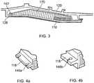
- the first end 112 of the first casing element 110is aligned with the first end 122 of the second casing element 120 and is maintained in its radial position relative to the fan blades 130 by an energy absorbing element in the form of a crushable collar 140.
- the energy absorbing elementtakes the form of a fusible or stretchable fastener 142, such as a bolt, as shown in Figure 3 .
- the stretchable bolt 142connects the first end 112 of the first casing element 110 to the first end 122 of the second casing element 120.
- these fasteners 142extend through holes 144 in a forward rail 118 extending across the width of the first end 112 of the first casing element 110.
- these holes 144further comprise slots 146a,146b, as shown in Figures 4a and 4b .
- the use of slotted holesallows the first end 112 of the first casing element 110 to hinge and move axially whilst the fasteners 142 stretch to failure.
- a ratchet retention mechanism 160is provided at the juncture of the first ends 112,122 of the first and second casing elements 110,120.
- This mechanism 160takes the form of a linear rack 162 which is disposed at the first end 122 of the second casing element 120 and a pawl 164 disposed on the first end 112 of the first casing element 110.
- the pawl 164engages with the rack 162 such that the first casing element 110 is able to move radially outwards but is not able to return to its original position.
- the casing assembly 100comprises an infill member 170, in the form of a structural liner positioned between the proximal 114,116 and distal surfaces of the first casing element 110.
- the infill member 170may be formed from a frangible or crushable structure, such as acoustic foam or honeycomb material.
- the honeycomb materialmay be formed from a metal, such as aluminium, or from a non-metallic material, such as NomexTM (a flame resistant aramid material).
- the infill member 170may be formed as a separate, discrete layer positioned between the first and second casing elements 110,120.
- Each first casing element 110includes, on its radially proximal surface 114, an abradable layer 117 (see Figure 5 ).
- the abradable layer 117is attached to the infill member 170.
- An exemplary material for the abradable layer 117is an epoxy resin or a polysulphide sealant, which may be curable at room temperature.
- the abradable layer 117provides a surface against which the fan blade 130 is able to rub and cut a path for itself. For example, the fan blades 130 may rub against the abradable layer 117 and form a seal during normal engine operation.
- a septum layer(not shown) may be provided as an interlayer between the abradable layer 117 and the infill member 170.
- the septum layermay be metallic or may be formed from a carbon fibre and/or glass fibre reinforced composite material.
- the forward portion of the distal face 116 of the first casing element 110is angled relative to the corresponding proximal face 124 of the second casing element 120 such that a void 134 is defined between the first and second casing elements 110,120 at their forward, or first, ends 112,122.
- the relative angled arrangement between the forward portions of the first and second casing elements 110,120results in the forward portion of the first casing element 110 forming a cantilever structure 180.
- the cantilever 180is arranged in the region extending along the first casing element 110 from the first end 112 and having a pivot axis 182 at a mid portion of the first casing element 110.
- the cantilever 180is arranged such that upon release of one of the fan blades 130, the cantilever 180 bends into the void 134 provided between the first and second casing elements 110, 120.
- the length of the cantilever 180is arranged to be large enough to provide purchase for the fan blade 130 and/or to develop enough bending moment to cause collapse of the first casing element 110 at the cantilever pivot 182.
- the distal (radially outer) surface 116 of the first casing element 110may be provided with a linear array of rhomboid apertures 184 (see Figure 5 ) which are formed across the width of the first casing element 110 at the cantilever pivot axis 182.
- the infill member 170is severed at the pivot axis 182.
- the first casing element 110may be provided with apertures 184 of an alternative shape.
- the ply orientation of the structure of the distal surface 116may be locally modified at the pivot axis 182.
- a further alternative arrangementinvolves cutting through the distal surface 116 of the first casing element 110 at the cantilever pivot axis 182 and attaching a strong, flexible material, such as a KevlarTM patch 186, across the pivot axis 182, to form a hinge.
- a strong, flexible materialsuch as a KevlarTM patch 186
- a still further alternative, shown in Figure 7involves cutting through the distal surface 116 of the first casing element 110 and the infill member 170 at the cantilever pivot axis 182 to form a slit 188, and cutting the distal surface 116 to form a plurality of finger portions 192 which extend along the distal surface 116 of the first casing element 110, with a plurality of ligaments 194 therebetween.
- These finger portions 192are attached to the distal surface 116 of the first casing element 110 with alternate finger portions 192 extending towards opposite ends of the first casing element 110.
- the slit 188widens and the hinge point 182 is allowed to fracture the ligaments 194. This results in the separation of the first casing element 110 into two sections with the forward section being allowed to move forwards and radially outwards.
- the finger portions 192serve to retain the two sections of the first casing element 110 together to prevent complete separation while allowing relative movement of the forward section.
- the slit 188may be filled with, for example, a non-setting filler or low tensile strength filler material. This would allow for the transmission of compressive loads across the slit 188 whilst allowing the slit 188 to open when the forward section of the first casing element 110 hinges about the hinge portion 182.
- the second casing element 120comprises a fan blade retaining feature 128 disposed at a forward, or first, end thereof, in the form of a hooked portion 128.
- the hooked portion 128extends radially inwardly and then axially in a rearward direction, and corresponds to the hook 18 of Figure 1 .
- a fan blade 130In use, if a fan blade 130 becomes detached, it first strikes the proximal surface 114 of the forward portion of the first casing element 110. The energy associated with this impact event is then transferred to and absorbed by the energy absorbing element, for example by the compressive crushing of the crushable collar 140 and the infill member 170. This allows the forward portion of the first casing element 110 to deform radially outwards, exposing the hook 128. As the detached blade 130 continues to travel forwards and radially outwards, the blade tip engages with the hook 128 and subsequently becomes trapped in the casing assembly 100, thus preventing the blade 130 from travelling forward of the first end 122 of the second casing element 120.
- a fan casing assemblynot forming part of the present invention, is designated generally by the reference numeral 200.
- Features of the fan casing assembly 200 which correspond to those of fan casing assembly 100have been given corresponding reference numerals for ease of reference.
- the fan casing assembly 200has a first casing element 210 and a second casing element 120.
- the first casing element 210has a first end 212, a radially proximal surface 214 and a radially distal surface 216.
- the radially distal surface 216 of the first casing element 210corresponds to the radially proximal surface 124 of the second casing element 120.
- a rigid, hollow or fluid filled pocket 230is disposed between the radially proximal and distal surfaces 214,216 at the first end 212 of the first casing element 210 and extends from the first end 212 towards a mid portion of the first casing element 210.
- An infill member 270extends from the pocket 230 at the mid portion of the first casing element 210 to the rear end thereof.
- the pocket 230is filled with a pressurised gas.
- the pocket 230may be filled with a liquid such as, for example, an epoxy resin. It may be advantageous for the epoxy resin to cure in response to UV radiation or to include a catalyst which cures in contact with air.
- a two part resin, or adhesive fillermay be utilised in which mixing of the components takes place after the fan blade 130 has penetrated the pockets 230.
- the pocket 230may be formed as a region of foam material 240, as shown in Figure 9 .
- the foam materialmay be provided on its radially innermost surface with an abradable skin.
- a primary pocket 232is disposed at the first end 212 of the first casing element 210 and a plurality of secondary pockets 234 are disposed adjacent to the primary pocket 232 and extending behind a portion of the infill member 270 towards the rear of the first case element 210.
- the primary and secondary pockets 232,234may or may not be in fluid communication with one another. This arrangement can provide a more progressive collapse mechanism to the impact by a fan blade 130.
- the abradable layer 117extends across both the infill member 270 and the fluid-filled pocket 230 on the proximal surface of the first casing element 210.
- the pocket 230itself is formed from a reinforced fabric material such as, for example, carbon fibre or glass fibre reinforced composite materials or a mixture thereof. Other materials, such as thermoplastics and aramid or metallic fibres or foils, may be used to form the pocket.
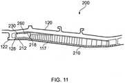
- a cutting portion 250is provided on a forward portion of the fan blade 130. This cutting portion 250 takes the form of a plurality of sharp projections. The position of the cutting portion 250 on the blade tip is arranged such that during a heavy tip rub condition, the cutting portion 250 does not contact the abradable layer 117.
- the cutting portionmay comprise an abrasive coating applied to a portion of the blade tip.
- the cutting portion 260may be disposed on an inner surface of the first casing element 210.
- the cutting portion 250is disposed on an inner surface 218 of the first casing element 210 and is in direct contact with the skin of the pocket 230. Consequently, impact energy applied to the abradable layer 117 is transferred to the cutting portion 260 where it may be applied to the pocket 230.
- a force transfer feature 224is provided within the pocket 230 which transfers a load applied to the proximal surface 214 of the first casing element 210 to the interface between the cutting portion 260 and the pocket. In this way, no modification to the fan blade130 to include a cutting portion 250 is required.
- the force transfer feature 224may be configured (in this embodiment with holes / hollow sections) to allow deformation of the force transfer feature 224 so as not to overly impede the travel of the detached blade 130 on its course to be trapped by the hook 128and the second casing element 120.
- the blade 130In use, when the blade 130 becomes detached, it penetrates the abradable layer 117 and the cutting portion 260 punctures the pocket 230. This allows the blade 130 to travel into the void defined by the pocket and exposes the hook 128 (see Figures 11 and 12 ) which engages with the blade 130 to trap it within the casing assembly 200.
- a fan casing assemblyaccording to a first embodiment of the invention is designated generally by the reference numeral 300.
- Features of the fan casing assembly 300 which correspond to those of fan casing assembly 100have been given corresponding reference numerals for ease of reference.
- the fan casing assembly 300has a first casing element 310 and a second casing element 120.
- the first casing element 310has a first end 312, a radially proximal surface 314 and a radially distal surface 316.
- the radially distal surface 316 of the first casing element 310abuts against the radially proximal surface 124 of the second casing element 120.
- the first casing element 310includes, on its radially proximal surface, an abradable layer 117 which is attached to an infill member 370.
- the abradable layer 117has a proximal surface 350 and a distal surface 352.
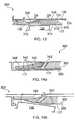
- the forward portion of the first casing element 310comprises a plurality of resilient leaf elements 340 arranged in a stack and aligned with the axis of the fan casing assembly 300.
- each leaf element 340increases through the stack in a radially outward direction.
- the shortest leaf element 340is immediately adjacent to the abradable layer 117 and the longest is furthest from the abradable layer 117.
- the leaf elements 340are formed from a resilient material such as, for example a thermoplastic, carbon fibre or glass fibre laminate.
- the leaf elements 340are independent of one another and are mounted in a slotted elastomeric binder block 342 which is disposed laterally across the width of the first casing element 310.
- the binder block 342is formed from an elastomeric (rubber) material. In other embodiments, the binder block 342 may be formed from an alternative resilient material.
- the binder block 342abuts the forward edge of the infill member 370 and is angled rearwards.
- the leaf elements 340are biased towards the proximal surface 314 of the first case element 310 and they may be through stitched 346 to maintain them in their biased position. In this way, the biased stack of leaf elements 340 abuts the distal face 352 of the abradable layer 117.
- the forward ends of the plurality of resilient leaf elements 340extend beyond the first end 312 of the first casing element 310 and are arranged to contact a distal surface of the hook 128.
- a blade130In use, when a blade130 becomes detached, it penetrates the abradable layer 117 and impacts the stack of resilient leaf elements 340. Some of the energy of the impact is dissipated in tearing the stitching 346 which holds the stack of leaf elements 340 together which results in the elements 346 deflecting and returning to their straight configuration. This in turn exposes the hook 128 which engages with the blade 130 to trap it within the casing assembly 300.
- the casing assemblies disclosed hereinare equally applicable to solid and hollow fan blades and may be used with light-weight (hollow line-core, or solid or hollow composite) fan blades.
- the casing assembliesmay also be used with aerofoil structures, e.g. fan blades, comprising a principal load-carrying member at the front of the aerofoil structure such as a picture frame or metallic sheath.
- aerofoil structurese.g. fan blades, comprising a principal load-carrying member at the front of the aerofoil structure such as a picture frame or metallic sheath.
- the present disclosuremay also be applied to swept or unswept aerofoil structures.
Landscapes
- Engineering & Computer Science (AREA)
- Mechanical Engineering (AREA)
- General Engineering & Computer Science (AREA)
- Structures Of Non-Positive Displacement Pumps (AREA)
Description
- This invention relates to a turbomachine casing assembly and particularly, but not exclusively, to a casing assembly for the fan of a turbofan gas turbine engine.
- Turbofan gas turbine engines for powering aircraft generally compriseinter alia a core engine, which drives a fan. The fan comprises a number of radially extending fan blades mounted on a fan rotor which is enclosed by a generally cylindrical fan casing.
- To satisfy regulatory requirements, such engines are required to demonstrate that if part or all of a fan blade were to become detached from the remainder of the fan, that the detached parts are suitably captured within the engine containment system.
- It is known to provide the fan casing with a fan track liner which together incorporate a containment system, designed to contain any released blades or associated debris.
Figure 1 shows a partial cross-section of such a casing and fan track liner. - In the event of a "fan blade off" (FBO) event, the
detached fan blade 8 travels radially outward and forwards. In doing so, it penetrates theattrition liner 10. It may also penetrate theseptum 12 andaluminium honeycomb layer 14 before engaging thehook 18. The fan track liner must therefore be relatively weak in order that any released blade or fragment thereof can pass through it essentially unimpeded and subsequently be trapped by the fan casing. - In addition to providing a blade containment system, the fan track liner includes an annular layer of abradable material which surrounds the fan blades. During operation of the engine, the fan blades rotate freely within the fan track liner. At their maximum extension of movement and/or creep, or during an extreme event, the blades may cut a path into this abradable layer creating a seal against the fan casing and minimising air leakage around the blade tips.
- The fan track liner must also be resistant to ice impact loads. A rearward portion of the fan track liner is conventionally provided with an annular ice impact panel. This is typically a glass-reinforced plastic (GRP) moulding which may also be wrapped with GRP to increase its impact strength. Ice which forms on the fan blades is acted on by both centrifugal and airflow forces, which respectively cause it to move outwards and rearwards before being shed from the blades.
- The geometry of a conventional fan blade is such that the ice is shed from the trailing edge of the blade, strikes the ice impact panel and is deflected without damaging the panel.
US 5,431,532 discloses a blade containment system which includes an annular casing positioned radially outward of the blades and in surrounding relationship therewith. The annular casing including a plurality of composite tapes bonded to the outer or inner radial surfaces thereof, wherein the composite tapes limit the propagation of cracks and holes formed in the annular casing.EP 2 305 985 A2 discloses a containment assembly for a turbo fan engine, comprising a casing arranged in use around a rotatable fan, to form a duct for the fan. The containment assembly comprises at least one liner element disposed on an interior surface between the casing and blades of the rotatable fan, with the liner element comprising a body portion mounted in a recess in the casing and a wall portion arranged to form part of an inner wall of the duct. The wall portion and the body portion are attached, and define a containment cavity therebetween for containment of a detached fan blade fragment in use. The wall portion comprises a moveable portion which is movable between a first configuration in which it lies substantially flush with the inner wall of the duct, and a second configuration in which it provides an opening through which a fan blade fragment can enter the containment cavity.- Swept fan blades are increasingly used in turbofan engines as they offer significant advantages in efficiency over conventional fan blades. Swept fan blades have a greater chord length at their central portion than conventional fan blades. This greater chordal length means that ice that forms on a swept fan blade follows the same rearward and outward path as on a conventional fan blade but may reach the radially outer tip of the blade before it reaches the trailing edge. It will therefore be shed from the blade tip and may strike the fan track liner forward of the ice impact panel within the blade off zone.
- The liner used with a swept fan blade is therefore required to be strong enough to resist ice impact whilst allowing a detached fan blade to penetrate and be contained therewithin.
- In recent years there has been a trend towards the use of lighter fan blades, which are typically either of hollow metal or of composite construction. These lighter blades have a similar impact energy per unit area as an ice sheet, which makes it more difficult to devise a casing arrangement that will resist the passage of ice and yet not interfere with the trajectory of a released fan blade.
- It is an objective of this invention to provide a gas turbine engine containment assembly that will substantially overcome the problems described above, and that is particularly suited for use with composite, hollow metallic, or other lightweight, fan blades.
- According to a first aspect of the present invention there is provided a turbomachine casing assembly, comprising:
- a first casing element locatable radially outward of one or more rotating aerofoil elements of a turbomachine;
- a second casing element located radially outward of the first casing element; and
- a void, provided between the first casing element and the second casing element, at a first end of the first casing element;
- wherein the first end of the first casing element is located against a corresponding first end of the second casing element by a plurality of resilient leaf elements, the leaf elements being biased towards a radially proximal face of the first casing element, and
- the first casing element comprises a cantilever, the cantilever being arranged in a region extending along the first casing element from the first end and having a pivot axis at a mid portion of the first casing element;
- whereby upon release of one of the rotating aerofoil elements, the cantilever bends into the void provided between the first and second casing elements, which causes the resilient leaf elements to deform and to thereby absorb at least some of the impact energy resulting from the released rotating aerofoil element wherein the first casing element comprises an infill element disposed between the proximal and distal faces thereof, and wherein the plurality of leaf elements are each bonded to a first end of the infill element.
- The casing assembly of the present invention allows a shed fan blade to penetrate the first casing element at a first, or forward, end, whilst remaining rigid to ice impact at the opposite, or rear, end. The competing requirements of fan blade ice shedding loads and fan blade off loads may thus be accommodated in a way that was not previously possible. The manner in which this is done allows for the potential to tune the casing assembly to correctly service each requirement and does so whilst saving weight and easing manufacture.
- In addition, by forming a void within the casing assembly, the weight of the assembly can be reduced. This increases the efficiency of the engine and thus makes it more attractive for aircraft applications.
- The use of a plurality of leaf elements provides a simple and effective means of providing an energy absorbing element which occupies a minimum volume of space.
- Optionally, the or each leaf element is formed from a material selected from the group comprising thermoplastic, carbon fibre and glass fibre materials and composites thereof.
- Optionally, an end of each of the plurality of leaf elements is bonded to a binder block, the binder block being attached to the first end of the infill element.
- The use of a binder block to accommodate an end of each of the leaf elements makes the assembly of the first casing element easier and more convenient.
- Optionally, each of the plurality of leaf elements is attached to one another.
- Optionally, each of the plurality of leaf elements is attached to one another by through stitching.
- In one embodiment of the present invention the plurality of leaf elements are through stitched to one another. In other arrangements, the leaf elements may be adhesively bonded to one another.
- Other aspects of the invention provide devices, methods and systems which include and/or implement some or all of the actions described herein. The illustrative aspects of the invention are designed to solve one or more of the problems herein described and/or one or more other problems not discussed.
- There now follows a description of preferred embodiments of the invention, by way of non-limiting example, with reference being made to the accompanying drawings in which:
Figure 1 shows a partial, sectional view of a conventional fan track liner as used in a gas turbine engine casing;Figure 2 shows a partial, sectional view of a fan casing assembly, not forming part of the present invention;Figure 3 shows a partial, sectional view of a fan casing assembly, not forming part of the present invention;Figures 4a and 4b show details of alternative fastening arrangements for the fan casing assembly ofFigure 3 ;Figure 5 shows a perspective view of a fan track liner, not forming part of the present invention;Figure 6 shows a partial, perspective view of a fan track liner, not forming part of the present invention;Figure 7 shows a perspective view of a fan track liner, not forming part of the present invention;Figure 8 shows a partial, sectional view of a fan casing assembly, not forming part of the present invention;Figure 9 shows a partial, sectional view of a fan casing assembly, not forming part of the present invention;Figure 10 shows a partial, sectional view of an alternative arrangement of the fan casing assembly ofFigure 8 ;Figure 11 shows a partial, sectional view of the fan casing assembly ofFigure 8 in which the pocket incorporates one or more cutting features;Figure 12 shows a partial, sectional view of the fan casing assembly ofFigure 8 including a force transfer feature incorporating a cutting feature;Figure 13 shows a partial, sectional view of a fan casing assembly according to a first embodiment of the invention; andFigures 14a and 14b show partial, sectional views of the fan casing assembly ofFigure 13 , before and after the impact of a fan blade.- It is noted that the drawings may not be to scale. The drawings are intended to depict only typical aspects of the invention, and therefore should not be considered as limiting the scope of the invention. In the drawings, like numbering represents like elements between the drawings.
- Referring to
Figure 2 , a fan casing assembly, not forming part of the present invention, is designated generally by thereference numeral 100 and comprises afirst casing element 110 and asecond casing element 120. - The
first casing element 110 has afirst end 112, a radiallyproximal surface 114 and a radiallydistal surface 116, and thesecond casing element 120 has afirst end 122, a radiallyproximal surface 124 and a radiallydistal surface 126. - The
first casing element 110 at least partially encloses one or morerotating aerofoil structures 130. Theseaerofoil structures 130 may comprise blades of a turbomachine, in particular compressor fan blades. Thesecond casing element 120 is disposed radially distal to thefirst casing element 110. - The
turbomachine casing assembly 100 comprises a plurality offirst casing elements 110 circumferentially disposed about a curve defined by the blade tip path of the one ormore aerofoil structures 130 of the turbomachine. The first and/or second casing elements 110,120 may typically be metallic and may, for example, be formed of aluminium, titanium, steel or any other suitable metal. The first and/or second casing elements 110,120 may typically be formed from fibre reinforced composite materials which may include some integral metallic features. - The
first end 112 of thefirst casing element 110 is aligned with thefirst end 122 of thesecond casing element 120 and is maintained in its radial position relative to thefan blades 130 by an energy absorbing element in the form of acrushable collar 140. - In an alternative arrangement, the energy absorbing element takes the form of a fusible or
stretchable fastener 142, such as a bolt, as shown inFigure 3 . Thestretchable bolt 142 connects thefirst end 112 of thefirst casing element 110 to thefirst end 122 of thesecond casing element 120. As shown inFigure 5 , thesefasteners 142 extend throughholes 144 in aforward rail 118 extending across the width of thefirst end 112 of thefirst casing element 110. As a further alternative, theseholes 144further comprise slots Figures 4a and 4b . The use of slotted holes allows thefirst end 112 of thefirst casing element 110 to hinge and move axially whilst thefasteners 142 stretch to failure. - A
ratchet retention mechanism 160 is provided at the juncture of the first ends 112,122 of the first and second casing elements 110,120. Thismechanism 160 takes the form of alinear rack 162 which is disposed at thefirst end 122 of thesecond casing element 120 and apawl 164 disposed on thefirst end 112 of thefirst casing element 110. Thepawl 164 engages with therack 162 such that thefirst casing element 110 is able to move radially outwards but is not able to return to its original position. - The
casing assembly 100 comprises aninfill member 170, in the form of a structural liner positioned between the proximal 114,116 and distal surfaces of thefirst casing element 110. Theinfill member 170 may be formed from a frangible or crushable structure, such as acoustic foam or honeycomb material. - The honeycomb material may be formed from a metal, such as aluminium, or from a non-metallic material, such as Nomex™ (a flame resistant aramid material).
- In an alternative embodiment not forming part of the present invention, the
infill member 170 may be formed as a separate, discrete layer positioned between the first and second casing elements 110,120. - Each
first casing element 110 includes, on its radiallyproximal surface 114, an abradable layer 117 (seeFigure 5 ). Theabradable layer 117 is attached to theinfill member 170. An exemplary material for theabradable layer 117 is an epoxy resin or a polysulphide sealant, which may be curable at room temperature. Theabradable layer 117 provides a surface against which thefan blade 130 is able to rub and cut a path for itself. For example, thefan blades 130 may rub against theabradable layer 117 and form a seal during normal engine operation. - Optionally, a septum layer (not shown) may be provided as an interlayer between the
abradable layer 117 and theinfill member 170. The septum layer may be metallic or may be formed from a carbon fibre and/or glass fibre reinforced composite material. - As shown in
Figure 2 , the forward portion of thedistal face 116 of thefirst casing element 110 is angled relative to the correspondingproximal face 124 of thesecond casing element 120 such that avoid 134 is defined between the first and second casing elements 110,120 at their forward, or first, ends 112,122. - The relative angled arrangement between the forward portions of the first and second casing elements 110,120 results in the forward portion of the
first casing element 110 forming acantilever structure 180. Thecantilever 180 is arranged in the region extending along thefirst casing element 110 from thefirst end 112 and having apivot axis 182 at a mid portion of thefirst casing element 110. - The
cantilever 180 is arranged such that upon release of one of thefan blades 130, thecantilever 180 bends into the void 134 provided between the first andsecond casing elements cantilever 180 is arranged to be large enough to provide purchase for thefan blade 130 and/or to develop enough bending moment to cause collapse of thefirst casing element 110 at thecantilever pivot 182. - The distal (radially outer)
surface 116 of thefirst casing element 110 may be provided with a linear array of rhomboid apertures 184 (seeFigure 5 ) which are formed across the width of thefirst casing element 110 at thecantilever pivot axis 182. In addition, theinfill member 170 is severed at thepivot axis 182. - In other arrangements, the
first casing element 110 may be provided withapertures 184 of an alternative shape. Alternatively, in preference to providingapertures 184 on thedistal surface 116, the ply orientation of the structure of thedistal surface 116 may be locally modified at thepivot axis 182. - A further alternative arrangement, shown in
Figure 6 , involves cutting through thedistal surface 116 of thefirst casing element 110 at thecantilever pivot axis 182 and attaching a strong, flexible material, such as aKevlar™ patch 186, across thepivot axis 182, to form a hinge. - A still further alternative, shown in
Figure 7 , involves cutting through thedistal surface 116 of thefirst casing element 110 and theinfill member 170 at thecantilever pivot axis 182 to form aslit 188, and cutting thedistal surface 116 to form a plurality offinger portions 192 which extend along thedistal surface 116 of thefirst casing element 110, with a plurality ofligaments 194 therebetween. Thesefinger portions 192 are attached to thedistal surface 116 of thefirst casing element 110 withalternate finger portions 192 extending towards opposite ends of thefirst casing element 110. - When the forward section of
casing element 116 is forced outwards, theslit 188 widens and thehinge point 182 is allowed to fracture theligaments 194. This results in the separation of thefirst casing element 110 into two sections with the forward section being allowed to move forwards and radially outwards. Thefinger portions 192 serve to retain the two sections of thefirst casing element 110 together to prevent complete separation while allowing relative movement of the forward section. - In an alternative embodiment not forming part of the present invention, the
slit 188 may be filled with, for example, a non-setting filler or low tensile strength filler material. This would allow for the transmission of compressive loads across theslit 188 whilst allowing theslit 188 to open when the forward section of thefirst casing element 110 hinges about thehinge portion 182. - The
second casing element 120 comprises a fanblade retaining feature 128 disposed at a forward, or first, end thereof, in the form of a hookedportion 128. The hookedportion 128 extends radially inwardly and then axially in a rearward direction, and corresponds to thehook 18 ofFigure 1 . - In use, if a
fan blade 130 becomes detached, it first strikes theproximal surface 114 of the forward portion of thefirst casing element 110. The energy associated with this impact event is then transferred to and absorbed by the energy absorbing element, for example by the compressive crushing of thecrushable collar 140 and theinfill member 170. This allows the forward portion of thefirst casing element 110 to deform radially outwards, exposing thehook 128. As thedetached blade 130 continues to travel forwards and radially outwards, the blade tip engages with thehook 128 and subsequently becomes trapped in thecasing assembly 100, thus preventing theblade 130 from travelling forward of thefirst end 122 of thesecond casing element 120. - Referring to
Figures 8 and 9 , a fan casing assembly, not forming part of the present invention, is designated generally by thereference numeral 200. Features of thefan casing assembly 200 which correspond to those offan casing assembly 100 have been given corresponding reference numerals for ease of reference. - The
fan casing assembly 200 has afirst casing element 210 and asecond casing element 120. - In this embodiment, the
first casing element 210 has afirst end 212, a radiallyproximal surface 214 and a radiallydistal surface 216. The radiallydistal surface 216 of thefirst casing element 210 corresponds to the radiallyproximal surface 124 of thesecond casing element 120. - A rigid, hollow or fluid filled
pocket 230 is disposed between the radially proximal and distal surfaces 214,216 at thefirst end 212 of thefirst casing element 210 and extends from thefirst end 212 towards a mid portion of thefirst casing element 210. Aninfill member 270 extends from thepocket 230 at the mid portion of thefirst casing element 210 to the rear end thereof. - While the embodiment described shows a
single pocket 230, in other arrangements there may be two or more pockets. - The
pocket 230 is filled with a pressurised gas. Alternatively, thepocket 230 may be filled with a liquid such as, for example, an epoxy resin. It may be advantageous for the epoxy resin to cure in response to UV radiation or to include a catalyst which cures in contact with air. In arrangements in which there is more than onepocket 230, a two part resin, or adhesive filler, may be utilised in which mixing of the components takes place after thefan blade 130 has penetrated thepockets 230. - Alternatively, the
pocket 230 may be formed as a region offoam material 240, as shown inFigure 9 . In the arrangement ofFigure 9 , the foam material may be provided on its radially innermost surface with an abradable skin. - In an alternative arrangement, shown in
Figure 10 , aprimary pocket 232 is disposed at thefirst end 212 of thefirst casing element 210 and a plurality ofsecondary pockets 234 are disposed adjacent to theprimary pocket 232 and extending behind a portion of theinfill member 270 towards the rear of thefirst case element 210. The primary and secondary pockets 232,234 may or may not be in fluid communication with one another. This arrangement can provide a more progressive collapse mechanism to the impact by afan blade 130. - The
abradable layer 117 extends across both theinfill member 270 and the fluid-filledpocket 230 on the proximal surface of thefirst casing element 210. - The
pocket 230 itself is formed from a reinforced fabric material such as, for example, carbon fibre or glass fibre reinforced composite materials or a mixture thereof. Other materials, such as thermoplastics and aramid or metallic fibres or foils, may be used to form the pocket. - A cutting
portion 250 is provided on a forward portion of thefan blade 130. This cuttingportion 250 takes the form of a plurality of sharp projections. The position of the cuttingportion 250 on the blade tip is arranged such that during a heavy tip rub condition, the cuttingportion 250 does not contact theabradable layer 117. - In other arrangements, the cutting portion may comprise an abrasive coating applied to a portion of the blade tip.
- Alternatively, as shown in
Figures 11 and12 , the cuttingportion 260 may be disposed on an inner surface of thefirst casing element 210. In these arrangements, the cuttingportion 250 is disposed on aninner surface 218 of thefirst casing element 210 and is in direct contact with the skin of thepocket 230. Consequently, impact energy applied to theabradable layer 117 is transferred to the cuttingportion 260 where it may be applied to thepocket 230. - In the arrangement of
Figure 12 , aforce transfer feature 224 is provided within thepocket 230 which transfers a load applied to theproximal surface 214 of thefirst casing element 210 to the interface between the cuttingportion 260 and the pocket. In this way, no modification to the fan blade130 to include a cuttingportion 250 is required. As shown inFigure 12 , theforce transfer feature 224 may be configured (in this embodiment with holes / hollow sections) to allow deformation of theforce transfer feature 224 so as not to overly impede the travel of thedetached blade 130 on its course to be trapped by the hook 128and thesecond casing element 120. - In use, when the
blade 130 becomes detached, it penetrates theabradable layer 117 and the cuttingportion 260 punctures thepocket 230. This allows theblade 130 to travel into the void defined by the pocket and exposes the hook 128 (seeFigures 11 and12 ) which engages with theblade 130 to trap it within thecasing assembly 200. - Referring to
Figures 13 and 14 , a fan casing assembly according to a first embodiment of the invention is designated generally by thereference numeral 300. Features of thefan casing assembly 300 which correspond to those offan casing assembly 100 have been given corresponding reference numerals for ease of reference. - The
fan casing assembly 300 has a first casing element 310 and asecond casing element 120. - In this embodiment, the first casing element 310 has a
first end 312, a radiallyproximal surface 314 and a radiallydistal surface 316. The radiallydistal surface 316 of the first casing element 310 abuts against the radiallyproximal surface 124 of thesecond casing element 120. - The first casing element 310 includes, on its radially proximal surface, an
abradable layer 117 which is attached to an infill member 370. Theabradable layer 117 has aproximal surface 350 and adistal surface 352. - The forward portion of the first casing element 310 comprises a plurality of
resilient leaf elements 340 arranged in a stack and aligned with the axis of thefan casing assembly 300. - In this embodiment, the length of each
leaf element 340 increases through the stack in a radially outward direction. Thus theshortest leaf element 340 is immediately adjacent to theabradable layer 117 and the longest is furthest from theabradable layer 117. - The
leaf elements 340 are formed from a resilient material such as, for example a thermoplastic, carbon fibre or glass fibre laminate. - The
leaf elements 340 are independent of one another and are mounted in a slottedelastomeric binder block 342 which is disposed laterally across the width of the first casing element 310. In this embodiment, thebinder block 342 is formed from an elastomeric (rubber) material. In other embodiments, thebinder block 342 may be formed from an alternative resilient material. - The
binder block 342 abuts the forward edge of the infill member 370 and is angled rearwards. Theleaf elements 340 are biased towards theproximal surface 314 of the first case element 310 and they may be through stitched 346 to maintain them in their biased position. In this way, the biased stack ofleaf elements 340 abuts thedistal face 352 of theabradable layer 117. - The forward ends of the plurality of
resilient leaf elements 340 extend beyond thefirst end 312 of the first casing element 310 and are arranged to contact a distal surface of thehook 128. - In use, when a blade130 becomes detached, it penetrates the
abradable layer 117 and impacts the stack ofresilient leaf elements 340. Some of the energy of the impact is dissipated in tearing thestitching 346 which holds the stack ofleaf elements 340 together which results in theelements 346 deflecting and returning to their straight configuration. This in turn exposes thehook 128 which engages with theblade 130 to trap it within thecasing assembly 300. - The casing assemblies disclosed herein are equally applicable to solid and hollow fan blades and may be used with light-weight (hollow line-core, or solid or hollow composite) fan blades. The casing assemblies may also be used with aerofoil structures, e.g. fan blades, comprising a principal load-carrying member at the front of the aerofoil structure such as a picture frame or metallic sheath. The present disclosure may also be applied to swept or unswept aerofoil structures.
- The foregoing description of various aspects of the invention has been presented for purposes of illustration and description. It is not intended to be exhaustive or to limit the invention to the precise form disclosed, and obviously, many modifications and variations are possible. Such modifications and variations that may be apparent to a person of skill in the art are included within the scope of the invention as defined by the accompanying claims.
Claims (8)
- A turbomachine casing assembly (300), comprising:a first casing element (310)configured to be located radially outward of one or more rotating aerofoil elements (130) of a turbomachine;a second casing element (120) located radially outward of the first casing element (310); anda void, provided between the first casing element (310) and the second casing element (120), at a first end (312) of the first casing element (310);wherein the first end (312) of the first casing element (310) is located against a corresponding first end of the second casing element (120) by a plurality of resilient leaf elements (340), the leaf elements (340) being biased towards a radially proximal face (314) of the first casing element (310), andthe first casing element (310) comprises a cantilever (180), the cantilever (180) being arranged in a region extending along the first casing element (310) from the first end and having a pivot axis at a mid portion of the first casing element (310);whereby upon release of one of the rotating aerofoil elements (130), the cantilever (180) is configured to bend into the void provided between the first and second casing elements (310,120), which causes the resilient leaf elements (340) to deform and to thereby absorb at least some of the impact energy resulting from the released rotating aerofoil element (130),wherein the first casing element (310) comprises an infill element (370) disposed between the proximal face (314) and the distal face (316) thereof, and wherein the plurality of leaf elements (340) are each bonded to a first end of the infill element (370).
- A turbomachine casing assembly (300) as claimed in Claim 1, wherein the or each leaf element (340) is formed from a material selected from the group comprising thermoplastic, carbon fibre and glass fibre materials and composites thereof.
- A turbomachine casing assembly (300) as claimed in Claim 1, wherein an end of each of the plurality of leaf elements (340) is bonded to a binder block (342), the binder block (342) being attached to the first end of the infill element (370).
- A turbomachine casing element (300) as claimed in any one of Claims 1 to 3, wherein each of the plurality of leaf elements (340) is attached to one another.
- A turbomachine casing assembly (300) as claimed in Claim 4, wherein each of the plurality of leaf elements (340) is attached to one another by through stitching.
- A turbomachine casing assembly (300) as claimed in any one of Claims 1 to 5, wherein the radially proximal face (314) of the first casing element (310) is contiguous with the radially proximal face (124) of the second casing element (120) to form an uninterrupted surface.
- A gas turbine engine fan casing comprising the turbomachine casing assembly (300) as claimed in any one of Claims 1 to 6.
- A gas turbine comprising a turbomachine casing assembly (300) as claimed in any one of Claims 1 to 6.
Applications Claiming Priority (1)
| Application Number | Priority Date | Filing Date | Title |
|---|---|---|---|
| GBGB1201180.5AGB201201180D0 (en) | 2011-03-04 | 2012-01-25 | A turbomachine casing assembly |
Publications (2)
| Publication Number | Publication Date |
|---|---|
| EP2620654A1 EP2620654A1 (en) | 2013-07-31 |
| EP2620654B1true EP2620654B1 (en) | 2016-03-30 |
Family
ID=47519992
Family Applications (1)
| Application Number | Title | Priority Date | Filing Date |
|---|---|---|---|
| EP13151240.2ANot-in-forceEP2620654B1 (en) | 2012-01-25 | 2013-01-15 | A turbomachine casing assembly with blade containment cavity |
Country Status (1)
| Country | Link |
|---|---|
| EP (1) | EP2620654B1 (en) |
Families Citing this family (7)
| Publication number | Priority date | Publication date | Assignee | Title |
|---|---|---|---|---|
| EP2876289B1 (en) | 2013-11-21 | 2016-03-30 | Rolls-Royce plc | Fan containment system for a gas turbine engine |
| EP2902592B1 (en)* | 2014-01-31 | 2017-04-12 | Rolls-Royce plc | Gas turbine engine |
| GB201401767D0 (en)* | 2014-02-03 | 2014-03-19 | Rolls Royce Plc | Gas turbine engine |
| GB201408688D0 (en)* | 2014-05-16 | 2014-07-02 | Rolls Royce Plc | Gas turbine engine |
| GB201417415D0 (en)* | 2014-10-02 | 2014-11-19 | Rolls Royce Plc | Fan track liner assembly |
| GB201417416D0 (en) | 2014-10-02 | 2014-11-19 | Rolls Royce Plc | Fan track liner assembly |
| US10808539B2 (en)* | 2016-07-25 | 2020-10-20 | Raytheon Technologies Corporation | Rotor blade for a gas turbine engine |
Family Cites Families (3)
| Publication number | Priority date | Publication date | Assignee | Title |
|---|---|---|---|---|
| US5431532A (en)* | 1994-05-20 | 1995-07-11 | General Electric Company | Blade containment system |
| DE102006036648A1 (en)* | 2006-08-03 | 2008-02-07 | Rolls-Royce Deutschland Ltd & Co Kg | Ice protection ring for the fan housing of an aircraft gas turbine |
| GB0916823D0 (en)* | 2009-09-25 | 2009-11-04 | Rolls Royce Plc | Containment casing for an aero engine |
- 2013
- 2013-01-15EPEP13151240.2Apatent/EP2620654B1/ennot_activeNot-in-force
Also Published As
| Publication number | Publication date |
|---|---|
| EP2620654A1 (en) | 2013-07-31 |
Similar Documents
| Publication | Publication Date | Title |
|---|---|---|
| US9206706B2 (en) | Turbomachine casing assembly | |
| EP2620652B1 (en) | Turbomachine casing assembly with blade containment cavity | |
| EP2620654B1 (en) | A turbomachine casing assembly with blade containment cavity | |
| US9085992B2 (en) | Turbomachine casing assembly | |
| EP1277919B1 (en) | Joint arrangement | |
| EP2336500B1 (en) | Method of manufacturing an inlet assembly for an aircraft engine | |
| EP2096269B1 (en) | Fan track liner assembly for a gas turbine engine | |
| EP2876289B1 (en) | Fan containment system for a gas turbine engine | |
| US9732626B2 (en) | Turbomachine casing assembly | |
| US9957835B2 (en) | Fan track liner assembly | |
| EP3027856B1 (en) | Fan track liner | |
| CN111287802A (en) | Multi-material leading edge protector | |
| JP2017503950A (en) | Composite fan inlet blade containment structure | |
| EP3001040B1 (en) | Gas turbine engine | |
| US9243512B1 (en) | Rotary machine with a frangible composite blade | |
| EP2620653B1 (en) | A turbomachine casing assembly with blade containment cavity | |
| CN107407154B (en) | Fragile composite airfoil | |
| EP4223980B1 (en) | Rotor assembly with structural platforms for gas turbine engines | |
| GB2498194A (en) | Ice impact panel for a gas turbine engine |
Legal Events
| Date | Code | Title | Description |
|---|---|---|---|
| PUAI | Public reference made under article 153(3) epc to a published international application that has entered the european phase | Free format text:ORIGINAL CODE: 0009012 | |
| AK | Designated contracting states | Kind code of ref document:A1 Designated state(s):AL AT BE BG CH CY CZ DE DK EE ES FI FR GB GR HR HU IE IS IT LI LT LU LV MC MK MT NL NO PL PT RO RS SE SI SK SM TR | |
| AX | Request for extension of the european patent | Extension state:BA ME | |
| 17P | Request for examination filed | Effective date:20140130 | |
| RBV | Designated contracting states (corrected) | Designated state(s):AL AT BE BG CH CY CZ DE DK EE ES FI FR GB GR HR HU IE IS IT LI LT LU LV MC MK MT NL NO PL PT RO RS SE SI SK SM TR | |
| 17Q | First examination report despatched | Effective date:20150216 | |
| RAP1 | Party data changed (applicant data changed or rights of an application transferred) | Owner name:ROLLS-ROYCE PLC | |
| REG | Reference to a national code | Ref country code:DE Ref legal event code:R079 Ref document number:602013005819 Country of ref document:DE Free format text:PREVIOUS MAIN CLASS: F04D0029520000 Ipc:F01D0021040000 | |
| GRAP | Despatch of communication of intention to grant a patent | Free format text:ORIGINAL CODE: EPIDOSNIGR1 | |
| RIC1 | Information provided on ipc code assigned before grant | Ipc:F01D 25/26 20060101ALI20150924BHEP Ipc:F04D 29/52 20060101ALI20150924BHEP Ipc:F01D 25/24 20060101ALI20150924BHEP Ipc:F01D 21/04 20060101AFI20150924BHEP | |
| INTG | Intention to grant announced | Effective date:20151021 | |
| GRAS | Grant fee paid | Free format text:ORIGINAL CODE: EPIDOSNIGR3 | |
| GRAA | (expected) grant | Free format text:ORIGINAL CODE: 0009210 | |
| AK | Designated contracting states | Kind code of ref document:B1 Designated state(s):AL AT BE BG CH CY CZ DE DK EE ES FI FR GB GR HR HU IE IS IT LI LT LU LV MC MK MT NL NO PL PT RO RS SE SI SK SM TR | |
| REG | Reference to a national code | Ref country code:GB Ref legal event code:FG4D | |
| REG | Reference to a national code | Ref country code:CH Ref legal event code:EP | |
| REG | Reference to a national code | Ref country code:AT Ref legal event code:REF Ref document number:785642 Country of ref document:AT Kind code of ref document:T Effective date:20160415 | |
| REG | Reference to a national code | Ref country code:IE Ref legal event code:FG4D | |
| REG | Reference to a national code | Ref country code:DE Ref legal event code:R096 Ref document number:602013005819 Country of ref document:DE | |
| REG | Reference to a national code | Ref country code:LT Ref legal event code:MG4D | |
| PG25 | Lapsed in a contracting state [announced via postgrant information from national office to epo] | Ref country code:FI Free format text:LAPSE BECAUSE OF FAILURE TO SUBMIT A TRANSLATION OF THE DESCRIPTION OR TO PAY THE FEE WITHIN THE PRESCRIBED TIME-LIMIT Effective date:20160330 Ref country code:NO Free format text:LAPSE BECAUSE OF FAILURE TO SUBMIT A TRANSLATION OF THE DESCRIPTION OR TO PAY THE FEE WITHIN THE PRESCRIBED TIME-LIMIT Effective date:20160630 Ref country code:GR Free format text:LAPSE BECAUSE OF FAILURE TO SUBMIT A TRANSLATION OF THE DESCRIPTION OR TO PAY THE FEE WITHIN THE PRESCRIBED TIME-LIMIT Effective date:20160701 Ref country code:HR Free format text:LAPSE BECAUSE OF FAILURE TO SUBMIT A TRANSLATION OF THE DESCRIPTION OR TO PAY THE FEE WITHIN THE PRESCRIBED TIME-LIMIT Effective date:20160330 | |
| REG | Reference to a national code | Ref country code:NL Ref legal event code:MP Effective date:20160330 | |
| REG | Reference to a national code | Ref country code:AT Ref legal event code:MK05 Ref document number:785642 Country of ref document:AT Kind code of ref document:T Effective date:20160330 | |
| PG25 | Lapsed in a contracting state [announced via postgrant information from national office to epo] | Ref country code:LV Free format text:LAPSE BECAUSE OF FAILURE TO SUBMIT A TRANSLATION OF THE DESCRIPTION OR TO PAY THE FEE WITHIN THE PRESCRIBED TIME-LIMIT Effective date:20160330 Ref country code:LT Free format text:LAPSE BECAUSE OF FAILURE TO SUBMIT A TRANSLATION OF THE DESCRIPTION OR TO PAY THE FEE WITHIN THE PRESCRIBED TIME-LIMIT Effective date:20160330 Ref country code:SE Free format text:LAPSE BECAUSE OF FAILURE TO SUBMIT A TRANSLATION OF THE DESCRIPTION OR TO PAY THE FEE WITHIN THE PRESCRIBED TIME-LIMIT Effective date:20160330 Ref country code:RS Free format text:LAPSE BECAUSE OF FAILURE TO SUBMIT A TRANSLATION OF THE DESCRIPTION OR TO PAY THE FEE WITHIN THE PRESCRIBED TIME-LIMIT Effective date:20160330 | |
| PG25 | Lapsed in a contracting state [announced via postgrant information from national office to epo] | Ref country code:NL Free format text:LAPSE BECAUSE OF FAILURE TO SUBMIT A TRANSLATION OF THE DESCRIPTION OR TO PAY THE FEE WITHIN THE PRESCRIBED TIME-LIMIT Effective date:20160330 | |
| PG25 | Lapsed in a contracting state [announced via postgrant information from national office to epo] | Ref country code:PL Free format text:LAPSE BECAUSE OF FAILURE TO SUBMIT A TRANSLATION OF THE DESCRIPTION OR TO PAY THE FEE WITHIN THE PRESCRIBED TIME-LIMIT Effective date:20160330 Ref country code:IS Free format text:LAPSE BECAUSE OF FAILURE TO SUBMIT A TRANSLATION OF THE DESCRIPTION OR TO PAY THE FEE WITHIN THE PRESCRIBED TIME-LIMIT Effective date:20160730 Ref country code:EE Free format text:LAPSE BECAUSE OF FAILURE TO SUBMIT A TRANSLATION OF THE DESCRIPTION OR TO PAY THE FEE WITHIN THE PRESCRIBED TIME-LIMIT Effective date:20160330 | |
| PG25 | Lapsed in a contracting state [announced via postgrant information from national office to epo] | Ref country code:SK Free format text:LAPSE BECAUSE OF FAILURE TO SUBMIT A TRANSLATION OF THE DESCRIPTION OR TO PAY THE FEE WITHIN THE PRESCRIBED TIME-LIMIT Effective date:20160330 Ref country code:AT Free format text:LAPSE BECAUSE OF FAILURE TO SUBMIT A TRANSLATION OF THE DESCRIPTION OR TO PAY THE FEE WITHIN THE PRESCRIBED TIME-LIMIT Effective date:20160330 Ref country code:PT Free format text:LAPSE BECAUSE OF FAILURE TO SUBMIT A TRANSLATION OF THE DESCRIPTION OR TO PAY THE FEE WITHIN THE PRESCRIBED TIME-LIMIT Effective date:20160801 Ref country code:ES Free format text:LAPSE BECAUSE OF FAILURE TO SUBMIT A TRANSLATION OF THE DESCRIPTION OR TO PAY THE FEE WITHIN THE PRESCRIBED TIME-LIMIT Effective date:20160330 Ref country code:RO Free format text:LAPSE BECAUSE OF FAILURE TO SUBMIT A TRANSLATION OF THE DESCRIPTION OR TO PAY THE FEE WITHIN THE PRESCRIBED TIME-LIMIT Effective date:20160330 Ref country code:CZ Free format text:LAPSE BECAUSE OF FAILURE TO SUBMIT A TRANSLATION OF THE DESCRIPTION OR TO PAY THE FEE WITHIN THE PRESCRIBED TIME-LIMIT Effective date:20160330 Ref country code:SM Free format text:LAPSE BECAUSE OF FAILURE TO SUBMIT A TRANSLATION OF THE DESCRIPTION OR TO PAY THE FEE WITHIN THE PRESCRIBED TIME-LIMIT Effective date:20160330 | |
| PG25 | Lapsed in a contracting state [announced via postgrant information from national office to epo] | Ref country code:BE Free format text:LAPSE BECAUSE OF FAILURE TO SUBMIT A TRANSLATION OF THE DESCRIPTION OR TO PAY THE FEE WITHIN THE PRESCRIBED TIME-LIMIT Effective date:20160330 Ref country code:IT Free format text:LAPSE BECAUSE OF FAILURE TO SUBMIT A TRANSLATION OF THE DESCRIPTION OR TO PAY THE FEE WITHIN THE PRESCRIBED TIME-LIMIT Effective date:20160330 | |
| REG | Reference to a national code | Ref country code:DE Ref legal event code:R097 Ref document number:602013005819 Country of ref document:DE | |
| REG | Reference to a national code | Ref country code:FR Ref legal event code:PLFP Year of fee payment:5 | |
| PG25 | Lapsed in a contracting state [announced via postgrant information from national office to epo] | Ref country code:DK Free format text:LAPSE BECAUSE OF FAILURE TO SUBMIT A TRANSLATION OF THE DESCRIPTION OR TO PAY THE FEE WITHIN THE PRESCRIBED TIME-LIMIT Effective date:20160330 | |
| PLBE | No opposition filed within time limit | Free format text:ORIGINAL CODE: 0009261 | |
| STAA | Information on the status of an ep patent application or granted ep patent | Free format text:STATUS: NO OPPOSITION FILED WITHIN TIME LIMIT | |
| 26N | No opposition filed | Effective date:20170103 | |
| PG25 | Lapsed in a contracting state [announced via postgrant information from national office to epo] | Ref country code:SI Free format text:LAPSE BECAUSE OF FAILURE TO SUBMIT A TRANSLATION OF THE DESCRIPTION OR TO PAY THE FEE WITHIN THE PRESCRIBED TIME-LIMIT Effective date:20160330 | |
| REG | Reference to a national code | Ref country code:CH Ref legal event code:PL | |
| PG25 | Lapsed in a contracting state [announced via postgrant information from national office to epo] | Ref country code:MC Free format text:LAPSE BECAUSE OF FAILURE TO SUBMIT A TRANSLATION OF THE DESCRIPTION OR TO PAY THE FEE WITHIN THE PRESCRIBED TIME-LIMIT Effective date:20160330 | |
| PG25 | Lapsed in a contracting state [announced via postgrant information from national office to epo] | Ref country code:CH Free format text:LAPSE BECAUSE OF NON-PAYMENT OF DUE FEES Effective date:20170131 Ref country code:LI Free format text:LAPSE BECAUSE OF NON-PAYMENT OF DUE FEES Effective date:20170131 | |
| REG | Reference to a national code | Ref country code:IE Ref legal event code:MM4A | |
| PG25 | Lapsed in a contracting state [announced via postgrant information from national office to epo] | Ref country code:LU Free format text:LAPSE BECAUSE OF NON-PAYMENT OF DUE FEES Effective date:20170115 | |
| REG | Reference to a national code | Ref country code:FR Ref legal event code:PLFP Year of fee payment:6 | |
| PG25 | Lapsed in a contracting state [announced via postgrant information from national office to epo] | Ref country code:IE Free format text:LAPSE BECAUSE OF NON-PAYMENT OF DUE FEES Effective date:20170115 | |
| PG25 | Lapsed in a contracting state [announced via postgrant information from national office to epo] | Ref country code:MT Free format text:LAPSE BECAUSE OF NON-PAYMENT OF DUE FEES Effective date:20170115 | |
| PG25 | Lapsed in a contracting state [announced via postgrant information from national office to epo] | Ref country code:AL Free format text:LAPSE BECAUSE OF FAILURE TO SUBMIT A TRANSLATION OF THE DESCRIPTION OR TO PAY THE FEE WITHIN THE PRESCRIBED TIME-LIMIT Effective date:20160330 | |
| PG25 | Lapsed in a contracting state [announced via postgrant information from national office to epo] | Ref country code:HU Free format text:LAPSE BECAUSE OF FAILURE TO SUBMIT A TRANSLATION OF THE DESCRIPTION OR TO PAY THE FEE WITHIN THE PRESCRIBED TIME-LIMIT; INVALID AB INITIO Effective date:20130115 | |
| PG25 | Lapsed in a contracting state [announced via postgrant information from national office to epo] | Ref country code:BG Free format text:LAPSE BECAUSE OF FAILURE TO SUBMIT A TRANSLATION OF THE DESCRIPTION OR TO PAY THE FEE WITHIN THE PRESCRIBED TIME-LIMIT Effective date:20160330 | |
| PG25 | Lapsed in a contracting state [announced via postgrant information from national office to epo] | Ref country code:CY Free format text:LAPSE BECAUSE OF NON-PAYMENT OF DUE FEES Effective date:20160330 | |
| PG25 | Lapsed in a contracting state [announced via postgrant information from national office to epo] | Ref country code:MK Free format text:LAPSE BECAUSE OF FAILURE TO SUBMIT A TRANSLATION OF THE DESCRIPTION OR TO PAY THE FEE WITHIN THE PRESCRIBED TIME-LIMIT Effective date:20160330 | |
| PG25 | Lapsed in a contracting state [announced via postgrant information from national office to epo] | Ref country code:TR Free format text:LAPSE BECAUSE OF FAILURE TO SUBMIT A TRANSLATION OF THE DESCRIPTION OR TO PAY THE FEE WITHIN THE PRESCRIBED TIME-LIMIT Effective date:20160330 | |
| PGFP | Annual fee paid to national office [announced via postgrant information from national office to epo] | Ref country code:GB Payment date:20200127 Year of fee payment:8 Ref country code:DE Payment date:20200129 Year of fee payment:8 | |
| PGFP | Annual fee paid to national office [announced via postgrant information from national office to epo] | Ref country code:FR Payment date:20200127 Year of fee payment:8 | |
| REG | Reference to a national code | Ref country code:DE Ref legal event code:R119 Ref document number:602013005819 Country of ref document:DE | |
| GBPC | Gb: european patent ceased through non-payment of renewal fee | Effective date:20210115 | |
| PG25 | Lapsed in a contracting state [announced via postgrant information from national office to epo] | Ref country code:FR Free format text:LAPSE BECAUSE OF NON-PAYMENT OF DUE FEES Effective date:20210131 | |
| PG25 | Lapsed in a contracting state [announced via postgrant information from national office to epo] | Ref country code:DE Free format text:LAPSE BECAUSE OF NON-PAYMENT OF DUE FEES Effective date:20210803 Ref country code:GB Free format text:LAPSE BECAUSE OF NON-PAYMENT OF DUE FEES Effective date:20210115 |