EP2618947B1 - Imaging transducer array - Google Patents
Imaging transducer arrayDownload PDFInfo
- Publication number
- EP2618947B1 EP2618947B1EP10766111.8AEP10766111AEP2618947B1EP 2618947 B1EP2618947 B1EP 2618947B1EP 10766111 AEP10766111 AEP 10766111AEP 2618947 B1EP2618947 B1EP 2618947B1
- Authority
- EP
- European Patent Office
- Prior art keywords
- transducer
- elements
- sub
- transducer elements
- width
- Prior art date
- Legal status (The legal status is an assumption and is not a legal conclusion. Google has not performed a legal analysis and makes no representation as to the accuracy of the status listed.)
- Active
Links
- 238000003384imaging methodMethods0.000titleclaimsdescription25
- 238000000034methodMethods0.000claimsdescription10
- 230000005855radiationEffects0.000claimsdescription5
- 239000011295pitchSubstances0.000description27
- 238000013459approachMethods0.000description7
- 238000012545processingMethods0.000description5
- 238000002604ultrasonographyMethods0.000description4
- 238000004891communicationMethods0.000description3
- 230000037361pathwayEffects0.000description3
- 238000003491arrayMethods0.000description2
- 230000001419dependent effectEffects0.000description2
- 230000001066destructive effectEffects0.000description2
- 238000002592echocardiographyMethods0.000description2
- 238000011156evaluationMethods0.000description2
- 230000000116mitigating effectEffects0.000description2
- 238000012805post-processingMethods0.000description2
- 238000012285ultrasound imagingMethods0.000description2
- 239000002131composite materialSubstances0.000description1
- 238000013329compoundingMethods0.000description1
- 230000007547defectEffects0.000description1
- 238000001514detection methodMethods0.000description1
- 238000005516engineering processMethods0.000description1
- 238000001914filtrationMethods0.000description1
- 230000006870functionEffects0.000description1
- 230000000977initiatory effectEffects0.000description1
- 239000011159matrix materialSubstances0.000description1
- 238000007639printingMethods0.000description1
- 239000000523sampleSubstances0.000description1
- 230000002123temporal effectEffects0.000description1
- 230000000007visual effectEffects0.000description1
Images


Classifications
- G—PHYSICS
- G01—MEASURING; TESTING
- G01S—RADIO DIRECTION-FINDING; RADIO NAVIGATION; DETERMINING DISTANCE OR VELOCITY BY USE OF RADIO WAVES; LOCATING OR PRESENCE-DETECTING BY USE OF THE REFLECTION OR RERADIATION OF RADIO WAVES; ANALOGOUS ARRANGEMENTS USING OTHER WAVES
- G01S15/00—Systems using the reflection or reradiation of acoustic waves, e.g. sonar systems
- G01S15/88—Sonar systems specially adapted for specific applications
- G01S15/89—Sonar systems specially adapted for specific applications for mapping or imaging
- B—PERFORMING OPERATIONS; TRANSPORTING
- B06—GENERATING OR TRANSMITTING MECHANICAL VIBRATIONS IN GENERAL
- B06B—METHODS OR APPARATUS FOR GENERATING OR TRANSMITTING MECHANICAL VIBRATIONS OF INFRASONIC, SONIC, OR ULTRASONIC FREQUENCY, e.g. FOR PERFORMING MECHANICAL WORK IN GENERAL
- B06B1/00—Methods or apparatus for generating mechanical vibrations of infrasonic, sonic, or ultrasonic frequency
- B06B1/02—Methods or apparatus for generating mechanical vibrations of infrasonic, sonic, or ultrasonic frequency making use of electrical energy
- B06B1/06—Methods or apparatus for generating mechanical vibrations of infrasonic, sonic, or ultrasonic frequency making use of electrical energy operating with piezoelectric effect or with electrostriction
- B06B1/0607—Methods or apparatus for generating mechanical vibrations of infrasonic, sonic, or ultrasonic frequency making use of electrical energy operating with piezoelectric effect or with electrostriction using multiple elements
- B06B1/0622—Methods or apparatus for generating mechanical vibrations of infrasonic, sonic, or ultrasonic frequency making use of electrical energy operating with piezoelectric effect or with electrostriction using multiple elements on one surface
- B06B1/0629—Square array
- G—PHYSICS
- G01—MEASURING; TESTING
- G01S—RADIO DIRECTION-FINDING; RADIO NAVIGATION; DETERMINING DISTANCE OR VELOCITY BY USE OF RADIO WAVES; LOCATING OR PRESENCE-DETECTING BY USE OF THE REFLECTION OR RERADIATION OF RADIO WAVES; ANALOGOUS ARRANGEMENTS USING OTHER WAVES
- G01S15/00—Systems using the reflection or reradiation of acoustic waves, e.g. sonar systems
- G01S15/88—Sonar systems specially adapted for specific applications
- G01S15/89—Sonar systems specially adapted for specific applications for mapping or imaging
- G01S15/8906—Short-range imaging systems; Acoustic microscope systems using pulse-echo techniques
- G01S15/8909—Short-range imaging systems; Acoustic microscope systems using pulse-echo techniques using a static transducer configuration
- G01S15/8915—Short-range imaging systems; Acoustic microscope systems using pulse-echo techniques using a static transducer configuration using a transducer array
- G—PHYSICS
- G01—MEASURING; TESTING
- G01S—RADIO DIRECTION-FINDING; RADIO NAVIGATION; DETERMINING DISTANCE OR VELOCITY BY USE OF RADIO WAVES; LOCATING OR PRESENCE-DETECTING BY USE OF THE REFLECTION OR RERADIATION OF RADIO WAVES; ANALOGOUS ARRANGEMENTS USING OTHER WAVES
- G01S7/00—Details of systems according to groups G01S13/00, G01S15/00, G01S17/00
- G01S7/52—Details of systems according to groups G01S13/00, G01S15/00, G01S17/00 of systems according to group G01S15/00
- G01S7/52017—Details of systems according to groups G01S13/00, G01S15/00, G01S17/00 of systems according to group G01S15/00 particularly adapted to short-range imaging
- G01S7/52046—Techniques for image enhancement involving transmitter or receiver
- G01S7/52047—Techniques for image enhancement involving transmitter or receiver for elimination of side lobes or of grating lobes; for increasing resolving power
- G—PHYSICS
- G01—MEASURING; TESTING
- G01S—RADIO DIRECTION-FINDING; RADIO NAVIGATION; DETERMINING DISTANCE OR VELOCITY BY USE OF RADIO WAVES; LOCATING OR PRESENCE-DETECTING BY USE OF THE REFLECTION OR RERADIATION OF RADIO WAVES; ANALOGOUS ARRANGEMENTS USING OTHER WAVES
- G01S15/00—Systems using the reflection or reradiation of acoustic waves, e.g. sonar systems
- G01S15/88—Sonar systems specially adapted for specific applications
- G01S15/89—Sonar systems specially adapted for specific applications for mapping or imaging
- G01S15/8906—Short-range imaging systems; Acoustic microscope systems using pulse-echo techniques
- G01S15/8934—Short-range imaging systems; Acoustic microscope systems using pulse-echo techniques using a dynamic transducer configuration
- G01S15/8945—Short-range imaging systems; Acoustic microscope systems using pulse-echo techniques using a dynamic transducer configuration using transducers mounted for linear mechanical movement
Definitions
- Each of the elements 104has a physical width (W) 106 and a height (H) 108 and is separated from a neighboring element 104 by a spacing (S) 110 such as a kerf resulting from a dice-and-fill or other element forming approach.
- Wphysical width
- Hheight
- Sspacing
- each element 404has a portion or protrusion protruding or extending in the direction of the long or longitudinal axis 405, and adjacent or neighboring elements 404 are arranged with respect to each other such that corresponding protrusions interleave.
- the transducer 302has a length (L) 414 and a pitch (P) 412, and each of the elements 404 has an effective width (W) 406 (from protrusion end to protrusion end), which is larger than the pitch 412.
- an element 404 of the transducer 302has an element factor 504 with zero crossings 512 that are closer to a main lobe 506 and between grating lobes 510 and the main lobe 506.
- the grating lobes 510are outside of the imaging field of view of the element 404.
- Another way to look at thisis that by effectively increasing the width of the elements via the interleaved protrusions, the element factor 504 can be narrowed so that the gating lobes 510 fall outside of the element factor 504.
- grating lobe artifactsmay be reduced for a given pitch.
- the width 406is about two times (2x) the pitch 412.
- the effective width 406may be larger or smaller than two times (2x) the pitch 412.
- an element with a width which is an integer times the pitchwill have an element factor with zero crossings that facilitate mitigating grating lobes.
- Figures 4 and 6illustrate two non-limiting examples with non-rectangular shaped elements where an effective width is greater than the transducer pitch.
- Other shapesare also contemplated herein. Technologies such as cMUT, thick film printing, piezo-composites, and the like can be used to produce elements with such shapes and/or other shapes in which the elements have effective widths that are larger than the pitches.
- the elements 804are shifted between positions 820 and 822 through an electrical approach, as shown in Figure 9 .
- a microprocessor 902changes (e.g., via switches, etc.) the electrical pathways connecting the various groups of sub-elements 802 to form different sets of the elements 804.
- Figure 9Ashows the elements 804 at the first position 820 in which the element 804 is formed with sub-elements 802 1 and 802 2 , which are in electrical communication
- Figure 9Bshows the elements 804 at the second position 822 in which the element 804 is formed with sub-elements 802 2 and 802 3 , which are in electrical communication.
- Figure 11illustrates another method, as defined by the claims.
Landscapes
- Engineering & Computer Science (AREA)
- Radar, Positioning & Navigation (AREA)
- Remote Sensing (AREA)
- Physics & Mathematics (AREA)
- Computer Networks & Wireless Communication (AREA)
- General Physics & Mathematics (AREA)
- Acoustics & Sound (AREA)
- Mechanical Engineering (AREA)
- Ultra Sonic Daignosis Equipment (AREA)
- Investigating Or Analyzing Materials By The Use Of Ultrasonic Waves (AREA)
- Transducers For Ultrasonic Waves (AREA)
- Measurement Of Velocity Or Position Using Acoustic Or Ultrasonic Waves (AREA)
Description
- The following generally relates to an imaging transducer array and finds particular application to ultrasound (US) imaging; however, it is also amenable to non-ultrasound applications.
- Ultrasound probes include one-dimensional (1D) or two-dimensional (2D) transducer arrays. An example of one dimensional (1D)
transducer 102 is illustrated inFigure 1 and includes a plurality of generally rectangularshaped elements 104, such aselements longitudinal axis 105 of the onedimensional transducer 102. Each of theelements 104 has a physical width (W) 106 and a height (H) 108 and is separated from a neighboringelement 104 by a spacing (S) 110 such as a kerf resulting from a dice-and-fill or other element forming approach. - The
transducer array 102 has a pitch (P) 112, which, in this example, is defined by a center-to-center distance of neighboring elements 104 (e.g., 1041 and 1042) and is equal to a summation of half of a width of one of the neighboring elements, half of a width of the other neighboring element, and thespacing 110 between the neighboring elements (i.e., P = ½*W + ½*W + S). As such, in this example, thewidth 106 is always less than thepitch 112. Thetransducer array 102 has a length (L) 114, which is dependent on the number ofelements 104, thewidth 106 and thespacing 110. Note that the illustrated geometry (e.g.,width 106,height 108,spacing 110,pitch 112, and length 114) is for explanatory purposes and is not limiting. - With further reference to
Figure 1 , and with reference toFigure 2 , anexample radiation pattern 202 of thetransducer array 102 in connection with an element factor 204 (which defines the imaging region or field of view of an element) for one of theelements 104 is shown as a function of thelength 114 of thetransducer 102 at a given distance away from thearray 102 and focus. Theradiation pattern 202 includes amain lobe 206,side lobes 208, andgating lobes 210. As shown, locations of zerocrossings 212 of theelement factor 204, with respect to themain lobe 206, are inversely proportional to the width 106 (e.g., ∼ 1/W), and locations of thegating lobes 210, with respect to themain lobe 206, are inversely proportional to the pitch 112 (e.g., ∼ 1/P). - With this configuration, the
gating lobes 210 are located between the zerocrossings 212 and themain lobe 206, and inside of theelement factor 204 and hence in the field of view or imaging region of theelement 104. Unfortunately, such grating lobes introduce artifacts into the images generated with the data acquired by thetransducer 102. Examples of such artifacts include dark shadows inside of bright areas, shadows behind darker areas, ghost flow at the edges of vessel or in place of tissue where there are no vessels, and/or other artifacts. - One approach for reducing such artifacts is to reduce the pitch to avoid large grating lobes. This can be achieved through utilizing
narrower width elements 104. Unfortunately, narrower elements have poorer signal-to-noise characteristics and a greater impendence mismatch with the cables interfacing the elements. Furthermore, a greater number of narrower elements, relative to wider elements, are needed for a given array aperture or length, and increasing the number of elements tends to increase the cost of the transducer array. - In an article byM H Bae et al. entitled "Grating Lobe Reduction in Ultrasonic Synthetic Focusing" (Electronics Letters, IEE Stevenage, GB, Vol. 27, No. 14, pages 1225 to 1227, 4 July 1999), an ultrasound imaging system is disclosed in which an array of transducer elements is controlled to move the array between more than one position. The transducer elements are spaced apart along a long axis of the array and are spaced apart by a center-to-center distance. Each transducer element has a width which is less than the center-to-center distance. Data is acquired at each position and processed to provide an effective width for each transducer element which is at least the same as that of the center-to-center distance.
- In an article byC Holmes et al. entitled "Advanced post-processing for scanned ultrasonic arrays: Application to defect detection and classification in non-destructive evaluation" (Ultrasonics, Vo.l. 48, No. 6-7, pages 636 to 642, November 2008), a number of array post-processing methods for scanning applications in non-destructive evaluation are described. A full matrix of all transmit-receive time-domain signals are captured from the array and processed to enable a multitude of imaging modalities to be implemented.
- Aspects of the application address the above matters, and others.
- In one aspect, an ultrasound imaging system according to
claim 1 is provided. - In another aspect, a method for acquiring data with an ultrasonic imaging system in accordance with claim 5 is provided.
- Those skilled in the art will recognize still other aspects of the present application upon reading and understanding the attached description.
- The application is illustrated by way of example and not limitation in the figures of the accompanying drawings, in which like references indicate similar elements and in which:
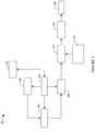
Figure 1 illustrates a prior art 1D transducer;Figure 2 illustrates an example radiation pattern for the prior art transducer ofFigure 1 ;Figure 3 illustrates an example imaging system;Figure 4 illustrates an example imaging transducer configuration for the system ofFigure 3 ;Figure 5 illustrates an example radiation pattern for the transducer configuration ofFigure 4 ;Figures 6 and7 illustrate examples of imaging transducer configurations for the system ofFigure 3 ;Figure 8 illustrates an embodiment of an imaging transducer configuration, in accordance with the present invention, for the system ofFigure 3 ;Figure 9 illustrates another example imaging transducer configuration for the system ofFigure 3 ;Figure 10 illustrates an example method; andFigure 11 illustrates an example method in accordance with the present invention.Figure 3 illustrates animaging system 302 such as ultrasonic imaging system. Theimaging system 302 includes atransducer 304, which can include a one-dimensional or a two-dimensional array of elements arranged in a linear, curved, circular, or other manner. The illustratedtransducer 304 is configured so as to facilitate mitigating gating lobe artifact in images generated by the system. As described in greater detail below, this includes utilizing transducer elements with effective widths that are equal to or greater than a pitch (or center-to-center distance between neighboring elements) of thetransducer 304. In one non-limiting instance, the effective widths are produced by spatially and/or temporally interleaving the elements and/or the data acquired thereby.- A
transmit circuit 306 controls actuation of the elements of thetransducer 304, which allows for steering and/or focusing the transmitted beam from predetermined origins along the array and at predetermined angles. A receivecircuit 308 receives echoes received by thetransducer 304. A controller 330 controls thetransmit circuit 306 and/or the receivecircuit 308. Such control may include, but is not limited to, identifying the scanning mode (e.g., A-mode, B-mode, C-plane, etc.), identifying the processing algorithm (e.g., synthetic aperture or non- synthetic aperture), moving the elements (e.g., electronically and/or physically) of thetransducer 304 between acquisitions, initiating scanning, etc. The controller 330 also controls thetransducer 304. This may include controlling an actuator for physically moving the elements between positions and/or a microprocessor for electronically moving the elements between positions. - An
echo processor 332 variously processes the received data. Such processing may include beamforming (e.g., delaying and summing) the echoes into samples, and spatial compounding and/or other processing such as FIR filtering, IIR filter, etc., which may lower speckle and/or improve specular reflector delineation and/or other processing. As described in greater detail below, where a synthetic aperture algorithm is to be utilized, theprocessor 332 may also be configured to combine data from different acquisitions based on a corresponding synthetic aperture algorithm inprocessing algorithm memory 334 or elsewhere. Theprocessor 332 may also employ an algorithm to synthesize sub-element data corresponding to a narrower pitch from element data. - A
scan converter 336 scan converts the acquired data to generate data for display, for example, by converting the data to the coordinate system of the display. Adisplay 338 and/or other display can be used to present the scan converted data. Auser interface 320 includes various input and/or output devices for interacting with the controller 330 such as buttons, knobs, a keypad, a touch screen, etc. and/or visual and/or audible output devices. - As briefly discussed above, a
suitable transducer 302 includes elements with effective widths that are equal to or greater than the pitch of thetransducer 302. In one instance, this may be achieved interleaving sub portions of the elements in space (spatial interleaving) to produce effective elements widths that are equal to or greater than the pitch. This is illustrated in connection withFigures 4-7 which do not fall within the scope of the claims. - Initially referring to
Figure 4 , asub portion 400 of thetransducer 302 includeselements 404, such aselements longitudinal axis 405 of thetransducer 302. Thetransducer 302 may include a total of 16, 32, 64, 192, 384, and/or other number of theelements 404. - In the illustrated example, each
element 404 has a portion or protrusion protruding or extending in the direction of the long orlongitudinal axis 405, and adjacent or neighboringelements 404 are arranged with respect to each other such that corresponding protrusions interleave. Furthermore, thetransducer 302 has a length (L) 414 and a pitch (P) 412, and each of theelements 404 has an effective width (W) 406 (from protrusion end to protrusion end), which is larger than thepitch 412. - As shown in
Figure 5 , and with continued reference toFigures 3 and4 , with thewidth 406, anelement 404 of thetransducer 302 has anelement factor 504 with zerocrossings 512 that are closer to amain lobe 506 and between gratinglobes 510 and themain lobe 506. As such, thegrating lobes 510 are outside of the imaging field of view of theelement 404. Another way to look at this is that by effectively increasing the width of the elements via the interleaved protrusions, theelement factor 504 can be narrowed so that thegating lobes 510 fall outside of theelement factor 504. As a consequence, relative to the element 104 (Figure 1 ), grating lobe artifacts may be reduced for a given pitch. - In
Figure 4 , thewidth 406 is about two times (2x) thepitch 412. In other example, theeffective width 406 may be larger or smaller than two times (2x) thepitch 412. In general, an element with a width which is an integer times the pitch will have an element factor with zero crossings that facilitate mitigating grating lobes. - Tuning to
Figure 6 , asub portion 600 includeselements 604, such aselements longitudinal axis 605 of thetransducer 302. In this example, anelement 604 includes one or more stair case shaped sections in the direction of thelongitudinal axis 605, and adjacent or neighboringelements 604 are arranged with respect to each other such that corresponding stair case shaped sections interleave. Thetransducer 302 has a pitch (P) 612, and each of theelements 604 has an effective width (W) 606, which is larger than thepitch 612 and, thus, the grating lobes are outside of the imaging field of view of theelement 604. Figures 4 and6 illustrate two non-limiting examples with non-rectangular shaped elements where an effective width is greater than the transducer pitch. Other shapes are also contemplated herein. Technologies such as cMUT, thick film printing, piezo-composites, and the like can be used to produce elements with such shapes and/or other shapes in which the elements have effective widths that are larger than the pitches.- Tuning now to
Figure 7, Figure 7A illustrates asub portion 700 including a plurality of generally rectangular shapedsub-elements 702.Figure 7B shows thesub portion 700 in a configuration in whichdifferent sub-elements 702, including non-contiguous sub-elements, are interleaved and electrically connected through different sets ofelectrical pathways 703 to form relativelylarger elements 704, such aselements - By way of example, the
element 7041 includes sub-elements 7021, 7023, 7024, 7025, and 7027, which are interconnected through theelectrical pathway 7031 and are interlaced with anunused sub-element 7022 and a sub-element 7026 of the neighboringelement 7042. In the illustrated example, the interleaved pattern is the same from element toelement 704. In other examples, at least one of theelements 704 may be formed using a different pattern of interleavedsub-elements 702. - In the illustrated example, the
sub portion 700 includes substantiallyequal size sub-elements 702. In an alternative example, thesub portion 700 may include two or more different size sub-elements. For example, thesub portion 700 may alternatively include two smaller sub-elements, such as 7021 and 7022, followed by a larger sub-element that is the size of the three sub-elements 7023 - 7025, and this or another pattern can be repeated. Such sub-elements can be electrically connected to effectively provide the sub portion shown inFigure 7(B) except that the three sub-elements 7023 - 7025 would be replaced with a larger sub-element. - Like
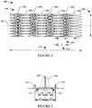
Figures 4 and6 , each of theelements Figure 7B has an effective width (W) 706, which is larger than an actual width of combination of the sub-elements and a pitch (P) 712 of thetransducer 302. As a result, the corresponding an element factor includes zero crossings that are between the grating lobes and the main lobe, and, thus the grating lobes are outside of the imaging field of view of theelement 704. Figures 4-7 illustrate examples in connection with spatial interleaving which do not fall within the scope of the claims.Figures 8 and9 illustrate examples in connection with temporal interleaving (interleaving in time) to provide elements with effective widths that are equal to or greater than the pitch of thetransducer 302. The example ofFigure 9 does not fall within the scope of the claims as it describes an electrical approach which is outside the scope of the claims.Figures 8A and 8B illustrate an example of asub portion 800 withelements 804. Each of theelements 804 includes multiple generally rectangular shapedsub-elements 802 in electrical communication. Theelements 804 are configured to move at least between afirst position 820 and asecond position 822 along a long orlongitudinal axis 805 of thetransducer 302.Figure 8A shows thesub portion 800 at thefirst position 820, andFigure 8B shows thesub portion 800 at thesecond position 822.- With this embodiment, the same elements can be used for acquiring data at the two different the
locations elements 804 are shifted one whole sub-element 802 (or half an element 804). As such, in one instance, an effective width 804' is about equal to the widths of three of the sub-elements 802 as shown inFigure 8C . - In the illustrated embodiment, two
sub-elements 802 form anelement 804. In other embodiments, more than twosub-elements 802 form anelement 804. In the illustrated embodiment, theelements 804 are shifted along theaxis 805 by a width of onesub-element 802. - Continuing with reference to
Figure 8 , in one embodiment, theelements 804 are shifted betweenpositions elements 804 are physically moved betweenpositions actuator 818 or the like. Theelements 804 may be shifted between thepositions 820 between data acquisition cycles (frames) or otherwise. An example of a suitable shift rate is on the order of one (1) to (25) millisecond (ms) and may be dependent on the frame rates (e.g., 10, 15, 25, 50, etc. frames per second) of the system so as to mitigate motion artifact. By physically moving the elements, the number of coaxes equals the number of elements and not the number of effective elements. - In another example, the
elements 804 are shifted betweenpositions Figure 9 . With this approach, amicroprocessor 902 changes (e.g., via switches, etc.) the electrical pathways connecting the various groups ofsub-elements 802 to form different sets of theelements 804. By way of example,Figure 9A shows theelements 804 at thefirst position 820 in which theelement 804 is formed withsub-elements Figure 9B shows theelements 804 at thesecond position 822 in which theelement 804 is formed withsub-elements - In the examples above, the
transducer 302 is illustrated with a linear array of elements. In other embodiments, the array can be curved. In yet another embodiment, the array may be circular, with a circular long axis. With a circular array transducer, the motion to shift the array between positions may be a small rotation of the array. With such a configuration, an array with more than 360 elements on a full circle can be obtained while having a physical array with half as many elements or even less. - In
Figures 8 and9 , data from different acquisitions is combined to form elements with effectives widths that are greater than the pitch of the transducer. In another embodiment, sub-elements corresponding to a finer pitch can be synthesized from elements such that the element width and/or effective elements are equal to or greater than the finer pitch. In one instance, this can be achieved by subtracting partially overlapping apertures. Figure 10 illustrates a method.- At 1002, data is acquired using an imaging transducer that includes a plurality of transducer elements having an effective width that is equal to or greater than a pitch of the transducer (center-to-center distance between adjacent transducer elements).
- At 1004, the image data is optionally processed.
- At 1006, the processed image data is saved and/or displayed.
Figure 11 illustrates another method, as defined by the claims.- At 1102, a plurality of transducer elements, which are arranged with respect to each other in an array along a long axis of a transducer, are moved between at least two positions along the long axis. As described herein, this can be done mechanically, electronically, and/or otherwise.
- At 1104, data is acquired at each of the at least two positions.
- At 1106, the acquired data is temporally interleaved so that an effective width of a transducer element is equal to or greater than a pitch of the transducer.
- It is to be appreciated that the methods herein may be implemented by one or more processors executing computer executable instructions stored, encoded, embodied, etc. on computer readable storage medium such as computer memory, non-transitory storage, etc. In another instance, the computer executable instructions are additionally or alternatively stored in transitory or signal medium.
- Although various embodiments discussed herein are illustrated in connection with a one dimensional transducer, it is to be understood that the discussion herein also applies to multi-dimensional transducers such as a two dimensional imaging transducer.
Claims (5)
- An ultrasonic imaging system (302) comprising:a transducer (304) including a plurality of transducer elements (804) arranged with respect to each other in an array along a long axis (805) of the transducer (304) and spaced apart by a center-to-center distance, each transducer element (804) having a width (806) which is less than the center-to-center distance;an actuator (818) configured to physically move the plurality of transducer elements (804) between at least two different positions (820, 822) along the long axis (805) between data acquisition frames, each transducer element (804) acquiring data at each of said at least two different positions (820, 822); anda processor (332) configured for combining the acquired data from each transducer element (804) at said at least two different positions (820, 822) to generate an effective width (804') for each transducer element (804n) that is equal to or greater than the center-to-center distance between adjacent transducer elements (804);characterized in that each transducer element (804) comprises two or more sub-transducer elements (802), each transducer element (804) being physically moved a distance which is approximately equal to a width of one of the sub-transducer elements (802).
- The imaging system of claim 1, wherein the actuator (818) is configured to shift each transducer element (804) between data acquisition frames at a shift rate of the order of between one to twenty-five milliseconds depending on frame rate of the system.
- The imaging system of claim 1, wherein the effective width is equal to the width of three of the sub-transducer elements (802).
- The imaging system of any one of claims 1 to 3, wherein an element factor (504) of at least one of the transducer elements (804) includes zero crossings (512) configured to be positioned between grating lobes (510) and a main lobe (506) of a radiation pattern of all transducer elements (804).
- A method for acquiring data with an ultrasonic imaging system (302), the method comprising:physically moving a plurality of transducer elements (804) between at least two different positions (820, 822) along a long axis (805) between data acquisition frames, the plurality of transducer elements (804) being arranged with respect to each other in an array along the long axis (805) and spaced apart by a center-to-center distance, each transducer element (804) having a width (806) which is less than the center-to-center distance,;acquiring data from each of the transducer elements (804) at each of said at least two different positions (820, 822); andcombining the acquired data from each transducer element (804) at said at least two different positions (820, 822) to generate an effective width (804') for each transducer element (804) that is equal to or greater than the center-to-center distance between adjacent transducer elements (804);characterized in that each transducer element (804) comprises two or more sub-transducer elements (802) and the step of physically moving the plurality of transducer elements (804) comprises physically moving each transducer element (804) a distance which is approximately equal to a width of one of the sub-transducer elements (802).
Applications Claiming Priority (1)
| Application Number | Priority Date | Filing Date | Title |
|---|---|---|---|
| PCT/IB2010/002343WO2012038770A1 (en) | 2010-09-20 | 2010-09-20 | Imaging transducer array |
Publications (2)
| Publication Number | Publication Date |
|---|---|
| EP2618947A1 EP2618947A1 (en) | 2013-07-31 |
| EP2618947B1true EP2618947B1 (en) | 2018-12-12 |
Family
ID=43935414
Family Applications (1)
| Application Number | Title | Priority Date | Filing Date |
|---|---|---|---|
| EP10766111.8AActiveEP2618947B1 (en) | 2010-09-20 | 2010-09-20 | Imaging transducer array |
Country Status (4)
| Country | Link |
|---|---|
| US (1) | US9638798B2 (en) |
| EP (1) | EP2618947B1 (en) |
| JP (1) | JP2013543670A (en) |
| WO (1) | WO2012038770A1 (en) |
Families Citing this family (5)
| Publication number | Priority date | Publication date | Assignee | Title |
|---|---|---|---|---|
| EP3256265B1 (en)* | 2015-02-13 | 2024-07-10 | Airmar Technology Corporation | Acoustic transducer element |
| CN104688271B (en)* | 2015-03-27 | 2017-04-26 | 清华大学 | Ultrasonic imaging method and ultrasonic imaging device by synthetic focusing |
| US10598773B2 (en) | 2016-03-02 | 2020-03-24 | University Of Washington | Systems and methods for measuring pressure distributions of acoustic beams from ultrasound sources |
| US10697939B2 (en)* | 2018-03-02 | 2020-06-30 | B-K Medical Aps | Synthetic fine-pitch ultrasound imaging |
| CN109782260B (en)* | 2019-03-13 | 2021-07-20 | 海鹰企业集团有限责任公司 | Method for reducing linear array side lobe |
Citations (1)
| Publication number | Priority date | Publication date | Assignee | Title |
|---|---|---|---|---|
| US20020050169A1 (en)* | 2000-08-30 | 2002-05-02 | Ritter Timothy Adam | High frequency synthetic ultrasound array incorporating an actuator |
Family Cites Families (19)
| Publication number | Priority date | Publication date | Assignee | Title |
|---|---|---|---|---|
| JPS5734176A (en)* | 1980-08-08 | 1982-02-24 | Hitachi Ltd | Liquid crystal composition |
| US4425525A (en)* | 1982-02-16 | 1984-01-10 | General Electric Company | Ultrasonic transducer array shading |
| US4516838A (en)* | 1983-09-26 | 1985-05-14 | Isomet Corporation | Overlapping electrode structure for multi-channel acousto-optic devices |
| JPS62144500A (en)* | 1985-12-19 | 1987-06-27 | Fuji Electric Co Ltd | ultrasonic probe |
| NL8801776A (en)* | 1988-07-13 | 1990-02-01 | Optische Ind De Oude Delft Nv | ULTRASONIC TRANSDUCER INCLUDING AT LEAST ONE ROW OF ULTRASONIC ELEMENTS. |
| JPH05277117A (en)* | 1992-04-02 | 1993-10-26 | Yokogawa Medical Syst Ltd | Method and device for ultrasonic diagnosis |
| WO2000068931A1 (en)* | 1999-05-10 | 2000-11-16 | B-K Medical A/S | Recursive ultrasound imaging |
| TW474040B (en)* | 2000-07-31 | 2002-01-21 | Shr-Guang Li | Piezoelectric transformer and filter, and transducer apparatus |
| JP3655860B2 (en)* | 2001-09-27 | 2005-06-02 | アロカ株式会社 | Ultrasonic probe |
| JP3944009B2 (en)* | 2002-06-28 | 2007-07-11 | アロカ株式会社 | Ultrasonic vibrator and manufacturing method thereof |
| EP1616525A3 (en)* | 2002-07-19 | 2006-02-01 | Aloka Co., Ltd. | Ultrasonic probe |
| US6879279B2 (en) | 2003-01-14 | 2005-04-12 | The Regents Of The University Of California | Differential optical synthetic aperture radar |
| JP4235006B2 (en)* | 2003-02-12 | 2009-03-04 | アロカ株式会社 | Ultrasonic diagnostic equipment |
| JP2004350705A (en)* | 2003-05-26 | 2004-12-16 | Olympus Corp | Capsule ultrasonic endoscopic device |
| ITRM20040300A1 (en)* | 2004-06-18 | 2004-09-18 | Esaote Spa | INTERDIGITED GEOMETRY TRANSDUCER FOR THE OPTIMIZATION OF THE RADIATED SOUND BEAM. |
| EP2461180A1 (en)* | 2005-05-04 | 2012-06-06 | Volcano Corporation | Miniature actuator mechanism for intravascular imaging |
| US8600299B2 (en)* | 2006-11-10 | 2013-12-03 | Siemens Medical Solutions Usa, Inc. | Transducer array imaging system |
| US7775982B2 (en) | 2006-12-15 | 2010-08-17 | General Electric Company | Method and system for sub-aperture processing |
| JP2009042173A (en)* | 2007-08-10 | 2009-02-26 | Toshiba Corp | Ultrasonic flaw detection apparatus and ultrasonic flaw detection method |
- 2010
- 2010-09-20EPEP10766111.8Apatent/EP2618947B1/enactiveActive
- 2010-09-20JPJP2013528773Apatent/JP2013543670A/enactivePending
- 2010-09-20USUS13/825,178patent/US9638798B2/enactiveActive
- 2010-09-20WOPCT/IB2010/002343patent/WO2012038770A1/enactiveApplication Filing
Patent Citations (1)
| Publication number | Priority date | Publication date | Assignee | Title |
|---|---|---|---|---|
| US20020050169A1 (en)* | 2000-08-30 | 2002-05-02 | Ritter Timothy Adam | High frequency synthetic ultrasound array incorporating an actuator |
Non-Patent Citations (1)
| Title |
|---|
| HOLMES C ET AL: "Advanced post-processing for scanned ultrasonic arrays: Application to defect detection and classification in non-destructive evaluation", ULTRASONICS, IPC SCIENCE AND TECHNOLOGY PRESS LTD. GUILDFORD, GB, vol. 48, no. 6-7, 1 November 2008 (2008-11-01), pages 636 - 642, XP025626908, ISSN: 0041-624X, [retrieved on 20080820], DOI: 10.1016/J.ULTRAS.2008.07.019* |
Also Published As
| Publication number | Publication date |
|---|---|
| WO2012038770A1 (en) | 2012-03-29 |
| US9638798B2 (en) | 2017-05-02 |
| EP2618947A1 (en) | 2013-07-31 |
| JP2013543670A (en) | 2013-12-05 |
| US20130201798A1 (en) | 2013-08-08 |
Similar Documents
| Publication | Publication Date | Title |
|---|---|---|
| US8316714B2 (en) | Scan patterns for electronically positioned apertures on an array | |
| EP1664840B1 (en) | Ultrasonic spatial compounding with multiple simultaneous beam transmission | |
| US11391838B2 (en) | Ultrasound transducer arrays with variable patch geometries | |
| EP2618947B1 (en) | Imaging transducer array | |
| EP2979110B1 (en) | Ultrasonic diagnostic imaging system with spatial compounding of trapezoidal sector | |
| EP1292847B1 (en) | Ultrasonic spatial compounding with curved array scanheads | |
| WO2013109965A1 (en) | Data reconstruction for improved ultrasound imaging | |
| US20080294045A1 (en) | Three Dimensional Ultrasonic Imaging Using Mechanical Probes with Beam Scanning Reversal | |
| US12130359B2 (en) | Ultrasonic imaging by sparse sampling and associated devices, systems, and methods | |
| US6911008B2 (en) | Compound ultrasound imaging method | |
| WO2014118588A1 (en) | Multi-faced ultrasound transducer element | |
| EP2347713B1 (en) | Ultrasound image enhancement in an ultrasound system | |
| CN110636799B (en) | Optimal scan plane selection for organ viewing | |
| JP2008534106A (en) | Adaptive parallel artifact reduction | |
| EP2575625A1 (en) | High volume rate 3d ultrasonic diagnostic imaging | |
| US9885780B2 (en) | Object information acquiring apparatus | |
| US20050124887A1 (en) | Three dimensional scan conversion of data from mechanically scanned array probes | |
| US20180303457A1 (en) | Imaging Transducer Array |
Legal Events
| Date | Code | Title | Description |
|---|---|---|---|
| PUAI | Public reference made under article 153(3) epc to a published international application that has entered the european phase | Free format text:ORIGINAL CODE: 0009012 | |
| 17P | Request for examination filed | Effective date:20130416 | |
| AK | Designated contracting states | Kind code of ref document:A1 Designated state(s):AL AT BE BG CH CY CZ DE DK EE ES FI FR GB GR HR HU IE IS IT LI LT LU LV MC MK MT NL NO PL PT RO SE SI SK SM TR | |
| DAX | Request for extension of the european patent (deleted) | ||
| STAA | Information on the status of an ep patent application or granted ep patent | Free format text:STATUS: EXAMINATION IS IN PROGRESS | |
| 17Q | First examination report despatched | Effective date:20161208 | |
| GRAP | Despatch of communication of intention to grant a patent | Free format text:ORIGINAL CODE: EPIDOSNIGR1 | |
| STAA | Information on the status of an ep patent application or granted ep patent | Free format text:STATUS: GRANT OF PATENT IS INTENDED | |
| INTG | Intention to grant announced | Effective date:20180713 | |
| GRAS | Grant fee paid | Free format text:ORIGINAL CODE: EPIDOSNIGR3 | |
| GRAA | (expected) grant | Free format text:ORIGINAL CODE: 0009210 | |
| STAA | Information on the status of an ep patent application or granted ep patent | Free format text:STATUS: THE PATENT HAS BEEN GRANTED | |
| AK | Designated contracting states | Kind code of ref document:B1 Designated state(s):AL AT BE BG CH CY CZ DE DK EE ES FI FR GB GR HR HU IE IS IT LI LT LU LV MC MK MT NL NO PL PT RO SE SI SK SM TR | |
| REG | Reference to a national code | Ref country code:GB Ref legal event code:FG4D | |
| REG | Reference to a national code | Ref country code:CH Ref legal event code:EP | |
| REG | Reference to a national code | Ref country code:AT Ref legal event code:REF Ref document number:1075264 Country of ref document:AT Kind code of ref document:T Effective date:20181215 | |
| REG | Reference to a national code | Ref country code:DE Ref legal event code:R096 Ref document number:602010055781 Country of ref document:DE | |
| REG | Reference to a national code | Ref country code:IE Ref legal event code:FG4D | |
| REG | Reference to a national code | Ref country code:NL Ref legal event code:MP Effective date:20181212 | |
| REG | Reference to a national code | Ref country code:LT Ref legal event code:MG4D | |
| PG25 | Lapsed in a contracting state [announced via postgrant information from national office to epo] | Ref country code:ES Free format text:LAPSE BECAUSE OF FAILURE TO SUBMIT A TRANSLATION OF THE DESCRIPTION OR TO PAY THE FEE WITHIN THE PRESCRIBED TIME-LIMIT Effective date:20181212 Ref country code:LT Free format text:LAPSE BECAUSE OF FAILURE TO SUBMIT A TRANSLATION OF THE DESCRIPTION OR TO PAY THE FEE WITHIN THE PRESCRIBED TIME-LIMIT Effective date:20181212 Ref country code:BG Free format text:LAPSE BECAUSE OF FAILURE TO SUBMIT A TRANSLATION OF THE DESCRIPTION OR TO PAY THE FEE WITHIN THE PRESCRIBED TIME-LIMIT Effective date:20190312 Ref country code:HR Free format text:LAPSE BECAUSE OF FAILURE TO SUBMIT A TRANSLATION OF THE DESCRIPTION OR TO PAY THE FEE WITHIN THE PRESCRIBED TIME-LIMIT Effective date:20181212 Ref country code:NO Free format text:LAPSE BECAUSE OF FAILURE TO SUBMIT A TRANSLATION OF THE DESCRIPTION OR TO PAY THE FEE WITHIN THE PRESCRIBED TIME-LIMIT Effective date:20190312 Ref country code:LV Free format text:LAPSE BECAUSE OF FAILURE TO SUBMIT A TRANSLATION OF THE DESCRIPTION OR TO PAY THE FEE WITHIN THE PRESCRIBED TIME-LIMIT Effective date:20181212 Ref country code:FI Free format text:LAPSE BECAUSE OF FAILURE TO SUBMIT A TRANSLATION OF THE DESCRIPTION OR TO PAY THE FEE WITHIN THE PRESCRIBED TIME-LIMIT Effective date:20181212 | |
| REG | Reference to a national code | Ref country code:AT Ref legal event code:MK05 Ref document number:1075264 Country of ref document:AT Kind code of ref document:T Effective date:20181212 | |
| PG25 | Lapsed in a contracting state [announced via postgrant information from national office to epo] | Ref country code:AL Free format text:LAPSE BECAUSE OF FAILURE TO SUBMIT A TRANSLATION OF THE DESCRIPTION OR TO PAY THE FEE WITHIN THE PRESCRIBED TIME-LIMIT Effective date:20181212 Ref country code:SE Free format text:LAPSE BECAUSE OF FAILURE TO SUBMIT A TRANSLATION OF THE DESCRIPTION OR TO PAY THE FEE WITHIN THE PRESCRIBED TIME-LIMIT Effective date:20181212 Ref country code:GR Free format text:LAPSE BECAUSE OF FAILURE TO SUBMIT A TRANSLATION OF THE DESCRIPTION OR TO PAY THE FEE WITHIN THE PRESCRIBED TIME-LIMIT Effective date:20190313 | |
| PG25 | Lapsed in a contracting state [announced via postgrant information from national office to epo] | Ref country code:NL Free format text:LAPSE BECAUSE OF FAILURE TO SUBMIT A TRANSLATION OF THE DESCRIPTION OR TO PAY THE FEE WITHIN THE PRESCRIBED TIME-LIMIT Effective date:20181212 | |
| PG25 | Lapsed in a contracting state [announced via postgrant information from national office to epo] | Ref country code:PT Free format text:LAPSE BECAUSE OF FAILURE TO SUBMIT A TRANSLATION OF THE DESCRIPTION OR TO PAY THE FEE WITHIN THE PRESCRIBED TIME-LIMIT Effective date:20190412 Ref country code:CZ Free format text:LAPSE BECAUSE OF FAILURE TO SUBMIT A TRANSLATION OF THE DESCRIPTION OR TO PAY THE FEE WITHIN THE PRESCRIBED TIME-LIMIT Effective date:20181212 Ref country code:IT Free format text:LAPSE BECAUSE OF FAILURE TO SUBMIT A TRANSLATION OF THE DESCRIPTION OR TO PAY THE FEE WITHIN THE PRESCRIBED TIME-LIMIT Effective date:20181212 Ref country code:PL Free format text:LAPSE BECAUSE OF FAILURE TO SUBMIT A TRANSLATION OF THE DESCRIPTION OR TO PAY THE FEE WITHIN THE PRESCRIBED TIME-LIMIT Effective date:20181212 | |
| PG25 | Lapsed in a contracting state [announced via postgrant information from national office to epo] | Ref country code:EE Free format text:LAPSE BECAUSE OF FAILURE TO SUBMIT A TRANSLATION OF THE DESCRIPTION OR TO PAY THE FEE WITHIN THE PRESCRIBED TIME-LIMIT Effective date:20181212 Ref country code:SM Free format text:LAPSE BECAUSE OF FAILURE TO SUBMIT A TRANSLATION OF THE DESCRIPTION OR TO PAY THE FEE WITHIN THE PRESCRIBED TIME-LIMIT Effective date:20181212 Ref country code:IS Free format text:LAPSE BECAUSE OF FAILURE TO SUBMIT A TRANSLATION OF THE DESCRIPTION OR TO PAY THE FEE WITHIN THE PRESCRIBED TIME-LIMIT Effective date:20190412 Ref country code:SK Free format text:LAPSE BECAUSE OF FAILURE TO SUBMIT A TRANSLATION OF THE DESCRIPTION OR TO PAY THE FEE WITHIN THE PRESCRIBED TIME-LIMIT Effective date:20181212 Ref country code:RO Free format text:LAPSE BECAUSE OF FAILURE TO SUBMIT A TRANSLATION OF THE DESCRIPTION OR TO PAY THE FEE WITHIN THE PRESCRIBED TIME-LIMIT Effective date:20181212 | |
| REG | Reference to a national code | Ref country code:DE Ref legal event code:R097 Ref document number:602010055781 Country of ref document:DE | |
| PLBE | No opposition filed within time limit | Free format text:ORIGINAL CODE: 0009261 | |
| STAA | Information on the status of an ep patent application or granted ep patent | Free format text:STATUS: NO OPPOSITION FILED WITHIN TIME LIMIT | |
| PG25 | Lapsed in a contracting state [announced via postgrant information from national office to epo] | Ref country code:DK Free format text:LAPSE BECAUSE OF FAILURE TO SUBMIT A TRANSLATION OF THE DESCRIPTION OR TO PAY THE FEE WITHIN THE PRESCRIBED TIME-LIMIT Effective date:20181212 Ref country code:AT Free format text:LAPSE BECAUSE OF FAILURE TO SUBMIT A TRANSLATION OF THE DESCRIPTION OR TO PAY THE FEE WITHIN THE PRESCRIBED TIME-LIMIT Effective date:20181212 Ref country code:SI Free format text:LAPSE BECAUSE OF FAILURE TO SUBMIT A TRANSLATION OF THE DESCRIPTION OR TO PAY THE FEE WITHIN THE PRESCRIBED TIME-LIMIT Effective date:20181212 | |
| 26N | No opposition filed | Effective date:20190913 | |
| PG25 | Lapsed in a contracting state [announced via postgrant information from national office to epo] | Ref country code:TR Free format text:LAPSE BECAUSE OF FAILURE TO SUBMIT A TRANSLATION OF THE DESCRIPTION OR TO PAY THE FEE WITHIN THE PRESCRIBED TIME-LIMIT Effective date:20181212 | |
| PG25 | Lapsed in a contracting state [announced via postgrant information from national office to epo] | Ref country code:MC Free format text:LAPSE BECAUSE OF FAILURE TO SUBMIT A TRANSLATION OF THE DESCRIPTION OR TO PAY THE FEE WITHIN THE PRESCRIBED TIME-LIMIT Effective date:20181212 | |
| REG | Reference to a national code | Ref country code:CH Ref legal event code:PL | |
| PG25 | Lapsed in a contracting state [announced via postgrant information from national office to epo] | Ref country code:CH Free format text:LAPSE BECAUSE OF NON-PAYMENT OF DUE FEES Effective date:20190930 Ref country code:LI Free format text:LAPSE BECAUSE OF NON-PAYMENT OF DUE FEES Effective date:20190930 Ref country code:LU Free format text:LAPSE BECAUSE OF NON-PAYMENT OF DUE FEES Effective date:20190920 Ref country code:IE Free format text:LAPSE BECAUSE OF NON-PAYMENT OF DUE FEES Effective date:20190920 | |
| REG | Reference to a national code | Ref country code:BE Ref legal event code:MM Effective date:20190930 | |
| PG25 | Lapsed in a contracting state [announced via postgrant information from national office to epo] | Ref country code:BE Free format text:LAPSE BECAUSE OF NON-PAYMENT OF DUE FEES Effective date:20190930 | |
| GBPC | Gb: european patent ceased through non-payment of renewal fee | Effective date:20190920 | |
| PG25 | Lapsed in a contracting state [announced via postgrant information from national office to epo] | Ref country code:FR Free format text:LAPSE BECAUSE OF NON-PAYMENT OF DUE FEES Effective date:20190930 Ref country code:GB Free format text:LAPSE BECAUSE OF NON-PAYMENT OF DUE FEES Effective date:20190920 | |
| PG25 | Lapsed in a contracting state [announced via postgrant information from national office to epo] | Ref country code:CY Free format text:LAPSE BECAUSE OF FAILURE TO SUBMIT A TRANSLATION OF THE DESCRIPTION OR TO PAY THE FEE WITHIN THE PRESCRIBED TIME-LIMIT Effective date:20181212 | |
| PG25 | Lapsed in a contracting state [announced via postgrant information from national office to epo] | Ref country code:MT Free format text:LAPSE BECAUSE OF FAILURE TO SUBMIT A TRANSLATION OF THE DESCRIPTION OR TO PAY THE FEE WITHIN THE PRESCRIBED TIME-LIMIT Effective date:20181212 Ref country code:HU Free format text:LAPSE BECAUSE OF FAILURE TO SUBMIT A TRANSLATION OF THE DESCRIPTION OR TO PAY THE FEE WITHIN THE PRESCRIBED TIME-LIMIT; INVALID AB INITIO Effective date:20100920 | |
| PG25 | Lapsed in a contracting state [announced via postgrant information from national office to epo] | Ref country code:MK Free format text:LAPSE BECAUSE OF FAILURE TO SUBMIT A TRANSLATION OF THE DESCRIPTION OR TO PAY THE FEE WITHIN THE PRESCRIBED TIME-LIMIT Effective date:20181212 | |
| P01 | Opt-out of the competence of the unified patent court (upc) registered | Effective date:20230528 | |
| PGFP | Annual fee paid to national office [announced via postgrant information from national office to epo] | Ref country code:DE Payment date:20240820 Year of fee payment:15 |