EP2618718B1 - Multi-camera endoscope having fluid channels - Google Patents
Multi-camera endoscope having fluid channelsDownload PDFInfo
- Publication number
- EP2618718B1 EP2618718B1EP11826512.3AEP11826512AEP2618718B1EP 2618718 B1EP2618718 B1EP 2618718B1EP 11826512 AEP11826512 AEP 11826512AEP 2618718 B1EP2618718 B1EP 2618718B1
- Authority
- EP
- European Patent Office
- Prior art keywords
- fluid
- channeling component
- tip section
- channel
- opening
- Prior art date
- Legal status (The legal status is an assumption and is not a legal conclusion. Google has not performed a legal analysis and makes no representation as to the accuracy of the status listed.)
- Active
Links
- 239000012530fluidSubstances0.000titleclaimsdescription276
- 230000005465channelingEffects0.000claimsdescription143
- 239000007788liquidSubstances0.000claimsdescription48
- 238000004140cleaningMethods0.000claimsdescription35
- 238000012546transferMethods0.000claimsdescription11
- 238000003780insertionMethods0.000claimsdescription7
- 230000037431insertionEffects0.000claimsdescription7
- 230000002262irrigationEffects0.000claimsdescription5
- 238000003973irrigationMethods0.000claimsdescription5
- 230000003287optical effectEffects0.000description21
- XLYOFNOQVPJJNP-UHFFFAOYSA-NwaterSubstancesOXLYOFNOQVPJJNP-UHFFFAOYSA-N0.000description8
- 210000001072colonAnatomy0.000description7
- 239000000463materialSubstances0.000description6
- 238000000034methodMethods0.000description6
- 239000008280bloodSubstances0.000description5
- 210000004369bloodAnatomy0.000description5
- 239000000356contaminantSubstances0.000description5
- 210000003608feceAnatomy0.000description5
- 238000012986modificationMethods0.000description4
- 230000004048modificationEffects0.000description4
- FAPWRFPIFSIZLT-UHFFFAOYSA-MSodium chlorideChemical compound[Na+].[Cl-]FAPWRFPIFSIZLT-UHFFFAOYSA-M0.000description3
- 238000002052colonoscopyMethods0.000description3
- 239000000835fiberSubstances0.000description3
- 238000005286illuminationMethods0.000description3
- 238000002347injectionMethods0.000description3
- 239000007924injectionSubstances0.000description3
- 230000001681protective effectEffects0.000description3
- 239000011780sodium chlorideSubstances0.000description3
- 238000007792additionMethods0.000description2
- 208000014674injuryDiseases0.000description2
- 239000002184metalSubstances0.000description2
- 206010034960PhotophobiaDiseases0.000description1
- 208000027418Wounds and injuryDiseases0.000description1
- 210000003484anatomyAnatomy0.000description1
- 238000003491arrayMethods0.000description1
- 230000000712assemblyEffects0.000description1
- 238000000429assemblyMethods0.000description1
- 238000005452bendingMethods0.000description1
- 230000009286beneficial effectEffects0.000description1
- 238000005266castingMethods0.000description1
- 239000002131composite materialSubstances0.000description1
- 238000002574cystoscopyMethods0.000description1
- 230000006378damageEffects0.000description1
- 230000001419dependent effectEffects0.000description1
- 238000002405diagnostic procedureMethods0.000description1
- 238000001839endoscopyMethods0.000description1
- 238000003384imaging methodMethods0.000description1
- 238000002955isolationMethods0.000description1
- 238000002357laparoscopic surgeryMethods0.000description1
- 208000013469light sensitivityDiseases0.000description1
- 238000004519manufacturing processMethods0.000description1
- 238000002324minimally invasive surgeryMethods0.000description1
- 238000012634optical imagingMethods0.000description1
- 210000000056organAnatomy0.000description1
- 238000012856packingMethods0.000description1
- 229920000642polymerPolymers0.000description1
- 238000005245sinteringMethods0.000description1
- 239000007787solidSubstances0.000description1
- 238000001356surgical procedureMethods0.000description1
- 238000012360testing methodMethods0.000description1
- 230000008733traumaEffects0.000description1
- 210000001835visceraAnatomy0.000description1
- 238000005406washingMethods0.000description1
Images


Classifications
- A—HUMAN NECESSITIES
- A61—MEDICAL OR VETERINARY SCIENCE; HYGIENE
- A61B—DIAGNOSIS; SURGERY; IDENTIFICATION
- A61B1/00—Instruments for performing medical examinations of the interior of cavities or tubes of the body by visual or photographical inspection, e.g. endoscopes; Illuminating arrangements therefor
- A61B1/12—Instruments for performing medical examinations of the interior of cavities or tubes of the body by visual or photographical inspection, e.g. endoscopes; Illuminating arrangements therefor with cooling or rinsing arrangements
- A61B1/126—Instruments for performing medical examinations of the interior of cavities or tubes of the body by visual or photographical inspection, e.g. endoscopes; Illuminating arrangements therefor with cooling or rinsing arrangements provided with means for cleaning in-use
- A—HUMAN NECESSITIES
- A61—MEDICAL OR VETERINARY SCIENCE; HYGIENE
- A61B—DIAGNOSIS; SURGERY; IDENTIFICATION
- A61B1/00—Instruments for performing medical examinations of the interior of cavities or tubes of the body by visual or photographical inspection, e.g. endoscopes; Illuminating arrangements therefor
- A61B1/00064—Constructional details of the endoscope body
- A61B1/00071—Insertion part of the endoscope body
- A61B1/0008—Insertion part of the endoscope body characterised by distal tip features
- A61B1/00091—Nozzles
- A—HUMAN NECESSITIES
- A61—MEDICAL OR VETERINARY SCIENCE; HYGIENE
- A61B—DIAGNOSIS; SURGERY; IDENTIFICATION
- A61B1/00—Instruments for performing medical examinations of the interior of cavities or tubes of the body by visual or photographical inspection, e.g. endoscopes; Illuminating arrangements therefor
- A61B1/00064—Constructional details of the endoscope body
- A61B1/00071—Insertion part of the endoscope body
- A61B1/0008—Insertion part of the endoscope body characterised by distal tip features
- A61B1/00094—Suction openings
- A—HUMAN NECESSITIES
- A61—MEDICAL OR VETERINARY SCIENCE; HYGIENE
- A61B—DIAGNOSIS; SURGERY; IDENTIFICATION
- A61B1/00—Instruments for performing medical examinations of the interior of cavities or tubes of the body by visual or photographical inspection, e.g. endoscopes; Illuminating arrangements therefor
- A61B1/00064—Constructional details of the endoscope body
- A61B1/00071—Insertion part of the endoscope body
- A61B1/0008—Insertion part of the endoscope body characterised by distal tip features
- A61B1/00096—Optical elements
- A—HUMAN NECESSITIES
- A61—MEDICAL OR VETERINARY SCIENCE; HYGIENE
- A61B—DIAGNOSIS; SURGERY; IDENTIFICATION
- A61B1/00—Instruments for performing medical examinations of the interior of cavities or tubes of the body by visual or photographical inspection, e.g. endoscopes; Illuminating arrangements therefor
- A61B1/00112—Connection or coupling means
- A61B1/00114—Electrical cables in or with an endoscope
- A—HUMAN NECESSITIES
- A61—MEDICAL OR VETERINARY SCIENCE; HYGIENE
- A61B—DIAGNOSIS; SURGERY; IDENTIFICATION
- A61B1/00—Instruments for performing medical examinations of the interior of cavities or tubes of the body by visual or photographical inspection, e.g. endoscopes; Illuminating arrangements therefor
- A61B1/00163—Optical arrangements
- A61B1/00174—Optical arrangements characterised by the viewing angles
- A61B1/00177—Optical arrangements characterised by the viewing angles for 90 degrees side-viewing
- A—HUMAN NECESSITIES
- A61—MEDICAL OR VETERINARY SCIENCE; HYGIENE
- A61B—DIAGNOSIS; SURGERY; IDENTIFICATION
- A61B1/00—Instruments for performing medical examinations of the interior of cavities or tubes of the body by visual or photographical inspection, e.g. endoscopes; Illuminating arrangements therefor
- A61B1/00163—Optical arrangements
- A61B1/00174—Optical arrangements characterised by the viewing angles
- A61B1/00181—Optical arrangements characterised by the viewing angles for multiple fixed viewing angles
- A—HUMAN NECESSITIES
- A61—MEDICAL OR VETERINARY SCIENCE; HYGIENE
- A61B—DIAGNOSIS; SURGERY; IDENTIFICATION
- A61B1/00—Instruments for performing medical examinations of the interior of cavities or tubes of the body by visual or photographical inspection, e.g. endoscopes; Illuminating arrangements therefor
- A61B1/005—Flexible endoscopes
- A61B1/008—Articulations
- A—HUMAN NECESSITIES
- A61—MEDICAL OR VETERINARY SCIENCE; HYGIENE
- A61B—DIAGNOSIS; SURGERY; IDENTIFICATION
- A61B1/00—Instruments for performing medical examinations of the interior of cavities or tubes of the body by visual or photographical inspection, e.g. endoscopes; Illuminating arrangements therefor
- A61B1/012—Instruments for performing medical examinations of the interior of cavities or tubes of the body by visual or photographical inspection, e.g. endoscopes; Illuminating arrangements therefor characterised by internal passages or accessories therefor
- A61B1/015—Control of fluid supply or evacuation
- A—HUMAN NECESSITIES
- A61—MEDICAL OR VETERINARY SCIENCE; HYGIENE
- A61B—DIAGNOSIS; SURGERY; IDENTIFICATION
- A61B1/00—Instruments for performing medical examinations of the interior of cavities or tubes of the body by visual or photographical inspection, e.g. endoscopes; Illuminating arrangements therefor
- A61B1/012—Instruments for performing medical examinations of the interior of cavities or tubes of the body by visual or photographical inspection, e.g. endoscopes; Illuminating arrangements therefor characterised by internal passages or accessories therefor
- A61B1/018—Instruments for performing medical examinations of the interior of cavities or tubes of the body by visual or photographical inspection, e.g. endoscopes; Illuminating arrangements therefor characterised by internal passages or accessories therefor for receiving instruments
- A—HUMAN NECESSITIES
- A61—MEDICAL OR VETERINARY SCIENCE; HYGIENE
- A61B—DIAGNOSIS; SURGERY; IDENTIFICATION
- A61B1/00—Instruments for performing medical examinations of the interior of cavities or tubes of the body by visual or photographical inspection, e.g. endoscopes; Illuminating arrangements therefor
- A61B1/04—Instruments for performing medical examinations of the interior of cavities or tubes of the body by visual or photographical inspection, e.g. endoscopes; Illuminating arrangements therefor combined with photographic or television appliances
- A61B1/05—Instruments for performing medical examinations of the interior of cavities or tubes of the body by visual or photographical inspection, e.g. endoscopes; Illuminating arrangements therefor combined with photographic or television appliances characterised by the image sensor, e.g. camera, being in the distal end portion
- A61B1/053—Instruments for performing medical examinations of the interior of cavities or tubes of the body by visual or photographical inspection, e.g. endoscopes; Illuminating arrangements therefor combined with photographic or television appliances characterised by the image sensor, e.g. camera, being in the distal end portion being detachable
- A—HUMAN NECESSITIES
- A61—MEDICAL OR VETERINARY SCIENCE; HYGIENE
- A61B—DIAGNOSIS; SURGERY; IDENTIFICATION
- A61B1/00—Instruments for performing medical examinations of the interior of cavities or tubes of the body by visual or photographical inspection, e.g. endoscopes; Illuminating arrangements therefor
- A61B1/06—Instruments for performing medical examinations of the interior of cavities or tubes of the body by visual or photographical inspection, e.g. endoscopes; Illuminating arrangements therefor with illuminating arrangements
- A61B1/0661—Endoscope light sources
- A61B1/0676—Endoscope light sources at distal tip of an endoscope
- A—HUMAN NECESSITIES
- A61—MEDICAL OR VETERINARY SCIENCE; HYGIENE
- A61B—DIAGNOSIS; SURGERY; IDENTIFICATION
- A61B1/00—Instruments for performing medical examinations of the interior of cavities or tubes of the body by visual or photographical inspection, e.g. endoscopes; Illuminating arrangements therefor
- A61B1/06—Instruments for performing medical examinations of the interior of cavities or tubes of the body by visual or photographical inspection, e.g. endoscopes; Illuminating arrangements therefor with illuminating arrangements
- A61B1/0661—Endoscope light sources
- A61B1/0684—Endoscope light sources using light emitting diodes [LED]
- A—HUMAN NECESSITIES
- A61—MEDICAL OR VETERINARY SCIENCE; HYGIENE
- A61B—DIAGNOSIS; SURGERY; IDENTIFICATION
- A61B1/00—Instruments for performing medical examinations of the interior of cavities or tubes of the body by visual or photographical inspection, e.g. endoscopes; Illuminating arrangements therefor
- A61B1/31—Instruments for performing medical examinations of the interior of cavities or tubes of the body by visual or photographical inspection, e.g. endoscopes; Illuminating arrangements therefor for the rectum, e.g. proctoscopes, sigmoidoscopes, colonoscopes
Definitions
- Embodiments of the disclosurerelate to a multi-camera endoscope having fluid channels.
- Endoscopeshave attained great acceptance within the medical community, since they provide a means for performing procedures with minimal patient trauma, while enabling the physician to view the internal anatomy of the patient.
- numerous endoscopeshave been developed and categorized according to specific applications, such as cystoscopy, colonoscopy, laparoscopy, upper GI endoscopy and others. Endoscopes may be inserted into the body's natural orifices or through an incision in the skin.
- An endoscopeis usually an elongated tubular shaft, rigid or flexible, having a video camera or a fiber optic lens assembly at its distal end.
- the shaftis connected to a handle, which sometimes includes an ocular for direct viewing. Viewing is also usually possible via an external screen.
- Various surgical toolsmay be inserted through a working channel in the endoscope for performing different surgical procedures.
- Endoscopessuch as colonoscopes, that are currently being used, typically have a front camera for viewing the internal organ, such as the colon, an illuminator, a fluid injector for cleaning the camera lens and sometimes also the illuminator and a working channel for insertion of surgical tools, for example, for removing polyps found in the colon.
- endoscopesalso have fluid injectors ("jet") for cleaning a body cavity, such as the colon, into which they are inserted.
- the illuminators commonly usedare fiber optics which transmit light, generated remotely, to the endoscope tip section. The use of light-emitting diodes (LEDs) for illumination is also known.
- US 5 685 823describes an end structure of an endoscope which includes a front end body of a cylindrical insertion portion to be inserted in a human body.
- the end structurealso includes a fluid discharge opening which opens into the front end body and a front end cap detachably attached to the front end body and having a fluid injection nozzle connected to the fluid discharge opening.
- a projectionis provided on the end cap, which is fitted in the fluid discharge port, and constitutes at least a part of the fluid injection nozzle.
- US 5,725,476discloses a tip assembly of an endoscope with a forward looking camera.
- a tip section of a multi-camera endoscopecomprising: a unitary fluid channeling component adapted to channel fluid for insufflations and/or irrigation (I/I), the unitary fluid channeling component comprising: a proximal opening adapted to receive a fluid tube, the proximal opening being in fluid flow connection with a front fluid (I/I) channel and a side fluid channel.
- the fluid tubemay include a gas tube and a liquid tube separated from each other or combined into one tube.
- the front fluid channelmay lead to a front opening at a distal end in the unitary fluid channeling component; and the side fluid channel may lead to a left side opening and to a right side opening in the unitary fluid channeling component.
- the front fluid channelmay extend along the length of the unitary fluid channeling component.
- the side fluid channelmay be essentially perpendicular to the length of the unitary fluid channeling component.
- the front openingmay be adapted to receive a fluid injector and wherein the side openings are adapted to receive fluid injectors.
- the front channel, the side channel or bothmay be drilled in the unitary fluid channeling component.
- the front fluid channel, the side fluid channel or bothmay be partially internal and partially external to unitary fluid channeling component.
- the unitary fluid channeling componentmay further include a working channel adapted for the insertion of a medical tool.
- the unitary fluid channeling componentmay further include a jet fluid channel adapted to clean a body cavity into which the endoscope is inserted.
- the unitary fluid channeling componentmay further include a groove or a channel for guiding a cable.
- a tip section of a multi-camera endoscopecomprising: a unitary fluid channeling component adapted to channel fluid for insufflations and/or irrigation, the unitary fluid channeling component comprising: a first proximal opening adapted to receive a first fluid tube and connected to a front fluid (I/I) channel; and a second proximal opening adapted to receive a second fluid tube and connected to a first side fluid (I/I) channel, wherein any of the first and second fluid tubes are adapted to transfer liquid, gas or a combination thereof to the tip section.
- a unitary fluid channeling componentadapted to channel fluid for insufflations and/or irrigation
- the unitary fluid channeling componentcomprising: a first proximal opening adapted to receive a first fluid tube and connected to a front fluid (I/I) channel; and a second proximal opening adapted to receive a second fluid tube and connected to a first side fluid (I/I) channel, wherein any of the first and second fluid tubes
- the front fluid channelmay lead to a front opening at a distal end in the unitary fluid channeling component; and the side fluid channel may lead to one or more side opening in the unitary fluid channeling component.
- the front and side openingsmay be adapted to receive fluid injectors.
- the front fluid channelmay extend along the length of the unitary fluid channeling component.
- the first side fluid channelmay lead to a left side opening and to a right side opening in the unitary fluid channeling component and may be essentially perpendicular to the length of the unitary fluid channeling component.
- the unitary fluid channeling componentmay further include a third proximal opening adapted to receive a third fluid tube connected to a second side fluid (I/I) channel.
- any of the side front channel and the one or more side channelmay be drilled in the unitary fluid channeling component. Any of the front fluid channel and the one or more side fluid channels may be partially internal and partially external to unitary fluid channeling component.
- the unitary fluid channeling componentmay further include a working channel adapted for the insertion of a medical tool.
- the unitary fluid channeling componentmay further include a jet fluid channel adapted to clean a body cavity into which the endoscope is inserted.
- the unitary fluid channeling componentmay further include a groove or a channel for guiding a cable.
- the tip sectionmay have a diameter of about 17 mm or less.
- the tip sectionmay have a diameter of about 12 mm or less.
- the tip sectionmay have a diameter of about 10 mm or less.
- an endoscopecomprising a tip section as described herein.
- a manifold for irrigation and/or insufflation (I/I) fluidsfor providing gas such as CO 2 or air for inflating the colon (or other body cavity) during diagnostic or minimally invasive procedure, such as colonoscopy, and/or for providing cleaning liquid, for example water or saline, for cleaning optical front surfaces in an endoscope having at least one forward looking camera and one or more side looking cameras while maintaining small size of the tip section of the endoscope.
- I/Iinsufflation
- proximal opening for gas tube and liquid tubeis directly opened to I/I channel manifold, located entirely within the tip section cylinder, the manifold comprises: According to the first exemplary embodiment of the current invention, proximal opening for gas tube and liquid tube is directly opened to I/I channel manifold, entirely within the cylinder which comprises:
- proximal opening for gas tube and liquid tube within a cylinder in the endoscope's tip sectionis opened to I/I channel manifold which comprises:
- proximal opening for gas tube and liquid tube within a cylinder in the endoscope's tip sectionis opened to right I/I opening and through it to a I/I manifold which comprises:
- proximal opening for gas tube and liquid tube within a cylinder in the endoscope's tip sectionis opened to right I/I opening and through it to a I/I manifold which comprises:
- proximal opening for gas tube and liquid tube within a cylinder in the endoscope's tip sectionis opened to a right I/I opening and connected through hole to I/I manifold which comprises:
- proximal opening for gas tube and liquid tube within a cylinder in the endoscope's tip sectionis opened to a hole and through it to a I/I manifold which comprises:
- the medical endoscope tip sectionis less than 17mm in diameter In some embodiments the medical endoscope tip section is less than 12 mm in diameter More details and features of the current invention and its embodiments may be found in the description and the attached drawings.
- each of the words “comprise” “include” and “have”, and forms thereof,are not necessarily limited to members in a list with which the words may be associated.
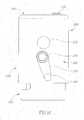
- Figure 1aschematically depicts an external isometric view of an endoscope 200 having multiple fields of view according to an exemplary embodiment of the current invention.
- tip section 230 of endoscope 200comprises at least a forwards looking TV camera and at least one side looking TV camera.
- Tip section 230is turnable by way of flexible shaft 260 (which may also be referred to as a bending section, for example a vertebra mechanism).
- endoscopemay refer particularly to a colonoscope, according to some embodiments, but is not limited only to colonoscopes.
- endoscopemay refer to any instrument used to examine the interior of a hollow organ or cavity of the body.
- Figure 1ashows front camera element 236 of forwards looking camera 116 (seen in figure 2b ) on the front face 320 of tip section 230.
- Optical axis of forwards looking camera 116is substantially directed along the long dimension of the endoscope.
- forwards looking camera 116is typically a wide angle camera, its Field Of View (FOV) may include viewing directions at large angles to its optical axis.
- optical windows 242a and 242b of LEDs 240a and 240bare also seen on front face 320 of tip section 230. It should be noted that number of LEDs used for illumination of the FOV may vary.
- Distal opening 340 of working channel 262is preferably located on front face 320 of tip section 230, such that a surgical tool inserted through working channel tube 162, and through working channel 262 in the endoscope's tip section and deployed beyond front face 320 may be viewed by forwards looking camera 116.
- Distal opening 344 of a jet fluid channelis preferably also located on front face 320 of tip section 230.
- Distal opening 344 of a jet fluid channelmay be used for providing high pressure jet of fluid such as water or saline for cleaning the walls of the body cavity.
- I/I injector 346 having a nozzle 348 aimed at front camera element 236may be used for injecting fluid (liquid and/or gas) to wash contaminants such as blood, feces and other debris from front camera element 236 of forwards looking camera.
- fluidliquid and/or gas
- the same injectoris used for cleaning both front camera element 236 and one or both optical windows 242a and 242b.
- I/I injector 346may be fed by fluid such as water and/or gas which may be used for cleaning and/or inflating a body cavity.
- side looking camera element 256 of side looking camera 220Visible on the side wall 362 of tip section 230 is the side camera (side looking camera) element 256 of side looking camera 220 (two such cameras are seen in figure 2a ) and optical window 252 of LED 250.
- Optical axis of side looking camera 220is substantially directed perpendicular to the long dimension of the endoscope. However, since side looking camera 220 is typically a wide angle camera, its field of view may include viewing directions at large angles to its optical axis.
- I/I injector 366 having a nozzle 368 aimed at side camera element 256may be used for injecting fluid to wash contaminants such as blood, feces and other debris from side camera element 256 of side looking camera.
- the fluidmay include gas which may be used for inflating a body cavity.
- the same injectoris used for cleaning both side camera element 256 and optical windows 252.
- the tipmay include more than one window and LEDs, on the side and more than one window and LEDs in the front (for example, two windows and two LEDs on the side and three windows and three LEDs in the front).
- the I/I injectorsare configured to clean all or a part of these windows/LEDs).
- I/I injectors 346 and 366may be fed from same channel.
- An optional groove 370helps directing the cleaning fluid from nozzle 368 towards side camera element 256.
- Groove 370may be beneficial when side wall 362 is near or pressed against the rectal wall.
- I/I injector 366may be at least partially recessed in groove 370, thus reducing the maximum diameter of tip section 230 and reduce the risk of injury to the rectal wall due to friction with I/I injector 366.
- flexible shaft 260is constructed of a plurality of links 382 connected to each other by pivots 384.
- Links 382allows pushing, pulling and rotating the endoscope while pivots 384 provide limited flexibility.
- the shaftis preferably covered with an elastic sheath (removed from this figure for simplification purposes).
- the lumen in links 382holds the working channel tube 162.
- the jet channelconnected to distal opening 344, optional cleaning fluid channel and electrical cables supplying power to the LEDs and cameras and transmitting video signals from the camera.
- the shaftalso comprises mechanical actuators (not seen), for example cables attached to the links for directing and aiming the tip section during use.
- FIG. 1apreferably at least two side looking cameras may be located within tip section 230.
- the side looking camerasare preferably installed such that their field of views are substantially opposing.
- different configurations and number of side looking camerasare possible within the general scope of the current invention.
- Figure 1bschematically depicts a front view of tip section 230 of endoscope 200 having multiple fields of view according to an exemplary embodiment of the current invention.
- tip section 230 of endoscope 200comprises at least a forwards looking TV camera and at least two side looking TV cameras.
- Figure 1bshows a front camera element 236 of forwards looking camera 116 on the front face 320 of tip section 230.
- optical windows 242a and 242b of LEDs 240a and 240bare also seen on front face 320 of tip section 230.
- Distal opening 340 of working channel and distal opening 344 of a jet channelare preferably also located on front face 320 of tip section 230.
- I/I injector 346 having a nozzle 348is also visible in this view.
- I/I injectors 366a and 366b aimed at side looking camera element 256a and 256b respectivelymay be used for injecting fluid (the term "fluid” may also include gas and/or liquid) to wash contaminants such as blood, feces and other debris from side camera elements 256a and 256b of side looking cameras.
- the injectorsmay supply liquid for cleaning any of the tip elements (such as any camera element, windows, LEDs, and other elements).
- Figure 1cschematically depicts a side view of endoscope 200 having multiple fields of view according to an exemplary embodiment of the current invention.
- Figure 1cshows side camera element 256 of side looking camera 220, optional groove 370 and optical window 252 on the side wall 362 of tip section 230. I/I injectors 346 and 366 are also visible in this view.
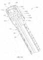
- Figure 2aschematically depicts a cross section isometric view of an endoscope 400 having multiple fields of view according to another exemplary embodiment not forming part of the invention.
- tip section 430 of endoscope 200comprises at least a forwards looking TV camera 116 and two side looking cameras 220a and 220b.
- Optical windows 242a and 242b of LEDs used for forward illuminationare also seen on front face of tip section 230.
- Distal opening 340 of working channelis preferably located on front face of tip section 230 such that a surgical tool inserted through the working channel 262 and deployed beyond front face may be viewed by forwards looking camera 116.
- Distal opening 344 of a jet channelis preferably also located on front face of tip section 230.
- I/I injector 346 having a nozzle aimed at front camera element of camera 116may be used for injecting fluid (gas and/or water) to wash contaminants such as blood, feces and other debris from front camera element of forwards looking camera 116 and to inflate a body cavity (such as a colon) into which the endoscope (such as colonoscope) is inserted.
- the same injectoris used for cleaning the front camera element and one or both optical windows 242a and 242b.
- I/I injector 346may receive fluid from a fluid channel or may be fed by a dedicated cleaning fluid channel.
- tip section 230Visible on right hand side of tip section 230 is side camera element 256b of side looking camera 220b and optical window 252b of side illuminating LED.
- I/I injector 366b having a nozzle aimed at side camera element 256bmay be used for injecting fluid to wash contaminants such as blood, feces and other debris from side camera element 256b of side looking camera 220b and to inflate a body cavity (such as a colon) into which the endoscope (such as a colonoscope) is inserted.
- a body cavitysuch as a colon
- the same injectoris used for cleaning both front camera element 256b and optical windows 252b.
- An optional groove 370bhelps directing the cleaning fluid from I/I injector 366b towards side camera element 256b.
- all the I/I injectors 346 and 366are fed from same conduits.
- flexible shaft (vertebra mechanism) 260is constructed of a plurality of links 382 (only one is marked for simplification). Electrical cable 396 within shaft 260 is seen connected to cameras 116, 220a and 220b. The same or separate electrical cable is used to power the LEDs.
- Figure 2bschematically depicts a cross section of an endoscope 200 having multiple fields of view showing some details of the tip section 230 according to an exemplary embodiment not forming part of the invention.
- tip section 230 of endoscope 200comprises at least a forwards looking TV camera 116 and two side looking cameras 220a and 220b.
- Each of cameras 116 and 220is provided with an optical imaging system such as lens assemblies 132 and 232 respectively and solid state detector arrays 134 and 234 respectively.
- Front camera elements 236 and 256 of cameras 116 and 220 respectivelymay be a flat protective window, but preferably an optical element used as part of the imaging systems 134 and 132 respectively.
- cameras 116 and 220are similar or identical, however different camera designs may be used, for example, field of views 118 and 218 may be different. Additionally or alternatively, other camera designs parameters such as: resolution, light sensitivity, pixel size and pixel number, focal length, focal distance and depth of field may be selected to be same or different.
- Lightis provided by Light Emitting Diodes (LED) that illuminates the field of views.
- LEDLight Emitting Diodes
- white light LEDsare used.
- field of view 118 of forwards looking camera 116is illuminated by two LEDs 240a and 240b located within the endoscope tip section 230 and protected by optical window 242a and 242b respectively.
- forwards looking camera 116may be illuminated by any other number of LEDs, for example, 1, 3, 4, 5 LEDs)
- field of views of side looking camera 220is illuminated by a single LED 250 located within the endoscope tip section 230 and protected by optical window 252.
- side looking camera 220may be illuminated by any other number of LEDs, for example, 2, 3, 4, 5 LEDs)
- LED light sourcesand their position in respect to the cameras may vary within the scope of the current invention. For example few LEDs may be positioned behind the same protective window, a camera and an LED or plurality of LED may be located behind the same protective window, etc.
- Tip section 230 of endoscope 200is located at the distal end of a flexible shaft 260.
- shaft 260comprises a working channel 262 for insertion of surgical tools.
- shaft 260may comprises channels for irrigation, insufflation, suction and supplying liquid for washing the external elements of the cameras and optionally the light sources.
- Figure 2cschematically depicts an isometric proximal view of an inner part of a tip section of an endoscope according to an exemplary embodiment not forming part of the invention showing the entrances of various channels in the inner part of a tip section.
- Inner part 100 of a tip sectionis located within the tip section and may be used for holding in place the components of the endoscope's tip section such as I/I injectors 364, 366a and 366b; cameras, lenses and other elements.
- a cover(not seen in this figure) is placed over inner part 100.
- I/I injectors 364 and 366and optionally side camera element 256b may be assembled after the cover was placed.
- Inner part 100 of a tip sectionmay comprise of several parts.
- inner part 100 of the tip sectioncomprises: unitary fluid channeling component 190, central section 192 and front section 194 (examples of which are seen in some of the following figures).
- Unitary fluid channeling component 190may be made of a metal or any other material, such as a polymer, a composite material or any other appropriate material or combination of materials.
- Unitary fluid channeling component 190may generally include two parts: a proximal fluid channeling component section 190' and a distal fluid channeling component section 190".
- Proximal fluid channeling component section 190'may have an essentially cylindrical shape.
- Distal unitary channeling component section 190"may partially continue the cylindrical shape of proximal fluid channeling component section 190' and may have a shape of a partial cylinder (optionally elongated partial cylinder), having only a fraction of the cylinder (along the height axis of the cylinder), wherein another fraction of the cylinder (along the height axis of the cylinder) is missing.
- distal fluid channeling component section 190which may be integrally formed as a unitary block with proximal fluid channeling component section 190'. The height of distal fluid channeling component section 190" may by higher than that of proximal fluid channeling component section 190'.
- the shape of the partial cylindermay provide a space to accommodate central section 192.
- Central section 192may include electronics and optical components, such as light means (LEDs for example), cameras (CCD or CMOS, for example) lenses, and other elements.
- LEDslight means
- CMOScomplementary metal-oxide-semiconductor
- This configuration of inner part 100 of the tip sectionmay thus be adapted to separate the fluid channels and work channel, which are located in fluid channeling component 190 from the sensitive electronic and optical parts which are located in central section 192. This paragraph may apply to any one of main bodies 190a-190f.
- proximal opening 144 of the jet fluid channelleading to distal opening 344 of the jet channel.
- Fluid tube(not shown in this figure for simplification purposes) may be inserted into, and affixed to distal opening 144 of the jet fluid channel.
- the jet fluid tubeis threaded through flexible shaft 260 and is used for delivering fluid to the body cavity.
- proximal opening 165 of the working channel 262leading to distal opening 340 of the working channel.
- Working channel tube/toolsmay be inserted into, and optionally affixed to proximal opening 165 of the working channel.
- the working channel 162is threaded through flexible shaft 260 and is used for delivering surgical tools to the body cavity.
- Working channel 162may also be used for suction of fluid from the body cavity.
- unitary fluid channeling component 190On the proximal surface 191 of unitary fluid channeling component 190 is the electric cable opening 150 for electrical cable 396 (seen for example in figure 2a ). Electrical cable 396 is connected at its distal end to the electronic components such as cameras and light sources in the endoscope's tip section. Electrical cable 396 is threaded through flexible shaft 260 and is used for delivering electrical power and command signals to the tip section and transmitting video signal from the cameras to be displayed to the user.
- proximal opening 110 for gas tube 114 and liquid tube 112is the I/I tubes proximal opening 110 for gas tube 114 and liquid tube 112 (seen for example in figure 3a ).
- Gas and fluid tubesmay be inserted into, and affixed to proximal opening 110 of I/I channels manifold which delivers cleaning fluids to I/I injectors 364 and 366.
- the gas and liquid tubes(such as gas tube 114 and liquid tube 112) may be threaded through flexible shaft 260 and are used for delivering fluid (gas and/or liquid) to I/I injectors 364 and 366 for cleaning the optical surfaces on the endoscope's tip section and for inflating a body cavity.
- the gas and liquid tubes(such as gas tube 114 and liquid tube 112) may also be combined into one tube and connected to the tip section as one tube.
- FIG. 2cgenerically depicts the unitary fluid channeling component 190, and shows its proximal surface 191
- Figure 3aschematically depicts a partially disassembled tip section 230a of an endoscope having I/I channels manifold internal to unitary fluid channeling component 190a according to a first exemplary embodiment not forming part of the present invention.
- Cover 196ais designed to fit over inner part (of the tip section) 100a, and to provide protection to the internal components in the inner part. Holes 164', 340', 344', 242a', 336', 242b', 256b', 252b' and 166b' in cover 196a are aligned with the corresponding components and channel openings 164, 165, 144, 242a, 336, 242b, 256b, 252b and 366b in inner part 100a respectively. Optional groove 370b in cover 196a enable cleaning fluid from I/I injector 366b to arrive, and clean the front surface 252b of side looking camera.
- groove 370aand holes 256a', 252a' and 166a' in cover 196a which are aligned with the corresponding components and channel openings 256a, 252a and 166a on the other side of inner part 100a respectively.
- I/I injectors 364, 366a and 366bmay be inserted into the corresponding I/I opening 164, 166a and 166b in unitary fluid channeling component 190a through the corresponding holes 164', 166a' and 166b' in cover 196a.
- I/I injectors 364, 366a and 366bmay be removed from I/I opening 164, 166a and 166b for cleaning the endoscope after use.
- I/I injectors 364, 366a and 366bmay be replaceable or disposable.
- the nozzlessuch as nozzle 348, nozzle 368 or any other nozzle may be inserted into the unitary fluid channeling component, such as unitary fluid channeling components 190 or 190a, within an isolating (e.g., plastic) part into the opening to allows us better electric isolation particularly when the unitary fluid channeling component and the nozzles are made of metal.
- an isolating (e.g., plastic) partinto the opening to allows us better electric isolation particularly when the unitary fluid channeling component and the nozzles are made of metal.
- I/I opening 164, 166a and 166bare connected to proximal opening 110 for gas tube 114 and liquid tube 112 via I/I manifold channels which are within unitary fluid channeling component 190a.
- Distal opening 344'is the opening of a jet fluid channel which may be used for providing high pressure jet of fluid such as water or saline for cleaning the walls of the body cavity (such as the colon) and optionally for suction.
- Figure 3bschematically depicts an isometric cross section of Inner part 100a having I/I channels manifold internal to unitary fluid channeling component 190a according to a first exemplary embodiment not forming part of the invention.
- gas tube 114 and liquid tube 112are terminated in a plug 109 adapted to fit into proximal opening 110. It should be noted that although gas tube 112 appears above liquid tube 114, their order may be reversed, they may be positioned side by side, or replaced with a single tube or the tubes may be joined to one tube before entering inner part 100a. Alternatively, each of gas tube 114 and liquid tube 112 is separately connected to unitary fluid channeling component 190, and their lumens open to a common conduit.
- Proximal opening 110 for gas tube 114 and liquid tube 112is opened to I/I channel manifold.
- This cross sectionshows proximal opening 110 opened to front I/I channel 171 leading to front I/I opening 164 into which front I/I injector 364 is inserted.
- front I/I channel 171(may also be referred to as front fluid channel) may be drilled in unitary fluid channeling component 190a.
- unitary fluid channeling component 190a and other parts of inner part 100amay be machined or be made by casting, sintering, injection or other manufacturing techniques.
- Figure 3cschematically depicts an isometric cross section of unitary fluid channeling component 190a having I/I channels manifold internal to it according to a first exemplary embodiment not forming part of the invention
- Figure 3dschematically depicts another isometric cross section of inner part 110a, showing unitary fluid channeling component 190a having I/I channels manifold internal to it according to a first exemplary embodiment not forming part of the invention.
- Proximal opening 110 for gas tube 114 and liquid tube 112is seen in this figure opened to I/I channel manifold.
- This cross sectionshows proximal opening 110 opened to cross I/I channel 172 (may also be referred to as side fluid channel or side I/I channel) leading to left I/I opening 166a into which left I/I injector 366a is inserted and to right I/I opening 166b into which right I/I injector 366b is inserted.
- cross I/I channel 172may be drilled in unitary fluid channeling component 190a.
- proximal opening 110 for gas tube 114 and liquid tube 112is directly opened to I/I channel manifold, within unitary fluid channeling component 190a which comprises:
- Figure 4aschematically depicts an isometric view of a partially disassembled tip section 230b of an endoscope having I/I channels manifold partially internal and partially external to unitary fluid channeling component 190b according to a second exemplary embodiment of the current invention.
- cleaning fluidsare supplied to left I/I injector 366a via a groove 472 in unitary fluid channeling component 190b.
- Groove 472is connected in one side to proximal opening 110 by hole 474 and is opened to left I/I opening 166a which can hardly be seen in this view.
- Cover 196bis designed to fit over inner part 100b, and to provide protection to the internal components of inner part 100b. Additionally, cover 196b is tightly fitted and preferably hermetically seals groove 472 to convert it to fluid tight conduit.
- Figure 4bschematically depicts an isometric view of inner part 100b of an endoscope tip section having I/I channels manifold partially internal and partially external to unitary fluid channeling component 190b according to a second exemplary embodiment of the current invention.
- Figure 4cschematically depicts an isometric cross section of unitary fluid channeling component 190b according to the second exemplary embodiment of the current invention.
- proximal opening 110 for gas tube 114 and liquid tube 112is seen in this figure opened to I/I channel manifold which comprises:
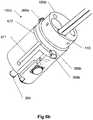
- Figure 5aschematically depicts an isometric view of a partially disassembled tip section 230c of an endoscope having I/I channels manifold partially internal and partially external to unitary fluid channeling component 190c according to a third exemplary embodiment of the current invention.
- fluidsare supplied to left I/I injector 366b via a groove 572 in unitary fluid channeling component 190c.
- groove 572is connected in the right side to right I/I opening 166b and opened on the left to left I/I opening 166a which can hardly be seen in this view.
- Cover 196cis designed to fit over inner part 100c, and to provide protection to the internal components of inner part 100c. Additionally, cover 196c is tightly fitted and preferably hermetically seals groove 572 to convert it to fluid tight conduit.
- Figure 5bschematically depicts an isometric view of inner part 100c of an endoscope tip section having I/I channels manifold partially internal and partially external to unitary fluid channeling component 190c according to a third exemplary embodiment of the current invention.
- groove 572 on surface of unitary fluid channeling component 190cmay be different.
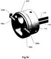
- Figure 5cschematically depicts an isometric cross section of unitary fluid channeling component 190c according to the third exemplary embodiment of the current invention.
- Proximal opening 110 for gas tube 114 and liquid tube 112is seen in this figure opened to right I/I opening 166b and through it to groove 572 leading to left I/I opening 166a.
- Figure 5dschematically depicts another isometric cross section of unitary fluid channeling component 190c according to the third exemplary embodiment of the current invention.
- Proximal opening 110 for gas tube 114 and liquid tube 112is seen in this figure opened to right I/I opening 166b and through it to I/I manifold which comprises:
- Figure 6aschematically depicts an isometric cross section view of an assembled tip section 230d of an endoscope having I/I channels manifold external to unitary fluid channeling component 190d according to a forth exemplary embodiment of the current invention.
- groove 672is connected in the right side to right I/I opening 166b and opened on the left to left I/I opening 166a.
- front I/I injector 364fluids are supplied to front I/I injector 364 via a front groove 671 in unitary fluid channeling component 190d.
- Front groove 671is opened in its proximal end to groove 672, and at its distal end to front I/I opening 164.
- Cover 196dis designed to fit over inner part 100d, and to provide protection to the internal components of inner part 100d. Additionally, cover 196d is tightly fitted and preferably hermetically seals grooves 671 and 672 to convert them to fluid tight conduits.
- Figure 6bschematically depicts an isometric view of inner part 100d of an endoscope tip section having I/I channels manifold external to unitary fluid channeling component 190d according to a forth exemplary embodiment of the current invention.
- grooves 671 and 672 on surface of unitary fluid channeling component 190dmay be different.
- the location of any of the groovesmay be completely or partially inside the cover, for example, within the walls of the cover.
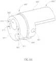
- Figure 6cschematically depicts an isometric cross section of unitary fluid channeling component 190d according to the forth exemplary embodiment of the current invention.
- Proximal opening 110 for gas tube 114 and liquid tube 112is seen in this figure opened to right I/I opening 166b and through it to groove 672 leading to left I/I opening 166a. Also seen in this figure is the intersection of grooves 672 and front groove 671
- proximal opening 110 for gas tube 114 and liquid tube 112is opened to right I/I opening 166b and through it to an I/I manifold which comprises:
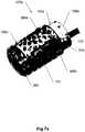
- Figure 7aschematically depicts an isometric view of an assembled tip section 230e of an endoscope having I/I channels manifold partially external to unitary fluid channeling component 190e according to a fifth exemplary embodiment of the current invention.
- cover 196dwas drawn partially transparent to show inner part 100e.
- groove 772is proximal opening 110 by hole 774 and opened on the left to left I/I opening 166a (not seen in this figure).
- cleaning fluidsare supplied to front I/I injector 364 via a front groove 771 in unitary fluid channeling component 190e.
- Front groove 771is opened in its proximal end to groove 772, and at its distal end to front I/I opening 164.
- Cover 196eis designed to fit over inner part 100e, and to provide protection to the internal components of inner part 100e. Additionally, cover 196e is tightly fitted and preferably hermetically seals grooves 771 and 772 to convert them to fluid tight conduits.
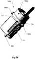
- Figure 7bschematically depicts an isometric view of inner part 100e of an endoscope tip section having I/I channels manifold partially external to unitary fluid channeling component 190e according to a fifth exemplary embodiment of the current invention.
- grooves 771 and 772 on surface of unitary fluid channeling component 190dmay be different.
- Figure 7cschematically depicts another isometric view of inner part 100e of an endoscope tip section having I/I channels manifold partially external to unitary fluid channeling component 190e according to a fifth exemplary embodiment of the current invention.
- This viewdepicts groove 772 connection to left I/I opening 166a.
- Figure 7dschematically depicts an isometric cross section of endoscope tip section 230e according to the fifth exemplary embodiment of the current invention.
- Proximal opening 110 for gas tube 114 and liquid tube 112is seen in this figure opened to right I/I opening 166b. Also seen in this figure is hole 774 connecting proximal opening 110 to front groove 771 and the connection of front groove 771 to front get opening 164.
- proximal opening 110 for gas tube 114 and liquid tube 112is opened to right I/I opening 166b and through hole 774 to I/I manifold which comprises:
- Figure 8aschematically depicts an isometric view of an assembled tip section 230f of an endoscope having I/I channels manifold external to unitary fluid channeling component 190f in inner part 100f according to a sixth exemplary embodiment of the current invention.
- groove 872 in unitary fluid channeling component 190fis connected in the right side to right I/I opening 166b and opened on the left to left I/I opening 166a.
- front groove 871is connected in its proximal end to groove 872.
- cleaning fluidsare supplied groove 871 and 872 via hole 874 connecting them to proximal opening 110.
- Cover 196fis designed to fit over inner part 100f, and to provide protection to the internal components of inner part 100f. Additionally, cover 196f is tightly fitted and preferably hermetically seals grooves 871 and 872 to convert them to fluid tight conduits.
- Figure 8bschematically depicts an isometric view of a partially disassembled tip section 230f of an endoscope having I/I channels manifold external to unitary fluid channeling component 190f in inner part 100f according to a sixth exemplary embodiment of the current invention.
- grooves 871 and 872 on surface of unitary fluid channeling component 190dmay be different.
- proximal opening 110 for gas tube 114 and liquid tube 112is opened hole 874 and through it to an I/I manifold which comprises:
- I/I injectors 336a and 336b, and optionally also 364may be constructed as identical interchangeable inserts.
- Figure 9aschematically depicts an isometric proximal view of a main section of an inner part of an endoscope tip section, according to an exemplary embodiment not forming part of the current invention
- Figure 9bschematically depicts an isometric cross section of the main section of Figure 9a , according to an exemplary embodiment not forming part of the current invention.
- Unitary fluid channeling component 990 of an inner part of a tip section of an endoscopeis configured to be located within the tip section and may be used for accommodating fluid channels, work channel and optionally cable channel/recess and for holding in place the components such as tubing/tubes, and injectors.
- Unitary fluid channeling component 990may be a part of the inner part of the tip section in a similar manner to that described for example in Figure 2c .
- Unitary fluid channeling component 990may generally include two parts: a proximal fluid channeling component section 990' and a distal fluid channeling component section 990".
- Proximal fluid channeling component section 990'may have an essentially cylindrical shape.
- Distal fluid channeling component section 990"may partially continue the cylindrical shape of proximal fluid channeling component section 990' and may have a shape of a partial cylinder (optionally elongated partial cylinder), having only a fraction of the cylinder (along the height axis of the cylinder), wherein another fraction of the cylinder (along the height axis of the cylinder) is missing.
- Distal fluid channeling component section 990"may be integrally formed as a unitary block with proximal fluid channeling component section 990'.
- the height of distal fluid channeling component section 990"may by higher than that of proximal fluid channeling component section 990'.
- the shape of the partial cylinder(for example, partial cylinder having only a fraction of a cylinder shape along one side of the height axis) may provide a space to accommodate a central section (not shown).
- proximal opening 944 of the jet fluid channel leading to distal opening of a jet channel(not shown).
- a jet fluid tubemay be inserted through a flexible shaft and may be used for delivering fluid to, and optionally suction of fluid from the body cavity, for cleaning purposes.
- proximal opening 965 of the working channel 262leading to a distal opening of the working channel (not shown).
- Unitary fluid channeling component 990includes groove 950 extending from proximal surface 991along the length of proximal fluid channeling component section 990'.
- Groove 950is adapted to guide (and optionally hold in place) an electric cable(s) which may be connected at its distal end to the electronic components such as cameras and/or light sources in the endoscope's tip section and deliver electrical power and/or command signals to the tip section and/or transmitting video signal from the cameras to be displayed to the user.
- the electrical cable(s)do not have to be threaded through proximal fluid channeling component section 990' (which may be complicated) but can be simply placed in groove 950 and held by it.
- I/I tubes proximal openingsOn proximal surface 991 of unitary fluid channeling component 990 are I/I tubes proximal openings: front I/I proximal opening 910; right side I/I proximal opening; 911 and left side I/I proximal opening 913.
- Front I/I proximal opening 910; right side I/I proximal opening 911 (not shown) and left side I/I proximal opening 913lead to front I/I channel 970; right side I/I channel 971 (not shown); and left side I/I channel 973, respectively.
- Front I/I channel 970extends from front I/I proximal opening 910, through proximal fluid channeling component section 990' and distal fluid channeling component section 990" to front I/I opening 960.
- Left side I/I channel 973extends from right I/I proximal opening 913, through proximal fluid channeling component section 990' to left I/I opening 963.
- Right side I/I channel 971(not shown) extends from right I/I proximal opening 911 (not shown), through proximal fluid channeling component section 990' to right I/I opening (not shown), similar to the left side arrangement.
- Front I/I channel 970may include two parts: a proximal part 970' (extending through proximal fluid channeling component section 990') and a distal part 970" extending through distal fluid channeling component section 990").
- Proximal part 970' of front I/I channel 970is adapted to receive, through front I/I proximal opening 910, tube 980 (shown in Figure 9c ) which is adapted to transfer fluid (liquid and/or gas) to front I/I channel 970.
- Tube 980may be divided at any point along its length (for example at junction 981) into two tubes, one is adapted to transfer gas and the other is adapted to transfer liquid (such as water).
- Left side I/I channel 973may be adapted to receive, at its proximal part, through left side I/I proximal opening 913, tube 982 (shown in Figure 9c ) which is adapted to transfer fluid (liquid and/or gas) to left side I/I channel 973.
- Tube 982may be divided at any point along its length (for example at junction 983) into two tubes, one is adapted to transfer gas and the other is adapted to transfer liquid (such as water).
- Right side I/I channelmay be adapted to receive, at its proximal, through right side I/I proximal opening 911, part tube 984 (shown in Figure 9c ) which is adapted to transfer fluid (liquid and/or gas) to right side I/I channel.
- Tube 984may be divided at any point along its length (for example at junction 985) into two tubes, one is adapted to transfer gas and the other is adapted to transfer liquid (such as water).
- the endoscope usercan thus decide which fluid (gas, liquid or both) he or she would like to pass through the I/I channel, which fluid, as mentioned herein, may be used for cleaning and/or insufflation purposes.
- Figure 9cschematically depicts an isometric proximal view of the main section of Figure 9a , having liquid and gas tubes connected thereto, according to an exemplary embodiment not forming part of the current invention.
Landscapes
- Health & Medical Sciences (AREA)
- Life Sciences & Earth Sciences (AREA)
- Surgery (AREA)
- Optics & Photonics (AREA)
- Engineering & Computer Science (AREA)
- Physics & Mathematics (AREA)
- Nuclear Medicine, Radiotherapy & Molecular Imaging (AREA)
- General Health & Medical Sciences (AREA)
- Radiology & Medical Imaging (AREA)
- Biophysics (AREA)
- Veterinary Medicine (AREA)
- Biomedical Technology (AREA)
- Heart & Thoracic Surgery (AREA)
- Medical Informatics (AREA)
- Molecular Biology (AREA)
- Animal Behavior & Ethology (AREA)
- Pathology (AREA)
- Public Health (AREA)
- Rehabilitation Therapy (AREA)
- Microelectronics & Electronic Packaging (AREA)
- Endoscopes (AREA)
- Instruments For Viewing The Inside Of Hollow Bodies (AREA)
Description
- Embodiments of the disclosure relate to a multi-camera endoscope having fluid channels.
- Endoscopes have attained great acceptance within the medical community, since they provide a means for performing procedures with minimal patient trauma, while enabling the physician to view the internal anatomy of the patient. Over the years, numerous endoscopes have been developed and categorized according to specific applications, such as cystoscopy, colonoscopy, laparoscopy, upper GI endoscopy and others. Endoscopes may be inserted into the body's natural orifices or through an incision in the skin.
- An endoscope is usually an elongated tubular shaft, rigid or flexible, having a video camera or a fiber optic lens assembly at its distal end. The shaft is connected to a handle, which sometimes includes an ocular for direct viewing. Viewing is also usually possible via an external screen. Various surgical tools may be inserted through a working channel in the endoscope for performing different surgical procedures.
- Endoscopes, such as colonoscopes, that are currently being used, typically have a front camera for viewing the internal organ, such as the colon, an illuminator, a fluid injector for cleaning the camera lens and sometimes also the illuminator and a working channel for insertion of surgical tools, for example, for removing polyps found in the colon. Often, endoscopes also have fluid injectors ("jet") for cleaning a body cavity, such as the colon, into which they are inserted. The illuminators commonly used are fiber optics which transmit light, generated remotely, to the endoscope tip section. The use of light-emitting diodes (LEDs) for illumination is also known.
US 5 685 823 describes an end structure of an endoscope which includes a front end body of a cylindrical insertion portion to be inserted in a human body. The end structure also includes a fluid discharge opening which opens into the front end body and a front end cap detachably attached to the front end body and having a fluid injection nozzle connected to the fluid discharge opening. A projection is provided on the end cap, which is fitted in the fluid discharge port, and constitutes at least a part of the fluid injection nozzle.US 5,725,476 discloses a tip assembly of an endoscope with a forward looking camera.- Among the disadvantages of such endoscopes, are their limited field of view and their complicated packing of all the required elements, such as electronics and fiber optics together with fluid carrying elements in the small sized endoscope tip section.
- There is thus a need in the art for endoscopes, such as colonoscopies, that allow a broader field of view and also enable the function of all necessary elements in the tip section.
- The foregoing examples of the related art and limitations related therewith are intended to be illustrative and not exclusive. Other limitations of the related art will become apparent to those of skill in the art upon a reading of the specification and a study of the figures.
- The present invention is defined by the independent claims and preferred embodiments of the invention are defined by the dependent claims.
- The following embodiments and aspects thereof are described and illustrated in conjunction with systems, tools and methods which are meant to be exemplary and illustrative, not limiting in scope.
- In accordance with some embodiments of the invention, there is provided a tip section of a multi-camera endoscope, the tip section comprising: a unitary fluid channeling component adapted to channel fluid for insufflations and/or irrigation (I/I), the unitary fluid channeling component comprising: a proximal opening adapted to receive a fluid tube, the proximal opening being in fluid flow connection with a front fluid (I/I) channel and a side fluid channel.
- The fluid tube may include a gas tube and a liquid tube separated from each other or combined into one tube. The front fluid channel may lead to a front opening at a distal end in the unitary fluid channeling component; and the side fluid channel may lead to a left side opening and to a right side opening in the unitary fluid channeling component. The front fluid channel may extend along the length of the unitary fluid channeling component. The side fluid channel may be essentially perpendicular to the length of the unitary fluid channeling component.
- The front opening may be adapted to receive a fluid injector and wherein the side openings are adapted to receive fluid injectors. The front channel, the side channel or both may be drilled in the unitary fluid channeling component. The front fluid channel, the side fluid channel or both may be partially internal and partially external to unitary fluid channeling component.
- The unitary fluid channeling component may further include a working channel adapted for the insertion of a medical tool. The unitary fluid channeling component may further include a jet fluid channel adapted to clean a body cavity into which the endoscope is inserted. The unitary fluid channeling component may further include a groove or a channel for guiding a cable.
- In accordance with some embodiments of the invention, there is provided a tip section of a multi-camera endoscope, the tip section comprising: a unitary fluid channeling component adapted to channel fluid for insufflations and/or irrigation, the unitary fluid channeling component comprising: a first proximal opening adapted to receive a first fluid tube and connected to a front fluid (I/I) channel; and a second proximal opening adapted to receive a second fluid tube and connected to a first side fluid (I/I) channel, wherein any of the first and second fluid tubes are adapted to transfer liquid, gas or a combination thereof to the tip section.
- The front fluid channel may lead to a front opening at a distal end in the unitary fluid channeling component; and the side fluid channel may lead to one or more side opening in the unitary fluid channeling component. The front and side openings may be adapted to receive fluid injectors. The front fluid channel may extend along the length of the unitary fluid channeling component. The first side fluid channel may lead to a left side opening and to a right side opening in the unitary fluid channeling component and may be essentially perpendicular to the length of the unitary fluid channeling component.
- The unitary fluid channeling component may further include a third proximal opening adapted to receive a third fluid tube connected to a second side fluid (I/I) channel.
- Any of the side front channel and the one or more side channel may be drilled in the unitary fluid channeling component. Any of the front fluid channel and the one or more side fluid channels may be partially internal and partially external to unitary fluid channeling component.
- The unitary fluid channeling component may further include a working channel adapted for the insertion of a medical tool. The unitary fluid channeling component may further include a jet fluid channel adapted to clean a body cavity into which the endoscope is inserted. The unitary fluid channeling component may further include a groove or a channel for guiding a cable.
- The tip section may have a diameter of about 17 mm or less. The tip section may have a diameter of about 12 mm or less. The tip section may have a diameter of about 10 mm or less.
- In accordance with some embodiments of the invention, there is provided an endoscope comprising a tip section as described herein.
- In accordance with some embodiments of the invention, there is provided a manifold for irrigation and/or insufflation (I/I) fluids, for providing gas such as CO2 or air for inflating the colon (or other body cavity) during diagnostic or minimally invasive procedure, such as colonoscopy, and/or for providing cleaning liquid, for example water or saline, for cleaning optical front surfaces in an endoscope having at least one forward looking camera and one or more side looking cameras while maintaining small size of the tip section of the endoscope.
- According to a first exemplary embodiment of the current invention, proximal opening for gas tube and liquid tube is directly opened to I/I channel manifold, located entirely within the tip section cylinder, the manifold comprises:
According to the first exemplary embodiment of the current invention, proximal opening for gas tube and liquid tube is directly opened to I/I channel manifold, entirely within the cylinder which comprises: - a) a right I/I opening, connected to the proximal opening, and into which right I/I injector is inserted;
- b) a front I/I channel connected to proximal opening, and leading to front I/I opening into which front I/I injector is inserted; and
- c) a cross I/I channel, connected to the proximal opening, and which is opened to left I/I opening a into which left I/I injector is inserted.
- According to a second exemplary embodiment of the current invention, proximal opening for gas tube and liquid tube within a cylinder in the endoscope's tip section is opened to I/I channel manifold which comprises:
- a) a right I/I opening into which right I/I injector is inserted;
- b) a front I/I channel within the cylinder, connected to front I/I opening into which front I/I injector is inserted; and
- c) a hole, connected to a groove on the surface of the cylinder which is opened to left I/I a into which left I/I injector is inserted.
- According to the third exemplary embodiment of the current invention proximal opening for gas tube and liquid tube within a cylinder in the endoscope's tip section is opened to right I/I opening and through it to a I/I manifold which comprises:
- a) a right I/I opening into which right I/I injector is inserted;
- b) a front I/I channel within the cylinder, connected to front I/I opening into which front I/I injector is inserted ; and
- c) a groove on the surface of the cylinder, which receives cleaning fluids from right I/I opening, and is opened to left I/I opening into which left I/I injector is inserted.
- According to a forth embodiment of the current invention, proximal opening for gas tube and liquid tube within a cylinder in the endoscope's tip section is opened to right I/I opening and through it to a I/I manifold which comprises:
- a) a right I/I opening into which right I/I injector is inserted;
- b) a groove on the surface of the cylinder which receives cleaning fluids from right I/I opening, and is opened to left I/I opening into which left I/I injector is inserted; and
- c) a front I/I groove on the surface of the cylinder, receiving I/I fluids from the groove, and connected to front I/I opening into which front I/I injector is inserted.
- According to a fifth embodiment of the current invention, proximal opening for gas tube and liquid tube within a cylinder in the endoscope's tip section is opened to a right I/I opening and connected through hole to I/I manifold which comprises:
- a) a right I/I opening into which right I/I injector is inserted;
- b) a groove on the surface of the cylinder which receives cleaning fluids via a hole connected to the proximal opening, and is opened to left I/I opening into which left I/I injector is inserted; and
- c) a front I/I groove on the surface of the cylinder, receiving I/I fluids from the hole, and connected to front I/I opening into which front I/I injector is inserted.
- According to a sixth embodiment of the current invention, proximal opening for gas tube and liquid tube within a cylinder in the endoscope's tip section is opened to a hole and through it to a I/I manifold which comprises:
- a) a grove on the surface of the cylinder which receives cleaning fluids from proximal opening via the hole; and is connected to right I/I opening into which right I/I injector is inserted;
- b) the same groove is connected to left I/I opening, to which left I/I injector is inserted; and
- c) a front I/I groove, receiving I/I fluids from the groove, and connected to front I/I opening into which front I/I injector is inserted.
- According to an exemplary embodiment of the current invention, the medical endoscope tip section is less than 17mm in diameter
In some embodiments the medical endoscope tip section is less than 12 mm in diameter
More details and features of the current invention and its embodiments may be found in the description and the attached drawings. - Unless otherwise defined, all technical and scientific terms used herein have the same meaning as commonly understood by one of ordinary skill in the art to which this invention belongs. Although methods and materials similar or equivalent to those described herein can be used in the practice or testing of the present invention, suitable methods and materials are described below. In case of conflict, the patent specification, including definitions, will control. In addition, the materials, methods, and examples are illustrative only and not intended to be limiting.
- Exemplary embodiments are illustrated in referenced figures. Dimensions of components and features shown in the figures are generally chosen for convenience and clarity of presentation and are not necessarily shown to scale. It is intended that the embodiments and figures disclosed herein are to be considered illustrative rather than restrictive. The figures are listed below:
Figure 1a schematically depicts an external isometric view of an endoscope having multiple fields of view according to an exemplary embodiment of the current invention.Figure 1b schematically depicts a front view of an endoscope having multiple fields of view according to an exemplary embodiment of the current invention.Figure 1c schematically depicts a side view of endoscope having multiple fields of view according to an exemplary embodiment of the current invention.Figure 2a schematically depicts an isometric cross section of an endoscope having multiple fields of view, for use within bodily cavity according to an exemplary embodiment not forming part of the invention.Figure 2b schematically depicts a cross section of an endoscope tip section having multiple fields of view showing some details of the tip section according to an exemplary embodiment not forming part of the invention.Figure 2c schematically depicts an isometric proximal view of an inner part of an endoscope tip section according to an exemplary embodiment not forming part of the invention.Figure 3a schematically depicts a partially disassembled tip section of an endoscope having I/I channels manifold internal to a unitary fluid channeling component, according to a first exemplary embodiment not forming part of the invention.Figure 3b schematically depicts an isometric cross section of an inner part of a tip section, having I/I channels manifold internal to a unitary fluid channeling component, according to a first exemplary embodiment not forming part of the invention.Figure 3c schematically depicts an isometric cross section of a unitary fluid channeling component of an inner part of a tip section having I/I channels manifold internal to the unitary fluid channeling component, according to a first exemplary embodiment not forming part of the invention.Figure 3d schematically depicts another isometric cross section of an inner part of a tip section, showing the unitary fluid channeling component having I/I channels manifold internal to it, according to a first exemplary embodiment not forming part of the invention.Figure 4a schematically depicts an isometric view of a partially disassembled tip section of an endoscope having I/I channels manifold partially internal and partially external to the unitary fluid channeling component of the tip section, according to a second exemplary embodiment of the current invention.Figure 4b schematically depicts an isometric view of an inner part of a tip section having I/I channels manifold partially internal and partially external to the unitary fluid channeling component of the tip section, according to a second exemplary embodiment of the current invention.Figure 4c schematically depicts an isometric cross section of the inner part, according to the second exemplary embodiment of the current invention.Figure 5a schematically depicts an isometric view of a partially disassembled tip section of an endoscope having I/I channels manifold partially internal and partially external to the unitary fluid channeling component of the tip section, according to a third exemplary embodiment of the current invention.Figure 5b schematically depicts an isometric view of an inner part of a tip section having I/I channels manifold partially internal and partially external to a unitary fluid channeling component of the inner part of the tip section, according to a third exemplary embodiment of the current invention.Figure 5c schematically depicts an isometric cross section of the unitary fluid channeling component, according to the third exemplary embodiment of the current invention.Figure 5d schematically depicts another isometric cross section of an inner part of a tip section of an endoscope, according to the third exemplary embodiment of the current invention.Figure 6a schematically depicts an isometric cross section view of an assembled tip section of an endoscope having I/I channels manifold external to a unitary fluid channeling component of the inner part of the tip section, according to a forth exemplary embodiment of the current invention.Figure 6b schematically depicts an isometric view of an inner part of a tip section having I/I channels manifold external to the unitary fluid channeling component, according to the forth exemplary embodiment of the current invention.Figure 6c schematically depicts an isometric cross section of a unitary fluid channeling component, according to the forth exemplary embodiment of the current invention.Figure 7a schematically depicts an isometric view of an assembled tip section of an endoscope having I/I channels manifold partially external to a unitary fluid channeling component of an inner part of the tip section, according to a fifth exemplary embodiment of the current invention.Figure 7b schematically depicts an isometric view of an inner part of a tip section having I/I channels manifold partially external to the unitary fluid channeling component, according to the fifth exemplary embodiment of the current invention.Figure 7c schematically depicts another isometric view of an inner part of a tip section having I/I channels manifold partially external to the unitary fluid channeling component, according to a fifth exemplary embodiment of the current invention.Figure 7d schematically depicts an isometric cross section of an endoscope tip section according to the fifth exemplary embodiment of the current invention.Figure 8a schematically depicts an isometric view of an assembled tip section of an endoscope having I/I channels manifold external to a unitary fluid channeling component of an inner part of the tip section, according to a sixth exemplary embodiment of the current invention.Figure 8b schematically depicts an isometric view of a partially disassembled tip section of an endoscope having I/I channels manifold external to the unitary fluid channeling component, according to a sixth exemplary embodiment of the current invention.Figure 9a schematically depicts an isometric proximal view of a main section of an inner part of an endoscope tip section, according to an exemplary embodiment not forming part of the current invention.Figure 9b schematically depicts an isometric cross section of the main section ofFigure 9a , according to an exemplary embodiment not forming part of the current invention.Figure 9c schematically depicts an isometric proximal view of the main section ofFigure 9a , having liquid and gas tubes connected thereto, according to an exemplary embodiment not forming part of the current invention.- While a number of exemplary aspects and embodiments have been discussed above, those of skill in the art will recognize certain modifications, permutations, additions and sub-combinations thereof. It is therefore intended that the following appended claims be interpreted to include all such modifications, permutations, additions and sub-combinations as are within their true scope.
- In the description and claims of the application, each of the words "comprise" "include" and "have", and forms thereof, are not necessarily limited to members in a list with which the words may be associated.
Figure 1a schematically depicts an external isometric view of anendoscope 200 having multiple fields of view according to an exemplary embodiment of the current invention.- According to an exemplary embodiment of the current invention,
tip section 230 ofendoscope 200 comprises at least a forwards looking TV camera and at least one side looking TV camera.Tip section 230 is turnable by way of flexible shaft 260 (which may also be referred to as a bending section, for example a vertebra mechanism). - It is noted that the term "endoscope" as mentioned to herein may refer particularly to a colonoscope, according to some embodiments, but is not limited only to colonoscopes. The term "endoscope" may refer to any instrument used to examine the interior of a hollow organ or cavity of the body.
Figure 1a showsfront camera element 236 of forwards looking camera 116 (seen infigure 2b ) on thefront face 320 oftip section 230. Optical axis offorwards looking camera 116 is substantially directed along the long dimension of the endoscope. However, sinceforwards looking camera 116 is typically a wide angle camera, its Field Of View (FOV) may include viewing directions at large angles to its optical axis. Additionally,optical windows LEDs figure 2b ) are also seen onfront face 320 oftip section 230. It should be noted that number of LEDs used for illumination of the FOV may vary.Distal opening 340 of working channel 262 (seen for example infigure 1b ) is preferably located onfront face 320 oftip section 230, such that a surgical tool inserted through workingchannel tube 162, and through workingchannel 262 in the endoscope's tip section and deployed beyondfront face 320 may be viewed byforwards looking camera 116.Distal opening 344 of a jet fluid channel is preferably also located onfront face 320 oftip section 230.Distal opening 344 of a jet fluid channel may be used for providing high pressure jet of fluid such as water or saline for cleaning the walls of the body cavity.- I/I injector 346 having a
nozzle 348 aimed atfront camera element 236 may be used for injecting fluid (liquid and/or gas) to wash contaminants such as blood, feces and other debris fromfront camera element 236 of forwards looking camera. Optionally the same injector is used for cleaning bothfront camera element 236 and one or bothoptical windows - Visible on the
side wall 362 oftip section 230 is the side camera (side looking camera)element 256 of side looking camera 220 (two such cameras are seen infigure 2a ) andoptical window 252 ofLED 250. Optical axis of side looking camera 220 is substantially directed perpendicular to the long dimension of the endoscope. However, since side looking camera 220 is typically a wide angle camera, its field of view may include viewing directions at large angles to its optical axis. - I/I injector 366 having a
nozzle 368 aimed atside camera element 256 may be used for injecting fluid to wash contaminants such as blood, feces and other debris fromside camera element 256 of side looking camera. The fluid may include gas which may be used for inflating a body cavity. Optionally the same injector is used for cleaning bothside camera element 256 andoptical windows 252. It is noted that according to some embodiments, the tip may include more than one window and LEDs, on the side and more than one window and LEDs in the front (for example, two windows and two LEDs on the side and three windows and three LEDs in the front). The I/I injectors are configured to clean all or a part of these windows/LEDs). I/I injectors 346 and 366 may be fed from same channel. Anoptional groove 370 helps directing the cleaning fluid fromnozzle 368 towardsside camera element 256. Groove 370 may be beneficial whenside wall 362 is near or pressed against the rectal wall. Optionally, I/I injector 366 may be at least partially recessed ingroove 370, thus reducing the maximum diameter oftip section 230 and reduce the risk of injury to the rectal wall due to friction with I/I injector 366. - In the depicted embodiment,
flexible shaft 260 is constructed of a plurality oflinks 382 connected to each other bypivots 384.Links 382 allows pushing, pulling and rotating the endoscope whilepivots 384 provide limited flexibility. The shaft is preferably covered with an elastic sheath (removed from this figure for simplification purposes). The lumen inlinks 382 holds the workingchannel tube 162. Not seen in this figure are the jet channel connected todistal opening 344, optional cleaning fluid channel and electrical cables supplying power to the LEDs and cameras and transmitting video signals from the camera. Generally, the shaft also comprises mechanical actuators (not seen), for example cables attached to the links for directing and aiming the tip section during use. - It should be noted that while only one side looking camera is seen in
figure 1a , preferably at least two side looking cameras may be located withintip section 230. When two side looking cameras are used, the side looking cameras are preferably installed such that their field of views are substantially opposing. However, different configurations and number of side looking cameras are possible within the general scope of the current invention. Figure 1b schematically depicts a front view oftip section 230 ofendoscope 200 having multiple fields of view according to an exemplary embodiment of the current invention.- According to an exemplary embodiment of the current invention,
tip section 230 ofendoscope 200 comprises at least a forwards looking TV camera and at least two side looking TV cameras.Figure 1b shows afront camera element 236 offorwards looking camera 116 on thefront face 320 oftip section 230. Additionally,optical windows LEDs front face 320 oftip section 230.Distal opening 340 of working channel anddistal opening 344 of a jet channel are preferably also located onfront face 320 oftip section 230. I/I injector 346 having anozzle 348 is also visible in this view. - Additionally, I/I
injectors camera element side camera elements Figure 1c schematically depicts a side view ofendoscope 200 having multiple fields of view according to an exemplary embodiment of the current invention.Figure 1c showsside camera element 256 of side looking camera 220,optional groove 370 andoptical window 252 on theside wall 362 oftip section 230. I/I injectors 346 and 366 are also visible in this view.Figure 2a schematically depicts a cross section isometric view of an endoscope 400 having multiple fields of view according to another exemplary embodiment not forming part of the invention.- According to an exemplary embodiment of the current invention, tip section 430 of
endoscope 200 comprises at least a forwards lookingTV camera 116 and twoside looking cameras Optical windows tip section 230.Distal opening 340 of working channel is preferably located on front face oftip section 230 such that a surgical tool inserted through the workingchannel 262 and deployed beyond front face may be viewed byforwards looking camera 116.Distal opening 344 of a jet channel is preferably also located on front face oftip section 230.- I/I injector 346 having a nozzle aimed at front camera element of
camera 116 may be used for injecting fluid (gas and/or water) to wash contaminants such as blood, feces and other debris from front camera element offorwards looking camera 116 and to inflate a body cavity (such as a colon) into which the endoscope (such as colonoscope) is inserted. Optionally the same injector is used for cleaning the front camera element and one or bothoptical windows - Visible on right hand side of
tip section 230 isside camera element 256b ofside looking camera 220b andoptical window 252b of side illuminating LED. - I/I injector 366b having a nozzle aimed at
side camera element 256b may be used for injecting fluid to wash contaminants such as blood, feces and other debris fromside camera element 256b ofside looking camera 220b and to inflate a body cavity (such as a colon) into which the endoscope (such as a colonoscope) is inserted. Optionally the same injector is used for cleaning bothfront camera element 256b andoptical windows 252b. Anoptional groove 370b helps directing the cleaning fluid from I/I injector 366b towardsside camera element 256b. - Although not seen in this figure, it is understood that
equivalent elements tip section 230. - Preferably, all the I/I injectors 346 and 366 are fed from same conduits.
- In the depicted embodiment, flexible shaft (vertebra mechanism) 260 is constructed of a plurality of links 382 (only one is marked for simplification).
Electrical cable 396 withinshaft 260 is seen connected tocameras Figure 2b schematically depicts a cross section of anendoscope 200 having multiple fields of view showing some details of thetip section 230 according to an exemplary embodiment not forming part of the invention.- According to embodiments of the current invention,
tip section 230 ofendoscope 200 comprises at least a forwards lookingTV camera 116 and twoside looking cameras cameras 116 and 220 is provided with an optical imaging system such aslens assemblies state detector arrays Front camera elements cameras 116 and 220 respectively may be a flat protective window, but preferably an optical element used as part of theimaging systems cameras 116 and 220 are similar or identical, however different camera designs may be used, for example, field ofviews - Light is provided by Light Emitting Diodes (LED) that illuminates the field of views. Preferably, white light LEDs are used.
- In the depicted embodiment, field of
view 118 offorwards looking camera 116 is illuminated by twoLEDs endoscope tip section 230 and protected byoptical window forwards looking camera 116 may be illuminated by any other number of LEDs, for example, 1, 3, 4, 5 LEDs) - Similarly, in the depicted embodiment, field of views of side looking camera 220 is illuminated by a
single LED 250 located within theendoscope tip section 230 and protected byoptical window 252. According to some embodiments, side looking camera 220 may be illuminated by any other number of LEDs, for example, 2, 3, 4, 5 LEDs) - It should be noted that number of LED light sources and their position in respect to the cameras may vary within the scope of the current invention. For example few LEDs may be positioned behind the same protective window, a camera and an LED or plurality of LED may be located behind the same protective window, etc.
Tip section 230 ofendoscope 200 is located at the distal end of aflexible shaft 260. Similarly to shafts of the art,shaft 260 comprises a workingchannel 262 for insertion of surgical tools. Additionally,shaft 260 may comprises channels for irrigation, insufflation, suction and supplying liquid for washing the external elements of the cameras and optionally the light sources.Figure 2c schematically depicts an isometric proximal view of an inner part of a tip section of an endoscope according to an exemplary embodiment not forming part of the invention showing the entrances of various channels in the inner part of a tip section.Inner part 100 of a tip section is located within the tip section and may be used for holding in place the components of the endoscope's tip section such as I/I injectors 364, 366a and 366b; cameras, lenses and other elements. A cover (not seen in this figure) is placed overinner part 100. Some elements, for example I/I injectors 364 and 366 (and optionallyside camera element 256b) may be assembled after the cover was placed.Inner part 100 of a tip section may comprise of several parts. In the depicted embodimentinner part 100 of the tip section comprises: unitaryfluid channeling component 190,central section 192 and front section 194 (examples of which are seen in some of the following figures). Unitaryfluid channeling component 190 may be made of a metal or any other material, such as a polymer, a composite material or any other appropriate material or combination of materials. Unitaryfluid channeling component 190, according to some embodiments, may generally include two parts: a proximal fluid channeling component section 190' and a distal fluid channelingcomponent section 190". Proximal fluid channeling component section 190' may have an essentially cylindrical shape. Distal unitary channelingcomponent section 190" may partially continue the cylindrical shape of proximal fluid channeling component section 190' and may have a shape of a partial cylinder (optionally elongated partial cylinder), having only a fraction of the cylinder (along the height axis of the cylinder), wherein another fraction of the cylinder (along the height axis of the cylinder) is missing. (Distal fluid channelingcomponent section 190", which may be integrally formed as a unitary block with proximal fluid channeling component section 190'. The height of distal fluid channelingcomponent section 190" may by higher than that of proximal fluid channeling component section 190'. In the case of distal fluid channelingcomponent section 190", the shape of the partial cylinder (for example, partial cylinder having only a fraction of a cylinder shape along one side of the height axis) may provide a space to accommodatecentral section 192.Central section 192 may include electronics and optical components, such as light means (LEDs for example), cameras (CCD or CMOS, for example) lenses, and other elements. This configuration ofinner part 100 of the tip section may thus be adapted to separate the fluid channels and work channel, which are located in fluid channelingcomponent 190 from the sensitive electronic and optical parts which are located incentral section 192. This paragraph may apply to any one ofmain bodies 190a-190f.- On the
proximal surface 191 of unitaryfluid channeling component 190 isproximal opening 144 of the jet fluid channel leading todistal opening 344 of the jet channel. Fluid tube (not shown in this figure for simplification purposes) may be inserted into, and affixed todistal opening 144 of the jet fluid channel. The jet fluid tube is threaded throughflexible shaft 260 and is used for delivering fluid to the body cavity. - On the
proximal surface 191 of unitaryfluid channeling component 190 isproximal opening 165 of the workingchannel 262 leading todistal opening 340 of the working channel. Working channel tube/tools may be inserted into, and optionally affixed toproximal opening 165 of the working channel. The workingchannel 162 is threaded throughflexible shaft 260 and is used for delivering surgical tools to the body cavity. Workingchannel 162 may also be used for suction of fluid from the body cavity. - On the
proximal surface 191 of unitaryfluid channeling component 190 is theelectric cable opening 150 for electrical cable 396 (seen for example infigure 2a ).Electrical cable 396 is connected at its distal end to the electronic components such as cameras and light sources in the endoscope's tip section.Electrical cable 396 is threaded throughflexible shaft 260 and is used for delivering electrical power and command signals to the tip section and transmitting video signal from the cameras to be displayed to the user. - On the
proximal surface 191 of unitaryfluid channeling component 190 is the I/I tubesproximal opening 110 forgas tube 114 and liquid tube 112 (seen for example infigure 3a ). Gas and fluid tubes may be inserted into, and affixed toproximal opening 110 of I/I channels manifold which delivers cleaning fluids to I/I injectors 364 and 366. The gas and liquid tubes (such asgas tube 114 and liquid tube 112) may be threaded throughflexible shaft 260 and are used for delivering fluid (gas and/or liquid) to I/I injectors 364 and 366 for cleaning the optical surfaces on the endoscope's tip section and for inflating a body cavity. The gas and liquid tubes (such asgas tube 114 and liquid tube 112) may also be combined into one tube and connected to the tip section as one tube. - It should be realized that it is important to keep the dimensions of the tip section of the endoscope small. Within the tight confines of the endoscope's tip section are the sensors, lenses, electric cables, at least one working channel, and a plurality of fluid channels. In contrast to endoscopes of the art, wherein each of the fluid tubes was directed to its destination, embodiments of the current invention provide I/I channels manifold to supply cleaning liquid and gas to the plurality of I/I injectors.
- While
figure 2c generically depicts the unitaryfluid channeling component 190, and shows itsproximal surface 191, the following figures depict some specific exemplary embodiments of the I/I channels manifolds and main bodies (such as cylinders), according to embodiments not forming part of the invention. Figure 3a schematically depicts a partially disassembledtip section 230a of an endoscope having I/I channels manifold internal to unitaryfluid channeling component 190a according to a first exemplary embodiment not forming part of the present invention.Cover 196a is designed to fit over inner part (of the tip section) 100a, and to provide protection to the internal components in the inner part.Holes 164', 340', 344', 242a', 336', 242b', 256b', 252b' and 166b' incover 196a are aligned with the corresponding components andchannel openings inner part 100a respectively.Optional groove 370b incover 196a enable cleaning fluid from I/I injector 366b to arrive, and clean thefront surface 252b of side looking camera. Not seen in this view are groove 370a, andholes 256a', 252a' and 166a' incover 196a which are aligned with the corresponding components andchannel openings inner part 100a respectively.- After fitting and attaching
cover 196a overinner part 100a, I/I injectors 364, 366a and 366b may be inserted into the corresponding I/I opening 164, 166a and 166b in unitaryfluid channeling component 190a through the correspondingholes 164', 166a' and 166b' incover 196a. Preferably, I/I injectors 364, 366a and 366b may be removed from I/I opening 164, 166a and 166b for cleaning the endoscope after use. Optionally, I/I injectors 364, 366a and 366b may be replaceable or disposable. Optionally, the nozzles, such asnozzle 348,nozzle 368 or any other nozzle may be inserted into the unitary fluid channeling component, such as unitaryfluid channeling components - In the first exemplary embodiment of the current invention, I/I opening 164, 166a and 166b are connected to
proximal opening 110 forgas tube 114 andliquid tube 112 via I/I manifold channels which are within unitaryfluid channeling component 190a. Distal opening 344' is the opening of a jet fluid channel which may be used for providing high pressure jet of fluid such as water or saline for cleaning the walls of the body cavity (such as the colon) and optionally for suction. Figure 3b schematically depicts an isometric cross section ofInner part 100a having I/I channels manifold internal to unitaryfluid channeling component 190a according to a first exemplary embodiment not forming part of the invention.- In the depicted
embodiment gas tube 114 andliquid tube 112 are terminated in aplug 109 adapted to fit intoproximal opening 110. It should be noted that althoughgas tube 112 appears aboveliquid tube 114, their order may be reversed, they may be positioned side by side, or replaced with a single tube or the tubes may be joined to one tube before enteringinner part 100a. Alternatively, each ofgas tube 114 andliquid tube 112 is separately connected to unitaryfluid channeling component 190, and their lumens open to a common conduit. Proximal opening 110 forgas tube 114 andliquid tube 112 is opened to I/I channel manifold. This cross section showsproximal opening 110 opened to front I/I channel 171 leading to front I/I opening 164 into which front I/I injector 364 is inserted. According to some embodiments, front I/I channel 171(may also be referred to as front fluid channel) may be drilled in unitaryfluid channeling component 190a. It should be noted that unitaryfluid channeling component 190a and other parts ofinner part 100a may be machined or be made by casting, sintering, injection or other manufacturing techniques.- Reference is now made to
Figure 3c , which schematically depicts an isometric cross section of unitaryfluid channeling component 190a having I/I channels manifold internal to it according to a first exemplary embodiment not forming part of the invention and toFigure 3d , which schematically depicts another isometric cross section of inner part 110a, showing unitaryfluid channeling component 190a having I/I channels manifold internal to it according to a first exemplary embodiment not forming part of the invention. Proximal opening 110 forgas tube 114 andliquid tube 112 is seen in this figure opened to I/I channel manifold. This cross section showsproximal opening 110 opened to cross I/I channel 172 (may also be referred to as side fluid channel or side I/I channel) leading to left I/I opening 166a into which left I/I injector 366a is inserted and to right I/I opening 166b into which right I/I injector 366b is inserted.- According to some embodiments, cross I/I channel 172 may be drilled in unitary
fluid channeling component 190a. - According to the first exemplary embodiment of the current invention,
proximal opening 110 forgas tube 114 andliquid tube 112 is directly opened to I/I channel manifold, within unitaryfluid channeling component 190a which comprises: - a) a right I/I opening 166b, connected to
proximal opening 110, and into which right I/I injector 366b is inserted; - b) a front I/I channel 171 connected to
proximal opening 110, and leading to front I/I opening 164 into which front I/I injector 364 is inserted; and - c) a cross I/I channel 172, connected to the proximal opening, and which is opened to left I/I opening 166a into which left I/I injector 366a is inserted.
Figure 4a schematically depicts an isometric view of a partially disassembledtip section 230b of an endoscope having I/I channels manifold partially internal and partially external to unitaryfluid channeling component 190b according to a second exemplary embodiment of the current invention.- In contrast to the first embodiment depicted in
figures 3 , in the embodiment depicted infigures 4 , cleaning fluids are supplied to left I/I injector 366a via agroove 472 in unitaryfluid channeling component 190b.Groove 472 is connected in one side toproximal opening 110 byhole 474 and is opened to left I/I opening 166a which can hardly be seen in this view. Cover 196b is designed to fit overinner part 100b, and to provide protection to the internal components ofinner part 100b. Additionally,cover 196b is tightly fitted and preferably hermetically sealsgroove 472 to convert it to fluid tight conduit.Figure 4b schematically depicts an isometric view ofinner part 100b of an endoscope tip section having I/I channels manifold partially internal and partially external to unitaryfluid channeling component 190b according to a second exemplary embodiment of the current invention.Figure 4c schematically depicts an isometric cross section of unitaryfluid channeling component 190b according to the second exemplary embodiment of the current invention.- According to the second exemplary embodiment of the current invention,
proximal opening 110 forgas tube 114 andliquid tube 112 is seen in this figure opened to I/I channel manifold which comprises: - a) a right I/I opening166b, connected to
proximal opening 110, into which right I/I injector 366b is inserted; - b) a front I/I channel 171 connected to front I/I opening 164 into which front I/I injector 364 is inserted; and
- c)
hole 474 connected to groove 472 which is opened to left I/I opening 166a (not seen here) into which left I/I injector 366a (not seen here) is inserted. Figure 5a schematically depicts an isometric view of a partially disassembledtip section 230c of an endoscope having I/I channels manifold partially internal and partially external to unitaryfluid channeling component 190c according to a third exemplary embodiment of the current invention.- In contrast to the first embodiment depicted in
figures 3 , in the embodiment depicted infigures 5 , fluids (liquid and/or gas) are supplied to left I/I injector 366b via agroove 572 in unitaryfluid channeling component 190c. However, in contrast to the second embodiment, depicted infigures 4 , groove 572 is connected in the right side to right I/I opening 166b and opened on the left to left I/I opening 166a which can hardly be seen in this view. Cover 196c is designed to fit overinner part 100c, and to provide protection to the internal components ofinner part 100c. Additionally,cover 196c is tightly fitted and preferably hermetically sealsgroove 572 to convert it to fluid tight conduit.Figure 5b schematically depicts an isometric view ofinner part 100c of an endoscope tip section having I/I channels manifold partially internal and partially external to unitaryfluid channeling component 190c according to a third exemplary embodiment of the current invention.- It should be noted that the location of
groove 572 on surface of unitaryfluid channeling component 190c, and its depth and shape may be different. Figure 5c schematically depicts an isometric cross section of unitaryfluid channeling component 190c according to the third exemplary embodiment of the current invention.Proximal opening 110 forgas tube 114 andliquid tube 112 is seen in this figure opened to right I/I opening 166b and through it to groove 572 leading to left I/I opening 166a.Figure 5d schematically depicts another isometric cross section of unitaryfluid channeling component 190c according to the third exemplary embodiment of the current invention.Proximal opening 110 forgas tube 114 andliquid tube 112 is seen in this figure opened to right I/I opening 166b and through it to I/I manifold which comprises:- a) a right I/I opening 166b, connected to
proximal opening 110, into which right I/I injector 366b is inserted; - b) a front I/I channel 171, connected to
proximal opening 110, ad leading to front I/I opening 164 into which front I/I injector 364b is inserted ; and - c) a
groove 572 which receives cleaning fluids from right I/I opening 166b, and is opened to left I/I opening 166a (not seen here) into which left I/I injector 366a is inserted. Figure 6a schematically depicts an isometric cross section view of an assembledtip section 230d of an endoscope having I/I channels manifold external to unitaryfluid channeling component 190d according to a forth exemplary embodiment of the current invention.- Similarly to third embodiment depicted in
figures 5 , groove 672 is connected in the right side to right I/I opening 166b and opened on the left to left I/I opening 166a. - However in contrast to the first, second and third embodiments depicted in
figures 3 ,4 , and5 , in the embodiment depicted infigures 6 , fluids are supplied to front I/I injector 364 via afront groove 671 in unitaryfluid channeling component 190d.Front groove 671 is opened in its proximal end to groove 672, and at its distal end to front I/I opening 164. Cover 196d is designed to fit overinner part 100d, and to provide protection to the internal components ofinner part 100d. Additionally,cover 196d is tightly fitted and preferably hermetically sealsgrooves Figure 6b schematically depicts an isometric view ofinner part 100d of an endoscope tip section having I/I channels manifold external to unitaryfluid channeling component 190d according to a forth exemplary embodiment of the current invention.- It should be noted that the location of
grooves fluid channeling component 190d, and their depth and shape may be different. For example, the location of any of the grooves may be completely or partially inside the cover, for example, within the walls of the cover. Figure 6c schematically depicts an isometric cross section of unitaryfluid channeling component 190d according to the forth exemplary embodiment of the current invention.Proximal opening 110 forgas tube 114 andliquid tube 112 is seen in this figure opened to right I/I opening 166b and through it to groove 672 leading to left I/I opening 166a. Also seen in this figure is the intersection ofgrooves 672 andfront groove 671- According to the forth embodiment of the current invention,
proximal opening 110 forgas tube 114 andliquid tube 112 is opened to right I/I opening 166b and through it to an I/I manifold which comprises: - a) a right I/I opening 166b, connected to
proximal opening 110, into which right I/I injector 366b is inserted; - b)
groove 672 which receives cleaning fluids from right I/I opening 166b, and is opened to left I/I opening 166a into which left I/I injector 366a is inserted; and - c) front I/I groove 671, receiving I/I fluids from
groove 672, and connected to front I/I opening 164 into which front I/I injector 364 is inserted. Figure 7a schematically depicts an isometric view of an assembledtip section 230e of an endoscope having I/I channels manifold partially external to unitaryfluid channeling component 190e according to a fifth exemplary embodiment of the current invention.- For clarity,
cover 196d was drawn partially transparent to showinner part 100e. - Similarly to second embodiment depicted in
figures 4 , groove 772 isproximal opening 110 byhole 774 and opened on the left to left I/I opening 166a (not seen in this figure). - Similarly to the forth embodiment depicted in
figures 5 , cleaning fluids are supplied to front I/I injector 364 via afront groove 771 in unitaryfluid channeling component 190e.Front groove 771 is opened in its proximal end to groove 772, and at its distal end to front I/I opening 164. Cover 196e is designed to fit overinner part 100e, and to provide protection to the internal components ofinner part 100e. Additionally,cover 196e is tightly fitted and preferably hermetically sealsgrooves Figure 7b schematically depicts an isometric view ofinner part 100e of an endoscope tip section having I/I channels manifold partially external to unitaryfluid channeling component 190e according to a fifth exemplary embodiment of the current invention.- It should be noted that the location of
grooves fluid channeling component 190d, and their depth and shape may be different. Figure 7c schematically depicts another isometric view ofinner part 100e of an endoscope tip section having I/I channels manifold partially external to unitaryfluid channeling component 190e according to a fifth exemplary embodiment of the current invention.- This view depicts
groove 772 connection to left I/I opening 166a. Figure 7d schematically depicts an isometric cross section ofendoscope tip section 230e according to the fifth exemplary embodiment of the current invention.Proximal opening 110 forgas tube 114 andliquid tube 112 is seen in this figure opened to right I/I opening 166b. Also seen in this figure ishole 774 connectingproximal opening 110 tofront groove 771 and the connection offront groove 771 to front get opening 164.- According to the fifth embodiment of the current invention,
proximal opening 110 forgas tube 114 andliquid tube 112 is opened to right I/I opening 166b and throughhole 774 to I/I manifold which comprises: - a) a right I/I opening 166b, connected to
proximal opening 110, into which right I/I injector 366b is inserted; - b)
groove 772 which receives fluids viahole 774 connected toproximal opening 110, and is opened to left I/I opening 166a into which left I/I injector 366a is inserted; and - c) front I/I groove 771, receiving I/I fluids from
hole 774, and connected to front I/I opening 164 into which front I/I injector 364b is inserted. Figure 8a schematically depicts an isometric view of an assembledtip section 230f of an endoscope having I/I channels manifold external to unitaryfluid channeling component 190f ininner part 100f according to a sixth exemplary embodiment of the current invention.- Similarly to forth embodiment depicted in
figures 6 ,groove 872 in unitaryfluid channeling component 190f is connected in the right side to right I/I opening 166b and opened on the left to left I/I opening 166a. - Similarly to forth embodiment depicted in
figures 6 ,front groove 871 is connected in its proximal end to groove 872. - However in contrast to the forth embodiment cleaning fluids are supplied
groove hole 874 connecting them toproximal opening 110. Cover 196f is designed to fit overinner part 100f, and to provide protection to the internal components ofinner part 100f. Additionally,cover 196f is tightly fitted and preferably hermetically sealsgrooves Figure 8b schematically depicts an isometric view of a partially disassembledtip section 230f of an endoscope having I/I channels manifold external to unitaryfluid channeling component 190f ininner part 100f according to a sixth exemplary embodiment of the current invention.- It should be noted that the location of
grooves fluid channeling component 190d, and their depth and shape may be different. - According to the sixth embodiment not forming part of the current invention,
proximal opening 110 forgas tube 114 andliquid tube 112 is openedhole 874 and through it to an I/I manifold which comprises: - a)
grove 872 which receives cleaning fluids fromproximal opening 110 viahole 874; connected to right I/I opening 166b into which right I/I injector 366b is inserted; - b)
same groove 872 connected to left I/I opening, to which left I/I injector 366a is inserted; and - c) front I/I groove 871, receiving I/I fluids from
groove 872, and connected to front I/I opening into which front I/I injector 364 is inserted. - It should be noted that optionally I/I injectors 336a and 336b, and optionally also 364 may be constructed as identical interchangeable inserts.
- Reference is now made to
Figure 9a which schematically depicts an isometric proximal view of a main section of an inner part of an endoscope tip section, according to an exemplary embodiment not forming part of the current invention and toFigure 9b , which schematically depicts an isometric cross section of the main section ofFigure 9a , according to an exemplary embodiment not forming part of the current invention. - Unitary
fluid channeling component 990 of an inner part of a tip section of an endoscope (such as colonoscope) is configured to be located within the tip section and may be used for accommodating fluid channels, work channel and optionally cable channel/recess and for holding in place the components such as tubing/tubes, and injectors. Unitaryfluid channeling component 990 may be a part of the inner part of the tip section in a similar manner to that described for example inFigure 2c . - Unitary
fluid channeling component 990, according to some embodiments, may generally include two parts: a proximal fluid channeling component section 990' and a distal fluid channelingcomponent section 990". Proximal fluid channeling component section 990' may have an essentially cylindrical shape. Distal fluid channelingcomponent section 990" may partially continue the cylindrical shape of proximal fluid channeling component section 990' and may have a shape of a partial cylinder (optionally elongated partial cylinder), having only a fraction of the cylinder (along the height axis of the cylinder), wherein another fraction of the cylinder (along the height axis of the cylinder) is missing. Distal fluid channelingcomponent section 990" may be integrally formed as a unitary block with proximal fluid channeling component section 990'. The height of distal fluid channelingcomponent section 990" may by higher than that of proximal fluid channeling component section 990'. In the case of distal fluid channelingcomponent section 990", the shape of the partial cylinder(for example, partial cylinder having only a fraction of a cylinder shape along one side of the height axis) may provide a space to accommodate a central section (not shown). - On
proximal surface 991 of fluid channelingcomponent 990 isproximal opening 944 of the jet fluid channel leading to distal opening of a jet channel (not shown). A jet fluid tube may be inserted through a flexible shaft and may be used for delivering fluid to, and optionally suction of fluid from the body cavity, for cleaning purposes. - On
proximal surface 991 of unitaryfluid channeling component 990 isproximal opening 965 of the workingchannel 262 leading to a distal opening of the working channel (not shown). - Unitary
fluid channeling component 990 includesgroove 950 extending from proximal surface 991along the length of proximal fluid channeling component section 990'.Groove 950 is adapted to guide (and optionally hold in place) an electric cable(s) which may be connected at its distal end to the electronic components such as cameras and/or light sources in the endoscope's tip section and deliver electrical power and/or command signals to the tip section and/or transmitting video signal from the cameras to be displayed to the user. According to this embodiment the electrical cable(s) do not have to be threaded through proximal fluid channeling component section 990' (which may be complicated) but can be simply placed ingroove 950 and held by it. - On
proximal surface 991 of unitaryfluid channeling component 990 are I/I tubes proximal openings: front I/I proximal opening 910; right side I/I proximal opening; 911 and left side I/Iproximal opening 913. Front I/I proximal opening 910; right side I/I proximal opening 911 (not shown) and left side I/I proximal opening 913 lead to front I/I channel 970; right side I/I channel 971 (not shown); and left side I/I channel 973, respectively. Front I/I channel 970 extends from front I/I proximal opening 910, through proximal fluid channeling component section 990' and distal fluid channelingcomponent section 990" to front I/I opening 960. Left side I/I channel 973 extends from right I/I proximal opening 913, through proximal fluid channeling component section 990' to left I/I opening 963. Right side I/I channel 971 (not shown) extends from right I/I proximal opening 911 (not shown), through proximal fluid channeling component section 990' to right I/I opening (not shown), similar to the left side arrangement. - Front I/I channel 970 may include two parts: a proximal part 970' (extending through proximal fluid channeling component section 990') and a
distal part 970" extending through distal fluid channelingcomponent section 990"). Proximal part 970' of front I/I channel 970 is adapted to receive, through front I/I proximal opening 910, tube 980 (shown inFigure 9c ) which is adapted to transfer fluid (liquid and/or gas) to front I/I channel 970.Tube 980 may be divided at any point along its length (for example at junction 981) into two tubes, one is adapted to transfer gas and the other is adapted to transfer liquid (such as water). - Left side I/I channel 973 may be adapted to receive, at its proximal part, through left side I/I proximal opening 913, tube 982 (shown in
Figure 9c ) which is adapted to transfer fluid (liquid and/or gas) to left side I/I channel 973.Tube 982 may be divided at any point along its length (for example at junction 983) into two tubes, one is adapted to transfer gas and the other is adapted to transfer liquid (such as water). - Right side I/I channel (not shown) may be adapted to receive, at its proximal, through right side I/I proximal opening 911, part tube 984 (shown in
Figure 9c ) which is adapted to transfer fluid (liquid and/or gas) to right side I/I channel.Tube 984 may be divided at any point along its length (for example at junction 985) into two tubes, one is adapted to transfer gas and the other is adapted to transfer liquid (such as water). - The endoscope user can thus decide which fluid (gas, liquid or both) he or she would like to pass through the I/I channel, which fluid, as mentioned herein, may be used for cleaning and/or insufflation purposes.
Figure 9c schematically depicts an isometric proximal view of the main section ofFigure 9a , having liquid and gas tubes connected thereto, according to an exemplary embodiment not forming part of the current invention.- Although the invention has been described in conjunction with specific embodiments thereof, it is evident that many alternatives, modifications and variations will be apparent to those skilled in the art. Accordingly, it is intended to embrace all such alternatives, modifications and variations that fall within the scope of the appended claims.
Claims (13)
- A tip section of a multi-camera endoscope, the tip section comprising:a forward looking camera (116);a fluid tube (112, 114, 980, 982, 984);a unitary fluid channeling component (190, 990) adapted to channel fluid for insufflation and/or irrigation; anda cover (196c) designed to fit over the unitary fluid channeling component (190, 990);said unitary fluid channeling component (190, 990) comprising:a working channel (262) adapted for the insertion of a medical tool;a front fluid channel (171); anda proximal opening (110) adapted to receive the fluid tube (112, 114, 980, 982, 984), said proximal opening (110) being in fluid flow connection with the front fluid channel (171);a front opening (164) for cleaning the front camera (116) at a distal end in said unitary fluid channeling component (190, 990), wherein said front fluid channel (171) leads to the front opening;andwherein the unitary fluid channeling component (190, 990) is integrally formed as a unitary block comprising a proximal fluid channel component (190', 990') having an essentially cylindrical shape and a distal fluid channel component (190", 990") having a shape of a partial cylinder,characterized in thatthe tip section further comprises two side looking cameras (220);said unitary fluid channeling component (190, 990) further comprisesa first side opening (166a) and a second side opening (166b) in said unitary fluid channeling component (190, 990), wherein each side opening (166a, 166b) is for cleaning one side looking camera (220);wherein the second side opening (166b) is internally fluidly connected to the proximal opening (110);a circumference groove (472, 572) fluidly connected on one side (474, 166b) to the proximal opening (110) and on the other side fluidly connected to the first side opening (166a), wherein the cover (196c) is tightly fitted and hermetically sealed to the groove (472, 572) for converting the groove (472, 572) into a fluid tight conduit.
- The tip section according to claim 1, wherein said fluid tube (112, 114, 980, 982, 984) comprises a gas tube (114) and a liquid tube (112) separated from each other or combined into one tube.
- The tip section according to claim 1,
wherein said front fluid channel (171) extends along the length of said unitary fluid channeling component (190, 990); or
wherein said front opening is adapted to receive a fluid injector and wherein said side openings are adapted to receive fluid injectors. - The tip section according to claim 1, wherein said front channel is drilled in said unitary fluid channeling component (190, 990).
- The tip section according to claim 1, wherein said front fluid channel (171) is partially internal and partially external to the unitary fluid channeling component (190, 990).
- The tip section according to claim 1, wherein said unitary fluid channeling component (190, 990) further comprises a jet fluid channel adapted to clean a body cavity into which said endoscope is inserted.
- The tip section according to claim 1, wherein said unitary fluid channeling component (190, 990) further comprises a groove or a channel for guiding a cable.
- The tip section according to claim 1,
having a diameter of about 17 mm or less; or
having a diameter of about 12 mm or less. - The tip section according to claim 1, wherein the tip section further comprises:a second fluid tube (112, 114, 980, 982, 984); andthe unitary fluid channeling component further comprises:
a second proximal opening adapted to receive the second fluid tube (112, 114, 980, 982, 984) and connected to the side fluid channel,
wherein any of said fluid tubes (112, 114, 980, 982, 984) are adapted to transfer liquid, gas or a combination thereof to said tip section. - The tip section according to claim 9,
wherein said front and side openings are adapted to receive fluid injectors; or
wherein said front fluid channel (171) extends along the length of said unitary fluid channeling component (190, 990). - The tip section according to claim 9,
wherein said side front channel is drilled in said unitary fluid channeling component (190, 990); or
wherein said front fluid channel (171) is partially internal and partially external to the unitary fluid channeling component (190, 990); or
wherein said unitary fluid channeling component (190, 990) further comprises a working channel adapted for the insertion of a medical tool; or
wherein said unitary fluid channeling component (190, 990) further comprises a jet fluid channel adapted to clean a body cavity into which said endoscope is inserted; or
wherein said unitary fluid channeling component (190, 990) further comprises a groove or a channel for guiding a cable; or
having a diameter of about 17 mm or less; or
having a diameter of about 12 mm or less. - An endoscope comprising the tip section of any one of claims 1-11.
- A colonoscope comprising the tip section of any one of claims 1-11.
Priority Applications (2)
| Application Number | Priority Date | Filing Date | Title |
|---|---|---|---|
| EP23173529.1AEP4233680B1 (en) | 2010-09-20 | 2011-09-20 | Endoscope distal section comprising a unitary fluid channeling component |
| EP20169327.2AEP3718466B1 (en) | 2010-09-20 | 2011-09-20 | Endoscope distal section comprising a unitary fluid channeling component |
Applications Claiming Priority (2)
| Application Number | Priority Date | Filing Date | Title |
|---|---|---|---|
| US38435410P | 2010-09-20 | 2010-09-20 | |
| PCT/IL2011/000745WO2012038958A2 (en) | 2010-09-20 | 2011-09-20 | Multi-camera endoscope having fluid channels |
Related Child Applications (2)
| Application Number | Title | Priority Date | Filing Date |
|---|---|---|---|
| EP20169327.2ADivisionEP3718466B1 (en) | 2010-09-20 | 2011-09-20 | Endoscope distal section comprising a unitary fluid channeling component |
| EP23173529.1ADivisionEP4233680B1 (en) | 2010-09-20 | 2011-09-20 | Endoscope distal section comprising a unitary fluid channeling component |
Publications (3)
| Publication Number | Publication Date |
|---|---|
| EP2618718A2 EP2618718A2 (en) | 2013-07-31 |
| EP2618718A4 EP2618718A4 (en) | 2017-05-10 |
| EP2618718B1true EP2618718B1 (en) | 2020-04-15 |
Family
ID=45874218
Family Applications (3)
| Application Number | Title | Priority Date | Filing Date |
|---|---|---|---|
| EP11826512.3AActiveEP2618718B1 (en) | 2010-09-20 | 2011-09-20 | Multi-camera endoscope having fluid channels |
| EP20169327.2AActiveEP3718466B1 (en) | 2010-09-20 | 2011-09-20 | Endoscope distal section comprising a unitary fluid channeling component |
| EP23173529.1AActiveEP4233680B1 (en) | 2010-09-20 | 2011-09-20 | Endoscope distal section comprising a unitary fluid channeling component |
Family Applications After (2)
| Application Number | Title | Priority Date | Filing Date |
|---|---|---|---|
| EP20169327.2AActiveEP3718466B1 (en) | 2010-09-20 | 2011-09-20 | Endoscope distal section comprising a unitary fluid channeling component |
| EP23173529.1AActiveEP4233680B1 (en) | 2010-09-20 | 2011-09-20 | Endoscope distal section comprising a unitary fluid channeling component |
Country Status (4)
| Country | Link |
|---|---|
| US (1) | US10080486B2 (en) |
| EP (3) | EP2618718B1 (en) |
| CA (1) | CA2812097A1 (en) |
| WO (1) | WO2012038958A2 (en) |
Cited By (2)
| Publication number | Priority date | Publication date | Assignee | Title |
|---|---|---|---|---|
| US11555997B2 (en) | 2015-04-27 | 2023-01-17 | Endochoice, Inc. | Endoscope with integrated measurement of distance to objects of interest |
| US12038572B2 (en) | 2015-03-18 | 2024-07-16 | Endochoice, Inc. | Systems and methods for image magnification using relative movement between an image sensor and a lens assembly |
Families Citing this family (115)
| Publication number | Priority date | Publication date | Assignee | Title |
|---|---|---|---|---|
| DE10154163A1 (en) | 2001-11-03 | 2003-05-22 | Advanced Med Tech | Device for straightening and stabilizing the spine |
| US8182422B2 (en) | 2005-12-13 | 2012-05-22 | Avantis Medical Systems, Inc. | Endoscope having detachable imaging device and method of using |
| WO2007087421A2 (en) | 2006-01-23 | 2007-08-02 | Avantis Medical Systems, Inc. | Endoscope |
| US8979931B2 (en) | 2006-12-08 | 2015-03-17 | DePuy Synthes Products, LLC | Nucleus replacement device and method |
| US8064666B2 (en) | 2007-04-10 | 2011-11-22 | Avantis Medical Systems, Inc. | Method and device for examining or imaging an interior surface of a cavity |
| US20090088789A1 (en) | 2007-09-28 | 2009-04-02 | O'neil Michael J | Balloon With Shape Control For Spinal Procedures |
| BRPI0818608A2 (en) | 2007-10-05 | 2015-04-22 | Synthes Gmbh | Sequential directional dilatation system for dilating from a nerve of a patient's anatomy, and method for forming an access opening through a psoas muscle to a patient's spine using a dilatation system |
| US11547275B2 (en) | 2009-06-18 | 2023-01-10 | Endochoice, Inc. | Compact multi-viewing element endoscope system |
| US9101268B2 (en) | 2009-06-18 | 2015-08-11 | Endochoice Innovation Center Ltd. | Multi-camera endoscope |
| US9492063B2 (en) | 2009-06-18 | 2016-11-15 | Endochoice Innovation Center Ltd. | Multi-viewing element endoscope |
| US9101287B2 (en) | 2011-03-07 | 2015-08-11 | Endochoice Innovation Center Ltd. | Multi camera endoscope assembly having multiple working channels |
| US8926502B2 (en) | 2011-03-07 | 2015-01-06 | Endochoice, Inc. | Multi camera endoscope having a side service channel |
| US11864734B2 (en) | 2009-06-18 | 2024-01-09 | Endochoice, Inc. | Multi-camera endoscope |
| US9872609B2 (en) | 2009-06-18 | 2018-01-23 | Endochoice Innovation Center Ltd. | Multi-camera endoscope |
| US11278190B2 (en) | 2009-06-18 | 2022-03-22 | Endochoice, Inc. | Multi-viewing element endoscope |
| US9901244B2 (en) | 2009-06-18 | 2018-02-27 | Endochoice, Inc. | Circuit board assembly of a multiple viewing elements endoscope |
| US10165929B2 (en) | 2009-06-18 | 2019-01-01 | Endochoice, Inc. | Compact multi-viewing element endoscope system |
| WO2010146587A1 (en) | 2009-06-18 | 2010-12-23 | Peer Medical Ltd. | Multi-camera endoscope |
| US9402533B2 (en) | 2011-03-07 | 2016-08-02 | Endochoice Innovation Center Ltd. | Endoscope circuit board assembly |
| US12137873B2 (en) | 2009-06-18 | 2024-11-12 | Endochoice, Inc. | Compact multi-viewing element endoscope system |
| US9642513B2 (en) | 2009-06-18 | 2017-05-09 | Endochoice Inc. | Compact multi-viewing element endoscope system |
| US10524645B2 (en) | 2009-06-18 | 2020-01-07 | Endochoice, Inc. | Method and system for eliminating image motion blur in a multiple viewing elements endoscope |
| US9706903B2 (en) | 2009-06-18 | 2017-07-18 | Endochoice, Inc. | Multiple viewing elements endoscope system with modular imaging units |
| US9713417B2 (en) | 2009-06-18 | 2017-07-25 | Endochoice, Inc. | Image capture assembly for use in a multi-viewing elements endoscope |
| US9474440B2 (en) | 2009-06-18 | 2016-10-25 | Endochoice, Inc. | Endoscope tip position visual indicator and heat management system |
| US10130246B2 (en) | 2009-06-18 | 2018-11-20 | Endochoice, Inc. | Systems and methods for regulating temperature and illumination intensity at the distal tip of an endoscope |
| US12220105B2 (en) | 2010-06-16 | 2025-02-11 | Endochoice, Inc. | Circuit board assembly of a multiple viewing elements endoscope |
| EP2618718B1 (en) | 2010-09-20 | 2020-04-15 | EndoChoice Innovation Center Ltd. | Multi-camera endoscope having fluid channels |
| US9560953B2 (en) | 2010-09-20 | 2017-02-07 | Endochoice, Inc. | Operational interface in a multi-viewing element endoscope |
| US9706908B2 (en) | 2010-10-28 | 2017-07-18 | Endochoice, Inc. | Image capture and video processing systems and methods for multiple viewing element endoscopes |
| CN103403605A (en) | 2010-10-28 | 2013-11-20 | 恩多巧爱思创新中心有限公司 | Optical systems for multi-sensor endoscopes |
| US10663714B2 (en) | 2010-10-28 | 2020-05-26 | Endochoice, Inc. | Optical system for an endoscope |
| US12204087B2 (en) | 2010-10-28 | 2025-01-21 | Endochoice, Inc. | Optical systems for multi-sensor endoscopes |
| US9320419B2 (en) | 2010-12-09 | 2016-04-26 | Endochoice Innovation Center Ltd. | Fluid channeling component of a multi-camera endoscope |
| CN107361721B (en) | 2010-12-09 | 2019-06-18 | 恩多巧爱思创新中心有限公司 | Flexible electronic circuit boards for multi-camera endoscopes |
| US10517464B2 (en) | 2011-02-07 | 2019-12-31 | Endochoice, Inc. | Multi-element cover for a multi-camera endoscope |
| US11304590B2 (en) | 2011-02-07 | 2022-04-19 | Endochoice, Inc. | Illuminator circuit board assembly for an endoscope |
| EP2672878B1 (en) | 2011-02-07 | 2017-11-22 | Endochoice Innovation Center Ltd. | Multi-element cover for a multi-camera endoscope |
| WO2013038806A1 (en)* | 2011-09-14 | 2013-03-21 | オリンパスメディカルシステムズ株式会社 | Endoscope device |
| US9622779B2 (en) | 2011-10-27 | 2017-04-18 | DePuy Synthes Products, Inc. | Method and devices for a sub-splenius / supra-levator scapulae surgical access technique |
| US9808232B2 (en) | 2011-11-01 | 2017-11-07 | DePuy Synthes Products, Inc. | Dilation system |
| US20140257139A1 (en)* | 2011-11-16 | 2014-09-11 | Commonwealth Scientific And Industrial Research Organisation | Optical sensing device |
| CA2798716A1 (en) | 2011-12-13 | 2013-06-13 | Peermedical Ltd. | Removable tip endoscope |
| EP2604172B1 (en) | 2011-12-13 | 2015-08-12 | EndoChoice Innovation Center Ltd. | Rotatable connector for an endoscope |
| US9265490B2 (en) | 2012-04-16 | 2016-02-23 | DePuy Synthes Products, Inc. | Detachable dilator blade |
| US9560954B2 (en) | 2012-07-24 | 2017-02-07 | Endochoice, Inc. | Connector for use with endoscope |
| US9480855B2 (en) | 2012-09-26 | 2016-11-01 | DePuy Synthes Products, Inc. | NIR/red light for lateral neuroprotection |
| US12207796B2 (en) | 2013-03-28 | 2025-01-28 | Endochoice Inc. | Multi-jet controller for an endoscope |
| US9993142B2 (en) | 2013-03-28 | 2018-06-12 | Endochoice, Inc. | Fluid distribution device for a multiple viewing elements endoscope |
| US9636003B2 (en) | 2013-06-28 | 2017-05-02 | Endochoice, Inc. | Multi-jet distributor for an endoscope |
| US9986899B2 (en) | 2013-03-28 | 2018-06-05 | Endochoice, Inc. | Manifold for a multiple viewing elements endoscope |
| EP3721784B1 (en)* | 2013-03-28 | 2023-12-20 | EndoChoice, Inc. | Compact multi-viewing element endoscope system |
| US10595714B2 (en) | 2013-03-28 | 2020-03-24 | Endochoice, Inc. | Multi-jet controller for an endoscope |
| EP3482673B1 (en)* | 2013-05-06 | 2020-09-16 | EndoChoice, Inc. | Image capture assembly for use in a multi-viewing elements endoscope |
| WO2014182723A1 (en) | 2013-05-07 | 2014-11-13 | Endochoice, Inc. | White balance enclosed for use with a multi-viewing elements endoscope |
| US10499794B2 (en) | 2013-05-09 | 2019-12-10 | Endochoice, Inc. | Operational interface in a multi-viewing element endoscope |
| US9949623B2 (en) | 2013-05-17 | 2018-04-24 | Endochoice, Inc. | Endoscope control unit with braking system |
| EP2996540A4 (en)* | 2013-05-17 | 2018-01-24 | Avantis Medical Systems, Inc. | Secondary imaging endoscopic device |
| CN105592767B (en)* | 2013-06-28 | 2018-04-03 | 恩多巧爱思股份有限公司 | Multi-viewing element endoscopy system with modular imaging unit |
| US10064541B2 (en) | 2013-08-12 | 2018-09-04 | Endochoice, Inc. | Endoscope connector cover detection and warning system |
| US9943218B2 (en) | 2013-10-01 | 2018-04-17 | Endochoice, Inc. | Endoscope having a supply cable attached thereto |
| CA2927173A1 (en)* | 2013-10-10 | 2015-04-16 | Kumudhini HENDRIX | Method and apparatus for multi-camera intubation |
| JP2016540571A (en)* | 2013-12-02 | 2016-12-28 | エンドチョイス インコーポレイテッドEndochoice, Inc. | Fluid distributor for observation endoscope |
| US9968242B2 (en) | 2013-12-18 | 2018-05-15 | Endochoice, Inc. | Suction control unit for an endoscope having two working channels |
| WO2015112747A2 (en) | 2014-01-22 | 2015-07-30 | Endochoice, Inc. | Image capture and video processing systems and methods for multiple viewing element endoscopes |
| WO2015134060A1 (en)* | 2014-03-04 | 2015-09-11 | Endochoice, Inc. | Manifold for a multiple viewing elements endoscope |
| US11234581B2 (en) | 2014-05-02 | 2022-02-01 | Endochoice, Inc. | Elevator for directing medical tool |
| US11606497B2 (en)* | 2014-06-10 | 2023-03-14 | Nitesh Ratnakar | Endoscope with multiple views and novel configurations adapted thereto |
| EP3689219B1 (en) | 2014-07-21 | 2023-08-30 | EndoChoice, Inc. | Multi-focal, multi-camera endoscope systems |
| US9980737B2 (en) | 2014-08-04 | 2018-05-29 | Medos International Sarl | Flexible transport auger |
| US10542877B2 (en) | 2014-08-29 | 2020-01-28 | Endochoice, Inc. | Systems and methods for varying stiffness of an endoscopic insertion tube |
| US10111712B2 (en) | 2014-09-09 | 2018-10-30 | Medos International Sarl | Proximal-end securement of a minimally invasive working channel |
| US10264959B2 (en) | 2014-09-09 | 2019-04-23 | Medos International Sarl | Proximal-end securement of a minimally invasive working channel |
| US9924979B2 (en) | 2014-09-09 | 2018-03-27 | Medos International Sarl | Proximal-end securement of a minimally invasive working channel |
| EP3235241B1 (en) | 2014-12-18 | 2023-09-06 | EndoChoice, Inc. | System for processing video images generated by a multiple viewing elements endoscope |
| WO2016112034A2 (en)* | 2015-01-05 | 2016-07-14 | Endochoice, Inc. | Tubed manifold of a multiple viewing elements endoscope |
| US10376181B2 (en) | 2015-02-17 | 2019-08-13 | Endochoice, Inc. | System for detecting the location of an endoscopic device during a medical procedure |
| US10524636B2 (en) | 2015-02-23 | 2020-01-07 | Uroviu Corp. | Handheld surgical endoscope |
| US10869592B2 (en) | 2015-02-23 | 2020-12-22 | Uroviu Corp. | Handheld surgical endoscope |
| US10292571B2 (en) | 2015-02-23 | 2019-05-21 | Uroviu Corporation | Handheld surgical endoscope with wide field of view (FOV) and illumination brightness adjusted by area within the FOV |
| WO2016137838A1 (en) | 2015-02-23 | 2016-09-01 | Xiaolong Ouyang | Handheld surgical endoscope |
| US10786264B2 (en) | 2015-03-31 | 2020-09-29 | Medos International Sarl | Percutaneous disc clearing device |
| US10516865B2 (en) | 2015-05-17 | 2019-12-24 | Endochoice, Inc. | Endoscopic image enhancement using contrast limited adaptive histogram equalization (CLAHE) implemented in a processor |
| US11439380B2 (en) | 2015-09-04 | 2022-09-13 | Medos International Sarl | Surgical instrument connectors and related methods |
| CN113143355A (en) | 2015-09-04 | 2021-07-23 | 美多斯国际有限公司 | Multi-shield spinal access system |
| US12150636B2 (en) | 2015-09-04 | 2024-11-26 | Medos International Sárl | Surgical instrument connectors and related methods |
| US10987129B2 (en) | 2015-09-04 | 2021-04-27 | Medos International Sarl | Multi-shield spinal access system |
| US11744447B2 (en) | 2015-09-04 | 2023-09-05 | Medos International | Surgical visualization systems and related methods |
| US11672562B2 (en) | 2015-09-04 | 2023-06-13 | Medos International Sarl | Multi-shield spinal access system |
| US20170119474A1 (en) | 2015-10-28 | 2017-05-04 | Endochoice, Inc. | Device and Method for Tracking the Position of an Endoscope within a Patient's Body |
| EP4579310A3 (en) | 2015-11-24 | 2025-09-10 | Endochoice, Inc. | Disposable air/water and suction valves for an endoscope |
| US10299838B2 (en) | 2016-02-05 | 2019-05-28 | Medos International Sarl | Method and instruments for interbody fusion and posterior fixation through a single incision |
| JP2019507628A (en) | 2016-02-24 | 2019-03-22 | エンドチョイス インコーポレイテッドEndochoice, Inc. | Circuit board assembly for multiple view element endoscopes using CMOS sensors |
| US10292570B2 (en) | 2016-03-14 | 2019-05-21 | Endochoice, Inc. | System and method for guiding and tracking a region of interest using an endoscope |
| US20190136070A1 (en)* | 2016-04-27 | 2019-05-09 | President And Fellows Of Harvard College | Anti-fouling endoscopes and uses thereof |
| EP3426129A4 (en)* | 2016-06-21 | 2020-03-04 | Endochoice, Inc. | Illuminator circuit board assembly for an endoscope |
| EP3429478B1 (en) | 2016-06-21 | 2021-04-21 | Endochoice, Inc. | Endoscope system with multiple connection interfaces to interface with different video data signal sources |
| US11684248B2 (en) | 2017-09-25 | 2023-06-27 | Micronvision Corp. | Endoscopy/stereo colposcopy medical instrument |
| US11832797B2 (en) | 2016-09-25 | 2023-12-05 | Micronvision Corp. | Endoscopic fluorescence imaging |
| WO2018136950A1 (en)* | 2017-01-23 | 2018-07-26 | Uroviu Corporation | Handheld surgical endoscope |
| US11980342B2 (en) | 2020-11-12 | 2024-05-14 | Micronvision Corp. | Minimally invasive endoscope |
| US12268358B2 (en) | 2019-12-05 | 2025-04-08 | Uroviu Corp. | Portable endoscope with side-mountable disposable portion |
| US11771304B1 (en) | 2020-11-12 | 2023-10-03 | Micronvision Corp. | Minimally invasive endoscope |
| CN108175373A (en)* | 2018-01-22 | 2018-06-19 | 周世珍 | A kind of endoscope and image processing device for anorectum department |
| US11589736B2 (en) | 2018-03-13 | 2023-02-28 | Meditrina, Inc. | Deflectable endoscope and method of use |
| US11013530B2 (en) | 2019-03-08 | 2021-05-25 | Medos International Sarl | Surface features for device retention |
| US11241252B2 (en) | 2019-03-22 | 2022-02-08 | Medos International Sarl | Skin foundation access portal |
| US11129727B2 (en) | 2019-03-29 | 2021-09-28 | Medos International Sari | Inflatable non-distracting intervertebral implants and related methods |
| US11813026B2 (en) | 2019-04-05 | 2023-11-14 | Medos International Sarl | Systems, devices, and methods for providing surgical trajectory guidance |
| EP4003138A4 (en) | 2019-07-25 | 2023-08-30 | Uroviu Corp. | DISPOSABLE ENDOSCOPY NEEDLE WITH INTEGRATED GRIPPER |
| CN114746004B (en)* | 2019-11-29 | 2025-08-05 | 富士胶片株式会社 | Endoscope |
| US11259695B2 (en) | 2020-07-21 | 2022-03-01 | Meditrina, Inc. | Endoscope and method of use |
| WO2022098898A1 (en)* | 2020-11-04 | 2022-05-12 | Werd, Llc | Tube assemblies |
| US11771517B2 (en) | 2021-03-12 | 2023-10-03 | Medos International Sarl | Camera position indication systems and methods |
| CN116370729B (en)* | 2023-06-06 | 2023-08-22 | 杭州莱恩瑟特医疗技术有限公司 | Drainage device, cleaning head for endoscope, and endoscope |
Citations (3)
| Publication number | Priority date | Publication date | Assignee | Title |
|---|---|---|---|---|
| JPH04341232A (en)* | 1991-03-11 | 1992-11-27 | Olympus Optical Co Ltd | Electronic endoscope system |
| US5725476A (en)* | 1993-11-18 | 1998-03-10 | Asahi Kogaku Kogyo Kabushiki Kaisha | Front end structure of endoscope |
| WO2009095915A1 (en)* | 2008-01-29 | 2009-08-06 | Jetprep Ltd. | Distal Head Units for Endoscopes |
Family Cites Families (860)
| Publication number | Priority date | Publication date | Assignee | Title |
|---|---|---|---|---|
| US3639714A (en) | 1970-05-15 | 1972-02-01 | Fujisoku Electric | Pushbutton alternate action switch with pushbutton shaft unconnected to alternate action actuator block |
| US3955064A (en) | 1974-05-23 | 1976-05-04 | Le Salon Bruno Demetrio Ltd. | Hair styling iron having interchangeable heating tips |
| US4084401A (en) | 1975-07-09 | 1978-04-18 | Hughes Aircraft Company | Digital watch with two buttons and improved setting and display control |
| US4037588A (en) | 1975-09-11 | 1977-07-26 | Richard Wolf Gmbh | Laryngoscopes |
| JPS5545468A (en) | 1978-09-29 | 1980-03-31 | Olympus Optical Co | Connector for endoscope |
| JPS5551270A (en) | 1978-10-11 | 1980-04-14 | Hitachi Ltd | Refrigerator with vegetable chamber |
| JPS5568350A (en) | 1978-11-20 | 1980-05-23 | Olympus Optical Co | Connector for endoscope |
| JPS5578932A (en) | 1978-12-08 | 1980-06-14 | Olympus Optical Co | Connector for light guide cable of endoscope |
| JPS5675133A (en) | 1979-11-22 | 1981-06-22 | Olympus Optical Co | Light source apparatus for endoscope |
| JPS5734823A (en) | 1980-08-07 | 1982-02-25 | Olympus Optical Co | Endoscope apparatus with adaptor |
| US4469090A (en) | 1980-12-19 | 1984-09-04 | Olympus Optical Co., Ltd. | Suction control device for an endoscope |
| JPS57192547A (en) | 1981-05-21 | 1982-11-26 | Olympus Optical Co | Ultrasonic diagnostic apparatus for body cavity |
| JPS5829439A (en) | 1981-08-14 | 1983-02-21 | オリンパス光学工業株式会社 | Wide visual field endoscope and observing method of image thereof |
| JPS5865134A (en) | 1981-10-12 | 1983-04-18 | オリンパス光学工業株式会社 | Television camera connecting apparatus for endoscope |
| DE3363322D1 (en) | 1982-02-08 | 1986-06-12 | Olympus Optical Co | Connecting device for endoscope |
| JPS58152532A (en) | 1982-03-08 | 1983-09-10 | オリンパス光学工業株式会社 | Apparatus for connecting endoscope |
| US4522196A (en) | 1982-06-11 | 1985-06-11 | Cunningham Frank W | Reusable, sterile covering for a surgical camera |
| US4590923A (en) | 1983-04-18 | 1986-05-27 | Watanabe Robert S | Arthroscope-video camera assembly |
| JPS60263916A (en) | 1984-06-13 | 1985-12-27 | Olympus Optical Co Ltd | Retrofocus type varifocal objective lens for endoscope |
| US4588294A (en) | 1984-06-27 | 1986-05-13 | Warner-Lambert Technologies, Inc. | Searching and measuring endoscope |
| US4641635A (en) | 1984-08-15 | 1987-02-10 | Olympus Optical Co., Ltd. | Endoscope apparatus |
| JPS6234525A (en) | 1985-08-09 | 1987-02-14 | オリンパス光学工業株式会社 | Endoscope apparatus |
| US4736732A (en) | 1985-09-03 | 1988-04-12 | Olympus Optical Co., Ltd. | Endoscopic fluid changing device |
| JPS6296616A (en) | 1985-10-23 | 1987-05-06 | Nippon Steel Corp | Manufacturing method of unidirectional electrical steel sheet with excellent iron loss |
| US4699463A (en) | 1985-11-01 | 1987-10-13 | Circon Corporation | Multidirectional viewing borescope |
| JPS62139626A (en) | 1985-12-13 | 1987-06-23 | オリンパス光学工業株式会社 | Flexible tube for endoscope |
| JPS62220918A (en) | 1986-03-22 | 1987-09-29 | Olympus Optical Co Ltd | Endoscope optical system |
| JPH07119893B2 (en) | 1986-09-22 | 1995-12-20 | オリンパス光学工業株式会社 | Endoscope optical system |
| US4841952A (en) | 1986-11-06 | 1989-06-27 | Olympus Optical Co., Ltd. | Endoscope with an optical system |
| JPS63143025A (en) | 1986-12-04 | 1988-06-15 | オリンパス光学工業株式会社 | Suction controller of endoscope |
| US4727859A (en) | 1986-12-29 | 1988-03-01 | Welch Allyn, Inc. | Right angle detachable prism assembly for borescope |
| US4868644A (en) | 1987-04-01 | 1989-09-19 | Olympus Optical Co. | Electronic endoscope with solid state imaging device |
| US4888639A (en) | 1987-05-22 | 1989-12-19 | Olympous Optical Co., Ltd. | Endoscope apparatus having integrated disconnectable light transmitting and image signal transmitting cord |
| JP2697822B2 (en) | 1987-05-25 | 1998-01-14 | オリンパス光学工業株式会社 | Endoscope objective lens |
| US4974075A (en) | 1987-08-11 | 1990-11-27 | Olympus Optical Co., Ltd. | Image pickup apparatus having connector capable of separately shielding grouped electrical connections |
| US4982724A (en) | 1987-12-28 | 1991-01-08 | Olympus Opicals Co. | Endoscope apparatus |
| JP2804267B2 (en) | 1988-05-02 | 1998-09-24 | オリンパス光学工業株式会社 | Endoscope objective lens |
| US4846154A (en) | 1988-06-13 | 1989-07-11 | Macanally Richard B | Dual view endoscope |
| JPH0253701A (en) | 1988-08-15 | 1990-02-22 | Ube Ind Ltd | Hardened cement material having herbicidal pericarp and method for controlling weeds or algae using this hardened material |
| JPH07122692B2 (en) | 1988-09-29 | 1995-12-25 | 富士写真光機株式会社 | Objective lens for endoscope |
| US5143054A (en) | 1988-12-28 | 1992-09-01 | Adair Edwin Lloyd | Cervical videoscope with detachable camera unit |
| US4905670A (en) | 1988-12-28 | 1990-03-06 | Adair Edwin Lloyd | Apparatus for cervical videoscopy |
| JPH0754373B2 (en) | 1989-01-18 | 1995-06-07 | 富士写真光機株式会社 | Objective lens for endoscope |
| JP3217343B2 (en) | 1989-03-23 | 2001-10-09 | オリンパス光学工業株式会社 | Image processing device |
| US4914521A (en) | 1989-02-03 | 1990-04-03 | Adair Edwin Lloyd | Sterilizable video camera cover |
| US4878485A (en) | 1989-02-03 | 1989-11-07 | Adair Edwin Lloyd | Rigid video endoscope with heat sterilizable sheath |
| JP3151437B2 (en) | 1989-05-16 | 2001-04-03 | シチズン時計株式会社 | Position control method and position control device thereof |
| DE3921233A1 (en) | 1989-06-28 | 1991-02-14 | Storz Karl Gmbh & Co | ENDOSCOPE WITH A VIDEO DEVICE AT THE DISTAL END |
| JPH03116801A (en) | 1989-09-29 | 1991-05-17 | Asahi Glass Co Ltd | resistor paste |
| FR2655169B1 (en) | 1989-11-30 | 1994-07-08 | Bull Sa | PROCESSOR WITH MULTIPLE MICROPROGRAMMED PROCESSING UNITS. |
| US4998182A (en) | 1990-02-08 | 1991-03-05 | Welch Allyn, Inc. | Connector for optical sensor |
| GB2245670A (en) | 1990-06-27 | 1992-01-08 | Ford Motor Co | A pipe coupling |
| JP3094431B2 (en) | 1990-08-24 | 2000-10-03 | 富士写真光機株式会社 | Endoscope video signal processing method |
| JP2948640B2 (en) | 1990-09-18 | 1999-09-13 | 旭光学工業株式会社 | Endoscope connector device |
| JP2848574B2 (en) | 1990-09-21 | 1999-01-20 | オリンパス光学工業株式会社 | Color shift correction device |
| JPH04176435A (en) | 1990-11-09 | 1992-06-24 | Olympus Optical Co Ltd | Endoscope apparatus |
| US5193525A (en) | 1990-11-30 | 1993-03-16 | Vision Sciences | Antiglare tip in a sheath for an endoscope |
| JPH0827429B2 (en) | 1991-03-04 | 1996-03-21 | オリンパス光学工業株式会社 | Objective lens for endoscope |
| US5223982A (en) | 1991-03-05 | 1993-06-29 | Olympus Optical Co., Ltd. | Objective lens system for endoscopes |
| JP2000325306A (en) | 1991-03-11 | 2000-11-28 | Olympus Optical Co Ltd | Endoscope device |
| JP3337682B2 (en) | 1991-03-11 | 2002-10-21 | オリンパス光学工業株式会社 | Image processing device |
| JP3078085B2 (en) | 1991-03-26 | 2000-08-21 | オリンパス光学工業株式会社 | Image processing apparatus and image processing method |
| US5386817A (en)* | 1991-06-10 | 1995-02-07 | Endomedical Technologies, Inc. | Endoscope sheath and valve system |
| JPH0549596A (en) | 1991-08-21 | 1993-03-02 | Olympus Optical Co Ltd | Suction controller for endoscope |
| JPH0549594A (en) | 1991-08-28 | 1993-03-02 | Olympus Optical Co Ltd | Electrically-driven bending type endoscope apparatus |
| US5359456A (en) | 1991-10-15 | 1994-10-25 | Olympus Optical Co., Ltd. | Objective lens system for endoscopes |
| US5485316A (en) | 1991-10-25 | 1996-01-16 | Olympus Optical Co., Ltd. | Illumination optical system for endoscopes |
| EP0543738A1 (en) | 1991-11-22 | 1993-05-26 | Welch Allyn, Inc. | Detachable servo actuated insertion tube for borescope or endoscope |
| US5894322A (en) | 1992-01-15 | 1999-04-13 | Olympus Optical Co., Ltd. | Endoscope system with improved controller |
| US5315383A (en) | 1992-02-27 | 1994-05-24 | Olympus Optical Co., Ltd. | Endoscope system |
| JP3347385B2 (en) | 1992-03-27 | 2002-11-20 | オリンパス光学工業株式会社 | Endoscope image processing device |
| JPH05309069A (en) | 1992-05-12 | 1993-11-22 | Olympus Optical Co Ltd | Electronic endoscope |
| JPH0630420A (en) | 1992-05-13 | 1994-02-04 | Olympus Optical Co Ltd | Face sequential type image pickup device |
| US5305121A (en) | 1992-06-08 | 1994-04-19 | Origin Medsystems, Inc. | Stereoscopic endoscope system |
| US5585840A (en) | 1992-06-11 | 1996-12-17 | Olympus Optical Co., Ltd. | Endoscope apparatus in which image pickup means and signal control means are connected to each other by signal transmitting means |
| US5609560A (en) | 1992-08-19 | 1997-03-11 | Olympus Optical Co., Ltd. | Medical operation device control system for controlling a operation devices accessed respectively by ID codes |
| US5630782A (en) | 1992-09-01 | 1997-05-20 | Adair; Edwin L. | Sterilizable endoscope with separable auxiliary assembly |
| JP3421038B2 (en) | 1992-09-01 | 2003-06-30 | エドウィン エル アデアー, | Sterilizable endoscope having a detachable disposable tube assembly |
| US5339800A (en) | 1992-09-10 | 1994-08-23 | Devmed Group Inc. | Lens cleaning means for invasive viewing medical instruments with anti-contamination means |
| US5313934A (en) | 1992-09-10 | 1994-05-24 | Deumed Group Inc. | Lens cleaning means for invasive viewing medical instruments |
| US5441043A (en) | 1992-09-11 | 1995-08-15 | Welch Allyn, Inc. | Video laparoscope with modular video connector and dual low-wattage light sources |
| EP0587514A1 (en) | 1992-09-11 | 1994-03-16 | Welch Allyn, Inc. | Processor module for video inspection probe |
| JPH06105800A (en) | 1992-09-28 | 1994-04-19 | Olympus Optical Co Ltd | Endoscope device |
| US5412478A (en) | 1992-09-30 | 1995-05-02 | Olympus Optical Co., Ltd. | Endoscope system which changes over switches in interlocking relation to each other within video processor and image display apparatus to perform display of endoscope image |
| US5347990A (en) | 1992-10-08 | 1994-09-20 | Wendell V. Ebling | Endoscope with sterile sleeve |
| US6450950B2 (en) | 1992-11-12 | 2002-09-17 | Karl Storz Gmbh & Co. Kg | Endoscope having stereo-lateral-view optics |
| US5836894A (en) | 1992-12-21 | 1998-11-17 | Artann Laboratories | Apparatus for measuring mechanical parameters of the prostate and for imaging the prostate using such parameters |
| JP3372980B2 (en) | 1993-01-22 | 2003-02-04 | オリンパス光学工業株式会社 | Endoscope |
| US5863286A (en) | 1993-01-27 | 1999-01-26 | Olympus Optical Company, Ltd. | Endoscope system including endoscope and disposable protection cover |
| US5460167A (en) | 1993-03-04 | 1995-10-24 | Olympus Optical Co., Ltd. | Endoscope cover with channel |
| US5512940A (en) | 1993-03-19 | 1996-04-30 | Olympus Optical Co., Ltd. | Image processing apparatus, endoscope image sensing and processing apparatus, and image processing method for performing different displays depending upon subject quantity |
| US5550582A (en) | 1993-03-19 | 1996-08-27 | Olympus Optical Co., Ltd. | Endoscope-image processing apparatus for performing image processing of emphasis in endoscope image by pigment concentration distribution |
| US5569157A (en) | 1993-05-07 | 1996-10-29 | Olympus Optical Co., Ltd. | Endoscope |
| JPH06327624A (en) | 1993-05-21 | 1994-11-29 | Olympus Optical Co Ltd | Electronic endoscope equipment |
| US5507717A (en) | 1993-05-24 | 1996-04-16 | Olympus Optical Co., Ltd. | Device for bending the insertion section of an endoscope |
| US5475420A (en) | 1993-06-09 | 1995-12-12 | Origin Medsystems, Inc. | Video imaging system with image processing optimized for small-diameter endoscopes |
| US5589874A (en) | 1993-06-09 | 1996-12-31 | Origin Medsystems, Inc. | Video imaging system with external area processing optimized for small-diameter endoscopes |
| JPH07352A (en) | 1993-06-15 | 1995-01-06 | Olympus Optical Co Ltd | Insertion auxiliary tool for endoscope |
| US5447148A (en) | 1993-07-08 | 1995-09-05 | Vision Sciences, Inc. | Endoscopic contamination protection system to facilitate cleaning of endoscopes |
| US5852511A (en) | 1993-10-20 | 1998-12-22 | Olympus Optical Co. Ltd | Optical system for non-flexible endoscopes |
| US5746695A (en) | 1993-11-18 | 1998-05-05 | Asahi Kogaku Kogyo Kabushiki Kaisha | Front end structure of endoscope |
| JP3392920B2 (en) | 1993-11-26 | 2003-03-31 | ペンタックス株式会社 | Endoscope tip |
| US6500114B1 (en) | 1993-11-23 | 2002-12-31 | Dofi Technologies, Inc. | Method of extracting biopsy cells from the breast |
| GB9324047D0 (en) | 1993-11-23 | 1994-01-12 | Watts Jonathan | Image detecting apparatus |
| JP3765500B2 (en) | 1993-12-24 | 2006-04-12 | オリンパス株式会社 | Endoscope objective lens |
| JPH07191265A (en) | 1993-12-27 | 1995-07-28 | Olympus Optical Co Ltd | Endoscope optical system |
| US5483951A (en) | 1994-02-25 | 1996-01-16 | Vision-Sciences, Inc. | Working channels for a disposable sheath for an endoscope |
| US5743846A (en) | 1994-03-17 | 1998-04-28 | Olympus Optical Co., Ltd. | Stereoscopic endoscope objective lens system having a plurality of front lens groups and one common rear lens group |
| US5590660A (en) | 1994-03-28 | 1997-01-07 | Xillix Technologies Corp. | Apparatus and method for imaging diseased tissue using integrated autofluorescence |
| US5547455A (en) | 1994-03-30 | 1996-08-20 | Medical Media Systems | Electronically steerable endoscope |
| US5685823A (en)* | 1994-03-30 | 1997-11-11 | Asahi Kogaku Kogyo Kabushiki Kaisha | End structure of endoscope |
| US6025873A (en) | 1994-04-07 | 2000-02-15 | Olympus Optical Co., Ltd. | Endoscope system provided with low-pass filter for moire removal |
| US5653677A (en) | 1994-04-12 | 1997-08-05 | Fuji Photo Optical Co. Ltd | Electronic endoscope apparatus with imaging unit separable therefrom |
| JP3497231B2 (en) | 1994-04-22 | 2004-02-16 | オリンパス株式会社 | Freeze device |
| US5656011A (en) | 1994-04-28 | 1997-08-12 | Epflex Feinwerktechnik Gmbh | Endoscope tube system |
| US5782751A (en) | 1994-05-26 | 1998-07-21 | Asahi Kogaku Kogyo Kabushiki Kaisha | Side view endoscope |
| US5679110A (en) | 1994-05-26 | 1997-10-21 | Olympus Optical Co., Ltd. | Endoscope cover attaching apparatus |
| JP3379821B2 (en) | 1994-05-31 | 2003-02-24 | オリンパス光学工業株式会社 | Endoscope |
| US5518502A (en)* | 1994-06-08 | 1996-05-21 | The United States Surgical Corporation | Compositions, methods and apparatus for inhibiting fogging of endoscope lenses |
| US5452391A (en) | 1994-06-22 | 1995-09-19 | Xintec Corporation | Reusable optical fiber connector adapter with optical barrier |
| US5823943A (en) | 1994-08-02 | 1998-10-20 | Olympus Optical Co., Ltd | Light source device for endoscopes |
| DE19535114B4 (en) | 1994-09-21 | 2013-09-05 | Hoya Corp. | Endoscope system with fluorescence diagnosis |
| JP3051035B2 (en) | 1994-10-18 | 2000-06-12 | 富士写真光機株式会社 | Objective lens for endoscope |
| JP2998578B2 (en) | 1994-10-20 | 2000-01-11 | 富士写真光機株式会社 | Endoscope main body operation unit |
| US5940126A (en) | 1994-10-25 | 1999-08-17 | Kabushiki Kaisha Toshiba | Multiple image video camera apparatus |
| US6184923B1 (en) | 1994-11-25 | 2001-02-06 | Olympus Optical Co., Ltd. | Endoscope with an interchangeable distal end optical adapter |
| JP3331273B2 (en) | 1994-12-26 | 2002-10-07 | 富士写真光機株式会社 | Endoscope |
| JP3732865B2 (en) | 1995-01-18 | 2006-01-11 | ペンタックス株式会社 | Endoscope device |
| US5876326A (en) | 1995-03-10 | 1999-03-02 | Olympus Optical Co., Ltd. | Electronic endoscope with grounded spirally-wound lead wires |
| US5605530A (en) | 1995-03-23 | 1997-02-25 | Fischell; Robert E. | System for safe implantation of radioisotope stents |
| US5716323A (en) | 1995-04-05 | 1998-02-10 | Karl Storz Imaging | Electrical isolation of endoscopic video camera |
| US5913817A (en) | 1995-04-05 | 1999-06-22 | Karl Storz Imaging | Electrical isolation of endoscopic video camera |
| US6080104A (en) | 1995-05-16 | 2000-06-27 | Asahi Kogaku Kogyo Kabushiki Kaisha | Electronic endoscope system |
| US5830124A (en) | 1995-05-18 | 1998-11-03 | Fuji Photo Optical Co., Ltd. | Guide structure for electronic endoscope systems |
| US6606113B2 (en) | 1995-05-24 | 2003-08-12 | Olympus Optical Co., Ltd. | Stereoscopic endocsope system and TV imaging system for endoscope |
| JP3461974B2 (en) | 1995-05-31 | 2003-10-27 | 株式会社町田製作所 | Endoscope |
| JPH0910170A (en) | 1995-06-29 | 1997-01-14 | Olympus Optical Co Ltd | Objective optical system of endoscope |
| DE19530478A1 (en) | 1995-08-18 | 1997-02-20 | Storz Karl Gmbh & Co | Medical instrument |
| JPH0980305A (en) | 1995-09-11 | 1997-03-28 | Fuji Photo Optical Co Ltd | Endoscope objective lens |
| US6117068A (en) | 1995-10-19 | 2000-09-12 | Elite Genetics, Inc | Artificial insemination system |
| JPH09113796A (en) | 1995-10-20 | 1997-05-02 | Olympus Optical Co Ltd | Hard mirror optical system |
| US5871440A (en) | 1995-12-15 | 1999-02-16 | Olympus Optical Co., Ltd. | Endoscope |
| DE29520445U1 (en) | 1995-12-22 | 1996-02-08 | Wolf Gmbh Richard | Device for connecting a light guide cable to the light guide connection of an endoscope |
| US5846249A (en) | 1996-02-07 | 1998-12-08 | Pinotage, Llc | Video gynecological examination apparatus |
| US6139490A (en) | 1996-02-22 | 2000-10-31 | Precision Optics Corporation | Stereoscopic endoscope with virtual reality viewing |
| US5792044A (en) | 1996-03-22 | 1998-08-11 | Danek Medical, Inc. | Devices and methods for percutaneous surgery |
| JP3315859B2 (en) | 1996-04-03 | 2002-08-19 | 旭光学工業株式会社 | Electronic endoscope |
| US6466256B1 (en) | 1996-04-05 | 2002-10-15 | Asahi Kogaku Kogyo Kabushiki Kaisha | Video-signal processing device connectable to an electronic endoscope |
| JPH09299327A (en) | 1996-05-15 | 1997-11-25 | Olympus Optical Co Ltd | Light source device for endoscope |
| US5860913A (en) | 1996-05-16 | 1999-01-19 | Olympus Optical Co., Ltd. | Endoscope whose distal cover can be freely detachably attached to main distal part thereof with high positioning precision |
| JPH09325273A (en) | 1996-06-06 | 1997-12-16 | Olympus Optical Co Ltd | Zooming image pickup optical system for endoscope |
| US6296608B1 (en) | 1996-07-08 | 2001-10-02 | Boston Scientific Corporation | Diagnosing and performing interventional procedures on tissue in vivo |
| US6217500B1 (en) | 1996-07-26 | 2001-04-17 | Twist-Ease, Inc. | Method and apparatus for dispensing twist-ties |
| US6009189A (en) | 1996-08-16 | 1999-12-28 | Schaack; David F. | Apparatus and method for making accurate three-dimensional size measurements of inaccessible objects |
| US5751340A (en) | 1996-08-21 | 1998-05-12 | Karl Storz Gmbh & Co. | Method and apparatus for reducing the inherently dark grid pattern from the video display of images from fiber optic bundles |
| JP3752320B2 (en) | 1996-08-23 | 2006-03-08 | オリンパス株式会社 | Optical equipment coupling mechanism |
| DE19636152C2 (en) | 1996-09-06 | 1999-07-01 | Schneider Co Optische Werke | Compact wide angle lens |
| JPH1090603A (en) | 1996-09-18 | 1998-04-10 | Olympus Optical Co Ltd | Endscopic optical system |
| US20040220451A1 (en) | 1996-10-04 | 2004-11-04 | Dietrich Gravenstein | Imaging scope |
| US5964696A (en) | 1996-10-24 | 1999-10-12 | Smith & Nephew, Inc. | Stereoscopic imaging by alternately blocking light |
| US6104540A (en) | 1996-11-05 | 2000-08-15 | Olympus Optical Co., Ltd. | Decentered optical system |
| JP3911053B2 (en) | 1996-11-08 | 2007-05-09 | ペンタックス株式会社 | Connector device for electronic endoscope device |
| JP3911055B2 (en) | 1996-11-26 | 2007-05-09 | ペンタックス株式会社 | Connector device for electronic endoscope device |
| US6128144A (en) | 1996-12-02 | 2000-10-03 | Olympus Optical Co., Ltd. | Optical system for camera and camera apparatus |
| JP3532368B2 (en) | 1996-12-10 | 2004-05-31 | 富士写真フイルム株式会社 | Endoscope |
| JP4054094B2 (en) | 1996-12-27 | 2008-02-27 | オリンパス株式会社 | Electronic endoscope |
| US6142930A (en) | 1997-01-13 | 2000-11-07 | Asahi Kogaku Kogyo Kabushiki Kaisha | Electronic endoscope having compact construction |
| AUPO478397A0 (en) | 1997-01-31 | 1997-02-20 | Fairmont Medical Products Pty Ltd | Endoscopic drape |
| US6215517B1 (en) | 1997-04-14 | 2001-04-10 | Asahi Kogaku Kogyo Kabushiki Kaisha | Electronic endoscope system |
| JPH1123972A (en) | 1997-07-02 | 1999-01-29 | Olympus Optical Co Ltd | Image-forming optical device |
| US6538687B1 (en) | 1997-07-23 | 2003-03-25 | Olympus Optical Co., Ltd. | Endoscopic imaging system making it possible to detachably attach expansion unit having external expansion facility and add expansion facility for improving capability of system |
| DE19732991C2 (en) | 1997-07-31 | 1999-09-09 | Storz Karl Gmbh & Co | Endoscope and method for mounting components of an optical system |
| US6132369A (en) | 1997-08-21 | 2000-10-17 | Fuji Photo Optical Co., Ltd. | Opening/closing and flow rate controller for an endoscope pipe |
| US5924976A (en) | 1997-08-21 | 1999-07-20 | Stelzer; Paul | Minimally invasive surgery device |
| US6069698A (en) | 1997-08-28 | 2000-05-30 | Olympus Optical Co., Ltd. | Optical imaging apparatus which radiates a low coherence light beam onto a test object, receives optical information from light scattered by the object, and constructs therefrom a cross-sectional image of the object |
| US6043839A (en) | 1997-10-06 | 2000-03-28 | Adair; Edwin L. | Reduced area imaging devices |
| US6211904B1 (en) | 1997-09-11 | 2001-04-03 | Edwin L. Adair | Surgical devices incorporating reduced area imaging devices |
| US5929901A (en) | 1997-10-06 | 1999-07-27 | Adair; Edwin L. | Reduced area imaging devices incorporated within surgical instruments |
| US5986693A (en) | 1997-10-06 | 1999-11-16 | Adair; Edwin L. | Reduced area imaging devices incorporated within surgical instruments |
| US7030904B2 (en) | 1997-10-06 | 2006-04-18 | Micro-Medical Devices, Inc. | Reduced area imaging device incorporated within wireless endoscopic devices |
| US6310642B1 (en) | 1997-11-24 | 2001-10-30 | Micro-Medical Devices, Inc. | Reduced area imaging devices incorporated within surgical instruments |
| JPH11125773A (en) | 1997-10-21 | 1999-05-11 | Olympus Optical Co Ltd | Endoscope |
| DE69822958T2 (en) | 1997-10-23 | 2005-03-10 | Olympus Corporation | Image recording device with means for expanding the dynamic range |
| IL122111A (en) | 1997-11-04 | 2004-06-01 | Sightline Techn Ltd | Video rectoscope |
| JPH11137512A (en) | 1997-11-07 | 1999-05-25 | Toshiba Corp | Endoscope device |
| US6982740B2 (en) | 1997-11-24 | 2006-01-03 | Micro-Medical Devices, Inc. | Reduced area imaging devices utilizing selected charge integration periods |
| JP4036943B2 (en) | 1997-12-09 | 2008-01-23 | ペンタックス株式会社 | Connection device between endoscope and light source device |
| DE19804234C1 (en) | 1998-02-04 | 1999-11-04 | Storz Karl Gmbh & Co | Endoscope, especially video endoscope |
| US6210322B1 (en) | 1998-02-09 | 2001-04-03 | Donny M. Byrne | Adapter for the connection of a water bottle to an endoscope |
| JPH11225951A (en) | 1998-02-17 | 1999-08-24 | Olympus Optical Co Ltd | Treatment tool for endoscope |
| JP3969827B2 (en) | 1998-03-10 | 2007-09-05 | オリンパス株式会社 | Endoscope device |
| US6196967B1 (en) | 1998-03-18 | 2001-03-06 | Linvatec Corporation | Arthroscopic component joining system |
| US6334845B1 (en) | 1998-03-25 | 2002-01-01 | Fuji Photo Optical Co., Ltd. | Electronic-endoscope light source unit for setting shading period |
| JP4112066B2 (en) | 1998-03-25 | 2008-07-02 | オリンパス株式会社 | Imaging optical system and imaging apparatus, camera apparatus, observation apparatus, and endoscope apparatus using the same |
| DE19813383A1 (en) | 1998-03-26 | 1999-10-07 | Storz Karl Gmbh & Co | Device with a transmitter unit, via which the position of a medical instrument can be detected in the context of a CAS system |
| JP4054104B2 (en) | 1998-04-10 | 2008-02-27 | オリンパス株式会社 | Endoscopic image processing device |
| US6462770B1 (en) | 1998-04-20 | 2002-10-08 | Xillix Technologies Corp. | Imaging system with automatic gain control for reflectance and fluorescence endoscopy |
| JP4198784B2 (en) | 1998-05-22 | 2008-12-17 | オリンパス株式会社 | Optical prism, lens frame and optical assembly |
| US6629630B2 (en) | 1998-06-19 | 2003-10-07 | Scimed Life Systems, Inc. | Non-circular resection device and endoscope |
| JP2000010000A (en) | 1998-06-24 | 2000-01-14 | Olympus Optical Co Ltd | Image forming optical system |
| JP2000010003A (en) | 1998-06-24 | 2000-01-14 | Olympus Optical Co Ltd | Image-formation optical system |
| US6545703B1 (en) | 1998-06-26 | 2003-04-08 | Pentax Corporation | Electronic endoscope |
| JP2000047109A (en) | 1998-07-24 | 2000-02-18 | Olympus Optical Co Ltd | Image forming optical system |
| JP2000066115A (en) | 1998-08-21 | 2000-03-03 | Fuji Photo Optical Co Ltd | Light source device for endoscope |
| JP2000066106A (en) | 1998-08-21 | 2000-03-03 | Olympus Optical Co Ltd | Image forming optical system and observation optical system |
| JP2000066105A (en) | 1998-08-21 | 2000-03-03 | Olympus Optical Co Ltd | Image forming optical system |
| DE19839188C2 (en) | 1998-08-28 | 2003-08-21 | Storz Endoskop Gmbh Schaffhaus | endoscope |
| WO2000019926A1 (en) | 1998-10-05 | 2000-04-13 | Scimed Life Systems, Inc. | Large area thermal ablation |
| JP2000199853A (en) | 1998-10-26 | 2000-07-18 | Olympus Optical Co Ltd | Image-formation optical system and observation optical system |
| FR2785132B1 (en) | 1998-10-27 | 2000-12-22 | Tokendo Sarl | DISTAL COLOR CCD SENSOR VIDEOENDOSCOPIC PROBE |
| JP2000137172A (en) | 1998-10-29 | 2000-05-16 | Olympus Optical Co Ltd | Image pickup device |
| US6322496B1 (en) | 1998-11-06 | 2001-11-27 | Asahi Kogaku Kogyo Kabushiki Kaisha | Electronic endoscope system |
| US6690410B1 (en) | 1999-06-09 | 2004-02-10 | Olympus Optical Co., Ltd. | Image processing unit with expandable image signal processing capability and endoscopic imaging system |
| JP4014186B2 (en) | 1998-11-30 | 2007-11-28 | フジノン株式会社 | Endoscope objective lens |
| JP2000171727A (en) | 1998-12-03 | 2000-06-23 | Fuji Photo Optical Co Ltd | Endoscopic device |
| JP2000171717A (en) | 1998-12-07 | 2000-06-23 | Olympus Optical Co Ltd | Image-formation optical system |
| US6720988B1 (en) | 1998-12-08 | 2004-04-13 | Intuitive Surgical, Inc. | Stereo imaging system and method for use in telerobotic systems |
| US6937267B1 (en) | 1998-12-22 | 2005-08-30 | Pentax Corporation | Electronic endoscope |
| JP4223609B2 (en) | 1998-12-24 | 2009-02-12 | Hoya株式会社 | Endoscope device |
| US6473116B1 (en) | 1998-12-28 | 2002-10-29 | Asahi Kogaku Kogyo Kabushiki Kaisha | Electronic endoscope |
| JP2000210251A (en) | 1999-01-21 | 2000-08-02 | Olympus Optical Co Ltd | Endoscope unit |
| US6530881B1 (en) | 1999-01-21 | 2003-03-11 | Vision Sciences, Inc. | Sheath apparatus for endoscopes and methods for forming same |
| KR20010110420A (en) | 1999-01-26 | 2001-12-13 | 추후제출 | Autofluorescence imaging system for endoscopy |
| DE19903437C1 (en) | 1999-01-29 | 2000-08-31 | Storz Karl Gmbh & Co Kg | Device for pivoting in and out at least one optical component within an endoscopic system |
| FR2790196A1 (en) | 1999-02-26 | 2000-09-01 | Charles Baur | ENDOSCOPIC OBSERVATION DEVICE |
| DE19910295C2 (en) | 1999-03-09 | 2002-06-20 | Storz Karl Gmbh & Co Kg | Medical or technical endoscopic instrument |
| US6527704B1 (en) | 1999-03-10 | 2003-03-04 | Stryker Corporation | Endoscopic camera system integrated with a trocar sleeve |
| US6249391B1 (en) | 1999-03-11 | 2001-06-19 | Olympus Optical Co., Ltd. | Image-forming optical system |
| JP2000330015A (en) | 1999-03-12 | 2000-11-30 | Fuji Photo Optical Co Ltd | Variable observation depth objective lens for endoscopes |
| US7355625B1 (en) | 1999-03-17 | 2008-04-08 | Olympus Corporation | Endoscopic imaging system and endoscope system |
| JP3309276B2 (en) | 1999-03-17 | 2002-07-29 | エーカポット・パンナチェート | Fluorescent endoscope system |
| US6461304B1 (en) | 1999-03-30 | 2002-10-08 | Fuji Photo Optical Co., Ltd. | Ultrasound inspection apparatus detachably connected to endoscope |
| US6569084B1 (en) | 1999-03-31 | 2003-05-27 | Olympus Optical Co., Ltd. | Endoscope holder and endoscope device |
| DE19924189C2 (en) | 1999-05-27 | 2001-04-26 | Storz Karl Gmbh & Co Kg | Image sensor module and method for assembling such an image sensor module |
| DE19924440A1 (en) | 1999-05-28 | 2000-12-07 | Storz Karl Gmbh & Co Kg | Shaft for a flexible endoscope |
| US8229549B2 (en) | 2004-07-09 | 2012-07-24 | Tyco Healthcare Group Lp | Surgical imaging device |
| DE19925323A1 (en) | 1999-06-02 | 2000-12-14 | Winter & Ibe Olympus | Electronic endoscope with detachable shaft, to enable easier changing of shaft length, with shaft change accomplished by use of mechanical and optical fiber couplings |
| IL143258A0 (en) | 2001-05-20 | 2002-04-21 | Given Imaging Ltd | A method for in vivo imaging of the gastrointestinal tract in unmodified conditions |
| JP2001008199A (en) | 1999-06-24 | 2001-01-12 | Fuji Photo Optical Co Ltd | Electronic endoscope device |
| US6638212B1 (en) | 1999-07-27 | 2003-10-28 | Olympus Optical | Endoscope system having storage part of endoscope-related-data provided in endoscope |
| US6464633B1 (en) | 1999-08-23 | 2002-10-15 | Olympus Optical Co., Ltd. | Light source device for endoscope using DMD |
| JP2001061762A (en) | 1999-08-31 | 2001-03-13 | Olympus Optical Co Ltd | Method for assembling endoscope |
| US20020087047A1 (en) | 1999-09-13 | 2002-07-04 | Visionscope, Inc. | Miniature endoscope system |
| JP3722458B2 (en) | 1999-09-20 | 2005-11-30 | フジノン株式会社 | Endoscope objective lens |
| US7037258B2 (en) | 1999-09-24 | 2006-05-02 | Karl Storz Imaging, Inc. | Image orientation for endoscopic video displays |
| US6471637B1 (en) | 1999-09-24 | 2002-10-29 | Karl Storz Imaging, Inc. | Image orientation for endoscopic video displays |
| JP2001095747A (en) | 1999-09-30 | 2001-04-10 | Olympus Optical Co Ltd | Electronic endoscope |
| JP2001174744A (en) | 1999-10-06 | 2001-06-29 | Olympus Optical Co Ltd | Optical scanning probe device |
| US6318907B1 (en) | 1999-10-08 | 2001-11-20 | Visteon Global Technologies, Inc. | Fiber optic connector |
| DE19955229C1 (en) | 1999-11-17 | 2001-08-09 | Winter & Ibe Olympus | Endoscope with distal video camera and camera rotating device |
| JP2003514616A (en) | 1999-11-24 | 2003-04-22 | グリースハーバー ウント コンパニー アーゲー シャフハウゼン | Apparatus for improving the outflow of aqueous humor in a living eye |
| US6677984B2 (en) | 1999-11-30 | 2004-01-13 | Pentax Corporation | Electronic endoscope system |
| US7772786B2 (en) | 1999-12-02 | 2010-08-10 | Olympus Corporation | Battery-powered light source device for endoscope |
| US6422995B2 (en) | 1999-12-03 | 2002-07-23 | Fuji Photo Optical Co., Ltd. | Linear transmission member driving unit for endoscope |
| DE10059661B4 (en) | 1999-12-03 | 2016-01-28 | Hoya Corp. | Electronic endoscope |
| JP4360724B2 (en) | 2000-01-11 | 2009-11-11 | Hoya株式会社 | Signal switching device for electronic endoscope |
| JP4450297B2 (en) | 2000-01-12 | 2010-04-14 | 富士フイルム株式会社 | Endoscope objective lens |
| JP2001198086A (en) | 2000-01-21 | 2001-07-24 | Olympus Optical Co Ltd | Connector device for medical apparatus |
| US6623423B2 (en) | 2000-02-29 | 2003-09-23 | Olympus Optical Co., Ltd. | Surgical operation system |
| EP1261282B1 (en) | 2000-03-03 | 2013-09-25 | C. R. Bard, Inc. | Endoscopic tissue apposition device with multiple suction ports |
| US7104951B2 (en) | 2000-03-15 | 2006-09-12 | Olympus Corporation | Endoscope apparatus with drum part to wind insertion part therearound |
| IL138632A (en) | 2000-09-21 | 2008-06-05 | Minelu Zonnenschein | Multiple view endoscopes |
| JP4477280B2 (en) | 2000-03-16 | 2010-06-09 | メディガス リミテッド | Gastric fistula wall forming device |
| US6837846B2 (en) | 2000-04-03 | 2005-01-04 | Neo Guide Systems, Inc. | Endoscope having a guide tube |
| IL135571A0 (en) | 2000-04-10 | 2001-05-20 | Doron Adler | Minimal invasive surgery imaging system |
| JP2001353124A (en) | 2000-04-10 | 2001-12-25 | Olympus Optical Co Ltd | Endoscopic apparatus |
| US6712760B2 (en) | 2000-04-10 | 2004-03-30 | Pentax Corporation | Television device of portable endoscope |
| US6692430B2 (en) | 2000-04-10 | 2004-02-17 | C2Cure Inc. | Intra vascular imaging apparatus |
| US6656111B2 (en) | 2000-04-19 | 2003-12-02 | Pentax Corporation | Control device for an endoscope |
| US20010055062A1 (en) | 2000-04-20 | 2001-12-27 | Keiji Shioda | Operation microscope |
| JP3619424B2 (en) | 2000-05-10 | 2005-02-09 | ペンタックス株式会社 | Radial scanning forward-view ultrasound endoscope |
| EP1292214A4 (en) | 2000-05-19 | 2007-07-04 | Bard Inc C R | Guidewire with viewing capability |
| US6829003B2 (en) | 2000-06-02 | 2004-12-07 | Pentax Corporation | Sampling pulse generator of electronic endoscope |
| WO2001095943A2 (en) | 2000-06-14 | 2001-12-20 | Medarex, Inc. | Prodrug compounds with an oligopeptide having an isoleucine residue |
| JP4465542B2 (en) | 2000-06-22 | 2010-05-19 | 富士フイルム株式会社 | Electronic endoscope device |
| JP4445647B2 (en) | 2000-06-30 | 2010-04-07 | オリンパス株式会社 | Objective lens |
| US7242833B2 (en) | 2000-07-10 | 2007-07-10 | University Health Network | Method and apparatus for high resolution coherent optical imaging |
| JP3945133B2 (en) | 2000-08-02 | 2007-07-18 | フジノン株式会社 | Endoscope observation window cleaning device |
| JP2002058636A (en) | 2000-08-21 | 2002-02-26 | Olympus Optical Co Ltd | Electronic endoscope |
| JP2002065575A (en) | 2000-08-25 | 2002-03-05 | Olympus Optical Co Ltd | Electronic endoscope |
| JP2002065589A (en) | 2000-08-30 | 2002-03-05 | Olympus Optical Co Ltd | Endoscope device |
| DE50113303D1 (en) | 2000-09-05 | 2008-01-03 | Storz Endoskop Gmbh | SYSTEM AND METHOD FOR THE CENTRALIZED CONTROL OF DEVICES USED DURING OPERATION |
| JP3673157B2 (en) | 2000-09-05 | 2005-07-20 | オリンパス株式会社 | Electric angle type electronic endoscope device |
| JP3821206B2 (en) | 2000-09-29 | 2006-09-13 | フジノン株式会社 | Waterproof cap for connector of endoscope |
| JP3600194B2 (en) | 2000-10-02 | 2004-12-08 | オリンパス株式会社 | Endoscope |
| JP3884226B2 (en) | 2000-10-10 | 2007-02-21 | オリンパス株式会社 | Imaging system |
| US6930705B2 (en) | 2000-11-14 | 2005-08-16 | Pentax Corporation | Image search device |
| US6974466B2 (en) | 2000-12-06 | 2005-12-13 | Wilson-Cook Medical Inc. | Ligating band delivery apparatus |
| US6826424B1 (en) | 2000-12-19 | 2004-11-30 | Haishan Zeng | Methods and apparatus for fluorescence and reflectance imaging and spectroscopy and for contemporaneous measurements of electromagnetic radiation with multiple measuring devices |
| JP4943580B2 (en) | 2000-12-25 | 2012-05-30 | オリンパス株式会社 | Imaging optics |
| JP2002191554A (en) | 2000-12-26 | 2002-07-09 | Asahi Optical Co Ltd | Electronic endoscope equipped with three-dimensional image detection device |
| JP3961765B2 (en) | 2000-12-28 | 2007-08-22 | ペンタックス株式会社 | Electronic endoscope system |
| JP4090201B2 (en) | 2001-01-09 | 2008-05-28 | フジノン株式会社 | Electronic endoscope device |
| IL156876A0 (en) | 2001-01-11 | 2004-02-08 | Given Imaging Ltd | Device and system for in-vivo procedures |
| US20020109774A1 (en) | 2001-01-16 | 2002-08-15 | Gavriel Meron | System and method for wide field imaging of body lumens |
| US7553276B2 (en) | 2001-01-16 | 2009-06-30 | Given Imaging Ltd. | Method and device for imaging body lumens |
| US6699181B2 (en) | 2001-01-19 | 2004-03-02 | Fuji Photo Optical Co., Ltd. | Connector device for endoscope |
| JP2002216902A (en) | 2001-01-19 | 2002-08-02 | Olympus Optical Co Ltd | Connector device for endoscope |
| US20020098732A1 (en) | 2001-01-19 | 2002-07-25 | Olympus Optical Co., Ltd. | Connector device for an endoscope |
| US6736773B2 (en) | 2001-01-25 | 2004-05-18 | Scimed Life Systems, Inc. | Endoscopic vision system |
| JP3939158B2 (en) | 2001-02-06 | 2007-07-04 | オリンパス株式会社 | Endoscope device |
| US20020109771A1 (en) | 2001-02-14 | 2002-08-15 | Michael Ledbetter | Method and system for videoconferencing |
| US7262797B2 (en) | 2001-02-22 | 2007-08-28 | Ge Inspection Technologies Lp | Method and system for storing calibration data within image files |
| US6793621B2 (en) | 2001-03-08 | 2004-09-21 | Atropos Limited | Colonic overtube |
| JP2002263055A (en) | 2001-03-12 | 2002-09-17 | Olympus Optical Co Ltd | Tip hood for endoscope |
| JP2002263063A (en) | 2001-03-12 | 2002-09-17 | Asahi Optical Co Ltd | Endoscope system |
| JP3875505B2 (en) | 2001-03-29 | 2007-01-31 | オリンパス株式会社 | Imaging device |
| JP3962553B2 (en) | 2001-03-30 | 2007-08-22 | フジノン株式会社 | Electronic endoscope device |
| JP3922890B2 (en) | 2001-03-30 | 2007-05-30 | フジノン株式会社 | Electronic endoscope device |
| DE10116056B4 (en) | 2001-03-30 | 2005-09-08 | Karl Storz Gmbh & Co. Kg | Endoscopic visualization device with different image systems |
| JP4716595B2 (en) | 2001-04-04 | 2011-07-06 | オリンパス株式会社 | Endoscope apparatus and method for assembling endoscope optical adapter |
| JP2002306509A (en) | 2001-04-10 | 2002-10-22 | Olympus Optical Co Ltd | Remote operation supporting system |
| DE10121450A1 (en) | 2001-04-27 | 2002-11-21 | Storz Endoskop Gmbh Schaffhaus | Optical instrument, in particular an endoscope, with an exchangeable head |
| US6468201B1 (en) | 2001-04-27 | 2002-10-22 | Welch Allyn, Inc. | Apparatus using PNP bipolar transistor as buffer to drive video signal |
| US6618205B2 (en) | 2001-05-14 | 2003-09-09 | Pentax Corporation | Endoscope objective optical system |
| US7231135B2 (en) | 2001-05-18 | 2007-06-12 | Pentax Of American, Inc. | Computer-based video recording and management system for medical diagnostic equipment |
| US6947070B2 (en) | 2001-05-21 | 2005-09-20 | Pentax Corporation | Video scope utilized in electronic endoscope system |
| JP2002345745A (en) | 2001-05-22 | 2002-12-03 | Olympus Optical Co Ltd | Endoscopic system |
| JP4338337B2 (en) | 2001-06-15 | 2009-10-07 | Hoya株式会社 | Electronic endoscope apparatus for performing color adjustment processing and video scope of electronic endoscope apparatus |
| JP4610799B2 (en) | 2001-06-25 | 2011-01-12 | オリンパス株式会社 | Stereoscopic observation system and endoscope apparatus |
| US7050086B2 (en) | 2001-06-26 | 2006-05-23 | Pentax Corporation | Electronic endoscope system with color-balance alteration process |
| JP2003000536A (en) | 2001-06-26 | 2003-01-07 | Pentax Corp | Electronic endoscope device |
| WO2003002003A2 (en) | 2001-06-29 | 2003-01-09 | The Trustees Of Columbia University | Optical transesophageal echocardiography probe |
| US7033316B2 (en) | 2001-07-06 | 2006-04-25 | Pentax Corporation | Endoscope system |
| JP4648591B2 (en) | 2001-07-31 | 2011-03-09 | Hoya株式会社 | Electronic endoscope and connecting cable |
| US6809866B2 (en) | 2001-08-03 | 2004-10-26 | Olympus Corporation | Optical imaging apparatus |
| DE10143058A1 (en) | 2001-09-03 | 2003-03-20 | Reinhold Blazejewski | Connector for a combination cable |
| US6692431B2 (en) | 2001-09-07 | 2004-02-17 | Smith & Nephew, Inc. | Endoscopic system with a solid-state light source |
| JP2003093341A (en) | 2001-09-25 | 2003-04-02 | Fuji Photo Optical Co Ltd | Electronic endoscope system |
| US7042488B2 (en) | 2001-09-27 | 2006-05-09 | Fujinon Corporation | Electronic endoscope for highlighting blood vessel |
| US6977670B2 (en) | 2001-09-28 | 2005-12-20 | Pentax Corporation | Method and apparatus for selective registration of endoscopes with database |
| US7123288B2 (en) | 2001-09-28 | 2006-10-17 | Fujinon Corporation | Electronic endoscope eliminating influence of light distribution in optical zooming |
| US6980227B2 (en) | 2001-10-01 | 2005-12-27 | Pentax Corporation | Electronic endoscope with light-amount adjustment apparatus |
| JP3875866B2 (en) | 2001-10-05 | 2007-01-31 | ペンタックス株式会社 | Connector structure for electronic endoscope |
| US6835173B2 (en) | 2001-10-05 | 2004-12-28 | Scimed Life Systems, Inc. | Robotic endoscope |
| US6863651B2 (en) | 2001-10-19 | 2005-03-08 | Visionscope, Llc | Miniature endoscope with imaging fiber system |
| US20070167681A1 (en) | 2001-10-19 | 2007-07-19 | Gill Thomas J | Portable imaging system employing a miniature endoscope |
| US8038602B2 (en) | 2001-10-19 | 2011-10-18 | Visionscope Llc | Portable imaging system employing a miniature endoscope |
| US20030125788A1 (en) | 2001-11-09 | 2003-07-03 | Long Gary L. | Self-propelled, intraluminal device with electrode configuration and method of use |
| US6605078B2 (en) | 2001-11-26 | 2003-08-12 | Scimed Life Systems, Inc. | Full thickness resection device |
| US6860516B2 (en) | 2001-12-07 | 2005-03-01 | Pentax Corporation | Channel tube coupling structure for anti-pollution type endoscope |
| JP4159282B2 (en) | 2001-12-10 | 2008-10-01 | オリンパス株式会社 | Endoscope device |
| EP1463441A4 (en) | 2001-12-11 | 2009-01-21 | C2Cure Inc | Apparatus, method and system for intravascular photographic imaging |
| JP2003180628A (en) | 2001-12-14 | 2003-07-02 | Pentax Corp | Electronic scope board structure |
| JP2003188489A (en) | 2001-12-14 | 2003-07-04 | Pentax Corp | Electronic scope board structure |
| EP1455635B1 (en) | 2001-12-20 | 2011-08-10 | Endogene Pty. Ltd. | Self-advancing device |
| JP3989723B2 (en) | 2001-12-27 | 2007-10-10 | ペンタックス株式会社 | Connector structure of electronic endoscope |
| EP1779789B1 (en) | 2001-12-28 | 2009-02-25 | Olympus Corporation | Living tissue harvesting apparatus |
| US7471310B2 (en) | 2001-12-28 | 2008-12-30 | Karl Storz Imaging, Inc. | Intelligent camera head |
| US6960161B2 (en) | 2001-12-28 | 2005-11-01 | Karl Storz Imaging Inc. | Unified electrical and illumination cable for endoscopic video imaging system |
| US6740030B2 (en) | 2002-01-04 | 2004-05-25 | Vision Sciences, Inc. | Endoscope assemblies having working channels with reduced bending and stretching resistance |
| JP4132841B2 (en) | 2002-01-31 | 2008-08-13 | Hoya株式会社 | Endoscope suction channel switching dial and rotation dial structure |
| EP1332710B1 (en) | 2002-02-05 | 2008-12-03 | Kersten Zaar | Endoscope with side-view optics |
| USD481125S1 (en) | 2002-02-08 | 2003-10-21 | Pentax Corporation | Connector for endoscope |
| JP4199463B2 (en) | 2002-02-20 | 2008-12-17 | Hoya株式会社 | Endoscope light source device and light source unit assembly method |
| JP4056760B2 (en) | 2002-02-22 | 2008-03-05 | ペンタックス株式会社 | Endoscope suction switching mechanism |
| USD490898S1 (en) | 2002-02-27 | 2004-06-01 | Pentax Corporation | Connector for endoscope |
| JP4363843B2 (en) | 2002-03-08 | 2009-11-11 | オリンパス株式会社 | Capsule endoscope |
| US8194122B2 (en) | 2002-03-12 | 2012-06-05 | Karl Storz Imaging, Inc. | Universal scope reader |
| JP2003334163A (en) | 2002-03-14 | 2003-11-25 | Olympus Optical Co Ltd | Endoscopic image processor |
| US20040049172A1 (en) | 2002-03-18 | 2004-03-11 | Root Thomas V. | Reusable instruments and related systems and methods |
| JP4026744B2 (en) | 2002-03-22 | 2007-12-26 | フジノン株式会社 | Endoscope suction valve |
| CN1156795C (en) | 2002-03-27 | 2004-07-07 | 清华大学 | Image processing method for image transmission system and its optical fibre endoscope |
| US7179221B2 (en) | 2002-03-28 | 2007-02-20 | Fuji Photo Film Co., Ltd. | Endoscope utilizing fiduciary alignment to process image data |
| US6846311B2 (en) | 2002-04-02 | 2005-01-25 | Acueity, Inc. | Method and apparatus for in VIVO treatment of mammary ducts by light induced fluorescence |
| EP1351491A1 (en) | 2002-04-02 | 2003-10-08 | STMicroelectronics Limited | Reset function for image sensor |
| JP3845331B2 (en) | 2002-04-05 | 2006-11-15 | ペンタックス株式会社 | Endoscope objective optical system |
| US20040073120A1 (en) | 2002-04-05 | 2004-04-15 | Massachusetts Institute Of Technology | Systems and methods for spectroscopy of biological tissue |
| CA2482451C (en) | 2002-04-10 | 2010-06-08 | Karl Storz Endoscopy-America, Inc. | Apparatus and method for powering portable battery operated light sources |
| JP2005522274A (en) | 2002-04-17 | 2005-07-28 | スーパー ディメンション リミテッド | Techniques for navigating to targets in endoscopic and bifurcated structures |
| US7306588B2 (en) | 2002-04-22 | 2007-12-11 | Trimedyne, Inc. | Devices and methods for directed, interstitial ablation of tissue |
| US6802838B2 (en) | 2002-04-22 | 2004-10-12 | Trimedyne, Inc. | Devices and methods for directed, interstitial ablation of tissue |
| EP1513440A2 (en) | 2002-05-30 | 2005-03-16 | The Board of Trustees of The Leland Stanford Junior University | Apparatus and method for coronary sinus access |
| JP4360777B2 (en) | 2002-05-31 | 2009-11-11 | Hoya株式会社 | Automatic adjustment device for amplification of electronic endoscope |
| JP2004022391A (en) | 2002-06-18 | 2004-01-22 | Olympus Corp | Connector for medical instruments, and locking device used for this connector |
| US6801325B2 (en) | 2002-06-25 | 2004-10-05 | Intuitive Surgical, Inc. | Method and devices for inspecting and calibrating of stereoscopic endoscopes |
| US8285015B2 (en) | 2002-07-05 | 2012-10-09 | Lawrence Livermore Natioonal Security, LLC | Simultaneous acquisition of differing image types |
| WO2004004552A1 (en) | 2002-07-08 | 2004-01-15 | Manuel Caballero Chaves | System for the actual viewing of colours on surfaces in the absence of light, which is intended for use in endoscopy |
| US7248281B2 (en) | 2002-07-16 | 2007-07-24 | Fujinon Corporation | Electronic endoscope apparatus which superimposes signals on power supply |
| US7133063B2 (en) | 2002-07-16 | 2006-11-07 | Fujinon Corporation | Electronic endoscope apparatus which superimposes signals on power supply |
| JP4133074B2 (en) | 2002-07-23 | 2008-08-13 | Hoya株式会社 | Capsule endoscope holding mechanism |
| US7001329B2 (en) | 2002-07-23 | 2006-02-21 | Pentax Corporation | Capsule endoscope guidance system, capsule endoscope holder, and capsule endoscope |
| JP4166525B2 (en) | 2002-07-23 | 2008-10-15 | Hoya株式会社 | Capsule endoscope having external terminal and capsule endoscope holder |
| JP3854205B2 (en) | 2002-07-25 | 2006-12-06 | オリンパス株式会社 | Endoscope device |
| US7108656B2 (en) | 2002-08-06 | 2006-09-19 | Olympus Optical Co., Ltd. | Endoscope apparatus |
| US7473218B2 (en) | 2002-08-06 | 2009-01-06 | Olympus Corporation | Assembling method of capsule medical apparatus |
| US7128709B2 (en) | 2002-09-11 | 2006-10-31 | Olympus Optical Co., Ltd. | Endoscope apparatus |
| GB0221724D0 (en) | 2002-09-19 | 2002-10-30 | Endospine Kinetics Ltd | Endoscope |
| AU2003275336A1 (en) | 2002-09-30 | 2004-04-23 | Power Medical Interventions, Inc. | Self-contained sterilizable surgical system |
| JP4246469B2 (en) | 2002-10-10 | 2009-04-02 | Hoya株式会社 | Endoscope pipe switching device |
| JP4131012B2 (en) | 2002-10-10 | 2008-08-13 | Hoya株式会社 | Endoscope with sheath |
| US7252633B2 (en) | 2002-10-18 | 2007-08-07 | Olympus Corporation | Remote controllable endoscope system |
| JP4187508B2 (en) | 2002-11-12 | 2008-11-26 | フジノン株式会社 | Electronic endoscope device |
| US7351202B2 (en) | 2002-12-05 | 2008-04-01 | Ethicon Endo-Surgery, Inc. | Medical device with track and method of use |
| JP4502577B2 (en) | 2002-12-19 | 2010-07-14 | Hoya株式会社 | Electronic endoscope device |
| JP4265909B2 (en) | 2002-12-25 | 2009-05-20 | フジノン株式会社 | Endoscope objective lens |
| US6887194B2 (en) | 2003-01-17 | 2005-05-03 | Applied Medical Resources Corporation | Surgical access apparatus and method |
| EP1441530B1 (en) | 2003-01-17 | 2010-04-28 | Tokendo | Video endoscope |
| JP2004258629A (en) | 2003-02-05 | 2004-09-16 | Olympus Corp | Endoscopic device |
| US7267647B2 (en) | 2003-02-10 | 2007-09-11 | Pentax Corporation | Endoscope |
| US7027231B2 (en) | 2003-02-14 | 2006-04-11 | Fujinon Corporation | Endoscope objective lens |
| JP3684365B2 (en) | 2003-02-21 | 2005-08-17 | フジノン株式会社 | 3D electronic endoscope imaging device |
| US7559890B2 (en) | 2003-02-26 | 2009-07-14 | Ikona Medical Corporation | Endoscopic imaging of an organ system |
| JP3668480B2 (en) | 2003-03-06 | 2005-07-06 | オリンパス株式会社 | Imaging device |
| JP4155072B2 (en) | 2003-03-26 | 2008-09-24 | フジノン株式会社 | Endoscope |
| US7160249B2 (en) | 2003-03-28 | 2007-01-09 | Olympus Corporation | Endoscope image pickup unit for picking up magnified images of an object, a focus adjustment apparatus and method, and a focus range check apparatus and method for the same |
| JP4207626B2 (en) | 2003-03-28 | 2009-01-14 | フジノン株式会社 | Endoscope |
| US7267648B2 (en) | 2003-03-31 | 2007-09-11 | Olympus Corporation | Magnifying image pickup unit for an endoscope, an endoscope for in vivo cellular observation that uses it, and endoscopic, in vivo cellular observation methods |
| US20050154262A1 (en) | 2003-04-01 | 2005-07-14 | Banik Michael S. | Imaging system for video endoscope |
| EP1631185B1 (en) | 2003-04-22 | 2014-06-18 | Jorge A. Campos | Apparatus for viewing a visually obscured portion of a cavity |
| JP4323209B2 (en) | 2003-04-25 | 2009-09-02 | オリンパス株式会社 | Electric bending endoscope |
| WO2004096008A2 (en) | 2003-05-01 | 2004-11-11 | Given Imaging Ltd. | Panoramic field of view imaging device |
| JP2004341032A (en) | 2003-05-13 | 2004-12-02 | Olympus Corp | Imaging unit and imaging apparatus |
| JP2004337311A (en) | 2003-05-14 | 2004-12-02 | Olympus Corp | Endoscope system |
| JP4229754B2 (en) | 2003-05-15 | 2009-02-25 | オリンパス株式会社 | Objective lens and endoscope using the same |
| WO2004104921A2 (en) | 2003-05-16 | 2004-12-02 | Andrew Odlivak | System and method for automatic processing of endoscopic images |
| US7401984B2 (en) | 2003-05-16 | 2008-07-22 | Hoya Corporation | Optical connector |
| IL156074A0 (en) | 2003-05-22 | 2003-12-23 | Israel Aircraft Ind Ltd | Measurement system for indirectly measuring defects |
| DE10323216B3 (en) | 2003-05-22 | 2004-12-23 | Siemens Ag | Endoscope apparatus has cameras which are provided at respective ends of endoscope capsule, such that one of camera is tilted or rotated to change photography range |
| JP3521910B1 (en) | 2003-05-29 | 2004-04-26 | 清輝 司馬 | External forceps channel device for endoscope |
| JP4245985B2 (en) | 2003-05-30 | 2009-04-02 | オリンパス株式会社 | Endoscope objective lens |
| JP4144444B2 (en) | 2003-06-20 | 2008-09-03 | フジノン株式会社 | Endoscope fluid delivery device |
| JP4343594B2 (en) | 2003-06-23 | 2009-10-14 | オリンパス株式会社 | Endoscope device |
| JP2005013557A (en) | 2003-06-27 | 2005-01-20 | Pentax Corp | Endoscope device |
| US20100081875A1 (en) | 2003-07-15 | 2010-04-01 | EndoRobotics Inc. | Surgical Device For Minimal Access Surgery |
| DE10334100A1 (en) | 2003-07-25 | 2005-03-03 | Viktor Josef Wimmer | Flexible endoscope with longitudinal axial channels |
| US20050027164A1 (en) | 2003-07-29 | 2005-02-03 | Scimed Life Systems, Inc. | Vision catheter |
| US8753262B2 (en) | 2003-07-29 | 2014-06-17 | Hoya Corporation | Internal treatment apparatus having circumferential side holes |
| JP4179946B2 (en) | 2003-08-08 | 2008-11-12 | オリンパス株式会社 | Stereoscopic endoscope device |
| US20050038318A1 (en) | 2003-08-13 | 2005-02-17 | Benad Goldwasser | Gastrointestinal tool over guidewire |
| JP4394394B2 (en) | 2003-08-18 | 2010-01-06 | Hoya株式会社 | Endoscope switching valve |
| JP4533695B2 (en) | 2003-09-23 | 2010-09-01 | オリンパス株式会社 | Treatment endoscope |
| JP4104523B2 (en) | 2003-10-02 | 2008-06-18 | オリンパス株式会社 | Video signal generator |
| US8435173B2 (en) | 2003-10-06 | 2013-05-07 | Olympus Corporation | Endoscope |
| JP2005110954A (en) | 2003-10-08 | 2005-04-28 | Fujinon Corp | Electronic endoscope apparatus |
| US20070213590A1 (en) | 2003-10-09 | 2007-09-13 | Gyntec Medical, Inc. | Apparatus and methods for examining, visualizing, diagnosing, manipulating, treating and recording of abnormalities within interior regions of body cavities |
| US20050251127A1 (en) | 2003-10-15 | 2005-11-10 | Jared Brosch | Miniature ultrasonic transducer with focusing lens for intracardiac and intracavity applications |
| JP3877718B2 (en) | 2003-10-16 | 2007-02-07 | オリンパス株式会社 | Endoscope |
| JP2005130881A (en) | 2003-10-28 | 2005-05-26 | Fujinon Corp | Electronic endoscope apparatus |
| JP4615204B2 (en) | 2003-10-29 | 2011-01-19 | 富士フイルム株式会社 | Electronic endoscope device |
| CN1878497A (en) | 2003-11-14 | 2006-12-13 | 杏股份有限公司 | Endoscope device and imaging method using the same |
| US7232409B2 (en) | 2003-11-20 | 2007-06-19 | Karl Storz Development Corp. | Method and apparatus for displaying endoscopic images |
| US20050154255A1 (en) | 2003-11-20 | 2005-07-14 | The Children's Hospital Of Philadelphia | Surgical device |
| JP4594612B2 (en) | 2003-11-27 | 2010-12-08 | オリンパス株式会社 | Insertion aid |
| US7901348B2 (en) | 2003-12-12 | 2011-03-08 | University Of Washington | Catheterscope 3D guidance and interface system |
| GB2409326B (en) | 2003-12-19 | 2005-12-07 | Keymed | A dummy medical instrument for use in a simulator |
| CN1910495A (en) | 2004-01-14 | 2007-02-07 | 精密光学公司 | Convergence optics for stereoscopic imaging systems |
| DE602005021052D1 (en) | 2004-01-19 | 2010-06-17 | Olympus Corp | MEDICAL TREATMENT DEVICE OF CAPSULE TYPE |
| WO2005067783A1 (en) | 2004-01-19 | 2005-07-28 | Olympus Corporation | Imaging device for endoscope and capsule type endoscope |
| JP2005205077A (en) | 2004-01-26 | 2005-08-04 | Olympus Corp | Capsule type endoscope |
| JP4426854B2 (en) | 2004-01-27 | 2010-03-03 | 富士フイルム株式会社 | Electronic endoscope device |
| JP4504696B2 (en) | 2004-02-03 | 2010-07-14 | オリンパス株式会社 | Endoscopic treatment tool, endoscope, and endoscope treatment system |
| JP4461100B2 (en) | 2004-02-16 | 2010-05-12 | オリンパス株式会社 | Endoscope system |
| WO2005082228A1 (en) | 2004-02-26 | 2005-09-09 | Olympus Corporation | Endoscope and endoscope system |
| US7427263B2 (en) | 2004-03-03 | 2008-09-23 | Karl Storz Development Corp. | Method and interface for operating a variable direction of view endoscope |
| US7273452B2 (en) | 2004-03-04 | 2007-09-25 | Scimed Life Systems, Inc. | Vision catheter system including movable scanning plate |
| US20050203338A1 (en) | 2004-03-10 | 2005-09-15 | Couvillon Lucien A.Jr. | Endoscope with fiber optic transmission of digital video |
| JP4373819B2 (en) | 2004-03-10 | 2009-11-25 | Hoya株式会社 | Imaging optical system |
| JP4448348B2 (en) | 2004-03-10 | 2010-04-07 | Hoya株式会社 | Endoscope water channel |
| JP4727158B2 (en) | 2004-03-23 | 2011-07-20 | オリンパス株式会社 | Endoscope system |
| ES2552252T3 (en) | 2004-03-23 | 2015-11-26 | Boston Scientific Limited | Live View System |
| US7749156B2 (en) | 2004-03-24 | 2010-07-06 | Hoya Corporation | Retractable treatment instrument for endoscope |
| JP2005278762A (en) | 2004-03-29 | 2005-10-13 | Fujinon Corp | Centesis type probe for endoscope |
| US8060172B2 (en) | 2004-03-29 | 2011-11-15 | Olympus Corporation | In-vivo information measurement apparatus |
| DE102005008153B4 (en) | 2004-04-01 | 2008-01-31 | Isolde Scharf | Endoscopic observation device |
| US7976462B2 (en) | 2004-04-06 | 2011-07-12 | Integrated Endoscopy, Inc. | Endoscope designs and methods of manufacture |
| US20050272977A1 (en) | 2004-04-14 | 2005-12-08 | Usgi Medical Inc. | Methods and apparatus for performing endoluminal procedures |
| US8277373B2 (en) | 2004-04-14 | 2012-10-02 | Usgi Medical, Inc. | Methods and apparaus for off-axis visualization |
| US8512229B2 (en) | 2004-04-14 | 2013-08-20 | Usgi Medical Inc. | Method and apparatus for obtaining endoluminal access |
| US7773110B2 (en) | 2004-04-16 | 2010-08-10 | Fujinon Corporation | Electronic endoscope apparatus |
| US9554691B2 (en) | 2004-04-21 | 2017-01-31 | Acclarent, Inc. | Endoscopic methods and devices for transnasal procedures |
| DE102004020071A1 (en) | 2004-04-24 | 2005-11-17 | Karl Storz Gmbh & Co. Kg | Valve device for suction and / or flushing lines of medical instruments |
| JP4500096B2 (en) | 2004-04-27 | 2010-07-14 | オリンパス株式会社 | Endoscope and endoscope system |
| GB0409474D0 (en) | 2004-04-28 | 2004-06-02 | Ucl Biomedica Plc | Colonoscope and a colon cleaning method for use therewith |
| US7708689B2 (en) | 2004-05-12 | 2010-05-04 | Linvatec Corporation | Endoscope and related system |
| RU2006137465A (en) | 2004-05-13 | 2008-06-20 | Сайтлайн Текнолоджиз Лтд. (Il) | METHOD OF CUTTING AND SEALING OF REPLACEABLE MULTI-LIGHT TUBE |
| WO2005110189A1 (en) | 2004-05-14 | 2005-11-24 | Olympus Corporation | Endoscope |
| RU2006144442A (en) | 2004-05-14 | 2008-06-20 | Олимпус Медикал Системз Корп. (Jp) | ELECTRONIC ENDOSCOPE |
| JP3967337B2 (en) | 2004-05-14 | 2007-08-29 | オリンパス株式会社 | Endoscope and endoscope apparatus |
| US7695429B2 (en) | 2004-05-25 | 2010-04-13 | Fujinon Corporation | Endoscope connector device, endoscope cable lead-out unit and endoscope device |
| DE102004026004B4 (en) | 2004-05-27 | 2006-09-21 | Stm Medizintechnik Starnberg Gmbh | Endoscope with visual device for all-round view |
| JP4717383B2 (en) | 2004-06-16 | 2011-07-06 | オリンパス株式会社 | Endoscopic imaging unit and method for assembling the same |
| JP2006000375A (en) | 2004-06-17 | 2006-01-05 | Olympus Corp | Endoscopic equipment |
| JP2006000536A (en) | 2004-06-21 | 2006-01-05 | Olympus Corp | Operating theater-controlling system |
| US8500630B2 (en) | 2004-06-30 | 2013-08-06 | Given Imaging Ltd. | In vivo device with flexible circuit board and method for assembly thereof |
| JP4779120B2 (en) | 2004-07-02 | 2011-09-28 | 国立大学法人大阪大学 | Endoscope attachment and endoscope |
| EP1769719A4 (en) | 2004-07-05 | 2009-10-21 | Olympus Medical Systems Corp | ELECTRONIC ENDOSCOPE |
| EP1614390B1 (en) | 2004-07-06 | 2007-09-12 | Fujinon Corporation | Ultrasonic endoscope |
| JP3965170B2 (en) | 2004-07-27 | 2007-08-29 | オリンパス株式会社 | Endoscope |
| JP3938774B2 (en) | 2004-08-05 | 2007-06-27 | オリンパス株式会社 | Endoscope signal processing apparatus, endoscope signal monitor, and endoscope system |
| DE202004012991U1 (en) | 2004-08-19 | 2005-12-29 | Storz Endoskop Produktions Gmbh | Plug unit for endoscopes |
| JP4709513B2 (en) | 2004-08-19 | 2011-06-22 | オリンパス株式会社 | Electric bending control device |
| US7335159B2 (en) | 2004-08-26 | 2008-02-26 | Scimed Life Systems, Inc. | Endoscope having auto-insufflation and exsufflation |
| JP4649606B2 (en) | 2004-08-31 | 2011-03-16 | 国立大学法人 名古屋工業大学 | Spherical capsule type omnidirectional endoscope |
| JP4727959B2 (en) | 2004-09-03 | 2011-07-20 | オリンパス株式会社 | Endoscope optical system |
| AU2005278773A1 (en) | 2004-09-03 | 2006-03-09 | Stryker Gi Ltd. | Optical head for endoscope |
| US8827899B2 (en) | 2004-09-24 | 2014-09-09 | Vivid Medical, Inc. | Disposable endoscopic access device and portable display |
| US8480566B2 (en) | 2004-09-24 | 2013-07-09 | Vivid Medical, Inc. | Solid state illumination for endoscopy |
| US7241263B2 (en) | 2004-09-30 | 2007-07-10 | Scimed Life Systems, Inc. | Selectively rotatable shaft coupler |
| EP1799096A2 (en)* | 2004-09-30 | 2007-06-27 | Boston Scientific Scimed, Inc. | System and method of obstruction removal |
| US7479106B2 (en) | 2004-09-30 | 2009-01-20 | Boston Scientific Scimed, Inc. | Automated control of irrigation and aspiration in a single-use endoscope |
| JP4482418B2 (en) | 2004-10-08 | 2010-06-16 | 富士フイルム株式会社 | Endoscope device |
| US11653816B2 (en) | 2004-10-11 | 2023-05-23 | Nitesh Ratnakar | Next generation endoscope |
| US7621869B2 (en) | 2005-05-06 | 2009-11-24 | Nitesh Ratnakar | Next generation colonoscope |
| US8585584B2 (en) | 2004-10-11 | 2013-11-19 | Nitesh Ratnakar | Dual view endoscope |
| WO2006039797A1 (en) | 2004-10-12 | 2006-04-20 | Led Medical Diagnostics, Inc. | Systems and methods relating to colposcopic viewing tubes for enhanced viewing andexamination |
| US7627189B2 (en) | 2004-10-20 | 2009-12-01 | Fujinon Corporation | Sharpness adjustment method and program and electronic endoscope apparatus |
| US9770261B2 (en) | 2004-10-28 | 2017-09-26 | Nico Corporation | Surgical access assembly and method of using same |
| DE102004056946A1 (en) | 2004-11-23 | 2006-05-24 | Karl Storz Gmbh & Co. Kg | Image pick-up module and method of assembling an image pick-up module |
| EP1838223A2 (en) | 2004-11-23 | 2007-10-03 | Novare Surgical Systems, Inc. | Articulating mechanisms and link systems with torque transmission in remote manipulation of instruments and tools |
| EP1824374A1 (en) | 2004-11-26 | 2007-08-29 | Olympus Corporation | Medical system |
| JP4598498B2 (en) | 2004-11-29 | 2010-12-15 | オリンパス株式会社 | Intra-subject introduction device |
| JP2006178320A (en) | 2004-12-24 | 2006-07-06 | Olympus Corp | Variable spectral transmittance element and endoscope apparatus equipped with same |
| US20060149129A1 (en) | 2005-01-05 | 2006-07-06 | Watts H D | Catheter with multiple visual elements |
| US8872906B2 (en) | 2005-01-05 | 2014-10-28 | Avantis Medical Systems, Inc. | Endoscope assembly with a polarizing filter |
| US20070293720A1 (en) | 2005-01-05 | 2007-12-20 | Avantis Medical Systems, Inc. | Endoscope assembly and method of viewing an area inside a cavity |
| US8182422B2 (en) | 2005-12-13 | 2012-05-22 | Avantis Medical Systems, Inc. | Endoscope having detachable imaging device and method of using |
| US8797392B2 (en) | 2005-01-05 | 2014-08-05 | Avantis Medical Sytems, Inc. | Endoscope assembly with a polarizing filter |
| US8289381B2 (en) | 2005-01-05 | 2012-10-16 | Avantis Medical Systems, Inc. | Endoscope with an imaging catheter assembly and method of configuring an endoscope |
| US20080021274A1 (en) | 2005-01-05 | 2008-01-24 | Avantis Medical Systems, Inc. | Endoscopic medical device with locking mechanism and method |
| AU2005323771B2 (en) | 2005-01-06 | 2011-03-31 | G.I. View Ltd. | Gastrointestinal tool over guiding element |
| JP4575174B2 (en) | 2005-01-07 | 2010-11-04 | オリンパスメディカルシステムズ株式会社 | Endoscope insertion part and endoscope |
| JP4451316B2 (en) | 2005-01-07 | 2010-04-14 | オリンパスメディカルシステムズ株式会社 | Endoscope insertion part and endoscope |
| US7384308B2 (en) | 2005-01-10 | 2008-06-10 | Perceptron, Inc. | Detachable coupling for a remote inspection device |
| WO2006086106A2 (en) | 2005-01-10 | 2006-08-17 | Perceptron, Inc. | Optical snake |
| US7584534B2 (en) | 2005-01-10 | 2009-09-08 | Perceptron, Inc. | Remote inspection device |
| EP1839559B1 (en) | 2005-01-17 | 2015-09-09 | Olympus Corporation | Electric connector for endoscope, endoscope, and method for assembling electric connector |
| JP2006217317A (en) | 2005-02-04 | 2006-08-17 | Pentax Corp | CCD damage prevention system |
| JP2006218155A (en) | 2005-02-14 | 2006-08-24 | Pentax Corp | Bending structure of electronic endoscope and universal tube for electronic endoscope |
| US20060183971A1 (en) | 2005-02-16 | 2006-08-17 | Yehuda Haviv | Cellular telephone with remote video scope and motion detector |
| US7530948B2 (en) | 2005-02-28 | 2009-05-12 | University Of Washington | Tethered capsule endoscope for Barrett's Esophagus screening |
| JP4786915B2 (en) | 2005-03-02 | 2011-10-05 | Hoya株式会社 | Electronic endoscope device |
| JP4647347B2 (en) | 2005-03-04 | 2011-03-09 | 富士フイルム株式会社 | Endoscope device |
| JP4732769B2 (en) | 2005-03-04 | 2011-07-27 | 富士フイルム株式会社 | Endoscope device |
| WO2006095336A2 (en) | 2005-03-08 | 2006-09-14 | Truphatek International Ltd | Handheld portable medical viewing assembly for displaying medical images during endotracheal intubation, and intubation stylet for use therewith |
| USD535393S1 (en) | 2005-03-09 | 2007-01-16 | Karl Storz Gmbh & Co. Kg | Video-bronchoscope |
| JP4575198B2 (en) | 2005-03-10 | 2010-11-04 | オリンパスメディカルシステムズ株式会社 | Endoscopic imaging unit |
| JP4780980B2 (en) | 2005-03-11 | 2011-09-28 | 富士フイルム株式会社 | Endoscope device |
| US7998064B2 (en) | 2005-03-15 | 2011-08-16 | Olympus Medical Systems Corp. | Endoscope insertion portion |
| US20060217594A1 (en) | 2005-03-24 | 2006-09-28 | Ferguson Gary W | Endoscopy device with removable tip |
| JP4681921B2 (en) | 2005-03-30 | 2011-05-11 | Hoya株式会社 | Endoscope objective lens system |
| US20060224040A1 (en) | 2005-03-31 | 2006-10-05 | Given Imaging Ltd. | In vivo imaging device and method of manufacture thereof |
| JP4674383B2 (en) | 2005-03-31 | 2011-04-20 | 富士フイルム株式会社 | Endoscope |
| US8388523B2 (en) | 2005-04-01 | 2013-03-05 | Welch Allyn, Inc. | Medical diagnostic instrument having portable illuminator |
| DE102005015522A1 (en) | 2005-04-04 | 2006-10-05 | Karl Storz Gmbh & Co. Kg | Intracorporal probe for human or animal body, has image acquisition unit designed for optical admission of area outside probe, and movably held within housing in order to change movement of admission area |
| JP4354425B2 (en) | 2005-04-11 | 2009-10-28 | オリンパスメディカルシステムズ株式会社 | Endoscope insertion part and endoscope |
| JP4516475B2 (en) | 2005-04-27 | 2010-08-04 | オリンパスメディカルシステムズ株式会社 | Imaging optical system for an endoscope having a substantially spherical observation window |
| US8235942B2 (en) | 2005-05-04 | 2012-08-07 | Olympus Endo Technology America Inc. | Rotate-to-advance catheterization system |
| JP4754871B2 (en) | 2005-05-11 | 2011-08-24 | オリンパスメディカルシステムズ株式会社 | End of the endoscope |
| AU2006245247B2 (en) | 2005-05-11 | 2009-10-15 | Olympus Medical Systems Corp. | Signal processing device for biological observation apparatus |
| US20060293556A1 (en) | 2005-05-16 | 2006-12-28 | Garner David M | Endoscope with remote control module or camera |
| JP4685510B2 (en) | 2005-05-24 | 2011-05-18 | 富士フイルム株式会社 | Endoscope objective lens |
| US7443488B2 (en) | 2005-05-24 | 2008-10-28 | Olympus Corporation | Endoscope apparatus, method of operating the endoscope apparatus, and program to be executed to implement the method |
| JP4875319B2 (en) | 2005-06-20 | 2012-02-15 | オリンパスメディカルシステムズ株式会社 | Endoscope |
| DE102005029756A1 (en) | 2005-06-20 | 2007-01-11 | Karl Storz Gmbh & Co. Kg | Key-operated valve for medical instruments for sucking and rinsing |
| JP4987257B2 (en) | 2005-06-29 | 2012-07-25 | オリンパス株式会社 | Endoscope |
| US7940296B2 (en) | 2005-07-01 | 2011-05-10 | Hoya Corporation | Image capturing unit for endoscope |
| US20100047733A1 (en) | 2005-07-12 | 2010-02-25 | Sialo-Lite Ltd. | Device, system and method for procedures associated with the intra-oral cavity |
| CN2829646Y (en) | 2005-07-13 | 2006-10-25 | 王华林 | Visual uterine curettage device |
| US20070015968A1 (en) | 2005-07-13 | 2007-01-18 | Judson Shelnutt | Apparatus and method for fluid propulsion of an elongate device |
| WO2007011654A1 (en) | 2005-07-14 | 2007-01-25 | Enhanced Medical System Llc | Robot for minimally invasive interventions |
| JP2007020797A (en) | 2005-07-14 | 2007-02-01 | Olympus Medical Systems Corp | Endoscope |
| JP2007020866A (en) | 2005-07-15 | 2007-02-01 | Pentax Corp | Rigid endoscope |
| US20070019916A1 (en) | 2005-07-20 | 2007-01-25 | Pentax Corporation | Stereoscopic illumination endoscope system |
| JP4716821B2 (en) | 2005-08-24 | 2011-07-06 | オリンパスメディカルシステムズ株式会社 | Endoscope system, endoscope treatment tool, and endoscope |
| JP4731248B2 (en) | 2005-08-25 | 2011-07-20 | Hoya株式会社 | Electronic endoscope system |
| DE102005041454A1 (en) | 2005-08-31 | 2007-03-01 | Karl Storz Gmbh & Co. Kg | Endoscope, has bowden cable that is mounted proximal-laterally by clamping grippers, where plug-in depth of towing cable of bowden cable is limited in clamping grippers by pressing unit, which acts on towing cable and clamping grippers |
| JP2007068550A (en) | 2005-09-02 | 2007-03-22 | Olympus Medical Systems Corp | Medical equipment |
| RU2008106934A (en) | 2005-09-06 | 2009-10-20 | 8 Хаешель Ст., Бизнес энд Индастриал Парк (IL) | REPLACE TIP FOR ENDOSCOPE |
| US7658708B2 (en) | 2005-09-20 | 2010-02-09 | Ai Medical Devices, Inc. | Endotracheal intubation device |
| JP4827477B2 (en) | 2005-09-22 | 2011-11-30 | オリンパスメディカルシステムズ株式会社 | Endoscope system and adapter applied to the endoscope system |
| DE102005045729A1 (en) | 2005-09-23 | 2007-03-29 | Karl Storz Gmbh & Co. Kg | Illumination system for endoscopic examinations |
| JP2007097767A (en) | 2005-10-03 | 2007-04-19 | Olympus Corp | Electron endoscope system |
| DE102005049021B4 (en) | 2005-10-11 | 2008-08-21 | Richard Wolf Gmbh | endoscope |
| DE102005051209A1 (en) | 2005-10-18 | 2007-04-19 | Karl Storz Gmbh & Co. Kg | Endoscope consists of a shaft with outer and inner pipe that house a shorter intermediate pipe and has channel to hold fibre optic |
| US7918788B2 (en) | 2005-10-31 | 2011-04-05 | Ethicon, Inc. | Apparatus and method for providing flow to endoscope channels |
| JP2007130085A (en) | 2005-11-08 | 2007-05-31 | Olympus Corp | Electronic endoscope |
| JP5086535B2 (en) | 2005-11-21 | 2012-11-28 | オリンパスメディカルシステムズ株式会社 | Two-plate imaging device |
| JP4789597B2 (en) | 2005-11-22 | 2011-10-12 | オリンパスメディカルシステムズ株式会社 | Endoscope |
| US7896805B2 (en) | 2005-11-23 | 2011-03-01 | Given Imaging Ltd. | In-vivo imaging device and optical system thereof |
| CN2936129Y (en) | 2005-12-02 | 2007-08-22 | 张包铮 | Thin diameter microscopic diagnostic and therapeutic instrument for oral |
| US8523764B2 (en) | 2005-12-07 | 2013-09-03 | Siemens Energy, Inc. | Remote viewing apparatus |
| JP4855059B2 (en) | 2005-12-08 | 2012-01-18 | オリンパス株式会社 | Endoscope device |
| JP4869699B2 (en) | 2005-12-13 | 2012-02-08 | オリンパス株式会社 | Endoscope device |
| US20090118577A9 (en) | 2005-12-13 | 2009-05-07 | Gyrus Acmi, Inc. | Medical device made with a super alloy |
| JP4873949B2 (en) | 2005-12-26 | 2012-02-08 | Hoya株式会社 | Electronic endoscope device |
| US20070162095A1 (en) | 2006-01-06 | 2007-07-12 | Ezc Medical Llc | Modular visualization stylet apparatus and methods of use |
| USD564659S1 (en) | 2006-01-10 | 2008-03-18 | Pentax Corporation | Endoscope connector |
| USD564660S1 (en) | 2006-01-10 | 2008-03-18 | Pentax Corporation | Endoscope connector |
| JP4783155B2 (en) | 2006-01-12 | 2011-09-28 | 富士フイルム株式会社 | Endoscope suction control device |
| US8617054B2 (en) | 2006-01-13 | 2013-12-31 | Olympus Medical Systems Corp. | Medical treatment endoscope |
| JP4787024B2 (en) | 2006-01-13 | 2011-10-05 | Hoya株式会社 | Endoscope device |
| JP2007190326A (en) | 2006-01-23 | 2007-08-02 | Olympus Corp | Manufacturing method of endoscope insertion part |
| WO2007087421A2 (en) | 2006-01-23 | 2007-08-02 | Avantis Medical Systems, Inc. | Endoscope |
| TWI285543B (en) | 2006-01-24 | 2007-08-21 | Everest Display Inc | Capsule laparoscope having a mechanism of direction control and releasing |
| JP4932266B2 (en) | 2006-01-31 | 2012-05-16 | オリンパスメディカルシステムズ株式会社 | Endoscope system |
| WO2007092108A2 (en) | 2006-02-07 | 2007-08-16 | Boston Scientific Limited | Medical device light source |
| WO2007093994A2 (en) | 2006-02-16 | 2007-08-23 | Vision - Sciences Inc. | Endoscope with imaging capsule |
| JP4441496B2 (en) | 2006-02-20 | 2010-03-31 | Hoya株式会社 | Bipolar high-frequency treatment instrument for endoscope |
| DE102007038859B4 (en) | 2006-02-23 | 2020-03-12 | Atmos Medizintechnik Gmbh & Co. Kg | Method and arrangement for generating a signal according to patent DE 10 2006 008 990 B4 corresponding to the opening state of the vocal folds of the larynx |
| DE102006008990B4 (en) | 2006-02-23 | 2008-05-21 | Atmos Medizintechnik Gmbh & Co. Kg | Method and arrangement for generating a signal corresponding to the opening state of the vocal folds of the larynx |
| WO2007100846A2 (en)* | 2006-02-28 | 2007-09-07 | Emphasys Medical, Inc. | Endoscopic tool |
| US7834910B2 (en) | 2006-03-01 | 2010-11-16 | David M. DeLorme | Method and apparatus for panoramic imaging |
| US9814372B2 (en) | 2007-06-27 | 2017-11-14 | Syntheon, Llc | Torque-transmitting, variably-flexible, locking insertion device and method for operating the insertion device |
| JP2007236414A (en) | 2006-03-03 | 2007-09-20 | Olympus Medical Systems Corp | Ultrasound endoscope |
| JP2007243852A (en) | 2006-03-13 | 2007-09-20 | Fujifilm Corp | Color chart for color adjustment and color adjustment method |
| JP5242381B2 (en) | 2006-03-16 | 2013-07-24 | オリンパスメディカルシステムズ株式会社 | Medical image processing apparatus and medical image processing method |
| JP2007252448A (en) | 2006-03-22 | 2007-10-04 | Pentax Corp | Endoscope insertion part |
| US20070225556A1 (en) | 2006-03-23 | 2007-09-27 | Ethicon Endo-Surgery, Inc. | Disposable endoscope devices |
| US8063933B2 (en) | 2006-03-27 | 2011-11-22 | Given Imaging Ltd. | Battery contacts for an in-vivo imaging device |
| WO2007113801A2 (en) | 2006-03-30 | 2007-10-11 | Given Imaging Ltd. | In-vivo sensing device and method for communicating between imagers and processor thereof |
| EP1891882A3 (en) | 2006-04-05 | 2008-12-31 | Arthrex, Inc. | Deflectable tip videoarthroscope |
| US20070244362A1 (en) | 2006-04-12 | 2007-10-18 | Roger El-Hachem | Segmented colonoscope |
| US7794393B2 (en) | 2006-04-13 | 2010-09-14 | Larsen Dane M | Resectoscopic device and method |
| US7435217B2 (en) | 2006-04-17 | 2008-10-14 | Microvision, Inc. | Scanned beam imagers and endoscopes with positionable light collector |
| JP4855824B2 (en) | 2006-04-25 | 2012-01-18 | オリンパスメディカルシステムズ株式会社 | Endoscope tip cover, endoscope device, and method of removing endoscope tip cover in endoscope device |
| FR2900741B1 (en) | 2006-05-05 | 2008-07-18 | Mauna Kea Technologies Soc Par | MINIATURIZED OPTICAL HEAD WITH HIGH SPACE RESOLUTION AND HIGH SENSITIVITY, ESPECIALLY FOR FIBROUS CONFOCAL FLUORESCENCE IMAGING |
| JP2007301092A (en) | 2006-05-10 | 2007-11-22 | Pentax Corp | Connector device for electronic endoscope |
| US8167796B2 (en) | 2006-05-12 | 2012-05-01 | Hoya Corporation | Endoscope light source unit |
| US8310529B2 (en) | 2006-05-15 | 2012-11-13 | Olympus Medical Systems Corp. | System and method for automatic processing of endoscopic images |
| US7280283B1 (en) | 2006-05-17 | 2007-10-09 | Olympus Corporation | Endoscopic objective optical system, and imaging system using the same |
| EP2023795A2 (en) | 2006-05-19 | 2009-02-18 | Avantis Medical Systems, Inc. | Device and method for reducing effects of video artifacts |
| US20070282165A1 (en) | 2006-05-31 | 2007-12-06 | Karl Storz Endovision | Optically coupled endoscope with microchip |
| JP5160050B2 (en) | 2006-06-07 | 2013-03-13 | オリンパスメディカルシステムズ株式会社 | Endoscopic treatment tool |
| KR101477133B1 (en) | 2006-06-13 | 2014-12-29 | 인튜어티브 서지컬 인코포레이티드 | Minimally invasive surgical system |
| US20080058595A1 (en) | 2006-06-14 | 2008-03-06 | Snoke Phillip J | Medical device introduction systems and methods |
| JP5281737B2 (en) | 2006-06-14 | 2013-09-04 | オリンパスメディカルシステムズ株式会社 | Ultrasonic observation device and ultrasonic diagnostic device |
| JP4780713B2 (en) | 2006-06-15 | 2011-09-28 | オリンパス株式会社 | Optical system |
| JP2007330529A (en) | 2006-06-15 | 2007-12-27 | Olympus Medical Systems Corp | End of the endoscope |
| US7581988B2 (en) | 2006-06-30 | 2009-09-01 | Perceptron, Inc. | Detachable coupling for a remote inspection device |
| US7431619B2 (en) | 2006-06-30 | 2008-10-07 | Perceptron, Inc. | Detachable coupling for a remote inspection device |
| GB0613576D0 (en) | 2006-07-10 | 2006-08-16 | Leuven K U Res & Dev | Endoscopic vision system |
| IL177040A0 (en) | 2006-07-24 | 2006-12-10 | Wave Group Ltd | A discrete routine vaginal exam medical device |
| JP4868970B2 (en) | 2006-08-03 | 2012-02-01 | オリンパスメディカルシステムズ株式会社 | Rotating self-propelled endoscope system |
| US7582055B2 (en) | 2006-08-09 | 2009-09-01 | Olympus Medical Systems Corp. | Endoscope system |
| JP5173164B2 (en) | 2006-08-11 | 2013-03-27 | オリンパスメディカルシステムズ株式会社 | Endoscope |
| US20080039693A1 (en) | 2006-08-14 | 2008-02-14 | University Of Washington | Endoscope tip unit and endoscope with scanning optical fiber |
| JP5073415B2 (en) | 2006-08-28 | 2012-11-14 | オリンパスメディカルシステムズ株式会社 | Ultrasound endoscope |
| JP4308233B2 (en) | 2006-09-01 | 2009-08-05 | オリンパスメディカルシステムズ株式会社 | Imaging module for endoscope |
| JP5030514B2 (en) | 2006-09-15 | 2012-09-19 | オリンパスメディカルシステムズ株式会社 | Endoscope and endoscope system |
| US8248414B2 (en) | 2006-09-18 | 2012-08-21 | Stryker Corporation | Multi-dimensional navigation of endoscopic video |
| US7967745B2 (en) | 2006-09-28 | 2011-06-28 | Given Imaging, Ltd. | In vivo imaging device and method of manufacture thereof |
| JP4964551B2 (en) | 2006-09-29 | 2012-07-04 | 富士フイルム株式会社 | Endoscope objective lens and endoscope imaging apparatus using the same |
| JP4931199B2 (en) | 2006-09-29 | 2012-05-16 | 富士フイルム株式会社 | Electronic endoscope device |
| JP5080485B2 (en) | 2006-10-02 | 2012-11-21 | オリンパス株式会社 | Image processing apparatus, image processing method, and image processing program |
| JP4981403B2 (en) | 2006-10-11 | 2012-07-18 | オリンパスメディカルシステムズ株式会社 | Endoscope cleaning sheath and endoscope apparatus including the same |
| JP4841391B2 (en) | 2006-10-17 | 2011-12-21 | オリンパスメディカルシステムズ株式会社 | Endoscope |
| JP5006616B2 (en) | 2006-10-19 | 2012-08-22 | Hoya株式会社 | Endoscope processor |
| US20100030020A1 (en) | 2006-10-20 | 2010-02-04 | Femsuite Llc | Optical surgical device and method of use |
| US20100317919A1 (en) | 2006-10-23 | 2010-12-16 | Olympus Corporation | Spectral endoscope and its wavelength calibration method |
| JP2008107391A (en) | 2006-10-23 | 2008-05-08 | Olympus Medical Systems Corp | Endoscope objective optical system |
| JP5033394B2 (en) | 2006-10-30 | 2012-09-26 | Hoya株式会社 | Endoscope system, operation method of endoscope system, endoscope processor, and endoscope processor control device |
| JP4795202B2 (en) | 2006-11-07 | 2011-10-19 | オリンパスメディカルシステムズ株式会社 | Imaging device |
| JP5395671B2 (en) | 2006-11-16 | 2014-01-22 | ストライカー・コーポレーション | Wireless endoscope camera |
| EP2085015A4 (en) | 2006-11-24 | 2010-03-10 | Olympus Medical Systems Corp | ENCAPSULATED ENDOSCOPE |
| JP5226533B2 (en) | 2006-11-28 | 2013-07-03 | オリンパス株式会社 | Endoscope device |
| US20080147018A1 (en) | 2006-12-15 | 2008-06-19 | Squilla John R | Laparoscopic cannula with camera and lighting |
| JP4813349B2 (en) | 2006-12-28 | 2011-11-09 | オリンパスメディカルシステムズ株式会社 | Endoscope system |
| US20130317295A1 (en) | 2006-12-29 | 2013-11-28 | GE Inspection Technologies | Light assembly for remote visual inspection apparatus |
| US7870765B2 (en) | 2007-01-04 | 2011-01-18 | Scot Incorporated | Safing lock mechanism |
| CN107126182B (en) | 2007-01-19 | 2020-06-16 | 桑尼布鲁克健康科学中心 | Scanning mechanism for imaging probe |
| JP5086648B2 (en) | 2007-01-19 | 2012-11-28 | オリンパスメディカルシステムズ株式会社 | Treatment tool |
| US8187174B2 (en) | 2007-01-22 | 2012-05-29 | Capso Vision, Inc. | Detection of when a capsule camera enters into or goes out of a human body and associated operations |
| US20080177140A1 (en) | 2007-01-23 | 2008-07-24 | Xillix Technologies Corp. | Cameras for fluorescence and reflectance imaging |
| US8200042B2 (en) | 2007-01-31 | 2012-06-12 | Olympus Corporation | Endoscope apparatus and program |
| WO2008093288A2 (en) | 2007-01-31 | 2008-08-07 | Jetprep Ltd. | Colonic cleansing device |
| US20090231419A1 (en) | 2007-02-06 | 2009-09-17 | Avantis Medical Systems, Inc. | Endoscope Assembly and Method of Performing a Medical Procedure |
| DE102007009292A1 (en) | 2007-02-16 | 2008-08-21 | Karl Storz Gmbh & Co. Kg | Videoscope |
| JP2008200173A (en) | 2007-02-19 | 2008-09-04 | Hoya Corp | Processor for electronic endoscope |
| US20100010302A1 (en) | 2007-02-26 | 2010-01-14 | Vision-Sciences Inc. | Endoscopic reflector |
| JP2010519974A (en) | 2007-03-01 | 2010-06-10 | カンポス,ジヨージ・エイ | Endoscope assembly for endoscope |
| JP4928320B2 (en) | 2007-03-23 | 2012-05-09 | 富士フイルム株式会社 | Electronic endoscope device |
| JP4928322B2 (en) | 2007-03-27 | 2012-05-09 | 富士フイルム株式会社 | Electronic endoscope device |
| US8810637B2 (en) | 2007-04-03 | 2014-08-19 | Karl Storz Imaging, Inc. | Universal camera control unit |
| JP4999078B2 (en) | 2007-04-09 | 2012-08-15 | 富士フイルム株式会社 | Endoscope objective lens and endoscope |
| EP1980889B1 (en) | 2007-04-09 | 2012-01-04 | FUJIFILM Corporation | Endoscope objective lens and endoscope |
| JP5084330B2 (en) | 2007-04-09 | 2012-11-28 | オリンパス株式会社 | Observation optical system |
| JP2008259634A (en) | 2007-04-11 | 2008-10-30 | Olympus Corp | Connection structure of flexible tube for endoscope and annular connection member |
| RU2009141610A (en) | 2007-04-11 | 2011-05-20 | Форт Фотоникс Лимитед (Gb) | SUPPORT DESIGN AND WORK STATION CONTAINING A SUPPORT DESIGN FOR IMPROVEMENT, IMPROVEMENT OF OBJECTIVITY AND DOCUMENTATION OF UTERINE INSPECTIONS IN VIVO |
| US20080255460A1 (en) | 2007-04-13 | 2008-10-16 | Ethicon Endo-Surgery, Inc. | Nanoparticle tissue based identification and illumination |
| US7813538B2 (en) | 2007-04-17 | 2010-10-12 | University Of Washington | Shadowing pipe mosaicing algorithms with application to esophageal endoscopy |
| EP2134238B1 (en) | 2007-04-17 | 2016-08-03 | SurgiQuest, Incorporated | Endoluminal and transluminal surgical devices |
| EP2667412A1 (en) | 2007-04-18 | 2013-11-27 | Invisage Technologies, INC. | Materials, systems and methods for optoelectronic devices |
| US7706646B2 (en) | 2007-04-24 | 2010-04-27 | Tomophase Corporation | Delivering light via optical waveguide and multi-view optical probe head |
| JP5074092B2 (en) | 2007-05-10 | 2012-11-14 | オリンパス株式会社 | Endoscope bending tube, endoscope, and method of manufacturing the bending tube |
| BRMU8703063U2 (en) | 2007-06-05 | 2013-04-30 | Marcela Cardenas Roja | medical device for exploring and intervening object title |
| ES2708428T3 (en) | 2007-06-08 | 2019-04-09 | Medeon Biodesign Inc | Devices for the elimination of residues from the objective of an endoscope |
| US9186207B2 (en) | 2007-06-14 | 2015-11-17 | Medtronic, Inc. | Distal viewing window of a medical catheter |
| CA2690560C (en) | 2007-06-15 | 2013-09-10 | Max Endoscopy, Inc. | Flexible infrared delivery apparatus and method |
| US20100185056A1 (en) | 2007-06-21 | 2010-07-22 | Tal Gordon | System for advancing in a body lumen |
| EP2172146B1 (en) | 2007-06-22 | 2015-03-04 | Olympus Medical Systems Corp. | Capsule-type medical device |
| DE102007034704A1 (en) | 2007-07-18 | 2009-01-22 | Karl Storz Gmbh & Co. Kg | The image pick |
| JP5011024B2 (en) | 2007-08-10 | 2012-08-29 | オリンパスメディカルシステムズ株式会社 | Endoscope |
| WO2009025843A1 (en) | 2007-08-20 | 2009-02-26 | Samir Bhatt | Laryngeal airway nerve monitor |
| JP2009047947A (en) | 2007-08-21 | 2009-03-05 | Fujinon Corp | Imaging lens and imaging apparatus |
| CN100582855C (en) | 2007-08-23 | 2010-01-20 | 鸿富锦精密工业(深圳)有限公司 | Endoscopy lens and endoscopy device |
| JP2009056105A (en) | 2007-08-31 | 2009-03-19 | Olympus Medical Systems Corp | Endoscope with variable focal length |
| CN101385633B (en) | 2007-09-10 | 2010-09-08 | 飞秒光电科技(西安)有限公司 | Male urethra dilator with endoscope |
| US20100256447A1 (en) | 2007-09-24 | 2010-10-07 | Shay Dubi | Virtual channel enabling device for use in endoscopic instrument insertion and body cavity cleansing |
| JP2009080413A (en) | 2007-09-27 | 2009-04-16 | Fujinon Corp | Imaging optical system, image pickup apparatus for endoscope |
| JP5329065B2 (en) | 2007-09-28 | 2013-10-30 | 富士フイルム株式会社 | Ultrasonic probe |
| WO2009047490A2 (en) | 2007-10-08 | 2009-04-16 | Renishaw Plc | Catheter |
| WO2009053989A2 (en) | 2007-10-24 | 2009-04-30 | Technion Research & Development Foundation Ltd. | Multi-view endoscopic imaging system |
| US8105233B2 (en) | 2007-10-24 | 2012-01-31 | Tarek Ahmed Nabil Abou El Kheir | Endoscopic system and method for therapeutic applications and obtaining 3-dimensional human vision simulated imaging with real dynamic convergence |
| JP5305668B2 (en) | 2007-11-12 | 2013-10-02 | オリンパス株式会社 | Imaging unit |
| CN201108422Y (en) | 2007-11-16 | 2008-09-03 | 徐逸 | Cavity channel expanders for electric gynecology laryngoscope camera shooting machine |
| US9118850B2 (en) | 2007-11-27 | 2015-08-25 | Capso Vision, Inc. | Camera system with multiple pixel arrays on a chip |
| EP2215960B1 (en) | 2007-11-29 | 2017-12-27 | Olympus Corporation | Endoscope curve control apparatus |
| US8360964B2 (en) | 2007-12-10 | 2013-01-29 | Stryker Corporation | Wide angle HDTV endoscope |
| US8366603B2 (en) | 2007-12-21 | 2013-02-05 | Boston Scientific Scimed, Inc. | Endoscope including a multifunction conductor |
| JP4920572B2 (en) | 2007-12-21 | 2012-04-18 | オリンパスメディカルシステムズ株式会社 | Endoscope objective lens |
| US7885010B1 (en) | 2008-01-14 | 2011-02-08 | Integrated Medical Systems International | Endoscope objective lens and method of assembly |
| US8529441B2 (en) | 2008-02-12 | 2013-09-10 | Innurvation, Inc. | Ingestible endoscopic optical scanning device |
| JP4588077B2 (en) | 2008-02-12 | 2010-11-24 | オリンパスメディカルシステムズ株式会社 | Re-imaging optical system and endoscope using the same |
| JP2009189528A (en) | 2008-02-14 | 2009-08-27 | Fujinon Corp | Processor unit for endoscope and endoscopic system |
| EP2095757A1 (en) | 2008-02-26 | 2009-09-02 | FUJIFILM Corporation | Endoscopic aspiration device |
| JP5244644B2 (en) | 2008-03-07 | 2013-07-24 | オリンパス株式会社 | Solid-state imaging device and its application device |
| JP2009233186A (en) | 2008-03-27 | 2009-10-15 | Hoya Corp | Connection structure of flexible tube to connector section in electronic endoscope |
| JP5289812B2 (en) | 2008-03-31 | 2013-09-11 | オリンパスメディカルシステムズ株式会社 | Endoscope, endoscope with tip cap, and cleaning sheath for endoscope |
| JP5053904B2 (en) | 2008-03-31 | 2012-10-24 | オリンパスメディカルシステムズ株式会社 | Endoscope, endoscope with tip cap, and cleaning sheath for endoscope |
| JP2009240634A (en) | 2008-03-31 | 2009-10-22 | Olympus Corp | Endoscope apparatus |
| JP5108595B2 (en) | 2008-04-04 | 2012-12-26 | オリンパスメディカルシステムズ株式会社 | Endoscope, endoscope with tip cap, and cleaning sheath for endoscope |
| JP4732480B2 (en) | 2008-04-04 | 2011-07-27 | オリンパスメディカルシステムズ株式会社 | Endoscope objective optical system |
| US20090259097A1 (en) | 2008-04-09 | 2009-10-15 | Thompson Ronald J | Cannula visualization arrangement |
| JP2009251574A (en) | 2008-04-11 | 2009-10-29 | I Systems:Kk | Wide-field endoscope |
| US9526407B2 (en) | 2008-04-25 | 2016-12-27 | Karl Storz Imaging, Inc. | Wirelessly powered medical devices and instruments |
| US8169468B2 (en) | 2008-04-26 | 2012-05-01 | Intuitive Surgical Operations, Inc. | Augmented stereoscopic visualization for a surgical robot |
| EP2119390B1 (en) | 2008-05-16 | 2011-07-20 | FUJIFILM Corporation | Connector for endoscope |
| JP5244455B2 (en) | 2008-05-21 | 2013-07-24 | Hoya株式会社 | Endoscope processor and endoscope system |
| JP5308716B2 (en) | 2008-05-21 | 2013-10-09 | オリンパスメディカルシステムズ株式会社 | Electronic endoscope device |
| US7821720B2 (en) | 2008-05-22 | 2010-10-26 | General Electric Company | Endoscope objective lens with large entrance pupil diameter and high numerical aperture |
| US8636653B2 (en) | 2008-06-09 | 2014-01-28 | Capso Vision, Inc. | In vivo camera with multiple sources to illuminate tissue at different distances |
| US7630148B1 (en) | 2008-06-11 | 2009-12-08 | Ge Inspection Technologies, Lp | System for providing zoom, focus and aperture control in a video inspection device |
| US20090318757A1 (en) | 2008-06-23 | 2009-12-24 | Percuvision, Llc | Flexible visually directed medical intubation instrument and method |
| US8814782B2 (en) | 2008-07-08 | 2014-08-26 | Karl Storz Imaging, Inc. | Solid state variable direction of view endoscope |
| US8334900B2 (en) | 2008-07-21 | 2012-12-18 | The Hong Kong University Of Science And Technology | Apparatus and method of optical imaging for medical diagnosis |
| JP5148403B2 (en) | 2008-07-28 | 2013-02-20 | オリンパスメディカルシステムズ株式会社 | Endoscope objective optical system |
| US8500728B2 (en) | 2008-08-18 | 2013-08-06 | Encision, Inc. | Enhanced control systems including flexible shielding and support systems for electrosurgical applications |
| US8629916B2 (en) | 2008-08-19 | 2014-01-14 | Rohm Co., Ltd. | Camera with imaging unit and imaging unit for camera |
| JP5407036B2 (en) | 2008-09-02 | 2014-02-05 | オリンパスメディカルシステムズ株式会社 | Treatment endoscope |
| WO2010028612A1 (en) | 2008-09-11 | 2010-03-18 | Jiri Votruba | Device for spectral analysis of parenchyma |
| JP5558058B2 (en) | 2008-09-19 | 2014-07-23 | オリンパスメディカルシステムズ株式会社 | Endoscopic endoscope |
| JP2010069231A (en) | 2008-09-22 | 2010-04-02 | Fujifilm Corp | Imaging apparatus and endoscope |
| US20120040305A1 (en) | 2008-09-24 | 2012-02-16 | Denstply International Inc. | Imaging device for dental instruments and methods for intra-oral viewing |
| US20100087706A1 (en) | 2008-09-30 | 2010-04-08 | Intrapace, Inc. | Lead Access |
| US8860793B2 (en) | 2008-10-15 | 2014-10-14 | The Regents Of The University Of California | Camera system with autonomous miniature camera and light source assembly and method for image enhancement |
| US20100121142A1 (en) | 2008-11-12 | 2010-05-13 | Ouyang Xiaolong | Minimally Invasive Imaging Device |
| EP2358256A2 (en) | 2008-11-17 | 2011-08-24 | Mayo Foundation for Medical Education and Research | Diagnostic capsules, delivery/retrieval systems, kits and methods |
| US8107170B2 (en) | 2008-11-19 | 2012-01-31 | Olympus Corporation | Objective optical system |
| JP2010131161A (en) | 2008-12-04 | 2010-06-17 | Hoya Corp | Optical scanning endoscope processor, image processing apparatus, and optical scanning endoscope system |
| JPWO2010064506A1 (en) | 2008-12-04 | 2012-05-10 | オリンパスメディカルシステムズ株式会社 | Imaging apparatus and endoscope |
| US8864654B2 (en) | 2010-04-20 | 2014-10-21 | Jeffrey B. Kleiner | Method and apparatus for performing retro peritoneal dissection |
| EP2387347A2 (en) | 2008-12-10 | 2011-11-23 | Ambu A/S | Endoscope with a bending portion |
| ES2341079B1 (en) | 2008-12-11 | 2011-07-13 | Fundacio Clinic Per A La Recerca Biomedica | EQUIPMENT FOR IMPROVED VISION BY INFRARED VASCULAR STRUCTURES, APPLICABLE TO ASSIST PHYTOSCOPIC, LAPAROSCOPIC AND ENDOSCOPIC INTERVENTIONS AND SIGNAL TREATMENT PROCESS TO IMPROVE SUCH VISION. |
| US9095328B2 (en) | 2008-12-12 | 2015-08-04 | Boston Scientific Scimed, Inc. | Endoscopes having multiple lumens for tissue acquisition and removal and related methods of use |
| US8425406B2 (en) | 2008-12-19 | 2013-04-23 | Boston Scientific Scimed, Inc. | Systems and methods for directing instruments to varying positions at the distal end of a guide tube |
| EP2301411B1 (en) | 2009-01-15 | 2012-12-12 | Olympus Medical Systems Corp. | Endoscope system |
| JP5235706B2 (en) | 2009-02-03 | 2013-07-10 | Hoya株式会社 | Treatment endoscope |
| US20100204609A1 (en) | 2009-02-10 | 2010-08-12 | Howard Worth | Microendoscope and methods of use |
| JP5313068B2 (en) | 2009-03-09 | 2013-10-09 | 富士フイルム株式会社 | Endoscopic endoscope device |
| JP5500844B2 (en) | 2009-03-18 | 2014-05-21 | 富士フイルム株式会社 | Endoscope |
| HRP20211849T1 (en) | 2009-03-31 | 2022-03-04 | Dilon Technologies, Inc. | Laryngoscope and system |
| US8361041B2 (en) | 2009-04-09 | 2013-01-29 | University Of Utah Research Foundation | Optically guided feeding tube, catheters and associated methods |
| WO2010120324A1 (en) | 2009-04-13 | 2010-10-21 | Sasaki Larry S | Endoscope with surgical instrument multi-positioning capability |
| CN102460266B (en) | 2009-04-16 | 2014-10-15 | 奥林巴斯医疗株式会社 | objective optical system |
| US8485966B2 (en) | 2009-05-08 | 2013-07-16 | Boston Scientific Scimed, Inc. | Endoscope with distal tip having encased optical components and display orientation capabilities |
| JP4642159B2 (en) | 2009-05-18 | 2011-03-02 | オリンパスメディカルシステムズ株式会社 | Endoscope device |
| CN102428401B (en) | 2009-05-26 | 2014-06-25 | 奥林巴斯医疗株式会社 | Objective lens of endoscope |
| JP2010279539A (en) | 2009-06-04 | 2010-12-16 | Fujifilm Corp | Diagnosis support apparatus and method, and program. |
| US20100317921A1 (en) | 2009-06-11 | 2010-12-16 | Prescient Medical, Inc. | Balloon expandable intravascular basket catheter |
| DE102009025662A1 (en) | 2009-06-17 | 2010-12-23 | Karl Storz Gmbh & Co. Kg | Method and apparatus for controlling a multicolor output of an image of a medical object |
| WO2010146587A1 (en) | 2009-06-18 | 2010-12-23 | Peer Medical Ltd. | Multi-camera endoscope |
| US9492063B2 (en) | 2009-06-18 | 2016-11-15 | Endochoice Innovation Center Ltd. | Multi-viewing element endoscope |
| US9872609B2 (en) | 2009-06-18 | 2018-01-23 | Endochoice Innovation Center Ltd. | Multi-camera endoscope |
| US8926502B2 (en) | 2011-03-07 | 2015-01-06 | Endochoice, Inc. | Multi camera endoscope having a side service channel |
| US9101268B2 (en) | 2009-06-18 | 2015-08-11 | Endochoice Innovation Center Ltd. | Multi-camera endoscope |
| US9101287B2 (en) | 2011-03-07 | 2015-08-11 | Endochoice Innovation Center Ltd. | Multi camera endoscope assembly having multiple working channels |
| US9402533B2 (en) | 2011-03-07 | 2016-08-02 | Endochoice Innovation Center Ltd. | Endoscope circuit board assembly |
| US8516691B2 (en) | 2009-06-24 | 2013-08-27 | Given Imaging Ltd. | Method of assembly of an in vivo imaging device with a flexible circuit board |
| JP4916595B2 (en) | 2009-06-25 | 2012-04-11 | オリンパスメディカルシステムズ株式会社 | Imaging unit |
| WO2011004771A1 (en) | 2009-07-06 | 2011-01-13 | オリンパスメディカルシステムズ株式会社 | Signal output substrate and endoscope |
| WO2011008922A2 (en) | 2009-07-16 | 2011-01-20 | Hansen Medical, Inc. | Endoscopic robotic catheter system |
| WO2011013518A1 (en) | 2009-07-30 | 2011-02-03 | オリンパスメディカルシステムズ株式会社 | Optical system for endoscope, and endoscope |
| US8652157B2 (en) | 2009-08-07 | 2014-02-18 | Thayer Intellectual Property, Inc. | Systems and methods for treatment of compressed nerves |
| DE102009038021A1 (en) | 2009-08-18 | 2011-02-24 | Olaf Dipl.-Ing. Christiansen | Image processing system with an additional to be processed together with the image information scale information |
| CN102686142B (en) | 2009-08-31 | 2014-10-29 | 布拉蔻诊断公司 | In-line gas adapter for endoscopic apparatus |
| WO2011027594A1 (en) | 2009-09-03 | 2011-03-10 | オリンパスメディカルシステムズ株式会社 | Image pickup unit |
| WO2011041724A2 (en) | 2009-10-01 | 2011-04-07 | Jacobsen Stephen C | Method and apparatus for viewing a body cavity |
| WO2011047339A2 (en) | 2009-10-15 | 2011-04-21 | Inventio Llc | Disposable and reusable complex shaped see-through endoscope |
| CN101732082B (en) | 2009-11-06 | 2011-06-22 | 广州宝胆医疗器械科技有限公司 | Soft and hard gallbladder and cholangioscopic system |
| CN102469912B (en) | 2009-11-06 | 2014-08-06 | 奥林巴斯医疗株式会社 | Endoscope system |
| EP2420178B1 (en) | 2009-11-06 | 2013-07-24 | Olympus Medical Systems Corp. | Endoscope |
| JP2011120863A (en) | 2009-11-11 | 2011-06-23 | Fujifilm Corp | Endoscope |
| CA2781059A1 (en) | 2009-11-16 | 2011-05-19 | Verathon Inc. | Channel laryngoscopes and systems |
| EP2503933A1 (en) | 2009-11-25 | 2012-10-03 | Hanoch Kislev | Probing system for measuring the direction and speed of mucus flow in vivo |
| JP4934233B2 (en) | 2009-12-11 | 2012-05-16 | オリンパスメディカルシステムズ株式会社 | Objective optical system |
| US8465421B2 (en) | 2009-12-14 | 2013-06-18 | C2Cure Inc. | Endoscope with an improved working channel |
| ES2874194T3 (en) | 2009-12-16 | 2021-11-04 | Boston Scient Scimed Inc | Arrangements for making an endoluminal anatomical structure |
| WO2011087801A1 (en) | 2009-12-22 | 2011-07-21 | Integrated Endoscopy, Inc. | Endoscope with different color light sources |
| WO2011083451A2 (en) | 2010-01-11 | 2011-07-14 | Motus Gi Medical Technologies Ltd. | Systems and methods for cleaning body cavities |
| US20110169931A1 (en) | 2010-01-12 | 2011-07-14 | Amit Pascal | In-vivo imaging device with double field of view and method for use |
| US20110196204A1 (en) | 2010-02-11 | 2011-08-11 | Al Medical Devices, Inc. | Shape-conforming intubation device |
| JP2011192808A (en) | 2010-03-15 | 2011-09-29 | Fujifilm Corp | Imaging module, method of manufacturing the same, and endoscopic device |
| US9654745B2 (en) | 2010-03-17 | 2017-05-16 | Haishan Zeng | Rapid multi-spectral imaging methods and apparatus and applications for cancer detection and localization |
| EP2552293B1 (en) | 2010-03-29 | 2015-01-07 | Endoclear LLC | Airway cleaning and visualization |
| US20110245609A1 (en) | 2010-03-30 | 2011-10-06 | Vadim Laser | Video adapter for laryngoscope |
| JP2011212161A (en) | 2010-03-31 | 2011-10-27 | Fujifilm Corp | Solid-state image pickup device and endoscopic device |
| JP4902033B1 (en) | 2010-04-07 | 2012-03-21 | オリンパスメディカルシステムズ株式会社 | Objective lens and endoscope using the same |
| US9144373B2 (en) | 2010-04-26 | 2015-09-29 | United States Endoscopy Group, Inc. | Water bottle adapter for coupling an endoscope to a water bottle |
| CA2835495A1 (en) | 2010-05-10 | 2011-11-17 | Nanamed,Llc | Method and device for imaging an interior surface of an intracorporeal cavity |
| WO2011143269A1 (en) | 2010-05-10 | 2011-11-17 | Nanamed, Llc | Method and endoscopic device for examining or imaging an interior surface of a corporeal cavity |
| US10226167B2 (en) | 2010-05-13 | 2019-03-12 | Beaver-Visitec International, Inc. | Laser video endoscope |
| CA2743187A1 (en) | 2010-06-11 | 2011-12-11 | The Hospital For Sick Children | Folding endoscope and method of using the same |
| US9326663B2 (en) | 2010-06-17 | 2016-05-03 | Covidien Lp | Endoluminal crawler |
| JP2012016545A (en) | 2010-07-09 | 2012-01-26 | Fujifilm Corp | Endoscope apparatus |
| GB201012446D0 (en) | 2010-07-24 | 2010-09-08 | Smiths Medical Int Ltd | Medico-surgical assemblies |
| US20120041534A1 (en) | 2010-08-10 | 2012-02-16 | Boston Scientific Scimed, Inc. | Stent delivery system with integrated camera |
| EP2618718B1 (en) | 2010-09-20 | 2020-04-15 | EndoChoice Innovation Center Ltd. | Multi-camera endoscope having fluid channels |
| DE102010047288A1 (en) | 2010-09-27 | 2012-03-29 | Karl Storz Gmbh & Co. Kg | Image sensor module and method for producing an image sensor module |
| US20120088965A1 (en) | 2010-10-12 | 2012-04-12 | Ethicon Endo-Surgery, Inc. | Magnetically manipulatable surgical camera with removable adhesion removal system |
| US8764642B2 (en) | 2010-10-14 | 2014-07-01 | Medivators Inc. | Combined irrigation and rinsing tube set |
| US9392929B2 (en) | 2010-10-14 | 2016-07-19 | Medivators Inc. | Connector comprising backflow valve for a tube set |
| CN103403605A (en) | 2010-10-28 | 2013-11-20 | 恩多巧爱思创新中心有限公司 | Optical systems for multi-sensor endoscopes |
| CN201870615U (en) | 2010-11-03 | 2011-06-22 | 东莞微视医疗科技有限公司 | Medical wide-angle speculum |
| CN107361721B (en) | 2010-12-09 | 2019-06-18 | 恩多巧爱思创新中心有限公司 | Flexible electronic circuit boards for multi-camera endoscopes |
| US9320419B2 (en) | 2010-12-09 | 2016-04-26 | Endochoice Innovation Center Ltd. | Fluid channeling component of a multi-camera endoscope |
| JP6173917B2 (en) | 2010-12-21 | 2017-08-02 | ザ ユニバーシティ オブ ユタ リサーチ ファウンデイション | Assembly and use of optically guided medical tubes and control units |
| US20120178995A1 (en) | 2011-01-05 | 2012-07-12 | Parametric Mechanisms, LLC | Method and Apparatus for Cleaning the Field of View of an Endoscopic Lens |
| EP2667763A4 (en) | 2011-01-25 | 2014-04-09 | Nvision Medical Corp | SYSTEMS AND METHODS FOR PRESERVING NARROW BODILY LIGHT |
| CN102058375B (en) | 2011-01-31 | 2012-11-21 | 广州宝胆医疗器械科技有限公司 | Three-dimensional hard electronic hysteroscope system and use method thereof |
| CN102058380B (en) | 2011-01-31 | 2012-09-19 | 广州宝胆医疗器械科技有限公司 | Three-dimensional hard electronic laryngoscope system |
| EP2672878B1 (en) | 2011-02-07 | 2017-11-22 | Endochoice Innovation Center Ltd. | Multi-element cover for a multi-camera endoscope |
| WO2012116339A1 (en) | 2011-02-24 | 2012-08-30 | Olive Medical Corporation | Imaging sensor providing improved visualization for surgical scopes |
| JP5839811B2 (en) | 2011-03-08 | 2016-01-06 | オリンパス株式会社 | Imaging unit and endoscope |
| JP5318142B2 (en) | 2011-03-31 | 2013-10-16 | 富士フイルム株式会社 | Electronic endoscope |
| WO2012138815A1 (en) | 2011-04-05 | 2012-10-11 | United States Endoscopy Group, Inc. | Balloon access device for endoscope |
| HK1198738A1 (en) | 2011-05-03 | 2015-06-05 | Endosee股份有限公司 | Method and apparatus for hysteroscopy and endometrial biopsy |
| US20140316207A1 (en) | 2011-05-09 | 2014-10-23 | Mor Research Applications Ltd. | Platform for Laryngeal Microsurgery |
| US8747299B2 (en) | 2011-06-02 | 2014-06-10 | Grieshaber Ophtalmic Research Foundation | Method and device for the pathology analysis of the Schlemm's canal |
| EP2757931B1 (en) | 2011-09-20 | 2015-11-25 | Boston Scientific Scimed, Inc. | Access devices and related methods of use |
| WO2013063011A1 (en) | 2011-10-27 | 2013-05-02 | Cook Medical Technologies Llc | Visualization catheter periscope |
| US20130131447A1 (en) | 2011-11-21 | 2013-05-23 | Christopher A. Benning | Endoscopic system for optimized visualization |
| EP2596756B1 (en) | 2011-11-22 | 2014-02-26 | Ovesco Endoscopy AG | Implanting apparatus |
| WO2013078402A2 (en) | 2011-11-23 | 2013-05-30 | Boston Scientific Scimed, Inc. | Tissue and stone removal device and related methods of use |
| KR20130059150A (en) | 2011-11-28 | 2013-06-05 | 삼성전자주식회사 | Objective lens for endoscopic device, actuator for focusing and endoscopic system |
| CA2798716A1 (en) | 2011-12-13 | 2013-06-13 | Peermedical Ltd. | Removable tip endoscope |
| US9668643B2 (en) | 2011-12-29 | 2017-06-06 | Cook Medical Technologies Llc | Space-optimized visualization catheter with oblong shape |
| US20130172673A1 (en) | 2011-12-29 | 2013-07-04 | Cook Medical Technologies Llc | Space-optimized visualization catheter |
| US10244927B2 (en) | 2011-12-29 | 2019-04-02 | Cook Medical Technologies Llc | Space-optimized visualization catheter with camera train holder |
| EP2797490B1 (en) | 2011-12-29 | 2016-11-09 | Cook Medical Technologies LLC | Space-optimized visualization catheter having a camera train holder in a catheter with off-centered lumens |
| WO2013106444A1 (en) | 2012-01-10 | 2013-07-18 | Boston Scientific Scimed, Inc. | A steerable medical device having an imaging system |
| US9146576B2 (en) | 2012-02-06 | 2015-09-29 | Arthrex, Inc. | Arthroscope rotation mechanisms and methods of endoscopic rotation |
| FR2987554B1 (en) | 2012-03-01 | 2014-04-04 | Yves Sutter | PRECISION MICRO-ENDOSCOPY DEVICE |
| DE112012005999T5 (en) | 2012-03-09 | 2014-12-31 | Charité - Universitätsmedizin Berlin | Endoscopic multifunction device for medical therapy |
| JP5540036B2 (en) | 2012-03-26 | 2014-07-02 | 富士フイルム株式会社 | Endoscope |
| EP2830478B1 (en) | 2012-03-27 | 2019-08-21 | Medigus Ltd. | Integrated endoscope irrigation |
| DE102012205598A1 (en) | 2012-04-04 | 2013-10-10 | Henke-Sass, Wolf Gmbh | Protective sleeve for an endoscope tube having endoscope |
| EP2908714A4 (en) | 2012-10-18 | 2016-06-29 | Endochoice Innovation Ct Ltd | Multi-camera endoscope |
| US20140364691A1 (en) | 2013-03-28 | 2014-12-11 | Endochoice, Inc. | Circuit Board Assembly of A Multiple Viewing Elements Endoscope |
| JP6359332B2 (en) | 2014-05-09 | 2018-07-18 | ルネサスエレクトロニクス株式会社 | Semiconductor device |
- 2011
- 2011-09-20EPEP11826512.3Apatent/EP2618718B1/enactiveActive
- 2011-09-20WOPCT/IL2011/000745patent/WO2012038958A2/enactiveApplication Filing
- 2011-09-20USUS13/822,908patent/US10080486B2/enactiveActive
- 2011-09-20EPEP20169327.2Apatent/EP3718466B1/enactiveActive
- 2011-09-20EPEP23173529.1Apatent/EP4233680B1/enactiveActive
- 2011-09-20CACA2812097Apatent/CA2812097A1/ennot_activeAbandoned
Patent Citations (3)
| Publication number | Priority date | Publication date | Assignee | Title |
|---|---|---|---|---|
| JPH04341232A (en)* | 1991-03-11 | 1992-11-27 | Olympus Optical Co Ltd | Electronic endoscope system |
| US5725476A (en)* | 1993-11-18 | 1998-03-10 | Asahi Kogaku Kogyo Kabushiki Kaisha | Front end structure of endoscope |
| WO2009095915A1 (en)* | 2008-01-29 | 2009-08-06 | Jetprep Ltd. | Distal Head Units for Endoscopes |
Cited By (2)
| Publication number | Priority date | Publication date | Assignee | Title |
|---|---|---|---|---|
| US12038572B2 (en) | 2015-03-18 | 2024-07-16 | Endochoice, Inc. | Systems and methods for image magnification using relative movement between an image sensor and a lens assembly |
| US11555997B2 (en) | 2015-04-27 | 2023-01-17 | Endochoice, Inc. | Endoscope with integrated measurement of distance to objects of interest |
Also Published As
| Publication number | Publication date |
|---|---|
| WO2012038958A2 (en) | 2012-03-29 |
| EP4233680B1 (en) | 2025-06-18 |
| EP2618718A2 (en) | 2013-07-31 |
| EP3718466B1 (en) | 2023-06-07 |
| WO2012038958A3 (en) | 2012-08-09 |
| EP3718466A1 (en) | 2020-10-07 |
| EP4233680A3 (en) | 2023-09-13 |
| CA2812097A1 (en) | 2012-03-29 |
| US10080486B2 (en) | 2018-09-25 |
| EP4233680A2 (en) | 2023-08-30 |
| EP2618718A4 (en) | 2017-05-10 |
| US20130172676A1 (en) | 2013-07-04 |
Similar Documents
| Publication | Publication Date | Title |
|---|---|---|
| EP2618718B1 (en) | Multi-camera endoscope having fluid channels | |
| US11534056B2 (en) | Multi-camera endoscope | |
| US10070774B2 (en) | Multi-element cover for a multi-camera endoscope | |
| US10905320B2 (en) | Multi-camera endoscope | |
| US10799095B2 (en) | Multi-viewing element endoscope | |
| US9872609B2 (en) | Multi-camera endoscope | |
| US12336686B2 (en) | Multi-viewing element endoscope | |
| EP2908714A1 (en) | Multi-camera endoscope | |
| US12303106B2 (en) | Multi-camera endoscope |
Legal Events
| Date | Code | Title | Description |
|---|---|---|---|
| PUAI | Public reference made under article 153(3) epc to a published international application that has entered the european phase | Free format text:ORIGINAL CODE: 0009012 | |
| 17P | Request for examination filed | Effective date:20130311 | |
| AK | Designated contracting states | Kind code of ref document:A2 Designated state(s):AL AT BE BG CH CY CZ DE DK EE ES FI FR GB GR HR HU IE IS IT LI LT LU LV MC MK MT NL NO PL PT RO RS SE SI SK SM TR | |
| RAP1 | Party data changed (applicant data changed or rights of an application transferred) | Owner name:ENDOCHOICE INNOVATION CENTER LTD. | |
| DAX | Request for extension of the european patent (deleted) | ||
| A4 | Supplementary search report drawn up and despatched | Effective date:20170406 | |
| RIC1 | Information provided on ipc code assigned before grant | Ipc:A61B 1/015 20060101AFI20170401BHEP | |
| STAA | Information on the status of an ep patent application or granted ep patent | Free format text:STATUS: EXAMINATION IS IN PROGRESS | |
| 17Q | First examination report despatched | Effective date:20180314 | |
| GRAP | Despatch of communication of intention to grant a patent | Free format text:ORIGINAL CODE: EPIDOSNIGR1 | |
| STAA | Information on the status of an ep patent application or granted ep patent | Free format text:STATUS: GRANT OF PATENT IS INTENDED | |
| INTG | Intention to grant announced | Effective date:20191030 | |
| GRAS | Grant fee paid | Free format text:ORIGINAL CODE: EPIDOSNIGR3 | |
| GRAA | (expected) grant | Free format text:ORIGINAL CODE: 0009210 | |
| STAA | Information on the status of an ep patent application or granted ep patent | Free format text:STATUS: THE PATENT HAS BEEN GRANTED | |
| AK | Designated contracting states | Kind code of ref document:B1 Designated state(s):AL AT BE BG CH CY CZ DE DK EE ES FI FR GB GR HR HU IE IS IT LI LT LU LV MC MK MT NL NO PL PT RO RS SE SI SK SM TR | |
| REG | Reference to a national code | Ref country code:CH Ref legal event code:EP Ref country code:GB Ref legal event code:FG4D | |
| REG | Reference to a national code | Ref country code:DE Ref legal event code:R096 Ref document number:602011066304 Country of ref document:DE | |
| REG | Reference to a national code | Ref country code:DE Ref legal event code:R082 Ref document number:602011066304 Country of ref document:DE Representative=s name:VOSSIUS & PARTNER PATENTANWAELTE RECHTSANWAELT, DE Ref country code:IE Ref legal event code:FG4D Ref country code:DE Ref legal event code:R081 Ref document number:602011066304 Country of ref document:DE Owner name:ENDOCHOICE, INC., ALPHARETTA, US Free format text:FORMER OWNER: ENDOCHOICE INNOVATION CENTER LTD., CAESAREA, IL | |
| REG | Reference to a national code | Ref country code:AT Ref legal event code:REF Ref document number:1256324 Country of ref document:AT Kind code of ref document:T Effective date:20200515 | |
| REG | Reference to a national code | Ref country code:NL Ref legal event code:FP | |
| RAP2 | Party data changed (patent owner data changed or rights of a patent transferred) | Owner name:ENDOCHOICE, INC. | |
| REG | Reference to a national code | Ref country code:NL Ref legal event code:PD Owner name:ENDOCHOICE, INC.; US Free format text:DETAILS ASSIGNMENT: CHANGE OF OWNER(S), ASSIGNMENT; FORMER OWNER NAME: ENDOCHOICE INNOVATION CENTER LTD. Effective date:20200602 | |
| REG | Reference to a national code | Ref country code:GB Ref legal event code:732E Free format text:REGISTERED BETWEEN 20200716 AND 20200722 | |
| REG | Reference to a national code | Ref country code:LT Ref legal event code:MG4D | |
| PG25 | Lapsed in a contracting state [announced via postgrant information from national office to epo] | Ref country code:SE Free format text:LAPSE BECAUSE OF FAILURE TO SUBMIT A TRANSLATION OF THE DESCRIPTION OR TO PAY THE FEE WITHIN THE PRESCRIBED TIME-LIMIT Effective date:20200415 Ref country code:LT Free format text:LAPSE BECAUSE OF FAILURE TO SUBMIT A TRANSLATION OF THE DESCRIPTION OR TO PAY THE FEE WITHIN THE PRESCRIBED TIME-LIMIT Effective date:20200415 Ref country code:GR Free format text:LAPSE BECAUSE OF FAILURE TO SUBMIT A TRANSLATION OF THE DESCRIPTION OR TO PAY THE FEE WITHIN THE PRESCRIBED TIME-LIMIT Effective date:20200716 Ref country code:FI Free format text:LAPSE BECAUSE OF FAILURE TO SUBMIT A TRANSLATION OF THE DESCRIPTION OR TO PAY THE FEE WITHIN THE PRESCRIBED TIME-LIMIT Effective date:20200415 Ref country code:PT Free format text:LAPSE BECAUSE OF FAILURE TO SUBMIT A TRANSLATION OF THE DESCRIPTION OR TO PAY THE FEE WITHIN THE PRESCRIBED TIME-LIMIT Effective date:20200817 Ref country code:NO Free format text:LAPSE BECAUSE OF FAILURE TO SUBMIT A TRANSLATION OF THE DESCRIPTION OR TO PAY THE FEE WITHIN THE PRESCRIBED TIME-LIMIT Effective date:20200715 Ref country code:IS Free format text:LAPSE BECAUSE OF FAILURE TO SUBMIT A TRANSLATION OF THE DESCRIPTION OR TO PAY THE FEE WITHIN THE PRESCRIBED TIME-LIMIT Effective date:20200815 | |
| REG | Reference to a national code | Ref country code:AT Ref legal event code:MK05 Ref document number:1256324 Country of ref document:AT Kind code of ref document:T Effective date:20200415 | |
| PG25 | Lapsed in a contracting state [announced via postgrant information from national office to epo] | Ref country code:HR Free format text:LAPSE BECAUSE OF FAILURE TO SUBMIT A TRANSLATION OF THE DESCRIPTION OR TO PAY THE FEE WITHIN THE PRESCRIBED TIME-LIMIT Effective date:20200415 Ref country code:LV Free format text:LAPSE BECAUSE OF FAILURE TO SUBMIT A TRANSLATION OF THE DESCRIPTION OR TO PAY THE FEE WITHIN THE PRESCRIBED TIME-LIMIT Effective date:20200415 Ref country code:RS Free format text:LAPSE BECAUSE OF FAILURE TO SUBMIT A TRANSLATION OF THE DESCRIPTION OR TO PAY THE FEE WITHIN THE PRESCRIBED TIME-LIMIT Effective date:20200415 Ref country code:BG Free format text:LAPSE BECAUSE OF FAILURE TO SUBMIT A TRANSLATION OF THE DESCRIPTION OR TO PAY THE FEE WITHIN THE PRESCRIBED TIME-LIMIT Effective date:20200715 | |
| PG25 | Lapsed in a contracting state [announced via postgrant information from national office to epo] | Ref country code:AL Free format text:LAPSE BECAUSE OF FAILURE TO SUBMIT A TRANSLATION OF THE DESCRIPTION OR TO PAY THE FEE WITHIN THE PRESCRIBED TIME-LIMIT Effective date:20200415 | |
| REG | Reference to a national code | Ref country code:DE Ref legal event code:R097 Ref document number:602011066304 Country of ref document:DE | |
| PG25 | Lapsed in a contracting state [announced via postgrant information from national office to epo] | Ref country code:RO Free format text:LAPSE BECAUSE OF FAILURE TO SUBMIT A TRANSLATION OF THE DESCRIPTION OR TO PAY THE FEE WITHIN THE PRESCRIBED TIME-LIMIT Effective date:20200415 Ref country code:CZ Free format text:LAPSE BECAUSE OF FAILURE TO SUBMIT A TRANSLATION OF THE DESCRIPTION OR TO PAY THE FEE WITHIN THE PRESCRIBED TIME-LIMIT Effective date:20200415 Ref country code:ES Free format text:LAPSE BECAUSE OF FAILURE TO SUBMIT A TRANSLATION OF THE DESCRIPTION OR TO PAY THE FEE WITHIN THE PRESCRIBED TIME-LIMIT Effective date:20200415 Ref country code:AT Free format text:LAPSE BECAUSE OF FAILURE TO SUBMIT A TRANSLATION OF THE DESCRIPTION OR TO PAY THE FEE WITHIN THE PRESCRIBED TIME-LIMIT Effective date:20200415 Ref country code:DK Free format text:LAPSE BECAUSE OF FAILURE TO SUBMIT A TRANSLATION OF THE DESCRIPTION OR TO PAY THE FEE WITHIN THE PRESCRIBED TIME-LIMIT Effective date:20200415 Ref country code:EE Free format text:LAPSE BECAUSE OF FAILURE TO SUBMIT A TRANSLATION OF THE DESCRIPTION OR TO PAY THE FEE WITHIN THE PRESCRIBED TIME-LIMIT Effective date:20200415 Ref country code:SM Free format text:LAPSE BECAUSE OF FAILURE TO SUBMIT A TRANSLATION OF THE DESCRIPTION OR TO PAY THE FEE WITHIN THE PRESCRIBED TIME-LIMIT Effective date:20200415 Ref country code:IT Free format text:LAPSE BECAUSE OF FAILURE TO SUBMIT A TRANSLATION OF THE DESCRIPTION OR TO PAY THE FEE WITHIN THE PRESCRIBED TIME-LIMIT Effective date:20200415 | |
| PLBE | No opposition filed within time limit | Free format text:ORIGINAL CODE: 0009261 | |
| STAA | Information on the status of an ep patent application or granted ep patent | Free format text:STATUS: NO OPPOSITION FILED WITHIN TIME LIMIT | |
| PG25 | Lapsed in a contracting state [announced via postgrant information from national office to epo] | Ref country code:PL Free format text:LAPSE BECAUSE OF FAILURE TO SUBMIT A TRANSLATION OF THE DESCRIPTION OR TO PAY THE FEE WITHIN THE PRESCRIBED TIME-LIMIT Effective date:20200415 Ref country code:SK Free format text:LAPSE BECAUSE OF FAILURE TO SUBMIT A TRANSLATION OF THE DESCRIPTION OR TO PAY THE FEE WITHIN THE PRESCRIBED TIME-LIMIT Effective date:20200415 | |
| 26N | No opposition filed | Effective date:20210118 | |
| PG25 | Lapsed in a contracting state [announced via postgrant information from national office to epo] | Ref country code:MC Free format text:LAPSE BECAUSE OF FAILURE TO SUBMIT A TRANSLATION OF THE DESCRIPTION OR TO PAY THE FEE WITHIN THE PRESCRIBED TIME-LIMIT Effective date:20200415 | |
| REG | Reference to a national code | Ref country code:CH Ref legal event code:PL | |
| PG25 | Lapsed in a contracting state [announced via postgrant information from national office to epo] | Ref country code:SI Free format text:LAPSE BECAUSE OF FAILURE TO SUBMIT A TRANSLATION OF THE DESCRIPTION OR TO PAY THE FEE WITHIN THE PRESCRIBED TIME-LIMIT Effective date:20200415 | |
| REG | Reference to a national code | Ref country code:BE Ref legal event code:MM Effective date:20200930 | |
| PG25 | Lapsed in a contracting state [announced via postgrant information from national office to epo] | Ref country code:LU Free format text:LAPSE BECAUSE OF NON-PAYMENT OF DUE FEES Effective date:20200920 | |
| PG25 | Lapsed in a contracting state [announced via postgrant information from national office to epo] | Ref country code:FR Free format text:LAPSE BECAUSE OF NON-PAYMENT OF DUE FEES Effective date:20200930 | |
| PG25 | Lapsed in a contracting state [announced via postgrant information from national office to epo] | Ref country code:CH Free format text:LAPSE BECAUSE OF NON-PAYMENT OF DUE FEES Effective date:20200930 Ref country code:BE Free format text:LAPSE BECAUSE OF NON-PAYMENT OF DUE FEES Effective date:20200930 Ref country code:LI Free format text:LAPSE BECAUSE OF NON-PAYMENT OF DUE FEES Effective date:20200930 | |
| PG25 | Lapsed in a contracting state [announced via postgrant information from national office to epo] | Ref country code:TR Free format text:LAPSE BECAUSE OF FAILURE TO SUBMIT A TRANSLATION OF THE DESCRIPTION OR TO PAY THE FEE WITHIN THE PRESCRIBED TIME-LIMIT Effective date:20200415 Ref country code:MT Free format text:LAPSE BECAUSE OF FAILURE TO SUBMIT A TRANSLATION OF THE DESCRIPTION OR TO PAY THE FEE WITHIN THE PRESCRIBED TIME-LIMIT Effective date:20200415 Ref country code:CY Free format text:LAPSE BECAUSE OF FAILURE TO SUBMIT A TRANSLATION OF THE DESCRIPTION OR TO PAY THE FEE WITHIN THE PRESCRIBED TIME-LIMIT Effective date:20200415 | |
| PG25 | Lapsed in a contracting state [announced via postgrant information from national office to epo] | Ref country code:MK Free format text:LAPSE BECAUSE OF FAILURE TO SUBMIT A TRANSLATION OF THE DESCRIPTION OR TO PAY THE FEE WITHIN THE PRESCRIBED TIME-LIMIT Effective date:20200415 | |
| P01 | Opt-out of the competence of the unified patent court (upc) registered | Effective date:20230529 | |
| PGFP | Annual fee paid to national office [announced via postgrant information from national office to epo] | Ref country code:NL Payment date:20240820 Year of fee payment:14 | |
| PGFP | Annual fee paid to national office [announced via postgrant information from national office to epo] | Ref country code:DE Payment date:20240820 Year of fee payment:14 Ref country code:IE Payment date:20240821 Year of fee payment:14 | |
| PGFP | Annual fee paid to national office [announced via postgrant information from national office to epo] | Ref country code:GB Payment date:20240820 Year of fee payment:14 |