EP2618617B1 - Method for a control channel transmission by a wireless transmit/receive unit and corresponding wireless transmit/receive unit - Google Patents
Method for a control channel transmission by a wireless transmit/receive unit and corresponding wireless transmit/receive unitDownload PDFInfo
- Publication number
- EP2618617B1 EP2618617B1EP13163880.1AEP13163880AEP2618617B1EP 2618617 B1EP2618617 B1EP 2618617B1EP 13163880 AEP13163880 AEP 13163880AEP 2618617 B1EP2618617 B1EP 2618617B1
- Authority
- EP
- European Patent Office
- Prior art keywords
- wtru
- ccch
- traffic
- dcch
- dtch
- Prior art date
- Legal status (The legal status is an assumption and is not a legal conclusion. Google has not performed a legal analysis and makes no representation as to the accuracy of the status listed.)
- Active
Links
Images


Classifications
- H—ELECTRICITY
- H04—ELECTRIC COMMUNICATION TECHNIQUE
- H04W—WIRELESS COMMUNICATION NETWORKS
- H04W72/00—Local resource management
- H04W72/20—Control channels or signalling for resource management
- H—ELECTRICITY
- H04—ELECTRIC COMMUNICATION TECHNIQUE
- H04W—WIRELESS COMMUNICATION NETWORKS
- H04W60/00—Affiliation to network, e.g. registration; Terminating affiliation with the network, e.g. de-registration
- H04W60/02—Affiliation to network, e.g. registration; Terminating affiliation with the network, e.g. de-registration by periodical registration
- H—ELECTRICITY
- H04—ELECTRIC COMMUNICATION TECHNIQUE
- H04L—TRANSMISSION OF DIGITAL INFORMATION, e.g. TELEGRAPHIC COMMUNICATION
- H04L5/00—Arrangements affording multiple use of the transmission path
- H04L5/003—Arrangements for allocating sub-channels of the transmission path
- H04L5/0048—Allocation of pilot signals, i.e. of signals known to the receiver
- H04L5/0051—Allocation of pilot signals, i.e. of signals known to the receiver of dedicated pilots, i.e. pilots destined for a single user or terminal
- H—ELECTRICITY
- H04—ELECTRIC COMMUNICATION TECHNIQUE
- H04L—TRANSMISSION OF DIGITAL INFORMATION, e.g. TELEGRAPHIC COMMUNICATION
- H04L5/00—Arrangements affording multiple use of the transmission path
- H04L5/003—Arrangements for allocating sub-channels of the transmission path
- H04L5/0053—Allocation of signalling, i.e. of overhead other than pilot signals
- H—ELECTRICITY
- H04—ELECTRIC COMMUNICATION TECHNIQUE
- H04W—WIRELESS COMMUNICATION NETWORKS
- H04W24/00—Supervisory, monitoring or testing arrangements
- H04W24/02—Arrangements for optimising operational condition
- H—ELECTRICITY
- H04—ELECTRIC COMMUNICATION TECHNIQUE
- H04W—WIRELESS COMMUNICATION NETWORKS
- H04W40/00—Communication routing or communication path finding
- H04W40/24—Connectivity information management, e.g. connectivity discovery or connectivity update
- H04W40/248—Connectivity information update
- H—ELECTRICITY
- H04—ELECTRIC COMMUNICATION TECHNIQUE
- H04W—WIRELESS COMMUNICATION NETWORKS
- H04W48/00—Access restriction; Network selection; Access point selection
- H04W48/08—Access restriction or access information delivery, e.g. discovery data delivery
- H—ELECTRICITY
- H04—ELECTRIC COMMUNICATION TECHNIQUE
- H04W—WIRELESS COMMUNICATION NETWORKS
- H04W72/00—Local resource management
- H—ELECTRICITY
- H04—ELECTRIC COMMUNICATION TECHNIQUE
- H04W—WIRELESS COMMUNICATION NETWORKS
- H04W72/00—Local resource management
- H04W72/04—Wireless resource allocation
- H—ELECTRICITY
- H04—ELECTRIC COMMUNICATION TECHNIQUE
- H04W—WIRELESS COMMUNICATION NETWORKS
- H04W72/00—Local resource management
- H04W72/20—Control channels or signalling for resource management
- H04W72/21—Control channels or signalling for resource management in the uplink direction of a wireless link, i.e. towards the network
- H—ELECTRICITY
- H04—ELECTRIC COMMUNICATION TECHNIQUE
- H04W—WIRELESS COMMUNICATION NETWORKS
- H04W74/00—Wireless channel access
- H04W74/08—Non-scheduled access, e.g. ALOHA
- H04W74/0833—Random access procedures, e.g. with 4-step access
- H—ELECTRICITY
- H04—ELECTRIC COMMUNICATION TECHNIQUE
- H04W—WIRELESS COMMUNICATION NETWORKS
- H04W8/00—Network data management
- H04W8/26—Network addressing or numbering for mobility support
- H—ELECTRICITY
- H04—ELECTRIC COMMUNICATION TECHNIQUE
- H04W—WIRELESS COMMUNICATION NETWORKS
- H04W88/00—Devices specially adapted for wireless communication networks, e.g. terminals, base stations or access point devices
- H04W88/02—Terminal devices
Definitions
- This applicationis related to wireless communications.
- FIG. 1shows radio resource control (RRC) service states 100 of a Third Generation Partnership Project (3GPP) wireless transmit/receive unit (WTRU) with an enhanced uplink in a Universal Mobile Telecommunications System (UMTS).
- the WTRUmay operate in several states depending on user activity. The following states have been defined for UMTS Terrestrial Radio Access (UTRA) radio resource control (RRC) connected mode: IDLE 110, CELL_DCH 120, CELL_FACH 130, URA_PCH 140, and CELL_PCH 150.
- Other states that the WTRUmay transition to include a general packet radio service (GPRS) packet transfer mode 160, a global system for mobile communications (GSM) connected mode 170, or an enhanced UTRA (E-UTRA) connected mode 180.
- GPRSgeneral packet radio service
- GSMglobal system for mobile communications
- E-UTRAenhanced UTRA
- E-RACHenhanced random access channel
- E-DCHenhanced dedicated channel
- ULuplink
- RACHlegacy random access channel
- a Node-Bresponds with an E-DCH resource assignment from its pool of resources, and the details are signaled to the WTRUs through the broadcast system information.
- the Node-Bneeds only signal an index as to which E-DCH resource to use. The index is signaled over an acquisition indicator channel (AICH) or over an evolved AICH (E-AICH).
- AICHacquisition indicator channel
- E-AICHevolved AICH
- the WTRUis configured with the E-DCH resource and may start transmitting UL data over the E-DCH.
- a common E-DCH resourcemay be used by WTRUs that are in idle mode, CELL_FACH state, CELL_PCH state, or URA_PCH state.
- a WTRU in the CELL_FACH statemay transmit common control channel (CCCH) traffic or dedicated control channel/dedicated traffic channel (DCCH/DTCH) traffic over the common E-DCH resource.
- CCCHcommon control channel
- DCCH/DTCHdedicated control channel/dedicated traffic channel
- E-RNTIE-DCH radio network temporary identifier
- the DCCH/DTCH data transmission over an assigned E-DCH resourcestarts with a contention resolution phase.
- the WTRU's E-RNTIis included in all the medium access control (MAC)-i protocol data units (PDUs).
- MACmedium access control
- the networke.g., Universal Mobile Telecommunications System Terrestrial Radio Access Network or UTRAN
- the Node-Bmay send an enhanced access grant channel (E-AGCH) signal confirming the WTRU's E-RNTI (through an E-RNTI specific cyclic redundancy check (CRC) attachment).
- E-AGCHenhanced access grant channel
- CRCcyclic redundancy check
- the WTRUhas CCCH data to transmit, no contention resolution phase is performed.
- the WTRUhas a maximum CCCH allocation time to transmit the data. When the time expires the resources are released.
- the E-DCH resourcesmay also be released due to the reception of the value 'inactive" on E-AGCH; due to a radio link failure; due to total E-DCH buffer status (TEBS) equal to zero; or due to the expiration of an inactivity timer.
- TEBStotal E-DCH buffer status
- a WTRUWhen a WTRU transmits CCCH traffic, the underlying assumption is that it will not have an allocated E-RNTI and will not perform contention resolution. Although this is the case for CELL UPDATE messages after a cell selection/reselection and for RRC CONNECTION REQUEST messages, situations exist where a WTRU has an E-RNTI and must transmit the CCCH traffic (e.g., a periodic cell update message). For such cases, WTRU behavior becomes ambiguous. According to current specifications, if an E-RNTI is allocated, the WTRU is required to add its E-RNTI to all MAC-i PDUs until the contention resolution is resolved (i.e., when the WTRU receives an E-AGCH with its E-RNTI).
- a WTRU that is transmitting CCCH trafficis not required to perform contention resolution and is not required to monitor the E-AGCH.
- Contention resolutionmay not be required for CCCH traffic, such as a periodic cell update message, since the periodic cell update message is anticipated to be small in size.
- the WTRUneeds to handle the situation where a WTRU has common E-DCH resources allocated and is already sending DCCH/DTCH traffic when a periodic cell update is triggered.
- the WTRUalso needs to handle the situation where a WTRU is already transmitting CCCH traffic with an E-RNTI allocated when DCCH/DTCH data becomes available for transmission.
- a method and apparatusfor control of wireless communication signals over an enhanced dedicated channel (E-DCH) resource while operating in the CELL_FACH state with an allocated E-DCH radio network temporary identifier (E-RNTI).
- E-DCHenhanced dedicated channel
- E-RNTIallocated E-DCH radio network temporary identifier
- a determinationis made that a periodic cell update timer is expired.
- a determinationis made whether the WTRU has an allocated E-DCH resource. If the WTRU has an allocated E-DCH resource, the periodic cell update timer is re-started without performing a periodic cell update.
- wireless transmit/receive unitincludes but is not limited to a user equipment (UE), a mobile station, a fixed or mobile subscriber unit, a pager, a cellular telephone, a personal digital assistant (PDA), a computer, or any other type of user device capable of operating in a wireless environment.
- base stationincludes but is not limited to a Node-B, a site controller, an access point (AP), or any other type of interfacing device capable of operating in a wireless environment.
- FIG. 2shows a wireless communication system 200 including a plurality of WTRUs 210, a Node-B 220, an RNC 230, and a core network 240.
- the WTRUs 210are in communication with the Node-B 220, which is in communication with the RNC 230, which is in communication with the core network 240.
- the core network 240is in communication with the core network 240.
- three WTRUs 210, one Node-B 220, and one RNC 230are shown in Figure 2 , it should be noted that any combination of wireless and wired devices may be included in the wireless communication system 200.
- FIG 3is a functional block diagram 300 of a WTRU 210 and the Node-B 220 of the wireless communication system 200 of Figure 2 .
- the WTRU 210is in communication with the Node-B 220 and the WTRU 210 is configured to perform a method for control of CCCH transmission over common E-DCH resources in the CELL_FACH state.
- the WTRU 210includes a processor 215, a receiver 216, a transmitter 217, and an antenna 218.
- the processor 215is configured to perform a method for control of CCCH transmission over common E-DCH resources in the CELL_FACH state.
- the receiver 216 and the transmitter 217are in communication with the processor 215.
- the antenna 218is in communication with both the receiver 216 and the transmitter 217 to facilitate the transmission and reception of wireless data.
- one WTRU 210 antenna 218is shown in Figure 3 , it should be noted that more than one antenna may be included in the WTRU 210.
- the Node-B 220includes a processor 225, a receiver 226, a transmitter 227, and an antenna 228.
- the processor 225is configured to perform a method for control of CCCH transmission over common E-DCH resources in the CELL_FACH state.
- the receiver 226 and the transmitter 227are in communication with the processor 225.
- the antenna 228is in communication with both the receiver 226 and the transmitter 227 to facilitate the transmission and reception of wireless data. Although one antenna 228 is shown in Figure 3 , it should be noted that more than one antenna may be included in the Node-B 220.
- the networkmay implicitly detect that a WTRU 210 is still connected if the WTRU 210 has ongoing DCCH/DTCH traffic (i.e. has an allocated common E-DCH resource for DCCH/DTCH traffic), and therefore, a periodic cell update may not be needed.
- the WTRU 210may skip (i.e. not perform) a periodic cell update or prevent a periodic cell update from occurring if it has an allocated common E-DCH resource for DCCH/DTCH traffic.
- FIG. 4shows a flow diagram of a WTRU 210 that does not perform (i.e. skips) a periodic cell update when a periodic cell update is triggered and the WTRU 210 has an allocated E-DCH resource.
- the WTRU 210may be operating in the CELL_FACH state with an allocated E-RNTI (410).
- the WTRU 210determines that a periodic cell update timer is expired (420).
- the periodic cell update timermay be a T305 timer.
- the WTRU 210determines whether it has an E-DCH resource allocated (430).
- the E-DCH resourcemay be a common E-DCH resource for DCCH/DTCH traffic.
- the WTRU 210On a condition that the WTRU 210 has an E-DCH resource allocated, the WTRU 210 re-starts the periodic cell update timer (440), which allows the WTRU 210 to skip the periodic cell update.
- the WTRU 210may re-start the periodic cell update timer immediately or upon the release of E-DCH resources.
- the WTRU 210On a condition that the WTRU 210 does not have an allocated E-DCH resource, the WTRU 210 may perform a cell update procedure (450).
- the WTRUmay receive an allocation of common E-DCH resource for CCCH transmission and CCCH data may be transmitted. In response to performing the cell update, the WTRU 210 may not allow transmission of DCCH/DTCH traffic until the CCCH resources are released.
- the WTRU 210may re-start the periodic cell update timer (460).
- FIG. 5shows a flow diagram of a WTRU 210 that prevents a periodic cell update if the WTRU 210 has an allocated E-DCH resource.
- the WTRU 210may be operating in the CELL_FACH state with an allocated E-RNTI (510).
- the WTRU 210may start a periodic cell update timer (520).
- the periodic cell update timermay be a T305 timer.
- the WTRU 210receives an E-DCH resource allocation (530).
- the WTRU 210may receive "E-DCH resource index”.
- the WTRU 210may also receive an E-DCH resource allocation after a contention resolution phase is resolved.
- the WTRU 210may also receive an E-DCH resource allocation after the transmission of a first successful data (i.e.
- the E-DCH resourcemay be a common E-DCH resource for DCCH/DTCH traffic.
- HARQhybrid automatic repeat request
- RLCradio link control
- the WTRU 210may stop the periodic cell update timer (540) once the E-DCH resource allocation is received.
- the WTRU 210determines that the E-DCH resource is released (550).
- the WTRU 210may re-start the periodic cell update timer (560) once the E-DCH resource is released.
- the WTRU 210may be configured to re-start the periodic cell update timer in response to E-DCH resources being released under the following conditions: if the radio resource control (RRC) in the WTRU 210 received the "Enhanced Uplink in CELL_FACH and Idle mode process termination" by the medium access control (MAC) with the CMAC-STATUS primitive; or if the WTRU 210 failed to establish the physical channels; or if the criteria for radio link failure are met; then set the variable COMMON_E_DCH_TRANSMISSION to FALSE and (re)-start periodic cell update timer.
- the periodic cell update timermay be a T305 timer.
- Physical channel establishment failuremay occur when a physical dedicated channel establishment is initiated by the WTRU 210, the WTRU 210 shall initialize a timer and wait for layer 1 to indicate "in sync" indications.
- the timermay be a T312 timer.
- the WTRU 210On receiving "in sync" indications, the physical channel is considered established and the timer T312 is stopped and reset. If the timer T312 expires before the physical channel is established, the WTRU 210 shall consider this as a "physical channel failure".
- Radio link failuremay occur when the WTRU 210 is in the CELL_DCH state and after receiving a number of consecutive "out of sync" indications from layer 1 for the established dedicated physical control channel (DPCCH) or fractional dedicated physical channel (F-DPCH) in frequency division duplex (FDD), and the physical channels associated with mapped DCCHs in time division duplex (TDD), the WTRU 210 shall initialize a timer , and upon receiving a number of successive "in sync" indications from layer 1 and upon change of WTRU 210 state, the timer is stopped and reset. The timer may be a T313 timer. If the timer T313 expires, then the WTRU 210 considers it as a radio link failure.
- DPCCHdedicated physical control channel
- F-DPCHfractional dedicated physical channel
- FDDfrequency division duplex
- TDDtime division duplex
- TDDtime division duplex
- the timermay be a T313 timer. If the timer T313 expire
- the periodic cell update timeris not stopped when the WTRU 210 has an allocated E-DCH resource in the CELL_FACH state, wherein the E-DCH resource may be a common E-DCH resource for DCCH/DTCH traffic.
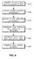
- FIG. 6shows a flow diagram of a WTRU 210 that multiplexes CCCH data with DCCH/DTCH data when the WTRU 210 has an allocated E-DCH resource and a periodic cell update is triggered.
- the WTRU 210may be operating in the CELL_FACH state with an allocated E-RNTI (610).
- the WTRU 210may initiate an E-RACH access procedure (620).
- the WTRU 210may receive an E-DCH resource allocation (630).
- the E-DCH resourcemay be a common E-DCH resource for DCCH/DTCH traffic.
- the WTRU 210determines that a periodic cell update is triggered (640).
- the WTRU 210may continue with the E-RACH access procedure and may multiplex CCCH data with DCCH/DTCH data in a same transmit time interval (TTI) (650) and transmit a cell update message (660).
- TTItransmit time interval
- 660transmit a cell update message
- the WTRU 210may be restricted from multiplexing CCCH data with DCCH/DTCH data in the same TTI.
- a determination of whether the WTRU 210 may multiplex the CCCH data with the DCCH/DTCH data in the same TTImay be preconfigured in the WTRU 210 or may be signaled as part of a MAC-d flow configuration for the CCCH.
- CCCH transmissionmay be given a higher priority than DCCH/DTCH data transmission.
- FIG. 7shows a flow diagram of a WTRU 210 that initiates another E-RACH access to send CCCH data when the WTRU 210 has an allocated E-DCH resource and a periodic cell update is triggered.
- the WTRU 210may be operating in the CELL_FACH state with an allocated E-RNTI (710).
- the WTRU 210may initiate an E-RACH access procedure (720).
- the WTRU 210may receive an E-DCH resource allocation (730).
- the E-DCH resourcemay be a common E-DCH resource for DCCH/DTCH traffic.
- the WTRU 210determines that a periodic cell update is triggered (740).
- the WTRU 210may be restricted from sending CCCH data on the same E-RACH access opportunity as DCCH/DTCH data and may wait until the ongoing E-RACH access is terminated based on a cell update trigger.
- a cell update triggermay occur upon the expiration of a periodic cell update timer, or upon re-selection to a new cell.
- the WTRU 210determines that the ongoing E-RACH access is terminated (750). Once the E-RACH access is terminated, the WTRU 210 may initiate another E-RACH access (760), where the WTRU 210 may transmit CCCH data (770).
- the CCCH datamay be a periodic cell update message.
- FIG 8shows a flow diagram of a WTRU 210 that has an allocated E-DCH resource and waits for all HARQ processes to be emptied before initiating a new E-RACH access to transmit CCCH data.
- the WTRU 210maybe operating in the CELL_FACH state with an allocated E-RNTI (810).
- the WTRU 210may initiate an E-RACH access procedure (820).
- the WTRU 210may receive an E-DCH resource allocation (830).
- the E-DCH resourcemay be a common E-DCH resource for DCCH/DTCH traffic.
- the WTRU 210determines that a periodic cell update is triggered (840).
- the WTRU 210determines that all HARQ processes are empty (850).
- the WTRU 210may terminate the ongoing E-RACH access procedure (860).
- the WTRU 210may terminate the ongoing E-RACH access as soon as segmentation entities are emptied.
- the WTRU 210may terminate the ongoing E-RACH access as soon as both the HARQ processes and the segmentation entities are emptied.
- the WTRU 210may initiate a new E-RACH access procedure for CCCH transmission (870).
- the CCCH transmissionmay contain a periodic cell update message.
- FIG. 9shows a flow diagram of a WTRU 210 that initiates CCCH transmission on a current E-DCH resource when the WTRU 210 has an allocated E-DCH resource and a periodic cell update is triggered.
- the WTRU 210may be operating in the CELL_FACH state with an allocated E-RNTI (910).
- the WTRU 210may start an E-RACH access procedure (920).
- the WTRU 210may receive an E-DCH resource allocation (930).
- the E-DCH resourcemaybe a common E-DCH resource for DCCH/DTCH traffic.
- the WTRU 210determines that a periodic cell update is triggered (940).
- the WTRU 210may begin CCCH transmission on the current E-DCH resource (950).
- the CCCH transmissionmay contain a periodic cell update message.
- the WTRU 210may stop any additional DCCH/DTCH transmission (960). More specifically, the MAC and the RLC may stop delivering DCCH/DTCH data to the physical layer. Optionally, the WTRU 210 may stop any timers associated with DCCH/DTCH data delivery (i.e. contention resolution timer) and start a CCCH maximum resolution timer.
- the WTRU 210starts transmitting a CCCH message without performing contention resolution even though it has an allocated E-RNTI. While CCCH transmission is still ongoing, DCCH/DTCH data becomes available for transmission. Since the WTRU 210 has not performed contention resolution, it may not be preferable to allow the WTRU 210 to transmit the DCCH/DTCH data during the same E-RACH access as the CCCH data.
- Figure 10shows a flow diagram of a WTRU 210 that does not allow DCCH/DTCH data to be transmitted if E-DCH resources are allocated for CCCH transmission. More specifically, the WTRU 210 waits for CCCH resources to be released before initiating another E-RACH access to transmit DCCH/DTCH data.
- the WTRU 210may be operating in the CELL_FACH state with an allocated E-RNTI (1010).
- the WTRU 210may have ongoing CCCH traffic (i.e. an allocated common E-DCH resource for CCCH traffic) (1020).
- the WTRU 210determines that DCCH/DTCH data is available for transmission (1030).
- the WTRU 210determines whether CCCH resources are released, and may be configured to wait until the CCCH resources are released before transmitting DCCH/DTCH traffic (1040).
- the CCCH resourcesmay be released if a maximum duration is reached, or if the WTRU 210 does not have any more CCCH data to transmit.
- the WTRU 210and more specifically the RLC and MAC, may be allowed to initiate a new E-RACH access procedure to transmit DCCH/DTCH traffic (i.e. contention resolution is initiated) (1050).
- the MAC layermay not request data from any other logical channels until CCCH transmission and E-RACH access has been terminated.
- the RLCmay buffer the DCCH/DTCH data and not send any data to lower layers until the E-RACH access has been terminated.
- FIG 11shows a flow diagram of a WTRU 210 restricting DCCH/DTCH data transmission until a cell update confirm message is received.
- the WTRU 210may be operating in the CELL_FACH state with an allocated E-RNTI (1110).
- the WTRU 210may have ongoing CCCH data traffic (i.e. an allocated common E-DCH resource for CCCH traffic) (1120).
- the WTRU 210determines that DCCH/DTCH data is available for transmission (1130).
- the WTRU 210determines that a periodic cell update is triggered (1140). Once the periodic cell update is triggered, the WTRU 210 may not allow any transmission of DCCH/DTCH data until a cell update confirm message is received.
- the WTRU 210may delete the E-RNTI on a condition that a periodic cell update is triggered (1150). This will restrict all subsequent DCCH/DTCH data from being configured.
- the WTRU 210may receive a re-allocated E-RNTI via a cell update confirm message (1160).
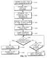
- FIG 12shows a flow diagram of a WTRU 210 that transmits DCCH/DTCH data on the same E-RACH access as ongoing CCCH transmission.
- the WTRU 210may be operating in the CELL_FACH state with an allocated E-RNTI (1210).
- the WTRU 210may have ongoing CCCH data transmissions (i.e. an allocated common E-DCH resource for CCCH traffic) (1215).
- the WTRU 210determines that DCCH/DTCH data becomes available for transmission (1220). Once DCCH/DTCH data becomes available for transmission, the WTRU 210 may start DCCH/DTCH transmission on the same E-RACH access, even if E-DCH resources have been allocated for CCCH (1225).
- the WTRU 210may initiate a contention resolution phase immediately by appending its E-RNTI to the first MAC-i PDU (1230).
- the WTRU 210may start a contention resolution timer upon transmission of the first MAC-i PDU containing its E-RNTI (1235).
- the WTRU 210determines whether the contention resolution timer expires (1240). On a condition that the contention resolution timer expires, the WTRU 210 may stop E-DCH transmission (1245) and release the E-DCH resources (1250). On a condition that the contention resolution timer is not expired, the WTRU 210 determines whether it received its E-RNTI on an E-AGCH (1255). On a condition that the WTRU 210 received its E-RNTI on the E-AGCH, the WTRU 210 may stop the contention resolution timer (1260).
- FIG 13shows a flow diagram of a WTRU 210 that transmits a periodic cell update over the DCCH.
- the WTRU 210may be operating in the CELL_FACH state (1310).
- the WTRU 210may have ongoing CCCH data traffic (i.e. an allocated common E-DCH resource for CCCH traffic) (1320).
- the WTRU 210determines that DCCH/DTCH data is available for transmission (1330). On a condition that DCCH/DTCH data is available for transmission, the WTRU 210 determines that it has an allocated E-RNTI, cell RNTI (C-RNTI), and high speed downlink shared channel (HS-DSCH) RNTI (H-RNTI) (130).
- C-RNTIcell RNTI
- HS-DSCHhigh speed downlink shared channel
- the WTRU 210may send a periodic cell update message over the DCCH (1350).
- the cell update messagemay be delivered directly to the serving radio network controller (SRNC) instead of the controlling radio network controller (CRNC).
- SRNCserving radio network controller
- CRNCcontrolling radio network controller
- the interface between the SRNC and CRNCis modified. More specifically, upon reception of the cell update signal, the SRNC sends it to the CRNC via the Iur interface.
- ROMread only memory
- RAMrandom access memory
- registercache memory
- semiconductor memory devicesmagnetic media such as internal hard disks and removable disks, magneto-optical media, and optical media such as CD-ROM disks, and digital versatile disks (DVDs).
- Suitable processorsinclude, by way of example, a general purpose processor, a special purpose processor, a conventional processor, a digital signal processor (DSP), a plurality of microprocessors, one or more microprocessors in association with a DSP core, a controller, a microcontroller, Application Specific Integrated Circuits (ASICs), Field Programmable Gate Arrays (FPGAs) circuits, any other type of integrated circuit (IC), and/or a state machine.
- DSPdigital signal processor
- ASICsApplication Specific Integrated Circuits
- FPGAsField Programmable Gate Arrays
- a processor in association with softwaremay be used to implement a radio frequency transceiver for use in a wireless transmit receive unit (WTRU), user equipment (UE), terminal, base station, radio network controller (RNC), or any host computer.
- the WTRUmay be used in conjunction with modules, implemented in hardware and/or software, such as a camera, a video camera module, a videophone, a speakerphone, a vibration device, a speaker, a microphone, a television transceiver, a hands free headset, a keyboard, a Bluetooth® module, a frequency modulated (FM) radio unit, a liquid crystal display (LCD) display unit, an organic light-emitting diode (OLED) display unit, a digital music player, a media player, a video game player module, an Internet browser, and/or any wireless local area network (PLAN) or Ultra Wide Band (UWB) module.
- WLANwireless local area network
- UWBUltra Wide Band
Landscapes
- Engineering & Computer Science (AREA)
- Signal Processing (AREA)
- Computer Networks & Wireless Communication (AREA)
- Databases & Information Systems (AREA)
- Computer Security & Cryptography (AREA)
- Mobile Radio Communication Systems (AREA)
Description
- This application is related to wireless communications.
Figure 1 shows radio resource control (RRC) service states 100 of a Third Generation Partnership Project (3GPP) wireless transmit/receive unit (WTRU) with an enhanced uplink in a Universal Mobile Telecommunications System (UMTS). The WTRU may operate in several states depending on user activity. The following states have been defined for UMTS Terrestrial Radio Access (UTRA) radio resource control (RRC) connected mode: IDLE 110, CELL_DCH 120, CELL_FACH 130, URA_PCH 140, and CELL_PCH 150. Other states that the WTRU may transition to include a general packet radio service (GPRS)packet transfer mode 160, a global system for mobile communications (GSM) connectedmode 170, or an enhanced UTRA (E-UTRA) connectedmode 180. RRC state transitions may be controlled by the network using radio network controller (RNC) parameters.- As part of the work effort for 3GPP Release 8, it has been proposed to allow a WTRU that is in the CELL_FACH state or in idle mode to use an enhanced random access channel (E-RACH) mechanism, whereby the WTRU uses enhanced dedicated channel (E-DCH) resources in the uplink (UL). The E-DCH resources are taken from a small pool of common resources that are shared among other 3GPP Release 8 CELL_FACH WTRUs. These WTRUs request E-DCH resources using the legacy random access channel (RACH) ramp up procedure. As part of this ramp up procedure, the WTRU transmits a randomly selected signature sequence, or a preamble signature, in a randomly selected access slot. If the signature is correctly decoded, a Node-B responds with an E-DCH resource assignment from its pool of resources, and the details are signaled to the WTRUs through the broadcast system information. In assigning the E-DCH resource, the Node-B needs only signal an index as to which E-DCH resource to use. The index is signaled over an acquisition indicator channel (AICH) or over an evolved AICH (E-AICH). Upon reception of the E-DCH resource index, the WTRU is configured with the E-DCH resource and may start transmitting UL data over the E-DCH.
- A common E-DCH resource may be used by WTRUs that are in idle mode, CELL_FACH state, CELL_PCH state, or URA_PCH state. A WTRU in the CELL_FACH state may transmit common control channel (CCCH) traffic or dedicated control channel/dedicated traffic channel (DCCH/DTCH) traffic over the common E-DCH resource. If the WTRU has an E-DCH radio network temporary identifier (E-RNTI) allocated, the DCCH/DTCH data transmission over an assigned E-DCH resource starts with a contention resolution phase. During the contention resolution phase, the WTRU's E-RNTI is included in all the medium access control (MAC)-i protocol data units (PDUs). With the reception of the WTRU's E-RNTI, the network (e.g., Universal Mobile Telecommunications System Terrestrial Radio Access Network or UTRAN) is informed of which WTRU was granted the E-DCH resource and the Node-B may send an enhanced access grant channel (E-AGCH) signal confirming the WTRU's E-RNTI (through an E-RNTI specific cyclic redundancy check (CRC) attachment). If the WTRU does not receive its E-RNTI on the E-AGCH upon the expiration of a timer, then the contention has not been resolved and the WTRU releases the associated E-DCH resources.
- If the WTRU has CCCH data to transmit, no contention resolution phase is performed. The WTRU has a maximum CCCH allocation time to transmit the data. When the time expires the resources are released.
- The E-DCH resources may also be released due to the reception of the value 'inactive" on E-AGCH; due to a radio link failure; due to total E-DCH buffer status (TEBS) equal to zero; or due to the expiration of an inactivity timer.
- When a WTRU transmits CCCH traffic, the underlying assumption is that it will not have an allocated E-RNTI and will not perform contention resolution. Although this is the case for CELL UPDATE messages after a cell selection/reselection and for RRC CONNECTION REQUEST messages, situations exist where a WTRU has an E-RNTI and must transmit the CCCH traffic (e.g., a periodic cell update message). For such cases, WTRU behavior becomes ambiguous. According to current specifications, if an E-RNTI is allocated, the WTRU is required to add its E-RNTI to all MAC-i PDUs until the contention resolution is resolved (i.e., when the WTRU receives an E-AGCH with its E-RNTI). However, a WTRU that is transmitting CCCH traffic is not required to perform contention resolution and is not required to monitor the E-AGCH. Contention resolution may not be required for CCCH traffic, such as a periodic cell update message, since the periodic cell update message is anticipated to be small in size. Based on this assumption, on the network side, it is specified that when the WTRU E-RNTI is present, it identifies DCCH/DTCH data transmission from this WTRU, however, this assumption may not be correct, especially when an E-RNTI is present with CCCH data transmission.
- The document "on E-DCH resource release", NOKIA SIEMENS NETWORKS, R2-082579, XP50140245, 29.04.2008, discloses different alternatives of common E-DCH resource released.
- Methods to handle the above described scenario are not defined and apparent. More specifically, the WTRU needs to handle the situation where a WTRU has common E-DCH resources allocated and is already sending DCCH/DTCH traffic when a periodic cell update is triggered. The WTRU also needs to handle the situation where a WTRU is already transmitting CCCH traffic with an E-RNTI allocated when DCCH/DTCH data becomes available for transmission.
- The invention is defined by the subject-matter of the independent claims. Particular embodiments of the invention are set out in the dependent claims.
- Furthermore, a method and apparatus is disclosed for control of wireless communication signals over an enhanced dedicated channel (E-DCH) resource while operating in the CELL_FACH state with an allocated E-DCH radio network temporary identifier (E-RNTI). A determination is made that a periodic cell update timer is expired. In response to the periodic cell update timer expiring, a determination is made whether the WTRU has an allocated E-DCH resource. If the WTRU has an allocated E-DCH resource, the periodic cell update timer is re-started without performing a periodic cell update.
- A more detailed understanding may be had from the following description, given by way of example in conjunction with the accompanying drawings wherein:
Figure 1 shows the RRC states with high speed downlink packet access (HSDPA)/high speed uplink packet access (HSUPA);Figure 2 is an example of a wireless communication system including a plurality of wireless transmit/receive units (WTRUs), a Node-B, a radio network controller (RNC), and a core network;Figure 3 is a functional block diagram of a WTRU and the Node-B ofFigure 2 ;Figure 4 shows a flow diagram of a WTRU that does not perform (i.e. skips) a periodic cell update when a periodic cell update is triggered and the WTRU has an allocated E-DCH resource;Figure 5 shows a flow diagram of a WTRU that prevents a periodic cell update if the WTRU has an allocated E-DCH resource;Figure 6 shows a flow diagram of a WTRU that multiplexes CCCH data with DCCH/DTCH data when the WTRU has an allocated E-DCH resource and a periodic cell update is triggered;Figure 7 shows a flow diagram of a WTRU that initiates another E-RACH access to send CCCH data when the WTRU has an allocated E-DCH resource and a periodic cell update is triggered and;Figure 8 shows a flow diagram of a WTRU that has an allocated E-DCH resource and waits for all HARQ processes to be emptied before initiating a new E-RACH access to transmit CCCH data;Figure 9 shows a flow diagram of a WTRU that starts CCCH transmission on a current E-DCH resource when the WTRU has an allocated E-DCH resource and a periodic cell update is triggered;Figure 10 shows a flow diagram of a WTRU that does not allow DCCH/DTCH data to be transmitted if E-DCH resources are allocated for CCCH transmission ;Figure 11 shows a flow diagram of a WTRU restricting DCCH/DTCH data transmission until a cell update confirm message is received;Figure 12 shows a flow diagram of a WTRU that transmits DCCH/DTCH data on the same E-RACH access as ongoing CCCH transmission; andFigure 13 shows a flow diagram of a WTRU that transmits a periodic cell update over the DCCH.- When referred to hereafter, the terminology "wireless transmit/receive unit (WTRU)" includes but is not limited to a user equipment (UE), a mobile station, a fixed or mobile subscriber unit, a pager, a cellular telephone, a personal digital assistant (PDA), a computer, or any other type of user device capable of operating in a wireless environment. When referred to hereafter, the terminology "base station" includes but is not limited to a Node-B, a site controller, an access point (AP), or any other type of interfacing device capable of operating in a wireless environment.
Figure 2 shows awireless communication system 200 including a plurality of WTRUs 210, a Node-B 220, anRNC 230, and acore network 240. As shown inFigure 2 , the WTRUs 210 are in communication with the Node-B 220, which is in communication with theRNC 230, which is in communication with thecore network 240. Although three WTRUs 210, one Node-B 220, and oneRNC 230 are shown inFigure 2 , it should be noted that any combination of wireless and wired devices may be included in thewireless communication system 200.Figure 3 is a functional block diagram 300 of aWTRU 210 and the Node-B 220 of thewireless communication system 200 ofFigure 2 . As shown inFigure 3 , theWTRU 210 is in communication with the Node-B 220 and theWTRU 210 is configured to perform a method for control of CCCH transmission over common E-DCH resources in the CELL_FACH state.- In addition to the components that may be found in a typical WTRU, the
WTRU 210 includes aprocessor 215, areceiver 216, atransmitter 217, and anantenna 218. Theprocessor 215 is configured to perform a method for control of CCCH transmission over common E-DCH resources in the CELL_FACH state. Thereceiver 216 and thetransmitter 217 are in communication with theprocessor 215. Theantenna 218 is in communication with both thereceiver 216 and thetransmitter 217 to facilitate the transmission and reception of wireless data. Although oneWTRU 210antenna 218 is shown inFigure 3 , it should be noted that more than one antenna may be included in theWTRU 210. - In addition to the components that may be found in a typical Node-B, the Node-
B 220 includes aprocessor 225, areceiver 226, atransmitter 227, and anantenna 228. Theprocessor 225 is configured to perform a method for control of CCCH transmission over common E-DCH resources in the CELL_FACH state. Thereceiver 226 and thetransmitter 227 are in communication with theprocessor 225. Theantenna 228 is in communication with both thereceiver 226 and thetransmitter 227 to facilitate the transmission and reception of wireless data. Although oneantenna 228 is shown inFigure 3 , it should be noted that more than one antenna may be included in the Node-B 220. - The network may implicitly detect that a
WTRU 210 is still connected if theWTRU 210 has ongoing DCCH/DTCH traffic (i.e. has an allocated common E-DCH resource for DCCH/DTCH traffic), and therefore, a periodic cell update may not be needed. TheWTRU 210 may skip (i.e. not perform) a periodic cell update or prevent a periodic cell update from occurring if it has an allocated common E-DCH resource for DCCH/DTCH traffic. Figure 4 shows a flow diagram of aWTRU 210 that does not perform (i.e. skips) a periodic cell update when a periodic cell update is triggered and theWTRU 210 has an allocated E-DCH resource. TheWTRU 210 may be operating in the CELL_FACH state with an allocated E-RNTI (410). TheWTRU 210 determines that a periodic cell update timer is expired (420). The periodic cell update timer may be a T305 timer. TheWTRU 210 determines whether it has an E-DCH resource allocated (430). The E-DCH resource may be a common E-DCH resource for DCCH/DTCH traffic. On a condition that theWTRU 210 has an E-DCH resource allocated, theWTRU 210 re-starts the periodic cell update timer (440), which allows theWTRU 210 to skip the periodic cell update. TheWTRU 210 may re-start the periodic cell update timer immediately or upon the release of E-DCH resources. On a condition that theWTRU 210 does not have an allocated E-DCH resource, theWTRU 210 may perform a cell update procedure (450). The WTRU may receive an allocation of common E-DCH resource for CCCH transmission and CCCH data may be transmitted. In response to performing the cell update, theWTRU 210 may not allow transmission of DCCH/DTCH traffic until the CCCH resources are released. Once the cell update procedure is complete, theWTRU 210 may re-start the periodic cell update timer (460).Figure 5 shows a flow diagram of aWTRU 210 that prevents a periodic cell update if theWTRU 210 has an allocated E-DCH resource. TheWTRU 210 may be operating in the CELL_FACH state with an allocated E-RNTI (510). TheWTRU 210 may start a periodic cell update timer (520). The periodic cell update timer may be a T305 timer. TheWTRU 210 receives an E-DCH resource allocation (530). For example, theWTRU 210 may receive "E-DCH resource index". TheWTRU 210 may also receive an E-DCH resource allocation after a contention resolution phase is resolved. TheWTRU 210 may also receive an E-DCH resource allocation after the transmission of a first successful data (i.e. when theWTRU 210 receives a hybrid automatic repeat request (HARQ) acknowledgement (ACK) or alternatively a radio link control (RLC) ACK). The E-DCH resource may be a common E-DCH resource for DCCH/DTCH traffic. When theWTRU 210 receives a common E-DCH resource allocation, it may set a variable COMMON_E-DCH_TRANSMISSION to true. TheWTRU 210 may stop the periodic cell update timer (540) once the E-DCH resource allocation is received. TheWTRU 210 determines that the E-DCH resource is released (550). TheWTRU 210 may re-start the periodic cell update timer (560) once the E-DCH resource is released.- The
WTRU 210 may be configured to re-start the periodic cell update timer in response to E-DCH resources being released under the following conditions: if the radio resource control (RRC) in theWTRU 210 received the "Enhanced Uplink in CELL_FACH and Idle mode process termination" by the medium access control (MAC) with the CMAC-STATUS primitive; or if theWTRU 210 failed to establish the physical channels; or if the criteria for radio link failure are met; then set the variable COMMON_E_DCH_TRANSMISSION to FALSE and (re)-start periodic cell update timer. The periodic cell update timer may be a T305 timer. - Physical channel establishment failure may occur when a physical dedicated channel establishment is initiated by the
WTRU 210, theWTRU 210 shall initialize a timer and wait for layer 1 to indicate "in sync" indications. The timer may be a T312 timer. On receiving "in sync" indications, the physical channel is considered established and the timer T312 is stopped and reset. If the timer T312 expires before the physical channel is established, theWTRU 210 shall consider this as a "physical channel failure". - Radio link failure may occur when the
WTRU 210 is in the CELL_DCH state and after receiving a number of consecutive "out of sync" indications from layer 1 for the established dedicated physical control channel (DPCCH) or fractional dedicated physical channel (F-DPCH) in frequency division duplex (FDD), and the physical channels associated with mapped DCCHs in time division duplex (TDD), theWTRU 210 shall initialize a timer , and upon receiving a number of successive "in sync" indications from layer 1 and upon change ofWTRU 210 state, the timer is stopped and reset. The timer may be a T313 timer. If the timer T313 expires, then theWTRU 210 considers it as a radio link failure. - As an alternative, the periodic cell update timer is not stopped when the
WTRU 210 has an allocated E-DCH resource in the CELL_FACH state, wherein the E-DCH resource may be a common E-DCH resource for DCCH/DTCH traffic. Figure 6 shows a flow diagram of aWTRU 210 that multiplexes CCCH data with DCCH/DTCH data when theWTRU 210 has an allocated E-DCH resource and a periodic cell update is triggered. TheWTRU 210 may be operating in the CELL_FACH state with an allocated E-RNTI (610). TheWTRU 210 may initiate an E-RACH access procedure (620). TheWTRU 210 may receive an E-DCH resource allocation (630). The E-DCH resource may be a common E-DCH resource for DCCH/DTCH traffic. TheWTRU 210 determines that a periodic cell update is triggered (640). In response to the determination that the periodic cell update is triggered, theWTRU 210 may continue with the E-RACH access procedure and may multiplex CCCH data with DCCH/DTCH data in a same transmit time interval (TTI) (650) and transmit a cell update message (660).- Alternatively, the
WTRU 210 may be restricted from multiplexing CCCH data with DCCH/DTCH data in the same TTI. A determination of whether theWTRU 210 may multiplex the CCCH data with the DCCH/DTCH data in the same TTI may be preconfigured in theWTRU 210 or may be signaled as part of a MAC-d flow configuration for the CCCH. Optionally, CCCH transmission may be given a higher priority than DCCH/DTCH data transmission. Figure 7 shows a flow diagram of aWTRU 210 that initiates another E-RACH access to send CCCH data when theWTRU 210 has an allocated E-DCH resource and a periodic cell update is triggered. TheWTRU 210 may be operating in the CELL_FACH state with an allocated E-RNTI (710). TheWTRU 210 may initiate an E-RACH access procedure (720). TheWTRU 210 may receive an E-DCH resource allocation (730). The E-DCH resource may be a common E-DCH resource for DCCH/DTCH traffic. TheWTRU 210 determines that a periodic cell update is triggered (740). TheWTRU 210 may be restricted from sending CCCH data on the same E-RACH access opportunity as DCCH/DTCH data and may wait until the ongoing E-RACH access is terminated based on a cell update trigger. A cell update trigger may occur upon the expiration of a periodic cell update timer, or upon re-selection to a new cell. TheWTRU 210 determines that the ongoing E-RACH access is terminated (750). Once the E-RACH access is terminated, theWTRU 210 may initiate another E-RACH access (760), where theWTRU 210 may transmit CCCH data (770). The CCCH data may be a periodic cell update message.Figure 8 shows a flow diagram of aWTRU 210 that has an allocated E-DCH resource and waits for all HARQ processes to be emptied before initiating a new E-RACH access to transmit CCCH data. TheWTRU 210 maybe operating in the CELL_FACH state with an allocated E-RNTI (810). TheWTRU 210 may initiate an E-RACH access procedure (820). TheWTRU 210 may receive an E-DCH resource allocation (830). The E-DCH resource may be a common E-DCH resource for DCCH/DTCH traffic. TheWTRU 210 determines that a periodic cell update is triggered (840). TheWTRU 210 determines that all HARQ processes are empty (850). Once all HARQ processes are empty, theWTRU 210 may terminate the ongoing E-RACH access procedure (860). Optionally, theWTRU 210 may terminate the ongoing E-RACH access as soon as segmentation entities are emptied. Optionally, theWTRU 210 may terminate the ongoing E-RACH access as soon as both the HARQ processes and the segmentation entities are emptied. TheWTRU 210 may initiate a new E-RACH access procedure for CCCH transmission (870). The CCCH transmission may contain a periodic cell update message.Figure 9 shows a flow diagram of aWTRU 210 that initiates CCCH transmission on a current E-DCH resource when theWTRU 210 has an allocated E-DCH resource and a periodic cell update is triggered. TheWTRU 210 may be operating in the CELL_FACH state with an allocated E-RNTI (910). TheWTRU 210 may start an E-RACH access procedure (920). TheWTRU 210 may receive an E-DCH resource allocation (930). The E-DCH resource maybe a common E-DCH resource for DCCH/DTCH traffic. TheWTRU 210 determines that a periodic cell update is triggered (940). TheWTRU 210 may begin CCCH transmission on the current E-DCH resource (950). The CCCH transmission may contain a periodic cell update message. TheWTRU 210 may stop any additional DCCH/DTCH transmission (960). More specifically, the MAC and the RLC may stop delivering DCCH/DTCH data to the physical layer. Optionally, theWTRU 210 may stop any timers associated with DCCH/DTCH data delivery (i.e. contention resolution timer) and start a CCCH maximum resolution timer.- There may be situations where the
WTRU 210 starts transmitting a CCCH message without performing contention resolution even though it has an allocated E-RNTI. While CCCH transmission is still ongoing, DCCH/DTCH data becomes available for transmission. Since theWTRU 210 has not performed contention resolution, it may not be preferable to allow theWTRU 210 to transmit the DCCH/DTCH data during the same E-RACH access as the CCCH data. Figure 10 shows a flow diagram of aWTRU 210 that does not allow DCCH/DTCH data to be transmitted if E-DCH resources are allocated for CCCH transmission. More specifically, theWTRU 210 waits for CCCH resources to be released before initiating another E-RACH access to transmit DCCH/DTCH data. TheWTRU 210 may be operating in the CELL_FACH state with an allocated E-RNTI (1010). TheWTRU 210 may have ongoing CCCH traffic (i.e. an allocated common E-DCH resource for CCCH traffic) (1020). TheWTRU 210 determines that DCCH/DTCH data is available for transmission (1030). TheWTRU 210 determines whether CCCH resources are released, and may be configured to wait until the CCCH resources are released before transmitting DCCH/DTCH traffic (1040). The CCCH resources may be released if a maximum duration is reached, or if theWTRU 210 does not have any more CCCH data to transmit. Once the CCCH resources are released, theWTRU 210, and more specifically the RLC and MAC, may be allowed to initiate a new E-RACH access procedure to transmit DCCH/DTCH traffic (i.e. contention resolution is initiated) (1050). In order to implement this restriction, the MAC layer may not request data from any other logical channels until CCCH transmission and E-RACH access has been terminated. Alternatively, the RLC may buffer the DCCH/DTCH data and not send any data to lower layers until the E-RACH access has been terminated.Figure 11 shows a flow diagram of aWTRU 210 restricting DCCH/DTCH data transmission until a cell update confirm message is received. TheWTRU 210 may be operating in the CELL_FACH state with an allocated E-RNTI (1110). TheWTRU 210 may have ongoing CCCH data traffic (i.e. an allocated common E-DCH resource for CCCH traffic) (1120). TheWTRU 210 determines that DCCH/DTCH data is available for transmission (1130). TheWTRU 210 determines that a periodic cell update is triggered (1140). Once the periodic cell update is triggered, theWTRU 210 may not allow any transmission of DCCH/DTCH data until a cell update confirm message is received. To configure theWTRU 210 with such a restriction, theWTRU 210 may delete the E-RNTI on a condition that a periodic cell update is triggered (1150). This will restrict all subsequent DCCH/DTCH data from being configured. TheWTRU 210 may receive a re-allocated E-RNTI via a cell update confirm message (1160).Figure 12 shows a flow diagram of aWTRU 210 that transmits DCCH/DTCH data on the same E-RACH access as ongoing CCCH transmission. TheWTRU 210 may be operating in the CELL_FACH state with an allocated E-RNTI (1210). TheWTRU 210 may have ongoing CCCH data transmissions (i.e. an allocated common E-DCH resource for CCCH traffic) (1215). TheWTRU 210 determines that DCCH/DTCH data becomes available for transmission (1220). Once DCCH/DTCH data becomes available for transmission, theWTRU 210 may start DCCH/DTCH transmission on the same E-RACH access, even if E-DCH resources have been allocated for CCCH (1225). TheWTRU 210 may initiate a contention resolution phase immediately by appending its E-RNTI to the first MAC-i PDU (1230). TheWTRU 210 may start a contention resolution timer upon transmission of the first MAC-i PDU containing its E-RNTI (1235). TheWTRU 210 determines whether the contention resolution timer expires (1240). On a condition that the contention resolution timer expires, theWTRU 210 may stop E-DCH transmission (1245) and release the E-DCH resources (1250). On a condition that the contention resolution timer is not expired, theWTRU 210 determines whether it received its E-RNTI on an E-AGCH (1255). On a condition that theWTRU 210 received its E-RNTI on the E-AGCH, theWTRU 210 may stop the contention resolution timer (1260).Figure 13 shows a flow diagram of aWTRU 210 that transmits a periodic cell update over the DCCH. TheWTRU 210 may be operating in the CELL_FACH state (1310). TheWTRU 210 may have ongoing CCCH data traffic (i.e. an allocated common E-DCH resource for CCCH traffic) (1320). TheWTRU 210 determines that DCCH/DTCH data is available for transmission (1330). On a condition that DCCH/DTCH data is available for transmission, theWTRU 210 determines that it has an allocated E-RNTI, cell RNTI (C-RNTI), and high speed downlink shared channel (HS-DSCH) RNTI (H-RNTI) (130). TheWTRU 210 may send a periodic cell update message over the DCCH (1350). On a condition that logical channel DCCH is used, the cell update message may be delivered directly to the serving radio network controller (SRNC) instead of the controlling radio network controller (CRNC). In order to allow DCCH transmission, the interface between the SRNC and CRNC is modified. More specifically, upon reception of the cell update signal, the SRNC sends it to the CRNC via the Iur interface.- Although features and elements are described above in particular combinations, each feature or element can be used alone without the other features and elements or in various combinations with or without other features and elements. The methods or flow charts provided herein may be implemented in a computer program, software, or firmware incorporated in a computer-readable storage medium for execution by a general purpose computer or a processor. Examples of computer-readable storage mediums include a read only memory (ROM), a random access memory (RAM), a register, cache memory, semiconductor memory devices, magnetic media such as internal hard disks and removable disks, magneto-optical media, and optical media such as CD-ROM disks, and digital versatile disks (DVDs).
- Suitable processors include, by way of example, a general purpose processor, a special purpose processor, a conventional processor, a digital signal processor (DSP), a plurality of microprocessors, one or more microprocessors in association with a DSP core, a controller, a microcontroller, Application Specific Integrated Circuits (ASICs), Field Programmable Gate Arrays (FPGAs) circuits, any other type of integrated circuit (IC), and/or a state machine.
- A processor in association with software may be used to implement a radio frequency transceiver for use in a wireless transmit receive unit (WTRU), user equipment (UE), terminal, base station, radio network controller (RNC), or any host computer. The WTRU may be used in conjunction with modules, implemented in hardware and/or software, such as a camera, a video camera module, a videophone, a speakerphone, a vibration device, a speaker, a microphone, a television transceiver, a hands free headset, a keyboard, a Bluetooth® module, a frequency modulated (FM) radio unit, a liquid crystal display (LCD) display unit, an organic light-emitting diode (OLED) display unit, a digital music player, a media player, a video game player module, an Internet browser, and/or any wireless local area network (PLAN) or Ultra Wide Band (UWB) module.
Claims (18)
- A method for a control channel transmission by a wireless transmit/receive unit, WTRU, the method comprising:operating with a common enhanced dedicated channel, E-DCH, resource and on-going common control channel, CCCH, traffic, wherein the common E-DCH resource is associated with the on-going CCCH traffic;determining that dedicated control channel, DCCH / dedicated traffic channel, DTCH, data is available for transmission; andwaiting until a CCCH resource is released before transmitting DCCH/DTCH traffic.
- The method of claim 1, wherein the CCCH resource is released when the WTRU no longer has CCCH traffic.
- The method of claim 2, wherein the WTRU no longer has CCCH traffic when a CCCH buffer status is empty.
- The method of claim 1, further comprising initiating an access procedure.
- The method of claim 4, wherein the access procedure is initiated when the CCCH resource is released.
- The method of claim 5, wherein the access procedure is initiated by a medium access control, MAC.
- The method of claim 1, wherein the waiting is performed by a medium access control, MAC.
- The method of claim 7, wherein the WTRU has DCCH/DTCH data in a buffer.
- The method of claim 1, further comprising transmitting DCCH/DTCH traffic when the CCCH resource is released.
- A wireless transmit/receive unit (WTRU) comprising:a processor configured to:operate with a common enhanced dedicated channel, E-DCH, resource and on-going common control channel, CCCH, traffic,wherein the common E-DCH resource is associated with the on-going CCCH traffic;determine that dedicated control channel, DCCH / dedicated traffic channel, DTCH, data is available for transmission; andwait until a CCCH resource is released before transmitting DCCH/DTCH traffic.
- The WTRU of claim 10, wherein the CCCH resource is released when the WTRU no longer has CCCH traffic.
- The WTRU of claim 11, wherein the WTRU no longer has CCCH traffic when a CCCH buffer status is empty.
- The WTRU of claim 10, wherein the processor is further configured to initiate an access procedure.
- The WTRU of claim 13, wherein the access procedure is initiated when the CCCH resource is released.
- The WTRU of claim 14, wherein the access procedure is initiated by a medium access control, MAC.
- The WTRU of claim 10, wherein the waiting is performed by a medium access control, MAC.
- The WTRU of claim 10, wherein the WTRU has DCCH/DTCH data in a buffer.
- The WTRU of claim 10, wherein the processor is further configured to transmit DCCH/DTCH traffic when the CCCH resource is released.
Priority Applications (1)
| Application Number | Priority Date | Filing Date | Title |
|---|---|---|---|
| EP15180566.0AEP3024292A1 (en) | 2008-09-15 | 2009-09-15 | Method for a control channel transmission by a wireless transmit/receive unit and corresponding wireless transmit/receive unit |
Applications Claiming Priority (2)
| Application Number | Priority Date | Filing Date | Title |
|---|---|---|---|
| US9705508P | 2008-09-15 | 2008-09-15 | |
| EP09792532.5AEP2338305B1 (en) | 2008-09-15 | 2009-09-15 | Method and apparatus for control of common control channel transmission over common enhanced dedicated channel resources in cell_fach state |
Related Parent Applications (2)
| Application Number | Title | Priority Date | Filing Date |
|---|---|---|---|
| EP09792532.5Division | 2009-09-15 | ||
| EP09792532.5ADivisionEP2338305B1 (en) | 2008-09-15 | 2009-09-15 | Method and apparatus for control of common control channel transmission over common enhanced dedicated channel resources in cell_fach state |
Related Child Applications (1)
| Application Number | Title | Priority Date | Filing Date |
|---|---|---|---|
| EP15180566.0ADivisionEP3024292A1 (en) | 2008-09-15 | 2009-09-15 | Method for a control channel transmission by a wireless transmit/receive unit and corresponding wireless transmit/receive unit |
Publications (2)
| Publication Number | Publication Date |
|---|---|
| EP2618617A1 EP2618617A1 (en) | 2013-07-24 |
| EP2618617B1true EP2618617B1 (en) | 2015-08-12 |
Family
ID=41445548
Family Applications (4)
| Application Number | Title | Priority Date | Filing Date |
|---|---|---|---|
| EP20130163878ActiveEP2618616B1 (en) | 2008-09-15 | 2009-09-15 | Method for control of wireless communication signals and corresponding wireless transmit/receive unit |
| EP09792532.5AActiveEP2338305B1 (en) | 2008-09-15 | 2009-09-15 | Method and apparatus for control of common control channel transmission over common enhanced dedicated channel resources in cell_fach state |
| EP13163880.1AActiveEP2618617B1 (en) | 2008-09-15 | 2009-09-15 | Method for a control channel transmission by a wireless transmit/receive unit and corresponding wireless transmit/receive unit |
| EP15180566.0AWithdrawnEP3024292A1 (en) | 2008-09-15 | 2009-09-15 | Method for a control channel transmission by a wireless transmit/receive unit and corresponding wireless transmit/receive unit |
Family Applications Before (2)
| Application Number | Title | Priority Date | Filing Date |
|---|---|---|---|
| EP20130163878ActiveEP2618616B1 (en) | 2008-09-15 | 2009-09-15 | Method for control of wireless communication signals and corresponding wireless transmit/receive unit |
| EP09792532.5AActiveEP2338305B1 (en) | 2008-09-15 | 2009-09-15 | Method and apparatus for control of common control channel transmission over common enhanced dedicated channel resources in cell_fach state |
Family Applications After (1)
| Application Number | Title | Priority Date | Filing Date |
|---|---|---|---|
| EP15180566.0AWithdrawnEP3024292A1 (en) | 2008-09-15 | 2009-09-15 | Method for a control channel transmission by a wireless transmit/receive unit and corresponding wireless transmit/receive unit |
Country Status (11)
| Country | Link |
|---|---|
| US (3) | US8885573B2 (en) |
| EP (4) | EP2618616B1 (en) |
| JP (3) | JP5393793B2 (en) |
| KR (3) | KR101259268B1 (en) |
| CN (2) | CN104244402A (en) |
| AR (1) | AR073377A1 (en) |
| BR (1) | BRPI0913536B1 (en) |
| DK (1) | DK2338305T3 (en) |
| RU (1) | RU2454041C1 (en) |
| TW (2) | TWI523560B (en) |
| WO (1) | WO2010031031A1 (en) |
Families Citing this family (20)
| Publication number | Priority date | Publication date | Assignee | Title |
|---|---|---|---|---|
| TWI523560B (en)* | 2008-09-15 | 2016-02-21 | 內數位專利控股公司 | Control method and device for sharing control channel transmission in CELL_FACH state by sharing enhanced dedicated channel resource |
| WO2010101808A1 (en)* | 2009-03-02 | 2010-09-10 | Interdigital Patent Holdings, Inc. | Method and apparatus for extending coverage for ul transmission over e-dch in idle mode and cell_fach state |
| JP5048746B2 (en) | 2009-12-09 | 2012-10-17 | シャープ株式会社 | Communication system, mobile station apparatus, radio link state management method, and integrated circuit |
| CN102726081B (en) | 2010-01-28 | 2016-01-20 | 瑞典爱立信有限公司 | Method and device for managing secure reconfiguration in a cellular communication system |
| EP2596670B1 (en)* | 2010-07-21 | 2020-02-26 | Nokia Technologies Oy | Apparatus and method for acquisition of a common enhanced dedicated channel resource |
| CN102740262B (en)* | 2011-04-13 | 2014-12-31 | 华为技术有限公司 | Data and/or signaling transmitting and receiving method, terminal thereof, base station controller, and base station |
| EP2557870B1 (en)* | 2011-08-10 | 2020-07-08 | Alcatel Lucent | Configuring transmissions |
| WO2013044497A1 (en)* | 2011-09-30 | 2013-04-04 | Nokia Corporation | Selection between random access and dedicated scheduling request resources |
| HK1197341A1 (en)* | 2012-01-25 | 2015-01-09 | 瑞典爱立信有限公司 | Method and apparatus for resource release in a wireless communication network |
| WO2013172778A2 (en)* | 2012-05-15 | 2013-11-21 | Telefonaktiebolaget L M Ericsson (Publ) | Methods and apparatus for operating timer(s) for stand-alone hs-dpcch |
| CN104737614B (en)* | 2012-10-08 | 2019-04-02 | 寰发股份有限公司 | Data transmission method |
| CN104363974A (en)* | 2013-03-20 | 2015-02-18 | 华为技术有限公司 | Method for detecting user equipment conflict, user equipment, and base station |
| JP6375384B2 (en)* | 2013-10-30 | 2018-08-15 | インターデイジタル パテント ホールディングス インコーポレイテッド | Connectivity robustness in wireless systems |
| US11637763B2 (en) | 2013-10-30 | 2023-04-25 | Interdigital Patent Holdings, Inc. | Connectivity robustness in wireless systems |
| MY188887A (en) | 2014-03-21 | 2022-01-12 | Ericsson Telefon Ab L M | Mobility robustness in a cellular network |
| US9320064B2 (en)* | 2014-03-25 | 2016-04-19 | Telefonaktiebolaget Lm Ericsson (Publ) | System and method for improving PDP context activation latency |
| WO2015171063A1 (en)* | 2014-05-08 | 2015-11-12 | Telefonaktiebolaget L M Ericsson (Publ) | Method and apparatus for controlling the activity state of a wireless device having device-to-device communication capabilities |
| EP3205169A1 (en)* | 2014-10-08 | 2017-08-16 | Nokia Solutions and Networks Oy | Connection establishment robustness optimization |
| US9843946B2 (en)* | 2015-01-28 | 2017-12-12 | Mediatek Inc. | Apparatuses and methods for reducing call recovery time associated with a cell update procedure |
| WO2023001200A1 (en)* | 2021-07-20 | 2023-01-26 | FG Innovation Company Limited | User equipment and method for performing configured grant based small data transmission |
Family Cites Families (29)
| Publication number | Priority date | Publication date | Assignee | Title |
|---|---|---|---|---|
| US5026A (en)* | 1847-03-20 | Cut-off valve | ||
| EP1361768B1 (en)* | 2002-05-03 | 2007-06-13 | Innovative Sonic Limited | Method of cell update via idle mode for power saving in a UMTS mobile upon radio link failure. |
| TWI245519B (en)* | 2002-05-29 | 2005-12-11 | Interdigital Tech Corp | Device and method for establishing a temporary dedicated channel in a wireless communication system |
| US6961570B2 (en)* | 2002-07-17 | 2005-11-01 | Asustek Computer Inc. | Handling of a wireless device re-entering a service area |
| CN1788435A (en)* | 2003-06-20 | 2006-06-14 | 富士通株式会社 | WCDMA mobile communication system |
| FI20031912A0 (en)* | 2003-12-29 | 2003-12-29 | Nokia Corp | Procedure and system for controlling a real-time communication service |
| RU2408170C2 (en)* | 2004-06-21 | 2010-12-27 | Нокиа Корпорейшн | Method to recover lost connection of signaling using high-speed packet access along down-link channelpartial dedicated physical channel |
| KR20060006725A (en) | 2004-07-16 | 2006-01-19 | 삼성전자주식회사 | Method and apparatus for parameter determination for autonomous transmission in mobile communication system supporting enhanced uplink dedicated channel |
| US7688796B2 (en) | 2005-08-31 | 2010-03-30 | Interdigital Technology Corporation | Wireless communication method and apparatus for decoding enhanced dedicated channel absolute grant channel transmissions |
| CN101146269A (en)* | 2006-03-22 | 2008-03-19 | 华为技术有限公司 | Service Authorization Processing Method in E-DCH |
| CN100542352C (en)* | 2006-03-22 | 2009-09-16 | 华为技术有限公司 | Service Authorization Processing Method in E-DCH |
| PL2062453T3 (en)* | 2006-09-13 | 2018-04-30 | Telefonaktiebolaget Lm Ericsson (Publ) | Method for mapping logical channel on shared channel |
| WO2008036366A2 (en) | 2006-09-20 | 2008-03-27 | Interdigital Technology Corporation | Method for enhanced dedicated channel (e-dch) transmission overlap detection for compressed mode gap slots |
| KR100983278B1 (en)* | 2006-11-01 | 2010-09-24 | 엘지전자 주식회사 | Downlink data transmission control method, data receiving method, measurement result reporting method and terminal in wireless communication system |
| CN101090364A (en)* | 2006-11-02 | 2007-12-19 | 华为技术有限公司 | High-speed downlink packet access related channel sending/receiving method and device |
| CN101222419B (en)* | 2007-01-10 | 2011-07-20 | 华为技术有限公司 | Data communication method and system, data transmitting/receiving device |
| AU2008214414B2 (en) | 2007-02-02 | 2011-11-03 | Interdigital Technology Corporation | Cell reselection/ update while in an enhanced Cell FACH state |
| CN101247176A (en)* | 2007-02-12 | 2008-08-20 | 华硕电脑股份有限公司 | Method and device for improving high-speed downlink function of forward access state |
| KR101469281B1 (en)* | 2007-04-30 | 2014-12-04 | 엘지전자 주식회사 | State transition method of wireless terminal |
| DE602008001024D1 (en)* | 2007-05-06 | 2010-06-02 | Innovative Sonic Ltd | Method for transmitting paging information in a wireless communication system and corresponding device |
| US8219119B2 (en)* | 2007-06-13 | 2012-07-10 | Innovative Sonic Limited | Method and apparatus for improving DRX operation in a wireless communications system |
| CN104837204A (en)* | 2007-09-28 | 2015-08-12 | 交互数字专利控股公司 | Method and apparatus for terminating message transmission on enhanced random access channel |
| US8867455B2 (en)* | 2007-10-01 | 2014-10-21 | Qualcomm Incorporated | Enhanced uplink for inactive state in a wireless communication system |
| CA2852143C (en)* | 2007-12-20 | 2015-04-14 | Telefonaktiebolaget L M Ericsson (Publ) | Releasing common enhanced dedicated channel, e-dch, radio resources |
| US8780704B2 (en)* | 2008-01-10 | 2014-07-15 | Qualcomm Incorporated | Shared resource allocation |
| US8446859B2 (en)* | 2008-02-01 | 2013-05-21 | Lg Electronics Inc. | Method for controlling uplink load in cell— FACH state |
| AU2009225432B2 (en)* | 2008-03-21 | 2014-01-09 | Interdigital Patent Holdings, Inc | Method of supporting cell reselection in an evolved HSPA network |
| TWI523560B (en)* | 2008-09-15 | 2016-02-21 | 內數位專利控股公司 | Control method and device for sharing control channel transmission in CELL_FACH state by sharing enhanced dedicated channel resource |
| US20110194433A1 (en)* | 2010-02-05 | 2011-08-11 | Qualcomm Incorporated | Managing dedicated channel resource allocation to user equipment based on radio bearer traffic within a wireless communications system |
- 2009
- 2009-09-14TWTW098130904Apatent/TWI523560B/enactive
- 2009-09-14TWTW104111846Apatent/TW201536087A/enunknown
- 2009-09-15CNCN201410353683.9Apatent/CN104244402A/enactivePending
- 2009-09-15KRKR1020117008383Apatent/KR101259268B1/ennot_activeExpired - Fee Related
- 2009-09-15KRKR1020117028979Apatent/KR101549288B1/ennot_activeExpired - Fee Related
- 2009-09-15EPEP20130163878patent/EP2618616B1/enactiveActive
- 2009-09-15KRKR1020137013801Apatent/KR101608566B1/ennot_activeExpired - Fee Related
- 2009-09-15CNCN200980136023.2Apatent/CN102150463B/enactiveActive
- 2009-09-15ARARP090103525Apatent/AR073377A1/enactiveIP Right Grant
- 2009-09-15EPEP09792532.5Apatent/EP2338305B1/enactiveActive
- 2009-09-15WOPCT/US2009/056921patent/WO2010031031A1/enactiveApplication Filing
- 2009-09-15DKDK09792532.5Tpatent/DK2338305T3/enactive
- 2009-09-15RURU2011114806/08Apatent/RU2454041C1/enactive
- 2009-09-15EPEP13163880.1Apatent/EP2618617B1/enactiveActive
- 2009-09-15BRBRPI0913536-7Apatent/BRPI0913536B1/enactiveIP Right Grant
- 2009-09-15USUS12/559,619patent/US8885573B2/enactiveActive
- 2009-09-15EPEP15180566.0Apatent/EP3024292A1/ennot_activeWithdrawn
- 2009-09-15JPJP2011527036Apatent/JP5393793B2/enactiveActive
- 2013
- 2013-10-15JPJP2013214590Apatent/JP5688440B2/ennot_activeExpired - Fee Related
- 2014
- 2014-09-22USUS14/492,775patent/US20150009941A1/ennot_activeAbandoned
- 2015
- 2015-01-26JPJP2015012650Apatent/JP2015080275A/enactivePending
- 2017
- 2017-06-27USUS15/635,076patent/US20170303256A1/ennot_activeAbandoned
Also Published As
| Publication number | Publication date |
|---|---|
| JP5688440B2 (en) | 2015-03-25 |
| DK2338305T3 (en) | 2013-07-15 |
| JP2015080275A (en) | 2015-04-23 |
| KR20130069872A (en) | 2013-06-26 |
| EP3024292A1 (en) | 2016-05-25 |
| EP2618616B1 (en) | 2015-04-29 |
| US20170303256A1 (en) | 2017-10-19 |
| KR101608566B1 (en) | 2016-04-01 |
| CN102150463A (en) | 2011-08-10 |
| JP2014017877A (en) | 2014-01-30 |
| TWI523560B (en) | 2016-02-21 |
| TW201536087A (en) | 2015-09-16 |
| JP2012503362A (en) | 2012-02-02 |
| WO2010031031A1 (en) | 2010-03-18 |
| EP2338305A1 (en) | 2011-06-29 |
| KR20110054048A (en) | 2011-05-24 |
| KR101549288B1 (en) | 2015-09-01 |
| RU2454041C1 (en) | 2012-06-20 |
| CN102150463B (en) | 2014-08-20 |
| US8885573B2 (en) | 2014-11-11 |
| AR073377A1 (en) | 2010-11-03 |
| BRPI0913536B1 (en) | 2020-10-13 |
| US20150009941A1 (en) | 2015-01-08 |
| TW201012281A (en) | 2010-03-16 |
| EP2618616A1 (en) | 2013-07-24 |
| EP2338305B1 (en) | 2013-04-17 |
| CN104244402A (en) | 2014-12-24 |
| JP5393793B2 (en) | 2014-01-22 |
| BRPI0913536A2 (en) | 2019-01-15 |
| EP2618617A1 (en) | 2013-07-24 |
| US20100074203A1 (en) | 2010-03-25 |
| KR20110138299A (en) | 2011-12-26 |
| KR101259268B1 (en) | 2013-04-29 |
Similar Documents
| Publication | Publication Date | Title |
|---|---|---|
| EP2618617B1 (en) | Method for a control channel transmission by a wireless transmit/receive unit and corresponding wireless transmit/receive unit | |
| US12185382B2 (en) | Method and apparatus for receiving and releasing wireless communication resources | |
| HK1225216A1 (en) | Method for a control channel transmission by a wireless transmit/receive unit and corresponding wireless transmit/receive unit | |
| HK1159408A (en) | Method and apparatus for control of common control channel transmission over common enhanced dedicated channel resources in cell_fach state |
Legal Events
| Date | Code | Title | Description |
|---|---|---|---|
| PUAI | Public reference made under article 153(3) epc to a published international application that has entered the european phase | Free format text:ORIGINAL CODE: 0009012 | |
| 17P | Request for examination filed | Effective date:20130416 | |
| AC | Divisional application: reference to earlier application | Ref document number:2338305 Country of ref document:EP Kind code of ref document:P | |
| AK | Designated contracting states | Kind code of ref document:A1 Designated state(s):AT BE BG CH CY CZ DE DK EE ES FI FR GB GR HR HU IE IS IT LI LT LU LV MC MK MT NL NO PL PT RO SE SI SK SM TR | |
| GRAP | Despatch of communication of intention to grant a patent | Free format text:ORIGINAL CODE: EPIDOSNIGR1 | |
| RIC1 | Information provided on ipc code assigned before grant | Ipc:H04W 60/02 20090101AFI20150121BHEP Ipc:H04W 72/00 20090101ALN20150121BHEP Ipc:H04W 8/26 20090101ALN20150121BHEP | |
| INTG | Intention to grant announced | Effective date:20150209 | |
| GRAS | Grant fee paid | Free format text:ORIGINAL CODE: EPIDOSNIGR3 | |
| GRAA | (expected) grant | Free format text:ORIGINAL CODE: 0009210 | |
| AC | Divisional application: reference to earlier application | Ref document number:2338305 Country of ref document:EP Kind code of ref document:P | |
| AK | Designated contracting states | Kind code of ref document:B1 Designated state(s):AT BE BG CH CY CZ DE DK EE ES FI FR GB GR HR HU IE IS IT LI LT LU LV MC MK MT NL NO PL PT RO SE SI SK SM TR | |
| REG | Reference to a national code | Ref country code:GB Ref legal event code:FG4D | |
| REG | Reference to a national code | Ref country code:CH Ref legal event code:EP | |
| REG | Reference to a national code | Ref country code:AT Ref legal event code:REF Ref document number:743083 Country of ref document:AT Kind code of ref document:T Effective date:20150815 | |
| REG | Reference to a national code | Ref country code:IE Ref legal event code:FG4D | |
| REG | Reference to a national code | Ref country code:DE Ref legal event code:R096 Ref document number:602009032942 Country of ref document:DE | |
| REG | Reference to a national code | Ref country code:NL Ref legal event code:FP | |
| REG | Reference to a national code | Ref country code:LT Ref legal event code:MG4D | |
| REG | Reference to a national code | Ref country code:AT Ref legal event code:MK05 Ref document number:743083 Country of ref document:AT Kind code of ref document:T Effective date:20150812 | |
| PG25 | Lapsed in a contracting state [announced via postgrant information from national office to epo] | Ref country code:LT Free format text:LAPSE BECAUSE OF FAILURE TO SUBMIT A TRANSLATION OF THE DESCRIPTION OR TO PAY THE FEE WITHIN THE PRESCRIBED TIME-LIMIT Effective date:20150812 Ref country code:NO Free format text:LAPSE BECAUSE OF FAILURE TO SUBMIT A TRANSLATION OF THE DESCRIPTION OR TO PAY THE FEE WITHIN THE PRESCRIBED TIME-LIMIT Effective date:20151112 Ref country code:LV Free format text:LAPSE BECAUSE OF FAILURE TO SUBMIT A TRANSLATION OF THE DESCRIPTION OR TO PAY THE FEE WITHIN THE PRESCRIBED TIME-LIMIT Effective date:20150812 Ref country code:GR Free format text:LAPSE BECAUSE OF FAILURE TO SUBMIT A TRANSLATION OF THE DESCRIPTION OR TO PAY THE FEE WITHIN THE PRESCRIBED TIME-LIMIT Effective date:20151113 | |
| PG25 | Lapsed in a contracting state [announced via postgrant information from national office to epo] | Ref country code:HR Free format text:LAPSE BECAUSE OF FAILURE TO SUBMIT A TRANSLATION OF THE DESCRIPTION OR TO PAY THE FEE WITHIN THE PRESCRIBED TIME-LIMIT Effective date:20150812 Ref country code:PL Free format text:LAPSE BECAUSE OF FAILURE TO SUBMIT A TRANSLATION OF THE DESCRIPTION OR TO PAY THE FEE WITHIN THE PRESCRIBED TIME-LIMIT Effective date:20150812 Ref country code:SE Free format text:LAPSE BECAUSE OF FAILURE TO SUBMIT A TRANSLATION OF THE DESCRIPTION OR TO PAY THE FEE WITHIN THE PRESCRIBED TIME-LIMIT Effective date:20150812 Ref country code:ES Free format text:LAPSE BECAUSE OF FAILURE TO SUBMIT A TRANSLATION OF THE DESCRIPTION OR TO PAY THE FEE WITHIN THE PRESCRIBED TIME-LIMIT Effective date:20150812 Ref country code:IS Free format text:LAPSE BECAUSE OF FAILURE TO SUBMIT A TRANSLATION OF THE DESCRIPTION OR TO PAY THE FEE WITHIN THE PRESCRIBED TIME-LIMIT Effective date:20151212 Ref country code:AT Free format text:LAPSE BECAUSE OF FAILURE TO SUBMIT A TRANSLATION OF THE DESCRIPTION OR TO PAY THE FEE WITHIN THE PRESCRIBED TIME-LIMIT Effective date:20150812 Ref country code:PT Free format text:LAPSE BECAUSE OF FAILURE TO SUBMIT A TRANSLATION OF THE DESCRIPTION OR TO PAY THE FEE WITHIN THE PRESCRIBED TIME-LIMIT Effective date:20151214 | |
| PG25 | Lapsed in a contracting state [announced via postgrant information from national office to epo] | Ref country code:EE Free format text:LAPSE BECAUSE OF FAILURE TO SUBMIT A TRANSLATION OF THE DESCRIPTION OR TO PAY THE FEE WITHIN THE PRESCRIBED TIME-LIMIT Effective date:20150812 Ref country code:SK Free format text:LAPSE BECAUSE OF FAILURE TO SUBMIT A TRANSLATION OF THE DESCRIPTION OR TO PAY THE FEE WITHIN THE PRESCRIBED TIME-LIMIT Effective date:20150812 Ref country code:DK Free format text:LAPSE BECAUSE OF FAILURE TO SUBMIT A TRANSLATION OF THE DESCRIPTION OR TO PAY THE FEE WITHIN THE PRESCRIBED TIME-LIMIT Effective date:20150812 Ref country code:CZ Free format text:LAPSE BECAUSE OF FAILURE TO SUBMIT A TRANSLATION OF THE DESCRIPTION OR TO PAY THE FEE WITHIN THE PRESCRIBED TIME-LIMIT Effective date:20150812 | |
| REG | Reference to a national code | Ref country code:CH Ref legal event code:PL | |
| REG | Reference to a national code | Ref country code:DE Ref legal event code:R097 Ref document number:602009032942 Country of ref document:DE | |
| PG25 | Lapsed in a contracting state [announced via postgrant information from national office to epo] | Ref country code:RO Free format text:LAPSE BECAUSE OF FAILURE TO SUBMIT A TRANSLATION OF THE DESCRIPTION OR TO PAY THE FEE WITHIN THE PRESCRIBED TIME-LIMIT Effective date:20150812 Ref country code:MC Free format text:LAPSE BECAUSE OF FAILURE TO SUBMIT A TRANSLATION OF THE DESCRIPTION OR TO PAY THE FEE WITHIN THE PRESCRIBED TIME-LIMIT Effective date:20150812 | |
| PLBE | No opposition filed within time limit | Free format text:ORIGINAL CODE: 0009261 | |
| STAA | Information on the status of an ep patent application or granted ep patent | Free format text:STATUS: NO OPPOSITION FILED WITHIN TIME LIMIT | |
| REG | Reference to a national code | Ref country code:IE Ref legal event code:MM4A | |
| 26N | No opposition filed | Effective date:20160513 | |
| PG25 | Lapsed in a contracting state [announced via postgrant information from national office to epo] | Ref country code:IE Free format text:LAPSE BECAUSE OF NON-PAYMENT OF DUE FEES Effective date:20150915 Ref country code:CH Free format text:LAPSE BECAUSE OF NON-PAYMENT OF DUE FEES Effective date:20150930 Ref country code:LI Free format text:LAPSE BECAUSE OF NON-PAYMENT OF DUE FEES Effective date:20150930 | |
| REG | Reference to a national code | Ref country code:FR Ref legal event code:PLFP Year of fee payment:8 | |
| PG25 | Lapsed in a contracting state [announced via postgrant information from national office to epo] | Ref country code:SI Free format text:LAPSE BECAUSE OF FAILURE TO SUBMIT A TRANSLATION OF THE DESCRIPTION OR TO PAY THE FEE WITHIN THE PRESCRIBED TIME-LIMIT Effective date:20150812 | |
| PG25 | Lapsed in a contracting state [announced via postgrant information from national office to epo] | Ref country code:BE Free format text:LAPSE BECAUSE OF FAILURE TO SUBMIT A TRANSLATION OF THE DESCRIPTION OR TO PAY THE FEE WITHIN THE PRESCRIBED TIME-LIMIT Effective date:20150812 | |
| PG25 | Lapsed in a contracting state [announced via postgrant information from national office to epo] | Ref country code:MT Free format text:LAPSE BECAUSE OF FAILURE TO SUBMIT A TRANSLATION OF THE DESCRIPTION OR TO PAY THE FEE WITHIN THE PRESCRIBED TIME-LIMIT Effective date:20150812 | |
| PG25 | Lapsed in a contracting state [announced via postgrant information from national office to epo] | Ref country code:BG Free format text:LAPSE BECAUSE OF FAILURE TO SUBMIT A TRANSLATION OF THE DESCRIPTION OR TO PAY THE FEE WITHIN THE PRESCRIBED TIME-LIMIT Effective date:20150812 Ref country code:HU Free format text:LAPSE BECAUSE OF FAILURE TO SUBMIT A TRANSLATION OF THE DESCRIPTION OR TO PAY THE FEE WITHIN THE PRESCRIBED TIME-LIMIT; INVALID AB INITIO Effective date:20090915 Ref country code:SM Free format text:LAPSE BECAUSE OF FAILURE TO SUBMIT A TRANSLATION OF THE DESCRIPTION OR TO PAY THE FEE WITHIN THE PRESCRIBED TIME-LIMIT Effective date:20150812 | |
| PG25 | Lapsed in a contracting state [announced via postgrant information from national office to epo] | Ref country code:CY Free format text:LAPSE BECAUSE OF FAILURE TO SUBMIT A TRANSLATION OF THE DESCRIPTION OR TO PAY THE FEE WITHIN THE PRESCRIBED TIME-LIMIT Effective date:20150812 | |
| REG | Reference to a national code | Ref country code:FR Ref legal event code:PLFP Year of fee payment:9 | |
| PG25 | Lapsed in a contracting state [announced via postgrant information from national office to epo] | Ref country code:LU Free format text:LAPSE BECAUSE OF NON-PAYMENT OF DUE FEES Effective date:20150915 | |
| PG25 | Lapsed in a contracting state [announced via postgrant information from national office to epo] | Ref country code:MK Free format text:LAPSE BECAUSE OF FAILURE TO SUBMIT A TRANSLATION OF THE DESCRIPTION OR TO PAY THE FEE WITHIN THE PRESCRIBED TIME-LIMIT Effective date:20150812 Ref country code:TR Free format text:LAPSE BECAUSE OF FAILURE TO SUBMIT A TRANSLATION OF THE DESCRIPTION OR TO PAY THE FEE WITHIN THE PRESCRIBED TIME-LIMIT Effective date:20150812 | |
| REG | Reference to a national code | Ref country code:FR Ref legal event code:PLFP Year of fee payment:10 | |
| P01 | Opt-out of the competence of the unified patent court (upc) registered | Effective date:20230512 | |
| PGFP | Annual fee paid to national office [announced via postgrant information from national office to epo] | Ref country code:DE Payment date:20240926 Year of fee payment:16 | |
| PGFP | Annual fee paid to national office [announced via postgrant information from national office to epo] | Ref country code:GB Payment date:20240924 Year of fee payment:16 | |
| PGFP | Annual fee paid to national office [announced via postgrant information from national office to epo] | Ref country code:FR Payment date:20240925 Year of fee payment:16 | |
| PGFP | Annual fee paid to national office [announced via postgrant information from national office to epo] | Ref country code:NL Payment date:20240925 Year of fee payment:16 | |
| PGFP | Annual fee paid to national office [announced via postgrant information from national office to epo] | Ref country code:IT Payment date:20240924 Year of fee payment:16 | |
| PGFP | Annual fee paid to national office [announced via postgrant information from national office to epo] | Ref country code:FI Payment date:20250925 Year of fee payment:17 |