EP2618497B1 - Mobile wireless communications device including nfc antenna scanning switch and related methods - Google Patents
Mobile wireless communications device including nfc antenna scanning switch and related methodsDownload PDFInfo
- Publication number
- EP2618497B1 EP2618497B1EP12151981.3AEP12151981AEP2618497B1EP 2618497 B1EP2618497 B1EP 2618497B1EP 12151981 AEP12151981 AEP 12151981AEP 2618497 B1EP2618497 B1EP 2618497B1
- Authority
- EP
- European Patent Office
- Prior art keywords
- nfc
- transceiver
- antenna
- controller
- adjacent
- Prior art date
- Legal status (The legal status is an assumption and is not a legal conclusion. Google has not performed a legal analysis and makes no representation as to the accuracy of the status listed.)
- Active
Links
Images


Classifications
- H—ELECTRICITY
- H04—ELECTRIC COMMUNICATION TECHNIQUE
- H04B—TRANSMISSION
- H04B5/00—Near-field transmission systems, e.g. inductive or capacitive transmission systems
- H04B5/40—Near-field transmission systems, e.g. inductive or capacitive transmission systems characterised by components specially adapted for near-field transmission
- H04B5/48—Transceivers
- H—ELECTRICITY
- H04—ELECTRIC COMMUNICATION TECHNIQUE
- H04B—TRANSMISSION
- H04B7/00—Radio transmission systems, i.e. using radiation field
- H04B7/02—Diversity systems; Multi-antenna system, i.e. transmission or reception using multiple antennas
- H04B7/04—Diversity systems; Multi-antenna system, i.e. transmission or reception using multiple antennas using two or more spaced independent antennas
- H04B7/06—Diversity systems; Multi-antenna system, i.e. transmission or reception using multiple antennas using two or more spaced independent antennas at the transmitting station
- H04B7/0602—Diversity systems; Multi-antenna system, i.e. transmission or reception using multiple antennas using two or more spaced independent antennas at the transmitting station using antenna switching
- H04B7/0604—Diversity systems; Multi-antenna system, i.e. transmission or reception using multiple antennas using two or more spaced independent antennas at the transmitting station using antenna switching with predefined switching scheme
- H04B7/0606—Random or pseudo-random switching scheme
Definitions
- the present disclosuregenerally relates to the field of wireless communications systems, and, more particularly, to mobile wireless communications devices and related methods.
- PDAPersonal Digital Assistant
- NFCnear field communication
- RFIDradio frequency identification
- United States Patent Publication No. 2010/0087146 to Han et al.is directed to a method and device for performing short range wireless communication of a mobile terminal purports to reduce a time period of searching for terminals for connection.
- a short wireless communication distancecan be extended by switching to/from a directional antenna and an omni-directional antenna of the mobile terminal according to a user setting.
- the method of performing short range wireless communication in a mobile terminal including a directional first antenna, an omni-directional second antenna, and a switch unit for switching the first antenna and the second antennaincludes: activating the first antenna and searching for connectable terminals, when a short range wireless communication function is activated; and forming a communication channel with the found terminal, if a connectable terminal is found after activating the first antenna.
- a mobile wireless communications devicemay include a wireless transceiver, a processor coupled to the wireless transceiver, and a near-field communication (NFC) device coupled to the processor.
- the NFC devicemay include an NFC controller, an NFC transceiver coupled to the NFC controller, and a plurality of spaced apart NFC antennas.
- the NFC devicealso includes a scanning switch coupled between the plurality of spaced apart NFC antennas and the NFC transceiver.
- the NFC controllermay be configured to operate the scanning switch to successively couple each NFC antenna of the plurality thereof to the NFC transceiver while attempting to establish NFC communication with an adjacent NFC device.
- the NFC devicemay also be configured to lock coupling to a corresponding NFC antenna upon establishing NFC communication with the adjacent NFC device.
- the NFC controllermay be configured to operate the scanning switch to successively couple each NFC antenna of the plurality thereof to the NFC transceiver in a random fashion, for example.
- the NFC controllermay be configured to operate the scanning switch to successively couple each NFC antenna of the plurality thereof to the NFC transceiver in a predetermined pattern, for example.
- the NFC controllermay be configured to operate the scanning switch to unlock coupling to the corresponding NFC antenna upon losing NFC communication with the adjacent NFC device.
- the NFC controllermay be configured to resume operating the scanning switch to successively couple each NFC antenna of the plurality thereof to the NFC transceiver while attempting to establish NFC communication with an adjacent NFC device after coupling has been unlocked, for example.
- the NFC controllermay be configured to determine a relative position of the adjacent NFC device based upon the corresponding NFC antenna with locked coupling.
- the mobile wireless communications devicemay further include a display coupled to the processor.
- the processormay be configured to generate an image on the display based upon the relative position of the adjacent NFC device, for example.
- the mobile wireless communications devicemay further include a portable housing carrying the wireless transceiver, the processor, and the NFC device, for example.
- the plurality of spaced apart NFC antennasmay be spaced around a periphery of the portable housing.
- the wireless transceivermay include a cellular transceiver, for example.
- a related method aspectis directed to a communications method for a mobile wireless communications device that may include a wireless transceiver, a processor coupled to the wireless transceiver, and a near-field communication (NFC) device coupled with the processor.
- the NFC devicemay include an NFC controller, an NFC transceiver coupled with the NFC controller, a plurality of spaced apart NFC antennas, and a scanning switch coupled between the plurality of spaced apart NFC antennas and the NFC transceiver.
- the methodmay include using the NFC controller to operate the scanning switch to successively couple each NFC antenna of the plurality thereof to the NFC transceiver while attempting to establish NFC communication with an adjacent NFC device.
- the methodmay further include using the NFC controller to operate the scanning switch to lock coupling to a corresponding NFC antenna upon establishing NFC communication with the adjacent NFC device.
- a communications system 30illustratively includes a mobile wireless communications device 32 (also referred to as a "mobile device” herein).
- Example mobile wireless communications devicesmay include portable or personal media players (e.g., music or MP3 players, video players, etc.), portable gaming devices, portable or mobile telephones, smartphones, tablet computers, digital cameras, etc.
- the mobile device 32illustratively includes a portable housing 33 and a wireless transceiver 34 carried by the portable housing 33 .
- the wireless transceiver 34may comprise a cellular transceiver or other type of wireless communications transceiver, and may communicate any combination of voice and data, such as, for example, email.
- the mobile device 32includes a display 46 carried by the portable housing 33 .
- the display 46may comprise a liquid crystal display (LCD) and may be configured to display information relating to data or voice communications.
- the display 46may be in the form of an active display that includes a backlight, for example.
- the display 46may display email information, contact information, or call information.
- the display 46may be another type of display, for example, a passive display, and may display other information.
- the mobile device 32also includes a processor 35 that is carried by the portable housing 33 and coupled with the wireless transceiver 34 and the display 46 .
- the processor 35may be implemented using hardware (e.g., memory, etc.) and software components, i.e., computer-readable instructions for causing the mobile device 32 to perform the various functions or operations described herein.
- the mobile device 32also includes a NFC device 40 carried by the portable housing 33 and coupled with the processor 35 .
- the NFC device 40includes a NFC controller 41 and a NFC transceiver 42 coupled with the NFC controller 41 .
- the NFC device 40also includes spaced apart NFC antennas 43a-43f spaced around a periphery of the portable housing 31 .
- spaced apart NFC antennas 43a-43fspaced around the portable housing 33: two on each side of the portable housing, one adjacent the top of the portable housing, and one adjacent the bottom of the portable housing.
- spaced apart NFC antennas 43which may be spaced apart or carried by the portable housing 33 in a different configuration.
- the NFC controller 41 , the NFC transceiver 42 , and the spaced apart NFC antennas 43a-43fadvantageously cooperate to perform at least one NFC communication function.
- the NFC device 40may communicate with an adjacent NFC device 31 or terminal that is part of the communications system 30 based upon proximity thereto using NFC communication.
- the adjacent NFC device 31may be a NFC tag, a NFC-enabled mobile device, a smart poster etc.
- NFCis a short-range wireless communications technology in which NFC-enabled devices are “swiped,” “bumped” or otherwise moved in close proximity to communicate.
- NFCmay operate at 13.56 MHz and with an effective range of about 10cm, but other suitable versions of near-field communication which may have different operating frequencies, effective ranges, etc., for example, may also be used.
- the NFC device 40also includes a scanning switch 44 coupled between the NFC antennas 43a-43f and the NFC transceiver 42 .
- the NFC controller 41is configured to operate with the scanning switch 44 to successively couple each of the NFC antennas 43a-43f to the NFC transceiver 42 (e.g. 43a, 43b, 43c, etc.) while attempting to establish NFC communication with the adjacent NFC device 31 .
- the NFC controller 41is also configured to operate the scanning switch 44 to lock coupling to a corresponding NFC antenna 43a-43f upon established NFC communication with the adjacent NFC device 31 . In the illustrated embodiment in FIG. 1 , the scanning switch would likely be locked with NFC antenna 43a or 43b depending on the scanning pattern.
- the NFC controller 41operates the scanning switch 44 as a multiplexer to switch from one NFC antenna 43a-43f to another, attempt to communicate with the adjacent NFC device 31 using each coupled NFC antenna, and if no communication can be established with the adjacent NFC device, then switching to the next NFC antenna to attempt to establish NFC communication. The switching continues until communication is established with the adjacent NFC device 31 .
- the NFC controller 41may be configured to operate the scanning switch 44 to successively couple each NFC antenna 43a-43f to the NFC transceiver 42 in a random manner.
- the NFC controller 41may be configured to operate the scanning switch 44 to successively couple each NFC antenna 43a-43f to the NFC transceiver 42 in a predetermined pattern.
- the NFC controller 41may be configured to operate the scanning switch 44 to successively couple each NFC antenna 43a-43f to the NFC transceiver 42 in a zig-zag pattern (e.g. 43a, 43d, 43f, 43c, 43e, 43b ), by location in the portable housing 33 (e.g. 43a, 43f, 43c, 43d, 43b, 43e ).
- the NFC controller 41may operate the scanning switch to successively couple each of the NFC antennas 43a-43f that are not-locked to the NFC transceiver 42 while attempting to establish NFC communication with another adjacent NFC device. In other words, more than one NFC antenna 43a-43f may be locked upon establishing communication with respective adjacent NFC devices.
- the NFC controller 41is also configured to operate the scanning switch 44 to unlock coupling to the corresponding NFC antenna 43a-43f upon losing NFC communication with the adjacent NFC device 31 . This may occur, for example, if adjacent NFC device 31 is outside the effective range of the NFC transceiver 42 .
- the NFC controller 41is also configured to resume operating the scanning switch 44 to successively couple each NFC antenna 43a-43f to the NFC transceiver 42 while again attempting to establish NFC communication with the adjacent NFC device after coupling has been unlocked.
- a single NFC antennamay be a "blocker" to achieve desired performance in cases of common use.
- an NFC device near a center of a mobile wireless communications devicemay make it increasingly difficult to interact with adjacent NFC device when the mobile wireless communications device is placed on a table.
- Coupling multiple NFC antennas, for example, in series, to an NFC transceiverresults in increased attenuation, and thus, undesired operation.
- Including multiple NFC antennas with respective NFC transceiversmay address the above-noted problem; however, multiple NFC transceivers increase production costs, draw an increased amount of power, and occupy an increased amount of space in the portable housing.
- the NFC controller 41being configured to operate the scanning switch 44 , as described herein, has a reduced impact on efficiency with respect to other approaches, as it may consume roughly the same amount of power as compared to a single NFC antenna. Sensitivity of each NFC antenna 43a-43f may also be maintained.
- the NFC controller 41may be configured to determine a relative position of the adjacent NFC device 31 based upon the corresponding NFC antenna 43a-43f with locked coupling.
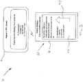
- the processor 35may be configured to generate an image 47 , (e.g. an arrow) on the display 46 based upon the relative position of the adjacent NFC device 31 ( FIG. 2 ). This may be particularly advantageous for use with a directionally based application, for example, where a user interface is updated based upon the relative location of the adjacent NFC device 31 .
- determining the relative location of the adjacent NFC device 31may also be particularly advantageous for spanning a user interface across multiple displays, for example.
- one exemplary application of the embodiments described hereinmay be in a fast food setting with a fast food ordering application.
- a usermay order items on tablet, for example, and pay with an NFC equipped smart phone through a front NFC antenna.
- the rear NFC antennamay be used for relaying information or functions for the fast food restaurant employees, for example, locking, unlocking, and/or cancelling an order.
- a related method aspectis directed to a communications method for a mobile wireless communications device 30 that may include a wireless transceiver 34 , a processor 35 coupled to the wireless transceiver, and a near-field communication (NFC) device 40 coupled with the processor.
- the NFC device 40may include an NFC controller 41 , an NFC transceiver 42 coupled with the NFC controller, a plurality of spaced apart NFC antennas 43a-43f, and a scanning switch 44 coupled between the plurality of spaced apart NFC antennas and the NFC transceiver.
- the methodincludes using the NFC controller 41 to operate the scanning switch 44 to successively couple each NFC antenna 43a-43f to the NFC transceiver 44 while attempting to establish NFC communication with an adjacent NFC device 31 .
- the methodfurther includes, at Block 76 using the NFC controller 41 to operate the scanning switch 44 to lock coupling to a corresponding NFC antenna 43a-43f upon establishing NFC communication with the adjacent NFC device 31 .
- the methodfurther includes, at Block 80 , using the NFC controller 41 to resume operating the scanning switch to successively couple each NFC antenna 43a-43f to the NFC transceiver 41 while attempting to establish NFC communication with an adjacent NFC device 31 after coupling has been unlocked.
- the device 1000illustratively includes a housing 1200 , a keyboard or keypad 1400 and an output device 1600 .
- the output device shownis a display 1600 , which may comprise a full graphic LCD. Other types of output devices may alternatively be utilized.
- a processing device 1800is contained within the housing 1200 and is coupled between the keypad 1400 and the display 1600. The processing device 1800 controls the operation of the display 1600 , as well as the overall operation of the mobile device 1000 , in response to actuation of keys on the keypad 1400 .
- the housing 1200may be elongated vertically, or may take on other sizes and shapes (including clamshell housing structures).
- the keypadmay include a mode selection key, or other hardware or software for switching between text entry and telephony entry.
- FIG. 4In addition to the processing device 1800 , other parts of the mobile device 1000 are shown schematically in FIG. 4 . These include a communications subsystem 1001 ; a short-range communications subsystem 1020 ; the keypad 1400 and the display 1600 , along with other input/output devices 1060 , 1080 , 1100 and 1120 ; as well as memory devices 1160 , 1180 and various other device subsystems 1201 .
- the mobile device 1000may comprise a two-way RF communications device having data and, optionally, voice communications capabilities. In addition, the mobile device 1000 may have the capability to communicate with other computer systems via the Internet.
- Operating system software executed by the processing device 1800is stored in a persistent store, such as the flash memory 1160 , but may be stored in other types of memory devices, such as a read only memory (ROM) or similar storage element.
- system software, specific device applications, or parts thereofmay be temporarily loaded into a volatile store, such as the random access memory (RAM) 1180 .
- Communications signals received by the mobile devicemay also be stored in the RAM 1180.
- the processing device 1800in addition to its operating system functions, enables execution of software applications 1300A-1300N on the device 1000 .
- a personal information manager (PIM) applicationmay be installed during manufacture.
- the PIMmay be capable of organizing and managing data items, such as e-mail, calendar events, voice mails, appointments, and task items.
- the PIM applicationmay also be capable of sending and receiving data items via a wireless network 1401 .
- the PIM data itemsmay be seamlessly integrated, synchronized and updated via the wireless network 1401 with corresponding data items stored or associated with a host computer system.
- the communications subsystem 1001includes a receiver 1500 , a transmitter 1520 , and one or more antennas 1540 and 1560 .
- the communications subsystem 1001also includes a processing module, such as a digital signal processor (DSP) 1580 , and local oscillators (LOs) 1601 .
- DSPdigital signal processor
- LOslocal oscillators
- a mobile device 1000may include a communications subsystem 1001 designed to operate with the Mobitex TM , Data TAC TM or General Packet Radio Service (GPRS) mobile data communications networks, and also designed to operate with any of a variety of voice communications networks, such as AMPS, TDMA, CDMA, WCDMA, PCS, GSM, EDGE, etc. Other types of data and voice networks, both separate and integrated, may also be utilized with the mobile device 1000 .
- the mobile device 1000may also be compliant with other communications standards such as 3GSM, 3GPP, UMTS, 4G, etc.
- Network access requirementsvary depending upon the type of communication system. For example, in the Mobitex and DataTAC networks, mobile devices are registered on the network using a unique personal identification number or PIN associated with each device. In GPRS networks, however, network access is associated with a subscriber or user of a device. A GPRS device therefore typically involves use of a subscriber identity module, commonly referred to as a SIM card, in order to operate on a GPRS network.
- SIM cardsubscriber identity module
- the mobile device 1000may send and receive communications signals over the communication network 1401 .
- Signals received from the communications network 1401 by the antenna 1540are routed to the receiver 1500 , which provides for signal amplification, frequency down conversion, filtering, channel selection, etc., and may also provide analog to digital conversion. Analog-to-digital conversion of the received signal allows the DSP 1580 to perform more complex communications functions, such as demodulation and decoding.
- signals to be transmitted to the network 1401are processed (e.g. modulated and encoded) by the DSP 1580 and are then provided to the transmitter 1520 for digital to analog conversion, frequency up conversion, filtering, amplification and transmission to the communication network 1401 (or networks) via the antenna 1560.
- the DSP 1580provides for control of the receiver 1500 and the transmitter 1520 .
- gains applied to communications signals in the receiver 1500 and transmitter 1520may be adaptively controlled through automatic gain control algorithms implemented in the DSP 1580.
- a received signalsuch as a text message or web page download
- the communications subsystem 1001is input to the processing device 1800 .
- the received signalis then further processed by the processing device 1800 for an output to the display 1600 , or alternatively to some other auxiliary I/O device 1060 .
- a devicemay also be used to compose data items, such as e-mail messages, using the keypad 1400 and/or some other auxiliary I/O device 1060 , such as a touchpad, a rocker switch, a thumb-wheel, or some other type of input device.
- the composed data itemsmay then be transmitted over the communications network 1401 via the communications subsystem 1001 .
- a voice communications modeIn a voice communications mode, overall operation of the device is substantially similar to the data communications mode, except that received signals are output to a speaker 1100 , and signals for transmission are generated by a microphone 1120 .
- Alternative voice or audio I/O subsystemssuch as a voice message recording subsystem, may also be implemented on the device 1000 .
- the display 1600may also be utilized in voice communications mode, for example to display the identity of a calling party, the duration of a voice call, or other voice call related information.
- the short-range communications subsystemenables communication between the mobile device 1000 and other proximate systems or devices, which need not necessarily be similar devices.
- the short-range communications subsystemmay include an infrared device and associated circuits and components, a Bluetooth TM communications module to provide for communication with similarly-enabled systems and devices, or a near field communications (NFC) sensor for communicating with a NFC device or NFC tag via NFC communications.
- NFCnear field communications
Landscapes
- Engineering & Computer Science (AREA)
- Computer Networks & Wireless Communication (AREA)
- Signal Processing (AREA)
- Mobile Radio Communication Systems (AREA)
- Telephone Function (AREA)
Description
- The present disclosure generally relates to the field of wireless communications systems, and, more particularly, to mobile wireless communications devices and related methods.
- Mobile communication systems continue to grow in popularity and have become an integral part of both personal and business communications. Various mobile devices now incorporate Personal Digital Assistant (PDA) features such as calendars, address books, task lists, calculators, memo and writing programs, media players, games, etc. These multifunction devices usually allow electronic mail (email) messages to be sent and received wirelessly, as well as access the internet via a cellular network and/or a wireless local area network (WLAN), for example.
- Some mobile devices incorporate contactless card technology and/or near field communication (NFC) chips. NFC technology is commonly used for contactless short-range communications based on radio frequency identification (RFID) standards, using magnetic field induction to enable communication between electronic devices, including mobile wireless communications devices. This short-range high frequency wireless communications technology exchanges data between devices over a short distance, such as only a few centimeters
- United States Patent Publication No.
2010/0087146 to Han et al. is directed to a method and device for performing short range wireless communication of a mobile terminal purports to reduce a time period of searching for terminals for connection. A short wireless communication distance can be extended by switching to/from a directional antenna and an omni-directional antenna of the mobile terminal according to a user setting. The method of performing short range wireless communication in a mobile terminal including a directional first antenna, an omni-directional second antenna, and a switch unit for switching the first antenna and the second antenna includes: activating the first antenna and searching for connectable terminals, when a short range wireless communication function is activated; and forming a communication channel with the found terminal, if a connectable terminal is found after activating the first antenna. - The invention is defined in the independent claims. Some optional features of the invention are defined in the dependent claims.
FIG. 1 is a schematic block diagram of a communications system in accordance with an example embodiment.FIG. 2 is a schematic diagram of the communications system ofFIG. 1 showing the display of the mobile device.FIG. 3 is a flow diagram illustrating example method aspects associated with the system and devices ofFIGS. 1-2 .FIG. 4 is a schematic block diagram illustrating example mobile wireless communications device components that may be used with the devices ofFIGS. 1 and2 .- The present description is made with reference to the accompanying drawings, in which various embodiments are shown. However, many different embodiments may be used, and thus the description should not be construed as limited to the embodiments set forth herein. Rather, these embodiments are provided so that this disclosure will be thorough and complete. Like numbers refer to like elements throughout.
- Generally speaking, a mobile wireless communications device is disclosed herein which may include a wireless transceiver, a processor coupled to the wireless transceiver, and a near-field communication (NFC) device coupled to the processor. The NFC device may include an NFC controller, an NFC transceiver coupled to the NFC controller, and a plurality of spaced apart NFC antennas. The NFC device also includes a scanning switch coupled between the plurality of spaced apart NFC antennas and the NFC transceiver. The NFC controller may be configured to operate the scanning switch to successively couple each NFC antenna of the plurality thereof to the NFC transceiver while attempting to establish NFC communication with an adjacent NFC device. The NFC device may also be configured to lock coupling to a corresponding NFC antenna upon establishing NFC communication with the adjacent NFC device.
- The NFC controller may be configured to operate the scanning switch to successively couple each NFC antenna of the plurality thereof to the NFC transceiver in a random fashion, for example. The NFC controller may be configured to operate the scanning switch to successively couple each NFC antenna of the plurality thereof to the NFC transceiver in a predetermined pattern, for example.
- The NFC controller may be configured to operate the scanning switch to unlock coupling to the corresponding NFC antenna upon losing NFC communication with the adjacent NFC device. The NFC controller may be configured to resume operating the scanning switch to successively couple each NFC antenna of the plurality thereof to the NFC transceiver while attempting to establish NFC communication with an adjacent NFC device after coupling has been unlocked, for example.
- The NFC controller may be configured to determine a relative position of the adjacent NFC device based upon the corresponding NFC antenna with locked coupling. The mobile wireless communications device may further include a display coupled to the processor. The processor may be configured to generate an image on the display based upon the relative position of the adjacent NFC device, for example.
- The mobile wireless communications device may further include a portable housing carrying the wireless transceiver, the processor, and the NFC device, for example. The plurality of spaced apart NFC antennas may be spaced around a periphery of the portable housing. The wireless transceiver may include a cellular transceiver, for example.
- A related method aspect is directed to a communications method for a mobile wireless communications device that may include a wireless transceiver, a processor coupled to the wireless transceiver, and a near-field communication (NFC) device coupled with the processor. The NFC device may include an NFC controller, an NFC transceiver coupled with the NFC controller, a plurality of spaced apart NFC antennas, and a scanning switch coupled between the plurality of spaced apart NFC antennas and the NFC transceiver. The method may include using the NFC controller to operate the scanning switch to successively couple each NFC antenna of the plurality thereof to the NFC transceiver while attempting to establish NFC communication with an adjacent NFC device. The method may further include using the NFC controller to operate the scanning switch to lock coupling to a corresponding NFC antenna upon establishing NFC communication with the adjacent NFC device.
- Referring initially to
FIGS. 1-2 , acommunications system 30 illustratively includes a mobile wireless communications device32 (also referred to as a "mobile device" herein). Example mobile wireless communications devices may include portable or personal media players (e.g., music or MP3 players, video players, etc.), portable gaming devices, portable or mobile telephones, smartphones, tablet computers, digital cameras, etc. - The
mobile device 32 illustratively includes aportable housing 33 and awireless transceiver 34 carried by theportable housing 33. Thewireless transceiver 34 may comprise a cellular transceiver or other type of wireless communications transceiver, and may communicate any combination of voice and data, such as, for example, email. - The
mobile device 32 includes adisplay 46 carried by theportable housing 33. Thedisplay 46 may comprise a liquid crystal display (LCD) and may be configured to display information relating to data or voice communications. Thedisplay 46 may be in the form of an active display that includes a backlight, for example. Thedisplay 46 may display email information, contact information, or call information. Thedisplay 46 may be another type of display, for example, a passive display, and may display other information. - The
mobile device 32 also includes aprocessor 35 that is carried by theportable housing 33 and coupled with thewireless transceiver 34 and thedisplay 46. Theprocessor 35 may be implemented using hardware (e.g., memory, etc.) and software components, i.e., computer-readable instructions for causing themobile device 32 to perform the various functions or operations described herein. - The
mobile device 32 also includes aNFC device 40 carried by theportable housing 33 and coupled with theprocessor 35. TheNFC device 40 includes aNFC controller 41 and a NFC transceiver42 coupled with theNFC controller 41. - The
NFC device 40 also includes spaced apart NFC antennas43a-43f spaced around a periphery of theportable housing 31. Illustratively, there are six spaced apart NFC antennas43a-43f spaced around the portable housing33: two on each side of the portable housing, one adjacent the top of the portable housing, and one adjacent the bottom of the portable housing. Of course, there may be a different number of spaced apartNFC antennas 43 which may be spaced apart or carried by theportable housing 33 in a different configuration. - The
NFC controller 41, the NFC transceiver42, and the spaced apart NFC antennas43a-43f advantageously cooperate to perform at least one NFC communication function. For example, theNFC device 40 may communicate with anadjacent NFC device 31 or terminal that is part of thecommunications system 30 based upon proximity thereto using NFC communication. Theadjacent NFC device 31 may be a NFC tag, a NFC-enabled mobile device, a smart poster etc. - By way of background, NFC is a short-range wireless communications technology in which NFC-enabled devices are "swiped," "bumped" or otherwise moved in close proximity to communicate. In one non-limiting example implementation, NFC may operate at 13.56 MHz and with an effective range of about 10cm, but other suitable versions of near-field communication which may have different operating frequencies, effective ranges, etc., for example, may also be used.
- The
NFC device 40 also includes a scanning switch44 coupled between the NFC antennas43a-43f and the NFC transceiver42. TheNFC controller 41 is configured to operate with the scanning switch44 to successively couple each of the NFC antennas43a-43f to the NFC transceiver42 (e.g.43a, 43b, 43c, etc.) while attempting to establish NFC communication with theadjacent NFC device 31. TheNFC controller 41 is also configured to operate the scanning switch44 to lock coupling to a corresponding NFC antenna43a-43f upon established NFC communication with theadjacent NFC device 31. In the illustrated embodiment inFIG. 1 , the scanning switch would likely be locked with NFC antenna43a or43b depending on the scanning pattern. - In other words, the
NFC controller 41 operates the scanning switch44 as a multiplexer to switch from one NFC antenna43a-43f to another, attempt to communicate with theadjacent NFC device 31 using each coupled NFC antenna, and if no communication can be established with the adjacent NFC device, then switching to the next NFC antenna to attempt to establish NFC communication. The switching continues until communication is established with theadjacent NFC device 31. - The
NFC controller 41 may be configured to operate the scanning switch44 to successively couple each NFC antenna43a-43f to the NFC transceiver42 in a random manner. TheNFC controller 41 may be configured to operate the scanning switch44 to successively couple each NFC antenna43a-43f to the NFC transceiver42 in a predetermined pattern. For example, theNFC controller 41 may be configured to operate the scanning switch44 to successively couple each NFC antenna43a-43f to the NFC transceiver42 in a zig-zag pattern (e.g.43a, 43d, 43f, 43c, 43e, 43b), by location in the portable housing33 (e.g.43a, 43f, 43c, 43d, 43b, 43e). - In some embodiments, after communication has been established with the
adjacent NFC device 31, theNFC controller 41 may operate the scanning switch to successively couple each of the NFC antennas43a-43f that are not-locked to the NFC transceiver42 while attempting to establish NFC communication with another adjacent NFC device. In other words, more than one NFC antenna43a-43f may be locked upon establishing communication with respective adjacent NFC devices. - The
NFC controller 41 is also configured to operate the scanning switch44 to unlock coupling to the corresponding NFC antenna43a-43f upon losing NFC communication with theadjacent NFC device 31. This may occur, for example, ifadjacent NFC device 31 is outside the effective range of the NFC transceiver42. TheNFC controller 41 is also configured to resume operating the scanning switch44 to successively couple each NFC antenna43a-43f to the NFC transceiver42 while again attempting to establish NFC communication with the adjacent NFC device after coupling has been unlocked. - As will be appreciated by those skilled in the art, when using NFC with multiple devices, a single NFC antenna may be a "blocker" to achieve desired performance in cases of common use. For example, an NFC device near a center of a mobile wireless communications device may make it increasingly difficult to interact with adjacent NFC device when the mobile wireless communications device is placed on a table. Coupling multiple NFC antennas, for example, in series, to an NFC transceiver results in increased attenuation, and thus, undesired operation. Including multiple NFC antennas with respective NFC transceivers may address the above-noted problem; however, multiple NFC transceivers increase production costs, draw an increased amount of power, and occupy an increased amount of space in the portable housing. Advantageously, the
NFC controller 41 being configured to operate the scanning switch44, as described herein, has a reduced impact on efficiency with respect to other approaches, as it may consume roughly the same amount of power as compared to a single NFC antenna. Sensitivity of each NFC antenna43a-43f may also be maintained. - The
NFC controller 41 may be configured to determine a relative position of theadjacent NFC device 31 based upon the corresponding NFC antenna43a-43f with locked coupling. In particular, theprocessor 35 may be configured to generate an image47, (e.g. an arrow) on thedisplay 46 based upon the relative position of the adjacent NFC device31 (FIG. 2 ). This may be particularly advantageous for use with a directionally based application, for example, where a user interface is updated based upon the relative location of theadjacent NFC device 31. Additionally, determining the relative location of theadjacent NFC device 31 may also be particularly advantageous for spanning a user interface across multiple displays, for example. - As will be appreciated by those skilled in the art, one exemplary application of the embodiments described herein may be in a fast food setting with a fast food ordering application. A user may order items on tablet, for example, and pay with an NFC equipped smart phone through a front NFC antenna. The rear NFC antenna may be used for relaying information or functions for the fast food restaurant employees, for example, locking, unlocking, and/or cancelling an order.
- Referring now to the
flowchart 70 inFIG. 3 , beginning atBlock 72, a related method aspect is directed to a communications method for a mobilewireless communications device 30 that may include awireless transceiver 34, aprocessor 35 coupled to the wireless transceiver, and a near-field communication (NFC)device 40 coupled with the processor. TheNFC device 40 may include anNFC controller 41, an NFC transceiver42 coupled with the NFC controller, a plurality of spaced apart NFC antennas43a-43f, and a scanning switch44 coupled between the plurality of spaced apart NFC antennas and the NFC transceiver. AtBlock 74, the method includes using theNFC controller 41 to operate the scanning switch44 to successively couple each NFC antenna43a-43f to the NFC transceiver44 while attempting to establish NFC communication with anadjacent NFC device 31. The method further includes, atBlock 76 using theNFC controller 41 to operate the scanning switch44 to lock coupling to a corresponding NFC antenna43a-43f upon establishing NFC communication with theadjacent NFC device 31. - At
Block 78, the further includes using theNFC controller 41 to operate the scanning switch44 to unlock coupling to the corresponding NFC antenna43a-43f upon losing NFC communication with theadjacent NFC device 31. The method further includes, atBlock 80, using theNFC controller 41 to resume operating the scanning switch to successively couple each NFC antenna43a-43f to theNFC transceiver 41 while attempting to establish NFC communication with anadjacent NFC device 31 after coupling has been unlocked. The method ends at Block82. - Example components of a mobile
wireless communications device 1000 that may be used in accordance with the above-described embodiments are further described below with reference toFIG. 4 . Thedevice 1000 illustratively includes ahousing 1200, a keyboard orkeypad 1400 and anoutput device 1600. The output device shown is adisplay 1600, which may comprise a full graphic LCD. Other types of output devices may alternatively be utilized. Aprocessing device 1800 is contained within thehousing 1200 and is coupled between thekeypad 1400 and thedisplay 1600. Theprocessing device 1800 controls the operation of thedisplay 1600, as well as the overall operation of themobile device 1000, in response to actuation of keys on thekeypad 1400. - The
housing 1200 may be elongated vertically, or may take on other sizes and shapes (including clamshell housing structures). The keypad may include a mode selection key, or other hardware or software for switching between text entry and telephony entry. - In addition to the
processing device 1800, other parts of themobile device 1000 are shown schematically inFIG. 4 . These include acommunications subsystem 1001; a short-range communications subsystem 1020; thekeypad 1400 and thedisplay 1600, along with other input/output devices memory devices other device subsystems 1201. Themobile device 1000 may comprise a two-way RF communications device having data and, optionally, voice communications capabilities. In addition, themobile device 1000 may have the capability to communicate with other computer systems via the Internet. - Operating system software executed by the
processing device 1800 is stored in a persistent store, such as theflash memory 1160, but may be stored in other types of memory devices, such as a read only memory (ROM) or similar storage element. In addition, system software, specific device applications, or parts thereof, may be temporarily loaded into a volatile store, such as the random access memory (RAM)1180. Communications signals received by the mobile device may also be stored in theRAM 1180. - The
processing device 1800, in addition to its operating system functions, enables execution ofsoftware applications 1300A-1300N on thedevice 1000. A predetermined set of applications that control basic device operations, such as data andvoice communications device 1000 during manufacture. In addition, a personal information manager (PIM) application may be installed during manufacture. The PIM may be capable of organizing and managing data items, such as e-mail, calendar events, voice mails, appointments, and task items. The PIM application may also be capable of sending and receiving data items via awireless network 1401. The PIM data items may be seamlessly integrated, synchronized and updated via thewireless network 1401 with corresponding data items stored or associated with a host computer system. - Communication functions, including data and voice communications, are performed through the
communications subsystem 1001, and possibly through the short-range communications subsystem. Thecommunications subsystem 1001 includes areceiver 1500, atransmitter 1520, and one ormore antennas communications subsystem 1001 also includes a processing module, such as a digital signal processor (DSP)1580, and local oscillators (LOs)1601. The specific design and implementation of thecommunications subsystem 1001 is dependent upon the communications network in which themobile device 1000 is intended to operate. For example, amobile device 1000 may include acommunications subsystem 1001 designed to operate with the Mobitex™, Data TAC™ or General Packet Radio Service (GPRS) mobile data communications networks, and also designed to operate with any of a variety of voice communications networks, such as AMPS, TDMA, CDMA, WCDMA, PCS, GSM, EDGE, etc. Other types of data and voice networks, both separate and integrated, may also be utilized with themobile device 1000. Themobile device 1000 may also be compliant with other communications standards such as 3GSM, 3GPP, UMTS, 4G, etc. - Network access requirements vary depending upon the type of communication system. For example, in the Mobitex and DataTAC networks, mobile devices are registered on the network using a unique personal identification number or PIN associated with each device. In GPRS networks, however, network access is associated with a subscriber or user of a device. A GPRS device therefore typically involves use of a subscriber identity module, commonly referred to as a SIM card, in order to operate on a GPRS network.
- When required network registration or activation procedures have been completed, the
mobile device 1000 may send and receive communications signals over thecommunication network 1401. Signals received from thecommunications network 1401 by theantenna 1540 are routed to thereceiver 1500, which provides for signal amplification, frequency down conversion, filtering, channel selection, etc., and may also provide analog to digital conversion. Analog-to-digital conversion of the received signal allows theDSP 1580 to perform more complex communications functions, such as demodulation and decoding. In a similar manner, signals to be transmitted to thenetwork 1401 are processed (e.g. modulated and encoded) by theDSP 1580 and are then provided to thetransmitter 1520 for digital to analog conversion, frequency up conversion, filtering, amplification and transmission to the communication network1401 (or networks) via theantenna 1560. - In addition to processing communications signals, the
DSP 1580 provides for control of thereceiver 1500 and thetransmitter 1520. For example, gains applied to communications signals in thereceiver 1500 andtransmitter 1520 may be adaptively controlled through automatic gain control algorithms implemented in theDSP 1580. - In a data communications mode, a received signal, such as a text message or web page download, is processed by the
communications subsystem 1001 and is input to theprocessing device 1800. The received signal is then further processed by theprocessing device 1800 for an output to thedisplay 1600, or alternatively to some other auxiliary I/O device 1060. A device may also be used to compose data items, such as e-mail messages, using thekeypad 1400 and/or some other auxiliary I/O device 1060, such as a touchpad, a rocker switch, a thumb-wheel, or some other type of input device. The composed data items may then be transmitted over thecommunications network 1401 via thecommunications subsystem 1001. - In a voice communications mode, overall operation of the device is substantially similar to the data communications mode, except that received signals are output to a
speaker 1100, and signals for transmission are generated by amicrophone 1120. Alternative voice or audio I/O subsystems, such as a voice message recording subsystem, may also be implemented on thedevice 1000. In addition, thedisplay 1600 may also be utilized in voice communications mode, for example to display the identity of a calling party, the duration of a voice call, or other voice call related information. - The short-range communications subsystem enables communication between the
mobile device 1000 and other proximate systems or devices, which need not necessarily be similar devices. For example, the short-range communications subsystem may include an infrared device and associated circuits and components, a Bluetooth™ communications module to provide for communication with similarly-enabled systems and devices, or a near field communications (NFC) sensor for communicating with a NFC device or NFC tag via NFC communications. - Many modifications and other embodiments will come to the mind of one skilled in the art having the benefit of the teachings presented in the foregoing descriptions and the associated drawings. Therefore, it is understood that various modifications and embodiments are intended to be included within the scope of the appended claims.
Claims (14)
- A mobile wireless communications device (32) comprising:a wireless transceiver (34);a processor (35) coupled to said wireless transceiver; anda near-field communication (NFC) device (40) coupled to said processor and comprisingan NFC controller (41),an NFC transceiver (42) coupled to said NFC controller, anda plurality of spaced apart NFC antennas (43a-43f), anda scanning switch (44) coupled between said plurality of spaced apart NFC antennas and said NFC transceiver,said NFC controller configured to operate said scanning switch tosuccessively couple each NFC antenna of said plurality thereof to said NFC transceiver while attempting to establish NFC communication with an adjacent NFC device,lock coupling to a corresponding NFC antenna upon establishing NFC communication with the adjacent NFC device, andunlock coupling to the corresponding NFC antenna upon losing NFC communication with the adjacent NFC device.
- The mobile wireless communications device of Claim 1, wherein said NFC controller is configured to operate the scanning switch to successively couple each NFC antenna of said plurality thereof to said NFC transceiver in a random fashion.
- The mobile wireless communications device of Claim 1, wherein said NFC controller is configured to operate the scanning switch to successively couple each NFC antenna of said plurality thereof to said NFC transceiver in a predetermined pattern.
- The mobile wireless communications device of Claim 1, wherein said NFC controller is configured to resume operating the scanning switch to successively couple each NFC antenna of said plurality thereof to said NFC transceiver while attempting to establish NFC communication with an adjacent NFC device after coupling has been unlocked.
- The mobile wireless communications device of Claim 1, wherein said NFC controller is configured to determine a relative position of the adjacent NFC device based upon the corresponding NFC antenna with locked coupling.
- The mobile wireless communications device of Claim 5, further comprising a display (46) coupled to said processor; and wherein said processor is configured to generate an image (47) on said display based upon the relative position of the adjacent NFC device.
- The mobile wireless communications device of Claim 1, further comprising a portable housing (33) carrying said wireless transceiver, said processor, and said NFC device; and wherein said plurality of spaced apart NFC antennas is spaced around a periphery of said portable housing.
- The mobile wireless communications device of Claim 1, wherein said wireless transceiver comprises a cellular transceiver.
- A communications method for a mobile wireless communications device (32) comprising a wireless transceiver (34), a processor (35) coupled to the wireless transceiver, and a near-field communication (NFC) device (40) coupled with the processor and comprising an NFC controller (41), an NFC transceiver (42) coupled with the NFC controller, a plurality of spaced apart NFC antennas (43a-43f), and a scanning switch (44) coupled between the plurality of spaced apart NFC antennas and the NFC transceiver, the method comprising:using the NFC controller to operate the scanning switch to successively couple each NFC antenna of the plurality thereof to the NFC transceiver while attempting to establish NFC communication with an adjacent NFC device;using the NFC controller to operate the scanning switch to lock coupling to a corresponding NFC antenna upon establishing NFC communication with the adjacent NFC device; andusing the NFC controller to operate the scanning switch to unlock coupling to the corresponding NFC antenna upon losing NFC communication with the adjacent NFC device.
- The method of Claim 9, further comprising using the NFC controller to operate the scanning switch to successively couple each NFC antenna of the plurality thereof to the NFC transceiver in a random fashion.
- The method of Claim 9, further comprising using the NFC controller to operate the scanning switch to successively couple each NFC antenna of the plurality thereof to the NFC transceiver in a predetermined pattern.
- The method of Claim 9, further comprising using the NFC controller to resume operating the scanning switch to successively couple each NFC antenna of the plurality thereof to the NFC transceiver while attempting to establish NFC communication with an adjacent NFC device after coupling has been unlocked.
- The method of Claim 9, further comprising using the NFC controller to determine a relative position of the adjacent NFC device based upon the corresponding NFC antenna with locked coupling.
- The method of Claim 13, wherein the mobile wireless communications device further comprises a display (46) coupled to said processor; the method further comprising generating an image (47) on said display based upon the relative position of the adjacent NFC device.
Priority Applications (2)
| Application Number | Priority Date | Filing Date | Title |
|---|---|---|---|
| EP12151981.3AEP2618497B1 (en) | 2012-01-20 | 2012-01-20 | Mobile wireless communications device including nfc antenna scanning switch and related methods |
| CA2802200ACA2802200C (en) | 2012-01-20 | 2013-01-15 | Mobile wireless communications device including nfc antenna scanning switch and related methods |
Applications Claiming Priority (1)
| Application Number | Priority Date | Filing Date | Title |
|---|---|---|---|
| EP12151981.3AEP2618497B1 (en) | 2012-01-20 | 2012-01-20 | Mobile wireless communications device including nfc antenna scanning switch and related methods |
Publications (2)
| Publication Number | Publication Date |
|---|---|
| EP2618497A1 EP2618497A1 (en) | 2013-07-24 |
| EP2618497B1true EP2618497B1 (en) | 2017-04-05 |
Family
ID=45509312
Family Applications (1)
| Application Number | Title | Priority Date | Filing Date |
|---|---|---|---|
| EP12151981.3AActiveEP2618497B1 (en) | 2012-01-20 | 2012-01-20 | Mobile wireless communications device including nfc antenna scanning switch and related methods |
Country Status (2)
| Country | Link |
|---|---|
| EP (1) | EP2618497B1 (en) |
| CA (1) | CA2802200C (en) |
Cited By (1)
| Publication number | Priority date | Publication date | Assignee | Title |
|---|---|---|---|---|
| WO2023174716A1 (en)* | 2022-03-18 | 2023-09-21 | Valeo Comfort And Driving Assistance | Nfc control system and control method for motor vehicle, and motor vehicle |
Families Citing this family (8)
| Publication number | Priority date | Publication date | Assignee | Title |
|---|---|---|---|---|
| US9793616B2 (en) | 2012-11-19 | 2017-10-17 | Apple Inc. | Shared antenna structures for near-field communications and non-near-field communications circuitry |
| US9621230B2 (en)* | 2014-03-03 | 2017-04-11 | Apple Inc. | Electronic device with near-field antennas |
| US9325080B2 (en) | 2014-03-03 | 2016-04-26 | Apple Inc. | Electronic device with shared antenna structures and balun |
| US10312593B2 (en) | 2014-04-16 | 2019-06-04 | Apple Inc. | Antennas for near-field and non-near-field communications |
| JP6383187B2 (en) | 2014-06-12 | 2018-08-29 | キヤノン株式会社 | COMMUNICATION DEVICE, COMMUNICATION DEVICE CONTROL METHOD, AND PROGRAM |
| US11038257B2 (en) | 2017-01-16 | 2021-06-15 | Huawei Technologies Co., Ltd. | Antenna structure and communications terminal |
| US11606680B2 (en) | 2021-01-27 | 2023-03-14 | Capital One Services, Llc | Method and device for discriminating one of a group of NFC transmitters |
| CN118175227A (en)* | 2022-12-09 | 2024-06-11 | 华为技术有限公司 | Mobile terminal |
Family Cites Families (3)
| Publication number | Priority date | Publication date | Assignee | Title |
|---|---|---|---|---|
| JPH08321785A (en)* | 1995-05-24 | 1996-12-03 | Sony Corp | Transmitter, receiver, transmitting method, receiving method and transmitting method |
| JP2005244260A (en)* | 2003-12-24 | 2005-09-08 | Toshiba Corp | Portable wireless terminal |
| KR20100038790A (en)* | 2008-10-06 | 2010-04-15 | 삼성전자주식회사 | Method and apparatus for near field communication of portable terminal |
- 2012
- 2012-01-20EPEP12151981.3Apatent/EP2618497B1/enactiveActive
- 2013
- 2013-01-15CACA2802200Apatent/CA2802200C/enactiveActive
Non-Patent Citations (1)
| Title |
|---|
| None* |
Cited By (1)
| Publication number | Priority date | Publication date | Assignee | Title |
|---|---|---|---|---|
| WO2023174716A1 (en)* | 2022-03-18 | 2023-09-21 | Valeo Comfort And Driving Assistance | Nfc control system and control method for motor vehicle, and motor vehicle |
Also Published As
| Publication number | Publication date |
|---|---|
| EP2618497A1 (en) | 2013-07-24 |
| CA2802200C (en) | 2016-04-12 |
| CA2802200A1 (en) | 2013-07-20 |
Similar Documents
| Publication | Publication Date | Title |
|---|---|---|
| US8688043B2 (en) | Mobile wireless communications device including NFC antenna scanning switch and related methods | |
| EP2618497B1 (en) | Mobile wireless communications device including nfc antenna scanning switch and related methods | |
| US8989767B2 (en) | Wireless communication system with NFC-controlled access and related methods | |
| EP2579388B1 (en) | Electronic device with NFC antenna adjacent display and related methods | |
| US8831509B2 (en) | Mobile device having enhanced in-holster power saving features using NFC and related methods | |
| US8750795B2 (en) | Mobile wireless communications device having a near field communication (NFC) device and providing memory disabling and related methods | |
| US9072052B2 (en) | Communication system providing context-based mobile wireless communications device power consumption management and related methods | |
| US9014734B2 (en) | Mobile wireless communications device with NFC coupling circuit and related methods | |
| US20120077432A1 (en) | Mobile wireless communications device establishing wireless communication links based upon near field communication and related methods | |
| US20120214413A1 (en) | Mobile wireless communications device establishing wireless communication links based upon near field communication and related methods | |
| US8660612B2 (en) | Electronic device having an NFC antenna in a speaker compartment and related methods | |
| CA2748692C (en) | Communication system providing context-based mobile wireless communications device power consumption management and related methods | |
| CA2766362C (en) | Mobile device having enhanced in-holster power saving features and related methods | |
| EP2493233A1 (en) | Wireless communication system with nfc-controlled access and related methods | |
| EP2506542A1 (en) | Mobile wireless communications device having a near field communication (NFC) device and providing memory disabling and related methods | |
| EP2613455B1 (en) | Mobile wireless communications device with NFC coupling circuit and related methods | |
| HK1176198A (en) | Mobile wireless communications device having a near field communication (nfc) device and providing memory disabling and related methods |
Legal Events
| Date | Code | Title | Description |
|---|---|---|---|
| PUAI | Public reference made under article 153(3) epc to a published international application that has entered the european phase | Free format text:ORIGINAL CODE: 0009012 | |
| 17P | Request for examination filed | Effective date:20120120 | |
| AK | Designated contracting states | Kind code of ref document:A1 Designated state(s):AL AT BE BG CH CY CZ DE DK EE ES FI FR GB GR HR HU IE IS IT LI LT LU LV MC MK MT NL NO PL PT RO RS SE SI SK SM TR | |
| AX | Request for extension of the european patent | Extension state:BA ME | |
| RAP1 | Party data changed (applicant data changed or rights of an application transferred) | Owner name:BLACKBERRY LIMITED | |
| RAP1 | Party data changed (applicant data changed or rights of an application transferred) | Owner name:BLACKBERRY LIMITED | |
| 17Q | First examination report despatched | Effective date:20131219 | |
| GRAP | Despatch of communication of intention to grant a patent | Free format text:ORIGINAL CODE: EPIDOSNIGR1 | |
| INTG | Intention to grant announced | Effective date:20161025 | |
| GRAS | Grant fee paid | Free format text:ORIGINAL CODE: EPIDOSNIGR3 | |
| GRAA | (expected) grant | Free format text:ORIGINAL CODE: 0009210 | |
| AK | Designated contracting states | Kind code of ref document:B1 Designated state(s):AL AT BE BG CH CY CZ DE DK EE ES FI FR GB GR HR HU IE IS IT LI LT LU LV MC MK MT NL NO PL PT RO RS SE SI SK SM TR | |
| REG | Reference to a national code | Ref country code:GB Ref legal event code:FG4D | |
| REG | Reference to a national code | Ref country code:CH Ref legal event code:EP | |
| REG | Reference to a national code | Ref country code:AT Ref legal event code:REF Ref document number:882698 Country of ref document:AT Kind code of ref document:T Effective date:20170415 | |
| REG | Reference to a national code | Ref country code:IE Ref legal event code:FG4D | |
| REG | Reference to a national code | Ref country code:DE Ref legal event code:R096 Ref document number:602012030654 Country of ref document:DE | |
| REG | Reference to a national code | Ref country code:NL Ref legal event code:MP Effective date:20170405 | |
| REG | Reference to a national code | Ref country code:LT Ref legal event code:MG4D | |
| REG | Reference to a national code | Ref country code:AT Ref legal event code:MK05 Ref document number:882698 Country of ref document:AT Kind code of ref document:T Effective date:20170405 | |
| PG25 | Lapsed in a contracting state [announced via postgrant information from national office to epo] | Ref country code:NL Free format text:LAPSE BECAUSE OF FAILURE TO SUBMIT A TRANSLATION OF THE DESCRIPTION OR TO PAY THE FEE WITHIN THE PRESCRIBED TIME-LIMIT Effective date:20170405 | |
| PG25 | Lapsed in a contracting state [announced via postgrant information from national office to epo] | Ref country code:NO Free format text:LAPSE BECAUSE OF FAILURE TO SUBMIT A TRANSLATION OF THE DESCRIPTION OR TO PAY THE FEE WITHIN THE PRESCRIBED TIME-LIMIT Effective date:20170705 Ref country code:LT Free format text:LAPSE BECAUSE OF FAILURE TO SUBMIT A TRANSLATION OF THE DESCRIPTION OR TO PAY THE FEE WITHIN THE PRESCRIBED TIME-LIMIT Effective date:20170405 Ref country code:FI Free format text:LAPSE BECAUSE OF FAILURE TO SUBMIT A TRANSLATION OF THE DESCRIPTION OR TO PAY THE FEE WITHIN THE PRESCRIBED TIME-LIMIT Effective date:20170405 Ref country code:ES Free format text:LAPSE BECAUSE OF FAILURE TO SUBMIT A TRANSLATION OF THE DESCRIPTION OR TO PAY THE FEE WITHIN THE PRESCRIBED TIME-LIMIT Effective date:20170405 Ref country code:GR Free format text:LAPSE BECAUSE OF FAILURE TO SUBMIT A TRANSLATION OF THE DESCRIPTION OR TO PAY THE FEE WITHIN THE PRESCRIBED TIME-LIMIT Effective date:20170706 Ref country code:HR Free format text:LAPSE BECAUSE OF FAILURE TO SUBMIT A TRANSLATION OF THE DESCRIPTION OR TO PAY THE FEE WITHIN THE PRESCRIBED TIME-LIMIT Effective date:20170405 Ref country code:AT Free format text:LAPSE BECAUSE OF FAILURE TO SUBMIT A TRANSLATION OF THE DESCRIPTION OR TO PAY THE FEE WITHIN THE PRESCRIBED TIME-LIMIT Effective date:20170405 | |
| PG25 | Lapsed in a contracting state [announced via postgrant information from national office to epo] | Ref country code:SE Free format text:LAPSE BECAUSE OF FAILURE TO SUBMIT A TRANSLATION OF THE DESCRIPTION OR TO PAY THE FEE WITHIN THE PRESCRIBED TIME-LIMIT Effective date:20170405 Ref country code:RS Free format text:LAPSE BECAUSE OF FAILURE TO SUBMIT A TRANSLATION OF THE DESCRIPTION OR TO PAY THE FEE WITHIN THE PRESCRIBED TIME-LIMIT Effective date:20170405 Ref country code:LV Free format text:LAPSE BECAUSE OF FAILURE TO SUBMIT A TRANSLATION OF THE DESCRIPTION OR TO PAY THE FEE WITHIN THE PRESCRIBED TIME-LIMIT Effective date:20170405 Ref country code:PL Free format text:LAPSE BECAUSE OF FAILURE TO SUBMIT A TRANSLATION OF THE DESCRIPTION OR TO PAY THE FEE WITHIN THE PRESCRIBED TIME-LIMIT Effective date:20170405 Ref country code:IS Free format text:LAPSE BECAUSE OF FAILURE TO SUBMIT A TRANSLATION OF THE DESCRIPTION OR TO PAY THE FEE WITHIN THE PRESCRIBED TIME-LIMIT Effective date:20170805 Ref country code:BG Free format text:LAPSE BECAUSE OF FAILURE TO SUBMIT A TRANSLATION OF THE DESCRIPTION OR TO PAY THE FEE WITHIN THE PRESCRIBED TIME-LIMIT Effective date:20170705 | |
| REG | Reference to a national code | Ref country code:DE Ref legal event code:R097 Ref document number:602012030654 Country of ref document:DE | |
| REG | Reference to a national code | Ref country code:FR Ref legal event code:PLFP Year of fee payment:7 | |
| PG25 | Lapsed in a contracting state [announced via postgrant information from national office to epo] | Ref country code:DK Free format text:LAPSE BECAUSE OF FAILURE TO SUBMIT A TRANSLATION OF THE DESCRIPTION OR TO PAY THE FEE WITHIN THE PRESCRIBED TIME-LIMIT Effective date:20170405 Ref country code:EE Free format text:LAPSE BECAUSE OF FAILURE TO SUBMIT A TRANSLATION OF THE DESCRIPTION OR TO PAY THE FEE WITHIN THE PRESCRIBED TIME-LIMIT Effective date:20170405 Ref country code:SK Free format text:LAPSE BECAUSE OF FAILURE TO SUBMIT A TRANSLATION OF THE DESCRIPTION OR TO PAY THE FEE WITHIN THE PRESCRIBED TIME-LIMIT Effective date:20170405 Ref country code:RO Free format text:LAPSE BECAUSE OF FAILURE TO SUBMIT A TRANSLATION OF THE DESCRIPTION OR TO PAY THE FEE WITHIN THE PRESCRIBED TIME-LIMIT Effective date:20170405 Ref country code:CZ Free format text:LAPSE BECAUSE OF FAILURE TO SUBMIT A TRANSLATION OF THE DESCRIPTION OR TO PAY THE FEE WITHIN THE PRESCRIBED TIME-LIMIT Effective date:20170405 | |
| PLBE | No opposition filed within time limit | Free format text:ORIGINAL CODE: 0009261 | |
| STAA | Information on the status of an ep patent application or granted ep patent | Free format text:STATUS: NO OPPOSITION FILED WITHIN TIME LIMIT | |
| PG25 | Lapsed in a contracting state [announced via postgrant information from national office to epo] | Ref country code:IT Free format text:LAPSE BECAUSE OF FAILURE TO SUBMIT A TRANSLATION OF THE DESCRIPTION OR TO PAY THE FEE WITHIN THE PRESCRIBED TIME-LIMIT Effective date:20170405 Ref country code:SM Free format text:LAPSE BECAUSE OF FAILURE TO SUBMIT A TRANSLATION OF THE DESCRIPTION OR TO PAY THE FEE WITHIN THE PRESCRIBED TIME-LIMIT Effective date:20170405 | |
| 26N | No opposition filed | Effective date:20180108 | |
| PG25 | Lapsed in a contracting state [announced via postgrant information from national office to epo] | Ref country code:SI Free format text:LAPSE BECAUSE OF FAILURE TO SUBMIT A TRANSLATION OF THE DESCRIPTION OR TO PAY THE FEE WITHIN THE PRESCRIBED TIME-LIMIT Effective date:20170405 | |
| REG | Reference to a national code | Ref country code:CH Ref legal event code:PL | |
| PG25 | Lapsed in a contracting state [announced via postgrant information from national office to epo] | Ref country code:LU Free format text:LAPSE BECAUSE OF NON-PAYMENT OF DUE FEES Effective date:20180120 | |
| REG | Reference to a national code | Ref country code:IE Ref legal event code:MM4A | |
| REG | Reference to a national code | Ref country code:BE Ref legal event code:MM Effective date:20180131 | |
| PG25 | Lapsed in a contracting state [announced via postgrant information from national office to epo] | Ref country code:BE Free format text:LAPSE BECAUSE OF NON-PAYMENT OF DUE FEES Effective date:20180131 Ref country code:CH Free format text:LAPSE BECAUSE OF NON-PAYMENT OF DUE FEES Effective date:20180131 Ref country code:LI Free format text:LAPSE BECAUSE OF NON-PAYMENT OF DUE FEES Effective date:20180131 | |
| PG25 | Lapsed in a contracting state [announced via postgrant information from national office to epo] | Ref country code:IE Free format text:LAPSE BECAUSE OF NON-PAYMENT OF DUE FEES Effective date:20180120 | |
| PG25 | Lapsed in a contracting state [announced via postgrant information from national office to epo] | Ref country code:MC Free format text:LAPSE BECAUSE OF FAILURE TO SUBMIT A TRANSLATION OF THE DESCRIPTION OR TO PAY THE FEE WITHIN THE PRESCRIBED TIME-LIMIT Effective date:20170405 | |
| PG25 | Lapsed in a contracting state [announced via postgrant information from national office to epo] | Ref country code:MT Free format text:LAPSE BECAUSE OF NON-PAYMENT OF DUE FEES Effective date:20180120 | |
| PG25 | Lapsed in a contracting state [announced via postgrant information from national office to epo] | Ref country code:TR Free format text:LAPSE BECAUSE OF FAILURE TO SUBMIT A TRANSLATION OF THE DESCRIPTION OR TO PAY THE FEE WITHIN THE PRESCRIBED TIME-LIMIT Effective date:20170405 | |
| PG25 | Lapsed in a contracting state [announced via postgrant information from national office to epo] | Ref country code:HU Free format text:LAPSE BECAUSE OF FAILURE TO SUBMIT A TRANSLATION OF THE DESCRIPTION OR TO PAY THE FEE WITHIN THE PRESCRIBED TIME-LIMIT; INVALID AB INITIO Effective date:20120120 Ref country code:PT Free format text:LAPSE BECAUSE OF FAILURE TO SUBMIT A TRANSLATION OF THE DESCRIPTION OR TO PAY THE FEE WITHIN THE PRESCRIBED TIME-LIMIT Effective date:20170405 | |
| PG25 | Lapsed in a contracting state [announced via postgrant information from national office to epo] | Ref country code:MK Free format text:LAPSE BECAUSE OF NON-PAYMENT OF DUE FEES Effective date:20170405 Ref country code:CY Free format text:LAPSE BECAUSE OF FAILURE TO SUBMIT A TRANSLATION OF THE DESCRIPTION OR TO PAY THE FEE WITHIN THE PRESCRIBED TIME-LIMIT Effective date:20170405 | |
| PG25 | Lapsed in a contracting state [announced via postgrant information from national office to epo] | Ref country code:AL Free format text:LAPSE BECAUSE OF FAILURE TO SUBMIT A TRANSLATION OF THE DESCRIPTION OR TO PAY THE FEE WITHIN THE PRESCRIBED TIME-LIMIT Effective date:20170405 | |
| REG | Reference to a national code | Ref country code:DE Ref legal event code:R079 Ref document number:602012030654 Country of ref document:DE Free format text:PREVIOUS MAIN CLASS: H04B0005020000 Ipc:H04B0005480000 | |
| REG | Reference to a national code | Ref country code:DE Ref legal event code:R082 Ref document number:602012030654 Country of ref document:DE Ref country code:DE Ref legal event code:R081 Ref document number:602012030654 Country of ref document:DE Owner name:MALIKIE INNOVATIONS LTD., IE Free format text:FORMER OWNER: BLACKBERRY LIMITED, WATERLOO, ONTARIO, CA | |
| REG | Reference to a national code | Ref country code:GB Ref legal event code:732E Free format text:REGISTERED BETWEEN 20240620 AND 20240627 | |
| PGFP | Annual fee paid to national office [announced via postgrant information from national office to epo] | Ref country code:DE Payment date:20250129 Year of fee payment:14 | |
| PGFP | Annual fee paid to national office [announced via postgrant information from national office to epo] | Ref country code:FR Payment date:20250127 Year of fee payment:14 | |
| PGFP | Annual fee paid to national office [announced via postgrant information from national office to epo] | Ref country code:GB Payment date:20250121 Year of fee payment:14 |