EP2617442B1 - Reduced-pressure treatment systems and methods employing hydrogel reservoir members - Google Patents
Reduced-pressure treatment systems and methods employing hydrogel reservoir membersDownload PDFInfo
- Publication number
- EP2617442B1 EP2617442B1EP13164197.9AEP13164197AEP2617442B1EP 2617442 B1EP2617442 B1EP 2617442B1EP 13164197 AEP13164197 AEP 13164197AEP 2617442 B1EP2617442 B1EP 2617442B1
- Authority
- EP
- European Patent Office
- Prior art keywords
- pressure
- hydrogel
- manifold
- reduced
- tissue site
- Prior art date
- Legal status (The legal status is an assumption and is not a legal conclusion. Google has not performed a legal analysis and makes no representation as to the accuracy of the status listed.)
- Revoked
Links
- 239000000017hydrogelSubstances0.000titleclaimsdescription201
- 238000000034methodMethods0.000titleclaimsdescription22
- 239000012530fluidSubstances0.000claimsdescription89
- 239000011324beadSubstances0.000claimsdescription58
- 238000007789sealingMethods0.000claimsdescription32
- 239000011248coating agentSubstances0.000claimsdescription23
- 238000000576coating methodMethods0.000claimsdescription23
- 239000006260foamSubstances0.000claimsdescription13
- 238000004519manufacturing processMethods0.000claimsdescription13
- 230000002706hydrostatic effectEffects0.000claimsdescription6
- 210000001519tissueAnatomy0.000description92
- 239000000463materialSubstances0.000description27
- 206010052428WoundDiseases0.000description21
- 208000027418Wounds and injuryDiseases0.000description19
- 230000002093peripheral effectEffects0.000description15
- 239000011148porous materialSubstances0.000description10
- 210000002615epidermisAnatomy0.000description6
- 230000003247decreasing effectEffects0.000description5
- 230000008569processEffects0.000description5
- 239000004599antimicrobialSubstances0.000description4
- 230000008878couplingEffects0.000description4
- 238000010168coupling processMethods0.000description4
- 238000005859coupling reactionMethods0.000description4
- 229920001971elastomerPolymers0.000description4
- 239000004952PolyamideSubstances0.000description3
- 239000000806elastomerSubstances0.000description3
- 239000007788liquidSubstances0.000description3
- 229920002647polyamidePolymers0.000description3
- 229920000642polymerPolymers0.000description3
- 229920000098polyolefinPolymers0.000description3
- 239000004814polyurethaneSubstances0.000description3
- 239000000126substanceSubstances0.000description3
- 239000004820Pressure-sensitive adhesiveSubstances0.000description2
- 229920001247Reticulated foamPolymers0.000description2
- 238000010521absorption reactionMethods0.000description2
- 238000013459approachMethods0.000description2
- 229920006037cross link polymerPolymers0.000description2
- 238000004132cross linkingMethods0.000description2
- 239000000839emulsionSubstances0.000description2
- 210000000416exudates and transudateAnatomy0.000description2
- 239000000835fiberSubstances0.000description2
- 239000000499gelSubstances0.000description2
- 230000035876healingEffects0.000description2
- 238000005470impregnationMethods0.000description2
- 230000001788irregularEffects0.000description2
- 238000002803macerationMethods0.000description2
- 238000009581negative-pressure wound therapyMethods0.000description2
- -1open-cellPolymers0.000description2
- 230000037361pathwayEffects0.000description2
- 229920001200poly(ethylene-vinyl acetate)Polymers0.000description2
- 229920000728polyesterPolymers0.000description2
- 229920001296polysiloxanePolymers0.000description2
- 229920002635polyurethanePolymers0.000description2
- 150000003839saltsChemical class0.000description2
- 229910052709silverInorganic materials0.000description2
- 239000004332silverSubstances0.000description2
- 239000007787solidSubstances0.000description2
- 239000000243solutionSubstances0.000description2
- 239000000758substrateSubstances0.000description2
- 230000000007visual effectEffects0.000description2
- SMZOUWXMTYCWNB-UHFFFAOYSA-N2-(2-methoxy-5-methylphenyl)ethanamineChemical compoundCOC1=CC=C(C)C=C1CCNSMZOUWXMTYCWNB-UHFFFAOYSA-N0.000description1
- NIXOWILDQLNWCW-UHFFFAOYSA-N2-Propenoic acidNatural productsOC(=O)C=CNIXOWILDQLNWCW-UHFFFAOYSA-N0.000description1
- 229920002134Carboxymethyl cellulosePolymers0.000description1
- 229920002943EPDM rubberPolymers0.000description1
- 229920000181Ethylene propylene rubberPolymers0.000description1
- 244000043261Hevea brasiliensisSpecies0.000description1
- CERQOIWHTDAKMF-UHFFFAOYSA-NMethacrylic acidChemical compoundCC(=C)C(O)=OCERQOIWHTDAKMF-UHFFFAOYSA-N0.000description1
- HDBGLOPETVNYPB-UHFFFAOYSA-NN-(4-methyl-2,2-dioxooxathiolan-3-yl)prop-2-enamideChemical compoundC(C=C)(=O)NC1C(COS1(=O)=O)CHDBGLOPETVNYPB-UHFFFAOYSA-N0.000description1
- 229920000459Nitrile rubberPolymers0.000description1
- 239000005062PolybutadieneSubstances0.000description1
- 229920000297RayonPolymers0.000description1
- 208000002847Surgical WoundDiseases0.000description1
- 229920006397acrylic thermoplasticPolymers0.000description1
- 239000000853adhesiveSubstances0.000description1
- 230000001070adhesive effectEffects0.000description1
- 210000000577adipose tissueAnatomy0.000description1
- 235000010443alginic acidNutrition0.000description1
- 229920000615alginic acidPolymers0.000description1
- 230000004075alterationEffects0.000description1
- 230000000845anti-microbial effectEffects0.000description1
- 230000009286beneficial effectEffects0.000description1
- 239000003139biocideSubstances0.000description1
- 239000000560biocompatible materialSubstances0.000description1
- 210000000988bone and boneAnatomy0.000description1
- 229920005549butyl rubberPolymers0.000description1
- 210000000845cartilageAnatomy0.000description1
- 230000001413cellular effectEffects0.000description1
- 238000004891communicationMethods0.000description1
- 239000012141concentrateSubstances0.000description1
- 239000004020conductorSubstances0.000description1
- 210000002808connective tissueAnatomy0.000description1
- 210000004207dermisAnatomy0.000description1
- 238000010586diagramMethods0.000description1
- 239000006185dispersionSubstances0.000description1
- 238000009826distributionMethods0.000description1
- 230000002500effect on skinEffects0.000description1
- 230000005489elastic deformationEffects0.000description1
- 239000013536elastomeric materialSubstances0.000description1
- 238000005516engineering processMethods0.000description1
- 239000005038ethylene vinyl acetateSubstances0.000description1
- 239000012943hotmeltSubstances0.000description1
- 239000000416hydrocolloidSubstances0.000description1
- 230000002209hydrophobic effectEffects0.000description1
- 229920002681hypalonPolymers0.000description1
- 238000007654immersionMethods0.000description1
- 208000015181infectious diseaseDiseases0.000description1
- 210000003041ligamentAnatomy0.000description1
- 238000007726management methodMethods0.000description1
- 239000012528membraneSubstances0.000description1
- 210000003205muscleAnatomy0.000description1
- 229920003052natural elastomerPolymers0.000description1
- 229920005615natural polymerPolymers0.000description1
- 229920001194natural rubberPolymers0.000description1
- 206010033675panniculitisDiseases0.000description1
- 239000006072pasteSubstances0.000description1
- 229920001084poly(chloroprene)Polymers0.000description1
- 229920003229poly(methyl methacrylate)Polymers0.000description1
- 229920002857polybutadienePolymers0.000description1
- 229920006149polyester-amide block copolymerPolymers0.000description1
- 229920001195polyisoprenePolymers0.000description1
- 229920001021polysulfidePolymers0.000description1
- 239000005077polysulfideSubstances0.000description1
- 150000008117polysulfidesPolymers0.000description1
- 239000000843powderSubstances0.000description1
- 239000002964rayonSubstances0.000description1
- 230000009467reductionEffects0.000description1
- 239000005060rubberSubstances0.000description1
- 229920006395saturated elastomerPolymers0.000description1
- 210000003491skinAnatomy0.000description1
- 230000001954sterilising effectEffects0.000description1
- 238000004659sterilization and disinfectionMethods0.000description1
- 229920003048styrene butadiene rubberPolymers0.000description1
- 210000004304subcutaneous tissueAnatomy0.000description1
- 238000006467substitution reactionMethods0.000description1
- 125000001273sulfonato groupChemical group[O-]S(*)(=O)=O0.000description1
- 229920000247superabsorbent polymerPolymers0.000description1
- 239000000725suspensionSubstances0.000description1
- 229920001059synthetic polymerPolymers0.000description1
- 210000002435tendonAnatomy0.000description1
- ISXSCDLOGDJUNJ-UHFFFAOYSA-Ntert-butyl prop-2-enoateChemical compoundCC(C)(C)OC(=O)C=CISXSCDLOGDJUNJ-UHFFFAOYSA-N0.000description1
- 238000002560therapeutic procedureMethods0.000description1
- 230000032258transportEffects0.000description1
- 230000002792vascularEffects0.000description1
Images


Classifications
- A—HUMAN NECESSITIES
- A61—MEDICAL OR VETERINARY SCIENCE; HYGIENE
- A61M—DEVICES FOR INTRODUCING MEDIA INTO, OR ONTO, THE BODY; DEVICES FOR TRANSDUCING BODY MEDIA OR FOR TAKING MEDIA FROM THE BODY; DEVICES FOR PRODUCING OR ENDING SLEEP OR STUPOR
- A61M1/00—Suction or pumping devices for medical purposes; Devices for carrying-off, for treatment of, or for carrying-over, body-liquids; Drainage systems
- A61M1/90—Negative pressure wound therapy devices, i.e. devices for applying suction to a wound to promote healing, e.g. including a vacuum dressing
- A—HUMAN NECESSITIES
- A61—MEDICAL OR VETERINARY SCIENCE; HYGIENE
- A61F—FILTERS IMPLANTABLE INTO BLOOD VESSELS; PROSTHESES; DEVICES PROVIDING PATENCY TO, OR PREVENTING COLLAPSING OF, TUBULAR STRUCTURES OF THE BODY, e.g. STENTS; ORTHOPAEDIC, NURSING OR CONTRACEPTIVE DEVICES; FOMENTATION; TREATMENT OR PROTECTION OF EYES OR EARS; BANDAGES, DRESSINGS OR ABSORBENT PADS; FIRST-AID KITS
- A61F13/00—Bandages or dressings; Absorbent pads
- A61F13/02—Adhesive bandages or dressings
- A—HUMAN NECESSITIES
- A61—MEDICAL OR VETERINARY SCIENCE; HYGIENE
- A61M—DEVICES FOR INTRODUCING MEDIA INTO, OR ONTO, THE BODY; DEVICES FOR TRANSDUCING BODY MEDIA OR FOR TAKING MEDIA FROM THE BODY; DEVICES FOR PRODUCING OR ENDING SLEEP OR STUPOR
- A61M1/00—Suction or pumping devices for medical purposes; Devices for carrying-off, for treatment of, or for carrying-over, body-liquids; Drainage systems
- A61M1/64—Containers with integrated suction means
- A61M1/65—Containers with integrated suction means the suction means being electrically actuated
- A—HUMAN NECESSITIES
- A61—MEDICAL OR VETERINARY SCIENCE; HYGIENE
- A61M—DEVICES FOR INTRODUCING MEDIA INTO, OR ONTO, THE BODY; DEVICES FOR TRANSDUCING BODY MEDIA OR FOR TAKING MEDIA FROM THE BODY; DEVICES FOR PRODUCING OR ENDING SLEEP OR STUPOR
- A61M1/00—Suction or pumping devices for medical purposes; Devices for carrying-off, for treatment of, or for carrying-over, body-liquids; Drainage systems
- A61M1/90—Negative pressure wound therapy devices, i.e. devices for applying suction to a wound to promote healing, e.g. including a vacuum dressing
- A61M1/91—Suction aspects of the dressing
- A61M1/912—Connectors between dressing and drainage tube
- A—HUMAN NECESSITIES
- A61—MEDICAL OR VETERINARY SCIENCE; HYGIENE
- A61M—DEVICES FOR INTRODUCING MEDIA INTO, OR ONTO, THE BODY; DEVICES FOR TRANSDUCING BODY MEDIA OR FOR TAKING MEDIA FROM THE BODY; DEVICES FOR PRODUCING OR ENDING SLEEP OR STUPOR
- A61M1/00—Suction or pumping devices for medical purposes; Devices for carrying-off, for treatment of, or for carrying-over, body-liquids; Drainage systems
- A61M1/90—Negative pressure wound therapy devices, i.e. devices for applying suction to a wound to promote healing, e.g. including a vacuum dressing
- A61M1/91—Suction aspects of the dressing
- A61M1/915—Constructional details of the pressure distribution manifold
- A—HUMAN NECESSITIES
- A61—MEDICAL OR VETERINARY SCIENCE; HYGIENE
- A61M—DEVICES FOR INTRODUCING MEDIA INTO, OR ONTO, THE BODY; DEVICES FOR TRANSDUCING BODY MEDIA OR FOR TAKING MEDIA FROM THE BODY; DEVICES FOR PRODUCING OR ENDING SLEEP OR STUPOR
- A61M27/00—Drainage appliance for wounds or the like, i.e. wound drains, implanted drains
- A—HUMAN NECESSITIES
- A61—MEDICAL OR VETERINARY SCIENCE; HYGIENE
- A61M—DEVICES FOR INTRODUCING MEDIA INTO, OR ONTO, THE BODY; DEVICES FOR TRANSDUCING BODY MEDIA OR FOR TAKING MEDIA FROM THE BODY; DEVICES FOR PRODUCING OR ENDING SLEEP OR STUPOR
- A61M1/00—Suction or pumping devices for medical purposes; Devices for carrying-off, for treatment of, or for carrying-over, body-liquids; Drainage systems
- A61M1/90—Negative pressure wound therapy devices, i.e. devices for applying suction to a wound to promote healing, e.g. including a vacuum dressing
- A61M1/98—Containers specifically adapted for negative pressure wound therapy
- A61M1/982—Containers specifically adapted for negative pressure wound therapy with means for detecting level of collected exudate
- A—HUMAN NECESSITIES
- A61—MEDICAL OR VETERINARY SCIENCE; HYGIENE
- A61M—DEVICES FOR INTRODUCING MEDIA INTO, OR ONTO, THE BODY; DEVICES FOR TRANSDUCING BODY MEDIA OR FOR TAKING MEDIA FROM THE BODY; DEVICES FOR PRODUCING OR ENDING SLEEP OR STUPOR
- A61M2205/00—General characteristics of the apparatus
- A61M2205/82—Internal energy supply devices
- A61M2205/8206—Internal energy supply devices battery-operated
Definitions
- the present disclosurerelates generally to medical treatment systems and, more particularly, but not by way of limitation, to reduced-pressure treatment systems and methods employing hydrogel reservoir members.
- Negative pressure wound therapymay be used to remove fluids from the tissue site. With conventional negative pressure wound therapy, however, the tissue may be exposed to moisture for extended periods of time when negative pressure is not being delivered to the tissue.
- US 2007/185426describes a multi-layer reduced pressure delivery apparatus for use at a tissue site.
- the multi-layer apparatusincludes a tissue contact layer, a release layer, and a manifold layer.
- the tissue contact layerincludes a scaffold
- the release layerincludes a hydrogel-forming material and a plurality of flow channels
- the manifold layerincludes a distribution manifold.
- the release layeris positioned between the tissue contact layer and the manifold layer to allow easy release of the manifold layer from the tissue contact layer.
- WO 2005/123170discloses a wound dressing for vacuum therapy.
- the dressingincludes a cover over the wound to maintain a reduced pressure and a screen structure for placement between the cover and the wound.
- the screen structureis adapted to remove or inactivate undesirable components from the wound environment and/or to concentrate desirable components present; in the wound environment.
- a reduced-pressure treatment system for treating a tissue site on a patientincludes a manifold pad, a sealing drape for placing over the tissue site to form a fluid seal, and a reduced-pressure subsystem for delivering reduced pressure to the manifold pad.
- the manifold padincludes a manifold member for disposing proximate to the tissue site and a hydrogel reservoir member impregnated within the manifold member.
- the hydrogel reservoir memberis adapted to receive and store a fluid from the tissue site at a first pressure and adapted to release at least a portion of the fluid at a second pressure, wherein the first pressure is greater than the second pressure on an absolute pressure scale.
- a method of manufacturing a manifold pad for treating a tissue site on a patientincludes the steps of: forming a manifold member; and impregnating a hydrogel reservoir member with the manifold member.
- the hydrogel reservoir memberis adapted to receive and hold fluid from the tissue site at a first pressure and adapted to release at least a portion of the fluid at a second pressure.
- a reduced-pressure treatment system 100 for treating a tissue site 102e.g. a wound 104
- the wound 104may include, without limitation, any irregularity with a tissue, such as an open wound, surgical incision, or diseased tissue.
- the wound 104may involve various tissues: epidermis 106 (or generally skin), dermis 108, and subcutaneous tissue 110.
- the reduced-pressure treatment system 100may be used to treat the tissue site 102, such as a wound 104 of any depth, as well as many different types of wounds including open wounds.
- the tissue site 102may be the bodily tissue of any human, animal, or other organism, including bone tissue, adipose tissue, muscle tissue, dermal tissue, vascular tissue, connective tissue, cartilage, tendons, ligaments, or any other tissue. Unless otherwise indicated, as used herein, "or" does not require mutual exclusivity.
- the reduced-pressure treatment system 100generally includes a manifold pad 111, a sealing drape 116, and a reduced-pressure subsystem 118.
- the manifold pad 111includes a manifold member 112 and a hydrogel reservoir member 114.
- the manifold pad 111has a tissue-facing side 122 and is operable at a first pressure (P 1 ) to receive and hold, or store, fluids and, in particular, the hydrogel reservoir member 114 stores the fluids.
- the manifold pad 111may distribute the reduced pressure, allow fluids to flow through the manifold pad 111, and release at least a portion of the previously stored fluids from the hydrogel reservoir member 114.
- the manifold pad 111will be further described below.
- the sealing drape 116provides a fluid seal over the tissue site 102.
- the reduced-pressure treatment system 100may include an attachment device 120.
- the sealing drape 116 and attachment device 120form a fluid seal between the sealing drape 116 and the patient's epidermis 106.
- the manifold pad 111is positioned between a tissue-facing (inward-facing) side 132 of the sealing drape 116 and the tissue site 102.
- Fluid sealor "seal,” means a seal adequate to maintain reduced pressure at a desired site given the particular reduced-pressure source or subsystem involved.
- manifoldgenerally refers to a substance or structure that is provided to assist in applying reduced pressure to, delivering fluids to, or removing fluids from a tissue site, e.g., the tissue site 102.
- the manifold member 112typically includes a plurality of flow channels or pathways to distribute fluids provided to and remove fluids from around the manifold member 112. The plurality of flow channels or pathways may be interconnected.
- the manifold member 112may be a biocompatible material that is capable of being placed in contact with a tissue site, e.g., the tissue site 102, and distributing reduced pressure to the tissue site 102.
- manifold membersmay include, without limitation, devices that have structural elements arranged to form flow channels, such as, for example, cellular foam, open-cell foam, porous tissue collections, liquids, gels, and foams that include, or cure to include, flow channels.
- the manifold member 112may be porous and may be made from foam, gauze, felted mat, etc.
- the manifold member 112may be formed from a porous material, e.g., a foam, or from a material that is made porous, e.g., a solid member in which apertures have been applied.
- the manifold member 112is a porous foam that includes a plurality of interconnected struts 124.
- the interconnected struts 124may help form a plurality of interconnected cells or pores 126, which act as flow channels through the manifold member 112.
- the porous foammay be a polyurethane, open-cell, reticulated foam, such as a GranuFoam® material manufactured by Kinetic Concepts, Incorporated of San Antonio, Texas.
- the pores 126may have a pore size (pores per inch (ppi)) between 20 ppi and 60 ppi.
- the hydrogel reservoir member 114is associated with the manifold member 112 and is operable at a first pressure (P 1 ) to receive and hold, or store, a fluid, such as exudate or any other fluid, from the tissue site 102 and is operable at a second pressure (P 2 ) to release at least a portion of the absorbed fluid.
- the first pressureis greater than the second pressure on an absolute pressure scale, i.e., P 1 > P 2 .
- the first pressureis substantially atmospheric pressure (gauge pressure 0 mm Hg and an absolute pressure at sea level of about 760 mm Hg).
- the first pressureis a hydrostatic pressure at the tissue site 102.
- the second pressureis generally a reduced pressure as provided by the reduced-pressure subsystem 118 for treatment of the tissue site 102 and is generally in the range of -75 mm Hg to -500 mm Hg (gauge pressure).
- the manifold pad 111which has the hydrogel reservoir member 114, distributes (or manifolds) reduced pressure under the influence of a reduced pressure, e.g., the second pressure (P 2 ).
- a reduced pressuree.g., the second pressure (P 2 ).
- the reduced pressureis decreased (the pressure is raised in terms of absolute pressure), e.g., to the first pressure (P 1 ), due to an equipment failure or other reason, the fluids continue to be removed from the tissue site 102 but are now stored in the hydrogel reservoir 114 of the manifold pad 111.
- the reduced pressureis increased, e.g., to the second pressure (P 2 )
- the fluidis removed, at least in part, from the hydrogel reservoir 114, and the manifold pad 111 distributes the reduced pressure to the tissue site 102.
- the hydrogel reservoir member 114releases between 20% and 80% of the absorbed, or stored, fluid when placed under the influence of the greater reduced pressure (lower absolute pressure), e.g.
- the hydrogel reservoir member 114may be formed from any suitable hydrogel material.
- Hydrogelsinclude without limitation, any superaborbent natural or synthetic polymers, such as hydrophilic cross-linked polymers.
- suitable hydrogelsinclude acrylics, e.g., acrylic acid, methacrylic acid and their salts; sulphonates, e.g., amps (acrylamido-2-methyl-propanosulfonic acid, and their salts), carboxy methyl cellulose (CMC), and alginates.
- the hydrogel materialis an ionic hydrogel.
- the hydrogel reservoir member 114may also incorporate biocides, antimicrobial agents, electrically conductive materials for pain management, visual indicators to, for example, indicate saturation, and other materials.
- the hydrogel reservoir member 114may be associated with the manifold member 112 in numerous ways. As a non-limiting, illustrative example, the manifold member 112 may be coated with the hydrogel material. In some embodiments, the hydrogel reservoir member 114 may be directly coupled to the manifold member 112 or the hydrogel reservoir member 114 may be placed adjacent to the manifold member 112.
- the term “coupled”generally includes coupling via a separate object and includes direct coupling. The term “coupled” also encompasses two or more components that are continuous with one another by virtue of each of the components being formed from the same piece of material. Also, the term “coupled” may include chemical, mechanical, thermal, or electrical coupling. Fluidly coupling means that fluid is in communication between the designated parts or locations.
- the hydrogel reservoir member 114is a hydrogel coating 128 that is applied to at least one of the interconnected struts 124 of the manifold member 112.
- the hydrogel coating 128may be applied by any suitable technique.
- the hydrogel coating 128is applied to the manifold member 112 by first immersing at least a portion of the manifold member 112, or substrate, into a liquefied, or partially liquefied, hydrogel.
- the hydrogelmay be supplied as a non-crosslinked solution, dispersion, solid (hot melt or powder), or emulsion.
- the non-crosslinked solutionis then either activated during the impregnation process (e.g., using UV light) or immediately before the impregnation process, such that the crosslinking process continues within the manifold member 112, or substrate.
- the crosslinkingmay be achieved during a separate process, such as coincident with a sterilization process using gamma or e-beam irradiation.
- a pre-crosslinked gelis supplied as a suspension or emulsion and may be used to impregnate the manifold member 112.
- At least a portion of the interconnected struts 124are coated with the hydrogel. All or substantially all of the interconnected struts 124 may be coated with a hydrogel. Excess hydrogel from immersion may then be removed from the manifold member 112 by squeezing the manifold member 112 such that the excess hydrogel is released from the manifold member 112. The remaining hydrogel on the manifold pad 111 adheres to the interconnected struts 124, dries, and forms a hydrogel coating 128 about the interconnected struts 124.
- the hydrogelmay be sprayed over at least a portion of the manifold member 112 whereby at least a portion of the interconnected struts 124 receive the hydrogel coating 128.
- the hydrogelmay be applied using a blade coating or offset-roll coating.
- the manifold pad 111is covered with the sealing drape 116.
- the sealing drape 116includes a first side 130 and a tissue-facing (inward-facing) side 132.
- the sealing drape 116may be sized so that the sealing drape 116 overlaps the wound 104 in such a manner that a portion of the sealing drape 116 form a drape extension 134. the drape extension 134 extends beyond the periphery of the wound 104.
- the sealing drape 116may be any material that provides a fluid seal.
- the sealing drape 116may, for example, be an impermeable or semi-permeable, elastomeric material. "Elastomeric" means having the properties of an elastomer. It generally refers to a polymeric material that has rubber-like properties.
- elastomershave an ultimate elongation greater than 100% and a significant amount of resilience.
- the resilience of a materialrefers to the material's ability to recover from an elastic deformation.
- elastomersmay include, but are not limited to, natural rubbers, polyisoprene, styrene butadiene rubber, chloroprene rubber, polybutadiene, nitrile rubber, butyl rubber, ethylene propylene rubber, ethylene propylene diene monomer, chlorosulfonated polyethylene, polysulfide rubber, polyurethane (PU), EVA film, co-polyester, and silicones.
- Additional examples of sealing drapes 116include a silicone drape, 3M Tegaderm® drape, PU drape such as one available from Avery Dennison Corporation of Pasadena, California.
- the attachment device 120may be used to hold the sealing drape 116 against the patient's epidermis 106 or another layer, such as a gasket or additional sealing member.
- the attachment device 120may take numerous forms.
- the attachment device 120may be a medically acceptable, pressure-sensitive adhesive that is applied to the drape extensions 134 of the sealing drape 116.
- the pressure-sensitive adhesivemay span the entire width of the sealing drape 116.
- Alternative attachment devices 120may include, but are not limited to, heat-activated adhesives, sealing tapes, double-sided sealing tapes, pastes, hydrocolloids, hydrogels, hooks, or sutures.
- the reduced-pressure subsystem 118includes a reduced-pressure source 136.
- the reduced-pressure source 136provides reduced pressure, e.g., the second reduced pressure (P 2 ), as a part of the reduced-pressure treatment system 100.
- reduced pressuregenerally refers to a pressure less than the ambient pressure at the tissue site 102 that is being subjected to treatment. In most cases, this reduced pressure will be less than the atmospheric pressure at which the patient is located. Alternatively, the reduced pressure may be less than a hydrostatic pressure at the tissue site 102. Reduced pressure may initially generate fluid flow in the manifold pad 111, a reduced-pressure delivery conduit 138, or conduit 138, and proximate the tissue site 102, e.g., the wound 104.
- the reduced pressure deliveredmay be constant, varied (patterned or random) and may be delivered continuously or intermittently.
- the reduced-pressure source 136may be involve any technique or be any device for supplying a reduced pressure, such as a vacuum pump or wall suction. While the amount and nature of reduced pressure applied to the tissue site 102 will typically vary according to the application, the reduced pressure will typically be between -5mm Hg and - 500mm Hg (gauge pressure).
- the reduced-pressure source 136has a battery compartment 140 and a canister 142 with windows 144 providing a visual indication of the level of fluid within canister 142.
- An interposed membrane filtersuch as hydrophobic or oleophobic filter, may be interspersed between the reduced-pressure delivery conduit 138 and the reduced-pressure source 136.
- the reduced pressure developed by the reduced-pressure source 136is delivered through the reduced-pressure delivery conduit 138 to a reduced-pressure interface 146, which may be an elbow port 148.
- the elbow port 148is a TRAC® technology port available from Kinetic Concepts, Inc. of San Antonio, Texas.
- the reduced-pressure interface 146allows the reduced pressure to be delivered to the sealing drape 116 and realized within an interior portion below the sealing drape 116 and further realized within the manifold member 112.
- the elbow port 148extends through the sealing drape 116 and to the manifold member 112, but numerous arrangements are possible.
- the manifold pad 111may be placed proximate the tissue site 102, e.g., the wound 104.
- the sealing drape 116may be placed over the manifold pad 111 such that the drape extension 134 extends beyond a periphery of the wound 104.
- the drape extension 134may be secured to the patient's epidermis 106 by the attachment device 120 in order to form a fluid seal over the tissue site 102 and the manifold pad 111.
- the reduced-pressure interface 146may then be applied, if not already installed.
- the reduced-pressure delivery conduit 138is fluidly coupled to the reduced-pressure interface 146 and fluidly coupled to the reduced-pressure source 136.
- the reduced-pressure subsystem 118may be activated so that reduced pressure is delivered into the reduced-pressure delivery conduit 138. Under a reduced pressure (P 2 ), fluids will be delivered from the tissue site 102 to the manifold pad 111 and through reduced-pressure delivery conduit 138 to canister 142. During this operation if an event occurs such that the reduced pressure is decreased, e.g., the pressure goes from P 2 to P 1 , fluid flow in the reduced-pressure delivery conduit 138 may cease, and yet fluids may continue to be removed from the tissue site 102 and stored away from the tissue site 102 by the hydrogel reservoir member 114 of the manifold pad 111.
- the fluidWhen the reduced pressure is restored, e.g., the pressure goes from P 1 to P 2 , the fluid will again flow in the reduced-pressure delivery conduit 138 and be delivered to the canister 142 and all or a portion of the fluid in the hydrogel reservoir member 114 will be released.
- fluid associated with the tissue site 102e.g., the exudates or other fluids associated with the tissue site 102
- the hydrogel coating 128is, however, adapted to receive at least a portion of the fluid from the tissue site 102 at the existing pressure (P 1 ).
- the hydrogel coating 128may be adapted to draw fluid from the tissue site 102 without the delivery of reduced pressure thereto, and this fluid removal may be beneficial for treatment and healing at the tissue site 102 when reduced pressure is not available.
- the hydrogel coating 128absorbs the fluid, the hydrogel coating 128 swells into adjacent pore(s) 126 thereby closing the pores 126 such that additional fluid at the tissue site 102 is diverted to other areas of the manifold member 112 not yet exposed to fluid and the fluid is absorbed by the hydrogel coating 128. Reduced pressure may then be used to remove fluids.
- the reduced-pressure source 136is activated, a reduced pressure is delivered to the interior of the sealing drape 116 and the manifold pad 111.
- the reduced pressure (P 2 )is delivered, the hydrogel coating 128 releases at least a portion of the previously absorbed, or stored, fluid.
- the hydrogel coating 128shrinks and the interconnected pores 126 open. Additional fluid from the tissue site 102 may then be drawn into the manifold pad 111 via the interconnected pores 126.
- the reduced-pressure treatment system 100may be operable to remove at least some fluid from the tissue site 102 with or without delivery of a reduced pressure.
- fluid from the tissue site 102passes through the manifold pad 111 via the interconnected pores 126, into the reduced-pressure interface 146, through the reduced-pressure delivery conduit 138, and into the canister 142 of the reduced-pressure source 136.
- the manifold pad 211includes a hydrogel reservoir member 214 that is associated with a manifold member 212.
- the hydrogel reservoir member 214comprises one or a plurality of hydrogel beads 250, which may be in spaced relationship relative to one another.
- the hydrogel beads 250may be formed from an ionic hydrogel or any of the materials previously mentioned for the hydrogel reservoir member 114.
- hydrogel beads 250may include an antimicrobial agent, such as ionic silver or any other suitable antimicrobial agent.
- antimicrobial beadsformed from any suitable antimicrobial agent, such as ionic silver, may be disposed in the manifold member 212 adjacent to the hydrogel beads 250.
- the hydrogel beads 250may be disposed within the manifold member 212 via any suitable technique.
- the hydrogel beads 250may be injected into the manifold member 212 by using a syringe or a syringe-like implement.
- the manifold member 212may be formed around the hydrogel beads 250.
- the manifold member 212has a height (h 1 ) and the hydrogel beads 250 are disposed within the upper third (h 2 ) of the manifold member 212 for the orientation shown.
- the hydrogel beads 250may be disposed at any suitable position within the manifold member 212 relative to the manifold member 212.
- the manifold member 212may include a first zone 252, which is nearest the center of the manifold member 212, and a second zone 254, or peripheral portion, which is nearest the periphery of the manifold member 212.
- the second zone 254 of the manifold member 212includes a greater amount of hydrogel relative to the first zone 252 of the manifold member 212.
- the hydrogel beads 250 located in the second zone 254may have a greater diameter or density than the hydrogel beads 250 located in the first zone 252.
- the diameter of a given hydrogel beads 250may be proportional to the distance the hydrogel bead 250 is from the center of the manifold member 212.
- the hydrogel beads 250 nearest the periphery of the manifold member 212are the largest and the hydrogel beads 250 become gradually smaller as the hydrogel beads 250 get closer to the center of the manifold member 212.
- the density of hydrogel beads 250may be varied. That is the number of hydrogel beads 250 located in the second zone 254 may be greater than the number of hydrogel beads 250 located in the first zone 252. Also, the hydrogel beads 250 may take any suitable shape.
- the hydrogel beads 250may be spherically shaped (spheroids).
- the hydrogel beads 250may have an elongated square bar shape.
- the hydrogel beads 250may also be teardrop-shaped, polygon, irregular shaped, or another shape. It will be appreciated that the hydrogel beads 250 may have any suitable shape or size.
- the manifold member 212in operation, is placed proximate a tissue site (e.g., the tissue site 102 in FIG. 1A ) and a sealing drape may be used to form a fluid seal. Under reduced pressure (P 2 ), the manifold member 212 distributes reduced pressure with only minimal absorption of fluid. When the reduced pressure is decreased (absolute pressure increased) to (P 1 ), fluid from the tissue site enters the manifold member 212 but is absorbed by the hydrogel beads 250.
- a tissue sitee.g., the tissue site 102 in FIG. 1A
- a sealing drapemay be used to form a fluid seal.
- P 2reduced pressure
- the manifold member 212distributes reduced pressure with only minimal absorption of fluid.
- the reduced pressureis decreased (absolute pressure increased) to (P 1 )
- fluid from the tissue siteenters the manifold member 212 but is absorbed by the hydrogel beads 250.
- the hydrogel beads 250 nearest the center of the manifold member 112will generally become saturated with fluid from the tissue site first, and thereafter additional fluid from the tissue site is diverted towards the hydrogel beads 250 nearest the periphery of the manifold member 212 for absorption.
- the hydrogel beads 250release at least a portion of the previously absorbed, or stored, fluid. As the fluid from the hydrogel beads 250 is released, the hydrogel beads 250 shrink and fluid from the tissue site is permitted to pass through the manifold member 212 and ultimately to a canister of a reduced-pressure subsystem.
- the reduced-pressure treatment systemmay be operable to remove at least some fluid from the tissue site with or without delivery of a reduced pressure thereto.
- the manifold pad 311includes a hydrogel reservoir member 314 associated with a manifold member 312.
- the hydrogel reservoir member 314is a hydrogel sheet 356 disposed adjacent to the manifold member 312 proximate a tissue-facing side 313 of the manifold member 312.
- the hydrogel sheet 356may abut the manifold member 312, be laminated with the manifold member 312, or be coupled to the manifold member 312.
- the hydrogel sheet 356may be cast with, co-extruded with, or otherwise formed with the manifold member 312.
- the hydrogel sheet 356may be formed from any suitable hydrogel material, such as those previously mentioned.
- the hydrogel sheet 356is formed from an ionic hydrogel material.
- the hydrogel sheet 356may include one or more apertures 358.
- the hydrogel sheet 356may include a first zone 352 that is nearest the center of the hydrogel sheet 356 and a second zone 354 that is nearest the periphery of the hydrogel sheet 356.
- the size or number of the apertures 358 located in the second zone 354 of the hydrogel sheet 356may be greater than the size or number of apertures 358 located in the first zone 352.
- the size of the apertures 358may be proportional to the distance a given aperture is from the center of the hydrogel sheet 356.
- the apertures 358 nearest the periphery of the hydrogel sheet 356are the largest and the apertures 358 become gradually smaller the closer the apertures 358 are to the center of the hydrogel sheet 356.
- the apertures 358may have any suitable shape, including, but not limited to, circular, elliptical, triangular, square, rectangular, hexagonal, octagonal, irregular, or other shape.
- the diameter of the apertures 358may be within the range of about 1mm to about 10 mm..
- the distance (d) between adjacent apertures 358may be in the range of abut 1mm to about 10 mm.
- a wicking layer 360may be disposed adjacent to a tissue-facing side 357 of the hydrogel sheet 356 such that the hydrogel sheet 356 is disposed between the wicking layer 360 and the manifold member 312.
- the wicking layer 360may abut the hydrogel sheet 356, be laminated with the hydrogel sheet 356, or otherwise coupled to the hydrogel sheet 356.
- the wicking layer 360may be operable to transmit fluid from a tissue-facing side 362 of the wicking layer 360 to a first side 364.
- the wicking layer 360may also be operable to, or adapted to, manifold an applied reduced pressure.
- the wicking layer 360may be formed from any suitable material, including, but not limited to a non-woven material, such as a non-woven rayon sheet, non-woven polyester, polyamide, polyolefine, compressed fiber blocks (e.g., formed from polyester, or polyamide, or polyolefine fibers), or a sinterted polymer (e.g., polyolefine, EVA, polyamide, or other polymer.), a reticulated foam, or another non-woven material.
- the wicking layer 360may be treated, or otherwise modified, to be hydrophilic.
- the wicking layer 360 and hydrogel sheet 356may be employed without the use of the manifold member 312.
- the tissue-facing side 362 of the wicking layer 360is placed proximate the tissue site.
- the wicking layer 360receives fluid from the tissue site and transports the fluid from the tissue-facing side 362 to the first side 364.
- the fluidmay be transmitted under the influence of reduced pressure (P 2 ) through the manifold member 312 and eventually to a canister or other location.
- the hydrogel reservoir member 314may absorb some of the fluid.
- the hydrogel sheet 356stores additional fluid. As the hydrogel sheet 356 absorbs the fluid, the hydrogel sheet 356 swells and the apertures 358 begin to shrink.
- the hydrogel sheet 356releases at least a portion of the previously absorbed, or stored, fluid.
- the apertures 358begin to increase in diameter thereby allowing fluid to pass from the tissue site, through the wicking layer 360, through the apertures 358 that are through the hydrogel sheet 356, into the manifold member 312 and ultimately to a canister of a reduced-pressure source.
- the reduced-pressure treatment systemmay be operable to remove at least a portion of fluid from the tissue site with and without the delivery of a reduced pressure thereto.
Landscapes
- Health & Medical Sciences (AREA)
- Heart & Thoracic Surgery (AREA)
- General Health & Medical Sciences (AREA)
- Veterinary Medicine (AREA)
- Engineering & Computer Science (AREA)
- Biomedical Technology (AREA)
- Public Health (AREA)
- Life Sciences & Earth Sciences (AREA)
- Animal Behavior & Ethology (AREA)
- Anesthesiology (AREA)
- Hematology (AREA)
- Vascular Medicine (AREA)
- Otolaryngology (AREA)
- Media Introduction/Drainage Providing Device (AREA)
- External Artificial Organs (AREA)
- Prostheses (AREA)
Description
- The present disclosure relates generally to medical treatment systems and, more particularly, but not by way of limitation, to reduced-pressure treatment systems and methods employing hydrogel reservoir members.
- Tissue that is exposed to moisture for extended periods of time runs the risk of maceration and other issues. In order to promote healing, decrease the risk of infection, as well as decrease the risk of maceration, it is often advantageous to remove fluids from the tissue site. Negative pressure wound therapy may be used to remove fluids from the tissue site. With conventional negative pressure wound therapy, however, the tissue may be exposed to moisture for extended periods of time when negative pressure is not being delivered to the tissue.
US 2007/185426 describes a multi-layer reduced pressure delivery apparatus for use at a tissue site. The multi-layer apparatus includes a tissue contact layer, a release layer, and a manifold layer. The tissue contact layer includes a scaffold, the release layer includes a hydrogel-forming material and a plurality of flow channels, and the manifold layer includes a distribution manifold. The release layer is positioned between the tissue contact layer and the manifold layer to allow easy release of the manifold layer from the tissue contact layer.WO 2005/123170 discloses a wound dressing for vacuum therapy. The dressing includes a cover over the wound to maintain a reduced pressure and a screen structure for placement between the cover and the wound. The screen structure is adapted to remove or inactivate undesirable components from the wound environment and/or to concentrate desirable components present; in the wound environment.- Improvements to existing wound care systems, apparatuses, and methods are addressed by the illustrative systems, apparatuses, and methods of the illustrative, non-limiting embodiments herein. According one illustrative, non-limiting embodiment, a reduced-pressure treatment system for treating a tissue site on a patient includes a manifold pad, a sealing drape for placing over the tissue site to form a fluid seal, and a reduced-pressure subsystem for delivering reduced pressure to the manifold pad. The manifold pad includes a manifold member for disposing proximate to the tissue site and a hydrogel reservoir member impregnated within the manifold member. The hydrogel reservoir member is adapted to receive and store a fluid from the tissue site at a first pressure and adapted to release at least a portion of the fluid at a second pressure, wherein the first pressure is greater than the second pressure on an absolute pressure scale.
- According to still another illustrative, non-limiting embodiment, a method of manufacturing a manifold pad for treating a tissue site on a patient includes the steps of: forming a manifold member; and impregnating a hydrogel reservoir member with the manifold member. The hydrogel reservoir member is adapted to receive and hold fluid from the tissue site at a first pressure and adapted to release at least a portion of the fluid at a second pressure.
- Other features and advantages of the illustrative, non-limiting embodiments will become apparent with reference to the drawings and detailed description that follow.
FIGURE 1A is a schematic diagram with a portion shown in cross section of an illustrative, non-limiting embodiment of a reduced-pressure treatment system employing a hydrogel reservoir member;FIGURE 1B is an enlarged view of area 1B inFIGURE 1 A;FIGURE 2 is a schematic, cross-sectional view taken alone line 2-2 inFIGURE 1B ;FIGURE 3A is a schematic, perspective view of an illustrative, non-limiting embodiment of a manifold pad for use as part of an illustrative, non-limiting embodiment of a reduced-pressure wound treatment system;FIGURE 3B is an enlarged, schematic, perspective view of a portion of an illustrative, non-limiting embodiment of a manifold pad employing hydrogel beads;FIGURE 3C is an enlarged, schematic, cross-sectional view of a portion of an illustrative manifold pad employing hydrogel beads;FIGURE 3D is an enlarged, schematic, perspective view of a portion of an alternative manifold pad employing hydrogel beads;FIGURE 3E is a schematic, top view of the manifold pad ofFIGURE 3A ;FIGURE 4A is a schematic, perspective view of an illustrative, non-limiting embodiment of a manifold pad for use as part of an illustrative, non-limiting embodiment of a reduced-pressure wound treatment system;FIGURE 4B is a schematic, cross-sectional view of the manifold pad ofFIGURE 4A taken alongline 4B-4B; andFIGURE 4C is a schematic, top view of the manifold pad ofFIGURE 4A .- In the following detailed description of illustrative, non-limiting embodiments, reference is made to the accompanying drawings that form a part hereof. These embodiments are described in sufficient detail to enable those skilled in the art to practice the inventions, and it is understood that other embodiments may be utilized and that logical structural, mechanical, electrical, and chemical changes may be made without departing from the spirit or scope of the invention. To avoid detail not necessary to enable those skilled in the art to practice the embodiments described herein, the description may omit certain information known to those skilled in the art. The following detailed description is not to be taken in a limiting sense, and the scope of the illustrative embodiments are defined only by the appended claims.
- Referring to the drawings and primarily to
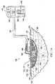
FIGURES 1A-2 , an illustrative, non-limiting embodiment of a reduced-pressure treatment system 100 for treating atissue site 102, e.g. awound 104, is presented. Thewound 104 may include, without limitation, any irregularity with a tissue, such as an open wound, surgical incision, or diseased tissue. Thewound 104 may involve various tissues: epidermis 106 (or generally skin),dermis 108, andsubcutaneous tissue 110. The reduced-pressure treatment system 100 may be used to treat thetissue site 102, such as awound 104 of any depth, as well as many different types of wounds including open wounds. Thetissue site 102 may be the bodily tissue of any human, animal, or other organism, including bone tissue, adipose tissue, muscle tissue, dermal tissue, vascular tissue, connective tissue, cartilage, tendons, ligaments, or any other tissue. Unless otherwise indicated, as used herein, "or" does not require mutual exclusivity. - In the illustrative, non-limiting embodiment, the reduced-
pressure treatment system 100 generally includes amanifold pad 111, asealing drape 116, and a reduced-pressure subsystem 118. Themanifold pad 111 includes amanifold member 112 and ahydrogel reservoir member 114. Themanifold pad 111 has a tissue-facingside 122 and is operable at a first pressure (P1) to receive and hold, or store, fluids and, in particular, thehydrogel reservoir member 114 stores the fluids. When the reduced pressure, or negative pressure, is increased, i.e., absolute pressure is decreased, to a second pressure (P2), themanifold pad 111 may distribute the reduced pressure, allow fluids to flow through themanifold pad 111, and release at least a portion of the previously stored fluids from thehydrogel reservoir member 114. Themanifold pad 111 will be further described below. - The sealing
drape 116 provides a fluid seal over thetissue site 102. The reduced-pressure treatment system 100 may include anattachment device 120. Thesealing drape 116 andattachment device 120 form a fluid seal between thesealing drape 116 and the patient'sepidermis 106. Themanifold pad 111 is positioned between a tissue-facing (inward-facing)side 132 of thesealing drape 116 and thetissue site 102. "Fluid seal," or "seal," means a seal adequate to maintain reduced pressure at a desired site given the particular reduced-pressure source or subsystem involved. - The term "manifold" as used herein generally refers to a substance or structure that is provided to assist in applying reduced pressure to, delivering fluids to, or removing fluids from a tissue site, e.g., the
tissue site 102. Themanifold member 112 typically includes a plurality of flow channels or pathways to distribute fluids provided to and remove fluids from around themanifold member 112. The plurality of flow channels or pathways may be interconnected. Themanifold member 112 may be a biocompatible material that is capable of being placed in contact with a tissue site, e.g., thetissue site 102, and distributing reduced pressure to thetissue site 102. Examples of manifold members may include, without limitation, devices that have structural elements arranged to form flow channels, such as, for example, cellular foam, open-cell foam, porous tissue collections, liquids, gels, and foams that include, or cure to include, flow channels. Themanifold member 112 may be porous and may be made from foam, gauze, felted mat, etc. Themanifold member 112 may be formed from a porous material, e.g., a foam, or from a material that is made porous, e.g., a solid member in which apertures have been applied. - In one illustrative, non-limiting embodiment, the
manifold member 112 is a porous foam that includes a plurality ofinterconnected struts 124. Theinterconnected struts 124 may help form a plurality of interconnected cells orpores 126, which act as flow channels through themanifold member 112. The porous foam may be a polyurethane, open-cell, reticulated foam, such as a GranuFoam® material manufactured by Kinetic Concepts, Incorporated of San Antonio, Texas. In one illustrative, non-limiting embodiment, thepores 126 may have a pore size (pores per inch (ppi)) between 20 ppi and 60 ppi. - The
hydrogel reservoir member 114 is associated with themanifold member 112 and is operable at a first pressure (P1) to receive and hold, or store, a fluid, such as exudate or any other fluid, from thetissue site 102 and is operable at a second pressure (P2) to release at least a portion of the absorbed fluid. The first pressure is greater than the second pressure on an absolute pressure scale, i.e., P1 > P2. In one illustrative embodiment, the first pressure is substantially atmospheric pressure (gauge pressure 0 mm Hg and an absolute pressure at sea level of about 760 mm Hg). In an alternative embodiment, the first pressure is a hydrostatic pressure at thetissue site 102. As will be discussed further below, the second pressure is generally a reduced pressure as provided by the reduced-pressure subsystem 118 for treatment of thetissue site 102 and is generally in the range of -75 mm Hg to -500 mm Hg (gauge pressure). - The
manifold pad 111, which has thehydrogel reservoir member 114, distributes (or manifolds) reduced pressure under the influence of a reduced pressure, e.g., the second pressure (P2). When the reduced pressure is decreased (the pressure is raised in terms of absolute pressure), e.g., to the first pressure (P1), due to an equipment failure or other reason, the fluids continue to be removed from thetissue site 102 but are now stored in thehydrogel reservoir 114 of themanifold pad 111. When the reduced pressure is increased, e.g., to the second pressure (P2), the fluid is removed, at least in part, from thehydrogel reservoir 114, and themanifold pad 111 distributes the reduced pressure to thetissue site 102. In one illustrative embodiment, thehydrogel reservoir member 114 releases between 20% and 80% of the absorbed, or stored, fluid when placed under the influence of the greater reduced pressure (lower absolute pressure), e.g., the second reduced pressure (P2). - The
hydrogel reservoir member 114 may be formed from any suitable hydrogel material. Hydrogels, include without limitation, any superaborbent natural or synthetic polymers, such as hydrophilic cross-linked polymers. Illustrative, non-limiting examples of suitable hydrogels include acrylics, e.g., acrylic acid, methacrylic acid and their salts; sulphonates, e.g., amps (acrylamido-2-methyl-propanosulfonic acid, and their salts), carboxy methyl cellulose (CMC), and alginates. In some embodiments, the hydrogel material is an ionic hydrogel. Additionally, thehydrogel reservoir member 114 may also incorporate biocides, antimicrobial agents, electrically conductive materials for pain management, visual indicators to, for example, indicate saturation, and other materials. - The
hydrogel reservoir member 114 may be associated with themanifold member 112 in numerous ways. As a non-limiting, illustrative example, themanifold member 112 may be coated with the hydrogel material. In some embodiments, thehydrogel reservoir member 114 may be directly coupled to themanifold member 112 or thehydrogel reservoir member 114 may be placed adjacent to themanifold member 112. As used herein, the term "coupled" generally includes coupling via a separate object and includes direct coupling. The term "coupled" also encompasses two or more components that are continuous with one another by virtue of each of the components being formed from the same piece of material. Also, the term "coupled" may include chemical, mechanical, thermal, or electrical coupling. Fluidly coupling means that fluid is in communication between the designated parts or locations. - In the illustrative, non-limiting embodiment of
FIGURES 1A-2 , thehydrogel reservoir member 114 is ahydrogel coating 128 that is applied to at least one of theinterconnected struts 124 of themanifold member 112. Thehydrogel coating 128 may be applied by any suitable technique. In one illustrative embodiment, thehydrogel coating 128 is applied to themanifold member 112 by first immersing at least a portion of themanifold member 112, or substrate, into a liquefied, or partially liquefied, hydrogel. The hydrogel may be supplied as a non-crosslinked solution, dispersion, solid (hot melt or powder), or emulsion. The non-crosslinked solution is then either activated during the impregnation process (e.g., using UV light) or immediately before the impregnation process, such that the crosslinking process continues within themanifold member 112, or substrate. In another illustrative, non-limiting embodiment, the crosslinking may be achieved during a separate process, such as coincident with a sterilization process using gamma or e-beam irradiation. As another illustrative, non-limiting embodiment, a pre-crosslinked gel, is supplied as a suspension or emulsion and may be used to impregnate themanifold member 112. - Regardless of the approach used, at least a portion of the
interconnected struts 124 are coated with the hydrogel. All or substantially all of theinterconnected struts 124 may be coated with a hydrogel. Excess hydrogel from immersion may then be removed from themanifold member 112 by squeezing themanifold member 112 such that the excess hydrogel is released from themanifold member 112. The remaining hydrogel on themanifold pad 111 adheres to theinterconnected struts 124, dries, and forms ahydrogel coating 128 about theinterconnected struts 124. Alternatively, the hydrogel may be sprayed over at least a portion of themanifold member 112 whereby at least a portion of theinterconnected struts 124 receive thehydrogel coating 128. Alternatively, the hydrogel may be applied using a blade coating or offset-roll coating. Themanifold pad 111 is covered with the sealingdrape 116. - The sealing
drape 116 includes afirst side 130 and a tissue-facing (inward-facing)side 132. The sealingdrape 116 may be sized so that the sealingdrape 116 overlaps thewound 104 in such a manner that a portion of the sealingdrape 116 form adrape extension 134. thedrape extension 134 extends beyond the periphery of thewound 104. The sealingdrape 116 may be any material that provides a fluid seal. The sealingdrape 116 may, for example, be an impermeable or semi-permeable, elastomeric material. "Elastomeric" means having the properties of an elastomer. It generally refers to a polymeric material that has rubber-like properties. More specifically, most elastomers have an ultimate elongation greater than 100% and a significant amount of resilience. The resilience of a material refers to the material's ability to recover from an elastic deformation. Examples of elastomers may include, but are not limited to, natural rubbers, polyisoprene, styrene butadiene rubber, chloroprene rubber, polybutadiene, nitrile rubber, butyl rubber, ethylene propylene rubber, ethylene propylene diene monomer, chlorosulfonated polyethylene, polysulfide rubber, polyurethane (PU), EVA film, co-polyester, and silicones. Additional examples of sealingdrapes 116 include a silicone drape, 3M Tegaderm® drape, PU drape such as one available from Avery Dennison Corporation of Pasadena, California. - The
attachment device 120 may be used to hold the sealingdrape 116 against the patient'sepidermis 106 or another layer, such as a gasket or additional sealing member. Theattachment device 120 may take numerous forms. For example, theattachment device 120 may be a medically acceptable, pressure-sensitive adhesive that is applied to thedrape extensions 134 of the sealingdrape 116. Alternatively, the pressure-sensitive adhesive may span the entire width of the sealingdrape 116.Alternative attachment devices 120 may include, but are not limited to, heat-activated adhesives, sealing tapes, double-sided sealing tapes, pastes, hydrocolloids, hydrogels, hooks, or sutures. - The reduced-
pressure subsystem 118 includes a reduced-pressure source 136. The reduced-pressure source 136 provides reduced pressure, e.g., the second reduced pressure (P2), as a part of the reduced-pressure treatment system 100. As used herein, "reduced pressure" generally refers to a pressure less than the ambient pressure at thetissue site 102 that is being subjected to treatment. In most cases, this reduced pressure will be less than the atmospheric pressure at which the patient is located. Alternatively, the reduced pressure may be less than a hydrostatic pressure at thetissue site 102. Reduced pressure may initially generate fluid flow in themanifold pad 111, a reduced-pressure delivery conduit 138, orconduit 138, and proximate thetissue site 102, e.g., thewound 104. As the hydrostatic pressure around thetissue site 102, e.g. thewound 104, approaches the desired reduced pressure, the flow may subside, and the reduced pressure may be maintained. The reduced pressure delivered may be constant, varied (patterned or random) and may be delivered continuously or intermittently. Although the terms "vacuum" and "negative pressure" may be used to describe the pressure applied to thetissue site 102, the actual pressure applied to thetissue site 102 may be more than the pressure normally associated with a complete vacuum. Consistent with the use herein, an increase in reduced pressure or vacuum pressure typically refers to a relative reduction in absolute pressure. - The reduced-
pressure source 136 may be involve any technique or be any device for supplying a reduced pressure, such as a vacuum pump or wall suction. While the amount and nature of reduced pressure applied to thetissue site 102 will typically vary according to the application, the reduced pressure will typically be between -5mm Hg and - 500mm Hg (gauge pressure). - In the illustrative, non-limiting embodiment of
FIGURE 1 , the reduced-pressure source 136 has abattery compartment 140 and acanister 142 withwindows 144 providing a visual indication of the level of fluid withincanister 142. An interposed membrane filter, such as hydrophobic or oleophobic filter, may be interspersed between the reduced-pressure delivery conduit 138 and the reduced-pressure source 136. - The reduced pressure developed by the reduced-
pressure source 136 is delivered through the reduced-pressure delivery conduit 138 to a reduced-pressure interface 146, which may be anelbow port 148. In one illustrative, non-limiting embodiment, theelbow port 148 is a TRAC® technology port available from Kinetic Concepts, Inc. of San Antonio, Texas. The reduced-pressure interface 146 allows the reduced pressure to be delivered to the sealingdrape 116 and realized within an interior portion below the sealingdrape 116 and further realized within themanifold member 112. In this illustrative, non-limiting embodiment, theelbow port 148 extends through the sealingdrape 116 and to themanifold member 112, but numerous arrangements are possible. - According to an illustrative, non-limiting embodiment, in operation, the
manifold pad 111 may be placed proximate thetissue site 102, e.g., thewound 104. The sealingdrape 116 may be placed over themanifold pad 111 such that thedrape extension 134 extends beyond a periphery of thewound 104. Thedrape extension 134 may be secured to the patient'sepidermis 106 by theattachment device 120 in order to form a fluid seal over thetissue site 102 and themanifold pad 111. The reduced-pressure interface 146 may then be applied, if not already installed. The reduced-pressure delivery conduit 138 is fluidly coupled to the reduced-pressure interface 146 and fluidly coupled to the reduced-pressure source 136. - The reduced-
pressure subsystem 118 may be activated so that reduced pressure is delivered into the reduced-pressure delivery conduit 138. Under a reduced pressure (P2), fluids will be delivered from thetissue site 102 to themanifold pad 111 and through reduced-pressure delivery conduit 138 tocanister 142. During this operation if an event occurs such that the reduced pressure is decreased, e.g., the pressure goes from P2 to P1, fluid flow in the reduced-pressure delivery conduit 138 may cease, and yet fluids may continue to be removed from thetissue site 102 and stored away from thetissue site 102 by thehydrogel reservoir member 114 of themanifold pad 111. When the reduced pressure is restored, e.g., the pressure goes from P1 to P2, the fluid will again flow in the reduced-pressure delivery conduit 138 and be delivered to thecanister 142 and all or a portion of the fluid in thehydrogel reservoir member 114 will be released. - According to another illustrative, non-limiting embodiment, in operation, after the
manifold member 112 is placed adjacent to thetissue site 102, fluid associated with thetissue site 102, e.g., the exudates or other fluids associated with thetissue site 102, may begin to be absorbed by thehydrogel coating 128 even though reduced pressure (P2) has not been applied. Thehydrogel coating 128 is, however, adapted to receive at least a portion of the fluid from thetissue site 102 at the existing pressure (P1). In other words, thehydrogel coating 128 may be adapted to draw fluid from thetissue site 102 without the delivery of reduced pressure thereto, and this fluid removal may be beneficial for treatment and healing at thetissue site 102 when reduced pressure is not available. As thehydrogel coating 128 absorbs the fluid, thehydrogel coating 128 swells into adjacent pore(s) 126 thereby closing thepores 126 such that additional fluid at thetissue site 102 is diverted to other areas of themanifold member 112 not yet exposed to fluid and the fluid is absorbed by thehydrogel coating 128. Reduced pressure may then be used to remove fluids. - Once the reduced-
pressure source 136 is activated, a reduced pressure is delivered to the interior of the sealingdrape 116 and themanifold pad 111. As the reduced pressure (P2) is delivered, thehydrogel coating 128 releases at least a portion of the previously absorbed, or stored, fluid. As the absorbed fluid is released by thehydrogel coating 128, thehydrogel coating 128 shrinks and theinterconnected pores 126 open. Additional fluid from thetissue site 102 may then be drawn into themanifold pad 111 via the interconnected pores 126. Thus, the reduced-pressure treatment system 100 may be operable to remove at least some fluid from thetissue site 102 with or without delivery of a reduced pressure. With the continued delivery of reduced pressure, fluid from thetissue site 102 passes through themanifold pad 111 via theinterconnected pores 126, into the reduced-pressure interface 146, through the reduced-pressure delivery conduit 138, and into thecanister 142 of the reduced-pressure source 136. - Referring now primarily to
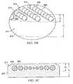
FIGURES 3A-3E , another illustrative, non-limiting embodiment of amanifold pad 211 for use with a reduced-pressure treatment system, e.g., the reduced-pressure treatment system 100 ofFIGURE 1A , is presented. Themanifold pad 211 includes ahydrogel reservoir member 214 that is associated with amanifold member 212. In the illustrative, non-limiting embodiment ofFIGURES 3A-3C , thehydrogel reservoir member 214 comprises one or a plurality ofhydrogel beads 250, which may be in spaced relationship relative to one another. Thehydrogel beads 250 may be formed from an ionic hydrogel or any of the materials previously mentioned for thehydrogel reservoir member 114. Some of thehydrogel beads 250 may include an antimicrobial agent, such as ionic silver or any other suitable antimicrobial agent. Alternatively or in addition, antimicrobial beads (not shown), formed from any suitable antimicrobial agent, such as ionic silver, may be disposed in themanifold member 212 adjacent to thehydrogel beads 250. - The
hydrogel beads 250 may be disposed within themanifold member 212 via any suitable technique. For example, thehydrogel beads 250 may be injected into themanifold member 212 by using a syringe or a syringe-like implement. Alternatively, themanifold member 212 may be formed around thehydrogel beads 250. In one illustrative, non-limiting embodiment shown inFIGURE 3B , themanifold member 212 has a height (h1) and thehydrogel beads 250 are disposed within the upper third (h2) of themanifold member 212 for the orientation shown. However, it will be appreciated that thehydrogel beads 250 may be disposed at any suitable position within themanifold member 212 relative to themanifold member 212. - Referring now primarily to
FIGURE 3E , in some embodiments, themanifold member 212 may include afirst zone 252, which is nearest the center of themanifold member 212, and asecond zone 254, or peripheral portion, which is nearest the periphery of themanifold member 212. In some embodiments, thesecond zone 254 of themanifold member 212 includes a greater amount of hydrogel relative to thefirst zone 252 of themanifold member 212. For example, thehydrogel beads 250 located in thesecond zone 254 may have a greater diameter or density than thehydrogel beads 250 located in thefirst zone 252. - In another illustrative, non-limiting embodiment shown in
FIGURE 3C , the diameter of a givenhydrogel beads 250 may be proportional to the distance thehydrogel bead 250 is from the center of themanifold member 212. For example, thehydrogel beads 250 nearest the periphery of themanifold member 212 are the largest and thehydrogel beads 250 become gradually smaller as thehydrogel beads 250 get closer to the center of themanifold member 212. In yet another illustrative, non-limiting embodiment, the density ofhydrogel beads 250 may be varied. That is the number ofhydrogel beads 250 located in thesecond zone 254 may be greater than the number ofhydrogel beads 250 located in thefirst zone 252. Also, thehydrogel beads 250 may take any suitable shape. For example, as shown inFIGURES 3B and 3C , thehydrogel beads 250 may be spherically shaped (spheroids). Alternatively, as shown inFIGURE 3D , thehydrogel beads 250 may have an elongated square bar shape. Thehydrogel beads 250 may also be teardrop-shaped, polygon, irregular shaped, or another shape. It will be appreciated that thehydrogel beads 250 may have any suitable shape or size. - According to an illustrative, non-limiting embodiment, in operation, the
manifold member 212 is placed proximate a tissue site (e.g., thetissue site 102 inFIG. 1A ) and a sealing drape may be used to form a fluid seal. Under reduced pressure (P2), themanifold member 212 distributes reduced pressure with only minimal absorption of fluid. When the reduced pressure is decreased (absolute pressure increased) to (P1), fluid from the tissue site enters themanifold member 212 but is absorbed by thehydrogel beads 250. In embodiments where the greatest amount of hydrogel is located nearest the periphery of themanifold member 212, thehydrogel beads 250 nearest the center of themanifold member 112 will generally become saturated with fluid from the tissue site first, and thereafter additional fluid from the tissue site is diverted towards thehydrogel beads 250 nearest the periphery of themanifold member 212 for absorption. - When a reduced pressure is delivered or restored to the
manifold member 212, as discussed in relation toFIGS. 1-2 , thehydrogel beads 250 release at least a portion of the previously absorbed, or stored, fluid. As the fluid from thehydrogel beads 250 is released, thehydrogel beads 250 shrink and fluid from the tissue site is permitted to pass through themanifold member 212 and ultimately to a canister of a reduced-pressure subsystem. Thus, the reduced-pressure treatment system may be operable to remove at least some fluid from the tissue site with or without delivery of a reduced pressure thereto. - Referring now primarily to
FIGURES 4A-4C , another illustrative, non-limiting embodiment of amanifold pad 311 that may be used with a reduced-pressure treatment system, such as the reduced-pressure treatment system 100 ofFIGURE 1A , is presented. Themanifold pad 311 includes ahydrogel reservoir member 314 associated with amanifold member 312. Thehydrogel reservoir member 314 is ahydrogel sheet 356 disposed adjacent to themanifold member 312 proximate a tissue-facingside 313 of themanifold member 312. Thehydrogel sheet 356 may abut themanifold member 312, be laminated with themanifold member 312, or be coupled to themanifold member 312. Alternatively, thehydrogel sheet 356 may be cast with, co-extruded with, or otherwise formed with themanifold member 312. Thehydrogel sheet 356 may be formed from any suitable hydrogel material, such as those previously mentioned. In some embodiments, thehydrogel sheet 356 is formed from an ionic hydrogel material. - The
hydrogel sheet 356 may include one ormore apertures 358. Thehydrogel sheet 356 may include afirst zone 352 that is nearest the center of thehydrogel sheet 356 and asecond zone 354 that is nearest the periphery of thehydrogel sheet 356. The size or number of theapertures 358 located in thesecond zone 354 of thehydrogel sheet 356 may be greater than the size or number ofapertures 358 located in thefirst zone 352. Alternatively, and as best shown inFIGURE 4B , the size of theapertures 358 may be proportional to the distance a given aperture is from the center of thehydrogel sheet 356. For example, theapertures 358 nearest the periphery of thehydrogel sheet 356 are the largest and theapertures 358 become gradually smaller the closer theapertures 358 are to the center of thehydrogel sheet 356. Theapertures 358 may have any suitable shape, including, but not limited to, circular, elliptical, triangular, square, rectangular, hexagonal, octagonal, irregular, or other shape. In some embodiments, the diameter of theapertures 358 may be within the range of about 1mm to about 10 mm.. In some embodiments, the distance (d) betweenadjacent apertures 358 may be in the range of abut 1mm to about 10 mm. - In some embodiments, including the
manifold pad 311 that is presented inFIGURES 4A-4C , awicking layer 360 may be disposed adjacent to a tissue-facingside 357 of thehydrogel sheet 356 such that thehydrogel sheet 356 is disposed between thewicking layer 360 and themanifold member 312. Thewicking layer 360 may abut thehydrogel sheet 356, be laminated with thehydrogel sheet 356, or otherwise coupled to thehydrogel sheet 356. Thewicking layer 360 may be operable to transmit fluid from a tissue-facingside 362 of thewicking layer 360 to afirst side 364. Thewicking layer 360 may also be operable to, or adapted to, manifold an applied reduced pressure. - The
wicking layer 360 may be formed from any suitable material, including, but not limited to a non-woven material, such as a non-woven rayon sheet, non-woven polyester, polyamide, polyolefine, compressed fiber blocks (e.g., formed from polyester, or polyamide, or polyolefine fibers), or a sinterted polymer (e.g., polyolefine, EVA, polyamide, or other polymer.), a reticulated foam, or another non-woven material. In some embodiments, thewicking layer 360 may be treated, or otherwise modified, to be hydrophilic. In some embodiments, thewicking layer 360 andhydrogel sheet 356 may be employed without the use of themanifold member 312. - According to an illustrative, non-limiting embodiment, in operation, the tissue-facing
side 362 of thewicking layer 360 is placed proximate the tissue site. Thewicking layer 360 receives fluid from the tissue site and transports the fluid from the tissue-facingside 362 to thefirst side 364. Once the fluid has passed thewicking layer 360, the fluid may be transmitted under the influence of reduced pressure (P2) through themanifold member 312 and eventually to a canister or other location. During operation with reduced pressure applied, thehydrogel reservoir member 314 may absorb some of the fluid. When the reduced pressure is removed or is decreased (absolute pressure increased), e.g., to P1, thehydrogel sheet 356 stores additional fluid. As thehydrogel sheet 356 absorbs the fluid, thehydrogel sheet 356 swells and theapertures 358 begin to shrink. - When a reduced pressure is delivered or restored, e.g., to P2, the
hydrogel sheet 356 releases at least a portion of the previously absorbed, or stored, fluid. Once thehydrogel sheet 356 begins to release the fluid, theapertures 358 begin to increase in diameter thereby allowing fluid to pass from the tissue site, through thewicking layer 360, through theapertures 358 that are through thehydrogel sheet 356, into themanifold member 312 and ultimately to a canister of a reduced-pressure source. Thus, the reduced-pressure treatment system may be operable to remove at least a portion of fluid from the tissue site with and without the delivery of a reduced pressure thereto. - Although the present invention and its advantages have been disclosed in the context of certain illustrative, non-limiting embodiments, it should be understood that various changes, substitutions, permutations, and alterations can be made without departing from the scope of the invention as defined by the appended claims. It will be appreciated that any feature that is described in a connection to any one embodiment may also be applicable to any other embodiment.
- A selection of aspects will now be described in the following numbered clauses
- Clause 1. A reduced-pressure treatment system for treating a tissue site on a patient, the reduced-pressure treatment system comprising:
- a manifold pad for disposing proximate the tissue site, the manifold pad comprising: a manifold member, and
- a hydrogel reservoir member associated with the manifold member, the hydrogel reservoir member adapted to receive and store a fluid from the tissue site at a first pressure and adapted to release at least a portion of the fluid at a second pressure, wherein the first pressure is greater than the second pressure on an absolute pressure scale;
- a sealing drape for placing over the tissue site and the manifold pad, the sealing drape adapted to form a fluid seal;
- and a reduced-pressure subsystem for delivering reduced pressure to the manifold pad.
Clause 2. The reduced-pressure treatment system of Clause 1, wherein the first pressure is substantially atmospheric pressure.- Clause 3. The reduced-pressure treatment system of Clause 1, wherein the first pressure is a hydrostatic pressure proximate to the tissue site.
- Clause 4. The reduced-pressure treatment system of Clause 1, wherein the hydrogel reservoir member is adapted to release between 20% and 80% of the stored fluid under the influence of the, second pressure.
- Clause 5. The reduced-pressure treatment system of Clause 1, wherein the hydrogel reservoir member is a hydrogel coating applied to at least a portion of the manifold member.
- Clause 6. The reduced-pressure treatment system of Clause 1, wherein the hydrogel reservoir member comprises a plurality of hydrogel beads disposed within the manifold member.
- Clause 7. The reduced-pressure treatment system of Clause 1, wherein the hydrogel reservoir member comprises a hydrogel sheet disposed adjacent to the manifold member.
- Clause 8. The reduced-pressure treatment system of Clause 7, wherein the hydrogel sheet is formed with at least one aperture, and wherein the diameter of the at least one aperture is between 1 mm and 10 mm.
- Clause 9. The reduced-pressure treatment system of Clause 7, wherein the hydrogel sheet includes a plurality of apertures.
- Clause 10. The reduced-pressure treatment system of Clause 7, further comprising a wicking layer disposed adjacent to the hydrogel sheet such that the hydrogel sheet is disposed between the wicking layer and the manifold member.
- Clause 11. The reduced-pressure treatment system of Clause 1, wherein the hydrogel reservoir member comprises an ionic hydrogel.
- Clause 12. A manifold pad for treating a tissue site of a patient, the manifold pad comprising:
- a manifold member adapted to distribute reduced pressure;
- a hydrogel reservoir member associated with the manifold member; and wherein the hydrogel reservoir member is adapted to receive and store a fluid from the tissue site at a first pressure and adapted to release at least a portion of the fluid at a second pressure, wherein the first pressure is greater than the second pressure on an absolute pressure scale.
- Clause 13. The manifold pad of Clause 12, wherein the manifold member comprises a foam having a plurality of interconnected struts; wherein the hydrogel reservoir member comprises a hydrogel coating; and wherein at least a portion of the plurality of interconnected struts are at least partially coated with the hydrogel coating.
- Clause 14. The manifold pad of Clause 12, wherein the hydrogel reservoir member is an ionic hydrogel.
- Clause 15. The manifold pad of Clause 12, wherein the hydrogel reservoir member is adapted to release between 20% and 80% of the absorbed fluid under the influence of reduced pressure.
- Clause 16. The manifold pad of Clause 12, wherein the hydrogel reservoir member comprises a plurality of hydrogel beads; and wherein the plurality of hydrogel beads is disposed within the manifold member.
- Clause 17. The manifold pad of Clause 12, wherein:
- the manifold member includes a central portion and a peripheral portion;
- a first plurality of hydrogel beads is disposed within the central portion; and
- a second plurality of hydrogel beads is disposed within the peripheral portion and the second plurality of hydrogel beds is more numerous than the first plurality of hydrogel beads.
- Clause 18. The manifold pad of Clause 12, wherein: the manifold member includes a central portion and a peripheral portion; a plurality of hydrogel beads are disposed within the central portion and within the peripheral portion; and a first diameter of each of the hydrogel beads disposed within the peripheral portion is greater than a second diameter of the hydrogel beads disposed within the central portion.
- Clause 19. The manifold pad of Clause 17, wherein a cross-section of each of the plurality of hydrogel beads is circular.
- Clause 20. The manifold pad of Clause 17, wherein the manifold member has a height (hi), a tissue-facing side, and a first side; and wherein the plurality of hydrogel beads is disposed within one third (1/3) hi from the first side of the manifold member.
- Clause 21. The manifold pad of Clause 12, wherein the hydrogel reservoir member comprises a hydrogel sheet comprising: a central portion having a first plurality of apertures; and a peripheral portion having a second plurality of apertures disposed about the peripheral portion.
- Clause 22. The manifold pad of Clause 21, wherein the first plurality of apertures has a first diameter, and wherein the second plurality of apertures has a second diameter, and wherein the first diameter is less than the second diameter.
- Clause 23. A method for treating a tissue site on a patient, the method comprising the steps of: placing a manifold pad proximate the tissue site, the manifold pad having a manifold member and a hydrogel reservoir member associated with the manifold member, the hydrogel reservoir member adapted to receive and store a fluid from the tissue site at a first pressure and adapted to release at least a portion of the fluid at a second pressure, wherein the first pressure is greater than the second pressure on an absolute pressure scale; disposing a sealing drape over the manifold member and a patient's epidermis; forming a fluid seal between the sealing drape and the patient's epidermis; and delivering reduced pressure to the manifold pad.
- Clause 24. The method for treating a tissue site of Clause 23, wherein the first pressure is substantially atmospheric pressure.
- Clause 25. The method for treating a tissue site of Clause 23, wherein the first pressure is a hydrostatic pressure proximate to the tissue site.
- Clause 26. The method for treating a tissue site of Clause 23, wherein the hydrogel reservoir member is adapted to release between 20% and 80% of the stored fluid under the influence of the second pressure.
- Clause 27. The method for treating a tissue site of Clause 23, wherein the manifold pad comprises a foam, and wherein the hydrogel member is a hydrogel coating applied to at least a portion of the manifold member.
- Clause 28. The method for treating a tissue site of Clause 23, wherein the manifold pad comprises a foam and wherein the hydrogel reservoir member comprises a plurality of hydrogel beads disposed within the manifold member.
- Clause 29. The method for treating a tissue site of Clause 23, wherein the manifold pad comprises a foam and wherein the hydrogel reservoir member comprises a hydrogel sheet disposed adjacent to the manifold member.
- Clause 30. A method of manufacturing a manifold pad for treating a tissue site on a patient, the method comprising the steps of: forming a manifold member; and associating a hydrogel reservoir member with the manifold member, wherein the hydrogel reservoir member is adapted to receive and store fluid from the tissue site at a first pressure and adapted to release at least a portion of the fluid at a second pressure, wherein the first pressure is greater than the second pressure on an absolute pressure scale.
- Clause 31. The method of manufacturing a manifold pad Clause 30, wherein the step of forming a manifold member comprises forming a manifold member with a plurality of interconnected struts, and wherein the step of associating a hydrogel reservoir member with the manifold member comprises coating at least a portion of the plurality of interconnected struts with a hydrogel.
- Clause 32. The method of manufacturing a manifold pad Clause 30, wherein the step of associating a hydrogel reservoir member with the manifold member comprises injecting a plurality of hydrogel beads into the manifold member.
- Clause 33. The method of manufacturing a manifold pad Clause 32, wherein the manifold member includes a central portion and a peripheral portion and wherein the step of injecting a plurality of hydrogel beads comprises injecting a first plurality of hydrogel beads into the central portion and injecting second plurality of hydrogel beads into the peripheral portion.
- Clause 34. The method of manufacturing a manifold pad Clause 33, wherein the first plurality of hydrogel beads injected into the peripheral portion is more numerous than the second plurality of hydrogel beads injected into the central portion.
- Clause 35. The method of manufacturing a manifold pad Clause 33, wherein a first diameter of each of the hydrogel beads injected into the peripheral portion is greater than a second diameter of each of the hydrogel beads injected into the central portion.
- Clause 36. The method of manufacturing a manifold pad Clause 32, wherein a cross-section of each of the plurality of hydrogel beads is circular.
- Clause 37. he method of manufacturing a manifold pad Clause 32, wherein each of the plurality of hydrogel beads is tear-shaped.
- Clause 38. The method of manufacturing a manifold pad Clause 30, wherein the step of associating a hydrogel reservoir member with the manifold member comprises forming a sheet having a central portion and a peripheral portion from a hydrogel material; forming at least one aperture in the central portion of the sheet; forming at least one aperture in the peripheral portion; and disposing the sheet adjacent the manifold member.
- Clause 39. The method of manufacturing a manifold pad Clause 38, wherein the diameter of the at least one aperture formed in the central portion is less than the diameter of the at least one aperture formed in the peripheral portion.
- Clause 40. A manifold pad for treating a tissue site on a patient, the manifold pad comprising: a manifold member comprising a first material; a hydrogel reservoir member comprising a second material wherein the first material and the second material are different materials; wherein the hydrogel reservoir member is coupled to the manifold member; and wherein the second material is a super absorbent polymer that is adapted to received and retain liquids from the tissue site at a first pressure and is adapted to release a substantial portion of the liquids at a second pressure.
- Clause 41. The manifold of Clause 40, wherein the first material is a porous polymer foam and the second material is hydrophilic cross-linked polymer.
Claims (9)
- A reduced-pressure treatment system (100) for treating a tissue site (102) on a patient, the reduced-pressure treatment system (100) comprising:a manifold pad (111, 211) for disposing proximate the tissue site (102), the manifold pad (111, 211) comprising:a manifold member (112, 212), anda hydrogel reservoir member (114, 214) impregnated within the manifold member (112, 212), the hydrogel reservoir member (114, 214) adapted to receive and store a fluid from the tissue site (102) at a first pressure and adapted to release at least a portion of the fluid at a second pressure, wherein the first pressure is greater than the second pressure on an absolute pressure scale;a sealing drape (116) for placing over the tissue site (102) and the manifold pad (111, 211), the sealing drape (116) adapted to form a fluid seal; anda reduced-pressure subsystem (118) for delivering reduced pressure to the manifold pad (111, 211).
- The reduced-pressure treatment system (100) of claim 1, wherein the first pressure is substantially atmospheric pressure.
- The reduced-pressure treatment system (100) of claim 1, wherein the first pressure is a hydrostatic pressure proximate to the tissue site (102).
- The reduced-pressure treatment system (100) of claim 1, wherein the hydrogel reservoir member (114, 214) is adapted to release between 20% and 80% of the stored fluid under the influence of the second pressure.
- The reduced-pressure treatment system (100) of claim 1, wherein the manifold member (112) comprises a porous foam having interconnected struts (124) within the manifold member (112), and wherein the hydrogel reservoir member (114) comprises a hydrogel coating (128) applied to the interconnected struts (124) of the manifold member (112).
- The reduced-pressure treatment system (100) of claim 1, wherein the hydrogel reservoir member (214) comprises a plurality of hydrogel beads (250) disposed within the manifold member (212), and each of the plurality of hydrogel beads (250) has a diameter proportional to a distance from the center of the manifold member (212).
- The reduced-pressure treatment system (100) of claim 1, wherein the hydrogel reservoir member (114, 214) comprises an ionic hydrogel.
- A method of manufacturing the manifold pad (111, 211) of claim 1 for treating a tissue site (102) on a patient, the method comprising the steps of:forming a manifold member (112, 212); andimpregnating a hydrogel reservoir member (114, 214) within the manifold member (112, 212), wherein the hydrogel reservoir member (114, 214) is adapted to receive and store fluid from the tissue site (102) at a first pressure and adapted to release at least a portion of the fluid at a second pressure, wherein the first pressure is greater than the second pressure on an absolute pressure scale.
- The method of manufacturing a manifold pad (111, 211) of claim 9, wherein the step of forming a manifold member (112, 212) comprises forming a manifold member (112, 212) with a plurality of interconnected struts, and wherein the step of impregnating a hydrogel reservoir member (114, 214) within the manifold member (112, 212) comprises coating at least a portion of the plurality of interconnected struts (124) with a hydrogel.
Applications Claiming Priority (3)
| Application Number | Priority Date | Filing Date | Title |
|---|---|---|---|
| US18328509P | 2009-06-02 | 2009-06-02 | |
| US12/786,188US9421309B2 (en) | 2009-06-02 | 2010-05-24 | Reduced-pressure treatment systems and methods employing hydrogel reservoir members |
| EP10721243.3AEP2437803B2 (en) | 2009-06-02 | 2010-05-25 | Reduced-pressure treatment systems and methods employing hydrogel reservoir members |
Related Parent Applications (3)
| Application Number | Title | Priority Date | Filing Date |
|---|---|---|---|
| EP10721243.3Division | 2010-05-25 | ||
| EP10721243.3ADivisionEP2437803B2 (en) | 2009-06-02 | 2010-05-25 | Reduced-pressure treatment systems and methods employing hydrogel reservoir members |
| EP10721243.3ADivision-IntoEP2437803B2 (en) | 2009-06-02 | 2010-05-25 | Reduced-pressure treatment systems and methods employing hydrogel reservoir members |
Publications (2)
| Publication Number | Publication Date |
|---|---|
| EP2617442A1 EP2617442A1 (en) | 2013-07-24 |
| EP2617442B1true EP2617442B1 (en) | 2016-02-10 |
Family
ID=43221052
Family Applications (2)
| Application Number | Title | Priority Date | Filing Date |
|---|---|---|---|
| EP13164197.9ARevokedEP2617442B1 (en) | 2009-06-02 | 2010-05-25 | Reduced-pressure treatment systems and methods employing hydrogel reservoir members |
| EP10721243.3ANot-in-forceEP2437803B2 (en) | 2009-06-02 | 2010-05-25 | Reduced-pressure treatment systems and methods employing hydrogel reservoir members |
Family Applications After (1)
| Application Number | Title | Priority Date | Filing Date |
|---|---|---|---|
| EP10721243.3ANot-in-forceEP2437803B2 (en) | 2009-06-02 | 2010-05-25 | Reduced-pressure treatment systems and methods employing hydrogel reservoir members |
Country Status (12)
| Country | Link |
|---|---|
| US (1) | US9421309B2 (en) |
| EP (2) | EP2617442B1 (en) |
| JP (2) | JP5587994B2 (en) |
| KR (1) | KR20120020181A (en) |
| CN (1) | CN102448507B (en) |
| AU (1) | AU2010256992B2 (en) |
| CA (1) | CA2763012C (en) |
| MX (1) | MX2011012833A (en) |
| RU (1) | RU2011149389A (en) |
| SG (1) | SG176114A1 (en) |
| TW (1) | TW201106995A (en) |
| WO (1) | WO2010141271A1 (en) |
Families Citing this family (76)
| Publication number | Priority date | Publication date | Assignee | Title |
|---|---|---|---|---|
| GB0224986D0 (en) | 2002-10-28 | 2002-12-04 | Smith & Nephew | Apparatus |
| GB0325129D0 (en) | 2003-10-28 | 2003-12-03 | Smith & Nephew | Apparatus in situ |
| US10058642B2 (en) | 2004-04-05 | 2018-08-28 | Bluesky Medical Group Incorporated | Reduced pressure treatment system |
| US7909805B2 (en) | 2004-04-05 | 2011-03-22 | Bluesky Medical Group Incorporated | Flexible reduced pressure treatment appliance |
| CA2949821C (en) | 2005-09-06 | 2021-05-18 | Smith & Nephew, Inc. | Self contained wound dressing with micropump |
| US7779625B2 (en) | 2006-05-11 | 2010-08-24 | Kalypto Medical, Inc. | Device and method for wound therapy |
| GB0715259D0 (en) | 2007-08-06 | 2007-09-12 | Smith & Nephew | Canister status determination |
| US9408954B2 (en) | 2007-07-02 | 2016-08-09 | Smith & Nephew Plc | Systems and methods for controlling operation of negative pressure wound therapy apparatus |
| US12121648B2 (en) | 2007-08-06 | 2024-10-22 | Smith & Nephew Plc | Canister status determination |
| EP2214612B1 (en) | 2007-11-21 | 2019-05-01 | Smith & Nephew PLC | Wound dressing |
| ES2715605T3 (en) | 2007-11-21 | 2019-06-05 | Smith & Nephew | Wound dressing |
| WO2009067711A2 (en) | 2007-11-21 | 2009-05-28 | T.J. Smith & Nephew, Limited | Suction device and dressing |
| GB0722820D0 (en) | 2007-11-21 | 2008-01-02 | Smith & Nephew | Vacuum assisted wound dressing |
| US11253399B2 (en) | 2007-12-06 | 2022-02-22 | Smith & Nephew Plc | Wound filling apparatuses and methods |
| GB0723855D0 (en) | 2007-12-06 | 2008-01-16 | Smith & Nephew | Apparatus and method for wound volume measurement |
| US20130096518A1 (en) | 2007-12-06 | 2013-04-18 | Smith & Nephew Plc | Wound filling apparatuses and methods |
| US8152785B2 (en) | 2008-03-13 | 2012-04-10 | Tyco Healthcare Group Lp | Vacuum port for vacuum wound therapy |
| US9414968B2 (en) | 2008-09-05 | 2016-08-16 | Smith & Nephew, Inc. | Three-dimensional porous film contact layer with improved wound healing |
| GB0902368D0 (en) | 2009-02-13 | 2009-04-01 | Smith & Nephew | Wound packing |
| GB2470940A (en)† | 2009-06-10 | 2010-12-15 | Systagenix Wound Man Ip Co Bv | Vacuum wound dressing with hydrogel layer |
| US8690844B2 (en) | 2009-08-27 | 2014-04-08 | Kci Licensing, Inc. | Re-epithelialization wound dressings and systems |
| US20110066123A1 (en) | 2009-09-15 | 2011-03-17 | Aidan Marcus Tout | Medical dressings, systems, and methods employing sealants |
| AU2010341491B2 (en) | 2009-12-22 | 2015-05-14 | Smith & Nephew, Inc. | Apparatuses and methods for negative pressure wound therapy |
| US8791315B2 (en) | 2010-02-26 | 2014-07-29 | Smith & Nephew, Inc. | Systems and methods for using negative pressure wound therapy to manage open abdominal wounds |
| US9061095B2 (en) | 2010-04-27 | 2015-06-23 | Smith & Nephew Plc | Wound dressing and method of use |
| US10639404B2 (en)* | 2010-06-03 | 2020-05-05 | Wound Healing Technologies, Llc | Wound dressing |
| GB201015656D0 (en) | 2010-09-20 | 2010-10-27 | Smith & Nephew | Pressure control apparatus |
| CA140189S (en) | 2010-10-15 | 2011-11-07 | Smith & Nephew | Medical dressing |
| CA140188S (en) | 2010-10-15 | 2011-11-07 | Smith & Nephew | Medical dressing |
| CA2819032C (en) | 2010-11-25 | 2020-06-23 | Smith & Nephew Plc | Composition i-ii and products and uses thereof |
| GB201020005D0 (en) | 2010-11-25 | 2011-01-12 | Smith & Nephew | Composition 1-1 |
| GB201108229D0 (en) | 2011-05-17 | 2011-06-29 | Smith & Nephew | Tissue healing |
| RU2611760C2 (en)* | 2011-06-07 | 2017-02-28 | Смит Энд Нефью Плс | Wound contacting elements and methods of their use |
| WO2013066426A2 (en)* | 2011-06-24 | 2013-05-10 | Kci Licensing, Inc. | Reduced-pressure dressings employing tissue-fixation elements |
| CN107252383A (en) | 2011-07-14 | 2017-10-17 | 史密夫及内修公开有限公司 | Wound dressing and treatment method |
| AU2012301427B2 (en)* | 2011-08-31 | 2017-03-02 | Solventum Intellectual Properties Company | Reduced-pressure treatment and debridement systems and methods |
| US9084845B2 (en) | 2011-11-02 | 2015-07-21 | Smith & Nephew Plc | Reduced pressure therapy apparatuses and methods of using same |
| US20150159066A1 (en) | 2011-11-25 | 2015-06-11 | Smith & Nephew Plc | Composition, apparatus, kit and method and uses thereof |
| JP6250571B2 (en) | 2012-03-12 | 2017-12-20 | スミス アンド ネフュー ピーエルシーSmith & Nephew Public Limited Company | Pressure reducing apparatus and method |
| AU2013237095B2 (en) | 2012-03-20 | 2017-10-05 | Smith & Nephew Plc | Controlling operation of a reduced pressure therapy system based on dynamic duty cycle threshold determination |
| US9427505B2 (en) | 2012-05-15 | 2016-08-30 | Smith & Nephew Plc | Negative pressure wound therapy apparatus |
| AU346291S (en) | 2012-05-15 | 2013-01-09 | Smith & Nephew | Medical dressing |
| JP6400570B2 (en) | 2012-05-23 | 2018-10-10 | スミス アンド ネフュー ピーエルシーSmith & Nephew Public Limited Company | Apparatus and method for local negative pressure closure therapy |
| WO2014020440A1 (en) | 2012-08-01 | 2014-02-06 | Smith & Nephew Plc | Wound dressing |
| CN108186200B (en) | 2012-08-01 | 2021-08-10 | 史密夫及内修公开有限公司 | Wound dressing |
| GB201317746D0 (en) | 2013-10-08 | 2013-11-20 | Smith & Nephew | PH indicator |
| CN105407932A (en) | 2013-03-15 | 2016-03-16 | 史密夫及内修公开有限公司 | Wound dressing and method of treatment |
| US10695226B2 (en) | 2013-03-15 | 2020-06-30 | Smith & Nephew Plc | Wound dressing and method of treatment |
| EP2968647B1 (en) | 2013-03-15 | 2022-06-29 | Smith & Nephew plc | Wound dressing sealant and use thereof |
| US20160120706A1 (en) | 2013-03-15 | 2016-05-05 | Smith & Nephew Plc | Wound dressing sealant and use thereof |
| JP2017512620A (en) | 2014-03-28 | 2017-05-25 | スリーエム イノベイティブ プロパティズ カンパニー | Articles and methods for negative pressure wound closure therapy |
| WO2015172111A1 (en) | 2014-05-09 | 2015-11-12 | Kci Licensing, Inc. | Disruptive dressing for use with negative pressure and fluid instillation |
| WO2015172108A1 (en) | 2014-05-09 | 2015-11-12 | Kci Licensing, Inc. | Dressing with contracting layer for linear tissue sites |
| US10898217B2 (en) | 2014-05-09 | 2021-01-26 | Kci Licensing, Inc. | Dressing providing apertures with multiple orifice sizes for negative-pressure therapy |
| US10610414B2 (en) | 2014-06-18 | 2020-04-07 | Smith & Nephew Plc | Wound dressing and method of treatment |
| EP3180039B1 (en)* | 2014-08-11 | 2020-05-13 | KCI Licensing, Inc. | Protease modulating wound interface layer for use with negative pressure wound therapy |
| EP3237032B1 (en) | 2014-12-22 | 2024-08-07 | Smith & Nephew plc | Negative pressure wound therapy apparatus |
| WO2016109420A1 (en) | 2014-12-30 | 2016-07-07 | 3M Innovative Properties Company | Negative pressure wound dressing with absorbent adhesive sealant layer |
| US10076594B2 (en) | 2015-05-18 | 2018-09-18 | Smith & Nephew Plc | Fluidic connector for negative pressure wound therapy |
| US11090196B2 (en) | 2015-12-30 | 2021-08-17 | Smith & Nephew Plc | Absorbent negative pressure wound therapy dressing |
| US11364150B2 (en) | 2015-12-30 | 2022-06-21 | Smith & Nephew Plc | Negative pressure wound therapy apparatus |
| JP1586116S (en) | 2016-02-29 | 2017-09-19 | ||
| USD796735S1 (en) | 2016-02-29 | 2017-09-05 | Smith & Nephew Plc | Mount apparatus for portable negative pressure apparatus |
| WO2017148824A1 (en) | 2016-03-04 | 2017-09-08 | Smith & Nephew Plc | Negative pressure wound therapy apparatus for post breast surgery wounds |
| GB2555584B (en) | 2016-10-28 | 2020-05-27 | Smith & Nephew | Multi-layered wound dressing and method of manufacture |
| EP3551147B1 (en) | 2016-12-12 | 2023-08-09 | Smith & Nephew PLC | Wound dressing |
| AU2018282188A1 (en)* | 2017-06-07 | 2019-12-19 | 3M Innovative Properties Company | Tissue contact interface |
| US20210145648A1 (en)* | 2017-06-09 | 2021-05-20 | Kci Licensing, Inc. | Granulating Chronic Wound Dressing |
| JP7155162B2 (en) | 2017-06-14 | 2022-10-18 | ティージェイ スミス アンド ネフュー リミテッド | Negative pressure wound therapy unit |
| EP3644914A1 (en) | 2017-06-30 | 2020-05-06 | T J Smith & Nephew Limited | Negative pressure wound therapy apparatus |
| WO2019182594A1 (en) | 2018-03-22 | 2019-09-26 | Kimberly-Clark Worldwide, Inc. | Products with materials that shrink in one dimension and expand in another dimension |
| GB201811449D0 (en) | 2018-07-12 | 2018-08-29 | Smith & Nephew | Apparatuses and methods for negative pressure wound therapy |
| US12409072B2 (en) | 2019-12-05 | 2025-09-09 | Kci Manufacturing Unlimited Company | Multi-layer negative pressure incisional wound therapy dressing |
| CN111135337B (en)* | 2020-01-10 | 2022-03-22 | 江苏君隽生物科技有限公司 | Dressing containing microalgae gel for wound repair and using method thereof |
| GB202000574D0 (en) | 2020-01-15 | 2020-02-26 | Smith & Nephew | Fluidic connectors for negative pressure wound therapy |
| GB202001212D0 (en) | 2020-01-29 | 2020-03-11 | Smith & Nephew | Systems and methods for measuring and tracking wound volume |
Citations (23)
| Publication number | Priority date | Publication date | Assignee | Title |
|---|---|---|---|---|
| EP0041934A1 (en) | 1980-06-11 | 1981-12-16 | AB Ferrosan | Foamed plastic containing swellable polymer particles, and method for production thereof |
| US4676784A (en) | 1984-05-01 | 1987-06-30 | Personal Products Company | Stable disposable absorbent structure |
| EP0455324A1 (en) | 1990-05-02 | 1991-11-06 | New Dimensions in Medicine, Inc. (a Delaware Corporation) | Burn dressing product |
| EP0541391A1 (en) | 1991-11-07 | 1993-05-12 | JOHNSON & JOHNSON MEDICAL, INC. | Method of making polyurethane foam |
| EP0543868B1 (en) | 1990-08-17 | 1994-11-30 | SEBA-PHARMA GMBH & CO. | Dressing system |
| US6905986B2 (en) | 2001-10-09 | 2005-06-14 | Kimberly-Clark Worldwide, Inc. | Composites comprising superabsorbent materials having a bimodal particle size distribution and methods of making the same |
| US20050186260A1 (en) | 2004-02-19 | 2005-08-25 | Narini Philip P. | Medicated gel foam and method of use |
| WO2005123170A1 (en) | 2004-06-21 | 2005-12-29 | Ethicon, Inc. | Wound dressings for vacuum therapy |
| GB2415908A (en) | 2004-07-09 | 2006-01-11 | Ethicon Inc | Vacuum wound dressings |
| WO2006005939A1 (en) | 2004-07-09 | 2006-01-19 | Ethicon, Inc. | Vacuum wound dressings |
| WO2006014917A2 (en) | 2004-07-26 | 2006-02-09 | Kci Licensing, Inc. | Method for coating substrate with antimicrobial agent and product formed thereby |
| US20070185426A1 (en) | 2001-02-16 | 2007-08-09 | Kci Licensing, Inc. | Biocompatible wound dressing |
| WO2007106591A2 (en) | 2006-03-14 | 2007-09-20 | Kci Licensing Inc. | System and method for purging a reduced pressure apparatus during the administration of reduced pressure treatment |
| US20070265586A1 (en) | 2006-05-11 | 2007-11-15 | Joshi Ashok V | Device and method for wound therapy |
| US20080033324A1 (en)* | 2006-03-14 | 2008-02-07 | Cornet Douglas A | System for administering reduced pressure treatment having a manifold with a primary flow passage and a blockage prevention member |
| US20080082059A1 (en) | 2006-09-28 | 2008-04-03 | David Fink | Portable wound therapy system |
| US20080215020A1 (en) | 2007-01-22 | 2008-09-04 | Reeves William H | Apparatuses and methods for healing wounds |
| US20080234641A1 (en) | 2007-02-09 | 2008-09-25 | Christopher Brian Locke | System and method for managing reduced pressure at a tissue site |
| EP1994916A2 (en) | 2002-05-08 | 2008-11-26 | Birgit Riesinger | Absorption bodies for attachment to the human body |
| WO2009002260A1 (en) | 2007-06-27 | 2008-12-31 | Mölnlycke Health Care Ab | A device for treatment of wounds with reduced pressure |
| US20090012441A1 (en) | 2007-07-06 | 2009-01-08 | Sharon Mulligan | Subatmospheric pressure wound therapy dressing |
| WO2010000450A2 (en) | 2008-07-03 | 2010-01-07 | Paul Hartmann Ag | Wound dressing comprising a hydrogel matrix |
| WO2010142959A2 (en) | 2009-06-10 | 2010-12-16 | Systagenix Wound Management Ip Co. B.V. | Hydrogel wound dressing for use with suction |
Family Cites Families (136)
| Publication number | Priority date | Publication date | Assignee | Title |
|---|---|---|---|---|
| US1355846A (en) | 1920-02-06 | 1920-10-19 | David A Rannells | Medical appliance |
| US2547758A (en) | 1949-01-05 | 1951-04-03 | Wilmer B Keeling | Instrument for treating the male urethra |
| US2632443A (en) | 1949-04-18 | 1953-03-24 | Eleanor P Lesher | Surgical dressing |
| GB692578A (en) | 1949-09-13 | 1953-06-10 | Minnesota Mining & Mfg | Improvements in or relating to drape sheets for surgical use |
| US2682873A (en) | 1952-07-30 | 1954-07-06 | Johnson & Johnson | General purpose protective dressing |
| NL189176B (en) | 1956-07-13 | 1900-01-01 | Hisamitsu Pharmaceutical Co | PLASTER BASED ON A SYNTHETIC RUBBER. |
| US2969057A (en) | 1957-11-04 | 1961-01-24 | Brady Co W H | Nematodic swab |
| US3066672A (en) | 1960-09-27 | 1962-12-04 | Jr William H Crosby | Method and apparatus for serial sampling of intestinal juice |
| US3367332A (en) | 1965-08-27 | 1968-02-06 | Gen Electric | Product and process for establishing a sterile area of skin |
| US3520300A (en) | 1967-03-15 | 1970-07-14 | Amp Inc | Surgical sponge and suction device |
| US3568675A (en) | 1968-08-30 | 1971-03-09 | Clyde B Harvey | Fistula and penetrating wound dressing |
| US3682180A (en) | 1970-06-08 | 1972-08-08 | Coilform Co Inc | Drain clip for surgical drain |
| BE789293Q (en) | 1970-12-07 | 1973-01-15 | Parke Davis & Co | MEDICO-SURGICAL DRESSING FOR BURNS AND SIMILAR LESIONS |
| US3826254A (en) | 1973-02-26 | 1974-07-30 | Verco Ind | Needle or catheter retaining appliance |
| DE2527706A1 (en) | 1975-06-21 | 1976-12-30 | Hanfried Dr Med Weigand | DEVICE FOR THE INTRODUCTION OF CONTRAST AGENTS INTO AN ARTIFICIAL INTESTINAL OUTLET |
| DE2640413C3 (en) | 1976-09-08 | 1980-03-27 | Richard Wolf Gmbh, 7134 Knittlingen | Catheter monitor |
| NL7710909A (en) | 1976-10-08 | 1978-04-11 | Smith & Nephew | COMPOSITE STRAPS. |
| GB1562244A (en) | 1976-11-11 | 1980-03-05 | Lock P M | Wound dressing materials |
| US4080970A (en) | 1976-11-17 | 1978-03-28 | Miller Thomas J | Post-operative combination dressing and internal drain tube with external shield and tube connector |
| US4139004A (en) | 1977-02-17 | 1979-02-13 | Gonzalez Jr Harry | Bandage apparatus for treating burns |
| US4184510A (en) | 1977-03-15 | 1980-01-22 | Fibra-Sonics, Inc. | Valued device for controlling vacuum in surgery |
| US4165748A (en) | 1977-11-07 | 1979-08-28 | Johnson Melissa C | Catheter tube holder |
| US4245637A (en) | 1978-07-10 | 1981-01-20 | Nichols Robert L | Shutoff valve sleeve |
| SE414994B (en) | 1978-11-28 | 1980-09-01 | Landstingens Inkopscentral | VENKATETERFORBAND |
| GB2047543B (en) | 1978-12-06 | 1983-04-20 | Svedman Paul | Device for treating tissues for example skin |
| US4266545A (en) | 1979-04-06 | 1981-05-12 | Moss James P | Portable suction device for collecting fluids from a closed wound |
| US4284079A (en) | 1979-06-28 | 1981-08-18 | Adair Edwin Lloyd | Method for applying a male incontinence device |
| US4261363A (en) | 1979-11-09 | 1981-04-14 | C. R. Bard, Inc. | Retention clips for body fluid drains |
| US4569348A (en) | 1980-02-22 | 1986-02-11 | Velcro Usa Inc. | Catheter tube holder strap |
| WO1981002516A1 (en) | 1980-03-11 | 1981-09-17 | E Schmid | Cushion for holding an element of grafted skin |
| US4297995A (en) | 1980-06-03 | 1981-11-03 | Key Pharmaceuticals, Inc. | Bandage containing attachment post |
| US4333468A (en) | 1980-08-18 | 1982-06-08 | Geist Robert W | Mesentery tube holder apparatus |
| US4465485A (en) | 1981-03-06 | 1984-08-14 | Becton, Dickinson And Company | Suction canister with unitary shut-off valve and filter features |
| US4392853A (en) | 1981-03-16 | 1983-07-12 | Rudolph Muto | Sterile assembly for protecting and fastening an indwelling device |
| US4373519A (en) | 1981-06-26 | 1983-02-15 | Minnesota Mining And Manufacturing Company | Composite wound dressing |
| US4392858A (en) | 1981-07-16 | 1983-07-12 | Sherwood Medical Company | Wound drainage device |
| US4419097A (en) | 1981-07-31 | 1983-12-06 | Rexar Industries, Inc. | Attachment for catheter tube |
| SE429197B (en) | 1981-10-14 | 1983-08-22 | Frese Nielsen | SAR TREATMENT DEVICE |
| DE3146266A1 (en) | 1981-11-21 | 1983-06-01 | B. Braun Melsungen Ag, 3508 Melsungen | COMBINED DEVICE FOR A MEDICAL SUCTION DRAINAGE |
| US4551139A (en) | 1982-02-08 | 1985-11-05 | Marion Laboratories, Inc. | Method and apparatus for burn wound treatment |
| US4475909A (en) | 1982-05-06 | 1984-10-09 | Eisenberg Melvin I | Male urinary device and method for applying the device |
| EP0100148B1 (en) | 1982-07-06 | 1986-01-08 | Dow Corning Limited | Medical-surgical dressing and a process for the production thereof |
| NZ206837A (en) | 1983-01-27 | 1986-08-08 | Johnson & Johnson Prod Inc | Thin film adhesive dressing:backing material in three sections |
| US4548202A (en) | 1983-06-20 | 1985-10-22 | Ethicon, Inc. | Mesh tissue fasteners |
| US4540412A (en) | 1983-07-14 | 1985-09-10 | The Kendall Company | Device for moist heat therapy |
| US4543100A (en) | 1983-11-01 | 1985-09-24 | Brodsky Stuart A | Catheter and drain tube retainer |
| US4525374A (en) | 1984-02-27 | 1985-06-25 | Manresa, Inc. | Treating hydrophobic filters to render them hydrophilic |
| CA1286177C (en) | 1984-05-03 | 1991-07-16 | Smith And Nephew Associated Companies Plc | Adhesive wound dressing |
| US4897081A (en) | 1984-05-25 | 1990-01-30 | Thermedics Inc. | Percutaneous access device |
| US5215522A (en) | 1984-07-23 | 1993-06-01 | Ballard Medical Products | Single use medical aspirating device and method |
| GB8419745D0 (en) | 1984-08-02 | 1984-09-05 | Smith & Nephew Ass | Wound dressing |
| US4872450A (en) | 1984-08-17 | 1989-10-10 | Austad Eric D | Wound dressing and method of forming same |
| US4655754A (en) | 1984-11-09 | 1987-04-07 | Stryker Corporation | Vacuum wound drainage system and lipids baffle therefor |
| US4826494A (en) | 1984-11-09 | 1989-05-02 | Stryker Corporation | Vacuum wound drainage system |
| US4605399A (en) | 1984-12-04 | 1986-08-12 | Complex, Inc. | Transdermal infusion device |
| US5037397A (en) | 1985-05-03 | 1991-08-06 | Medical Distributors, Inc. | Universal clamp |
| US4640688A (en) | 1985-08-23 | 1987-02-03 | Mentor Corporation | Urine collection catheter |
| US4710165A (en) | 1985-09-16 | 1987-12-01 | Mcneil Charles B | Wearable, variable rate suction/collection device |
| US4758220A (en) | 1985-09-26 | 1988-07-19 | Alcon Laboratories, Inc. | Surgical cassette proximity sensing and latching apparatus |
| US4733659A (en) | 1986-01-17 | 1988-03-29 | Seton Company | Foam bandage |
| EP0256060A1 (en) | 1986-01-31 | 1988-02-24 | OSMOND, Roger L. W. | Suction system for wound and gastro-intestinal drainage |
| US4838883A (en) | 1986-03-07 | 1989-06-13 | Nissho Corporation | Urine-collecting device |
| JPS62281965A (en) | 1986-05-29 | 1987-12-07 | テルモ株式会社 | Catheter and catheter fixing member |
| GB8621884D0 (en) | 1986-09-11 | 1986-10-15 | Bard Ltd | Catheter applicator |
| GB2195255B (en) | 1986-09-30 | 1991-05-01 | Vacutec Uk Limited | Apparatus for vacuum treatment of an epidermal surface |
| US4743232A (en) | 1986-10-06 | 1988-05-10 | The Clinipad Corporation | Package assembly for plastic film bandage |
| DE3634569A1 (en) | 1986-10-10 | 1988-04-21 | Sachse Hans E | CONDOM CATHETER, A URINE TUBE CATHETER FOR PREVENTING RISING INFECTIONS |
| JPS63135179A (en) | 1986-11-26 | 1988-06-07 | 立花 俊郎 | Subcataneous drug administration set |
| GB8628564D0 (en) | 1986-11-28 | 1987-01-07 | Smiths Industries Plc | Anti-foaming agent suction apparatus |
| GB8706116D0 (en) | 1987-03-14 | 1987-04-15 | Smith & Nephew Ass | Adhesive dressings |
| US4787888A (en) | 1987-06-01 | 1988-11-29 | University Of Connecticut | Disposable piezoelectric polymer bandage for percutaneous delivery of drugs and method for such percutaneous delivery (a) |
| US4863449A (en) | 1987-07-06 | 1989-09-05 | Hollister Incorporated | Adhesive-lined elastic condom cathether |
| GB8717949D0 (en)* | 1987-07-29 | 1987-09-03 | Yarsley Technical Centre Ltd | Water absorbent structures |
| US5176663A (en) | 1987-12-02 | 1993-01-05 | Pal Svedman | Dressing having pad with compressibility limiting elements |
| US4906240A (en) | 1988-02-01 | 1990-03-06 | Matrix Medica, Inc. | Adhesive-faced porous absorbent sheet and method of making same |
| US4985019A (en) | 1988-03-11 | 1991-01-15 | Michelson Gary K | X-ray marker |
| GB8812803D0 (en) | 1988-05-28 | 1988-06-29 | Smiths Industries Plc | Medico-surgical containers |
| US4919654A (en) | 1988-08-03 | 1990-04-24 | Kalt Medical Corporation | IV clamp with membrane |
| US5000741A (en) | 1988-08-22 | 1991-03-19 | Kalt Medical Corporation | Transparent tracheostomy tube dressing |
| US5059596A (en) | 1989-01-16 | 1991-10-22 | Roussel Uclaf | Azabicyclo compounds |
| GB8906100D0 (en) | 1989-03-16 | 1989-04-26 | Smith & Nephew | Laminates |
| US5261893A (en) | 1989-04-03 | 1993-11-16 | Zamierowski David S | Fastening system and method |
| US5100396A (en) | 1989-04-03 | 1992-03-31 | Zamierowski David S | Fluidic connection system and method |
| US4969880A (en) | 1989-04-03 | 1990-11-13 | Zamierowski David S | Wound dressing and treatment method |
| US5527293A (en) | 1989-04-03 | 1996-06-18 | Kinetic Concepts, Inc. | Fastening system and method |
| US5358494A (en) | 1989-07-11 | 1994-10-25 | Svedman Paul | Irrigation dressing |
| JP2719671B2 (en) | 1989-07-11 | 1998-02-25 | 日本ゼオン株式会社 | Wound dressing |
| US5232453A (en) | 1989-07-14 | 1993-08-03 | E. R. Squibb & Sons, Inc. | Catheter holder |
| GB2235877A (en) | 1989-09-18 | 1991-03-20 | Antonio Talluri | Closed wound suction apparatus |
| US5134994A (en) | 1990-02-12 | 1992-08-04 | Say Sam L | Field aspirator in a soft pack with externally mounted container |
| US5092858A (en) | 1990-03-20 | 1992-03-03 | Becton, Dickinson And Company | Liquid gelling agent distributor device |
| US5204110A (en)* | 1990-05-02 | 1993-04-20 | Ndm Acquisition Corp. | High absorbency hydrogel wound dressing |
| US5149331A (en) | 1991-05-03 | 1992-09-22 | Ariel Ferdman | Method and device for wound closure |
| US5278100A (en) | 1991-11-08 | 1994-01-11 | Micron Technology, Inc. | Chemical vapor deposition technique for depositing titanium silicide on semiconductor wafers |
| US5645081A (en) | 1991-11-14 | 1997-07-08 | Wake Forest University | Method of treating tissue damage and apparatus for same |
| US5636643A (en) | 1991-11-14 | 1997-06-10 | Wake Forest University | Wound treatment employing reduced pressure |
| US5279550A (en) | 1991-12-19 | 1994-01-18 | Gish Biomedical, Inc. | Orthopedic autotransfusion system |
| US5167613A (en) | 1992-03-23 | 1992-12-01 | The Kendall Company | Composite vented wound dressing |
| US5423736A (en)* | 1992-04-02 | 1995-06-13 | New Dimensions In Medicine, Inc. | Wound dressing with dehydrated hydrogel gauze |
| FR2690617B1 (en) | 1992-04-29 | 1994-06-24 | Cbh Textile | TRANSPARENT ADHESIVE DRESSING. |
| DE4306478A1 (en) | 1993-03-02 | 1994-09-08 | Wolfgang Dr Wagner | Drainage device, in particular pleural drainage device, and drainage method |
| US5342376A (en) | 1993-05-03 | 1994-08-30 | Dermagraphics, Inc. | Inserting device for a barbed tissue connector |
| US6241747B1 (en) | 1993-05-03 | 2001-06-05 | Quill Medical, Inc. | Barbed Bodily tissue connector |
| US5344415A (en) | 1993-06-15 | 1994-09-06 | Deroyal Industries, Inc. | Sterile system for dressing vascular access site |
| US5437651A (en) | 1993-09-01 | 1995-08-01 | Research Medical, Inc. | Medical suction apparatus |
| US5549584A (en) | 1994-02-14 | 1996-08-27 | The Kendall Company | Apparatus for removing fluid from a wound |
| US5556375A (en) | 1994-06-16 | 1996-09-17 | Hercules Incorporated | Wound dressing having a fenestrated base layer |
| US5607388A (en) | 1994-06-16 | 1997-03-04 | Hercules Incorporated | Multi-purpose wound dressing |
| US5664270A (en) | 1994-07-19 | 1997-09-09 | Kinetic Concepts, Inc. | Patient interface system |
| DE69505545T2 (en) | 1994-08-22 | 1999-03-11 | Kinetic Concepts Inc | WOUND DRAINAGE DEVICE |
| DE29504378U1 (en) | 1995-03-15 | 1995-09-14 | MTG Medizinisch, technische Gerätebau GmbH, 66299 Friedrichsthal | Electronically controlled low-vacuum pump for chest and wound drainage |
| GB9523253D0 (en) | 1995-11-14 | 1996-01-17 | Mediscus Prod Ltd | Portable wound treatment apparatus |
| US6135116A (en) | 1997-07-28 | 2000-10-24 | Kci Licensing, Inc. | Therapeutic method for treating ulcers |
| AU755496B2 (en) | 1997-09-12 | 2002-12-12 | Kci Licensing, Inc. | Surgical drape and suction head for wound treatment |
| GB9719520D0 (en) | 1997-09-12 | 1997-11-19 | Kci Medical Ltd | Surgical drape and suction heads for wound treatment |
| US6071267A (en) | 1998-02-06 | 2000-06-06 | Kinetic Concepts, Inc. | Medical patient fluid management interface system and method |
| US6488643B1 (en) | 1998-10-08 | 2002-12-03 | Kci Licensing, Inc. | Wound healing foot wrap |
| US6329565B1 (en)* | 1998-12-24 | 2001-12-11 | Kimberly-Clark Worldwide, Inc. | Absorbent structure and method |
| US6287316B1 (en) | 1999-03-26 | 2001-09-11 | Ethicon, Inc. | Knitted surgical mesh |
| US6856821B2 (en) | 2000-05-26 | 2005-02-15 | Kci Licensing, Inc. | System for combined transcutaneous blood gas monitoring and vacuum assisted wound closure |
| US7799004B2 (en) | 2001-03-05 | 2010-09-21 | Kci Licensing, Inc. | Negative pressure wound treatment apparatus and infection identification system and method |
| US6991643B2 (en) | 2000-12-20 | 2006-01-31 | Usgi Medical Inc. | Multi-barbed device for retaining tissue in apposition and methods of use |
| US6423818B1 (en)* | 1999-07-30 | 2002-07-23 | Takehisa Matsuda | Coumarin endcapped absorbable polymers |
| ES2220734T3 (en) | 2000-02-24 | 2004-12-16 | Venetec International, Inc. | UNIVERSAL FIXING SYSTEM FOR CATETER. |
| US7070584B2 (en)* | 2001-02-20 | 2006-07-04 | Kci Licensing, Inc. | Biocompatible wound dressing |
| US6540705B2 (en) | 2001-02-22 | 2003-04-01 | Core Products International, Inc. | Ankle brace providing upper and lower ankle adjustment |
| US6515075B1 (en)* | 2001-07-12 | 2003-02-04 | Kimberly-Clark Worldwide, Inc. | Films, fibers and articles of chemically modified polyethylene oxide compositions with improved environmental stability and method of making same |
| US7520872B2 (en)* | 2002-09-13 | 2009-04-21 | Neogen Technologies, Inc. | Closed wound drainage system |
| US6979324B2 (en)* | 2002-09-13 | 2005-12-27 | Neogen Technologies, Inc. | Closed wound drainage system |
| US20070237812A1 (en)* | 2006-04-11 | 2007-10-11 | Tyco Healthcare Group | Multi-layer wound dressings |
| CA2949821C (en)* | 2005-09-06 | 2021-05-18 | Smith & Nephew, Inc. | Self contained wound dressing with micropump |
| AU2007212488B2 (en)* | 2006-02-07 | 2012-07-12 | Smith & Nephew Inc. | Surgical wound dressing |
| US20070219585A1 (en)* | 2006-03-14 | 2007-09-20 | Cornet Douglas A | System for administering reduced pressure treatment having a manifold with a primary flow passage and a blockage prevention member |
| US7943683B2 (en)* | 2006-12-01 | 2011-05-17 | Tepha, Inc. | Medical devices containing oriented films of poly-4-hydroxybutyrate and copolymers |
| US8377016B2 (en)* | 2007-01-10 | 2013-02-19 | Wake Forest University Health Sciences | Apparatus and method for wound treatment employing periodic sub-atmospheric pressure |
| AU2008311789A1 (en)* | 2007-10-18 | 2009-04-23 | Convatec Technologies Inc. | Aspiration system for removing liquid discharged by the human body, and liquid sensor therefor |
- 2010
- 2010-05-24USUS12/786,188patent/US9421309B2/ennot_activeExpired - Fee Related
- 2010-05-25EPEP13164197.9Apatent/EP2617442B1/ennot_activeRevoked
- 2010-05-25AUAU2010256992Apatent/AU2010256992B2/ennot_activeCeased
- 2010-05-25CACA2763012Apatent/CA2763012C/ennot_activeExpired - Fee Related
- 2010-05-25SGSG2011084605Apatent/SG176114A1/enunknown
- 2010-05-25KRKR1020117030587Apatent/KR20120020181A/ennot_activeWithdrawn
- 2010-05-25MXMX2011012833Apatent/MX2011012833A/ennot_activeApplication Discontinuation
- 2010-05-25WOPCT/US2010/036080patent/WO2010141271A1/enactiveApplication Filing
- 2010-05-25EPEP10721243.3Apatent/EP2437803B2/ennot_activeNot-in-force
- 2010-05-25RURU2011149389/14Apatent/RU2011149389A/enunknown
- 2010-05-25CNCN201080024171.8Apatent/CN102448507B/ennot_activeExpired - Fee Related
- 2010-05-25JPJP2012513981Apatent/JP5587994B2/ennot_activeExpired - Fee Related
- 2010-06-02TWTW099117809Apatent/TW201106995A/enunknown
- 2014
- 2014-07-24JPJP2014150310Apatent/JP2014221408A/ennot_activeWithdrawn
Patent Citations (24)
| Publication number | Priority date | Publication date | Assignee | Title |
|---|---|---|---|---|
| EP0041934A1 (en) | 1980-06-11 | 1981-12-16 | AB Ferrosan | Foamed plastic containing swellable polymer particles, and method for production thereof |
| US4676784A (en) | 1984-05-01 | 1987-06-30 | Personal Products Company | Stable disposable absorbent structure |
| EP0455324A1 (en) | 1990-05-02 | 1991-11-06 | New Dimensions in Medicine, Inc. (a Delaware Corporation) | Burn dressing product |
| US5115801A (en) | 1990-05-02 | 1992-05-26 | Ndm Acquisition Corp. | Hydrogel burn dressing product |
| EP0543868B1 (en) | 1990-08-17 | 1994-11-30 | SEBA-PHARMA GMBH & CO. | Dressing system |
| EP0541391A1 (en) | 1991-11-07 | 1993-05-12 | JOHNSON & JOHNSON MEDICAL, INC. | Method of making polyurethane foam |
| US20070185426A1 (en) | 2001-02-16 | 2007-08-09 | Kci Licensing, Inc. | Biocompatible wound dressing |
| US6905986B2 (en) | 2001-10-09 | 2005-06-14 | Kimberly-Clark Worldwide, Inc. | Composites comprising superabsorbent materials having a bimodal particle size distribution and methods of making the same |
| EP1994916A2 (en) | 2002-05-08 | 2008-11-26 | Birgit Riesinger | Absorption bodies for attachment to the human body |
| US20050186260A1 (en) | 2004-02-19 | 2005-08-25 | Narini Philip P. | Medicated gel foam and method of use |
| WO2005123170A1 (en) | 2004-06-21 | 2005-12-29 | Ethicon, Inc. | Wound dressings for vacuum therapy |
| GB2415908A (en) | 2004-07-09 | 2006-01-11 | Ethicon Inc | Vacuum wound dressings |
| WO2006005939A1 (en) | 2004-07-09 | 2006-01-19 | Ethicon, Inc. | Vacuum wound dressings |
| WO2006014917A2 (en) | 2004-07-26 | 2006-02-09 | Kci Licensing, Inc. | Method for coating substrate with antimicrobial agent and product formed thereby |
| WO2007106591A2 (en) | 2006-03-14 | 2007-09-20 | Kci Licensing Inc. | System and method for purging a reduced pressure apparatus during the administration of reduced pressure treatment |
| US20080033324A1 (en)* | 2006-03-14 | 2008-02-07 | Cornet Douglas A | System for administering reduced pressure treatment having a manifold with a primary flow passage and a blockage prevention member |
| US20070265586A1 (en) | 2006-05-11 | 2007-11-15 | Joshi Ashok V | Device and method for wound therapy |
| US20080082059A1 (en) | 2006-09-28 | 2008-04-03 | David Fink | Portable wound therapy system |
| US20080215020A1 (en) | 2007-01-22 | 2008-09-04 | Reeves William H | Apparatuses and methods for healing wounds |
| US20080234641A1 (en) | 2007-02-09 | 2008-09-25 | Christopher Brian Locke | System and method for managing reduced pressure at a tissue site |
| WO2009002260A1 (en) | 2007-06-27 | 2008-12-31 | Mölnlycke Health Care Ab | A device for treatment of wounds with reduced pressure |
| US20090012441A1 (en) | 2007-07-06 | 2009-01-08 | Sharon Mulligan | Subatmospheric pressure wound therapy dressing |
| WO2010000450A2 (en) | 2008-07-03 | 2010-01-07 | Paul Hartmann Ag | Wound dressing comprising a hydrogel matrix |
| WO2010142959A2 (en) | 2009-06-10 | 2010-12-16 | Systagenix Wound Management Ip Co. B.V. | Hydrogel wound dressing for use with suction |
Non-Patent Citations (4)
| Title |
|---|
| "Combining Ionic Silver Wound Hydrogel and Negative Pressure for Limb Salvage Study #LIT465", THE SYMPOSIUM OF ADVANCED WOUND CARE, April 2006 (2006-04-01), XP055322726 |
| FL BUCHHOLZ ET AL., MODERN SUPERABSORBENT POLYMER TECHNOLOGY, 1998, pages 5 - 11 , 182-195, XP055259884 |
| FL BUCHHOLZ ET AL., MODERN SUPERABSORBENT POLYMER TECHNOLOGY, 1998, XP055259884, ISBN: 0-471-19411-5 |
| HUA ET AL.: "Synthesis of self-crosslinking sodium polyacrylate hydrogel and water-absorbing mechanism", J. MAT. SCI.;, vol. 36, 2001, pages 731 - 738, XP055322733 |
Also Published As
| Publication number | Publication date |
|---|---|
| RU2011149389A (en) | 2013-07-20 |
| MX2011012833A (en) | 2011-12-16 |
| US9421309B2 (en) | 2016-08-23 |
| AU2010256992B2 (en) | 2015-12-03 |
| CN102448507A (en) | 2012-05-09 |
| US20100305526A1 (en) | 2010-12-02 |
| EP2617442A1 (en) | 2013-07-24 |
| EP2437803A1 (en) | 2012-04-11 |
| TW201106995A (en) | 2011-03-01 |
| SG176114A1 (en) | 2011-12-29 |
| EP2437803B1 (en) | 2013-06-26 |
| JP2014221408A (en) | 2014-11-27 |
| KR20120020181A (en) | 2012-03-07 |
| WO2010141271A1 (en) | 2010-12-09 |
| JP5587994B2 (en) | 2014-09-10 |
| CA2763012C (en) | 2017-12-05 |
| JP2012528680A (en) | 2012-11-15 |
| AU2010256992A1 (en) | 2011-12-08 |
| CA2763012A1 (en) | 2010-12-09 |
| CN102448507B (en) | 2016-01-13 |
| EP2437803B2 (en) | 2021-10-27 |
Similar Documents
| Publication | Publication Date | Title |
|---|---|---|
| EP2617442B1 (en) | Reduced-pressure treatment systems and methods employing hydrogel reservoir members | |
| US11083629B2 (en) | Re-epithelialization wound dressings and systems | |
| US20190175416A1 (en) | Multi-Layer Dressings, Systems, And Methods For Applying Reduced Pressure At A Tissue Site | |
| EP2941232B1 (en) | Moisture absorbing seal | |
| US10064759B2 (en) | Reduced-pressure wound dressings and systems for re-epithelialization and granulation | |
| AU2015200669A1 (en) | Multi-layer dressings, systems, and methods for applying reduced pressure at a tissue site | |
| HK1158486B (en) | Multi-layer dressings, systems, and methods for applying reduced pressure at a tissue site |
Legal Events
| Date | Code | Title | Description |
|---|---|---|---|
| PUAI | Public reference made under article 153(3) epc to a published international application that has entered the european phase | Free format text:ORIGINAL CODE: 0009012 | |
| AC | Divisional application: reference to earlier application | Ref document number:2437803 Country of ref document:EP Kind code of ref document:P | |
| AK | Designated contracting states | Kind code of ref document:A1 Designated state(s):AL AT BE BG CH CY CZ DE DK EE ES FI FR GB GR HR HU IE IS IT LI LT LU LV MC MK MT NL NO PL PT RO SE SI SK SM TR | |
| 17P | Request for examination filed | Effective date:20140114 | |
| RBV | Designated contracting states (corrected) | Designated state(s):AL AT BE BG CH CY CZ DE DK EE ES FI FR GB GR HR HU IE IS IT LI LT LU LV MC MK MT NL NO PL PT RO SE SI SK SM TR | |
| 17Q | First examination report despatched | Effective date:20141125 | |
| GRAP | Despatch of communication of intention to grant a patent | Free format text:ORIGINAL CODE: EPIDOSNIGR1 | |
| INTG | Intention to grant announced | Effective date:20150921 | |
| GRAS | Grant fee paid | Free format text:ORIGINAL CODE: EPIDOSNIGR3 | |
| GRAA | (expected) grant | Free format text:ORIGINAL CODE: 0009210 | |
| RIN1 | Information on inventor provided before grant (corrected) | Inventor name:LOCKE, CHRISTOPHER BRIAN Inventor name:ROBINSON, TIMOTHY MARK | |
| AC | Divisional application: reference to earlier application | Ref document number:2437803 Country of ref document:EP Kind code of ref document:P | |
| AK | Designated contracting states | Kind code of ref document:B1 Designated state(s):AL AT BE BG CH CY CZ DE DK EE ES FI FR GB GR HR HU IE IS IT LI LT LU LV MC MK MT NL NO PL PT RO SE SI SK SM TR | |
| REG | Reference to a national code | Ref country code:GB Ref legal event code:FG4D | |
| REG | Reference to a national code | Ref country code:AT Ref legal event code:REF Ref document number:774327 Country of ref document:AT Kind code of ref document:T Effective date:20160215 Ref country code:CH Ref legal event code:EP | |
| REG | Reference to a national code | Ref country code:IE Ref legal event code:FG4D | |
| REG | Reference to a national code | Ref country code:DE Ref legal event code:R096 Ref document number:602010030631 Country of ref document:DE | |
| REG | Reference to a national code | Ref country code:LT Ref legal event code:MG4D | |
| REG | Reference to a national code | Ref country code:NL Ref legal event code:MP Effective date:20160210 | |
| REG | Reference to a national code | Ref country code:AT Ref legal event code:MK05 Ref document number:774327 Country of ref document:AT Kind code of ref document:T Effective date:20160210 | |
| PG25 | Lapsed in a contracting state [announced via postgrant information from national office to epo] | Ref country code:ES Free format text:LAPSE BECAUSE OF FAILURE TO SUBMIT A TRANSLATION OF THE DESCRIPTION OR TO PAY THE FEE WITHIN THE PRESCRIBED TIME-LIMIT Effective date:20160210 Ref country code:FI Free format text:LAPSE BECAUSE OF FAILURE TO SUBMIT A TRANSLATION OF THE DESCRIPTION OR TO PAY THE FEE WITHIN THE PRESCRIBED TIME-LIMIT Effective date:20160210 Ref country code:GR Free format text:LAPSE BECAUSE OF FAILURE TO SUBMIT A TRANSLATION OF THE DESCRIPTION OR TO PAY THE FEE WITHIN THE PRESCRIBED TIME-LIMIT Effective date:20160511 Ref country code:NO Free format text:LAPSE BECAUSE OF FAILURE TO SUBMIT A TRANSLATION OF THE DESCRIPTION OR TO PAY THE FEE WITHIN THE PRESCRIBED TIME-LIMIT Effective date:20160510 Ref country code:IT Free format text:LAPSE BECAUSE OF FAILURE TO SUBMIT A TRANSLATION OF THE DESCRIPTION OR TO PAY THE FEE WITHIN THE PRESCRIBED TIME-LIMIT Effective date:20160210 Ref country code:HR Free format text:LAPSE BECAUSE OF FAILURE TO SUBMIT A TRANSLATION OF THE DESCRIPTION OR TO PAY THE FEE WITHIN THE PRESCRIBED TIME-LIMIT Effective date:20160210 | |
| PG25 | Lapsed in a contracting state [announced via postgrant information from national office to epo] | Ref country code:AT Free format text:LAPSE BECAUSE OF FAILURE TO SUBMIT A TRANSLATION OF THE DESCRIPTION OR TO PAY THE FEE WITHIN THE PRESCRIBED TIME-LIMIT Effective date:20160210 Ref country code:LT Free format text:LAPSE BECAUSE OF FAILURE TO SUBMIT A TRANSLATION OF THE DESCRIPTION OR TO PAY THE FEE WITHIN THE PRESCRIBED TIME-LIMIT Effective date:20160210 Ref country code:BE Free format text:LAPSE BECAUSE OF NON-PAYMENT OF DUE FEES Effective date:20160531 Ref country code:PL Free format text:LAPSE BECAUSE OF FAILURE TO SUBMIT A TRANSLATION OF THE DESCRIPTION OR TO PAY THE FEE WITHIN THE PRESCRIBED TIME-LIMIT Effective date:20160210 Ref country code:NL Free format text:LAPSE BECAUSE OF FAILURE TO SUBMIT A TRANSLATION OF THE DESCRIPTION OR TO PAY THE FEE WITHIN THE PRESCRIBED TIME-LIMIT Effective date:20160210 Ref country code:IS Free format text:LAPSE BECAUSE OF FAILURE TO SUBMIT A TRANSLATION OF THE DESCRIPTION OR TO PAY THE FEE WITHIN THE PRESCRIBED TIME-LIMIT Effective date:20160610 Ref country code:PT Free format text:LAPSE BECAUSE OF FAILURE TO SUBMIT A TRANSLATION OF THE DESCRIPTION OR TO PAY THE FEE WITHIN THE PRESCRIBED TIME-LIMIT Effective date:20160613 Ref country code:SE Free format text:LAPSE BECAUSE OF FAILURE TO SUBMIT A TRANSLATION OF THE DESCRIPTION OR TO PAY THE FEE WITHIN THE PRESCRIBED TIME-LIMIT Effective date:20160210 Ref country code:LV Free format text:LAPSE BECAUSE OF FAILURE TO SUBMIT A TRANSLATION OF THE DESCRIPTION OR TO PAY THE FEE WITHIN THE PRESCRIBED TIME-LIMIT Effective date:20160210 | |
| PG25 | Lapsed in a contracting state [announced via postgrant information from national office to epo] | Ref country code:DK Free format text:LAPSE BECAUSE OF FAILURE TO SUBMIT A TRANSLATION OF THE DESCRIPTION OR TO PAY THE FEE WITHIN THE PRESCRIBED TIME-LIMIT Effective date:20160210 Ref country code:EE Free format text:LAPSE BECAUSE OF FAILURE TO SUBMIT A TRANSLATION OF THE DESCRIPTION OR TO PAY THE FEE WITHIN THE PRESCRIBED TIME-LIMIT Effective date:20160210 | |
| REG | Reference to a national code | Ref country code:DE Ref legal event code:R026 Ref document number:602010030631 Country of ref document:DE | |
| PLBI | Opposition filed | Free format text:ORIGINAL CODE: 0009260 | |
| PLBI | Opposition filed | Free format text:ORIGINAL CODE: 0009260 | |
| PG25 | Lapsed in a contracting state [announced via postgrant information from national office to epo] | Ref country code:SM Free format text:LAPSE BECAUSE OF FAILURE TO SUBMIT A TRANSLATION OF THE DESCRIPTION OR TO PAY THE FEE WITHIN THE PRESCRIBED TIME-LIMIT Effective date:20160210 Ref country code:RO Free format text:LAPSE BECAUSE OF FAILURE TO SUBMIT A TRANSLATION OF THE DESCRIPTION OR TO PAY THE FEE WITHIN THE PRESCRIBED TIME-LIMIT Effective date:20160210 Ref country code:SK Free format text:LAPSE BECAUSE OF FAILURE TO SUBMIT A TRANSLATION OF THE DESCRIPTION OR TO PAY THE FEE WITHIN THE PRESCRIBED TIME-LIMIT Effective date:20160210 Ref country code:CZ Free format text:LAPSE BECAUSE OF FAILURE TO SUBMIT A TRANSLATION OF THE DESCRIPTION OR TO PAY THE FEE WITHIN THE PRESCRIBED TIME-LIMIT Effective date:20160210 | |
| 26 | Opposition filed | Opponent name:PAUL HARTMANN AG Effective date:20161109 | |
| PLAX | Notice of opposition and request to file observation + time limit sent | Free format text:ORIGINAL CODE: EPIDOSNOBS2 | |
| 26 | Opposition filed | Opponent name:SMITH & NEPHEW, INC. Effective date:20161110 | |
| PG25 | Lapsed in a contracting state [announced via postgrant information from national office to epo] | Ref country code:BE Free format text:LAPSE BECAUSE OF FAILURE TO SUBMIT A TRANSLATION OF THE DESCRIPTION OR TO PAY THE FEE WITHIN THE PRESCRIBED TIME-LIMIT Effective date:20160210 Ref country code:LU Free format text:LAPSE BECAUSE OF FAILURE TO SUBMIT A TRANSLATION OF THE DESCRIPTION OR TO PAY THE FEE WITHIN THE PRESCRIBED TIME-LIMIT Effective date:20160525 | |
| REG | Reference to a national code | Ref country code:CH Ref legal event code:PL | |
| RAP2 | Party data changed (patent owner data changed or rights of a patent transferred) | Owner name:KCI LICENSING, INC. | |
| RAP2 | Party data changed (patent owner data changed or rights of a patent transferred) | Owner name:KCI LICENSING, INC. | |
| PG25 | Lapsed in a contracting state [announced via postgrant information from national office to epo] | Ref country code:CH Free format text:LAPSE BECAUSE OF NON-PAYMENT OF DUE FEES Effective date:20160531 Ref country code:LI Free format text:LAPSE BECAUSE OF NON-PAYMENT OF DUE FEES Effective date:20160531 | |
| REG | Reference to a national code | Ref country code:IE Ref legal event code:MM4A | |
| PG25 | Lapsed in a contracting state [announced via postgrant information from national office to epo] | Ref country code:SI Free format text:LAPSE BECAUSE OF FAILURE TO SUBMIT A TRANSLATION OF THE DESCRIPTION OR TO PAY THE FEE WITHIN THE PRESCRIBED TIME-LIMIT Effective date:20160210 Ref country code:BG Free format text:LAPSE BECAUSE OF FAILURE TO SUBMIT A TRANSLATION OF THE DESCRIPTION OR TO PAY THE FEE WITHIN THE PRESCRIBED TIME-LIMIT Effective date:20160510 | |
| REG | Reference to a national code | Ref country code:FR Ref legal event code:ST Effective date:20170131 | |
| PG25 | Lapsed in a contracting state [announced via postgrant information from national office to epo] | Ref country code:FR Free format text:LAPSE BECAUSE OF NON-PAYMENT OF DUE FEES Effective date:20160531 | |
| PLBB | Reply of patent proprietor to notice(s) of opposition received | Free format text:ORIGINAL CODE: EPIDOSNOBS3 | |
| PG25 | Lapsed in a contracting state [announced via postgrant information from national office to epo] | Ref country code:IE Free format text:LAPSE BECAUSE OF NON-PAYMENT OF DUE FEES Effective date:20160525 | |
| RAP2 | Party data changed (patent owner data changed or rights of a patent transferred) | Owner name:KCI LICENSING, INC. | |
| PGFP | Annual fee paid to national office [announced via postgrant information from national office to epo] | Ref country code:GB Payment date:20180329 Year of fee payment:9 | |
| RDAF | Communication despatched that patent is revoked | Free format text:ORIGINAL CODE: EPIDOSNREV1 | |
| STAA | Information on the status of an ep patent application or granted ep patent | Free format text:STATUS: THE PATENT HAS BEEN GRANTED | |
| PG25 | Lapsed in a contracting state [announced via postgrant information from national office to epo] | Ref country code:HU Free format text:LAPSE BECAUSE OF FAILURE TO SUBMIT A TRANSLATION OF THE DESCRIPTION OR TO PAY THE FEE WITHIN THE PRESCRIBED TIME-LIMIT; INVALID AB INITIO Effective date:20100525 Ref country code:CY Free format text:LAPSE BECAUSE OF FAILURE TO SUBMIT A TRANSLATION OF THE DESCRIPTION OR TO PAY THE FEE WITHIN THE PRESCRIBED TIME-LIMIT Effective date:20160210 | |
| REG | Reference to a national code | Ref country code:DE Ref legal event code:R103 Ref document number:602010030631 Country of ref document:DE Ref country code:DE Ref legal event code:R064 Ref document number:602010030631 Country of ref document:DE | |
| PG25 | Lapsed in a contracting state [announced via postgrant information from national office to epo] | Ref country code:MT Free format text:LAPSE BECAUSE OF NON-PAYMENT OF DUE FEES Effective date:20160531 Ref country code:MC Free format text:LAPSE BECAUSE OF FAILURE TO SUBMIT A TRANSLATION OF THE DESCRIPTION OR TO PAY THE FEE WITHIN THE PRESCRIBED TIME-LIMIT Effective date:20160210 Ref country code:TR Free format text:LAPSE BECAUSE OF FAILURE TO SUBMIT A TRANSLATION OF THE DESCRIPTION OR TO PAY THE FEE WITHIN THE PRESCRIBED TIME-LIMIT Effective date:20160210 Ref country code:MK Free format text:LAPSE BECAUSE OF FAILURE TO SUBMIT A TRANSLATION OF THE DESCRIPTION OR TO PAY THE FEE WITHIN THE PRESCRIBED TIME-LIMIT Effective date:20160210 | |
| REG | Reference to a national code | Ref country code:DE Ref legal event code:R082 Ref document number:602010030631 Country of ref document:DE Representative=s name:SIMMONS & SIMMONS LLP, DE | |
| PGFP | Annual fee paid to national office [announced via postgrant information from national office to epo] | Ref country code:DE Payment date:20180515 Year of fee payment:9 | |
| RDAG | Patent revoked | Free format text:ORIGINAL CODE: 0009271 | |
| STAA | Information on the status of an ep patent application or granted ep patent | Free format text:STATUS: PATENT REVOKED | |
| 27W | Patent revoked | Effective date:20180601 | |
| GBPR | Gb: patent revoked under art. 102 of the ep convention designating the uk as contracting state | Effective date:20180601 | |
| PG25 | Lapsed in a contracting state [announced via postgrant information from national office to epo] | Ref country code:AL Free format text:LAPSE BECAUSE OF FAILURE TO SUBMIT A TRANSLATION OF THE DESCRIPTION OR TO PAY THE FEE WITHIN THE PRESCRIBED TIME-LIMIT Effective date:20160210 |