EP2617278A1 - Farm equipment for a motor vehicle, with a deformable parallelogram for laterally offsetting a tool portion - Google Patents
Farm equipment for a motor vehicle, with a deformable parallelogram for laterally offsetting a tool portionDownload PDFInfo
- Publication number
- EP2617278A1 EP2617278A1EP13305061.7AEP13305061AEP2617278A1EP 2617278 A1EP2617278 A1EP 2617278A1EP 13305061 AEP13305061 AEP 13305061AEP 2617278 A1EP2617278 A1EP 2617278A1
- Authority
- EP
- European Patent Office
- Prior art keywords
- agricultural equipment
- tool part
- frame
- equipment according
- telescopic
- Prior art date
- Legal status (The legal status is an assumption and is not a legal conclusion. Google has not performed a legal analysis and makes no representation as to the accuracy of the status listed.)
- Granted
Links
- 230000008878couplingEffects0.000claimsabstractdescription41
- 238000010168coupling processMethods0.000claimsabstractdescription41
- 238000005859coupling reactionMethods0.000claimsabstractdescription41
- 238000004904shorteningMethods0.000claimsabstractdescription9
- 239000002689soilSubstances0.000claimsabstractdescription3
- 238000006073displacement reactionMethods0.000claimsdescription6
- 230000005540biological transmissionEffects0.000claimsdescription5
- 239000012530fluidSubstances0.000claims1
- 230000007935neutral effectEffects0.000description8
- 230000000284resting effectEffects0.000description4
- 238000013459approachMethods0.000description2
- 238000013461designMethods0.000description2
- 230000006866deteriorationEffects0.000description2
- 230000000694effectsEffects0.000description2
- 238000012423maintenanceMethods0.000description2
- 239000000463materialSubstances0.000description2
- 238000012550auditMethods0.000description1
- 230000004888barrier functionEffects0.000description1
- 230000000295complement effectEffects0.000description1
- 239000000470constituentSubstances0.000description1
- 238000012217deletionMethods0.000description1
- 230000037430deletionEffects0.000description1
- 229940082150encoreDrugs0.000description1
- 238000002955isolationMethods0.000description1
- 238000000034methodMethods0.000description1
- 239000010908plant wasteSubstances0.000description1
- 230000001681protective effectEffects0.000description1
- 238000013138pruningMethods0.000description1
- 238000012546transferMethods0.000description1
- 230000001131transforming effectEffects0.000description1
- 239000002023woodSubstances0.000description1
Images


Classifications
- A—HUMAN NECESSITIES
- A01—AGRICULTURE; FORESTRY; ANIMAL HUSBANDRY; HUNTING; TRAPPING; FISHING
- A01D—HARVESTING; MOWING
- A01D34/00—Mowers; Mowing apparatus of harvesters
- A01D34/835—Mowers; Mowing apparatus of harvesters specially adapted for particular purposes
- A01D34/86—Mowers; Mowing apparatus of harvesters specially adapted for particular purposes for use on sloping ground, e.g. on embankments or in ditches
- A01D34/863—Mowers; Mowing apparatus of harvesters specially adapted for particular purposes for use on sloping ground, e.g. on embankments or in ditches and for mowing around obstacles, e.g. posts, trees, fences or the like
Definitions
- the present inventionrelates to agricultural equipment intended to be coupled to a motor vehicle.
- Some agricultural equipmentis hitched to a motorized vehicle for the treatment of soil and / or vegetation cover.
- these equipmentinclude: - a tool part, for example comprising a rotor for cutting and crushing plants, and - a coupling portion, intended to be secured to a self-propelled tractor, truck or specifically adapted.
- Some of these agricultural equipmentalso comprise connecting means forming a deformable parallelogram, for adjusting the lateral offset of the tool portion relative to the coupling portion.
- This adjustment of the offset of the tool part, operated by the driver of the self-propelled,avoids and bypass visible obstacles such as trees, poles or road signs.
- the document DE-20 2010 011 917describes for example a shoulder grinder for mowing a road border.
- This equipmentincludes a cantilever arm terminated by a deformable parallelogram associated with hydraulic cylinders for its operation.
- This deformable parallelogramare controlled by a support sensor rod pivotally mounted at the front of the tool part to cooperate with an obstacle (such as a vertical pole of a barrier).
- the actuating cylindersare actively controlled in length for the operation of the deformable parallelogram.
- Such a structurehas the disadvantage of being particularly complex, requiring a steep and continuous control actuators actuators to avoid the support of the tool part on the obstacle.
- the agricultural equipmentcomprises: - a tool part, - a coupling part, intended to be secured to the associated motorized vehicle, - connecting means forming a deformable parallelogram, comprising two juxtaposed links whose ends are pivotally mounted about vertical axes of rotation on said tool portion and said coupling portion, and - actuating means for adjusting the lateral offset of said tool portion relative to said coupling portion by pivoting said links around their axes respective rotation; and this equipment is characterized in that at least one of said pivoting links consists of at least one telescopic member which has a length L at rest, with a stroke available in elongation and / or in shortening with respect to said resting length ; and said telescopic member is associated with elastic return means at said length L at rest.
- the connecting meansthus form a deformable parallelogram which allows a movement of the tool part parallel to itself; these connecting means also allow a pivoting of the tool part relative to the coupling portion, ensuring the erasing phenomenon.
- the telescopic memberconsists of a hydraulic jack, hydraulic or pneumatic type.
- the telescopic memberadvantageously consists of a jack comprising a cylinder having two opposite ends which are each equipped with a movable rod, providing a stroke in elongation and shortening of said telescopic member relative to the length L at rest.
- the telescopic memberconsists of a hydraulic cylinder; and the elastic return means consist of a hydraulic accumulator to ensure a return of said cylinder to an initial position corresponding to the length L at rest.
- the second pivoting linkcomprises at least one non-telescopic arm.
- the second pivoting linkadvantageously consists of two independent superposed non-telescopic arms, one upper and one lower, which extend in the same vertical plane and whose ends are pivotally mounted around axes. coaxial vertical rotation on the tool part and the coupling part.
- a frame of the hitch portion and a frame of the tool portionare defined by an upper edge and a lower edge; and said non-telescopic arms connect, for one, said upper edges and, for the other, said lower edges.
- a frame of the hitch portion and a frame of the tool portionare defined by two side edges; and the pivoting links connect these frames so that: the telescopic member connects two lateral edges facing said associated frames, and the non-telescopic arm (s) extend between said lateral edges of said two associated frames, preferably equidistant from said side edges.
- the means for adjusting the lateral offset of said tool portion relative to said coupling portionadvantageously consist of a linear actuator interposed between the or one of the non-telescopic arms and said tool part.
- the agricultural equipment 1is intended to be coupled to a motor vehicle, for example a towing vehicle T.
- the towing vehicle Tis here equipped with two agricultural equipment 1, one in rear mounting (in the upper part on the figure 1 ) and the other in front mounting (in the lower part on the figure 1 ).
- each agricultural equipment 1is able to fade widely in contact with an obstacle, forwards and / or backwards, and then to return to its position. initial neutral position once the contact is interrupted (as described below, particularly in relation to Figures 6 to 8 ).
- This functional featuremakes it possible to limit the risks of a deterioration of the agricultural equipment 1, the motorized vehicle T equipped and / or the obstacle struck; it is also possible to provide precision work around the obstacle concerned.
- the agricultural equipment 1further comprises: - connecting means 4, forming a deformable parallelogram to allow a lateral offset of the tool part 2 relative to the coupling portion 3, and - means deportation maneuver 5, to adjust this lateral offset.
- the frame 8 of this tool part 2has a generally quadrangular shape, defining a general plane 8 'extending here vertically ( Figures 4 and 5 ).
- the frame 8has a trapezoidal shape which is composed of an upper edge 8a (for extending away from the ground), a lower edge 8B (for extending the ground side), a first side edge 8 c (extending away from the rotor / housing), and a second lateral edge 8 d (extending on the side of the rotor / housing - figures 3 , 4 and 5 ).
- the frame 8On the side of its second lateral edge 8 d , the frame 8 is secured to the casing 7 by means of horizontal joints 9 ( Figures 3 to 5 ).
- These horizontal joints 9have the function of allowing a rotation of the rotor assembly 6 / box 7 around a horizontal pivot axis 9 'which extends perpendicularly to the axis of rotation 6' of the rotor 6 and to the plane general 8 'chassis 8 (see in particular figure 9 ).
- the horizontal joints 9are arranged symmetrically with respect to the general plane 8 'of the frame 8, at the same distance and on both sides of the latter.
- this particular provisioncontributes to the stiffening of the agricultural equipment 1 during a support against an obstacle.
- the tool part 2further comprises means 10 for locking the rotor 6 in a raised vertical position, as described in more detail below in connection with the figure 9 .
- These locking means 10consist here - a movable hook 10 has, fitted to the frame 8 and associated with actuating means (not shown), and - an additional rod 10 b formed on the housing 7 (shown in figure 3 ).
- the hook 10 a maneuvering meansconsist for example - a single-acting linear actuator, for its pivoting in the inactive position, and - a return spring in the active position.
- Maneuvering means 10cfor example a linear actuator of the hydraulic cylinder type ( figure 3 ), are interposed between the casing 7 and the frame 8 for the maneuvering of the casing assembly 7 / rotor 6 about its horizontal axis of rotation 9 '.
- the tool part 2further comprises transmission means 11, for driving the rotor 6 by the motorization of the tractor vehicle T.
- a cardan shaft 11aintended to be coupled with the PTO of the tractor T vehicle, is fixed to a driven shaft 11b (shown in figure 3 ) integrated in the chassis 8.
- the receiving shaft 11bis here through with two fluted ends (not visible) which open on either side of the frame 8 and which are each protected within a protective cup 11c .
- Such a receiving shaft 11ballows indifferent mounting of the agricultural equipment 1, at the front or rear of the motor vehicle T , as illustrated by the figure 1 .
- a "secondary" transmissionnot visible, connects the receiver shaft 11b and the rotor 6.
- the coupling portion 3also comprises a frame 12, extending in a vertical plane 12 '( Figures 4 and 5 ).
- This frame 12is further provided with means 13 which are adapted to cooperate with the coupling means on the tractor three-point T vehicle, namely two yokes 13 and has a central point 13 b ( figure 2 ).
- the telescopic member 15 of the connecting means 4constitutes one of the elements for providing the function "elastic erasure" for the tool part 2.
- This telescopic member 15consists of a linear actuator which defines a longitudinal axis 15 '( figure 4 ) and which extends in a horizontal plane passing through the lower edges 8b , 12b of the frames 8, 12 of the tool 2 and coupling 3 parts.
- Both ends 15 a of the telescopic member 15are joined (i) for one of the frame 8 of the tool part 2, at the junction between its lower edge 8 b and 8 c first side edge, and ( ii) for the other on the chassis 12 of the coupling part 3, at the junction between its lower edge 12 b and the first lateral edge 12 c.
- Both ends 15 aare each further pivotally mounted about a vertical axis of rotation 15 a ', extending parallel with respect to each other and in the vertical plane 8', 12 'of the frame 8, 12, respectively.
- this telescopic member 15consists here of a double-rod hydraulic cylinder comprising a cylinder 15b having two opposite ends which are each equipped with a movable rod 15 c constituting one of said ends 15a.
- This telescopic member 15will again be referred to as “safety cylinder” or “telescopic safety device”.
- Such a safety cylinder 15has in practice a race in elongation and shortening, taking into account a length at rest.
- the telescopic safety device 15has a rest length L ( figure 6 ), with a stroke available in lengthening ( figure 7 ) and in shortening ( figure 8 ) with respect to said rest length L.
- a first moving rod 15 ce.g., the side of the tool part 2
- a second movable rod 15 ce.g., the side of the coupling portion 3
- the travel of the telescopic member 15is between 50 mm and 150 mm, preferably of the order of 80 mm to 120 mm, on either side of this resting length L (in elongation and in shortening).
- Hydraulic means 17are associated with the telescopic member 15 for its elastic return in the rest length L.
- hydraulic means of elastic return 17consist in the occurrence of a hydraulic accumulator (visible in particular on Figures 2 and 3 ), adapted to tend to maintain, and to ensure a return, two rods 15 c in an initial position corresponding to the rest length of the safety cylinder 15.
- the two non-telescopic arms 16 a and 16 b constituting the second pivoting link 16are independent of one another and extend in the same vertical plane 16 '(illustrated in FIG. Figures 4 and 5 ).
- Each non-telescopic arms 16 a, 16 bextends more in a horizontal plane, respectively by the upper edges 8, 12a and lower edges 8b, 12b of the chassis 8, 12 of the tool parts 2 and coupling 3.
- ends 16 to 1, 16 b 1 of these two non-telescopic arms 16 a , 16 bare secured (i) for one on the frame 8 of the tool part 2, respectively on its upper edge 8 a and its lower edge 8b and (ii) for the other on the chassis 12 of the coupling part 3, respectively on its upper edge 12a and its lower edge 12 b.
- these non-telescopic arms 16a, 16bextend between the side edges 8 c, 8 d, 12 c, 12 d of the frame 8, 12 associated, preferably at equal distances from the latter (even otherwise said, in the middle of the length of the upper edge 8 a, 12 a lower or 8 b, 12 b).
- the non-telescopic arms 16a, 16bextend between the two lateral drawbar couplings 13 has, at and in a vertical plane passing through the third coupling point 13 b.
- the ends 16 to 1, 16 b 1 of these two non-telescopic arms 16 a , 16 bare each able to pivot about a vertical axis of rotation 16 to 1 ', 16 b 1' ( figure 4 ).
- the rotational axes 16 1 ', 16 1 b' of the ends 16a 1, 16b 1are coaxial with respect to the tool part 2 and the coupling portion 3, defining axes 16c, 16d respectively.
- the axis of rotation 16 c of the two non-telescopic arms 16a, 16bdefines, with two horizontal joints 9, a virtual triangle 18 is isosceles here ( figure 4 ).
- This structural featureaims to limit the deformation of the chassis in case of impact, or "pressed" contact.
- the means 5 for adjusting the lateral offset of the tool part 2(also called “offset maneuvering means 5") here consist of a linear actuator, for example a hydraulic cylinder, interposed between the lower non-telescopic arm 16 b and one of the horizontal joints 9.
- This hydraulic cylinder 5advantageously of the double-acting type, will here again be designated “offset cylinder”.
- the agricultural equipment 1further comprises means for servocontrolling the locking means 10 and remote operating means 5 (for example a suitable design of the hydraulic circuit).
- the jack 10c for the operation of the box assembly 7 / rotor 6is advantageously controlled independently of these servo means.
- the rotor 6 / casing 7 assemblyis raised in a vertical position, or at least approximately vertical, with respect to its support frame 8 ( figure 9 ); this position is maintained by the locking means 10 in the active position.
- the remote control means 5are in this case retracted, so as to position the frame 8 of the tool part 2 in a recentered position with respect to the frame 12 of the coupling portion 3 ( figure 5 ).
- the vehicle Tthen advances at a steady speed, or at least substantially regular, for example between 2 and 4 km / hour.
- the normal direction of advancementis represented schematically on the figures 1 and 7 , by the arrow indicated by the A mark.
- the sense of hindsightis represented schematically on the figures 1 and 8 , by the arrow indicated by the B mark.
- the rotor 6is rotated so as to treat the plants on the ground.
- the tool part 2 of the agricultural equipment 1is advantageously maintained in an offset position ( figures 4 and 6 ), by the deployment of the dedicated linear actuator.
- This tool part 2is also maintained so that the axis of rotation 6 'of the rotor 6 and the general plane 8' of its frame 8 extend parallel to and away from the general plane 12 'of the frame 12 of the coupling portion 3 .
- the telescopic safety device 15is maintained in its rest length L , also corresponding to the length of the non-telescopic arms 16 ( figure 6 ), or approximately this length.
- the driver of the vehiclecan actuate the dedicated offset cylinder 5, to reduce the lateral offset of the rotor assembly 6 / box 7 and offset the latter laterally with respect to this obstacle C to treat.
- This actionis accompanied by a rotation of the links 15, 16 around their respective axes of rotation 15a ', 16c, 16d.
- the planes 8 'and 12' of the two frames 8 and 12 of the agricultural equipment 1remain here parallel, or at least approximately parallel, with respect to each other.
- the towing vehicle Tcontinues to advance until the rotor assembly 6 / box 7 comes take support on this obstacle C ( figure 7 ).
- the tool part 2thus undergoes a pivot-like movement relative to the hitch part 3 (clockwise on the figure 7 ), with in particular a pivoting of the general plane 8 'of the tool part 2 relative to the general plane 12' of the coupling portion 3 around the axis of rotation 16 c of the non-telescopic arms 16 on this tool part 2.
- the agricultural equipment 1thus undergoes a phenomenon of erasure towards the rear, avoiding its deterioration and that of the obstacle C.
- the drivercan maneuver the towing vehicle in reverse B.
- the telescopic safety device 15then automatically resumes its length at rest L , causing the return of the rotor assembly 6 / box 7 at rest ( figure 6 ).
- the vehicle Tadvances so that the rotor assembly 6 / box 7 retracted exceeds this obstacle C before redeployment.
- the vehiclethen moves back in the direction B , so that the box 7 comes to bear again on the obstacle C ( figure 8 ).
- the telescopic safety device 15then undergoes a retraction phenomenon in a shortening stroke to a length L2 which is less than the rest length L.
- the rotor assembly 6 / box 7thus undergoes a phenomenon of erasure towards the front.
- the tool part 2is subjected to a movement of the pivoting kind relative to the coupling portion 3 in a reverse direction (in a counterclockwise direction on the figure 8 ), with again a pivoting of the general plane 8 'of the tool part 2 relative to the general plane 12' of the coupling portion 3 around the axis of rotation 16 c of the non-telescopic arms 16 on this tool part 2.
- the traversing receiving shaft 11bfacilitates the front and rear connections, to modify a front work mode to a rear work mode, or vice versa.
- the power transfer elementsare independent of the forward / reverse mode and therefore require no intervention.
- connecting means 4 and the coupling portion 3are symmetrical, which allows an indifferent mounting to the front or rear of the tractor vehicle T.
Landscapes
- Life Sciences & Earth Sciences (AREA)
- Environmental Sciences (AREA)
- Agricultural Machines (AREA)
- Harvester Elements (AREA)
Abstract
Translated fromFrenchDescription
Translated fromFrenchLa présente invention concerne un équipement agricole destiné à être attelé à un véhicule motorisé.The present invention relates to agricultural equipment intended to be coupled to a motor vehicle.
Certains équipements agricoles sont attelés à un véhicule motorisé pour le traitement du sol et/ou du couvert végétal.Some agricultural equipment is hitched to a motorized vehicle for the treatment of soil and / or vegetation cover.
C'est par exemple le cas des équipements du genre broyeurs qui sont conçus pour le déchiquetage au sol de résidus de récolte (fanes, éteules, etc.), pour l'entretien des terrains enherbés (bords de routes, pâtures, etc.), ou encore pour le broyage de bois de taille.This is the case, for example, of crushing-type equipment designed for shredding crop residues (haulms, stakes, etc.), for the maintenance of grassed areas (roadsides, pastures, etc.). , or for the grinding of pruning wood.
Pour cela, ces équipements comprennent : - une partie outil, comportant par exemple un rotor pour la coupe et le broyage de végétaux, et - une partie attelage, destinée à être solidarisée avec un automoteur de type tracteur, camion ou spécifiquement adapté.For this, these equipment include: - a tool part, for example comprising a rotor for cutting and crushing plants, and - a coupling portion, intended to be secured to a self-propelled tractor, truck or specifically adapted.
Certains de ces équipements agricoles comprennent encore des moyens de liaison formant un parallélogramme déformable, pour ajuster le déport latéral de la partie outil par rapport à la partie attelage.Some of these agricultural equipment also comprise connecting means forming a deformable parallelogram, for adjusting the lateral offset of the tool portion relative to the coupling portion.
Ce réglage du déport de la partie outil, manoeuvré par le conducteur de l'automoteur, permet d'éviter et de contourner les obstacles visibles que sont notamment les arbres, les poteaux ou les panneaux de signalisation.This adjustment of the offset of the tool part, operated by the driver of the self-propelled, avoids and bypass visible obstacles such as trees, poles or road signs.
En pratique, l'opérateur doit ainsi faire preuve d'une concentration permanente pour, à la fois, conduire le véhicule motorisé et commander le déport de la partie outil constitutive de l'équipement agricole associé.In practice, the operator must demonstrate a permanent concentration to both drive the motor vehicle and control the offset of the constituent tool part of the associated agricultural equipment.
Cependant, des obstacles de toute nature (naturels ou non) peuvent être dissimulés dans une matière fournie ; et malgré toute l'attention de l'opérateur, lors d'un broyage, la partie outil de l'équipement agricole est susceptible de buter et percuter contre de tels obstacles, avec des déformations ou ruptures inhérentes de pièces constitutives du véhicule et/ou de l'équipement associé.However, obstacles of any kind (natural or not) can be hidden in a given material; and despite all the attention of the operator, during grinding, the tool part of the agricultural equipment is likely to abut and strike against such obstacles, with deformations or breaks inherent parts of the vehicle and / or associated equipment.
De même, si l'opérateur souhaite travailler avec précision auprès d'un obstacle vers l'avant ou vers l'arrière, il peut hésiter à trop en approcher de peur de déformer ou de détériorer le véhicule motorisé, l'équipement agricole et/ou l'obstacle lui-même.Similarly, if the operator wishes to work accurately with an obstacle to the front or rear, he may be reluctant to approach too close for fear of deforming or damaging the motorized vehicle, agricultural equipment and / or or the obstacle itself.
Pour limiter ces inconvénients, certains équipements agricoles sont équipés de systèmes de sécurité de type chape inférieure d'attelage montée sur pivot, bielle formant coulisse équipée d'un ressort de rappel, ou chape montée sur lame ressort de rappel solidarisée sur la bordure inférieure de l'attelage ; mais un tel système présente cependant une faible amplitude, le rendant relativement inefficace.To limit these drawbacks, certain agricultural equipment are equipped with safety systems of the lower clevis type hitch mounted pivot, connecting rod forming a slide with a return spring, or clevis mounted on spring return leaf blade secured to the lower edge of the hitch; but such a system has a small amplitude, making it relatively inefficient.
Le document
Cet équipement comprend un bras en porte-à-faux terminé par un parallélogramme déformable associé à des vérins hydrauliques pour sa manoeuvre.This equipment includes a cantilever arm terminated by a deformable parallelogram associated with hydraulic cylinders for its operation.
Les mouvements de ce parallélogramme déformable sont contrôlés par une tige détecteur d'appui, montée pivotante à l'avant de la partie outil pour venir coopérer avec un obstacle (tel qu'un poteau vertical d'une barrière).The movements of this deformable parallelogram are controlled by a support sensor rod pivotally mounted at the front of the tool part to cooperate with an obstacle (such as a vertical pole of a barrier).
Les vérins de manoeuvre sont pilotés activement en longueur pour la manoeuvre du parallélogramme déformable.The actuating cylinders are actively controlled in length for the operation of the deformable parallelogram.
La présence d'un obstacle entraîne un contact avec la tige détecteur, laquelle entraîne le pilotage des vérins pour manoeuvrer le parallélogramme déformable afin d'éviter le contact entre l'outil et l'obstacle.The presence of an obstacle causes contact with the sensor rod, which drives the actuators to manipulate the deformable parallelogram to avoid contact between the tool and the obstacle.
Une telle structure présente l'inconvénient d'être particulièrement complexe, nécessitant un pilotage pointu et en continu des vérins de manoeuvre pour éviter l'appui de la partie outil sur l'obstacle.Such a structure has the disadvantage of being particularly complex, requiring a steep and continuous control actuators actuators to avoid the support of the tool part on the obstacle.
Dans ce contexte, il existe un besoin pour la conception d'un équipement agricole apte à s'effacer largement au contact d'un obstacle, puis à revenir automatiquement dans sa position initiale une fois le contact interrompu.In this context, there is a need for the design of agricultural equipment able to fade largely in contact with an obstacle, then to return automatically to its initial position once the contact interrupted.
A cet effet, l'équipement agricole selon l'invention comporte : - une partie outil, - une partie attelage, destinée à être solidarisée avec le véhicule motorisé associé, - des moyens de liaison formant un parallélogramme déformable, comprenant deux chaînons juxtaposés dont les extrémités sont montées pivotantes autour d'axes de rotation verticaux sur ladite partie outil et ladite partie attelage, et - des moyens de manoeuvre, pour ajuster le déport latéral de ladite partie outil par rapport à ladite partie attelage par pivotement desdits chaînons autour de leurs axes de rotation respectifs ; et cet équipement est caractérisé par le fait que l'un au moins desdits chaînons pivotants consiste en au moins un organe télescopique qui présente une longueurL au repos, avec une course disponible en allongement et/ou en raccourcissement par rapport à ladite longueur au repos ; et ledit organe télescopique est associé à des moyens de rappel élastique à ladite longueurL au repos.For this purpose, the agricultural equipment according to the invention comprises: - a tool part, - a coupling part, intended to be secured to the associated motorized vehicle, - connecting means forming a deformable parallelogram, comprising two juxtaposed links whose ends are pivotally mounted about vertical axes of rotation on said tool portion and said coupling portion, and - actuating means for adjusting the lateral offset of said tool portion relative to said coupling portion by pivoting said links around their axes respective rotation; and this equipment is characterized in that at least one of said pivoting links consists of at least one telescopic member which has a lengthL at rest, with a stroke available in elongation and / or in shortening with respect to said resting length ; and said telescopic member is associated with elastic return means at said lengthL at rest.
Les moyens de liaison forment ainsi un parallélogramme déformable qui permet un déplacement de la partie outil parallèlement à elle-même ; ces moyens de liaison autorisent en outre un pivotement de la partie outil par rapport à la partie attelage, assurant le phénomène d'effacement.The connecting means thus form a deformable parallelogram which allows a movement of the tool part parallel to itself; these connecting means also allow a pivoting of the tool part relative to the coupling portion, ensuring the erasing phenomenon.
Selon un mode de réalisation préféré, l'organe télescopique consiste en un vérin à fluide, de type hydraulique ou pneumatique.According to a preferred embodiment, the telescopic member consists of a hydraulic jack, hydraulic or pneumatic type.
Dans ce cas, l'organe télescopique consiste avantageusement en un vérin comprenant un cylindre présentant deux extrémités opposées qui sont chacune équipées d'une tige mobile, offrant une course en allongement et en raccourcissement dudit organe télescopique par rapport à la longueurL au repos.In this case, the telescopic member advantageously consists of a jack comprising a cylinder having two opposite ends which are each equipped with a movable rod, providing a stroke in elongation and shortening of said telescopic member relative to the lengthL at rest.
De préférence, encore dans ce cas, l'organe télescopique consiste en un vérin hydraulique ; et les moyens de rappel élastique consistent en un accumulateur hydraulique pour assurer un retour dudit vérin dans une position initiale correspondant à la longueurL au repos.Preferably, again in this case, the telescopic member consists of a hydraulic cylinder; and the elastic return means consist of a hydraulic accumulator to ensure a return of said cylinder to an initial position corresponding to the lengthL at rest.
Selon encore une caractéristique particulière, le second chaînon pivotant comporte au moins un bras non-télescopique.According to another particular characteristic, the second pivoting link comprises at least one non-telescopic arm.
Dans ce cas, le second chaînon pivotant se compose avantageusement de deux bras non-télescopiques superposés indépendants, l'un supérieur et l'autre inférieur, qui s'étendent dans un même plan vertical et dont les extrémités sont montées pivotantes autour d'axes de rotation verticaux coaxiaux sur la partie outil et la partie attelage.In this case, the second pivoting link advantageously consists of two independent superposed non-telescopic arms, one upper and one lower, which extend in the same vertical plane and whose ends are pivotally mounted around axes. coaxial vertical rotation on the tool part and the coupling part.
Encore de préférence, un châssis de la partie attelage et un châssis de la partie outil sont définis par une bordure supérieure et par une bordure inférieure ; et lesdits bras non-télescopiques relient, pour l'un, lesdites bordures supérieures et, pour l'autre, lesdites bordures inférieures.Still more preferably, a frame of the hitch portion and a frame of the tool portion are defined by an upper edge and a lower edge; and said non-telescopic arms connect, for one, said upper edges and, for the other, said lower edges.
Encore dans ce cas, un châssis de la partie attelage et un châssis de la partie outil sont définis par deux bordures latérales ; et les chaînons pivotants relient ces châssis de telle sorte que : - l'organe télescopique relie deux bordures latérales en regard desdits châssis associés, et - le ou les bras non-télescopiques s'étendent entre lesdites bordures latérales desdits deux châssis associés, de préférence à égale distance desdites bordures latérales.Still in this case, a frame of the hitch portion and a frame of the tool portion are defined by two side edges; and the pivoting links connect these frames so that: the telescopic member connects two lateral edges facing said associated frames, and the non-telescopic arm (s) extend between said lateral edges of said two associated frames, preferably equidistant from said side edges.
Toujours dans ce cas, les moyens pour ajuster le déport latéral de ladite partie outil par rapport à ladite partie attelage consistent avantageusement en un actionneur linéaire intercalé entre le ou l'un des bras non-télescopiques et ladite partie outil.Still in this case, the means for adjusting the lateral offset of said tool portion relative to said coupling portion advantageously consist of a linear actuator interposed between the or one of the non-telescopic arms and said tool part.
D'autres caractéristiques avantageuses, pouvant être prises indépendamment ou en combinaison les unes avec les autres, sont précisées ci-dessous :
- la partie outil comporte - au moins une pièce rotative pour la coupe et le broyage de végétaux, et - un châssis relié à la partie attelage par lesdits moyens de liaison et intégrant un arbre traversant de transmission pour l'entraînement de ladite pièce rotative ; ledit arbre traversant est cannelé à l'avant et à l'arrière pour autoriser son montage indifférent à l'avant ou à l'arrière du véhicule motorisé ;
- la partie outil comporte - au moins une pièce rotative pour la coupe et le broyage de végétaux, et - un châssis relié à la partie attelage par les moyens de liaison, laquelle pièce rotative est assemblée avec ledit châssis par le biais d'au moins une articulation horizontale autorisant une rotation de ladite pièce rotative entre - une position relevée au repos et - une position déployée de travail ; en outre la partie outil comporte des moyens de verrouillage qui sont mobiles entre une position active, apte à bloquer ladite pièce rotative dans ladite position relevée, et une position inactive, pour libérer ladite pièce rotative ; dans ce cas, l'équipement comporte avantageusement des moyens d'asservissement associés aux moyens de verrouillage et aux moyens de manoeuvre en déport pour ajuster le déport latéral de la partie outil, de sorte à assurer le déplacement en position inactive desdits moyens de verrouillage et une action sur lesdits moyens de manoeuvre en déport ; encore dans ce cas, l'équipement agricole comporte avantageusement deux articulations horizontales ménagées de part et d'autre du châssis porteur de la partie outil, pour définir un triangle, équilatéral ou isocèle, avec l'axe de rotation défini par l'extrémité du ou des bras non-télescopiques associés audit châssis de la partie outil.
- the tool part comprises - at least one rotating part for cutting and crushing plants, and - a frame connected to the coupling portion by said connecting means and incorporating a transmission through shaft for driving said rotary part; said traversing shaft is fluted at the front and rear to allow its indifferent mounting to the front or rear of the motor vehicle;
- the tool part comprises - at least one rotating part for cutting and crushing plants, and - a frame connected to the coupling part by the connecting means, which rotating part is assembled with said frame by means of at least one horizontal joint allowing a rotation of said rotating part between - a raised position at rest and - an extended working position; in addition, the tool part comprises locking means which are movable between an active position, able to block said rotating part in said raised position, and an inactive position, to release said rotary part; in this case, the equipment advantageously comprises servo-control means associated with the locking means and the remote control means for adjusting the lateral offset of the tool part, so as to ensure the displacement in the inactive position of said locking means and an action on said remote maneuvering means; again in this case, the agricultural equipment advantageously comprises two horizontal joints arranged on either side of the carrier frame of the tool part, to define a triangle, equilateral or isosceles, with the axis of rotation defined by the end of the or non-telescopic arms associated with said frame of the tool part.
L'invention sera encore illustrée, sans être aucunement limitée, par la description suivante en relation avec les dessins annexés dans lesquels :
- la
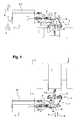
figure 1 est une vue de dessus d'un véhicule tracteur, ici équipé de deux équipements agricoles selon l'invention, l'un en position avant et l'autre en position arrière ; - la
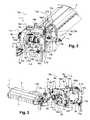
figure 2 est une vue générale et en perspective de l'un des équipements agricoles de lafigure 1 , représenté isolément ; - la
figure 3 représente l'équipement agricole de lafigure 2 , selon une seconde perspective ; - les
figures 4 et 5 représentent l'équipement agricole desfigures 2 et 3 , vu de dessus, avec la partie outil manoeuvrée entre une position déportée (figure 4 ) et une position escamotée ou recentrée (figure 5 ) ; - les
figures 6 à 8 montrent toujours le même équipement avec une représentation schématique des moyens de liaison, en montage avant et lors d'un contact avec un obstacle, et dont la partie outil se trouve, respectivement, en position neutre, en position effacement vers l'arrière et en position effacement vers l'avant (la position neutre est illustrée en traits discontinus sur lesfigures 7 et 8 ) ; - la
figure 9 illustre les mouvements de la pièce rotative de broyage/déchiquetage autour d'un axe de rotation horizontal, par rapport au châssis relié à la partie attelage par les moyens de liaison, pour sa manoeuvre notamment dans une position relevée au repos et une position déployée de travail.
- the
figure 1 is a top view of a towing vehicle, here equipped with two agricultural equipment according to the invention, one in the forward position and the other in the rear position; - the
figure 2 is a general and perspective view of one of the agricultural equipment of thefigure 1 , shown in isolation; - the
figure 3 represents the agricultural equipment of thefigure 2 according to a second perspective; - the
Figures 4 and 5 represent the agricultural equipment of theFigures 2 and 3 , seen from above, with the tool part operated between a remote position (figure 4 ) and a retracted or recentered position (figure 5 ); - the
Figures 6 to 8 always show the same equipment with a schematic representation of the connecting means, mounted before and during contact with an obstacle, and whose tool part is, respectively, in the neutral position, in the retracted position and in the forward erase position (the neutral position is shown in broken lines on theFigures 7 and 8 ); - the
figure 9 illustrates the movements of the rotating grinding / shredding piece about a horizontal axis of rotation, relative to the frame connected to the coupling portion by the connecting means, for its operation in particular in a raised position at rest and an extended position of job.
Tel qu'illustré sur la
En l'occurrence et cela uniquement à titre d'illustration, le véhicule tracteurT est ici équipé de deux équipements agricoles 1, l'un en montage arrière (en partie supérieure sur la
Selon l'invention, lors de l'avancement du véhicule tracteurT, chaque équipement agricole 1 est apte à s'effacer largement au contact d'un obstacle, vers l'avant et/ou vers l'arrière, puis à revenir dans sa position initiale neutre une fois le contact interrompu (tel que décrit ci-après en particulier en relation avec les
Cette particularité fonctionnelle permet de limiter les risques d'une détérioration de l'équipement agricole 1, du véhicule motoriséT équipé et/ou de l'obstacle percuté ; il est également ainsi possible de fournir un travail de précision autour de l'obstacle concerné.This functional feature makes it possible to limit the risks of a deterioration of the
Tel qu'illustré en particulier par les
- une
partie outil 2, pour le traitement des végétaux (par exemple du type broyage et déchiquetage), et - une
partie attelage 3, destinée à être solidarisée avec le véhicule motoriséT.
- a
tool part 2, for the treatment of plants (for example of the grinding and shredding type), and - a
coupling portion 3, intended to be secured to the motor vehicleT.
Intercalé entre ces deux parties 2 et 3, l'équipement agricole 1 comporte encore : - des moyens de liaison 4, formant un parallélogramme déformable pour autoriser un déport latéral de la partie outil 2 par rapport à la partie attelage 3, et - des moyens de manoeuvre en déport 5, pour ajuster ce déport latéral.Interleaved between these two
La partie outil 2, adaptée ici pour le broyage et le déchiquetage de végétaux, comporte :
- une pièce rotative horizontale 6 ou rotor horizontal (illustré schématiquement sur la
figure 4 ), dont la rotation autour de son axe 6' assure la coupe et le broyage de végétaux, et qui est protégé ici par uncaisson 7, et - un
châssis 8, portant l'ensemblecaisson 7 / pièce rotative 6 et coopérant avec la partie attelage 3 par le biais des moyens deliaison 4.
- a horizontal rotating
part 6 or horizontal rotor (illustrated schematically on thefigure 4 ), whose rotation about its axis 6 'ensures the cutting and grinding of plants, and which is protected here by abox 7, and - a
frame 8, carrying thebox assembly 7 /rotary part 6 and cooperating with thecoupling portion 3 through theconnecting means 4.
Le châssis 8 de cette partie outil 2 présente une forme générale quadrangulaire, définissant un plan général 8' s'étendant ici verticalement (
En l'occurrence, selon les
Du côté de sa seconde bordure latérale 8d, le châssis 8 est solidarisé avec le caisson 7 par l'intermédiaire d'articulations horizontales 9 (
Ces articulations horizontales 9 ont pour fonction d'autoriser une rotation de l'ensemble rotor 6/caisson 7 autour d'un axe de pivotement horizontal 9' qui s'étend perpendiculairement à l'axe de rotation 6' du rotor 6 et au plan général 8' du châssis 8 (voir notamment
Ici au nombre de deux, les articulations horizontales 9 sont ménagées de manière symétrique par rapport au plan général 8' du châssis 8, à une même distance et de part et d'autre de ce dernier.Here in number two, the
Tel que développé ci-après, cette disposition particulière participe à la rigidification de l'équipement agricole 1 lors d'un appui contre un obstacle.As developed below, this particular provision contributes to the stiffening of the
La partie outil 2 comporte encore des moyens 10 pour le verrouillage du rotor 6 dans une position relevée verticale, tel que décrit plus en détails ci-après en relation avec la
Ces moyens de verrouillage 10 consistent ici en - un crochet mobile 10a, équipant le châssis 8 et associé à des moyens de manoeuvre (non représentés), et - une tige complémentaire 10b ménagée sur le caisson 7 (visible sur la
Les moyens de manoeuvre du crochet 10a consistent par exemple en - un actionneur linéaire simple effet, pour son pivotement en position inactive, et - un ressort de rappel en position active.The
Des moyens de manoeuvre 10c, par exemple un actionneur linéaire du genre vérin hydraulique (
La partie outil 2 comporte encore des moyens de transmission 11, pour l'entraînement du rotor 6 par la motorisation du véhicule tracteurT.The
Sur les
L'arbre récepteur 11b est ici traversant avec deux extrémités cannelées (non visibles) qui débouchent de part et d'autre du châssis 8 et qui sont protégées chacune au sein d'une coupelle de protection 11c.The receiving
Un tel arbre récepteur 11b autorise un montage indifférent de l'équipement agricole 1, à l'avant ou à l'arrière du véhicule motoriséT, tel qu'illustré par la
Une transmission « secondaire », non visible, relie l'arbre récepteur 11b et le rotor 6.A "secondary" transmission, not visible, connects the
La partie attelage 3 comporte quant à elle également un châssis 12, s'étendant dans un plan vertical 12' (
Ce châssis 12, ici de forme rectangulaire, se compose :
- d'une bordure supérieure 12a, formée par un premier longeron,
- d'une bordure inférieure 12b formée par un second longeron,
- d'une première bordure latérale 12c, formée par un premier montant et s'étendant à distance de l'ensemble
rotor 6/caisson 7, et - d'une seconde bordure latérale 12d, formée par un second montant et s'étendant du côté de l'ensemble
rotor 6/caisson 7.
- 12has an upper edge formed by a first side member,
- a
lower edge 12b formed by a second spar, - a first
lateral edge 12c formed by a first amount and extending away from therotor assembly 6 /casing 7, and - a second
lateral edge 12d , formed by a second upright and extending on the side of therotor assembly 6 /box 7.
Ce châssis 12 est en plus muni de moyens 13 qui sont aptes à coopérer avec les moyens d'attelage trois points équipant le véhicule tracteurT, à savoir deux chapes 13a et un point central 13b (
Les moyens de liaison 4, entre la partie outil 2 et la partie attelage 3, comprennent quant à eux deux chaînons pivotants juxtaposés 15, 16, à savoir :
- un
premier chaînon 15, consistant ici en un organe télescopique, et - un
second chaînon 16, constitué ici de deux bras non-télescopiques superposés indépendants, l'un supérieur 16a (visiblefigures 2 à 5 ) et l'autre inférieur 16b (visiblefigure 2 ).
- a
first link 15, here consisting of a telescopic member, and - a
second link 16, consisting here of two independent non-telescopic arms superposed, the upper one 16a (visibleFigures 2 to 5 ) and the other lower 16b (visiblefigure 2 ).
L'organe télescopique 15 des moyens de liaison 4 constitue l'un des éléments pour assurer la fonction « effacement élastique » pour la partie outil 2.The
Cet organe télescopique 15 consiste en un actionneur linéaire qui définit un axe longitudinal 15' (
Les deux extrémités 15a de cet organe télescopique 15 sont solidarisées (i) pour l'une sur le châssis 8 de la partie outil 2, au niveau de la jonction entre sa bordure inférieure 8b et sa première bordure latérale 8c, et (ii) pour l'autre sur le châssis 12 de la partie attelage 3, au niveau de la jonction entre sa bordure inférieure 12b et sa première bordure latérale 12c.Both ends 15a of the
Ces deux extrémités 15a sont de plus montées pivotantes chacune autour d'un axe de rotation vertical 15a', s'étendant parallèlement l'un par rapport à l'autre et dans le plan vertical 8', 12' des châssis 8, 12, respectivement.Both ends 15a are each further pivotally mounted about a vertical axis of
Plus précisément, cet organe télescopique 15 consiste ici en un vérin hydraulique à double tige comprenant un cylindre 15b présentant deux extrémités opposées qui sont chacune équipées d'une tige mobile 15c constituant l'une desdites extrémités 15a.More specifically, this
Cet organe télescopique 15 sera ici encore dénommé « vérin de sécurité » ou « organe télescopique de sécurité ».This
Un tel vérin de sécurité 15 présente en pratique une course en allongement et en raccourcissement, tenant compte d'une longueur au repos.Such a
L'organe télescopique de sécurité 15 présente une longueur au reposL (
Pour cela, au repos, une première tige mobile 15c (par exemple du côté de la partie outil 2) est en position déployée, et une seconde tige mobile 15c (par exemple du côté de la partie attelage 3) est en position escamotée.For this, at rest, a first moving
Par exemple, la course de l'organe télescopique 15 est comprise entre 50 mm et 150 mm, de préférence de l'ordre de 80 mm à 120 mm, de part et d'autre de cette longueur au reposL (en allongement et en raccourcissement).For example, the travel of the
La force développée par cet organe télescopique 15 assure avantageusement un compromis entre :
- un maintien de la partie outil 2 en position neutre,
- une possibilité d'effacement en cas d'appui sur un obstacle, et
- un retour de la partie outil 2 en position neutre suite à un effacement.
- a maintenance of the
tool part 2 in neutral position, - a possibility of erasure in case of support on an obstacle, and
- a return of the
tool part 2 in the neutral position following an erasure.
Des moyens hydrauliques 17 sont associés à l'organe télescopique 15 pour son rappel élastique dans la longueur au reposL.Hydraulic means 17 are associated with the
Ces moyens hydrauliques de rappel élastique 17 consistent en l'occurrence en un accumulateur hydraulique (visible notamment sur les
D'autre part, les deux bras non télescopiques 16a et 16b constitutifs du second chaînon pivotant 16 sont indépendants l'un de l'autre et s'étendent dans un même plan vertical 16' (illustré
Chaque bras non télescopique 16a, 16b s'étend en plus dans un plan horizontal passant, respectivement, par les bordures supérieures 8a, 12a et les bordures inférieures 8b, 12b des châssis 8, 12 des parties outil 2 et attelage 3.Each
Les extrémités 16a1, 16b1 de ces deux bras non télescopiques 16a, 16b sont solidarisées (i) pour l'une sur le châssis 8 de la partie outil 2, respectivement sur sa bordure supérieure 8a et sa bordure inférieure 8b, et (ii) pour l'autre sur le châssis 12 de la partie attelage 3, respectivement sur sa bordure supérieure 12a et sa bordure inférieure 12b.The ends 16to 1, 16
Plus précisément, ces bras non-télescopiques 16a, 16b s'étendent entre les bordures latérales 8c, 8d et 12c, 12d des châssis 8, 12 associés, avantageusement à égale distance de ces dernières (autrement dit encore, au milieu de la longueur des bordures supérieure 8a, 12a ou inférieure 8b, 12b).Specifically, these
De préférence, les bras non-télescopiques 16a, 16b s'étendent entre les deux chapes latérales d'attelage 13a, au niveau et dans un plan vertical passant par le troisième point d'attelage 13b.Preferably, the
Les extrémités 16a1, 16b1 de ces deux bras non-télescopiques 16a, 16b sont chacune aptes à pivoter autour d'un axe de rotation vertical 16a1', 16b1' (
Les axes de rotation 16a1', 16b1' des extrémités 16a1, 16b1 en regard sont coaxiaux sur la partie outil 2 et sur la partie attelage 3, définissant des axes 16c, 16d respectivement.The
Ces deux axes de rotation verticaux 16c, 16d s'étendent parallèlement l'un par rapport à l'autre, et dans le plan vertical 8', 12' des châssis 8, 12 respectifs.These two vertical rotation axes16c,16d extend parallel relative to each other, and in the vertical plane 8 ', 12' of the
Tel qu'illustré sur la
Par ailleurs, les moyens 5 pour ajuster le déport latéral de la partie outil 2 (dit encore « moyens de manoeuvre en déport 5 ») consistent ici en un actionneur linéaire, par exemple un vérin hydraulique, intercalé entre le bras non-télescopique inférieur 16b et l'une des articulations horizontales 9.Moreover, the
Ce vérin hydraulique 5, avantageusement du type double effet, sera ici encore désigné « vérin de déport ».This
Ce montage particulier de cet actionneur linéaire 5, en déport sur le bras non-télescopique inférieur 16b et le châssis 8 permet d'augmenter la rigidification du matériel et de diminuer l'encombrement.This particular mounting of the
L'équipement agricole 1 comporte encore des moyens pour l'asservissement des moyens de verrouillage 10 et des moyens de manoeuvre en déport 5 (par exemple une conception adaptée du circuit hydraulique).The
Comme développé encore ci-après, ces moyens d'asservissement (non représentés) sont configurés de sorte à assurer :
- l'action sur l'actionneur linéaire associé au crochet mobile 10a pour son déplacement en position inactive, et l'action sur les moyens de manoeuvre en
déport 5 pour le déplacement en position déportée de la partie outil 2, ou - l'action sur les moyens de manoeuvre en
déport 5 pour le déplacement en position recentrée de la partie outil 2, et l'arrêt de l'action sur l'actionneur linéaire associé au crochet mobile 10a pour son retour en position active sous l'effet de son ressort de rappel.
- the action on the linear actuator associated with the
movable hook 10has for its displacement in the inactive position, and the action on the remote maneuvering means 5 for the displacement in remote position of thetool part 2, or - the action on the offset operating means 5 for the displacement in the recentered position of the
tool part 2, and the stopping of the action on the linear actuator associated with themovable hook 10has for its return to the active position under the effect of its return spring.
Le vérin 10c pour la manoeuvre de l'ensemble caisson 7/rotor 6 est avantageusement piloté indépendamment de ces moyens d'asservissement.The
En pratique, pour son transport sur route, l'ensemble rotor 6/caisson 7 est relevé selon une position verticale, ou au moins approximativement verticale, par rapport à son châssis porteur 8 (
Les moyens de manoeuvre en déport 5 sont dans ce cas escamotés, de sorte à positionner le châssis 8 de la partie outil 2 dans une position recentrée par rapport au châssis 12 de la partie attelage 3 (
Lorsque le tracteurT atteint le site à traiter, les moyens d'asservissement permettent d'assurer, successivement :
- le déplacement en position inactive des moyens de verrouillage 10 par un mouvement vers le haut du crochet 10a, autorisant le pivotement du
rotor 6 autour de l'axe horizontal 9' vers une position déployée en appui sur le sol (selon un sens anti-horaire sur lafigure 9 ), puis - une action en déploiement des moyens de manoeuvre en
déport 5, par laquelle la partie outil 2 se déplace parallèlement à elle-même, selon un mouvement correspondant approximativement à un sens s'étendant depuis la première bordure 12c vers la seconde bordure 12d du châssis 12 de la partie attelage 3 (depuis lafigure 5 et jusqu'à lafigure 4 ).
- the displacement in the inactive position of the locking means 10 by an upward movement of the
hook 10to authorizing the pivoting of therotor 6 about thehorizontal axis 9 'to an extended position resting on the ground (in a counterclockwise time on thefigure 9 ) and then - an action in deployment of the remote maneuvering means 5, by which the
tool part 2 moves parallel to itself, in a movement corresponding approximately to a direction extending from thefirst edge 12c to thesecond edge 12dof thechassis 12 of the coupling part 3 (since thefigure 5 and until thefigure 4 ).
Le véhiculeT avance alors à une vitesse régulière, ou au moins sensiblement régulière, comprise par exemple entre 2 et 4 km/heure.The vehicleT then advances at a steady speed, or at least substantially regular, for example between 2 and 4 km / hour.
Le sens normal d'avancement est représenté schématiquement sur les
Lors du mouvement vers l'avantA, le rotor 6 est en rotation de sorte à traiter les végétaux au sol.During the forward movementA , the
La partie outil 2 de l'équipement agricole 1 est avantageusement maintenue en position déportée (
Cette partie outil 2 est également maintenue de sorte que l'axe de rotation 6' du rotor 6 et le plan général 8' de son châssis 8 s'étendent parallèlement et à distance du plan général 12' du châssis 12 de la partie attelage 3.This
A cet effet, l'organe télescopique de sécurité 15 est maintenu dans sa longueur au reposL, correspondant également à la longueur des bras non-télescopique 16 (
L'approche d'un obstacleC est décrite ci-dessous pour un équipement agricole 1 en montage avant (les mouvements seraient tout simplement inverses pour un montage arrière).The approach of an obstacleC is described below for
Ainsi, lors de l'approche d'un obstacleC à contourner, le conducteur du véhicule peut actionner le vérin de déport 5 dédié, pour réduire le déport latéral de l'ensemble rotor 6/caisson 7 et décaler ce dernier latéralement par rapport à cet obstacleC à traiter.Thus, when approaching an obstacleC to be bypassed, the driver of the vehicle can actuate the dedicated offset
Cette action s'accompagne d'une rotation des chainons 15, 16 autour de leurs axes de rotation respectifs 15a', 16c, 16d.This action is accompanied by a rotation of the
Les plans 8' et 12' des deux châssis 8 et 12 de l'équipement agricole 1 restent ici parallèles, ou au moins approximativement parallèles, l'un par rapport à l'autre.The planes 8 'and 12' of the two
Si le conducteur n'a pas vu l'obstacleC ou s'il souhaite traiter la végétation au plus près de celui-ci, le véhicule tracteurT continue à avancer jusqu'à ce que l'ensemble rotor 6/caisson 7 vienne prendre appui sur cet obstacleC (
Du fait de la poursuite de l'avancement du véhicule tracteurT, le caisson 7 en appui sur l'obstacle fixeC exerce une force sur le châssis 8 associé, qui provoque lui-même une course en allongement de l'organe télescopique de sécurité 15 jusqu'à une longueurL1 supérieure à la longueur au reposL (illustré sur la
La partie outil 2 subit ainsi un mouvement du genre pivotement par rapport à la partie attelage 3 (sens horaire sur la
L'équipement agricole 1 subit ainsi un phénomène d'effacement vers l'arrière, évitant sa détérioration et celle de l'obstacleC.The
Pour le retour de la partie outil 2 en position neutre, le conducteur peut manoeuvrer le véhicule tracteur en marche arrièreB.For the return of the
L'organe télescopique de sécurité 15 reprend alors automatiquement sa longueur au reposL, provoquant le retour de l'ensemble rotor 6/caisson 7 au repos (
Pour travailler au plus près de l'autre côté de cet obstacleC, le véhiculeT avance de sorte que l'ensemble rotor 6/caisson 7 escamoté dépasse cet obstacleC avant son redéploiement.To work closer to the other side of this obstacleC , the vehicleT advances so that the
Le véhicule recule alors dans le sensB, de sorte que le caisson 7 vient à nouveau prendre appui sur l'obstacleC (
L'organe télescopique de sécurité 15 subit alors un phénomène de rétractation selon une course en raccourcissement jusqu'à une longueurL2 qui est inférieure à la longueur au reposL.The
L'ensemble rotor 6/caisson 7 subit ainsi un phénomène d'effacement vers l'avant. La partie outil 2 est soumise à un mouvement du genre pivotement par rapport à la partie attelage 3 dans un sens inverse (selon un sens anti-horaire sur la
Là encore, il suffit à l'opérateur de manoeuvrer son véhicule tracteur vers l'avant pour que l'ensemble rotor 6 / caisson 7 revienne dans une position neutre (
Pour revenir en position route, l'équipement 1 est piloté de sorte à assurer :
- le pivotement de l'ensemble
rotor 6/caisson 7 autour de l'axe horizontal 9' vers la position verticale (selon un sens horaire sur lafigure 9 ), par l'action du vérin hydraulique 10c dédié, et - la commande des moyens de manoeuvre en
déport 5 pour recentrer le châssis 8 de la partie outil 2 afin que cette dernière se déplace parallèlement à elle-même selon un mouvement correspondant approximativement à un sens s'étendant depuis la seconde bordure 12d vers la première bordure 12c du châssis 12 de la partie attelage 3 (depuis lafigure 4 et jusqu'à lafigure 5 ), et le retour du crochet mobile 10a en position active (sous l'effet de son ressort de rappel) pour coopérer avec la tigecomplémentaire 10b.
- the pivoting of the
rotor assembly 6 /box 7 about thehorizontal axis 9 'to the vertical position (in a clockwise direction on thefigure 9 ), by the action of thehydraulic cylinder 10c dedicated, and - the control of the remote maneuvering means 5 for recentering the
frame 8 of thetool part 2 so that the latter moves parallel to itself in a movement corresponding approximately to a direction extending from thesecond edge 12d towards the first 12c rim of theframe 12 of the hitch part 3 (since thefigure 4 and until thefigure 5 ), and the return of themovable hook 10has in the active position (under the effect of its return spring) to cooperate with thecomplementary rod 10b .
L'arbre récepteur traversant 11b permet de faciliter les raccordements avant et arrière, pour modifier un mode de travail avant vers un mode de travail arrière, ou inversement.The
Les éléments de transfert de puissance sont indépendants du mode avant/arrière et ne nécessitent donc aucune intervention.The power transfer elements are independent of the forward / reverse mode and therefore require no intervention.
De plus, les moyens de liaison 4 et la partie attelage 3 sont symétriques, ce qui autorise un montage indifférent à l'avant ou à l'arrière du véhicule tracteurT.In addition, the connecting
Le procédé de transformation d'un mode avant/arrière vers l'autre consiste tout simplement à :
- démonter le vérin de sécurité 15 et le vérin de déport 5,
- démonter les bras non-télescopiques 16a, 16b par
rapport au châssis 8 de la partie outil 2, - disposer l'ensemble dans l'autre position,
- refixer les bras non-télescopiques 16a, 16b sur le châssis 8 de la partie outil 2, puis
- remonter le vérin de sécurité 15 et le vérin de déport 5 sur l'équipement 1, symétriquement par rapport au plan 8' du châssis 8 de la partie outil 2.
- dismantle the
safety cylinder 15 and the offsetcylinder 5, - dismantling the
non-telescopic arms frame 8 of thetool part 2, - arrange the whole in the other position,
- reattaching the
non-telescopic arms frame 8 of thetool part 2, and then - reassemble the
safety jack 15 and the offsetcylinder 5 on theequipment 1, symmetrically with respect to the plane 8 'of theframe 8 of thetool part 2.
A titre indicatif, en montage arrière (
- un effacement vers l'arrière, illustré par la flècheM dans le sens horaire sur la
figure 1 , dans lequel le vérin de sécurité 15 subit le phénomène de rétractation, et - un effacement vers l'avant, illustré par la flècheN dans le sens anti-horaire sur la
figure 1 , dans lequel le vérin de sécurité 15 subit le phénomène d'allongement.
- a backward erasure, illustrated by the arrowM clockwise on the
figure 1 , in which thesafety jack 15 undergoes the retraction phenomenon, and - forward deletion, shown by theN arrow in the counterclockwise direction on the
figure 1 , in which thesafety cylinder 15 undergoes the phenomenon of elongation.
Claims (13)
Translated fromFrenchcaractérisé en ce que l'un au moins desdits chaînons pivotants (15) consiste en au moins un organe télescopique qui présente une longueur au repos (L), avec une course disponible en allongement et/ou en raccourcissement par rapport à ladite longueur au repos (L),
eten ce que ledit organe télescopique (15) est associé à des moyens (17) de rappel élastique à ladite longueur au repos (L).
characterized in that at least one of said pivoting links (15) consists of at least one telescopic member which has a rest length (L ), with a stroke available in elongation and / or shortening with respect to said rest length (L ),
andin that said telescopic member (15) is associated with elastic return means (17) at said rest length (L ).
Applications Claiming Priority (1)
| Application Number | Priority Date | Filing Date | Title |
|---|---|---|---|
| FR1250588AFR2985881B1 (en) | 2012-01-20 | 2012-01-20 | AGRICULTURAL EQUIPMENT FOR A MOTORIZED VEHICLE, WITH DEFORMABLE PARALLELOGRAM FOR THE LATERAL DEPORT OF A TOOL PART |
Publications (2)
| Publication Number | Publication Date |
|---|---|
| EP2617278A1true EP2617278A1 (en) | 2013-07-24 |
| EP2617278B1 EP2617278B1 (en) | 2017-01-18 |
Family
ID=47603512
Family Applications (1)
| Application Number | Title | Priority Date | Filing Date |
|---|---|---|---|
| EP13305061.7AActiveEP2617278B1 (en) | 2012-01-20 | 2013-01-18 | Farm equipment for a motor vehicle, with a deformable parallelogram for laterally offsetting a tool portion |
Country Status (2)
| Country | Link |
|---|---|
| EP (1) | EP2617278B1 (en) |
| FR (1) | FR2985881B1 (en) |
Cited By (4)
| Publication number | Priority date | Publication date | Assignee | Title |
|---|---|---|---|---|
| EP3216337A1 (en)* | 2016-03-11 | 2017-09-13 | Nobili S.p.A. | Equipment for shredding plant material |
| EP3369299A1 (en)* | 2017-03-03 | 2018-09-05 | Guy Dehondt | Self-propelled multi-purpose agricultural machine for maintaining road shoulders and edges |
| US20190281761A1 (en)* | 2016-11-10 | 2019-09-19 | Claudio CORSETTI | Movement system for any farming machinery |
| EP3616495A1 (en) | 2018-09-03 | 2020-03-04 | Seppi M. spa-AG | Fastening mechanism for a crushing / cutting device for plant material on a vehicle, especially a tractor or similar |
Citations (5)
| Publication number | Priority date | Publication date | Assignee | Title |
|---|---|---|---|---|
| WO2003084307A1 (en)* | 2002-04-05 | 2003-10-16 | Seppi M. S.R.L. | Controller for an automatic sensor in a row of trees |
| WO2004021763A2 (en)* | 2002-09-09 | 2004-03-18 | Scordilis Frank P | Mower |
| DE202008014778U1 (en)* | 2007-11-07 | 2009-02-19 | BMK - Engineering d.o.o. Brežice | Tractor mulch Accessories |
| DE202010011917U1 (en) | 2010-08-27 | 2010-10-28 | Mulag Fahrzeugwerk Heinz Wössner GmbH u. Co KG | Edge strip mower for guardrail |
| FR2956791A1 (en)* | 2010-02-26 | 2011-09-02 | Sarl Jean Michel Egretier | Inter-plant tool holder for retracting inter-plat tool and bringing back tool in work position for field of plantations on lines, has displacement jack electrovalve deviating tool to combine movements for limiting angular tilting of tool |
- 2012
- 2012-01-20FRFR1250588Apatent/FR2985881B1/ennot_activeExpired - Fee Related
- 2013
- 2013-01-18EPEP13305061.7Apatent/EP2617278B1/enactiveActive
Patent Citations (5)
| Publication number | Priority date | Publication date | Assignee | Title |
|---|---|---|---|---|
| WO2003084307A1 (en)* | 2002-04-05 | 2003-10-16 | Seppi M. S.R.L. | Controller for an automatic sensor in a row of trees |
| WO2004021763A2 (en)* | 2002-09-09 | 2004-03-18 | Scordilis Frank P | Mower |
| DE202008014778U1 (en)* | 2007-11-07 | 2009-02-19 | BMK - Engineering d.o.o. Brežice | Tractor mulch Accessories |
| FR2956791A1 (en)* | 2010-02-26 | 2011-09-02 | Sarl Jean Michel Egretier | Inter-plant tool holder for retracting inter-plat tool and bringing back tool in work position for field of plantations on lines, has displacement jack electrovalve deviating tool to combine movements for limiting angular tilting of tool |
| DE202010011917U1 (en) | 2010-08-27 | 2010-10-28 | Mulag Fahrzeugwerk Heinz Wössner GmbH u. Co KG | Edge strip mower for guardrail |
Cited By (5)
| Publication number | Priority date | Publication date | Assignee | Title |
|---|---|---|---|---|
| EP3216337A1 (en)* | 2016-03-11 | 2017-09-13 | Nobili S.p.A. | Equipment for shredding plant material |
| US20190281761A1 (en)* | 2016-11-10 | 2019-09-19 | Claudio CORSETTI | Movement system for any farming machinery |
| EP3369299A1 (en)* | 2017-03-03 | 2018-09-05 | Guy Dehondt | Self-propelled multi-purpose agricultural machine for maintaining road shoulders and edges |
| FR3063417A1 (en)* | 2017-03-03 | 2018-09-07 | Guy Dehondt | AGRICULTURAL ENGINE AUTOMOTIVE CARRIER FOR THE MAINTENANCE OF ACCOTEMENTS AND TRAFFIC TRACK |
| EP3616495A1 (en) | 2018-09-03 | 2020-03-04 | Seppi M. spa-AG | Fastening mechanism for a crushing / cutting device for plant material on a vehicle, especially a tractor or similar |
Also Published As
| Publication number | Publication date |
|---|---|
| FR2985881B1 (en) | 2014-02-21 |
| EP2617278B1 (en) | 2017-01-18 |
| FR2985881A1 (en) | 2013-07-26 |
Similar Documents
| Publication | Publication Date | Title |
|---|---|---|
| EP0356358B1 (en) | Mower with an improved frame | |
| US7971886B2 (en) | Steering for towed implements | |
| EP3645376B1 (en) | Agricultural vehicle chassis with adjustable width and agricultural vehicle | |
| EP3386287B1 (en) | A work vehicle | |
| CA2629914A1 (en) | Agricultural implement comprising an improved hitch structure | |
| AU2014351686B2 (en) | Agricultural machine, in particular machine for harvesting plant matter, comprising two driven working units that are articulated on a single lateral arm | |
| EP2689651B1 (en) | Plant cutting device | |
| EP2617278B1 (en) | Farm equipment for a motor vehicle, with a deformable parallelogram for laterally offsetting a tool portion | |
| JPH02245113A (en) | Mowing machine with safety device | |
| AU2006208796B2 (en) | Lawn mower provided with an improved folding and unfolding device | |
| EP3259970B1 (en) | Agricultural tool-holder device for facilitating furrow selection, associated installation process and agricultural system | |
| EP3369299B1 (en) | Self-propelled multi-purpose agricultural machine for maintaining road shoulders and edges | |
| EP2445330B1 (en) | Agricultural machine | |
| FR2638597A1 (en) | Device for mounting a mowing head on a vehicle | |
| EP4147551A1 (en) | Agricultural machine with a coupling head provided with a translational locking device | |
| FR3032595A1 (en) | VEGETABLE CUTTING MACHINE AND MOTOR VEHICLE COMPRISING SUCH CUTTING MACHINE | |
| EP0399914A1 (en) | Agricultural machine comprising a leading central tool and two pivotable side tools | |
| EP1466516B1 (en) | Agricultural machine with at least one wheel | |
| EP2165588B1 (en) | Device for tearing and grinding plants on the ground, hitchable to a tow vehicle | |
| EP2397395B1 (en) | Motorised tool-carrier vehicle with 4 skewed wheels | |
| WO2005015974A2 (en) | Forest soil treating combine | |
| FR2809593A1 (en) | Towed vegetation mower implement has angle drive box mounted on hitch frame to transmit power for tractor power take off to rotor | |
| EP0801887A1 (en) | Cutting machine | |
| FR2882500A1 (en) | Mowing/scrub clearing and pruning machine for e.g. maintenance of shoulder of road, has frame rigidly fixed to vehicle and including axle with independent wheels mounted at rear end of pulled arm whose front end is articulated on frame | |
| FR2776163A1 (en) | Agricultural device with separately driven lifting mechanism |
Legal Events
| Date | Code | Title | Description |
|---|---|---|---|
| PUAI | Public reference made under article 153(3) epc to a published international application that has entered the european phase | Free format text:ORIGINAL CODE: 0009012 | |
| AK | Designated contracting states | Kind code of ref document:A1 Designated state(s):AL AT BE BG CH CY CZ DE DK EE ES FI FR GB GR HR HU IE IS IT LI LT LU LV MC MK MT NL NO PL PT RO RS SE SI SK SM TR | |
| AX | Request for extension of the european patent | Extension state:BA ME | |
| 17P | Request for examination filed | Effective date:20140123 | |
| RBV | Designated contracting states (corrected) | Designated state(s):AL AT BE BG CH CY CZ DE DK EE ES FI FR GB GR HR HU IE IS IT LI LT LU LV MC MK MT NL NO PL PT RO RS SE SI SK SM TR | |
| GRAP | Despatch of communication of intention to grant a patent | Free format text:ORIGINAL CODE: EPIDOSNIGR1 | |
| INTG | Intention to grant announced | Effective date:20160819 | |
| GRAS | Grant fee paid | Free format text:ORIGINAL CODE: EPIDOSNIGR3 | |
| GRAA | (expected) grant | Free format text:ORIGINAL CODE: 0009210 | |
| AK | Designated contracting states | Kind code of ref document:B1 Designated state(s):AL AT BE BG CH CY CZ DE DK EE ES FI FR GB GR HR HU IE IS IT LI LT LU LV MC MK MT NL NO PL PT RO RS SE SI SK SM TR | |
| REG | Reference to a national code | Ref country code:GB Ref legal event code:FG4D Free format text:NOT ENGLISH | |
| REG | Reference to a national code | Ref country code:CH Ref legal event code:EP | |
| REG | Reference to a national code | Ref country code:AT Ref legal event code:REF Ref document number:862338 Country of ref document:AT Kind code of ref document:T Effective date:20170215 | |
| REG | Reference to a national code | Ref country code:IE Ref legal event code:FG4D Free format text:LANGUAGE OF EP DOCUMENT: FRENCH | |
| REG | Reference to a national code | Ref country code:FR Ref legal event code:PLFP Year of fee payment:5 | |
| REG | Reference to a national code | Ref country code:DE Ref legal event code:R096 Ref document number:602013016680 Country of ref document:DE | |
| REG | Reference to a national code | Ref country code:NL Ref legal event code:MP Effective date:20170118 | |
| REG | Reference to a national code | Ref country code:LT Ref legal event code:MG4D | |
| PG25 | Lapsed in a contracting state [announced via postgrant information from national office to epo] | Ref country code:BE Free format text:LAPSE BECAUSE OF NON-PAYMENT OF DUE FEES Effective date:20170131 | |
| REG | Reference to a national code | Ref country code:AT Ref legal event code:MK05 Ref document number:862338 Country of ref document:AT Kind code of ref document:T Effective date:20170118 | |
| PG25 | Lapsed in a contracting state [announced via postgrant information from national office to epo] | Ref country code:NL Free format text:LAPSE BECAUSE OF FAILURE TO SUBMIT A TRANSLATION OF THE DESCRIPTION OR TO PAY THE FEE WITHIN THE PRESCRIBED TIME-LIMIT Effective date:20170118 | |
| PG25 | Lapsed in a contracting state [announced via postgrant information from national office to epo] | Ref country code:LT Free format text:LAPSE BECAUSE OF FAILURE TO SUBMIT A TRANSLATION OF THE DESCRIPTION OR TO PAY THE FEE WITHIN THE PRESCRIBED TIME-LIMIT Effective date:20170118 Ref country code:FI Free format text:LAPSE BECAUSE OF FAILURE TO SUBMIT A TRANSLATION OF THE DESCRIPTION OR TO PAY THE FEE WITHIN THE PRESCRIBED TIME-LIMIT Effective date:20170118 Ref country code:NO Free format text:LAPSE BECAUSE OF FAILURE TO SUBMIT A TRANSLATION OF THE DESCRIPTION OR TO PAY THE FEE WITHIN THE PRESCRIBED TIME-LIMIT Effective date:20170418 Ref country code:GR Free format text:LAPSE BECAUSE OF FAILURE TO SUBMIT A TRANSLATION OF THE DESCRIPTION OR TO PAY THE FEE WITHIN THE PRESCRIBED TIME-LIMIT Effective date:20170419 Ref country code:HR Free format text:LAPSE BECAUSE OF FAILURE TO SUBMIT A TRANSLATION OF THE DESCRIPTION OR TO PAY THE FEE WITHIN THE PRESCRIBED TIME-LIMIT Effective date:20170118 Ref country code:IS Free format text:LAPSE BECAUSE OF FAILURE TO SUBMIT A TRANSLATION OF THE DESCRIPTION OR TO PAY THE FEE WITHIN THE PRESCRIBED TIME-LIMIT Effective date:20170518 | |
| REG | Reference to a national code | Ref country code:DE Ref legal event code:R119 Ref document number:602013016680 Country of ref document:DE | |
| PG25 | Lapsed in a contracting state [announced via postgrant information from national office to epo] | Ref country code:ES Free format text:LAPSE BECAUSE OF FAILURE TO SUBMIT A TRANSLATION OF THE DESCRIPTION OR TO PAY THE FEE WITHIN THE PRESCRIBED TIME-LIMIT Effective date:20170118 Ref country code:PT Free format text:LAPSE BECAUSE OF FAILURE TO SUBMIT A TRANSLATION OF THE DESCRIPTION OR TO PAY THE FEE WITHIN THE PRESCRIBED TIME-LIMIT Effective date:20170518 Ref country code:AT Free format text:LAPSE BECAUSE OF FAILURE TO SUBMIT A TRANSLATION OF THE DESCRIPTION OR TO PAY THE FEE WITHIN THE PRESCRIBED TIME-LIMIT Effective date:20170118 Ref country code:RS Free format text:LAPSE BECAUSE OF FAILURE TO SUBMIT A TRANSLATION OF THE DESCRIPTION OR TO PAY THE FEE WITHIN THE PRESCRIBED TIME-LIMIT Effective date:20170118 Ref country code:LV Free format text:LAPSE BECAUSE OF FAILURE TO SUBMIT A TRANSLATION OF THE DESCRIPTION OR TO PAY THE FEE WITHIN THE PRESCRIBED TIME-LIMIT Effective date:20170118 Ref country code:BG Free format text:LAPSE BECAUSE OF FAILURE TO SUBMIT A TRANSLATION OF THE DESCRIPTION OR TO PAY THE FEE WITHIN THE PRESCRIBED TIME-LIMIT Effective date:20170418 Ref country code:SE Free format text:LAPSE BECAUSE OF FAILURE TO SUBMIT A TRANSLATION OF THE DESCRIPTION OR TO PAY THE FEE WITHIN THE PRESCRIBED TIME-LIMIT Effective date:20170118 Ref country code:PL Free format text:LAPSE BECAUSE OF FAILURE TO SUBMIT A TRANSLATION OF THE DESCRIPTION OR TO PAY THE FEE WITHIN THE PRESCRIBED TIME-LIMIT Effective date:20170118 | |
| REG | Reference to a national code | Ref country code:CH Ref legal event code:PL | |
| PG25 | Lapsed in a contracting state [announced via postgrant information from national office to epo] | Ref country code:LI Free format text:LAPSE BECAUSE OF NON-PAYMENT OF DUE FEES Effective date:20170131 Ref country code:RO Free format text:LAPSE BECAUSE OF FAILURE TO SUBMIT A TRANSLATION OF THE DESCRIPTION OR TO PAY THE FEE WITHIN THE PRESCRIBED TIME-LIMIT Effective date:20170118 Ref country code:CZ Free format text:LAPSE BECAUSE OF FAILURE TO SUBMIT A TRANSLATION OF THE DESCRIPTION OR TO PAY THE FEE WITHIN THE PRESCRIBED TIME-LIMIT Effective date:20170118 Ref country code:IT Free format text:LAPSE BECAUSE OF FAILURE TO SUBMIT A TRANSLATION OF THE DESCRIPTION OR TO PAY THE FEE WITHIN THE PRESCRIBED TIME-LIMIT Effective date:20170118 Ref country code:CH Free format text:LAPSE BECAUSE OF NON-PAYMENT OF DUE FEES Effective date:20170131 Ref country code:SK Free format text:LAPSE BECAUSE OF FAILURE TO SUBMIT A TRANSLATION OF THE DESCRIPTION OR TO PAY THE FEE WITHIN THE PRESCRIBED TIME-LIMIT Effective date:20170118 Ref country code:EE Free format text:LAPSE BECAUSE OF FAILURE TO SUBMIT A TRANSLATION OF THE DESCRIPTION OR TO PAY THE FEE WITHIN THE PRESCRIBED TIME-LIMIT Effective date:20170118 | |
| REG | Reference to a national code | Ref country code:IE Ref legal event code:MM4A | |
| PLBE | No opposition filed within time limit | Free format text:ORIGINAL CODE: 0009261 | |
| STAA | Information on the status of an ep patent application or granted ep patent | Free format text:STATUS: NO OPPOSITION FILED WITHIN TIME LIMIT | |
| PG25 | Lapsed in a contracting state [announced via postgrant information from national office to epo] | Ref country code:MC Free format text:LAPSE BECAUSE OF FAILURE TO SUBMIT A TRANSLATION OF THE DESCRIPTION OR TO PAY THE FEE WITHIN THE PRESCRIBED TIME-LIMIT Effective date:20170118 Ref country code:DK Free format text:LAPSE BECAUSE OF FAILURE TO SUBMIT A TRANSLATION OF THE DESCRIPTION OR TO PAY THE FEE WITHIN THE PRESCRIBED TIME-LIMIT Effective date:20170118 Ref country code:LU Free format text:LAPSE BECAUSE OF NON-PAYMENT OF DUE FEES Effective date:20170118 Ref country code:DE Free format text:LAPSE BECAUSE OF NON-PAYMENT OF DUE FEES Effective date:20170801 Ref country code:SM Free format text:LAPSE BECAUSE OF FAILURE TO SUBMIT A TRANSLATION OF THE DESCRIPTION OR TO PAY THE FEE WITHIN THE PRESCRIBED TIME-LIMIT Effective date:20170118 | |
| REG | Reference to a national code | Ref country code:FR Ref legal event code:PLFP Year of fee payment:6 | |
| 26N | No opposition filed | Effective date:20171019 | |
| GBPC | Gb: european patent ceased through non-payment of renewal fee | Effective date:20170418 | |
| REG | Reference to a national code | Ref country code:BE Ref legal event code:MM Effective date:20170131 | |
| PG25 | Lapsed in a contracting state [announced via postgrant information from national office to epo] | Ref country code:GB Free format text:LAPSE BECAUSE OF NON-PAYMENT OF DUE FEES Effective date:20170418 Ref country code:SI Free format text:LAPSE BECAUSE OF FAILURE TO SUBMIT A TRANSLATION OF THE DESCRIPTION OR TO PAY THE FEE WITHIN THE PRESCRIBED TIME-LIMIT Effective date:20170118 Ref country code:IE Free format text:LAPSE BECAUSE OF NON-PAYMENT OF DUE FEES Effective date:20170118 | |
| PG25 | Lapsed in a contracting state [announced via postgrant information from national office to epo] | Ref country code:MT Free format text:LAPSE BECAUSE OF FAILURE TO SUBMIT A TRANSLATION OF THE DESCRIPTION OR TO PAY THE FEE WITHIN THE PRESCRIBED TIME-LIMIT Effective date:20170118 | |
| PG25 | Lapsed in a contracting state [announced via postgrant information from national office to epo] | Ref country code:HU Free format text:LAPSE BECAUSE OF FAILURE TO SUBMIT A TRANSLATION OF THE DESCRIPTION OR TO PAY THE FEE WITHIN THE PRESCRIBED TIME-LIMIT; INVALID AB INITIO Effective date:20130118 | |
| PG25 | Lapsed in a contracting state [announced via postgrant information from national office to epo] | Ref country code:CY Free format text:LAPSE BECAUSE OF NON-PAYMENT OF DUE FEES Effective date:20170118 | |
| PG25 | Lapsed in a contracting state [announced via postgrant information from national office to epo] | Ref country code:MK Free format text:LAPSE BECAUSE OF FAILURE TO SUBMIT A TRANSLATION OF THE DESCRIPTION OR TO PAY THE FEE WITHIN THE PRESCRIBED TIME-LIMIT Effective date:20170118 | |
| PG25 | Lapsed in a contracting state [announced via postgrant information from national office to epo] | Ref country code:TR Free format text:LAPSE BECAUSE OF FAILURE TO SUBMIT A TRANSLATION OF THE DESCRIPTION OR TO PAY THE FEE WITHIN THE PRESCRIBED TIME-LIMIT Effective date:20170118 | |
| PG25 | Lapsed in a contracting state [announced via postgrant information from national office to epo] | Ref country code:AL Free format text:LAPSE BECAUSE OF FAILURE TO SUBMIT A TRANSLATION OF THE DESCRIPTION OR TO PAY THE FEE WITHIN THE PRESCRIBED TIME-LIMIT Effective date:20170118 | |
| PGFP | Annual fee paid to national office [announced via postgrant information from national office to epo] | Ref country code:FR Payment date:20241205 Year of fee payment:13 |