EP2613315B1 - Method and device for coding an audio signal - Google Patents
Method and device for coding an audio signalDownload PDFInfo
- Publication number
- EP2613315B1 EP2613315B1EP12731282.5AEP12731282AEP2613315B1EP 2613315 B1EP2613315 B1EP 2613315B1EP 12731282 AEP12731282 AEP 12731282AEP 2613315 B1EP2613315 B1EP 2613315B1
- Authority
- EP
- European Patent Office
- Prior art keywords
- sub
- band
- bandwidth
- audio signal
- signal
- Prior art date
- Legal status (The legal status is an assumption and is not a legal conclusion. Google has not performed a legal analysis and makes no representation as to the accuracy of the status listed.)
- Active
Links
Images


Classifications
- G—PHYSICS
- G10—MUSICAL INSTRUMENTS; ACOUSTICS
- G10L—SPEECH ANALYSIS TECHNIQUES OR SPEECH SYNTHESIS; SPEECH RECOGNITION; SPEECH OR VOICE PROCESSING TECHNIQUES; SPEECH OR AUDIO CODING OR DECODING
- G10L19/00—Speech or audio signals analysis-synthesis techniques for redundancy reduction, e.g. in vocoders; Coding or decoding of speech or audio signals, using source filter models or psychoacoustic analysis
- G10L19/008—Multichannel audio signal coding or decoding using interchannel correlation to reduce redundancy, e.g. joint-stereo, intensity-coding or matrixing
- G—PHYSICS
- G10—MUSICAL INSTRUMENTS; ACOUSTICS
- G10L—SPEECH ANALYSIS TECHNIQUES OR SPEECH SYNTHESIS; SPEECH RECOGNITION; SPEECH OR VOICE PROCESSING TECHNIQUES; SPEECH OR AUDIO CODING OR DECODING
- G10L19/00—Speech or audio signals analysis-synthesis techniques for redundancy reduction, e.g. in vocoders; Coding or decoding of speech or audio signals, using source filter models or psychoacoustic analysis
- G10L19/02—Speech or audio signals analysis-synthesis techniques for redundancy reduction, e.g. in vocoders; Coding or decoding of speech or audio signals, using source filter models or psychoacoustic analysis using spectral analysis, e.g. transform vocoders or subband vocoders
- G10L19/032—Quantisation or dequantisation of spectral components
- G—PHYSICS
- G10—MUSICAL INSTRUMENTS; ACOUSTICS
- G10L—SPEECH ANALYSIS TECHNIQUES OR SPEECH SYNTHESIS; SPEECH RECOGNITION; SPEECH OR VOICE PROCESSING TECHNIQUES; SPEECH OR AUDIO CODING OR DECODING
- G10L19/00—Speech or audio signals analysis-synthesis techniques for redundancy reduction, e.g. in vocoders; Coding or decoding of speech or audio signals, using source filter models or psychoacoustic analysis
- G10L19/002—Dynamic bit allocation
- G—PHYSICS
- G10—MUSICAL INSTRUMENTS; ACOUSTICS
- G10L—SPEECH ANALYSIS TECHNIQUES OR SPEECH SYNTHESIS; SPEECH RECOGNITION; SPEECH OR VOICE PROCESSING TECHNIQUES; SPEECH OR AUDIO CODING OR DECODING
- G10L19/00—Speech or audio signals analysis-synthesis techniques for redundancy reduction, e.g. in vocoders; Coding or decoding of speech or audio signals, using source filter models or psychoacoustic analysis
- G10L19/02—Speech or audio signals analysis-synthesis techniques for redundancy reduction, e.g. in vocoders; Coding or decoding of speech or audio signals, using source filter models or psychoacoustic analysis using spectral analysis, e.g. transform vocoders or subband vocoders
- G10L19/028—Noise substitution, i.e. substituting non-tonal spectral components by noisy source
- G—PHYSICS
- G10—MUSICAL INSTRUMENTS; ACOUSTICS
- G10L—SPEECH ANALYSIS TECHNIQUES OR SPEECH SYNTHESIS; SPEECH RECOGNITION; SPEECH OR VOICE PROCESSING TECHNIQUES; SPEECH OR AUDIO CODING OR DECODING
- G10L19/00—Speech or audio signals analysis-synthesis techniques for redundancy reduction, e.g. in vocoders; Coding or decoding of speech or audio signals, using source filter models or psychoacoustic analysis
- G10L19/02—Speech or audio signals analysis-synthesis techniques for redundancy reduction, e.g. in vocoders; Coding or decoding of speech or audio signals, using source filter models or psychoacoustic analysis using spectral analysis, e.g. transform vocoders or subband vocoders
- G10L19/0204—Speech or audio signals analysis-synthesis techniques for redundancy reduction, e.g. in vocoders; Coding or decoding of speech or audio signals, using source filter models or psychoacoustic analysis using spectral analysis, e.g. transform vocoders or subband vocoders using subband decomposition
Definitions
- the present inventionrelates to the field of audio signal coding and decoding technologies, and in particular, to an audio signal coding method and device.
- the current audio coding technologygenerally uses FFT (Fast Fourier Transform, fast Fourier transform) or MDCT (Modified Discrete Cosine Transform, modified discrete cosine transform) to transform time domain signals to the frequency domain, and then code the frequency domain signals.
- FFTFast Fourier Transform
- MDCTModified Discrete Cosine Transform, modified discrete cosine transform
- a limited number of bits for quantization used in the case of a low bit ratedoes not fulfill the requirements for quantizing all audio signals. Therefore, generally the BWE (Bandwidth Extension, bandwidth extension) technology and the spectrum overlay technology may be used.
- first input time domain signalsare transformed to the frequency domain, and a sub-band normalization factor, that is, envelope information of a spectrum, is extracted from the frequency domain.
- the spectrumis normalized by using the quantized sub-band normalization factors to obtain the normalized spectrum information.
- bit allocation for each sub-bandis determined, and the normalized spectrum is quantized. In this manner, the audio signals are coded into quantized envelope information and normalized spectrum information, and then bit streams are output.
- the process at a decoding endis inverse to that at a coding end.
- the coding endis incapable of coding all frequency bands; and at the decoding end, the bandwidth extension technology is required to recover frequency bands that are not coded at the coding end. Meanwhile, a lot of zero frequency points may be produced on the coded sub-band due to the limitation of a quantizer, so a noise filling module is needed to improve the performance.
- the decoded sub-band normalization factorsare applied to a decoded normalization spectrum coefficient to obtain a reconstructed spectrum coefficient, and an inverse transform is performed to output time domain audio signals.
- high-frequency harmonicsmay be allocated with some dispersed bits for coding.
- the distribution of bits at the time axisis not continuous, and consequently high-frequency harmonics reconstructed during decoding are sometimes continuous and sometimes not. This produces much noise, causing a poor quality of the reconstructed audio.
- WO 2009/029037 A1discloses a method for spectrum recovery in spectral decoding of an audio signal.
- the methodcomprises: obtaining of an initial set of spectral coefficients representing the audio signal, and determining a transition frequency.
- the transition frequencyis adapted to a spectral content of the audio signal.
- Spectral holes in the initial set of spectral coefficients below the transition frequencyare noise filled and the initial set of spectral coefficients are bandwidth extended above the transition frequency.
- WO 2009/029035 A1discloses a method of perceptual transform coding of audio signals in a telecommunication system. The method comprises: performing the steps of determining transform coefficients representative of a time to frequency transformation of a time segmented input audio signal; determining a spectrum of perceptual sub-bands for said input audio signal based on said determined transform coefficients; determining masking thresholds for each said sub-band based on said determined spectrum; computing scale factors for each said sub-band based on said determined masking thresholds, and finally adapting said computed scale factors for each said sub-band to prevent energy loss for perceptually relevant sub-bands.
- US 2002/0103637 A1discloses digital audio coding systems that employ high frequency reconstruction (HFR) methods. It teaches how to improve the overall performance of such systems, by means of an adaption over time of the crossover frequency between the lowband coded by a core codec, and the highband coded by an HFR system. US 2002/0103637 A1 also discloses different methods of establishing the instantaneous optimum choice of crossover frequency.
- HFRhigh frequency reconstruction
- WO 2010/003618 A2discloses an audio encoder , which comprises a window function controller, a windower, a time warper with a final quality check functionality, a time/frequency converter, a temporal noise shaping (TNS) stage or a quantizer encoder.
- the window function controller, the time warper, the TNS stage or an additional noise filling analyzerare controlled by signal analysis results obtained by a time warp analyzer or a signal classifier.
- a decoderapplies a noise filling operation using a manipulated noise filling estimate depending on a harmonic or speech characteristic of the audio signal.
- the present inventionprovides an audio signal coding method according to claim 1 and device according to claim 5, which are capable of improving audio quality.
- a signal bandwidth for bit allocationis determined according to the quantized sub-band normalization factors, or according to the quantized sub-band normalisation factors and bit rate information. In this manner, the determined signal bandwidth is effectively coded by centralizing the bits, and audio quality is improved.
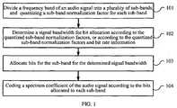
- FIG. 1is a flowchart of an audio signal coding method according to an embodiment of the present invention.
- the followinguses MDCT transform as an example for a detailed description.
- the MDCT transformis performed for an input audio signal to obtain a frequency domain coefficient.
- the MDCT transformmay include processes such as windowing, time domain aliasing, and discrete DCT transform.
- a time domain signal x ( n )is sine-windowed.
- h nsin n + 1 2 ⁇ 2 L
- the frequency domain envelopeis extracted from the MDCT coefficient and quantized.
- the entire frequency bandis divided into multiple sub-bands having different frequency domain resolutions, a normalization factor for each sub-band is extracted, and the sub-band normalization factor is quantized.
- sub-band divisionmay be conducted according to the form shown in Table 1.
- Table 1Grouped sub-band division Group Number of Coefficients Within the Sub-band Number of Sub-bands in the Group Number of Coefficients in the Group.
- BandwidthHz
- Starting Frequency PointHz
- Ending Frequency PointHz
- L pindicates the number of coefficients in a sub-band
- s pindicates a starting point of the sub-band
- e pindicates an ending point of the sub-band
- Pindicates the total number of sub-bands.
- the normalization factormay be quantized in a log domain to obtain a quantized sub-band normalization factor wnorm.
- the signal bandwidth sfm_limit for the bit allocationmay be defined as a part of the bandwidth of the audio signal, for example, a part of the bandwidth 0-sfm_limit at low frequencies or an intermediate part of the bandwidth.
- a ratio factor factmay be determined according to bit rate information, where the ratio factor fact is larger than 0 and smaller than or equal to 1.
- the smaller the bit ratethe smaller the ratio factor.
- fact values corresponding to different bit ratesmay be obtained according to Table 2.
- Table 2Mapping table of the bit rate and the fact value Bit Rate Fact Value 24 kbps 0.8 32 kbps 0.9 48 kbps 0.95 > 64 kbps 1
- the part of the bandwidthis determined according to the ratio factor fact and the quantized sub-band normalization factors wnorm.
- a spectrum energy within each sub-bandmay be obtained according to the quantized sub-band normalization factors, the spectrum energy within each sub-band may be accumulated from low frequencies to high frequencies until the accumulated spectrum energy is larger than the product of a total spectrum energy of all sub-bands multiplied by the ratio factor fact, and a bandwidth below the current sub-band is used as the part of the bandwidth.
- a lowest frequency point for accumulationmay be set first, and a spectrum energy sum energy_low of each sub-band lower than the frequency point may be calculated.
- sub-bandsare added until a total spectrum energy energy_sum of all sub-bands is calculated.
- sub-bandsare accumulated one by one from low frequencies to high frequencies to obtain the spectrum energy energy_limit, and it is determined whether energy_limit > fact x energy_sum is satisfied. If no, more sub-bands need to be accumulated for a higher accumulated spectrum energy. If yes, the current sub-band is used as the last sub-band of the defined part of the bandwidth. A sequence number sfm_limit of the current sub-band is output for representing the defined part of the bandwidth, that is, 0-sfm_limit.
- the ratio factor factis determined by using the bit rate.
- the factmay be determined by using the sub-band normalization factors.
- a harmonic class or a noise level noise_level of the audio signalis first obtained according to the sub-band normalization factors.
- the larger the harmonic class of the audio signalthe lower the noise level.
- the followinguses the noise level as an example for a detailed description.
- the part of the bandwidthmay be implemented in another form, for example, a part of the bandwidth from a non-zero low frequency point to sfm limit.
- the bit allocationmay be performed according to a wnorm value of a sub-band within the determined signal bandwidth.
- the following iteration methodmay be used: a) find the sub-band corresponding to the maximum wnorm value and allocate a certain number of bits; b) correspondingly reduce the wnorm value of the sub-band; c) repeat steps a) to b) until the bits are allocated completely.
- the coding of the coefficientmay use the lattice vector quantization solution, or another existing solution for quantizing the MDCT spectrum coefficient.
- a signal bandwidth for the bit allocationmay be determined according to the quantized sub-band normalization factors and bit rate information. In this manner, the determined signal bandwidth is effectively coded and decoded by centralizing the bits, and audio quality is improved.
- bitsare allocated for the signal bandwidth 0-sfm_limit.
- the bandwidth sfm_limit for the bit allocationis limited so that the selected frequency band is effectively coded by centralizing the bits in the case of a low bit rate and that a more effective bandwidth extension is performed for an uncoded frequency band. This is mainly because if the bit allocation bandwidth is not restricted, a high-frequency harmonic may be allocated with dispersed bits for coding. However, in this case, the distribution of bits at the time axis is not continuous, and consequently the reconstructed high-frequency harmonic is sometimes continuous and sometimes not.
- the dispersed bitsare centralized at the low frequency, enabling a better coding of the low-frequency signal; and bandwidth extension is performed for the high-frequency harmonic by using the low-frequency signal, enabling a more continuous high-frequency harmonic signal.
- the sub-band normalization factor for the sub-band within the bandwidthis firstly adjusted so that a high frequency band is allocated with more bits.
- the adjustment scalingmay be self-adaptive to the bit rate. This considers that if a lower frequency band having larger energy within the bandwidth is allocated with more bits, and the bits required for quantization are sufficient, the sub-band normalization factor may be adjusted to increase bits for quantization of high frequencies within the frequency band. In this manner, more harmonics may be coded, which is beneficial to a bandwidth extension of the higher frequency band.
- the sub-band normalization factor for an intermediate sub-band of the part of the bandwidthis used as the sub-band normalization factor for each sub-band following the intermediate sub-band.
- the normalization factor for the (sfm_limit/2) th sub-bandmay be used as the sub-band normalization factor for each sub-band within the frequency sfm_limit/2-sfm_limit. If sfm_limit/2 is not an integer, it may be rounded up or down. In this case, during the bit allocation, the adjusted sub-band normalization factor may be used.
- classification of frames of the audio signalmay be further considered.
- different coding and decoding policies directing to different classificationsare able to be used, thereby improving coding and decoding quality of different signals.
- the audio signalmay be classified into types such as Noise (noise), Harmonic (harmonic), and Transient (transient).
- a noise-like signalis classified as a Noise mode, with a flat spectrum; a signal changing abruptly in the time domain is classified as a Transient mode, with a flat spectrum; and a signal having a strong harmonic feature is classified as a Harmonic mode, with a greatly changing spectrum and including more information.
- the followinguses the harmonic type and non-harmonic type for a detailed description.
- the method as shown in FIG. 2is performed continuously.
- the signal bandwidth for the bit allocationmay be defined according to the embodiment illustrated in FIG. 1 , that is, defining a signal bandwidth for the bit allocation of the frame as a part of the bandwidth of the frame.
- the signal bandwidth for the bit allocationmay be defined as a part of the bandwidth according to the embodiment illustrated in FIG. 1 , or the signal bandwidth for the bit allocation may not be defined, for example, determining the bit allocation bandwidth of the frame as the whole bandwidth of the frame.
- the frames of the audio signalmay be classified according to a peak-to-average ratio. For example, the peak-to-average ratio of each sub-band among all or part of the (high-frequency sub-bands) sub-bands of the frames is obtained.
- the peak-to-average ratiois calculated from the peak energy of a sub-band divided by the average energy of the sub-band.
- a first thresholdWhen the number of sub-bands, whose peak-to-average ratio is larger than a first threshold, is larger than or equal to a second threshold, it is determined that the frames belong to the harmonic type, when the number of sub-bands, whose peak-to-average ratio is larger than the first threshold, is smaller than the second threshold, it is determined that the frames belong to the non-harmonic type.
- the first threshold and the second thresholdmay be set or changed as required.
- classificationmay be performed according to another parameter.
- the bandwidth sfm_limit for the bit allocationis limited so that the selected frequency band is effectively coded by centralizing the bits in the case of a low bit rate and that a more effective bandwidth extension is performed for an uncoded frequency band. This is mainly because if the bit allocation bandwidth is not restricted, a high-frequency harmonic may be allocated with dispersed bits for coding. However, in this case, the distribution of bits at the time axis is not continuous, and consequently the reconstructed high-frequency harmonic is sometimes continuous and sometimes not.
- the dispersed bitsare centralized at the low frequencies, enabling a better coding of the low-frequency signal; and bandwidth extension is performed for the high-frequency harmonic by using the low-frequency signal, enabling a more continuous high-frequency harmonic signal.
- FIG. 2is a flowchart of an audio signal decoding method.
- the quantized sub-band normalization factorsmay be obtained by decoding a bit stream.
- 202Determine a signal bandwidth for bit allocation according to the quantized sub-band normalization factors, or according to the quantized sub-band normalization factors and bit rate information. 202 is similar to 102 as shown in FIG. 1 , which is therefore not repeatedly described.
- Allocate bits for a sub-band within the determined signal bandwidth. 203is similar to 103 as shown in FIG. 1 , which is therefore not repeatedly described.
- the spectrum coefficient of the audio signalis recovered and obtained by multiplying the normalized spectrum of each sub-band by the sub-band normalization factor for the sub-band.
- a signal bandwidth for the bit allocationis determined according to the quantized sub-band normalization factors and bit rate information. In this manner, the determined signal bandwidth is effectively coded and decoded by centralizing the bits, and audio quality is improved.
- the noise filling and the bandwidth extension described in step 205are not limited in terms of sequence.
- the noise fillingmay be performed before the bandwidth extension; or the bandwidth extension may be performed before the noise filling.
- the bandwidth extensionmay be performed for a part of a frequency band while the noise filling may be performed for the other part of the frequency band simultaneously.
- the bandwidth extensionmay be performed for the normalized spectrum after the noise filling to obtain a normalized full band spectrum.
- a first frequency bandmay be determined according to the bit allocation of a current frame and N frames previous to the current frame, and used as a frequency band to copy (copy).
- Nis a positive integer. It is generally desired that multiple continuous sub-bands having allocated bits are selected as a range of the first frequency band. Then, a spectrum coefficient of a high frequency band is obtained according to a spectrum coefficient of the first frequency band.
- a correlation between a bit allocated for the current frame and bits allocated for the previous N framesmay be obtained, and the first frequency band may be determined according to the obtained correlation.
- the bit allocated to the current frameis R_current
- the bit allocated to a previous frameis R_previous
- correlation R_correlationmay be obtained by multiplying R_current by R_previous.
- a first sub-band meeting R_correlation ⁇ 0is searched from the highest frequency band having allocated bits last_sfm to the lower ones. This indicates that the current frame and its previous frame both have allocated bits. Assume that the sequence number of the sub-band is top_band.
- top_bandmay be used as an upper limit of the first frequency band
- top_band/2may be used as a lower limit of the first frequency band. If the difference between the lower limit of the first frequency band of the previous frame and the lower limit of the first frequency band of the current frame is less than 1 kHz, the lower limit of the first frequency band of the previous frame may be used as the lower limit of the first frequency band of the current frame. This is to ensure continuity of the first frequency band for bandwidth extension and thereby ensure a continuous high frequency spectrum after the bandwidth extension.
- R_current of the current frameis cached and used as R_previous of a next frame. If top_limit/2 is not an integer, it may be rounded up or down.
- the spectrum coefficient of the first frequency band top_band/2-top_bandis copied to the high frequency band last_sfm-high_sfm.
- the foregoingdescribes an example of performing the noise filling first.
- Oneis not limited thereto.
- the bandwidth extensionmay be performed first, and then background noise may be filled on the extended full frequency band.
- the method for noise fillingmay be similar to the foregoing example.
- the filled background noise within the frequency band range last_sfm-high_sfmmay be further adjusted by using the noise_level value estimated by the decoding end.
- noise_levelis obtained by using the decoded sub-band normalization factor, for differentiating the intensity level of the filled noise. Therefore, the coding bits do not need to be transmitted.
- ⁇ norm (k)indicates the decoded normalization factor and noise_CB(k) indicates a noise codebook.
- the bandwidth extensionis performed for a high-frequency harmonic by using a low-frequency signal, enabling the high-frequency harmonic signal to be more continuous, and thereby ensuring the audio quality.
- the foregoingdescribes an example of directly copying the spectrum coefficient of the first frequency band.
- the spectrum coefficient of the first frequency bandwidthmay be adjusted first, and the bandwidth extension is performed by using the adjusted spectrum coefficient to further enhance the performance of the high frequency band.
- a normalization lengthmay be obtained according to spectrum flatness information and a high frequency band signal type, the spectrum coefficient of the first frequency band is normalized according to the obtained normalization length, and the normalized spectrum coefficient of the first frequency band is used as the spectrum coefficient of the high frequency band.
- the spectrum flatness informationmay include: a peak-to-average ratio of each sub-band in the first frequency band, a correlation of time domain signals corresponding to the first frequency band, or a zero-crossing rate of time domain signals corresponding to the first frequency band.
- the followinguses the peak-to-average ratio as an example for a detailed description. However, other flatness information may also be used for adjustment.
- the peak-to-average ratiois calculated from the peak energy of a sub-band divided by the average energy of the sub-band.
- the peak-to-average ratio of each sub-band of the first frequency bandis calculated according to the spectrum coefficient of the first frequency band, it is determined whether the sub-band is a harmonic sub-band according to the value of the peak-to-average ratio and the maximum peak value within the sub-band, the number n_band of harmonic sub-bands is accumulated, and finally a normalization length length_norm_harm is determined self-adaptively according to n_band and a signal type of the high frequency band.
- length_norm_harm⁇ ⁇ * 1 + n_band M ⁇ , where M indicates the number of sub-bands of the first frequency band; ⁇ indicates the self-adaptive signal type; in the case of a harmonic signal, ⁇ > 1.
- the spectrum coefficient of the first frequency bandmay be normalized by using the obtained normalization length, and the normalized spectrum coefficient of the first frequency band is used as the coefficient of the high frequency band.
- classification of frames of the audio signalmay also be further considered at the decoding end.
- different coding and decoding policies directing to different classificationsare able to be used, thereby improving coding and decoding quality of different signals.
- the method for classification of frames of the audio signalrefer to that of the coding end, which is not detailed here.
- Classification information indicating a frame typemay be extracted from the bit stream.
- the signal bandwidth for the bit allocationmay be defined according to the embodiment illustrated in FIG. 2 , that is, defining a signal bandwidth for the bit allocation of the frame as a part of the bandwidth of the frame.
- the signal bandwidth for the bit allocationmay be defined as a part of the bandwidth according to the embodiment illustrated in FIG. 2 , or, according to the prior art, the signal bandwidth for the bit allocation may not be defined, for example, determining the bit allocation bandwidth of the frame as the whole bandwidth of the frame.
- the reconstructed time domain audio signalmay be obtained by using frequency inverse transform. Therefore, the harmonic signal quality is able to be improved while the non-harmonic signal quality is maintained.
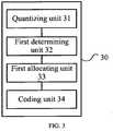
- FIG. 3is a block diagram of an audio signal coding device according to an embodiment of the present invention.
- an audio signal coding device 30includes a quantizing unit 31, a first determining unit 32, a first allocating unit 33, and a coding unit 34.
- the quantizing unit 31divides a frequency band of an audio signal into a plurality of sub-bands, and quantizes a sub-band normalization factor for each sub-band.
- the first determining unit 32determines a signal bandwidth for bit allocation according to the sub-band normalization factors quantized by the quantizing unit 31, or according to the quantized sub-band normalization factors and bit rate information.
- the first allocating unit 33allocates bits for a sub-band within the signal bandwidth determined by the first determining unit 32.
- the coding unit 34codes a spectrum coefficient of the audio signal according to the bits allocated by the first allocating unit 33 for each sub-band for which bits have been allocated.
- a signal bandwidth for the bit allocationis determined according to the quantized sub-band normalization factors, or according to the quantized sub-band normalisation factors and bit rate information. In this manner, the determined signal bandwidth is effectively coded by centralizing the bits, and audio quality is improved.
- FIG. 4is a block diagram of an audio signal coding device according to preferred embodiment of the present invention.
- the audio signal coding device 40 as shown in FIG. 4units or elements similar to those as shown in FIG. 3 are denoted by the same reference numerals.
- the first determining unit 32When determining the signal bandwidth for the bit allocation, the first determining unit 32 defines the signal bandwidth for the bit allocation as a part of the bandwidth of the audio signal. A as shown in FIG. 4 , the first determining unit 32 includes first ratio factor determining module 321. The first ratio factor determining module 321 is configured to determine a ratio factor fact according to the bit rate information, where the ratio factor fact is larger than 0 and smaller than or equal to 1. Alternatively, the first determining unit 32 may include a second ratio factor determining module 322 for replacing the first ratio factor determining module 321. The second ratio factor determining module 322 obtains a harmonic class or a noise level of the audio signal according to the sub-band normalization factor, and determines a ratio factor fact according to the harmonic class and the noise level.
- the first determining unit 32further includes a first bandwidth determining module 323. After obtaining the ratio factor fact, the first bandwidth determining module 323 determines the part of the bandwidth according to the ratio factor fact and the quantized sub-band normalization factors.
- the first bandwidth determining module 323, when determining the part of the bandwidthmay obtain a spectrum energy within each sub-band according to the quantized sub-band normalization factors, accumulate the spectrum energy within each sub-band from low frequencies to high frequencies until the accumulated spectrum energy is larger than the product of a total spectrum energy of all sub-bands multiplied by the ratio factor fact, and use a bandwidth below the current sub-band as the part of the bandwidth.
- the audio signal coding device 40may further include a classifying unit 35, configured to classify frames of the audio signal.
- the classifying unit 35may determine whether the frames of the audio signal belong to a harmonic type or a non-harmonic type; and if the frames of the audio signal belong to the harmonic type, trigger the quantizing unit 31.
- the type of the framesmay be determined according to a peak-to-average ratio.
- the classifying unit 35obtains a peak-to-average radio of each sub-band among all or part of sub-bands of the frames; when the number of sub-bands, whose peak-to-average ratio is larger than a first threshold, is larger than or equal to a second threshold, determines that the frames belong to the harmonic type; and when the number of sub-bands, whose peak-to-average ratio is larger than the first threshold, is smaller than the second threshold, determines that the frames belong to the non-harmonic type.
- the first determining unit 32regarding the frames belonging to the harmonic type, defines the signal bandwidth for the bit allocation as a part of the bandwidth of the frames.
- the first allocating unit 33may include a sub-band normalization factor adjusting module 331 and a bit allocating module 332.
- the sub-band normalization factor adjusting module 331adjusts the sub-band normalization factor for the sub-band within the determined signal bandwidth.
- the bit allocating module 332allocates the bits according to the adjusted sub-band normalization factor.
- the first allocating unit 33may use the sub-band normalization factor for an intermediate sub-band of the part of the bandwidth as a sub-band normalization factor for each sub-band following the intermediate sub-band.
- a signal bandwidth for the bit allocationis determined according to the quantized sub-band normalization factors, or according to the quantized sub-band normalization factors and bit rate information. In this manner, the determined signal bandwidth is effectively coded and decoded by centralizing the bits, and audio quality is improved.
- FIG. 5is a block diagram of an audio signal decoding device.
- the audio signal decoding device 50 as shown in FIG. 5includes an obtaining unit 51, a second determining unit 52, a second allocating unit 53, a decoding unit 54, an extending unit 55, and a recovering unit 56.
- the obtaining unit 51obtains quantized sub-band normalization factors.
- the second determining unit 52determines a signal bandwidth for bit allocation according to the quantized sub-band normalization factors obtained by the obtaining unit 51, or according to the quantized sub-band normalization factors and bit rate information.
- the second allocating unit 53allocates bits for a sub-band within the signal bandwidth determined by the second determining unit 52.
- the decoding unit 54decodes a normalized spectrum according to the bits allocated by the second allocating unit 53 for each sub-band.
- the extending unit 55performs noise filling and bandwidth extension for the normalized spectrum decoded by the decoding unit 54 to obtain a normalized full band spectrum.
- the recovering unit 56obtains a spectrum coefficient of an audio signal according to the normalized full band spectrum obtained by the extending unit 55 and the sub-band normalization factors. According to the above, during decoding, a signal bandwidth for the bit allocation is determined according to the quantized sub-band normalization factors and bit rate information. In this manner, the determined signal bandwidth is effectively decoded by centralizing the bits, and audio quality is improved.
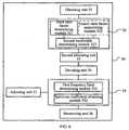
- FIG. 6is a block diagram of another audio signal decoding device.
- the audio signal decoding device 60 as shown in FIG. 6units or elements similar to those as shown in FIG. 5 are denoted by the same reference numerals.
- a second determining unit 52 of the audio signal decoding device 60may define a signal bandwidth for bit allocationas a part of the bandwidth of an audio signal.
- the second determining unit 52may include a third ratio factor determining unit 521, configured to determine a ratio factor fact according to the bit rate information, where the ratio factor fact is larger than 0 and smaller than or equal to 1.
- the second determining unit 52may include a fourth ratio factor determining unit 522, configured to obtain a harmonic class or a noise level of the audio signal according to the sub-band normalization factors, and determine a ratio factor fact according to the harmonic class and the noise level.
- the second determining unit 52further includes a second bandwidth determining module 523.
- the second bandwidth determining module 523may determine the part of the bandwidth according to the ratio factor fact and the quantized sub-band normalization factor.
- the second bandwidth determining module 523when determining the part of the bandwidth, obtains a spectrum energy within each sub-band according to the quantized sub-band normalization factors, accumulates the spectrum energy within each sub-band from low frequencies to high frequencies until the accumulated spectrum energy is larger than the product of a total spectrum energy of all sub-bands multiplied by the ratio factor fact, and uses a bandwidth below the current sub-band as the part of the bandwidth.
- the extending unit 55may further include a first frequency band determining module 551 and a spectrum coefficient obtaining module 552.
- the first frequency band determining module 551determines a first frequency band according to the bit allocation of a current frame and N frames previous to the current frame, where N is a positive integer.
- the spectrum coefficient obtaining module 552obtains a spectrum coefficient of a high frequency band according to a spectrum coefficient of the first frequency band. For example, when determining the first frequency band, the first frequency band determining module 551 may obtain a correlation between a bit allocated for the current frame and the bits allocated for the previous N frames, and determine the first frequency band according to the obtained correlation.
- the audio signal decoding device 60may further include an adjusting unit 57, configured to obtain a noise level according to the sub-band normalization factors and adjust background noise within the high frequency band by using the obtained noise level.
- the spectrum coefficient obtaining module 552may obtain a normalization length according to spectrum flatness information and a high frequency band signal type, normalize the spectrum coefficient of the first frequency band according to the obtained normalization length, and use normalized spectrum coefficient of the first frequency band as the spectrum coefficient of the high frequency band.
- the spectrum flatness informationmay include: a peak-to-average ratio of each sub-band in the first frequency band, a correlation of time domain signals corresponding to the first frequency band, or a zero-crossing rate of time domain signals corresponding to the first frequency band.
- a signal bandwidth for the bit allocationis determined according to the quantized sub-band normalization factors and bit rate information. In this manner, the determined signal bandwidth is effectively decoded by centralizing the bits, and audio quality is improved.
- a coding and decoding systemmay include an audio signal coding device and an audio signal decoding device as described above.
- the disclosed system, apparatus, and device, and methodmay also be implemented in other manners.
- the apparatusare merely exemplary ones.
- the unitsare divided only by the logic function. In practical implementation, other division manners may also be used.
- a plurality of units or elementsmay be combined or may be integrated into a system, or some features may be ignored or not implemented.
- the illustrated or described inter-coupling, direct coupling, or communicatively connectionmay be implemented using some interfaces, apparatuses, or units in electronic or mechanical mode, or other manners.
- the units used as separate componentsmay be or may not be physically independent of each other.
- the element illustrated as a unitmay be or may not be a physical unit, that is be either located at a position or deployed on a plurality of network units. Part of or all of the units may be selected as required to implement the technical solutions disclosed in the embodiments of the present invention
- various function units in embodiments of the present inventionmay be integrated in a processing unit, or physical independent units; or two or more than two function units may be integrated into a unit.
- the functionsare implemented in the form of software functional units and functions as an independent product for sale or use, it may also be stored in a computer readable storage medium.
- the software productmay be stored in a storage medium.
- the software productincludes a number of instructions that enable a computer device (a PC, a server, or a network device) to execute the methods provided in the embodiments of the present invention or part of the steps.
- the storage mediuminclude various mediums capable of storing program code, for example, read only memory (ROM), random access memory (RAM), magnetic disk, or compact disc-read only memory (CD-ROM).
Landscapes
- Engineering & Computer Science (AREA)
- Physics & Mathematics (AREA)
- Computational Linguistics (AREA)
- Signal Processing (AREA)
- Health & Medical Sciences (AREA)
- Audiology, Speech & Language Pathology (AREA)
- Human Computer Interaction (AREA)
- Acoustics & Sound (AREA)
- Multimedia (AREA)
- Spectroscopy & Molecular Physics (AREA)
- Mathematical Physics (AREA)
- Compression, Expansion, Code Conversion, And Decoders (AREA)
Description
- The present invention relates to the field of audio signal coding and decoding technologies, and in particular, to an audio signal coding method and device.
- At present, communication transmission has been placing more and more importance on quality of audio. Therefore, it is required that music quality is improved as much as possible during coding and decoding while ensuring the voice quality. Music signals usually carry much more abundant information, so a traditional voice CELP (Code Excited Linear Prediction, code excited linear prediction) coding mode is not suitable for coding the music signals. Generally, a transform coding mode is used to process the music signals in a frequency domain to improve the coding quality of the music signals. However, it is a hot topic for research in the field of current audio coding on how to effectively use the limited coding bits to efficiently code information.
- The current audio coding technology generally uses FFT (Fast Fourier Transform, fast Fourier transform) or MDCT (Modified Discrete Cosine Transform, modified discrete cosine transform) to transform time domain signals to the frequency domain, and then code the frequency domain signals. A limited number of bits for quantization used in the case of a low bit rate does not fulfill the requirements for quantizing all audio signals. Therefore, generally the BWE (Bandwidth Extension, bandwidth extension) technology and the spectrum overlay technology may be used.
- At the coding end, first input time domain signals are transformed to the frequency domain, and a sub-band normalization factor, that is, envelope information of a spectrum, is extracted from the frequency domain. The spectrum is normalized by using the quantized sub-band normalization factors to obtain the normalized spectrum information. Finally, bit allocation for each sub-band is determined, and the normalized spectrum is quantized. In this manner, the audio signals are coded into quantized envelope information and normalized spectrum information, and then bit streams are output.
- The process at a decoding end is inverse to that at a coding end. During low-rate coding, the coding end is incapable of coding all frequency bands; and at the decoding end, the bandwidth extension technology is required to recover frequency bands that are not coded at the coding end. Meanwhile, a lot of zero frequency points may be produced on the coded sub-band due to the limitation of a quantizer, so a noise filling module is needed to improve the performance. Finally, the decoded sub-band normalization factors are applied to a decoded normalization spectrum coefficient to obtain a reconstructed spectrum coefficient, and an inverse transform is performed to output time domain audio signals.
- However, during the coding process, high-frequency harmonics may be allocated with some dispersed bits for coding. However, in this case, the distribution of bits at the time axis is not continuous, and consequently high-frequency harmonics reconstructed during decoding are sometimes continuous and sometimes not. This produces much noise, causing a poor quality of the reconstructed audio.
WO 2009/029037 A1 discloses a method for spectrum recovery in spectral decoding of an audio signal. The method comprises: obtaining of an initial set of spectral coefficients representing the audio signal, and determining a transition frequency. The transition frequency is adapted to a spectral content of the audio signal. Spectral holes in the initial set of spectral coefficients below the transition frequency are noise filled and the initial set of spectral coefficients are bandwidth extended above the transition frequency.WO 2009/029035 A1 discloses a method of perceptual transform coding of audio signals in a telecommunication system. The method comprises: performing the steps of determining transform coefficients representative of a time to frequency transformation of a time segmented input audio signal; determining a spectrum of perceptual sub-bands for said input audio signal based on said determined transform coefficients; determining masking thresholds for each said sub-band based on said determined spectrum; computing scale factors for each said sub-band based on said determined masking thresholds, and finally adapting said computed scale factors for each said sub-band to prevent energy loss for perceptually relevant sub-bands.US 2002/0103637 A1 discloses digital audio coding systems that employ high frequency reconstruction (HFR) methods. It teaches how to improve the overall performance of such systems, by means of an adaption over time of the crossover frequency between the lowband coded by a core codec, and the highband coded by an HFR system.US 2002/0103637 A1 also discloses different methods of establishing the instantaneous optimum choice of crossover frequency.WO 2010/003618 A2 discloses an audio encoder , which comprises a window function controller, a windower, a time warper with a final quality check functionality, a time/frequency converter, a temporal noise shaping (TNS) stage or a quantizer encoder. The window function controller, the time warper, the TNS stage or an additional noise filling analyzer are controlled by signal analysis results obtained by a time warp analyzer or a signal classifier. Furthermore, a decoder applies a noise filling operation using a manipulated noise filling estimate depending on a harmonic or speech characteristic of the audio signal.- The present invention provides an audio signal coding method according to claim 1 and device according to claim 5, which are capable of improving audio quality.
- According to the present invention, during coding, a signal bandwidth for bit allocation is determined according to the quantized sub-band normalization factors, or according to the quantized sub-band normalisation factors and bit rate information. In this manner, the determined signal bandwidth is effectively coded by centralizing the bits, and audio quality is improved.
- To make the technical solutions of the present invention clearer, the accompanying drawings for illustrating various embodiments of the present invention are briefly described below.
FIG. 1 is a flowchart of an audio signal coding method according to an embodiment of the present invention;FIG. 2 is a flowchart of an audio signal decoding method ;FIG. 3 is a block diagram of an audio signal coding device according to an embodiment of the present invention;FIG. 4 is a block diagram of an audio signal coding device according to preferred embodiment of the present invention;FIG. 5 is a block diagram of an audio signal decoding device; andFIG. 6 is a block diagram of another audio signal decoding device.- The technical solutions disclosed in embodiments of the present invention are described below with reference to embodiments and accompanying drawings.
FIG. 1 is a flowchart of an audio signal coding method according to an embodiment of the present invention.- 101. Divide a frequency band of an audio signal into a plurality of sub-bands, and quantize a sub-band normalization factor for each sub-band.
- The following uses MDCT transform as an example for a detailed description. First, the MDCT transform is performed for an input audio signal to obtain a frequency domain coefficient. The MDCT transform may include processes such as windowing, time domain aliasing, and discrete DCT transform.
- For example, a time domain signalx(n) is sine-windowed.

- The obtained windowed signal is:

- Then an time domain aliasing operation is performed:

- IL/2 and JL/2 respectively indicate two diagonal matrices with an order ofL/2:

- Discrete DCT transform is performed for the time domain aliased signal to finally obtain an MDCT coefficient of the frequency domain:

- The frequency domain envelope is extracted from the MDCT coefficient and quantized. The entire frequency band is divided into multiple sub-bands having different frequency domain resolutions, a normalization factor for each sub-band is extracted, and the sub-band normalization factor is quantized.
- For example, regarding an audio signal sampled at a frequency of 32 kHz corresponding to a frequency band having a 16 kHz bandwidth, if the frame length is 20 ms (640 sampling points), sub-band division may be conducted according to the form shown in Table 1.
Table 1 Grouped sub-band division Group Number of Coefficients Within the Sub-band Number of Sub-bands in the Group Number of Coefficients in the Group. Bandwidth (Hz) Starting Frequency Point (Hz) Ending Frequency Point (Hz) I 8 16 128 3200 0 3200 II 16 8 128 3200 3200 6400 III 24 12 288 7200 6400 13600 ... ... ... ... ... ... ... - First, the sub-bands are grouped in several groups, and then sub-bands in a group are finally divided. The normalization factor for each sub-band is defined as:

- Lp indicates the number of coefficients in a sub-band,sp indicates a starting point of the sub-band,ep indicates an ending point of the sub-band, andP indicates the total number of sub-bands.
- After the normalization factor is obtained, the normalization factor may be quantized in a log domain to obtain a quantized sub-band normalization factor wnorm.
- 102. Determine a signal bandwidth for bit allocation according to the quantized sub-band normalization factors, or according to the quantized sub-band normalization factors and bit rate information.
- Optionally, in an embodiment, the signal bandwidth sfm_limit for the bit allocation may be defined as a part of the bandwidth of the audio signal, for example, a part of the bandwidth 0-sfm_limit at low frequencies or an intermediate part of the bandwidth.
- In an example, when defining the signal bandwidth sfm_limit for the bit allocation, a ratio factor fact may be determined according to bit rate information, where the ratio factor fact is larger than 0 and smaller than or equal to 1. In an embodiment, the smaller the bit rate, the smaller the ratio factor. For example, fact values corresponding to different bit rates may be obtained according to Table 2.
Table 2 Mapping table of the bit rate and the fact value Bit Rate Fact Value 24 kbps 0.8 32 kbps 0.9 48 kbps 0.95 > 64 kbps 1 - Alternatively, fact may also be obtained according to an equation, for example, fact = q x (0.5 + bitrate_value/128000), where bitrate_value indicates a value of the bit rate, for example, 24000, and q indicates a correction factor. For example, it may be assumed that q = 1. This embodiment of the present invention is not limited to such specific value examples.
- The part of the bandwidth is determined according to the ratio factor fact and the quantized sub-band normalization factors wnorm. A spectrum energy within each sub-band may be obtained according to the quantized sub-band normalization factors, the spectrum energy within each sub-band may be accumulated from low frequencies to high frequencies until the accumulated spectrum energy is larger than the product of a total spectrum energy of all sub-bands multiplied by the ratio factor fact, and a bandwidth below the current sub-band is used as the part of the bandwidth.
- For example, a lowest frequency point for accumulation may be set first, and a spectrum energy sum energy_low of each sub-band lower than the frequency point may be calculated. The spectrum energy may be obtained according to the sub-band normalization factors and the following equation:

- Accordingly, sub-bands are added until a total spectrum energy energy_sum of all sub-bands is calculated.
- Based on energy_low, sub-bands are accumulated one by one from low frequencies to high frequencies to obtain the spectrum energy energy_limit, and it is determined whether energy_limit > fact x energy_sum is satisfied. If no, more sub-bands need to be accumulated for a higher accumulated spectrum energy. If yes, the current sub-band is used as the last sub-band of the defined part of the bandwidth. A sequence number sfm_limit of the current sub-band is output for representing the defined part of the bandwidth, that is, 0-sfm_limit.
- In the foregoing example, the ratio factor fact is determined by using the bit rate. In another example, the fact may be determined by using the sub-band normalization factors. For example, a harmonic class or a noise level noise_level of the audio signal is first obtained according to the sub-band normalization factors. Generally, the larger the harmonic class of the audio signal, the lower the noise level. The following uses the noise level as an example for a detailed description. The noise level noise_level may be obtained according to the following equation:

- When noise_level is high, fact is large; when noise_level is low, fact is small. If the harmonic class is used as a parameter, when the harmonic class is large, fact is small; when the harmonic class is small, fact is large.
- It should be noted that although the foregoing uses the low-frequency bandwidth of 0-sfm_limit, this embodiment of the present invention is not limited to this. As required, the part of the bandwidth may be implemented in another form, for example, a part of the bandwidth from a non-zero low frequency point to sfm limit.
- 103. Allocate bits for a sub-band within the determined signal bandwidth.
- The bit allocation may be performed according to a wnorm value of a sub-band within the determined signal bandwidth. The following iteration method may be used: a) find the sub-band corresponding to the maximum wnorm value and allocate a certain number of bits; b) correspondingly reduce the wnorm value of the sub-band; c) repeat steps a) to b) until the bits are allocated completely.
- 104. Code a spectrum coefficient of the audio signal according to the bits allocated for each sub-band.
- For example, the coding of the coefficient may use the lattice vector quantization solution, or another existing solution for quantizing the MDCT spectrum coefficient.
- During coding and decoding, a signal bandwidth for the bit allocation may be determined according to the quantized sub-band normalization factors and bit rate information. In this manner, the determined signal bandwidth is effectively coded and decoded by centralizing the bits, and audio quality is improved.
- For example, when the determined signal bandwidth is 0-sfm_limit of the low frequency part, bits are allocated for the signal bandwidth 0-sfm_limit. The bandwidth sfm_limit for the bit allocation is limited so that the selected frequency band is effectively coded by centralizing the bits in the case of a low bit rate and that a more effective bandwidth extension is performed for an uncoded frequency band. This is mainly because if the bit allocation bandwidth is not restricted, a high-frequency harmonic may be allocated with dispersed bits for coding. However, in this case, the distribution of bits at the time axis is not continuous, and consequently the reconstructed high-frequency harmonic is sometimes continuous and sometimes not. If the bit allocation bandwidth is restricted, the dispersed bits are centralized at the low frequency, enabling a better coding of the low-frequency signal; and bandwidth extension is performed for the high-frequency harmonic by using the low-frequency signal, enabling a more continuous high-frequency harmonic signal.
- Optionally, in 103 as shown in
FIG. 1 , during the bit allocation after the signal bandwidth sfm_limit for the bit allocation is determined, the sub-band normalization factor for the sub-band within the bandwidth is firstly adjusted so that a high frequency band is allocated with more bits. The adjustment scaling may be self-adaptive to the bit rate. This considers that if a lower frequency band having larger energy within the bandwidth is allocated with more bits, and the bits required for quantization are sufficient, the sub-band normalization factor may be adjusted to increase bits for quantization of high frequencies within the frequency band. In this manner, more harmonics may be coded, which is beneficial to a bandwidth extension of the higher frequency band. For example, the sub-band normalization factor for an intermediate sub-band of the part of the bandwidth is used as the sub-band normalization factor for each sub-band following the intermediate sub-band. To be specific, the normalization factor for the (sfm_limit/2)th sub-band may be used as the sub-band normalization factor for each sub-band within the frequency sfm_limit/2-sfm_limit. If sfm_limit/2 is not an integer, it may be rounded up or down. In this case, during the bit allocation, the adjusted sub-band normalization factor may be used. - In application of the coding method provided in the embodiment of the present invention, classification of frames of the audio signal may be further considered. In this case, different coding and decoding policies directing to different classifications are able to be used, thereby improving coding and decoding quality of different signals. For example, the audio signal may be classified into types such as Noise (noise), Harmonic (harmonic), and Transient (transient). Generally, a noise-like signal is classified as a Noise mode, with a flat spectrum; a signal changing abruptly in the time domain is classified as a Transient mode, with a flat spectrum; and a signal having a strong harmonic feature is classified as a Harmonic mode, with a greatly changing spectrum and including more information.
- The following uses the harmonic type and non-harmonic type for a detailed description. According to this preferred embodiment of the present invention, before 101 as shown in
FIG. 1 , it is determined whether frames of the audio signal belong to the harmonic type or non-harmonic type. If the frames of the audio signal belong to the harmonic type, the method as shown inFIG. 2 is performed continuously. Specifically, regarding a frame of the harmonic type, the signal bandwidth for the bit allocation may be defined according to the embodiment illustrated inFIG. 1 , that is, defining a signal bandwidth for the bit allocation of the frame as a part of the bandwidth of the frame. Regarding a frame of the non-harmonic type, the signal bandwidth for the bit allocation may be defined as a part of the bandwidth according to the embodiment illustrated inFIG. 1 , or the signal bandwidth for the bit allocation may not be defined, for example, determining the bit allocation bandwidth of the frame as the whole bandwidth of the frame. - The frames of the audio signal may be classified according to a peak-to-average ratio. For example, the peak-to-average ratio of each sub-band among all or part of the (high-frequency sub-bands) sub-bands of the frames is obtained. The peak-to-average ratio is calculated from the peak energy of a sub-band divided by the average energy of the sub-band. When the number of sub-bands, whose peak-to-average ratio is larger than a first threshold, is larger than or equal to a second threshold, it is determined that the frames belong to the harmonic type, when the number of sub-bands, whose peak-to-average ratio is larger than the first threshold, is smaller than the second threshold, it is determined that the frames belong to the non-harmonic type. The first threshold and the second threshold may be set or changed as required.
- However, one is not limited to the example of classification according to the peak-to-average ratio, and classification may be performed according to another parameter.
- The bandwidth sfm_limit for the bit allocation is limited so that the selected frequency band is effectively coded by centralizing the bits in the case of a low bit rate and that a more effective bandwidth extension is performed for an uncoded frequency band. This is mainly because if the bit allocation bandwidth is not restricted, a high-frequency harmonic may be allocated with dispersed bits for coding. However, in this case, the distribution of bits at the time axis is not continuous, and consequently the reconstructed high-frequency harmonic is sometimes continuous and sometimes not. If the bit allocation bandwidth is restricted, the dispersed bits are centralized at the low frequencies, enabling a better coding of the low-frequency signal; and bandwidth extension is performed for the high-frequency harmonic by using the low-frequency signal, enabling a more continuous high-frequency harmonic signal.
- The foregoing describes the processing at the coding end, which is an inverse processing for the decoding end.
FIG. 2 is a flowchart of an audio signal decoding method. - 201. Obtain quantized sub-band normalization factors.
- The quantized sub-band normalization factors may be obtained by decoding a bit stream.
- 202. Determine a signal bandwidth for bit allocation according to the quantized sub-band normalization factors, or according to the quantized sub-band normalization factors and bit rate information. 202 is similar to 102 as shown in
FIG. 1 , which is therefore not repeatedly described. - 203. Allocate bits for a sub-band within the determined signal bandwidth. 203 is similar to 103 as shown in
FIG. 1 , which is therefore not repeatedly described. - 204. Decode a normalized spectrum according to the bits allocated for each sub-band.
- 205. Perform noise filling and bandwidth extension for the decoded normalized spectrum to obtain a normalized full band spectrum.
- 206. Obtain a spectrum coefficient of an audio signal according to the normalized full band spectrum and the sub-band normalization factors.
- For example, the spectrum coefficient of the audio signal is recovered and obtained by multiplying the normalized spectrum of each sub-band by the sub-band normalization factor for the sub-band.
- According to this method, during coding and decoding, a signal bandwidth for the bit allocation is determined according to the quantized sub-band normalization factors and bit rate information. In this manner, the determined signal bandwidth is effectively coded and decoded by centralizing the bits, and audio quality is improved.
- The noise filling and the bandwidth extension described in
step 205 are not limited in terms of sequence. To be specific, the noise filling may be performed before the bandwidth extension; or the bandwidth extension may be performed before the noise filling. In addition, the bandwidth extension may be performed for a part of a frequency band while the noise filling may be performed for the other part of the frequency band simultaneously. - Many zero frequency points may be produced due to the limitation of the quantizer during sub-band coding. Generally, some noise may be filled to ensure that the reconstructed audio signal sounds more natural.
- If the noise filling is performed first, the bandwidth extension may be performed for the normalized spectrum after the noise filling to obtain a normalized full band spectrum. For example, a first frequency band may be determined according to the bit allocation of a current frame and N frames previous to the current frame, and used as a frequency band to copy (copy). N is a positive integer. It is generally desired that multiple continuous sub-bands having allocated bits are selected as a range of the first frequency band. Then, a spectrum coefficient of a high frequency band is obtained according to a spectrum coefficient of the first frequency band.
- Using the case where N = 1 as an example, optionally, in an embodiment, a correlation between a bit allocated for the current frame and bits allocated for the previous N frames may be obtained, and the first frequency band may be determined according to the obtained correlation. For example, assume that the bit allocated to the current frame is R_current, the bit allocated to a previous frame is R_previous, and correlation R_correlation may be obtained by multiplying R_current by R_previous.
- After the correlation is obtained, a first sub-band meeting R_correlation ≠ 0 is searched from the highest frequency band having allocated bits last_sfm to the lower ones. This indicates that the current frame and its previous frame both have allocated bits. Assume that the sequence number of the sub-band is top_band.
- The obtained top_band may be used as an upper limit of the first frequency band, top_band/2 may be used as a lower limit of the first frequency band. If the difference between the lower limit of the first frequency band of the previous frame and the lower limit of the first frequency band of the current frame is less than 1 kHz, the lower limit of the first frequency band of the previous frame may be used as the lower limit of the first frequency band of the current frame. This is to ensure continuity of the first frequency band for bandwidth extension and thereby ensure a continuous high frequency spectrum after the bandwidth extension. R_current of the current frame is cached and used as R_previous of a next frame. If top_limit/2 is not an integer, it may be rounded up or down.
- During bandwidth extension, the spectrum coefficient of the first frequency band top_band/2-top_band is copied to the high frequency band last_sfm-high_sfm.
- The foregoing describes an example of performing the noise filling first. One is not limited thereto. To be specific, the bandwidth extension may be performed first, and then background noise may be filled on the extended full frequency band. The method for noise filling may be similar to the foregoing example.
- In addition, regarding the high frequency band, for example, the foregoing-described range of last_sfm-high_sfm, the filled background noise within the frequency band range last_sfm-high_sfm may be further adjusted by using the noise_level value estimated by the decoding end. For the method for calculating noise_level, refer to equation (8). noise_level is obtained by using the decoded sub-band normalization factor, for differentiating the intensity level of the filled noise. Therefore, the coding bits do not need to be transmitted.
- The background noise within the high frequency band may be adjusted by using the obtained noise level according to the following method:

- ŷnorm (k) indicates the decoded normalization factor andnoise_CB(k) indicates a noise codebook.
- In this manner, the bandwidth extension is performed for a high-frequency harmonic by using a low-frequency signal, enabling the high-frequency harmonic signal to be more continuous, and thereby ensuring the audio quality.
- The foregoing describes an example of directly copying the spectrum coefficient of the first frequency band. The spectrum coefficient of the first frequency bandwidth may be adjusted first, and the bandwidth extension is performed by using the adjusted spectrum coefficient to further enhance the performance of the high frequency band.
- A normalization length may be obtained according to spectrum flatness information and a high frequency band signal type, the spectrum coefficient of the first frequency band is normalized according to the obtained normalization length, and the normalized spectrum coefficient of the first frequency band is used as the spectrum coefficient of the high frequency band.
- The spectrum flatness information may include: a peak-to-average ratio of each sub-band in the first frequency band, a correlation of time domain signals corresponding to the first frequency band, or a zero-crossing rate of time domain signals corresponding to the first frequency band. The following uses the peak-to-average ratio as an example for a detailed description. However, other flatness information may also be used for adjustment. The peak-to-average ratio is calculated from the peak energy of a sub-band divided by the average energy of the sub-band.
- Firstly, the peak-to-average ratio of each sub-band of the first frequency band is calculated according to the spectrum coefficient of the first frequency band, it is determined whether the sub-band is a harmonic sub-band according to the value of the peak-to-average ratio and the maximum peak value within the sub-band, the number n_band of harmonic sub-bands is accumulated, and finally a normalization length length_norm_harm is determined self-adaptively according to n_band and a signal type of the high frequency band.

- Subsequently, the spectrum coefficient of the first frequency band may be normalized by using the obtained normalization length, and the normalized spectrum coefficient of the first frequency band is used as the coefficient of the high frequency band.
- The foregoing describes an example of improving bandwidth extension performance, and other algorithms capable of improving the bandwidth extension performance may also be applied.
- In addition, similar to the coding end, classification of frames of the audio signal may also be further considered at the decoding end. In this case, different coding and decoding policies directing to different classifications are able to be used, thereby improving coding and decoding quality of different signals. For the method for classification of frames of the audio signal, refer to that of the coding end, which is not detailed here.
- Classification information indicating a frame type may be extracted from the bit stream. Regarding a frame of the harmonic type, the signal bandwidth for the bit allocation may be defined according to the embodiment illustrated in
FIG. 2 , that is, defining a signal bandwidth for the bit allocation of the frame as a part of the bandwidth of the frame. Regarding a frame of the non-harmonic type, the signal bandwidth for the bit allocation may be defined as a part of the bandwidth according to the embodiment illustrated inFIG. 2 , or, according to the prior art, the signal bandwidth for the bit allocation may not be defined, for example, determining the bit allocation bandwidth of the frame as the whole bandwidth of the frame. - After the spectrum coefficients of the entire frequency band are obtained, the reconstructed time domain audio signal may be obtained by using frequency inverse transform. Therefore, the harmonic signal quality is able to be improved while the non-harmonic signal quality is maintained.
FIG. 3 is a block diagram of an audio signal coding device according to an embodiment of the present invention. Referring toFIG. 3 , an audiosignal coding device 30 includes a quantizingunit 31, a first determiningunit 32, a first allocatingunit 33, and acoding unit 34.- The quantizing
unit 31 divides a frequency band of an audio signal into a plurality of sub-bands, and quantizes a sub-band normalization factor for each sub-band. The first determiningunit 32 determines a signal bandwidth for bit allocation according to the sub-band normalization factors quantized by the quantizingunit 31, or according to the quantized sub-band normalization factors and bit rate information. The first allocatingunit 33 allocates bits for a sub-band within the signal bandwidth determined by the first determiningunit 32. Thecoding unit 34 codes a spectrum coefficient of the audio signal according to the bits allocated by the first allocatingunit 33 for each sub-band for which bits have been allocated. - According to this embodiment of the present invention, during coding, a signal bandwidth for the bit allocation is determined according to the quantized sub-band normalization factors, or according to the quantized sub-band normalisation factors and bit rate information. In this manner, the determined signal bandwidth is effectively coded by centralizing the bits, and audio quality is improved.
FIG. 4 is a block diagram of an audio signal coding device according to preferred embodiment of the present invention. In the audiosignal coding device 40 as shown inFIG. 4 , units or elements similar to those as shown inFIG. 3 are denoted by the same reference numerals.- When determining the signal bandwidth for the bit allocation, the first determining
unit 32 defines the signal bandwidth for the bit allocation as a part of the bandwidth of the audio signal. A as shown inFIG. 4 , the first determiningunit 32 includes first ratiofactor determining module 321. The first ratiofactor determining module 321 is configured to determine a ratio factor fact according to the bit rate information, where the ratio factor fact is larger than 0 and smaller than or equal to 1. Alternatively, the first determiningunit 32 may include a second ratiofactor determining module 322 for replacing the first ratiofactor determining module 321. The second ratiofactor determining module 322 obtains a harmonic class or a noise level of the audio signal according to the sub-band normalization factor, and determines a ratio factor fact according to the harmonic class and the noise level. - In addition, the first determining
unit 32 further includes a first bandwidth determining module 323. After obtaining the ratio factor fact, the first bandwidth determining module 323 determines the part of the bandwidth according to the ratio factor fact and the quantized sub-band normalization factors. - Alternatively, in an embodiment, the first bandwidth determining module 323, when determining the part of the bandwidth, may obtain a spectrum energy within each sub-band according to the quantized sub-band normalization factors, accumulate the spectrum energy within each sub-band from low frequencies to high frequencies until the accumulated spectrum energy is larger than the product of a total spectrum energy of all sub-bands multiplied by the ratio factor fact, and use a bandwidth below the current sub-band as the part of the bandwidth.
- Considering classification information, the audio
signal coding device 40 may further include a classifyingunit 35, configured to classify frames of the audio signal. For example, the classifyingunit 35 may determine whether the frames of the audio signal belong to a harmonic type or a non-harmonic type; and if the frames of the audio signal belong to the harmonic type, trigger thequantizing unit 31. In an embodiment, the type of the frames may be determined according to a peak-to-average ratio. For example, the classifyingunit 35 obtains a peak-to-average radio of each sub-band among all or part of sub-bands of the frames; when the number of sub-bands, whose peak-to-average ratio is larger than a first threshold, is larger than or equal to a second threshold, determines that the frames belong to the harmonic type; and when the number of sub-bands, whose peak-to-average ratio is larger than the first threshold, is smaller than the second threshold, determines that the frames belong to the non-harmonic type. In this case, the first determiningunit 32, regarding the frames belonging to the harmonic type, defines the signal bandwidth for the bit allocation as a part of the bandwidth of the frames. - Alternatively, in another embodiment, the first allocating
unit 33 may include a sub-band normalization factor adjusting module 331 and abit allocating module 332. The sub-band normalization factor adjusting module 331 adjusts the sub-band normalization factor for the sub-band within the determined signal bandwidth. Thebit allocating module 332 allocates the bits according to the adjusted sub-band normalization factor. For example, the first allocatingunit 33 may use the sub-band normalization factor for an intermediate sub-band of the part of the bandwidth as a sub-band normalization factor for each sub-band following the intermediate sub-band. - According to this embodiment of the present invention as illustrated by
FIG. 4 , during coding and decoding, a signal bandwidth for the bit allocation is determined according to the quantized sub-band normalization factors, or according to the quantized sub-band normalization factors and bit rate information. In this manner, the determined signal bandwidth is effectively coded and decoded by centralizing the bits, and audio quality is improved. FIG. 5 is a block diagram of an audio signal decoding device. The audiosignal decoding device 50 as shown inFIG. 5 includes an obtainingunit 51, a second determiningunit 52, a second allocatingunit 53, adecoding unit 54, an extendingunit 55, and a recoveringunit 56.- The obtaining
unit 51 obtains quantized sub-band normalization factors. The second determiningunit 52 determines a signal bandwidth for bit allocation according to the quantized sub-band normalization factors obtained by the obtainingunit 51, or according to the quantized sub-band normalization factors and bit rate information. The second allocatingunit 53 allocates bits for a sub-band within the signal bandwidth determined by the second determiningunit 52. Thedecoding unit 54 decodes a normalized spectrum according to the bits allocated by the second allocatingunit 53 for each sub-band. The extendingunit 55 performs noise filling and bandwidth extension for the normalized spectrum decoded by thedecoding unit 54 to obtain a normalized full band spectrum. The recoveringunit 56 obtains a spectrum coefficient of an audio signal according to the normalized full band spectrum obtained by the extendingunit 55 and the sub-band normalization factors. According to the above, during decoding, a signal bandwidth for the bit allocation is determined according to the quantized sub-band normalization factors and bit rate information. In this manner, the determined signal bandwidth is effectively decoded by centralizing the bits, and audio quality is improved. FIG. 6 is a block diagram of another audio signal decoding device. In the audiosignal decoding device 60 as shown inFIG. 6 , units or elements similar to those as shown inFIG. 5 are denoted by the same reference numerals.- Similar to the first determining
unit 32 as shown inFIG. 4 , when determining a signal bandwidth for the bit allocation, a second determiningunit 52 of the audiosignal decoding device 60 may define a signal bandwidth for bit allocationas a part of the bandwidth of an audio signal. For example, the second determiningunit 52 may include a third ratiofactor determining unit 521, configured to determine a ratio factor fact according to the bit rate information, where the ratio factor fact is larger than 0 and smaller than or equal to 1. Alternatively, the second determiningunit 52 may include a fourth ratiofactor determining unit 522, configured to obtain a harmonic class or a noise level of the audio signal according to the sub-band normalization factors, and determine a ratio factor fact according to the harmonic class and the noise level. - In addition, the second determining
unit 52 further includes a second bandwidth determining module 523. After obtaining the ratio factor fact, the second bandwidth determining module 523 may determine the part of the bandwidth according to the ratio factor fact and the quantized sub-band normalization factor. - Alternatively, the second bandwidth determining module 523, when determining the part of the bandwidth, obtains a spectrum energy within each sub-band according to the quantized sub-band normalization factors, accumulates the spectrum energy within each sub-band from low frequencies to high frequencies until the accumulated spectrum energy is larger than the product of a total spectrum energy of all sub-bands multiplied by the ratio factor fact, and uses a bandwidth below the current sub-band as the part of the bandwidth.
- Alternatively, the extending
unit 55 may further include a first frequencyband determining module 551 and a spectrumcoefficient obtaining module 552. The first frequencyband determining module 551 determines a first frequency band according to the bit allocation of a current frame and N frames previous to the current frame, where N is a positive integer. The spectrumcoefficient obtaining module 552 obtains a spectrum coefficient of a high frequency band according to a spectrum coefficient of the first frequency band. For example, when determining the first frequency band, the first frequencyband determining module 551 may obtain a correlation between a bit allocated for the current frame and the bits allocated for the previous N frames, and determine the first frequency band according to the obtained correlation. - If background noise needs to be adjusted, the audio
signal decoding device 60 may further include an adjusting unit 57, configured to obtain a noise level according to the sub-band normalization factors and adjust background noise within the high frequency band by using the obtained noise level. - Alternatively, the spectrum
coefficient obtaining module 552 may obtain a normalization length according to spectrum flatness information and a high frequency band signal type, normalize the spectrum coefficient of the first frequency band according to the obtained normalization length, and use normalized spectrum coefficient of the first frequency band as the spectrum coefficient of the high frequency band. The spectrum flatness information may include: a peak-to-average ratio of each sub-band in the first frequency band, a correlation of time domain signals corresponding to the first frequency band, or a zero-crossing rate of time domain signals corresponding to the first frequency band. - According to this during decoding, a signal bandwidth for the bit allocation is determined according to the quantized sub-band normalization factors and bit rate information. In this manner, the determined signal bandwidth is effectively decoded by centralizing the bits, and audio quality is improved.
- A coding and decoding system may include an audio signal coding device and an audio signal decoding device as described above.
- Those skilled in the art may understand that the technical solutions of the present invention may be implemented in the form of electronic hardware, computer software, or integration of the hardware and software by combining the exemplary units and algorithm steps described in the embodiments of the present invention. Whether the functions are implemented in hardware or software depends on specific applications and designed limitations of the technical solutions. Those skilled in the art may use different methods to implement the functions in the case of the specific applications. However, this implementation shall not be considered going beyond the scope of the present invention.
- The disclosed system, apparatus, and device, and method may also be implemented in other manners. For example, the apparatus are merely exemplary ones. For example, the units are divided only by the logic function. In practical implementation, other division manners may also be used. For example, a plurality of units or elements may be combined or may be integrated into a system, or some features may be ignored or not implemented. Further, the illustrated or described inter-coupling, direct coupling, or communicatively connection may be implemented using some interfaces, apparatuses, or units in electronic or mechanical mode, or other manners.
- The units used as separate components may be or may not be physically independent of each other. The element illustrated as a unit may be or may not be a physical unit, that is be either located at a position or deployed on a plurality of network units. Part of or all of the units may be selected as required to implement the technical solutions disclosed in the embodiments of the present invention
- In addition, various function units in embodiments of the present invention may be integrated in a processing unit, or physical independent units; or two or more than two function units may be integrated into a unit.
- If the functions are implemented in the form of software functional units and functions as an independent product for sale or use, it may also be stored in a computer readable storage medium. Based on such understandings, the technical solutions or part of the technical solutions disclosed in the present invention that make contributions to the prior art or part of the technical solutions may be essentially embodied in the form of a software product. The software product may be stored in a storage medium. The software product includes a number of instructions that enable a computer device (a PC, a server, or a network device) to execute the methods provided in the embodiments of the present invention or part of the steps. The storage medium include various mediums capable of storing program code, for example, read only memory (ROM), random access memory (RAM), magnetic disk, or compact disc-read only memory (CD-ROM). In conclusion, the foregoing are merely exemplary embodiments. The scope of the present invention is not limited thereto.


Claims (7)
- An audio signal coding method, comprising:dividing (101) a frequency band of an audio signal into a plurality of sub-bands, and quantizing a sub-band normalization factor for each sub-band;determining (102) a signal bandwidth for bit allocation according to the quantized sub-band normalization factors, or according to the quantized sub-band normalization factors and bit rate information;allocating (103) bits for at least one sub-band of the plurality of sub-bands, wherein the at least one sub-band is within the determined signal bandwidth; andcoding (104) a spectrum coefficient of the audio signal according to the bits allocated for each sub-band for which bits have been allocated.
- The method according to claim 1, wherein the determining the signal bandwidth for the bit allocation comprises:defining a part of the bandwidth of the audio signal as the signal bandwidth for the bit allocation.
- The method according to claim 2, wherein the defining the part of the bandwidth of the audio signal as the signal bandwidth for the bit allocation comprises:determining a ratio factor according to the bit rate information, wherein the ratio factor is larger than 0 and smaller than or equal to 1; anddetermining the part of the bandwidth according to the ratio factor and the quantized sub-band normalization factors.
- The method according to any one of claims 1 to 3, wherein before the dividing the frequency band of the audio signal into the plurality of sub-bands, and the quantizing the sub-band normalization factor for each sub-band, the method further comprises:determining whether frames of the audio signal belong to a harmonic type or a non-harmonic type; andif the frames of the audio signal belong to the harmonic type, continuing performing the method.
- An audio signal coding device, comprising:a quantizing unit (31), configured to divide a frequency band of an audio signal into a plurality of sub-bands, and quantize a sub-band normalization factor for each sub-band;a first determining unit (32), configured to determine a signal bandwidth for bit allocation according to the quantized sub-band normalization factors, or according to the quantized sub-band normalization factors and bit rate information;a first allocating unit (33), configured to allocate bits for at least one sub-band of the plurality of sub-bands, wherein the at least one sub-band is within the signal bandwidth determined by the first determining unit; anda coding unit (34), configured to code a spectrum coefficient of the audio signal according to the bits allocated by the first allocating unit for each sub-band for which bits have been allocated.
- The device according to claim 5, wherein the first determining unit is specifically configured to define a part of the bandwidth of the audio signal as the signal bandwidth for the bit allocation.
- The device according to claim 6, wherein the first determining unit comprises:a first ratio factor determining module (321), configured to determine a ratio factor according to the bit rate information, wherein the ratio factor is larger than 0 and smaller than or equal to 1; anda first bandwidth determining module (323), configured to determine the part of the bandwidth according to the ratio factor and the quantized sub-band normalization factors.
Priority Applications (1)
| Application Number | Priority Date | Filing Date | Title |
|---|---|---|---|
| EP16160249.5AEP3174049B1 (en) | 2011-07-13 | 2012-03-22 | Audio signal coding method and device |
Applications Claiming Priority (2)
| Application Number | Priority Date | Filing Date | Title |
|---|---|---|---|
| CN2011101960353ACN102208188B (en) | 2011-07-13 | 2011-07-13 | Audio signal encoding-decoding method and device |
| PCT/CN2012/072778WO2012149843A1 (en) | 2011-07-13 | 2012-03-22 | Method and device for coding/decoding audio signals |
Related Child Applications (2)
| Application Number | Title | Priority Date | Filing Date |
|---|---|---|---|
| EP16160249.5ADivisionEP3174049B1 (en) | 2011-07-13 | 2012-03-22 | Audio signal coding method and device |
| EP16160249.5ADivision-IntoEP3174049B1 (en) | 2011-07-13 | 2012-03-22 | Audio signal coding method and device |
Publications (3)
| Publication Number | Publication Date |
|---|---|
| EP2613315A4 EP2613315A4 (en) | 2013-07-10 |
| EP2613315A1 EP2613315A1 (en) | 2013-07-10 |
| EP2613315B1true EP2613315B1 (en) | 2016-11-02 |
Family
ID=44696990
Family Applications (2)
| Application Number | Title | Priority Date | Filing Date |
|---|---|---|---|
| EP16160249.5AActiveEP3174049B1 (en) | 2011-07-13 | 2012-03-22 | Audio signal coding method and device |
| EP12731282.5AActiveEP2613315B1 (en) | 2011-07-13 | 2012-03-22 | Method and device for coding an audio signal |
Family Applications Before (1)
| Application Number | Title | Priority Date | Filing Date |
|---|---|---|---|
| EP16160249.5AActiveEP3174049B1 (en) | 2011-07-13 | 2012-03-22 | Audio signal coding method and device |
Country Status (8)
| Country | Link |
|---|---|
| US (4) | US9105263B2 (en) |
| EP (2) | EP3174049B1 (en) |
| JP (3) | JP5986199B2 (en) |
| KR (3) | KR101690121B1 (en) |
| CN (1) | CN102208188B (en) |
| ES (2) | ES2718400T3 (en) |
| PT (2) | PT2613315T (en) |
| WO (1) | WO2012149843A1 (en) |
Families Citing this family (39)
| Publication number | Priority date | Publication date | Assignee | Title |
|---|---|---|---|---|
| CN102208188B (en) | 2011-07-13 | 2013-04-17 | 华为技术有限公司 | Audio signal encoding-decoding method and device |
| KR102136038B1 (en)* | 2012-03-29 | 2020-07-20 | 텔레폰악티에볼라겟엘엠에릭슨(펍) | Transform Encoding/Decoding of Harmonic Audio Signals |
| CN110706715B (en) | 2012-03-29 | 2022-05-24 | 华为技术有限公司 | Method and apparatus for encoding and decoding signal |
| CN103544957B (en) | 2012-07-13 | 2017-04-12 | 华为技术有限公司 | Method and apparatus for bit allocation of audio signal |
| CN103778918B (en)* | 2012-10-26 | 2016-09-07 | 华为技术有限公司 | The method and apparatus of the bit distribution of audio signal |
| CN103854653B (en) | 2012-12-06 | 2016-12-28 | 华为技术有限公司 | Method and device for signal decoding |
| EP3457400B1 (en)* | 2012-12-13 | 2023-08-16 | Fraunhofer-Gesellschaft zur Förderung der angewandten Forschung e.V. | Voice audio encoding device, voice audio decoding device, voice audio encoding method, and voice audio decoding method |
| CN103915097B (en)* | 2013-01-04 | 2017-03-22 | 中国移动通信集团公司 | Voice signal processing method, device and system |
| KR101897092B1 (en)* | 2013-01-29 | 2018-09-11 | 프라운호퍼 게젤샤프트 쭈르 푀르데룽 데어 안겐반텐 포르슝 에.베. | Noise Filling Concept |
| EP2806353B1 (en)* | 2013-05-24 | 2018-07-18 | Immersion Corporation | Method and system for haptic data encoding |
| CN104217727B (en) | 2013-05-31 | 2017-07-21 | 华为技术有限公司 | Signal decoding method and equipment |
| KR102158896B1 (en) | 2013-06-11 | 2020-09-22 | 프라운호퍼-게젤샤프트 추르 푀르데룽 데어 안제반텐 포르슝 에 파우 | Device and method for bandwidth extension for audio signals |
| CN104282308B (en) | 2013-07-04 | 2017-07-14 | 华为技术有限公司 | Vector Quantization Method and Device for Frequency Domain Envelope |
| JP6243540B2 (en) | 2013-09-16 | 2017-12-06 | サムスン エレクトロニクス カンパニー リミテッド | Spectrum encoding method and spectrum decoding method |
| EP4407609A3 (en) | 2013-12-02 | 2024-08-21 | Top Quality Telephony, Llc | A computer-readable storage medium and a computer software product |
| EP2881943A1 (en)* | 2013-12-09 | 2015-06-10 | Fraunhofer-Gesellschaft zur Förderung der angewandten Forschung e.V. | Apparatus and method for decoding an encoded audio signal with low computational resources |
| MX361028B (en) | 2014-02-28 | 2018-11-26 | Fraunhofer Ges Forschung | Decoding device, encoding device, decoding method, encoding method, terminal device, and base station device. |
| AR099761A1 (en) | 2014-03-14 | 2016-08-17 | ERICSSON TELEFON AB L M (publ) | METHOD AND APPLIANCE FOR AUDIO CODING |
| KR102865245B1 (en)* | 2014-03-24 | 2025-09-25 | 삼성전자주식회사 | Method and apparatus for encoding highband and method and apparatus for decoding high band |
| BR112016019838B1 (en)* | 2014-03-31 | 2023-02-23 | Fraunhofer-Gesellschaft Zur Forderung Der Angewandten Forschung E.V. | AUDIO ENCODER, AUDIO DECODER, ENCODING METHOD, DECODING METHOD, AND NON-TRANSITORY COMPUTER READABLE RECORD MEDIA |
| CN105096957B (en)* | 2014-04-29 | 2016-09-14 | 华为技术有限公司 | Signal processing method and device |
| CN110097892B (en)* | 2014-06-03 | 2022-05-10 | 华为技术有限公司 | Voice frequency signal processing method and device |
| CN106448688B (en) | 2014-07-28 | 2019-11-05 | 华为技术有限公司 | Audio coding method and relevant apparatus |
| EP2980792A1 (en)* | 2014-07-28 | 2016-02-03 | Fraunhofer-Gesellschaft zur Förderung der angewandten Forschung e.V. | Apparatus and method for generating an enhanced signal using independent noise-filling |
| JP2016038435A (en)* | 2014-08-06 | 2016-03-22 | ソニー株式会社 | Encoding device and method, decoding device and method, and program |
| US9838700B2 (en)* | 2014-11-27 | 2017-12-05 | Nippon Telegraph And Telephone Corporation | Encoding apparatus, decoding apparatus, and method and program for the same |
| KR101701623B1 (en)* | 2015-07-09 | 2017-02-13 | 라인 가부시키가이샤 | System and method for concealing bandwidth reduction for voice call of voice-over internet protocol |
| EP3208800A1 (en)* | 2016-02-17 | 2017-08-23 | Fraunhofer-Gesellschaft zur Förderung der angewandten Forschung e.V. | Apparatus and method for stereo filing in multichannel coding |
| EP3324406A1 (en) | 2016-11-17 | 2018-05-23 | Fraunhofer Gesellschaft zur Förderung der Angewand | Apparatus and method for decomposing an audio signal using a variable threshold |
| EP3324407A1 (en) | 2016-11-17 | 2018-05-23 | Fraunhofer Gesellschaft zur Förderung der Angewand | Apparatus and method for decomposing an audio signal using a ratio as a separation characteristic |
| CN108630212B (en)* | 2018-04-03 | 2021-05-07 | 湖南商学院 | Perception reconstruction method and device for high-frequency excitation signal in non-blind bandwidth extension |
| GB2582749A (en)* | 2019-03-28 | 2020-10-07 | Nokia Technologies Oy | Determination of the significance of spatial audio parameters and associated encoding |
| EP3751567B1 (en)* | 2019-06-10 | 2022-01-26 | Axis AB | A method, a computer program, an encoder and a monitoring device |
| CN113948097B (en)* | 2020-07-17 | 2025-06-13 | 华为技术有限公司 | Multi-channel audio signal encoding method and device |
| CN112289328B (en)* | 2020-10-28 | 2024-06-21 | 北京百瑞互联技术股份有限公司 | Method and system for determining audio coding rate |
| CN112669860B (en)* | 2020-12-29 | 2022-12-09 | 北京百瑞互联技术有限公司 | Method and device for increasing effective bandwidth of LC3 audio coding and decoding |
| CN113724716B (en)* | 2021-09-30 | 2024-02-23 | 北京达佳互联信息技术有限公司 | Speech processing method and speech processing device |
| CN115410586B (en)* | 2022-07-26 | 2025-02-25 | 北京达佳互联信息技术有限公司 | Audio processing method, device, electronic device and storage medium |
| WO2024080597A1 (en)* | 2022-10-12 | 2024-04-18 | 삼성전자주식회사 | Electronic device and method for adaptively processing audio bitstream, and non-transitory computer-readable storage medium |
Family Cites Families (30)
| Publication number | Priority date | Publication date | Assignee | Title |
|---|---|---|---|---|
| ATE195618T1 (en)* | 1991-09-30 | 2000-09-15 | Sony Corp | METHOD AND DEVICE FOR AUDIO DATA COMPRESSION |
| JP3173218B2 (en)* | 1993-05-10 | 2001-06-04 | ソニー株式会社 | Compressed data recording method and apparatus, compressed data reproducing method, and recording medium |
| JP3283413B2 (en)* | 1995-11-30 | 2002-05-20 | 株式会社日立製作所 | Encoding / decoding method, encoding device and decoding device |
| JPH10240297A (en)* | 1996-12-27 | 1998-09-11 | Mitsubishi Electric Corp | Acoustic signal coding device |
| JPH11195995A (en) | 1997-12-26 | 1999-07-21 | Hitachi Ltd | Video / audio compression / decompression device |
| JP3802219B2 (en)* | 1998-02-18 | 2006-07-26 | 富士通株式会社 | Speech encoding device |
| JP4193243B2 (en)* | 1998-10-07 | 2008-12-10 | ソニー株式会社 | Acoustic signal encoding method and apparatus, acoustic signal decoding method and apparatus, and recording medium |
| JP2000165251A (en) | 1998-11-27 | 2000-06-16 | Matsushita Electric Ind Co Ltd | Audio signal encoding device and microphone realizing the same |
| JP2001134295A (en)* | 1999-08-23 | 2001-05-18 | Sony Corp | Encoder and encoding method, recorder and recording method, transmitter and transmission method, decoder and decoding method, reproducing device and reproducing method, and recording medium |
| JP2001267928A (en) | 2000-03-17 | 2001-09-28 | Casio Comput Co Ltd | Audio data compression device and storage medium |
| JP4055336B2 (en) | 2000-07-05 | 2008-03-05 | 日本電気株式会社 | Speech coding apparatus and speech coding method used therefor |
| SE0004187D0 (en)* | 2000-11-15 | 2000-11-15 | Coding Technologies Sweden Ab | Enhancing the performance of coding systems that use high frequency reconstruction methods |
| JP3478267B2 (en) | 2000-12-20 | 2003-12-15 | ヤマハ株式会社 | Digital audio signal compression method and compression apparatus |
| JP2003280695A (en) | 2002-03-19 | 2003-10-02 | Sanyo Electric Co Ltd | Method and apparatus for compressing audio |
| FR2852172A1 (en)* | 2003-03-04 | 2004-09-10 | France Telecom | Audio signal coding method, involves coding one part of audio signal frequency spectrum with core coder and another part with extension coder, where part of spectrum is coded with both core coder and extension coder |
| EP1633448A1 (en) | 2003-06-05 | 2006-03-15 | Flexiped AS | Physical exercise apparatus and footrest platform for use with the apparatus |
| EP1747555B1 (en) | 2004-05-17 | 2007-08-29 | Nokia Corporation | Audio encoding with different coding models |
| KR100657916B1 (en) | 2004-12-01 | 2006-12-14 | 삼성전자주식회사 | Audio signal processing apparatus and method using similarity between frequency bands |
| US7676043B1 (en)* | 2005-02-28 | 2010-03-09 | Texas Instruments Incorporated | Audio bandwidth expansion |
| KR100851970B1 (en)* | 2005-07-15 | 2008-08-12 | 삼성전자주식회사 | Method and apparatus for extracting ISCImportant Spectral Component of audio signal, and method and appartus for encoding/decoding audio signal with low bitrate using it |
| JP5355387B2 (en) | 2007-03-30 | 2013-11-27 | パナソニック株式会社 | Encoding apparatus and encoding method |
| CN101325059B (en)* | 2007-06-15 | 2011-12-21 | 华为技术有限公司 | Method and apparatus for transmitting and receiving encoding-decoding speech |
| ES2375192T3 (en)* | 2007-08-27 | 2012-02-27 | Telefonaktiebolaget L M Ericsson (Publ) | CODIFICATION FOR IMPROVED SPEECH TRANSFORMATION AND AUDIO SIGNALS. |
| EP2571024B1 (en)* | 2007-08-27 | 2014-10-22 | Telefonaktiebolaget L M Ericsson AB (Publ) | Adaptive transition frequency between noise fill and bandwidth extension |
| WO2009081568A1 (en) | 2007-12-21 | 2009-07-02 | Panasonic Corporation | Encoder, decoder, and encoding method |
| ES2654432T3 (en)* | 2008-07-11 | 2018-02-13 | Fraunhofer-Gesellschaft zur Förderung der angewandten Forschung e.V. | Audio signal encoder, method to generate an audio signal and computer program |
| US8463412B2 (en)* | 2008-08-21 | 2013-06-11 | Motorola Mobility Llc | Method and apparatus to facilitate determining signal bounding frequencies |
| US20100223061A1 (en)* | 2009-02-27 | 2010-09-02 | Nokia Corporation | Method and Apparatus for Audio Coding |
| KR101819180B1 (en) | 2010-03-31 | 2018-01-16 | 한국전자통신연구원 | Encoding method and apparatus, and deconding method and apparatus |
| CN102208188B (en) | 2011-07-13 | 2013-04-17 | 华为技术有限公司 | Audio signal encoding-decoding method and device |
- 2011
- 2011-07-13CNCN2011101960353Apatent/CN102208188B/enactiveActive
- 2012
- 2012-03-22KRKR1020167005104Apatent/KR101690121B1/enactiveActive
- 2012-03-22KRKR1020167035436Apatent/KR101765740B1/enactiveActive
- 2012-03-22JPJP2014519382Apatent/JP5986199B2/enactiveActive
- 2012-03-22EPEP16160249.5Apatent/EP3174049B1/enactiveActive
- 2012-03-22PTPT127312825Tpatent/PT2613315T/enunknown
- 2012-03-22ESES16160249Tpatent/ES2718400T3/enactiveActive
- 2012-03-22PTPT16160249Tpatent/PT3174049T/enunknown
- 2012-03-22ESES12731282.5Tpatent/ES2612516T3/enactiveActive
- 2012-03-22EPEP12731282.5Apatent/EP2613315B1/enactiveActive
- 2012-03-22KRKR1020137032084Apatent/KR101602408B1/enactiveActive
- 2012-03-22WOPCT/CN2012/072778patent/WO2012149843A1/enactiveApplication Filing
- 2012-06-25USUS13/532,237patent/US9105263B2/enactiveActive
- 2015
- 2015-07-01USUS14/789,755patent/US9984697B2/enactiveActive
- 2016
- 2016-08-04JPJP2016153513Apatent/JP6321734B2/enactiveActive
- 2018
- 2018-04-04JPJP2018072226Apatent/JP6702593B2/enactiveActive
- 2018-05-16USUS15/981,645patent/US10546592B2/enactiveActive
- 2019
- 2019-12-31USUS16/731,897patent/US11127409B2/enactiveActive
Also Published As
| Publication number | Publication date |
|---|---|
| US9105263B2 (en) | 2015-08-11 |
| JP2014523549A (en) | 2014-09-11 |
| US11127409B2 (en) | 2021-09-21 |
| EP3174049A1 (en) | 2017-05-31 |
| KR20160149326A (en) | 2016-12-27 |
| KR101765740B1 (en) | 2017-08-07 |
| JP2016218465A (en) | 2016-12-22 |
| CN102208188A (en) | 2011-10-05 |
| CN102208188B (en) | 2013-04-17 |
| PT2613315T (en) | 2016-12-22 |
| PT3174049T (en) | 2019-04-22 |
| KR20160028511A (en) | 2016-03-11 |
| EP3174049B1 (en) | 2019-01-09 |
| KR101602408B1 (en) | 2016-03-10 |
| KR20140005358A (en) | 2014-01-14 |
| US20130018660A1 (en) | 2013-01-17 |
| US20200135219A1 (en) | 2020-04-30 |
| US20150302860A1 (en) | 2015-10-22 |
| JP5986199B2 (en) | 2016-09-06 |
| KR101690121B1 (en) | 2016-12-27 |
| JP6321734B2 (en) | 2018-05-09 |
| ES2612516T3 (en) | 2017-05-17 |
| US9984697B2 (en) | 2018-05-29 |
| ES2718400T3 (en) | 2019-07-01 |
| WO2012149843A1 (en) | 2012-11-08 |
| US10546592B2 (en) | 2020-01-28 |
| EP2613315A4 (en) | 2013-07-10 |
| US20180261234A1 (en) | 2018-09-13 |
| JP2018106208A (en) | 2018-07-05 |
| JP6702593B2 (en) | 2020-06-03 |
| EP2613315A1 (en) | 2013-07-10 |
Similar Documents
| Publication | Publication Date | Title |
|---|---|---|
| EP2613315B1 (en) | Method and device for coding an audio signal | |
| JP7177185B2 (en) | Signal classification method and signal classification device, and encoding/decoding method and encoding/decoding device | |
| US10194151B2 (en) | Signal encoding method and apparatus and signal decoding method and apparatus | |
| KR101703810B1 (en) | Allocation of bits in an enhancement coding/decoding for improving a hierarchical coding/decoding of digital audio signals | |
| US10827175B2 (en) | Signal encoding method and apparatus and signal decoding method and apparatus | |
| CN103778918B (en) | The method and apparatus of the bit distribution of audio signal | |
| MX2014000161A (en) | Apparatus and method for generating bandwidth extension signal. | |
| CN101751926A (en) | Signal coding and decoding method and device, and coding and decoding system | |
| EP3217398A1 (en) | Advanced quantizer | |
| US10192558B2 (en) | Adaptive gain-shape rate sharing | |
| US10186271B2 (en) | Signal processing method and device | |
| HK1197112A1 (en) | Method and device for bit distribution of audio signal | |
| HK1197112B (en) | Method and device for bit distribution of audio signal |
Legal Events
| Date | Code | Title | Description |
|---|---|---|---|
| PUAI | Public reference made under article 153(3) epc to a published international application that has entered the european phase | Free format text:ORIGINAL CODE: 0009012 | |
| 17P | Request for examination filed | Effective date:20120712 | |
| A4 | Supplementary search report drawn up and despatched | Effective date:20130606 | |
| AK | Designated contracting states | Kind code of ref document:A1 Designated state(s):AL AT BE BG CH CY CZ DE DK EE ES FI FR GB GR HR HU IE IS IT LI LT LU LV MC MK MT NL NO PL PT RO RS SE SI SK SM TR | |
| 17Q | First examination report despatched | Effective date:20140528 | |
| DAX | Request for extension of the european patent (deleted) | ||
| GRAP | Despatch of communication of intention to grant a patent | Free format text:ORIGINAL CODE: EPIDOSNIGR1 | |
| RIC1 | Information provided on ipc code assigned before grant | Ipc:G10L 19/028 20130101ALN20151210BHEP Ipc:G10L 19/032 20130101ALI20151210BHEP Ipc:G10L 19/02 20130101ALN20151210BHEP Ipc:G10L 19/002 20130101AFI20151210BHEP | |
| RIC1 | Information provided on ipc code assigned before grant | Ipc:G10L 19/002 20130101AFI20151215BHEP Ipc:G10L 19/02 20130101ALN20151215BHEP Ipc:G10L 19/028 20130101ALN20151215BHEP Ipc:G10L 19/032 20130101ALI20151215BHEP | |
| INTG | Intention to grant announced | Effective date:20160111 | |
| REG | Reference to a national code | Ref country code:DE Ref legal event code:R079 Ref document number:602012024841 Country of ref document:DE Free format text:PREVIOUS MAIN CLASS: G10L0019000000 Ipc:G10L0019002000 | |
| GRAP | Despatch of communication of intention to grant a patent | Free format text:ORIGINAL CODE: EPIDOSNIGR1 | |
| RIC1 | Information provided on ipc code assigned before grant | Ipc:G10L 19/02 20130101ALN20160414BHEP Ipc:G10L 19/002 20130101AFI20160414BHEP Ipc:G10L 19/032 20130101ALI20160414BHEP Ipc:G10L 19/028 20130101ALN20160414BHEP | |
| RIC1 | Information provided on ipc code assigned before grant | Ipc:G10L 19/032 20130101ALI20160427BHEP Ipc:G10L 19/002 20130101AFI20160427BHEP | |
| INTG | Intention to grant announced | Effective date:20160510 | |
| GRAS | Grant fee paid | Free format text:ORIGINAL CODE: EPIDOSNIGR3 | |
| GRAA | (expected) grant | Free format text:ORIGINAL CODE: 0009210 | |
| AK | Designated contracting states | Kind code of ref document:B1 Designated state(s):AL AT BE BG CH CY CZ DE DK EE ES FI FR GB GR HR HU IE IS IT LI LT LU LV MC MK MT NL NO PL PT RO RS SE SI SK SM TR | |
| REG | Reference to a national code | Ref country code:GB Ref legal event code:FG4D | |
| REG | Reference to a national code | Ref country code:AT Ref legal event code:REF Ref document number:842547 Country of ref document:AT Kind code of ref document:T Effective date:20161115 Ref country code:CH Ref legal event code:EP | |
| REG | Reference to a national code | Ref country code:IE Ref legal event code:FG4D | |
| REG | Reference to a national code | Ref country code:DE Ref legal event code:R096 Ref document number:602012024841 Country of ref document:DE | |
| REG | Reference to a national code | Ref country code:PT Ref legal event code:SC4A Ref document number:2613315 Country of ref document:PT Date of ref document:20161222 Kind code of ref document:T Free format text:AVAILABILITY OF NATIONAL TRANSLATION Effective date:20161216 | |
| REG | Reference to a national code | Ref country code:NL Ref legal event code:FP | |
| REG | Reference to a national code | Ref country code:FR Ref legal event code:PLFP Year of fee payment:6 | |
| REG | Reference to a national code | Ref country code:SE Ref legal event code:TRGR | |
| PG25 | Lapsed in a contracting state [announced via postgrant information from national office to epo] | Ref country code:LV Free format text:LAPSE BECAUSE OF FAILURE TO SUBMIT A TRANSLATION OF THE DESCRIPTION OR TO PAY THE FEE WITHIN THE PRESCRIBED TIME-LIMIT Effective date:20161102 | |
| REG | Reference to a national code | Ref country code:LT Ref legal event code:MG4D | |
| REG | Reference to a national code | Ref country code:AT Ref legal event code:MK05 Ref document number:842547 Country of ref document:AT Kind code of ref document:T Effective date:20161102 | |
| PG25 | Lapsed in a contracting state [announced via postgrant information from national office to epo] | Ref country code:NO Free format text:LAPSE BECAUSE OF FAILURE TO SUBMIT A TRANSLATION OF THE DESCRIPTION OR TO PAY THE FEE WITHIN THE PRESCRIBED TIME-LIMIT Effective date:20170202 Ref country code:LT Free format text:LAPSE BECAUSE OF FAILURE TO SUBMIT A TRANSLATION OF THE DESCRIPTION OR TO PAY THE FEE WITHIN THE PRESCRIBED TIME-LIMIT Effective date:20161102 Ref country code:GR Free format text:LAPSE BECAUSE OF FAILURE TO SUBMIT A TRANSLATION OF THE DESCRIPTION OR TO PAY THE FEE WITHIN THE PRESCRIBED TIME-LIMIT Effective date:20170203 | |
| REG | Reference to a national code | Ref country code:ES Ref legal event code:FG2A Ref document number:2612516 Country of ref document:ES Kind code of ref document:T3 Effective date:20170517 | |
| PG25 | Lapsed in a contracting state [announced via postgrant information from national office to epo] | Ref country code:IS Free format text:LAPSE BECAUSE OF FAILURE TO SUBMIT A TRANSLATION OF THE DESCRIPTION OR TO PAY THE FEE WITHIN THE PRESCRIBED TIME-LIMIT Effective date:20170302 Ref country code:HR Free format text:LAPSE BECAUSE OF FAILURE TO SUBMIT A TRANSLATION OF THE DESCRIPTION OR TO PAY THE FEE WITHIN THE PRESCRIBED TIME-LIMIT Effective date:20161102 Ref country code:RS Free format text:LAPSE BECAUSE OF FAILURE TO SUBMIT A TRANSLATION OF THE DESCRIPTION OR TO PAY THE FEE WITHIN THE PRESCRIBED TIME-LIMIT Effective date:20161102 Ref country code:AT Free format text:LAPSE BECAUSE OF FAILURE TO SUBMIT A TRANSLATION OF THE DESCRIPTION OR TO PAY THE FEE WITHIN THE PRESCRIBED TIME-LIMIT Effective date:20161102 Ref country code:PL Free format text:LAPSE BECAUSE OF FAILURE TO SUBMIT A TRANSLATION OF THE DESCRIPTION OR TO PAY THE FEE WITHIN THE PRESCRIBED TIME-LIMIT Effective date:20161102 | |
| PG25 | Lapsed in a contracting state [announced via postgrant information from national office to epo] | Ref country code:RO Free format text:LAPSE BECAUSE OF FAILURE TO SUBMIT A TRANSLATION OF THE DESCRIPTION OR TO PAY THE FEE WITHIN THE PRESCRIBED TIME-LIMIT Effective date:20161102 Ref country code:SK Free format text:LAPSE BECAUSE OF FAILURE TO SUBMIT A TRANSLATION OF THE DESCRIPTION OR TO PAY THE FEE WITHIN THE PRESCRIBED TIME-LIMIT Effective date:20161102 Ref country code:EE Free format text:LAPSE BECAUSE OF FAILURE TO SUBMIT A TRANSLATION OF THE DESCRIPTION OR TO PAY THE FEE WITHIN THE PRESCRIBED TIME-LIMIT Effective date:20161102 Ref country code:CZ Free format text:LAPSE BECAUSE OF FAILURE TO SUBMIT A TRANSLATION OF THE DESCRIPTION OR TO PAY THE FEE WITHIN THE PRESCRIBED TIME-LIMIT Effective date:20161102 Ref country code:DK Free format text:LAPSE BECAUSE OF FAILURE TO SUBMIT A TRANSLATION OF THE DESCRIPTION OR TO PAY THE FEE WITHIN THE PRESCRIBED TIME-LIMIT Effective date:20161102 | |
| REG | Reference to a national code | Ref country code:DE Ref legal event code:R097 Ref document number:602012024841 Country of ref document:DE | |
| PG25 | Lapsed in a contracting state [announced via postgrant information from national office to epo] | Ref country code:SM Free format text:LAPSE BECAUSE OF FAILURE TO SUBMIT A TRANSLATION OF THE DESCRIPTION OR TO PAY THE FEE WITHIN THE PRESCRIBED TIME-LIMIT Effective date:20161102 Ref country code:BG Free format text:LAPSE BECAUSE OF FAILURE TO SUBMIT A TRANSLATION OF THE DESCRIPTION OR TO PAY THE FEE WITHIN THE PRESCRIBED TIME-LIMIT Effective date:20170202 Ref country code:BE Free format text:LAPSE BECAUSE OF FAILURE TO SUBMIT A TRANSLATION OF THE DESCRIPTION OR TO PAY THE FEE WITHIN THE PRESCRIBED TIME-LIMIT Effective date:20161102 | |
| PLBE | No opposition filed within time limit | Free format text:ORIGINAL CODE: 0009261 | |
| STAA | Information on the status of an ep patent application or granted ep patent | Free format text:STATUS: NO OPPOSITION FILED WITHIN TIME LIMIT | |
| 26N | No opposition filed | Effective date:20170803 | |
| PG25 | Lapsed in a contracting state [announced via postgrant information from national office to epo] | Ref country code:MC Free format text:LAPSE BECAUSE OF FAILURE TO SUBMIT A TRANSLATION OF THE DESCRIPTION OR TO PAY THE FEE WITHIN THE PRESCRIBED TIME-LIMIT Effective date:20161102 Ref country code:SI Free format text:LAPSE BECAUSE OF FAILURE TO SUBMIT A TRANSLATION OF THE DESCRIPTION OR TO PAY THE FEE WITHIN THE PRESCRIBED TIME-LIMIT Effective date:20161102 | |
| REG | Reference to a national code | Ref country code:IE Ref legal event code:MM4A | |
| PG25 | Lapsed in a contracting state [announced via postgrant information from national office to epo] | Ref country code:LU Free format text:LAPSE BECAUSE OF NON-PAYMENT OF DUE FEES Effective date:20170322 | |
| REG | Reference to a national code | Ref country code:FR Ref legal event code:PLFP Year of fee payment:7 | |
| PG25 | Lapsed in a contracting state [announced via postgrant information from national office to epo] | Ref country code:IE Free format text:LAPSE BECAUSE OF NON-PAYMENT OF DUE FEES Effective date:20170322 | |
| PG25 | Lapsed in a contracting state [announced via postgrant information from national office to epo] | Ref country code:MT Free format text:LAPSE BECAUSE OF NON-PAYMENT OF DUE FEES Effective date:20170322 | |
| PG25 | Lapsed in a contracting state [announced via postgrant information from national office to epo] | Ref country code:HU Free format text:LAPSE BECAUSE OF FAILURE TO SUBMIT A TRANSLATION OF THE DESCRIPTION OR TO PAY THE FEE WITHIN THE PRESCRIBED TIME-LIMIT; INVALID AB INITIO Effective date:20120322 | |
| PG25 | Lapsed in a contracting state [announced via postgrant information from national office to epo] | Ref country code:CY Free format text:LAPSE BECAUSE OF NON-PAYMENT OF DUE FEES Effective date:20161102 | |
| PG25 | Lapsed in a contracting state [announced via postgrant information from national office to epo] | Ref country code:MK Free format text:LAPSE BECAUSE OF FAILURE TO SUBMIT A TRANSLATION OF THE DESCRIPTION OR TO PAY THE FEE WITHIN THE PRESCRIBED TIME-LIMIT Effective date:20161102 | |
| PG25 | Lapsed in a contracting state [announced via postgrant information from national office to epo] | Ref country code:TR Free format text:LAPSE BECAUSE OF FAILURE TO SUBMIT A TRANSLATION OF THE DESCRIPTION OR TO PAY THE FEE WITHIN THE PRESCRIBED TIME-LIMIT Effective date:20161102 | |
| PG25 | Lapsed in a contracting state [announced via postgrant information from national office to epo] | Ref country code:AL Free format text:LAPSE BECAUSE OF FAILURE TO SUBMIT A TRANSLATION OF THE DESCRIPTION OR TO PAY THE FEE WITHIN THE PRESCRIBED TIME-LIMIT Effective date:20161102 | |
| P01 | Opt-out of the competence of the unified patent court (upc) registered | Effective date:20230524 | |
| PGFP | Annual fee paid to national office [announced via postgrant information from national office to epo] | Ref country code:NL Payment date:20250107 Year of fee payment:14 | |
| PGFP | Annual fee paid to national office [announced via postgrant information from national office to epo] | Ref country code:PT Payment date:20250321 Year of fee payment:14 Ref country code:DE Payment date:20241231 Year of fee payment:14 | |
| PGFP | Annual fee paid to national office [announced via postgrant information from national office to epo] | Ref country code:FI Payment date:20250314 Year of fee payment:14 | |
| PGFP | Annual fee paid to national office [announced via postgrant information from national office to epo] | Ref country code:SE Payment date:20250113 Year of fee payment:14 | |
| PGFP | Annual fee paid to national office [announced via postgrant information from national office to epo] | Ref country code:FR Payment date:20250210 Year of fee payment:14 | |
| PGFP | Annual fee paid to national office [announced via postgrant information from national office to epo] | Ref country code:IT Payment date:20250211 Year of fee payment:14 Ref country code:GB Payment date:20250102 Year of fee payment:14 | |
| REG | Reference to a national code | Ref country code:GB Ref legal event code:732E Free format text:REGISTERED BETWEEN 20250529 AND 20250604 | |
| REG | Reference to a national code | Ref country code:DE Ref legal event code:R081 Ref document number:602012024841 Country of ref document:DE Owner name:TOP QUALITY TELEPHONY, LLC, AUSTIN, US Free format text:FORMER OWNER: HUAWEI TECHNOLOGIES CO., LTD., SHENZHEN, GUANGDONG, CN | |
| PGFP | Annual fee paid to national office [announced via postgrant information from national office to epo] | Ref country code:ES Payment date:20250410 Year of fee payment:14 | |
| PGFP | Annual fee paid to national office [announced via postgrant information from national office to epo] | Ref country code:CH Payment date:20250401 Year of fee payment:14 | |
| REG | Reference to a national code | Ref country code:FI Ref legal event code:PCE Owner name:TOP QUALITY TELEPHONY, LLC, US |