EP2612685B1 - Blood processing unit with modified flow path - Google Patents
Blood processing unit with modified flow pathDownload PDFInfo
- Publication number
- EP2612685B1 EP2612685B1EP13161841.5AEP13161841AEP2612685B1EP 2612685 B1EP2612685 B1EP 2612685B1EP 13161841 AEP13161841 AEP 13161841AEP 2612685 B1EP2612685 B1EP 2612685B1
- Authority
- EP
- European Patent Office
- Prior art keywords
- blood
- heat exchanger
- core
- hollow fibers
- processing apparatus
- Prior art date
- Legal status (The legal status is an assumption and is not a legal conclusion. Google has not performed a legal analysis and makes no representation as to the accuracy of the status listed.)
- Active
Links
Images


Classifications
- A—HUMAN NECESSITIES
- A61—MEDICAL OR VETERINARY SCIENCE; HYGIENE
- A61M—DEVICES FOR INTRODUCING MEDIA INTO, OR ONTO, THE BODY; DEVICES FOR TRANSDUCING BODY MEDIA OR FOR TAKING MEDIA FROM THE BODY; DEVICES FOR PRODUCING OR ENDING SLEEP OR STUPOR
- A61M1/00—Suction or pumping devices for medical purposes; Devices for carrying-off, for treatment of, or for carrying-over, body-liquids; Drainage systems
- A61M1/14—Dialysis systems; Artificial kidneys; Blood oxygenators ; Reciprocating systems for treatment of body fluids, e.g. single needle systems for hemofiltration or pheresis
- A61M1/16—Dialysis systems; Artificial kidneys; Blood oxygenators ; Reciprocating systems for treatment of body fluids, e.g. single needle systems for hemofiltration or pheresis with membranes
- A61M1/1698—Blood oxygenators with or without heat-exchangers
- A—HUMAN NECESSITIES
- A61—MEDICAL OR VETERINARY SCIENCE; HYGIENE
- A61M—DEVICES FOR INTRODUCING MEDIA INTO, OR ONTO, THE BODY; DEVICES FOR TRANSDUCING BODY MEDIA OR FOR TAKING MEDIA FROM THE BODY; DEVICES FOR PRODUCING OR ENDING SLEEP OR STUPOR
- A61M1/00—Suction or pumping devices for medical purposes; Devices for carrying-off, for treatment of, or for carrying-over, body-liquids; Drainage systems
- A61M1/14—Dialysis systems; Artificial kidneys; Blood oxygenators ; Reciprocating systems for treatment of body fluids, e.g. single needle systems for hemofiltration or pheresis
- A61M1/32—Oxygenators without membranes
- A—HUMAN NECESSITIES
- A61—MEDICAL OR VETERINARY SCIENCE; HYGIENE
- A61M—DEVICES FOR INTRODUCING MEDIA INTO, OR ONTO, THE BODY; DEVICES FOR TRANSDUCING BODY MEDIA OR FOR TAKING MEDIA FROM THE BODY; DEVICES FOR PRODUCING OR ENDING SLEEP OR STUPOR
- A61M1/00—Suction or pumping devices for medical purposes; Devices for carrying-off, for treatment of, or for carrying-over, body-liquids; Drainage systems
- A61M1/36—Other treatment of blood in a by-pass of the natural circulatory system, e.g. temperature adaptation, irradiation ; Extra-corporeal blood circuits
- A61M1/3621—Extra-corporeal blood circuits
- A61M1/3627—Degassing devices; Buffer reservoirs; Drip chambers; Blood filters
- A—HUMAN NECESSITIES
- A61—MEDICAL OR VETERINARY SCIENCE; HYGIENE
- A61M—DEVICES FOR INTRODUCING MEDIA INTO, OR ONTO, THE BODY; DEVICES FOR TRANSDUCING BODY MEDIA OR FOR TAKING MEDIA FROM THE BODY; DEVICES FOR PRODUCING OR ENDING SLEEP OR STUPOR
- A61M1/00—Suction or pumping devices for medical purposes; Devices for carrying-off, for treatment of, or for carrying-over, body-liquids; Drainage systems
- A61M1/36—Other treatment of blood in a by-pass of the natural circulatory system, e.g. temperature adaptation, irradiation ; Extra-corporeal blood circuits
- A61M1/3621—Extra-corporeal blood circuits
- A61M1/3666—Cardiac or cardiopulmonary bypass, e.g. heart-lung machines
- A61M1/3667—Cardiac or cardiopulmonary bypass, e.g. heart-lung machines with assisted venous return
- B—PERFORMING OPERATIONS; TRANSPORTING
- B01—PHYSICAL OR CHEMICAL PROCESSES OR APPARATUS IN GENERAL
- B01D—SEPARATION
- B01D63/00—Apparatus in general for separation processes using semi-permeable membranes
- B01D63/02—Hollow fibre modules
- F—MECHANICAL ENGINEERING; LIGHTING; HEATING; WEAPONS; BLASTING
- F28—HEAT EXCHANGE IN GENERAL
- F28D—HEAT-EXCHANGE APPARATUS, NOT PROVIDED FOR IN ANOTHER SUBCLASS, IN WHICH THE HEAT-EXCHANGE MEDIA DO NOT COME INTO DIRECT CONTACT
- F28D21/00—Heat-exchange apparatus not covered by any of the groups F28D1/00 - F28D20/00
- F28D21/0015—Heat and mass exchangers, e.g. with permeable walls
- F—MECHANICAL ENGINEERING; LIGHTING; HEATING; WEAPONS; BLASTING
- F28—HEAT EXCHANGE IN GENERAL
- F28D—HEAT-EXCHANGE APPARATUS, NOT PROVIDED FOR IN ANOTHER SUBCLASS, IN WHICH THE HEAT-EXCHANGE MEDIA DO NOT COME INTO DIRECT CONTACT
- F28D7/00—Heat-exchange apparatus having stationary tubular conduit assemblies for both heat-exchange media, the media being in contact with different sides of a conduit wall
- F28D7/10—Heat-exchange apparatus having stationary tubular conduit assemblies for both heat-exchange media, the media being in contact with different sides of a conduit wall the conduits being arranged one within the other, e.g. concentrically
- F28D7/103—Heat-exchange apparatus having stationary tubular conduit assemblies for both heat-exchange media, the media being in contact with different sides of a conduit wall the conduits being arranged one within the other, e.g. concentrically consisting of more than two coaxial conduits or modules of more than two coaxial conduits
- F—MECHANICAL ENGINEERING; LIGHTING; HEATING; WEAPONS; BLASTING
- F28—HEAT EXCHANGE IN GENERAL
- F28D—HEAT-EXCHANGE APPARATUS, NOT PROVIDED FOR IN ANOTHER SUBCLASS, IN WHICH THE HEAT-EXCHANGE MEDIA DO NOT COME INTO DIRECT CONTACT
- F28D7/00—Heat-exchange apparatus having stationary tubular conduit assemblies for both heat-exchange media, the media being in contact with different sides of a conduit wall
- F28D7/16—Heat-exchange apparatus having stationary tubular conduit assemblies for both heat-exchange media, the media being in contact with different sides of a conduit wall the conduits being arranged in parallel spaced relation
- F28D7/1615—Heat-exchange apparatus having stationary tubular conduit assemblies for both heat-exchange media, the media being in contact with different sides of a conduit wall the conduits being arranged in parallel spaced relation the conduits being inside a casing and extending at an angle to the longitudinal axis of the casing; the conduits crossing the conduit for the other heat exchange medium
- F28D7/1623—Heat-exchange apparatus having stationary tubular conduit assemblies for both heat-exchange media, the media being in contact with different sides of a conduit wall the conduits being arranged in parallel spaced relation the conduits being inside a casing and extending at an angle to the longitudinal axis of the casing; the conduits crossing the conduit for the other heat exchange medium with particular pattern of flow of the heat exchange media, e.g. change of flow direction
- F—MECHANICAL ENGINEERING; LIGHTING; HEATING; WEAPONS; BLASTING
- F28—HEAT EXCHANGE IN GENERAL
- F28F—DETAILS OF HEAT-EXCHANGE AND HEAT-TRANSFER APPARATUS, OF GENERAL APPLICATION
- F28F13/00—Arrangements for modifying heat-transfer, e.g. increasing, decreasing
- F28F13/06—Arrangements for modifying heat-transfer, e.g. increasing, decreasing by affecting the pattern of flow of the heat-exchange media
- F—MECHANICAL ENGINEERING; LIGHTING; HEATING; WEAPONS; BLASTING
- F28—HEAT EXCHANGE IN GENERAL
- F28F—DETAILS OF HEAT-EXCHANGE AND HEAT-TRANSFER APPARATUS, OF GENERAL APPLICATION
- F28F21/00—Constructions of heat-exchange apparatus characterised by the selection of particular materials
- F28F21/06—Constructions of heat-exchange apparatus characterised by the selection of particular materials of plastics material
- F28F21/062—Constructions of heat-exchange apparatus characterised by the selection of particular materials of plastics material the heat-exchange apparatus employing tubular conduits
- A—HUMAN NECESSITIES
- A61—MEDICAL OR VETERINARY SCIENCE; HYGIENE
- A61M—DEVICES FOR INTRODUCING MEDIA INTO, OR ONTO, THE BODY; DEVICES FOR TRANSDUCING BODY MEDIA OR FOR TAKING MEDIA FROM THE BODY; DEVICES FOR PRODUCING OR ENDING SLEEP OR STUPOR
- A61M1/00—Suction or pumping devices for medical purposes; Devices for carrying-off, for treatment of, or for carrying-over, body-liquids; Drainage systems
- A61M1/36—Other treatment of blood in a by-pass of the natural circulatory system, e.g. temperature adaptation, irradiation ; Extra-corporeal blood circuits
- A61M1/3621—Extra-corporeal blood circuits
- A61M1/3623—Means for actively controlling temperature of blood
- A—HUMAN NECESSITIES
- A61—MEDICAL OR VETERINARY SCIENCE; HYGIENE
- A61M—DEVICES FOR INTRODUCING MEDIA INTO, OR ONTO, THE BODY; DEVICES FOR TRANSDUCING BODY MEDIA OR FOR TAKING MEDIA FROM THE BODY; DEVICES FOR PRODUCING OR ENDING SLEEP OR STUPOR
- A61M2206/00—Characteristics of a physical parameter; associated device therefor
- A61M2206/10—Flow characteristics
- A61M2206/14—Static flow deviators in tubes disturbing laminar flow in tubes, e.g. archimedes screws
- A—HUMAN NECESSITIES
- A61—MEDICAL OR VETERINARY SCIENCE; HYGIENE
- A61M—DEVICES FOR INTRODUCING MEDIA INTO, OR ONTO, THE BODY; DEVICES FOR TRANSDUCING BODY MEDIA OR FOR TAKING MEDIA FROM THE BODY; DEVICES FOR PRODUCING OR ENDING SLEEP OR STUPOR
- A61M2206/00—Characteristics of a physical parameter; associated device therefor
- A61M2206/10—Flow characteristics
- A61M2206/16—Rotating swirling helical flow, e.g. by tangential inflows
- A—HUMAN NECESSITIES
- A61—MEDICAL OR VETERINARY SCIENCE; HYGIENE
- A61M—DEVICES FOR INTRODUCING MEDIA INTO, OR ONTO, THE BODY; DEVICES FOR TRANSDUCING BODY MEDIA OR FOR TAKING MEDIA FROM THE BODY; DEVICES FOR PRODUCING OR ENDING SLEEP OR STUPOR
- A61M2206/00—Characteristics of a physical parameter; associated device therefor
- A61M2206/10—Flow characteristics
- A61M2206/18—Coaxial flows, e.g. one flow within another
- A—HUMAN NECESSITIES
- A61—MEDICAL OR VETERINARY SCIENCE; HYGIENE
- A61M—DEVICES FOR INTRODUCING MEDIA INTO, OR ONTO, THE BODY; DEVICES FOR TRANSDUCING BODY MEDIA OR FOR TAKING MEDIA FROM THE BODY; DEVICES FOR PRODUCING OR ENDING SLEEP OR STUPOR
- A61M2206/00—Characteristics of a physical parameter; associated device therefor
- A61M2206/10—Flow characteristics
- A61M2206/20—Flow characteristics having means for promoting or enhancing the flow, actively or passively
- B—PERFORMING OPERATIONS; TRANSPORTING
- B01—PHYSICAL OR CHEMICAL PROCESSES OR APPARATUS IN GENERAL
- B01D—SEPARATION
- B01D2313/00—Details relating to membrane modules or apparatus
- B01D2313/08—Flow guidance means within the module or the apparatus
- B—PERFORMING OPERATIONS; TRANSPORTING
- B01—PHYSICAL OR CHEMICAL PROCESSES OR APPARATUS IN GENERAL
- B01D—SEPARATION
- B01D2313/00—Details relating to membrane modules or apparatus
- B01D2313/19—Specific flow restrictors
- B—PERFORMING OPERATIONS; TRANSPORTING
- B01—PHYSICAL OR CHEMICAL PROCESSES OR APPARATUS IN GENERAL
- B01D—SEPARATION
- B01D2313/00—Details relating to membrane modules or apparatus
- B01D2313/22—Cooling or heating elements
- B01D2313/221—Heat exchangers
- B—PERFORMING OPERATIONS; TRANSPORTING
- B01—PHYSICAL OR CHEMICAL PROCESSES OR APPARATUS IN GENERAL
- B01D—SEPARATION
- B01D2313/00—Details relating to membrane modules or apparatus
- B01D2313/32—Intermediate chambers
- F—MECHANICAL ENGINEERING; LIGHTING; HEATING; WEAPONS; BLASTING
- F28—HEAT EXCHANGE IN GENERAL
- F28D—HEAT-EXCHANGE APPARATUS, NOT PROVIDED FOR IN ANOTHER SUBCLASS, IN WHICH THE HEAT-EXCHANGE MEDIA DO NOT COME INTO DIRECT CONTACT
- F28D21/00—Heat-exchange apparatus not covered by any of the groups F28D1/00 - F28D20/00
- F28D2021/0019—Other heat exchangers for particular applications; Heat exchange systems not otherwise provided for
- F28D2021/005—Other heat exchangers for particular applications; Heat exchange systems not otherwise provided for for medical applications
- F—MECHANICAL ENGINEERING; LIGHTING; HEATING; WEAPONS; BLASTING
- F28—HEAT EXCHANGE IN GENERAL
- F28F—DETAILS OF HEAT-EXCHANGE AND HEAT-TRANSFER APPARATUS, OF GENERAL APPLICATION
- F28F2260/00—Heat exchangers or heat exchange elements having special size, e.g. microstructures
- Y—GENERAL TAGGING OF NEW TECHNOLOGICAL DEVELOPMENTS; GENERAL TAGGING OF CROSS-SECTIONAL TECHNOLOGIES SPANNING OVER SEVERAL SECTIONS OF THE IPC; TECHNICAL SUBJECTS COVERED BY FORMER USPC CROSS-REFERENCE ART COLLECTIONS [XRACs] AND DIGESTS
- Y10—TECHNICAL SUBJECTS COVERED BY FORMER USPC
- Y10S—TECHNICAL SUBJECTS COVERED BY FORMER USPC CROSS-REFERENCE ART COLLECTIONS [XRACs] AND DIGESTS
- Y10S128/00—Surgery
- Y10S128/03—Heart-lung
- Y—GENERAL TAGGING OF NEW TECHNOLOGICAL DEVELOPMENTS; GENERAL TAGGING OF CROSS-SECTIONAL TECHNOLOGIES SPANNING OVER SEVERAL SECTIONS OF THE IPC; TECHNICAL SUBJECTS COVERED BY FORMER USPC CROSS-REFERENCE ART COLLECTIONS [XRACs] AND DIGESTS
- Y10—TECHNICAL SUBJECTS COVERED BY FORMER USPC
- Y10S—TECHNICAL SUBJECTS COVERED BY FORMER USPC CROSS-REFERENCE ART COLLECTIONS [XRACs] AND DIGESTS
- Y10S261/00—Gas and liquid contact apparatus
- Y10S261/28—Blood oxygenators
Definitions
- the disclosurepertains generally to blood processing units used in blood perfusion systems.
- Blood perfusionentails encouraging blood through the vessels of the body.
- blood perfusion systemstypically entail the use of one or more pumps in an extracorporeal circuit that is interconnected with the vascular system of a patient.
- Cardiopulmonary bypass surgerytypically requires a perfusion system that provides for the temporary cessation of the heart to create a still operating field by replacing the function of the heart and lungs. Such isolation allows for the surgical correction of vascular stenosis, valvular disorders, and congenital heart defects.
- an extracorporeal blood circuitis established that includes at least one pump and an oxygenation device to replace the functions of the heart and lungs.
- oxygen-poor bloodi.e., venous blood
- venous bloodis gravity-drained or vacuum suctioned from a large vein entering the heart or other veins in the body (e.g., femoral) and is transferred through a venous line in the extracorporeal circuit.
- the venous bloodis pumped to an oxygenator that provides for oxygen transfer to the blood.
- Oxygenmay be introduced into the blood by transfer across a membrane or, less frequently, by bubbling oxygen through the blood. Concurrently, carbon dioxide is removed across the membrane.
- the oxygenated bloodis filtered and then returned through an arterial line to the aorta, femoral artery, or other artery.
- An example of a blood processing apparatusis known, e.g., from EP-A-0 582 959 .
- Example 1is a blood processing apparatus including a housing having a blood inlet and a blood outlet, the blood inlet extending into an interior of the housing.
- a heat exchanger coreis arranged coaxially within the housing, the heat exchanger core including an outer surface configured to impart a radial blood flow component and a core aperture in fluid communication with the blood inlet and configured to permit blood to pass from the blood inlet to an exterior of the heat exchanger core.
- Heat exchanger hollow fibersare disposed about the heat exchanger core such that a heat exchanger fluid may flow through the heat exchanger hollow fibers and blood passing from the core aperture may flow across the heat exchanger hollow fibers.
- a cylindrical shellextends coaxially about the heat exchanger core, the cylindrical shell including an annular shell aperture disposed near an end of the cylindrical shell opposite to an end near which the core aperture is located, the annular shell aperture configured to permit blood to pass to an exterior of the cylindrical shell.
- Gas exchanger hollow fibersare disposed about the cylindrical shell such that gases may flow through the gas exchange hollow fibers and blood passing from the annular shell aperture may flow across the gas exchanger hollow fibers.
- Example 2the blood processing apparatus of Example 1 in which the outer surface of the heat exchanger core includes one or more radially disposed core ribs configured to impart a radial component to blood flow across the heat exchanger hollow fibers.
- Example 3the blood processing apparatus of Example 1 or Example 2 in which the cylindrical shell includes an inner surface upon which one or more radially disposed shell ribs are disposed, the one or more radially disposed shell ribs configured to impart a radial component to blood flow trajectory across the heat exchanger hollow fibers.
- Example 4the blood processing apparatus of any of Examples 1-3 in which the heat exchanger core includes a conical deflection surface that is disposed between the blood inlet and the core aperture, the conical deflection surface imparting a radial component to blood flow trajectory leaving the core aperture.
- Example 5the blood processing apparatus of any of Examples 1-4 in which the housing includes an inner surface upon which one or more radially disposed housing ribs are disposed, the one or more radially disposed housing ribs configured to impart a radial component to blood flow trajectory across the gas exchanger hollow fibers.
- Example 6the blood processing apparatus of Example 1 in which the core aperture includes a pair of core apertures disposed about 180 degrees apart, and the annular shell aperture includes a pair of shell apertures that are disposed about 180 degrees apart and radially offset from the pair of core apertures in order to alter blood flow trajectory of the blood flowing across the heat exchanger hollow fibers.
- Example 7the blood processing apparatus of any of Examples 1-6, further including a first end cap secured to the housing, the blood inlet being integrally formed with the first end cap.
- Example 8the blood processing apparatus of Example 7, further including a gas inlet integrally formed with the first end cap, the gas inlet in fluid communication with an interior of the gas exchanger hollow fibers.
- Example 9the blood processing apparatus of any of Examples 1-8, further including a second end cap secured to the housing, the second end cap including a heat exchanger fluid inlet integrally formed with the second end cap and a heat exchanger fluid outlet integrally formed with the second end cap, the heat exchanger fluid inlet and outlet each in fluid communication with an interior of the heat exchanger hollow fibers.
- Example 10the blood processing apparatus of Example 9, further including a gas outlet integrally formed with the second end cap, the gas outlet in fluid communication with an interior of the gas exchanger hollow fibers.
- Example 11is blood processing apparatus including a housing having a blood inlet and a blood outlet, the blood inlet extending into an interior of the housing.
- a heat exchanger coreis disposed within the housing and in operative communication with the blood inlet, the heat exchanger core including an exterior surface and a core aperture in fluid communication with the blood inlet and configured to permit blood to pass from the blood inlet to an exterior of the heat exchanger core.
- Heat exchanger hollow fibersare disposed about the heat exchanger core such that a heat exchanger fluid may flow through the heat exchanger hollow fibers and blood passing from the core aperture may flow across the heat exchanger hollow fibers.
- the heat exchanger coreincludes one or more radially disposed ribs configured to impart a radial component to blood flow across the heat exchanger hollow fibers.
- a cylindrical shellextends coaxially about the heat exchanger core, the cylindrical shell including an annular shell aperture disposed near an end of the cylindrical shell opposite to an end near which the core aperture is located, the annular shell aperture configured to permit blood to pass to an exterior of the cylindrical shell.
- Gas exchanger hollow fibersare disposed about the cylindrical shell such that gases may flow through the gas exchange hollow fibers and blood passing from the annular shell aperture may flow across the gas exchanger hollow fibers.
- One or more ribsare radially disposed on an outer surface of the cylindrical shell, the one or more radially disposed ribs configured to impart a radial component to blood flow across the gas exchanger hollow fibers.
- Example 12the blood processing apparatus of Example 11 in which the cylindrical shell includes an inner surface upon which one or more radially disposed shell ribs are disposed, the one or more radially disposed shell ribs configured to impart a radial component to blood flow trajectory across the heat exchanger hollow fibers.
- Example 13the blood processing apparatus of Example 11 or Example 12 in which the heat exchanger core includes a conical deflection surface disposed between the blood inlet and the core aperture, the conical deflection surface imparting a radial component to blood flow trajectory leaving the core aperture.
- Example 14the blood processing apparatus of any of Examples 11-13 in which the housing includes an inner surface upon which one or more radially disposed housing ribs are disposed, the one or more radially disposed housing ribs configured to impart a radial component to blood flow trajectory across the gas exchanger hollow fibers.
- Example 15the blood processing apparatus of any of Examples 11-14, further including one or more radially disposed ribs that are disposed on an inner surface of the cylindrical shell and configured to impart a radial component to blood flow trajectory across the heat exchanger hollow fibers.
- Example 16the blood processing apparatus of any of Examples 11-15, further including one or more radially disposed ribs that are disposed on an inner surface of the housing and configured to impart a radial component to blood flow trajectory across the gas exchanger hollow fibers.
- Example 17is a blood processing apparatus that includes a housing having a blood inlet extending into an interior of the housing and a blood outlet.
- a heat exchanger coreextends coaxially within the housing and is axially aligned with the blood inlet.
- the heat exchanger coreincludes a pair of core apertures that are disposed about 180 degrees apart and that are configured to permit blood to pass from the blood inlet to an exterior of the heat exchanger core.
- Heat exchanger hollow fibersare disposed about the heat exchanger core such that a heat exchanger fluid may flow through the heat exchanger hollow fibers and blood passing from the core aperture may flow across the heat exchanger hollow fibers.
- a cylindrical shellextends coaxially about the heat exchanger core and includes a pair of shell apertures that are disposed about 180 degrees apart and that are radially offset from the pair of core apertures in order to cause a spiral blood flow through the heat exchanger hollow fibers.
- the blood processing apparatusincludes gas exchanger hollow fibers that are disposed about the cylindrical shell such that gases may flow through the gas exchange hollow fibers and blood passing from the annular shell aperture may flow across the gas exchanger hollow fibers.
- Example 18the blood processing apparatus of Example 17 in which the pair of shell apertures are disposed near an end of the cylindrical shell opposite to an end near where the pair of core apertures is located.
- Example 19the blood processing apparatus of Examples 17 or 18 wherein at least one of the heat exchanger hollow fibers and the gas exchanger hollow fibers are made from a polymer material.
- the disclosurepertains to a blood processing apparatus that, according to various exemplary embodiments, includes one or more of a heat exchanger and a gas exchanger (also commonly referred to as an oxygenator).
- the term oxygenatormay be used to refer to an integrated structure that combines a heat exchanger and a gas exchanger in a unitary device.
- the heat exchanger and gas exchangerare disposed in a concentric fashion with one component located inside of the other component.
- the heat exchanger and gas exchangerare structurally distinct structures operable coupled to each other.
- an oxygenatormay be used in an extracorporeal blood circuit.
- An extracorporeal blood circuitsuch as may be used in a bypass procedure, may include several different elements such as a heart-lung machine, a blood reservoir, as well as an oxygenator.
- FIG. 1is a schematic illustration of a blood processing apparatus or oxygenator 10. While the internal components are not visible in this illustration, the oxygenator 10 may include one or more of a heat exchanger and a gas exchanger. According to some embodiments, the heat exchanger and the gas exchanger are integrated into a single structure that forms an oxygenator housing.
- the oxygenator 10includes a housing 12, a first end cap 14 that is secured to the housing 12 and a second end cap 16 that is secured to the housing 12.
- the housing 12may include other structure that enables attachment of the housing 12 to other devices. While the housing 12 is illustrated as largely cylindrical in shape, in some embodiments, the housing 12 may have a rectangular or other parallelogram cross-sectional shape.
- Each of the heat exchanger and the gas exchangermay have generally the same sectional shape or each may have a different sectional shape.
- the heat exchangermay be inside the gas exchanger while in other embodiments the gas exchanger may be located within the heat exchanger.
- the heat exchanger and the gas exchangermay be concentric.
- a blood inlet 18extends into the housing 12 and a blood outlet 20 exits the housing 12.
- the blood processing apparatus 10includes a gas exchanger and thus may include a gas inlet 22 and a gas outlet 24.
- the blood processing apparatus 10includes a heat exchanger and thus may include a heat exchanger fluid inlet 26 and a heat exchanger fluid outlet 28 that is behind (in the illustrated orientation) the heating fluid inlet 26.
- the heat exchanger fluid inlet 26may be disposed at one end of the housing 12 while the heat exchanger fluid outlet 28 may be disposed at an opposite end of the housing 12.
- the blood processing apparatus 10may include a purge port 30 that may be used for purging air bubbles from the interior of the blood processing apparatus 10.
- the positions of the inlets, outlets and purge portare merely illustrative, as other arrangements and configurations are contemplated.
- the purge portmay include a valve or a threaded cap.
- the purge portoperates to permit gases (e.g., air bubbles) that exit the blood to be vented or aspirated and removed from the blood processing apparatus 10.
- Figures 2 and 3illustrate the first end cap 14 and the second end cap 16, respectively.
- the first end cap 14 and the second end cap 16are each configured to be secured to the housing 12.
- the first end cap 14 and/or the second end cap 16may be adhesively secured in place.
- the first end cap 14 and/or the second end cap 16may be snap-fitted into place or even threaded onto their respective ends of the housing 12.
- the blood inlet 18 and/or the gas inlet 22may be integrally formed with the first end cap 14.
- the first end cap 14may be injection molded with the blood inlet 18 and/or the gas inlet 22 formed as part of the injection molded part.
- the first end cap 14may be formed having apertures to which the blood inlet 18 and/or the gas inlet 22 may be attached.
- the first end cap 14includes an annular ring 32 that is disposed about a periphery of the first end cap 14 and that serves, in some embodiments, as an attachment point for securing the first end cap 14 to the housing 12.
- the first end cap 14also includes an annular ring 34 that, as will be described subsequently, locates portions of the heat exchanger.
- the heat exchanger fluid inlet 26 and/or the heat exchanger fluid outlet 28may be integrally formed with the second end cap 16.
- the second end cap 16may be injection molded with the heat exchanger fluid inlet 26 and/or the heat exchanger fluid outlet 28 formed as part of the injection molded part.
- the second end cap 16may be injected molded with the gas outlet 24 formed as part of the injection molded part.
- the second end cap 16may be formed having apertures to which one or more of the heat exchanger fluid inlet 26, the heat exchanger fluid outlet 28 and/or the gas outlet 24 may be attached.
- the second end cap 16includes an annular ring 36 that is disposed about a periphery of the second end cap 16 and that serves, in some embodiments, as an attachment point for securing the second end cap 16 to the housing 12.
- the second end cap 16also includes an annular ring 38 that, as will be described subsequently, locates portions of the heat exchanger.
- one of the heat exchanger fluid inlet 26 and the heat exchanger fluid outlet 28may be located in the first end cap 14 while the other of the heat exchanger fluid inlet 26 and the heat exchanger fluid outlet 28 may be located in the second end cap 16.
- the heat exchanger fluid inlet 26 and outlet 28may be located in the first end cap 14. In some embodiments, the heat exchanger fluid inlet 26 and outlet 28 may be located in the second end cap 16.
- FIG 4is a perspective illustration of a heat exchanger core 40 having a first end 42 and a second end 44.
- the heat exchanger core 40may be disposed within the blood processing apparatus 10 such that the first end 42 is near the first end cap 14 while the second end 44 is near the second end cap 16.
- the heat exchanger core 40includes an annular portion 46 that, in some embodiments, helps to locate the first end 42 relative to the first end cap 14.
- the second end 44may be configured to help locate the second end 44 relative to the second end cap 16.
- the heat exchanger core 40includes a conical deflection surface 48 upon which incoming blood from the blood inlet 18 impinges.
- the conical deflection surface 48deflects the blood in a radial direction.
- the conical deflection surface 48may include a divider 50 that assists in directing blood in particular directions.
- the heat exchanger core 40includes an outer surface 52.
- a core aperture 54is formed within the outer surface 52 such that blood impinging on the conical deflection surface 48 is deflected radially outwardly through the core aperture 54.
- the heat exchanger core 40may have one, two, three, four or any desired number of core apertures 54 spaced radially about the heat exchanger core 40.
- the heat exchanger core 40includes a first radially disposed core rib 56 and a second radially disposed core rib 58.
- the core ribs (or projections) 56 and 58deflect blood away from the outer surface 52 in a radially-outward direction.
- the core ribs 56 and 58are designed to impart a radial component to blood flow trajectory. While two core ribs 56 and 58 are illustrated, in some cases the heat exchanger core 40 may include a greater number of core ribs.
- the heat exchanger core 40may also include longitudinally-extending ribs 60 that may serve to promote longitudinal flow paths down the outside of the heat exchanger core 40.
- the ribs 56 and 58extend circumferentially around or substantially around the outer surface of the heat exchanger core 40.
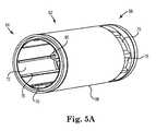
- Figure 5Ais a perspective illustration of a cylindrical shell 62 that may be disposed within the housing 12 and arranged coaxially with the heat exchanger core 40 (see Figure 6 ).
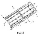
- Figure 5Bis a cross-sectional view of the cylindrical shell 62.
- the cylindrical shell 62includes a first end 64 and a second end 66.
- the cylindrical shell 62may be disposed within the housing 12 such that the first end 64 is near the first end cap 14 while the second end 66 is near the second end cap 16.
- the cylindrical shell 62includes an outer surface 68.
- a shell aperture 70is formed within the outer surface 68 such that blood flowing between the outer surface 52 of the heat exchanger core 40 and an inner surface 72 of the cylindrical shell 62 can exit the cylindrical shell 62.
- the inner surface 72 of the cylindrical shell 62may include one or more shell ribs 80 that protrude from the inner surface 72 and extend toward the heat exchanger core 40. The one or more shell ribs 80 deflect blood away from the inner surface 72 in a radially inward direction.
- the one or more shell ribs 80may, in combination with the core ribs 56 and 58, interrupt longitudinal blood flow and impart a radial flow component to blood flow through the heat exchanger, i.e., between the outer surface 52 of the heat exchanger core 40 and the inner surface 72 of the cylindrical shell 72.
- the heat exchanger core 40may also include one or more longitudinally-extending ribs 75 that may serve to promote longitudinal flow paths between the heat exchanger core 40 and the cylindrical shell 62.
- the cylindrical shell 62may have one, two, three, four, five, six or any desired number of shell apertures 70 spaced radially about the cylindrical shell 62.
- the core aperture(s) 54 and the shell aperture(s) 70are generally disposed at opposite ends of the blood processing apparatus 10.
- blood entering the volume between the outer surface 52 of the heat exchanger core 40 and an inner surface 72 of the cylindrical shell 62is forced to flow at least substantially the entire length thereof before exiting the cylindrical shell 62.
- Figure 7is a cross-sectional illustration of an embodiment of the blood processing apparatus 10, illustrating the coaxial arrangement between the housing 12, the heat exchanger core 40 and the cylindrical shell 62.
- the blood processing apparatus 10includes a schematically illustrated heat exchanger element 74 as well as a schematically illustrated gas exchanger element 76.
- the heat exchanger element 74includes a number of hollow fibers through which a heating fluid such as water can flow.
- the bloodmay flow around and past the hollow fibers and thus be suitably heated.
- the hollow fibersmay be polymeric. In some cases, metallic fibers may be used.
- the heat exchanger element 74may instead include a metal bellows or other structure having a substantial surface area (e.g., fins) for facilitating heat transfer with the blood.
- the hollow fibersmay be formed of polyurethane, polyester, or any other suitable polymer or plastic material.
- the hollow fibershave an outer diameter of between about 0.2 and 1.0 millimeters or, more specifically, between about 0.25 and 0.5 millimeters.
- the hollow fibersmay be woven into mats that can range, for example, from about 80 to about 200 millimeters in width. In some embodiments, the mats are arranged in a criss-cross configuration.
- the gas exchanger element 76may include a number of microporous hollow fibers through which a gas such as oxygen may flow.
- the bloodmay flow around and past the hollow fibers. Due to concentration gradients, oxygen may diffuse through the microporous hollow fibers into the blood while carbon dioxide may diffuse into the hollow fibers and out of the blood.
- the hollow fibersare made of polypropylene, polyester, or any other suitable polymer or plastic material. According to various embodiments, the hollow fibers have an outer diameter of about 0.38 millimeters. According to other embodiments, the microporous hollow fibers having a diameter of between about 0.2 and 1.0 millimeters, or more specifically, between about 0.25 and 0.5 millimeters.
- the hollow fibersmay be woven into mats that can range, for example, from about 80 to about 200 millimeters in width. In some embodiments, the mats are in a criss-cross configuration.
- blood that enters the blood processing apparatus 10 through the blood inlet 18is radially directed through the core aperture(s) 54 such that the blood flows over and around the hollow fibers within the heat exchanger element 74. At least some of the blood flow impinges on the inner surface 72 of the cylindrical shell 62 and is radially directed back towards the outer surface 52 of the heat exchanger core 40. At least some of the blood flow is then directed radially outwards by the core ribs 56 and 58. The blood continues traveling back and forth radially until it reaches the shell aperture(s) 70 and enters a space between the cylindrical shell 62 and the housing 12. In some embodiments, improved heat transfer may be achieved by combining radial and longitudinal flow through the heat exchanger element 74. The blood exiting the shell aperture(s) 70 flows over and around the gas exchanger element 76 and eventually exits the blood processing apparatus 10 through the blood outlet 20.
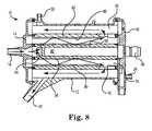
- FIG 8is a cross-sectional view of the blood processing apparatus 10, illustrating the relative orientation of the elements previously discussed.
- the heat exchanger coreis centrally located, with the heat exchanger element 74 coaxially disposed about the heat exchanger core 40.
- the cylindrical shell 62is coaxially disposed about the heat exchanger element 74, followed sequentially by the gas exchanger element 76 and the housing 12.
- the heat exchanger core 40may have core ribs 56 and 58 that are configured to impart a radial component to blood flow trajectory across the heat exchanger element 74.
- the cylindrical shell 62may have one or more radially disposed shell ribs 80 that are configured to impart a radial component to blood flow trajectory across the heat exchanger element 74.
- FIG. 9is a cross-sectional view of a blood processing apparatus 90 in accordance with an embodiment of the invention.
- the blood processing apparatus 90is similar to the blood processing apparatus 10, but includes a modified gas exchanger portion.
- an inner surface of the housing 12includes one or more housing ribs 92 that are configured to impart a radial component to blood flow trajectory through and across the gas exchanger element 76.
- an outer surface of the cylindrical shell 62includes one or more outer shell ribs 94 that are configured to impart a radial component to blood flow trajectory through and across the gas exchanger element 76.
- improved gas transfermay be achieved by combining radial and longitudinal flow through the gas exchanger element 76.
- the ribssuch as the core ribs 56 and 58, the shell ribs 80 and/or the housing ribs 92 may extend about 10 to about 70 percent of the distance between a surface from which they extend to an opposing surface. In some embodiments, the ribs may extend about 25 to about 50 percent of the aforementioned distance. To illustrate, the core ribs 56 and 58 may extend about 10 to about 70 percent, or about 25 to about 50 percent, of a distance between the heat exchanger core 40 and the cylindrical shell 62. In some embodiments, the ribs may form an angle with the surface from which they extend that is in the range of about 30 to about 90 degrees. In some embodiments, the ribs may form an angle of about 45 to about 60 degrees. In some embodiments, the ribs may have a height that is in the range of about 0.2 millimeters to about 3 millimeters and a width that is in the range of about 0.5 millimeters to about 10 millimeters.
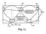
- FIG 10is a cross-sectional view of a blood processing apparatus 100 in accordance with an embodiment of the invention.
- the blood processing apparatus 100is similar to those discussed above, but blood flow through the heat exchanger has a spiral component.
- the blood processing apparatus 100has a heat exchanger core 102 that includes one or more core apertures 104. Blood passes through the one or more core apertures 104 and enters a heat exchanger element 106 that as discussed above may include a number of hollow fibers. Blood exits the heat exchanger element 106 through one or more shell apertures 108 and then passes longitudinally through a gas exchanger element 112 before exiting through the blood outlet 20.
- the core apertures 104 and the shell apertures 108are longitudinally spaced apart such that blood entering the heat exchanger element 106 passes the length of the heat exchanger element 106 before exiting into the gas exchanger element 112.
- the core apertures 104 and the shell apertures 108are radially spaced apart from one another.
- the core apertures 104may be spaced about 180 degrees apart from each other.
- the shell apertures 108may also be spaced about 180 degrees apart from each other, and moreover may be radially displaced from the core apertures 104 by about 180 degrees.
Landscapes
- Health & Medical Sciences (AREA)
- Engineering & Computer Science (AREA)
- Heart & Thoracic Surgery (AREA)
- Vascular Medicine (AREA)
- Physics & Mathematics (AREA)
- Thermal Sciences (AREA)
- Mechanical Engineering (AREA)
- General Engineering & Computer Science (AREA)
- Life Sciences & Earth Sciences (AREA)
- Public Health (AREA)
- Veterinary Medicine (AREA)
- General Health & Medical Sciences (AREA)
- Anesthesiology (AREA)
- Biomedical Technology (AREA)
- Hematology (AREA)
- Animal Behavior & Ethology (AREA)
- Cardiology (AREA)
- Emergency Medicine (AREA)
- Urology & Nephrology (AREA)
- Pulmonology (AREA)
- Chemical & Material Sciences (AREA)
- Chemical Kinetics & Catalysis (AREA)
- External Artificial Organs (AREA)
Description
- The disclosure pertains generally to blood processing units used in blood perfusion systems.
- Blood perfusion entails encouraging blood through the vessels of the body. For such purposes, blood perfusion systems typically entail the use of one or more pumps in an extracorporeal circuit that is interconnected with the vascular system of a patient. Cardiopulmonary bypass surgery typically requires a perfusion system that provides for the temporary cessation of the heart to create a still operating field by replacing the function of the heart and lungs. Such isolation allows for the surgical correction of vascular stenosis, valvular disorders, and congenital heart defects. In perfusion systems used for cardiopulmonary bypass surgery, an extracorporeal blood circuit is established that includes at least one pump and an oxygenation device to replace the functions of the heart and lungs.
- More specifically, in cardiopulmonary bypass procedures oxygen-poor blood, i.e., venous blood, is gravity-drained or vacuum suctioned from a large vein entering the heart or other veins in the body (e.g., femoral) and is transferred through a venous line in the extracorporeal circuit. The venous blood is pumped to an oxygenator that provides for oxygen transfer to the blood. Oxygen may be introduced into the blood by transfer across a membrane or, less frequently, by bubbling oxygen through the blood. Concurrently, carbon dioxide is removed across the membrane. The oxygenated blood is filtered and then returned through an arterial line to the aorta, femoral artery, or other artery. An example of a blood processing apparatus is known, e.g., from
EP-A-0 582 959 . - Example 1 is a blood processing apparatus including a housing having a blood inlet and a blood outlet, the blood inlet extending into an interior of the housing. A heat exchanger core is arranged coaxially within the housing, the heat exchanger core including an outer surface configured to impart a radial blood flow component and a core aperture in fluid communication with the blood inlet and configured to permit blood to pass from the blood inlet to an exterior of the heat exchanger core. Heat exchanger hollow fibers are disposed about the heat exchanger core such that a heat exchanger fluid may flow through the heat exchanger hollow fibers and blood passing from the core aperture may flow across the heat exchanger hollow fibers. A cylindrical shell extends coaxially about the heat exchanger core, the cylindrical shell including an annular shell aperture disposed near an end of the cylindrical shell opposite to an end near which the core aperture is located, the annular shell aperture configured to permit blood to pass to an exterior of the cylindrical shell. Gas exchanger hollow fibers are disposed about the cylindrical shell such that gases may flow through the gas exchange hollow fibers and blood passing from the annular shell aperture may flow across the gas exchanger hollow fibers.
- In Example 2, the blood processing apparatus of Example 1 in which the outer surface of the heat exchanger core includes one or more radially disposed core ribs configured to impart a radial component to blood flow across the heat exchanger hollow fibers.
- In Example 3, the blood processing apparatus of Example 1 or Example 2 in which the cylindrical shell includes an inner surface upon which one or more radially disposed shell ribs are disposed, the one or more radially disposed shell ribs configured to impart a radial component to blood flow trajectory across the heat exchanger hollow fibers.
- In Example 4, the blood processing apparatus of any of Examples 1-3 in which the heat exchanger core includes a conical deflection surface that is disposed between the blood inlet and the core aperture, the conical deflection surface imparting a radial component to blood flow trajectory leaving the core aperture.
- In Example 5, the blood processing apparatus of any of Examples 1-4 in which the housing includes an inner surface upon which one or more radially disposed housing ribs are disposed, the one or more radially disposed housing ribs configured to impart a radial component to blood flow trajectory across the gas exchanger hollow fibers.
- In Example 6, the blood processing apparatus of Example 1 in which the core aperture includes a pair of core apertures disposed about 180 degrees apart, and the annular shell aperture includes a pair of shell apertures that are disposed about 180 degrees apart and radially offset from the pair of core apertures in order to alter blood flow trajectory of the blood flowing across the heat exchanger hollow fibers.
- In Example 7, the blood processing apparatus of any of Examples 1-6, further including a first end cap secured to the housing, the blood inlet being integrally formed with the first end cap.
- In Example 8, the blood processing apparatus of Example 7, further including a gas inlet integrally formed with the first end cap, the gas inlet in fluid communication with an interior of the gas exchanger hollow fibers.
- In Example 9, the blood processing apparatus of any of Examples 1-8, further including a second end cap secured to the housing, the second end cap including a heat exchanger fluid inlet integrally formed with the second end cap and a heat exchanger fluid outlet integrally formed with the second end cap, the heat exchanger fluid inlet and outlet each in fluid communication with an interior of the heat exchanger hollow fibers.
- In Example 10, the blood processing apparatus of Example 9, further including a gas outlet integrally formed with the second end cap, the gas outlet in fluid communication with an interior of the gas exchanger hollow fibers.
- Example 11 is blood processing apparatus including a housing having a blood inlet and a blood outlet, the blood inlet extending into an interior of the housing. A heat exchanger core is disposed within the housing and in operative communication with the blood inlet, the heat exchanger core including an exterior surface and a core aperture in fluid communication with the blood inlet and configured to permit blood to pass from the blood inlet to an exterior of the heat exchanger core. Heat exchanger hollow fibers are disposed about the heat exchanger core such that a heat exchanger fluid may flow through the heat exchanger hollow fibers and blood passing from the core aperture may flow across the heat exchanger hollow fibers. The heat exchanger core includes one or more radially disposed ribs configured to impart a radial component to blood flow across the heat exchanger hollow fibers. A cylindrical shell extends coaxially about the heat exchanger core, the cylindrical shell including an annular shell aperture disposed near an end of the cylindrical shell opposite to an end near which the core aperture is located, the annular shell aperture configured to permit blood to pass to an exterior of the cylindrical shell. Gas exchanger hollow fibers are disposed about the cylindrical shell such that gases may flow through the gas exchange hollow fibers and blood passing from the annular shell aperture may flow across the gas exchanger hollow fibers. One or more ribs are radially disposed on an outer surface of the cylindrical shell, the one or more radially disposed ribs configured to impart a radial component to blood flow across the gas exchanger hollow fibers.
- In Example 12, the blood processing apparatus of Example 11 in which the cylindrical shell includes an inner surface upon which one or more radially disposed shell ribs are disposed, the one or more radially disposed shell ribs configured to impart a radial component to blood flow trajectory across the heat exchanger hollow fibers.
- In Example 13, the blood processing apparatus of Example 11 or Example 12 in which the heat exchanger core includes a conical deflection surface disposed between the blood inlet and the core aperture, the conical deflection surface imparting a radial component to blood flow trajectory leaving the core aperture.
- In Example 14, the blood processing apparatus of any of Examples 11-13 in which the housing includes an inner surface upon which one or more radially disposed housing ribs are disposed, the one or more radially disposed housing ribs configured to impart a radial component to blood flow trajectory across the gas exchanger hollow fibers.
- In Example 15, the blood processing apparatus of any of Examples 11-14, further including one or more radially disposed ribs that are disposed on an inner surface of the cylindrical shell and configured to impart a radial component to blood flow trajectory across the heat exchanger hollow fibers.
- In Example 16, the blood processing apparatus of any of Examples 11-15, further including one or more radially disposed ribs that are disposed on an inner surface of the housing and configured to impart a radial component to blood flow trajectory across the gas exchanger hollow fibers.
- Example 17 is a blood processing apparatus that includes a housing having a blood inlet extending into an interior of the housing and a blood outlet. A heat exchanger core extends coaxially within the housing and is axially aligned with the blood inlet. The heat exchanger core includes a pair of core apertures that are disposed about 180 degrees apart and that are configured to permit blood to pass from the blood inlet to an exterior of the heat exchanger core. Heat exchanger hollow fibers are disposed about the heat exchanger core such that a heat exchanger fluid may flow through the heat exchanger hollow fibers and blood passing from the core aperture may flow across the heat exchanger hollow fibers. A cylindrical shell extends coaxially about the heat exchanger core and includes a pair of shell apertures that are disposed about 180 degrees apart and that are radially offset from the pair of core apertures in order to cause a spiral blood flow through the heat exchanger hollow fibers. The blood processing apparatus includes gas exchanger hollow fibers that are disposed about the cylindrical shell such that gases may flow through the gas exchange hollow fibers and blood passing from the annular shell aperture may flow across the gas exchanger hollow fibers.
- In Example 18, the blood processing apparatus of Example 17 in which the pair of shell apertures are disposed near an end of the cylindrical shell opposite to an end near where the pair of core apertures is located.
- In Example 19, the blood processing apparatus of Examples 17 or 18 wherein at least one of the heat exchanger hollow fibers and the gas exchanger hollow fibers are made from a polymer material.
- While multiple embodiments are disclosed, still other embodiments of the present invention will become apparent to those skilled in the art from the following detailed description, which shows and describes illustrative embodiments of the invention. Accordingly, the drawings and detailed description are to be regarded as illustrative in nature and not restrictive.
Figure 1 is a schematic illustration of a blood processing apparatus in accordance with an embodiment of the invention.Figure 2 is an illustration of a first end cap in accordance with an embodiment of the invention.Figure 3 is an illustration of a second end cap in accordance with an embodiment of the invention.Figure 4 is a perspective illustration of a heat exchanger core in accordance with an embodiment of the invention.Figure 5A is a perspective view of a cylindrical shell forming a barrier between a heat exchanger and a gas exchanger in accordance with an embodiment of the invention.Figure 5B is a cross-sectional view of the cylindrical shell ofFigure 5A .Figure 6 is a perspective view of the heat exchanger core ofFigure 4 disposed within the cylindrical shell ofFigure 5 .Figure 7 is a cross-sectional view of the blood processing apparatus ofFigure 1 .Figure 8 is a cross-sectional illustration of a blood processing apparatus in accordance with an embodiment of the invention.Figure 9 is a cross-sectional illustration of a blood processing apparatus in accordance with an embodiment of the invention.Figure 10 is a cross-sectional illustration of a blood processing apparatus in accordance with an embodiment of the invention.Figure 11 is a diagram illustrating blood flow paths in the blood processing apparatus ofFigure 10 .- The disclosure pertains to a blood processing apparatus that, according to various exemplary embodiments, includes one or more of a heat exchanger and a gas exchanger (also commonly referred to as an oxygenator). In some embodiments, the term oxygenator may be used to refer to an integrated structure that combines a heat exchanger and a gas exchanger in a unitary device. In various embodiments, for example, the heat exchanger and gas exchanger are disposed in a concentric fashion with one component located inside of the other component. According to other embodiments, the heat exchanger and gas exchanger are structurally distinct structures operable coupled to each other. In some embodiments, an oxygenator may be used in an extracorporeal blood circuit. An extracorporeal blood circuit, such as may be used in a bypass procedure, may include several different elements such as a heart-lung machine, a blood reservoir, as well as an oxygenator.
Figure 1 is a schematic illustration of a blood processing apparatus oroxygenator 10. While the internal components are not visible in this illustration, theoxygenator 10 may include one or more of a heat exchanger and a gas exchanger. According to some embodiments, the heat exchanger and the gas exchanger are integrated into a single structure that forms an oxygenator housing. Theoxygenator 10 includes ahousing 12, afirst end cap 14 that is secured to thehousing 12 and asecond end cap 16 that is secured to thehousing 12. In some embodiments, thehousing 12 may include other structure that enables attachment of thehousing 12 to other devices. While thehousing 12 is illustrated as largely cylindrical in shape, in some embodiments, thehousing 12 may have a rectangular or other parallelogram cross-sectional shape. Each of the heat exchanger and the gas exchanger may have generally the same sectional shape or each may have a different sectional shape. In some embodiments, the heat exchanger may be inside the gas exchanger while in other embodiments the gas exchanger may be located within the heat exchanger. In some embodiments, the heat exchanger and the gas exchanger may be concentric.- In some embodiments, a
blood inlet 18 extends into thehousing 12 and ablood outlet 20 exits thehousing 12. As noted, in some embodiments theblood processing apparatus 10 includes a gas exchanger and thus may include a gas inlet 22 and agas outlet 24. In some embodiments, theblood processing apparatus 10 includes a heat exchanger and thus may include a heatexchanger fluid inlet 26 and a heatexchanger fluid outlet 28 that is behind (in the illustrated orientation) theheating fluid inlet 26. In some embodiments, the heatexchanger fluid inlet 26 may be disposed at one end of thehousing 12 while the heatexchanger fluid outlet 28 may be disposed at an opposite end of thehousing 12. In some embodiments, theblood processing apparatus 10 may include apurge port 30 that may be used for purging air bubbles from the interior of theblood processing apparatus 10. - The positions of the inlets, outlets and purge port are merely illustrative, as other arrangements and configurations are contemplated. The purge port may include a valve or a threaded cap. The purge port operates to permit gases (e.g., air bubbles) that exit the blood to be vented or aspirated and removed from the
blood processing apparatus 10. Figures 2 and3 illustrate thefirst end cap 14 and thesecond end cap 16, respectively. Thefirst end cap 14 and thesecond end cap 16 are each configured to be secured to thehousing 12. In some embodiments, thefirst end cap 14 and/or thesecond end cap 16 may be adhesively secured in place. In some embodiments, thefirst end cap 14 and/or thesecond end cap 16 may be snap-fitted into place or even threaded onto their respective ends of thehousing 12.- In some embodiments, as shown in
Figure 2 , theblood inlet 18 and/or the gas inlet 22 may be integrally formed with thefirst end cap 14. For example, in some cases thefirst end cap 14 may be injection molded with theblood inlet 18 and/or the gas inlet 22 formed as part of the injection molded part. In some embodiments, thefirst end cap 14 may be formed having apertures to which theblood inlet 18 and/or the gas inlet 22 may be attached. Thefirst end cap 14 includes anannular ring 32 that is disposed about a periphery of thefirst end cap 14 and that serves, in some embodiments, as an attachment point for securing thefirst end cap 14 to thehousing 12. In some embodiments, thefirst end cap 14 also includes anannular ring 34 that, as will be described subsequently, locates portions of the heat exchanger. - In some embodiments, as shown in
Figure 3 , the heatexchanger fluid inlet 26 and/or the heatexchanger fluid outlet 28 may be integrally formed with thesecond end cap 16. For example, in some cases thesecond end cap 16 may be injection molded with the heatexchanger fluid inlet 26 and/or the heatexchanger fluid outlet 28 formed as part of the injection molded part. Similarly, in some embodiments, thesecond end cap 16 may be injected molded with thegas outlet 24 formed as part of the injection molded part. However, in some embodiments, thesecond end cap 16 may be formed having apertures to which one or more of the heatexchanger fluid inlet 26, the heatexchanger fluid outlet 28 and/or thegas outlet 24 may be attached. Thesecond end cap 16 includes anannular ring 36 that is disposed about a periphery of thesecond end cap 16 and that serves, in some embodiments, as an attachment point for securing thesecond end cap 16 to thehousing 12. In some embodiments, thesecond end cap 16 also includes anannular ring 38 that, as will be described subsequently, locates portions of the heat exchanger. - In some embodiments, one of the heat
exchanger fluid inlet 26 and the heatexchanger fluid outlet 28 may be located in thefirst end cap 14 while the other of the heatexchanger fluid inlet 26 and the heatexchanger fluid outlet 28 may be located in thesecond end cap 16. In some embodiments, the heatexchanger fluid inlet 26 andoutlet 28 may be located in thefirst end cap 14. In some embodiments, the heatexchanger fluid inlet 26 andoutlet 28 may be located in thesecond end cap 16. Figure 4 is a perspective illustration of aheat exchanger core 40 having afirst end 42 and asecond end 44. In some embodiments, as will be illustrated with respect to subsequent drawings, theheat exchanger core 40 may be disposed within theblood processing apparatus 10 such that thefirst end 42 is near thefirst end cap 14 while thesecond end 44 is near thesecond end cap 16. Theheat exchanger core 40 includes anannular portion 46 that, in some embodiments, helps to locate thefirst end 42 relative to thefirst end cap 14. Similarly, thesecond end 44 may be configured to help locate thesecond end 44 relative to thesecond end cap 16.- The
heat exchanger core 40 includes aconical deflection surface 48 upon which incoming blood from theblood inlet 18 impinges. Theconical deflection surface 48 deflects the blood in a radial direction. In some embodiments, theconical deflection surface 48 may include adivider 50 that assists in directing blood in particular directions. Theheat exchanger core 40 includes an outer surface 52. Acore aperture 54 is formed within the outer surface 52 such that blood impinging on theconical deflection surface 48 is deflected radially outwardly through thecore aperture 54. In some embodiments, theheat exchanger core 40 may have one, two, three, four or any desired number ofcore apertures 54 spaced radially about theheat exchanger core 40. - In some embodiments, as illustrated, the
heat exchanger core 40 includes a first radially disposedcore rib 56 and a second radially disposedcore rib 58. In some embodiments, the core ribs (or projections) 56 and 58 deflect blood away from the outer surface 52 in a radially-outward direction. Thecore ribs core ribs heat exchanger core 40 may include a greater number of core ribs. In some embodiments, theheat exchanger core 40 may also include longitudinally-extendingribs 60 that may serve to promote longitudinal flow paths down the outside of theheat exchanger core 40. According to various embodiments, theribs heat exchanger core 40. Figure 5A is a perspective illustration of acylindrical shell 62 that may be disposed within thehousing 12 and arranged coaxially with the heat exchanger core 40 (seeFigure 6 ).Figure 5B is a cross-sectional view of thecylindrical shell 62. Thecylindrical shell 62 includes afirst end 64 and asecond end 66. In some embodiments, thecylindrical shell 62 may be disposed within thehousing 12 such that thefirst end 64 is near thefirst end cap 14 while thesecond end 66 is near thesecond end cap 16.- The
cylindrical shell 62 includes anouter surface 68. Ashell aperture 70 is formed within theouter surface 68 such that blood flowing between the outer surface 52 of theheat exchanger core 40 and aninner surface 72 of thecylindrical shell 62 can exit thecylindrical shell 62. In some embodiments, theinner surface 72 of thecylindrical shell 62 may include one ormore shell ribs 80 that protrude from theinner surface 72 and extend toward theheat exchanger core 40. The one ormore shell ribs 80 deflect blood away from theinner surface 72 in a radially inward direction. In some embodiments, the one ormore shell ribs 80 may, in combination with thecore ribs heat exchanger core 40 and theinner surface 72 of thecylindrical shell 72. In some embodiments, theheat exchanger core 40 may also include one or more longitudinally-extendingribs 75 that may serve to promote longitudinal flow paths between theheat exchanger core 40 and thecylindrical shell 62. - In some embodiments, the
cylindrical shell 62 may have one, two, three, four, five, six or any desired number ofshell apertures 70 spaced radially about thecylindrical shell 62. As illustrated inFigure 6 , the core aperture(s) 54 and the shell aperture(s) 70 are generally disposed at opposite ends of theblood processing apparatus 10. Thus, blood entering the volume between the outer surface 52 of theheat exchanger core 40 and aninner surface 72 of thecylindrical shell 62 is forced to flow at least substantially the entire length thereof before exiting thecylindrical shell 62. Figure 7 is a cross-sectional illustration of an embodiment of theblood processing apparatus 10, illustrating the coaxial arrangement between thehousing 12, theheat exchanger core 40 and thecylindrical shell 62. In some embodiments, theblood processing apparatus 10 includes a schematically illustratedheat exchanger element 74 as well as a schematically illustratedgas exchanger element 76.- In some embodiments, the
heat exchanger element 74 includes a number of hollow fibers through which a heating fluid such as water can flow. The blood may flow around and past the hollow fibers and thus be suitably heated. In some embodiments, the hollow fibers may be polymeric. In some cases, metallic fibers may be used. According to other embodiments, theheat exchanger element 74 may instead include a metal bellows or other structure having a substantial surface area (e.g., fins) for facilitating heat transfer with the blood. In some embodiments, the hollow fibers may be formed of polyurethane, polyester, or any other suitable polymer or plastic material. According to various embodiments, the hollow fibers have an outer diameter of between about 0.2 and 1.0 millimeters or, more specifically, between about 0.25 and 0.5 millimeters. The hollow fibers may be woven into mats that can range, for example, from about 80 to about 200 millimeters in width. In some embodiments, the mats are arranged in a criss-cross configuration. - In some embodiments the
gas exchanger element 76 may include a number of microporous hollow fibers through which a gas such as oxygen may flow. The blood may flow around and past the hollow fibers. Due to concentration gradients, oxygen may diffuse through the microporous hollow fibers into the blood while carbon dioxide may diffuse into the hollow fibers and out of the blood. In some embodiments, the hollow fibers are made of polypropylene, polyester, or any other suitable polymer or plastic material. According to various embodiments, the hollow fibers have an outer diameter of about 0.38 millimeters. According to other embodiments, the microporous hollow fibers having a diameter of between about 0.2 and 1.0 millimeters, or more specifically, between about 0.25 and 0.5 millimeters. The hollow fibers may be woven into mats that can range, for example, from about 80 to about 200 millimeters in width. In some embodiments, the mats are in a criss-cross configuration. - As shown in
Figure 8 , blood that enters theblood processing apparatus 10 through theblood inlet 18 is radially directed through the core aperture(s) 54 such that the blood flows over and around the hollow fibers within theheat exchanger element 74. At least some of the blood flow impinges on theinner surface 72 of thecylindrical shell 62 and is radially directed back towards the outer surface 52 of theheat exchanger core 40. At least some of the blood flow is then directed radially outwards by thecore ribs cylindrical shell 62 and thehousing 12. In some embodiments, improved heat transfer may be achieved by combining radial and longitudinal flow through theheat exchanger element 74. The blood exiting the shell aperture(s) 70 flows over and around thegas exchanger element 76 and eventually exits theblood processing apparatus 10 through theblood outlet 20. Figure 8 is a cross-sectional view of theblood processing apparatus 10, illustrating the relative orientation of the elements previously discussed. As shown, the heat exchanger core is centrally located, with theheat exchanger element 74 coaxially disposed about theheat exchanger core 40. Thecylindrical shell 62 is coaxially disposed about theheat exchanger element 74, followed sequentially by thegas exchanger element 76 and thehousing 12. In some embodiments, theheat exchanger core 40 may havecore ribs heat exchanger element 74. In some embodiments, thecylindrical shell 62 may have one or more radially disposedshell ribs 80 that are configured to impart a radial component to blood flow trajectory across theheat exchanger element 74.Figure 9 is a cross-sectional view of ablood processing apparatus 90 in accordance with an embodiment of the invention. Theblood processing apparatus 90 is similar to theblood processing apparatus 10, but includes a modified gas exchanger portion. In some embodiments, an inner surface of thehousing 12 includes one ormore housing ribs 92 that are configured to impart a radial component to blood flow trajectory through and across thegas exchanger element 76. In some embodiments, an outer surface of thecylindrical shell 62 includes one or moreouter shell ribs 94 that are configured to impart a radial component to blood flow trajectory through and across thegas exchanger element 76. In some embodiments, improved gas transfer may be achieved by combining radial and longitudinal flow through thegas exchanger element 76.- In some embodiments, the ribs such as the
core ribs shell ribs 80 and/or thehousing ribs 92 may extend about 10 to about 70 percent of the distance between a surface from which they extend to an opposing surface. In some embodiments, the ribs may extend about 25 to about 50 percent of the aforementioned distance. To illustrate, thecore ribs heat exchanger core 40 and thecylindrical shell 62. In some embodiments, the ribs may form an angle with the surface from which they extend that is in the range of about 30 to about 90 degrees. In some embodiments, the ribs may form an angle of about 45 to about 60 degrees. In some embodiments, the ribs may have a height that is in the range of about 0.2 millimeters to about 3 millimeters and a width that is in the range of about 0.5 millimeters to about 10 millimeters. Figure 10 is a cross-sectional view of ablood processing apparatus 100 in accordance with an embodiment of the invention. Theblood processing apparatus 100 is similar to those discussed above, but blood flow through the heat exchanger has a spiral component. Theblood processing apparatus 100 has aheat exchanger core 102 that includes one ormore core apertures 104. Blood passes through the one ormore core apertures 104 and enters aheat exchanger element 106 that as discussed above may include a number of hollow fibers. Blood exits theheat exchanger element 106 through one ormore shell apertures 108 and then passes longitudinally through agas exchanger element 112 before exiting through theblood outlet 20.- As shown in
Figure 10 that thecore apertures 104 and theshell apertures 108 are longitudinally spaced apart such that blood entering theheat exchanger element 106 passes the length of theheat exchanger element 106 before exiting into thegas exchanger element 112. The core apertures 104 and theshell apertures 108 are radially spaced apart from one another. As schematically shown inFigure 11 , for example, thecore apertures 104 may be spaced about 180 degrees apart from each other. Theshell apertures 108 may also be spaced about 180 degrees apart from each other, and moreover may be radially displaced from thecore apertures 104 by about 180 degrees. As a result, blood passing through theheat exchanger element 106 undergoes a spiral flow path through and around the hollow fibers within theheat exchanger element 106. - Various modifications and additions can be made to the exemplary embodiments discussed without departing from the scope of the present invention. For example, while the embodiments described above refer to particular features, the scope of this invention also includes embodiments having different combinations of features and embodiments that do not include all of the above described features.
Claims (12)
- A blood processing apparatus (10) comprising:a housing (12) having a blood inlet (18) and a blood outlet (20), the blood inlet (18) extending into an interior of the housing (12);a heat exchanger core (40) arranged coaxially within the housing (12), the heat exchanger core (40) including an outer surface (52) configured to impart a radial blood flow component and a core aperture (54) in fluid communication with the blood inlet (18) and configured to permit blood to pass from the blood inlet (18) to an exterior of the heat exchanger core (40);heat exchanger hollow fibers disposed about the heat exchanger core (40) such that a heat exchanger fluid may flow through the heat exchanger hollow fibers and blood passing from the core aperture (54) may flow across the heat exchanger hollow fibers;a cylindrical shell (62) extending coaxially about the heat exchanger core (40), the cylindrical shell (62) including an annular shell aperture (70) disposed near an end (66) of the cylindrical shell (62) opposite to an end (64) near which the core aperture (54) is located, the annular shell aperture (70) configured to permit blood to pass to an exterior of the cylindrical shell (62); andgas exchanger hollow fibers disposed about the cylindrical shell (62) such that gases may flow through the gas exchange hollow fibers and blood passing from the annular shell aperture (70) may flow across the gas exchanger hollow fibers,wherein the outer surface (52) of the heat exchanger core (40) includes one or more radially disposed core ribs (56, 58) configured to impart a radial component to blood flow across the heat exchanger hollow fibers.
- The blood processing apparatus of claim 1, wherein the cylindrical shell (62) includes an inner surface (72) and one or more shell ribs (80) that protrude from the inner surface (72) and extend toward the heat exchanger core (40), the one or more shell ribs (80) being configured for deflecting blood away from the inner surface (72) in a radially inward direction.
- The blood processing apparatus (10) of claim 1, wherein the heat exchanger core (40) includes a conical deflection surface (48) disposed between the blood inlet (18) and the core aperture (54), the conical deflection surface (48) imparting a radial component to blood flow trajectory leaving the core aperture (54).
- The blood processing apparatus (10) of claim 1, wherein the housing (12) includes an inner surface upon which one or more radially disposed housing ribs (92) are disposed, the one or more radially disposed housing ribs (92) configured to impart a radial component to blood flow trajectory across the gas exchanger hollow fibers.
- The blood processing apparatus (10) of claim 1, wherein the core aperture (54) comprises a pair of core apertures disposed about 180 degrees apart, and the annular shell aperture (70) comprises a pair of shell apertures that are disposed about 180 degrees apart and radially offset from the pair of core apertures in order to alter blood flow trajectory of the blood flowing across the heat exchanger hollow fibers.
- The blood processing apparatus (10) of claim 1, further comprising a first end cap (14) secured to the housing (12), the blood inlet (18) being integrally formed with the first end cap (14).
- The blood processing apparatus (10) of claim 6, further comprising a gas inlet (22) integrally formed with the first end cap (14), the gas inlet (22) in fluid communication with an interior of the gas exchanger hollow fibers.
- The blood processing apparatus (10) of claim 1, further comprising a second end cap (16) secured to the housing (12), the second end cap (16) including a heat exchanger fluid inlet (26) integrally formed with the second end cap (16) and a heat exchanger fluid outlet (28) integrally formed with the second end cap (16), the heat exchanger fluid inlet (26) and outlet (28) each in fluid communication with an interior of the heat exchanger hollow fibers.
- The blood processing apparatus (10) of claim 8, further comprising a gas outlet (24) integrally formed with the second end cap (16), the gas outlet (24) in fluid communication with an interior of the gas exchanger hollow fibers.
- The blood processing apparatus (10) of claim 5, wherein the pair of shell apertures are disposed near an end of the cylindrical shell (62) opposite to an end near which the pair of core apertures (54) are located.
- The blood processing apparatus (10) of claim 1, wherein at least one of the heat exchanger hollow fibers and the gas exchanger hollow fibers are made from a polymer material.
- The blood processing apparatus (10) according to claim 1, wherein the heat exchanger core (40) extending coaxially within the housing (12) is axially aligned with the blood inlet (18).
Priority Applications (1)
| Application Number | Priority Date | Filing Date | Title |
|---|---|---|---|
| EP13161841.5AEP2612685B1 (en) | 2010-08-19 | 2010-08-19 | Blood processing unit with modified flow path |
Applications Claiming Priority (2)
| Application Number | Priority Date | Filing Date | Title |
|---|---|---|---|
| EP10173436.6AEP2420262B1 (en) | 2010-08-19 | 2010-08-19 | Blood processing unit with modified flow path |
| EP13161841.5AEP2612685B1 (en) | 2010-08-19 | 2010-08-19 | Blood processing unit with modified flow path |
Related Parent Applications (2)
| Application Number | Title | Priority Date | Filing Date |
|---|---|---|---|
| EP10173436.6ADivisionEP2420262B1 (en) | 2010-08-19 | 2010-08-19 | Blood processing unit with modified flow path |
| EP10173436.6Division | 2010-08-19 |
Publications (2)
| Publication Number | Publication Date |
|---|---|
| EP2612685A1 EP2612685A1 (en) | 2013-07-10 |
| EP2612685B1true EP2612685B1 (en) | 2014-10-08 |
Family
ID=43425894
Family Applications (4)
| Application Number | Title | Priority Date | Filing Date |
|---|---|---|---|
| EP13161841.5AActiveEP2612685B1 (en) | 2010-08-19 | 2010-08-19 | Blood processing unit with modified flow path |
| EP10173436.6AActiveEP2420262B1 (en) | 2010-08-19 | 2010-08-19 | Blood processing unit with modified flow path |
| EP10191140.2ANot-in-forceEP2420263B1 (en) | 2010-08-19 | 2010-11-15 | Blood processing unit with circumferential blood flow |
| EP12187501.7ANot-in-forceEP2543403B1 (en) | 2010-08-19 | 2010-11-15 | Blood processing unit with circumferential blood flow |
Family Applications After (3)
| Application Number | Title | Priority Date | Filing Date |
|---|---|---|---|
| EP10173436.6AActiveEP2420262B1 (en) | 2010-08-19 | 2010-08-19 | Blood processing unit with modified flow path |
| EP10191140.2ANot-in-forceEP2420263B1 (en) | 2010-08-19 | 2010-11-15 | Blood processing unit with circumferential blood flow |
| EP12187501.7ANot-in-forceEP2543403B1 (en) | 2010-08-19 | 2010-11-15 | Blood processing unit with circumferential blood flow |
Country Status (2)
| Country | Link |
|---|---|
| US (7) | US8394049B2 (en) |
| EP (4) | EP2612685B1 (en) |
Families Citing this family (22)
| Publication number | Priority date | Publication date | Assignee | Title |
|---|---|---|---|---|
| US8318092B2 (en) | 2010-04-29 | 2012-11-27 | Sorin Group Italia S.R.L. | Oxygenator with integrated arterial filter |
| US8388566B2 (en) | 2010-04-29 | 2013-03-05 | Sorin Group Italia, S.r.l. | Oxygenator with integrated arterial filter including filter frame |
| EP2612685B1 (en) | 2010-08-19 | 2014-10-08 | Sorin Group Italia S.r.l. | Blood processing unit with modified flow path |
| EP2524712B1 (en) | 2011-05-17 | 2018-12-12 | Sorin Group Italia S.r.l. | Blood processing unit with cross blood flow |
| US10098994B2 (en) | 2014-01-09 | 2018-10-16 | Sorin Group Italia S.R.L. | Blood processing unit with heat exchanger core for providing modified flow path |
| WO2015128886A1 (en) | 2014-02-28 | 2015-09-03 | Sorin Group Italia S.R.L. | System for providing an integrated arterial filter into an oxygenator, minimizing added priming volume |
| EP3131663A2 (en) | 2014-03-29 | 2017-02-22 | Princeton Trade and Technology Inc. | Blood processing cartridges and systems, and methods for extracorporeal blood therapies |
| WO2016064715A1 (en) | 2014-10-20 | 2016-04-28 | The Regents Of The University Of Michigan | Gated-concentric artificial lung |
| EP3218087A1 (en) | 2014-11-12 | 2017-09-20 | Sorin Group Italia S.r.l. | Elastic protection tube for a hollow fibre blood processing apparatus |
| EP3294368B1 (en) | 2015-05-12 | 2019-06-26 | Sorin Group Italia S.r.l. | Blood gas exchanger with restriction element or elements to reduce gas exchange |
| US10426884B2 (en) | 2015-06-26 | 2019-10-01 | Novaflux Inc. | Cartridges and systems for outside-in flow in membrane-based therapies |
| EP3352888B8 (en) | 2015-09-24 | 2022-01-12 | Princeton Trade and Technology Inc. | Cartridges for hollow fibre membrane-based therapies |
| KR101762228B1 (en)* | 2015-11-27 | 2017-07-27 | 재단법인 아산사회복지재단 | A blood oxygenator |
| CN110234370B (en) | 2016-09-22 | 2022-04-05 | C·J·普洛特 | Device and method for extracorporeal blood regulation |
| US11771810B2 (en) | 2017-06-01 | 2023-10-03 | Sorin Group Italia S.R.L. | Oxygenator with thermal insulation |
| JP6972737B2 (en)* | 2017-07-28 | 2021-11-24 | 東洋紡株式会社 | Hollow fiber membrane module |
| CN115998976A (en) | 2017-08-15 | 2023-04-25 | 马里兰大学巴尔的摩 | Dual chamber gas exchanger and method for respiratory support |
| JP6948465B2 (en)* | 2017-10-10 | 2021-10-13 | ソリン・グループ・イタリア・ソシエタ・ア・レスポンサビリタ・リミタータSorin Group Italia S.r.l. | Blood processing unit (BPU) with countercurrent blood / water flow path in heat exchanger (HEX) |
| US11541157B2 (en) | 2019-06-18 | 2023-01-03 | Michigan Critical Care Consultants, Inc. | Membrane oxygenator with gas exchange fiber lumen access based on fiber effective length |
| US11925739B2 (en) | 2019-10-23 | 2024-03-12 | Seagate Technology Llc | Artificial kidney |
| KR102797193B1 (en)* | 2022-10-18 | 2025-04-22 | 주식회사 인성메디칼 | Blood oxygenator |
| CN116764018B (en)* | 2023-06-25 | 2024-01-09 | 江苏赛腾医疗科技有限公司 | Oblique-through runner oxygenator with liquid inlet dispersion structure |
Family Cites Families (110)
| Publication number | Priority date | Publication date | Assignee | Title |
|---|---|---|---|---|
| US3339341A (en) | 1965-12-22 | 1967-09-05 | Du Pont | Fluid separation process and apparatus |
| JPS445526Y1 (en) | 1968-07-22 | 1969-02-28 | ||
| FR2214502B1 (en)* | 1973-01-18 | 1976-05-14 | Rhone Poulenc Ind | |
| FR2231421B1 (en) | 1973-05-30 | 1976-05-07 | Rhone Poulenc Ind | |
| JPS52126681A (en) | 1976-04-16 | 1977-10-24 | Asahi Chem Ind Co Ltd | Improved hollow fiber fluid separating apparatus |
| SE421999B (en) | 1977-10-17 | 1982-02-15 | Gambro Dialysatoren | DEVICE FOR DIFFUSION AND / OR FILTRATION OF THE SUBSTANCE BETWEEN TWO FLUIDS THROUGH SEMIPERMEABLE MEMBRANE, WHICH DEVICE INCLUDES PARALLEL CONNECTED CIRCUITS INCLUDING SERIAL CONNECTED CHAMBERS |
| IT1091268B (en)* | 1977-12-15 | 1985-07-06 | Hospal Dasco Spa | REFINEMENT TO A HEMODIALIZER |
| JPS5935631B2 (en) | 1980-07-24 | 1984-08-29 | テルモ株式会社 | Body fluid “filtration” device |
| US4707268A (en) | 1982-10-18 | 1987-11-17 | Baxter Travenol Laboratories, Inc. | Hollow fiber potted microfilter |
| US4902476A (en) | 1983-01-14 | 1990-02-20 | Baxter International Inc. | Heat exchanger and blood oxygenator apparatus |
| JPS59147603A (en) | 1983-02-10 | 1984-08-24 | Kuraray Co Ltd | Hollow fiber bundle with protector |
| JPS6053156A (en) | 1983-09-01 | 1985-03-26 | 三菱レイヨン株式会社 | blood purifier |
| EP0312125B1 (en) | 1983-11-11 | 1992-03-04 | TERUMO KABUSHIKI KAISHA trading as TERUMO CORPORATION | Device for receiving and treating blood |
| US4639353A (en) | 1984-04-24 | 1987-01-27 | Mitsubishi Rayon Co., Ltd. | Blood oxygenator using a hollow-fiber membrane |
| CA1258436A (en) | 1984-08-01 | 1989-08-15 | Michael A. Smoot | Mat structure for use in filtration devices |
| JPS63139562A (en) | 1986-12-01 | 1988-06-11 | 株式会社 日本メデイカル・サプライ | Hollow yarn type artificial lung |
| US4758341A (en) | 1987-04-20 | 1988-07-19 | The Dow Chemical Company | Membrane separation device |
| JPS6440060A (en) | 1987-08-06 | 1989-02-10 | Ube Industries | Artificial lung provided with built-in heat exchanger |
| JPS6476868A (en) | 1987-09-18 | 1989-03-22 | Nippon Medical Supply | Improved pump-oxygenator |
| US5120501A (en) | 1988-10-20 | 1992-06-09 | Baxter International Inc. | Integrated membrane blood oxygenator/heat exchanger |
| US5316724A (en)* | 1989-03-31 | 1994-05-31 | Baxter International Inc. | Multiple blood path membrane oxygenator |
| JPH0347271A (en) | 1989-07-14 | 1991-02-28 | Terumo Corp | Liquid treatment device |
| US5578267A (en) | 1992-05-11 | 1996-11-26 | Minntech Corporation | Cylindrical blood heater/oxygenator |
| US5270004A (en) | 1989-10-01 | 1993-12-14 | Minntech Corporation | Cylindrical blood heater/oxygenator |
| EP0519132A1 (en)* | 1989-10-18 | 1992-12-23 | Exxon Research And Engineering Company | Hollow fiber module |
| JPH03169329A (en) | 1989-11-30 | 1991-07-23 | Nok Corp | Production of hollow yarn module |
| JP3228518B2 (en) | 1990-12-14 | 2001-11-12 | 日機装株式会社 | Heart-lung machine |
| JPH05177117A (en) | 1991-10-23 | 1993-07-20 | Hisateru Takano | Substance exchange device |
| JP3284568B2 (en) | 1991-10-31 | 2002-05-20 | 株式会社ジェイ・エム・エス | Inlet header for oxygenator and oxygenator using it |
| US5192439A (en) | 1992-02-03 | 1993-03-09 | Electromedics, Inc. | Blood collection reservoir and filter device |
| WO1994003266A1 (en) | 1992-08-03 | 1994-02-17 | Maloney James V Jr | Improved mass and thermal transfer means for use in heart lung machines, dialyzers, and other applications |
| IT1255820B (en)* | 1992-08-10 | 1995-11-16 | Nicola Ghelli | HEAT EXCHANGER IN EXTRACORPOREAL BLOOD CIRCUIT |
| US5489413A (en)* | 1992-11-03 | 1996-02-06 | Cobe Laboratories, Inc. | Hollow fiber blood oxygenator |
| US5501663A (en) | 1993-07-02 | 1996-03-26 | Medtronic Electromedics, Inc. | Inflatable percutaneous oxygenator with transverse hollow fibers |
| US5514095A (en) | 1994-04-04 | 1996-05-07 | Haemonetics Corporation | Apparatus for heating, filtering and eliminating gas from biological fluids |
| IT1271104B (en) | 1994-11-25 | 1997-05-26 | Dideco Spa | BLOOD OXYGENATOR WITH A LAYER OF MICROPOROUS MEMBRANE CAPILLARIES. |
| JPH08168525A (en) | 1994-12-19 | 1996-07-02 | Terumo Corp | Production of hollow fiber membrane type blood treating device and production apparatus therefor |
| US5651765A (en) | 1995-04-27 | 1997-07-29 | Avecor Cardiovascular Inc. | Blood filter with concentric pleats and method of use |
| EP0765683B1 (en) | 1995-09-25 | 1998-07-01 | MEDOS Medizintechnik GmbH | Device for treating liquids, in particular blood |
| US5770149A (en) | 1995-10-31 | 1998-06-23 | Baxter International | Extracorporeal blood oxygenation system having integrated blood pump, heat exchanger and membrane oxygenator |
| US5762868A (en) | 1995-11-30 | 1998-06-09 | Minnesota Mining And Manufacturing Company | Blood oxygenator and heat exchanger |
| JPH11508476A (en) | 1996-01-11 | 1999-07-27 | メドトロニック・インコーポレーテッド | Compact membrane oxygenator with concentric heat exchanger and improved manifold |
| SE506613C2 (en)* | 1996-05-30 | 1998-01-19 | Votinex Management Sa | Filter and heat exchanger device |
| US5762869A (en)* | 1996-07-24 | 1998-06-09 | Gish Biomedical, Inc. | Blood oxygenator |
| WO1998022161A1 (en) | 1996-11-15 | 1998-05-28 | Scitec K.K. | Hollow fiber dialyzer |
| JPH1147189A (en) | 1997-08-01 | 1999-02-23 | Oji Paper Co Ltd | Diapers |
| JPH1147268A (en) | 1997-08-06 | 1999-02-23 | Terumo Corp | Hollow fiber membrane type artificial lung |
| JPH1181476A (en) | 1997-09-12 | 1999-03-26 | Sekisui Chem Co Ltd | Wall panel interval adjusting jig and wall panel interval adjusting method |
| US6241945B1 (en) | 1998-03-16 | 2001-06-05 | Life Science Holdings, Inc. | Modular combined pump, filtration, oxygenation and/or debubbler apparatus |
| EP1076572A2 (en) | 1998-05-08 | 2001-02-21 | Baxter International Inc. | Low prime membrane oxygenator with integrated heat exchanger/reservoir |
| US6113782A (en) | 1998-07-28 | 2000-09-05 | Terumo Cardiovascular Systems Corporation | Potting of tubular bundles in housing |
| US6193681B1 (en) | 1998-09-14 | 2001-02-27 | American Immuno Tech, Llc. | Septicemia prevention and treatment system |
| JP3992377B2 (en) | 1998-09-18 | 2007-10-17 | テルモ株式会社 | Hollow fiber membrane oxygenator with built-in heat exchange function |
| US6454999B1 (en)* | 1998-12-30 | 2002-09-24 | Cardiovention, Inc. | Integrated blood pump and oxygenator system having extended blood flow path |
| JP4041254B2 (en)* | 1999-12-15 | 2008-01-30 | テルモ株式会社 | Hollow fiber membrane oxygenator |
| WO2001066237A1 (en) | 2000-03-07 | 2001-09-13 | Mat Adsorption Technologies Gmbh & Co. Kg | Module with membrane elements in a cross-flow and in a dead-end arrangement |
| US6459937B1 (en) | 2000-04-25 | 2002-10-01 | Pacesetter, Inc. | Endocardial pacing lead with detachable tip electrode assembly |
| IT1318742B1 (en) | 2000-08-08 | 2003-09-10 | Dideco Spa | BLOOD OXYGEN DEVICE IN EXTRACORPOREAL CIRCUIT. |
| US6730267B2 (en) | 2001-02-09 | 2004-05-04 | Cardiovention, Inc. | Integrated blood handling system having active gas removal system and methods of use |
| US6755894B2 (en)* | 2001-05-02 | 2004-06-29 | Praxair Technology, Inc. | Hollow fiber membrane gas separation cartridge and gas purification assembly |
| US6623638B2 (en) | 2001-06-01 | 2003-09-23 | Baxter International Inc. | Hemodialyzer having improved dialysate perfusion |
| CN100353134C (en)* | 2001-09-25 | 2007-12-05 | 本田技研工业株式会社 | Heat accumulation unit and method of manufacturing the unit |
| CN2511309Y (en) | 2001-11-16 | 2002-09-18 | 广东省医疗器械研究所 | Membrane oxygen supplier |
| US20030175149A1 (en) | 2002-03-18 | 2003-09-18 | Bruce Searles | Renewable, modifiable, membrane gas exchanger |
| JP4214910B2 (en) | 2002-12-26 | 2009-01-28 | ニプロ株式会社 | Dialysis machine and manufacturing method thereof |
| ATE458511T1 (en) | 2002-12-26 | 2010-03-15 | Nipro Corp | DIALYZER AND ITS PRODUCTION PROCESS |
| JP4218433B2 (en) | 2003-06-13 | 2009-02-04 | 株式会社Sumco | Single crystal rod pulling wire load applying device |
| JP4337573B2 (en) | 2004-02-10 | 2009-09-30 | 株式会社ジェイ・エム・エス | Heat exchanger, method for producing the same, and heart-lung machine |
| DE102004012049B4 (en) | 2004-03-11 | 2006-02-09 | Siemens Ag | Method for fastening a laminated core for the stator winding of a linear motor on the guideway |
| CN2772515Y (en) | 2004-04-23 | 2006-04-19 | 广东省医疗器械研究所 | Hollow fibrous coat oxygenator |
| JP4366268B2 (en) | 2004-07-23 | 2009-11-18 | テルモ株式会社 | Artificial lung |
| DE102005031582A1 (en) | 2005-07-06 | 2007-01-11 | Maquet Cardiopulmonary Ag | Device for treating blood in an extracorporeal blood circulation |
| DE102005039446B4 (en) | 2005-08-18 | 2009-06-25 | Ilias-Medical Gmbh | Device for accumulating and depleting substances in a liquid |
| US7981121B2 (en) | 2005-08-22 | 2011-07-19 | St. Jude Medical Ab | Tool and a method for attaching a cardiac stimulator lead at a desired position inside a heart |
| US20070107884A1 (en)* | 2005-10-27 | 2007-05-17 | Sirkar Kamalesh K | Polymeric hollow fiber heat exchange systems |
| JP4500776B2 (en) | 2006-01-19 | 2010-07-14 | テルモ株式会社 | Artificial lung |
| EP1810704B1 (en)* | 2006-01-19 | 2015-04-22 | Terumo Kabushiki Kaisha | Oxygenator |
| ITMI20060490A1 (en) | 2006-03-17 | 2007-09-18 | Eurosets Srl | INTEGRATED DEVICE FOR BLOOD RE-HEALING AND OXYGENATION IN EXTRACORPOREAL CIRCUIT |
| JP4855119B2 (en) | 2006-03-28 | 2012-01-18 | テルモ株式会社 | Filter member and artificial lung |
| JP4714082B2 (en) | 2006-06-07 | 2011-06-29 | 株式会社東芝 | Light emitting device display structure of outdoor equipment |
| DE102007010112A1 (en) | 2007-02-28 | 2008-09-04 | Rheinisch-Westfälische Technische Hochschule Aachen | Blood oxygenator for material and/or energy exchange has at least one pump element in chamber, by which first medium can be expelled and second one sucked in |
| KR100902674B1 (en) | 2007-10-10 | 2009-06-15 | 엔에이치엔(주) | Method and system for providing document navigation service |
| JP5020111B2 (en) | 2008-02-04 | 2012-09-05 | 株式会社小松製作所 | Hydraulic control device, hydraulic control method, and adjustment method of hydraulic control device |
| US20100272606A1 (en) | 2009-04-23 | 2010-10-28 | Carpenter Walt L | Radial flow oxygenator/heat exchanger |
| JP5828170B2 (en) | 2009-04-23 | 2015-12-02 | メドトロニック,インコーポレイテッド | Radial design oxygenator with heat exchanger |
| US20100272607A1 (en)* | 2009-04-23 | 2010-10-28 | Carpenter Walt L | Radial design oxygenator with heat exchanger and inlet mandrel |
| US20100269342A1 (en) | 2009-04-23 | 2010-10-28 | Carpenter Walt L | Method of making radial design oxygenator with heat exchanger |
| EP2295646B1 (en) | 2009-08-28 | 2012-06-27 | BAUER Maschinen GmbH | Drilling equipment and method |
| CN201510571U (en) | 2009-09-29 | 2010-06-23 | 山东威高新生医疗器械有限公司 | Membrane type oxygenator |
| JP5418275B2 (en) | 2010-02-15 | 2014-02-19 | ニプロ株式会社 | Heat exchanger and oxygenator with integrated heat exchanger |
| CN101837151B (en) | 2010-03-19 | 2012-07-04 | 南方医科大学珠江医院 | Two-way filling type bioreactor control system and method |
| DE102010027973A1 (en) | 2010-04-20 | 2011-10-20 | Ilias-Medical Gmbh | Method and device for producing a membrane mode |
| US8318092B2 (en) | 2010-04-29 | 2012-11-27 | Sorin Group Italia S.R.L. | Oxygenator with integrated arterial filter |
| US8388566B2 (en) | 2010-04-29 | 2013-03-05 | Sorin Group Italia, S.r.l. | Oxygenator with integrated arterial filter including filter frame |
| AU2011258203A1 (en) | 2010-05-26 | 2013-01-10 | The Charles Stark Draper Laboratory, Inc. | Microfabricated artificial lung assist device, and methods of use and manufacture thereof |
| EP2612685B1 (en) | 2010-08-19 | 2014-10-08 | Sorin Group Italia S.r.l. | Blood processing unit with modified flow path |
| EP2524712B1 (en) | 2011-05-17 | 2018-12-12 | Sorin Group Italia S.r.l. | Blood processing unit with cross blood flow |
| WO2012066439A1 (en) | 2010-11-15 | 2012-05-24 | Sorin Group Italia S.R.L. | Blood processing unit with circumferential blood flow |
| US8518259B2 (en) | 2011-01-27 | 2013-08-27 | Medtronic, Inc. | De-airing oxygenator for treating blood in an extracorporeal blood circuit |
| CN201978219U (en) | 2011-02-09 | 2011-09-21 | 朱宗涛 | Flow-controllable blood extracorporeal circulation oxygenator |
| JP5890827B2 (en) | 2011-03-31 | 2016-03-22 | テルモ株式会社 | Artificial lung |
| US8685319B2 (en) | 2011-04-29 | 2014-04-01 | Medtronic, Inc. | Combination oxygenator and arterial filter device with a fiber bundle of continuously wound hollow fibers for treating blood in an extracorporeal blood circuit |
| US8865067B2 (en) | 2011-04-29 | 2014-10-21 | Medtronic, Inc. | Combination oxygenator and arterial filter device for treating blood in an extracorporeal blood circuit |
| US9566376B2 (en) | 2011-05-31 | 2017-02-14 | Ahmad Ali Kashefi Khorasani | Apparatus for exchanging mass- and/or between two fluids |
| JP5844585B2 (en) | 2011-09-15 | 2016-01-20 | ソリン・グループ・イタリア・ソシエタ・ア・レスポンサビリタ・リミタータ | Blood processing unit having a modified flow path |
| US10098994B2 (en) | 2014-01-09 | 2018-10-16 | Sorin Group Italia S.R.L. | Blood processing unit with heat exchanger core for providing modified flow path |
| EP3096810B1 (en) | 2014-01-20 | 2019-05-01 | Eurosets S.r.l. | Device for the extracorporeal oxygenation of the blood of a patient |
| WO2015128886A1 (en) | 2014-02-28 | 2015-09-03 | Sorin Group Italia S.R.L. | System for providing an integrated arterial filter into an oxygenator, minimizing added priming volume |
| EP3218087A1 (en) | 2014-11-12 | 2017-09-20 | Sorin Group Italia S.r.l. | Elastic protection tube for a hollow fibre blood processing apparatus |
| EP3294368B1 (en) | 2015-05-12 | 2019-06-26 | Sorin Group Italia S.r.l. | Blood gas exchanger with restriction element or elements to reduce gas exchange |
- 2010
- 2010-08-19EPEP13161841.5Apatent/EP2612685B1/enactiveActive
- 2010-08-19EPEP10173436.6Apatent/EP2420262B1/enactiveActive
- 2010-08-20USUS12/860,062patent/US8394049B2/enactiveActive
- 2010-11-15EPEP10191140.2Apatent/EP2420263B1/ennot_activeNot-in-force
- 2010-11-15EPEP12187501.7Apatent/EP2543403B1/ennot_activeNot-in-force
- 2010-11-16USUS12/947,171patent/US8795220B2/enactiveActive
- 2013
- 2013-01-30USUS13/753,638patent/US8652406B2/enactiveActive
- 2014
- 2014-01-16USUS14/156,937patent/US9402943B2/ennot_activeExpired - Fee Related
- 2016
- 2016-07-20USUS15/215,527patent/US10159777B2/enactiveActive
- 2018
- 2018-11-28USUS16/203,483patent/US11160912B2/enactiveActive
- 2021
- 2021-10-07USUS17/496,330patent/US12171923B2/enactiveActive
Also Published As
| Publication number | Publication date |
|---|---|
| US20140227133A1 (en) | 2014-08-14 |
| US20190091395A1 (en) | 2019-03-28 |
| EP2420263A1 (en) | 2012-02-22 |
| US20160354529A1 (en) | 2016-12-08 |
| US8795220B2 (en) | 2014-08-05 |
| EP2612685A1 (en) | 2013-07-10 |
| EP2420262A1 (en) | 2012-02-22 |
| EP2543403B1 (en) | 2014-12-17 |
| US11160912B2 (en) | 2021-11-02 |
| US20220023519A1 (en) | 2022-01-27 |
| US8394049B2 (en) | 2013-03-12 |
| US12171923B2 (en) | 2024-12-24 |
| EP2420263B1 (en) | 2015-06-17 |
| US20130142696A1 (en) | 2013-06-06 |
| EP2420262B1 (en) | 2013-04-17 |
| US8652406B2 (en) | 2014-02-18 |
| US20120046594A1 (en) | 2012-02-23 |
| US20120121463A1 (en) | 2012-05-17 |
| US10159777B2 (en) | 2018-12-25 |
| EP2543403A2 (en) | 2013-01-09 |
| EP2543403A3 (en) | 2013-12-18 |
| US9402943B2 (en) | 2016-08-02 |
Similar Documents
| Publication | Publication Date | Title |
|---|---|---|
| US12171923B2 (en) | Blood processing unit with modified flow path | |
| EP3092015B1 (en) | Blood processing unit with heat exchanger core for providing modified flow path | |
| US8980176B2 (en) | Blood processing unit with cross blood flow | |
| JP5844585B2 (en) | Blood processing unit having a modified flow path | |
| WO2012066439A1 (en) | Blood processing unit with circumferential blood flow | |
| US10814056B2 (en) | Elastic protection tube for a hollow fiber blood processing apparatus | |
| JP6030210B2 (en) | Blood processing unit having a modified flow path | |
| US20240165310A1 (en) | Blood processing unit (bpu) with countercurrent blood/water flow paths in the heat exchanger (hex) |
Legal Events
| Date | Code | Title | Description |
|---|---|---|---|
| PUAI | Public reference made under article 153(3) epc to a published international application that has entered the european phase | Free format text:ORIGINAL CODE: 0009012 | |
| AC | Divisional application: reference to earlier application | Ref document number:2420262 Country of ref document:EP Kind code of ref document:P | |
| AK | Designated contracting states | Kind code of ref document:A1 Designated state(s):AL AT BE BG CH CY CZ DE DK EE ES FI FR GB GR HR HU IE IS IT LI LT LU LV MC MK MT NL NO PL PT RO SE SI SK SM TR | |
| RIN1 | Information on inventor provided before grant (corrected) | Inventor name:FIORE, GIANFRANCO BENIAMINO Inventor name:BAIOTTO, CHRISTIAN Inventor name:REDAELLI, ALBERTO Inventor name:REGGIANI, STEFANO | |
| 17P | Request for examination filed | Effective date:20131122 | |
| RBV | Designated contracting states (corrected) | Designated state(s):AL AT BE BG CH CY CZ DE DK EE ES FI FR GB GR HR HU IE IS IT LI LT LU LV MC MK MT NL NO PL PT RO SE SI SK SM TR | |
| RIC1 | Information provided on ipc code assigned before grant | Ipc:A61M 1/16 20060101AFI20140123BHEP Ipc:A61M 1/32 20060101ALI20140123BHEP Ipc:F28F 21/06 20060101ALI20140123BHEP | |
| GRAP | Despatch of communication of intention to grant a patent | Free format text:ORIGINAL CODE: EPIDOSNIGR1 | |
| INTG | Intention to grant announced | Effective date:20140228 | |
| GRAC | Information related to communication of intention to grant a patent modified | Free format text:ORIGINAL CODE: EPIDOSCIGR1 | |
| INTG | Intention to grant announced | Effective date:20140429 | |
| GRAS | Grant fee paid | Free format text:ORIGINAL CODE: EPIDOSNIGR3 | |
| GRAA | (expected) grant | Free format text:ORIGINAL CODE: 0009210 | |
| AC | Divisional application: reference to earlier application | Ref document number:2420262 Country of ref document:EP Kind code of ref document:P | |
| AK | Designated contracting states | Kind code of ref document:B1 Designated state(s):AL AT BE BG CH CY CZ DE DK EE ES FI FR GB GR HR HU IE IS IT LI LT LU LV MC MK MT NL NO PL PT RO SE SI SK SM TR | |
| REG | Reference to a national code | Ref country code:GB Ref legal event code:FG4D | |
| REG | Reference to a national code | Ref country code:CH Ref legal event code:EP Ref country code:AT Ref legal event code:REF Ref document number:690259 Country of ref document:AT Kind code of ref document:T Effective date:20141015 | |
| REG | Reference to a national code | Ref country code:IE Ref legal event code:FG4D | |
| REG | Reference to a national code | Ref country code:DE Ref legal event code:R096 Ref document number:602010019501 Country of ref document:DE Effective date:20141120 | |
| REG | Reference to a national code | Ref country code:NL Ref legal event code:T3 | |
| REG | Reference to a national code | Ref country code:AT Ref legal event code:MK05 Ref document number:690259 Country of ref document:AT Kind code of ref document:T Effective date:20141008 | |
| REG | Reference to a national code | Ref country code:LT Ref legal event code:MG4D | |
| PG25 | Lapsed in a contracting state [announced via postgrant information from national office to epo] | Ref country code:FI Free format text:LAPSE BECAUSE OF FAILURE TO SUBMIT A TRANSLATION OF THE DESCRIPTION OR TO PAY THE FEE WITHIN THE PRESCRIBED TIME-LIMIT Effective date:20141008 Ref country code:PT Free format text:LAPSE BECAUSE OF FAILURE TO SUBMIT A TRANSLATION OF THE DESCRIPTION OR TO PAY THE FEE WITHIN THE PRESCRIBED TIME-LIMIT Effective date:20150209 Ref country code:ES Free format text:LAPSE BECAUSE OF FAILURE TO SUBMIT A TRANSLATION OF THE DESCRIPTION OR TO PAY THE FEE WITHIN THE PRESCRIBED TIME-LIMIT Effective date:20141008 Ref country code:IS Free format text:LAPSE BECAUSE OF FAILURE TO SUBMIT A TRANSLATION OF THE DESCRIPTION OR TO PAY THE FEE WITHIN THE PRESCRIBED TIME-LIMIT Effective date:20150208 Ref country code:NO Free format text:LAPSE BECAUSE OF FAILURE TO SUBMIT A TRANSLATION OF THE DESCRIPTION OR TO PAY THE FEE WITHIN THE PRESCRIBED TIME-LIMIT Effective date:20150108 Ref country code:LT Free format text:LAPSE BECAUSE OF FAILURE TO SUBMIT A TRANSLATION OF THE DESCRIPTION OR TO PAY THE FEE WITHIN THE PRESCRIBED TIME-LIMIT Effective date:20141008 | |
| PG25 | Lapsed in a contracting state [announced via postgrant information from national office to epo] | Ref country code:AT Free format text:LAPSE BECAUSE OF FAILURE TO SUBMIT A TRANSLATION OF THE DESCRIPTION OR TO PAY THE FEE WITHIN THE PRESCRIBED TIME-LIMIT Effective date:20141008 Ref country code:GR Free format text:LAPSE BECAUSE OF FAILURE TO SUBMIT A TRANSLATION OF THE DESCRIPTION OR TO PAY THE FEE WITHIN THE PRESCRIBED TIME-LIMIT Effective date:20150109 Ref country code:LV Free format text:LAPSE BECAUSE OF FAILURE TO SUBMIT A TRANSLATION OF THE DESCRIPTION OR TO PAY THE FEE WITHIN THE PRESCRIBED TIME-LIMIT Effective date:20141008 Ref country code:PL Free format text:LAPSE BECAUSE OF FAILURE TO SUBMIT A TRANSLATION OF THE DESCRIPTION OR TO PAY THE FEE WITHIN THE PRESCRIBED TIME-LIMIT Effective date:20141008 Ref country code:HR Free format text:LAPSE BECAUSE OF FAILURE TO SUBMIT A TRANSLATION OF THE DESCRIPTION OR TO PAY THE FEE WITHIN THE PRESCRIBED TIME-LIMIT Effective date:20141008 Ref country code:SE Free format text:LAPSE BECAUSE OF FAILURE TO SUBMIT A TRANSLATION OF THE DESCRIPTION OR TO PAY THE FEE WITHIN THE PRESCRIBED TIME-LIMIT Effective date:20141008 Ref country code:CY Free format text:LAPSE BECAUSE OF FAILURE TO SUBMIT A TRANSLATION OF THE DESCRIPTION OR TO PAY THE FEE WITHIN THE PRESCRIBED TIME-LIMIT Effective date:20141008 | |
| REG | Reference to a national code | Ref country code:DE Ref legal event code:R097 Ref document number:602010019501 Country of ref document:DE | |
| PG25 | Lapsed in a contracting state [announced via postgrant information from national office to epo] | Ref country code:CZ Free format text:LAPSE BECAUSE OF FAILURE TO SUBMIT A TRANSLATION OF THE DESCRIPTION OR TO PAY THE FEE WITHIN THE PRESCRIBED TIME-LIMIT Effective date:20141008 Ref country code:EE Free format text:LAPSE BECAUSE OF FAILURE TO SUBMIT A TRANSLATION OF THE DESCRIPTION OR TO PAY THE FEE WITHIN THE PRESCRIBED TIME-LIMIT Effective date:20141008 Ref country code:RO Free format text:LAPSE BECAUSE OF FAILURE TO SUBMIT A TRANSLATION OF THE DESCRIPTION OR TO PAY THE FEE WITHIN THE PRESCRIBED TIME-LIMIT Effective date:20141008 Ref country code:DK Free format text:LAPSE BECAUSE OF FAILURE TO SUBMIT A TRANSLATION OF THE DESCRIPTION OR TO PAY THE FEE WITHIN THE PRESCRIBED TIME-LIMIT Effective date:20141008 Ref country code:SK Free format text:LAPSE BECAUSE OF FAILURE TO SUBMIT A TRANSLATION OF THE DESCRIPTION OR TO PAY THE FEE WITHIN THE PRESCRIBED TIME-LIMIT Effective date:20141008 | |
| PLBE | No opposition filed within time limit | Free format text:ORIGINAL CODE: 0009261 | |
| STAA | Information on the status of an ep patent application or granted ep patent | Free format text:STATUS: NO OPPOSITION FILED WITHIN TIME LIMIT | |
| 26N | No opposition filed | Effective date:20150709 | |
| PG25 | Lapsed in a contracting state [announced via postgrant information from national office to epo] | Ref country code:SI Free format text:LAPSE BECAUSE OF FAILURE TO SUBMIT A TRANSLATION OF THE DESCRIPTION OR TO PAY THE FEE WITHIN THE PRESCRIBED TIME-LIMIT Effective date:20141008 | |
| PG25 | Lapsed in a contracting state [announced via postgrant information from national office to epo] | Ref country code:LU Free format text:LAPSE BECAUSE OF FAILURE TO SUBMIT A TRANSLATION OF THE DESCRIPTION OR TO PAY THE FEE WITHIN THE PRESCRIBED TIME-LIMIT Effective date:20150819 Ref country code:MC Free format text:LAPSE BECAUSE OF FAILURE TO SUBMIT A TRANSLATION OF THE DESCRIPTION OR TO PAY THE FEE WITHIN THE PRESCRIBED TIME-LIMIT Effective date:20141008 | |
| REG | Reference to a national code | Ref country code:CH Ref legal event code:PL | |
| PG25 | Lapsed in a contracting state [announced via postgrant information from national office to epo] | Ref country code:LI Free format text:LAPSE BECAUSE OF NON-PAYMENT OF DUE FEES Effective date:20150831 Ref country code:CH Free format text:LAPSE BECAUSE OF NON-PAYMENT OF DUE FEES Effective date:20150831 | |
| REG | Reference to a national code | Ref country code:IE Ref legal event code:MM4A | |
| REG | Reference to a national code | Ref country code:FR Ref legal event code:PLFP Year of fee payment:7 | |
| PG25 | Lapsed in a contracting state [announced via postgrant information from national office to epo] | Ref country code:IE Free format text:LAPSE BECAUSE OF NON-PAYMENT OF DUE FEES Effective date:20150819 | |
| PG25 | Lapsed in a contracting state [announced via postgrant information from national office to epo] | Ref country code:MT Free format text:LAPSE BECAUSE OF FAILURE TO SUBMIT A TRANSLATION OF THE DESCRIPTION OR TO PAY THE FEE WITHIN THE PRESCRIBED TIME-LIMIT Effective date:20141008 | |
| PG25 | Lapsed in a contracting state [announced via postgrant information from national office to epo] | Ref country code:HU Free format text:LAPSE BECAUSE OF FAILURE TO SUBMIT A TRANSLATION OF THE DESCRIPTION OR TO PAY THE FEE WITHIN THE PRESCRIBED TIME-LIMIT; INVALID AB INITIO Effective date:20100819 Ref country code:BG Free format text:LAPSE BECAUSE OF FAILURE TO SUBMIT A TRANSLATION OF THE DESCRIPTION OR TO PAY THE FEE WITHIN THE PRESCRIBED TIME-LIMIT Effective date:20141008 Ref country code:SM Free format text:LAPSE BECAUSE OF FAILURE TO SUBMIT A TRANSLATION OF THE DESCRIPTION OR TO PAY THE FEE WITHIN THE PRESCRIBED TIME-LIMIT Effective date:20141008 | |
| REG | Reference to a national code | Ref country code:FR Ref legal event code:PLFP Year of fee payment:8 | |
| PG25 | Lapsed in a contracting state [announced via postgrant information from national office to epo] | Ref country code:BE Free format text:LAPSE BECAUSE OF FAILURE TO SUBMIT A TRANSLATION OF THE DESCRIPTION OR TO PAY THE FEE WITHIN THE PRESCRIBED TIME-LIMIT Effective date:20141008 | |
| PG25 | Lapsed in a contracting state [announced via postgrant information from national office to epo] | Ref country code:MK Free format text:LAPSE BECAUSE OF FAILURE TO SUBMIT A TRANSLATION OF THE DESCRIPTION OR TO PAY THE FEE WITHIN THE PRESCRIBED TIME-LIMIT Effective date:20141008 | |
| REG | Reference to a national code | Ref country code:FR Ref legal event code:PLFP Year of fee payment:9 | |
| PG25 | Lapsed in a contracting state [announced via postgrant information from national office to epo] | Ref country code:AL Free format text:LAPSE BECAUSE OF FAILURE TO SUBMIT A TRANSLATION OF THE DESCRIPTION OR TO PAY THE FEE WITHIN THE PRESCRIBED TIME-LIMIT Effective date:20141008 | |
| PGFP | Annual fee paid to national office [announced via postgrant information from national office to epo] | Ref country code:TR Payment date:20180807 Year of fee payment:9 | |
| PGFP | Annual fee paid to national office [announced via postgrant information from national office to epo] | Ref country code:NL Payment date:20190814 Year of fee payment:10 | |
| REG | Reference to a national code | Ref country code:NL Ref legal event code:MM Effective date:20200901 | |
| PG25 | Lapsed in a contracting state [announced via postgrant information from national office to epo] | Ref country code:NL Free format text:LAPSE BECAUSE OF NON-PAYMENT OF DUE FEES Effective date:20200901 | |
| PG25 | Lapsed in a contracting state [announced via postgrant information from national office to epo] | Ref country code:TR Free format text:LAPSE BECAUSE OF NON-PAYMENT OF DUE FEES Effective date:20190819 | |
| P01 | Opt-out of the competence of the unified patent court (upc) registered | Effective date:20230516 | |
| PGFP | Annual fee paid to national office [announced via postgrant information from national office to epo] | Ref country code:DE Payment date:20240625 Year of fee payment:15 | |
| PGFP | Annual fee paid to national office [announced via postgrant information from national office to epo] | Ref country code:IT Payment date:20240710 Year of fee payment:15 | |
| PGFP | Annual fee paid to national office [announced via postgrant information from national office to epo] | Ref country code:GB Payment date:20250626 Year of fee payment:16 | |
| PGFP | Annual fee paid to national office [announced via postgrant information from national office to epo] | Ref country code:FR Payment date:20250610 Year of fee payment:16 |