EP2609670B1 - Wireless power transmission system - Google Patents
Wireless power transmission systemDownload PDFInfo
- Publication number
- EP2609670B1 EP2609670B1EP11820399.1AEP11820399AEP2609670B1EP 2609670 B1EP2609670 B1EP 2609670B1EP 11820399 AEP11820399 AEP 11820399AEP 2609670 B1EP2609670 B1EP 2609670B1
- Authority
- EP
- European Patent Office
- Prior art keywords
- power
- phase
- power transmission
- signal
- receiver
- Prior art date
- Legal status (The legal status is an assumption and is not a legal conclusion. Google has not performed a legal analysis and makes no representation as to the accuracy of the status listed.)
- Active
Links
- 230000005540biological transmissionEffects0.000titleclaimsdescription90
- 238000004891communicationMethods0.000description32
- 238000000034methodMethods0.000description19
- 238000003491arrayMethods0.000description18
- 238000010586diagramMethods0.000description16
- 230000033001locomotionEffects0.000description15
- 210000004027cellAnatomy0.000description8
- 230000008859changeEffects0.000description8
- 238000001514detection methodMethods0.000description5
- 230000000737periodic effectEffects0.000description5
- 230000008569processEffects0.000description5
- 238000012546transferMethods0.000description5
- 239000013598vectorSubstances0.000description5
- 238000004519manufacturing processMethods0.000description4
- 230000007246mechanismEffects0.000description4
- 230000002829reductive effectEffects0.000description4
- 230000000694effectsEffects0.000description3
- 238000012913prioritisationMethods0.000description3
- 230000005855radiationEffects0.000description3
- 230000009286beneficial effectEffects0.000description2
- 239000003990capacitorSubstances0.000description2
- 238000013461designMethods0.000description2
- 230000007613environmental effectEffects0.000description2
- 230000006870functionEffects0.000description2
- 230000006872improvementEffects0.000description2
- 238000009434installationMethods0.000description2
- 238000005259measurementMethods0.000description2
- 230000010355oscillationEffects0.000description2
- 229920001690polydopaminePolymers0.000description2
- 230000004044responseEffects0.000description2
- 230000002441reversible effectEffects0.000description2
- 230000001360synchronised effectEffects0.000description2
- 238000012360testing methodMethods0.000description2
- 210000003771C cellAnatomy0.000description1
- 210000004128D cellAnatomy0.000description1
- 230000018199S phaseEffects0.000description1
- 239000000654additiveSubstances0.000description1
- 230000000996additive effectEffects0.000description1
- 238000013459approachMethods0.000description1
- 230000033228biological regulationEffects0.000description1
- 235000020965cold beverageNutrition0.000description1
- 230000001351cycling effectEffects0.000description1
- 230000035622drinkingEffects0.000description1
- 230000005611electricityEffects0.000description1
- 230000005670electromagnetic radiationEffects0.000description1
- 230000002708enhancing effectEffects0.000description1
- 238000009408flooringMethods0.000description1
- 239000012530fluidSubstances0.000description1
- 231100001261hazardousToxicity0.000description1
- 235000012171hot beverageNutrition0.000description1
- 230000006698inductionEffects0.000description1
- 238000009413insulationMethods0.000description1
- 230000000670limiting effectEffects0.000description1
- 239000000463materialSubstances0.000description1
- 239000003607modifierSubstances0.000description1
- 238000012544monitoring processMethods0.000description1
- 238000004806packaging method and processMethods0.000description1
- 238000012856packingMethods0.000description1
- 238000010422paintingMethods0.000description1
- 238000000819phase cycleMethods0.000description1
- 230000000979retarding effectEffects0.000description1
- 238000012552reviewMethods0.000description1
- 239000007779soft materialSubstances0.000description1
- 230000003068static effectEffects0.000description1
- 210000001519tissueAnatomy0.000description1
- 230000004304visual acuityEffects0.000description1
Images


Classifications
- H02J7/025—
- H—ELECTRICITY
- H02—GENERATION; CONVERSION OR DISTRIBUTION OF ELECTRIC POWER
- H02J—CIRCUIT ARRANGEMENTS OR SYSTEMS FOR SUPPLYING OR DISTRIBUTING ELECTRIC POWER; SYSTEMS FOR STORING ELECTRIC ENERGY
- H02J50/00—Circuit arrangements or systems for wireless supply or distribution of electric power
- H02J50/20—Circuit arrangements or systems for wireless supply or distribution of electric power using microwaves or radio frequency waves
- H02J50/23—Circuit arrangements or systems for wireless supply or distribution of electric power using microwaves or radio frequency waves characterised by the type of transmitting antennas, e.g. directional array antennas or Yagi antennas
- H—ELECTRICITY
- H02—GENERATION; CONVERSION OR DISTRIBUTION OF ELECTRIC POWER
- H02J—CIRCUIT ARRANGEMENTS OR SYSTEMS FOR SUPPLYING OR DISTRIBUTING ELECTRIC POWER; SYSTEMS FOR STORING ELECTRIC ENERGY
- H02J50/00—Circuit arrangements or systems for wireless supply or distribution of electric power
- H02J50/20—Circuit arrangements or systems for wireless supply or distribution of electric power using microwaves or radio frequency waves
- H02J50/27—Circuit arrangements or systems for wireless supply or distribution of electric power using microwaves or radio frequency waves characterised by the type of receiving antennas, e.g. rectennas
- H—ELECTRICITY
- H02—GENERATION; CONVERSION OR DISTRIBUTION OF ELECTRIC POWER
- H02J—CIRCUIT ARRANGEMENTS OR SYSTEMS FOR SUPPLYING OR DISTRIBUTING ELECTRIC POWER; SYSTEMS FOR STORING ELECTRIC ENERGY
- H02J50/00—Circuit arrangements or systems for wireless supply or distribution of electric power
- H02J50/40—Circuit arrangements or systems for wireless supply or distribution of electric power using two or more transmitting or receiving devices
- H02J50/402—Circuit arrangements or systems for wireless supply or distribution of electric power using two or more transmitting or receiving devices the two or more transmitting or the two or more receiving devices being integrated in the same unit, e.g. power mats with several coils or antennas with several sub-antennas
- H—ELECTRICITY
- H02—GENERATION; CONVERSION OR DISTRIBUTION OF ELECTRIC POWER
- H02J—CIRCUIT ARRANGEMENTS OR SYSTEMS FOR SUPPLYING OR DISTRIBUTING ELECTRIC POWER; SYSTEMS FOR STORING ELECTRIC ENERGY
- H02J50/00—Circuit arrangements or systems for wireless supply or distribution of electric power
- H02J50/70—Circuit arrangements or systems for wireless supply or distribution of electric power involving the reduction of electric, magnetic or electromagnetic leakage fields
- H—ELECTRICITY
- H02—GENERATION; CONVERSION OR DISTRIBUTION OF ELECTRIC POWER
- H02J—CIRCUIT ARRANGEMENTS OR SYSTEMS FOR SUPPLYING OR DISTRIBUTING ELECTRIC POWER; SYSTEMS FOR STORING ELECTRIC ENERGY
- H02J50/00—Circuit arrangements or systems for wireless supply or distribution of electric power
- H02J50/80—Circuit arrangements or systems for wireless supply or distribution of electric power involving the exchange of data, concerning supply or distribution of electric power, between transmitting devices and receiving devices
- H—ELECTRICITY
- H02—GENERATION; CONVERSION OR DISTRIBUTION OF ELECTRIC POWER
- H02J—CIRCUIT ARRANGEMENTS OR SYSTEMS FOR SUPPLYING OR DISTRIBUTING ELECTRIC POWER; SYSTEMS FOR STORING ELECTRIC ENERGY
- H02J50/00—Circuit arrangements or systems for wireless supply or distribution of electric power
- H02J50/90—Circuit arrangements or systems for wireless supply or distribution of electric power involving detection or optimisation of position, e.g. alignment
- H—ELECTRICITY
- H02—GENERATION; CONVERSION OR DISTRIBUTION OF ELECTRIC POWER
- H02J—CIRCUIT ARRANGEMENTS OR SYSTEMS FOR SUPPLYING OR DISTRIBUTING ELECTRIC POWER; SYSTEMS FOR STORING ELECTRIC ENERGY
- H02J7/00—Circuit arrangements for charging or depolarising batteries or for supplying loads from batteries
- H02J7/0029—Circuit arrangements for charging or depolarising batteries or for supplying loads from batteries with safety or protection devices or circuits
- H—ELECTRICITY
- H04—ELECTRIC COMMUNICATION TECHNIQUE
- H04B—TRANSMISSION
- H04B5/00—Near-field transmission systems, e.g. inductive or capacitive transmission systems
- H04B5/70—Near-field transmission systems, e.g. inductive or capacitive transmission systems specially adapted for specific purposes
- H04B5/79—Near-field transmission systems, e.g. inductive or capacitive transmission systems specially adapted for specific purposes for data transfer in combination with power transfer
- H—ELECTRICITY
- H02—GENERATION; CONVERSION OR DISTRIBUTION OF ELECTRIC POWER
- H02J—CIRCUIT ARRANGEMENTS OR SYSTEMS FOR SUPPLYING OR DISTRIBUTING ELECTRIC POWER; SYSTEMS FOR STORING ELECTRIC ENERGY
- H02J7/00—Circuit arrangements for charging or depolarising batteries or for supplying loads from batteries
- H02J7/007—Regulation of charging or discharging current or voltage
Definitions
- the present inventionrelates generally to power transmission systems and battery chargers, and particularly to a method and system for wireless power transmission by microwave transmission to power a device requiring electrical power.
- A.C.alternating current
- microwave energyAnother potential source of electromagnetic energy that would provide power to a battery charger at a location remote from the A.C. power mains is microwave energy, which might be derived from a solar powered satellite and transmitted to earth by microwave beams, or derived from ambient radio frequency energy from cell phone transmitters and the like.
- microwave energymight be derived from a solar powered satellite and transmitted to earth by microwave beams, or derived from ambient radio frequency energy from cell phone transmitters and the like.
- an EM signalgets reduced by a factor of 1/ r 2 in magnitude over a distance r.
- the received power at a large distance from the EM transmitteris a small fraction of the power transmitted.
- Utilizing a directional antennahas several challenges, some of which are: knowing where to point it; the mechanical devices needed to track it would be noisy and unreliable; and creating interference for devices in the line of sight of the transmission.
- Directional power transmissiongenerally requires knowing the location of the device to be able to point the signal in the right direction to enhance the power transmission efficiency. However, even when the device is located, efficient transmission is not guaranteed due to reflections and interference of objects in the path or vicinity of the receiving device.
- US 2008/0309452 A1discloses a wireless power transmission system for providing wireless charging and/or primary power to electronic/electrical devices via microwave energy.
- the microwave energyis focused onto a device to be charged by a power transmitter having one or more adaptively-phased microwave array emitters. Rectennas within the device to be charged receive and rectify the microwave energy and use it for battery charging and/or for primary power.
- a communications channelis opened between the wireless power source and the device to be charged.
- the device to be chargedreports to the power source via the channel a received beam signal strength at the rectennas. This information is used by the system to adjust the transmitting phases of the microwave array emitters until a maximum microwave energy is reported by the device to be charged. Backscatter is minimized by physically configuring the microwave array emitters in a substantially non-uniform, non-coplanar manner.
- the wireless power transmissionis a system for providing wireless charging and/or primary power to electronic/electrical devices via microwave energy.
- the microwave energyis focused to a location in response to receiving a beacon signal from a beacon device by a power transmitter having one or more adaptively-phased microwave array emitters. Rectennas within the device to be charged receive and rectify the microwave energy and use it for battery charging and/or for primary power.
- the device to be chargedreports the received beam signal strength at the rectennas to the power source via the side channel. This information is used by the system to adjust the transmitting phases of the microwave array emitters until maximum microwave energy is reported by the device to be charged.
- the array elementscan be set to receive a calibration signal from the device being charged.
- Each array elementcan detect/report phase information from the received calibration signal. Subsequently, each array element uses the detected phase for that element as a guide to the transmitting phase back to the device being charged.
- Mirror focal points caused by, for example, flat, two dimensional arraysare minimized by physically configuring the microwave array emitters in a substantially non-uniform, non-coplanar manner.
- the present inventionincludes a system 100a, or alternatively system 100b, for providing wireless charging and/or primary power to electronic/electrical devices, such as laptop computer 102, or the like, via microwave energy.
- power transmission grid 101a or alternative power transmission grid 101bcan obtain operational power from the A.C. mains via power cord P being plugged into power outlet O.
- the microwave transmission frequencyis preferably an available FCC unregulated frequency having a suitable wavelength.
- a preferred frequencyalthough not limiting the choice of other frequencies that the system may operate on, has been determined to be 5.8 GHz (5.17 cm wavelength), which is suitable for power transmission to such devices as a laptop, cell phone, PDA, etc., over distances on the scale of a room, auditorium, or the like.
- the microwave energyis focused onto a device to be charged by a power source 300 connected to one or more adaptively-phased microwave array emitters 204, i.e., antennae or radiators.
- the microwave energy from the adaptively-phased microwave array emitters 204may be focused onto the device without the need to know the location of the device.
- FIGS. 1A-3Bthe microwave energy is focused onto a device to be charged by a power source 300 connected to one or more adaptively-phased microwave array emitters 204, i.e., antennae or radiators.
- the microwave energy from the adaptively-phased microwave array emitters 204may be focused onto the device without the need to know the location of the device.
- rectennais a rectifying antenna that converts microwave energy directly into direct current (D.C.) electricity; such devices are known in the art and will not be described further herein
- a communications channelis opened between the wireless power source 100a and power receiver 330b in the device to be charged 102 on a frequency other than the frequency used to convey power.
- the device to be charged 102relays a received beam signal strength at the rectennas 340 over the communications channel 110a to a receiver section of communications device 320 in the power transmitter 330a of system 100a via a signal from a transmitter section of communications device 360 in the power receiver 330b.
- This informationis used by control logic 310 of the system 100a to power up, power down, and adjust the transmitting phases of the microwave array emitter nodes 204 until a maximum microwave energy beam 301 is radiated by the array 110a, as reported by the device to be charged 102.
- Each emitter 204being connected to a single source of the desired transmission frequency, can transmit a signal with a specific phase difference, which is a multiple of ⁇ /2.
- the ⁇ /2 phase incrementsare exemplary only, and other phase increments such as ⁇ /4, ⁇ /8, ⁇ /16, and the like, are possible.
- poweris not adjusted, except that the emitter 204 can be turned off or turned on to a desired phase.
- wire 210is a zero phase feed line.
- Wire 212is a 1 ⁇ 2 ⁇ phase feed line, and wire 209 is a vertical control line.
- wire 214is a ⁇ phase feed line.
- Wire 216is a 3/2 ⁇ phase feed line, and wire 211 is a horizontal control line.
- Control lines 209 and 211can be connected to the controller 310 in order to control which phase is active on any given node 204.
- Single antenna controlcan be on a chip 206, while the actual node radiator or antenna 208 may be formed as a circular element surrounding the geometric center of the node 204. It should be understood that either a single controller or a plurality of controllers may control one or more of power transmission grids.
- An exemplary algorithm of control logic 310 for system 100amight be as follows: (1) the power receiver 330 can use the communications channel 110a to declare its presence to any transmitters 330a in the vicinity; (2) the power transmitter 330a may communicate its presence on the communications channel 1110a and start transmitting with only one of its antennae 208 or nodes 204; (3) the power receiver 330b may acknowledge receiving the faint signal on the communications channel 110a; (4) the power transmitter 330a switches on another antenna 208 or node 204 with a default phase of zero and may ask the receiver 330b over the communications channel 110a for signal strength; (5) the power receiver 330b may send back a signal indicating that the received signal is higher, the same, or lower than before; (6) if the signal is lower than or the same as before, the controller 310 may cause the phase at node 204 to increase its phase by 1 ⁇ 2 ⁇ and request another signal strength transmission; (7) steps 5 and 6 are repeated for all phases; (8) if no increase in signal strength is observed then that particular node 204 is
- step (6)may include increasing the phase over a three-phase cycle that includes 0, 1 ⁇ 2 ⁇ , and 5 ⁇ /4 radians. In this manner, the approximate shape of the whole sinusoidal curve may be determined. Accordingly, the phase angle of the peak power may be determined. Also, since when adding up tuned antennas, the next added antenna received power may only be a small percentage of the total power received. Thus, adding the second antenna may increases the power by 4x, while adding the 101st antenna may add 2% to the power and the 1001 st may add 0.2% to the total power received. This may make it difficult to detect the actual power gain/loss from the tested antenna. Therefore, only a few antennas may be powered up during the testing cycle, and the phases for each antenna tested may be remembered. Once the full array's phases have been determined, all the elements may be switched on to deliver power.
- all of the antennas in the power transmittedmay be re-tuned, possibly by moving their phases slightly around their current values, and detecting the impact on the received signal. If it improves in one direction, (e.g., advancing or retarding the phase), the phase may continue to be cycle/incremented until there is no improvement to either side. This will depend on the ability to detect the change in received power level for a large array, otherwise, the whole array might be required to switch off and re-establish the phases from scratch
- each array element or node 204can be set to receive a calibration signal from a calibration transmitter 460 in the power receiving system 330b.
- Each array element or node 204can send the received calibration signal detected at that node 204 to the control logic 310 via data line 303.
- controller 310, controller 206, or both controllers in combinationmay set each array element or node 204 to the detected phase for that element as a transmitting phase in order to send an optimized power transmission 301 back to the power receiver 330b.
- a configuration memory devicemay be in operable communication with the controller logic 310 in order to enable the array to transmit power to a specific location or "hotspot" without first having to communicate to the device to be charged 102. This feature is useful in sending power transmission 301 to the device to be charged 102 when the device to be charged 102 has no reserve power to establish communications channel 110a or 110b.
- the second embodimentmay operate as follows to utilize two way capabilities in the receiver and every transmitter antenna, such as that in a transceiver.
- a controllermay prepare every transceiver to receive the beacon signal from the power receiver, (i.e., device to be charged).
- the device to be chargedthen sends out a beacon signal, (e.g., calibration signal that may be the same frequency of the phased array via, for example, a wireless communication between the array and the receiver to sync up their clocks), that traverses all open paths between the device to be charged and the power transmitter.
- the received signal at the power transmitteris equivalent to the sum of all open paths between the receiver and transmitter's antennae that lands on each antenna in the power transmitter, with the sum of each path adding up to a specific power level and phase at every specific power transmitter antenna.
- Each antenna in the transmitter arraycompares the incoming signal with an internal signal to detect the received phase. Once the received phase is established by all the transmitter's antennas, each antenna transmits back at the complex conjugate of the received phase with its full power.
- any changes to the configuration of the environmentmay be equivalent to the receiver being moved or the power transmitter array's physical configuration being changed. Therefore frequent re-tuning of the array may be required constantly, (e.g., 10 or more times per second).
- the arraymay reduce the frequency of the retuning when the power level at the receiver does not change significantly in order to maximize the power delivery to the receiver.
- the arraymay increase the frequency of the updates until the receiver power stabilizes again.
- Specific limits on the frequency of the tuningmay be set up, such as a minimum of 10 tps (tunings per second) to a maximum of 500tps. Since very high frequency retuning might lower the efficiency of the power transfer beyond usefulness.
- the tuning of a number (n) antennasmay be performed as follows. All n antennas may be switched off. One of the n antennas is then turned on and left on as a reference for each of the other n antennas to tune. Each of the rest of the n antennas are then turned on, their optimal phase is recorded, and they are then turned off. When this sequence is performed on the nth antenna, all antennas are turned on at their respective optimal phases.
- all of the transmitter antennasmay need to be re-tuned, for example by moving their phases slightly around their current values and detecting the impact on the received signal. If it improves in one direction, cycling/incrementing the phase continues until there is no improvement to either side. This may depend on the ability to detect a change in the received power level for a large array, otherwise, the whole array might be required to switch off and re-establish the phases from the beginning.
- An exemplary array 101a or 101bcan be a 30x30 grid net of approximately one meter per side, with each intersection of wires having a single transmission antenna 204.
- array grid 101a or 101bis made of flexible/soft materials. Flexibility of grid material enables a user to physically configure the microwave array emitter grid 101a or 101b in a substantially non-uniform, non-coplanar manner, i.e., spread out, but not flat, in order to minimize mirror focal points caused by, for example, flat, two dimensional arrays, and blind spots that ordinarily occur in flat, regularly disposed arrays having discrete phase differences. As shown in FIGS. 1A-1B , either array 101a or array 101b is sufficiently flexible so that it can be draped over a support structure, such as potted plant S, to provide the preferably non-uniform, non-coplanar configuration.
- phased antennais directional, thereby creating gain via a constructively phased beam signal that can be received at the receiving device 102.
- use of a phased array, such as 101a or 101bobviates the necessity of using a more cumbersome, unsightly device such as a physical directional antenna, i.e., a dish, a Yagi, or the like.
- low powermay be used for the transmission such that the electromagnetic (EM) signal can have most of its strength proximate the receiving device instead of spread all over, in order not to harm the environment or cause interference with devices located elsewhere.
- the process of converting the approximately 5.80 GHz AC current coming from the antenna into a DC current to charge the battery 370, power storage capacitor, or the like,is done with lower voltage rectifiers capable of the task.
- These rectifierscan either be based on small area Schottky diode or utilize a resonance with a 5.80 GHz oscillating circuit in the same phase as the received signal, thus enhancing its power to the point of overcoming the voltage drop of the diodes used in the rectifier portion of the rectenna 340.
- multiple devicesmay be charged by time sharing the array, or by superimposing phases of the antennas in order to simulate a multiple beam configuration.
- the charging mechanism described aboveoperates when the transmitter and receiver are in communication with one another. However, a method for charging a receiver that has no power to communicate may be beneficial as well. To accomplish this, a location, or locations, that will receive a periodic power transmission burst may be established.
- a beacon devicemay be placed in the location to receive the periodic power transmission burst or on demand by the user.
- the beacon devicecommunicates with the power transmission grid, such as by transmitting a beacon signal, and the power transmission grid recognizes that beacon signal phase configuration as a location to transmit a periodic power transmission burst, (e.g., a one second burst every ten minutes, or a 0.1 second burst every minute with a one second burst every ten minutes).
- the beacon signal transmitted from the beacon devicemay be reflected and/or refracted through various media before it arrives at the power transmission grid. Accordingly, multiple beacon signals may be received by the power transmission grid.
- the power transmission gridreceives the one or more beacon signals, the open path(s) from the location of the beacon device to the power transmission grid may be established.
- the power transmission gridmay then aggregate the beacon signals to recreate the waveform of the transmitted beacon signal. From this recreated waveform, the power transmission grid can then transmit the power transmission burst as, for example, a reverse waveform of the recreated waveform to provide a power burst at the location established by the beacon device.
- the reverse waveformmay be determined by taking the complex conjugate, or mathematically equivalent transform, of the waveforms received from the beacon device.
- the beacon devicecan be turned off once the location to receive a periodic power transmission burst is established.
- the device to be charged 102 that has no battery powercan then be placed at that location where it will receive the periodic power transmission burst until it has enough power to communicate with the power transmission grid to undergo the charging process described above. The device can then be moved away from that location.
- the power transmission gridmay re-tune itself, (e.g., re-align transmission antennas), to establish the best transmission power to the device to be charged 102.
- This re-tuningmay occur in response to the device 102 reporting a drop in power or in regular intervals, (e.g., 1ms-10s).
- regular intervalmay be shortened or lengthened depending on how well the signal power is maintained by the receiver, while continuing to re-tune regularly despite no drop in power.
- the transmitter antennasmay also take the form of including circuitry into a single chip and daisy chaining the chips with wires to create long strips of "phased wires" that may be configured and used in various shapes and designs. Constructing complex arrays with thousands of antennas and associated controllers through strings of "phase control" chips, the wires between the chips may serve as the data paths connecting the chips to a common controller, while at the same time, the wires may also act as the transmitting/receiving antennas themselves. Each chip may have more wires coming out of it acting as antennas. Each antenna may be given an address, (e.g., a, b, c, and the like), allowing the chip to control the phase of each antenna independently from the others. Additionally, the wires may be configured in all sorts of arrangements, depending on available space since the tuning of the array is irrespective of the antenna locations and arrangements.
- the wiresmay be utilized as antenna in several ways.
- the wires themselvesmay be driven by oscillator and/or amplifiers, or a shield may be used around the wires, with the shield itself driven and used as an antenna, thus preventing the communication wires from shielding the signal in multilayers arrays.
- FIG. 4is a block diagram of an alternative first embodiment transmitter.
- the transmittermay be an antenna controller 400 that includes a control logic 410, phase shifters 420 (N Count), signal generator/multiplier 430, amplifiers 440 (N Count), and (N) antennas 450.
- the antenna controller 400receives power and base frequency control signals, as well as other commands and communication signals, on a common bus from a single controller that controls all antenna controllers or from a previous antenna controller 400.
- the power signalfor example, may be received by a power supply of the transmitter 400 (not shown), while the base frequency control signal may be received by the signal generator/multiplier 430, and the communication signals and commands may be received by the control logic 410.
- each previous antenna controller 400provides the power and base frequency control signals
- a bus carrying those signalsmay continue on to the next antenna controller 400.
- the control logic 410may control the phase shifter 420 to cause it to adjust the phase of the amplifiers 440.
- the signal generator/multiplierreceives the signal from the bus at, for example 10 MHz, and converts it up to for example 2.4, 5.8 GHz and the like for wireless transmission.
- FIG 5is a block diagram of an alternative second embodiment transmitter.
- the transmittermay be an antenna controller 500 that includes a control logic 510, phase shifters 520 (N count), signal generator/multiplier 530, transceivers 540 (N Count), (N) antennas 550, and phase comparators 560 (N Count).
- the transceivers 540receive the calibration or beacon signals from the receivers and forward the signal to the phase comparators 560.
- the phase comparators 560determine the phase of the received signals of their respective transceivers 540 and determine an optimal phase angle for which to transmit the power signal.
- phase shifter 520sets the phase, (e.g., at the complex conjugate of the received beacon/calibration signal), of the transceivers and transmit the power at that set phase.
- the signal generator/multiplier 530performs a function substantially similar to the signal generator/multiplier 430 of the antenna controller 400.
- the bus signalsare similar to those in the transmitter 400, with the signals being received, for example, by the counterpart components in transmitter 500.
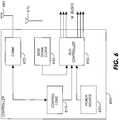
- FIG. 6is block diagram of a controller 600 for controlling, for example, the antenna controllers of FIGS. 4 and 5 .
- the controller 600includes a control logic 610, power source 620, communication block 630 connected to an antenna 660, base signal clock 640 connected to an antenna 670, and bus controller 650.
- the control logic 610controls the bus controller 650, which transmits signals out on M buses to M number of antenna controllers, (e.g., 400 and 500).
- the power source 620provides a source of power to the bus controller 650.
- the communication block 630transmits and receives data from a receiver over its respective antenna 660.
- the base signal clock 640transmits the base signal to other controllers and may also send/receive transmissions to the receiver for synchronization.
- One controller 600may be utilized to control all transmitter antennas or several controllers 600 may be used where one controller 600 controls a group of antennas. Additionally, it should be noted that although separate communication blocks and base signal clock, having respective antennas are shown, the functionality may be incorporated into one block, (e.g., the communication block 630).
- FIG. 7is block diagram of an alternative receiver 700 in accordance with the first embodiment.
- the receiver 700includes a control logic 710, battery 720, communication block 730 and associated antenna 760, power meter 740, and rectifier 750 and associated antenna 770.
- the control logic 710transmits and receives a data signal on a data carrier frequency from the communication block 730. This data signal may be in the form of the power strength signal transmitted over the side channel described above.
- the rectifier 750receives the power transmission signal from the power transmitter, which is fed through the power meter 740 to the battery 720 for charging.
- the power meter 740measures the received power signal strength and provides the control logic 710 with this measurement.
- the control logic 710also may receive the battery power level from the battery 720 itself.
- the receiver 700may be synchronized with, for example, the controller 600 by having the controller 600 transmit the base frequency signal via the antenna 670. The receiver 700 may then use this signal to synchronize a beacon signal, or calibration signal, that the receiver transmits back to the controller 600. It may also be noted that this technique may be utilized with multiple controllers as well. That is, where multiple transmission arrays are being utilized, the controllers may be synchronized with one another by utilizing a base frequency signal sent from one of the controllers.
- FIG. 8is block diagram of an alternative receiver 800 in accordance with the second embodiment.
- the receiver 800includes a control logic 810, battery 820, communication block 830 and associated antenna 870, power meter 840, rectifier 850, beacon signal generator 860 and an associated antenna 880, and switch 865 connecting the rectifier 850 or the beacon signal generator 860 to an associated antenna 890.
- the rectifier 850receives the power transmission signal from the power transmitter, which is fed through the power meter 840 to the battery 820 for charging.
- the power meter 840measures the received power signal strength and provides the control logic 810 with this measurement.
- the control logic 810also may receive the battery power level from the battery 820 itself.
- the control logic 810may also transmit/receive via the communication block 830 a data signal on a data carrier frequency, such as the base signal clock for clock synchronization.
- the beacon signal generator 860transmits the beacon signal, or calibration signal using either the antenna 880 or 890.
- the battery 820is shown for being charged and for providing power to the receiver 800, the receiver may also receive its power directly from the rectifier 850. This may be in addition to the rectifier 850 providing charging current to the battery 820, or in lieu of providing charging.
- the use of multiple antennasis one example implementation and the structure may be reduced to one shared antenna..
- the transmitter's antenna control circuits and the receiver power and control circuitsmay be built as Integrated Chips (ICs), and may share several key circuit components, the two chip functionalities may be designed as a single chip, and by choosing different packaging or configuration, the chip may function as either a transmitter or receiver. That is, the same chip with certain portions enabled or disabled may be utilized as a transmit antenna controller or a receiver controller. This may reduce the cost of building and testing two different chips, as well as save on chip fabrication costs, which may be significant.
- ICsIntegrated Chips
- the shape of the transmission gridmay take on many varieties. Accordingly, the packing of the antennas could be close enough to around half a wavelength of the transmitted power signal, to several times the wavelength. Two-dimensional arrangements could be made to allow the array to be laid flat under a carpet, or draped over attic heat insulation. For example, multiple wide wires, (e.g., narrow strips of a two-dimensional array), may be employed that contain multiple transmitting antennas. These wide wires could be installed in flooring or within walls. Alternatively, the power transmission grid could be in the form of loop antennas, or any other shape.
- grid arraysmay be formed in several layers stacked behind one another, allowing for a higher density antenna.
- the arrayacts similarly to a "phased volume" having a single forward beam with a minimum of a mirror beam behind it. The mirror beam may be reduced as the thickness of the phased volume increases.
- perfectly flat phased arrays using omni-directional antennaemay create two "images" of the formed wavefronts symmetrically around the plane of the array, (e.g., when there is free space or an identical environment on opposite sides of the array). This could have undesirable consequences of reducing the power delivery, (e.g., 50% of the power going to the backplane), and thus reducing the efficiency of the transfer.
- Arranging the array antennae in non-planar formmay reduce this symmetrical wavefront even if it has a 3-dimensional array symmetrical design, due to the fact that the antennas will have different phases on across the symmetrical sides of the array, making the signal non-symmetrical and non-"mirrored".
- every antenna in the arrayhas a specific phase to which it transmits to create a signal that reaches that particular receiver.
- Two or more receiverscan be configured to receive power by one or a combination of the following techniques.
- time sharing the power deliverymay be utilized between the different receivers. This can be done by tuning the antennas in the array to one receiver, and then switching to the next receiver, giving each receiver an equal (or unequal) amount of time.
- the tuning of the array to each receivermay be done from memory or by re-tuning the array using a process similar to the second embodiment technique.
- phase modulating all the array antennae to create multiple power spotsmay be utilized.
- the received signalis a vector with the phase being the received angle, while the magnitude is the power level of received signal.
- the phase of the transmissionmay be determined as being the angle of the sum of the received vectors.
- the peak received signal power from each receivermay be discovered, and the vector addition may be biased by scaling the vectors against a normalized scale, (e.g., peak power from each receiver may be considered of magnitude 1.0 for the peak power).
- the addition of the vectorsmay ensure that each antenna provides more power to the receiver that it delivers more power to, or, alternatively, receives more power from.
- Antenna sharingis another technique. By dividing the whole array to multiple sub-arrays, each may dedicate its power to a specific receiver. This approach may be beneficial when the array is large enough to be efficient when divided.
- Separate arraysmay be used in unison, where the individual array units synchronize their base signal clocks using a shared over the air frequency to achieve a continuous signal from a designated "master” unit, allowing all "slave” transmitter controller units to add up their waveforms coherently.
- Thisallows the separate arrays to be distributed in the environment, giving the users flexibility in arranging multiple arrays around the building, living quarters, manufacturing plan or offices.
- an installer/managermay link the different controller arrays to each other by designating a master unit along with failover sequences such that no matter how many arrays fail, the system will continue working using the available arrays.
- the arraysmay be set by synchronizing them using an atomic clock.
- separate array unitsmay work without synchronizing on a base frequency by using accurate atomic clocks, (e.g., greater than 1:10 ⁇ 10 accuracy), if the separate array units utilize a single frequency to use for power transmission. In this case, they would be in phase for fractions of a second, allowing coherency of phase/signal to be maintained.
- accurate atomic clockse.g., greater than 1:10 ⁇ 10 accuracy
- the transmittermay send out a regular signal at the side communication channel broadcasting its presence to all receivers. If there are other transmitters in the vicinity, it ensures to use one of the agreed upon frequencies, or avoid signal collisions by monitoring other transmitter's signals. These broadcast announcements can vary in frequency from several per minute to less than one per minute.
- the receivermay send out a signal announcing its presence, and the transmitters may negotiate to find which one is the most suitable for the power transfer. Once decided, the receiver "locks" onto a single transmitter. This may require that each transmitter is defined as a logical (single controller) device - which could be made up of multiple linked transmitters. If the controller detects that the power envelope has changed, (i.e., a receiver is not requiring the same power), the controller may continue to provide power so that the receiver will not fail.
- the transmitterscould be set up such that they are open to serve power to any wanting device, or they could be "paired" with the devices they should serve. Pairing avoids the problem of the neighbors' borrowing power from each other unintentionally, which could affect the efficiency from the transmitter's owner point of view.
- the transmitterWhen the transmitter is confronted with multiple receivers, it may want to establish a hierarchy for prioritization, such as giving the most needy devices the power first, which could be established on one or more predefined criteria.
- some of the criteriamay include: the device is of critical importance to its owner, (e.g., a cell phone as opposed to a toy); the device does not typically spend all day in the vicinity of the transmitter, (e.g., a TV remote control compared to a cell phone); or the device is found to need immediate power or it will fail. Such devices may be given higher priority over others until they reach non-critical power. Alternatively, a user customized priority may be utilized, whereby the user decides which device should get the highest priority.
- the example prioritization preference described abovemay be preinstalled into the transmitter system, (e.g., in the control logic), with the ability to be overruled by the installer of the array, ensuring that the system is delivering on the prioritization of the owners/users.
- the owner or usermay also desire whether the array would be open to deliver power to any device, or may desire to register specific devices as highest priority or least priority. Additionally, the user or owner may desire to determine whether or not to maintain power to specific device even if it is moving.
- the transmission of powerhas to be stopped as the array re-tunes to a new location of the receiver. If these re-tune operations are done at a high frequency due to fast movement of the receivers or due to rapid changes in the configuration of the environment, the time needed to keep the array turned off while receiving a new beacon signal could reduce the power delivery efficiency. Accordingly, to counteract this, more than one frequency may be used by the array/receiver. While one frequency is being tuned, another frequency may continue to transmit power, then the subsequent frequency is tuned until all the frequencies have re-tuned, thus avoiding any stopped gaps in the transmission.
- a standard format battery(e.g., AA, AAA, C-cell, D-cell or others), with ability to receive power and recharge itself might be desired as a replacement for a disposable or rechargeable batteries used in an electronic/electrical device. This would require the battery to have all the circuitry needed to communicate with the transmitter array, as well as have charge/energy capacitance to be used to run the device the battery powers.
- the deviceoften requires voltage or current to activate the components or battery capacitance to ensure long operation between battery swaps, that exceeds the capability of single battery. Therefore multiple batteries are often used in series or in parallel. However, with a single receiver battery, only one battery can be necessary for device operation, since the battery can deliver the required voltage and the energy capacity becomes a moot issue since the battery is able to receive copious amounts of energy to maintain operation perpetually without need for changing the batteries.
- FIG. 9is a block diagram of a receiver battery system 900.
- the system 900includes at least one receiver battery 910 and may include any number of null batteries 920.
- one receiver battery 910is shown and two null batteries 920, however, it should be noted that any number of null batteries may be utilized.
- the receiver battery 910includes a power capacitor 911, a control circuit 912, and a voltage control oscillator 913.
- the null battery 920includes induction logic 921.
- the battery system 900may operate as follows. Only one battery with the "receiver" enabled battery, (i.e., 910) is provided. However, used regular batteries placed in series with a good running battery may have their resistance build up over time, and they could leak once their lifetime usage is exceeded, among other problems that can occur.
- null batteriesmay be used in conjunction with a "power selector” on the receiver battery 910.
- the null batteries 920in one example are devices with exact battery dimensions but with their anodes shortened, making the voltage of the receiver battery 910 drive the device unaided.
- the receiver battery 910utilizes the control circuitry or slider 912 or other selection mechanism to allow the user to select the number of batteries he/she is replacing.
- the receiver battery 910then outputs the desired voltage to compensate for the null batteries 920.
- intelligent null-batteries 920as well as an intelligent receiver battery 910 may be used.
- the receiver batterywill initially output the voltage of one battery of the desired format as well as 1KHz (or similar other frequency) low voltage oscillation ( ⁇ 0.1V oscillation for the duration of detecting the number of null batteries used), and the intelligent null-batteries 920 use the 1KHz to power themselves inductively.
- the null batteriesnow create an effect on the power-line by resistance, capacitance or other means that the receiver battery can detect.
- the frequency of effect of the intelligent null-batteries 920is done by onboard quasi-random generators, (e.g., logic 921), that have the characteristic of being statistically additive. It can therefore be determined the count of the quasi-random generators on the line.
- One embodiment of thiswould be the use of a 32-bit linear feedback shift register running at a known interval, such that the shifted bit is used to trigger the effect "blips" on the power line.
- the seed number of the feedback shift registers on power upshould be different on all the null batteries 920 so they do not work in unison.
- FIG. 10is an example battery system power line diagram 1000, including "blips" 1010.
- the receiver battery 910counts the blips 1010 on the power line and determines the number of intelligent null-batteries 920.
- the blips 1010could be high frequency pulses or capacitance modifiers. Blips that are not masked out by most electrical/electronic devices may be chosen. This process is performed for a short period of time, for example, less than 1 millisecond. After that, the receiver battery 910 does not require voltage detection until a next power-up which could be in a different device with different power needs.
- the 1KHz "power" frequency created by the receiver battery 910stops and the null batteries 920 become dormant and become transparent to the device being powered.
- random blips 1010are generated by each of the two null batteries 920 over the power system line of system 900.
- the blips 1010are used to determine the number of random blip generators by the receiver battery 910. By counting the blips over time, and dividing by the expected number from a single null battery 920, it can be determined the number of null batteries 920 installed in series. In a parallel battery installation system, however, one receiver battery 910 may be required for each parallel power line.
- the deviceWhen a device is receiving power at high frequencies above 500MHz, its location may become a hotspot of (incoming) radiation. So when the device is on a person, the level of radiation may exceed the FCC regulation or exceed acceptable radiation levels set by medical/industrial authorities. To avoid any over-radiation issue, the device may integrate motion detection mechanisms such as accelerometers or equivalent mechanisms. Once the device detects that it is in motion, it may be assumed that it is being manhandled, and would trigger a signal to the array either to stop transmitting power to it, or to lower the received power to an acceptable fraction of the power. In cases where the device is used in a moving environment like a car, train or plane, the power might only be transmitted intermittently or at a reduced level unless the device is close to losing all available power.
- motion detection mechanismssuch as accelerometers or equivalent mechanisms.
- FIG. 11is an alternative receiver 110 in accordance with the first embodiment that includes motion detection as described above.
- the receiver 1100includes a control logic 1110, battery 1120, communication block 1130 and associated antenna 1160, power meter 1140, rectifier 1150 and associated antenna 1170, and a motion sensor 1180. With the exception of the motion sensor 1180, the rest of the components operate functionally similar to the respective components of receiver 700.
- the motion sensor 1180detects motion as described above and signals the control logic 1110 to act in accordance with the technique described above.
- FIG. 12is an alternative receiver 1200 in accordance with the second embodiment that includes motion detection as described above.
- Receiver 1200includes a control logic 1210, battery 1220, communication block 1230 and associated antenna 1270, power meter 1240, rectifier 1250, beacon signal generator 1260 and an associated antenna 1280, and switch 1265 connecting the rectifier 1250 or the beacon signal generator 1260 to an associated antenna 1290.
- the motion sensor 1280With the exception of the motion sensor 1280, the rest of the components operate functionally similar to the respective components of receiver 800.
- the motion sensor 1280detects motion as described above and signals the control logic 1210 to act in accordance with the technique described above.
- a device designed to receive power at frequencies used by WiFi communication or Bluetooth and the likesuch as a cell phone or media player might already have antennas capable of receiving power at the power transmission frequencies. Accordingly, instead of having additional antennas to receive the power, the same communication antennas used for the WiFi communication and the like may be used to receive power, by adding the required circuitry to the communication hardware, (e.g., adding rectification, control logic, etc.).
- Some example uses of the wireless power transmission systemmay include supermarket and consumer retail outlets provide pricing tags on the shelves of the merchandise. Managing the price number on these tags can be an expensive and time consuming effort. Also, special deals and promotions mean that the tags would be changed daily.
- each tagmade of a small electronic device that displays the prices/promotions quite effectively, and electronic ink consumes no power while displaying a static image.
- poweris required to receive the new data to display and it is also required to change the electronic ink display.
- Having wires reaching every tagis not a feasible solution nor is having batteries in each tag. Since they would require charging or replacement regularly.
- thousands of tagscan be maintained operational from wireless power transmitter arrays placed in the ceilings or shelves; powering the tags on regular basis, as well as when a tag is moved. Once the tags arrive at the desired destination, the tags may be activated with initial power either wired or wireless.
- manufacturing plantsutilize a large number of sensors and controllers to maintain synchronization of production, overall productivity and quality of manufactured goods.
- wireless communicationit is still required to run power carrying wires to every device, which makes the devices dependant on one more component that is prone to failure, and the devices cannot be hermetically sealed before installation for use in highly combustible environments such as oil refineries, since the devices need to have holes to bring the power wires into the device.
- wireless powermay be provided to these devices by incorporating one of the wireless power receivers described above.
- the wireless power systemmay also be utilized for motion detection.
- the power transmission systemWhen the power transmission system is active, small disturbances in the environment can change the efficiency of the transfer, even when the change is not in the line of sight of the transmission. Since this system leverages the multiple paths (multipath) in the environment, it can be used as a motion detector. By measuring the power received from an array that is localized or distributed in the environment, any changes to the power level received will be an indication of changes to the electromagnetic configuration of the environment. It may be noted that in such uses, the power transfer level can be very small, since wires can power the receiver, but is acting only as means of tuning the array. Once a change in the environment's configuration is detected, the security system/alarms may be notified of the change.
- individual drink and food containers that regulate the temperature of their contentsneed to have a constant power source. If these containers are highly mobile, it becomes difficult to maintain the power source availability. Wireless power can be used to maintain a power source availability and hence the temperature of the containers can be maintained at the desired temperature.
- the containerscan also use the available power to report the contents temperature, level of fluid or weight of contents. An example of this is when cold/hot drinks are served on hot days, or when drinking them cold/hot is the best way to drink them, with this capability, the drinker does not have to finish their drink before it reaches the ambient temperature, but could enjoy their drinks on a longer time period. Also, when the drinks are getting low, a host can be wirelessly notified through a signal receiver and can top up the drinks in time before they run out.
- fire alarmsmay be considered as having failed if they are not consuming the nominal power they use, or when power consumption of a device changes drastically, which usually occurs when a device is about to fail.
- any type of rechargeable batteriesmay be utilized to receive the charge from the power transmission grid, including standard size rechargeable batteries or custom rechargeable batteries for use in specific electronic devices, (i.e., cell phones, PDAs, and the like). These rechargeable batteries may be utilized to replace the currently existing batteries and may include the electronics of the receiver that will allow them to receive the power transmission signal and convert it to recharge the batteries.
Landscapes
- Engineering & Computer Science (AREA)
- Power Engineering (AREA)
- Computer Networks & Wireless Communication (AREA)
- Physics & Mathematics (AREA)
- Electromagnetism (AREA)
- Signal Processing (AREA)
- Charge And Discharge Circuits For Batteries Or The Like (AREA)
- Variable-Direction Aerials And Aerial Arrays (AREA)
Description
- The present invention relates generally to power transmission systems and battery chargers, and particularly to a method and system for wireless power transmission by microwave transmission to power a device requiring electrical power.
- Many portable electronic devices are powered by batteries. Rechargeable batteries are often used to avoid the cost of replacing conventional dry-cell batteries, and to conserve precious resources. However, recharging batteries with conventional rechargeable battery chargers requires access to an alternating current (A.C.) power outlet, which is sometimes not available or not convenient. It would therefore be desirable to derive power for a battery charger from electromagnetic radiation.
- While solar-powered battery chargers are known, solar cells are expensive, and a large array of solar cells may be required to charge a battery of any significant capacity. Another potential source of electromagnetic energy that would provide power to a battery charger at a location remote from the A.C. power mains is microwave energy, which might be derived from a solar powered satellite and transmitted to earth by microwave beams, or derived from ambient radio frequency energy from cell phone transmitters and the like. However, there are several problems associated with the efficient delivery of power by microwave transmission that have precluded the use of dedicated terrestrial microwave power transmitters for the purpose.
- Assuming a single source power transmission of electro-magnetic (EM) signal, an EM signal gets reduced by a factor of 1/r2 in magnitude over a distance r. Thus, the received power at a large distance from the EM transmitter is a small fraction of the power transmitted.
- To increase the power of the received signal, we would have to boost the transmission power. Assuming that the transmitted signal has an efficient reception at three centimeters from the EM transmitter, receiving the same signal power over a useful distance of three meters would entail boosting the transmitted power by 10,000x. Such power transmission is wasteful, as most of the energy would be transmitted and not received by the intended devices, it could be hazardous to living tissue, it would most likely interfere with most electronic devices in the immediate vicinity, and it may be dissipated as heat.
- Utilizing a directional antenna has several challenges, some of which are: knowing where to point it; the mechanical devices needed to track it would be noisy and unreliable; and creating interference for devices in the line of sight of the transmission.
- Directional power transmission generally requires knowing the location of the device to be able to point the signal in the right direction to enhance the power transmission efficiency. However, even when the device is located, efficient transmission is not guaranteed due to reflections and interference of objects in the path or vicinity of the receiving device.
- Thus, a wireless power transmission system solving the aforementioned problems is desired.
US 2008/0309452 A1 discloses a wireless power transmission system for providing wireless charging and/or primary power to electronic/electrical devices via microwave energy. The microwave energy is focused onto a device to be charged by a power transmitter having one or more adaptively-phased microwave array emitters. Rectennas within the device to be charged receive and rectify the microwave energy and use it for battery charging and/or for primary power. A communications channel is opened between the wireless power source and the device to be charged. The device to be charged reports to the power source via the channel a received beam signal strength at the rectennas. This information is used by the system to adjust the transmitting phases of the microwave array emitters until a maximum microwave energy is reported by the device to be charged. Backscatter is minimized by physically configuring the microwave array emitters in a substantially non-uniform, non-coplanar manner.- The wireless power transmission is a system for providing wireless charging and/or primary power to electronic/electrical devices via microwave energy. The microwave energy is focused to a location in response to receiving a beacon signal from a beacon device by a power transmitter having one or more adaptively-phased microwave array emitters. Rectennas within the device to be charged receive and rectify the microwave energy and use it for battery charging and/or for primary power.
- The device to be charged reports the received beam signal strength at the rectennas to the power source via the side channel. This information is used by the system to adjust the transmitting phases of the microwave array emitters until maximum microwave energy is reported by the device to be charged.
- Alternatively, the array elements can be set to receive a calibration signal from the device being charged. Each array element can detect/report phase information from the received calibration signal. Subsequently, each array element uses the detected phase for that element as a guide to the transmitting phase back to the device being charged.
- Mirror focal points caused by, for example, flat, two dimensional arrays are minimized by physically configuring the microwave array emitters in a substantially non-uniform, non-coplanar manner.
- These and other features of the present invention will become readily apparent upon further review of the following specification and drawings.
FIG. 1A is an environmental, perspective view of a first embodiment of a wireless power transmission system according to the present invention.FIG. 1B is an environmental, perspective view of a second embodiment of a wireless power transmission system according to the present invention.FIG. 2A is a perspective view of the phased array net antenna for a microwave transmitter in a wireless power transmission system according to the present invention.FIG. 2B is a diagrammatic view of a power transmission node in a wireless power transmission system according to the present invention.FIG. 3A is a block diagram of the first embodiment of the wireless power transmission system according to the present invention.FIG. 3B is a block diagram of the second embodiment of the wireless power transmission system according to the present invention.FIG. 4 is a block diagram of an alternative first embodiment power transmitter.FIG. 5 is a block diagram of an alternative second embodiment power transmitter.FIG. 6 is block diagram of a controller.FIG. 7 is block diagram of an alternative receiver in accordance with the first embodiment.FIG. 8 is a block diagram of an alternative receiver in accordance with the second embodiment.FIG. 9 is a block diagram of a receiver battery system.FIG. 10 is an example battery system power line diagram.FIG. 11 is an alternative receiver in accordance with the first embodiment.FIG. 12 is an alternative receiver in accordance with the second embodiment.- Similar reference characters denote corresponding features consistently throughout the attached drawings.
- As shown in
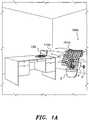
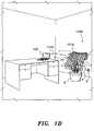
FIGS. 1A-1B , the present invention includes asystem 100a, or alternativelysystem 100b, for providing wireless charging and/or primary power to electronic/electrical devices, such aslaptop computer 102, or the like, via microwave energy. In eithersystem 100a orsystem 100b,power transmission grid 101a or alternativepower transmission grid 101b can obtain operational power from the A.C. mains via power cord P being plugged into power outlet O. The microwave transmission frequency is preferably an available FCC unregulated frequency having a suitable wavelength. Since the wavelength can limit resolving power of the phasedarray 101a or alternative phasedarray 101b, a preferred frequency, although not limiting the choice of other frequencies that the system may operate on, has been determined to be 5.8 GHz (5.17 cm wavelength), which is suitable for power transmission to such devices as a laptop, cell phone, PDA, etc., over distances on the scale of a room, auditorium, or the like. - As shown in
FIGS. 1A-3B , the microwave energy is focused onto a device to be charged by apower source 300 connected to one or more adaptively-phasedmicrowave array emitters 204, i.e., antennae or radiators. According to the present invention, the microwave energy from the adaptively-phasedmicrowave array emitters 204 may be focused onto the device without the need to know the location of the device. As shown inFIGS. 1A ,1B , and3A-3B , preferably highly efficient rectennas 340 (a rectenna is a rectifying antenna that converts microwave energy directly into direct current (D.C.) electricity; such devices are known in the art and will not be described further herein) within the device to be charged 102 receive and rectify the microwave energy and use it for chargingbattery 370 via charging and/or for primary power to thedevice 102 as determined bycontrol logic 350. In a first embodiment, a communications channel is opened between thewireless power source 100a andpower receiver 330b in the device to be charged 102 on a frequency other than the frequency used to convey power. - The device to be charged 102 relays a received beam signal strength at the
rectennas 340 over thecommunications channel 110a to a receiver section ofcommunications device 320 in thepower transmitter 330a ofsystem 100a via a signal from a transmitter section ofcommunications device 360 in thepower receiver 330b. This information is used bycontrol logic 310 of thesystem 100a to power up, power down, and adjust the transmitting phases of the microwavearray emitter nodes 204 until a maximummicrowave energy beam 301 is radiated by thearray 110a, as reported by the device to be charged 102. - Each
emitter 204, being connected to a single source of the desired transmission frequency, can transmit a signal with a specific phase difference, which is a multiple of π/2. The π/2 phase increments are exemplary only, and other phase increments such as π/4, π/8, π/16, and the like, are possible. Preferably, power is not adjusted, except that theemitter 204 can be turned off or turned on to a desired phase. - As most clearly shown in
FIGS. 2A-2B , vertical and horizontal cables intersect at eacharray node 204. This configuration applies to eitherarray 101a orarray 101b. Withinvertical cable 202,wire 210 is a zero phase feed line.Wire 212 is a ½ π phase feed line, andwire 209 is a vertical control line. Similarly, withinhorizontal cable 200,wire 214 is a π phase feed line.Wire 216 is a 3/2 π phase feed line, andwire 211 is a horizontal control line.Control lines controller 310 in order to control which phase is active on any givennode 204. Single antenna control can be on achip 206, while the actual node radiator orantenna 208 may be formed as a circular element surrounding the geometric center of thenode 204. It should be understood that either a single controller or a plurality of controllers may control one or more of power transmission grids. - An exemplary algorithm of control logic 310 for system 100a might be as follows: (1) the power receiver 330 can use the communications channel 110a to declare its presence to any transmitters 330a in the vicinity; (2) the power transmitter 330a may communicate its presence on the communications channel 1110a and start transmitting with only one of its antennae 208 or nodes 204; (3) the power receiver 330b may acknowledge receiving the faint signal on the communications channel 110a; (4) the power transmitter 330a switches on another antenna 208 or node 204 with a default phase of zero and may ask the receiver 330b over the communications channel 110a for signal strength; (5) the power receiver 330b may send back a signal indicating that the received signal is higher, the same, or lower than before; (6) if the signal is lower than or the same as before, the controller 310 may cause the phase at node 204 to increase its phase by ½ π and request another signal strength transmission; (7) steps 5 and 6 are repeated for all phases; (8) if no increase in signal strength is observed then that particular node 204 is switched off and another node is used in the process, repeating from step 4; (9) steps 4-6 are repeated until all emitters nodes are in use.
- In another example, step (6) may include increasing the phase over a three-phase cycle that includes 0, ½ π, and 5π/4 radians. In this manner, the approximate shape of the whole sinusoidal curve may be determined. Accordingly, the phase angle of the peak power may be determined. Also, since when adding up tuned antennas, the next added antenna received power may only be a small percentage of the total power received. Thus, adding the second antenna may increases the power by 4x, while adding the 101st antenna may add 2% to the power and the 1001st may add 0.2% to the total power received. This may make it difficult to detect the actual power gain/loss from the tested antenna. Therefore, only a few antennas may be powered up during the testing cycle, and the phases for each antenna tested may be remembered. Once the full array's phases have been determined, all the elements may be switched on to deliver power.
- Alternatively, all of the antennas in the power transmitted may be re-tuned, possibly by moving their phases slightly around their current values, and detecting the impact on the received signal. If it improves in one direction, (e.g., advancing or retarding the phase), the phase may continue to be cycle/incremented until there is no improvement to either side. This will depend on the ability to detect the change in received power level for a large array, otherwise, the whole array might be required to switch off and re-establish the phases from scratch
- In a second embodiment, as most clearly shown in
FIGS. 2B and3B , each array element ornode 204 can be set to receive a calibration signal from acalibration transmitter 460 in thepower receiving system 330b. Each array element ornode 204 can send the received calibration signal detected at thatnode 204 to thecontrol logic 310 viadata line 303. Subsequently, eithercontroller 310,controller 206, or both controllers in combination may set each array element ornode 204 to the detected phase for that element as a transmitting phase in order to send an optimizedpower transmission 301 back to thepower receiver 330b. In bothembodiments controller logic 310 in order to enable the array to transmit power to a specific location or "hotspot" without first having to communicate to the device to be charged 102. This feature is useful in sendingpower transmission 301 to the device to be charged 102 when the device to be charged 102 has no reserve power to establishcommunications channel - Alternatively, the second embodiment may operate as follows to utilize two way capabilities in the receiver and every transmitter antenna, such as that in a transceiver. A controller may prepare every transceiver to receive the beacon signal from the power receiver, (i.e., device to be charged). The device to be charged then sends out a beacon signal, (e.g., calibration signal that may be the same frequency of the phased array via, for example, a wireless communication between the array and the receiver to sync up their clocks), that traverses all open paths between the device to be charged and the power transmitter. The received signal at the power transmitter is equivalent to the sum of all open paths between the receiver and transmitter's antennae that lands on each antenna in the power transmitter, with the sum of each path adding up to a specific power level and phase at every specific power transmitter antenna.
- Each antenna in the transmitter array compares the incoming signal with an internal signal to detect the received phase. Once the received phase is established by all the transmitter's antennas, each antenna transmits back at the complex conjugate of the received phase with its full power.
- In addition, since the above tuning of the array takes into consideration all possible paths, (e.g., there is no assumption that there is a direct open path between array and receiver or that the receiver moves in smooth and linear motion in the environment), any changes to the configuration of the environment may be equivalent to the receiver being moved or the power transmitter array's physical configuration being changed. Therefore frequent re-tuning of the array may be required constantly, (e.g., 10 or more times per second).
- Since retuning the antenna array requires shutting off the power being sent to "listen" to the receiver's beacon signal, time may be lost that could have been used to power the array. Accordingly, the array may reduce the frequency of the retuning when the power level at the receiver does not change significantly in order to maximize the power delivery to the receiver. When the power reception at the receiver drops, the array may increase the frequency of the updates until the receiver power stabilizes again. Specific limits on the frequency of the tuning may be set up, such as a minimum of 10 tps (tunings per second) to a maximum of 500tps. Since very high frequency retuning might lower the efficiency of the power transfer beyond usefulness.
- Alternatively, the tuning of a number (n) antennas may be performed as follows. All n antennas may be switched off. One of the n antennas is then turned on and left on as a reference for each of the other n antennas to tune. Each of the rest of the n antennas are then turned on, their optimal phase is recorded, and they are then turned off. When this sequence is performed on the nth antenna, all antennas are turned on at their respective optimal phases.
- With respect to the first embodiment having a moving receiver, all of the transmitter antennas may need to be re-tuned, for example by moving their phases slightly around their current values and detecting the impact on the received signal. If it improves in one direction, cycling/incrementing the phase continues until there is no improvement to either side. This may depend on the ability to detect a change in the received power level for a large array, otherwise, the whole array might be required to switch off and re-establish the phases from the beginning.
- An
exemplary array single transmission antenna 204. Preferablyarray grid array emitter grid FIGS. 1A-1B , eitherarray 101a orarray 101b is sufficiently flexible so that it can be draped over a support structure, such as potted plant S, to provide the preferably non-uniform, non-coplanar configuration. - In this manner, the inverse-square law is successfully challenged, since the phased antenna is directional, thereby creating gain via a constructively phased beam signal that can be received at the receiving
device 102. Moreover, use of a phased array, such as 101a or 101b, obviates the necessity of using a more cumbersome, unsightly device such as a physical directional antenna, i.e., a dish, a Yagi, or the like. Additionally, due to the efficiency of the power transmission process, low power may be used for the transmission such that the electromagnetic (EM) signal can have most of its strength proximate the receiving device instead of spread all over, in order not to harm the environment or cause interference with devices located elsewhere. - Once the signal is received and its power is available, the process of converting the approximately 5.80 GHz AC current coming from the antenna into a DC current to charge the
battery 370, power storage capacitor, or the like, is done with lower voltage rectifiers capable of the task. These rectifiers can either be based on small area Schottky diode or utilize a resonance with a 5.80 GHz oscillating circuit in the same phase as the received signal, thus enhancing its power to the point of overcoming the voltage drop of the diodes used in the rectifier portion of therectenna 340. It should be noted that multiple devices may be charged by time sharing the array, or by superimposing phases of the antennas in order to simulate a multiple beam configuration. - The charging mechanism described above operates when the transmitter and receiver are in communication with one another. However, a method for charging a receiver that has no power to communicate may be beneficial as well. To accomplish this, a location, or locations, that will receive a periodic power transmission burst may be established.
- In one example of how to charge a device having no battery power, a beacon device, or resurrector, (not shown) may be placed in the location to receive the periodic power transmission burst or on demand by the user. The beacon device communicates with the power transmission grid, such as by transmitting a beacon signal, and the power transmission grid recognizes that beacon signal phase configuration as a location to transmit a periodic power transmission burst, (e.g., a one second burst every ten minutes, or a 0.1 second burst every minute with a one second burst every ten minutes). The beacon signal transmitted from the beacon device may be reflected and/or refracted through various media before it arrives at the power transmission grid. Accordingly, multiple beacon signals may be received by the power transmission grid. When the power transmission grid receives the one or more beacon signals, the open path(s) from the location of the beacon device to the power transmission grid may be established.
- The power transmission grid may then aggregate the beacon signals to recreate the waveform of the transmitted beacon signal. From this recreated waveform, the power transmission grid can then transmit the power transmission burst as, for example, a reverse waveform of the recreated waveform to provide a power burst at the location established by the beacon device. In one embodiment, the reverse waveform may be determined by taking the complex conjugate, or mathematically equivalent transform, of the waveforms received from the beacon device. The beacon device can be turned off once the location to receive a periodic power transmission burst is established.
- The device to be charged 102 that has no battery power can then be placed at that location where it will receive the periodic power transmission burst until it has enough power to communicate with the power transmission grid to undergo the charging process described above. The device can then be moved away from that location.
- Once a device to be charged 102 is moved from one location to another, or the power transmission grid is moved, the power transmission grid may re-tune itself, (e.g., re-align transmission antennas), to establish the best transmission power to the device to be charged 102. This re-tuning may occur in response to the
device 102 reporting a drop in power or in regular intervals, (e.g., 1ms-10s). However, the regular interval may be shortened or lengthened depending on how well the signal power is maintained by the receiver, while continuing to re-tune regularly despite no drop in power. - The transmitter antennas may also take the form of including circuitry into a single chip and daisy chaining the chips with wires to create long strips of "phased wires" that may be configured and used in various shapes and designs. Constructing complex arrays with thousands of antennas and associated controllers through strings of "phase control" chips, the wires between the chips may serve as the data paths connecting the chips to a common controller, while at the same time, the wires may also act as the transmitting/receiving antennas themselves. Each chip may have more wires coming out of it acting as antennas. Each antenna may be given an address, (e.g., a, b, c, and the like), allowing the chip to control the phase of each antenna independently from the others. Additionally, the wires may be configured in all sorts of arrangements, depending on available space since the tuning of the array is irrespective of the antenna locations and arrangements.
- Since the antenna chip controllers are connected through short wires, the wires may be utilized as antenna in several ways. For example, the wires themselves may be driven by oscillator and/or amplifiers, or a shield may be used around the wires, with the shield itself driven and used as an antenna, thus preventing the communication wires from shielding the signal in multilayers arrays.
FIG. 4 is a block diagram of an alternative first embodiment transmitter. The transmitter may be anantenna controller 400 that includes acontrol logic 410, phase shifters 420 (N Count), signal generator/multiplier 430, amplifiers 440 (N Count), and (N)antennas 450. Theantenna controller 400 receives power and base frequency control signals, as well as other commands and communication signals, on a common bus from a single controller that controls all antenna controllers or from aprevious antenna controller 400. The power signal, for example, may be received by a power supply of the transmitter 400 (not shown), while the base frequency control signal may be received by the signal generator/multiplier 430, and the communication signals and commands may be received by thecontrol logic 410. In the case where eachprevious antenna controller 400 provides the power and base frequency control signals, a bus carrying those signals may continue on to thenext antenna controller 400. Thecontrol logic 410 may control thephase shifter 420 to cause it to adjust the phase of theamplifiers 440. The signal generator/multiplier receives the signal from the bus at, for example 10 MHz, and converts it up to for example 2.4, 5.8 GHz and the like for wireless transmission.FIG 5 is a block diagram of an alternative second embodiment transmitter. The transmitter may be anantenna controller 500 that includes acontrol logic 510, phase shifters 520 (N count), signal generator/multiplier 530, transceivers 540 (N Count), (N)antennas 550, and phase comparators 560 (N Count). Thetransceivers 540 receive the calibration or beacon signals from the receivers and forward the signal to thephase comparators 560. Thephase comparators 560 determine the phase of the received signals of theirrespective transceivers 540 and determine an optimal phase angle for which to transmit the power signal. This information is provided to thecontrol logic 510, which then causes thephase shifter 520 to set the phase, (e.g., at the complex conjugate of the received beacon/calibration signal), of the transceivers and transmit the power at that set phase. The signal generator/multiplier 530 performs a function substantially similar to the signal generator/multiplier 430 of theantenna controller 400. In addition, the bus signals are similar to those in thetransmitter 400, with the signals being received, for example, by the counterpart components intransmitter 500.FIG. 6 is block diagram of acontroller 600 for controlling, for example, the antenna controllers ofFIGS. 4 and5 . Thecontroller 600 includes acontrol logic 610,power source 620,communication block 630 connected to anantenna 660,base signal clock 640 connected to anantenna 670, andbus controller 650. Thecontrol logic 610 controls thebus controller 650, which transmits signals out on M buses to M number of antenna controllers, (e.g., 400 and 500). Thepower source 620 provides a source of power to thebus controller 650. Thecommunication block 630 transmits and receives data from a receiver over itsrespective antenna 660. Thebase signal clock 640 transmits the base signal to other controllers and may also send/receive transmissions to the receiver for synchronization. Onecontroller 600 may be utilized to control all transmitter antennas orseveral controllers 600 may be used where onecontroller 600 controls a group of antennas. Additionally, it should be noted that although separate communication blocks and base signal clock, having respective antennas are shown, the functionality may be incorporated into one block, (e.g., the communication block 630).FIG. 7 is block diagram of analternative receiver 700 in accordance with the first embodiment. Thereceiver 700 includes acontrol logic 710,battery 720,communication block 730 and associatedantenna 760,power meter 740, andrectifier 750 and associatedantenna 770. Thecontrol logic 710 transmits and receives a data signal on a data carrier frequency from thecommunication block 730. This data signal may be in the form of the power strength signal transmitted over the side channel described above. Therectifier 750 receives the power transmission signal from the power transmitter, which is fed through thepower meter 740 to thebattery 720 for charging. Thepower meter 740 measures the received power signal strength and provides thecontrol logic 710 with this measurement. Thecontrol logic 710 also may receive the battery power level from thebattery 720 itself.- The
receiver 700 may be synchronized with, for example, thecontroller 600 by having thecontroller 600 transmit the base frequency signal via theantenna 670. Thereceiver 700 may then use this signal to synchronize a beacon signal, or calibration signal, that the receiver transmits back to thecontroller 600. It may also be noted that this technique may be utilized with multiple controllers as well. That is, where multiple transmission arrays are being utilized, the controllers may be synchronized with one another by utilizing a base frequency signal sent from one of the controllers. FIG. 8 is block diagram of analternative receiver 800 in accordance with the second embodiment. Thereceiver 800 includes acontrol logic 810,battery 820,communication block 830 and associatedantenna 870,power meter 840,rectifier 850,beacon signal generator 860 and an associatedantenna 880, and switch 865 connecting therectifier 850 or thebeacon signal generator 860 to an associatedantenna 890. Therectifier 850 receives the power transmission signal from the power transmitter, which is fed through thepower meter 840 to thebattery 820 for charging. Thepower meter 840 measures the received power signal strength and provides thecontrol logic 810 with this measurement. Thecontrol logic 810 also may receive the battery power level from thebattery 820 itself. Thecontrol logic 810 may also transmit/receive via the communication block 830 a data signal on a data carrier frequency, such as the base signal clock for clock synchronization. Thebeacon signal generator 860 transmits the beacon signal, or calibration signal using either theantenna battery 820 is shown for being charged and for providing power to thereceiver 800, the receiver may also receive its power directly from therectifier 850. This may be in addition to therectifier 850 providing charging current to thebattery 820, or in lieu of providing charging. Also, it may be noted that the use of multiple antennas is one example implementation and the structure may be reduced to one shared antenna..- Since the transmitter's antenna control circuits and the receiver power and control circuits may be built as Integrated Chips (ICs), and may share several key circuit components, the two chip functionalities may be designed as a single chip, and by choosing different packaging or configuration, the chip may function as either a transmitter or receiver. That is, the same chip with certain portions enabled or disabled may be utilized as a transmit antenna controller or a receiver controller. This may reduce the cost of building and testing two different chips, as well as save on chip fabrication costs, which may be significant.
- As discussed above, the shape of the transmission grid may take on many varieties. Accordingly, the packing of the antennas could be close enough to around half a wavelength of the transmitted power signal, to several times the wavelength. Two-dimensional arrangements could be made to allow the array to be laid flat under a carpet, or draped over attic heat insulation. For example, multiple wide wires, (e.g., narrow strips of a two-dimensional array), may be employed that contain multiple transmitting antennas. These wide wires could be installed in flooring or within walls. Alternatively, the power transmission grid could be in the form of loop antennas, or any other shape.
- Three dimensional arrangements might pack the largest number of antennas and can be incorporated into convenient forms such as office ceiling tiles, doors, paintings and TVs - thus making the array invisible and non-obtrusive. Also, grid arrays may be formed in several layers stacked behind one another, allowing for a higher density antenna. In this example, the array acts similarly to a "phased volume" having a single forward beam with a minimum of a mirror beam behind it. The mirror beam may be reduced as the thickness of the phased volume increases.
- That is, perfectly flat phased arrays using omni-directional antennae may create two "images" of the formed wavefronts symmetrically around the plane of the array, (e.g., when there is free space or an identical environment on opposite sides of the array). This could have undesirable consequences of reducing the power delivery, (e.g., 50% of the power going to the backplane), and thus reducing the efficiency of the transfer. Arranging the array antennae in non-planar form may reduce this symmetrical wavefront even if it has a 3-dimensional array symmetrical design, due to the fact that the antennas will have different phases on across the symmetrical sides of the array, making the signal non-symmetrical and non-"mirrored".
- When the array is phase tuned for a particular receiver, every antenna in the array has a specific phase to which it transmits to create a signal that reaches that particular receiver. Two or more receivers can be configured to receive power by one or a combination of the following techniques.
- In a first technique, time sharing the power delivery may be utilized between the different receivers. This can be done by tuning the antennas in the array to one receiver, and then switching to the next receiver, giving each receiver an equal (or unequal) amount of time. The tuning of the array to each receiver may be done from memory or by re-tuning the array using a process similar to the second embodiment technique.
- In another technique, phase modulating all the array antennae to create multiple power spots may be utilized. For each antenna, the received signal is a vector with the phase being the received angle, while the magnitude is the power level of received signal. To create the returned signal to multiple receivers, the phase of the transmission may be determined as being the angle of the sum of the received vectors. Although it may not be necessary to utilize the magnitude of the received signal and transmit from each antenna at normal transmission power, in order to create a biased multi-focus signal that performs better when multipath signals are considered, the peak received signal power from each receiver may be discovered, and the vector addition may be biased by scaling the vectors against a normalized scale, (e.g., peak power from each receiver may be considered of magnitude 1.0 for the peak power). The addition of the vectors may ensure that each antenna provides more power to the receiver that it delivers more power to, or, alternatively, receives more power from.
- Antenna sharing is another technique. By dividing the whole array to multiple sub-arrays, each may dedicate its power to a specific receiver. This approach may be beneficial when the array is large enough to be efficient when divided.
- Separate arrays may be used in unison, where the individual array units synchronize their base signal clocks using a shared over the air frequency to achieve a continuous signal from a designated "master" unit, allowing all "slave" transmitter controller units to add up their waveforms coherently. This allows the separate arrays to be distributed in the environment, giving the users flexibility in arranging multiple arrays around the building, living quarters, manufacturing plan or offices. During setup of these controllers, an installer/manager may link the different controller arrays to each other by designating a master unit along with failover sequences such that no matter how many arrays fail, the system will continue working using the available arrays. For example, the arrays may be set by synchronizing them using an atomic clock. That is, separate array units may work without synchronizing on a base frequency by using accurate atomic clocks, (e.g., greater than 1:10^10 accuracy), if the separate array units utilize a single frequency to use for power transmission. In this case, they would be in phase for fractions of a second, allowing coherency of phase/signal to be maintained.
- In another power transmission technique, the transmitter may send out a regular signal at the side communication channel broadcasting its presence to all receivers. If there are other transmitters in the vicinity, it ensures to use one of the agreed upon frequencies, or avoid signal collisions by monitoring other transmitter's signals. These broadcast announcements can vary in frequency from several per minute to less than one per minute. The receiver may send out a signal announcing its presence, and the transmitters may negotiate to find which one is the most suitable for the power transfer. Once decided, the receiver "locks" onto a single transmitter. This may require that each transmitter is defined as a logical (single controller) device - which could be made up of multiple linked transmitters. If the controller detects that the power envelope has changed, (i.e., a receiver is not requiring the same power), the controller may continue to provide power so that the receiver will not fail.
- In another power transmission technique, the transmitters could be set up such that they are open to serve power to any wanting device, or they could be "paired" with the devices they should serve. Pairing avoids the problem of the neighbors' borrowing power from each other unintentionally, which could affect the efficiency from the transmitter's owner point of view. When the transmitter is confronted with multiple receivers, it may want to establish a hierarchy for prioritization, such as giving the most needy devices the power first, which could be established on one or more predefined criteria.
- For example, some of the criteria may include: the device is of critical importance to its owner, (e.g., a cell phone as opposed to a toy); the device does not typically spend all day in the vicinity of the transmitter, (e.g., a TV remote control compared to a cell phone); or the device is found to need immediate power or it will fail. Such devices may be given higher priority over others until they reach non-critical power. Alternatively, a user customized priority may be utilized, whereby the user decides which device should get the highest priority.
- The example prioritization preference described above may be preinstalled into the transmitter system, (e.g., in the control logic), with the ability to be overruled by the installer of the array, ensuring that the system is delivering on the prioritization of the owners/users. The owner or user may also desire whether the array would be open to deliver power to any device, or may desire to register specific devices as highest priority or least priority. Additionally, the user or owner may desire to determine whether or not to maintain power to specific device even if it is moving.
- In the second embodiment array tuning algorithm, the transmission of power has to be stopped as the array re-tunes to a new location of the receiver. If these re-tune operations are done at a high frequency due to fast movement of the receivers or due to rapid changes in the configuration of the environment, the time needed to keep the array turned off while receiving a new beacon signal could reduce the power delivery efficiency. Accordingly, to counteract this, more than one frequency may be used by the array/receiver. While one frequency is being tuned, another frequency may continue to transmit power, then the subsequent frequency is tuned until all the frequencies have re-tuned, thus avoiding any stopped gaps in the transmission.
- When designing large phased arrays, having to send the required frequency to every antenna may be difficult due to the large number of cables, (e.g., coaxial). This may be even more difficult when the number of antennas reaches over 1000. In another alternative, therefore, instead of sending a high frequency signal (>1GHz) to all the antennas, a lower frequency signal (∼10MHz) may be transmitted through to all the antennas, and every antenna would have frequency multiplication circuitry such as Phased Locked Loop (PLL) and phase shifter.
- Additionally, a standard format battery, (e.g., AA, AAA, C-cell, D-cell or others), with ability to receive power and recharge itself might be desired as a replacement for a disposable or rechargeable batteries used in an electronic/electrical device. This would require the battery to have all the circuitry needed to communicate with the transmitter array, as well as have charge/energy capacitance to be used to run the device the battery powers.
- The device often requires voltage or current to activate the components or battery capacitance to ensure long operation between battery swaps, that exceeds the capability of single battery. Therefore multiple batteries are often used in series or in parallel. However, with a single receiver battery, only one battery can be necessary for device operation, since the battery can deliver the required voltage and the energy capacity becomes a moot issue since the battery is able to receive copious amounts of energy to maintain operation perpetually without need for changing the batteries.
- However, using a single battery in place of several batteries may not work due to the configuration of the devices battery storage area. Accordingly, additional techniques may be employed to overcome this.
FIG. 9 is a block diagram of areceiver battery system 900. Thesystem 900 includes at least onereceiver battery 910 and may include any number ofnull batteries 920. For purposes of example, onereceiver battery 910 is shown and twonull batteries 920, however, it should be noted that any number of null batteries may be utilized. Thereceiver battery 910 includes apower capacitor 911, acontrol circuit 912, and avoltage control oscillator 913. Thenull battery 920 includesinduction logic 921.- Accordingly, the
battery system 900 may operate as follows. Only one battery with the "receiver" enabled battery, (i.e., 910) is provided. However, used regular batteries placed in series with a good running battery may have their resistance build up over time, and they could leak once their lifetime usage is exceeded, among other problems that can occur. - Alternatively, "null" batteries, (i.e., 920), may be used in conjunction with a "power selector" on the
receiver battery 910. Thenull batteries 920 in one example are devices with exact battery dimensions but with their anodes shortened, making the voltage of thereceiver battery 910 drive the device unaided. Thereceiver battery 910 utilizes the control circuitry orslider 912 or other selection mechanism to allow the user to select the number of batteries he/she is replacing. Thereceiver battery 910 then outputs the desired voltage to compensate for thenull batteries 920. - In another technique, intelligent null-
batteries 920 as well as anintelligent receiver battery 910 may be used. The receiver battery will initially output the voltage of one battery of the desired format as well as 1KHz (or similar other frequency) low voltage oscillation (<0.1V oscillation for the duration of detecting the number of null batteries used), and the intelligent null-batteries 920 use the 1KHz to power themselves inductively. The null batteries now create an effect on the power-line by resistance, capacitance or other means that the receiver battery can detect. The frequency of effect of the intelligent null-batteries 920 is done by onboard quasi-random generators, (e.g., logic 921), that have the characteristic of being statistically additive. It can therefore be determined the count of the quasi-random generators on the line. One embodiment of this would be the use of a 32-bit linear feedback shift register running at a known interval, such that the shifted bit is used to trigger the effect "blips" on the power line. The seed number of the feedback shift registers on power up should be different on all thenull batteries 920 so they do not work in unison. FIG. 10 is an example battery system power line diagram 1000, including "blips" 1010. Thereceiver battery 910 counts theblips 1010 on the power line and determines the number of intelligent null-batteries 920. Theblips 1010 could be high frequency pulses or capacitance modifiers. Blips that are not masked out by most electrical/electronic devices may be chosen. This process is performed for a short period of time, for example, less than 1 millisecond. After that, thereceiver battery 910 does not require voltage detection until a next power-up which could be in a different device with different power needs. The 1KHz "power" frequency created by thereceiver battery 910 stops and thenull batteries 920 become dormant and become transparent to the device being powered.- Referring again to
FIG. 10 ,random blips 1010 are generated by each of the twonull batteries 920 over the power system line ofsystem 900. Theblips 1010 are used to determine the number of random blip generators by thereceiver battery 910. By counting the blips over time, and dividing by the expected number from a singlenull battery 920, it can be determined the number ofnull batteries 920 installed in series. In a parallel battery installation system, however, onereceiver battery 910 may be required for each parallel power line. - When a device is receiving power at high frequencies above 500MHz, its location may become a hotspot of (incoming) radiation. So when the device is on a person, the level of radiation may exceed the FCC regulation or exceed acceptable radiation levels set by medical/industrial authorities. To avoid any over-radiation issue, the device may integrate motion detection mechanisms such as accelerometers or equivalent mechanisms. Once the device detects that it is in motion, it may be assumed that it is being manhandled, and would trigger a signal to the array either to stop transmitting power to it, or to lower the received power to an acceptable fraction of the power. In cases where the device is used in a moving environment like a car, train or plane, the power might only be transmitted intermittently or at a reduced level unless the device is close to losing all available power.
FIG. 11 is an alternative receiver 110 in accordance with the first embodiment that includes motion detection as described above. Thereceiver 1100 includes acontrol logic 1110,battery 1120,communication block 1130 and associatedantenna 1160,power meter 1140,rectifier 1150 and associatedantenna 1170, and amotion sensor 1180. With the exception of themotion sensor 1180, the rest of the components operate functionally similar to the respective components ofreceiver 700. Themotion sensor 1180 detects motion as described above and signals thecontrol logic 1110 to act in accordance with the technique described above.FIG. 12 is analternative receiver 1200 in accordance with the second embodiment that includes motion detection as described above.Receiver 1200 includes acontrol logic 1210,battery 1220,communication block 1230 and associatedantenna 1270,power meter 1240,rectifier 1250,beacon signal generator 1260 and an associatedantenna 1280, andswitch 1265 connecting therectifier 1250 or thebeacon signal generator 1260 to an associatedantenna 1290. With the exception of themotion sensor 1280, the rest of the components operate functionally similar to the respective components ofreceiver 800. Themotion sensor 1280 detects motion as described above and signals thecontrol logic 1210 to act in accordance with the technique described above.- A device designed to receive power at frequencies used by WiFi communication or Bluetooth and the like such as a cell phone or media player might already have antennas capable of receiving power at the power transmission frequencies. Accordingly, instead of having additional antennas to receive the power, the same communication antennas used for the WiFi communication and the like may be used to receive power, by adding the required circuitry to the communication hardware, (e.g., adding rectification, control logic, etc.).
- Some example uses of the wireless power transmission system may include supermarket and consumer retail outlets provide pricing tags on the shelves of the merchandise. Managing the price number on these tags can be an expensive and time consuming effort. Also, special deals and promotions mean that the tags would be changed daily.
- With today's electronic ink signage, it is possible to have each tag made of a small electronic device that displays the prices/promotions quite effectively, and electronic ink consumes no power while displaying a static image. However, power is required to receive the new data to display and it is also required to change the electronic ink display. Having wires reaching every tag is not a feasible solution nor is having batteries in each tag. Since they would require charging or replacement regularly. By utilizing wireless power transmission, thousands of tags can be maintained operational from wireless power transmitter arrays placed in the ceilings or shelves; powering the tags on regular basis, as well as when a tag is moved. Once the tags arrive at the desired destination, the tags may be activated with initial power either wired or wireless.
- In another example, manufacturing plants utilize a large number of sensors and controllers to maintain synchronization of production, overall productivity and quality of manufactured goods. Despite the use of wireless communication, it is still required to run power carrying wires to every device, which makes the devices dependant on one more component that is prone to failure, and the devices cannot be hermetically sealed before installation for use in highly combustible environments such as oil refineries, since the devices need to have holes to bring the power wires into the device. Accordingly, wireless power may be provided to these devices by incorporating one of the wireless power receivers described above.
- The wireless power system may also be utilized for motion detection. When the power transmission system is active, small disturbances in the environment can change the efficiency of the transfer, even when the change is not in the line of sight of the transmission. Since this system leverages the multiple paths (multipath) in the environment, it can be used as a motion detector. By measuring the power received from an array that is localized or distributed in the environment, any changes to the power level received will be an indication of changes to the electromagnetic configuration of the environment. It may be noted that in such uses, the power transfer level can be very small, since wires can power the receiver, but is acting only as means of tuning the array. Once a change in the environment's configuration is detected, the security system/alarms may be notified of the change.
- In another example, individual drink and food containers that regulate the temperature of their contents need to have a constant power source. If these containers are highly mobile, it becomes difficult to maintain the power source availability. Wireless power can be used to maintain a power source availability and hence the temperature of the containers can be maintained at the desired temperature. The containers can also use the available power to report the contents temperature, level of fluid or weight of contents. An example of this is when cold/hot drinks are served on hot days, or when drinking them cold/hot is the best way to drink them, with this capability, the drinker does not have to finish their drink before it reaches the ambient temperature, but could enjoy their drinks on a longer time period. Also, when the drinks are getting low, a host can be wirelessly notified through a signal receiver and can top up the drinks in time before they run out.
- In another example, when you can monitor the power usage of the devices using power receivers, it is possible to detect failed devices prior to failure. For example fire alarms may be considered as having failed if they are not consuming the nominal power they use, or when power consumption of a device changes drastically, which usually occurs when a device is about to fail.
- It is to be understood that the present invention is not limited to the embodiments described above, but encompasses any and all embodiments within the scope of the following claims. For example, although a frequency of 5.8 GHz has been described above, any frequency over 100 MHz may be utilized for the power transmission frequency.
- It should also be noted that any type of rechargeable batteries may be utilized to receive the charge from the power transmission grid, including standard size rechargeable batteries or custom rechargeable batteries for use in specific electronic devices, (i.e., cell phones, PDAs, and the like). These rechargeable batteries may be utilized to replace the currently existing batteries and may include the electronics of the receiver that will allow them to receive the power transmission signal and convert it to recharge the batteries.
Claims (6)
- A wireless microwave power transmitter (330a) comprising:a controller (310) and a phased array antenna (101b) having a plurality of microwave array transceivers (101b) each for transmitting a microwave power transmission signal, the transceivers (101b) being adaptively-phased by the controller (310) to transmit their respective power transmission signals at a respective selected phase;each transceiver (101b) further operable to receive multipath calibration signals from a device to be charged (102) by the microwave power transmission signals, and detect a phase at which each of the multipath calibration signals is received by the respective transceiver (101b);the controller (310) further configured to adjust the respective selected phase for use in transmitting the respective power transmission signal at a respective determined phase, wherein the respective determined phase is substantially a complex conjugate of the respective detected phase, for the respective power transmission signal to be transmitted to the device to be charged (102); andwherein each power transmission signal is transmitted without utilizing a location signal, if any, from the device to be charged (102) that indicates the location of the device to be charged (102), and
wherein the microwave transmitter (330a) and device to be charged (102) are not required to be in line of sight of each other. - The wireless microwave power transmitter (330a) of claim 1 wherein the determined phase is a phase angle within a margin of deviation from the complex conjugate of the detected phase.
- The wireless microwave power transmitter (330a) of claim 2 wherein the determined phase is a phase angle within plus or minus 36 degrees of the complex conjugate of the detected phase.
- A system, comprising:a wireless microwave power transmitter (330a) comprising:a controller (310) and a phased array antenna (101b) having a plurality of microwave array transceivers (101b) each for transmitting a microwave power transmission signal, the transceivers (101b) being adaptively-phased by the controller (310) to transmit their respective power transmission signals at a respective selected phase;each transceiver (101b) further operable to receive multipath calibration signals from a wireless microwave power receiver of a device to be charged (102) by the microwave power transmission signals, and detect a phase at which each of the multipath calibration signals is received by the respective transceiver (101b);the controller (310) further configured to adjust the respective selected phase for use in transmitting the respective power transmission signal at a respective determined phase, wherein the respective determined phase is substantially a complex conjugate of the respective detected phase, for the respective power transmission signal to be transmitted to the device to be charged (102); andwherein each power transmission signal is transmitted without utilizing a location signal, if any, from the device to be charged (102) that indicates the location of the device to be charged (102); anda wireless microwave power receiver (330b), comprising:one or more rectennas (340) configured to receive the power transmission signals from the wireless microwave power transmitter (330a) to charge the wireless microwave power receiver (330b);a transmitter (460) configured to transmit said multipath calibration signals to said wireless microwave power transmitter (330a); and,wherein each rectenna (340) is further configured to receive the power transmission signal having the determined phase, the determined phase of the power transmission signal generated under the control of the controller (310) at the wireless microwave power transmitter (330a) being substantially a complex conjugate of the detected phase of the calibration signal; andwherein the microwave power transmitter (330a) and wireless microwave power receiver (330b) are not required to be in line of sight of each other.
- The wireless microwave power receiver (330b) of claim 4 wherein the determined phase is a phase angle within a margin of deviation from the complex conjugate of the detected phase of the calibration signal.
- The wireless microwave power receiver (330b) of claim 5 wherein the determined phase is a phase angle within plus or minus 36 degrees of the complex conjugate of the detected phase of the calibration signal.
Priority Applications (1)
| Application Number | Priority Date | Filing Date | Title |
|---|---|---|---|
| EP18211220.1AEP3474415A1 (en) | 2010-08-23 | 2011-08-17 | Wireless power transmission system |
Applications Claiming Priority (2)
| Application Number | Priority Date | Filing Date | Title |
|---|---|---|---|
| US12/861,526US8159364B2 (en) | 2007-06-14 | 2010-08-23 | Wireless power transmission system |
| PCT/US2011/048075WO2012027166A1 (en) | 2010-08-23 | 2011-08-17 | Wireless power transmission system |
Related Child Applications (1)
| Application Number | Title | Priority Date | Filing Date |
|---|---|---|---|
| EP18211220.1ADivisionEP3474415A1 (en) | 2010-08-23 | 2011-08-17 | Wireless power transmission system |
Publications (3)
| Publication Number | Publication Date |
|---|---|
| EP2609670A1 EP2609670A1 (en) | 2013-07-03 |
| EP2609670A4 EP2609670A4 (en) | 2017-05-10 |
| EP2609670B1true EP2609670B1 (en) | 2018-12-26 |
Family
ID=45723743
Family Applications (2)
| Application Number | Title | Priority Date | Filing Date |
|---|---|---|---|
| EP18211220.1APendingEP3474415A1 (en) | 2010-08-23 | 2011-08-17 | Wireless power transmission system |
| EP11820399.1AActiveEP2609670B1 (en) | 2010-08-23 | 2011-08-17 | Wireless power transmission system |
Family Applications Before (1)
| Application Number | Title | Priority Date | Filing Date |
|---|---|---|---|
| EP18211220.1APendingEP3474415A1 (en) | 2010-08-23 | 2011-08-17 | Wireless power transmission system |
Country Status (9)
| Country | Link |
|---|---|
| US (9) | US8159364B2 (en) |
| EP (2) | EP3474415A1 (en) |
| JP (6) | JP5738416B2 (en) |
| KR (6) | KR102066720B1 (en) |
| CN (4) | CN103155353B (en) |
| BR (1) | BR112013004393B1 (en) |
| RU (2) | RU2596604C2 (en) |
| TW (4) | TWI478461B (en) |
| WO (1) | WO2012027166A1 (en) |
Families Citing this family (508)
| Publication number | Priority date | Publication date | Assignee | Title |
|---|---|---|---|---|
| US9130602B2 (en) | 2006-01-18 | 2015-09-08 | Qualcomm Incorporated | Method and apparatus for delivering energy to an electrical or electronic device via a wireless link |
| US8447234B2 (en) | 2006-01-18 | 2013-05-21 | Qualcomm Incorporated | Method and system for powering an electronic device via a wireless link |
| US9774086B2 (en) | 2007-03-02 | 2017-09-26 | Qualcomm Incorporated | Wireless power apparatus and methods |
| US8482157B2 (en) | 2007-03-02 | 2013-07-09 | Qualcomm Incorporated | Increasing the Q factor of a resonator |
| US8378523B2 (en) | 2007-03-02 | 2013-02-19 | Qualcomm Incorporated | Transmitters and receivers for wireless energy transfer |
| US9124120B2 (en) | 2007-06-11 | 2015-09-01 | Qualcomm Incorporated | Wireless power system and proximity effects |
| US8159364B2 (en)* | 2007-06-14 | 2012-04-17 | Omnilectric, Inc. | Wireless power transmission system |
| US11264841B2 (en) | 2007-06-14 | 2022-03-01 | Ossia Inc. | Wireless power transmission system |
| WO2009036405A1 (en) | 2007-09-13 | 2009-03-19 | Nigelpower, Llc | Maximizing power yield from wireless power magnetic resonators |
| JP5362733B2 (en) | 2007-10-11 | 2013-12-11 | クゥアルコム・インコーポレイテッド | Wireless power transfer using a magneto-mechanical system |
| US8653784B2 (en)* | 2008-01-31 | 2014-02-18 | Todd Allen Bland | System and method for relaying energy from a space transmitter to an electronic device via an earth station |
| US8629576B2 (en) | 2008-03-28 | 2014-01-14 | Qualcomm Incorporated | Tuning and gain control in electro-magnetic power systems |
| JP4544338B2 (en)* | 2008-04-28 | 2010-09-15 | ソニー株式会社 | Power transmission device, power reception device, power transmission method, program, and power transmission system |
| US10447094B2 (en)* | 2016-05-03 | 2019-10-15 | Origin Wireless, Inc. | Method, system, and apparatus for wireless power transmission based on power waveforming |
| US8264101B2 (en) | 2008-09-30 | 2012-09-11 | The Invention Science Fund I, Llc | Beam power with multiple power zones |
| US8803053B2 (en)* | 2008-09-30 | 2014-08-12 | The Invention Science Fund I, Llc | Beam power with multipoint reception |
| US7786419B2 (en)* | 2008-09-30 | 2010-08-31 | The Invention Science Fund I, Llc | Beam power with beam redirection |
| US8929957B2 (en)* | 2008-11-21 | 2015-01-06 | Qualcomm Incorporated | Reduced jamming between receivers and wireless power transmitters |
| US9173178B2 (en)* | 2010-09-21 | 2015-10-27 | Broadcom Corporation | Method and system for power headroom reporting in the presence of multiple transmit antennas |
| US8759721B1 (en) | 2010-11-02 | 2014-06-24 | Piatto Technologies, Inc. | Heated or cooled dishwasher safe dishware and drinkware |
| US10010213B2 (en) | 2010-11-02 | 2018-07-03 | Ember Technologies, Inc. | Heated or cooled dishware and drinkware and food containers |
| US11950726B2 (en) | 2010-11-02 | 2024-04-09 | Ember Technologies, Inc. | Drinkware container with active temperature control |
| CN105496128B (en) | 2010-11-02 | 2020-06-09 | 恩伯技术公司 | Mug system |
| US9814331B2 (en) | 2010-11-02 | 2017-11-14 | Ember Technologies, Inc. | Heated or cooled dishware and drinkware |
| US9035222B2 (en) | 2010-11-02 | 2015-05-19 | Oromo Technologies, Inc. | Heated or cooled dishware and drinkware |
| WO2012092383A1 (en)* | 2010-12-30 | 2012-07-05 | Mohawk Carpet Corporation | Floor systems and methods of making and using same |
| US9819399B2 (en) | 2011-05-27 | 2017-11-14 | uBeam Inc. | Beam interaction control for wireless power transfer |
| US9831920B2 (en) | 2011-05-27 | 2017-11-28 | uBeam Inc. | Motion prediction for wireless power transfer |
| US9722671B2 (en) | 2011-05-27 | 2017-08-01 | uBeam Inc. | Oscillator circuits for wireless power transfer |
| US9094111B2 (en) | 2011-05-27 | 2015-07-28 | uBeam Inc. | Receiver transducer for wireless power transfer |
| US9537322B2 (en) | 2011-05-27 | 2017-01-03 | uBeam Inc. | Sub-apertures with interleaved transmit elements for wireless power transfer |
| US10148131B2 (en) | 2011-05-27 | 2018-12-04 | uBeam Inc. | Power density control for wireless power transfer |
| US9030161B2 (en)* | 2011-06-27 | 2015-05-12 | Board Of Regents, The University Of Texas System | Wireless power transmission |
| KR101832331B1 (en)* | 2011-06-29 | 2018-02-26 | 엘지전자 주식회사 | Wireless power transmission and communication between devices |
| KR101222777B1 (en)* | 2011-10-25 | 2013-01-15 | 삼성전기주식회사 | Coil structure for wireless chargement and wireless charging apparatus having the same |
| SG190477A1 (en)* | 2011-11-28 | 2013-06-28 | Sony Corp | Wireless energy transfer system |
| US9553959B2 (en) | 2011-12-29 | 2017-01-24 | Elwha Llc | Customized hardware selection for a mobile phone |
| US8391934B1 (en) | 2011-12-29 | 2013-03-05 | Elwha Llc | Customized hardware selection for a mobile phone |
| EP2810356A1 (en)* | 2012-02-05 | 2014-12-10 | Humavox Ltd. | Remote charging system |
| US9018898B2 (en)* | 2012-02-10 | 2015-04-28 | Sandisk Technologies Inc. | Regulation of wirelessly charging multiple devices from the same source |
| KR20130098521A (en)* | 2012-02-28 | 2013-09-05 | 삼성전자주식회사 | Wireless power providing device and method for controlling thereof |
| NZ702514A (en) | 2012-05-29 | 2016-11-25 | Humavox Ltd | Wireless charging device |
| US9490649B2 (en)* | 2012-06-13 | 2016-11-08 | Toyota Motor Engineering & Manufacturing North America, Inc. | System and method for wireless charging |
| CN103488099B (en)* | 2012-06-14 | 2017-02-08 | 珠海格力电器股份有限公司 | Electric appliance standby control device and control method |
| US9867062B1 (en) | 2014-07-21 | 2018-01-09 | Energous Corporation | System and methods for using a remote server to authorize a receiving device that has requested wireless power and to determine whether another receiving device should request wireless power in a wireless power transmission system |
| US10050462B1 (en) | 2013-08-06 | 2018-08-14 | Energous Corporation | Social power sharing for mobile devices based on pocket-forming |
| US9130397B2 (en)* | 2013-05-10 | 2015-09-08 | Energous Corporation | Wireless charging and powering of electronic devices in a vehicle |
| US10008889B2 (en)* | 2014-08-21 | 2018-06-26 | Energous Corporation | Method for automatically testing the operational status of a wireless power receiver in a wireless power transmission system |
| US9941754B2 (en)* | 2012-07-06 | 2018-04-10 | Energous Corporation | Wireless power transmission with selective range |
| US9906065B2 (en)* | 2012-07-06 | 2018-02-27 | Energous Corporation | Systems and methods of transmitting power transmission waves based on signals received at first and second subsets of a transmitter's antenna array |
| US10959158B2 (en) | 2012-07-06 | 2021-03-23 | Neutronic Perpetual Innovations Operating, Llc | System and method for mobile data expansion |
| US10312715B2 (en)* | 2015-09-16 | 2019-06-04 | Energous Corporation | Systems and methods for wireless power charging |
| US9954374B1 (en) | 2014-05-23 | 2018-04-24 | Energous Corporation | System and method for self-system analysis for detecting a fault in a wireless power transmission Network |
| US9900057B2 (en)* | 2012-07-06 | 2018-02-20 | Energous Corporation | Systems and methods for assigning groups of antenas of a wireless power transmitter to different wireless power receivers, and determining effective phases to use for wirelessly transmitting power using the assigned groups of antennas |
| US9838083B2 (en) | 2014-07-21 | 2017-12-05 | Energous Corporation | Systems and methods for communication with remote management systems |
| US10439448B2 (en) | 2014-08-21 | 2019-10-08 | Energous Corporation | Systems and methods for automatically testing the communication between wireless power transmitter and wireless power receiver |
| US9806564B2 (en) | 2014-05-07 | 2017-10-31 | Energous Corporation | Integrated rectifier and boost converter for wireless power transmission |
| US10243414B1 (en) | 2014-05-07 | 2019-03-26 | Energous Corporation | Wearable device with wireless power and payload receiver |
| US9871398B1 (en) | 2013-07-01 | 2018-01-16 | Energous Corporation | Hybrid charging method for wireless power transmission based on pocket-forming |
| US12057715B2 (en) | 2012-07-06 | 2024-08-06 | Energous Corporation | Systems and methods of wirelessly delivering power to a wireless-power receiver device in response to a change of orientation of the wireless-power receiver device |
| US9941747B2 (en)* | 2014-07-14 | 2018-04-10 | Energous Corporation | System and method for manually selecting and deselecting devices to charge in a wireless power network |
| US9812890B1 (en) | 2013-07-11 | 2017-11-07 | Energous Corporation | Portable wireless charging pad |
| US10992185B2 (en) | 2012-07-06 | 2021-04-27 | Energous Corporation | Systems and methods of using electromagnetic waves to wirelessly deliver power to game controllers |
| US9824815B2 (en)* | 2013-05-10 | 2017-11-21 | Energous Corporation | Wireless charging and powering of healthcare gadgets and sensors |
| US9843213B2 (en)* | 2013-08-06 | 2017-12-12 | Energous Corporation | Social power sharing for mobile devices based on pocket-forming |
| US20140375253A1 (en)* | 2013-06-24 | 2014-12-25 | DvineWave Inc. | Methodology for multiple pocket-forming |
| US9859797B1 (en) | 2014-05-07 | 2018-01-02 | Energous Corporation | Synchronous rectifier design for wireless power receiver |
| US10199835B2 (en) | 2015-12-29 | 2019-02-05 | Energous Corporation | Radar motion detection using stepped frequency in wireless power transmission system |
| US20150077036A1 (en)* | 2013-05-10 | 2015-03-19 | DvineWave Inc. | Wireless power distribution system for military applications |
| US10211682B2 (en) | 2014-05-07 | 2019-02-19 | Energous Corporation | Systems and methods for controlling operation of a transmitter of a wireless power network based on user instructions received from an authenticated computing device powered or charged by a receiver of the wireless power network |
| US9831718B2 (en) | 2013-07-25 | 2017-11-28 | Energous Corporation | TV with integrated wireless power transmitter |
| US9893554B2 (en) | 2014-07-14 | 2018-02-13 | Energous Corporation | System and method for providing health safety in a wireless power transmission system |
| US10090699B1 (en) | 2013-11-01 | 2018-10-02 | Energous Corporation | Wireless powered house |
| US9991741B1 (en) | 2014-07-14 | 2018-06-05 | Energous Corporation | System for tracking and reporting status and usage information in a wireless power management system |
| US20150326143A1 (en)* | 2014-05-07 | 2015-11-12 | Energous Corporation | Synchronous Rectifier Design for Wireless Power Receiver |
| US9450449B1 (en)* | 2012-07-06 | 2016-09-20 | Energous Corporation | Antenna arrangement for pocket-forming |
| US9859757B1 (en) | 2013-07-25 | 2018-01-02 | Energous Corporation | Antenna tile arrangements in electronic device enclosures |
| US9887584B1 (en) | 2014-08-21 | 2018-02-06 | Energous Corporation | Systems and methods for a configuration web service to provide configuration of a wireless power transmitter within a wireless power transmission system |
| US20150222126A1 (en)* | 2013-05-10 | 2015-08-06 | Energous | External or internal receiver for smart mobile devices |
| US9143000B2 (en) | 2012-07-06 | 2015-09-22 | Energous Corporation | Portable wireless charging pad |
| US9252628B2 (en) | 2013-05-10 | 2016-02-02 | Energous Corporation | Laptop computer as a transmitter for wireless charging |
| US20150041459A1 (en)* | 2013-08-06 | 2015-02-12 | DvineWave Inc. | Wireless electrical temperature regulator for food and beverages |
| US10193396B1 (en) | 2014-05-07 | 2019-01-29 | Energous Corporation | Cluster management of transmitters in a wireless power transmission system |
| US9825674B1 (en)* | 2014-05-23 | 2017-11-21 | Energous Corporation | Enhanced transmitter that selects configurations of antenna elements for performing wireless power transmission and receiving functions |
| US9843201B1 (en)* | 2012-07-06 | 2017-12-12 | Energous Corporation | Wireless power transmitter that selects antenna sets for transmitting wireless power to a receiver based on location of the receiver, and methods of use thereof |
| US9876379B1 (en) | 2013-07-11 | 2018-01-23 | Energous Corporation | Wireless charging and powering of electronic devices in a vehicle |
| US10381880B2 (en) | 2014-07-21 | 2019-08-13 | Energous Corporation | Integrated antenna structure arrays for wireless power transmission |
| US10211674B1 (en) | 2013-06-12 | 2019-02-19 | Energous Corporation | Wireless charging using selected reflectors |
| US10128693B2 (en) | 2014-07-14 | 2018-11-13 | Energous Corporation | System and method for providing health safety in a wireless power transmission system |
| US20140008993A1 (en) | 2012-07-06 | 2014-01-09 | DvineWave Inc. | Methodology for pocket-forming |
| US9219991B2 (en) | 2012-07-06 | 2015-12-22 | Neutronic Perpetual Innovations, Llc. | System and method for mobile data expansion |
| US9793758B2 (en) | 2014-05-23 | 2017-10-17 | Energous Corporation | Enhanced transmitter using frequency control for wireless power transmission |
| US9891669B2 (en) | 2014-08-21 | 2018-02-13 | Energous Corporation | Systems and methods for a configuration web service to provide configuration of a wireless power transmitter within a wireless power transmission system |
| US9899861B1 (en) | 2013-10-10 | 2018-02-20 | Energous Corporation | Wireless charging methods and systems for game controllers, based on pocket-forming |
| US20140354063A1 (en)* | 2013-05-10 | 2014-12-04 | DvineWave Inc. | Tracking surface for determining optimal charging position |
| US20150326070A1 (en) | 2014-05-07 | 2015-11-12 | Energous Corporation | Methods and Systems for Maximum Power Point Transfer in Receivers |
| US10205239B1 (en) | 2014-05-07 | 2019-02-12 | Energous Corporation | Compact PIFA antenna |
| US9876394B1 (en) | 2014-05-07 | 2018-01-23 | Energous Corporation | Boost-charger-boost system for enhanced power delivery |
| US10992187B2 (en) | 2012-07-06 | 2021-04-27 | Energous Corporation | System and methods of using electromagnetic waves to wirelessly deliver power to electronic devices |
| US10199849B1 (en) | 2014-08-21 | 2019-02-05 | Energous Corporation | Method for automatically testing the operational status of a wireless power receiver in a wireless power transmission system |
| US10148097B1 (en)* | 2013-11-08 | 2018-12-04 | Energous Corporation | Systems and methods for using a predetermined number of communication channels of a wireless power transmitter to communicate with different wireless power receivers |
| US9887739B2 (en)* | 2012-07-06 | 2018-02-06 | Energous Corporation | Systems and methods for wireless power transmission by comparing voltage levels associated with power waves transmitted by antennas of a plurality of antennas of a transmitter to determine appropriate phase adjustments for the power waves |
| US9847677B1 (en) | 2013-10-10 | 2017-12-19 | Energous Corporation | Wireless charging and powering of healthcare gadgets and sensors |
| US9912199B2 (en)* | 2012-07-06 | 2018-03-06 | Energous Corporation | Receivers for wireless power transmission |
| US11502551B2 (en) | 2012-07-06 | 2022-11-15 | Energous Corporation | Wirelessly charging multiple wireless-power receivers using different subsets of an antenna array to focus energy at different locations |
| US20150077037A1 (en)* | 2013-05-10 | 2015-03-19 | DvineWave Inc. | Wireless power transmission utilizing alternate energy sources |
| US9882427B2 (en) | 2013-05-10 | 2018-01-30 | Energous Corporation | Wireless power delivery using a base station to control operations of a plurality of wireless power transmitters |
| US10291066B1 (en) | 2014-05-07 | 2019-05-14 | Energous Corporation | Power transmission control systems and methods |
| US9853458B1 (en) | 2014-05-07 | 2017-12-26 | Energous Corporation | Systems and methods for device and power receiver pairing |
| US9847679B2 (en) | 2014-05-07 | 2017-12-19 | Energous Corporation | System and method for controlling communication between wireless power transmitter managers |
| US10103582B2 (en)* | 2012-07-06 | 2018-10-16 | Energous Corporation | Transmitters for wireless power transmission |
| US9923386B1 (en)* | 2012-07-06 | 2018-03-20 | Energous Corporation | Systems and methods for wireless power transmission by modifying a number of antenna elements used to transmit power waves to a receiver |
| US9973021B2 (en)* | 2012-07-06 | 2018-05-15 | Energous Corporation | Receivers for wireless power transmission |
| US9882430B1 (en) | 2014-05-07 | 2018-01-30 | Energous Corporation | Cluster management of transmitters in a wireless power transmission system |
| US10090886B1 (en) | 2014-07-14 | 2018-10-02 | Energous Corporation | System and method for enabling automatic charging schedules in a wireless power network to one or more devices |
| US10211680B2 (en) | 2013-07-19 | 2019-02-19 | Energous Corporation | Method for 3 dimensional pocket-forming |
| US10263432B1 (en) | 2013-06-25 | 2019-04-16 | Energous Corporation | Multi-mode transmitter with an antenna array for delivering wireless power and providing Wi-Fi access |
| US9806792B2 (en) | 2012-07-06 | 2017-10-31 | Neutronic Perpetual Innovations Operating, Llc | System and method for mobile data expansion |
| US9787103B1 (en) | 2013-08-06 | 2017-10-10 | Energous Corporation | Systems and methods for wirelessly delivering power to electronic devices that are unable to communicate with a transmitter |
| US10128699B2 (en) | 2014-07-14 | 2018-11-13 | Energous Corporation | Systems and methods of providing wireless power using receiver device sensor inputs |
| US9899873B2 (en) | 2014-05-23 | 2018-02-20 | Energous Corporation | System and method for generating a power receiver identifier in a wireless power network |
| US9966765B1 (en) | 2013-06-25 | 2018-05-08 | Energous Corporation | Multi-mode transmitter |
| US10965164B2 (en) | 2012-07-06 | 2021-03-30 | Energous Corporation | Systems and methods of wirelessly delivering power to a receiver device |
| US20150076917A1 (en)* | 2013-05-10 | 2015-03-19 | DvineWave Inc. | Wireless power supply for logistic services |
| US9859756B2 (en)* | 2012-07-06 | 2018-01-02 | Energous Corporation | Transmittersand methods for adjusting wireless power transmission based on information from receivers |
| US10063105B2 (en) | 2013-07-11 | 2018-08-28 | Energous Corporation | Proximity transmitters for wireless power charging systems |
| US9368020B1 (en) | 2013-05-10 | 2016-06-14 | Energous Corporation | Off-premises alert system and method for wireless power receivers in a wireless power network |
| US10224758B2 (en)* | 2013-05-10 | 2019-03-05 | Energous Corporation | Wireless powering of electronic devices with selective delivery range |
| US9438045B1 (en) | 2013-05-10 | 2016-09-06 | Energous Corporation | Methods and systems for maximum power point transfer in receivers |
| US9893768B2 (en)* | 2012-07-06 | 2018-02-13 | Energous Corporation | Methodology for multiple pocket-forming |
| US10141768B2 (en) | 2013-06-03 | 2018-11-27 | Energous Corporation | Systems and methods for maximizing wireless power transfer efficiency by instructing a user to change a receiver device's position |
| US10038337B1 (en)* | 2013-09-16 | 2018-07-31 | Energous Corporation | Wireless power supply for rescue devices |
| US10291055B1 (en)* | 2014-12-29 | 2019-05-14 | Energous Corporation | Systems and methods for controlling far-field wireless power transmission based on battery power levels of a receiving device |
| US10230266B1 (en)* | 2014-02-06 | 2019-03-12 | Energous Corporation | Wireless power receivers that communicate status data indicating wireless power transmission effectiveness with a transmitter using a built-in communications component of a mobile device, and methods of use thereof |
| US9124125B2 (en) | 2013-05-10 | 2015-09-01 | Energous Corporation | Wireless power transmission with selective range |
| US9941707B1 (en) | 2013-07-19 | 2018-04-10 | Energous Corporation | Home base station for multiple room coverage with multiple transmitters |
| US10063064B1 (en) | 2014-05-23 | 2018-08-28 | Energous Corporation | System and method for generating a power receiver identifier in a wireless power network |
| US10124754B1 (en) | 2013-07-19 | 2018-11-13 | Energous Corporation | Wireless charging and powering of electronic sensors in a vehicle |
| US10218227B2 (en) | 2014-05-07 | 2019-02-26 | Energous Corporation | Compact PIFA antenna |
| US10075008B1 (en)* | 2014-07-14 | 2018-09-11 | Energous Corporation | Systems and methods for manually adjusting when receiving electronic devices are scheduled to receive wirelessly delivered power from a wireless power transmitter in a wireless power network |
| US10256657B2 (en) | 2015-12-24 | 2019-04-09 | Energous Corporation | Antenna having coaxial structure for near field wireless power charging |
| US10223717B1 (en)* | 2014-05-23 | 2019-03-05 | Energous Corporation | Systems and methods for payment-based authorization of wireless power transmission service |
| US20150001949A1 (en)* | 2013-07-01 | 2015-01-01 | DvineWave Inc. | Hybrid charging method for wireless power transmission based on pocket-forming |
| US9853692B1 (en) | 2014-05-23 | 2017-12-26 | Energous Corporation | Systems and methods for wireless power transmission |
| US9876648B2 (en)* | 2014-08-21 | 2018-01-23 | Energous Corporation | System and method to control a wireless power transmission system by configuration of wireless power transmission control parameters |
| US9876380B1 (en)* | 2013-09-13 | 2018-01-23 | Energous Corporation | Secured wireless power distribution system |
| US10141791B2 (en) | 2014-05-07 | 2018-11-27 | Energous Corporation | Systems and methods for controlling communications during wireless transmission of power using application programming interfaces |
| US9948135B2 (en)* | 2015-09-22 | 2018-04-17 | Energous Corporation | Systems and methods for identifying sensitive objects in a wireless charging transmission field |
| US10206185B2 (en)* | 2013-05-10 | 2019-02-12 | Energous Corporation | System and methods for wireless power transmission to an electronic device in accordance with user-defined restrictions |
| US20140354221A1 (en)* | 2013-05-10 | 2014-12-04 | DvineWave Inc. | Antenna arrangement for pocket-forming |
| US10063106B2 (en) | 2014-05-23 | 2018-08-28 | Energous Corporation | System and method for a self-system analysis in a wireless power transmission network |
| US20150130285A1 (en)* | 2013-05-10 | 2015-05-14 | DvineWave Inc. | Portable transmitter for wireless power transmission |
| US10224982B1 (en) | 2013-07-11 | 2019-03-05 | Energous Corporation | Wireless power transmitters for transmitting wireless power and tracking whether wireless power receivers are within authorized locations |
| US9893555B1 (en) | 2013-10-10 | 2018-02-13 | Energous Corporation | Wireless charging of tools using a toolbox transmitter |
| US10270261B2 (en) | 2015-09-16 | 2019-04-23 | Energous Corporation | Systems and methods of object detection in wireless power charging systems |
| US10186913B2 (en)* | 2012-07-06 | 2019-01-22 | Energous Corporation | System and methods for pocket-forming based on constructive and destructive interferences to power one or more wireless power receivers using a wireless power transmitter including a plurality of antennas |
| US9939864B1 (en)* | 2014-08-21 | 2018-04-10 | Energous Corporation | System and method to control a wireless power transmission system by configuration of wireless power transmission control parameters |
| US10270297B2 (en) | 2012-08-06 | 2019-04-23 | Ge Hybrid Technologies, Llc | Apparatus and method for providing compatibility in wireless power transmission system |
| SG2012082020A (en)* | 2012-11-02 | 2014-06-27 | Sony Corp | A system and method for tracking |
| US11843260B2 (en) | 2012-11-09 | 2023-12-12 | California Institute Of Technology | Generator unit for wireless power transfer |
| US11616520B2 (en) | 2012-11-09 | 2023-03-28 | California Institute Of Technology | RF receiver |
| CN104885333B (en) | 2012-11-09 | 2018-05-15 | 加州理工学院 | Smart RF Lensing: Efficient, Dynamic, and Mobile Wireless Power Transfer |
| US9735835B2 (en)* | 2012-12-28 | 2017-08-15 | Avago Technologies General Ip (Singapore) Pte. Ltd. | Power transfer architecture with charging history |
| KR102004541B1 (en)* | 2012-12-31 | 2019-07-26 | 지이 하이브리드 테크놀로지스, 엘엘씨 | Method for controlling wireless power transmission in resonat wireless power transmission system, wireless power transmitting apparatus using the same, and wireless power receiving apparatus using the same |
| US9424665B1 (en) | 2013-01-04 | 2016-08-23 | University Of Maryland | System and method for signals transmission in complex scattering environments using interaction of the waves with a nonlinear object |
| CN103915878A (en)* | 2013-01-06 | 2014-07-09 | 王薪 | Remote wireless power supply method |
| US20140203643A1 (en)* | 2013-01-22 | 2014-07-24 | Ryuji Maeda | Energy Harvesting Scheme |
| US9685711B2 (en) | 2013-02-04 | 2017-06-20 | Ossia Inc. | High dielectric antenna array |
| US9553473B2 (en)* | 2013-02-04 | 2017-01-24 | Ossia Inc. | Systems and methods for optimally delivering pulsed wireless power |
| US9983616B2 (en) | 2013-03-15 | 2018-05-29 | uBeam Inc. | Transducer clock signal distribution |
| US9707593B2 (en) | 2013-03-15 | 2017-07-18 | uBeam Inc. | Ultrasonic transducer |
| WO2014144250A1 (en)* | 2013-03-15 | 2014-09-18 | Neutronic Perpetual Innovations, LLC | System and method for mobile data expansion |
| US9242272B2 (en) | 2013-03-15 | 2016-01-26 | uBeam Inc. | Ultrasonic driver |
| US9278375B2 (en) | 2013-03-15 | 2016-03-08 | uBeam Inc. | Ultrasonic transducer control |
| GB2512092A (en)* | 2013-03-20 | 2014-09-24 | Univ Bedfordshire | Method of charging batteries in electronic devices |
| US9419443B2 (en) | 2013-05-10 | 2016-08-16 | Energous Corporation | Transducer sound arrangement for pocket-forming |
| US9538382B2 (en) | 2013-05-10 | 2017-01-03 | Energous Corporation | System and method for smart registration of wireless power receivers in a wireless power network |
| US9866279B2 (en) | 2013-05-10 | 2018-01-09 | Energous Corporation | Systems and methods for selecting which power transmitter should deliver wireless power to a receiving device in a wireless power delivery network |
| US9537357B2 (en) | 2013-05-10 | 2017-01-03 | Energous Corporation | Wireless sound charging methods and systems for game controllers, based on pocket-forming |
| US20140368161A1 (en)* | 2013-06-17 | 2014-12-18 | DvineWave Inc. | Battery life of portable electronic devices |
| US9819230B2 (en) | 2014-05-07 | 2017-11-14 | Energous Corporation | Enhanced receiver for wireless power transmission |
| US9843763B2 (en) | 2013-05-10 | 2017-12-12 | Energous Corporation | TV system with wireless power transmitter |
| US10103552B1 (en) | 2013-06-03 | 2018-10-16 | Energous Corporation | Protocols for authenticated wireless power transmission |
| US10003211B1 (en)* | 2013-06-17 | 2018-06-19 | Energous Corporation | Battery life of portable electronic devices |
| US9705183B2 (en)* | 2013-06-19 | 2017-07-11 | Intermec Ip Corp. | Wirelessly reconfigurable antenna |
| US9521926B1 (en) | 2013-06-24 | 2016-12-20 | Energous Corporation | Wireless electrical temperature regulator for food and beverages |
| US9601267B2 (en) | 2013-07-03 | 2017-03-21 | Qualcomm Incorporated | Wireless power transmitter with a plurality of magnetic oscillators |
| US10021523B2 (en) | 2013-07-11 | 2018-07-10 | Energous Corporation | Proximity transmitters for wireless power charging systems |
| US9979440B1 (en) | 2013-07-25 | 2018-05-22 | Energous Corporation | Antenna tile arrangements configured to operate as one functional unit |
| CA2865739C (en) | 2013-09-30 | 2018-12-04 | Norman R. Byrne | Wireless power for portable articles |
| CA2865457C (en) | 2013-09-30 | 2019-01-22 | Norman R. Byrne | Articles with electrical charging surfaces |
| US20150091496A1 (en)* | 2013-10-01 | 2015-04-02 | Blackberry Limited | Bi-directional communication with a device under charge |
| US20150091508A1 (en)* | 2013-10-01 | 2015-04-02 | Blackberry Limited | Bi-directional communication with a device under charge |
| KR102195109B1 (en)* | 2013-11-20 | 2020-12-24 | 삼성전자주식회사 | Apparatus and method for for wireless charge |
| EP3072214B1 (en)* | 2013-11-22 | 2018-10-10 | California Institute of Technology | Generator unit for wireless power transfer |
| CN103762724B (en)* | 2014-01-03 | 2017-09-05 | 北京智谷睿拓技术服务有限公司 | Wireless energy transfer method and system |
| US10181877B2 (en)* | 2014-01-21 | 2019-01-15 | Ossia Inc. | Systems and methods for wireless power and communication |
| US9935482B1 (en)* | 2014-02-06 | 2018-04-03 | Energous Corporation | Wireless power transmitters that transmit at determined times based on power availability and consumption at a receiving mobile device |
| US10075017B2 (en)* | 2014-02-06 | 2018-09-11 | Energous Corporation | External or internal wireless power receiver with spaced-apart antenna elements for charging or powering mobile devices using wirelessly delivered power |
| CN103795157B (en) | 2014-02-08 | 2016-03-23 | 北京智谷睿拓技术服务有限公司 | Wireless energy transfer method and wireless energy receiving equipment |
| CN103872796B (en) | 2014-03-21 | 2016-09-28 | 北京智谷睿拓技术服务有限公司 | Wireless energy transfer method and detection equipment |
| CN103956803B (en)* | 2014-04-15 | 2017-04-05 | 华南理工大学 | A kind of wireless charging circuit of efficient electric automobile |
| CN103972993A (en) | 2014-04-23 | 2014-08-06 | 北京智谷睿拓技术服务有限公司 | Wireless energy transmission method and wireless energy transmission device |
| CN103944282B (en) | 2014-04-23 | 2016-07-27 | 北京智谷睿拓技术服务有限公司 | Wireless energy transfer method and wireless energy send equipment |
| CN103944283B (en) | 2014-04-23 | 2016-10-05 | 北京智谷睿拓技术服务有限公司 | Wireless energy transfer method and wireless energy send equipment |
| US10158257B2 (en) | 2014-05-01 | 2018-12-18 | Energous Corporation | System and methods for using sound waves to wirelessly deliver power to electronic devices |
| US9966784B2 (en) | 2014-06-03 | 2018-05-08 | Energous Corporation | Systems and methods for extending battery life of portable electronic devices charged by sound |
| US10170917B1 (en) | 2014-05-07 | 2019-01-01 | Energous Corporation | Systems and methods for managing and controlling a wireless power network by establishing time intervals during which receivers communicate with a transmitter |
| US10153645B1 (en) | 2014-05-07 | 2018-12-11 | Energous Corporation | Systems and methods for designating a master power transmitter in a cluster of wireless power transmitters |
| US9973008B1 (en) | 2014-05-07 | 2018-05-15 | Energous Corporation | Wireless power receiver with boost converters directly coupled to a storage element |
| US10153653B1 (en) | 2014-05-07 | 2018-12-11 | Energous Corporation | Systems and methods for using application programming interfaces to control communications between a transmitter and a receiver |
| US9800172B1 (en) | 2014-05-07 | 2017-10-24 | Energous Corporation | Integrated rectifier and boost converter for boosting voltage received from wireless power transmission waves |
| US9876536B1 (en) | 2014-05-23 | 2018-01-23 | Energous Corporation | Systems and methods for assigning groups of antennas to transmit wireless power to different wireless power receivers |
| CN104037954B (en) | 2014-06-12 | 2017-05-10 | 北京智谷睿拓技术服务有限公司 | Wireless energy transmission control method and control device |
| US9400904B2 (en)* | 2014-06-13 | 2016-07-26 | Verily Life Sciences Llc | System for aligning a handheld RFID reader |
| US10630108B2 (en)* | 2014-06-27 | 2020-04-21 | Intel Corporation | Systems, methods, and devices for wireless charging |
| CN104090265B (en) | 2014-07-04 | 2016-10-05 | 北京智谷睿拓技术服务有限公司 | Localization method and equipment |
| US10218221B2 (en) | 2014-07-17 | 2019-02-26 | University Of Florida Research Foundation, Inc. | Wireless power transfer using one or more rotating magnets in a receiver |
| CN104079080A (en)* | 2014-07-17 | 2014-10-01 | 江苏博信通科技有限公司 | Power supply device of high-voltage line equipment |
| US10068703B1 (en) | 2014-07-21 | 2018-09-04 | Energous Corporation | Integrated miniature PIFA with artificial magnetic conductor metamaterials |
| US10116143B1 (en) | 2014-07-21 | 2018-10-30 | Energous Corporation | Integrated antenna arrays for wireless power transmission |
| US9871301B2 (en) | 2014-07-21 | 2018-01-16 | Energous Corporation | Integrated miniature PIFA with artificial magnetic conductor metamaterials |
| US10447092B2 (en) | 2014-07-31 | 2019-10-15 | Ossia Inc. | Techniques for determining distance between radiating objects in multipath wireless power delivery environments |
| EP3183797B1 (en)* | 2014-08-19 | 2020-10-07 | California Institute of Technology | Wireless power transfer |
| US9965009B1 (en) | 2014-08-21 | 2018-05-08 | Energous Corporation | Systems and methods for assigning a power receiver to individual power transmitters based on location of the power receiver |
| US9917477B1 (en) | 2014-08-21 | 2018-03-13 | Energous Corporation | Systems and methods for automatically testing the communication between power transmitter and wireless receiver |
| BR112017002417A2 (en) | 2014-09-12 | 2017-11-28 | Hendrickson Usa Llc | wheel end sensor for heavy duty vehicles |
| US10811908B2 (en) | 2014-09-25 | 2020-10-20 | Supply, Inc. | System and method for wireless power reception |
| EP3210279B1 (en)* | 2014-10-22 | 2019-07-03 | Elwha LLC | Wireless power receiver in a mobile device |
| US10256678B2 (en) | 2014-10-31 | 2019-04-09 | Teslonix Inc. | Wireless energy transfer using alignment of electromagnetic waves |
| US10474852B2 (en) | 2014-10-31 | 2019-11-12 | Teslonix Inc. | Charging long-range radio frequency identification tags |
| US10530190B2 (en) | 2014-10-31 | 2020-01-07 | Teslonix Inc. | Wireless energy transfer in a multipath environment |
| EP3213390A4 (en)* | 2014-10-31 | 2018-03-14 | Teslonix Inc. | Wireless energy transfer using alignment of electromagnetic waves |
| US10099253B2 (en) | 2014-12-10 | 2018-10-16 | uBeam Inc. | Transducer with mesa |
| US10122415B2 (en)* | 2014-12-27 | 2018-11-06 | Energous Corporation | Systems and methods for assigning a set of antennas of a wireless power transmitter to a wireless power receiver based on a location of the wireless power receiver |
| WO2016106259A1 (en)* | 2014-12-27 | 2016-06-30 | Energous Corporation | Receivers for wireless power transmission |
| CN110289701B (en)* | 2014-12-29 | 2023-11-24 | 艾诺格思公司 | System and method for wireless power transfer |
| CN104638777B (en)* | 2015-02-03 | 2018-04-27 | 黄雄壮 | A kind of wireless power supply system |
| JP6337797B2 (en) | 2015-02-13 | 2018-06-06 | オムロン株式会社 | Wireless power supply control system, wireless power supply control device, wireless power supply control method, and directivity information generation method |
| US9893535B2 (en) | 2015-02-13 | 2018-02-13 | Energous Corporation | Systems and methods for determining optimal charging positions to maximize efficiency of power received from wirelessly delivered sound wave energy |
| CN107533534A (en)* | 2015-02-19 | 2018-01-02 | 欧希亚有限公司 | Embedded or sedimentation type skin antenna for integrated wireless power facility |
| US9782036B2 (en) | 2015-02-24 | 2017-10-10 | Ember Technologies, Inc. | Heated or cooled portable drinkware |
| US10181735B2 (en) | 2015-03-11 | 2019-01-15 | Norman R. Byrne | Portable electrical power unit |
| JP6312031B2 (en)* | 2015-04-02 | 2018-04-18 | パナソニックIpマネジメント株式会社 | Wireless power supply method |
| US9971015B2 (en) | 2015-04-10 | 2018-05-15 | Ossia Inc. | Techniques for imaging wireless power delivery environments and tracking objects therein |
| US10825417B2 (en)* | 2015-04-10 | 2020-11-03 | Ossia Inc. | Wirelessly powered electronic display apparatuses |
| US10079494B2 (en)* | 2015-04-10 | 2018-09-18 | Ossia Inc. | Removably attachable portable device apparatus with integrated wireless power receiving facilities |
| WO2016164790A1 (en) | 2015-04-10 | 2016-10-13 | Ossia Inc. | Wireless power transceivers for supplementing wireless power delivery and extending range |
| US10193397B2 (en) | 2015-04-10 | 2019-01-29 | Ossia Inc. | Establishing connections with chargers in multi-charger wireless power delivery environments |
| US10177607B2 (en) | 2015-04-10 | 2019-01-08 | Ossia Inc. | Techniques for delivering retrodirective wireless power |
| US9632554B2 (en) | 2015-04-10 | 2017-04-25 | Ossia Inc. | Calculating power consumption in wireless power delivery systems |
| US9620996B2 (en)* | 2015-04-10 | 2017-04-11 | Ossia Inc. | Wireless charging with multiple power receiving facilities on a wireless device |
| US10559971B2 (en) | 2015-04-10 | 2020-02-11 | Ossia Inc. | Wirelessly chargeable battery apparatus |
| KR20160125048A (en)* | 2015-04-21 | 2016-10-31 | 엘지이노텍 주식회사 | Wireless power control method based on network, and apparatus and system thereof |
| US9711973B2 (en) | 2015-04-24 | 2017-07-18 | Motorola Solutions, Inc. | Wireless power transfer using a microwave signal |
| US9736579B2 (en) | 2015-05-20 | 2017-08-15 | uBeam Inc. | Multichannel waveform synthesis engine |
| EP3694081B1 (en)* | 2015-05-28 | 2025-08-20 | NIKE Innovate C.V. | Transportation apparatus with nfc charger |
| US9997963B2 (en)* | 2015-06-08 | 2018-06-12 | Ossia Inc. | Techniques for scheduling delivery of wireless power in wireless power delivery environments |
| US9673665B2 (en) | 2015-06-30 | 2017-06-06 | Ossia Inc. | Energy delivery modulation in wireless power delivery environments |
| US10498177B2 (en) | 2015-06-30 | 2019-12-03 | Ossia Inc. | Techniques for wireless power transmission system handoff and load balancing |
| US10566845B2 (en) | 2015-06-30 | 2020-02-18 | Ossia Inc. | Techniques for clock synchronization and control in wireless power delivery environments |
| JP6380279B2 (en)* | 2015-07-30 | 2018-08-29 | アイシン精機株式会社 | Locking and unlocking device for vehicle opening / closing body |
| US10243412B1 (en) | 2015-08-27 | 2019-03-26 | The United States Of America As Represented By The Administrator Of The National Aeronautics And Space Administration | Beamforming rectennas, systems and methods for wireless power transfer |
| US9857402B2 (en)* | 2015-09-08 | 2018-01-02 | CPG Technologies, L.L.C. | Measuring and reporting power received from guided surface waves |
| US10523033B2 (en) | 2015-09-15 | 2019-12-31 | Energous Corporation | Receiver devices configured to determine location within a transmission field |
| US9906275B2 (en)* | 2015-09-15 | 2018-02-27 | Energous Corporation | Identifying receivers in a wireless charging transmission field |
| US12283828B2 (en) | 2015-09-15 | 2025-04-22 | Energous Corporation | Receiver devices configured to determine location within a transmission field |
| US9893538B1 (en) | 2015-09-16 | 2018-02-13 | Energous Corporation | Systems and methods of object detection in wireless power charging systems |
| US10211685B2 (en)* | 2015-09-16 | 2019-02-19 | Energous Corporation | Systems and methods for real or near real time wireless communications between a wireless power transmitter and a wireless power receiver |
| US9941752B2 (en) | 2015-09-16 | 2018-04-10 | Energous Corporation | Systems and methods of object detection in wireless power charging systems |
| US11710321B2 (en) | 2015-09-16 | 2023-07-25 | Energous Corporation | Systems and methods of object detection in wireless power charging systems |
| US10008875B1 (en) | 2015-09-16 | 2018-06-26 | Energous Corporation | Wireless power transmitter configured to transmit power waves to a predicted location of a moving wireless power receiver |
| US10199850B2 (en)* | 2015-09-16 | 2019-02-05 | Energous Corporation | Systems and methods for wirelessly transmitting power from a transmitter to a receiver by determining refined locations of the receiver in a segmented transmission field associated with the transmitter |
| US9871387B1 (en) | 2015-09-16 | 2018-01-16 | Energous Corporation | Systems and methods of object detection using one or more video cameras in wireless power charging systems |
| US10158259B1 (en)* | 2015-09-16 | 2018-12-18 | Energous Corporation | Systems and methods for identifying receivers in a transmission field by transmitting exploratory power waves towards different segments of a transmission field |
| US10186893B2 (en)* | 2015-09-16 | 2019-01-22 | Energous Corporation | Systems and methods for real time or near real time wireless communications between a wireless power transmitter and a wireless power receiver |
| US10778041B2 (en) | 2015-09-16 | 2020-09-15 | Energous Corporation | Systems and methods for generating power waves in a wireless power transmission system |
| US10027168B2 (en) | 2015-09-22 | 2018-07-17 | Energous Corporation | Systems and methods for generating and transmitting wireless power transmission waves using antennas having a spacing that is selected by the transmitter |
| US10050470B1 (en) | 2015-09-22 | 2018-08-14 | Energous Corporation | Wireless power transmission device having antennas oriented in three dimensions |
| US10020678B1 (en) | 2015-09-22 | 2018-07-10 | Energous Corporation | Systems and methods for selecting antennas to generate and transmit power transmission waves |
| US9693196B2 (en)* | 2015-09-22 | 2017-06-27 | Intel IP Corporation | Detection of wireless power transmitters |
| US10135294B1 (en) | 2015-09-22 | 2018-11-20 | Energous Corporation | Systems and methods for preconfiguring transmission devices for power wave transmissions based on location data of one or more receivers |
| US10135295B2 (en)* | 2015-09-22 | 2018-11-20 | Energous Corporation | Systems and methods for nullifying energy levels for wireless power transmission waves |
| US10153660B1 (en) | 2015-09-22 | 2018-12-11 | Energous Corporation | Systems and methods for preconfiguring sensor data for wireless charging systems |
| US10033222B1 (en) | 2015-09-22 | 2018-07-24 | Energous Corporation | Systems and methods for determining and generating a waveform for wireless power transmission waves |
| US10128686B1 (en)* | 2015-09-22 | 2018-11-13 | Energous Corporation | Systems and methods for identifying receiver locations using sensor technologies |
| CN108352209A (en)* | 2015-09-22 | 2018-07-31 | 加州理工学院 | RF receivers |
| EP3338340B1 (en)* | 2015-09-24 | 2020-06-17 | Apple Inc. | Configurable wireless transmitter device |
| US10333332B1 (en) | 2015-10-13 | 2019-06-25 | Energous Corporation | Cross-polarized dipole antenna |
| US10734717B2 (en) | 2015-10-13 | 2020-08-04 | Energous Corporation | 3D ceramic mold antenna |
| EP3363097A4 (en)* | 2015-10-15 | 2019-03-13 | Ossia Inc. | Focusing pulsed transmissions in multipath wireless power delivery environments |
| JP2018536372A (en)* | 2015-10-15 | 2018-12-06 | オシア,インク. | Concentration method of pulsed transmission in multipath wireless power supply environment |
| CN105259900A (en)* | 2015-10-22 | 2016-01-20 | 毛茂军 | Microwave-charged underwater robot remote control system |
| US9853485B2 (en) | 2015-10-28 | 2017-12-26 | Energous Corporation | Antenna for wireless charging systems |
| US9899744B1 (en) | 2015-10-28 | 2018-02-20 | Energous Corporation | Antenna for wireless charging systems |
| US10135112B1 (en) | 2015-11-02 | 2018-11-20 | Energous Corporation | 3D antenna mount |
| US10063108B1 (en) | 2015-11-02 | 2018-08-28 | Energous Corporation | Stamped three-dimensional antenna |
| US10027180B1 (en) | 2015-11-02 | 2018-07-17 | Energous Corporation | 3D triple linear antenna that acts as heat sink |
| CN105262173A (en)* | 2015-11-03 | 2016-01-20 | 福建奥通迈胜电力科技有限公司 | Wireless charger suitable for fault indicator |
| KR20170053237A (en)* | 2015-11-06 | 2017-05-16 | 엘지이노텍 주식회사 | Multi-Coil Wireless Charging Method and Apparatus and System therefor |
| US10317963B1 (en) | 2015-11-13 | 2019-06-11 | X Development Llc | Modular mechanism enabled by mid-range wireless power |
| US10153644B2 (en) | 2015-11-13 | 2018-12-11 | X Development Llc | Delivering and negotiating wireless power delivery in a multi-receiver system |
| US10389140B2 (en) | 2015-11-13 | 2019-08-20 | X Development Llc | Wireless power near-field repeater system that includes metamaterial arrays to suppress far-field radiation and power loss |
| US9866039B2 (en) | 2015-11-13 | 2018-01-09 | X Development Llc | Wireless power delivery over medium range distances using magnetic, and common and differential mode-electric, near-field coupling |
| US10128660B1 (en) | 2015-11-13 | 2018-11-13 | X Development Llc | Wireless solar power delivery |
| US10181729B1 (en) | 2015-11-13 | 2019-01-15 | X Development Llc | Mobile hybrid transmit/receive node for near-field wireless power delivery |
| US10135257B1 (en) | 2015-11-13 | 2018-11-20 | X Development Llc | Extending the distance range of near-field wireless power delivery |
| WO2017087730A1 (en)* | 2015-11-17 | 2017-05-26 | Ossia Inc. | Integrated circuits for transmitting wireless power, receiving wireless power, and/or communicating wirelessly |
| KR102582542B1 (en)* | 2015-12-16 | 2023-09-25 | 삼성메디슨 주식회사 | Ultrasound probe and charging method thereof |
| US10424972B2 (en) | 2015-12-17 | 2019-09-24 | Ossia Inc. | Systems and methods for wireless power transfer in multipath vehicle environments |
| US10263465B2 (en) | 2015-12-17 | 2019-04-16 | Witricity Corporation | Radiative wireless power transmission |
| US11863001B2 (en) | 2015-12-24 | 2024-01-02 | Energous Corporation | Near-field antenna for wireless power transmission with antenna elements that follow meandering patterns |
| US10038332B1 (en) | 2015-12-24 | 2018-07-31 | Energous Corporation | Systems and methods of wireless power charging through multiple receiving devices |
| US10027159B2 (en) | 2015-12-24 | 2018-07-17 | Energous Corporation | Antenna for transmitting wireless power signals |
| US10320446B2 (en) | 2015-12-24 | 2019-06-11 | Energous Corporation | Miniaturized highly-efficient designs for near-field power transfer system |
| US10116162B2 (en) | 2015-12-24 | 2018-10-30 | Energous Corporation | Near field transmitters with harmonic filters for wireless power charging |
| US10256677B2 (en) | 2016-12-12 | 2019-04-09 | Energous Corporation | Near-field RF charging pad with adaptive loading to efficiently charge an electronic device at any position on the pad |
| US10079515B2 (en) | 2016-12-12 | 2018-09-18 | Energous Corporation | Near-field RF charging pad with multi-band antenna element with adaptive loading to efficiently charge an electronic device at any position on the pad |
| US10008886B2 (en) | 2015-12-29 | 2018-06-26 | Energous Corporation | Modular antennas with heat sinks in wireless power transmission systems |
| WO2017132509A1 (en)* | 2016-01-27 | 2017-08-03 | University Of South Florida | Thermal rectifying antenna complex (trac) |
| CN105759682A (en)* | 2016-02-03 | 2016-07-13 | 深圳市有方科技股份有限公司 | A wireless wake-up system, method, control device and controlled device |
| TWM526343U (en)* | 2016-02-05 | 2016-08-01 | 品法設計國際有限公司 | Wireless temperature maintenance container |
| CN108702030A (en)* | 2016-02-09 | 2018-10-23 | 泰斯尼克斯公司 | Improved wireless energy transfer using electromagnetic wave alignment |
| US10230271B2 (en) | 2016-03-03 | 2019-03-12 | uBeam Inc. | Beamforming for wireless power transfer |
| US10148137B2 (en)* | 2016-03-03 | 2018-12-04 | uBeam Inc. | Beamforming for wireless power transfer |
| DE102016203937A1 (en)* | 2016-03-10 | 2017-09-14 | Robert Bosch Gmbh | Method for an inductive energy transfer |
| MX383881B (en) | 2016-03-11 | 2025-03-14 | Norman R Byrne | Furniture-mounted charging station |
| US10797537B2 (en)* | 2016-03-15 | 2020-10-06 | Northeastern University | Distributed wireless charging system and method |
| KR102592492B1 (en)* | 2016-03-31 | 2023-10-23 | 삼성전자주식회사 | Wireless power transmitter and method for controlling thereof |
| US10411523B2 (en) | 2016-04-06 | 2019-09-10 | Powersphyr Inc. | Intelligent multi-mode wireless power system |
| US10069328B2 (en) | 2016-04-06 | 2018-09-04 | Powersphyr Inc. | Intelligent multi-mode wireless power system |
| KR102601601B1 (en) | 2016-04-19 | 2023-11-13 | 삼성전자주식회사 | Wireless Power Transceiver using phase and amplitude control algorithm and wireless power receiver |
| WO2017192396A1 (en) | 2016-05-02 | 2017-11-09 | Ember Technologies, Inc. | Heated or cooled drinkware |
| KR102013507B1 (en) | 2016-05-12 | 2019-10-21 | 엠버 테크놀로지스 인코포레이티드 | Beverage conatiner system |
| US11183885B2 (en) | 2016-05-13 | 2021-11-23 | Samsung Electronics Co., Ltd. | Wireless power transmission device and control method thereof |
| US11038379B2 (en)* | 2016-05-16 | 2021-06-15 | Ossia Inc. | Techniques for calibrating wireless power transmission systems for operation in multipath wireless power delivery environments |
| JP2017212849A (en)* | 2016-05-27 | 2017-11-30 | マクセルホールディングス株式会社 | Power transmission device and power reception device |
| JP6437954B2 (en)* | 2016-06-02 | 2018-12-12 | パナソニック株式会社 | Wireless power supply method |
| US10988940B2 (en) | 2016-06-03 | 2021-04-27 | Norman R. Byrne | Surface-mounted resonators for wireless power |
| TWI679826B (en)* | 2016-06-10 | 2019-12-11 | 美商歐西亞股份有限公司 | Method and apparatus for wireless power transmission for near and far field applications |
| US10536041B2 (en)* | 2016-07-13 | 2020-01-14 | Comcast Cable Communications, Llc | System and method for wireless intercommunication and power delivery |
| US10367374B2 (en) | 2016-07-27 | 2019-07-30 | Azbil North America Research and Development, Inc. | System and method for wireless sharing of electrical power in a wireless mesh network |
| US20180062434A1 (en) | 2016-08-26 | 2018-03-01 | Nucurrent, Inc. | Wireless Connector Receiver Module Circuit |
| US10622843B2 (en) | 2016-09-02 | 2020-04-14 | Motorola Solutions, Inc. | System and method for determining a microwave beam and a power setting for wireless power transfer within a volume |
| KR102572578B1 (en)* | 2016-09-19 | 2023-09-01 | 삼성전자주식회사 | Wireless power transmitter and method for controlling thereof |
| EP3522310A1 (en) | 2016-09-28 | 2019-08-07 | Kyocera Corporation | Power receiver and adapter |
| KR20180035662A (en) | 2016-09-29 | 2018-04-06 | 엠버 테크놀로지스 인코포레이티드 | Heated or cooled drinkware |
| JP6808742B2 (en)* | 2016-09-30 | 2021-01-06 | 株式会社日立製作所 | Wireless battery system |
| WO2018070293A1 (en) | 2016-10-14 | 2018-04-19 | 京セラ株式会社 | Power receiver, power transmitter, power receiver/transmitter, and power transmission system |
| US10547211B2 (en) | 2016-10-18 | 2020-01-28 | Powersphyr Inc. | Intelligent multi-mode wireless power transmitter system |
| US9830816B1 (en)* | 2016-10-27 | 2017-11-28 | Ford Global Technologies, Llc | Antenna validation for vehicle-to-vehicle communication |
| US10923954B2 (en) | 2016-11-03 | 2021-02-16 | Energous Corporation | Wireless power receiver with a synchronous rectifier |
| KR102607544B1 (en) | 2016-11-08 | 2023-11-30 | 삼성전자주식회사 | Wireless power transmitting apparatus |
| US9991752B1 (en)* | 2016-12-07 | 2018-06-05 | Panasonic Corporation | Wireless power feeding method |
| US9995529B1 (en)* | 2016-12-08 | 2018-06-12 | Nova Laboratories | Temperature-regulating containment system |
| KR102185600B1 (en) | 2016-12-12 | 2020-12-03 | 에너저스 코포레이션 | A method of selectively activating antenna zones of a near field charging pad to maximize transmitted wireless power |
| RU2643177C1 (en) | 2016-12-14 | 2018-01-31 | Самсунг Электроникс Ко., Лтд. | Microwave wireless charger device with focusing of microwave field |
| KR102133294B1 (en) | 2016-12-16 | 2020-07-14 | 전자부품연구원 | Wireless power transmission and reception system and method |
| US10790703B2 (en)* | 2016-12-19 | 2020-09-29 | Koji Yoden | Smart wireless power transfer between devices |
| IT201600130208A1 (en)* | 2016-12-22 | 2018-06-22 | Eggtronic Eng S R L | Wireless power transfer system |
| KR102623589B1 (en) | 2016-12-23 | 2024-01-11 | 삼성전자주식회사 | Wireless power transmitter, electronic device and method for controlling thereof |
| US10243415B1 (en) | 2016-12-29 | 2019-03-26 | X Development Llc | Mobile power transmitter |
| US10389161B2 (en) | 2017-03-15 | 2019-08-20 | Energous Corporation | Surface mount dielectric antennas for wireless power transmitters |
| US10439442B2 (en) | 2017-01-24 | 2019-10-08 | Energous Corporation | Microstrip antennas for wireless power transmitters |
| US10680319B2 (en) | 2017-01-06 | 2020-06-09 | Energous Corporation | Devices and methods for reducing mutual coupling effects in wireless power transmission systems |
| US10277078B2 (en) | 2017-02-01 | 2019-04-30 | Ossia Inc. | Central controller board enhancements for wireless power battery charging systems |
| JP6764541B2 (en)* | 2017-03-02 | 2020-09-30 | シグニファイ ホールディング ビー ヴィSignify Holding B.V. | Wireless power distribution controllers and methods for controlling wireless power supply |
| US11011942B2 (en) | 2017-03-30 | 2021-05-18 | Energous Corporation | Flat antennas having two or more resonant frequencies for use in wireless power transmission systems |
| US11146093B2 (en) | 2017-03-31 | 2021-10-12 | Ossia Inc. | Actively modifying output voltage of a wirelessly chargeable energy storage apparatus |
| JP6967867B2 (en) | 2017-04-04 | 2021-11-17 | キヤノン株式会社 | Power transmission equipment and its control method, as well as programs |
| US10425131B2 (en) | 2017-04-06 | 2019-09-24 | Ossia Inc. | Beacon localization for a client device in wireless environment applications |
| KR102268987B1 (en) | 2017-04-07 | 2021-06-24 | 광동 오포 모바일 텔레커뮤니케이션즈 코포레이션 리미티드 | Wireless charging device, wireless charging method and charging standby equipment |
| CN106849380A (en)* | 2017-04-17 | 2017-06-13 | 华南师范大学 | A kind of phased microwave energy collection device and method based on Butler matrixes |
| US10511097B2 (en) | 2017-05-12 | 2019-12-17 | Energous Corporation | Near-field antennas for accumulating energy at a near-field distance with minimal far-field gain |
| US12074452B2 (en) | 2017-05-16 | 2024-08-27 | Wireless Electrical Grid Lan, Wigl Inc. | Networked wireless charging system |
| US12074460B2 (en) | 2017-05-16 | 2024-08-27 | Wireless Electrical Grid Lan, Wigl Inc. | Rechargeable wireless power bank and method of using |
| US11462949B2 (en) | 2017-05-16 | 2022-10-04 | Wireless electrical Grid LAN, WiGL Inc | Wireless charging method and system |
| US9942788B1 (en) | 2017-05-19 | 2018-04-10 | Ossia Inc. | Systems and methods for determining operational status of functional components of a wireless signal transmission environment |
| US10355515B2 (en) | 2017-05-22 | 2019-07-16 | Witricity Corporation | Multi-supply synchronization for wireless charging |
| US10523038B2 (en) | 2017-05-23 | 2019-12-31 | Hand Held Products, Inc. | System and method for wireless charging of a beacon and/or sensor device |
| WO2018215073A1 (en)* | 2017-05-26 | 2018-11-29 | Abb Schweiz Ag | Communications system for transmission of control signals to a power electronics module |
| WO2018218252A1 (en) | 2017-05-26 | 2018-11-29 | California Institute Of Technology | Method and apparatus for dynamic rf lens focusing and tracking of wireless power recovery unit |
| US11264715B2 (en) | 2017-06-02 | 2022-03-01 | California Institute Of Technology | Self-calibrating phased-array transceiver |
| US11178625B2 (en) | 2017-06-06 | 2021-11-16 | Supply, Inc. | Method and system for wireless power delivery |
| WO2018226871A1 (en) | 2017-06-06 | 2018-12-13 | Supply, Inc. | Method and system for wireless power delivery |
| US10798665B2 (en) | 2017-06-06 | 2020-10-06 | Supply, Inc. | Method and system for wireless power delivery |
| US10283952B2 (en) | 2017-06-22 | 2019-05-07 | Bretford Manufacturing, Inc. | Rapidly deployable floor power system |
| US10848853B2 (en) | 2017-06-23 | 2020-11-24 | Energous Corporation | Systems, methods, and devices for utilizing a wire of a sound-producing device as an antenna for receipt of wirelessly delivered power |
| DE102017006678A1 (en)* | 2017-07-14 | 2019-01-17 | Drägerwerk AG & Co. KGaA | Cascadable multi-loader and method of operation thereof |
| JP7193863B2 (en) | 2017-07-19 | 2022-12-21 | 帝國製薬株式会社 | Transdermal formulation containing rivastigmine |
| EP3432443B1 (en) | 2017-07-20 | 2025-09-10 | Goodrich Actuation Systems Limited | Wireless power system |
| US11536756B2 (en)* | 2017-07-21 | 2022-12-27 | California Institute Of Technology | Phased array wireless power delivery optmization |
| MX387762B (en) | 2017-07-24 | 2025-03-18 | Norman R Byrne | Furniture-mounted electrical charging station |
| RU2658332C1 (en)* | 2017-08-04 | 2018-06-20 | Самсунг Электроникс Ко., Лтд. | Wireless power transmission system for a multi-path environment |
| KR101966636B1 (en)* | 2017-08-23 | 2019-04-08 | (주)성진아이엘 | Wireless power transmitter and operation method thereof |
| US10862344B2 (en) | 2017-09-28 | 2020-12-08 | Ossia Inc. | Wafer-level integrated antenna array for wireless battery charging |
| KR102179684B1 (en) | 2017-09-29 | 2020-11-17 | 주식회사 엘지화학 | Apparatus and method for calculating battery pack SOH |
| US11105526B1 (en) | 2017-09-29 | 2021-08-31 | Integrated Global Services, Inc. | Safety shutdown systems and methods for LNG, crude oil refineries, petrochemical plants, and other facilities |
| US11545855B2 (en)* | 2017-10-09 | 2023-01-03 | Voice Life Inc. | Receiver device for facilitating transaction of energy wirelessly received by the receiver device |
| DK3673560T3 (en)* | 2017-10-09 | 2022-02-28 | Voice Life Inc | RECEIVER DEVICE TO EASY WIRELESS POWER RECEPTION |
| US12199445B2 (en)* | 2018-04-03 | 2025-01-14 | Voice Life FZCO | Systems, methods, apparatuses, and devices for facilitating harnessing terahertz electromagnetic waves for energy generation |
| US11735960B2 (en)* | 2017-10-09 | 2023-08-22 | Voice Life FZCO | Systems, methods, apparatuses, and devices for facilitating wireless energy transmissions |
| US11171521B2 (en) | 2018-04-03 | 2021-11-09 | Voice Life Inc. | Receiver device for facilitating wireless energy reception |
| US12348048B2 (en)* | 2017-10-09 | 2025-07-01 | TeraNova Energy Inc. | Systems, methods, apparatuses, and devices for facilitating harnessing terahertz electromagnetic waves for photovoltaically generating electrical energy |
| US10122219B1 (en) | 2017-10-10 | 2018-11-06 | Energous Corporation | Systems, methods, and devices for using a battery as a antenna for receiving wirelessly delivered power from radio frequency power waves |
| US20190110643A1 (en)* | 2017-10-14 | 2019-04-18 | Gloria Contreras | Smart charger plate |
| JP6630712B2 (en) | 2017-10-30 | 2020-01-15 | 京セラ株式会社 | Measurement method, measurement program, and measurement device |
| US11342798B2 (en) | 2017-10-30 | 2022-05-24 | Energous Corporation | Systems and methods for managing coexistence of wireless-power signals and data signals operating in a same frequency band |
| CN117791901A (en) | 2017-11-08 | 2024-03-29 | 欧希亚有限公司 | Wireless power transmission system and method of operating the same |
| CN107733105A (en)* | 2017-11-08 | 2018-02-23 | 深圳市春宏实业有限公司 | Contactless power transmission device |
| US10558260B2 (en) | 2017-12-15 | 2020-02-11 | Microsoft Technology Licensing, Llc | Detecting the pose of an out-of-range controller |
| CN111758204B (en)* | 2017-12-22 | 2021-10-19 | 欧希亚有限公司 | Transmission Path Identification Based on Propagation Channel Diversity |
| US10418861B2 (en) | 2017-12-22 | 2019-09-17 | Ossia Inc. | Transmission path identification based on propagation channel diversity |
| KR20240090580A (en) | 2018-01-02 | 2024-06-21 | 위-차지 리미티드. | Multiple beam wireless power transmission system |
| WO2019152386A1 (en) | 2018-01-31 | 2019-08-08 | Ember Technologies, Inc. | Actively heated or cooled infant bottle system |
| US10615647B2 (en) | 2018-02-02 | 2020-04-07 | Energous Corporation | Systems and methods for detecting wireless power receivers and other objects at a near-field charging pad |
| US20190245388A1 (en) | 2018-02-06 | 2019-08-08 | Kabushiki Kaisha Toshiba | Wireless power transmission device and wireless power transmission system |
| WO2019165299A1 (en)* | 2018-02-23 | 2019-08-29 | Phion Technologies Llc | A method for safe and secure free space power and data transfer |
| JP2019154195A (en)* | 2018-03-06 | 2019-09-12 | 株式会社東芝 | Electronic device and power feeding method |
| EP3763015A4 (en) | 2018-03-08 | 2021-12-29 | Supply, Inc. | Method and system for wireless power delivery |
| US11159057B2 (en) | 2018-03-14 | 2021-10-26 | Energous Corporation | Loop antennas with selectively-activated feeds to control propagation patterns of wireless power signals |
| WO2019191336A1 (en) | 2018-03-27 | 2019-10-03 | Auspion, Inc. | Situation aware wireless power transmission |
| EP3766271B1 (en)* | 2018-04-03 | 2023-06-07 | Voice Life Inc. | Receiver device for facilitating wireless power reception |
| US10708871B2 (en)* | 2018-04-19 | 2020-07-07 | Blackberry Limited | Apparatus and method for powering nodes of a wireless network |
| EP3781884A1 (en) | 2018-04-19 | 2021-02-24 | Ember Technologies, Inc. | Portable cooler with active temperature control |
| KR102657294B1 (en)* | 2018-04-25 | 2024-04-12 | 오시아 인크. | Directional wireless power and wireless data communication |
| RU184180U1 (en)* | 2018-05-05 | 2018-10-18 | Дмитрий Валерьевич Хачатуров | Two-way wireless electricity transmission device |
| FR3081620B1 (en)* | 2018-05-25 | 2020-07-17 | Greenerwave | METHOD FOR DETERMINING A CHARACTERISTIC OF A RECEPTOR IN A MEDIUM, AND SYSTEM IMPLEMENTING THIS METHOD |
| US10796112B2 (en) | 2018-05-28 | 2020-10-06 | Teslonix Inc. | Protocol layer coordination of wireless energy transfer systems |
| US11515732B2 (en) | 2018-06-25 | 2022-11-29 | Energous Corporation | Power wave transmission techniques to focus wirelessly delivered power at a receiving device |
| JP7083720B2 (en)* | 2018-07-27 | 2022-06-13 | 京セラ株式会社 | Power transmission equipment, wireless power supply system and power transmission method |
| US10903677B2 (en)* | 2018-07-31 | 2021-01-26 | International Business Machines Corporation | Prioritizing an inductive charging of each device of multiple devices based on power preferences |
| CN119482994A (en) | 2018-08-02 | 2025-02-18 | 麦克赛尔株式会社 | Wireless terminal device and wireless power supply device |
| KR102607259B1 (en) | 2018-08-23 | 2023-11-29 | 삼성전자주식회사 | Wireless power transmitter, electronic device wirelessly receiving power and method for controlling thereof |
| CN109088484B (en)* | 2018-08-23 | 2020-11-10 | 四川大学 | Spatial Matching Method for Wireless Energy Transmission |
| US10374470B1 (en) | 2018-08-31 | 2019-08-06 | At&T Intellectual Property I, L.P. | Wireless energy transfer in a far-field environment |
| US10770931B2 (en) | 2018-09-26 | 2020-09-08 | The Invention Science Fund I Llc | Wireless energy transfer systems for networks of interlinked prescribed paths |
| US20200099260A1 (en)* | 2018-09-26 | 2020-03-26 | Searete Llc | Wireless energy transfer systems for networks of interlinked prescribed paths |
| US10763708B2 (en) | 2018-09-26 | 2020-09-01 | The Invention Science Fund I Llc | Wireless energy transfer systems for networks of interlinked prescribed paths |
| US10916974B2 (en)* | 2018-09-26 | 2021-02-09 | The Invention Science Fund I Llc | Wireless power receivers that receive power during traversal of a prescribed path |
| CN111030201A (en)* | 2018-10-10 | 2020-04-17 | Oppo广东移动通信有限公司 | Wireless charging device, method, storage medium and electronic device |
| CN109245221B (en)* | 2018-10-12 | 2021-06-04 | Oppo(重庆)智能科技有限公司 | Wireless charging method and system for mobile terminal and wireless charger |
| US11437735B2 (en) | 2018-11-14 | 2022-09-06 | Energous Corporation | Systems for receiving electromagnetic energy using antennas that are minimally affected by the presence of the human body |
| KR102202728B1 (en)* | 2018-11-16 | 2021-01-13 | 한국과학기술원 | Wireless power transmit apparatus |
| US10820283B2 (en) | 2018-11-28 | 2020-10-27 | Supply, Inc. | System and method for wireless power delivery |
| WO2020113046A1 (en) | 2018-11-30 | 2020-06-04 | Supply, Inc. | Methods and systems for multi-objective optimization and/or wireless power delivery |
| JP7021059B2 (en)* | 2018-12-05 | 2022-02-16 | 株式会社東芝 | Electronic devices and methods |
| JP6937287B2 (en)* | 2018-12-06 | 2021-09-22 | 株式会社東芝 | Electronics and methods |
| EP3906617A1 (en)* | 2019-01-02 | 2021-11-10 | GE Hybrid Technologies, LLC | Wireless power transmission using multiple transmitters and receivers |
| JP7082214B2 (en) | 2019-01-09 | 2022-06-07 | マクセル株式会社 | Wireless power transmission method using mobile terminal devices and mobile terminal devices |
| CA3125017A1 (en) | 2019-01-11 | 2020-07-16 | Ember Technologies, Inc. | Portable cooler with active temperature control |
| US11031827B2 (en)* | 2019-01-18 | 2021-06-08 | Ossia Inc. | Optimizing pairing of a wireless power transmission system with a wireless power receiver client |
| US11539243B2 (en) | 2019-01-28 | 2022-12-27 | Energous Corporation | Systems and methods for miniaturized antenna for wireless power transmissions |
| EP3921945A1 (en)* | 2019-02-06 | 2021-12-15 | Energous Corporation | Systems and methods of estimating optimal phases to use for individual antennas in an antenna array |
| US12155231B2 (en) | 2019-04-09 | 2024-11-26 | Energous Corporation | Asymmetric spiral antennas for wireless power transmission and reception |
| WO2020247916A1 (en)* | 2019-06-07 | 2020-12-10 | Jonathan Nord | Docking station with spatially-adjusted wireless energy transfer and digital offloading |
| US11162716B2 (en) | 2019-06-25 | 2021-11-02 | Ember Technologies, Inc. | Portable cooler |
| EP4621318A2 (en) | 2019-06-25 | 2025-09-24 | YETI Coolers, LLC | Portable cooler |
| US11668508B2 (en) | 2019-06-25 | 2023-06-06 | Ember Technologies, Inc. | Portable cooler |
| CN110429723B (en)* | 2019-07-27 | 2023-07-25 | 西南电子技术研究所(中国电子科技集团公司第十研究所) | Wireless charging microwave power transmission system |
| CN112039227B (en)* | 2019-07-31 | 2022-06-28 | 南京绿芯集成电路有限公司 | Distributed wireless charging method |
| JP7321849B2 (en) | 2019-09-06 | 2023-08-07 | 株式会社東芝 | Electronic device and method |
| WO2021055899A1 (en) | 2019-09-20 | 2021-03-25 | Energous Corporation | Systems and methods of protecting wireless power receivers using multiple rectifiers and establishing in-band communications using multiple rectifiers |
| US11381118B2 (en) | 2019-09-20 | 2022-07-05 | Energous Corporation | Systems and methods for machine learning based foreign object detection for wireless power transmission |
| WO2021055901A1 (en) | 2019-09-20 | 2021-03-25 | Energous Corporation | Asymmetric spiral antennas with parasitic elements for wireless power transmission |
| CN114731061A (en) | 2019-09-20 | 2022-07-08 | 艾诺格思公司 | Classifying and detecting foreign objects using a power amplifier controller integrated circuit in a wireless power transmission system |
| WO2021055898A1 (en) | 2019-09-20 | 2021-03-25 | Energous Corporation | Systems and methods for machine learning based foreign object detection for wireless power transmission |
| CN110536519B (en)* | 2019-09-23 | 2024-05-28 | 天津华来科技股份有限公司 | Wireless intelligent wall switch based on super capacitor and rechargeable battery |
| KR102274679B1 (en)* | 2019-10-21 | 2021-07-08 | 충북대학교 산학협력단 | System of wireless power transfer system with human body protection function |
| JP2023500400A (en) | 2019-11-12 | 2023-01-05 | ジーイー・ハイブリッド・テクノロジーズ・エルエルシー | Wireless power transfer using load sharing receiver |
| CN112886994B (en)* | 2019-11-29 | 2022-05-06 | 北京小米移动软件有限公司 | Terminal |
| JP7425590B2 (en)* | 2019-12-12 | 2024-01-31 | キヤノン株式会社 | Power receiving device, its control method, and program |
| US11355966B2 (en) | 2019-12-13 | 2022-06-07 | Energous Corporation | Charging pad with guiding contours to align an electronic device on the charging pad and efficiently transfer near-field radio-frequency energy to the electronic device |
| US10985617B1 (en) | 2019-12-31 | 2021-04-20 | Energous Corporation | System for wirelessly transmitting energy at a near-field distance without using beam-forming control |
| US12046910B2 (en) | 2020-02-24 | 2024-07-23 | Ossia Inc. | Devices and systems for providing wirelessly chargeable batteries with improved charge capacities |
| JP2023521040A (en) | 2020-04-03 | 2023-05-23 | エンバー ライフサイエンシズ, インコーポレイテッド | Portable cooler with active temperature control |
| US11799324B2 (en) | 2020-04-13 | 2023-10-24 | Energous Corporation | Wireless-power transmitting device for creating a uniform near-field charging area |
| US12042043B2 (en) | 2020-06-11 | 2024-07-23 | Kohler Co. | Temperature tracking mirror |
| US11283300B1 (en) | 2020-07-07 | 2022-03-22 | Armani Campbell | Vehicular cigarette battery charger using resonant inductive coupling |
| US11469629B2 (en) | 2020-08-12 | 2022-10-11 | Energous Corporation | Systems and methods for secure wireless transmission of power using unidirectional communication signals from a wireless-power-receiving device |
| CN112165185B (en)* | 2020-09-22 | 2022-03-04 | 中国运载火箭技术研究院 | In-situ wireless energy replenishment system and method for aircraft wireless sensor network nodes |
| US12306285B2 (en) | 2020-12-01 | 2025-05-20 | Energous Corporation | Systems and methods for using one or more sensors to detect and classify objects in a keep-out zone of a wireless-power transmission field, and antennas with integrated sensor arrangements |
| CN112621719B (en)* | 2020-12-11 | 2022-09-02 | 珠海格力电器股份有限公司 | Demonstrator system file protection method and device, storage medium and demonstrator |
| US11764832B2 (en) | 2020-12-14 | 2023-09-19 | University Of Maryland, College Park | Systems, methods, and media for wireless power transfer |
| CN114977539A (en)* | 2021-02-27 | 2022-08-30 | 华为技术有限公司 | Microwave transmitting method and device |
| CN113108824A (en)* | 2021-04-13 | 2021-07-13 | 内蒙古显鸿科技股份有限公司 | Test system and test method |
| US11611242B2 (en) | 2021-04-14 | 2023-03-21 | Reach Power, Inc. | System and method for wireless power networking |
| EP4092863A1 (en)* | 2021-05-17 | 2022-11-23 | Nxp B.V. | Gain control for packet based wireless battery management system |
| JP7571974B2 (en)* | 2021-05-19 | 2024-10-23 | ミネベアミツミ株式会社 | Power supply device and power supply method |
| KR102593833B1 (en)* | 2021-08-24 | 2023-10-26 | 한국과학기술원 | Waveform Design for Multi-user Wideband Wireless Power Transfer with Non-linear Energy Harvester |
| EP4145635A1 (en) | 2021-09-07 | 2023-03-08 | TMY Technology Inc. | Beamforming apparatus and beam controlling method |
| JP7557659B1 (en)* | 2021-09-23 | 2024-09-27 | オシア インク. | Retrodirective wireless power transmission using backscattering |
| JP7632253B2 (en)* | 2021-12-08 | 2025-02-19 | 豊田合成株式会社 | Power receiving device and non-contact power supply system |
| US11916398B2 (en) | 2021-12-29 | 2024-02-27 | Energous Corporation | Small form-factor devices with integrated and modular harvesting receivers, and shelving-mounted wireless-power transmitters for use therewith |
| JP7683509B2 (en) | 2022-02-24 | 2025-05-27 | 豊田合成株式会社 | Power transmission equipment |
| US12142939B2 (en) | 2022-05-13 | 2024-11-12 | Energous Corporation | Integrated wireless-power-transmission platform designed to operate in multiple bands, and multi-band antennas for use therewith |
| JP7476395B2 (en)* | 2022-05-26 | 2024-04-30 | マクセル株式会社 | Portable terminal device and power transmission system |
| CN117279125A (en)* | 2022-06-14 | 2023-12-22 | 中兴通讯股份有限公司 | Communication devices and equipment |
| ES1296544Y (en)* | 2022-08-12 | 2023-04-12 | Velasco Antolin David | Remote electric charging wireless device |
| KR102660274B1 (en)* | 2022-08-30 | 2024-04-24 | 이노시스 주식회사 | Magnesium ion-containing curing agent for synthetic bone and synthetic bone composition comprising the same |
| JP2024050220A (en)* | 2022-09-29 | 2024-04-10 | トヨタ自動車株式会社 | Non-contact power supply device |
| WO2024118762A1 (en)* | 2022-11-29 | 2024-06-06 | Voice Life FZCO | Systems, methods, apparatuses, and devices for facilitating wireless energy transmissions |
| CN115655515B (en)* | 2022-12-07 | 2023-03-14 | 四川赛康智能科技股份有限公司 | High-voltage switch cabinet online temperature measurement system based on energy information integrated transmission technology |
| US20240213810A1 (en)* | 2022-12-23 | 2024-06-27 | Ossia Inc. | Method and apparatus for providing high power in a wireless power system |
| US20240243615A1 (en)* | 2023-01-17 | 2024-07-18 | Ossia Inc. | Wireless power communication system for communicating with mobile electronic devices through backscattering |
| WO2024160644A1 (en)* | 2023-01-31 | 2024-08-08 | Sony Group Corporation | Waveform for wireless power transfer with multiple antennas |
| CN119651935A (en)* | 2023-09-15 | 2025-03-18 | 华为技术有限公司 | A wireless charging method and communication device |
| EP4586462A1 (en)* | 2024-01-11 | 2025-07-16 | Yan Kit Suen | Wireless charging method and equipment, and storage media |
Family Cites Families (75)
| Publication number | Priority date | Publication date | Assignee | Title |
|---|---|---|---|---|
| US500037A (en)* | 1893-06-20 | Workman s time-recorder | ||
| US2255243A (en)* | 1937-08-25 | 1941-09-09 | Fawick General Company Inc | Driving clutch |
| US3989994A (en)* | 1974-08-09 | 1976-11-02 | Raytheon Company | Space oriented microwave power transmission system |
| US4257050A (en)* | 1978-02-16 | 1981-03-17 | George Ploussios | Large element antenna array with grouped overlapped apertures |
| US4361892A (en)* | 1980-11-03 | 1982-11-30 | Bell Telephone Laboratories, Incorporated | Adaptive equalizer |
| SU1094110A1 (en)* | 1983-02-01 | 1984-05-23 | Предприятие П/Я А-1836 | Rectenna |
| US5223781A (en)* | 1983-07-13 | 1993-06-29 | Criswell David R | Power collection and transmission system and method |
| US4779097A (en) | 1985-09-30 | 1988-10-18 | The Boeing Company | Segmented phased array antenna system with mechanically movable segments |
| US4685047A (en)* | 1986-07-16 | 1987-08-04 | Phillips Raymond P Sr | Apparatus for converting radio frequency energy to direct current |
| US5218374A (en)* | 1988-09-01 | 1993-06-08 | Apti, Inc. | Power beaming system with printer circuit radiating elements having resonating cavities |
| JP3099405B2 (en)* | 1991-04-24 | 2000-10-16 | 株式会社デンソー | Power supply for vehicles |
| GB2256948B (en)* | 1991-05-31 | 1995-01-25 | Thomas William Russell East | Self-focussing antenna array |
| US5486833A (en)* | 1993-04-02 | 1996-01-23 | Barrett; Terence W. | Active signalling systems |
| US5503350A (en)* | 1993-10-28 | 1996-04-02 | Skysat Communications Network Corporation | Microwave-powered aircraft |
| JPH07236204A (en) | 1994-02-22 | 1995-09-05 | Hitachi Ltd | Method and system for charging electric automobile |
| JP3339967B2 (en)* | 1994-07-22 | 2002-10-28 | 株式会社アイ・エイチ・アイ・エアロスペース | Microwave power transmission equipment |
| JPH08103039A (en) | 1994-09-30 | 1996-04-16 | Mitsubishi Electric Corp | Radio power feeder |
| JPH08130840A (en) | 1994-11-01 | 1996-05-21 | Mitsubishi Electric Corp | Radio power feeder |
| US6895253B1 (en)* | 1995-03-14 | 2005-05-17 | Lucent Technologies Inc. | Wireless indoor communications using antenna arrays |
| US5733313A (en)* | 1996-08-01 | 1998-03-31 | Exonix Corporation | RF coupled, implantable medical device with rechargeable back-up power source |
| US7068991B2 (en)* | 1997-05-09 | 2006-06-27 | Parise Ronald J | Remote power recharge for electronic equipment |
| US5982139A (en)* | 1997-05-09 | 1999-11-09 | Parise; Ronald J. | Remote charging system for a vehicle |
| US6615074B2 (en)* | 1998-12-22 | 2003-09-02 | University Of Pittsburgh Of The Commonwealth System Of Higher Education | Apparatus for energizing a remote station and related method |
| JP2000278888A (en)* | 1999-03-19 | 2000-10-06 | Toshiba Corp | Inter-satellite power transmission system |
| US6127799A (en)* | 1999-05-14 | 2000-10-03 | Gte Internetworking Incorporated | Method and apparatus for wireless powering and recharging |
| JP2003503974A (en) | 1999-07-02 | 2003-01-28 | ザ トラスティーズ オブ コロンビア ユニヴァーシティ イン ザ シティ オブ ニューヨーク | Mobile and handheld broadcast video earth station terminal and method for communicating with earth terminal via satellite |
| US6474341B1 (en)* | 1999-10-28 | 2002-11-05 | Surgical Navigation Technologies, Inc. | Surgical communication and power system |
| US6466165B2 (en)* | 2000-06-16 | 2002-10-15 | Kabushiki Kaisha Toshiba | Adaptive array antenna |
| JP3505618B2 (en) | 2000-09-04 | 2004-03-08 | 株式会社椿本チエイン | Power supply device, transport vehicle and transport system |
| JP3385472B2 (en) | 2000-09-07 | 2003-03-10 | 京都大学長 | Rectenna and how to increase rectenna power |
| US6882128B1 (en)* | 2000-09-27 | 2005-04-19 | Science Applications International Corporation | Method and system for energy reclamation and reuse |
| JP2002152995A (en) | 2000-11-10 | 2002-05-24 | Toyota Motor Corp | Power receiving system |
| US6690324B2 (en)* | 2000-12-12 | 2004-02-10 | Harris Corporation | Phased array antenna having reduced beam settling times and related methods |
| US6621470B1 (en)* | 2001-03-23 | 2003-09-16 | Northrop Grumman Corporation | Tiled phased array antenna |
| US6738017B2 (en)* | 2002-08-06 | 2004-05-18 | Lockheed Martin Corporation | Modular phased array with improved beam-to-beam isolation |
| US6856291B2 (en)* | 2002-08-15 | 2005-02-15 | University Of Pittsburgh- Of The Commonwealth System Of Higher Education | Energy harvesting circuits and associated methods |
| JP3891427B2 (en)* | 2002-12-27 | 2007-03-14 | 富士通株式会社 | Adaptive array antenna controller |
| JP2004229427A (en)* | 2003-01-23 | 2004-08-12 | Toyota Motor Corp | Transportation system using energy |
| US8310201B1 (en) | 2003-05-06 | 2012-11-13 | Cypress Semiconductor Corporation | Battery with electronic compartment |
| US6967462B1 (en)* | 2003-06-05 | 2005-11-22 | Nasa Glenn Research Center | Charging of devices by microwave power beaming |
| US7084605B2 (en)* | 2003-10-29 | 2006-08-01 | University Of Pittsburgh | Energy harvesting circuit |
| JP3777577B2 (en) | 2004-02-12 | 2006-05-24 | 関西ティー・エル・オー株式会社 | Wireless power supply system for portable IT equipment |
| US7288918B2 (en) | 2004-03-02 | 2007-10-30 | Distefano Michael Vincent | Wireless battery charger via carrier frequency signal |
| KR100524254B1 (en) | 2004-03-29 | 2005-10-26 | 주식회사 한림포스텍 | Non-contact battery charging system possible multi-charging and core block design method for it |
| JP2005304154A (en)* | 2004-04-09 | 2005-10-27 | Ntn Corp | Rectenna and bearing device fitted with rectenna |
| JP4318044B2 (en) | 2005-03-03 | 2009-08-19 | ソニー株式会社 | Power supply system, power supply apparatus and method, power reception apparatus and method, recording medium, and program |
| US7844306B2 (en)* | 2005-05-24 | 2010-11-30 | Powercast Corporation | Power transmission network |
| CN101860089B (en)* | 2005-07-12 | 2013-02-06 | 麻省理工学院 | wireless non-radiative energy transfer |
| JP4113207B2 (en) | 2005-07-13 | 2008-07-09 | 島田理化工業株式会社 | Phase control method, phase control oscillator, and transmitting array antenna |
| JP4632889B2 (en) | 2005-07-19 | 2011-02-16 | 三菱電機株式会社 | Power supply system for flying object and power transmission device and flying object used for flying object |
| US7904117B2 (en) | 2005-08-12 | 2011-03-08 | Sibeam | Wireless communication device using adaptive beamforming |
| KR100654623B1 (en)* | 2005-10-12 | 2006-12-08 | 인하대학교 산학협력단 | Lectenna array system consisting of multiple dipole rectennas to enhance power reception of wireless power delivery |
| WO2007052649A1 (en)* | 2005-10-31 | 2007-05-10 | Sharp Kabushiki Kaisha | Radio transmitter, radio communication system, and radio transmission method |
| KR100734676B1 (en) | 2005-11-25 | 2007-07-02 | 엘에스전선 주식회사 | Wireless charging device having a plurality of charging cells and control method thereof |
| US20070132578A1 (en)* | 2005-12-14 | 2007-06-14 | Powell Michael J | Monitoring system and method |
| JP4658146B2 (en)* | 2005-12-26 | 2011-03-23 | シャープ株式会社 | Wireless transmitter and wireless transmission method |
| US7307589B1 (en)* | 2005-12-29 | 2007-12-11 | Hrl Laboratories, Llc | Large-scale adaptive surface sensor arrays |
| KR20080106186A (en) | 2006-01-18 | 2008-12-04 | 나이젤 파워 엘엘씨 | Method and apparatus for transferring energy to an electrical or electronic device over a wireless link |
| US9130602B2 (en)* | 2006-01-18 | 2015-09-08 | Qualcomm Incorporated | Method and apparatus for delivering energy to an electrical or electronic device via a wireless link |
| CN101401322A (en)* | 2006-01-18 | 2009-04-01 | 奈杰尔电力有限公司 | Method and system for powering electronic devices via a wireless link |
| RU2306653C1 (en)* | 2006-04-20 | 2007-09-20 | Олег Валерьевич Белянин | Wireless charging system with reverse communication |
| US7826873B2 (en)* | 2006-06-08 | 2010-11-02 | Flextronics Ap, Llc | Contactless energy transmission converter |
| US8791824B2 (en)* | 2006-08-14 | 2014-07-29 | Allen Hollister | Method for reading RFID tags using directional antennas |
| JP2010503368A (en) | 2006-09-01 | 2010-01-28 | パワーキャスト コーポレイション | Hybrid power extraction and method |
| JP5336709B2 (en)* | 2007-03-09 | 2013-11-06 | 三菱重工業株式会社 | Power supply system |
| TW200904015A (en)* | 2007-03-15 | 2009-01-16 | Powercast Corp | Multiple frequency transmitter, receiver, and systems thereof |
| US7744032B2 (en) | 2007-04-27 | 2010-06-29 | Lockheed Martin Corporation | Power and imaging system for an airship |
| US8159364B2 (en)* | 2007-06-14 | 2012-04-17 | Omnilectric, Inc. | Wireless power transmission system |
| US8446248B2 (en)* | 2007-06-14 | 2013-05-21 | Omnilectric, Inc. | Wireless power transmission system |
| US8855554B2 (en) | 2008-03-05 | 2014-10-07 | Qualcomm Incorporated | Packaging and details of a wireless power device |
| US20090284369A1 (en)* | 2008-05-13 | 2009-11-19 | Qualcomm Incorporated | Transmit power control for a wireless charging system |
| JP4715874B2 (en)* | 2008-06-20 | 2011-07-06 | 三菱電機株式会社 | Wireless power transmission system, power transmission device, and rectenna base station |
| US7893564B2 (en)* | 2008-08-05 | 2011-02-22 | Broadcom Corporation | Phased array wireless resonant power delivery system |
| WO2011135493A2 (en)* | 2010-04-29 | 2011-11-03 | Koninklijke Philips Electronics N.V. | Method of driving an arc-discharge lamp |
| US9893768B2 (en)* | 2012-07-06 | 2018-02-13 | Energous Corporation | Methodology for multiple pocket-forming |
- 2010
- 2010-08-23USUS12/861,526patent/US8159364B2/enactiveActive
- 2011
- 2011-08-17EPEP18211220.1Apatent/EP3474415A1/enactivePending
- 2011-08-17KRKR1020197020780Apatent/KR102066720B1/enactiveActive
- 2011-08-17KRKR1020177020582Apatent/KR101911052B1/enactiveActive
- 2011-08-17KRKR1020187030047Apatent/KR102002624B1/enactiveActive
- 2011-08-17CNCN201180041117.9Apatent/CN103155353B/enactiveActive
- 2011-08-17KRKR1020207000784Apatent/KR102227472B1/enactiveActive
- 2011-08-17CNCN201610890579.2Apatent/CN107069905B/enactiveActive
- 2011-08-17WOPCT/US2011/048075patent/WO2012027166A1/enactiveApplication Filing
- 2011-08-17KRKR1020137007452Apatent/KR101762882B1/enactiveActive
- 2011-08-17EPEP11820399.1Apatent/EP2609670B1/enactiveActive
- 2011-08-17CNCN201610890916.8Apatent/CN106877524B/enactiveActive
- 2011-08-17JPJP2013525987Apatent/JP5738416B2/enactiveActive
- 2011-08-17RURU2013112936/08Apatent/RU2596604C2/enactive
- 2011-08-17CNCN201610891908.5Apatent/CN106953424B/enactiveActive
- 2011-08-17RURU2016131457Apatent/RU2719472C2/enactive
- 2011-08-17BRBR112013004393-8Apatent/BR112013004393B1/enactiveIP Right Grant
- 2011-08-17KRKR1020217007009Apatent/KR102391333B1/enactiveActive
- 2011-08-18TWTW100129570Apatent/TWI478461B/ennot_activeIP Right Cessation
- 2011-08-18TWTW105121042Apatent/TW201717523A/enunknown
- 2011-08-18TWTW103114589Apatent/TWI499156B/enactive
- 2011-08-18TWTW104124300Apatent/TWI563767B/ennot_activeIP Right Cessation
- 2012
- 2012-04-10USUS13/443,355patent/US8410953B2/enactiveActive
- 2013
- 2013-03-27USUS13/851,528patent/US8558661B2/enactiveActive
- 2013-10-14USUS14/052,828patent/US8854176B2/enactiveActive
- 2014
- 2014-09-04JPJP2014180372Apatent/JP6125471B2/enactiveActive
- 2014-10-06USUS14/507,095patent/US9142973B2/enactiveActive
- 2015
- 2015-09-21USUS14/859,909patent/US10008887B2/enactiveActive
- 2017
- 2017-04-05JPJP2017075466Apatent/JP6797061B2/enactiveActive
- 2017-07-31USUS15/664,889patent/US10396602B2/enactiveActive
- 2019
- 2019-08-26USUS16/551,132patent/US10566846B2/enactiveActive
- 2020
- 2020-01-16JPJP2020005233Apatent/JP7405624B2/enactiveActive
- 2020-02-14USUS16/791,765patent/US10897161B2/enactiveActive
- 2022
- 2022-01-07JPJP2022001883Apatent/JP7428732B2/enactiveActive
- 2023
- 2023-11-08JPJP2023190775Apatent/JP2023184683A/enactivePending
Non-Patent Citations (1)
| Title |
|---|
| None* |
Also Published As
Similar Documents
| Publication | Publication Date | Title |
|---|---|---|
| US10897161B2 (en) | Wireless power transmission system | |
| US12341351B2 (en) | Wireless power transmission system | |
| EP4362279A2 (en) | Method and apparatus for power delivery in a wireless power system | |
| EP4391303A1 (en) | Method and apparatus for providing high power in a wireless power system | |
| HK1185458A (en) | Wireless power transmission system |
Legal Events
| Date | Code | Title | Description |
|---|---|---|---|
| PUAI | Public reference made under article 153(3) epc to a published international application that has entered the european phase | Free format text:ORIGINAL CODE: 0009012 | |
| 17P | Request for examination filed | Effective date:20130318 | |
| AK | Designated contracting states | Kind code of ref document:A1 Designated state(s):AL AT BE BG CH CY CZ DE DK EE ES FI FR GB GR HR HU IE IS IT LI LT LU LV MC MK MT NL NO PL PT RO RS SE SI SK SM TR | |
| DAX | Request for extension of the european patent (deleted) | ||
| REG | Reference to a national code | Ref country code:DE Ref legal event code:R079 Ref document number:602011055223 Country of ref document:DE Free format text:PREVIOUS MAIN CLASS: H02J0017000000 Ipc:H02J0007000000 | |
| RA4 | Supplementary search report drawn up and despatched (corrected) | Effective date:20170412 | |
| RIC1 | Information provided on ipc code assigned before grant | Ipc:H02J 50/23 20160101ALI20170406BHEP Ipc:H02J 50/20 20160101ALI20170406BHEP Ipc:H02J 7/00 20060101AFI20170406BHEP Ipc:H02J 50/27 20160101ALI20170406BHEP Ipc:H02J 7/02 20160101ALI20170406BHEP | |
| GRAP | Despatch of communication of intention to grant a patent | Free format text:ORIGINAL CODE: EPIDOSNIGR1 | |
| STAA | Information on the status of an ep patent application or granted ep patent | Free format text:STATUS: GRANT OF PATENT IS INTENDED | |
| INTG | Intention to grant announced | Effective date:20180629 | |
| GRAS | Grant fee paid | Free format text:ORIGINAL CODE: EPIDOSNIGR3 | |
| GRAA | (expected) grant | Free format text:ORIGINAL CODE: 0009210 | |
| STAA | Information on the status of an ep patent application or granted ep patent | Free format text:STATUS: THE PATENT HAS BEEN GRANTED | |
| RAP1 | Party data changed (applicant data changed or rights of an application transferred) | Owner name:OSSIA INC. | |
| AK | Designated contracting states | Kind code of ref document:B1 Designated state(s):AL AT BE BG CH CY CZ DE DK EE ES FI FR GB GR HR HU IE IS IT LI LT LU LV MC MK MT NL NO PL PT RO RS SE SI SK SM TR | |
| REG | Reference to a national code | Ref country code:GB Ref legal event code:FG4D | |
| REG | Reference to a national code | Ref country code:CH Ref legal event code:EP | |
| REG | Reference to a national code | Ref country code:AT Ref legal event code:REF Ref document number:1082753 Country of ref document:AT Kind code of ref document:T Effective date:20190115 | |
| REG | Reference to a national code | Ref country code:DE Ref legal event code:R096 Ref document number:602011055223 Country of ref document:DE | |
| REG | Reference to a national code | Ref country code:IE Ref legal event code:FG4D | |
| REG | Reference to a national code | Ref country code:CH Ref legal event code:PK Free format text:BERICHTIGUNGEN | |
| RIC2 | Information provided on ipc code assigned after grant | Ipc:H02J 50/20 20160101ALI20170406BHEP Ipc:H02J 50/27 20160101ALI20170406BHEP Ipc:H02J 50/23 20160101ALI20170406BHEP Ipc:H02J 7/00 20060101AFI20170406BHEP Ipc:H02J 7/02 20160101ALI20170406BHEP | |
| PG25 | Lapsed in a contracting state [announced via postgrant information from national office to epo] | Ref country code:FI Free format text:LAPSE BECAUSE OF FAILURE TO SUBMIT A TRANSLATION OF THE DESCRIPTION OR TO PAY THE FEE WITHIN THE PRESCRIBED TIME-LIMIT Effective date:20181226 Ref country code:BG Free format text:LAPSE BECAUSE OF FAILURE TO SUBMIT A TRANSLATION OF THE DESCRIPTION OR TO PAY THE FEE WITHIN THE PRESCRIBED TIME-LIMIT Effective date:20190326 Ref country code:LT Free format text:LAPSE BECAUSE OF FAILURE TO SUBMIT A TRANSLATION OF THE DESCRIPTION OR TO PAY THE FEE WITHIN THE PRESCRIBED TIME-LIMIT Effective date:20181226 Ref country code:NO Free format text:LAPSE BECAUSE OF FAILURE TO SUBMIT A TRANSLATION OF THE DESCRIPTION OR TO PAY THE FEE WITHIN THE PRESCRIBED TIME-LIMIT Effective date:20190326 Ref country code:HR Free format text:LAPSE BECAUSE OF FAILURE TO SUBMIT A TRANSLATION OF THE DESCRIPTION OR TO PAY THE FEE WITHIN THE PRESCRIBED TIME-LIMIT Effective date:20181226 Ref country code:LV Free format text:LAPSE BECAUSE OF FAILURE TO SUBMIT A TRANSLATION OF THE DESCRIPTION OR TO PAY THE FEE WITHIN THE PRESCRIBED TIME-LIMIT Effective date:20181226 | |
| REG | Reference to a national code | Ref country code:NL Ref legal event code:MP Effective date:20181226 | |
| REG | Reference to a national code | Ref country code:LT Ref legal event code:MG4D | |
| PG25 | Lapsed in a contracting state [announced via postgrant information from national office to epo] | Ref country code:AL Free format text:LAPSE BECAUSE OF FAILURE TO SUBMIT A TRANSLATION OF THE DESCRIPTION OR TO PAY THE FEE WITHIN THE PRESCRIBED TIME-LIMIT Effective date:20181226 Ref country code:SE Free format text:LAPSE BECAUSE OF FAILURE TO SUBMIT A TRANSLATION OF THE DESCRIPTION OR TO PAY THE FEE WITHIN THE PRESCRIBED TIME-LIMIT Effective date:20181226 Ref country code:RS Free format text:LAPSE BECAUSE OF FAILURE TO SUBMIT A TRANSLATION OF THE DESCRIPTION OR TO PAY THE FEE WITHIN THE PRESCRIBED TIME-LIMIT Effective date:20181226 Ref country code:GR Free format text:LAPSE BECAUSE OF FAILURE TO SUBMIT A TRANSLATION OF THE DESCRIPTION OR TO PAY THE FEE WITHIN THE PRESCRIBED TIME-LIMIT Effective date:20190327 | |
| REG | Reference to a national code | Ref country code:AT Ref legal event code:MK05 Ref document number:1082753 Country of ref document:AT Kind code of ref document:T Effective date:20181226 | |
| PG25 | Lapsed in a contracting state [announced via postgrant information from national office to epo] | Ref country code:NL Free format text:LAPSE BECAUSE OF FAILURE TO SUBMIT A TRANSLATION OF THE DESCRIPTION OR TO PAY THE FEE WITHIN THE PRESCRIBED TIME-LIMIT Effective date:20181226 | |
| PG25 | Lapsed in a contracting state [announced via postgrant information from national office to epo] | Ref country code:IT Free format text:LAPSE BECAUSE OF FAILURE TO SUBMIT A TRANSLATION OF THE DESCRIPTION OR TO PAY THE FEE WITHIN THE PRESCRIBED TIME-LIMIT Effective date:20181226 Ref country code:PL Free format text:LAPSE BECAUSE OF FAILURE TO SUBMIT A TRANSLATION OF THE DESCRIPTION OR TO PAY THE FEE WITHIN THE PRESCRIBED TIME-LIMIT Effective date:20181226 Ref country code:ES Free format text:LAPSE BECAUSE OF FAILURE TO SUBMIT A TRANSLATION OF THE DESCRIPTION OR TO PAY THE FEE WITHIN THE PRESCRIBED TIME-LIMIT Effective date:20181226 Ref country code:CZ Free format text:LAPSE BECAUSE OF FAILURE TO SUBMIT A TRANSLATION OF THE DESCRIPTION OR TO PAY THE FEE WITHIN THE PRESCRIBED TIME-LIMIT Effective date:20181226 Ref country code:PT Free format text:LAPSE BECAUSE OF FAILURE TO SUBMIT A TRANSLATION OF THE DESCRIPTION OR TO PAY THE FEE WITHIN THE PRESCRIBED TIME-LIMIT Effective date:20190426 | |
| PG25 | Lapsed in a contracting state [announced via postgrant information from national office to epo] | Ref country code:SM Free format text:LAPSE BECAUSE OF FAILURE TO SUBMIT A TRANSLATION OF THE DESCRIPTION OR TO PAY THE FEE WITHIN THE PRESCRIBED TIME-LIMIT Effective date:20181226 Ref country code:EE Free format text:LAPSE BECAUSE OF FAILURE TO SUBMIT A TRANSLATION OF THE DESCRIPTION OR TO PAY THE FEE WITHIN THE PRESCRIBED TIME-LIMIT Effective date:20181226 Ref country code:IS Free format text:LAPSE BECAUSE OF FAILURE TO SUBMIT A TRANSLATION OF THE DESCRIPTION OR TO PAY THE FEE WITHIN THE PRESCRIBED TIME-LIMIT Effective date:20190426 Ref country code:RO Free format text:LAPSE BECAUSE OF FAILURE TO SUBMIT A TRANSLATION OF THE DESCRIPTION OR TO PAY THE FEE WITHIN THE PRESCRIBED TIME-LIMIT Effective date:20181226 Ref country code:SK Free format text:LAPSE BECAUSE OF FAILURE TO SUBMIT A TRANSLATION OF THE DESCRIPTION OR TO PAY THE FEE WITHIN THE PRESCRIBED TIME-LIMIT Effective date:20181226 | |
| REG | Reference to a national code | Ref country code:DE Ref legal event code:R097 Ref document number:602011055223 Country of ref document:DE | |
| PG25 | Lapsed in a contracting state [announced via postgrant information from national office to epo] | Ref country code:DK Free format text:LAPSE BECAUSE OF FAILURE TO SUBMIT A TRANSLATION OF THE DESCRIPTION OR TO PAY THE FEE WITHIN THE PRESCRIBED TIME-LIMIT Effective date:20181226 Ref country code:AT Free format text:LAPSE BECAUSE OF FAILURE TO SUBMIT A TRANSLATION OF THE DESCRIPTION OR TO PAY THE FEE WITHIN THE PRESCRIBED TIME-LIMIT Effective date:20181226 | |
| PLBE | No opposition filed within time limit | Free format text:ORIGINAL CODE: 0009261 | |
| STAA | Information on the status of an ep patent application or granted ep patent | Free format text:STATUS: NO OPPOSITION FILED WITHIN TIME LIMIT | |
| 26N | No opposition filed | Effective date:20190927 | |
| PG25 | Lapsed in a contracting state [announced via postgrant information from national office to epo] | Ref country code:SI Free format text:LAPSE BECAUSE OF FAILURE TO SUBMIT A TRANSLATION OF THE DESCRIPTION OR TO PAY THE FEE WITHIN THE PRESCRIBED TIME-LIMIT Effective date:20181226 | |
| PG25 | Lapsed in a contracting state [announced via postgrant information from national office to epo] | Ref country code:TR Free format text:LAPSE BECAUSE OF FAILURE TO SUBMIT A TRANSLATION OF THE DESCRIPTION OR TO PAY THE FEE WITHIN THE PRESCRIBED TIME-LIMIT Effective date:20181226 | |
| PG25 | Lapsed in a contracting state [announced via postgrant information from national office to epo] | Ref country code:CH Free format text:LAPSE BECAUSE OF NON-PAYMENT OF DUE FEES Effective date:20190831 Ref country code:LU Free format text:LAPSE BECAUSE OF NON-PAYMENT OF DUE FEES Effective date:20190817 Ref country code:LI Free format text:LAPSE BECAUSE OF NON-PAYMENT OF DUE FEES Effective date:20190831 Ref country code:MC Free format text:LAPSE BECAUSE OF FAILURE TO SUBMIT A TRANSLATION OF THE DESCRIPTION OR TO PAY THE FEE WITHIN THE PRESCRIBED TIME-LIMIT Effective date:20181226 | |
| REG | Reference to a national code | Ref country code:BE Ref legal event code:MM Effective date:20190831 | |
| REG | Reference to a national code | Ref country code:DE Ref legal event code:R081 Ref document number:602011055223 Country of ref document:DE Owner name:OSSIA INC., BELLEVUE, US Free format text:FORMER OWNER: OSSIA, INC., REDMOND, WASH., US | |
| PG25 | Lapsed in a contracting state [announced via postgrant information from national office to epo] | Ref country code:IE Free format text:LAPSE BECAUSE OF NON-PAYMENT OF DUE FEES Effective date:20190817 | |
| PG25 | Lapsed in a contracting state [announced via postgrant information from national office to epo] | Ref country code:BE Free format text:LAPSE BECAUSE OF NON-PAYMENT OF DUE FEES Effective date:20190831 | |
| PG25 | Lapsed in a contracting state [announced via postgrant information from national office to epo] | Ref country code:CY Free format text:LAPSE BECAUSE OF FAILURE TO SUBMIT A TRANSLATION OF THE DESCRIPTION OR TO PAY THE FEE WITHIN THE PRESCRIBED TIME-LIMIT Effective date:20181226 | |
| PG25 | Lapsed in a contracting state [announced via postgrant information from national office to epo] | Ref country code:HU Free format text:LAPSE BECAUSE OF FAILURE TO SUBMIT A TRANSLATION OF THE DESCRIPTION OR TO PAY THE FEE WITHIN THE PRESCRIBED TIME-LIMIT; INVALID AB INITIO Effective date:20110817 Ref country code:MT Free format text:LAPSE BECAUSE OF FAILURE TO SUBMIT A TRANSLATION OF THE DESCRIPTION OR TO PAY THE FEE WITHIN THE PRESCRIBED TIME-LIMIT Effective date:20181226 | |
| PG25 | Lapsed in a contracting state [announced via postgrant information from national office to epo] | Ref country code:MK Free format text:LAPSE BECAUSE OF FAILURE TO SUBMIT A TRANSLATION OF THE DESCRIPTION OR TO PAY THE FEE WITHIN THE PRESCRIBED TIME-LIMIT Effective date:20181226 | |
| PGFP | Annual fee paid to national office [announced via postgrant information from national office to epo] | Ref country code:DE Payment date:20240703 Year of fee payment:14 | |
| PGFP | Annual fee paid to national office [announced via postgrant information from national office to epo] | Ref country code:GB Payment date:20240704 Year of fee payment:14 | |
| PGFP | Annual fee paid to national office [announced via postgrant information from national office to epo] | Ref country code:FR Payment date:20240708 Year of fee payment:14 |