EP2608961B1 - Printer vapor treatment preheating - Google Patents
Printer vapor treatment preheatingDownload PDFInfo
- Publication number
- EP2608961B1 EP2608961B1EP10859354.2AEP10859354AEP2608961B1EP 2608961 B1EP2608961 B1EP 2608961B1EP 10859354 AEP10859354 AEP 10859354AEP 2608961 B1EP2608961 B1EP 2608961B1
- Authority
- EP
- European Patent Office
- Prior art keywords
- vapors
- treatment system
- vapor treatment
- heat exchanger
- imaging material
- Prior art date
- Legal status (The legal status is an assumption and is not a legal conclusion. Google has not performed a legal analysis and makes no representation as to the accuracy of the status listed.)
- Not-in-force
Links
- 239000000463materialSubstances0.000claimsdescription55
- 238000003384imaging methodMethods0.000claimsdescription47
- 230000007246mechanismEffects0.000claimsdescription35
- 239000000758substrateSubstances0.000claimsdescription22
- 238000000034methodMethods0.000claimsdescription21
- 238000007639printingMethods0.000claimsdescription12
- 230000003197catalytic effectEffects0.000claimsdescription11
- 230000003647oxidationEffects0.000claimsdescription8
- 238000007254oxidation reactionMethods0.000claimsdescription8
- 239000012855volatile organic compoundSubstances0.000claimsdescription8
- 238000010438heat treatmentMethods0.000claimsdescription7
- 230000001988toxicityEffects0.000claimsdescription5
- 231100000419toxicityToxicity0.000claimsdescription5
- 238000004064recyclingMethods0.000claimsdescription4
- 230000003472neutralizing effectEffects0.000claims1
- 239000007789gasSubstances0.000description26
- 239000007788liquidSubstances0.000description14
- 239000002245particleSubstances0.000description13
- 239000000976inkSubstances0.000description12
- 239000003086colorantSubstances0.000description10
- 238000004140cleaningMethods0.000description9
- 238000001035dryingMethods0.000description7
- 239000012530fluidSubstances0.000description5
- 239000002904solventSubstances0.000description5
- BASFCYQUMIYNBI-UHFFFAOYSA-NplatinumChemical compound[Pt]BASFCYQUMIYNBI-UHFFFAOYSA-N0.000description4
- LFQSCWFLJHTTHZ-UHFFFAOYSA-NEthanolChemical compoundCCOLFQSCWFLJHTTHZ-UHFFFAOYSA-N0.000description3
- XEKOWRVHYACXOJ-UHFFFAOYSA-NEthyl acetateChemical compoundCCOC(C)=OXEKOWRVHYACXOJ-UHFFFAOYSA-N0.000description3
- OKKJLVBELUTLKV-UHFFFAOYSA-NMethanolChemical compoundOCOKKJLVBELUTLKV-UHFFFAOYSA-N0.000description3
- 229910052751metalInorganic materials0.000description3
- 239000002184metalSubstances0.000description3
- VLKZOEOYAKHREP-UHFFFAOYSA-Nn-HexaneChemical compoundCCCCCCVLKZOEOYAKHREP-UHFFFAOYSA-N0.000description3
- 239000007787solidSubstances0.000description3
- KDLHZDBZIXYQEI-UHFFFAOYSA-NPalladiumChemical compound[Pd]KDLHZDBZIXYQEI-UHFFFAOYSA-N0.000description2
- OFBQJSOFQDEBGM-UHFFFAOYSA-NPentaneChemical compoundCCCCCOFBQJSOFQDEBGM-UHFFFAOYSA-N0.000description2
- 230000002745absorbentEffects0.000description2
- 239000002250absorbentSubstances0.000description2
- 239000011230binding agentSubstances0.000description2
- 230000000903blocking effectEffects0.000description2
- 239000004020conductorSubstances0.000description2
- 238000010586diagramMethods0.000description2
- 229910052697platinumInorganic materials0.000description2
- 239000011347resinSubstances0.000description2
- 229920005989resinPolymers0.000description2
- 238000000926separation methodMethods0.000description2
- 238000003860storageMethods0.000description2
- RYGMFSIKBFXOCR-UHFFFAOYSA-NCopperChemical compound[Cu]RYGMFSIKBFXOCR-UHFFFAOYSA-N0.000description1
- 239000004831Hot glueSubstances0.000description1
- 239000000853adhesiveSubstances0.000description1
- 230000001070adhesive effectEffects0.000description1
- 229910052782aluminiumInorganic materials0.000description1
- XAGFODPZIPBFFR-UHFFFAOYSA-NaluminiumChemical compound[Al]XAGFODPZIPBFFR-UHFFFAOYSA-N0.000description1
- 239000006227byproductSubstances0.000description1
- 239000003054catalystSubstances0.000description1
- 229920002678cellulosePolymers0.000description1
- 239000001913celluloseSubstances0.000description1
- 238000004891communicationMethods0.000description1
- 229910052802copperInorganic materials0.000description1
- 239000010949copperSubstances0.000description1
- 230000006378damageEffects0.000description1
- 230000007423decreaseEffects0.000description1
- 238000007599dischargingMethods0.000description1
- 238000009826distributionMethods0.000description1
- 239000000975dyeSubstances0.000description1
- 230000005686electrostatic fieldEffects0.000description1
- 238000004134energy conservationMethods0.000description1
- 238000005265energy consumptionMethods0.000description1
- 230000007613environmental effectEffects0.000description1
- 230000006870functionEffects0.000description1
- 239000004973liquid crystal related substanceSubstances0.000description1
- 229910052763palladiumInorganic materials0.000description1
- 230000002085persistent effectEffects0.000description1
- 229920000642polymerPolymers0.000description1
- 238000002360preparation methodMethods0.000description1
- 229910052702rheniumInorganic materials0.000description1
- WUAPFZMCVAUBPE-UHFFFAOYSA-Nrhenium atomChemical compound[Re]WUAPFZMCVAUBPE-UHFFFAOYSA-N0.000description1
- 239000000126substanceSubstances0.000description1
- 238000010023transfer printingMethods0.000description1
- 230000007704transitionEffects0.000description1
- 238000009834vaporizationMethods0.000description1
- 230000008016vaporizationEffects0.000description1
Images


Classifications
- B—PERFORMING OPERATIONS; TRANSPORTING
- B41—PRINTING; LINING MACHINES; TYPEWRITERS; STAMPS
- B41J—TYPEWRITERS; SELECTIVE PRINTING MECHANISMS, i.e. MECHANISMS PRINTING OTHERWISE THAN FROM A FORME; CORRECTION OF TYPOGRAPHICAL ERRORS
- B41J11/00—Devices or arrangements of selective printing mechanisms, e.g. ink-jet printers or thermal printers, for supporting or handling copy material in sheet or web form
- B41J11/0015—Devices or arrangements of selective printing mechanisms, e.g. ink-jet printers or thermal printers, for supporting or handling copy material in sheet or web form for treating before, during or after printing or for uniform coating or laminating the copy material before or after printing
- B41J11/002—Curing or drying the ink on the copy materials, e.g. by heating or irradiating
- B41J11/0022—Curing or drying the ink on the copy materials, e.g. by heating or irradiating using convection means, e.g. by using a fan for blowing or sucking air
- B—PERFORMING OPERATIONS; TRANSPORTING
- B41—PRINTING; LINING MACHINES; TYPEWRITERS; STAMPS
- B41J—TYPEWRITERS; SELECTIVE PRINTING MECHANISMS, i.e. MECHANISMS PRINTING OTHERWISE THAN FROM A FORME; CORRECTION OF TYPOGRAPHICAL ERRORS
- B41J11/00—Devices or arrangements of selective printing mechanisms, e.g. ink-jet printers or thermal printers, for supporting or handling copy material in sheet or web form
- B41J11/0015—Devices or arrangements of selective printing mechanisms, e.g. ink-jet printers or thermal printers, for supporting or handling copy material in sheet or web form for treating before, during or after printing or for uniform coating or laminating the copy material before or after printing
- B41J11/002—Curing or drying the ink on the copy materials, e.g. by heating or irradiating
- B—PERFORMING OPERATIONS; TRANSPORTING
- B41—PRINTING; LINING MACHINES; TYPEWRITERS; STAMPS
- B41J—TYPEWRITERS; SELECTIVE PRINTING MECHANISMS, i.e. MECHANISMS PRINTING OTHERWISE THAN FROM A FORME; CORRECTION OF TYPOGRAPHICAL ERRORS
- B41J29/00—Details of, or accessories for, typewriters or selective printing mechanisms not otherwise provided for
- B41J29/377—Cooling or ventilating arrangements
- G—PHYSICS
- G03—PHOTOGRAPHY; CINEMATOGRAPHY; ANALOGOUS TECHNIQUES USING WAVES OTHER THAN OPTICAL WAVES; ELECTROGRAPHY; HOLOGRAPHY
- G03G—ELECTROGRAPHY; ELECTROPHOTOGRAPHY; MAGNETOGRAPHY
- G03G21/00—Arrangements not provided for by groups G03G13/00 - G03G19/00, e.g. cleaning, elimination of residual charge
- G03G21/20—Humidity or temperature control also ozone evacuation; Internal apparatus environment control
Definitions
- Printerssometimes form images by applying imaging materials that are wet and that may have solvents.
- the wet imaging materialmay produce undesirable vapors that should be neutralized.
- US 2006/0037854discloses an image forming apparatus with a gas purifying device.
- FIG. 1systematically illustrates a printing system or printer 10 according to an example embodiment.
- printer 10treats vapors resulting from printing and recycles heat from the vapor treatment to preheat untreated vapors to assist in their subsequent treatment.
- printer 10additionally recycles heat from the vapor treatment to heat imaging material applied on a substrate as an image. Because printer 10 recycles such heat, printer 10 is energy-efficient.
- Printer 10comprises print mechanism 20, gas transfer mechanism 22, vapor treatment system 24, heat exchanger 26 and heat exchanger 28.
- Print mechanism 20comprises a device or mechanism configured to deposit, eject, form or otherwise apply imaging material 27 onto a substrate 30 in a print zone or region 31 so as to form an image or part of an image 32 on substrate 30.
- images 32include, but are not limited to, alphanumeric text, patterns, photographs or graphics.
- imaging material 27include, but are not limited to inks, toners or other liquids having one or more components within solvent or other liquids carrying particles, dyes or other elements.
- substrate 30may comprise a print medium which serves as a final destination for the printed image.
- a print mediuminclude a web or sheet of medium such as a coated or uncoated cellulose-based medium or polymer-based medium.
- substrate 30may constitute an intermediate transfer member or surface, such as a drum or belt, wherein the image 32 formed by imaging material 27 on substrate 30 is subsequently transferred directly or transferred using additional intermediate transfer members to form a final image 32' on the final print medium 36 as shown in broken lines.
- print mechanism 20comprises one or more thermoresistive or piezoresistive printheads configured to eject or apply liquid imaging material onto substrate 30 to form image 32.
- print mechanism 20comprises a liquid electric photography (LEP) print mechanism.
- print mechanism 20may comprise other devices configured to apply liquid imaging material to a substrate to form an image.
- Gas transfer mechanism 22comprises one or more devices and/or structures configured to urge and direct or guide flow of gas or vapors produced during the printing of image 32 (or 32') through heat exchanger 26 to vapor treatment system 24 and to further direct gas or vapor flow from vapor treatment system 24 through heat exchanger 26 to substrate 30.
- gas transfer mechanism 22comprises one or more blowers and one or more conduits or plenums, wherein the blowers urge the vapors through the conduits or plenums between print region 31, heat exchanger 26 and vapor treatment system 24.
- Vapor treatment system 24comprises a device or mechanism configured to treat vapors produced during the printing of image 32. Vapor treatment system 24 neutralizes or lessons a toxicity or harmfulness (human or environmental) of the vapors. Vapor treatment system 24 treats vapors at an elevated temperature (above room temperature). Vapor treatment system 24 receives untreated vapors from heat exchanger 26, treats the vapors and returns treated vapors to heat exchanger 26 for preheating the untreated vapors passing through heat exchanger 26 towards vapor treatment system 24.
- vapor treatment system 24includes one or more temperature sensors 37, controller 38 and one or more heaters 39. Sensors 37 sense a temperature of the vapors prior to entering vapor treatment system 24 or while such vapors are being treated by vapor treatment system 24.
- Controller 38comprises one or more processing units configured to receive temperature feedback from sensor 37 and to control energy output of heaters 39 based upon such temperature feedback. Controller 38 adjusts the energy output of heaters 39 such that vapors within vapor treatment system 24 have a sufficiently elevated temperature for being treated.
- processing unitshall mean a presently developed or future developed processing unit that executes sequences of instructions contained in a memory. Execution of the sequences of instructions causes the processing unit to perform steps such as generating control signals. The instructions may be loaded in a random access memory (RAM) for execution by the processing unit from a read only memory (ROM), a mass storage device, or some other persistent storage.
- RAMrandom access memory
- ROMread only memory
- mass storage deviceor some other persistent storage.
- controller 38may be embodied as part of one or more application-specific integrated circuits (ASICs). Unless otherwise specifically noted, the controller is not limited to any specific combination of hardware circuitry and software, nor to any particular source for the instructions executed by the processing unit.
- ASICsapplication-specific integrated circuits
- Heaters 39apply additional heat to the vapors such that the vapors have a sufficiently high temperature for effective treatment of the vapors by vapor treatment system 24.
- vapor treatment system 24treats the vapor by removing volatile organic compounds from the vapor. Examples of volatile organic compounds include, but are not limited to, pentane, ethanol, methanol, hexane, ethyl acetate and other solvent vaporizations or byproducts.
- vapor treatment system 24comprises a catalytic oxidation system (also known as a catalytic converter).
- vapor treatment system 24includes a catalytic layer of metal catalysts such as platinum, palladium, platinum/rhenium and the like to oxidize the volatile organic compounds.
- the catalytic oxidation processhas an operating temperature of at least about 170°C for destruction efficiency of greater than 95% volatile organic compounds of Isopar vapors.
- the operating temperature or inlet temperature for the catalytic oxidation processmay be higher or lower depending upon the type and distribution of volatile organic compounds in the vapors being treated.
- vapor treatment system 24may comprise other systems for treating vapors in other manners, wherein a sufficiently high temperature of the vapor or a sufficiently high temperature of components of the vapor treatment system facilitates or enhances treatment of the vapors.
- Heat exchanger 26comprises a mechanism configured to thermally conduct or otherwise transfer heat from a first fluid to a second fluid while preventing direct contact of the first and second fluids.
- Heat exchanger 26receives treated vapors 54 from vapor treatment system 24 at a higher temperature as compared to the untreated vapors 50 that heat exchanger 26 receives from print region 40.
- Heat exchanger 26preheats the untreated vapors 50 from print region 40, using heat taken from the treated vapors, prior to the untreated vapors being transmitted to vapor treatment system 24.
- heat exchanger 26reduces the amount of heat that is applied by heaters 39, increasing energy efficiency.
- heat exchanger 26comprises a pair of intertwined pipes or liquid conduits 42, 44 (schematically illustrated) in the form of coils, wherein the vapor from print region 40 flowing to vapor treatment system 24 flows through conduit 42 and wherein vapor discharged from vapor treatment system 24 flows through heat exchanger 26 through conduits 44 (shown in broken lines). Because the vapor flowing through conduit 44 is at a higher temperature as compared to the vapor flowing through conduit 42 in heat exchanger 26, heat is thermally conduct from conduit 42 to conduit 44 to preheat vapor within conduit 44.
- conduits 42 and 44may be formed from copper or other highly thermally conductive materials. In other embodiments, heat exchanger 26 may have other configurations.
- heat exchanger 26may use a phase transition of an intermediate material to pass heat from one fluid to another.
- Heat exchange 28is structurally identical to heat changer 26 except that heat exchanger 28 receives vapors 56 discharged from heat changer 26 and conducts or otherwise transfers the heat from vapor 56 to air or other gases being supplied to or directed at image 32 upon substrate 30.
- papers 56 from heat exchanger 26pass through heat exchanger 28 and are discharged to atmosphere 29.
- air from atmosphere 29is drawn through heat changer 28, is heated within heat changer 28, and is supplied to image 32 to assist in volatizing vapors from image 32.
- the treated vapors 54 that are discharged from vapor treatment system 24is further recycled to volatizing vapors from image 32 to further reduce energy consumption.
- the air from atmosphere 29is drawn through heat exchanger 28 at a rate less than the rate at which vapors 50 are drawn from the print region 31 such that a vacuum or lower pressure region remains in print region 31. Consequently, any leaks in printer 10 merely result in their atmosphere being drawn into printer 10 rather than untreated vapors leaking out of printer 10.
- printer 10is illustrated as discharging the treated vapors 56 from heat exchanger 28 to atmosphere 29, in other embodiments, heat changer 28 may discharged gas or vapors to other treatment systems or to a containment system. In yet other embodiments, heat exchanger 28 may be omitted, wherein treated vapors 56 are directly supplied to image 32 upon substrate 30 without passing through any intermediate heat exchangers.
- Figure 2is a flow diagram illustrating an example printing method or process 100 that may be performed by printer 10 shown in Figure 1 .
- print mechanism 20 of printer 10(shown in 1) applies imaging material 27 to substrate 30 to form an image 32 upon a surface of substrate 30.
- untreated vapors 50are generated or produced in print region 40.
- gas transfer mechanism 22draws the untreated vapors 50 away from print region 40 and away from image 32 through conduit 42 of the exchanger 26 towards vapor treatment system 24.
- gas transfer mechanism 22may apply a negative pressure to print region 31 to draw vapor 50 into conduit 42 of exchanger 26 which is at a higher pressure.
- gas transfer mechanism 22utilizes one more fans or blowers to create the pressure differential for drawing vapors 50 into conduit 42 of heat exchanger 26 and towards vapor treatment system 24.
- vapor treatment system 24receives and treats vapors 52 that have passed through heat exchanger 26. Vapor treatment system 24 treats vapors 52 using one or more treatment techniques that treat vapor 52 when vapors 52 (or components of vapor treatment system 24 in thermal contact with vapor 52) have a sufficiently high temperature. In one embodiment, vapor treatment system 24 senses a temperature of vapors 52 just before entering vapor treatment system 24 or while within vapor treatment system 24. Based on the sensed temperature feedback, vapor treatment system 24 applies heat (using one or more heating devices 39) to vapors 52 such that vapors 52 have a sufficiently high temperature for treatment.
- vapor treatment system 24reduces or neutralizes toxicity or harmfulness of vapors 52.
- vapor treatment system 24removes volatile organic compounds from vapors 52.
- vapor treatment system 24may treat vapors 52 in other manners by altering other chemical characteristics of vapors 52. As shown by Figure 1 , vapor treatment system 24 discharges treated vapors 54. Because the process used to treat vapors 52 is performed at an elevated temperature or may itself raise the temperature of the vapors, treated vapors 54 exit vapor treatment system 24 at an elevated temperature.
- heat exchanger 26recycles heat from the vapor treatment of vapor treatment system 24 to preheat vapors 50 passing through conduit 42.
- heat exchanger 26receives vapors 54 which are at a temperature greater than the temperature of vapors 50 also received by heat exchanger 26.
- Heat exchanger 26thermally conducts heat from vapors 54 to vapors 50 to preheat vapors 50 such that vapors 52 have a temperature greater than vapors 50 prior to entering vapor treatment system 24. Because vapors 52 are preheated to have a temperature greater than that of vapors 50 using the heat recycled from vapors 54, vapor treatment system 24 may treat vapors 52 with less heat being applied by heaters 39.
- gas transfer mechanism 22further directs vapors 56 discharged from the exchanger 26 through heat exchanger 48 to heat the air used to dry the image 32.
- substrate 30may comprise the actual print medium.
- substrate 30may comprise an intermediate transfer member.
- vapors 56may have a temperature less than that of vapors 54, vapors 56 have a temperature sufficiently high to assist in heating the air used to volatize vapors from the wet imaging material 27 forming image 32 on substrate 30. As a result, sufficient drying of the wet imaging material 27 forming image 32 on substrate 30 may be completed in less time and with less additional energy.
- vapors 50have a temperature in the range of 30 to 40 degrees Celsius (the temperature of the print mechanism (the press) with some heat contribution from a blower of the gas transfer mechanism) prior to being preheated by heat exchanger 26 and are directed by gas transfer mechanism 22 through heat exchanger 26 at a rate of about 30 liters per second to overcome potential leaks.
- Vapors 52which have been preheated by heat exchanger 26 using heat recycled from vapors 54, have a temperature of between about 70 and 80 degrees Celsius and are directed through or across vapor treatment system 24 (comprising a catalytic oxidation system or catalytic converter). In such an embodiment, vapor treatment system 24 sufficiently treats vapors 52 when vapors 52 have a temperature of at least 170 degrees Celsius.
- Vapors 54 being discharged from vapor treatment system 24have a temperature of between 170 and 240 degrees Celsius (depending upon vapor concentration) prior to entering heat exchanger 26.
- Vapors 58have a temperature of between 50 and 60 degrees Celsius when being directed at the wet imaging material 27 forming image 32 on substrate 30.
- vapors 50, 52, 54, 56 and 58, at the different stages of heat recyclingmay have different temperatures depending upon the characteristics of the print mechanism 20, heat exchanger 26, heat exchanger 28 and vapor treatment system 24.
- step 118 and the recycling of heat to heat imaging material 27may be omitted, wherein the treated vapors 56 discharged from heat exchanger 26 are used to heat other materials or structures or are contained or discharged to atmosphere.
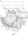
- FIGs 3 and 4illustrate printer 210, an example embodiment of printer 10 schematically shown in Figure 1 .
- printer 210utilizes a liquid electrophotographic (LEP) process.
- LEPliquid electrophotographic
- printer 210comprises print mechanism 220, intermediate transfer member 230, impression cylinder 232, media transport system 234, gas transfer mechanism 222, vapor treatment system 24, heat exchanger 26 and heat exchanger 28.
- Print mechanism 220comprises a device or mechanism configured to deposit, eject, form or otherwise apply imaging material onto intermediate transfer member 230 (serving as the substrate 30 shown in Figure 1 ) in a print zone or region 231 so as to form an image or part of an image on intermediate transfer member 230.
- print mechanism 220comprises photoconductor 244, charger 246, imager 248, ink or toner supplies 250, developers 252, charge eraser 254 and photoconductor cleaning station 256.
- Photoconductor 244generally comprises a cylindrical drum 260 supporting an electrophotographic surface 262, sometimes referred to as a photo imaging plate (PIP).
- Electrophotographic surface 262comprises a surface configured to be electrostatically charged and to be selectively discharged upon receiving light from imager 248.
- surface 262is illustrated as being supported by drum 260, surface 262 may alternatively be provided as part of an endless belt supported by a plurality of rollers.
- the exterior surface of the endless beltmay be configured to be electrostatically charged and to be selectively discharged for creating an electrostatic field in the form of an image.
- Charger 246comprises a device configured to electrostatically charge surface 262.
- charger 246includes 6 corotrons or scorotrons 268. In other embodiments, other devices for electrostatically charging surface 262 may be employed.
- Imager 248generally comprises any device configured to direct light upon surface 262 so as to form an image.
- imager 268comprises a scanning laser which is moved across surface 262 as photoconductor 244 is rotated about axis 270. Those portions of surface 262 which are impinged by the light or laser 272 become electrically conductive and discharge electrostatic charge to form an image (and latent image) upon surface 262.
- imager 248is illustrated and described as comprising a scanning laser, imager 248 may alternatively comprise other devices configured to selectively emit or selectively allow light to impinge upon surface 262.
- imager 248may alternatively include one or more shutter devices which employ liquid crystal materials to selectively block light and to selectively allow light to pass through to surface 262.
- imager 248may alternatively include shutters which include individual micro or nano light blocking shutters which pivot, slide or otherwise physically move between the light blocking and light transmitting states.
- surface 262may alternatively comprise an electrophotographic surface including an array of individual pixels configured to be selectively charged or selectively discharged using an array of switching mechanisms such as transistors or metal-insulator-metal (MIM) devices forming an active array or a passive array for the array of pixels.
- charger 246may be omitted.
- Ink or toner supplies 250comprise containers connected to developers 252 to supply imaging material (ink or toner) to developers 252.
- the imaging materialgenerally comprises a liquid or fluid ink comprising a liquid carrier and colorant particles.
- the colorant particlesmay have a size of less than 2 microns, although other sizes may be employed in other embodiments.
- the imaging materialgenerally includes up to 6% by weight, and nominally 2% by weight, colorant particles or solids prior to being applied to surface 262.
- the colorant particlesinclude a toner binder resin comprising hot melt adhesive.
- the imaging materialcomprises HEWLETT-PACKARD ELECTRO INK commercially available from Hewlett-Packard. In other embodiments, the imaging material may comprise other materials.
- Developers 252(known as binary ink developers or BIDs) comprise devices configured to apply the imaging material to surface 262 based upon the electrostatic charge upon surface 262 and to develop the image upon surface 262.
- each developeruses a roller to apply a charged imaging material to surface 262.
- developers 252may have other configurations.
- Charge eraser 254comprises a device situated along surface 262 and configured to remove residual charge from surface 262.
- charge eraser 262may comprise an LED erase lamp.
- eraser 252may comprise other devices or may be omitted.
- Intermediate transfer member 230comprises a member configured to transfer printing material from surface 262 to print medium 284 (shown in Figure 3 ).
- Intermediate transfer member 230includes an exterior surface 286 which is resiliently compressible and which is configured to be electrostatically charged. Because surface 286 is resiliently compressible, surface 286 conforms and adapts to irregularities on print medium 284. Because surface 286 is configured to be electrostatically charged, surface 286 may be charged to a voltage so as to facilitate transfer of printing material from surface 262 to surface 286.
- intermediate transfer member 230includes drum 288 and an external blanket 290 which provides surface 286.
- Drum 288generally comprises a cylinder that supports blanket 290.
- drum 288is formed from a thermally conductive material, such as a metal like aluminum.
- drum 288houses an internal heater 291 (schematically shown) which heats surface 286 to melt the imaging material.
- Blanket 290wraps about drum 288 and provides surface 286.
- blanket 290is adhered to drum 288.
- Blanket 290includes one or more resiliently compressible layers and includes one or more electrically conductive layers, enabling surface 286 to conform to and to be electrostatically charged.
- intermediate transfer member 230is illustrated as comprising drum 288 supporting blanket 290 which provides surface 286, intermediate transfer member 230 may alternatively comprise an endless belt supported by a plurality of rollers in contact or in close proximity to surface 262 and impression cylinder 232.
- Dryer 231comprises one or more devices configured to facilitate partial drying of imaging material upon surface 286.
- Dryer 232is arranged about intermediate transfer member 230 and includes heater 292, gas director 293 and sensor 294.
- Gas director 293comprises a chamber having an exit slit configured to direct air heated by heater 292 towards surface 286 to dry imaging material by volatizing vapors from imaging material.
- gas directormay be omitted or may have other configurations.
- Sensor 294comprises one or more sensors configured to sense a temperature of gas being directed towards surface 286 and the temperature of gas about surface 286.
- sensor 286may be configured to sense a dryness of the imaging material.
- heater 292under the control of a controller comprising a processing unit (not shown), increases or decreases heat being applied to achieve sufficient drying and energy conservation.
- Impression cylinder 232comprises a cylinder adjacent to intermediate transfer member 230 so as to form a nip 294 between member 230 and cylinder 232.
- Media 284is generally fed between intermediate transfer member 230 and impression cylinder 232, wherein imaging material is transferred from intermediate transfer member 230 to medium 284 at nip 296.
- impression member 232is illustrated as a cylinder or roller, impression member 232 may alternatively comprise an endless belt or a stationary surface against which intermediate transfer member 230 moves.
- Media transport 234(shown in Figure 3 ) delivers print media 284 to nip 296 where images for imaging material on surface 286 of intermediate transfer member 230 are transferred to media 284.
- media transport 234is configured to transport individual sheets of media from a stack 297 across nip 296 and then from nip 296 to an output 298.
- media transport 234may alternatively be configured to transport a web of media 284 across nip 296.
- Gas transfer mechanism 122comprises one or more devices and/or structures configured to urge and direct or guide the flow of gas or vapors produced during the printing of image upon intermediate transfer mechanism 230 through heat exchanger 26 to vapor treatment system 24 and to further direct gas or vapor flow from vapor treatment system 24 through heat exchanger 26 to member 230.
- gas transfer mechanism 122comprises chamber 300 and blowers 302, 304.
- Chamber 300extends partially about surface 286 of intermediate transfer member 230 between photoconductor 244 and impression cylinder 232.
- Chamber 300is in pneumatic communication or is pneumatically connected to blower 302 such that a vacuum may be created within chamber 300 by blower 302 to draw vapors, released during drying of the wet imaging material, towards heat exchanger 26.
- chamber 300may have other shapes or configurations defined by other walls or structures.
- Blower 302creates a vacuum within chamber 300 and draw vapors to heat exchanger 26.
- blower 304draws and directs vapors discharged by heat exchanger 26 through or past heater 292 to gas director 293.
- the treated heated vapors discharged from heat exchanger 26assist in drying or volatizing solvents of imaging material upon surface 286 of intermediate transfer member 230.
- sufficient drying of the wet imaging material forming the image on surface 286may be completed in less time and with less additional energy.
- Heat exchanger 28receives the treated vapors at the elevated temperature from heat exchanger 26 and thermally conducts or transfers heat from the treated vapors to air supplied to the image upon intermediate transfer member 230. Heat exchanger 28 recycles heat from the treated vapors such that printer 210 may dry the image upon member 230 using less heat or less energy.
- charger 246electrostatically charges surface 262.
- Surface 262is exposed to light from imager 248.
- surface 262is exposed to laser 272 which is controlled by a raster image processor that converts instructions from a digital file into on/off instructions for laser 272. This results in a latent image being formed for those electrostatically discharged portions of surface 262.
- Ink developers 252develop an image upon surface 262 by applying ink to those portions of surface 262 that remain electrostatically charged.
- eraser 254erases any remaining electrical charge upon surface 262 and the ink image is transferred to surface 286 of intermediate transfer member 230. Thereafter, any remaining imaging material on surface 262 is removed by cleaning station 256. In the embodiment shown, the imaging material forms an approximately 1.4 micron thick layer of approximately 85% solids colorant particles with relatively good cohesive strength upon surface 286.
- the released vaporsare drawn through heat exchanger 26 where they are preheated using heat recycled from treated vapors.
- the preheated vaporsare then treated by vapor treatment system 24 and directed through heat exchanger.
- the treated vaporsare directed by blower 304 to heat exchanger 28 which uses the heat to heat the air being directed by gas director 293 of dryer 231.
- the layer of melted colorant particles forming an image upon surface 286are transferred to media 284 passing between transfer member 230 and impression cylinder 232.
- the melted colorant particlesare transferred to print media 284 at approximately 90 degrees Celsius.
- the layer of melted colorant particlesfreeze to media 284 on contact in the nip 296 formed between intermediate transfer member 230 and impression cylinder 232.
- multi-shotin lieu of creating one color separation at a time on surface 286, sometimes referred to as "multi-shot" process, the above-noted process may be modified to employ a one-shot color process in which all color separations are layered upon surface 286 of intermediate transfer member 230 prior to being transferred to and deposited upon medium 284.
Landscapes
- Life Sciences & Earth Sciences (AREA)
- Engineering & Computer Science (AREA)
- Atmospheric Sciences (AREA)
- Biodiversity & Conservation Biology (AREA)
- Ecology (AREA)
- Environmental & Geological Engineering (AREA)
- Environmental Sciences (AREA)
- Physics & Mathematics (AREA)
- General Physics & Mathematics (AREA)
- Ink Jet (AREA)
- Printing Methods (AREA)
- Wet Developing In Electrophotography (AREA)
- Control Or Security For Electrophotography (AREA)
Description
- Printers sometimes form images by applying imaging materials that are wet and that may have solvents. The wet imaging material may produce undesirable vapors that should be neutralized.
US 2006/0037854 discloses an image forming apparatus with a gas purifying device.Figure 1 is a schematic illustration of a printer according to an example embodiment.Figure 2 is a flow diagram of a method of treating vapors according to an example embodiment.Figure 3 is a perspective view of a particular embodiment of the printer ofFigure 1 according to an example embodiment, with portions schematically shown.Figure 4 is a sectional view of a portion of the printer ofFigure 3 according to an example embodiment, with portions schematically shown.Figure 1 systematically illustrates a printing system orprinter 10 according to an example embodiment. As will be described hereafter,printer 10 treats vapors resulting from printing and recycles heat from the vapor treatment to preheat untreated vapors to assist in their subsequent treatment. In one embodiment, printer 10 additionally recycles heat from the vapor treatment to heat imaging material applied on a substrate as an image. Becauseprinter 10 recycles such heat,printer 10 is energy-efficient.Printer 10 comprisesprint mechanism 20,gas transfer mechanism 22,vapor treatment system 24,heat exchanger 26 andheat exchanger 28.Print mechanism 20 comprises a device or mechanism configured to deposit, eject, form or otherwise applyimaging material 27 onto asubstrate 30 in a print zone orregion 31 so as to form an image or part of animage 32 onsubstrate 30. Examples ofimages 32 include, but are not limited to, alphanumeric text, patterns, photographs or graphics. Examples ofimaging material 27 include, but are not limited to inks, toners or other liquids having one or more components within solvent or other liquids carrying particles, dyes or other elements.- According to one embodiment,
substrate 30 may comprise a print medium which serves as a final destination for the printed image. Examples of a print medium include a web or sheet of medium such as a coated or uncoated cellulose-based medium or polymer-based medium. In other embodiments,substrate 30 may constitute an intermediate transfer member or surface, such as a drum or belt, wherein theimage 32 formed byimaging material 27 onsubstrate 30 is subsequently transferred directly or transferred using additional intermediate transfer members to form a final image 32' on thefinal print medium 36 as shown in broken lines. - According to one embodiment,
print mechanism 20 comprises one or more thermoresistive or piezoresistive printheads configured to eject or apply liquid imaging material ontosubstrate 30 to formimage 32. In another embodiment,print mechanism 20 comprises a liquid electric photography (LEP) print mechanism. In still other embodiments,print mechanism 20 may comprise other devices configured to apply liquid imaging material to a substrate to form an image. Gas transfer mechanism 22 comprises one or more devices and/or structures configured to urge and direct or guide flow of gas or vapors produced during the printing of image 32 (or 32') throughheat exchanger 26 tovapor treatment system 24 and to further direct gas or vapor flow fromvapor treatment system 24 throughheat exchanger 26 tosubstrate 30. In one embodiment,gas transfer mechanism 22 comprises one or more blowers and one or more conduits or plenums, wherein the blowers urge the vapors through the conduits or plenums betweenprint region 31,heat exchanger 26 andvapor treatment system 24.Vapor treatment system 24 comprises a device or mechanism configured to treat vapors produced during the printing ofimage 32.Vapor treatment system 24 neutralizes or lessons a toxicity or harmfulness (human or environmental) of the vapors.Vapor treatment system 24 treats vapors at an elevated temperature (above room temperature).Vapor treatment system 24 receives untreated vapors fromheat exchanger 26, treats the vapors and returns treated vapors toheat exchanger 26 for preheating the untreated vapors passing throughheat exchanger 26 towardsvapor treatment system 24.- In one embodiment,
vapor treatment system 24 includes one ormore temperature sensors 37,controller 38 and one ormore heaters 39.Sensors 37 sense a temperature of the vapors prior to enteringvapor treatment system 24 or while such vapors are being treated byvapor treatment system 24. Controller 38 comprises one or more processing units configured to receive temperature feedback fromsensor 37 and to control energy output ofheaters 39 based upon such temperature feedback.Controller 38 adjusts the energy output ofheaters 39 such that vapors withinvapor treatment system 24 have a sufficiently elevated temperature for being treated. For purposes of this application, the term "processing unit" shall mean a presently developed or future developed processing unit that executes sequences of instructions contained in a memory. Execution of the sequences of instructions causes the processing unit to perform steps such as generating control signals. The instructions may be loaded in a random access memory (RAM) for execution by the processing unit from a read only memory (ROM), a mass storage device, or some other persistent storage. In other embodiments, hard wired circuitry may be used in place of or in combination with software instructions to implement the functions described. For example,controller 38 may be embodied as part of one or more application-specific integrated circuits (ASICs). Unless otherwise specifically noted, the controller is not limited to any specific combination of hardware circuitry and software, nor to any particular source for the instructions executed by the processing unit.Heaters 39, under the control ofcontroller 39, apply additional heat to the vapors such that the vapors have a sufficiently high temperature for effective treatment of the vapors byvapor treatment system 24. In one embodiment,vapor treatment system 24 treats the vapor by removing volatile organic compounds from the vapor. Examples of volatile organic compounds include, but are not limited to, pentane, ethanol, methanol, hexane, ethyl acetate and other solvent vaporizations or byproducts.- According to one embodiment,
vapor treatment system 24 comprises a catalytic oxidation system (also known as a catalytic converter). In embodiments wherevapor treatment system 24 comprises a catalytic oxidation system,vapor treatment system 24 includes a catalytic layer of metal catalysts such as platinum, palladium, platinum/rhenium and the like to oxidize the volatile organic compounds. The catalytic oxidation process has an operating temperature of at least about 170°C for destruction efficiency of greater than 95% volatile organic compounds of Isopar vapors. In other embodiments, the operating temperature or inlet temperature for the catalytic oxidation process may be higher or lower depending upon the type and distribution of volatile organic compounds in the vapors being treated. In other embodiments,vapor treatment system 24 may comprise other systems for treating vapors in other manners, wherein a sufficiently high temperature of the vapor or a sufficiently high temperature of components of the vapor treatment system facilitates or enhances treatment of the vapors. Heat exchanger 26 comprises a mechanism configured to thermally conduct or otherwise transfer heat from a first fluid to a second fluid while preventing direct contact of the first and second fluids.Heat exchanger 26 receives treatedvapors 54 fromvapor treatment system 24 at a higher temperature as compared to theuntreated vapors 50 thatheat exchanger 26 receives from print region 40.Heat exchanger 26 preheats theuntreated vapors 50 from print region 40, using heat taken from the treated vapors, prior to the untreated vapors being transmitted tovapor treatment system 24. By recycling the heat from the treated vapors discharged fromvapor treatment system 24 to preheat the untreated vapors,heat exchanger 26 reduces the amount of heat that is applied byheaters 39, increasing energy efficiency.- In the example illustrated,
heat exchanger 26 comprises a pair of intertwined pipes orliquid conduits 42, 44 (schematically illustrated) in the form of coils, wherein the vapor from print region 40 flowing tovapor treatment system 24 flows throughconduit 42 and wherein vapor discharged fromvapor treatment system 24 flows throughheat exchanger 26 through conduits 44 (shown in broken lines). Because the vapor flowing throughconduit 44 is at a higher temperature as compared to the vapor flowing throughconduit 42 inheat exchanger 26, heat is thermally conduct fromconduit 42 to conduit 44 to preheat vapor withinconduit 44. In one embodiment,conduits heat exchanger 26 may have other configurations. For example, in other embodiments,heat exchanger 26 may use a phase transition of an intermediate material to pass heat from one fluid to another.Heat exchange 28 is structurally identical toheat changer 26 except thatheat exchanger 28 receivesvapors 56 discharged fromheat changer 26 and conducts or otherwise transfers the heat fromvapor 56 to air or other gases being supplied to or directed atimage 32 uponsubstrate 30. In the example illustrated,papers 56 fromheat exchanger 26 pass throughheat exchanger 28 and are discharged toatmosphere 29. At the same time, air fromatmosphere 29 is drawn throughheat changer 28, is heated withinheat changer 28, and is supplied toimage 32 to assist in volatizing vapors fromimage 32. As a result, the treatedvapors 54 that are discharged fromvapor treatment system 24 is further recycled to volatizing vapors fromimage 32 to further reduce energy consumption.
According to one embodiment, the air fromatmosphere 29 is drawn throughheat exchanger 28 at a rate less than the rate at whichvapors 50 are drawn from theprint region 31 such that a vacuum or lower pressure region remains inprint region 31. Consequently, any leaks inprinter 10 merely result in their atmosphere being drawn intoprinter 10 rather than untreated vapors leaking out ofprinter 10. Althoughprinter 10 is illustrated as discharging the treatedvapors 56 fromheat exchanger 28 toatmosphere 29, in other embodiments,heat changer 28 may discharged gas or vapors to other treatment systems or to a containment system. In yet other embodiments,heat exchanger 28 may be omitted, wherein treatedvapors 56 are directly supplied toimage 32 uponsubstrate 30 without passing through any intermediate heat exchangers. Figure 2 is a flow diagram illustrating an example printing method orprocess 100 that may be performed byprinter 10 shown inFigure 1 . As shown byFigure 2 , instep 110,print mechanism 20 of printer 10 (shown in 1) appliesimaging material 27 tosubstrate 30 to form animage 32 upon a surface ofsubstrate 30. During the application or during heating ofimaging material 27 onsubstrate 30,untreated vapors 50 are generated or produced in print region 40.- As indicated by
step 112,gas transfer mechanism 22 draws theuntreated vapors 50 away from print region 40 and away fromimage 32 throughconduit 42 of theexchanger 26 towardsvapor treatment system 24. In one embodiment,gas transfer mechanism 22 may apply a negative pressure to printregion 31 to drawvapor 50 intoconduit 42 ofexchanger 26 which is at a higher pressure. In one embodiment,gas transfer mechanism 22 utilizes one more fans or blowers to create the pressure differential for drawingvapors 50 intoconduit 42 ofheat exchanger 26 and towardsvapor treatment system 24. - As indicated by
step 114 inFigure 2 ,vapor treatment system 24 receives and treatsvapors 52 that have passed throughheat exchanger 26.Vapor treatment system 24treats vapors 52 using one or more treatment techniques that treatvapor 52 when vapors 52 (or components ofvapor treatment system 24 in thermal contact with vapor 52) have a sufficiently high temperature. In one embodiment,vapor treatment system 24 senses a temperature ofvapors 52 just before enteringvapor treatment system 24 or while withinvapor treatment system 24. Based on the sensed temperature feedback,vapor treatment system 24 applies heat (using one or more heating devices 39) tovapors 52 such thatvapors 52 have a sufficiently high temperature for treatment. - As mentioned above, in one embodiment,
vapor treatment system 24 reduces or neutralizes toxicity or harmfulness ofvapors 52. In one embodiment,vapor treatment system 24 removes volatile organic compounds fromvapors 52. In yet other embodiments,vapor treatment system 24 may treatvapors 52 in other manners by altering other chemical characteristics ofvapors 52. As shown byFigure 1 ,vapor treatment system 24 discharges treatedvapors 54. Because the process used to treatvapors 52 is performed at an elevated temperature or may itself raise the temperature of the vapors, treatedvapors 54 exitvapor treatment system 24 at an elevated temperature. - As indicated by
step 116 ofFigure 2 , heat exchanger 26 (shown inFigure 1 ) recycles heat from the vapor treatment ofvapor treatment system 24 to preheatvapors 50 passing throughconduit 42. In particular,heat exchanger 26 receivesvapors 54 which are at a temperature greater than the temperature ofvapors 50 also received byheat exchanger 26.Heat exchanger 26 thermally conducts heat fromvapors 54 tovapors 50 to preheatvapors 50 such thatvapors 52 have a temperature greater thanvapors 50 prior to enteringvapor treatment system 24. Becausevapors 52 are preheated to have a temperature greater than that ofvapors 50 using the heat recycled fromvapors 54,vapor treatment system 24 may treatvapors 52 with less heat being applied byheaters 39. - As indicated by step 118 of the
method 100 ofFigure 2 ,gas transfer mechanism 22 further directsvapors 56 discharged from theexchanger 26 through heat exchanger 48 to heat the air used to dry theimage 32. As noted above, in one embodiment,substrate 30 may comprise the actual print medium. In another embodiment,substrate 30 may comprise an intermediate transfer member. Althoughvapors 56 may have a temperature less than that ofvapors 54,vapors 56 have a temperature sufficiently high to assist in heating the air used to volatize vapors from thewet imaging material 27 formingimage 32 onsubstrate 30. As a result, sufficient drying of thewet imaging material 27 formingimage 32 onsubstrate 30 may be completed in less time and with less additional energy. According to one embodiment,vapors 50 have a temperature in the range of 30 to 40 degrees Celsius (the temperature of the print mechanism (the press) with some heat contribution from a blower of the gas transfer mechanism) prior to being preheated byheat exchanger 26 and are directed bygas transfer mechanism 22 throughheat exchanger 26 at a rate of about 30 liters per second to overcome potential leaks.Vapors 52, which have been preheated byheat exchanger 26 using heat recycled fromvapors 54, have a temperature of between about 70 and 80 degrees Celsius and are directed through or across vapor treatment system 24 (comprising a catalytic oxidation system or catalytic converter). In such an embodiment,vapor treatment system 24 sufficiently treatsvapors 52 whenvapors 52 have a temperature of at least 170 degrees Celsius.Vapors 54 being discharged fromvapor treatment system 24 have a temperature of between 170 and 240 degrees Celsius (depending upon vapor concentration) prior to enteringheat exchanger 26.Vapors 58 have a temperature of between 50 and 60 degrees Celsius when being directed at thewet imaging material 27 formingimage 32 onsubstrate 30. In other embodiments,vapors print mechanism 20,heat exchanger 26,heat exchanger 28 andvapor treatment system 24. In still other embodiments, step 118 and the recycling of heat to heatimaging material 27 may be omitted, wherein the treatedvapors 56 discharged fromheat exchanger 26 are used to heat other materials or structures or are contained or discharged to atmosphere. Figures 3 and4 illustrateprinter 210, an example embodiment ofprinter 10 schematically shown inFigure 1 . In the example illustrated,printer 210 utilizes a liquid electrophotographic (LEP) process. As shown byFigure 3 ,printer 210 comprisesprint mechanism 220,intermediate transfer member 230,impression cylinder 232,media transport system 234,gas transfer mechanism 222,vapor treatment system 24,heat exchanger 26 andheat exchanger 28.Print mechanism 220 comprises a device or mechanism configured to deposit, eject, form or otherwise apply imaging material onto intermediate transfer member 230 (serving as thesubstrate 30 shown inFigure 1 ) in a print zone orregion 231 so as to form an image or part of an image onintermediate transfer member 230. As shown byFigure 4 ,print mechanism 220 comprisesphotoconductor 244,charger 246,imager 248, ink or toner supplies 250,developers 252,charge eraser 254 andphotoconductor cleaning station 256.Photoconductor 244 generally comprises acylindrical drum 260 supporting anelectrophotographic surface 262, sometimes referred to as a photo imaging plate (PIP).Electrophotographic surface 262 comprises a surface configured to be electrostatically charged and to be selectively discharged upon receiving light fromimager 248. Althoughsurface 262 is illustrated as being supported bydrum 260,surface 262 may alternatively be provided as part of an endless belt supported by a plurality of rollers. In such an embodiment, the exterior surface of the endless belt may be configured to be electrostatically charged and to be selectively discharged for creating an electrostatic field in the form of an image.Charger 246 comprises a device configured to electrostaticallycharge surface 262. In the particular example shown,charger 246 includes 6 corotrons orscorotrons 268. In other embodiments, other devices for electrostatically chargingsurface 262 may be employed.Imager 248 generally comprises any device configured to direct light uponsurface 262 so as to form an image. In the example shown,imager 268 comprises a scanning laser which is moved acrosssurface 262 asphotoconductor 244 is rotated aboutaxis 270. Those portions ofsurface 262 which are impinged by the light orlaser 272 become electrically conductive and discharge electrostatic charge to form an image (and latent image) uponsurface 262.- Although
imager 248 is illustrated and described as comprising a scanning laser,imager 248 may alternatively comprise other devices configured to selectively emit or selectively allow light to impinge uponsurface 262. For example, in other embodiments,imager 248 may alternatively include one or more shutter devices which employ liquid crystal materials to selectively block light and to selectively allow light to pass through to surface 262. In other embodiments,imager 248 may alternatively include shutters which include individual micro or nano light blocking shutters which pivot, slide or otherwise physically move between the light blocking and light transmitting states. - In still other embodiments,
surface 262 may alternatively comprise an electrophotographic surface including an array of individual pixels configured to be selectively charged or selectively discharged using an array of switching mechanisms such as transistors or metal-insulator-metal (MIM) devices forming an active array or a passive array for the array of pixels. In such an embodiment,charger 246 may be omitted. - Ink or toner supplies 250 comprise containers connected to
developers 252 to supply imaging material (ink or toner) todevelopers 252. In the particular example shown, the imaging material generally comprises a liquid or fluid ink comprising a liquid carrier and colorant particles. The colorant particles may have a size of less than 2 microns, although other sizes may be employed in other embodiments. In the example illustrated, the imaging material generally includes up to 6% by weight, and nominally 2% by weight, colorant particles or solids prior to being applied tosurface 262. In one embodiment, the colorant particles include a toner binder resin comprising hot melt adhesive. In one particular embodiment, the imaging material comprises HEWLETT-PACKARD ELECTRO INK commercially available from Hewlett-Packard. In other embodiments, the imaging material may comprise other materials. - Developers 252 (known as binary ink developers or BIDs) comprise devices configured to apply the imaging material to surface 262 based upon the electrostatic charge upon
surface 262 and to develop the image uponsurface 262. In the example illustrated, each developer uses a roller to apply a charged imaging material tosurface 262. In other embodiment,developers 252 may have other configurations. Charge eraser 254 comprises a device situated alongsurface 262 and configured to remove residual charge fromsurface 262. In one embodiment,charge eraser 262 may comprise an LED erase lamp. In particular embodiments,eraser 252 may comprise other devices or may be omitted.Cleaning station 256 is arranged proximate to surface 262 between theintermediate transfer member 230 andcharger 246.Cleaning station 256 comprises one or more devices configured to remove residual ink and electrical charge fromsurface 262. In particular examples shown, cleaningstation 256 directs a cooled liquid, such as a carrier liquid, acrosssurface 262 betweenrollers roller 278, which is absorbent. Particles and liquids picked up by the absorbent material ofroller 278 are squeegeed out by asqueegee roller 280. The cleaning process ofsurface 262 is completed bystation 256 using ascraper blade 282 which scrapes any remaining toner or ink fromsurface 262 and keeps the carrier liquid from leavingcleaning station 256. In other embodiments, other cleaning stations may be employed or cleaningstation 256 may be omitted.Intermediate transfer member 230 comprises a member configured to transfer printing material fromsurface 262 to print medium 284 (shown inFigure 3 ).Intermediate transfer member 230 includes anexterior surface 286 which is resiliently compressible and which is configured to be electrostatically charged. Becausesurface 286 is resiliently compressible,surface 286 conforms and adapts to irregularities onprint medium 284. Becausesurface 286 is configured to be electrostatically charged,surface 286 may be charged to a voltage so as to facilitate transfer of printing material fromsurface 262 tosurface 286.- In the particular embodiment shown,
intermediate transfer member 230 includesdrum 288 and anexternal blanket 290 which providessurface 286.Drum 288 generally comprises a cylinder that supportsblanket 290. In one embodiment,drum 288 is formed from a thermally conductive material, such as a metal like aluminum. In such an embodiment, drum 288 houses an internal heater 291 (schematically shown) which heatssurface 286 to melt the imaging material. Blanket 290 wraps aboutdrum 288 and providessurface 286. In one particular embodiment,blanket 290 is adhered to drum 288.Blanket 290 includes one or more resiliently compressible layers and includes one or more electrically conductive layers, enablingsurface 286 to conform to and to be electrostatically charged. Althoughintermediate transfer member 230 is illustrated as comprisingdrum 288 supportingblanket 290 which providessurface 286,intermediate transfer member 230 may alternatively comprise an endless belt supported by a plurality of rollers in contact or in close proximity to surface 262 andimpression cylinder 232.Dryer 231 comprises one or more devices configured to facilitate partial drying of imaging material uponsurface 286.Dryer 232 is arranged aboutintermediate transfer member 230 and includesheater 292,gas director 293 andsensor 294.Gas director 293 comprises a chamber having an exit slit configured to direct air heated byheater 292 towardssurface 286 to dry imaging material by volatizing vapors from imaging material. In other embodiments, gas director may be omitted or may have other configurations.Sensor 294 comprises one or more sensors configured to sense a temperature of gas being directed towardssurface 286 and the temperature of gas aboutsurface 286. Alternatively,sensor 286 may be configured to sense a dryness of the imaging material. Based on feedback fromsensor 294,heater 292, under the control of a controller comprising a processing unit (not shown), increases or decreases heat being applied to achieve sufficient drying and energy conservation.Impression cylinder 232 comprises a cylinder adjacent tointermediate transfer member 230 so as to form a nip 294 betweenmember 230 andcylinder 232.Media 284 is generally fed betweenintermediate transfer member 230 andimpression cylinder 232, wherein imaging material is transferred fromintermediate transfer member 230 to medium 284 atnip 296. Althoughimpression member 232 is illustrated as a cylinder or roller,impression member 232 may alternatively comprise an endless belt or a stationary surface against whichintermediate transfer member 230 moves.- Media transport 234 (shown in
Figure 3 ) deliversprint media 284 to nip 296 where images for imaging material onsurface 286 ofintermediate transfer member 230 are transferred tomedia 284. In the example illustrated,media transport 234 is configured to transport individual sheets of media from astack 297 across nip 296 and then from nip 296 to anoutput 298. In other embodiments,media transport 234 may alternatively be configured to transport a web ofmedia 284 acrossnip 296. - Gas transfer mechanism 122 comprises one or more devices and/or structures configured to urge and direct or guide the flow of gas or vapors produced during the printing of image upon
intermediate transfer mechanism 230 throughheat exchanger 26 tovapor treatment system 24 and to further direct gas or vapor flow fromvapor treatment system 24 throughheat exchanger 26 tomember 230. In the example illustrated, gas transfer mechanism 122 compriseschamber 300 andblowers Chamber 300 extends partially aboutsurface 286 ofintermediate transfer member 230 betweenphotoconductor 244 andimpression cylinder 232.Chamber 300 is in pneumatic communication or is pneumatically connected toblower 302 such that a vacuum may be created withinchamber 300 byblower 302 to draw vapors, released during drying of the wet imaging material, towardsheat exchanger 26. In other embodiments,chamber 300 may have other shapes or configurations defined by other walls or structures. Blower 302 creates a vacuum withinchamber 300 and draw vapors toheat exchanger 26. At the same time,blower 304 draws and directs vapors discharged byheat exchanger 26 through orpast heater 292 togas director 293. As a result, the treated heated vapors discharged fromheat exchanger 26 assist in drying or volatizing solvents of imaging material uponsurface 286 ofintermediate transfer member 230. As a result, sufficient drying of the wet imaging material forming the image onsurface 286 may be completed in less time and with less additional energy.Vapor treatment system 24 andheat exchanger 26 ofprinter 210 are identical toheat exchanger 26 and vapor treatment system 24-described above with respect toprinter 10. As noted above,vapor treatment system 24 treats vapors when such vapors are at a sufficiently high temperature. In the example illustrated,vapor treatment system 24 employs a catalytic oxidation process which itself increases the temperature of the vapors being treated by up to 70 degrees Celsius.Heat exchanger 26 receives the treated vapors at the elevated temperature and thermally conducts or transfers heat from the treated vapors to yet untreated vapors about to entervapor treatment system 24.Heat exchanger 26 recycles heat from the treated vapors to pre-heat such untreated vapors such thatvapor treatment system 24 may treat the vapors using less heat or less energy.Heat exchanger 28 receives the treated vapors at the elevated temperature fromheat exchanger 26 and thermally conducts or transfers heat from the treated vapors to air supplied to the image uponintermediate transfer member 230.Heat exchanger 28 recycles heat from the treated vapors such thatprinter 210 may dry the image uponmember 230 using less heat or less energy.- In operation,
charger 246 electrostatically charges surface 262.Surface 262 is exposed to light fromimager 248. In particular,surface 262 is exposed tolaser 272 which is controlled by a raster image processor that converts instructions from a digital file into on/off instructions forlaser 272. This results in a latent image being formed for those electrostatically discharged portions ofsurface 262.Ink developers 252 develop an image uponsurface 262 by applying ink to those portions ofsurface 262 that remain electrostatically charged. - Once an image upon
surface 262 has been developed,eraser 254 erases any remaining electrical charge uponsurface 262 and the ink image is transferred to surface 286 ofintermediate transfer member 230. Thereafter, any remaining imaging material onsurface 262 is removed by cleaningstation 256. In the embodiment shown, the imaging material forms an approximately 1.4 micron thick layer of approximately 85% solids colorant particles with relatively good cohesive strength uponsurface 286. - Once the printing material has been-transferred to surface 286, heat is applied to the imaging material on surface 86 so as to melt toner binder resin of the colorant particles or solids of
printing material 54 to form a hot melted adhesive.Dryer 231 partially dries the melted liquid colorant particles to volatize and release solvent or other vapors from the imaging material. - The released vapors are drawn through
heat exchanger 26 where they are preheated using heat recycled from treated vapors. The preheated vapors are then treated byvapor treatment system 24 and directed through heat exchanger. After preheating the untreated vapors passing throughheat exchanger 26, the treated vapors are directed byblower 304 toheat exchanger 28 which uses the heat to heat the air being directed bygas director 293 ofdryer 231. - After sufficient drying by
dryer 231, the layer of melted colorant particles forming an image uponsurface 286 are transferred tomedia 284 passing betweentransfer member 230 andimpression cylinder 232. In the embodiment shown, the melted colorant particles are transferred toprint media 284 at approximately 90 degrees Celsius. The layer of melted colorant particles freeze tomedia 284 on contact in thenip 296 formed betweenintermediate transfer member 230 andimpression cylinder 232. - These operations are repeated for every color for preparation in the final image to be produced. In other embodiments, in lieu of creating one color separation at a time on
surface 286, sometimes referred to as "multi-shot" process, the above-noted process may be modified to employ a one-shot color process in which all color separations are layered uponsurface 286 ofintermediate transfer member 230 prior to being transferred to and deposited uponmedium 284. - Although the present disclosure has been described with reference to example embodiments, workers skilled in the art will recognize that changes may be made in form and detail without departing from the scope of the invention as claimed.
Claims (14)
- A printer (10) comprising:a printing mechanism (20) to apply an imaging material (27) to a substrate;a vapor treatment system (24) to reduce toxicity or harmfulness of vapors;a heat exchanger (26)to receive treated vapors from the vapor treatment system; anda gas transfer mechanism (22) to transfer vapors from a region proximate the printing mechanism (20) through the heat exchanger (26) and then to the vapor treatment system (24), wherein untreated vapors are heated in the heat exchanger (26) using treated vapors from the vapor treatment system (24).
- The printer (10) of claim 1, wherein the vapor treatment system (24) is to remove volatile organic compounds from the vapor.
- The printer (10) of claim 1, wherein the vapor treatment system (24) comprises a catalytic oxidation system.
- The printer (10) of claim 1, further comprising a second heat exchanger (28) to receive treated vapors from the heat exchanger (26) and to supply heat to the imaging material (27) that has been applied by the printing mechanism (20).
- The printer (10) of claim 4 further comprising an intermediate transfer member to carry the imaging material (27) formed in the image, whereby the image is subsequently transferred to a print medium, and wherein the gas transfer mechanism (22) is to direct vapors from the vapor treatment system (24), after the vapors have passed through the heat exchanger (26), towards the intermediate transfer member to volatize vapors from the imaging material (27) on the intermediate transfer member.
- The printer (10) of claim 5, wherein the intermediate transfer member comprises a drum having a compressible blanket.
- The printer (10) of claim 1 further comprising a heating device to heat the imaging material (27) applied as the image.
- A method comprising:applying an imaging material (27) to a substrate;withdrawing vapors from the applied imaging material (27);treating the withdrawn vapors with a vapor treatment system (24) to reduce toxicity or harmfulness of the withdrawn vapors; andheating untreated withdrawn vapors with heat from the vapor treatment system (24).
- The method of claim 8, wherein the heating untreated withdrawn vapours comprises directing withdrawn vapors that have been treated through a heat exchanger (26)_sin contact with the withdrawn vapors that have not yet been treated.
- The method of claim 8 further comprising recycling heat from the vapor treatment system (24) to heat imaging material (27) applied as the image.
- The method of claim 8 further comprising heating the imaging material (27) applied as the image to increase a rate at which vapors are released from the imaging material (27) applied as the image.
- The method of claim 8, wherein the withdrawn vapors are treated with a catalytic oxidation system.
- The method of claim 8, wherein treating the withdrawn vapors includes removing volatile organic compounds from the vapors.
- The method of claim 8, wherein treating the withdrawn vapors includes neutralizing toxicity or harmfulness of the withdrawn vapors.
Applications Claiming Priority (1)
| Application Number | Priority Date | Filing Date | Title |
|---|---|---|---|
| PCT/US2010/055011WO2012060815A1 (en) | 2010-11-01 | 2010-11-01 | Printer vapor treatment preheating |
Publications (3)
| Publication Number | Publication Date |
|---|---|
| EP2608961A1 EP2608961A1 (en) | 2013-07-03 |
| EP2608961A4 EP2608961A4 (en) | 2014-04-16 |
| EP2608961B1true EP2608961B1 (en) | 2017-01-04 |
Family
ID=46024729
Family Applications (1)
| Application Number | Title | Priority Date | Filing Date |
|---|---|---|---|
| EP10859354.2ANot-in-forceEP2608961B1 (en) | 2010-11-01 | 2010-11-01 | Printer vapor treatment preheating |
Country Status (4)
| Country | Link |
|---|---|
| US (1) | US9025990B2 (en) |
| EP (1) | EP2608961B1 (en) |
| JP (1) | JP2014502365A (en) |
| WO (1) | WO2012060815A1 (en) |
Families Citing this family (5)
| Publication number | Priority date | Publication date | Assignee | Title |
|---|---|---|---|---|
| KR102098575B1 (en)* | 2016-03-04 | 2020-04-09 | 휴렛-팩커드 디벨롭먼트 컴퍼니, 엘.피. | Curing device |
| EP3535335B1 (en) | 2017-03-17 | 2020-10-21 | HP Indigo B.V. | Liquid electrophotographic ink(s) |
| US10824084B2 (en) | 2017-04-10 | 2020-11-03 | Hp Indigo B.V. | Print agent transfer assemblies |
| US20240411258A1 (en)* | 2021-10-28 | 2024-12-12 | Hewlett-Packard Development Company, L.P. | Identification of gas conveyance malfunctions |
| TW202436381A (en)* | 2022-12-02 | 2024-09-16 | 南韓商Lg化學股份有限公司 | Modified conjugated diene-based polymer and method for preparing the same |
Family Cites Families (26)
| Publication number | Priority date | Publication date | Assignee | Title |
|---|---|---|---|---|
| DE3466986D1 (en) | 1983-02-04 | 1987-12-03 | Ciba Geigy Ag | N-PHENYLSULFONYL-N'-PYRIMIDINYL AND -TRIAZINYLUREA |
| US5555813A (en)* | 1990-07-09 | 1996-09-17 | Sawgrass Systems, Inc. | Permanment heat activated electrographic printing process and composition |
| EP0673492A4 (en) | 1992-12-17 | 1997-12-29 | Thermatrix Inc | Method and apparatus for control of fugitive voc emissions. |
| US6435086B1 (en) | 1995-05-04 | 2002-08-20 | Howard W. DeMoore | Retractable inking/coating apparatus having ferris movement between printing units |
| JP4057759B2 (en)* | 2000-03-30 | 2008-03-05 | 株式会社東芝 | Electrophotographic equipment |
| JP2001350380A (en)* | 2000-06-09 | 2001-12-21 | Minolta Co Ltd | Sheet regenerating device |
| US6569260B2 (en) | 2000-08-07 | 2003-05-27 | Microblend, Llc | Non-solvent very low VOC formulation for removal of ink from printing presses and the like, and methods of using the same |
| JP2002062714A (en)* | 2000-08-21 | 2002-02-28 | Pfu Ltd | Liquid development full color electrophotographic equipment |
| US6651357B2 (en) | 2001-01-12 | 2003-11-25 | Megtec Systems, Inc. | Web dryer with fully integrated regenerative heat source and control thereof |
| JP3564075B2 (en) | 2001-02-28 | 2004-09-08 | キヤノン株式会社 | Image forming device |
| US6660239B2 (en) | 2001-11-07 | 2003-12-09 | Moez Nagji | Method and system for treating volatile organic compounds using a catalytic oxidizer without a burner |
| US6536863B1 (en) | 2002-01-31 | 2003-03-25 | Hewlett-Packard Company | Inkjet print moisture re-circulation |
| US6905645B2 (en) | 2002-07-03 | 2005-06-14 | Therics, Inc. | Apparatus, systems and methods for use in three-dimensional printing |
| JP2004230709A (en) | 2003-01-30 | 2004-08-19 | Fuji Photo Film Co Ltd | Ink jet recording device |
| US7185960B2 (en)* | 2003-07-30 | 2007-03-06 | Hewlett-Packard Development Company, L.P. | Printing device having a printing fluid detector |
| JP4074229B2 (en)* | 2003-07-30 | 2008-04-09 | 株式会社東芝 | Color image forming apparatus |
| US7225739B2 (en)* | 2004-01-21 | 2007-06-05 | Silverbrook Research Pty Ltd | Drying system for use in a printing system |
| KR20050105016A (en)* | 2004-04-30 | 2005-11-03 | 삼성전자주식회사 | Oxidation catalyst device, controlling method thereof and wet-type electrophotographic image forming apparatus having the same |
| US7343116B2 (en)* | 2004-08-23 | 2008-03-11 | Samsung Electronics Co., Ltd. | Gas purifying apparatus, image forming apparatus having the same, and method of purifying gas of the image forming apparatus |
| US7187885B2 (en)* | 2004-10-29 | 2007-03-06 | Samsung Electronics Co., Ltd. | Oxidation of volatile organic compounds in electrographic printing |
| KR20060071651A (en)* | 2004-12-22 | 2006-06-27 | 삼성전자주식회사 | Wet image forming apparatus and image forming method |
| JP5118823B2 (en) | 2005-09-14 | 2013-01-16 | 東北リコー株式会社 | Ink fixing method, ink fixing device, and printing apparatus |
| JP4800087B2 (en)* | 2006-04-07 | 2011-10-26 | 近藤工業株式会社 | Hot air dryer for printing paper |
| GB2447919B (en) | 2007-03-27 | 2012-04-04 | Linx Printing Tech | Ink jet printing |
| US7955462B2 (en) | 2007-05-25 | 2011-06-07 | Robert Tubbs | Method for accommodating the use of chemicals that contain low amounts of VOC in an existing device where chemicals that contained high levels of VOC had previously been used and resultant product |
| JP5152980B2 (en)* | 2008-05-27 | 2013-02-27 | 富士フイルム株式会社 | Inkjet recording apparatus and method |
- 2010
- 2010-11-01EPEP10859354.2Apatent/EP2608961B1/ennot_activeNot-in-force
- 2010-11-01JPJP2013536585Apatent/JP2014502365A/enactivePending
- 2010-11-01USUS13/879,666patent/US9025990B2/enactiveActive
- 2010-11-01WOPCT/US2010/055011patent/WO2012060815A1/enactiveApplication Filing
Also Published As
| Publication number | Publication date |
|---|---|
| US9025990B2 (en) | 2015-05-05 |
| EP2608961A1 (en) | 2013-07-03 |
| WO2012060815A1 (en) | 2012-05-10 |
| EP2608961A4 (en) | 2014-04-16 |
| US20130216254A1 (en) | 2013-08-22 |
| JP2014502365A (en) | 2014-01-30 |
Similar Documents
| Publication | Publication Date | Title |
|---|---|---|
| US7447471B2 (en) | Ink heating on blanket by contact of a rotating hot surface | |
| US8041275B2 (en) | Release layer | |
| US9268286B2 (en) | Printing arrangement for two-sided printing on a recording medium and printing method | |
| EP2608961B1 (en) | Printer vapor treatment preheating | |
| JP2009163065A (en) | Liquid toner fixing device, liquid-developing electronic printing machine and liquid toner fixing method | |
| JP5333023B2 (en) | Fixing apparatus and image forming apparatus | |
| US9176432B2 (en) | Imaging system and method | |
| US9057989B2 (en) | Method and device for drying a first side toner image before applying an opposite side second toner image | |
| JP2002513954A (en) | Drying system and method for electrophotographic image forming system | |
| EP2670597B1 (en) | Printers, methods, and apparatus to form an image on a print substrate | |
| EP2467757B1 (en) | Intermediate transfer member blanket, apparatus and transfer method | |
| EP2510403B1 (en) | Imaging system and method | |
| JP2009163064A (en) | Double-sided printing machine and double-sided printing method for liquid-developing electrophotographic system | |
| US20120020697A1 (en) | method of fixing a heat curable toner to a carrier | |
| US20150306866A1 (en) | Printers, Methods and Apparatus to Form an Image on a Print Substrate | |
| EP2919995B1 (en) | Fixing liquid toner | |
| JP2011175209A (en) | Electrophotographic printer | |
| JP2003241561A (en) | Method and apparatus for forming image | |
| WO2023069115A1 (en) | Image transfer for liquid electro-photographic printing | |
| JP2011175112A (en) | Fixing device for electrophotographic printing, and electrophotographic printer | |
| WO2014005655A1 (en) | Printing system |
Legal Events
| Date | Code | Title | Description |
|---|---|---|---|
| PUAI | Public reference made under article 153(3) epc to a published international application that has entered the european phase | Free format text:ORIGINAL CODE: 0009012 | |
| 17P | Request for examination filed | Effective date:20130328 | |
| AK | Designated contracting states | Kind code of ref document:A1 Designated state(s):AL AT BE BG CH CY CZ DE DK EE ES FI FR GB GR HR HU IE IS IT LI LT LU LV MC MK MT NL NO PL PT RO RS SE SI SK SM TR | |
| DAX | Request for extension of the european patent (deleted) | ||
| A4 | Supplementary search report drawn up and despatched | Effective date:20140318 | |
| RIC1 | Information provided on ipc code assigned before grant | Ipc:B41J 29/377 20060101ALI20140312BHEP Ipc:B41F 23/02 20060101AFI20140312BHEP | |
| GRAP | Despatch of communication of intention to grant a patent | Free format text:ORIGINAL CODE: EPIDOSNIGR1 | |
| INTG | Intention to grant announced | Effective date:20160414 | |
| GRAS | Grant fee paid | Free format text:ORIGINAL CODE: EPIDOSNIGR3 | |
| GRAA | (expected) grant | Free format text:ORIGINAL CODE: 0009210 | |
| AK | Designated contracting states | Kind code of ref document:B1 Designated state(s):AL AT BE BG CH CY CZ DE DK EE ES FI FR GB GR HR HU IE IS IT LI LT LU LV MC MK MT NL NO PL PT RO RS SE SI SK SM TR | |
| REG | Reference to a national code | Ref country code:GB Ref legal event code:FG4D | |
| REG | Reference to a national code | Ref country code:CH Ref legal event code:EP | |
| REG | Reference to a national code | Ref country code:AT Ref legal event code:REF Ref document number:858834 Country of ref document:AT Kind code of ref document:T Effective date:20170115 | |
| REG | Reference to a national code | Ref country code:IE Ref legal event code:FG4D | |
| REG | Reference to a national code | Ref country code:DE Ref legal event code:R096 Ref document number:602010039430 Country of ref document:DE | |
| REG | Reference to a national code | Ref country code:LT Ref legal event code:MG4D Ref country code:NL Ref legal event code:MP Effective date:20170104 | |
| REG | Reference to a national code | Ref country code:AT Ref legal event code:MK05 Ref document number:858834 Country of ref document:AT Kind code of ref document:T Effective date:20170104 | |
| PG25 | Lapsed in a contracting state [announced via postgrant information from national office to epo] | Ref country code:NL Free format text:LAPSE BECAUSE OF FAILURE TO SUBMIT A TRANSLATION OF THE DESCRIPTION OR TO PAY THE FEE WITHIN THE PRESCRIBED TIME-LIMIT Effective date:20170104 | |
| PG25 | Lapsed in a contracting state [announced via postgrant information from national office to epo] | Ref country code:HR Free format text:LAPSE BECAUSE OF FAILURE TO SUBMIT A TRANSLATION OF THE DESCRIPTION OR TO PAY THE FEE WITHIN THE PRESCRIBED TIME-LIMIT Effective date:20170104 Ref country code:GR Free format text:LAPSE BECAUSE OF FAILURE TO SUBMIT A TRANSLATION OF THE DESCRIPTION OR TO PAY THE FEE WITHIN THE PRESCRIBED TIME-LIMIT Effective date:20170405 Ref country code:FI Free format text:LAPSE BECAUSE OF FAILURE TO SUBMIT A TRANSLATION OF THE DESCRIPTION OR TO PAY THE FEE WITHIN THE PRESCRIBED TIME-LIMIT Effective date:20170104 Ref country code:NO Free format text:LAPSE BECAUSE OF FAILURE TO SUBMIT A TRANSLATION OF THE DESCRIPTION OR TO PAY THE FEE WITHIN THE PRESCRIBED TIME-LIMIT Effective date:20170404 Ref country code:LT Free format text:LAPSE BECAUSE OF FAILURE TO SUBMIT A TRANSLATION OF THE DESCRIPTION OR TO PAY THE FEE WITHIN THE PRESCRIBED TIME-LIMIT Effective date:20170104 Ref country code:IS Free format text:LAPSE BECAUSE OF FAILURE TO SUBMIT A TRANSLATION OF THE DESCRIPTION OR TO PAY THE FEE WITHIN THE PRESCRIBED TIME-LIMIT Effective date:20170504 | |
| PG25 | Lapsed in a contracting state [announced via postgrant information from national office to epo] | Ref country code:RS Free format text:LAPSE BECAUSE OF FAILURE TO SUBMIT A TRANSLATION OF THE DESCRIPTION OR TO PAY THE FEE WITHIN THE PRESCRIBED TIME-LIMIT Effective date:20170104 Ref country code:AT Free format text:LAPSE BECAUSE OF FAILURE TO SUBMIT A TRANSLATION OF THE DESCRIPTION OR TO PAY THE FEE WITHIN THE PRESCRIBED TIME-LIMIT Effective date:20170104 Ref country code:SE Free format text:LAPSE BECAUSE OF FAILURE TO SUBMIT A TRANSLATION OF THE DESCRIPTION OR TO PAY THE FEE WITHIN THE PRESCRIBED TIME-LIMIT Effective date:20170104 Ref country code:PT Free format text:LAPSE BECAUSE OF FAILURE TO SUBMIT A TRANSLATION OF THE DESCRIPTION OR TO PAY THE FEE WITHIN THE PRESCRIBED TIME-LIMIT Effective date:20170504 Ref country code:LV Free format text:LAPSE BECAUSE OF FAILURE TO SUBMIT A TRANSLATION OF THE DESCRIPTION OR TO PAY THE FEE WITHIN THE PRESCRIBED TIME-LIMIT Effective date:20170104 Ref country code:PL Free format text:LAPSE BECAUSE OF FAILURE TO SUBMIT A TRANSLATION OF THE DESCRIPTION OR TO PAY THE FEE WITHIN THE PRESCRIBED TIME-LIMIT Effective date:20170104 Ref country code:BG Free format text:LAPSE BECAUSE OF FAILURE TO SUBMIT A TRANSLATION OF THE DESCRIPTION OR TO PAY THE FEE WITHIN THE PRESCRIBED TIME-LIMIT Effective date:20170404 Ref country code:ES Free format text:LAPSE BECAUSE OF FAILURE TO SUBMIT A TRANSLATION OF THE DESCRIPTION OR TO PAY THE FEE WITHIN THE PRESCRIBED TIME-LIMIT Effective date:20170104 | |
| REG | Reference to a national code | Ref country code:DE Ref legal event code:R097 Ref document number:602010039430 Country of ref document:DE | |
| REG | Reference to a national code | Ref country code:FR Ref legal event code:PLFP Year of fee payment:8 | |
| PG25 | Lapsed in a contracting state [announced via postgrant information from national office to epo] | Ref country code:CZ Free format text:LAPSE BECAUSE OF FAILURE TO SUBMIT A TRANSLATION OF THE DESCRIPTION OR TO PAY THE FEE WITHIN THE PRESCRIBED TIME-LIMIT Effective date:20170104 Ref country code:RO Free format text:LAPSE BECAUSE OF FAILURE TO SUBMIT A TRANSLATION OF THE DESCRIPTION OR TO PAY THE FEE WITHIN THE PRESCRIBED TIME-LIMIT Effective date:20170104 Ref country code:SK Free format text:LAPSE BECAUSE OF FAILURE TO SUBMIT A TRANSLATION OF THE DESCRIPTION OR TO PAY THE FEE WITHIN THE PRESCRIBED TIME-LIMIT Effective date:20170104 Ref country code:EE Free format text:LAPSE BECAUSE OF FAILURE TO SUBMIT A TRANSLATION OF THE DESCRIPTION OR TO PAY THE FEE WITHIN THE PRESCRIBED TIME-LIMIT Effective date:20170104 Ref country code:IT Free format text:LAPSE BECAUSE OF FAILURE TO SUBMIT A TRANSLATION OF THE DESCRIPTION OR TO PAY THE FEE WITHIN THE PRESCRIBED TIME-LIMIT Effective date:20170104 | |
| PLBE | No opposition filed within time limit | Free format text:ORIGINAL CODE: 0009261 | |
| STAA | Information on the status of an ep patent application or granted ep patent | Free format text:STATUS: NO OPPOSITION FILED WITHIN TIME LIMIT | |
| PG25 | Lapsed in a contracting state [announced via postgrant information from national office to epo] | Ref country code:SM Free format text:LAPSE BECAUSE OF FAILURE TO SUBMIT A TRANSLATION OF THE DESCRIPTION OR TO PAY THE FEE WITHIN THE PRESCRIBED TIME-LIMIT Effective date:20170104 Ref country code:DK Free format text:LAPSE BECAUSE OF FAILURE TO SUBMIT A TRANSLATION OF THE DESCRIPTION OR TO PAY THE FEE WITHIN THE PRESCRIBED TIME-LIMIT Effective date:20170104 | |
| 26N | No opposition filed | Effective date:20171005 | |
| PG25 | Lapsed in a contracting state [announced via postgrant information from national office to epo] | Ref country code:SI Free format text:LAPSE BECAUSE OF FAILURE TO SUBMIT A TRANSLATION OF THE DESCRIPTION OR TO PAY THE FEE WITHIN THE PRESCRIBED TIME-LIMIT Effective date:20170104 | |
| PG25 | Lapsed in a contracting state [announced via postgrant information from national office to epo] | Ref country code:MC Free format text:LAPSE BECAUSE OF FAILURE TO SUBMIT A TRANSLATION OF THE DESCRIPTION OR TO PAY THE FEE WITHIN THE PRESCRIBED TIME-LIMIT Effective date:20170104 | |
| PG25 | Lapsed in a contracting state [announced via postgrant information from national office to epo] | Ref country code:LI Free format text:LAPSE BECAUSE OF NON-PAYMENT OF DUE FEES Effective date:20171130 Ref country code:CH Free format text:LAPSE BECAUSE OF NON-PAYMENT OF DUE FEES Effective date:20171130 | |
| PG25 | Lapsed in a contracting state [announced via postgrant information from national office to epo] | Ref country code:LU Free format text:LAPSE BECAUSE OF NON-PAYMENT OF DUE FEES Effective date:20171101 | |
| REG | Reference to a national code | Ref country code:BE Ref legal event code:MM Effective date:20171130 | |
| REG | Reference to a national code | Ref country code:IE Ref legal event code:MM4A | |
| PG25 | Lapsed in a contracting state [announced via postgrant information from national office to epo] | Ref country code:MT Free format text:LAPSE BECAUSE OF NON-PAYMENT OF DUE FEES Effective date:20171101 | |
| REG | Reference to a national code | Ref country code:FR Ref legal event code:PLFP Year of fee payment:9 | |
| PG25 | Lapsed in a contracting state [announced via postgrant information from national office to epo] | Ref country code:IE Free format text:LAPSE BECAUSE OF NON-PAYMENT OF DUE FEES Effective date:20171101 | |
| PG25 | Lapsed in a contracting state [announced via postgrant information from national office to epo] | Ref country code:BE Free format text:LAPSE BECAUSE OF NON-PAYMENT OF DUE FEES Effective date:20171130 | |
| PG25 | Lapsed in a contracting state [announced via postgrant information from national office to epo] | Ref country code:HU Free format text:LAPSE BECAUSE OF FAILURE TO SUBMIT A TRANSLATION OF THE DESCRIPTION OR TO PAY THE FEE WITHIN THE PRESCRIBED TIME-LIMIT; INVALID AB INITIO Effective date:20101101 | |
| PG25 | Lapsed in a contracting state [announced via postgrant information from national office to epo] | Ref country code:CY Free format text:LAPSE BECAUSE OF NON-PAYMENT OF DUE FEES Effective date:20170104 | |
| PG25 | Lapsed in a contracting state [announced via postgrant information from national office to epo] | Ref country code:MK Free format text:LAPSE BECAUSE OF FAILURE TO SUBMIT A TRANSLATION OF THE DESCRIPTION OR TO PAY THE FEE WITHIN THE PRESCRIBED TIME-LIMIT Effective date:20170104 | |
| PG25 | Lapsed in a contracting state [announced via postgrant information from national office to epo] | Ref country code:TR Free format text:LAPSE BECAUSE OF FAILURE TO SUBMIT A TRANSLATION OF THE DESCRIPTION OR TO PAY THE FEE WITHIN THE PRESCRIBED TIME-LIMIT Effective date:20170104 | |
| PG25 | Lapsed in a contracting state [announced via postgrant information from national office to epo] | Ref country code:AL Free format text:LAPSE BECAUSE OF FAILURE TO SUBMIT A TRANSLATION OF THE DESCRIPTION OR TO PAY THE FEE WITHIN THE PRESCRIBED TIME-LIMIT Effective date:20170104 | |
| PGFP | Annual fee paid to national office [announced via postgrant information from national office to epo] | Ref country code:GB Payment date:20211020 Year of fee payment:12 Ref country code:DE Payment date:20211020 Year of fee payment:12 | |
| PGFP | Annual fee paid to national office [announced via postgrant information from national office to epo] | Ref country code:FR Payment date:20211020 Year of fee payment:12 | |
| REG | Reference to a national code | Ref country code:DE Ref legal event code:R119 Ref document number:602010039430 Country of ref document:DE | |
| GBPC | Gb: european patent ceased through non-payment of renewal fee | Effective date:20221101 | |
| PG25 | Lapsed in a contracting state [announced via postgrant information from national office to epo] | Ref country code:GB Free format text:LAPSE BECAUSE OF NON-PAYMENT OF DUE FEES Effective date:20221101 Ref country code:DE Free format text:LAPSE BECAUSE OF NON-PAYMENT OF DUE FEES Effective date:20230601 | |
| PG25 | Lapsed in a contracting state [announced via postgrant information from national office to epo] | Ref country code:FR Free format text:LAPSE BECAUSE OF NON-PAYMENT OF DUE FEES Effective date:20221130 |