EP2608704B1 - Simple motorized brewing unit - Google Patents
Simple motorized brewing unitDownload PDFInfo
- Publication number
- EP2608704B1 EP2608704B1EP11718373.1AEP11718373AEP2608704B1EP 2608704 B1EP2608704 B1EP 2608704B1EP 11718373 AEP11718373 AEP 11718373AEP 2608704 B1EP2608704 B1EP 2608704B1
- Authority
- EP
- European Patent Office
- Prior art keywords
- motor
- machine
- assembly
- assemblies
- capsule
- Prior art date
- Legal status (The legal status is an assumption and is not a legal conclusion. Google has not performed a legal analysis and makes no representation as to the accuracy of the status listed.)
- Active
Links
Images


Classifications
- A—HUMAN NECESSITIES
- A47—FURNITURE; DOMESTIC ARTICLES OR APPLIANCES; COFFEE MILLS; SPICE MILLS; SUCTION CLEANERS IN GENERAL
- A47J—KITCHEN EQUIPMENT; COFFEE MILLS; SPICE MILLS; APPARATUS FOR MAKING BEVERAGES
- A47J31/00—Apparatus for making beverages
- A47J31/24—Coffee-making apparatus in which hot water is passed through the filter under pressure, i.e. in which the coffee grounds are extracted under pressure
- A47J31/34—Coffee-making apparatus in which hot water is passed through the filter under pressure, i.e. in which the coffee grounds are extracted under pressure with hot water under liquid pressure
- A47J31/36—Coffee-making apparatus in which hot water is passed through the filter under pressure, i.e. in which the coffee grounds are extracted under pressure with hot water under liquid pressure with mechanical pressure-producing means
- A—HUMAN NECESSITIES
- A47—FURNITURE; DOMESTIC ARTICLES OR APPLIANCES; COFFEE MILLS; SPICE MILLS; SUCTION CLEANERS IN GENERAL
- A47J—KITCHEN EQUIPMENT; COFFEE MILLS; SPICE MILLS; APPARATUS FOR MAKING BEVERAGES
- A47J31/00—Apparatus for making beverages
- A47J31/44—Parts or details or accessories of beverage-making apparatus
- A47J31/4403—Constructional details
- A47J31/446—Filter holding means; Attachment of filters to beverage-making apparatus
- A—HUMAN NECESSITIES
- A47—FURNITURE; DOMESTIC ARTICLES OR APPLIANCES; COFFEE MILLS; SPICE MILLS; SUCTION CLEANERS IN GENERAL
- A47J—KITCHEN EQUIPMENT; COFFEE MILLS; SPICE MILLS; APPARATUS FOR MAKING BEVERAGES
- A47J31/00—Apparatus for making beverages
- A47J31/24—Coffee-making apparatus in which hot water is passed through the filter under pressure, i.e. in which the coffee grounds are extracted under pressure
- A47J31/34—Coffee-making apparatus in which hot water is passed through the filter under pressure, i.e. in which the coffee grounds are extracted under pressure with hot water under liquid pressure
- A47J31/36—Coffee-making apparatus in which hot water is passed through the filter under pressure, i.e. in which the coffee grounds are extracted under pressure with hot water under liquid pressure with mechanical pressure-producing means
- A47J31/3604—Coffee-making apparatus in which hot water is passed through the filter under pressure, i.e. in which the coffee grounds are extracted under pressure with hot water under liquid pressure with mechanical pressure-producing means with a mechanism arranged to move the brewing chamber between loading, infusing and ejecting stations
- A47J31/3623—Cartridges being employed
- A47J31/3633—Means to perform transfer from a loading position to an infusing position
- A—HUMAN NECESSITIES
- A47—FURNITURE; DOMESTIC ARTICLES OR APPLIANCES; COFFEE MILLS; SPICE MILLS; SUCTION CLEANERS IN GENERAL
- A47J—KITCHEN EQUIPMENT; COFFEE MILLS; SPICE MILLS; APPARATUS FOR MAKING BEVERAGES
- A47J31/00—Apparatus for making beverages
- A47J31/40—Beverage-making apparatus with dispensing means for adding a measured quantity of ingredients, e.g. coffee, water, sugar, cocoa, milk, tea
- A47J31/407—Beverage-making apparatus with dispensing means for adding a measured quantity of ingredients, e.g. coffee, water, sugar, cocoa, milk, tea with ingredient-containing cartridges; Cartridge-perforating means
- A—HUMAN NECESSITIES
- A47—FURNITURE; DOMESTIC ARTICLES OR APPLIANCES; COFFEE MILLS; SPICE MILLS; SUCTION CLEANERS IN GENERAL
- A47J—KITCHEN EQUIPMENT; COFFEE MILLS; SPICE MILLS; APPARATUS FOR MAKING BEVERAGES
- A47J31/00—Apparatus for making beverages
- A47J31/44—Parts or details or accessories of beverage-making apparatus
- A47J31/58—Safety devices
Definitions
- the present inventionrelates to a beverage machine for the preparation of a beverage from an ingredient capsule. More particularly, the machine has a brewing unit with a simple motorization for closing the brewing unit in a convenient and safe manner.
- a "beverage”is meant to include any human-consumable liquid substance, such as tea, coffee, hot or cold chocolate, milk, soup, baby food, etc.
- a "capsule”is meant to include any pre-portioned beverage ingredient, such as a flavouring ingredient, within an enclosing packaging of any material, in particular an airtight packaging, e.g. plastic, aluminium, recyclable and/or biodegradable packagings, and of any shape and structure, including soft pods or rigid cartridges containing the ingredient.
- Certain beverage preparation machinesuse capsules containing ingredients to be extracted or to be dissolved and/or ingredients that are stored and dosed automatically in the machine or else are added at the time of preparation of the drink.
- Some beverage machines possess filling meansthat include a pump for liquid, usually water, which pumps the liquid from a source of water that is cold or indeed heated through heating means, e.g. a thermoblock or the like.
- a capsule containing beverage ingredientsis inserted in a brewing device.
- the brewing deviceis tightly closed about the capsule, water is injected at the first face of the capsule, the beverage is produced in the closed volume of the capsule and a brewed beverage can be drained from a second face of the capsule and collected into a receptacle such as a cup or glass.
- Brewing deviceshave been developed to facilitate insertion of a "fresh" capsule and removal of the capsule upon use.
- WO 2005/004683 and WO 2007/135136relate to such brewing devices.
- the devicescomprise a frame, a fixed holding part for the capsule, a movable holding part which is mounted relative to the frame in a sliding relationship, one or two knuckle joint mechanisms that provide a mechanical system which enables to close in a steady and fluid-tight manner the holding parts about the capsule while also resisting to the counter-force acting while re-opening and generated by the internal brewing pressure, and a handle for directly levering the knuckle joint mechanism.
- Such a deviceforms a simple assembly enabling insertion of the capsule by vertical fall through a passage in the frame and removal of the used capsule in the same direction as the insertion direction.
- the handlemay serve to cover and uncover the passage for the capsule.
- the movable parts of the brewing deviceare actuated manually via the handle.
- the manual force required to move the movable partsvaries during closure and opening of the machine and depends on the dimensional tolerances of the capsules used and the positioning and nature of the capsules as well as the temperature of the brewing unit.
- WO 2009/043630discloses a beverage preparation machine including a brewing unit having a front part with a passage for inserting a capsule into the brewing unit.
- the front partis arranged to telescope out of the machine's housing for uncovering the passage for inserting a capsule into the brewing unit and telescopes into the brewing unit for sliding the passage under the housing and thus covering the passage by the housing.
- the actuation of the movable part of the brewing devicemay be motorized.
- EP 1 767 129relates to a motor-driven extraction module for a capsule-based beverage production device.
- the brewing devicehas a capsule insertion passage provided with a safety door assembled to the movable part of the brewing device via a switch for detecting an undesired presence of a finger in the passage during closure and prevent squeezing-injuries by stopping the motor before any finger is caught in the brewing device.
- An object of the inventionis to provide a motorized closure function of the brewing unit for providing more convenience in loading and ejection of the ingredient capsule and reducing user's intervention. Another object is to provide a safe operation by reducing the risk of injuries while using a motorized beverage machine. Another object is to provide added value functionalities such as semi-automatic or automatic brewing, rinsing and/or de-scaling modes. Another object is to control optimal conditions for rinsing and/or de-scaling the machine. A further object of the present invention is to provide a simple motorized closure function of the brewing unit.
- the inventionrelates to a motorized machine for preparing and dispensing a beverage and more particularly to a beverage machine having a motorized brewing unit.
- the machineis a coffee, tea, chocolate, cacao, milk or soup preparation machine.
- the machineis arranged for preparing within a beverage processing module a beverage by passing hot or cold water or another liquid through a capsule containing an ingredient, such as a flavouring ingredient, of the beverage to be prepared, such as ground coffee or tea or chocolate or cacao or milk powder.
- Such beverage preparationtypically includes the mixing of a plurality of beverage ingredients, e.g. water and milk powder, and/or the infusion of a beverage ingredient, such as an infusion of ground coffee or tea with water.
- a predetermined amount of beverageis formed and dispensed on user-request, which corresponds to a serving.
- the volume of such a servingmay be in the range of 25 to 200 ml, e.g. the volume for filling a cup or mug, depending on the type of beverage.
- Formed and dispensed beveragesmay be selected from ristrettos, espressos, lungos, cappuccinos, café latte, americano coffees, teas, etc...
- a coffee machinemay be configured for dispensing espressos, e.g. an adjustable volume of 20 to 60 ml per serving, and/or for dispensing lungos, e.g. a volume in the range of 70 to 150 ml per serving.
- the motorized beverage machinehas:
- At least one of these assembliesis:
- the assembliesare relatively movable to one another.
- One assemblymay be fixed in the machine, e.g. in the main frame or outer housing of the machine, and the other assembly may be movable thereto.
- both assembliesmay be movable in the machine, e.g. in the main frame or outer housing of the machine.
- the motorfor driving the movable assembly between said open and closed positions, is a low power motor configured to:
- a low power motorBy providing a low power motor, it is possible to simplify the construction and control of the motorized machine. As compared to high power motors, a low power motor has a smaller inertia due to the reduced mechanical inertia and lower power load. Hence, temporary variations of the force (or torque) required from the motor, e.g. to overcome an obstacle or additional friction, is not or less absorbed by the dampening effect of the mechanical inertia and electric load of the motor but timely translated in a temporary increase of required electric powering of the motor. Moreover, since the motor has a lower mechanical and electric inertia, interrupting the powering of the motor is not followed by a significant discharge of the energy load (mechanical and electric) of the motor into the mechanical system.
- the motoris arranged to generate a maximum torque of at least 20 mNm, in particular a maximum torque in the range of 25 to 40 mNm.
- the motorcan be arranged to consume a maximum power in the range of 7 to 25 W, in particular 10 to 15 W.
- the motorcan have an angular speed of up to 10K RPM, such as from 0 to 5000 RPM.
- the activation meanstypically includes a transmission means for transmitting a drive action from the motor to the movable assembly, e.g. one or more transmission gears and/or belts and/or cardans.
- the transmission meanscomprises a gear assembly, optionally having a gear ratio of at least 1:100, in particular from 1:200 to 1:500 such as 1:250 to 1:450, e.g. 1:300.
- the transmission meanshas a force transmission ratio from the motor to the assembly of at least 1:50, in particular from 1:100 to 1:300 or 1:500.
- the low power of the motorcan be compensated by a corresponding transmission rate to reduce the output speed of the motor and increase the generated force (or torque).
- the transmission meanscomprises a worm drive.
- the transmission meansis advantageously unidirectional, e.g. by including a worm drive.
- the transmission meanse.g. via a worm drive, is configured to transmit power only into one direction, namely from the motor to the assemblies and not vice versa. It follows that no further break or stop system is needed to maintain the assemblies in a position into which they are driven by the motor.
- the activation meansfurther comprises:
- the control meansmay include:
- the circumstances under which the assemblies are moved to the open and/or closed positioncan be monitored by monitoring the power consumption of the motor.
- the required mechanical output energy of the motor to produce a movementis directly linked to its consumed input energy, e.g. electric energy, can be measured.
- the set referencemay be based on a power consumption modelisation and/or an empiric power consumption measure under predetermined conditions, e.g. with or without ingredient capsule in the brewing unit, specific environment of use, etc...
- the set referencetypically includes a tolerance margin to take into account variations that may occur e.g. due to the environment of use and/or manufacturing tolerances and/or handling tolerances.
- the motoris controlled to produce an output movement, e.g. rotation of a rotor, at a predetermined speed and/or to operate at a predetermined input voltage for example at constant voltage.
- the input powering of the motormay be adjusted in line with the needed output powering, e.g. angular speed and torque (depending on the constraints under which the motor has to operate in a given circumstance).
- the power supply of the motormay be arranged to control the motor's input voltage and the motor can be arranged to draw the required amount of current needed to maintain the input voltage.
- Such constraintsmay correspond to normal operation of the motorized machine, e.g. opening or closing the brewing unit assemblies with or without a capsule ingredient, or to an abnormal operation, e.g. an interference with an obstacle preventing normal opening or closing, such as a human body part e.g. a finger, caught inbetween the assemblies or inhibiting reopening of the assemblies, e.g. jamming of the brewing unit.
- an abnormal operatione.g. an interference with an obstacle preventing normal opening or closing, such as a human body part e.g. a finger, caught inbetween the assemblies or inhibiting reopening of the assemblies, e.g. jamming of the brewing unit.
- the motorized beverage machinemay be configured to allow a corresponding operation, e.g. beverage preparation or cleaning, or to carry it out automatically.
- a safety modemay be provided, e.g.
- a safety inputcan be provided to the motor when detecting a variation of the measured parameter relative to the set reference which is abnormal.
- the variationis deemed abnormal when the measured parameter:
- Providing a reference set that includes a tolerance range, e.g. 20, 30, 40 or even 50% relative to a median or average reference setmay be appropriate to take into account normal variations of mechanical effects occurring in the machine, such as variations of a friction coefficient, temperature and humidity as well as manufacturing tolerances.
- the safety inputmay involve the inversion of the motor action to move the movable assembly into the open position or reducing or stopping the drive action of the motor.
- the control meansmay be configured to detect the abnormal variation in comparison to a referential curve representing the normal evolution of the electrical parameter as a function of time corresponding to:
- a water supply mode consisting of supplying heated water to the brewing chambermay be initiated when no abnormal variation of the measured parameter relative to the set reference has been detected and the assembly is in a closed position ("Capsule closure mode or empty closure mode").
- the supplying of heated watermay involve the circulation, e.g. by using a pump, of water from a source, e.g. a water tank, and/or the heating of water, e.g. continuous or batch heating, to the brewing chamber.
- the supply of heated watermay be controlled, e.g. via one or more temperature sensors, pressure sensors and/or flowmeters, to adjust the heating and flow characteristics of the supplied heated water.
- control meanscomprise a user-interface to selectively initiate the water supply mode.
- watermay be circulated to the brewing chamber automatically or upon a user-request via the user-interface.
- the control meansmay be configured to initiate a brewing mode when the measured parameter matches the referential curve (including a possible tolerance) corresponding to the "capsule closure mode".
- the control meanscan be configured to initiate a rinsing and/or de-scaling mode when the measured parameter matches the referential curve corresponding to the "empty closure mode".
- the control meanscan be configured so that said supplied water is heated at a temperature, such as in the range of 55 to 85°C, lower than the normal brewing temperature, such as in the range of 85 to 98°C.
- At least one measured parametermay represent the current consumption of the motor.
- the control meanscan be free of end position sensors in the open position and/or in the closed position.
- the measure of the power consumption by the motormay be used to determine the open position and/or closed position.
- the measure of the power consumptionmay be correlated with a time evolution to link the consumption to a time-based expected position of the movable assembly, for instance to distinguish the power consumption resulting from reaching an end position from the power consumption resulting from interference with an intermediate undesired obstacle.
- control meansmay include at least one end position sensor, e.g. two end position sensors in particular for detecting the open position and/or the closed position.
- the motorized beverage machinemay include an ingredient capsule between the first and second assemblies, the motor being controlled by the control means to move the assemblies from the open position to the closed position to form the brewing chamber to contain the ingredient capsule, the measuring means of the control means being arranged to measure at least one parameter representative of the power consumption of the motor during motion of the assemblies to the closed position with the capsule between the closing assemblies, the comparing means of the control means being arranged to compare the evolution of said measured parameter to the set reference, the input means of the control means being arranged to provide to at least one of said activation means the input resulting from said comparison.
- the control meanscan be configured to detect any abnormal variation in comparison to a referential curve representing the normal evolution of the electrical parameter as a function of time and to:
- the machinemay comprise an ingredient capsule between the first and second assemblies, the motor being arranged to move the assemblies from the open position to the closed position to form the brewing chamber to contain the ingredient capsule, the motor being associated with a power consumption measuring means for detecting via the measured power consumption: a presence of such capsule between the first and second assemblies during closure; and when the assemblies reach the closed position.
- FIG. 1An exemplary motorized beverage machine 1 according to the invention is illustrated in Figure 1 .
- the machinecomprises activation means with a motor (3) and a brewing unit 2 which is connected to electric motor 3 which drives transmission means 4 for moving brewing unit 2 from an open to a closed position and/or vice versa.
- Water supply means 5are also provided as a part of machine 1.
- Such means 5may include a water reservoir 6, a water pump 7 and a water heater 8.
- Watercirculates in a water circuit 9 which is linked to brewing unit 2.
- circuit 9is in fluid connection with brewing unit 2.
- Control means 10are also provided in machine 1.
- Control means 10include a control unit 11, sensors (not represented) and a user interface 12.
- Control unit 10includes processor(s), memories and programs enabling to provide appropriate inputs to and receive outputs from the different activation means of the machine in particular, the pump, heater and motor.
- Control means 10may be connected, e.g. wired or wireless, to user interface 12, pump 7, heater 8 and various sensors, such as flow-meters, temperature sensors, pressure sensors, ammeter (e.g. for measuring the current consumption of motor 3) such as a Hall sensor.
- control means 11may control electric power switches and/or current and voltage regulators associated with motor 3, pump 7 and heater 8.
- brewing unit 2has a first assembly 13 and a second assembly 14 which are movable relatively one another.
- assemblymay refer to a single component assembling different functions, e.g. mechanical guiding function, mechanical holding function, mechanical piercing function, flow function, pressure function, etc..., and/or refer to a plurality of components assembling the desired functions.
- first assembly 13is a rear injection assembly 13 and includes a capsule cage with injection blades 15.
- Front assembly 14forms a beverage delivery assembly and includes a capsule delivery plate 16.
- Front assembly 14is associated to an outer casing 17 and is movable therewith relatively to rear injection assembly 13 which remains fixed to a frame 18 of machine 1.
- Front delivery assembly 14includes a beverage outlet 19.
- Front delivery assembly 14is moved relatively to rear injection assembly 13 by means of motor 3 which drives transmission means 4.
- motor 3is a low power motor configured to: generate a maximum torque of no more than 50 mNm; and/or consume a maximum power of no more than 50 watt, for driving movable assembly 14 between the open and closed positions.
- motor 3is arranged to generate a maximum torque of at least 20 mNm, in particular a maximum torque in the range of 25 to 40 mNm.
- Motor 3can be arranged to consume a maximum power in the range of 7 to 25 watt, in particular 10 to 15 watt.
- the motorcan have an angular speed of up to 10K RPM, such as from 0 to 5000 RPM.
- a passage 31is provided between the first and second assemblies 13,14 for allowing the insertion of a capsule 30.
- the capsulemay be positioned in an intermediate position, for example as described in EP 1 646 305 or WO 2009/043630 .
- a brewing chamber 29is formed in the closed position ( Fig. 3 ).
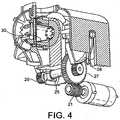
- Brewing chamber 29is occupied at least partially by a capsule 30 in a normally closed position of the brewing unit ( figure 4 ).
- the capsulemay be of any type and should simply be compatible with brewing chamber 29 and passage 31 for being handled by the assemblies during closure and opening of the brewing unit. Suitable capsules and brewing chambers are for instance disclosed in EP 0 512 468 , EP 0 512 470 and EP 2 068 684 .
- Transmission means 4may include various mechanical systems. Transmission means 4 may have a force transmission ratio from the motor to the assembly of at least 1:50, in particular from 1:100 to 1:300 to 1:500.
- transmission means 4includes a gear assembly 20 linked to a cam 22 and cam-follower 23.
- cam 22comprise a pair of elongated grooves located on each side of casing 17.
- Gear assembly 20comprises a worm drive 21 connected to the motor axle (i.e. to the rotor of motor 3).
- Worm drive 21operates a large gear 24, e.g. a spur gear or helical gear, which is fixed to an axle 25 on which sit two lateral smaller gears 26, 27, e.g. spur gears or helical gears or friction gears.
- the smaller gears 26, 27drives a pair of gear segments 28, e.g.
- gear segments 28 with cam-followers 23are positioned such that the brewing pressure is absorbed across the gear segments without it being transmitted to the rest of the drive system, e.g. radially across the gear segments.
- the brewing pressurecan be absorbed by the drive system by a suitable configuration.
- the gear ratio between worm drive 21 and large gear 24may be in the range of 1:25 to 1:100, such as 1:50 to 1:80.
- the gear ratio between small gear 27 and gear segment 28can be in the range of 1:3 to 1:10, in particular in the range of 1:5 to 1:8.
- worm drive 21 in transmission 4can.make this transmission unidirectional. In other words, force and movement can only be transmitted from motor 3 to transmission 4 and not vice versa, worm drive 21 acting as a stop in the opposite direction. Hence, no further stop means is needed to maintain the assemblies in a given position. It is sufficient to interrupt the powering of motor 3 to secure assemblies 13,14 in a given position, in particular in the closed or open position.
- both open and closed end positionsare geometrically made as "hard stops” with no end switches or sensors.
- the input for the motor controlmay involve the user-interface, the current absorption of the motor and a timer of the control unit.
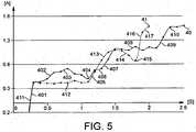
- two different typical curves 40,41can be detected over time, e.g. by measuring the power consumption of motor 3, for example by measuring the current consumption of motor 3, in particular when motor 3 is a DC motor, e.g. operated at generally constant voltage.
- Curve 40represents the evolution over time of the current consumption of motor 3 in the "capsule closure mode".
- the closed state of brewing unit 2 in the capsule closure modeis represented in Figure 4 with a capsule 30 enclosed in the closed brewing chamber.
- Curve 41represents the evolution of the current consumption of motor 3 in the "empty closure mode".
- the closed state of brewing unit 2 in the empty closure modeis represented in Figure 3 .
- curves 40,41correspond to a closure movement of assemblies 13,14 of brewing unit 2.
- curvescan be determined for the opening movements, e.g. with and without capsule 30 inbetween assemblies 13,14.
- Such opening curvescan be used as a reference set to detect possible disturbances of an opening movement of assemblies 13,14, e.g. jamming of a human body part such as a finger between a housing of the machine and a therein movable assembly of brewing unit 2.
- Control unit 10 of machine 1is configured for comparing the variation of the actual current consumption to referential curves 40 and 41 depending on the relevant mode the brewing unit is engaged in. Such configuration is obtained by software.
- a brewing cyclecan be initiated.
- the start of brewing cyclecan be triggered by a command or request on the user's interface 12. Alternatively, the start of the brewing cycle can be triggered automatically by the reaching of the closed position.
- a rinsing and/or de-scaling mode with reduced temperature to allow optimal de-scaling and/or save energyis initiated in the closed position ( Figure 3 ).
- the start of rinsing and/or de-scaling cyclecan also be triggered by a command or request on the user's interface 12. Alternatively, the start of the rinsing and/or de-scaling cycle can be triggered automatically by the reaching of the closed position.
- a cuppreheating modemay be initiated that involves the dispensing of heated water into a user-cup for preheating thereof prior to preparing and dispensing a beverage. Preheating of the cup may be carried out at beverage preparation temperature or at a reduced temperature.
- curve 40 illustrating an exemplary evolution of current consumption over time by motor 3 when a capsule 30 is inserted into brewing unit 2includes various phases:
- Curve 41 illustrating an exemplary evolution of current consumption over time by motor 3 when no capsule is inserted into brewing unit 2,includes various phases:
- the time needed for closing the assemblies when no capsule is inserted into brewing unit 2is slightly shorter, approx 0.5 sec, than when motor 3 has to overcome additional forces caused by the presence of a capsule 3.
- closurecan be achieved within 2 or 2.5 sec, as illustrated with this particular embodiment of the invention.
- the time needed for opening of closing the assemblies of a brewing unitmay typically be in the range of 1 to 10 seconds.
- the safety inputpreferably comprises the operation of inverting the motor action to move the movable assembly back into the open position.
- the safety inputmay amount to reducing or stopping the drive action of the motor. This safety measure protects for example the user from jamming a finger in the running mechanism.
- the safety inputmay be triggered when the resistance against closure of the assemblies exceeds 50, 80, 100, 125 or 150 N before reaching the closed position before reaching the closed position.
- the safety inputmay be triggered when an excessive resistance occurs at a distance between the assemblies before closure which is greater than 1 or 2 mm, in particular greater than 3 mm or 4 mm.
- the gear assemblyis preferably configured to provide a gear ratio of at least 1:100, preferably comprised between 1:200 and 1:500 such as between 1:250 and 1:450, e.g. 1:300. Due to this relatively high gear ratio, another benefit of the present invention comes from the possibility to use relatively low power motor, for example comprised between 20 - 50 mNm.
Landscapes
- Engineering & Computer Science (AREA)
- Food Science & Technology (AREA)
- Mechanical Engineering (AREA)
- Apparatus For Making Beverages (AREA)
- Devices For Dispensing Beverages (AREA)
Description
- The present invention relates to a beverage machine for the preparation of a beverage from an ingredient capsule. More particularly, the machine has a brewing unit with a simple motorization for closing the brewing unit in a convenient and safe manner.
- For the purpose of the present description, a "beverage" is meant to include any human-consumable liquid substance, such as tea, coffee, hot or cold chocolate, milk, soup, baby food, etc... A "capsule" is meant to include any pre-portioned beverage ingredient, such as a flavouring ingredient, within an enclosing packaging of any material, in particular an airtight packaging, e.g. plastic, aluminium, recyclable and/or biodegradable packagings, and of any shape and structure, including soft pods or rigid cartridges containing the ingredient.
- Certain beverage preparation machines use capsules containing ingredients to be extracted or to be dissolved and/or ingredients that are stored and dosed automatically in the machine or else are added at the time of preparation of the drink. Some beverage machines possess filling means that include a pump for liquid, usually water, which pumps the liquid from a source of water that is cold or indeed heated through heating means, e.g. a thermoblock or the like.
- Especially in the field of coffee preparation, machines have been widely developed in which a capsule containing beverage ingredients is inserted in a brewing device. The brewing device is tightly closed about the capsule, water is injected at the first face of the capsule, the beverage is produced in the closed volume of the capsule and a brewed beverage can be drained from a second face of the capsule and collected into a receptacle such as a cup or glass.
- Brewing devices have been developed to facilitate insertion of a "fresh" capsule and removal of the capsule upon use.
WO 2005/004683 andWO 2007/135136 relate to such brewing devices. The devices comprise a frame, a fixed holding part for the capsule, a movable holding part which is mounted relative to the frame in a sliding relationship, one or two knuckle joint mechanisms that provide a mechanical system which enables to close in a steady and fluid-tight manner the holding parts about the capsule while also resisting to the counter-force acting while re-opening and generated by the internal brewing pressure, and a handle for directly levering the knuckle joint mechanism. Such a device forms a simple assembly enabling insertion of the capsule by vertical fall through a passage in the frame and removal of the used capsule in the same direction as the insertion direction. The handle may serve to cover and uncover the passage for the capsule. The movable parts of the brewing device are actuated manually via the handle. The manual force required to move the movable parts varies during closure and opening of the machine and depends on the dimensional tolerances of the capsules used and the positioning and nature of the capsules as well as the temperature of the brewing unit.WO 2009/043630 discloses a beverage preparation machine including a brewing unit having a front part with a passage for inserting a capsule into the brewing unit. The front part is arranged to telescope out of the machine's housing for uncovering the passage for inserting a capsule into the brewing unit and telescopes into the brewing unit for sliding the passage under the housing and thus covering the passage by the housing.- From a different approach, the actuation of the movable part of the brewing device may be motorized.
EP 1 767 129 relates to a motor-driven extraction module for a capsule-based beverage production device. In this case, the user does not have to provide any manual effort to open or close the brewing device. The brewing device has a capsule insertion passage provided with a safety door assembled to the movable part of the brewing device via a switch for detecting an undesired presence of a finger in the passage during closure and prevent squeezing-injuries by stopping the motor before any finger is caught in the brewing device. - An object of the invention is to provide a motorized closure function of the brewing unit for providing more convenience in loading and ejection of the ingredient capsule and reducing user's intervention. Another object is to provide a safe operation by reducing the risk of injuries while using a motorized beverage machine. Another object is to provide added value functionalities such as semi-automatic or automatic brewing, rinsing and/or de-scaling modes. Another object is to control optimal conditions for rinsing and/or de-scaling the machine. A further object of the present invention is to provide a simple motorized closure function of the brewing unit.
- One or more of these objects are meet by a motorized brewing machine according to the independent claim(s). The dependent claims further provide solutions to these objects and/or additional benefits.
- The invention relates to a motorized machine for preparing and dispensing a beverage and more particularly to a beverage machine having a motorized brewing unit. For instance, the machine is a coffee, tea, chocolate, cacao, milk or soup preparation machine. In particular, the machine is arranged for preparing within a beverage processing module a beverage by passing hot or cold water or another liquid through a capsule containing an ingredient, such as a flavouring ingredient, of the beverage to be prepared, such as ground coffee or tea or chocolate or cacao or milk powder.
- Such beverage preparation typically includes the mixing of a plurality of beverage ingredients, e.g. water and milk powder, and/or the infusion of a beverage ingredient, such as an infusion of ground coffee or tea with water. For instance, a predetermined amount of beverage is formed and dispensed on user-request, which corresponds to a serving. The volume of such a serving may be in the range of 25 to 200 ml, e.g. the volume for filling a cup or mug, depending on the type of beverage. Formed and dispensed beverages may be selected from ristrettos, espressos, lungos, cappuccinos, café latte, americano coffees, teas, etc... In particular, a coffee machine may be configured for dispensing espressos, e.g. an adjustable volume of 20 to 60 ml per serving, and/or for dispensing lungos, e.g. a volume in the range of 70 to 150 ml per serving.
- In particular, the motorized beverage machine has:
- activation means that comprise a motor; and
- a brewing unit that comprises a first assembly and a second assembly cooperating together, each assembly delimiting part of a brewing chamber for containing an ingredient capsule.
- At least one of these assemblies is:
- movable away from the cooperating assembly into an open position within the machine for forming between the assemblies a passage for inserting into and/or removing from the brewing unit the ingredient capsule; and
- movable to (e.g. towards) the cooperating assembly into a closed position for forming the brewing chamber.
- The assemblies are relatively movable to one another. One assembly may be fixed in the machine, e.g. in the main frame or outer housing of the machine, and the other assembly may be movable thereto. Alternatively, both assemblies may be movable in the machine, e.g. in the main frame or outer housing of the machine.
- In accordance with the invention, for driving the movable assembly between said open and closed positions, the motor is a low power motor configured to:
- generate a maximum torque of no more than 50 mNm; and/or
- consume a maximum power of no more than 50 W.
- By providing a low power motor, it is possible to simplify the construction and control of the motorized machine. As compared to high power motors, a low power motor has a smaller inertia due to the reduced mechanical inertia and lower power load. Hence, temporary variations of the force (or torque) required from the motor, e.g. to overcome an obstacle or additional friction, is not or less absorbed by the dampening effect of the mechanical inertia and electric load of the motor but timely translated in a temporary increase of required electric powering of the motor. Moreover, since the motor has a lower mechanical and electric inertia, interrupting the powering of the motor is not followed by a significant discharge of the energy load (mechanical and electric) of the motor into the mechanical system. It follows that by using a low power motor, the actual mechanical behaviour of the relatively movable assemblies can be monitored via the power consumption of the motor. Moreover, the machine does not require end position sensors to stop the motor when it is about to reach the end positions. The reaching of an obstacle at the end position can be nearly instantaneously identified by monitoring the power consumption of the motor the powering of which can be stopped without the risk of the motor forcing the assemblies detrimentally beyond the end position by discharging its mechanical and electric inertia.
- For instance, the motor is arranged to generate a maximum torque of at least 20 mNm, in particular a maximum torque in the range of 25 to 40 mNm.
- The motor can be arranged to consume a maximum power in the range of 7 to 25 W, in particular 10 to 15 W.
- The motor can have an angular speed of up to 10K RPM, such as from 0 to 5000 RPM.
- The activation means typically includes a transmission means for transmitting a drive action from the motor to the movable assembly, e.g. one or more transmission gears and/or belts and/or cardans. For instance, the transmission means comprises a gear assembly, optionally having a gear ratio of at least 1:100, in particular from 1:200 to 1:500 such as 1:250 to 1:450, e.g. 1:300. Typically, the transmission means has a force transmission ratio from the motor to the assembly of at least 1:50, in particular from 1:100 to 1:300 or 1:500.
- Hence, the low power of the motor can be compensated by a corresponding transmission rate to reduce the output speed of the motor and increase the generated force (or torque).
- In one embodiment, the transmission means comprises a worm drive.
- More generally, the transmission means is advantageously unidirectional, e.g. by including a worm drive. Hence, when the motor is stopped, the motor cannot be forced by motion of the assemblies since the transmission means, e.g. via a worm drive, is configured to transmit power only into one direction, namely from the motor to the assemblies and not vice versa. It follows that no further break or stop system is needed to maintain the assemblies in a position into which they are driven by the motor.
- Typically, the activation means further comprises:
- water supply means for supplying heated water to the brewing chamber, e.g. a water source with a pump and/or a heater and a control unit such as a PCB with a controller and optional memory device and/or other electronic components (i.e. a PCBA "Printed Circuit Board Assembly"); and
- control means for controlling the drive action of the motor, e.g. a control unit such as a PCB with a controller or a PCBA, the control means being typically free of end position sensors in the open position and/or closed position as discussed above.
- The control means may include:
- means for measuring at least one electrical parameter representative of a consumption of power by the motor;
- means for comparing to a set reference an evolution of this measured parameter as a function of time during the transfer of the assembly from the open to the closed position;
- means for providing to at least one of this activation means an input resulting from the comparison of the evolution of the measured parameter to the set reference; and optionally
- means for providing an input to at least one of the activation means as a result of the compared evolution of said measured parameter.
- Hence, the circumstances under which the assemblies are moved to the open and/or closed position can be monitored by monitoring the power consumption of the motor. In particular, the required mechanical output energy of the motor to produce a movement is directly linked to its consumed input energy, e.g. electric energy, can be measured.
- The set reference may be based on a power consumption modelisation and/or an empiric power consumption measure under predetermined conditions, e.g. with or without ingredient capsule in the brewing unit, specific environment of use, etc... The set reference typically includes a tolerance margin to take into account variations that may occur e.g. due to the environment of use and/or manufacturing tolerances and/or handling tolerances.
- For example, the motor is controlled to produce an output movement, e.g. rotation of a rotor, at a predetermined speed and/or to operate at a predetermined input voltage for example at constant voltage. To maintain the predetermined speed and/or voltage, the input powering of the motor may be adjusted in line with the needed output powering, e.g. angular speed and torque (depending on the constraints under which the motor has to operate in a given circumstance). In particular, the power supply of the motor may be arranged to control the motor's input voltage and the motor can be arranged to draw the required amount of current needed to maintain the input voltage. By measuring the required motor input powering to maintain the desired motor output speed and/or the input voltage, the mechanical constraints exercised against the motor output can be determined. Such constraints may correspond to normal operation of the motorized machine, e.g. opening or closing the brewing unit assemblies with or without a capsule ingredient, or to an abnormal operation, e.g. an interference with an obstacle preventing normal opening or closing, such as a human body part e.g. a finger, caught inbetween the assemblies or inhibiting reopening of the assemblies, e.g. jamming of the brewing unit. In the former case (normal operation), the motorized beverage machine may be configured to allow a corresponding operation, e.g. beverage preparation or cleaning, or to carry it out automatically. In the latter case (abnormal operation), a safety mode may be provided, e.g. to stop closure or reopen the assemblies when an undesired obstacle is caught between the assemblies, or stop the motor when the brewing unit is jammed e.g. to prevent undesired stress in the machine and allow for example manual unjamming by a user and/or service person, as appropriate.
- A safety input can be provided to the motor when detecting a variation of the measured parameter relative to the set reference which is abnormal. Typically, the variation is deemed abnormal when the measured parameter:
- exceeds a level that is at least 20% above the set reference, in particular 30 or 40% thereabove such as 50% thereabove; and/or
- corresponds to a resistance against closure caused by the presence of an obstacle, in particular a human body part such as a finger, inbetween the assemblies moving towards the closed position and prior to reaching thereof, for example a resistance between the assemblies of the brewing unit in the range from 50 to 200 N, in particular from 75, 100 or 120 to 130 or 150 N.
- Providing a reference set that includes a tolerance range, e.g. 20, 30, 40 or even 50% relative to a median or average reference set may be appropriate to take into account normal variations of mechanical effects occurring in the machine, such as variations of a friction coefficient, temperature and humidity as well as manufacturing tolerances.
- The safety input may involve the inversion of the motor action to move the movable assembly into the open position or reducing or stopping the drive action of the motor.
- The control means may be configured to detect the abnormal variation in comparison to a referential curve representing the normal evolution of the electrical parameter as a function of time corresponding to:
- a mode in which the movable assembly is moved into a closed position with an ingredient capsule inserted in the brewing chamber (hereinafter the "Capsule closure mode"); and/or
- a mode in which the movable assembly is moved into a closed position with no capsule inserted in the brewing chamber (hereinafter the "Empty closure mode"),
- A water supply mode consisting of supplying heated water to the brewing chamber may be initiated when no abnormal variation of the measured parameter relative to the set reference has been detected and the assembly is in a closed position ("Capsule closure mode or empty closure mode"). The supplying of heated water may involve the circulation, e.g. by using a pump, of water from a source, e.g. a water tank, and/or the heating of water, e.g. continuous or batch heating, to the brewing chamber. The supply of heated water may be controlled, e.g. via one or more temperature sensors, pressure sensors and/or flowmeters, to adjust the heating and flow characteristics of the supplied heated water.
- Optionally, the control means comprise a user-interface to selectively initiate the water supply mode. Hence, water may be circulated to the brewing chamber automatically or upon a user-request via the user-interface.
- The control means may be configured to initiate a brewing mode when the measured parameter matches the referential curve (including a possible tolerance) corresponding to the "capsule closure mode".
- The control means can be configured to initiate a rinsing and/or de-scaling mode when the measured parameter matches the referential curve corresponding to the "empty closure mode". In particular, the control means can be configured so that said supplied water is heated at a temperature, such as in the range of 55 to 85°C, lower than the normal brewing temperature, such as in the range of 85 to 98°C.
- At least one measured parameter may represent the current consumption of the motor.
- The control means can be free of end position sensors in the open position and/or in the closed position. In this case, the measure of the power consumption by the motor may be used to determine the open position and/or closed position. The measure of the power consumption may be correlated with a time evolution to link the consumption to a time-based expected position of the movable assembly, for instance to distinguish the power consumption resulting from reaching an end position from the power consumption resulting from interference with an intermediate undesired obstacle.
- Alternatively, the control means may include at least one end position sensor, e.g. two end position sensors in particular for detecting the open position and/or the closed position.
- The motorized beverage machine may include an ingredient capsule between the first and second assemblies, the motor being controlled by the control means to move the assemblies from the open position to the closed position to form the brewing chamber to contain the ingredient capsule, the measuring means of the control means being arranged to measure at least one parameter representative of the power consumption of the motor during motion of the assemblies to the closed position with the capsule between the closing assemblies, the comparing means of the control means being arranged to compare the evolution of said measured parameter to the set reference, the input means of the control means being arranged to provide to at least one of said activation means the input resulting from said comparison.
- The control means can be configured to detect any abnormal variation in comparison to a referential curve representing the normal evolution of the electrical parameter as a function of time and to:
- initiate a water supply mode when no abnormal variation of the measured parameter relative to the set reference has been detected and the assembly is in a closed position; and/or
- provide a safety input to the motor when an abnormal variation of the measured parameter relative to the set reference is detected.
- More generally, the machine may comprise an ingredient capsule between the first and second assemblies, the motor being arranged to move the assemblies from the open position to the closed position to form the brewing chamber to contain the ingredient capsule, the motor being associated with a power consumption measuring means for detecting via the measured power consumption: a presence of such capsule between the first and second assemblies during closure; and when the assemblies reach the closed position.
- The invention will now be described with reference to the schematic drawings, wherein:
Figure 1 is a partly schematic and partly perspective view of a beverage machine according to the invention;Figure 2 shows a partial cross-sectional perspective representation of a brewing unit of the beverage machine offigure 1 in open position;Figure 3 shows a partial cross-sectional perspective representation of a closed brewing unit of the beverage machine offigure 1 in an "empty closure mode";Figure 4 shows a partial cross-sectional perspective representation of a closed brewing unit of the beverage machine offigure 1 in a "capsule closure mode"; andFigure 5 shows a graphic of referential curves of the current absorption of the motor as a function of time in a "capsule closure mode" and in an "empty closure mode".- An exemplary motorized beverage machine 1 according to the invention is illustrated in
Figure 1 . The machine comprises activation means with a motor (3) and abrewing unit 2 which is connected toelectric motor 3 which drives transmission means 4 for movingbrewing unit 2 from an open to a closed position and/or vice versa. Water supply means 5 are also provided as a part of machine 1. Such means 5 may include a water reservoir 6, a water pump 7 and a water heater 8. Water circulates in a water circuit 9 which is linked tobrewing unit 2. Typically, circuit 9 is in fluid connection withbrewing unit 2. Control means 10 are also provided in machine 1. Control means 10 include acontrol unit 11, sensors (not represented) and auser interface 12.Control unit 10 includes processor(s), memories and programs enabling to provide appropriate inputs to and receive outputs from the different activation means of the machine in particular, the pump, heater and motor. - Control means 10 may be connected, e.g. wired or wireless, to
user interface 12, pump 7, heater 8 and various sensors, such as flow-meters, temperature sensors, pressure sensors, ammeter (e.g. for measuring the current consumption of motor 3) such as a Hall sensor. In particular, control means 11 may control electric power switches and/or current and voltage regulators associated withmotor 3, pump 7 and heater 8. - As shown in
Figures 2 and 3 ,brewing unit 2 has afirst assembly 13 and asecond assembly 14 which are movable relatively one another. - In the context of the present invention, "assembly" may refer to a single component assembling different functions, e.g. mechanical guiding function, mechanical holding function, mechanical piercing function, flow function, pressure function, etc..., and/or refer to a plurality of components assembling the desired functions.
- For instance,
first assembly 13 is arear injection assembly 13 and includes a capsule cage withinjection blades 15.Front assembly 14 forms a beverage delivery assembly and includes acapsule delivery plate 16.Front assembly 14 is associated to anouter casing 17 and is movable therewith relatively torear injection assembly 13 which remains fixed to aframe 18 of machine 1.Front delivery assembly 14 includes abeverage outlet 19. Front delivery assembly 14 is moved relatively torear injection assembly 13 by means ofmotor 3 which drives transmission means 4.- In accordance with the invention,
motor 3 is a low power motor configured to: generate a maximum torque of no more than 50 mNm; and/or consume a maximum power of no more than 50 watt, for drivingmovable assembly 14 between the open and closed positions. - For instance,
motor 3 is arranged to generate a maximum torque of at least 20 mNm, in particular a maximum torque in the range of 25 to 40 mNm.Motor 3 can be arranged to consume a maximum power in the range of 7 to 25 watt, in particular 10 to 15 watt. The motor can have an angular speed of up to 10K RPM, such as from 0 to 5000 RPM. - In the open position (
Fig. 2 ), apassage 31 is provided between the first andsecond assemblies capsule 30. The capsule may be positioned in an intermediate position, for example as described inEP 1 646 305 orWO 2009/043630 . - In the closed position (
Fig. 3 ), abrewing chamber 29 is formed. Brewingchamber 29 is occupied at least partially by acapsule 30 in a normally closed position of the brewing unit (figure 4 ). The capsule may be of any type and should simply be compatible withbrewing chamber 29 andpassage 31 for being handled by the assemblies during closure and opening of the brewing unit. Suitable capsules and brewing chambers are for instance disclosed inEP 0 512 468EP 0 512 470EP 2 068 684 - Transmission means 4 may include various mechanical systems. Transmission means 4 may have a force transmission ratio from the motor to the assembly of at least 1:50, in particular from 1:100 to 1:300 to 1:500.
- In the embodiment illustrated in
Figs 1 to 4 , transmission means 4 includes agear assembly 20 linked to acam 22 and cam-follower 23. For a balanced transmission of the forces on casing 17,cam 22 comprise a pair of elongated grooves located on each side ofcasing 17.Gear assembly 20 comprises aworm drive 21 connected to the motor axle (i.e. to the rotor of motor 3).Worm drive 21 operates alarge gear 24, e.g. a spur gear or helical gear, which is fixed to anaxle 25 on which sit two lateralsmaller gears gear segments 28, e.g. spur gears or helical gears or friction gears, which moves cam-follower 23 and, by way of consequence, movecam 22 with thecasing 17 from the opened to the closed position and vice versa. In the closedposition gear segments 28 with cam-followers 23 are positioned such that the brewing pressure is absorbed across the gear segments without it being transmitted to the rest of the drive system, e.g. radially across the gear segments. However, as explained hereafter, the brewing pressure can be absorbed by the drive system by a suitable configuration. - The gear ratio between
worm drive 21 andlarge gear 24 may be in the range of 1:25 to 1:100, such as 1:50 to 1:80. The gear ratio betweensmall gear 27 andgear segment 28 can be in the range of 1:3 to 1:10, in particular in the range of 1:5 to 1:8. - For instance, the use of a
worm drive 21 intransmission 4 can.make this transmission unidirectional. In other words, force and movement can only be transmitted frommotor 3 totransmission 4 and not vice versa,worm drive 21 acting as a stop in the opposite direction. Hence, no further stop means is needed to maintain the assemblies in a given position. It is sufficient to interrupt the powering ofmotor 3 to secureassemblies - In a possible solution, both open and closed end positions are geometrically made as "hard stops" with no end switches or sensors.
- The input for the motor control may involve the user-interface, the current absorption of the motor and a timer of the control unit.
- As illustrated in
Figure 5 , two differenttypical curves motor 3, for example by measuring the current consumption ofmotor 3, in particular whenmotor 3 is a DC motor, e.g. operated at generally constant voltage. Curve 40 represents the evolution over time of the current consumption ofmotor 3 in the "capsule closure mode". The closed state ofbrewing unit 2 in the capsule closure mode is represented inFigure 4 with acapsule 30 enclosed in the closed brewing chamber.Curve 41 represents the evolution of the current consumption ofmotor 3 in the "empty closure mode". The closed state ofbrewing unit 2 in the empty closure mode is represented inFigure 3 .- Hence, curves 40,41 correspond to a closure movement of
assemblies brewing unit 2. Likewise, curves can be determined for the opening movements, e.g. with and withoutcapsule 30inbetween assemblies assemblies brewing unit 2. Control unit 10 of machine 1 is configured for comparing the variation of the actual current consumption toreferential curves - If a
capsule 30 is inserted inbrewing unit 2, and no abnormal variation of the current absorption is detected in comparison tocurve 40, e.g. no variation exceeding 20% of the typicalcurrent consumption curve 40, a brewing cycle can be initiated. The start of brewing cycle can be triggered by a command or request on the user'sinterface 12. Alternatively, the start of the brewing cycle can be triggered automatically by the reaching of the closed position. - If no capsule is inserted into
brewing chamber 2 and no abnormal variation of the variation of the current absorption is detected in comparison tocurve 41, a rinsing and/or de-scaling mode with reduced temperature to allow optimal de-scaling and/or save energy is initiated in the closed position (Figure 3 ). The start of rinsing and/or de-scaling cycle can also be triggered by a command or request on the user'sinterface 12. Alternatively, the start of the rinsing and/or de-scaling cycle can be triggered automatically by the reaching of the closed position. If no capsule is inserted intobrewing chamber 2 and no abnormal variation of the variation of the current absorption is detected in comparison tocurve 41, a cuppreheating mode may be initiated that involves the dispensing of heated water into a user-cup for preheating thereof prior to preparing and dispensing a beverage. Preheating of the cup may be carried out at beverage preparation temperature or at a reduced temperature. - More specifically,
curve 40 illustrating an exemplary evolution of current consumption over time bymotor 3 when acapsule 30 is inserted intobrewing unit 2, includes various phases: - An
initial portion 401, i.e. a sharp increase of current consumption reflects the start of motion of the movable assembly, in particular the power consumption needed to overcome the static friction forces. Asecond portion 402, starts at a level slightly below the top of portion 401 (the dynamic friction forces being lower than the static friction forces) and increases slowly. This portion illustrates the increasing resistance caused by acapsule 30 progressively enteringbrewing chamber 29 during closure. A maximum 403 is reached whencapsule 30 is forced out of an intermediate position in which it is supported by stop members, e.g. as explained inEP 2 103 236capsule 30 byblades 15 during closure. The more or lessflat portion 408 represents the final approach of the assemblies. Thecurrent increase 409 reflects the power needed to stress a biasing spring (not shown) for a play take-up between the assemblies in the closed position. Once the current consumption reaches maximum 410, the maximum power is consumed bymotor 3 which indicates that themotor 3 is blocked: the assemblies are in their closed position. Curve 41 illustrating an exemplary evolution of current consumption over time bymotor 3 when no capsule is inserted intobrewing unit 2, includes various phases:Portion 411 corresponds toportion 401, i.e. the movable assembly is put in motion. Once the assembly is motion, portions 412,413 and 414 illustrate essentially the force distribution of the rotating cam-follower 23 moving in thestraight grooves 22 andassembly 13 moving generally perpendicularly to the direction ofgrooves 22. Portion 416,417 illustrate the power consumption increase due to stressing the biasing spring. Like above, once the current consumption reaches maximum 417, the maximum power is consumed bymotor 3 which indicates that the resistance againstmotor 3 is complete: the assemblies are in their closed position.- As illustrated in
Fig. 5 by way of Example, the time needed for closing the assemblies when no capsule is inserted intobrewing unit 2, is slightly shorter, approx 0.5 sec, than whenmotor 3 has to overcome additional forces caused by the presence of acapsule 3. Overall, closure can be achieved within 2 or 2.5 sec, as illustrated with this particular embodiment of the invention. - The time needed for opening of closing the assemblies of a brewing unit may typically be in the range of 1 to 10 seconds.
- When the measure of the current absorption does not match the two above mentioned
curves - The gear assembly is preferably configured to provide a gear ratio of at least 1:100, preferably comprised between 1:200 and 1:500 such as between 1:250 and 1:450, e.g. 1:300. Due to this relatively high gear ratio, another benefit of the present invention comes from the possibility to use relatively low power motor, for example comprised between 20 - 50 mNm.
Claims (17)
- A motorized beverage machine (1) having:- activation means that comprise a motor (3); and- a brewing unit (2) that comprises a first assembly (13) and a second assembly (14) cooperating together, each assembly delimiting part of a brewing chamber (29) for containing an ingredient capsule (30),at least one of said assemblies (14) being:- movable away from the cooperating assembly (13) into an open position within said machine for forming between said assemblies a passage (31) for inserting into and/or removing from the brewing unit said ingredient capsule; and- movable to the cooperating assembly into a closed position for forming said brewing chamber,characterised in that the motor is a low power motor configured to:- generate a maximum torque of no more than 50 mNm; and/or- consume a maximum power of no more than 50 W, for driving said movable assembly between said open and closed positions.
- The machine of claim 1, wherein the motor (3) is arranged to generate a maximum torque of at least 20 mNm, such as a maximum torque in the range of 25 to 40 mNm.
- The machine of claim 1 or 2, wherein the motor (3) is arranged to consume a maximum power in the range of 7 to 25 W, in particular 10 to 15 W.
- The machine of any preceding claim, wherein the activation means comprises a transmission means (4) for transmitting a drive action from the motor (3) to the movable assembly (14).
- The machine of claim 4, wherein the transmission means (4) comprising a gear assembly (20).
- The machine of claim 5, wherein the gear assembly (20) comprises a gear ratio of at least 1:100, in particular from 1:200 to 1:500.
- The machine of any one of claims 4 to 6, wherein the transmission means (4) has a force transmission ratio from the motor (3) to the assembly (14) of at least 1:50, in particular from 1:100 to 1:300 to 1:500.
- The machine of any one of claims 4 to 7, wherein the transmission means (4) comprises a worm drive (21).
- The machine of any one of claims 4 to 8, wherein the transmission means (4) is unidirectional.
- The machine of any preceding claim, wherein the activation means further comprises:- water supply means (5) for supplying heated water to the brewing chamber; and- control means (10) for controlling the drive action of the motor (3), optionally the control means being free of end position sensors in the open position and/or closed position.
- The machine of claim 10, wherein the control means (10) comprise:- means for measuring at least one electrical parameter representative of a consumption of power by the motor;- means for comparing to a set reference (40,41) an evolution of said measured parameter as a function of time during the transfer of the assembly from the open to the closed position; and- means for providing to at least one of said activation means an input resulting from comparing the evolution of said measured parameter to the set reference.
- The machine of claim 11, wherein a safety input is provided to the motor (3) when detecting a variation of the measured parameter relative to the set reference (40,41) which is abnormal, the variation being in particular deemed abnormal when the measured parameter:- exceeds a level that is at least 20% above the set reference (40,41), in particular 30 or 40% thereabove such as 50% thereabove; and/or- corresponds to a resistance against closure caused by the presence of an obstacle, such as a human body part e.g. a finger, inbetween the assemblies moving towards the closed position and prior to reaching thereof,
- The machine of claim 12, wherein the safety input comprises inverting the motor action to move the movable assembly (14) into the open position or reducing or stopping the drive action of the motor (3).
- The machine of claim 13, wherein the control means (10) is configured to detect the abnormal variation in comparison to a referential curve (40,41) representing the normal evolution of the electrical parameter as a function of time corresponding to:- a mode in which the movable assembly (14) is moved into a closed position with an ingredient capsule (30) inserted in the brewing chamber (29); and/or- a mode in which the movable assembly is moved into a closed position with no capsule inserted in the brewing chamber.
- The machine of any preceding claim, which comprises an ingredient capsule (30) between the first and second assemblies (13,14), the motor (3) being arranged to move the assemblies from the open position to the closed position to form the brewing chamber (29) to contain the ingredient capsule, the motor being associated with a power consumption measuring means for detecting via the measured power consumption: a presence of such capsule between the first and second assemblies during closure; and when the assemblies reach the closed position.
- A method of operating a motorized beverage machine comprising a capsule (30) between the first and second assemblies (13,14) as defined in claim 15, which comprises driving the movable assembly by the low power motor, whereby the motor:- generates a maximum torque of no more than 50 mNm; and/or- consumes a maximum power of no more than 50 W.
- A use, of an ingredient capsule (30), for- implementing a motorized beverage machine comprising a capsule between the first and second assemblies (13,14) as defined in claim 15, or- carrying out the method of claim 16.
Priority Applications (1)
| Application Number | Priority Date | Filing Date | Title |
|---|---|---|---|
| EP11718373.1AEP2608704B1 (en) | 2010-08-27 | 2011-05-05 | Simple motorized brewing unit |
Applications Claiming Priority (3)
| Application Number | Priority Date | Filing Date | Title |
|---|---|---|---|
| EP10174412 | 2010-08-27 | ||
| EP11718373.1AEP2608704B1 (en) | 2010-08-27 | 2011-05-05 | Simple motorized brewing unit |
| PCT/EP2011/057235WO2012025259A1 (en) | 2010-08-27 | 2011-05-05 | Simple motorized brewing unit |
Publications (2)
| Publication Number | Publication Date |
|---|---|
| EP2608704A1 EP2608704A1 (en) | 2013-07-03 |
| EP2608704B1true EP2608704B1 (en) | 2016-06-22 |
Family
ID=44065470
Family Applications (3)
| Application Number | Title | Priority Date | Filing Date |
|---|---|---|---|
| EP11718373.1AActiveEP2608704B1 (en) | 2010-08-27 | 2011-05-05 | Simple motorized brewing unit |
| EP15164569.4AActiveEP2926698B1 (en) | 2010-08-27 | 2011-05-05 | Controlled motorized brewing unit |
| EP11719510.7AActiveEP2608705B2 (en) | 2010-08-27 | 2011-05-05 | Controlled motorized brewing unit |
Family Applications After (2)
| Application Number | Title | Priority Date | Filing Date |
|---|---|---|---|
| EP15164569.4AActiveEP2926698B1 (en) | 2010-08-27 | 2011-05-05 | Controlled motorized brewing unit |
| EP11719510.7AActiveEP2608705B2 (en) | 2010-08-27 | 2011-05-05 | Controlled motorized brewing unit |
Country Status (17)
| Country | Link |
|---|---|
| US (2) | US10631683B2 (en) |
| EP (3) | EP2608704B1 (en) |
| JP (2) | JP2013539384A (en) |
| KR (2) | KR20130095757A (en) |
| CN (2) | CN103179890B (en) |
| AU (2) | AU2011295341C1 (en) |
| BR (2) | BR112013004688B1 (en) |
| CA (2) | CA2809051C (en) |
| CH (1) | CH705749B1 (en) |
| DE (1) | DE112011102829T5 (en) |
| DK (1) | DK201300013U4 (en) |
| ES (3) | ES2588711T3 (en) |
| MX (2) | MX341681B (en) |
| PT (3) | PT2608705E (en) |
| RU (1) | RU2560911C2 (en) |
| WO (2) | WO2012025258A1 (en) |
| ZA (2) | ZA201302271B (en) |
Families Citing this family (86)
| Publication number | Priority date | Publication date | Assignee | Title |
|---|---|---|---|---|
| EP2608704B1 (en)* | 2010-08-27 | 2016-06-22 | Nestec S.A. | Simple motorized brewing unit |
| BR112013017104A2 (en)* | 2011-01-03 | 2019-09-24 | Nestec Sa | mechanical transmission motorized beverage machine |
| ITVR20110179A1 (en)* | 2011-09-19 | 2013-03-20 | Caffita System Spa | INFUSION DEVICE FOR THE PRODUCTION OF DRINKS BY USING CARTRIDGES, WHICH CARTRIDGES OR PODS |
| ITVR20110180A1 (en)* | 2011-09-19 | 2013-03-20 | Caffita System Spa | INFUSION DEVICE FOR THE PRODUCTION OF DRINKS BY USING CARTRIDGES, WHICH CAPSULES OR PODS |
| DE112012001531T5 (en)* | 2012-02-28 | 2013-12-24 | Nestec S.A. | Capsule-controlled motorized brewing unit |
| JP2015534486A (en) | 2012-10-09 | 2015-12-03 | ネステク ソシエテ アノニム | Beverage machine equipped with ingredient capsule attachment device |
| CN104869874B (en) | 2012-10-09 | 2018-01-05 | 雀巢产品技术援助有限公司 | Extraction unit with more size magazine chambers |
| RU2015116419A (en) | 2012-10-09 | 2016-11-27 | Нестек С.А. | EXTRACTION DEVICE WITH ADJUSTABLE RECEIVER FOR VARIOUS SIZES CAPSULES |
| ES2987856T3 (en) | 2012-12-19 | 2024-11-18 | Nestle Sa | Method of extracting cartridges in an extraction unit |
| PT2934246T (en) | 2012-12-20 | 2018-07-16 | Nestle Sa | Double ramp for closing a receptacle holder |
| WO2014096122A1 (en) | 2012-12-20 | 2014-06-26 | Nestec S.A. | Variable transmission for closing a receptacle holder |
| ES2605107T3 (en) | 2012-12-21 | 2017-03-13 | Delica Ag | Device for the preparation of a drink |
| WO2014191218A1 (en)* | 2013-05-29 | 2014-12-04 | Nestec S.A. | Beverage mixing device |
| BE1021777B1 (en)* | 2013-06-25 | 2016-01-18 | Tconcept Company S.P.R.L. | DEVICE FOR PREPARING INFUTED BEVERAGES COMPRISING A POSITIONING MEANS FOR THE CAPSULE |
| WO2015086371A1 (en) | 2013-12-11 | 2015-06-18 | Nestec S.A. | Beverage machine with a pivotable capsule gate |
| EP3119246A1 (en) | 2014-03-19 | 2017-01-25 | Nestec S.A. | Beverage machine with exchangeable outermost panels |
| WO2015155145A1 (en) | 2014-04-08 | 2015-10-15 | Nestec S.A. | Multisize capsule handling with serial actuation |
| US9880526B2 (en)* | 2014-05-07 | 2018-01-30 | Regal Beloit America, Inc. | System and method for automating ancillary devices using a motor controller for a pump |
| AU2015261073B2 (en)* | 2014-05-12 | 2019-05-23 | Société des Produits Nestlé S.A. | Beverage brewing unit particularly for machines for preparing beverages from capsules |
| WO2016005348A1 (en) | 2014-07-09 | 2016-01-14 | Nestec S.A. | Device for connecting a beverage machine to a distribution network with safe flow interruption |
| US10595670B2 (en) | 2014-07-09 | 2020-03-24 | Societe Des Produits Nestle S.A. | Coupling of a device for connecting a beverage machine to a distribution network |
| EP3166457B1 (en) | 2014-07-09 | 2019-10-09 | Société des Produits Nestlé S.A. | Device for connecting a beverage machine to a distribution network with safe monitoring |
| ES2699086T3 (en) | 2014-07-09 | 2019-02-07 | Nestec Sa | Accessory to automatically supply a beverage machine with a liquid from a distribution network |
| KR102293489B1 (en)* | 2014-09-12 | 2021-08-27 | 코웨이 주식회사 | Coffee machine and preheating method thereof |
| CA3207639A1 (en) | 2014-10-20 | 2016-04-28 | Bedford Systems Llc | Cartridge holder for beverage machine |
| US10334871B2 (en)* | 2014-11-17 | 2019-07-02 | Apiqe Holdings, Llc | System, disposable cartridge, and method for the preparation of a liquid product |
| US11684204B2 (en)* | 2014-11-27 | 2023-06-27 | Societe Des Produits Nestle S.A. | Liquid dispensing machine with compact drop stop |
| WO2016083485A1 (en) | 2014-11-27 | 2016-06-02 | Nestec S.A. | Liquid dispensing machine with manual drop stop |
| MX389243B (en)* | 2015-05-07 | 2025-03-20 | Smart Wave Tech Corp | Signal and detection system for pairing products |
| AU2016323540C1 (en) | 2015-09-18 | 2022-01-20 | Société des Produits Nestlé S.A. | Removal of a capsule from a capsule holder |
| ITUB20154199A1 (en) | 2015-10-07 | 2017-04-07 | Carpigiani Group Ali Spa | MACHINE AND METHOD FOR THE REALIZATION OF LIQUID AND SEMILIQUID PRODUCTS OF THE HOT OR COLD TYPE. |
| US11284738B2 (en) | 2015-11-11 | 2022-03-29 | Societe Des Produits Nestle S.A. | Easy connection of a liquid tank to a beverage machine |
| EP3175747A1 (en)* | 2015-12-03 | 2017-06-07 | Qbo Coffee GmbH | Machine for making beverages |
| CN109310230B (en)* | 2016-06-30 | 2022-06-21 | 雀巢产品有限公司 | Beverage preparation machine with controlled pump |
| IT201600074471A1 (en) | 2016-07-15 | 2018-01-15 | Ali Group Srl Carpigiani | MACHINE AND METHOD FOR THE PRODUCTION OF LIQUID AND SEMIQUID PRODUCTS OF THE ICE CREAM, PASTRY OR RESTAURANT SECTOR. |
| PT3509464T (en)* | 2016-09-09 | 2021-10-13 | Nestle Sa | BEVERAGE MACHINE WITH ERGONOMIC HANDLING |
| IT201600100869A1 (en)* | 2016-10-07 | 2018-04-07 | Ali Group Srl Carpigiani | METHOD AND CLEANING SYSTEM OF A MACHINE FOR THE REALIZATION OF LIQUID AND / OR SEMIQUINE FOODSTUFFS IN THE ICE-CREAM, PASTRY OR RESTAURANT SECTOR |
| RU2752302C2 (en) | 2016-10-11 | 2021-07-26 | Сосьете Де Продюи Нестле С.А. | Liquid dispensing device with drop limiter |
| EP3525634B1 (en) | 2016-10-11 | 2020-10-07 | Société des Produits Nestlé S.A. | Liquid dispensing machine with speed regulator |
| CA3041722A1 (en) | 2016-11-09 | 2018-05-17 | Pepsico, Inc. | Carbonated beverage makers, methods, and systems |
| US11643269B2 (en) | 2016-12-01 | 2023-05-09 | Bedford Systems, LLC | Container and opening arrangement for beverage production |
| US11432674B2 (en) | 2017-02-28 | 2022-09-06 | Societe Des Produits Nestle S.A. | Dispenser with parallel dispensing paths |
| JP2020517528A (en) | 2017-04-11 | 2020-06-18 | ソシエテ・デ・プロデュイ・ネスレ・エス・アー | Beverage preparation device with beverage discharge means |
| US11589704B2 (en) | 2017-04-11 | 2023-02-28 | Societe Des Produits Nestle S.A. | Beverage preparation device with beverage draining means |
| EP3387966A1 (en) | 2017-04-11 | 2018-10-17 | Nestec S.A. | Beverage preparation device for vehicle |
| IT201700043975A1 (en) | 2017-04-21 | 2018-10-21 | Ali Group Srl Carpigiani | MACHINE AND METHOD FOR THE PRODUCTION OF LIQUID AND SEMIQUID PRODUCTS OF THE ICE CREAM SECTOR. |
| CN110662469B (en) | 2017-06-01 | 2023-03-14 | 雀巢产品有限公司 | Beverage machine with storable dispensing head |
| CN110662468B (en) | 2017-06-01 | 2022-04-29 | 雀巢产品有限公司 | Beverage machine with ergonomic power switch |
| WO2018219989A1 (en) | 2017-06-01 | 2018-12-06 | Nestec Sa | Beverage machine with a stablizing foot |
| WO2018219984A1 (en) | 2017-06-01 | 2018-12-06 | Nestec Sa | Beverage machine with a collapsible interface |
| CN110753505B (en) | 2017-06-13 | 2022-03-15 | 雀巢产品有限公司 | Beverage preparation machine with capsule recognition |
| CN111132588A (en) | 2017-09-25 | 2020-05-08 | 雀巢产品有限公司 | Beverage machine with removable module |
| WO2019057619A1 (en) | 2017-09-25 | 2019-03-28 | Nestec Sa | Beverage machines with modularity |
| EP3501349A1 (en)* | 2017-12-21 | 2019-06-26 | Koninklijke Philips N.V. | A coffee machine with integrated steam and hot water generation |
| JP7242686B2 (en) | 2018-02-09 | 2023-03-20 | ソシエテ・デ・プロデュイ・ネスレ・エス・アー | Beverage preparation machine that recognizes capsules |
| CA3093758A1 (en) | 2018-03-14 | 2019-09-19 | Societe Des Produits Nestle S.A. | Beverage extraction unit with movable outflow obstructor |
| EP3764850A1 (en) | 2018-03-14 | 2021-01-20 | Société des Produits Nestlé S.A. | Beverage machine with a non-homogeneous ingredient extraction configuration |
| JP2021517019A (en) | 2018-03-14 | 2021-07-15 | ソシエテ・デ・プロデュイ・ネスレ・エス・アー | Beverage extraction unit for selectively providing different types of orifices in capsules for extracting beverages |
| JP2021515626A (en) | 2018-03-14 | 2021-06-24 | ソシエテ・デ・プロデュイ・ネスレ・エス・アー | Beverage machine that controls and pierces capsules |
| BR112020015699A2 (en) | 2018-03-14 | 2020-12-08 | Société des Produits Nestlé S.A. | DRINKING MACHINE WITH A PARTIALLY CLOSED DISPENSING FACE |
| JP2021515623A (en) | 2018-03-14 | 2021-06-24 | ソシエテ・デ・プロデュイ・ネスレ・エス・アー | Beverage machine with controlled outflow opening |
| CA3094751A1 (en)* | 2018-03-22 | 2019-09-26 | Bedford Systems Llc | Puncture mechanism for beverage machine |
| US12390044B2 (en) | 2018-09-27 | 2025-08-19 | Societe Des Produits Nestle S.A. | Adaptive service unit of a beverage machine |
| EP3628195A1 (en) | 2018-09-27 | 2020-04-01 | Société des Produits Nestlé S.A. | Beverage preparation machine with recipient detection |
| PT3855986T (en) | 2018-09-27 | 2023-09-11 | Nestle Sa | Beverage machine with an actuation distribution |
| FR3088435B1 (en)* | 2018-11-09 | 2020-11-06 | Cie Mediterraneenne Des Cafes | DEVICE AND METHOD FOR DETECTION OF AN ANOMALY IN THE CLOSURE OF AN INFUSION GROUP |
| CA3121432A1 (en) | 2018-12-12 | 2020-06-18 | Societes Des Produits Nestle S.A. | Beverage preparation machine with capsule recognition |
| IT201900008844A1 (en) | 2019-06-13 | 2020-12-13 | Lavazza Luigi Spa | Motorized infusion unit |
| KR102851239B1 (en)* | 2019-11-15 | 2025-08-27 | 노바델타-코메르시오 이 인더스트리아 드 카페즈, 엘디에이 | Systems and processes for preparing beverages using electric operation |
| ES2975752T3 (en) | 2020-02-05 | 2024-07-12 | Nestle Sa | Capsule recognition beverage preparation machine |
| CN115023164A (en) | 2020-02-05 | 2022-09-06 | 雀巢产品有限公司 | Beverage preparation machine with capsule recognition |
| FR3110065A1 (en) | 2020-05-13 | 2021-11-19 | Compagnie Mediterraneenne Des Cafes | METHOD AND DEVICE FOR DETECTION AT THE TIME OF A STUCK DOSE |
| CN111616591B (en)* | 2020-05-21 | 2022-04-08 | 四川虹美智能科技有限公司 | Tea brewing device |
| JP2024537023A (en) | 2021-10-13 | 2024-10-10 | ソシエテ・デ・プロデュイ・ネスレ・エス・アー | Ergonomic Drinking Machine |
| IT202100031811A1 (en)* | 2021-12-20 | 2023-06-20 | Citaly Srl | Infusion group for coffee preparation machines |
| JP2025501063A (en) | 2021-12-22 | 2025-01-17 | ソシエテ・デ・プロデュイ・ネスレ・エス・アー | Beverage preparation with simple capsule transfer |
| US20250151945A1 (en) | 2021-12-22 | 2025-05-15 | Societe Des Produits Nestle S.A. | Beverage preparation by stable capsule centrifugation |
| EP4452020A1 (en) | 2021-12-22 | 2024-10-30 | Société des Produits Nestlé S.A. | Beverage preparation with compact conditioning chamber |
| US20250151944A1 (en) | 2021-12-22 | 2025-05-15 | Société des Produits Nestlé S.A. | Beverage preparation by centrifugation with reliable capsule transfer |
| CN118338822A (en) | 2021-12-22 | 2024-07-12 | 雀巢产品有限公司 | Beverage preparation with flexible outlet valve |
| EP4452019A1 (en) | 2021-12-22 | 2024-10-30 | Société des Produits Nestlé S.A. | Beverage preparation with a stable outlet valve |
| US20250255428A1 (en) | 2022-04-14 | 2025-08-14 | Societe Des Produits Nestle S.A. | Centrifugal chamber with capsule opening elements |
| JP2025511669A (en) | 2022-04-14 | 2025-04-16 | ソシエテ・デ・プロデュイ・ネスレ・エス・アー | Centrifugal chamber with capsule positioning guide |
| JP2025511671A (en) | 2022-04-14 | 2025-04-16 | ソシエテ・デ・プロデュイ・ネスレ・エス・アー | Centrifugal beverage chamber with closure fastener - Patents.com |
| WO2025018448A1 (en)* | 2023-07-18 | 2025-01-23 | 엘지전자 주식회사 | Beverage apparatus |
| WO2025120122A1 (en) | 2023-12-07 | 2025-06-12 | Societe Des Produits Nestle S.A. | Reliable capsule beverage dispensing system |
Citations (12)
| Publication number | Priority date | Publication date | Assignee | Title |
|---|---|---|---|---|
| EP0118074A1 (en) | 1983-03-03 | 1984-09-12 | FIAT AUTO S.p.A. | A safety circuit for the electrical control of a motor vehicle electric window actuator unit |
| US5086260A (en) | 1990-02-16 | 1992-02-04 | Jidosha Denki Kogyo K.K. | Wiper apparatus with reversing motor protected from overload |
| EP0627186A1 (en) | 1993-05-27 | 1994-12-07 | Sara Lee/DE N.V. | Method and apparatus for preparing a beverage |
| US6101923A (en) | 1997-03-13 | 2000-08-15 | Egro Ag | Automatic coffee maker |
| US6505544B1 (en) | 1999-01-28 | 2003-01-14 | Compagnie Mediterraneenne Des Cafes | Coffee extracting device |
| US6557458B1 (en) | 1999-04-27 | 2003-05-06 | Compagnie Mediterraneenne Des Cafes | Device and method for controlling the closing and opening of an extraction chamber of a coffee maker |
| WO2005019946A2 (en) | 2003-08-25 | 2005-03-03 | Jcae Do Brasil Ltda. | Control system for direct-current electrics motors |
| EP1767129A1 (en) | 2005-09-27 | 2007-03-28 | Nestec S.A. | Extraction module for a capsule-based beverage production device |
| US7210401B1 (en) | 2004-04-20 | 2007-05-01 | Rolfes Patrick J | Single cup pod beverage brewer |
| US20080084172A1 (en) | 2006-10-10 | 2008-04-10 | Square D Company | DC motor mechanical shock protection system |
| EP2080457A1 (en) | 2008-01-21 | 2009-07-22 | BSH Bosch und Siemens Hausgeräte GmbH | Fully automatic coffee machine with service display |
| US20100098823A1 (en) | 2008-10-20 | 2010-04-22 | Chris Nenov | Portable electrical piston-driven espresso machine |
Family Cites Families (61)
| Publication number | Priority date | Publication date | Assignee | Title |
|---|---|---|---|---|
| US2868109A (en)* | 1954-12-13 | 1959-01-13 | James F Davis | Coffee maker |
| US3306183A (en)* | 1964-07-13 | 1967-02-28 | Levine Alfred B | Beverage infusion machine |
| DE3101511A1 (en)* | 1981-01-19 | 1982-08-26 | Siemens AG, 1000 Berlin und 8000 München | METHOD AND ARRANGEMENT FOR DETERMINING THE LOAD OF DEVICES DRIVEN BY AN ELECTRIC MOTOR |
| JPH0743772Y2 (en) | 1989-03-20 | 1995-10-09 | 三洋電機株式会社 | Rotating cylinder device |
| DE4005110C1 (en)* | 1990-02-17 | 1991-07-25 | Philips Patentverwaltung Gmbh, 2000 Hamburg, De | |
| JP2874345B2 (en) | 1990-12-12 | 1999-03-24 | 松下電器産業株式会社 | Electric coffee kettle |
| TW199884B (en) | 1991-05-08 | 1993-02-11 | Sociere Des Produits Nestle S A | |
| AU1505192A (en) | 1991-05-10 | 1992-11-12 | Societe Des Produits Nestle S.A. | Sealed cartridge for the prepartion of a beverage |
| IT1250447B (en)* | 1991-07-03 | 1995-04-07 | Lucio Grossi | AUTOMATIC MACHINE FOR THE PRODUCTION OF COFFEE WITH DIRECT CURRENT MOTOR OPERATION AND ENDLESS SCREWS. |
| US5334876A (en) | 1992-04-22 | 1994-08-02 | Nartron Corporation | Power window or panel controller |
| US5701063A (en) | 1995-04-05 | 1997-12-23 | Ford Global Technologies, Inc. | Obstruction-sensing system for a movable member |
| AU2704397A (en) | 1997-04-21 | 1998-11-13 | Compagnie Mediterraneenne Des Cafes (S.A.) | Method for transforming an espresso-coffee maker with vertical coffee extractioninto a machine with horizontal extraction and transformed machine |
| CH692443A5 (en)* | 1998-01-26 | 2002-06-28 | Fianara Int Bv | Coffee machine. |
| IT1310366B1 (en)* | 1999-05-04 | 2002-02-13 | Euromatik Srl | SINGLE-DOSE PODS FEEDING DEVICE PRECOMPRESSED INTO THE MACHINES FOR THE PRODUCTION OF ESPRESSO COFFEE BEVERAGES. |
| NL1014817C2 (en)* | 2000-03-31 | 2001-10-02 | Jong Duke De | Coffee maker. |
| ES2246201T3 (en) | 2000-05-09 | 2006-02-16 | Societe Des Produits Nestle S.A. | DEVICE FOR THE REMOVAL OF A SUBSTANCE. |
| DE20105672U1 (en) | 2001-03-31 | 2001-09-13 | Eugster/Frismag Ag, Romanshorn | Espresso brewing device |
| NL1019127C2 (en) | 2001-09-21 | 2003-03-25 | Nedap Nv | Control device for shifting a panel of a vehicle. |
| PT1310199E (en) | 2001-11-09 | 2007-02-28 | Nestle Sa | Device and method for selecting and extracting a cartridge for preparing a beverage |
| DE60303320T2 (en) | 2003-02-07 | 2006-09-21 | Nestec S.A. | Linear extraction module for preparing a beverage from a cartridge |
| EP1495702A1 (en)* | 2003-07-10 | 2005-01-12 | Nestec S.A. | Device for the extraction of a cartridge |
| US6904840B1 (en)* | 2004-01-28 | 2005-06-14 | Grindmaster Corporation | Brewer apparatus with improved tray assembly |
| US20050193891A1 (en) | 2004-03-08 | 2005-09-08 | Brent Garson | Espresso making apparatus and method of brewing espresso |
| FR2874164B1 (en)* | 2004-08-10 | 2006-10-06 | Cie Mediterraneenne Des Cafes | DEVICE FOR PRODUCING BEVERAGE WITH MEANS OF DETECTION |
| US7661352B2 (en)* | 2004-08-31 | 2010-02-16 | Nestec S.A. | Method and system for in-cup dispensing, mixing and foaming hot and cold beverages from liquid concentrates |
| DE102005000061A1 (en)* | 2005-05-18 | 2006-11-23 | Hilti Ag | Electrically operated tacker |
| CN101253788A (en) | 2005-07-07 | 2008-08-27 | 高通股份有限公司 | Method and device for providing location information |
| DE602005019216D1 (en)* | 2005-11-22 | 2010-03-18 | Saeco Ipr Ltd | COFFEE PREPARATION DEVICE |
| ITLE20060009A1 (en) | 2006-03-10 | 2006-06-09 | Giovanni Spinelli | INVENTION IN THE FIELD OF COFFEE MACHINES A FAP / CAPSULES |
| DE602006009232D1 (en)* | 2006-05-24 | 2009-10-29 | Nestec Sa | Brewing device for capsule with locking mechanism with variable transmission ratio |
| WO2008005131A2 (en)* | 2006-05-30 | 2008-01-10 | Robert Downs | Continuously variable transmission |
| ITMI20061232A1 (en)* | 2006-06-26 | 2007-12-27 | Saeco Ipr Ltd | METHOD OF DETECTION OF THE QUANTITY OF GRAINS IN A GRINDING DEVICE |
| WO2008038201A2 (en)* | 2006-09-25 | 2008-04-03 | Koninklijke Philips Electronics N.V. | Method for controlling a pressure of hot water which is used in a process of making espresso |
| AU2007302077A1 (en) | 2006-09-26 | 2008-04-03 | Nestec S.A. | Extraction system for the preparation of a beverage from a cartridge |
| CN201019539Y (en)* | 2007-01-10 | 2008-02-13 | 王冬雷 | Coffee machine capable of brewing coffee capsule |
| ITFI20070028A1 (en)* | 2007-02-07 | 2008-08-08 | Saeco Ipr Ltd | INFUSION DEVICE FOR THE PREPARATION OF DRINKS FROM SINGLE-DOSE CAPSULES WITH A CAPSULES CENTERING DEVICE. |
| ITFI20070049A1 (en)* | 2007-02-27 | 2008-08-28 | Saeco Ipr Ltd | METHOD FOR THE AUTOMATIC ADJUSTMENT OF THE AMOUNT OF COFFEE AND COFFEE MACHINE THAT USE THE SAID METHOD. |
| DE202007005791U1 (en) | 2007-04-21 | 2008-08-21 | Wik Far East Ltd. | Brewing unit for a coffee machine and coffee machine with such a brewing unit |
| US7589942B2 (en) | 2007-06-15 | 2009-09-15 | General Electric Company | MEMS based motor starter with motor failure detection |
| CN201061463Y (en)* | 2007-07-23 | 2008-05-21 | 王冬雷 | Device for preparing hot beverage |
| DE502007006675D1 (en)* | 2007-08-22 | 2011-04-21 | Delica Ag | Device for brewing a liquid food or beverage |
| EP2039293A1 (en)* | 2007-09-19 | 2009-03-25 | F. Hoffman-la Roche AG | Combination drive for a sample extraction system for obtaining a liquid sample |
| EP2218369B1 (en)* | 2007-10-04 | 2017-05-03 | Nestec S.A. | Beverage brewing unit |
| WO2009124786A1 (en)* | 2008-04-07 | 2009-10-15 | Nestec S.A. | Beverage preparation device with in-line scale removal system and descaling method using such system |
| EP2309900B1 (en)* | 2008-08-08 | 2015-05-27 | Nestec S.A. | Beverage machine with carrying handle and configurable appearance&side functions |
| DE102008048252A1 (en)* | 2008-09-12 | 2010-04-15 | Eppendorf Ag | pipetting |
| EP2196115A1 (en)* | 2008-12-12 | 2010-06-16 | Jura Elektroapparate AG | Drive for a coffee brewing device and coffee brewing device |
| CN201452867U (en) | 2009-04-25 | 2010-05-12 | 广东新宝电器股份有限公司 | Coffee machine for brewing coffee capsules |
| CN101536874B (en)* | 2009-04-25 | 2011-07-27 | 广东新宝电器股份有限公司 | Coffee machine for brewing coffee capsules |
| CN101606825B (en)* | 2009-07-22 | 2011-03-02 | 广东新宝电器股份有限公司 | Capsule coffee machine |
| EP2608704B1 (en)* | 2010-08-27 | 2016-06-22 | Nestec S.A. | Simple motorized brewing unit |
| US9155418B2 (en)* | 2010-11-15 | 2015-10-13 | Conair Corporation | Brewed beverage appliance and method |
| CN102525278A (en)* | 2010-12-15 | 2012-07-04 | 雀巢产品技术援助有限公司 | System for testing and diagnosing faults in water dispenser and method |
| BR112013017104A2 (en)* | 2011-01-03 | 2019-09-24 | Nestec Sa | mechanical transmission motorized beverage machine |
| CA2828408C (en)* | 2011-03-14 | 2019-10-22 | Nestec S.A. | Automatic beverage machine |
| DE112012001531T5 (en) | 2012-02-28 | 2013-12-24 | Nestec S.A. | Capsule-controlled motorized brewing unit |
| JP2015507993A (en)* | 2012-02-28 | 2015-03-16 | ネステク ソシエテ アノニム | Cover for raw material inlet with humidity control |
| US9949758B2 (en)* | 2014-03-12 | 2018-04-24 | Orthospin Ltd. | Preloaded medical struts |
| CN106470578B (en)* | 2014-07-09 | 2020-02-28 | 雀巢产品有限公司 | Capsule handling unit for beverage preparation machines |
| DE102015217051A1 (en)* | 2015-09-07 | 2017-03-09 | Volkswagen Aktiengesellschaft | Commercial vehicle steering |
| DE102016200019A1 (en)* | 2016-01-05 | 2017-07-06 | Stabilus Gmbh | scissor drive |
- 2011
- 2011-05-05EPEP11718373.1Apatent/EP2608704B1/enactiveActive
- 2011-05-05ESES11718373.1Tpatent/ES2588711T3/enactiveActive
- 2011-05-05CHCH00497/13Apatent/CH705749B1/enunknown
- 2011-05-05CNCN201180051930.4Apatent/CN103179890B/enactiveActive
- 2011-05-05WOPCT/EP2011/057233patent/WO2012025258A1/enactiveApplication Filing
- 2011-05-05AUAU2011295341Apatent/AU2011295341C1/enactiveActive
- 2011-05-05RURU2013113574/12Apatent/RU2560911C2/enactive
- 2011-05-05CNCN201180051873.XApatent/CN103209622B/enactiveActive
- 2011-05-05JPJP2013525195Apatent/JP2013539384A/enactivePending
- 2011-05-05USUS13/819,637patent/US10631683B2/enactiveActive
- 2011-05-05ESES11719510Tpatent/ES2546489T5/enactiveActive
- 2011-05-05AUAU2011295342Apatent/AU2011295342B2/enactiveActive
- 2011-05-05BRBR112013004688-0Apatent/BR112013004688B1/enactiveIP Right Grant
- 2011-05-05MXMX2013002271Apatent/MX341681B/enactiveIP Right Grant
- 2011-05-05PTPT117195107Tpatent/PT2608705E/enunknown
- 2011-05-05MXMX2013002272Apatent/MX365198B/enactiveIP Right Grant
- 2011-05-05PTPT151645694Tpatent/PT2926698T/enunknown
- 2011-05-05DEDE112011102829Tpatent/DE112011102829T5/ennot_activeCeased
- 2011-05-05KRKR1020137007706Apatent/KR20130095757A/ennot_activeWithdrawn
- 2011-05-05CACA2809051Apatent/CA2809051C/enactiveActive
- 2011-05-05BRBR112013004767-4Apatent/BR112013004767B1/enactiveIP Right Grant
- 2011-05-05WOPCT/EP2011/057235patent/WO2012025259A1/enactiveApplication Filing
- 2011-05-05ESES15164569Tpatent/ES2929550T3/enactiveActive
- 2011-05-05USUS13/819,630patent/US10285534B2/enactiveActive
- 2011-05-05EPEP15164569.4Apatent/EP2926698B1/enactiveActive
- 2011-05-05PTPT117183731Tpatent/PT2608704T/enunknown
- 2011-05-05JPJP2013525194Apatent/JP5871927B2/enactiveActive
- 2011-05-05CACA2809078Apatent/CA2809078C/enactiveActive
- 2011-05-05KRKR1020137007705Apatent/KR20130095756A/ennot_activeWithdrawn
- 2011-05-05EPEP11719510.7Apatent/EP2608705B2/enactiveActive
- 2013
- 2013-01-31DKDKBA201300013Upatent/DK201300013U4/ennot_activeIP Right Cessation
- 2013-03-26ZAZA2013/02271Apatent/ZA201302271B/enunknown
- 2013-03-26ZAZA2013/02273Apatent/ZA201302273B/enunknown
Patent Citations (12)
| Publication number | Priority date | Publication date | Assignee | Title |
|---|---|---|---|---|
| EP0118074A1 (en) | 1983-03-03 | 1984-09-12 | FIAT AUTO S.p.A. | A safety circuit for the electrical control of a motor vehicle electric window actuator unit |
| US5086260A (en) | 1990-02-16 | 1992-02-04 | Jidosha Denki Kogyo K.K. | Wiper apparatus with reversing motor protected from overload |
| EP0627186A1 (en) | 1993-05-27 | 1994-12-07 | Sara Lee/DE N.V. | Method and apparatus for preparing a beverage |
| US6101923A (en) | 1997-03-13 | 2000-08-15 | Egro Ag | Automatic coffee maker |
| US6505544B1 (en) | 1999-01-28 | 2003-01-14 | Compagnie Mediterraneenne Des Cafes | Coffee extracting device |
| US6557458B1 (en) | 1999-04-27 | 2003-05-06 | Compagnie Mediterraneenne Des Cafes | Device and method for controlling the closing and opening of an extraction chamber of a coffee maker |
| WO2005019946A2 (en) | 2003-08-25 | 2005-03-03 | Jcae Do Brasil Ltda. | Control system for direct-current electrics motors |
| US7210401B1 (en) | 2004-04-20 | 2007-05-01 | Rolfes Patrick J | Single cup pod beverage brewer |
| EP1767129A1 (en) | 2005-09-27 | 2007-03-28 | Nestec S.A. | Extraction module for a capsule-based beverage production device |
| US20080084172A1 (en) | 2006-10-10 | 2008-04-10 | Square D Company | DC motor mechanical shock protection system |
| EP2080457A1 (en) | 2008-01-21 | 2009-07-22 | BSH Bosch und Siemens Hausgeräte GmbH | Fully automatic coffee machine with service display |
| US20100098823A1 (en) | 2008-10-20 | 2010-04-22 | Chris Nenov | Portable electrical piston-driven espresso machine |
Non-Patent Citations (16)
| Title |
|---|
| "Handbook of Electric Motors, 2nd ed.,", 2004, M. DEKKER, article NEIL NICHOLS: "Chapter 10: Motor Protection", pages: 515 - 545, XP055290515 |
| "Repair Instruction Nespresso capsule systems", OPERATING INSTRUCTION DOCUMENT, 20 March 2006 (2006-03-20), pages 1 - 64, XP055364343 |
| ANONYMOUS: "The Insider: A weekly guide to spending", THE INDEPENDENT, 10 September 2005 (2005-09-10), pages 4pp, XP055364399 |
| BUNN-O-MATIC CORPORATION: "Autopod Brewer- Commercial grade, single-cup pod brewer", BUNN SALES BROCHURE, 2009, pages 3pp, XP055364441 |
| BUNN-O-MATIC CORPORATION: "Bunn Illustrated Parts Catalog", 2008, pages 1 - 22, XP055364438 |
| BUNN-O-MATIC CORPORATION: "Bunn Installation & Operating Guide", 2008, pages 1 - 13, XP055364467 |
| BUNN-O-MATIC CORPORATION: "Bunn Technical Training AutoPOD, Rev.B", 2009, pages 3pp, 4 - 29, XP055364470 |
| DAVID CROSS: "Technical analysis of motor torque, electrical power and electrical parameters used in the motorised brew unit of the Bunn AutoPod beverage machine PODA003207", DOCUMENT REFERENCE: FSV-14-0897-D, 8 December 2014 (2014-12-08), pages 2pp, 1 - 26, XP055364435 |
| DAVID CROSS: "Technical analysis of motor torque, electrical power and electrical parameters used in the motorised brew unit of the Siemens TK70 beverage machine", DOCUMENT REFERENCE: FSV-14-0892-D, 9 September 2014 (2014-09-09), pages 2pp, 1 - 26, XP055364333 |
| DURAN157: "Bunn Autopod Brewer with Eldorado Coffee Pods", YOU TUBE, 12 August 2008 (2008-08-12), XP0549772264, Retrieved from the Internet <URL:https://www.youtube.com/watch?v=QQMPtbt1viM> |
| NHCOFFEE: "Commercial Brew Machine FINAL.mov", YOU TUBE, 12 March 2010 (2010-03-12), XP054977265, Retrieved from the Internet <URL:https://www.youtube.com/watch?v=l6bgnznh-RE> |
| RESTAURANT BUSINESS STAFF: "What’s brewing?", RESTAURANT BUSINESS, 1 April 2010 (2010-04-01), pages 1, XP055364456 |
| SIEMENS: "Free-standing appliances 2006", SIEMENS BROCHURE, 2006, pages 58pp, XP055364355 |
| SIEMENS: "Free-standing appliances 2007", SIEMENS BROCHURE, 2007, pages 1 - 103, XP055364364 |
| SIEMENS-ELECTROGERÄTE GMBH: "Gebrauchsanleitung /Operating instructions, Notice d`utilisation/ TK 70 N 01", 5 July 2004 (2004-07-05), pages 7pp, 4 - 91, 5pp, XP055364420 |
| WALTER A. ELMORE: "Protective Relaying Theory and Applications", 2004, MARCEL DEKKER, article C.L. DOWNS: "Chapter 9: Motor Protection", pages: 145 - 161, XP055290518 |
Also Published As
Similar Documents
| Publication | Publication Date | Title |
|---|---|---|
| EP2608704B1 (en) | Simple motorized brewing unit | |
| AU2013201040B2 (en) | Capsule-controlled motorized brewing unit | |
| AU2013201039A1 (en) | Controlled motorized brewing unit | |
| RU2574970C2 (en) | Mechanised beverage preparation device |
Legal Events
| Date | Code | Title | Description |
|---|---|---|---|
| PUAI | Public reference made under article 153(3) epc to a published international application that has entered the european phase | Free format text:ORIGINAL CODE: 0009012 | |
| 17P | Request for examination filed | Effective date:20130327 | |
| AK | Designated contracting states | Kind code of ref document:A1 Designated state(s):AL AT BE BG CH CY CZ DE DK EE ES FI FR GB GR HR HU IE IS IT LI LT LU LV MC MK MT NL NO PL PT RO RS SE SI SK SM TR | |
| DAX | Request for extension of the european patent (deleted) | ||
| GRAP | Despatch of communication of intention to grant a patent | Free format text:ORIGINAL CODE: EPIDOSNIGR1 | |
| TPAC | Observations filed by third parties | Free format text:ORIGINAL CODE: EPIDOSNTIPA | |
| INTG | Intention to grant announced | Effective date:20140314 | |
| RIN1 | Information on inventor provided before grant (corrected) | Inventor name:MOERI, PETER | |
| GRAJ | Information related to disapproval of communication of intention to grant by the applicant or resumption of examination proceedings by the epo deleted | Free format text:ORIGINAL CODE: EPIDOSDIGR1 | |
| GRAP | Despatch of communication of intention to grant a patent | Free format text:ORIGINAL CODE: EPIDOSNIGR1 | |
| 17Q | First examination report despatched | Effective date:20140520 | |
| INTC | Intention to grant announced (deleted) | ||
| REG | Reference to a national code | Ref country code:DE Ref legal event code:R079 Ref document number:602011027553 Country of ref document:DE Free format text:PREVIOUS MAIN CLASS: A47J0031360000 Ipc:A47J0031440000 | |
| GRAP | Despatch of communication of intention to grant a patent | Free format text:ORIGINAL CODE: EPIDOSNIGR1 | |
| RIC1 | Information provided on ipc code assigned before grant | Ipc:A47J 31/36 20060101ALI20151104BHEP Ipc:A47J 31/58 20060101ALI20151104BHEP Ipc:A47J 31/44 20060101AFI20151104BHEP Ipc:A47J 31/40 20060101ALI20151104BHEP | |
| INTG | Intention to grant announced | Effective date:20151201 | |
| GRAS | Grant fee paid | Free format text:ORIGINAL CODE: EPIDOSNIGR3 | |
| GRAA | (expected) grant | Free format text:ORIGINAL CODE: 0009210 | |
| AK | Designated contracting states | Kind code of ref document:B1 Designated state(s):AL AT BE BG CH CY CZ DE DK EE ES FI FR GB GR HR HU IE IS IT LI LT LU LV MC MK MT NL NO PL PT RO RS SE SI SK SM TR | |
| REG | Reference to a national code | Ref country code:GB Ref legal event code:FG4D | |
| REG | Reference to a national code | Ref country code:CH Ref legal event code:EP | |
| REG | Reference to a national code | Ref country code:IE Ref legal event code:FG4D | |
| REG | Reference to a national code | Ref country code:AT Ref legal event code:REF Ref document number:807149 Country of ref document:AT Kind code of ref document:T Effective date:20160715 | |
| REG | Reference to a national code | Ref country code:DE Ref legal event code:R096 Ref document number:602011027553 Country of ref document:DE | |
| REG | Reference to a national code | Ref country code:PT Ref legal event code:SC4A Ref document number:2608704 Country of ref document:PT Date of ref document:20160817 Kind code of ref document:T Free format text:AVAILABILITY OF NATIONAL TRANSLATION Effective date:20160808 | |
| REG | Reference to a national code | Ref country code:NL Ref legal event code:FP | |
| REG | Reference to a national code | Ref country code:LT Ref legal event code:MG4D | |
| PG25 | Lapsed in a contracting state [announced via postgrant information from national office to epo] | Ref country code:FI Free format text:LAPSE BECAUSE OF FAILURE TO SUBMIT A TRANSLATION OF THE DESCRIPTION OR TO PAY THE FEE WITHIN THE PRESCRIBED TIME-LIMIT Effective date:20160622 Ref country code:LT Free format text:LAPSE BECAUSE OF FAILURE TO SUBMIT A TRANSLATION OF THE DESCRIPTION OR TO PAY THE FEE WITHIN THE PRESCRIBED TIME-LIMIT Effective date:20160622 Ref country code:NO Free format text:LAPSE BECAUSE OF FAILURE TO SUBMIT A TRANSLATION OF THE DESCRIPTION OR TO PAY THE FEE WITHIN THE PRESCRIBED TIME-LIMIT Effective date:20160922 | |
| REG | Reference to a national code | Ref country code:ES Ref legal event code:FG2A Ref document number:2588711 Country of ref document:ES Kind code of ref document:T3 Effective date:20161104 | |
| PG25 | Lapsed in a contracting state [announced via postgrant information from national office to epo] | Ref country code:SE Free format text:LAPSE BECAUSE OF FAILURE TO SUBMIT A TRANSLATION OF THE DESCRIPTION OR TO PAY THE FEE WITHIN THE PRESCRIBED TIME-LIMIT Effective date:20160622 Ref country code:HR Free format text:LAPSE BECAUSE OF FAILURE TO SUBMIT A TRANSLATION OF THE DESCRIPTION OR TO PAY THE FEE WITHIN THE PRESCRIBED TIME-LIMIT Effective date:20160622 Ref country code:RS Free format text:LAPSE BECAUSE OF FAILURE TO SUBMIT A TRANSLATION OF THE DESCRIPTION OR TO PAY THE FEE WITHIN THE PRESCRIBED TIME-LIMIT Effective date:20160622 Ref country code:GR Free format text:LAPSE BECAUSE OF FAILURE TO SUBMIT A TRANSLATION OF THE DESCRIPTION OR TO PAY THE FEE WITHIN THE PRESCRIBED TIME-LIMIT Effective date:20160923 Ref country code:LV Free format text:LAPSE BECAUSE OF FAILURE TO SUBMIT A TRANSLATION OF THE DESCRIPTION OR TO PAY THE FEE WITHIN THE PRESCRIBED TIME-LIMIT Effective date:20160622 | |
| PG25 | Lapsed in a contracting state [announced via postgrant information from national office to epo] | Ref country code:EE Free format text:LAPSE BECAUSE OF FAILURE TO SUBMIT A TRANSLATION OF THE DESCRIPTION OR TO PAY THE FEE WITHIN THE PRESCRIBED TIME-LIMIT Effective date:20160622 Ref country code:RO Free format text:LAPSE BECAUSE OF FAILURE TO SUBMIT A TRANSLATION OF THE DESCRIPTION OR TO PAY THE FEE WITHIN THE PRESCRIBED TIME-LIMIT Effective date:20160622 Ref country code:SK Free format text:LAPSE BECAUSE OF FAILURE TO SUBMIT A TRANSLATION OF THE DESCRIPTION OR TO PAY THE FEE WITHIN THE PRESCRIBED TIME-LIMIT Effective date:20160622 Ref country code:IS Free format text:LAPSE BECAUSE OF FAILURE TO SUBMIT A TRANSLATION OF THE DESCRIPTION OR TO PAY THE FEE WITHIN THE PRESCRIBED TIME-LIMIT Effective date:20161022 Ref country code:CZ Free format text:LAPSE BECAUSE OF FAILURE TO SUBMIT A TRANSLATION OF THE DESCRIPTION OR TO PAY THE FEE WITHIN THE PRESCRIBED TIME-LIMIT Effective date:20160622 | |
| PG25 | Lapsed in a contracting state [announced via postgrant information from national office to epo] | Ref country code:SM Free format text:LAPSE BECAUSE OF FAILURE TO SUBMIT A TRANSLATION OF THE DESCRIPTION OR TO PAY THE FEE WITHIN THE PRESCRIBED TIME-LIMIT Effective date:20160622 Ref country code:PL Free format text:LAPSE BECAUSE OF FAILURE TO SUBMIT A TRANSLATION OF THE DESCRIPTION OR TO PAY THE FEE WITHIN THE PRESCRIBED TIME-LIMIT Effective date:20160622 | |
| REG | Reference to a national code | Ref country code:DE Ref legal event code:R026 Ref document number:602011027553 Country of ref document:DE | |
| PLBI | Opposition filed | Free format text:ORIGINAL CODE: 0009260 | |
| REG | Reference to a national code | Ref country code:FR Ref legal event code:PLFP Year of fee payment:7 | |
| 26 | Opposition filed | Opponent name:UNILEVER PLC/ UNILEVER N.V. Effective date:20170315 | |
| PLAX | Notice of opposition and request to file observation + time limit sent | Free format text:ORIGINAL CODE: EPIDOSNOBS2 | |
| PG25 | Lapsed in a contracting state [announced via postgrant information from national office to epo] | Ref country code:DK Free format text:LAPSE BECAUSE OF FAILURE TO SUBMIT A TRANSLATION OF THE DESCRIPTION OR TO PAY THE FEE WITHIN THE PRESCRIBED TIME-LIMIT Effective date:20160622 | |
| PGFP | Annual fee paid to national office [announced via postgrant information from national office to epo] | Ref country code:TR Payment date:20170327 Year of fee payment:7 | |
| PG25 | Lapsed in a contracting state [announced via postgrant information from national office to epo] | Ref country code:SI Free format text:LAPSE BECAUSE OF FAILURE TO SUBMIT A TRANSLATION OF THE DESCRIPTION OR TO PAY THE FEE WITHIN THE PRESCRIBED TIME-LIMIT Effective date:20160622 Ref country code:LU Free format text:LAPSE BECAUSE OF NON-PAYMENT OF DUE FEES Effective date:20170531 | |
| PLBB | Reply of patent proprietor to notice(s) of opposition received | Free format text:ORIGINAL CODE: EPIDOSNOBS3 | |
| PG25 | Lapsed in a contracting state [announced via postgrant information from national office to epo] | Ref country code:MC Free format text:LAPSE BECAUSE OF FAILURE TO SUBMIT A TRANSLATION OF THE DESCRIPTION OR TO PAY THE FEE WITHIN THE PRESCRIBED TIME-LIMIT Effective date:20160622 | |
| REG | Reference to a national code | Ref country code:IE Ref legal event code:MM4A | |
| PG25 | Lapsed in a contracting state [announced via postgrant information from national office to epo] | Ref country code:LU Free format text:LAPSE BECAUSE OF NON-PAYMENT OF DUE FEES Effective date:20170505 | |
| REG | Reference to a national code | Ref country code:FR Ref legal event code:PLFP Year of fee payment:8 | |
| PG25 | Lapsed in a contracting state [announced via postgrant information from national office to epo] | Ref country code:IE Free format text:LAPSE BECAUSE OF NON-PAYMENT OF DUE FEES Effective date:20170505 | |
| PLCK | Communication despatched that opposition was rejected | Free format text:ORIGINAL CODE: EPIDOSNREJ1 | |
| STAA | Information on the status of an ep patent application or granted ep patent | Free format text:STATUS: THE PATENT HAS BEEN GRANTED | |
| PG25 | Lapsed in a contracting state [announced via postgrant information from national office to epo] | Ref country code:MT Free format text:LAPSE BECAUSE OF NON-PAYMENT OF DUE FEES Effective date:20170505 | |
| REG | Reference to a national code | Ref country code:DE Ref legal event code:R100 Ref document number:602011027553 Country of ref document:DE | |
| PG25 | Lapsed in a contracting state [announced via postgrant information from national office to epo] | Ref country code:AL Free format text:LAPSE BECAUSE OF FAILURE TO SUBMIT A TRANSLATION OF THE DESCRIPTION OR TO PAY THE FEE WITHIN THE PRESCRIBED TIME-LIMIT Effective date:20160622 | |
| PLAE | Information related to rejection of opposition modified | Free format text:ORIGINAL CODE: 0009299REJO | |
| PLBN | Opposition rejected | Free format text:ORIGINAL CODE: 0009273 | |
| STAA | Information on the status of an ep patent application or granted ep patent | Free format text:STATUS: OPPOSITION REJECTED | |
| D27O | Information related to the rejection of opposition deleted | ||
| 27O | Opposition rejected | Effective date:20181004 | |
| REG | Reference to a national code | Ref country code:AT Ref legal event code:UEP Ref document number:807149 Country of ref document:AT Kind code of ref document:T Effective date:20160622 | |
| REG | Reference to a national code | Ref country code:BE Ref legal event code:FP Effective date:20160921 | |
| PG25 | Lapsed in a contracting state [announced via postgrant information from national office to epo] | Ref country code:HU Free format text:LAPSE BECAUSE OF FAILURE TO SUBMIT A TRANSLATION OF THE DESCRIPTION OR TO PAY THE FEE WITHIN THE PRESCRIBED TIME-LIMIT; INVALID AB INITIO Effective date:20110505 | |
| REG | Reference to a national code | Ref country code:NL Ref legal event code:PD Owner name:SOCIETE DES PRODUITS NESTLE S.A.; CH Free format text:DETAILS ASSIGNMENT: CHANGE OF OWNER(S), MERGE; FORMER OWNER NAME: NESTEC S.A. Effective date:20190620 | |
| REG | Reference to a national code | Ref country code:CH Ref legal event code:PFUS Owner name:SOCIETE DES PRODUITS NESTLE S.A., CH Free format text:FORMER OWNER: NESTEC S.A., CH | |
| REG | Reference to a national code | Ref country code:GB Ref legal event code:732E Free format text:REGISTERED BETWEEN 20190801 AND 20190807 | |
| PG25 | Lapsed in a contracting state [announced via postgrant information from national office to epo] | Ref country code:BG Free format text:LAPSE BECAUSE OF FAILURE TO SUBMIT A TRANSLATION OF THE DESCRIPTION OR TO PAY THE FEE WITHIN THE PRESCRIBED TIME-LIMIT Effective date:20160622 | |
| REG | Reference to a national code | Ref country code:ES Ref legal event code:PC2A Owner name:SOCIETE DES PRODUITS NESTLE S.A. Effective date:20191010 | |
| PG25 | Lapsed in a contracting state [announced via postgrant information from national office to epo] | Ref country code:CY Free format text:LAPSE BECAUSE OF NON-PAYMENT OF DUE FEES Effective date:20160622 | |
| REG | Reference to a national code | Ref country code:AT Ref legal event code:PC Ref document number:807149 Country of ref document:AT Kind code of ref document:T Owner name:SOCIETE DES PRODUITS NESTLE S.A., CH Effective date:20190916 | |
| REG | Reference to a national code | Ref country code:BE Ref legal event code:PD Owner name:SOCIETE DES PRODUITS NESTLE S.A.; CH Free format text:DETAILS ASSIGNMENT: CHANGE OF OWNER(S), CESSION; FORMER OWNER NAME: NESTEC S.A. Effective date:20190712 | |
| PG25 | Lapsed in a contracting state [announced via postgrant information from national office to epo] | Ref country code:MK Free format text:LAPSE BECAUSE OF FAILURE TO SUBMIT A TRANSLATION OF THE DESCRIPTION OR TO PAY THE FEE WITHIN THE PRESCRIBED TIME-LIMIT Effective date:20160622 | |
| REG | Reference to a national code | Ref country code:DE Ref legal event code:R082 Ref document number:602011027553 Country of ref document:DE Representative=s name:MITSCHERLICH, PATENT- UND RECHTSANWAELTE PARTM, DE Ref country code:DE Ref legal event code:R081 Ref document number:602011027553 Country of ref document:DE Owner name:SOCIETE DES PRODUITS NESTLE S.A., CH Free format text:FORMER OWNER: NESTEC S.A., VEVEY, CH | |
| PG25 | Lapsed in a contracting state [announced via postgrant information from national office to epo] | Ref country code:TR Free format text:LAPSE BECAUSE OF NON-PAYMENT OF DUE FEES Effective date:20180505 | |
| P01 | Opt-out of the competence of the unified patent court (upc) registered | Effective date:20230527 | |
| PGFP | Annual fee paid to national office [announced via postgrant information from national office to epo] | Ref country code:NL Payment date:20250409 Year of fee payment:15 | |
| PGFP | Annual fee paid to national office [announced via postgrant information from national office to epo] | Ref country code:DE Payment date:20250402 Year of fee payment:15 | |
| PGFP | Annual fee paid to national office [announced via postgrant information from national office to epo] | Ref country code:GB Payment date:20250401 Year of fee payment:15 Ref country code:ES Payment date:20250605 Year of fee payment:15 | |
| PGFP | Annual fee paid to national office [announced via postgrant information from national office to epo] | Ref country code:BE Payment date:20250410 Year of fee payment:15 Ref country code:IT Payment date:20250422 Year of fee payment:15 | |
| PGFP | Annual fee paid to national office [announced via postgrant information from national office to epo] | Ref country code:PT Payment date:20250502 Year of fee payment:15 | |
| PGFP | Annual fee paid to national office [announced via postgrant information from national office to epo] | Ref country code:FR Payment date:20250401 Year of fee payment:15 | |
| PGFP | Annual fee paid to national office [announced via postgrant information from national office to epo] | Ref country code:CH Payment date:20250601 Year of fee payment:15 | |
| PGFP | Annual fee paid to national office [announced via postgrant information from national office to epo] | Ref country code:AT Payment date:20250425 Year of fee payment:15 |