EP2608536B1 - Method for counting objects and apparatus using a plurality of sensors - Google Patents
Method for counting objects and apparatus using a plurality of sensorsDownload PDFInfo
- Publication number
- EP2608536B1 EP2608536B1EP10856181.2AEP10856181AEP2608536B1EP 2608536 B1EP2608536 B1EP 2608536B1EP 10856181 AEP10856181 AEP 10856181AEP 2608536 B1EP2608536 B1EP 2608536B1
- Authority
- EP
- European Patent Office
- Prior art keywords
- depth
- objects
- interest
- patterns
- image
- Prior art date
- Legal status (The legal status is an assumption and is not a legal conclusion. Google has not performed a legal analysis and makes no representation as to the accuracy of the status listed.)
- Active
Links
Images


Classifications
- H—ELECTRICITY
- H04—ELECTRIC COMMUNICATION TECHNIQUE
- H04N—PICTORIAL COMMUNICATION, e.g. TELEVISION
- H04N7/00—Television systems
- H04N7/18—Closed-circuit television [CCTV] systems, i.e. systems in which the video signal is not broadcast
- H04N7/181—Closed-circuit television [CCTV] systems, i.e. systems in which the video signal is not broadcast for receiving images from a plurality of remote sources
- G—PHYSICS
- G06—COMPUTING OR CALCULATING; COUNTING
- G06T—IMAGE DATA PROCESSING OR GENERATION, IN GENERAL
- G06T7/00—Image analysis
- G06T7/10—Segmentation; Edge detection
- G06T7/12—Edge-based segmentation
- G—PHYSICS
- G06—COMPUTING OR CALCULATING; COUNTING
- G06V—IMAGE OR VIDEO RECOGNITION OR UNDERSTANDING
- G06V20/00—Scenes; Scene-specific elements
- G06V20/50—Context or environment of the image
- G06V20/52—Surveillance or monitoring of activities, e.g. for recognising suspicious objects
- G06V20/53—Recognition of crowd images, e.g. recognition of crowd congestion
- G—PHYSICS
- G06—COMPUTING OR CALCULATING; COUNTING
- G06V—IMAGE OR VIDEO RECOGNITION OR UNDERSTANDING
- G06V20/00—Scenes; Scene-specific elements
- G06V20/60—Type of objects
- G06V20/64—Three-dimensional objects
- G—PHYSICS
- G06—COMPUTING OR CALCULATING; COUNTING
- G06T—IMAGE DATA PROCESSING OR GENERATION, IN GENERAL
- G06T2207/00—Indexing scheme for image analysis or image enhancement
- G06T2207/10—Image acquisition modality
- G06T2207/10028—Range image; Depth image; 3D point clouds
- G—PHYSICS
- G06—COMPUTING OR CALCULATING; COUNTING
- G06T—IMAGE DATA PROCESSING OR GENERATION, IN GENERAL
- G06T2207/00—Indexing scheme for image analysis or image enhancement
- G06T2207/30—Subject of image; Context of image processing
- G06T2207/30242—Counting objects in image
Definitions
- the present inventionrelates to a method and apparatus for counting objects, and more particularly, to a method and apparatus for counting the number of objects using a plurality of sensors.
- a monitoring systemwhich interworks with a camera apparatus provides not only a basic function to demonstrate or record image information on an area of interest, but also a function to track or count objects such as persons traversing the area of interest, based on the image information.
- Document: Baldemar Gil et al“Experiments in combining intensity and range edge maps" Computer vision, graphics and image processing, Elsevier science, vol. 21, no. 3, 1 March 1983 pages 395-411 ISSN: 0734-189X , discloses methods for combining intensity and range edge maps in a computerized image processing system.
- an object of the present inventionis to provide a method for counting objects using not only a foreground image acquired by a system for counting objects based on image information, but also other information associated with the image information.
- Another object of the present inventionis to provide a method for determining whether a camera apparatus for counting objects of interest has been properly installed above an area of interest, in a system for counting objects.
- a methodfor counting objects of interest using an image sensor and a depth sensor, the method comprising: acquiring an image by the image sensor, and acquiring a depth map from the depth sensor, the depth map indicating depth information on the subject in the image; acquiring edge information of objects of interest in the image; generating a corrected depth map by applying the edge information to the depth map; identifying depth patterns of the objects of interest from the corrected depth map; and counting the identified objects of interest.
- depth patterns of a reference object stored in a depth pattern databasemay be compared with the depth patterns of the corrected depth map.
- the methodmay further comprise tracking movement of the depth patterns of the identified objects of interest.
- a camera apparatuscomprising: an image sensor configured to generate an image captured with respect to objects of interest; a depth sensor configured to generate a depth map indicating depth information on the subject in the image; and a controller configured to acquire edge information on the objects of interest in the image, configured to generate a corrected depth map by applying the edge information to the depth map, configured to identify depth patterns of the objects of interest from the corrected depth map, and configured to count the identified objects of interest.
- the camera apparatusmay further comprise a memory configured to store therein a depth pattern database for storing depth patterns of a reference object at different angles, and the controller may identify depth patterns of the objects of interest, from the corrected depth map, using the depth patterns of the reference object at different angles.
- an apparatus for counting objectscomprising: a transceiver configured to receive an image captured with respect to objects of interest, and a depth map indicating depth information on the subject in the image; and a controller configured to acquire edge information on the objects of interest in the image, configured to generate a corrected depth map by applying the edge information to the depth map, configured to identify depth patterns of the objects of interest from the corrected depth map, and configured to count the identified objects of interest.
- the apparatusmay further comprise a memory configured to store therein a depth pattern database for storing depth patterns of a reference object at different angles, and the controller may identify depth patterns of the objects of interest, from the corrected depth map, using the depth patterns of the reference object at different angles.
- a method for displaying an installation state of a camera apparatus having an image sensor and a depth sensorcomprising: acquiring an image captured with respect to objects of interest by the image sensor, and acquiring a depth map from the depth sensor, the depth map indicating depth information on the subject in the image; calculating an installation height of the camera apparatus based on the depth information, and determining whether the installation height is proper or not; calculating installation angles of the image sensor and the depth sensor based on the depth map and a depth pattern database, and determining whether the installation angles are proper or not, wherein the depth pattern database stores therein depth patterns of a reference object at different angles, and wherein the installation angles of the image sensor and the depth sensor are calculated by comparing depth patterns of the objects of interest extracted from the depth map, with the depth patterns of the reference object at different angles included in the depth pattern database; and displaying determination results on whether the installation height and the installation angles are proper or
- the depth patterns of the objects of interestmay be extracted by generating a corrected depth map by applying edge information on the objects of interest acquired from the image, to the depth map, and then by identifying the depth patterns of the objects of interest from the corrected depth map.
- the determination results on whether the installation height and the installation angles are proper or not,may be displayed on a display attached to the camera apparatus, or on a display of a remote apparatus connected to the camera apparatus.
- the displaymay be implemented as at least one lamp.
- the camera apparatusmay control an on-off state, a blinking interval, a color or an intensity of illumination of said at least one lamp, based on the determination results on whether the installation height and the installation angles are proper or not.
- a method for detecting an installation state of a camera apparatus having an image sensor and a depth sensor, by a remote apparatus connected to the camera apparatuscomprising: receiving, from the camera apparatus, an image captured with respect to objects of interest, and a depth map indicating depth information on the subject in the image; calculating an installation height of the camera apparatus based on the depth information, and determining whether the installation height is proper or not; calculating installation angles of the image sensor and the depth sensor based on the depth map and a depth pattern database, and determining whether the installation angles are proper or not, wherein the depth pattern database stores therein depth patterns of a reference object at different angles, and wherein the installation angles of the image sensor and the depth sensor are calculated by comparing depth patterns of the objects of interest extracted from the depth map, with the depth patterns of the reference object at different angles included in the depth pattern database; and displaying determination results on whether the installation height and the installation angles are
- the methodmay further comprise transmitting, to the camera apparatus, the determination results on whether the installation height and the installation angles are proper or not.
- a camera apparatuscomprising: an image sensor configured to generate an image captured with respect to objects of interest; a depth sensor configured to generate a depth map indicating depth information on the subject in the image; a memory configured to store therein a depth pattern database for storing depth patterns of a reference object at different angles; a controller configured to calculate an installation height of the camera apparatus based on the depth information, configured to calculate installation angles of the image sensor and the depth sensor based on the depth map and the depth pattern database, and configured to determine whether the installation height and the installation angles are proper or not, wherein the installation angles of the image sensor and the depth sensor are calculated by comparing depth patterns of the objects of interest extracted from the depth map, with the depth patterns of the reference object at different angles included in the depth pattern database; and a display configured to display determination results on whether the installation height and the installation angles are proper or not.
- the depth patterns of the objects of interestmay be extracted by generating a corrected depth map by applying edge information on the objects of interest acquired from the image, to the depth map, and then by identifying the depth patterns of the objects of interest from the corrected depth map.
- the displaymay be implemented as at least one lamp.
- the controllermay control an on-off state, a blinking interval, a color or an intensity of illumination of said at least one lamp, based on the determination results on whether the installation height and the installation angles are proper or not.
- an apparatus for counting objectscomprising: a transceiver configured to receive, from a camera apparatus, an image captured with respect to objects of interest, and a depth map indicating depth information on the subject in the image; a memory configured to store therein a depth pattern database for storing depth patterns of a reference object at different angles; a controller configured to calculate an installation height of the apparatus based on the depth information, configured to calculate installation angles of the image sensor and the depth sensor based on the depth map and the depth pattern database, and configured to determine whether the installation height and the installation angles are proper or not, wherein the installation angles of the image sensor and the depth sensor are calculated by comparing depth patterns of the objects of interest extracted from the depth map, with the depth patterns of the reference object at different angles included in the depth pattern database; and a display configured to display determination results on whether the installation height and the installation angles are proper or not.
- the depth patterns of the objects of interestmay be extracted by generating a corrected depth map by applying edge information on the objects of interest acquired from the image, to the depth map, and then by identifying the depth patterns of the objects of interest from the corrected depth map.
- the displaymay be implemented as at least one lamp.
- the controllermay control an on-off state, a blinking interval, a color or an intensity of illumination of said at least one lamp, based on the determination results on whether the installation height and the installation angles are proper or not.
- the present inventioncan have the following effects.
- the number of objects traversing an area of interestcan be calculated with a relatively lower error rate, by reducing errors occurring when detecting objects of interest from image information.
- the apparatus for counting objects of interestthere is provided a function to determine whether a camera apparatus has been properly installed or not, in order to acquire information suitable for detecting objects of interest.
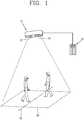
- FIG. 1is an exemplary view of a system for counting objects according to the present invention.
- the system for counting objectscomprises a camera apparatus 10 installed at an area of interest 30, a remote apparatus 20 connected to the camera apparatus 10, etc.
- the camera apparatus 10is provided with an image sensor 12 for acquiring image information on the area of interest 30, and a depth sensor 14 for acquiring a depth map indicating depth information on objects included in the image information.
- the system for counting objectsis configured to count objects traversing a reference line 32 in the area of interest 30, based on the image information and the depth map acquired from the camera apparatus 10.
- FIG. 2is an exemplary view of image information processed in a system for counting objects.
- the system for counting objectsmay acquire an original image 110 of an area of interest shown in FIG. 2A , by the image sensor attached to the camera apparatus.
- the system for counting objectsextracts a foreground image 120 of FIG. 2B from the original image 110, using an object detect engine mounted therein, and counts objects included in the foreground image 120, thereby counting objects traversing the area of interest.
- the system for counting objectsis configured to count human objects of interest.
- the original image 110 acquired by the system for counting objectsis implemented by capturing objects in an area of interest including objects of interest 112, 114 and 116, as the subject.
- the system for counting objectsmay acquire the foreground image 120 of FIG. 2B , from the original image 110, using a general object detect engine.
- the objects 112 and 114 different from each other even if they are close to each othermay be displayed as a single object 122. Accordingly, if the system counts objects of interest based on only the foreground image 120, there may occur errors. In order to solve such object grouping, part in the foreground image where objects overlap each other may be divided by size information such as a width of the objects. However, in this case, there may still occur errors in precisely counting objects, because all of the objects overlapping each other are not objects of interest.
- the method for counting objects using only a foreground imagemay have another problem contrary to the aforementioned 'object grouping', that is, 'over segmentation' where a single object in the foreground image is recognized as a plurality of objects due to various causes including reflection of light.
- the method for counting objects using only a foreground imagehas a difficulty in detecting objects of interest, because objects having similar colors to a neighboring object in the original image are not well identified, and because it is difficult to precisely check the outlines of the objects.
- part of the original image rather than the objects of interestsuch as a background image (e.g., shadow occurring due to illumination, etc.) may be recognized as the objects of interest.
- a method for counting objects according to the present inventionwill be explained with reference to FIGS. 3 to 5 .
- the number of objects of interest traversing an area of interestis calculated, based on information including an original image on the area of interest acquired from an image sensor, a depth map acquired from a depth sensor, and depth patterns of the objects of interest.
- the method for counting objects according to the present inventionhas the following advantages. Firstly, a background image is removed by the depth information. Further, can be reduced errors occurring due to neighboring objects having similar colors to the objects of interest, and due to shadows of the objects of interest.
- FIG. 3is a flowchart showing a method for counting objects of interest in a system for counting objects according to the present invention.
- the system for counting objectsacquires an original image of an area of interest from an image sensor of a camera apparatus, and acquires a depth map of the area of interest from a depth sensor of the camera apparatus (S110).
- the depth mapis data indicating a distance of each part of a subject from the camera apparatus (or depth information), the subject such as objects in the depth map to be captured by the camera apparatus having the depth sensor attached thereto.
- the depth mapis implemented in order to provide additional information to information extracted from the original information for counting objects.
- the depth map and the original imageinclude the same area of interest.
- the system for counting objectsextracts edge information (boundary information) from the original image (S120), and compensates for the depth map using the extracted edge information (S130).
- the edge informationis extracted information on objects in the original image.
- As the edge informationis applied to the depth map acquired from the depth sensor, a corrected depth map is generated.
- the system for counting objectsidentifies depth patterns of objects of interest, from the corrected depth map (S140).
- the depth patterns of the objects of interestare obtained through an object modeling with respect to the objects of interest, which will be explained later with reference to FIG. 5 .
- the system for counting objectsmay identify depth patterns of objects of interest. For instance, when a result value obtained by comparing depth patterns of objects included in the corrected depth map with the depth patterns of the objects of interest, is more than a prescribed threshold, the system determines the captured objects as objects of interest.
- the systemcounts the identified objects of interest (S150).
- the systemmay count the identified objects of interest in a simple manner.
- the systemmay more precisely count the identified objects of interest, through tracking of movements of the identified objects of interest, by repeatedly performing the aforementioned steps using original images and depth maps consecutively acquired by the camera apparatus according to lapse of time.
- the number of objects of interestmay be more precisely calculated, by using similar colors of objects of interest which can be extracted from the consecutively-acquired original images.
- the number of objects of interestmay be more precisely calculated, by predicting the next positions obtained from the consecutively-acquired original images and depth maps, using the Kalman filter.
- objects of interest moving out of the reference line 32 of the area of interest 30, and objects of interest moving towards the reference line 32may be distinguished from each other, by using the tacking method.
- the respective steps S110 ⁇ S150 of FIG. 3may be executed by the camera apparatus 10 of the system.
- information on original images and depth maps acquired by the camera apparatus 10 of the systemmay be transmitted to the remote controller 20 connected to the camera apparatus 10, and the respective steps S120 ⁇ S150 of FIG. 3 may be executed by the remote controller 20.
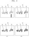
- FIG. 4is an exemplary view of image information processed for counting objects of interest in a system for counting objects according to the present invention.
- the system for counting objectsis configured to count human objects of interest.
- An original image 210 acquired by the system for counting objectsis implemented by capturing objects in an area of interest including objects of interest 212, 214 and 216, as the subject.
- the original image 210further includes a background region 218 having a distinguished color, rather than the objects of interest 212, 214 and 216.
- the system for counting objectsmay extract edge information 220, from the original image 210.
- the objects 212 and 214 different from each other even if they are close to each other in the original image 210 of FIG. 4Amay be displayed on the edge information 220 as a single object.
- the edge information 220may include edge information on the background region 218 having a distinguished color and included in the original image 210. Accordingly, a depth map indicating depth information of an area of interest, as well as the edge information 220, may be used as later explained.
- the system for counting objectsmay acquire a depth map 230 from the depth sensor of the camera apparatus.
- the depth mapis data indicating a distance of each part of a subject from the camera apparatus (or depth information), the subject such as objects in the depth map to be captured by the camera apparatus having the depth sensor attached thereto.
- Distance information which cannot be acquired from the original image 210can be acquired based on the depth information in the depth map.
- the depth mapis implemented in order to provide additional information to information extracted from the original information for counting objects.
- the depth map and the original imageinclude the same area of interest.
- objects of interestare displayed in different colors according to the size of depth information on each region in the area of interest.
- the depth information in the depth mapmay be displayed unlike in FIG. 4C .
- the system for counting objectsgenerates a corrected depth map 240, by applying the edge information 220 to the depth map 230.
- the system for counting objectsmay reduce errors occurring when identifying objects of interest based on only the original image 210.
- the system for counting objectscan identify objects of interest regardless of colors, and can remove errors such as shadows occurring due to illumination. Further, the system for counting objects can obtain clear outlines of the objects, and can directly identify the objects without an additional effort to reduce such errors.
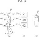
- FIG. 5is a view for explaining depth patterns used to identify the objects of interest of FIG. 3 .
- FIG. 5will be explained a method for identifying objects of interest using a depth pattern by the system for counting objects according to the present invention.
- FIG. 5Aschematically shows a method for extracting a depth pattern of an object of interest 410, under an assumption that the object of interest 410 is the human body.
- the camera apparatus of the system for counting objects according to the present inventionis installed above an area of interest. Accordingly, while performing an object modeling with respect to the object of interest, a depth pattern may be extracted based on information corresponding to virtual planes 412a, 414a and 416a crossing the object of interest 410 towards the lower side of the object of interest 410. That is, as shown in FIG. 5B , a plurality of information 412b, 414b and 416b corresponding to the virtual planes 412a, 414a and 416a, indicate the shape of the object of interest on the respective planes.
- an object modeli.e., a depth pattern 420 of the object of interest can be obtained as shown in FIG. 5C .
- the depth pattern 420 of the object of interesthas information which can be compared with depth patterns of the respective objects in the corrected depth map 240 of FIG. 4D .
- the system for counting objectscompare depth patterns of objects in the corrected depth map, with the depth pattern 420 of the object of interest.
- a candidate region including factors of the object of interestsuch as a height and an area, may be used for comparison of the depth patterns. It is determined whether the objects included in the corrected depth map have a result value more than a prescribed threshold, the result value obtained by comparing the depth patterns of the objects in the corrected depth map with the depth pattern 420. If the result value is more than the prescribed threshold, the system for counting objects may identify the objects in the corrected depth map as objects of interest.
- the proper installation of the camera apparatusindicates the position of the camera apparatus configured to acquire basic information for counting objects, installed at a proper angle and at a proper height with respect to an area of interest where objects of interest are to traverse. Therefore, determining whether the camera apparatus has been properly installed or not, means determining whether an installation height of the camera apparatus is within an allowable range, and whether installation angles of the image sensor and the depth sensor of the camera apparatus are within an allowable range where the occurrence of errors can be minimized.
- the system for counting objects according to the present inventioncalculates an installation height of the camera apparatus based on a depth map, and calculates installation angles of the image sensor and the depth sensor based on a depth pattern database to be later explained.
- FIG. 6is a flowchart showing a method for displaying determination results on whether a camera apparatus has been properly installed, in a system for counting objects according to the present invention.
- FIG. 7is a view showing the principle of a depth pattern database used to determine whether installation angles of the image sensor and the depth sensor are proper or not, in a system for counting objects according to the present invention.
- an original image of an area of interestis acquired from the image sensor 12 of the camera apparatus of the system for counting objects, and a depth map with respect to the area of interest is acquired from the depth sensor 14 of the camera apparatus (S210).
- the original imagemay include at least one object of interest.
- the system for counting objectsuses a depth pattern database on a reference object having the same type as the objects of interest. For instance, in case of calculating objects under an assumption that the object is the human body, the system for counting objects uses a depth pattern database related to the human body.
- the system for counting objectscalculates an installation height of the camera apparatus, based on the acquired depth information in the depth map (S220). Then, the system for counting objects determines whether the installation height of the camera apparatus is proper or not (S230). Since the depth information in the depth map is distance information, the installation height of the camera apparatus may be one of the depth information in the depth map.
- the system for counting objectscalculates installation angles of the image sensor and the depth sensor, based on the depth map and the depth pattern database (S250).
- the depth pattern database used to calculate the installation anglesstores therein depth patterns of a reference object at different angles.
- the reference objectis the human body
- an object modelingis performed with respect to the reference object, so as to extract the depth pattern 420 of the reference object shown in FIG. 5 .
- the depth pattern databasemay demonstrate depth patterns of the reference object in association with various angles.
- the system for counting objects according to the present inventionincludes a depth pattern database 430 on the reference object, the depth pattern database 430 viewed from the upper side and radially displayed according to various angles.
- the installation angles of the image sensor and the depth sensormay be acquired by comparing the depth patterns of the objects of interest, with the depth patterns of the reference object stored in the depth pattern database, and then by selecting an angle corresponding to a depth pattern of the object similar to the depth pattern of the reference object.
- the determination on whether the installation height and the installation angles are proper or notmay be executed by determining whether the calculated installation height and installation angles are within an allowable range, respectively.
- the system for counting objectsdisplays determination results on whether the installation height and the installation angels are proper or not (S260).
- the determination results on whether the installation height and the installation angels are proper or notmay be displayed on a display attached to the camera apparatus, or on a display of a remote apparatus connected to the camera apparatus.
- the display for displaying determination results on whether the installation height and the installation angels are proper or notmay be implemented as at least one lamp.
- the camera apparatusmay control an on-off state, a blinking interval, a color or an intensity of illumination of said at least one lamp, based on the determination results on whether the installation height and the installation angles are proper or not.
- at least one lampmay be turned-on if the installation state is good.
- at least one lampmay have a long blinking interval if the installation state is bad, but may have a shortened blinking interval if the installation state is nearly good. In this case, if the installation state is good, said at least one lamp may be continuously turned-on.
- the display for displaying determination results on whether the installation height and the installation angels are proper or notmay be a apparatus having an additional monitor.
- the method for determining whether the camera apparatus of the system has been properly installed or notmay be implemented by performing the aforementioned steps (S110 ⁇ S150) of FIG. 6 by the camera apparatus 10 under an assumption that the display is included in the camera apparatus.
- the method for determining whether the camera apparatus of the system has been properly installed or notmay be implemented by transmitting information on original images and depth maps acquired by the camera apparatus 10 of the system to the remote controller 20 connected to the camera apparatus 10, and by executing the respective steps S120 ⁇ S150 of FIG. 3 by the remote controller 20.
Landscapes
- Engineering & Computer Science (AREA)
- Multimedia (AREA)
- Physics & Mathematics (AREA)
- General Physics & Mathematics (AREA)
- Theoretical Computer Science (AREA)
- Signal Processing (AREA)
- Computer Vision & Pattern Recognition (AREA)
- Image Processing (AREA)
- Length Measuring Devices By Optical Means (AREA)
- Image Analysis (AREA)
Description
- The present invention relates to a method and apparatus for counting objects, and more particularly, to a method and apparatus for counting the number of objects using a plurality of sensors.
- Recently, a monitoring system which interworks with a camera apparatus provides not only a basic function to demonstrate or record image information on an area of interest, but also a function to track or count objects such as persons traversing the area of interest, based on the image information. Document:Liu Xia et al "Hand gesture recognition using depth data", Automatic face and gesture recognition 2004, proceedings, Sixth IEEE International conference on, IEEE Piscataway, NJ, USA, 17 May 2004 pages 529-534 ISBN: 978-0-7695-2122-0, discloses methods for hand gesture recognition using depth data. Document:Baldemar Gil et al "Experiments in combining intensity and range edge maps" Computer vision, graphics and image processing, Elsevier science, vol. 21, no. 3, 1 March 1983 pages 395-411 ISSN: 0734-189X, discloses methods for combining intensity and range edge maps in a computerized image processing system.
- Therefore, an object of the present invention is to provide a method for counting objects using not only a foreground image acquired by a system for counting objects based on image information, but also other information associated with the image information.
- Another object of the present invention is to provide a method for determining whether a camera apparatus for counting objects of interest has been properly installed above an area of interest, in a system for counting objects.
- To achieve these and other advantages and in accordance with the purpose of the present invention, as embodied and broadly described herein, there is provided a method according to
claim 1 for counting objects of interest using an image sensor and a depth sensor, the method comprising: acquiring an image by the image sensor, and acquiring a depth map from the depth sensor, the depth map indicating depth information on the subject in the image; acquiring edge information of objects of interest in the image; generating a corrected depth map by applying the edge information to the depth map; identifying depth patterns of the objects of interest from the corrected depth map; and counting the identified objects of interest. - In the step of identifying depth patterns of the objects of interest, depth patterns of a reference object stored in a depth pattern database, may be compared with the depth patterns of the corrected depth map.
- The method may further comprise tracking movement of the depth patterns of the identified objects of interest.
- To achieve these and other advantages and in accordance with the purpose of the present invention, as embodied and broadly described herein, there is also provided a camera apparatus according to claim 8, comprising: an image sensor configured to generate an image captured with respect to objects of interest; a depth sensor configured to generate a depth map indicating depth information on the subject in the image; and a controller configured to acquire edge information on the objects of interest in the image, configured to generate a corrected depth map by applying the edge information to the depth map, configured to identify depth patterns of the objects of interest from the corrected depth map, and configured to count the identified objects of interest.
- The camera apparatus may further comprise a memory configured to store therein a depth pattern database for storing depth patterns of a reference object at different angles, and the controller may identify depth patterns of the objects of interest, from the corrected depth map, using the depth patterns of the reference object at different angles.
- To achieve these and other advantages and in accordance with the purpose of the present invention, as embodied and broadly described herein, there is also provided an apparatus for counting objects, comprising: a transceiver configured to receive an image captured with respect to objects of interest, and a depth map indicating depth information on the subject in the image; and a controller configured to acquire edge information on the objects of interest in the image, configured to generate a corrected depth map by applying the edge information to the depth map, configured to identify depth patterns of the objects of interest from the corrected depth map, and configured to count the identified objects of interest.
- The apparatus may further comprise a memory configured to store therein a depth pattern database for storing depth patterns of a reference object at different angles, and the controller may identify depth patterns of the objects of interest, from the corrected depth map, using the depth patterns of the reference object at different angles.
- To achieve these and other advantages and in accordance with the purpose of the present invention, as embodied and broadly described herein, there is also provided a method for displaying an installation state of a camera apparatus having an image sensor and a depth sensor, the method comprising: acquiring an image captured with respect to objects of interest by the image sensor, and acquiring a depth map from the depth sensor, the depth map indicating depth information on the subject in the image; calculating an installation height of the camera apparatus based on the depth information, and determining whether the installation height is proper or not; calculating installation angles of the image sensor and the depth sensor based on the depth map and a depth pattern database, and determining whether the installation angles are proper or not, wherein the depth pattern database stores therein depth patterns of a reference object at different angles, and wherein the installation angles of the image sensor and the depth sensor are calculated by comparing depth patterns of the objects of interest extracted from the depth map, with the depth patterns of the reference object at different angles included in the depth pattern database; and displaying determination results on whether the installation height and the installation angles are proper or not.
- The depth patterns of the objects of interest may be extracted by generating a corrected depth map by applying edge information on the objects of interest acquired from the image, to the depth map, and then by identifying the depth patterns of the objects of interest from the corrected depth map.
- The determination results on whether the installation height and the installation angles are proper or not, may be displayed on a display attached to the camera apparatus, or on a display of a remote apparatus connected to the camera apparatus.
- The display may be implemented as at least one lamp. And, the camera apparatus may control an on-off state, a blinking interval, a color or an intensity of illumination of said at least one lamp, based on the determination results on whether the installation height and the installation angles are proper or not.
- To achieve these and other advantages and in accordance with the purpose of the present invention, as embodied and broadly described herein, there is also provided a method for detecting an installation state of a camera apparatus having an image sensor and a depth sensor, by a remote apparatus connected to the camera apparatus, the method comprising: receiving, from the camera apparatus, an image captured with respect to objects of interest, and a depth map indicating depth information on the subject in the image; calculating an installation height of the camera apparatus based on the depth information, and determining whether the installation height is proper or not; calculating installation angles of the image sensor and the depth sensor based on the depth map and a depth pattern database, and determining whether the installation angles are proper or not, wherein the depth pattern database stores therein depth patterns of a reference object at different angles, and wherein the installation angles of the image sensor and the depth sensor are calculated by comparing depth patterns of the objects of interest extracted from the depth map, with the depth patterns of the reference object at different angles included in the depth pattern database; and displaying determination results on whether the installation height and the installation angles are proper or not.
- The method may further comprise transmitting, to the camera apparatus, the determination results on whether the installation height and the installation angles are proper or not.
- To achieve these and other advantages and in accordance with the purpose of the present invention, as embodied and broadly described herein, there is also provided a camera apparatus, comprising: an image sensor configured to generate an image captured with respect to objects of interest; a depth sensor configured to generate a depth map indicating depth information on the subject in the image; a memory configured to store therein a depth pattern database for storing depth patterns of a reference object at different angles; a controller configured to calculate an installation height of the camera apparatus based on the depth information, configured to calculate installation angles of the image sensor and the depth sensor based on the depth map and the depth pattern database, and configured to determine whether the installation height and the installation angles are proper or not, wherein the installation angles of the image sensor and the depth sensor are calculated by comparing depth patterns of the objects of interest extracted from the depth map, with the depth patterns of the reference object at different angles included in the depth pattern database; and a display configured to display determination results on whether the installation height and the installation angles are proper or not.
- The depth patterns of the objects of interest may be extracted by generating a corrected depth map by applying edge information on the objects of interest acquired from the image, to the depth map, and then by identifying the depth patterns of the objects of interest from the corrected depth map.
- The display may be implemented as at least one lamp. And, the controller may control an on-off state, a blinking interval, a color or an intensity of illumination of said at least one lamp, based on the determination results on whether the installation height and the installation angles are proper or not.
- To achieve these and other advantages and in accordance with the purpose of the present invention, as embodied and broadly described herein, there is also provided an apparatus for counting objects, comprising: a transceiver configured to receive, from a camera apparatus, an image captured with respect to objects of interest, and a depth map indicating depth information on the subject in the image; a memory configured to store therein a depth pattern database for storing depth patterns of a reference object at different angles; a controller configured to calculate an installation height of the apparatus based on the depth information, configured to calculate installation angles of the image sensor and the depth sensor based on the depth map and the depth pattern database, and configured to determine whether the installation height and the installation angles are proper or not, wherein the installation angles of the image sensor and the depth sensor are calculated by comparing depth patterns of the objects of interest extracted from the depth map, with the depth patterns of the reference object at different angles included in the depth pattern database; and a display configured to display determination results on whether the installation height and the installation angles are proper or not.
- The depth patterns of the objects of interest may be extracted by generating a corrected depth map by applying edge information on the objects of interest acquired from the image, to the depth map, and then by identifying the depth patterns of the objects of interest from the corrected depth map.
- The display may be implemented as at least one lamp. And, the controller may control an on-off state, a blinking interval, a color or an intensity of illumination of said at least one lamp, based on the determination results on whether the installation height and the installation angles are proper or not.
- The present invention can have the following effects.
- In the apparatus for counting objects of interest according to the present invention, the number of objects traversing an area of interest can be calculated with a relatively lower error rate, by reducing errors occurring when detecting objects of interest from image information.
- In the apparatus for counting objects of interest according to the present invention, there is provided a function to determine whether a camera apparatus has been properly installed or not, in order to acquire information suitable for detecting objects of interest.
FIG. 1 is an exemplary view of a system for counting objects according to the present invention;FIG. 2 is an exemplary view of image information processed in a system for counting objects;FIG. 3 is a flowchart showing a method for counting objects of interest in a system for counting objects according to the present invention;FIG. 4 is an exemplary view of image information processed for counting objects of interest in a system for counting objects according to the present invention;FIG. 5 is a view for explaining depth patterns used to identify the objects of interest ofFIG. 3 ;FIG. 6 is a flowchart showing a method for displaying determination results on whether a camera apparatus has been properly installed, in a system for counting objects according to the present invention; andFIG. 7 is a view showing the principle of a depth pattern database used to determine whether installation angles of an image sensor and a depth sensor are proper or not, in a system for counting objects according to the present invention.- Reference will now be made in detail to the preferred embodiments of the present invention, examples of which are illustrated in the accompanying drawings. It will also be apparent to those skilled in the art that various modifications and variations can be made in the present invention without departing from the spirit or scope of the invention. Thus, it is intended that the present invention cover modifications and variations of this invention provided they come within the scope of the appended claims and their equivalents.
FIG. 1 is an exemplary view of a system for counting objects according to the present invention.- As shown in
FIG. 1 , the system for counting objects according to the present invention comprises acamera apparatus 10 installed at an area ofinterest 30, aremote apparatus 20 connected to thecamera apparatus 10, etc. Thecamera apparatus 10 is provided with animage sensor 12 for acquiring image information on the area ofinterest 30, and adepth sensor 14 for acquiring a depth map indicating depth information on objects included in the image information. The system for counting objects is configured to count objects traversing areference line 32 in the area ofinterest 30, based on the image information and the depth map acquired from thecamera apparatus 10. FIG. 2 is an exemplary view of image information processed in a system for counting objects.- The system for counting objects may acquire an
original image 110 of an area of interest shown inFIG. 2A , by the image sensor attached to the camera apparatus. The system for counting objects extracts aforeground image 120 ofFIG. 2B from theoriginal image 110, using an object detect engine mounted therein, and counts objects included in theforeground image 120, thereby counting objects traversing the area of interest. - However, such general method using a foreground image cannot precisely count objects, unless it utilizes additional information for object detection. For instance, in a case where a plurality of objects displayed in the foreground image are close to each other, the plurality of objects may be recognized as a single object (which is called 'object grouping'). Referring to
FIG. 2A , the system for counting objects is configured to count human objects of interest. Theoriginal image 110 acquired by the system for counting objects is implemented by capturing objects in an area of interest including objects ofinterest foreground image 120 ofFIG. 2B , from theoriginal image 110, using a general object detect engine. In theforeground image 120, theobjects single object 122. Accordingly, if the system counts objects of interest based on only theforeground image 120, there may occur errors. In order to solve such object grouping, part in the foreground image where objects overlap each other may be divided by size information such as a width of the objects. However, in this case, there may still occur errors in precisely counting objects, because all of the objects overlapping each other are not objects of interest. - The method for counting objects using only a foreground image may have another problem contrary to the aforementioned 'object grouping', that is, 'over segmentation' where a single object in the foreground image is recognized as a plurality of objects due to various causes including reflection of light. The method for counting objects using only a foreground image, has a difficulty in detecting objects of interest, because objects having similar colors to a neighboring object in the original image are not well identified, and because it is difficult to precisely check the outlines of the objects. Further, in the process of extracting the foreground image from the original image, part of the original image rather than the objects of interest, such as a background image (e.g., shadow occurring due to illumination, etc.) may be recognized as the objects of interest.
- A method for counting objects according to the present invention will be explained with reference to
FIGS. 3 to 5 . As explained later with reference toFIG. 3 , in the method for counting objects according to the present invention, the number of objects of interest traversing an area of interest is calculated, based on information including an original image on the area of interest acquired from an image sensor, a depth map acquired from a depth sensor, and depth patterns of the objects of interest. When compared with the aforementioned method for counting objects using only a foreground image, the method for counting objects according to the present invention has the following advantages. Firstly, a background image is removed by the depth information. Further, can be reduced errors occurring due to neighboring objects having similar colors to the objects of interest, and due to shadows of the objects of interest. FIG. 3 is a flowchart showing a method for counting objects of interest in a system for counting objects according to the present invention.- Firstly, the system for counting objects acquires an original image of an area of interest from an image sensor of a camera apparatus, and acquires a depth map of the area of interest from a depth sensor of the camera apparatus (S110). The depth map is data indicating a distance of each part of a subject from the camera apparatus (or depth information), the subject such as objects in the depth map to be captured by the camera apparatus having the depth sensor attached thereto. The depth map is implemented in order to provide additional information to information extracted from the original information for counting objects. Preferably, the depth map and the original image include the same area of interest.
- Next, the system for counting objects extracts edge information (boundary information) from the original image (S120), and compensates for the depth map using the extracted edge information (S130). The edge information is extracted information on objects in the original image. As the edge information is applied to the depth map acquired from the depth sensor, a corrected depth map is generated.
- Next, the system for counting objects identifies depth patterns of objects of interest, from the corrected depth map (S140). The depth patterns of the objects of interest are obtained through an object modeling with respect to the objects of interest, which will be explained later with reference to
FIG. 5 . The system for counting objects may identify depth patterns of objects of interest. For instance, when a result value obtained by comparing depth patterns of objects included in the corrected depth map with the depth patterns of the objects of interest, is more than a prescribed threshold, the system determines the captured objects as objects of interest. - Next, the system counts the identified objects of interest (S150). In counting the identified objects of interest, the system may count the identified objects of interest in a simple manner. As another method, the system may more precisely count the identified objects of interest, through tracking of movements of the identified objects of interest, by repeatedly performing the aforementioned steps using original images and depth maps consecutively acquired by the camera apparatus according to lapse of time. In the method for counting objects of interest through tracking, the number of objects of interest may be more precisely calculated, by using similar colors of objects of interest which can be extracted from the consecutively-acquired original images. In the method for counting objects of interest through tracking, the number of objects of interest may be more precisely calculated, by predicting the next positions obtained from the consecutively-acquired original images and depth maps, using the Kalman filter. In the system for counting objects according to the present invention, objects of interest moving out of the
reference line 32 of the area ofinterest 30, and objects of interest moving towards thereference line 32 may be distinguished from each other, by using the tacking method. - Hereinafter, will be explained modification examples of the method for counting objects according to the present invention.
- In the method for counting objects according to the present invention, the respective steps S110 ∼ S150 of
FIG. 3 may be executed by thecamera apparatus 10 of the system. - In a method for counting objects according to modification examples of the present invention, information on original images and depth maps acquired by the
camera apparatus 10 of the system may be transmitted to theremote controller 20 connected to thecamera apparatus 10, and the respective steps S120 ∼ S150 ofFIG. 3 may be executed by theremote controller 20. - Hereinafter, information processed by the system for counting objects according to the present invention will be explained with reference to
FIG. 4 . FIG. 4 is an exemplary view of image information processed for counting objects of interest in a system for counting objects according to the present invention.- Referring to
FIG. 4A , the system for counting objects is configured to count human objects of interest. Anoriginal image 210 acquired by the system for counting objects is implemented by capturing objects in an area of interest including objects of interest 212, 214 and 216, as the subject. Theoriginal image 210 further includes a background region 218 having a distinguished color, rather than the objects of interest 212, 214 and 216. - Referring to
FIG. 4B , the system for counting objects may extractedge information 220, from theoriginal image 210. The objects 212 and 214 different from each other even if they are close to each other in theoriginal image 210 ofFIG. 4A , may be displayed on theedge information 220 as a single object. Further, theedge information 220 may include edge information on the background region 218 having a distinguished color and included in theoriginal image 210. Accordingly, a depth map indicating depth information of an area of interest, as well as theedge information 220, may be used as later explained. - Referring to
FIG. 4C , the system for counting objects may acquire adepth map 230 from the depth sensor of the camera apparatus. The depth map is data indicating a distance of each part of a subject from the camera apparatus (or depth information), the subject such as objects in the depth map to be captured by the camera apparatus having the depth sensor attached thereto. Distance information which cannot be acquired from theoriginal image 210, can be acquired based on the depth information in the depth map. The depth map is implemented in order to provide additional information to information extracted from the original information for counting objects. Preferably, the depth map and the original image include the same area of interest. In thedepth map 230 ofFIG. 4C , for a cubic effect, objects of interest are displayed in different colors according to the size of depth information on each region in the area of interest. The depth information in the depth map may be displayed unlike inFIG. 4C . - Referring to
FIG. 4D , the system for counting objects generates a correcteddepth map 240, by applying theedge information 220 to thedepth map 230. In case of identifying objects of interest based on the correcteddepth map 240, the system for counting objects may reduce errors occurring when identifying objects of interest based on only theoriginal image 210. For instance, the system for counting objects can identify objects of interest regardless of colors, and can remove errors such as shadows occurring due to illumination. Further, the system for counting objects can obtain clear outlines of the objects, and can directly identify the objects without an additional effort to reduce such errors. FIG. 5 is a view for explaining depth patterns used to identify the objects of interest ofFIG. 3 . With reference toFIG. 5 , will be explained a method for identifying objects of interest using a depth pattern by the system for counting objects according to the present invention.FIG. 5A schematically shows a method for extracting a depth pattern of an object ofinterest 410, under an assumption that the object ofinterest 410 is the human body. Generally, the camera apparatus of the system for counting objects according to the present invention, is installed above an area of interest. Accordingly, while performing an object modeling with respect to the object of interest, a depth pattern may be extracted based on information corresponding tovirtual planes interest 410 towards the lower side of the object ofinterest 410. That is, as shown inFIG. 5B , a plurality ofinformation virtual planes information depth pattern 420 of the object of interest can be obtained as shown inFIG. 5C .- The
depth pattern 420 of the object of interest has information which can be compared with depth patterns of the respective objects in the correcteddepth map 240 ofFIG. 4D . In S140 ofFIG. 3 for identifying depth patterns of objects of interest, the system for counting objects compare depth patterns of objects in the corrected depth map, with thedepth pattern 420 of the object of interest. In S140, a candidate region including factors of the object of interest, such as a height and an area, may be used for comparison of the depth patterns. It is determined whether the objects included in the corrected depth map have a result value more than a prescribed threshold, the result value obtained by comparing the depth patterns of the objects in the corrected depth map with thedepth pattern 420. If the result value is more than the prescribed threshold, the system for counting objects may identify the objects in the corrected depth map as objects of interest. - With reference to
FIGS. 6 and7 , will be explained a method for determining whether the camera apparatus of the system for counting objects according to the present invention, has been properly installed. Here, the proper installation of the camera apparatus indicates the position of the camera apparatus configured to acquire basic information for counting objects, installed at a proper angle and at a proper height with respect to an area of interest where objects of interest are to traverse. Therefore, determining whether the camera apparatus has been properly installed or not, means determining whether an installation height of the camera apparatus is within an allowable range, and whether installation angles of the image sensor and the depth sensor of the camera apparatus are within an allowable range where the occurrence of errors can be minimized. To this end, the system for counting objects according to the present invention calculates an installation height of the camera apparatus based on a depth map, and calculates installation angles of the image sensor and the depth sensor based on a depth pattern database to be later explained. FIG. 6 is a flowchart showing a method for displaying determination results on whether a camera apparatus has been properly installed, in a system for counting objects according to the present invention.FIG. 7 is a view showing the principle of a depth pattern database used to determine whether installation angles of the image sensor and the depth sensor are proper or not, in a system for counting objects according to the present invention.- Referring to
FIG. 6 , an original image of an area of interest is acquired from theimage sensor 12 of the camera apparatus of the system for counting objects, and a depth map with respect to the area of interest is acquired from thedepth sensor 14 of the camera apparatus (S210). The original image may include at least one object of interest. The system for counting objects uses a depth pattern database on a reference object having the same type as the objects of interest. For instance, in case of calculating objects under an assumption that the object is the human body, the system for counting objects uses a depth pattern database related to the human body. - Next, the system for counting objects calculates an installation height of the camera apparatus, based on the acquired depth information in the depth map (S220). Then, the system for counting objects determines whether the installation height of the camera apparatus is proper or not (S230). Since the depth information in the depth map is distance information, the installation height of the camera apparatus may be one of the depth information in the depth map.
- Next, the system for counting objects calculates installation angles of the image sensor and the depth sensor, based on the depth map and the depth pattern database (S250).
- The depth pattern database used to calculate the installation angles, stores therein depth patterns of a reference object at different angles. In a case where the reference object is the human body, an object modeling is performed with respect to the reference object, so as to extract the
depth pattern 420 of the reference object shown inFIG. 5 . When viewed at various angles, the depth pattern of the reference object has different shapes at different angles. Therefore, the depth pattern database may demonstrate depth patterns of the reference object in association with various angles. Referring toFIG. 7 , the system for counting objects according to the present invention includes adepth pattern database 430 on the reference object, thedepth pattern database 430 viewed from the upper side and radially displayed according to various angles. Accordingly, the installation angles of the image sensor and the depth sensor may be acquired by comparing the depth patterns of the objects of interest, with the depth patterns of the reference object stored in the depth pattern database, and then by selecting an angle corresponding to a depth pattern of the object similar to the depth pattern of the reference object. - The determination on whether the installation height and the installation angles are proper or not, may be executed by determining whether the calculated installation height and installation angles are within an allowable range, respectively.
- Next, the system for counting objects displays determination results on whether the installation height and the installation angels are proper or not (S260). The determination results on whether the installation height and the installation angels are proper or not, may be displayed on a display attached to the camera apparatus, or on a display of a remote apparatus connected to the camera apparatus.
- The display for displaying determination results on whether the installation height and the installation angels are proper or not, may be implemented as at least one lamp. And, the camera apparatus may control an on-off state, a blinking interval, a color or an intensity of illumination of said at least one lamp, based on the determination results on whether the installation height and the installation angles are proper or not. In a case where the camera apparatus controls an on-off state, at least one lamp may be turned-on if the installation state is good. In a case where the camera apparatus controls a blinking interval, at least one lamp may have a long blinking interval if the installation state is bad, but may have a shortened blinking interval if the installation state is nearly good. In this case, if the installation state is good, said at least one lamp may be continuously turned-on.
- The display for displaying determination results on whether the installation height and the installation angels are proper or not, may be a apparatus having an additional monitor.
- Hereinafter, will be explained modifications of a method for determining whether the camera apparatus of the system for counting objects according to the present invention, has been properly installed or not.
- The method for determining whether the camera apparatus of the system has been properly installed or not according to a preferred embodiment of the present invention, may be implemented by performing the aforementioned steps (S110 ∼ S150) of
FIG. 6 by thecamera apparatus 10 under an assumption that the display is included in the camera apparatus. - The method for determining whether the camera apparatus of the system has been properly installed or not according to a modified embodiment of the present invention, may be implemented by transmitting information on original images and depth maps acquired by the
camera apparatus 10 of the system to theremote controller 20 connected to thecamera apparatus 10, and by executing the respective steps S120 ∼ S150 ofFIG. 3 by theremote controller 20.
Claims (12)
- A method for counting objects using a camera apparatus (10) having an image sensor (12) and a depth sensor (14), the method comprising:acquiring (S110) an image by the image sensor (12), and acquiring a depth map from the depth sensor (14), the depth map indicating depth information on the subject in the image;acquiring (S120) edge information of objects of interest in the image;generating (S130) a corrected depth map by applying the edge information to the depth map;identifying (S140) depth patterns of the objects of interest from the corrected depth map; andcounting (S150) the identified objects of interest.
- The method of claim 1, wherein, in the step of identifying (S140) depth patterns of the objects of interest, depth patterns of a reference object stored in a depth pattern database, is compared with the depth patterns of the corrected depth map.
- The method of any one of claim 1 and claim 2, further comprising tracking movement of the identified depth patterns of the objects of interest.
- The method of any one of claims 1 to 3, further comprising calculating (S210) an installation height of the camera apparatus (10), based on the depth information, and determining (S230) whether the installation height is proper or not;
calculating (S240) installation angles of the image sensor (12) and the depth sensor (14), based on the depth map and a depth pattern database, and determining (S250) whether the installation angles are proper or not,
wherein the depth pattern database stores therein depth patterns of a reference object at different angles, and
wherein the installation angles of the image sensor (12) and the depth sensor (14) are calculated by comparing depth patterns of the objects of interest extracted from the depth map, with the depth patterns of the reference object at different angles included in the depth pattern database; and
displaying (S260) determination results on whether the installation height and the installation angles are proper or not. - The method of claim 4, wherein the determination results on whether the installation height and the installation angles are proper or not, are displayed on a display attached to the camera apparatus (10), or on a display of a remote apparatus connected to the camera apparatus (10).
- The method of claim 5, wherein the display is implemented as at least one lamp, and
wherein the camera apparatus (10) controls an on-off state, a blinking interval, a color or an intensity of illumination of said at least one lamp, based on the determination results on whether the installation height and the installation angles are proper or not. - The method of claim 1, wherein the step of counting the identified objects of interest comprises:identifying at least one valid object among the objects of interest by comparing the identified depth patterns and reference depth patterns stored in a database; andcounting the identified valid object,wherein a depth pattern of each of the objects of interest is identified based on projection information on a virtual plane crossing each object, while moving toward a lower side of each object.
- An apparatus (10), comprising:an image sensor (12) configured to generate an image captured with respect to objects of interest;a depth sensor (14) configured to generate a depth map indicating depth information on the subject in the image; anda controller configured to acquire edge information of the objects of interest in the image, configured to generate a corrected depth map by applying the edge information to the depth map, configured to identify depth patterns of the objects of interest from the corrected depth map, and configured to count the objects of interest.
- The apparatus (10) of claim 8, further comprising a memory configured to store therein a depth pattern database for storing depth patterns of a reference object at different angles,
wherein the controller identifies depth patterns of the objects of interest, using the depth patterns of the reference object at different angles, from the corrected depth map. - The apparatus (10) of claim 9, wherein the controller configured to calculate an installation height of the apparatus (10) based on the depth information, configured to calculate installation angles of the image sensor (12) and the depth sensor (14) based on the depth map and the depth pattern database, and configured to determine whether the installation height and the installation angles are proper or not,
wherein the installation angles of the image sensor (12) and the depth sensor (14) are calculated by comparing depth patterns of the objects of interest extracted from the depth map, with the depth patterns of the reference object at different angles included in the depth pattern database; and further comprising a display configured to display determination results on whether the installation height and the installation angles are proper or not. - The apparatus (10) of claim 10, wherein the display is implemented as at least one lamp, and
wherein the controller controls an on-off state, a blinking interval, a color or an intensity of illumination of said at least one lamp, based on the determination results on whether the installation height and the installation angles are proper or not. - The apparatus (10) of claim 8, wherein the controller is further configured to:identify at least one valid object among the objects of interest by comparing the identified depth patterns and reference depth patterns stored in a database; andcount the identified valid object,wherein a depth pattern of each of the objects of interest is identified based on projection information on a virtual plane crossing each object, while moving toward a lower side of each object.
Applications Claiming Priority (1)
| Application Number | Priority Date | Filing Date | Title |
|---|---|---|---|
| PCT/KR2010/005430WO2012023639A1 (en) | 2010-08-17 | 2010-08-17 | Method for counting objects and apparatus using a plurality of sensors |
Publications (3)
| Publication Number | Publication Date |
|---|---|
| EP2608536A1 EP2608536A1 (en) | 2013-06-26 |
| EP2608536A4 EP2608536A4 (en) | 2015-07-29 |
| EP2608536B1true EP2608536B1 (en) | 2017-05-03 |
Family
ID=45605289
Family Applications (1)
| Application Number | Title | Priority Date | Filing Date |
|---|---|---|---|
| EP10856181.2AActiveEP2608536B1 (en) | 2010-08-17 | 2010-08-17 | Method for counting objects and apparatus using a plurality of sensors |
Country Status (4)
| Country | Link |
|---|---|
| US (1) | US9087258B2 (en) |
| EP (1) | EP2608536B1 (en) |
| CN (1) | CN103069796B (en) |
| WO (1) | WO2012023639A1 (en) |
Families Citing this family (39)
| Publication number | Priority date | Publication date | Assignee | Title |
|---|---|---|---|---|
| US8983121B2 (en)* | 2010-10-27 | 2015-03-17 | Samsung Techwin Co., Ltd. | Image processing apparatus and method thereof |
| CN103324977B (en)* | 2012-03-21 | 2016-03-30 | 日电(中国)有限公司 | A kind of destination number detection method and equipment |
| TWI448990B (en)* | 2012-09-07 | 2014-08-11 | Univ Nat Chiao Tung | Real-time people counting system using layer scanning method |
| GB201217721D0 (en)* | 2012-10-03 | 2012-11-14 | Holition Ltd | Video image processing |
| US10009579B2 (en) | 2012-11-21 | 2018-06-26 | Pelco, Inc. | Method and system for counting people using depth sensor |
| JP2014106732A (en)* | 2012-11-27 | 2014-06-09 | Sony Computer Entertainment Inc | Information processor and information processing method |
| US9860510B2 (en)* | 2013-03-15 | 2018-01-02 | Intuitive Surgical Operations, Inc. | Depth based modification of captured images |
| US9563955B1 (en)* | 2013-05-15 | 2017-02-07 | Amazon Technologies, Inc. | Object tracking techniques |
| US9560103B2 (en)* | 2013-06-26 | 2017-01-31 | Echostar Technologies L.L.C. | Custom video content |
| CN105917355B (en)* | 2013-12-14 | 2020-07-03 | 维亚凯姆有限责任公司 | Camera-based tracking system for determining physical, physiological and/or biometric data and/or for risk assessment |
| FR3015731B1 (en)* | 2013-12-20 | 2016-02-05 | Thales Sa | METHOD FOR ESTIMATING THE NUMBER OF PEOPLE AND OR OBETS IN A SPACE |
| FR3015730B1 (en)* | 2013-12-20 | 2017-07-21 | Thales Sa | METHOD FOR DETECTING PEOPLE AND OR OBJECTS IN A SPACE |
| FR3015732B1 (en)* | 2013-12-20 | 2016-02-05 | Thales Sa | METHOD FOR DETECTING PEOPLE AND OR OBJECTS IN A SPACE |
| RU2014110361A (en)* | 2014-03-18 | 2015-09-27 | ЭлЭсАй Корпорейшн | IMAGE PROCESSOR CONFIGURED FOR EFFICIENT EVALUATION AND ELIMINATION OF FRONT PLAN INFORMATION ON IMAGES |
| TWI537842B (en)* | 2014-09-30 | 2016-06-11 | 廣達電腦股份有限公司 | People counting system |
| KR20160118783A (en)* | 2015-04-03 | 2016-10-12 | 한화테크윈 주식회사 | Method and Apparatus for counting the number of person |
| US10066933B2 (en)* | 2015-05-04 | 2018-09-04 | Facebook, Inc. | Camera depth mapping using structured light patterns |
| US10785393B2 (en) | 2015-05-22 | 2020-09-22 | Facebook, Inc. | Methods and devices for selective flash illumination |
| WO2017123920A1 (en) | 2016-01-14 | 2017-07-20 | RetailNext, Inc. | Detecting, tracking and counting objects in videos |
| US10204444B2 (en) | 2016-04-28 | 2019-02-12 | Verizon Patent And Licensing Inc. | Methods and systems for creating and manipulating an individually-manipulable volumetric model of an object |
| ES2800725T3 (en)* | 2016-06-22 | 2021-01-04 | Outsight | Methods and systems for detecting intrusions in a controlled volume |
| US10630959B2 (en)* | 2016-07-12 | 2020-04-21 | Datalogic Usa, Inc. | System and method for object counting and tracking |
| US10582095B2 (en)* | 2016-10-14 | 2020-03-03 | MP High Tech Solutions Pty Ltd | Imaging apparatuses and enclosures |
| US10628960B2 (en)* | 2016-11-24 | 2020-04-21 | Ricoh Company, Ltd. | Information processing apparatus, imaging apparatus, device control system, moving object, information processing method, and recording medium |
| JP6814053B2 (en)* | 2017-01-19 | 2021-01-13 | 株式会社日立エルジーデータストレージ | Object position detector |
| CN107067468B (en)* | 2017-03-30 | 2020-05-26 | 联想(北京)有限公司 | Information processing method and electronic equipment |
| US10733876B2 (en) | 2017-04-05 | 2020-08-04 | Carnegie Mellon University | Deep learning methods for estimating density and/or flow of objects, and related methods and software |
| US11765323B2 (en) | 2017-05-26 | 2023-09-19 | Calumino Pty Ltd. | Apparatus and method of location determination in a thermal imaging system |
| IT201700064301A1 (en)* | 2017-06-09 | 2018-12-09 | Mectho S R L | DEVICE AND DETECTION PROCEDURE |
| IT201700064312A1 (en)* | 2017-06-09 | 2018-12-09 | Mectho S R L | DEVICE AND DETECTION PROCEDURE |
| IT201700064268A1 (en)* | 2017-06-09 | 2018-12-09 | Mectho S R L | DEVICE AND DETECTION PROCEDURE |
| CA3033030A1 (en)* | 2018-02-08 | 2019-08-08 | Flaschebottle Technologies Inc. | Estimating a number of containers by digital image analysis |
| WO2019178253A1 (en) | 2018-03-13 | 2019-09-19 | Magic Leap, Inc. | Image-enhanced depth sensing using machine learning |
| CN109344690B (en)* | 2018-08-09 | 2022-09-23 | 上海青识智能科技有限公司 | People counting method based on depth camera |
| US10896516B1 (en)* | 2018-10-02 | 2021-01-19 | Facebook Technologies, Llc | Low-power depth sensing using dynamic illumination |
| US11048948B2 (en)* | 2019-06-10 | 2021-06-29 | City University Of Hong Kong | System and method for counting objects |
| EP3798969A1 (en)* | 2019-09-27 | 2021-03-31 | Stemmer Imaging AG | Depth image processing method, image processing apparatus and depth camera |
| CN116277149B (en)* | 2023-02-09 | 2025-09-09 | 合肥芯明智能科技有限公司 | Binocular vision module mounting method and device, electronic equipment and storage medium |
| CN117593297B (en)* | 2024-01-18 | 2024-04-19 | 福州市展凌智能科技有限公司 | Jig identification and counting system and method based on image processing |
Family Cites Families (10)
| Publication number | Priority date | Publication date | Assignee | Title |
|---|---|---|---|---|
| JP4198054B2 (en) | 2001-08-15 | 2008-12-17 | コーニンクレッカ フィリップス エレクトロニクス エヌ ヴィ | 3D video conferencing system |
| US6940538B2 (en)* | 2001-08-29 | 2005-09-06 | Sony Corporation | Extracting a depth map from known camera and model tracking data |
| JP3704706B2 (en)* | 2002-03-13 | 2005-10-12 | オムロン株式会社 | 3D monitoring device |
| US7043084B2 (en)* | 2002-07-30 | 2006-05-09 | Mitsubishi Electric Research Laboratories, Inc. | Wheelchair detection using stereo vision |
| CN1950722B (en)* | 2004-07-30 | 2010-05-05 | 松下电工株式会社 | Individual detector and accompanying detection device |
| KR100808543B1 (en) | 2006-09-15 | 2008-02-29 | 한국과학기술연구원 | Apparatus and method for acquiring human motion information using stereo vision sensor |
| US7965866B2 (en) | 2007-07-03 | 2011-06-21 | Shoppertrak Rct Corporation | System and process for detecting, tracking and counting human objects of interest |
| KR100881230B1 (en)* | 2008-08-27 | 2009-02-09 | 주식회사 상상돔 | High Precision Counterfeit Discrimination System Using Stereo Images |
| US8594425B2 (en)* | 2010-05-31 | 2013-11-26 | Primesense Ltd. | Analysis of three-dimensional scenes |
| WO2012009789A2 (en)* | 2010-07-19 | 2012-01-26 | Smart Technologies Ulc | Interactive input system having a 3d input space |
- 2010
- 2010-08-17EPEP10856181.2Apatent/EP2608536B1/enactiveActive
- 2010-08-17WOPCT/KR2010/005430patent/WO2012023639A1/enactiveApplication Filing
- 2010-08-17USUS13/816,304patent/US9087258B2/enactiveActive
- 2010-08-17CNCN201080068622.8Apatent/CN103069796B/ennot_activeExpired - Fee Related
Also Published As
| Publication number | Publication date |
|---|---|
| CN103069796B (en) | 2016-05-11 |
| WO2012023639A1 (en) | 2012-02-23 |
| EP2608536A4 (en) | 2015-07-29 |
| US20130136307A1 (en) | 2013-05-30 |
| US9087258B2 (en) | 2015-07-21 |
| CN103069796A (en) | 2013-04-24 |
| EP2608536A1 (en) | 2013-06-26 |
Similar Documents
| Publication | Publication Date | Title |
|---|---|---|
| EP2608536B1 (en) | Method for counting objects and apparatus using a plurality of sensors | |
| CA3094424C (en) | Safety monitoring and early-warning method for man-machine interaction behavior of underground conveyor belt operator | |
| JP7004017B2 (en) | Object tracking system, object tracking method, program | |
| US8184859B2 (en) | Road marking recognition apparatus and method | |
| CN105631390B (en) | Method and system for spatial finger positioning | |
| US9295415B2 (en) | Foreign object determination device, foreign object determination method and foreign object determination program | |
| US20130070095A1 (en) | Fast obstacle detection | |
| CN109284674A (en) | A kind of method and device of determining lane line | |
| JP5105400B2 (en) | Traffic measuring method and traffic measuring device | |
| US9298995B2 (en) | Red-eye determination device | |
| JP2013101045A (en) | Recognition device and recognition method of three-dimensional position posture of article | |
| CN109211207A (en) | A kind of screw identification and positioning device based on machine vision | |
| CN114155557B (en) | Positioning method, positioning device, robot and computer-readable storage medium | |
| KR101850835B1 (en) | Method of estimating the location of mobile robot using ray-tracing technique | |
| JP2016091053A (en) | Information processing apparatus, container shape estimation method, work picking system, and program | |
| JP4048779B2 (en) | Distance image processing device | |
| JP4674179B2 (en) | Shadow recognition method and shadow boundary extraction method | |
| CN106296708B (en) | Car tracing method and apparatus | |
| JP2009279186A (en) | Face detecting device and method | |
| JP2010286995A (en) | Image processing system for vehicle | |
| CN106650735B (en) | A kind of LED character automatic positioning recognition methods | |
| CN104766329B (en) | A kind of image processing method and electronic equipment | |
| KR20220089968A (en) | Apparatus and Method for Attaching Tag For Steel Product | |
| US20230196773A1 (en) | Object detection device, object detection method, and computer-readable storage medium | |
| JP2000261787A (en) | Intruding object detection method and device |
Legal Events
| Date | Code | Title | Description |
|---|---|---|---|
| PUAI | Public reference made under article 153(3) epc to a published international application that has entered the european phase | Free format text:ORIGINAL CODE: 0009012 | |
| 17P | Request for examination filed | Effective date:20130218 | |
| AK | Designated contracting states | Kind code of ref document:A1 Designated state(s):AL AT BE BG CH CY CZ DE DK EE ES FI FR GB GR HR HU IE IS IT LI LT LU LV MC MK MT NL NO PL PT RO SE SI SK SM TR | |
| DAX | Request for extension of the european patent (deleted) | ||
| RA4 | Supplementary search report drawn up and despatched (corrected) | Effective date:20150626 | |
| RIC1 | Information provided on ipc code assigned before grant | Ipc:H04N 7/18 20060101AFI20150622BHEP | |
| 17Q | First examination report despatched | Effective date:20160620 | |
| REG | Reference to a national code | Ref country code:DE Ref legal event code:R079 Ref document number:602010042140 Country of ref document:DE Free format text:PREVIOUS MAIN CLASS: H04N0007180000 Ipc:G06T0007000000 | |
| GRAP | Despatch of communication of intention to grant a patent | Free format text:ORIGINAL CODE: EPIDOSNIGR1 | |
| STAA | Information on the status of an ep patent application or granted ep patent | Free format text:STATUS: GRANT OF PATENT IS INTENDED | |
| RIC1 | Information provided on ipc code assigned before grant | Ipc:G06K 9/32 20060101ALI20161108BHEP Ipc:G06K 9/00 20060101ALI20161108BHEP Ipc:G06T 7/00 20060101AFI20161108BHEP | |
| INTG | Intention to grant announced | Effective date:20161125 | |
| GRAS | Grant fee paid | Free format text:ORIGINAL CODE: EPIDOSNIGR3 | |
| GRAA | (expected) grant | Free format text:ORIGINAL CODE: 0009210 | |
| STAA | Information on the status of an ep patent application or granted ep patent | Free format text:STATUS: THE PATENT HAS BEEN GRANTED | |
| AK | Designated contracting states | Kind code of ref document:B1 Designated state(s):AL AT BE BG CH CY CZ DE DK EE ES FI FR GB GR HR HU IE IS IT LI LT LU LV MC MK MT NL NO PL PT RO SE SI SK SM TR | |
| REG | Reference to a national code | Ref country code:GB Ref legal event code:FG4D | |
| REG | Reference to a national code | Ref country code:AT Ref legal event code:REF Ref document number:890751 Country of ref document:AT Kind code of ref document:T Effective date:20170515 Ref country code:CH Ref legal event code:EP | |
| REG | Reference to a national code | Ref country code:IE Ref legal event code:FG4D | |
| REG | Reference to a national code | Ref country code:DE Ref legal event code:R096 Ref document number:602010042140 Country of ref document:DE | |
| REG | Reference to a national code | Ref country code:NL Ref legal event code:MP Effective date:20170503 | |
| REG | Reference to a national code | Ref country code:AT Ref legal event code:MK05 Ref document number:890751 Country of ref document:AT Kind code of ref document:T Effective date:20170503 | |
| REG | Reference to a national code | Ref country code:LT Ref legal event code:MG4D | |
| PG25 | Lapsed in a contracting state [announced via postgrant information from national office to epo] | Ref country code:ES Free format text:LAPSE BECAUSE OF FAILURE TO SUBMIT A TRANSLATION OF THE DESCRIPTION OR TO PAY THE FEE WITHIN THE PRESCRIBED TIME-LIMIT Effective date:20170503 Ref country code:NO Free format text:LAPSE BECAUSE OF FAILURE TO SUBMIT A TRANSLATION OF THE DESCRIPTION OR TO PAY THE FEE WITHIN THE PRESCRIBED TIME-LIMIT Effective date:20170803 Ref country code:HR Free format text:LAPSE BECAUSE OF FAILURE TO SUBMIT A TRANSLATION OF THE DESCRIPTION OR TO PAY THE FEE WITHIN THE PRESCRIBED TIME-LIMIT Effective date:20170503 Ref country code:AT Free format text:LAPSE BECAUSE OF FAILURE TO SUBMIT A TRANSLATION OF THE DESCRIPTION OR TO PAY THE FEE WITHIN THE PRESCRIBED TIME-LIMIT Effective date:20170503 Ref country code:FI Free format text:LAPSE BECAUSE OF FAILURE TO SUBMIT A TRANSLATION OF THE DESCRIPTION OR TO PAY THE FEE WITHIN THE PRESCRIBED TIME-LIMIT Effective date:20170503 Ref country code:LT Free format text:LAPSE BECAUSE OF FAILURE TO SUBMIT A TRANSLATION OF THE DESCRIPTION OR TO PAY THE FEE WITHIN THE PRESCRIBED TIME-LIMIT Effective date:20170503 Ref country code:GR Free format text:LAPSE BECAUSE OF FAILURE TO SUBMIT A TRANSLATION OF THE DESCRIPTION OR TO PAY THE FEE WITHIN THE PRESCRIBED TIME-LIMIT Effective date:20170804 | |
| PG25 | Lapsed in a contracting state [announced via postgrant information from national office to epo] | Ref country code:LV Free format text:LAPSE BECAUSE OF FAILURE TO SUBMIT A TRANSLATION OF THE DESCRIPTION OR TO PAY THE FEE WITHIN THE PRESCRIBED TIME-LIMIT Effective date:20170503 Ref country code:SE Free format text:LAPSE BECAUSE OF FAILURE TO SUBMIT A TRANSLATION OF THE DESCRIPTION OR TO PAY THE FEE WITHIN THE PRESCRIBED TIME-LIMIT Effective date:20170503 Ref country code:PL Free format text:LAPSE BECAUSE OF FAILURE TO SUBMIT A TRANSLATION OF THE DESCRIPTION OR TO PAY THE FEE WITHIN THE PRESCRIBED TIME-LIMIT Effective date:20170503 Ref country code:BG Free format text:LAPSE BECAUSE OF FAILURE TO SUBMIT A TRANSLATION OF THE DESCRIPTION OR TO PAY THE FEE WITHIN THE PRESCRIBED TIME-LIMIT Effective date:20170803 Ref country code:NL Free format text:LAPSE BECAUSE OF FAILURE TO SUBMIT A TRANSLATION OF THE DESCRIPTION OR TO PAY THE FEE WITHIN THE PRESCRIBED TIME-LIMIT Effective date:20170503 Ref country code:IS Free format text:LAPSE BECAUSE OF FAILURE TO SUBMIT A TRANSLATION OF THE DESCRIPTION OR TO PAY THE FEE WITHIN THE PRESCRIBED TIME-LIMIT Effective date:20170903 | |
| PG25 | Lapsed in a contracting state [announced via postgrant information from national office to epo] | Ref country code:EE Free format text:LAPSE BECAUSE OF FAILURE TO SUBMIT A TRANSLATION OF THE DESCRIPTION OR TO PAY THE FEE WITHIN THE PRESCRIBED TIME-LIMIT Effective date:20170503 Ref country code:CZ Free format text:LAPSE BECAUSE OF FAILURE TO SUBMIT A TRANSLATION OF THE DESCRIPTION OR TO PAY THE FEE WITHIN THE PRESCRIBED TIME-LIMIT Effective date:20170503 Ref country code:RO Free format text:LAPSE BECAUSE OF FAILURE TO SUBMIT A TRANSLATION OF THE DESCRIPTION OR TO PAY THE FEE WITHIN THE PRESCRIBED TIME-LIMIT Effective date:20170503 Ref country code:SK Free format text:LAPSE BECAUSE OF FAILURE TO SUBMIT A TRANSLATION OF THE DESCRIPTION OR TO PAY THE FEE WITHIN THE PRESCRIBED TIME-LIMIT Effective date:20170503 Ref country code:DK Free format text:LAPSE BECAUSE OF FAILURE TO SUBMIT A TRANSLATION OF THE DESCRIPTION OR TO PAY THE FEE WITHIN THE PRESCRIBED TIME-LIMIT Effective date:20170503 | |
| REG | Reference to a national code | Ref country code:DE Ref legal event code:R097 Ref document number:602010042140 Country of ref document:DE | |
| PG25 | Lapsed in a contracting state [announced via postgrant information from national office to epo] | Ref country code:SM Free format text:LAPSE BECAUSE OF FAILURE TO SUBMIT A TRANSLATION OF THE DESCRIPTION OR TO PAY THE FEE WITHIN THE PRESCRIBED TIME-LIMIT Effective date:20170503 Ref country code:IT Free format text:LAPSE BECAUSE OF FAILURE TO SUBMIT A TRANSLATION OF THE DESCRIPTION OR TO PAY THE FEE WITHIN THE PRESCRIBED TIME-LIMIT Effective date:20170503 | |
| PLBE | No opposition filed within time limit | Free format text:ORIGINAL CODE: 0009261 | |
| STAA | Information on the status of an ep patent application or granted ep patent | Free format text:STATUS: NO OPPOSITION FILED WITHIN TIME LIMIT | |
| REG | Reference to a national code | Ref country code:CH Ref legal event code:PL | |
| PG25 | Lapsed in a contracting state [announced via postgrant information from national office to epo] | Ref country code:MC Free format text:LAPSE BECAUSE OF FAILURE TO SUBMIT A TRANSLATION OF THE DESCRIPTION OR TO PAY THE FEE WITHIN THE PRESCRIBED TIME-LIMIT Effective date:20170503 | |
| 26N | No opposition filed | Effective date:20180206 | |
| GBPC | Gb: european patent ceased through non-payment of renewal fee | Effective date:20170817 | |
| PG25 | Lapsed in a contracting state [announced via postgrant information from national office to epo] | Ref country code:LI Free format text:LAPSE BECAUSE OF NON-PAYMENT OF DUE FEES Effective date:20170831 Ref country code:CH Free format text:LAPSE BECAUSE OF NON-PAYMENT OF DUE FEES Effective date:20170831 | |
| REG | Reference to a national code | Ref country code:FR Ref legal event code:ST Effective date:20180430 | |
| REG | Reference to a national code | Ref country code:IE Ref legal event code:MM4A | |
| PG25 | Lapsed in a contracting state [announced via postgrant information from national office to epo] | Ref country code:SI Free format text:LAPSE BECAUSE OF FAILURE TO SUBMIT A TRANSLATION OF THE DESCRIPTION OR TO PAY THE FEE WITHIN THE PRESCRIBED TIME-LIMIT Effective date:20170503 | |
| REG | Reference to a national code | Ref country code:BE Ref legal event code:MM Effective date:20170831 | |
| PG25 | Lapsed in a contracting state [announced via postgrant information from national office to epo] | Ref country code:LU Free format text:LAPSE BECAUSE OF NON-PAYMENT OF DUE FEES Effective date:20170817 | |
| PG25 | Lapsed in a contracting state [announced via postgrant information from national office to epo] | Ref country code:GB Free format text:LAPSE BECAUSE OF NON-PAYMENT OF DUE FEES Effective date:20170817 Ref country code:IE Free format text:LAPSE BECAUSE OF NON-PAYMENT OF DUE FEES Effective date:20170817 | |
| PG25 | Lapsed in a contracting state [announced via postgrant information from national office to epo] | Ref country code:BE Free format text:LAPSE BECAUSE OF NON-PAYMENT OF DUE FEES Effective date:20170831 Ref country code:FR Free format text:LAPSE BECAUSE OF NON-PAYMENT OF DUE FEES Effective date:20170831 | |
| PG25 | Lapsed in a contracting state [announced via postgrant information from national office to epo] | Ref country code:MT Free format text:LAPSE BECAUSE OF NON-PAYMENT OF DUE FEES Effective date:20170817 | |
| PG25 | Lapsed in a contracting state [announced via postgrant information from national office to epo] | Ref country code:HU Free format text:LAPSE BECAUSE OF FAILURE TO SUBMIT A TRANSLATION OF THE DESCRIPTION OR TO PAY THE FEE WITHIN THE PRESCRIBED TIME-LIMIT; INVALID AB INITIO Effective date:20100817 | |
| PG25 | Lapsed in a contracting state [announced via postgrant information from national office to epo] | Ref country code:CY Free format text:LAPSE BECAUSE OF NON-PAYMENT OF DUE FEES Effective date:20170503 | |
| PG25 | Lapsed in a contracting state [announced via postgrant information from national office to epo] | Ref country code:MK Free format text:LAPSE BECAUSE OF FAILURE TO SUBMIT A TRANSLATION OF THE DESCRIPTION OR TO PAY THE FEE WITHIN THE PRESCRIBED TIME-LIMIT Effective date:20170503 | |
| PG25 | Lapsed in a contracting state [announced via postgrant information from national office to epo] | Ref country code:TR Free format text:LAPSE BECAUSE OF FAILURE TO SUBMIT A TRANSLATION OF THE DESCRIPTION OR TO PAY THE FEE WITHIN THE PRESCRIBED TIME-LIMIT Effective date:20170503 | |
| PG25 | Lapsed in a contracting state [announced via postgrant information from national office to epo] | Ref country code:PT Free format text:LAPSE BECAUSE OF FAILURE TO SUBMIT A TRANSLATION OF THE DESCRIPTION OR TO PAY THE FEE WITHIN THE PRESCRIBED TIME-LIMIT Effective date:20170503 | |
| PG25 | Lapsed in a contracting state [announced via postgrant information from national office to epo] | Ref country code:AL Free format text:LAPSE BECAUSE OF FAILURE TO SUBMIT A TRANSLATION OF THE DESCRIPTION OR TO PAY THE FEE WITHIN THE PRESCRIBED TIME-LIMIT Effective date:20170503 | |
| PGFP | Annual fee paid to national office [announced via postgrant information from national office to epo] | Ref country code:DE Payment date:20240705 Year of fee payment:15 |