EP2606919A1 - Sluice device for inserting a catheter - Google Patents
Sluice device for inserting a catheterDownload PDFInfo
- Publication number
- EP2606919A1 EP2606919A1EP11075272.2AEP11075272AEP2606919A1EP 2606919 A1EP2606919 A1EP 2606919A1EP 11075272 AEP11075272 AEP 11075272AEP 2606919 A1EP2606919 A1EP 2606919A1
- Authority
- EP
- European Patent Office
- Prior art keywords
- lock
- tubular portion
- catheter
- pump
- clamping
- Prior art date
- Legal status (The legal status is an assumption and is not a legal conclusion. Google has not performed a legal analysis and makes no representation as to the accuracy of the status listed.)
- Withdrawn
Links
Images


Classifications
- A—HUMAN NECESSITIES
- A61—MEDICAL OR VETERINARY SCIENCE; HYGIENE
- A61M—DEVICES FOR INTRODUCING MEDIA INTO, OR ONTO, THE BODY; DEVICES FOR TRANSDUCING BODY MEDIA OR FOR TAKING MEDIA FROM THE BODY; DEVICES FOR PRODUCING OR ENDING SLEEP OR STUPOR
- A61M25/00—Catheters; Hollow probes
- A61M25/01—Introducing, guiding, advancing, emplacing or holding catheters
- A61M25/06—Body-piercing guide needles or the like
- A61M25/0662—Guide tubes
- A61M25/0668—Guide tubes splittable, tear apart
- A—HUMAN NECESSITIES
- A61—MEDICAL OR VETERINARY SCIENCE; HYGIENE
- A61M—DEVICES FOR INTRODUCING MEDIA INTO, OR ONTO, THE BODY; DEVICES FOR TRANSDUCING BODY MEDIA OR FOR TAKING MEDIA FROM THE BODY; DEVICES FOR PRODUCING OR ENDING SLEEP OR STUPOR
- A61M25/00—Catheters; Hollow probes
- A61M25/01—Introducing, guiding, advancing, emplacing or holding catheters
- A61M25/06—Body-piercing guide needles or the like
- A61M25/0662—Guide tubes
- A—HUMAN NECESSITIES
- A61—MEDICAL OR VETERINARY SCIENCE; HYGIENE
- A61M—DEVICES FOR INTRODUCING MEDIA INTO, OR ONTO, THE BODY; DEVICES FOR TRANSDUCING BODY MEDIA OR FOR TAKING MEDIA FROM THE BODY; DEVICES FOR PRODUCING OR ENDING SLEEP OR STUPOR
- A61M39/00—Tubes, tube connectors, tube couplings, valves, access sites or the like, specially adapted for medical use
- A61M39/02—Access sites
- A61M39/0247—Semi-permanent or permanent transcutaneous or percutaneous access sites to the inside of the body
- A—HUMAN NECESSITIES
- A61—MEDICAL OR VETERINARY SCIENCE; HYGIENE
- A61M—DEVICES FOR INTRODUCING MEDIA INTO, OR ONTO, THE BODY; DEVICES FOR TRANSDUCING BODY MEDIA OR FOR TAKING MEDIA FROM THE BODY; DEVICES FOR PRODUCING OR ENDING SLEEP OR STUPOR
- A61M39/00—Tubes, tube connectors, tube couplings, valves, access sites or the like, specially adapted for medical use
- A61M39/02—Access sites
- A61M39/06—Haemostasis valves, i.e. gaskets sealing around a needle, catheter or the like, closing on removal thereof
- A—HUMAN NECESSITIES
- A61—MEDICAL OR VETERINARY SCIENCE; HYGIENE
- A61M—DEVICES FOR INTRODUCING MEDIA INTO, OR ONTO, THE BODY; DEVICES FOR TRANSDUCING BODY MEDIA OR FOR TAKING MEDIA FROM THE BODY; DEVICES FOR PRODUCING OR ENDING SLEEP OR STUPOR
- A61M60/00—Blood pumps; Devices for mechanical circulatory actuation; Balloon pumps for circulatory assistance
- A61M60/10—Location thereof with respect to the patient's body
- A61M60/122—Implantable pumps or pumping devices, i.e. the blood being pumped inside the patient's body
- A61M60/126—Implantable pumps or pumping devices, i.e. the blood being pumped inside the patient's body implantable via, into, inside, in line, branching on, or around a blood vessel
- A61M60/13—Implantable pumps or pumping devices, i.e. the blood being pumped inside the patient's body implantable via, into, inside, in line, branching on, or around a blood vessel by means of a catheter allowing explantation, e.g. catheter pumps temporarily introduced via the vascular system
- A—HUMAN NECESSITIES
- A61—MEDICAL OR VETERINARY SCIENCE; HYGIENE
- A61M—DEVICES FOR INTRODUCING MEDIA INTO, OR ONTO, THE BODY; DEVICES FOR TRANSDUCING BODY MEDIA OR FOR TAKING MEDIA FROM THE BODY; DEVICES FOR PRODUCING OR ENDING SLEEP OR STUPOR
- A61M60/00—Blood pumps; Devices for mechanical circulatory actuation; Balloon pumps for circulatory assistance
- A61M60/10—Location thereof with respect to the patient's body
- A61M60/122—Implantable pumps or pumping devices, i.e. the blood being pumped inside the patient's body
- A61M60/126—Implantable pumps or pumping devices, i.e. the blood being pumped inside the patient's body implantable via, into, inside, in line, branching on, or around a blood vessel
- A61M60/148—Implantable pumps or pumping devices, i.e. the blood being pumped inside the patient's body implantable via, into, inside, in line, branching on, or around a blood vessel in line with a blood vessel using resection or like techniques, e.g. permanent endovascular heart assist devices
- A—HUMAN NECESSITIES
- A61—MEDICAL OR VETERINARY SCIENCE; HYGIENE
- A61M—DEVICES FOR INTRODUCING MEDIA INTO, OR ONTO, THE BODY; DEVICES FOR TRANSDUCING BODY MEDIA OR FOR TAKING MEDIA FROM THE BODY; DEVICES FOR PRODUCING OR ENDING SLEEP OR STUPOR
- A61M60/00—Blood pumps; Devices for mechanical circulatory actuation; Balloon pumps for circulatory assistance
- A61M60/10—Location thereof with respect to the patient's body
- A61M60/122—Implantable pumps or pumping devices, i.e. the blood being pumped inside the patient's body
- A61M60/165—Implantable pumps or pumping devices, i.e. the blood being pumped inside the patient's body implantable in, on, or around the heart
- A61M60/178—Implantable pumps or pumping devices, i.e. the blood being pumped inside the patient's body implantable in, on, or around the heart drawing blood from a ventricle and returning the blood to the arterial system via a cannula external to the ventricle, e.g. left or right ventricular assist devices
- A—HUMAN NECESSITIES
- A61—MEDICAL OR VETERINARY SCIENCE; HYGIENE
- A61M—DEVICES FOR INTRODUCING MEDIA INTO, OR ONTO, THE BODY; DEVICES FOR TRANSDUCING BODY MEDIA OR FOR TAKING MEDIA FROM THE BODY; DEVICES FOR PRODUCING OR ENDING SLEEP OR STUPOR
- A61M60/00—Blood pumps; Devices for mechanical circulatory actuation; Balloon pumps for circulatory assistance
- A61M60/20—Type thereof
- A61M60/205—Non-positive displacement blood pumps
- A61M60/216—Non-positive displacement blood pumps including a rotating member acting on the blood, e.g. impeller
- A—HUMAN NECESSITIES
- A61—MEDICAL OR VETERINARY SCIENCE; HYGIENE
- A61M—DEVICES FOR INTRODUCING MEDIA INTO, OR ONTO, THE BODY; DEVICES FOR TRANSDUCING BODY MEDIA OR FOR TAKING MEDIA FROM THE BODY; DEVICES FOR PRODUCING OR ENDING SLEEP OR STUPOR
- A61M60/00—Blood pumps; Devices for mechanical circulatory actuation; Balloon pumps for circulatory assistance
- A61M60/80—Constructional details other than related to driving
- A61M60/855—Constructional details other than related to driving of implantable pumps or pumping devices
- A61M60/865—Devices for guiding or inserting pumps or pumping devices into the patient's body
- A—HUMAN NECESSITIES
- A61—MEDICAL OR VETERINARY SCIENCE; HYGIENE
- A61B—DIAGNOSIS; SURGERY; IDENTIFICATION
- A61B17/00—Surgical instruments, devices or methods
- A61B2017/0046—Surgical instruments, devices or methods with a releasable handle; with handle and operating part separable
- A61B2017/00469—Surgical instruments, devices or methods with a releasable handle; with handle and operating part separable for insertion of instruments, e.g. guide wire, optical fibre
- A—HUMAN NECESSITIES
- A61—MEDICAL OR VETERINARY SCIENCE; HYGIENE
- A61M—DEVICES FOR INTRODUCING MEDIA INTO, OR ONTO, THE BODY; DEVICES FOR TRANSDUCING BODY MEDIA OR FOR TAKING MEDIA FROM THE BODY; DEVICES FOR PRODUCING OR ENDING SLEEP OR STUPOR
- A61M25/00—Catheters; Hollow probes
- A61M25/01—Introducing, guiding, advancing, emplacing or holding catheters
- A61M2025/0188—Introducing, guiding, advancing, emplacing or holding catheters having slitted or breakaway lumens
- A—HUMAN NECESSITIES
- A61—MEDICAL OR VETERINARY SCIENCE; HYGIENE
- A61M—DEVICES FOR INTRODUCING MEDIA INTO, OR ONTO, THE BODY; DEVICES FOR TRANSDUCING BODY MEDIA OR FOR TAKING MEDIA FROM THE BODY; DEVICES FOR PRODUCING OR ENDING SLEEP OR STUPOR
- A61M25/00—Catheters; Hollow probes
- A61M25/01—Introducing, guiding, advancing, emplacing or holding catheters
- A61M25/06—Body-piercing guide needles or the like
- A61M25/0662—Guide tubes
- A61M25/0668—Guide tubes splittable, tear apart
- A61M2025/0675—Introducing-sheath slitters
- A—HUMAN NECESSITIES
- A61—MEDICAL OR VETERINARY SCIENCE; HYGIENE
- A61M—DEVICES FOR INTRODUCING MEDIA INTO, OR ONTO, THE BODY; DEVICES FOR TRANSDUCING BODY MEDIA OR FOR TAKING MEDIA FROM THE BODY; DEVICES FOR PRODUCING OR ENDING SLEEP OR STUPOR
- A61M25/00—Catheters; Hollow probes
- A61M25/01—Introducing, guiding, advancing, emplacing or holding catheters
- A61M25/06—Body-piercing guide needles or the like
- A61M25/0662—Guide tubes
- A61M2025/0681—Systems with catheter and outer tubing, e.g. sheath, sleeve or guide tube
- A—HUMAN NECESSITIES
- A61—MEDICAL OR VETERINARY SCIENCE; HYGIENE
- A61M—DEVICES FOR INTRODUCING MEDIA INTO, OR ONTO, THE BODY; DEVICES FOR TRANSDUCING BODY MEDIA OR FOR TAKING MEDIA FROM THE BODY; DEVICES FOR PRODUCING OR ENDING SLEEP OR STUPOR
- A61M39/00—Tubes, tube connectors, tube couplings, valves, access sites or the like, specially adapted for medical use
- A61M39/02—Access sites
- A61M39/0247—Semi-permanent or permanent transcutaneous or percutaneous access sites to the inside of the body
- A61M2039/0258—Semi-permanent or permanent transcutaneous or percutaneous access sites to the inside of the body for vascular access, e.g. blood stream access
- A—HUMAN NECESSITIES
- A61—MEDICAL OR VETERINARY SCIENCE; HYGIENE
- A61M—DEVICES FOR INTRODUCING MEDIA INTO, OR ONTO, THE BODY; DEVICES FOR TRANSDUCING BODY MEDIA OR FOR TAKING MEDIA FROM THE BODY; DEVICES FOR PRODUCING OR ENDING SLEEP OR STUPOR
- A61M39/00—Tubes, tube connectors, tube couplings, valves, access sites or the like, specially adapted for medical use
- A61M39/02—Access sites
- A61M39/0247—Semi-permanent or permanent transcutaneous or percutaneous access sites to the inside of the body
- A61M2039/0279—Semi-permanent or permanent transcutaneous or percutaneous access sites to the inside of the body for introducing medical instruments into the body, e.g. endoscope, surgical tools
- A—HUMAN NECESSITIES
- A61—MEDICAL OR VETERINARY SCIENCE; HYGIENE
- A61M—DEVICES FOR INTRODUCING MEDIA INTO, OR ONTO, THE BODY; DEVICES FOR TRANSDUCING BODY MEDIA OR FOR TAKING MEDIA FROM THE BODY; DEVICES FOR PRODUCING OR ENDING SLEEP OR STUPOR
- A61M39/00—Tubes, tube connectors, tube couplings, valves, access sites or the like, specially adapted for medical use
- A61M39/02—Access sites
- A61M39/06—Haemostasis valves, i.e. gaskets sealing around a needle, catheter or the like, closing on removal thereof
- A61M2039/062—Haemostasis valves, i.e. gaskets sealing around a needle, catheter or the like, closing on removal thereof used with a catheter
- A—HUMAN NECESSITIES
- A61—MEDICAL OR VETERINARY SCIENCE; HYGIENE
- A61M—DEVICES FOR INTRODUCING MEDIA INTO, OR ONTO, THE BODY; DEVICES FOR TRANSDUCING BODY MEDIA OR FOR TAKING MEDIA FROM THE BODY; DEVICES FOR PRODUCING OR ENDING SLEEP OR STUPOR
- A61M39/00—Tubes, tube connectors, tube couplings, valves, access sites or the like, specially adapted for medical use
- A61M39/02—Access sites
- A61M39/06—Haemostasis valves, i.e. gaskets sealing around a needle, catheter or the like, closing on removal thereof
- A61M2039/0626—Haemostasis valves, i.e. gaskets sealing around a needle, catheter or the like, closing on removal thereof used with other surgical instruments, e.g. endoscope, trocar
- A—HUMAN NECESSITIES
- A61—MEDICAL OR VETERINARY SCIENCE; HYGIENE
- A61M—DEVICES FOR INTRODUCING MEDIA INTO, OR ONTO, THE BODY; DEVICES FOR TRANSDUCING BODY MEDIA OR FOR TAKING MEDIA FROM THE BODY; DEVICES FOR PRODUCING OR ENDING SLEEP OR STUPOR
- A61M39/00—Tubes, tube connectors, tube couplings, valves, access sites or the like, specially adapted for medical use
- A61M39/02—Access sites
- A61M39/06—Haemostasis valves, i.e. gaskets sealing around a needle, catheter or the like, closing on removal thereof
- A61M2039/0673—Haemostasis valves, i.e. gaskets sealing around a needle, catheter or the like, closing on removal thereof comprising means actively pressing on the device passing through the seal, e.g. inflatable seals, diaphragms, clamps
- A—HUMAN NECESSITIES
- A61—MEDICAL OR VETERINARY SCIENCE; HYGIENE
- A61M—DEVICES FOR INTRODUCING MEDIA INTO, OR ONTO, THE BODY; DEVICES FOR TRANSDUCING BODY MEDIA OR FOR TAKING MEDIA FROM THE BODY; DEVICES FOR PRODUCING OR ENDING SLEEP OR STUPOR
- A61M2207/00—Methods of manufacture, assembly or production
- A—HUMAN NECESSITIES
- A61—MEDICAL OR VETERINARY SCIENCE; HYGIENE
- A61M—DEVICES FOR INTRODUCING MEDIA INTO, OR ONTO, THE BODY; DEVICES FOR TRANSDUCING BODY MEDIA OR FOR TAKING MEDIA FROM THE BODY; DEVICES FOR PRODUCING OR ENDING SLEEP OR STUPOR
- A61M25/00—Catheters; Hollow probes
- A61M25/0097—Catheters; Hollow probes characterised by the hub
- A—HUMAN NECESSITIES
- A61—MEDICAL OR VETERINARY SCIENCE; HYGIENE
- A61M—DEVICES FOR INTRODUCING MEDIA INTO, OR ONTO, THE BODY; DEVICES FOR TRANSDUCING BODY MEDIA OR FOR TAKING MEDIA FROM THE BODY; DEVICES FOR PRODUCING OR ENDING SLEEP OR STUPOR
- A61M60/00—Blood pumps; Devices for mechanical circulatory actuation; Balloon pumps for circulatory assistance
- A61M60/40—Details relating to driving
- A61M60/403—Details relating to driving for non-positive displacement blood pumps
- A61M60/408—Details relating to driving for non-positive displacement blood pumps the force acting on the blood contacting member being mechanical, e.g. transmitted by a shaft or cable
- A61M60/411—Details relating to driving for non-positive displacement blood pumps the force acting on the blood contacting member being mechanical, e.g. transmitted by a shaft or cable generated by an electromotor
- A61M60/414—Details relating to driving for non-positive displacement blood pumps the force acting on the blood contacting member being mechanical, e.g. transmitted by a shaft or cable generated by an electromotor transmitted by a rotating cable, e.g. for blood pumps mounted on a catheter
Definitions
- the inventionis in the field of mechanics and can be used with advantage in medical technology. It deals with a lock device for inserting a catheter into a patient's body, the lock leading into the patient's body and a proximal end of the lock protruding therefrom.
- the sheathprovides a lumen through which a catheter can be inserted into the patient's body.
- Such lock devicesare known in principle. They are used to introduce a variety of catheters, for example in the minimally invasive medical field.
- a lockmay for example be provided for introducing a blood pump for heart support, such a unit having a distal pump unit and a hollow catheter and a guided through the hollow catheter Drive shaft may have.
- Such pumpsare often designed in the miniaturized region in such a way that they can be introduced radially compressible and in the compressed state together with the catheter through a blood vessel of the body.
- the pumpcan then be expanded. In the expanded state with established conveyor elements, such a pump can then develop the necessary pump power.
- the lock itselfcan be introduced by means of the known Seldinger technique, for example in a vascular system.
- an openingis first introduced into a body vessel by means of a puncture needle, whereupon a guide wire is inserted. If necessary, a dilator and then the sluice itself is inserted over the guidewire. Thereafter, the guide wire can be removed if it is not needed for further guidance tasks, and other elements can be inserted through the sheath.
- a corresponding methodis for example from the WO 02/43791 A1 known. There, it is provided to advance a heart pump along a guide wire into the left ventricle of the heart of a patient and to advance a pump unit out of the lock through the vascular system to the ventricle.
- a corresponding fluid pumpwhich is intended for high speeds in order to develop a corresponding pumping power, is in the design as a blood pump also from the WO 02/43791 A1 , but also from the EP 2047872 A1 known. From the EP 2 047 872 A1 a pump can be seen which has a distal pump unit, which is followed by a proximal hollow shaft catheter. A drive shaft extending in the shaft catheter is connected to a drive unit for driving the rotor of the pump.
- a comfortable lock for inserting a catheterin particular with a drive shaft, has the advantage that during introduction of the catheter and in particular a drive shaft is subjected to little mechanical stress. This is particularly advantageous in the case of the high mechanical loads to which a drive shaft is exposed during the operation of a blood pump.
- a corresponding lock for introducing a catheterin particular with a distal pump unit
- the unit to be introducedis moved as short as possible in the vascular system or corresponding cavities of the patient body outside a lock, so that the load on the vessel walls on the one hand by the introduction of the foreign body and the mechanical load of the introduced unit on the other hand is largely reduced.
- the present inventionhas for its object to make a corresponding lock device advantageous so that it is particularly easy to handle.
- a lock device for inserting a catheter into a patient's bodyhas a first lock with a proximal end and a distal end, wherein the distal end of the first lock is disposed within the patient's body when used as intended, while the proximal end of the lock Patient body protrudes.
- the first lockalso has a tubular portion and a arranged at the proximal end lock housing with a receiving channel for a strand-shaped body, in particular for a catheter on.
- the lock devicecan first be pushed into the patient's body to a certain extent for insertion of the catheter into the patient's body, then the catheter is extracted and then the lock device is moved out of the patient's body to some extent be pulled out again. Then can be solved in a particularly simple manner, the tubular portion of the clamp, shortened and clamped again.
- An advantageous embodiment of the inventionprovides that the tubular portion is slidable into the lock housing in the released state of the clamping device. In this way, the tubular portion can either be received in the lock housing, removed within the lock housing or removed by a proximal opening of the lock housing.
- this embodimentmakes it particularly easy to insert a catheter into the tubular section, by first inserting the catheter into the lock housing, guided in the receiving channel and thus easily passed to the mouth of the tubular portion. In this way it can be ensured that the insertion of the catheter into the proximal end of the lock device is simplified and reliably succeeds.
- the proximal end of the tubular portion of the lockcan be easily pushed into the receiving channel within the lock housing to be either taken up there or removed.
- a further advantageous embodiment of the inventionprovides that the clamping device has an elastically deformable clamping ring which surrounds the tubular portion and which can be pressed by a manipulation device such that it clamps the tubular portion radially.
- a clamping deviceis mechanically extremely simple, reliable, space-saving and easy to use. It causes a non-positive fixation of the tubular portion, which is also solvable again in a simple manner.
- the clamping ringis radially deformable by axial pressure effect. It can be configured either for this purpose either as an elastomeric ring or as a slotted ring made of a plastic or a metal.
- the clamping ringcan be flattened as an elastomer ring, for example by means of a pressure piece, wherein it expands radially inwardly and outwardly, whereby the inner diameter of the ring is reduced.
- the clamping ringis a slotted plastic or metal ring, it can For example, be compressed radially inwardly under the action of a wedge body on its radial outer side.
- wedge-shaped in cross section ringcan be used.
- the clamping ringcan also be conically shaped in cross section.
- itis a clamping ring which simultaneously ensures a fluid-tight connection between the lock housing and the tubular element, as can be realized for example in the form of the mentioned elastomeric ring.
- the tightnesscan, however, also be realized by an additional sealing element, for example when using a slotted plastic or metal ring.
- the clamping devicemay, for example, for axial pressing of a clamping ring have a screw. By means of the screwing can then be pressed against the clamping ring in the axial direction, for example, a pressure piece.
- the tubular portionhas at least at its proximal end at least one predetermined breaking point, by means of which a longitudinal portion of the tubular portion can be separated.
- the tubular portionmay, for example, in the circumferential direction circumferential partial incisions or perforations or other weakenings of the material, optionally also predetermined by a molecular structure having.
- tubular portionmay also have one or more predetermined breaking points or tear lines extending in the axial direction, which are known per se in so-called peel-away locks.
- tear linesa lock can be opened and removed from one end by pulling two or more sheath parts apart.
- a tubular portionmay also have handling elements at its proximal end, such as eyelets or tabs.
- the lock devicecan also have a cutting device by means of which a part of the tubular section can be separated or perforated, cut or scored for easier separation.
- a cutting deviceby means of which a part of the tubular section can be separated or perforated, cut or scored for easier separation.
- one or more bladescan be inserted into the lock housing in such a way that the tubular section is automatically cut when pushed through the lock housing. Such an incision can be made, for example, in the longitudinal direction of the tubular portion.
- a blademay also be provided which, upon rotation of the lock housing relative to the tubular section, produces a section or weakening of the tubular section in the circumferential direction.
- Such bladesmay be made of a very hard material such as a ceramic, so that reinforced, in particular reinforced by a metal mesh tubular sections can be cut. It may also be provided substantially needle-shaped blades, which are both in a movement of the tubular portion can cut in the axial direction as well as a rotation in the circumferential direction.
- a particularly advantageous embodiment of the inventionprovides that the cutting device has at least one blade, which is movably guided in particular in the lock housing, in particular radially to the catheter is guided to be movable.
- a bladecan be actuated by means of a handle on the outside of the lock housing, so that with a simple hand movement when pushing out the tubular portion of the patient's body and the displacement relative to the lock housing a cut can be set to separate a portion of the tubular portion.
- the inventionrelates, in addition to a lock device of the type described above, also to a catheter system having a catheter and such a lock device, wherein according to the invention it can be advantageously provided that the lock housing has a further clamping device on the proximal side of the clamping device, wherein the further Clamping device for radially clamping the catheter or for radially clamping a second lock is provided, which surrounds the catheter and / or a functional element connected to the catheter.
- the corresponding further clamping devicecan basically also have a clamping ring and, for example, be constructed in the same way as the first clamping device for fixing the tubular section.
- the other clamping devicemay also have a different structure than the first clamping device and basically be constructed according to one of the variants of a clamping device described above.
- the inventionalso relates to a method for inserting a catheter with a functional element arranged at its end into a patient's body, wherein it is provided that the catheter is inserted into the lock housing and the tubular section and inserted into the patient's body in the tubular section, that then the tubular portion is a distance away in the proximal direction of the patient's body and that it releases the clamping device and the tubular portion is moved into the lock housing.
- the tubular portioncan be shortened after moving into the lock housing or pushing through the lock housing. Before or after shortening the tubular section can be clamped again by means of the clamping device.
- the shorteningcan advantageously take place by tearing the tubular section in the longitudinal direction, in particular from the proximal end of the tubular section, followed by a tearing off.
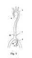
- a schematic human vascular system 1is shown.
- the femoral arteries 2which is connected via a main artery to the aortic arch 3 and then opens into the heart chamber 4.
- an introducer sheath 10is first inserted into the femoral artery 2.
- the femoral artery or any blood vesselis punctured, for example with a steel cannula with a cutting tip.
- a guide wire 12is pushed through the steel cannula introduced into the puncture and inserted retrograde over the aortic arch 3 into the left ventricle of the heart 4.
- the puncture cannula designed as an introducer sluice first lock 10which comprises a tubular portion 11 and optionally a dilator not shown here, threaded onto the guide wire and inserted through the dotted spot in the vascular system, the lock a small distance into the lumen the vascular system or even to the site of an element to be inserted is introduced. Subsequently, a fluid pump is introduced through the introducer sheath 10 into the vascular system.
- the tubular portion 11 of the first sheath 10is inserted into the artery such that the proximal end of the first sheath 10 is outside the femoral artery and thus can be used for introducing, for example, a pump. So it is possible to thread the pump on the guide wire 12 to guide the pump with the help of the guide wire into the left ventricle.
- the methodis illustrated merely by inserting a pump into the left ventricle to support cardiac function.
- the pump or other functional elementmay also be located and placed at other locations in the body's own vasculature.
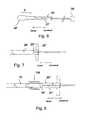
- Fig. 2is the area of Fig. 1 represented, in which the first lock 10 is guided by the body's own tissue from the outside into the lumen L G of the femoral artery 2.
- the first lockcomprises a tubular section 11, which is connected proximally to a lock housing 13.
- the tubular portion 11defines a lumen L 1 , which has an inner diameter d 11 .
- the lock housing 13includes a hemostatic valve known in the art. This prevents that fluid in the lumen L G can escape through the lumen L 1 to the outside.
- the first lock 10 of the Fig. 2coupled with a second lock 20.
- a tubular portion 21is shown, which defines a lumen L 2 with an inner diameter d 21 .
- the distal end of the second lock 20in this case has such an outer diameter that it can be inserted into the lock housing 13.
- the inner diameter d 21is larger than the inner diameter d 11, however .
- a not shown, located in the lumen L 2 pumpcan now be converted by pressing from the second sheath lumen L 2 in the first sheath lumen L1. Subsequently, the pump is transported through the first lock lumen L 1 to the point in the vascular system at which the pump is to be effective. In this case, the pump can either be guided on a guide wire or be introduced without guidewire through the first lock lumen.
- the first sheathmay be advanced distally to the pump site to save the pump and the vessel walls, as well as the shaft catheter, before the pump is pushed out.
- the pump 30comprises a distal pump unit 31 and a shaft catheter 32 adjoining the proximal end of the distal pump unit 31.
- the shaft catheter 32has at its proximal end, not shown, a coupling for coupling the shaft catheter 32 to a drive device.
- the drive devicecan be arranged outside the patient's body and sets a running in the shaft catheter 32 flexible shaft in rotation, which in turn drives the distal pump unit 31.
- the distal pump unitincludes a pump housing 33 made of intersecting Nitinol struts.
- the nitinol housingis in part provided with a coating 34 which extends distally and proximally of a rotor 35 arranged in the housing 33.
- the rotoris connected to the shaft 36 passing through the shaft catheter 32 and is thus rotated.
- the housing and the rotorare compressible, d. h., the pump is a self-decompressible pump.
- the deployment of the pumptakes place after pushing out of the distal pump unit from the distal end of a lock.
- the distal pump unitis retracted into the distal end of a lock lumen of a second sheath.
- the lock lumenhas an inner diameter which is at least greater than the outer diameter of the shaft catheter.
- the rotormay be displaceable relative to the pump housing in the axial direction, in particular by means of an axial displacement of the drive shaft.
- the rotorcan also be fixed in the axial direction with respect to the pump housing.
- the pumphas a discharge hose 37, which defines a flow channel for the pumped fluid located proximally of the rotor 35. At the proximal end of the discharge hose 37 are not shown outlet openings.
- the pumpcan also be switched from a pump mode to a suction mode, so that the pump no longer carries fluid from the distal end to the proximal end, but vice versa.
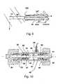
- a pump 30 'is shown, which is substantially the pump 30 after the Fig. 4 equivalent. For simplicity, details of the pump are not shown. Only the bulbous housing and the "pigtail" distal to the bulbous housing are shown, which prevents the heart pump from being sucked up against the heart wall. Proximal to the distal pump unit 31 'runs the wave catheter 32'. Surrounding a region 38 'of the shaft catheter 32' is a second sheath 20 'which comprises a lumen L 2 whose inner diameter d 21 is smaller than the diameter of the distal pump unit 31' in the deployed state.
- the in the Fig. 5 illustrated pump 30 'is a compressible pump, that is, the distal pump unit 31', which includes, inter alia, the pump housing and the rotor therein, is designed such that it can be compressed, ie reduced in diameter.
- a quality inspector or doctorfor example, has been able to convince himself of the correct function of the pump 30 ', e.g.
- pulling the shaft catheter 32' in the proximal directiondraws the distal pump unit 31 'into the lumen L 2 of the second sheath 20'.
- FIG. 6an intermediate step is shown in drawing the distal pump unit 30 'into the lumen of the second sheath 20'. It will be appreciated that the distal pump unit 30 'is compressible and can be made smaller in diameter so that the distal pump unit 30' can be received in the lumen of the second sheath 20 '.
- a coupling 39 'adjoining the shaft catheter 32'is provided, which allows a coupling of the shaft extending in the shaft catheter to a drive unit. Since the coupling 39 'often has a larger outer diameter than the inner diameter of the lumen L 2 , the second lock 20' is usually placed in the distal direction before mounting the coupling 39 'from the proximal end of the shaft catheter 32', so that the Pump in the system 200, that is, the pump with the proximal of the distal pump unit 31 'located second lock 20' and the preassembled coupling 39 ', is delivered.
- the Pump in the system 200that is, the pump with the proximal of the distal pump unit 31 'located second lock 20' and the preassembled coupling 39 '
- trumpet-shaped widening of the distal end of the second sheath 20 'is also shown.
- the distal pump unit 31 'is located completely in the lumen L 2 of the second sheath 20 ".
- the second sheath 20"has two preassembled handle units 22 ", which better hold or remove the second sheath 20" when the distal pump unit 31 is retracted 'allow in the lumen L 2 or a subsequent tearing.
- a "pigtail”this is likewise drawn into the lumen L 2 , so that the distal pump unit 31 'together with components of the pump located distally of the distal pump unit 31' is located in the lumen L 2 .
- the system 200 of pump 30 'and second sheath 20is operatively combined with the first sheath 10 to form a system 100.
- the second sheath 20is inserted with its distal end into the sheath housing of the first sheath 10.
- the pumpis displaced from the second sheath 20 'by pushing the pump in the distal direction, pushing by shunting the shaft catheter 32'. into the first sheath 10 ', where the diameter of the distal one becomes Pump unit 31 'further reduced to the inner diameter d 11 of the lumen L 1 .
- the subsequent stepis shown, in which the distal pump unit 31 'is located completely in the lumen L 1 of the first lock 10.
- the fact that the distal pump unit 31 'is located completely in the lumen L 1 of the first lock 10can be identified, for example, by means of a colored marking 50 which is applied on the outside of the shaft catheter 32'.
- the second sheath 20 "which is formed as a" peel-away "lock, is removed from the shaft catheter 32 'by tearing open the peel-away sheath from the proximal to the distal end and withdrawing it from the shaft catheter 32' directed tearing from the proximal to the distal end may be assisted by notches A, but is primarily due to the alignment of the molecular chains of the plastic used from the proximal to the distal direction.
- the pump 30is further guided within the lumen L 1 of the first lock 10 to the desired location.
- the first sheathmay also be advanced into the immediate vicinity of the site of use before or after insertion of the pump with the distal port mouth.
- the first lock on the necessary lengthmay also be advanced into the immediate vicinity of the site of use before or after insertion of the pump with the distal port mouth.
- a stiffening of the second sheath 20 "is in particular when retracting the distal pump unit 31 'in the distal end of the second lock lumen L 2is not necessary, since the risk of kinking of the shaft is greatly reduced during a pulling movement.
- the second lockmay comprise a reinforcing structure in the form of an inserted wire, or the tubular portion 21 "of the lock 20" is not made of a flexible plastic, but of a dimensionally stable plastic or metal.
- Another way to stabilize the pump and the second lockis to move the pump 30 'in the distal direction, i. in particular when transferring the pump 30 'from the second lock into the first lock to hold the second lock 20 "by a support device 40 in the form of a stable outer sleeve.
- the pumpis first filled with sterile physiological saline and thus completely deaerated.
- the peel-away sluice located proximally of the distal pump unitis advanced to a possibly existing outflow tube.
- the peel-away sluicehas a diameter of, for example, 10 Fr.
- the peel-away sluiceis surrounded by a sleeve-shaped device for holding the second sluice.
- the distal pump unitoptionally with slight rotational movement, pulled into the peel-away lock by pulling the shaft catheter in the proximal direction is exercised.
- the pumpis moved so far into the second lock that a possibly existing pigtail is also recovered in the peel-away lock.
- any dilator presentis pulled out of the introducer sheath and removed.
- the pump held in the peel-away lockwhich for example is initially surrounded by the sleeve for holding the second lock, is pushed into the lock housing until the tip of the peel-away lock abuts against a mechanical stop.
- the pumpis transferred from the peel-away lock into the tubular section by pushing the shaft catheter.
- the distal pump unithas been completely transferred into the introducer sheath, as can be checked, for example, by means of an optical marking on the shaft catheter shaft, the peel-away sheath can be torn open and removed from the shaft catheter.
- the pumpis inside the first sheath advanced to the left ventricle. The first sheath is then withdrawn from the left ventricle to the beginning of the descending aorta.
- the positioning of the distal pump unit in the left ventricle of the heartcan be controlled, for example, by fluoroscopy.
- there is a radiopaque marking on the pump housing or in its vicinity, for example on the catheter, or the pump housing itselfis radiopaque.
- the outlet area of the pumpi. the outflow openings of a discharge hose, lie in the region of the ascending aorta. This can also be checked with a radiopaque marker. Any existing pigtail catheter tip should abut the tip of the left ventricle of the heart.
- the shaft cathetermay have a feed funnel into which the pump can be pulled by train on the drive shaft. Subsequently, the first lock and other remaining components are removed from the vascular system.
- a particular advantage of the inventionis the use of a long lock during the implantation and explantation of the pump.
- the long lockis not only, as is common in the art, for Introduce the pump into an endogenous lumen, but to guide the pump through the sluice lumen in the vicinity of the impact. It is advantageous if in the medical field, the lock has a length between 40 and 120 cm. The length is determined by the later place of action of the pump and the physique of the patient.
- the pumpis pulled out of the body's own lumen together with the long sluice, the bleeding of the femoral artery is stopped with a pressure bandage.
- the pumpcan be pulled out of the lock lumen of the long lock.
- another guidewirecan be placed through the lumen of the sluice, and then, after removal of the sluice, a device for closing the puncture can be guided. This achieves improved hemostasis.
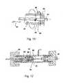
- FIGS. 10 to 13specifically show an inventive embodiment of the first lock with one or more clamping devices for fixing a tubular portion 41 in a lock housing 43rd
- Fig. 10shows in a longitudinal section a lock housing 43, which has substantially the shape of a cylindrical sleeve, which is closed at least at the distal, the patient's body-facing end 44 by a pressure screw 45.
- the lock housing 43has a continuous receiving channel 46 for a tubular portion 41 of the first lock.
- the tubular portion 41coming from the patient's body into the washing chamber 47 of the Receiving channel 46 throughout, then shown in dashed lines in the proximal direction. This indicates that the tubular portion 41 is axially displaceable with respect to the lock housing 43 within the receiving channel 46 or, in other words, that the lock housing 43 is slidable on the tubular portion 41.
- the tubular section 41is usually pulled out of the sheath housing 43 in the distal direction or positioned in the production of the first sheath so that it ends approximately at the level of the first stop piece 48.
- a second lock with a retracted pumpas described above, can then be advanced to then move the pump from the second lock to the first lock.
- the first clamping devicehas as elements the first pressure screw 45, a first clamping ring 50 made of an elastomeric material and the first stop piece 48.
- the pressure screwis screwed by means of an external thread in the region of the overlap with the distal end 44 of the lock housing 43 with this.
- a manual rotation of the pressure screw 45thus causes a movement of the pressure screw in the axial direction, which leads to an axial compression or expansion of the clamping ring 50.
- the clamping ring 50tends to dodge radially inwardly and outwardly to maintain its volume, thereby clamping the tubular one Section 41, since it undergoes resistance on its proximal side by the first stop piece 48.
- the tubular portion 41is fixed axially against the lock housing 43. This fixation can be solved simply by loosening the pressure screw 45, so that the tubular portion 41 can then easily be moved axially in the lock housing 43.
- the clamping ringmay have an inner diameter in the relaxed state, which is equal to or greater than the diameter of the first lock.
- the tubular portion 41as far as possible pushed into the patient's body to allow insertion of the pump in the protection of the lock to the place of use, for example in a Herzventrikel, so after deployment of the pump, the tubular portion 41 is pulled out, and the lock as a whole protrudes relatively far from the patient's body. Thereafter, the clamping device 48, 45, 50 dissolved and the lock housing 43 are pushed on the tubular portion 41 closer to the patient's body. In this case, the tubular portion 41 then passes through the lock housing 43 completely and possibly projects out of it in the proximal direction. Thereupon, by means to be described in more detail below, the tubular portion 41 may be partially severed to remove the excess length.
- a so-called combined hemostasis valveconsisting of a dome valve 51 and a valve plate 52, is provided for better sealing.
- the valve platecloses the lock housing 43, if at this point neither the tubular portion 41 nor a wave catheter passes through the receiving channel 46, while the dome valve 51 is optimized around a strand-shaped body, such as the tubular portion or a catheter for the tight closure.
- a further pressure screw 54is provided, which works in principle as well as the first pressure screw 45 and via a pressure piece 55 causes the compression of a second clamping ring 56 relative to a second mechanical stop 57.
- the second clamping ring 56tapers at its distal end, which favors a deformation radially inwardly when exerting an axial pressure by the pressure screw 54.
- the second stop 57is conical. However, it can also be used at this point a non-conical, but in cross-section rectangular or round clamping ring 56.
- One or more additional valve (s) between the clamping device 48, 45,50 and the flushing inlet 58can also be additionally arranged in the flushing chamber, thereby ensuring that between the tubular section 41 and the lock housing 43, also when dissolved clamping device 48,45, 50 is a fluid-tight connection.
- a flushing device 58schematically indicated, which allows the flushing of the washing chamber 47 with a liquid, the penetration of germs through the first lock in the patient's body prevented.
- This flushingis particularly effective when the tubular portion 41 terminates in the flushing space 47 or on the distal side thereof, so that both the outside and the inside of the tubular portion 41 are reached by the flushing liquid.
- Fig. 11shows an example of the arrangement and operation of a cutting device according to the invention.
- predetermined breaking pointsare provided, these can be appropriately introduced when using the first lock by a cutting device.
- a cutting device with blades 59, 60are provided, which intersect in the circumferential direction, for example, upon rotation of the lock housing relative to the tubular portion. It can also be introduced cuts in the axial direction.
- the blades 59, 60may also be arranged so that they intersect in the axial direction, as indicated by the arrow 61, during a movement of the tubular portion 41 in the longitudinal direction. It is also possible to provide both blades for cutting in the circumferential direction and for cutting in the longitudinal direction.
- Fig. 11is also shown that the blades 59, 60 in the direction radially to the tubular Section 41 can be moved by an operation of the outside of the lock housing 43.
- a pressure on the bladescan then be exerted by hand and the unneeded part of the tubular portion 41 can be cut off.
- An abutmentnot shown here, prevents the depth of cut from exceeding a critical level, thereby damaging any catheter within the sheath.
- the illustrated bladesmay also form a cutting device for a second lock.
- the Fig. 12shows an advantageous use of the second clamping device on the proximal side of the lock housing 43 after the tubular portion 41 is shortened and a shaft catheter 61 from the proximal end of the tubular portion 41 out and on to a not shown coupling device for a drivable shaft of a pump from the Lock housing 43 leads.
- the shaft catheteris sealed in the above-mentioned mandrel seal 51, and the clamping device with the elements of the second pressure screw 54 and the second clamping ring 56, which is axially compressed by the pressure piece 55 relative to a second stop 57, so far deviates radially inwardly He the wave catheter 61, the much smaller Outer diameter than the tubular portion 41 or a second lock, clamps and in particular also additionally seals.
- both the tubular portion 41 and the shaft catheter 61 protruding therefromcan be fixed in the lock housing 43.
- the second clamping deviceis also suitable, when inserting a second lock into the lock housing 43, to fix the second lock with the second clamping ring 56 so that it is sufficiently fixed relative to the lock housing 43 and in particular also to the tubular section 41 for pushing through the shaft catheter 61 is.
- the first and second clamping ring 50, 56may be made of an elastomer, such as a rubber or a silicone elastomer, and thus be fully elastic, but volumeninkompressibel deformable. However, it is at this point also the use of an elastic foam conceivable, which is partially volumenkompressibel.
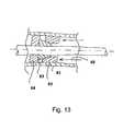
- FIG. 13schematically another type of clamping ring 62 is shown, which may for example consist of a plastic or a metal and in particular slotted and thus radially compressible.
- the slotted clamping ring 62has a conical outer contour against which the conical contour of a pressure piece 63 presses to radially compress the clamping ring as soon as an axial compressive force in the direction of the arrow 65, for example by a pressure screw shown above, is exerted on the pressure piece 63 ,
- the slotted clamping ring 62is fixed axially by the stopper 64.
Landscapes
- Health & Medical Sciences (AREA)
- Heart & Thoracic Surgery (AREA)
- Life Sciences & Earth Sciences (AREA)
- Engineering & Computer Science (AREA)
- Public Health (AREA)
- Veterinary Medicine (AREA)
- Anesthesiology (AREA)
- Biomedical Technology (AREA)
- Hematology (AREA)
- Animal Behavior & Ethology (AREA)
- General Health & Medical Sciences (AREA)
- Cardiology (AREA)
- Pulmonology (AREA)
- Biophysics (AREA)
- Mechanical Engineering (AREA)
- Vascular Medicine (AREA)
- Gastroenterology & Hepatology (AREA)
- Media Introduction/Drainage Providing Device (AREA)
- Infusion, Injection, And Reservoir Apparatuses (AREA)
- Surgical Instruments (AREA)
Abstract
Description
Translated fromGermanDie Erfindung liegt auf dem Gebiet der Mechanik und ist mit Vorteil in der Medizintechnik einsetzbar. Sie befasst sich mit einer Schleuseneinrichtung zum Einführen eines Katheters in einen Patientenkörper, wobei die Schleuse in den Patientenkörper hineinführt und ein proximales Ende der Schleuse aus diesem herausragt. Die Schleuse stellt ein Lumen bereit, durch das ein Katheter in den Patientenkörper eingeführt werden kann.The invention is in the field of mechanics and can be used with advantage in medical technology. It deals with a lock device for inserting a catheter into a patient's body, the lock leading into the patient's body and a proximal end of the lock protruding therefrom. The sheath provides a lumen through which a catheter can be inserted into the patient's body.
Derartige Schleuseneinrichtungen sind grundsätzlich bekannt. Sie werden zum Einführen verschiedenartiger Katheter, beispielsweise im minimalinvasiven medizinischen Bereich, angewendet. Eine derartige Schleuse kann beispielsweise zum Einführen einer Blutpumpe zur Herzunterstützung vorgesehen sein, wobei eine solche Einheit eine distale Pumpeneinheit sowie einen Hohlkatheter und eine durch den Hohlkatheter geführte Antriebswelle aufweisen kann. Solche Pumpen werden im miniaturisierten Bereich oft derart ausgestaltet, dass sie radial komprimierbar und im komprimierten Zustand mit dem Katheter zusammen durch ein Blutgefäß des Körpers einführbar sind. Am Einsatzort, beispielsweise in einem Blutgefäß oder in einer Herzkammer, kann die Pumpe dann expandiert werden. Im expandierten Zustand mit aufgestellten Förderelementen kann eine solche Pumpe dann die notwendige Pumpleistung entfalten.Such lock devices are known in principle. They are used to introduce a variety of catheters, for example in the minimally invasive medical field. Such a lock may for example be provided for introducing a blood pump for heart support, such a unit having a distal pump unit and a hollow catheter and a guided through the hollow catheter Drive shaft may have. Such pumps are often designed in the miniaturized region in such a way that they can be introduced radially compressible and in the compressed state together with the catheter through a blood vessel of the body. At the place of use, for example in a blood vessel or in a ventricle, the pump can then be expanded. In the expanded state with established conveyor elements, such a pump can then develop the necessary pump power.
Außer solchen komprimierbaren Herzpumpen sind auch andere Funktionselemente denkbar, die mittels einer erfindungsgemäßen Schleuse in einen Hohlraum eines Körpers eingebracht werden, wie beispielsweise Stents oder Fräsköpfe für die Beseitigung von Gefäßablagerungen.Apart from such compressible heart pumps, other functional elements are conceivable, which are introduced by means of a lock according to the invention into a cavity of a body, such as stents or milling heads for the removal of vessel deposits.
Das Einführen solcher Funktionselemente und Katheter mittels einer Schleuse ist gegenüber einem direkten Einführen beträchtlich einfacher und auch mit geringeren medizinischen Risiken verbunden.The introduction of such functional elements and catheters by means of a sluice is considerably simpler than direct introduction and also associated with lower medical risks.
Die Schleuse selbst kann mittels der bekannten Seldinger-Technik beispielsweise in ein Gefäßsystem eingeführt werden. Zu diesem Zweck wird zunächst mittels einer Punktionsnadel eine Öffnung in ein Körpergefäß eingebracht, worauf ein Führungsdraht eingeschoben wird. Über den Führungsdraht wird dann gegebenenfalls ein Dilatator und darauf die Schleuse selbst eingeschoben. Danach kann der Führungsdraht entfernt werden, wenn er nicht für weitere Führungsaufgaben benötigt wird, und weitere Elemente können durch die Schleuse eingeschoben werden.The lock itself can be introduced by means of the known Seldinger technique, for example in a vascular system. For this purpose, an opening is first introduced into a body vessel by means of a puncture needle, whereupon a guide wire is inserted. If necessary, a dilator and then the sluice itself is inserted over the guidewire. Thereafter, the guide wire can be removed if it is not needed for further guidance tasks, and other elements can be inserted through the sheath.
Ein entsprechendes Verfahren ist beispielsweise aus der
Eine entsprechende Fluidpumpe, die für hohe Drehzahlen vorgesehen ist, um eine entsprechende Pumpleistung entfalten zu können, ist in der Bauform als Blutpumpe ebenfalls aus der
Die Verwendung einer komfortablen Schleuse zum Einführen eines Katheters, insbesondere mit einer Antriebswelle, bringt den Vorteil, dass beim Einführen der Katheter und insbesondere eine Antriebswelle wenig mechanisch belastet wird. Dies ist insbesondere bei den hohen mechanischen Belastungen, denen eine Antriebswelle im Betrieb einer Blutpumpe ausgesetzt ist, vorteilhaft.The use of a comfortable lock for inserting a catheter, in particular with a drive shaft, has the advantage that during introduction of the catheter and in particular a drive shaft is subjected to little mechanical stress. This is particularly advantageous in the case of the high mechanical loads to which a drive shaft is exposed during the operation of a blood pump.
Für eine komfortable Verwendung einer entsprechenden Schleuse zum Einführen eines Katheters, insbesondere mit einer distalen Pumpeneinheit, ist es wünschenswert, die Schleuse mit dem Hohlkatheter möglichst weit bis in die Nähe des Einsatzortes vorschieben zu können und dann den Wellenkatheter bzw. die Pumpe aus der Schleuse auszubringen, um die Schleuse daraufhin wenigstens ein Stück weit zurückziehen zu können. Auf diese Weise wird die einzubringende Einheit eine möglichst kurze Strecke im Gefäßsystem bzw. entsprechenden Hohlräumen des Patientenkörpers außerhalb einer Schleuse bewegt, so dass die Belastung der Gefäßwandungen einerseits durch das Einführen des Fremdkörpers und die mechanische Belastung der einzuführenden Einheit andererseits weitgehend reduziert ist.For a comfortable use of a corresponding lock for introducing a catheter, in particular with a distal pump unit, it is desirable to be able to advance the sluice with the hollow catheter as far as possible to the vicinity of the place of use and then deploy the shaft catheter or the pump out of the sluice in order to be able to withdraw the lock then at least a little bit. On In this way, the unit to be introduced is moved as short as possible in the vascular system or corresponding cavities of the patient body outside a lock, so that the load on the vessel walls on the one hand by the introduction of the foreign body and the mechanical load of the introduced unit on the other hand is largely reduced.
Auf der anderen Seite erfordert ein derartiges Vorgehen eine entsprechende Überlänge der Schleuse, die nach dem Vorschieben und nachfolgenden Zurückziehen üblicherweise ein Stück weit aus dem Patientenkörper hervorragt.On the other hand, such a procedure requires a corresponding excess length of the lock, which usually protrudes a bit from the patient's body after advancement and subsequent retraction.
Der vorliegenden Erfindung liegt die Aufgabe zugrunde, eine entsprechende Schleuseneinrichtung vorteilhaft so zu gestalten, dass sie besonders einfach handhabbar ist.The present invention has for its object to make a corresponding lock device advantageous so that it is particularly easy to handle.
Die Aufgabe wird mit den Merkmalen der Erfindung gemäß Patentanspruch 1 sowie mit einem Kathetersystem entsprechend Patentanspruch 11 und unter Verwendung eines Verfahrens gemäß Patentanspruch 12 gelöst.The object is achieved with the features of the invention according to claim 1 and with a catheter system according to
Die Erfindung sieht vor, dass eine Schleuseneinrichtung zum Einführen eines Katheters in einen Patientenkörper eine erste Schleuse mit einem proximalen Ende und einem distalen Ende aufweist, wobei das distale Ende der ersten Schleuse beim bestimmungsgemäßen Gebrauch innerhalb des Patientenkörpers angeordnet ist, während das proximale Ende aus dem Patientenkörper herausragt. Die erste Schleuse weist zudem einen schlauchförmigen Abschnitt und ein an dessen proximalem Ende angeordnetes Schleusengehäuse mit einem Aufnahmekanal für einen strangförmigen Körper, insbesondere für einen Katheter, auf.The invention provides that a lock device for inserting a catheter into a patient's body has a first lock with a proximal end and a distal end, wherein the distal end of the first lock is disposed within the patient's body when used as intended, while the proximal end of the lock Patient body protrudes. The first lock also has a tubular portion and a arranged at the proximal end lock housing with a receiving channel for a strand-shaped body, in particular for a catheter on.
Dadurch, dass der schlauchförmige Abschnitt in einer Klemmvorrichtung des Schleusengehäuses lösbar kraftschlüssig gehalten ist, kann zunächst zum Einführen des Katheters in den Patientenkörper die Schleuseneinrichtung insgesamt ein Stück weit in den Patientenkörper hineingeschoben, darauf der Katheter extrahiert und dann die Schleuseneinrichtung aus dem Patientenkörper ein Stück weit wieder herausgezogen werden. Danach kann in besonders einfacher Weise der schlauchförmige Abschnitt aus der Klemmung gelöst, gekürzt und erneut geklemmt werden.Due to the fact that the tubular section is detachably frictionally held in a clamping device of the lock housing, the lock device can first be pushed into the patient's body to a certain extent for insertion of the catheter into the patient's body, then the catheter is extracted and then the lock device is moved out of the patient's body to some extent be pulled out again. Then can be solved in a particularly simple manner, the tubular portion of the clamp, shortened and clamped again.
Hierdurch ist es besonders einfach, die Schleuseneinrichtung nach dem Gebrauch derart passend abzulängen, dass sie nicht weiter als notwendig aus dem Patientenkörper herausragt.This makes it particularly easy to cut off the lock device after use so fitting that it does not protrude further than necessary from the patient's body.
Eine vorteilhafte Ausgestaltung der Erfindung sieht vor, dass der schlauchförmige Abschnitt im gelösten Zustand der Klemmvorrichtung in das Schleusengehäuse hinein verschiebbar ist. Auf diese Weise kann der schlauchförmige Abschnitt entweder in dem Schleusengehäuse aufgenommen, innerhalb des Schleusengehäuses entfernt oder durch eine proximale Öffnung des Schleusengehäuses entfernt werden.An advantageous embodiment of the invention provides that the tubular portion is slidable into the lock housing in the released state of the clamping device. In this way, the tubular portion can either be received in the lock housing, removed within the lock housing or removed by a proximal opening of the lock housing.
Besonders sinnvoll erscheint es, dass der schlauchförmige Abschnitt in direkter Verlängerung des Aufnahmekanals für den Katheter in dem Schleusengehäuse mündet. Auf der einen Seite ist durch diese Ausgestaltung das Einführen eines Katheters in den schlauchförmigen Abschnitt besonders einfach, indem der Katheter zunächst in das Schleusengehäuse eingeführt, in dessen Aufnahmekanal geführt und damit ohne weiteres zur Mündung des schlauchförmigen Abschnittes geleitet wird. Auf diese Weise kann sichergestellt werden, dass das Einführen des Katheters in das proximale Ende der Schleuseneinrichtung vereinfacht ist und zuverlässig gelingt. Andererseits kann durch diese Ausgestaltung das proximale Ende des schlauchförmigen Abschnittes der Schleuse in einfacher Weise in den Aufnahmekanal innerhalb des Schleusengehäuses hineingeschoben werden, um dort entweder aufgenommen zu werden oder entfernt zu werden.It makes particularly sense that the tubular portion opens in direct extension of the receiving channel for the catheter in the lock housing. On the one hand, this embodiment makes it particularly easy to insert a catheter into the tubular section, by first inserting the catheter into the lock housing, guided in the receiving channel and thus easily passed to the mouth of the tubular portion. In this way it can be ensured that the insertion of the catheter into the proximal end of the lock device is simplified and reliably succeeds. On the other hand, by this embodiment, the proximal end of the tubular portion of the lock can be easily pushed into the receiving channel within the lock housing to be either taken up there or removed.
Eine weitere vorteilhafte Ausgestaltung der Erfindung sieht vor, dass die Klemmvorrichtung einen elastisch verformbaren Klemmring aufweist, der den schlauchförmigen Abschnitt umgibt und der durch eine Manipulationsvorrichtung derart pressbar ist, dass er den schlauchförmigen Abschnitt radial einklemmt. Eine derartige Klemmvorrichtung ist mechanisch äußerst einfach aufgebaut, zuverlässig, platzsparend und einfach zu bedienen. Sie bewirkt eine kraftschlüssige Fixierung des schlauchförmigen Abschnitts, die in einfacher Weise auch wieder lösbar ist.A further advantageous embodiment of the invention provides that the clamping device has an elastically deformable clamping ring which surrounds the tubular portion and which can be pressed by a manipulation device such that it clamps the tubular portion radially. Such a clamping device is mechanically extremely simple, reliable, space-saving and easy to use. It causes a non-positive fixation of the tubular portion, which is also solvable again in a simple manner.
Es kann hierzu vorgesehen sein, dass der Klemmring durch axiale Druckwirkung radial verformbar ist. Er kann zu diesem Zweck entweder als Elastomerring ausgestaltet sein oder als geschlitzter Ring aus einem Kunststoff oder einem Metall bestehen.It can be provided for this purpose that the clamping ring is radially deformable by axial pressure effect. It can be configured either for this purpose either as an elastomeric ring or as a slotted ring made of a plastic or a metal.
Der Klemmring kann als Elastomerring beispielsweise mittels eines Druckstücks flachdrückbar sein, wobei er radial nach innen und außen expandiert, wodurch der Innendurchmesser des Rings verringert wird. Handelt es sich bei dem Klemmring um einen geschlitzten Kunststoff- oder Metallring, so kann dieser beispielsweise unter Einwirkung eines Keilkörpers an seiner radialen Außenseite radial nach innen komprimiert werden. Beispielsweise kann zu diesem Zweck ein axial in Bezug auf das schlauchförmige Element bewegter, im Querschnitt keilförmiger Ring verwendet werden. Der Klemmring kann ebenfalls im Querschnitt konisch gestaltet sein. In einer bevorzugten Ausführung handelt es sich um einen Klemmring, der gleichzeitig eine fluiddichte Verbindung zwischen dem Schleusengehäuse und dem schlauchförmigen Element sicherstellt, wie es beispielsweise in Form des erwähnten Elastomerrings realisiert werden kann. Die Dichtheit kann aber, beispielsweise bei Verwendung eines geschlitzten Kunststoff- oder Metallrings, auch durch ein zusätzliches Dichtelement realisiert werden.The clamping ring can be flattened as an elastomer ring, for example by means of a pressure piece, wherein it expands radially inwardly and outwardly, whereby the inner diameter of the ring is reduced. If the clamping ring is a slotted plastic or metal ring, it can For example, be compressed radially inwardly under the action of a wedge body on its radial outer side. For example, for this purpose an axially in relation to the tubular member moving, wedge-shaped in cross section ring can be used. The clamping ring can also be conically shaped in cross section. In a preferred embodiment, it is a clamping ring which simultaneously ensures a fluid-tight connection between the lock housing and the tubular element, as can be realized for example in the form of the mentioned elastomeric ring. The tightness can, however, also be realized by an additional sealing element, for example when using a slotted plastic or metal ring.
Die Klemmvorrichtung kann beispielsweise zur axialen Pressung eines Klemmrings eine Schraubvorrichtung aufweisen. Mittels der Schraubvorrichtung kann dann beispielsweise ein Druckstück gegen den Klemmring in axialer Richtung gedrückt werden.The clamping device may, for example, for axial pressing of a clamping ring have a screw. By means of the screwing can then be pressed against the clamping ring in the axial direction, for example, a pressure piece.
Zur Erleichterung der Abtrennbarkeit von Teilen des schlauchförmigen Abschnitts zu dessen Kürzung kann vorteilhaft vorgesehen sein, dass der schlauchförmige Abschnitt wenigstens an seinem proximalen Ende wenigstens eine Sollbruchstelle aufweist, mittels deren ein Längenabschnitt des schlauchförmigen Abschnitts abgetrennt werden kann. Der schlauchförmige Abschnitt kann beispielsweise in Umfangsrichtung umlaufende teilweise Einschnitte oder Perforationen oder sonstige Schwächungen des Materials, gegebenenfalls auch vorgegebenen durch eine molekulare Struktur, aufweisen.In order to facilitate the separability of parts of the tubular portion to its reduction can be advantageously provided that the tubular portion has at least at its proximal end at least one predetermined breaking point, by means of which a longitudinal portion of the tubular portion can be separated. The tubular portion may, for example, in the circumferential direction circumferential partial incisions or perforations or other weakenings of the material, optionally also predetermined by a molecular structure having.
Ebenso kann der schlauchförmige Abschnitt auch eine oder mehrere in axialer Richtung verlaufende Sollbruchstellen oder Reißlinien aufweisen, die an sich bei sogenannten Peel-away-Schleusen bekannt sind. Bei solchen Reißlinien kann eine Schleuse von einem Ende her durch Auseinanderziehen zweier oder mehrerer Mantelteile geöffnet und abgezogen werden. Zu diesem Zweck kann ein schlauchförmiger Abschnitt auch Handhabungselemente an seinem proximalen Ende, wie beispielsweise Ösen oder Laschen, aufweisen.Likewise, the tubular portion may also have one or more predetermined breaking points or tear lines extending in the axial direction, which are known per se in so-called peel-away locks. In such tear lines, a lock can be opened and removed from one end by pulling two or more sheath parts apart. For this purpose, a tubular portion may also have handling elements at its proximal end, such as eyelets or tabs.
Die Schleuseneinrichtung kann gemäß der Erfindung auch eine Schneidvorrichtung aufweisen, mittels deren ein Teil des schlauchförmigen Abschnitts abgetrennt oder zur leichteren Abtrennung perforiert, eingeschnitten oder angeritzt werden kann. Beispielsweise kann eine oder können mehrere Klingen derart in das Schleusengehäuse eingesetzt werden, dass der schlauchförmige Abschnitt beim Durchschieben durch das Schleusengehäuse selbsttätig eingeschnitten wird. Ein solcher Einschnitt kann beispielsweise in Längsrichtung des schlauchförmigen Abschnitts erfolgen. Es kann auch eine Klinge vorgesehen sein, die bei einer Drehung des Schleusengehäuses relativ zu dem schlauchförmigen Abschnitt einen Schnitt oder eine Schwächung des schlauchförmigen Abschnitts in Umfangsrichtung erzeugt.According to the invention, the lock device can also have a cutting device by means of which a part of the tubular section can be separated or perforated, cut or scored for easier separation. For example, one or more blades can be inserted into the lock housing in such a way that the tubular section is automatically cut when pushed through the lock housing. Such an incision can be made, for example, in the longitudinal direction of the tubular portion. A blade may also be provided which, upon rotation of the lock housing relative to the tubular section, produces a section or weakening of the tubular section in the circumferential direction.
Derartige Klingen können aus einem sehr harten Material wie beispielsweise einer Keramik gefertigt sein, so dass auch verstärkte, insbesondere durch ein Metallgewebe verstärkte schlauchförmige Abschnitte geschnitten werden können. Es können auch im Wesentlichen nadelförmige Klingen vorgesehen sein, die sowohl bei einer Bewegung des schlauchförmigen Abschnitts in Axialrichtung als auch bei einer Drehung in Umfangsrichtung schneiden können.Such blades may be made of a very hard material such as a ceramic, so that reinforced, in particular reinforced by a metal mesh tubular sections can be cut. It may also be provided substantially needle-shaped blades, which are both in a movement of the tubular portion can cut in the axial direction as well as a rotation in the circumferential direction.
Eine besonders vorteilhafte Ausführung der Erfindung sieht vor, dass die Schneidvorrichtung wenigstens eine Klinge aufweist, die insbesondere in dem Schleusengehäuse beweglich geführt, insbesondere radial auf den Katheter zu beweglich geführt ist. Dabei kann eine derartige Klinge mittels eines Handgriffs an der Außenseite des Schleusengehäuses betätigbar sein, so dass mit einer einfachen Handbewegung beim Herausschieben des schlauchförmigen Abschnittes aus dem Patientenkörper und dem Verschieben gegenüber dem Schleusengehäuse ein Schnitt zur Abtrennung eines Teils des schlauchförmigen Abschnitts gesetzt werden kann.A particularly advantageous embodiment of the invention provides that the cutting device has at least one blade, which is movably guided in particular in the lock housing, in particular radially to the catheter is guided to be movable. In this case, such a blade can be actuated by means of a handle on the outside of the lock housing, so that with a simple hand movement when pushing out the tubular portion of the patient's body and the displacement relative to the lock housing a cut can be set to separate a portion of the tubular portion.
Die Erfindung bezieht sich außer auf eine Schleuseneinrichtung der oben beschriebenen Art auch auf ein Kathetersystem mit einem Katheter und einer derartigen Schleuseneinrichtung, wobei gemäß der Erfindung vorteilhaft vorgesehen sein kann, dass das Schleusengehäuse eine weitere Klemmvorrichtung auf der proximalen Seite der Klemmvorrichtung aufweist, wobei die weitere Klemmvorrichtung zum radialen Klemmen des Katheters oder zum radialen Klemmen einer zweiten Schleuse vorgesehen ist, die den Katheter und/oder ein an dem Katheter angeschlossenes Funktionselement umgibt.The invention relates, in addition to a lock device of the type described above, also to a catheter system having a catheter and such a lock device, wherein according to the invention it can be advantageously provided that the lock housing has a further clamping device on the proximal side of the clamping device, wherein the further Clamping device for radially clamping the catheter or for radially clamping a second lock is provided, which surrounds the catheter and / or a functional element connected to the catheter.
Die entsprechende weitere Klemmvorrichtung kann grundsätzlich ebenfalls einen Klemmring aufweisen und beispielsweise ebenso aufgebaut sein wie die erste Klemmvorrichtung zum Fixieren des schlauchförmigen Abschnitts. Die weitere Klemmvorrichtung kann jedoch auch einen anderen Aufbau als die erste Klemmvorrichtung aufweisen und grundsätzlich gemäß einer der oben beschriebenen Varianten einer Klemmvorrichtung aufgebaut sein.The corresponding further clamping device can basically also have a clamping ring and, for example, be constructed in the same way as the first clamping device for fixing the tubular section. However, the other clamping device may also have a different structure than the first clamping device and basically be constructed according to one of the variants of a clamping device described above.
Die Erfindung bezieht sich zudem auf ein Verfahren zum Einführen eines Katheters mit einem an dessen Ende angeordnete Funktionselement in einen Patientenkörper, wobei vorgesehen ist, dass der Katheter in das Schleusengehäuse und den schlauchförmigen Abschnitt eingeführt und darauf in dem schlauchförmigen Abschnitt in den Patientenkörper eingeführt wird, dass dann der schlauchförmige Abschnitt ein Stück weit in proximaler Richtung aus dem Patientenkörper entfernt wird und dass darauf die Klemmvorrichtung gelöst und der schlauchförmige Abschnitt in das Schleusengehäuse hineinbewegt wird.The invention also relates to a method for inserting a catheter with a functional element arranged at its end into a patient's body, wherein it is provided that the catheter is inserted into the lock housing and the tubular section and inserted into the patient's body in the tubular section, that then the tubular portion is a distance away in the proximal direction of the patient's body and that it releases the clamping device and the tubular portion is moved into the lock housing.
Der schlauchförmige Abschnitt kann nach dem Hineinbewegen in das Schleusengehäuse bzw. Durchschieben durch das Schleusengehäuse gekürzt werden. Vor oder nach dem Kürzen kann der schlauchförmige Abschnitt erneut mittels der Klemmvorrichtung geklemmt werden.The tubular portion can be shortened after moving into the lock housing or pushing through the lock housing. Before or after shortening the tubular section can be clamped again by means of the clamping device.
Vorteilhaft kann die Kürzung durch Aufreißen des schlauchförmigen Abschnitts in Längsrichtung, insbesondere vom proximalen Ende des schlauchförmigen Abschnitts her, gefolgt von einem Abreißen, erfolgen.The shortening can advantageously take place by tearing the tubular section in the longitudinal direction, in particular from the proximal end of the tubular section, followed by a tearing off.
Im Folgenden wird die Erfindung anhand eines Ausführungsbeispiels in einer Zeichnung gezeigt und nachfolgend beschrieben.
- Fig. 1
- eine schematische Übersicht über ein Gefäßsystem mit einer eingeführten ersten Schleuse;
- Fig. 2
- eine Detailansicht eines Ausschnitts der
Fig. 1 ; - Fig. 3
- eine Ausführungsform der Erfindung mit einer ersten Schleuse und einer zweiten Schleuse;
- Fig. 4
- eine Ausführungsform einer Pumpe;
- Fig. 5
- eine zweite Schleuse mit einer aus dieser extrahierten Pumpe;
- Fign. 6, 7
- das Einziehen einer Pumpe in eine zweite Schleuse;
- Fign. 8, 9
- das Überführen einer Pumpe von einer zweiten in eine erste Schleuse;
- Fig. 10
- einen Längsschnitt durch ein Schleusengehäuse mit einem schlauchförmigen Abschnitt;
- Fig. 11
- einen Längsschnitt durch einen Teil eines Schleusengehäuses mit einer Schneidvorrichtung;
- Fig. 12
- einen Längsschnitt durch ein Schleusengehäuse mit einer Klemmvorrichtung für den schlauchförmigen Abschnitt und einer weiteren Klemmvorrichtung; und
- Fig. 13
- einen Längsschnitt durch einen alternativen Klemmring mit einem konischen Druckstück.
- Fig. 1
- a schematic overview of a vascular system with an inserted first lock;
- Fig. 2
- a detailed view of a section of the
Fig. 1 ; - Fig. 3
- an embodiment of the invention with a first lock and a second lock;
- Fig. 4
- an embodiment of a pump;
- Fig. 5
- a second lock with a pump extracted therefrom;
- FIGS. 6, 7
- the insertion of a pump into a second lock;
- FIGS. 8, 9
- the transfer of a pump from a second to a first lock;
- Fig. 10
- a longitudinal section through a lock housing with a tubular portion;
- Fig. 11
- a longitudinal section through a part of a lock housing with a cutting device;
- Fig. 12
- a longitudinal section through a lock housing with a clamping device for the tubular portion and another clamping device; and
- Fig. 13
- a longitudinal section through an alternative clamping ring with a conical pressure piece.
In der
Der schlauchförmige Abschnitt 11 der ersten Schleuse 10 ist derart in die Arterie eingeführt, dass das proximale Ende der ersten Schleuse 10 außerhalb der femoralen Arterie liegt und somit zum Einführen beispielsweise einer Pumpe genutzt werden kann. So ist es möglich, die Pumpe auf dem Führungsdraht 12 aufzufädeln, um die Pumpe mithilfe des Führungsdrahtes bis in den linken Herzventrikel zu führen.The
Es ist auch möglich, den schlauchförmigen Abschnitt 11 der ersten Schleuse 10 durch den Führungsdraht geführt bis in den linken Herzventrikel zu führen und den Führungsdraht 12 anschließend aus der ersten Schleuse zu entfernen. Eine etwaige Pumpeneinheit wird anschließend durch das erste Schleusenlumen bis in die Nähe oder bis in den linken Ventrikel 4 geführt.It is also possible to guide the
Vorliegend wird das Verfahren lediglich anhand des Einführens einer Pumpe in den linken Herzventrikel zum Unterstützen einer Herzfunktion dargestellt. Für den Fachmann ist jedoch leicht erkennbar, dass die Pumpe oder ein anderes Funktionselement auch an andere Stellen im körpereigenen Gefäßsystem angeordnet und eingebracht werden kann.In the present case, the method is illustrated merely by inserting a pump into the left ventricle to support cardiac function. However, it will be readily apparent to those skilled in the art that the pump or other functional element may also be located and placed at other locations in the body's own vasculature.
In der
Das Schleusengehäuse 13 enthält ein im Stand der Technik bekanntes hämostatisches Ventil. Dieses verhindert, dass im Lumen LG befindliches Fluid durch das Lumen L1 nach außen austreten kann.The
In der Darstellung der
Eine nicht dargestellte, im Lumen L2 befindliche Pumpe kann nun durch Drücken vom zweiten Schleusenlumen L2 in das erste Schleusenlumen L1 überführt werden. Anschließend wird die Pumpe durch das erste Schleusenlumen L1 bis an die Stelle im Gefäßsystem transportiert, an welcher die Pumpe ihre Wirkung entfalten soll. Hierbei kann die Pumpe entweder auf einem Führungsdraht geführt werden oder ohne Führungsdraht durch das erste Schleusenlumen eingebracht werden. Die erste Schleuse kann, um die Pumpe und die Gefäßwände sowie den Wellenkatheter zu schonen, distal bis zum Einsatzort der Pumpe vorgeschoben werden, bevor die Pumpe herausgeschoben wird.A not shown, located in the lumen L2 pump can now be converted by pressing from the second sheath lumen L2 in the first sheath lumenL1. Subsequently, the pump is transported through the first lock lumen L1 to the point in the vascular system at which the pump is to be effective. In this case, the pump can either be guided on a guide wire or be introduced without guidewire through the first lock lumen. The first sheath may be advanced distally to the pump site to save the pump and the vessel walls, as well as the shaft catheter, before the pump is pushed out.
Anhand der
Die distale Pumpeneinheit umfasst ein Pumpengehäuse 33, welches aus sich kreuzenden Nitinolstreben hergestellt ist. Das Nitinolgehäuse ist zu Teilen mit einer Beschichtung 34 versehen, welche sich distal und proximal eines im Gehäuse 33 angeordneten Rotors 35 erstreckt. Der Rotor ist mit der durch den Wellenkatheter 32 verlaufenden Welle 36 verbunden und wird so in Drehung versetzt. Das Gehäuse und der Rotor sind komprimierbar, d. h., die Pumpe ist eine selbstentkomprimierbare Pumpe. Die Entfaltung der Pumpe vollzieht sich nach dem Herausschieben der distalen Pumpeneinheit aus dem distalen Ende einer Schleuse. Zum Komprimieren der Pumpe in Vorbereitung der Implantation wird die distale Pumpeneinheit in das distale Ende eines Schleusenlumens einer zweiten Schleuse eingezogen. Das Schleusenlumen besitzt dabei einen Innendurchmesser, welcher zumindest größer als der Außendurchmesser des Wellenkatheters ist.The distal pump unit includes a
Der Rotor kann gegenüber dem Pumpengehäuse in Axialrichtung verschiebbar sein, insbesondere mittels einer Axialverschiebung der Antriebswelle. Der Rotor kann andererseits auch in Axialrichtung gegenüber dem Pumpengehäuse fixiert sein.The rotor may be displaceable relative to the pump housing in the axial direction, in particular by means of an axial displacement of the drive shaft. On the other hand, the rotor can also be fixed in the axial direction with respect to the pump housing.
Optional weist die Pumpe einen Abströmschlauch 37 auf, welcher einen proximal des Rotors 35 gelegenen Strömungskanal für das gepumpte Fluid definiert. Am proximalen Ende des Abströmschlauchs 37 befinden sich nicht näher dargestellte Auslassöffnungen.Optionally, the pump has a
Selbstverständlich kann die Pumpe auch von einem Pumpbetrieb in einen Saugbetrieb umgeschaltet werden, so dass die Pumpe nicht länger Fluid vom distalen Ende ans proximale Ende führt, sondern umgekehrt.Of course, the pump can also be switched from a pump mode to a suction mode, so that the pump no longer carries fluid from the distal end to the proximal end, but vice versa.
Eine detailliertere Beschreibung einer weiteren geeigneten Pumpe kann beispielsweise der Druckschrift
Anhand der
In der
Die in der
Obgleich das System sowohl mit aktiv entkomprimierbaren Pumpen als auch mit selbstentkomprimierbaren Pumpen realisierbar ist, eignet es sich insbesondere für selbstentkomprimierbare Pumpen, d.h. Pumpen, deren distale Pumpeneinheit außerhalb der Schleuse selbsttätig wieder die ursprüngliche Größe annimmt.Although the system is feasible with both actively decompressible pumps and self-decompressible pumps, it is particularly suitable for self-decompressible pumps, i. Pumps whose distal pump unit outside the lock automatically resumes its original size.
In der
Ferner ist in der
In der
In der
In der
Anschließend wird die zweite Schleuse 20", welche als eine "Peel-away"-Schleuse ausgebildet ist, vom Wellenkatheter 32' entfernt, indem die Peel-away-Schleuse vom proximalen zum distalen Ende hin aufgerissen und vom Wellenkatheter 32' abgezogen wird. Das gerichtete Aufreißen vom proximalen zum distalen Ende hin kann durch Einkerbungen A unterstützt werden, beruht jedoch vorwiegend auf der Ausrichtung der Molekülketten des verwendeten Kunststoffs von der proximalen in die distale Richtung.Subsequently, the
Nachdem die Peel-away-Schleuse entfernt wurde, wird die Pumpe 30' weiter innerhalb des Lumens L1 der ersten Schleuse 10 bis zum gewünschten Ort geführt.After the peel-away lock has been removed, the pump 30 'is further guided within the lumen L1 of the
Wahlweise kann die erste Schleuse auch vor oder nach dem Einführen der Pumpe mit der distalen Schleusenmündung in die unmittelbare Nähe des Einsatzortes vorgeschoben werden. Hierzu weist die erste Schleuse die notwendige Länge auf.Optionally, the first sheath may also be advanced into the immediate vicinity of the site of use before or after insertion of the pump with the distal port mouth. For this purpose, the first lock on the necessary length.
Eine Versteifung der zweiten Schleuse 20" ist insbesondere beim Einziehen der distalen Pumpeneinheit 31' in das distale Ende des zweiten Schleusenlumens L2 nicht notwendig, da die Gefahr eines Abknickens der Welle bei einer Ziehbewegung stark reduziert ist.A stiffening of the
Beim Überführen der Pumpe von der zweiten Schleuse in die erste Schleuse, wie anhand der
Eine weitere Möglichkeit zum Stabilisieren der Pumpe und der zweiten Schleuse besteht darin, beim Vorschieben der Pumpe 30' in distaler Richtung, d.h. insbesondere beim Überführen der Pumpe 30' von der zweiten Schleuse in die erste Schleuse, die zweite Schleuse 20" durch eine Stützvorrichtung 40 in Form einer stabilen äußeren Hülse zu halten.Another way to stabilize the pump and the second lock is to move the pump 30 'in the distal direction, i. in particular when transferring the pump 30 'from the second lock into the first lock to hold the
Anschließend soll noch eine mögliche Variante eines Verfahrens zum Einführen einer Pumpe in einen linken Herzventrikel geschildert werden. Als vorbereitende Maßnahme wird die Pumpe zunächst mit steriler physiologischer Kochsalzlösung befüllt und somit komplett entlüftet. Anschließend wird die proximal der distalen Pumpeneinheit gelegene Peel-away-Schleuse bis zu einem eventuell vorhandenen Abströmschlauch vorgeschoben. Die Peel-away-Schleuse besitzt einen Durchmesser von beispielsweise 10 Fr. Nachdem die Peel-away-Schleuse bis zum Abströmschlauch vorgeschoben wurde, wird die Peel-away-Schleuse von einer hülsenförmigen Vorrichtung zum Halten der zweiten Schleuse umfasst. Anschließend wird die distale Pumpeneinheit, gegebenenfalls unter leichter Drehbewegung, in die Peel-away-Schleuse eingezogen, indem am Wellenkatheter eine Zugbewegung in proximaler Richtung ausgeübt wird. Die Pumpe wird so weit in die zweite Schleuse verschoben, dass ein eventuell vorhandenes Pigtail ebenfalls in der Peel-away-Schleuse geborgen ist. Durch diese Schritte ist es möglich, die Funktionsfähigkeit der Pumpe bereits vor einem operativen Eingriff zu überprüfen und die Pumpe erst anschließend in eine Schleuse einzuführen, ohne unter Zeitdruck agieren zu müssen. Zum Beispiel erst anschließend wird die Punktur des Gefäßsystems zum Einführen der ersten Schleuse durchgeführt. Zur Zeiteinsparung ist es auf diese Weise aber auch möglich, dass ein Assistent die Pumpe vorbereitet während der Anwender bereits parallel die Punktion durchführt.Subsequently, another possible variant of a method for introducing a pump into a left ventricle will be described. As a preliminary measure, the pump is first filled with sterile physiological saline and thus completely deaerated. Subsequently, the peel-away sluice located proximally of the distal pump unit is advanced to a possibly existing outflow tube. The peel-away sluice has a diameter of, for example, 10 Fr. After the peel-away sluice has been advanced to the outflow tube, the peel-away sluice is surrounded by a sleeve-shaped device for holding the second sluice. Subsequently, the distal pump unit, optionally with slight rotational movement, pulled into the peel-away lock by pulling the shaft catheter in the proximal direction is exercised. The pump is moved so far into the second lock that a possibly existing pigtail is also recovered in the peel-away lock. Through these steps, it is possible to check the functioning of the pump before a surgical procedure and only then to introduce the pump in a lock, without having to act under time pressure. For example, only then is the puncture of the vascular system for introducing the first sheath performed. In order to save time, it is also possible in this way for an assistant to prepare the pump while the user is already performing the puncture in parallel.
Nachdem beispielsweise eine 9Fr-Einführschleuse bis in den linken Herzventrikel eingeführt wurde, wird ein eventuell vorhandener Dilatator aus der Einführschleuse gezogen und aus dieser entfernt.For example, after a 9Fr introducer sheath has been inserted into the left ventricle, any dilator present is pulled out of the introducer sheath and removed.
Anschließend wird die in der Peel-away-Schleuse gehaltene Pumpe, welche beispielsweise anfangs von der Hülse zum Halten der zweiten Schleuse umfasst wird, in das Schleusengehäuse eingeschoben, bis die Spitze der Peel-away-Schleuse an einem mechanischen Anschlag anschlägt. Anschließend wird die Pumpe durch Schieben des Wellenkatheters von der Peel-away-Schleuse in den schlauchförmigen Abschnitt überführt. Sobald die distale Pumpeneinheit komplett in die Einführschleuse überführt wurde, wie dies beispielsweise anhand einer optischen Markierung auf dem Wellenkatheterschaft überprüfbar ist, kann die Peel-away-Schleuse aufgerissen und vom Wellenkatheter abgezogen werden. Anschließend wird die Pumpe innerhalb der ersten Schleuse bis in den linken Herzventrikel vorgeschoben. Die erste Schleuse wird anschließend aus dem linken Herzventrikel bis zum Beginn der absteigenden Aorta zurückgezogen.Subsequently, the pump held in the peel-away lock, which for example is initially surrounded by the sleeve for holding the second lock, is pushed into the lock housing until the tip of the peel-away lock abuts against a mechanical stop. Subsequently, the pump is transferred from the peel-away lock into the tubular section by pushing the shaft catheter. Once the distal pump unit has been completely transferred into the introducer sheath, as can be checked, for example, by means of an optical marking on the shaft catheter shaft, the peel-away sheath can be torn open and removed from the shaft catheter. Subsequently, the pump is inside the first sheath advanced to the left ventricle. The first sheath is then withdrawn from the left ventricle to the beginning of the descending aorta.
Die Positionierung der distalen Pumpeneinheit im linken Herzventrikel kann beispielsweise durch Röntgendurchleuchtung kontrolliert werden. Hierzu befindet sich eine röntgensichtbare Markierung am Pumpengehäuse bzw. in dessen Nähe, beispielsweise am Katheter, oder das Pumpengehäuse selbst ist röntgensichtbar. Ebenso sollte der Auslassbereich der Pumpe, d.h. die Ausströmöffnungen eines Abströmschlauches, im Bereich der aufsteigenden Aorta liegen. Auch dies kann mit einer röntgensichtbaren Markierung überprüft werden. Eine eventuell vorhandene Pigtail-Katheterspitze sollte an der Spitze des linken Herzventrikels anstoßen.The positioning of the distal pump unit in the left ventricle of the heart can be controlled, for example, by fluoroscopy. For this purpose, there is a radiopaque marking on the pump housing or in its vicinity, for example on the catheter, or the pump housing itself is radiopaque. Similarly, the outlet area of the pump, i. the outflow openings of a discharge hose, lie in the region of the ascending aorta. This can also be checked with a radiopaque marker. Any existing pigtail catheter tip should abut the tip of the left ventricle of the heart.
Um die Pumpe aus dem Herzventrikel zu entfernen, wird diese mittels am Wellenkatheter aufgebrachter Zugkraft in die Einführschleuse zurückgezogen und komprimiert aus dem arteriellen Gefäßsystem entfernt. Sie kann auch, wenn die erste Schleuse bereits gekürzt ist, zunächst in den Wellenkatheter ein Stück weit zurückgezogen werden, um die Pumpe zu komprimieren. Hierzu kann der Wellenkatheter einen Einzugtrichter aufweisen, in den die Pumpe durch Zug an der Antriebswelle eingezogen werden kann. Anschließend werden die erste Schleuse und weitere verbliebene Komponenten aus dem Gefäßsystem entfernt.To remove the pump from the heart ventricle, this is withdrawn by means of tensile force applied to the shaft catheter in the introducer sheath and compressed away from the arterial vascular system. It may also, when the first sheath is already shortened, be initially withdrawn a little way into the shaft catheter to compress the pump. For this purpose, the shaft catheter may have a feed funnel into which the pump can be pulled by train on the drive shaft. Subsequently, the first lock and other remaining components are removed from the vascular system.
Besonderen Vorteil bringt bei der Erfindung die Verwendung einer langen Schleuse bei der Implantation und Explantation der Pumpe. Die lange Schleuse dient nicht nur, wie im Stand der Technik üblich, zum Einführen der Pumpe in ein körpereigenes Lumen, sondern zur Führung der Pumpe durch das Schleusenlumen in die Nähe des Wirkungsorts. Hierbei ist es vorteilhaft, wenn im medizinischen Bereich die Schleuse eine Länge zwischen 40 und 120 cm besitzt. Die Länge wird durch den späteren Wirkungsort der Pumpe und die Physis des Patienten bestimmt.A particular advantage of the invention is the use of a long lock during the implantation and explantation of the pump. The long lock is not only, as is common in the art, for Introduce the pump into an endogenous lumen, but to guide the pump through the sluice lumen in the vicinity of the impact. It is advantageous if in the medical field, the lock has a length between 40 and 120 cm. The length is determined by the later place of action of the pump and the physique of the patient.
Wird die Pumpe zusammen mit der langen Schleuse aus einem körpereigenen Lumen herausgezogen, so wird die Blutung der femoralen Arterie mit einem Druckverband gestillt. Alternativ kann die Pumpe aus dem Schleusenlumen der langen Schleuse herausgezogen werden. Dann kann durch das Lumen der Schleuse ein weiterer Führungsdraht platziert werden, über den dann nach Entfernung der Schleuse eine Vorrichtung zum Schließen der Punktur geführt werden kann. Hierdurch ist eine verbesserte Blutungsstillung erreichbar.If the pump is pulled out of the body's own lumen together with the long sluice, the bleeding of the femoral artery is stopped with a pressure bandage. Alternatively, the pump can be pulled out of the lock lumen of the long lock. Then another guidewire can be placed through the lumen of the sluice, and then, after removal of the sluice, a device for closing the puncture can be guided. This achieves improved hemostasis.
Die
Zum Einführen eines Funktionselementes, beispielsweise einer Pumpe, in die erste Schleuse wird üblicherweise der schlauchförmige Abschnitt 41 so weit in distaler Richtung aus dem Schleusengehäuse 43 herausgezogen oder bei der Herstellung der ersten Schleuse so positioniert, dass er etwa in Höhe des ersten Anschlagstückes 48 endet. Bis zu diesem Punkt kann dann eine zweite Schleuse mit einer eingezogenen Pumpe, wie oben beschrieben, vorgeschoben werden, um dann die Pumpe von der zweiten Schleuse in die erste Schleuse durchzubewegen.For introducing a functional element, for example a pump, into the first sheath, the
Die erste Klemmvorrichtung weist als Elemente die erste Druckschraube 45, einen ersten Klemmring 50 aus einem Elastomermaterial sowie das erste Anschlagstück 48 auf.The first clamping device has as elements the
Die Druckschraube ist mittels eines Außengewindes im Bereich der Überlappung mit dem distalen Ende 44 des Schleusengehäuses 43 mit diesem verschraubt. Ein manuelles Drehen an der Druckschraube 45 bewirkt damit eine Bewegung der Druckschraube in axialer Richtung, die zu einer axialen Kompression oder Ausdehnung des Klemmrings 50 führt. Bei einer axialen Kompression hat der Klemmring 50 die Tendenz, zur Erhaltung seines Volumens radial nach innen und außen auszuweichen, und klemmt damit den schlauchförmigen Abschnitt 41, da er auf seiner proximalen Seite einen Widerstand durch das erste Anschlagstück 48 erfährt.The pressure screw is screwed by means of an external thread in the region of the overlap with the
Damit wird der schlauchförmige Abschnitt 41 axial gegenüber dem Schleusengehäuse 43 fixiert. Diese Fixierung kann einfach durch Lösen der Druckschraube 45 aufgelöst werden, so dass der schlauchförmige Abschnitt 41 dann leicht axial in dem Schleusengehäuse 43 verschoben werden kann. Der Klemmring kann dazu im entspannten Zustand einen Innendurchmesser aufweisen, der gleich wie oder größer als der Durchmesser der ersten Schleuse ist.Thus, the
Wird also zunächst der schlauchförmige Abschnitt 41 möglichst weit in den Patientenkörper hineingeschoben, um ein Einführen der Pumpe in dem Schutz der Schleuse bis zum Einsatzort, beispielsweise in einem Herzventrikel, zu ermöglichen, so wird nach dem Ausbringen der Pumpe der schlauchförmige Abschnitt 41 herausgezogen, und die Schleuse insgesamt steht relativ weit aus dem Patientenkörper vor. Danach kann die Klemmvorrichtung 48, 45, 50 gelöst und das Schleusengehäuse 43 auf dem schlauchförmigen Abschnitt 41 näher zum Patientenkörper herangeschoben werden. Dabei durchsetzt der schlauchförmige Abschnitt 41 das Schleusengehäuse 43 dann vollständig und ragt gegebenenfalls in proximaler Richtung aus diesem heraus. Darauf kann mit Mitteln, die weiter unten ausführlicher beschrieben werden, der schlauchförmige Abschnitt 41 teilweise abgetrennt werden, um die Überlänge zu entfernen.Thus, if first the
Innerhalb des Schleusengehäuses 43 ist zur besseren Abdichtung ein sogenanntes kombiniertes Hämostaseventil, bestehend aus einem Domventil 51 und einer Ventilplatte 52 vorgesehen. Die Ventilplatte schließt das Schleusengehäuse 43, wenn an dieser Stelle weder der schlauchförmige Abschnitt 41 noch ein Wellenkatheter den Aufnahmekanal 46 durchsetzt, während das Domventil 51 für den dichten Abschluss um einen strangförmigen Körper herum, beispielsweise den schlauchförmigen Abschnitt oder einen Katheter, optimiert ist.Within the
Am proximalen Ende 53 des Schleusengehäuses 43 ist eine weitere Druckschraube 54 vorgesehen, die im Prinzip ebenso funktioniert wie die erste Druckschraube 45 und die über ein Druckstück 55 die Kompression eines zweiten Klemmrings 56 gegenüber einem zweiten mechanischen Anschlag 57 bewirkt. Als Besonderheit ist hier zu erwähnen, dass der zweite Klemmring 56 an seinem distalen Ende konisch zuläuft, was eine Verformung radial nach innen beim Ausüben eines axialen Drucks durch die Druckschraube 54 begünstigt. Entsprechend gegensinnig ist der zweite Anschlag 57 konisch ausgebildet. Es kann jedoch an dieser Stelle ebenso ein nicht konischer, sondern im Querschnitt rechteckiger oder runder Klemmring 56 eingesetzt werden.At the
Es kann/können auch zusätzlich im Spülraum ein oder mehrere weitere(s) Ventil(e) zwischen der Klemmvorrichtung 48, 45,50 und dem Spüleinlass 58 angeordnet werden, wodurch sichergestellt wird, dass zwischen dem schlauchförmigen Abschnitt 41 und dem Schleusengehäuse 43, auch bei gelöster Klemmvorrichtung 48,45, 50 eine fluiddichte Verbindung besteht.One or more additional valve (s) between the clamping
In der
Wenn keine vorgeschnittenen oder in anderer Weise, beispielsweise durch eine vorgegebene Molekülstruktur oder stellenweise Schwächung der Wandstärke des schlauchförmigen Abschnitts 21, vorgegebenen Sollbruchstellen vorgesehen sind, können diese passend bei Verwendung der ersten Schleuse durch eine Schneidvorrichtung eingebracht werden. In der
Zu diesem Zweck können die Klingen 59, 60 auch so angeordnet sein, dass sie bei einer Bewegung des schlauchförmigen Abschnitts 41 in axialer Richtung, wie durch den Pfeil 61 angedeutet, in Längsrichtung schneiden. Es können auch sowohl Klingen für ein Schneiden in Umfangsrichtung als auch für ein Schneiden in Längsrichtung vorgesehen sein.For this purpose, the
In der
Die dargestellten Klingen können auch eine Schneidvorrichtung für eine zweite Schleuse bilden.The illustrated blades may also form a cutting device for a second lock.
Die
Die zweite Klemmvorrichtung ist ebenso dazu geeignet, beim Einführen einer zweiten Schleuse in das Schleusengehäuse 43 die zweite Schleuse mit dem zweiten Klemmring 56 so zu fixieren, dass sie gegenüber dem Schleusengehäuse 43 und insbesondere auch gegenüber dem schlauchförmigen Abschnitt 41 zum Durchschieben des Wellenkatheters 61 ausreichend fixiert ist.The second clamping device is also suitable, when inserting a second lock into the
Der erste und zweite Klemmring 50, 56 können aus einem Elastomer, beispielsweise einem Gummi oder einem Silikonelastomer, bestehen und somit vollelastisch, aber volumeninkompressibel verformbar sein. Es ist an dieser Stelle jedoch auch die Verwendung eines elastischen Schaumstoffs denkbar, der teilweise volumenkompressibel ist.The first and
In der
Claims (14)
Translated fromGermanPriority Applications (11)
| Application Number | Priority Date | Filing Date | Title |
|---|---|---|---|
| EP11075272.2AEP2606919A1 (en) | 2011-12-22 | 2011-12-22 | Sluice device for inserting a catheter |
| HK15100207.2AHK1199846B (en) | 2011-12-22 | 2012-12-21 | Sheath device for inserting a catheter |
| PCT/EP2012/076587WO2013092971A1 (en) | 2011-12-22 | 2012-12-21 | Sheath device for inserting a catheter |
| CN201711161532.3ACN107754071B (en) | 2011-12-22 | 2012-12-21 | For being inserted into the sheath device of conduit |
| US13/261,902US9642984B2 (en) | 2011-12-22 | 2012-12-21 | Sheath device for inserting a catheter |
| CN201280060021.1ACN103974729B (en) | 2011-12-22 | 2012-12-21 | Sheath device for catheter insertion |
| DE112012005410.5TDE112012005410T5 (en) | 2011-12-22 | 2012-12-21 | Lock device for insertion of a catheter |
| US15/474,592US10525238B2 (en) | 2011-12-22 | 2017-03-30 | Sheath device for inserting a catheter |
| HK18111321.7AHK1251993B (en) | 2011-12-22 | 2018-09-04 | Sheath device for inserting a catheter |
| US16/696,664US11135405B2 (en) | 2011-12-22 | 2019-11-26 | Sheath device for inserting a catheter |
| US17/476,031US20220062594A1 (en) | 2011-12-22 | 2021-09-15 | Sheath device for inserting a catheter |
Applications Claiming Priority (1)
| Application Number | Priority Date | Filing Date | Title |
|---|---|---|---|
| EP11075272.2AEP2606919A1 (en) | 2011-12-22 | 2011-12-22 | Sluice device for inserting a catheter |
Publications (1)
| Publication Number | Publication Date |
|---|---|
| EP2606919A1true EP2606919A1 (en) | 2013-06-26 |
Family
ID=45470221
Family Applications (1)
| Application Number | Title | Priority Date | Filing Date |
|---|---|---|---|
| EP11075272.2AWithdrawnEP2606919A1 (en) | 2011-12-22 | 2011-12-22 | Sluice device for inserting a catheter |
Country Status (5)
| Country | Link |
|---|---|
| US (4) | US9642984B2 (en) |
| EP (1) | EP2606919A1 (en) |
| CN (2) | CN103974729B (en) |
| DE (1) | DE112012005410T5 (en) |
| WO (1) | WO2013092971A1 (en) |
Cited By (36)
| Publication number | Priority date | Publication date | Assignee | Title |
|---|---|---|---|---|
| US8926492B2 (en) | 2011-10-11 | 2015-01-06 | Ecp Entwicklungsgesellschaft Mbh | Housing for a functional element |
| US8932141B2 (en) | 2009-10-23 | 2015-01-13 | Ecp Entwicklungsgesellschaft Mbh | Flexible shaft arrangement |
| US8944748B2 (en) | 2009-05-05 | 2015-02-03 | Ecp Entwicklungsgesellschaft Mbh | Fluid pump changeable in diameter, in particular for medical application |
| US8979493B2 (en) | 2009-03-18 | 2015-03-17 | ECP Entwicklungsgesellscaft mbH | Fluid pump |
| US8998792B2 (en) | 2008-12-05 | 2015-04-07 | Ecp Entwicklungsgesellschaft Mbh | Fluid pump with a rotor |
| US9028216B2 (en) | 2009-09-22 | 2015-05-12 | Ecp Entwicklungsgesellschaft Mbh | Rotor for an axial flow pump for conveying a fluid |
| US9067006B2 (en) | 2009-06-25 | 2015-06-30 | Ecp Entwicklungsgesellschaft Mbh | Compressible and expandable blade for a fluid pump |
| US9089670B2 (en) | 2009-02-04 | 2015-07-28 | Ecp Entwicklungsgesellschaft Mbh | Catheter device having a catheter and an actuation device |
| US9217442B2 (en) | 2010-03-05 | 2015-12-22 | Ecp Entwicklungsgesellschaft Mbh | Pump or rotary cutter for operation in a fluid |
| US9314558B2 (en) | 2009-12-23 | 2016-04-19 | Ecp Entwicklungsgesellschaft Mbh | Conveying blades for a compressible rotor |
| US9328741B2 (en) | 2010-05-17 | 2016-05-03 | Ecp Entwicklungsgesellschaft Mbh | Pump arrangement |
| US9339596B2 (en) | 2009-12-23 | 2016-05-17 | Ecp Entwicklungsgesellschaft Mbh | Radially compressible and expandable rotor for a fluid pump |
| US9358330B2 (en) | 2009-12-23 | 2016-06-07 | Ecp Entwicklungsgesellschaft Mbh | Pump device having a detection device |
| US9416791B2 (en) | 2010-01-25 | 2016-08-16 | Ecp Entwicklungsgesellschaft Mbh | Fluid pump having a radially compressible rotor |
| US9416783B2 (en) | 2009-09-22 | 2016-08-16 | Ecp Entwicklungsgellschaft Mbh | Compressible rotor for a fluid pump |
| US9603983B2 (en) | 2009-10-23 | 2017-03-28 | Ecp Entwicklungsgesellschaft Mbh | Catheter pump arrangement and flexible shaft arrangement having a core |
| US9611743B2 (en) | 2010-07-15 | 2017-04-04 | Ecp Entwicklungsgesellschaft Mbh | Radially compressible and expandable rotor for a pump having an impeller blade |
| US9771801B2 (en) | 2010-07-15 | 2017-09-26 | Ecp Entwicklungsgesellschaft Mbh | Rotor for a pump, produced with a first elastic material |
| US9867916B2 (en) | 2010-08-27 | 2018-01-16 | Berlin Heart Gmbh | Implantable blood conveying device, manipulating device and coupling device |
| US9895475B2 (en) | 2010-07-15 | 2018-02-20 | Ecp Entwicklungsgesellschaft Mbh | Blood pump for the invasive application within a body of a patient |
| US9974893B2 (en) | 2010-06-25 | 2018-05-22 | Ecp Entwicklungsgesellschaft Mbh | System for introducing a pump |
| US10107299B2 (en) | 2009-09-22 | 2018-10-23 | Ecp Entwicklungsgesellschaft Mbh | Functional element, in particular fluid pump, having a housing and a conveying element |
| US10172985B2 (en) | 2009-08-06 | 2019-01-08 | Ecp Entwicklungsgesellschaft Mbh | Catheter device having a coupling device for a drive device |
| US10391278B2 (en) | 2011-03-10 | 2019-08-27 | Ecp Entwicklungsgesellschaft Mbh | Push device for the axial insertion of an elongate, flexible body |
| US10722631B2 (en) | 2018-02-01 | 2020-07-28 | Shifamed Holdings, Llc | Intravascular blood pumps and methods of use and manufacture |
| US11185677B2 (en) | 2017-06-07 | 2021-11-30 | Shifamed Holdings, Llc | Intravascular fluid movement devices, systems, and methods of use |
| US11511103B2 (en) | 2017-11-13 | 2022-11-29 | Shifamed Holdings, Llc | Intravascular fluid movement devices, systems, and methods of use |
| US11654275B2 (en) | 2019-07-22 | 2023-05-23 | Shifamed Holdings, Llc | Intravascular blood pumps with struts and methods of use and manufacture |
| US11666746B2 (en) | 2011-09-05 | 2023-06-06 | Ecp Entwicklungsgesellschaft Mbh | Medical product comprising a functional element for the invasive use in a patient's body |
| US11724089B2 (en) | 2019-09-25 | 2023-08-15 | Shifamed Holdings, Llc | Intravascular blood pump systems and methods of use and control thereof |
| US11964145B2 (en) | 2019-07-12 | 2024-04-23 | Shifamed Holdings, Llc | Intravascular blood pumps and methods of manufacture and use |
| US12102815B2 (en) | 2019-09-25 | 2024-10-01 | Shifamed Holdings, Llc | Catheter blood pumps and collapsible pump housings |
| US12121713B2 (en) | 2019-09-25 | 2024-10-22 | Shifamed Holdings, Llc | Catheter blood pumps and collapsible blood conduits |
| US12161857B2 (en) | 2018-07-31 | 2024-12-10 | Shifamed Holdings, Llc | Intravascular blood pumps and methods of use |
| US12220570B2 (en) | 2018-10-05 | 2025-02-11 | Shifamed Holdings, Llc | Intravascular blood pumps and methods of use |
| US12409310B2 (en) | 2019-12-11 | 2025-09-09 | Shifamed Holdings, Llc | Descending aorta and vena cava blood pumps |
Families Citing this family (42)
| Publication number | Priority date | Publication date | Assignee | Title |
|---|---|---|---|---|
| US7393181B2 (en) | 2004-09-17 | 2008-07-01 | The Penn State Research Foundation | Expandable impeller pump |
| CN102380135A (en) | 2006-03-23 | 2012-03-21 | 宾州研究基金会 | Heart assist device with expandable impeller pump |
| EP2246078A1 (en) | 2009-04-29 | 2010-11-03 | ECP Entwicklungsgesellschaft mbH | Shaft assembly with a shaft which moves within a fluid-filled casing |
| WO2012094641A2 (en) | 2011-01-06 | 2012-07-12 | Thoratec Corporation | Percutaneous heart pump |
| EP2606919A1 (en)* | 2011-12-22 | 2013-06-26 | ECP Entwicklungsgesellschaft mbH | Sluice device for inserting a catheter |
| US8721517B2 (en) | 2012-05-14 | 2014-05-13 | Thoratec Corporation | Impeller for catheter pump |
| US9446179B2 (en) | 2012-05-14 | 2016-09-20 | Thoratec Corporation | Distal bearing support |
| US9872947B2 (en) | 2012-05-14 | 2018-01-23 | Tc1 Llc | Sheath system for catheter pump |
| EP4218887A1 (en) | 2012-05-14 | 2023-08-02 | Tc1 Llc | Mechanical circulatory support device for stabilizing a patient after cardiogenic shock |
| US9358329B2 (en) | 2012-07-03 | 2016-06-07 | Thoratec Corporation | Catheter pump |
| US9421311B2 (en) | 2012-07-03 | 2016-08-23 | Thoratec Corporation | Motor assembly for catheter pump |
| EP4186557A1 (en) | 2012-07-03 | 2023-05-31 | Tc1 Llc | Motor assembly for catheter pump |
| US11033728B2 (en) | 2013-03-13 | 2021-06-15 | Tc1 Llc | Fluid handling system |
| US11077294B2 (en) | 2013-03-13 | 2021-08-03 | Tc1 Llc | Sheath assembly for catheter pump |
| WO2014164136A1 (en) | 2013-03-13 | 2014-10-09 | Thoratec Corporation | Fluid handling system |
| US9308302B2 (en) | 2013-03-15 | 2016-04-12 | Thoratec Corporation | Catheter pump assembly including a stator |
| EP4190376A1 (en) | 2013-03-15 | 2023-06-07 | Tc1 Llc | Catheter pump assembly including a stator |
| EP3131599B1 (en) | 2014-04-15 | 2019-02-20 | Tc1 Llc | Catheter pump with access ports |
| WO2015160943A1 (en) | 2014-04-15 | 2015-10-22 | Thoratec Corporation | Sensors for catheter pumps |
| US10583232B2 (en) | 2014-04-15 | 2020-03-10 | Tc1 Llc | Catheter pump with off-set motor position |
| EP3131597B1 (en) | 2014-04-15 | 2020-12-02 | Tc1 Llc | Catheter pump introducer systems |
| EP2962721B1 (en)* | 2014-07-04 | 2019-05-08 | Abiomed Europe GmbH | Sheath for sealed access to a vessel |
| EP4574200A3 (en) | 2014-07-04 | 2025-09-10 | Abiomed Europe GmbH | Sheath |
| EP3583973A1 (en) | 2014-08-18 | 2019-12-25 | Tc1 Llc | Guide features for percutaneous catheter pump |
| US9675738B2 (en) | 2015-01-22 | 2017-06-13 | Tc1 Llc | Attachment mechanisms for motor of catheter pump |
| US9770543B2 (en) | 2015-01-22 | 2017-09-26 | Tc1 Llc | Reduced rotational mass motor assembly for catheter pump |
| WO2016118781A2 (en) | 2015-01-22 | 2016-07-28 | Thoratec Corporation | Motor assembly with heat exchanger for catheter pump |
| CA2976805C (en)* | 2015-02-23 | 2020-04-07 | C.R. Bard, Inc. | Access system |
| US11160970B2 (en) | 2016-07-21 | 2021-11-02 | Tc1 Llc | Fluid seals for catheter pump motor assembly |
| EP3808401A1 (en) | 2016-07-21 | 2021-04-21 | Tc1 Llc | Gas-filled chamber for catheter pump motor assembly |
| EP3398646B1 (en) | 2017-05-05 | 2019-10-09 | Greatbatch Ltd. | Medical device with hemostatic valve |
| EP3446731A1 (en)* | 2017-08-23 | 2019-02-27 | ECP Entwicklungsgesellschaft mbH | Device for compressing a compressible part of a catheter pump |
| DE102018208555A1 (en) | 2018-05-30 | 2019-12-05 | Kardion Gmbh | Apparatus for anchoring a cardiac assist system in a blood vessel, method of operation, and method of making a device and cardiac assist system |
| CN108790140B (en)* | 2018-06-19 | 2020-09-25 | 湘潭大学 | Magnetic pipeline traction device |
| CN108837276A (en)* | 2018-07-18 | 2018-11-20 | 董鹏 | Dedicated reverse microtubular |
| WO2020082001A1 (en) | 2018-10-18 | 2020-04-23 | Abiomed, Inc. | Systems and methods for minimizing leaks during insertion of pumps |
| CN111375118B (en)* | 2018-12-29 | 2025-07-18 | 微创神通医疗科技(上海)有限公司 | Guidance device and guidance system |
| US12097016B2 (en) | 2019-03-14 | 2024-09-24 | Abiomed, Inc. | Blood flow rate measurement system |
| CA3149258A1 (en)* | 2019-08-28 | 2021-03-04 | Pj ANAND | Fluid delivery system |
| NL2028130B1 (en) | 2021-05-03 | 2022-11-10 | Cardiacbooster B V | Cardiac assist device with high frequency operation |
| EP4590379A1 (en)* | 2022-09-21 | 2025-07-30 | Silk Road Medical, Inc. | Sheaths configured for vascular access |
| CN116492571B (en)* | 2023-06-20 | 2023-10-17 | 佛山特种医用导管有限责任公司 | Catheter sheath and method for manufacturing same |
Citations (4)
| Publication number | Priority date | Publication date | Assignee | Title |
|---|---|---|---|---|
| WO2002043791A1 (en) | 2000-12-01 | 2002-06-06 | Impella Cardiosystems Ag | Intravascular pump |
| US20040147877A1 (en)* | 2003-01-27 | 2004-07-29 | Heuser Richard R | Catheter introducer system |
| EP2047872A1 (en) | 2007-10-08 | 2009-04-15 | Ais Gmbh Aachen Innovative Solutions | Catheter device |
| EP2347778A1 (en)* | 2010-01-25 | 2011-07-27 | ECP Entwicklungsgesellschaft mbH | Fluid pump with a radially compressible rotor |
Family Cites Families (174)
| Publication number | Priority date | Publication date | Assignee | Title |
|---|---|---|---|---|
| US2350534A (en) | 1942-10-05 | 1944-06-06 | Rosinger Arthur | Magnetic stirrer |
| US3243207A (en)* | 1964-06-12 | 1966-03-29 | Chemplast Inc | Plastic fluid tight sealing device |
| JPS4824967B1 (en) | 1964-11-27 | 1973-07-25 | ||
| US3333127A (en) | 1965-12-27 | 1967-07-25 | Bergstrom Mfg Company | Magnetic drive or coupling |
| US3489145A (en) | 1966-08-08 | 1970-01-13 | Surgeon General Of The Public | Method and apparatus for continuous separation of blood in vivo |
| US3439859A (en) | 1967-07-27 | 1969-04-22 | Matsushita Electric Industrial Co Ltd | Brazing slug |
| GB1489055A (en) | 1973-08-17 | 1977-10-19 | Pont Res & Investment Services | Magnetic coupling |
| US4065234A (en) | 1975-12-22 | 1977-12-27 | Nihon Kagaku Kizai Kabushiki Kaisha | Magnetically driven rotary pumps |
| DE2624058C2 (en) | 1976-05-28 | 1984-11-15 | Franz Klaus-Union, 4630 Bochum | Permanent magnet pump |
| US4135253A (en) | 1976-11-30 | 1979-01-23 | Medtronic, Inc. | Centrifugal blood pump for cardiac assist |
| US4153048A (en) | 1977-09-14 | 1979-05-08 | Cleveland Clinic Foundation | Thermodilution catheter and method |
| US4430081A (en)* | 1981-01-06 | 1984-02-07 | Cook, Inc. | Hemostasis sheath |
| US4420851A (en) | 1981-12-07 | 1983-12-20 | Wiener Stanley M | Mechanized tooth brush having movement in two planes |
| JPS6171065A (en) | 1984-09-13 | 1986-04-11 | テルモ株式会社 | Catheter introducer |
| US4686982A (en) | 1985-06-19 | 1987-08-18 | John Nash | Spiral wire bearing for rotating wire drive catheter |
| US4699611A (en) | 1985-04-19 | 1987-10-13 | C. R. Bard, Inc. | Biliary stent introducer |
| US4679558A (en) | 1985-08-12 | 1987-07-14 | Intravascular Surgical Instruments, Inc. | Catheter based surgical methods and apparatus therefor |
| US4728319A (en) | 1986-03-20 | 1988-03-01 | Helmut Masch | Intravascular catheter |
| US4747840A (en) | 1986-09-17 | 1988-05-31 | Ladika Joseph E | Selective pulmonary arteriograph catheter |
| US4777951A (en) | 1986-09-19 | 1988-10-18 | Mansfield Scientific, Inc. | Procedure and catheter instrument for treating patients for aortic stenosis |
| US4747821A (en) | 1986-10-22 | 1988-05-31 | Intravascular Surgical Instruments, Inc. | Catheter with high speed moving working head |
| US4753221A (en) | 1986-10-22 | 1988-06-28 | Intravascular Surgical Instruments, Inc. | Blood pumping catheter and method of use |
| US4749376A (en) | 1986-10-24 | 1988-06-07 | Intravascular Surgical Instruments, Inc. | Reciprocating working head catheter |
| US4723550A (en)* | 1986-11-10 | 1988-02-09 | Cordis Corporation | Leakproof hemostasis valve with single valve member |
| US4846152A (en) | 1987-11-24 | 1989-07-11 | Nimbus Medical, Inc. | Single-stage axial flow blood pump |
| US4895557A (en) | 1987-12-07 | 1990-01-23 | Nimbus Medical, Inc. | Drive mechanism for powering intravascular blood pumps |
| US5061256A (en) | 1987-12-07 | 1991-10-29 | Johnson & Johnson | Inflow cannula for intravascular blood pumps |
| US4886507A (en)* | 1988-02-01 | 1989-12-12 | Medex, Inc. | Y connector for angioplasty procedure |
| US5372138A (en) | 1988-03-21 | 1994-12-13 | Boston Scientific Corporation | Acousting imaging catheters and the like |
| US5011469A (en) | 1988-08-29 | 1991-04-30 | Shiley, Inc. | Peripheral cardiopulmonary bypass and coronary reperfusion system |
| US4919647A (en) | 1988-10-13 | 1990-04-24 | Kensey Nash Corporation | Aortically located blood pumping catheter and method of use |
| US5234425A (en) | 1989-03-03 | 1993-08-10 | Thomas J. Fogarty | Variable diameter sheath method and apparatus for use in body passages |
| US5017103A (en) | 1989-03-06 | 1991-05-21 | St. Jude Medical, Inc. | Centrifugal blood pump and magnetic coupling |
| US5147186A (en) | 1989-08-04 | 1992-09-15 | Bio Medicus, Inc. | Blood pump drive system |
| US5097849A (en) | 1989-08-17 | 1992-03-24 | Kensey Nash Corporation | Method of use of catheter with working head having selectable impacting surfaces |
| US5042984A (en) | 1989-08-17 | 1991-08-27 | Kensey Nash Corporation | Catheter with working head having selectable impacting surfaces and method of using the same |
| US4984972A (en) | 1989-10-24 | 1991-01-15 | Minnesota Mining And Manufacturing Co. | Centrifugal blood pump |
| US5037403A (en) | 1989-11-08 | 1991-08-06 | Cordis Corporation | Pigtail catheter with angled apertures |
| JPH0636821B2 (en) | 1990-03-08 | 1994-05-18 | 健二 山崎 | Implantable auxiliary artificial heart |
| NL9000833A (en) | 1990-04-09 | 1991-11-01 | Cordis Europ | ANGIOGRAPHY CATHETER. |
| ES2020787A6 (en) | 1990-07-20 | 1991-09-16 | Figuera Aymerich Diego | Intra-ventricular expansible assist pump |
| US5139486A (en) | 1991-01-02 | 1992-08-18 | Gerald Moss | Dilator/introducer for percutaneous gastrostomy |
| US5158279A (en) | 1991-09-30 | 1992-10-27 | Xerox Corporation | Magnetic clutch with adjustable slip torque |
| WO1993006878A1 (en) | 1991-10-11 | 1993-04-15 | Boston Scientific Corporation | Catheter introducer sheath assembly |
| US5167636A (en)* | 1991-10-24 | 1992-12-01 | Mectra Labs, Inc. | Cannula sealing mechanism |
| US5395349A (en) | 1991-12-13 | 1995-03-07 | Endovascular Technologies, Inc. | Dual valve reinforced sheath and method |
| US5935122A (en) | 1991-12-13 | 1999-08-10 | Endovascular Technologies, Inc. | Dual valve, flexible expandable sheath and method |
| US5250059A (en) | 1992-01-22 | 1993-10-05 | Devices For Vascular Intervention, Inc. | Atherectomy catheter having flexible nose cone |
| FR2688923B1 (en) | 1992-03-23 | 1994-06-10 | Sagem | WATERPROOF MAGNETIC DRIVE DEVICE WITHOUT WALL CROSSING AND ULTRA-SOUND PROBE COMPRISING APPLICATION. |
| US5300112A (en) | 1992-07-14 | 1994-04-05 | Aai Corporation | Articulated heart pump |
| US5304142A (en) | 1992-08-04 | 1994-04-19 | Medamicus, Inc. | Dilator - Introducer locking hub and sheath valve apparatus |
| SE501215C2 (en) | 1992-09-02 | 1994-12-12 | Oeyvind Reitan | catheter Pump |
| US5376114A (en) | 1992-10-30 | 1994-12-27 | Jarvik; Robert | Cannula pumps for temporary cardiac support and methods of their application and use |
| NL9300231A (en) | 1993-02-04 | 1994-09-01 | Cordis Europ | Angiography catheter. |
| US5320611A (en) | 1993-02-04 | 1994-06-14 | Peter M. Bonutti | Expandable cannula having longitudinal wire and method of use |
| US6338730B1 (en) | 1993-02-04 | 2002-01-15 | Peter M. Bonutti | Method of using expandable cannula |
| US5423762A (en)* | 1993-04-15 | 1995-06-13 | Cordis Corporation | Modular catheter sheath introducer |
| DE4321260C1 (en) | 1993-06-25 | 1995-03-09 | Westphal Dieter Dipl Ing Dipl | Blood pump as a centrifugal pump |
| US5492530A (en) | 1994-02-07 | 1996-02-20 | Cathco, Inc. | Method for accessing the coronary arteries from the radial or brachial artery in the arm |
| US5533986A (en) | 1994-02-18 | 1996-07-09 | Merit Medical Systems, Inc. | Catheter apparatus with means for subcutaneous delivery of anesthetic agent or other fluid medicament |
| US5407430A (en) | 1994-03-21 | 1995-04-18 | Peters; Michael J. | Intravenous catheter |
| US5395341A (en) | 1994-03-21 | 1995-03-07 | Cordis Corporation | One piece vessel dilator/catheter sheath introducer |
| US5488960A (en) | 1994-04-11 | 1996-02-06 | Abbott Laboratories | Coronary sinus catheter introducer system |
| DE4414903A1 (en) | 1994-04-28 | 1995-11-02 | Aesculap Ag | Surgical instrument with tubular shaft for arthroscopy |
| US5824041A (en) | 1994-06-08 | 1998-10-20 | Medtronic, Inc. | Apparatus and methods for placement and repositioning of intraluminal prostheses |
| US5536255A (en) | 1994-10-03 | 1996-07-16 | Moss; Gerald | Dilator/introducer apparatus for percutaneous gastrostomy |
| NL1003226C2 (en) | 1996-05-29 | 1997-12-03 | Cordis Europ | Suction catheter with preformed end section. |
| US6015272A (en) | 1996-06-26 | 2000-01-18 | University Of Pittsburgh | Magnetically suspended miniature fluid pump and method of designing the same |
| US5779721A (en) | 1996-07-26 | 1998-07-14 | Kensey Nash Corporation | System and method of use for revascularizing stenotic bypass grafts and other blood vessels |
| US5827171A (en) | 1996-10-31 | 1998-10-27 | Momentum Medical, Inc. | Intravascular circulatory assist device |
| US5971993A (en) | 1996-11-07 | 1999-10-26 | Myocardial Stents, Inc. | System for delivery of a trans myocardial device to a heart wall |
| US5911710A (en)* | 1997-05-02 | 1999-06-15 | Schneider/Namic | Medical insertion device with hemostatic valve |
| US5954745A (en) | 1997-05-16 | 1999-09-21 | Gertler; Jonathan | Catheter-filter set having a compliant seal |
| US6129704A (en) | 1997-06-12 | 2000-10-10 | Schneider (Usa) Inc. | Perfusion balloon catheter having a magnetically driven impeller |
| US6123725A (en) | 1997-07-11 | 2000-09-26 | A-Med Systems, Inc. | Single port cardiac support apparatus |
| WO1999013934A1 (en) | 1997-09-12 | 1999-03-25 | Nippon Zeon Co., Ltd. | Balloon catheter |
| US5984944A (en) | 1997-09-12 | 1999-11-16 | B. Braun Medical, Inc. | Introducer for an expandable vascular occlusion device |
| US5908413A (en)* | 1997-10-03 | 1999-06-01 | Scimed Life Systems, Inc. | Radiopaque catheter and method of manufacture thereof |
| US5935112A (en)* | 1997-10-15 | 1999-08-10 | Stevens; Brian W. | Hemostasis valve with catheter/guidewire seals |
| US5911702A (en) | 1997-11-06 | 1999-06-15 | Heartport, Inc. | Methods and devices for cannulating a patient's blood vessel |
| US6007478A (en) | 1997-11-13 | 1999-12-28 | Impella Cardiotechnik Aktiengesellschaft | Cannula having constant wall thickness with increasing distal flexibility and method of making |
| US6149996A (en)* | 1998-01-15 | 2000-11-21 | Schneider (Usa) Inc. | Molded tip and tubing and method of making same |
| JPH11244376A (en) | 1998-02-27 | 1999-09-14 | Kyocera Corp | Blood pump |
| DE29804046U1 (en) | 1998-03-07 | 1998-04-30 | Günther, Rolf W., Prof. Dr.med., 52074 Aachen | Percutaneously implantable, self-expanding axial pump for temporary heart support |
| US6540712B1 (en) | 1998-03-13 | 2003-04-01 | Arteria Medical Science, Inc. | Methods and low profile apparatus for reducing embolization during treatment of carotid artery disease |
| DE19821307C1 (en) | 1998-05-13 | 1999-10-21 | Impella Cardiotech Gmbh | Intra-cardiac blood pump |
| US6054788A (en) | 1998-08-12 | 2000-04-25 | Reliance Electric Industrial Company | Magnetic power transmission coupling |
| WO2000019097A1 (en) | 1998-09-30 | 2000-04-06 | A-Med Systems, Inc. | Blood pump system with magnetic cable drive |
| US6217541B1 (en) | 1999-01-19 | 2001-04-17 | Kriton Medical, Inc. | Blood pump using cross-flow principles |
| US7780628B1 (en) | 1999-01-11 | 2010-08-24 | Angiodynamics, Inc. | Apparatus and methods for treating congestive heart disease |
| FR2788223B1 (en) | 1999-01-12 | 2001-09-21 | Francis Bartolome | MEDICO-SURGICAL DISCHARGE CANNULA |
| US6245007B1 (en) | 1999-01-28 | 2001-06-12 | Terumo Cardiovascular Systems Corporation | Blood pump |
| EP1034808A1 (en) | 1999-03-09 | 2000-09-13 | Paul Frederik Gründeman | A device for transventricular mechanical circulatory support |
| US6186981B1 (en) | 1999-03-23 | 2001-02-13 | Peter Cho | Cavo-atrial cannula |
| US6692462B2 (en) | 1999-05-19 | 2004-02-17 | Mackenzie Andrew J. | System and method for establishing vascular access |
| US20050165269A9 (en) | 1999-06-18 | 2005-07-28 | Aboul-Hosn Walid N. | Cannulation system and related methods |
| US6607547B1 (en) | 1999-08-25 | 2003-08-19 | Origin Medsystems, Inc. | Longitudinal dilator and method |
| US20060287574A1 (en) | 1999-08-25 | 2006-12-21 | Chin Albert K | Longitudinal dilator |
| AU7354400A (en) | 1999-09-03 | 2001-04-10 | A-Med Systems, Inc. | Guidable intravascular blood pump and related methods |
| US7022100B1 (en) | 1999-09-03 | 2006-04-04 | A-Med Systems, Inc. | Guidable intravascular blood pump and related methods |
| US7494485B2 (en) | 1999-12-10 | 2009-02-24 | Sprite Solutions | Fluidic interventional device and method of distal protection |
| US6551283B1 (en)* | 2000-01-25 | 2003-04-22 | St. Jude Medical, Daig Division | Hemostasis valve |
| US6413222B1 (en) | 2000-04-13 | 2002-07-02 | Boston Scientific Corporation | Catheter drive shaft clutch |
| US6517528B1 (en) | 2000-04-13 | 2003-02-11 | Scimed Life Systems, Inc. | Magnetic catheter drive shaft clutch |
| US6808508B1 (en) | 2000-09-13 | 2004-10-26 | Cardiacassist, Inc. | Method and system for closed chest blood flow support |
| CN1157545C (en) | 2000-10-25 | 2004-07-14 | 李国坤 | Magnetic suspension bearing |
| DE10060275A1 (en) | 2000-12-05 | 2002-06-13 | Impella Cardiotech Ag | Method for calibrating a pressure sensor or a flow sensor on a rotary pump |
| US6537247B2 (en) | 2001-06-04 | 2003-03-25 | Donald T. Shannon | Shrouded strain relief medical balloon device and method of use |
| US6952855B2 (en) | 2001-06-29 | 2005-10-11 | Homedics, Inc. | Automatic electric toothbrush |
| US6981942B2 (en) | 2001-11-19 | 2006-01-03 | University Of Medicine And Dentristy Of New Jersey | Temporary blood circulation assist device |
| DE60235574D1 (en) | 2001-12-26 | 2010-04-15 | Univ Yale | VESSEL shunt device |
| AU2003236497A1 (en) | 2002-06-11 | 2003-12-22 | Walid Aboul-Hosn | Expandable blood pump and related methods |
| US7186222B1 (en)* | 2002-09-10 | 2007-03-06 | Radiant Medical, Inc. | Vascular introducer with temperature monitoring probe and systems for endovascular temperature control |
| WO2004034767A2 (en) | 2002-09-20 | 2004-04-29 | Flowmedica, Inc. | Catheter system for renal therapy |
| US6841910B2 (en) | 2002-10-02 | 2005-01-11 | Quadrant Technology Corp. | Magnetic coupling using halbach type magnet array |
| US6673101B1 (en)* | 2002-10-09 | 2004-01-06 | Endovascular Technologies, Inc. | Apparatus and method for deploying self-expanding stents |
| US8066674B2 (en) | 2003-01-27 | 2011-11-29 | Heuser Richard R | Catheter introducer system |
| US8262671B2 (en) | 2003-03-14 | 2012-09-11 | Oscor Inc. | Vascular introducer having hemostatic valve with integral seal |
| US7316678B2 (en) | 2003-03-28 | 2008-01-08 | Kensey Nash Corporation | Catheter with associated extension lumen |
| EP1608293B1 (en) | 2003-04-03 | 2015-06-03 | Cook Medical Technologies LLC | Deployment system for a branched stent graft |
| US20040260237A1 (en) | 2003-06-17 | 2004-12-23 | Paul Squadrito | Inflation adaptor with magnetically-assisted loading |
| DE10336902C5 (en) | 2003-08-08 | 2019-04-25 | Abiomed Europe Gmbh | Intracardiac pumping device |
| US7229258B2 (en) | 2003-09-25 | 2007-06-12 | Medforte Research Foundation | Streamlined unobstructed one-pass axial-flow pump |
| ATE475448T1 (en) | 2003-10-03 | 2010-08-15 | Medtronic Inc | EXPANDABLE GUIDE LOCK AND DEVICE |
| US20050149097A1 (en) | 2003-12-30 | 2005-07-07 | Regnell Sandra J. | Transseptal needle |
| US7942804B2 (en) | 2004-05-20 | 2011-05-17 | Cor-Med Vascular, Inc. | Replaceable expandable transmyocardial ventricular assist device |
| EP2151257B1 (en) | 2004-08-13 | 2013-04-17 | Delgado, Reynolds M., III | Apparatus for long-term assisting a left ventricle to pump blood |
| US7524305B2 (en) | 2004-09-07 | 2009-04-28 | B. Braun Medical, Inc. | Peel-away introducer and method for making the same |
| EP1819391B1 (en) | 2004-09-09 | 2020-02-19 | Onset Medical Corporation | Expandable transluminal sheath |
| US7393181B2 (en) | 2004-09-17 | 2008-07-01 | The Penn State Research Foundation | Expandable impeller pump |
| DE102004054714A1 (en) | 2004-11-12 | 2006-05-24 | Impella Cardiosystems Gmbh | Foldable intravascular insertable blood pump |
| WO2006074044A2 (en) | 2004-12-30 | 2006-07-13 | Neomend, Inc. | Method and apparatus for percutaneous wound sealing |
| EP1848478A4 (en) | 2005-02-14 | 2012-10-31 | Flexicath Ltd | Method and apparatus for inserting a catheter device |
| US7479102B2 (en) | 2005-02-28 | 2009-01-20 | Robert Jarvik | Minimally invasive transvalvular ventricular assist device |
| DE102005035795A1 (en) | 2005-05-03 | 2006-11-09 | Rheinisch-Westfälisch Technische Hochschule Aachen | Device for detecting physiological parameters inside the body |
| US20060253184A1 (en)* | 2005-05-04 | 2006-11-09 | Kurt Amplatz | System for the controlled delivery of stents and grafts |
| DE102005030472A1 (en) | 2005-06-28 | 2007-01-04 | Joachim-Georg Pfeffer | Rod-shaped body |
| US20080004571A1 (en) | 2006-06-28 | 2008-01-03 | Abbott Laboratories | Expandable introducer sheath |
| US8801744B2 (en) | 2006-06-28 | 2014-08-12 | Abbott Laboratories | Expandable introducer sheath to preserve guidewire access |
| DE102005033950A1 (en) | 2005-07-20 | 2007-01-25 | E.E.P.D. Electronic Equipment Produktion & Distribution Gmbh | Electronic device |
| DE102005039950A1 (en) | 2005-08-24 | 2007-03-15 | Wulfsberg, Jens Peter, Prof. Dr.-Ing. | Electric drive for tissue ablation device, has drive motor, where drive is completely integrated in closed housing, and electrical energy required for drive motor is inductively transferred via housing by transformer |
| US8613728B2 (en)* | 2005-11-07 | 2013-12-24 | Flexicath Ltd. | Removable adapter for a splittable introducer and method of use thereof |
| DE102006040301A1 (en) | 2005-12-06 | 2008-03-06 | Düring, Klaus, Dr. | Device for splinting a cavity, organ path and / or vessel |
| US7632254B1 (en)* | 2006-01-23 | 2009-12-15 | Pacesetter, Inc. | Device for splitting the tubular body of a catheter or sheath |
| CN102380135A (en) | 2006-03-23 | 2012-03-21 | 宾州研究基金会 | Heart assist device with expandable impeller pump |
| WO2007131516A1 (en) | 2006-05-11 | 2007-11-22 | Gabriele Krombach | Catheter device for percutaneous interventions |
| US7867270B2 (en) | 2006-06-02 | 2011-01-11 | William A. Cook Australia Pty. Ltd. | Multi-port delivery device |
| US20080033396A1 (en) | 2006-08-01 | 2008-02-07 | Percutaneous Systems, Inc. | Vascular sheaths and methods for their deployment |
| US20080051821A1 (en) | 2006-08-22 | 2008-02-28 | Gephart Matthew P | Tissue dilation tool and method of dilating tissue |
| EP2397108B1 (en) | 2006-09-08 | 2013-08-07 | Edwards Lifesciences Corporation | Apparatus for treating a defective heart valve |
| CN101662999B (en) | 2006-09-28 | 2016-01-20 | 心叶科技公司 | Delivery tools for percutaneous delivery of prostheses |
| US9028392B2 (en) | 2006-12-01 | 2015-05-12 | NuCardia, Inc. | Medical device |
| US20080177249A1 (en) | 2007-01-22 | 2008-07-24 | Heuser Richard R | Catheter introducer system |
| US7722568B2 (en) | 2007-01-29 | 2010-05-25 | Onset Medical Corporation | Expandable intra-aortic balloon pump sheath |
| US20090012476A1 (en) | 2007-07-05 | 2009-01-08 | Galt Medical Corporation | Hemostasis valve for a catheter introducer |
| US8079948B2 (en) | 2007-08-29 | 2011-12-20 | NuCardia, Inc. | Article comprising an impeller |
| US8489190B2 (en) | 2007-10-08 | 2013-07-16 | Ais Gmbh Aachen Innovative Solutions | Catheter device |
| US8439859B2 (en) | 2007-10-08 | 2013-05-14 | Ais Gmbh Aachen Innovative Solutions | Catheter device |
| WO2009131612A1 (en) | 2008-03-21 | 2009-10-29 | William Joseph Drasler | Expandable introducer sheath |
| GB0815339D0 (en)* | 2008-08-21 | 2008-10-01 | Angiomed Ag | Method of loading a stent into a sheath |
| EP2520320B1 (en) | 2008-07-01 | 2016-11-02 | Endologix, Inc. | Catheter system |
| US8257312B2 (en)* | 2008-07-30 | 2012-09-04 | Medtronic, Inc. | Integrated slitter for medical instrument inserter |
| EP2194278A1 (en) | 2008-12-05 | 2010-06-09 | ECP Entwicklungsgesellschaft mbH | Fluid pump with a rotor |
| EP2229965A1 (en) | 2009-03-18 | 2010-09-22 | ECP Entwicklungsgesellschaft mbH | Fluid pump with particular form of a rotor blade |
| EP2548605B1 (en) | 2010-03-15 | 2021-06-16 | Terumo Kabushiki Kaisha | Introducer assembly |
| EP2399639A1 (en) | 2010-06-25 | 2011-12-28 | ECP Entwicklungsgesellschaft mbH | System for introducing a pump |
| WO2012021406A2 (en) | 2010-08-12 | 2012-02-16 | Silk Road Medical, Inc. | Systems and methods for treating a carotid artery |
| US20170112480A9 (en) | 2010-12-17 | 2017-04-27 | Boston Scientific Scimed, Inc. | Expandable device sheath for vascular closure plug deployment |
| US8758402B2 (en) | 2010-12-17 | 2014-06-24 | Boston Scientific Scimed, Inc. | Tissue puncture closure device |
| WO2012096816A1 (en) | 2011-01-10 | 2012-07-19 | Spotlight Technology Partners Llc | Apparatus and methods for accessing and treating a body cavity, lumen, or ostium |
| EP4101399B1 (en) | 2011-08-05 | 2025-04-09 | Route 92 Medical, Inc. | System for treatment of acute ischemic stroke |
| EP2606919A1 (en)* | 2011-12-22 | 2013-06-26 | ECP Entwicklungsgesellschaft mbH | Sluice device for inserting a catheter |
| US20130317438A1 (en) | 2012-05-25 | 2013-11-28 | Arstasis, Inc. | Vascular access configuration |
| US20130317481A1 (en) | 2012-05-25 | 2013-11-28 | Arstasis, Inc. | Vascular access configuration |
- 2011
- 2011-12-22EPEP11075272.2Apatent/EP2606919A1/ennot_activeWithdrawn
- 2012
- 2012-12-21WOPCT/EP2012/076587patent/WO2013092971A1/enactiveApplication Filing
- 2012-12-21DEDE112012005410.5Tpatent/DE112012005410T5/enactivePending
- 2012-12-21CNCN201280060021.1Apatent/CN103974729B/enactiveActive
- 2012-12-21CNCN201711161532.3Apatent/CN107754071B/enactiveActive
- 2012-12-21USUS13/261,902patent/US9642984B2/enactiveActive
- 2017
- 2017-03-30USUS15/474,592patent/US10525238B2/enactiveActive
- 2019
- 2019-11-26USUS16/696,664patent/US11135405B2/enactiveActive
- 2021
- 2021-09-15USUS17/476,031patent/US20220062594A1/enactivePending
Patent Citations (4)
| Publication number | Priority date | Publication date | Assignee | Title |
|---|---|---|---|---|
| WO2002043791A1 (en) | 2000-12-01 | 2002-06-06 | Impella Cardiosystems Ag | Intravascular pump |
| US20040147877A1 (en)* | 2003-01-27 | 2004-07-29 | Heuser Richard R | Catheter introducer system |
| EP2047872A1 (en) | 2007-10-08 | 2009-04-15 | Ais Gmbh Aachen Innovative Solutions | Catheter device |
| EP2347778A1 (en)* | 2010-01-25 | 2011-07-27 | ECP Entwicklungsgesellschaft mbH | Fluid pump with a radially compressible rotor |
Cited By (98)
| Publication number | Priority date | Publication date | Assignee | Title |
|---|---|---|---|---|
| US10662967B2 (en) | 2008-12-05 | 2020-05-26 | Ecp Entwicklungsgesellschaft Mbh | Fluid pump with a rotor |
| US11852155B2 (en) | 2008-12-05 | 2023-12-26 | Ecp Entwicklungsgesellschaft Mbh | Fluid pump with a rotor |
| US9964115B2 (en) | 2008-12-05 | 2018-05-08 | Ecp Entwicklungsgesellschaft Mbh | Fluid pump with a rotor |
| US9404505B2 (en) | 2008-12-05 | 2016-08-02 | Ecp Entwicklungsgesellschaft Mbh | Fluid pump with a rotor |
| US8998792B2 (en) | 2008-12-05 | 2015-04-07 | Ecp Entwicklungsgesellschaft Mbh | Fluid pump with a rotor |
| US12209593B2 (en) | 2008-12-05 | 2025-01-28 | Ecp Entwicklungsgesellschaft Mbh | Fluid pump with a rotor |
| US10495101B2 (en) | 2008-12-05 | 2019-12-03 | Ecp Entwicklungsgesellschaft Mbh | Fluid pump with a rotor |
| US11969560B2 (en) | 2009-02-04 | 2024-04-30 | Ecp Entwicklungsgesellschaft Mbh | Catheter device having a catheter and an actuation device |
| US9089670B2 (en) | 2009-02-04 | 2015-07-28 | Ecp Entwicklungsgesellschaft Mbh | Catheter device having a catheter and an actuation device |
| US10406323B2 (en) | 2009-02-04 | 2019-09-10 | Ecp Entwicklungsgesellschaft Mbh | Catheter device having a catheter and an actuation device |
| US11229774B2 (en) | 2009-02-04 | 2022-01-25 | Ecp Entwicklungsgesellschaft Mbh | Catheter device having a catheter and an actuation device |
| US12377246B2 (en) | 2009-02-04 | 2025-08-05 | Ecp Entwicklungsgesellschaft Mbh | Catheter device having a catheter and an actuation device |
| US9981110B2 (en) | 2009-02-04 | 2018-05-29 | Ecp Entwicklungsgesellschaft Mbh | Catheter device having a catheter and an actuation device |
| US9649475B2 (en) | 2009-02-04 | 2017-05-16 | Ecp Entwicklungsgesellschaft Mbh | Catheter device having a catheter and an actuation device |
| US8979493B2 (en) | 2009-03-18 | 2015-03-17 | ECP Entwicklungsgesellscaft mbH | Fluid pump |
| US10265448B2 (en) | 2009-05-05 | 2019-04-23 | Ecp Entwicklungsgesellschaft Mbh | Fluid pump changeable in diameter, in particular for medical application |
| US8944748B2 (en) | 2009-05-05 | 2015-02-03 | Ecp Entwicklungsgesellschaft Mbh | Fluid pump changeable in diameter, in particular for medical application |
| US9512839B2 (en) | 2009-05-05 | 2016-12-06 | Ecp Entwicklungsgesellschaft Mbh | Fluid pump changeable in diameter, in particular for medical application |
| US10330101B2 (en) | 2009-06-25 | 2019-06-25 | Ecp Entwicklungsgesellschaft Mbh | Compressible and expandable blade for a fluid pump |
| US9067006B2 (en) | 2009-06-25 | 2015-06-30 | Ecp Entwicklungsgesellschaft Mbh | Compressible and expandable blade for a fluid pump |
| US12372092B2 (en) | 2009-06-25 | 2025-07-29 | Ecp Entwicklungsgesellschaft Mbh | Compressible and expandable blade for a fluid pump |
| US11994133B2 (en) | 2009-06-25 | 2024-05-28 | Ecp Entwicklungsgesellschaft Mbh | Compressible and expandable blade for a fluid pump |
| US11268521B2 (en) | 2009-06-25 | 2022-03-08 | Ecp Entwicklungsgesellschaft Mbh | Compressible and expandable blade for a fluid pump |
| US12042647B2 (en) | 2009-08-06 | 2024-07-23 | Ecp Entwicklungsgesellschaft Mbh | Catheter device having a coupling device for a drive device |
| US10172985B2 (en) | 2009-08-06 | 2019-01-08 | Ecp Entwicklungsgesellschaft Mbh | Catheter device having a coupling device for a drive device |
| US11116960B2 (en) | 2009-08-06 | 2021-09-14 | Ecp Entwicklungsgesellschaft Mbh | Catheter device having a coupling device for a drive device |
| US9028216B2 (en) | 2009-09-22 | 2015-05-12 | Ecp Entwicklungsgesellschaft Mbh | Rotor for an axial flow pump for conveying a fluid |
| US9416783B2 (en) | 2009-09-22 | 2016-08-16 | Ecp Entwicklungsgellschaft Mbh | Compressible rotor for a fluid pump |
| US12276285B2 (en) | 2009-09-22 | 2025-04-15 | Ecp Entwicklungsgesellschaft Mbh | Compressible rotor for a fluid pump |
| US11773861B2 (en) | 2009-09-22 | 2023-10-03 | Ecp Entwicklungsgesellschaft Mbh | Compressible rotor for a fluid pump |
| US10107299B2 (en) | 2009-09-22 | 2018-10-23 | Ecp Entwicklungsgesellschaft Mbh | Functional element, in particular fluid pump, having a housing and a conveying element |
| US11421701B2 (en) | 2009-09-22 | 2022-08-23 | Ecp Entwicklungsgesellschaft Mbh | Compressible rotor for a fluid pump |
| US8932141B2 (en) | 2009-10-23 | 2015-01-13 | Ecp Entwicklungsgesellschaft Mbh | Flexible shaft arrangement |
| US9603983B2 (en) | 2009-10-23 | 2017-03-28 | Ecp Entwicklungsgesellschaft Mbh | Catheter pump arrangement and flexible shaft arrangement having a core |
| US10792406B2 (en) | 2009-10-23 | 2020-10-06 | Ecp Entwicklungsgesellschaft Mbh | Catheter pump arrangement and flexible shaft arrangement having a core |
| US12313113B2 (en) | 2009-10-23 | 2025-05-27 | Ecp Entwicklungsgesellschaft Mbh | Catheter pump arrangement and flexible shaft arrangement having a core |
| US12117014B2 (en) | 2009-12-23 | 2024-10-15 | Ecp Entwicklungsgesellschaft Mbh | Conveying blades for a compressible rotor |
| US10806838B2 (en) | 2009-12-23 | 2020-10-20 | Ecp Entwicklungsgesellschaft Mbh | Conveying blades for a compressible rotor |
| US11434922B2 (en) | 2009-12-23 | 2022-09-06 | Ecp Entwicklungsgesellschaft Mbh | Radially compressible and expandable rotor for a fluid pump |
| US11815097B2 (en) | 2009-12-23 | 2023-11-14 | Ecp Entwicklungsgesellschaft Mbh | Pump device having a detection device |
| US10557475B2 (en) | 2009-12-23 | 2020-02-11 | Ecp Entwicklungsgesellschaft Mbh | Radially compressible and expandable rotor for a fluid pump |
| US10561772B2 (en) | 2009-12-23 | 2020-02-18 | Ecp Entwicklungsgesellschaft Mbh | Pump device having a detection device |
| US12158151B2 (en) | 2009-12-23 | 2024-12-03 | Ecp Entwicklungsgesellschaft Mbh | Pump device having a detection device |
| US9358330B2 (en) | 2009-12-23 | 2016-06-07 | Ecp Entwicklungsgesellschaft Mbh | Pump device having a detection device |
| US9339596B2 (en) | 2009-12-23 | 2016-05-17 | Ecp Entwicklungsgesellschaft Mbh | Radially compressible and expandable rotor for a fluid pump |
| US11486400B2 (en) | 2009-12-23 | 2022-11-01 | Ecp Entwicklungsgesellschaft Mbh | Pump device having a detection device |
| US9314558B2 (en) | 2009-12-23 | 2016-04-19 | Ecp Entwicklungsgesellschaft Mbh | Conveying blades for a compressible rotor |
| US12085088B2 (en) | 2009-12-23 | 2024-09-10 | Ecp Entwicklungsgesellschaft Mbh | Radially compressible and expandable rotor for a fluid pump |
| US11781557B2 (en) | 2009-12-23 | 2023-10-10 | Ecp Entwicklungsgesellschaft Mbh | Radially compressible and expandable rotor for a fluid pump |
| US9903384B2 (en) | 2009-12-23 | 2018-02-27 | Ecp Entwicklungsgesellschaft Mbh | Radially compressible and expandable rotor for a fluid pump |
| US12305662B2 (en) | 2009-12-23 | 2025-05-20 | Ecp Entwicklungsgesellschaft Mbh | Conveying blades for a compressible rotor |
| US11549517B2 (en) | 2009-12-23 | 2023-01-10 | Ecp Entwicklungsgesellschaft Mbh | Conveying blades for a compressible rotor |
| US11266824B2 (en) | 2009-12-23 | 2022-03-08 | Ecp Entwicklungsgesellschaft Mbh | Conveying blades for a compressible rotor |
| US9795727B2 (en) | 2009-12-23 | 2017-10-24 | Ecp Entwicklungsgesellschaft Mbh | Pump device having a detection device |
| US11773863B2 (en) | 2009-12-23 | 2023-10-03 | Ecp Entwicklungsgesellschaft Mbh | Conveying blades for a compressible rotor |
| US9416791B2 (en) | 2010-01-25 | 2016-08-16 | Ecp Entwicklungsgesellschaft Mbh | Fluid pump having a radially compressible rotor |
| US11517739B2 (en) | 2010-01-25 | 2022-12-06 | Ecp Entwicklungsgesellschaft Mbh | Fluid pump having a radially compressible rotor |
| US12018698B2 (en) | 2010-01-25 | 2024-06-25 | Ecp Entwicklungsgesellschaft Mbh | Fluid pump having a radially compressible rotor |
| US10316853B2 (en) | 2010-01-25 | 2019-06-11 | Ecp Entwicklungsgesellschaft Mbh | Fluid pump having a radially compressible rotor |
| US9217442B2 (en) | 2010-03-05 | 2015-12-22 | Ecp Entwicklungsgesellschaft Mbh | Pump or rotary cutter for operation in a fluid |
| US11986205B2 (en) | 2010-03-05 | 2024-05-21 | Ecp Entwicklungsgesellschaft Mbh | Pump or rotary cutter for operation in a fluid |
| US10413646B2 (en) | 2010-03-05 | 2019-09-17 | Ecp Entwicklungsgesellschaft Mbh | Pump or rotary cutter for operation in a fluid |
| US9907891B2 (en) | 2010-03-05 | 2018-03-06 | Ecp Entwicklungsgesellschaft Mbh | Pump or rotary cutter for operation in a fluid |
| US11976674B2 (en) | 2010-05-17 | 2024-05-07 | Ecp Entwicklungsgesellschaft Mbh | Pump arrangement |
| US11168705B2 (en) | 2010-05-17 | 2021-11-09 | Ecp Entwicklungsgesellschaft Mbh | Pump arrangement |
| US9328741B2 (en) | 2010-05-17 | 2016-05-03 | Ecp Entwicklungsgesellschaft Mbh | Pump arrangement |
| US10221866B2 (en) | 2010-05-17 | 2019-03-05 | Ecp Entwicklungsgesellschaft Mbh | Pump arrangement |
| US9759237B2 (en) | 2010-05-17 | 2017-09-12 | Ecp Entwicklungsgesellschaft Mbh | Pump arrangement |
| US10898625B2 (en) | 2010-06-25 | 2021-01-26 | Ecp Entwicklungsgesellschaft Mbh | System for introducing a pump |
| US11957846B2 (en) | 2010-06-25 | 2024-04-16 | Ecp Entwicklungsgesellschaft Mbh | System for introducing a pump |
| US9974893B2 (en) | 2010-06-25 | 2018-05-22 | Ecp Entwicklungsgesellschaft Mbh | System for introducing a pump |
| US10874781B2 (en) | 2010-06-25 | 2020-12-29 | Ecp Entwicklungsgesellschaft Mbh | System for introducing a pump |
| US10920596B2 (en) | 2010-07-15 | 2021-02-16 | Ecp Entwicklungsgesellschaft Mbh | Radially compressible and expandable rotor for a pump having an impeller blade |
| US9895475B2 (en) | 2010-07-15 | 2018-02-20 | Ecp Entwicklungsgesellschaft Mbh | Blood pump for the invasive application within a body of a patient |
| US11913467B2 (en) | 2010-07-15 | 2024-02-27 | Ecp Entwicklungsgesellschaft Mbh | Radially compressible and expandable rotor for a pump having an impeller blade |
| US11844939B2 (en) | 2010-07-15 | 2023-12-19 | Ecp Entwicklungsgesellschaft Mbh | Blood pump for the invasive application within a body of a patient |
| US9771801B2 (en) | 2010-07-15 | 2017-09-26 | Ecp Entwicklungsgesellschaft Mbh | Rotor for a pump, produced with a first elastic material |
| US10589012B2 (en) | 2010-07-15 | 2020-03-17 | Ecp Entwicklungsgesellschaft Mbh | Blood pump for the invasive application within a body of a patient |
| US9611743B2 (en) | 2010-07-15 | 2017-04-04 | Ecp Entwicklungsgesellschaft Mbh | Radially compressible and expandable rotor for a pump having an impeller blade |
| US9867916B2 (en) | 2010-08-27 | 2018-01-16 | Berlin Heart Gmbh | Implantable blood conveying device, manipulating device and coupling device |
| US11083885B2 (en) | 2010-08-27 | 2021-08-10 | Berlin Heart Gmbh | Implantable blood conveying device, manipulating device and coupling device |
| US10391278B2 (en) | 2011-03-10 | 2019-08-27 | Ecp Entwicklungsgesellschaft Mbh | Push device for the axial insertion of an elongate, flexible body |
| US11666746B2 (en) | 2011-09-05 | 2023-06-06 | Ecp Entwicklungsgesellschaft Mbh | Medical product comprising a functional element for the invasive use in a patient's body |
| US8926492B2 (en) | 2011-10-11 | 2015-01-06 | Ecp Entwicklungsgesellschaft Mbh | Housing for a functional element |
| US11185677B2 (en) | 2017-06-07 | 2021-11-30 | Shifamed Holdings, Llc | Intravascular fluid movement devices, systems, and methods of use |
| US11717670B2 (en) | 2017-06-07 | 2023-08-08 | Shifamed Holdings, LLP | Intravascular fluid movement devices, systems, and methods of use |
| US11511103B2 (en) | 2017-11-13 | 2022-11-29 | Shifamed Holdings, Llc | Intravascular fluid movement devices, systems, and methods of use |
| US12076545B2 (en) | 2018-02-01 | 2024-09-03 | Shifamed Holdings, Llc | Intravascular blood pumps and methods of use and manufacture |
| US10722631B2 (en) | 2018-02-01 | 2020-07-28 | Shifamed Holdings, Llc | Intravascular blood pumps and methods of use and manufacture |
| US11229784B2 (en) | 2018-02-01 | 2022-01-25 | Shifamed Holdings, Llc | Intravascular blood pumps and methods of use and manufacture |
| US12161857B2 (en) | 2018-07-31 | 2024-12-10 | Shifamed Holdings, Llc | Intravascular blood pumps and methods of use |
| US12220570B2 (en) | 2018-10-05 | 2025-02-11 | Shifamed Holdings, Llc | Intravascular blood pumps and methods of use |
| US11964145B2 (en) | 2019-07-12 | 2024-04-23 | Shifamed Holdings, Llc | Intravascular blood pumps and methods of manufacture and use |
| US11654275B2 (en) | 2019-07-22 | 2023-05-23 | Shifamed Holdings, Llc | Intravascular blood pumps with struts and methods of use and manufacture |
| US12121713B2 (en) | 2019-09-25 | 2024-10-22 | Shifamed Holdings, Llc | Catheter blood pumps and collapsible blood conduits |
| US12102815B2 (en) | 2019-09-25 | 2024-10-01 | Shifamed Holdings, Llc | Catheter blood pumps and collapsible pump housings |
| US11724089B2 (en) | 2019-09-25 | 2023-08-15 | Shifamed Holdings, Llc | Intravascular blood pump systems and methods of use and control thereof |
| US12409310B2 (en) | 2019-12-11 | 2025-09-09 | Shifamed Holdings, Llc | Descending aorta and vena cava blood pumps |
Also Published As
| Publication number | Publication date |
|---|---|
| CN107754071B (en) | 2019-12-03 |
| CN103974729A (en) | 2014-08-06 |
| DE112012005410T5 (en) | 2014-12-11 |
| US20170203081A1 (en) | 2017-07-20 |
| CN107754071A (en) | 2018-03-06 |
| US11135405B2 (en) | 2021-10-05 |
| HK1251993A1 (en) | 2019-05-10 |
| US20200164182A1 (en) | 2020-05-28 |
| WO2013092971A1 (en) | 2013-06-27 |
| CN103974729B (en) | 2017-12-26 |
| US20220062594A1 (en) | 2022-03-03 |
| US9642984B2 (en) | 2017-05-09 |
| HK1199846A1 (en) | 2015-07-24 |
| US10525238B2 (en) | 2020-01-07 |
| US20140303596A1 (en) | 2014-10-09 |
Similar Documents
| Publication | Publication Date | Title |
|---|---|---|
| EP2606919A1 (en) | Sluice device for inserting a catheter | |
| EP2606920A1 (en) | Sluice device for inserting a catheter | |
| EP2745869A1 (en) | Sluice assembly for the introduction of a cord-like body, in particular of a catheter, into a patient | |
| EP2399639A1 (en) | System for introducing a pump | |
| EP0630617B1 (en) | Suction catheter assembly | |
| DE4236210C1 (en) | Tubular implant for use in percutaneous feeding | |
| DE69230689T2 (en) | DIVISIBLE SHELL ARRANGEMENT | |
| DE69533677T2 (en) | DEVICE FOR REMOVING FABRICS FROM THE BODY | |
| DE69724579T2 (en) | Device for protecting against excess pressure in a catheter | |
| DE3853057T2 (en) | Removable endoarterial device designed for repair of detachments in arterial walls. | |
| DE69433123T2 (en) | Device for treating wounds | |
| DE10059714C1 (en) | Intravasal pump has pump stage fitted with flexible expandible sleeve contricted during insertion through blood vessel | |
| DE2715198C2 (en) | Cannula for introducing a flexible vascular catheter into a blood vessel | |
| DE102004049986A1 (en) | Intracardiac blood pump | |
| CH684307A5 (en) | Extension of linear and tubular tissue. | |
| EP3368117B1 (en) | Aspiration catheter | |
| WO2007147439A1 (en) | Device for introducing and positioning surgical instruments and corresponding method | |
| DE3402573A1 (en) | Balloon dilation apparatus with a cutting tool on a primarily single-lumen multi-purpose catheter | |
| DE102006029599A1 (en) | Device for introducing a tracheostomy tube into a tracheostoma | |
| DE69934732T2 (en) | Device for removing a closure prosthesis | |
| EP2415422A1 (en) | Cylinder for a penis prosthetic with removable guidance | |
| EP2952222A1 (en) | Balloon catheter with an insertion aid for a guide wire | |
| WO2021074371A1 (en) | Guide element for a controllable vessel expansion system, and controllable vessel expansion system | |
| DE60317112T2 (en) | diagnostic catheters | |
| DE102013104021B4 (en) | Medical catheter for endovascular tempering of blood, treatment system and manufacturing process |
Legal Events
| Date | Code | Title | Description |
|---|---|---|---|
| AK | Designated contracting states | Kind code of ref document:A1 Designated state(s):AL AT BE BG CH CY CZ DE DK EE ES FI FR GB GR HR HU IE IS IT LI LT LU LV MC MK MT NL NO PL PT RO RS SE SI SK SM TR | |
| AX | Request for extension of the european patent | Extension state:BA ME | |
| PUAI | Public reference made under article 153(3) epc to a published international application that has entered the european phase | Free format text:ORIGINAL CODE: 0009012 | |
| STAA | Information on the status of an ep patent application or granted ep patent | Free format text:STATUS: THE APPLICATION IS DEEMED TO BE WITHDRAWN | |
| 18D | Application deemed to be withdrawn | Effective date:20140103 |