EP2606872B1 - Method and apparatus for contamination-free transfer of a hazardous drug - Google Patents
Method and apparatus for contamination-free transfer of a hazardous drugDownload PDFInfo
- Publication number
- EP2606872B1 EP2606872B1EP20130156536EP13156536AEP2606872B1EP 2606872 B1EP2606872 B1EP 2606872B1EP 20130156536EP20130156536EP 20130156536EP 13156536 AEP13156536 AEP 13156536AEP 2606872 B1EP2606872 B1EP 2606872B1
- Authority
- EP
- European Patent Office
- Prior art keywords
- membrane
- distal
- actuator
- fluid transfer
- connector section
- Prior art date
- Legal status (The legal status is an assumption and is not a legal conclusion. Google has not performed a legal analysis and makes no representation as to the accuracy of the status listed.)
- Active
Links
Images


Classifications
- A—HUMAN NECESSITIES
- A61—MEDICAL OR VETERINARY SCIENCE; HYGIENE
- A61J—CONTAINERS SPECIALLY ADAPTED FOR MEDICAL OR PHARMACEUTICAL PURPOSES; DEVICES OR METHODS SPECIALLY ADAPTED FOR BRINGING PHARMACEUTICAL PRODUCTS INTO PARTICULAR PHYSICAL OR ADMINISTERING FORMS; DEVICES FOR ADMINISTERING FOOD OR MEDICINES ORALLY; BABY COMFORTERS; DEVICES FOR RECEIVING SPITTLE
- A61J1/00—Containers specially adapted for medical or pharmaceutical purposes
- A61J1/14—Details; Accessories therefor
- A61J1/20—Arrangements for transferring or mixing fluids, e.g. from vial to syringe
- A61J1/2096—Combination of a vial and a syringe for transferring or mixing their contents
- A—HUMAN NECESSITIES
- A61—MEDICAL OR VETERINARY SCIENCE; HYGIENE
- A61M—DEVICES FOR INTRODUCING MEDIA INTO, OR ONTO, THE BODY; DEVICES FOR TRANSDUCING BODY MEDIA OR FOR TAKING MEDIA FROM THE BODY; DEVICES FOR PRODUCING OR ENDING SLEEP OR STUPOR
- A61M39/00—Tubes, tube connectors, tube couplings, valves, access sites or the like, specially adapted for medical use
- A61M39/22—Valves or arrangement of valves
- A61M39/24—Check- or non-return valves
- A—HUMAN NECESSITIES
- A61—MEDICAL OR VETERINARY SCIENCE; HYGIENE
- A61M—DEVICES FOR INTRODUCING MEDIA INTO, OR ONTO, THE BODY; DEVICES FOR TRANSDUCING BODY MEDIA OR FOR TAKING MEDIA FROM THE BODY; DEVICES FOR PRODUCING OR ENDING SLEEP OR STUPOR
- A61M5/00—Devices for bringing media into the body in a subcutaneous, intra-vascular or intramuscular way; Accessories therefor, e.g. filling or cleaning devices, arm-rests
- A61M5/14—Infusion devices, e.g. infusing by gravity; Blood infusion; Accessories therefor
- A61M5/162—Needle sets, i.e. connections by puncture between reservoir and tube ; Connections between reservoir and tube
- B—PERFORMING OPERATIONS; TRANSPORTING
- B65—CONVEYING; PACKING; STORING; HANDLING THIN OR FILAMENTARY MATERIAL
- B65D—CONTAINERS FOR STORAGE OR TRANSPORT OF ARTICLES OR MATERIALS, e.g. BAGS, BARRELS, BOTTLES, BOXES, CANS, CARTONS, CRATES, DRUMS, JARS, TANKS, HOPPERS, FORWARDING CONTAINERS; ACCESSORIES, CLOSURES, OR FITTINGS THEREFOR; PACKAGING ELEMENTS; PACKAGES
- B65D51/00—Closures not otherwise provided for
- B65D51/002—Closures to be pierced by an extracting-device for the contents and fixed on the container by separate retaining means
- A—HUMAN NECESSITIES
- A61—MEDICAL OR VETERINARY SCIENCE; HYGIENE
- A61J—CONTAINERS SPECIALLY ADAPTED FOR MEDICAL OR PHARMACEUTICAL PURPOSES; DEVICES OR METHODS SPECIALLY ADAPTED FOR BRINGING PHARMACEUTICAL PRODUCTS INTO PARTICULAR PHYSICAL OR ADMINISTERING FORMS; DEVICES FOR ADMINISTERING FOOD OR MEDICINES ORALLY; BABY COMFORTERS; DEVICES FOR RECEIVING SPITTLE
- A61J1/00—Containers specially adapted for medical or pharmaceutical purposes
- A61J1/05—Containers specially adapted for medical or pharmaceutical purposes for collecting, storing or administering blood, plasma or medical fluids ; Infusion or perfusion containers
- A61J1/10—Bag-type containers
- A—HUMAN NECESSITIES
- A61—MEDICAL OR VETERINARY SCIENCE; HYGIENE
- A61J—CONTAINERS SPECIALLY ADAPTED FOR MEDICAL OR PHARMACEUTICAL PURPOSES; DEVICES OR METHODS SPECIALLY ADAPTED FOR BRINGING PHARMACEUTICAL PRODUCTS INTO PARTICULAR PHYSICAL OR ADMINISTERING FORMS; DEVICES FOR ADMINISTERING FOOD OR MEDICINES ORALLY; BABY COMFORTERS; DEVICES FOR RECEIVING SPITTLE
- A61J1/00—Containers specially adapted for medical or pharmaceutical purposes
- A61J1/14—Details; Accessories therefor
- A61J1/1443—Containers with means for dispensing liquid medicaments in a filtered or sterile way, e.g. with bacterial filters
- A61J1/145—Containers with means for dispensing liquid medicaments in a filtered or sterile way, e.g. with bacterial filters using air filters
- A—HUMAN NECESSITIES
- A61—MEDICAL OR VETERINARY SCIENCE; HYGIENE
- A61J—CONTAINERS SPECIALLY ADAPTED FOR MEDICAL OR PHARMACEUTICAL PURPOSES; DEVICES OR METHODS SPECIALLY ADAPTED FOR BRINGING PHARMACEUTICAL PRODUCTS INTO PARTICULAR PHYSICAL OR ADMINISTERING FORMS; DEVICES FOR ADMINISTERING FOOD OR MEDICINES ORALLY; BABY COMFORTERS; DEVICES FOR RECEIVING SPITTLE
- A61J1/00—Containers specially adapted for medical or pharmaceutical purposes
- A61J1/14—Details; Accessories therefor
- A61J1/1475—Inlet or outlet ports
- A—HUMAN NECESSITIES
- A61—MEDICAL OR VETERINARY SCIENCE; HYGIENE
- A61J—CONTAINERS SPECIALLY ADAPTED FOR MEDICAL OR PHARMACEUTICAL PURPOSES; DEVICES OR METHODS SPECIALLY ADAPTED FOR BRINGING PHARMACEUTICAL PRODUCTS INTO PARTICULAR PHYSICAL OR ADMINISTERING FORMS; DEVICES FOR ADMINISTERING FOOD OR MEDICINES ORALLY; BABY COMFORTERS; DEVICES FOR RECEIVING SPITTLE
- A61J1/00—Containers specially adapted for medical or pharmaceutical purposes
- A61J1/14—Details; Accessories therefor
- A61J1/20—Arrangements for transferring or mixing fluids, e.g. from vial to syringe
- A61J1/2003—Accessories used in combination with means for transfer or mixing of fluids, e.g. for activating fluid flow, separating fluids, filtering fluid or venting
- A61J1/2006—Piercing means
- A61J1/201—Piercing means having one piercing end
- A—HUMAN NECESSITIES
- A61—MEDICAL OR VETERINARY SCIENCE; HYGIENE
- A61J—CONTAINERS SPECIALLY ADAPTED FOR MEDICAL OR PHARMACEUTICAL PURPOSES; DEVICES OR METHODS SPECIALLY ADAPTED FOR BRINGING PHARMACEUTICAL PRODUCTS INTO PARTICULAR PHYSICAL OR ADMINISTERING FORMS; DEVICES FOR ADMINISTERING FOOD OR MEDICINES ORALLY; BABY COMFORTERS; DEVICES FOR RECEIVING SPITTLE
- A61J1/00—Containers specially adapted for medical or pharmaceutical purposes
- A61J1/14—Details; Accessories therefor
- A61J1/20—Arrangements for transferring or mixing fluids, e.g. from vial to syringe
- A61J1/2003—Accessories used in combination with means for transfer or mixing of fluids, e.g. for activating fluid flow, separating fluids, filtering fluid or venting
- A61J1/2006—Piercing means
- A61J1/2013—Piercing means having two piercing ends
- A—HUMAN NECESSITIES
- A61—MEDICAL OR VETERINARY SCIENCE; HYGIENE
- A61J—CONTAINERS SPECIALLY ADAPTED FOR MEDICAL OR PHARMACEUTICAL PURPOSES; DEVICES OR METHODS SPECIALLY ADAPTED FOR BRINGING PHARMACEUTICAL PRODUCTS INTO PARTICULAR PHYSICAL OR ADMINISTERING FORMS; DEVICES FOR ADMINISTERING FOOD OR MEDICINES ORALLY; BABY COMFORTERS; DEVICES FOR RECEIVING SPITTLE
- A61J1/00—Containers specially adapted for medical or pharmaceutical purposes
- A61J1/14—Details; Accessories therefor
- A61J1/20—Arrangements for transferring or mixing fluids, e.g. from vial to syringe
- A61J1/2003—Accessories used in combination with means for transfer or mixing of fluids, e.g. for activating fluid flow, separating fluids, filtering fluid or venting
- A61J1/2006—Piercing means
- A61J1/2017—Piercing means having three or more piercing ends
- A—HUMAN NECESSITIES
- A61—MEDICAL OR VETERINARY SCIENCE; HYGIENE
- A61J—CONTAINERS SPECIALLY ADAPTED FOR MEDICAL OR PHARMACEUTICAL PURPOSES; DEVICES OR METHODS SPECIALLY ADAPTED FOR BRINGING PHARMACEUTICAL PRODUCTS INTO PARTICULAR PHYSICAL OR ADMINISTERING FORMS; DEVICES FOR ADMINISTERING FOOD OR MEDICINES ORALLY; BABY COMFORTERS; DEVICES FOR RECEIVING SPITTLE
- A61J1/00—Containers specially adapted for medical or pharmaceutical purposes
- A61J1/14—Details; Accessories therefor
- A61J1/20—Arrangements for transferring or mixing fluids, e.g. from vial to syringe
- A61J1/2003—Accessories used in combination with means for transfer or mixing of fluids, e.g. for activating fluid flow, separating fluids, filtering fluid or venting
- A61J1/2048—Connecting means
- A61J1/2055—Connecting means having gripping means
- A—HUMAN NECESSITIES
- A61—MEDICAL OR VETERINARY SCIENCE; HYGIENE
- A61J—CONTAINERS SPECIALLY ADAPTED FOR MEDICAL OR PHARMACEUTICAL PURPOSES; DEVICES OR METHODS SPECIALLY ADAPTED FOR BRINGING PHARMACEUTICAL PRODUCTS INTO PARTICULAR PHYSICAL OR ADMINISTERING FORMS; DEVICES FOR ADMINISTERING FOOD OR MEDICINES ORALLY; BABY COMFORTERS; DEVICES FOR RECEIVING SPITTLE
- A61J1/00—Containers specially adapted for medical or pharmaceutical purposes
- A61J1/14—Details; Accessories therefor
- A61J1/20—Arrangements for transferring or mixing fluids, e.g. from vial to syringe
- A61J1/2003—Accessories used in combination with means for transfer or mixing of fluids, e.g. for activating fluid flow, separating fluids, filtering fluid or venting
- A61J1/2068—Venting means
- A61J1/2072—Venting means for internal venting
- A—HUMAN NECESSITIES
- A61—MEDICAL OR VETERINARY SCIENCE; HYGIENE
- A61J—CONTAINERS SPECIALLY ADAPTED FOR MEDICAL OR PHARMACEUTICAL PURPOSES; DEVICES OR METHODS SPECIALLY ADAPTED FOR BRINGING PHARMACEUTICAL PRODUCTS INTO PARTICULAR PHYSICAL OR ADMINISTERING FORMS; DEVICES FOR ADMINISTERING FOOD OR MEDICINES ORALLY; BABY COMFORTERS; DEVICES FOR RECEIVING SPITTLE
- A61J3/00—Devices or methods specially adapted for bringing pharmaceutical products into particular physical or administering forms
- A61J3/002—Compounding apparatus specially for enteral or parenteral nutritive solutions
- A—HUMAN NECESSITIES
- A61—MEDICAL OR VETERINARY SCIENCE; HYGIENE
- A61M—DEVICES FOR INTRODUCING MEDIA INTO, OR ONTO, THE BODY; DEVICES FOR TRANSDUCING BODY MEDIA OR FOR TAKING MEDIA FROM THE BODY; DEVICES FOR PRODUCING OR ENDING SLEEP OR STUPOR
- A61M5/00—Devices for bringing media into the body in a subcutaneous, intra-vascular or intramuscular way; Accessories therefor, e.g. filling or cleaning devices, arm-rests
- A61M5/14—Infusion devices, e.g. infusing by gravity; Blood infusion; Accessories therefor
- A61M5/162—Needle sets, i.e. connections by puncture between reservoir and tube ; Connections between reservoir and tube
- A61M2005/1623—Details of air intake
- Y—GENERAL TAGGING OF NEW TECHNOLOGICAL DEVELOPMENTS; GENERAL TAGGING OF CROSS-SECTIONAL TECHNOLOGIES SPANNING OVER SEVERAL SECTIONS OF THE IPC; TECHNICAL SUBJECTS COVERED BY FORMER USPC CROSS-REFERENCE ART COLLECTIONS [XRACs] AND DIGESTS
- Y10—TECHNICAL SUBJECTS COVERED BY FORMER USPC
- Y10T—TECHNICAL SUBJECTS COVERED BY FORMER US CLASSIFICATION
- Y10T29/00—Metal working
- Y10T29/49—Method of mechanical manufacture
- Y10T29/49826—Assembling or joining
Definitions
- the present inventionrelates to the field of fluid transfer devices. More particularly, the invention relates to a connector section for use in contamination-free transfer of a hazardous drug from one container to another.
- a "hazardous drug”is any injectable material the contact with which, or with the vapors of which, may constitute a health hazard.
- cytotoxinsinclude, inter alia, cytotoxins, antiviral drugs, chemotherapy drugs, antibiotics, and radiopharmaceuticals, such as herceptin, cisplatinum, fluorouracil, leucovorin, taxol, metatroxat, gemzar, cyclophosphamide, cytoxan, and neosar, or a combination thereof, in a liquid, solid, or gaseous state.
- radiopharmaceuticalssuch as herceptin, cisplatinum, fluorouracil, leucovorin, taxol, metatroxat, gemzar, cyclophosphamide, cytoxan, and neosar, or a combination thereof, in a liquid, solid, or gaseous state.
- Hazardous drugs in liquid or powder formare contained within vials, and are typically prepared in a separate room by pharmacists provided with protective clothing, a mouth mask, and a laminar flow safety cabinet.
- a syringe provided with a cannula, i.e. a hollow needle,is used for transferring the drug from a vial.
- the hazardous drugis added to a solution contained in a bag which is intended for parenteral administration, such as a saline solution intended for intravenous administration.
- WO 2005/041846discloses a drug mixing system comprising a receptacle port adaptor adapted to be inserted into a port of a fluid receptacle, a vial adaptor adapted for connection to a vial containing a drug, and a syringe adaptor attached to a syringe.
- the syringe adaptoris adapted to be brought into fluid communication and mechanically locked to at least one of the receptacle port adaptor and vial adaptor in an axial motion.
- the syringe adaptorcomprises a septa housing, a compression spring seated within the septa housing, and a needle sealingly mounted within the housing and axially extending within the spring.
- the septa housingis movable relative to the needle in order to expose the needle tip.
- This drug transfer systemis an open system, which comprises a membrane vent and filter, for venting at least one of the receptacle port adaptor, the vial adaptor, and syringe adaptor to the atmosphere. After filtration, air contaminated by micro-quantities of the drug vapors is nevertheless exposed to the environment.
- Another disadvantage of this drug mixing systemis that two septa are placed in mutual touching engagement by means of the biasing force of the spring. The biasing force applied by the spring is lower when the two septa are first placed in contact and increases as the septa are pierced by the needle.
- the system of the inventioncomprises a venting filter, which vents air that might be contaminated by vapors of the drug to the environment.
- WO 02/11794 , WO 03/086529 , and US 6,715,520disclose a closed-system fluid transfer assembly for contamination-free drug transfer, i.e. without passage of a gas from the interior of a receptacle containing a hazardous drug to the surrounding environment.
- a connector to a drug bottlehas a hollow needle for penetrating the closure of the drug bottle at a predetermined angle when establishing a fluid transfer line in a fluid transfer assembly.
- a connector locking member and membraneare included in a double membrane bayonet coupling with the fluid transfer device.
- a gas channel within the hollow needletransports gas from the bottle to a flexible container constituting a pressure compensator, and vice versa.
- the fluid transfer devicecomprises a syringe and a coupling unit.
- the coupling unithas a first part arranged for connection to the syringe and a second part arranged for connection to the drug bottle connector.
- the second partwhich can be telescoped into the first part, is prevented from rising by a detent which slips into an opening of the first part and its locked position is released by an outwardly displaceable handle connected to the detent.
- an injection needle of the coupling unitpenetrates a membrane of the injection port of a mixing device connected to the inlet port of an infusion bag.
- a spike member of an infusion linepierces the membrane of an outlet port of the mixing device without leakage.
- This fluid transfer assemblyrequires a large number of steps in order to establish a connection by which a hazardous drug is transferred, including the steps of connecting the connector to the drug bottle, rotating and locking the coupling unit onto the syringe, lowering the coupling unit onto the connector, rotating and locking the coupling unit onto the connector, outwardly displacing the handle of the coupling unit, pressing on the fluid transfer assembly in order to retract the second part into the first part of the coupling unit, and manipulating the syringe.
- An additional disadvantage of this fluid transfer assemblyis that a predetermined volume of air needs to be injected to the flexible container prior to a liquid transfer operation, in order to displace a corresponding volume of the drug from the vial; however, the volume of drug to be transferred, which is dependent on the volume of the injected air, cannot be adjusted by the health practitioner during a liquid transfer operation.
- An additional disadvantage of this fluid transfer assemblyis that the air that needs to be injected prior to operation is taken from the environment and therefore involves the risk of introducing contaminants from the environment to the drug and violating its sterility.
- the flexible containerwhich is made of sheet material and is located externally to the syringe, may be punctured, thereby exposing the contaminated air to the environment and rendering the fluid transfer assembly inoperable.
- the sharp hollow needle of the drug bottle connector endangerswhile remaining exposed to, a pharmacist until it penetrates the drug bottle closure. Consequently, this fluid transfer assembly cannot be considered within the group of safety products generally referred to as "needleless", i.e. a transfer device having a sharp needle which is not exposed to a user.
- needlelessi.e. a transfer device having a sharp needle which is not exposed to a user.
- An additional disadvantage of this fluid transfer assemblyis that an operator is liable to forget to perform one or more steps during the connection sequence, leading to the dangerous result that a double membrane seal will not be established. The dangerous drug will therefore be exposed to the surrounding air or is liable to be discharged from the syringe, thereby endangering the operator and bystanders.
- EP 0 311 787describes an apparatus for connecting a syringe to a bottle,
- the apparatusis comprised of three cylindrical components that are fitted coaxially into each other and can move relative to each other to afect the connection.
- the main innovation claimed by the inventoris a mechanism that prevents relative motion between the parts of tha apparatus if no bottle is inserted into it, thereby preventing an internal needle from emerging from a closed chamber in which it is housed.
- exchangemeans the transfer of first and second fluids in opposite directions within different fluid passageways between two containers such that when the first fluid is transferred from the first container to the second container an equal volume of the second fluid is transferred from the second container, to the first container.
- the term "contamination-free transfer of liquid”means that during the transfer process there is no leakage of the liquid or air contaminated by the liquid or vapors of the liquid to the surroundings and also that no contaminants from the surroundings come into contact with the liquid.
- a "fluid passageway”means a flow path between said syringe means and said receptacle, which comprises at least one segment from each of said syringe means and said receptacle that are in mutual fluid communication when said syringe means is coupled to said receptacle.
- a “segment”means a volume enclosed by one or more walls in which a fluid can flow.
- proximalmeans in a direction closer to a user who manipulates the apparatus.
- distalmeans in a direction farther from a user who manipulates the apparatus.
- a "secured double engagement procedure”means a procedure during which two pierceable membranes of two fluid transfer components, respectively, are brought to mutual engagement and during which separation of said two membranes is prevented during the application of a distally directed force.
- fluid transfer componentmeans any component, e.g. syringe, vial, infusion bag, adaptors of various types, that are used to contain, transport, and transfer a liquid drug from one fluid transfer component to another or to a patient.
- the inventionis a connector section for use in a fluid transfer operation according to claim 1
- the enlarged elements of the resilient armsare pressed into the distal shoulder portion of the cylindrical body of the connector section, thereby allowing the membrane enclosure at the proximal end of a fluid transfer component to be inserted into the opening at the distal end of the connector section and advanced until the membrane in the membrane enclosure contacts the part of the distal membrane that protrudes distally from the casing of the double membrane seal actuator.
- the diameter of the distal shoulder portion and the size of the enlarged elements at the distal end of the armsare such that, when an axial force is applied to push the double membrane seal actuator and fluid transfer component towards each other, the sides of the membrane enclosure prevent the enlarged elements at the distal end of the arms from moving radially inwards. This causes the distal actuator membrane to be compressed against the membrane in the membrane enclosure until the sides of the membrane enclosure are displaced proximally in relation to the enlarged elements. At this point the enlarged elements have room to move radially inwards, are released from the distal shoulder portion of the double membrane seal actuator, and abut the distal underside of the membrane enclosure.
- distal actuator membraneis locked against the membrane in the membrane enclosure in secured and compressed engagement, preventing disengagement of the actuator from the fluid transfer component, and allowing the actuator and the coupled fluid transfer component to be reciprocably displaced within the hollow interior of the outer body of the connector section.
- the distance that the actuator and attached fluid transfer component can be displaced proximally within the hollow interior of the outer body of the connector section and the length of the two conduitsare such that, when the actuator and the attached fluid transfer component are displaced proximally, the sharp pointed ends of the two conduits penetrate the distal membrane of the actuator and the membrane in the membrane enclosure, thereby establishing a liquid path and a gas path respectively between the connector section and the fluid transfer component.
- the sharp pointed ends of the two conduitsare pulled back through the distal membrane of the actuator and the membrane in the membrane enclosure, thereby breaking the liquid path and the gas path respectively between the connector section and the fluid transfer component.
- the sharp pointed ends of the two conduitsare located between the proximal membrane and the distal membrane of the double membrane seal actuator.
- the connector section of the inventioncan be coupled to a fluid transfer component in order to affect a secured double membrane engagement according to the method of claim 6.
- the structure of the connector sectionenables the connector section and the fluid transfer components to be connected by a single axial motion and disconnected by a single axial motion without having to set a locking securing device or a release mechanism.
- This applicationdescribes a method that allows contamination-free transfer of a liquid from one container to another and devices including embodiments of a transfer apparatus and adaptors that are used to carry out the method.
- the main advantages of the methodin addition to its simplicity, is that at no stage of the transfer procedure is there leakage of the liquid or air contaminated by the liquid or vapors of the liquid to the surroundings and also that no contaminants from the surroundings come into contact with the liquid.
- liquidcan be withdraw from a first container and then part of it injected into five different containers, following which part of the liquid can be withdraw from one of the container and then injected into the original container and so on, in practically any order and combination and quantity.
- the methodis particularly directed towards providing an apparatus that is adapted to effect contamination-free transfer of a hazardous drug to and from any container equipped with a standard connector port.
- the method for the contamination-free transfer of liquid from a first container containing a volume of the liquid and at least an equal volume of gas to a second container containing at least a volume of gas equal to the amount of liquid that is to be transferred into itcomprises the following steps:
- Fig. 1illustrates a perspective view of an apparatus 10 for transferring hazardous drugs without contaminating the surroundings, according to one embodiment of the invention.
- the proximal section 27 of apparatus 10is essentially a conventional syringe, which is adapted to draw a desired volume of a hazardous drug from a fluid transfer component, e.g. a vial 14 or an intravenous (IV) bag in which it is contained and to subsequently transfer the drug to another fluid transfer component.
- a fluid transfer componente.g. a vial 14 or an intravenous (IV) bag in which it is contained and to subsequently transfer the drug to another fluid transfer component.
- IVintravenous
- Connector section 25' of transfer apparatus 10is shown to comprise integral distal collar 18, which is suitably sized to surround head portion 20 of vial 14, locking elements 22a and 22b for releasably engaging head portion 20 of vial 14 within collar 18.
- Proximal section 27 of apparatus 10comprises cylinder 24, tubular throat 26 having a considerably smaller diameter than cylinder 24 and extending from cylinder 24 to collar 18, annular rubber stopper 28 fitted on the proximal end of cylinder 24, hollow piston rod 30 which sealingly passes through stopper 28, and proximal piston rod cap 32 by which a user can push and pull piston rod 30 up and down through stopper 28.
- Collar 18 and cylinder 24are made of a rigid material, e.g. plastic.
- Fig. 2illustrates a schematic cross sectional view of transfer apparatus 10.
- piston rod 30extends from cap 32 to piston 34, which sealingly engages the inner wall of, and is displaceable with respect to, cylinder 24.
- Separating element 36is internal to, and integrally formed with, throat 26.
- Piston 34defines two chambers of variable volume: a distal liquid chamber 38 between the distal face of piston 34 and separating element 36 and a proximal air chamber 40 between the proximal face of piston 34 and stopper 28.
- a deformable membrane 42having the shape of a truncated cone is firmly attached at its base to separating element 36 and distally extends to the distal end 44 of collar 18.
- Membrane 42completely surrounds two conduits 46 and 48 and, when in its undeformed configuration, membrane 42 serves to effectively isolate the interior of transfer apparatus 10 from the surroundings.
- Conduits 46 and 48pass through and are firmly bonded to separating element 36.
- Elongated conduit 46is an air conduit and extends through the hollow piston rod 30.
- Piston rod 30is formed with a distal aperture 50, so that air, which flows through conduit 46, is able to exit from the interior of piston rod 30 via aperture 50 to air chamber 40.
- Conduit 48is a liquid conduit through which a solution of a hazardous drug can flow from vial 14 to transfer apparatus 10 or vice versa.
- Conduit 48which is considerably shorter than air conduit 46, terminates within liquid chamber 38.
- hollow piston rod 30may be attached to piston 34 by means of an annular disc 52, e.g. made of plastic, which is engaged with piston 34.
- a plurality of reinforcing ribs 54are attached to the proximal face of disc 52, and a central sleeve 56 is connected to each rib 54, so that piston rod 30 may pass through sleeve 56 while piston 34 is in sealing engagement with cylinder 24.
- the air conduitwhich is not shown, passes through piston 34 and extends within the interior of piston rod 30.
- Fig. 4illustrates the coupling of transfer apparatus 10 to the head portion 20 of vial 14.
- Head portion 20is provided with a central seal 58 (see Fig. 1 ), to prevent the outward leakage of hazardous drug 60 contained within vial 14.
- the first passagewayis an air passageway defined by the interior of vial 14, air conduit 46, and air chamber 40.
- the second passagewayis a liquid passageway defined by the interior of vial 14, liquid conduit 48 and liquid chamber 38.
- the interior of vial 14 which is not occupied by drug 60may serve alternately as a passageway for air or for liquid, depending on which fluid occupies the proximal portion of the interior, as will be described hereinafter. Since the two fluid passageways are internal to transfer apparatus 10 and to vial 14, a liquid transfer operation between them is contamination-free.
- a solid ring(not shown) may be attached to the distal end of transfer apparatus 10 fitting around conical membrane 42 by use of locking elements 22a and 22b.
- locking elements 22a and 22bWhen the locking elements are engaged with the ring, compression of conical membrane 42 is prevented.
- conduits 46 and 48are also prevented from penetrating membrane 42, thereby avoiding exposure of the ends of the conduits to the surroundings and injury to a user.
- conical membrane 42is able to be compressed and transfer apparatus 10 is able to be coupled to head portion 20 of vial 14, as described hereinabove.
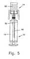
- the initial pressure of air within air chamber 40 and of air, or any other gas retained within interior space 60 of vial 14,may be slightly greater or less than atmospheric pressure. Although there may be an initial pressure difference between the air in air chamber 40 and the gas in the interior 66 of vial 14, upon penetration of membrane 42 and seal 58, the pressure within the air passageway quickly achieves equilibrium. During this stage, liquid conduit 48 is also in communication with the air which occupies the proximal portion of interior 66 of vial 14, and therefore liquid chamber 38 of transfer apparatus is also substantially at the same uniform pressure.
- the coupled transfer apparatus 10 and vial 16are then inverted, to enable the two-way fluid exchange of liquid drug from vial 14 to transfer apparatus 10 and simultaneously of air from transfer apparatus 10 to vial 14. Since vial 14 is inverted, drug 60 descends by gravity and occupies the proximal portion of vial 14. Since the pressure of air in chamber 40 is substantially equal to the pressure on the drug 60, drug 60 will be prevented from flowing through air conduit 46 and liquid conduit 48.
- the liquid passagewayis shown in Fig. 6 .
- the volume of liquid chamber 38is increased, causing the liquid drug to be drawn by suction from vial 14 through conduit 48 into liquid chamber 38 within transfer apparatus 10.
- the entire amount of the drug in the vial, or any desired portion thereof,may be transferred to liquid chamber 38.
- the volume of air chamber 40simultaneously is reduced, causing the air within chamber 40 to flow through conduit 46 to interior 66 of vial 14.
- the air flowing into vial 14occupies the volume of the liquid that has been transferred out. The air will continue to flow through conduit 46 into the vial until the piston stops moving and the pressure within air chamber 40 and interior of vial 14 again reaches equilibrium.
- Fig. 7schematically illustrates the transfer of the hazardous drug from transfer apparatus 10 to an IV bag 74.
- Adaptor 70is first attached to port 72 of an IV bag.
- the IV bagmay be provided with a rubber seal 76, which prevents leakage of liquid from the IV bag.
- Adaptor 70is configured with a central bore 78, in which port 72 is inserted, and a plurality of fins 80 lying in planes that pass through the bore axis. As adaptor 70 is mounted about inlet port 78, fins 80 contact outer wall 82 of inlet port 72 by a press fit.
- Adaptor 70is also provided with a head portion 84, which has substantially the same shape and dimensions as head portion 20 of vial 14 ( Fig. 2 ).
- the IV bagis inverted such that it is below adaptor 70. In this orientation, the gaseous medium retained within the IV bag, e.g. air, is above the liquid.
- Transfer apparatus 10is then coupled to adaptor 70 by pushing head portion 84 of adaptor 70 into collar 18 at the distal end of transfer apparatus 10.
- head portion 84 of adaptor 70is introduced within the cavity defined by collar 18, the distal end of membrane 42 is pressed against rubber seal 76 in the neck of port 72 of IV bag 74.
- conical membrane 42to collapse towards its base and conduits 46 and 48 penetrate both membrane 42 and seal 76 to establish fluid communication between the interior of IV bag 74 and air chamber 40 and liquid chamber 38 in transfer apparatus 10.
- the volume of air chamber 40is increased, causing the gaseous medium retained in the IV bag, e.g. air, to be transferred by suction to air chamber 40.
- the airceases to flow through conduit 46 when piston stops moving and the pressure within air chamber 40 and within the IV bag reaches equilibrium.
- the proximal ends of locking elements 22a and 22bare pressed inwards to release collar 18 from head portion 84 of adaptor 70. Transfer apparatus 10 is slowly pulled apart from adaptor 70.
- conduits 46 and 48are pulled back through seal 51, which continues to serve as a fluid barrier to prevent leakage from IV bag 74, and through membrane 42, which returns to its conical shape isolating the interior of liquid transfer apparatus 10 from the surroundings.
- Transfer apparatus 10may also be used to draw a liquid from the IV bag. To do this, after collar 18 is coupled to adaptor 70, the IV bag is inverted such that it is above transfer apparatus 10. Then piston rod cap 32 is proximally displaced, thereby simultaneously transferring the desired liquid from the IV bag to the liquid chamber 38 and air from the air chamber 40 to the interior of the IV bag.
- the adaptormay comprise a hollow double cannula spike element for piercing the seal in the port of the IV bag, with a secondary port similar to the port of the IV bag, to which the tubing of an infusion set can be connected, and with a port which has substantially the same shape and dimensions as head portion 20 of vial 14 ( Fig. 2 ), to which the transfer apparatus 10 is then coupled.
- Fig. 8is a vertical cross sectional view of another embodiment of the contamination-free drug transfer apparatus 10.
- proximal section 27 of apparatus 10is identical to that of the first embodiment described hereinabove.
- connector section 25is connected to the throat 26 of proximal section 27 by means of a collar 124 which proximally protrudes from proximal cap 113 and surrounds throat 26.
- Throat 26 and collar 124can be formed together as a single element at the time of manufacture, or permanently attached together, e.g. by means of glue or welding, or formed with a coupling means, such as threaded engagement or a luer connector.
- the connector sectioncomprises a compressible and reciprocable double membrane seal actuator which assumes a normal, relaxed configuration by which the needles are concealed when the double membrane seal actuator is disposed in a first, distal position and which is compressed to expose the needles when proximally displaced.
- Connector section 25is adapted to be releasably coupled to another fluid transfer component, which can be any fluids container with a standard connector such as a drug vial, intravenous bag, or an intravenous line to produce a "fluid transfer assembly", through which a fluid is transferred from one fluid transfer component to another.
- a fluid transfer componentwhich can be any fluids container with a standard connector such as a drug vial, intravenous bag, or an intravenous line to produce a "fluid transfer assembly", through which a fluid is transferred from one fluid transfer component to another.
- connector section 25comprises a cylindrical, hollow outer body 128, a distal shoulder portion 129 radially protruding from body 128 and terminating with opening 126 through which the proximal end of a fluid transfer component is inserted for coupling, a double membrane seal actuator 130 reciprocably displaceable within the interior of body 128, resilient arms 133 and 134 which are connected at a proximal end thereof to an intermediate portion of cylindrical actuator casing 137, and stationary air conduit 46 and liquid conduit 48 that are retained in needle holder 115, which protrudes into interior 119 of connector section 25 from a central portion of closed proximal cap 113 thereof. Needle holder 115 is part of the outer body 128 and proximal cap 113 to which the needles are bonded.
- Conduits 46 and 48distally extend from needle holder 115, piercing membrane 142 of actuator 130.
- the distal ends of conduits 46 and 48have sharp pointed ends 46a and 48a, respectively, and further provided with apertures 111 and 112, respectively, through which fluid is transferred during a fluid transfer operation. While the proximal end of air conduit 46 extends within the interior of fluid transfer unit 10, the proximal end of liquid conduit 48 terminates at or slightly proximally from cap 113 of connector section 25, so that the liquid conduit will be in fluid communication with the interior of throat 26 of fluid transfer unit 10.
- Fluid transfer unit 10comprises a hollow piston rod 30 extending from cap 52 to piston 34, which sealingly engages the inner wall of, and is displaceable with respect to, barrel 24.
- Piston 34defines two chambers of variable volume: a distal liquid chamber 38 between piston 34 and connector section 25 and a proximal air chamber 40 between piston 34 and stopper 28.
- Air conduit 46passes through piston 34 and extends inside of hollow piston rod 30. Air flowing through conduit 46 enters the interior of piston rod 30 and exits to air chamber 40 through an aperture 50 (shown in Fig. 10C ) formed at the distal end of piston rod 30.
- Conduit 48which is considerably shorter than air conduit 46, is adapted to allow a solution of a drug to flow into liquid chamber 38.
- Double membrane seal actuator 130comprises a proximal disc shaped membrane 142 having a rectangular cross-section and a distal double disc shaped membrane 143 having a T-shaped cross-section with a rectangular proximal portion 144 and a distal portion 147 disposed radially inwards with respect to proximal portion 144.
- Membranes 142 and 143are seated within casing 137, while distal portion 147 protrudes distally from casing 137.
- Arms 133 and 134 of equal lengthare elongated and are substantially longitudinally disposed, being attached at connection points 161' and 162', respectively, to casing 37. Arms 33 and 34 terminate with distal enlarged elements 161 and 162, respectively.
- the resilient arms 133 and 134are designed such that, if not prevented from doing so, the distance between enlarged elements 161 and 162 is larger then the diameter of connector section 25.
- Enlarged elements 161 and 162are configured to be received in, and engaged by, shoulder portion 129 when actuator 130 is disposed in a first, distal position.
- pointed ends 46a and 48aare retained between membranes 142 and 143, preventing a user from being exposed to, and injured by, the pointed ends and also sealing the ends of conduits 46 and 48 from the surroundings, thereby preventing contamination of the interior of fluid transfer unit 10 and leakage of a harmful drug contained within the interior of unit 10 to the surroundings.
- Fig. 10Ais a cross sectional view of the fluid transfer apparatus.
- Fig. 10B, Fig. 10C, and Fig. 10Dare enlarged views of sections B, C, and D of Fig. 10A illustrating the air and fluid passageways through the fluid transfer apparatus.
- liquid conduit 48passes through proximal cap 113 and the throat section 26 of the cylindrical wall 24 of transfer apparatus 10 and terminates inside distal liquid chamber 38.
- Fig. 109Cit is seen how the proximal end of the liquid chamber 38 is defined by the distal surface of piston 34.
- Air conduit 46passes through liquid chamber 38 and can be seen in Fig.
- FIG. 10Cpassing through piston 34, disc 52, and reinforcing ribs 54 and entering the interior of hollow piston rod 30.
- Conduit 46terminates near the top of cylindrical portion 24 of device 10. Air which enters at the distal end of conduit 46, can only exit at the distal end, where the air passes into the interior of hollow piston rod 30.
- Seen in Fig. 10Care one or more apertures 50 at the bottom of piston rod 30 that allow the air to enter proximal air chamber 40.
- the distal end of air chamber 40is defined by the proximal surface of piston 34 and its proximal end is defined by the distal surface of rubber stopper 28. It can be understood from Fig. 10A to Fig.
- rubber stopper 28 and piston 34 of transfer unit 10 and membranes 142 and 143 of connector section 25are conventional self-sealing types that allow piston rod 30, air conduit 46 and liquid conduit 48 to slide through them, while maintaining a fluid seal isolating the interior of the volume closed by the stopper, piston, or membrane respectively from the outside.
- Vial adaptor 160is an intermediate connection that is used to connect connector section 25 to a drug vial 14 or any other component having a suitably shaped and dimensioned port. Vial adaptor 160 can also be used with the first embodiment of the fluid transfer device.
- the top external surface of the membrane 58 that seals the top of commercially available drug vialsare typically not smooth. Therefore the vial connector is used to provide a smooth seal to seal contact with the distal portion 147 of membrane 143 at the distal end of connector section 25 that is necessary to provide contamination-free transfer of the drug.
- the material of which the membrane 58 is typically madehas poor performance, i.e. when it is pierced by needles, it disintegrates and leaks after being punctured several times.
- Vial adaptor 160comprises a collar portion 165 provided with an annular proximal cap 168 and a longitudinal extension 169 projecting proximally from cap 168.
- Longitudinal extension 169is a second reason for using the vial adaptor. It is much longer than the neck on a conventional drug vial and therefore fits into opening 126 at the distal end of connector section 25 to allow transfer of the drug as described hereinbelow.
- Collar portion 165consists of a plurality of circumferential segments 167 formed with a convex lip 163 on the inner face thereof, for facilitating securement to a head portion 20 of a vial 14.
- Longitudinal extension 169terminates proximally with a membrane enclosure 171 having a diameter larger than that of extension 169. Membrane enclosure 171 has a proximal central opening 172, by which membrane 176 retained therein is made accessible.
- Two longitudinal channels 178 and 179 distally extending from membrane 176are internally formed within longitudinal extension 169, and are adapted to receive conduits 46 and 48, respectively.
- the ridge/pin and slotare located on their respective parts so that the conduits 46 and 48 will always enter their designated channel within the longitudinal extension 169.
- Longitudinal extension 169terminates distally with a spike element 177 which protrudes distally from cap 68.
- Spike element 177is formed with openings 188 and 189 in communication with channels 178 and 179, respectively.
- Vial 14has a central, proximal seal 58, which is adapted to prevent the outward leakage of a drug contained therein.
- the spike elementpierces seal 58 of vial 14, to allow channels 178 and 179 to communicate with the interior of drug vial 14.
- circumferential segments 167 of the collar portion165are securely engaged with head portion 20 of vial 14.
- membrane 58 of vial 14is pierced it seals around spike 177 preventing the outward leakage of the drug from the vial.
- the tops of channels 178 and 179are sealed by membrane 176, preventing air from entering or drug from exiting the interior of vial 14.
- Fig. 13 to Fig. 16illustrate, respectively, the secured double membrane engagement procedure made possible by actuator 30.
- distal membrane 143 of actuator 130is brought into secured engagement with membrane 176 of vial adaptor 160, but it will be appreciated that the secured engagement operation can be carried in conjunction with any other suitable fluid transfer component.
- the procedureis carried out as follows: Step 1 - Membrane enclosure 171 of vial adaptor 160 is positioned close to distal opening 126 of connector section 25. Step 2 - A double membrane engagement procedure is initiated by distally displacing body 128 of connector section 25 until membrane enclosure 171 and extension 169 of vial adaptor 160 enters the distal end of the interior 119 of connector section 25.
- Step 3Membrane 143 of actuator 30 is caused to contact and be pressed against the stationary membrane 176 of vial adaptor 160 by additional distal displacement of body 128. After the membranes are pressed tightly together the enlarged elements 161 and 162 are released from the shoulder portion 129. At this stage, membranes 143 and 176 are held pressed together by enlarged elements 161 and 162 and disengagement of actuator 130 from vial connector 160 by a relative proximal displacement is prevented.
- Step 4Additional distal displacement of body 128 causes actuator 130 to move proximally relative to body 128 until the tips of conduits 46 and 48 pierce membranes 143 and 176 and are in fluid communication to the interior of vial 14.
- Fig. 13The first step of the procedure of connecting the connector section 25, to which fluid transfer apparatus 10 is attached, to the vial adaptor 160, to which vial 14 is attached, is illustrated in Fig. 13 .
- the double membrane seal actuator 130in its first, distal position at the distal end of connector section 25 and brought close to the membrane enclosure 171 of vial adaptor 160. All of the elements of fluid transfer apparatus 10, connector section 25, vial adaptor 160, and vial 14 shown in Fig. 13 have been described hereinabove with reference to Fig. 9 and Fig. 12 .
- Fig. 14illustrates the second step of the secured double membrane engagement procedure.
- the diameter of membrane enclosure 171is less than the spacing between enlarged elements 161 and 162 when they are held in shoulder portion 129 by the natural tendency of the flexible arms 133 and 134 to push the enlarged portions laterally outward. This allows for effortless entry of membrane enclosure 171 into interior of 119.
- enlarged elements 161 and 162are held in shoulder portion 129 and prevented from moving inwards by the sides of membrane enclosure 171.
- Upper surfaces 131 and 132 of shoulder 129are in contact with the distal portion of arms 133 and 134, respectively, and prevent them from being proximally displaced relative to body 128 of connector section 25.
- Fig. 15illustrates the third step of the secured double membrane engagement procedure.
- the distal membrane portion 147 of T-shaped membrane 143enters central opening 172 ( Fig. 11 ) of membrane enclosure 171.
- Distal membrane portion 147contacts membrane 176 of the vial adaptor and the two membranes are compressed one against the other, as schematically represented by the dark area 194.
- the actuator 130is prevented from being able to ascend into the body 128 of connector 25 by the enlarged elements 161 and 162, which are prevented from coming out of the distal shoulder portion 129 the wall of the body 28 of connector 25 by the outer surface of membrane enclosure 171 of vial adaptor 60.
- Fig. 16illustrates the fourth step of the secured double membrane engagement procedure.
- Enlarged elements 161 and 162have been released from shoulder portion 129 of connector section 25 and are prevented from moving laterally outwards by the interior wall of body 128 of the connector section. This keeps membrane enclosure 171 of the vial adaptor fixedly attached to the double seal actuator 130. Additional distal displacement of connector section 25 relative to vial adaptor 160 will cause double membrane seal actuator 130 and the attached vial connector 160 to move proximally within the interior 119 of connector section 25.
- conduits 46 and 48are rigidly fixed in needle holder 115 at the proximal end of connector section 25, as double membrane seal actuator 130 moves proximally, the pointed distal ends 46a and 48a of conduits 46 and 48 will be progressively forced through diaphragms 143 and 176 until they enter longitudinal channels 178 and 179 in the vial connector 160. Since vial connector 160 had previously been connected to vial 14, spike 177 penetrates membrane 165 at the top of the vial 14 and therefore there now has been established two independent fluid passageways between the interior of the vial 14 and the distal liquid chamber 38 and proximal air chamber 40 in the fluid transfer apparatus 10 respectively.
- proximal interior surface of enlarged elements 161 and 162engage the planar underside of membrane enclosure 171 and are prevented from moving outwards; therefore membrane enclosure 171 is prevented from being inadvertently disengaged from the connector section under normal handling.
- the vial adaptorcan be disengaged from the double membrane seal actuator, as will be described herein below.
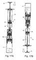
- Figs. 17A and 17Bshow schematically the two most common applications in drug preparation.
- Fig. 17Ashows injection of a liquid into a vial and
- Fig. 17Bshows withdrawal of liquid from a vial.
- Fig. 17Bare shown the air bubbles created by the air entering the vial from air chamber 40 through the air conduit.
- the first stage of a process of administering a drug to a patienttakes place in the pharmacy of a hospital.
- the pharmacistuses the secured double membrane engagement procedure described herein above to connect connector section 25 of apparatus 10 to vial adaptor 160, which has been previously connected to a vial 14 containing diluent (solvent), e.g. distilled water.
- solvente.g. distilled water
- Transfer apparatus 10is now held as shown in Fig. 17B and the pharmacist fills the fluid chamber 38 of fluid transfer apparatus 10 with a measured quantity of diluent.
- the first vialis now disconnected from liquid transfer apparatus 10 and a second vial which contains drug in powder or concentrated liquid form is attached.
- liquid chamber 38 of apparatus 10is filled with diluent and the interior of vial 14 is partially filled with powder or liquid drug.
- the pharmacistnow pushes down on piston rod cap 32 forcing piston 34 distally and pushing the liquid out of liquid chamber 38 through conduit 48 and channel 179 (see Fig.
- the pharmacistdisengages the vial adaptor from the connector section of apparatus 10 and either injects the drug into an infusion bag through a dedicated adaptor or sends the transfer unit to the ward where the drug will be administered to the patient through a dedicated adaptor.
- To disconnect vial adaptor 160 from connector section 25 of fluid transfer apparatus 10the four stages of the secured double membrane engagement procedure are performed continuously in reverse order. That is, vial adaptor 160 and connector section 25 are gripped firmly and an axial force is applied to pull them in opposite directions. This causes actuator 130 to be distally displaced within the interior 119 of connector section 25.
- Fig. 18is a cross sectional view showing a spike adapter 200 used in conjunction with fluid transfer apparatus 10 to transfer a drug to and from an intravenous (IV) bag.
- Spike adaptor 200comprises body 202 terminating in spike element 177 at the proximal end and a standard "twist off' end 204 to a spike port for connecting an infusion set at the distal end.
- Substantially at right angles to body 202is a longitudinal extension 169.
- membrane enclosure 171 and membrane 176are membrane enclosure 171 and membrane 176.
- Fig. 19is a cross sectional view showing the fluid transfer apparatus 10 attached to infusion bag 206 using the spike adaptor shown in Fig. 18 .
- spike element 177is inserted into spike port 208 of infusion bag 206.
- the fluid transfer apparatus10 filled with the drug connector sectionis connected to the spike adapter 200 using the secured double membrane engagement procedure described herein above.
- the bagis hung such that the liquid inside it is down and the part of the bag above the liquid, i.e. the volume of the bag occupied by air (or inert gas), is up and the tip of spike element 177 is located in this air and is surrounded by it.
- the piston in transfer apparatus 10is then pushed in the distal direction pushing the drug out of the liquid chamber 38 in transfer apparatus 10, through liquid conduit 48 in connector section 25 and liquid channel 179 in spike adaptor 200 into infusion bag 206. Simultaneously, air from inside the infusion bag is drawn through liquid channel 178 in spike adaptor 200 and air conduit 46 into air chamber 40 in transfer apparatus 10.
- the connector section 25is disconnected from spike adapter 200, as described herein above, the twist-off end 204 is twisted off and infusion bag 206 is connected to an infusion tubing set and the drug is administered to the patient in the usual manner.
- Spike adaptor 200is also used to draw liquid from an IV bag in the same manner as described above for drawing a drug from a vial.
- the IV bagis hung such that the spike element 177 is positioned at the bottom of the liquid and is surrounded by that liquid.
- Such liquidis typically used as a diluent for dissolving (reconstitution) of powder drugs in vials.
- injecting liquids through adaptor 200 into an infusion bagrequires the presence of at least the same volume of air in the bag as the injected liquid in order to enable air/liquid exchange. The presence of such a quantity of air is not a default for all commercial bags; therefore, the required air can be prefilled by the pharmacist.
- bag adaptor 200is suited for liquid withdrawal and injection of liquid into an IV bag that contains a sufficient volume of gas; , for the case when the IV bag does not contain a sufficient volume of gas, the drug injection adaptor 210, described herein below, is the better choice.
- Fig. 20is a cross sectional view showing a spike adapter 210 comprising a one-way air inlet valve 212.
- Fig. 21is a cross sectional view showing a fluid transfer apparatus attached to an infusion bag using the spike adaptor shown in Fig. 20 .
- Most of the components of spike adaptor 210are the same as those of spike adaptor 200 shown in Fig. 18 and Fig. 19 .
- the other major difference between the two spike adaptorsis that in spike adaptor 210 air channel 178 is not continuous from the tip of spike element 177 to diaphragm 176. The channel is blocked so that air can not pass between the interior of the IV bag and air chamber 40 in transfer apparatus 10.
- a channel 178'is provided in longitudinal extension 169.
- the tip of air conduit 46penetrates through diaphragm 176 it enters the proximal end of channel 178'.
- the operation of one-way valve 212is easily understood from Fig. 20 .
- dome shaped rubber cap 214Inside the valve is dome shaped rubber cap 214. The center of the cap is attached to the frame of the adaptor and the circumference sits on a flat seat 220.
- Negative pressure on the side of the fluid transfer apparatuscauses the cap 214 to "lift off" seat 220 allowing ambient air to be sucked in through the one way valve 212 and air to flow through hole 218 into channel 178'.
- the cap 214In the absence of negative pressure or if there is a positive pressure on the side of the fluid transfer apparatus, then the cap 214 is pushed down onto seat 220 blocking the flow of air through valve 212.
- Adaptor 210enables injection of liquids into the bag regardless of the bag/liquid/air position and it requires no presence of air in the IV bag. However, liquid can not be withdrawn from the IV bag using adaptor 210 since in order to draw liquid from the IV bag, the volume of the air chamber in apparatus 10 is reduced, thereby creating a positive pressure and closing valve 212.
- adaptor 210air can be sucked into transfer apparatus 10 but no air or drug or vapors can ever escape transfer apparatus 10, since for this to happen the pressure inside the air chamber of the transfer apparatus would have to be higher than that on the other side of valve 212, and therefore the one-way valve will be in its normally closed configuration.
- a standard 0.22 micron filter 216is provided covering opening 218 into channel 178'.
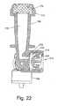
- Fig. 22is a cross sectional view showing an adapter 222 for transferring a drug directly from a fluid transfer assembly 10 into any fluids receiver which is equipped with a standard luer connector as a port, such as: infusion tubing leading directly to the bloodstream of a patient, tubing systems, receptacles, stopcocks, etc.
- Adapter 222comprises a one-way air inlet valve 212 in order to provide the required volume of air in air chamber 40 of transfer apparatus 10 necessary to replace the volume of liquid that is expelled from the liquid chamber during injection of the liquid.
- Fig. 23is a cross sectional view showing a fluid transfer apparatus 10 attached to adapter 222 via connector section 25.
- Adapter 222is essentially the same as spike adapter 210 shown in Fig. 20 , with the exception that spike element 177, body 202, and twist off end 204 are replaced by standard luer connector 222, which is adapted to be connected directly to any luer connector port.
Landscapes
- Health & Medical Sciences (AREA)
- Life Sciences & Earth Sciences (AREA)
- Animal Behavior & Ethology (AREA)
- General Health & Medical Sciences (AREA)
- Public Health (AREA)
- Veterinary Medicine (AREA)
- Pharmacology & Pharmacy (AREA)
- Engineering & Computer Science (AREA)
- Hematology (AREA)
- Heart & Thoracic Surgery (AREA)
- Anesthesiology (AREA)
- Biomedical Technology (AREA)
- Physics & Mathematics (AREA)
- Fluid Mechanics (AREA)
- Mechanical Engineering (AREA)
- Vascular Medicine (AREA)
- Pulmonology (AREA)
- Infusion, Injection, And Reservoir Apparatuses (AREA)
- Medical Preparation Storing Or Oral Administration Devices (AREA)
Description
- The present invention relates to the field of fluid transfer devices. More particularly, the invention relates to a connector section for use in contamination-free transfer of a hazardous drug from one container to another.
- Medical and pharmacological personnel that are involved in the preparation and administration of hazardous drugs suffer the risk of being exposed to drugs and to their vapors, which may escape to the surroundings. As referred to herein, a "hazardous drug" is any injectable material the contact with which, or with the vapors of which, may constitute a health hazard. Illustrative and non-limitative examples of such drugs include,inter alia, cytotoxins, antiviral drugs, chemotherapy drugs, antibiotics, and radiopharmaceuticals, such as herceptin, cisplatinum, fluorouracil, leucovorin, taxol, metatroxat, gemzar, cyclophosphamide, cytoxan, and neosar, or a combination thereof, in a liquid, solid, or gaseous state.
- Hazardous drugs in liquid or powder form are contained within vials, and are typically prepared in a separate room by pharmacists provided with protective clothing, a mouth mask, and a laminar flow safety cabinet. A syringe provided with a cannula, i.e. a hollow needle, is used for transferring the drug from a vial. After being prepared, the hazardous drug is added to a solution contained in a bag which is intended for parenteral administration, such as a saline solution intended for intravenous administration.
- Since hazardous drugs are toxic, direct bodily contact thereto, or exposure to even micro-quantities of the drug vapors, considerably increases the risk of developing health fatalities such as skin cancer, leukemia, liver damage, malformation, miscarriage and premature birth. Such exposure can take place when a drug containing receptacle, such as a vial, bottle, syringe, and intravenous bag, is subjected to overpressure, resulting in the leakage of fluid or air contaminated by the hazardous drug to the surroundings. Exposure to a hazardous drug also results from a drug solution remaining on a needle tip, on a vial or intravenous bag seal, or by the accidental puncturing of the skin by the needle tip.
- Some prior art liquid transfer devices are intended to provide contamination-free transfer of hazardous drugs.
- For example,
WO 2005/041846 discloses a drug mixing system comprising a receptacle port adaptor adapted to be inserted into a port of a fluid receptacle, a vial adaptor adapted for connection to a vial containing a drug, and a syringe adaptor attached to a syringe. The syringe adaptor is adapted to be brought into fluid communication and mechanically locked to at least one of the receptacle port adaptor and vial adaptor in an axial motion. When a user retracts the syringe plunger, fluid flows directly into the syringe, ensuring that the fluid remains sterile and that the user is not exposed to the fluid. The user is also not exposed to the fluid as the syringe adaptor is connected to, or disconnected from, the receptacle port adaptor or vial adaptor since the septum of the syringe adaptor is pushed into touching engagement with the corresponding septum of the receptacle port adaptor or vial adaptor, thereby preventing exposure of the syringe needle to the environment. The syringe adaptor comprises a septa housing, a compression spring seated within the septa housing, and a needle sealingly mounted within the housing and axially extending within the spring. The septa housing is movable relative to the needle in order to expose the needle tip. This drug transfer system is an open system, which comprises a membrane vent and filter, for venting at least one of the receptacle port adaptor, the vial adaptor, and syringe adaptor to the atmosphere. After filtration, air contaminated by micro-quantities of the drug vapors is nevertheless exposed to the environment. Another disadvantage of this drug mixing system is that two septa are placed in mutual touching engagement by means of the biasing force of the spring. The biasing force applied by the spring is lower when the two septa are first placed in contact and increases as the septa are pierced by the needle. Consequently, any inadvertent movement of the system when the two septa are first placed in contact is liable to cause the two septa to be separated from each other and to cause a risk of exposure of the dangerous drug to the surroundings. An additional disadvantage of this system is that a securing device is engaged when the spring is fully compressed, and a release mechanism for manually disengaging the securing device is needed. In addition the system of the invention comprises a venting filter, which vents air that might be contaminated by vapors of the drug to the environment. - It would be desirable to provide a connector that causes two separated septa to be brought in locking engagement prior to a liquid transfer operation and to be separated following said operation without having to set a securing device or a release mechanism.
WO 02/11794 WO 03/086529 US 6,715,520 disclose a closed-system fluid transfer assembly for contamination-free drug transfer, i.e. without passage of a gas from the interior of a receptacle containing a hazardous drug to the surrounding environment. A connector to a drug bottle has a hollow needle for penetrating the closure of the drug bottle at a predetermined angle when establishing a fluid transfer line in a fluid transfer assembly. A connector locking member and membrane are included in a double membrane bayonet coupling with the fluid transfer device. A gas channel within the hollow needle transports gas from the bottle to a flexible container constituting a pressure compensator, and vice versa. The fluid transfer device comprises a syringe and a coupling unit. The coupling unit has a first part arranged for connection to the syringe and a second part arranged for connection to the drug bottle connector. The second part, which can be telescoped into the first part, is prevented from rising by a detent which slips into an opening of the first part and its locked position is released by an outwardly displaceable handle connected to the detent. After the drug is received in the fluid transfer device, an injection needle of the coupling unit penetrates a membrane of the injection port of a mixing device connected to the inlet port of an infusion bag. A spike member of an infusion line pierces the membrane of an outlet port of the mixing device without leakage.- This fluid transfer assembly requires a large number of steps in order to establish a connection by which a hazardous drug is transferred, including the steps of connecting the connector to the drug bottle, rotating and locking the coupling unit onto the syringe, lowering the coupling unit onto the connector, rotating and locking the coupling unit onto the connector, outwardly displacing the handle of the coupling unit, pressing on the fluid transfer assembly in order to retract the second part into the first part of the coupling unit, and manipulating the syringe. An additional disadvantage of this fluid transfer assembly is that a predetermined volume of air needs to be injected to the flexible container prior to a liquid transfer operation, in order to displace a corresponding volume of the drug from the vial; however, the volume of drug to be transferred, which is dependent on the volume of the injected air, cannot be adjusted by the health practitioner during a liquid transfer operation. An additional disadvantage of this fluid transfer assembly is that the air that needs to be injected prior to operation is taken from the environment and therefore involves the risk of introducing contaminants from the environment to the drug and violating its sterility. Also, there is a risk that the flexible container, which is made of sheet material and is located externally to the syringe, may be punctured, thereby exposing the contaminated air to the environment and rendering the fluid transfer assembly inoperable. Furthermore, the sharp hollow needle of the drug bottle connector endangers, while remaining exposed to, a pharmacist until it penetrates the drug bottle closure. Consequently, this fluid transfer assembly cannot be considered within the group of safety products generally referred to as "needleless", i.e. a transfer device having a sharp needle which is not exposed to a user. An additional disadvantage of this fluid transfer assembly is that an operator is liable to forget to perform one or more steps during the connection sequence, leading to the dangerous result that a double membrane seal will not be established. The dangerous drug will therefore be exposed to the surrounding air or is liable to be discharged from the syringe, thereby endangering the operator and bystanders.
EP 0 311 787 describes an apparatus for connecting a syringe to a bottle, The apparatus is comprised of three cylindrical components that are fitted coaxially into each other and can move relative to each other to afect the connection. The main innovation claimed by the inventor is a mechanism that prevents relative motion between the parts of tha apparatus if no bottle is inserted into it, thereby preventing an internal needle from emerging from a closed chamber in which it is housed.- It is an object of the present invention to provide a connector section that can be used in a closed-system fluid transfer assembly that is adapted to prevent the leakage of a hazardous drug or air contaminated by the hazardous drug or drug vapors and prevents contaminants from the environment from coming into contact with the drug during the transfer process.
- It is another object of the present invention to provide a connector section that can be used in a closed-system fluid transfer assembly in which the same volume of the hazardous drug and air are exchanged internally by means of a pressure equalization arrangement within the fluid transfer assembly, thereby preventing any exposure of a user to the hazardous drug.
- It is yet an additional object of the present invention to provide a connector section that can be used in a fluid transfer assembly which does not expose any sharp objects such as the tip of a needle to a user during any stage of a fluid transfer operation.
- Other objects and advantages of the invention will become apparent as the description proceeds.
- As referred to herein, the term "exchange" means the transfer of first and second fluids in opposite directions within different fluid passageways between two containers such that when the first fluid is transferred from the first container to the second container an equal volume of the second fluid is transferred from the second container, to the first container.
- As referred to herein, the term "contamination-free transfer of liquid" means that during the transfer process there is no leakage of the liquid or air contaminated by the liquid or vapors of the liquid to the surroundings and also that no contaminants from the surroundings come into contact with the liquid.
- A "fluid passageway" means a flow path between said syringe means and said receptacle, which comprises at least one segment from each of said syringe means and said receptacle that are in mutual fluid communication when said syringe means is coupled to said receptacle.
- A "segment" means a volume enclosed by one or more walls in which a fluid can flow.
- As referred to herein, "proximal" means in a direction closer to a user who manipulates the apparatus.
- As referred to herein, "distal" means in a direction farther from a user who manipulates the apparatus.
- As referred to herein, a "secured double engagement procedure" means a procedure during which two pierceable membranes of two fluid transfer components, respectively, are brought to mutual engagement and during which separation of said two membranes is prevented during the application of a distally directed force.
- As referred to herein, fluid transfer component means any component, e.g. syringe, vial, infusion bag, adaptors of various types, that are used to contain, transport, and transfer a liquid drug from one fluid transfer component to another or to a patient.
- The invention is a connector section for use in a fluid transfer operation according to claim 1
- When the double membrane seal actuator is at the distal end of the cylindrical body of the connector section the enlarged elements of the resilient arms are pressed into the distal shoulder portion of the cylindrical body of the connector section, thereby allowing the membrane enclosure at the proximal end of a fluid transfer component to be inserted into the opening at the distal end of the connector section and advanced until the membrane in the membrane enclosure contacts the part of the distal membrane that protrudes distally from the casing of the double membrane seal actuator.
- The diameter of the distal shoulder portion and the size of the enlarged elements at the distal end of the arms are such that, when an axial force is applied to push the double membrane seal actuator and fluid transfer component towards each other, the sides of the membrane enclosure prevent the enlarged elements at the distal end of the arms from moving radially inwards. This causes the distal actuator membrane to be compressed against the membrane in the membrane enclosure until the sides of the membrane enclosure are displaced proximally in relation to the enlarged elements. At this point the enlarged elements have room to move radially inwards, are released from the distal shoulder portion of the double membrane seal actuator, and abut the distal underside of the membrane enclosure. In this way the distal actuator membrane is locked against the membrane in the membrane enclosure in secured and compressed engagement, preventing disengagement of the actuator from the fluid transfer component, and allowing the actuator and the coupled fluid transfer component to be reciprocably displaced within the hollow interior of the outer body of the connector section.
- The distance that the actuator and attached fluid transfer component can be displaced proximally within the hollow interior of the outer body of the connector section and the length of the two conduits are such that, when the actuator and the attached fluid transfer component are displaced proximally, the sharp pointed ends of the two conduits penetrate the distal membrane of the actuator and the membrane in the membrane enclosure, thereby establishing a liquid path and a gas path respectively between the connector section and the fluid transfer component. When the actuator and attached fluid transfer component are displaced distally within the hollow interior of the outer body of the connector section, the sharp pointed ends of the two conduits are pulled back through the distal membrane of the actuator and the membrane in the membrane enclosure, thereby breaking the liquid path and the gas path respectively between the connector section and the fluid transfer component.
- When the double membrane seal actuator is at the distal end of the cylindrical body of the conductor section, the sharp pointed ends of the two conduits are located between the proximal membrane and the distal membrane of the double membrane seal actuator.
- The connector section of the invention can be coupled to a fluid transfer component in order to affect a secured double membrane engagement according to the method of claim 6.
- The structure of the connector section enables the connector section and the fluid transfer components to be connected by a single axial motion and disconnected by a single axial motion without having to set a locking securing device or a release mechanism.
- In the drawings:
Fig. 1 is a perspective view from the side of an apparatus for transferring hazardous drugs, according to one embodiment of the invention;Fig. 2 is a schematic vertical cross sectional view of the apparatus ofFig. 1 ;Fig. 3 is a perspective view of ribs for reinforcing the attachment of a hollow piston rod to a piston;Fig. 4 is a schematic illustration, in vertical cross sectional view, of the releasable coupling of the apparatus ofFig. 1 with a drug vial;Fig. 5 is a schematic illustration, in vertical cross sectional view, of an inverted vial coupled with a liquid transfer device, prior to contamination-free fluid exchange;Fig. 6 is a schematic illustration of the transfer of a hazardous drug to a liquid chamber of the apparatus ofFig. 4 ;Fig. 7 schematically illustrates the transfer of the hazardous drug from the transfer apparatus ofFig. 2 to an IV bag;Fig. 8 is a vertical cross sectional of another embodiment of the contamination-free drug transfer apparatus of the invention;Fig. 9 is a cross sectional view of the connector section of the embodiment of the contamination-free drug transfer apparatus shown inFig. 8 ;Fig. 10A is a cross sectional view of the fluid transfer apparatus and connector section shown inFig. 7 ;Fig. 10B, Fig. 10C, and Fig. 10D are enlarged views of sections ofFig. 10A illustrating the air and fluid passageways through the fluid transfer apparatus and connector section;Fig. 11 is a perspective view of a vial adaptor to which a connector section can be connected;Fig. 12 is a vertical cross sectional view of a vial adaptor;Fig.13 to Fig. 16 are vertical cross sectional views of illustrating the secured double membrane engagement operation using the apparatus ofFig. 8 ;Figs. 17A and 17B show schematically the two most common applications in drug preparation;Fig. 18 is a cross sectional view showing a spike adapter used in conjunction with fluid transfer apparatus and connector section to transfer a drug to and from an intravenous (IV) bag;Fig. 19 is a cross sectional view showing a fluid transfer apparatus attached to infusion bag using the spike adaptor shown inFig. 18 ;Fig. 20 is a cross sectional view showing a spike adapter comprising a one-way air inlet valve;Fig. 21 is a cross sectional view showing a fluid transfer apparatus attached to infusion bag using the spike adaptor shown inFig. 20 ;Fig. 22 is a cross sectional view showing an adapter for transferring a drug directly from a fluid transfer assembly of the invention directly into the bloodstream of a patient; andFig. 23 is a cross sectional view showing a fluid transfer apparatus attached to the adapter ofFig. 22 .- This application describes a method that allows contamination-free transfer of a liquid from one container to another and devices including embodiments of a transfer apparatus and adaptors that are used to carry out the method. The main advantages of the method, in addition to its simplicity, is that at no stage of the transfer procedure is there leakage of the liquid or air contaminated by the liquid or vapors of the liquid to the surroundings and also that no contaminants from the surroundings come into contact with the liquid.
- Although the method is described herein as transferring a liquid from one container to a second one, it is to be understood that the transfer can take place between several containers. For example, liquid can be withdraw from a first container and then part of it injected into five different containers, following which part of the liquid can be withdraw from one of the container and then injected into the original container and so on, in practically any order and combination and quantity.
- The method is particularly directed towards providing an apparatus that is adapted to effect contamination-free transfer of a hazardous drug to and from any container equipped with a standard connector port.
- The method for the contamination-free transfer of liquid from a first container containing a volume of the liquid and at least an equal volume of gas to a second container containing at least a volume of gas equal to the amount of liquid that is to be transferred into it comprises the following steps:
- a) providing a fluid transfer apparatus comprising: a closed container having a moveable internal partition that divides the interior of the container into two separate fluid tight chambers having variable volume, wherein one of the chambers is a gas chamber and the other of the chambers is a liquid chamber; a first segment of a gas channel and a first segment of a liquid channel, wherein the proximal ends of the first segments are in fluid communication with the interiors of the gas chamber and the liquid chamber respectively and the distal ends of the first segments are enclosed by sealing means;
- b) providing a second segment of a gas channel and a second segment of a liquid chamber, wherein the distal ends of the second segments are in fluid communication with the interior of the first container and the proximal ends of the second segments are enclosed by sealing means;
- c) pushing the distal end of the first segments in the direction of the proximal end of the second segments until the distal ends of the first segments penetrate the sealing means at the distal end of the first segments, penetrate the sealing means at the proximal end of the second segments, and enter the proximal ends of the second segments, thereby providing a continuous gas channel between the interior of the first container and the interior of the gas chamber and a separate continuous liquid channel between the interior of the first container and the interior of the liquid chamber;
- d) allowing an equilibrium to be established between the pressure of the gas in the first container and the pressure of the gas in the gas chamber and between the pressure exerted on the liquid in the first container and the pressure exerted on the liquid in the liquid chamber;
- e) moving the internal partition in a first direction in order to increase the volume of the liquid chamber and instantaneously decrease the pressure inside the liquid chamber and simultaneously decrease the volume of the gas chamber and instantaneously increase the pressure of the gas inside the gas chamber, wherein the differences of pressure caused by moving the internal partition cause liquid to flow from the first container through the continuous liquid channel into the liquid chamber and an equal volume of gas to flow simultaneously from the gas chamber through the continuous air channel into the first container, wherein the flow of liquid in one direction and simultaneous flow of gas in the other direction continues until the internal partition stops moving and the equilibrium is reestablished;
- f) disconnecting the first container from the fluid transfer device by pulling the distal ends of the first segments back out of the proximal ends of the second segments, through the sealing means at the proximal end of the second segments, thereby enclosing the ends of the second segments, and through the sealing means at the distal end of the first segments, thereby enclosing the ends of the first segments;
- g) providing a third segment of a gas channel and a third segment of a liquid channel, wherein the distal ends of the third segments are in fluid communication with the interior of the second container and the proximal ends of the third segments are enclosed by sealing means;
- h) pushing the distal end of the first segments in the direction of the proximal end of the third segments until the distal ends of the first segments penetrate the sealing means at the distal end of the first segments, penetrate the sealing means at the proximal end of the third segments, and enter the proximal ends of the third segments, thereby providing a continuous gas channel between the interior of the second container and the interior of the gas chamber and a separate continuous liquid channel between the interior of the second container and the interior of the liquid chamber;
- i) allowing an equilibrium to be established between the pressure of the gas in the second container and the pressure of the gas in the gas chamber and between the pressure exerted on the liquid in the second container and the pressure exerted on the liquid in the liquid chamber;
- j) moving the internal partition in a second direction in order to decrease the volume of the liquid chamber and instantaneously increase the pressure inside the liquid chamber and simultaneously increase the volume of the gas chamber and instantaneously decrease the pressure of the gas inside the gas chamber, wherein the differences of pressure caused by moving the internal partition cause liquid to flow from the liquid chamber through the continuous liquid channel into the second container and an equal volume of gas to flow simultaneously from the second container through the continuous air channel into the gas chamber, wherein the flow of liquid in one direction and simultaneous flow of gas in the other direction continues until the internal partition stops moving and the equilibrium is reestablished; and
- k) disconnecting the second container from the fluid transfer device by pulling the distal ends of the first segments back out of the proximal ends of the third segments, through the sealing means at the proximal end of the third segments, thereby enclosing the ends of the third segments, and through the sealing means at the distal end of the first segments, thereby enclosing the ends of the first segments.
- Illustrative embodiments of the devices used to carry out the method are described herein below.
Fig. 1 illustrates a perspective view of anapparatus 10 for transferring hazardous drugs without contaminating the surroundings, according to one embodiment of the invention. Theproximal section 27 ofapparatus 10 is essentially a conventional syringe, which is adapted to draw a desired volume of a hazardous drug from a fluid transfer component, e.g. avial 14 or an intravenous (IV) bag in which it is contained and to subsequently transfer the drug to another fluid transfer component.- Connector section 25' of
transfer apparatus 10 is shown to comprise integraldistal collar 18, which is suitably sized to surroundhead portion 20 ofvial 14, lockingelements head portion 20 ofvial 14 withincollar 18.Proximal section 27 ofapparatus 10 comprisescylinder 24,tubular throat 26 having a considerably smaller diameter thancylinder 24 and extending fromcylinder 24 tocollar 18,annular rubber stopper 28 fitted on the proximal end ofcylinder 24,hollow piston rod 30 which sealingly passes throughstopper 28, and proximalpiston rod cap 32 by which a user can push and pullpiston rod 30 up and down throughstopper 28.Collar 18 andcylinder 24 are made of a rigid material, e.g. plastic. Fig. 2 illustrates a schematic cross sectional view oftransfer apparatus 10. As shown,piston rod 30 extends fromcap 32 topiston 34, which sealingly engages the inner wall of, and is displaceable with respect to,cylinder 24. Separatingelement 36 is internal to, and integrally formed with,throat 26.Piston 34 defines two chambers of variable volume: a distalliquid chamber 38 between the distal face ofpiston 34 and separatingelement 36 and aproximal air chamber 40 between the proximal face ofpiston 34 andstopper 28. Adeformable membrane 42 having the shape of a truncated cone is firmly attached at its base to separatingelement 36 and distally extends to thedistal end 44 ofcollar 18.Membrane 42 completely surrounds twoconduits membrane 42 serves to effectively isolate the interior oftransfer apparatus 10 from the surroundings.Conduits element 36. Distal ends 46a and 48a ofconduits distal end 44 ofcollar 18, have sharp pointed ends.Elongated conduit 46 is an air conduit and extends through thehollow piston rod 30.Piston rod 30 is formed with adistal aperture 50, so that air, which flows throughconduit 46, is able to exit from the interior ofpiston rod 30 viaaperture 50 toair chamber 40.Conduit 48 is a liquid conduit through which a solution of a hazardous drug can flow fromvial 14 to transferapparatus 10 or vice versa.Conduit 48, which is considerably shorter thanair conduit 46, terminates withinliquid chamber 38.- As shown in
Fig. 3 ,hollow piston rod 30 may be attached topiston 34 by means of anannular disc 52, e.g. made of plastic, which is engaged withpiston 34. A plurality of reinforcingribs 54 are attached to the proximal face ofdisc 52, and acentral sleeve 56 is connected to eachrib 54, so thatpiston rod 30 may pass throughsleeve 56 whilepiston 34 is in sealing engagement withcylinder 24. The air conduit, which is not shown, passes throughpiston 34 and extends within the interior ofpiston rod 30. Fig. 4 illustrates the coupling oftransfer apparatus 10 to thehead portion 20 ofvial 14.Head portion 20 is provided with a central seal 58 (seeFig. 1 ), to prevent the outward leakage ofhazardous drug 60 contained withinvial 14.- Before
transfer apparatus 10 andvial 14 are coupled, they are moved closed together. Lockingelements collar 18 are flexed, to allowhead portion 20 ofvial 14 to entercollar 18. Ashead portion 20 ofvial 14 is introduced within the cavity defined bycollar 18, the distal end ofmembrane 42 is pressed againstseal 58 in thehead portion 20 ofvial 14. Continued pushing ofhead 20 intocollar 18 causesconical membrane 42 to collapse towards its base andconduits membrane 42 and seal 58 to establish fluid communication between the interior ofvial 14 andair chamber 40 andliquid chamber 38 intransfer apparatus 10. Whenhead portion 20 is pressed tightly intocollar 18, the pointed ends 62a and 62b respectively of lockingelements distal edge 64 ofhead portion 20. This locks thetransfer apparatus 10 firmly tohead portion 20 and keepsmembrane 42 tightly pressed againstseal 58, thereby preventing contamination of the interior of the transfer apparatus and vial and also escape of the fluids within them to the surroundings. - When
conduits membrane 42 and seal 58 ofvial 14, two alternate fluid passageways are formed. The first passageway is an air passageway defined by the interior ofvial 14,air conduit 46, andair chamber 40. The second passageway is a liquid passageway defined by the interior ofvial 14,liquid conduit 48 andliquid chamber 38. The interior ofvial 14 which is not occupied bydrug 60 may serve alternately as a passageway for air or for liquid, depending on which fluid occupies the proximal portion of the interior, as will be described hereinafter. Since the two fluid passageways are internal to transferapparatus 10 and tovial 14, a liquid transfer operation between them is contamination-free. - As a safety measure a solid ring (not shown) may be attached to the distal end of
transfer apparatus 10 fitting aroundconical membrane 42 by use of lockingelements conical membrane 42 is prevented. Thusconduits membrane 42, thereby avoiding exposure of the ends of the conduits to the surroundings and injury to a user. When the solid ring is removed,conical membrane 42 is able to be compressed andtransfer apparatus 10 is able to be coupled tohead portion 20 ofvial 14, as described hereinabove. - The initial pressure of air within
air chamber 40 and of air, or any other gas retained withininterior space 60 ofvial 14, may be slightly greater or less than atmospheric pressure. Although there may be an initial pressure difference between the air inair chamber 40 and the gas in theinterior 66 ofvial 14, upon penetration ofmembrane 42 andseal 58, the pressure within the air passageway quickly achieves equilibrium. During this stage,liquid conduit 48 is also in communication with the air which occupies the proximal portion ofinterior 66 ofvial 14, and thereforeliquid chamber 38 of transfer apparatus is also substantially at the same uniform pressure. - As shown in
Fig. 5 , the coupledtransfer apparatus 10 and vial 16 are then inverted, to enable the two-way fluid exchange of liquid drug fromvial 14 to transferapparatus 10 and simultaneously of air fromtransfer apparatus 10 tovial 14. Sincevial 14 is inverted,drug 60 descends by gravity and occupies the proximal portion ofvial 14. Since the pressure of air inchamber 40 is substantially equal to the pressure on thedrug 60,drug 60 will be prevented from flowing throughair conduit 46 andliquid conduit 48. - The liquid passageway is shown in
Fig. 6 . Whenpiston rod cap 32 is proximally displaced, the volume ofliquid chamber 38 is increased, causing the liquid drug to be drawn by suction fromvial 14 throughconduit 48 intoliquid chamber 38 withintransfer apparatus 10. The entire amount of the drug in the vial, or any desired portion thereof, may be transferred toliquid chamber 38. As the piston is pulled proximally to cause liquid to be transferred fromvial 14, the volume ofair chamber 40 simultaneously is reduced, causing the air withinchamber 40 to flow throughconduit 46 tointerior 66 ofvial 14. The air flowing intovial 14 occupies the volume of the liquid that has been transferred out. The air will continue to flow throughconduit 46 into the vial until the piston stops moving and the pressure withinair chamber 40 and interior ofvial 14 again reaches equilibrium. - After the desired amount of drug is transferred to
liquid chamber 38, with reference again toFig. 4 , lockingelements head portion 20 ofvial 14.Transfer apparatus 10 is then separated fromvial 14 by another axial motion, i.e. by being pulled axially apart. When the vial separates from the transfer device,conduits seal 58 ofvial 40 andmembrane 42 in the distal end of thetransfer apparatus 10. As this happens,distal ends Fig. 2 ) ofconduits seal 58. Any residual droplets ofhazardous drug 60 are removed from the conduits and remain on the inner surface ofseal 58 within the interior ofvial 14, and therefore are not exposed to the ambient air.Membrane 42, at the same time, returns to the original position shown inFig. 2 ; thereby sealing the air contaminated by contact with the drug insideair chamber 40 and the drug withinliquid chamber 38. Fig. 7 schematically illustrates the transfer of the hazardous drug fromtransfer apparatus 10 to anIV bag 74.Adaptor 70 is first attached to port 72 of an IV bag. The IV bag may be provided with arubber seal 76, which prevents leakage of liquid from the IV bag.Adaptor 70 is configured with acentral bore 78, in whichport 72 is inserted, and a plurality offins 80 lying in planes that pass through the bore axis. Asadaptor 70 is mounted aboutinlet port 78,fins 80 contactouter wall 82 ofinlet port 72 by a press fit.Adaptor 70 is also provided with ahead portion 84, which has substantially the same shape and dimensions ashead portion 20 of vial 14 (Fig. 2 ).- The IV bag is inverted such that it is below
adaptor 70. In this orientation, the gaseous medium retained within the IV bag, e.g. air, is above the liquid.Transfer apparatus 10 is then coupled toadaptor 70 by pushinghead portion 84 ofadaptor 70 intocollar 18 at the distal end oftransfer apparatus 10. Ashead portion 84 ofadaptor 70 is introduced within the cavity defined bycollar 18, the distal end ofmembrane 42 is pressed againstrubber seal 76 in the neck ofport 72 ofIV bag 74. Continued pushing ofhead 84 intocollar 18 causesconical membrane 42 to collapse towards its base andconduits membrane 42 and seal 76 to establish fluid communication between the interior ofIV bag 74 andair chamber 40 andliquid chamber 38 intransfer apparatus 10. Whenhead portion 84 is pressed tightly intocollar 18, the pointed ends of lockingelements distal edge 86 ofhead portion 84. This locks thetransfer apparatus 10 firmly toadaptor 84 and keepsmembrane 42 tightly pressed againstseal 76, thereby preventing contamination of the interior of the transfer apparatus and IV bag and also escape of the fluids within them to the surroundings. Aftertransfer apparatus 10 is coupled toadaptor 70, the user applies a distal force torod cap 32.Piston 34 is therefore caused to be distally displaced towards separating element 3. As the piston moves the hazardous drug contained in theliquid chamber 38 oftransfer apparatus 10 is pushed throughport 72 into the IV bag. Simultaneously as the liquid drug is transferred to the IV bag, the volume ofair chamber 40 is increased, causing the gaseous medium retained in the IV bag, e.g. air, to be transferred by suction toair chamber 40. The air ceases to flow throughconduit 46 when piston stops moving and the pressure withinair chamber 40 and within the IV bag reaches equilibrium. After the required amount of the drug is discharged into the IV bag, The proximal ends of lockingelements collar 18 fromhead portion 84 ofadaptor 70.Transfer apparatus 10 is slowly pulled apart fromadaptor 70. As this separation takes place,conduits IV bag 74, and throughmembrane 42, which returns to its conical shape isolating the interior ofliquid transfer apparatus 10 from the surroundings. Transfer apparatus 10 may also be used to draw a liquid from the IV bag. To do this, aftercollar 18 is coupled toadaptor 70, the IV bag is inverted such that it is abovetransfer apparatus 10. Thenpiston rod cap 32 is proximally displaced, thereby simultaneously transferring the desired liquid from the IV bag to theliquid chamber 38 and air from theair chamber 40 to the interior of the IV bag.- In another embodiment the adaptor may comprise a hollow double cannula spike element for piercing the seal in the port of the IV bag, with a secondary port similar to the port of the IV bag, to which the tubing of an infusion set can be connected, and with a port which has substantially the same shape and dimensions as
head portion 20 of vial 14 (Fig. 2 ), to which thetransfer apparatus 10 is then coupled. Fig. 8 is a vertical cross sectional view of another embodiment of the contamination-freedrug transfer apparatus 10. In this embodiment of the invention,proximal section 27 ofapparatus 10 is identical to that of the first embodiment described hereinabove.- As shown in
Fig. 9 ,connector section 25 is connected to thethroat 26 ofproximal section 27 by means of acollar 124 which proximally protrudes fromproximal cap 113 and surroundsthroat 26.Throat 26 andcollar 124 can be formed together as a single element at the time of manufacture, or permanently attached together, e.g. by means of glue or welding, or formed with a coupling means, such as threaded engagement or a luer connector. The connector section comprises a compressible and reciprocable double membrane seal actuator which assumes a normal, relaxed configuration by which the needles are concealed when the double membrane seal actuator is disposed in a first, distal position and which is compressed to expose the needles when proximally displaced.Connector section 25 is adapted to be releasably coupled to another fluid transfer component, which can be any fluids container with a standard connector such as a drug vial, intravenous bag, or an intravenous line to produce a "fluid transfer assembly", through which a fluid is transferred from one fluid transfer component to another. - As shown in
Fig. 9 ,connector section 25 comprises a cylindrical, hollowouter body 128, adistal shoulder portion 129 radially protruding frombody 128 and terminating withopening 126 through which the proximal end of a fluid transfer component is inserted for coupling, a doublemembrane seal actuator 130 reciprocably displaceable within the interior ofbody 128,resilient arms cylindrical actuator casing 137, andstationary air conduit 46 andliquid conduit 48 that are retained inneedle holder 115, which protrudes intointerior 119 ofconnector section 25 from a central portion of closedproximal cap 113 thereof.Needle holder 115 is part of theouter body 128 andproximal cap 113 to which the needles are bonded. Conduits needle holder 115, piercingmembrane 142 ofactuator 130. The distal ends ofconduits apertures air conduit 46 extends within the interior offluid transfer unit 10, the proximal end ofliquid conduit 48 terminates at or slightly proximally fromcap 113 ofconnector section 25, so that the liquid conduit will be in fluid communication with the interior ofthroat 26 offluid transfer unit 10.- As explained herein above, fluid is transferred by means of a pressure equalization arrangement in which the same volume of the hazardous drug and air are exchanged internally within the fluid transfer assembly.
Fluid transfer unit 10 comprises ahollow piston rod 30 extending fromcap 52 topiston 34, which sealingly engages the inner wall of, and is displaceable with respect to,barrel 24.Piston 34 defines two chambers of variable volume: a distalliquid chamber 38 betweenpiston 34 andconnector section 25 and aproximal air chamber 40 betweenpiston 34 andstopper 28.Air conduit 46 passes throughpiston 34 and extends inside ofhollow piston rod 30. Air flowing throughconduit 46 enters the interior ofpiston rod 30 and exits toair chamber 40 through an aperture 50 (shown inFig. 10C ) formed at the distal end ofpiston rod 30.Conduit 48, which is considerably shorter thanair conduit 46, is adapted to allow a solution of a drug to flow intoliquid chamber 38. - Double
membrane seal actuator 130 comprises a proximal disc shapedmembrane 142 having a rectangular cross-section and a distal double disc shapedmembrane 143 having a T-shaped cross-section with a rectangularproximal portion 144 and adistal portion 147 disposed radially inwards with respect toproximal portion 144.Membranes casing 137, whiledistal portion 147 protrudes distally fromcasing 137.Arms Arms 33 and 34 terminate with distalenlarged elements resilient arms enlarged elements connector section 25.Enlarged elements shoulder portion 129 whenactuator 130 is disposed in a first, distal position. When actuator 130 is in this first position, pointed ends 46a and 48a are retained betweenmembranes conduits fluid transfer unit 10 and leakage of a harmful drug contained within the interior ofunit 10 to the surroundings. Fig. 10A is a cross sectional view of the fluid transfer apparatus.Fig. 10B, Fig. 10C, and Fig. 10D are enlarged views of sections B, C, and D ofFig. 10A illustrating the air and fluid passageways through the fluid transfer apparatus. Referring to 10B, it can be seen howliquid conduit 48 passes throughproximal cap 113 and thethroat section 26 of thecylindrical wall 24 oftransfer apparatus 10 and terminates inside distalliquid chamber 38. In Fig. 109C it is seen how the proximal end of theliquid chamber 38 is defined by the distal surface ofpiston 34.Air conduit 46 passes throughliquid chamber 38 and can be seen inFig. 10C passing throughpiston 34,disc 52, and reinforcingribs 54 and entering the interior ofhollow piston rod 30.Conduit 46 terminates near the top ofcylindrical portion 24 ofdevice 10. Air which enters at the distal end ofconduit 46, can only exit at the distal end, where the air passes into the interior ofhollow piston rod 30. Seen inFig. 10C are one ormore apertures 50 at the bottom ofpiston rod 30 that allow the air to enterproximal air chamber 40. As seen inFig. 10B and 10C respectively, the distal end ofair chamber 40 is defined by the proximal surface ofpiston 34 and its proximal end is defined by the distal surface ofrubber stopper 28. It can be understood fromFig. 10A to Fig. 10D , that as the piston is moved, for example in the proximal direction, the volume ofliquid chamber 38 increases and the volume ofair chamber 40 decreases by the same amount. It is noted thatrubber stopper 28 andpiston 34 oftransfer unit 10 andmembranes connector section 25 are conventional self-sealing types that allowpiston rod 30,air conduit 46 andliquid conduit 48 to slide through them, while maintaining a fluid seal isolating the interior of the volume closed by the stopper, piston, or membrane respectively from the outside.Fig. 11 andFig. 12 show respectively a perspective view and a cross sectional view ofvial adaptor 160.Vial adaptor 160 is an intermediate connection that is used to connectconnector section 25 to adrug vial 14 or any other component having a suitably shaped and dimensioned port.Vial adaptor 160 can also be used with the first embodiment of the fluid transfer device. One of the main reasons for introducing a vial adaptor is that the top external surface of themembrane 58 that seals the top of commercially available drug vials are typically not smooth. Therefore the vial connector is used to provide a smooth seal to seal contact with thedistal portion 147 ofmembrane 143 at the distal end ofconnector section 25 that is necessary to provide contamination-free transfer of the drug. Additionally, the material of which themembrane 58 is typically made has poor performance, i.e. when it is pierced by needles, it disintegrates and leaks after being punctured several times.Vial adaptor 160 comprises acollar portion 165 provided with an annularproximal cap 168 and alongitudinal extension 169 projecting proximally fromcap 168.Longitudinal extension 169 is a second reason for using the vial adaptor. It is much longer than the neck on a conventional drug vial and therefore fits intoopening 126 at the distal end ofconnector section 25 to allow transfer of the drug as described hereinbelow.Collar portion 165 consists of a plurality ofcircumferential segments 167 formed with aconvex lip 163 on the inner face thereof, for facilitating securement to ahead portion 20 of avial 14.Longitudinal extension 169 terminates proximally with amembrane enclosure 171 having a diameter larger than that ofextension 169.Membrane enclosure 171 has a proximalcentral opening 172, by whichmembrane 176 retained therein is made accessible.- Two
longitudinal channels membrane 176 are internally formed withinlongitudinal extension 169, and are adapted to receiveconduits membrane enclosure 171 there is a slot and on the inner side of cylindrical, hollowouter body 128 ofconnector section 25 there is a ridge or pin (neither slot nor ridge are shown in the figures). During the connection the ridge/pin must enter and slide in the slot, in any other orientation the ridge/pin will contactmembrane enclosure 171 and will prohibit further connecting movement. The ridge/pin and slot are located on their respective parts so that theconduits longitudinal extension 169.Longitudinal extension 169 terminates distally with aspike element 177 which protrudes distally from cap 68.Spike element 177 is formed withopenings channels Vial 14 has a central,proximal seal 58, which is adapted to prevent the outward leakage of a drug contained therein. When a distal force is applied tovial adaptor 160, the spike element piercesseal 58 ofvial 14, to allowchannels drug vial 14. When this occurs,circumferential segments 167 of the collar portion165 are securely engaged withhead portion 20 ofvial 14. Aftermembrane 58 ofvial 14 is pierced it seals around spike 177 preventing the outward leakage of the drug from the vial. At the same time the tops ofchannels membrane 176, preventing air from entering or drug from exiting the interior ofvial 14.Fig. 13 to Fig. 16 illustrate, respectively, the secured double membrane engagement procedure made possible byactuator 30. As shown,distal membrane 143 ofactuator 130 is brought into secured engagement withmembrane 176 ofvial adaptor 160, but it will be appreciated that the secured engagement operation can be carried in conjunction with any other suitable fluid transfer component. The procedure is carried out as follows: Step 1 -Membrane enclosure 171 ofvial adaptor 160 is positioned close todistal opening 126 ofconnector section 25. Step 2 - A double membrane engagement procedure is initiated by distally displacingbody 128 ofconnector section 25 untilmembrane enclosure 171 andextension 169 ofvial adaptor 160 enters the distal end of theinterior 119 ofconnector section 25. Step 3 -Membrane 143 ofactuator 30 is caused to contact and be pressed against thestationary membrane 176 ofvial adaptor 160 by additional distal displacement ofbody 128. After the membranes are pressed tightly together theenlarged elements shoulder portion 129. At this stage,membranes enlarged elements actuator 130 fromvial connector 160 by a relative proximal displacement is prevented. Step 4 - Additional distal displacement ofbody 128 causes actuator 130 to move proximally relative tobody 128 until the tips ofconduits pierce membranes vial 14. These four steps are performed by one continuous axial motion asconnector section 25 is distally displaced relative to thevial adaptor 160, and they will be reversed toseparate connector section 25 fromvial adaptor 160 by holdingconnector section 25 stationary and displacingvial adaptor 160 distally. It is important to emphasize that the procedure is described herein as comprising four separate steps, however this is for ease in describing the procedure only. It is to be realized that in actual practice the secured double membrane engagement (and disengagement) procedure using the present invention is carried out using a single smooth axial movement.- The first step of the procedure of connecting the
connector section 25, to whichfluid transfer apparatus 10 is attached, to thevial adaptor 160, to whichvial 14 is attached, is illustrated inFig. 13 . In the stage shown inFig. 13 , the doublemembrane seal actuator 130 in its first, distal position at the distal end ofconnector section 25 and brought close to themembrane enclosure 171 ofvial adaptor 160. All of the elements offluid transfer apparatus 10,connector section 25,vial adaptor 160, andvial 14 shown inFig. 13 have been described hereinabove with reference toFig. 9 andFig. 12 . Fig. 14 illustrates the second step of the secured double membrane engagement procedure. The diameter ofmembrane enclosure 171 is less than the spacing betweenenlarged elements shoulder portion 129 by the natural tendency of theflexible arms membrane enclosure 171 into interior of 119. Asconnector section 25 is pushed in the direction ofvial adaptor 160,enlarged elements shoulder portion 129 and prevented from moving inwards by the sides ofmembrane enclosure 171. Upper surfaces 131 and 132 ofshoulder 129 are in contact with the distal portion ofarms body 128 ofconnector section 25.Fig. 15 illustrates the third step of the secured double membrane engagement procedure. Upon additional distal displacement ofconnector section 25, thedistal membrane portion 147 of T-shapedmembrane 143 enters central opening 172 (Fig. 11 ) ofmembrane enclosure 171.Distal membrane portion 147contacts membrane 176 of the vial adaptor and the two membranes are compressed one against the other, as schematically represented by thedark area 194. While the membranes are being pressed together theactuator 130 is prevented from being able to ascend into thebody 128 ofconnector 25 by theenlarged elements distal shoulder portion 129 the wall of thebody 28 ofconnector 25 by the outer surface ofmembrane enclosure 171 ofvial adaptor 60. As more force is applied to pushconnector section 25 andvial adaptor 160 together, the amount of compression of the membranes increases allowing thelongitudinal extension 169 andmembrane enclosure 171 to move further into the interior of 119 until the sides ofmembrane enclosure 171 have moved past the enlarged elements 61 and 62. Once they are no longer blocked by membrane enclosure,enlarged elements shoulder portion 129, and abut thedistal underside 181 ofmembrane enclosure 171. At this stage, the twomembranes Fig. 16 illustrates the fourth step of the secured double membrane engagement procedure.Enlarged elements shoulder portion 129 ofconnector section 25 and are prevented from moving laterally outwards by the interior wall ofbody 128 of the connector section. This keepsmembrane enclosure 171 of the vial adaptor fixedly attached to thedouble seal actuator 130. Additional distal displacement ofconnector section 25 relative tovial adaptor 160 will cause doublemembrane seal actuator 130 and the attachedvial connector 160 to move proximally within theinterior 119 ofconnector section 25. Sinceconduits needle holder 115 at the proximal end ofconnector section 25, as doublemembrane seal actuator 130 moves proximally, the pointeddistal ends conduits diaphragms longitudinal channels vial connector 160. Sincevial connector 160 had previously been connected tovial 14, spike 177 penetratesmembrane 165 at the top of thevial 14 and therefore there now has been established two independent fluid passageways between the interior of thevial 14 and the distalliquid chamber 38 andproximal air chamber 40 in thefluid transfer apparatus 10 respectively.- As shown in
Fig. 16 , the proximal interior surface ofenlarged elements membrane enclosure 171 and are prevented from moving outwards; thereforemembrane enclosure 171 is prevented from being inadvertently disengaged from the connector section under normal handling. However, if a relatively large magnitude vertical force is applied to the fluid transfer apparatus while the vial adaptor is held in a stationary position, the vial adaptor can be disengaged from the double membrane seal actuator, as will be described herein below. Figs. 17A and 17B show schematically the two most common applications in drug preparation.Fig. 17A shows injection of a liquid into a vial andFig. 17B shows withdrawal of liquid from a vial. InFig. 17B are shown the air bubbles created by the air entering the vial fromair chamber 40 through the air conduit. In a typical application the first stage of a process of administering a drug to a patient takes place in the pharmacy of a hospital. In a first step the pharmacist uses the secured double membrane engagement procedure described herein above to connectconnector section 25 ofapparatus 10 tovial adaptor 160, which has been previously connected to avial 14 containing diluent (solvent), e.g. distilled water. At thisstage piston 34 is in its most distal position andliquid chamber 38 is empty.Transfer apparatus 10 is now held as shown inFig. 17B and the pharmacist fills thefluid chamber 38 offluid transfer apparatus 10 with a measured quantity of diluent. The first vial is now disconnected fromliquid transfer apparatus 10 and a second vial which contains drug in powder or concentrated liquid form is attached. At this stage,liquid chamber 38 ofapparatus 10 is filled with diluent and the interior ofvial 14 is partially filled with powder or liquid drug. Now, with the apparatus is held vertically with the vial at the bottom as shown inFig, 17A . The pharmacist now pushes down onpiston rod cap 32 forcingpiston 34 distally and pushing the liquid out ofliquid chamber 38 throughconduit 48 and channel 179 (seeFig. 16 ) intovial 14. Simultaneously, as the volume ofliquid chamber 38 is reduced by the distally moving piston, the volume ofair chamber 40 is increased. This creates a temporary state of negative pressure in the air chamber and therefore air (or an inert gas) insidevial 14 will be sucked throughchannel 178 andconduit 46 intoair chamber 40. Additionally and simultaneously, as the liquid is added to the vial, the volume available for the air in the vial is reduced creating a temporary state of positive pressure, therefore the air is forced from thevial 14 throughchannel 178 andconduit 46 intoair chamber 40 which, as said, is in a temporary state of negative pressure. Once all of the liquid has been added to the vial, the apparatus is thoroughly shaken to completely dissolve the drug. After this, the pharmacist turns the apparatus over, as shown inFig. 17B and pulls piston rod cap in the proximal direction to draw the required quantity of drug out of the vial and into theliquid chamber 38 of thetransfer unit 10. The flow of liquid and air to simultaneously fill the liquid chamber and empty the air chamber is in the opposite directions to that described in relation toFig. 17A .- Once the
transfer unit 10 has been filled with the required quantity of drug, the pharmacist disengages the vial adaptor from the connector section ofapparatus 10 and either injects the drug into an infusion bag through a dedicated adaptor or sends the transfer unit to the ward where the drug will be administered to the patient through a dedicated adaptor. To disconnectvial adaptor 160 fromconnector section 25 offluid transfer apparatus 10 the four stages of the secured double membrane engagement procedure are performed continuously in reverse order. That is,vial adaptor 160 andconnector section 25 are gripped firmly and an axial force is applied to pull them in opposite directions. This causes actuator 130 to be distally displaced within theinterior 119 ofconnector section 25. Since outer surface ofenlarged elements body 128 of the connector section, the doublemembrane seal actuator 130 andvial adaptor 160 move together towards the distal end of theconnector section 25.Conduits needle holder 115 at the proximal end of thebody 128 of the connector section. Therefore asseal actuator 130 moves distally withinbody 128 the distal ends 46a and 48a ofconduits diaphragms membranes interior 119 of theconnector section 25, theenlarged elements resilient arms shoulder portion 129. In this way themembrane enclosure 171 of thevial adaptor 160 is separated from the doublemembrane seal actuator 130. Fig. 18 is a cross sectional view showing aspike adapter 200 used in conjunction withfluid transfer apparatus 10 to transfer a drug to and from an intravenous (IV) bag.Spike adaptor 200 comprisesbody 202 terminating inspike element 177 at the proximal end and a standard "twist off' end 204 to a spike port for connecting an infusion set at the distal end. Substantially at right angles tobody 202 is alongitudinal extension 169. At the end oflongitudinal extension 169 aremembrane enclosure 171 andmembrane 176. These elements are exactly as described hereinabove with respect tovial adaptor 60 ofFig. 11 including the presence of two separatedchannels spike element 177 tomembrane 176.Fig. 19 is a cross sectional view showing thefluid transfer apparatus 10 attached toinfusion bag 206 using the spike adaptor shown inFig. 18 . Continuing with the scenario described above,spike element 177 is inserted intospike port 208 ofinfusion bag 206. The fluid transfer apparatus10 filled with the drug connector section is connected to thespike adapter 200 using the secured double membrane engagement procedure described herein above. The bag is hung such that the liquid inside it is down and the part of the bag above the liquid, i.e. the volume of the bag occupied by air (or inert gas), is up and the tip ofspike element 177 is located in this air and is surrounded by it. The piston intransfer apparatus 10 is then pushed in the distal direction pushing the drug out of theliquid chamber 38 intransfer apparatus 10, throughliquid conduit 48 inconnector section 25 andliquid channel 179 inspike adaptor 200 intoinfusion bag 206. Simultaneously, air from inside the infusion bag is drawn throughliquid channel 178 inspike adaptor 200 andair conduit 46 intoair chamber 40 intransfer apparatus 10. After the drug has been transferred to the infusion bag, theconnector section 25 is disconnected fromspike adapter 200, as described herein above, the twist-offend 204 is twisted off andinfusion bag 206 is connected to an infusion tubing set and the drug is administered to the patient in the usual manner.Spike adaptor 200 is also used to draw liquid from an IV bag in the same manner as described above for drawing a drug from a vial. In this case the IV bag is hung such that thespike element 177 is positioned at the bottom of the liquid and is surrounded by that liquid. Such liquid is typically used as a diluent for dissolving (reconstitution) of powder drugs in vials. It should be noted that injecting liquids throughadaptor 200 into an infusion bag requires the presence of at least the same volume of air in the bag as the injected liquid in order to enable air/liquid exchange. The presence of such a quantity of air is not a default for all commercial bags; therefore, the required air can be prefilled by the pharmacist. In cases where the liquid is first withdrawn from the bag (for powder drug diluting in a vial), air from theair chamber 40 is injected into the bag, this way providing the required air for the next liquid injection into the IV bag. Althoughbag adaptor 200 is suited for liquid withdrawal and injection of liquid into an IV bag that contains a sufficient volume of gas; , for the case when the IV bag does not contain a sufficient volume of gas, thedrug injection adaptor 210, described herein below, is the better choice.Fig. 20 is a cross sectional view showing aspike adapter 210 comprising a one-wayair inlet valve 212.Fig. 21 is a cross sectional view showing a fluid transfer apparatus attached to an infusion bag using the spike adaptor shown inFig. 20 . Most of the components ofspike adaptor 210 are the same as those ofspike adaptor 200 shown inFig. 18 andFig. 19 . In addition to one-way valve 212 the other major difference between the two spike adaptors is that inspike adaptor 210air channel 178 is not continuous from the tip ofspike element 177 todiaphragm 176. The channel is blocked so that air can not pass between the interior of the IV bag andair chamber 40 intransfer apparatus 10. In spike adaptor 210 a channel 178' is provided inlongitudinal extension 169. When the tip ofair conduit 46 penetrates throughdiaphragm 176 it enters the proximal end of channel 178'. Air enters channel 178' throughopening 218 from the one-way valve. The operation of one-way valve 212 is easily understood fromFig. 20 . Inside the valve is dome shapedrubber cap 214. The center of the cap is attached to the frame of the adaptor and the circumference sits on aflat seat 220. When liquid is injected intoIV bag 206 fromliquid chamber 38, the volume of theair chamber 40 intransfer apparatus 10 is increased creating a temporary state of air negative pressure. Negative pressure on the side of the fluid transfer apparatus causes thecap 214 to "lift off"seat 220 allowing ambient air to be sucked in through the oneway valve 212 and air to flow throughhole 218 into channel 178'. In the absence of negative pressure or if there is a positive pressure on the side of the fluid transfer apparatus, then thecap 214 is pushed down ontoseat 220 blocking the flow of air throughvalve 212.Adaptor 210 enables injection of liquids into the bag regardless of the bag/liquid/air position and it requires no presence of air in the IV bag. However, liquid can not be withdrawn from the IVbag using adaptor 210 since in order to draw liquid from the IV bag, the volume of the air chamber inapparatus 10 is reduced, thereby creating a positive pressure and closingvalve 212. Note that while usingadaptor 210 air can be sucked intotransfer apparatus 10 but no air or drug or vapors can ever escapetransfer apparatus 10, since for this to happen the pressure inside the air chamber of the transfer apparatus would have to be higher than that on the other side ofvalve 212, and therefore the one-way valve will be in its normally closed configuration. In order to insure sterility and prevent the entrance of bacteria into the fluid transfer apparatus, a standard 0.22micron filter 216 is provided coveringopening 218 into channel 178'. After the drug has been transferred to the infusion bag, theconnector section 25 is disconnected fromspike adapter 210, as described herein above, the twist-offend 204 is twisted off andinfusion bag 206 is connected to an infusion tubing set and the drug is administered to the patient in the usual manner.Fig. 22 is a cross sectional view showing anadapter 222 for transferring a drug directly from afluid transfer assembly 10 into any fluids receiver which is equipped with a standard luer connector as a port, such as: infusion tubing leading directly to the bloodstream of a patient, tubing systems, receptacles, stopcocks, etc.Adapter 222 comprises a one-wayair inlet valve 212 in order to provide the required volume of air inair chamber 40 oftransfer apparatus 10 necessary to replace the volume of liquid that is expelled from the liquid chamber during injection of the liquid.Fig. 23 is a cross sectional view showing afluid transfer apparatus 10 attached toadapter 222 viaconnector section 25.Adapter 222 is essentially the same asspike adapter 210 shown inFig. 20 , with the exception that spikeelement 177,body 202, and twist offend 204 are replaced bystandard luer connector 222, which is adapted to be connected directly to any luer connector port.- It is noted that although the detailed description of the operation and use of
fluid transfer apparatus 10, especially its use with the various adaptors, relates to the embodiment shown inFig. 8 , these various adaptors can also be attached to the connection section of the embodiment ofapparatus 10 shown inFig. 1 and used to transfer fluids in a similar manner. - While some embodiments of the invention have been described by way of illustration, it will be apparent that the invention can be carried out with many modifications, variations and adaptations, and with the use of numerous equivalents or alternative solutions that are within the scope of persons skilled in the art, without exceeding the scope of the claims.
- Material which is outside of the scope of the claims does not form part of the invention but represents background art that is useful for an understanding of the invention.
Claims (7)
- A connector section (25) for use in a fluid transfer operation, said connector section (25) comprising a hollow cylindrical outer body (128) having:a. a distal shoulder portion (129) radially protruding from said outer body (128) and terminating with an opening (126) through which the proximal end of a fluid transfer component (14) can be inserted for coupling;b. a closed proximal cap (113) having a central portion comprising connection means protruding proximally from it to connect to the distal end of a fluid transfer apparatus (14);c. a needle holder (115) protruding into the interior of said outer body (128) from a central portion of said closed proximal cap (113) for retaining therein at least one conduit (46, 48) comprising a sharp pointed end (46a, 48a) and further provided with apertures (111, 112) through which fluid is transferred during said fluid transfer operation; andd. a double membrane seal actuator (130) reciprocably displaceable within the hollow interior of said outer body (128);wherein said double membrane seal actuator (130) comprises:i) a cylindrical actuator casing (137);ii) a proximal membrane (142) that seals the proximal end of said casing (137);iii) a distal membrane (143) that seals the distal end of said casing (137), wherein a part of said distal membrane (143) protrudes distally from said casing (137); andiv) at least two resilient arms (133, 134) which are connected at a proximal end thereof to an intermediate portion of the exterior of said
casing (137) and comprise enlarged elements (161, 162) at their distal ends;
characterized in that said proximal membrane (142) and said distal membrane (143) are seated within said cylindrical actuator casing (137) such that the distance between them remains constant as said double membrane seal actuator (130) is reciprocally displaced within the hollow interior of said outer body (128). - A connector section (25) according to claim 1, wherein when the double membrane seal actuator (130) is at the distal end of the cylindrical body (128) of said connector section the enlarged elements (161, 162) of the resilient arms (133, 134) are pressed into the distal shoulder portion (129) of the cylindrical body (128) of said connector section (25), thereby allowing the membrane (142) enclosure at the proximal end of a fluid transfer component (14) to be inserted into the opening (126) at the distal end of said connector section (25) and advanced until said membrane in said membrane enclosure contacts the part of the distal membrane (143) that protrudes distally from the casing (137) of said double membrane seal actuator (130).
- A connector section (25) according to claim 2, wherein the diameter of the distal shoulder portion (129) and the size of the enlarged elements (161, 162) at the distal end of the arms (133, 134) are such that, when an axial force is applied to push the double membrane seal actuator (130) and fluid transfer component towards each other, the sides of the membrane enclosure prevent said enlarged elements (161, 162) at the distal end of the arms (133, 134) from moving radially inwards thereby causing the distal actuator membrane (130) to be compressed against the membrane in said membrane enclosure until the sides of said membrane enclosure are displaced proximally in relation to said enlarged elements (161, 162); at which point said enlarged elements (161, 162) have room to move radially inwards, are released from the distal shoulder portion (129) of said double membrane seal actuator (130), and about the distal underside of said membrane enclosure; thereby locking said distal actuator membrane (130) against said membrane in said membrane enclosure in secured and compressed engagement, preventing disengagement of said actuator from said fluid transfer component, and allowing said actuator (130) and said coupled fluid transfer component to be reciprocably displaced within the hollow interior of the outer body (128) of said connector section.
- A connector section (25) according to claim 1, wherein when the double membrane seal actuator (130) is at the distal end of the cylindrical body (128) of said conductor section (25), the sharp pointed end of the at least one conduit (46, 48) are located between the proximal membrane (142) and the distal membrane (143) of said double membrane seal actuator (130).
- A connector section (25) according to claim 3, wherein the distance that the actuator (130) and attached fluid transfer component (14) can be displaced proximally within the hollow interior of the outer body (128) of said connector section (25) and the length of the at least one conduit (46, 48) is such that, when said actuator (130) and said attached fluid transfer component (14) are displaced proximally, the sharp pointed end (46a, 48a) of said at least one conduit (46, 48) penetrates the distal membrane (143) of said actuator (130) and the membrane in the membrane enclosure, thereby establishing a fluid path between said connector section (25) and said fluid transfer component (14); and, when said actuator (130) and attached fluid transfer component are displaced distally within said hollow interior of said outer body (128) of said connector section (25), said sharp pointed end (46a, 48a) of said at least one conduit (46, 48) is pulled back through said distal membrane (143) of
said actuator (130) and said membrane in said membrane enclosure, thereby breaking the fluid path between said connector section (25) and said fluid transfer component (14). - A method for coupling the connector section (25) of claim 1 to a fluid transfer component (14) in order to affect a secured double membrane engagement, said method comprising the steps ofa. positioning the opening (126) in the distal shoulder portion (129) of the outer body (128) of said connector section (25) in the vicinity of the proximal end of said fluid transfer component (14);b. initiating a double membrane engagement operation by distally displacing the outer body (128) of said connector section (25) until the membrane enclosure at the proximal end of said fluid transfer component (14) is received in the interior of said connector section (25);c. additionally displacing distally said outer body (128) relative to said fluid transfer component (14) until the distal membrane (143) of said actuator (130) contacts and is pressed against the membrane in said membrane enclosure at the proximal end of said fluid transfer component (14), wherein during this step the enlarged elements (161, 162) at the distal end of the arms (133, 134) attached to the double membrane seal actuator (130) are held in the distal shoulder portion (129) of said outer body (128) of said connector section by the sides of said membrane enclosure, thereby preventing said actuator (130) from moving proximally within said outer body (128) of said connector section (25); andd. additionally displacing distally said outer body (128) relative to said fluid transfer component (14) until said distal membrane (143) of said actuator (130) and said membrane in said membrane enclosure at the proximal end of said second fluid transfer component (14) are compressed together sufficiently to allow said sides of said membrane enclosure to pass said enlarged elements (161, 162), allowing said arms (133, 134) to move radially inwards, thereby locking said distal actuator membrane (143) against said membrane in said membrane enclosure in secured and compressed engagement, preventing disengagement of said actuator (130) from said fluid transfer component (14), and allowing said actuator (130) and said attached fluid transfer component (14) to be reciprocably displaced within the hollow interior of the outer body (128) of said connector section (25), whereupon when said actuator (130) and attached fluid transfer component (14) are displaced proximally within the hollow interior of said outer body (128) of said connector section (25), the sharp pointed end of the at least one conduit (46, 48) penetrates the distal membrane (143) of said actuator (130) and the membrane in said membrane enclosure, thereby establishing a fluid path between said connector section and said fluid transfer component (14); and, when said actuator (130) and attached fluid transfer component (14) are displaced distally within said hollow interior of said outer body (128) of said connector section (25), said sharp pointed end (46a, 48a) of said at least one conduit (46, 48) is pulled back through said distal membrane (143) of said actuator (130) and said membrane in said membrane enclosure, thereby breaking said fluid path between said connector section (25) and said fluid transfer component (14).
- A method according to claim 6 wherein the structure of the connector section (25) enables the connector section (25) and the fluid transfer components (14) to be connected by a single axial motion and disconnected by a single axial motion without having to set a locking securing device or a release mechanism.
Applications Claiming Priority (3)
| Application Number | Priority Date | Filing Date | Title |
|---|---|---|---|
| IL182743AIL182743A0 (en) | 2007-04-23 | 2007-04-23 | Apparatus and method for contamination-free transfer of a hazardous drug |
| IL189584AIL189584A0 (en) | 2008-02-18 | 2008-02-18 | Connector unit for a contamination-free drug transfer assembly |
| EP08738252.9AEP2139442B1 (en) | 2007-04-23 | 2008-04-27 | Method and apparatus for contamination-free transfer of a hazardous drug |
Related Parent Applications (3)
| Application Number | Title | Priority Date | Filing Date |
|---|---|---|---|
| EP08738252.9Division | 2008-04-27 | ||
| EP08738252.9ADivisionEP2139442B1 (en) | 2007-04-23 | 2008-04-27 | Method and apparatus for contamination-free transfer of a hazardous drug |
| EP08738252.9ADivision-IntoEP2139442B1 (en) | 2007-04-23 | 2008-04-27 | Method and apparatus for contamination-free transfer of a hazardous drug |
Publications (2)
| Publication Number | Publication Date |
|---|---|
| EP2606872A1 EP2606872A1 (en) | 2013-06-26 |
| EP2606872B1true EP2606872B1 (en) | 2014-07-02 |
Family
ID=39712388
Family Applications (2)
| Application Number | Title | Priority Date | Filing Date |
|---|---|---|---|
| EP08738252.9AActiveEP2139442B1 (en) | 2007-04-23 | 2008-04-27 | Method and apparatus for contamination-free transfer of a hazardous drug |
| EP20130156536ActiveEP2606872B1 (en) | 2007-04-23 | 2008-04-27 | Method and apparatus for contamination-free transfer of a hazardous drug |
Family Applications Before (1)
| Application Number | Title | Priority Date | Filing Date |
|---|---|---|---|
| EP08738252.9AActiveEP2139442B1 (en) | 2007-04-23 | 2008-04-27 | Method and apparatus for contamination-free transfer of a hazardous drug |
Country Status (10)
| Country | Link |
|---|---|
| US (2) | US8196614B2 (en) |
| EP (2) | EP2139442B1 (en) |
| JP (2) | JP5216846B2 (en) |
| KR (2) | KR101507841B1 (en) |
| CN (2) | CN102784058B (en) |
| AU (1) | AU2008242160B2 (en) |
| BR (1) | BRPI0810542A2 (en) |
| CA (2) | CA2684745C (en) |
| IL (2) | IL201683A0 (en) |
| WO (1) | WO2008129550A2 (en) |
Cited By (2)
| Publication number | Priority date | Publication date | Assignee | Title |
|---|---|---|---|---|
| US11311459B2 (en) | 2018-04-19 | 2022-04-26 | Becton Dickinson and Company Limited | Syringe adapter with aspiration assembly |
| WO2022207560A1 (en) | 2021-03-31 | 2022-10-06 | B. Braun Melsungen Ag | Fluid transfer device and closed medicine transfer system |
Families Citing this family (206)
| Publication number | Priority date | Publication date | Assignee | Title |
|---|---|---|---|---|
| US6695817B1 (en) | 2000-07-11 | 2004-02-24 | Icu Medical, Inc. | Medical valve with positive flow characteristics |
| US7415594B2 (en) | 2002-06-26 | 2008-08-19 | Coherent Logix, Incorporated | Processing system with interspersed stall propagating processors and communication elements |
| IN2014MN00187A (en) | 2003-10-30 | 2015-08-21 | Teva Medical Ltd | |
| US7712637B2 (en)* | 2003-12-11 | 2010-05-11 | Gregory Lambrecht | Wine extraction and preservation device and method |
| HK1077154A2 (en) | 2003-12-30 | 2006-02-03 | Icu Medical, Inc. | Valve assembly |
| US20060161115A1 (en) | 2004-11-05 | 2006-07-20 | Fangrow Thomas F | Soft-grip medical connector |
| US20070088293A1 (en) | 2005-07-06 | 2007-04-19 | Fangrow Thomas F Jr | Medical connector with closeable male luer |
| US7998134B2 (en) | 2007-05-16 | 2011-08-16 | Icu Medical, Inc. | Medical connector |
| US7547300B2 (en) | 2006-04-12 | 2009-06-16 | Icu Medical, Inc. | Vial adaptor for regulating pressure |
| US7883499B2 (en) | 2007-03-09 | 2011-02-08 | Icu Medical, Inc. | Vial adaptors and vials for regulating pressure |
| EP1995182A1 (en)* | 2007-05-25 | 2008-11-26 | F.Hoffmann-La Roche Ag | A sealing cap for a fluid container and a blood collection device |
| WO2009140511A1 (en) | 2008-05-14 | 2009-11-19 | J&J Solutions, Inc. | Systems and methods for safe medicament transport |
| DE102008035835B4 (en)* | 2008-08-02 | 2015-02-19 | Walter Pobitschka | Method and device for transferring a substance between closed systems |
| WO2010022095A1 (en) | 2008-08-20 | 2010-02-25 | Icu Medical, Inc. | Anti-reflux vial adaptors |
| US9168366B2 (en) | 2008-12-19 | 2015-10-27 | Icu Medical, Inc. | Medical connector with closeable luer connector |
| EP2391329B1 (en) | 2009-01-30 | 2017-06-28 | Biocompatibles UK Limited | Method for increasing the leakage resistance in a closed, pressurized system comprising a septum-sealed container |
| US8454579B2 (en) | 2009-03-25 | 2013-06-04 | Icu Medical, Inc. | Medical connector with automatic valves and volume regulator |
| DE202009011019U1 (en)* | 2009-07-01 | 2010-12-02 | Süddeutsche Feinmechanik GmbH | Arrangement for removing a medium from a vial |
| IL201323A0 (en) | 2009-10-01 | 2010-05-31 | Medimop Medical Projects Ltd | Fluid transfer device for assembling a vial with pre-attached female connector |
| IL202070A0 (en) | 2009-11-12 | 2010-06-16 | Medimop Medical Projects Ltd | Inline liquid drug medical device |
| US9492353B2 (en)* | 2009-11-20 | 2016-11-15 | Carmel Pharma Ab | Medical device connector |
| USD644731S1 (en) | 2010-03-23 | 2011-09-06 | Icu Medical, Inc. | Medical connector |
| BR112012025861A2 (en)* | 2010-04-09 | 2016-06-28 | Sanofi Aventis Deutschland | drug reservoir connection element coded with bendable locking elements |
| US8758306B2 (en) | 2010-05-17 | 2014-06-24 | Icu Medical, Inc. | Medical connectors and methods of use |
| MX348044B (en) | 2010-05-27 | 2017-05-25 | J&J Solutions Inc | Closed fluid transfer system. |
| US20120000569A1 (en)* | 2010-07-01 | 2012-01-05 | Wiegel Christopher D | Reservoir filling aid for a medical pump |
| EP2632510A4 (en)* | 2010-10-25 | 2015-02-25 | Univ Kansas | DEVICE FOR ACCESSING A MEDICAMENT TO PREVENT CONTAMINANT OF A MEDICINE RESERVOIR |
| IL209290A0 (en) | 2010-11-14 | 2011-01-31 | Medimop Medical Projects Ltd | Inline liquid drug medical device having rotary flow control member |
| CN103384510B (en)* | 2010-12-30 | 2016-10-19 | 通用电气健康护理有限公司 | Many phials distribute |
| JP2014511249A (en)* | 2011-03-04 | 2014-05-15 | デュオジェクト・メディカル・システムズ・インコーポレイテッド | Easy transfer system |
| US10773863B2 (en) | 2011-06-22 | 2020-09-15 | Sartorius Stedim North America Inc. | Vessel closures and methods for using and manufacturing same |
| US8485231B2 (en)* | 2011-07-11 | 2013-07-16 | Tessy Plastics Corporation | Method and apparatus for dispensing liquid medicine |
| CA3176437A1 (en) | 2011-08-18 | 2013-02-21 | Icu Medical, Inc. | Pressure-regulating vial adaptors |
| ES2664517T3 (en) | 2011-09-09 | 2018-04-19 | Icu Medical, Inc. | Medical connectors with fluid resistant coupling interfaces |
| US9352312B2 (en) | 2011-09-23 | 2016-05-31 | Alere Switzerland Gmbh | System and apparatus for reactions |
| IL215699A0 (en) | 2011-10-11 | 2011-12-29 | Medimop Medical Projects Ltd | Liquid drug reconstitution assemblage for use with iv bag and drug vial |
| EP2592005A1 (en) | 2011-11-14 | 2013-05-15 | ETH Zürich | System for dispensing hazardous fluids into vials |
| DK2802377T3 (en) | 2012-01-13 | 2017-03-20 | Icu Medical Inc | Pressure regulating bottle adapter and method |
| SG192310A1 (en) | 2012-02-02 | 2013-08-30 | Becton Dickinson Holdings Pte Ltd | Adaptor for coupling to a medical container |
| USD737436S1 (en) | 2012-02-13 | 2015-08-25 | Medimop Medical Projects Ltd. | Liquid drug reconstitution assembly |
| USD720451S1 (en) | 2012-02-13 | 2014-12-30 | Medimop Medical Projects Ltd. | Liquid drug transfer assembly |
| CN110090153B (en)* | 2012-03-01 | 2022-02-22 | 贝克顿迪金森有限公司 | Pressure equalizing device and reservoir |
| AU2013204180B2 (en) | 2012-03-22 | 2016-07-21 | Icu Medical, Inc. | Pressure-regulating vial adaptors |
| IL219065A0 (en) | 2012-04-05 | 2012-07-31 | Medimop Medical Projects Ltd | Fluid transfer device with manual operated cartridge release arrangement |
| ES2634011T3 (en)* | 2012-05-21 | 2017-09-26 | Carmel Pharma Ab | Protective cap |
| JP5991642B2 (en)* | 2012-05-31 | 2016-09-14 | ニプロ株式会社 | Chemical co-infusion device |
| CN103508393B (en)* | 2012-06-21 | 2015-05-13 | 永克達工業股份有限公司 | Bicycle hydraulic filling device |
| EP3753545B1 (en) | 2012-06-27 | 2025-04-23 | Carmel Pharma AB | Medical connecting device |
| CA2879558C (en)* | 2012-07-24 | 2018-03-06 | Intelligent Hospital Systems Inc. | Closed system transfer device and automation system |
| US8535289B1 (en) | 2012-07-25 | 2013-09-17 | Vincent C. Forbes | Vial attachment pliers |
| IL221634A0 (en) | 2012-08-26 | 2012-12-31 | Medimop Medical Projects Ltd | Universal drug vial adapter |
| IL221635A0 (en) | 2012-08-26 | 2012-12-31 | Medimop Medical Projects Ltd | Drug vial mixing and transfer device for use with iv bag and drug vial |
| DK2872100T3 (en) | 2012-09-13 | 2017-07-10 | Medimop Medical Projects Ltd | Telescopic female adapter for drug ampoule |
| ITMO20120219A1 (en)* | 2012-09-17 | 2014-03-18 | Giuseppe Maffei | EQUIPMENT FOR THE TRANSFER OF BIOMEDICAL FLUIDS BETWEEN HOSPITAL BINS |
| USD734868S1 (en) | 2012-11-27 | 2015-07-21 | Medimop Medical Projects Ltd. | Drug vial adapter with downwardly depending stopper |
| US9724269B2 (en) | 2012-11-30 | 2017-08-08 | Becton Dickinson and Company Ltd. | Connector for fluid communication |
| JP6106846B2 (en)* | 2012-12-13 | 2017-04-05 | パナソニックIpマネジメント株式会社 | Drug mixing method |
| US9089475B2 (en) | 2013-01-23 | 2015-07-28 | Icu Medical, Inc. | Pressure-regulating vial adaptors |
| ES2739291T3 (en) | 2013-01-23 | 2020-01-30 | Icu Medical Inc | Pressure regulation vial adapters |
| CN105008227B (en) | 2013-02-07 | 2017-03-08 | 伊奎希尔德医疗有限公司 | Improvements to closed drug delivery systems |
| US20140257253A1 (en)* | 2013-03-11 | 2014-09-11 | Boston Scientific Scimed, Inc. | Medical device handles and related methods of use |
| US9101717B2 (en)* | 2013-03-12 | 2015-08-11 | Carefusion 303, Inc. | Non-vented vial access syringe |
| US9597260B2 (en) | 2013-03-15 | 2017-03-21 | Becton Dickinson and Company Ltd. | System for closed transfer of fluids |
| US9414990B2 (en) | 2013-03-15 | 2016-08-16 | Becton Dickinson and Company Ltd. | Seal system for cannula |
| US9314607B2 (en)* | 2013-03-20 | 2016-04-19 | Swi Barak | Vented Luer tip connector |
| IL225734A0 (en) | 2013-04-14 | 2013-09-30 | Medimop Medical Projects Ltd | Ready-to-use drug vial assemblages including drug vial and drug vial closure having fluid transfer member, and drug vial closure therefor |
| IL226281A (en)* | 2013-05-09 | 2017-01-31 | Kriheli Marino | Needle valve and connectors for use in liquid transfer apparatuses |
| CN105228676B (en) | 2013-05-10 | 2018-01-05 | 麦迪麦珀医疗工程有限公司 | Include the medical treatment device of the vial adapter with inline dry kit |
| KR101457935B1 (en)* | 2013-05-21 | 2014-11-07 | 임형범 | Bottle for cell separation of fat and method using the same |
| CA3179530A1 (en)* | 2013-07-19 | 2015-01-22 | Icu Medical, Inc. | Pressure-regulating fluid transfer systems and methods |
| WO2015017858A1 (en) | 2013-08-02 | 2015-02-05 | J&J SOLUTIONS, INC. d.b.a CORVIDA MEDICAL | Compounding systems and methods for safe medicament transport |
| USD765837S1 (en) | 2013-08-07 | 2016-09-06 | Medimop Medical Projects Ltd. | Liquid transfer device with integral vial adapter |
| DE212014000169U1 (en) | 2013-08-07 | 2016-03-14 | Medimop Medical Projects Ltd. | Fluid transfer devices for use with infusion fluid containers |
| USD767124S1 (en) | 2013-08-07 | 2016-09-20 | Medimop Medical Projects Ltd. | Liquid transfer device with integral vial adapter |
| WO2015029018A1 (en) | 2013-08-26 | 2015-03-05 | Equashield Medical Ltd. | Robotic system for compounding medication |
| JP6284219B2 (en)* | 2013-09-27 | 2018-02-28 | テルモ株式会社 | Vial adapter |
| JPWO2015049730A1 (en)* | 2013-10-01 | 2017-03-09 | 株式会社メディカルクリエーション | Drug transfer kit |
| JPWO2015049729A1 (en)* | 2013-10-01 | 2017-03-09 | 株式会社メディカルクリエーション | Drug transfer device |
| FR3011735B1 (en)* | 2013-10-16 | 2016-10-14 | Vygon | DEVICE FOR INTERFACING A PERFORATING BOTTLE |
| ES2780856T3 (en) | 2013-11-06 | 2020-08-27 | Becton Dickinson & Co Ltd | Medical connector having locking coupling |
| CA2929476C (en) | 2013-11-06 | 2019-01-22 | Becton Dickinson and Company Limited | System for closed transfer of fluids with a locking member |
| ES2780857T3 (en) | 2013-11-06 | 2020-08-27 | Becton Dickinson & Co Ltd | Connection device for a medical device |
| EP3065694B1 (en) | 2013-11-06 | 2020-04-29 | Becton Dickinson and Company Limited | System for closed transfer of fluids having connector |
| CN104622536B (en)* | 2013-11-15 | 2017-01-25 | 上海理工大学 | Quick-change connector for connecting a DVT remover to a power unit |
| AU2014364218B2 (en) | 2013-12-11 | 2019-06-06 | Icu Medical, Inc. | Check valve |
| CN106232082B (en) | 2014-04-16 | 2019-03-12 | 贝克顿迪金森有限公司 | Fluid delivery device with axially and rotatably movable parts |
| EP4091597A1 (en)* | 2014-04-21 | 2022-11-23 | Becton Dickinson and Company Limited | Syringe adapter with disconnection feedback mechanism |
| EP3134057B1 (en) | 2014-04-21 | 2018-06-27 | Becton Dickinson and Company Limited | Syringe adapter with compound motion disengagement |
| EP3134058B1 (en) | 2014-04-21 | 2020-03-18 | Becton Dickinson and Company Limited | Fluid transfer device and packaging therefor |
| EP3398583A1 (en) | 2014-04-21 | 2018-11-07 | Becton Dickinson and Company Limited | System with adapter for closed transfer of fluids |
| CN110353993B (en) | 2014-04-21 | 2022-04-12 | 贝克顿迪金森有限公司 | Bottle stabilizer base with attachable bottle adapter |
| ES2792512T3 (en) | 2014-04-21 | 2020-11-11 | Becton Dickinson & Co Ltd | Fluid transfer device and packaging for it |
| AU2015249915B2 (en) | 2014-04-21 | 2017-11-30 | Becton Dickinson and Company Limited | System for closed transfer of fluids |
| BR112016024680B8 (en)* | 2014-04-21 | 2021-11-09 | Becton Dickinson & Co Ltd | Syringe adapter |
| US10596068B2 (en)* | 2014-05-02 | 2020-03-24 | Jms Co., Ltd. | Drug container connector and male member cover |
| WO2015195844A1 (en) | 2014-06-20 | 2015-12-23 | Icu Medical, Inc. | Pressure-regulating vial adaptors |
| USD757933S1 (en) | 2014-09-11 | 2016-05-31 | Medimop Medical Projects Ltd. | Dual vial adapter assemblage |
| IL234746A0 (en) | 2014-09-18 | 2014-11-30 | Equashield Medical Ltd | Improved needle valve and connectors for use in liquid transfer apparatuses |
| CA2963349C (en)* | 2014-10-02 | 2023-02-14 | Equashield Medical Ltd. | Liquid transfer system |
| USD786427S1 (en) | 2014-12-03 | 2017-05-09 | Icu Medical, Inc. | Fluid manifold |
| USD793551S1 (en) | 2014-12-03 | 2017-08-01 | Icu Medical, Inc. | Fluid manifold |
| JP6358724B2 (en)* | 2015-01-05 | 2018-07-18 | ウエスト・ファーマ.サービシーズ・イスラエル,リミテッド | Dual vial adapter assembly with easy removable pill adapter to ensure accurate use |
| FR3031668A1 (en)* | 2015-01-20 | 2016-07-22 | Philippe Perovitch | DEVICE FOR DELIVERY OF ACTIVE PRINCIPLE BY PERMUCOSAL MOUTH. |
| IL237788B (en) | 2015-03-16 | 2019-10-31 | Kriheli Marino | Septum holders for use in syringe connectors |
| CN107438442B (en)* | 2015-04-24 | 2021-02-09 | 艾斯曲尔医疗公司 | Drug delivery device |
| TW201639753A (en)* | 2015-05-06 | 2016-11-16 | Kaiwood Technology Co Ltd | Mixing mechanism and mixing apparatus |
| WO2016199116A1 (en)* | 2015-06-08 | 2016-12-15 | Teva Medical Ltd | Method for maintenance of sterility and integrity of a drug in liquid form |
| IL239366B (en)* | 2015-06-11 | 2018-07-31 | Kriheli Marino | Components of a fluid transfer apparatus |
| BR112017026574B1 (en)* | 2015-06-12 | 2022-04-26 | Becton Dickinson and Company Limited | Syringe adapter with rotating connector |
| WO2017009822A1 (en) | 2015-07-16 | 2017-01-19 | Medimop Medical Projects Ltd | Liquid drug transfer devices for secure telescopic snap fit on injection vials |
| JP6578474B2 (en)* | 2015-09-03 | 2019-09-25 | レジメンキット株式会社 | Kit preparation and dose adjustment method |
| AU2016323793B2 (en) | 2015-09-17 | 2021-03-11 | J&J SOLUTIONS, INC. d/b/a Corvida Medical | Medicament vial assembly |
| CA3001858C (en) | 2015-10-13 | 2021-03-23 | J&J SOLUTIONS, INC. d/b/a Corvida Medical | Automated compounding equipment for closed fluid transfer system |
| USD801522S1 (en) | 2015-11-09 | 2017-10-31 | Medimop Medical Projects Ltd. | Fluid transfer assembly |
| CN115721558A (en) | 2015-11-25 | 2023-03-03 | 西部制药服务以色列有限公司 | Dual vial adapter assembly comprising a drug vial adapter having a self-sealing inlet valve |
| IL243108B (en)* | 2015-12-22 | 2018-08-30 | Kriheli Marino | Connector section |
| CN105688330B (en)* | 2016-01-19 | 2022-04-29 | 深圳梵活生命科学股份有限公司 | Converter for connecting atomizer with liquid medicine bottle |
| US10022531B2 (en) | 2016-01-21 | 2018-07-17 | Teva Medical Ltd. | Luer lock adaptor |
| EP3397231B1 (en) | 2016-01-29 | 2022-03-02 | ICU Medical, Inc. | Pressure-regulating vial adaptors |
| WO2017172364A1 (en)* | 2016-03-29 | 2017-10-05 | Phipps Innovations, Llc | System, apparatus, and method for extending the useful life of medicine |
| IL245289B (en)* | 2016-04-21 | 2019-03-31 | Kriheli Marino | A septum holder with moveable septum |
| IL245803A0 (en) | 2016-05-24 | 2016-08-31 | West Pharma Services Il Ltd | Dual vial adapter assemblages including vented drug vial adapter and vented liquid vial adapter |
| IL245800A0 (en) | 2016-05-24 | 2016-08-31 | West Pharma Services Il Ltd | Dual vial adapter assemblages including identical twin vial adapters |
| IL246073A0 (en) | 2016-06-06 | 2016-08-31 | West Pharma Services Il Ltd | Fluid transfer devices for use with drug pump cartridge having slidable driving plunger |
| US10463573B2 (en)* | 2016-08-03 | 2019-11-05 | Shinva Ande Healthcare Apparatus Co., Ltd | Sealed fluid transfer device and sealed fluid transfer method |
| CN106176221B (en)* | 2016-08-03 | 2023-04-07 | 山东安得医疗用品股份有限公司 | Closed fluid transfer device and closed fluid transfer method |
| US10850873B2 (en) | 2016-08-04 | 2020-12-01 | Vanrx Pharmasystems Inc. | Apparatus and method for asepticaly filling pharmaceutical containers with a pharmaceutical fluid using rotary stage |
| IL247376A0 (en) | 2016-08-21 | 2016-12-29 | Medimop Medical Projects Ltd | Syringe assembly |
| CN109640920B (en) | 2016-08-22 | 2022-06-07 | 伊莱利利公司 | Safe drug transfer system |
| CA3037577A1 (en) | 2016-09-30 | 2018-04-05 | Icu Medical, Inc. | Pressure-regulating vial access devices and methods |
| USD832430S1 (en) | 2016-11-15 | 2018-10-30 | West Pharma. Services IL, Ltd. | Dual vial adapter assemblage |
| IL249408A0 (en) | 2016-12-06 | 2017-03-30 | Medimop Medical Projects Ltd | Liquid transfer device for use with infusion liquid container and pincers-like hand tool for use therewith for releasing intact drug vial therefrom |
| US20190343722A1 (en)* | 2016-12-06 | 2019-11-14 | Injec Technologies Inc/Les Technologies Injec Inc. | Method and apparatus for filling syringes with retractable needle |
| AU2018210833B2 (en) | 2017-01-17 | 2023-05-04 | Becton Dickinson and Company Limited | Syringe adapter |
| EP3570931B1 (en) | 2017-01-17 | 2023-06-07 | Becton Dickinson and Company Limited | Syringe adapter with lock mechanism |
| IL268043B2 (en) | 2017-01-17 | 2023-10-01 | Becton Dickinson & Co Ltd | Connector for a closed fluid transfer system |
| ES2949067T3 (en) | 2017-01-17 | 2023-09-25 | Becton Dickinson & Co Ltd | Syringe adapter for closed fluid transfer |
| CA3050433A1 (en) | 2017-01-17 | 2018-07-26 | Becton Dickinson and Company Limited | Syringe adapter with cap |
| WO2018175928A1 (en)* | 2017-03-24 | 2018-09-27 | Carefusion 303, Inc. | Needleless cartridge for automatic drug compounder |
| IL251458A0 (en) | 2017-03-29 | 2017-06-29 | Medimop Medical Projects Ltd | User actuated liquid drug transfer devices for use in ready-to-use (rtu) liquid drug transfer assemblages |
| AU2018248265B2 (en)* | 2017-04-03 | 2023-06-01 | Daiwa Can Company | Connection equipment and equipment connector |
| WO2018186276A1 (en)* | 2017-04-04 | 2018-10-11 | ニプロ株式会社 | Connector |
| JP7237013B2 (en) | 2017-05-05 | 2023-03-10 | エフ・ホフマン-ラ・ロシュ・アクチェンゲゼルシャフト | Drug preparation kit and process of preparing drugs |
| MX2019015902A (en)* | 2017-07-11 | 2021-01-29 | Becton Dickinson France | Device for vacuum stoppering a medical container. |
| CA3072311A1 (en) | 2017-08-10 | 2019-02-14 | Simplivia Healthcare Ltd. | Syringe adaptor and complementary fluid-port adaptor |
| CA3073896C (en)* | 2017-08-24 | 2024-01-23 | Innatoss Laboratories B.V. | Liquid handling system and method |
| IL254802A0 (en) | 2017-09-29 | 2017-12-31 | Medimop Medical Projects Ltd | Dual vial adapter assemblages with twin vented female vial adapters |
| WO2019086589A1 (en)* | 2017-11-02 | 2019-05-09 | F. Hoffmann-La Roche Ag | Container adapter, delivery assembly and method of delivering a liquid to a patient |
| US11319201B2 (en) | 2019-07-23 | 2022-05-03 | Sartorius Stedim North America Inc. | System for simultaneous filling of multiple containers |
| US12252391B2 (en) | 2017-11-14 | 2025-03-18 | Sartorius Stedim North America Inc. | System for simultaneous distribution of fluid to multiple vessels and method of using the same |
| US11577953B2 (en) | 2017-11-14 | 2023-02-14 | Sartorius Stedim North America, Inc. | System for simultaneous distribution of fluid to multiple vessels and method of using the same |
| JP2021503304A (en) | 2017-11-14 | 2021-02-12 | ザルトリウス ステディム ノース アメリカ インコーポレイテッド | Fluid transfer assembly with junctions with multiple fluid paths |
| US11691866B2 (en) | 2017-11-14 | 2023-07-04 | Sartorius Stedim North America Inc. | System for simultaneous distribution of fluid to multiple vessels and method of using the same |
| CN111526855B (en)* | 2018-01-04 | 2024-06-07 | 爱康医学农业合作协会有限公司 | Vial adapter assembly for closed fluid delivery system |
| USD907193S1 (en) | 2018-02-21 | 2021-01-05 | Eli Lilly And Company | Secured medication transfer set |
| IL257778B (en) | 2018-02-27 | 2022-07-01 | Equashield Medical Ltd | Device for securing device connections |
| US11413216B2 (en) | 2018-03-20 | 2022-08-16 | Becton Dickinson and Company Limited | Connection arrangement for closed system transfer of fluids |
| US11446209B2 (en)* | 2018-04-13 | 2022-09-20 | Fresenius Kabi Ab | Arrangement and method for providing a formulation for parenteral nutrition |
| WO2019217864A1 (en)* | 2018-05-11 | 2019-11-14 | Bristol-Myers Squibb Company | Combinatorial drug delivery device |
| JPWO2019216397A1 (en)* | 2018-05-11 | 2021-05-13 | テルモ株式会社 | Hollow needle for medical use and how to use it |
| USD903864S1 (en) | 2018-06-20 | 2020-12-01 | West Pharma. Services IL, Ltd. | Medication mixing apparatus |
| JP1630477S (en) | 2018-07-06 | 2019-05-07 | ||
| IL261024B2 (en) | 2018-08-07 | 2023-07-01 | Equashield Medical Ltd | A septum holder with moveable septum |
| CN109377923B (en) | 2018-10-30 | 2020-12-29 | 重庆先进光电显示技术研究院 | Detection device and detection method for display panel |
| CN109353560B (en)* | 2018-11-30 | 2020-06-02 | 重庆君诚硅胶有限公司 | Silica gel partial shipment device |
| USD923812S1 (en) | 2019-01-16 | 2021-06-29 | West Pharma. Services IL, Ltd. | Medication mixing apparatus |
| JP1648075S (en) | 2019-01-17 | 2019-12-16 | ||
| JP7209849B2 (en)* | 2019-01-18 | 2023-01-20 | ウェスト・ファーマ・サービシーズ・アイエル・リミテッド | Liquid transfer device for use with IV bottles |
| US11918542B2 (en) | 2019-01-31 | 2024-03-05 | West Pharma. Services IL, Ltd. | Liquid transfer device |
| ES1229480Y (en)* | 2019-02-11 | 2019-08-05 | Lopez Carlos Francisco Vidal | DEVICE FOR CRUSHING AND DISSOLUTION / SUSPENSION OF HAZARDOUS MEDICINES OF ENTERAL ADMINISTRATION |
| GB2582157B (en)* | 2019-03-12 | 2024-01-10 | Quantumdx Group Ltd | Interface for a microfluidic device |
| JP7284289B2 (en) | 2019-04-09 | 2023-05-30 | ウェスト ファーマ サービシーズ イスラエル リミテッド | Infusion device with integrated syringe |
| KR102245535B1 (en)* | 2019-04-29 | 2021-04-28 | 대한약품공업 주식회사 | Connection socket capable of disconnecting and collecting medicine bottle after use |
| KR20240122586A (en) | 2019-04-30 | 2024-08-12 | 웨스트 파마. 서비시즈 일, 리미티드 | Liquid transfer device with dual lumen iv spike |
| ES2976185T3 (en)* | 2019-06-13 | 2024-07-26 | Trenta2 S R L | Fluid transfer system and its components |
| IL268368B2 (en)* | 2019-07-30 | 2023-11-01 | Equashield Medical Ltd | Ingredients for open systems of liquid drug delivery and a robotic system that utilizes them |
| US20220362106A1 (en)* | 2019-09-30 | 2022-11-17 | Becton, Dickinson And Company | Medicament filling system |
| AU2020370717A1 (en)* | 2019-10-25 | 2022-05-05 | MAQUET CARDIOPULMONARY GmbH | A working fluid treatment device for mass transfer between a working fluid and two fluid exchange media |
| US11865076B2 (en) | 2019-11-22 | 2024-01-09 | Aktivax, Inc. | Closed system for transferring medication from a flexible container |
| CN110812227B (en)* | 2019-12-07 | 2022-04-05 | 张金梅 | A non-hanging infusion device based on clinical nursing in medicine |
| US11491269B2 (en)* | 2020-01-21 | 2022-11-08 | Fresenius Medical Care Holdings, Inc. | Arterial chambers for hemodialysis and related systems and tubing sets |
| DE102020202941A1 (en) | 2020-03-06 | 2021-09-09 | B. Braun Melsungen Aktiengesellschaft | Coupling element and coupling system for a closed fluid transfer system |
| DE102020202935A1 (en) | 2020-03-06 | 2021-09-09 | B. Braun Melsungen Aktiengesellschaft | Coupling element for a closed fluid transfer system, mating coupling element for such a coupling element and coupling system |
| DE102020202939A1 (en) | 2020-03-06 | 2021-09-09 | B. Braun Melsungen Aktiengesellschaft | Coupling element for a closed fluid transfer system, mating coupling element for such a coupling element and coupling system |
| CN111297683B (en)* | 2020-03-20 | 2021-05-07 | 江苏苏云医疗器材有限公司 | Safe type liquid medicine translator |
| DE102020207973A1 (en) | 2020-06-26 | 2021-12-30 | B. Braun Melsungen Aktiengesellschaft | Device for a drug transfer system and drug transfer system |
| USD956958S1 (en) | 2020-07-13 | 2022-07-05 | West Pharma. Services IL, Ltd. | Liquid transfer device |
| EP3944850A1 (en)* | 2020-07-31 | 2022-02-02 | Guerbet | Multi-part adapter assembly for bulk medical fluid container |
| CN111957245B (en)* | 2020-08-10 | 2024-11-22 | 复旦大学附属眼耳鼻喉科医院 | A single-dose solid-liquid separation eye drop device and its preparation and use method |
| US11690787B2 (en)* | 2020-08-25 | 2023-07-04 | Becton, Dickinson And Company | Drug transfer adapter |
| IT202000026326A1 (en)* | 2020-11-04 | 2022-05-04 | Bormioli Pharma Spa | ADAPTER APPLICABLE TO A CONTAINER |
| JP7386578B2 (en)* | 2020-12-25 | 2023-11-27 | 株式会社大協精工 | Plastic caps and closed drug delivery systems |
| WO2022137489A1 (en)* | 2020-12-25 | 2022-06-30 | 株式会社大協精工 | Plastic cap |
| JP7386579B2 (en)* | 2020-12-25 | 2023-11-27 | 株式会社大協精工 | Plastic adapters and closed drug delivery systems |
| IL305598A (en) | 2021-03-03 | 2023-11-01 | Equashield Medical Ltd | Sealed lower connector and valve assembly to adapter |
| US20240216222A1 (en)* | 2021-04-29 | 2024-07-04 | B. Braun Medical Inc. | Closed system transfer device |
| EP4098572A1 (en)* | 2021-06-02 | 2022-12-07 | SCHOTT Schweiz AG | Container closed with a press-fit cap |
| US12239127B2 (en) | 2021-07-28 | 2025-03-04 | Sartorius Stedim North America Inc. | Thermal capacitors, systems, and methods for rapid freezing or heating of biological materials |
| AU2022343098A1 (en)* | 2021-09-07 | 2024-03-21 | Anne Marie BREE | Linking structure and container assembly to facilitate liquid transfer from a donor container to a recipient container |
| JP2025509154A (en) | 2022-03-08 | 2025-04-11 | エクアシールド メディカル リミテッド | Fluid transfer station in a robotic pharmaceutical preparation system |
| CN115607445B (en)* | 2022-07-01 | 2024-03-01 | 广东健力源医疗科技有限公司 | Side conduit type totally-enclosed safety dispensing device |
| CN115607446A (en)* | 2022-07-01 | 2023-01-17 | 湛江健力源医疗用品有限公司 | Central needle type fully enclosed safety dispensing device with air pressure balance |
| CN115607444B (en)* | 2022-09-30 | 2023-05-02 | 湛江健力源医疗用品有限公司 | Double-indoor circulation closed type liquid medicine transfer device and liquid medicine transfer system |
| WO2025017555A1 (en)* | 2023-07-17 | 2025-01-23 | Equashield Medical Ltd | Container adaptor in a fluid transfer system |
| EP4529912A1 (en)* | 2023-09-29 | 2025-04-02 | Nemera La Verpilliere | Connection system for opening a connection, process for manufacturing such a system and method for opening a connection using such a system |
| CN119911489B (en)* | 2025-04-02 | 2025-06-20 | 湖南省银峰新能源有限公司 | Automatic change electrolyte filling device |
Citations (1)
| Publication number | Priority date | Publication date | Assignee | Title |
|---|---|---|---|---|
| US4576211A (en)* | 1984-02-24 | 1986-03-18 | Farmitalia Carlo Erba S.P.A. | Safety device for connection of a syringe with the mouth or opening of a bottle containing a drug or a small tube for drug delivery from the syringe |
Family Cites Families (25)
| Publication number | Priority date | Publication date | Assignee | Title |
|---|---|---|---|---|
| US3938520A (en)* | 1974-06-10 | 1976-02-17 | Abbott Laboratories | Transfer unit having a dual channel transfer member |
| US4296786A (en)* | 1979-09-28 | 1981-10-27 | The West Company | Transfer device for use in mixing a primary solution and a secondary or additive substance |
| SE434700B (en)* | 1983-05-20 | 1984-08-13 | Bengt Gustavsson | DEVICE FOR AIRED TRANSFER OF SUBSTANCE FROM A KERLE TO ANOTHER |
| WO1984004673A1 (en)* | 1983-05-20 | 1984-12-06 | Bengt Gustavsson | A device for transferring a substance |
| US4552277A (en)* | 1984-06-04 | 1985-11-12 | Richardson Robert D | Protective shield device for use with medicine vial and the like |
| US4768568A (en)* | 1987-07-07 | 1988-09-06 | Survival Technology, Inc. | Hazardous material vial apparatus providing expansible sealed and filter vented chambers |
| IT1231892B (en)* | 1987-10-14 | 1992-01-15 | Farmitalia Carlo Erba S P A Mi | APPARATUS WITH SAFETY LOCKING ORGANS FOR CONNECTION OF A SYRINGE TO A BOTTLE CONTAINING A DRUG |
| RU2141306C1 (en)* | 1993-09-07 | 1999-11-20 | Дебиотек С.А. | Syringe device for mixing of two components |
| AU735906B2 (en)* | 1996-12-16 | 2001-07-19 | Board Of Supervisors Of Louisiana State University And Agricultural And Mechanical College, The | Blunt tip cannula with access pin |
| US5971722A (en)* | 1997-09-05 | 1999-10-26 | Baxter International Inc | Electrochemical syringe pump having a sealed storage reservoir for a charge transfer medium |
| US7243689B2 (en)* | 2000-02-11 | 2007-07-17 | Medical Instill Technologies, Inc. | Device with needle penetrable and laser resealable portion and related method |
| US6604561B2 (en)* | 2000-02-11 | 2003-08-12 | Medical Instill Technologies, Inc. | Medicament vial having a heat-sealable cap, and apparatus and method for filling the vial |
| JP4372310B2 (en)* | 2000-04-10 | 2009-11-25 | ニプロ株式会社 | Adapter for mixed injection |
| SE517084C2 (en) | 2000-08-10 | 2002-04-09 | Carmel Pharma Ab | Procedures and devices for aseptic preparation |
| FR2815328B1 (en)* | 2000-10-17 | 2002-12-20 | Biodome | CONNECTION DEVICE BETWEEN A CONTAINER AND A CONTAINER AND READY-TO-USE ASSEMBLY COMPRISING SUCH A DEVICE |
| US6715520B2 (en) | 2001-10-11 | 2004-04-06 | Carmel Pharma Ab | Method and assembly for fluid transfer |
| DE60210735T2 (en)* | 2001-12-17 | 2007-03-29 | Bristol-Myers Squibb Co. | Transfer device and system with a cap assembly, a container and the transfer device |
| US7744581B2 (en) | 2002-04-08 | 2010-06-29 | Carmel Pharma Ab | Device and method for mixing medical fluids |
| US7338465B2 (en)* | 2002-07-02 | 2008-03-04 | Patton Medical Devices, Lp | Infusion device and method thereof |
| CN100531812C (en)* | 2002-08-22 | 2009-08-26 | 舍伍德服务公开股份有限公司 | Sliding seal connector for feeding systems |
| US7086431B2 (en)* | 2002-12-09 | 2006-08-08 | D'antonio Consultants International, Inc. | Injection cartridge filling apparatus |
| IN2014MN00187A (en) | 2003-10-30 | 2015-08-21 | Teva Medical Ltd | |
| US7975733B2 (en)* | 2007-05-08 | 2011-07-12 | Carmel Pharma Ab | Fluid transfer device |
| US8287513B2 (en)* | 2007-09-11 | 2012-10-16 | Carmel Pharma Ab | Piercing member protection device |
| US8141601B2 (en)* | 2008-10-02 | 2012-03-27 | Roche Diagnostics Operations, Inc. | Manual filling aid with push button fill |
- 2008
- 2008-04-27KRKR1020147036693Apatent/KR101507841B1/enactiveActive
- 2008-04-27WOPCT/IL2008/000550patent/WO2008129550A2/enactiveApplication Filing
- 2008-04-27EPEP08738252.9Apatent/EP2139442B1/enactiveActive
- 2008-04-27CACA2684745Apatent/CA2684745C/enactiveActive
- 2008-04-27BRBRPI0810542-1A2Apatent/BRPI0810542A2/ennot_activeIP Right Cessation
- 2008-04-27CNCN201210227600.2Apatent/CN102784058B/enactiveActive
- 2008-04-27CACA2866458Apatent/CA2866458C/enactiveActive
- 2008-04-27JPJP2010505003Apatent/JP5216846B2/enactiveActive
- 2008-04-27USUS12/158,719patent/US8196614B2/enactiveActive
- 2008-04-27AUAU2008242160Apatent/AU2008242160B2/enactiveActive
- 2008-04-27EPEP20130156536patent/EP2606872B1/enactiveActive
- 2008-04-27KRKR1020097023716Apatent/KR101507828B1/enactiveActive
- 2008-04-27CNCN200880021623.XApatent/CN101686896B/enactiveActive
- 2009
- 2009-10-22ILIL201683Apatent/IL201683A0/enactiveIP Right Grant
- 2011
- 2011-10-18USUS13/275,835patent/US8267127B2/enactiveActive
- 2012
- 2012-02-27ILIL218347Apatent/IL218347A/enactiveIP Right Grant
- 2012-12-10JPJP2012269537Apatent/JP5524317B2/enactiveActive
Patent Citations (1)
| Publication number | Priority date | Publication date | Assignee | Title |
|---|---|---|---|---|
| US4576211A (en)* | 1984-02-24 | 1986-03-18 | Farmitalia Carlo Erba S.P.A. | Safety device for connection of a syringe with the mouth or opening of a bottle containing a drug or a small tube for drug delivery from the syringe |
Cited By (4)
| Publication number | Priority date | Publication date | Assignee | Title |
|---|---|---|---|---|
| US11311459B2 (en) | 2018-04-19 | 2022-04-26 | Becton Dickinson and Company Limited | Syringe adapter with aspiration assembly |
| US11806309B2 (en) | 2018-04-19 | 2023-11-07 | Becton Dickinson and Company Limited | Syringe adapter with aspiration assembly |
| WO2022207560A1 (en) | 2021-03-31 | 2022-10-06 | B. Braun Melsungen Ag | Fluid transfer device and closed medicine transfer system |
| DE102021108157A1 (en) | 2021-03-31 | 2022-10-06 | B. Braun Melsungen Aktiengesellschaft | Fluid transfer device and closed drug delivery system |
Also Published As
| Publication number | Publication date |
|---|---|
| CA2866458C (en) | 2016-08-30 |
| JP2010524626A (en) | 2010-07-22 |
| CN101686896A (en) | 2010-03-31 |
| CA2684745C (en) | 2016-06-28 |
| HK1178780A1 (en) | 2013-09-19 |
| US20100218846A1 (en) | 2010-09-02 |
| KR101507841B1 (en) | 2015-04-07 |
| WO2008129550A3 (en) | 2009-02-05 |
| AU2008242160B2 (en) | 2013-02-21 |
| BRPI0810542A2 (en) | 2014-10-21 |
| KR20100016526A (en) | 2010-02-12 |
| CN101686896B (en) | 2014-07-09 |
| JP2013066748A (en) | 2013-04-18 |
| EP2139442A2 (en) | 2010-01-06 |
| CN102784058A (en) | 2012-11-21 |
| WO2008129550A2 (en) | 2008-10-30 |
| CN102784058B (en) | 2014-12-17 |
| US20120046636A1 (en) | 2012-02-23 |
| HK1142520A1 (en) | 2010-12-10 |
| US8196614B2 (en) | 2012-06-12 |
| KR101507828B1 (en) | 2015-04-06 |
| IL201683A0 (en) | 2010-05-31 |
| EP2606872A1 (en) | 2013-06-26 |
| CA2866458A1 (en) | 2008-10-30 |
| IL218347A0 (en) | 2012-04-30 |
| JP5524317B2 (en) | 2014-06-18 |
| AU2008242160A1 (en) | 2008-10-30 |
| KR20150008930A (en) | 2015-01-23 |
| CA2684745A1 (en) | 2008-10-30 |
| IL218347A (en) | 2013-02-28 |
| US8267127B2 (en) | 2012-09-18 |
| JP5216846B2 (en) | 2013-06-19 |
| EP2139442B1 (en) | 2014-04-02 |
Similar Documents
| Publication | Publication Date | Title |
|---|---|---|
| EP2606872B1 (en) | Method and apparatus for contamination-free transfer of a hazardous drug | |
| AU2013200393B2 (en) | Method and apparatus for contamination-free transfer of a hazardous drug | |
| US20230355473A1 (en) | Septum holders for use in syringe connectors | |
| US11730679B2 (en) | Components of a fluid transfer apparatus | |
| JP6392325B2 (en) | Needle valve and connector used for liquid transfer device | |
| HK1142520B (en) | Method and apparatus for contamination-free transfer of a hazardous drug | |
| HK1178780B (en) | Method and apparatus for contamination-free transfer of a hazardous drug | |
| HK1217282B (en) | Needle valve and connectors for use in liquid transfer apparatuses |
Legal Events
| Date | Code | Title | Description |
|---|---|---|---|
| 17P | Request for examination filed | Effective date:20130225 | |
| AC | Divisional application: reference to earlier application | Ref document number:2139442 Country of ref document:EP Kind code of ref document:P | |
| AK | Designated contracting states | Kind code of ref document:A1 Designated state(s):AT BE BG CH CY CZ DE DK EE ES FI FR GB GR HR HU IE IS IT LI LT LU LV MC MT NL NO PL PT RO SE SI SK TR | |
| PUAI | Public reference made under article 153(3) epc to a published international application that has entered the european phase | Free format text:ORIGINAL CODE: 0009012 | |
| GRAP | Despatch of communication of intention to grant a patent | Free format text:ORIGINAL CODE: EPIDOSNIGR1 | |
| INTG | Intention to grant announced | Effective date:20140214 | |
| RAP1 | Party data changed (applicant data changed or rights of an application transferred) | Owner name:EQUASHIELD MEDICAL LTD | |
| GRAS | Grant fee paid | Free format text:ORIGINAL CODE: EPIDOSNIGR3 | |
| GRAA | (expected) grant | Free format text:ORIGINAL CODE: 0009210 | |
| AC | Divisional application: reference to earlier application | Ref document number:2139442 Country of ref document:EP Kind code of ref document:P | |
| AK | Designated contracting states | Kind code of ref document:B1 Designated state(s):AT BE BG CH CY CZ DE DK EE ES FI FR GB GR HR HU IE IS IT LI LT LU LV MC MT NL NO PL PT RO SE SI SK TR | |
| REG | Reference to a national code | Ref country code:GB Ref legal event code:FG4D | |
| REG | Reference to a national code | Ref country code:AT Ref legal event code:REF Ref document number:675513 Country of ref document:AT Kind code of ref document:T Effective date:20140715 Ref country code:CH Ref legal event code:EP | |
| REG | Reference to a national code | Ref country code:IE Ref legal event code:FG4D | |
| REG | Reference to a national code | Ref country code:DE Ref legal event code:R096 Ref document number:602008033166 Country of ref document:DE Effective date:20140814 | |
| REG | Reference to a national code | Ref country code:AT Ref legal event code:MK05 Ref document number:675513 Country of ref document:AT Kind code of ref document:T Effective date:20140702 | |
| REG | Reference to a national code | Ref country code:NL Ref legal event code:VDEP Effective date:20140702 | |
| REG | Reference to a national code | Ref country code:LT Ref legal event code:MG4D | |
| PG25 | Lapsed in a contracting state [announced via postgrant information from national office to epo] | Ref country code:GR Free format text:LAPSE BECAUSE OF FAILURE TO SUBMIT A TRANSLATION OF THE DESCRIPTION OR TO PAY THE FEE WITHIN THE PRESCRIBED TIME-LIMIT Effective date:20141003 Ref country code:CZ Free format text:LAPSE BECAUSE OF FAILURE TO SUBMIT A TRANSLATION OF THE DESCRIPTION OR TO PAY THE FEE WITHIN THE PRESCRIBED TIME-LIMIT Effective date:20140702 Ref country code:BG Free format text:LAPSE BECAUSE OF FAILURE TO SUBMIT A TRANSLATION OF THE DESCRIPTION OR TO PAY THE FEE WITHIN THE PRESCRIBED TIME-LIMIT Effective date:20141002 Ref country code:PT Free format text:LAPSE BECAUSE OF FAILURE TO SUBMIT A TRANSLATION OF THE DESCRIPTION OR TO PAY THE FEE WITHIN THE PRESCRIBED TIME-LIMIT Effective date:20141103 Ref country code:ES Free format text:LAPSE BECAUSE OF FAILURE TO SUBMIT A TRANSLATION OF THE DESCRIPTION OR TO PAY THE FEE WITHIN THE PRESCRIBED TIME-LIMIT Effective date:20140702 Ref country code:NO Free format text:LAPSE BECAUSE OF FAILURE TO SUBMIT A TRANSLATION OF THE DESCRIPTION OR TO PAY THE FEE WITHIN THE PRESCRIBED TIME-LIMIT Effective date:20141002 Ref country code:SE Free format text:LAPSE BECAUSE OF FAILURE TO SUBMIT A TRANSLATION OF THE DESCRIPTION OR TO PAY THE FEE WITHIN THE PRESCRIBED TIME-LIMIT Effective date:20140702 Ref country code:LT Free format text:LAPSE BECAUSE OF FAILURE TO SUBMIT A TRANSLATION OF THE DESCRIPTION OR TO PAY THE FEE WITHIN THE PRESCRIBED TIME-LIMIT Effective date:20140702 Ref country code:FI Free format text:LAPSE BECAUSE OF FAILURE TO SUBMIT A TRANSLATION OF THE DESCRIPTION OR TO PAY THE FEE WITHIN THE PRESCRIBED TIME-LIMIT Effective date:20140702 | |
| PG25 | Lapsed in a contracting state [announced via postgrant information from national office to epo] | Ref country code:CY Free format text:LAPSE BECAUSE OF FAILURE TO SUBMIT A TRANSLATION OF THE DESCRIPTION OR TO PAY THE FEE WITHIN THE PRESCRIBED TIME-LIMIT Effective date:20140702 Ref country code:PL Free format text:LAPSE BECAUSE OF FAILURE TO SUBMIT A TRANSLATION OF THE DESCRIPTION OR TO PAY THE FEE WITHIN THE PRESCRIBED TIME-LIMIT Effective date:20140702 Ref country code:IS Free format text:LAPSE BECAUSE OF FAILURE TO SUBMIT A TRANSLATION OF THE DESCRIPTION OR TO PAY THE FEE WITHIN THE PRESCRIBED TIME-LIMIT Effective date:20141102 Ref country code:AT Free format text:LAPSE BECAUSE OF FAILURE TO SUBMIT A TRANSLATION OF THE DESCRIPTION OR TO PAY THE FEE WITHIN THE PRESCRIBED TIME-LIMIT Effective date:20140702 Ref country code:LV Free format text:LAPSE BECAUSE OF FAILURE TO SUBMIT A TRANSLATION OF THE DESCRIPTION OR TO PAY THE FEE WITHIN THE PRESCRIBED TIME-LIMIT Effective date:20140702 Ref country code:HR Free format text:LAPSE BECAUSE OF FAILURE TO SUBMIT A TRANSLATION OF THE DESCRIPTION OR TO PAY THE FEE WITHIN THE PRESCRIBED TIME-LIMIT Effective date:20140702 Ref country code:NL Free format text:LAPSE BECAUSE OF FAILURE TO SUBMIT A TRANSLATION OF THE DESCRIPTION OR TO PAY THE FEE WITHIN THE PRESCRIBED TIME-LIMIT Effective date:20140702 | |
| REG | Reference to a national code | Ref country code:DE Ref legal event code:R097 Ref document number:602008033166 Country of ref document:DE | |
| PG25 | Lapsed in a contracting state [announced via postgrant information from national office to epo] | Ref country code:EE Free format text:LAPSE BECAUSE OF FAILURE TO SUBMIT A TRANSLATION OF THE DESCRIPTION OR TO PAY THE FEE WITHIN THE PRESCRIBED TIME-LIMIT Effective date:20140702 Ref country code:DK Free format text:LAPSE BECAUSE OF FAILURE TO SUBMIT A TRANSLATION OF THE DESCRIPTION OR TO PAY THE FEE WITHIN THE PRESCRIBED TIME-LIMIT Effective date:20140702 Ref country code:RO Free format text:LAPSE BECAUSE OF FAILURE TO SUBMIT A TRANSLATION OF THE DESCRIPTION OR TO PAY THE FEE WITHIN THE PRESCRIBED TIME-LIMIT Effective date:20140702 Ref country code:SK Free format text:LAPSE BECAUSE OF FAILURE TO SUBMIT A TRANSLATION OF THE DESCRIPTION OR TO PAY THE FEE WITHIN THE PRESCRIBED TIME-LIMIT Effective date:20140702 | |
| PLBE | No opposition filed within time limit | Free format text:ORIGINAL CODE: 0009261 | |
| STAA | Information on the status of an ep patent application or granted ep patent | Free format text:STATUS: NO OPPOSITION FILED WITHIN TIME LIMIT | |
| 26N | No opposition filed | Effective date:20150407 | |
| PG25 | Lapsed in a contracting state [announced via postgrant information from national office to epo] | Ref country code:MC Free format text:LAPSE BECAUSE OF FAILURE TO SUBMIT A TRANSLATION OF THE DESCRIPTION OR TO PAY THE FEE WITHIN THE PRESCRIBED TIME-LIMIT Effective date:20140702 Ref country code:LU Free format text:LAPSE BECAUSE OF FAILURE TO SUBMIT A TRANSLATION OF THE DESCRIPTION OR TO PAY THE FEE WITHIN THE PRESCRIBED TIME-LIMIT Effective date:20150427 Ref country code:SI Free format text:LAPSE BECAUSE OF FAILURE TO SUBMIT A TRANSLATION OF THE DESCRIPTION OR TO PAY THE FEE WITHIN THE PRESCRIBED TIME-LIMIT Effective date:20140702 | |
| REG | Reference to a national code | Ref country code:CH Ref legal event code:PL | |
| REG | Reference to a national code | Ref country code:IE Ref legal event code:MM4A | |
| PG25 | Lapsed in a contracting state [announced via postgrant information from national office to epo] | Ref country code:CH Free format text:LAPSE BECAUSE OF NON-PAYMENT OF DUE FEES Effective date:20150430 Ref country code:LI Free format text:LAPSE BECAUSE OF NON-PAYMENT OF DUE FEES Effective date:20150430 | |
| REG | Reference to a national code | Ref country code:FR Ref legal event code:PLFP Year of fee payment:9 | |
| PG25 | Lapsed in a contracting state [announced via postgrant information from national office to epo] | Ref country code:IE Free format text:LAPSE BECAUSE OF NON-PAYMENT OF DUE FEES Effective date:20150427 | |
| PG25 | Lapsed in a contracting state [announced via postgrant information from national office to epo] | Ref country code:MT Free format text:LAPSE BECAUSE OF FAILURE TO SUBMIT A TRANSLATION OF THE DESCRIPTION OR TO PAY THE FEE WITHIN THE PRESCRIBED TIME-LIMIT Effective date:20140702 | |
| REG | Reference to a national code | Ref country code:FR Ref legal event code:PLFP Year of fee payment:10 | |
| PG25 | Lapsed in a contracting state [announced via postgrant information from national office to epo] | Ref country code:HU Free format text:LAPSE BECAUSE OF FAILURE TO SUBMIT A TRANSLATION OF THE DESCRIPTION OR TO PAY THE FEE WITHIN THE PRESCRIBED TIME-LIMIT; INVALID AB INITIO Effective date:20080427 | |
| REG | Reference to a national code | Ref country code:FR Ref legal event code:PLFP Year of fee payment:11 | |
| REG | Reference to a national code | Ref country code:FR Ref legal event code:PLFP Year of fee payment:16 | |
| PGFP | Annual fee paid to national office [announced via postgrant information from national office to epo] | Ref country code:DE Payment date:20250402 Year of fee payment:18 | |
| PGFP | Annual fee paid to national office [announced via postgrant information from national office to epo] | Ref country code:GB Payment date:20250401 Year of fee payment:18 | |
| PGFP | Annual fee paid to national office [announced via postgrant information from national office to epo] | Ref country code:BE Payment date:20250410 Year of fee payment:18 Ref country code:IT Payment date:20250422 Year of fee payment:18 | |
| PGFP | Annual fee paid to national office [announced via postgrant information from national office to epo] | Ref country code:FR Payment date:20250401 Year of fee payment:18 | |
| PGFP | Annual fee paid to national office [announced via postgrant information from national office to epo] | Ref country code:TR Payment date:20250417 Year of fee payment:18 |