EP2605902B1 - Composite structures having composite-to-metal joints and method for making the same - Google Patents
Composite structures having composite-to-metal joints and method for making the sameDownload PDFInfo
- Publication number
- EP2605902B1 EP2605902B1EP11729850.5AEP11729850AEP2605902B1EP 2605902 B1EP2605902 B1EP 2605902B1EP 11729850 AEP11729850 AEP 11729850AEP 2605902 B1EP2605902 B1EP 2605902B1
- Authority
- EP
- European Patent Office
- Prior art keywords
- metal
- composite
- plies
- layers
- fiber reinforced
- Prior art date
- Legal status (The legal status is an assumption and is not a legal conclusion. Google has not performed a legal analysis and makes no representation as to the accuracy of the status listed.)
- Active
Links
Images


Classifications
- B—PERFORMING OPERATIONS; TRANSPORTING
- B29—WORKING OF PLASTICS; WORKING OF SUBSTANCES IN A PLASTIC STATE IN GENERAL
- B29C—SHAPING OR JOINING OF PLASTICS; SHAPING OF MATERIAL IN A PLASTIC STATE, NOT OTHERWISE PROVIDED FOR; AFTER-TREATMENT OF THE SHAPED PRODUCTS, e.g. REPAIRING
- B29C65/00—Joining or sealing of preformed parts, e.g. welding of plastics materials; Apparatus therefor
- B29C65/02—Joining or sealing of preformed parts, e.g. welding of plastics materials; Apparatus therefor by heating, with or without pressure
- B—PERFORMING OPERATIONS; TRANSPORTING
- B32—LAYERED PRODUCTS
- B32B—LAYERED PRODUCTS, i.e. PRODUCTS BUILT-UP OF STRATA OF FLAT OR NON-FLAT, e.g. CELLULAR OR HONEYCOMB, FORM
- B32B7/00—Layered products characterised by the relation between layers; Layered products characterised by the relative orientation of features between layers, or by the relative values of a measurable parameter between layers, i.e. products comprising layers having different physical, chemical or physicochemical properties; Layered products characterised by the interconnection of layers
- B32B7/04—Interconnection of layers
- B32B7/12—Interconnection of layers using interposed adhesives or interposed materials with bonding properties
- B32B7/14—Interconnection of layers using interposed adhesives or interposed materials with bonding properties applied in spaced arrangements, e.g. in stripes
- B—PERFORMING OPERATIONS; TRANSPORTING
- B32—LAYERED PRODUCTS
- B32B—LAYERED PRODUCTS, i.e. PRODUCTS BUILT-UP OF STRATA OF FLAT OR NON-FLAT, e.g. CELLULAR OR HONEYCOMB, FORM
- B32B3/00—Layered products comprising a layer with external or internal discontinuities or unevennesses, or a layer of non-planar shape; Layered products comprising a layer having particular features of form
- B32B3/10—Layered products comprising a layer with external or internal discontinuities or unevennesses, or a layer of non-planar shape; Layered products comprising a layer having particular features of form characterised by a discontinuous layer, i.e. formed of separate pieces of material
- B32B3/18—Layered products comprising a layer with external or internal discontinuities or unevennesses, or a layer of non-planar shape; Layered products comprising a layer having particular features of form characterised by a discontinuous layer, i.e. formed of separate pieces of material characterised by an internal layer formed of separate pieces of material which are juxtaposed side-by-side
- B—PERFORMING OPERATIONS; TRANSPORTING
- B29—WORKING OF PLASTICS; WORKING OF SUBSTANCES IN A PLASTIC STATE IN GENERAL
- B29C—SHAPING OR JOINING OF PLASTICS; SHAPING OF MATERIAL IN A PLASTIC STATE, NOT OTHERWISE PROVIDED FOR; AFTER-TREATMENT OF THE SHAPED PRODUCTS, e.g. REPAIRING
- B29C65/00—Joining or sealing of preformed parts, e.g. welding of plastics materials; Apparatus therefor
- B29C65/48—Joining or sealing of preformed parts, e.g. welding of plastics materials; Apparatus therefor using adhesives, i.e. using supplementary joining material; solvent bonding
- B—PERFORMING OPERATIONS; TRANSPORTING
- B29—WORKING OF PLASTICS; WORKING OF SUBSTANCES IN A PLASTIC STATE IN GENERAL
- B29C—SHAPING OR JOINING OF PLASTICS; SHAPING OF MATERIAL IN A PLASTIC STATE, NOT OTHERWISE PROVIDED FOR; AFTER-TREATMENT OF THE SHAPED PRODUCTS, e.g. REPAIRING
- B29C66/00—General aspects of processes or apparatus for joining preformed parts
- B29C66/01—General aspects dealing with the joint area or with the area to be joined
- B29C66/05—Particular design of joint configurations
- B29C66/10—Particular design of joint configurations particular design of the joint cross-sections
- B29C66/12—Joint cross-sections combining only two joint-segments; Tongue and groove joints; Tenon and mortise joints; Stepped joint cross-sections
- B29C66/124—Tongue and groove joints
- B29C66/1248—Interpenetrating groove joints
- B—PERFORMING OPERATIONS; TRANSPORTING
- B29—WORKING OF PLASTICS; WORKING OF SUBSTANCES IN A PLASTIC STATE IN GENERAL
- B29C—SHAPING OR JOINING OF PLASTICS; SHAPING OF MATERIAL IN A PLASTIC STATE, NOT OTHERWISE PROVIDED FOR; AFTER-TREATMENT OF THE SHAPED PRODUCTS, e.g. REPAIRING
- B29C66/00—General aspects of processes or apparatus for joining preformed parts
- B29C66/40—General aspects of joining substantially flat articles, e.g. plates, sheets or web-like materials; Making flat seams in tubular or hollow articles; Joining single elements to substantially flat surfaces
- B29C66/41—Joining substantially flat articles ; Making flat seams in tubular or hollow articles
- B29C66/43—Joining a relatively small portion of the surface of said articles
- B—PERFORMING OPERATIONS; TRANSPORTING
- B29—WORKING OF PLASTICS; WORKING OF SUBSTANCES IN A PLASTIC STATE IN GENERAL
- B29C—SHAPING OR JOINING OF PLASTICS; SHAPING OF MATERIAL IN A PLASTIC STATE, NOT OTHERWISE PROVIDED FOR; AFTER-TREATMENT OF THE SHAPED PRODUCTS, e.g. REPAIRING
- B29C66/00—General aspects of processes or apparatus for joining preformed parts
- B29C66/50—General aspects of joining tubular articles; General aspects of joining long products, i.e. bars or profiled elements; General aspects of joining single elements to tubular articles, hollow articles or bars; General aspects of joining several hollow-preforms to form hollow or tubular articles
- B—PERFORMING OPERATIONS; TRANSPORTING
- B29—WORKING OF PLASTICS; WORKING OF SUBSTANCES IN A PLASTIC STATE IN GENERAL
- B29C—SHAPING OR JOINING OF PLASTICS; SHAPING OF MATERIAL IN A PLASTIC STATE, NOT OTHERWISE PROVIDED FOR; AFTER-TREATMENT OF THE SHAPED PRODUCTS, e.g. REPAIRING
- B29C66/00—General aspects of processes or apparatus for joining preformed parts
- B29C66/70—General aspects of processes or apparatus for joining preformed parts characterised by the composition, physical properties or the structure of the material of the parts to be joined; Joining with non-plastics material
- B29C66/72—General aspects of processes or apparatus for joining preformed parts characterised by the composition, physical properties or the structure of the material of the parts to be joined; Joining with non-plastics material characterised by the structure of the material of the parts to be joined
- B29C66/721—Fibre-reinforced materials
- B—PERFORMING OPERATIONS; TRANSPORTING
- B29—WORKING OF PLASTICS; WORKING OF SUBSTANCES IN A PLASTIC STATE IN GENERAL
- B29C—SHAPING OR JOINING OF PLASTICS; SHAPING OF MATERIAL IN A PLASTIC STATE, NOT OTHERWISE PROVIDED FOR; AFTER-TREATMENT OF THE SHAPED PRODUCTS, e.g. REPAIRING
- B29C66/00—General aspects of processes or apparatus for joining preformed parts
- B29C66/70—General aspects of processes or apparatus for joining preformed parts characterised by the composition, physical properties or the structure of the material of the parts to be joined; Joining with non-plastics material
- B29C66/72—General aspects of processes or apparatus for joining preformed parts characterised by the composition, physical properties or the structure of the material of the parts to be joined; Joining with non-plastics material characterised by the structure of the material of the parts to be joined
- B29C66/723—General aspects of processes or apparatus for joining preformed parts characterised by the composition, physical properties or the structure of the material of the parts to be joined; Joining with non-plastics material characterised by the structure of the material of the parts to be joined being multi-layered
- B29C66/7232—General aspects of processes or apparatus for joining preformed parts characterised by the composition, physical properties or the structure of the material of the parts to be joined; Joining with non-plastics material characterised by the structure of the material of the parts to be joined being multi-layered comprising a non-plastics layer
- B29C66/72321—General aspects of processes or apparatus for joining preformed parts characterised by the composition, physical properties or the structure of the material of the parts to be joined; Joining with non-plastics material characterised by the structure of the material of the parts to be joined being multi-layered comprising a non-plastics layer consisting of metals or their alloys
- B—PERFORMING OPERATIONS; TRANSPORTING
- B29—WORKING OF PLASTICS; WORKING OF SUBSTANCES IN A PLASTIC STATE IN GENERAL
- B29C—SHAPING OR JOINING OF PLASTICS; SHAPING OF MATERIAL IN A PLASTIC STATE, NOT OTHERWISE PROVIDED FOR; AFTER-TREATMENT OF THE SHAPED PRODUCTS, e.g. REPAIRING
- B29C66/00—General aspects of processes or apparatus for joining preformed parts
- B29C66/70—General aspects of processes or apparatus for joining preformed parts characterised by the composition, physical properties or the structure of the material of the parts to be joined; Joining with non-plastics material
- B29C66/74—Joining plastics material to non-plastics material
- B29C66/742—Joining plastics material to non-plastics material to metals or their alloys
- B—PERFORMING OPERATIONS; TRANSPORTING
- B29—WORKING OF PLASTICS; WORKING OF SUBSTANCES IN A PLASTIC STATE IN GENERAL
- B29C—SHAPING OR JOINING OF PLASTICS; SHAPING OF MATERIAL IN A PLASTIC STATE, NOT OTHERWISE PROVIDED FOR; AFTER-TREATMENT OF THE SHAPED PRODUCTS, e.g. REPAIRING
- B29C70/00—Shaping composites, i.e. plastics material comprising reinforcements, fillers or preformed parts, e.g. inserts
- B29C70/04—Shaping composites, i.e. plastics material comprising reinforcements, fillers or preformed parts, e.g. inserts comprising reinforcements only, e.g. self-reinforcing plastics
- B29C70/28—Shaping operations therefor
- B29C70/30—Shaping by lay-up, i.e. applying fibres, tape or broadsheet on a mould, former or core; Shaping by spray-up, i.e. spraying of fibres on a mould, former or core
- B29C70/304—In-plane lamination by juxtaposing or interleaving of plies, e.g. scarf joining
- B—PERFORMING OPERATIONS; TRANSPORTING
- B29—WORKING OF PLASTICS; WORKING OF SUBSTANCES IN A PLASTIC STATE IN GENERAL
- B29C—SHAPING OR JOINING OF PLASTICS; SHAPING OF MATERIAL IN A PLASTIC STATE, NOT OTHERWISE PROVIDED FOR; AFTER-TREATMENT OF THE SHAPED PRODUCTS, e.g. REPAIRING
- B29C70/00—Shaping composites, i.e. plastics material comprising reinforcements, fillers or preformed parts, e.g. inserts
- B29C70/68—Shaping composites, i.e. plastics material comprising reinforcements, fillers or preformed parts, e.g. inserts by incorporating or moulding on preformed parts, e.g. inserts or layers, e.g. foam blocks
- B29C70/86—Incorporated in coherent impregnated reinforcing layers, e.g. by winding
- B—PERFORMING OPERATIONS; TRANSPORTING
- B32—LAYERED PRODUCTS
- B32B—LAYERED PRODUCTS, i.e. PRODUCTS BUILT-UP OF STRATA OF FLAT OR NON-FLAT, e.g. CELLULAR OR HONEYCOMB, FORM
- B32B15/00—Layered products comprising a layer of metal
- B32B15/01—Layered products comprising a layer of metal all layers being exclusively metallic
- B—PERFORMING OPERATIONS; TRANSPORTING
- B32—LAYERED PRODUCTS
- B32B—LAYERED PRODUCTS, i.e. PRODUCTS BUILT-UP OF STRATA OF FLAT OR NON-FLAT, e.g. CELLULAR OR HONEYCOMB, FORM
- B32B15/00—Layered products comprising a layer of metal
- B32B15/04—Layered products comprising a layer of metal comprising metal as the main or only constituent of a layer, which is next to another layer of the same or of a different material
- B32B15/08—Layered products comprising a layer of metal comprising metal as the main or only constituent of a layer, which is next to another layer of the same or of a different material of synthetic resin
- B—PERFORMING OPERATIONS; TRANSPORTING
- B32—LAYERED PRODUCTS
- B32B—LAYERED PRODUCTS, i.e. PRODUCTS BUILT-UP OF STRATA OF FLAT OR NON-FLAT, e.g. CELLULAR OR HONEYCOMB, FORM
- B32B15/00—Layered products comprising a layer of metal
- B32B15/14—Layered products comprising a layer of metal next to a fibrous or filamentary layer
- B—PERFORMING OPERATIONS; TRANSPORTING
- B32—LAYERED PRODUCTS
- B32B—LAYERED PRODUCTS, i.e. PRODUCTS BUILT-UP OF STRATA OF FLAT OR NON-FLAT, e.g. CELLULAR OR HONEYCOMB, FORM
- B32B3/00—Layered products comprising a layer with external or internal discontinuities or unevennesses, or a layer of non-planar shape; Layered products comprising a layer having particular features of form
- B32B3/02—Layered products comprising a layer with external or internal discontinuities or unevennesses, or a layer of non-planar shape; Layered products comprising a layer having particular features of form characterised by features of form at particular places, e.g. in edge regions
- B32B3/06—Layered products comprising a layer with external or internal discontinuities or unevennesses, or a layer of non-planar shape; Layered products comprising a layer having particular features of form characterised by features of form at particular places, e.g. in edge regions for securing layers together; for attaching the product to another member, e.g. to a support, or to another product, e.g. groove/tongue, interlocking
- B—PERFORMING OPERATIONS; TRANSPORTING
- B32—LAYERED PRODUCTS
- B32B—LAYERED PRODUCTS, i.e. PRODUCTS BUILT-UP OF STRATA OF FLAT OR NON-FLAT, e.g. CELLULAR OR HONEYCOMB, FORM
- B32B3/00—Layered products comprising a layer with external or internal discontinuities or unevennesses, or a layer of non-planar shape; Layered products comprising a layer having particular features of form
- B32B3/10—Layered products comprising a layer with external or internal discontinuities or unevennesses, or a layer of non-planar shape; Layered products comprising a layer having particular features of form characterised by a discontinuous layer, i.e. formed of separate pieces of material
- B32B3/14—Layered products comprising a layer with external or internal discontinuities or unevennesses, or a layer of non-planar shape; Layered products comprising a layer having particular features of form characterised by a discontinuous layer, i.e. formed of separate pieces of material characterised by a face layer formed of separate pieces of material which are juxtaposed side-by-side
- B—PERFORMING OPERATIONS; TRANSPORTING
- B32—LAYERED PRODUCTS
- B32B—LAYERED PRODUCTS, i.e. PRODUCTS BUILT-UP OF STRATA OF FLAT OR NON-FLAT, e.g. CELLULAR OR HONEYCOMB, FORM
- B32B37/00—Methods or apparatus for laminating, e.g. by curing or by ultrasonic bonding
- B32B37/02—Methods or apparatus for laminating, e.g. by curing or by ultrasonic bonding characterised by a sequence of laminating steps, e.g. by adding new layers at consecutive laminating stations
- B—PERFORMING OPERATIONS; TRANSPORTING
- B32—LAYERED PRODUCTS
- B32B—LAYERED PRODUCTS, i.e. PRODUCTS BUILT-UP OF STRATA OF FLAT OR NON-FLAT, e.g. CELLULAR OR HONEYCOMB, FORM
- B32B5/00—Layered products characterised by the non- homogeneity or physical structure, i.e. comprising a fibrous, filamentary, particulate or foam layer; Layered products characterised by having a layer differing constitutionally or physically in different parts
- B32B5/22—Layered products characterised by the non- homogeneity or physical structure, i.e. comprising a fibrous, filamentary, particulate or foam layer; Layered products characterised by having a layer differing constitutionally or physically in different parts characterised by the presence of two or more layers which are next to each other and are fibrous, filamentary, formed of particles or foamed
- B32B5/24—Layered products characterised by the non- homogeneity or physical structure, i.e. comprising a fibrous, filamentary, particulate or foam layer; Layered products characterised by having a layer differing constitutionally or physically in different parts characterised by the presence of two or more layers which are next to each other and are fibrous, filamentary, formed of particles or foamed one layer being a fibrous or filamentary layer
- B32B5/26—Layered products characterised by the non- homogeneity or physical structure, i.e. comprising a fibrous, filamentary, particulate or foam layer; Layered products characterised by having a layer differing constitutionally or physically in different parts characterised by the presence of two or more layers which are next to each other and are fibrous, filamentary, formed of particles or foamed one layer being a fibrous or filamentary layer another layer next to it also being fibrous or filamentary
- B—PERFORMING OPERATIONS; TRANSPORTING
- B32—LAYERED PRODUCTS
- B32B—LAYERED PRODUCTS, i.e. PRODUCTS BUILT-UP OF STRATA OF FLAT OR NON-FLAT, e.g. CELLULAR OR HONEYCOMB, FORM
- B32B5/00—Layered products characterised by the non- homogeneity or physical structure, i.e. comprising a fibrous, filamentary, particulate or foam layer; Layered products characterised by having a layer differing constitutionally or physically in different parts
- B32B5/22—Layered products characterised by the non- homogeneity or physical structure, i.e. comprising a fibrous, filamentary, particulate or foam layer; Layered products characterised by having a layer differing constitutionally or physically in different parts characterised by the presence of two or more layers which are next to each other and are fibrous, filamentary, formed of particles or foamed
- B32B5/24—Layered products characterised by the non- homogeneity or physical structure, i.e. comprising a fibrous, filamentary, particulate or foam layer; Layered products characterised by having a layer differing constitutionally or physically in different parts characterised by the presence of two or more layers which are next to each other and are fibrous, filamentary, formed of particles or foamed one layer being a fibrous or filamentary layer
- B32B5/28—Layered products characterised by the non- homogeneity or physical structure, i.e. comprising a fibrous, filamentary, particulate or foam layer; Layered products characterised by having a layer differing constitutionally or physically in different parts characterised by the presence of two or more layers which are next to each other and are fibrous, filamentary, formed of particles or foamed one layer being a fibrous or filamentary layer impregnated with or embedded in a plastic substance
- B—PERFORMING OPERATIONS; TRANSPORTING
- B32—LAYERED PRODUCTS
- B32B—LAYERED PRODUCTS, i.e. PRODUCTS BUILT-UP OF STRATA OF FLAT OR NON-FLAT, e.g. CELLULAR OR HONEYCOMB, FORM
- B32B7/00—Layered products characterised by the relation between layers; Layered products characterised by the relative orientation of features between layers, or by the relative values of a measurable parameter between layers, i.e. products comprising layers having different physical, chemical or physicochemical properties; Layered products characterised by the interconnection of layers
- B32B7/04—Interconnection of layers
- B32B7/12—Interconnection of layers using interposed adhesives or interposed materials with bonding properties
- B—PERFORMING OPERATIONS; TRANSPORTING
- B64—AIRCRAFT; AVIATION; COSMONAUTICS
- B64C—AEROPLANES; HELICOPTERS
- B64C1/00—Fuselages; Constructional features common to fuselages, wings, stabilising surfaces or the like
- B64C1/06—Frames; Stringers; Longerons ; Fuselage sections
- B64C1/061—Frames
- B—PERFORMING OPERATIONS; TRANSPORTING
- B64—AIRCRAFT; AVIATION; COSMONAUTICS
- B64C—AEROPLANES; HELICOPTERS
- B64C1/00—Fuselages; Constructional features common to fuselages, wings, stabilising surfaces or the like
- B64C1/06—Frames; Stringers; Longerons ; Fuselage sections
- B64C1/12—Construction or attachment of skin panels
- C—CHEMISTRY; METALLURGY
- C22—METALLURGY; FERROUS OR NON-FERROUS ALLOYS; TREATMENT OF ALLOYS OR NON-FERROUS METALS
- C22C—ALLOYS
- C22C14/00—Alloys based on titanium
- B—PERFORMING OPERATIONS; TRANSPORTING
- B29—WORKING OF PLASTICS; WORKING OF SUBSTANCES IN A PLASTIC STATE IN GENERAL
- B29C—SHAPING OR JOINING OF PLASTICS; SHAPING OF MATERIAL IN A PLASTIC STATE, NOT OTHERWISE PROVIDED FOR; AFTER-TREATMENT OF THE SHAPED PRODUCTS, e.g. REPAIRING
- B29C66/00—General aspects of processes or apparatus for joining preformed parts
- B29C66/70—General aspects of processes or apparatus for joining preformed parts characterised by the composition, physical properties or the structure of the material of the parts to be joined; Joining with non-plastics material
- B29C66/71—General aspects of processes or apparatus for joining preformed parts characterised by the composition, physical properties or the structure of the material of the parts to be joined; Joining with non-plastics material characterised by the composition of the plastics material of the parts to be joined
- B—PERFORMING OPERATIONS; TRANSPORTING
- B29—WORKING OF PLASTICS; WORKING OF SUBSTANCES IN A PLASTIC STATE IN GENERAL
- B29C—SHAPING OR JOINING OF PLASTICS; SHAPING OF MATERIAL IN A PLASTIC STATE, NOT OTHERWISE PROVIDED FOR; AFTER-TREATMENT OF THE SHAPED PRODUCTS, e.g. REPAIRING
- B29C66/00—General aspects of processes or apparatus for joining preformed parts
- B29C66/70—General aspects of processes or apparatus for joining preformed parts characterised by the composition, physical properties or the structure of the material of the parts to be joined; Joining with non-plastics material
- B29C66/72—General aspects of processes or apparatus for joining preformed parts characterised by the composition, physical properties or the structure of the material of the parts to be joined; Joining with non-plastics material characterised by the structure of the material of the parts to be joined
- B29C66/721—Fibre-reinforced materials
- B29C66/7212—Fibre-reinforced materials characterised by the composition of the fibres
- B—PERFORMING OPERATIONS; TRANSPORTING
- B29—WORKING OF PLASTICS; WORKING OF SUBSTANCES IN A PLASTIC STATE IN GENERAL
- B29C—SHAPING OR JOINING OF PLASTICS; SHAPING OF MATERIAL IN A PLASTIC STATE, NOT OTHERWISE PROVIDED FOR; AFTER-TREATMENT OF THE SHAPED PRODUCTS, e.g. REPAIRING
- B29C66/00—General aspects of processes or apparatus for joining preformed parts
- B29C66/70—General aspects of processes or apparatus for joining preformed parts characterised by the composition, physical properties or the structure of the material of the parts to be joined; Joining with non-plastics material
- B29C66/72—General aspects of processes or apparatus for joining preformed parts characterised by the composition, physical properties or the structure of the material of the parts to be joined; Joining with non-plastics material characterised by the structure of the material of the parts to be joined
- B29C66/721—Fibre-reinforced materials
- B29C66/7214—Fibre-reinforced materials characterised by the length of the fibres
- B29C66/72141—Fibres of continuous length
- B—PERFORMING OPERATIONS; TRANSPORTING
- B29—WORKING OF PLASTICS; WORKING OF SUBSTANCES IN A PLASTIC STATE IN GENERAL
- B29C—SHAPING OR JOINING OF PLASTICS; SHAPING OF MATERIAL IN A PLASTIC STATE, NOT OTHERWISE PROVIDED FOR; AFTER-TREATMENT OF THE SHAPED PRODUCTS, e.g. REPAIRING
- B29C66/00—General aspects of processes or apparatus for joining preformed parts
- B29C66/70—General aspects of processes or apparatus for joining preformed parts characterised by the composition, physical properties or the structure of the material of the parts to be joined; Joining with non-plastics material
- B29C66/72—General aspects of processes or apparatus for joining preformed parts characterised by the composition, physical properties or the structure of the material of the parts to be joined; Joining with non-plastics material characterised by the structure of the material of the parts to be joined
- B29C66/721—Fibre-reinforced materials
- B29C66/7214—Fibre-reinforced materials characterised by the length of the fibres
- B29C66/72143—Fibres of discontinuous lengths
- B—PERFORMING OPERATIONS; TRANSPORTING
- B29—WORKING OF PLASTICS; WORKING OF SUBSTANCES IN A PLASTIC STATE IN GENERAL
- B29K—INDEXING SCHEME ASSOCIATED WITH SUBCLASSES B29B, B29C OR B29D, RELATING TO MOULDING MATERIALS OR TO MATERIALS FOR MOULDS, REINFORCEMENTS, FILLERS OR PREFORMED PARTS, e.g. INSERTS
- B29K2703/00—Use of resin-bonded materials for preformed parts, e.g. inserts
- B29K2703/04—Inorganic materials
- B29K2703/06—Metal powders, metal carbides or the like
- B—PERFORMING OPERATIONS; TRANSPORTING
- B29—WORKING OF PLASTICS; WORKING OF SUBSTANCES IN A PLASTIC STATE IN GENERAL
- B29L—INDEXING SCHEME ASSOCIATED WITH SUBCLASS B29C, RELATING TO PARTICULAR ARTICLES
- B29L2031/00—Other particular articles
- B29L2031/30—Vehicles, e.g. ships or aircraft, or body parts thereof
- B29L2031/3002—Superstructures characterized by combining metal and plastics, i.e. hybrid parts
- B—PERFORMING OPERATIONS; TRANSPORTING
- B29—WORKING OF PLASTICS; WORKING OF SUBSTANCES IN A PLASTIC STATE IN GENERAL
- B29L—INDEXING SCHEME ASSOCIATED WITH SUBCLASS B29C, RELATING TO PARTICULAR ARTICLES
- B29L2031/00—Other particular articles
- B29L2031/30—Vehicles, e.g. ships or aircraft, or body parts thereof
- B29L2031/3076—Aircrafts
- B—PERFORMING OPERATIONS; TRANSPORTING
- B32—LAYERED PRODUCTS
- B32B—LAYERED PRODUCTS, i.e. PRODUCTS BUILT-UP OF STRATA OF FLAT OR NON-FLAT, e.g. CELLULAR OR HONEYCOMB, FORM
- B32B2250/00—Layers arrangement
- B32B2250/05—5 or more layers
- B—PERFORMING OPERATIONS; TRANSPORTING
- B32—LAYERED PRODUCTS
- B32B—LAYERED PRODUCTS, i.e. PRODUCTS BUILT-UP OF STRATA OF FLAT OR NON-FLAT, e.g. CELLULAR OR HONEYCOMB, FORM
- B32B2250/00—Layers arrangement
- B32B2250/20—All layers being fibrous or filamentary
- B—PERFORMING OPERATIONS; TRANSPORTING
- B32—LAYERED PRODUCTS
- B32B—LAYERED PRODUCTS, i.e. PRODUCTS BUILT-UP OF STRATA OF FLAT OR NON-FLAT, e.g. CELLULAR OR HONEYCOMB, FORM
- B32B2260/00—Layered product comprising an impregnated, embedded, or bonded layer wherein the layer comprises an impregnation, embedding, or binder material
- B32B2260/02—Composition of the impregnated, bonded or embedded layer
- B32B2260/021—Fibrous or filamentary layer
- B32B2260/023—Two or more layers
- B—PERFORMING OPERATIONS; TRANSPORTING
- B32—LAYERED PRODUCTS
- B32B—LAYERED PRODUCTS, i.e. PRODUCTS BUILT-UP OF STRATA OF FLAT OR NON-FLAT, e.g. CELLULAR OR HONEYCOMB, FORM
- B32B2260/00—Layered product comprising an impregnated, embedded, or bonded layer wherein the layer comprises an impregnation, embedding, or binder material
- B32B2260/04—Impregnation, embedding, or binder material
- B32B2260/046—Synthetic resin
- B—PERFORMING OPERATIONS; TRANSPORTING
- B32—LAYERED PRODUCTS
- B32B—LAYERED PRODUCTS, i.e. PRODUCTS BUILT-UP OF STRATA OF FLAT OR NON-FLAT, e.g. CELLULAR OR HONEYCOMB, FORM
- B32B2262/00—Composition or structural features of fibres which form a fibrous or filamentary layer or are present as additives
- B32B2262/10—Inorganic fibres
- B32B2262/106—Carbon fibres, e.g. graphite fibres
- B—PERFORMING OPERATIONS; TRANSPORTING
- B32—LAYERED PRODUCTS
- B32B—LAYERED PRODUCTS, i.e. PRODUCTS BUILT-UP OF STRATA OF FLAT OR NON-FLAT, e.g. CELLULAR OR HONEYCOMB, FORM
- B32B2305/00—Condition, form or state of the layers or laminate
- B32B2305/07—Parts immersed or impregnated in a matrix
- B32B2305/076—Prepregs
- B—PERFORMING OPERATIONS; TRANSPORTING
- B32—LAYERED PRODUCTS
- B32B—LAYERED PRODUCTS, i.e. PRODUCTS BUILT-UP OF STRATA OF FLAT OR NON-FLAT, e.g. CELLULAR OR HONEYCOMB, FORM
- B32B2305/00—Condition, form or state of the layers or laminate
- B32B2305/77—Uncured, e.g. green
- B—PERFORMING OPERATIONS; TRANSPORTING
- B32—LAYERED PRODUCTS
- B32B—LAYERED PRODUCTS, i.e. PRODUCTS BUILT-UP OF STRATA OF FLAT OR NON-FLAT, e.g. CELLULAR OR HONEYCOMB, FORM
- B32B2307/00—Properties of the layers or laminate
- B32B2307/70—Other properties
- B32B2307/714—Inert, i.e. inert to chemical degradation, corrosion
- B—PERFORMING OPERATIONS; TRANSPORTING
- B32—LAYERED PRODUCTS
- B32B—LAYERED PRODUCTS, i.e. PRODUCTS BUILT-UP OF STRATA OF FLAT OR NON-FLAT, e.g. CELLULAR OR HONEYCOMB, FORM
- B32B2605/00—Vehicles
- B32B2605/18—Aircraft
- Y—GENERAL TAGGING OF NEW TECHNOLOGICAL DEVELOPMENTS; GENERAL TAGGING OF CROSS-SECTIONAL TECHNOLOGIES SPANNING OVER SEVERAL SECTIONS OF THE IPC; TECHNICAL SUBJECTS COVERED BY FORMER USPC CROSS-REFERENCE ART COLLECTIONS [XRACs] AND DIGESTS
- Y02—TECHNOLOGIES OR APPLICATIONS FOR MITIGATION OR ADAPTATION AGAINST CLIMATE CHANGE
- Y02T—CLIMATE CHANGE MITIGATION TECHNOLOGIES RELATED TO TRANSPORTATION
- Y02T50/00—Aeronautics or air transport
- Y02T50/40—Weight reduction
- Y—GENERAL TAGGING OF NEW TECHNOLOGICAL DEVELOPMENTS; GENERAL TAGGING OF CROSS-SECTIONAL TECHNOLOGIES SPANNING OVER SEVERAL SECTIONS OF THE IPC; TECHNICAL SUBJECTS COVERED BY FORMER USPC CROSS-REFERENCE ART COLLECTIONS [XRACs] AND DIGESTS
- Y10—TECHNICAL SUBJECTS COVERED BY FORMER USPC
- Y10T—TECHNICAL SUBJECTS COVERED BY FORMER US CLASSIFICATION
- Y10T156/00—Adhesive bonding and miscellaneous chemical manufacture
- Y10T156/10—Methods of surface bonding and/or assembly therefor
- Y—GENERAL TAGGING OF NEW TECHNOLOGICAL DEVELOPMENTS; GENERAL TAGGING OF CROSS-SECTIONAL TECHNOLOGIES SPANNING OVER SEVERAL SECTIONS OF THE IPC; TECHNICAL SUBJECTS COVERED BY FORMER USPC CROSS-REFERENCE ART COLLECTIONS [XRACs] AND DIGESTS
- Y10—TECHNICAL SUBJECTS COVERED BY FORMER USPC
- Y10T—TECHNICAL SUBJECTS COVERED BY FORMER US CLASSIFICATION
- Y10T428/00—Stock material or miscellaneous articles
- Y10T428/19—Sheets or webs edge spliced or joined
- Y10T428/192—Sheets or webs coplanar
- Y10T428/195—Beveled, stepped, or skived in thickness
- Y—GENERAL TAGGING OF NEW TECHNOLOGICAL DEVELOPMENTS; GENERAL TAGGING OF CROSS-SECTIONAL TECHNOLOGIES SPANNING OVER SEVERAL SECTIONS OF THE IPC; TECHNICAL SUBJECTS COVERED BY FORMER USPC CROSS-REFERENCE ART COLLECTIONS [XRACs] AND DIGESTS
- Y10—TECHNICAL SUBJECTS COVERED BY FORMER USPC
- Y10T—TECHNICAL SUBJECTS COVERED BY FORMER US CLASSIFICATION
- Y10T428/00—Stock material or miscellaneous articles
- Y10T428/24—Structurally defined web or sheet [e.g., overall dimension, etc.]
- Y10T428/24752—Laterally noncoextensive components
Definitions
- This disclosuregenerally relates to composite structures, especially to fiber reinforced resin laminates, and deals more particularly with a hybrid composite having a composite-to-metal joint.
- Bonding techniquesare often used to assemble composite structures.
- the local thickness or gauge of the structure surrounding the fastenermay need to be increased in order to withstand loads transmitted through the fastener joint.
- the fastenermay need to be lengthened, thereby adding weight to the structure.
- the increased local thickness of the structuremay increase the eccentricity of the load path across the fastener joint, which may place undesired bending loads on the fastener.
- metal fittingsmay be formed of titanium or similar metals that may not substantially chemically react with carbon fiber reinforced composites in which they are in contact. Titanium fittings, however may be relatively expensive, particularly when it is necessary to form them into complex shapes.
- Document WO 00/56541 A1is entitled "Composite material with a reinforced connecting area" and states in accordance with its abstract a composite material, comprising a fiber composite consisting of a plurality of fiber layers embedded in a polymer matrix, some of which preferably have fiber orientations differing from the fiber orientations of the other fiber layers, in addition to a connecting area formed by a reinforcement material that is highly resistant to bearing pressure, wherein a transition area is formed between the fiber composite and the connecting area, in which the fiber layers meet with the reinforcement material of the connecting area.
- the disclosureaims at providing a composite material that is highly resistant to tensile strength and bearing pressure in the connecting area. This is achieved in that the connecting area is formed by fiber layers passing from the reinforcement material through the transition area into the connecting area and in that non-continuous fiber layers meet with the corresponding layers from the reinforcement material in the transition area between the continuous fiber layers.
- KOLESNIKOW et al"CFRP/titanium hybrid materials for improving composite bolted joints ", COMPOSITE STRUCTURES, ELSEVIER SCIENCE LTD, GB, vol. 83, no 4, 8 February 2008, pages 368-380, XP02247335 relates to composite bolted joints.
- a hybrid composite resin-metal aircraft structurecomprising: a plurality of laminated layers forming a fiber reinforced, all composite portion, an all metal portion and a hybrid composite-metal finger joint connecting the composite portion with the metal portion, each of the layers including a plurality of plies of fiber reinforced composite resin and a titanium metal sheet, wherein the plies and the metal sheet are arranged in edge-to-edge abutment with each other forming a composite-to-metal transition point in the layer, wherein the plurality of plies of each of the layers form a laminated stack, wherein the titanium metal sheets of each of the layers form a metal sheet stack, and wherein the transition points in the layers are staggered relative to each other to form the finger joint; and a layer of adhesive between the metal sheets for unitizing the metal sheets, wherein the thickness of the plies in each of the layers is substantially equal to combined thickness of one of the metal sheets and a layer of the adhesive.
- a method of fabricating a composite structurecomprising: forming a multi-layer composite lay-up having a fiber reinforced composite resin portion and a metal portion, including forming a composite-to-metal joint between the composite resin portion and the metal portion of the lay-up, each of the layers including a plurality of plies of fiber reinforced composite resin and a titanium metal sheet, wherein the plies and the metal sheet are arranged in edge-to-edge abutment with each other forming a composite-to-metal transition point in the layer, wherein the plurality of plies of each of the layers form a laminated stack, wherein the titanium metal sheets of each of the layers form a metal sheet stack, wherein forming the lay-up includes forming each of the layers by placing a plurality of fiber reinforced composite resin plies and one metal sheet in substantially edge-to-edge abutment with each other to form a transition point between the fiber reinforced composite resin and the metal in the layer, wherein forming the lay-up includes staggering the transition points in the layers relative to each other, further
- the disclosed embodimentsprovide a hybrid-type composite structure that includes a fiber reinforced resin composite-to-metal joint that may be used to connect a substantially all-metal fitting with a substantially all composite resin structure.
- the jointprovides a transition between the composite and metallic structures that is suitable for use in higher performance applications, such as aerospace vehicles. This transition from a substantially all composite to a substantially all metal material may reduce or eliminate the possibility of corrosion and/or problems stemming from eccentricity.
- sheets of metalare substituted for a number of composite plies, and the transition from composite plies to metal sheets occurs at staggered locations so as to provide adequate load transfer from the composite portion to the metal portion.
- the staggered transitionresults in an interleaving between the composite plies and the metal sheets and creates multiple bond lines that may reduce the occurrence and/or propagation of cracks or disbonds in the joint.
- An adhesive placed between the metal sheetsbinds and unitizes the sheets into a nearly solid metal fitting.
- the composite structurecomprises the laminated stack of fiber reinforced resin plies and the stack of metal sheets.
- the metal sheetshave edges that are interleaved with the edges of the fiber reinforced resin plies to form a composite-to-metal joint connecting the fiber reinforced resin plies with the metal sheets.
- the hybrid resin-metal structurecomprises the composite resin portion, the metal portion, and a transition section between the resin and metal portions.
- the resin portionincludes laminated plies of fiber reinforced resin
- the metal portionincludes bonded sheets of metal.
- the transition sectionincludes staggered overlaps between the laminated plies and the metal sheets.
- the hybrid composite metal structurecomprises a layup of fiber reinforced composite material that is terminated at an interface location. At the interface location, a metal ply of the same thickness as the composite material continues to the metal edge of the part, and the layup is repeated with a composite to metal interface that is staggered toward the edge of the part from the prior interface location. A ply of structural adhesive is placed between the metal plies, with the next metal to composite interface staggered away from the part edge to produce a nested splice, and the staggered interface stacking produces nested tabs is continued to the full thickness of the part with none of the composite plies extending fully to the edge of the part.
- the method of fabricating a composite structurecomprises forming a multi-ply composite lay-up having a composite portion and a metal portion, and forming a composite-to-metal joint between the composite portion and the metal portion.
- the methodfurther includes compacting and curing the layup.
- the methodfurther including continuing the staggered interface stacking of the composite and metal plies to produces nested tabs to the full thickness of the part with none of composite plies extending fully to the edge of the part.
- the methodfurther including vacuum bag processing the part to remove air voids in the layup; and curing the laid up part.
- the hybrid composite resin-metal aircraft structureincludes a plurality of laminated layers forming a fiber reinforced, all composite portion, an all metal portion and a hybrid composite-metal finger joint connecting the composite portion with the metal portion, each of the layers including a plurality of plies of composite resin and a titanium metal sheet, wherein the plies and the metal sheet are arranged in edge-to-edge abutment with each other forming a composite-to-metal transition point in the layer, and wherein the transition points in the layers are staggered relative to each other to form the finger joint; and a layer of adhesive between the metal sheets for unitizing the metal sheets, and wherein the thickness of the plies in each of the layers is substantially equal to combined thickness of one of the sheets and layer of the adhesive.
- the method of making a hybrid composite resin-metal aircraft structurepreferably compacting the layup; and curing the layup.
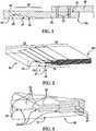
- a hybrid composite structure 20includes a composite resin portion 22 joined to a metal portion 24 by a transition section 25 that includes a composite-to-metal joint 26.
- the composite structure 20is a substantially flat composite sheet, however depending upon the application, the structure 20 may have one or more curves, contours or other geometric features.
- composite structure 20may comprise an inner and/or outer contoured skin of an aircraft (not shown) which is secured to a frame 28 portion of the aircraft by means of a lap joint 30 and fasteners 32 which pass through the skin 20 into the frame 28.
- the frame 28may comprise a composite, a metal or other rigid material, and the metal portion 24 of the structure 20 may serve as a rigid metal fitting 24 that is suited to transfer a range of loads and types of loadings between the frame 28 and the composite portion 20.
- the composite resin portion 22may comprise a carbon fiber reinforced epoxy
- the metal portion 24comprises titanium
- the frame 28may comprise an aluminum alloy or a composite.
- the transition section 25 and the joint 26are strong enough to carry the typical range and types of loads between the composite resin portion 22 and the metal portion 24, including but not limited to tension, bending, torsion and shear loads.
- a layup of composite material plies 35is terminated at a interface location 39 referred to later herein as a transition point 39, where a titanium metal sheet or ply 37 of the substantially the same thickness as the composite material plies 35 continues to the metal edge 24a of the metal portion 24, and the layup is repeated with a composite-to-metal interface 39 that is staggered toward the metal edge 24a from the prior interface location 39 and includes a ply of structural metal adhesive 45 (see FIGS. 5 and 6 ) between the metal plies 37, with the next metal-to-composite interface 39 staggered away from the part edge 24a to produce a nested splice 27.
- This staggered interface stackingwhich produces nested tabs 29 (see FIG. 3 ), is continued to the full thickness of the hybrid composite structure 20 with none of the composite plies 35 extending fully to the metal edge 24a of the all metal portion 24
- the composite portion 22 of the structure 20comprises a laminated stack 34 of fiber reinforced resin plies 35
- the metal portion 24 of the structure 20comprises a stack 36 of metal sheets or plies 37 that are bonded together to form a substantially unitized metal structure.
- the composite plies 35 and the metal sheets 37are arranged in layers 38.
- Each of the layers 38comprises one or more of the composite plies 35 in substantially edge-to-edge abutment with one of the metal sheets 37.
- each of the layers 38transitions at a point 39 from a composite i.e. composite resin plies 35, to a metal, i.e. metal sheet 37.
- the transition points 39are staggered relative to each other according to a predetermined lay-up schedule such that the plies 35 and the metal sheets 37 overlap each other in the transition section 25 ( FIG. 1 ). Staggering of the transition points 39 creates multiple bond lines that may reduce the occurrence and/or propagation of cracks or disbonds in the joint 26.
- the staggering of the transition points 39also results in a form of interleaving of the composite plies 35 and the metal sheets 37 within the joint 26 which forms a nested splice 27 between the all composite portion 22 and the all metal portion 24.
- This nested splice 27may also be referred to as a finger bond 26, a finger joint 26 or a multiple step lap joint 26.
- the adjacent ones of the transition points 39are spaced from each other in the in-plane direction of the structure 20 so as to achieve a bonded joint 26 that exhibits optimum performance characteristics, including strength and resistance to disbonds and propagation of inconsistencies such as cracks.
- the nested splice 27 forming the joint 26is a form of a double finger joint 26 in which the transition points 39 are staggered in opposite directions from a generally central point 55 of maximum overlap.
- other joint configurationsare possible including but not limited to a single finger joint in which the multiple transition points 39 are staggered in a single direction.
- the composite plies 35may comprise a fiber reinforced resin, such as without limitation, carbon fiber epoxy, which may be in the form of unidirectional prepreg tape or fabric. Other fiber reinforcements are possible, including glass fibers, and the use of non-prepreg materials may be possible.
- the composite plies 35may have predetermined fiber orientations and are laid up according to a predefined ply schedule to meet desired performance specifications.
- the bonded sheets 37comprise a titanium that is suitable for the intended application.
- the stack 36 of metal sheets 37has a total thickness t 1 which is generally substantially equal to the thickness t 2 of the laminated stack 34 of plies 35. In the illustrated example however, t 2 is slightly greater than t 1 by a factor of the thickness of several overwrap plies 43 on opposite sides of the stack 37.
- FIGS. 5 and 6illustrate details of two adjoining layers 38 of the joint 26 shown in FIGS. 2-4 .
- each layer 38comprises four plies 35 having a collective total thickness T 1 .
- the individual metal sheets 37 of the adjacent layers 38are bonded together by means of a layer of structural adhesive 45, which may comprise a commercial film adhesive or other forms of a suitable adhesive that is placed between the metal sheets 36 during the lay-up process.
- each metal sheet 37 and one layer of adhesive 45 represented as T 2 in FIG. 5is substantially equal to the thickness T 1 of the composite plies 35 in the layer 38.
- a thin film of adhesivemay be placed between the plies 35 to increase the interlaminar bond strength.
- the distance between adjacent transition points 39, and thus the length of the overlap between the layers 38, as well as the thickness and number of composite plies 35 and the thickness of the metal sheets 37will depend on the requirements of the particular application, including the type and magnitude of the loads that are to be transmitted through the joint 26, and possibly other performance specifications.
- Ultrasonic structural wavesmay be introduced into the structure 20 at the edge of the metal portion 24, at the composite portion 22 or in the transition section 25. These ultrasonic waves travel through what amounts to a waveguide formed by the metal 37 sheets and the interfaces (not shown) between the composite plies 35 and the metal sheets 37.
- MEMS-based (microelectromechanical) sensors, thin piezo-electric sensors (not shown) or other transducers placed in the structure 20may be used to receive the ultrasonic structural waves for purposes on analyzing the condition of the bondlines in the joint 26.
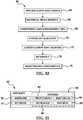
- one method of making the composite structure 20comprises forming a multi-layer composite lay-up as shown at 65.
- Forming the lay-upincludes laying up a composite resin portion 22 at step 67, and laying up a metal portion 24 at 69.
- the step 65 of forming the layupfurther includes forming a composite-to-metal joint between the composite resin portion and the metal portion of the lay-up, shown at 71.
- FIG. 8illustrates additional details of the method shown in FIG. 7 .
- individual metal sheets 37are trimmed to a desired size and/or shape.
- the surfaces of the metal sheets 37are prepared by suitable processes that may include cleaning the sheets 37 with a solvent, drying them, etc. then at 44, the lay-up is assembled by laying up the metal sheets 36 and the composite plies 35 in a sequence that is determined by a predefined ply schedule (not shown) which includes a predetermined staggering of the transition points 39 between the plies 35 and the metal sheet 36 in each layer 38.
- the metal sheets 37are sequenced like plies into the lay-up, much like composite plies are sequenced into a lay-up in a conventional lay-up process.
- adhesiveis introduced between the metal sheets 37 in order to bond them together into a unitized metal structure.
- a bonding adhesivemay be introduced between the individual composite plies 35 in order to increase the bond strength between these plies 35.
- the lay-upmay be compacted using any of several known compaction techniques, such as vacuum bagging following which the lay-up is cured at step 50 using autoclave or out-of-autoclave curing processes.
- the cured composite structure 20may be trimmed and/or inspected, as necessary.
- FIG. 9illustrates still another embodiment of a method of making a hybrid composite part 20.
- the methodbegins at step 73 with laying at least one composite ply 35 that is terminated at an interface location 39 on a suitable layup tool (not shown).
- an adjacent metal ply 37is laid up which is substantially the same thickness as the adjacent composite material play 35.
- the layup processis repeated with a composite-to-metal interface 39 that is staggered toward the metal edge 24a of the part 20 from the prior interface location 39.
- a 79, a ply 45 of structural adhesiveis laid between the metal plies 37.
- Steps 73-79are repeated successively to produce a nested splice 27 and a staggered interface stacking forming nested tabs 29 to the full thickness of the hybrid part 20, with none composite plies 35 extending fully to the metal edge 24a of the part 20.
- the completed layupis vacuum bagged processed to remove voids, and is subsequently cured using any suitable curing method.
- Embodiments of the disclosuremay find use in a variety of potential applications, particularly in the transportation industry, including for example, aerospace, marine and automotive applications.
- Aircraft applications of the disclosed embodimentsmay include, for example, a wide variety of structural composite parts and components, especially those requiring the use of fasteners during the assembly process.
- exemplary method 60may include specification and design 64 of the aircraft 62 and material procurement 66.
- component and subassembly manufacturing 68 and system integration 70 of the aircraft 62takes place. Thereafter, the aircraft 62 may go through certification and delivery 72 in order to be placed in service 74. While in service by a customer, the aircraft 62 is scheduled for routine maintenance and service 76 (which may also include modification, reconfiguration, refurbishment, and so on).
- a system integratormay include without limitation any number of aircraft manufacturers and major-system subcontractors; a third party may include without limitation any number of vendors, subcontractors, and suppliers; and an operator may be an airline, leasing company, military entity, service organization, and so on.
- the aircraft 62 produced by exemplary method 60may include an airframe 78 with a plurality of systems 80 and an interior 82.
- high-level systems 82include one or more of a propulsion system 84, an electrical system 86, a hydraulic system 88, and an environmental system 90. Any number of other systems may be included.
- the disclosed methodmay be employed to fabricate parts, structures and components used in the airframe 78 or in the interior 82.
- an aerospace exampleis shown, the principles of the disclosure may be applied to other industries, such as the marine and automotive industries.
- Systems and methods embodied hereinmay be employed during any one or more of the stages of the production and service method 60.
- parts, structures and components corresponding to production process 68may be fabricated or manufactured in a manner similar to parts, structures and components produced while the aircraft 62 is in service.
- one or more apparatus embodiments, method embodiments, or a combination thereofmay be utilized during the production stages 68 and 70, for example, by substantially expediting assembly of or reducing the cost of an aircraft 62.
- apparatus embodiments, method embodiments, or a combination thereofmay be utilized while the aircraft 62 is in service, for example and without limitation, to maintenance and service 76.
Landscapes
- Engineering & Computer Science (AREA)
- Mechanical Engineering (AREA)
- Chemical & Material Sciences (AREA)
- Aviation & Aerospace Engineering (AREA)
- Composite Materials (AREA)
- Materials Engineering (AREA)
- Metallurgy (AREA)
- Organic Chemistry (AREA)
- Moulding By Coating Moulds (AREA)
- Laminated Bodies (AREA)
Description
- This disclosure generally relates to composite structures, especially to fiber reinforced resin laminates, and deals more particularly with a hybrid composite having a composite-to-metal joint.
- Bonding techniques are often used to assemble composite structures. In applications where the composite structure also requires fasteners, the local thickness or gauge of the structure surrounding the fastener may need to be increased in order to withstand loads transmitted through the fastener joint. As the local thickness of the structure increases, the fastener may need to be lengthened, thereby adding weight to the structure. Additionally, the increased local thickness of the structure may increase the eccentricity of the load path across the fastener joint, which may place undesired bending loads on the fastener.
- One solution to the problems mentioned above consists of attaching metal fittings to the composite structure in the area of the fasteners. These metal fittings may be formed of titanium or similar metals that may not substantially chemically react with carbon fiber reinforced composites in which they are in contact. Titanium fittings, however may be relatively expensive, particularly when it is necessary to form them into complex shapes.
- Accordingly, there is a need for a composite resin-to-metal joint that may be used to connect substantially all metal fittings with substantially all composite resin structures, which is relatively inexpensive and easy to manufacture, and which may withstand loads transferred around fastener connection points. There is also a need for a composite resin-to-metal joint that substantially avoids chemical reactions between the all metal fitting and the all composite resin structure.
- Document
WO 00/56541 A1 - KOLESNIKOW et al: "CFRP/titanium hybrid materials for improving composite bolted joints", COMPOSITE STRUCTURES, ELSEVIER SCIENCE LTD, GB, vol. 83, no 4, 8 February 2008, pages 368-380, XP02247335 relates to composite bolted joints.
- A hybrid composite resin-metal aircraft structure, comprising: a plurality of laminated layers forming a fiber reinforced, all composite portion, an all metal portion and a hybrid composite-metal finger joint connecting the composite portion with the metal portion, each of the layers including a plurality of plies of fiber reinforced composite resin and a titanium metal sheet, wherein the plies and the metal sheet are arranged in edge-to-edge abutment with each other forming a composite-to-metal transition point in the layer, wherein the plurality of plies of each of the layers form a laminated stack, wherein the titanium metal sheets of each of the layers form a metal sheet stack, and wherein the transition points in the layers are staggered relative to each other to form the finger joint; and a layer of adhesive between the metal sheets for unitizing the metal sheets, wherein the thickness of the plies in each of the layers is substantially equal to combined thickness of one of the metal sheets and a layer of the adhesive.
- A method of fabricating a composite structure, comprising: forming a multi-layer composite lay-up having a fiber reinforced composite resin portion and a metal portion, including forming a composite-to-metal joint between the composite resin portion and the metal portion of the lay-up, each of the layers including a plurality of plies of fiber reinforced composite resin and a titanium metal sheet, wherein the plies and the metal sheet are arranged in edge-to-edge abutment with each other forming a composite-to-metal transition point in the layer, wherein the plurality of plies of each of the layers form a laminated stack, wherein the titanium metal sheets of each of the layers form a metal sheet stack, wherein forming the lay-up includes forming each of the layers by placing a plurality of fiber reinforced composite resin plies and one metal sheet in substantially edge-to-edge abutment with each other to form a transition point between the fiber reinforced composite resin and the metal in the layer, wherein forming the lay-up includes staggering the transition points in the layers relative to each other, further comprising: unitizing the metal portion by placing a layer of adhesive between the metal sheets, wherein the thickness of the plies in each of the layers is substantially equal to combined thickness of one of the metal sheets and a layer of the adhesive.
- In general, the disclosed embodiments provide a hybrid-type composite structure that includes a fiber reinforced resin composite-to-metal joint that may be used to connect a substantially all-metal fitting with a substantially all composite resin structure. The joint provides a transition between the composite and metallic structures that is suitable for use in higher performance applications, such as aerospace vehicles. This transition from a substantially all composite to a substantially all metal material may reduce or eliminate the possibility of corrosion and/or problems stemming from eccentricity. During lay-up of the composite structure, sheets of metal are substituted for a number of composite plies, and the transition from composite plies to metal sheets occurs at staggered locations so as to provide adequate load transfer from the composite portion to the metal portion. The staggered transition results in an interleaving between the composite plies and the metal sheets and creates multiple bond lines that may reduce the occurrence and/or propagation of cracks or disbonds in the joint. An adhesive placed between the metal sheets binds and unitizes the sheets into a nearly solid metal fitting.
- The composite structure comprises the laminated stack of fiber reinforced resin plies and the stack of metal sheets. The metal sheets have edges that are interleaved with the edges of the fiber reinforced resin plies to form a composite-to-metal joint connecting the fiber reinforced resin plies with the metal sheets.
- The hybrid resin-metal structurecomprises the composite resin portion, the metal portion, and a transition section between the resin and metal portions. The resin portion includes laminated plies of fiber reinforced resin, and the metal portion includes bonded sheets of metal. The transition section includes staggered overlaps between the laminated plies and the metal sheets.
- The hybrid composite metal structure comprises a layup of fiber reinforced composite material that is terminated at an interface location. At the interface location, a metal ply of the same thickness as the composite material continues to the metal edge of the part, and the layup is repeated with a composite to metal interface that is staggered toward the edge of the part from the prior interface location. A ply of structural adhesive is placed between the metal plies, with the next metal to composite interface staggered away from the part edge to produce a nested splice, and the staggered interface stacking produces nested tabs is continued to the full thickness of the part with none of the composite plies extending fully to the edge of the part.
- The method of fabricating a composite structure comprises forming a multi-ply composite lay-up having a composite portion and a metal portion, and forming a composite-to-metal joint between the composite portion and the metal portion. The method further includes compacting and curing the layup.
- Advantageously the method further including continuing the staggered interface stacking of the composite and metal plies to produces nested tabs to the full thickness of the part with none of composite plies extending fully to the edge of the part.
- Advantageously the method further including vacuum bag processing the part to remove air voids in the layup; and curing the laid up part.
- The hybrid composite resin-metal aircraft structure includes a plurality of laminated layers forming a fiber reinforced, all composite portion, an all metal portion and a hybrid composite-metal finger joint connecting the composite portion with the metal portion, each of the layers including a plurality of plies of composite resin and a titanium metal sheet, wherein the plies and the metal sheet are arranged in edge-to-edge abutment with each other forming a composite-to-metal transition point in the layer, and wherein the transition points in the layers are staggered relative to each other to form the finger joint; and a layer of adhesive between the metal sheets for unitizing the metal sheets, and wherein the thickness of the plies in each of the layers is substantially equal to combined thickness of one of the sheets and layer of the adhesive.
- The method of making a hybrid composite resin-metal aircraft structure preferably compacting the layup; and curing the layup.
FIG. 1 is an illustration of a sectional view of a composite structure having a composite-to-metal joint.FIG. 2 is an illustration of a perspective view of the composite structure including the composite-to-metal joint.FIG. 3 is an illustration of a perspective view of the area designated asFIG. 3 inFIG. 2 .FIG. 4 is an illustration of a cross sectional view of the joint, better showing interleaving between composite plies and the metal sheets.FIG. 5 is an illustration of a cross sectional view of two separated layers of the joint shown inFIG. 4 , also showing the application of a film adhesive on the metal sheets.FIG. 6 is an illustration of an enlarged, cross sectional view of a portion of the joint formed by the two layers shown inFIG. 5 .FIG. 7 is an illustration of a broad flow diagram of a method of making a composite structure having the composite joint shown inFIGS. 2-4 .FIG. 8 is an illustration of a flow diagram showing additional details of the method shown inFIG. 7 .FIG. 9 is a flow diagram of another method of making a composite structure having the composite joint shown inFIGS. 2-4 .FIG. 10 is an illustration of a flow diagram of aircraft production and service methodology.FIG. 11 is an illustration of a block diagram of an aircraft.- Referring first to
FIG. 1 , ahybrid composite structure 20 includes acomposite resin portion 22 joined to ametal portion 24 by atransition section 25 that includes a composite-to-metal joint 26. In the illustrated example, thecomposite structure 20 is a substantially flat composite sheet, however depending upon the application, thestructure 20 may have one or more curves, contours or other geometric features. For example,composite structure 20 may comprise an inner and/or outer contoured skin of an aircraft (not shown) which is secured to aframe 28 portion of the aircraft by means of alap joint 30 andfasteners 32 which pass through theskin 20 into theframe 28. - The
frame 28 may comprise a composite, a metal or other rigid material, and themetal portion 24 of thestructure 20 may serve as arigid metal fitting 24 that is suited to transfer a range of loads and types of loadings between theframe 28 and thecomposite portion 20. In one practical embodiment for example, and without limitation, thecomposite resin portion 22 may comprise a carbon fiber reinforced epoxy, themetal portion 24 comprises titanium, and theframe 28 may comprise an aluminum alloy or a composite. Thetransition section 25 and thejoint 26 are strong enough to carry the typical range and types of loads between thecomposite resin portion 22 and themetal portion 24, including but not limited to tension, bending, torsion and shear loads. - Referring to
FIGS. 1-4 , a layup ofcomposite material plies 35 is terminated at ainterface location 39 referred to later herein as atransition point 39, where a titanium metal sheet orply 37 of the substantially the same thickness as thecomposite material plies 35 continues to themetal edge 24a of themetal portion 24, and the layup is repeated with a composite-to-metal interface 39 that is staggered toward themetal edge 24a from theprior interface location 39 and includes a ply of structural metal adhesive 45 (seeFIGS. 5 and 6 ) between themetal plies 37, with the next metal-to-composite interface 39 staggered away from thepart edge 24a to produce anested splice 27. This staggered interface stacking, which produces nested tabs 29 (seeFIG. 3 ), is continued to the full thickness of thehybrid composite structure 20 with none of thecomposite plies 35 extending fully to themetal edge 24a of the allmetal portion 24 - Referring now also to
FIGS. 2-4 , thecomposite portion 22 of thestructure 20 comprises a laminatedstack 34 of fiber reinforcedresin plies 35, and themetal portion 24 of thestructure 20 comprises astack 36 of metal sheets orplies 37 that are bonded together to form a substantially unitized metal structure. As shown inFIGS. 5 and 6 , thecomposite plies 35 and themetal sheets 37 are arranged inlayers 38. Each of thelayers 38 comprises one or more of thecomposite plies 35 in substantially edge-to-edge abutment with one of themetal sheets 37. Thus, each of thelayers 38 transitions at apoint 39 from a composite i.e.composite resin plies 35, to a metal,i.e. metal sheet 37. - The
transition points 39 are staggered relative to each other according to a predetermined lay-up schedule such that theplies 35 and themetal sheets 37 overlap each other in the transition section 25 (FIG. 1 ). Staggering of thetransition points 39 creates multiple bond lines that may reduce the occurrence and/or propagation of cracks or disbonds in the joint 26. The staggering of thetransition points 39 also results in a form of interleaving of the composite plies 35 and themetal sheets 37 within the joint 26 which forms a nestedsplice 27 between the allcomposite portion 22 and the allmetal portion 24. This nestedsplice 27 may also be referred to as afinger bond 26, a finger joint 26 or a multiple step lap joint 26. The adjacent ones of thetransition points 39 are spaced from each other in the in-plane direction of thestructure 20 so as to achieve a bonded joint 26 that exhibits optimum performance characteristics, including strength and resistance to disbonds and propagation of inconsistencies such as cracks. In the illustrated example, the nestedsplice 27 forming the joint 26 is a form of a double finger joint 26 in which thetransition points 39 are staggered in opposite directions from a generallycentral point 55 of maximum overlap. However, other joint configurations are possible including but not limited to a single finger joint in which themultiple transition points 39 are staggered in a single direction. - The composite plies 35 may comprise a fiber reinforced resin, such as without limitation, carbon fiber epoxy, which may be in the form of unidirectional prepreg tape or fabric. Other fiber reinforcements are possible, including glass fibers, and the use of non-prepreg materials may be possible. The composite plies 35 may have predetermined fiber orientations and are laid up according to a predefined ply schedule to meet desired performance specifications. As previously mentioned, the bonded
sheets 37 comprise a titanium that is suitable for the intended application. In the illustrated example, thestack 36 ofmetal sheets 37 has a total thicknesst1 which is generally substantially equal to the thicknesst2 of thelaminated stack 34 ofplies 35. In the illustrated example however,t2 is slightly greater thant1 by a factor of the thickness of several overwrap plies 43 on opposite sides of thestack 37. FIGS. 5 and 6 illustrate details of two adjoininglayers 38 of the joint 26 shown inFIGS. 2-4 . In this example, eachlayer 38 comprises fourplies 35 having a collective total thicknessT1. Theindividual metal sheets 37 of theadjacent layers 38 are bonded together by means of a layer ofstructural adhesive 45, which may comprise a commercial film adhesive or other forms of a suitable adhesive that is placed between themetal sheets 36 during the lay-up process.- The combined thickness of each
metal sheet 37 and one layer of adhesive 45 represented asT2 inFIG. 5 is substantially equal to the thicknessT1 of the composite plies 35 in thelayer 38. Although not shown in the Figures, a thin film of adhesive may be placed between theplies 35 to increase the interlaminar bond strength. The distance betweenadjacent transition points 39, and thus the length of the overlap between thelayers 38, as well as the thickness and number of composite plies 35 and the thickness of themetal sheets 37 will depend on the requirements of the particular application, including the type and magnitude of the loads that are to be transmitted through the joint 26, and possibly other performance specifications. - The differing layers 38 of the joint 26 between the two differing materials of the composite and
metal portions FIG. 1 ), render thestructure 20 well suited to nondestructive evaluations of bond quality using embedded or mounted sensors (not shown). Ultrasonic structural waves (not shown) may be introduced into thestructure 20 at the edge of themetal portion 24, at thecomposite portion 22 or in thetransition section 25. These ultrasonic waves travel through what amounts to a waveguide formed by themetal 37 sheets and the interfaces (not shown) between the composite plies 35 and themetal sheets 37. MEMS-based (microelectromechanical) sensors, thin piezo-electric sensors (not shown) or other transducers placed in thestructure 20 may be used to receive the ultrasonic structural waves for purposes on analyzing the condition of the bondlines in the joint 26. - Referring now to
FIG. 7 , one method of making thecomposite structure 20 comprises forming a multi-layer composite lay-up as shown at 65. Forming the lay-up includes laying up acomposite resin portion 22 atstep 67, and laying up ametal portion 24 at 69. Thestep 65 of forming the layup further includes forming a composite-to-metal joint between the composite resin portion and the metal portion of the lay-up, shown at 71. FIG. 8 illustrates additional details of the method shown inFIG. 7 . Beginning atstep 40,individual metal sheets 37 are trimmed to a desired size and/or shape. Next at 42, the surfaces of themetal sheets 37 are prepared by suitable processes that may include cleaning thesheets 37 with a solvent, drying them, etc. then at 44, the lay-up is assembled by laying up themetal sheets 36 and the composite plies 35 in a sequence that is determined by a predefined ply schedule (not shown) which includes a predetermined staggering of thetransition points 39 between theplies 35 and themetal sheet 36 in eachlayer 38.- During the lay-up process, the
metal sheets 37 are sequenced like plies into the lay-up, much like composite plies are sequenced into a lay-up in a conventional lay-up process. As shown atstep 46, adhesive is introduced between themetal sheets 37 in order to bond them together into a unitized metal structure. Similarly, although not shown inFIG. 8 , a bonding adhesive may be introduced between the individual composite plies 35 in order to increase the bond strength between theseplies 35. Next, at 48, the lay-up may be compacted using any of several known compaction techniques, such as vacuum bagging following which the lay-up is cured atstep 50 using autoclave or out-of-autoclave curing processes. Atstep 52, the curedcomposite structure 20 may be trimmed and/or inspected, as necessary. FIG. 9 illustrates still another embodiment of a method of making a hybridcomposite part 20. The method begins atstep 73 with laying at least onecomposite ply 35 that is terminated at aninterface location 39 on a suitable layup tool (not shown). At 75, an adjacent metal ply 37 is laid up which is substantially the same thickness as the adjacentcomposite material play 35. As shown at 77, the layup process is repeated with a composite-to-metal interface 39 that is staggered toward themetal edge 24a of thepart 20 from theprior interface location 39. A 79, aply 45 of structural adhesive is laid between the metal plies 37. Steps 73-79 are repeated successively to produce a nestedsplice 27 and a staggered interface stacking forming nestedtabs 29 to the full thickness of thehybrid part 20, with none composite plies 35 extending fully to themetal edge 24a of thepart 20. Although not shown inFIG. 9 , the completed layup is vacuum bagged processed to remove voids, and is subsequently cured using any suitable curing method.- Embodiments of the disclosure may find use in a variety of potential applications, particularly in the transportation industry, including for example, aerospace, marine and automotive applications. Thus, referring now to
FIGS. 10 and 11 , embodiments of the disclosure may be used in the context of an air10raft manufacturing andservice method 60 as shown inFIG. 10 and anaircraft 62 as shown inFIG. 11 . Aircraft applications of the disclosed embodiments may include, for example, a wide variety of structural composite parts and components, especially those requiring the use of fasteners during the assembly process. During pre-production,exemplary method 60 may include specification anddesign 64 of theaircraft 62 andmaterial procurement 66. During production, component andsubassembly manufacturing 68 andsystem integration 70 of theaircraft 62 takes place. Thereafter, theaircraft 62 may go through certification anddelivery 72 in order to be placed inservice 74. While in service by a customer, theaircraft 62 is scheduled for routine maintenance and service 76 (which may also include modification, reconfiguration, refurbishment, and so on). - Each of the processes of
method 60 may be performed or carried out by a system integrator, a third party, and/or an operator (e.g., a customer). For the purposes of this description, a system integrator may include without limitation any number of aircraft manufacturers and major-system subcontractors; a third party may include without limitation any number of vendors, subcontractors, and suppliers; and an operator may be an airline, leasing company, military entity, service organization, and so on. - As shown in
FIG. 11 , theaircraft 62 produced byexemplary method 60 may include anairframe 78 with a plurality ofsystems 80 and an interior 82. Examples of high-level systems 82 include one or more of apropulsion system 84, anelectrical system 86, ahydraulic system 88, and anenvironmental system 90. Any number of other systems may be included. The disclosed method may be employed to fabricate parts, structures and components used in theairframe 78 or in the interior 82. Although an aerospace example is shown, the principles of the disclosure may be applied to other industries, such as the marine and automotive industries. - Systems and methods embodied herein may be employed during any one or more of the stages of the production and
service method 60. For example, parts, structures and components corresponding toproduction process 68 may be fabricated or manufactured in a manner similar to parts, structures and components produced while theaircraft 62 is in service. Also, one or more apparatus embodiments, method embodiments, or a combination thereof may be utilized during the production stages 68 and 70, for example, by substantially expediting assembly of or reducing the cost of anaircraft 62. Similarly, one or more of apparatus embodiments, method embodiments, or a combination thereof may be utilized while theaircraft 62 is in service, for example and without limitation, to maintenance andservice 76. - Although the embodiments of this disclosure have been described with respect to certain exemplary embodiments, it is to be understood that the specific embodiments are for purposes of illustration and not limitation, as other variations will occur to those of skill in the art.
Claims (6)
- A hybrid composite resin-metal aircraft structure (20), comprising:a plurality of laminated layers (38) forming a fiber reinforced, all composite portion (22), an all metal portion (24) and a hybrid composite-metal finger joint (26) connecting the composite portion (22) with the metal portion (24),each of the layers (38) including a plurality of plies (35) of fiber reinforced composite resin and a titanium metal sheet (37), wherein the plies (35) and the metal sheet (37) are arranged in edge-to-edge abutment with each other forming a composite-to-metal transition point (39) in the layer (38), wherein the plurality of plies (35) of each of the layers (38) form a laminated stack (34), wherein the titanium metal sheets (37) of each of the layers (38) form a metal sheet stack (36), and wherein the transition points (39) in the layers (38) are staggered relative to each other to form the finger joint; and a layer (45) of adhesive between the metal sheets (37) for unitizing the metal sheets (37),wherein the thickness (T1) of the plies (35) in each of the layers (38) is substantially equal to combined thickness (T2) of one of the metal sheets (37) and a layer (45) of the adhesive.
- The composite structure of claim 1, wherein the metal sheets (37) form a stack of metal sheets defining a metal edge (24a) of the all metal portion (24), wherein none of the resin plies (35) extends fully to the metal edge (24a) of the all metal portion (24).
- The composite structure of claim 1, wherein:the resin plies form a laminated stack of fiber reinforced resin plies; andthe metal sheets form a stack of metal sheets (37) having edges interleaved with edges of the fiber reinforced resin plies to form the composite-metal finger joint (26) connecting the fiber reinforced resin plies with the metal sheets.
- The composite structure of claim 3, wherein:
the stacks of fiber reinforced resin plies and metal sheets are arranged in layers, wherein each of the layers includes a metal sheet and at least one of the fiber reinforced resin plies. - An aircraft including an inner and/or outer contoured skin (20) and a frame portion (28), the skin being formed by a composite structure (20) of any of claims 1 - 4, wherein the skin is secured to the frame portion (28) by means of a lap joint (30) and fasteners (32) which pass through the all metal portion (24) into the frame portion (28), wherein the transition of the all composite portion (22) to the all metal portion (24) reduces or eliminates the possibility of corrosion.
- A method of fabricating a composite structure, comprising:forming a multi-layer composite lay-up having a fiber reinforced composite resin portion and a metal portion, including forming a composite-to-metal joint between the composite resin portion and the metal portion of the lay-up, each of the layers (38) including a plurality of plies (35) of fiber reinforced composite resin and a titanium metal sheet (37), wherein the plies (35) and the metal sheet (37) are arranged in edge-to-edge abutment with each other forming a composite-to-metal transition point (39) in the layer (38), wherein the plurality of plies (35) of each of the layers (38) form a laminated stack (34), wherein the titanium metal sheets (37) of each of the layers (38) form a metal sheet stack (36),wherein forming the lay-up includes forming each of the layers by placing a plurality of fiber reinforced composite resin plies and one metal sheet in substantially edge-to-edge abutment with each other to form a transition point between the fiber reinforced composite resin and the metal in the layer,wherein forming the lay-up includes staggering the transition points in the layers relative to each other,further comprising:
unitizing the metal portion by placing a layer of adhesive between the metal sheets,
wherein the thickness (T1) of the plies (35) in each of the layers (38) is substantially equal to combined thickness (T2) of one of the metal sheets (37) and a layer (45) of the adhesive.
Applications Claiming Priority (2)
| Application Number | Priority Date | Filing Date | Title |
|---|---|---|---|
| US12/857,835US8652606B2 (en) | 2010-08-17 | 2010-08-17 | Composite structures having composite-to-metal joints and method for making the same |
| PCT/US2011/041519WO2012024023A1 (en) | 2010-08-17 | 2011-06-22 | Composite structures having composite-to-metal joints and method for making the same |
Publications (2)
| Publication Number | Publication Date |
|---|---|
| EP2605902A1 EP2605902A1 (en) | 2013-06-26 |
| EP2605902B1true EP2605902B1 (en) | 2021-02-17 |
Family
ID=44280683
Family Applications (1)
| Application Number | Title | Priority Date | Filing Date |
|---|---|---|---|
| EP11729850.5AActiveEP2605902B1 (en) | 2010-08-17 | 2011-06-22 | Composite structures having composite-to-metal joints and method for making the same |
Country Status (8)
| Country | Link |
|---|---|
| US (2) | US8652606B2 (en) |
| EP (1) | EP2605902B1 (en) |
| JP (1) | JP5840687B2 (en) |
| KR (1) | KR101859783B1 (en) |
| CN (1) | CN103068565B (en) |
| BR (1) | BR112013003588B1 (en) |
| CA (1) | CA2805468C (en) |
| WO (1) | WO2012024023A1 (en) |
Families Citing this family (62)
| Publication number | Priority date | Publication date | Assignee | Title |
|---|---|---|---|---|
| US9586699B1 (en) | 1999-08-16 | 2017-03-07 | Smart Drilling And Completion, Inc. | Methods and apparatus for monitoring and fixing holes in composite aircraft |
| US9625361B1 (en) | 2001-08-19 | 2017-04-18 | Smart Drilling And Completion, Inc. | Methods and apparatus to prevent failures of fiber-reinforced composite materials under compressive stresses caused by fluids and gases invading microfractures in the materials |
| US8442804B2 (en) | 2007-10-25 | 2013-05-14 | The Boeing Company | Method and apparatus for composite part data extraction |
| US8620627B2 (en) | 2009-10-13 | 2013-12-31 | The Boeing Company | Composite information display for a part |
| US9522512B2 (en) | 2010-08-17 | 2016-12-20 | The Boeing Company | Methods for making composite structures having composite-to-metal joints |
| US8652606B2 (en) | 2010-08-17 | 2014-02-18 | The Boeing Company | Composite structures having composite-to-metal joints and method for making the same |
| US8993084B2 (en) | 2010-08-17 | 2015-03-31 | The Boeing Company | Multi-layer metallic structure and composite-to-metal joint methods |
| GB201016279D0 (en) | 2010-09-28 | 2010-11-10 | Airbus Operations Ltd | Stiffener run-out |
| US8875931B2 (en) | 2010-11-19 | 2014-11-04 | The Boeing Company | Composite sandwich shell edge joint |
| US8784596B2 (en)* | 2010-11-19 | 2014-07-22 | The Boeing Company | Method for making and joining composite sandwich shell edge joint |
| KR20130059153A (en)* | 2011-11-28 | 2013-06-05 | 현대자동차주식회사 | A method for preparing joints of metallic sheets and polymer composites by using adhesive |
| EP3581376A1 (en)* | 2012-04-10 | 2019-12-18 | The Boeing Company | A method of fabricating a composite structure and an integrated attachment fitting for a structure |
| FR2989723B1 (en) | 2012-04-20 | 2024-02-09 | Astrium Sas | ASSEMBLY OF STRUCTURES OF STRUCTURAL PARTS |
| US8770134B2 (en)* | 2012-04-30 | 2014-07-08 | Carl E. Baugh | Structurally-interlaminated marine vessel |
| US10655328B2 (en)* | 2012-05-24 | 2020-05-19 | The University Of Kentucky Research Foundation | Structural reinforcement, reinforced structural member and related method |
| GB201209437D0 (en)* | 2012-05-28 | 2012-07-11 | Kitchener Renato | Power supply and battery charger |
| CN102941703A (en)* | 2012-10-21 | 2013-02-27 | 刘君才 | Super composite material laminated plate |
| WO2014116151A1 (en)* | 2013-01-24 | 2014-07-31 | Saab Ab | An aerial skin article with reinforced fastening holes |
| US9040138B2 (en) | 2013-04-29 | 2015-05-26 | General Electric Company | Composite article including composite to metal interlock and method of fabrication |
| WO2014189946A1 (en)* | 2013-05-21 | 2014-11-27 | Cutting Dynamics, Inc. | Reinforced thermoplastic structural component and process to make the same |
| US9227718B2 (en)* | 2013-06-07 | 2016-01-05 | The Boeing Company | Lower joints between outboard wing boxes and center wing sections of aircraft wing assemblies |
| RU2548435C2 (en)* | 2013-07-18 | 2015-04-20 | Открытое акционерное общество "Национальный институт авиационных технологий" (ОАО НИАТ) | Connection of sheets of metal composites and method to this end |
| US9524356B2 (en)* | 2013-10-16 | 2016-12-20 | General Electric Company | System and methods of generating a computer model of composite component |
| DE102013221168A1 (en)* | 2013-10-18 | 2015-05-07 | Bayerische Motoren Werke Aktiengesellschaft | component arrangement |
| US9403350B2 (en) | 2013-12-16 | 2016-08-02 | The Nordam Group, Inc. | Flash control metal bonding |
| JP5972854B2 (en)* | 2013-12-17 | 2016-08-17 | 三菱重工業株式会社 | Joining method and joined body of fiber reinforced composite member, and manufacturing method of wind turbine blade |
| CN106171042A (en)* | 2014-01-13 | 2016-11-30 | 谢尔·林斯科格 | Method and apparatus for manufacturing a product or completing a product |
| NL2012458B1 (en)* | 2014-03-17 | 2016-01-08 | Gtm-Advanced Products B V | Laminate of mutually bonded adhesive layers and metal sheets, and method to obtain such laminate. |
| US9719536B2 (en)* | 2014-07-03 | 2017-08-01 | The Boeing Company | Assemblies including shape memory alloy fittings and composite structural members |
| JP6690910B2 (en)* | 2014-10-09 | 2020-04-28 | ザ・ボーイング・カンパニーThe Boeing Company | COMPOSITE MATERIAL STRUCTURE HAVING JOINT OF COMPOSITE MATERIAL AND METAL, AND MANUFACTURING METHOD THEREOF |
| WO2016129570A1 (en)* | 2015-02-13 | 2016-08-18 | 国立大学法人東京大学 | Bonded structure |
| DE102016104187A1 (en)* | 2016-03-08 | 2017-09-14 | Profil Verbindungstechnik Gmbh & Co. Kg | functional element |
| KR101846648B1 (en) | 2016-03-15 | 2018-04-09 | 현대자동차주식회사 | Composite product with inosculation structure |
| KR102507815B1 (en) | 2016-04-06 | 2023-03-08 | 현대자동차주식회사 | Composite with inserted metal sheet |
| CN107453018B (en)* | 2016-05-31 | 2021-03-09 | 洛阳尖端技术研究院 | Metamaterial antenna and forming method thereof |
| US11491766B2 (en) | 2016-08-29 | 2022-11-08 | Northrop Grumman Systems Corporation | Hybrid metal composite structures, rocket motors and multi stage rocket motor assemblies including hybrid metal composite structures, and related methods |
| US10603873B2 (en) | 2016-08-29 | 2020-03-31 | Northrop Grumman Innovation Systems, Inc. | Hybrid metal composite structures, rocket cases, and related methods |
| JP6789047B2 (en)* | 2016-09-23 | 2020-11-25 | 矢崎総業株式会社 | Vehicle ground structure |
| KR101836716B1 (en) | 2016-10-12 | 2018-03-08 | 현대자동차주식회사 | Composite parts with inserted metal plate and manufacturing method of the same |
| NL2017849B1 (en)* | 2016-11-23 | 2018-05-28 | Gtm Advanced Products B V | Laminate of mutually bonded adhesive layers and spliced metal sheets |
| JP6810593B2 (en)* | 2016-12-14 | 2021-01-06 | 三菱重工業株式会社 | Composite material molding method and composite material |
| US20180179990A1 (en) | 2016-12-27 | 2018-06-28 | Orbital Atk, Inc. | Hybrid metal composite structures, rocket motors and multi-stage rocket motor assemblies including hybrid metal composite structures, and related methods |
| US10661838B2 (en)* | 2017-05-31 | 2020-05-26 | Honda Motor Co., Ltd. | Multi-material vehicle roof stiffener |
| US11760043B2 (en) | 2017-09-29 | 2023-09-19 | Honda Motor Co., Ltd. | High strength mechanical fastening inclusions for fiber reinforced polymer structures |
| US10994856B2 (en)* | 2017-10-16 | 2021-05-04 | Rohr, Inc. | Structural panel with splice joint between adjacent core structures |
| DE102017126052A1 (en)* | 2017-11-08 | 2019-05-09 | Airbus Operations Gmbh | Stiffening arrangement for an opening in an aircraft structure |
| DE102018126473A1 (en)* | 2018-07-12 | 2020-01-16 | Tdk Electronics Ag | arrangement |
| US11358345B2 (en) | 2019-01-02 | 2022-06-14 | The Boeing Company | Internal tooling for composite parts |
| US11155056B2 (en)* | 2019-04-08 | 2021-10-26 | The Boeing Company | Methods of making laminated metallic structures |
| NL2023482B1 (en) | 2019-07-11 | 2021-02-03 | Dutch Thermoplastic Components B V | Thermoplastic composite product |
| US11718047B2 (en)* | 2019-12-12 | 2023-08-08 | The Boeing Company | Flyaway stringer end caps |
| US11806948B2 (en) | 2019-12-12 | 2023-11-07 | The Boeing Company | Method of forming flyaway stringer end caps |
| US12275227B2 (en) | 2020-02-11 | 2025-04-15 | Helicoid Industries, Inc. | Composite materials and structures |
| US11376812B2 (en) | 2020-02-11 | 2022-07-05 | Helicoid Industries Inc. | Shock and impact resistant structures |
| US12358242B2 (en)* | 2020-04-17 | 2025-07-15 | Honda Motor Co., Ltd. | Functional integration of transition structures into fiber reinforced composite layups |
| US11852297B2 (en) | 2021-06-01 | 2023-12-26 | Helicoid Industries Inc. | Containers and methods for protecting pressure vessels |
| US11346499B1 (en) | 2021-06-01 | 2022-05-31 | Helicoid Industries Inc. | Containers and methods for protecting pressure vessels |
| CN114346616B (en)* | 2022-01-17 | 2023-03-17 | 哈焊国创(青岛)焊接工程创新中心有限公司 | A heterogeneous joint of light alloy and fiber reinforced composite material and its preparation method |
| EP4215346B1 (en)* | 2022-01-20 | 2025-04-23 | Airbus Operations GmbH | Cryogenic storage tank, aircraft with a cryogenic storage tank and method for forming a hybrid metal polymer joint |
| WO2024006078A1 (en) | 2022-06-27 | 2024-01-04 | Helicoid Industries Inc. | High impact-resistant, reinforced fiber for leading edge protection of aerodynamic structures |
| GB202303505D0 (en) | 2023-03-10 | 2023-04-26 | Rolls Royce Plc | Method for manufacturing a composite bladed disk or rotor |
| WO2025099776A1 (en)* | 2023-11-09 | 2025-05-15 | Promoclad S.R.L. | Metallic composite panel and related production process |
Family Cites Families (110)
| Publication number | Priority date | Publication date | Assignee | Title |
|---|---|---|---|---|
| US3711934A (en) | 1970-09-17 | 1973-01-23 | Monsanto Co | Method of preparing metal foil/graphite fiber/epoxy resin laminates |
| US3780929A (en) | 1971-06-11 | 1973-12-25 | Stack Pac Corp | Packaging construction |
| US4072516A (en) | 1975-09-15 | 1978-02-07 | Fiber Materials, Inc. | Graphite fiber/metal composites |
| US4229473A (en) | 1978-03-24 | 1980-10-21 | The United States Of America As Represented By The Administrator Of The National Aeronautics And Space Administration | Partial interlaminar separation system for composites |
| US4334124A (en) | 1980-03-26 | 1982-06-08 | Intergraph Corporation | Floating coordinate system |
| US4498139A (en) | 1981-10-09 | 1985-02-05 | Moskovskoe Nauchno-Proizvodstvennoe Objedinenie Po Stroitelnomu I Dorozhnomu Mashinostroeniju | Apparatus for designing three-dimensional structures |
| US4524620A (en)* | 1983-02-07 | 1985-06-25 | Hughes Helicopters, Inc. | In-flight monitoring of composite structural components such as helicopter rotor blades |
| US4666546A (en) | 1985-10-18 | 1987-05-19 | Treber Gerald C | Method for validating sequential ordering of laminate plies |
| US4849913A (en) | 1987-04-10 | 1989-07-18 | The Boeing Company | Method for the design and construction of composite parts |
| US5006990A (en) | 1987-04-10 | 1991-04-09 | The Boeing Company | Method and apparatus for the design and construction of composite parts |
| US5031457A (en) | 1988-01-22 | 1991-07-16 | Board Of Regents Of The Ou | System for nondestructively determining composite material parameters |
| US4907164A (en) | 1988-09-26 | 1990-03-06 | General Electric Company | Automatically optimized NC tool path generation for machining |
| US5038291A (en) | 1989-04-03 | 1991-08-06 | General Electric Company | Computerized ply pattern generation |
| US5119309A (en) | 1989-04-26 | 1992-06-02 | General Motors Corporation | Feature based method of designing automotive panels |
| US5216612A (en) | 1990-07-16 | 1993-06-01 | R. J. Reynolds Tobacco Company | Intelligent computer integrated maintenance system and method |
| US5365996A (en) | 1992-06-10 | 1994-11-22 | Amei Technologies Inc. | Method and apparatus for making customized fixation devices |
| US5951800A (en)* | 1992-11-18 | 1999-09-14 | Mcdonnell Douglas Corp. | Fiber/metal laminate splice |
| US5500272A (en) | 1995-01-11 | 1996-03-19 | Northrop Grumman Corporation | High efficiency load transfer in composite structure |
| US5866272A (en) | 1996-01-11 | 1999-02-02 | The Boeing Company | Titanium-polymer hybrid laminates |
| US6030483A (en) | 1996-09-10 | 2000-02-29 | Wilson; Graeme Paul | Method of forming laminates using a tessellated core |
| US6253218B1 (en) | 1996-12-26 | 2001-06-26 | Atsushi Aoki | Three dimensional data display method utilizing view point tracing and reduced document images |
| US5984511A (en) | 1997-05-12 | 1999-11-16 | Mcdonnell Douglas Corporation | Knowledge driven composite design optimization process and system therefor |
| US7010472B1 (en) | 1997-05-12 | 2006-03-07 | Mcdonnell Douglas Corporation | Knowledge driven composite design optimization process and system therefor |
| DE69808903T2 (en)* | 1997-05-28 | 2003-08-07 | Structural Laminates Co., Pittsburgh | METHOD FOR PRODUCING A MULTILAYER MATERIAL AND A MULTILAYER MATERIAL TO BE MANUFACTURED BY THIS METHOD |
| US6041132A (en) | 1997-07-29 | 2000-03-21 | General Electric Company | Computed tomography inspection of composite ply structure |
| US6052631A (en) | 1997-08-08 | 2000-04-18 | Management Systems Data Service, Inc. ("Msds, Inc.") | Method and system for facilitating vehicle inspection to detect previous damage and repairs |
| US6445390B1 (en) | 1997-12-29 | 2002-09-03 | The United States Of America As Represented By The Adminstrator Of The National Aeronautics And Space Administration | Triangle geometry processing for surface modeling and cartesian grid generation |
| US6278457B1 (en) | 1998-01-15 | 2001-08-21 | International Business Machines Corporation | Methods and apparatus for performing sampling based synthesis of three-dimensional geometric models |
| US6138056A (en) | 1998-03-02 | 2000-10-24 | Therwood Corporation | System and method for maintenance and repair of CNC machines |
| JP2000182081A (en) | 1998-12-14 | 2000-06-30 | Suzuki Motor Corp | Method and device for generating analysis model, and storage medium stored with analysis model generating program or analysis model data |
| WO2000056541A1 (en) | 1999-03-20 | 2000-09-28 | DLR Deutsches Zentrum für Luft- und Raumfahrt e.V. | Composite material with a reinforced connecting area |
| US6356437B1 (en) | 1999-03-29 | 2002-03-12 | Siemens Dematic Postal Automation, L.P. | System, apparatus and method for providing a portable customizable maintenance support instruction system |
| DE69910174T3 (en) | 1999-04-07 | 2012-03-08 | Mcdonnell Douglas Corp. | Knowledge-based design optimization process for composites and system for it |
| JP2000298734A (en) | 1999-04-12 | 2000-10-24 | Mitsubishi Electric Corp | 3D model section generator |
| US7424543B2 (en) | 1999-09-08 | 2008-09-09 | Rice Iii James L | System and method of permissive data flow and application transfer |
| US6959235B1 (en) | 1999-10-28 | 2005-10-25 | General Electric Company | Diagnosis and repair system and method |
| US6629302B2 (en) | 1999-12-22 | 2003-09-30 | Shinji Miura | Circuit board design aiding apparatus, design aiding method, and storage medium storing design aiding program |
| US6484776B1 (en) | 2000-04-07 | 2002-11-26 | Northrop Grumman Corporation | System for constructing a laminate |
| GB2362596B (en) | 2000-05-26 | 2002-07-10 | Gerber Technology Inc | An apparatus and method for cutting a layup of sheet material |
| EP1321866A4 (en) | 2000-09-18 | 2007-01-10 | Hitachi Ltd | METHOD FOR DESCRIBING FULL PROFILES AND ASSOCIATED DEVICE AND SYSTEM FOR ASSISTING THE DESIGN OF FULL PROFILES USING THEM |
| US6690159B2 (en) | 2000-09-28 | 2004-02-10 | Eldec Corporation | Position indicating system |
| US6799081B1 (en) | 2000-11-15 | 2004-09-28 | Mcdonnell Douglas Corporation | Fiber placement and fiber steering systems and corresponding software for composite structures |
| JP2002183432A (en) | 2000-12-14 | 2002-06-28 | Ibm Japan Ltd | Data extraction method, data operation method, bond information extraction method, database system, bond commercialization processing device, storage medium, and computer program |
| US6625618B1 (en) | 2000-12-15 | 2003-09-23 | Tsunehiko Arai | Maintenance manual interface system and medium containing a computer program product thereof |
| US7079996B2 (en) | 2001-05-30 | 2006-07-18 | Ford Global Technologies, Llc | System and method for design of experiments using direct surface manipulation of a mesh model |
| US20030055812A1 (en) | 2001-09-14 | 2003-03-20 | Xccelerator Technologies, Inc. | Vehicle parts monitoring system and associated method |
| DE10148232B4 (en) | 2001-09-21 | 2004-04-15 | Vaillant Gmbh | Procedure for troubleshooting, preferably in heating devices |
| US7324103B2 (en) | 2001-10-30 | 2008-01-29 | Ford Motor Company | System and method of direct mesh manipulation |
| US7171344B2 (en) | 2001-12-21 | 2007-01-30 | Caterpillar Inc | Method and system for providing end-user visualization |
| US20030145017A1 (en) | 2002-01-31 | 2003-07-31 | Patton Thadd Clark | Method and application for removing material from documents for external sources |
| GB0208088D0 (en) | 2002-04-09 | 2002-05-22 | Delcam Plc | Method and system for the generation of a computer model |
| GB0209543D0 (en) | 2002-04-26 | 2002-06-05 | Rolls Royce Plc | The automation and optimisation of the design of a component |
| US20040024661A1 (en) | 2002-08-02 | 2004-02-05 | Girish Shirhatti | Systems and methods for inventory management |
| US6843565B2 (en) | 2002-08-02 | 2005-01-18 | General Electric Company | Laser projection system to facilitate layup of complex composite shapes |
| US7244230B2 (en) | 2002-11-08 | 2007-07-17 | Siemens Medical Solutions Usa, Inc. | Computer aided diagnostic assistance for medical imaging |
| CA2411898A1 (en) | 2002-11-15 | 2004-05-15 | Idelix Software Inc. | A method and system for controlling access to detail-in-context presentations |
| US6907313B2 (en) | 2003-01-17 | 2005-06-14 | Dp Technology Corp. | Method and system for computer aided manufacturing |
| JP4364520B2 (en) | 2003-01-29 | 2009-11-18 | 富士通株式会社 | Three-dimensional sheet metal model creation method and computer program |
| JP2004264993A (en) | 2003-02-28 | 2004-09-24 | Honda Motor Co Ltd | Repair parts integration support system and repair parts integration support method |
| US7809679B2 (en) | 2003-03-03 | 2010-10-05 | Fisher-Rosemount Systems, Inc. | Distributed data access methods and apparatus for process control systems |
| US7366643B2 (en) | 2003-03-20 | 2008-04-29 | Delphi Technologies, Inc. | System, method, and storage medium for determining a packaging design for a container |
| US20040236561A1 (en) | 2003-05-21 | 2004-11-25 | Gary Smith | Component management engine |
| JP2005056090A (en) | 2003-08-01 | 2005-03-03 | Tsunehiko Arai | Interface system for maintenance manual and program recording medium of same |
| US7159112B1 (en) | 2003-08-26 | 2007-01-02 | Nvidia Corporation | Decryption of graphics data in a graphics processing pipeline |
| US7115323B2 (en)* | 2003-08-28 | 2006-10-03 | The Boeing Company | Titanium foil ply replacement in layup of composite skin |
| US8262823B2 (en)* | 2003-09-04 | 2012-09-11 | The Boeing Company | Window skin panel and method of making same |
| US7300693B2 (en) | 2003-09-04 | 2007-11-27 | The Boeing Company | Resin infused transparent skin panel and method of making same |
| US7099725B2 (en) | 2003-12-02 | 2006-08-29 | The Boeing Company | Alternate ply representation for composite design and manufacturing |
| US6819966B1 (en) | 2003-12-06 | 2004-11-16 | Paul E. Haeberli | Fabrication of free form structures from planar materials |
| US7243055B2 (en) | 2004-01-28 | 2007-07-10 | The Boeing Company | Composite stacking sequence optimization for multi-zoned composites |
| US7076323B2 (en) | 2004-02-06 | 2006-07-11 | The Boeing Company | Apparatus and method for creating sketch-based eggcrate substructures for composite parts |
| WO2005106604A2 (en) | 2004-04-21 | 2005-11-10 | Ingersoll Machine Tools, Inc. | Controlling high-speed events during automated fiber placement |
| US7407556B2 (en) | 2004-04-21 | 2008-08-05 | Ingersoll Machine Tools, Inc. | Automated fiber placement using multiple placement heads, replaceable creels, and replaceable placement heads |
| WO2005106317A1 (en) | 2004-04-29 | 2005-11-10 | Federico Martinez-Cepeda | Stiffened channel |
| WO2006137823A2 (en)* | 2004-06-17 | 2006-12-28 | The Regents Of The University Of California | Designs and fabrication of structural armor |
| TW200629058A (en) | 2004-07-19 | 2006-08-16 | United Technologies Corp | System and method for fault code driven maintenance system |
| US7526418B2 (en) | 2004-08-12 | 2009-04-28 | Saudi Arabian Oil Company | Highly-parallel, implicit compositional reservoir simulator for multi-million-cell models |
| WO2006023877A2 (en) | 2004-08-21 | 2006-03-02 | Co-Exprise, Inc. | Methods, systems, and apparatuses for extended enterprise commerce |
| US7365747B2 (en) | 2004-12-07 | 2008-04-29 | The Boeing Company | Methods and systems for controlling an image generator to define, generate, and view geometric images of an object |
| US20080052281A1 (en) | 2006-08-23 | 2008-02-28 | Lockheed Martin Corporation | Database insertion and retrieval system and method |
| US20060265198A1 (en) | 2005-03-01 | 2006-11-23 | Satoshi Kanai | Apparatus and a method of feature edge extraction from a triangular mesh model |
| JP2006350499A (en) | 2005-06-14 | 2006-12-28 | Shin Caterpillar Mitsubishi Ltd | Maintenance management device for work machine |
| JP5017909B2 (en) | 2005-06-22 | 2012-09-05 | コニカミノルタエムジー株式会社 | Region extraction apparatus, region extraction method, and program |
| US7423523B2 (en) | 2005-08-03 | 2008-09-09 | The Boeing Company | Composite ply layup using electronically identifiable tags |
| US7376480B2 (en) | 2005-11-09 | 2008-05-20 | The Boeing Company | Multihead composite material application machine programming method and apparatus for manufacturing composite structures |
| US7643970B2 (en) | 2005-11-09 | 2010-01-05 | The Boeing Company | Tape course generation method and apparatus for programming a composite tape lamination machine |
| US7747421B2 (en) | 2005-12-23 | 2010-06-29 | The Boeing Company | Head assignment modeling and simulation |
| US7769481B2 (en) | 2005-12-23 | 2010-08-03 | The Boeing Company | Head assignment system and method |
| US7561996B2 (en) | 2006-01-13 | 2009-07-14 | Chrysler Llc | Automated dimensional drawing generating apparatus |
| US7761183B2 (en) | 2006-02-13 | 2010-07-20 | Sullivan Douglas G | Methods and systems for producing numerical control program files for controlling machine tools |
| EP1840775A1 (en) | 2006-03-31 | 2007-10-03 | Airbus Espana, S.L. | Computer-aided method of obtaining a ply model of composite component |
| US7545274B2 (en) | 2006-04-10 | 2009-06-09 | The Boeing Company | RFID data management system |
| DE102007063608B4 (en)* | 2007-05-23 | 2011-04-21 | Airbus Operations Gmbh | Composite and fuselage cell section with such a composite |
| US7809531B2 (en) | 2007-06-15 | 2010-10-05 | The Boeing Company | Methods and systems for explicit representation of composite structures |
| US7912602B2 (en) | 2007-06-29 | 2011-03-22 | Caterpillar Inc. | Visual diagnostic system and subscription service |
| US7555404B2 (en) | 2007-08-09 | 2009-06-30 | The Boeing Company | Methods and systems for automated ply boundary and orientation inspection |
| US7809454B2 (en) | 2007-09-17 | 2010-10-05 | The Boeing Company | Method and apparatus for simulating composite panel manufacturing |
| US7720561B2 (en) | 2007-09-21 | 2010-05-18 | The Boeing Company | Optimizing non-productive part motion in an automated tape laydown machine |
| US8321180B2 (en) | 2007-10-25 | 2012-11-27 | The Boeing Company | Method and apparatus for composite part data extraction |
| US8285407B2 (en) | 2007-10-25 | 2012-10-09 | The Boeing Company | Method and apparatus for composite part data extraction |
| US8442804B2 (en) | 2007-10-25 | 2013-05-14 | The Boeing Company | Method and apparatus for composite part data extraction |
| US20090138139A1 (en) | 2007-11-26 | 2009-05-28 | Tsai Ta C | Technical data navigation system and method |
| US7983809B2 (en) | 2007-12-21 | 2011-07-19 | Sikorsky Aircraft Corporation | Aircraft integrated support system (ISS) |
| US8165703B2 (en) | 2008-08-18 | 2012-04-24 | Airbus Operations S.L. | Computer assisted method for the advanced design of bent parts of composite material |
| US8209838B2 (en) | 2008-12-19 | 2012-07-03 | The Boeing Company | Repairing composite structures |
| US8108058B2 (en) | 2009-02-09 | 2012-01-31 | The Boeing Company | Method of analyzing composite structures |
| JP4952763B2 (en) | 2009-10-07 | 2012-06-13 | 富士通株式会社 | Cooperation analysis simulation apparatus, cooperation analysis simulation method, and cooperation analysis simulation program |
| US8620627B2 (en) | 2009-10-13 | 2013-12-31 | The Boeing Company | Composite information display for a part |
| US8652606B2 (en) | 2010-08-17 | 2014-02-18 | The Boeing Company | Composite structures having composite-to-metal joints and method for making the same |
| US8333345B2 (en) | 2010-08-26 | 2012-12-18 | The Boeing Company | Composite aircraft joint |
- 2010
- 2010-08-17USUS12/857,835patent/US8652606B2/enactiveActive
- 2011
- 2011-06-22WOPCT/US2011/041519patent/WO2012024023A1/enactiveApplication Filing
- 2011-06-22EPEP11729850.5Apatent/EP2605902B1/enactiveActive
- 2011-06-22BRBR112013003588-9Apatent/BR112013003588B1/enactiveIP Right Grant
- 2011-06-22CNCN201180039587.1Apatent/CN103068565B/enactiveActive
- 2011-06-22JPJP2013524848Apatent/JP5840687B2/enactiveActive
- 2011-06-22KRKR1020137002699Apatent/KR101859783B1/enactiveActive
- 2011-06-22CACA2805468Apatent/CA2805468C/enactiveActive
- 2012
- 2012-12-16USUS13/716,171patent/US8894801B2/enactiveActive
Non-Patent Citations (4)
| Title |
|---|
| AXEL FINK ET AL: "Hybrid Titanium Composite Material Improving Composite Structure coupling", EUROPEAN CONFERENCE ON SPACECRAFT STRUCTURES MATERIALS AND TESTING., 1 August 2005 (2005-08-01), pages 1 - 6, XP055212170* |
| BOYER ET AL: "An overview on the use of titanium in the aerospace industry", MATERIALS SCIENCE AND ENGINEERING A: STRUCTURAL MATERIALS: PROPERTIES, MICROSTRUCTURES AND PROCESSING, ELSEVIER BV, NL, vol. 213, no. 1-2, 15 August 1996 (1996-08-15), pages 103 - 114, XP005504371, ISSN: 0921-5093, DOI: 10.1016/0921-5093(96)10233-1* |
| DR-ING MICHAEL HOLZAPFEL ET AL: "High-performance drives for 350km/h: when the new AVE S103 train enters service in Spain, the route between Madrid and Barcelona will have a maximum speed of 350km/h. Voith Turbo explains how it met demanding noise requirements for the final drive unit", INTERNATIONAL RAILWAY JOURNAL, 1 August 2005 (2005-08-01), pages 30, XP055211977, Retrieved from the Internet <URL:http://www.dlr.de/fa/Portaldata/17/Resources/dokumente/institut/2003/2003_11.pdf>* |
| GARDINER, GINGER: "Lightning Strike Protection For Composite Structures", 1 July 2006 (2006-07-01), Retrieved from the Internet <URL:https://www.compositesworld.com/articles/lightning-strike-protection-for-composite-structures> [retrieved on 20180209]* |
Also Published As
| Publication number | Publication date |
|---|---|
| JP5840687B2 (en) | 2016-01-06 |
| US20130122236A1 (en) | 2013-05-16 |
| WO2012024023A1 (en) | 2012-02-23 |
| EP2605902A1 (en) | 2013-06-26 |
| BR112013003588A2 (en) | 2018-03-20 |
| US8652606B2 (en) | 2014-02-18 |
| JP2013539428A (en) | 2013-10-24 |
| CN103068565A (en) | 2013-04-24 |
| KR101859783B1 (en) | 2018-05-18 |
| BR112013003588B1 (en) | 2020-02-11 |
| CA2805468C (en) | 2016-09-13 |
| CA2805468A1 (en) | 2012-02-23 |
| US20120045606A1 (en) | 2012-02-23 |
| US8894801B2 (en) | 2014-11-25 |
| KR20130096232A (en) | 2013-08-29 |
| CN103068565B (en) | 2016-05-18 |
Similar Documents
| Publication | Publication Date | Title |
|---|---|---|
| EP2605902B1 (en) | Composite structures having composite-to-metal joints and method for making the same | |
| US11084269B2 (en) | Multi-layer metallic structure and composite-to-metal joint methods | |
| US10793250B2 (en) | Apparatus configured as a structure comprising a skin including a bond without a splice plate | |
| EP3006189B1 (en) | Composite structures having composite-to-metal joints and methods for making the same | |
| EP2406071B1 (en) | Composite structures employing quasi-isotropic laminates | |
| US9370921B2 (en) | Composite radius fillers and methods of forming the same | |
| EP2871050B1 (en) | Laminated composite radius filler with geometric shaped filler element and method of forming the same | |
| EP2507050B1 (en) | Sandwich structure having arrestment feature and method of making the same | |
| EP2650120B1 (en) | Multi-layer metallic structure |
Legal Events
| Date | Code | Title | Description |
|---|---|---|---|
| PUAI | Public reference made under article 153(3) epc to a published international application that has entered the european phase | Free format text:ORIGINAL CODE: 0009012 | |
| 17P | Request for examination filed | Effective date:20130314 | |
| AK | Designated contracting states | Kind code of ref document:A1 Designated state(s):AL AT BE BG CH CY CZ DE DK EE ES FI FR GB GR HR HU IE IS IT LI LT LU LV MC MK MT NL NO PL PT RO RS SE SI SK SM TR | |
| DAX | Request for extension of the european patent (deleted) | ||
| 17Q | First examination report despatched | Effective date:20150915 | |
| STAA | Information on the status of an ep patent application or granted ep patent | Free format text:STATUS: EXAMINATION IS IN PROGRESS | |
| GRAP | Despatch of communication of intention to grant a patent | Free format text:ORIGINAL CODE: EPIDOSNIGR1 | |
| STAA | Information on the status of an ep patent application or granted ep patent | Free format text:STATUS: GRANT OF PATENT IS INTENDED | |
| INTG | Intention to grant announced | Effective date:20181121 | |
| GRAJ | Information related to disapproval of communication of intention to grant by the applicant or resumption of examination proceedings by the epo deleted | Free format text:ORIGINAL CODE: EPIDOSDIGR1 | |
| STAA | Information on the status of an ep patent application or granted ep patent | Free format text:STATUS: EXAMINATION IS IN PROGRESS | |
| INTC | Intention to grant announced (deleted) | ||
| GRAP | Despatch of communication of intention to grant a patent | Free format text:ORIGINAL CODE: EPIDOSNIGR1 | |
| STAA | Information on the status of an ep patent application or granted ep patent | Free format text:STATUS: GRANT OF PATENT IS INTENDED | |
| GRAJ | Information related to disapproval of communication of intention to grant by the applicant or resumption of examination proceedings by the epo deleted | Free format text:ORIGINAL CODE: EPIDOSDIGR1 | |
| GRAP | Despatch of communication of intention to grant a patent | Free format text:ORIGINAL CODE: EPIDOSNIGR1 | |
| INTG | Intention to grant announced | Effective date:20190612 | |
| INTG | Intention to grant announced | Effective date:20190625 | |
| GRAJ | Information related to disapproval of communication of intention to grant by the applicant or resumption of examination proceedings by the epo deleted | Free format text:ORIGINAL CODE: EPIDOSDIGR1 | |
| GRAJ | Information related to disapproval of communication of intention to grant by the applicant or resumption of examination proceedings by the epo deleted | Free format text:ORIGINAL CODE: EPIDOSDIGR1 | |
| STAA | Information on the status of an ep patent application or granted ep patent | Free format text:STATUS: EXAMINATION IS IN PROGRESS | |
| GRAP | Despatch of communication of intention to grant a patent | Free format text:ORIGINAL CODE: EPIDOSNIGR1 | |
| STAA | Information on the status of an ep patent application or granted ep patent | Free format text:STATUS: GRANT OF PATENT IS INTENDED | |
| INTC | Intention to grant announced (deleted) | ||
| INTG | Intention to grant announced | Effective date:20191122 | |
| GRAJ | Information related to disapproval of communication of intention to grant by the applicant or resumption of examination proceedings by the epo deleted | Free format text:ORIGINAL CODE: EPIDOSDIGR1 | |
| STAA | Information on the status of an ep patent application or granted ep patent | Free format text:STATUS: EXAMINATION IS IN PROGRESS | |
| INTC | Intention to grant announced (deleted) | ||
| GRAP | Despatch of communication of intention to grant a patent | Free format text:ORIGINAL CODE: EPIDOSNIGR1 | |
| STAA | Information on the status of an ep patent application or granted ep patent | Free format text:STATUS: GRANT OF PATENT IS INTENDED | |
| INTG | Intention to grant announced | Effective date:20200924 | |
| GRAS | Grant fee paid | Free format text:ORIGINAL CODE: EPIDOSNIGR3 | |
| GRAA | (expected) grant | Free format text:ORIGINAL CODE: 0009210 | |
| STAA | Information on the status of an ep patent application or granted ep patent | Free format text:STATUS: THE PATENT HAS BEEN GRANTED | |
| AK | Designated contracting states | Kind code of ref document:B1 Designated state(s):AL AT BE BG CH CY CZ DE DK EE ES FI FR GB GR HR HU IE IS IT LI LT LU LV MC MK MT NL NO PL PT RO RS SE SI SK SM TR | |
| REG | Reference to a national code | Ref country code:GB Ref legal event code:FG4D | |
| REG | Reference to a national code | Ref country code:CH Ref legal event code:EP | |
| REG | Reference to a national code | Ref country code:DE Ref legal event code:R096 Ref document number:602011070126 Country of ref document:DE | |
| REG | Reference to a national code | Ref country code:AT Ref legal event code:REF Ref document number:1360951 Country of ref document:AT Kind code of ref document:T Effective date:20210315 | |
| REG | Reference to a national code | Ref country code:IE Ref legal event code:FG4D | |
| REG | Reference to a national code | Ref country code:LT Ref legal event code:MG9D | |
| REG | Reference to a national code | Ref country code:NL Ref legal event code:MP Effective date:20210217 | |
| PG25 | Lapsed in a contracting state [announced via postgrant information from national office to epo] | Ref country code:PT Free format text:LAPSE BECAUSE OF FAILURE TO SUBMIT A TRANSLATION OF THE DESCRIPTION OR TO PAY THE FEE WITHIN THE PRESCRIBED TIME-LIMIT Effective date:20210617 Ref country code:LT Free format text:LAPSE BECAUSE OF FAILURE TO SUBMIT A TRANSLATION OF THE DESCRIPTION OR TO PAY THE FEE WITHIN THE PRESCRIBED TIME-LIMIT Effective date:20210217 Ref country code:GR Free format text:LAPSE BECAUSE OF FAILURE TO SUBMIT A TRANSLATION OF THE DESCRIPTION OR TO PAY THE FEE WITHIN THE PRESCRIBED TIME-LIMIT Effective date:20210518 Ref country code:HR Free format text:LAPSE BECAUSE OF FAILURE TO SUBMIT A TRANSLATION OF THE DESCRIPTION OR TO PAY THE FEE WITHIN THE PRESCRIBED TIME-LIMIT Effective date:20210217 Ref country code:FI Free format text:LAPSE BECAUSE OF FAILURE TO SUBMIT A TRANSLATION OF THE DESCRIPTION OR TO PAY THE FEE WITHIN THE PRESCRIBED TIME-LIMIT Effective date:20210217 Ref country code:NO Free format text:LAPSE BECAUSE OF FAILURE TO SUBMIT A TRANSLATION OF THE DESCRIPTION OR TO PAY THE FEE WITHIN THE PRESCRIBED TIME-LIMIT Effective date:20210517 Ref country code:BG Free format text:LAPSE BECAUSE OF FAILURE TO SUBMIT A TRANSLATION OF THE DESCRIPTION OR TO PAY THE FEE WITHIN THE PRESCRIBED TIME-LIMIT Effective date:20210517 | |
| REG | Reference to a national code | Ref country code:AT Ref legal event code:MK05 Ref document number:1360951 Country of ref document:AT Kind code of ref document:T Effective date:20210217 | |
| PG25 | Lapsed in a contracting state [announced via postgrant information from national office to epo] | Ref country code:SE Free format text:LAPSE BECAUSE OF FAILURE TO SUBMIT A TRANSLATION OF THE DESCRIPTION OR TO PAY THE FEE WITHIN THE PRESCRIBED TIME-LIMIT Effective date:20210217 Ref country code:NL Free format text:LAPSE BECAUSE OF FAILURE TO SUBMIT A TRANSLATION OF THE DESCRIPTION OR TO PAY THE FEE WITHIN THE PRESCRIBED TIME-LIMIT Effective date:20210217 Ref country code:RS Free format text:LAPSE BECAUSE OF FAILURE TO SUBMIT A TRANSLATION OF THE DESCRIPTION OR TO PAY THE FEE WITHIN THE PRESCRIBED TIME-LIMIT Effective date:20210217 Ref country code:LV Free format text:LAPSE BECAUSE OF FAILURE TO SUBMIT A TRANSLATION OF THE DESCRIPTION OR TO PAY THE FEE WITHIN THE PRESCRIBED TIME-LIMIT Effective date:20210217 Ref country code:PL Free format text:LAPSE BECAUSE OF FAILURE TO SUBMIT A TRANSLATION OF THE DESCRIPTION OR TO PAY THE FEE WITHIN THE PRESCRIBED TIME-LIMIT Effective date:20210217 | |
| PG25 | Lapsed in a contracting state [announced via postgrant information from national office to epo] | Ref country code:IS Free format text:LAPSE BECAUSE OF FAILURE TO SUBMIT A TRANSLATION OF THE DESCRIPTION OR TO PAY THE FEE WITHIN THE PRESCRIBED TIME-LIMIT Effective date:20210617 | |
| PG25 | Lapsed in a contracting state [announced via postgrant information from national office to epo] | Ref country code:EE Free format text:LAPSE BECAUSE OF FAILURE TO SUBMIT A TRANSLATION OF THE DESCRIPTION OR TO PAY THE FEE WITHIN THE PRESCRIBED TIME-LIMIT Effective date:20210217 Ref country code:CZ Free format text:LAPSE BECAUSE OF FAILURE TO SUBMIT A TRANSLATION OF THE DESCRIPTION OR TO PAY THE FEE WITHIN THE PRESCRIBED TIME-LIMIT Effective date:20210217 Ref country code:AT Free format text:LAPSE BECAUSE OF FAILURE TO SUBMIT A TRANSLATION OF THE DESCRIPTION OR TO PAY THE FEE WITHIN THE PRESCRIBED TIME-LIMIT Effective date:20210217 Ref country code:SM Free format text:LAPSE BECAUSE OF FAILURE TO SUBMIT A TRANSLATION OF THE DESCRIPTION OR TO PAY THE FEE WITHIN THE PRESCRIBED TIME-LIMIT Effective date:20210217 | |
| REG | Reference to a national code | Ref country code:DE Ref legal event code:R097 Ref document number:602011070126 Country of ref document:DE | |
| PG25 | Lapsed in a contracting state [announced via postgrant information from national office to epo] | Ref country code:DK Free format text:LAPSE BECAUSE OF FAILURE TO SUBMIT A TRANSLATION OF THE DESCRIPTION OR TO PAY THE FEE WITHIN THE PRESCRIBED TIME-LIMIT Effective date:20210217 Ref country code:ES Free format text:LAPSE BECAUSE OF FAILURE TO SUBMIT A TRANSLATION OF THE DESCRIPTION OR TO PAY THE FEE WITHIN THE PRESCRIBED TIME-LIMIT Effective date:20210217 Ref country code:SK Free format text:LAPSE BECAUSE OF FAILURE TO SUBMIT A TRANSLATION OF THE DESCRIPTION OR TO PAY THE FEE WITHIN THE PRESCRIBED TIME-LIMIT Effective date:20210217 Ref country code:RO Free format text:LAPSE BECAUSE OF FAILURE TO SUBMIT A TRANSLATION OF THE DESCRIPTION OR TO PAY THE FEE WITHIN THE PRESCRIBED TIME-LIMIT Effective date:20210217 | |
| PLBE | No opposition filed within time limit | Free format text:ORIGINAL CODE: 0009261 | |
| STAA | Information on the status of an ep patent application or granted ep patent | Free format text:STATUS: NO OPPOSITION FILED WITHIN TIME LIMIT | |
| 26N | No opposition filed | Effective date:20211118 | |
| PG25 | Lapsed in a contracting state [announced via postgrant information from national office to epo] | Ref country code:AL Free format text:LAPSE BECAUSE OF FAILURE TO SUBMIT A TRANSLATION OF THE DESCRIPTION OR TO PAY THE FEE WITHIN THE PRESCRIBED TIME-LIMIT Effective date:20210217 Ref country code:MC Free format text:LAPSE BECAUSE OF FAILURE TO SUBMIT A TRANSLATION OF THE DESCRIPTION OR TO PAY THE FEE WITHIN THE PRESCRIBED TIME-LIMIT Effective date:20210217 | |
| REG | Reference to a national code | Ref country code:CH Ref legal event code:PL | |
| PG25 | Lapsed in a contracting state [announced via postgrant information from national office to epo] | Ref country code:SI Free format text:LAPSE BECAUSE OF FAILURE TO SUBMIT A TRANSLATION OF THE DESCRIPTION OR TO PAY THE FEE WITHIN THE PRESCRIBED TIME-LIMIT Effective date:20210217 | |
| REG | Reference to a national code | Ref country code:BE Ref legal event code:MM Effective date:20210630 | |
| PG25 | Lapsed in a contracting state [announced via postgrant information from national office to epo] | Ref country code:LU Free format text:LAPSE BECAUSE OF NON-PAYMENT OF DUE FEES Effective date:20210622 | |
| PG25 | Lapsed in a contracting state [announced via postgrant information from national office to epo] | Ref country code:LI Free format text:LAPSE BECAUSE OF NON-PAYMENT OF DUE FEES Effective date:20210630 Ref country code:IT Free format text:LAPSE BECAUSE OF FAILURE TO SUBMIT A TRANSLATION OF THE DESCRIPTION OR TO PAY THE FEE WITHIN THE PRESCRIBED TIME-LIMIT Effective date:20210217 Ref country code:IE Free format text:LAPSE BECAUSE OF NON-PAYMENT OF DUE FEES Effective date:20210622 Ref country code:CH Free format text:LAPSE BECAUSE OF NON-PAYMENT OF DUE FEES Effective date:20210630 | |
| PG25 | Lapsed in a contracting state [announced via postgrant information from national office to epo] | Ref country code:IS Free format text:LAPSE BECAUSE OF FAILURE TO SUBMIT A TRANSLATION OF THE DESCRIPTION OR TO PAY THE FEE WITHIN THE PRESCRIBED TIME-LIMIT Effective date:20210617 | |
| PG25 | Lapsed in a contracting state [announced via postgrant information from national office to epo] | Ref country code:BE Free format text:LAPSE BECAUSE OF NON-PAYMENT OF DUE FEES Effective date:20210630 | |
| PG25 | Lapsed in a contracting state [announced via postgrant information from national office to epo] | Ref country code:HU Free format text:LAPSE BECAUSE OF FAILURE TO SUBMIT A TRANSLATION OF THE DESCRIPTION OR TO PAY THE FEE WITHIN THE PRESCRIBED TIME-LIMIT; INVALID AB INITIO Effective date:20110622 Ref country code:CY Free format text:LAPSE BECAUSE OF FAILURE TO SUBMIT A TRANSLATION OF THE DESCRIPTION OR TO PAY THE FEE WITHIN THE PRESCRIBED TIME-LIMIT Effective date:20210217 | |
| P01 | Opt-out of the competence of the unified patent court (upc) registered | Effective date:20230516 | |
| PG25 | Lapsed in a contracting state [announced via postgrant information from national office to epo] | Ref country code:MK Free format text:LAPSE BECAUSE OF FAILURE TO SUBMIT A TRANSLATION OF THE DESCRIPTION OR TO PAY THE FEE WITHIN THE PRESCRIBED TIME-LIMIT Effective date:20210217 | |
| PG25 | Lapsed in a contracting state [announced via postgrant information from national office to epo] | Ref country code:MT Free format text:LAPSE BECAUSE OF FAILURE TO SUBMIT A TRANSLATION OF THE DESCRIPTION OR TO PAY THE FEE WITHIN THE PRESCRIBED TIME-LIMIT Effective date:20210217 | |
| PGFP | Annual fee paid to national office [announced via postgrant information from national office to epo] | Ref country code:DE Payment date:20250627 Year of fee payment:15 | |
| PGFP | Annual fee paid to national office [announced via postgrant information from national office to epo] | Ref country code:GB Payment date:20250627 Year of fee payment:15 | |
| PGFP | Annual fee paid to national office [announced via postgrant information from national office to epo] | Ref country code:FR Payment date:20250625 Year of fee payment:15 |