EP2604223B1 - Anti-leakage prosthesis - Google Patents
Anti-leakage prosthesisDownload PDFInfo
- Publication number
- EP2604223B1 EP2604223B1EP12197550.2AEP12197550AEP2604223B1EP 2604223 B1EP2604223 B1EP 2604223B1EP 12197550 AEP12197550 AEP 12197550AEP 2604223 B1EP2604223 B1EP 2604223B1
- Authority
- EP
- European Patent Office
- Prior art keywords
- sleeve
- lumen
- prosthesis according
- distal portion
- prosthesis
- Prior art date
- Legal status (The legal status is an assumption and is not a legal conclusion. Google has not performed a legal analysis and makes no representation as to the accuracy of the status listed.)
- Active
Links
Images


Classifications
- A—HUMAN NECESSITIES
- A61—MEDICAL OR VETERINARY SCIENCE; HYGIENE
- A61F—FILTERS IMPLANTABLE INTO BLOOD VESSELS; PROSTHESES; DEVICES PROVIDING PATENCY TO, OR PREVENTING COLLAPSING OF, TUBULAR STRUCTURES OF THE BODY, e.g. STENTS; ORTHOPAEDIC, NURSING OR CONTRACEPTIVE DEVICES; FOMENTATION; TREATMENT OR PROTECTION OF EYES OR EARS; BANDAGES, DRESSINGS OR ABSORBENT PADS; FIRST-AID KITS
- A61F2/00—Filters implantable into blood vessels; Prostheses, i.e. artificial substitutes or replacements for parts of the body; Appliances for connecting them with the body; Devices providing patency to, or preventing collapsing of, tubular structures of the body, e.g. stents
- A61F2/02—Prostheses implantable into the body
- A61F2/04—Hollow or tubular parts of organs, e.g. bladders, tracheae, bronchi or bile ducts
- A—HUMAN NECESSITIES
- A61—MEDICAL OR VETERINARY SCIENCE; HYGIENE
- A61B—DIAGNOSIS; SURGERY; IDENTIFICATION
- A61B17/00—Surgical instruments, devices or methods
- A61B17/11—Surgical instruments, devices or methods for performing anastomosis; Buttons for anastomosis
- A61B17/1114—Surgical instruments, devices or methods for performing anastomosis; Buttons for anastomosis of the digestive tract, e.g. bowels or oesophagus
- A—HUMAN NECESSITIES
- A61—MEDICAL OR VETERINARY SCIENCE; HYGIENE
- A61B—DIAGNOSIS; SURGERY; IDENTIFICATION
- A61B17/00—Surgical instruments, devices or methods
- A61B17/22—Implements for squeezing-off ulcers or the like on inner organs of the body; Implements for scraping-out cavities of body organs, e.g. bones; for invasive removal or destruction of calculus using mechanical vibrations; for removing obstructions in blood vessels, not otherwise provided for
- A61B17/221—Gripping devices in the form of loops or baskets for gripping calculi or similar types of obstructions
- A—HUMAN NECESSITIES
- A61—MEDICAL OR VETERINARY SCIENCE; HYGIENE
- A61F—FILTERS IMPLANTABLE INTO BLOOD VESSELS; PROSTHESES; DEVICES PROVIDING PATENCY TO, OR PREVENTING COLLAPSING OF, TUBULAR STRUCTURES OF THE BODY, e.g. STENTS; ORTHOPAEDIC, NURSING OR CONTRACEPTIVE DEVICES; FOMENTATION; TREATMENT OR PROTECTION OF EYES OR EARS; BANDAGES, DRESSINGS OR ABSORBENT PADS; FIRST-AID KITS
- A61F2/00—Filters implantable into blood vessels; Prostheses, i.e. artificial substitutes or replacements for parts of the body; Appliances for connecting them with the body; Devices providing patency to, or preventing collapsing of, tubular structures of the body, e.g. stents
- A61F2/02—Prostheses implantable into the body
- A61F2/04—Hollow or tubular parts of organs, e.g. bladders, tracheae, bronchi or bile ducts
- A61F2/06—Blood vessels
- A61F2/07—Stent-grafts
- A—HUMAN NECESSITIES
- A61—MEDICAL OR VETERINARY SCIENCE; HYGIENE
- A61F—FILTERS IMPLANTABLE INTO BLOOD VESSELS; PROSTHESES; DEVICES PROVIDING PATENCY TO, OR PREVENTING COLLAPSING OF, TUBULAR STRUCTURES OF THE BODY, e.g. STENTS; ORTHOPAEDIC, NURSING OR CONTRACEPTIVE DEVICES; FOMENTATION; TREATMENT OR PROTECTION OF EYES OR EARS; BANDAGES, DRESSINGS OR ABSORBENT PADS; FIRST-AID KITS
- A61F2/00—Filters implantable into blood vessels; Prostheses, i.e. artificial substitutes or replacements for parts of the body; Appliances for connecting them with the body; Devices providing patency to, or preventing collapsing of, tubular structures of the body, e.g. stents
- A61F2/82—Devices providing patency to, or preventing collapsing of, tubular structures of the body, e.g. stents
- A61F2/86—Stents in a form characterised by the wire-like elements; Stents in the form characterised by a net-like or mesh-like structure
- A—HUMAN NECESSITIES
- A61—MEDICAL OR VETERINARY SCIENCE; HYGIENE
- A61F—FILTERS IMPLANTABLE INTO BLOOD VESSELS; PROSTHESES; DEVICES PROVIDING PATENCY TO, OR PREVENTING COLLAPSING OF, TUBULAR STRUCTURES OF THE BODY, e.g. STENTS; ORTHOPAEDIC, NURSING OR CONTRACEPTIVE DEVICES; FOMENTATION; TREATMENT OR PROTECTION OF EYES OR EARS; BANDAGES, DRESSINGS OR ABSORBENT PADS; FIRST-AID KITS
- A61F2/00—Filters implantable into blood vessels; Prostheses, i.e. artificial substitutes or replacements for parts of the body; Appliances for connecting them with the body; Devices providing patency to, or preventing collapsing of, tubular structures of the body, e.g. stents
- A61F2/82—Devices providing patency to, or preventing collapsing of, tubular structures of the body, e.g. stents
- A61F2/94—Stents retaining their form, i.e. not being deformable, after placement in the predetermined place
- A—HUMAN NECESSITIES
- A61—MEDICAL OR VETERINARY SCIENCE; HYGIENE
- A61B—DIAGNOSIS; SURGERY; IDENTIFICATION
- A61B17/00—Surgical instruments, devices or methods
- A61B17/22—Implements for squeezing-off ulcers or the like on inner organs of the body; Implements for scraping-out cavities of body organs, e.g. bones; for invasive removal or destruction of calculus using mechanical vibrations; for removing obstructions in blood vessels, not otherwise provided for
- A61B17/22031—Gripping instruments, e.g. forceps, for removing or smashing calculi
- A61B2017/22034—Gripping instruments, e.g. forceps, for removing or smashing calculi for gripping the obstruction or the tissue part from inside
- A—HUMAN NECESSITIES
- A61—MEDICAL OR VETERINARY SCIENCE; HYGIENE
- A61B—DIAGNOSIS; SURGERY; IDENTIFICATION
- A61B17/00—Surgical instruments, devices or methods
- A61B17/22—Implements for squeezing-off ulcers or the like on inner organs of the body; Implements for scraping-out cavities of body organs, e.g. bones; for invasive removal or destruction of calculus using mechanical vibrations; for removing obstructions in blood vessels, not otherwise provided for
- A61B2017/22038—Implements for squeezing-off ulcers or the like on inner organs of the body; Implements for scraping-out cavities of body organs, e.g. bones; for invasive removal or destruction of calculus using mechanical vibrations; for removing obstructions in blood vessels, not otherwise provided for with a guide wire
- A61B2017/22042—Details of the tip of the guide wire
- A61B2017/22044—Details of the tip of the guide wire with a pointed tip
- A—HUMAN NECESSITIES
- A61—MEDICAL OR VETERINARY SCIENCE; HYGIENE
- A61B—DIAGNOSIS; SURGERY; IDENTIFICATION
- A61B17/00—Surgical instruments, devices or methods
- A61B17/22—Implements for squeezing-off ulcers or the like on inner organs of the body; Implements for scraping-out cavities of body organs, e.g. bones; for invasive removal or destruction of calculus using mechanical vibrations; for removing obstructions in blood vessels, not otherwise provided for
- A61B17/221—Gripping devices in the form of loops or baskets for gripping calculi or similar types of obstructions
- A61B2017/2215—Gripping devices in the form of loops or baskets for gripping calculi or similar types of obstructions having an open distal end
- A—HUMAN NECESSITIES
- A61—MEDICAL OR VETERINARY SCIENCE; HYGIENE
- A61B—DIAGNOSIS; SURGERY; IDENTIFICATION
- A61B2217/00—General characteristics of surgical instruments
- A61B2217/002—Auxiliary appliance
- A61B2217/005—Auxiliary appliance with suction drainage system
- A—HUMAN NECESSITIES
- A61—MEDICAL OR VETERINARY SCIENCE; HYGIENE
- A61F—FILTERS IMPLANTABLE INTO BLOOD VESSELS; PROSTHESES; DEVICES PROVIDING PATENCY TO, OR PREVENTING COLLAPSING OF, TUBULAR STRUCTURES OF THE BODY, e.g. STENTS; ORTHOPAEDIC, NURSING OR CONTRACEPTIVE DEVICES; FOMENTATION; TREATMENT OR PROTECTION OF EYES OR EARS; BANDAGES, DRESSINGS OR ABSORBENT PADS; FIRST-AID KITS
- A61F2/00—Filters implantable into blood vessels; Prostheses, i.e. artificial substitutes or replacements for parts of the body; Appliances for connecting them with the body; Devices providing patency to, or preventing collapsing of, tubular structures of the body, e.g. stents
- A61F2/02—Prostheses implantable into the body
- A61F2/04—Hollow or tubular parts of organs, e.g. bladders, tracheae, bronchi or bile ducts
- A61F2/06—Blood vessels
- A61F2/064—Blood vessels with special features to facilitate anastomotic coupling
- A—HUMAN NECESSITIES
- A61—MEDICAL OR VETERINARY SCIENCE; HYGIENE
- A61F—FILTERS IMPLANTABLE INTO BLOOD VESSELS; PROSTHESES; DEVICES PROVIDING PATENCY TO, OR PREVENTING COLLAPSING OF, TUBULAR STRUCTURES OF THE BODY, e.g. STENTS; ORTHOPAEDIC, NURSING OR CONTRACEPTIVE DEVICES; FOMENTATION; TREATMENT OR PROTECTION OF EYES OR EARS; BANDAGES, DRESSINGS OR ABSORBENT PADS; FIRST-AID KITS
- A61F2/00—Filters implantable into blood vessels; Prostheses, i.e. artificial substitutes or replacements for parts of the body; Appliances for connecting them with the body; Devices providing patency to, or preventing collapsing of, tubular structures of the body, e.g. stents
- A61F2/02—Prostheses implantable into the body
- A61F2/04—Hollow or tubular parts of organs, e.g. bladders, tracheae, bronchi or bile ducts
- A61F2002/041—Bile ducts
- A—HUMAN NECESSITIES
- A61—MEDICAL OR VETERINARY SCIENCE; HYGIENE
- A61F—FILTERS IMPLANTABLE INTO BLOOD VESSELS; PROSTHESES; DEVICES PROVIDING PATENCY TO, OR PREVENTING COLLAPSING OF, TUBULAR STRUCTURES OF THE BODY, e.g. STENTS; ORTHOPAEDIC, NURSING OR CONTRACEPTIVE DEVICES; FOMENTATION; TREATMENT OR PROTECTION OF EYES OR EARS; BANDAGES, DRESSINGS OR ABSORBENT PADS; FIRST-AID KITS
- A61F2/00—Filters implantable into blood vessels; Prostheses, i.e. artificial substitutes or replacements for parts of the body; Appliances for connecting them with the body; Devices providing patency to, or preventing collapsing of, tubular structures of the body, e.g. stents
- A61F2/02—Prostheses implantable into the body
- A61F2/04—Hollow or tubular parts of organs, e.g. bladders, tracheae, bronchi or bile ducts
- A61F2/06—Blood vessels
- A61F2/07—Stent-grafts
- A61F2002/075—Stent-grafts the stent being loosely attached to the graft material, e.g. by stitching
- A—HUMAN NECESSITIES
- A61—MEDICAL OR VETERINARY SCIENCE; HYGIENE
- A61F—FILTERS IMPLANTABLE INTO BLOOD VESSELS; PROSTHESES; DEVICES PROVIDING PATENCY TO, OR PREVENTING COLLAPSING OF, TUBULAR STRUCTURES OF THE BODY, e.g. STENTS; ORTHOPAEDIC, NURSING OR CONTRACEPTIVE DEVICES; FOMENTATION; TREATMENT OR PROTECTION OF EYES OR EARS; BANDAGES, DRESSINGS OR ABSORBENT PADS; FIRST-AID KITS
- A61F2250/00—Special features of prostheses classified in groups A61F2/00 - A61F2/26 or A61F2/82 or A61F9/00 or A61F11/00 or subgroups thereof
- A61F2250/0014—Special features of prostheses classified in groups A61F2/00 - A61F2/26 or A61F2/82 or A61F9/00 or A61F11/00 or subgroups thereof having different values of a given property or geometrical feature, e.g. mechanical property or material property, at different locations within the same prosthesis
- A61F2250/0039—Special features of prostheses classified in groups A61F2/00 - A61F2/26 or A61F2/82 or A61F9/00 or A61F11/00 or subgroups thereof having different values of a given property or geometrical feature, e.g. mechanical property or material property, at different locations within the same prosthesis differing in diameter
- A—HUMAN NECESSITIES
- A61—MEDICAL OR VETERINARY SCIENCE; HYGIENE
- A61M—DEVICES FOR INTRODUCING MEDIA INTO, OR ONTO, THE BODY; DEVICES FOR TRANSDUCING BODY MEDIA OR FOR TAKING MEDIA FROM THE BODY; DEVICES FOR PRODUCING OR ENDING SLEEP OR STUPOR
- A61M27/00—Drainage appliance for wounds or the like, i.e. wound drains, implanted drains
- A61M27/002—Implant devices for drainage of body fluids from one part of the body to another
- A61M27/008—Implant devices for drainage of body fluids from one part of the body to another pre-shaped, for use in the urethral or ureteral tract
Definitions
- the present inventionrelates to medical devices and methods and in particular to a prosthesis having a sleeve to prevent leakage after a medical procedure in the gastrointestinal tract.
- Endoscopic biliary stentingis typically used to treat bile duct obstruction.
- ERCP treatment of the bile ductfails or is not a viable treatment and surgery or percutaneous biliary drainage may be needed.
- surgery and percutaneous biliary drainagehave a relatively high complication rate.
- transgastric endoscopic ultrasonographyEUS
- EUStransgastric endoscopic ultrasonography
- biliary drainagecan be provided by hepaticogastrostomy or choledochoduodenstomy approaches for placing a stent for biliary decompression.
- Hepaticogastrostomy or choledochoduodenstomy approacheshave been shown to have lower complication rates than surgery or percutaneous drainage.
- US 2011/0054381discloses a biliary shunt for deployment between a gallbladder and a location within a gastrointestinal tract of a patient.
- That componentmay have an element inserted into the inner lumen or passageway, which element may include a valve.
- the inserted elementmay also provide rigidity or support.
- the inserted elementmay be secured within the component by an O ring or an adhesive.
- US 2003/0236567discloses an implantable prosthesis having a radially-expandable tubular body and at least one skirt extending therefrom.
- the skirtterminates in a peripheral edge, wherein at least portions of the peripheral edge are free and displaceable to a greater diameter of the tubular body.
- the implantable prosthesisbeing a stent-graft used to treat an aortic aneurysm
- the skirtmay be used to inhibit endoleaks upon its selective displacement in response to irregular aortic shaping and/or aneurysm neck expansion.
- the skirtmay actively inhibit endoleaks by forming a physical barrier against flow between the tubular body and the aortic wall.
- a prosthesis for directing flow through a passageway formed between a first bodily lumen and a second bodily lumenincludes a body having a proximal portion, a distal portion and a lumen extending therethrough.
- the prosthesisalso includes a sleeve operably connected to the body at a connected portion.
- the sleevehas a proximal portion, a distal portion, and a sleeve lumen extending therethrough.
- At least a portion of the bodyis positioned within at least a portion of the sleeve lumen and the distal portion of the sleeve is free from connection to the distal portion of the body and extendable away from the body to contact a wall of the first bodily lumen.
- the sleeveis configured to allow fluid flow through the sleeve lumen from the first bodily lumen to the second bodily lumen.
- proximal and distalshould be understood as being in the terms of a physician delivering the prosthesis to a patient.
- distalmeans the portion of the prosthesis that is farthest from the physician and the term “proximal” means the portion of the prosthesis that is nearest to the physician.
- the present inventionrelates to medical devices, and in particular to a prosthesis for implantation in a body to form a conduit between two organs such as the bile duct and the stomach or the duodenum.
- implantablerefers to an ability of a medical device to be positioned at a location within a body, either temporarily, semi-permanently, or permanently. Permanent fixation of the device in a particular position is not required.
- implantationand “implanted” refer to the positioning of a medical device at a location within a body.
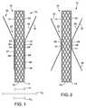
- FIG. 1illustrates a prosthesis 10 in accordance with an embodiment of the present invention.
- the prosthesis 10includes a body 12 having proximal portion 14, a distal portion 16 and a lumen 18 extending therethrough.
- the body 12may be an expandable stent, such as a self-expanding stent.
- the stentmay be coated or non-coated.
- the body 12may be a non-expandable tubular stent.
- the prosthesis 10further includes a sleeve 22 having a connected portion 24 operably connecting the sleeve 22 to the body 12 at at least one position along the body 12. At least a portion of the body 12 extends through a portion of a sleeve lumen 23 so that the sleeve and body coextend, for example, across the peritoneum.
- the sleeve 22is connected to the body 12 in such a way that fluid can pass through the sleeve lumen 23 between an outer surface 26 of the body 12 and an inner surface 28 of the sleeve 22.
- the connected portion 24 of the sleeve 22is configured so that the connected portion 24 still allows fluid flow through the sleeve lumen 23 generally from a distal portion 32 of the sleeve 22 to a proximal portion 36 of the sleeve 22.
- the connected portion 24may be a single connection point.
- the connected portion 24may be a longitudinally extending connection so that a majority of a circumference 37 of the sleeve 22 is unconnected to the body 12.
- the connected portion 24may be a plurality of connections to the body 12, for example at points spaced apart around a circumference 38 of the body 12.
- the connected portions 24may be spaced about by 60°, 90°, 120°, 180° and the like. Several rows of connected portions 24 may be used. Other connection configurations are also possible that connect the sleeve 22 to the body 12 and still allow fluid flow through the sleeve lumen 23 between the sleeve 22 and the body 12. As shown in FIG. 1 , the connected portion 24 may be positioned away from the distal portion 16 of the body 12. In some embodiments, one or more connected portions 24 may be positioned at or near a mid portion 34 of the body 12. The connected portion 24 may be positioned so that the connected portion 24 is positioned within the bile duct or outside of the bile duct as described in more detail below.
- the distal portion 32 of the sleeve 22is unconnected to the body 12 of the prosthesis 10 and includes sufficient material to extend away from the body 12 as will be explained in more detail below.
- the sleeve 22is formed of a liquid impermeable, thin, flexible polymeric material so that the liquid transported through the sleeve 22 exits at the proximal portion 36 of the sleeve 22 and not through a wall of the sleeve 22.
- the distal portion 32 of the sleeve 22may be collapsed against the body 12 for delivery of the prosthesis 10 to the bodily lumen and then the distal portion 32 may be extended away from the body 12 when the prosthesis 10 is in positioned within the bodily lumen.
- the proximal portion 36 of the sleeve 22may be sized and shaped to fit close to the body 12 as shown in FIG. 1 or to include sufficient material to extend away from the body 12 as shown in FIG. 2 .
- the proximal portion 36 of the sleeve 22may be connected to the body 12 by a connected portion 24.
- the proximal portion 36 of the sleeve 22may be unconnected to the body 12 and closely fit to the body 12 or extended away from the body 12.
- the proximal portion 14 of the body 12may extend proximal to the proximal portion 36 of the sleeve 22 as shown in FIG. 1 .
- the proximal portion 36 of the sleeve 22may extend proximal to the proximal portion 14 of the body 12 as shown in FIG. 3 and described in more detail below.
- a diameter d 1 of the proximal portion 36 of the sleeve 22may be smaller than a diameter d 2 of the distal portion 32 of the sleeve 22 as shown in FIG. 1 .
- the diameter d 1 of the proximal portion 36may be the same or greater than the diameter d 2 of the distal portion 36 of the sleeve 22.
- the diameter d 2 of the distal portion 36 of the sleeve 22is greater than a diameter d 3 surrounding the mid portion 34 of the body 12.
- a mid portion 37 of the sleeve 22 surrounding the mid portion 34 of the body 12is sized so that a diameter 39 of the mid portion 37 of the sleeve 22 is slightly larger than a diameter 41 of the mid portion 34 of the body 12.
- the proximal portion 36 of the sleeve 22may extend proximal to the proximal portion 14 of the body 12. As shown, the proximal portion 36 may close on itself in the absence of fluid flowing through the body 12 or the sleeve 22. In some embodiments, the proximal portion 36 may form a one-way valve that allows bile to flow into the duodenum or the stomach but prevents contents from the duodenum or the stomach from traveling through the lumen 18 of the body 12 to the bile duct.
- FIG. 4illustrates an alternative embodiment of the prosthesis 10 showing a valve 40 extending proximally from the proximal portion 14 of the body 12.
- the valve 40may be separate from the sleeve 22 so that the distal portion 36 of the sleeve 22 is distal to the valve 40.
- the distal portion 36may be similar to the distal portions 36 in the embodiments described above.
- the valve 40may be a one-way valve so that contents from the duodenum or the stomach do not travel through the lumen 18 of the body 12 to the bile duct.
- the valve 40may be a one-way valve positioned within the lumen 18 of the body 12 as shown in FIG. 5 .
- FIGS. 6 and 7illustrate cross-sectional views through the body 12 of the prosthesis 10.
- FIG. 6illustrates the body 12 having a substantially uniform circumference 38.
- the connected portion 24is shown with the sleeve 22 connected to the body 12.
- the sleeve lumen 23 and the body lumen 18are also shown.
- FIG. 7illustrates an alternative embodiment showing the body 12 having one or more channels 52 involuted from the surface 26 of the body 12.
- the connected portions 24are spaced apart from the channels 52 so that the sleeve lumen 23 is positioned between the body 12 and the sleeve 22.
- the channels 52allow for fluid to continue flowing within the lumen 23 in the event that the sleeve 22 is pressed against the body 12 at an unconnected portion and fluid flow is inhibited.
- FIGS. 8 and 9illustrate embodiments of a prosthesis 100.
- the prosthesis 100includes a body 112 having proximal portion 114, a distal portion 116 and a lumen 118 extending therethrough.
- the body 112is provided as a non-expandable tubular stent.
- the body 112is shown as a double pigtail stent but may also be provided having a single pigtail and/or skived portions on the proximal and/or distal portions 114, 116 to help hold the body 112 in position within the bodily site.
- the prosthesis 100further includes a sleeve 122 having a connected portion 124 to operably connect the sleeve 122 to the body 112 at at least one position along the body 112.
- the sleeve 122is connected to the body 112 in such a way that fluid can pass through a sleeve lumen 123 between an outer surface 126 of the body 112 and an inner surface 128 of the sleeve 122.
- the connected portion 124 of the sleeve 122is configured so that the connected portion 124 still allows fluid flow through the sleeve lumen 123 generally from a distal portion 132 of the sleeve 122 to a proximal portion 136 of the sleeve 122.
- the connected portion 124may be similar to the connected portion 24 described above.
- the distal portion 132 of the sleeve 122is unconnected to the body 112 of the prosthesis 100 and includes sufficient material to extend away from the body 112 as will be explained in more detail below.
- the distal portion 132 of the sleeve 122may be collapsed against the body 112 for delivery of the prosthesis 100 to the bodily lumen and then the distal portion 132 may be extended away from the body 112 when the prosthesis 100 is in positioned within the bodily lumen.
- the proximal portion 136 of the sleeve 122may be sized and shaped to fit close to the body 112 as shown in FIG. 8 or to include sufficient material to extend away from the body 112 as shown in FIG. 9 .
- the proximal portion 136 of the sleeve 122may be connected to the body 112 by a connected portion 124.
- the proximal portion 136 of the sleeve 122may be unconnected to the body 112 and sized closely fit to the body 112 or extended away from the body 112.
- a diameter d 1 of the proximal portion 136 of the sleeve 122may be smaller than a diameter d 2 of the distal portion 132 of the sleeve 122 as shown in FIG. 8 .
- the diameter d 1 of the proximal portion 36may be the same or greater than the diameter d 2 of the distal portion 36 of the sleeve 22.
- the prosthesis 100may include one or more channels 152 similar to the channels 52 described above.
- FIG. 10illustrates an embodiment of the prosthesis 10 wherein the body 12 includes an expanded proximal end portion 56 and an expanded distal end portion 58 that have larger diameters than a central portion 62 of the body 12.
- the expanded proximal and distal end portions 56, 58may be used to help hold the prosthesis 10 in position within the body of the patient.
- the distal portion 32 of the sleeve 22is shown expanded away from the distal end portion 58 of the body 12. Fluid may enter the sleeve lumen 23 or the body lumen 18 to drain fluid out of the duct as described in more detail below.
- FIG. 11illustrates the prosthesis 10 with the distal portion 16 of the body 12 positioned within the gall bladder or a hepatic duct 226 of the liver 227.
- the distal portion 32 of the sleeve 22is positioned in the duct 226.
- the sleeve 22is shown extended away from the distal portion 16 of the body 12 and positioned against a wall 225 of the duct 226.
- the distal portion 32 of the sleeve 22is made of a flexible material so that the distal portion 32 can abut the wall 225 and generally conform to the shape of the wall 225 so that bile needing to drain from the duct 226 is captured by the distal portion 32 of the sleeve 22 and directed to the sleeve lumen 23.
- the bilecan also drain through the lumen 18 of the body 12.
- the body 12 and the sleeve 22extend through the wall 225 of the duct 226, across the peritoneum 228, through a wall 229 of the gastrointestinal tract 230 and into the gastrointestinal tract 230.
- the proximal portion 14 of the body 12is positioned within the gastrointestinal tract 230.
- the proximal portion 36 of the sleeve 22also extends into the gastrointestinal tract 230 so that fluid entering the sleeve lumen 23 in the duct 226 is released in the gastrointestinal tract 230 and not the peritoneum 228.
- the sleeve 22extends across the peritoneum 228 and retains the fluid within the lumen 23 of the sleeve 22 until the sleeve 22 opens within the gastrointestinal tract 230.
- the sleeve 22may be connected to the body 12 at one or more connected portions 24.
- the connected portionmay be positioned near the wall 225 so that the distal portion 32 is free to expand against the wall 225 but once the sleeve 22 exits the wall 225, the connected portion 24helps to maintain the sleeve 22 in close proximity to the body 12 so that the sleeve 22 does not gather together and block flow through the sleeve lumen 23.
- the sleeve 22may be sized and shaped to closely fit over the body 12 once the body 12 exits the wall 225 yet allows fluid flow through the sleeve lumen. In some embodiments, the sleeve 22 may be formed of stiffer material relative to the distal portion 32 once the sleeve 22 exits the wall 225. The length of the body 12 and the sleeve 22 will vary depending on the patient and will have sufficient length to extend between the duct 226 and the gastrointestinal tract 230.
- the materials used to manufacture the components of the prosthetic devices described hereinmay be any materials known to one skilled in the art that are suitable for use in patients.
- the bodymay be formed from metals or polymers. Suitable exemplary metals include stainless steel and nitinol. In some embodiments, the body may be woven or provided in a zig-zag configuration.
- Sleeves of the prosthetic devices of the embodimentsmay be made from any suitable biocompatible material that is liquid impermeable and that does not degrade in the presence of fluids or gastric material that comes in contact therewith.
- the sleevemay be made from a medical grade expanded PTFE, polyurethane material, silicone, nylon, polyamides such as other urethanes, or other biocompatible materials that are flexible and acid resistant.
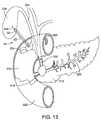
- FIGS. 12-14illustrate delivery of the prosthesis 10.
- the pancreatic duct 200 of the pancreas 210is shown having an obstruction 214 obstructing the common bile duct 220 and the pancreatic duct 200.
- the obstruction 214prevents the placement of a biliary stent within the common bile duct 220 to allow the bile to drain.
- an endoscope or an endoscopic ultrasound (EUS) devicethat utilizes high frequency sound waves to create an image of living tissue or an echogenic surface, is positioned in the duodenum 212.
- An EUS device 232is shown in FIG. 12 having an ultrasonic array of transducers 234 at the distal end 238of the endoscope 232.
- the transducers 234may be connected to an imaging system (not shown) for viewing the image created by the ultrasonic transducers 234 to facilitate placement of the prosthesis 10.
- the transducers 234generate an ultrasonic scanning plane to permit real-time monitoring of an insertion needle 242 having an echogenic surface. As shown in FIG. 12 , the needle 242 is used to puncture the bile duct 226.
- Bilemay be withdrawn through the needle and contrast may be injected to facilitate delivery of the prosthesis 10.
- a wire guide 244may be inserted through the needle 242 and delivered to the bile duct 226.
- the prosthesis 10is delivered from the duodenum 212 over the wire guide 244 into the gall bladder 226 as shown in FIG. 13 .
- the sleeve 22is delivered to the site positioned against the body 12. In some embodiments, an outer sheath may be placed over the sleeve 22 and body 12 for delivery of the prosthesis 10 to the site.
- the distal portion 32 of the sleeve 22is temporarily secured to the distal portion 16 of the body 12, for example by a releasable suture or by a temporary glue that dissolves on contact with bodily fluids.
- Other methods for temporarily securing the distal portion 32 of the sleeve 22 to the body 12are also possible.
- FIG. 14illustrates the prosthesis 10 positioned in the gall bladder 226 and extending across the peritoneum 228 into the duodenum 212.
- the distal portion 32 of the sleeve 22is shown extended away from the distal portion 16 of the body 12 and positioned against the wall 225 of the gall bladder 226, generally conforming to the shape of the wall 225 so that bile needing to drain from the gall bladder 226 is captured by the distal portion 32 of the sleeve 22 and directed to the sleeve lumen 23.
- the bilecan also drain through the lumen 18 of the body 12.
- the proximal portion 14 of the body 12is positioned within the duodenum 212.
- the proximal portion 36 of the sleeve 22also extends into the duodenum 212 so that fluid entering the sleeve lumen 23 in the gall bladder 226 is released in the duodenum 212 and not the peritoneum 228.
- the sleeve 22extends across the peritoneum 228 and retains the fluid within the lumen 23 of the sleeve 22 until the sleeve 22 opens within the duodenum 212.
- the body 12may be expanded so that the diameter of the expanded stent is less than the diameter of the sleeve, at least at the mid portion of both the body and the sleeve.
Landscapes
- Health & Medical Sciences (AREA)
- Life Sciences & Earth Sciences (AREA)
- Engineering & Computer Science (AREA)
- Biomedical Technology (AREA)
- Animal Behavior & Ethology (AREA)
- Veterinary Medicine (AREA)
- Public Health (AREA)
- Heart & Thoracic Surgery (AREA)
- General Health & Medical Sciences (AREA)
- Surgery (AREA)
- Vascular Medicine (AREA)
- Transplantation (AREA)
- Oral & Maxillofacial Surgery (AREA)
- Cardiology (AREA)
- Nuclear Medicine, Radiotherapy & Molecular Imaging (AREA)
- Medical Informatics (AREA)
- Molecular Biology (AREA)
- Orthopedic Medicine & Surgery (AREA)
- Gastroenterology & Hepatology (AREA)
- Pulmonology (AREA)
- Physiology (AREA)
- Prostheses (AREA)
Description
- This application claims the benefit of
U.S. Provisional Application No. 61/576,152, filed December 15, 2011 - The present invention relates to medical devices and methods and in particular to a prosthesis having a sleeve to prevent leakage after a medical procedure in the gastrointestinal tract.
- Endoscopic biliary stenting is typically used to treat bile duct obstruction. In some cases, ERCP treatment of the bile duct fails or is not a viable treatment and surgery or percutaneous biliary drainage may be needed. However, surgery and percutaneous biliary drainage have a relatively high complication rate. Recently, transgastric endoscopic ultrasonography (EUS) has been used to provide imaging of the left lobe of the liver, especially of dilated intrahepatic ducts in patients with biliary obstruction. Using EUS guidance, biliary drainage can be provided by hepaticogastrostomy or choledochoduodenstomy approaches for placing a stent for biliary decompression. Hepaticogastrostomy or choledochoduodenstomy approaches have been shown to have lower complication rates than surgery or percutaneous drainage.
- One potential complication of the hepaticogastrostomy or choledochoduodenstomy approach to treating biliary obstruction is the potential for bile to leak into the peritoneum. Bile leaks into the peritoneum when the bile flows outside of the wall of a stent placed between the hepatic biliary system (including extrahepatic bile ducts and/or intrahepatic bile ducts) and the stomach or the duodenum.
- Reference is directed to
US 2011/0054381 which discloses a biliary shunt for deployment between a gallbladder and a location within a gastrointestinal tract of a patient. That component may have an element inserted into the inner lumen or passageway, which element may include a valve. The inserted element may also provide rigidity or support. The inserted element may be secured within the component by an O ring or an adhesive. - Reference is also directed to
US 2003/0236567 which discloses an implantable prosthesis having a radially-expandable tubular body and at least one skirt extending therefrom. The skirt terminates in a peripheral edge, wherein at least portions of the peripheral edge are free and displaceable to a greater diameter of the tubular body. Thus, with the implantable prosthesis being a stent-graft used to treat an aortic aneurysm, the skirt may be used to inhibit endoleaks upon its selective displacement in response to irregular aortic shaping and/or aneurysm neck expansion. The skirt may actively inhibit endoleaks by forming a physical barrier against flow between the tubular body and the aortic wall. - What is needed in the art is a prosthesis and a method for biliary decompression that minimizes the potential for peritoneal biliary leakage.
- Accordingly, it is an object of the present invention to provide a device having features that resolve or improve on the above-described drawbacks.
- The scope of the present invention is set forth in the appended claims. A prosthesis for directing flow through a passageway formed between a first bodily lumen and a second bodily lumen is provided. The prosthesis includes a body having a proximal portion, a distal portion and a lumen extending therethrough. The prosthesis also includes a sleeve operably connected to the body at a connected portion. The sleeve has a proximal portion, a distal portion, and a sleeve lumen extending therethrough. At least a portion of the body is positioned within at least a portion of the sleeve lumen and the distal portion of the sleeve is free from connection to the distal portion of the body and extendable away from the body to contact a wall of the first bodily lumen. The sleeve is configured to allow fluid flow through the sleeve lumen from the first bodily lumen to the second bodily lumen.
FIG. 1 is a sectional view of a prosthetic device in accordance with an embodiment of the present invention;FIG. 2 is a sectional view of a prosthetic device in accordance with an embodiment of the present invention;FIG. 3 is a sectional view of a prosthetic device in accordance with an embodiment of the present invention;FIG. 4 is a sectional view of a prosthetic device in accordance with an embodiment of the present invention;FIG. 5 is a sectional view of a prosthetic device in accordance with an embodiment of the present invention;FIG. 6 is a cross-sectional view of a prosthetic device in accordance with an embodiment of the present invention;FIG. 7 is a cross-sectional view of a prosthetic device in accordance with an embodiment of the present invention;FIG. 8 is a side view of a prosthetic device in accordance with an embodiment of the present invention;FIG. 9 is a side view of a prosthetic device in accordance with an embodiment of the present invention;FIG. 10 is a sectional view of a prosthetic device in accordance with an embodiment of the present invention;FIG. 11 illustrates an embodiment of a prosthetic device operably connecting the biliary tract and the gastrointestinal intestinal tract; andFIG. 12-14 illustrate delivery of an embodiment of a prosthetic device to the gall bladder and the gastrointestinal tract.- The invention is described with reference to the drawings in which like elements are referred to by like numerals. The relationship and functioning of the various elements of this invention are better understood by the following detailed description. However, the embodiments of this invention are not limited to the embodiments illustrated in the drawings. It should be understood that the drawings are not to scale, and in certain instances details have been omitted which are not necessary for an understanding of the present invention, such as conventional fabrication and assembly.
- As used in the specification, the terms proximal and distal should be understood as being in the terms of a physician delivering the prosthesis to a patient. Hence the term "distal" means the portion of the prosthesis that is farthest from the physician and the term "proximal" means the portion of the prosthesis that is nearest to the physician.
- The present invention relates to medical devices, and in particular to a prosthesis for implantation in a body to form a conduit between two organs such as the bile duct and the stomach or the duodenum. As used herein, the term "implantable" refers to an ability of a medical device to be positioned at a location within a body, either temporarily, semi-permanently, or permanently. Permanent fixation of the device in a particular position is not required. Furthermore, the terms "implantation" and "implanted" refer to the positioning of a medical device at a location within a body.
FIG. 1 illustrates aprosthesis 10 in accordance with an embodiment of the present invention. Theprosthesis 10 includes abody 12 havingproximal portion 14, adistal portion 16 and alumen 18 extending therethrough. In some embodiments, thebody 12 may be an expandable stent, such as a self-expanding stent. The stent may be coated or non-coated. In some embodiments, thebody 12 may be a non-expandable tubular stent.- The
prosthesis 10 further includes asleeve 22 having a connectedportion 24 operably connecting thesleeve 22 to thebody 12 at at least one position along thebody 12. At least a portion of thebody 12 extends through a portion of asleeve lumen 23 so that the sleeve and body coextend, for example, across the peritoneum. Thesleeve 22 is connected to thebody 12 in such a way that fluid can pass through thesleeve lumen 23 between anouter surface 26 of thebody 12 and aninner surface 28 of thesleeve 22. The connectedportion 24 of thesleeve 22 is configured so that the connectedportion 24 still allows fluid flow through thesleeve lumen 23 generally from adistal portion 32 of thesleeve 22 to aproximal portion 36 of thesleeve 22. In some embodiments, the connectedportion 24 may be a single connection point. In some embodiments, the connectedportion 24 may be a longitudinally extending connection so that a majority of acircumference 37 of thesleeve 22 is unconnected to thebody 12. In yet other embodiments, the connectedportion 24 may be a plurality of connections to thebody 12, for example at points spaced apart around acircumference 38 of thebody 12. By way of non-limiting example, theconnected portions 24 may be spaced about by 60°, 90°, 120°, 180° and the like. Several rows ofconnected portions 24 may be used. Other connection configurations are also possible that connect thesleeve 22 to thebody 12 and still allow fluid flow through thesleeve lumen 23 between thesleeve 22 and thebody 12. As shown inFIG. 1 , the connectedportion 24 may be positioned away from thedistal portion 16 of thebody 12. In some embodiments, one or moreconnected portions 24 may be positioned at or near amid portion 34 of thebody 12. The connectedportion 24 may be positioned so that the connectedportion 24 is positioned within the bile duct or outside of the bile duct as described in more detail below. - As shown in
FIGS. 1 and 2 , thedistal portion 32 of thesleeve 22 is unconnected to thebody 12 of theprosthesis 10 and includes sufficient material to extend away from thebody 12 as will be explained in more detail below. Thesleeve 22 is formed of a liquid impermeable, thin, flexible polymeric material so that the liquid transported through thesleeve 22 exits at theproximal portion 36 of thesleeve 22 and not through a wall of thesleeve 22. Thedistal portion 32 of thesleeve 22 may be collapsed against thebody 12 for delivery of theprosthesis 10 to the bodily lumen and then thedistal portion 32 may be extended away from thebody 12 when theprosthesis 10 is in positioned within the bodily lumen. - The
proximal portion 36 of thesleeve 22 may be sized and shaped to fit close to thebody 12 as shown inFIG. 1 or to include sufficient material to extend away from thebody 12 as shown inFIG. 2 . In some embodiments, theproximal portion 36 of thesleeve 22 may be connected to thebody 12 by a connectedportion 24. In other embodiments, theproximal portion 36 of thesleeve 22 may be unconnected to thebody 12 and closely fit to thebody 12 or extended away from thebody 12. In some embodiments, theproximal portion 14 of thebody 12 may extend proximal to theproximal portion 36 of thesleeve 22 as shown inFIG. 1 . In some embodiments, theproximal portion 36 of thesleeve 22 may extend proximal to theproximal portion 14 of thebody 12 as shown inFIG. 3 and described in more detail below. In some embodiments, a diameter d1 of theproximal portion 36 of thesleeve 22 may be smaller than a diameter d2 of thedistal portion 32 of thesleeve 22 as shown inFIG. 1 . In some embodiments, the diameter d1 of theproximal portion 36 may be the same or greater than the diameter d2 of thedistal portion 36 of thesleeve 22. The diameter d2 of thedistal portion 36 of thesleeve 22 is greater than a diameter d3 surrounding themid portion 34 of thebody 12. In some embodiments, amid portion 37 of thesleeve 22 surrounding themid portion 34 of thebody 12 is sized so that adiameter 39 of themid portion 37 of thesleeve 22 is slightly larger than adiameter 41 of themid portion 34 of thebody 12. - As shown in
FIG. 3 , theproximal portion 36 of thesleeve 22 may extend proximal to theproximal portion 14 of thebody 12. As shown, theproximal portion 36 may close on itself in the absence of fluid flowing through thebody 12 or thesleeve 22. In some embodiments, theproximal portion 36 may form a one-way valve that allows bile to flow into the duodenum or the stomach but prevents contents from the duodenum or the stomach from traveling through thelumen 18 of thebody 12 to the bile duct. FIG. 4 illustrates an alternative embodiment of theprosthesis 10 showing avalve 40 extending proximally from theproximal portion 14 of thebody 12. Thevalve 40 may be separate from thesleeve 22 so that thedistal portion 36 of thesleeve 22 is distal to thevalve 40. Thedistal portion 36 may be similar to thedistal portions 36 in the embodiments described above. Thevalve 40 may be a one-way valve so that contents from the duodenum or the stomach do not travel through thelumen 18 of thebody 12 to the bile duct. In some embodiments, thevalve 40 may be a one-way valve positioned within thelumen 18 of thebody 12 as shown inFIG. 5 .FIGS. 6 and 7 illustrate cross-sectional views through thebody 12 of theprosthesis 10.FIG. 6 illustrates thebody 12 having a substantiallyuniform circumference 38. The connectedportion 24 is shown with thesleeve 22 connected to thebody 12. Thesleeve lumen 23 and thebody lumen 18 are also shown.FIG. 7 illustrates an alternative embodiment showing thebody 12 having one ormore channels 52 involuted from thesurface 26 of thebody 12. Theconnected portions 24 are spaced apart from thechannels 52 so that thesleeve lumen 23 is positioned between thebody 12 and thesleeve 22. Thechannels 52 allow for fluid to continue flowing within thelumen 23 in the event that thesleeve 22 is pressed against thebody 12 at an unconnected portion and fluid flow is inhibited.FIGS. 8 and 9 illustrate embodiments of aprosthesis 100. Theprosthesis 100 includes abody 112 havingproximal portion 114, adistal portion 116 and alumen 118 extending therethrough. As shown inFIGS. 8 and 9 , thebody 112 is provided as a non-expandable tubular stent. Thebody 112 is shown as a double pigtail stent but may also be provided having a single pigtail and/or skived portions on the proximal and/ordistal portions body 112 in position within the bodily site.- The
prosthesis 100 further includes asleeve 122 having a connectedportion 124 to operably connect thesleeve 122 to thebody 112 at at least one position along thebody 112. Thesleeve 122 is connected to thebody 112 in such a way that fluid can pass through asleeve lumen 123 between anouter surface 126 of thebody 112 and aninner surface 128 of thesleeve 122. Theconnected portion 124 of thesleeve 122 is configured so that theconnected portion 124 still allows fluid flow through thesleeve lumen 123 generally from adistal portion 132 of thesleeve 122 to aproximal portion 136 of thesleeve 122. Theconnected portion 124 may be similar to the connectedportion 24 described above. As shown inFIGS. 8 and 9 , thedistal portion 132 of thesleeve 122 is unconnected to thebody 112 of theprosthesis 100 and includes sufficient material to extend away from thebody 112 as will be explained in more detail below. Thedistal portion 132 of thesleeve 122 may be collapsed against thebody 112 for delivery of theprosthesis 100 to the bodily lumen and then thedistal portion 132 may be extended away from thebody 112 when theprosthesis 100 is in positioned within the bodily lumen. - The
proximal portion 136 of thesleeve 122 may be sized and shaped to fit close to thebody 112 as shown inFIG. 8 or to include sufficient material to extend away from thebody 112 as shown inFIG. 9 . In some embodiments, theproximal portion 136 of thesleeve 122 may be connected to thebody 112 by aconnected portion 124. In other embodiments, theproximal portion 136 of thesleeve 122 may be unconnected to thebody 112 and sized closely fit to thebody 112 or extended away from thebody 112. In some embodiments, a diameter d1 of theproximal portion 136 of thesleeve 122 may be smaller than a diameter d2 of thedistal portion 132 of thesleeve 122 as shown inFIG. 8 . In some embodiments, the diameter d1 of theproximal portion 36 may be the same or greater than the diameter d2 of thedistal portion 36 of thesleeve 22. - In some embodiments, the
prosthesis 100 may include one or more channels 152 similar to thechannels 52 described above. FIG. 10 illustrates an embodiment of theprosthesis 10 wherein thebody 12 includes an expandedproximal end portion 56 and an expandeddistal end portion 58 that have larger diameters than acentral portion 62 of thebody 12. The expanded proximal anddistal end portions prosthesis 10 in position within the body of the patient. Thedistal portion 32 of thesleeve 22 is shown expanded away from thedistal end portion 58 of thebody 12. Fluid may enter thesleeve lumen 23 or thebody lumen 18 to drain fluid out of the duct as described in more detail below.FIG. 11 illustrates theprosthesis 10 with thedistal portion 16 of thebody 12 positioned within the gall bladder or ahepatic duct 226 of theliver 227. Thedistal portion 32 of thesleeve 22 is positioned in theduct 226. Thesleeve 22 is shown extended away from thedistal portion 16 of thebody 12 and positioned against awall 225 of theduct 226. Thedistal portion 32 of thesleeve 22 is made of a flexible material so that thedistal portion 32 can abut thewall 225 and generally conform to the shape of thewall 225 so that bile needing to drain from theduct 226 is captured by thedistal portion 32 of thesleeve 22 and directed to thesleeve lumen 23. The bile can also drain through thelumen 18 of thebody 12. As shown inFIG. 11 , thebody 12 and thesleeve 22 extend through thewall 225 of theduct 226, across theperitoneum 228, through awall 229 of thegastrointestinal tract 230 and into thegastrointestinal tract 230. Theproximal portion 14 of thebody 12 is positioned within thegastrointestinal tract 230. Theproximal portion 36 of thesleeve 22 also extends into thegastrointestinal tract 230 so that fluid entering thesleeve lumen 23 in theduct 226 is released in thegastrointestinal tract 230 and not theperitoneum 228. Thesleeve 22 extends across theperitoneum 228 and retains the fluid within thelumen 23 of thesleeve 22 until thesleeve 22 opens within thegastrointestinal tract 230. Thesleeve 22 may be connected to thebody 12 at one or moreconnected portions 24. For example, the connected portion may be positioned near thewall 225 so that thedistal portion 32 is free to expand against thewall 225 but once thesleeve 22 exits thewall 225, the connected portion 24helps to maintain thesleeve 22 in close proximity to thebody 12 so that thesleeve 22 does not gather together and block flow through thesleeve lumen 23. In some embodiments, thesleeve 22 may be sized and shaped to closely fit over thebody 12 once thebody 12 exits thewall 225 yet allows fluid flow through the sleeve lumen. In some embodiments, thesleeve 22 may be formed of stiffer material relative to thedistal portion 32 once thesleeve 22 exits thewall 225. The length of thebody 12 and thesleeve 22 will vary depending on the patient and will have sufficient length to extend between theduct 226 and thegastrointestinal tract 230.- The materials used to manufacture the components of the prosthetic devices described herein may be any materials known to one skilled in the art that are suitable for use in patients. By way of non-limiting example, the body may be formed from metals or polymers. Suitable exemplary metals include stainless steel and nitinol. In some embodiments, the body may be woven or provided in a zig-zag configuration. Sleeves of the prosthetic devices of the embodiments may be made from any suitable biocompatible material that is liquid impermeable and that does not degrade in the presence of fluids or gastric material that comes in contact therewith. By way of non-limiting example, the sleeve may be made from a medical grade expanded PTFE, polyurethane material, silicone, nylon, polyamides such as other urethanes, or other biocompatible materials that are flexible and acid resistant.
- Delivery of the prosthesis will be explained with reference to the
prosthesis 10 as an example and being positioned between the gall bladder and the duodenum. One skilled in the art will also understand that theprosthesis FIGS. 12-14 illustrate delivery of theprosthesis 10. For reference, thepancreatic duct 200 of thepancreas 210 is shown having anobstruction 214 obstructing thecommon bile duct 220 and thepancreatic duct 200. Theobstruction 214 prevents the placement of a biliary stent within thecommon bile duct 220 to allow the bile to drain. - Typically an endoscope or an endoscopic ultrasound (EUS) device that utilizes high frequency sound waves to create an image of living tissue or an echogenic surface, is positioned in the
duodenum 212. AnEUS device 232 is shown inFIG. 12 having an ultrasonic array oftransducers 234 at the distal end 238of theendoscope 232. Thetransducers 234 may be connected to an imaging system (not shown) for viewing the image created by theultrasonic transducers 234 to facilitate placement of theprosthesis 10. Thetransducers 234 generate an ultrasonic scanning plane to permit real-time monitoring of aninsertion needle 242 having an echogenic surface. As shown inFIG. 12 , theneedle 242 is used to puncture thebile duct 226. Bile may be withdrawn through the needle and contrast may be injected to facilitate delivery of theprosthesis 10. Awire guide 244 may be inserted through theneedle 242 and delivered to thebile duct 226. Theprosthesis 10 is delivered from theduodenum 212 over thewire guide 244 into thegall bladder 226 as shown inFIG. 13 . Thesleeve 22 is delivered to the site positioned against thebody 12. In some embodiments, an outer sheath may be placed over thesleeve 22 andbody 12 for delivery of theprosthesis 10 to the site. According to the invention, thedistal portion 32 of thesleeve 22 is temporarily secured to thedistal portion 16 of thebody 12, for example by a releasable suture or by a temporary glue that dissolves on contact with bodily fluids. Other methods for temporarily securing thedistal portion 32 of thesleeve 22 to thebody 12 are also possible. FIG. 14 illustrates theprosthesis 10 positioned in thegall bladder 226 and extending across theperitoneum 228 into theduodenum 212. Thedistal portion 32 of thesleeve 22 is shown extended away from thedistal portion 16 of thebody 12 and positioned against thewall 225 of thegall bladder 226, generally conforming to the shape of thewall 225 so that bile needing to drain from thegall bladder 226 is captured by thedistal portion 32 of thesleeve 22 and directed to thesleeve lumen 23. The bile can also drain through thelumen 18 of thebody 12. Theproximal portion 14 of thebody 12 is positioned within theduodenum 212. Theproximal portion 36 of thesleeve 22 also extends into theduodenum 212 so that fluid entering thesleeve lumen 23 in thegall bladder 226 is released in theduodenum 212 and not theperitoneum 228. Thesleeve 22 extends across theperitoneum 228 and retains the fluid within thelumen 23 of thesleeve 22 until thesleeve 22 opens within theduodenum 212. In some embodiments, where thebody 12 is an expandable stent, thebody 12 may be expanded so that the diameter of the expanded stent is less than the diameter of the sleeve, at least at the mid portion of both the body and the sleeve.- The above Figures and disclosure are intended to be illustrative and not exhaustive. This description will suggest many variations and alternatives to one of ordinary skill in the art. All such variations and alternatives are intended to be encompassed within the scope of the attached claims. Those familiar with the art may recognize other equivalents to the specific embodiments described herein which equivalents are also intended to be encompassed by the attached claims.
Claims (15)
- A prosthesis (10) for directing flow through a passageway formed between a first bodily lumen and a second bodily lumen, the prosthesis comprising:a body (12) having a proximal portion (14), a distal portion (16) and a lumen (18) extending therethrough; anda sleeve (22) operably connected to the body at a connected portion (24), the sleeve having a proximal portion (36), a distal portion (32), and a sleeve lumen (23) extending therethrough, at least a portion of the body positioned within at least a portion of the sleeve lumen and the distal portion of the sleeve being in a use configuration free from connection to the distal portion of the body and extendable away from the body to contact a wall of the first bodily lumen,wherein the sleeve is configured to allow fluid flow through the sleeve lumen between an outer surface (26) of the body and an inner surface (28) of the sleeve from the first bodily lumen to the second bodily lumen;characterised in that in a delivery configuration the distal portion (32) of the sleeve (22) is temporarily secured to the distal portion (16) of the body (12).
- The prosthesis according to claim 1, wherein the distal portion (32) of the sleeve (22) is temporarily secured to the distal portion (16) of the body by a releasable suture or by a temporary glue that dissolves on contact with bodily fluids.
- The prosthesis according to claim 1, wherein the body (12) comprises a self-expanding stent or a non-expandable stent.
- The prosthesis according to any of claims 1-3, wherein the body (12) comprises a retention device at the proximal portion (14) or the distal portion (16) of the body or both the proximal portion and the distal portion of the body.
- The prosthesis according to claim 4, wherein the retention device comprises an expanded diameter (56, 58) at a distal end portion (16) of the body or a proximal end portion (14) of the body or both.
- The prosthesis according to claim 4, wherein the retention device comprises a pigtail configuration.
- The prosthesis according to any of claims 1-6, wherein the sleeve comprises polytetrafluoroethylene (PTFE).
- The prosthesis according to any of claims 1-7, wherein the sleeve comprises a fluid impermeable, flexible material so that the distal portion of the sleeve can conform to the wall of the first bodily lumen.
- The prosthesis according to any of claims 1-8, wherein a diameter of the sleeve distal portion is greater than a diameter of a mid portion of the sleeve.
- The prosthesis according to any of claims 1-9, wherein a diameter of the proximal portion of the sleeve is greater than a diameter of a mid portion of the sleeve.
- The prosthesis according to any of claims 1-8, wherein a diameter of a mid portion of the sleeve is greater than a diameter of a mid portion of the body and the mid portion of the sleeve and a mid portion of the body coaxially extend between the first body lumen and the second bodily lumen.
- The prosthesis according to any of claims 1-11, wherein the proximal portion of the sleeve is connected to the proximal portion of the body.
- The prosthesis according to any of claims 1-12, wherein the sleeve extends proximal to the proximal portion of the body.
- The prosthesis according to any of claims 1-13, further comprising a valve (40) configured to restrict flow from the second bodily lumen toward the first bodily lumen.
- The prosthesis according to any of claims 1-14, wherein the body comprises at least one involuted portion (52) configured to facilitate flow through the lumen of the sleeve.
Applications Claiming Priority (1)
| Application Number | Priority Date | Filing Date | Title |
|---|---|---|---|
| US201161576152P | 2011-12-15 | 2011-12-15 |
Publications (2)
| Publication Number | Publication Date |
|---|---|
| EP2604223A1 EP2604223A1 (en) | 2013-06-19 |
| EP2604223B1true EP2604223B1 (en) | 2016-06-29 |
Family
ID=47602956
Family Applications (1)
| Application Number | Title | Priority Date | Filing Date |
|---|---|---|---|
| EP12197550.2AActiveEP2604223B1 (en) | 2011-12-15 | 2012-12-17 | Anti-leakage prosthesis |
Country Status (2)
| Country | Link |
|---|---|
| US (2) | US20130158673A1 (en) |
| EP (1) | EP2604223B1 (en) |
Families Citing this family (18)
| Publication number | Priority date | Publication date | Assignee | Title |
|---|---|---|---|---|
| CA3010828A1 (en)* | 2008-01-17 | 2009-07-23 | Boston Scientific Scimed, Inc. | Stent with anti-migration feature |
| EP3494934B1 (en)* | 2013-01-23 | 2022-12-21 | Cook Medical Technologies LLC | Stent with positioning arms |
| JP5408682B1 (en)* | 2013-06-28 | 2014-02-05 | ガデリウス・メディカル株式会社 | Stent kit |
| US9937067B2 (en)* | 2014-02-07 | 2018-04-10 | Cook Medical Technologies Llc | Telescoping ureteral stent |
| KR101604987B1 (en)* | 2014-03-28 | 2016-03-21 | 주식회사 에스앤지바이오텍 | Stent for preventing the regurgitation |
| WO2016141295A1 (en) | 2015-03-05 | 2016-09-09 | Merit Medical Systems, Inc. | Vascular prosthesis deployment device and method of use |
| EP3349687B1 (en)* | 2015-09-15 | 2020-09-09 | THE UNITED STATES OF AMERICA, represented by the S | Devices for effectuating percutaneous glenn and fontan procedures |
| US10470906B2 (en) | 2015-09-15 | 2019-11-12 | Merit Medical Systems, Inc. | Implantable device delivery system |
| US10130465B2 (en) | 2016-02-23 | 2018-11-20 | Abbott Cardiovascular Systems Inc. | Bifurcated tubular graft for treating tricuspid regurgitation |
| CN115054413A (en) | 2016-09-29 | 2022-09-16 | 美国医疗设备有限公司 | Method of adjusting effective length of stent and prosthesis delivery catheter assembly |
| EP4467111A3 (en) | 2017-03-15 | 2025-03-05 | Merit Medical Systems, Inc. | Transluminal stents |
| US11628078B2 (en) | 2017-03-15 | 2023-04-18 | Merit Medical Systems, Inc. | Transluminal delivery devices and related kits and methods |
| USD836194S1 (en) | 2017-03-21 | 2018-12-18 | Merit Medical Systems, Inc. | Stent deployment device |
| JP7249332B2 (en) | 2017-09-01 | 2023-03-30 | トランスミューラル システムズ エルエルシー | Percutaneous shunt device and related methods |
| WO2019209745A1 (en)* | 2018-04-23 | 2019-10-31 | Boston Scientific Scimed, Inc. | Stent with selectively covered region |
| JP2020189037A (en)* | 2019-05-24 | 2020-11-26 | ソウル ナショナル ユニバーシティ ホスピタル | Stent for connecting between different organs with pigtail structure |
| EP4185239A4 (en) | 2020-07-24 | 2024-08-07 | Merit Medical Systems, Inc. | ESOPHAGEAL STENT PROSTHESES AND RELATED METHODS |
| CA3194910A1 (en) | 2020-10-26 | 2022-05-05 | Tiffany ETHRIDGE | Esophageal stents with helical thread |
Citations (2)
| Publication number | Priority date | Publication date | Assignee | Title |
|---|---|---|---|---|
| US20030236567A1 (en)* | 2002-06-25 | 2003-12-25 | Scimed Life Systems, Inc. | Implantable prosthesis with displaceabe skirt |
| WO2013087096A1 (en)* | 2011-12-13 | 2013-06-20 | Ethicon Endo-Surgery, Inc. | Endoluminal sleeve device and methods for deploying an endoluminal sleeve in the gi tract |
Family Cites Families (9)
| Publication number | Priority date | Publication date | Assignee | Title |
|---|---|---|---|---|
| US5476434A (en)* | 1992-05-27 | 1995-12-19 | Kalb; Irvin M. | Female incontinence device including electronic sensors |
| US8911491B2 (en)* | 2005-09-02 | 2014-12-16 | Medtronic Vascular, Inc. | Methods and apparatus for treatment of aneurysms adjacent branch arteries including branch artery flow lumen alignment |
| US20070179599A1 (en)* | 2006-01-31 | 2007-08-02 | Icon Medical Corp. | Vascular protective device |
| US8376981B2 (en)* | 2006-03-02 | 2013-02-19 | Michael D. Laufer | Gastrointestinal implant and methods for use |
| US8715336B2 (en)* | 2007-04-19 | 2014-05-06 | Medtronic Vascular, Inc. | Methods and apparatus for treatment of aneurysms adjacent to branch arteries |
| US20090143759A1 (en) | 2007-11-30 | 2009-06-04 | Jacques Van Dam | Methods, Devices, Kits and Systems for Defunctionalizing the Cystic Duct |
| US9901347B2 (en)* | 2009-05-29 | 2018-02-27 | Terus Medical, Inc. | Biliary shunts, delivery systems, and methods of using the same |
| EP2803339B1 (en)* | 2010-03-26 | 2016-12-28 | Olympus Corporation | Medical stent |
| US9005275B2 (en)* | 2011-11-18 | 2015-04-14 | Mayo Foundation For Medical Education And Research | Methods for replacing a circumferential segment of an esophagus |
- 2012
- 2012-12-10USUS13/709,234patent/US20130158673A1/ennot_activeAbandoned
- 2012-12-17EPEP12197550.2Apatent/EP2604223B1/enactiveActive
- 2015
- 2015-11-12USUS14/939,696patent/US10092388B2/enactiveActive
Patent Citations (2)
| Publication number | Priority date | Publication date | Assignee | Title |
|---|---|---|---|---|
| US20030236567A1 (en)* | 2002-06-25 | 2003-12-25 | Scimed Life Systems, Inc. | Implantable prosthesis with displaceabe skirt |
| WO2013087096A1 (en)* | 2011-12-13 | 2013-06-20 | Ethicon Endo-Surgery, Inc. | Endoluminal sleeve device and methods for deploying an endoluminal sleeve in the gi tract |
Also Published As
| Publication number | Publication date |
|---|---|
| US20130158673A1 (en) | 2013-06-20 |
| US10092388B2 (en) | 2018-10-09 |
| US20160058545A1 (en) | 2016-03-03 |
| EP2604223A1 (en) | 2013-06-19 |
Similar Documents
| Publication | Publication Date | Title |
|---|---|---|
| EP2604223B1 (en) | Anti-leakage prosthesis | |
| KR102247660B1 (en) | Biliary stent | |
| US11529143B2 (en) | Flow control valve | |
| JP5531016B2 (en) | Stent graft fixation coupling | |
| JP6261339B2 (en) | Apparatus and method for placement of a graft or graft system | |
| CN103501735B (en) | Medical Devices for Stomas | |
| JP2021142324A (en) | Stent with dual tissue-wall anchoring mechanism | |
| CA2777960C (en) | Balloon-tipped endoscopic system with inverted sleeve | |
| US20220323731A1 (en) | Systems and methods for percutaneous body lumen drainage | |
| KR20190056395A (en) | Anastomosed drainage stent | |
| AU2022200146B2 (en) | Stomach lining funnel with anastomosis | |
| US20220361865A1 (en) | Retrievable access valve | |
| PL219405B1 (en) | System for positioning of the stent, particularly intestinal and the stent, particularly intestinal |
Legal Events
| Date | Code | Title | Description |
|---|---|---|---|
| PUAI | Public reference made under article 153(3) epc to a published international application that has entered the european phase | Free format text:ORIGINAL CODE: 0009012 | |
| AK | Designated contracting states | Kind code of ref document:A1 Designated state(s):AL AT BE BG CH CY CZ DE DK EE ES FI FR GB GR HR HU IE IS IT LI LT LU LV MC MK MT NL NO PL PT RO RS SE SI SK SM TR | |
| AX | Request for extension of the european patent | Extension state:BA ME | |
| 17P | Request for examination filed | Effective date:20131218 | |
| RBV | Designated contracting states (corrected) | Designated state(s):AL AT BE BG CH CY CZ DE DK EE ES FI FR GB GR HR HU IE IS IT LI LT LU LV MC MK MT NL NO PL PT RO RS SE SI SK SM TR | |
| 17Q | First examination report despatched | Effective date:20150413 | |
| RIC1 | Information provided on ipc code assigned before grant | Ipc:A61B 17/22 20060101ALN20151020BHEP Ipc:A61F 2/04 20130101AFI20151020BHEP Ipc:A61F 2/07 20130101ALN20151020BHEP Ipc:A61F 2/06 20130101ALI20151020BHEP Ipc:A61B 17/11 20060101ALN20151020BHEP | |
| GRAP | Despatch of communication of intention to grant a patent | Free format text:ORIGINAL CODE: EPIDOSNIGR1 | |
| INTG | Intention to grant announced | Effective date:20151216 | |
| RIC1 | Information provided on ipc code assigned before grant | Ipc:A61F 2/07 20130101ALN20151204BHEP Ipc:A61B 17/11 20060101ALN20151204BHEP Ipc:A61B 17/22 20060101ALN20151204BHEP Ipc:A61F 2/06 20060101ALI20151204BHEP Ipc:A61F 2/04 20060101AFI20151204BHEP | |
| GRAS | Grant fee paid | Free format text:ORIGINAL CODE: EPIDOSNIGR3 | |
| GRAR | Information related to intention to grant a patent recorded | Free format text:ORIGINAL CODE: EPIDOSNIGR71 | |
| GRAA | (expected) grant | Free format text:ORIGINAL CODE: 0009210 | |
| RIC1 | Information provided on ipc code assigned before grant | Ipc:A61B 17/221 20060101ALN20160425BHEP Ipc:A61B 17/22 20060101ALN20160425BHEP Ipc:A61F 2/04 20060101AFI20160425BHEP Ipc:A61F 2/06 20060101ALI20160425BHEP Ipc:A61M 27/00 20060101ALN20160425BHEP Ipc:A61F 2/07 20130101ALN20160425BHEP Ipc:A61B 17/11 20060101ALN20160425BHEP | |
| AK | Designated contracting states | Kind code of ref document:B1 Designated state(s):AL AT BE BG CH CY CZ DE DK EE ES FI FR GB GR HR HU IE IS IT LI LT LU LV MC MK MT NL NO PL PT RO RS SE SI SK SM TR | |
| INTG | Intention to grant announced | Effective date:20160520 | |
| REG | Reference to a national code | Ref country code:GB Ref legal event code:FG4D | |
| REG | Reference to a national code | Ref country code:CH Ref legal event code:EP | |
| REG | Reference to a national code | Ref country code:AT Ref legal event code:REF Ref document number:808473 Country of ref document:AT Kind code of ref document:T Effective date:20160715 | |
| REG | Reference to a national code | Ref country code:IE Ref legal event code:FG4D | |
| REG | Reference to a national code | Ref country code:DE Ref legal event code:R096 Ref document number:602012019923 Country of ref document:DE | |
| REG | Reference to a national code | Ref country code:LT Ref legal event code:MG4D | |
| PG25 | Lapsed in a contracting state [announced via postgrant information from national office to epo] | Ref country code:LT Free format text:LAPSE BECAUSE OF FAILURE TO SUBMIT A TRANSLATION OF THE DESCRIPTION OR TO PAY THE FEE WITHIN THE PRESCRIBED TIME-LIMIT Effective date:20160629 Ref country code:NO Free format text:LAPSE BECAUSE OF FAILURE TO SUBMIT A TRANSLATION OF THE DESCRIPTION OR TO PAY THE FEE WITHIN THE PRESCRIBED TIME-LIMIT Effective date:20160929 Ref country code:FI Free format text:LAPSE BECAUSE OF FAILURE TO SUBMIT A TRANSLATION OF THE DESCRIPTION OR TO PAY THE FEE WITHIN THE PRESCRIBED TIME-LIMIT Effective date:20160629 | |
| REG | Reference to a national code | Ref country code:NL Ref legal event code:MP Effective date:20160629 | |
| PG25 | Lapsed in a contracting state [announced via postgrant information from national office to epo] | Ref country code:HR Free format text:LAPSE BECAUSE OF FAILURE TO SUBMIT A TRANSLATION OF THE DESCRIPTION OR TO PAY THE FEE WITHIN THE PRESCRIBED TIME-LIMIT Effective date:20160629 Ref country code:SE Free format text:LAPSE BECAUSE OF FAILURE TO SUBMIT A TRANSLATION OF THE DESCRIPTION OR TO PAY THE FEE WITHIN THE PRESCRIBED TIME-LIMIT Effective date:20160629 Ref country code:NL Free format text:LAPSE BECAUSE OF FAILURE TO SUBMIT A TRANSLATION OF THE DESCRIPTION OR TO PAY THE FEE WITHIN THE PRESCRIBED TIME-LIMIT Effective date:20160629 Ref country code:GR Free format text:LAPSE BECAUSE OF FAILURE TO SUBMIT A TRANSLATION OF THE DESCRIPTION OR TO PAY THE FEE WITHIN THE PRESCRIBED TIME-LIMIT Effective date:20160930 Ref country code:RS Free format text:LAPSE BECAUSE OF FAILURE TO SUBMIT A TRANSLATION OF THE DESCRIPTION OR TO PAY THE FEE WITHIN THE PRESCRIBED TIME-LIMIT Effective date:20160629 Ref country code:LV Free format text:LAPSE BECAUSE OF FAILURE TO SUBMIT A TRANSLATION OF THE DESCRIPTION OR TO PAY THE FEE WITHIN THE PRESCRIBED TIME-LIMIT Effective date:20160629 | |
| REG | Reference to a national code | Ref country code:AT Ref legal event code:MK05 Ref document number:808473 Country of ref document:AT Kind code of ref document:T Effective date:20160629 | |
| PG25 | Lapsed in a contracting state [announced via postgrant information from national office to epo] | Ref country code:IT Free format text:LAPSE BECAUSE OF FAILURE TO SUBMIT A TRANSLATION OF THE DESCRIPTION OR TO PAY THE FEE WITHIN THE PRESCRIBED TIME-LIMIT Effective date:20160629 Ref country code:SK Free format text:LAPSE BECAUSE OF FAILURE TO SUBMIT A TRANSLATION OF THE DESCRIPTION OR TO PAY THE FEE WITHIN THE PRESCRIBED TIME-LIMIT Effective date:20160629 Ref country code:EE Free format text:LAPSE BECAUSE OF FAILURE TO SUBMIT A TRANSLATION OF THE DESCRIPTION OR TO PAY THE FEE WITHIN THE PRESCRIBED TIME-LIMIT Effective date:20160629 Ref country code:RO Free format text:LAPSE BECAUSE OF FAILURE TO SUBMIT A TRANSLATION OF THE DESCRIPTION OR TO PAY THE FEE WITHIN THE PRESCRIBED TIME-LIMIT Effective date:20160629 Ref country code:CZ Free format text:LAPSE BECAUSE OF FAILURE TO SUBMIT A TRANSLATION OF THE DESCRIPTION OR TO PAY THE FEE WITHIN THE PRESCRIBED TIME-LIMIT Effective date:20160629 Ref country code:IS Free format text:LAPSE BECAUSE OF FAILURE TO SUBMIT A TRANSLATION OF THE DESCRIPTION OR TO PAY THE FEE WITHIN THE PRESCRIBED TIME-LIMIT Effective date:20161029 | |
| PG25 | Lapsed in a contracting state [announced via postgrant information from national office to epo] | Ref country code:ES Free format text:LAPSE BECAUSE OF FAILURE TO SUBMIT A TRANSLATION OF THE DESCRIPTION OR TO PAY THE FEE WITHIN THE PRESCRIBED TIME-LIMIT Effective date:20160629 Ref country code:PL Free format text:LAPSE BECAUSE OF FAILURE TO SUBMIT A TRANSLATION OF THE DESCRIPTION OR TO PAY THE FEE WITHIN THE PRESCRIBED TIME-LIMIT Effective date:20160629 Ref country code:AT Free format text:LAPSE BECAUSE OF FAILURE TO SUBMIT A TRANSLATION OF THE DESCRIPTION OR TO PAY THE FEE WITHIN THE PRESCRIBED TIME-LIMIT Effective date:20160629 Ref country code:PT Free format text:LAPSE BECAUSE OF FAILURE TO SUBMIT A TRANSLATION OF THE DESCRIPTION OR TO PAY THE FEE WITHIN THE PRESCRIBED TIME-LIMIT Effective date:20161031 Ref country code:SM Free format text:LAPSE BECAUSE OF FAILURE TO SUBMIT A TRANSLATION OF THE DESCRIPTION OR TO PAY THE FEE WITHIN THE PRESCRIBED TIME-LIMIT Effective date:20160629 Ref country code:BE Free format text:LAPSE BECAUSE OF FAILURE TO SUBMIT A TRANSLATION OF THE DESCRIPTION OR TO PAY THE FEE WITHIN THE PRESCRIBED TIME-LIMIT Effective date:20160629 | |
| REG | Reference to a national code | Ref country code:DE Ref legal event code:R097 Ref document number:602012019923 Country of ref document:DE | |
| PLBE | No opposition filed within time limit | Free format text:ORIGINAL CODE: 0009261 | |
| STAA | Information on the status of an ep patent application or granted ep patent | Free format text:STATUS: NO OPPOSITION FILED WITHIN TIME LIMIT | |
| PG25 | Lapsed in a contracting state [announced via postgrant information from national office to epo] | Ref country code:DK Free format text:LAPSE BECAUSE OF FAILURE TO SUBMIT A TRANSLATION OF THE DESCRIPTION OR TO PAY THE FEE WITHIN THE PRESCRIBED TIME-LIMIT Effective date:20160629 | |
| 26N | No opposition filed | Effective date:20170330 | |
| REG | Reference to a national code | Ref country code:CH Ref legal event code:PL | |
| PG25 | Lapsed in a contracting state [announced via postgrant information from national office to epo] | Ref country code:SI Free format text:LAPSE BECAUSE OF FAILURE TO SUBMIT A TRANSLATION OF THE DESCRIPTION OR TO PAY THE FEE WITHIN THE PRESCRIBED TIME-LIMIT Effective date:20160629 Ref country code:BG Free format text:LAPSE BECAUSE OF FAILURE TO SUBMIT A TRANSLATION OF THE DESCRIPTION OR TO PAY THE FEE WITHIN THE PRESCRIBED TIME-LIMIT Effective date:20160929 | |
| PG25 | Lapsed in a contracting state [announced via postgrant information from national office to epo] | Ref country code:MC Free format text:LAPSE BECAUSE OF FAILURE TO SUBMIT A TRANSLATION OF THE DESCRIPTION OR TO PAY THE FEE WITHIN THE PRESCRIBED TIME-LIMIT Effective date:20160629 | |
| REG | Reference to a national code | Ref country code:FR Ref legal event code:ST Effective date:20170831 | |
| PG25 | Lapsed in a contracting state [announced via postgrant information from national office to epo] | Ref country code:FR Free format text:LAPSE BECAUSE OF NON-PAYMENT OF DUE FEES Effective date:20170102 Ref country code:LU Free format text:LAPSE BECAUSE OF NON-PAYMENT OF DUE FEES Effective date:20161217 Ref country code:CH Free format text:LAPSE BECAUSE OF NON-PAYMENT OF DUE FEES Effective date:20161231 Ref country code:LI Free format text:LAPSE BECAUSE OF NON-PAYMENT OF DUE FEES Effective date:20161231 | |
| PG25 | Lapsed in a contracting state [announced via postgrant information from national office to epo] | Ref country code:HU Free format text:LAPSE BECAUSE OF FAILURE TO SUBMIT A TRANSLATION OF THE DESCRIPTION OR TO PAY THE FEE WITHIN THE PRESCRIBED TIME-LIMIT; INVALID AB INITIO Effective date:20121217 Ref country code:CY Free format text:LAPSE BECAUSE OF FAILURE TO SUBMIT A TRANSLATION OF THE DESCRIPTION OR TO PAY THE FEE WITHIN THE PRESCRIBED TIME-LIMIT Effective date:20160629 | |
| PG25 | Lapsed in a contracting state [announced via postgrant information from national office to epo] | Ref country code:MK Free format text:LAPSE BECAUSE OF FAILURE TO SUBMIT A TRANSLATION OF THE DESCRIPTION OR TO PAY THE FEE WITHIN THE PRESCRIBED TIME-LIMIT Effective date:20160629 Ref country code:TR Free format text:LAPSE BECAUSE OF FAILURE TO SUBMIT A TRANSLATION OF THE DESCRIPTION OR TO PAY THE FEE WITHIN THE PRESCRIBED TIME-LIMIT Effective date:20160629 | |
| PG25 | Lapsed in a contracting state [announced via postgrant information from national office to epo] | Ref country code:MT Free format text:LAPSE BECAUSE OF NON-PAYMENT OF DUE FEES Effective date:20161217 | |
| PG25 | Lapsed in a contracting state [announced via postgrant information from national office to epo] | Ref country code:AL Free format text:LAPSE BECAUSE OF FAILURE TO SUBMIT A TRANSLATION OF THE DESCRIPTION OR TO PAY THE FEE WITHIN THE PRESCRIBED TIME-LIMIT Effective date:20160629 | |
| P01 | Opt-out of the competence of the unified patent court (upc) registered | Effective date:20230602 | |
| PGFP | Annual fee paid to national office [announced via postgrant information from national office to epo] | Ref country code:IE Payment date:20231128 Year of fee payment:12 | |
| PGFP | Annual fee paid to national office [announced via postgrant information from national office to epo] | Ref country code:GB Payment date:20241217 Year of fee payment:13 | |
| PGFP | Annual fee paid to national office [announced via postgrant information from national office to epo] | Ref country code:DE Payment date:20241227 Year of fee payment:13 |