EP2604212B1 - Systems for determining physiologic characteristics for treatment of the esophagus - Google Patents
Systems for determining physiologic characteristics for treatment of the esophagusDownload PDFInfo
- Publication number
- EP2604212B1 EP2604212B1EP13159576.1AEP13159576AEP2604212B1EP 2604212 B1EP2604212 B1EP 2604212B1EP 13159576 AEP13159576 AEP 13159576AEP 2604212 B1EP2604212 B1EP 2604212B1
- Authority
- EP
- European Patent Office
- Prior art keywords
- balloon
- generator
- tissue
- catheter
- treatment
- Prior art date
- Legal status (The legal status is an assumption and is not a legal conclusion. Google has not performed a legal analysis and makes no representation as to the accuracy of the status listed.)
- Ceased
Links
Images


Classifications
- A—HUMAN NECESSITIES
- A61—MEDICAL OR VETERINARY SCIENCE; HYGIENE
- A61M—DEVICES FOR INTRODUCING MEDIA INTO, OR ONTO, THE BODY; DEVICES FOR TRANSDUCING BODY MEDIA OR FOR TAKING MEDIA FROM THE BODY; DEVICES FOR PRODUCING OR ENDING SLEEP OR STUPOR
- A61M25/00—Catheters; Hollow probes
- A61M25/10—Balloon catheters
- A61M25/1018—Balloon inflating or inflation-control devices
- A61M25/10184—Means for controlling or monitoring inflation or deflation
- A—HUMAN NECESSITIES
- A61—MEDICAL OR VETERINARY SCIENCE; HYGIENE
- A61B—DIAGNOSIS; SURGERY; IDENTIFICATION
- A61B18/00—Surgical instruments, devices or methods for transferring non-mechanical forms of energy to or from the body
- A61B18/04—Surgical instruments, devices or methods for transferring non-mechanical forms of energy to or from the body by heating
- A61B18/12—Surgical instruments, devices or methods for transferring non-mechanical forms of energy to or from the body by heating by passing a current through the tissue to be heated, e.g. high-frequency current
- A61B18/1206—Generators therefor
- A—HUMAN NECESSITIES
- A61—MEDICAL OR VETERINARY SCIENCE; HYGIENE
- A61B—DIAGNOSIS; SURGERY; IDENTIFICATION
- A61B18/00—Surgical instruments, devices or methods for transferring non-mechanical forms of energy to or from the body
- A61B18/04—Surgical instruments, devices or methods for transferring non-mechanical forms of energy to or from the body by heating
- A61B18/12—Surgical instruments, devices or methods for transferring non-mechanical forms of energy to or from the body by heating by passing a current through the tissue to be heated, e.g. high-frequency current
- A61B18/14—Probes or electrodes therefor
- A61B18/1492—Probes or electrodes therefor having a flexible, catheter-like structure, e.g. for heart ablation
- A—HUMAN NECESSITIES
- A61—MEDICAL OR VETERINARY SCIENCE; HYGIENE
- A61B—DIAGNOSIS; SURGERY; IDENTIFICATION
- A61B18/00—Surgical instruments, devices or methods for transferring non-mechanical forms of energy to or from the body
- A61B18/18—Surgical instruments, devices or methods for transferring non-mechanical forms of energy to or from the body by applying electromagnetic radiation, e.g. microwaves
- A—HUMAN NECESSITIES
- A61—MEDICAL OR VETERINARY SCIENCE; HYGIENE
- A61B—DIAGNOSIS; SURGERY; IDENTIFICATION
- A61B5/00—Measuring for diagnostic purposes; Identification of persons
- A61B5/05—Detecting, measuring or recording for diagnosis by means of electric currents or magnetic fields; Measuring using microwaves or radio waves
- A61B5/053—Measuring electrical impedance or conductance of a portion of the body
- A61B5/0538—Measuring electrical impedance or conductance of a portion of the body invasively, e.g. using a catheter
- A—HUMAN NECESSITIES
- A61—MEDICAL OR VETERINARY SCIENCE; HYGIENE
- A61B—DIAGNOSIS; SURGERY; IDENTIFICATION
- A61B5/00—Measuring for diagnostic purposes; Identification of persons
- A61B5/103—Measuring devices for testing the shape, pattern, colour, size or movement of the body or parts thereof, for diagnostic purposes
- A61B5/107—Measuring physical dimensions, e.g. size of the entire body or parts thereof
- A61B5/1076—Measuring physical dimensions, e.g. size of the entire body or parts thereof for measuring dimensions inside body cavities, e.g. using catheters
- A—HUMAN NECESSITIES
- A61—MEDICAL OR VETERINARY SCIENCE; HYGIENE
- A61B—DIAGNOSIS; SURGERY; IDENTIFICATION
- A61B5/00—Measuring for diagnostic purposes; Identification of persons
- A61B5/42—Detecting, measuring or recording for evaluating the gastrointestinal, the endocrine or the exocrine systems
- A61B5/4222—Evaluating particular parts, e.g. particular organs
- A61B5/4233—Evaluating particular parts, e.g. particular organs oesophagus
- A—HUMAN NECESSITIES
- A61—MEDICAL OR VETERINARY SCIENCE; HYGIENE
- A61B—DIAGNOSIS; SURGERY; IDENTIFICATION
- A61B5/00—Measuring for diagnostic purposes; Identification of persons
- A61B5/68—Arrangements of detecting, measuring or recording means, e.g. sensors, in relation to patient
- A61B5/6846—Arrangements of detecting, measuring or recording means, e.g. sensors, in relation to patient specially adapted to be brought in contact with an internal body part, i.e. invasive
- A61B5/6885—Monitoring or controlling sensor contact pressure
- A—HUMAN NECESSITIES
- A61—MEDICAL OR VETERINARY SCIENCE; HYGIENE
- A61N—ELECTROTHERAPY; MAGNETOTHERAPY; RADIATION THERAPY; ULTRASOUND THERAPY
- A61N1/00—Electrotherapy; Circuits therefor
- A61N1/02—Details
- A61N1/04—Electrodes
- A61N1/06—Electrodes for high-frequency therapy
- A—HUMAN NECESSITIES
- A61—MEDICAL OR VETERINARY SCIENCE; HYGIENE
- A61B—DIAGNOSIS; SURGERY; IDENTIFICATION
- A61B17/00—Surgical instruments, devices or methods
- A61B17/11—Surgical instruments, devices or methods for performing anastomosis; Buttons for anastomosis
- A61B17/1114—Surgical instruments, devices or methods for performing anastomosis; Buttons for anastomosis of the digestive tract, e.g. bowels or oesophagus
- A—HUMAN NECESSITIES
- A61—MEDICAL OR VETERINARY SCIENCE; HYGIENE
- A61B—DIAGNOSIS; SURGERY; IDENTIFICATION
- A61B18/00—Surgical instruments, devices or methods for transferring non-mechanical forms of energy to or from the body
- A61B18/04—Surgical instruments, devices or methods for transferring non-mechanical forms of energy to or from the body by heating
- A61B18/12—Surgical instruments, devices or methods for transferring non-mechanical forms of energy to or from the body by heating by passing a current through the tissue to be heated, e.g. high-frequency current
- A61B18/14—Probes or electrodes therefor
- A61B18/1485—Probes or electrodes therefor having a short rigid shaft for accessing the inner body through natural openings
- A—HUMAN NECESSITIES
- A61—MEDICAL OR VETERINARY SCIENCE; HYGIENE
- A61B—DIAGNOSIS; SURGERY; IDENTIFICATION
- A61B18/00—Surgical instruments, devices or methods for transferring non-mechanical forms of energy to or from the body
- A61B18/18—Surgical instruments, devices or methods for transferring non-mechanical forms of energy to or from the body by applying electromagnetic radiation, e.g. microwaves
- A61B18/1815—Surgical instruments, devices or methods for transferring non-mechanical forms of energy to or from the body by applying electromagnetic radiation, e.g. microwaves using microwaves
- A—HUMAN NECESSITIES
- A61—MEDICAL OR VETERINARY SCIENCE; HYGIENE
- A61B—DIAGNOSIS; SURGERY; IDENTIFICATION
- A61B17/00—Surgical instruments, devices or methods
- A61B2017/00017—Electrical control of surgical instruments
- A61B2017/00022—Sensing or detecting at the treatment site
- A61B2017/00026—Conductivity or impedance, e.g. of tissue
- A—HUMAN NECESSITIES
- A61—MEDICAL OR VETERINARY SCIENCE; HYGIENE
- A61B—DIAGNOSIS; SURGERY; IDENTIFICATION
- A61B17/00—Surgical instruments, devices or methods
- A61B2017/00017—Electrical control of surgical instruments
- A61B2017/00022—Sensing or detecting at the treatment site
- A61B2017/00084—Temperature
- A—HUMAN NECESSITIES
- A61—MEDICAL OR VETERINARY SCIENCE; HYGIENE
- A61B—DIAGNOSIS; SURGERY; IDENTIFICATION
- A61B17/00—Surgical instruments, devices or methods
- A61B17/00234—Surgical instruments, devices or methods for minimally invasive surgery
- A61B2017/00292—Surgical instruments, devices or methods for minimally invasive surgery mounted on or guided by flexible, e.g. catheter-like, means
- A61B2017/00296—Surgical instruments, devices or methods for minimally invasive surgery mounted on or guided by flexible, e.g. catheter-like, means mounted on an endoscope
- A—HUMAN NECESSITIES
- A61—MEDICAL OR VETERINARY SCIENCE; HYGIENE
- A61B—DIAGNOSIS; SURGERY; IDENTIFICATION
- A61B17/00—Surgical instruments, devices or methods
- A61B2017/00477—Coupling
- A61B2017/00482—Coupling with a code
- A—HUMAN NECESSITIES
- A61—MEDICAL OR VETERINARY SCIENCE; HYGIENE
- A61B—DIAGNOSIS; SURGERY; IDENTIFICATION
- A61B17/00—Surgical instruments, devices or methods
- A61B2017/00743—Type of operation; Specification of treatment sites
- A61B2017/00818—Treatment of the gastro-intestinal system
- A—HUMAN NECESSITIES
- A61—MEDICAL OR VETERINARY SCIENCE; HYGIENE
- A61B—DIAGNOSIS; SURGERY; IDENTIFICATION
- A61B18/00—Surgical instruments, devices or methods for transferring non-mechanical forms of energy to or from the body
- A61B2018/00053—Mechanical features of the instrument of device
- A61B2018/0016—Energy applicators arranged in a two- or three dimensional array
- A—HUMAN NECESSITIES
- A61—MEDICAL OR VETERINARY SCIENCE; HYGIENE
- A61B—DIAGNOSIS; SURGERY; IDENTIFICATION
- A61B18/00—Surgical instruments, devices or methods for transferring non-mechanical forms of energy to or from the body
- A61B2018/00053—Mechanical features of the instrument of device
- A61B2018/00172—Connectors and adapters therefor
- A61B2018/00178—Electrical connectors
- A—HUMAN NECESSITIES
- A61—MEDICAL OR VETERINARY SCIENCE; HYGIENE
- A61B—DIAGNOSIS; SURGERY; IDENTIFICATION
- A61B18/00—Surgical instruments, devices or methods for transferring non-mechanical forms of energy to or from the body
- A61B2018/00053—Mechanical features of the instrument of device
- A61B2018/00214—Expandable means emitting energy, e.g. by elements carried thereon
- A61B2018/0022—Balloons
- A—HUMAN NECESSITIES
- A61—MEDICAL OR VETERINARY SCIENCE; HYGIENE
- A61B—DIAGNOSIS; SURGERY; IDENTIFICATION
- A61B18/00—Surgical instruments, devices or methods for transferring non-mechanical forms of energy to or from the body
- A61B2018/00315—Surgical instruments, devices or methods for transferring non-mechanical forms of energy to or from the body for treatment of particular body parts
- A61B2018/00482—Digestive system
- A61B2018/00488—Esophagus
- A—HUMAN NECESSITIES
- A61—MEDICAL OR VETERINARY SCIENCE; HYGIENE
- A61B—DIAGNOSIS; SURGERY; IDENTIFICATION
- A61B18/00—Surgical instruments, devices or methods for transferring non-mechanical forms of energy to or from the body
- A61B2018/00315—Surgical instruments, devices or methods for transferring non-mechanical forms of energy to or from the body for treatment of particular body parts
- A61B2018/00482—Digestive system
- A61B2018/00494—Stomach, intestines or bowel
- A—HUMAN NECESSITIES
- A61—MEDICAL OR VETERINARY SCIENCE; HYGIENE
- A61B—DIAGNOSIS; SURGERY; IDENTIFICATION
- A61B18/00—Surgical instruments, devices or methods for transferring non-mechanical forms of energy to or from the body
- A61B2018/00315—Surgical instruments, devices or methods for transferring non-mechanical forms of energy to or from the body for treatment of particular body parts
- A61B2018/00553—Sphincter
- A—HUMAN NECESSITIES
- A61—MEDICAL OR VETERINARY SCIENCE; HYGIENE
- A61B—DIAGNOSIS; SURGERY; IDENTIFICATION
- A61B18/00—Surgical instruments, devices or methods for transferring non-mechanical forms of energy to or from the body
- A61B2018/00571—Surgical instruments, devices or methods for transferring non-mechanical forms of energy to or from the body for achieving a particular surgical effect
- A61B2018/00577—Ablation
- A—HUMAN NECESSITIES
- A61—MEDICAL OR VETERINARY SCIENCE; HYGIENE
- A61B—DIAGNOSIS; SURGERY; IDENTIFICATION
- A61B18/00—Surgical instruments, devices or methods for transferring non-mechanical forms of energy to or from the body
- A61B2018/00636—Sensing and controlling the application of energy
- A61B2018/00642—Sensing and controlling the application of energy with feedback, i.e. closed loop control
- A—HUMAN NECESSITIES
- A61—MEDICAL OR VETERINARY SCIENCE; HYGIENE
- A61B—DIAGNOSIS; SURGERY; IDENTIFICATION
- A61B18/00—Surgical instruments, devices or methods for transferring non-mechanical forms of energy to or from the body
- A61B2018/00636—Sensing and controlling the application of energy
- A61B2018/00696—Controlled or regulated parameters
- A61B2018/00738—Depth, e.g. depth of ablation
- A—HUMAN NECESSITIES
- A61—MEDICAL OR VETERINARY SCIENCE; HYGIENE
- A61B—DIAGNOSIS; SURGERY; IDENTIFICATION
- A61B18/00—Surgical instruments, devices or methods for transferring non-mechanical forms of energy to or from the body
- A61B2018/00636—Sensing and controlling the application of energy
- A61B2018/00773—Sensed parameters
- A61B2018/00791—Temperature
- A61B2018/00797—Temperature measured by multiple temperature sensors
- A—HUMAN NECESSITIES
- A61—MEDICAL OR VETERINARY SCIENCE; HYGIENE
- A61B—DIAGNOSIS; SURGERY; IDENTIFICATION
- A61B18/00—Surgical instruments, devices or methods for transferring non-mechanical forms of energy to or from the body
- A61B2018/00636—Sensing and controlling the application of energy
- A61B2018/00773—Sensed parameters
- A61B2018/00875—Resistance or impedance
- A—HUMAN NECESSITIES
- A61—MEDICAL OR VETERINARY SCIENCE; HYGIENE
- A61B—DIAGNOSIS; SURGERY; IDENTIFICATION
- A61B18/00—Surgical instruments, devices or methods for transferring non-mechanical forms of energy to or from the body
- A61B2018/00636—Sensing and controlling the application of energy
- A61B2018/00898—Alarms or notifications created in response to an abnormal condition
- A—HUMAN NECESSITIES
- A61—MEDICAL OR VETERINARY SCIENCE; HYGIENE
- A61B—DIAGNOSIS; SURGERY; IDENTIFICATION
- A61B18/00—Surgical instruments, devices or methods for transferring non-mechanical forms of energy to or from the body
- A61B18/04—Surgical instruments, devices or methods for transferring non-mechanical forms of energy to or from the body by heating
- A61B18/12—Surgical instruments, devices or methods for transferring non-mechanical forms of energy to or from the body by heating by passing a current through the tissue to be heated, e.g. high-frequency current
- A61B18/1206—Generators therefor
- A61B2018/1246—Generators therefor characterised by the output polarity
- A61B2018/126—Generators therefor characterised by the output polarity bipolar
- A—HUMAN NECESSITIES
- A61—MEDICAL OR VETERINARY SCIENCE; HYGIENE
- A61B—DIAGNOSIS; SURGERY; IDENTIFICATION
- A61B18/00—Surgical instruments, devices or methods for transferring non-mechanical forms of energy to or from the body
- A61B18/04—Surgical instruments, devices or methods for transferring non-mechanical forms of energy to or from the body by heating
- A61B18/12—Surgical instruments, devices or methods for transferring non-mechanical forms of energy to or from the body by heating by passing a current through the tissue to be heated, e.g. high-frequency current
- A61B18/14—Probes or electrodes therefor
- A61B2018/1467—Probes or electrodes therefor using more than two electrodes on a single probe
- A—HUMAN NECESSITIES
- A61—MEDICAL OR VETERINARY SCIENCE; HYGIENE
- A61B—DIAGNOSIS; SURGERY; IDENTIFICATION
- A61B18/00—Surgical instruments, devices or methods for transferring non-mechanical forms of energy to or from the body
- A61B18/18—Surgical instruments, devices or methods for transferring non-mechanical forms of energy to or from the body by applying electromagnetic radiation, e.g. microwaves
- A61B2018/1807—Surgical instruments, devices or methods for transferring non-mechanical forms of energy to or from the body by applying electromagnetic radiation, e.g. microwaves using light other than laser radiation
- A—HUMAN NECESSITIES
- A61—MEDICAL OR VETERINARY SCIENCE; HYGIENE
- A61B—DIAGNOSIS; SURGERY; IDENTIFICATION
- A61B90/00—Instruments, implements or accessories specially adapted for surgery or diagnosis and not covered by any of the groups A61B1/00 - A61B50/00, e.g. for luxation treatment or for protecting wound edges
- A61B90/06—Measuring instruments not otherwise provided for
- A61B2090/061—Measuring instruments not otherwise provided for for measuring dimensions, e.g. length
- A—HUMAN NECESSITIES
- A61—MEDICAL OR VETERINARY SCIENCE; HYGIENE
- A61B—DIAGNOSIS; SURGERY; IDENTIFICATION
- A61B90/00—Instruments, implements or accessories specially adapted for surgery or diagnosis and not covered by any of the groups A61B1/00 - A61B50/00, e.g. for luxation treatment or for protecting wound edges
- A61B90/06—Measuring instruments not otherwise provided for
- A61B2090/064—Measuring instruments not otherwise provided for for measuring force, pressure or mechanical tension
- A—HUMAN NECESSITIES
- A61—MEDICAL OR VETERINARY SCIENCE; HYGIENE
- A61B—DIAGNOSIS; SURGERY; IDENTIFICATION
- A61B5/00—Measuring for diagnostic purposes; Identification of persons
- A61B5/05—Detecting, measuring or recording for diagnosis by means of electric currents or magnetic fields; Measuring using microwaves or radio waves
- A61B5/053—Measuring electrical impedance or conductance of a portion of the body
- A—HUMAN NECESSITIES
- A61—MEDICAL OR VETERINARY SCIENCE; HYGIENE
- A61M—DEVICES FOR INTRODUCING MEDIA INTO, OR ONTO, THE BODY; DEVICES FOR TRANSDUCING BODY MEDIA OR FOR TAKING MEDIA FROM THE BODY; DEVICES FOR PRODUCING OR ENDING SLEEP OR STUPOR
- A61M25/00—Catheters; Hollow probes
- A61M25/10—Balloon catheters
- A61M25/1018—Balloon inflating or inflation-control devices
- A61M25/10181—Means for forcing inflation fluid into the balloon
- A—HUMAN NECESSITIES
- A61—MEDICAL OR VETERINARY SCIENCE; HYGIENE
- A61N—ELECTROTHERAPY; MAGNETOTHERAPY; RADIATION THERAPY; ULTRASOUND THERAPY
- A61N5/00—Radiation therapy
- A61N5/06—Radiation therapy using light
- A61N5/0601—Apparatus for use inside the body
- A61N5/0603—Apparatus for use inside the body for treatment of body cavities
- A61N2005/0609—Stomach and/or esophagus
- A—HUMAN NECESSITIES
- A61—MEDICAL OR VETERINARY SCIENCE; HYGIENE
- A61N—ELECTROTHERAPY; MAGNETOTHERAPY; RADIATION THERAPY; ULTRASOUND THERAPY
- A61N5/00—Radiation therapy
- A61N5/06—Radiation therapy using light
- A61N5/0613—Apparatus adapted for a specific treatment
- A61N5/062—Photodynamic therapy, i.e. excitation of an agent
Definitions
- the present inventionrelates generally to medical systems for treating body lumens. More particularly, the invention is directed to systems for treating and determining physiologic characteristics of body lumens such as the esophagus.
- the human bodyhas a number of internal body lumens or cavities located within, many of which have an inner lining or layer. These inner linings can be susceptible to disease. In some cases, surgical intervention can be required to remove the inner lining in order to prevent the spread of disease to otherwise healthy tissue located nearby.
- gastro esophageal reflux diseasemanifested by classic symptoms of heartburn and regurgitation of gastric and intestinal contents.
- the causative agent for such problemsmay vary. Patients with severe forms of gastroesophageal reflux disease, no matter what the cause, can sometimes develop secondary damage of the esophagus due to the interaction of gastric or intestinal contents with esophageal cells not designed to experience such interaction.
- the esophagusis composed of three primary tissue layers; a superficial mucosal layer lined by squamous epithelial cells, a middle submucosal layer and a deeper muscle layer.
- gastroesophageal refluxoccurs, the superficial squamous epithelial cells are exposed to gastric acid, along with intestinal bile acids and enzymes. This exposure may be tolerated, but in some cases can lead to damage and alteration of the squamous cells, causing them to change into taller, specialized columnar epithelial cells.
- This metaplastic change of the mucosal epithelium from squamous cells to columnar cellsis called Barrett's esophagus, named after the British surgeon who originally described the condition.
- Banett's esophagushas important clinical consequences, since the Barrett's columnar cells can, in some patients, become dysplastic and then progress to a certain type of deadly cancer of the esophagus.
- the presence of Barrett's esophagusis the main risk factor for the development of adenocarcinoma of the esophagus.
- Expandable cathetersare preferred because the profile of the catheter is ideally as small as possible to allow for ease of delivery, while treatment of the esophagus is most efficiently performed when the catheter is at or slightly larger than the diameter of the esophageal wall. Proper sizing and/or pressurization of the delivery device is therefore desirable to prevent over-distension of the organ, which could result in harm to the organ, or under-expansion of the catheter, which often results in incomplete treatment.
- the compliance of the lumencan be determined by measuring the cross section of the lumen at two or more pressure values.
- U.S. Patent No. 5,275,169describes apparatus and methods for determining physiologic characteristics of blood vessels.
- the devicemeasures the diameter and wall compliance of the blood vessel, and does not administer treatment. Additionally, the method relies on using only an incompressible fluid to inflate a balloon inside a blood vessel.
- Other patents or patent applications of interestinclude US 6,010,511 ; US 6,039,701 ; US 6,551,310 ; US 2004/215235 A1 and WO 91/03207 A .
- the present inventioncomprises systems for sizing a body lumen, such as the esophagus. Systems are also provided for treating the body lumen once the proper measurements have been made.
- the systems of the present inventionmay be used whenever accurate measurement of a body lumen or uniform delivery of energy is desired to treat a controlled depth of tissue in a lumen or cavity of the body, especially where such body structures may vary in size. Therefore, the following description is provided for exemplary purposes and should not be construed to limit the scope of the invention.
- the inventionis used in a method for measuring an inner diameter of a body lumen, including inserting a balloon in the body lumen; inflating the balloon inside the body lumen using an expansion medium; and monitoring a mass of the expansion medium inside the balloon.
- Implementations of the inventioncan include one or more of the following features.
- Monitoring the mass of the expansion mediumcan be performed using a mass flow sensor.
- the expansion mediumcan be a gas or a liquid.
- the ballooncan be inflated at a fixed pressure, and the fixed pressure can be approximately 4 psig.
- the inventionis used in a method for treating tissue in a body lumen, including deploying a selected electrode structure at the surface of the tissue; delivering energy to the electrode structure to ablate the tissue to a depth from the surface; and controlling the depth of ablated tissue by monitoring a change in tissue impedance.
- Controlling the depth of ablated tissuecan include monitoring when the tissue impedance reaches a targeted impedance value.
- the targeted impedance valueranges from approximately 0.5 ohms to 10 ohms.
- controlling the depth of ablated tissuecan additionally include monitoring when the tissue impedance changes a specified percentage from an initial tissue impedance level.
- controlling the depth of ablated tissuecan include monitoring when the tissue impedance reaches its minimum value.
- the desired depth of ablated tissueis approximately between 0.5 mm and 1 mm.
- the inventionis used in a method for treating tissue of a body lumen, including: deploying an electrode structure at a surface of the tissue; delivering energy to the electrode structure to ablate the tissue to a depth from the surface; and controlling the depth of tissue ablation of the tissue by monitoring a change in the tissue temperature.
- controlling the depth of tissue ablationincludes monitoring when the tissue temperature reaches a target range.
- the temperature target rangecan be between approximately 65° and 95° C, and the energy can be delivered as long as the measured tissue temperature does not exceed a maximum temperature.
- the maximum temperatureis approximately 95°C.
- the inventionis used in a method for treating abnormal tissue inside a body lumen, including: automatically determining an inner diameter of the body lumen at a location proximal to the abnormal tissue; deploying an electrode structure at a surface of the tissue at the proximal location; and delivering energy to the electrode structure for treating the tissue.
- the inner diameter of the body lumencan be determined by automatically inflating and deflating a balloon inside the body lumen using an expansion medium.
- This embodimentcan further include monitoring a mass of the expansion medium inside the balloon and controlling a depth of treated tissue.
- controlling the depth of treated tissueincludes controlling an amount of power delivered to the tissue over time.
- controlling the depth of treated tissueincludes normalizing power delivered to the tissue over time; and/or controlling the depth of treated tissue by controlling an amount of energy delivered to the tissue over time; and/or controlling the depth of treated tissue by controlling delivered energy density; and/or controlling the depth of treated tissue by monitoring and controlling tissue impedance over time; and/or controlling the depth of treated tissue by monitoring and controlling tissue temperature over time.
- Implementations of the inventioncan include one or more of the following features. Controlling an amount of power delivered to the tissue by rapidly increasing the power until it reaches a set target value and/or controlling the amount of power delivered by using a proportional integral derivative controller.
- the inventionfeatures an apparatus for treating a tissue inside a body lumen, including: an electrode structure adapted to be positioned at a surface of the tissue inside the body lumen, wherein the electrode structure is coupled to an expansion member; and a generator for producing and delivering energy to the electrode structure; wherein the generator is adapted to automatically inflate the expansion member inside the body lumen and control the pressure inside the expansion member during treatment of the tissue.
- the expansion membercan be a balloon coupled to a catheter.
- the apparatuscan further include a storage device for storing generator settings.
- the storage deviceis an EEPROM.
- the apparatuscan further include a pump for automatically inflating and deflating the expansion member.
- the generator of the apparatuscan be adapted to determine an inner diameter of the body lumen using an inflatable balloon.
- the generatoris adapted to control the amount of energy delivered to the tissue over time based on the measured diameter of the esophagus.
- the generatoris adapted to normalize the density of energy delivered to the tissue based on the measured diameter of the esophagus.
- the generatoris adapted to control the amount of power delivered to the tissue over time based on the measured diameter of the esophagus.
- the generatoris adapted to control the energy delivered to the electrode structure.
- the generatoris adapted to control the power delivered to the electrode structure.
- the generatoris adapted to normalize the amount of power delivered to the tissue over time based on the measure diameter of the esophagus. In a further implementation the generator is adapted to detect whether a catheter is attached thereto and to identify a characteristic of the attached catheter. In a related implementation, the apparatus can further include a storage device adapted to store information about the attached catheter.
- the apparatuscan further include a footswitch coupled to the generator and adapted to control the energy delivered to the electrode structure and/or a display for displaying information to a user.
- the generatoris adapted to be manually controlled by a user such that the user controls the energy delivered to the electrode structure over time.
- the apparatuscan further include a proportional integral derivative controller adapted to gradually increase power delivered to the electrode structure until it reaches a set target value.
- the inventionfeatures an apparatus for treating a tissue inside a body lumen, including: an electrode structure adapted to be positioned at a surface of the tissue inside the body lumen, wherein the electrode structure is coupled to an expansion member; and a generator for producing, delivering and controlling energy delivered to the electrode structure; wherein the generator is adapted to determine an inner diameter of the body lumen.
- a method for treating a body lumen at a treatment locationcomprises measuring a luminal dimension at the treatment location of the lumen, selecting an electrode deployment device having an array of electrodes or other electrode structure with a pre-selected deployed size which corresponds to the measured dimension, positioning the electrode deployment device at the treatment location within the lumen, deploying the electrode array to the pre-selected deployed state to engage a wall of the lumen, and delivering energy to the electrodes for treatment of the luminal tissue.
- measuring the luminal dimensioncomprises positioning a sizing member at the treatment location within the lumen, expanding the sizing member until it engages an inside wall of the lumen, and calculating the luminal dimension at the treatment location of the esophagus based on the expansion of the sizing member.
- expanding the sizing membercomprises inflating a sizing balloon by introducing an expansion medium.
- the expansion mediummay be a compressible or non-compressible fluid.
- the lumen dimensionsare calculated by determining the amount of the expansion medium introduced to the sizing balloon while it is inflated. For example, the mass or volume of the expansion medium can be measured by use of a mass-flow meter or the like.
- a pressure sensormay be coupled to the sizing balloon, so that the luminal dimension can be calculated from the measured amount of expansion medium introduced to the balloon at a given pressure.
- the sizing membermay comprise a basket, plurality of struts, or calipers, or the like.
- the lumenmay also be measured by ultrasound, optical, or fluoroscopic imaging or by use of measuring strip.
- the sizing balloonmay comprise any material or configuration.
- the sizing balloonis cylindrical and has a known length and a diameter that is greater than the diameter of the target lumen.
- the sizing balloonis non-distensible, such as a bladder having a diameter in its fully expanded form that is larger than the lumen diameter.
- Suitable materials for the balloonmay comprise a polymer such as polyimide or polyethylene terephthalate (PET).
- PETpolyethylene terephthalate
- the balloonmay comprise a mixture of polymers and elastomers.
- an electrode deployment device matching the measured luminal dimensionmay be selected from an inventory of devices having different electrode deployment sizes.
- the electrode deployment deviceis transesophageally delivered to a treatment area within the esophagus.
- delivering the devicemay be facilitated by advancing a catheter through the esophagus, wherein the catheter carries the electrode array and an expansion member.
- the expansion membermay comprise any of the materials or configurations of the sizing member, such as an inflatable cylindrical balloon comprising a polymer such as polyimide or PET.
- the array of electrodes or other electrode structureis arranged on a surface of a dimensionally stable support such as a non-distensible, electrode backing.
- the backingmay comprise a thin, rectangular sheet of polymer materials such as polyimide, polyester or other flexible thermoplastic or thermosetting polymer film, polymer covered materials, or other nonconductive materials.
- the backingmay also comprise an electrically insulating polymer, with an electro-conductive material, such as copper, deposited onto a surface.
- an electrode patterncan be etched into the material to create an array of electrodes.
- the electrode patternmay be aligned in an axial or traverse direction across the backing, formed in a linear or non-linear parallel array or series of bipolar pairs, or other suitable pattern.
- delivering energycomprises applying radiofrequency (RF) energy to tissue of the body lumen, through the electrodes.
- the electrodesmay be arranged to control the depth and pattern of treatment.
- the electrode widthsare less than 3 mm, typically a width in the range from 0.1 mm to 3 mm, preferably 0.1 mm to 0.3 mm, and adjacent electrodes are spaced apart less than 3 mm, typically in the range from 0.1 mm to 3 mm, preferably from 0.1 mm to 0.3 mm.
- energymay be delivered by use of structures other than those having an array of electrodes.
- the electrode structuremay comprise a continuous electrode arranged in a helical pattern over the balloon.
- the measurement of the luminal dimensionmay be used to determine the amount of energy delivered to the tissue of the lumen.
- a method for treating the tissue of a body lumen at a treatment locationcomprises measuring a luminal dimension at a location of the lumen, positioning an electrode deployment device at that location, deploying the expansion member to engage an electrode array to a wall of the lumen; and delivering sufficient energy to the electrode array for treatment of the luminal tissue based on the measured dimension of the lumen.
- the amount of power delivered to the electrodeswill vary depending on the type of treatment and the overall surface area of the luminal tissue to be treated.
- the expansion membercan variably expand to engage the wall of the lumen independent of the size of the lumen.
- the expansion membermay comprise a balloon that can expand to a range of diameters between 12 mm and 50 mm.
- the total energy density delivered to the esophageal tissuewill be in the range from 1 J/cm 2 to 50 J/cm 2 , usually being from 5 J/cm 2 to 15 J/cm 2 .
- Radiofrequency energyit is preferable to deliver the radiofrequency energy within a time span of less than 5 seconds.
- An optimal time for effective treatmentis less than 1 second, and preferably less than 0.5 second or 0.25 seconds.
- the lower bound on timemay be limited by the ability of the RF power source to deliver high powers.
- a method for measuring an internal dimension at a location in a body lumencomprises positioning a cylindrical balloon at a location within the lumen, inflating the balloon with an expansion medium to engage an inside wall of the lumen, monitoring the extent of engagement of the balloon, determining the amount of expansion medium in the balloon while inflated at the location, and calculating the internal dimension of the esophagus based on the length of the balloon and the measured amount of expansion medium inside the balloon.
- the balloonis transesophageally delivered to a treatment area within the esophagus by advancing a catheter carrying the balloon through the esophagus.
- the balloonis non-distensible and has a diameter that is greater than the diameter of the inside wall of the lumen.
- the balloonmay be filled with an expansion medium that is a compressible fluid, such as air.
- Monitoring the extent of engagementcomprises determining the expansion of the balloon via a pressure sensor coupled to the balloon, wherein the extent of engagement is determined by the internal pressure exerted from the expansion medium as measured by the pressure sensor and by visual verification.
- the pressure sensormay comprise any device for determining the pressure inside a vessel, such as a strain gauge.
- the extent of engagementmay be monitored by determining the expansion of the balloon via visual inspection.
- the balloonmay be expanded to apply pressure to the inside wall of the lumen, thereby causing the lumen to stretch.
- a method for determining wall compliance of an esophaguscomprises positioning a balloon at a location within the esophagus, inflating the balloon with a compressible fluid, measuring the static pressure within the balloon, measuring the total amount of fluid within the balloon at least two static pressure values, and calculating the wall compliance based on the variation in the amount of fluid between a first measured pressure and a second measured pressure.
- the static pressure values to be usedare typically below 10 psig, and preferably at or below 7 psig.
- a system for treating tissue of a body lumencomprises a sizing member for measuring the cross section at a location of the lumen and a catheter having a set of individual treatment devices, each device comprising an electrode array adapted to treat a target location, wherein at least some of the arrays are adapted to treat locations having different sizes determined by the sizing member.
- the sizing membercomprises an inflatable, noncompliant sizing balloon that is oversized with respect to the inside wall of the lumen.
- the sizing balloonmay be cylindrical with a diameter that is oversized with respect to the inside wall of the lumen.
- the sizing balloonmay further be coupled to a pressure sensor for determining the internal pressure in the balloon from the introduction of the expansion medium.
- the systemmay further comprise a measuring means, such as a mass flow meter, for determining the amount of fluid in the sizing balloon.
- each of the individual treatment devicesfurther include an expansion member comprising an inflatable balloon.
- each balloonis cylindrical and ranges in diameter from 12 mm to 50 mm when expanded. A balloon within the range is selected based on the measurement made from the sizing balloon so that when the balloon is expanded to its fully inflated shape, it properly engages the wall of the lumen.
- the expansion memberis inflated with the same medium as the sizing balloon.
- the treatment devicemay further include a pressure sensor as an extra precaution against over-distension of the organ.
- the present inventionprovides systems for measuring, and treating at a controlled and uniform depth, the inner lining of a lumen within a patient. It will be appreciated that the present invention is applicable to a variety of different tissue sites and organs, including but not limited to the esophagus.
- a treatment apparatusincluding a sizing member and a treatment device comprising an expandable electrode array is provided. The sizing member is first positioned at a treatment site within the lumen. Once in place, the sizing member is expanded to engage the wall of the lumen to obtain the dimensions of the lumen.
- the sizing memberis removed, and at least a portion of the treatment device is positioned at the tissue site, where the electrode array is expanded to contact the tissue surface according to the measurements made by the sizing member. Sufficient energy is then delivered from the electrode array to impart a desired therapeutic effect, such as cell necrosis, to a discrete layer of tissue.
- Certain disorderscan cause the retrograde flow of gastric or intestinal contents from the stomach 12, into the esophagus 14, as shown by arrows A and B in Figure 1 .
- this retrograde flowmay result in secondary disorders, such as Barrett's Esophagus, which require treatment independent of and quite different from treatments appropriate for the primary disorder-such as disorders of the lower esophageal sphincter 16.
- Barrett's esophagusis an inflammatory disorder in which the stomach acids, bile acids and enzymes regurgitated from the stomach and duodenum enter into the lower esophagus causing damage to the esophageal mucosa.
- the present inventionprovides systems for sizing the esophagus and treating the epithelium of selected sites of the esophagus in order to mitigate more severe implications for the patient.
- the desired treatment effectis ablation of the tissue.
- ablationmeans thermal damage to the tissue causing tissue or cell necrosis.
- some therapeutic proceduresmay have a desired treatment effect that falls short of ablation, e.g. some level of agitation or damage that is imparted to the tissue to inure a desired change in the cellular makeup of the tissue, rather than necrosis of the tissue.
- a variety of different energy delivery devicescan be utilized to create a treatment effect in a superficial layer of tissue, while preserving intact the function of deeper layers, as described hereafter.
- Cell or tissue necrosiscan be achieved with the use of energy, such as radiofrequency energy, at appropriate levels to accomplish ablation of mucosal or submucosal level tissue, while substantially preserving muscularis tissue.
- energysuch as radiofrequency energy
- such ablationis designed to remove the entire mucosal lining in the treatment region, including the abnormal columnar growths 20 from the portions of the esophagus 14 so affected, and allow re-growth of a normal mucosal lining.
- the esophagus in its collapsed, relaxed statedoes not form a perfect, cylindrical tube. Rather, the walls of the esophagus 14 undulate into a plurality of folds. In this state, the diameter of the esophagus is difficult to determine, especially by use of visualization techniques such as ultrasound or optical imaging. Additionally, uniform treatment of target tissue areas is also difficult because of the irregular surface contours of the esophageal wall.
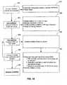
- a methodfor utilizing a sizing device to measure luminal dimensions.
- the sizing device 40is first delivered to the treatment region in the body lumen, as shown at block 70.
- the esophagus 14will be in a relaxed or collapsed configuration during delivery of the sizing device.
- the sizing device 40is in a collapsed configuration during the delivery of the device to the treatment site in the esophagus.
- the low profile of the collapsed sizing device 40eases the delivery of the device into the esophagus and minimizes discomfort to the patient.
- an expansion fluidis injected into the balloon, as shown at block 72.
- the balloonis inflated until it engages the inside wall of the lumen, as shown in Figure 3 .
- the extent of engagement of the balloonis monitored, as well as the amount of expansion medium being injected into the balloon, as shown by block 74.
- the final mass or volume of expansion mediumis recorded so that the internal dimension of the esophagus may be calculated, shown at blocks 78, 82.
- the sizing balloonis then deflated so that it can be readily removed from the treatment site, shown at block 80.
- a device of the present inventioncomprises a sizing device 40 for determining the dimensions of a treatment lumen.
- the device 40has an expansion member 42 that is inserted into a lumen in a collapsed configuration and expanded upon proper placement at a pre-selected treatment area.
- the expansion member 42is a cylindrical balloon with a native diameter that is oversized so that it will be larger in its fully expanded configuration than the expected diameter of the treatment lumen.
- the balloon 42comprises a thin, flexible, bladder made of a polymer material, for example polyimide, polyurethane, PET, or the like.
- the balloonis attached to a catheter sleeve 44, wherein the balloon is disposed on the distal end 46 of the catheter sleeve for infusing an expansion medium into the balloon from an infusion source IS.
- Infusion sourceis connected to an access port 50 of a y-connector located at the proximal end 48 of the catheter sleeve 44.
- the expansion mediumcomprises a compressible fluid, such as air.
- the expansion mediummay alternatively comprise an incompressible fluid, such as water, saline solution, or the like. It would be understood by one of skill in the art that sizing a body lumen by monitoring the mass of an expansion medium advantageously can be accomplished using either compressible or incompressible fluids. Infusion of the expansion medium into the sizing balloon may be accomplished by a positive displacement device such as a fluid-infusion pump or calibrated syringe driven by stepper motor or by hand. Alternatively, for a compressible expansion medium, pressurized air or gas may also be used.
- the sizing devicealso comprises a means for determining the amount of expansion fluid transferred to the balloon, such as a calibrated syringe.
- a mass or volume flow metermay be coupled to the fluid delivery source for simultaneously measuring the amount of fluid in the balloon as it is inflated.
- the balloonexpands radially from its axis to engage the wall of the lumen.
- the walls of the esophagus 14unfold to form a more cylindrical shape as balloon 42 expands, as illustrated in Figure 3 .
- internal diameter D1 of the esophagus 14is readily calculated based on the length L of the balloon and the measured amount of expansion medium inside the balloon.
- Balloon 42is oversized so that the diameter D2 of the balloon when unrestrained and fully inflated is larger than the diameter of the balloon when constrained in the lumen.
- the sizing membermay comprise a basket, plurality of struts, calipers, or the like instrument for determining the internal diameter of a tubular member.
- Testswere performed to calculate the inside diameter of a member by using volume flow measurements.
- Various types and sizes of tubeswere tested by measuring the mass of air used to inflate an oversized bladder inside the tube.
- the diameter of the tubecan be repeatably estimated by measuring the volume of air delivered into the balloon.
- a pressure sensormay be coupled to the sizing device, wherein the extent of engagement is determined by the internal pressure exerted from the expansion medium as measured by the pressure sensor or visual verification.
- the pressure sensormay comprise any device for determining the pressure inside a vessel, such as a strain gauge.
- the pressure sensor PSis located at access port 52 at the proximal end of the catheter sleeve 44.
- the pressure sensorcan be located inside the balloon 42. As the balloon expands to engage the wall of the lumen, the pressure in the balloon increases as a result of the constraint on the balloon from the lumen wall.
- the balloonis oversized and not at its fully extended diameter when contacting the lumen wall, the pressure in the balloon is equal to the contact force per unit area against the lumen wall. Therefore, the pressure inside the balloon is directly proportional to the contact force on the lumen wall. Furthermore, the balloon may be expanded to apply pressure to the inside wall of the lumen, thereby causing the lumen to stretch. Generally, the sizing balloon will be inflated to a pressure corresponding to the desired pressure for treatment of the lumen. For esophageal treatment, it is desirable to expand the treatment device sufficiently to occlude the vasculature of the submucosa, including the arterial, capillary, or venular vessels. The pressure to be exerted to do so should therefore be greater than the pressure exerted by such vessels, typically from 1 psig to 10 psig, preferably from 4 psig to 7 psig and more preferably from 2 psig to 3 psig.
- the measurement of the pressure inside the balloonmay be used to monitor the extent of engagement of the balloon with the lumen wall.
- the extent of engagementmay be monitored by determining the expansion of the balloon via visual inspection with use of an endoscope, or by ultrasound, optical, or fluoroscopic imaging (not shown).
- Testswere performed on different sized rigid tubes to calculate the amount of mass required to inflate an oversized balloon in a constrained tube at various pressures. As shown in Figure 8 , the test results showed predictable linear relationships between the measured inflated air mass and the tube diameter for each pressure range tested.
- a system of the present invention and the method of use thereofis disclosed for treating a luminal tissue. Similar to the method described in Figure 5 , a sizing device is used to calculate the internal diameter of the lumen, as shown at block 84. The measurement obtained from the sizing device is then used to select a treatment device from an array of different sized catheters, shown at block 86. The device is then inserted into the body lumen and delivered to the treatment site, as shown at block 88. An expansion fluid is then injected into the device by an infusion source like that of the sizing device as shown in block 90.
- the catheteris selected to have an outer diameter when fully expanded that appropriately distends the luminal wall, it is not necessary to monitor the expansion of the catheter. However, the pressure and fluid volume of expansion medium delivered to the treatment device can be monitored as a precautionary measure, as shown in blocks 92 and 94.
- energysuch as RF energy
- the catheteris deflated for removal from the lumen as shown in block 98.
- a treatment device 10constructed in accordance with the principles of the present invention, includes an elongated catheter sleeve 22 that is configured to be inserted into the body in any of various ways selected by the medical provider.
- the treatment devicemay be placed, (i) endoscopically, e.g. through esophagus 14, (ii) surgically or (iii) by other means.
- catheter sleeve 22can be inserted in the lumen of the endoscope, or catheter sleeve 22 can be positioned on the outside of the endoscope. Alternately, an endoscope may be used to visualize the pathway that catheter 22 should follow during placement. As well, catheter sleeve 22 can be inserted into esophagus 1014 after removal of the endoscope.
- Electrode support 24is provided and can be positioned at a distal end 26 of catheter sleeve 22 to provide appropriate energy for ablation as desired.
- Electrode support 24has a plurality of electrode area segments 32 attached to the surface of the support.
- the electrodes 32can be configured in an array 30 of various patterns to facilitate a specific treatment by controlling the electrode size and spacing (electrode density).
- electrode support 24is coupled to an energy source configured for powering the array 30 at levels appropriate to provide the selectable ablation of tissue to a predetermined depth of tissue.
- the energymay be delivered circumferentially about the axis of the treatment device in a single step, i.e., all at one time. Alternatively, the energy may be delivered to different circumferential and/or axial sections of the esophageal wall sequentially.
- the support 24may comprise a flexible, non-distensible backing.
- the support 24may comprise of a thin, rectangular sheet of polymer materials such as polyimide, polyester or other flexible thermoplastic or thermosetting polymer film.
- the support 24may also comprise polymer covered materials, or other nonconductive materials.
- the backingmay include an electrically insulating polymer, with an electro-conductive material, such as copper, deposited onto a surface so that an electrode pattern can be etched into the material to create an array of electrodes.
- Electrode support 24can be operated at a controlled distance from, or in direct contact with the wall of the tissue site. This can be achieved by coupling electrode support 24 to an expandable member 28, which has a cylindrical configuration with a known, fixed length, and a diameter sized to match at its expanded state the calculated diameter of the expanded (not collapsed) lumen.
- Suitable expandable membersinclude but are not limited to a balloon, non-compliant balloon, balloon with a tapered geometry, cage, frame, basket, plurality of struts, expandable member with a furled and an unfurled state, one or more springs, foam, bladder, backing material that expands to an expanded configuration when unrestrained, and the like.
- the expandable memberFor esophageal treatment, it is desirable to expand the expandable member to distend the lumen sufficiently to occlude the vasculature of the submucosa, including the arterial, capillary, or venular vessels.
- the pressure to be exerted to do soshould therefore be greater than the pressure exerted by such vessels, typically from 1 psig to 10 psig, preferably from 4 psig to 7 psig and more preferably from 2 psig to 3 psig.
- the expandable member for the treatment devicewill be selected to match the diameter measured by the sizing device at the desired pressure. Under this configuration, full expansion of the expandable member will result in a pressure that properly distends the luminal wall.
- the electrode support 24is wrapped around the circumference of expandable member 28.
- a plurality of expandable memberscan be provided wherein the diameter of the expandable member varies from 12 mm to 50 mm when expanded.
- the systemmay include a plurality of electrode supports, each sized differently corresponding to the different sized expandable members.
- the electrode support 24may be oversized to be at least large enough to cover the circumference of the largest expandable member. In such a configuration, the electrode support overlaps itself as it is wrapped around the circumference of the expandable member, similar to the electrode support of device 100 illustrated in '1, discussed infra.
- expandable member 28is utilized to deliver the ablation energy itself.
- An important feature of this embodimentincludes the means by which the energy is transferred from distal end 26 to expandable member 28.
- one type of energy distribution that can be utilizedis disclosed in U.S. Patent No. 5,713,942 , in which an expandable balloon is connected to a power source, which provides radio frequency power having the desired characteristics to selectively heat the target tissue to a desired temperature.
- Expandable member 28may be constructed from electrically insulating polymer, with an electro-conductive material, such as copper, deposited onto a surface so that an electrode pattern can be etched into the material to create an array of electrodes.
- Electrode support 24can deliver a variety of different types of energy including but not limited to, radio frequency, microwave, ultrasonic, resistive heating, chemical, a heatable fluid, optical including without limitation, ultraviolet, visible, infrared, collimated or non-collimated, coherent or incoherent, or other light energy, and the like. It will be appreciated that the energy, including but not limited to optical, can be used in combination with one or more sensitizing agents.
- the depth of treatment obtained with treatment device 10can be controlled by the selection of appropriate treatment parameters by the user as described in the examples set forth herein.
- One important parameter in controlling the depth of treatmentis the electrode density of the array 30. As the spacing between electrodes decreases, the depth of treatment of the affected tissue also decreases. Very close spacing of the electrodes assures that the current and resulting ohmic heating in the tissue is limited to a very shallow depth so that injury and heating of the submucosal layer are minimized.
- each RF electrodeFor treatment of esophageal tissue using RF energy, it may be desirable to have a width of each RF electrode to be no more than, (i) 3 mm, (ii) 2 mm, (iii) 1 mm (iv) 0.5 mm or (v) 0.3 mm (vi) 0.1 mm and the like. Accordingly, it may be desirable to have a spacing between adjacent RF electrodes to be no more than, (i) 3 mm, (ii) 2 mm, (iii) 1 mm (iv) 0.5 mm or (v) 0.3 mm (vi) 0.1 mm and the like.
- the plurality of electrodescan be arranged in segments, with at least a portion of the segments being multiplexed. An RF electrode between adjacent segments can be shared by each of adjacent segments when multiplexed.
- the electrode patterns of the present inventionmay be varied depending on the length of the site to be treated, the depth of the mucosa and submucosa, in the case of the esophagus, at the site of treatment and other factors.
- the electrode pattern 30may be aligned in axial or traverse direction across the electrode support 24, or formed in a linear or non-linear parallel matrix or series of bipolar pairs or monopolar electrodes.
- One or more different patternsmay be coupled to various locations of expandable member 28.
- an electrode arrayas illustrated in Figures 13(a) through 13(c) , may comprise a pattern of bipolar axial interlaced finger electrodes 68, six bipolar rings 62 with 2 mm separation, or monopolar rectangles 65 with 1 mm separation.
- Pattern 54is a pattern of bipolar axial interlaced finger electrodes with 0:3 mm separation.
- Pattern 56includes monopolar bands with 0.3 mm separation.
- Pattern 60includes bipolar rings with 0.3 mm separation.
- Pattern 58is electrodes in a pattern of undulating electrodes with 0.2548 mm separation.
- a probe sensormay also be used with the system of the present invention to monitor and determine the depth of ablation.
- one or more sensorscan be included and associated with each electrode segment 32 in order to monitor the temperature from each segment and then be used for control.
- the controlcan be by way of an open or closed loop feedback system.
- the electrocenductive membercan be configured to permit transmission of microwave energy to the tissue site.
- Treatment apparatus 10can also include steerable and directional control devices, a probe sensor for accurately sensing depth of ablation, and the like.
- one embodiment of the inventioncomprises an electrode deployment device 100 having an electrode support 110 furled around the outside of an inflatable balloon 116 that is mounted on a catheter sleeve 118.
- Support 110has an electrode array 112 etched on its surface, and is aligned between edges 120 that intersect the taper region located at the distal and proximal ends of balloon 116.
- Support 110may be attached at a first end 122 to balloon 116 with an adhesive.
- the second end 124 of the supportis furled around the balloon, overlapping the first end 122.
- support 110may be retained in a compressed furled state around balloon 116 by an elastic band.
- the adhesiveneed not be applied to attach first end 122 to balloon 116, thus allowing for rapid placement or exchange of the appropriately sized balloon 116 to match measurements made from the sizing device 10 illustrated in Figure 4 .
- Figure 12shows a bottom view 150 and a top view 152 of the electrode array 112 of support 110.
- the array 112has 20 parallel bars, 0.25 nun wide, separated by gaps of 0.3 mm.
- the bars on the circuitform twenty complete continuous rings around the circumference of balloon 116.
- Electrode array 112can be etched from a laminate consisting of copper on both sides of a polyimide substrate. One end of each copper bar has a small plated through hole 128, which allows signals to be passed to these bars from 1 of 2 copper junction blocks 156 and 158, respectively, on the back of the laminate.
- One junction block 156is connected to all of the even numbered bars, while the other junction block 158 is connected to all of the odd numbered bars.
- each junction block 156 and 158is then wired to a bundle of AWG wires 134.
- the wiringis external to balloon 116, with the distal circuit wires affixed beneath the proximal circuit.
- these bundles 134can be soldered to three litz wire bundles 136.
- One bundle 136serves as a common conductor for both circuits while the other two bundles 136 are wired individually to each of the two circuits.
- the litz wiresare encompassed with heat shrink tubing along the entire length of the catheter sleeve 118 of the device.
- each of these bundles 136Upon emerging from the proximal end of the catheter sleeve, each of these bundles 136 is individually insulated with heat shrink tubing before terminating to a mini connector plug 138. Under this configuration, power can be delivered to either or both of the two bundles so that treatment can be administered to a specific area along the array.
- connector 142 at the proximal end of the catheter sleeveincludes access ports for both the thru lumen 144 and the inflation lumen 146.
- the thru lumenspans the entire length of the balloon catheter and exits through lumen tip 148 at the distal end of balloon 116.
- the inflation lumen 146is coupled to balloon 116 so that the balloon can be inflated by delivery of a liquid, gaseous solution such as air, or the like.
- support 110is tightly furled about deflated balloon 116 and placed with within a sheath (not shown). During deployment, this sheath is retracted along the shaft to expose support 110.
- an elastic member(not shown) may be coupled to the support 110 to keep the support furled around balloon 116 during deployment of apparatus 100.
- slight suctionmay be applied to the through lumen tube to reduce the air pressure in the esophagus 14 distal to balloon 116.
- the application of this slight suctioncan be simultaneously applied to the portion of the esophagus 14 proximal to balloon 116. This suction causes the portion of the esophageal wall distended by balloon 116 to be pulled against electrode arrays 112 located on balloon 116.
- Electrode array 112can be activated with approximately 300 watts of radio frequency power for the length of time necessary to deliver an energy density from 1 J/cm 2 to 50 J/cm 2 . To determine the appropriate level of energy, the diameter of the lumen is evaluated so that the total treatment area can be calculated. A typical treatment area of 10 cm 2 will require total energy ranging from 10 J to 500 J. In one embodiment, controlling the depth of treated tissue can include normalizing the amount of power delivered to the tissue over time.
- normalizing power deliveredmeans equivalent power densities (i.e., power unit area of electrode surface area ⁇ W/cm 2 ⁇ ) are delivered to esophagi of differing diameters.
- controlling the depth of treated tissuecomprises controlling the amount of delivered energy density. Such can be accomplished by normalizing the amount of energy delivered to tissue over time so that equivalent energy densities (i.e., energy per unit area of electrode surface area ⁇ J/cm 2 ⁇ ) are delivered to esophagi of differing diameters.
- the radiofrequency energyIn order to effectively ablate the mucosal lining of the esophagus and allow re-growth of a normal mucosal lining without creating damage to underlying tissue structures, it is preferable to deliver the radiofrequency energy over a short time span in order to reduce the effects of thermal conduction of energy to deeper tissue layers, thereby creating a "searing" effect. It is preferable to deliver the radiofrequency energy within a time span of less than 5 seconds.
- An optimal time for effective treatmentis less than 1 second and preferably less than 0.5 second or 0.25 second. The lower bound on time may be limited by the ability of the RF power source to deliver high powers, or alternatively by the required depth of treatment.
- RF powers of several hundred wattswould be required in order to deliver the desired energy density in short periods of time. This may pose a practical limitation on the lower limit of time.
- an RF power sourceconfigured to deliver a very short, high power, pulse of energy could be utilized. Using techniques similar to those used for flash lamp sources, or other types of capacitor discharge sources, a very high power, short pulse of RF energy can be created. This would allow treatment times of a few msec, or less. While this type of approach is feasible, in practice a more conventional RF source with a power capability of several hundred watts may be preferred.
- the energy sourcemay be manually controlled by the user and is adapted to allow the user to select the appropriate treatment time and power setting to obtain a controlled depth of ablation.
- the energy sourcecan be coupled to a controller (not shown), which may be a digital or analog controller for use with the energy source, including but not limited to an RF source, or a computer with software.
- the computer controllerWhen the computer controller is used it can include a CPU coupled through a system bus.
- the systemmay include a keyboard, a disk drive, or other non volatile memory system, a display and other peripherals known in the art.
- a program memory and a data memorywill also be coupled to the bus.
- systemsfor treating luminal tissue with a single treatment device that variably expands to accommodate a number of different sized lumens.
- the treatment devicecomprises a furled electrode support that variably engages the luminal wall while keeping the electrode density constant.
- balloon 116may be oversized with respect to the size of the lumen so that it can be expanded to accommodate differing luminal dimensions from patient to patient. Measurements from sizing device 10 can be used to scale as needed the desired power and energy settings to deliver the same power and energy per unit area.
- Electrodes array 112can be modified to create either a deeper or more superficial treatment region. Making the electrodes of array 112 more narrow and spacing the electrodes closer together reduces the treatment depth. Making the electrodes of array 112 wider, and spacing the electrodes further apart, increases the depth of the treatment region. Non-uniform widths and spacings may be exploited to achieve various treatment effects.
- the sizing devicemay be used as a method for determining the lumen diameter and wall compliance of one or more sections of the esophagus.
- a sizing device having an inflatable balloon like that of device 40 illustrated in Figure 5is inserted into the esophagus in a compressed configuration and positioned at a location within the esophagus, as shown at block 200.
- the balloonis then inflated with a compressible fluid so that the balloon engages the inside wall of the esophagus and distends the wall of the esophagus, shown at block 202.
- the expansion mediumis delivered to the balloon, the static pressure inside the balloon is monitored with a pressure sensor and the amount of expansion medium delivered to the balloon is measured, shown at block 204.
- the pressuremay be measured at the infusion source with strain gauge or the like. Alternatively, the pressure can be measured at a location inside the balloon with a microminiature pressure transducer or the like.
- the amount of expansion medium delivered to the balloonmay be measured by a mass-flow meter or the like.
- a first target pressure (P1) inside the balloonis achieved, a corresponding first mass or volume measurement (M1) is recorded, as shown at blocks 206 and 208.
- the values of P1 and M1are used to calculate the lumen diameter at pressure P1, using the relationship previously determined and shown in Figure 8 , block 200 of Figure 15 , or other equivalent means. Additional expansion medium is then delivered to the balloon, and the static pressure and the total amount of expansion medium within the balloon are monitored, shown at blocks 210 and 212.
- Target pressure values P1 and P2are generally set at values that cause the esophagus to distend, but not over-distend. Typical target pressure values range from 1 psig to 7 psig, preferably from 4 psig to 7 psig and more preferably from 2 psig to 3 psig. Wall compliance of the esophagus is then determined based on the variation in the calculated lumen diameter between a first measured pressure P1 and a second measured pressure P2, as shown in block 222.
- Figure 21is an exemplary front panel of a generator system according to one embodiment of the invention.
- the generator 230produces, delivers and controls power, such as RF power.
- Other functions of the generator 230include controlling inflation and deflation of the sizing balloon, estimating the diameter of the sizing balloon, selective delivery of RF power and energy to a treatment catheter and specific electrodes within the treatment catheter, and displaying various information to a user.
- the front panel of the generator 230incorporates various controls, displays and indicators.
- the generator 230connects to the catheter 22 through the RF and communication (Python) cable 234.
- the generatoris capable of detecting whether it is a sizing catheter, used for determining the size of the esophagus, or a treatment catheter, used for ablation.
- the generator 230reads from a storage device the type of catheter that is connected thereto.
- the storage devicestores various catheter specific information and sizing specific parameters. For example, the storage device contains various generator settings for each diameter ranges. Further, the generator 230 may cause additional information to be stored, recommended catheter size after balloon auto-sizing is performed or the number of ablations performed. It should be noted that the storage device may be any suitable storage device, such as an EEPROM.
- the generator 230When the generator 230 detects a sizing catheter, the generator 230 performs an estimation of the balloon diameter. In order to reduce uncertainty in the diameter measurement, a calibration of the balloon may be performed, using control 264. During calibration, the volume of gas needed to fully expand the unconstrained balloon is determined, and will be used to determine a calibration constant. Using a mass flow sensor, the generator 230 measures the total gas or fluid mass required to inflate the sizing balloon to a specific pre-determined pressure. This predetermined pressure is a clinically safe pressure to perform the sizing of the esophagus and is chosen to ensure that inflation of the balloon within the esophagus would not rupture the esophagus while stretching and smoothing its lining.
- This predetermined pressureis a clinically safe pressure to perform the sizing of the esophagus and is chosen to ensure that inflation of the balloon within the esophagus would not rupture the esophagus while stretching and smoothing its lining.
- the balloonIn order to initially evacuate all the gas in the balloon, the balloon is inflated to a pressure of approximately 4 psig, then deflated to a negative pressure of approximately up to - 4 psig, and then inflated again to about 4 psig. Fluid or gas is delivered to the balloon using a pneumatic connection cable 236. Upon depression of the automatic inflation button 240, the generator will deliver air to the balloon according the sizing catheter inflation pressure. It should be noted that the balloons on either the treatment catheter or the sizing catheter may be inflated or deflated using the control buttons 240 and 241. While the balloon is inflated, the balloon pressure may be continuously displayed on display 251.
- each balloonBefore inserting the sizing balloon in the esophagus to measure its effective diameter at a given inflation pressure (nominal 4psig) each balloon is first calibrated in air.
- the calibration processinvolves attaching the sizing balloon to the pneumatic connection cable 236 and generator 230 and first pulling a vacuum (typical pressure values range from 0 to -6 psig, nominal -4psig) to fully collapse the balloon.
- a mass flow sensor of the generator 230is used to accurately measure the amount of air necessary to fill the balloon (nominal 33.7mm diameter) to 4 psig, thereby solving the relationship between volume and pressure for that balloon size and shape.
- This calibration informationsubsequently enables diameter measurements of the esophagus by measuring the amount of air necessary to inflate the balloon to a specific diameter.
- the sizing balloonis introduced in the esophagus and repositioned at various locations within the esophagus. For each one of these locations, the generator 230 estimates the diameter of the balloon and effectively the esophagus diameter at the set pressure and then automatically recommends an ablation balloon catheter diameter to be subsequently used. The generator 230 will then display the recommended balloon diameter on display 250. After auto-sizing is performed, the system will automatically deflate the sizing catheter balloon to a negative pressure of approximately -2 psig or less.
- Figure 16is an exemplary flow chart of the method for measuring the size of the esophagus and finding the most proximal Barrett's esophagus location or other areas to be ablated.
- a sizing catheteris connected to the generator.
- the specific characteristics of the sizing catheterare recognized by the generator from the storage device, such as: whether and when the catheter has been used before, and whether the balloon has already met a maximum number of allowed inflations.
- the systemis ready for calibrating the balloon at step 161 if the catheter and the balloon are optimal for use. For better accuracy, the balloon is unconstrained in air during calibration.
- the balloongoes through the inflate-deflate-inflate cycle such that the mass flow sensor determines the volume in the balloon at a pre-set pressure.
- the balloonautomatically deflates and is introduced into the esophagus for sizing, as shown at step 164.
- the balloonis inflated again inside the esophagus at various locations to estimate the inner diameter of the esophagus.
- a first sizeis displayed and a stand by state is indicated on the front panel of the generator.
- the sizing routineis repeated at various locations in the esophagus to find the location of the abnormal cells and determine the recommended catheter size, as shown in steps 166, 167 and 168.
- the generator 230stores various information obtained throughout the sizing process, such as the estimated diameter of the esophagus, the calibration balloon volume, the number of sizing performed and the measured diameters.
- Figure 17illustrates a schematic of an exemplary mechanism for performing balloon sizing using a mass flow meter and pressure sensors.
- the generator 230monitors and controls the pressure in the balloon and estimates the volume within the balloon.
- Pump 171supplies compressed air to the solenoid valve 172, which can switch the flow of air for either inflating or deflating the balloon.
- filter 170removes particulates from the gas that will enter the pump 171.
- the mass flow sensor 173senses the mass of air coming in the system.
- the flow sensor 173could be used to measure the flow of air out of the system for enhanced safety and accuracy of the system.
- the pressure within the systemis measured by pressure sensors 174 and 175, with sensor 175 measuring the atmospheric pressure.
- a positive displacement pumpmay be used to pump a known amount of fluid or gas into the balloon.
- the airflows from the inside of the balloon to the mass flow sensor 173.
- the sizing method and system described hereinmay be used for estimating the inner diameter or other cross-sectional parameters of any body lumens or passageways, for example for lumens within the gastrointestinal tract, vasculature, urinary tract, urogenital system or pulmonary system.
- an appropriate treatment catheteris connected to the generator in order to ablate abnormal cells within the esophagus.
- the diameter of the balloon of the attached treatment catheteris read from the storage device.
- treatment of the esophagusmay be performed using the same catheter and balloon used for sizing.
- the generatorwould recognize the catheter's dual function, sizing/treatment, and would read the appropriate parameters from the storage device.
- the diameteris displayed on display 250.
- the appropriate generator settingsare retrieved from the storage device, such as: balloon inflation pressure, balloon volume data, default, maximum or minimum power settings, default, maximum or minimum energy settings, or size of the electrodes.
- the energy density and power levelscan be automatically set according to the size of the treatment catheter.
- the preset power levelis displayed on display 244, while the preset energy density level is displayed on display 248.
- the generator 230then inflates the balloon of the attached treatment catheter to a preset pressure of approximately 7 psig, which will be displayed on display 251.
- the set indicator 254indicates the unit is in stand-by mode, when all the values are being set. In the standby mode, all the set values are displayed. Throughout the entire ablation procedure, it is desirable to maintain the pressure on the balloon at a steady pressure as a safety precaution. If the balloon stays at a pressure of at least 6.5 psig (typical pressure values range from 0.5 - 200 psig), the system is then considered “armed.”
- the arm indicator 256indicates that the displayed values are the set values and the system is ready to deliver RF energy.
- the RF on/off switch 238indicates and controls when RF power is being delivered.
- the generator 230delivers and controls power until the desired energy density is delivered.
- the generatormaintains a set power on each electrode and is capable of sequentially delivering energy to each electrode on the treatment catheter.
- the completed indicator 258indicates the ablation is completed.
- a usermay have the capability to adjust the power and the energy density delivered to the tissue.
- the output powercan be set and adjusted using the up and down buttons 241.
- the actual power delivered to the tissue from the catheter leadsis displayed on the power display 244.
- the energy densityis set using the up and down button 246 and the output energy density delivered is displayed on the LED display 248.
- the system status display 252is an LCD panel and displays operational codes and user instructions. For example, the panel 252 displays the "Calibration" function prior to performing auto-sizing of the balloon. The panel 252 also displays error codes and an error message with instructions for solving errors.
- the reset button 262may be pressed to reset the system if an error occurs. Further, the panel 252 indicates when the system is in standby mode. The fault indicator 260 indicates when the system is in the fault mode and a non-recoverable error was detected. It should be noted that the front panel of the generator 230 may display, control and indicate functions other than the exemplary functions described herein.
- pedal-type footswitch 232is attached to the generator rear panel and may control the inflation system and RF delivery.
- the pedal 232is capable of duplicating certain functions of the generator front panel buttons.
- the footswitch 232may duplicate the RF on/off button 238 and/or the balloon auto inflation up and down buttons 240 and 241.
- FIG 18is an exemplary flowchart of the ablation procedure.
- the generatorrecognizes the specific characteristics of the ablation catheter and is ready to inflate the balloon, at step 181.
- the catheteris armed at 182 and the balloon is inflated and maintained at a pressure of approximately 7 psig (typical pressure values range from 0.5 to 200 psig). If the balloon pressure is steady, the ARM indicator is lit on the front panel display of the generator.
- the generatoris ready for delivering energy to electrodes of the ablation catheter. The energy is subsequently automatically delivered by the generator 230, as shown at step 184.
- the balloonis automatically deflated in order to reposition the balloon and the electrodes to another ablation location within the esophagus.
- a series of subsequent ablationsare performed as needed at step 186.
- the ablationis complete at step 188.
- the generatordelivers energy only after the system meets certain safety checks, as shown at steps 185 and 187.
- the generatorperiodically monitors balloon inflation, energy parameters and overall system integrity before and during the tissue treatment. These safety procedures ensure that the generator can safely deliver the required power. For example, the generator will not deliver power to the electrodes unless the impedance and temperature of the tissue are within acceptable parameters. Similarly, the generator monitors any pressure fluctuations within the treatment balloon. In one embodiment, the generator 230 will only deliver power if the balloon inside the esophagus is maintained at a steady required pressure of approximately 7 +/- 1 psig. This safety check ensures that there is no connection leak or balloon leak and the esophagus is fully distended prior to ablation.
- the generator 230monitors and controls the power output to the electrodes and ensures that a constant power is delivered.
- a proportional integral derivative (PID) controllercontrols the amount of power by increasing the power level, and inherently the voltage level, until it reaches a set target valued.
- the PID controllercontrols the amount of power by gradually increasing the power level.
- the PID controllercontrols the amount of power by rapidly increasing the power level. Further, to better control the ablation depth, the PID controller makes sure that the desired power level is achieved within a certain time window.
- the generatoris adapted to control the amount of energy delivered to the tissue over time based on the measured diameter of the esophagus.
- the generatorcan be adapted to normalize the density of energy delivered to the tissue over time based on the measured diameter of the esophagus so that equivalent energy densities (i.e., energy per unit are of electrode surface area ⁇ J/cm 2 ⁇ ) are delivered to esophagi of differing diameters.
- the generatoris adapted to control the amount of power delivered to the tissue over time based on the measured diameter of the esophagus so that equivalent power densities (i.e., power per unit area of electrode surface area ⁇ W/cm 2 ⁇ ) are delivered to esophagi of differing diameters.
- the system described hereincontrols the total energy delivered to the esophageal tissue and the amount of time for which the energy is delivered, as described above.
- Other methodsmay be similarly employed to ablate a desired surface area rapidly and circumferentially, while controlling the ablation depth.
- the generator 230may be manually controlled by a user such that the amount of power density delivered to the esophageal tissue can be monitored over time. As such, the generator 230 is adapted to allow the user to select an appropriate power density to be delivered to the tissue in short burst.
- the time for an effective treatmentis less than one second. In another embodiment, the time is approximately 300 ms.
- Methods of tracking the characteristics of the esophageal tissue and the changes in its cellular characteristicsinclude monitoring the tissue impedance and/or the tissue temperature. The ablation time could be then adjusted based on the individual characteristics of the tissue and its measured impedance and/or temperature values.
- Figure 19illustrates a graphical representation of impedance measurements during ablation over time.
- the tissue temperaturerises, which causes a decrease in the tissue resistivity.
- This drop in impedance from an initial impedance valueis represented by the exemplary reference points A and B. If the ablation continues beyond the reference point B, the tissue cell membranes rupture such that desiccation of cells occurs and resistivity of the tissue increases.
- the exemplary increased impedance value measured during this period of timeis shown by reference point C.
- the generator 230monitors the changes in the measured tissue impedance values.
- the generator 230delivers the energy to the tissue in a time window defined by the tissue impedance measurements.
- generator 230may ablate only for the time it takes the tissue to reach an absolute impedance target.
- the target targeted impedance valueranges from approximately .5-10 ohms.
- generator 230may ablate only until the impedance value decreases a pre-determined percentage from the initial impedance value of the tissue prior to ablation.
- the time of ablationcan depend on the point at which the impedance values reach an inflection point on the graph illustrated in Figure 19 , i.e., when the impedance values are between the reference points B and C.
- the energy deliverycould cease when the impedance reaches its minimum value, at which point it starts to increase.
- the ablation timemay be defined by the impedance value that exceeds a particular level. If the tissue impedance value reaches levels higher then the initial impedance value, as shown by the exemplary reference point D, the extent of the treatment may reach levels such that the esophageal wall is breached. As such, it may desirable to cease delivering energy to the tissue before the impedance reaches its initial value, e.g., reference value C.
- Figure 20illustrates a graphical representation of the tissue temperature over time.
- T1, T2 and T3represent temperature curves of different sensors positioned at different locations within or outside the tissue to be ablated.
- the ablation timeshould be controlled such that the temperature of the tissue is less than 100 °C.
- the generator 230controls the ablation time such that the temperature of the tissue is between 65 ° C and 95 ° C.
- the ablation timecould be defined by the amount of time that it takes the tissue to heat to a preset target temperature.
- the generator 230monitors the temperature of the tissue and, when the tissue has reached a certain temperature, generator 230 stops the delivery of the energy to the tissue.
Landscapes
- Health & Medical Sciences (AREA)
- Life Sciences & Earth Sciences (AREA)
- Engineering & Computer Science (AREA)
- Surgery (AREA)
- Veterinary Medicine (AREA)
- General Health & Medical Sciences (AREA)
- Public Health (AREA)
- Animal Behavior & Ethology (AREA)
- Biomedical Technology (AREA)
- Heart & Thoracic Surgery (AREA)
- Medical Informatics (AREA)
- Molecular Biology (AREA)
- Physics & Mathematics (AREA)
- Nuclear Medicine, Radiotherapy & Molecular Imaging (AREA)
- Biophysics (AREA)
- Pathology (AREA)
- Otolaryngology (AREA)
- Radiology & Medical Imaging (AREA)
- Plasma & Fusion (AREA)
- Electromagnetism (AREA)
- Endocrinology (AREA)
- Gastroenterology & Hepatology (AREA)
- Physiology (AREA)
- Dentistry (AREA)
- Oral & Maxillofacial Surgery (AREA)
- Cardiology (AREA)
- Child & Adolescent Psychology (AREA)
- Pulmonology (AREA)
- Anesthesiology (AREA)
- Hematology (AREA)
- Surgical Instruments (AREA)
- Media Introduction/Drainage Providing Device (AREA)
Description
- Field of the Invention. The present invention relates generally to medical systems for treating body lumens. More particularly, the invention is directed to systems for treating and determining physiologic characteristics of body lumens such as the esophagus.
- The human body has a number of internal body lumens or cavities located within, many of which have an inner lining or layer. These inner linings can be susceptible to disease. In some cases, surgical intervention can be required to remove the inner lining in order to prevent the spread of disease to otherwise healthy tissue located nearby.
- Those with persistent problems or inappropriate relaxation of the lower esophageal sphincter can develop a condition known as gastro esophageal reflux disease, manifested by classic symptoms of heartburn and regurgitation of gastric and intestinal contents. The causative agent for such problems may vary. Patients with severe forms of gastroesophageal reflux disease, no matter what the cause, can sometimes develop secondary damage of the esophagus due to the interaction of gastric or intestinal contents with esophageal cells not designed to experience such interaction.
- The esophagus is composed of three primary tissue layers; a superficial mucosal layer lined by squamous epithelial cells, a middle submucosal layer and a deeper muscle layer. When gastroesophageal reflux occurs, the superficial squamous epithelial cells are exposed to gastric acid, along with intestinal bile acids and enzymes. This exposure may be tolerated, but in some cases can lead to damage and alteration of the squamous cells, causing them to change into taller, specialized columnar epithelial cells. This metaplastic change of the mucosal epithelium from squamous cells to columnar cells is called Barrett's esophagus, named after the British surgeon who originally described the condition.
- Banett's esophagus has important clinical consequences, since the Barrett's columnar cells can, in some patients, become dysplastic and then progress to a certain type of deadly cancer of the esophagus. The presence of Barrett's esophagus is the main risk factor for the development of adenocarcinoma of the esophagus.
- Accordingly, attention has been focused on identifying and removing this abnormal Barrett's columnar epithelium in order to mitigate more severe implications for the patient. Devices and methods for treating abnormal body tissue by application of various forms of energy to such tissue have been described, such as radio frequency ablation. However, without precise control of the depth of penetration of the energy means, these methods and devices are deficient. Uncontrolled energy application can penetrate too deeply into the esophageal wall, beyond the mucosa and submucosal layers, into the muscularis externa, potentially causing esophageal perforation, stricture or bleeding. Accordingly, proper administration of the correct amount of treatment energy to the tissue can be facilitated by knowledge of the size of the esophagus and area to be treated.
- Additionally, medical procedures for treating Barrett's esophagus typically involve deployment of an expandable catheter inside the esophagus. Expandable catheters are preferred because the profile of the catheter is ideally as small as possible to allow for ease of delivery, while treatment of the esophagus is most efficiently performed when the catheter is at or slightly larger than the diameter of the esophageal wall. Proper sizing and/or pressurization of the delivery device is therefore desirable to prevent over-distension of the organ, which could result in harm to the organ, or under-expansion of the catheter, which often results in incomplete treatment. Accordingly, accurate and simple measurement of the size of the lumen and control of the pressure of the catheter on the lumen surface promotes the proper engagement and delivery of energy to the luminal wall so that a uniform and controlled depth of treatment can be administered. In addition to calculating luminal dimensions, the compliance of the lumen can be determined by measuring the cross section of the lumen at two or more pressure values.
- Therefore, it would be advantageous to have systems for accurately determining in vivo the size and optionally the compliance of a body lumen such as the esophagus. In addition, it would be desirable to provide a system for treating the body lumen once having determined its size. At least some of these objectives will be met by the present invention.
- Description of the Background Art.
U.S. Patent No. 5,275,169 describes apparatus and methods for determining physiologic characteristics of blood vessels. The device measures the diameter and wall compliance of the blood vessel, and does not administer treatment. Additionally, the method relies on using only an incompressible fluid to inflate a balloon inside a blood vessel. Other patents or patent applications of interest includeUS 6,010,511 ;US 6,039,701 ;US 6,551,310 ;US 2004/215235 A1 andWO 91/03207 A - The invention is defined in the appended set of claims. Methods mentioned herein do not form part of the invention.
- The present invention comprises systems for sizing a body lumen, such as the esophagus. Systems are also provided for treating the body lumen once the proper measurements have been made.
- Although the following description will focus on embodiments configured for treatment of the esophagus, other embodiments may be used to treat any other suitable lumen in the body. In particular, the systems of the present invention may be used whenever accurate measurement of a body lumen or uniform delivery of energy is desired to treat a controlled depth of tissue in a lumen or cavity of the body, especially where such body structures may vary in size. Therefore, the following description is provided for exemplary purposes and should not be construed to limit the scope of the invention.
- In general, in one aspect, the invention is used in a method for measuring an inner diameter of a body lumen, including inserting a balloon in the body lumen; inflating the balloon inside the body lumen using an expansion medium; and monitoring a mass of the expansion medium inside the balloon.
- Implementations of the invention can include one or more of the following features. Monitoring the mass of the expansion medium can be performed using a mass flow sensor. Additionally, the expansion medium can be a gas or a liquid. The balloon can be inflated at a fixed pressure, and the fixed pressure can be approximately 4 psig.
- In general, in another aspect, the invention is used in a method for treating tissue in a body lumen, including deploying a selected electrode structure at the surface of the tissue; delivering energy to the electrode structure to ablate the tissue to a depth from the surface; and controlling the depth of ablated tissue by monitoring a change in tissue impedance.
- Controlling the depth of ablated tissue can include monitoring when the tissue impedance reaches a targeted impedance value. In one implementation, the targeted impedance value ranges from approximately 0.5 ohms to 10 ohms. In another implementation, controlling the depth of ablated tissue can additionally include monitoring when the tissue impedance changes a specified percentage from an initial tissue impedance level. In a further implementation, controlling the depth of ablated tissue can include monitoring when the tissue impedance reaches its minimum value. In a particular implementation, the desired depth of ablated tissue is approximately between 0.5 mm and 1 mm.
- In general, in another aspect, the invention is used in a method for treating tissue of a body lumen, including: deploying an electrode structure at a surface of the tissue; delivering energy to the electrode structure to ablate the tissue to a depth from the surface; and controlling the depth of tissue ablation of the tissue by monitoring a change in the tissue temperature.
- In one embodiment of this aspect of the invention, controlling the depth of tissue ablation includes monitoring when the tissue temperature reaches a target range. The temperature target range can be between approximately 65° and 95° C, and the energy can be delivered as long as the measured tissue temperature does not exceed a maximum temperature. In one implementation, the maximum temperature is approximately 95°C.
- In general, in another aspect, the invention is used in a method for treating abnormal tissue inside a body lumen, including: automatically determining an inner diameter of the body lumen at a location proximal to the abnormal tissue; deploying an electrode structure at a surface of the tissue at the proximal location; and delivering energy to the electrode structure for treating the tissue.
- In one embodiment of this aspect of the invention, the inner diameter of the body lumen can be determined by automatically inflating and deflating a balloon inside the body lumen using an expansion medium. This embodiment can further include monitoring a mass of the expansion medium inside the balloon and controlling a depth of treated tissue. In one implementation, controlling the depth of treated tissue includes controlling an amount of power delivered to the tissue over time. In other implementations, controlling the depth of treated tissue includes normalizing power delivered to the tissue over time; and/or controlling the depth of treated tissue by controlling an amount of energy delivered to the tissue over time; and/or controlling the depth of treated tissue by controlling delivered energy density; and/or controlling the depth of treated tissue by monitoring and controlling tissue impedance over time; and/or controlling the depth of treated tissue by monitoring and controlling tissue temperature over time.
- Implementations of the invention can include one or more of the following features. Controlling an amount of power delivered to the tissue by rapidly increasing the power until it reaches a set target value and/or controlling the amount of power delivered by using a proportional integral derivative controller.
- In general, in another aspect, the invention features an apparatus for treating a tissue inside a body lumen, including: an electrode structure adapted to be positioned at a surface of the tissue inside the body lumen, wherein the electrode structure is coupled to an expansion member; and a generator for producing and delivering energy to the electrode structure; wherein the generator is adapted to automatically inflate the expansion member inside the body lumen and control the pressure inside the expansion member during treatment of the tissue.
- Implementations of the invention can include one or more of the following features. The expansion member can be a balloon coupled to a catheter. The apparatus can further include a storage device for storing generator settings. In one implementation, the storage device is an EEPROM. The apparatus can further include a pump for automatically inflating and deflating the expansion member.
- The generator of the apparatus can be adapted to determine an inner diameter of the body lumen using an inflatable balloon. In one implementation, the generator is adapted to control the amount of energy delivered to the tissue over time based on the measured diameter of the esophagus. In another implementation, the generator is adapted to normalize the density of energy delivered to the tissue based on the measured diameter of the esophagus. In yet another implementation, the generator is adapted to control the amount of power delivered to the tissue over time based on the measured diameter of the esophagus. In another implementation, the generator is adapted to control the energy delivered to the electrode structure. In another implementation, the generator is adapted to control the power delivered to the electrode structure. In yet another implementation, the generator is adapted to normalize the amount of power delivered to the tissue over time based on the measure diameter of the esophagus. In a further implementation the generator is adapted to detect whether a catheter is attached thereto and to identify a characteristic of the attached catheter. In a related implementation, the apparatus can further include a storage device adapted to store information about the attached catheter.
- The apparatus can further include a footswitch coupled to the generator and adapted to control the energy delivered to the electrode structure and/or a display for displaying information to a user.
- In another implementation, the generator is adapted to be manually controlled by a user such that the user controls the energy delivered to the electrode structure over time.
- The apparatus can further include a proportional integral derivative controller adapted to gradually increase power delivered to the electrode structure until it reaches a set target value.
- In general, in another aspect, the invention features an apparatus for treating a tissue inside a body lumen, including: an electrode structure adapted to be positioned at a surface of the tissue inside the body lumen, wherein the electrode structure is coupled to an expansion member; and a generator for producing, delivering and controlling energy delivered to the electrode structure; wherein the generator is adapted to determine an inner diameter of the body lumen.
- In one aspect, a method for treating a body lumen at a treatment location comprises measuring a luminal dimension at the treatment location of the lumen, selecting an electrode deployment device having an array of electrodes or other electrode structure with a pre-selected deployed size which corresponds to the measured dimension, positioning the electrode deployment device at the treatment location within the lumen, deploying the electrode array to the pre-selected deployed state to engage a wall of the lumen, and delivering energy to the electrodes for treatment of the luminal tissue.
- In some embodiments, measuring the luminal dimension comprises positioning a sizing member at the treatment location within the lumen, expanding the sizing member until it engages an inside wall of the lumen, and calculating the luminal dimension at the treatment location of the esophagus based on the expansion of the sizing member. Often, expanding the sizing member comprises inflating a sizing balloon by introducing an expansion medium. The expansion medium may be a compressible or non-compressible fluid. In some embodiments, the lumen dimensions are calculated by determining the amount of the expansion medium introduced to the sizing balloon while it is inflated. For example, the mass or volume of the expansion medium can be measured by use of a mass-flow meter or the like. Optionally, a pressure sensor may be coupled to the sizing balloon, so that the luminal dimension can be calculated from the measured amount of expansion medium introduced to the balloon at a given pressure. Alternatively, the sizing member may comprise a basket, plurality of struts, or calipers, or the like. The lumen may also be measured by ultrasound, optical, or fluoroscopic imaging or by use of measuring strip.
- The sizing balloon may comprise any material or configuration. In general, the sizing balloon is cylindrical and has a known length and a diameter that is greater than the diameter of the target lumen. In this configuration, the sizing balloon is non-distensible, such as a bladder having a diameter in its fully expanded form that is larger than the lumen diameter. Suitable materials for the balloon may comprise a polymer such as polyimide or polyethylene terephthalate (PET). Alternatively, the balloon may comprise a mixture of polymers and elastomers.
- Once the lumen dimensions are determined, an electrode deployment device matching the measured luminal dimension may be selected from an inventory of devices having different electrode deployment sizes. In some embodiments, the electrode deployment device is transesophageally delivered to a treatment area within the esophagus. For example, delivering the device may be facilitated by advancing a catheter through the esophagus, wherein the catheter carries the electrode array and an expansion member. The expansion member may comprise any of the materials or configurations of the sizing member, such as an inflatable cylindrical balloon comprising a polymer such as polyimide or PET.
- In some aspects of the invention, the array of electrodes or other electrode structure is arranged on a surface of a dimensionally stable support such as a non-distensible, electrode backing. The backing may comprise a thin, rectangular sheet of polymer materials such as polyimide, polyester or other flexible thermoplastic or thermosetting polymer film, polymer covered materials, or other nonconductive materials. The backing may also comprise an electrically insulating polymer, with an electro-conductive material, such as copper, deposited onto a surface. For example, an electrode pattern can be etched into the material to create an array of electrodes. The electrode pattern may be aligned in an axial or traverse direction across the backing, formed in a linear or non-linear parallel array or series of bipolar pairs, or other suitable pattern. In many embodiments, delivering energy comprises applying radiofrequency (RF) energy to tissue of the body lumen, through the electrodes. Depending on the desired treatment effect, the electrodes may be arranged to control the depth and pattern of treatment. For treatment of esophageal tissue, the electrode widths are less than 3 mm, typically a width in the range from 0.1 mm to 3 mm, preferably 0.1 mm to 0.3 mm, and adjacent electrodes are spaced apart less than 3 mm, typically in the range from 0.1 mm to 3 mm, preferably from 0.1 mm to 0.3 mm. Alternatively, energy may be delivered by use of structures other than those having an array of electrodes. For example, the electrode structure may comprise a continuous electrode arranged in a helical pattern over the balloon.
- In another method, the measurement of the luminal dimension may be used to determine the amount of energy delivered to the tissue of the lumen. For example, a method for treating the tissue of a body lumen at a treatment location comprises measuring a luminal dimension at a location of the lumen, positioning an electrode deployment device at that location, deploying the expansion member to engage an electrode array to a wall of the lumen; and delivering sufficient energy to the electrode array for treatment of the luminal tissue based on the measured dimension of the lumen. In general, the amount of power delivered to the electrodes will vary depending on the type of treatment and the overall surface area of the luminal tissue to be treated. In some cases, the expansion member can variably expand to engage the wall of the lumen independent of the size of the lumen. For esophageal treatment, the expansion member may comprise a balloon that can expand to a range of diameters between 12 mm and 50 mm. Typically, the total energy density delivered to the esophageal tissue will be in the range from 1 J/cm2 to 50 J/cm2, usually being from 5 J/cm2 to 15 J/cm2. In order to effectively ablate the mucosal lining of the esophagus and allow re-growth of a normal mucosal lining without creating damage to underlying tissue structures, it is preferable to deliver the radiofrequency energy over a short time span in order to reduce the effects of thermal conduction of energy to deeper tissue layers, thereby creating a "searing" effect. It is preferable to deliver the radiofrequency energy within a time span of less than 5 seconds. An optimal time for effective treatment is less than 1 second, and preferably less than 0.5 second or 0.25 seconds. The lower bound on time may be limited by the ability of the RF power source to deliver high powers.
- In one aspect, a method for measuring an internal dimension at a location in a body lumen comprises positioning a cylindrical balloon at a location within the lumen, inflating the balloon with an expansion medium to engage an inside wall of the lumen, monitoring the extent of engagement of the balloon, determining the amount of expansion medium in the balloon while inflated at the location, and calculating the internal dimension of the esophagus based on the length of the balloon and the measured amount of expansion medium inside the balloon. In some cases, the balloon is transesophageally delivered to a treatment area within the esophagus by advancing a catheter carrying the balloon through the esophagus. Often, the balloon is non-distensible and has a diameter that is greater than the diameter of the inside wall of the lumen. The balloon may be filled with an expansion medium that is a compressible fluid, such as air.
- Monitoring the extent of engagement comprises determining the expansion of the balloon via a pressure sensor coupled to the balloon, wherein the extent of engagement is determined by the internal pressure exerted from the expansion medium as measured by the pressure sensor and by visual verification. The pressure sensor may comprise any device for determining the pressure inside a vessel, such as a strain gauge. Alternatively, the extent of engagement may be monitored by determining the expansion of the balloon via visual inspection. In some embodiments, the balloon may be expanded to apply pressure to the inside wall of the lumen, thereby causing the lumen to stretch.
- In one aspect, a method for determining wall compliance of an esophagus comprises positioning a balloon at a location within the esophagus, inflating the balloon with a compressible fluid, measuring the static pressure within the balloon, measuring the total amount of fluid within the balloon at least two static pressure values, and calculating the wall compliance based on the variation in the amount of fluid between a first measured pressure and a second measured pressure. For esophageal treatment, the static pressure values to be used are typically below 10 psig, and preferably at or below 7 psig.
- In another aspect, a system for treating tissue of a body lumen comprises a sizing member for measuring the cross section at a location of the lumen and a catheter having a set of individual treatment devices, each device comprising an electrode array adapted to treat a target location, wherein at least some of the arrays are adapted to treat locations having different sizes determined by the sizing member. In some embodiments, the sizing member comprises an inflatable, noncompliant sizing balloon that is oversized with respect to the inside wall of the lumen. The sizing balloon may be cylindrical with a diameter that is oversized with respect to the inside wall of the lumen. The sizing balloon may further be coupled to a pressure sensor for determining the internal pressure in the balloon from the introduction of the expansion medium. In addition, the system may further comprise a measuring means, such as a mass flow meter, for determining the amount of fluid in the sizing balloon.
- In some embodiments, each of the individual treatment devices further include an expansion member comprising an inflatable balloon. Generally, each balloon is cylindrical and ranges in diameter from 12 mm to 50 mm when expanded. A balloon within the range is selected based on the measurement made from the sizing balloon so that when the balloon is expanded to its fully inflated shape, it properly engages the wall of the lumen. Typically, the expansion member is inflated with the same medium as the sizing balloon. Optionally, the treatment device may further include a pressure sensor as an extra precaution against over-distension of the organ.
Figure 1 is a schematic view of portions of an upper digestive tract in a human.Figure 2 is a cross sectional view of a device of the invention inserted in to an esophagus in its relaxed, collapsed state.Figure 3 is a cross-sectional view of a device of the invention deployed in an expanded configuration in the esophagus.Figure 4 is a schematic view of a sizing device of the invention.Figure 5 is a flow chart of a method for sizing a luminal dimension.Figure 6 is a flow chart of a method for treating luminal tissueFigure 7 is a chart of test results performed on calculating the diameter of a vessel by measuring the volume of air used to inflate the balloon.Figure 8 is a chart of test results for the air mass required to achieve various pressure levels in differently sized rigid containers.Figure 9 is a schematic view of a treatment device of the invention in a compressed configuration in the esophagus.Figure 10 is a schematic view of a treatment device of the invention in an expanded configuration in the esophagus.Figure 11 is a schematic view of another embodiment of a treatment device of the invention.Figure 12 shows a top view and a bottom view of an electrode pattern of the device ofFigure 11 .Figure 13a-c shows the electrode patterns that may be used with a treatment device of the invention.Figure 14a-d shows additional electrode patterns that may be used with a treatment device of the invention.Figure 15 shows a flow chart of a method for determining the wall compliance of a lumen.Figure 16 illustrates a flow chart of a method for size estimation.Figure 17 illustrates an exemplary schematic of a mechanism for performing balloon sizing using a mass flow meter and pressure sensors.Figure 18 is an exemplary flowchart of the ablation method.Figure 19 illustrates a graphical representation of tissue impedance over time.Figure 20 illustrates a graphical representation of the tissue temperature over time.Figure 21 illustrates an exemplary front panel of the generator.- In various embodiments, the present invention provides systems for measuring, and treating at a controlled and uniform depth, the inner lining of a lumen within a patient. It will be appreciated that the present invention is applicable to a variety of different tissue sites and organs, including but not limited to the esophagus. A treatment apparatus including a sizing member and a treatment device comprising an expandable electrode array is provided. The sizing member is first positioned at a treatment site within the lumen. Once in place, the sizing member is expanded to engage the wall of the lumen to obtain the dimensions of the lumen. The sizing member is removed, and at least a portion of the treatment device is positioned at the tissue site, where the electrode array is expanded to contact the tissue surface according to the measurements made by the sizing member. Sufficient energy is then delivered from the electrode array to impart a desired therapeutic effect, such as cell necrosis, to a discrete layer of tissue.
- Certain disorders can cause the retrograde flow of gastric or intestinal contents from the
stomach 12, into theesophagus 14, as shown by arrows A and B inFigure 1 . Although the causation of these problems are varied, this retrograde flow may result in secondary disorders, such as Barrett's Esophagus, which require treatment independent of and quite different from treatments appropriate for the primary disorder-such as disorders of the loweresophageal sphincter 16. Barrett's esophagus is an inflammatory disorder in which the stomach acids, bile acids and enzymes regurgitated from the stomach and duodenum enter into the lower esophagus causing damage to the esophageal mucosa. When this type of retrograde flow occurs frequently enough, damage may occur to esophagealepithelial cells 18. In some cases the damage may lead to the alteration of the squamous cells, causing them to change into taller specialized columnarepithelial cells 20. This metaplastic change of the mucosal epithelium from squamous cells to columnar cells is called Barrett's esophagus. Although some of the columnar cells may be benign, others may result in adenocarcinoma. - In one aspect, the present invention provides systems for sizing the esophagus and treating the epithelium of selected sites of the esophagus in order to mitigate more severe implications for the patient. In many therapeutic procedures, the desired treatment effect is ablation of the tissue. The term "ablation" as used herein means thermal damage to the tissue causing tissue or cell necrosis. However, some therapeutic procedures may have a desired treatment effect that falls short of ablation, e.g. some level of agitation or damage that is imparted to the tissue to inure a desired change in the cellular makeup of the tissue, rather than necrosis of the tissue. With the present invention, a variety of different energy delivery devices can be utilized to create a treatment effect in a superficial layer of tissue, while preserving intact the function of deeper layers, as described hereafter.
- Cell or tissue necrosis can be achieved with the use of energy, such as radiofrequency energy, at appropriate levels to accomplish ablation of mucosal or submucosal level tissue, while substantially preserving muscularis tissue. In a particular aspect, such ablation is designed to remove the entire mucosal lining in the treatment region, including the abnormal
columnar growths 20 from the portions of theesophagus 14 so affected, and allow re-growth of a normal mucosal lining. - As illustrated in a cross-sectional view in
Figure 2 , the esophagus in its collapsed, relaxed state does not form a perfect, cylindrical tube. Rather, the walls of theesophagus 14 undulate into a plurality of folds. In this state, the diameter of the esophagus is difficult to determine, especially by use of visualization techniques such as ultrasound or optical imaging. Additionally, uniform treatment of target tissue areas is also difficult because of the irregular surface contours of the esophageal wall. - As illustrated in
Figures 2, 3 and 4 and the flow chart ofFigure 5 , a method is disclosed for utilizing a sizing device to measure luminal dimensions. The sizingdevice 40 is first delivered to the treatment region in the body lumen, as shown atblock 70. For esophageal sizing as shown inFigure 2 , theesophagus 14 will be in a relaxed or collapsed configuration during delivery of the sizing device. The sizingdevice 40 is in a collapsed configuration during the delivery of the device to the treatment site in the esophagus. The low profile of the collapsed sizingdevice 40, as shown inFigure 2 , eases the delivery of the device into the esophagus and minimizes discomfort to the patient. Once the sizing device is oriented in the proper treatment area, an expansion fluid is injected into the balloon, as shown atblock 72. The balloon is inflated until it engages the inside wall of the lumen, as shown inFigure 3 . During the infusion of the expansion medium, the extent of engagement of the balloon is monitored, as well as the amount of expansion medium being injected into the balloon, as shown byblock 74. Once the balloon properly engages the lumen wall (shown at block 76), the final mass or volume of expansion medium is recorded so that the internal dimension of the esophagus may be calculated, shown atblocks block 80. - Referring to
Figures 2, 3, 4 , a device of the present invention comprises a sizingdevice 40 for determining the dimensions of a treatment lumen. Thedevice 40 has anexpansion member 42 that is inserted into a lumen in a collapsed configuration and expanded upon proper placement at a pre-selected treatment area. In a preferred configuration, theexpansion member 42 is a cylindrical balloon with a native diameter that is oversized so that it will be larger in its fully expanded configuration than the expected diameter of the treatment lumen. Theballoon 42 comprises a thin, flexible, bladder made of a polymer material, for example polyimide, polyurethane, PET, or the like. The balloon is attached to acatheter sleeve 44, wherein the balloon is disposed on thedistal end 46 of the catheter sleeve for infusing an expansion medium into the balloon from an infusion source IS. Infusion source is connected to anaccess port 50 of a y-connector located at theproximal end 48 of thecatheter sleeve 44. - Ideally, the expansion medium comprises a compressible fluid, such as air. The expansion medium may alternatively comprise an incompressible fluid, such as water, saline solution, or the like. It would be understood by one of skill in the art that sizing a body lumen by monitoring the mass of an expansion medium advantageously can be accomplished using either compressible or incompressible fluids. Infusion of the expansion medium into the sizing balloon may be accomplished by a positive displacement device such as a fluid-infusion pump or calibrated syringe driven by stepper motor or by hand. Alternatively, for a compressible expansion medium, pressurized air or gas may also be used. In many embodiments, the sizing device also comprises a means for determining the amount of expansion fluid transferred to the balloon, such as a calibrated syringe. A mass or volume flow meter may be coupled to the fluid delivery source for simultaneously measuring the amount of fluid in the balloon as it is inflated.
- As the expansion medium is injected into
balloon 42, the balloon expands radially from its axis to engage the wall of the lumen. For esophageal treatment, the walls of theesophagus 14 unfold to form a more cylindrical shape asballoon 42 expands, as illustrated inFigure 3 . In this configuration, internal diameter D1 of theesophagus 14 is readily calculated based on the length L of the balloon and the measured amount of expansion medium inside the balloon.Balloon 42 is oversized so that the diameter D2 of the balloon when unrestrained and fully inflated is larger than the diameter of the balloon when constrained in the lumen. Although an inflatable balloon is generally preferred, the sizing member may comprise a basket, plurality of struts, calipers, or the like instrument for determining the internal diameter of a tubular member. - Tests were performed to calculate the inside diameter of a member by using volume flow measurements. Various types and sizes of tubes were tested by measuring the mass of air used to inflate an oversized bladder inside the tube. As shown in
Figure 7 , the diameter of the tube can be repeatably estimated by measuring the volume of air delivered into the balloon. - In some embodiments of the invention, a pressure sensor may be coupled to the sizing device, wherein the extent of engagement is determined by the internal pressure exerted from the expansion medium as measured by the pressure sensor or visual verification.
- The pressure sensor may comprise any device for determining the pressure inside a vessel, such as a strain gauge. In
Figure 4 , the pressure sensor PS is located ataccess port 52 at the proximal end of thecatheter sleeve 44. Alternatively, the pressure sensor can be located inside theballoon 42. As the balloon expands to engage the wall of the lumen, the pressure in the balloon increases as a result of the constraint on the balloon from the lumen wall. - Because the balloon is oversized and not at its fully extended diameter when contacting the lumen wall, the pressure in the balloon is equal to the contact force per unit area against the lumen wall. Therefore, the pressure inside the balloon is directly proportional to the contact force on the lumen wall. Furthermore, the balloon may be expanded to apply pressure to the inside wall of the lumen, thereby causing the lumen to stretch. Generally, the sizing balloon will be inflated to a pressure corresponding to the desired pressure for treatment of the lumen. For esophageal treatment, it is desirable to expand the treatment device sufficiently to occlude the vasculature of the submucosa, including the arterial, capillary, or venular vessels. The pressure to be exerted to do so should therefore be greater than the pressure exerted by such vessels, typically from 1 psig to 10 psig, preferably from 4 psig to 7 psig and more preferably from 2 psig to 3 psig.
- In some embodiments, the measurement of the pressure inside the balloon may be used to monitor the extent of engagement of the balloon with the lumen wall. Alternatively, the extent of engagement may be monitored by determining the expansion of the balloon via visual inspection with use of an endoscope, or by ultrasound, optical, or fluoroscopic imaging (not shown).
- Tests were performed on different sized rigid tubes to calculate the amount of mass required to inflate an oversized balloon in a constrained tube at various pressures. As shown in
Figure 8 , the test results showed predictable linear relationships between the measured inflated air mass and the tube diameter for each pressure range tested. - As shown in the flow chart of
Figure 6 , a system of the present invention and the method of use thereof is disclosed for treating a luminal tissue. Similar to the method described inFigure 5 , a sizing device is used to calculate the internal diameter of the lumen, as shown atblock 84. The measurement obtained from the sizing device is then used to select a treatment device from an array of different sized catheters, shown atblock 86. The device is then inserted into the body lumen and delivered to the treatment site, as shown atblock 88. An expansion fluid is then injected into the device by an infusion source like that of the sizing device as shown inblock 90. Because the catheter is selected to have an outer diameter when fully expanded that appropriately distends the luminal wall, it is not necessary to monitor the expansion of the catheter. However, the pressure and fluid volume of expansion medium delivered to the treatment device can be monitored as a precautionary measure, as shown inblocks block 96. Once treatment has been administered, the catheter is deflated for removal from the lumen as shown inblock 98. - As illustrated in
Figures 9 and 10 , atreatment device 10 constructed in accordance with the principles of the present invention, includes anelongated catheter sleeve 22 that is configured to be inserted into the body in any of various ways selected by the medical provider. For treatment of the esophagus, the treatment device may be placed, (i) endoscopically, e.g. throughesophagus 14, (ii) surgically or (iii) by other means. - When an endoscope (not shown) is used,
catheter sleeve 22 can be inserted in the lumen of the endoscope, orcatheter sleeve 22 can be positioned on the outside of the endoscope. Alternately, an endoscope may be used to visualize the pathway thatcatheter 22 should follow during placement. As well,catheter sleeve 22 can be inserted into esophagus 1014 after removal of the endoscope. - An
electrode support 24 is provided and can be positioned at adistal end 26 ofcatheter sleeve 22 to provide appropriate energy for ablation as desired.Electrode support 24 has a plurality ofelectrode area segments 32 attached to the surface of the support. Theelectrodes 32 can be configured in anarray 30 of various patterns to facilitate a specific treatment by controlling the electrode size and spacing (electrode density). In various embodiments,electrode support 24 is coupled to an energy source configured for powering thearray 30 at levels appropriate to provide the selectable ablation of tissue to a predetermined depth of tissue. The energy may be delivered circumferentially about the axis of the treatment device in a single step, i.e., all at one time. Alternatively, the energy may be delivered to different circumferential and/or axial sections of the esophageal wall sequentially. - In many embodiments, the
support 24 may comprise a flexible, non-distensible backing. For example, thesupport 24 may comprise of a thin, rectangular sheet of polymer materials such as polyimide, polyester or other flexible thermoplastic or thermosetting polymer film. Thesupport 24 may also comprise polymer covered materials, or other nonconductive materials. Additionally, the backing may include an electrically insulating polymer, with an electro-conductive material, such as copper, deposited onto a surface so that an electrode pattern can be etched into the material to create an array of electrodes. Electrode support 24 can be operated at a controlled distance from, or in direct contact with the wall of the tissue site. This can be achieved by couplingelectrode support 24 to anexpandable member 28, which has a cylindrical configuration with a known, fixed length, and a diameter sized to match at its expanded state the calculated diameter of the expanded (not collapsed) lumen. Suitable expandable members include but are not limited to a balloon, non-compliant balloon, balloon with a tapered geometry, cage, frame, basket, plurality of struts, expandable member with a furled and an unfurled state, one or more springs, foam, bladder, backing material that expands to an expanded configuration when unrestrained, and the like. For esophageal treatment, it is desirable to expand the expandable member to distend the lumen sufficiently to occlude the vasculature of the submucosa, including the arterial, capillary, or venular vessels. The pressure to be exerted to do so should therefore be greater than the pressure exerted by such vessels, typically from 1 psig to 10 psig, preferably from 4 psig to 7 psig and more preferably from 2 psig to 3 psig. Generally, the expandable member for the treatment device will be selected to match the diameter measured by the sizing device at the desired pressure. Under this configuration, full expansion of the expandable member will result in a pressure that properly distends the luminal wall. In some embodiments, it may be desirable to employ a pressure sensor or mass flow meter (not shown) as a precautionary measure so that over-distension of the lumen does not occur.- As shown in
Figures 9 and 10 , theelectrode support 24 is wrapped around the circumference ofexpandable member 28. In one system of the present invention, a plurality of expandable members can be provided wherein the diameter of the expandable member varies from 12 mm to 50 mm when expanded. Accordingly, the system may include a plurality of electrode supports, each sized differently corresponding to the different sized expandable members. Alternatively, theelectrode support 24 may be oversized to be at least large enough to cover the circumference of the largest expandable member. In such a configuration, the electrode support overlaps itself as it is wrapped around the circumference of the expandable member, similar to the electrode support ofdevice 100 illustrated in '1, discussed infra. - In another embodiment,
expandable member 28 is utilized to deliver the ablation energy itself. An important feature of this embodiment includes the means by which the energy is transferred fromdistal end 26 toexpandable member 28. By way of illustration, one type of energy distribution that can be utilized is disclosed inU.S. Patent No. 5,713,942 , in which an expandable balloon is connected to a power source, which provides radio frequency power having the desired characteristics to selectively heat the target tissue to a desired temperature.Expandable member 28 may be constructed from electrically insulating polymer, with an electro-conductive material, such as copper, deposited onto a surface so that an electrode pattern can be etched into the material to create an array of electrodes. Electrode support 24 can deliver a variety of different types of energy including but not limited to, radio frequency, microwave, ultrasonic, resistive heating, chemical, a heatable fluid, optical including without limitation, ultraviolet, visible, infrared, collimated or non-collimated, coherent or incoherent, or other light energy, and the like. It will be appreciated that the energy, including but not limited to optical, can be used in combination with one or more sensitizing agents.- The depth of treatment obtained with
treatment device 10 can be controlled by the selection of appropriate treatment parameters by the user as described in the examples set forth herein. One important parameter in controlling the depth of treatment is the electrode density of thearray 30. As the spacing between electrodes decreases, the depth of treatment of the affected tissue also decreases. Very close spacing of the electrodes assures that the current and resulting ohmic heating in the tissue is limited to a very shallow depth so that injury and heating of the submucosal layer are minimized. For treatment of esophageal tissue using RF energy, it may be desirable to have a width of each RF electrode to be no more than, (i) 3 mm, (ii) 2 mm, (iii) 1 mm (iv) 0.5 mm or (v) 0.3 mm (vi) 0.1 mm and the like. Accordingly, it may be desirable to have a spacing between adjacent RF electrodes to be no more than, (i) 3 mm, (ii) 2 mm, (iii) 1 mm (iv) 0.5 mm or (v) 0.3 mm (vi) 0.1 mm and the like. The plurality of electrodes can be arranged in segments, with at least a portion of the segments being multiplexed. An RF electrode between adjacent segments can be shared by each of adjacent segments when multiplexed. - The electrode patterns of the present invention may be varied depending on the length of the site to be treated, the depth of the mucosa and submucosa, in the case of the esophagus, at the site of treatment and other factors. The
electrode pattern 30 may be aligned in axial or traverse direction across theelectrode support 24, or formed in a linear or non-linear parallel matrix or series of bipolar pairs or monopolar electrodes. One or more different patterns may be coupled to various locations ofexpandable member 28. For example, an electrode array, as illustrated inFigures 13(a) through 13(c) , may comprise a pattern of bipolar axial interlacedfinger electrodes 68, sixbipolar rings 62 with 2 mm separation, ormonopolar rectangles 65 with 1 mm separation. Other suitable RF electrode patterns which may be used include, without limitation, those patterns shown inFigures 14(a) through 14(d) as 54, 56, 58 and 60, respectively. Pattern 54 is a pattern of bipolar axial interlaced finger electrodes with 0:3 mm separation. Pattern 56 includes monopolar bands with 0.3 mm separation.Pattern 60 includes bipolar rings with 0.3 mm separation. Pattern 58 is electrodes in a pattern of undulating electrodes with 0.2548 mm separation. - A probe sensor may also be used with the system of the present invention to monitor and determine the depth of ablation. In one embodiment, one or more sensors (not shown), including but not limited to thermal and the like, can be included and associated with each
electrode segment 32 in order to monitor the temperature from each segment and then be used for control. The control can be by way of an open or closed loop feedback system. In another embodiment, the electrocenductive member can be configured to permit transmission of microwave energy to the tissue site.Treatment apparatus 10 can also include steerable and directional control devices, a probe sensor for accurately sensing depth of ablation, and the like. - Referring to
Figure 11 , one embodiment of the invention comprises anelectrode deployment device 100 having anelectrode support 110 furled around the outside of aninflatable balloon 116 that is mounted on acatheter sleeve 118.Support 110 has anelectrode array 112 etched on its surface, and is aligned betweenedges 120 that intersect the taper region located at the distal and proximal ends ofballoon 116.Support 110 may be attached at afirst end 122 to balloon 116 with an adhesive. Thesecond end 124 of the support is furled around the balloon, overlapping thefirst end 122. Alternatively,support 110 may be retained in a compressed furled state aroundballoon 116 by an elastic band. In such a configuration, the adhesive need not be applied to attachfirst end 122 to balloon 116, thus allowing for rapid placement or exchange of the appropriatelysized balloon 116 to match measurements made from the sizingdevice 10 illustrated inFigure 4 . Figure 12 shows abottom view 150 and atop view 152 of theelectrode array 112 ofsupport 110. In this embodiment, thearray 112 has 20 parallel bars, 0.25 nun wide, separated by gaps of 0.3 mm. The bars on the circuit form twenty complete continuous rings around the circumference ofballoon 116.Electrode array 112 can be etched from a laminate consisting of copper on both sides of a polyimide substrate. One end of each copper bar has a small plated throughhole 128, which allows signals to be passed to these bars from 1 of 2 copper junction blocks 156 and 158, respectively, on the back of the laminate. Onejunction block 156 is connected to all of the even numbered bars, while theother junction block 158 is connected to all of the odd numbered bars.- As shown in
Figures 11 and 12 , eachjunction block AWG wires 134. The wiring is external to balloon 116, with the distal circuit wires affixed beneath the proximal circuit. Upon meeting the catheter sleeve of the device, thesebundles 134 can be soldered to three litz wire bundles 136. Onebundle 136 serves as a common conductor for both circuits while the other twobundles 136 are wired individually to each of the two circuits. The litz wires are encompassed with heat shrink tubing along the entire length of thecatheter sleeve 118 of the device. Upon emerging from the proximal end of the catheter sleeve, each of thesebundles 136 is individually insulated with heat shrink tubing before terminating to amini connector plug 138. Under this configuration, power can be delivered to either or both of the two bundles so that treatment can be administered to a specific area along the array. - They
connector 142 at the proximal end of the catheter sleeve includes access ports for both the thrulumen 144 and theinflation lumen 146. The thru lumen spans the entire length of the balloon catheter and exits throughlumen tip 148 at the distal end ofballoon 116. Theinflation lumen 146 is coupled toballoon 116 so that the balloon can be inflated by delivery of a liquid, gaseous solution such as air, or the like. - In some embodiments, for delivery of
apparatus 100,support 110 is tightly furled about deflatedballoon 116 and placed with within a sheath (not shown). During deployment, this sheath is retracted along the shaft to exposesupport 110. In alternative embodiments, an elastic member (not shown) may be coupled to thesupport 110 to keep the support furled aroundballoon 116 during deployment ofapparatus 100. - In order to ensure good contact between the esophageal wall and
electrode array 112, slight suction may be applied to the through lumen tube to reduce the air pressure in theesophagus 14 distal to balloon 116. The application of this slight suction can be simultaneously applied to the portion of theesophagus 14 proximal toballoon 116. This suction causes the portion of the esophageal wall distended byballoon 116 to be pulled againstelectrode arrays 112 located onballoon 116. Apparatus 100, illustrated inFigure 11 , is designed for use with the RF energy methods as set forth herein.Electrode array 112 can be activated with approximately 300 watts of radio frequency power for the length of time necessary to deliver an energy density from 1 J/cm2 to 50 J/cm2. To determine the appropriate level of energy, the diameter of the lumen is evaluated so that the total treatment area can be calculated. A typical treatment area of 10 cm2 will require total energy ranging from 10 J to 500 J. In one embodiment, controlling the depth of treated tissue can include normalizing the amount of power delivered to the tissue over time. In this context, normalizing power delivered means equivalent power densities (i.e., power unit area of electrode surface area {W/cm2}) are delivered to esophagi of differing diameters. In another embodiment, controlling the depth of treated tissue comprises controlling the amount of delivered energy density. Such can be accomplished by normalizing the amount of energy delivered to tissue over time so that equivalent energy densities (i.e., energy per unit area of electrode surface area {J/cm2}) are delivered to esophagi of differing diameters.- In order to effectively ablate the mucosal lining of the esophagus and allow re-growth of a normal mucosal lining without creating damage to underlying tissue structures, it is preferable to deliver the radiofrequency energy over a short time span in order to reduce the effects of thermal conduction of energy to deeper tissue layers, thereby creating a "searing" effect. It is preferable to deliver the radiofrequency energy within a time span of less than 5 seconds. An optimal time for effective treatment is less than 1 second and preferably less than 0.5 second or 0.25 second. The lower bound on time may be limited by the ability of the RF power source to deliver high powers, or alternatively by the required depth of treatment. Since the electrode area and consequently the tissue treatment area can be as much as several square centimeters, RF powers of several hundred watts would be required in order to deliver the desired energy density in short periods of time. This may pose a practical limitation on the lower limit of time. However, an RF power source configured to deliver a very short, high power, pulse of energy could be utilized. Using techniques similar to those used for flash lamp sources, or other types of capacitor discharge sources, a very high power, short pulse of RF energy can be created. This would allow treatment times of a few msec, or less. While this type of approach is feasible, in practice a more conventional RF source with a power capability of several hundred watts may be preferred.
- The energy source may be manually controlled by the user and is adapted to allow the user to select the appropriate treatment time and power setting to obtain a controlled depth of ablation. The energy source can be coupled to a controller (not shown), which may be a digital or analog controller for use with the energy source, including but not limited to an RF source, or a computer with software. When the computer controller is used it can include a CPU coupled through a system bus. The system may include a keyboard, a disk drive, or other non volatile memory system, a display and other peripherals known in the art. A program memory and a data memory will also be coupled to the bus.
- In some embodiments of the present invention, systems are disclosed for treating luminal tissue with a single treatment device that variably expands to accommodate a number of different sized lumens. Preferably, the treatment device comprises a furled electrode support that variably engages the luminal wall while keeping the electrode density constant. Such approaches are described in detail in the co-pending application no.
10/754,444 treatment device 100 shown inFigure 11 , which employs a variable exposed-length electrode array 112,balloon 116 may be oversized with respect to the size of the lumen so that it can be expanded to accommodate differing luminal dimensions from patient to patient. Measurements from sizingdevice 10 can be used to scale as needed the desired power and energy settings to deliver the same power and energy per unit area. These changes can be made either automatically or from user input to the RF power source. If different treatment depths are desired, the geometry ofelectrode array 112 can be modified to create either a deeper or more superficial treatment region. Making the electrodes ofarray 112 more narrow and spacing the electrodes closer together reduces the treatment depth. Making the electrodes ofarray 112 wider, and spacing the electrodes further apart, increases the depth of the treatment region. Non-uniform widths and spacings may be exploited to achieve various treatment effects. - Referring to
Figure 15 , the sizing device may be used as a method for determining the lumen diameter and wall compliance of one or more sections of the esophagus. A sizing device having an inflatable balloon like that ofdevice 40 illustrated inFigure 5 is inserted into the esophagus in a compressed configuration and positioned at a location within the esophagus, as shown atblock 200. The balloon is then inflated with a compressible fluid so that the balloon engages the inside wall of the esophagus and distends the wall of the esophagus, shown atblock 202. While the expansion medium is delivered to the balloon, the static pressure inside the balloon is monitored with a pressure sensor and the amount of expansion medium delivered to the balloon is measured, shown atblock 204. The pressure may be measured at the infusion source with strain gauge or the like. Alternatively, the pressure can be measured at a location inside the balloon with a microminiature pressure transducer or the like. The amount of expansion medium delivered to the balloon may be measured by a mass-flow meter or the like. Once a first target pressure (P1) inside the balloon is achieved, a corresponding first mass or volume measurement (M1) is recorded, as shown atblocks Figure 8 , block 200 ofFigure 15 , or other equivalent means. Additional expansion medium is then delivered to the balloon, and the static pressure and the total amount of expansion medium within the balloon are monitored, shown atblocks blocks block 220. The sizing balloon is then deflated and then removed from the esophagus as shown inblock 218. Target pressure values P1 and P2 are generally set at values that cause the esophagus to distend, but not over-distend. Typical target pressure values range from 1 psig to 7 psig, preferably from 4 psig to 7 psig and more preferably from 2 psig to 3 psig. Wall compliance of the esophagus is then determined based on the variation in the calculated lumen diameter between a first measured pressure P1 and a second measured pressure P2, as shown inblock 222. Figure 21 is an exemplary front panel of a generator system according to one embodiment of the invention. In one embodiment, thegenerator 230 produces, delivers and controls power, such as RF power. Other functions of thegenerator 230 include controlling inflation and deflation of the sizing balloon, estimating the diameter of the sizing balloon, selective delivery of RF power and energy to a treatment catheter and specific electrodes within the treatment catheter, and displaying various information to a user. To deliver various information regarding use parameters and status of the system, the front panel of thegenerator 230 incorporates various controls, displays and indicators.- The
generator 230 connects to thecatheter 22 through the RF and communication (Python)cable 234. When thegenerator 230 is connected to a catheter, the generator is capable of detecting whether it is a sizing catheter, used for determining the size of the esophagus, or a treatment catheter, used for ablation. Thegenerator 230 reads from a storage device the type of catheter that is connected thereto. The storage device stores various catheter specific information and sizing specific parameters. For example, the storage device contains various generator settings for each diameter ranges. Further, thegenerator 230 may cause additional information to be stored, recommended catheter size after balloon auto-sizing is performed or the number of ablations performed. It should be noted that the storage device may be any suitable storage device, such as an EEPROM. - When the
generator 230 detects a sizing catheter, thegenerator 230 performs an estimation of the balloon diameter. In order to reduce uncertainty in the diameter measurement, a calibration of the balloon may be performed, using control 264. During calibration, the volume of gas needed to fully expand the unconstrained balloon is determined, and will be used to determine a calibration constant. Using a mass flow sensor, thegenerator 230 measures the total gas or fluid mass required to inflate the sizing balloon to a specific pre-determined pressure. This predetermined pressure is a clinically safe pressure to perform the sizing of the esophagus and is chosen to ensure that inflation of the balloon within the esophagus would not rupture the esophagus while stretching and smoothing its lining. In order to initially evacuate all the gas in the balloon, the balloon is inflated to a pressure of approximately 4 psig, then deflated to a negative pressure of approximately up to - 4 psig, and then inflated again to about 4 psig. Fluid or gas is delivered to the balloon using apneumatic connection cable 236. Upon depression of theautomatic inflation button 240, the generator will deliver air to the balloon according the sizing catheter inflation pressure. It should be noted that the balloons on either the treatment catheter or the sizing catheter may be inflated or deflated using thecontrol buttons display 251. - Before inserting the sizing balloon in the esophagus to measure its effective diameter at a given inflation pressure (nominal 4psig) each balloon is first calibrated in air. The calibration process involves attaching the sizing balloon to the
pneumatic connection cable 236 andgenerator 230 and first pulling a vacuum (typical pressure values range from 0 to -6 psig, nominal -4psig) to fully collapse the balloon. Next a mass flow sensor of thegenerator 230 is used to accurately measure the amount of air necessary to fill the balloon (nominal 33.7mm diameter) to 4 psig, thereby solving the relationship between volume and pressure for that balloon size and shape. This calibration information subsequently enables diameter measurements of the esophagus by measuring the amount of air necessary to inflate the balloon to a specific diameter. - Once balloon calibration is complete, the sizing balloon is introduced in the esophagus and repositioned at various locations within the esophagus. For each one of these locations, the
generator 230 estimates the diameter of the balloon and effectively the esophagus diameter at the set pressure and then automatically recommends an ablation balloon catheter diameter to be subsequently used. Thegenerator 230 will then display the recommended balloon diameter ondisplay 250. After auto-sizing is performed, the system will automatically deflate the sizing catheter balloon to a negative pressure of approximately -2 psig or less. Figure 16 is an exemplary flow chart of the method for measuring the size of the esophagus and finding the most proximal Barrett's esophagus location or other areas to be ablated. Atstep 160, a sizing catheter is connected to the generator. The specific characteristics of the sizing catheter are recognized by the generator from the storage device, such as: whether and when the catheter has been used before, and whether the balloon has already met a maximum number of allowed inflations. The system is ready for calibrating the balloon atstep 161 if the catheter and the balloon are optimal for use. For better accuracy, the balloon is unconstrained in air during calibration. Atstep 163, the balloon goes through the inflate-deflate-inflate cycle such that the mass flow sensor determines the volume in the balloon at a pre-set pressure. When calibration is complete, the balloon automatically deflates and is introduced into the esophagus for sizing, as shown atstep 164. The balloon is inflated again inside the esophagus at various locations to estimate the inner diameter of the esophagus. Atstep 165, a first size is displayed and a stand by state is indicated on the front panel of the generator. The sizing routine is repeated at various locations in the esophagus to find the location of the abnormal cells and determine the recommended catheter size, as shown insteps generator 230 stores various information obtained throughout the sizing process, such as the estimated diameter of the esophagus, the calibration balloon volume, the number of sizing performed and the measured diameters.Figure 17 illustrates a schematic of an exemplary mechanism for performing balloon sizing using a mass flow meter and pressure sensors. Using this mechanism, thegenerator 230 monitors and controls the pressure in the balloon and estimates the volume within the balloon. Pump 171 supplies compressed air to thesolenoid valve 172, which can switch the flow of air for either inflating or deflating the balloon. Prior to the gas entering thepump 171,filter 170 removes particulates from the gas that will enter thepump 171. Themass flow sensor 173 senses the mass of air coming in the system. In addition, theflow sensor 173 could be used to measure the flow of air out of the system for enhanced safety and accuracy of the system. The pressure within the system is measured bypressure sensors sensor 175 measuring the atmospheric pressure. Alternatively, instead of sensing the pressure within the system, a positive displacement pump may be used to pump a known amount of fluid or gas into the balloon. When the balloon is deflated, the air flows from the inside of the balloon to themass flow sensor 173.Filters Python cable 178, prevent contamination of themass flow sensor 173 and pump 171 during deflation.- It should be noted that the sizing method and system described herein may be used for estimating the inner diameter or other cross-sectional parameters of any body lumens or passageways, for example for lumens within the gastrointestinal tract, vasculature, urinary tract, urogenital system or pulmonary system.
- Once the size of the esophagus is estimated for a set pressure, an appropriate treatment catheter is connected to the generator in order to ablate abnormal cells within the esophagus. The diameter of the balloon of the attached treatment catheter is read from the storage device. It should be noted that, in an alternate embodiment, treatment of the esophagus may be performed using the same catheter and balloon used for sizing. In such embodiment, the generator would recognize the catheter's dual function, sizing/treatment, and would read the appropriate parameters from the storage device.
- Referring to
Figure 21 , after the ablation balloon diameter is read from the storage device, the diameter is displayed ondisplay 250. Based on the recommended size of the treatment catheter, the appropriate generator settings are retrieved from the storage device, such as: balloon inflation pressure, balloon volume data, default, maximum or minimum power settings, default, maximum or minimum energy settings, or size of the electrodes. Thus, the energy density and power levels can be automatically set according to the size of the treatment catheter. The preset power level is displayed ondisplay 244, while the preset energy density level is displayed ondisplay 248. - The
generator 230 then inflates the balloon of the attached treatment catheter to a preset pressure of approximately 7 psig, which will be displayed ondisplay 251. Theset indicator 254 indicates the unit is in stand-by mode, when all the values are being set. In the standby mode, all the set values are displayed. Throughout the entire ablation procedure, it is desirable to maintain the pressure on the balloon at a steady pressure as a safety precaution. If the balloon stays at a pressure of at least 6.5 psig (typical pressure values range from 0.5 - 200 psig), the system is then considered "armed." Thearm indicator 256 indicates that the displayed values are the set values and the system is ready to deliver RF energy. The RF on/offswitch 238 indicates and controls when RF power is being delivered. In one embodiment, thegenerator 230 delivers and controls power until the desired energy density is delivered. The generator maintains a set power on each electrode and is capable of sequentially delivering energy to each electrode on the treatment catheter. When the desired energy is delivered to all the desired locations, the completedindicator 258 indicates the ablation is completed. - A user may have the capability to adjust the power and the energy density delivered to the tissue. The output power can be set and adjusted using the up and down
buttons 241. The actual power delivered to the tissue from the catheter leads is displayed on thepower display 244. Similarly, the energy density is set using the up and downbutton 246 and the output energy density delivered is displayed on theLED display 248. - The
system status display 252 is an LCD panel and displays operational codes and user instructions. For example, thepanel 252 displays the "Calibration" function prior to performing auto-sizing of the balloon. Thepanel 252 also displays error codes and an error message with instructions for solving errors. Thereset button 262 may be pressed to reset the system if an error occurs. Further, thepanel 252 indicates when the system is in standby mode. Thefault indicator 260 indicates when the system is in the fault mode and a non-recoverable error was detected. It should be noted that the front panel of thegenerator 230 may display, control and indicate functions other than the exemplary functions described herein. - In one embodiment, pedal-
type footswitch 232 is attached to the generator rear panel and may control the inflation system and RF delivery. Thepedal 232 is capable of duplicating certain functions of the generator front panel buttons. For example thefootswitch 232 may duplicate the RF on/offbutton 238 and/or the balloon auto inflation up and downbuttons Figure 18 is an exemplary flowchart of the ablation procedure. When the ablation catheter is connected to the generator, atstep 180, the generator recognizes the specific characteristics of the ablation catheter and is ready to inflate the balloon, atstep 181. The catheter is armed at 182 and the balloon is inflated and maintained at a pressure of approximately 7 psig (typical pressure values range from 0.5 to 200 psig). If the balloon pressure is steady, the ARM indicator is lit on the front panel display of the generator. Atstep 183, once the ARM light is on, the generator is ready for delivering energy to electrodes of the ablation catheter. The energy is subsequently automatically delivered by thegenerator 230, as shown atstep 184. After each ablation, the balloon is automatically deflated in order to reposition the balloon and the electrodes to another ablation location within the esophagus. A series of subsequent ablations are performed as needed atstep 186. After treating all the desired locations within the esophagus, the ablation is complete atstep 188.- It should be noted that the generator delivers energy only after the system meets certain safety checks, as shown at
steps generator 230 will only deliver power if the balloon inside the esophagus is maintained at a steady required pressure of approximately 7 +/- 1 psig. This safety check ensures that there is no connection leak or balloon leak and the esophagus is fully distended prior to ablation. Another precaution is taken with respect to deflation of the balloon between ablations. In order to ensure that the balloon is fully deflated before repositioning it to a different location within the esophagus, the balloon is deflated to a pressure of approximately -2 psig. - In one embodiment, the
generator 230 monitors and controls the power output to the electrodes and ensures that a constant power is delivered. A proportional integral derivative (PID) controller controls the amount of power by increasing the power level, and inherently the voltage level, until it reaches a set target valued. In one embodiment, the PID controller controls the amount of power by gradually increasing the power level. In a particularly advantageous embodiment, the PID controller controls the amount of power by rapidly increasing the power level. Further, to better control the ablation depth, the PID controller makes sure that the desired power level is achieved within a certain time window. In one embodiment, the generator is adapted to control the amount of energy delivered to the tissue over time based on the measured diameter of the esophagus. Furthermore, the generator can be adapted to normalize the density of energy delivered to the tissue over time based on the measured diameter of the esophagus so that equivalent energy densities (i.e., energy per unit are of electrode surface area {J/cm2}) are delivered to esophagi of differing diameters. In another embodiment, the generator is adapted to control the amount of power delivered to the tissue over time based on the measured diameter of the esophagus so that equivalent power densities (i.e., power per unit area of electrode surface area {W/cm2}) are delivered to esophagi of differing diameters. - In order to effectively ablate the mucosal lining of the esophagus, the system described herein controls the total energy delivered to the esophageal tissue and the amount of time for which the energy is delivered, as described above. Other methods may be similarly employed to ablate a desired surface area rapidly and circumferentially, while controlling the ablation depth. The
generator 230 may be manually controlled by a user such that the amount of power density delivered to the esophageal tissue can be monitored over time. As such, thegenerator 230 is adapted to allow the user to select an appropriate power density to be delivered to the tissue in short burst. In one embodiment, the time for an effective treatment is less than one second. In another embodiment, the time is approximately 300 ms. - In order to effectively eliminate abnormal cells in the esophagus, energy must be applied such that a physiological change occurs at the cellular level within the esophagus lining. Methods of tracking the characteristics of the esophageal tissue and the changes in its cellular characteristics include monitoring the tissue impedance and/or the tissue temperature. The ablation time could be then adjusted based on the individual characteristics of the tissue and its measured impedance and/or temperature values.
Figure 19 illustrates a graphical representation of impedance measurements during ablation over time. During ablation, the tissue temperature rises, which causes a decrease in the tissue resistivity. This drop in impedance from an initial impedance value is represented by the exemplary reference points A and B. If the ablation continues beyond the reference point B, the tissue cell membranes rupture such that desiccation of cells occurs and resistivity of the tissue increases. The exemplary increased impedance value measured during this period of time is shown by reference point C. In order to control the depth of ablation and the extent of treatment in terms of the total volume of tissue desiccated, thegenerator 230 monitors the changes in the measured tissue impedance values. As such, thegenerator 230 delivers the energy to the tissue in a time window defined by the tissue impedance measurements. For example, in one embodiment,generator 230 may ablate only for the time it takes the tissue to reach an absolute impedance target. For example, the target targeted impedance value ranges from approximately .5-10 ohms. In another embodiment,generator 230 may ablate only until the impedance value decreases a pre-determined percentage from the initial impedance value of the tissue prior to ablation. Yet, in another embodiment, the time of ablation can depend on the point at which the impedance values reach an inflection point on the graph illustrated inFigure 19 , i.e., when the impedance values are between the reference points B and C. As such, the energy delivery could cease when the impedance reaches its minimum value, at which point it starts to increase. In another embodiment, the ablation time may be defined by the impedance value that exceeds a particular level. If the tissue impedance value reaches levels higher then the initial impedance value, as shown by the exemplary reference point D, the extent of the treatment may reach levels such that the esophageal wall is breached. As such, it may desirable to cease delivering energy to the tissue before the impedance reaches its initial value, e.g., reference value C.Figure 20 illustrates a graphical representation of the tissue temperature over time. When the tissue receives RF energy, heat is being generated. T1, T2 and T3 represent temperature curves of different sensors positioned at different locations within or outside the tissue to be ablated. For optimal ablation with controlled depth, the ablation time should be controlled such that the temperature of the tissue is less than 100 °C. For example, if the desired ablation reaches inside the tissue approximately ½ to 1 millimeter from the surface, thegenerator 230 controls the ablation time such that the temperature of the tissue is between 65 ° C and 95 ° C. Alternatively, the ablation time could be defined by the amount of time that it takes the tissue to heat to a preset target temperature. In this method, thegenerator 230 monitors the temperature of the tissue and, when the tissue has reached a certain temperature,generator 230 stops the delivery of the energy to the tissue.- While the exemplary embodiments have been described in some detail, by way of example and for clarity of understanding, those of skill in the art will recognize that a variety of modification, adaptations, and changes may be employed. Hence, the scope of the present invention should be limited solely by the appending claims.
Claims (13)
- A system for treating a tissue inside a body lumen, comprising:a sizing catheter (40) for determining a size of the body lumen (14);a treatment catheter (10) for ablation and having an expansion member (28), an electrode array (30, 32) on the expansion member, a pneumatic connector (142) in communication with the interior of the expansion member (28) and an electrical connection connected to the electrode array; anda generator (230) having an RF energy source and a generator electrical connector (234) to attach to the electrical connection (138) of the treatment catheter (10), a pump and a generator pneumatic connector (236) to attach to the pneumatic connector (142) of the treatment catheter,wherein, when the sizing catheter (40) is connected to the generator electrical connector (234) and the generator pneumatic connector (236), the generator is configured to inflate the sizing catheter (40) to determine a dimension of the body lumen (14) and thereafter, when the treatment catheter (10) is connected to the generator pneumatic connector (236) and the generator electrical connector (234), the generator (230) is configured to inflate the expansion member (28) to a dimension corresponding to the determined dimension of the body lumen (14) and to provide energy to the electrode array (30, 32) configured to sear the lining of the distended lumen.
- The system of claim 1, wherein the generator (230) is configured to inflate the treatment catheter (10) to the same pressure used to inflate the sizing catheter (40).
- The system of claim 1 or 2, wherein the generator (230) is configured to provide energy to the electrode array to produce an energy density of 1 J/cm2 to 50 J/cm2 to sear the lining of the body lumen (14).
- The system of any of claims 1 to 3, wherein the generator (230) is configured to inflate the sizing catheter (40) to distend the body lumen (14) with a pressure of between 108 kPa - 171 kPa.
- The system of any of claims 1 to 4, wherein the generator (230) is configured to provide energy to the electrode array (30, 32) to sear the lining of the body lumen based on the determined dimension of the body lumen (14).
- The system of any of claims 1 to 5, wherein, after connecting and inflating the sizing catheter (40), the generator is configured to display a recommended treatment catheter size.
- The system of claim 6, wherein the outer diameter of the recommended treatment catheter size is sized to distend a wall of the body lumen (14).
- The system of any of claims 1 to 7, wherein the generator (230) is configured to provide energy to the electrode array (30, 32) to sear the lining of the body lumen (14) by delivering energy to different circumferential sections of the body lumen wall sequentially in less than 5 seconds.
- The system of any of claims 1 to 8, wherein the generator is further configured to inflate the sizing catheter (40) to unfold the walls of the body lumen (14).
- The system of any of claims 1 to 9, wherein the treatment catheter (10) is selected to match the body lumen dimension determined by the sizing catheter.
- The system of any of claims 1 to 10, wherein the generator (230) is configured to provide the energy to the electrode array (30, 32) for less than 1 second to sear the lining of the body lumen.
- The system of any of claims 1 to 11, wherein the generator (230) is configured to provide the energy to the electrode array (30, 32) for less than 0.5 second to sear the lining of the body lumen (14).
- A system according to any of claims 1 to 13 suitable for esophageal treatments.
Applications Claiming Priority (4)
| Application Number | Priority Date | Filing Date | Title |
|---|---|---|---|
| US16568799P | 1999-11-16 | 1999-11-16 | |
| US09/714,344US6551310B1 (en) | 1999-11-16 | 2000-11-16 | System and method of treating abnormal tissue in the human esophagus |
| US11/244,385US20060095032A1 (en) | 1999-11-16 | 2005-10-04 | Methods and systems for determining physiologic characteristics for treatment of the esophagus |
| EP06815716.3AEP1931272B1 (en) | 1999-11-16 | 2006-09-29 | System for treatment of body lumens |
Related Parent Applications (3)
| Application Number | Title | Priority Date | Filing Date |
|---|---|---|---|
| EP06815716.3ADivision-IntoEP1931272B1 (en) | 1999-11-16 | 2006-09-29 | System for treatment of body lumens |
| EP06815716.3ADivisionEP1931272B1 (en) | 1999-11-16 | 2006-09-29 | System for treatment of body lumens |
| EP06815716.3Division | 2006-09-29 |
Publications (2)
| Publication Number | Publication Date |
|---|---|
| EP2604212A1 EP2604212A1 (en) | 2013-06-19 |
| EP2604212B1true EP2604212B1 (en) | 2014-08-06 |
Family
ID=46124130
Family Applications (4)
| Application Number | Title | Priority Date | Filing Date |
|---|---|---|---|
| EP14176496.9ANot-in-forceEP2799027B1 (en) | 1999-11-16 | 2006-09-29 | System for treatment of body lumens |
| EP06815716.3AActiveEP1931272B1 (en) | 1999-11-16 | 2006-09-29 | System for treatment of body lumens |
| EP13159593.6ACeasedEP2604213B1 (en) | 1999-11-16 | 2006-09-29 | Systems for determining physiologic characteristics for treatment of the esophagus |
| EP13159576.1ACeasedEP2604212B1 (en) | 1999-11-16 | 2006-09-29 | Systems for determining physiologic characteristics for treatment of the esophagus |
Family Applications Before (3)
| Application Number | Title | Priority Date | Filing Date |
|---|---|---|---|
| EP14176496.9ANot-in-forceEP2799027B1 (en) | 1999-11-16 | 2006-09-29 | System for treatment of body lumens |
| EP06815716.3AActiveEP1931272B1 (en) | 1999-11-16 | 2006-09-29 | System for treatment of body lumens |
| EP13159593.6ACeasedEP2604213B1 (en) | 1999-11-16 | 2006-09-29 | Systems for determining physiologic characteristics for treatment of the esophagus |
Country Status (7)
| Country | Link |
|---|---|
| US (5) | US20060095032A1 (en) |
| EP (4) | EP2799027B1 (en) |
| JP (2) | JP5222144B2 (en) |
| AU (1) | AU2006302688B2 (en) |
| BR (1) | BRPI0616840A2 (en) |
| CA (1) | CA2624792C (en) |
| WO (1) | WO2007044244A2 (en) |
Families Citing this family (155)
| Publication number | Priority date | Publication date | Assignee | Title |
|---|---|---|---|---|
| US6464697B1 (en) | 1998-02-19 | 2002-10-15 | Curon Medical, Inc. | Stomach and adjoining tissue regions in the esophagus |
| US6740082B2 (en)* | 1998-12-29 | 2004-05-25 | John H. Shadduck | Surgical instruments for treating gastro-esophageal reflux |
| WO2001035846A1 (en) | 1999-11-16 | 2001-05-25 | Ganz Robert A | System and method of treating abnormal tissue in the human esophagus |
| US20060095032A1 (en) | 1999-11-16 | 2006-05-04 | Jerome Jackson | Methods and systems for determining physiologic characteristics for treatment of the esophagus |
| US20040215235A1 (en) | 1999-11-16 | 2004-10-28 | Barrx, Inc. | Methods and systems for determining physiologic characteristics for treatment of the esophagus |
| US7455666B2 (en) | 2001-07-13 | 2008-11-25 | Board Of Regents, The University Of Texas System | Methods and apparatuses for navigating the subarachnoid space |
| EP1515775A4 (en) | 2002-05-07 | 2010-03-03 | Oncostim Inc | Method and device for treating concer with electrical therapy in conjunction with chemotherapeutic agents and radiation therapy |
| US8845672B2 (en) | 2002-05-09 | 2014-09-30 | Reshape Medical, Inc. | Balloon system and methods for treating obesity |
| ATE479343T1 (en) | 2002-10-01 | 2010-09-15 | Nellcor Puritan Bennett Inc | USE OF A HEADBAND FOR VOLTAGE DISPLAY AND SYSTEM OF OXYMETER AND HEADBAND |
| US7297143B2 (en) | 2003-02-05 | 2007-11-20 | Arthrocare Corporation | Temperature indicating electrosurgical apparatus and methods |
| US20040226556A1 (en) | 2003-05-13 | 2004-11-18 | Deem Mark E. | Apparatus for treating asthma using neurotoxin |
| US7047056B2 (en) | 2003-06-25 | 2006-05-16 | Nellcor Puritan Bennett Incorporated | Hat-based oximeter sensor |
| US8412297B2 (en) | 2003-10-01 | 2013-04-02 | Covidien Lp | Forehead sensor placement |
| US7150745B2 (en) | 2004-01-09 | 2006-12-19 | Barrx Medical, Inc. | Devices and methods for treatment of luminal tissue |
| US8075540B2 (en)* | 2004-11-09 | 2011-12-13 | Hollister Incorporated | Bowel management system with physiologic sensors |
| US20070100368A1 (en) | 2005-10-31 | 2007-05-03 | Quijano Rodolfo C | Intragastric space filler |
| US7997278B2 (en) | 2005-11-23 | 2011-08-16 | Barrx Medical, Inc. | Precision ablating method |
| US7959627B2 (en)* | 2005-11-23 | 2011-06-14 | Barrx Medical, Inc. | Precision ablating device |
| US8702694B2 (en)* | 2005-11-23 | 2014-04-22 | Covidien Lp | Auto-aligning ablating device and method of use |
| US11389232B2 (en) | 2006-06-28 | 2022-07-19 | Kardium Inc. | Apparatus and method for intra-cardiac mapping and ablation |
| CN103222894B (en)* | 2006-06-28 | 2015-07-01 | 美敦力Af卢森堡公司 | Methods and systems for thermally-induced renal neuromodulation |
| US9119633B2 (en) | 2006-06-28 | 2015-09-01 | Kardium Inc. | Apparatus and method for intra-cardiac mapping and ablation |
| US8486060B2 (en)* | 2006-09-18 | 2013-07-16 | Cytyc Corporation | Power ramping during RF ablation |
| US20220031270A1 (en)* | 2007-03-08 | 2022-02-03 | Sync-Rx, Ltd | Identification an dpresentation of device-tovessel relative motion |
| US8641711B2 (en) | 2007-05-04 | 2014-02-04 | Covidien Lp | Method and apparatus for gastrointestinal tract ablation for treatment of obesity |
| US8784338B2 (en) | 2007-06-22 | 2014-07-22 | Covidien Lp | Electrical means to normalize ablational energy transmission to a luminal tissue surface of varying size |
| WO2009001326A1 (en)* | 2007-06-27 | 2008-12-31 | Flip Technologies Limited | 'an ablation system and a device and a method for ablating matter in a lumen or a cavity' |
| WO2009001328A2 (en)* | 2007-06-27 | 2008-12-31 | Flip Technologies Limited | A system, device and a method for dilating a stricture in a lumen and for determining the transverse cross-sectional area of a lumen or cavity |
| CN102688092B (en)* | 2007-07-06 | 2015-04-22 | 柯惠有限合伙公司 | Ablation in the gastrointestinal tract to achieve hemostasis and eradicate lesions with a propensity for bleeding |
| WO2009009443A1 (en) | 2007-07-06 | 2009-01-15 | Barrx Medical, Inc. | Method and apparatus for gastrointestinal tract ablation to achieve loss of persistent and/or recurrent excess body weight following a weight-loss operation |
| US8273012B2 (en) | 2007-07-30 | 2012-09-25 | Tyco Healthcare Group, Lp | Cleaning device and methods |
| US8646460B2 (en)* | 2007-07-30 | 2014-02-11 | Covidien Lp | Cleaning device and methods |
| US8301265B2 (en) | 2007-09-10 | 2012-10-30 | Medtronic, Inc. | Selective depth electrode deployment for electrical stimulation |
| US9289141B2 (en) | 2007-10-12 | 2016-03-22 | Micropen Technologies Corporation | Apparatus and methods for the measurement of cardiac output |
| US8906011B2 (en) | 2007-11-16 | 2014-12-09 | Kardium Inc. | Medical device for use in bodily lumens, for example an atrium |
| US8521249B2 (en) | 2007-12-20 | 2013-08-27 | Flip Technologies Limited | Method and apparatus for determining volume of a vessel |
| US8483831B1 (en) | 2008-02-15 | 2013-07-09 | Holaira, Inc. | System and method for bronchial dilation |
| JP2011519699A (en) | 2008-05-09 | 2011-07-14 | インノブアトイブエ プルモナルイ ソルウトイオンス,インコーポレイティッド | Systems, assemblies and methods for treatment of bronchial trees |
| US8915845B2 (en)* | 2008-05-14 | 2014-12-23 | Physcient, Inc. | Methods and devices to decrease tissue trauma during surgery |
| US9050049B2 (en)* | 2008-06-12 | 2015-06-09 | Daniel David Ryan | Urethra gauge and methods of manufacture, and operation thereof |
| ES2908706T3 (en)* | 2008-08-20 | 2022-05-03 | Prostacare Pty Ltd | System including a catheter and deployable electrodes for non-thermal tissue ablation |
| US9597145B2 (en)* | 2008-08-20 | 2017-03-21 | Prostacare Pty Ltd | Non-thermal ablation system for treating tissue |
| US8364220B2 (en) | 2008-09-25 | 2013-01-29 | Covidien Lp | Medical sensor and technique for using the same |
| US8257274B2 (en) | 2008-09-25 | 2012-09-04 | Nellcor Puritan Bennett Llc | Medical sensor and technique for using the same |
| US9700365B2 (en)* | 2008-10-06 | 2017-07-11 | Santa Anna Tech Llc | Method and apparatus for the ablation of gastrointestinal tissue |
| US9561066B2 (en)* | 2008-10-06 | 2017-02-07 | Virender K. Sharma | Method and apparatus for tissue ablation |
| US9561068B2 (en)* | 2008-10-06 | 2017-02-07 | Virender K. Sharma | Method and apparatus for tissue ablation |
| US10064697B2 (en) | 2008-10-06 | 2018-09-04 | Santa Anna Tech Llc | Vapor based ablation system for treating various indications |
| US10695126B2 (en) | 2008-10-06 | 2020-06-30 | Santa Anna Tech Llc | Catheter with a double balloon structure to generate and apply a heated ablative zone to tissue |
| US9301871B2 (en) | 2009-02-26 | 2016-04-05 | Advanced Cooling Therapy, Inc. | Devices and methods for controlling patient temperature |
| US9622909B2 (en) | 2009-02-26 | 2017-04-18 | Advanced Cooling Therapy, Inc. | Devices and methods for controlling patient temperature |
| US9326890B2 (en) | 2009-02-26 | 2016-05-03 | Advanced Cooling Therapy, Inc. | Devices and methods for controlling patient temperature |
| US9131898B2 (en)* | 2009-03-09 | 2015-09-15 | Flip Technologies Limited | Catheter, a balloon catheter and a method and apparatus for monitoring the transverse cross-section of a stoma |
| US8515515B2 (en) | 2009-03-25 | 2013-08-20 | Covidien Lp | Medical sensor with compressible light barrier and technique for using the same |
| US8781548B2 (en) | 2009-03-31 | 2014-07-15 | Covidien Lp | Medical sensor with flexible components and technique for using the same |
| US9402610B2 (en) | 2009-04-13 | 2016-08-02 | Physcient, Inc. | Rib-protecting devices for thoracoscopic surgery, and related methods |
| US9604038B2 (en)* | 2009-07-23 | 2017-03-28 | Reshape Medical, Inc. | Inflation and deflation mechanisms for inflatable medical devices |
| US9050174B2 (en) | 2009-07-23 | 2015-06-09 | Reshape Medical, Inc. | Deflation and removal of implantable medical devices |
| US9345541B2 (en)* | 2009-09-08 | 2016-05-24 | Medtronic Advanced Energy Llc | Cartridge assembly for electrosurgical devices, electrosurgical unit and methods of use thereof |
| US8467844B2 (en)* | 2009-09-21 | 2013-06-18 | Neurovision Medical Products, Inc. | Electrode for prolonged monitoring of laryngeal electromyography |
| US20110092955A1 (en)* | 2009-10-07 | 2011-04-21 | Purdy Phillip D | Pressure-Sensing Medical Devices, Systems and Methods, and Methods of Forming Medical Devices |
| WO2011056684A2 (en) | 2009-10-27 | 2011-05-12 | Innovative Pulmonary Solutions, Inc. | Delivery devices with coolable energy emitting assemblies |
| US8911439B2 (en) | 2009-11-11 | 2014-12-16 | Holaira, Inc. | Non-invasive and minimally invasive denervation methods and systems for performing the same |
| WO2011060200A1 (en) | 2009-11-11 | 2011-05-19 | Innovative Pulmonary Solutions, Inc. | Systems, apparatuses, and methods for treating tissue and controlling stenosis |
| US8529562B2 (en)* | 2009-11-13 | 2013-09-10 | Minerva Surgical, Inc | Systems and methods for endometrial ablation |
| US20110231027A1 (en)* | 2010-03-20 | 2011-09-22 | Amarante Technologies, Inc. | Systems for monitoring power consumption |
| EP2555705A4 (en) | 2010-04-06 | 2014-01-15 | Reshape Medical Inc | Inflation devices for intragastric devices with improved attachment and detachment and associated systems and methods |
| WO2011146739A1 (en) | 2010-05-19 | 2011-11-24 | Physcient, Inc. | Methods and devices to decrease tissue trauma during surgery |
| EP2593029A4 (en)* | 2010-07-13 | 2015-03-04 | Sandhill Scient Inc | APPARATUS AND METHOD FOR DETECTING AND MEASURING THE STATUS OF THE OESOPHAGIAN MUCOUS AND INDICATIONS OF PATHOLOGICAL GASTROESOPHAGEAL REFLUX |
| US10456195B2 (en)* | 2010-08-31 | 2019-10-29 | Cook Medical Technologies Llc | Ablation overtube |
| US9216054B2 (en) | 2010-11-04 | 2015-12-22 | Mayo Foundation For Medical Education And Research | Esophageal mucosectomy systems, devices and methods |
| JP6052566B2 (en)* | 2011-01-07 | 2016-12-27 | 協和発酵バイオ株式会社 | Fatigue odor inhibitor |
| EP2665433B1 (en) | 2011-01-19 | 2021-03-10 | Fractyl Laboratories Inc. | Devices for the treatment of tissue |
| CA2764494A1 (en) | 2011-01-21 | 2012-07-21 | Kardium Inc. | Enhanced medical device for use in bodily cavities, for example an atrium |
| US9480525B2 (en) | 2011-01-21 | 2016-11-01 | Kardium, Inc. | High-density electrode-based medical device system |
| US11259867B2 (en) | 2011-01-21 | 2022-03-01 | Kardium Inc. | High-density electrode-based medical device system |
| US9452016B2 (en) | 2011-01-21 | 2016-09-27 | Kardium Inc. | Catheter system |
| US10278774B2 (en) | 2011-03-18 | 2019-05-07 | Covidien Lp | Selectively expandable operative element support structure and methods of use |
| EP2792322B1 (en) | 2011-08-25 | 2017-10-04 | Covidien LP | Systems and devices for treatment of luminal tissue |
| US20130158452A1 (en) | 2011-12-16 | 2013-06-20 | Chordate Medical Ag | Treatment of gastrointestinal disease |
| WO2013087886A1 (en) | 2011-12-16 | 2013-06-20 | Chordate Medical Ag | Device for stimulation of hypothalamus |
| WO2013087892A1 (en) | 2011-12-16 | 2013-06-20 | Chordate Medical Ag | Double stimulation |
| JP6134734B2 (en) | 2011-12-16 | 2017-05-24 | コーデイト・メディカル・アクチエボラーグChordate Medical AB | Pressure sensing system and operating method thereof |
| WO2013087885A1 (en) | 2011-12-16 | 2013-06-20 | Chordate Medical Ag | Device for treatment of headache disorders |
| CA2865567C (en) | 2012-02-27 | 2022-10-11 | Fractyl Laboratories, Inc. | Heat ablation systems, devices and methods for the treatment of tissue |
| JP5425944B2 (en)* | 2012-03-01 | 2014-02-26 | 中国電力株式会社 | Separation distance detector |
| US9872814B2 (en) | 2012-03-20 | 2018-01-23 | Chordate Medical Ag | Vibration pattern for vibration stimulation |
| EP2641580B1 (en) | 2012-03-20 | 2020-06-03 | Chordate Medical AB | Electroactive vibration device |
| EP3711810B1 (en) | 2012-04-19 | 2023-02-22 | Fractyl Health, Inc. | Tissue expansion systems |
| US10610294B2 (en) | 2012-04-22 | 2020-04-07 | Newuro, B.V. | Devices and methods for transurethral bladder partitioning |
| EP2841154B1 (en) | 2012-04-22 | 2022-06-08 | NewUro, B.V. | Bladder tissue modification for overactive bladder disorders |
| US9883906B2 (en) | 2012-04-22 | 2018-02-06 | Newuro, B.V. | Bladder tissue modification for overactive bladder disorders |
| US9408662B2 (en) | 2012-05-07 | 2016-08-09 | Cook Medical Technologies Llc | Sphincterotome having expandable tines |
| JP6313295B2 (en)* | 2012-07-11 | 2018-04-18 | ランガード、リミテッドLunguard Ltd. | Device and system for monitoring pressure applied along the length of a biological channel |
| EP3714826A1 (en)* | 2012-07-30 | 2020-09-30 | Fractyl Laboratories, Inc. | Electrical energy ablation systems and devices for the treatment of tissue |
| WO2014026055A1 (en) | 2012-08-09 | 2014-02-13 | Fractyl Laboratories Inc. | Ablation systems, devices and methods for the treatment of tissue |
| EP2903626A4 (en) | 2012-10-05 | 2016-10-19 | Fractyl Lab Inc | METHODS, SYSTEMS AND DEVICES FOR REALIZING MULTIPLE TREATMENTS ON A PATIENT |
| US9364277B2 (en) | 2012-12-13 | 2016-06-14 | Cook Medical Technologies Llc | RF energy controller and method for electrosurgical medical devices |
| US9204921B2 (en) | 2012-12-13 | 2015-12-08 | Cook Medical Technologies Llc | RF energy controller and method for electrosurgical medical devices |
| US9398933B2 (en) | 2012-12-27 | 2016-07-26 | Holaira, Inc. | Methods for improving drug efficacy including a combination of drug administration and nerve modulation |
| EP3964151A3 (en)* | 2013-01-17 | 2022-03-30 | Virender K. Sharma | Apparatus for tissue ablation |
| US20140277313A1 (en)* | 2013-03-14 | 2014-09-18 | Biotronik Se & Co. Kg | Implantable Electrode |
| KR101297791B1 (en)* | 2013-03-22 | 2013-08-19 | 이기세 | Tip structure for a skin care apparatus |
| EP3003461B1 (en) | 2013-06-04 | 2019-05-01 | Fractyl Laboratories, Inc. | Systems and devices for reducing the luminal surface area of the gastrointestinal tract |
| EP3043732B1 (en) | 2013-09-12 | 2021-04-07 | Fractyl Laboratories, Inc. | Systems and devices for treatment of target tissue |
| US9743981B2 (en) | 2013-10-25 | 2017-08-29 | Covidien Lp | Unfurling electrode devices with spring |
| AU2014253527B2 (en)* | 2013-10-25 | 2019-01-17 | Covidien Lp | Unfurling electrode devices with the multiple longitudinal electrode segments |
| US20150119877A1 (en)* | 2013-10-25 | 2015-04-30 | Covidien Lp | Electrode ablation balloon catheter |
| KR102284469B1 (en) | 2013-11-22 | 2021-08-02 | 프랙틸 헬쓰, 인코포레이티드 | Systems, devices and methods for the creation of a therapeutic restriction in the gastrointestinal tract |
| US10959774B2 (en) | 2014-03-24 | 2021-03-30 | Fractyl Laboratories, Inc. | Injectate delivery devices, systems and methods |
| EP3169260B1 (en) | 2014-07-16 | 2019-09-25 | Fractyl Laboratories, Inc. | System for treating diabetes and related diseases and disorders |
| US11185367B2 (en) | 2014-07-16 | 2021-11-30 | Fractyl Health, Inc. | Methods and systems for treating diabetes and related diseases and disorders |
| US9757535B2 (en) | 2014-07-16 | 2017-09-12 | Fractyl Laboratories, Inc. | Systems, devices and methods for performing medical procedures in the intestine |
| JP6825789B2 (en) | 2014-11-19 | 2021-02-03 | エピックス セラピューティクス,インコーポレイテッド | Systems and methods for high resolution mapping of tissues |
| JP6725178B2 (en) | 2014-11-19 | 2020-07-15 | エピックス セラピューティクス,インコーポレイテッド | Ablation apparatus, systems and methods using high resolution electrode assemblies |
| WO2016081611A1 (en) | 2014-11-19 | 2016-05-26 | Advanced Cardiac Therapeutics, Inc. | High-resolution mapping of tissue with pacing |
| EP3226783B1 (en) | 2014-12-03 | 2024-01-10 | PAVmed Inc. | Systems for percutaneous division of fibrous structures |
| US10368934B2 (en) | 2015-01-14 | 2019-08-06 | Covidien Lp | Arrangement of multi-channel bipolar electrode zones to minimize leakage and edge effects |
| US10149716B2 (en) | 2015-02-02 | 2018-12-11 | Covidien Lp | Self-sizing catheter features to prevent over-tightening of the electrode |
| JP6246143B2 (en)* | 2015-02-13 | 2017-12-13 | 有限会社日本エレクテル | Balloon catheter ablation system |
| US9636164B2 (en) | 2015-03-25 | 2017-05-02 | Advanced Cardiac Therapeutics, Inc. | Contact sensing systems and methods |
| US10716672B2 (en)* | 2015-04-07 | 2020-07-21 | St. Jude Medical, Cardiology Division, Inc. | System and method for intraprocedural assessment of geometry and compliance of valve annulus for trans-catheter valve implantation |
| JP7495778B2 (en) | 2015-10-07 | 2024-06-05 | メイヨ・ファウンデーション・フォー・メディカル・エデュケーション・アンド・リサーチ | Electroporation for the treatment of obesity or diabetes |
| JP6933857B2 (en) | 2015-10-29 | 2021-09-08 | イノブレイティブ デザインズ, インコーポレイテッド | Net spherical tissue ablation device and method |
| US12207863B2 (en) | 2015-10-29 | 2025-01-28 | Innoblative Designs, Inc. | Screen sphere tissue ablation devices and methods |
| WO2017160808A1 (en) | 2016-03-15 | 2017-09-21 | Advanced Cardiac Therapeutics, Inc. | Improved devices, systems and methods for irrigated ablation |
| US12364537B2 (en) | 2016-05-02 | 2025-07-22 | Santa Anna Tech Llc | Catheter with a double balloon structure to generate and apply a heated ablative zone to tissue |
| US11331140B2 (en) | 2016-05-19 | 2022-05-17 | Aqua Heart, Inc. | Heated vapor ablation systems and methods for treating cardiac conditions |
| WO2018075389A1 (en) | 2016-10-17 | 2018-04-26 | Innoblative Designs, Inc. | Treatment devices and methods |
| JP6875757B2 (en) | 2016-11-08 | 2021-05-26 | イノブレイティブ デザインズ, インコーポレイテッド | Electrosurgical tissue and vascular seal device |
| CN110809448B (en) | 2017-04-27 | 2022-11-25 | Epix疗法公司 | Determining properties of contact between catheter tip and tissue |
| US20180310989A1 (en)* | 2017-04-28 | 2018-11-01 | Rex Medical, L.P. | Esophageal retractor with sensor |
| EP3658053B1 (en) | 2017-07-26 | 2023-09-13 | Innoblative Designs, Inc. | Minimally invasive articulating assembly having ablation capabilities |
| WO2019104326A1 (en) | 2017-11-27 | 2019-05-31 | Prostacare Pty Ltd | An apparatus and a method for the treatment of a prostatic disease |
| WO2019168949A1 (en) | 2018-02-28 | 2019-09-06 | Prostacare Pty Ltd | System for managing high impedance changes in a non-thermal ablation system for bph |
| GB2571567B (en)* | 2018-03-01 | 2022-03-09 | Cmr Surgical Ltd | Electrosurgical network |
| JP7356978B2 (en)* | 2018-04-10 | 2023-10-05 | ユー.エス. パテント イノベーションズ エルエルシー | Gas-enhanced electrosurgical generator |
| US11291382B2 (en) | 2018-06-01 | 2022-04-05 | Diversatek Healthcare, Inc. | System and method for detecting and measuring the condition of intraluminal esophageal mucosa |
| EP3801324B1 (en) | 2018-06-01 | 2025-05-28 | Aqua Medical, Inc. | Vapor generation and delivery systems |
| US12364538B2 (en)* | 2018-11-05 | 2025-07-22 | Biosense Webster (Israel) Ltd. | Indifferent electrode with selectable area |
| US11395697B2 (en) | 2018-11-14 | 2022-07-26 | Medtronic, Inc. | Devices and methods for preparing a valve for a transcatheter valve replacement procedure |
| US12390152B2 (en)* | 2018-11-16 | 2025-08-19 | Northwestern University | Four-dimensional manometry |
| US20220117543A1 (en)* | 2019-02-28 | 2022-04-21 | Diversatek Healthcare, Inc. | Mucosal Impedance Measuring Device With Endoscopic Articulation |
| US20220248939A1 (en)* | 2019-05-17 | 2022-08-11 | The University Of Vermont And State Agricultural College | Method and apparatus for endoscopic dilation |
| EP4048179A1 (en)* | 2019-10-21 | 2022-08-31 | Endogenex, Inc. | Devices, systems, and methods for pulsed electric field treatment of the duodenum |
| US11771488B2 (en)* | 2019-10-21 | 2023-10-03 | Biosense Webster (Israel) Ltd. | Ablation of lesions of low-medium depths using ultrahigh radiofrequency (RF) power for ultrashort durations |
| EP4090282A4 (en) | 2020-01-15 | 2024-02-21 | Fractyl Health, Inc. | AUTOMATIC FABRIC TREATMENT DEVICES, SYSTEMS AND METHODS |
| US12156693B2 (en) | 2020-05-27 | 2024-12-03 | PAVmed Inc. | Systems and methods for minimally-invasive division of fibrous structures |
| US20230310066A1 (en)* | 2020-08-26 | 2023-10-05 | St. Jude Medical, Cardiology Division, Inc. | Device and method for delivering electroporation therapy |
| US12048479B2 (en) | 2020-09-10 | 2024-07-30 | Biosense Webster (Israel) Ltd. | Surface mounted electrode catheter |
| JP2024515682A (en)* | 2021-04-20 | 2024-04-10 | エンドジェネクス, インコーポレイテッド | DEVICES, SYSTEMS AND METHODS FOR PULSED ELECTRIC FIELD TREATMENT OF TISSUE |
| US20230026504A1 (en)* | 2021-07-19 | 2023-01-26 | Otsuka Medical Devices Co., Ltd. | Methods and systems for determining body lumen size |
| EP4154808A1 (en)* | 2021-09-16 | 2023-03-29 | Löwenstein Medical Technology S.A. | Method and system for filling an esophageal balloon |
| AU2022471283A1 (en)* | 2022-07-29 | 2025-02-13 | Neurogut Inc | Treatment of anorectal and pelvic floor disorders using biofeedback therapy |
| EP4389186A1 (en)* | 2022-12-20 | 2024-06-26 | Biotronik Ag | Dynamically deriving inflation behavior of dilatation catheter |
Family Cites Families (428)
| Publication number | Priority date | Publication date | Assignee | Title |
|---|---|---|---|---|
| US552832A (en) | 1896-01-07 | Instrument for treatment of strictures by electrolysis | ||
| US1798902A (en)* | 1928-11-05 | 1931-03-31 | Edwin M Raney | Surgical instrument |
| US3517128A (en) | 1968-02-08 | 1970-06-23 | James R Hines | Surgical expanding arm dilator |
| US3924628A (en) | 1972-12-01 | 1975-12-09 | William Droegemueller | Cyrogenic bladder for necrosing tissue cells |
| US3901241A (en) | 1973-05-31 | 1975-08-26 | Al Corp Du | Disposable cryosurgical instrument |
| DE2513868C2 (en)* | 1974-04-01 | 1982-11-04 | Olympus Optical Co., Ltd., Tokyo | Bipolar electrodiathermy forceps |
| US4196724A (en)* | 1978-01-31 | 1980-04-08 | Frecker William H | Tongue locking device |
| US4311154A (en) | 1979-03-23 | 1982-01-19 | Rca Corporation | Nonsymmetrical bulb applicator for hyperthermic treatment of the body |
| US4304239A (en) | 1980-03-07 | 1981-12-08 | The Kendall Company | Esophageal probe with balloon electrode |
| WO1981003271A1 (en) | 1980-05-13 | 1981-11-26 | American Hospital Supply Corp | A multipolar electrosurgical device |
| DK238080A (en)* | 1980-06-03 | 1981-12-04 | P Pless | GIANT STIMULATION PROBLEMS FOR ELECTRIC STIMULATION OF THE HEART |
| JPS5755573A (en)* | 1980-09-18 | 1982-04-02 | Olympus Optical Co Ltd | Cassette storing device |
| US4411266A (en) | 1980-09-24 | 1983-10-25 | Cosman Eric R | Thermocouple radio frequency lesion electrode |
| US4565200A (en)* | 1980-09-24 | 1986-01-21 | Cosman Eric R | Universal lesion and recording electrode system |
| JPS57172327A (en)* | 1981-04-16 | 1982-10-23 | Canon Inc | Video camera equipped with electronic view finder |
| US4407298A (en) | 1981-07-16 | 1983-10-04 | Critikon Inc. | Connector for thermodilution catheter |
| US5421819A (en) | 1992-08-12 | 1995-06-06 | Vidamed, Inc. | Medical probe device |
| US5370675A (en) | 1992-08-12 | 1994-12-06 | Vidamed, Inc. | Medical probe device and method |
| US5385544A (en)* | 1992-08-12 | 1995-01-31 | Vidamed, Inc. | BPH ablation method and apparatus |
| US5435805A (en) | 1992-08-12 | 1995-07-25 | Vidamed, Inc. | Medical probe device with optical viewing capability |
| US5542915A (en) | 1992-08-12 | 1996-08-06 | Vidamed, Inc. | Thermal mapping catheter with ultrasound probe |
| EP0105677B1 (en) | 1982-09-27 | 1986-12-10 | Kureha Kagaku Kogyo Kabushiki Kaisha | Endotract antenna device for hyperthermia |
| JPS5957650A (en) | 1982-09-27 | 1984-04-03 | 呉羽化学工業株式会社 | Probe for heating body cavity |
| CA1244889A (en) | 1983-01-24 | 1988-11-15 | Kureha Chemical Ind Co Ltd | Device for hyperthermia |
| JPS6055966A (en) | 1983-09-05 | 1985-04-01 | オリンパス光学工業株式会社 | Medical electrode apparatus |
| US4601296A (en) | 1983-10-07 | 1986-07-22 | Yeda Research And Development Co., Ltd. | Hyperthermia apparatus |
| US4674481A (en) | 1983-10-31 | 1987-06-23 | Board Of Regents, The University Of Texas System | RF electromagnetic field generation apparatus for regionally-focused hyperthermia |
| US4705041A (en) | 1984-07-06 | 1987-11-10 | Kim Il G | Dilator for Sphincter of Oddi |
| US5019075A (en) | 1984-10-24 | 1991-05-28 | The Beth Israel Hospital | Method and apparatus for angioplasty |
| JPH0644105B2 (en) | 1985-01-14 | 1994-06-08 | オリンパス光学工業株式会社 | Endoscope |
| US4658836A (en)* | 1985-06-28 | 1987-04-21 | Bsd Medical Corporation | Body passage insertable applicator apparatus for electromagnetic |
| FR2586141B1 (en) | 1985-08-06 | 1987-11-20 | Thomson Csf | SENSITIVE THYRISTOR WITH INTEGRATED TRIGGER-CATHODE DECOUPLING |
| AT385894B (en) | 1985-10-04 | 1988-05-25 | Basem Dr Nashef | TUBULAR PROBE |
| US4709698A (en) | 1986-05-14 | 1987-12-01 | Thomas J. Fogarty | Heatable dilation catheter |
| JPH0311011Y2 (en) | 1986-06-27 | 1991-03-18 | ||
| US4740207A (en)* | 1986-09-10 | 1988-04-26 | Kreamer Jeffry W | Intralumenal graft |
| US5231995A (en)* | 1986-11-14 | 1993-08-03 | Desai Jawahar M | Method for catheter mapping and ablation |
| US5215103A (en) | 1986-11-14 | 1993-06-01 | Desai Jawahar M | Catheter for mapping and ablation and method therefor |
| US5365926A (en) | 1986-11-14 | 1994-11-22 | Desai Jawahar M | Catheter for mapping and ablation and method therefor |
| US4765331A (en) | 1987-02-10 | 1988-08-23 | Circon Corporation | Electrosurgical device with treatment arc of less than 360 degrees |
| US4901737A (en)* | 1987-04-13 | 1990-02-20 | Toone Kent J | Method and therapeutic apparatus for reducing snoring |
| US5888743A (en) | 1987-04-24 | 1999-03-30 | Das; Kiron M. | In vitro method for diagnosing benign Barrett's Epithelium |
| US4943290A (en) | 1987-06-23 | 1990-07-24 | Concept Inc. | Electrolyte purging electrode tip |
| JPH088933B2 (en) | 1987-07-10 | 1996-01-31 | 日本ゼオン株式会社 | Catheter |
| JPS6446056U (en)* | 1987-09-17 | 1989-03-22 | ||
| US4860744A (en) | 1987-11-02 | 1989-08-29 | Raj K. Anand | Thermoelectrically controlled heat medical catheter |
| FR2624747A1 (en)* | 1987-12-18 | 1989-06-23 | Delsanti Gerard | REMOVABLE ENDO-ARTERIAL DEVICES FOR REPAIRING ARTERIAL WALL DECOLLEMENTS |
| US5588432A (en) | 1988-03-21 | 1996-12-31 | Boston Scientific Corporation | Catheters for imaging, sensing electrical potentials, and ablating tissue |
| US4907589A (en)* | 1988-04-29 | 1990-03-13 | Cosman Eric R | Automatic over-temperature control apparatus for a therapeutic heating device |
| DE3821544C2 (en) | 1988-06-25 | 1994-04-28 | H Prof Dr Med Just | Dilatation catheter |
| US4947842A (en) | 1988-09-22 | 1990-08-14 | Medical Engineering And Development Institute, Inc. | Method and apparatus for treating tissue with first and second modalities |
| US4906203A (en)* | 1988-10-24 | 1990-03-06 | General Motors Corporation | Electrical connector with shorting clip |
| US4955377A (en) | 1988-10-28 | 1990-09-11 | Lennox Charles D | Device and method for heating tissue in a patient's body |
| US5151100A (en) | 1988-10-28 | 1992-09-29 | Boston Scientific Corporation | Heating catheters |
| US4966597A (en) | 1988-11-04 | 1990-10-30 | Cosman Eric R | Thermometric cardiac tissue ablation electrode with ultra-sensitive temperature detection |
| DE3838840C2 (en) | 1988-11-17 | 1997-02-20 | Leibinger Gmbh | High frequency coagulation device for surgical purposes |
| AU4945490A (en) | 1989-01-06 | 1990-08-01 | Angioplasty Systems Inc. | Electrosurgical catheter for resolving atherosclerotic plaque |
| US5779698A (en) | 1989-01-18 | 1998-07-14 | Applied Medical Resources Corporation | Angioplasty catheter system and method for making same |
| CA1332905C (en) | 1989-03-10 | 1994-11-08 | John A. Murchie | Method and apparatus for treatment of snoring |
| US4930521A (en) | 1989-03-17 | 1990-06-05 | Metzger William T | Variable stiffness esophageal catheter |
| US5458571A (en) | 1989-03-17 | 1995-10-17 | Merit Medical Systems, Inc. | System and method for monitoring, displaying and recording balloon catheter condition interval data |
| US5057107A (en) | 1989-04-13 | 1991-10-15 | Everest Medical Corporation | Ablation catheter with selectively deployable electrodes |
| US4976711A (en) | 1989-04-13 | 1990-12-11 | Everest Medical Corporation | Ablation catheter with selectively deployable electrodes |
| US5078717A (en)* | 1989-04-13 | 1992-01-07 | Everest Medical Corporation | Ablation catheter with selectively deployable electrodes |
| US4979948A (en) | 1989-04-13 | 1990-12-25 | Purdue Research Foundation | Method and apparatus for thermally destroying a layer of an organ |
| US5125928A (en) | 1989-04-13 | 1992-06-30 | Everest Medical Corporation | Ablation catheter with selectively deployable electrodes |
| US5151085A (en) | 1989-04-28 | 1992-09-29 | Olympus Optical Co., Ltd. | Apparatus for generating ultrasonic oscillation |
| DE3915636C1 (en) | 1989-05-12 | 1990-04-26 | Sass, Wolfgang, Dr. | |
| US5006119A (en)* | 1989-05-25 | 1991-04-09 | Engineering & Research Associates, Inc. | Hollow core coaxial catheter |
| US5084044A (en)* | 1989-07-14 | 1992-01-28 | Ciron Corporation | Apparatus for endometrial ablation and method of using same |
| US5056532A (en) | 1989-07-25 | 1991-10-15 | Medtronic, Inc. | Esophageal pacing lead |
| AU6042690A (en) | 1989-08-01 | 1991-03-11 | Claudio D'orazi | Percutaneous mechanical dilating catheter for cardiac valves and blood vessels |
| US5010895A (en)* | 1989-08-03 | 1991-04-30 | Empi, Inc. | Expandable vaginal electrode |
| US5057105A (en) | 1989-08-28 | 1991-10-15 | The University Of Kansas Med Center | Hot tip catheter assembly |
| EP0490979B1 (en)* | 1989-09-08 | 1996-11-13 | Boston Scientific Corporation | Physiologic low stress angioplasty |
| US5045056A (en) | 1989-09-15 | 1991-09-03 | Behl Robert S | Method and device for thermal ablation of hollow body organs |
| US5117828A (en) | 1989-09-25 | 1992-06-02 | Arzco Medical Electronics, Inc. | Expandable esophageal catheter |
| US5035696A (en) | 1990-02-02 | 1991-07-30 | Everest Medical Corporation | Electrosurgical instrument for conducting endoscopic retrograde sphincterotomy |
| US5205287A (en)* | 1990-04-26 | 1993-04-27 | Hoechst Aktiengesellschaft | Ultrasonic contrast agents, processes for their preparation and the use thereof as diagnostic and therapeutic agents |
| US5122137A (en) | 1990-04-27 | 1992-06-16 | Boston Scientific Corporation | Temperature controlled rf coagulation |
| US5236413B1 (en) | 1990-05-07 | 1996-06-18 | Andrew J Feiring | Method and apparatus for inducing the permeation of medication into internal tissue |
| US5190540A (en)* | 1990-06-08 | 1993-03-02 | Cardiovascular & Interventional Research Consultants, Inc. | Thermal balloon angioplasty |
| US5163938A (en) | 1990-07-19 | 1992-11-17 | Olympus Optical Co., Ltd. | High-frequency surgical treating device for use with endoscope |
| US5083565A (en)* | 1990-08-03 | 1992-01-28 | Everest Medical Corporation | Electrosurgical instrument for ablating endocardial tissue |
| US5100423A (en)* | 1990-08-21 | 1992-03-31 | Medical Engineering & Development Institute, Inc. | Ablation catheter |
| US5422926A (en) | 1990-09-05 | 1995-06-06 | Photoelectron Corporation | X-ray source with shaped radiation pattern |
| JPH05506174A (en)* | 1990-09-14 | 1993-09-16 | アメリカン・メディカル・システムズ・インコーポレーテッド | Combined hyperthermia and dilatation catheter |
| AU646892B2 (en) | 1990-10-03 | 1994-03-10 | Ernest Truffer | Snoring prevention device |
| US5256138A (en) | 1990-10-04 | 1993-10-26 | The Birtcher Corporation | Electrosurgical handpiece incorporating blade and conductive gas functionality |
| US5088979A (en)* | 1990-10-11 | 1992-02-18 | Wilson-Cook Medical Inc. | Method for esophageal invagination and devices useful therein |
| US5190541A (en)* | 1990-10-17 | 1993-03-02 | Boston Scientific Corporation | Surgical instrument and method |
| DE9190181U1 (en) | 1990-12-10 | 1993-07-29 | Howmedica Inc. (n.d.Ges.d.Staates Delaware), New York, N.Y. | Device for interstitial laser energy delivery |
| US5094233A (en)* | 1991-01-11 | 1992-03-10 | Brennan Louis G | Turbinate sheath device |
| US5368557A (en) | 1991-01-11 | 1994-11-29 | Baxter International Inc. | Ultrasonic ablation catheter device having multiple ultrasound transmission members |
| US5720293A (en) | 1991-01-29 | 1998-02-24 | Baxter International Inc. | Diagnostic catheter with memory |
| US5156151A (en) | 1991-02-15 | 1992-10-20 | Cardiac Pathways Corporation | Endocardial mapping and ablation system and catheter probe |
| US5370901A (en) | 1991-02-15 | 1994-12-06 | Bracco International B.V. | Compositions for increasing the image contrast in diagnostic investigations of the digestive tract of patients |
| US5465717A (en) | 1991-02-15 | 1995-11-14 | Cardiac Pathways Corporation | Apparatus and Method for ventricular mapping and ablation |
| US5345936A (en) | 1991-02-15 | 1994-09-13 | Cardiac Pathways Corporation | Apparatus with basket assembly for endocardial mapping |
| US5409453A (en)* | 1992-08-12 | 1995-04-25 | Vidamed, Inc. | Steerable medical probe with stylets |
| AU660444B2 (en) | 1991-02-15 | 1995-06-29 | Ingemar H. Lundquist | Torquable catheter and method |
| US5275610A (en)* | 1991-05-13 | 1994-01-04 | Cook Incorporated | Surgical retractors and method of use |
| US5542928A (en) | 1991-05-17 | 1996-08-06 | Innerdyne, Inc. | Method and device for thermal ablation having improved heat transfer |
| WO1992021285A1 (en)* | 1991-05-24 | 1992-12-10 | Ep Technologies, Inc. | Combination monophasic action potential/ablation catheter and high-performance filter system |
| FI93607C (en) | 1991-05-24 | 1995-05-10 | John Koivukangas | Cutting Remedy |
| CA2045822A1 (en) | 1991-06-27 | 1992-12-28 | Sakari Pinomaki | Hoisting boom assembly |
| US5383917A (en) | 1991-07-05 | 1995-01-24 | Jawahar M. Desai | Device and method for multi-phase radio-frequency ablation |
| US5171299A (en)* | 1991-08-02 | 1992-12-15 | Baxter International Inc. | Balloon catheter inflation pressure and diameter display apparatus and method |
| JPH06507815A (en) | 1991-09-26 | 1994-09-08 | ベア ハンス | Medical technical method for measuring bleeding from an organ and medium for carrying out the method |
| US5275608A (en)* | 1991-10-16 | 1994-01-04 | Implemed, Inc. | Generic endoscopic instrument |
| US5976129A (en) | 1991-10-18 | 1999-11-02 | Desai; Ashvin H. | Endoscopic surgical instrument |
| CA2106410C (en) | 1991-11-08 | 2004-07-06 | Stuart D. Edwards | Ablation electrode with insulated temperature sensing elements |
| US5275162A (en)* | 1991-11-08 | 1994-01-04 | Ep Technologies, Inc. | Valve mapping catheter |
| US5383874A (en) | 1991-11-08 | 1995-01-24 | Ep Technologies, Inc. | Systems for identifying catheters and monitoring their use |
| US5363861A (en) | 1991-11-08 | 1994-11-15 | Ep Technologies, Inc. | Electrode tip assembly with variable resistance to bending |
| US5328467A (en) | 1991-11-08 | 1994-07-12 | Ep Technologies, Inc. | Catheter having a torque transmitting sleeve |
| US5257451A (en) | 1991-11-08 | 1993-11-02 | Ep Technologies, Inc. | Method of making durable sleeve for enclosing a bendable electrode tip assembly |
| AU3128593A (en) | 1991-11-08 | 1993-06-07 | Ep Technologies Inc | Radiofrequency ablation with phase sensitive power detection |
| US5197964A (en)* | 1991-11-12 | 1993-03-30 | Everest Medical Corporation | Bipolar instrument utilizing one stationary electrode and one movable electrode |
| US5197963A (en)* | 1991-12-02 | 1993-03-30 | Everest Medical Corporation | Electrosurgical instrument with extendable sheath for irrigation and aspiration |
| US5192297A (en)* | 1991-12-31 | 1993-03-09 | Medtronic, Inc. | Apparatus and method for placement and implantation of a stent |
| US6355032B1 (en)* | 1995-06-07 | 2002-03-12 | Arthrocare Corporation | Systems and methods for selective electrosurgical treatment of body structures |
| US5902272A (en)* | 1992-01-07 | 1999-05-11 | Arthrocare Corporation | Planar ablation probe and method for electrosurgical cutting and ablation |
| US6053172A (en) | 1995-06-07 | 2000-04-25 | Arthrocare Corporation | Systems and methods for electrosurgical sinus surgery |
| US5275169A (en)* | 1992-01-15 | 1994-01-04 | Innovation Associates | Apparatus and method for determining physiologic characteristics of body lumens |
| US5263493A (en) | 1992-02-24 | 1993-11-23 | Boaz Avitall | Deflectable loop electrode array mapping and ablation catheter for cardiac chambers |
| US5242441A (en) | 1992-02-24 | 1993-09-07 | Boaz Avitall | Deflectable catheter with rotatable tip electrode |
| US5480644A (en)* | 1992-02-28 | 1996-01-02 | Jsf Consultants Ltd. | Use of injectable biomaterials for the repair and augmentation of the anal sphincters |
| US5413588A (en) | 1992-03-06 | 1995-05-09 | Urologix, Inc. | Device and method for asymmetrical thermal therapy with helical dipole microwave antenna |
| US5281216A (en)* | 1992-03-31 | 1994-01-25 | Valleylab, Inc. | Electrosurgical bipolar treating apparatus |
| WO1993020768A1 (en) | 1992-04-13 | 1993-10-28 | Ep Technologies, Inc. | Steerable microwave antenna systems for cardiac ablation |
| US5281217A (en)* | 1992-04-13 | 1994-01-25 | Ep Technologies, Inc. | Steerable antenna systems for cardiac ablation that minimize tissue damage and blood coagulation due to conductive heating patterns |
| WO1993020886A1 (en) | 1992-04-13 | 1993-10-28 | Ep Technologies, Inc. | Articulated systems for cardiac ablation |
| US5314466A (en) | 1992-04-13 | 1994-05-24 | Ep Technologies, Inc. | Articulated unidirectional microwave antenna systems for cardiac ablation |
| US5277201A (en)* | 1992-05-01 | 1994-01-11 | Vesta Medical, Inc. | Endometrial ablation apparatus and method |
| US5562720A (en) | 1992-05-01 | 1996-10-08 | Vesta Medical, Inc. | Bipolar/monopolar endometrial ablation device and method |
| US5443470A (en)* | 1992-05-01 | 1995-08-22 | Vesta Medical, Inc. | Method and apparatus for endometrial ablation |
| US5255679A (en)* | 1992-06-02 | 1993-10-26 | Cardiac Pathways Corporation | Endocardial catheter for mapping and/or ablation with an expandable basket structure having means for providing selective reinforcement and pressure sensing mechanism for use therewith, and method |
| US5281218A (en)* | 1992-06-05 | 1994-01-25 | Cardiac Pathways Corporation | Catheter having needle electrode for radiofrequency ablation |
| US5324284A (en) | 1992-06-05 | 1994-06-28 | Cardiac Pathways, Inc. | Endocardial mapping and ablation system utilizing a separately controlled ablation catheter and method |
| US5254126A (en) | 1992-06-24 | 1993-10-19 | Ethicon, Inc. | Endoscopic suture punch |
| US5411025A (en) | 1992-06-30 | 1995-05-02 | Cordis Webster, Inc. | Cardiovascular catheter with laterally stable basket-shaped electrode array |
| WO1994002077A2 (en)* | 1992-07-15 | 1994-02-03 | Angelase, Inc. | Ablation catheter system |
| US5556377A (en) | 1992-08-12 | 1996-09-17 | Vidamed, Inc. | Medical probe apparatus with laser and/or microwave monolithic integrated circuit probe |
| US5542916A (en) | 1992-08-12 | 1996-08-06 | Vidamed, Inc. | Dual-channel RF power delivery system |
| US5484400A (en)* | 1992-08-12 | 1996-01-16 | Vidamed, Inc. | Dual channel RF delivery system |
| US5470308A (en) | 1992-08-12 | 1995-11-28 | Vidamed, Inc. | Medical probe with biopsy stylet |
| US5486161A (en)* | 1993-02-02 | 1996-01-23 | Zomed International | Medical probe device and method |
| US5514131A (en) | 1992-08-12 | 1996-05-07 | Stuart D. Edwards | Method for the ablation treatment of the uvula |
| US5720718A (en) | 1992-08-12 | 1998-02-24 | Vidamed, Inc. | Medical probe apparatus with enhanced RF, resistance heating, and microwave ablation capabilities |
| US5672153A (en) | 1992-08-12 | 1997-09-30 | Vidamed, Inc. | Medical probe device and method |
| US5456662A (en) | 1993-02-02 | 1995-10-10 | Edwards; Stuart D. | Method for reducing snoring by RF ablation of the uvula |
| US5772597A (en) | 1992-09-14 | 1998-06-30 | Sextant Medical Corporation | Surgical tool end effector |
| US5293869A (en)* | 1992-09-25 | 1994-03-15 | Ep Technologies, Inc. | Cardiac probe with dynamic support for maintaining constant surface contact during heart systole and diastole |
| US5313943A (en) | 1992-09-25 | 1994-05-24 | Ep Technologies, Inc. | Catheters and methods for performing cardiac diagnosis and treatment |
| US5401272A (en)* | 1992-09-25 | 1995-03-28 | Envision Surgical Systems, Inc. | Multimodality probe with extendable bipolar electrodes |
| US5309910A (en)* | 1992-09-25 | 1994-05-10 | Ep Technologies, Inc. | Cardiac mapping and ablation systems |
| US5471982A (en) | 1992-09-29 | 1995-12-05 | Ep Technologies, Inc. | Cardiac mapping and ablation systems |
| US5416020A (en) | 1992-09-29 | 1995-05-16 | Bio-Technical Resources | Lactobacillus delbrueckii ssp. bulgaricus strain and fermentation process for producing L-(+)-lactic acid |
| US5305696A (en)* | 1992-10-05 | 1994-04-26 | Mendenhall Robert Lamar | Process and system for treating contaminated particulate soil compositions |
| WO1994007446A1 (en)* | 1992-10-05 | 1994-04-14 | Boston Scientific Corporation | Device and method for heating tissue |
| US5334196A (en) | 1992-10-05 | 1994-08-02 | United States Surgical Corporation | Endoscopic fastener remover |
| US5415657A (en) | 1992-10-13 | 1995-05-16 | Taymor-Luria; Howard | Percutaneous vascular sealing method |
| US5360432A (en) | 1992-10-16 | 1994-11-01 | Shturman Cardiology Systems, Inc. | Abrasive drive shaft device for directional rotational atherectomy |
| US5342357A (en) | 1992-11-13 | 1994-08-30 | American Cardiac Ablation Co., Inc. | Fluid cooled electrosurgical cauterization system |
| EP0719113A1 (en)* | 1992-11-13 | 1996-07-03 | American Cardiac Ablation Co., Inc. | Fluid cooled electrosurgical probe |
| US5348554A (en) | 1992-12-01 | 1994-09-20 | Cardiac Pathways Corporation | Catheter for RF ablation with cooled electrode |
| US5409483A (en)* | 1993-01-22 | 1995-04-25 | Jeffrey H. Reese | Direct visualization surgical probe |
| IL108532A (en) | 1993-02-02 | 1997-07-13 | Vidamed Inc | Transurethral needle ablation device |
| DE4303882C2 (en) | 1993-02-10 | 1995-02-09 | Kernforschungsz Karlsruhe | Combination instrument for separation and coagulation for minimally invasive surgery |
| US5423321A (en) | 1993-02-11 | 1995-06-13 | Fontenot; Mark G. | Detection of anatomic passages using infrared emitting catheter |
| US5636634A (en) | 1993-03-16 | 1997-06-10 | Ep Technologies, Inc. | Systems using guide sheaths for introducing, deploying, and stabilizing cardiac mapping and ablation probes |
| US5330488A (en) | 1993-03-23 | 1994-07-19 | Goldrath Milton H | Verres needle suturing kit |
| US5336222A (en) | 1993-03-29 | 1994-08-09 | Boston Scientific Corporation | Integrated catheter for diverse in situ tissue therapy |
| US5403311A (en)* | 1993-03-29 | 1995-04-04 | Boston Scientific Corporation | Electro-coagulation and ablation and other electrotherapeutic treatments of body tissue |
| US5375594A (en) | 1993-03-29 | 1994-12-27 | Cueva; Roberto A. | Removable medical electrode system |
| JPH07507709A (en) | 1993-04-07 | 1995-08-31 | カーディアック パスウェイズ コーポレイション | Apparatus and method for ventricular mapping and ablation |
| US5365945A (en) | 1993-04-13 | 1994-11-22 | Halstrom Leonard W | Adjustable dental applicance for treatment of snoring and obstructive sleep apnea |
| US5716410A (en)* | 1993-04-30 | 1998-02-10 | Scimed Life Systems, Inc. | Temporary stent and method of use |
| US6832996B2 (en) | 1995-06-07 | 2004-12-21 | Arthrocare Corporation | Electrosurgical systems and methods for treating tissue |
| JP3587848B2 (en) | 1993-06-10 | 2004-11-10 | ミア エイ イムラン | Transurethral RF resection device |
| US5533958A (en) | 1993-06-17 | 1996-07-09 | Wilk; Peter J. | Intrapericardial assist device and associated method |
| US5800334A (en) | 1993-06-17 | 1998-09-01 | Wilk; Peter J. | Intrapericardial assist device and associated method |
| US5860974A (en)* | 1993-07-01 | 1999-01-19 | Boston Scientific Corporation | Heart ablation catheter with expandable electrode and method of coupling energy to an electrode on a catheter shaft |
| DE4323585A1 (en) | 1993-07-14 | 1995-01-19 | Delma Elektro Med App | Bipolar high-frequency surgical instrument |
| US5738096A (en)* | 1993-07-20 | 1998-04-14 | Biosense, Inc. | Cardiac electromechanics |
| US5400783A (en)* | 1993-10-12 | 1995-03-28 | Cardiac Pathways Corporation | Endocardial mapping apparatus with rotatable arm and method |
| US5582609A (en) | 1993-10-14 | 1996-12-10 | Ep Technologies, Inc. | Systems and methods for forming large lesions in body tissue using curvilinear electrode elements |
| WO1995010322A1 (en) | 1993-10-15 | 1995-04-20 | Ep Technologies, Inc. | Creating complex lesion patterns in body tissue |
| WO1995010320A1 (en) | 1993-10-15 | 1995-04-20 | Ep Technologies, Inc. | Device for lengthening cardiac conduction pathways |
| US5797903A (en) | 1996-04-12 | 1998-08-25 | Ep Technologies, Inc. | Tissue heating and ablation systems and methods using porous electrode structures with electrically conductive surfaces |
| US5433739A (en) | 1993-11-02 | 1995-07-18 | Sluijter; Menno E. | Method and apparatus for heating an intervertebral disc for relief of back pain |
| US5536267A (en) | 1993-11-08 | 1996-07-16 | Zomed International | Multiple electrode ablation apparatus |
| US5472441A (en) | 1993-11-08 | 1995-12-05 | Zomed International | Device for treating cancer and non-malignant tumors and methods |
| US5683384A (en) | 1993-11-08 | 1997-11-04 | Zomed | Multiple antenna ablation apparatus |
| US5599346A (en)* | 1993-11-08 | 1997-02-04 | Zomed International, Inc. | RF treatment system |
| US5458597A (en) | 1993-11-08 | 1995-10-17 | Zomed International | Device for treating cancer and non-malignant tumors and methods |
| US5507743A (en)* | 1993-11-08 | 1996-04-16 | Zomed International | Coiled RF electrode treatment apparatus |
| AU680569B2 (en) | 1993-11-10 | 1997-07-31 | Cardiorhythm | Electrode array catheter |
| WO1995015046A1 (en) | 1993-11-26 | 1995-06-01 | Octel Communications Corporation | Exchange of information between interconnected voicemail systems |
| US5730127A (en) | 1993-12-03 | 1998-03-24 | Avitall; Boaz | Mapping and ablation catheter system |
| JPH07184919A (en) | 1993-12-28 | 1995-07-25 | Clinical Supply:Kk | Abrasion balloon catheter |
| WO1995020345A1 (en)* | 1994-01-28 | 1995-08-03 | Ep Technologies, Inc. | Minimizing blood contact in cardiac tissue measurements |
| US5423812A (en)* | 1994-01-31 | 1995-06-13 | Ellman; Alan G. | Electrosurgical stripping electrode for palatopharynx tissue |
| US5462545A (en) | 1994-01-31 | 1995-10-31 | New England Medical Center Hospitals, Inc. | Catheter electrodes |
| US5517989A (en) | 1994-04-01 | 1996-05-21 | Cardiometrics, Inc. | Guidewire assembly |
| US5458596A (en) | 1994-05-06 | 1995-10-17 | Dorsal Orthopedic Corporation | Method and apparatus for controlled contraction of soft tissue |
| US6092528A (en) | 1994-06-24 | 2000-07-25 | Edwards; Stuart D. | Method to treat esophageal sphincters |
| US5575788A (en) | 1994-06-24 | 1996-11-19 | Stuart D. Edwards | Thin layer ablation apparatus |
| US6405732B1 (en) | 1994-06-24 | 2002-06-18 | Curon Medical, Inc. | Method to treat gastric reflux via the detection and ablation of gastro-esophageal nerves and receptors |
| US5681308A (en) | 1994-06-24 | 1997-10-28 | Stuart D. Edwards | Ablation apparatus for cardiac chambers |
| US5505730A (en) | 1994-06-24 | 1996-04-09 | Stuart D. Edwards | Thin layer ablation apparatus |
| US6056744A (en) | 1994-06-24 | 2000-05-02 | Conway Stuart Medical, Inc. | Sphincter treatment apparatus |
| US6009877A (en) | 1994-06-24 | 2000-01-04 | Edwards; Stuart D. | Method for treating a sphincter |
| US5746224A (en) | 1994-06-24 | 1998-05-05 | Somnus Medical Technologies, Inc. | Method for ablating turbinates |
| US6006755A (en) | 1994-06-24 | 1999-12-28 | Edwards; Stuart D. | Method to detect and treat aberrant myoelectric activity |
| US5823197A (en) | 1994-06-24 | 1998-10-20 | Somnus Medical Technologies, Inc. | Method for internal ablation of turbinates |
| US6044846A (en)* | 1994-06-24 | 2000-04-04 | Edwards; Stuart D. | Method to treat esophageal sphincters |
| US5566221A (en) | 1994-07-12 | 1996-10-15 | Photoelectron Corporation | Apparatus for applying a predetermined x-radiation flux to an interior surface of a body cavity |
| ATE207651T1 (en)* | 1994-07-12 | 2001-11-15 | Photoelectron Corp | X-RAY DEVICE FOR DOSING A PREDETERMINED FLOW OF RADIATION TO INNER SURFACES OF BODY CAVIES |
| US5454782A (en) | 1994-08-11 | 1995-10-03 | Perkins; Rodney C. | Translumenal circumferential energy delivery device |
| JP2802244B2 (en) | 1994-08-29 | 1998-09-24 | オリンパス光学工業株式会社 | Endoscope sheath |
| US5609151A (en)* | 1994-09-08 | 1997-03-11 | Medtronic, Inc. | Method for R-F ablation |
| US5524622A (en) | 1994-09-20 | 1996-06-11 | Oregon Health Sciences University | Non-invasive method of determining inflammation of the gastrointestinal tract |
| US5558673A (en) | 1994-09-30 | 1996-09-24 | Vidamed, Inc. | Medical probe device and method having a flexible resilient tape stylet |
| US5571116A (en) | 1994-10-02 | 1996-11-05 | United States Surgical Corporation | Non-invasive treatment of gastroesophageal reflux disease |
| US6142994A (en) | 1994-10-07 | 2000-11-07 | Ep Technologies, Inc. | Surgical method and apparatus for positioning a diagnostic a therapeutic element within the body |
| US6152920A (en) | 1997-10-10 | 2000-11-28 | Ep Technologies, Inc. | Surgical method and apparatus for positioning a diagnostic or therapeutic element within the body |
| US5514130A (en) | 1994-10-11 | 1996-05-07 | Dorsal Med International | RF apparatus for controlled depth ablation of soft tissue |
| US5588960A (en) | 1994-12-01 | 1996-12-31 | Vidamed, Inc. | Transurethral needle delivery device with cystoscope and method for treatment of urinary incontinence |
| US5868740A (en) | 1995-03-24 | 1999-02-09 | Board Of Regents-Univ Of Nebraska | Method for volumetric tissue ablation |
| CH688174A5 (en)* | 1995-03-28 | 1997-06-13 | Norman Godin | Prosthesis to oppose the gastric reflux into the esophagus. |
| US5752522A (en)* | 1995-05-04 | 1998-05-19 | Cardiovascular Concepts, Inc. | Lesion diameter measurement catheter and method |
| US5651788A (en) | 1995-05-17 | 1997-07-29 | C.R. Bard, Inc. | Mucosectomy process and device |
| US5895355A (en)* | 1995-05-23 | 1999-04-20 | Cardima, Inc. | Over-the-wire EP catheter |
| US5709224A (en)* | 1995-06-07 | 1998-01-20 | Radiotherapeutics Corporation | Method and device for permanent vessel occlusion |
| US6363937B1 (en)* | 1995-06-07 | 2002-04-02 | Arthrocare Corporation | System and methods for electrosurgical treatment of the digestive system |
| US5702438A (en) | 1995-06-08 | 1997-12-30 | Avitall; Boaz | Expandable recording and ablation catheter system |
| WO1997004702A1 (en) | 1995-07-28 | 1997-02-13 | Ep Technologies, Inc. | Systems and methods for conducting electrophysiological testing using high-voltage energy pulses to stun heart tissue |
| US6023638A (en) | 1995-07-28 | 2000-02-08 | Scimed Life Systems, Inc. | System and method for conducting electrophysiological testing using high-voltage energy pulses to stun tissue |
| US5624439A (en)* | 1995-08-18 | 1997-04-29 | Somnus Medical Technologies, Inc. | Method and apparatus for treatment of air way obstructions |
| DE69638174D1 (en) | 1995-10-06 | 2010-06-10 | Zeiss Carl Ag | DEVICE FOR IRRADIATING BY X-RAYS OF INTERNAL SURFACES OF BODIES |
| US5591195A (en)* | 1995-10-30 | 1997-01-07 | Taheri; Syde | Apparatus and method for engrafting a blood vessel |
| US5823955A (en) | 1995-11-20 | 1998-10-20 | Medtronic Cardiorhythm | Atrioventricular valve tissue ablation catheter and method |
| NL1001890C2 (en) | 1995-12-13 | 1997-06-17 | Cordis Europ | Catheter with plate-shaped electrode array. |
| US5925038A (en) | 1996-01-19 | 1999-07-20 | Ep Technologies, Inc. | Expandable-collapsible electrode structures for capacitive coupling to tissue |
| US5830213A (en) | 1996-04-12 | 1998-11-03 | Ep Technologies, Inc. | Systems for heating and ablating tissue using multifunctional electrode structures |
| US5836874A (en) | 1996-04-08 | 1998-11-17 | Ep Technologies, Inc. | Multi-function electrode structures for electrically analyzing and heating body tissue |
| US5871483A (en)* | 1996-01-19 | 1999-02-16 | Ep Technologies, Inc. | Folding electrode structures |
| US5904711A (en) | 1996-02-08 | 1999-05-18 | Heartport, Inc. | Expandable thoracoscopic defibrillation catheter system and method |
| US6036687A (en) | 1996-03-05 | 2000-03-14 | Vnus Medical Technologies, Inc. | Method and apparatus for treating venous insufficiency |
| US6152899A (en) | 1996-03-05 | 2000-11-28 | Vnus Medical Technologies, Inc. | Expandable catheter having improved electrode design, and method for applying energy |
| WO1997032532A1 (en) | 1996-03-05 | 1997-09-12 | Vnus Medical Technologies, Inc. | Vascular catheter-based system for heating tissue |
| US6033397A (en)* | 1996-03-05 | 2000-03-07 | Vnus Medical Technologies, Inc. | Method and apparatus for treating esophageal varices |
| US5863291A (en)* | 1996-04-08 | 1999-01-26 | Cardima, Inc. | Linear ablation assembly |
| US5769880A (en) | 1996-04-12 | 1998-06-23 | Novacept | Moisture transport system for contact electrocoagulation |
| US6013053A (en)* | 1996-05-17 | 2000-01-11 | Qlt Photo Therapeutics Inc. | Balloon catheter for photodynamic therapy |
| DE19626408A1 (en) | 1996-07-01 | 1998-01-08 | Berchtold Gmbh & Co Geb | Trocar for laparoscopic operations |
| SE509241C2 (en) | 1996-07-18 | 1998-12-21 | Radinvent Ab | Devices for electrodynamic radiation therapy of tumor diseases |
| US5957920A (en) | 1997-08-28 | 1999-09-28 | Isothermix, Inc. | Medical instruments and techniques for treatment of urinary incontinence |
| US5820629A (en) | 1996-08-13 | 1998-10-13 | Medtronic, Inc. | Intimal lining transition device and endarterectomy method |
| US6039701A (en) | 1996-09-05 | 2000-03-21 | Ob Inovations, Inc. | Method and apparatus for monitoring cervical diameter |
| WO1998010822A1 (en) | 1996-09-16 | 1998-03-19 | Green Philip S | System and method for endosurgery employing conjoint operation of an endoscope and endosurgical instrument |
| US5891134A (en)* | 1996-09-24 | 1999-04-06 | Goble; Colin | System and method for applying thermal energy to tissue |
| US6464697B1 (en) | 1998-02-19 | 2002-10-15 | Curon Medical, Inc. | Stomach and adjoining tissue regions in the esophagus |
| US6016437A (en)* | 1996-10-21 | 2000-01-18 | Irvine Biomedical, Inc. | Catheter probe system with inflatable soft shafts |
| US5827268A (en) | 1996-10-30 | 1998-10-27 | Hearten Medical, Inc. | Device for the treatment of patent ductus arteriosus and method of using the device |
| US6091995A (en) | 1996-11-08 | 2000-07-18 | Surx, Inc. | Devices, methods, and systems for shrinking tissues |
| US6073052A (en) | 1996-11-15 | 2000-06-06 | Zelickson; Brian D. | Device and method for treatment of gastroesophageal reflux disease |
| DE69738826D1 (en) | 1996-11-21 | 2008-08-21 | Boston Scient Ltd | |
| US5910104A (en)* | 1996-12-26 | 1999-06-08 | Cryogen, Inc. | Cryosurgical probe with disposable sheath |
| US5916213A (en) | 1997-02-04 | 1999-06-29 | Medtronic, Inc. | Systems and methods for tissue mapping and ablation |
| US6338726B1 (en) | 1997-02-06 | 2002-01-15 | Vidacare, Inc. | Treating urinary and other body strictures |
| US5882329A (en) | 1997-02-12 | 1999-03-16 | Prolifix Medical, Inc. | Apparatus and method for removing stenotic material from stents |
| EP0860181B1 (en) | 1997-02-21 | 2004-04-28 | Medtronic Ave, Inc. | X-ray device having a dilatation structure for delivering localized radiation to an interior of a body |
| US5833688A (en) | 1997-02-24 | 1998-11-10 | Boston Scientific Corporation | Sensing temperature with plurality of catheter sensors |
| US6547787B1 (en)* | 1997-03-13 | 2003-04-15 | Biocardia, Inc. | Drug delivery catheters that attach to tissue and methods for their use |
| US6634363B1 (en) | 1997-04-07 | 2003-10-21 | Broncus Technologies, Inc. | Methods of treating lungs having reversible obstructive pulmonary disease |
| US7425212B1 (en)* | 1998-06-10 | 2008-09-16 | Asthmatx, Inc. | Devices for modification of airways by transfer of energy |
| US5972026A (en)* | 1997-04-07 | 1999-10-26 | Broncus Technologies, Inc. | Bronchial stenter having diametrically adjustable electrodes |
| US6200333B1 (en)* | 1997-04-07 | 2001-03-13 | Broncus Technologies, Inc. | Bronchial stenter |
| US5876340A (en)* | 1997-04-17 | 1999-03-02 | Irvine Biomedical, Inc. | Ablation apparatus with ultrasonic imaging capabilities |
| US6024740A (en) | 1997-07-08 | 2000-02-15 | The Regents Of The University Of California | Circumferential ablation device assembly |
| US6012457A (en) | 1997-07-08 | 2000-01-11 | The Regents Of The University Of California | Device and method for forming a circumferential conduction block in a pulmonary vein |
| USH2037H1 (en) | 1997-05-14 | 2002-07-02 | David C. Yates | Electrosurgical hemostatic device including an anvil |
| US6027499A (en) | 1997-05-23 | 2000-02-22 | Fiber-Tech Medical, Inc. (Assignee Of Jennifer B. Cartledge) | Method and apparatus for cryogenic spray ablation of gastrointestinal mucosa |
| US6514249B1 (en) | 1997-07-08 | 2003-02-04 | Atrionix, Inc. | Positioning system and method for orienting an ablation element within a pulmonary vein ostium |
| US5984861A (en) | 1997-09-29 | 1999-11-16 | Boston Scientific Corporation | Endofluorescence imaging module for an endoscope |
| US6059719A (en) | 1997-08-06 | 2000-05-09 | Olympus Optical Co., Ltd. | Endoscope system |
| JPH11221229A (en)* | 1997-09-24 | 1999-08-17 | Eclipse Surgical Technol Inc | Catheter |
| US6468272B1 (en) | 1997-10-10 | 2002-10-22 | Scimed Life Systems, Inc. | Surgical probe for supporting diagnostic and therapeutic elements in contact with tissue in or around body orifices |
| US6917834B2 (en) | 1997-12-03 | 2005-07-12 | Boston Scientific Scimed, Inc. | Devices and methods for creating lesions in endocardial and surrounding tissue to isolate focal arrhythmia substrates |
| AU2317899A (en)* | 1998-01-14 | 1999-08-02 | Conway-Stuart Medical, Inc. | Gerd treatment apparatus and method |
| US6440128B1 (en) | 1998-01-14 | 2002-08-27 | Curon Medical, Inc. | Actively cooled electrode assemblies for forming lesions to treat dysfunction in sphincters and adjoining tissue regions |
| WO1999035986A1 (en) | 1998-01-14 | 1999-07-22 | Conway-Stuart Medical, Inc. | Electrosurgical apparatus for treating gastroesophageal reflux disease (gerd) and method |
| AU2114299A (en) | 1998-01-14 | 1999-08-02 | Conway-Stuart Medical, Inc. | Electrosurgical device for sphincter treatment |
| US6325798B1 (en) | 1998-02-19 | 2001-12-04 | Curon Medical, Inc. | Vacuum-assisted systems and methods for treating sphincters and adjoining tissue regions |
| US7329254B2 (en) | 1998-02-19 | 2008-02-12 | Curon Medical, Inc. | Systems and methods for treating dysfunctions in the intestines and rectum that adapt to the anatomic form and structure of different individuals |
| US6645201B1 (en) | 1998-02-19 | 2003-11-11 | Curon Medical, Inc. | Systems and methods for treating dysfunctions in the intestines and rectum |
| US6273886B1 (en) | 1998-02-19 | 2001-08-14 | Curon Medical, Inc. | Integrated tissue heating and cooling apparatus |
| US6358245B1 (en)* | 1998-02-19 | 2002-03-19 | Curon Medical, Inc. | Graphical user interface for association with an electrode structure deployed in contact with a tissue region |
| US6790207B2 (en) | 1998-06-04 | 2004-09-14 | Curon Medical, Inc. | Systems and methods for applying a selected treatment agent into contact with tissue to treat disorders of the gastrointestinal tract |
| US6091993A (en) | 1998-02-19 | 2000-07-18 | American Medical Systems, Inc. | Methods and apparatus for an electrode balloon |
| US6423058B1 (en) | 1998-02-19 | 2002-07-23 | Curon Medical, Inc. | Assemblies to visualize and treat sphincters and adjoining tissue regions |
| US7165551B2 (en) | 1998-02-19 | 2007-01-23 | Curon Medical, Inc. | Apparatus to detect and treat aberrant myoelectric activity |
| US6355031B1 (en)* | 1998-02-19 | 2002-03-12 | Curon Medical, Inc. | Control systems for multiple electrode arrays to create lesions in tissue regions at or near a sphincter |
| US7468060B2 (en) | 1998-02-19 | 2008-12-23 | Respiratory Diagnostic, Inc. | Systems and methods for treating obesity and other gastrointestinal conditions |
| US6258087B1 (en) | 1998-02-19 | 2001-07-10 | Curon Medical, Inc. | Expandable electrode assemblies for forming lesions to treat dysfunction in sphincters and adjoining tissue regions |
| US6402744B2 (en) | 1998-02-19 | 2002-06-11 | Curon Medical, Inc. | Systems and methods for forming composite lesions to treat dysfunction in sphincters and adjoining tissue regions |
| US6860878B2 (en)* | 1998-02-24 | 2005-03-01 | Endovia Medical Inc. | Interchangeable instrument |
| US6169926B1 (en) | 1998-02-27 | 2001-01-02 | James A. Baker | RF electrode array for low-rate collagen shrinkage in capsular shift procedures and methods of use |
| US20030135206A1 (en) | 1998-02-27 | 2003-07-17 | Curon Medical, Inc. | Method for treating a sphincter |
| EP1056405A1 (en) | 1998-02-27 | 2000-12-06 | Curon Medical, Inc. | Apparatus to electrosurgically treat esophageal sphincters |
| US6096054A (en) | 1998-03-05 | 2000-08-01 | Scimed Life Systems, Inc. | Expandable atherectomy burr and method of ablating an occlusion from a patient's blood vessel |
| JP2002505138A (en) | 1998-03-06 | 2002-02-19 | キューロン メディカル,インコーポレイテッド | Instrument for electrosurgically treating the esophageal sphincter |
| US20030109837A1 (en) | 1998-03-13 | 2003-06-12 | Mcbride-Sakal Marcia | Brush to clear occluded stents |
| US6146149A (en) | 1998-03-30 | 2000-11-14 | Lucent Technologies Inc | Building entrance protector with replaceable fusible link assembly |
| US6325800B1 (en) | 1998-04-15 | 2001-12-04 | Boston Scientific Corporation | Electro-cautery catheter |
| US6432104B1 (en) | 1998-04-15 | 2002-08-13 | Scimed Life Systems, Inc. | Electro-cautery catherer |
| AU3672299A (en) | 1998-04-30 | 1999-11-16 | Stuart D Edwards | Electrosurgical sphincter treatment apparatus |
| US6740082B2 (en) | 1998-12-29 | 2004-05-25 | John H. Shadduck | Surgical instruments for treating gastro-esophageal reflux |
| US6837885B2 (en)* | 1998-05-22 | 2005-01-04 | Scimed Life Systems, Inc. | Surgical probe for supporting inflatable therapeutic devices in contact with tissue in or around body orifices and within tumors |
| US20010044625A1 (en) | 1998-05-27 | 2001-11-22 | Cary Hata | Catheter for circular tissue ablation and methods thereof |
| US6802841B2 (en) | 1998-06-04 | 2004-10-12 | Curon Medical, Inc. | Systems and methods for applying a selected treatment agent into contact with tissue to treat sphincter dysfunction |
| US5997534A (en) | 1998-06-08 | 1999-12-07 | Tu; Hosheng | Medical ablation device and methods thereof |
| US6322559B1 (en) | 1998-07-06 | 2001-11-27 | Vnus Medical Technologies, Inc. | Electrode catheter having coil structure |
| JP3919947B2 (en) | 1998-07-09 | 2007-05-30 | アルフレッサファーマ株式会社 | Microwave surgical electrode device |
| US6296639B1 (en) | 1999-02-12 | 2001-10-02 | Novacept | Apparatuses and methods for interstitial tissue removal |
| US6112123A (en) | 1998-07-28 | 2000-08-29 | Endonetics, Inc. | Device and method for ablation of tissue |
| US6572639B1 (en) | 1998-07-31 | 2003-06-03 | Surx, Inc. | Interspersed heating/cooling to shrink tissues for incontinence |
| US6245065B1 (en) | 1998-09-10 | 2001-06-12 | Scimed Life Systems, Inc. | Systems and methods for controlling power in an electrosurgical probe |
| US6183468B1 (en)* | 1998-09-10 | 2001-02-06 | Scimed Life Systems, Inc. | Systems and methods for controlling power in an electrosurgical probe |
| US6053913A (en)* | 1998-09-10 | 2000-04-25 | Tu; Lily Chen | Rapid exchange stented balloon catheter having ablation capabilities |
| US6123703A (en) | 1998-09-19 | 2000-09-26 | Tu; Lily Chen | Ablation catheter and methods for treating tissues |
| WO2000019926A1 (en) | 1998-10-05 | 2000-04-13 | Scimed Life Systems, Inc. | Large area thermal ablation |
| JP4164235B2 (en) | 1998-10-23 | 2008-10-15 | コビディエン アクチェンゲゼルシャフト | Endoscopic bipolar electrosurgical forceps |
| US6123718A (en) | 1998-11-02 | 2000-09-26 | Polymerex Medical Corp. | Balloon catheter |
| US6258118B1 (en) | 1998-11-25 | 2001-07-10 | Israel Aircraft Industries Ltd. | Removable support device |
| US6102908A (en) | 1999-01-04 | 2000-08-15 | Tu; Lily Chen | Rotatable apparatus having ablation capabilities |
| US6409723B1 (en) | 1999-04-02 | 2002-06-25 | Stuart D. Edwards | Treating body tissue by applying energy and substances |
| US6425877B1 (en) | 1999-04-02 | 2002-07-30 | Novasys Medical, Inc. | Treatment of tissue in the digestive circulatory respiratory urinary and reproductive systems |
| US6162237A (en) | 1999-04-19 | 2000-12-19 | Chan; Winston Kam Yew | Temporary intravascular stent for use in retrohepatic IVC or hepatic vein injury |
| US6149647A (en) | 1999-04-19 | 2000-11-21 | Tu; Lily Chen | Apparatus and methods for tissue treatment |
| US6138046A (en) | 1999-04-20 | 2000-10-24 | Miravant Medical Technologies, Inc. | Dosimetry probe |
| WO2000066017A1 (en) | 1999-05-04 | 2000-11-09 | Curon Medical, Inc. | Electrodes for creating lesions in tissue regions at or near a sphincter |
| AU5275600A (en)* | 1999-05-18 | 2000-12-05 | Silhouette Medical Inc. | Surgical weight control device |
| US7160312B2 (en) | 1999-06-25 | 2007-01-09 | Usgi Medical, Inc. | Implantable artificial partition and methods of use |
| US6237355B1 (en) | 1999-06-25 | 2001-05-29 | Cryogen, Inc. | Precooled cryogenic ablation system |
| US6238392B1 (en) | 1999-06-29 | 2001-05-29 | Ethicon Endo-Surgery, Inc. | Bipolar electrosurgical instrument including a plurality of balloon electrodes |
| US6358197B1 (en)* | 1999-08-13 | 2002-03-19 | Enteric Medical Technologies, Inc. | Apparatus for forming implants in gastrointestinal tract and kit for use therewith |
| US6575966B2 (en) | 1999-08-23 | 2003-06-10 | Cryocath Technologies Inc. | Endovascular cryotreatment catheter |
| AU7352500A (en) | 1999-09-08 | 2001-04-10 | Curon Medical, Inc. | Systems and methods for monitoring and controlling use of medical devices |
| CA2388376A1 (en) | 1999-09-08 | 2001-03-15 | Curon Medical, Inc. | Systems and methods for monitoring and controlling use of medical devices |
| WO2001017452A1 (en) | 1999-09-08 | 2001-03-15 | Curon Medical, Inc. | System for controlling a family of treatment devices |
| CA2384866C (en) | 1999-09-28 | 2012-07-10 | Stuart D. Edwards | Treatment of tissue by application of energy and drugs |
| US20060095032A1 (en) | 1999-11-16 | 2006-05-04 | Jerome Jackson | Methods and systems for determining physiologic characteristics for treatment of the esophagus |
| WO2001035846A1 (en) | 1999-11-16 | 2001-05-25 | Ganz Robert A | System and method of treating abnormal tissue in the human esophagus |
| US20040215235A1 (en) | 1999-11-16 | 2004-10-28 | Barrx, Inc. | Methods and systems for determining physiologic characteristics for treatment of the esophagus |
| US20040215296A1 (en) | 1999-11-16 | 2004-10-28 | Barrx, Inc. | System and method for treating abnormal epithelium in an esophagus |
| WO2001045550A2 (en) | 1999-12-23 | 2001-06-28 | Therus Corporation | Ultrasound transducers for imaging and therapy |
| US6547776B1 (en) | 2000-01-03 | 2003-04-15 | Curon Medical, Inc. | Systems and methods for treating tissue in the crura |
| US6689131B2 (en)* | 2001-03-08 | 2004-02-10 | Tissuelink Medical, Inc. | Electrosurgical device having a tissue reduction sensor |
| US6544226B1 (en) | 2000-03-13 | 2003-04-08 | Curon Medical, Inc. | Operative devices that can be removably fitted on catheter bodies to treat tissue regions in the body |
| WO2001082814A2 (en) | 2000-05-03 | 2001-11-08 | C.R. Bard, Inc. | Apparatus and methods for mapping and ablation in electrophysiology procedures |
| WO2001087174A1 (en) | 2000-05-16 | 2001-11-22 | Atrionx, Inc. | Deflectable tip catheter with guidewire tracking mechanism |
| US6743239B1 (en) | 2000-05-25 | 2004-06-01 | St. Jude Medical, Inc. | Devices with a bendable tip for medical procedures |
| JP2001358214A (en) | 2000-06-15 | 2001-12-26 | Mitsubishi Electric Corp | Semiconductor device and method of manufacturing semiconductor device |
| US6454790B1 (en) | 2000-07-21 | 2002-09-24 | Ceramoptec Industries, Inc. | Treatment for Barrett's syndrome |
| US7678106B2 (en) | 2000-08-09 | 2010-03-16 | Halt Medical, Inc. | Gynecological ablation procedure and system |
| US6572578B1 (en) | 2000-08-25 | 2003-06-03 | Patrick A. Blanchard | Fluid-jet catheter and its application to flexible endoscopy |
| AU6314301A (en)* | 2000-11-16 | 2002-05-27 | Robert A Ganz | System and method of treating abnormal tissue in the human esophagus |
| US20040087936A1 (en) | 2000-11-16 | 2004-05-06 | Barrx, Inc. | System and method for treating abnormal tissue in an organ having a layered tissue structure |
| US6551315B2 (en) | 2000-12-06 | 2003-04-22 | Syntheon, Llc | Methods and apparatus for the treatment of gastric ulcers |
| US20020087151A1 (en) | 2000-12-29 | 2002-07-04 | Afx, Inc. | Tissue ablation apparatus with a sliding ablation instrument and method |
| US6415016B1 (en) | 2001-01-09 | 2002-07-02 | Medtronic Ave, Inc. | Crystal quartz insulating shell for X-ray catheter |
| EP1357842B1 (en)* | 2001-01-16 | 2010-11-03 | Cytyc Surgical Products | Apparatus and method for treating venous reflux |
| US6699243B2 (en) | 2001-09-19 | 2004-03-02 | Curon Medical, Inc. | Devices, systems and methods for treating tissue regions of the body |
| US7097644B2 (en) | 2001-03-30 | 2006-08-29 | Ethicon Endo-Surgery, Inc. | Medical device with improved wall construction |
| US20020177847A1 (en) | 2001-03-30 | 2002-11-28 | Long Gary L. | Endoscopic ablation system with flexible coupling |
| US6918906B2 (en) | 2001-03-30 | 2005-07-19 | Gary L. Long | Endoscopic ablation system with improved electrode geometry |
| US20030181900A1 (en) | 2002-03-25 | 2003-09-25 | Long Gary L. | Endoscopic ablation system with a plurality of electrodes |
| US6800083B2 (en) | 2001-04-09 | 2004-10-05 | Scimed Life Systems, Inc. | Compressible atherectomy burr |
| US6558400B2 (en) | 2001-05-30 | 2003-05-06 | Satiety, Inc. | Obesity treatment tools and methods |
| US7083629B2 (en) | 2001-05-30 | 2006-08-01 | Satiety, Inc. | Overtube apparatus for insertion into a body |
| JP3722729B2 (en) | 2001-06-04 | 2005-11-30 | オリンパス株式会社 | Endoscope treatment device |
| US6572610B2 (en) | 2001-08-21 | 2003-06-03 | Cryogen, Inc. | Cryogenic catheter with deflectable tip |
| US6953469B2 (en) | 2001-08-30 | 2005-10-11 | Ethicon, Inc, | Device and method for treating intraluminal tissue |
| US7615049B2 (en) | 2001-09-19 | 2009-11-10 | Mederi Therapeutics, Inc. | Devices, systems and methods for treating tissue regions of the body |
| US20060155261A1 (en)* | 2001-09-19 | 2006-07-13 | Curon Medical, Inc. | Systems and methods for treating tissue regions of the body |
| US6652518B2 (en) | 2001-09-28 | 2003-11-25 | Ethicon, Inc. | Transmural ablation tool and method |
| CN100508910C (en) | 2001-11-29 | 2009-07-08 | 麦迪威公司 | Radio frequency based catheter system with improved deflection and steering mechanism |
| US6641581B2 (en) | 2001-12-11 | 2003-11-04 | Mohiuddin M. Muzzammel | Variable angle cervical excision electrode |
| ATE526883T1 (en) | 2001-12-27 | 2011-10-15 | Olympus Corp | COVER WITH DEVICES FOR ENDOSCOPIC HARVESTING OF BLOOD VESSELS |
| US20030153905A1 (en) | 2002-01-25 | 2003-08-14 | Edwards Stuart Denzil | Selective ablation system |
| WO2003070091A1 (en)* | 2002-02-22 | 2003-08-28 | Hans Gregersen | Method and apparatus for investigating force-deformation properties in muscles in walls of bodily hollow systems |
| US7137981B2 (en) | 2002-03-25 | 2006-11-21 | Ethicon Endo-Surgery, Inc. | Endoscopic ablation system with a distally mounted image sensor |
| US6929642B2 (en) | 2002-06-28 | 2005-08-16 | Ethicon, Inc. | RF device for treating the uterus |
| US20040059263A1 (en)* | 2002-09-24 | 2004-03-25 | Spiration, Inc. | Device and method for measuring the diameter of an air passageway |
| US7083620B2 (en) | 2002-10-30 | 2006-08-01 | Medtronic, Inc. | Electrosurgical hemostat |
| US7744583B2 (en) | 2003-02-03 | 2010-06-29 | Boston Scientific Scimed | Systems and methods of de-endothelialization |
| US6923808B2 (en) | 2003-02-24 | 2005-08-02 | Boston Scientific Scimed, Inc. | Probes having helical and loop shaped inflatable therapeutic elements |
| US6964661B2 (en) | 2003-04-02 | 2005-11-15 | Boston Scientific Scimed, Inc. | Endovenous ablation mechanism with feedback control |
| US20040215180A1 (en) | 2003-04-25 | 2004-10-28 | Medtronic, Inc. | Ablation of stomach lining to treat obesity |
| US7090637B2 (en) | 2003-05-23 | 2006-08-15 | Novare Surgical Systems, Inc. | Articulating mechanism for remote manipulation of a surgical or diagnostic tool |
| WO2004105807A2 (en) | 2003-05-27 | 2004-12-09 | Venture Manufacturing, Llc | Balloon centered radially expanding ablation device |
| US7160294B2 (en) | 2003-09-02 | 2007-01-09 | Curon Medical, Inc. | Systems and methods for treating hemorrhoids |
| US7416549B2 (en) | 2003-10-10 | 2008-08-26 | Boston Scientific Scimed, Inc. | Multi-zone bipolar ablation probe assembly |
| US20050090817A1 (en) | 2003-10-22 | 2005-04-28 | Scimed Life Systems, Inc. | Bendable endoscopic bipolar device |
| US7252665B2 (en) | 2003-10-31 | 2007-08-07 | Medtronic, Inc | Ablation of stomach lining to reduce stomach acid secretion |
| US7150745B2 (en)* | 2004-01-09 | 2006-12-19 | Barrx Medical, Inc. | Devices and methods for treatment of luminal tissue |
| US20050288664A1 (en) | 2004-06-21 | 2005-12-29 | Curon Medical, Inc. | Systems and methods for treating tissue regions of the body |
| US20060020276A1 (en) | 2004-07-23 | 2006-01-26 | Usgi Medical Inc. | Apparatus and methods for achieving prolonged maintenance of gastrointestinal tissue folds |
| US20060069303A1 (en) | 2004-09-30 | 2006-03-30 | Couvillon Lucien A Jr | Endoscopic apparatus with integrated hemostasis device |
| US7674260B2 (en) | 2005-04-28 | 2010-03-09 | Cytyc Corporation | Emergency hemostasis device utilizing energy |
| US7727191B2 (en) | 2005-05-13 | 2010-06-01 | Medtronic Cryocath Lp | Compliant balloon catheter |
| EP2759276A1 (en) | 2005-06-20 | 2014-07-30 | Medtronic Ablation Frontiers LLC | Ablation catheter |
| US7997278B2 (en) | 2005-11-23 | 2011-08-16 | Barrx Medical, Inc. | Precision ablating method |
| US7959627B2 (en) | 2005-11-23 | 2011-06-14 | Barrx Medical, Inc. | Precision ablating device |
| JP5438323B2 (en) | 2005-11-23 | 2014-03-12 | コヴィディエン リミテッド パートナーシップ | High precision cutting device |
| US8702694B2 (en) | 2005-11-23 | 2014-04-22 | Covidien Lp | Auto-aligning ablating device and method of use |
| US8641711B2 (en) | 2007-05-04 | 2014-02-04 | Covidien Lp | Method and apparatus for gastrointestinal tract ablation for treatment of obesity |
| US8784338B2 (en) | 2007-06-22 | 2014-07-22 | Covidien Lp | Electrical means to normalize ablational energy transmission to a luminal tissue surface of varying size |
| US20090012518A1 (en) | 2007-07-06 | 2009-01-08 | Utley David S | Method and Apparatus for Ablation of Benign, Pre-Cancerous and Early Cancerous Lesions That Originate Within the Epithelium and are Limited to the Mucosal Layer of the Gastrointestinal Tract |
| CN102688092B (en) | 2007-07-06 | 2015-04-22 | 柯惠有限合伙公司 | Ablation in the gastrointestinal tract to achieve hemostasis and eradicate lesions with a propensity for bleeding |
| WO2009009443A1 (en) | 2007-07-06 | 2009-01-15 | Barrx Medical, Inc. | Method and apparatus for gastrointestinal tract ablation to achieve loss of persistent and/or recurrent excess body weight following a weight-loss operation |
| US8273012B2 (en) | 2007-07-30 | 2012-09-25 | Tyco Healthcare Group, Lp | Cleaning device and methods |
| US8646460B2 (en)* | 2007-07-30 | 2014-02-11 | Covidien Lp | Cleaning device and methods |
| US20090318914A1 (en) | 2008-06-18 | 2009-12-24 | Utley David S | System and method for ablational treatment of uterine cervical neoplasia |
- 2005
- 2005-10-04USUS11/244,385patent/US20060095032A1/ennot_activeAbandoned
- 2006
- 2006-09-29EPEP14176496.9Apatent/EP2799027B1/ennot_activeNot-in-force
- 2006-09-29JPJP2008534571Apatent/JP5222144B2/enactiveActive
- 2006-09-29EPEP06815716.3Apatent/EP1931272B1/enactiveActive
- 2006-09-29EPEP13159593.6Apatent/EP2604213B1/ennot_activeCeased
- 2006-09-29CACA2624792Apatent/CA2624792C/ennot_activeExpired - Fee Related
- 2006-09-29EPEP13159576.1Apatent/EP2604212B1/ennot_activeCeased
- 2006-09-29WOPCT/US2006/037930patent/WO2007044244A2/enactiveApplication Filing
- 2006-09-29AUAU2006302688Apatent/AU2006302688B2/ennot_activeCeased
- 2006-09-29BRBRPI0616840-0Apatent/BRPI0616840A2/ennot_activeIP Right Cessation
- 2010
- 2010-05-25USUS12/787,324patent/US8012149B2/ennot_activeExpired - Fee Related
- 2011
- 2011-07-25USUS13/189,793patent/US8377055B2/ennot_activeExpired - Fee Related
- 2012
- 2012-10-31JPJP2012239856Apatent/JP5583734B2/ennot_activeExpired - Fee Related
- 2013
- 2013-01-14USUS13/740,418patent/US8876818B2/ennot_activeExpired - Fee Related
- 2014
- 2014-10-01USUS14/503,472patent/US9555222B2/ennot_activeExpired - Fee Related
Also Published As
| Publication number | Publication date |
|---|---|
| EP2604213A1 (en) | 2013-06-19 |
| US8012149B2 (en) | 2011-09-06 |
| EP2604213B1 (en) | 2014-08-06 |
| JP2009509713A (en) | 2009-03-12 |
| US20130131661A1 (en) | 2013-05-23 |
| CA2624792A1 (en) | 2007-04-19 |
| JP2013066725A (en) | 2013-04-18 |
| BRPI0616840A2 (en) | 2011-07-05 |
| US20120004654A1 (en) | 2012-01-05 |
| EP1931272B1 (en) | 2014-11-12 |
| US20060095032A1 (en) | 2006-05-04 |
| WO2007044244A2 (en) | 2007-04-19 |
| US9555222B2 (en) | 2017-01-31 |
| JP5583734B2 (en) | 2014-09-03 |
| US20150038958A1 (en) | 2015-02-05 |
| AU2006302688B2 (en) | 2012-07-12 |
| CA2624792C (en) | 2015-12-01 |
| US8876818B2 (en) | 2014-11-04 |
| WO2007044244A3 (en) | 2007-07-05 |
| US8377055B2 (en) | 2013-02-19 |
| EP1931272A2 (en) | 2008-06-18 |
| EP2604212A1 (en) | 2013-06-19 |
| AU2006302688A1 (en) | 2007-04-19 |
| US20100234840A1 (en) | 2010-09-16 |
| EP1931272A4 (en) | 2010-04-07 |
| EP2799027B1 (en) | 2016-04-13 |
| JP5222144B2 (en) | 2013-06-26 |
| EP2799027A1 (en) | 2014-11-05 |
Similar Documents
| Publication | Publication Date | Title |
|---|---|---|
| EP2604212B1 (en) | Systems for determining physiologic characteristics for treatment of the esophagus | |
| US9597147B2 (en) | Methods and systems for treatment of tissue in a body lumen | |
| US10278776B2 (en) | Devices and methods for treatment of luminal tissue | |
| AU2014202911B2 (en) | Methods and systems for determining physiologic characteristics for treatment of the esophagus | |
| AU2012238241B2 (en) | Methods and systems for determining physiologic characteristics for treatment of the esophagus | |
| HK1113996B (en) | System for treatment of body lumens | |
| HK1113996A1 (en) | System for treatment of body lumens | |
| MX2008004552A (en) | Methods and systems for determining physiologic characteristics for treatment of the esophagus |
Legal Events
| Date | Code | Title | Description |
|---|---|---|---|
| PUAI | Public reference made under article 153(3) epc to a published international application that has entered the european phase | Free format text:ORIGINAL CODE: 0009012 | |
| AC | Divisional application: reference to earlier application | Ref document number:1931272 Country of ref document:EP Kind code of ref document:P | |
| AK | Designated contracting states | Kind code of ref document:A1 Designated state(s):AT BE BG CH CY CZ DE DK EE ES FI FR GB GR HU IE IS IT LI LT LU LV MC NL PL PT RO SE SI SK TR | |
| AX | Request for extension of the european patent | Extension state:AL BA HR MK RS | |
| RAP1 | Party data changed (applicant data changed or rights of an application transferred) | Owner name:COVIDIEN LP | |
| 17P | Request for examination filed | Effective date:20131219 | |
| RBV | Designated contracting states (corrected) | Designated state(s):AT BE BG CH CY CZ DE DK EE ES FI FR GB GR HU IE IS IT LI LT LU LV MC NL PL PT RO SE SI SK TR | |
| GRAP | Despatch of communication of intention to grant a patent | Free format text:ORIGINAL CODE: EPIDOSNIGR1 | |
| INTG | Intention to grant announced | Effective date:20140228 | |
| GRAS | Grant fee paid | Free format text:ORIGINAL CODE: EPIDOSNIGR3 | |
| GRAA | (expected) grant | Free format text:ORIGINAL CODE: 0009210 | |
| AC | Divisional application: reference to earlier application | Ref document number:1931272 Country of ref document:EP Kind code of ref document:P | |
| AK | Designated contracting states | Kind code of ref document:B1 Designated state(s):AT BE BG CH CY CZ DE DK EE ES FI FR GB GR HU IE IS IT LI LT LU LV MC NL PL PT RO SE SI SK TR | |
| REG | Reference to a national code | Ref country code:GB Ref legal event code:FG4D | |
| REG | Reference to a national code | Ref country code:AT Ref legal event code:REF Ref document number:680612 Country of ref document:AT Kind code of ref document:T Effective date:20140815 Ref country code:CH Ref legal event code:EP | |
| REG | Reference to a national code | Ref country code:IE Ref legal event code:FG4D | |
| REG | Reference to a national code | Ref country code:DE Ref legal event code:R096 Ref document number:602006042649 Country of ref document:DE Effective date:20140918 | |
| REG | Reference to a national code | Ref country code:AT Ref legal event code:MK05 Ref document number:680612 Country of ref document:AT Kind code of ref document:T Effective date:20140806 | |
| REG | Reference to a national code | Ref country code:NL Ref legal event code:VDEP Effective date:20140806 | |
| REG | Reference to a national code | Ref country code:LT Ref legal event code:MG4D | |
| PG25 | Lapsed in a contracting state [announced via postgrant information from national office to epo] | Ref country code:ES Free format text:LAPSE BECAUSE OF FAILURE TO SUBMIT A TRANSLATION OF THE DESCRIPTION OR TO PAY THE FEE WITHIN THE PRESCRIBED TIME-LIMIT Effective date:20140806 Ref country code:BG Free format text:LAPSE BECAUSE OF FAILURE TO SUBMIT A TRANSLATION OF THE DESCRIPTION OR TO PAY THE FEE WITHIN THE PRESCRIBED TIME-LIMIT Effective date:20141106 Ref country code:FI Free format text:LAPSE BECAUSE OF FAILURE TO SUBMIT A TRANSLATION OF THE DESCRIPTION OR TO PAY THE FEE WITHIN THE PRESCRIBED TIME-LIMIT Effective date:20140806 Ref country code:SE Free format text:LAPSE BECAUSE OF FAILURE TO SUBMIT A TRANSLATION OF THE DESCRIPTION OR TO PAY THE FEE WITHIN THE PRESCRIBED TIME-LIMIT Effective date:20140806 Ref country code:LT Free format text:LAPSE BECAUSE OF FAILURE TO SUBMIT A TRANSLATION OF THE DESCRIPTION OR TO PAY THE FEE WITHIN THE PRESCRIBED TIME-LIMIT Effective date:20140806 Ref country code:GR Free format text:LAPSE BECAUSE OF FAILURE TO SUBMIT A TRANSLATION OF THE DESCRIPTION OR TO PAY THE FEE WITHIN THE PRESCRIBED TIME-LIMIT Effective date:20141107 Ref country code:PT Free format text:LAPSE BECAUSE OF FAILURE TO SUBMIT A TRANSLATION OF THE DESCRIPTION OR TO PAY THE FEE WITHIN THE PRESCRIBED TIME-LIMIT Effective date:20141209 | |
| PG25 | Lapsed in a contracting state [announced via postgrant information from national office to epo] | Ref country code:PL Free format text:LAPSE BECAUSE OF FAILURE TO SUBMIT A TRANSLATION OF THE DESCRIPTION OR TO PAY THE FEE WITHIN THE PRESCRIBED TIME-LIMIT Effective date:20140806 Ref country code:IS Free format text:LAPSE BECAUSE OF FAILURE TO SUBMIT A TRANSLATION OF THE DESCRIPTION OR TO PAY THE FEE WITHIN THE PRESCRIBED TIME-LIMIT Effective date:20141206 Ref country code:AT Free format text:LAPSE BECAUSE OF FAILURE TO SUBMIT A TRANSLATION OF THE DESCRIPTION OR TO PAY THE FEE WITHIN THE PRESCRIBED TIME-LIMIT Effective date:20140806 Ref country code:NL Free format text:LAPSE BECAUSE OF FAILURE TO SUBMIT A TRANSLATION OF THE DESCRIPTION OR TO PAY THE FEE WITHIN THE PRESCRIBED TIME-LIMIT Effective date:20140806 Ref country code:CY Free format text:LAPSE BECAUSE OF FAILURE TO SUBMIT A TRANSLATION OF THE DESCRIPTION OR TO PAY THE FEE WITHIN THE PRESCRIBED TIME-LIMIT Effective date:20140806 Ref country code:LV Free format text:LAPSE BECAUSE OF FAILURE TO SUBMIT A TRANSLATION OF THE DESCRIPTION OR TO PAY THE FEE WITHIN THE PRESCRIBED TIME-LIMIT Effective date:20140806 | |
| PG25 | Lapsed in a contracting state [announced via postgrant information from national office to epo] | Ref country code:SK Free format text:LAPSE BECAUSE OF FAILURE TO SUBMIT A TRANSLATION OF THE DESCRIPTION OR TO PAY THE FEE WITHIN THE PRESCRIBED TIME-LIMIT Effective date:20140806 Ref country code:IT Free format text:LAPSE BECAUSE OF FAILURE TO SUBMIT A TRANSLATION OF THE DESCRIPTION OR TO PAY THE FEE WITHIN THE PRESCRIBED TIME-LIMIT Effective date:20140806 Ref country code:CZ Free format text:LAPSE BECAUSE OF FAILURE TO SUBMIT A TRANSLATION OF THE DESCRIPTION OR TO PAY THE FEE WITHIN THE PRESCRIBED TIME-LIMIT Effective date:20140806 Ref country code:DK Free format text:LAPSE BECAUSE OF FAILURE TO SUBMIT A TRANSLATION OF THE DESCRIPTION OR TO PAY THE FEE WITHIN THE PRESCRIBED TIME-LIMIT Effective date:20140806 Ref country code:EE Free format text:LAPSE BECAUSE OF FAILURE TO SUBMIT A TRANSLATION OF THE DESCRIPTION OR TO PAY THE FEE WITHIN THE PRESCRIBED TIME-LIMIT Effective date:20140806 Ref country code:RO Free format text:LAPSE BECAUSE OF FAILURE TO SUBMIT A TRANSLATION OF THE DESCRIPTION OR TO PAY THE FEE WITHIN THE PRESCRIBED TIME-LIMIT Effective date:20140806 | |
| REG | Reference to a national code | Ref country code:CH Ref legal event code:PL | |
| REG | Reference to a national code | Ref country code:DE Ref legal event code:R097 Ref document number:602006042649 Country of ref document:DE | |
| PG25 | Lapsed in a contracting state [announced via postgrant information from national office to epo] | Ref country code:MC Free format text:LAPSE BECAUSE OF FAILURE TO SUBMIT A TRANSLATION OF THE DESCRIPTION OR TO PAY THE FEE WITHIN THE PRESCRIBED TIME-LIMIT Effective date:20140806 | |
| PLBE | No opposition filed within time limit | Free format text:ORIGINAL CODE: 0009261 | |
| STAA | Information on the status of an ep patent application or granted ep patent | Free format text:STATUS: NO OPPOSITION FILED WITHIN TIME LIMIT | |
| PG25 | Lapsed in a contracting state [announced via postgrant information from national office to epo] | Ref country code:BE Free format text:LAPSE BECAUSE OF NON-PAYMENT OF DUE FEES Effective date:20140930 | |
| 26N | No opposition filed | Effective date:20150507 | |
| PG25 | Lapsed in a contracting state [announced via postgrant information from national office to epo] | Ref country code:LI Free format text:LAPSE BECAUSE OF NON-PAYMENT OF DUE FEES Effective date:20140930 Ref country code:CH Free format text:LAPSE BECAUSE OF NON-PAYMENT OF DUE FEES Effective date:20140930 | |
| PG25 | Lapsed in a contracting state [announced via postgrant information from national office to epo] | Ref country code:SI Free format text:LAPSE BECAUSE OF FAILURE TO SUBMIT A TRANSLATION OF THE DESCRIPTION OR TO PAY THE FEE WITHIN THE PRESCRIBED TIME-LIMIT Effective date:20140806 | |
| PG25 | Lapsed in a contracting state [announced via postgrant information from national office to epo] | Ref country code:BE Free format text:LAPSE BECAUSE OF FAILURE TO SUBMIT A TRANSLATION OF THE DESCRIPTION OR TO PAY THE FEE WITHIN THE PRESCRIBED TIME-LIMIT Effective date:20140806 Ref country code:HU Free format text:LAPSE BECAUSE OF FAILURE TO SUBMIT A TRANSLATION OF THE DESCRIPTION OR TO PAY THE FEE WITHIN THE PRESCRIBED TIME-LIMIT; INVALID AB INITIO Effective date:20060929 Ref country code:LU Free format text:LAPSE BECAUSE OF NON-PAYMENT OF DUE FEES Effective date:20140929 Ref country code:TR Free format text:LAPSE BECAUSE OF FAILURE TO SUBMIT A TRANSLATION OF THE DESCRIPTION OR TO PAY THE FEE WITHIN THE PRESCRIBED TIME-LIMIT Effective date:20140806 | |
| REG | Reference to a national code | Ref country code:FR Ref legal event code:PLFP Year of fee payment:11 | |
| REG | Reference to a national code | Ref country code:FR Ref legal event code:PLFP Year of fee payment:12 | |
| REG | Reference to a national code | Ref country code:FR Ref legal event code:PLFP Year of fee payment:13 | |
| REG | Reference to a national code | Ref country code:DE Ref legal event code:R082 Ref document number:602006042649 Country of ref document:DE Representative=s name:D YOUNG & CO LLP, DE | |
| PGFP | Annual fee paid to national office [announced via postgrant information from national office to epo] | Ref country code:IE Payment date:20230823 Year of fee payment:18 Ref country code:GB Payment date:20230823 Year of fee payment:18 | |
| PGFP | Annual fee paid to national office [announced via postgrant information from national office to epo] | Ref country code:FR Payment date:20230822 Year of fee payment:18 Ref country code:DE Payment date:20230822 Year of fee payment:18 | |
| REG | Reference to a national code | Ref country code:DE Ref legal event code:R119 Ref document number:602006042649 Country of ref document:DE | |
| GBPC | Gb: european patent ceased through non-payment of renewal fee | Effective date:20240929 | |
| PG25 | Lapsed in a contracting state [announced via postgrant information from national office to epo] | Ref country code:DE Free format text:LAPSE BECAUSE OF NON-PAYMENT OF DUE FEES Effective date:20250401 | |
| PG25 | Lapsed in a contracting state [announced via postgrant information from national office to epo] | Ref country code:GB Free format text:LAPSE BECAUSE OF NON-PAYMENT OF DUE FEES Effective date:20240929 | |
| PG25 | Lapsed in a contracting state [announced via postgrant information from national office to epo] | Ref country code:FR Free format text:LAPSE BECAUSE OF NON-PAYMENT OF DUE FEES Effective date:20240930 | |
| PG25 | Lapsed in a contracting state [announced via postgrant information from national office to epo] | Ref country code:IE Free format text:LAPSE BECAUSE OF NON-PAYMENT OF DUE FEES Effective date:20240929 |