EP2603067B1 - Locking device - Google Patents
Locking deviceDownload PDFInfo
- Publication number
- EP2603067B1 EP2603067B1EP11405365.5AEP11405365AEP2603067B1EP 2603067 B1EP2603067 B1EP 2603067B1EP 11405365 AEP11405365 AEP 11405365AEP 2603067 B1EP2603067 B1EP 2603067B1
- Authority
- EP
- European Patent Office
- Prior art keywords
- locking
- holder
- stop
- latching
- locking device
- Prior art date
- Legal status (The legal status is an assumption and is not a legal conclusion. Google has not performed a legal analysis and makes no representation as to the accuracy of the status listed.)
- Active
Links
- 238000003780insertionMethods0.000claimsdescription14
- 230000037431insertionEffects0.000claimsdescription14
- 238000000034methodMethods0.000description4
- 238000000605extractionMethods0.000description2
- 238000006073displacement reactionMethods0.000description1
- 230000005484gravityEffects0.000description1
- 230000003993interactionEffects0.000description1
- 238000012423maintenanceMethods0.000description1
Images


Classifications
- H—ELECTRICITY
- H05—ELECTRIC TECHNIQUES NOT OTHERWISE PROVIDED FOR
- H05K—PRINTED CIRCUITS; CASINGS OR CONSTRUCTIONAL DETAILS OF ELECTRIC APPARATUS; MANUFACTURE OF ASSEMBLAGES OF ELECTRICAL COMPONENTS
- H05K7/00—Constructional details common to different types of electric apparatus
- H05K7/14—Mounting supporting structure in casing or on frame or rack
- H05K7/1401—Mounting supporting structure in casing or on frame or rack comprising clamping or extracting means
- H05K7/1402—Mounting supporting structure in casing or on frame or rack comprising clamping or extracting means for securing or extracting printed circuit boards
- H05K7/1405—Mounting supporting structure in casing or on frame or rack comprising clamping or extracting means for securing or extracting printed circuit boards by clips or resilient members, e.g. hooks
- H—ELECTRICITY
- H05—ELECTRIC TECHNIQUES NOT OTHERWISE PROVIDED FOR
- H05K—PRINTED CIRCUITS; CASINGS OR CONSTRUCTIONAL DETAILS OF ELECTRIC APPARATUS; MANUFACTURE OF ASSEMBLAGES OF ELECTRICAL COMPONENTS
- H05K7/00—Constructional details common to different types of electric apparatus
- H05K7/14—Mounting supporting structure in casing or on frame or rack
- H05K7/1401—Mounting supporting structure in casing or on frame or rack comprising clamping or extracting means
- H05K7/1411—Mounting supporting structure in casing or on frame or rack comprising clamping or extracting means for securing or extracting box-type drawers
- Y—GENERAL TAGGING OF NEW TECHNOLOGICAL DEVELOPMENTS; GENERAL TAGGING OF CROSS-SECTIONAL TECHNOLOGIES SPANNING OVER SEVERAL SECTIONS OF THE IPC; TECHNICAL SUBJECTS COVERED BY FORMER USPC CROSS-REFERENCE ART COLLECTIONS [XRACs] AND DIGESTS
- Y10—TECHNICAL SUBJECTS COVERED BY FORMER USPC
- Y10T—TECHNICAL SUBJECTS COVERED BY FORMER US CLASSIFICATION
- Y10T403/00—Joints and connections
- Y10T403/59—Manually releaseable latch type
- Y10T403/599—Spring biased manipulator
Definitions
- the inventionrelates to a locking device for locking a plug-in device in a holder.
- Slide-in deviceswhich are inserted into a holder, a rack or a shelf, when reaching an end position in the holder an electromechanical connection with the holder z. B. a backplane ago.
- the locking device of the insertion deviceserves to secure the insertion device in the end position, so that vibrations or vibrations can not solve the device from the defined end position.
- Such a locking devicecan only be released manually by a user and the plug-in device can be pulled out of the holder.
- Locking devices for locking withdrawable devices in holders or racksare already known from the prior art.
- the DE 198 27 074 A1(FESTO AG & Co) a holding device, which serves for mounting a plug-in card in a slot housing. It comprises at least one retaining element, which has locking means which engage with latched plug-in card with locking counter-means of the respective other component in latching engagement.
- the holding elementhas a spring-elastic element, which biases the locking means in its holding position.
- the latching meansautomatically engages in a plug-in position.
- the DE 3146904 A1(Standard Electrics Lorenz AG) describes a locking device for insertable into rack carrier modules of telecommunications. It comprises a resilient web, which is suitable to lock the locking device in a transverse groove of the rack when inserting the module into the rack.
- the DE 6,181,549 B1discloses a Verlegelungssystem for an electronic component in a rack with a first locking element, which comprises a first locking element and is part of the electronic component.
- the locking systemfurther comprises a second locking element with a second locking element which is part of the rack. At least one of the locking elements is pivotally mounted and can be acted upon by a force to press both locking elements against each other.
- the locking systemfurther comprises a stop for limiting a maximum pivoting of the pivotable locking element in the direction of action of the force.
- FR 1 461 852 A(Philips ) describes an electrical device which can be inserted between two guide rails in a housing and fixed with a holding device therein.
- the holding deviceis mounted on the front side of the housing in a recess and comprises two bars.
- the first latchengages in a recess of the housing and thus fixes the electrical device against displacement in the housing.
- the second latchprotrudes from the housing and forms a handle with which the holding device can be moved horizontally against a spring force.
- the known locking deviceshave different disadvantages. For example, the insertion or removal of a drawer in and out of the holder is not possible in all cases. It is also not ensured by many known locking devices that not completely correctly inserted devices are reliably locked in the brackets.
- the object of the inventionis to eliminate or reduce the disadvantages of the prior art.
- the locking devicecomprises a first stop for limiting a maximum deflection of a locking element and a second stop for limiting an overlap of two locking elements.
- the inventionhas the advantage over the prior art that mechanical tolerances are automatically compensated, whereby the plug-in device remains securely locked.
- deformationsare compensated automatically by external influences, as a result of which the plug-in unit also remains securely locked. Also movements of the
- Insertion deviceare compensated by means of the invention, which means that the insertion device remains securely locked even in such movements.
- a locking devicefor locking a device in a holder, with a first locking element, which has a latching element and is covered by the device, and a second locking element, which has a second latching element and is covered by the holder, is at least one of the locking elements movably mounted and acted upon to lock the two locking elements with a force.
- the locking devicecomprises a first stop for limiting a maximum deflection of the movable locking element or for defining a maximum deflection position of the movable locking element.
- Such a locking device according to the inventioncomprises a second stop for limiting an overlap of the two locking elements in the locked state or for defining a maximum overlap of the two locking elements in the locked state.
- the second locking elementis the second locking element.
- the two stopsare arranged such that the movable locking element abuts when locking the two locking elements on the second stop before it abuts against the first stop. This is the case both when the device is in a normal position in the holder and when the device is not inserted correctly in the holder. In the latter case, the fact that there is still some distance between the movable locking element and the first stop when the locking element abuts against the second stop results in a distance between a device housing and the holder caused by the improperly inserted device can be compensated.
- the locking devicecomprises a spring element for acting on the movable locking element and / or the movable locking element with the force.
- the first element itselfis so heavy that it can be acted upon by the force of gravity.
- the spring elementis supported on the one hand on the movable locking element and on the other hand on the device or the holder.
- the first locking elementis rotatably mounted on a housing of the device.
- the second spring elementtypically comprises a spring which is attached to the first locking element and supported on the housing of the device.
- the spring elementis attached to the second locking element and / or is supported on the device itself or the holder.
- the first latching elementcomprises a latching nose for engaging in a recess and / or a latching opening of the holder.
- the second latching element or the second locking elementmay also comprise a latching nose for engaging in a recess and / or a latching opening of the housing of the device or of the device itself.
- the first latching element and / or the second latching elementcomprises a stop edge for abutment against the second stop.
- first locking element and / or the second locking elementcomprises a first Einfahrschräge to facilitate a retraction of the device in the holder is particularly advantageous.
- first Einfahrschräge between the locking lug and the stop edgeis arranged.
- the first locking element and / or the second locking elementcomprises a second Einfahrschräge for facilitating a retraction of the device in the holder.
- the second drive-in bevelis arranged behind the first entry slope and / or the stop edge, as viewed from the detent nose.
- the first stopis formed by the holder and / or the second stop is formed by the holder. Additionally or alternatively, the stops can also be formed by the housing of the device or by the first locking element.
- the second locking elementis formed by the recess of the holder. This has the advantage that the holder itself does not have to include any moving parts, which simplifies their handling and maintenance.
- An inventive device for mounting a holderadvantageously comprises at least a first inventive locking element.
- An inventive holder for receiving a devicetypically comprises at least a second inventive locking element.
Landscapes
- Engineering & Computer Science (AREA)
- Microelectronics & Electronic Packaging (AREA)
- Details Of Connecting Devices For Male And Female Coupling (AREA)
- General Engineering & Computer Science (AREA)
- Mechanical Engineering (AREA)
Description
Translated fromGermanDie Erfindung betrifft eine Verriegelungsvorrichtung zum Verriegeln eines Einschubgeräts in einer Halterung. Einschubgeräte, die in eine Halterung, ein Rack oder ein Shelf eingeschoben werden, stellen bei Erreichen einer Endposition in der Halterung eine elektromechanische Verbindung mit der Halterung z. B. einem Backplane her. Die Verriegelungsvorrichtung des Einschubgeräts dient dazu, das Einschubgerät in der Endposition zu sichern, so dass Vibrationen oder Erschütterungen das Gerät nicht aus der definierten Endposition lösen können. Eine solche Verriegelungsvorrichtung kann nur manuell von einem Benutzer gelöst und das Einschubgerät aus der Halterung herausgezogen werden.The invention relates to a locking device for locking a plug-in device in a holder. Slide-in devices, which are inserted into a holder, a rack or a shelf, when reaching an end position in the holder an electromechanical connection with the holder z. B. a backplane ago. The locking device of the insertion device serves to secure the insertion device in the end position, so that vibrations or vibrations can not solve the device from the defined end position. Such a locking device can only be released manually by a user and the plug-in device can be pulled out of the holder.
Aus dem Stand der Technik sind bereits Verriegelungsvorrichtungen zum Verriegeln von Einschubgeräten in Halterungen bzw. Racks bekannt.Locking devices for locking withdrawable devices in holders or racks are already known from the prior art.
Beispielsweise offenbart die
Das Halteelement verfügt über ein federelastisches Element, das die Rastmittel in ihre Haltestellung vorspannt. Das Rastmittel rastet bei einem Einschieben der Einschubkarte in das Einschubgehäuse selbständig in einer Einschubposition ein.The holding element has a spring-elastic element, which biases the locking means in its holding position. When the plug-in card is pushed into the plug-in housing, the latching means automatically engages in a plug-in position.
Die
Die
Die bekannten Verriegelungsvorrichtungen weisen jedoch unterschiedliche Nachteile auf. So ist beispielsweise das Einschieben oder das Herausziehen eines Einschubgeräts in die bzw. aus der Halterung nicht in allen Fällen einfach möglich. Auch wird von vielen bekannten Verriegelungsvorrichtungen nicht sichergestellt, dass auch nicht vollständig korrekt eingeschobene Geräte in den Halterungen zuverlässig verriegelt werden.However, the known locking devices have different disadvantages. For example, the insertion or removal of a drawer in and out of the holder is not possible in all cases. It is also not ensured by many known locking devices that not completely correctly inserted devices are reliably locked in the brackets.
Aufgabe der Erfindung ist es, die Nachteile des Stands der Technik zu beheben bzw. zu vermindern. Insbesondere ist es Aufgabe der Erfindung, eine Verriegelungsvorrichtung zu schaffen, welche möglichst einfach zu bedienen ist, und welche eine zuverlässige und sichere Verriegelung von Einschubgeräten in Halterungen ermöglicht, speziell auch bei niedrigen bzw. schwierigen Verhältnissen.The object of the invention is to eliminate or reduce the disadvantages of the prior art. In particular, it is an object of the invention to provide a locking device which is as easy as possible to use, and which allows a reliable and secure locking of plug-in devices in brackets, especially in low or difficult conditions.
Die Aufgabe wird mit dem Gegenstand des Anspruchs 1 dadurch gelöst, dass die Verriegelungsvorrichtung einen ersten Anschlag zur Begrenzung einer maximalen Auslenkung eines Verriegelungselements und einen zweiten Anschlag zur Begrenzung einer Überlappung zweier Rastelemente umfasst.The object is achieved with the subject matter of
Die Erfindung hat gegenüber dem Stand der Technik den Vorteil, dass mechanische Toleranzen automatisch ausgeglichen werden, wodurch das Einschubgerät sicher verriegelt bleibt. Zudem werden Verformungen durch äussere Einwirkungen automatisch ausgeglichen, wodurch das Einschubgerät ebenfalls sicher verriegelt bleibt. Auch Bewegungen desThe invention has the advantage over the prior art that mechanical tolerances are automatically compensated, whereby the plug-in device remains securely locked. In addition, deformations are compensated automatically by external influences, as a result of which the plug-in unit also remains securely locked. Also movements of the
Einschubgeräts werden mithilfe der Erfindung ausgeglichen, was dazu führt, dass das Einschubgerät auch bei solchen Bewegungen sicher verriegelt bleibt.Insertion device are compensated by means of the invention, which means that the insertion device remains securely locked even in such movements.
Bei einer erfindungsgemässen Verriegelungsvorrichtung zum Verriegeln eines Geräts in einer Halterung, mit einem ersten Verriegelungselement, das ein Rastelement aufweist und von dem Gerät umfasst ist, und einem zweiten Verriegelungselement, das ein zweites Rastelement aufweist und von der Halterung umfasst ist, ist wenigstens eines der Verriegelungselemente beweglich gelagert und zur Verriegelung der beiden Rastelemente mit einer Kraft beaufschlagbar. Dabei umfasst die Verriegelungsvorrichtung einen ersten Anschlag zur Begrenzung einer maximalen Auslenkung des beweglichen Verriegelungselements bzw. zur Definition einer Maximal-Auslenkungsposition des beweglichen Verriegelungselements. Eine solche erfindungsgemässe Verriegelungsvorrichtung umfasst einen zweiten Anschlag zur Begrenzung einer Überlappung der beiden Rastelemente im verriegelten Zustand bzw. zur Definition einer Maximal-Überlappung der beiden Rastelemente im verriegelten Zustand. Bei typischen Ausführungsformen ist das zweite Verriegelungselement das zweite Rastelement.
Bei typischen Ausführungsformen sind die beiden Anschläge derart angeordnet, dass das bewegliche Verriegelungselement beim Verriegeln der beiden Verriegelungselemente an dem zweiten Anschlag anschlägt, bevor es an dem ersten Anschlag anschlägt. Dies ist sowohl dann der Fall, wenn sich das Gerät in einer Normallage in der Halterung befindet, als auch dann, wenn das Gerät nicht korrekt in die Halterung eingeführt ist. Im letzteren Fall führt die Tatsache, dass zwischen dem beweglichen Verriegelungselement und dem ersten Anschlag noch ein gewisser Abstand vorhanden ist, wenn das Verriegelungselement an dem zweiten Anschlag anschlägt, dazu, dass ein durch das nicht korrekt eingeführte Gerät auftretender Abstand zwischen einem Gerätegehäuse und der Halterung ausgeglichen werden kann.In a locking device according to the invention for locking a device in a holder, with a first locking element, which has a latching element and is covered by the device, and a second locking element, which has a second latching element and is covered by the holder, is at least one of the locking elements movably mounted and acted upon to lock the two locking elements with a force. In this case, the locking device comprises a first stop for limiting a maximum deflection of the movable locking element or for defining a maximum deflection position of the movable locking element. Such a locking device according to the invention comprises a second stop for limiting an overlap of the two locking elements in the locked state or for defining a maximum overlap of the two locking elements in the locked state. In typical embodiments, the second locking element is the second locking element.
In typical embodiments, the two stops are arranged such that the movable locking element abuts when locking the two locking elements on the second stop before it abuts against the first stop. This is the case both when the device is in a normal position in the holder and when the device is not inserted correctly in the holder. In the latter case, the fact that there is still some distance between the movable locking element and the first stop when the locking element abuts against the second stop results in a distance between a device housing and the holder caused by the improperly inserted device can be compensated.
Bei vorteilhaften Ausführungsformen umfasst die Verriegelungsvorrichtung ein Federelement zur Beaufschlagung des beweglichen Rastelements und/oder des beweglichen Verriegelungselements mit der Kraft. Alternativ dazu ist es auch möglich, dass das erste Element selbst so schwer ist, dass es durch die Schwerkraft mit der Kraft beaufschlagbar wird.In advantageous embodiments, the locking device comprises a spring element for acting on the movable locking element and / or the movable locking element with the force. Alternatively, it is also possible that the first element itself is so heavy that it can be acted upon by the force of gravity.
Bei vorteilhaften Ausführungsformen ist das Federelement einerseits an dem beweglichen Verriegelungselement und andererseits an dem Gerät bzw. der Halterung abgestützt.In advantageous embodiments, the spring element is supported on the one hand on the movable locking element and on the other hand on the device or the holder.
Bei einer vorteilhaften Verriegelungsvorrichtung ist das erste Verriegelungselement drehbar an einem Gehäuse des Gerätes gelagert. Es ist jedoch prinzipiell auch möglich, dass das erste Verriegelungselement drehbar an dem Gerät selbst oder an der Halterung gelagert ist. Das zweite Federelement umfasst typischerweise eine Feder, welche an dem ersten Verriegelungselement befestigt und an dem Gehäuse des Gerätes abgestützt ist. Alternativ ist es auch möglich, dass das Federelement an dem zweiten Verriegelungselement befestigt und/oder an dem Gerät selbst oder der Halterung abgestützt ist.In an advantageous locking device, the first locking element is rotatably mounted on a housing of the device. However, it is also possible in principle that the first locking element is rotatably mounted on the device itself or on the holder. The second spring element typically comprises a spring which is attached to the first locking element and supported on the housing of the device. Alternatively, it is also possible that the spring element is attached to the second locking element and / or is supported on the device itself or the holder.
Bei einer typischen Verriegelungsvorrichtung umfasst das erste Rastelement eine Rastnase zum Eingreifen in eine Ausnehmung und/oder eine Rastöffnung der Halterung. Alternativ dazu oder zusätzlich kann auch das zweite Rastelement bzw. das zweite Verriegelungselement eine Rastnase zum Eingreifen in eine Ausnehmung und/oder eine Rastöffnung des Gehäuses des Geräts bzw. des Geräts selbst umfassen.In a typical locking device, the first latching element comprises a latching nose for engaging in a recess and / or a latching opening of the holder. Alternatively or additionally, the second latching element or the second locking element may also comprise a latching nose for engaging in a recess and / or a latching opening of the housing of the device or of the device itself.
Bei vorteilhaften Ausführungsformen umfasst das erste Rastelement und/oder das zweite Rastelement eine Anschlagskante zum Anschlagen an dem zweiten Anschlag.In advantageous embodiments, the first latching element and / or the second latching element comprises a stop edge for abutment against the second stop.
Besonders vorteilhaft ist es, wenn das erste Rastelement und/oder das zweite Rastelement eine erste Einfahrschräge zum Erleichtern eines Einfahrens des Geräts in die Halterung umfasst. Bei vorteilhaften Ausführungsformen ist die erste Einfahrschräge zwischen der Rastnase und der Anschlagskante angeordnet.It when the first locking element and / or the second locking element comprises a first Einfahrschräge to facilitate a retraction of the device in the holder is particularly advantageous. In advantageous embodiments, the first Einfahrschräge between the locking lug and the stop edge is arranged.
Bei besonders vorteilhaften Ausführungsformen umfasst das erste Rastelement und/oder das zweite Rastelement eine zweite Einfahrschräge zum Erleichtern eines Einfahrens des Geräts in die Halterung. Bei typischen Ausführungsformen ist die zweite Einfahrschräge von der Rastnase aus gesehen hinter der ersten Einfahrschräge und/oder der Anschlagskante angeordnet.In particularly advantageous embodiments, the first locking element and / or the second locking element comprises a second Einfahrschräge for facilitating a retraction of the device in the holder. In typical embodiments, the second drive-in bevel is arranged behind the first entry slope and / or the stop edge, as viewed from the detent nose.
Bei einer vorteilhaften Verriegelungsvorrichtung ist der erste Anschlag durch die Halterung gebildet und/oder der zweite Anschlag ist durch die Halterung gebildet. Zusätzlich oder alternativ dazu können die Anschläge auch vom Gehäuse des Geräts oder vom ersten Verriegelungselement gebildet sein.In an advantageous locking device, the first stop is formed by the holder and / or the second stop is formed by the holder. Additionally or alternatively, the stops can also be formed by the housing of the device or by the first locking element.
Bei vorteilhaften Ausführungsformen ist das zweite Verriegelungselement durch die Ausnehmung der Halterung gebildet. Dies hat den Vorteil, dass die Halterung selbst keine beweglichen Teile umfassen muss, wodurch sich ihre Handhabung und Wartung vereinfacht.In advantageous embodiments, the second locking element is formed by the recess of the holder. This has the advantage that the holder itself does not have to include any moving parts, which simplifies their handling and maintenance.
Ein erfindungsgemässes Gerät zur Montage einer Halterung umfasst vorteilhafterweise zumindest ein erstes erfindungsgemässes Verriegelungselement.An inventive device for mounting a holder advantageously comprises at least a first inventive locking element.
Eine erfindungsgemässe Halterung zur Aufnahme eines Geräts umfasst typischerweise zumindest ein zweites erfindungsgemässes Verriegelungselement.An inventive holder for receiving a device typically comprises at least a second inventive locking element.
Im Folgenden wird die Erfindung anhand von Figuren näher erläutert. Dabei zeigen:
- Figur 1:
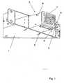
- eine perspektivische Ansicht eines Geräts, welches mithilfe einer erfindungsgemässen Verriegelungsvorrichtung in einer Halterung verriegelt wird;
- Figur 2:
- eine Seitenansicht eines Geräts, welches mithilfe einer erfindungsgemässen Verriegelungsvorrichtung in einer Halterung verriegelt wird;
- Figur 3:
- eine Seitenansicht eines Rastelements einer erfindungsgemässen Verriegelungsvorrichtung (stark vergrössert);
- Figur 4:
- eine perspektivische Ansicht einer erfindungsgemässen Verriegelungsvorrichtung, welche an der Innenseite eines Gerätegehäuses montiert ist;
- Figur 5:
- eine Seitenansicht einer erfindungsgemässen Verriegelungsvorrichtung zu Beginn eines Einfahrvorgangs;
- Figur 6:
- eine Seitenansicht einer erfindungsgemässen Verriegelungsvorrichtung während eines Einfahrvorgangs;
- Figur 7:
- eine Seitenansicht einer erfindungsgemässen Verriegelungsvorrichtung am Ende eines Einfahrvorgangs;
- Figur 8:
- eine Seitenansicht einer erfindungsgemässen Verriegelungsvorrichtung zu Beginn eines Ausziehvorgangs;
- Figur 9:
- eine Seitenansicht einer erfindungsgemässen Verriegelungsvorrichtung während eines Ausziehvorgangs;
- Figur 10:
- eine Seitenansicht einer erfindungsgemässen Verriegelungsvorrichtung bei nicht korrekt eingeführtem Gerät in eine Halterung;
- Figur 11:
- eine perspektivische Ansicht einer erfindungsgemässen Verriegelungsvorrichtung, welche an der Innenseite eines Gerätegehäuses montiert ist, in ihrer Ausgangslage;
- Figur 12:
- eine perspektivische Ansicht einer erfindungsgemässen Verriegelungsvorrichtung, welche an der Innenseite eines Gerätegehäuses montiert ist, in ihrer Verriegelungslage;
- Figur 13:
- eine perspektivische Ansicht einer erfindungsgemässen Verriegelungsvorrichtung, welche an der Innenseite eines Gerätegehäuses montiert ist, in ihrer Maximallage;
- Figur 14:
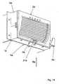
- eine perspektivische Ansicht eines weiteren Ausführungsbeispiels einer erfindungsgemässen Verriegelungsvorrichtung mit zwei ersten und zwei zweiten Verriegelungselementen und
- Figur 15:
- eine ausschnittsweise vergrösserte Darstellung der Verriegelungsvorrichtung aus
Figur 14 .
- FIG. 1:
- a perspective view of a device which is locked by means of a locking device according to the invention in a holder;
- FIG. 2:
- a side view of a device which is locked by means of a locking device according to the invention in a holder;
- FIG. 3:
- a side view of a locking element of a locking device according to the invention (greatly enlarged);
- FIG. 4:
- a perspective view of a locking device according to the invention, which is mounted on the inside of a device housing;
- FIG. 5:
- a side view of an inventive locking device at the beginning of a retraction process;
- FIG. 6:
- a side view of an inventive locking device during a retraction process;
- FIG. 7:
- a side view of an inventive locking device at the end of a retraction process;
- FIG. 8:
- a side view of an inventive locking device at the beginning of a pull-out;
- FIG. 9:
- a side view of an inventive locking device during a Ausziehvorgangs;
- FIG. 10:
- a side view of an inventive locking device when not correctly inserted device in a holder;
- FIG. 11:
- a perspective view of an inventive locking device, which is mounted on the inside of a device housing, in its initial position;
- FIG. 12:
- a perspective view of a locking device according to the invention, which is mounted on the inside of a device housing, in its locking position;
- FIG. 13:
- a perspective view of an inventive locking device, which is mounted on the inside of a device housing, in its maximum position;
- FIG. 14:
- a perspective view of another embodiment of an inventive locking device with two first and two second locking elements and
- FIG. 15:
- a partially enlarged view of the locking device
FIG. 14 ,
Figur 1 zeigt ein Gerät 2, welches mithilfe einer erfindungsgemässen Verriegelungsvorrichtung in einer Halterung 1 verriegelbar ist. Das Gerät 2 umfasst ein Gerätegehäuse 6, ein Frontelement 7 und ein Verriegelungselement 3. Das Verriegelungselement 3 umfasst ein Rastelement 4 sowie eine Bedienlasche 8 zum Bewegen bzw. Bedienen der Verriegelungsvorrichtung. Das Rastelement 4 ist derart geformt, dass es in eine Rastöffnung 5 eingreifen kann. Durch dieses Eingreifen des Rastelements 4 in die Rastöffnung 5 wird das Gerät 2 in der Halterung 1 verriegelt. Das Rastelement 4 ist derart geformt, dass es in keinem Fall über die Rastöffnung 5 hinausragen kann. Dadurch wird erreicht, dass das in der Halterung 1 verriegelte Gerät 2 in keinem Fall einen Einschub eines weiteren Geräts in die Halterung 1 verhindert, indem das Rastelement 4 aus der Rastöffnung 5 herausragt.FIG. 1 shows adevice 2, which can be locked in aholder 1 by means of a locking device according to the invention. Thedevice 2 comprises adevice housing 6, afront element 7 and alocking element 3. The lockingelement 3 comprises a latchingelement 4 and acontrol flap 8 for moving or operating the locking device. The lockingelement 4 is shaped such that it can engage in alatching opening 5. By this engagement of thelocking element 4 in thelatching opening 5, thedevice 2 is locked in theholder 1. The lockingelement 4 is shaped such that it can not protrude beyond the latchingopening 5 in any case. It is thereby achieved that the locked in theholder 1device 2 prevented in any case a slot of another device in theholder 1 by the lockingelement 4 protrudes from thedetent opening 5.Figur 2 zeigt eine Seitenansicht einer erfindungsgemässen Verriegelungsvorrichtung zum Verriegeln eines Geräts 2, welches ein Frontelement 7, ein Gerätegehäuse 6 und ein Verriegelungselement 3 umfasst, in einer Halterung 1. Zum Verriegeln des Geräts 2 in der Halterung 1 muss das Rastelement 4 mit der Rastöffnung 5 in Eingriff kommen. InFigur 2 ist die Verriegelungsvorrichtung bzw. das Verriegelungselement 3 in ihrer bzw. seiner Ausgangsstellung gezeigt. Dabei wird das Verriegelungselement 3 von einem inFigur 2 nicht erkennbaren Federelement 15 (sieheFigur 4 ) mit einer Kraft beaufschlagbar, so dass das Verriegelungselement 3 auf einen ersten Anschlag 9 gedrückt wird. Der erste Anschlag 9 ist im gezeigten Ausführungsbeispiel Teil des Gerätegehäuses 6.FIG. 2 shows a side view of an inventive locking device for locking adevice 2, which comprises afront element 7, adevice housing 6 and alocking element 3, in aholder 1. To lock thedevice 2 in theholder 1, the lockingelement 4 with the latchingopening 5 in engagement come. InFIG. 2 the locking device or thelocking element 3 is shown in its or its initial position. In this case, the lockingelement 3 of a inFIG. 2 unrecognizable spring element 15 (seeFIG. 4 ) can be acted upon by a force, so that the lockingelement 3 is pressed onto afirst stop 9. Thefirst stop 9 is part of thedevice housing 6 in the embodiment shown.Figur 3 zeigt eine Seitenansicht eines Rastelements 4 einer erfindungsgemässen Verriegelungsvorrichtung (stark vergrössert). InFigur 3 ist erkennbar, dass das Rastelement 4 eine Rastnase 10, eine Anschlagskante 11 sowie eine erste Einfahrschräge 12 und eine zweite Einfahrschräge 13 umfasst. Die erste Einfahrschräge 12 ist hierbei zwischen der Rastnase 10 und der Anschlagskante 11 angeordnet. Die zweite Einfahrschräge 13 ist am der Rastnase 10 entgegengesetzten Ende des Rastelements 4 angeordnet. Das Rastelement 4 ragt dabei zumindest teilweise durch einen Durchgriff 9 des Gerätegehäuses 6.FIG. 3 shows a side view of alocking element 4 of an inventive locking device (greatly enlarged). InFIG. 3 It can be seen that the lockingelement 4 comprises a latchingnose 10, astop edge 11 and afirst Einfahrschräge 12 and asecond Einfahrschräge 13. Thefirst Einfahrschräge 12 is in this case arranged between the lockinglug 10 and thestop edge 11. Thesecond Einfahrschräge 13 is disposed on the lockinglug 10 opposite end of thelocking element 4. The lockingelement 4 protrudes at least partially through apassage 9 of the device housing. 6- In
Figur 4 ist gezeigt, wie das Verriegelungselement 3 mithilfe eines Federelements 15 und einer Drehbefestigung 14 an einer Innenseite des Gerätegehäuses 6 befestigt ist. Die Drehbefestigung 14 verbindet hierbei das Verriegelungselement 3 mit dem Gerätegehäuse 6 und das Federelement 15 verspannt dabei das Federelement 3 gegen das Gerätegehäuse 6. An einer Gehäusebefestigung 16 greift das Federelement 15 unter eine Lasche. An einer Verriegelungselement-Befestigung 17 ist das Federelement 15 an dem Verriegelungselement 3 befestigt. In der inFigur 4 gezeigten Ausgangslage der Verriegelungsvorrichtung drückt das Federelement 15 das Verriegelungselement 3 auf den ersten Anschlag 18 des Gerätegehäuses 6. Wollte man das Verriegelungselement 3 von dem ersten Anschlag 18 weg bewegen, so müsste man die Bedienlasche 8 entgegen der Spannrichtung S betätigen. Dabei würde das Federelement 15 gestaucht werden.InFIG. 4 It is shown how the lockingelement 3 is fixed by means of aspring element 15 and arotary fastening 14 on an inner side of thedevice housing 6. The Rotary mount 14 in this case connects the lockingelement 3 with thedevice housing 6 and thespring element 15 braces thespring element 3 against thedevice housing 6. At ahousing attachment 16, thespring element 15 engages under a tab. At alocking element attachment 17, thespring element 15 is attached to thelocking element 3. In the inFIG. 4 If thelocking element 3 were to be moved away from thefirst stop 18, then theoperating flap 8 would have to be actuated counter to the tensioning direction S. In this case, thespring element 15 would be upset. Figuren 5-7 verdeutlichen einen Einfahrvorgang des Geräts 2 mit erfindungsgemässer Verriegelungsvorrichtung in die Halterung 1. InFigur 5 sind das Gerät 2 und die Halterung 1 zu Beginn des Einfahrvorgangs gezeigt. Es ist erkennbar, dass das Verriegelungselement 3 an dem ersten Anschlag 18 des Gerätegehäuses anschlägt. Das Rastelement 4 des Verriegelungselements 3 ragt durch den Durchgriff 9 des Gerätegehäuses 6 hindurch. Die zweite Einfahrschräge 13 schlägt in der inFigur 5 gezeigten Position des Geräts 2 an einer vorderen Kante der Halterung 1 an. Würde man das Gerät 2 aus der inFigur 5 gezeigten Position nun weiter in die Halterung 1 einschieben, so würde das Rastelement 4 an seiner zweiten Einfahrschräge 13 sukzessive an der vorderen Kante der Halterung 1 herauf laufen, bis die Anschlagskante 11 (in Figur fünf der Übersicht halber nicht eingezeichnet) auf der Innenseite der Halterung 1 auffliegt. In Figur sechs sind das Gerät 2 und die Halterung 1 während des Einfahrvorgangs gezeigt. Das Verriegelungselement 3 inFigur 6 liegt nicht mehr auf dem ersten Anschlag 18 des Gerätegehäuses 6 auf, sondern ist durch die Tatsache, dass das Rastelement 4 mit seiner Rastnase 10 auf der Oberseite der Halterung 1 auffliegt, nach oben, d.h. von dem ersten Anschlag 18 des Gerätegehäuses 6 weg, ausgerichtet. Würde man das Gerät 2 nun noch weiter in die Halterung 1 einschieben, so würde das Rastelement 4 schliesslich mit der Rastöffnung 5 der Halterung 1 in Eingriff kommen. Diese so genannte Verriegelungslage der Verriegelungsvorrichtung ist inFigur 7 dargestellt. InFigur 7 ist erkennbar, dass die Rastnase 10 des Verriegelungselements 4 in die Rastöffnung 5 der Halterung 1 eingreift, wobei die Anschlagskante 11 des Verriegelungselements 4 auf einem zweiten Anschlag 19 der Verriegelungsvorrichtung, insbesondere der Halterung 1, aufliegt. InFigur 7 ist zudem erkennbar, dass das Verriegelungselement 3 nicht auf dem ersten Anschlag 18 des Gerätegehäuses 6 auffliegt, sondern dass das Verriegelungselement drei und der erste Anschlag 18 beabstandet sind. Wenn es nötig wäre, könnte das inFigur 7 nicht erkennbare Federelement 15 (siehe zum BeispielFigur 4 ) das Verriegelungselement 3 also in der Verriegelungslage bis auf den ersten Anschlag 18 herunter drücken und dadurch das Rastelement 4 noch weiter durch den Durchgriff 9 (der Übersicht halber in Figur sieben nicht eingezeichnet) hindurch drücken.Figures 5-7 illustrate a retraction of thedevice 2 with inventive locking device in theholder 1. InFIG. 5 thedevice 2 and theholder 1 are shown at the beginning of the retraction process. It can be seen that the lockingelement 3 abuts against thefirst stop 18 of the device housing. The lockingelement 4 of thelocking element 3 projects through thepassage 9 of thedevice housing 6 therethrough. Thesecond Einfahrschräge 13 beats in the inFIG. 5 shown position of thedevice 2 at a front edge of thebracket 1 at. Would you thedevice 2 from the inFIG. 5 now shown in theholder 1, the latchingelement 4 would successively run up on itssecond insertion slope 13 at the front edge of theholder 1 until the stop edge 11 (not shown in Figure five for clarity) on the inside of theholder 1 hits. In Fig. 6, theapparatus 2 and thebracket 1 are shown during the retracting operation. The lockingelement 3 inFIG. 6 is no longer on thefirst stop 18 of thedevice housing 6, but is by the fact that the lockingelement 4 flies up with its lockinglug 10 on the top of theholder 1, upwards, ie from thefirst stop 18 of thedevice housing 6, aligned , If you were to push thedevice 2 even further into theholder 1, then thelocking element 4 would finally come into engagement with thelocking opening 5 of theholder 1. This so-called locking position of the locking device is inFIG. 7 shown. InFIG. 7 it can be seen that the latchinglug 10 of thelocking element 4 engages in thelatching opening 5 of theholder 1, wherein thestop edge 11 of thelocking element 4 rests on asecond stop 19 of the locking device, in particular theholder 1. InFIG. 7 is also seen that the lockingelement 3 does not fly on thefirst stop 18 of thedevice housing 6, but that the locking element three and thefirst stop 18 are spaced. If necessary, that could be inFIG. 7 unrecognizable spring element 15 (see for exampleFIG. 4 ) Press the lockingmember 3 so in the locking position down to thefirst stop 18 and thereby push thelocking element 4 even further through the passage 9 (not shown in Figure seven for clarity) through.Figuren 8 und 9 visualisieren einen Ausziehvorgang für das Herausziehen des Geräts 2 aus der Halterung 1.Figur 8 zeigt hierbei den Beginn des Ausziehvorgangs, bei dem die Bedienlasche 8 in Richtung der Betätigungsrichtung B bewegt und somit das Verriegelungselement 3 bezüglichFigur 8 nach oben ausgelenkt wird. Dadurch wird die Rastnase 10 aus der Rastöffnung 5 der Halterung 1 herausgehoben. Durch Ziehen an der weiter nach oben ausgelenkten Bedienlasche 8 in Richtung der Ausziehrichtung A kann das Gerät 2 mit Gerätegehäuse 6, Frontelement 7 und Verriegelungselement 3 aus der Halterung 1 herausgezogen werden. Dieses weitere Herausziehen ist inFigur 9 dargestellt.FIGS. 8 and 9 visualize an extraction process for the removal of thedevice 2 from the holder. 1FIG. 8 in this case shows the beginning of the pull-out, in which theoperating flap 8 moves in the direction of the actuating direction B and thus thelocking element 3 with respectFIG. 8 is deflected upward. As a result, the latchinglug 10 is lifted out of the latchingopening 5 of theholder 1. By pulling on the further upwardly deflectedoperating tab 8 in the direction of the withdrawal direction A, thedevice 2 withdevice housing 6,front element 7 and lockingelement 3 can be pulled out of theholder 1. This further extraction is inFIG. 9 shown.- In
Figur 10 ist ein Fall dargestellt, bei dem das Gerätegehäuse 6 nicht korrekt in die Halterung 1 eingeschoben ist. Die nicht korrekte Lage des Gerätegehäuses 6 bezüglich der Halterung 1 manifestiert sich unter anderem in einem Abstand d zwischen einer Innenseite der Halterung 1 und einer unteren Aussenseite des Gerätegehäuses 6. In diesem inFigur 10 gezeigten Fall ist das Verriegelungselement 3 nun weiter als in der inFigur 7 gezeigten Verriegelungslage in Richtung des ersten Anschlags 18 des Gerätegehäuses sechs gedrückt. Dadurch wird das Rastelement 4 auch weiter durch den Durchgriff 9 des Gerätegehäuses 6 hindurch gedrückt, als dies inFigur 7 der Fall ist. So wird sichergestellt, dass auch bei der inFigur 10 gezeigten nicht korrekten Lage des Gerätegehäuses 6 bezüglich der Halterung 1 die Rastnase 10 so weit in die Rastöffnung 5 eingreift, dass das Gerät 2 sicher in der Halterung 1 verriegelt wird. Gleichzeitig verhindert das Zusammenspiel zwischen der Anschlagskante 11 des Rastelements 4 und dem zweiten Anschlag 19 der Verriegelungsvorrichtung bzw. der Halterung 1, dass die Rastnase 10 über die Rastöffnung 5 und somit eine Unterseite der Halterung 1 heraus steht, wodurch das Einschieben eines weiteren Geräts in einem Fach der Halterung 1 unterhalb des inFigur 10 gezeigten Geräts 2 umkompromittiert würde.InFIG. 10 a case is shown in which thedevice housing 6 is not inserted correctly into theholder 1. The incorrect position of thedevice housing 6 with respect to theholder 1 manifests itself inter alia at a distance d between an inner side of theholder 1 and a lower outer side of thedevice housing 6. In this inFIG. 10 In the case shown, the lockingelement 3 is now wider than in the inFIG. 7 shown locking position in the direction of thefirst stop 18 of the device housing six pressed. As a result, the lockingelement 4 is also pushed further through thepassage 9 of thedevice housing 6, as this inFIG. 7 the case is. This will ensure that even in theFIG. 10 shown incorrect position of thedevice housing 6 with respect to theholder 1, the lockinglug 10 so far into the latchingopening 5 engages that thedevice 2 is securely locked in theholder 1. At the same time prevents the interaction between thestop edge 11 of thelocking element 4 and thesecond stop 19 of the locking device or theholder 1, that the lockinglug 10 on thelatching opening 5 and thus an underside of theholder 1 is out, whereby the insertion of another device in a Compartment of thebracket 1 below the inFIG. 10 Device 2 would be umkompromittiert. Figuren 11-13 zeigen nun perspektivische Ansichten einer erfindungsgemässen Verriegelungseinrichtung, welche an der Innenseite des Gerätegehäuses 6 montiert ist, in der Ausgangslage (Figur 11 ), der Verriegelungslage (Figur 12 ) und der Maximallage (Figur 13 ). In der inFigur 11 gezeigten Ausgangslage ist das Federelement 15 maximal entspannt und das Verriegelungselement 3 schlägt an dem ersten Anschlag 18 des Gerätegehäuses 6 an. In der inFigur 12 gezeigten Verriegelungslage befindet sich das Verriegelungselement 3 in einer Mittelstellung. In der inFigur 13 gezeigten Maximallage ist das Verriegelungselement 3 mithilfe der Bedienlasche 8 maximal nach oben ausgelenkt, so dass das Verriegelungselement 3 an einem Begrenzungsanschlag 20 des Gerätegehäuses 6 anschlägt. Das Federelement 15 ist dabei maximal gestaucht.FIGS. 11-13 Now show perspective views of an inventive locking device, which is mounted on the inside of thedevice housing 6, in the starting position (FIG. 11 ), the locking position (FIG. 12 ) and the maximum position (FIG. 13 ). In the inFIG. 11 shown starting position, thespring element 15 is maximally relaxed and thelocking element 3 abuts against thefirst stop 18 of thedevice housing 6. In the inFIG. 12 shown locking position is the locking element. 3 in a middle position. In the inFIG. 13 shown maximum position, the lockingelement 3 is deflected by means of theoperating tab 8 maximally upwards, so that the lockingelement 3 abuts against alimit stop 20 of thedevice housing 6. Thespring element 15 is compressed maximum.Figur 14 zeigt eine perspektivische Ansicht eines weiteren Ausführungsbeispiels einer erfindungsgemässen Verriegelungsvorrichtung mit zwei ersten und zwei zweiten Verriegelungselementen. Auch in dem inFigur 14 gezeigten Ausführungsbeispiel ist ein Gerät 2a gezeigt, welches in eine Halterung 1a eingeschoben wird. Im Unterschied zu dem in denFiguren 1 bis 13 dargestellten Ausführungsbeispiel umfasst das Gerät 2a zwei im Wesentlichen mittig am Gerät 2a angeordnete Rastelemente 4a. Diese Rastelemente 4a sind geeignet, in einer Verriegelungsposition der Verriegelungsvorrichtung mit jeweils einer Rastöffnung 5a der Halterung 1a in Eingriff zu kommen. Der Aufbau der Rastelemente 4a gleicht im Wesentlichen dem Aufbau des in denFiguren 1 bis 13 dargestellten Rastelements 4. Das Gerät 2a umfasst einen Entriegelungshebel 21 a. Dieser Entriegelungshebel 21a ist mit den beiden Rastelementen 4a verbunden (nicht explizit inFigur 14 gezeigt). Der Entriegelungshebel 21a ist als Federelement ausgebildet, wodurch der Entriegelungshebel 21a selbst und die beiden Rastelemente 4a zu einem Boden des Gerätegehäuses 6a hin vorgespannt werden. Alternativ könnte die inFigur 14 dargestellte Verriegelungsvorrichtung auch ein separates Federelement zum Vorspannen des Entriegelungshebels 21a und der beiden Rastelemente 4a zu dem Boden des Gerätegehäuses 6a hin umfassen. Zum Entriegeln eines in der Halterung 1a verriegelten Geräts 2a muss der Entriegelungshebel 21a in Richtung der Betätigungsrichtung Ba betätigt werden. Dadurch fahren die Rastelemente 4a aus den Rastöffnungen 5a aus. Zum Herausziehen des Geräts 2a aus der Halterung 1a kann dann bei betätigtem Entriegelungshebel 21 a das Gerät 2a an der fest am Gerät 2a montierten Bedienlasche 8a aus der Halterung 1a herausgezogen werden. Somit sind zum Herausziehen des Geräts 2a aus der Halterung 1a zwei Hände notwendig, nämlich eine zum Entriegeln und eine zum Herausziehen. Dies hat den Vorteil, dass es nicht möglich ist, das Gerät 2a einhändig herauszuziehen, wodurch eine gewissenhafte und sichere Handhabung des Geräts in jedem Fall gewährleistet wird. Alternativ zu einer derart beabstandeten Anordnung von Entriegelungshebel 21 a und Bedienlasche 8a, welche zum Entnehmen des Geräts 2a aus der Halterung 1a die Nutzung beider Hände bedingt, könnten Entriegelungshebel 21a und Bedienlasche 8a auch so nah beieinander angeordnet sein, dass ein Herausziehen des Geräts 2a aus der Halterung 1a mit einer einzigen Hand ermöglicht wird. Auch könnte der Entriegelungshebel 21a selbst eine Bedienlasche zum Herausziehen des Geräts 2a aus der Halterung 1a umfassen, so dass eine separate Bedienlasche entfallen könnte. Diese beiden alternativen Möglichkeiten könnten insbesondere bei kleinen und/oder leichten Einschubgeräten von Vorteil sein.FIG. 14 shows a perspective view of another embodiment of a locking device according to the invention with two first and two second locking elements. Also in the inFIG. 14 shown embodiment, adevice 2a is shown, which is inserted into aholder 1a. Unlike in theFIGS. 1 to 13 illustrated embodiment, thedevice 2a comprises two substantially centrally on thedevice 2a arranged lockingelements 4a. These latchingelements 4a are adapted to come into engagement in a locking position of the locking device, each with alatching opening 5a of theholder 1a. The structure of thelocking elements 4a is substantially similar to the structure of the in theFIGS. 1 to 13 Thedevice 2a comprises arelease lever 21 a. This unlockinglever 21a is connected to the twolatching elements 4a (not explicitly in FIGFIG. 14 shown). The unlockinglever 21a is formed as a spring element, whereby the unlockinglever 21a itself and the twolocking elements 4a are biased to a bottom of thedevice housing 6a out. Alternatively, the inFIG. 14 illustrated locking device also comprise a separate spring element for biasing the unlockinglever 21a and the twolatching elements 4a to the bottom of thedevice housing 6a out. To unlock adevice 2a locked in theholder 1a, the unlockinglever 21a must be actuated in the direction of the actuating direction Ba. As a result, the latchingelements 4a extend out of the latchingopenings 5a. To pull thedevice 2a out of theholder 1a, thedevice 2a can then be pulled out of theholder 1a on theoperating tab 8a permanently mounted on thedevice 2a when the unlockinglever 21a is actuated. Thus, for removing thedevice 2a from theholder 1a, two hands are necessary, namely one for unlocking and one for pulling out. This has the advantage that it is not possible to pull out thedevice 2a with one hand, whereby a conscientious and safe handling of the device is guaranteed in any case. Alternatively to such a spaced arrangement of unlockinglever 21 a andcontrol tab 8a, which requires the use of both hands to remove thedevice 2a from theholder 1a,release lever 21a andcontrol tab 8a could also be arranged so close to each other that pulling out of thedevice 2a theholder 1a is made possible with a single hand. Also, the unlockinglever 21a itself could include a control tab for pulling thedevice 2a out of theholder 1a, thus eliminating a separate operating tab could. These two alternative options could be particularly advantageous for small and / or lightweight plug-in devices.Figur 15 zeigt eine ausschnittsweise vergrösserte Darstellung der Verriegelungsvorrichtung ausFigur 14 .FIG. 15 shows a partially enlarged view of the locking deviceFIG. 14 ,
Die Erfindung ist nicht auf die hier gezeigten Ausführungsbeispiele beschränkt, vielmehr wird der Schutzbereich durch die Patentansprüche bestimmt.The invention is not limited to the embodiments shown here, but the scope of protection is determined by the claims.
Claims (13)
- Device for locking a unit (2) in a holder (1), having a first locking element (3), which has a first latching element (4) and is contained by the unit (2), and having a second locking element (5), which has a second latching element (5) and is comprised by the holder (1), wherein- at least one of the locking elements (3, 5) is mounted in a movable manner and may be subjected to a force for the purpose of locking the two latching elements (4, 5),- the locking device comprises a first stop (18), for limiting maximum deflection of the movable locking element (3) in the direction of the force,characterized in that
the locking device comprises a second stop (19) for limiting overlapping of the two latching elements (3, 5) in the locked state, andin that the two stops (18, 19) are arranged such that, when the two locking elements (3, 5) are being locked, the movable locking element (3) strikes against the second stop (19) before it strikes against the first stop (18). - Locking device according to Claim 1, wherein it comprises a spring element (15) for subjecting the movable latching element (4) to the force.
- Locking device according to one of Claims 1 - 2, wherein the spring element (15) is supported, on the one hand, on the movable locking element (3) and, on the other hand, on the unit (2) or a housing of the unit (6) or on the holder (1).
- Locking device according to one of Claims 1 - 3, wherein the first locking element (3) is mounted in a rotatable manner on the housing of the unit (6) and the spring element (15) comprises a spring which is fastened on the first locking element (3) and is supported on the housing of the unit (6).
- Locking device according to one of the preceding claims, wherein the first latching element (4) comprises a latching nose (10) for engaging in an aperture (5) of the holder (1).
- Locking device according to Claim 5,characterized in that the first latching element (4) comprises a stop edge (11) for striking against the second stop (19).
- Locking device according to one of the preceding claims,characterized in that the first latching element (4) comprises a first insertion slope (12) for facilitating insertion of the unit (2) into the holder (1).
- Locking device according to Claim 7,characterized in that the first insertion slope (12) is arranged between the latching nose (10) and the stop edge (11).
- Locking device according to one of the preceding claims,characterized in that the first latching element (4) comprises a second insertion slope (13) for facilitating insertion of the unit (2) into the holder (1).
- Locking device according to Claim 9,characterized in that the second insertion slope (13) is arranged behind the first insertion slope (12) and/or the stop edge (11), as seen from the latching nose (10).
- Locking device according to one of the preceding claims,characterized in that the first stop (18) is formed by the housing of the unit (6) and/or the second stop (19) is formed by the holder (1).
- Locking device according to one of Claims 5 to 11,characterized in that the second locking element (5) is formed by the aperture (5) of the holder (1).
- Arrangement of a unit (2) within a holder (1) for receiving the unit (2), comprising a locking device according to one of the preceding claims.
Priority Applications (3)
| Application Number | Priority Date | Filing Date | Title |
|---|---|---|---|
| EP11405365.5AEP2603067B1 (en) | 2011-12-09 | 2011-12-09 | Locking device |
| US13/708,633US20130149028A1 (en) | 2011-12-09 | 2012-12-07 | Locking device |
| CN201210599106.9ACN103442539B (en) | 2011-12-09 | 2012-12-09 | Locking device |
Applications Claiming Priority (1)
| Application Number | Priority Date | Filing Date | Title |
|---|---|---|---|
| EP11405365.5AEP2603067B1 (en) | 2011-12-09 | 2011-12-09 | Locking device |
Publications (2)
| Publication Number | Publication Date |
|---|---|
| EP2603067A1 EP2603067A1 (en) | 2013-06-12 |
| EP2603067B1true EP2603067B1 (en) | 2015-09-23 |
Family
ID=45422031
Family Applications (1)
| Application Number | Title | Priority Date | Filing Date |
|---|---|---|---|
| EP11405365.5AActiveEP2603067B1 (en) | 2011-12-09 | 2011-12-09 | Locking device |
Country Status (3)
| Country | Link |
|---|---|
| US (1) | US20130149028A1 (en) |
| EP (1) | EP2603067B1 (en) |
| CN (1) | CN103442539B (en) |
Families Citing this family (4)
| Publication number | Priority date | Publication date | Assignee | Title |
|---|---|---|---|---|
| CH713363B1 (en)* | 2017-01-12 | 2023-11-30 | Landis & Gyr Ag | Housing assembly and measuring device comprising the same. |
| TWI715430B (en)* | 2020-02-04 | 2021-01-01 | 四零四科技股份有限公司 | Electronic device capable of ejecting a detachable module by levering operation and related lever mechanism |
| TWI732590B (en)* | 2020-06-10 | 2021-07-01 | 和碩聯合科技股份有限公司 | Quick releasing device |
| CN113983307B (en)* | 2021-12-02 | 2023-12-26 | 广东天波信息技术股份有限公司 | Fixed stores pylon and face identification equipment |
Family Cites Families (22)
| Publication number | Priority date | Publication date | Assignee | Title |
|---|---|---|---|---|
| NL6414965A (en)* | 1964-12-23 | 1966-06-24 | ||
| DE3146904C2 (en) | 1980-12-13 | 1985-05-09 | Standard Elektrik Lorenz Ag, 7000 Stuttgart | Locking device for assemblies |
| EP0332793B1 (en)* | 1988-03-15 | 1993-12-22 | International Business Machines Corporation | Machine-pluggable electronic package having a mechanical interlock |
| US5216904A (en)* | 1990-11-06 | 1993-06-08 | Pioneer Electronic Corporation | Handle device having a lock mechanism for an audio equipment |
| US5262923A (en)* | 1991-06-21 | 1993-11-16 | Tandon Corporation | Railing with grounding tabs for grounding and mounting computer components in a computer |
| US5359492A (en)* | 1992-07-29 | 1994-10-25 | Ncr Corporation | Latch assembly for modular computer component |
| US5653518A (en)* | 1993-09-10 | 1997-08-05 | Compaq Computer Corporation | Quick release drive unit rail members |
| KR970022658A (en)* | 1995-10-30 | 1997-05-30 | 김광호 | Computers for easy removal of peripheral devices |
| US6181549B1 (en)* | 1997-06-24 | 2001-01-30 | Dell Products, L.P. | Chassis retaining system for an electronics rack |
| DE29717491U1 (en)* | 1997-09-30 | 1997-11-20 | Festo AG & Co, 73734 Esslingen | Holding device |
| JP2000021503A (en)* | 1998-07-06 | 2000-01-21 | Fujitec:Kk | Lock device for substrate socket |
| TW495056U (en)* | 2000-02-02 | 2002-07-11 | Hon Hai Prec Ind Co Ltd | Fixture apparatus of data access device |
| WO2001078077A2 (en)* | 2000-04-06 | 2001-10-18 | Plasmon Ide, Inc. | Universal media module |
| US6373695B1 (en)* | 2000-09-22 | 2002-04-16 | Mace Tech Corp. | Mobile rack mounting structure for computer |
| US6456501B1 (en)* | 2001-07-30 | 2002-09-24 | Hewlett-Packard Company | Quick release mechanism for sliding rail |
| TW527053U (en)* | 2002-07-26 | 2003-04-01 | Hon Hai Prec Ind Co Ltd | Computer enclosure |
| TWI223582B (en)* | 2003-08-01 | 2004-11-01 | Delta Electronics Inc | Removable electronic apparatus with handle assembly capable of automatically releasing the handle thereof |
| US7079402B2 (en)* | 2003-10-08 | 2006-07-18 | Inventec Corporation | Modularized circuit board mounting architecture |
| US20060134953A1 (en)* | 2004-12-22 | 2006-06-22 | Adaptec, Inc. | Electronic module latching mechanism |
| CN102136912B (en)* | 2010-01-25 | 2013-06-05 | 鸿富锦精密工业(深圳)有限公司 | Plug device and communication equipment using same |
| CN103037659A (en)* | 2011-10-07 | 2013-04-10 | 鸿富锦精密工业(深圳)有限公司 | Server tray fixing device |
| US8611103B2 (en)* | 2011-10-27 | 2013-12-17 | Cisco Technology, Inc. | Latching injector/ejector |
- 2011
- 2011-12-09EPEP11405365.5Apatent/EP2603067B1/enactiveActive
- 2012
- 2012-12-07USUS13/708,633patent/US20130149028A1/ennot_activeAbandoned
- 2012-12-09CNCN201210599106.9Apatent/CN103442539B/enactiveActive
Also Published As
| Publication number | Publication date |
|---|---|
| US20130149028A1 (en) | 2013-06-13 |
| EP2603067A1 (en) | 2013-06-12 |
| CN103442539B (en) | 2017-07-28 |
| CN103442539A (en) | 2013-12-11 |
Similar Documents
| Publication | Publication Date | Title |
|---|---|---|
| EP1499171B1 (en) | Device for inserting, extracting a plug-in unit in a bay | |
| EP2713819B1 (en) | Fastening device for mounting a front cover on a drawer | |
| EP1335644B2 (en) | Extraction-insertion mechanism for a plug-in unit | |
| DE2823422A1 (en) | DEVICE FOR ENGAGING AND RELEASING PRINTED CIRCUIT CARDS | |
| DE102012103439B9 (en) | Locking device for connecting components | |
| DE4105948C2 (en) | Assembly unit with a plate, in particular printed circuit board, which is designed for insertion into a receiving device | |
| EP2126494A2 (en) | Refrigerator | |
| EP1802188B1 (en) | Plugin unit with extraction lever | |
| EP2055208A1 (en) | Device for attaching items of furniture | |
| WO2018228877A1 (en) | Support rail fastening means | |
| WO2009030315A1 (en) | Locking mechanism for a housing to hold a plug-in module | |
| EP2603067B1 (en) | Locking device | |
| EP2625757B1 (en) | Locking apparatus for withdrawable units for electrical switchgear cabinets | |
| DE102009032147B3 (en) | safety device | |
| EP0086954B1 (en) | Tool to extract an electronic drawer from its frame | |
| DE102016100767B4 (en) | STRUCTURE FOR FIXING A PCB IN AN ELECTRONIC DEVICE UNIT | |
| DE2002350A1 (en) | Quick release with pull-out and engagement device | |
| DE3008298C2 (en) | Buckle for seat belts | |
| WO2017190824A1 (en) | Coupling device | |
| EP1786252A1 (en) | Device and method for inserting or removing a pluggable unit | |
| DE3636088C1 (en) | Device for insertion of an assembly into plug connectors and withdrawal of said assembly from plug connectors | |
| EP2182788A1 (en) | Holding assembly for a drawer module and holder rack | |
| DE3047089C2 (en) | Locking device for assemblies | |
| DE3732892C2 (en) | ||
| DE20311072U1 (en) | Drawer locking system for electronic module with conductor plate and front plate has double handle hinged on flange on side of front plate with lever engaging in profiled edge of support plate |
Legal Events
| Date | Code | Title | Description |
|---|---|---|---|
| PUAI | Public reference made under article 153(3) epc to a published international application that has entered the european phase | Free format text:ORIGINAL CODE: 0009012 | |
| AK | Designated contracting states | Kind code of ref document:A1 Designated state(s):AL AT BE BG CH CY CZ DE DK EE ES FI FR GB GR HR HU IE IS IT LI LT LU LV MC MK MT NL NO PL PT RO RS SE SI SK SM TR | |
| AX | Request for extension of the european patent | Extension state:BA ME | |
| 17P | Request for examination filed | Effective date:20130702 | |
| RBV | Designated contracting states (corrected) | Designated state(s):AL AT BE BG CH CY CZ DE DK EE ES FI FR GB GR HR HU IE IS IT LI LT LU LV MC MK MT NL NO PL PT RO RS SE SI SK SM TR | |
| 17Q | First examination report despatched | Effective date:20131008 | |
| GRAP | Despatch of communication of intention to grant a patent | Free format text:ORIGINAL CODE: EPIDOSNIGR1 | |
| INTG | Intention to grant announced | Effective date:20150611 | |
| GRAS | Grant fee paid | Free format text:ORIGINAL CODE: EPIDOSNIGR3 | |
| GRAA | (expected) grant | Free format text:ORIGINAL CODE: 0009210 | |
| AK | Designated contracting states | Kind code of ref document:B1 Designated state(s):AL AT BE BG CH CY CZ DE DK EE ES FI FR GB GR HR HU IE IS IT LI LT LU LV MC MK MT NL NO PL PT RO RS SE SI SK SM TR | |
| REG | Reference to a national code | Ref country code:GB Ref legal event code:FG4D Free format text:NOT ENGLISH | |
| REG | Reference to a national code | Ref country code:CH Ref legal event code:EP | |
| REG | Reference to a national code | Ref country code:AT Ref legal event code:REF Ref document number:751811 Country of ref document:AT Kind code of ref document:T Effective date:20151015 | |
| REG | Reference to a national code | Ref country code:IE Ref legal event code:FG4D Free format text:LANGUAGE OF EP DOCUMENT: GERMAN | |
| REG | Reference to a national code | Ref country code:DE Ref legal event code:R096 Ref document number:502011007923 Country of ref document:DE | |
| REG | Reference to a national code | Ref country code:CH Ref legal event code:NV Representative=s name:KELLER AND PARTNER PATENTANWAELTE AG, CH | |
| REG | Reference to a national code | Ref country code:FR Ref legal event code:PLFP Year of fee payment:5 | |
| REG | Reference to a national code | Ref country code:SE Ref legal event code:TRGR | |
| REG | Reference to a national code | Ref country code:NL Ref legal event code:MP Effective date:20150923 | |
| PG25 | Lapsed in a contracting state [announced via postgrant information from national office to epo] | Ref country code:LT Free format text:LAPSE BECAUSE OF FAILURE TO SUBMIT A TRANSLATION OF THE DESCRIPTION OR TO PAY THE FEE WITHIN THE PRESCRIBED TIME-LIMIT Effective date:20150923 Ref country code:GR Free format text:LAPSE BECAUSE OF FAILURE TO SUBMIT A TRANSLATION OF THE DESCRIPTION OR TO PAY THE FEE WITHIN THE PRESCRIBED TIME-LIMIT Effective date:20151224 Ref country code:LV Free format text:LAPSE BECAUSE OF FAILURE TO SUBMIT A TRANSLATION OF THE DESCRIPTION OR TO PAY THE FEE WITHIN THE PRESCRIBED TIME-LIMIT Effective date:20150923 Ref country code:FI Free format text:LAPSE BECAUSE OF FAILURE TO SUBMIT A TRANSLATION OF THE DESCRIPTION OR TO PAY THE FEE WITHIN THE PRESCRIBED TIME-LIMIT Effective date:20150923 Ref country code:NO Free format text:LAPSE BECAUSE OF FAILURE TO SUBMIT A TRANSLATION OF THE DESCRIPTION OR TO PAY THE FEE WITHIN THE PRESCRIBED TIME-LIMIT Effective date:20151223 | |
| REG | Reference to a national code | Ref country code:LT Ref legal event code:MG4D | |
| PG25 | Lapsed in a contracting state [announced via postgrant information from national office to epo] | Ref country code:RS Free format text:LAPSE BECAUSE OF FAILURE TO SUBMIT A TRANSLATION OF THE DESCRIPTION OR TO PAY THE FEE WITHIN THE PRESCRIBED TIME-LIMIT Effective date:20150923 Ref country code:HR Free format text:LAPSE BECAUSE OF FAILURE TO SUBMIT A TRANSLATION OF THE DESCRIPTION OR TO PAY THE FEE WITHIN THE PRESCRIBED TIME-LIMIT Effective date:20150923 | |
| PG25 | Lapsed in a contracting state [announced via postgrant information from national office to epo] | Ref country code:NL Free format text:LAPSE BECAUSE OF FAILURE TO SUBMIT A TRANSLATION OF THE DESCRIPTION OR TO PAY THE FEE WITHIN THE PRESCRIBED TIME-LIMIT Effective date:20150923 | |
| PG25 | Lapsed in a contracting state [announced via postgrant information from national office to epo] | Ref country code:EE Free format text:LAPSE BECAUSE OF FAILURE TO SUBMIT A TRANSLATION OF THE DESCRIPTION OR TO PAY THE FEE WITHIN THE PRESCRIBED TIME-LIMIT Effective date:20150923 Ref country code:ES Free format text:LAPSE BECAUSE OF FAILURE TO SUBMIT A TRANSLATION OF THE DESCRIPTION OR TO PAY THE FEE WITHIN THE PRESCRIBED TIME-LIMIT Effective date:20150923 Ref country code:SK Free format text:LAPSE BECAUSE OF FAILURE TO SUBMIT A TRANSLATION OF THE DESCRIPTION OR TO PAY THE FEE WITHIN THE PRESCRIBED TIME-LIMIT Effective date:20150923 Ref country code:CZ Free format text:LAPSE BECAUSE OF FAILURE TO SUBMIT A TRANSLATION OF THE DESCRIPTION OR TO PAY THE FEE WITHIN THE PRESCRIBED TIME-LIMIT Effective date:20150923 Ref country code:IS Free format text:LAPSE BECAUSE OF FAILURE TO SUBMIT A TRANSLATION OF THE DESCRIPTION OR TO PAY THE FEE WITHIN THE PRESCRIBED TIME-LIMIT Effective date:20160123 | |
| PG25 | Lapsed in a contracting state [announced via postgrant information from national office to epo] | Ref country code:PL Free format text:LAPSE BECAUSE OF FAILURE TO SUBMIT A TRANSLATION OF THE DESCRIPTION OR TO PAY THE FEE WITHIN THE PRESCRIBED TIME-LIMIT Effective date:20150923 Ref country code:BE Free format text:LAPSE BECAUSE OF NON-PAYMENT OF DUE FEES Effective date:20151231 Ref country code:PT Free format text:LAPSE BECAUSE OF FAILURE TO SUBMIT A TRANSLATION OF THE DESCRIPTION OR TO PAY THE FEE WITHIN THE PRESCRIBED TIME-LIMIT Effective date:20160125 Ref country code:RO Free format text:LAPSE BECAUSE OF FAILURE TO SUBMIT A TRANSLATION OF THE DESCRIPTION OR TO PAY THE FEE WITHIN THE PRESCRIBED TIME-LIMIT Effective date:20150923 | |
| REG | Reference to a national code | Ref country code:DE Ref legal event code:R097 Ref document number:502011007923 Country of ref document:DE | |
| PG25 | Lapsed in a contracting state [announced via postgrant information from national office to epo] | Ref country code:LU Free format text:LAPSE BECAUSE OF FAILURE TO SUBMIT A TRANSLATION OF THE DESCRIPTION OR TO PAY THE FEE WITHIN THE PRESCRIBED TIME-LIMIT Effective date:20151209 Ref country code:MC Free format text:LAPSE BECAUSE OF FAILURE TO SUBMIT A TRANSLATION OF THE DESCRIPTION OR TO PAY THE FEE WITHIN THE PRESCRIBED TIME-LIMIT Effective date:20150923 | |
| PLBE | No opposition filed within time limit | Free format text:ORIGINAL CODE: 0009261 | |
| STAA | Information on the status of an ep patent application or granted ep patent | Free format text:STATUS: NO OPPOSITION FILED WITHIN TIME LIMIT | |
| 26N | No opposition filed | Effective date:20160624 | |
| PG25 | Lapsed in a contracting state [announced via postgrant information from national office to epo] | Ref country code:DK Free format text:LAPSE BECAUSE OF FAILURE TO SUBMIT A TRANSLATION OF THE DESCRIPTION OR TO PAY THE FEE WITHIN THE PRESCRIBED TIME-LIMIT Effective date:20150923 | |
| REG | Reference to a national code | Ref country code:IE Ref legal event code:MM4A | |
| PG25 | Lapsed in a contracting state [announced via postgrant information from national office to epo] | Ref country code:IE Free format text:LAPSE BECAUSE OF NON-PAYMENT OF DUE FEES Effective date:20151209 | |
| PG25 | Lapsed in a contracting state [announced via postgrant information from national office to epo] | Ref country code:SI Free format text:LAPSE BECAUSE OF FAILURE TO SUBMIT A TRANSLATION OF THE DESCRIPTION OR TO PAY THE FEE WITHIN THE PRESCRIBED TIME-LIMIT Effective date:20150923 | |
| REG | Reference to a national code | Ref country code:FR Ref legal event code:PLFP Year of fee payment:6 | |
| PG25 | Lapsed in a contracting state [announced via postgrant information from national office to epo] | Ref country code:HU Free format text:LAPSE BECAUSE OF FAILURE TO SUBMIT A TRANSLATION OF THE DESCRIPTION OR TO PAY THE FEE WITHIN THE PRESCRIBED TIME-LIMIT; INVALID AB INITIO Effective date:20111209 Ref country code:SM Free format text:LAPSE BECAUSE OF FAILURE TO SUBMIT A TRANSLATION OF THE DESCRIPTION OR TO PAY THE FEE WITHIN THE PRESCRIBED TIME-LIMIT Effective date:20150923 Ref country code:BG Free format text:LAPSE BECAUSE OF FAILURE TO SUBMIT A TRANSLATION OF THE DESCRIPTION OR TO PAY THE FEE WITHIN THE PRESCRIBED TIME-LIMIT Effective date:20150923 | |
| PG25 | Lapsed in a contracting state [announced via postgrant information from national office to epo] | Ref country code:CY Free format text:LAPSE BECAUSE OF FAILURE TO SUBMIT A TRANSLATION OF THE DESCRIPTION OR TO PAY THE FEE WITHIN THE PRESCRIBED TIME-LIMIT Effective date:20150923 | |
| PG25 | Lapsed in a contracting state [announced via postgrant information from national office to epo] | Ref country code:MT Free format text:LAPSE BECAUSE OF FAILURE TO SUBMIT A TRANSLATION OF THE DESCRIPTION OR TO PAY THE FEE WITHIN THE PRESCRIBED TIME-LIMIT Effective date:20150923 | |
| REG | Reference to a national code | Ref country code:FR Ref legal event code:PLFP Year of fee payment:7 | |
| REG | Reference to a national code | Ref country code:AT Ref legal event code:MM01 Ref document number:751811 Country of ref document:AT Kind code of ref document:T Effective date:20161209 | |
| PG25 | Lapsed in a contracting state [announced via postgrant information from national office to epo] | Ref country code:AT Free format text:LAPSE BECAUSE OF NON-PAYMENT OF DUE FEES Effective date:20161209 | |
| PG25 | Lapsed in a contracting state [announced via postgrant information from national office to epo] | Ref country code:MK Free format text:LAPSE BECAUSE OF FAILURE TO SUBMIT A TRANSLATION OF THE DESCRIPTION OR TO PAY THE FEE WITHIN THE PRESCRIBED TIME-LIMIT Effective date:20150923 Ref country code:TR Free format text:LAPSE BECAUSE OF FAILURE TO SUBMIT A TRANSLATION OF THE DESCRIPTION OR TO PAY THE FEE WITHIN THE PRESCRIBED TIME-LIMIT Effective date:20150923 | |
| PG25 | Lapsed in a contracting state [announced via postgrant information from national office to epo] | Ref country code:AL Free format text:LAPSE BECAUSE OF FAILURE TO SUBMIT A TRANSLATION OF THE DESCRIPTION OR TO PAY THE FEE WITHIN THE PRESCRIBED TIME-LIMIT Effective date:20150923 | |
| REG | Reference to a national code | Ref country code:CH Ref legal event code:PUE Owner name:DELTA ELECTRONICS (THAILAND) PUBLIC CO., LTD., TH Free format text:FORMER OWNER: DET INTERNATIONAL HOLDING LIMITED, KY | |
| REG | Reference to a national code | Ref country code:DE Ref legal event code:R082 Ref document number:502011007923 Country of ref document:DE Representative=s name:LENZING GERBER STUTE PARTNERSCHAFTSGESELLSCHAF, DE Ref country code:DE Ref legal event code:R081 Ref document number:502011007923 Country of ref document:DE Owner name:DELTA ELECTRONICS (THAILAND) PUBLIC CO., LTD.,, TH Free format text:FORMER OWNER: DET INTERNATIONAL HOLDING LTD., GEORGE TOWN, GRAND CAYMAN, KY | |
| REG | Reference to a national code | Ref country code:CH Ref legal event code:PFA Owner name:DELTA ELECTRONICS (THAILAND) PUBLIC CO., LTD., TH Free format text:FORMER OWNER: DELTA ELECTRONICS (THAILAND) PUBLIC CO., LTD., TH | |
| REG | Reference to a national code | Ref country code:GB Ref legal event code:732E Free format text:REGISTERED BETWEEN 20200917 AND 20200923 | |
| PGFP | Annual fee paid to national office [announced via postgrant information from national office to epo] | Ref country code:DE Payment date:20241210 Year of fee payment:14 | |
| PGFP | Annual fee paid to national office [announced via postgrant information from national office to epo] | Ref country code:GB Payment date:20241224 Year of fee payment:14 | |
| PGFP | Annual fee paid to national office [announced via postgrant information from national office to epo] | Ref country code:FR Payment date:20241223 Year of fee payment:14 | |
| PGFP | Annual fee paid to national office [announced via postgrant information from national office to epo] | Ref country code:SE Payment date:20241219 Year of fee payment:14 | |
| PGFP | Annual fee paid to national office [announced via postgrant information from national office to epo] | Ref country code:CH Payment date:20250101 Year of fee payment:14 | |
| PGFP | Annual fee paid to national office [announced via postgrant information from national office to epo] | Ref country code:IT Payment date:20241223 Year of fee payment:14 |