EP2602741A2 - Detection of the vertical contour of a road - Google Patents
Detection of the vertical contour of a roadDownload PDFInfo
- Publication number
- EP2602741A2 EP2602741A2EP12195922.5AEP12195922AEP2602741A2EP 2602741 A2EP2602741 A2EP 2602741A2EP 12195922 AEP12195922 AEP 12195922AEP 2602741 A2EP2602741 A2EP 2602741A2
- Authority
- EP
- European Patent Office
- Prior art keywords
- image
- road
- image frame
- frame
- optical flow
- Prior art date
- Legal status (The legal status is an assumption and is not a legal conclusion. Google has not performed a legal analysis and makes no representation as to the accuracy of the status listed.)
- Ceased
Links
Images


Classifications
- G—PHYSICS
- G06—COMPUTING OR CALCULATING; COUNTING
- G06V—IMAGE OR VIDEO RECOGNITION OR UNDERSTANDING
- G06V20/00—Scenes; Scene-specific elements
- G06V20/50—Context or environment of the image
- G06V20/56—Context or environment of the image exterior to a vehicle by using sensors mounted on the vehicle
- G06V20/588—Recognition of the road, e.g. of lane markings; Recognition of the vehicle driving pattern in relation to the road
- B—PERFORMING OPERATIONS; TRANSPORTING
- B60—VEHICLES IN GENERAL
- B60W—CONJOINT CONTROL OF VEHICLE SUB-UNITS OF DIFFERENT TYPE OR DIFFERENT FUNCTION; CONTROL SYSTEMS SPECIALLY ADAPTED FOR HYBRID VEHICLES; ROAD VEHICLE DRIVE CONTROL SYSTEMS FOR PURPOSES NOT RELATED TO THE CONTROL OF A PARTICULAR SUB-UNIT
- B60W40/00—Estimation or calculation of non-directly measurable driving parameters for road vehicle drive control systems not related to the control of a particular sub unit, e.g. by using mathematical models
- B60W40/02—Estimation or calculation of non-directly measurable driving parameters for road vehicle drive control systems not related to the control of a particular sub unit, e.g. by using mathematical models related to ambient conditions
- B60W40/06—Road conditions
- B60W40/076—Slope angle of the road
- G—PHYSICS
- G06—COMPUTING OR CALCULATING; COUNTING
- G06V—IMAGE OR VIDEO RECOGNITION OR UNDERSTANDING
- G06V20/00—Scenes; Scene-specific elements
- G06V20/50—Context or environment of the image
- G06V20/56—Context or environment of the image exterior to a vehicle by using sensors mounted on the vehicle
- G06V20/58—Recognition of moving objects or obstacles, e.g. vehicles or pedestrians; Recognition of traffic objects, e.g. traffic signs, traffic lights or roads
- H—ELECTRICITY
- H04—ELECTRIC COMMUNICATION TECHNIQUE
- H04N—PICTORIAL COMMUNICATION, e.g. TELEVISION
- H04N7/00—Television systems
- H04N7/18—Closed-circuit television [CCTV] systems, i.e. systems in which the video signal is not broadcast
- B—PERFORMING OPERATIONS; TRANSPORTING
- B60—VEHICLES IN GENERAL
- B60W—CONJOINT CONTROL OF VEHICLE SUB-UNITS OF DIFFERENT TYPE OR DIFFERENT FUNCTION; CONTROL SYSTEMS SPECIALLY ADAPTED FOR HYBRID VEHICLES; ROAD VEHICLE DRIVE CONTROL SYSTEMS FOR PURPOSES NOT RELATED TO THE CONTROL OF A PARTICULAR SUB-UNIT
- B60W2420/00—Indexing codes relating to the type of sensors based on the principle of their operation
- B60W2420/40—Photo, light or radio wave sensitive means, e.g. infrared sensors
- B60W2420/403—Image sensing, e.g. optical camera
- B—PERFORMING OPERATIONS; TRANSPORTING
- B60—VEHICLES IN GENERAL
- B60W—CONJOINT CONTROL OF VEHICLE SUB-UNITS OF DIFFERENT TYPE OR DIFFERENT FUNCTION; CONTROL SYSTEMS SPECIALLY ADAPTED FOR HYBRID VEHICLES; ROAD VEHICLE DRIVE CONTROL SYSTEMS FOR PURPOSES NOT RELATED TO THE CONTROL OF A PARTICULAR SUB-UNIT
- B60W2552/00—Input parameters relating to infrastructure
- B60W2552/15—Road slope, i.e. the inclination of a road segment in the longitudinal direction
Definitions
- the present inventionrelates to a system that accurately detects the shape and particularly the vertical contour of a road using a camera.
- DAScamera based driver assistance systems
- executable code for performing the methodand/or a computer readable medium including code for performing the method.
- a driver assistance systemas in claim 13.
- a driver assistance systemmountable in a host vehicle, wherein the driver assistance system includes a camera operatively connectible to a processor, wherein the driver assistance system is operable while the host vehicle is moving to detect a deviation in vertical contour of a road, wherein a first image frame and a second image frame are captured in the field of view of the camera, wherein image motion is processed between respective images of the road, wherein said images of the road are derived from said first image frame and said second image frame, wherein the vertical contour of the road is estimated using a road surface model of the road and the deviation in the vertical contour is computed from said road surface model.
- optical flowis estimated between a plurality of first image patches of the road derived from said first image frame and corresponding second image patches of the road derived from said second image frame.
- the deviation in the vertical contouris determined by comparing said optical flow with an optical flow as predicted by said road surface model to produce thereby a residual optical flow indicating the deviation.
- the driver assistance systemincludes a camera operatively connectible to a processor.
- the driver assistance systemis operable while the host vehicle is moving to detect a deviation in vertical contour of a road.
- a first image frame and a second image frameare captured in the field of view of the camera.
- Image motionis processed between respective images of the road derived from the first image frame and the second image frame.
- the vertical contour of the roadis estimated using a road surface model of the road and the deviation in the vertical contour is computed from the road surface model.
- the optical flowmay be estimated between multiple first image patches of the road derived from the first image frame and corresponding second image patches of the road derived from the second image frame.
- the deviation in the vertical contouris determined by comparing the optical flow with an optical flow as predicted by the road surface model.
- the residual optical flowindicates the deviation in vertical contour of the road.
- a third image framemay be captured in the field of view of the camera and image motion between respective images of the road may be derived from the third image frame and one or more of the first and second image frames.
- a multi-frame road surface modelmay be computed by combining a road profile of the road derived from said road surface model based on said first image frame and said second image frame with said second processing.
- the multi-frame road surface modelmay be mapped from the first and/or second image frames to the third image frame by using a homography between said at least one previous image frame to the third image frame.
- the image motion of the images of the roadmay be processed by initially warping the second image frame toward the first image frame to produce a warped second image frame.
- the initial warpmay include aligning the second image frame with the first image frame by adjusting for an image shift due to motion of the vehicle relative to the road, yaw, pitch and/or roll.
- the initial warpmay include an adjustment for the relative scale change between the second image frame and the first image frame. The relative scale change arises from different distances to the camera.
- Multiple image pointsmay be selected in the first image frame.
- the image pointsmay be located on the image of the road surface and may be located at points of a fixed grid. For the image points, multiple image patches are located disposed respectively about the image points.
- the image pointsmay be tracked by correlating the image patches in the first image frame with corresponding image patches in the warped second image frame to produce multiple tracked points.
- the tracked pointsare fit to a homography.
- a refined warp of the warped second image frame toward the first image framemay be performed to correct the initial warp by using the homography and to produce a refinely warped second image frame.
- Optical flowmay be computed between the refinely warped second image frame and the first image frame.
- the optical flowis compared with a road surface optical flow based on a road surface model. The deviation in vertical contour of the road produces a residual optical flow different from the road surface optical flow as found by the road surface model.
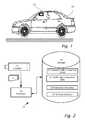
- FIG. 1 and 2illustrate a system 16 including a camera or image sensor 12 mounted in a vehicle 18, according to an embodiment of the present invention.
- Image sensor 12imaging a field of view in the forward direction provides image frames 15 in real time and image frames 15 are captured by an image processor 30.
- Processor 30may be used to process image frames 15 simultaneously and/or in parallel to serve a number of driver assistance systems/applications.
- Processor 30may be used to process image frames 15 to detect and recognize an image or portions of the image in the forward field of view of camera 12.
- the driver assistance systemsmay be implemented using specific hardware circuitry (not shown) with on board software and/or software control algorithms in storage 13.
- Image sensor 12may be monochrome or black-white, i.e. without color separation or image sensor 12 may be color sensitive.
- image frames 15are used to serve pedestrian detection 20, traffic sign recognition (TSR) 21, forward collision warning (FCW) 22 and real time detection 23 of the vertical contour of the road or deviation from the road plane according to features of embodiments of the present invention.
- TSRtraffic sign recognition
- FCWforward collision warning
- image frames 15are partitioned between different driver assistance applications and in other cases the image frames 15 may be shared between the different driver assistance applications.
- various embodiments of the present inventionare useful to accurately detect road shape i.e. vertical profile from a road using camera 12 mounted in host vehicle 18.
- bumps and/or holessuch as speed bumps, curbs and manhole covers may be detected with vertical deviations as little as two centimeters from the road plane.
- System and methods as disclosed hereinmay be similarly applied to forward viewing, side viewing and rear viewing cameras 12.
- Various methods as described hereinaccurately estimate the planar (or bi-quadratic) model of the road surface and then computes the small deviations from the planar (or bi-quadratic) model to detect bumps and holes.
- FIG. 3shows a flow diagram of simplified method 23 for real time measurement of vertical contour of a road while vehicle 18 is moving along a road, according to a feature of an embodiment of the present invention.
- a first image frame 15 and a second image frame 15are captured of a road in the field of view of camera 12 mounted in vehicle 18.
- Image motion from first image frame 15 to second image frame 15is processed (step 305) to detect a vertical contour in the road. Further details of step 305 are shown in the description that follows.
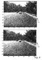
- FIG. 4shows two consecutive image frames 15a and 15b captured (step 303) from forward looking camera 12 mounted in a vehicle 18, according to a feature of an embodiment of the present invention.
- Image frame 15bis captured after image frame 15a is captured.
- Equivalently image frame 15bmay be captured prior to capturing image frame 15a
- Camera 12 in the description that followsmay be a WVGA camera (Aptina M9V024 and Sunny 4028A 5.7mm lens) as used in the MobileyeTM advance warning system (AWS)TM.
- WVGA cameraAlignina M9V024 and Sunny 4028A 5.7mm lens
- AWSMobileyeTM advance warning system
- FIG. 5includes a flow chart showing details of processing step 305, according to a feature of an embodiment of the present invention.
- warpingrefers to a transform from image space to image space.
- Image frame 15bis initially warped (step 501) into image frame 15a.
- image frame 15amay be initially warped into image frame 15b.
- a roadcan be modeled as an almost planar surface.
- imaged points of the roadwill move in image space according to a homography.
- homographyrefers to an invertible transformation from a projective space to itself that maps straight lines to straight lines.
- two images of the same planar surface in spaceare related by a homography assuming a pinhole camera model.
- FIG. 6includes flow chart illustrating further details of initial warping step 501, according to feature of an embodiment of the present invention.
- image 15bis transformed by rotation (step 601) towards image 15a according to an estimate of yaw, pitch and roll that are available.
- the estimatemay come from inertial sensors such as a yaw rate sensor in vehicle 18 or in camera 12 head.
- the estimatemight also come from values computed from previous image frames 15.
- Initial warping based on planar road plane modelin shown in step 603.
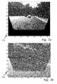
- FIG. 7ashows the results of the initial warp step 501 of image 15b towards image 15a, the results are shown as warped image 15w, according to a feature of an embodiment of the present invention.
- the warpmay be based on vehicle 18 motion (from the speedometer, inertial sensors etc.).
- Figure 7bshows the difference between warped image 15w and image 15a shown as image 15d, according to a feature of an embodiment of the present invention.
- Figure 7bit can be seen that some features on the road are still not perfectly aligned.
- step 501After initial warp (step 501), the remaining motion of features on the road can be approximated locally, as a uniform translation of an image patch from image 15a to image 15w. This is not true of the motion between the original image 15a and un-warped image 15b, where the motion of a patch also involves a non-uniform scale change.
- FIG. 8ashows warped image frame 15w with a trapezoidal region 80, according to a feature of an embodiment of the present invention.
- a fixed grid 84 of pointsis used for tracking (step 507).
- Grid 84 of pointsare selected (step 503) from a trapezoidal region 80 that roughly maps to up 15 meters ahead and one lane in width. Points 84 are spaced every 20 pixels in the horizontal direction and 10 pixels in the vertical direction. An alternative would be to randomly select points according to a particular distribution.
- a patchis located (step 505).
- the patchis 8 pixels in each direction centered around the point resulting in a 17x17 pixel square.
- the normalized correlationis then computed (e.g. MatlabTM function normxcorr2) for warped image 15w, where the patch center is shifted in the search region.
- MatlabTM function normxcorr2e.g. MatlabTM function normxcorr2
- a search region of (2x4+1) pixels in the x directionmay be used and (2x10+1) pixels in the y direction.
- Figure 8bshows a detail 82 of trapezoidal region 80 in warped image frame 15w, according to a feature of an embodiment of the present invention.
- Triangle and circle points 84are the starting location.
- Diamond pointsare the corresponding tracked location.
- Inliersare shown as circles and outliers are shown as triangles.
- Tracked points 509 as a result of tracking step 507,are fit to a homography (step 511) using RANdom SAmple Consensus (RANSAC).
- RANSACRANdom SAmple Consensus
- a number, e.g. four, of pointsare chosen at random and used to compute the homography.
- Points 509are then transformed using the homography and the number of points which are closer than a threshold are counted. Randomly choosing 4 points and counting the number of points which are closer than a threshold is repeated many times and the four points that gave the highest count are retained.
- the four best pointsare used to again (step 513) transform the points and all the points (inliers) that are closer than a (possibly different) threshold are used to compute a homography using least squares. The rest of the points that are not closer than a (possibly different) threshold are considered outliers.
- the number of inliers and their spread in warped image 15wgive an indication to the success of finding the road plane model. It is usual to get over 100 inliers and a good fit.
- Figure 8bshows the inliers as circles and outliers as triangles.
- the homographycan then be used to correct the initial alignment warp (step 501). Correction of the initial alignment warp can be done by integrating the correction into the initial warp (step 501) or to do the two warps consecutively.
- the formeris advantageous as it requires only one interpolation step and can be performed optionally by matrix multiplication of the two homography matrices.
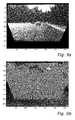
- Figure 9ashows the results of the refined warp of warped image 15w towards image 15a, according to a feature of an embodiment of the present invention.
- features on the roadare almost perfectly aligned. There are however, still some brightness differences that are not accounted for.
- Figure 9bshows the difference between the refined warp of warped image 15w towards image 15a and image 15a, according to a feature of an embodiment of the present invention.
- the tracking of pointsmay be repeated using a finer grid (e.g. every 5th pixel on every 5th row) and over a wider region of the road. Since the road plane is very well aligned, a smaller region may be searched over such as 2 pixels in each direction, again, with a subpixel search.
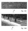
- Figure 10ashows the results of tracking a dense grid of points, according to a feature of an embodiment of the present invention.
- Figure 10aincludes area 124 with a car and shadow 104 on the car. Also areas 120 and 122 which include manhole cover 100 and sidewalk 102 respectively.
- Figures 10b , 10c and 10dshow greater details of areas 124, 120 and 122 respectively.
- Resultsare shown in Figures 10a-10d as a MatlabTM quiver plot.
- the MatlabTM quiver plotdisplays velocity vectors as arrows with components ( u,v ) at the points ( x,y ).
- the first vectoris defined by components u(1),v(1) and is displayed at the point x(1),y(1).
- Quiver( x,y,u,v )plots vectors as arrows at the coordinates specified in each corresponding pair of elements in x and y. Points on the road should exhibit flow close to zero. Points on features above the road plane will have flow greater than zero and points below the road plane will have residual flow below zero. Positive flow is defined as flow away from the focus of expansion (FOE) (generally speaking down and outwards).
- FOEfocus of expansion
- the elevated sidewalk 102 as shown in Figure 10d and sunken manhole cover 100 as shown in Figure 10cboth show up well. Objects which are not fixed to the road also show significant residual flow as on the car and the shadow 104 on the car. Points with flow above 0.5 pixels are shown in the elevated sidewalk 102 and points with flow below -0.5 pixels are shown on the sunken manhole cover 100, on the car and the shadow 104 on the car.
- Sidewalkscan thus be detected by detecting relatively homogenous positive residual flow regions that are separated from areas of low residual flow by elongated lines. These lines are roughly heading in the direction of the FOE or the direction of the road (i.e. the direction of the vanishing points of the lane marks).
- the Horn And Schunk optical flow computationmay be applied between image 15a and warped image 15b.
- Horn, B.K.P. & B.G Schunck, "Determining Optical Flow", Artificial Intelligence, Vol. 17,No.1-3,August 1981, pp. 185-203Since the images are well aligned the algorithm can converge quite well.
- Horn and Schunkuse quadratic error functions for both the data and the error terms. Better results can be obtained using L1 errors terms.
- the optical flow code of Ce LiuC. Liu. Beyond pixels: exploring new representations and applications for motion analysis. Doctoral Thesis. Massachusetts Institute of Technology. May 2009 . Appendix A pages 143-148 ) works quite well.
- a further termmay be added to the cost function which penalizes for straying far from the planar model (i.e. for flow above 1 pixel or some other threshold).
- a bandpass or high-pass filteringmay be performed.
- the optical flow computationmay be applied to only the part of the image typically occupied by the road. For example by starting only from the horizon down, remove 100 columns on the left and right and also the bottom part of image 15a which does not appear in warped image 15w (and is zero in the warped image, see Figure 9a ).
- Figure 11shows two filtered and cut images that are fed into the optical flow routine in the MatlabTM codes above, according to a feature of an embodiment of the present invention.
- the two images filtered and cropped to be used as input to the optical flow routinehave the road texture enhanced by the high-pass filtering.
- Figure 12shows the y component of the residual optical flow as a gray scale image, according to a feature of an embodiment of the present invention.
- the dark patchcentered around (300,140) on the horizontal and vertical axis respectively.
- the dark patchis due to the negative residual flow on manhole cover 100 which is sunken in the road.
- the solid linesindicate tracks 0.5m wide in front of the host vehicle wheels.
- the dotted lineis the row average of the data between each pair of solid lines.
- the datais scaled by 30 to make the shape of the data visible. Note the significant dip in the right dotted red line due to the manhole cover 100.
- FIG. 13shows the same data as shown in Figure 12 overlaid on the original image 15a, according to a feature of an embodiment of the present invention.
- the solid linesindicate tracks 0.5m wide in front of the host vehicle wheels.
- the dotted lineis the row average of the data between each pair of solid lines.
- Figure 14shows a graph of image y co-ordinate versus planar motion flow in the y direction, according to a feature of an embodiment of the present invention.
- the same information shown in Figures 12 and 13can be converted to metric values.
- Figure 14shows the expected flow in the y direction according to the planar model. Flow has been plotted on the x axis so that the y axis aligns with the y axis of the warped image 15w.
- the y coordinate of the minimum flowcorresponds to y 0 of the image space of image 15a, in other words the horizon or vanishing point of the road in image 15a.
- image co-ordinate y200.
- the x coordinate of the minimumis the change in the value for y 0 between image 15a and warped image 15w.
- the change in the value for y 0 between image 15a and warped image 15wis in effect the actual pitch value in pixels. In the case shown in Figure 14 the actual pitch value is 10 pixels.
- Figure 15shows a graph of road profile in meters versus distance from camera 12 in meters.
- Figure 15shows the road profile of the right hand track of Figure 12 in metric units of distance and height.
- the normalized correlationmay be computed in a small search region around the point to sub pixel accuracy.
- the normalized correlation computed in a small search regionis similar to the fine resolution grid described above. However, instead of picking the highest correlation for each point as before, the average correlation score along the row is computed for each possible residual flow and robust averaging to remove outliers may be used.
- a one dimensional optimization problem of this kindleads itself to dynamic programming.
- the score for each residual flowis computed in the given range (e.g. 2 pixels).
- the score associated with the average correlation score along row n + 1is computed.
- the score for each residual flowwhich is the best score taking into account the cumulative scores in row N and the smoothness score between this residual flow and the residual flows in row n is computed.
- NxM tableis set up, where N is the number of image rows in the track (for example, the 150 rows between 250 and 400) and M is the search space of residual flow. For example the 21 values: [-1:0.1:1].
- the first of the N rowsis simply the average correlation score given each residual flow: S NC (1, i) for each residual flow in the range [-1:0.1:1].
- T 1 ⁇ iS NC 1 ⁇ i
- the value for table entry T (n, j)is a combination the average correlation score for row n for residual motion j(S NC (n, j), and the score that maximizes the combination of T (n -1, i) and the smoothness score S sm (i,j).
- T n ⁇ j⁇ ⁇ S NC n ⁇ j , Max i ⁇ ⁇ ⁇ T ⁇ n - 1 , i , S sm i ⁇ j where ⁇ and ⁇ are functions that combine the scores.
- a simple functioncould be addition.
- the current frameis picked as frame 2 and then a search back is made through the frames to find the closest previous frame where the vehicle motion was above a certain value (for example 1m).
- the vehicle motion above a certain valueis based on the vehicle speed and the time stamps of the frames. This frame is denoted frame 1.
- the parameters for the initial motion warpcan be determined from inertial sensors or from the images themselves or a mixture of the two. For example, in a typical modem car, the speed is available also yaw rate. Pitch rate might not be available and will be estimated from the image.
- warpsit is more convenient to implement the warps using homography matrices. That way the warps can be combined together into a single warp.
- approximationscan be used such as performing the yaw and pitch warps as shifts and ignore roll.
- the later alignment stagewill correct for any affine and projective motion.
- the yaw rotation between the imagesis based on the yaw angle theta converted into pixels.
- the pitch between the imagesis determined from the images by tracking large patch centered on the horizon (for a high resolution 1280x960 pixel image the patch is 400 pixel wide and 200 pixel high).
- the patchis tracked over ⁇ 80 pixels in the vertical direction and the best match is used as the pitch value.
- the regioncan be tessellated into sub-patches, each path tracked and a median value used.
- the vehicle speed, focal length and camera heightare used to compute the expected road motion.
- Ha ⁇ 11Hw * Hdy * Hdx ;
- I ⁇ 1 ⁇ hwhomo Warp ⁇ 1 I ⁇ 1 ⁇ orig , Hall ;
- I ⁇ 1 ⁇ wI ⁇ 1 ⁇ hw ;
- the result of the RANSACis the correction homography H2fixed to the initial warp Hall.
- the correction homography H2fixed and the initial warp Hallcan be multiplied together to give the accurate homography of the road plane from previous image 1 to current image 2.
- H ⁇ 2 ⁇ finalHall * H ⁇ 2 ⁇ fixed
- the (')is used to denote terms in the coordinate system of the second image. Since the camera matrices K and K' are the same and are known, the homography matrix A ' can be broken down into its components: R , N ⁇ and T ⁇ d ⁇ ⁇
- the path of the vehicleis predicted based on yaw rate and steering angle and given the left and right wheel positions relative to the camera. For each wheel, a path of width 0.5m for example, is projected on to the image using the parameters of the plane. For every fifth image row along this path, the path width is divided into 11 grid points which represent every 0.05m
- Trackingis performed between image 2 and the warped image 1, for patches of size 17x17 or 9x9 pixels centered around each grid point.
- a search region of ⁇ 8 pixels in both x and yis used, including sub-pixel resolution search in the y direction.
- Sub-pixel resolution search in the x directioncan also be performed but tests did not show improved performance and sub-pixel resolution search in the x direction increases computation time.
- the search region for each pixelcan be optimized based on each pixel position in the image and the location of the focus of expansion (FOE), since the flow is expected only on lines passing through the FOE.
- FOEfocus of expansion
- An alternative optimizationwould be to rectify the images so that the FOE is mapped to infinity, the viewpoint is mapped to an overhead view point and the flow becomes vertical.
- the alternative optimizationis very similar to rectification in two camera stereo systems.
- a second stripcan be 8m to 16m centered around 11m and a third strip can be from 14m to 22m centered around 17m.
- the stripswould not extend the whole width of the image but only wide enough to cover the wheel tracks with a margin to allow for the patch size.
- a validity bitis set based on forward-backward verification, a minimal correlation value and thresholds on allowed x and y flow values. For each row, the median of the valid points out of the 11 points along the row is taken as the value for that row. The number of valid points along the row is a confidence value. For a row with no valid points a residual flow value is interpolated from valid neighbor points above and below.
- a further smoothing stepcan be used. For example, a median filter of width three can be used followed by a averaging filter of width three.
- ⁇ ⁇H Z ⁇ T z d ⁇ ⁇ ⁇ e ⁇ - p ⁇ w
- His the height of the point from the reference frame.
- the searchcan also allow a method for combining information from three or more motions. Consider a sequence of three frames 1, 2 and 3.
- the systemcan detect shape features and bumps that are a few centimeters high at distance of greater than 10m. Naturally there is also some noise in the system and spurious bumps are detected. However real shape features will move consistently with the movement of the vehicle, while spurious shape features due to noise will appear randomly or might be stationary in the image if they are due to imaging artifacts. Shape features due to moving objects will also not move consistently with the vehicle.
- One methodwould be to use plane information and the road profile information to create a road profile in 3D (X,Y,Z) coordinates and then use the ego motion of the vehicle to transform the model from frame to frame.
- a Kalman filtercould be used.
- Another methoduses the homography itself to carry information from frame to frame over time.
- Using the homography itself to carry information from frame to frame over timetakes advantage of the fact the road profile is defined on a road surface and the actual deviations due to the shape features are within 1 or 2 pixels, much smaller than the size of the surface regions or patches are being considered.
- the basic multi-frame algorithmis as follows:
- the single frame confidence value (VS) as definedis a vector of numbers between zero and 11 (assuming a path of width 0.5m sampled every 0.05m).
- the max functionensures that the multi-frame confidence is non zero for every point in the vector.
- embodiments of the present inventionare presented in the context of driver assistance applications, embodiments of the present invention may be equally applicable in other real time signal processing applications and/or digital processing applications, such as communications, machine vision, audio and/or speech processing as examples.
Landscapes
- Engineering & Computer Science (AREA)
- Multimedia (AREA)
- Physics & Mathematics (AREA)
- General Physics & Mathematics (AREA)
- Theoretical Computer Science (AREA)
- Signal Processing (AREA)
- Automation & Control Theory (AREA)
- Mathematical Physics (AREA)
- Transportation (AREA)
- Mechanical Engineering (AREA)
- Traffic Control Systems (AREA)
- Image Analysis (AREA)
- Image Processing (AREA)
- Length Measuring Devices By Optical Means (AREA)
Abstract
Description
- The present invention relates to a system that accurately detects the shape and particularly the vertical contour of a road using a camera.
- During the last few years camera based driver assistance systems (DAS) have been entering the market; including lane departure warning (LDW), automatic high-beam control (AHC), traffic sign recognition (TSR) forward collision warning (FCW) and pedestrian detection.
- According to an aspect of the invention, there is provided a computerized method as in claim 1.
- According to an aspect of the invention, there is provided executable code for performing the method and/or a computer readable medium including code for performing the method.
- According to an aspect of the invention, there is provided a driver assistance system as in
claim 13. - According to an aspect of the invention there is provided a driver assistance system mountable in a host vehicle, wherein the driver assistance system includes a camera operatively connectible to a processor, wherein the driver assistance system is operable while the host vehicle is moving to detect a deviation in vertical contour of a road, wherein a first image frame and a second image frame are captured in the field of view of the camera, wherein image motion is processed between respective images of the road, wherein said images of the road are derived from said first image frame and said second image frame, wherein the vertical contour of the road is estimated using a road surface model of the road and the deviation in the vertical contour is computed from said road surface model. Preferably, optical flow is estimated between a plurality of first image patches of the road derived from said first image frame and corresponding second image patches of the road derived from said second image frame.
- Preferably, the deviation in the vertical contour is determined by comparing said optical flow with an optical flow as predicted by said road surface model to produce thereby a residual optical flow indicating the deviation.
- Various driver assistance systems mountable in a host vehicle and computerized methods are provided for herein. The driver assistance system includes a camera operatively connectible to a processor. The driver assistance system is operable while the host vehicle is moving to detect a deviation in vertical contour of a road. A first image frame and a second image frame are captured in the field of view of the camera. Image motion is processed between respective images of the road derived from the first image frame and the second image frame. The vertical contour of the road is estimated using a road surface model of the road and the deviation in the vertical contour is computed from the road surface model. The optical flow may be estimated between multiple first image patches of the road derived from the first image frame and corresponding second image patches of the road derived from the second image frame. The deviation in the vertical contour is determined by comparing the optical flow with an optical flow as predicted by the road surface model. The residual optical flow indicates the deviation in vertical contour of the road.
- A third image frame may be captured in the field of view of the camera and image motion between respective images of the road may be derived from the third image frame and one or more of the first and second image frames. A multi-frame road surface model may be computed by combining a road profile of the road derived from said road surface model based on said first image frame and said second image frame with said second processing.
- The multi-frame road surface model may be mapped from the first and/or second image frames to the third image frame by using a homography between said at least one previous image frame to the third image frame.
- Assuming a planar model for the contour of the road, the image motion of the images of the road may be processed by initially warping the second image frame toward the first image frame to produce a warped second image frame. The initial warp may include aligning the second image frame with the first image frame by adjusting for an image shift due to motion of the vehicle relative to the road, yaw, pitch and/or roll. The initial warp may include an adjustment for the relative scale change between the second image frame and the first image frame. The relative scale change arises from different distances to the camera.
- Multiple image points may be selected in the first image frame. The image points may be located on the image of the road surface and may be located at points of a fixed grid. For the image points, multiple image patches are located disposed respectively about the image points. The image points may be tracked by correlating the image patches in the first image frame with corresponding image patches in the warped second image frame to produce multiple tracked points. The tracked points are fit to a homography. A refined warp of the warped second image frame toward the first image frame may be performed to correct the initial warp by using the homography and to produce a refinely warped second image frame. Optical flow may be computed between the refinely warped second image frame and the first image frame. The optical flow is compared with a road surface optical flow based on a road surface model. The deviation in vertical contour of the road produces a residual optical flow different from the road surface optical flow as found by the road surface model.
- The foregoing and/or other aspects will become apparent from the following detailed description when considered in conjunction with the accompanying drawing figures.
- Embodiments of the invention are herein described, by way of example only, with reference to the accompanying drawings, wherein:
Figures 1 and 2 illustrate a system including a camera or image sensor mounted in a vehicle, according to an embodiment of the present invention.Figure 3 shows a flow diagram of a simplified method for real time measurement of vertical contour of a road while a vehicle is moving along a road, according to a feature of an embodiment of the present invention.Figure 4 shows two consecutive image frames captured from a forward looking camera mounted in a vehicle, according to a feature of an embodiment of the present invention.Figure 5 includes a flow chart showing details of a processing step shown inFigure 3 , according to a feature of an embodiment of the present invention.Figure 6 includes a flow chart illustrating further details of an initial warping step shown inFigure 5 , according to feature of an embodiment of the present invention.Figure 7a shows the results of the initial warp step ofFigure 5 , the results shown as a warped image, according to a feature of an embodiment of the present invention.Figure 7b shows a difference image as a result of the difference between the warped image ofFigure 7a and an image, according to a feature of an embodiment of the present invention.Figure 8a shows a warped image frame with a trapezoidal region, according to a feature of an embodiment of the present invention.Figure 8b shows a detail of the trapezoidal region in warped image frame ofFigure 8a , according to a feature of an embodiment of the present invention.Figure 9a shows the results of the refined warp of a warped image towards an image, according to a feature of an embodiment of the present invention.Figure 9b shows the difference between the refined warp of a warped image towards an image and the image, according to a feature of an embodiment of the present invention.Figure 10a shows the results of tracking a dense grid of points, according to a feature of an embodiment of the present invention.Figures 10b ,10c and 10d show details of areas indicated inFigure 10a , according to a feature of an embodiment of the present invention.Figure 11 shows two filtered and cut images that are fed into an optical flow routine executed in Matlab™, according to a feature of an embodiment of the present invention.Figure 12 shows they component of the residual optical flow as a gray scale image, according to a feature of an embodiment of the present invention.Figure 13 shows the same data as shown inFigure 12 overlaid on an original image, according to a feature of an embodiment of the present invention.Figure 14 which shows a graph of image y co-ordinate versus planar motion flow in the y direction, according to a feature of an embodiment of the present invention.Figure 15 shows a graph of road profile in meters versus distance from a camera in meters, according to a feature of an embodiment of the present invention.- Reference will now be made in detail to features of the present invention, examples of which are illustrated in the accompanying drawings, wherein like reference numerals refer to the like elements throughout. The features are described below to explain preferred embodiments of the present invention by referring to the figures.
- Before explaining features of embodiments of the invention in detail, it is to be understood that the invention is not limited in its application to the details of design and the arrangement of the components set forth in the following description or illustrated in the drawings. The invention is capable of other features or of being practiced or carried out in various ways. Also, it is to be understood that the phraseology and terminology employed herein is for the purpose of description and should not be regarded as limiting.
- Reference is now made to
Figures 1 and 2 which illustrate asystem 16 including a camera orimage sensor 12 mounted in avehicle 18, according to an embodiment of the present invention.Image sensor 12, imaging a field of view in the forward direction provides image frames15 in real time and image frames15 are captured by animage processor 30.Processor 30 may be used to process image frames15 simultaneously and/or in parallel to serve a number of driver assistance systems/applications.Processor 30 may be used to process image frames15 to detect and recognize an image or portions of the image in the forward field of view ofcamera 12. The driver assistance systems may be implemented using specific hardware circuitry (not shown) with on board software and/or software control algorithms instorage 13.Image sensor 12 may be monochrome or black-white, i.e. without color separation orimage sensor 12 may be color sensitive. By way of example inFigure 2 , image frames15 are used to servepedestrian detection 20, traffic sign recognition (TSR)21, forward collision warning (FCW)22 andreal time detection 23 of the vertical contour of the road or deviation from the road plane according to features of embodiments of the present invention. - In some cases, image frames15 are partitioned between different driver assistance applications and in other cases the image frames15 may be shared between the different driver assistance applications.
- By way of introduction, various embodiments of the present invention are useful to accurately detect road shape i.e. vertical profile from a
road using camera 12 mounted inhost vehicle 18. Using systems and methods provided herein, bumps and/or holes such as speed bumps, curbs and manhole covers may be detected with vertical deviations as little as two centimeters from the road plane. System and methods as disclosed herein may be similarly applied to forward viewing, side viewing andrear viewing cameras 12. - Various methods as described herein accurately estimate the planar (or bi-quadratic) model of the road surface and then computes the small deviations from the planar (or bi-quadratic) model to detect bumps and holes.
- Reference is now made to
Figure 3 which shows a flow diagram ofsimplified method 23 for real time measurement of vertical contour of a road whilevehicle 18 is moving along a road, according to a feature of an embodiment of the present invention. Instep 303, afirst image frame 15 and asecond image frame 15 are captured of a road in the field of view ofcamera 12 mounted invehicle 18. Image motion fromfirst image frame 15 tosecond image frame 15 is processed (step305) to detect a vertical contour in the road. Further details ofstep 305 are shown in the description that follows. - Reference is now also made to
Figure 4 which shows two consecutive image frames15a and15b captured (step303) from forward lookingcamera 12 mounted in avehicle 18, according to a feature of an embodiment of the present invention.Image frame 15b is captured afterimage frame 15a is captured.Equivalently image frame 15b may be captured prior to capturingimage 12 in the description that follows may be a WVGA camera (Aptina M9V024 and Sunny 4028A 5.7mm lens) as used in the Mobileye™ advance warning system (AWS)™.frame 15a Camera - Reference is now also made to
Figure 5 which includes a flow chart showing details of processingstep 305, according to a feature of an embodiment of the present invention. The term "warping" as used herein refers to a transform from image space to image space. Image frame 15b is initially warped (step501) intoimage frame 15a. (In a similar process,image frame 15a may be initially warped intoimage frame 15b). It is assumed that a road can be modeled as an almost planar surface. Thus imaged points of the road will move in image space according to a homography. The term "homography" as used herein refers to an invertible transformation from a projective space to itself that maps straight lines to straight lines. In the field of computer vision, two images of the same planar surface in space are related by a homography assuming a pinhole camera model.- In particular, by way of example, for a given
camera 12 height (1.25m), focal length (950 pixels) and vehicle motion between frames (1.58m), it may be possible to predict the motion of the points on the road plane between the twoimage frames second image 15b towards thefirst image 15a. The following Matlab™ code would perform initial warp step501:
[h,w]=size(Iin); Iout=zeros(size(Iin)); for i=1:h, for j=1:w, x=j; y=i; S=dZ/(f*H); x1=x(:)-x0; y1=y(:)-y0; y2=y1./(1+y1*S); x2=x1./(1+y1*S); x2=x2+x0; y2=y2+y0; Iout(i,j)=bilinearInterpolate(Iin,x2,y2); end; end;wheredZ is the forward motion of


- 1. Often the texture on the road is very fine and only the texture can be seen in the highest resolution image and not in upper levels of the pyramid. Typically there is no coarse texture on the road so coarse -to- fine does not work.
- 2. The solution should not be pulled towards the significant, coarse scale brightness features. Otherwise the solution will be pulled away from the well aligned starting point and never recover.


- 1. Warping the earlier image towards the most recent image gives the results in the most relevant coordinate frame for the application.
- 2. When driving forward (the typical situation) all the road that appears in the most recent image has been viewed in the earlier images. There are no 'black' regions as appear for example in
Figure 7b . - 3. It makes it easier to implement the multi-frame concept.


- 1. Warp frames 1 and 3 towards
frame 2. - 2. Track points and keep valid points that tracked well from 1 to 2 and 3 to 2.
- 3. Perform RANSAC, picking 4 points from
image 2 and computing homographies from images 1 and 3. However the inlier count is the minimum of inliers from the mapping 1 to 2 and 3 to 2. - 4. Compute final homographies from 1 to 2 and 3 to 2 and warp images.
- 5. For points along the wheel tracks, perform a search for best height from the reference plane. For each height compute the residual pixel motion from 2 to 1 and from 2 to 3 separately, compute the normalized correlation scores separately and average (or minimum or maximum). Alternatively one can compute a combined normalized correlation score.
- 6. Pick best score.
- 1. Assume a multi-frame road profile has been computed for framen - m, where m is often equal 1 but might be larger if computing a profile for each frame is not required.
- 2. Compute the single frame road profile for frame n using framen and framen - k wherek might not be equal tom. Typicallyk is chosen so that the vehicle motion is above a certain value such as one meter.
- 3. The multi-frame profile and the single plane profile use different reference planes. The different reference planes are often very similar since they are determined by the same road with significant areas of overlap but when passing over a speed bump the assumption that the reference frames are very similar breaks down. It is therefore important to compensate for passing over a speed bump by:
- (a) Let πm be the reference plane of the multi-frame model and let πn be the reference plane of the single frame model.
- (b) For each point along the vehicle path (x, y), compute the corresponding (X, Y, Z) point on the plane πm. Then compute the distance from the point (X, Y, Z) to the plane πn.
- (c) The distance from the point (X, Y, Z) to the plane πn is added to the road profile for that point along the path.
- 4. Compute the homography matrix (Hnm) of the road between framesn andn - m (ifm =k we can reuse the results).
- 5. Use the inverse ofHnm to transform the path coordinates (x1, y1) from framen - m to framen, which gives the path from framen - m in the coordinates of frame n, (x1h,y1h).


- 6. Interpolate the values of the multi-frame road profile (ProfL1) and confidence values (VS1) to the coordinates of the path of framen, (x2,y2):


In the above code it is assumed that only small lateral changes in the path. If large lateral changes are expected then it is possible to reduce the multi-frame confidence at point (i) by a function of the difference (x1h(i) - x2(i)). - 7. The new multi-frame profile is a weighted average between the warped multi-frame profile and the current single frame profile:

Weighting is based on the confidence scores and a time factor (a). Note that this Matlab code. ProfL_1, VS, ProfL, VS_1Interp and ProfL_1Interp are all vectors and that the weighted average is performed for each element along the vector ProfL_1. - 8. The multi-frame confidence is also computed:


Claims (15)
- A computerized method for detecting a deviation in vertical contour of a road, the method performable by a driver assistance system mountable in a host vehicle while the host vehicle is moving, wherein the driver assistance system includes a camera operatively connectible to a processor, the method comprising:capturing a first image frame and a second image frame in the field of view of the camera; andprocessing image motion between respective images of the road, wherein said images of the road are derived from said first image frame and said second image frame, wherein said processing said image motion between said images of the road includes estimating the vertical contour of the road using a road surface model of the road; andcomputing the deviation in the vertical contour from said road surface model.
- The method of claim 1, wherein said computing the deviation in the vertical contour from said road surface model includes estimating optical flow between a plurality of first image patches of the road derived from said first image frame and corresponding second image patches of the road derived from said second image frame.
- The method of claim 2, wherein the deviation in the vertical contour is determined by comparing said optical flow with an optical flow as predicted by said road surface model and producing thereby a residual optical flow indicating the deviation.
- The method of any preceding claim, further comprising:capturing a third image frame in the field of view of the camera;second processing of image motion between respective images of the road derived from said third image frame and at least one of said first and second image frames;computing a multi-frame road surface model by combining a road profile of the road derived from said road surface model based on said first image frame and said second image frame with said second processing.
- The method of claim 4, further comprising:mapping said multi-frame road surface model from at least one previous image frame selected from the group consisting of said first and second image frames to said third image frame by using a homography between said at least one previous image frame to said third image frame.
- The method of any preceding claim, wherein said processing motion of said images of the road includes:initial warping said second image frame toward said first image frame assuming a planar model for the contour of the road, thereby producing a warped second image frame.
- The method of claim 6, wherein said initial warping includes:aligning said second image frame with said first image frame by adjusting for at least one image shift due to at least one motion of the vehicle relative to the road, wherein said at least one motion is selected from the group consisting of: yaw, pitch and roll; andadjusting for relative scale change between said second image frame and said first image frame, wherein said relative scale change arises from different distances to the camera.
- The method of claim 6 or 7, further comprising:selecting a plurality of image points in said first image frame;for said image points, locating a plurality of image patches disposed respectively about said image points;tracking the image points by correlating said image patches in said first image frame with corresponding image patches in said warped second image frame, thereby producing a plurality of tracked points.
- The method of claim 8, wherein said image points are located in a fixed distribution on the image of the road surface.
- The method of claim 8 or 9, further comprising:fitting the tracked points to a homography;refined warping said warped second image frame toward said first image frame thereby correcting said initial warping by using said homography and producing a refinely warped second image frame.
- The method of claim 10, further comprising:computing optical flow between said refinely warped second image frame and said first image frame; and comparing said optical flow with a road surface optical flow based on a road surface model, wherein the deviation in vertical contour of the road produces a residual optical flow different from said road surface optical flow.
- A driver assistance system including a camera and a processor configured to perform the computerized method, according to any preceding claim, for detecting a vertical contour of a road.
- A driver assistance system mountable in a host vehicle, wherein the driver assistance system includes a camera operatively connectible to a processor, wherein the driver assistance system is operable while the host vehicle is moving to detect a deviation in vertical contour of a road, the driver assistance system being operable to capture a first image frame and a second image frame in the field of view of the camera, to process image motion between respective images of the road, wherein said images of the road are derived from said first image frame and said second image frame, to estimate the vertical contour of the road using a road surface model of the road and to compute the deviation in the vertical contour from said road surface model.
- The driver assistance system of claim 13, wherein the system is operable to estimate optical flow between a plurality of first image patches of the road derived from said first image frame and corresponding second image patches of the road derived from said second image frame.
- The driver assistance system of claim 14, wherein the system is operable to determine the deviation in the vertical contour by comparing said optical flow with an optical flow as predicted by said road surface model to produce thereby a residual optical flow indicating the deviation.
Priority Applications (1)
| Application Number | Priority Date | Filing Date | Title |
|---|---|---|---|
| EP20155696.6AEP3726422A1 (en) | 2011-12-06 | 2012-12-06 | Road vertical contour detection |
Applications Claiming Priority (3)
| Application Number | Priority Date | Filing Date | Title |
|---|---|---|---|
| US201161567132P | 2011-12-06 | 2011-12-06 | |
| US201261727722P | 2012-11-18 | 2012-11-18 | |
| US201261727755P | 2012-11-19 | 2012-11-19 |
Related Child Applications (1)
| Application Number | Title | Priority Date | Filing Date |
|---|---|---|---|
| EP20155696.6ADivisionEP3726422A1 (en) | 2011-12-06 | 2012-12-06 | Road vertical contour detection |
Publications (2)
| Publication Number | Publication Date |
|---|---|
| EP2602741A2true EP2602741A2 (en) | 2013-06-12 |
| EP2602741A3 EP2602741A3 (en) | 2014-12-24 |
Family
ID=47563001
Family Applications (2)
| Application Number | Title | Priority Date | Filing Date |
|---|---|---|---|
| EP12195922.5ACeasedEP2602741A3 (en) | 2011-12-06 | 2012-12-06 | Detection of the vertical contour of a road |
| EP20155696.6AWithdrawnEP3726422A1 (en) | 2011-12-06 | 2012-12-06 | Road vertical contour detection |
Family Applications After (1)
| Application Number | Title | Priority Date | Filing Date |
|---|---|---|---|
| EP20155696.6AWithdrawnEP3726422A1 (en) | 2011-12-06 | 2012-12-06 | Road vertical contour detection |
Country Status (3)
| Country | Link |
|---|---|
| US (6) | US9118816B2 (en) |
| EP (2) | EP2602741A3 (en) |
| JP (3) | JP6211263B2 (en) |
Cited By (10)
| Publication number | Priority date | Publication date | Assignee | Title |
|---|---|---|---|---|
| US8917169B2 (en) | 1993-02-26 | 2014-12-23 | Magna Electronics Inc. | Vehicular vision system |
| US8993951B2 (en) | 1996-03-25 | 2015-03-31 | Magna Electronics Inc. | Driver assistance system for a vehicle |
| WO2015070965A1 (en)* | 2013-11-13 | 2015-05-21 | Audi Ag | Method for determining a value for a height |
| US9191634B2 (en) | 2004-04-15 | 2015-11-17 | Magna Electronics Inc. | Vision system for vehicle |
| WO2016135736A3 (en)* | 2015-02-26 | 2016-10-20 | Mobileye Vision Technologies Ltd. | Road vertical contour detection using a stabilized coordinate frame |
| WO2016183074A1 (en)* | 2015-05-10 | 2016-11-17 | Mobileye Vision Technologies Ltd. | Road profile along a predicted path |
| US9643605B2 (en) | 2002-05-03 | 2017-05-09 | Magna Electronics Inc. | Vision system for vehicle |
| US10071676B2 (en) | 2006-08-11 | 2018-09-11 | Magna Electronics Inc. | Vision system for vehicle |
| US10685424B2 (en) | 2010-09-21 | 2020-06-16 | Mobileye Vision Technologies Ltd. | Dense structure from motion |
| DE102021205852A1 (en) | 2021-06-10 | 2022-12-15 | Robert Bosch Gesellschaft mit beschränkter Haftung | Method and device for providing contour data with regard to a surface contour of a road surface on which a vehicle is driving, and method and device for controlling an operation of a vehicle |
Families Citing this family (154)
| Publication number | Priority date | Publication date | Assignee | Title |
|---|---|---|---|---|
| US6822563B2 (en) | 1997-09-22 | 2004-11-23 | Donnelly Corporation | Vehicle imaging system with accessory control |
| US6891563B2 (en) | 1996-05-22 | 2005-05-10 | Donnelly Corporation | Vehicular vision system |
| US7697027B2 (en) | 2001-07-31 | 2010-04-13 | Donnelly Corporation | Vehicular video system |
| US7881496B2 (en) | 2004-09-30 | 2011-02-01 | Donnelly Corporation | Vision system for vehicle |
| US7720580B2 (en) | 2004-12-23 | 2010-05-18 | Donnelly Corporation | Object detection system for vehicle |
| US8017898B2 (en) | 2007-08-17 | 2011-09-13 | Magna Electronics Inc. | Vehicular imaging system in an automatic headlamp control system |
| US9280711B2 (en) | 2010-09-21 | 2016-03-08 | Mobileye Vision Technologies Ltd. | Barrier and guardrail detection using a single camera |
| US9118816B2 (en)* | 2011-12-06 | 2015-08-25 | Mobileye Vision Technologies Ltd. | Road vertical contour detection |
| WO2012075250A1 (en) | 2010-12-01 | 2012-06-07 | Magna Electronics Inc. | System and method of establishing a multi-camera image using pixel remapping |
| US9357208B2 (en) | 2011-04-25 | 2016-05-31 | Magna Electronics Inc. | Method and system for dynamically calibrating vehicular cameras |
| US9834153B2 (en) | 2011-04-25 | 2017-12-05 | Magna Electronics Inc. | Method and system for dynamically calibrating vehicular cameras |
| US10793067B2 (en) | 2011-07-26 | 2020-10-06 | Magna Electronics Inc. | Imaging system for vehicle |
| WO2013019707A1 (en) | 2011-08-01 | 2013-02-07 | Magna Electronics Inc. | Vehicle camera alignment system |
| US20140218535A1 (en) | 2011-09-21 | 2014-08-07 | Magna Electronics Inc. | Vehicle vision system using image data transmission and power supply via a coaxial cable |
| US9491451B2 (en) | 2011-11-15 | 2016-11-08 | Magna Electronics Inc. | Calibration system and method for vehicular surround vision system |
| US10099614B2 (en) | 2011-11-28 | 2018-10-16 | Magna Electronics Inc. | Vision system for vehicle |
| CN103164851B (en)* | 2011-12-09 | 2016-04-20 | 株式会社理光 | Lane segmentation object detecting method and device |
| WO2013086249A2 (en) | 2011-12-09 | 2013-06-13 | Magna Electronics, Inc. | Vehicle vision system with customized display |
| WO2013126715A2 (en) | 2012-02-22 | 2013-08-29 | Magna Electronics, Inc. | Vehicle camera system with image manipulation |
| US10457209B2 (en) | 2012-02-22 | 2019-10-29 | Magna Electronics Inc. | Vehicle vision system with multi-paned view |
| US9723272B2 (en) | 2012-10-05 | 2017-08-01 | Magna Electronics Inc. | Multi-camera image stitching calibration system |
| JP6045889B2 (en)* | 2012-11-27 | 2016-12-14 | クラリオン株式会社 | In-vehicle control device |
| JP6285958B2 (en)* | 2013-01-15 | 2018-02-28 | モービルアイ ビジョン テクノロジーズ リミテッド | Stereo support with rolling shutter |
| US10179543B2 (en) | 2013-02-27 | 2019-01-15 | Magna Electronics Inc. | Multi-camera dynamic top view vision system |
| US9688200B2 (en) | 2013-03-04 | 2017-06-27 | Magna Electronics Inc. | Calibration system and method for multi-camera vision system |
| US9508014B2 (en) | 2013-05-06 | 2016-11-29 | Magna Electronics Inc. | Vehicular multi-camera vision system |
| US9205776B2 (en) | 2013-05-21 | 2015-12-08 | Magna Electronics Inc. | Vehicle vision system using kinematic model of vehicle motion |
| US9563951B2 (en) | 2013-05-21 | 2017-02-07 | Magna Electronics Inc. | Vehicle vision system with targetless camera calibration |
| CN111024099B (en) | 2013-06-13 | 2023-10-27 | 移动眼视力科技有限公司 | Mobile device, non-transitory machine-readable medium, and apparatus for navigation |
| US9554048B2 (en)* | 2013-09-26 | 2017-01-24 | Apple Inc. | In-stream rolling shutter compensation |
| US9747507B2 (en)* | 2013-12-19 | 2017-08-29 | Texas Instruments Incorporated | Ground plane detection |
| US9248832B2 (en) | 2014-01-30 | 2016-02-02 | Mobileye Vision Technologies Ltd. | Systems and methods for detecting traffic signal details |
| US9487235B2 (en) | 2014-04-10 | 2016-11-08 | Magna Electronics Inc. | Vehicle control system with adaptive wheel angle correction |
| EP3143607A1 (en)* | 2014-05-14 | 2017-03-22 | Mobileye Vision Technologies Ltd. | Systems and methods for curb detection and pedestrian hazard assessment |
| US9916660B2 (en) | 2015-01-16 | 2018-03-13 | Magna Electronics Inc. | Vehicle vision system with calibration algorithm |
| CN112902975B (en)* | 2015-02-10 | 2024-04-30 | 御眼视觉技术有限公司 | Autonomous vehicle navigation method, readable device, server, vehicle and system |
| US9542732B2 (en)* | 2015-04-03 | 2017-01-10 | Cognex Corporation | Efficient image transformation |
| US10275863B2 (en) | 2015-04-03 | 2019-04-30 | Cognex Corporation | Homography rectification |
| US10946799B2 (en) | 2015-04-21 | 2021-03-16 | Magna Electronics Inc. | Vehicle vision system with overlay calibration |
| US11228700B2 (en) | 2015-10-07 | 2022-01-18 | Magna Electronics Inc. | Vehicle vision system camera with adaptive field of view |
| US10187590B2 (en) | 2015-10-27 | 2019-01-22 | Magna Electronics Inc. | Multi-camera vehicle vision system with image gap fill |
| US10108864B2 (en)* | 2015-12-29 | 2018-10-23 | Texas Instruments Incorporated | Stationary-vehicle structure from motion |
| CN105654060A (en)* | 2016-01-04 | 2016-06-08 | 中海网络科技股份有限公司 | Method for acquiring vehicle speed from road monitoring video |
| EP3403216B1 (en)* | 2016-01-11 | 2023-11-01 | Mobileye Vision Technologies Ltd. | Systems and methods for augmenting upright object detection |
| US11277558B2 (en) | 2016-02-01 | 2022-03-15 | Magna Electronics Inc. | Vehicle vision system with master-slave camera configuration |
| US11433809B2 (en) | 2016-02-02 | 2022-09-06 | Magna Electronics Inc. | Vehicle vision system with smart camera video output |
| CN114694113A (en) | 2016-03-15 | 2022-07-01 | 无比视视觉技术有限公司 | Method, system and storage medium for processing road surface visual data |
| JP2017220843A (en) | 2016-06-09 | 2017-12-14 | ソニー株式会社 | Image control device, method, and vehicle |
| US10300859B2 (en) | 2016-06-10 | 2019-05-28 | Magna Electronics Inc. | Multi-sensor interior mirror device with image adjustment |
| KR20230017365A (en) | 2016-06-27 | 2023-02-03 | 모빌아이 비젼 테크놀로지스 엘티디. | controlling host vehicle based on detected spacing between stationary vehicles |
| US10365658B2 (en) | 2016-07-21 | 2019-07-30 | Mobileye Vision Technologies Ltd. | Systems and methods for aligning crowdsourced sparse map data |
| DE102016218852A1 (en)* | 2016-09-29 | 2018-03-29 | Conti Temic Microelectronic Gmbh | Detection of objects from images of a camera |
| US10750119B2 (en) | 2016-10-17 | 2020-08-18 | Magna Electronics Inc. | Vehicle camera LVDS repeater |
| US10452076B2 (en) | 2017-01-04 | 2019-10-22 | Magna Electronics Inc. | Vehicle vision system with adjustable computation and data compression |
| CA3049019A1 (en) | 2017-01-10 | 2018-07-19 | Cavh Llc | Connected automated vehicle highway systems and methods |
| WO2018132378A2 (en) | 2017-01-10 | 2018-07-19 | Cavh Llc | Connected automated vehicle highway systems and methods |
| US10380886B2 (en) | 2017-05-17 | 2019-08-13 | Cavh Llc | Connected automated vehicle highway systems and methods |
| JP6678605B2 (en)* | 2017-01-11 | 2020-04-08 | 株式会社東芝 | Information processing apparatus, information processing method, and information processing program |
| US10696227B2 (en)* | 2017-01-12 | 2020-06-30 | Mobileye Vision Technologies Ltd. | Determining a road surface characteristic |
| US10067509B1 (en) | 2017-03-10 | 2018-09-04 | TuSimple | System and method for occluding contour detection |
| US10147193B2 (en) | 2017-03-10 | 2018-12-04 | TuSimple | System and method for semantic segmentation using hybrid dilated convolution (HDC) |
| US11587304B2 (en) | 2017-03-10 | 2023-02-21 | Tusimple, Inc. | System and method for occluding contour detection |
| US10311312B2 (en) | 2017-08-31 | 2019-06-04 | TuSimple | System and method for vehicle occlusion detection |
| US9953236B1 (en) | 2017-03-10 | 2018-04-24 | TuSimple | System and method for semantic segmentation using dense upsampling convolution (DUC) |
| US10671873B2 (en) | 2017-03-10 | 2020-06-02 | Tusimple, Inc. | System and method for vehicle wheel detection |
| US10710592B2 (en) | 2017-04-07 | 2020-07-14 | Tusimple, Inc. | System and method for path planning of autonomous vehicles based on gradient |
| US10471963B2 (en) | 2017-04-07 | 2019-11-12 | TuSimple | System and method for transitioning between an autonomous and manual driving mode based on detection of a drivers capacity to control a vehicle |
| US9952594B1 (en) | 2017-04-07 | 2018-04-24 | TuSimple | System and method for traffic data collection using unmanned aerial vehicles (UAVs) |
| US10552691B2 (en) | 2017-04-25 | 2020-02-04 | TuSimple | System and method for vehicle position and velocity estimation based on camera and lidar data |
| US10692365B2 (en) | 2017-06-20 | 2020-06-23 | Cavh Llc | Intelligent road infrastructure system (IRIS): systems and methods |
| US12008893B2 (en) | 2017-05-17 | 2024-06-11 | Cavh Llc | Autonomous vehicle (AV) control system with roadside unit (RSU) network |
| US10481044B2 (en) | 2017-05-18 | 2019-11-19 | TuSimple | Perception simulation for improved autonomous vehicle control |
| US10558864B2 (en) | 2017-05-18 | 2020-02-11 | TuSimple | System and method for image localization based on semantic segmentation |
| US10474790B2 (en) | 2017-06-02 | 2019-11-12 | TuSimple | Large scale distributed simulation for realistic multiple-agent interactive environments |
| US10762635B2 (en) | 2017-06-14 | 2020-09-01 | Tusimple, Inc. | System and method for actively selecting and labeling images for semantic segmentation |
| US10303522B2 (en) | 2017-07-01 | 2019-05-28 | TuSimple | System and method for distributed graphics processing unit (GPU) computation |
| US10493988B2 (en) | 2017-07-01 | 2019-12-03 | TuSimple | System and method for adaptive cruise control for defensive driving |
| US10308242B2 (en) | 2017-07-01 | 2019-06-04 | TuSimple | System and method for using human driving patterns to detect and correct abnormal driving behaviors of autonomous vehicles |
| US10752246B2 (en) | 2017-07-01 | 2020-08-25 | Tusimple, Inc. | System and method for adaptive cruise control with proximate vehicle detection |
| US10737695B2 (en) | 2017-07-01 | 2020-08-11 | Tusimple, Inc. | System and method for adaptive cruise control for low speed following |
| US11029693B2 (en) | 2017-08-08 | 2021-06-08 | Tusimple, Inc. | Neural network based vehicle dynamics model |
| US10360257B2 (en) | 2017-08-08 | 2019-07-23 | TuSimple | System and method for image annotation |
| US10816354B2 (en) | 2017-08-22 | 2020-10-27 | Tusimple, Inc. | Verification module system and method for motion-based lane detection with multiple sensors |
| US10303956B2 (en) | 2017-08-23 | 2019-05-28 | TuSimple | System and method for using triplet loss for proposal free instance-wise semantic segmentation for lane detection |
| US10565457B2 (en) | 2017-08-23 | 2020-02-18 | Tusimple, Inc. | Feature matching and correspondence refinement and 3D submap position refinement system and method for centimeter precision localization using camera-based submap and LiDAR-based global map |
| US10762673B2 (en) | 2017-08-23 | 2020-09-01 | Tusimple, Inc. | 3D submap reconstruction system and method for centimeter precision localization using camera-based submap and LiDAR-based global map |
| US10678234B2 (en) | 2017-08-24 | 2020-06-09 | Tusimple, Inc. | System and method for autonomous vehicle control to minimize energy cost |
| CN107632308B (en)* | 2017-08-24 | 2021-02-05 | 吉林大学 | Method for detecting contour of obstacle in front of vehicle based on recursive superposition algorithm |
| US10783381B2 (en) | 2017-08-31 | 2020-09-22 | Tusimple, Inc. | System and method for vehicle occlusion detection |
| US10649458B2 (en) | 2017-09-07 | 2020-05-12 | Tusimple, Inc. | Data-driven prediction-based system and method for trajectory planning of autonomous vehicles |
| US10953881B2 (en) | 2017-09-07 | 2021-03-23 | Tusimple, Inc. | System and method for automated lane change control for autonomous vehicles |
| US10656644B2 (en) | 2017-09-07 | 2020-05-19 | Tusimple, Inc. | System and method for using human driving patterns to manage speed control for autonomous vehicles |
| US10782693B2 (en) | 2017-09-07 | 2020-09-22 | Tusimple, Inc. | Prediction-based system and method for trajectory planning of autonomous vehicles |
| US10782694B2 (en) | 2017-09-07 | 2020-09-22 | Tusimple, Inc. | Prediction-based system and method for trajectory planning of autonomous vehicles |
| US10953880B2 (en) | 2017-09-07 | 2021-03-23 | Tusimple, Inc. | System and method for automated lane change control for autonomous vehicles |
| US10552979B2 (en) | 2017-09-13 | 2020-02-04 | TuSimple | Output of a neural network method for deep odometry assisted by static scene optical flow |
| US10671083B2 (en) | 2017-09-13 | 2020-06-02 | Tusimple, Inc. | Neural network architecture system for deep odometry assisted by static scene optical flow |
| US10387736B2 (en) | 2017-09-20 | 2019-08-20 | TuSimple | System and method for detecting taillight signals of a vehicle |
| US10733465B2 (en) | 2017-09-20 | 2020-08-04 | Tusimple, Inc. | System and method for vehicle taillight state recognition |
| US10768626B2 (en) | 2017-09-30 | 2020-09-08 | Tusimple, Inc. | System and method for providing multiple agents for decision making, trajectory planning, and control for autonomous vehicles |
| US10962979B2 (en) | 2017-09-30 | 2021-03-30 | Tusimple, Inc. | System and method for multitask processing for autonomous vehicle computation and control |
| US10970564B2 (en) | 2017-09-30 | 2021-04-06 | Tusimple, Inc. | System and method for instance-level lane detection for autonomous vehicle control |
| US10410055B2 (en) | 2017-10-05 | 2019-09-10 | TuSimple | System and method for aerial video traffic analysis |
| US10739775B2 (en)* | 2017-10-28 | 2020-08-11 | Tusimple, Inc. | System and method for real world autonomous vehicle trajectory simulation |
| US10666730B2 (en) | 2017-10-28 | 2020-05-26 | Tusimple, Inc. | Storage architecture for heterogeneous multimedia data |
| US10812589B2 (en) | 2017-10-28 | 2020-10-20 | Tusimple, Inc. | Storage architecture for heterogeneous multimedia data |
| US10528851B2 (en) | 2017-11-27 | 2020-01-07 | TuSimple | System and method for drivable road surface representation generation using multimodal sensor data |
| US10657390B2 (en) | 2017-11-27 | 2020-05-19 | Tusimple, Inc. | System and method for large-scale lane marking detection using multimodal sensor data |
| US10528823B2 (en) | 2017-11-27 | 2020-01-07 | TuSimple | System and method for large-scale lane marking detection using multimodal sensor data |
| US10877476B2 (en) | 2017-11-30 | 2020-12-29 | Tusimple, Inc. | Autonomous vehicle simulation system for analyzing motion planners |
| US10860018B2 (en) | 2017-11-30 | 2020-12-08 | Tusimple, Inc. | System and method for generating simulated vehicles with configured behaviors for analyzing autonomous vehicle motion planners |
| DE102017222017A1 (en)* | 2017-12-06 | 2019-06-06 | Robert Bosch Gmbh | Method and system for determining and providing a soil profile |
| US10866307B2 (en)* | 2017-12-29 | 2020-12-15 | Automotive Research & Testing Center | Method for analyzing error and existence probability of multi-sensor fusion of obstacle detection |
| AU2019206509A1 (en) | 2018-01-09 | 2020-07-23 | Tusimple, Inc. | Real-time remote control of vehicles with high redundancy |
| CN115834617A (en) | 2018-01-11 | 2023-03-21 | 图森有限公司 | Monitoring system for autonomous vehicle operation |
| US10867512B2 (en) | 2018-02-06 | 2020-12-15 | Cavh Llc | Intelligent road infrastructure system (IRIS): systems and methods |
| US11009356B2 (en) | 2018-02-14 | 2021-05-18 | Tusimple, Inc. | Lane marking localization and fusion |
| US11009365B2 (en) | 2018-02-14 | 2021-05-18 | Tusimple, Inc. | Lane marking localization |
| US12270661B2 (en) | 2018-02-14 | 2025-04-08 | Tusimple, Inc. | Lane marking localization and fusion |
| US10685244B2 (en) | 2018-02-27 | 2020-06-16 | Tusimple, Inc. | System and method for online real-time multi-object tracking |
| WO2019166141A1 (en)* | 2018-03-01 | 2019-09-06 | Jaguar Land Rover Limited | Vehicle control method and apparatus |
| US10685239B2 (en) | 2018-03-18 | 2020-06-16 | Tusimple, Inc. | System and method for lateral vehicle detection |
| CN110378184A (en) | 2018-04-12 | 2019-10-25 | 北京图森未来科技有限公司 | A kind of image processing method applied to automatic driving vehicle, device |
| EP3673233B1 (en)* | 2018-04-18 | 2025-09-10 | Mobileye Vision Technologies Ltd. | Vehicle environment modeling with a camera |
| CN116129376A (en) | 2018-05-02 | 2023-05-16 | 北京图森未来科技有限公司 | Road edge detection method and device |
| AU2019266266B2 (en) | 2018-05-09 | 2024-06-20 | Cavh Llc | Systems and methods for driving intelligence allocation between vehicles and highways |
| US11104334B2 (en) | 2018-05-31 | 2021-08-31 | Tusimple, Inc. | System and method for proximate vehicle intention prediction for autonomous vehicles |
| WO2019246246A1 (en) | 2018-06-20 | 2019-12-26 | Cavh Llc | Connected automated vehicle highway systems and methods related to heavy vehicles |
| US12057011B2 (en) | 2018-06-28 | 2024-08-06 | Cavh Llc | Cloud-based technology for connected and automated vehicle highway systems |
| WO2020014128A1 (en) | 2018-07-10 | 2020-01-16 | Cavh Llc | Vehicle on-board unit for connected and automated vehicle systems |
| US11373122B2 (en) | 2018-07-10 | 2022-06-28 | Cavh Llc | Fixed-route service system for CAVH systems |
| US11735041B2 (en) | 2018-07-10 | 2023-08-22 | Cavh Llc | Route-specific services for connected automated vehicle highway systems |
| US10839234B2 (en) | 2018-09-12 | 2020-11-17 | Tusimple, Inc. | System and method for three-dimensional (3D) object detection |
| CN118289018A (en) | 2018-09-13 | 2024-07-05 | 图森有限公司 | Remote safe driving method and system |
| JP6744374B2 (en)* | 2018-09-27 | 2020-08-19 | 本田技研工業株式会社 | Display device, display control method, and program |
| US10796402B2 (en) | 2018-10-19 | 2020-10-06 | Tusimple, Inc. | System and method for fisheye image processing |
| US10942271B2 (en) | 2018-10-30 | 2021-03-09 | Tusimple, Inc. | Determining an angle between a tow vehicle and a trailer |
| CN109492609B (en)* | 2018-11-27 | 2020-05-15 | 上海芯仑光电科技有限公司 | Method for detecting lane line, vehicle and computing equipment |
| CN116184417A (en) | 2018-12-10 | 2023-05-30 | 北京图森智途科技有限公司 | Trailer pinch angle measuring method and device and vehicle |
| CN111319629B (en) | 2018-12-14 | 2021-07-16 | 北京图森智途科技有限公司 | A method, device and system for forming an autonomous vehicle fleet |
| KR102809843B1 (en)* | 2019-02-12 | 2025-05-22 | 주식회사 에이치엘클레무브 | Vehicle and method for controlling the same |
| CN110143199B (en)* | 2019-05-17 | 2020-09-25 | 南京理工大学 | Commercial vehicle weight self-adaptive hill start control method |
| US11823460B2 (en) | 2019-06-14 | 2023-11-21 | Tusimple, Inc. | Image fusion for autonomous vehicle operation |
| CN112130550B (en)* | 2019-06-24 | 2024-03-12 | 北京市商汤科技开发有限公司 | Road image processing method and device, electronic equipment and storage medium |
| CN112304293B (en)* | 2019-08-02 | 2022-09-13 | 北京地平线机器人技术研发有限公司 | Road height detection method and device, readable storage medium and electronic equipment |
| JP7287563B2 (en)* | 2020-02-17 | 2023-06-06 | 日本電気株式会社 | Projective transformation parameter estimation device, projective transformation parameter estimation method, and its program |
| CN111246485B (en)* | 2020-02-27 | 2022-09-20 | 华南理工大学 | A vehicle networking resource allocation method in a high-density vehicle communication environment |
| EP3893150A1 (en) | 2020-04-09 | 2021-10-13 | Tusimple, Inc. | Camera pose estimation techniques |
| KR20210148756A (en)* | 2020-06-01 | 2021-12-08 | 삼성전자주식회사 | Slope estimating apparatus and operating method thereof |
| AU2021203567A1 (en) | 2020-06-18 | 2022-01-20 | Tusimple, Inc. | Angle and orientation measurements for vehicles with multiple drivable sections |
| WO2022186814A1 (en)* | 2021-03-01 | 2022-09-09 | Gideon Stein | Vehicle environment modeling with a camera |
| US11845347B2 (en) | 2021-05-12 | 2023-12-19 | David Alan Copeland | Precision charging control of an untethered vehicle with a modular vehicle charging roadway |
| US12106492B2 (en)* | 2021-11-18 | 2024-10-01 | Volkswagen Aktiengesellschaft | Computer vision system for object tracking and time-to-collision |
| CN115546705B (en)* | 2022-11-29 | 2023-05-02 | 天津所托瑞安汽车科技有限公司 | Target identification method, terminal device and storage medium |
Family Cites Families (23)
| Publication number | Priority date | Publication date | Assignee | Title |
|---|---|---|---|---|
| AU2898795A (en)* | 1995-07-04 | 1997-02-05 | Hiroyuki Minakami | Traffic/transportation system |
| JP2001116527A (en)* | 1999-10-20 | 2001-04-27 | Matsushita Electric Ind Co Ltd | Three-dimensional object detection method and device |
| JP3786618B2 (en)* | 2002-03-25 | 2006-06-14 | 株式会社東芝 | Image processing apparatus and method |
| US7000710B1 (en)* | 2002-04-01 | 2006-02-21 | The Charles Machine Works, Inc. | Automatic path generation and correction system |
| JP2005323021A (en)* | 2004-05-07 | 2005-11-17 | Fuji Photo Film Co Ltd | In-vehicle imaging system and imaging method |
| DE102004057296A1 (en) | 2004-11-26 | 2006-06-08 | Daimlerchrysler Ag | Lane departure warning with distinction between lane markings and the construction boundary of the lane |
| US7646887B2 (en)* | 2005-01-04 | 2010-01-12 | Evolution Robotics Retail, Inc. | Optical flow for object recognition |
| JP4899424B2 (en)* | 2005-11-04 | 2012-03-21 | トヨタ自動車株式会社 | Object detection device |
| CN101211471A (en)* | 2006-12-26 | 2008-07-02 | 上海乐金广电电子有限公司 | Car accident information recording method and route tracking method |
| JP4895857B2 (en)* | 2007-02-22 | 2012-03-14 | 日立オートモティブシステムズ株式会社 | Vehicle behavior reproduction method |
| JP2008219063A (en)* | 2007-02-28 | 2008-09-18 | Sanyo Electric Co Ltd | Apparatus and method for monitoring vehicle's surrounding |
| US7872764B2 (en)* | 2007-10-16 | 2011-01-18 | Magna Electronics Inc. | Machine vision for predictive suspension |
| US20100057358A1 (en)* | 2008-08-28 | 2010-03-04 | TeleType Co., Inc. | Portable gps map device for commercial vehicle industry |
| JP5089545B2 (en) | 2008-09-17 | 2012-12-05 | 日立オートモティブシステムズ株式会社 | Road boundary detection and judgment device |
| JP5074365B2 (en)* | 2008-11-28 | 2012-11-14 | 日立オートモティブシステムズ株式会社 | Camera device |
| CN101419667B (en) | 2008-12-15 | 2010-12-08 | 东软集团股份有限公司 | Method and apparatus for identifying obstacle in image |
| JP2010205040A (en)* | 2009-03-04 | 2010-09-16 | Daihatsu Motor Co Ltd | Road surface shape recognition apparatus |
| US8755634B2 (en) | 2009-08-12 | 2014-06-17 | Nec Corporation | Obstacle detection device and method and obstacle detection system |
| US9118816B2 (en)* | 2011-12-06 | 2015-08-25 | Mobileye Vision Technologies Ltd. | Road vertical contour detection |
| US9959595B2 (en)* | 2010-09-21 | 2018-05-01 | Mobileye Vision Technologies Ltd. | Dense structure from motion |
| US8731303B2 (en)* | 2010-12-07 | 2014-05-20 | Sony Corporation | Vanishing point estimation system and methods |
| US9681062B2 (en)* | 2011-09-26 | 2017-06-13 | Magna Electronics Inc. | Vehicle camera image quality improvement in poor visibility conditions by contrast amplification |
| SI2757346T1 (en)* | 2013-01-21 | 2016-08-31 | Kapsch Trafficcom Ag | Method for measuring a height profile of a vehicle passing on the street |
- 2012
- 2012-12-04USUS13/693,713patent/US9118816B2/enactiveActive
- 2012-12-05JPJP2012266408Apatent/JP6211263B2/enactiveActive
- 2012-12-06EPEP12195922.5Apatent/EP2602741A3/ennot_activeCeased
- 2012-12-06EPEP20155696.6Apatent/EP3726422A1/ennot_activeWithdrawn
- 2015
- 2015-07-14USUS14/798,575patent/US9826199B2/enactiveActive
- 2017
- 2017-09-13JPJP2017175381Apatent/JP6612297B2/enactiveActive
- 2017-10-26USUS15/794,506patent/US10084992B2/enactiveActive
- 2018
- 2018-09-07USUS16/124,367patent/US10506200B2/enactiveActive
- 2019
- 2019-10-30JPJP2019197801Apatent/JP6896044B2/enactiveActive
- 2019-11-20USUS16/689,325patent/US10863140B2/enactiveActive
- 2020
- 2020-12-04USUS17/111,983patent/US11240471B2/enactiveActive
Non-Patent Citations (4)
| Title |
|---|
| C. LIU.: "Beyond pixels: exploring new representations and applications for motion analysis", DOCTORAL THESIS. MASSACHUSETTS INSTITUTE OF TECHNOLOGY, May 2009 (2009-05-01), pages 143 - 148 |
| HORN, B.K.P.; B.G SCHUNCK: "Determining Optical Flow", ARTIFICIAL INTELLIGENCE, vol. 17, no. 1-3, August 1981 (1981-08-01), pages 185 - 203 |
| SULL S ET AL: "Model-based obstacle detection from image sequences", PROCEEDINGS OF THE INTERNATIONAL CONFERENCE ON IMAGE PROCESSING. (ICIP). WASHINGTON, OCT. 23 - 26, 1995; [PROCEEDINGS OF THE INTERNATIONAL CONFERENCE ON IMAGE PROCESSING. (ICIP)], LOS ALAMITOS, IEEE COMP. SOC. PRESS, US, vol. 2, 23 October 1995 (1995-10-23), pages 647 - 650, XP010197052, ISBN: 978-0-7803-3122-8, DOI: 10.1109/ICIP.1995.537562* |
| T. BROX; A. BRUHN; N. PAPENBERG; J.WEICKERT.: "High accuracy optical flow estimation based on a theory for warping", EUROPEAN CONFERENCE ON COMPUTER VISION (ECCV, 2004, pages 25 - 36 |
Cited By (43)
| Publication number | Priority date | Publication date | Assignee | Title |
|---|---|---|---|---|
| US8917169B2 (en) | 1993-02-26 | 2014-12-23 | Magna Electronics Inc. | Vehicular vision system |
| US8993951B2 (en) | 1996-03-25 | 2015-03-31 | Magna Electronics Inc. | Driver assistance system for a vehicle |
| US11203340B2 (en) | 2002-05-03 | 2021-12-21 | Magna Electronics Inc. | Vehicular vision system using side-viewing camera |
| US9834216B2 (en) | 2002-05-03 | 2017-12-05 | Magna Electronics Inc. | Vehicular control system using cameras and radar sensor |
| US10118618B2 (en) | 2002-05-03 | 2018-11-06 | Magna Electronics Inc. | Vehicular control system using cameras and radar sensor |
| US10351135B2 (en) | 2002-05-03 | 2019-07-16 | Magna Electronics Inc. | Vehicular control system using cameras and radar sensor |
| US10683008B2 (en) | 2002-05-03 | 2020-06-16 | Magna Electronics Inc. | Vehicular driving assist system using forward-viewing camera |
| US9643605B2 (en) | 2002-05-03 | 2017-05-09 | Magna Electronics Inc. | Vision system for vehicle |
| US10735695B2 (en) | 2004-04-15 | 2020-08-04 | Magna Electronics Inc. | Vehicular control system with traffic lane detection |
| US9736435B2 (en) | 2004-04-15 | 2017-08-15 | Magna Electronics Inc. | Vision system for vehicle |
| US11847836B2 (en) | 2004-04-15 | 2023-12-19 | Magna Electronics Inc. | Vehicular control system with road curvature determination |
| US9191634B2 (en) | 2004-04-15 | 2015-11-17 | Magna Electronics Inc. | Vision system for vehicle |
| US9948904B2 (en) | 2004-04-15 | 2018-04-17 | Magna Electronics Inc. | Vision system for vehicle |
| US10015452B1 (en) | 2004-04-15 | 2018-07-03 | Magna Electronics Inc. | Vehicular control system |
| US9609289B2 (en) | 2004-04-15 | 2017-03-28 | Magna Electronics Inc. | Vision system for vehicle |
| US10110860B1 (en) | 2004-04-15 | 2018-10-23 | Magna Electronics Inc. | Vehicular control system |
| US10462426B2 (en) | 2004-04-15 | 2019-10-29 | Magna Electronics Inc. | Vehicular control system |
| US11503253B2 (en) | 2004-04-15 | 2022-11-15 | Magna Electronics Inc. | Vehicular control system with traffic lane detection |
| US10187615B1 (en) | 2004-04-15 | 2019-01-22 | Magna Electronics Inc. | Vehicular control system |
| US10306190B1 (en) | 2004-04-15 | 2019-05-28 | Magna Electronics Inc. | Vehicular control system |
| US11148583B2 (en) | 2006-08-11 | 2021-10-19 | Magna Electronics Inc. | Vehicular forward viewing image capture system |
| US11951900B2 (en) | 2006-08-11 | 2024-04-09 | Magna Electronics Inc. | Vehicular forward viewing image capture system |
| US10071676B2 (en) | 2006-08-11 | 2018-09-11 | Magna Electronics Inc. | Vision system for vehicle |
| US11623559B2 (en) | 2006-08-11 | 2023-04-11 | Magna Electronics Inc. | Vehicular forward viewing image capture system |
| US10787116B2 (en) | 2006-08-11 | 2020-09-29 | Magna Electronics Inc. | Adaptive forward lighting system for vehicle comprising a control that adjusts the headlamp beam in response to processing of image data captured by a camera |
| US11396257B2 (en) | 2006-08-11 | 2022-07-26 | Magna Electronics Inc. | Vehicular forward viewing image capture system |
| US11170466B2 (en) | 2010-09-21 | 2021-11-09 | Mobileye Vision Technologies Ltd. | Dense structure from motion |
| US10685424B2 (en) | 2010-09-21 | 2020-06-16 | Mobileye Vision Technologies Ltd. | Dense structure from motion |
| WO2015070965A1 (en)* | 2013-11-13 | 2015-05-21 | Audi Ag | Method for determining a value for a height |
| DE102013018926B4 (en)* | 2013-11-13 | 2021-06-02 | Audi Ag | Method and system for determining a value for an altitude |
| CN107750364B (en)* | 2015-02-26 | 2021-10-26 | 无比视视觉技术有限公司 | Road vertical profile detection using a stable coordinate system |
| US10452928B2 (en) | 2015-02-26 | 2019-10-22 | Mobileye Vision Technologies Ltd. | Road vertical contour detection using a stabilized coordinate frame |
| US10984259B2 (en) | 2015-02-26 | 2021-04-20 | Mobileye Vision Technologies Ltd. | Road vertical contour detection using a stabilized coordinate frame |
| WO2016135736A3 (en)* | 2015-02-26 | 2016-10-20 | Mobileye Vision Technologies Ltd. | Road vertical contour detection using a stabilized coordinate frame |
| CN107750364A (en)* | 2015-02-26 | 2018-03-02 | 无比视视觉技术有限公司 | Road vertical profile detection using a stable coordinate system |
| EP4202863A1 (en)* | 2015-02-26 | 2023-06-28 | Mobileye Vision Technologies Ltd. | Road vertical contour detection using a stabilized coordinate frame |
| US10115024B2 (en)* | 2015-02-26 | 2018-10-30 | Mobileye Vision Technologies Ltd. | Road vertical contour detection using a stabilized coordinate frame |
| US9902401B2 (en) | 2015-05-10 | 2018-02-27 | Mobileye Vision Technologies Ltd. | Road profile along a predicted path |
| US11192557B2 (en) | 2015-05-10 | 2021-12-07 | Mobileye Vision Technologies Ltd. | Road profile along a predicted path |
| WO2016183074A1 (en)* | 2015-05-10 | 2016-11-17 | Mobileye Vision Technologies Ltd. | Road profile along a predicted path |
| EP4220537A3 (en)* | 2015-05-10 | 2023-08-16 | Mobileye Vision Technologies Ltd. | Road profile along a predicted path |
| US10513269B2 (en) | 2015-05-10 | 2019-12-24 | Mobileye Vision Technologies Ltd | Road profile along a predicted path |
| DE102021205852A1 (en) | 2021-06-10 | 2022-12-15 | Robert Bosch Gesellschaft mit beschränkter Haftung | Method and device for providing contour data with regard to a surface contour of a road surface on which a vehicle is driving, and method and device for controlling an operation of a vehicle |
Also Published As
| Publication number | Publication date |
|---|---|
| US9118816B2 (en) | 2015-08-25 |
| US10506200B2 (en) | 2019-12-10 |
| US20210176432A1 (en) | 2021-06-10 |
| JP6896044B2 (en) | 2021-06-30 |
| US9826199B2 (en) | 2017-11-21 |
| JP2020042831A (en) | 2020-03-19 |
| EP2602741A3 (en) | 2014-12-24 |
| US20200112703A1 (en) | 2020-04-09 |
| JP2018026143A (en) | 2018-02-15 |
| US20180376109A1 (en) | 2018-12-27 |
| US20130141580A1 (en) | 2013-06-06 |
| JP2013239143A (en) | 2013-11-28 |
| US20180048867A1 (en) | 2018-02-15 |
| US10084992B2 (en) | 2018-09-25 |
| US20150317525A1 (en) | 2015-11-05 |
| US10863140B2 (en) | 2020-12-08 |
| JP6612297B2 (en) | 2019-11-27 |
| JP6211263B2 (en) | 2017-10-11 |
| EP3726422A1 (en) | 2020-10-21 |
| US11240471B2 (en) | 2022-02-01 |
Similar Documents
| Publication | Publication Date | Title |
|---|---|---|
| US11240471B2 (en) | Road vertical contour detection | |
| US9256791B2 (en) | Road vertical contour detection | |
| US11170466B2 (en) | Dense structure from motion | |
| US11763571B2 (en) | Monocular cued detection of three-dimensional structures from depth images | |
| EP2958054B1 (en) | Hazard detection in a scene with moving shadows | |
| EP3070430B1 (en) | Moving body position estimation device and moving body position estimation method | |
| JP2002197444A (en) | Vehicle travel path recognition device | |
| Baehring et al. | Detection of close cut-in and overtaking vehicles for driver assistance based on planar parallax | |
| JP5091897B2 (en) | Stop line detector | |
| Cerri et al. | Free space detection on highways using time correlation between stabilized sub-pixel precision IPM images | |
| Yang | Estimation of vehicle's lateral position via the Lucas-Kanade optical flow method | |
| Fangfang et al. | Real-time lane detection for intelligent vehicles based on monocular vision | |
| JP2007272461A (en) | Motion estimation apparatus, method, and program | |
| Rabe | Detection of moving objects by spatio-temporal motion analysis | |
| KR101949349B1 (en) | Apparatus and method for around view monitoring | |
| Klette et al. | Computer Vision for the Car Industry | |
| Yang | An Image-Based Optical Flow Approach to Determine Vehicle's Lateral Position | |
| Duffner et al. | On-Line Ego-Motion Video Stabilisation | |
| Gang et al. | East Inverse Perspective Mapping and its Applications to Road State Detection |
Legal Events
| Date | Code | Title | Description |
|---|---|---|---|
| PUAI | Public reference made under article 153(3) epc to a published international application that has entered the european phase | Free format text:ORIGINAL CODE: 0009012 | |
| AK | Designated contracting states | Kind code of ref document:A2 Designated state(s):AL AT BE BG CH CY CZ DE DK EE ES FI FR GB GR HR HU IE IS IT LI LT LU LV MC MK MT NL NO PL PT RO RS SE SI SK SM TR | |
| AX | Request for extension of the european patent | Extension state:BA ME | |
| PUAL | Search report despatched | Free format text:ORIGINAL CODE: 0009013 | |
| RAP1 | Party data changed (applicant data changed or rights of an application transferred) | Owner name:MOBILEYE VISION TECHNOLOGIES LTD. | |
| AK | Designated contracting states | Kind code of ref document:A3 Designated state(s):AL AT BE BG CH CY CZ DE DK EE ES FI FR GB GR HR HU IE IS IT LI LT LU LV MC MK MT NL NO PL PT RO RS SE SI SK SM TR | |
| AX | Request for extension of the european patent | Extension state:BA ME | |
| RIC1 | Information provided on ipc code assigned before grant | Ipc:G06K 9/00 20060101AFI20141117BHEP | |
| 17P | Request for examination filed | Effective date:20150619 | |
| RBV | Designated contracting states (corrected) | Designated state(s):AL AT BE BG CH CY CZ DE DK EE ES FI FR GB GR HR HU IE IS IT LI LT LU LV MC MK MT NL NO PL PT RO RS SE SI SK SM TR | |
| 17Q | First examination report despatched | Effective date:20160905 | |
| STAA | Information on the status of an ep patent application or granted ep patent | Free format text:STATUS: THE APPLICATION HAS BEEN REFUSED | |
| 18R | Application refused | Effective date:20191111 |